intrinsically porous polymer protects catalytic gold particles for enzymeless glucose oxidation
TRANSCRIPT
DOI: 10.1002/elan.201400085
Intrinsically Porous Polymer Protects Catalytic GoldParticles for Enzymeless Glucose OxidationYuanyang Rong,[a] Richard Malpass-Evans,[b] Mariolino Carta,[c] Neil B. McKeown,[c] Gary A. Attard,[b] andFrank Marken*[a]
1 Introduction
New materials in electrochemistry offer opportunities forimproved devices and processes and in the recent yearsseveral cases of interesting novel porous solids, e.g. metal-organic frameworks [1], zeolitic materials [2], or mesopo-rous films [3], have emerged. In terms of polymeric mate-rials, there have been many areas of progress includinggels [4], conducting polymers [5], and brushes [6]. Therecent development of polymers with intrinsic micro-porosity (PIMs) and similar novel materials [7] is particu-larly interesting with a range of potential applications inelectrochemical technology. Uncharged PIM materialshave been proposed [8] and developed for gas storage[9, 10] gas separation [11–13], and as sensor component[14]. The structurally highly rigid and disordered PIMbackbone achieves open packing to generate novel prop-erties due to permanent microporosity. When charged,these PIM materials introduce ion selectivity, permselec-tivity, and further porosity effects which are closelylinked to the molecular structure and functionalization ofthe backbone. Physicochemical characteristics are relatedto those observed for hydrogels [15,16] rather than thoseassociated with polymeric systems. To date, potential ap-plications are based on PIM-gas interaction, but ourrecent publication [17] has demonstrated benefits of PIM-electrolyte interactions and potential applications in solu-tion phase electrocatalysis.
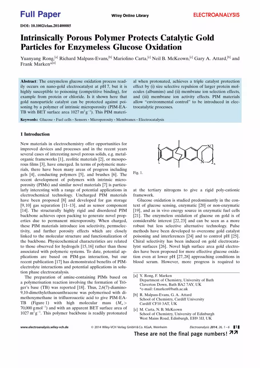
The preparation of amine-containing PIMs based ona polymerisation reaction involving the formation of Trç-ger�s base (TB) was reported [18]. Thus, 2,6(7)-diamino-9,10-dimethylethanoanthracene was polymerised with di-methoxymethane in trifluoroacetic acid to give PIM-EA-TB (Figure 1) with high molecular mass (Mw>70,000 g mol�1) and with an apparent BET surface area of1027 m2 g�1. This polymer backbone is readily protonated
at the tertiary nitrogens to give a rigid poly-cationicframework.
Glucose oxidation is studied predominantly in the con-text of glucose sensing, enzymatic [20] or non-enzymatic[19], and as in vivo energy source in enzymatic fuel cells[21]. The enzymeless oxidation of glucose on gold is ofconsiderable interest [22,23] and can be seen as a morerobust but less selective alternative technology. Pulsemethods have been developed to overcome gold catalystpoisoning and interferences [24] and to control pH [25].Chiral selectivity has been induced on gold electrocata-lytst surfaces [26]. Novel high surface area gold electro-des have been proposed for more effective glucose oxida-tion even at lower pH [27,28] approaching conditions inblood serum. However, more progress is required to
[a] Y. Rong, F. MarkenDepartment of Chemistry, University of BathClaverton Down, Bath BA2 7AY, UK*e-mail: [email protected]
[b] R. Malpass-Evans, G. A. AttardSchool of Chemistry, Cardiff UniversityCardiff CF10 3AT, UK
[c] M. Carta, N. B. McKeownSchool of Chemistry, University of EdinburghWest Mains Road, Edinburgh, EH9 3JJ, UK
Abstract : The enzymeless glucose oxidation process read-ily occurs on nano-gold electrocatalyst at pH 7, but it ishighly susceptible to poisoning (competitive binding), forexample from protein or chloride. Is it shown here thatgold nanoparticle catalyst can be protected against poi-soning by a polymer of intrinsic microporosity (PIM-EA-TB with BET surface area 1027 m2 g�1). This PIM materi-
al when protonated, achieves a triple catalyst protectioneffect by (i) size selective repulsion of larger protein mol-ecules (albumins) and (ii) membrane ion selection effects,and (iii) membrane ion activity effects. PIM materialsallow “environmental control” to be introduced in elec-trocatalytic processes.
Keywords: Glucose · Fuel cells · Sensors · Microporosity · Membranes · Electrocatalysis
Fig. 1.
www.electroanalysis.wiley-vch.de � 2014 Wiley-VCH Verlag GmbH & Co. KGaA, Weinheim Electroanalysis 2014, 26, 1 – 6 &1&
These are not the final page numbers! ��
Full Paper

make gold nanoparticle catalysts as effective as biologicalcatalysts. A considerable challenge remains in overcom-ing poisoning of the gold electrocatalysts under in vivoconditions.
It is shown here that the properties of PIM polymermembranes spin-coated over the gold nanoparticle cata-lyst can help protecting the catalyst from poisoning. Theeffect of the PIM membrane is studied (i) on the goldnanoparticle catalyst formation, (ii) on the electrocatalyticglucose oxidation mechanism, (iii) on the effect of proteinon gold catalyst poisoning, and (iv) on the effect of chlo-ride on gold catalyst poisoning in phosphate buffer atpH 7. PIM membranes are proposed as a versatile newclass of materials for electrochemistry in particular forcontrolling the reaction environment in electrocatalyticprocesses.
2 Experimental
2.1 Chemical Reagents
Potassium gold(III) tetrachloride, d-(+)-glucose, albuminfrom bovine serum, sodium chloride, phosphoric acid(85 %), potassium chloride, sulphuric acid (95 %–98%),and sodium hydroxide were purchased from Aldrich orFisher Scientific and used without further purification.PIM-EA-TB was prepared following a literature recipe[18]. Solutions were prepared with filtered and deionizedwater of resistivity 18.2 MW cm from a Thermo Scientificwater purification system (ELGA).
2.2 Instrumentation
A potentiostat system (IVIUM Compactstat) was em-ployed with a Pt wire counter electrode and a KCl-satu-rated calomel reference (SCE, Radiometer, Copenha-gen). The working electrode was prepared from ITOcoated glass (tin-doped indium oxide films sputter-coatedonto glass, active area 10 mm �10 mm, resistivity ca. 15 W
per square) obtained from Image Optics Components Ltd(Basildon, Essex, UK). ITO electrodes were rinsed withethanol and water, heat-treated in a tube furnace (EliteThermal System Ltd) for 30 minutes at 500 8C, and thenre-equilibrated to ambient conditions. All experimentswere conducted at a temperature of 293�2 K.
2.3 Gold Nanoparticle Deposition Method
A gold(III) solution was prepared by dissolving 1 mMKAuCl4 in 0.1 M KCl addition of sulphuric acid to pH 2.Electrodeposition was performed in chronoamperometrymode. ITO electrodes were pre-treated at 1 V vs. SCE for10 s followed by plating at �0.2 V vs. SCE for 200 s, rins-ing with water, and drying under ambient conditions.
2.4 Polymer with Intrinsic Microporosity Coating Method
Initially, a solution of 1 mg cm�3 PIM-EA-TB in chloro-form was applied directly by dipping the electrode fol-lowed by drying under ambient conditions. Improvedcoatings were obtained by spin-coating (Laurell WS-650Mz-23NPP, 1500 rpm for 30 seconds).
3 Results and Discussion
3.1 Electrodeposition of Catalytic Gold Nanoparticlesonto Tin-Doped Indium Oxide (ITO) Substrates
The gold electrodeposition approach was selected basedon an aqueous solution of 1 mM KAuCl4 in 0.1 M KCl atpH 2 (acidified with H2SO4). The deposition experimentswere conducted at �0.2 V vs. SCE for 200 s (if not statedotherwise) to form a uniform deposit of gold nanoparti-cles on the ITO substrate (see Figure 2A,B). Particles aretypically 100 nm to 200 nm in diameter and well distribut-ed over the electrode surface.
Fig. 2. Scanning electron microscopy images for (A) gold nano-particles grown on ITO for 200 s, (B) higher magnification imageof gold nanoparticles.
www.electroanalysis.wiley-vch.de � 2014 Wiley-VCH Verlag GmbH & Co. KGaA, Weinheim Electroanalysis 2014, 26, 1 – 6 &2&
These are not the final page numbers! ��
Full Paper

In cyclic voltammetry experiments these gold depositsimmersed in 0.1 M phosphate buffer at pH 7 give stablevoltammetric responses (see Figure 3A) with gold oxida-tion (see peak Iox at 0.80 V vs. SCE) and gold back-reduc-tion (see peak Ired at 0.55 V vs. SCE) indicative of anactive gold surface.
The gold electrodeposition was repeated in the pres-ence of a PIM film spin-coated onto the ITO surface (ca.500 nm thickness). The same type of gold nanoparticledeposit was formed (confirmed by voltammetry and elec-trocatalysis experiments, vide infra). But unfortunatelythese films were unstable and easily peeled off the surfacetogether with the PIM film. Better quality films were ob-tained by first electroplating gold nanoparticles onto ITO
and then coating with PIM. Drop-coating PIM resulted infilm imperfection, but spin-coating a solution 1 mg cm�3
PIM in chloroform at 1500 rpm (see experimental) result-ed in high quality film coatings.
3.2 Glucose Oxidation on Catalytic Gold Nanoparticleson Tin-Doped Indium Oxide (ITO) Substrates
The oxidation of glucose on gold nanoparticles immersedin phosphate buffer pH 7 has been reported previouslyand a typical anodic current peak is seen at 0.3 V vs. SCE(see Figure 3). As expected for a surface-catalytic kineti-cally controlled current response, this peak is not affectedby scan rate (see Figure 3B) but strongly affected by thegold nanoparticle catalyst deposition time (see Figure 3C,peak II, note that this peak is observed most clearlyduring the potential sweep towards negative potentials).A plot of the effect of the gold nanoparticle depositiontime on the glucose oxidation peak current is shown inFigure 3D. An improvement in the catalytic signal is seenup to approximately 400 s electrodeposition.
An investigation of the effect of the phosphate bufferconcentration on the catalytic process provides further in-sight into the mechanism. As shown in Figure 4A a signifi-cant enhancement of the catalytic current for glucose oxi-dation is observed upon lowering the phosphate concen-tration. When plotted versus logarithm of phosphate con-
Fig. 3. (A) Cyclic voltammograms (first and second cycle, scanrate 5 mVs�1, start point 0.0 V vs. SCE) for gold nanoparticleson ITO immersed in 0.1 M phosphate buffer pH 7. (B) Asbefore, but with 8 mM glucose and scan rate (i) 5, (ii) 10, (iii) 20,(iv) 50, (v) 100 mVs�1. (C) As before, but with 8 mM glucose,scan rate 5 mVs�1, and (i) 100 s, (ii) 200 s, (iii) 300 s, (iv) 600 sgold nanoparticle deposition time. (D) Plot of the glucose oxida-tion peak versus gold nanoparticle deposition time.
Fig. 4. (A) Cyclic voltammograms (scan rate 5 mV s�1, startpoint 0.0 V vs. SCE) for the oxidation of 8 mM glucose at goldnanoparticles on ITO immersed in (i) 10, (ii) 100, (iii) 1000 mMphosphate buffer pH 7. (B) Plot of the peak current versus loga-rithm of phosphate buffer concentration.
www.electroanalysis.wiley-vch.de � 2014 Wiley-VCH Verlag GmbH & Co. KGaA, Weinheim Electroanalysis 2014, 26, 1 – 6 &3&
These are not the final page numbers! ��
Full Paper
centration, the catalytic current exhibits an approximatelylinear dependence. This can be reconciled with a Lang-muirian binding model where the kinetically controlledglucose oxidation current IG is proportional to the cover-age with glucose VG at the active surface sites (Equa-tion 1).
IG ¼ constant�VG ¼ constant� KG½G�1þKG½G� þKP½P�
ð1Þ
Here, KG and KP represent Langmuirian binding con-stants for glucose and a competing molecule or ion. Forthe special case of half coverage, that is KG[G]�KP[P](here observed for 8 mM glucose and 100 mM phosphatebuffer), an approximately linear relationship around thepoint of half-coverage is possible, which suggests thathere KG/KP� [P]/[G]�12. Therefore glucose is bound ap-proximately an order of magnitude more strongly com-pared to other components in the phosphate buffer.
Next, the effect of glucose concentration is investigat-ed. Figure 5 shows data for gold nanoparticle catalyst in0.1 M phosphate buffer pH 7 for different glucose con-centrations. At low glucose levels an approximately linearincrease in glucose oxidation current is observed with pla-teauing at glucose concentration higher than 12 mM. Thisobservation is in agreement with the Langmuirian bindingmodel introduced above. The binding constant can be es-timated (here from the point of third coverage, whereVG ¼ KG ½G�
1þKG ½G�þKP ½P� ¼13 with KG[G]�KP[P]) as KG
�200 mol�1 dm3.
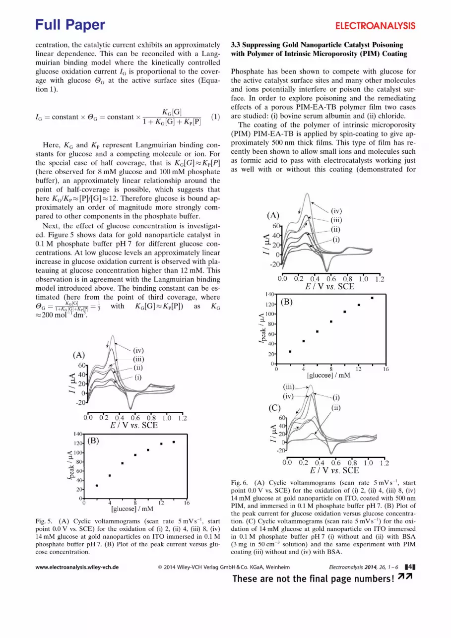
3.3 Suppressing Gold Nanoparticle Catalyst Poisoningwith Polymer of Intrinsic Microporosity (PIM) Coating
Phosphate has been shown to compete with glucose forthe active catalyst surface sites and many other moleculesand ions potentially interfere or poison the catalyst sur-face. In order to explore poisoning and the remediatingeffects of a porous PIM-EA-TB polymer film two casesare studied: (i) bovine serum albumin and (ii) chloride.
The coating of the polymer of intrinsic microporosity(PIM) PIM-EA-TB is applied by spin-coating to give ap-proximately 500 nm thick films. This type of film has re-cently been shown to allow small ions and molecules suchas formic acid to pass with electrocatalysts working justas well with or without this coating (demonstrated for
Fig. 5. (A) Cyclic voltammograms (scan rate 5 mV s�1, startpoint 0.0 V vs. SCE) for the oxidation of (i) 2, (ii) 4, (iii) 8, (iv)14 mM glucose at gold nanoparticles on ITO immersed in 0.1 Mphosphate buffer pH 7. (B) Plot of the peak current versus glu-cose concentration.
Fig. 6. (A) Cyclic voltammograms (scan rate 5 mV s�1, startpoint 0.0 V vs. SCE) for the oxidation of (i) 2, (ii) 4, (iii) 8, (iv)14 mM glucose at gold nanoparticle on ITO, coated with 500 nmPIM, and immersed in 0.1 M phosphate buffer pH 7. (B) Plot ofthe peak current for glucose oxidation versus glucose concentra-tion. (C) Cyclic voltammograms (scan rate 5 mV s�1) for the oxi-dation of 14 mM glucose at gold nanoparticle on ITO immersedin 0.1 M phosphate buffer pH 7 (i) without and (ii) with BSA(3 mg in 50 cm�3 solution) and the same experiment with PIMcoating (iii) without and (iv) with BSA.
www.electroanalysis.wiley-vch.de � 2014 Wiley-VCH Verlag GmbH & Co. KGaA, Weinheim Electroanalysis 2014, 26, 1 – 6 &4&
These are not the final page numbers! ��
Full Paper

formic acid oxidation on palladium [17]). Here the PIMcoating is shown to not detrimentally affect the glucoseoxidation (see Figure 6A) with clear oxidation peaks de-tected at 0.3 V vs. SCE. The plot of the peak currentversus glucose concentration has an extended range intohigher glucose concentrations (see Figure 6B) indicativeof less competition to phosphate buffer binding (the ac-tivity of the phosphate buffer is believed to be lower inthe PIM environment).
When adding bovine serum albumin (BSA) as a knowncatalyst poison [29], a dramatic change is observed in theglucose oxidation current. Figure 6C (i) and (ii) show thecurrent for glucose oxidation on bare gold nanoparticlecatalyst before and after addition BSA (3 mg in 50 cm3
solution), respectively. The same experiment was repeat-ed with PIM coating (see Figure 6C (iii) and (iv)) with nodetrimental effect of the protein. It is likely that the PIMcoating can repel the protein based on size exclusion.
A further severe poisoning effect on the gold nanopar-ticle electrocatalyst is induced by chloride. An addition of10 mM chloride into 0.1 M phosphate buffer pH 7 almostcompletely eliminates the catalytic glucose oxidation (seeFigure 7A (i) and (ii)). When the PIM coating is appliedthis effect is considerably less dramatic. In Figure 7A (iii)and (iv) the glucose oxidation for 8 mM glucose in 0.1 Mphosphate buffer pH 7 is shown without and with 10 mMchloride, respectively, and only a 50% drop in currentoccurs. Therefore the PIM membrane changes the accessof chloride to the catalyst surface (e.g. by competition ofphosphate and chloride for PIM anion sites).
These experiments were repeated systematically fora range of chloride concentrations and for two phosphatebuffer concentrations. The plot in Figure 7D shows boththe effect of the lower buffer concentration increasing theglucose oxidation current and the effect of chloride re-ducing the catalyst activity. The observed data plot isagain consistent with the model of competitive Langmuir-ian binding (Equation 1). Interestingly, with the PIMcoating the gold nanoparticle electrocatalyst is able to ef-fectively operate even in 20 mM chloride. Typical bloodserum levels of chloride are higher and therefore the im-provement in catalyst performance is still not sufficient.However, the observed improvement with a thin PIMfilm coating is promising and future development couldfocus on (i) improved PIM materials in terms of molecu-lar structure and pore structure for controlling access ofpoisons to the catalyst and (ii) improved design of the“electrocatalyst PIM environment” to optimise conditionsin the reaction zone close to the active catalyst sites.
4 Conclusions
It has been shown that novel PIM materials such as PIM-EA-TB with extremely high surface area and ability to beprotonated (to be semipermeable towards anions) pro-vide a new class of electrochemically effective compo-nents for application in electrocatalysis, for example forenergy harvesting and sensing. The rigid nature of the
Fig. 7. (A) Cyclic voltammograms (scan rate 5 mV s�1, startpoint 0.0 V vs. SCE) for the oxidation of 8 mM glucose at goldnanoparticles on ITO immersed in 0.1 M phosphate buffer pH 7(i) without and (ii) with 10 mM chloride and the same experi-ment with PIM coating (iii) without and (iv) with 10 mM chlo-ride. (B) (A) Cyclic voltammograms (scan rate 5 mV s�1) for theoxidation of 8 mM glucose at gold nanoparticles on ITO withPIM coating immersed in 0.1 M phosphate buffer pH 7 with (i) 0,(ii) 2, (iii) 10, (iv) 50, (v) 100 mM chloride. (C) (A) Cyclic vol-tammograms (scan rate 5 mVs�1) for the oxidation of 8 mM glu-cose at gold nanoparticles on ITO with PIM coating immersed in0.01 M phosphate buffer pH 7 with (i) 0, (ii) 2, (iii) 10, (iv) 50,(iv) 100 mM chloride. (D) Plot of the peak current for glucoseoxidation versus chloride concentration for 0.1 and 0.01 M phos-phate buffer pH 7.
www.electroanalysis.wiley-vch.de � 2014 Wiley-VCH Verlag GmbH & Co. KGaA, Weinheim Electroanalysis 2014, 26, 1 – 6 &5&
These are not the final page numbers! ��
Full Paper

PIM polymer backbone minimises structural fluctuationsand leads to a stable pore size for selective transport ofneutral and charged species. When protonated, the PIM-EA-TB film exhibits some degree of anion selectivitywith potential benefits in electrocatalytic processes (e.g.widening the linear range, influencing competitive bind-ing equilibria). Here, the oxidation of glucose on gold atpH 7 in phosphate buffer is investigated as a first modelcase. Three types of effects on the catalyst performanceare observed:
(i) The size selection effect of PIM pores allows poison-ing from larger proteins such as bovine serum albu-min to be suppressed
(ii) The anion selection effect allows access of chlorideto the catalyst surface to be reduced (in competitionto phosphate)
(iii) The change in anion activity in the catalyst reactionzone (e.g. reduced phosphate binding relative to glu-cose binding and extended linear range)
In future novel PIM materials could be designed andfurther improved by molecular control over pore size,pore shape, pore charge distribution, etc. In contrast tohydrogels, the novel PIM materials are highly stable andmore dense to impose a stronger effect on the membranepermeability and catalyst environment. Rigidity and themolecular structure of the PIM polymer backbone playa key role in introducing new functionality and novel ef-fects.
Acknowledgement
Y. R. thanks the University of Bath for a fee waiver.
References
[1] A. Morozan, F. Jaouen, Energy Environ. Sci. 2012, 5, 9269.[2] Z. H. Dai, H. X. Ju, TRAC – Trends Anal. Chem. 2012, 39,
149.[3] A. Walcarius, Chem. Soc. Rev. 2013, 42, 4098.[4] D. M. Lin, J. F. Che, Prog. Chem. 2010, 22, 1195.[5] T. F. Otero, J. G. Martinez, J. Arias-Pardilla, Electrochim.
Acta 2012, 84, 112.[6] N. Ayres, Polymer Chem. 2010, 1, 769.[7] Z. H. Xiang, D. P. Cao, J. Mater. Chem. A 2013, 1, 2691.[8] P. M. Budd, B. S. Ghanem, S. Makhseed, N. B. McKeown,
K. J. Msayib, C. E. Tattershall, Chem. Commun. 2004, 230.
[9] N. B. McKeown, P. M. Budd, Macromolecules 2010, 43,5163.
[10] N. B. McKeown, B. Gahnem, K. J. Msayib, P. M. Budd, C. E.Tattershall, K. Mahmood, S. Tan, D. Book, H. W. Langmi,A. Walton, Angew. Chem. Int. Ed. 2006, 45, 1804.
[11] S. V. Adymkanov, Y. P. Yampol�skii, A. M. Polyakov, P. M.Budd, K. J. Reynolds, N. B. McKeown, K. J. Msayib, Poly-mer Sci. 2008, 50, 444.
[12] P. M. Budd, N. B. McKeown, B. S. Ghanem, K. J. Msayib, D.Fritsch, L. Starannikova, N. Belov, O. Sanfirova, Y. P. Yam-pol�skii, V. Shantarovich, J. Membrane Sci. 2008, 325, 851.
[13] C. G. Bezzu, M. Carta, A. Tonkins, J. C. Jansen, P. Bernardo,F. Bazzarelli, N. B. McKeown, Adv. Mater. 2012, 24, 5930.
[14] Y. Wang, N. B. McKeown, K. J. Msayib, G. A. Turnbull,I. D.W. Samuel, Sensors 2011, 11, 2478.
[15] D. Buenger, F. Topuz, J. Groll, Progress Polymer Sci. 2012,37, 1678.
[16] A. Guiseppi-Elie, Biomaterials 2010, 31, 2701.[17] F. J. Xia, M. Pan, S. C. Mu, R. Malpass-Evans, M. Carta,
N. B. McKeown, G. A. Attard, A. Brew, D. J. Morgan, F.Marken, Electrochim. Acta 2014, in press, DOI: 10.1016/j.electacta.2013.08.169.
[18] M. Carta, R. Malpass-Evans, M. Croad, Y. Rogan, J. C.Jansen, P. Bernardo, F. Bazzarelli, N. B. McKeown, Science,2013, 339, 303.
[19] M. Arredondo, M. Stoytcheva, R. Zlatev, V. Gochev, Mini-Rev. Medicinal Chem. 2012, 12, 1301.
[20] G. F. Wang, X. P. He, L. L. Wang, A. X. Gu, Y. Huang, B.Fang, B. Y. Geng, X. J. Zhang, Microchim. Acta, 2013, 180,161.
[21] Q. Liu, X. H. Xu, G. L. Ren, W. Wang, Prog. Chem. 2006,18, 1530.
[22] Y. Li, Y. Y. Song, C. Yang, X. H. Xia, Electrochem.Commun. 2007, 9, 981.
[23] Y. G. Zhou, S. Yang, Q. Y. Qian, X. H. Xia, Electrochem.Commun. 2009, 11, 216.
[24] M. Pasta, F. La Mantia, Y. Cui, Electrochem. Commun.2010, 12, 1407.
[25] L. Rassaei, F. Marken, Anal. Chem. 2010, 82, 7063.[26] A. Martins, V. Ferreira, A. Queir�s, I. Aroso, F. Silva, J.
Feliu, Electrochem. Commun. 2003, 5, 741.[27] A. Celebanska, A. Lesniewski, M. Paszewski, M. Jonsson-
Niedziolka, J. Niedziolka-Jonsson, M. Opallo, Electrochem.Commun. 2011, 13, 1170.
[28] H. du Toit, M. Di Lorenzo, Sens. Actuators B, Chem. 2014,192, 725.
[29] Y. Chen, K. Flowers, M. Calizo, S. W. Bishnoi, Colloid. Surf.B, Biointerf. 2010, 76, 241.
Received: February 17, 2014Accepted: March 8, 2014
Published online: && &&, 2014
www.electroanalysis.wiley-vch.de � 2014 Wiley-VCH Verlag GmbH & Co. KGaA, Weinheim Electroanalysis 2014, 26, 1 – 6 &6&
These are not the final page numbers! ��
Full Paper