interstitial carbon induced fcc-ti exhibiting ultrahigh strength
TRANSCRIPT
Acta Materialia 203 (2021) 116456
Contents lists available at ScienceDirect
Acta Materialia
journal homepage: www.elsevier.com/locate/actamat
Interstitial carbon induced FCC-Ti exhibiting ultrahigh strength in a
Ti 37
Nb 28
Mo 28
-C 7
complex concentrated alloy
Shan Jiang
a , Lujun Huang
a , b , ∗, Xiang Gao
c , Gang Liu
d , Rui Zhang
a , Yang Jiao
a , Shang Peng
c , Qi An
a , Shuai Wang
a , Lin Geng
a , b
a School of Materials Science and Engineering, Harbin Institute of Technology, P.O. Box 433, Harbin 150 0 01, PR China b State Key Laboratory of Advanced Welding and Joining, Harbin Institute of Technology, Harbin 150 0 01, PR China c Center for High Pressure Science &Technology Advanced Research, Haidian District, Beijing, 10 0 094, P.R. China d State Key Laboratory for Mechanical Behavior of Materials, Xi’an Jiaotong University, Xi’an, 710049, China
a r t i c l e i n f o
Article history:
Received 4 June 2020
Revised 22 October 2020
Accepted 30 October 2020
Available online 9 November 2020
Keywords:
FCC-Ti
complex concentrated alloy
Cs-corrected STEM
micropillar compression
DFT
a b s t r a c t
An interstitial carbon induced-FCC-Ti was observed in a carbon-doped Ti 37 Nb 28 Mo 28 -C 7 (atomic percent-
age) complex concentrated alloys (TNMC alloys) . Not only the true crystal structure of this FCC-Ti was di-
rectly characterized using Cs-corrected STEM, but also the mechanical properties were tested by nanoin-
dentation and micro-pillar compression for the first time. The FCC-Ti exhibited a high nano hardness of
17.8 GPa and a high elastic modulus of 233.1 GPa. The micropillar compression tests demonstrated the
ultrahigh strengths of the interstitial C induced FCC-Ti (4.48 GPa at [1 1 1] direction, 2.67 GPa at [1 0
1] direction, and a CRSS of 1.12 ± 0.07 GPa). The nature of this FCC allotropic transformation was deter-
mined to be a rearrangement of lattice structure caused by interstitial C atoms, based on ab-initio studies.
Findings in this study provide insights into the characteristics of FCC-Ti as well as the role of interstitial
atoms in RCCAs which could open up unlimited possibilities in future material designing.
© 2020 Acta Materialia Inc. Published by Elsevier Ltd. All rights reserved.
1
a
A
c
c
i
1
r
b
h
a
t
t
(
T
m
b
i
s
u
c
s
t
g
c
i
g
r
t
T
t
d
c
t
d
v
F
m
h
1
. Introduction
As a class of promising engineering material, titanium materi-
ls, such as titanium alloys, titanium matrix composites, and Ti-
l intermet allics, have attracted increasing attention over the past
entury owing to the low density, high strength, and superior
orrosion resistance [1–6] . Ti also plays a critical role in emerg-
ng and rising refractory complex concentrated alloys (RCCAs) [7–
0] intended for high-temperature applications to fabricate the Ti-
ich RCCAs [11–14] to cope with the high-density problem brought
y concentrated heavy alloying elements [15] . However, with less
eavy refractory elements used, the strength enhancement would
lso drastically decrease. In recent years, doping non-metallic in-
erstitial atoms (e.g., boron, carbon, and oxygen) was found with
he ability to effectively strengthen the 3d transition metal CCAs
Co-Cr-Fe-Mn-Ni CCAs) without much sacrifice of ductility [16–19] .
he impact of different interstitial elements on the 3d transition
etal CCAs can be various, such as dislocation pinning, tuning sta-
ility of metastable matrix, grain boundary decorating, and form-
ng reinforcing phases. Considering the low atomic mass of inter-
∗ Corresponding author.
E-mail address: [email protected] (L. Huang).
g
p
p
β
ttps://doi.org/10.1016/j.actamat.2020.10.075
359-6454/© 2020 Acta Materialia Inc. Published by Elsevier Ltd. All rights reserved.
titial elements, applying the “interstitial CCAs” concept instead of
sing heavy metallic elements, could effectively alleviate the criti-
al high-density problem. Yet, the application of this novel alloying
trategy in RCCAs is quite rare [9, 20] , despite its tremendous po-
ential. Thus, to further utilize this novel alloying strategy, it is of
reat significance to continue exploiting in the interstitial RCCAs
ompositional space and figure out the role of interstitial atoms
n RCCAs. Here, based on the high-temperature application back-
round, a carbon-doped Ti 37 Nb 28 Mo 28 -C 7 RCCA (TNMC alloy) with
elatively lower density was designed and fabricated, and due to
he doped C atoms, an unexpected face-centered cubic phase of
i (FCC-Ti) was formed in the body-centered cubic RCCA. In fact,
itanium exhibits multiple allotropic phases under different con-
itions. Namely, hexagonal close-packed (HCP) phase ( α-Ti), body-
entered cubic (BCC) phase ( β-Ti), hexagonal ω-phase, α’ and or-
horhombic α’’ martensitic phases [21–27] . The discovery of FCC-Ti
ates back to the year of 1969 when Wawner and Lawless [28] re-
ealed such a structure within an epitaxial grown Ti nanofilm. The
CC-Ti has been found in different material systems and across
ultiple length scales: Nanosized FCC-Ti was found in epitaxial
rown Ti nanofilm [29–35] , interfaces between α-phase and β-
hase in α+ β titanium alloys [36–39] , cp-Ti powder [40] , Ti-Al
owders after severe plastic deformation [41] , and a metastable
-type alloy [42] . Recently, sub-micro scale FCC-Ti was observed
S. Jiang, L. Huang, X. Gao et al. Acta Materialia 203 (2021) 116456
i
(
2
t
T
t
n
r
t
a
F
a
1
c
[
c
b
t
B
b
s
c
T
T
s
o
e
i
o
d
T
a
f
s
p
a
M
c
u
a
(
o
n
i
n
c
e
s
i
a
C
d
2
2
u
e
a
a
T
b
s
a
a
w
w
t
t
p
2
d
i
p
t
n
b
t
t
t
e
m
r
d
e
F
e
t
c
i
S
y
m
a
7
A
p
P
s
t
l
d
e
a
6
l
a
o
2
N
t
c
N
a
t
w
a
2
c
e
n deformed Ti (~300nm) [43–46] , in-situ heated Nb-Ti-Si alloy
50~500nm) [47] , sintered Ti-Mo-Fe alloy (50 0~120 0nm) [48] , Ti–
0Zr–6.5Al–4V alloy (weight percentage) aged at high tempera-
ures [49] , FIB fabricated TEM samples [50] and in-situ heated Ti-O
EM sample (~400nm) [51] . The nature of the HCP to FCC allotropic
ransformation of titanium was also discussed: the formation of
ano-sized FCC-Ti is due to the energy minimization and it was
eported that the nano FCC-Ti could be stable in a large tempera-
ure range within the critical size (~27 nm at 882 o C, and 5-7 nm
t room temperature) [52, 53] ; the formation of the sub-microsized
CC-Ti, on the other hand, is achieved by the sequential gliding of
/3 < 1 1 0 0 > -type Schockley partials along every other {0 0 0
} plane of the HCP lattice. According to these studies, the lattice
onstants of the FCC-Ti were inconsistent and varied from 4.02 A
54] to 4.40 A [30] . However, as the research on the FCC-Ti ac-
umulated, some of the reported FCC-Ti was eventually proved to
e artifacts induced during sample preparation. According to sys-
ematic researches on the α- β interface phase in Ti alloys by D.
anerjee et al. [55–58] , the FCC interface phase was determined to
e titanium hydrides formed during TEM sample preparation. The
ame conclusion has also been found to be true in the cold-rolled
p-Ti TEM samples, that the so called “deformation induced FCC-
i” has a great chance to only be titanium hydride artifact [59] .
he cause of such a artefacts could be ascribed to the hydrogen ab-
orption during the electropolishing process which could be easily
verlooked [60] . And the difficulties in characterizing hydrogen el-
ment make it even harder to detect such an artifact. Therefore,
t is critical to carefully and thoroughly examine the FCC phase
f titanium to rule out any possibility for it being titanium hy-
rides, oxides, carbides, and nitrides artifacts. Even though FCC-
i has been studied systemically for half a century, yet this novel
llotropic phase of Ti still cannot be utilized for the phase trans-
ormation mechanism and mechanical properties of the FCC-Ti are
till lacking.
In order to have a better understanding of this hidden allotropic
hase of Ti and the effect of interstitial C atoms in this RCCAs,
systematic investigation was carried out on this novel FCC-Ti.
icrostructure and crystallographic structures of the interstitial
arbon induced FCC-Ti were carefully examined and determined
sing transmission electron microscopy (TEM) and state-of-the-
rt double Cs-corrected scanning transmission electron microscopy
STEM). Especially, the crystal structure was determined by direct
bservation of the true atomic arrangement for the first time. The
ature of this FCC-Ti allotropic transformation was revealed by ab-
nitio calculations. The FCC-Ti was found to possess high hard-
ess and modulus according to the nanoindentation test. The mi-
ropillar compression tests on the single crystal FCC-Ti of differ-
nt orientations provided the mechanical properties at a micro-
cale which could rule out the size effect of mechanical tests. Find-
ngs in this work provide critical insights into not only the char-
cteristics of FCC-Ti but also the role of interstitial atoms in RC-
As and could open up unlimited possibilities in future material
esigning.
. Experimental
.1. Alloy synthesis
The TNMC alloy was fabricated by powder metallurgy method
sing high purity spherical titanium powder with a mean diam-
ter of 100 μm, angular niobium and molybdenum powder with
mean diameter of 5 μm as starting materials. 1 wt.% stearic
cid was used as carbon source and possess controlling agent.
he powders were ball milled at 300 rpm for 10 hrs with a
all-to-powder weight ratio of 20:1 in a high purity argon atmo-
phere. Stainless steel vails with stainless steel balls were used
2
s milling medium. Then the ball-milled powders were filled in
graphite die and hot-pressing sintered at 1300 o C for 1.5 h
ith a 40 MPa uniaxial pressure applied. The sintering process
as carried out in a vacuum of 10 -2 Pa. To avoid the reac-
ion between the powder and graphite, a thin layer of boron ni-
ride (BN) was sprayed on the inner surface of the die and the
unches.
.2. Microstructure characterizations and sample preparation
X-ray diffraction (XRD) characterization of the mixed pow-
ers and the as-sintered alloy were carried out on a Panalyt-
cal Empyrean X-ray diffractometer with Cu K- α radiation. The
hase distribution and the grain sizes were characterized by elec-
ron back-scattered diffraction (EBSD) on a Zeiss SUPRA 55 scan-
ing electron microscope (SEM), the EBSD sample was prepared
y the ion etching method. The overall chemical composition of
he alloy was determined by glow-discharge optical emission spec-
roscopy (GDOES) on a LECO GDS850A spectrometer. Element dis-
ribution of the alloy and chemical composition quantification of
ach phase were characterized on a JEOL JXA-8230 electron probe
icroanalyzer (EMPA) equipped with a wavelength dispersive X-
ay spectrometer (WDS). TEM diffraction contrast imaging, energy-
ispersive X-ray spectroscopy (EDS) mapping, and selected area
lectron diffraction (SAED) were carried out on an FEI TALOS
200X TEM equipped with Super-X EDS system with an accel-
rating voltage of 200 kV. The diffraction contrast images were
aken using the � 30 μm objective aperture, and the SAED was
arried out using the � 10 μm selective area aperture which
s suitable for performing SAED on grains larger than 100 nm.
TEM imaging and electron energy-loss spectroscopy (EELS) anal-
sis were performed using an aberration-corrected JEOL ARM200F
icroscope. The STEM microscope was operated at 200 kV, using
convergence angle of 30 mrad, and inner/outer angles of about
8/200 mrad and 12/25 mrad for atomic resolution HAADF and
BF imaging, respectively. The TEM and STEM specimen were pre-
ared by mechanical grinding and followed ion milling (GATAN
IPS II MODEL 695) and were plasma cleaned right before in-
erting into the microscope. To minimize the influence of con-
amination build-up induced by the electron beam, atomic reso-
ution STEM imaging, and EELS characterization were all taken at
ifferent positions. Micropillars of the FCC-Ti with different ori-
ntations were fabricated by focused ion beam (FIB) technique
ccording to the EBSD IPF mapping on an FEI Helios NanoLab
00i DualBeam SEM using the top-down method. The micropil-
ars were final-milled down to a diameter of 3 μm to 5 μm
nd a length-diameter ratio larger than 3:1 with a beam current
f 80 pA.
.3. Mechanical properties tests
Nanoindentation tests were carried out on an Agilent G200
ano Indenter with a Berkovich diamond tip, at least five inden-
ations on each phase were carried out to ensure reliability. Mi-
ropillar compression tested were carried out on a Hysitron TI950
anomechanical Test Instrument using a flat diamond punch with
diameter of �20 μm. The compression strain rate was controlled
o be 8 ×10 -4 s -1 . The compressive engineering stress and strain
ere calculated using the area of the cross-section at mid-height
nd the height of the pillar.
.4. Ab-initio studies
The cohesive energies and generalized stacking fault energy
urves were calculated on the Cambridge Sequential Total En-
rgy Package (CASTEP) code based on density functional theory
S. Jiang, L. Huang, X. Gao et al. Acta Materialia 203 (2021) 116456
(
P
e
t
s
1
s
o
e
l
g
w
w
2
1
fl
c
T
d
fi
t
i
w
t
γ
m
A
d
c
G
a
e
9
2
w
1
1
t
E
w
υ
3
3
l
m
p
t
a
t
t
l
p
o
t
s
t
A
d
G
t
E
c
w
c
a
p
E
i
1
r
a
s
p
o
r
i
p
3
(
t
r
t
F
i
o
t
o
t
p
t
[
C
S
1
t
s
T
o
a
a
l
T
n
a
h
a
F
c
s
i
c
DFT), and the generalized gradient approximation (GGA) in the
erdew, Becke and Ernzerhof (PBE) form [33] . For the cohesive en-
rgy calculations and geometry optimization were performed using
he Broyden–Fletcher–Goldfarb–Shanno (BFGS) minimizer until the
ystem reached the convergence criteria: total energy tolerance of
0 -5 eV/atom, maximum force tolerance of 0.03 eV/ A, maximum
tress tolerance of 0.05 GPa, and maximum displacement tolerance
f 0.001 A. The 8 × 8 ×8 Monkhorst Pack k-point grids and an
nergy cutoff of 400 eV were set.
For the generalized stacking fault energy (GSFE) curves calcu-
ations, the cutoff energy was set to be 400 eV and the k-points
rids were set as 5 × 8 ×1 Monkhorst Pack grids. The supercells
ere created from the geometry optimized unit cell of the FCC-Ti,
hich consisted of 12 layers of (1 1 1) planes (x: [1 1 0], y: [1 1
], and z: [1 1 1]) with the stacking sequence of ABCABCABCABC. A
5 A – thick vacuum region was set at z-direction to avoid the in-
uence caused by the periodic boundary condition. The GSFE was
alculated by rigid shearing method along the [1 1 2] direction.
he top 4 layers were incrementally displaced along the [1 1 2]
irection at a step size of a/ √
6 10 A, while the bottom 8 layers were
xed to mimic the bulk material. After a displacement of a √
6 A,
he stacking sequence was deformed as ABCABCABABCA with an
ntrinsic stacking fault structure. The GSFE value of the supercell
ith a displacement of n( a √
6 ) A was then calculated according to
he following equation.
n GSF =
E n SF − E 0
A
Where E n SF
is the total energy of the supercell after displace-
ent of n( a √
6 ) A and E 0 is the total energy of the perfect lattice,
denotes the area of the fault plane, γ n GSF
is the GSFE value at a
isplacement of n( a √
6 ) A.
The polycrystalline bulk modulus and shear modulus were cal-
ulated using the Voigt-Reuss-Hill average estimation ( K VRH and
VRH ) based on the stiffness matrix (elastic tensor C ij and compli-
nce tensor s ij ) from the DFT calculation results according to the
quations below [61, 62] :
K VRH = 9 K V = 9 K R = ( C 11 + C 22 + C 33 ) +2 ( C 12 + C 23 + C 31 )
G VRH = G V + G R
here G V and G R are given by:
5 G V = ( C 11 + C 22 + C 33 ) −( C 12 + C 23 + C 31 ) +3 ( C 44 + C 55 + C 66 )
5 / G R = ( s 11 + s 22 + s 33 ) −( s 12 + s 23 + s 31 ) +3 ( s 44 + s 55 + s 66 )
he Young’s modulus ( E ) was calculated according to the relation
= 3K ( 1 − 2 υ)
here υ , the isotropic Poisson ratio, is calculated by
= 3 ( K VRH −2 G VRH ) / ( 6 K VRH +2 G VRH )
. Results and Discussion
.1. Microstructure characterizations of the TNMC alloy
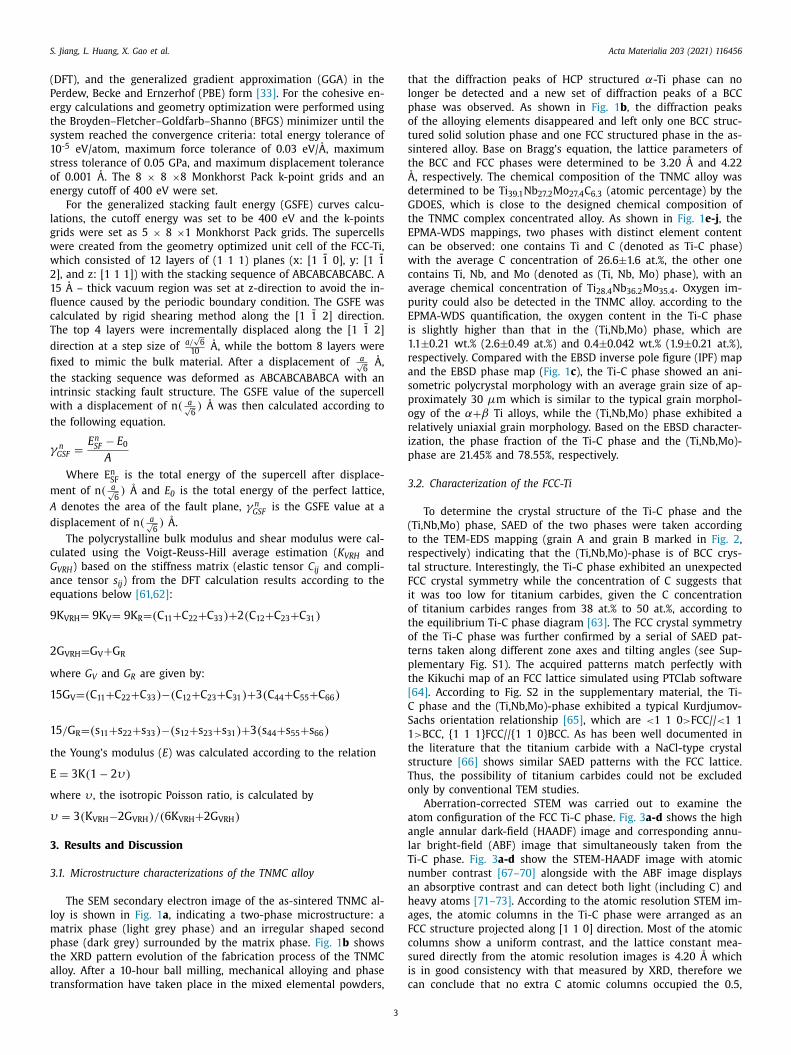
The SEM secondary electron image of the as-sintered TNMC al-
oy is shown in Fig. 1 a , indicating a two-phase microstructure: a
atrix phase (light grey phase) and an irregular shaped second
hase (dark grey) surrounded by the matrix phase. Fig. 1 b shows
he XRD pattern evolution of the fabrication process of the TNMC
lloy. After a 10-hour ball milling, mechanical alloying and phase
ransformation have taken place in the mixed elemental powders,
3
hat the diffraction peaks of HCP structured α-Ti phase can no
onger be detected and a new set of diffraction peaks of a BCC
hase was observed. As shown in Fig. 1 b , the diffraction peaks
f the alloying elements disappeared and left only one BCC struc-
ured solid solution phase and one FCC structured phase in the as-
intered alloy. Base on Bragg’s equation, the lattice parameters of
he BCC and FCC phases were determined to be 3.20 A and 4.22 ˚ , respectively. The chemical composition of the TNMC alloy was
etermined to be Ti 39.1 Nb 27.2 Mo 27.4 C 6.3 (atomic percentage) by the
DOES, which is close to the designed chemical composition of
he TNMC complex concentrated alloy. As shown in Fig. 1 e-j , the
PMA-WDS mappings, two phases with distinct element content
an be observed: one contains Ti and C (denoted as Ti-C phase)
ith the average C concentration of 26.6 ±1.6 at.%, the other one
ontains Ti, Nb, and Mo (denoted as (Ti, Nb, Mo) phase), with an
verage chemical concentration of Ti 28.4 Nb 36.2 Mo 35.4 . Oxygen im-
urity could also be detected in the TNMC alloy. according to the
PMA-WDS quantification, the oxygen content in the Ti-C phase
s slightly higher than that in the (Ti,Nb,Mo) phase, which are
.1 ±0.21 wt.% (2.6 ±0.49 at.%) and 0.4 ±0.042 wt.% (1.9 ±0.21 at.%),
espectively. Compared with the EBSD inverse pole figure (IPF) map
nd the EBSD phase map ( Fig. 1 c ), the Ti-C phase showed an ani-
ometric polycrystal morphology with an average grain size of ap-
roximately 30 μm which is similar to the typical grain morphol-
gy of the α+ β Ti alloys, while the (Ti,Nb,Mo) phase exhibited a
elatively uniaxial grain morphology. Based on the EBSD character-
zation, the phase fraction of the Ti-C phase and the (Ti,Nb,Mo)-
hase are 21.45% and 78.55%, respectively.
.2. Characterization of the FCC-Ti
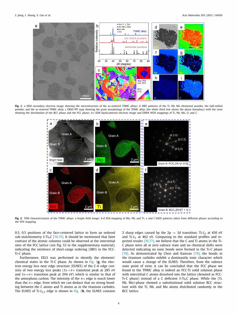
To determine the crystal structure of the Ti-C phase and the
Ti,Nb,Mo) phase, SAED of the two phases were taken according
o the TEM-EDS mapping (grain A and grain B marked in Fig. 2 ,
espectively) indicating that the (Ti,Nb,Mo)-phase is of BCC crys-
al structure. Interestingly, the Ti-C phase exhibited an unexpected
CC crystal symmetry while the concentration of C suggests that
t was too low for titanium carbides, given the C concentration
f titanium carbides ranges from 38 at.% to 50 at.%, according to
he equilibrium Ti-C phase diagram [63] . The FCC crystal symmetry
f the Ti-C phase was further confirmed by a serial of SAED pat-
erns taken along different zone axes and tilting angles (see Sup-
lementary Fig. S1). The acquired patterns match perfectly with
he Kikuchi map of an FCC lattice simulated using PTClab software
64] . According to Fig. S2 in the supplementary material, the Ti-
phase and the (Ti,Nb,Mo)-phase exhibited a typical Kurdjumov-
achs orientation relationship [65] , which are < 1 1 0 > FCC// < 1 1
> BCC, {1 1 1}FCC//{1 1 0}BCC. As has been well documented in
he literature that the titanium carbide with a NaCl-type crystal
tructure [66] shows similar SAED patterns with the FCC lattice.
hus, the possibility of titanium carbides could not be excluded
nly by conventional TEM studies.
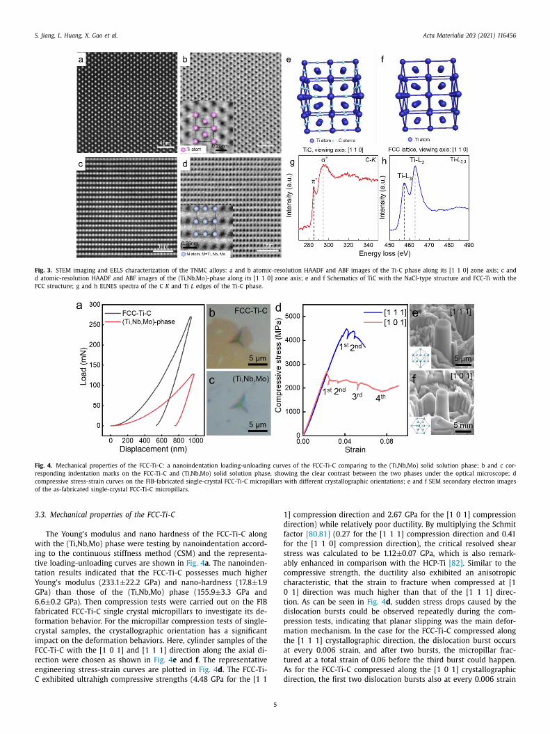
Aberration-corrected STEM was carried out to examine the
tom configuration of the FCC Ti-C phase. Fig. 3 a-d shows the high
ngle annular dark-field (HAADF) image and corresponding annu-
ar bright-field (ABF) image that simultaneously taken from the
i-C phase. Fig. 3 a-d show the STEM-HAADF image with atomic
umber contrast [67–70] alongside with the ABF image displays
n absorptive contrast and can detect both light (including C) and
eavy atoms [71–73] . According to the atomic resolution STEM im-
ges, the atomic columns in the Ti-C phase were arranged as an
CC structure projected along [1 1 0] direction. Most of the atomic
olumns show a uniform contrast, and the lattice constant mea-
ured directly from the atomic resolution images is 4.20 A which
s in good consistency with that measured by XRD, therefore we
an conclude that no extra C atomic columns occupied the 0.5,
S. Jiang, L. Huang, X. Gao et al. Acta Materialia 203 (2021) 116456
Fig. 1. a SEM secondary electron image showing the microstructure of the as-sintered TNMC alloys; b XRD patterns of the Ti, Nb, Mo elemental powder, the ball-milled
powder, and the as-sintered TNMC alloy; c EBSD IPF map showing the grain morphology of the TNMC alloy (the white thick line shows the phase boundary) with the inset
showing the distribution of the BCC phase and the FCC phase; d-i SEM backscattered electron image and EMPA WDS mappings of Ti, Nb, Mo, O, and C.
Fig. 2. TEM characterization of the TNMC alloys: a bright field image; b-d EDS-mapping of Mo, Nb, and Ti; e and f SAED patterns taken from different phases according to
the EDS mapping.
0
s
c
s
i
T
c
t
s
a
t
t
i
T
2
a
p
C
d
[
t
w
s
f
w
T
N
t
B
.5, 0.5 positions of the face-centered lattice to form an ordered
ub-stoichiometry δ-Ti x C [74, 75] . It should be mentioned that faint
ontrast of the atomic columns could be observed at the interstitial
ites of the FCC lattice (see Fig. S3 in the supplementary material),
ndicating the existence of short-range ordering (SRO) in the FCC-
i-C phase.
Furthermore, EELS was performed to identify the elements’
hemical states in the Ti-C phase. As shown in Fig. 3 g , the elec-
ron energy loss near edge structure (ELNES) of the C- K edge con-
ists of two energy loss peaks (1s → π∗ transition peak at 285 eV
nd 1s → σ∗ transition peak at 294 eV) which is similar to that of
he amorphous carbon. The intensity of the π∗ edge is much lower
han the σ∗ edge, from which we can deduce that no strong bond-
ng between the C atoms and Ti atoms as in the titanium carbides.
he ELNES of Ti- L 2,3 edge is shown in Fig. 3 h , the ELNES contains
4
sharp edges caused by the 2p → 3d transition: Ti- L 3 at 456 eV
nd Ti- L 2 at 462 eV. Comparing to the standard profiles and re-
orted results [76, 77] , we believe that the C and Ti atoms in the Ti-
phase were all at zero valence state and no chemical shifts were
etected indicating no ionic bonds were formed in the Ti-C phase
78] . As demonstrated by Chen and Kamran [79] , the bonds in
he titanium carbides exhibit a dominantly ionic character which
ould cause a change of the ELNES. Therefore, from the valence
tate point of view, it can be concluded that the FCC phase we
ound in the TNMC alloy is indeed an FCC-Ti solid solution phase
ith interstitial C atoms dissolved into the lattice (denoted as FCC-
i-C phase) instead of a C deficient δ-Ti x C phase. While the (Ti,
b, Mo)-phase showed a substitutional solid solution BCC struc-
ure with the Ti, Nb, and Mo atoms distributed randomly in the
CC lattice.
S. Jiang, L. Huang, X. Gao et al. Acta Materialia 203 (2021) 116456
Fig. 3. STEM imaging and EELS characterization of the TNMC alloys: a and b atomic-resolution HAADF and ABF images of the Ti-C phase along its [1 1 0] zone axis; c and
d atomic-resolution HAADF and ABF images of the (Ti,Nb,Mo)-phase along its [1 1 0] zone axis; e and f Schematics of TiC with the NaCl-type structure and FCC-Ti with the
FCC structure; g and h ELNES spectra of the C K and Ti L edges of the Ti-C phase.
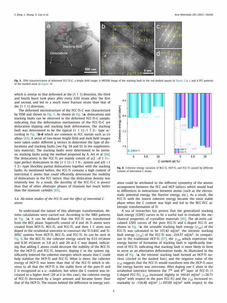
Fig. 4. Mechanical properties of the FCC-Ti-C: a nanoindentation loading-unloading curves of the FCC-Ti-C comparing to the (Ti,Nb,Mo) solid solution phase; b and c cor-
responding indentation marks on the FCC-Ti-C and (Ti,Nb,Mo) solid solution phase, showing the clear contrast between the two phases under the optical microscope; d
compressive stress-strain curves on the FIB-fabricated single-crystal FCC-Ti-C micropillars with different crystallographic orientations; e and f SEM secondary electron images
of the as-fabricated single-crystal FCC-Ti-C micropillars.
3
w
i
t
t
Y
G
6
f
f
c
i
F
r
e
C
1
d
f
f
s
a
c
c
0
t
d
p
m
t
a
t
A
d
.3. Mechanical properties of the FCC-Ti-C
The Young’s modulus and nano hardness of the FCC-Ti-C along
ith the (Ti,Nb,Mo) phase were testing by nanoindentation accord-
ng to the continuous stiffness method (CSM) and the representa-
ive loading-unloading curves are shown in Fig. 4 a . The nanoinden-
ation results indicated that the FCC-Ti-C possesses much higher
oung’s modulus (233.1 ±22.2 GPa) and nano-hardness (17.8 ±1.9
Pa) than those of the (Ti,Nb,Mo) phase (155.9 ±3.3 GPa and
.6 ±0.2 GPa). Then compression tests were carried out on the FIB
abricated FCC-Ti-C single crystal micropillars to investigate its de-
ormation behavior. For the micropillar compression tests of single-
rystal samples, the crystallographic orientation has a significant
mpact on the deformation behaviors. Here, cylinder samples of the
CC-Ti-C with the [1 0 1] and [1 1 1] direction along the axial di-
ection were chosen as shown in Fig. 4 e and f . The representative
ngineering stress-strain curves are plotted in Fig. 4 d . The FCC-Ti-
exhibited ultrahigh compressive strengths (4.48 GPa for the [1 1
5
] compression direction and 2.67 GPa for the [1 0 1] compression
irection) while relatively poor ductility. By multiplying the Schmit
actor [80, 81] (0.27 for the [1 1 1] compression direction and 0.41
or the [1 1 0] compression direction), the critical resolved shear
tress was calculated to be 1.12 ±0.07 GPa, which is also remark-
bly enhanced in comparison with the HCP-Ti [82] . Similar to the
ompressive strength, the ductility also exhibited an anisotropic
haracteristic, that the strain to fracture when compressed at [1
1] direction was much higher than that of the [1 1 1] direc-
ion. As can be seen in Fig. 4 d , sudden stress drops caused by the
islocation bursts could be observed repeatedly during the com-
ression tests, indicating that planar slipping was the main defor-
ation mechanism. In the case for the FCC-Ti-C compressed along
he [1 1 1] crystallographic direction, the dislocation burst occurs
t every 0.006 strain, and after two bursts, the micropillar frac-
ured at a total strain of 0.06 before the third burst could happen.
s for the FCC-Ti-C compressed along the [1 0 1] crystallographic
irection, the first two dislocation bursts also at every 0.006 strain
S. Jiang, L. Huang, X. Gao et al. Acta Materialia 203 (2021) 116456
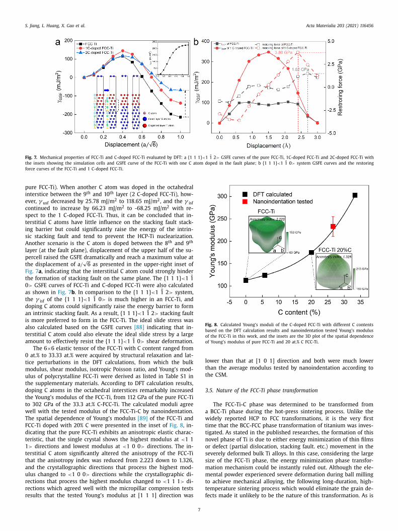
Fig. 5. TEM characterization of deformed FCC-Ti-C: a bright field image; b HRTEM image of the stacking fault in the red dashed square in Figure 5 a; c and d FFT patterns
of the marked areas in Figure 5 b.
w
a
a
t
b
s
i
d
f
c
a
w
l
t
s
T
t
1
f
i
o
r
t
t
3
a
i
i
f
c
d
2
F
a
i
F
n
h
e
v
C
c
o
t
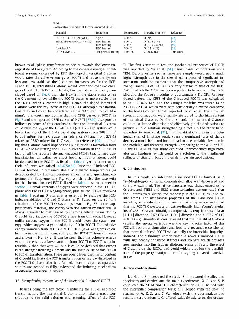
Fig. 6. Cohesive energy variation of BCC-Ti, HCP-Ti, and FCC-Ti caused by different
content of interstitial C atoms.
a
a
t
s
F
p
l
f
c
c
s
F
f
s
e
e
t
i
c
γt
o
C
m
m
hich is similar to that deformed at the [1 1 1] direction, the third
nd fourth burst took place after every 0.02 strain after the first
nd second, and led to a much more fracture strain than that of
he [1 1 1] direction.
The deformed microstructure of the FCC-Ti-C was characterized
y TEM and shown in Fig. 5 . As shown in Fig. 5 a , dislocations and
tacking faults can be observed in the deformed FCC-Ti-C sample,
ndicating that the deformation mechanisms of the FCC-Ti-C are
islocation slipping and stacking fault deformation. The stacking
ault was determined to be the typical {1 1 1} < 1 1 2 > type ac-
ording to Fig. 5 b-d which are common in FCC metals such as Co
lloys [83] . A serial of two-beam bright-field and dark-field images
ere taken under different g vectors to determine the type of dis-
ocations and stacking faults (see Fig. S4 and S5 in the supplemen-
ary material). The stacking faults were determined to be intrin-
ic stacking faults using the method proposed by A. Art et al [84] .
he dislocations in the FCC-Ti are mainly consist of a/2 < 0 1 1 > -
ype perfect dislocations in the {1 1 1} < 1 1 0 > system and a/6 < 1
2 > -type Shockley partial dislocations together with the stacking
aults. As mentioned before, the FCC-Ti contains a high content of
nterstitial C atoms that could efficiently deteriorate the mobility
f dislocations in the FCC lattice, thus the dislocation density was
elatively low. As a result, the ductility of the FCC-Ti-C is poorer
han that of other allotropic phases of titanium but much better
han the titanium carbides [85] .
.4. Ab-initio studies of the FCC-Ti and the effect of interstitial C
toms
To understand the nature of this allotropic transformation, Ab-
nitio calculations were carried out. According to the XRD patterns
n Fig. 1 a , it can be deduced that the FCC-Ti was transformed
rom the BCC phase. Supercells consist of 4 and 16 Ti atoms were
reated from HCP-Ti, BCC-Ti, and FCC-Ti, and then 1 C atom was
oped in the octahedral interstice to construct the Ti-5.8%C and Ti-
0%C systems from HCP-Ti, BCC-Ti, and FCC-Ti. As can be seen in
ig. 6 , for the BCC-Ti, the cohesive energy raised by 0.13 eV/atom
nd 0.30 eV/atom as 5.8 at.% and 20 at.% C was doped, indicat-
ng that adding C atoms could decrease the stability of the BCC-Ti.
or the HCP-Ti and FCC-Ti, however, doping C in the system sig-
ificantly lowered the cohesive energies which means that C could
elp stabilize the HCP-Ti and FCC-Ti. What is more, the cohesive
nergy of HCP-Ti was lower than that of the FCC-Ti which is ob-
ious to all that the HCP-Ti is the stable form of the pure-Ti and
is recognized as a α−stabilizer, but when the C content was in-
reased to a higher level (20 at.% in this case), the cohesive energy
f FCC-Ti decreased by a larger amount and became lower than
hat of the HCP-Ti. The reason behind the difference in energy vari-
6
tion could be attributed to the different symmetry of the atomic
rrangement between the FCC and HCP lattices which would lead
o differences in interactions between atoms (such as the electro-
tatic potential energy, the Hartree energy, etc.). As a result, the
CC-Ti with the lowest cohesive energy became the most stable
hase when the C content was high and led to the BCC-FCC al-
otropic transformation of Ti.
A sea of researches has proven that the generalized stacking
ault energy (GSFE) curves to be a useful tool to evaluate the me-
hanical properties of crystalline materials [86] . The ab-initio cal-
ulated GSFE curves of the pure FCC-Ti and C-doped FCC-Ti are
hown in Fig. 7 a . the unstable stacking fault energy ( γ usf ) of the
CC-Ti was calculated to be 115.42 mJ/m
2 , the intrinsic stacking
ault energy ( γ isf ) of the FCC-Ti was -214.57 mJ/m
2 . In compari-
on to the traditional HCP-Ti [87] , the γ usf which represents the
nergy barrier of formation of stacking fault is significantly low-
red of FCC-Ti, indicating that stacking fault is more likely to form
o serve as an alternative deformation mode. As illustrated in the
nset of Fig. 7 a , the intrinsic stacking fault formed an HCP-Ti nu-
leus (circled in the dashed line), and the negative value of the
isf suggests that the FCC-Ti would transform into the HCP-Ti once
he energy barrier was overcome. After doping one C atom in the
ctahedral interstice between the 7 th and 8 th layer of FCC-Ti (1
-doped FCC-Ti), γ usf increased slightly to 144.43 mJ/m
2 ( + 28.71
J/m
2 with respect to the pure FCC-Ti) and the γ isf increased re-
arkably to -134.48 mJ/m
2 ( + 107.09 mJ/m
2 with respect to the
S. Jiang, L. Huang, X. Gao et al. Acta Materialia 203 (2021) 116456
Fig. 7. Mechanical properties of FCC-Ti and C-doped FCC-Ti evaluated by DFT: a {1 1 1} < 1 1 2 > GSFE curves of the pure FCC-Ti, 1C-doped FCC-Ti and 2C-doped FCC-Ti with
the insets showing the simulation cells and GSFE curve of the FCC-Ti with one C atom doped in the fault plane; b {1 1 1} < 1 1 0 > system GSFE curves and the restoring
force curves of the FCC-Ti and 1 C-doped FCC-Ti.
p
i
e
c
s
t
i
s
A
l
p
t
F
t
0
a
t
d
a
i
a
t
a
0
t
m
u
t
d
t
t
w
T
F
d
t
1
t
t
a
u
r
r
r
Fig. 8. Calculated Young’s moduli of the C-doped FCC-Ti with different C contents
based on the DFT calculation results and nanoindentation tested Young’s modulus
of the FCC-Ti in this work, and the insets are the 3D plot of the spatial dependence
of Young’s modulus of pure FCC-Ti and 20 at.% C FCC-Ti.
l
t
t
3
a
w
t
t
n
o
s
s
m
m
t
t
f
ure FCC-Ti). When another C atom was doped in the octahedral
nterstice between the 9 th and 10 th layer (2 C-doped FCC-Ti), how-
ver, γ usf decreased by 25.78 mJ/m
2 to 118.65 mJ/m
2 , and the γ isf
ontinued to increase by 66.23 mJ/m
2 to -68.25 mJ/m
2 with re-
pect to the 1 C-doped FCC-Ti. Thus, it can be concluded that in-
erstitial C atoms have little influence on the stacking fault stack-
ng barrier but could significantly raise the energy of the intrin-
ic stacking fault and tend to prevent the HCP-Ti nuclearization.
nother scenario is the C atom is doped between the 8 th and 9 th
ayer (at the fault plane), displacement of the upper half of the su-
ercell raised the GSFE dramatically and reach a maximum value at
he displacement of a / √
6 as presented in the upper-right inset of
ig. 7 a , indicating that the interstitial C atom could strongly hinder
he formation of stacking fault on the same plane. The {1 1 1} < 1 1
> GSFE curves of FCC-Ti and C-doped FCC-Ti were also calculated
s shown in Fig. 7 b . In comparison to the {1 1 1} < 1 1 2 > system,
he γ isf of the {1 1 1} < 1 1 0 > is much higher in an FCC-Ti, and
oping C atoms could significantly raise the energy barrier to form
n intrinsic stacking fault. As a result, {1 1 1} < 1 1 2 > stacking fault
s more preferred to form in the FCC-Ti. The ideal slide stress was
lso calculated based on the GSFE curves [88] indicating that in-
erstitial C atom could also elevate the ideal slide stress by a large
mount to effectively resist the {1 1 1} < 1 1 0 > shear deformation.
The 6 ×6 elastic tensor of the FCC-Ti with C content ranged from
at.% to 33.33 at.% were acquired by structural relaxation and lat-
ice perturbations in the DFT calculations, from which the bulk
odulus, shear modulus, isotropic Poisson ratio, and Young’s mod-
lus of polycrystalline FCC-Ti were derived as listed in Table S1 in
he supplementary materials. According to DFT calculation results,
oping C atoms in the octahedral interstices remarkably increased
he Young’s modulus of the FCC-Ti, from 112 GPa of the pure FCC-Ti
o 302 GPa of the 33.3 at.% C-FCC-Ti. The calculated moduli agree
ell with the tested modulus of the FCC-Ti-C by nanoindentation.
he spatial dependence of Young’s modulus [89] of the FCC-Ti and
CC-Ti doped with 20% C were presented in the inset of Fig. 8 , in-
icating that the pure FCC-Ti exhibits an anisotropic elastic charac-
eristic, that the single crystal shows the highest modulus at < 1 1
> directions and lowest modulus at < 1 0 0 > directions. The in-
erstitial C atom significantly altered the anisotropy of the FCC-Ti
hat the anisotropy index was reduced from 2.223 down to 1.326,
nd the crystallographic directions that process the highest mod-
lus changed to < 1 0 0 > directions while the crystallographic di-
ections that process the highest modulus changed to < 1 1 1 > di-
ections which agreed well with the micropillar compression tests
esults that the tested Young’s modulus at [1 1 1] direction was
7
ower than that at [1 0 1] direction and both were much lower
han the average modulus tested by nanoindentation according to
he CSM.
.5. Nature of the FCC-Ti phase transformation
The FCC-Ti-C phase was determined to be transformed from
BCC-Ti phase during the hot-press sintering process. Unlike the
idely reported HCP to FCC transformations, it is the very first
ime that the BCC-FCC phase transformation of titanium was inves-
igated. As stated in the published researches, the formation of this
ovel phase of Ti is due to either energy minimization of thin films
r defect (partial dislocation, stacking fault. etc.) movement in the
everely deformed bulk Ti alloys. In this case, considering the large
ize of the FCC-Ti phase, the energy minimization phase transfor-
ation mechanism could be instantly ruled out. Although the ele-
ental powder experienced severe deformation during ball milling
o achieve mechanical alloying, the following long-duration, high-
emperature sintering process which would eliminate the grain de-
ects made it unlikely to be the nature of this transformation. As is
S. Jiang, L. Huang, X. Gao et al. Acta Materialia 203 (2021) 116456
Table 1
Comparative summary of thermal-induced FCC-Ti.
Material Treatment Temperature Impurity (content) Reference
Ti-15V-3Sn-3Cr-3Al (wt.%) Aging 600 °C O (NA) [42]
Nb-22Ti-16Si-3Al-xCr (wt.%) TEM heating 850 °C O (12.3 at.%) [47]
Ti TEM heating 700 °C O (0.05-7.8 at.%) [50]
Ti-0.1wt.%O TEM heating 600 °C O (0.1 wt.%) [51]
Ti 37 Nb 28 Mo 28 -C 7 Hot press sintering 1300 °C C (26.6 at.%) This work
k
e
f
w
l
T
g
c
t
t
C
t
n
F
i
c
l
t
m
i
F
f
i
b
t
T
d
p
f
s
p
i
i
c
p
a
O
u
e
e
l
a
w
t
i
t
o
t
s
o
3
t
t
T
w
T
h
f
Y
T
M
t
t
2
t
s
o
c
p
a
h
d
t
T
u
s
4
T
c
C
t
l
t
t
l
[
±c
F
t
i
w
n
o
i
R
A
s
c
t
s
r
nown to all, phase transformation occurs towards the lower en-
rgy state of the system. According to the cohesive energies of dif-
erent systems calculated by DFT, the doped interstitial C atoms
ould raise the cohesive energy of BCC-Ti and make the system
ess and less stable as the C content increases. As for the HCP-
i and FCC- Ti, interstitial C atoms would lower the cohesive ener-
ies of both the HCP-Ti and FCC-Ti, however, it can be easily con-
luded based on Fig. 6 that, the HCP-Ti is the stable phase when
he C content is low while the FCC-Ti becomes more stable than
he HCP-Ti when C content is high. Hence, the doped interstitial
atoms were the key factor of the BCC-FCC allotropic transforma-
ion of Ti and could be considered as the “FCC stabilizer of tita-
ium”. It is worth mentioning that the GSFE curves of FCC-Ti in
ig. 7 and the reported GSFE curves of HCP-Ti [87, 90] also provide
ndirect evidence of this conclusion, that the interstitial C atoms
ould raise the γ isf of the FCC-Ti {1 1 1} < 1 1 2 > slip system while
ower the γ isf of the HCP-Ti basial slip system (from 306 mJ/m
2
o 269 mJ/m
2 for Ti-O system in reference[87] and from 278.45
J/m
2 to 95.89 mJ/m
2 for Ti-C system in reference [90] ), indicat-
ng that C atoms could impede the HCP-Ti nucleus formation from
CC-Ti while facilitating the FCC-Ti nuclearization in the HCP-Ti. In
act, of all the reported thermal-induced FCC-Ti that formed dur-
ng sintering, annealing, or direct heating, impurity atoms could
e detected in the FCC-Ti, as listed in Table 1 , yet no attention on
heir influence was raised [42, 47, 50, 51] . Once the C-induced FCC-
i was formed, it remained stable at elevated temperatures (as
emonstrated by high-temperature annealing and quenching ex-
eriment in Supplementary Fig. S6), which is also the case with
or the thermal-induced FCC-Ti listed in Table 1 . As mentioned in
ection 3.1 , small contents of oxygen were detected in the FCC-Ti-C
hase and the BCC (Ti,Nb,Mo)-phase, plus all the FCC-Ti reviewed
n Table 1 contain O atoms, it is essential to evaluate the FCC-
nducing-abilities of C and O atoms in Ti. Based on the ab-initio
alculation of the FCC-Ti-O system (shown in Fig. S7 in the sup-
lementary material), the energy variation caused by interstitial O
toms is similar to that caused by C atoms, which means doping
could also induce the BCC-FCC phase transformation. However,
nlike carbon, oxygen in the BCC-Ti could lower the system en-
rgy, which suggests a good solubility of O in BCC-Ti. The cohesive
nergy variation from BCC-Ti-X to FCC-Ti-X (X = C or O) was calcu-
ated to assess the inducing ability of the BCC-FCC transformation
nd shown in Fig. S7 c . It can be seen that the cohesive energy
ould decrease by a larger amount from BCC-Ti to FCC-Ti with in-
erstitial C than that with O. Thus, it could be deduced that carbon
s the stronger inducing element and the main cause of this BCC-Ti
o FCC-Ti transformation. There are possibilities that minor content
f O could facilitate the FCC transformation or merely dissolved in
he FCC-Ti-C phase after it is formed, more in-depth comparative
tudies are needed to fully understand the inducing mechanisms
f different interstitial elements.
.6. Strengthening mechanism of the interstitial-C-induced FCC-Ti
Besides being the key factor in inducing the FCC-Ti allotropic
ransformation, the interstitial C atoms also make a great con-
ribution to the solid solution strengthening effect of the FCC-
8
i. The first attempt to test the mechanical properties of FCC-Ti
as reported by Yu et al. [51] using in-situ compression on a
EM. Despite using such a nanoscale sample would get a much
igher strength due to the size effect, a piece of significant in-
ormation could be extracted that the compressive strength and
oung’s modulus of FCC-Ti-O are very similar to that of the HCP-
i-O of which the CRSS has been reported to be no more than 200
Pa and the Young’s modulus of approximately 110 GPa. As men-
ioned before, the CRSS of the C-induced FCC-Ti was calculated
o be 1.12 ±0.07 GPa, and the Young’s modulus was tested to be
33.1 ±22.2 GPa, which were both considerably elevated compared
o the low O content FCC-Ti reported by Yu et al. The ultrahigh
trength and modulus were mainly attributed to the high content
f interstitial C atoms. On the one hand, the interstitial C atoms
ould cause lattice distortion and effectively pin the dislocations to
rovide a solid solution strengthening effect. On the other hand,
ccording to Song et al. [91] , the interstitial C atoms in the octa-
edral sites of Ti lattice would cause a significant raise of charge
ensity around them, and further lead to a remarkable elevation in
he modulus and theoretic strength. Comparing to the α-Ti and β-
i, the FCC- Ti-C in this study exhibited unprecedented high mod-
lus and hardness, which could be a solution to the insufficient
tiffness of titanium-based materials in certain applications.
. Conclusions
In this work, an interstitial-C-induced FCC-Ti formed in a
i 37 Nb 28 Mo 28 -C 7 complex concentrated alloy was discovered and
arefully examined. The lattice structure was characterized using
s-corrected STEM and EELS characterization demonstrated that
he C atoms were distributed randomly in the FCC-Ti as solid so-
ute atoms. The mechanical properties of the C-induced FCC-Ti
ested by nanoindentation and micropillar compression exhibited
hat the FCC-Ti-C possesses an extraordinarily high Young’s modu-
us of 233.1 GPa and ultrahigh compressive strengths (4.48 GPa at
1 1 1] direction, 2.67 GPa at [1 0 1] direction and a CRSS of 1.12
0.07 GPa). Ab-initio studies revealed that the interstitial C atoms
ausing the energy variation was the key inducing factor of this
CC allotropic transformation and lead to a reasonable conclusion
hat thermal-induced FCC-Ti was actually the interstitial-impurity-
nduced. These findings demonstrated a novel C-induced FCC-Ti
ith significantly enhanced stiffness and strength which provides
ew insights into this hidden allotropic phase of Ti and the effect
f C atoms on the RCCAs and could widely broaden the possibil-
ties of the property-manipulation of designing Ti-based materials
CCAs.
uthor contributions
L.J. H. and S. J. designed the study; S. J. prepared the alloy and
pecimens and carried out the main experiments; X. G. and S. P.
onducted the STEM and EELS characterizations; G. L. helped with
he micropillar compression tests; Y. J. helped with the ab-initio
tudies; Q. A., R. Z., and S. W. helped with the data analysis and
esults interpretation; L. G. offered valuable advice on the orches-
S. Jiang, L. Huang, X. Gao et al. Acta Materialia 203 (2021) 116456
t
t
D
c
i
A
P
s
n
t
t
n
w
i
p
t
a
S
f
R
[
[
[
[
[
[
[
[
[
[
[
[
[
[
[
[
[
[
[
[
[
[
[
[
ration of the study. All authors discussed the results and approved
he final version of the manuscript.
eclaration of Competing Interest
The authors declare that they have no known competing finan-
ial interests or personal relationships that could have appeared to
nfluence the work reported in this paper.
cknowledgment
This work was financially supported by the National Key R&D
rogram of China [grant number 2017YFB0703100 ], Key-Area Re-
earch and Development Program of GuangDong Province [grant
umber 2019B010942001], the National Natural Science Founda-
ion of China [grant numbers 51822103 , 51731009 and 51901056 ],
he Fundamental Research Funds for the Central Universities [grant
umber HIT.BRETIV.201902 and HIT.NSRIF.2020 0 02 ]. The authors
ould like to thank Mr. Shaolou Wei for the suggestions on ab-
nitio studies and Prof. Jianbo Wang from Wuhan University for
roviding the Cs-corrected STEM characterization platform. The au-
hors also would like to send their blessings to celebrate the 100 th
nniversary of Harbin Institute of Technology.
upplementary materials
Supplementary material associated with this article can be
ound, in the online version, at doi:10.1016/j.actamat.2020.10.075 .
eferences
[1] G. He , J. Eckert , W. Loser , L. Schultz , Novel Ti-base nanostructure-dendrite
composite with enhanced plasticity, Nature materials 2 (1) (2003) 33–37 . [2] Y. Chang , W. Lu , J. Guenole , L.T. Stephenson , A. Szczpaniak , P. Kontis , A.K. Ack-
erman , F.F. Dear , I. Mouton , X. Zhong , S. Zhang , D. Dye , C.H. Liebscher ,
D. Ponge , S. Korte-Kerzel , D. Raabe , B. Gault , Ti and its alloys as examplesof cryogenic focused ion beam milling of environmentally-sensitive materials,
Nature Communication 10 (1) (2019) 942 . [3] L.J. Huang , L. Geng , H-X Peng , Microstructurally inhomogeneous composites:
is a homogeneous reinforcement distribution optimal? Progress in Materials Science 71 (2015) 93–168 .
[4] T.M. Pollock , Alloy design for aircraft engines, Nature Materials 15 (2016) 809 .
[5] G. Singh , U. Ramamurty , Boron modified titanium alloys, Progress in Materials Science 111 (2020) 100653 .
[6] D. Banerjee , J.C. Williams , Perspectives on Titanium Science and Technology, Acta Materialia 61 (3) (2013) 844–879 .
[7] H. Huang , Y. Wu , J. He , H. Wang , X. Liu , K. An , W. Wu , Z. Lu , Phase-Transforma-tion Ductilization of Brittle High-Entropy Alloys via Metastability Engineering,
Advanced Materials 29 (30) (2017) 1701678 .
[8] S. Wei , S.J. Kim , J. Kang , Y. Zhang , Y. Zhang , T. Furuhara , E.S. Park , C.C. Tasan ,Natural-mixing guided design of refractory high-entropy alloys with as-cast
tensile ductility, Nature Materials (2020) . [9] Z. Lei , X. Liu , Y. Wu , H. Wang , S. Jiang , S. Wang , X. Hui , Y. Wu , B. Gault ,
P. Kontis , D. Raabe , L. Gu , Q. Zhang , H. Chen , H. Wang , J. Liu , K. An , Q. Zeng ,T.-G. Nieh , Z. Lu , Enhanced strength and ductility in a high-entropy alloy via
ordered oxygen complexes, Nature 563 (7732) (2018) 546–550 .
[10] S. Maiti , W. Steurer , Structural-disorder and its effect on mechanical properties in single-phase TaNbHfZr high-entropy alloy, Acta Materialia 106 (2016) 87–97 .
[11] S. Zherebtsov , N. Yurchenko , E. Panina , M. Tikhonovsky , N. Stepanov , Gum-likemechanical behavior of a partially ordered Al5Nb24Ti40V5Zr26 high entropy
alloy, Intermetallics 116 (2020) 106652 . [12] D. Shaysultanov , A. Nepapushev , S. Zherebtsov , D. Moskovskikh , N. Stepanov ,
Structure and mechanical properties of a low-density AlCrFeTi medium en-
tropy alloy produced by spark plasma sintering, Materials Science and Engi- neering: A 795 (2020) 140018 .
[13] L. Wang , C. Fu , Y. Wu , R. Li , X. Hui , Y. Wang , Superelastic effect in Ti-rich highentropy alloys via stress-induced martensitic transformation, Scripta Materialia
162 (2019) 112–117 . [14] L. Lilensten , J.-P. Couzinié, J. Bourgon , L. Perrière , G. Dirras , F. Prima , I. Guillot ,
Design and tensile properties of a bcc Ti-rich high-entropy alloy with transfor- mation-induced plasticity, Materials Research Letters 5 (2) (2017) 110–116 .
[15] O.N. Senkov , D.B. Miracle , K.J. Chaput , J.-P. Couzinie , Development and explo-
ration of refractory high entropy alloys—A review, Journal of materials research 33 (19) (2018) 3092–3128 .
[16] Z. Li , C.C. Tasan , H. Springer , B. Gault , D. Raabe , Interstitial atoms enable jointtwinning and transformation induced plasticity in strong and ductile high-en-
tropy alloys, Scientific Reports 7 (1) (2017) 40704 .
9
[17] Z. Li , D. Raabe , Strong and Ductile Non-equiatomic High-Entropy Alloys: De- sign, Processing, Microstructure, and Mechanical Properties, JOM 69 (11) (2017)
2099–2106 . [18] J.B. Seol , J.W. Bae , Z. Li , J. Chan Han , J.G. Kim , D. Raabe , H.S. Kim , Boron
doped ultrastrong and ductile high-entropy alloys, Acta Materialia 151 (2018) 366–376 .
[19] M. Wang , Z. Li , D. Raabe , In-situ SEM observation of phase transformation andtwinning mechanisms in an interstitial high-entropy alloy, Acta Materialia 147
(2018) 236–246 .
20] Y. Chen , Y. Li , X. Cheng , Z. Xu , C. Wu , B. Cheng , M. Wang , Interstitial strength-ening of refractory ZrTiHfNb0.5Ta0.5Ox (x = 0.05, 0.1, 0.2) high-entropy alloys,
Materials Letters 228 (2018) 145–147 . [21] L.J. Huang , L. Geng , A.B. Li , G.S. Wang , X.P. Cui , Effects of hot compres-
sion and heat treatment on the microstructure and tensile property of Ti–6.5Al–3.5Mo–1.5Zr–0.3Si alloy, Materials Science and Engineering: A 489 (1)
(2008) 330–336 .
22] X. Ma , F. Li , X. Fang , Z. Li , Z. Sun , J. Hou , J. Cao , Effect of strain reversalon the stress-induced martensitic transformation and tensile properties of a
metastable β titanium alloy, Journal of Alloys and Compounds 784 (2019) 111–116 .
23] J. Zhang , C.C. Tasan , M.J. Lai , A.C. Dippel , D. Raabe , Complexion-mediatedmartensitic phase transformation in Titanium, Nature Communications 8
(2017) 14210 .
24] M. Wang , Y. Lu , B. Pang , Z.T. Kloenne , H.L. Fraser , Y.L. Chiu , M.H. Loretto , Finealpha in current and newly developed Ti alloys, Acta Materialia 173 (2019)
242–248 . 25] K. Chou , E.A. Marquis , Oxygen effects on ω and α phase transformations in a
metastable β Ti–Nb alloy, Acta Materialia 181 (2019) 367–376 . 26] S. Balachandran , A. Kashiwar , A. Choudhury , D. Banerjee , R. Shi , Y. Wang , On
variant distribution and coarsening behavior of the α phase in a metastable βtitanium alloy, Acta Materialia 106 (2016) 374–387 .
27] S. Balachandran , S. Kumar , D. Banerjee , On recrystallization of the α and βphases in titanium alloys, Acta Materialia 131 (2017) 423–434 .
28] F.E. Wawner , K.R. Lawless , Epitaxial Growth of Titanium Thin Films, Journal of
Vacuum Science Technology 6 (4) (1969) 588–590 . 29] D.V. Heerden , D. Josell , D. Shechtman , The formation of f.c.c. titanium in tita-
nium-aluminum multilayers, Acta Materialia 44 (1) (1996) 297–306 .
30] A .F. Jankowski , M.A . Wall , Formation of face-centered cubic titanium on a Nisingle crystal and in Ni/Ti multilayers, Journal of Materials Research 9 (1)
(1994) 31–38 . [31] J. Kong , H. Shen , B. Chen , Z. Li , W. Shi , W. Yao , Z. Qi , The abnormal structure
of nanocrystalline titanium films prepared by d.c. sputtering, Thin Solid Films 207 (1) (1992) 51–53 .
32] Y. Yamada , K. Yoshida , Growth and structure of titanium evaporated films, Ap-
plied Surface Science 33-34 (1988) 465–471 . 33] J. Chakraborty , K. Kumar , R. Ranjan , S.G. Chowdhury , S.R. Singh , Thickness-de-
pendent fcc–hcp phase transformation in polycrystalline titanium thin films, Acta Materialia 59 (7) (2011) 2615–2623 .
34] A .A . Saleh , V. Shutthanandan , N.R. Shivaparan , R.J. Smith , T.T. Tran , S.A. Cham-bers , Epitaxial growth of fcc Ti films on Al(001) surfaces, Physical Review B 56
(15) (1997) 9841–9847 . 35] R. Banerjee , S.A. Dregia , H.L. Fraser , Stability of f.c.c. titanium in tita-
nium/aluminum multilayers, Acta Materialia 47 (15) (1999) 4225–4231 .
36] C.G. Rhodes , N.E. Paton , Formation characteristics of the α/ β interface phase in Ti-6Ai-4v, Metallurgical Transactions A 10 (2) (1979) 209 .
37] C. Rhodes, N.J.M.T.A. Paton, The influence of α/ β interface phase on tensile properties of Ti-6Al-4V, 10(11) (1979) 1753-1758.
38] C.G. Rhodes , J.C. Williams , Observations of an interface phase in the α/ βboundaries in titanium alloys, Metallurgical Transactions A 6 (8) (1975) 1670 .
39] C.G. Rhodes , J.C. Williams , The precipitation of α-phase in metastable β-phase
Ti alloys, Metallurgical Transactions A 6 (11) (1975) 2103–2114 . 40] I. Manna , P.P. Chattopadhyay , P. Nandi , F. Banhart , H.J. Fecht , Formation of face–
centered-cubic titanium by mechanical attrition, Journal of Applied Physics 93 (3) (2003) 1520–1524 .
[41] D.L. Zhang , D.Y. Ying , Formation of fcc titanium during heating high energy ball milled Al–Ti powders, Materials Letters 52 (4–5) (2002) 329–333 .
42] R. Sarkar , P. Ghosal , K.S. Prasad , T.K. Nandy , K.K. Ray , An FCC phase in a
metastable β-titanium alloy, Philosophical Magazine Letters 94 (5) (2014) 311–318 .
43] H.C. Wu , A. Kumar , J. Wang , X.F. Bi , C.N. Tome , Z. Zhang , S.X. Mao , Rolling-in-duced Face Centered Cubic Titanium in Hexagonal Close Packed Titanium at
Room Temperature, Scientific Reports 6 (2016) 24370 . 44] C. Chen , S. Qian , S. Wang , L. Niu , R. Liu , B. Liao , Z. Zhong , P. Lu , P. Li , L. Cao , The
microstructure and formation mechanism of face-centered cubic Ti in commer-
cial pure Ti foils during tensile deformation at room temperature, Materials Characterization 136 (2017) 257–263 .
45] S. Wang , L. Niu , C. Chen , Y. Pang , B. Liao , Z.H. Zhong , P. Lu , P. Li , X.D. Wu ,J.W. Coenen , L.F. Cao , Y.C. Wu , Size effects on the tensile properties and defor-
mation mechanism of commercial pure titanium foils, Materials Science and Engineering: A 730 (2018) 244–261 .
46] B. Wei , S. Ni , Y. Liu , M. Song , Three dimensional crystallographic orientation
relationships for hexagonal close packed structure to face centered cubic struc- ture transformation in pure titanium, Scripta Materialia 169 (2019) 46–51 .
[47] X. Ma , X. Guo , M. Fu , Y. Qiao , In-situ TEM observation of hcp-Ti to fcc-Ti phasetransformation in Nb-Ti-Si based alloys, Materials Characterization 142 (2018)
332–339 .
S. Jiang, L. Huang, X. Gao et al. Acta Materialia 203 (2021) 116456
[
[
[
[
[
[
[
[
[
[
[
[
[
[
[
[
[
[
[
[
[
[
[
[
[
[
[
[
[
[
[
[
[
[
[
[
[
[
[
[
48] G. Han , X. Lu , Q. Xia , B. Lei , Y. Yan , C.J. Shang , Face-centered-cubic titanium- A new crystal structure of Ti in a Ti-8Mo-6Fe alloy, Journal of Alloys and
Compounds 748 (2018) 943–952 . 49] R. Jing , C.Y. Liu , M.Z. Ma , R.P. Liu , Microstructural evolution and formation
mechanism of FCC titanium during heat treatment processing, Journal of Al- loys and Compounds 552 (2013) 202–207 .
50] R. Traylor , R. Zhang , J. Kacher , J.O. Douglas , P.A.J. Bagot , A.M. Minor , Impurityand texture driven HCP-to-FCC transformations in Ti-X thin films during in situ
TEM annealing and FIB milling, Acta Materialia 184 (2020) 199–210 .
[51] Q. Yu , J. Kacher , C. Gammer , R. Traylor , A. Samanta , Z. Yang , A.M. Minor , In situTEM observation of FCC Ti formation at elevated temperatures, Scripta Materi-
alia 140 (2017) 9–12 . 52] S. Xiong , W. Qi , B. Huang , M. Wang , Z. Li , S. Liang , Size–Temperature Phase
Diagram of Titanium Nanosolids, The Journal of Physical Chemistry C 116 (1) (2011) 237–241 .
53] Z.P. Chen , Z. Wen , Q. Jiang , Phase stabilities of fcc Ti nanocrystals, Solid State
Communications 132 (11) (2004) 747–750 . 54] L.P. Yue , W.G. Yao , Z.Z. Qi , Y.Z. He , Structure of nanometer-size crystalline Ti
film, Nanostructured Materials 4 (4) (1994) 451–456 . 55] D. Banerjee , V.S. Arunachalam , On the αβ interface phase in Ti alloys, Acta
Metallurgica 29 (10) (1981) 1685–1694 . 56] D. Banerjee , Identification of the Interface Phase in Titanium Alloys, Metallur-
gical Transactions A 13 (4) (1982) 6 81–6 84 .
57] D. Banerjee , J.C. Williams , The effect of foil preparation technique on interface phase formation in Ti alloys, Scripta Metallurgica 17 (9) (1983) 1125–1128 .
58] D. Banerjee , C.G. Shelton , B. Ralph , J.C. Williams , A resolution of the interfacephase problem in titanium alloys, Acta Metallurgica 36 (1) (1988) 125–141 .
59] Y. Chang , S. Zhang , C.H. Liebscher , D. Dye , D. Ponge , C. Scheu , G. Dehm ,D. Raabe , B. Gault , W. Lu , Could face-centered cubic titanium in cold-rolled
commercially-pure titanium only be a Ti-hydride? Scripta Materialia 178
(2020) 39–43 . 60] D. Banerjee , Comments on ‘Composite structure of α phase in metastable β Ti
alloys induced by lattice strain during β to α phase transformation’, Scripta Materialia 141 (2017) 146–147 .
61] M. de Jong , W. Chen , T. Angsten , A. Jain , R. Notestine , A. Gamst , M. Sluiter ,C. Krishna Ande , S. van der Zwaag , J.J. Plata , C. Toher , S. Curtarolo , G. Ceder ,
K.A. Persson , M. Asta , Charting the complete elastic properties of inorganic
crystalline compounds, Scientific Data 2 (2015) 150 0 09 . 62] D.H. Chung , W.R. Buessem , The Voigt-Reuss-Hill Approximation and Elastic
Moduli of Polycrystalline MgO, CaF2, β-ZnS, ZnSe, and CdTe, Journal of Ap- plied Physics 38 (6) (1967) 2535–2540 .
63] H.J. Seifert , H.L. Lukas , G. Petzow , Thermodynamic optimization of the Ti-C sys-tem, Journal of Phase Equilibria 17 (1) (1996) 24–35 .
64] X.-F. Gu , T. Furuhara , W.-Z. Zhang , PTCLab: free and open-source software for
calculating phase transformation crystallography, Journal of applied crystallog- raphy 49 (3) (2016) 1099–1106 .
65] G. Kurdjumov, G. Sachs, Oberden mechanismus det stahlhirtung, Z. Physik 64 (1930) 225.
66] S. Wei , L. Huang , X. Li , Q. An , L. Geng , Interactive effects of cyclic oxidationand structural evolution for Ti-6Al-4V/(TiC + TiB) alloy composites at elevated
temperatures, Journal of Alloys and Compounds 752 (2018) 164–178 . 67] P.D. Nellist , The Principles of STEM Imaging, in: S.J. Pennycook, P.D. Nel-
list (Eds.), Scanning Transmission Electron Microscopy: Imaging and Analysis,
Springer New York, New York, NY, 2011, pp. 91–115 . 68] S. Jiang , H. Wang , Y. Wu , X. Liu , H. Chen , M. Yao , B. Gault , D. Ponge , D. Raabe ,
A. Hirata , M. Chen , Y. Wang , Z. Lu , Ultrastrong steel via minimal lattice misfitand high-density nanoprecipitation, Nature 544 (7651) (2017) 460–464 .
69] W. Sun , Y. Zhu , R. Marceau , L. Wang , Q. Zhang , X. Gao , C. Hutchinson , Precipi-tation strengthening of aluminum alloys by room-temperature cyclic plasticity,
Science 363 (6430) (2019) 972–975 .
70] J. Lee , W. Zhou , S.J. Pennycook , J.-C. Idrobo , S.T. Pantelides , Direct visualizationof reversible dynamics in a Si6 cluster embedded in a graphene pore, Nature
Communications 4 (2013) 1650 . [71] X. Gao , C.A.J. Fisher , T. Kimura , Y.H. Ikuhara , H. Moriwake , A. Kuwabara , H. Oki ,
T. Tojigamori , R. Huang , Y. Ikuhara , Lithium Atom and A-Site Vacancy Distri-
10
butions in Lanthanum Lithium Titanate, Chemistry of Materials 25 (9) (2013) 1607–1614 .
72] S.D. Findlay , N. Shibata , H. Sawada , E. Okunishi , Y. Kondo , T. Yamamoto ,Y. Ikuhara , Robust atomic resolution imaging of light elements using scan-
ning transmission electron microscopy, Applied Physics Letters 95 (19) (2009) 191913 .
73] X. Gao , Y.H. Ikuhara , C.A.J. Fisher , H. Moriwake , A. Kuwabara , H. Oki , K. Ko-hama , R. Yoshida , R. Huang , Y. Ikuhara , Structural Distortion and Compositional
Gradients Adjacent to Epitaxial LiMn2O4 Thin Film Interfaces, Advanced Mate-
rials Interfaces 1 (8) (2014) 1400143 . [74] S. Wei , L. Huang , Y. Zhu , Z. Shi , X. Li , L. Geng , Sub-stoichiometry-facilitated
oxidation kinetics in a δ-TixC-doped Ti-based alloy, npj Materials Degradation 3 (1) (2019) 3 .
75] J. Buršík, G. Weatherly, Ordering of Substoichiometric δ-TiCx Phase in Ti–V–C Alloys, physica status solidi 174(2) (1999) 327-335.
[76] F. Hofer , F.P. Schmidt , W. Grogger , G. Kothleitner , Fundamentals of electron en-
ergy-loss spectroscopy, IOP Conference Series: Materials Science and Engineer- ing 109 (2016) 012007 .
77] R.D. Leapman , L.A. Grunes , P.L. Fejes , Study of the L 23 edges in the $3d$ tran-sition metals and their oxides by electron-energy-loss spectroscopy with com-
parisons to theory, Physical Review B 26 (2) (1982) 614–635 . 78] H. Daniels , R. Brydson , B. Rand , A. Brown , Investigating carbonization and
graphitization using electron energy loss spectroscopy (EELS) in the trans-
mission electron microscope (TEM), Philosophical Magazine 87 (27) (2007) 4073–4092 .
79] K. Chen , S. Kamran , Bonding characteristics of tic and tin, Modeling Numerical Simulation of Material Science 3 (1) (2013) 7 .
80] A. Cruzado , B. Gan , M. Jiménez , D. Barba , K. Ostolaza , A. Linaza , J.M. Molina-Al-dareguia , J. Llorca , J. Segurado , Multiscale modeling of the mechanical behavior
of IN718 superalloy based on micropillar compression and computational ho-
mogenization, Acta Materialia 98 (2015) 242–253 . 81] E. Paccou , B. Tanguy , M. Legros , Micropillar compression study of Fe-irradiated
304L steel, Scripta Materialia 172 (2019) 56–60 . 82] T.-S. Jun , Z. Zhang , G. Sernicola , F.P.E. Dunne , T.B. Britton , Local strain rate sen-
sitivity of single α phase within a dual-phase Ti alloy, Acta Materialia 107 (2016) 298–309 .
83] T.L. Achmad , W. Fu , H. Chen , C. Zhang , Z.-G. Yang , First-principles calculations
of generalized-stacking-fault-energy of Co-based alloys, Computational Materi- als Science 121 (2016) 86–96 .
84] A. Art, R. Gevers, S. Amelinckx, The Determination of the Type of Stacking Faults in Face Centered Cubic Alloys by Means of Contrast Effects in the Elec-
tron Microscope, 3(4) (1963) 697-711. 85] I. El Azhari , J. Garcia , M. Zamanzade , F. Soldera , C. Pauly , L. Llanes , F. Mück-
lich , Investigations on micro-mechanical properties of polycrystalline Ti(C,N)
and Zr(C,N) coatings, Acta Materialia 149 (2018) 364–376 . 86] C. Kale , P. Garg , B.G. Bazehhour , S. Srinivasan , M.A. Bhatia , P. Peralta ,
K.N. Solanki , Oxygen effects on crystal plasticity of Titanium: A multiscale cal- ibration and validation framework, Acta Materialia 176 (2019) 19–32 .
87] P. Kwasniak , H. Garbacz , K.J. Kurzydlowski , Solid solution strengthening of hexagonal titanium alloys: Restoring forces and stacking faults calculated from
first principles, Acta Materialia 102 (2016) 304–314 . 88] S.H. Zhang , D. Legut , R.F. Zhang , PNADIS: An automated Peierls–Nabarro ana-
lyzer for dislocation core structure and slip resistance, Computer Physics Com-
munications 240 (2019) 60–73 . 89] R. Gaillac , P. Pullumbi , F.-X. Coudert , ELATE: an open-source online application
for analysis and visualization of elastic tensors, Journal of Physics: Condensed Matter 28 (27) (2016) 275201 .
90] P. Garg , M.A. Bhatia , K.N. Solanki , Uncovering the influence of metallic andnon-metallic impurities on the ideal shear strength and ductility of Ti: An ab–
initio study, Journal of Alloys and Compounds 788 (2019) 413–421 .
91] Y. Song , Z.X. Guo , R. Yang , Influence of interstitial elements on the bulk modu-lus and theoretical strength of a-titanium: A first-principles study, Philosophi-
cal Magazine A 82 (7) (2002) 1345–1359 .