intel® xeon® processor scalable family thermal guide
TRANSCRIPT
Reference Number: 336064-004US
Intel® Xeon® Processor Scalable FamilyThermal Mechanical Specifications and Design Guide
December 2019
2 Intel® Xeon® Processor Scalable FamilyThermal Mechanical Specifications and Design Guide, December 2019
Intel technologies’ features and benefits depend on system configuration and may require enabled hardware, software or service activation. Learn more at Intel.com, or from the OEM or retailer.No computer system can be absolutely secure. Intel does not assume any liability for lost or stolen data or systems or any damages resulting from such losses.You may not use or facilitate the use of this document in connection with any infringement or other legal analysis concerning Intel products described herein. You agree to grant Intel a non-exclusive, royalty-free license to any patent claim thereafter drafted which includes subject matter disclosed herein.No license (express or implied, by estoppel or otherwise) to any intellectual property rights is granted by this document.The products described may contain design defects or errors known as errata which may cause the product to deviate from published specifications. Current characterized errata are available on request.This document contains information on products, services and/or processes in development. All information provided here is subject to change without notice. Contact your Intel representative to obtain the latest Intel product specifications and roadmaps.Intel disclaims all express and implied warranties, including without limitation, the implied warranties of merchantability, fitness for a particular purpose, and non-infringement, as well as any warranty arising from course of performance, course of dealing, or usage in trade.Intel, Xeon, Enhanced Intel SpeedStep Technology, and the Intel logo are trademarks of Intel Corporation in the U.S. and/or other countries.*Other names and brands may be claimed as the property of others. Copyright © 2018, Intel Corporation. All rights reserved.
Intel® Xeon® Processor Scalable Family 3Thermal Mechanical Specifications and Design Guide, December 2019
Contents
1 Introduction ............................................................................................................ 101.1 Objective ......................................................................................................... 101.2 Scope .............................................................................................................. 101.3 References ....................................................................................................... 121.4 Terminology ..................................................................................................... 13
2 Processor Package Mechanical Specification............................................................ 152.1 Processor Package Description ............................................................................ 152.2 Processor Mechanical Dimensions ........................................................................ 172.3 Processor Keep-Out Zones.................................................................................. 172.4 Processor Mechanical Loads ................................................................................ 18
2.4.1 Processor Component Keep-Out Zones...................................................... 182.5 Processor Mass Specification............................................................................... 192.6 Package Insertion Specifications.......................................................................... 192.7 Processor Markings............................................................................................ 20
2.7.1 Package Handling Guidelines.................................................................... 21
3 Socket Specifications............................................................................................... 223.1 Socket Overview ............................................................................................... 223.2 Socket Features ................................................................................................ 253.3 Socket Housing ................................................................................................. 25
3.3.1 Housing Material .................................................................................... 253.3.2 Housing Color ........................................................................................ 263.3.3 Package Installation/Removal Access ........................................................ 263.3.4 Package Alignment/Orientation ................................................................ 263.3.5 Heatsink Retention and Processor Package Carrier Compatibility ................... 263.3.6 Markings ............................................................................................... 263.3.7 Contact Characteristics ........................................................................... 273.3.8 Contact/Pad Mating Location.................................................................... 283.3.9 Contact-Deflection Curve......................................................................... 293.3.10 Solder Ball Characteristics ....................................................................... 30
3.4 Socket Mechanical Requirements......................................................................... 313.4.1 Socket Size ........................................................................................... 313.4.2 Socket Standoffs .................................................................................... 313.4.3 Package Seating Plane ............................................................................ 313.4.4 Package Translation................................................................................ 323.4.5 Insertion/Removal/Actuation Forces.......................................................... 323.4.6 Orientation in Packaging, Shipping, and Handling ....................................... 333.4.7 Pick and Place and Handling Cover............................................................ 333.4.8 Durability .............................................................................................. 333.4.9 Socket Keep-In/Keep-Out Zone................................................................ 333.4.10 Attachment ........................................................................................... 343.4.11 Socket Loading and Deflection Specifications.............................................. 343.4.12 Socket Critical-to-Function Interfaces........................................................ 35
3.5 Material and Recycling Requirements ................................................................... 353.6 LGA3647 Socket Land Pattern ............................................................................. 353.7 Strain Guidance for Socket ................................................................................. 36
4 Package and Socket Stack ....................................................................................... 374.1 Mechanical Load Specification ............................................................................. 374.2 Mechanical Design Considerations........................................................................ 384.3 Intel Fabric Passive (IFP) Cable ........................................................................... 38
5 Processor Thermal Management.............................................................................. 395.1 Processor Thermal Features................................................................................ 39
4 Intel® Xeon® Processor Scalable FamilyThermal Mechanical Specifications and Design Guide, December 2019
5.1.1 TCC Activation Temperature.....................................................................395.1.2 Intel® Turbo Boost Technology .................................................................395.1.3 Thermal Management..............................................................................40
5.2 Processor Thermal Specifications .........................................................................415.2.1 TCASE and DTS Thermal Specifications .......................................................415.2.2 Multi-Chip Package (MCP) Thermal Specification .........................................455.2.3 Thermal Metrology..................................................................................53
5.3 Processor Thermal Management Guidelines ...........................................................555.3.1 Processor Thermal Solution Environmental Conditions..................................555.3.2 Fan Speed Control ..................................................................................575.3.3 Thermal Excursion Power.........................................................................58
6 System Design Considerations .................................................................................596.1 PCB Design Consideration ...................................................................................60
6.1.1 Allowable Board Thickness .......................................................................606.1.2 Board Layout .........................................................................................606.1.3 Board Keep-Outs ....................................................................................606.1.4 Silkscreen Marking Identifying Socket and Keep-Out Area ............................606.1.5 Board Deflection .....................................................................................616.1.6 Socket Land Pattern Guidance ..................................................................61
6.2 System Mechanical Design Consideration ..............................................................636.2.1 Processor and Socket Stack-up Height.......................................................636.2.2 Components Volumetric...........................................................................636.2.3 Components Mass...................................................................................636.2.4 Intel Fabric Passive (IFP) Cable Integration ................................................64
6.3 System Thermal Design Considerations ................................................................646.3.1 Ambient Temperature (TLA) .....................................................................646.3.2 Airflow ..................................................................................................646.3.3 Pressure Drop (Delta P) ...........................................................................64
7 Thermal Design Guidelines.......................................................................................657.1 Heatsink Design Considerations ...........................................................................657.2 Thermal Interface Material (TIM) Considerations ....................................................657.3 Thermal Solution Performance Characterization .....................................................66
8 Processor Heatsink Module and Loading Mechanism Design Guide ...........................678.1 PHM Overview...................................................................................................678.2 PHM Mechanical Design Considerations and Recommendations.................................698.3 PHM Features....................................................................................................698.4 PHM Loading Mechanism (PHLM)..........................................................................70
8.4.1 Retention Mechanism Design Overview ......................................................708.4.2 PHLM Features .......................................................................................738.4.3 PHM Loading Mechanism Material Specifications..........................................788.4.4 Bolster and Back Plates Marking ...............................................................78
8.5 Package Carrier Design.......................................................................................798.5.1 Package Carrier Mechanical Features .........................................................798.5.2 Package carrier Marking...........................................................................848.5.3 Package Carrier Material Specifications ......................................................858.5.4 Package Carrier Durability........................................................................85
8.6 PHM Heatsink....................................................................................................858.6.1 Heatsink Mechanical Interfaces.................................................................868.6.2 Heatsink Mechanical Requirements............................................................87
9 Component Assembly Instructions...........................................................................899.1 Processor Enabling Components...........................................................................899.2 Top and Bolster Plate Installation .........................................................................929.3 Processor Heatsink Subassembly .........................................................................949.4 Processor Installation .........................................................................................95
Intel® Xeon® Processor Scalable Family 5Thermal Mechanical Specifications and Design Guide, December 2019
10 Reference Heatsink Design ...................................................................................... 9610.1 Reference Heatsink Design ................................................................................. 96
10.1.1 Thermal Interface Material (TIM) ............................................................ 102
11 Supplier Listing ..................................................................................................... 103
A Quality and Reliability Requirements ..................................................................... 110A.1 Thermal/Mechanical Solution Stress Test ............................................................ 110A.2 Intel Reference Component Validation................................................................ 111A.3 Ecological Requirement .................................................................................... 111
B Processor Package Mechanical Drawings ............................................................... 113
C LGA3647-0 Socket-P0 Mechanical Drawings .......................................................... 126
D Retention Assembly Mechanical Drawings ............................................................. 131D.1 Processor Heatsink Loading Mechanism (PHLM) Drawings ..................................... 131D.2 PHLM Narrow Fabric (NRW-F) Drawings.............................................................. 132D.3 PHLM Narrow (NRW) Drawings .......................................................................... 133D.4 PHLM Square (SQ) Drawings............................................................................. 133
E Heatsink Mechanical Drawings .............................................................................. 187E.1 Heatsink Drawings........................................................................................... 187E.2 1U Copper Base Heatsink Drawings ................................................................... 188E.3 1U Extruded Aluminum Heatsink Drawings.......................................................... 188E.4 2U Passive Heatsink Drawing ............................................................................ 188E.5 Square Tower Heatsink Drawings ...................................................................... 189
F Mechanical KOZs Drawings .................................................................................... 223F.1 Main Board Mechanical KOZs ............................................................................ 223
G Board Flexure Initiative......................................................................................... 235
Figures1-1 PHM Assembly with IFP Internal Cable ..................................................................... 111-2 PHM Assembly without the IFP Internal Cable ........................................................... 111-3 PHM Assembly with IFP Internal Cable in Shadowing Configuration and IFT Connector Carrier
Card ................................................................................................................... 122-1 Processor with Fabric Package Assembly - ISO View .................................................. 162-2 Processor without Fabric Package Assembly - ISO View.............................................. 172-3 Intel® Xeon® Processor Scalable Family Package Top Side Markings........................... 202-4 Intel® Xeon® Processor Scalable Family Package Bottom Side Markings...................... 213-1 LGA3647-0 Socket with PNP Cap............................................................................. 223-2 LGA3647-0 Socket with PNP Cap Post SMT Process.................................................... 233-3 LGA 3647-0 Socket (Right Side) ............................................................................. 233-4 LGA 3647-0 Socket (Left Side) ............................................................................... 243-5 LGA3647-0 Mechanical Features ............................................................................. 253-6 Contact Orientation............................................................................................... 283-7 LGA3647-0 Socket BGA to Package Pad Offset.......................................................... 293-8 Clearance Between Solder Resist and Socket Contact Tip ........................................... 293-9 Contact Deflection Curve ....................................................................................... 303-10 Solder Ball Wetting Angle and Height....................................................................... 313-11 LGA364-x Package Seating Plane ............................................................................ 323-12 LGA3647-0 Socket PCB Land Pattern ....................................................................... 365-1 Typical Thermal Profile Graph (Illustration Only) ....................................................... 425-2 TCase Locations for an MCP.................................................................................... 455-3 NEBS Thermal Profile ............................................................................................ 505-4 NEBS DTS Thermal Profile...................................................................................... 51
6 Intel® Xeon® Processor Scalable FamilyThermal Mechanical Specifications and Design Guide, December 2019
5-5 Case Temperature (TCASE) Measurement Location......................................................535-6 Thermal Margin to FSC Spec on Intel® Xeon® Processor Scalable Family (Non-MCP) .....545-7 Thermal Margin to FSC Spec on Intel® Xeon® Processor Scalable Family (MCP)............546-1 LGA3647 Socket Land Pattern Guidance ...................................................................626-2 Processor/Socket Stack Height................................................................................637-1 Thermal Characterization Parameters.......................................................................668-1 LGA 3647-0 Enabling Components (ISO View)...........................................................688-2 LGA3647-0 Enabling Components (Exploded View) ....................................................698-3 Narrow Fabric Bolster Plate Assembly (ISO View) ......................................................718-4 Narrow Non-Fabric Bolster Plate Assembly (ISO View)................................................718-5 Narrow Back Plate Assembly (ISO View)...................................................................728-6 Square Bolster Plate Assembly (ISO View)................................................................728-7 Square Back Plate (ISO View) .................................................................................738-8 Narrow Bolster Plate Part Feature ............................................................................748-9 Narrow Back Plate Part Feature ...............................................................................758-10 Square Bolster Plate Part Feature ............................................................................768-11 Square Back Plate Part Feature ...............................................................................778-12 Narrow Fabric Package Carrier Mechanical Features (Top View) ...................................798-13 Narrow Fabric Package Carrier Mechanical Features (Bottom View) ..............................808-14 Narrow Non-Fabric Package Carrier Mechanical Features (Top View).............................818-15 Narrow Non-Fabric Package Carrier Mechanical Features (Bottom View)........................828-16 Square Package Carrier Mechanical Features (Top View).............................................838-17 Square Package Carrier (Bottom View).....................................................................848-18 PHM Assembly (Bottom View) .................................................................................868-19 Heatsink Base Mechanical Features..........................................................................869-1 Processor and Enabling Components Mechanical Assembly..........................................919-2 LGA3647-0 Post SMT with PNP Cover .......................................................................929-3 LGA3647-0 Back Plate (Installed Position) ................................................................939-4 LGA3647-0 Bolster Plate in Installed Position with the Socket Dust Cover .....................939-5 Processor Heatsink Module in Installed Position .........................................................949-6 LGA3647-0 Processor Heatsink Module (PHM) Ready for Installation.............................9510-1 1U Narrow Low Impedance Heatsink........................................................................9610-2 1U Narrow High Performance Heatsink .....................................................................9710-3 2U Narrow High Performance Heat Pipe Heatsink.......................................................9910-4 Workstation Passive Square Heat Pipe Heatsink.......................................................10010-5 Non-MCP (10-Year Use + NEBS-Friendly) Low Profile Heatsink ..................................10110-6 Non-MCP (10-Year Use + NEBS-Friendly) Low Profile Heatsink Performance Chart .......102B-1 PMD XCC: Non Fabric Form Factor .........................................................................114B-2 PMD XCC: Fabric Form Factor ...............................................................................117B-3 PMD HCC Form Factor..........................................................................................120B-4 PMD LCC Form Factor ..........................................................................................123C-1 Socket Mechanical Drawing ..................................................................................127D-1 Bolster Guide Post - Small ....................................................................................135D-2 Bolster Guide Post - Large ....................................................................................136D-3 Backplate Stud ...................................................................................................137D-4 Spring Rivet .......................................................................................................138D-5 Bolster Captive Nut .............................................................................................139D-6 Bolster Captive Nut Collar.....................................................................................140D-7 Narrow Backplate................................................................................................141D-8 Narrow Backplate Insulator ..................................................................................142D-9 Narrow-Fabric Bolster Plate ..................................................................................143D-10 Square Backplate ................................................................................................146D-11 Square Backplate Insulator...................................................................................147D-12 Square Bolster Plate ............................................................................................148D-13 Square Bolster Insulator ......................................................................................151D-14 Narrow Bolster Plate ............................................................................................152
Intel® Xeon® Processor Scalable Family 7Thermal Mechanical Specifications and Design Guide, December 2019
D-15 Narrow Bolster Insulator...................................................................................... 155D-16 Narrow-Fabric CPU Carrier ................................................................................... 156D-17 Narrow CPU Carrier............................................................................................. 158D-18 Square CPU Carrier ............................................................................................. 160D-19 Narrow Backplate Assembly ................................................................................. 162D-20 Narrow Dust Cover ............................................................................................. 164D-21 Square Backplate Assembly ................................................................................. 166D-22 Square Dust Cover.............................................................................................. 168D-23 Bolster LEC Guide Pin .......................................................................................... 170D-24 Narrow Spring Assembly...................................................................................... 171D-25 Narrow Spring.................................................................................................... 172D-26 Square Spring Assembly ...................................................................................... 173D-27 Square Spring .................................................................................................... 174D-28 Narrow - Fabric Bolster Plate Assembly.................................................................. 175D-29 Narrow Bolster Plate Assembly ............................................................................. 177D-30 Square Bolster Plate Assembly.............................................................................. 179D-31 Bolster Corner Standoff ....................................................................................... 181D-32 Narrow Spring Stud ............................................................................................ 182D-33 Square Spring Stud............................................................................................. 183D-34 Backplate Stud: Long .......................................................................................... 184D-35 Narrow Backplate Long Stud Assembly .................................................................. 185E-1 2U Heatsink Assembly ......................................................................................... 190E-2 2U Heatsink Heatpipe: Small ................................................................................ 192E-3 2U Heatsink Heatpipe: Large ................................................................................ 193E-4 2U Heatsink Copper Slug ..................................................................................... 194E-5 2U Heatsink Aluminum Base................................................................................. 195E-6 2U Heatsink Fin Assembly .................................................................................... 196E-7 Delrin Heatsink Washer ....................................................................................... 197E-8 TIM PCM45F....................................................................................................... 198E-9 1U Heatsink Assembly ......................................................................................... 199E-10 1U Heatsink ....................................................................................................... 201E-11 1U Extruded Heatsink Assembly............................................................................ 203E-12 1U Extruded Heatsink.......................................................................................... 205E-13 Square Tower Heatsink........................................................................................ 207E-14 Square Tower Heatsink Assembly.......................................................................... 209E-15 Square Tower Copper Slug................................................................................... 211E-16 Square Tower Heat Pipe 1.................................................................................... 212E-17 Square Tower Heat Pipe 2.................................................................................... 213E-18 Square Tower Fin Stack Assembly......................................................................... 214E-19 Square Tower Heatsink Aluminum Frame Base ....................................................... 215E-20 Square Tower Heatsink Bracket ............................................................................ 216E-21 Heatsink Label.................................................................................................... 217E-22 Square Tower Heatsink Label ............................................................................... 218E-23 Heatsink Collar ................................................................................................... 219E-24 Heatsink Nut ...................................................................................................... 220E-25 Extruded Aluminum Heatsink Label ....................................................................... 222F-1 KOZ: PHM 6 Holes .............................................................................................. 224F-2 KOZ: PHM Narrow Backplate ................................................................................ 225F-3 KOZ: PHM Narrow Master .................................................................................... 226F-4 KOZ: PHM 7 Holes .............................................................................................. 232F-5 KOZ: PHM Square Top......................................................................................... 233F-6 KOZ:PHM Square Backplate ................................................................................. 234G-1 LGA3647 Socket BFI (Sheet 1 of 2) ....................................................................... 235G-2 LGA3647 Socket BFI (Sheet 2 of 2) ....................................................................... 236
8 Intel® Xeon® Processor Scalable FamilyThermal Mechanical Specifications and Design Guide, December 2019
Tables1-1 Reference Documents ............................................................................................121-2 Terms and Descriptions..........................................................................................132-1 Processor Loading Specifications .............................................................................182-2 Processor Materials................................................................................................192-3 Package Interface Requirement...............................................................................192-4 Processor Mark Definition .......................................................................................213-1 Socket Features Attribute.......................................................................................243-2 Socket PnP Cover Insertion/Removal .......................................................................333-3 Socket Loading and Deflection Specifications ............................................................344-1 PHM Load Specification ..........................................................................................375-1 Non-MCP SKU Thermal Specifications.......................................................................435-2 Testing with Live CPU Die.......................................................................................455-3 Obtaining Thermal Resistance Guidance when setting PFabric=0..................................455-4 Obtaining Thermal Resistance Guidance when setting PCPU=0 ....................................465-5 CPU + Fabric SKU Thermal Specifications .................................................................485-6 Non-MCP (10-Year Use + NEBS-Friendly) SKU Thermal Specifications ..........................525-7 Thermal Boundary Conditions .................................................................................566-1 LGA3647 Socket Land Pattern Guidance ...................................................................616-2 Components Mass .................................................................................................648-1 Bolster Plate Material Specifications .........................................................................788-2 Back Plate Material Specifications ............................................................................788-3 Bolster and Back Plates Traceability .........................................................................788-4 Package carrier Marking .........................................................................................848-5 Package Carrier Material Specifications.....................................................................858-6 Heatsink Mechanical Requirement ...........................................................................879-1 LGA3647-0 Components Listing and Compatibility .....................................................9010-1 1U Narrow Low Impedance Heatsink........................................................................9610-2 1U Narrow Low Impedance Heatsink........................................................................9710-3 1U Narrow High Performance Heatsink .....................................................................9710-4 1U Narrow High Performance Heatsink .....................................................................9810-5 2U Narrow High Performance Heat Pipe Heatsink.......................................................9810-6 2U Narrow High Performance Heatpipe Heatsink........................................................9910-7 Workstation Passive Square Heatpipe Heatsink........................................................10010-8 Workstation Passive Square Heatpipe Heatsink........................................................10110-9 Non-MCP (10-Year Use + NEBS-Friendly) Low Profile Heatsink ..................................10111-1 Intel® Xeon® Processor Scalable Family Platform LGA3647-0 Mechanical Components 10411-2 Alternative Thermal Solution.................................................................................10811-3 Components Supplier Contact Listing .....................................................................109A-1 Thermal Stress Test Examples ..............................................................................110A-2 Mechanical Stress Test Examples...........................................................................111B-1 Processor Package Drawing List ............................................................................113C-1 Socket Drawing List.............................................................................................126D-1 Intel® Xeon® Processor Scalable Family-based Mechanical Drawing List ....................131D-2 NRW-F Mechanical Drawing List.............................................................................132D-3 NRW Mechanical Drawing List ...............................................................................133D-4 SQ Mechanical Drawing List ..................................................................................133E-1 Heatsink Drawings List.........................................................................................187E-2 1U Copper Base Heatsink Drawing List ...................................................................188E-3 1U Extruded Aluminum Heatsink Drawing List .........................................................188E-4 2U Passive Heatsink Drawing List ..........................................................................188E-5 2U Passive Heatsink Drawing List ..........................................................................189F-1 Mechanical Keep-Out Zone Drawing List .................................................................223
Intel® Xeon® Processor Scalable Family 9Thermal Mechanical Specifications and Design Guide, December 2019
Revision History
§
Document Number
Revision Number Description Revision Date
336064 001 • Initial Release July 2017
336064 002
• Updated Figure 3-1, “LGA3647-0 Socket with PNP Cap”.• Updated Figure 3-3, “LGA 3647-0 Socket (Right Side)”.• Updated Figure 3-4, “LGA 3647-0 Socket (Left Side)”.• Updated Figure 3-5, “LGA3647-0 Mechanical Features”.• Updated Section 3.3.6, “Markings”.• Updated Section 3.3.7, “Contact Characteristics”.• Updated Table 11-1, “Intel® Xeon® Processor Scalable Family Platform
LGA3647-0 Mechanical Components”.• Updated Table 11-2, “Alternative Thermal Solution”.
October 2017
336064 003• Updated Section 6.1.1, “Allowable Board Thickness”• Added Note on Table 5-1, “Non-MCP SKU Thermal Specifications”• Added Note on Section 5.2.3.2, “DTS 2.0 Based Thermal Margin”
January 2018
336064 004 • Updated Table 11-1, “Intel® Xeon® Processor Scalable Family Platform LGA3647-0 Mechanical Components” December 2019
Introduction
10 Intel® Xeon® Processor Scalable Family Thermal Mechanical Specifications and Design Guide, December 2019
1 Introduction
This document provides specifications and guidelines for the design of thermal and mechanical solutions for Intel® Xeon® Processor Scalable Family.
1.1 ObjectiveIt is the intent of this document to explain and demonstrate the processor thermal and mechanical solution features and requirements. This document also provides an understanding of the processor thermal characteristics, and discusses guidelines for meeting the thermal requirements imposed on the entire life of the processor. As such, the purpose of this design guide is to describe the reference thermal solution and design parameters required for Intel® Xeon® Processor Scalable Family. The thermal/mechanical solutions described in this document are intended to aid component and system designers in developing and evaluating processor compatible solutions
• The components and information described in this document include:
• Thermal profiles and other processor specifications and recommendations
• Processor mechanical load limits
• Processor socket and board structural support
• Processor Heatsink Module (PHM) specifications and recommendations
• Heatsink specifications and recommendations
The goals of this document are:
• To assist board and system thermal mechanical designers
• To assist designers and suppliers of processor heatsinks
1.2 ScopeThe thermal/mechanical solutions described in this document pertain only to a solution(s) intended for use with the Intel® Xeon® Processor Scalable Family in 1U, 2U, 4U, Workstation form factor systems. This guide contains the mechanical and thermal requirements of the processor compatible cooling solution. Additional reference information is provided in the appendices of this document. The components described in this document include:
• The processor package
• The LGA3647-0 socket (socket P0)
• The Processor Heatsink Module (PHM) and the associated retention hardware
• Socket P0 (Fabric and Non-Fabric) retention mechanism
• Intel Fabric Passive (IFP) internal cable
Intel® Xeon® Processor Scalable Family 11Thermal Mechanical Specifications and Design Guide, December 2019
Introduction
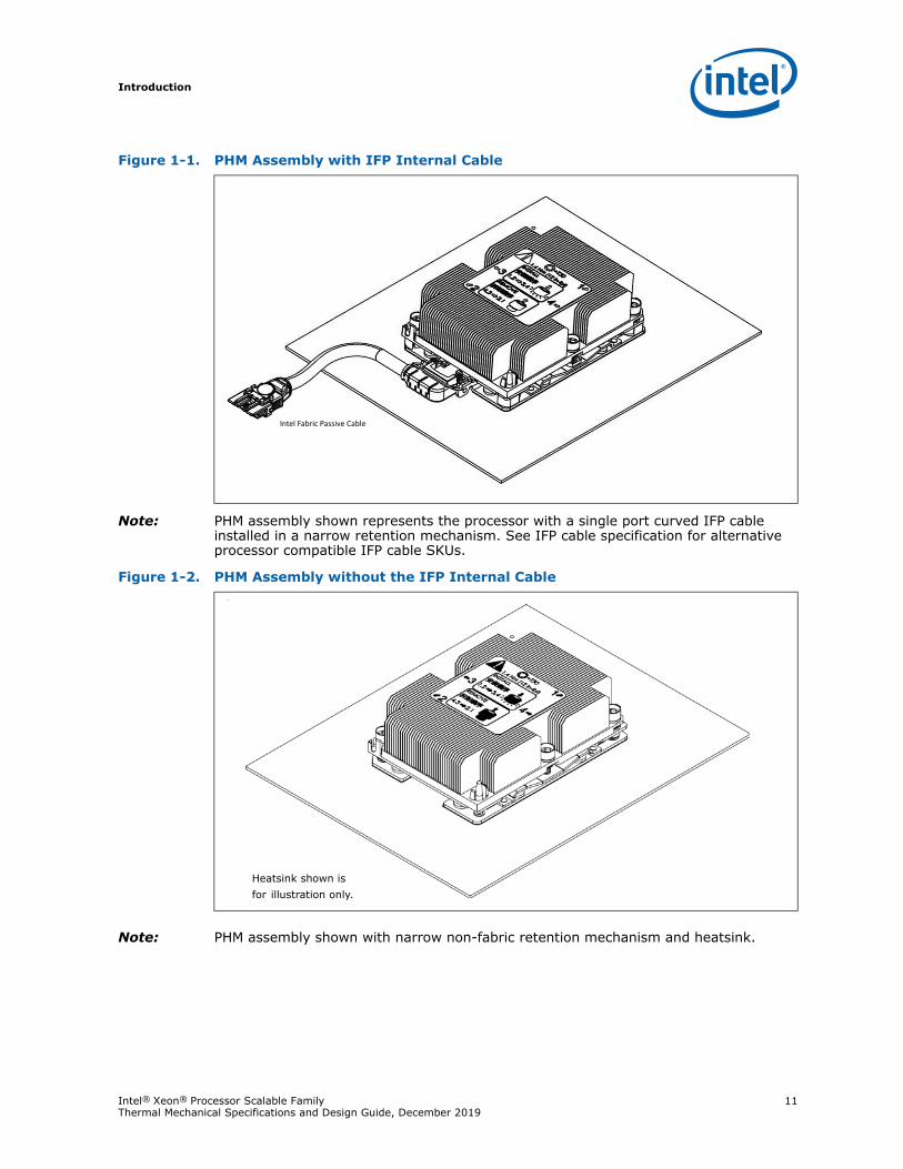
Note: PHM assembly shown represents the processor with a single port curved IFP cable installed in a narrow retention mechanism. See IFP cable specification for alternative processor compatible IFP cable SKUs.
Note: PHM assembly shown with narrow non-fabric retention mechanism and heatsink.
Figure 1-1. PHM Assembly with IFP Internal Cable
Figure 1-2. PHM Assembly without the IFP Internal Cable
Heatsink shown is for illustration only.
Introduction
12 Intel® Xeon® Processor Scalable Family Thermal Mechanical Specifications and Design Guide, December 2019
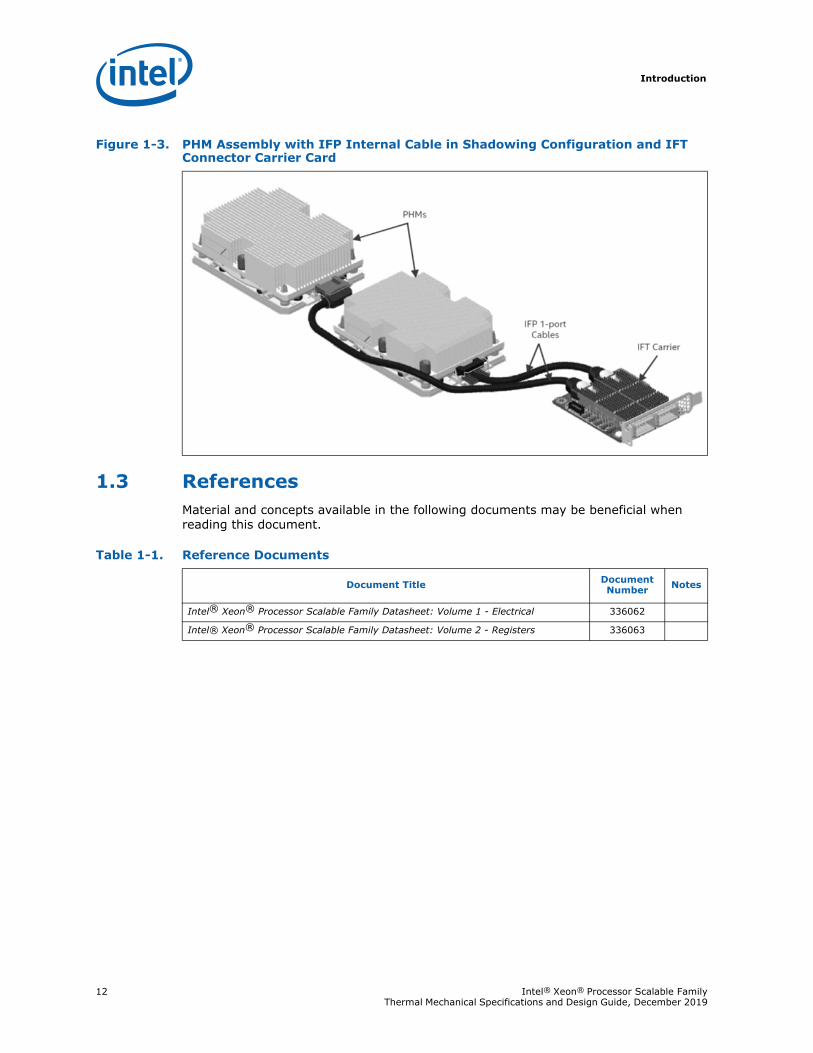
1.3 ReferencesMaterial and concepts available in the following documents may be beneficial when reading this document.
Figure 1-3. PHM Assembly with IFP Internal Cable in Shadowing Configuration and IFT Connector Carrier Card
Table 1-1. Reference Documents
Document Title Document Number Notes
Intel® Xeon® Processor Scalable Family Datasheet: Volume 1 - Electrical 336062
Intel® Xeon® Processor Scalable Family Datasheet: Volume 2 - Registers 336063
Intel® Xeon® Processor Scalable Family 13Thermal Mechanical Specifications and Design Guide, December 2019
Introduction
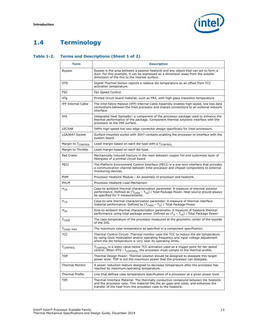
1.4 Terminology
Table 1-2. Terms and Descriptions (Sheet 1 of 2)
Term Description
Bypass Bypass is the area between a passive heatsink and any object that can act to form a duct. For this example, it can be expressed as a dimension away from the outside dimension of the fins to the nearest surface.
DTS Digital Thermal Sensor reports a relative die temperature as an offset from TCC activation temperature.
FSC Fan Speed Control
HTg Printed circuit board material, such as FR4, with high glass transition temperature
IFP Internal Cable The Intel Fabric Passive (IFP) Internal Cable Assembly enables high speed, low loss data connections between the Intel processor and chassis connections to an external network interface.
IHS Integrated Heat Spreader: a component of the processor package used to enhance the thermal performance of the package. Component thermal solutions interface with the processor at the IHS surface.
LEC54B 54Pin high speed low loss edge connector design specifically for Intel processors.
LGA3647 Socket Surface mounted socket with 3647-contacts enabling the processor to interface with the system board.
Margin to TCONTROL Least margin based on each die type with a TCONTROL.
Margin to Throttle Least margin based on each die type.
Pad Crater Mechanically induced fracture in the resin between copper foil and outermost layer of fiberglass of a printed circuit board
PECI The Platform Environment Control Interface (PECI) is a one-wire interface that provides a communication channel between Intel processor and chipset components to external monitoring devices.
PHM Processor Heatsink Module - An assembly of processor and heatsink
PHLM Processor Heatsink Load Mechanism
CA Case-to-ambient thermal characterization parameter. A measure of thermal solution performance. Defined as (TCASE – TLA) / Total Package Power. Heat source should always be specified for measurements.
CS Case-to-sink thermal characterization parameter. A measure of thermal interface material performance. Defined as (TCASE – TS) / Total Package Power.
SA Sink-to-ambient thermal characterization parameter. A measure of heatsink thermal performance using total package power. Defined as (TS – TLA) / Total Package Power.
TCASE The case temperature of the processor measured at the geometric center of the topside of the IHS.
TCASE_MAX The maximum case temperature as specified in a component specification.
TCC Thermal Control Circuit: Thermal monitor uses the TCC to reduce the die temperature by using clock modulation and/or operating frequency and input voltage adjustment when the die temperature is very near its operating limits.
TCONTROL TCONTROL is a static value below TCC activation used as a trigger point for fan speed control. When DTSTCONTROL, the processor must comply to the thermal profile.
TDP Thermal Design Power: Thermal solution should be designed to dissipate this target power level. TDP is not the maximum power that the processor can dissipate.
Thermal Monitor A power reduction feature designed to decrease temperature after the processor has reached its maximum operating temperature.
Thermal Profile Line that defines case temperature specification of a processor at a given power level.
TIM Thermal Interface Material: The thermally conductive compound between the heatsink and the processor case. This material fills the air gaps and voids, and enhances the transfer of the heat from the processor case to the heatsink.
Introduction
14 Intel® Xeon® Processor Scalable Family Thermal Mechanical Specifications and Design Guide, December 2019
§
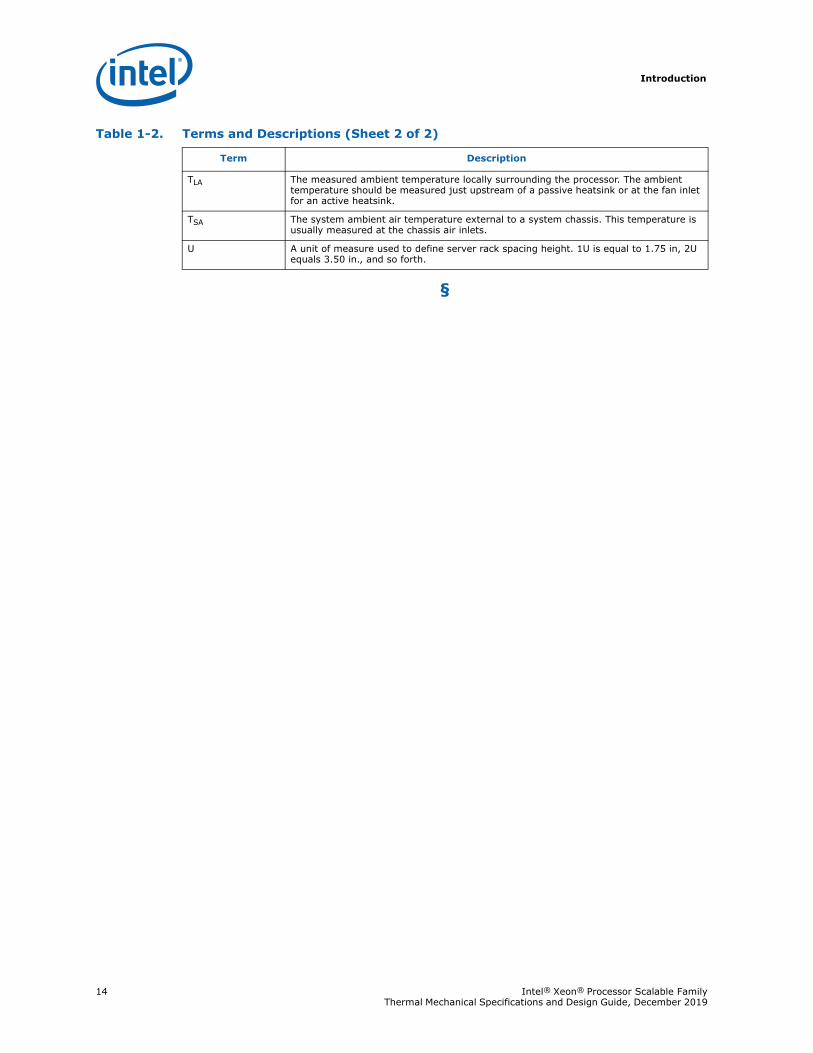
TLA The measured ambient temperature locally surrounding the processor. The ambient temperature should be measured just upstream of a passive heatsink or at the fan inlet for an active heatsink.
TSA The system ambient air temperature external to a system chassis. This temperature is usually measured at the chassis air inlets.
U A unit of measure used to define server rack spacing height. 1U is equal to 1.75 in, 2U equals 3.50 in., and so forth.
Table 1-2. Terms and Descriptions (Sheet 2 of 2)
Term Description
Processor Package Mechanical Specification
Intel® Xeon® Processor Scalable Family 15Thermal Mechanical Specifications and Design Guide, December 2019
2 Processor Package Mechanical Specification
This section provides an overview of the processor package mechanical design and integration. The package serves as the primary interface between the processor silicon die and the rest of the system. The package provides electrical signaling and power delivery as well as thermal transmission, mechanical physical attach, dimensional scale translation and structural strength and stiffness. A solid understanding of the processor design targets provides the necessary foundation to identify and establish thermal and mechanical design requirements for the motherboard and the system.
To ensure compatibility with the processor and the platform, the mechanical processor retention and thermal solution must meet the requirements and keep out zones of both the processor and the LGA3647-0 socket. This section provides the processor package specific mechanical specifications and handling guidance.
2.1 Processor Package DescriptionThe processor is housed in an Flip-Chip Land Grid Array (FC-LGA14) package that interfaces with the motherboard via an LGA3647-0 SMT socket. The package consists of a processor integrated heat spreader (IHS), which is attached to the package substrate and die and serves as the mating surface for the processor component thermal solutions, such as a heatsink. The IHS transfers the non-uniform heat from the die to the top of the IHS, out of which the heat flux is more uniform and spread over a larger surface area (not the entire IHS area). This allows more efficient heat transfer out of the package to an attached cooling device. The IHS is designed to be the interface for contacting a heatsink.
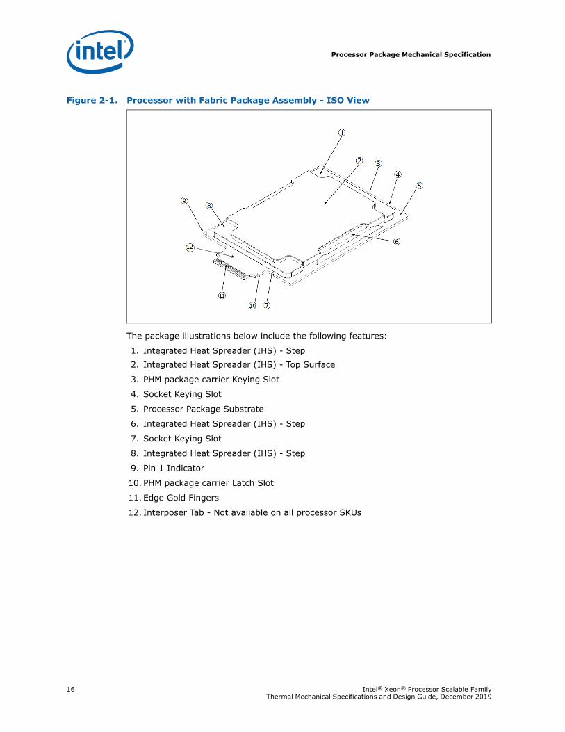
Processor package dimensions are different between the processor SKUs with and without the Intel® Omni-Path Technology. Both package types include an integrated heat spreader (IHS). Intel® Xeon® Processor Scalable Family with Fabric, processor SKU packages with the Intel Fabric Passive feature, include a tab which extend beyond the shadow of the socket that interfaces with the Intel Fabric Passive internal cable at the LEC54B connector end of the cable. The bottom side of the package has 3647 lands in a 43.18 x 50.24 mm pad array which interfaces with the LGA3647-0 SMT socket. Regardless of the package form factor Intel® Xeon® Processor Scalable Family 2S with 2 Intel® Ultra Path Interconnect (Intel® UPI), Intel® Xeon® Processor Scalable Family with Fabric, and Intel® Xeon® Processor Scalable Family with three Intel UPI SKUs are compatible with the LGA3647-0 SMT socket. Mechanical compatibility with the socket is controlled through predefined package to socket keying size and location. The following figure shows a sketch of the processor package components and how they are assembled together.
Note: Processor package actual land count is greater than the socket contact count. The 137 additional pads are reserved for use during the manufacturing process.
Processor Package Mechanical Specification
16 Intel® Xeon® Processor Scalable Family Thermal Mechanical Specifications and Design Guide, December 2019
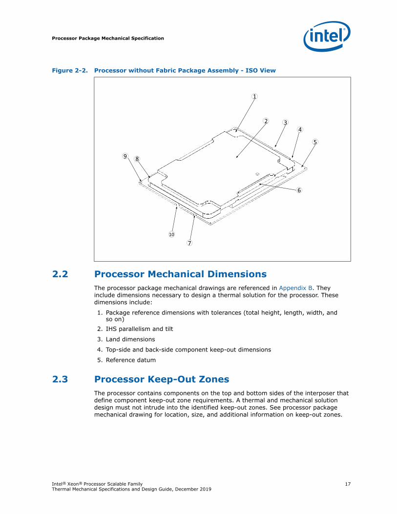
The package illustrations below include the following features:
1. Integrated Heat Spreader (IHS) - Step2. Integrated Heat Spreader (IHS) - Top Surface
3. PHM package carrier Keying Slot
4. Socket Keying Slot
5. Processor Package Substrate
6. Integrated Heat Spreader (IHS) - Step
7. Socket Keying Slot
8. Integrated Heat Spreader (IHS) - Step
9. Pin 1 Indicator
10. PHM package carrier Latch Slot
11. Edge Gold Fingers
12. Interposer Tab - Not available on all processor SKUs
Figure 2-1. Processor with Fabric Package Assembly - ISO View
Processor Package Mechanical Specification
Intel® Xeon® Processor Scalable Family 17Thermal Mechanical Specifications and Design Guide, December 2019
2.2 Processor Mechanical DimensionsThe processor package mechanical drawings are referenced in Appendix B. They include dimensions necessary to design a thermal solution for the processor. These dimensions include:
1. Package reference dimensions with tolerances (total height, length, width, and so on)
2. IHS parallelism and tilt
3. Land dimensions
4. Top-side and back-side component keep-out dimensions
5. Reference datum
2.3 Processor Keep-Out ZonesThe processor contains components on the top and bottom sides of the interposer that define component keep-out zone requirements. A thermal and mechanical solution design must not intrude into the identified keep-out zones. See processor package mechanical drawing for location, size, and additional information on keep-out zones.
Figure 2-2. Processor without Fabric Package Assembly - ISO View
2 4
5
6
7
9 8
1
3
10
Processor Package Mechanical Specification
18 Intel® Xeon® Processor Scalable Family Thermal Mechanical Specifications and Design Guide, December 2019
2.4 Processor Mechanical LoadsThe processor package has mechanical load limits that should not be exceeded during the processor ILM actuation, heatsink installation and removal, mechanical stress testing, or standard shipping conditions as permanent damage to the processor may occur. For example, when a compressive static load is necessary to ensure thermal performance of the Thermal Interface Material (TIM2) between the heatsink base and the IHS, it should not exceed the corresponding specification. The processor substrate should not be used as a mechanical reference or load-bearing surface for thermal solutions.
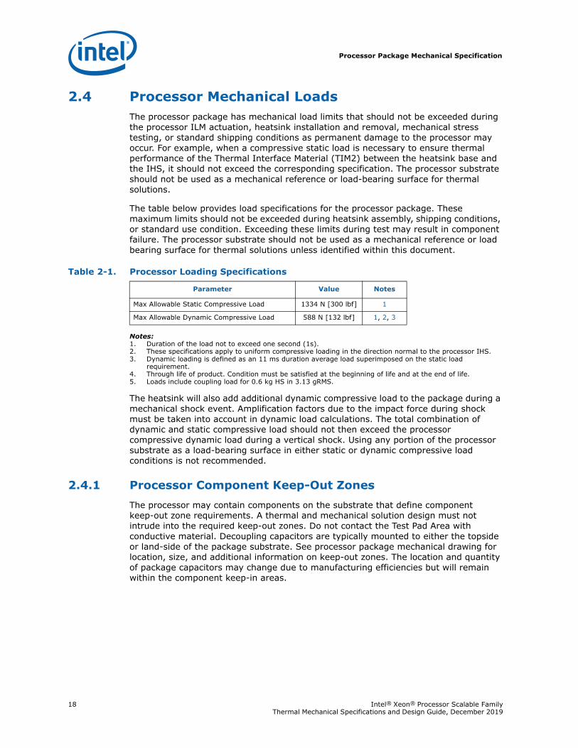
The table below provides load specifications for the processor package. These maximum limits should not be exceeded during heatsink assembly, shipping conditions, or standard use condition. Exceeding these limits during test may result in component failure. The processor substrate should not be used as a mechanical reference or load bearing surface for thermal solutions unless identified within this document.
Notes:1. Duration of the load not to exceed one second (1s).2. These specifications apply to uniform compressive loading in the direction normal to the processor IHS.3. Dynamic loading is defined as an 11 ms duration average load superimposed on the static load
requirement.4. Through life of product. Condition must be satisfied at the beginning of life and at the end of life.5. Loads include coupling load for 0.6 kg HS in 3.13 gRMS.
The heatsink will also add additional dynamic compressive load to the package during a mechanical shock event. Amplification factors due to the impact force during shock must be taken into account in dynamic load calculations. The total combination of dynamic and static compressive load should not then exceed the processor compressive dynamic load during a vertical shock. Using any portion of the processor substrate as a load-bearing surface in either static or dynamic compressive load conditions is not recommended.
2.4.1 Processor Component Keep-Out ZonesThe processor may contain components on the substrate that define component keep-out zone requirements. A thermal and mechanical solution design must not intrude into the required keep-out zones. Do not contact the Test Pad Area with conductive material. Decoupling capacitors are typically mounted to either the topside or land-side of the package substrate. See processor package mechanical drawing for location, size, and additional information on keep-out zones. The location and quantity of package capacitors may change due to manufacturing efficiencies but will remain within the component keep-in areas.
Table 2-1. Processor Loading Specifications
Parameter Value Notes
Max Allowable Static Compressive Load 1334 N [300 lbf] 1
Max Allowable Dynamic Compressive Load 588 N [132 lbf] 1, 2, 3
Processor Package Mechanical Specification
Intel® Xeon® Processor Scalable Family 19Thermal Mechanical Specifications and Design Guide, December 2019
2.4.1.1 Processor Materials
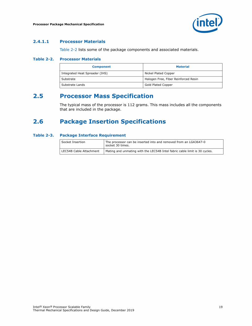
Table 2-2 lists some of the package components and associated materials.
2.5 Processor Mass SpecificationThe typical mass of the processor is 112 grams. This mass includes all the components that are included in the package.
2.6 Package Insertion Specifications
Table 2-2. Processor Materials
Component Material
Integrated Heat Spreader (IHS) Nickel Plated Copper
Substrate Halogen Free, Fiber Reinforced Resin
Substrate Lands Gold Plated Copper
Table 2-3. Package Interface Requirement
Socket Insertion The processor can be inserted into and removed from an LGA3647-0 socket 30 times.
LEC54B Cable Attachment Mating and unmating with the LEC54B Intel fabric cable limit is 30 cycles.
Processor Package Mechanical Specification
20 Intel® Xeon® Processor Scalable Family Thermal Mechanical Specifications and Design Guide, December 2019
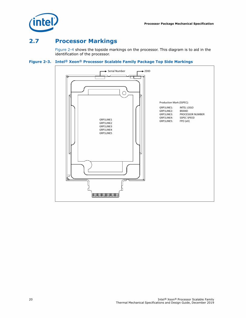
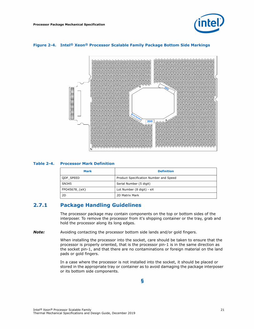
2.7 Processor MarkingsFigure 2-4 shows the topside markings on the processor. This diagram is to aid in the identification of the processor.
Figure 2-3. Intel® Xeon® Processor Scalable Family Package Top Side Markings
GRP1LINE1 GRP1LINE2GRP1LINE3GRP1LINE4GRP1LINE5
Production Mark (SSPEC):
GRP1LINE1: INTEL LOGOGRP1LINE2: BRAND GRP1LINE3: PROCESSOR NUMBERGRP1LINE4: SSPEC SPEEDGRP1LINE5: FPO {eX}
Serial Number 2DID
Processor Package Mechanical Specification
Intel® Xeon® Processor Scalable Family 21Thermal Mechanical Specifications and Design Guide, December 2019
2.7.1 Package Handling GuidelinesThe processor package may contain components on the top or bottom sides of the interposer. To remove the processor from it's shipping container or the tray, grab and hold the processor along its long edges.
Note: Avoiding contacting the processor bottom side lands and/or gold fingers.
When installing the processor into the socket, care should be taken to ensure that the processor is properly oriented, that is the processor pin-1 is in the same direction as the socket pin-1, and that there are no contaminations or foreign material on the land pads or gold fingers.
In a case where the processor is not installed into the socket, it should be placed or stored in the appropriate tray or container as to avoid damaging the package interposer or its bottom side components.
§
Figure 2-4. Intel® Xeon® Processor Scalable Family Package Bottom Side Markings
Table 2-4. Processor Mark Definition
Mark Definition
QDF_SPEED Product Specification Number and Speed
SN345 Serial Number (5 digit)
FPO45678_{eX} Lot Number (8 digit) - eX
2D 2D Matrix Mark
2DID
Socket Specifications
22 Intel® Xeon® Processor Scalable Family Thermal Mechanical Specifications and Design Guide, December 2019
3 Socket Specifications
This section describes the LGA3647-0 surface mount Land Grid Array (LGA) socket. The socket contains a total of 3647 contacts and provides I/O, power, and ground connections from the main board to the processor package.
The socket definitions listed intend to identify the minimum socket requirements and features necessary to ensure compatibility with the Intel® Xeon® Processor Scalable Family and the Intel® Xeon® Processor Scalable Family-based platform. In addition to these, socket suppliers may include design features to ensure their socket design meets Intel's specifications as well as their manufacturing process requirements. See the supplier listing for ordering and contacting information.
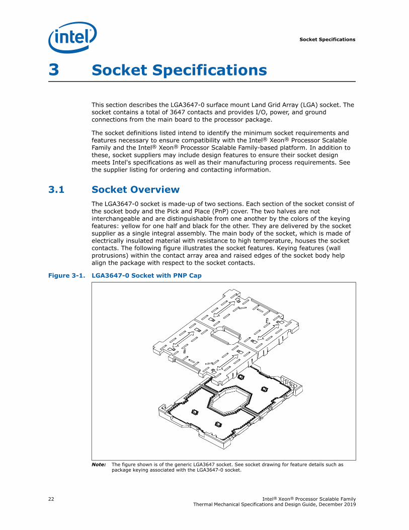
3.1 Socket OverviewThe LGA3647-0 socket is made-up of two sections. Each section of the socket consist of the socket body and the Pick and Place (PnP) cover. The two halves are not interchangeable and are distinguishable from one another by the colors of the keying features: yellow for one half and black for the other. They are delivered by the socket supplier as a single integral assembly. The main body of the socket, which is made of electrically insulated material with resistance to high temperature, houses the socket contacts. The following figure illustrates the socket features. Keying features (wall protrusions) within the contact array area and raised edges of the socket body help align the package with respect to the socket contacts.
Note: The figure shown is of the generic LGA3647 socket. See socket drawing for feature details such as package keying associated with the LGA3647-0 socket.
Figure 3-1. LGA3647-0 Socket with PNP Cap
Socket Specifications
Intel® Xeon® Processor Scalable Family 23Thermal Mechanical Specifications and Design Guide, December 2019
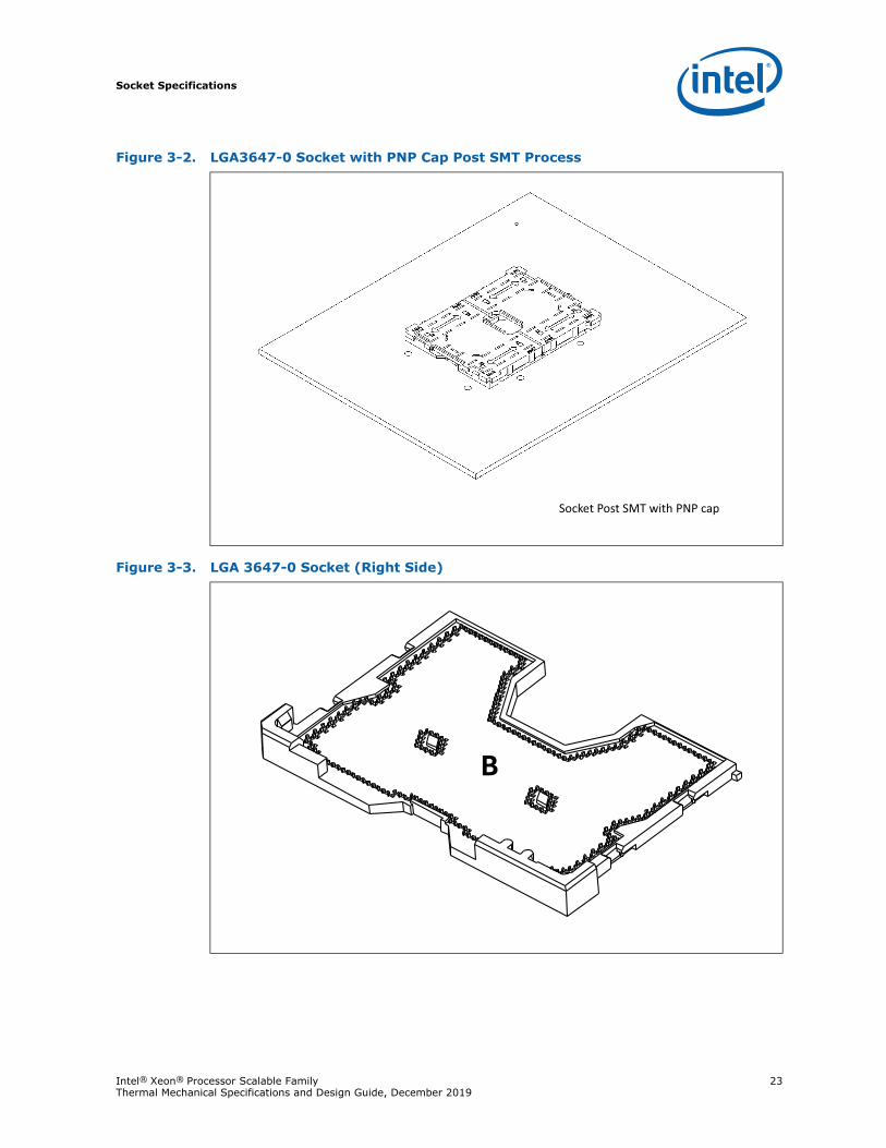
Figure 3-2. LGA3647-0 Socket with PNP Cap Post SMT Process
Figure 3-3. LGA 3647-0 Socket (Right Side)
Socket Post SMT with PNP cap
Socket Specifications
24 Intel® Xeon® Processor Scalable Family Thermal Mechanical Specifications and Design Guide, December 2019
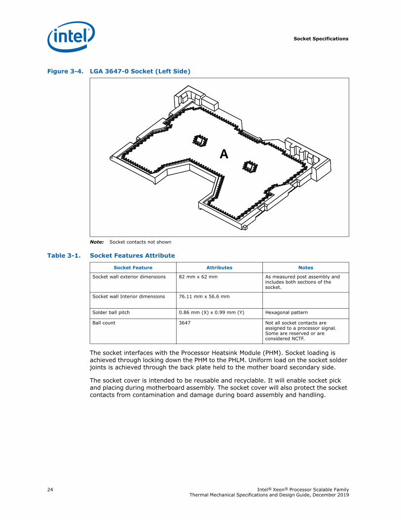
Note: Socket contacts not shown
The socket interfaces with the Processor Heatsink Module (PHM). Socket loading is achieved through locking down the PHM to the PHLM. Uniform load on the socket solder joints is achieved through the back plate held to the mother board secondary side.
The socket cover is intended to be reusable and recyclable. It will enable socket pick and placing during motherboard assembly. The socket cover will also protect the socket contacts from contamination and damage during board assembly and handling.
Figure 3-4. LGA 3647-0 Socket (Left Side)
A
Table 3-1. Socket Features Attribute
Socket Feature Attributes Notes
Socket wall exterior dimensions 82 mm x 62 mm As measured post assembly and includes both sections of the socket.
Socket wall Interior dimensions 76.11 mm x 56.6 mm
Solder ball pitch 0.86 mm (X) x 0.99 mm (Y) Hexagonal pattern
Ball count 3647 Not all socket contacts are assigned to a processor signal. Some are reserved or are considered NCTF.
Socket Specifications
Intel® Xeon® Processor Scalable Family 25Thermal Mechanical Specifications and Design Guide, December 2019
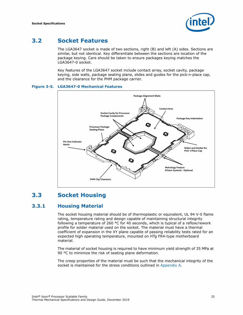
3.2 Socket FeaturesThe LGA3647 socket is made of two sections, right (B) and left (A) sides. Sections are similar, but not identical. Key differentiate between the sections are location of the package keying. Care should be taken to ensure packages keying matches the LGA3647-0 socket.
Key features of the LGA3647 socket include contact array, socket cavity, package keying, side walls, package seating plane, slides and guides for the pick-n-place cap, and the clearance for the PHM package carrier.
3.3 Socket Housing
3.3.1 Housing MaterialThe socket housing material should be of thermoplastic or equivalent, UL 94 V-0 flame rating, temperature rating and design capable of maintaining structural integrity following a temperature of 260 °C for 40 seconds, which is typical of a reflow/rework profile for solder material used on the socket. The material must have a thermal coefficient of expansion in the XY plane capable of passing reliability tests rated for an expected high operating temperature, mounted on HTg FR4-type motherboard material.
The material of socket housing is required to have minimum yield strength of 35 MPa at 90 °C to minimize the risk of seating plane deformation.
The creep properties of the material must be such that the mechanical integrity of the socket is maintained for the stress conditions outlined in Appendix A.
Figure 3-5. LGA3647-0 Mechanical Features
Package Alignment Walls
Pin One IndicatorNotch
Slides and Guides for Pick' n'Place Cap
Metrology Feature(Vision System) - Optional
PHM Clip Clearance
Contact Area
Socket Cavity for Processor Package Components
Package Key Indentation
Processor Package Seating Plane
Cl
Socket Specifications
26 Intel® Xeon® Processor Scalable Family Thermal Mechanical Specifications and Design Guide, December 2019
3.3.2 Housing ColorThe color of the socket housing must be dark as compared to the solder balls to provide the contrast needed for OEM’s pick and place vision systems. Components of the socket may be different colors, as long as they meet the above requirement.
3.3.3 Package Installation/Removal AccessAccess must be provided to facilitate the manual insertion and removal of the package. No tool should be required to install or remove the package from the socket.
3.3.4 Package Alignment/OrientationA means of providing fixed alignment and proper orientation with the pin 1 corner of the package must be provided. There are three different levels of package alignment:
• The first level is called gross alignment, which happens between PHM and the posts on the bolster plate.
• The second level is called intermediate alignment, which utilizes the socket exterior corner walls and package clip.
• The third level is which is fine alignment, relies on the socket inner wall surfaces.
The socket also has orientation posts or protrusions (keys) placed on opposite sides of the socket as noted in Appendix C. The package substrate will have keying notches at the corresponding locations. When package keying notches align with socket orientation posts, it prevents package from being mistakenly installed with a 180 degree in-plane rotation. The package will sit flush on the socket contacts when aligned.
3.3.5 Heatsink Retention and Processor Package Carrier CompatibilityA direct keying feature between the bolster plate and LGA3647-0 socket does exist. Keying is achieved through the board hole pattern for the bolster plate which is defined specifically for LGA3647-0 compatible bolster plates (narrow and square). During board assembly special attention should be given to the bolster plate part number and the processor package keying on the socket.
Two cutouts on the ends of socket provides clearance for the PHM package carrier-package latch feature. In addition, the PHM package carrier utilizes the socket side walls as the pre-alignment between the socket and processor.
3.3.6 MarkingsAll markings required in this section must withstand a temperature of 260 °C for 40 seconds, which is typical of a reflow/rework profile for solder material used on the socket, as well as any environmental test procedure outlined in Appendix A, without degrading. Socket marks must be visible after it is mounted on the motherboard.
• Name:
LF-LGA3647-0 (font type is Helvetica Bold – minimum 4 point [or 1.411 mm])
Note: This mark should be molded or laser marked as shown in Appendix C.
Manufacturer’s Insignia (font size at supplier’s discretion).
Socket Specifications
Intel® Xeon® Processor Scalable Family 27Thermal Mechanical Specifications and Design Guide, December 2019
This mark will be molded or laser-marked into the top side of the socket housing.
Both socket name and manufacturer’s insignia must be visible when first seated on the motherboard.
• Lot Traceability
Each socket will be marked with a lot identification code to allow traceability of all components, date of manufacture (year and week), and assembly location. The mark must be placed on a surface that is visible after the socket is mounted on the motherboard. In addition, this identification code must be marked on the exterior of the box in which the unit is shipped.
• Visual Aids
The socket must have Pin A1 and package/socket alignment keys.
3.3.7 Contact CharacteristicsNumber of Contacts
Total number of contacts: 3647
Layout
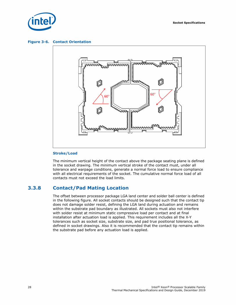
The contacts are laid out in two “C” shape regions opposing each other. The arrows in the figure indicate the wiping orientation of the contacts in the two regions to be 60° about the horizontal axis. There are 1823 and 1824 contacts in the right and left halves of the socket, respectively.
Base Material
High-strength copper alloy.
Contact Area Plating
For the area on socket contacts where the processor lands will mate, there is either a 0.762 μm [30 μ-inches] minimum gold plating over 1.27 μm [50 μ-inches] minimum nickel under plating in critical contact areas (area on socket contacts where the processor lands will mate) is required. No contamination by solder in the contact area is allowed during solder reflow.
Lubricants
For the final assembled product, no lubricant is permitted on the socket contacts. If lubricants are used elsewhere within the socket assembly, these lubricants must not be able to migrate to the socket contacts.
Co-Planarity
The co-planarity (profile) requirement for all contacts mating to the top side of the socket is defined in socket drawing.
True Position
The contact pattern has a true position requirement with respect to applicable datum in order to mate with the package land pattern.
Socket Specifications
28 Intel® Xeon® Processor Scalable Family Thermal Mechanical Specifications and Design Guide, December 2019
Stroke/Load
The minimum vertical height of the contact above the package seating plane is defined in the socket drawing. The minimum vertical stroke of the contact must, under all tolerance and warpage conditions, generate a normal force load to ensure compliance with all electrical requirements of the socket. The cumulative normal force load of all contacts must not exceed the load limits.
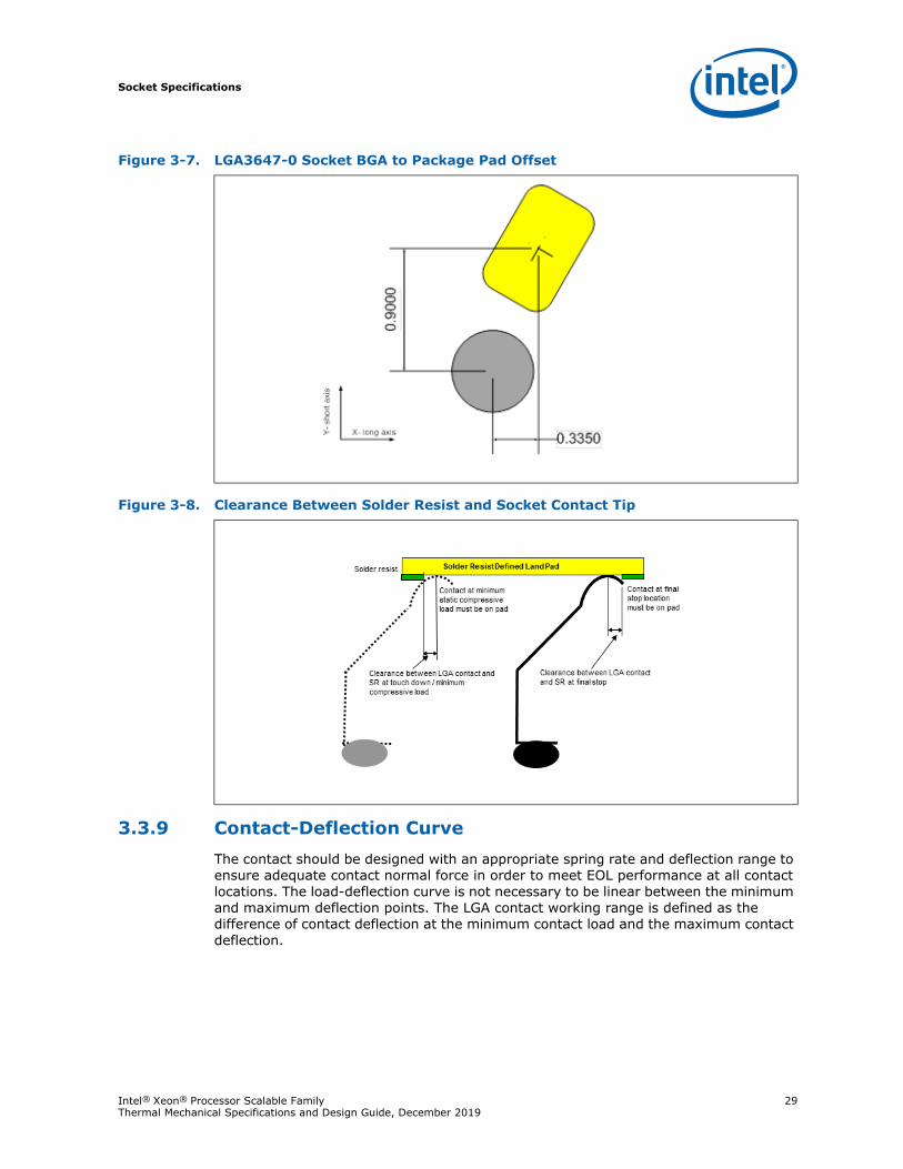
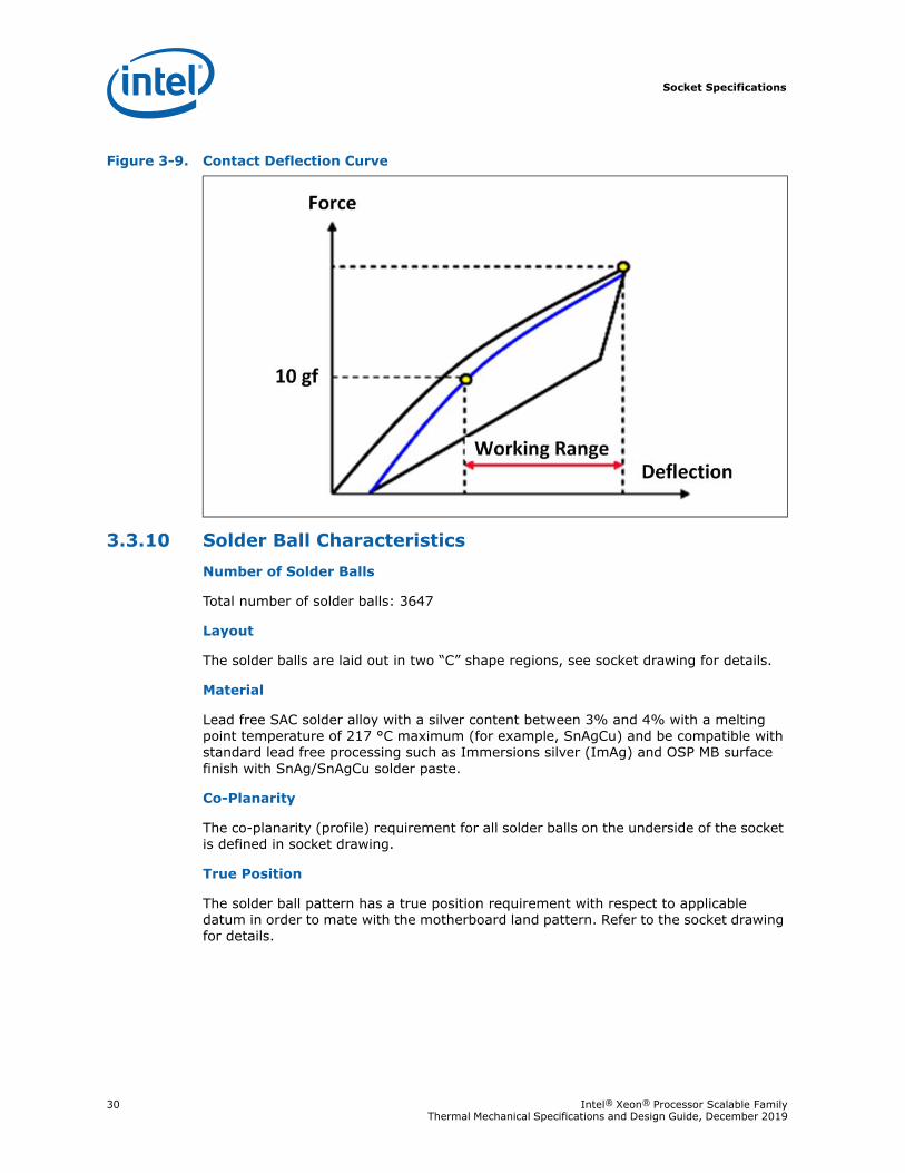
3.3.8 Contact/Pad Mating LocationThe offset between processor package LGA land center and solder ball center is defined in the following figure. All socket contacts should be designed such that the contact tip does not damage solder resist, defining the LGA land during actuation and remains within the substrate pad boundary as illustrated. All sockets must also not interfere with solder resist at minimum static compressive load per contact and at final installation after actuation load is applied. This requirement includes all the X-Y tolerances such as socket size, substrate size, and pad true positional tolerance, as defined in socket drawings. Also it is recommended that the contact tip remains within the substrate pad before any actuation load is applied.
Figure 3-6. Contact Orientation
� �
Socket Specifications
Intel® Xeon® Processor Scalable Family 29Thermal Mechanical Specifications and Design Guide, December 2019
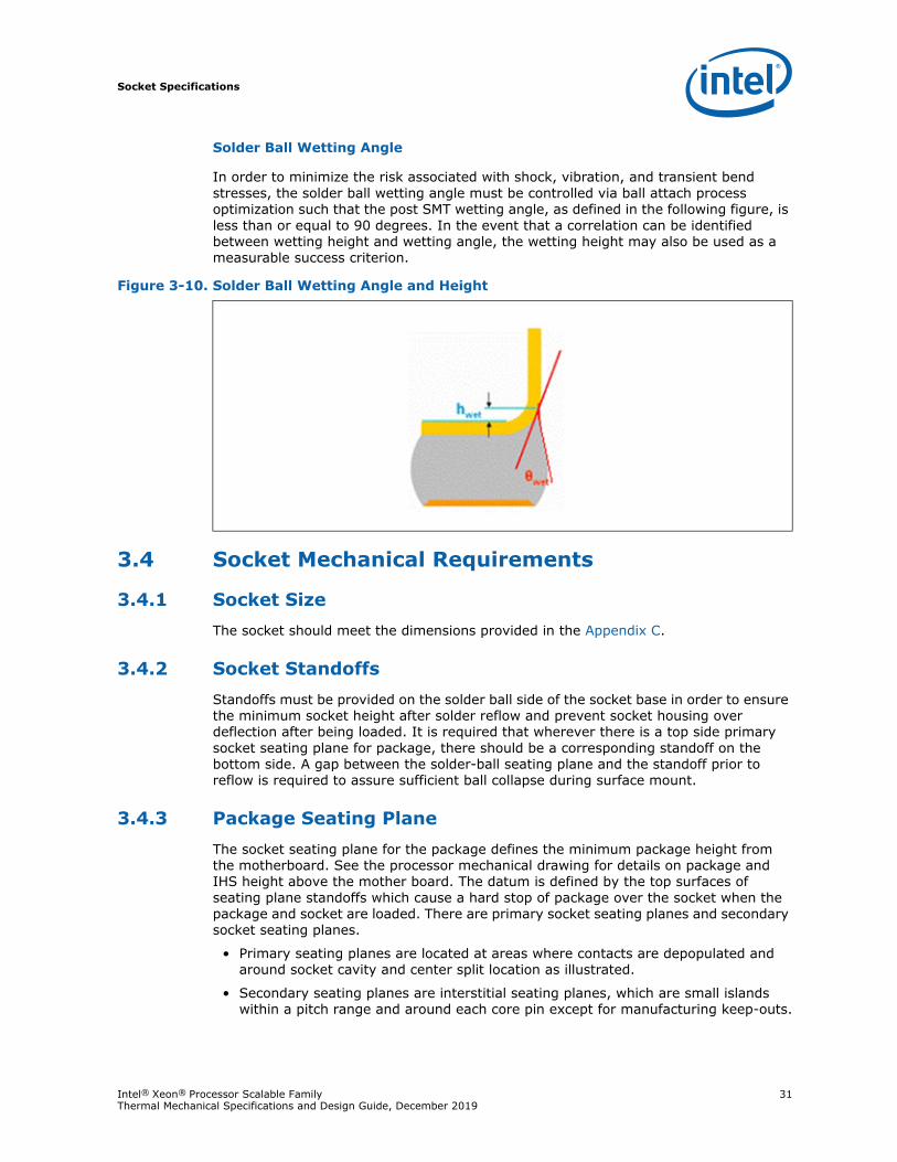
3.3.9 Contact-Deflection CurveThe contact should be designed with an appropriate spring rate and deflection range to ensure adequate contact normal force in order to meet EOL performance at all contact locations. The load-deflection curve is not necessary to be linear between the minimum and maximum deflection points. The LGA contact working range is defined as the difference of contact deflection at the minimum contact load and the maximum contact deflection.
Figure 3-7. LGA3647-0 Socket BGA to Package Pad Offset
Figure 3-8. Clearance Between Solder Resist and Socket Contact Tip
Socket Specifications
30 Intel® Xeon® Processor Scalable Family Thermal Mechanical Specifications and Design Guide, December 2019
3.3.10 Solder Ball CharacteristicsNumber of Solder Balls
Total number of solder balls: 3647
Layout
The solder balls are laid out in two “C” shape regions, see socket drawing for details.
Material
Lead free SAC solder alloy with a silver content between 3% and 4% with a melting point temperature of 217 °C maximum (for example, SnAgCu) and be compatible with standard lead free processing such as Immersions silver (ImAg) and OSP MB surface finish with SnAg/SnAgCu solder paste.
Co-Planarity
The co-planarity (profile) requirement for all solder balls on the underside of the socket is defined in socket drawing.
True Position
The solder ball pattern has a true position requirement with respect to applicable datum in order to mate with the motherboard land pattern. Refer to the socket drawing for details.
Figure 3-9. Contact Deflection Curve
Socket Specifications
Intel® Xeon® Processor Scalable Family 31Thermal Mechanical Specifications and Design Guide, December 2019
Solder Ball Wetting Angle
In order to minimize the risk associated with shock, vibration, and transient bend stresses, the solder ball wetting angle must be controlled via ball attach process optimization such that the post SMT wetting angle, as defined in the following figure, is less than or equal to 90 degrees. In the event that a correlation can be identified between wetting height and wetting angle, the wetting height may also be used as a measurable success criterion.
3.4 Socket Mechanical Requirements
3.4.1 Socket SizeThe socket should meet the dimensions provided in the Appendix C.
3.4.2 Socket StandoffsStandoffs must be provided on the solder ball side of the socket base in order to ensure the minimum socket height after solder reflow and prevent socket housing over deflection after being loaded. It is required that wherever there is a top side primary socket seating plane for package, there should be a corresponding standoff on the bottom side. A gap between the solder-ball seating plane and the standoff prior to reflow is required to assure sufficient ball collapse during surface mount.
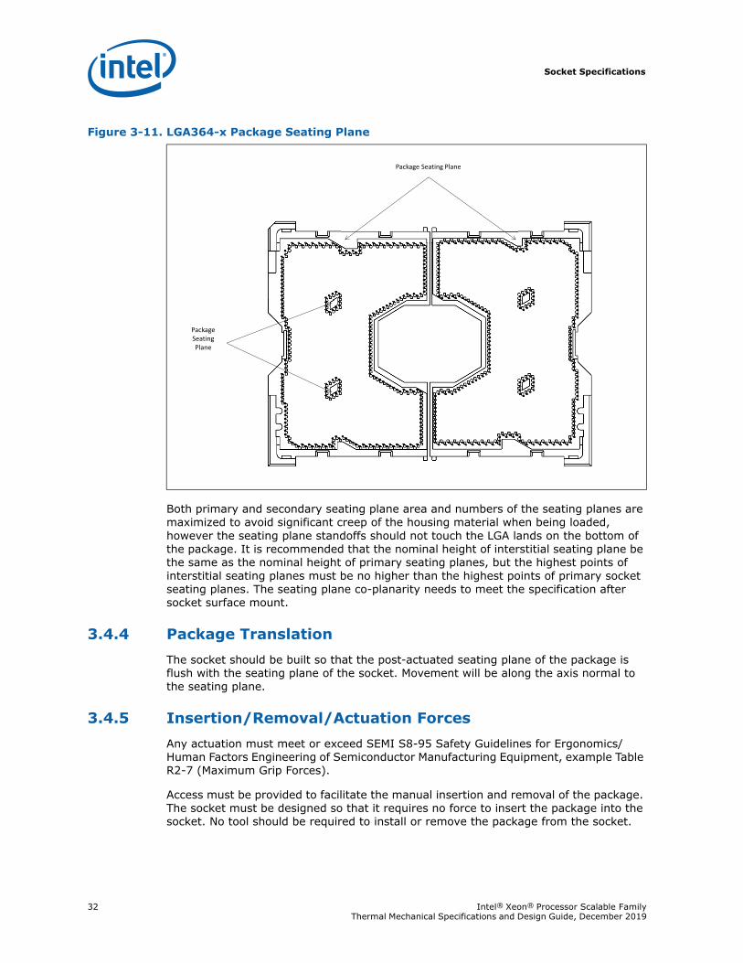
3.4.3 Package Seating PlaneThe socket seating plane for the package defines the minimum package height from the motherboard. See the processor mechanical drawing for details on package and IHS height above the mother board. The datum is defined by the top surfaces of seating plane standoffs which cause a hard stop of package over the socket when the package and socket are loaded. There are primary socket seating planes and secondary socket seating planes.
• Primary seating planes are located at areas where contacts are depopulated and around socket cavity and center split location as illustrated.
• Secondary seating planes are interstitial seating planes, which are small islands within a pitch range and around each core pin except for manufacturing keep-outs.
Figure 3-10. Solder Ball Wetting Angle and Height
Socket Specifications
32 Intel® Xeon® Processor Scalable Family Thermal Mechanical Specifications and Design Guide, December 2019
Both primary and secondary seating plane area and numbers of the seating planes are maximized to avoid significant creep of the housing material when being loaded, however the seating plane standoffs should not touch the LGA lands on the bottom of the package. It is recommended that the nominal height of interstitial seating plane be the same as the nominal height of primary seating planes, but the highest points of interstitial seating planes must be no higher than the highest points of primary socket seating planes. The seating plane co-planarity needs to meet the specification after socket surface mount.
3.4.4 Package TranslationThe socket should be built so that the post-actuated seating plane of the package is flush with the seating plane of the socket. Movement will be along the axis normal to the seating plane.
3.4.5 Insertion/Removal/Actuation ForcesAny actuation must meet or exceed SEMI S8-95 Safety Guidelines for Ergonomics/ Human Factors Engineering of Semiconductor Manufacturing Equipment, example Table R2-7 (Maximum Grip Forces).
Access must be provided to facilitate the manual insertion and removal of the package. The socket must be designed so that it requires no force to insert the package into the socket. No tool should be required to install or remove the package from the socket.
Figure 3-11. LGA364-x Package Seating Plane
Socket Specifications
Intel® Xeon® Processor Scalable Family 33Thermal Mechanical Specifications and Design Guide, December 2019
3.4.6 Orientation in Packaging, Shipping, and HandlingPackaging media needs to support high-volume manufacturing. Media design must be such that no component of the socket (solder balls, contacts, housing, and so on) is damaged during shipping and handling. Each part number will be shipped from suppliers in separate Joint Electron Device Engineering Council (JEDEC) trays; for example, all left halves of the socket in 1 tray and all right halves in another. Tray height could be taller than standard.
3.4.7 Pick and Place and Handling CoverTo facilitate high-volume manufacturing, the socket should have a detachable cover to support the vacuum type Pick and Place system. The cover will remain on the socket during reflow to help prevent contamination. The cover can withstand 260 °C for 40 seconds (typical reflow/rework profile) and the conditions listed without degrading. The cover could also be used as a protective device to prevent damage to the contact field during handling.
Cover retention must be sufficient to support the socket weight during lifting, translation, and placement, during board manufacturing, and throughout board and system shipping and handling. The cover design should allow use of a tool to remove the cover. The force required for removing of the cover should meet or exceed the applicable requirements of SEMI S8-0999 Safety Guidelines for Ergonomics/Human Factors Engineering of Semiconductor Manufacturing Equipment. The removal of the cover should not cause any damage to the socket body nor to the cover itself within the cover durability limit.
The pick-n-place cover should provide viewing window to the make the pin A1 indicator visible on the underlying socket.
3.4.8 DurabilityThe socket must withstand 30 cycles of processor insertion and removal. The maximum part average and single pin resistance from Appendix G, “Board Flexure Initiative” must be met when mated in the first and 30th cycles.
3.4.9 Socket Keep-In/Keep-Out ZoneSocket keep-in and keep-out zones are identified on the motherboard to ensure that sufficient space is available for the socket, and to prevent interference between the socket and the components on the motherboard. These areas are illustrated in board volumetric keep-outs for the socket. It is the responsibility of the socket supplier and the customer to identify any required deviation from specifications identified here.
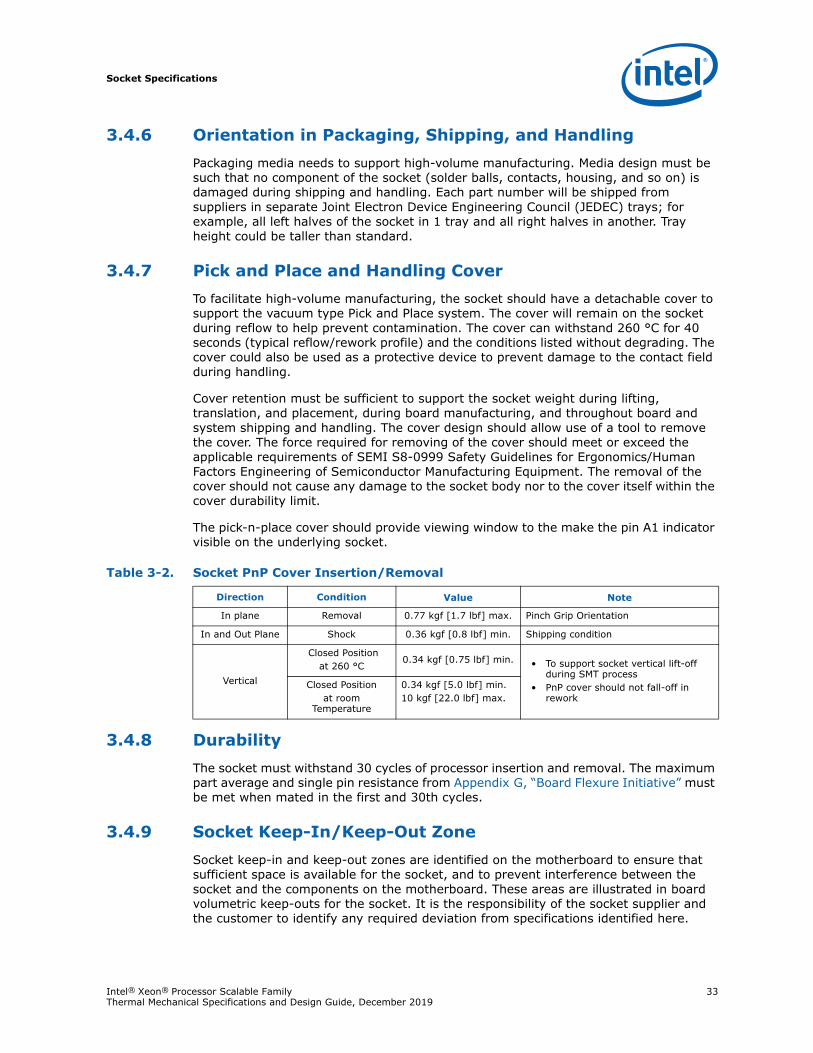
Table 3-2. Socket PnP Cover Insertion/Removal
Direction Condition Value Note
In plane Removal 0.77 kgf [1.7 lbf] max. Pinch Grip Orientation
In and Out Plane Shock 0.36 kgf [0.8 lbf] min. Shipping condition
Vertical
Closed Positionat 260 °C
0.34 kgf [0.75 lbf] min. • To support socket vertical lift-off during SMT process
• PnP cover should not fall-off in rework
Closed Positionat room
Temperature
0.34 kgf [5.0 lbf] min.10 kgf [22.0 lbf] max.
Socket Specifications
34 Intel® Xeon® Processor Scalable Family Thermal Mechanical Specifications and Design Guide, December 2019
3.4.10 AttachmentThe socket will be attached to the motherboard via its 3647 solder balls. There are no additional external methods (that is, screw, extra solder, adhesive, and so on) to attach the socket.
The socket will be tested against the mechanical shock and vibration requirements under the expected use conditions with all assembly components under the loading conditions.
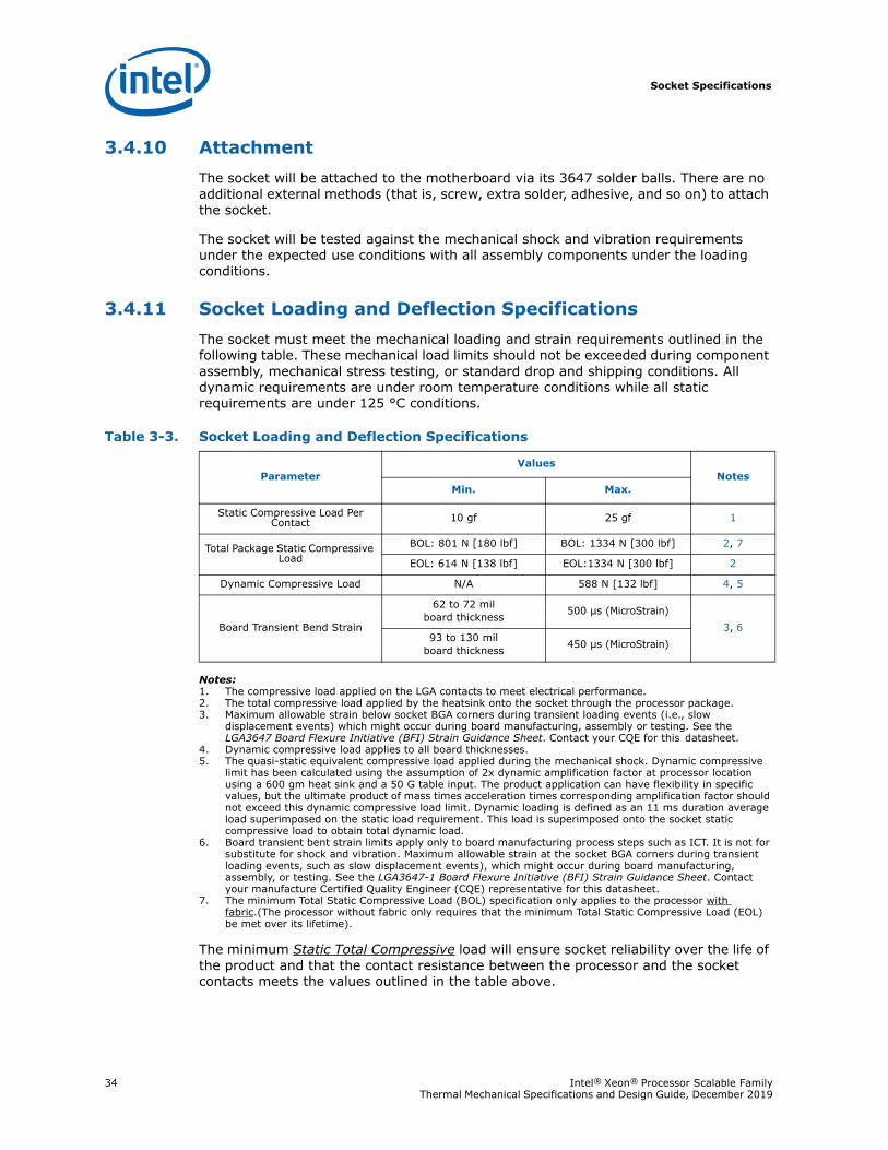
3.4.11 Socket Loading and Deflection SpecificationsThe socket must meet the mechanical loading and strain requirements outlined in the following table. These mechanical load limits should not be exceeded during component assembly, mechanical stress testing, or standard drop and shipping conditions. All dynamic requirements are under room temperature conditions while all static requirements are under 125 °C conditions.
Notes:1. The compressive load applied on the LGA contacts to meet electrical performance.2. The total compressive load applied by the heatsink onto the socket through the processor package.3. Maximum allowable strain below socket BGA corners during transient loading events (i.e., slow
displacement events) which might occur during board manufacturing, assembly or testing. See the LGA3647 Board Flexure Initiative (BFI) Strain Guidance Sheet. Contact your CQE for this datasheet.
4. Dynamic compressive load applies to all board thicknesses.5. The quasi-static equivalent compressive load applied during the mechanical shock. Dynamic compressive
limit has been calculated using the assumption of 2x dynamic amplification factor at processor location using a 600 gm heat sink and a 50 G table input. The product application can have flexibility in specific values, but the ultimate product of mass times acceleration times corresponding amplification factor should not exceed this dynamic compressive load limit. Dynamic loading is defined as an 11 ms duration average load superimposed on the static load requirement. This load is superimposed onto the socket static compressive load to obtain total dynamic load.
6. Board transient bent strain limits apply only to board manufacturing process steps such as ICT. It is not for substitute for shock and vibration. Maximum allowable strain at the socket BGA corners during transient loading events, such as slow displacement events), which might occur during board manufacturing, assembly, or testing. See the LGA3647-1 Board Flexure Initiative (BFI) Strain Guidance Sheet. Contact your manufacture Certified Quality Engineer (CQE) representative for this datasheet.
7. The minimum Total Static Compressive Load (BOL) specification only applies to the processor with fabric.(The processor without fabric only requires that the minimum Total Static Compressive Load (EOL) be met over its lifetime).
The minimum Static Total Compressive load will ensure socket reliability over the life of the product and that the contact resistance between the processor and the socket contacts meets the values outlined in the table above.
Table 3-3. Socket Loading and Deflection Specifications
ParameterValues
NotesMin. Max.
Static Compressive Load Per Contact 10 gf 25 gf 1
Total Package Static Compressive Load
BOL: 801 N [180 lbf] BOL: 1334 N [300 lbf] 2, 7
EOL: 614 N [138 lbf] EOL:1334 N [300 lbf] 2
Dynamic Compressive Load N/A 588 N [132 lbf] 4, 5
Board Transient Bend Strain
62 to 72 mil board thickness 500 µs (MicroStrain)
3, 693 to 130 mil
board thickness 450 µs (MicroStrain)
Socket Specifications
Intel® Xeon® Processor Scalable Family 35Thermal Mechanical Specifications and Design Guide, December 2019
3.4.12 Socket Critical-to-Function InterfacesCritical-to-function (CTF) dimensions for motherboard layout and assembled components’ interface to the socket are identified in the socket drawing. All sockets manufactured must meet the specified CTF dimensions.
3.5 Material and Recycling RequirementsCadmium should not be used in the painting or plating of the socket.
Chlorofluorocarbon Compounds (CFC) and Hydro-fluorocarbon Compounds (HFC) should not be used in manufacturing the socket.
Components should comply with recycling standards (e.g., European Blue Angel), and must comply with environmental legislation including those related to restrictions on the use of lead and bromine containing flame-retardants. Legislation varies by geography; European Union (RoHS/WEEE), China, California, and so forth.
3.6 LGA3647 Socket Land PatternSolder balls enable the socket to be surface mounted to the processor board. Each contact will have a corresponding solder ball. Solder ball position may be at an offset with respect to the contact tip and base. Hexagonal area array ball-out increases contact density by 12% while maintaining 39 mil minimum via pitch requirements.
Contact Pattern
LGA3647-0 socket contacts are in 1.0 mm (0.039”) hexagonal pitch in a 105 x 43 grid array with depopulated section in the center of the array and selective depopulation elsewhere, see socket drawing for details. The tips of the contacts will extend beyond the surface of the socket to make contact with the pads located at the bottom of the processor package.
BGA Pattern
The land pattern for the LGA3647 socket is a 39 mil hexagonal array. For CTF joints, the pad size will primarily be a circular Metal Defined (MD) pad and these pads should be designated as a Critical Dimension to the PCB vendors with a 17 mil ±1 mil tolerance. Some CTF pads will have a SMD Pad (20 x 17 mil).
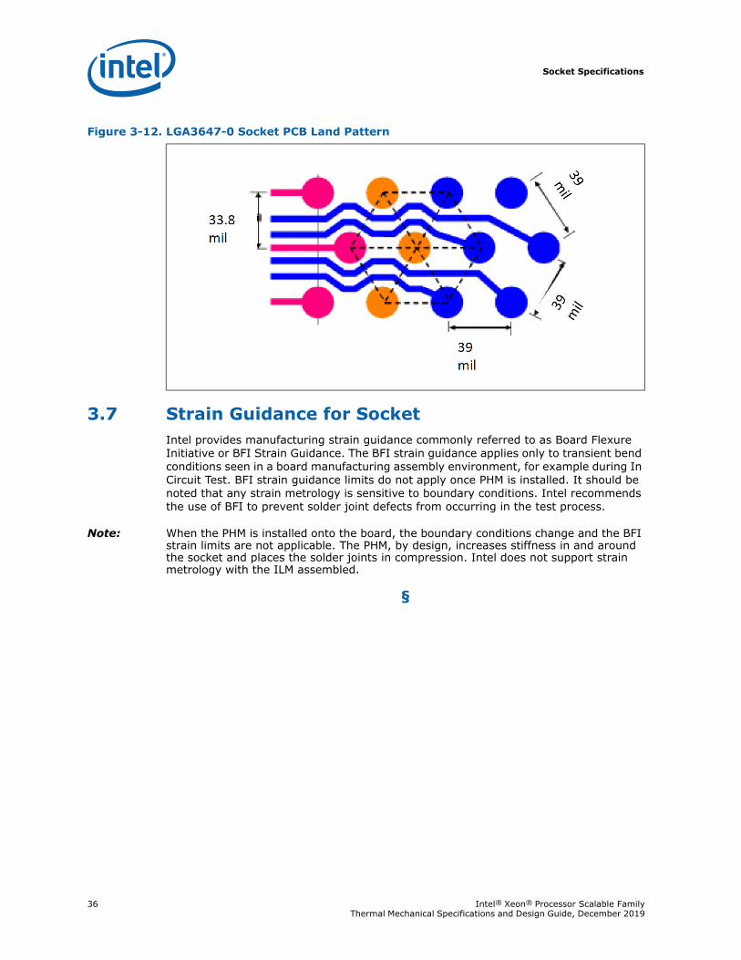
Socket Specifications
36 Intel® Xeon® Processor Scalable Family Thermal Mechanical Specifications and Design Guide, December 2019
3.7 Strain Guidance for SocketIntel provides manufacturing strain guidance commonly referred to as Board Flexure Initiative or BFI Strain Guidance. The BFI strain guidance applies only to transient bend conditions seen in a board manufacturing assembly environment, for example during In Circuit Test. BFI strain guidance limits do not apply once PHM is installed. It should be noted that any strain metrology is sensitive to boundary conditions. Intel recommends the use of BFI to prevent solder joint defects from occurring in the test process.
Note: When the PHM is installed onto the board, the boundary conditions change and the BFI strain limits are not applicable. The PHM, by design, increases stiffness in and around the socket and places the solder joints in compression. Intel does not support strain metrology with the ILM assembled.
§
Figure 3-12. LGA3647-0 Socket PCB Land Pattern
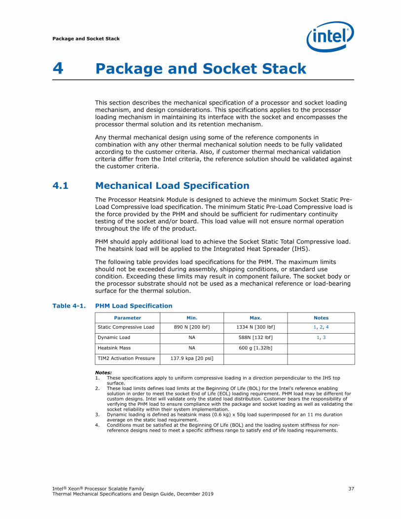
Package and Socket Stack
Intel® Xeon® Processor Scalable Family 37Thermal Mechanical Specifications and Design Guide, December 2019
4 Package and Socket Stack
This section describes the mechanical specification of a processor and socket loading mechanism, and design considerations. This specifications applies to the processor loading mechanism in maintaining its interface with the socket and encompasses the processor thermal solution and its retention mechanism.
Any thermal mechanical design using some of the reference components in combination with any other thermal mechanical solution needs to be fully validated according to the customer criteria. Also, if customer thermal mechanical validation criteria differ from the Intel criteria, the reference solution should be validated against the customer criteria.
4.1 Mechanical Load SpecificationThe Processor Heatsink Module is designed to achieve the minimum Socket Static Pre-Load Compressive load specification. The minimum Static Pre-Load Compressive load is the force provided by the PHM and should be sufficient for rudimentary continuity testing of the socket and/or board. This load value will not ensure normal operation throughout the life of the product.
PHM should apply additional load to achieve the Socket Static Total Compressive load. The heatsink load will be applied to the Integrated Heat Spreader (IHS).
The following table provides load specifications for the PHM. The maximum limits should not be exceeded during assembly, shipping conditions, or standard use condition. Exceeding these limits may result in component failure. The socket body or the processor substrate should not be used as a mechanical reference or load-bearing surface for the thermal solution.
Notes:1. These specifications apply to uniform compressive loading in a direction perpendicular to the IHS top
surface.2. These load limits defines load limits at the Beginning Of Life (BOL) for the Intel’s reference enabling
solution in order to meet the socket End of Life (EOL) loading requirement. PHM load may be different for custom designs. Intel will validate only the stated load distribution. Customer bears the responsibility of verifying the PHM load to ensure compliance with the package and socket loading as well as validating the socket reliability within their system implementation.
3. Dynamic loading is defined as heatsink mass (0.6 kg) x 50g load superimposed for an 11 ms duration average on the static load requirement.
4. Conditions must be satisfied at the Beginning Of Life (BOL) and the loading system stiffness for non-reference designs need to meet a specific stiffness range to satisfy end of life loading requirements.
Table 4-1. PHM Load Specification
Parameter Min. Max. Notes
Static Compressive Load 890 N [200 lbf] 1334 N [300 lbf] 1, 2, 4
Dynamic Load NA 588N [132 lbf] 1, 3
Heatsink Mass NA 600 g [1.32lb]
TIM2 Activation Pressure 137.9 kpa [20 psi]
Package and Socket Stack
38 Intel® Xeon® Processor Scalable Family Thermal Mechanical Specifications and Design Guide, December 2019
4.2 Mechanical Design ConsiderationsA retention/loading mechanism must be designed to support the heatsink because there are no features on the socket on which to directly attach a heatsink. In addition to holding the heatsink in place on top of the IHS, this mechanism plays a significant role in the performance of the system, in particular:
• Ensuring thermal performance of the TIM applied between the IHS and the heatsink. TIMs, especially those based on phase change materials, are very sensitive to applied pressure: the higher the pressure, the better the initial performance. TIMs such as thermal greases are not as sensitive to applied pressure. Designs should consider the possible decrease in applied pressure over time due to potential structural relaxation in enabled components.
• Ensuring system electrical, thermal, and structural integrity under shock and vibration events, particularly the socket solder joints. The mechanical requirements of the attachment mechanism depend on the weight of the heatsink and the level of shock and vibration that the system must support. The overall structural design of the baseboard and system must be considered when designing the heatsink attachment mechanism. Their design should provide a means for protecting socket solder joints, as well as preventing package pullout from the socket.
Note: The load applied by the attachment mechanism and the heatsink must comply with the package specifications, along with the dynamic load added by the mechanical shock and vibration requirements.
Note: The load applied by the attachment mechanism must comply with the processor mechanical specifications, along with the dynamic load added by the mechanical shock and vibration requirements.
A potential mechanical solution for heavy heatsinks is the use of a supporting mechanism such as a backer plate or the utilization of a direct attachment of the heatsink to the chassis pan. In these cases, the strength of the supporting component can be utilized rather than solely relying on the baseboard strength. In addition to the general guidelines given above, contact with the baseboard surfaces should be minimized during installation in order to avoid any damage to the baseboard.
Placement of board-to-chassis mounting holes also impacts board deflection and resultant socket solder ball stress. Customers need to assess the shock for their designs as heatsink retention (back plate), heatsink mass and chassis mounting holes may vary.
4.3 Intel Fabric Passive (IFP) CableSee the Intel Fabric Passive (IFP) internal cable assembly specification for the cable design details. The LEC54B connector end of the IFP cable which mates with the processor tab relies on the PHM package carrier and bolster designs to ensure the cable is fully engage and remains engaged during shock and vibration environmental conditions.
§
Processor Thermal Management
Intel® Xeon® Processor Scalable Family 39Thermal Mechanical Specifications and Design Guide, December 2019
5 Processor Thermal Management
Processor thermal management features and specifications are defined to ensure processor performance optimization within the targeted system and the processor thermal environmental conditions. It is the responsibility of the system and components thermal architects to ensure compliance with the processor thermal specifications. Compromising processor thermal requirements will impact the processor performance and reliability.
5.1 Processor Thermal Features
5.1.1 TCC Activation TemperatureThe processor has a software readable field in the TEMPERATURE_TARGET register that contains the minimum temperature at which the Thermal Control Circuit (TCC) will be activated and PROCHOT_N will be asserted. The TCC activation temperature is calibrated on a part-by-part basis and normal factory variation may result in the actual TCC activation temperature being higher than the value listed in the register.
TCC activation temperatures may change based on processor stepping, frequency or manufacturing efficiencies. Consult the for more information about this register.
Use of software that reports absolute temperature could be misleading since TCC activation temperature varies from part-to-part.
5.1.2 Intel® Turbo Boost TechnologyIntel® Turbo Boost Technology is a feature available on certain Intel® Xeon® Processor Scalable Family SKUs that opportunistically, and automatically allows the processor to run faster than the marked frequency if all of the following conditions are met:
1. Processor operating at base frequency (that is, P1 P-state)2. Power management not active (that is, not throttling)
3. Processor operating below its temperature limit (that is, DTS < 0)
4. Processor operating below its power and current limits (that is, < TDP and <ICC_MAX). Refer to Section 5.3.2, “Fan Speed Control” for more information.
With Intel Turbo Boost Technology enabled, the instantaneous processor power can exceed TDP for short durations resulting in increased performance.
System thermal design should consider the following important parameters (set via BIOS).
• POWER_LIMIT_1 (PL1) = Average processor power over a long time window (default setting is TDP)
• POWER_LIMIT_2 (PL2) = Average processor power over a short time window above TDP (short excursions). Maximum allowed by the processor is 20% above TDP for all SKUs (1.2 * TDP). Note that actual power will include IMON inaccuracy.
Processor Thermal Management
40 Intel® Xeon® Processor Scalable Family Thermal Mechanical Specifications and Design Guide, December 2019
• POWER_LIMIT_1_TIME (Tau) = Time constant for the exponential weighted moving average (EWMA) which optimizes performance while reducing thermal risk (dictates how quickly power decays from its peak).
Note: Although the processor can exceed PL1 (default TDP) for a certain amount of time, the Exponential Weighted Moving Average (EWMA) power will never exceed PL1.
A properly designed processor thermal solution is important to maximizing Turbo Boost performance. However, heatsink performance (thermal resistance, Ψ CA) is only one of several factors that can impact the amount of benefit. Other factors are operating environment, workload and system design. Intel Turbo Boost Technology performance is also constrained by ICC, and VCC limits. With Turbo Mode enabled, the processor may run more consistently at higher power levels (but still within TDP), and be more likely at temperatures above TCONTROL, as compared to when Turbo Mode is disabled. This may result in higher acoustics.
5.1.3 Thermal ManagementIntel® Xeon® Processor Scalable Family SKUs require careful monitoring and control of temperatures on multiple silicon dies inside the package. The case temperature of a multi die SKUs is defined as the temperature measured at various locations on the surface of the Integrated Heat Spreader (IHS) above these components. Component thermal solution designers may utilize IHS power gradient at the core locations to optimize the processor cooling solution or to verify the thermal solution capability in meeting the processor thermal requirement. To allow optimal operation and long-term reliability of Intel processor-based systems, the processor must remain between the minimum and maximum case temperature (TCASE) specifications as defined in the tables in the following sub-sections. Thermal solutions not designed to provide sufficient thermal cooling may affect the long-term reliability of the processor and system. Thermal profiles ensure adherence to Intel reliability requirements.
Intel assumes system boundary conditions (system ambient, airflow, heatsink performance/pressure drop, preheat, etc.) for each processor SKU. For servers, each processor will be aligned to either 1U or 2U system boundary conditions. Implementing a thermal solution that violates the thermal profile for extended periods of time may result in permanent damage to the processor or reduced life. The upper point of the thermal profile consists of the Thermal Design Power (TDP) and the corresponding TCASE_MAX value (x = TDP and y = TCASE_MAX) represents a thermal solution design point.
For embedded servers, communications and storage markets, Intel has SKUs that support thermal profiles with nominal and short-term conditions designed to meet NEBS level 3 compliance. For these SKUs, operation at either the nominal or short- term thermal profiles should result in virtually no TCC activation. Thermal profiles for these SKUs are found in this chapter as well.
Intel® Xeon® Processor Scalable Family implements a methodology for managing processor temperatures which is intended to support acoustic noise reduction through fan speed control and to assure processor reliability. Selection of the appropriate fan speed is based on the relative temperature data reported by the processor’s Platform Environment Control Interface (PECI) as described in the Intel® Xeon® Processor Scalable Family Datasheet: Volume 1 - Electrical.
If the DTS value is less than TCONTROL, then the case temperature is permitted to exceed the Thermal Profile, but the DTS value must remain at or below TCONTROL.
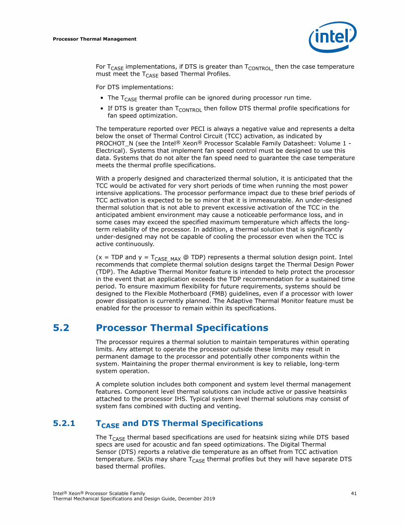
Processor Thermal Management
Intel® Xeon® Processor Scalable Family 41Thermal Mechanical Specifications and Design Guide, December 2019
For TCASE implementations, if DTS is greater than TCONTROL, then the case temperature must meet the TCASE based Thermal Profiles.
For DTS implementations:
• The TCASE thermal profile can be ignored during processor run time.
• If DTS is greater than TCONTROL then follow DTS thermal profile specifications for fan speed optimization.
The temperature reported over PECI is always a negative value and represents a delta below the onset of Thermal Control Circuit (TCC) activation, as indicated by PROCHOT_N (see the Intel® Xeon® Processor Scalable Family Datasheet: Volume 1 - Electrical). Systems that implement fan speed control must be designed to use this data. Systems that do not alter the fan speed need to guarantee the case temperature meets the thermal profile specifications.
With a properly designed and characterized thermal solution, it is anticipated that the TCC would be activated for very short periods of time when running the most power intensive applications. The processor performance impact due to these brief periods of TCC activation is expected to be so minor that it is immeasurable. An under-designed thermal solution that is not able to prevent excessive activation of the TCC in the anticipated ambient environment may cause a noticeable performance loss, and in some cases may exceed the specified maximum temperature which affects the long- term reliability of the processor. In addition, a thermal solution that is significantly under-designed may not be capable of cooling the processor even when the TCC is active continuously.
(x = TDP and y = TCASE_MAX @ TDP) represents a thermal solution design point. Intel recommends that complete thermal solution designs target the Thermal Design Power (TDP). The Adaptive Thermal Monitor feature is intended to help protect the processor in the event that an application exceeds the TDP recommendation for a sustained time period. To ensure maximum flexibility for future requirements, systems should be designed to the Flexible Motherboard (FMB) guidelines, even if a processor with lower power dissipation is currently planned. The Adaptive Thermal Monitor feature must be enabled for the processor to remain within its specifications.
5.2 Processor Thermal SpecificationsThe processor requires a thermal solution to maintain temperatures within operating limits. Any attempt to operate the processor outside these limits may result in permanent damage to the processor and potentially other components within the system. Maintaining the proper thermal environment is key to reliable, long-term system operation.
A complete solution includes both component and system level thermal management features. Component level thermal solutions can include active or passive heatsinks attached to the processor IHS. Typical system level thermal solutions may consist of system fans combined with ducting and venting.
5.2.1 TCASE and DTS Thermal SpecificationsThe TCASE thermal based specifications are used for heatsink sizing while DTS based specs are used for acoustic and fan speed optimizations. The Digital Thermal Sensor (DTS) reports a relative die temperature as an offset from TCC activation temperature. SKUs may share TCASE thermal profiles but they will have separate DTS based thermal profiles.

Processor Thermal Management
42 Intel® Xeon® Processor Scalable Family Thermal Mechanical Specifications and Design Guide, December 2019
5.2.1.1 TCASE Thermal Profile
In the case of multi die processor SKUs also known as Multi-Chip Package (MCP), TCASE values will be influenced by power dissipation by each die. For a single die processor package or non-MCP, all thermal profiles, whether based on TCASE or DTS, follow the straight-line equation format namely, y = mx + b. Where,
y = temperature (T) in °C
m = slope (ΨCA) (CA = Case to ambient)
x = power (P) in Watts
b = y-intercept (TLA) (LA = local ambient)
Note that there is no one-to-one correlation between TCASE and DTS. The TCASE specification exists to ensure that, when the TCASE margin is 0°C, the DTS reading should be at or below DTS_Max (thermal throttle) for virtually all server processors. Variation in DTS margin is normal, and results from several factors including DTS accuracy, thermal stack up variance, actual power under a TDP load, etc. The TCASE and DTS thermal profiles are expected to account for these variables.
The only way to accurately determine TCASE is to measure it with a thermocouple. The TCASE thermal profile specification is primarily for thermal solution sizing to ensure that virtually all processors within a particular SKU will operate with little to no thermal throttle. The DTS thermal profile provides a real time metric for FSC and acoustics, and to ensure performance and reliability. As long as a thermal solution meets the TCASE thermal profile specification, it is expected to support part-to-part variation in DTS margin.
Figure 5-1. Typical Thermal Profile Graph (Illustration Only)
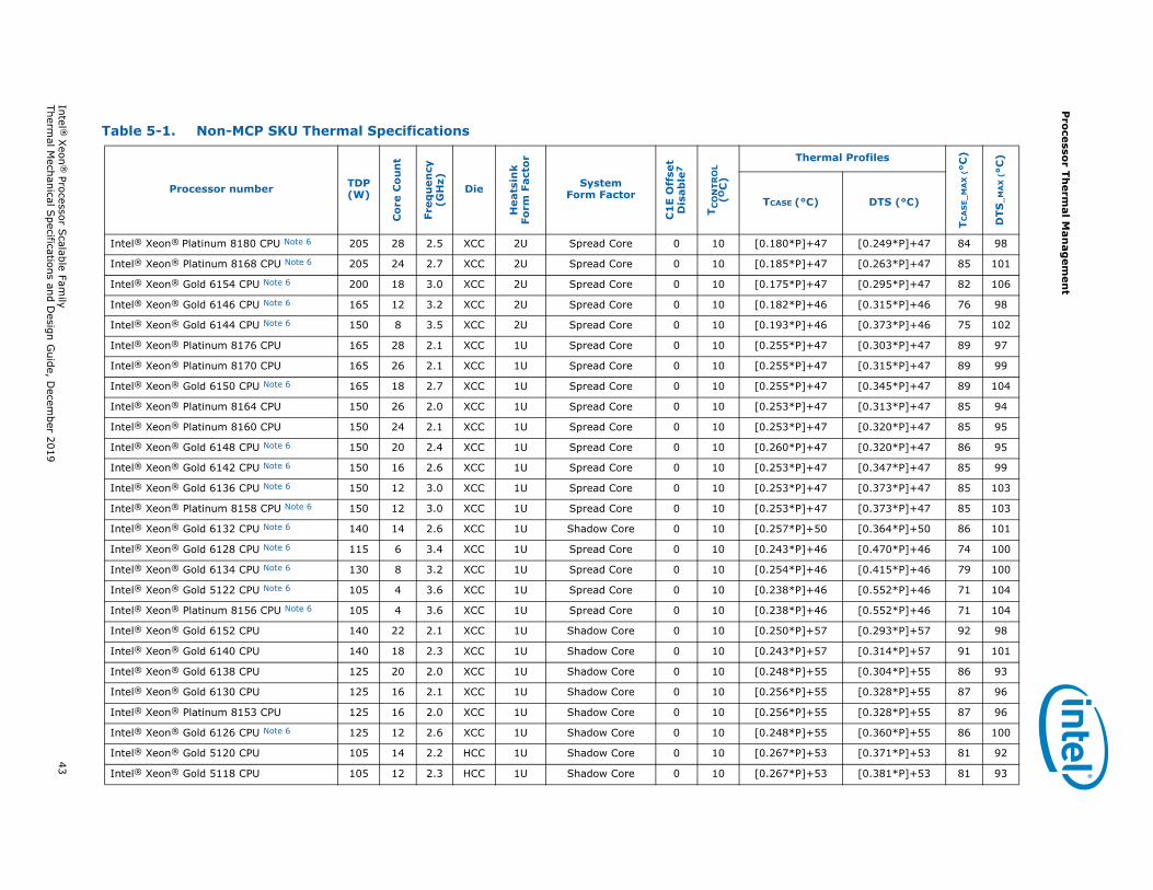
Pro
cessor Th
ermal M
anag
emen
t
Intel ® X
eon®
Processor Scalable Fam
ily43
Thermal M
echanical Specifications and D
esign Guide, D
ecember 2019
Table 5-1. Non-MCP SKU Thermal Specifications
Processor number TDP (W)
Co
re C
ou
nt
Freq
uen
cy(G
Hz)
Die
Hea
tsin
k Fo
rm F
acto
r
System Form Factor
C1
E O
ffse
tD
isab
le7
TC
ON
TR
OL
(OC
)
Thermal Profiles
TC
AS
E_M
AX
(°C
)
DTS
_M
AX
(°C
)
TCASE (°C) DTS (°C)
Intel® Xeon® Platinum 8180 CPU Note 6 205 28 2.5 XCC 2U Spread Core 0 10 [0.180*P]+47 [0.249*P]+47 84 98
Intel® Xeon® Platinum 8168 CPU Note 6 205 24 2.7 XCC 2U Spread Core 0 10 [0.185*P]+47 [0.263*P]+47 85 101
Intel® Xeon® Gold 6154 CPU Note 6 200 18 3.0 XCC 2U Spread Core 0 10 [0.175*P]+47 [0.295*P]+47 82 106
Intel® Xeon® Gold 6146 CPU Note 6 165 12 3.2 XCC 2U Spread Core 0 10 [0.182*P]+46 [0.315*P]+46 76 98
Intel® Xeon® Gold 6144 CPU Note 6 150 8 3.5 XCC 2U Spread Core 0 10 [0.193*P]+46 [0.373*P]+46 75 102
Intel® Xeon® Platinum 8176 CPU 165 28 2.1 XCC 1U Spread Core 0 10 [0.255*P]+47 [0.303*P]+47 89 97
Intel® Xeon® Platinum 8170 CPU 165 26 2.1 XCC 1U Spread Core 0 10 [0.255*P]+47 [0.315*P]+47 89 99
Intel® Xeon® Gold 6150 CPU Note 6 165 18 2.7 XCC 1U Spread Core 0 10 [0.255*P]+47 [0.345*P]+47 89 104
Intel® Xeon® Platinum 8164 CPU 150 26 2.0 XCC 1U Spread Core 0 10 [0.253*P]+47 [0.313*P]+47 85 94
Intel® Xeon® Platinum 8160 CPU 150 24 2.1 XCC 1U Spread Core 0 10 [0.253*P]+47 [0.320*P]+47 85 95
Intel® Xeon® Gold 6148 CPU Note 6 150 20 2.4 XCC 1U Spread Core 0 10 [0.260*P]+47 [0.320*P]+47 86 95
Intel® Xeon® Gold 6142 CPU Note 6 150 16 2.6 XCC 1U Spread Core 0 10 [0.253*P]+47 [0.347*P]+47 85 99
Intel® Xeon® Gold 6136 CPU Note 6 150 12 3.0 XCC 1U Spread Core 0 10 [0.253*P]+47 [0.373*P]+47 85 103
Intel® Xeon® Platinum 8158 CPU Note 6 150 12 3.0 XCC 1U Spread Core 0 10 [0.253*P]+47 [0.373*P]+47 85 103
Intel® Xeon® Gold 6132 CPU Note 6 140 14 2.6 XCC 1U Shadow Core 0 10 [0.257*P]+50 [0.364*P]+50 86 101
Intel® Xeon® Gold 6128 CPU Note 6 115 6 3.4 XCC 1U Spread Core 0 10 [0.243*P]+46 [0.470*P]+46 74 100
Intel® Xeon® Gold 6134 CPU Note 6 130 8 3.2 XCC 1U Spread Core 0 10 [0.254*P]+46 [0.415*P]+46 79 100
Intel® Xeon® Gold 5122 CPU Note 6 105 4 3.6 XCC 1U Spread Core 0 10 [0.238*P]+46 [0.552*P]+46 71 104
Intel® Xeon® Platinum 8156 CPU Note 6 105 4 3.6 XCC 1U Spread Core 0 10 [0.238*P]+46 [0.552*P]+46 71 104
Intel® Xeon® Gold 6152 CPU 140 22 2.1 XCC 1U Shadow Core 0 10 [0.250*P]+57 [0.293*P]+57 92 98
Intel® Xeon® Gold 6140 CPU 140 18 2.3 XCC 1U Shadow Core 0 10 [0.243*P]+57 [0.314*P]+57 91 101
Intel® Xeon® Gold 6138 CPU 125 20 2.0 XCC 1U Shadow Core 0 10 [0.248*P]+55 [0.304*P]+55 86 93
Intel® Xeon® Gold 6130 CPU 125 16 2.1 XCC 1U Shadow Core 0 10 [0.256*P]+55 [0.328*P]+55 87 96
Intel® Xeon® Platinum 8153 CPU 125 16 2.0 XCC 1U Shadow Core 0 10 [0.256*P]+55 [0.328*P]+55 87 96
Intel® Xeon® Gold 6126 CPU Note 6 125 12 2.6 XCC 1U Shadow Core 0 10 [0.248*P]+55 [0.360*P]+55 86 100
Intel® Xeon® Gold 5120 CPU 105 14 2.2 HCC 1U Shadow Core 0 10 [0.267*P]+53 [0.371*P]+53 81 92
Intel® Xeon® Gold 5118 CPU 105 12 2.3 HCC 1U Shadow Core 0 10 [0.267*P]+53 [0.381*P]+53 81 93
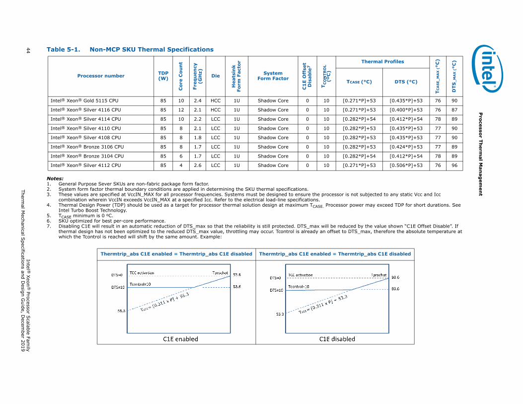
44 Intel ®
Xeon
® Processor S
calable Family
Thermal M
echanical Specifications and D
esign Guide, D
ecember 2019
Pro
cessor Th
ermal M
anag
emen
t
Notes:1. General Purpose Sever SKUs are non-fabric package form factor.2. System form factor thermal boundary conditions are applied in determining the SKU thermal specifications.3. These values are specified at VccIN_MAX for all processor frequencies. Systems must be designed to ensure the processor is not subjected to any static Vcc and Icc
combination wherein VccIN exceeds VccIN_MAX at a specified Icc. Refer to the electrical load-line specifications.4. Thermal Design Power (TDP) should be used as a target for processor thermal solution design at maximum TCASE. Processor power may exceed TDP for short durations. See
Intel Turbo Boost Technology.5. TCASE minimum is 0 oC.6. SKU optimized for best per-core performance.7. Disabling C1E will result in an automatic reduction of DTS_max so that the reliability is still protected. DTS_max will be reduced by the value shown “C1E Offset Disable”. If
thermal design has not been optimized to the reduced DTS_max value, throttling may occur. Tcontrol is already an offset to DTS_max, therefore the absolute temperature at which the Tcontrol is reached will shift by the same amount. Example:
Intel® Xeon® Gold 5115 CPU 85 10 2.4 HCC 1U Shadow Core 0 10 [0.271*P]+53 [0.435*P]+53 76 90
Intel® Xeon® Silver 4116 CPU 85 12 2.1 HCC 1U Shadow Core 0 10 [0.271*P]+53 [0.400*P]+53 76 87
Intel® Xeon® Silver 4114 CPU 85 10 2.2 LCC 1U Shadow Core 0 10 [0.282*P]+54 [0.412*P]+54 78 89
Intel® Xeon® Silver 4110 CPU 85 8 2.1 LCC 1U Shadow Core 0 10 [0.282*P]+53 [0.435*P]+53 77 90
Intel® Xeon® Silver 4108 CPU 85 8 1.8 LCC 1U Shadow Core 0 10 [0.282*P]+53 [0.435*P]+53 77 90
Intel® Xeon® Bronze 3106 CPU 85 8 1.7 LCC 1U Shadow Core 0 10 [0.282*P]+53 [0.424*P]+53 77 89
Intel® Xeon® Bronze 3104 CPU 85 6 1.7 LCC 1U Shadow Core 0 10 [0.282*P]+54 [0.412*P]+54 78 89
Intel® Xeon® Silver 4112 CPU 85 4 2.6 LCC 1U Shadow Core 0 10 [0.271*P]+53 [0.506*P]+53 76 96
Thermtrip_abs C1E enabled = Thermtrip_abs C1E disabled Thermtrip_abs C1E enabled = Thermtrip_abs C1E disabled
Table 5-1. Non-MCP SKU Thermal Specifications
Processor number TDP (W)
Co
re C
ou
nt
Freq
uen
cy(G
Hz)
Die
Hea
tsin
k Fo
rm F
acto
r
System Form Factor
C1
E O
ffse
tD
isab
le7
TC
ON
TR
OL
(OC
)
Thermal Profiles
TC
AS
E_M
AX
(°C
)
DTS
_M
AX
(°C
)
TCASE (°C) DTS (°C)
Processor Thermal Management
Intel® Xeon® Processor Scalable Family 45Thermal Mechanical Specifications and Design Guide, December 2019
5.2.2 Multi-Chip Package (MCP) Thermal Specification
5.2.2.1 MCP TCase Locations
For an MCP each die should have a corresponding TCASE location. Figure 5-2 shows that for the Intel® Xeon® Processor Scalable Family fabric form factor, the TCASE location is the top surface of the IHS directly above the center of each die.
5.2.2.2 MCP TCASE Methodology
For MCP processors, the multiple point case temperature specification is defined as each die is thermally coupled. In verifying the case temperature at each location, a superposition method can be applied to determine the influence of each die power dissipation at each case temperature location.
5.2.2.3 TCASE Testing Methodology
Figure 5-2. TCase Locations for an MCP
Table 5-2. Testing with Live CPU Die
Table 5-3. Obtaining Thermal Resistance Guidance when setting PFabric=0
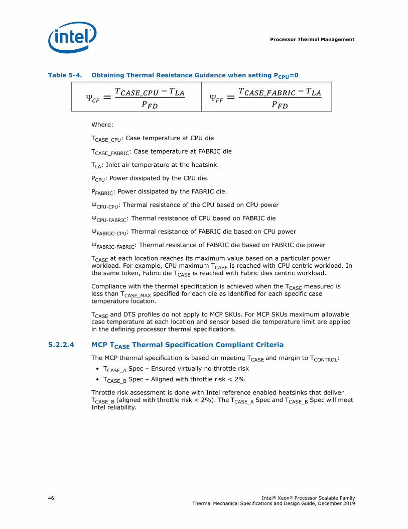
Processor Thermal Management
46 Intel® Xeon® Processor Scalable Family Thermal Mechanical Specifications and Design Guide, December 2019
Where:
TCASE_CPU: Case temperature at CPU die
TCASE_FABRIC: Case temperature at FABRIC die
TLA: Inlet air temperature at the heatsink.
PCPU: Power dissipated by the CPU die.
PFABRIC: Power dissipated by the FABRIC die.
ΨCPU-CPU: Thermal resistance of the CPU based on CPU power
ΨCPU-FABRIC: Thermal resistance of CPU based on FABRIC die
ΨFABRIC-CPU: Thermal resistance of FABRIC die based on CPU power
ΨFABRIC-FABRIC: Thermal resistance of FABRIC die based on FABRIC die power
TCASE at each location reaches its maximum value based on a particular power workload. For example, CPU maximum TCASE is reached with CPU centric workload. In the same token, Fabric die TCASE is reached with Fabric dies centric workload.
Compliance with the thermal specification is achieved when the TCASE measured is less than TCASE_MAX specified for each die as identified for each specific case temperature location.
TCASE and DTS profiles do not apply to MCP SKUs. For MCP SKUs maximum allowable case temperature at each location and sensor based die temperature limit are applied in the defining processor thermal specifications.
5.2.2.4 MCP TCASE Thermal Specification Compliant Criteria
The MCP thermal specification is based on meeting TCASE and margin to TCONTROL:
• TCASE_A Spec – Ensured virtually no throttle risk
• TCASE_B Spec – Aligned with throttle risk < 2%
Throttle risk assessment is done with Intel reference enabled heatsinks that deliver TCASE_B (aligned with throttle risk < 2%). The TCASE_A Spec and TCASE_B Spec will meet Intel reliability.
Table 5-4. Obtaining Thermal Resistance Guidance when setting PCPU=0
Processor Thermal Management
Intel® Xeon® Processor Scalable Family 47Thermal Mechanical Specifications and Design Guide, December 2019
5.2.2.5 Single Point TCASE Test Guidance for an MCP
A system thermal cooling capability evaluation must be conducted at the package integrated heat spreader level (to account for all remaining silicon components under the IHS). If only a CPU die under the IHS, a well-known BKM exists (BKM: PTU + embedded thermocouple). Additional dies (that is, fabric die) under the IHS, the thermal cooling capability assessment is difficult due to:
• No well-defined application load
• Companion die power varies widely
• Companion die thermal resistance varies widely
• Accurate small die thermocouple placement is challenging
Intel provides a single point TCASE test guidance for MCP as a simplification method that uses adjusted CPU TCASE as a proxy to align with the MCP TCASE.
5.2.2.5.1 MCP Thermal Spec Compliant Criteria:
1. Airflow ≥ Intel Thermal BC2. HS design assumptions
a. Heat removal of the thermal solution is relatively uniform for all dies.b. The companion die (fabric die) will be at idle.c. For air cooling:— The contact surface of the heat sink will cover all of the IHS. Fin height will be
uniform. d. For cold-plate design: — The fin structure inside the cold-plate must cover CPU and fabric die.e. For water cooling:— The internal water channels will cover all of the IHS.
3. Meeting 1 and 2 above will ensure MCP thermal spec compliant.
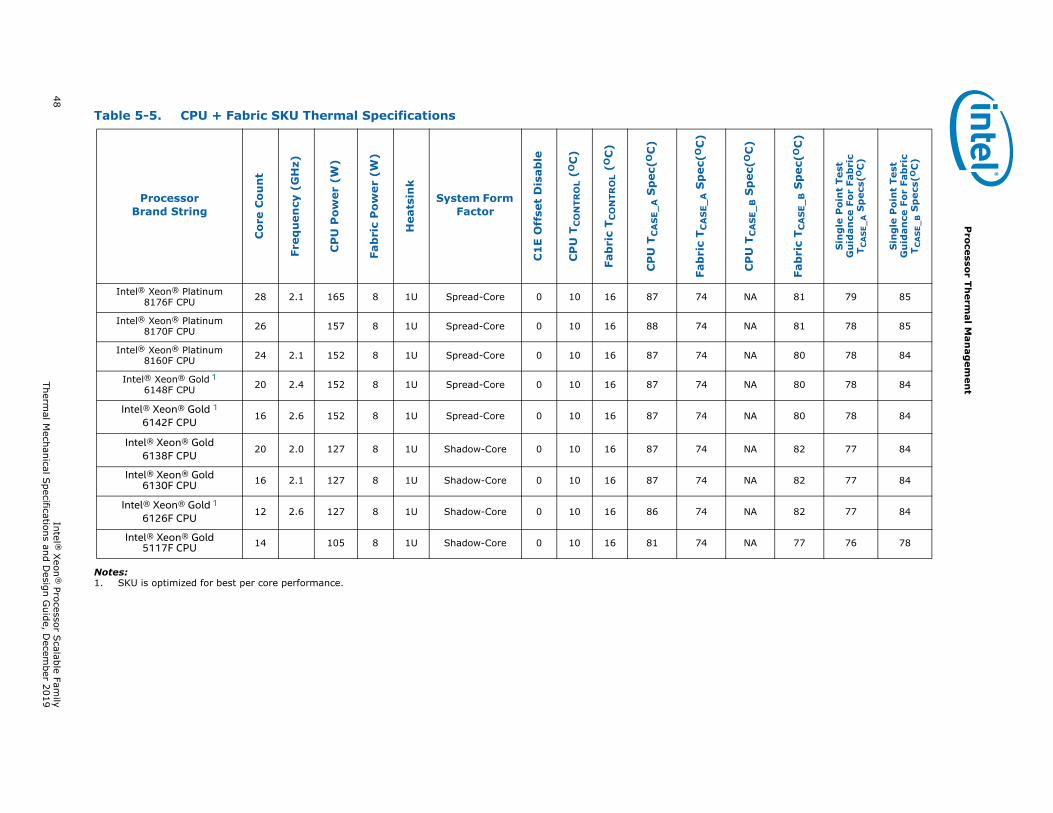
48 Intel ®
Xeon
® Processor S
calable Family
Thermal M
echanical Specifications and D
esign Guide, D
ecember 2019
Pro
cessor Th
ermal M
anag
emen
t
Notes:1. SKU is optimized for best per core performance.
Table 5-5. CPU + Fabric SKU Thermal Specifications
ProcessorBrand String
Cor
e C
ou
nt
Freq
uen
cy (
GH
z)
CP
U P
ower
(W
)
Fab
ric
Po
wer
(W
)
Hea
tsin
k
System Form Factor
C1
E O
ffse
t D
isab
le
CP
U T
CO
NTR
OL
(OC
)
Fab
ric
T CO
NTR
OL
(OC
)
CP
U T
CA
SE
_A S
pec
(OC
)
Fab
ric
T CA
SE_
A S
pec
(OC
)
CP
U T
CA
SE
_B S
pec
(OC
)
Fab
ric
T CA
SE
_B S
pec
(OC
)
Sin
gle
Po
int
Test
Gu
idan
ce F
or
Fab
ric
T CA
SE
_A S
pec
s(OC
)
Sin
gle
Po
int
Test
Gu
idan
ce F
or
Fab
ric
TC
AS
E_B S
pec
s(O
C)
Intel® Xeon® Platinum 8176F CPU 28 2.1 165 8 1U Spread-Core 0 10 16 87 74 NA 81 79 85
Intel® Xeon® Platinum 8170F CPU 26 157 8 1U Spread-Core 0 10 16 88 74 NA 81 78 85
Intel® Xeon® Platinum 8160F CPU 24 2.1 152 8 1U Spread-Core 0 10 16 87 74 NA 80 78 84
Intel® Xeon® Gold 16148F CPU 20 2.4 152 8 1U Spread-Core 0 10 16 87 74 NA 80 78 84
Intel® Xeon® Gold 16142F CPU 16 2.6 152 8 1U Spread-Core 0 10 16 87 74 NA 80 78 84
Intel® Xeon® Gold6138F CPU 20 2.0 127 8 1U Shadow-Core 0 10 16 87 74 NA 82 77 84
Intel® Xeon® Gold6130F CPU 16 2.1 127 8 1U Shadow-Core 0 10 16 87 74 NA 82 77 84
Intel® Xeon® Gold 1
6126F CPU 12 2.6 127 8 1U Shadow-Core 0 10 16 86 74 NA 82 77 84
Intel® Xeon® Gold5117F CPU 14 105 8 1U Shadow-Core 0 10 16 81 74 NA 77 76 78
Processor Thermal Management
Intel® Xeon® Processor Scalable Family 49Thermal Mechanical Specifications and Design Guide, December 2019
5.2.2.6 Non-MCP (10-Year Use + NEBS-Friendly) SKU Thermal Profiles
Network Equipment Building System (NEBS) is the most common set of environmental design guidelines applied to telecommunications equipment. Non-MCP (10-Year Use + NEBS-Friendly) SKU thermal profiles target operation at higher case temperatures and/or NEBS thermal profiles for embedded communications server and storage form factors. The term “Embedded” is used to refer to those segments collectively. Thermal profiles in this section pertain only to those specific non-MCP (10-Year Use + NEBS-Friendly) SKU thermal profiles.
The Nominal Thermal Profile must be used for standard operating conditions or for products that do not require NEBS Level 3 compliance.
The Short-Term Thermal Profile may only be used for short-term excursions to higher ambient operating temperatures, not to exceed 96 hours per instance, 360 hours per year, and a maximum of 15 instances per year, as intended by NEBS Level 3.
Operation at the Short-Term Thermal Profile for durations exceeding 360 hours per year violate the processor thermal specifications and may result in permanent damage to the processor.
Implementation of the defined thermal profile should result in virtually no TCC activation.
5.2.2.7 NEBS TCASE Thermal Profile
The NEBS thermal profiles help relieve thermal constraints for short-term NEBS conditions. To help with reliability, the processors must meet the nominal thermal profile under standard operating conditions and can only rise up to the short-term specification for the NEBS excursions, see the following thermal profile diagram.
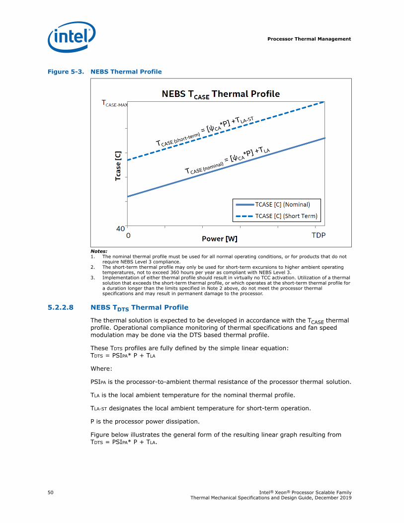
Processor Thermal Management
50 Intel® Xeon® Processor Scalable Family Thermal Mechanical Specifications and Design Guide, December 2019
Notes:1. The nominal thermal profile must be used for all normal operating conditions, or for products that do not
require NEBS Level 3 compliance.2. The short-term thermal profile may only be used for short-term excursions to higher ambient operating
temperatures, not to exceed 360 hours per year as compliant with NEBS Level 3.3. Implementation of either thermal profile should result in virtually no TCC activation. Utilization of a thermal
solution that exceeds the short-term thermal profile, or which operates at the short-term thermal profile for a duration longer than the limits specified in Note 2 above, do not meet the processor thermal specifications and may result in permanent damage to the processor.
5.2.2.8 NEBS TDTS Thermal Profile
The thermal solution is expected to be developed in accordance with the TCASE thermal profile. Operational compliance monitoring of thermal specifications and fan speed modulation may be done via the DTS based thermal profile.
These TDTS profiles are fully defined by the simple linear equation: TDTS = PSIPA* P + TLA
Where:
PSIPA is the processor-to-ambient thermal resistance of the processor thermal solution.
TLA is the local ambient temperature for the nominal thermal profile.
TLA-ST designates the local ambient temperature for short-term operation.
P is the processor power dissipation.
Figure below illustrates the general form of the resulting linear graph resulting from TDTS = PSIPA* P + TLA.
Figure 5-3. NEBS Thermal Profile
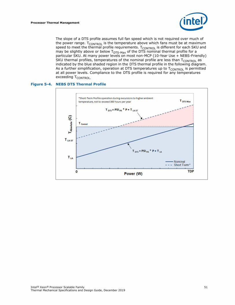
Processor Thermal Management
Intel® Xeon® Processor Scalable Family 51Thermal Mechanical Specifications and Design Guide, December 2019
The slope of a DTS profile assumes full fan speed which is not required over much of the power range. TCONTROL is the temperature above which fans must be at maximum speed to meet the thermal profile requirements. TCONTROL is different for each SKU and may be slightly above or below TDTS-Max of the DTS nominal thermal profile for a particular SKU. At many power levels on most non-MCP (10-Year Use + NEBS-Friendly) SKU thermal profiles, temperatures of the nominal profile are less than TCONTROL as indicated by the blue shaded region in the DTS thermal profile in the following diagram. As a further simplification, operation at DTS temperatures up to TCONTROL is permitted at all power levels. Compliance to the DTS profile is required for any temperatures exceeding TCONTROL.
Figure 5-4. NEBS DTS Thermal Profile
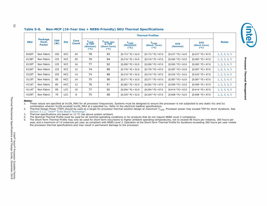
52 Intel ®
Xeon
® Processor S
calable Family
Thermal M
echanical Specifications and D
esign Guide, D
ecember 2019
Pro
cessor Th
ermal M
anag
emen
t
Notes:1. These values are specified at VccIN_MAX for all processor frequencies. Systems must be designed to ensure the processor is not subjected to any static Vcc and Icc
combination wherein VccIN exceeds VccIN_MAX at a specified Icc. Refer to the electrical loadline specifications.2. Thermal Design Power (TDP) should be used as a target for processor thermal solution design at maximum TCASE. Processor power may exceed TDP for short durations. See
Section 5.1.2, “Intel® Turbo Boost Technology”.3. Thermal specifications are based on 12 °C rise above system ambient.4. The Nominal Thermal Profile must be used for all nominal operating conditions or for products that do not require NEBS Level 3 compliance.5. The Short-Term Thermal Profile may only be used for short-term excursions to higher ambient operating temperatures, not to exceed 96 hours per instance, 360 hours per
year, and a maximum of 15 instances per year, as compliant with NEBS Level 3. Operation at the Short-Term Thermal Profile for durations exceeding 360 hours per year violate the processor thermal specifications and may result in permanent damage to the processor.
Table 5-6. Non-MCP (10-Year Use + NEBS-Friendly) SKU Thermal Specifications
SKUPackage
Form Factor
TDP (W) Die Core
Count
Thermal Profiles
NotesTCASE @ TDP
(Nominal) (°C)
TCASE_MAX @ TDP
(Short-Term)(°C)
TCASE(Nominal)
(°C)
TCASE(Short- Term)
(°C)
DTS(Nominal)
DTS(Short-Term)
(°C)
8160T Non Fabric 150 XCC 24 78 93 [0.173 * P] + 52.0 [0.173 * P] + 67.0 [0.237 * P] + 52.0 [0.237 * P] + 67.0 1, 2, 3, 4, 5
6138T Non Fabric 125 XCC 20 79 94 [0.216 * P] + 52.0 [0.216 * P] + 67.0 [0.285 * P] + 52.0 [0.285 * P] + 67.0 1, 2, 3, 4, 5
6130T Non Fabric 125 XCC 16 77 92 [0.200 * P] + 52.0 [0.200 * P] + 67.0 [0.285 * P] + 52.0 [0.285 * P] + 67.0 1, 2, 3, 4, 5
6126T Non Fabric 125 XCC 12 74 89 [0.176 * P] + 52.0 [0.176 * P] + 67.0 [0.287 * P] + 52.0 [0.287 * P] + 67.0 1, 2, 3, 4, 5
5120T Non Fabric 105 HCC 14 74 89 [0.210 * P] + 52.0 [0.210 * P] + 67.0 [0.335 * P] + 52.0 [0.335 * P] + 67.0 1, 2, 3, 4, 5
5119T Non Fabric 85 HCC 14 75 90 [0.271 * P] + 52.0 [0.271 * P] + 67.0 [0.387 * P] + 52.0 [0.387 * P] + 67.0 1, 2, 3, 4, 5
4116T Non Fabric 85 HCC 12 76 91 [0.282 * P] + 52.0 [0.282 * P] + 67.0 [0.399 * P] + 52.0 [0.399 * P] + 67.0 1, 2, 3, 4, 5
4114T Non Fabric 85 LCC 10 77 92 [0.294 * P] + 52.0 [0.294 * P] + 67.0 [0.414 * P] + 52.0 [0.414 * P] + 67.0 1, 2, 3, 4, 5
4109T Non Fabric 70 LCC 8 75 90 [0.329 * P] + 52.0 [0.329 * P] + 67.0 [0.508 * P] + 52.0 [0.508 * P] + 67.0 1, 2, 3, 4, 5
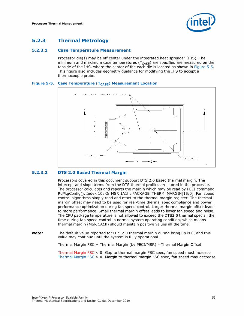
Processor Thermal Management
Intel® Xeon® Processor Scalable Family 53Thermal Mechanical Specifications and Design Guide, December 2019
5.2.3 Thermal Metrology
5.2.3.1 Case Temperature Measurement
Processor die(s) may be off center under the integrated heat spreader (IHS). The minimum and maximum case temperatures (TCASE) are specified are measured on the topside of the IHS, where the center of the each die is located as shown in Figure 5-5. This figure also includes geometry guidance for modifying the IHS to accept a thermocouple probe.
5.2.3.2 DTS 2.0 Based Thermal Margin
Processors covered in this document support DTS 2.0 based thermal margin. The intercept and slope terms from the DTS thermal profiles are stored in the processor. The processor calculates and reports the margin which may be read by PECI command RdPkgConfig(), Index 10; Or MSR 1A1h: PACKAGE_THERM_MARGIN[15:0]. Fan speed control algorithms simply read and react to the thermal margin register. The thermal margin offset may need to be used for real-time thermal spec compliance and power performance optimization during fan speed control. Larger thermal margin offset leads to more performance. Small thermal margin offset leads to lower fan speed and noise. The CPU package temperature is not allowed to exceed the DTS2.0 thermal spec all the time during fan speed control in normal system operating condition, which means thermal margin (MSR 1A1h) should maintain positive values all the time.
Note: The default value reported for DTS 2.0 thermal margin during bring up is 0, and this value may continue until the system is fully operational.
Thermal Margin FSC = Thermal Margin (by PECI/MSR) – Thermal Margin Offset
Thermal Margin FSC < 0: Gap to thermal margin FSC spec, fan speed must increaseThermal Margin FSC > 0: Margin to thermal margin FSC spec, fan speed may decrease
Figure 5-5. Case Temperature (TCASE) Measurement Location
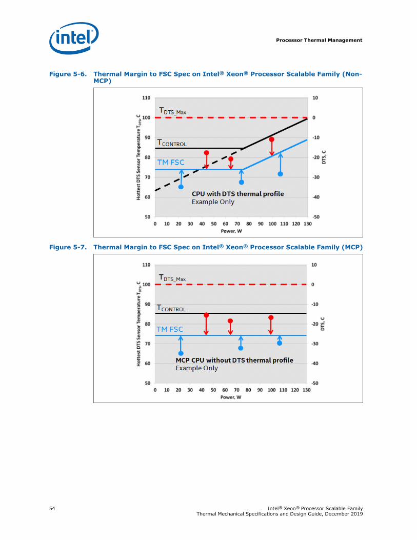
Processor Thermal Management
54 Intel® Xeon® Processor Scalable Family Thermal Mechanical Specifications and Design Guide, December 2019
Figure 5-6. Thermal Margin to FSC Spec on Intel® Xeon® Processor Scalable Family (Non-MCP)
Figure 5-7. Thermal Margin to FSC Spec on Intel® Xeon® Processor Scalable Family (MCP)
Processor Thermal Management
Intel® Xeon® Processor Scalable Family 55Thermal Mechanical Specifications and Design Guide, December 2019
5.3 Processor Thermal Management Guidelines
5.3.1 Processor Thermal Solution Environmental ConditionsProcessor heatsink design must comply with the TCASE based thermal profile. Systems that do not monitor the processor die temperature by monitoring the thermal sensor output must ensure processor cooling solution is capable of meeting the processor based TCASE spec. In some situations, implementation of DTS based thermal specification can reduce average fan power and improve acoustics as compared to the TCASE based thermal profile.
When all cores are active, a properly sized heatsink will be able to meet the processor thermal specification. When all cores are not active or when Intel Turbo Boost Technology is active, attempting to comply with the DTS based thermal specification may drive system fans to increased speed. In such situations, the TCASE temperature will be below the TCASE based thermal profile by design.
The following table provides thermal boundary conditions and performance targets applied in defining the processor thermal specifications. These values serve as a guide for designing a process compatible thermal solution.
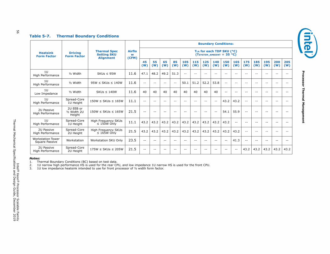
56 Intel ®
Xeon
® Processor S
calable Family
Thermal M
echanical Specifications and D
esign Guide, D
ecember 2019
Pro
cessor Th
ermal M
anag
emen
t
Notes:1. Thermal Boundary Conditions (BC) based on test data.2. 1U narrow high performance HS is used for the rear CPU, and low impedance 1U narrow HS is used for the front CPU.3. 1U low impedance heatsink intended to use for front processor of ½ width form factor.
Table 5-7. Thermal Boundary Conditions
Heatsink Form Factor
Driving Form Factor
Thermal Spec Setting SKU Alignment
Airflow
(CFM)
Boundary Conditions1
TLA for each TDP SKU (°C) (TSYSTEM_AMBIENT = 35 °C)
45 (W)
55 (W)
65 (W)
85 (W)
105 (W)
115 (W)
125(W)
140 (W)
150 (W)
165(W)
175 (W)
185 (W)
195 (W)
200 (W)
205(W)
1U High Performance ½ Width SKUs ≤ 95W 11.6 47.1 48.2 49.2 51.3 -- -- -- -- -- -- -- -- -- -- --
1U High Performance ½ Width 95W ≤ SKUs ≤ 140W 11.6 -- -- -- -- 50.1 51.2 52.2 53.8 -- -- -- -- -- -- --
1U Low Impedance ½ Width SKUs ≤ 140W 11.6 40 40 40 40 40 40 40 40 -- -- -- -- -- -- --
1U High Performance
Spread-Core1U Height 150W ≤ SKUs ≤ 165W 11.1 -- -- -- -- -- -- -- -- 43.2 43.2 -- -- -- -- --
2U Passive High Performance
2U EEB or½ Width 2U
Height150W ≤ SKUs ≤ 165W 21.5 -- -- -- -- -- -- -- -- 54.1 55.9 -- -- -- -- --
1U High Performance
Spread-Core1U Height
High Frequency SKUs ≤ 150W Only 11.1 43.2 43.2 43.2 43.2 43.2 43.2 43.2 43.2 43.2 -- -- -- -- -- --
2U PassiveHigh Performance
Spread-Core2U Height
High Frequency SKUs ≤ 165W Only 21.5 43.2 43.2 43.2 43.2 43.2 43.2 43.2 43.2 43.2 43.2 -- -- -- -- --
Workstation Tower Square Passive Workstation Workstation SKU Only 23.5 -- -- -- -- -- -- -- -- -- 41.3 -- -- -- -- --
2U Passive High Performance
Spread-Core2U Height 175W ≤ SKUs ≤ 205W 21.5 -- -- -- -- -- -- -- -- -- -- 43.2 43.2 43.2 43.2 43.2
Processor Thermal Management
Intel® Xeon® Processor Scalable Family 57Thermal Mechanical Specifications and Design Guide, December 2019
5.3.2 Fan Speed ControlFan Speed Control (FSC) techniques to reduce system-level acoustic noise are a common practice in server designs. The fan speed is one of the parameters that determines the amount of airflow provided to the thermal solution. Additionally, airflow is proportional to a thermal solution’s performance, which consequently determines the TCASE of the processor at a given power level. Because the temperature of a processor is an important parameter in determining the long-term reliability of a processor, the FSC implemented in a system directly correlates to the processor’s ability to meet the Thermal Profile. For this purpose, the parameter called TCONTROL, as explained in the Intel® Xeon® Processor Scalable Family Datasheet: Volume 1 - Electrical, is to be used in FSC designs to ensure that the long-term reliability of the processor is met while keeping the system-level acoustic noise down.
When Digital Temperature Sensor (DTS) value is less than TCONTROL, the thermal profile can be ignored. The DTS value is a relative temperature to PROCHOT which is the maximum allowable temperature before the thermal control circuit is activated. In this region, the DTS value can be utilized to not only ensure specification compliance but also to optimize fan speed control resulting in the lowest possible fan power and acoustics under any operating conditions. When DTS goes above TCONTROL, fan speed must increase to bring the sensor temperature below TCONTROL or to ensure compliance with the thermal profile.
The PECI temperature reading from the processor can be compared to this TCONTROL value. A fan speed control scheme can be implemented as described in the Intel® Xeon® Processor Scalable Family Datasheet: Volume 1 - Electrical without compromising the long-term reliability of the processor.
The PECI command for DTS is GetTemp(). Though use of a sign bit, the value returned from PECI is negative.
The PECI command for TCONTROL is RdPkgConfig(), temperature target read, 15:8. The value returned from PECI is unsigned (positive); however, it is negative by definition.
There are many different ways of implementing fan speed control, including FSC based on processor ambient temperature, FSC based on processor Digital Thermal Sensor (DTS) temperature, or a combination of the two. If FSC is based only on the processor ambient temperature, low acoustic targets can be achieved under low ambient temperature conditions. However, the acoustics cannot be optimized based on the behavior of the processor temperature. If FSC is based only on the digital thermal sensor, sustained temperatures above TCONTROL drive fans to maximum RPM. If FSC is based both on the ambient and digital thermal sensor, ambient temperature can be used to scale the fan RPM controlled by the digital thermal sensor. This would result in an optimal acoustic performance. Regardless of which scheme is employed, system designers must ensure that the thermal profile specification is met.
Condition FSC Scheme
DTS<= TCONTROL FSC can adjust fan speed to maintain DTS ≤ TCONTROL
(low acoustic region).
DTS > TCONTROL FSC should adjust fan speed to keep TCASE at or below the thermal profile specification (increased acoustic region).
Processor Thermal Management
58 Intel® Xeon® Processor Scalable Family Thermal Mechanical Specifications and Design Guide, December 2019
5.3.3 Thermal Excursion PowerUnder fan failure or other anomalous thermal excursions, processor temperature (either TCASE or DTS) may exceed the thermal profile for a duration totaling less than 360 hours per year without affecting long term reliability (life) of the processor. For more typical thermal excursions, Thermal Monitor is expected to control the processor power level as long as conditions do not allow the processor to exceed the temperature at which Thermal Control Circuit (TCC) activation initially occurred.
Under more severe anomalous thermal excursions when the processor temperature cannot be controlled at or below thermal profile by TCC activation, then data integrity is not assured. At some higher thresholds, THERMTRIP_N will enable a shut down in an attempt to prevent permanent damage to the processor.
§
System Design Considerations
Intel® Xeon® Processor Scalable Family 59Thermal Mechanical Specifications and Design Guide, December 2019
6 System Design Considerations
When designing a thermally capable system, all critical components must be simultaneously considered. The responsible engineer must determine how each component will affect another, while ensuring target performance for all components. The term “target performance” is used because some components (for example, LRDIMM) have better performance, depending on how well they are cooled. The system design team must set these target performance goals during the design phase so that they can be achieved with the selected component layout.
The location of components and their interaction must be considered during the layout phase. For example, memory that is heated by a processor will have worse performance than a layout that does not shadow memory behind a processor.
Although the memory components have fixed thermal specifications, the performance management of RDIMM will limit memory throughput to ensure that the temperature limits are met. Consequently, a poorly cooled memory subsystem will have worse performance. The processor is somewhat different in that it enables full performance at all times, as defined by its specifications. The thermal engineer’s responsibility is to ensure that each and every component meets its performance goals bounded by thermal and acoustic specifications but also computing performance such as memory throughput.
The thermal engineer directly influences the critical thermal parameters affecting processor cooling capability. For a given heatsink and retention solution, the layout and air-mover selection must ensure that all thermal specifications are met. It is desirable to drive chassis air temperature rise as low as reasonably possible while maximizing flow to each component. However, higher chassis temperature rise can be accommodated as long as the design implements a countering flow increase. These trade-offs are essential in designing a thermally capable system.
The number, size, and position of fans, vents, and other heat-generating components determine the component thermal performance and the resultant local ambient and airflow to the processor. The size and type (passive or active) of the thermal solution and the amount of system airflow can be traded off against each other to meet specific system design constraints.
In choosing the boundary conditions for a passive heatsink, the following methodology is recommended to ensure that a system can deliver the required boundary conditions. The Intel reference solution was developed by considering various system implementations to ensure that the boundary conditions were within reason.
Conceptualize the layout with the system architect, including approximate volumetric constraints for the heatsink.
Select air movers that will deliver airflow and local temperatures within reason to all system components (also account for Trise across the air-movers).
Create a Computational Fluid Dynamics (CFD) model of the system.
Run the CFD model with varying flow resistance representing the finned section of the heatsink.
Extract an effective air-mover curve from the CFD results.
System Design Considerations
60 Intel® Xeon® Processor Scalable Family Thermal Mechanical Specifications and Design Guide, December 2019
Optimize the heatsink (fin thickness, quantity, base thickness, and so on) based on the effective air-mover curve.
Determine whether that optimized thermal solution can meet processor specifications.
Iterate through the previous steps to find a solution that will meet thermal requirements.
To develop a reliable and cost-effective thermal solution, thermal characterization and simulation should be carried out at the entire system level, accounting for the thermal requirements of each component. In addition, acoustic noise constraints may limit the size, number, placement, and types of air-movers that can be used in a particular design. A number of collaterals, such as thermal and mechanical models, are made available to aid in performing system and component level thermal characterizations. See Table 1-1, “Reference Documents” for the listing of available collaterals.
6.1 PCB Design Consideration
6.1.1 Allowable Board ThicknessThe components described in this document (namely retention mechanism, back plate and the heatsink) will support board thickness in the range of 1.6 - 2.36 mm (0.063"- 0.093") and 2.36 - 3.3 mm (0.093" - 0.130"). The studs on the backplate will need to be changed for longer ones if using the thicker board range (2.36 - 3.3 mm). Boards (PCBs) not within this range may require modifications to the back plate and the bolster plate.
Note: The dimensions presented in here do not account for a +/- 10% Tolerance in them. For the max/min values please refer to the corresponding backplate drawings.
6.1.2 Board LayoutIntel's processors are targeted for use in a variety of board layouts and system form factors. Included in the list of system form factors are 1U, 2U, and workstation systems. Board layout varies within each system. Typical board layouts included shadowed configuration by which processors are placed in line or staggered with respect to direction of air flow. As an alternative processors may be placed side by side on the board.
6.1.3 Board Keep-OutsEach of the components described in this document require an area beyond its physical size to accommodate components movement for installation purposes as well as to address their movement during shock and vibration. In identifying the board keep-outs one should also consider board and system assembly process and tools. As a reference, recommended board keep-outs drawings (PCB top and bottom side) for the LGA3647 socket, retention mechanism and heatsink are made available and included in the components assembly drawing. PCB keep-outs includes retention mechanism attach hole locations and sizes, components height limits in vicinity of the socket, as well as recommended area to allow access to retention and socket for processor installation.
6.1.4 Silkscreen Marking Identifying Socket and Keep-Out AreaIntel is recommending the socket name be silkscreened adjacent to the socket such that it is visible after the bolster plate is installed.
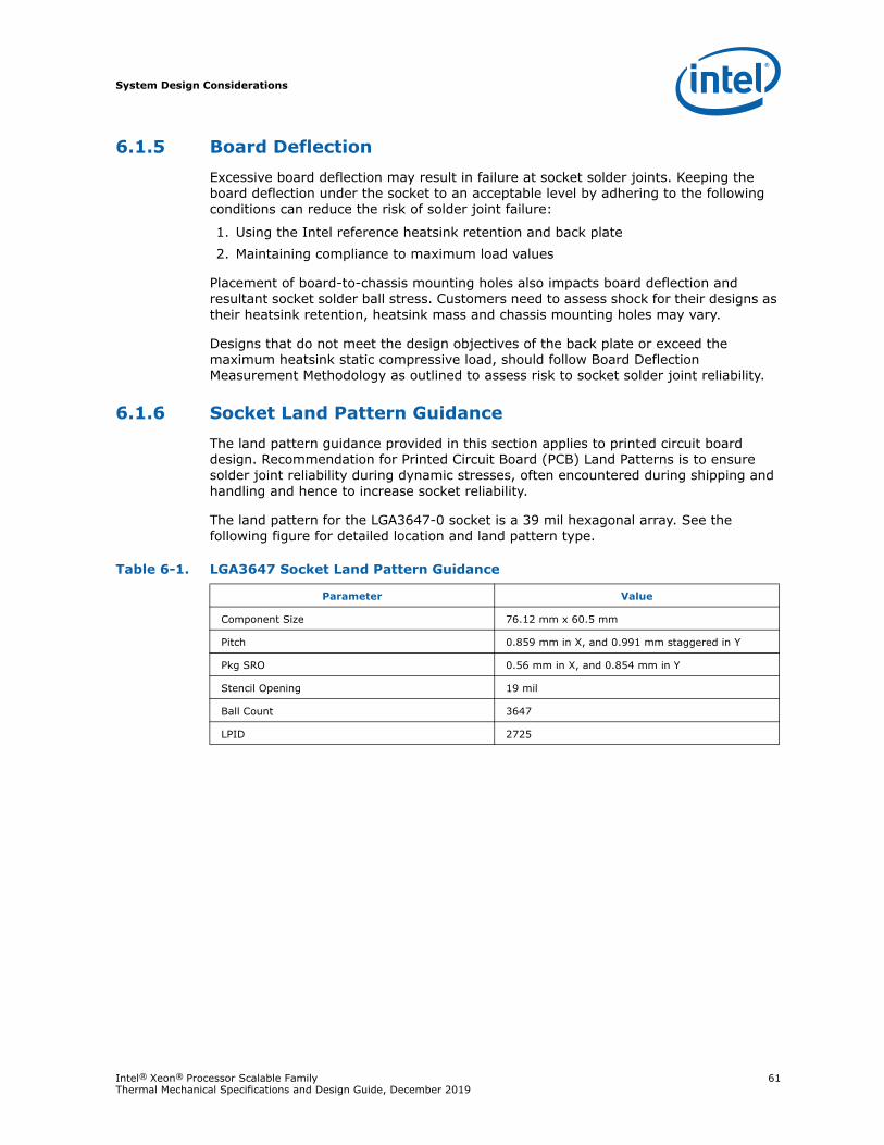
System Design Considerations
Intel® Xeon® Processor Scalable Family 61Thermal Mechanical Specifications and Design Guide, December 2019
6.1.5 Board DeflectionExcessive board deflection may result in failure at socket solder joints. Keeping the board deflection under the socket to an acceptable level by adhering to the following conditions can reduce the risk of solder joint failure:
1. Using the Intel reference heatsink retention and back plate2. Maintaining compliance to maximum load values
Placement of board-to-chassis mounting holes also impacts board deflection and resultant socket solder ball stress. Customers need to assess shock for their designs as their heatsink retention, heatsink mass and chassis mounting holes may vary.
Designs that do not meet the design objectives of the back plate or exceed the maximum heatsink static compressive load, should follow Board Deflection Measurement Methodology as outlined to assess risk to socket solder joint reliability.
6.1.6 Socket Land Pattern GuidanceThe land pattern guidance provided in this section applies to printed circuit board design. Recommendation for Printed Circuit Board (PCB) Land Patterns is to ensure solder joint reliability during dynamic stresses, often encountered during shipping and handling and hence to increase socket reliability.
The land pattern for the LGA3647-0 socket is a 39 mil hexagonal array. See the following figure for detailed location and land pattern type.
Table 6-1. LGA3647 Socket Land Pattern Guidance
Parameter Value
Component Size 76.12 mm x 60.5 mm
Pitch 0.859 mm in X, and 0.991 mm staggered in Y
Pkg SRO 0.56 mm in X, and 0.854 mm in Y
Stencil Opening 19 mil
Ball Count 3647
LPID 2725
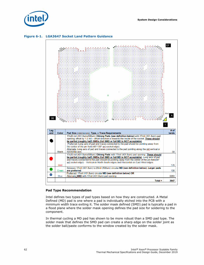
System Design Considerations
62 Intel® Xeon® Processor Scalable Family Thermal Mechanical Specifications and Design Guide, December 2019
Pad Type Recommendation
Intel defines two types of pad types based on how they are constructed. A Metal Defined (MD) pad is one where a pad is individually etched into the PCB with a minimum width trace exiting it. The solder mask defined (SMD) pad is typically a pad in a flood plane where the solder mask opening defines the pad size for soldering to the component.
In thermal cycling a MD pad has shown to be more robust than a SMD pad type. The solder mask that defines the SMD pad can create a sharp edge on the solder joint as the solder ball/paste conforms to the window created by the solder mask.
Figure 6-1. LGA3647 Socket Land Pattern Guidance
1
`
86
EF`
A`
Pin1
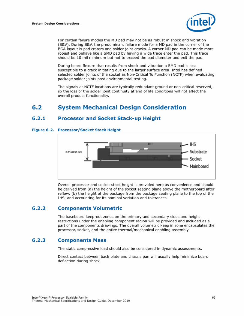
System Design Considerations
Intel® Xeon® Processor Scalable Family 63Thermal Mechanical Specifications and Design Guide, December 2019
For certain failure modes the MD pad may not be as robust in shock and vibration (S&V). During S&V, the predominant failure mode for a MD pad in the corner of the BGA layout is pad craters and solder joint cracks. A corner MD pad can be made more robust and behave like a SMD pad by having a wide trace enter the pad. This trace should be 10 mil minimum but not to exceed the pad diameter and exit the pad.
During board flexure that results from shock and vibration a SMD pad is less susceptible to a crack initiating due to the larger surface area. Intel has defined selected solder joints of the socket as Non-Critical To Function (NCTF) when evaluating package solder joints post environmental testing.
The signals at NCTF locations are typically redundant ground or non-critical reserved, so the loss of the solder joint continuity at end of life conditions will not affect the overall product functionality.
6.2 System Mechanical Design Consideration
6.2.1 Processor and Socket Stack-up Height
Overall processor and socket stack height is provided here as convenience and should be derived from (a) the height of the socket seating plane above the motherboard after reflow, (b) the height of the package from the package seating plane to the top of the IHS, and accounting for its nominal variation and tolerances.
6.2.2 Components VolumetricThe baseboard keep-out zones on the primary and secondary sides and height restrictions under the enabling component region will be provided and included as a part of the components drawings. The overall volumetric keep in zone encapsulates the processor, socket, and the entire thermal/mechanical enabling assembly.
6.2.3 Components MassThe static compressive load should also be considered in dynamic assessments.
Direct contact between back plate and chassis pan will usually help minimize board deflection during shock.
Figure 6-2. Processor/Socket Stack Height
System Design Considerations
64 Intel® Xeon® Processor Scalable Family Thermal Mechanical Specifications and Design Guide, December 2019
6.2.4 Intel Fabric Passive (IFP) Cable IntegrationAn integrated wire latch mechanism on the connector housing is defined to interface with specifically designed features on the bolster plate to lock the LEC54B connector end of the IFP54B cable in place. When in locked position, the mechanism ensures that the connector is always in a fully engaged position against the substrate and that the contact tips are in stable position on the pads such that they don't disengage during servicing. The features on the bolster plate have been designed to work with the connector and latch mechanism designs.
6.3 System Thermal Design Considerations
6.3.1 Ambient Temperature (TLA)The temperature of the inlet air entering the processor is referenced in this document as the ambient temperature (TLA). This is not a system requirement. It is measured from the air upstream and in close vicinity to the processor cooling device. For the cooling systems, the ambient temperature is measured from the inlet air to the cooling device.
6.3.2 AirflowAirflow should be provided by a system fan or blower in order to cool the processor package. Available airflow at the component’s cooling solution, direction, and restrictions through the system should be considered in optimizing the components cooling solution design.
6.3.3 Pressure Drop (Delta P)The allowable pressure drop in the airflow to ensure cooling requirements for the system components at downstream from the processor should be taken into account in designing the processor cooling requirements.
§
Table 6-2. Components Mass
Component Mass Notes
Processor 112 g
Socket including PnP cover 29 g Socket PnP cover mass is 6.5 g;Each socket half including PnP cover mass is 14.5 g
Top Plate Assembly 58 g
Backplate 139 g
Heatsink 600 g Maximum allowable heatsink mass. Actual heatsink mass may vary based on heatsink size and design of the heatsink.
Intel Fabric Cable ---
Thermal Design Guidelines
Intel® Xeon® Processor Scalable Family 65Thermal Mechanical Specifications and Design Guide, December 2019
7 Thermal Design Guidelines
7.1 Heatsink Design ConsiderationsTo remove the heat from the processor, basic thermal design considerations include:
• The area of the surface on which the heat transfer takes place - Without any enhancements, this is the surface of the processor package IHS. One method used to improve thermal performance is to attach a heatsink to the IHS. A heatsink can increase the effective heat transfer surface area by conducting heat out of the IHS and into the surrounding air through fins attached to the heatsink base.
• The conduction path from the heat source to the heatsink fins - Providing a direct conduction path from the heat source to the heatsink fins and selecting materials with higher thermal conductivity typically improves heatsink performance. The length, thickness, and conductivity of the conduction path from the heat source to the fins directly impacts the thermal performance of the heatsink. In particular, the quality of the contact between the package IHS and the heatsink base has a higher impact on the overall thermal solution performance. Thermal Interface Material (TIM) is used to fill in the gap between the IHS and the bottom surface of the heatsink, and thereby improves the overall performance of the thermal stack-up (IHS-TIM-Heatsink). With extremely poor heatsink interface flatness or roughness, TIM may not adequately fill the gap. The TIM thermal performance depends on its thermal conductivity as well as the pressure load applied to it.
• The heat transfer conditions on the surface upon which heat transfer takes place - Convective heat transfer occurs between the airflow and the surface exposed to the flow. It is characterized by the local ambient temperature of the air, TLA, and the local air velocity over the surface. The higher the air velocity over the surface, the more efficient the resulting cooling. The nature of the airflow can also enhance heat transfer via convection. Turbulent flow can provide improvement over laminar flow. In the case of a heatsink, the surface exposed to the flow includes the fin faces and the heatsink base.
An active heatsink typically incorporates a fan that helps manage the airflow through the heatsink.
Passive heatsink solutions require in-depth knowledge of the airflow in the chassis. As the heatsink fin density (the number of fins in a given cross-section) increases, the resistance to the airflow increases; it is more likely that the air will travel around the heatsink instead of through it, unless air bypass is carefully managed. Using air-ducting techniques to manage bypass area is an effective method for maximizing airflow through the heatsink fins.
7.2 Thermal Interface Material (TIM) ConsiderationsThermal interface material between the processor IHS and the heatsink base is necessary to improve thermal conduction from the IHS to the heatsink. Many thermal interface materials can be pre-applied to the heatsink base prior to shipment from the heatsink supplier without the need for a separate TIM dispense or attachment process in the final assembly factory.
All thermal interface materials should be sized and positioned on the heatsink base in a way that ensures that the entire area is covered. It is important to compensate for heatsink-to-processor positional alignment when selecting the proper TIM size.
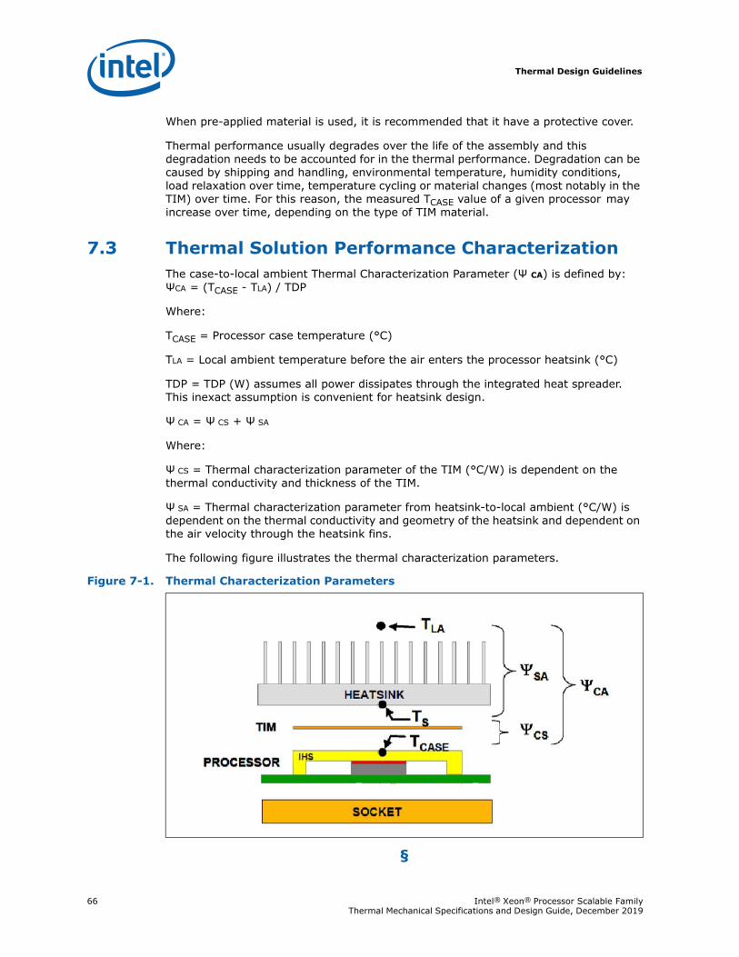
Thermal Design Guidelines
66 Intel® Xeon® Processor Scalable Family Thermal Mechanical Specifications and Design Guide, December 2019
When pre-applied material is used, it is recommended that it have a protective cover.
Thermal performance usually degrades over the life of the assembly and this degradation needs to be accounted for in the thermal performance. Degradation can be caused by shipping and handling, environmental temperature, humidity conditions, load relaxation over time, temperature cycling or material changes (most notably in the TIM) over time. For this reason, the measured TCASE value of a given processor may increase over time, depending on the type of TIM material.
7.3 Thermal Solution Performance CharacterizationThe case-to-local ambient Thermal Characterization Parameter (Ψ CA) is defined by: ΨCA = (TCASE - TLA) / TDP
Where:
TCASE = Processor case temperature (°C)
TLA = Local ambient temperature before the air enters the processor heatsink (°C)
TDP = TDP (W) assumes all power dissipates through the integrated heat spreader. This inexact assumption is convenient for heatsink design.
Ψ CA = Ψ CS + Ψ SA
Where:
Ψ CS = Thermal characterization parameter of the TIM (°C/W) is dependent on the thermal conductivity and thickness of the TIM.
Ψ SA = Thermal characterization parameter from heatsink-to-local ambient (°C/W) is dependent on the thermal conductivity and geometry of the heatsink and dependent on the air velocity through the heatsink fins.
The following figure illustrates the thermal characterization parameters.
§
Figure 7-1. Thermal Characterization Parameters
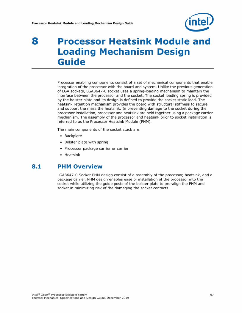
Processor Heatsink Module and Loading Mechanism Design Guide
Intel® Xeon® Processor Scalable Family 67Thermal Mechanical Specifications and Design Guide, December 2019
8 Processor Heatsink Module and Loading Mechanism Design Guide
Processor enabling components consist of a set of mechanical components that enable integration of the processor with the board and system. Unlike the previous generation of LGA sockets, LGA3647-0 socket uses a spring-loading mechanism to maintain the interface between the processor and the socket. The socket loading spring is provided by the bolster plate and its design is defined to provide the socket static load. The heatsink retention mechanism provides the board with structural stiffness to secure and support the mass the heatsink. In preventing damage to the socket during the processor installation, processor and heatsink are held together using a package carrier mechanism. The assembly of the processor and heatsink prior to socket installation is referred to as the Processor Heatsink Module (PHM).
The main components of the socket stack are:
• Backplate
• Bolster plate with spring
• Processor package carrier or carrier
• Heatsink
8.1 PHM OverviewLGA3647-0 Socket PHM design consist of a assembly of the processor, heatsink, and a package carrier. PHM design enables ease of installation of the processor into the socket while utilizing the guide posts of the bolster plate to pre-align the PHM and socket in minimizing risk of the damaging the socket contacts.
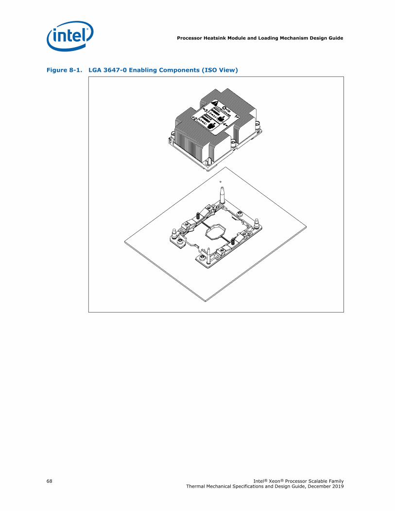
Processor Heatsink Module and Loading Mechanism Design Guide
68 Intel® Xeon® Processor Scalable Family Thermal Mechanical Specifications and Design Guide, December 2019
Figure 8-1. LGA 3647-0 Enabling Components (ISO View)
Processor Heatsink Module and Loading Mechanism Design Guide
Intel® Xeon® Processor Scalable Family 69Thermal Mechanical Specifications and Design Guide, December 2019
8.2 PHM Mechanical Design Considerations and Recommendations
8.3 PHM FeaturesOne of the key feature of the PHM is enabling the integration of the processor and heatsink as a single module. As a module, the PHM assembly acts as the vehicle for installing the processor onto the socket; reducing the risk of damaging the socket contacts.
Bolster plate guide posts serve as the alignment feature between the PHM and socket. Dissimilar posts on the bolster plate are the keying feature between the socket and the PHM that prevents the PHM from engaging with the socket when incorrectly oriented.
Protrusions on four corners of the package on the package carrier provide secondary alignment between the PHM and the socket as they interface with the socket wall exterior. Primary alignment between processor and socket is achieved through socket wall interior by constraining the processor movement.
Figure 8-2. LGA3647-0 Enabling Components (Exploded View)
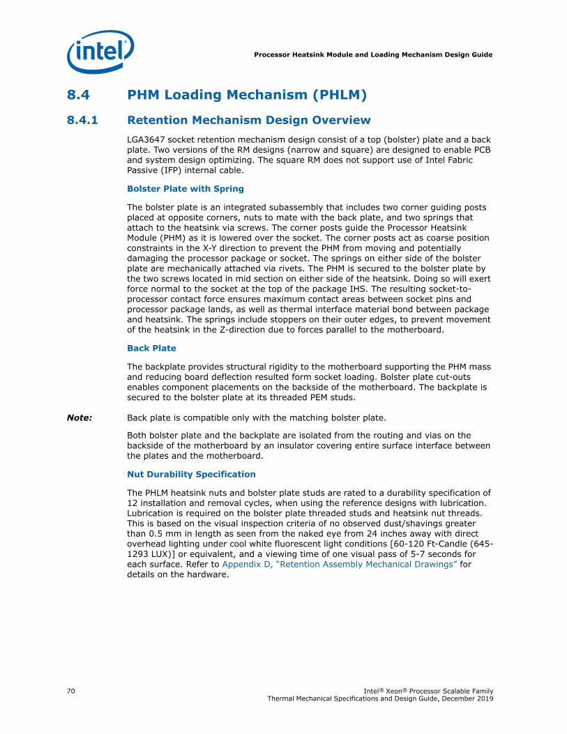
Processor Heatsink Module and Loading Mechanism Design Guide
70 Intel® Xeon® Processor Scalable Family Thermal Mechanical Specifications and Design Guide, December 2019
8.4 PHM Loading Mechanism (PHLM)
8.4.1 Retention Mechanism Design OverviewLGA3647 socket retention mechanism design consist of a top (bolster) plate and a back plate. Two versions of the RM designs (narrow and square) are designed to enable PCB and system design optimizing. The square RM does not support use of Intel Fabric Passive (IFP) internal cable.
Bolster Plate with Spring
The bolster plate is an integrated subassembly that includes two corner guiding posts placed at opposite corners, nuts to mate with the back plate, and two springs that attach to the heatsink via screws. The corner posts guide the Processor Heatsink Module (PHM) as it is lowered over the socket. The corner posts act as coarse position constraints in the X-Y direction to prevent the PHM from moving and potentially damaging the processor package or socket. The springs on either side of the bolster plate are mechanically attached via rivets. The PHM is secured to the bolster plate by the two screws located in mid section on either side of the heatsink. Doing so will exert force normal to the socket at the top of the package IHS. The resulting socket-to-processor contact force ensures maximum contact areas between socket pins and processor package lands, as well as thermal interface material bond between package and heatsink. The springs include stoppers on their outer edges, to prevent movement of the heatsink in the Z-direction due to forces parallel to the motherboard.
Back Plate
The backplate provides structural rigidity to the motherboard supporting the PHM mass and reducing board deflection resulted form socket loading. Bolster plate cut-outs enables component placements on the backside of the motherboard. The backplate is secured to the bolster plate at its threaded PEM studs.
Note: Back plate is compatible only with the matching bolster plate.
Both bolster plate and the backplate are isolated from the routing and vias on the backside of the motherboard by an insulator covering entire surface interface between the plates and the motherboard.
Nut Durability Specification
The PHLM heatsink nuts and bolster plate studs are rated to a durability specification of 12 installation and removal cycles, when using the reference designs with lubrication. Lubrication is required on the bolster plate threaded studs and heatsink nut threads. This is based on the visual inspection criteria of no observed dust/shavings greater than 0.5 mm in length as seen from the naked eye from 24 inches away with direct overhead lighting under cool white fluorescent light conditions [60-120 Ft-Candle (645-1293 LUX)] or equivalent, and a viewing time of one visual pass of 5-7 seconds for each surface. Refer to Appendix D, “Retention Assembly Mechanical Drawings” for details on the hardware.
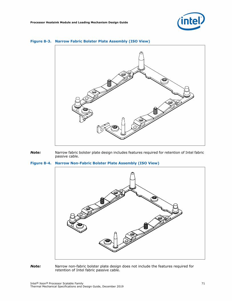
Processor Heatsink Module and Loading Mechanism Design Guide
Intel® Xeon® Processor Scalable Family 71Thermal Mechanical Specifications and Design Guide, December 2019
Note: Narrow fabric bolster plate design includes features required for retention of Intel fabric passive cable.
Note: Narrow non-fabric bolster plate design does not include the features required for retention of Intel fabric passive cable.
Figure 8-3. Narrow Fabric Bolster Plate Assembly (ISO View)
Figure 8-4. Narrow Non-Fabric Bolster Plate Assembly (ISO View)
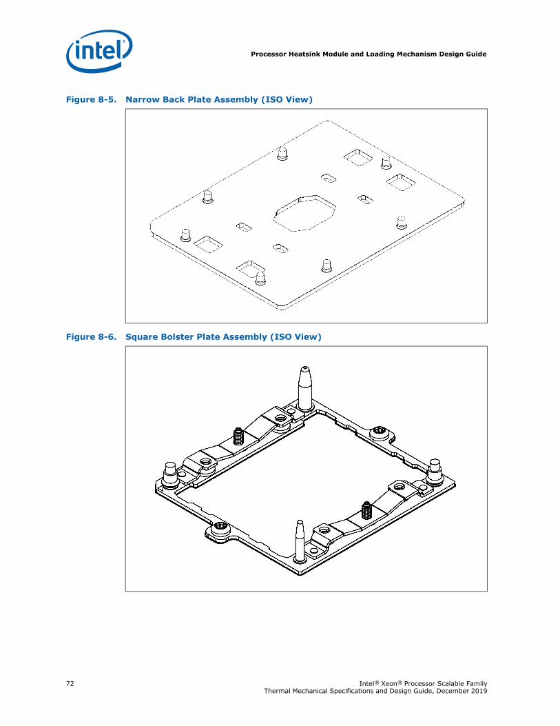
Processor Heatsink Module and Loading Mechanism Design Guide
72 Intel® Xeon® Processor Scalable Family Thermal Mechanical Specifications and Design Guide, December 2019
Figure 8-5. Narrow Back Plate Assembly (ISO View)
Figure 8-6. Square Bolster Plate Assembly (ISO View)
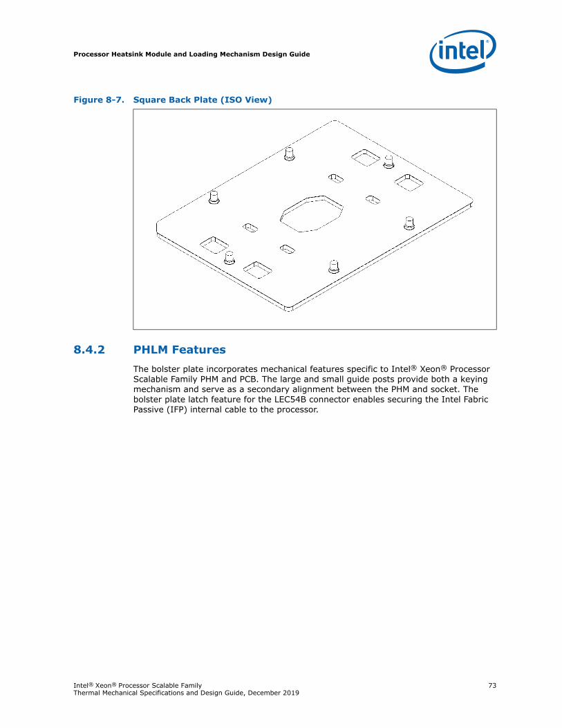
Processor Heatsink Module and Loading Mechanism Design Guide
Intel® Xeon® Processor Scalable Family 73Thermal Mechanical Specifications and Design Guide, December 2019
8.4.2 PHLM FeaturesThe bolster plate incorporates mechanical features specific to Intel® Xeon® Processor Scalable Family PHM and PCB. The large and small guide posts provide both a keying mechanism and serve as a secondary alignment between the PHM and socket. The bolster plate latch feature for the LEC54B connector enables securing the Intel Fabric Passive (IFP) internal cable to the processor.
Figure 8-7. Square Back Plate (ISO View)
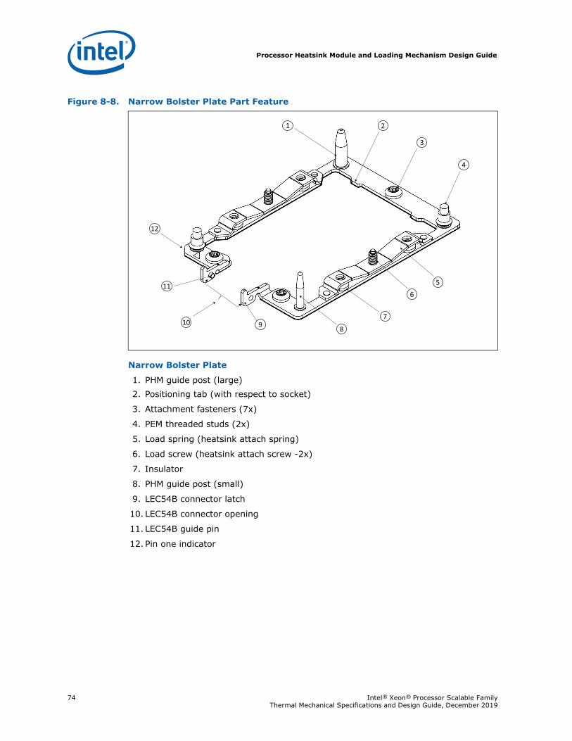
Processor Heatsink Module and Loading Mechanism Design Guide
74 Intel® Xeon® Processor Scalable Family Thermal Mechanical Specifications and Design Guide, December 2019
Narrow Bolster Plate
1. PHM guide post (large)2. Positioning tab (with respect to socket)
3. Attachment fasteners (7x)
4. PEM threaded studs (2x)
5. Load spring (heatsink attach spring)
6. Load screw (heatsink attach screw -2x)
7. Insulator
8. PHM guide post (small)
9. LEC54B connector latch
10. LEC54B connector opening
11. LEC54B guide pin
12. Pin one indicator
Figure 8-8. Narrow Bolster Plate Part Feature
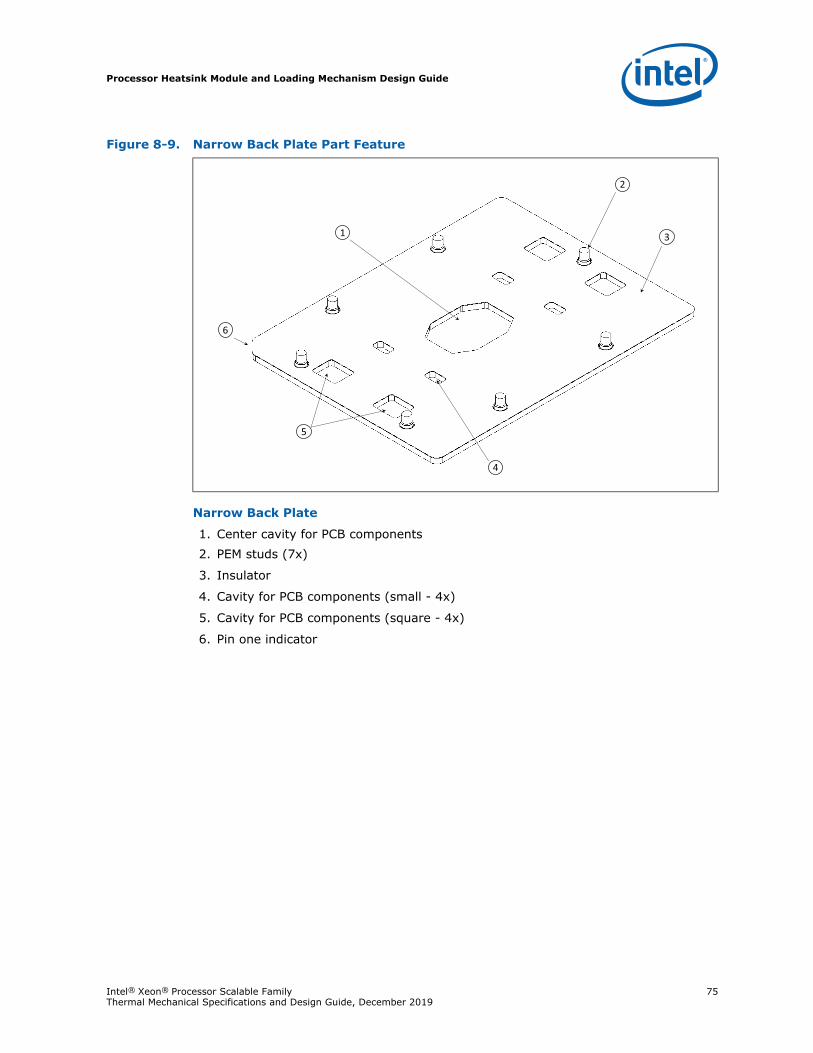
Processor Heatsink Module and Loading Mechanism Design Guide
Intel® Xeon® Processor Scalable Family 75Thermal Mechanical Specifications and Design Guide, December 2019
Narrow Back Plate
1. Center cavity for PCB components2. PEM studs (7x)
3. Insulator
4. Cavity for PCB components (small - 4x)
5. Cavity for PCB components (square - 4x)
6. Pin one indicator
Figure 8-9. Narrow Back Plate Part Feature
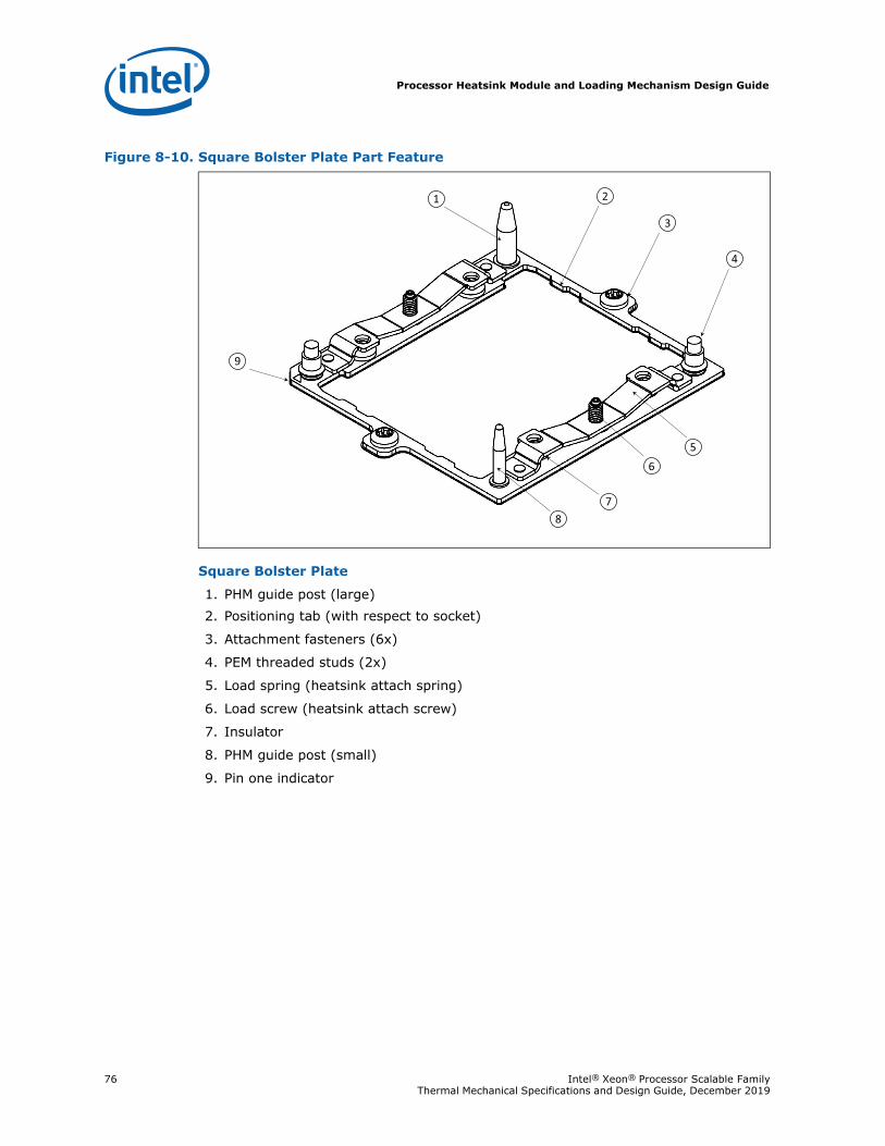
Processor Heatsink Module and Loading Mechanism Design Guide
76 Intel® Xeon® Processor Scalable Family Thermal Mechanical Specifications and Design Guide, December 2019
Square Bolster Plate
1. PHM guide post (large)2. Positioning tab (with respect to socket)
3. Attachment fasteners (6x)
4. PEM threaded studs (2x)
5. Load spring (heatsink attach spring)
6. Load screw (heatsink attach screw)
7. Insulator
8. PHM guide post (small)
9. Pin one indicator
Figure 8-10. Square Bolster Plate Part Feature
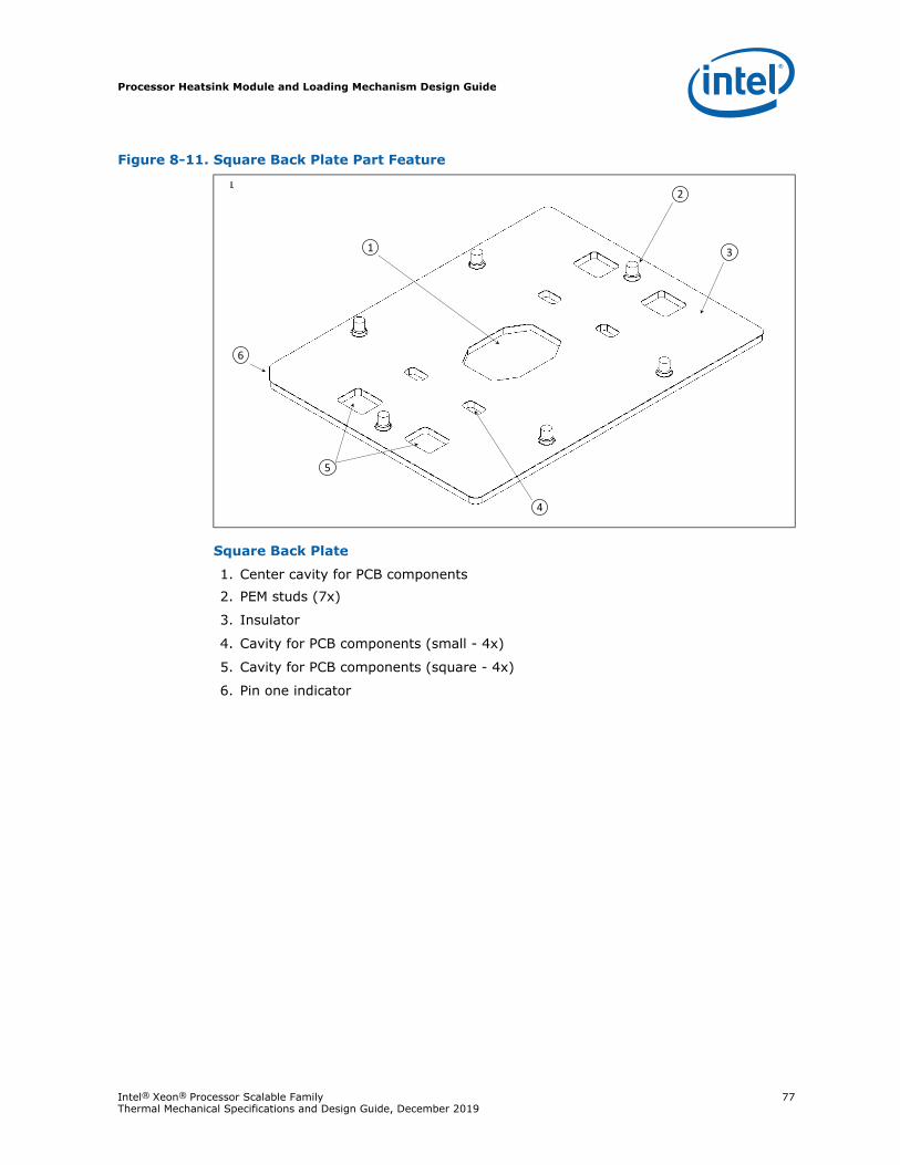
Processor Heatsink Module and Loading Mechanism Design Guide
Intel® Xeon® Processor Scalable Family 77Thermal Mechanical Specifications and Design Guide, December 2019
Square Back Plate
1. Center cavity for PCB components2. PEM studs (7x)
3. Insulator
4. Cavity for PCB components (small - 4x)
5. Cavity for PCB components (square - 4x)
6. Pin one indicator
Figure 8-11. Square Back Plate Part Feature
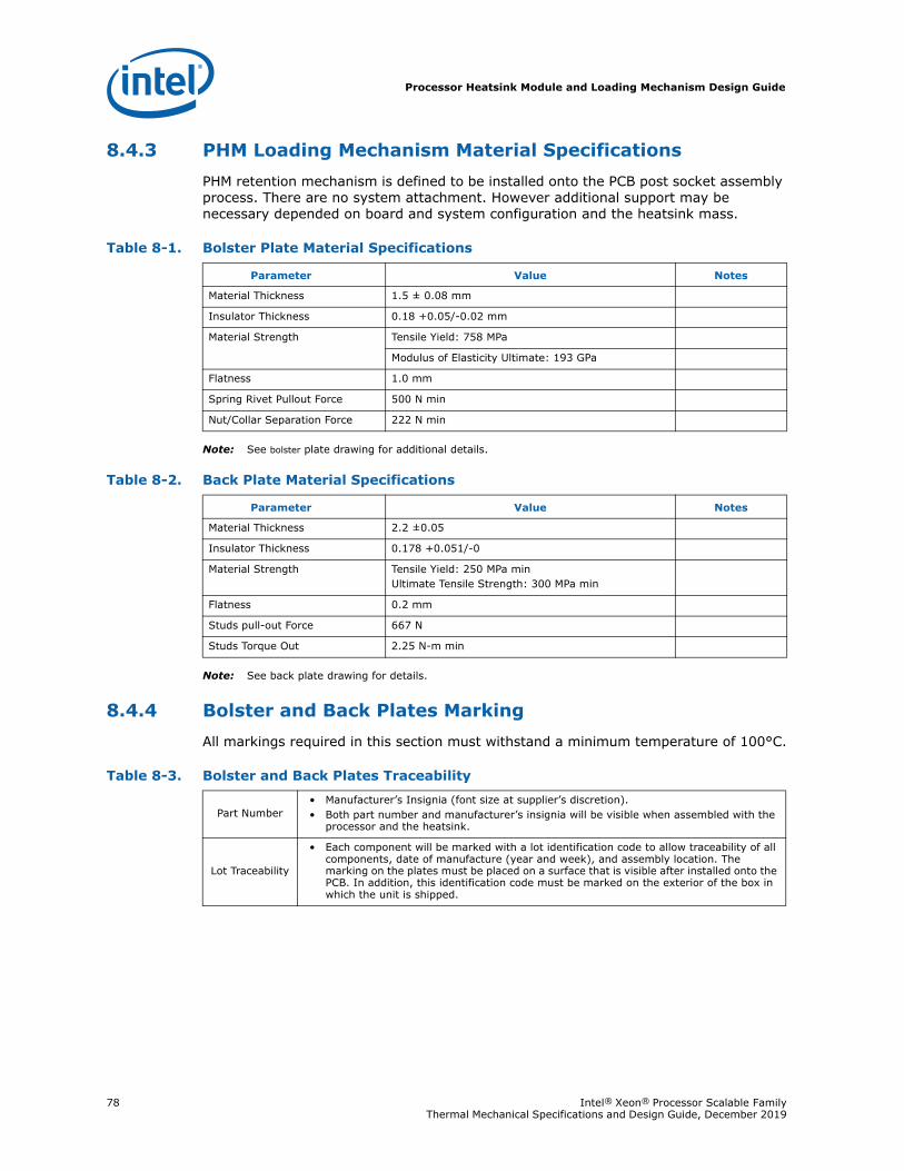
Processor Heatsink Module and Loading Mechanism Design Guide
78 Intel® Xeon® Processor Scalable Family Thermal Mechanical Specifications and Design Guide, December 2019
8.4.3 PHM Loading Mechanism Material SpecificationsPHM retention mechanism is defined to be installed onto the PCB post socket assembly process. There are no system attachment. However additional support may be necessary depended on board and system configuration and the heatsink mass.
Note: See bolster plate drawing for additional details.
Note: See back plate drawing for details.
8.4.4 Bolster and Back Plates MarkingAll markings required in this section must withstand a minimum temperature of 100°C.
Table 8-1. Bolster Plate Material Specifications
Parameter Value Notes
Material Thickness 1.5 ± 0.08 mm
Insulator Thickness 0.18 +0.05/-0.02 mm
Material Strength Tensile Yield: 758 MPa
Modulus of Elasticity Ultimate: 193 GPa
Flatness 1.0 mm
Spring Rivet Pullout Force 500 N min
Nut/Collar Separation Force 222 N min
Table 8-2. Back Plate Material Specifications
Parameter Value Notes
Material Thickness 2.2 ±0.05
Insulator Thickness 0.178 +0.051/-0
Material Strength Tensile Yield: 250 MPa minUltimate Tensile Strength: 300 MPa min
Flatness 0.2 mm
Studs pull-out Force 667 N
Studs Torque Out 2.25 N-m min
Table 8-3. Bolster and Back Plates Traceability
Part Number• Manufacturer’s Insignia (font size at supplier’s discretion).• Both part number and manufacturer’s insignia will be visible when assembled with the
processor and the heatsink.
Lot Traceability
• Each component will be marked with a lot identification code to allow traceability of all components, date of manufacture (year and week), and assembly location. The marking on the plates must be placed on a surface that is visible after installed onto the PCB. In addition, this identification code must be marked on the exterior of the box in which the unit is shipped.
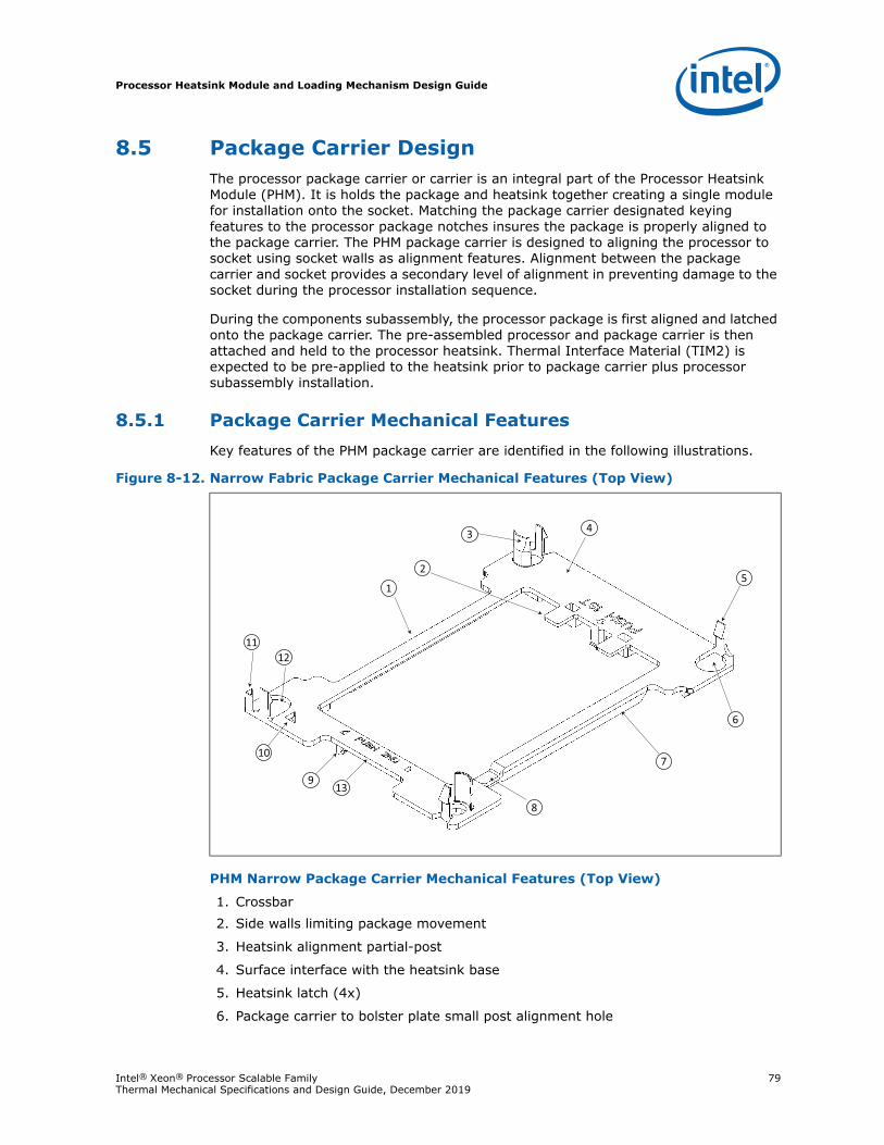
Processor Heatsink Module and Loading Mechanism Design Guide
Intel® Xeon® Processor Scalable Family 79Thermal Mechanical Specifications and Design Guide, December 2019
8.5 Package Carrier DesignThe processor package carrier or carrier is an integral part of the Processor Heatsink Module (PHM). It is holds the package and heatsink together creating a single module for installation onto the socket. Matching the package carrier designated keying features to the processor package notches insures the package is properly aligned to the package carrier. The PHM package carrier is designed to aligning the processor to socket using socket walls as alignment features. Alignment between the package carrier and socket provides a secondary level of alignment in preventing damage to the socket during the processor installation sequence.
During the components subassembly, the processor package is first aligned and latched onto the package carrier. The pre-assembled processor and package carrier is then attached and held to the processor heatsink. Thermal Interface Material (TIM2) is expected to be pre-applied to the heatsink prior to package carrier plus processor subassembly installation.
8.5.1 Package Carrier Mechanical FeaturesKey features of the PHM package carrier are identified in the following illustrations.
PHM Narrow Package Carrier Mechanical Features (Top View)
1. Crossbar2. Side walls limiting package movement
3. Heatsink alignment partial-post
4. Surface interface with the heatsink base
5. Heatsink latch (4x)
6. Package carrier to bolster plate small post alignment hole
Figure 8-12. Narrow Fabric Package Carrier Mechanical Features (Top View)
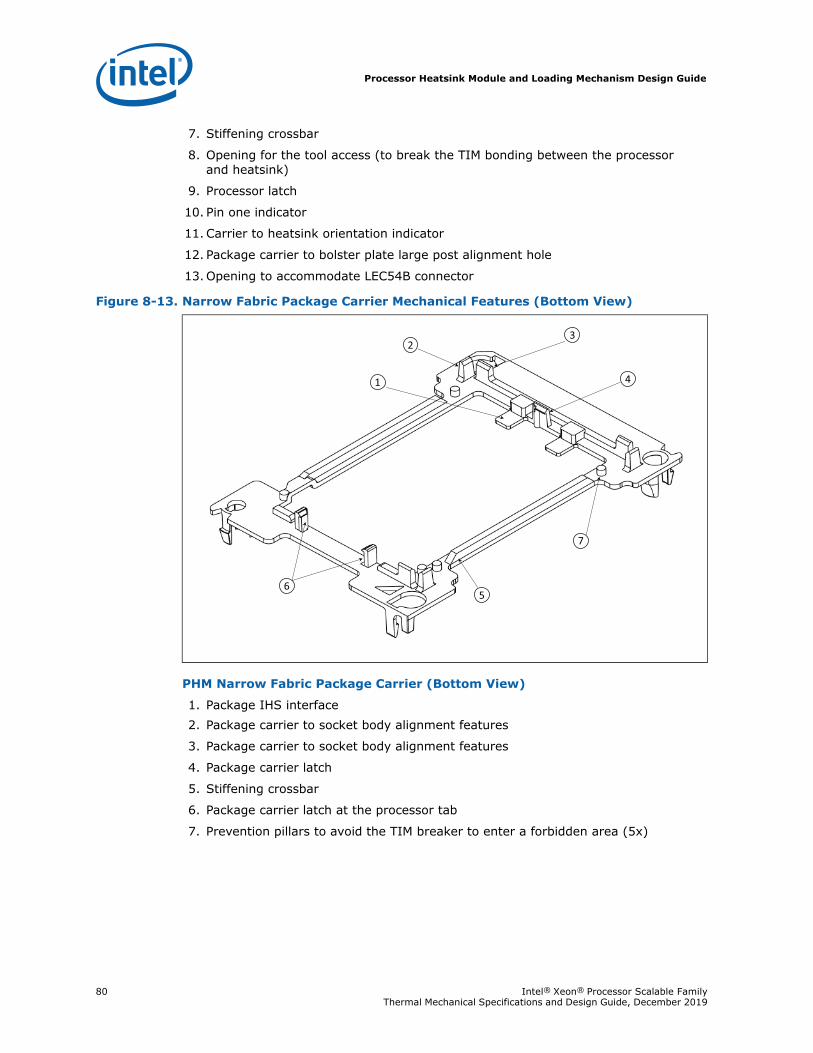
Processor Heatsink Module and Loading Mechanism Design Guide
80 Intel® Xeon® Processor Scalable Family Thermal Mechanical Specifications and Design Guide, December 2019
7. Stiffening crossbar
8. Opening for the tool access (to break the TIM bonding between the processor and heatsink)
9. Processor latch
10. Pin one indicator
11. Carrier to heatsink orientation indicator
12. Package carrier to bolster plate large post alignment hole
13. Opening to accommodate LEC54B connector
PHM Narrow Fabric Package Carrier (Bottom View)
1. Package IHS interface 2. Package carrier to socket body alignment features
3. Package carrier to socket body alignment features
4. Package carrier latch
5. Stiffening crossbar
6. Package carrier latch at the processor tab
7. Prevention pillars to avoid the TIM breaker to enter a forbidden area (5x)
Figure 8-13. Narrow Fabric Package Carrier Mechanical Features (Bottom View)
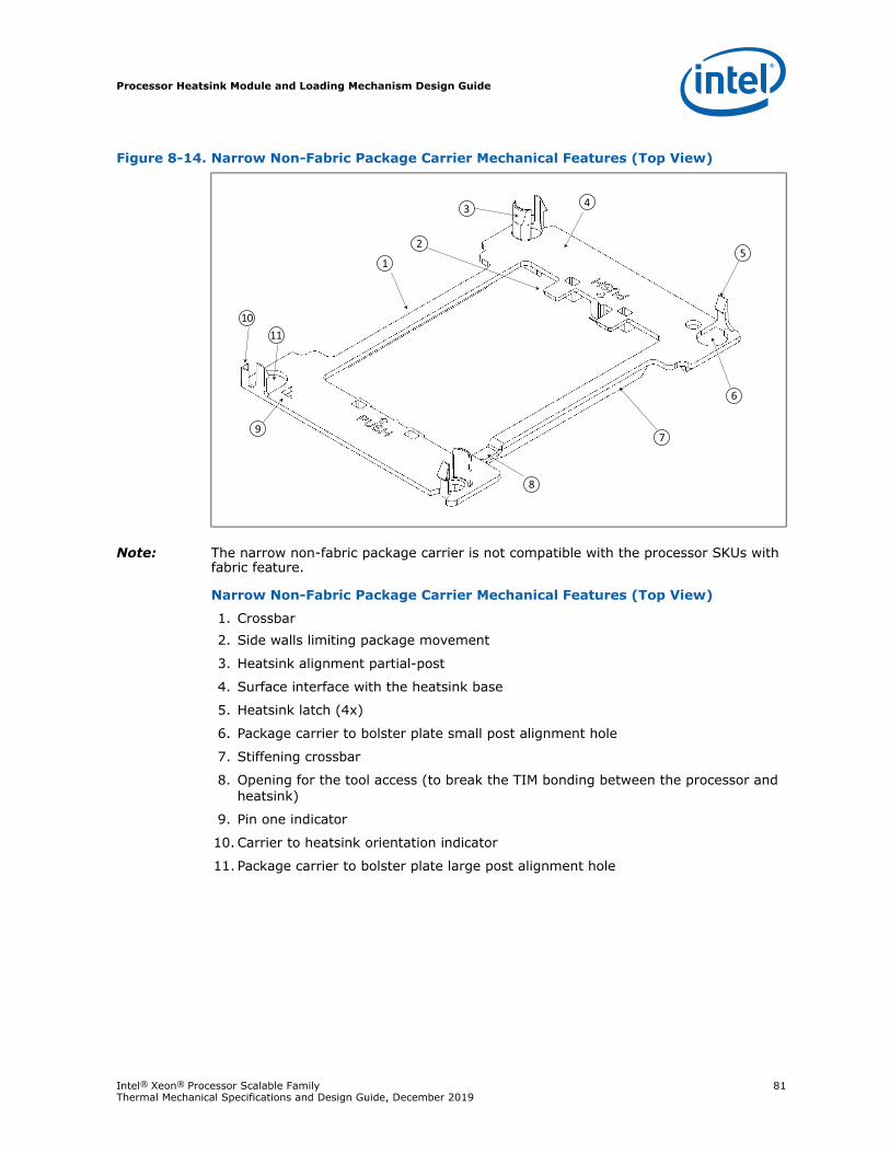
Processor Heatsink Module and Loading Mechanism Design Guide
Intel® Xeon® Processor Scalable Family 81Thermal Mechanical Specifications and Design Guide, December 2019
Note: The narrow non-fabric package carrier is not compatible with the processor SKUs with fabric feature.
Narrow Non-Fabric Package Carrier Mechanical Features (Top View)
1. Crossbar2. Side walls limiting package movement
3. Heatsink alignment partial-post
4. Surface interface with the heatsink base
5. Heatsink latch (4x)
6. Package carrier to bolster plate small post alignment hole
7. Stiffening crossbar
8. Opening for the tool access (to break the TIM bonding between the processor and heatsink)
9. Pin one indicator
10. Carrier to heatsink orientation indicator
11. Package carrier to bolster plate large post alignment hole
Figure 8-14. Narrow Non-Fabric Package Carrier Mechanical Features (Top View)
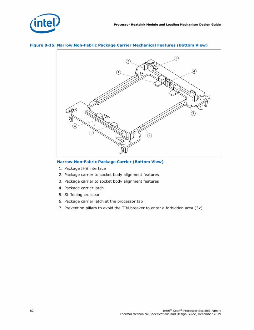
Processor Heatsink Module and Loading Mechanism Design Guide
82 Intel® Xeon® Processor Scalable Family Thermal Mechanical Specifications and Design Guide, December 2019
Narrow Non-Fabric Package Carrier (Bottom View)
1. Package IHS interface 2. Package carrier to socket body alignment features
3. Package carrier to socket body alignment features
4. Package carrier latch
5. Stiffening crossbar
6. Package carrier latch at the processor tab
7. Prevention pillars to avoid the TIM breaker to enter a forbidden area (3x)
Figure 8-15. Narrow Non-Fabric Package Carrier Mechanical Features (Bottom View)
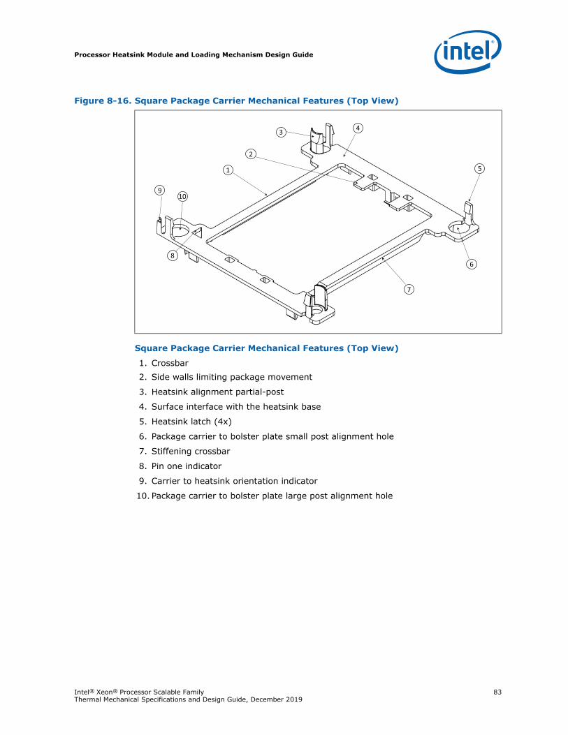
Processor Heatsink Module and Loading Mechanism Design Guide
Intel® Xeon® Processor Scalable Family 83Thermal Mechanical Specifications and Design Guide, December 2019
Square Package Carrier Mechanical Features (Top View)
1. Crossbar2. Side walls limiting package movement
3. Heatsink alignment partial-post
4. Surface interface with the heatsink base
5. Heatsink latch (4x)
6. Package carrier to bolster plate small post alignment hole
7. Stiffening crossbar
8. Pin one indicator
9. Carrier to heatsink orientation indicator
10. Package carrier to bolster plate large post alignment hole
Figure 8-16. Square Package Carrier Mechanical Features (Top View)
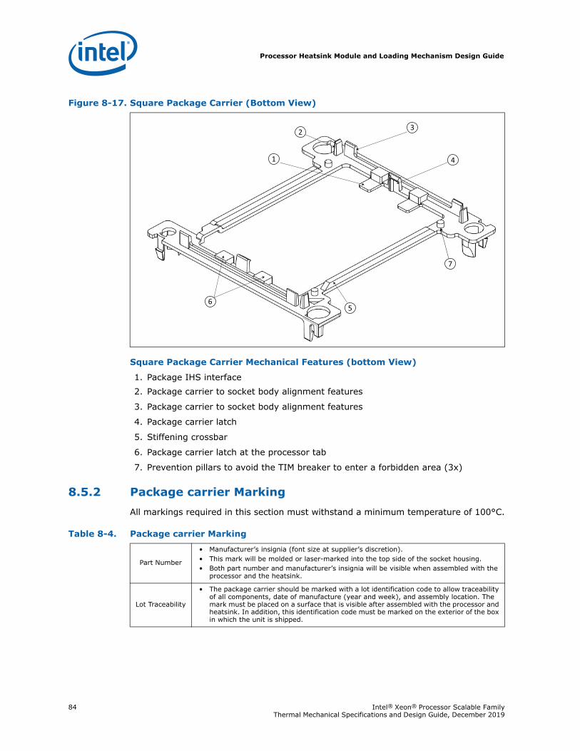
Processor Heatsink Module and Loading Mechanism Design Guide
84 Intel® Xeon® Processor Scalable Family Thermal Mechanical Specifications and Design Guide, December 2019
Square Package Carrier Mechanical Features (bottom View)
1. Package IHS interface 2. Package carrier to socket body alignment features
3. Package carrier to socket body alignment features
4. Package carrier latch
5. Stiffening crossbar
6. Package carrier latch at the processor tab
7. Prevention pillars to avoid the TIM breaker to enter a forbidden area (3x)
8.5.2 Package carrier MarkingAll markings required in this section must withstand a minimum temperature of 100°C.
Figure 8-17. Square Package Carrier (Bottom View)
Table 8-4. Package carrier Marking
Part Number
• Manufacturer’s insignia (font size at supplier’s discretion).• This mark will be molded or laser-marked into the top side of the socket housing.• Both part number and manufacturer’s insignia will be visible when assembled with the
processor and the heatsink.
Lot Traceability
• The package carrier should be marked with a lot identification code to allow traceability of all components, date of manufacture (year and week), and assembly location. The mark must be placed on a surface that is visible after assembled with the processor and heatsink. In addition, this identification code must be marked on the exterior of the box in which the unit is shipped.
Processor Heatsink Module and Loading Mechanism Design Guide
Intel® Xeon® Processor Scalable Family 85Thermal Mechanical Specifications and Design Guide, December 2019
8.5.3 Package Carrier Material Specifications
8.5.4 Package Carrier DurabilityPackage carrier must withstand 10 number of attachment/removal cycles. Attachment cycle defined as one time attachment of the carrier to the processor package and heatsink. Removal cycle is defined as separating the carrier from the processor and heatsink one time.
Package carrier must also withstand 10 number of socket installation/removal cycles. Installation and removal cycle is defined as installing the PHM onto the socket, securing it, un-securing the PHM, and disengaging the PHM from the socket.
8.6 PHM HeatsinkThe processor requires a heatsink to remove the heat dissipated at the processor package IHS and to maintain the processor die temperature within its operating temperature. The PHM heatsink design serves a dual purpose. One is to remove the heat from the processor. The other is to apply the required loading to actuate the LGA3647 socket and to apply a sufficient amount of pressure to maintain the bond between the TIM2, the heatsink pedestal, and the processor IHS.
Processor heatsink performance is dependent on the thermal environment it is in, such as inlet air temperature and flow rate, and applied heatsink design technology. The heatsink thermal characteristics within a defined set of thermal boundary conditions must meet the processor thermal specifications for the processor to achieve its optimum performance.
The processor heatsink is designed to interface with the PHM package carrier and the socket retention mechanism. Mechanical features at the base of the heatsink enable the PHM to latch on and hold together the processor and the heatsink. Retention mechanism standoffs provide alignment and orientation with respect to the socket.
Table 8-5. Package Carrier Material Specifications
Parameter Value Note
Type PC-ABS Recommended
Flammability UL Flammability rating 94-V0 Required
Withstand Temperature 120 °C min. Required
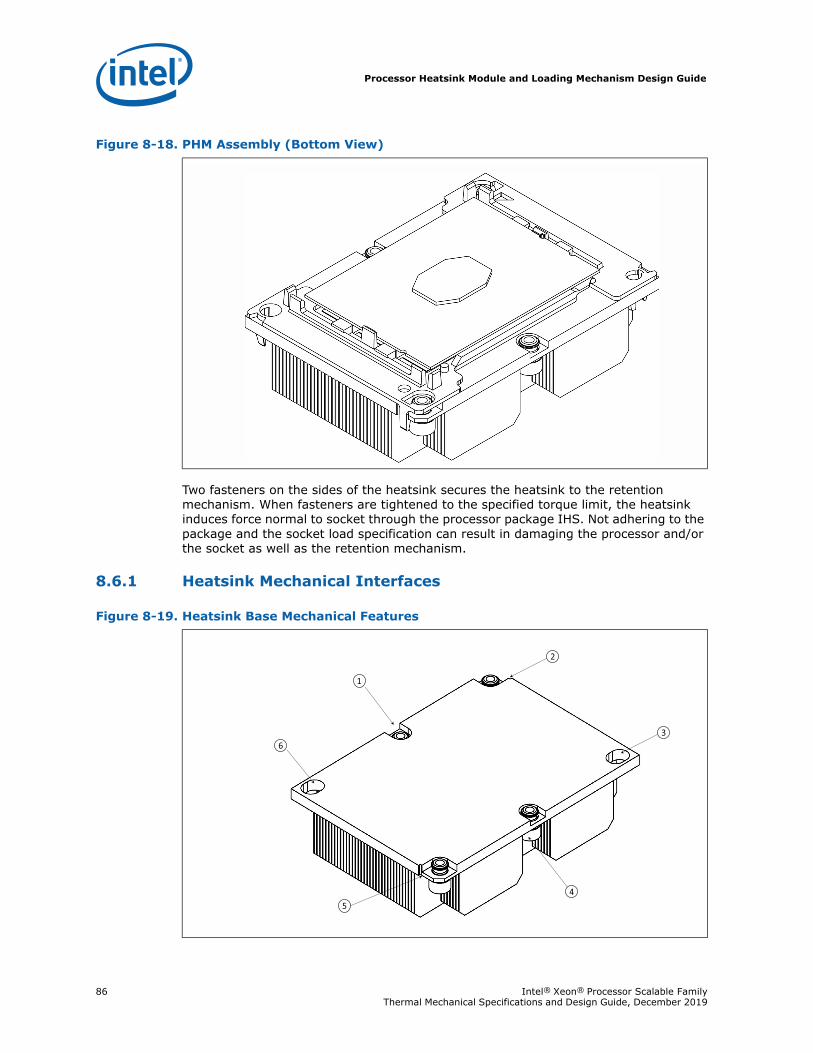
Processor Heatsink Module and Loading Mechanism Design Guide
86 Intel® Xeon® Processor Scalable Family Thermal Mechanical Specifications and Design Guide, December 2019
Two fasteners on the sides of the heatsink secures the heatsink to the retention mechanism. When fasteners are tightened to the specified torque limit, the heatsink induces force normal to socket through the processor package IHS. Not adhering to the package and the socket load specification can result in damaging the processor and/or the socket as well as the retention mechanism.
8.6.1 Heatsink Mechanical Interfaces
Figure 8-18. PHM Assembly (Bottom View)
Figure 8-19. Heatsink Base Mechanical Features
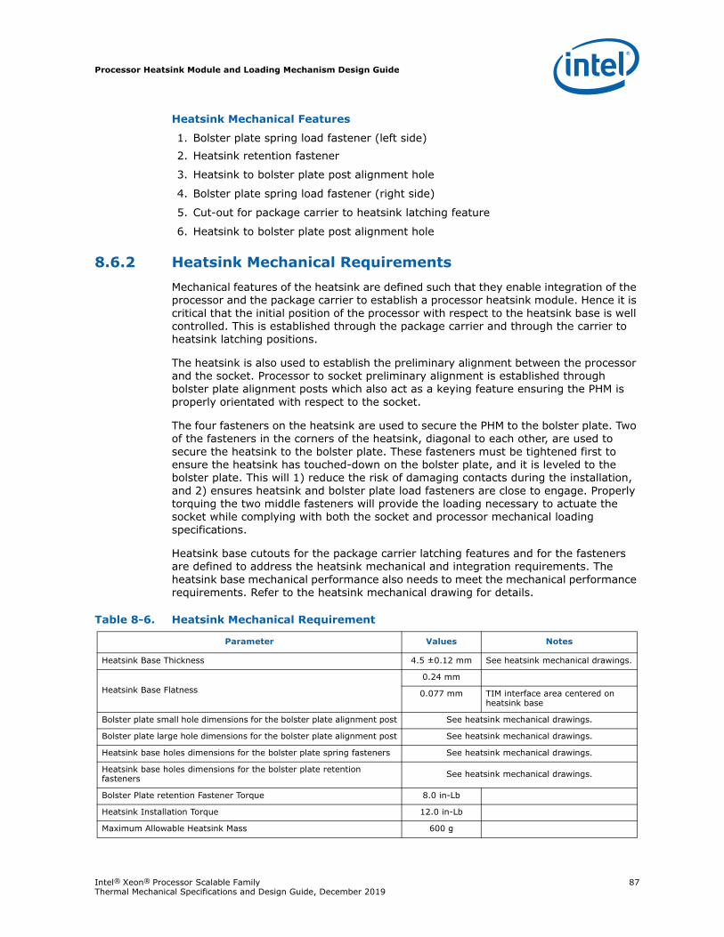
Processor Heatsink Module and Loading Mechanism Design Guide
Intel® Xeon® Processor Scalable Family 87Thermal Mechanical Specifications and Design Guide, December 2019
Heatsink Mechanical Features
1. Bolster plate spring load fastener (left side)2. Heatsink retention fastener
3. Heatsink to bolster plate post alignment hole
4. Bolster plate spring load fastener (right side)
5. Cut-out for package carrier to heatsink latching feature
6. Heatsink to bolster plate post alignment hole
8.6.2 Heatsink Mechanical Requirements Mechanical features of the heatsink are defined such that they enable integration of the processor and the package carrier to establish a processor heatsink module. Hence it is critical that the initial position of the processor with respect to the heatsink base is well controlled. This is established through the package carrier and through the carrier to heatsink latching positions.
The heatsink is also used to establish the preliminary alignment between the processor and the socket. Processor to socket preliminary alignment is established through bolster plate alignment posts which also act as a keying feature ensuring the PHM is properly orientated with respect to the socket.
The four fasteners on the heatsink are used to secure the PHM to the bolster plate. Two of the fasteners in the corners of the heatsink, diagonal to each other, are used to secure the heatsink to the bolster plate. These fasteners must be tightened first to ensure the heatsink has touched-down on the bolster plate, and it is leveled to the bolster plate. This will 1) reduce the risk of damaging contacts during the installation, and 2) ensures heatsink and bolster plate load fasteners are close to engage. Properly torquing the two middle fasteners will provide the loading necessary to actuate the socket while complying with both the socket and processor mechanical loading specifications.
Heatsink base cutouts for the package carrier latching features and for the fasteners are defined to address the heatsink mechanical and integration requirements. The heatsink base mechanical performance also needs to meet the mechanical performance requirements. Refer to the heatsink mechanical drawing for details.
Table 8-6. Heatsink Mechanical Requirement
Parameter Values Notes
Heatsink Base Thickness 4.5 ±0.12 mm See heatsink mechanical drawings.
Heatsink Base Flatness0.24 mm
0.077 mm TIM interface area centered on heatsink base
Bolster plate small hole dimensions for the bolster plate alignment post See heatsink mechanical drawings.
Bolster plate large hole dimensions for the bolster plate alignment post See heatsink mechanical drawings.
Heatsink base holes dimensions for the bolster plate spring fasteners See heatsink mechanical drawings.
Heatsink base holes dimensions for the bolster plate retention fasteners See heatsink mechanical drawings.
Bolster Plate retention Fastener Torque 8.0 in-Lb
Heatsink Installation Torque 12.0 in-Lb
Maximum Allowable Heatsink Mass 600 g

Processor Heatsink Module and Loading Mechanism Design Guide
88 Intel® Xeon® Processor Scalable Family Thermal Mechanical Specifications and Design Guide, December 2019
Note: This stiffness guidance is related to socket reliability, not thermal performance. Any potential thermal impact due to heatsink base deflection at lower stiffness levels needs to be determined separately.
§
Component Assembly Instructions
Intel® Xeon® Processor Scalable Family 89Thermal Mechanical Specifications and Design Guide, December 2019
9 Component Assembly Instructions
Reference enabling components are designed for compatibility with the Intel® Xeon® Processor Scalable Family package and to ease board and system assembly. The processor enabling solution is illustrated in Figure 9-1, “Processor and Enabling Components Mechanical Assembly” on page 91. The method of installing the processor onto the motherboard is to assemble the processor and its enabling solution prior to installation onto a board. This will allow the processor and its cooling solution to be assembled offline and delivered to the board or the system assembly site. This method is commonly referred to as the pre-attach method. In this section pre-assembling the processor and the heatsink as a module (PHM) and its installation onto the motherboard will be described. It should be noted that without the processor package carrier, there is no control mechanism to secure the processor to the heatsink or align the module to the socket.
The processor and its enabling components assembly are divided into three areas. First is the top and bottom plate installation onto the motherboard. Second is the processor, and its cooling solution assembly. Last is the processor installation onto the socket and securing the assembly to the board.
Instructions provided hereon are an overview of the components assembly and installation onto a board or a system.
9.1 Processor Enabling ComponentsProcessor enabling components consist of a set of components that enable integration of the processor with the board and system. Processor enabling components are listed in Table 9-1, “LGA3647-0 Components Listing and Compatibility” and are illustrated in n Figure 9-1, “Processor and Enabling Components Mechanical Assembly” on page 91. Note that n Figure 9-1, “Processor and Enabling Components Mechanical Assembly” on page 91 illustrates the components in support of a processor with fabric; however, a similar assembly sequence applies to components supporting a processor without fabric.
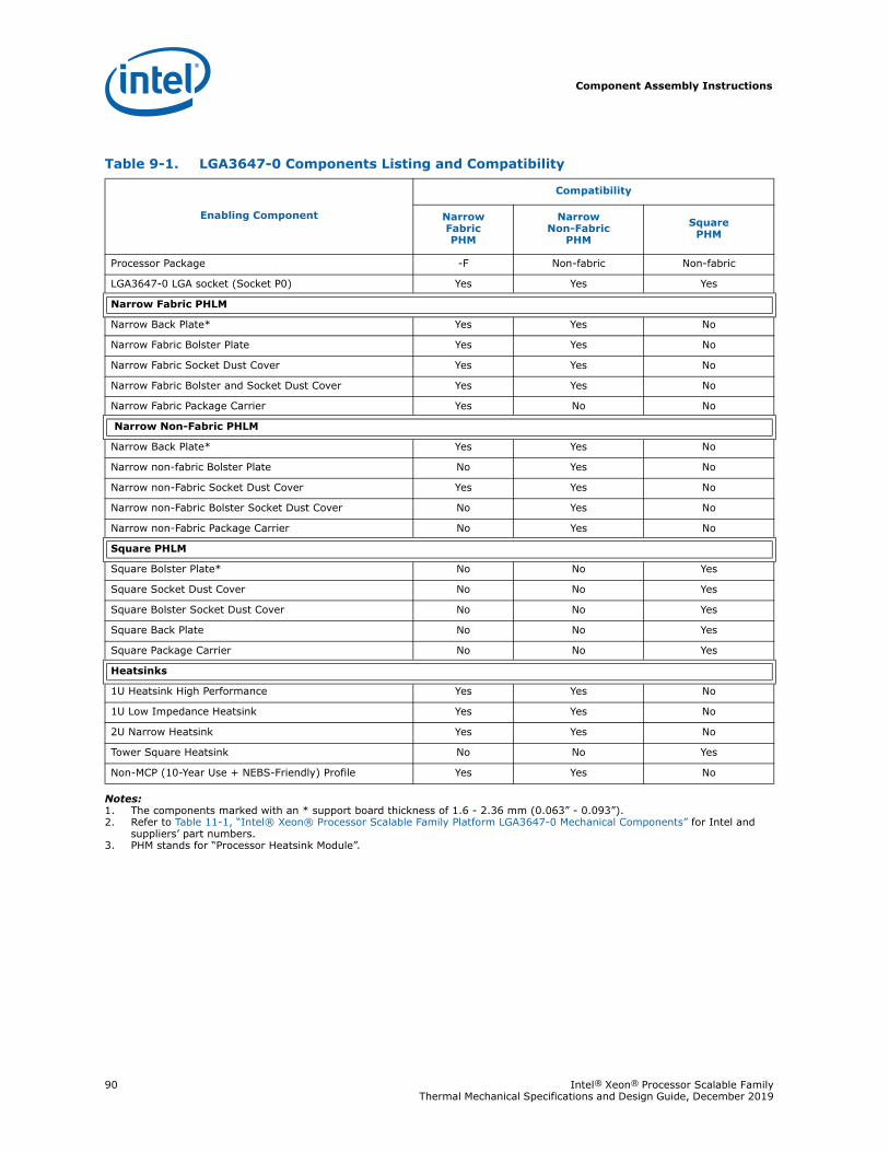
Component Assembly Instructions
90 Intel® Xeon® Processor Scalable Family Thermal Mechanical Specifications and Design Guide, December 2019
Notes:1. The components marked with an * support board thickness of 1.6 - 2.36 mm (0.063” - 0.093”).2. Refer to Table 11-1, “Intel® Xeon® Processor Scalable Family Platform LGA3647-0 Mechanical Components” for Intel and
suppliers’ part numbers.3. PHM stands for “Processor Heatsink Module”.
Table 9-1. LGA3647-0 Components Listing and Compatibility
Enabling Component
Compatibility
Narrow FabricPHM
Narrow Non-Fabric
PHM
Square PHM
Processor Package -F Non-fabric Non-fabric
LGA3647-0 LGA socket (Socket P0) Yes Yes Yes
Narrow Fabric PHLM
Narrow Back Plate* Yes Yes No
Narrow Fabric Bolster Plate Yes Yes No
Narrow Fabric Socket Dust Cover Yes Yes No
Narrow Fabric Bolster and Socket Dust Cover Yes Yes No
Narrow Fabric Package Carrier Yes No No
Narrow Non-Fabric PHLM
Narrow Back Plate* Yes Yes No
Narrow non-fabric Bolster Plate No Yes No
Narrow non-Fabric Socket Dust Cover Yes Yes No
Narrow non-Fabric Bolster Socket Dust Cover No Yes No
Narrow non-Fabric Package Carrier No Yes No
Square PHLM
Square Bolster Plate* No No Yes
Square Socket Dust Cover No No Yes
Square Bolster Socket Dust Cover No No Yes
Square Back Plate No No Yes
Square Package Carrier No No Yes
Heatsinks
1U Heatsink High Performance Yes Yes No
1U Low Impedance Heatsink Yes Yes No
2U Narrow Heatsink Yes Yes No
Tower Square Heatsink No No Yes
Non-MCP (10-Year Use + NEBS-Friendly) Profile Yes Yes No
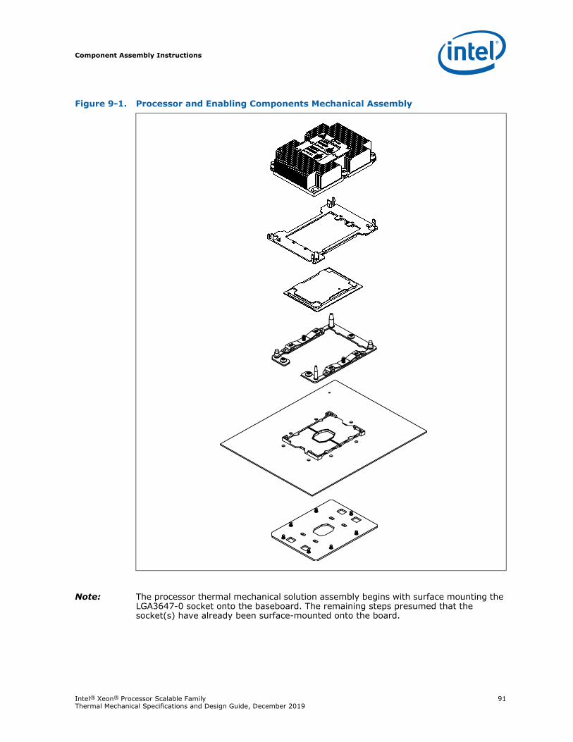
Component Assembly Instructions
Intel® Xeon® Processor Scalable Family 91Thermal Mechanical Specifications and Design Guide, December 2019
Note: The processor thermal mechanical solution assembly begins with surface mounting the LGA3647-0 socket onto the baseboard. The remaining steps presumed that the socket(s) have already been surface-mounted onto the board.
Figure 9-1. Processor and Enabling Components Mechanical Assembly
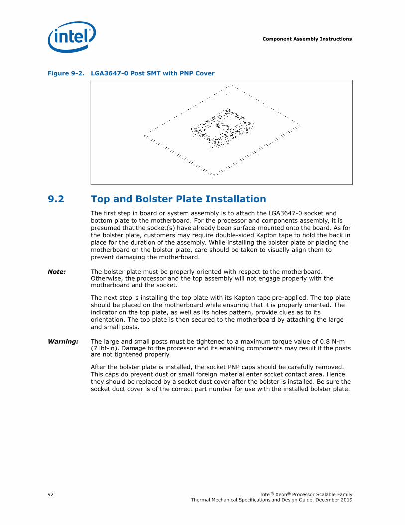
Component Assembly Instructions
92 Intel® Xeon® Processor Scalable Family Thermal Mechanical Specifications and Design Guide, December 2019
9.2 Top and Bolster Plate InstallationThe first step in board or system assembly is to attach the LGA3647-0 socket and bottom plate to the motherboard. For the processor and components assembly, it is presumed that the socket(s) have already been surface-mounted onto the board. As for the bolster plate, customers may require double-sided Kapton tape to hold the back in place for the duration of the assembly. While installing the bolster plate or placing the motherboard on the bolster plate, care should be taken to visually align them to prevent damaging the motherboard.
Note: The bolster plate must be properly oriented with respect to the motherboard. Otherwise, the processor and the top assembly will not engage properly with the motherboard and the socket.
The next step is installing the top plate with its Kapton tape pre-applied. The top plate should be placed on the motherboard while ensuring that it is properly oriented. The indicator on the top plate, as well as its holes pattern, provide clues as to its orientation. The top plate is then secured to the motherboard by attaching the large and small posts.
Warning: The large and small posts must be tightened to a maximum torque value of 0.8 N-m (7 lbf-in). Damage to the processor and its enabling components may result if the posts are not tightened properly.
After the bolster plate is installed, the socket PNP caps should be carefully removed. This caps do prevent dust or small foreign material enter socket contact area. Hence they should be replaced by a socket dust cover after the bolster is installed. Be sure the socket duct cover is of the correct part number for use with the installed bolster plate.
Figure 9-2. LGA3647-0 Post SMT with PNP Cover
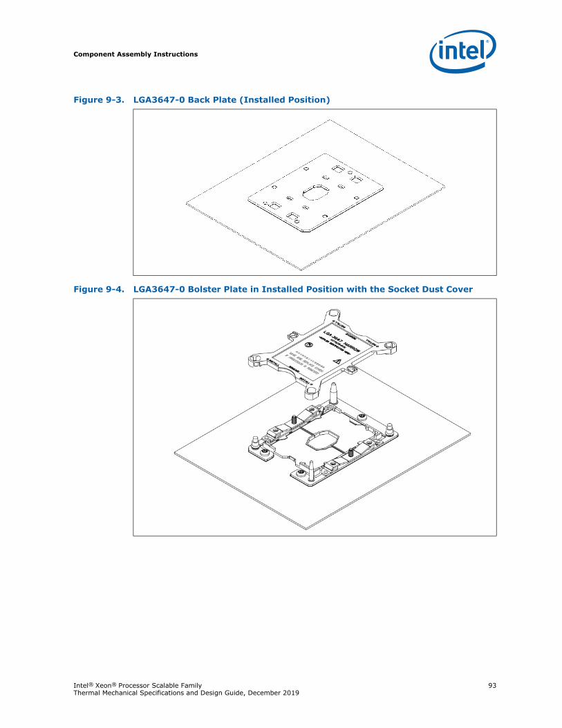
Component Assembly Instructions
Intel® Xeon® Processor Scalable Family 93Thermal Mechanical Specifications and Design Guide, December 2019
Figure 9-3. LGA3647-0 Back Plate (Installed Position)
Figure 9-4. LGA3647-0 Bolster Plate in Installed Position with the Socket Dust Cover
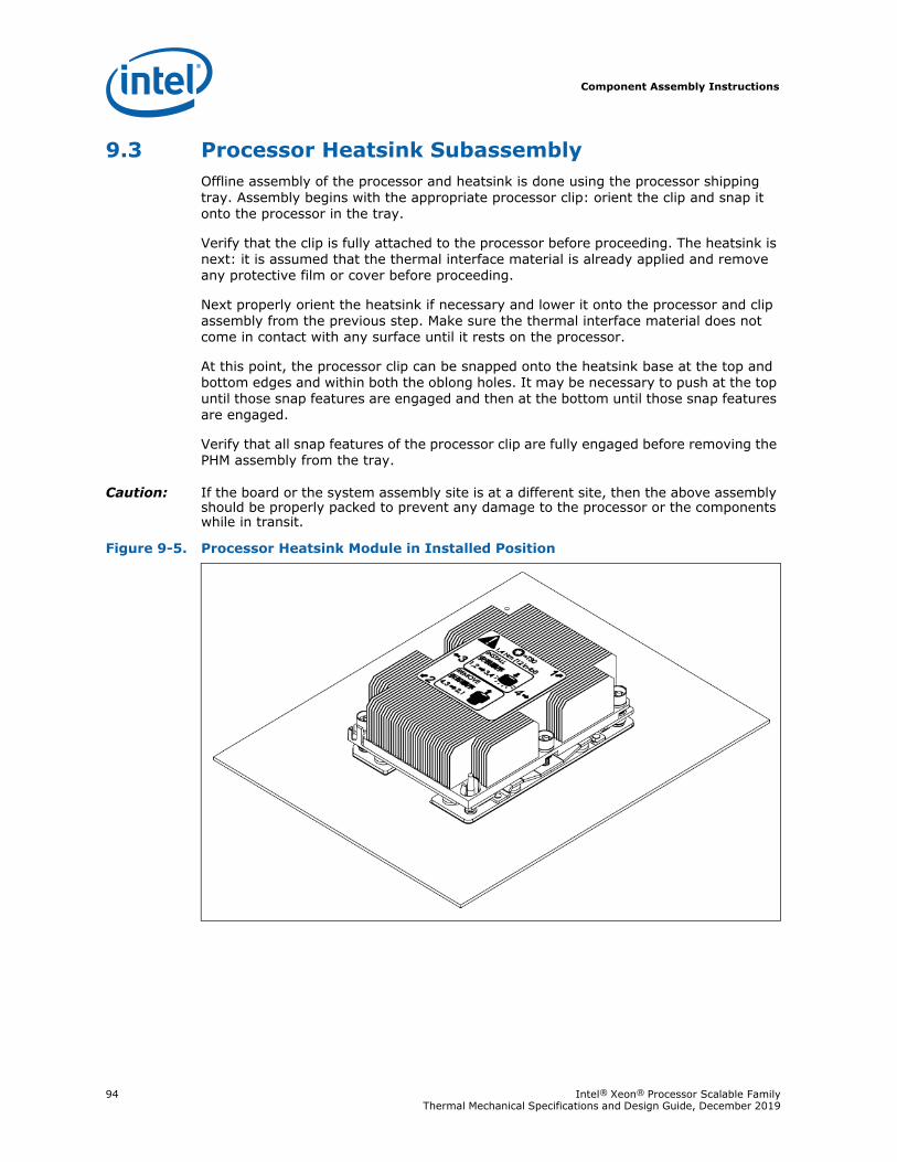
Component Assembly Instructions
94 Intel® Xeon® Processor Scalable Family Thermal Mechanical Specifications and Design Guide, December 2019
9.3 Processor Heatsink SubassemblyOffline assembly of the processor and heatsink is done using the processor shipping tray. Assembly begins with the appropriate processor clip: orient the clip and snap it onto the processor in the tray.
Verify that the clip is fully attached to the processor before proceeding. The heatsink is next: it is assumed that the thermal interface material is already applied and remove any protective film or cover before proceeding.
Next properly orient the heatsink if necessary and lower it onto the processor and clip assembly from the previous step. Make sure the thermal interface material does not come in contact with any surface until it rests on the processor.
At this point, the processor clip can be snapped onto the heatsink base at the top and bottom edges and within both the oblong holes. It may be necessary to push at the top until those snap features are engaged and then at the bottom until those snap features are engaged.
Verify that all snap features of the processor clip are fully engaged before removing the PHM assembly from the tray.
Caution: If the board or the system assembly site is at a different site, then the above assembly should be properly packed to prevent any damage to the processor or the components while in transit.
Figure 9-5. Processor Heatsink Module in Installed Position
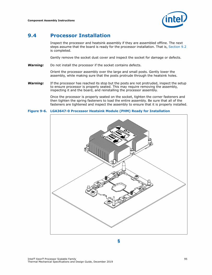
Component Assembly Instructions
Intel® Xeon® Processor Scalable Family 95Thermal Mechanical Specifications and Design Guide, December 2019
9.4 Processor InstallationInspect the processor and heatsink assembly if they are assembled offline. The next steps assume that the board is ready for the processor installation. That is, Section 9.2 is completed.
Gently remove the socket dust cover and inspect the socket for damage or defects.
Warning: Do not install the processor if the socket contains defects.
Orient the processor assembly over the large and small posts. Gently lower the assembly, while making sure that the posts protrude through the heatsink holes.
Warning: If the processor has reached its stop but the posts are not protruded, inspect the setup to ensure processor is properly seated. This may require removing the assembly, inspecting it and the board, and reinstalling the processor assembly.
Once the processor is properly seated on the socket, tighten the corner fasteners and then tighten the spring fasteners to load the entire assembly. Be sure that all of the fasteners are tightened and inspect the assembly to ensure that it is properly installed.
§
Figure 9-6. LGA3647-0 Processor Heatsink Module (PHM) Ready for Installation
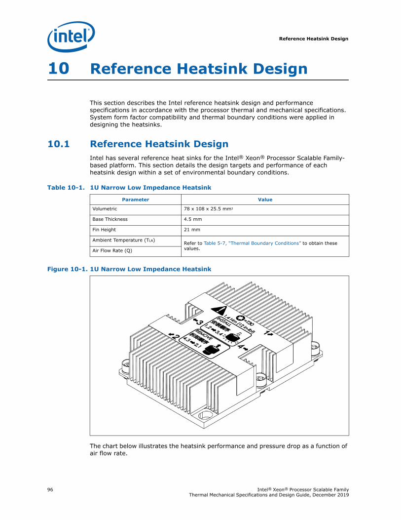
Reference Heatsink Design
96 Intel® Xeon® Processor Scalable Family Thermal Mechanical Specifications and Design Guide, December 2019
10 Reference Heatsink Design
This section describes the Intel reference heatsink design and performance specifications in accordance with the processor thermal and mechanical specifications. System form factor compatibility and thermal boundary conditions were applied in designing the heatsinks.
10.1 Reference Heatsink DesignIntel has several reference heat sinks for the Intel® Xeon® Processor Scalable Family-based platform. This section details the design targets and performance of each heatsink design within a set of environmental boundary conditions.
The chart below illustrates the heatsink performance and pressure drop as a function of air flow rate.
Table 10-1. 1U Narrow Low Impedance Heatsink
Parameter Value
Volumetric 78 x 108 x 25.5 mm3
Base Thickness 4.5 mm
Fin Height 21 mm
Ambient Temperature (TLA) Refer to Table 5-7, “Thermal Boundary Conditions” to obtain these values.Air Flow Rate (Q)
Figure 10-1. 1U Narrow Low Impedance Heatsink
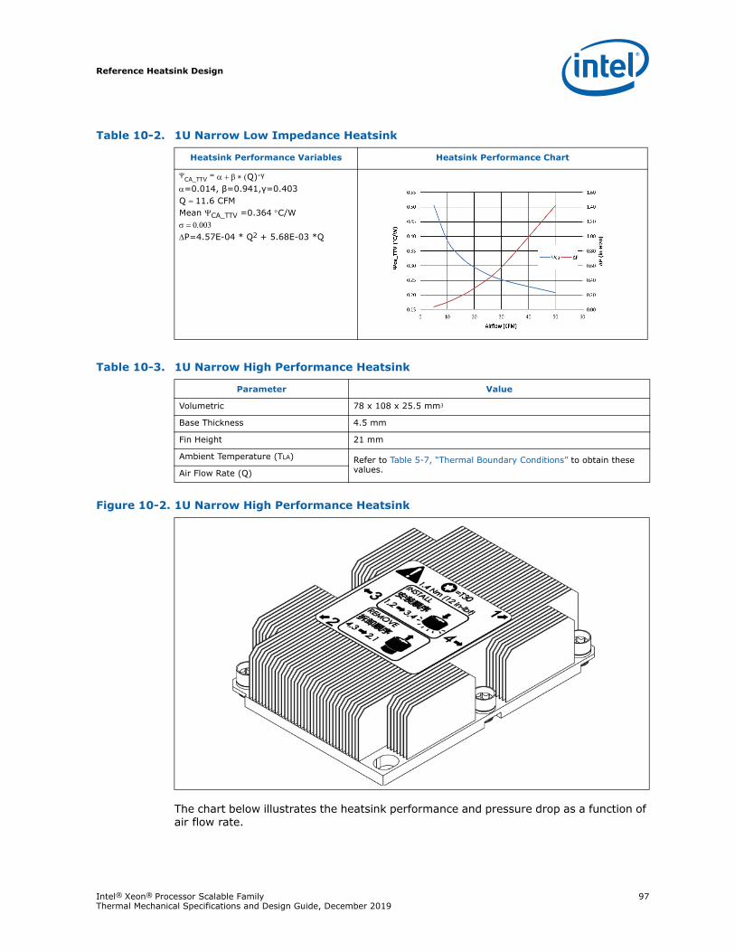
Reference Heatsink Design
Intel® Xeon® Processor Scalable Family 97Thermal Mechanical Specifications and Design Guide, December 2019
The chart below illustrates the heatsink performance and pressure drop as a function of air flow rate.
Table 10-2. 1U Narrow Low Impedance Heatsink
Heatsink Performance Variables Heatsink Performance Chart
CA_TTV = Q)-γ
=0.014, β=0.941,γ=0.403Q 11.6 CFMMean CA_TTV =0.364 C/WP=4.57E-04 * Q2 + 5.68E-03 *Q
Table 10-3. 1U Narrow High Performance Heatsink
Parameter Value
Volumetric 78 x 108 x 25.5 mm3
Base Thickness 4.5 mm
Fin Height 21 mm
Ambient Temperature (TLA) Refer to Table 5-7, “Thermal Boundary Conditions” to obtain these values.Air Flow Rate (Q)
Figure 10-2. 1U Narrow High Performance Heatsink
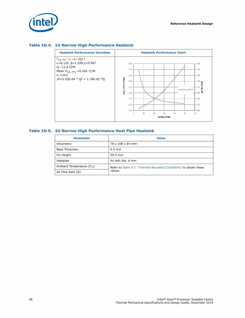
Reference Heatsink Design
98 Intel® Xeon® Processor Scalable Family Thermal Mechanical Specifications and Design Guide, December 2019
Table 10-4. 1U Narrow High Performance Heatsink
Heatsink Performance Variables Heatsink Performance Chart
CA_TTV = Q)-γ
=0.122, β=1.528,γ=0.967Q 11.6 CFMMean CA_TTV =0.265 C/WP=5.52E-04 * Q2 + 1.76E-02 *Q
Table 10-5. 2U Narrow High Performance Heat Pipe Heatsink
Parameter Value
Volumetric 78 x 108 x 64 mm3
Base Thickness 4.5 mm
Fin Height 59.5 mm
Heatpipe 4x with dia: 6 mm
Ambient Temperature (TLA) Refer to Table 5-7, “Thermal Boundary Conditions” to obtain these values.Air Flow Rate (Q)
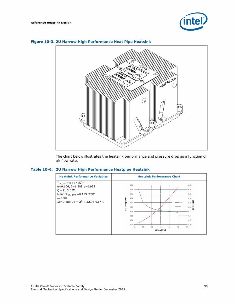
Reference Heatsink Design
Intel® Xeon® Processor Scalable Family 99Thermal Mechanical Specifications and Design Guide, December 2019
The chart below illustrates the heatsink performance and pressure drop as a function of air flow rate.
Figure 10-3. 2U Narrow High Performance Heat Pipe Heatsink
Table 10-6. 2U Narrow High Performance Heatpipe Heatsink
Heatsink Performance Variables Heatsink Performance Chart
CA_TTV = Q)-γ
=0.106, β=1.385,γ=0.938Q 21.5 CFMMean CA_TTV =0.179 C/WP=9.88E-05 * Q2 + 3.59E-03 * Q
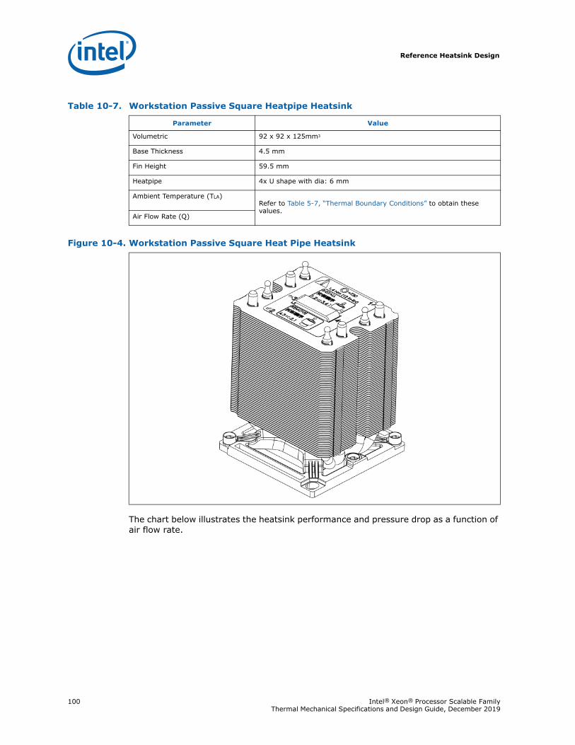
Reference Heatsink Design
100 Intel® Xeon® Processor Scalable Family Thermal Mechanical Specifications and Design Guide, December 2019
The chart below illustrates the heatsink performance and pressure drop as a function of air flow rate.
Table 10-7. Workstation Passive Square Heatpipe Heatsink
Parameter Value
Volumetric 92 x 92 x 125mm3
Base Thickness 4.5 mm
Fin Height 59.5 mm
Heatpipe 4x U shape with dia: 6 mm
Ambient Temperature (TLA)Refer to Table 5-7, “Thermal Boundary Conditions” to obtain these values.
Air Flow Rate (Q)
Figure 10-4. Workstation Passive Square Heat Pipe Heatsink
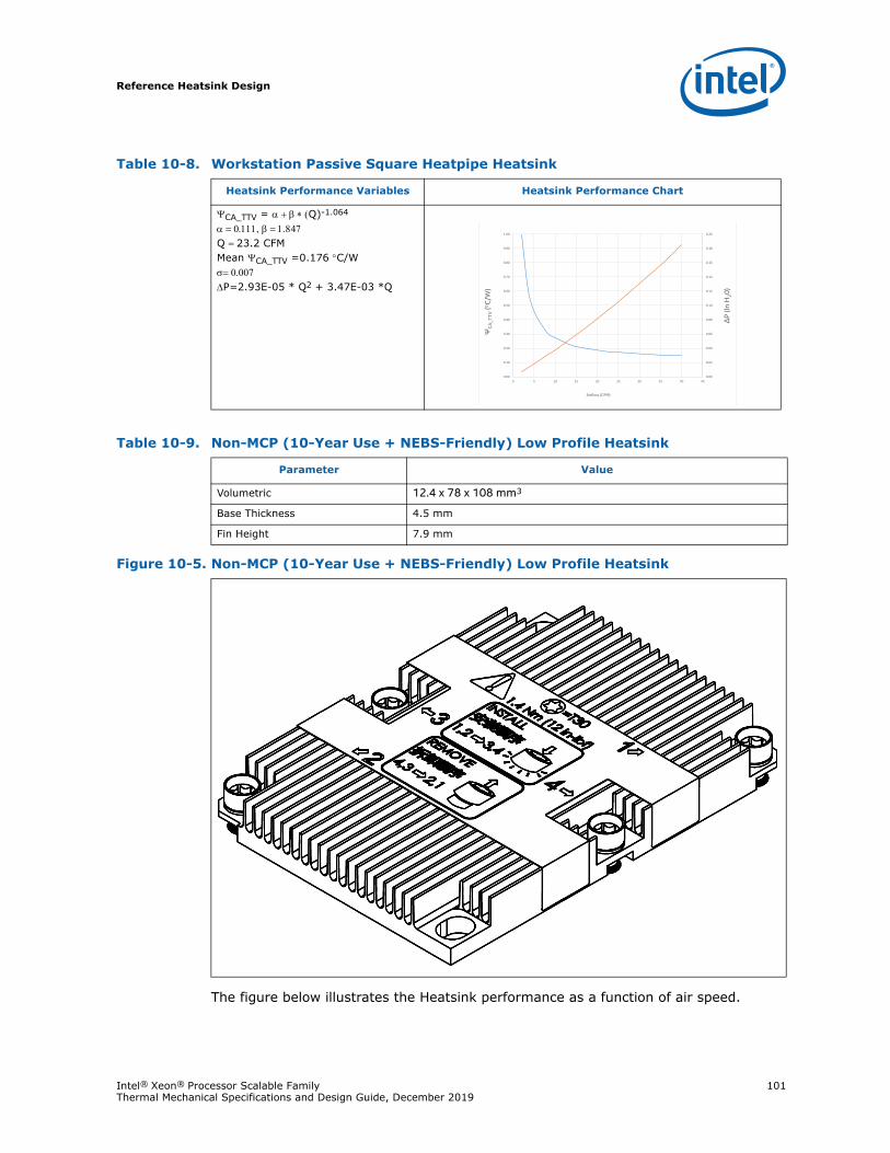
Reference Heatsink Design
Intel® Xeon® Processor Scalable Family 101Thermal Mechanical Specifications and Design Guide, December 2019
The figure below illustrates the Heatsink performance as a function of air speed.
Table 10-8. Workstation Passive Square Heatpipe Heatsink
Heatsink Performance Variables Heatsink Performance Chart
CA_TTV = Q)-1.064
Q 23.2 CFMMean CA_TTV =0.176 C/WP=2.93E-05 * Q2 + 3.47E-03 *Q
Table 10-9. Non-MCP (10-Year Use + NEBS-Friendly) Low Profile Heatsink
Parameter Value
Volumetric 12.4 x 78 x 108 mm3
Base Thickness 4.5 mm
Fin Height 7.9 mm
Figure 10-5. Non-MCP (10-Year Use + NEBS-Friendly) Low Profile Heatsink
ΔP
(In H
20)
ΨC
A_T
TV (o C
/W)
Airflow (CFM)
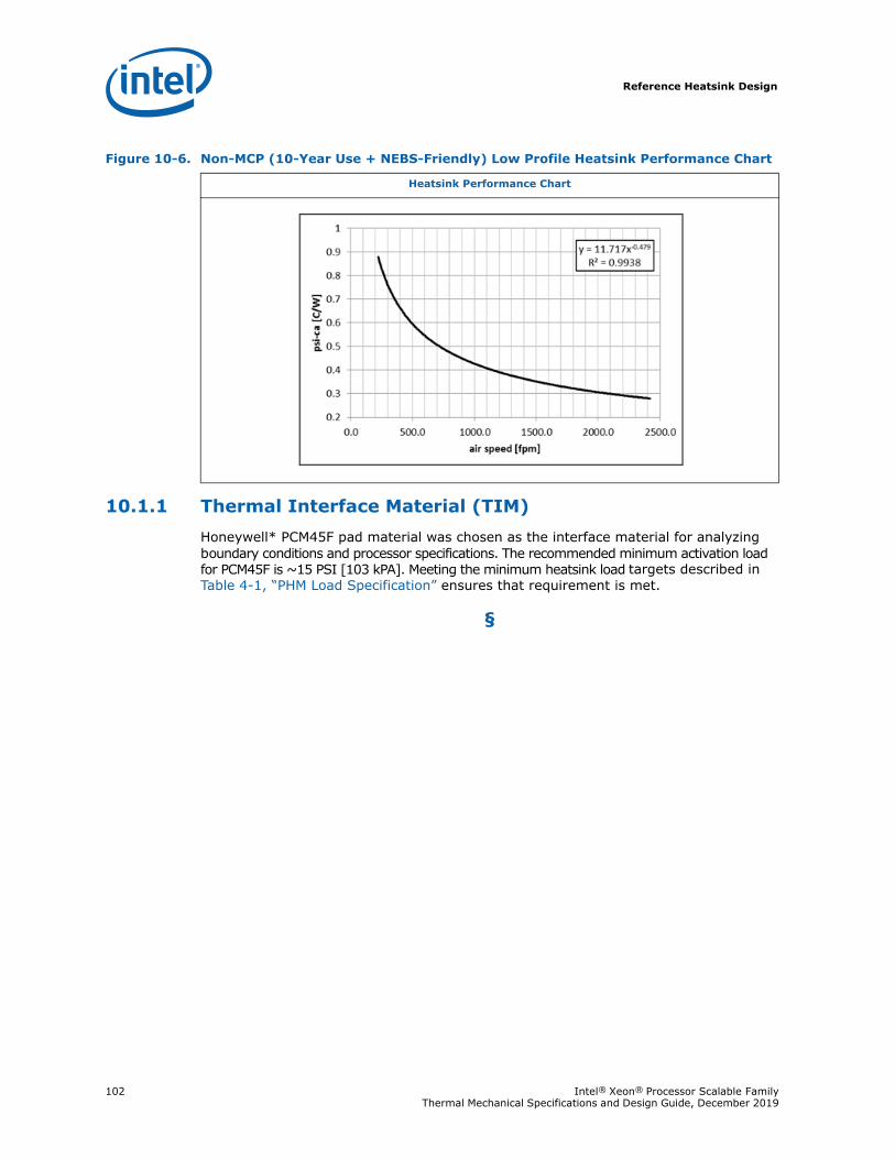
Reference Heatsink Design
102 Intel® Xeon® Processor Scalable Family Thermal Mechanical Specifications and Design Guide, December 2019
10.1.1 Thermal Interface Material (TIM)Honeywell* PCM45F pad material was chosen as the interface material for analyzing boundary conditions and processor specifications. The recommended minimum activation load for PCM45F is ~15 PSI [103 kPA]. Meeting the minimum heatsink load targets described in Table 4-1, “PHM Load Specification” ensures that requirement is met.
§
Figure 10-6. Non-MCP (10-Year Use + NEBS-Friendly) Low Profile Heatsink Performance Chart
Heatsink Performance Chart
Supplier Listing
Intel® Xeon® Processor Scalable Family 103Thermal Mechanical Specifications and Design Guide, December 2019
11 Supplier Listing
Third-part suppliers are enabled to ensure that reference thermal and mechanical components are available.
Intel Enabled Supplier Information
Notes:1. Supplier listing is provided by Intel as a convenience to its customers. Intel does
not make any representations or warranties whatsoever regarding the quality, reliability, functionality, or compatibility of these devices.
2. Supplier information provided in the table was deemed accurate when this document was released.
3. Customers planning on using the Intel reference design should contact the suppliers for the latest information on their product(s). Note that Intel requires MANDA form be signed by the customer and the supplier prior to disclosure of components design information or placing orders. Contact the local Intel representative to obtain a copy of the form.
4. Customers must evaluate performance against their own product requirements.
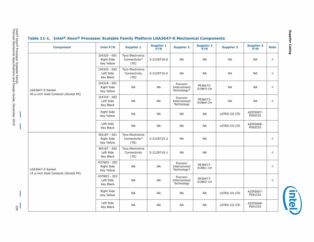
Su
pp
lier Listing
Intel ® X
eon®
Processor Scalable Fam
ily104
Thermal M
echanical Specifications and D
esign Guide, D
ecember 2019
Table 11-1. Intel® Xeon® Processor Scalable Family Platform LGA3647-0 Mechanical Components
Component Intel P/N Supplier 1 Supplier 1 P/N Supplier 2 Supplier 2
P/N Supplier 3 Supplier 3 P/N Note
LGA3647-0 Socket30 μ-inch Gold Contacts (Socket P0)
J34320 - 001Right SideKey Yellow
Tyco Electronics Connectivity*
(TE)2-2129710-6 NA NA NA NA 4
J34320 - 002Left SideKey Black
Tyco Electronics Connectivity
(TE)2-2129710-5 NA NA NA NA 4
J34318 - 001Right SideKey Yellow
NA NAFoxconn
Interconnect Technology*
PE36473-01NK3-1H NA NA 4
J34318 - 002Left SideKey Black
NA NAFoxconn
Interconnect Technology
PE36473-01NK4-1H NA NA 4
Right SideKey Yellow
NA NA NA NA LOTES CO LTD AZIFS007-P002C01
Left SideKey Black
NA NA NA NA LOTES CO LTD AZIFS008-P002C01
LGA3647-0 Socket15 μ-inch Gold Contacts (Socket P0)
J65187 - 001Right SideKey Yellow
Tyco Electronics Connectivity*
(TE)2-2129710-2 NA NA 4
J65187 - 002Left SideKey Black
Tyco Electronics Connectivity
(TE)2-2129710-1 NA NA 4
H37603 - 202Right SideKey Yellow
NA NAFoxconn
Interconnect Technology*
PE36477-01NK1-1H 4
H37603 - 203Left SideKey Black
NA NAFoxconn
Interconnect Technology
PE36477-01NK2-1H 4
Right SideKey Yellow
NA NA NA NA LOTES CO LTD AZIFS007-P001C01
Left SideKey Black
NA NA NA NA LOTES CO LTD AZIFS008-P001C01
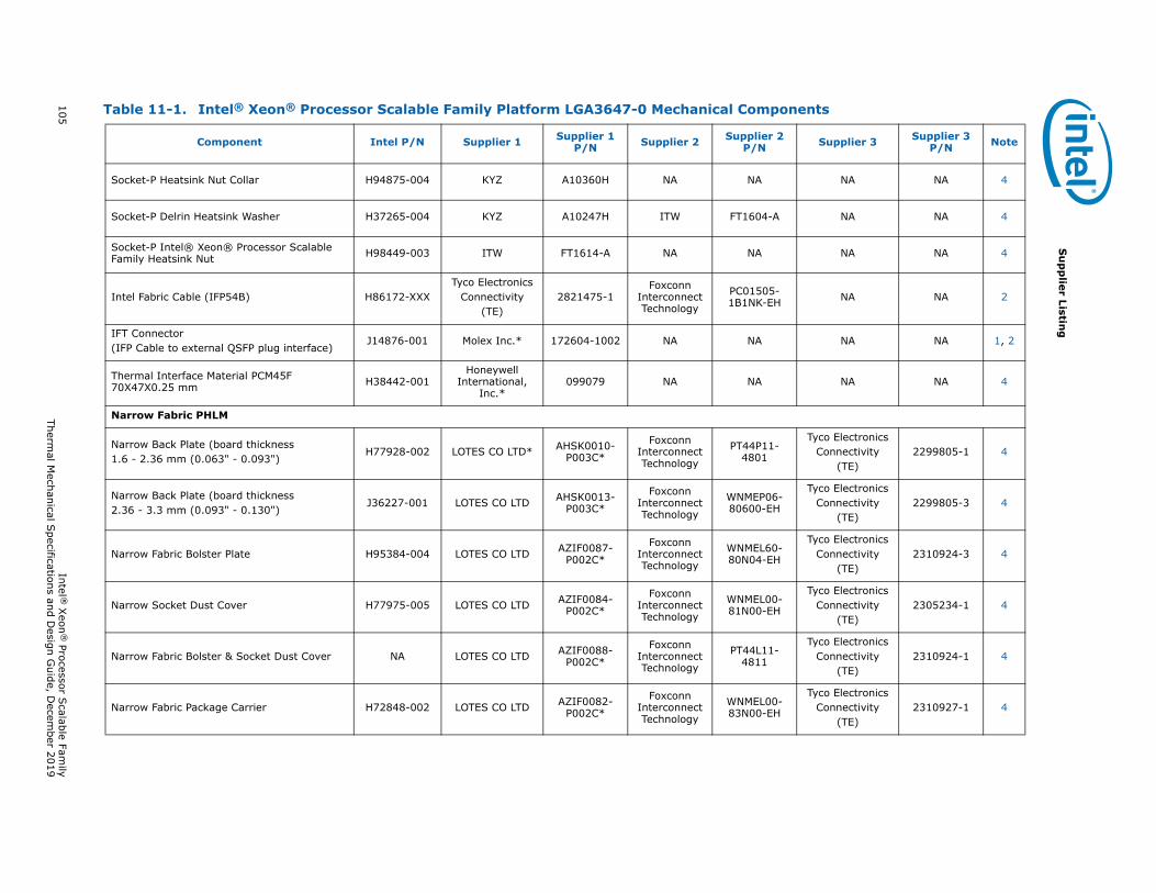
105 Intel ®
Xeon
® Processor S
calable Family
Thermal M
echanical Specifications and D
esign Guide, D
ecember 2019
Su
pp
lier Listing
Socket-P Heatsink Nut Collar H94875-004 KYZ A10360H NA NA NA NA 4
Socket-P Delrin Heatsink Washer H37265-004 KYZ A10247H ITW FT1604-A NA NA 4
Socket-P Intel® Xeon® Processor Scalable Family Heatsink Nut H98449-003 ITW FT1614-A NA NA NA NA 4
Intel Fabric Cable (IFP54B) H86172-XXXTyco Electronics
Connectivity(TE)
2821475-1Foxconn
Interconnect Technology
PC01505-1B1NK-EH NA NA 2
IFT Connector(IFP Cable to external QSFP plug interface)
J14876-001 Molex Inc.* 172604-1002 NA NA NA NA 1, 2
Thermal Interface Material PCM45F 70X47X0.25 mm H38442-001
Honeywell International,
Inc.*099079 NA NA NA NA 4
Narrow Fabric PHLM
Narrow Back Plate (board thickness 1.6 - 2.36 mm (0.063" - 0.093")
H77928-002 LOTES CO LTD* AHSK0010-P003C*
Foxconn Interconnect Technology
PT44P11-4801
Tyco Electronics Connectivity
(TE)2299805-1 4
Narrow Back Plate (board thickness 2.36 - 3.3 mm (0.093" - 0.130")
J36227-001 LOTES CO LTD AHSK0013-P003C*
Foxconn Interconnect Technology
WNMEP06-80600-EH
Tyco Electronics Connectivity
(TE)2299805-3 4
Narrow Fabric Bolster Plate H95384-004 LOTES CO LTD AZIF0087-P002C*
Foxconn Interconnect Technology
WNMEL60-80N04-EH
Tyco Electronics Connectivity
(TE)2310924-3 4
Narrow Socket Dust Cover H77975-005 LOTES CO LTD AZIF0084-P002C*
Foxconn Interconnect Technology
WNMEL00-81N00-EH
Tyco Electronics Connectivity
(TE)2305234-1 4
Narrow Fabric Bolster & Socket Dust Cover NA LOTES CO LTD AZIF0088-P002C*
Foxconn Interconnect Technology
PT44L11-4811
Tyco Electronics Connectivity
(TE)2310924-1 4
Narrow Fabric Package Carrier H72848-002 LOTES CO LTD AZIF0082-P002C*
Foxconn Interconnect Technology
WNMEL00-83N00-EH
Tyco Electronics Connectivity
(TE)2310927-1 4
Table 11-1. Intel® Xeon® Processor Scalable Family Platform LGA3647-0 Mechanical Components
Component Intel P/N Supplier 1 Supplier 1 P/N Supplier 2 Supplier 2
P/N Supplier 3 Supplier 3 P/N Note
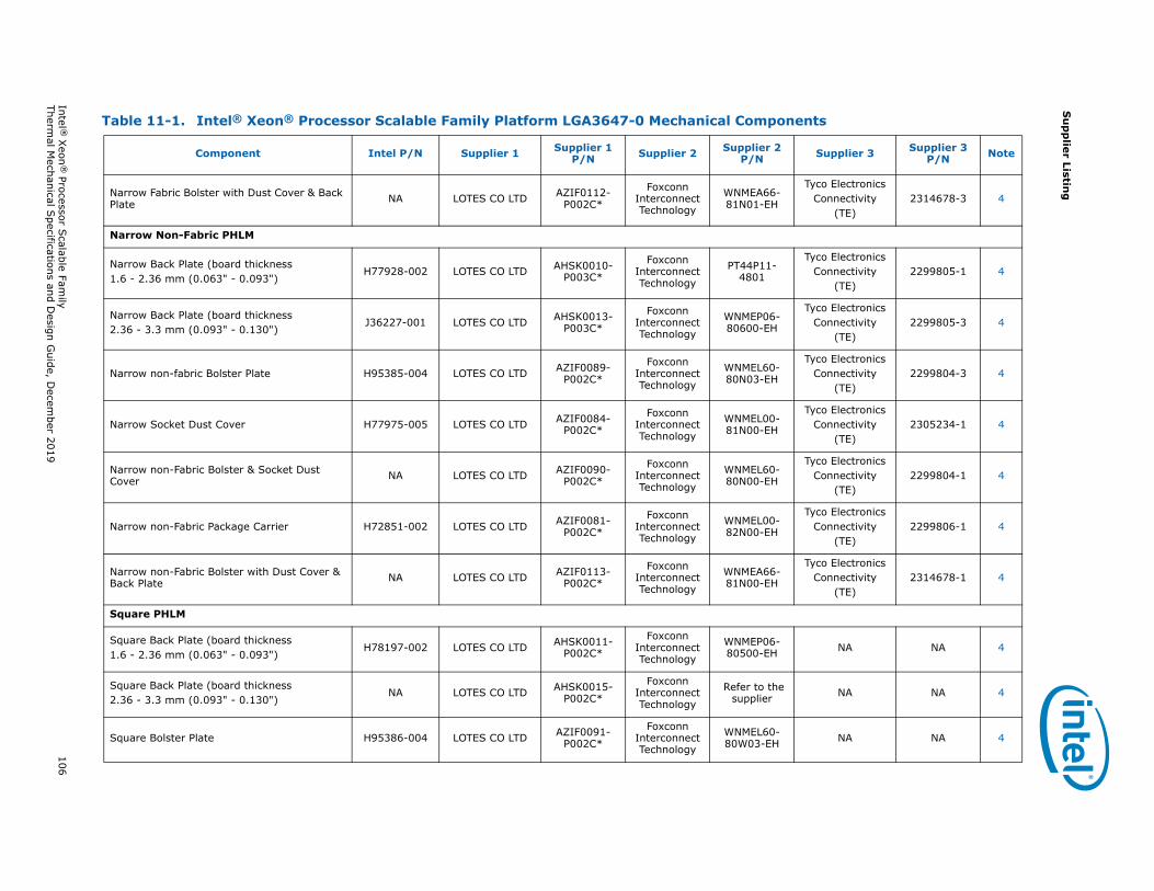
Su
pp
lier Listing
Intel ® X
eon®
Processor Scalable Fam
ily106
Thermal M
echanical Specifications and D
esign Guide, D
ecember 2019
Narrow Fabric Bolster with Dust Cover & Back Plate NA LOTES CO LTD AZIF0112-
P002C*
Foxconn Interconnect Technology
WNMEA66-81N01-EH
Tyco Electronics Connectivity
(TE)2314678-3 4
Narrow Non-Fabric PHLM
Narrow Back Plate (board thickness 1.6 - 2.36 mm (0.063" - 0.093")
H77928-002 LOTES CO LTD AHSK0010-P003C*
Foxconn Interconnect Technology
PT44P11-4801
Tyco Electronics Connectivity
(TE)2299805-1 4
Narrow Back Plate (board thickness 2.36 - 3.3 mm (0.093" - 0.130")
J36227-001 LOTES CO LTD AHSK0013-P003C*
Foxconn Interconnect Technology
WNMEP06-80600-EH
Tyco Electronics Connectivity
(TE)2299805-3 4
Narrow non-fabric Bolster Plate H95385-004 LOTES CO LTD AZIF0089-P002C*
Foxconn Interconnect Technology
WNMEL60-80N03-EH
Tyco Electronics Connectivity
(TE)2299804-3 4
Narrow Socket Dust Cover H77975-005 LOTES CO LTD AZIF0084-P002C*
Foxconn Interconnect Technology
WNMEL00-81N00-EH
Tyco Electronics Connectivity
(TE)2305234-1 4
Narrow non-Fabric Bolster & Socket Dust Cover NA LOTES CO LTD AZIF0090-
P002C*
Foxconn Interconnect Technology
WNMEL60-80N00-EH
Tyco Electronics Connectivity
(TE)2299804-1 4
Narrow non-Fabric Package Carrier H72851-002 LOTES CO LTD AZIF0081-P002C*
Foxconn Interconnect Technology
WNMEL00-82N00-EH
Tyco Electronics Connectivity
(TE)2299806-1 4
Narrow non-Fabric Bolster with Dust Cover & Back Plate NA LOTES CO LTD AZIF0113-
P002C*
Foxconn Interconnect Technology
WNMEA66-81N00-EH
Tyco Electronics Connectivity
(TE)2314678-1 4
Square PHLM
Square Back Plate (board thickness 1.6 - 2.36 mm (0.063" - 0.093")
H78197-002 LOTES CO LTD AHSK0011-P002C*
Foxconn Interconnect Technology
WNMEP06-80500-EH NA NA 4
Square Back Plate (board thickness 2.36 - 3.3 mm (0.093" - 0.130")
NA LOTES CO LTD AHSK0015-P002C*
Foxconn Interconnect Technology
Refer to the supplier NA NA 4
Square Bolster Plate H95386-004 LOTES CO LTD AZIF0091-P002C*
Foxconn Interconnect Technology
WNMEL60-80W03-EH NA NA 4
Table 11-1. Intel® Xeon® Processor Scalable Family Platform LGA3647-0 Mechanical Components
Component Intel P/N Supplier 1 Supplier 1 P/N Supplier 2 Supplier 2
P/N Supplier 3 Supplier 3 P/N Note
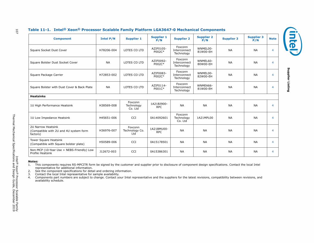
107 Intel ®
Xeon
® Processor S
calable Family
Thermal M
echanical Specifications and D
esign Guide, D
ecember 2019
Su
pp
lier Listing
Notes:1. This components requires RS-MPCITR form be signed by the customer and supplier prior to disclosure of component design specifications. Contact the local Intel
representative for additional information.2. See the component specifications for detail and ordering information.3. Contact the local Intel representative for sample availability.4. Components part numbers are subject to change. Contact your Intel representative and the suppliers for the latest revisions, compatibility between revisions, and
availability schedule.
Square Socket Dust Cover H78206-004 LOTES CO LTD AZIF0105-P002C*
Foxconn Interconnect Technology
WNMEL00-81W00-EH NA NA 4
Square Bolster Dust Socket Cover NA LOTES CO LTD AZIF0092-P002C*
Foxconn Interconnect Technology
WNMEL60-80W00-EH NA NA 4
Square Package Carrier H72853-002 LOTES CO LTD AZIF0083-P002C*
Foxconn Interconnect Technology
WNMEL00-82W00-EH NA NA 4
Square Bolster with Dust Cover & Back Plate NA LOTES CO LTD AZIF0114-P001C*
Foxconn Interconnect Technology
WNMEA66-81W00-EH NA NA 4
Heatsinks
1U High Performance Heatsink H38569-008Foxconn
Technology Co. Ltd
1A21BJ900-RPC NA NA NA NA 4
1U Low Impedance Heatsink H45651-006 CCI 0A14092601Foxconn
Technology Co. Ltd
1A21MPL00 NA NA 4
2U Narrow Heatsink(Compatible with 2U and 4U system form factors)
H36976-007Foxconn
Technology Co. Ltd
1A21BMU00-RPC NA NA NA NA 4
Tower Square Heatsink(Compatible with Square bolster plate)
H50589-006 CCI 0A15178501 NA NA NA NA 4
Non-MCP (10-Year Use + NEBS-Friendly) Low Profile Heatsink J12672-003 CCI 0A15386301 NA NA NA NA 4
Table 11-1. Intel® Xeon® Processor Scalable Family Platform LGA3647-0 Mechanical Components
Component Intel P/N Supplier 1 Supplier 1 P/N Supplier 2 Supplier 2
P/N Supplier 3 Supplier 3 P/N Note
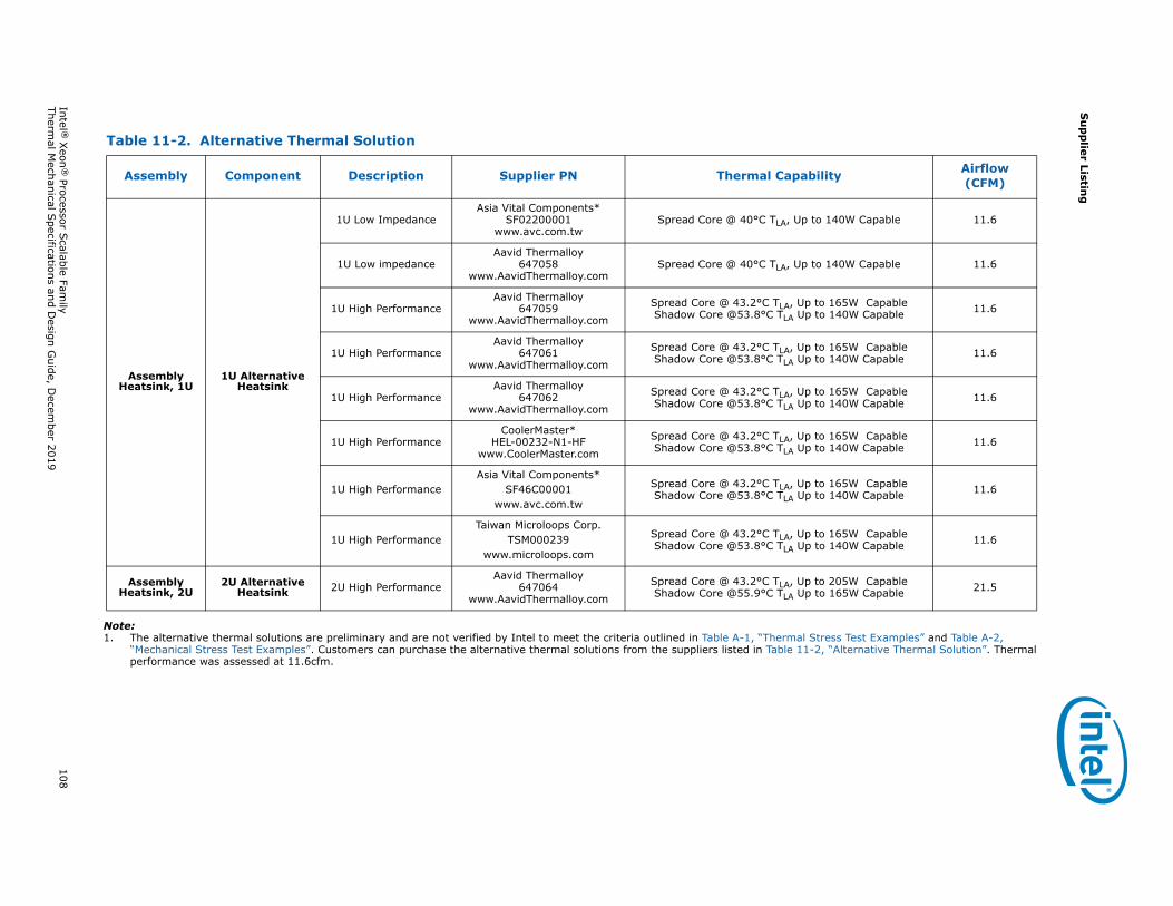
Su
pp
lier Listing
Intel ® X
eon®
Processor Scalable Fam
ily108
Thermal M
echanical Specifications and D
esign Guide, D
ecember 2019
Note:1. The alternative thermal solutions are preliminary and are not verified by Intel to meet the criteria outlined in Table A-1, “Thermal Stress Test Examples” and Table A-2,
“Mechanical Stress Test Examples”. Customers can purchase the alternative thermal solutions from the suppliers listed in Table 11-2, “Alternative Thermal Solution”. Thermal performance was assessed at 11.6cfm.
Table 11-2. Alternative Thermal Solution
Assembly Component Description Supplier PN Thermal Capability Airflow (CFM)
Assembly Heatsink, 1U
1U Alternative Heatsink
1U Low ImpedanceAsia Vital Components*
SF02200001www.avc.com.tw
Spread Core @ 40°C TLA, Up to 140W Capable 11.6
1U Low impedanceAavid Thermalloy
647058www.AavidThermalloy.com
Spread Core @ 40°C TLA, Up to 140W Capable 11.6
1U High PerformanceAavid Thermalloy
647059www.AavidThermalloy.com
Spread Core @ 43.2°C TLA, Up to 165W CapableShadow Core @53.8°C TLA Up to 140W Capable 11.6
1U High PerformanceAavid Thermalloy
647061www.AavidThermalloy.com
Spread Core @ 43.2°C TLA, Up to 165W CapableShadow Core @53.8°C TLA Up to 140W Capable 11.6
1U High PerformanceAavid Thermalloy
647062www.AavidThermalloy.com
Spread Core @ 43.2°C TLA, Up to 165W CapableShadow Core @53.8°C TLA Up to 140W Capable 11.6
1U High PerformanceCoolerMaster*
HEL-00232-N1-HFwww.CoolerMaster.com
Spread Core @ 43.2°C TLA, Up to 165W CapableShadow Core @53.8°C TLA Up to 140W Capable 11.6
1U High PerformanceAsia Vital Components*
SF46C00001www.avc.com.tw
Spread Core @ 43.2°C TLA, Up to 165W CapableShadow Core @53.8°C TLA Up to 140W Capable 11.6
1U High PerformanceTaiwan Microloops Corp.
TSM000239www.microloops.com
Spread Core @ 43.2°C TLA, Up to 165W CapableShadow Core @53.8°C TLA Up to 140W Capable 11.6
Assembly Heatsink, 2U
2U Alternative Heatsink 2U High Performance
Aavid Thermalloy647064
www.AavidThermalloy.com
Spread Core @ 43.2°C TLA, Up to 205W CapableShadow Core @55.9°C TLA Up to 165W Capable 21.5
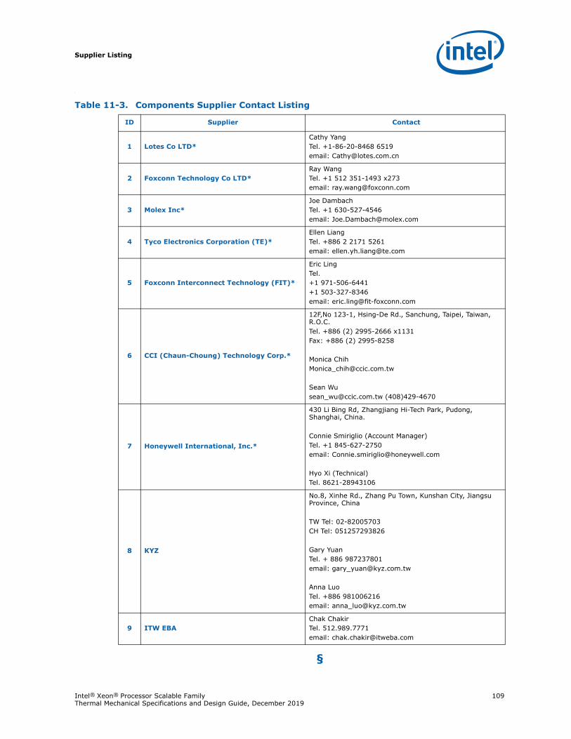
Supplier Listing
Intel® Xeon® Processor Scalable Family 109Thermal Mechanical Specifications and Design Guide, December 2019
.
§
Table 11-3. Components Supplier Contact Listing
ID Supplier Contact
1 Lotes Co LTD*Cathy YangTel. +1-86-20-8468 6519email: [email protected]
2 Foxconn Technology Co LTD*Ray WangTel. +1 512 351-1493 x273email: [email protected]
3 Molex Inc*Joe DambachTel. +1 630-527-4546email: [email protected]
4 Tyco Electronics Corporation (TE)*Ellen LiangTel. +886 2 2171 5261email: [email protected]
5 Foxconn Interconnect Technology (FIT)*
Eric LingTel. +1 971-506-6441+1 503-327-8346email: [email protected]
6 CCI (Chaun-Choung) Technology Corp.*
12F,No 123-1, Hsing-De Rd., Sanchung, Taipei, Taiwan, R.O.C.Tel. +886 (2) 2995-2666 x1131Fax: +886 (2) 2995-8258
Monica [email protected]
Sean [email protected] (408)429-4670
7 Honeywell International, Inc.*
430 Li Bing Rd, Zhangjiang Hi-Tech Park, Pudong, Shanghai, China.
Connie Smiriglio (Account Manager)Tel. +1 845-627-2750email: [email protected]
Hyo Xi (Technical)Tel. 8621-28943106
8 KYZ
No.8, Xinhe Rd., Zhang Pu Town, Kunshan City, Jiangsu Province, China
TW Tel: 02-82005703CH Tel: 051257293826
Gary Yuan Tel. + 886 987237801email: [email protected]
Anna LuoTel. +886 981006216email: [email protected]
9 ITW EBAChak ChakirTel. 512.989.7771email: [email protected]
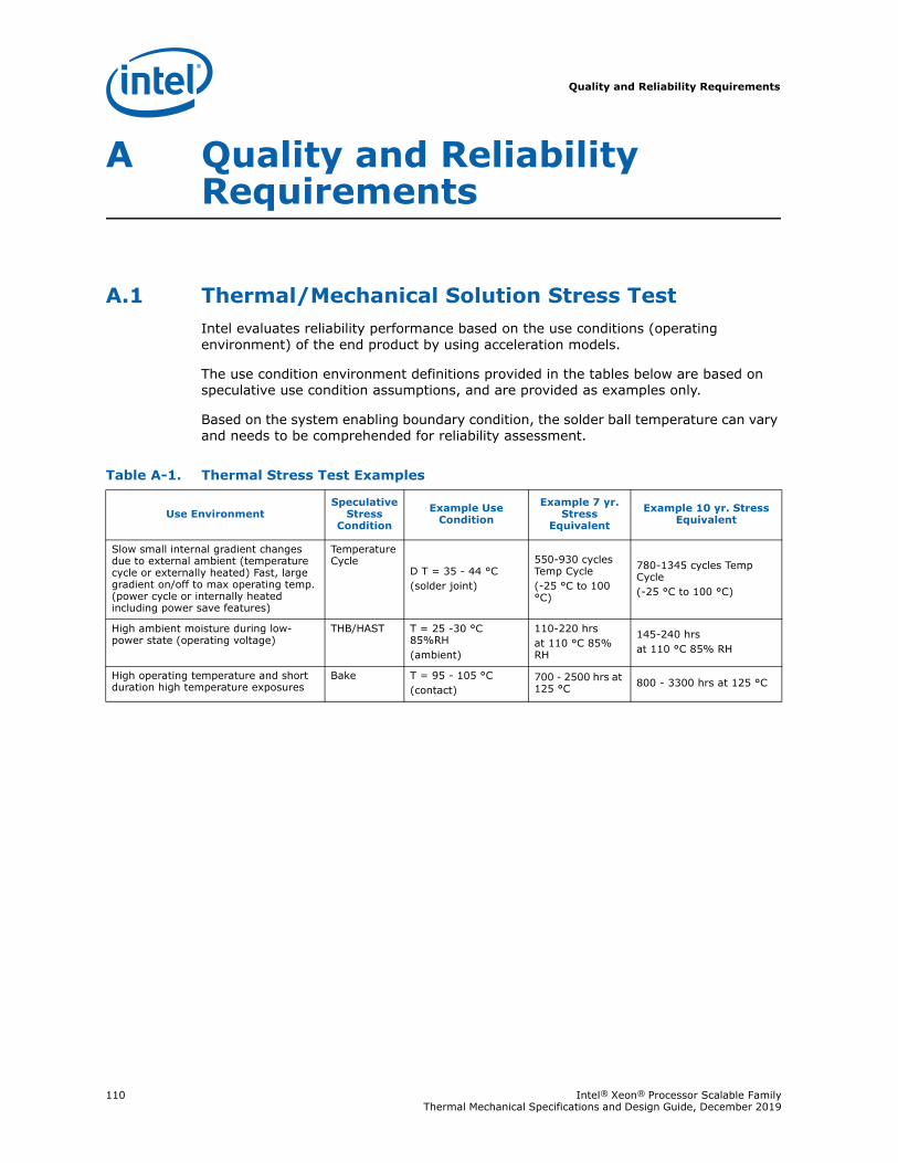
Quality and Reliability Requirements
110 Intel® Xeon® Processor Scalable Family Thermal Mechanical Specifications and Design Guide, December 2019
A Quality and Reliability Requirements
A.1 Thermal/Mechanical Solution Stress TestIntel evaluates reliability performance based on the use conditions (operating environment) of the end product by using acceleration models.
The use condition environment definitions provided in the tables below are based on speculative use condition assumptions, and are provided as examples only.
Based on the system enabling boundary condition, the solder ball temperature can vary and needs to be comprehended for reliability assessment.
Table A-1. Thermal Stress Test Examples
Use EnvironmentSpeculative
Stress Condition
Example Use Condition
Example 7 yr. Stress
Equivalent
Example 10 yr. Stress Equivalent
Slow small internal gradient changes due to external ambient (temperature cycle or externally heated) Fast, large gradient on/off to max operating temp. (power cycle or internally heated including power save features)
Temperature Cycle
D T = 35 - 44 °C(solder joint)
550-930 cycles Temp Cycle(-25 °C to 100 °C)
780-1345 cycles Temp Cycle(-25 °C to 100 °C)
High ambient moisture during low-power state (operating voltage)
THB/HAST T = 25 -30 °C 85%RH(ambient)
110-220 hrsat 110 °C 85% RH
145-240 hrsat 110 °C 85% RH
High operating temperature and short duration high temperature exposures
Bake T = 95 - 105 °C(contact)
700 - 2500 hrs at 125 °C 800 - 3300 hrs at 125 °C
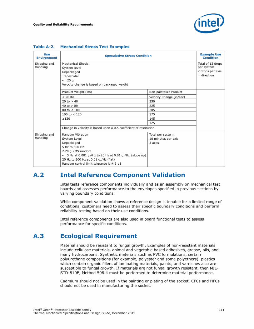
Quality and Reliability Requirements
Intel® Xeon® Processor Scalable Family 111Thermal Mechanical Specifications and Design Guide, December 2019
A.2 Intel Reference Component ValidationIntel tests reference components individually and as an assembly on mechanical test boards and assesses performance to the envelopes specified in previous sections by varying boundary conditions.
While component validation shows a reference design is tenable for a limited range of conditions, customers need to assess their specific boundary conditions and perform reliability testing based on their use conditions.
Intel reference components are also used in board functional tests to assess performance for specific conditions.
A.3 Ecological RequirementMaterial should be resistant to fungal growth. Examples of non-resistant materials include cellulose materials, animal and vegetable based adhesives, grease, oils, and many hydrocarbons. Synthetic materials such as PVC formulations, certain polyurethane compositions (for example, polyester and some polyethers), plastics which contain organic fillers of laminating materials, paints, and varnishes also are susceptible to fungal growth. If materials are not fungal growth resistant, then MIL- STD-810E, Method 508.4 must be performed to determine material performance.
Cadmium should not be used in the painting or plating of the socket. CFCs and HFCs should not be used in manufacturing the socket.
Table A-2. Mechanical Stress Test Examples
Use Environment
Speculative Stress Condition Example Use Condition
Shipping and Handling
Mechanical ShockSystem-levelUnpackagedTrapezoidal• 25 gVelocity change is based on packaged weight
Total of 12 drops per system:2 drops per axis± direction
Product Weight (lbs) Non-palatalize Product
< 20 lbs Velocity Change (in/sec)20 to > 40 25040 to > 80 22580 to < 100 205100 to < 120 175≥120 145
125
Change in velocity is based upon a 0.5 coefficient of restitution.
Shipping and Handling
Random VibrationSystem LevelUnpackaged5 Hz to 500 Hz2.20 g RMS random• 5 Hz at 0.001 g2/Hz to 20 Hz at 0.01 g2/Hz (slope up)20 Hz to 500 Hz at 0.01 g2/Hz (flat)Random control limit tolerance is ± 3 dB
Total per system:10 minutes per axis3 axes
Quality and Reliability Requirements
112 Intel® Xeon® Processor Scalable Family Thermal Mechanical Specifications and Design Guide, December 2019
Any plastic component exceeding 25 gm should be recyclable per the European Blue Angel recycling standards.
Supplier is responsible for complying with industry standards regarding environmental care as well as with the specific standards required per supplier's region. More specifically, supplier is responsible for compliance with the European regulations related to restrictions on the use of Lead and Bromine containing flame-retardants.
Legislation varies by geography, European Union (RoHS/WEEE), China, California, and so forth.
The following definitions apply to the use of the terms lead-free, Pb-free, and RoHS compliant.
Halogen flame retardant free (HFR-Free) PCB: Current guidance for the socket pad layout supports FR4 and HFR-Free designs. In future revisions of this document, Intel will be providing guidance on the mechanical impact to using a HFR-free laminate in the PCB. This will be limited to workstations.
Lead-free and Pb-free: Lead has not been intentionally added, but lead may still exist as an impurity below 1000 ppm.
RoHS compliant: Lead and other materials banned in RoHS Directive are either (1) below all applicable substance thresholds as proposed by the EU or (2) an approved/ pending exemption applies.
Note: RoHS implementation details are not fully defined and may change.
§
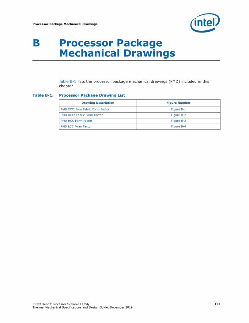
Processor Package Mechanical Drawings
Intel® Xeon® Processor Scalable Family 113Thermal Mechanical Specifications and Design Guide, December 2019
B Processor Package Mechanical Drawings
Table B-1 lists the processor package mechanical drawings (PMD) included in this chapter.
Table B-1. Processor Package Drawing List
Drawing Description Figure Number
PMD XCC: Non Fabric Form Factor Figure B-1
PMD XCC: Fabric Form Factor Figure B-2
PMD HCC Form Factor Figure B-3
PMD LCC Form Factor Figure B-4
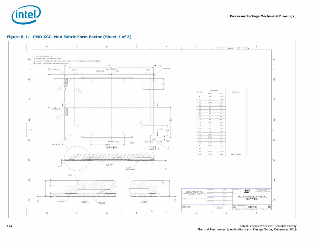
Processor Package Mechanical Drawings
114 Intel® Xeon® Processor Scalable FamilyThermal Mechanical Specifications and Design Guide, December 2019
Figure B-1. PMD XCC: Non Fabric Form Factor (Sheet 1 of 3)
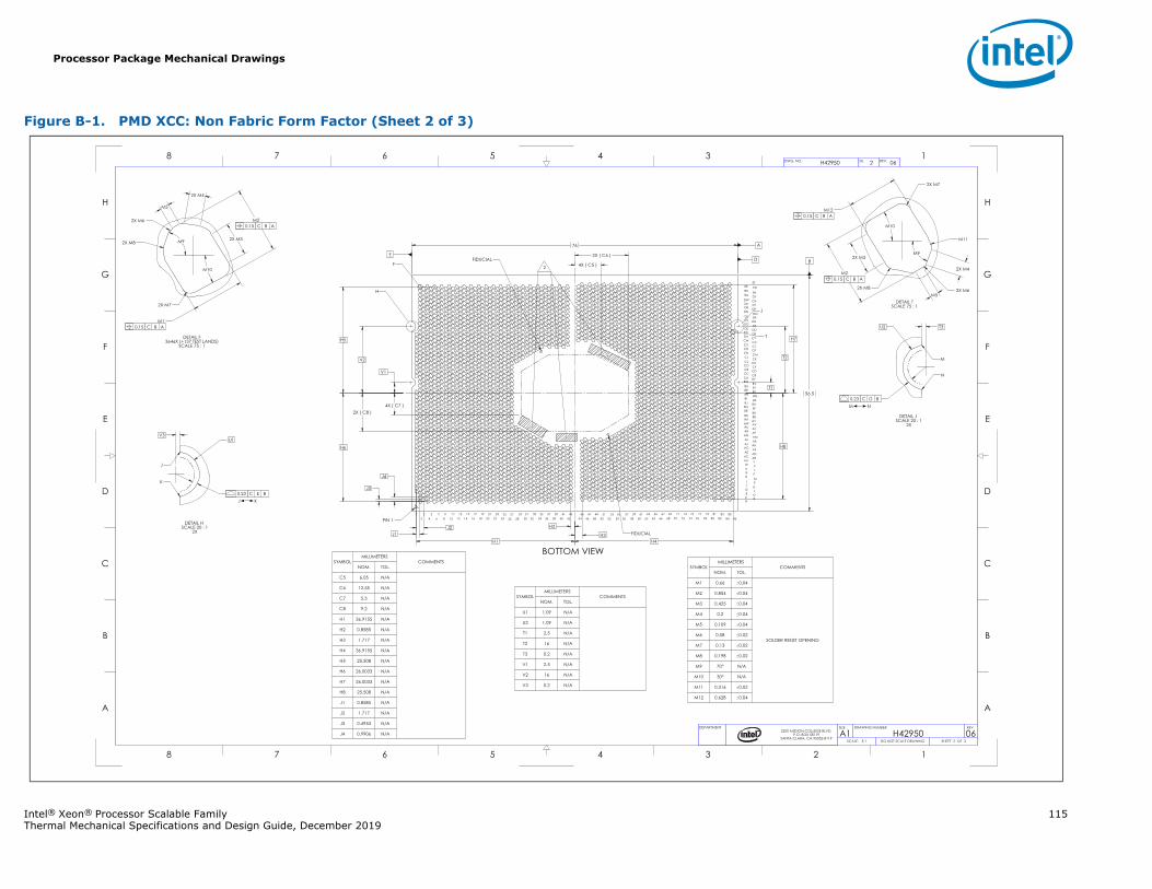
Processor Package Mechanical Drawings
Intel® Xeon® Processor Scalable Family 115Thermal Mechanical Specifications and Design Guide, December 2019
Figure B-1. PMD XCC: Non Fabric Form Factor (Sheet 2 of 3)
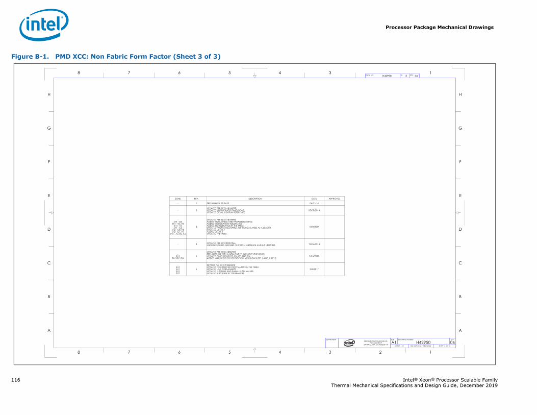
Processor Package Mechanical Drawings
116 Intel® Xeon® Processor Scalable FamilyThermal Mechanical Specifications and Design Guide, December 2019
Figure B-1. PMD XCC: Non Fabric Form Factor (Sheet 3 of 3)
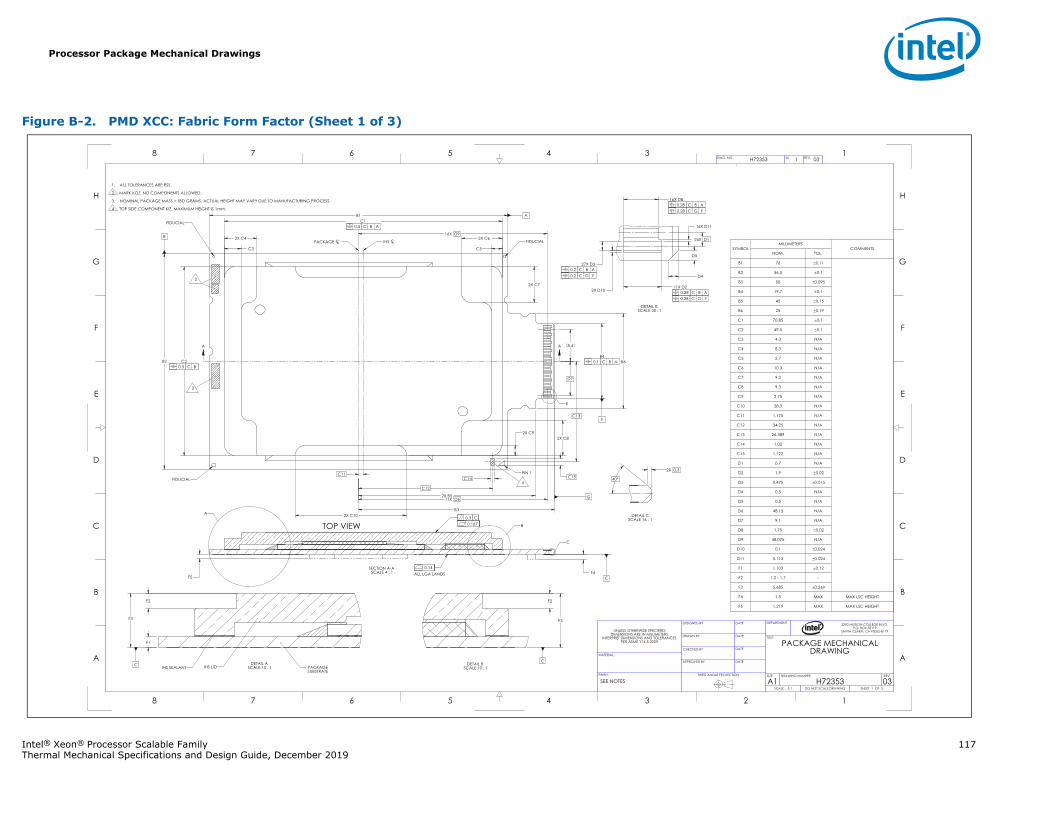
Processor Package Mechanical Drawings
Intel® Xeon® Processor Scalable Family 117Thermal Mechanical Specifications and Design Guide, December 2019
Figure B-2. PMD XCC: Fabric Form Factor (Sheet 1 of 3)
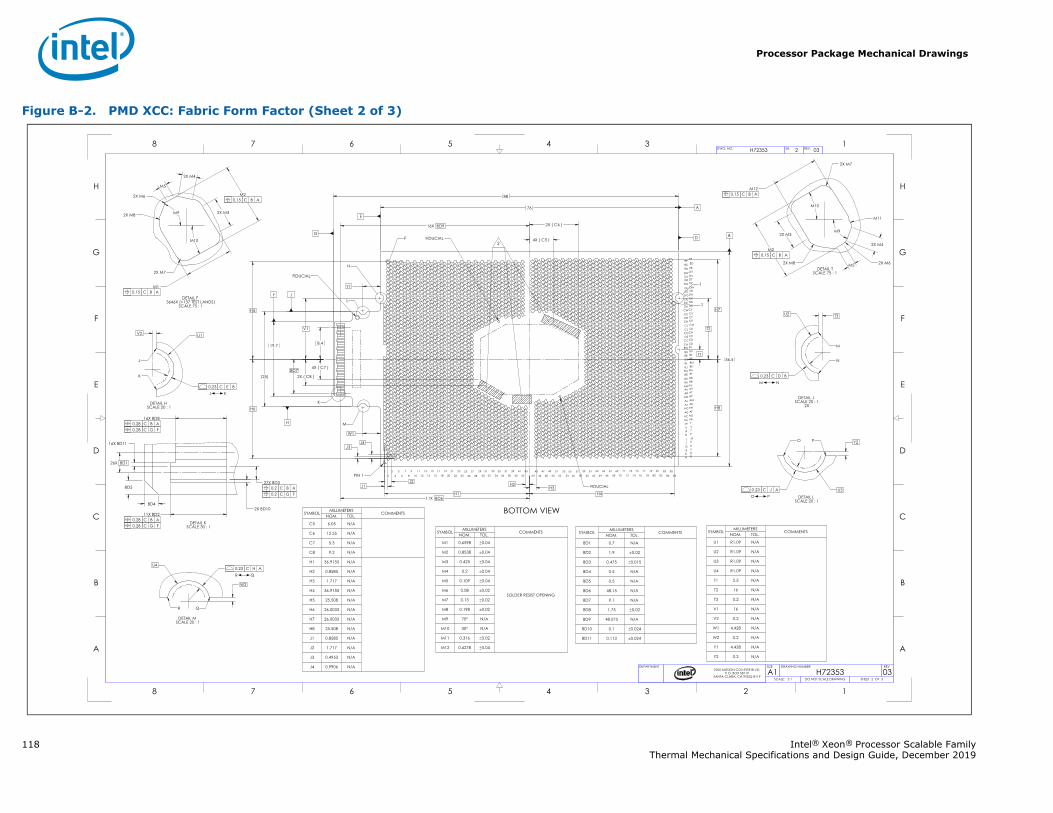
Processor Package Mechanical Drawings
118 Intel® Xeon® Processor Scalable FamilyThermal Mechanical Specifications and Design Guide, December 2019
Figure B-2. PMD XCC: Fabric Form Factor (Sheet 2 of 3)
Processor Package Mechanical Drawings
Intel® Xeon® Processor Scalable Family 119Thermal Mechanical Specifications and Design Guide, December 2019
Figure B-2. PMD XCC: Fabric Form Factor (Sheet 3 of 3)
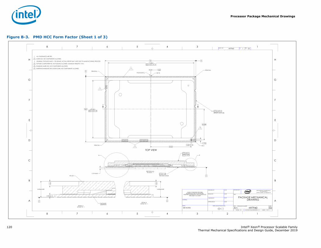
Processor Package Mechanical Drawings
120 Intel® Xeon® Processor Scalable FamilyThermal Mechanical Specifications and Design Guide, December 2019
Figure B-3. PMD HCC Form Factor (Sheet 1 of 3)
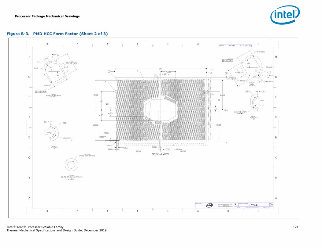
Processor Package Mechanical Drawings
Intel® Xeon® Processor Scalable Family 121Thermal Mechanical Specifications and Design Guide, December 2019
Figure B-3. PMD HCC Form Factor (Sheet 2 of 3)
Processor Package Mechanical Drawings
122 Intel® Xeon® Processor Scalable FamilyThermal Mechanical Specifications and Design Guide, December 2019
Figure B-3. PMD HCC Form Factor (Sheet 3 of 3)
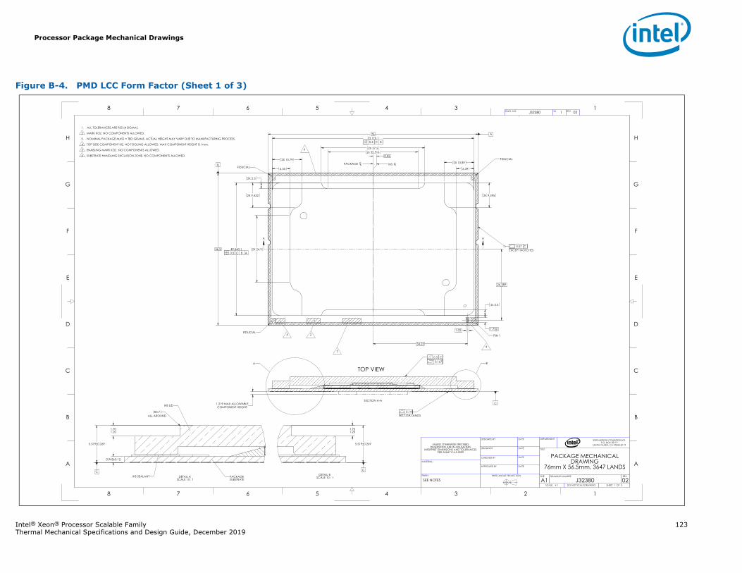
Processor Package Mechanical Drawings
Intel® Xeon® Processor Scalable Family 123Thermal Mechanical Specifications and Design Guide, December 2019
Figure B-4. PMD LCC Form Factor (Sheet 1 of 3)
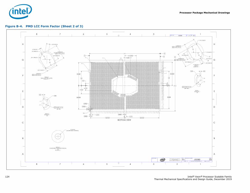
Processor Package Mechanical Drawings
124 Intel® Xeon® Processor Scalable FamilyThermal Mechanical Specifications and Design Guide, December 2019
Figure B-4. PMD LCC Form Factor (Sheet 2 of 3)
Processor Package Mechanical Drawings
Intel® Xeon® Processor Scalable Family 125Thermal Mechanical Specifications and Design Guide, December 2019
§
Figure B-4. PMD LCC Form Factor (Sheet 3 of 3)
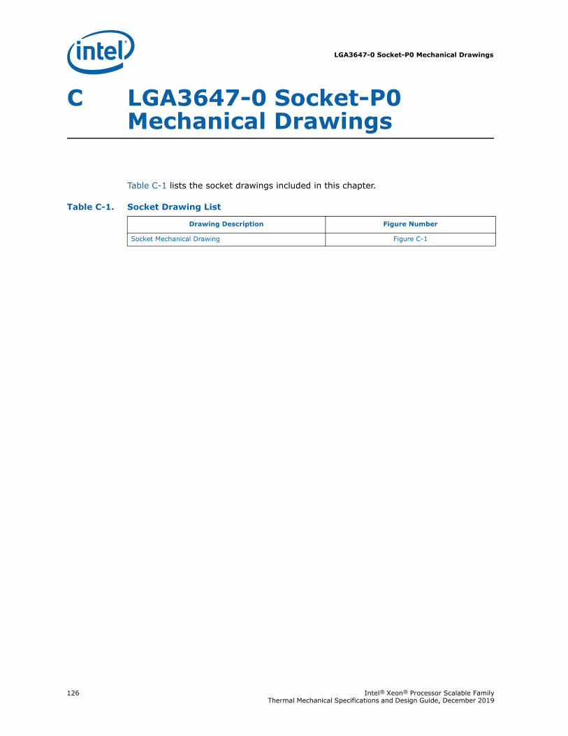
LGA3647-0 Socket-P0 Mechanical Drawings
126 Intel® Xeon® Processor Scalable Family Thermal Mechanical Specifications and Design Guide, December 2019
C LGA3647-0 Socket-P0 Mechanical Drawings
Table C-1 lists the socket drawings included in this chapter.
Table C-1. Socket Drawing List
Drawing Description Figure Number
Socket Mechanical Drawing Figure C-1
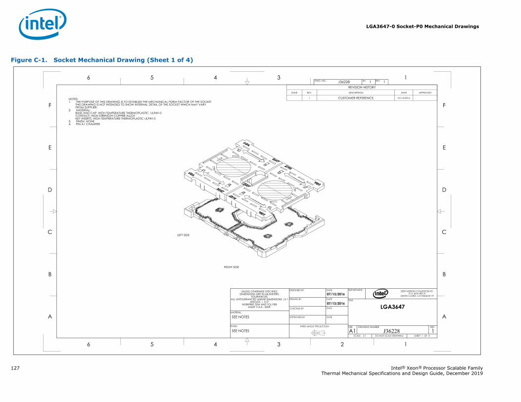
LGA3647-0 Socket-P0 Mechanical Drawings
127 Intel® Xeon® Processor Scalable FamilyThermal Mechanical Specifications and Design Guide, December 2019
Figure C-1. Socket Mechanical Drawing (Sheet 1 of 4)
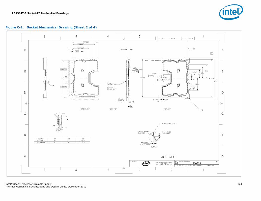
LGA3647-0 Socket-P0 Mechanical Drawings
Intel® Xeon® Processor Scalable Family 128Thermal Mechanical Specifications and Design Guide, December 2019
Figure C-1. Socket Mechanical Drawing (Sheet 2 of 4)
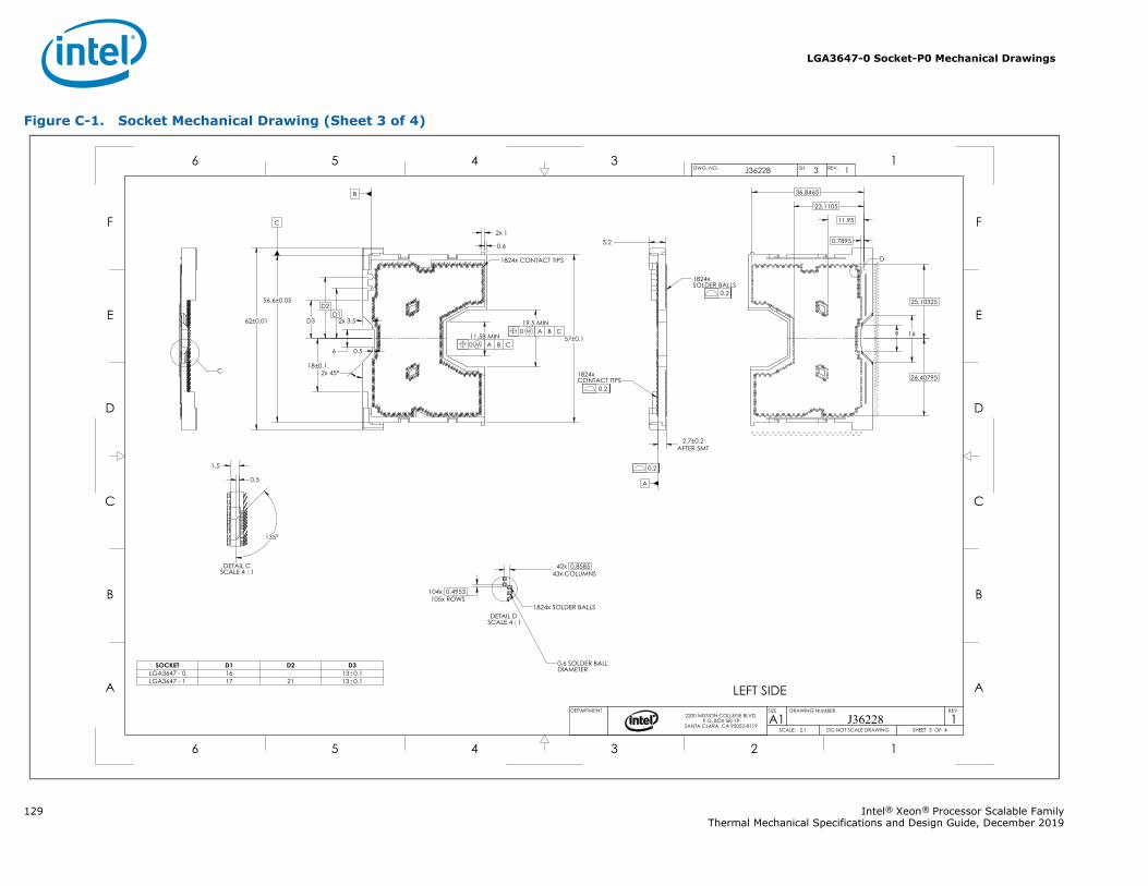
LGA3647-0 Socket-P0 Mechanical Drawings
129 Intel® Xeon® Processor Scalable FamilyThermal Mechanical Specifications and Design Guide, December 2019
Figure C-1. Socket Mechanical Drawing (Sheet 3 of 4)
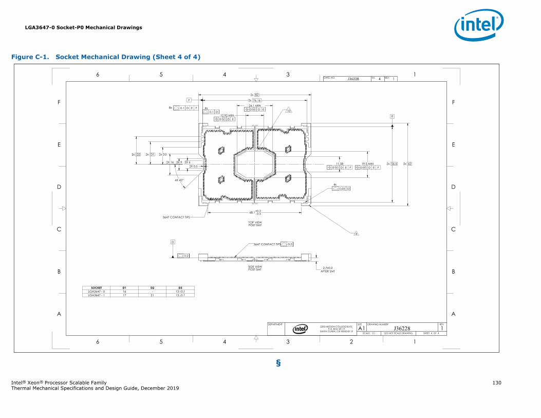
LGA3647-0 Socket-P0 Mechanical Drawings
Intel® Xeon® Processor Scalable Family 130Thermal Mechanical Specifications and Design Guide, December 2019
§
Figure C-1. Socket Mechanical Drawing (Sheet 4 of 4)
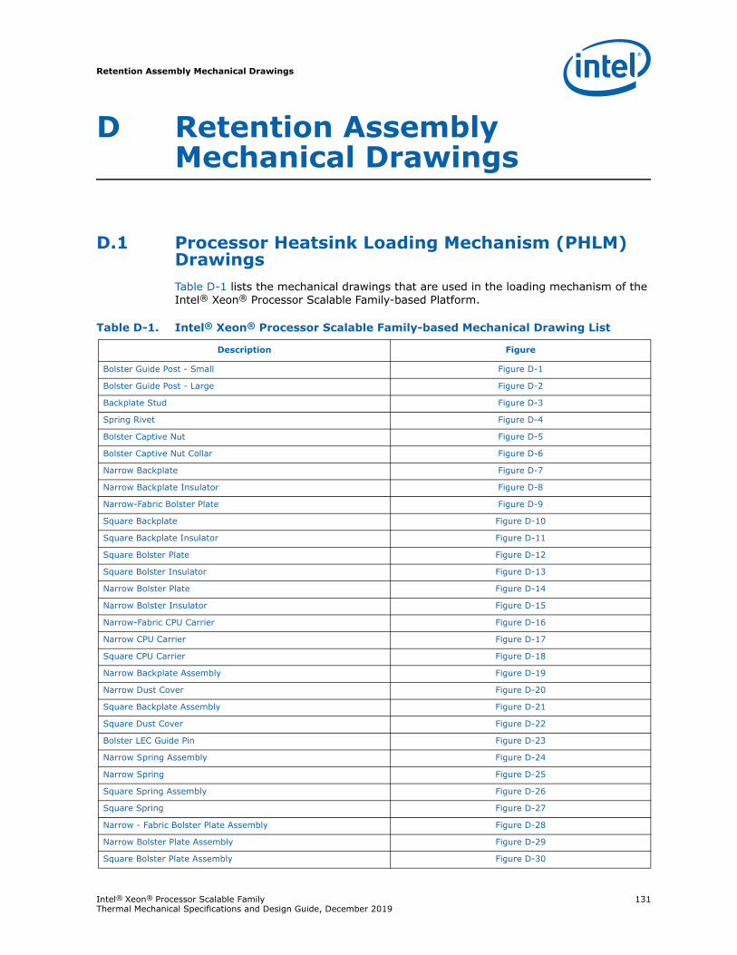
Retention Assembly Mechanical Drawings
Intel® Xeon® Processor Scalable Family 131Thermal Mechanical Specifications and Design Guide, December 2019
D Retention Assembly Mechanical Drawings
D.1 Processor Heatsink Loading Mechanism (PHLM) DrawingsTable D-1 lists the mechanical drawings that are used in the loading mechanism of the Intel® Xeon® Processor Scalable Family-based Platform.
Table D-1. Intel® Xeon® Processor Scalable Family-based Mechanical Drawing List
Description Figure
Bolster Guide Post - Small Figure D-1
Bolster Guide Post - Large Figure D-2
Backplate Stud Figure D-3
Spring Rivet Figure D-4
Bolster Captive Nut Figure D-5
Bolster Captive Nut Collar Figure D-6
Narrow Backplate Figure D-7
Narrow Backplate Insulator Figure D-8
Narrow-Fabric Bolster Plate Figure D-9
Square Backplate Figure D-10
Square Backplate Insulator Figure D-11
Square Bolster Plate Figure D-12
Square Bolster Insulator Figure D-13
Narrow Bolster Plate Figure D-14
Narrow Bolster Insulator Figure D-15
Narrow-Fabric CPU Carrier Figure D-16
Narrow CPU Carrier Figure D-17
Square CPU Carrier Figure D-18
Narrow Backplate Assembly Figure D-19
Narrow Dust Cover Figure D-20
Square Backplate Assembly Figure D-21
Square Dust Cover Figure D-22
Bolster LEC Guide Pin Figure D-23
Narrow Spring Assembly Figure D-24
Narrow Spring Figure D-25
Square Spring Assembly Figure D-26
Square Spring Figure D-27
Narrow - Fabric Bolster Plate Assembly Figure D-28
Narrow Bolster Plate Assembly Figure D-29
Square Bolster Plate Assembly Figure D-30
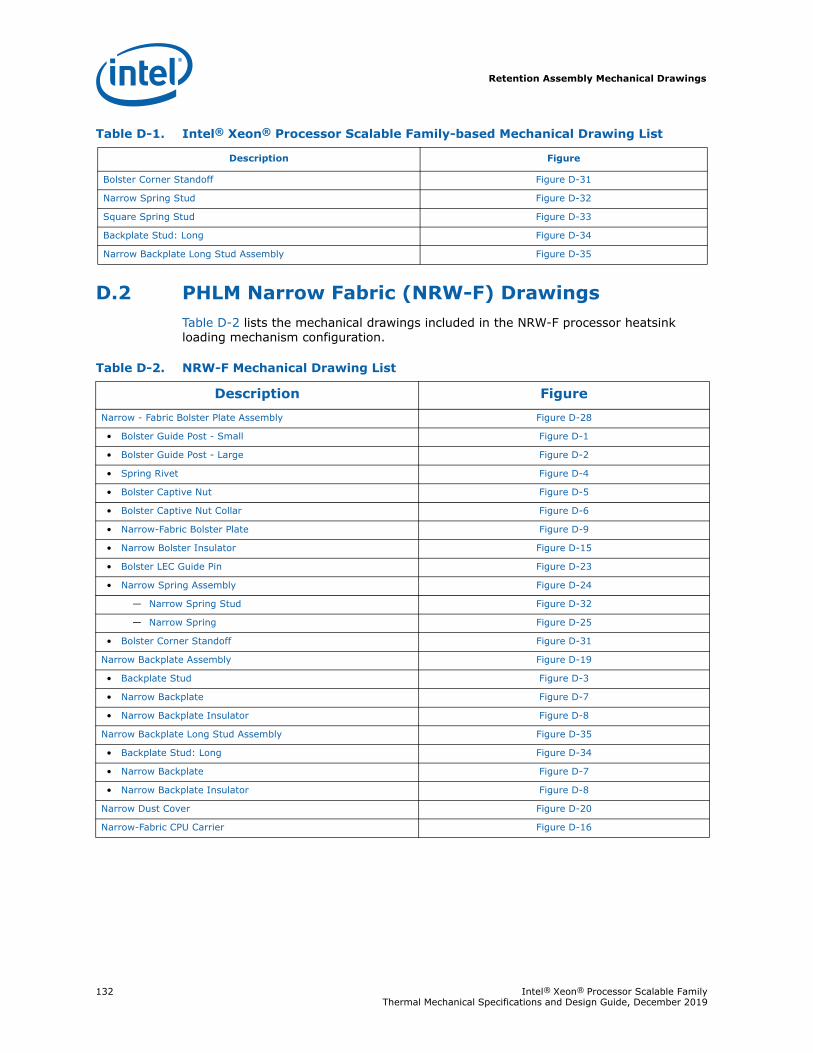
Retention Assembly Mechanical Drawings
132 Intel® Xeon® Processor Scalable Family Thermal Mechanical Specifications and Design Guide, December 2019
D.2 PHLM Narrow Fabric (NRW-F) DrawingsTable D-2 lists the mechanical drawings included in the NRW-F processor heatsink loading mechanism configuration.
Bolster Corner Standoff Figure D-31
Narrow Spring Stud Figure D-32
Square Spring Stud Figure D-33
Backplate Stud: Long Figure D-34
Narrow Backplate Long Stud Assembly Figure D-35
Table D-1. Intel® Xeon® Processor Scalable Family-based Mechanical Drawing List
Description Figure
Table D-2. NRW-F Mechanical Drawing List
Description FigureNarrow - Fabric Bolster Plate Assembly Figure D-28
• Bolster Guide Post - Small Figure D-1
• Bolster Guide Post - Large Figure D-2
• Spring Rivet Figure D-4
• Bolster Captive Nut Figure D-5
• Bolster Captive Nut Collar Figure D-6
• Narrow-Fabric Bolster Plate Figure D-9
• Narrow Bolster Insulator Figure D-15
• Bolster LEC Guide Pin Figure D-23
• Narrow Spring Assembly Figure D-24
— Narrow Spring Stud Figure D-32
— Narrow Spring Figure D-25
• Bolster Corner Standoff Figure D-31
Narrow Backplate Assembly Figure D-19
• Backplate Stud Figure D-3
• Narrow Backplate Figure D-7
• Narrow Backplate Insulator Figure D-8
Narrow Backplate Long Stud Assembly Figure D-35
• Backplate Stud: Long Figure D-34
• Narrow Backplate Figure D-7
• Narrow Backplate Insulator Figure D-8
Narrow Dust Cover Figure D-20
Narrow-Fabric CPU Carrier Figure D-16
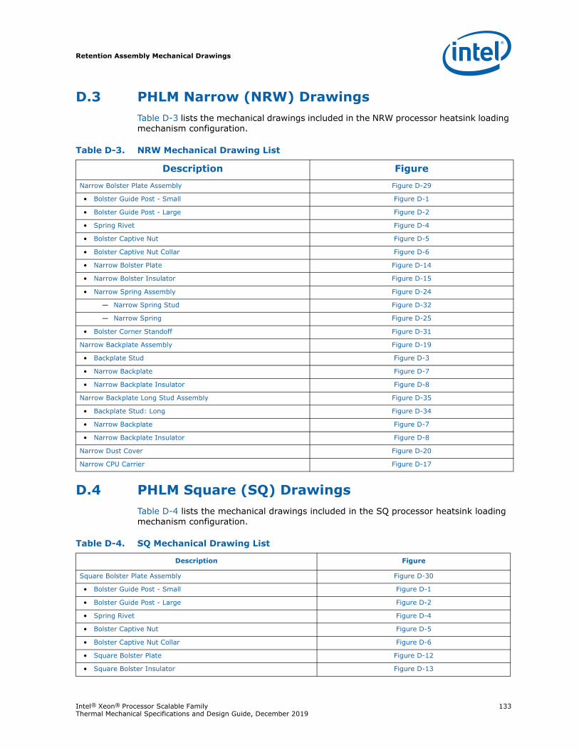
Retention Assembly Mechanical Drawings
Intel® Xeon® Processor Scalable Family 133Thermal Mechanical Specifications and Design Guide, December 2019
D.3 PHLM Narrow (NRW) DrawingsTable D-3 lists the mechanical drawings included in the NRW processor heatsink loading mechanism configuration.
D.4 PHLM Square (SQ) DrawingsTable D-4 lists the mechanical drawings included in the SQ processor heatsink loading mechanism configuration.
Table D-3. NRW Mechanical Drawing List
Description FigureNarrow Bolster Plate Assembly Figure D-29
• Bolster Guide Post - Small Figure D-1
• Bolster Guide Post - Large Figure D-2
• Spring Rivet Figure D-4
• Bolster Captive Nut Figure D-5
• Bolster Captive Nut Collar Figure D-6
• Narrow Bolster Plate Figure D-14
• Narrow Bolster Insulator Figure D-15
• Narrow Spring Assembly Figure D-24
— Narrow Spring Stud Figure D-32
— Narrow Spring Figure D-25
• Bolster Corner Standoff Figure D-31
Narrow Backplate Assembly Figure D-19
• Backplate Stud Figure D-3
• Narrow Backplate Figure D-7
• Narrow Backplate Insulator Figure D-8
Narrow Backplate Long Stud Assembly Figure D-35
• Backplate Stud: Long Figure D-34
• Narrow Backplate Figure D-7
• Narrow Backplate Insulator Figure D-8
Narrow Dust Cover Figure D-20
Narrow CPU Carrier Figure D-17
Table D-4. SQ Mechanical Drawing List
Description Figure
Square Bolster Plate Assembly Figure D-30
• Bolster Guide Post - Small Figure D-1
• Bolster Guide Post - Large Figure D-2
• Spring Rivet Figure D-4
• Bolster Captive Nut Figure D-5
• Bolster Captive Nut Collar Figure D-6
• Square Bolster Plate Figure D-12
• Square Bolster Insulator Figure D-13
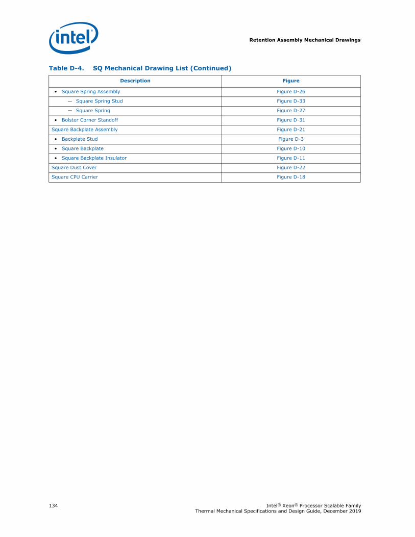
Retention Assembly Mechanical Drawings
134 Intel® Xeon® Processor Scalable Family Thermal Mechanical Specifications and Design Guide, December 2019
• Square Spring Assembly Figure D-26
— Square Spring Stud Figure D-33
— Square Spring Figure D-27
• Bolster Corner Standoff Figure D-31
Square Backplate Assembly Figure D-21
• Backplate Stud Figure D-3
• Square Backplate Figure D-10
• Square Backplate Insulator Figure D-11
Square Dust Cover Figure D-22
Square CPU Carrier Figure D-18
Table D-4. SQ Mechanical Drawing List (Continued)
Description Figure
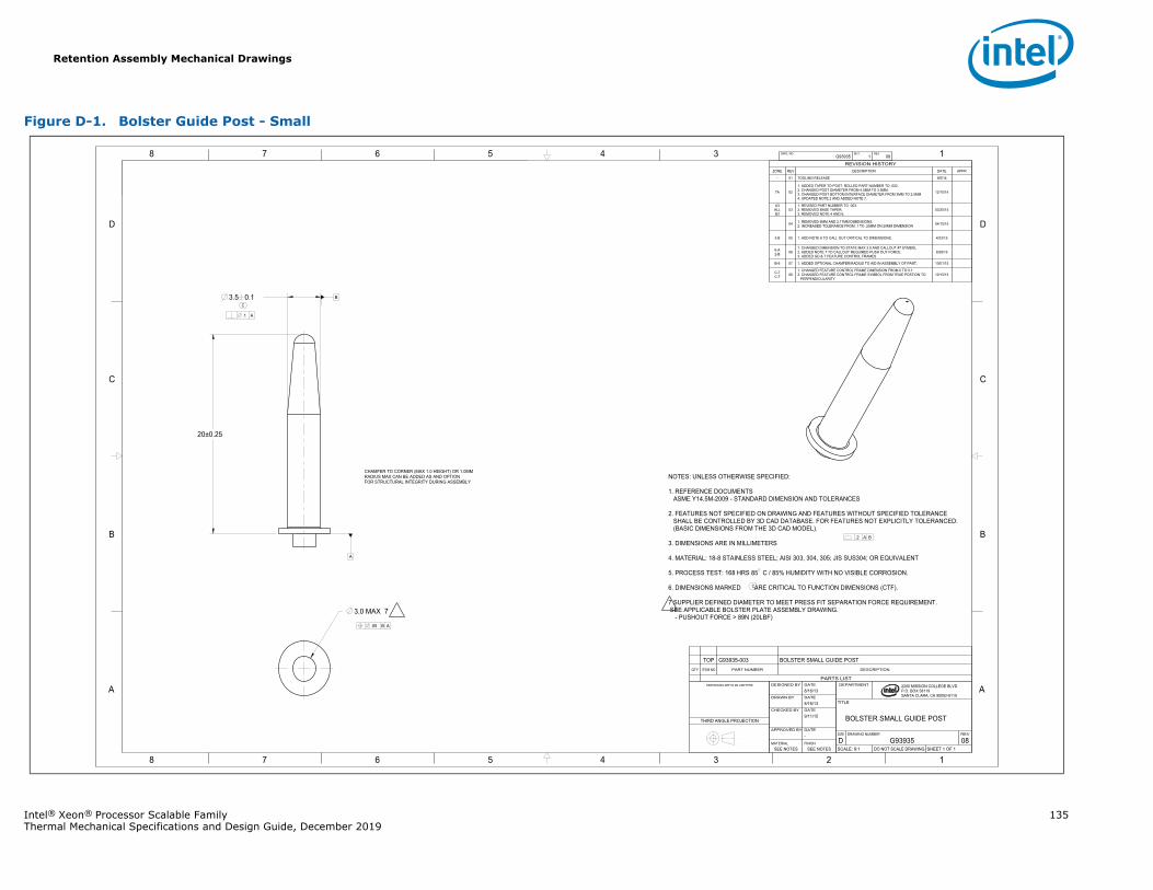
Retention Assembly Mechanical Drawings
Intel® Xeon® Processor Scalable Family 135Thermal Mechanical Specifications and Design Guide, December 2019
Figure D-1. Bolster Guide Post - Small
1345678
B
C
D
A
12345678
B
C
D
A
B
2200 MISSION COLLEGE BLVD.P.O. BOX 58119SANTA CLARA, CA 95052-8119
R
.1 A
.05 B A
.2 A B
3.5 0.1
3.0 MAX 7
20±0.25
A
G93935 1 08DWG. NO SHT. REV
SHEET 1 OF 1DO NOT SCALE DRAWINGSCALE: 9:108G93935DREVDRAWING NUMBERSIZE
BOLSTER SMALL GUIDE POST
TITLE
DEPARTMENT
SEE NOTESSEE NOTESFINISHMATERIAL
-DATEAPPROVED BY
9/11/15DATECHECKED BY
8/16/13DATEDRAWN BY
8/16/13DATEDESIGNED BYDIMENSIONS ARE IN MILLIMETERS
THIRD ANGLE PROJECTION
REVISION HISTORYZONE REV DESCRIPTION DATE APPR
- 01 TOOLING RELEASE 9/5/14
7A 02
1. ADDED TAPER TO POST. ROLLED PART NUMBER TO -002.2. CHANGED POST DIAMETER FROM 4.5MM TO 3.5MM.3. CHANGED POST BOTTOM INTERFACE DIAMETER FROM 3MM TO 2.5MM4. UPDATED NOTE 2 AND ADDED NOTE 7.
12/10/14
A3ALLB3
031. REVISED PART NUMBER TO -003.2. REMOVED BASE TAPER.3. REMOVED NOTE 4 AND 6.
03/25/15
04 1. REMOVED 8MM AND 2.17MM DIMENSIONS.2. INCREASED TOLERANCE FROM .1 TO .25MM ON 20MM DIMENSION 04/15/15
3-B 05 1. ADD NOTE 6 TO CALL OUT CRITICAL TO DIMENSIONS. 4/23/15
6-A2-B 06
1. CHANGED DIMENSION TO STATE MAX 3.0 AND CALLOUT #7 SYMBOL2. ADDED NOTE 7 TO CALLOUT REQUIRED PUSH OUT FORCE.3. ADDED GD & T FEATURE CONTROL FRAMES
8/28/15
B-6 07 1. ADDED OPTIONAL CHAMFER/RADIUS TO AID IN ASSEMBLY OF PART. 10/01/15
C-7C-7 08
1. CHANGED FEATURE CONTROL FRAME DIMENSION FROM 0 TO 0.1.2. CHANGED FEATURE CONTROL FRAME SYMBOL FROM TRUE POSTION TO PERPENDICULARITY
10/15/15
NOTES: UNLESS OTHERWISE SPECIFIED:
1. REFERENCE DOCUMENTSASME Y14.5M-2009 - STANDARD DIMENSION AND TOLERANCES
2. FEATURES NOT SPECIFIED ON DRAWING AND FEATURES WITHOUT SPECIFIED TOLERANCESHALL BE CONTROLLED BY 3D CAD DATABASE. FOR FEATURES NOT EXPLICITLY TOLERANCED:(BASIC DIMENSIONS FROM THE 3D CAD MODEL).
3. DIMENSIONS ARE IN MILLIMETERS
4. MATERIAL: 18-8 STAINLESS STEEL; AISI 303, 304, 305; JIS SUS304; OR EQUIVALENT
5. PROCESS TEST: 168 HRS 85 C / 85% HUMIDITY WITH NO VISIBLE CORROSION.
6. DIMENSIONS MARKED ARE CRITICAL TO FUNCTION DIMENSIONS (CTF).
7 SUPPLIER DEFINED DIAMETER TO MEET PRESS FIT SEPARATION FORCE REQUIREMENT. SEE APPLICABLE BOLSTER PLATE ASSEMBLY DRAWING.
- PUSHOUT FORCE > 89N (20LBF)
CHAMFER TO CORNER (MAX 1.0 HEIGHT) OR 1.0MMRADIUS MAX CAN BE ADDED AS AND OPTIONFOR STRUCTURAL INTEGRITY DURING ASSEMBLY
C
C
PARTS LIST
DESCRIPTIONPART NUMBERITEM NOQTY
BOLSTER SMALL GUIDE POSTG93935-003TOP
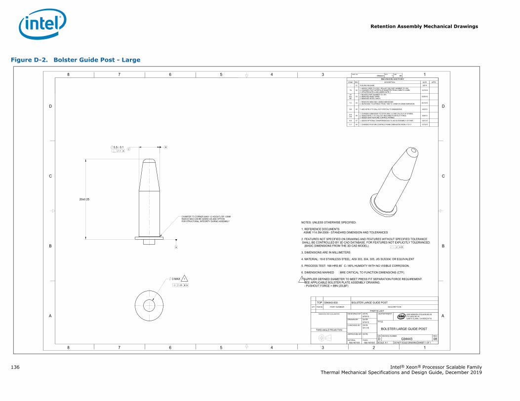
Retention Assembly Mechanical Drawings
136 Intel® Xeon® Processor Scalable FamilyThermal Mechanical Specifications and Design Guide, December 2019
Figure D-2. Bolster Guide Post - Large
1345678
B
C
D
A
12345678
B
C
D
A
B
2200 MISSION COLLEGE BLVD.P.O. BOX 58119SANTA CLARA, CA 95052-8119
R
.05 B A
.2 A B
.1 A5.5 0.1
3 MAX
20±0.25
A
G94443 1 08DWG. NO SHT. REV
SHEET 1 OF 1DO NOT SCALE DRAWINGSCALE: 9:108G94443DREVDRAWING NUMBERSIZE
BOLSTER LARGE GUIDE POST
TITLE
DEPARTMENT
SEE NOTESSEE NOTESFINISHMATERIAL
-DATEAPPROVED BY
9/11/15DATECHECKED BY
8/16/13DATEDRAWN BY
8/16/13DATEDESIGNED BYDIMENSIONS ARE IN MILLIMETERS
THIRD ANGLE PROJECTION
REVISION HISTORYZONE REV DESCRIPTION DATE APPR
- 01 TOOLING RELEASE 9/5/14
7A 021. ADDED TAPER TO POST. ROLLED THE PART NUMBER TO -002.2. CHANGED POST INTERFACE DIAMETER FROM 2.5MM TO 3.0MM.3. UPDATED NOTE 2 AND ADDED NOTE 7.
12/10/14
A3ALLB3
031. REVISED PART NUMBER TO -003.2. REMOVED BASE TAPER.3. REMOVED NOTE 4 AND 6.
03/25/15
7-C 04 1. REMOVED 8MM AND 3.26MM DIMENSIONS2. INCREASED TOLERANCE FROM .1MM TO .25MM ON 20MM DIMENSION. 04/15/15
3-B 05 1. ADD NOTE 6 TO CALL OUT CRITICAL TO DIMENSIONS. 4/23/15
6-A2-B 06
1. CHANGED DIMENSION TO STATE MAX 3.0 AND CALLOUT #7 SYMBOL2. ADDED NOTE 7 TO CALLOUT REQUIRED PUSH OUT FORCE.3. ADDED GD&T FEATURE CONTROL FRAMES.
8/28/15
B-6 07 1. ADDED OPTIONAL CHAMFER/RADIUS TO AID IN ASSEMBLY OF PART. 10/01/15
C-7 08 1. CHANGED FEATURE CONTROL FRAME DIMENSION FROM 0 TO 0.1 10/15/15
NOTES: UNLESS OTHERWISE SPECIFIED:
1. REFERENCE DOCUMENTSASME Y14.5M-2009 - STANDARD DIMENSION AND TOLERANCES
2. FEATURES NOT SPECIFIED ON DRAWING AND FEATURES WITHOUT SPECIFIED TOLERANCESHALL BE CONTROLLED BY 3D CAD DATABASE. FOR FEATURES NOT EXPLICITLY TOLERANCED:
(BASIC DIMENSIONS FROM THE 3D CAD MODEL).
3. DIMENSIONS ARE IN MILLIMETERS
4. MATERIAL: 18-8 STAINLESS STEEL; AISI 303, 304, 305; JIS SUS304; OR EQUIVALENT
5. PROCESS TEST: 168 HRS 85 C / 85% HUMIDITY WITH NO VISIBLE CORROSION.
6. DIMENSIONS MARKED ARE CRITICAL TO FUNCTION DIMENSIONS (CTF).
7 SUPPLIER DEFINED DIAMETER TO MEET PRESS FIT SEPARATION FORCE REQUIREMENT. SEE APPLICABLE BOLSTER PLATE ASSEMBLY DRAWING.
- PUSHOUT FORCE > 89N (20LBF)
7
CHAMFER TO CORNER (MAX 1.0 HEIGHT) OR 1.0MM RADIUS MAX CAN BE ADDED AS AND OPTIONFOR STRUCTURAL INTEGRITY DURING ASSEMBLY
C
C
PARTS LIST
DESCRIPTIONPART NUMBERITEM NOQTY
BOLSTER LARGE GUIDE POSTG94443-003TOP
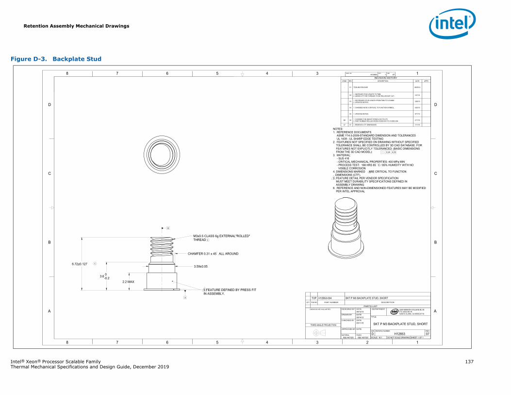
Retention Assembly Mechanical Drawings
Intel® Xeon® Processor Scalable Family 137Thermal Mechanical Specifications and Design Guide, December 2019
Figure D-3. Backplate Stud
1345678
B
C
D
A
12345678
B
C
D
A 2200 MISSION COLLEGE BLVD.P.O. BOX 58119SANTA CLARA, CA 95052-8119
R
0.24 A B
6.72±0.127
3.6 0-0.2
2.2 MAX
3.59±0.05
CHAMFER 0.31 x 45 ALL AROUND
A
H12853 1 07DWG. NO SHT. REV
SHEET 1 OF 1DO NOT SCALE DRAWINGSCALE: 16:107H12853DREVDRAWING NUMBERSIZE
SKT P M3 BACKPLATE STUD, SHORT
TITLE
DEPARTMENT
SEE NOTESSEE NOTESFINISHMATERIAL
-DATEAPPROVED BY
09/11/15DATECHECKED BY
08/14/13DATEDRAWN BY
08/14/13DATEDESIGNED BY DIMENSIONS ARE IN MILLIMETERS
THIRD ANGLE PROJECTION
REVISION HISTORYZONE REV DESCRIPTION DATE APPR
- 01 TOOLING RELEASE 08/20/14
02 1. INCREASE STUD LENGTH TO 7MM.2. ADDED CTF FOR THREADS TO BE ROLLED NOT CUT. 12/1/14
03 1. DECREASED STUD LENGTH FROM 7MM TO 6.334MM.2. UPDATED NOTES. 3/26/15
04 1. CHANGED NOTE 4 CRITICAL TO FUNCTION SYMBOL. 4/23/15
05 1. UPDATED NOTES. 9/11/15
B8 06 1. CHANGED THE HEIGHT FROM 6.334 TO 6.722. PART NUMBER ROLLED FROM H12853-003 TO H12583-004. 2/11/16
A7 07 1. REMOVED CTF DIMENSIONS. 7/11/16
NOTES:1. REFERENCE DOCUMENTS
ASME Y14.5-2009-STANDARD DIMENSION AND TOLERANCESUL 1439 - UL SHARP EDGE TESTING
2. FEATURES NOT SPECIFIED ON DRAWING WITHOUT SPECIFIEDTOLERANCE SHALL BE CONTROLLED BY 3D CAD DATABASE. FORFEATURES NOT EXPLICITLY TOLERANCED: (BASIC DIMENSIONSFROM THE 3D CAD MODEL):
3. MATERIAL:- SUS 416- CRITICAL MECHANICAL PROPERTIES: 400 MPa MIN- PROCESS TEST: 168 HRS 85 C / 85% HUMIDITY WITH NOVISIBLE CORROSION
4. DIMENSIONS MARKED ARE CRITICAL TO FUNCTION DIMENSIONS (CTF). 5 FEATURE DETAIL PER VENDOR SPECIFICATION MUST MEET DURABILITY SPECIFICATIONS DEFINED IN ASSEMBLY DRAWING6. REFERENCE AND NON-DIMENSIONED FEATURES MAY BE MODIFIED
PER INTEL APPROVAL
M3x0.5 CLASS 6g EXTERNAL"ROLLED" THREAD
5 FEATURE DEFINED BY PRESS FITIN ASSEMBLY.
C
C
C
B
PARTS LIST
DESCRIPTIONPART NUMBERITEM NOQTY
SKT P M3 BACKPLATE STUD, SHORTH12853-004TOP
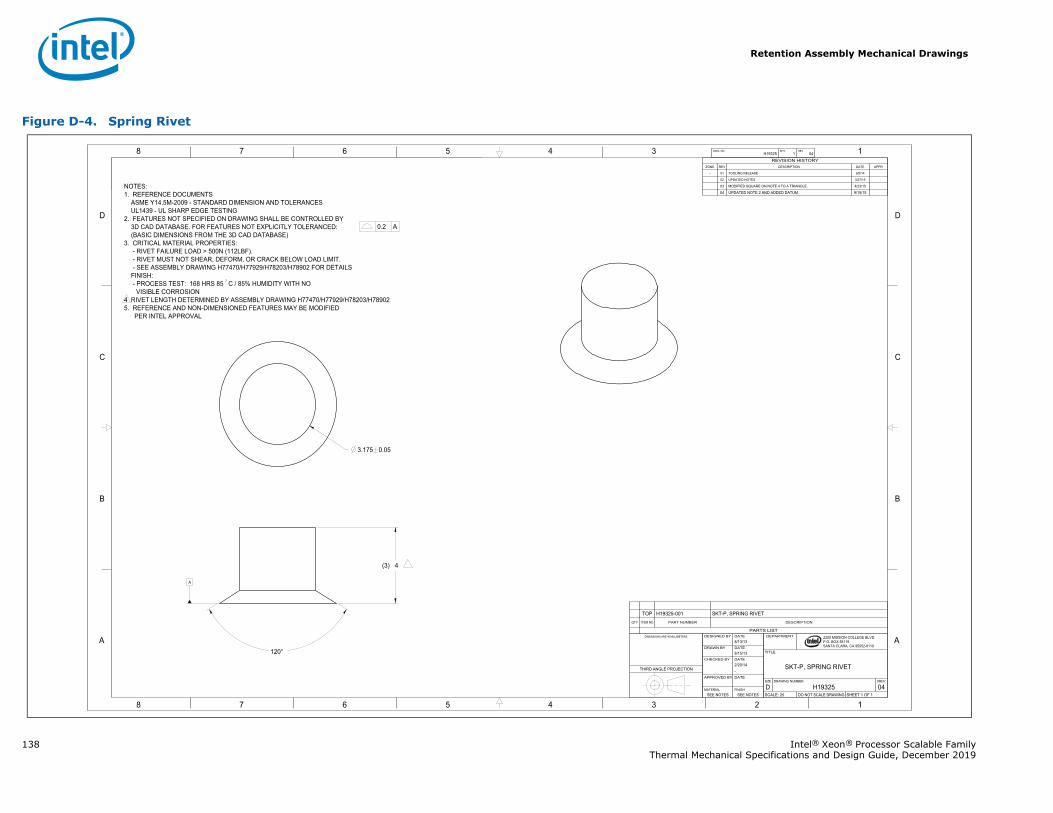
Retention Assembly Mechanical Drawings
138 Intel® Xeon® Processor Scalable FamilyThermal Mechanical Specifications and Design Guide, December 2019
Figure D-4. Spring Rivet
1345678
B
C
D
A
12345678
B
C
D
A 2200 MISSION COLLEGE BLVD.P.O. BOX 58119SANTA CLARA, CA 95052-8119
R
0.2 A
120°
3.175 0.05
A
(3) 4
H19325 1 04DWG. NO SHT. REV
SHEET 1 OF 1DO NOT SCALE DRAWINGSCALE: 2504H19325DREVDRAWING NUMBERSIZE
SKT-P, SPRING RIVET
TITLE
DEPARTMENT
SEE NOTESSEE NOTESFINISHMATERIAL
DATEAPPROVED BY
-2/20/14 DATECHECKED BY
8/15/13DATEDRAWN BY
8/13/13DATEDESIGNED BYDIMENSIONS ARE IN MILLIMETERS.
THIRD ANGLE PROJECTION
PARTS LIST
DESCRIPTIONPART NUMBERITEM NOQTY
SKT-P, SPRING RIVETH19325-001TOP
REVISION HISTORYZONE REV DESCRIPTION DATE APPR
- 01 TOOLING RELEASE 9/5/14
02 UPDATED NOTES 3/27/15
03 MODIFIED SQUARE ON NOTE 4 TO A TRIANGLE. 4/23/15
04 UPDATED NOTE 2 AND ADDED DATUM. 9/15/15NOTES:1. REFERENCE DOCUMENTS ASME Y14.5M-2009 - STANDARD DIMENSION AND TOLERANCES UL1439 - UL SHARP EDGE TESTING2. FEATURES NOT SPECIFIED ON DRAWING SHALL BE CONTROLLED BY 3D CAD DATABASE. FOR FEATURES NOT EXPLICITLY TOLERANCED: (BASIC DIMENSIONS FROM THE 3D CAD DATABASE)3. CRITICAL MATERIAL PROPERTIES:
- RIVET FAILURE LOAD > 500N (112LBF).- RIVET MUST NOT SHEAR, DEFORM, OR CRACK BELOW LOAD LIMIT.- SEE ASSEMBLY DRAWING H77470/H77929/H78203/H78902 FOR DETAILS
FINISH: - PROCESS TEST: 168 HRS 85 C / 85% HUMIDITY WITH NOVISIBLE CORROSION
4 RIVET LENGTH DETERMINED BY ASSEMBLY DRAWING H77470/H77929/H78203/H789025. REFERENCE AND NON-DIMENSIONED FEATURES MAY BE MODIFIED
PER INTEL APPROVAL
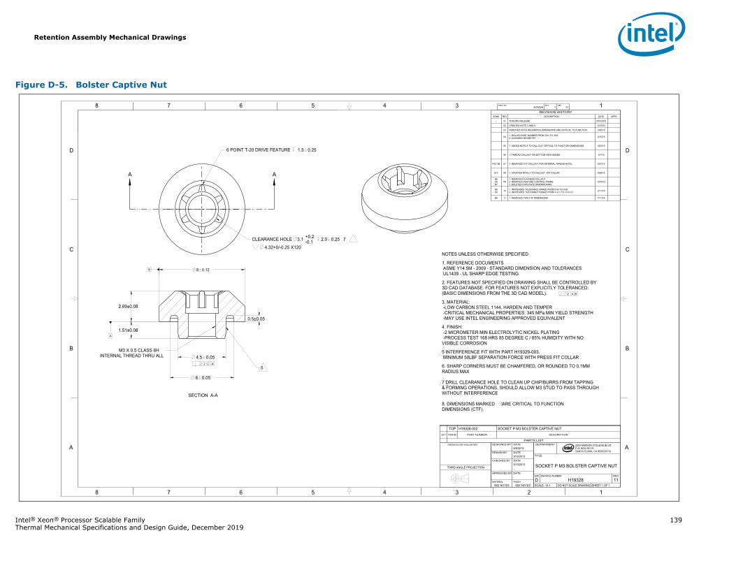
Retention Assembly Mechanical Drawings
Intel® Xeon® Processor Scalable Family 139Thermal Mechanical Specifications and Design Guide, December 2019
Figure D-5. Bolster Captive Nut
A A
1345678
B
C
D
A
12345678
B
C
D
A
B
2200 MISSION COLLEGE BLVD.P.O. BOX 58119SANTA CLARA, CA 95052-8119
R
.2 A B
.2 A
CLEARANCE HOLE 2.0 0.25 7
4.32+0/-0.25 X120
3.1 +0.2-0.1
4.5 0.05
2.69±0.08
1.51±0.08
6 0.05
0.5±0.05
8 0.12
A
H19328 1 11DWG. NO SHT. REV
SHEET 1 OF 1DO NOT SCALE DRAWINGSCALE: 14:111H19328DREVDRAWING NUMBERSIZE
SOCKET P M3 BOLSTER CAPTIVE NUT
TITLE
DEPARTMENT
SEE NOTESSEE NOTESFINISHMATERIAL
-DATEAPPROVED BY
-9/10/2013DATECHECKED BY
9/10/2013DATEDRAWN BY
8/8/2013DATEDESIGNED BY DIMENSIONS ARE IN MILLIMETERS
THIRD ANGLE PROJECTION
PARTS LIST
DESCRIPTIONPART NUMBERITEM NOQTY
SOCKET P M3 BOLSTER CAPTIVE NUTH19328-002TOP
REVISION HISTORYZONE REV DESCRIPTION DATE APPR
- 01 TOOLING RELEASE 9/10/2013
02 UPDATED NOTE 2 AND 6. 12/10/14
03 REMOVED NOTE REGARDING DIMENSIONS ARE CRITICAL TO FUNCTION. 3/26/15
04 1. ROLLED PART NUMBER FROM -001 TO -002.2. CHANGED GEOMETRY. 4/15/15
05 1. ADDED NOTE 8 TO CALL OUT CRITICAL TO FUNCTION DIMENSIONS. 4/23/15
06 1. THREAD CALLOUT ON BOTTOM VIEW ADDED. 5/1/15
PG1 8B 07 1. REMOVED CTF CALLOUT FOR INTERNAL THREAD NOTE. 5/21/15
B-3 08 1. UPDATED NOTE 5 TO CALLOUT -004 COLLAR 8/28/15
B6C6B7
091. REMOVED FLATNESS CALLOUT2. REMOVED FEATURE CONTROL FRAME3. DELETED DUPLICATE DIMENSIONING
10/15/15
B8C6 10 1. INCREASED TOLERANCE RANGE FROM 0.04 TO 0.08.
2. INCREASED TOELRANCE RANGE FROM +/-0.1 TO +0.2/-0.1 2/11/16
B6 11 1. REMOVED TWO CTF DIMENSIONS. 7/11/16
NOTES UNLESS OTHERWISE SPECIFIED
1. REFERENCE DOCUMENTSASME Y14.5M - 2009 - STANDARD DIMENSION AND TOLERANCESUL1439 - UL SHARP EDGE TESTING
2. FEATURES NOT SPECIFIED ON DRAWING SHALL BE CONTROLLED BY3D CAD DATABASE. FOR FEATURES NOT EXPLICITLY TOLERANCED:(BASIC DIMENSIONS FROM THE 3D CAD MODEL).
3. MATERIAL:-LOW CARBON STEEL 1144, HARDEN AND TEMPER-CRITICAL MECHANICAL PROPERTIES: 345 MPa MIN YIELD STRENGTH-MAY USE INTEL ENGINEERING APPROVED EQUIVALENT
4. FINISH:-2 MICROMETER MIN ELECTROLYTIC NICKEL PLATING-PROCESS TEST 168 HRS 85 DEGREE C / 85% HUMIDITY WITH NOVISIBLE CORROSION
5 INTERFERENCE FIT WITH PART H19329-003. MINIMUM 50LBF SEPARATION FORCE WITH PRESS FIT COLLAR
6. SHARP CORNERS MUST BE CHAMFERED, OR ROUNDED TO 0.1MMRADIUS MAX
7 DRILL CLEARANCE HOLE TO CLEAN UP CHIP/BURRS FROM TAPPING & FORMING OPERATIONS, SHOULD ALLOW M3 STUD TO PASS THROUGH WITHOUT INTERFERENCE
8. DIMENSIONS MARKED ARE CRITICAL TO FUNCTION DIMENSIONS (CTF).
6 POINT T-20 DRIVE FEATURE 1.5 0.25
SECTION A-A
5
M3 X 0.5 CLASS 6HINTERNAL THREAD THRU ALL
C
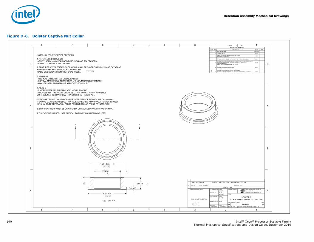
Retention Assembly Mechanical Drawings
140 Intel® Xeon® Processor Scalable FamilyThermal Mechanical Specifications and Design Guide, December 2019
Figure D-6. Bolster Captive Nut Collar
A A
1345678
B
C
D
A
12345678
B
C
D
A
A
B
2200 MISSION COLLEGE BLVD.P.O. BOX 58119SANTA CLARA, CA 95052-8119
R
.2 A B
.2 B
.2 B
5.7 0.05
6.5 0.05
1.9±0.05
0.4±0.03
(4.38) 5
H19329 1 07DWG. NO SHT. REV
SHEET 1 OF 1DO NOT SCALE DRAWINGSCALE: 21:107H19329DREVDRAWING NUMBERSIZE
SOCKET PM3 BOLSTER CAPTIVE NUT COLLAR
TITLE
DEPARTMENT
SEE NOTESSEE NOTESFINISHMATERIAL
-DATEAPPROVED BY
-9/11/15DATECHECKED BY
9/10/2013DATEDRAWN BY
8/8/2013DATEDESIGNED BY DIMENSIONS ARE IN MILLIMETERS
THIRD ANGLE PROJECTION
PARTS LIST
DESCRIPTIONPART NUMBERITEM NOQTY
SOCKET P M3 BOLSTER CAPTIVE NUT COLLARH19329-003TOP
REVISION HISTORYZONE REV DESCRIPTION DATE APPR
- 01 TOOLING RELEASE 9/10/2013
02 UPDATED NOTES 3/27/15
03 1. ROLLED THE PART NUMBER FROM -001 TO -002.2. CHANGED GEOMETRY 4/1/5/15
04 1. ADDED NOTE 7 TO CALL-OUT CRITICAL TO FUNCTION DIMENSIONS. 4/23/15
05
1. ADDED DATUMS A AND B AND FEATURE CONTROL FRAME TO DIMENSION.2. CHANGED INNER DIAMETER FROM 4.42MM TO A REFERENCEDIMENSION 4.38MM.3. ROLLED PART NUMBER FROM -002 TO -003.
5/6/15
06 1. UPDATED DIMENSIONING SCHEME 9/11/15
B6D7 07 1. ADDED CTF DIMENSION TO COLLAR DIAMETER.
2. ADDED DATUMS A AND B TO THE FEATURE CONTROL FRAME IN NOTE 2. 7/11/16
NOTES UNLESS OTHERWISE SPECIFIED
1. REFERENCE DOCUMENTSASME Y14.5M - 2009 - STANDARD DIMENSION AND TOLERANCESUL1439 - UL SHARP EDGE TESTING
2. FEATURES NOT SPECIFIED ON DRAWING SHALL BE CONTROLLED BY 3D CAD DATABASE.FOR FEATURES NOT EXPLICITLY TOLERANCED:(BASIC DIMENSIONS FROM THE 3D CAD MODEL)
3. MATERIAL:-ANSI 1215 CARBON STEEL OR EQUIVALENT-CRITICAL MECHANICAL PROPERTIES: 415 MPa MIN YIELD STRENGTH-MAY USE INTEL ENGINEERING APPROVED EQUIVALENT
4. FINISH:-2 MICROMETER MIN ELECTROLYTIC NICKEL PLATING-PROCESS TEST 168 HRS 85 DEGREES C / 85% HUMIDITY WITH NO VISIBLECORROSION, AFTER MATING WITH PRESS FIT NUT INTERFACE
5 FEATURE DEFINED BY VENDOR - FOR INTERFERENCE FIT WITH PART H19328-002 FEATURE MAY BE MODIFIED WITH INTEL ENGINEERING APPROVAL, IN ORDER TO MEET MINIMUM 50LBF SEPARATION FORCE FOR NUT/COLLAR PRESS FIT INTERFACE
6. SHARP CORNERS MUST BE CHAMFERED, OR ROUNDED TO 0.1MM RADIUS MAX.
7. DIMENSIONS MARKED ARE CRITICAL TO FUNCTION DIMENSIONS (CTF).
SECTION A-A
C
C
C
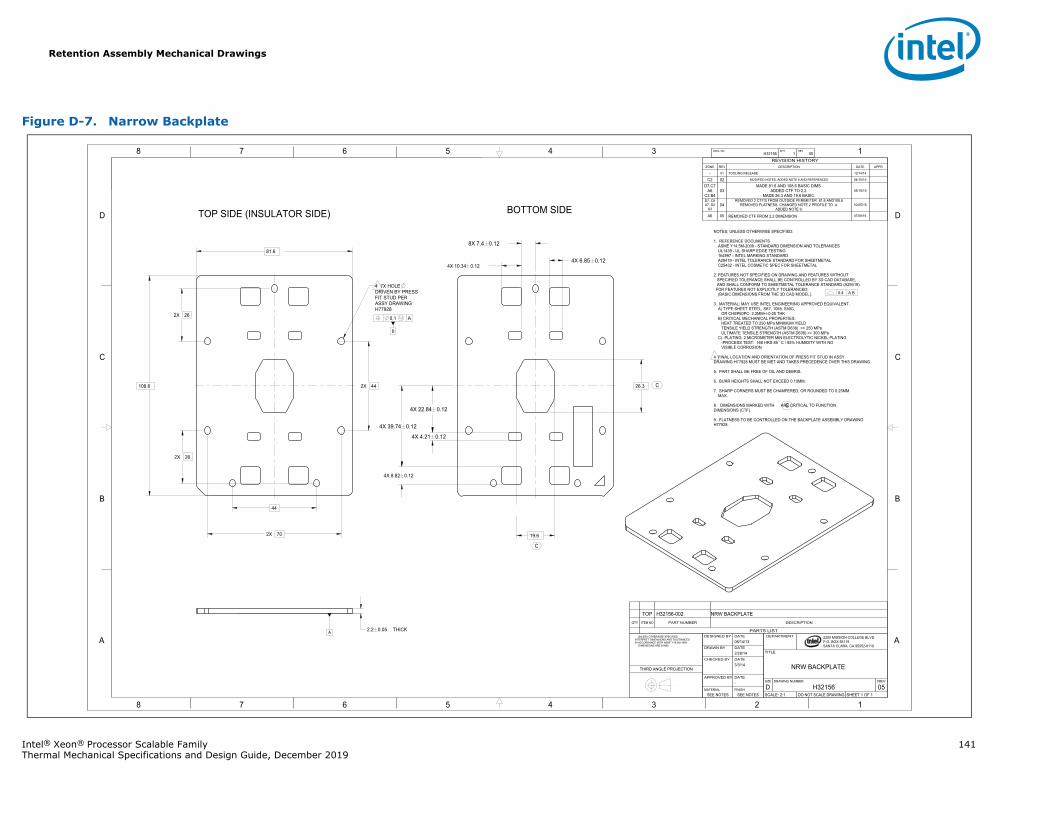
Retention Assembly Mechanical Drawings
Intel® Xeon® Processor Scalable Family 141Thermal Mechanical Specifications and Design Guide, December 2019
Figure D-7. Narrow Backplate
1345678
B
C
D
A
12345678
B
C
D
A 2200 MISSION COLLEGE BLVD.P.O. BOX 58119SANTA CLARA, CA 95052-8119
R
B
0.1 A
2X 44
2X 26
2X 26
44
2X 70
81.6
108.6
THICK 2.2 0.05
4X 10.34 0.12
4X 8.82 0.12
26.3
19.6
4X 22.84 0.12
4X 39.74 0.12
8X 7.4 0.12
4X 4.21 0.12
4X 6.85 0.12
A
H32156 1 05DWG. NO SHT. REV
SHEET 1 OF 1DO NOT SCALE DRAWINGSCALE: 2:105H32156DREVDRAWING NUMBERSIZE
NRW BACKPLATE
TITLE
DEPARTMENT
SEE NOTESSEE NOTESFINISHMATERIAL
-DATEAPPROVED BY
3/3/14 DATECHECKED BY
2/28/14DATEDRAWN BY
08/14/13DATEDESIGNED BY UNLESS OTHERWISE SPECIFIED
INTERPRET DIMENSIONS AND TOLERANCES IN ACCORDANCE WITH ASME Y14.5M-1994 DIMENSIONS ARE IN MM
THIRD ANGLE PROJECTION
REVISION HISTORYZONE REV DESCRIPTION DATE APPR
- 01 TOOLING RELEASE 12/14/14
C2 02 MODIFIED NOTES, ADDED NOTE 8 AND REFERENCES 04/15/15
D7,C7A6
C3 B403
MADE 81.6 AND 108.6 BASIC DIMS.ADDED CTF TO 2.2.
MADE 26.3 AND 19.6 BASIC.05/18/15
D7, C8A7, D2
A304
REMOVED 2 CTF'S FROM OUTSIDE PERIMETER 81.6 AND108.6REMOVED FLATNESS, CHANGED NOTE 2 PROFILE TO .4.
ADDED NOTE 9.10/05/15
A6 05 REMOVED CTF FROM 2.2 DIMENSION 07/08/16
NOTES; UNLESS OTHERWISE SPECIFIED:
1. REFERENCE DOCUMENTSASME Y14.5M-2009 - STANDARD DIMENSION AND TOLERANCESUL1439 - UL SHARP EDGE TESTING164997 - INTEL MARKING STANDARDA29419 - INTEL TOLERANCE STANDARD FOR SHEETMETALC25432 - INTEL COSMETIC SPEC FOR SHEETMETAL
2. FEATURES NOT SPECIFIED ON DRAWING AND FEATURES WITHOUTSPECIFIED TOLERANCE SHALL BE CONTROLLED BY 3D CAD DATABASE,AND SHALL CONFORM TO SHEETMETAL TOLERANCE STANDARD (A29419).FOR FEATURES NOT EXPLICITLY TOLERANCED:
(BASIC DIMENSIONS FROM THE 3D CAD MODEL).
3. MATERIAL: MAY USE INTEL ENGINEERING APPROVED EQUIVALENT.A) TYPE:SHEET STEEL, SK7, 1065, S50C,
OR CHSP60PC- 2.2MM+/-0.05 THKB) CRITICAL MECHANICAL PROPERTIES:
HEAT TREATED TO 250 MPa MINIMUM YIELDTENSILE YIELD STRENGTH (ASTM D638) >= 250 MPaULTIMATE TENSILE STRENGTH (ASTM D638) >= 300 MPa
C) -PLATING: 2 MICROMETER MIN ELECTROLYTIC NICKEL PLATING-PROCESS TEST: 168 HRS 85 C / 85% HUMIDITY WITH NOVISIBLE CORROSION
4 FINAL LOCATION AND ORIENTATION OF PRESS FIT STUD IN ASSY DRAWING H77928 MUST BE MET AND TAKES PRECEDENCE OVER THIS DRAWING
5. PART SHALL BE FREE OF OIL AND DEBRIS.
6. BURR HEIGHTS SHALL NOT EXCEED 0.10MM.
7. SHARP CORNERS MUST BE CHAMFERED, OR ROUNDED TO 0.25MMMAX.
8. DIMENSIONS MARKED WITH ARE CRITICAL TO FUNCTIONDIMENSIONS (CTF).
9. FLATNESS TO BE CONTROLLED ON THE BACKPLATE ASSEMBLY DRAWINGH77928.
TOP SIDE (INSULATOR SIDE) BOTTOM SIDE
0.4 A B4 7X HOLE DRIVEN BY PRESS FIT STUD PER ASSY DRAWING H77928
C
C
C
PARTS LIST
DESCRIPTIONPART NUMBERITEM NOQTY
NRW BACKPLATEH32156-002TOP
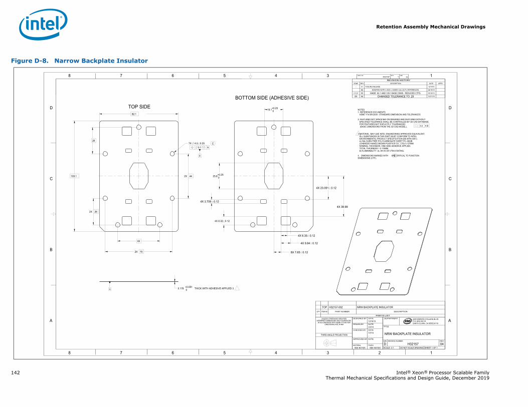
Retention Assembly Mechanical Drawings
142 Intel® Xeon® Processor Scalable FamilyThermal Mechanical Specifications and Design Guide, December 2019
Figure D-8. Narrow Backplate Insulator
1345678
B
C
D
A
12345678
B
C
D
A 2200 MISSION COLLEGE BLVD.P.O. BOX 58119SANTA CLARA, CA 95052-8119
R
B
0.1 A
82.1
109.1
26
2X 26
2X 44
44
2X 70
THICK WITH ADHESIVE APPLIED 30.178 +0.051 0
7X 4.5 0.25
4X 8.32 0.12
25.8+0.25 0
19.1+0.25 0
4X 9.84 0.12
8X 7.65 0.12
4X 23.091 0.12
4X 39.99
4X 6.35 0.12
4X 3.709 0.12
A
H32157 1 04DWG. NO SHT. REV
SHEET 1 OF 1DO NOT SCALE DRAWINGSCALE: 3:104H32157DREVDRAWING NUMBERSIZE
NRW BACKPLATE INSULATOR
TITLE
DEPARTMENT
SEE NOTESSEE NOTESFINISHMATERIAL
-DATEAPPROVED BY
-3/3/14DATECHECKED BY
3/3/14DATEDRAWN BY
12/16/13DATEDESIGNED BYUNLESS OTHERWISE SPECIFIED
INTERPRET DIMENSIONS AND TOLERANCES IN ACCORDANCE WITH ASME Y14.5M-1994
DIMENSIONS ARE IN MM
THIRD ANGLE PROJECTION
REVISION HISTORYZONE REV DESCRIPTION DATE APPR
- 01 TOOLING RELEASE 12/14/14
02 MODIFIED NOTE 2 AND 4, ADDED CALLOUT 4 REFERENCES. 04/15/15
C7,D7 03 MADE 82.1 AND 109.1 BASIC DIMS. REDUCED CTFS. 05/18/15
D5 04 CHANGED TOLERANCE TO .25 10/21/15
NOTES1. REFERENCE DOCUMENTS ASME Y14.5M-2009 - STANDARD DIMENSION AND TOLERANCES
2. FEATURES NOT SPECIFIED ON DRAWING AND FEATURES WITHOUTSPECIFIED TOLERANCE SHALL BE CONTROLLED BY 3D CAD DATABASE.FOR FEATURES NOT EXPLICITLY TOLERANCED:(BASIC DIMENSIONS FROM THE 3D CAD MODEL).
3 MATERIAL: MAY USE INTEL ENGINEERING APPROVED EQUIVALENT. ALL SUBSTANCES IN THIS PART MUST CONFORM TO INTEL ENVIRONMENTAL PRODUCT SPECIFICATION (BS-MTN-0001).
A) HALOGEN FREE POLYCARBONATE SHEET PC-1860B (CHENGDU KANGLONGXIN PLASTICS CO., LTD) 0.127MM NOMINAL THICKNESS, ONE SIDE ADHESIVE APPLIED. TOTAL THICKNESS = 0.178MM.
B) FLAMMABILITY: UL 94-V0 OR VTM-0 RATING.
4. DIMENSIONS MARKED WITH ARE CRITICAL TO FUNCTIONDIMENSIONS (CTF).
TOP SIDE
BOTTOM SIDE (ADHESIVE SIDE)
0.2 A B
C
C
PARTS LIST
DESCRIPTIONPART NUMBERITEM NOQTY
NRW BACKPLATE INSULATORH32157-002TOP
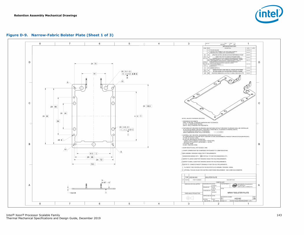
Retention Assembly Mechanical Drawings
Intel® Xeon® Processor Scalable Family 143Thermal Mechanical Specifications and Design Guide, December 2019
Figure D-9. Narrow-Fabric Bolster Plate (Sheet 1 of 3)
1345678
B
C
D
A
12345678
B
C
D
A
B
.1 A B C
C
2200 MISSION COLLEGE BLVD.P.O. BOX 58119SANTA CLARA, CA 95052-8119
R
.4 A B C
B
.1 A B C
61.5
78.5
2X 70
2X 44
2X 96
2X 108.5
1.5±0.08
443X 6.1 0.1
2X 90 1.5
64
2X 72
2X 95
2X 68
.1 A B C4X 4.9 0.1
2X 84
A
H32162 1 09DWG. NO SHT. REV
SHEET 1 OF 3DO NOT SCALE DRAWINGSCALE: 3:109H32162DREVDRAWING NUMBERSIZE
NRW-F BOLSTER PLATE
TITLE
DEPARTMENT
SEE NOTESSEE NOTESFINISHMATERIAL
DATEAPPROVED BY
-09/18/15DATECHECKED BY
2/26/14DATEDRAWN BY
12/16/13 DATEDESIGNED BYDIMENSIONS ARE IN MILLIMETERS
THIRD ANGLE PROJECTION
REVISION HISTORYZONE REV DESCRIPTION DATE APPR
- 01 TOOLING RELEASE 12/14/14
- 02 UPDATED: PART NUMBER TO -002, AND FLANGE GEOMETRY.REMOVED NOTE 4, ADDED NOTE 7 AND REFERENCES. 04/16/15
B3 03 UPDATED NOTES, MOVED DATUM B REFERENCE POINT 04/23/15
PG1PG1 C5 04 MADE 108.5, 78.5, 61.5 AND 84 CTFS BASIC DIMS
CHANGED 84.44 TO 84.4, ANNOTATION ERROR, NOT MODEL. 05/18/15
05 REVISION CHANGE TO -003, CHANGED HOLE DIAMETERS. ADDED SUPPLEMENTAL DFM ON PAGE 3, ADDED NOTES 8, 9, AND 10. 09/21/15
PG2 B2PG1 A7,A6
PG2 C5PG1 B2
A3
06
REMOVED PROFILE A-B FOR DETAIL A ON PAGE 2, REDIMENSIONED.REMOVED TAB RADIUS DIMENSION, REMOVED FLATNESS, TP TO .2 FOR 25.1MM DIMCHANGED NOTE 2 PROFILE TO .4.ADDED NOTE 11.
10/11/15
A3 07 ADDED NOTE 12. 12/15/15
PG1 B5 D5 08 ADDED DATUM C AND TIED ALL HOLES AS PATTERN
BY INCLUDING B-C IN FEATURE CONTROL FRAME 02/10/16
C5 09 MODIFIED DIMENSION LOCATION TO 84MM. REDUCED CTFS 06/20/16
NOTES, UNLESS OTHERWISE SPECIFIED:
1. REFERENCE DOCUMENTSASME Y14.5M-2009 - STANDARD DIMENSION AND TOLERANCESUL1439 - UL SHARP EDGE TESTINGA29419 - INTEL STANDARD FOR SHEETMETAL
2. FEATURES NOT SPECIFIED ON DRAWING AND FEATURES WITHOUT SPECIFIED TOLERANCE SHALL BE CONTROLLEDBY 3D CAD DATABASE, AND SHALL CONFORM TO SHEETMETAL TOLERANCE STANDARD (A29419).FOR FEATURES NOT EXPLICITLY TOLERANCED :(BASIC DIMENSIONS FROM THE 3D CAD MODEL).
3. MATERIAL: MAY USE INTELL ENGINEERING APPROVED EQUIVALENT.ALL SUBSTANCES IN THIS PART MUST CONFORM TO INTEL ENVIRONMENTAL PRODUCT SPECIFICATION (BS-MTN-0001).A) TYPE: 301 SS HALF HARDB) CRITICAL MECHANICAL PROPERTIES:
TENSILE YIELD STRENGTH (ASTM D638) >=758-930 MPaMODULUS OF ELASTICITY (ASTM D638) >= 193 GPa
C) PLATING: NONED) HEAT TREATING: NONE
4. BURR HEIGHTS SHALL NOT EXCEED 0.1MM.
5. SHARP CORNERS MUST BE CHAMFERED OR ROUNDED TO 0.25MM RADIUS MAX.
6 SEE ASSEMBLY DRAWING H78902 FOR FIT REQUIREMENTS.
7.DIMENSIONS MARKED WITH ARE CRITICAL TO FUNCTION DIMENSIONS (CTF).
8 REFER TO LARGE GUIDE POST DRAWING G94443 FOR HOLE REQUIREMENTS.
9 REFER TO SMALL GUIDE POST DRAWING G93935 FOR HOLE REQUIREMENTS.
10 REFER TO CORNER STANDOFF DRAWING H77926 FOR HOLE REQUIREMENTS.
11. FLATNESS TO BE CONTROLLED ON THE BOLSTER PLATE ASSEMBLY DRAWING H95384.
12 OPTIONAL TOOLING HOLES FOR HVM PRE-CONDITIONING REQUIREMENT. MAX 5.0MM HOLE DIAMETER.
109
108
4X 6
CC
C
PARTS LIST
DESCRIPTIONPART NUMBERITEM NOQTY
BOLSTER PLATEH32162-003TOP
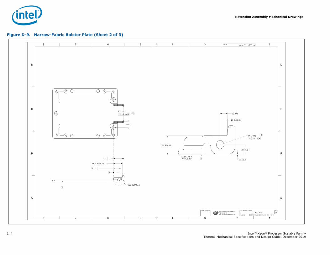
Retention Assembly Mechanical Drawings
144 Intel® Xeon® Processor Scalable FamilyThermal Mechanical Specifications and Design Guide, December 2019
Figure D-9. Narrow-Fabric Bolster Plate (Sheet 2 of 3)
1345678
B
C
D
A
12345678
B
C
D
A
2200 MISSION COLLEGE BLVD.P.O. BOX 58119SANTA CLARA, CA 95052-8119
R
.2 A B25.1 0.2
2X 0.18 0.1
2X 6 0.15
2X 0.2
2X 14.37 0.15
2X 12
2X 17
2X 3.2
.4 A B2X ( 2.6)
9.45
A
A
(2.37)
H32162 2 09DWG. NO SHT. REV
SHEET 2 OF 3DO NOT SCALE DRAWINGSCALE: 2:109H32162DREVDRAWING NUMBERSIZEDEPARTMENT
SEE DETAIL A
SCALE 10:12X DETAIL A
C
C
B
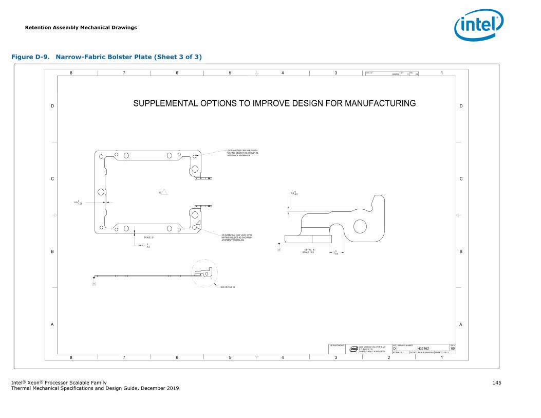
Retention Assembly Mechanical Drawings
Intel® Xeon® Processor Scalable Family 145Thermal Mechanical Specifications and Design Guide, December 2019
Figure D-9. Narrow-Fabric Bolster Plate (Sheet 3 of 3)
1345678
B
C
D
A
12345678
B
C
D
A
2200 MISSION COLLEGE BLVD.P.O. BOX 58119SANTA CLARA, CA 95052-8119
R
12X 0.2 0-0.2
1.25 0-1.25
0.5 0-0.5
3 0-0.5
A
A
H32162 3 09DWG. NO SHT. REV
SHEET 3 OF 3DO NOT SCALE DRAWINGSCALE: 2:109H32162DREVDRAWING NUMBERSIZEDEPARTMENT
SUPPLEMENTAL OPTIONS TO IMPROVE DESIGN FOR MANUFACTURING
SCALE 2:12X DIAMETER CAN VARY WITH MATING OBJECT AS SHOWN INASSEMBLY H95384-004
2X DIAMETER CAN VARY WITH MATING OBJECT AS SHOWN INASSEMBLY H95384-004
12
SEE DETAIL B
SCALE 10:1DETAIL B
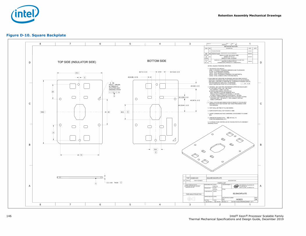
Retention Assembly Mechanical Drawings
146 Intel® Xeon® Processor Scalable FamilyThermal Mechanical Specifications and Design Guide, December 2019
Figure D-10. Square Backplate
1345678
B
C
D
A
12345678
B
C
D
A 2200 MISSION COLLEGE BLVD.P.O. BOX 58119SANTA CLARA, CA 95052-8119
R
B
0.1 A
2X 44
25
2X 70
81.6
108.6
THICK 2.2 0.05
26
19.6
26.3
4X 4.209 0.12
4X 8.82 0.12
4X 10.34 0.12
4X 22.841 0.12
4X 39.74 0.12
8X 7.4 0.12
4X 6.85 0.122
A
H43623 1 04DWG. NO SHT. REV
SHEET 1 OF 1DO NOT SCALE DRAWINGSCALE: 2:104H43623DREVDRAWING NUMBERSIZE
SQ BACKPLATE
TITLE
DEPARTMENT
SEE NOTESSEE NOTESFINISHMATERIAL
-DATEAPPROVED BY
DATECHECKED BY
4/15/14DATEDRAWN BY
08/14/13DATEDESIGNED BY UNLESS OTHERWISE SPECIFIED
INTERPRET DIMENSIONS AND TOLERANCES IN ACCORDANCE WITH ASME Y14.5M-1994 DIMENSIONS ARE IN MM
THIRD ANGLE PROJECTION
REVISION HISTORYZONE REV DESCRIPTION DATE APPR
- 01 TOOLING RELEASE 12/14/14
D2 02 MODIFIED NOTE 2 AND 4. REMOVED NOTE 4 CALLOUT REFERENCES.REVISED CTF SYMBOL. 04/24/15
D7 C8A5
C5 B403
MADE 81.6 AND 108.6 BASIC DIMS. ADDED CTF TO 2.2.
MADE 26.3 AND 19.6 BASIC.05/18/15
D7,C8A7
D2, C204
REMOVED 2 CTF'S FROM OUTSIDE PERIMETER, 81.6 AND 108.6REMOVED FLATNESS CALLOUT.
CHANGED NOTE 2 PROFILE TO .4. ADDED NOTE 9.10/05/15
NOTES; UNLESS OTHERWISE SPECIFIED:
1. REFERENCE DOCUMENTSASME Y14.5M-2009 - STANDARD DIMENSION AND TOLERANCESUL1439 - UL SHARP EDGE TESTING164997 - INTEL MARKING STANDARDA29419 - INTEL TOLERANCE STANDARD FOR SHEETMETALC25432 - INTEL COSMETIC SPEC FOR SHEETMETAL
2. FEATURES NOT SPECIFIED ON DRAWING AND FEATURES WITHOUTSPECIFIED TOLERANCE SHALL BE CONTROLLED BY 3D CAD DATABASE,AND SHALL CONFORM TO SHEETMETAL TOLERANCE STANDARD (A29419).FOR FEATURES NOT EXPLICITLY TOLERANCED: (BASIC DIMENSIONS FROM THE 3D CAD MODEL).
3. MATERIAL: MAY USE INTEL ENGINEERING APPROVED EQUIVALENT.A) TYPE:SHEET STEEL, SK7, 1065, S50C,
OR CHSP60PC- 2.2MM+/-0.05 THKB) CRITICAL MECHANICAL PROPERTIES:
HEAT TREATED TO 250 MPa MINIMUM YIELDTENSILE YIELD STRENGTH (ASTM D638) >= 250 MPaULTIMATE TENSILE STRENGTH (ASTM D638) >= 300 MPa
C) -PLATING: 2 MICROMETER MIN ELECTROLYTIC NICKEL PLATING-PROCESS TEST: 168 HRS 85 C / 85% HUMIDITY WITH NOVISIBLE CORROSION
4 FINAL LOCATION AND ORIENTATION OF PRESS FIT STUD IN ASSY DRAWING H78197 MUST BE MET AND TAKES PRECEDENCE OVER THIS DRAWING.
5. PART SHALL BE FREE OF OIL AND DEBRIS.
6. BURR HEIGHTS SHALL NOT EXCEED 0.10MM.
7. SHARP CORNERS MUST BE CHAMFERED, OR ROUNDED TO 0.25MMMAX.
8. DIMENSIONS MARKES WITH ARE CRITICAL TOFUNCTION DIMENSIONS (CTF).
9. FLATNESS TO BE CONTROLLED ON THE BOLSTER PLATE ASSEMBLYDRAWING H78197.
TOP SIDE (INSULATOR SIDE) BOTTOM SIDE
0.4 A B 4 6X HOLE DRIVEN BY PRESS FIT STUD PER ASSY DRAWING H78197
C
C
C
C PARTS LIST
DESCRIPTIONPART NUMBERITEM NOQTY
SQUARE-BACKPLATEH43623-001TOP
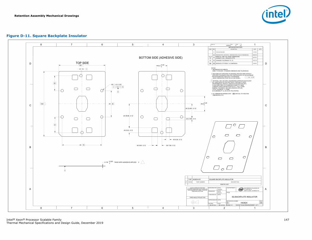
Retention Assembly Mechanical Drawings
Intel® Xeon® Processor Scalable Family 147Thermal Mechanical Specifications and Design Guide, December 2019
Figure D-11. Square Backplate Insulator
1345678
B
C
D
A
12345678
B
C
D
A 2200 MISSION COLLEGE BLVD.P.O. BOX 58119SANTA CLARA, CA 95052-8119
R
B
0.1 A
82.1
109.1
25
2X 44
2X 70
THICK WITH ADHESIVE APPLIED 30.178 +0.051 0
6X 4.5 0.25
4X 6.35 0.12
4X 3.709 0.12
4X 9.84 0.12
4X 8.32 0.12
25.8+0.25 0
19.1+0.25 0
26
4X 39.99 0.12
4X 23.091 0.12
8X 7.65 0.12
2
A
H43624 1 05DWG. NO SHT. REV
SHEET 1 OF 1DO NOT SCALE DRAWINGSCALE: 3:105H43624DREVDRAWING NUMBERSIZE
SQ BACKPLATE INSULATOR
TITLE
DEPARTMENT
SEE NOTESSEE NOTESFINISHMATERIAL
-DATEAPPROVED BY
-
DATECHECKED BY
4/15/14DATEDRAWN BY
12/16/13DATEDESIGNED BYUNLESS OTHERWISE SPECIFIED
INTERPRET DIMENSIONS AND TOLERANCES IN ACCORDANCE WITH ASME Y14.5M-1994
DIMENSIONS ARE IN MM
THIRD ANGLE PROJECTION
REVISION HISTORYZONE REV DESCRIPTION DATE APPR
- 01 TOOLING RELEASE 12/14/14
02 MODIFIED NOTE 2 AND NOTE 4. REMOVED NOTE 4 CALLOUT REFERENCES. 04/24/15
D7 C8D6 03 MADE 82.1 AND 109.1 BASIC DIMENSIONS.
CHANGE TO 6X. REDUCED CTFS. 05/18/15
C5 04 CHANGED TOLERANCE TO .25 10/21/15
D6 05 REMOVED CTF FROM 4.5 DIMENSION 07/08/16
NOTES1. REFERENCE DOCUMENTS
ASME Y14.5M-2009 - STANDARD DIMENSION AND TOLERANCES
2. FEATURES NOT SPECIFIED ON DRAWING AND FEATURES WITHOUTSPECIFIED TOLERANCE SHALL BE CONTROLLED BY 3D CAD DATABASE.
FOR FEATURES NOT EXPLICITLY TOLERANCED: (BASIC DIMENSIONS FROM THE 3D CAD MODEL).
3 MATERIAL: MAY USE INTEL ENGINEERING APPROVED EQUIVALENT. ALL SUBSTANCES IN THIS PART MUST CONFORM TO INTEL ENVIRONMENTAL PRODUCT SPECIFICATION (BS-MTN-0001).
A) HALOGEN FREE POLYCARBONATE SHEET PC-1860B (CHENGDU KANGLONGXIN PLASTICS CO., LTD) 0.127MM NOMINAL THICKNESS, ONE SIDE ADHESIVE APPLIED. TOTAL THICKNESS = 0.178MM.
B) FLAMMABILITY: UL 94-V0 OR VTM-0 RATING.
4. ALL DIMENSIONS MARKED WITH ARE CRITICAL TO FUNCTIONDIMENSIONS (CTF).
TOP SIDE
BOTTOM SIDE (ADHESIVE SIDE)
0.2 A B
C
PARTS LIST
DESCRIPTIONPART NUMBERITEM NOQTY
SQUARE-BACKPLATE-INSULATORH43624-001TOP
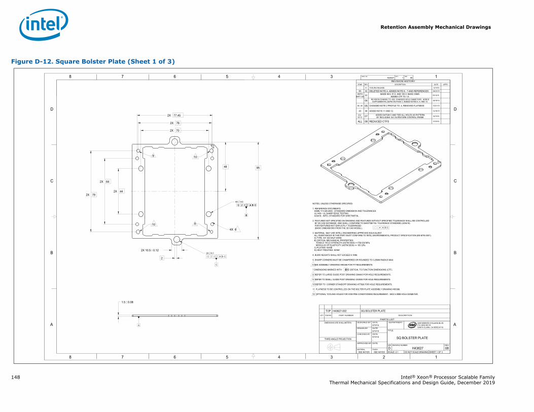
Retention Assembly Mechanical Drawings
148 Intel® Xeon® Processor Scalable FamilyThermal Mechanical Specifications and Design Guide, December 2019
Figure D-12. Square Bolster Plate (Sheet 1 of 3)
1345678
B
C
D
A
12345678
B
C
D
A
B
.1 A B C
C
2200 MISSION COLLEGE BLVD.P.O. BOX 58119SANTA CLARA, CA 95052-8119
R
B
.1 A B C
.4 A B C
2X 44
2X 64
2X 79
95
2X 76
2X 77.45
2X 70
2X 10.5 0.12
1.5 0.08
48
2
4X 4.9
.1 A B C2X 6.1
A
H43627 1 08DWG. NO SHT. REV
SHEET 1 OF 3DO NOT SCALE DRAWINGSCALE: 2:108H43627DREVDRAWING NUMBERSIZE
SQ BOLSTER PLATE
TITLE
DEPARTMENT
SEE NOTESSEE NOTESFINISHMATERIAL
DATEAPPROVED BY
-6/10/14DATECHECKED BY
6/10/14DATEDRAWN BY
6/10/14DATEDESIGNED BYDIMENSIONS ARE IN MILLIMETERS
THIRD ANGLE PROJECTION
REVISION HISTORYZONE REV DESCRIPTION DATE APPR
- 01 TOOLING RELEASE 12/14/14
B3 02 DELETED NOTE 4, ADDED NOTE 6, 7 AND REFERENCES. 04/23/15
SHT2SHT1 A7 03 MADE 88.5, 91.5, AND 105.5 BASIC DIMS.
ADDED CTF TO 1.5. 05/18/15
04 REVISION CHANGE TO -002, CHANGED HOLE DIAMETERS. ADDEDSUPPLEMENTAL DDFM ON PAGE 3, ADDED NOTES 8, 9, AND 10. 09/18/15
B2, A6 05 CHANGED NOTE 2 PROFILE TO .4, REMOVED FLATNESS 10/21/15
A3 06 ADDED NOTE 11 AND 12. 12/16/15
PG1 B5 C5 07 ADDED DATUM C AND TIED ALL HOLES AS PATTERN
BY INCLUDING B-C IN FEATURE CONTROL FRAME 02/10/16
ALL 08 REDUCED CTFS 07/20/16
NOTES, UNLESS OTHERWISE SPECIFIED:
1. REFERENCE DOCUMENTSASME Y14.5M-2009 - STANDARD DIMENSION AND TOLERANCESUL1439 - UL SHARP EDGE TESTINGA29419 - INTEL STANDARD FOR SHEETMETAL
2. FEATURES NOT SPECIFIED ON DRAWING AND FEATURES WITHOUT SPECIFIED TOLERANCE SHALL BE CONTROLLEDBY 3D CAD DATABASE, AND SHALL CONFORM TO SHEETMETAL TOLERANCE STANDARD (A29419).FOR FEATURES NOT EXPLICITLY TOLERANCED :(BASIC DIMENSIONS FROM THE 3D CAD MODEL).
3. MATERIAL: MAY USE INTELL ENGINEERING APPROVED EQUIVALENT.ALL SUBSTANCES IN THIS PART MUST CONFORM TO INTEL ENVIRONMENTAL PRODUCT SPECIFICATION (BS-MTN-0001).A) TYPE: 301 SS HALF HARDB) CRITICAL MECHANICAL PROPERTIES:
TENSILE YIELD STRENGTH (ASTM D638) >=758-930 MPaMODULUS OF ELASTICITY (ASTM D638) >= 193 GPa
C) PLATING: NONED) HEAT TREATING: NONE
4. BURR HEIGHTS SHALL NOT EXCEED 0.1MM.
5. SHARP CORNERS MUST BE CHAMFERED OR ROUNDED TO 0.25MM RADIUS MAX.
6 SEE ASSEMBLY DRAWING H95386 FOR FIT REQUIREMENTS.
7.DIMENSIONS MARKED WITH ARE CRITICAL TO FUNCTION DIMENSIONS (CTF).
8 REFER TO LARGE GUIDE POST DRAWING G94443 FOR HOLE REQUIREMENTS.
9 REFER TO SMALL GUIDE POST DRAWING G93935 FOR HOLE REQUIREMENTS.
10 REFER TO CORNER STANDOFF DRAWING H77926 FOR HOLE REQUIREMENTS.
11. FLATNESS TO BE CONTROLLED ON THE BOLTER PLATE ASSEMBLY DRAWING H95386.
12 OPTIONAL TOOLING HOLES FOR HVM PRE-CONDITIONING REQUIREMENT. MAX 5.0MM HOLE DIAMETER.
9 10
10 8
4X 6
C
PARTS LIST
DESCRIPTIONPART NUMBERITEM NOQTY
SQ BOLSTER PLATEH43627-002TOP
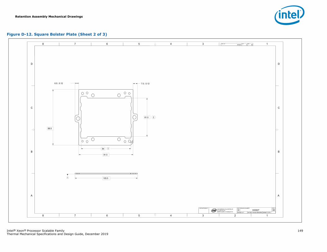
Retention Assembly Mechanical Drawings
Intel® Xeon® Processor Scalable Family 149Thermal Mechanical Specifications and Design Guide, December 2019
Figure D-12. Square Bolster Plate (Sheet 2 of 3)
1345678
B
C
D
A
12345678
B
C
D
A
2200 MISSION COLLEGE BLVD.P.O. BOX 58119SANTA CLARA, CA 95052-8119
R
105.5
6.5 0.12 7.5 0.12
88.5
61.5
84
91.5
A
H43627 2 08DWG. NO SHT. REV
SHEET 2 OF 3DO NOT SCALE DRAWINGSCALE: 2:108H43627DREVDRAWING NUMBERSIZEDEPARTMENT
C
C
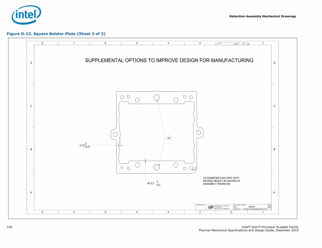
Retention Assembly Mechanical Drawings
150 Intel® Xeon® Processor Scalable FamilyThermal Mechanical Specifications and Design Guide, December 2019
Figure D-12. Square Bolster Plate (Sheet 3 of 3)
1345678
B
C
D
A
12345678
B
C
D
A
2200 MISSION COLLEGE BLVD.P.O. BOX 58119SANTA CLARA, CA 95052-8119
R
4X 0.2 0-0.2
0.75 0-0.75
H43627 3 08DWG. NO SHT. REV
SHEET 3 OF 3DO NOT SCALE DRAWINGSCALE: 2:108H43627DREVDRAWING NUMBERSIZEDEPARTMENT
SUPPLEMENTAL OPTIONS TO IMPROVE DESIGN FOR MANUFACTURING
2X DIAMETER CAN VARY WITH MATING OBJECT AS SHOWN INASSEMBLY H95386-004
12
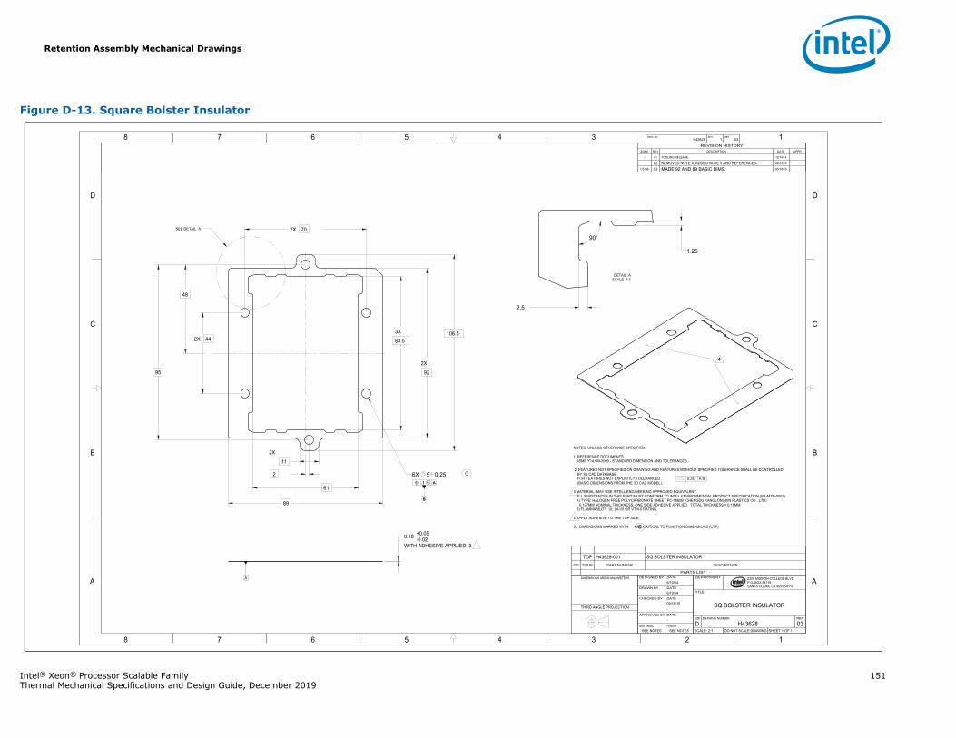
Retention Assembly Mechanical Drawings
Intel® Xeon® Processor Scalable Family 151Thermal Mechanical Specifications and Design Guide, December 2019
Figure D-13. Square Bolster Insulator
1345678
B
C
D
A
12345678
B
C
D
A
B
.1 A
2200 MISSION COLLEGE BLVD.P.O. BOX 58119SANTA CLARA, CA 95052-8119
R
B
.1 A
2X 70
2X 44
95
61
89
2X
11
3X
83.5
2X
92
106.5
WITH ADHESIVE APPLIED 3
0.18 +0.05-0.02
48
2 6X 5 0.25
2.5
1.25
90°
A
H43628 1 03DWG. NO SHT. REV
SHEET 1 OF 1DO NOT SCALE DRAWINGSCALE: 2:103H43628DREVDRAWING NUMBERSIZE
SQ BOLSTER INSULATOR
TITLE
DEPARTMENT
SEE NOTESSEE NOTESFINISHMATERIAL
-DATEAPPROVED BY
-09/18/15DATECHECKED BY
6/10/14DATEDRAWN BY
6/10/14DATEDESIGNED BY DIMENSIONS ARE IN MILLIMETERS
THIRD ANGLE PROJECTION
REVISION HISTORYZONE REV DESCRIPTION DATE APPR
- 01 TOOLING RELEASE. 12/14/14
02 REMOVED NOTE 4, ADDED NOTE 5 AND REFERENCES. 04/23/15
C5 B6 03 MADE 92 AND 89 BASIC DIMS. 05/18/15
NOTES, UNLESS OTHERWISE SPECIFIED:
1. REFERENCE DOCUMENTSASME Y14.5M-2009 - STANDARD DIMENSION AND TOLERANCES
2. FEATURES NOT SPECIFIED ON DRAWING AND FEATURES WITHOUT SPECIFIED TOLERANCE SHALL BE CONTROLLEDBY 3D CAD DATABASE.FOR FEATURES NOT EXPLICITLY TOLERANCED : (BASIC DIMENSIONS FROM THE 3D CAD MODEL).
3 MATERIAL: MAY USE INTELL ENGINEERING APPROVED EQUIVALENT. ALL SUBSTANCES IN THIS PART MUST CONFORM TO INTEL ENVIRONMENTAL PRODUCT SPECIFICATION (BS-MTN-0001).
A) TYPE: HALOGEN FREE POLYCARBONATE SHEET PC-1860B (CHENGDU KANGLONGXIN PLASTICS CO., LTD) 0.127MM NOMINAL THICKNESS, ONE SIDE ADHESIVE APPLIED. TOTAL THICKNESS = 0.18MM.
B) FLAMMABILITY: UL 94-V0 OR VTM-0 RATING.
4 APPLY ADHESIVE TO THE TOP SIDE.
5. DIMENSIONS MARKED WITH ARE CRITICAL TO FUNCTION DIMENSIONS (CTF).
0.24 A B
SEE DETAIL A
4
SCALE 4:1DETAIL A
C
C
PARTS LIST
DESCRIPTIONPART NUMBERITEM NOQTY
SQ BOLSTER INSULATORH43628-001TOP
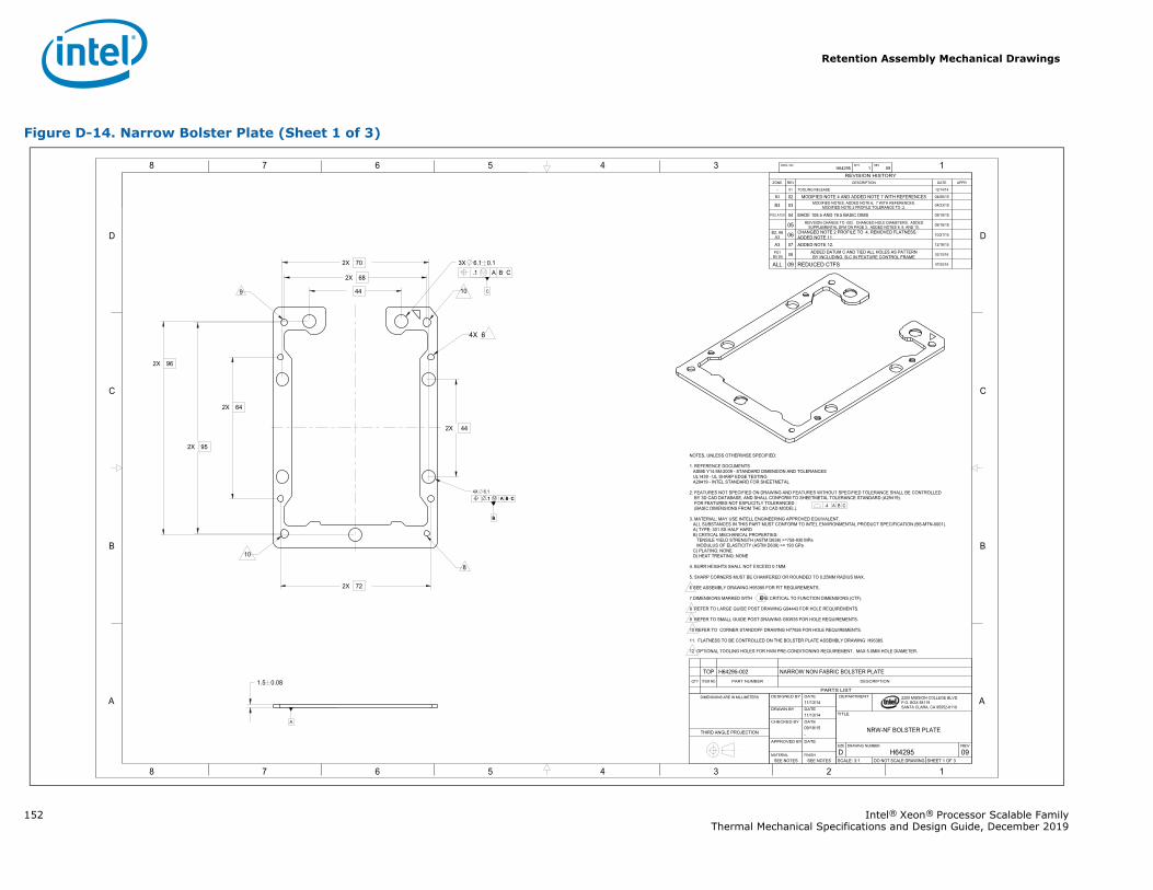
Retention Assembly Mechanical Drawings
152 Intel® Xeon® Processor Scalable FamilyThermal Mechanical Specifications and Design Guide, December 2019
Figure D-14. Narrow Bolster Plate (Sheet 1 of 3)
1345678
B
C
D
A
12345678
B
C
D
A
B
.1 A B C
C
2200 MISSION COLLEGE BLVD.P.O. BOX 58119SANTA CLARA, CA 95052-8119
R
B
.1 A B C.4 A B C
2X 70
2X 44
2X 96
2X 64
1.5 0.08
2X 72
2X 95
2X 68
44
4X 6.1
.1 A B C3X 6.1 0.1
A
H64295 1 09DWG. NO SHT. REV
SHEET 1 OF 3DO NOT SCALE DRAWINGSCALE: 3:109H64295DREVDRAWING NUMBERSIZE
NRW-NF BOLSTER PLATE
TITLE
DEPARTMENT
SEE NOTESSEE NOTESFINISHMATERIAL
DATEAPPROVED BY
-09/18/15DATECHECKED BY
11/13/14DATEDRAWN BY
11/13/14DATEDESIGNED BYDIMENSIONS ARE IN MILLIMETERS
THIRD ANGLE PROJECTION
REVISION HISTORYZONE REV DESCRIPTION DATE APPR
- 01 TOOLING RELEASE 12/14/14
B3 02 MODIFIED NOTE 4 AND ADDED NOTE 7 WITH REFERENCES 04/06/15
B3 03 MODIFIED NOTES, ADDED NOTE 6, 7 WITH REFERENCES.MODIFIED NOTE 2 PROFILE TOLERANCE TO .2. 04/23/15
PG2 A7C8 04 MADE 108.5 AND 78.5 BASIC DIMS 05/18/15
05 REIVSION CHANGE TO -002. CHANGED HOLE DIAMETERS. ADDEDSUPPLEMENTAL DFM ON PAGE 3. ADDED NOTES 8, 9, AND 10. 09/18/15
B2, A6A3 06 CHANGED NOTE 2 PROFILE TO .4, REMOVED FLATNESS.
ADDED NOTE 11. 10/21/15
A3 07 ADDED NOTE 12. 12/16/15
PG1 B5 D5 08 ADDED DATUM C AND TIED ALL HOLES AS PATTERN
BY INCLUDING B-C IN FEATURE CONTROL FRAME 02/10/16
ALL 09 REDUCED CTFS 07/20/16
NOTES, UNLESS OTHERWISE SPECIFIED:
1. REFERENCE DOCUMENTSASME Y14.5M-2009 - STANDARD DIMENSION AND TOLERANCESUL1439 - UL SHARP EDGE TESTINGA29419 - INTEL STANDARD FOR SHEETMETAL
2. FEATURES NOT SPECIFIED ON DRAWING AND FEATURES WITHOUT SPECIFIED TOLERANCE SHALL BE CONTROLLEDBY 3D CAD DATABASE, AND SHALL CONFORM TO SHEETMETAL TOLERANCE STANDARD (A29419).FOR FEATURES NOT EXPLICITLY TOLERANCED : (BASIC DIMENSIONS FROM THE 3D CAD MODEL).
3. MATERIAL: MAY USE INTELL ENGINEERING APPROVED EQUIVALENT.ALL SUBSTANCES IN THIS PART MUST CONFORM TO INTEL ENVIRONMENTAL PRODUCT SPECIFICATION (BS-MTN-0001).A) TYPE: 301 SS HALF HARDB) CRITICAL MECHANICAL PROPERTIES:
TENSILE YIELD STRENGTH (ASTM D638) >=758-930 MPaMODULUS OF ELASTICITY (ASTM D638) >= 193 GPa
C) PLATING: NONED) HEAT TREATING: NONE
4. BURR HEIGHTS SHALL NOT EXCEED 0.1MM.
5. SHARP CORNERS MUST BE CHAMFERED OR ROUNDED TO 0.25MM RADIUS MAX.
6 SEE ASSEMBLY DRAWING H95385 FOR FIT REQUIREMENTS.
7.DIMENSIONS MARKED WITH ARE CRITICAL TO FUNCTION DIMENSIONS (CTF).
8 REFER TO LARGE GUIDE POST DRAWING G94443 FOR HOLE REQUIREMENTS.
9 REFER TO SMALL GUIDE POST DRAWING G93935 FOR HOLE REQUIREMENTS.
10 REFER TO CORNER STANDOFF DRAWING H77926 FOR HOLE REQUIREMENTS.
11. FLATNESS TO BE CONTROLLED ON THE BOLSTER PLATE ASSEMBLY DRAWING H95385.
12 OPTIONAL TOOLING HOLES FOR HVM PRE-CONDITIONING REQUIREMENT. MAX 5.0MM HOLE DIAMETER.
109
10
8
4X 6
C
PARTS LIST
DESCRIPTIONPART NUMBERITEM NOQTY
NARROW NON FABRIC BOLSTER PLATEH64295-002TOP
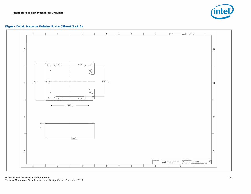
Retention Assembly Mechanical Drawings
Intel® Xeon® Processor Scalable Family 153Thermal Mechanical Specifications and Design Guide, December 2019
Figure D-14. Narrow Bolster Plate (Sheet 2 of 3)
1345678
B
C
D
A
12345678
B
C
D
A
2200 MISSION COLLEGE BLVD.P.O. BOX 58119SANTA CLARA, CA 95052-8119
R
78.5
108.5
2X 84
61.5
A
H64295 2 09DWG. NO SHT. REV
SHEET 2 OF 3DO NOT SCALE DRAWINGSCALE: 2:109H64295DREVDRAWING NUMBERSIZEDEPARTMENT
C
C
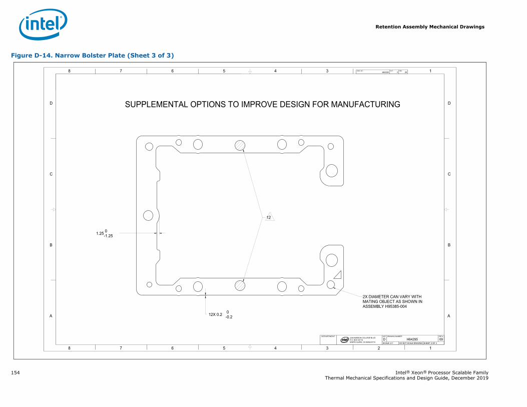
Retention Assembly Mechanical Drawings
154 Intel® Xeon® Processor Scalable FamilyThermal Mechanical Specifications and Design Guide, December 2019
Figure D-14. Narrow Bolster Plate (Sheet 3 of 3)
1345678
B
C
D
A
12345678
B
C
D
A
2200 MISSION COLLEGE BLVD.P.O. BOX 58119SANTA CLARA, CA 95052-8119
R
12X 0.2 0-0.2
1.25 0-1.25
H64295 3 09DWG. NO SHT. REV
SHEET 3 OF 3DO NOT SCALE DRAWINGSCALE: 2:109H64295DREVDRAWING NUMBERSIZEDEPARTMENT
SUPPLEMENTAL OPTIONS TO IMPROVE DESIGN FOR MANUFACTURING
2X DIAMETER CAN VARY WITH MATING OBJECT AS SHOWN INASSEMBLY H95385-004
12
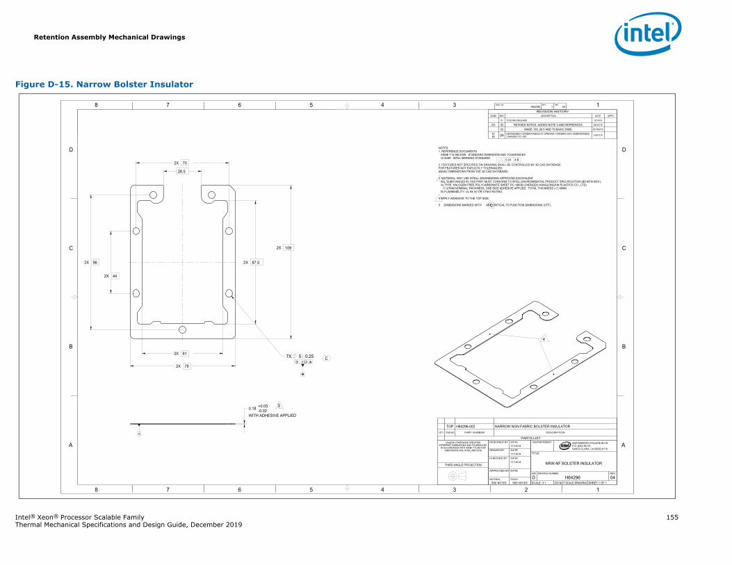
Retention Assembly Mechanical Drawings
Intel® Xeon® Processor Scalable Family 155Thermal Mechanical Specifications and Design Guide, December 2019
Figure D-15. Narrow Bolster Insulator
1345678
B
C
D
A
12345678
B
C
D
A
B
.1 A
2200 MISSION COLLEGE BLVD.P.O. BOX 58119SANTA CLARA, CA 95052-8119
R
B
.1 A
WITH ADHESIVE APPLIED
0.18 +0.05-0.02
2X 61
2X 79
2X 44
2X 96 2X 87.5
2X 10⁹
2X 70
28.5
7X 5 0.25
A
H64296 1 04DWG. NO SHT. REV
SHEET 1 OF 1DO NOT SCALE DRAWINGSCALE: 3:104H64296DREVDRAWING NUMBERSIZE
NRW-NF BOLSTER INSULATOR
TITLE
DEPARTMENT
SEE NOTESSEE NOTESFINISHMATERIAL
-DATEAPPROVED BY
-11/14/14DATECHECKED BY
11/14/14DATEDRAWN BY
11/14/14DATEDESIGNED BYUNLESS OTHERWISE SPECIFIED
INTERPRET DIMENSIONS AND TOLERANCES IN ACCORDANCE WITH ASME Y14.5M-1994
DIMENSIONS ARE IN MILLIMETERS
THIRD ANGLE PROJECTION
REVISION HISTORYZONE REV DESCRIPTION DATE APPR
- 01 TOOLING RELEASE 12/14/14
D3 02 REVISED NOTES, ADDED NOTE 5 AND REFRENCES. 04/23/15
03 MADE 109, 28.5 AND 79 BASIC DIMS. 05/18/015
D7B5 04 DECREASED CORNER RADIUS AT OPENING CORNERS (NOT DIMENSIONED)
CHANGED TO -002 10/01/15
NOTES1. REFERENCE DOCUMENTS ASME Y14.5M-2009 - STANDARD DIMENSION AND TOLERANCES G14599 - INTEL MARKING STANDARD
2. FEATURES NOT SPECIFIED ON DRAWING SHALL BE CONTROLLED BY 3D CAD DATABASE.FOR FEATURES NOT EXPLICITLY TOLERANCED:(BASIC DIMENSIONS FROM THE 3D CAD DATABASE)
3. MATERIAL: MAY USE INTELL ENGINEERING APPROVED EQUIVALENT.ALL SUBSTANCES IN THIS PART MUST CONFORM TO INTEL ENVIRONMENTAL PRODUCT SPECIFICATION (BS-MTN-0001).A) TYPE: HALOGEN FREE POLYCARBONATE SHEET PC-1860B (CHENGDU KANGLONGXIN PLASTICS CO., LTD)
0.127MM NOMINAL THICKNESS, ONE SIDE ADHESIVE APPLIED. TOTAL THICKNESS = 0.18MM.B) FLAMMABILITY: UL 94-V0 OR VTM-0 RATING.
4 APPLY ADHESIVE TO THE TOP SIDE.
5. DIMENSIONS MARKED WITH ARE CRITICAL TO FUNCTION DIMENSIONS (CTF).
0.24 A B
3
4
C
C
PARTS LIST
DESCRIPTIONPART NUMBERITEM NOQTY
NARROW NON FABRIC BOLSTER INSULATORH64296-002TOP
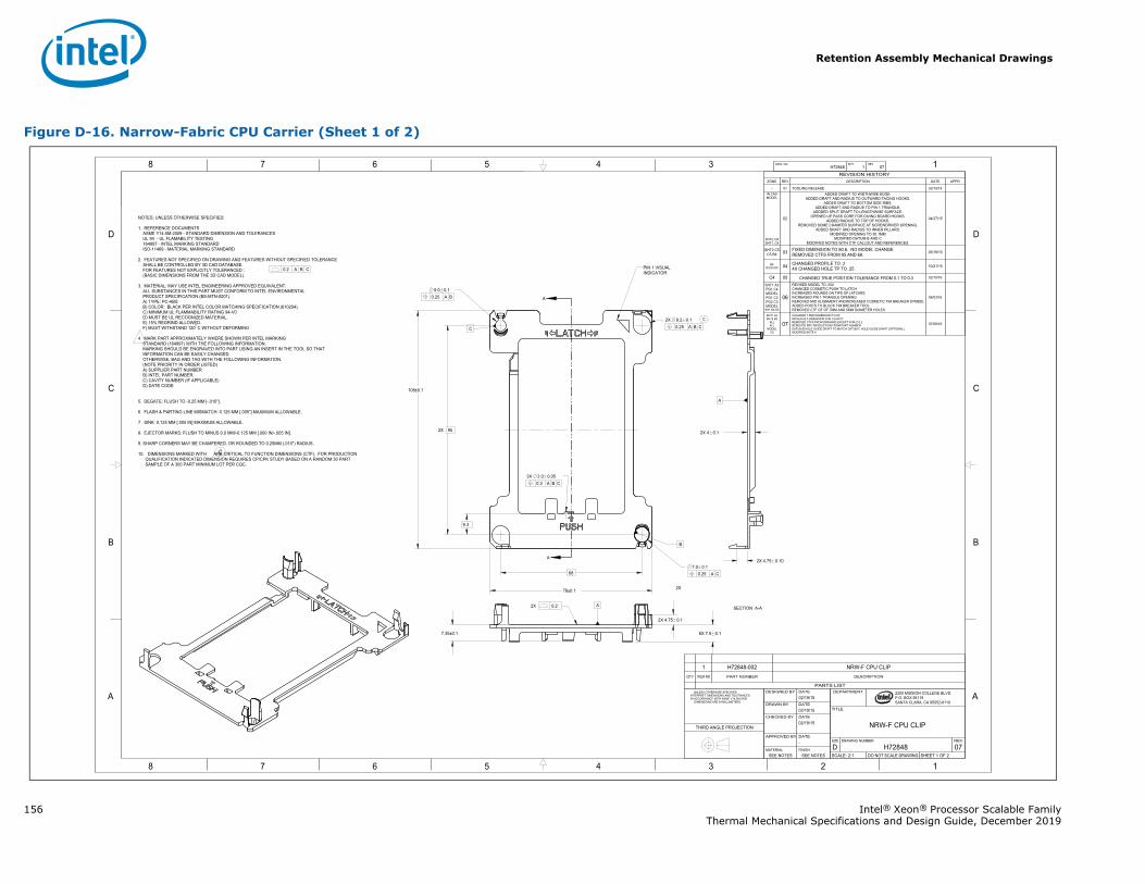
Retention Assembly Mechanical Drawings
156 Intel® Xeon® Processor Scalable FamilyThermal Mechanical Specifications and Design Guide, December 2019
Figure D-16. Narrow-Fabric CPU Carrier (Sheet 1 of 2)
A
A
1345678
B
C
D
A
12345678
B
C
D
A 2200 MISSION COLLEGE BLVD.P.O. BOX 58119SANTA CLARA, CA 95052-8119
R
2X 95
68
78±0.1
108±0.1
2X 4.75 0.1
6X 7.5 0.17.35±0.1
2X 4 0.1
9.3
0.25 A B5.0 0.1
0.25 A C7.0 0.1
0.25 A B C2X 8.2 0.1
2X 4.75 0.10
0.3 A B C3X 2.0 0.05
A
A
H72848 1 07DWG. NO SHT. REV
SHEET 1 OF 2DO NOT SCALE DRAWINGSCALE: 2:107H72848DREVDRAWING NUMBERSIZE
NRW-F CPU CLIP
TITLE
DEPARTMENT
SEE NOTESSEE NOTESFINISHMATERIAL
-DATEAPPROVED BY
02/19/15DATECHECKED BY
02/19/15DATEDRAWN BY
02/19/15DATEDESIGNED BY UNLESS OTHERWISE SPECIFIED
INTERPRET DIMENSIONS AND TOLERANCES IN ACCORDANCE WITH ASME Y14.5M-2009 DIMENSIONS ARE IN MILLIMETERS
THIRD ANGLE PROJECTION
REVISION HISTORYZONE REV DESCRIPTION DATE APPR
- 01 TOOLING RELEASE 02/19/15IN CADMODEL
SHT2, D4SHT1, C8
02
ADDED DRAFT TO WIDTHWISE EDGE.ADDED DRAFT AND RADIUS TO OUTWARD FACING HOOKS.
ADDED DRAFT TO BOTTOM SIDE RIBS.ADDED DRAFT AND RADIUS TO PIN 1 TRIANGLE.
ADDDED SPLIT DRAFT TO LENGTHWISE SURFACE.OPENED UP PASS CORE FOR DIVING BOARD HOOKS.
ADDED RADIUS TO TOP OF HOOKS.REMOVED SOME CHAMFER SURFACE AT SCREWDRIVER OPENING.
ADDED DRAFT AND RADIUS TO INNER PILLARS.MODIFIED OPENING TO 30.1MM
MODIFIED DATUM B AND CMODIFIED NOTES WITH CTF CALLOUT AND REFERENCES.
04/27/15
SHT2 C5C5 B4 03 FIXED DIMENSION TO 80.6. NO MODEL CHANGE.
REMOVED CTFS FROM 95 AND 68. 05/18/15
B4B3,D3,D5 04 CHANGED PROFILE TO .2
4X CHANGED HOLE TP TO .25 10/21/15
C4 05 CHANGED TRUE POSITION TOLERANCE FROM 0.1 TO 0.3 02/10/16
SHT1 A3PG1 C4MODELPG1 C3PG2 C3MODEL
SH1 B3,D5
06
REVISED MODEL TO -002CHANGED COSMETIC PUSH TO LATCHINCREASED ROUNDS ON TIPS OF LATCHESINCREASED PIN 1 TRIANGLE OPENINGREMOVED MID ALIGNMENT ANDINCREASED COSMETIC TIM BREAKER SYMBOLADDED POSTS TO BLOCK TIM BREAKER TOOLREMOVED CTF OF OF 7MM AND 5MM DIAMETER HOLES
06/03/16
SHT1 A3SHT2 B3
ALLALL
MODELC8
07CHANGED 7.5MM DIMENSION TO 6XMOVED 62.5 DIMENSION FOR CLARITYREMOVED CTFS FROM DRAWING EXCEPT FOR 8.2REMOVED PRE PRODUCTION FROM PART NUMBERDATUM B HOLE GUIDE DRAFT TO MATCH DATUM C HOLE GUIDE DRAFT (OPTIONAL)MODIFIED NOTE 4.
07/08/16
NOTES; UNLESS OTHERWISE SPECIFIED:
1. REFERENCE DOCUMENTSASME Y14.5M-2009 - STANDARD DIMENSION AND TOLERANCESUL 94 - UL FLAMABILITY TESTING164997 - INTEL MARKING STANDARDISO-11469 - MATERIAL MARKING STANDARD
2. FEATURES NOT SPECIFIED ON DRAWING AND FEATURES WITHOUT SPECIFIED TOLERANCESHALL BE CONTROLLED BY 3D CAD DATABASE.FOR FEATURES NOT EXPLICITLY TOLERANCED : (BASIC DIMENSIONS FROM THE 3D CAD MODEL).
3. MATERIAL: MAY USE INTEL ENGINEERING APPROVED EQUIVALENT.ALL SUBSTANCES IN THIS PART MUST CONFORM TO INTEL ENVIRONMENTALPRODUCT SPECIFICATION (BS-MTN-0001).A) TYPE: PC-ABSB) COLOR: BLACK PER INTEL COLOR MATCHING SPECIFICATION (610204).C) MINIMUM UL FLAMMABILITY RATING 94-V0D) MUST BE UL RECOGNIZED MATERIAL.E) 15% REGRIND ALLOWED.F) MUST WITHSTAND 120 C WITHOUT DEFORMING
4 MARK PART APPROXIMATELY WHERE SHOWN PER INTEL MARKING STANDARD (164997) WITH THE FOLLOWING INFORMATION. MARKING SHOULD BE ENGRAVED INTO PART USING AN INSERT IN THE TOOL SO THAT INFORMATION CAN BE EASILY CHANGED. OTHERWISE, BAG AND TAG WITH THE FOLLOWING INFORMATION. (NOTE PRIORITY IN ORDER LISTED)
A) SUPPLIER PART NUMBERB) INTEL PART NUMBER:C) CAVITY NUMBER (IF APPLICABLE)D) DATE CODE
5. DEGATE: FLUSH TO -0.25 MM [-.010"].
6. FLASH & PARTING LINE MISMATCH: 0.125 MM [.005"] MAXIMUM ALLOWABLE.
7. SINK: 0.125 MM [.005 IN] MAXIMUM ALLOWABLE.
8. EJECTOR MARKS: FLUSH TO MINUS 0.0 MM/-0.125 MM [.000 IN/-.005 IN].
9. SHARP CORNERS MAY BE CHAMFERED, OR ROUNDED TO 0.25MM (.010") RADIUS.
10. DIMENSIONS MARKED WITH ARE CRITICAL TO FUNCTION DIMENSIONS (CTF). FOR PRODUCTION QUALIFICATION INDICATED DIMENSION REQUIRES CP/CPK STUDY BASED ON A RANDOM 30 PART SAMPLE OF A 300 PART MINIMUM LOT PER CQC.
0.2 A B C
2X
PIN 1 VISUALINDICATOR
SECTION A-A2X 0.2
B
C
C
C
PARTS LIST
DESCRIPTIONPART NUMBERITEM NOQTY
NRW-F CPU CLIPH72848-0021
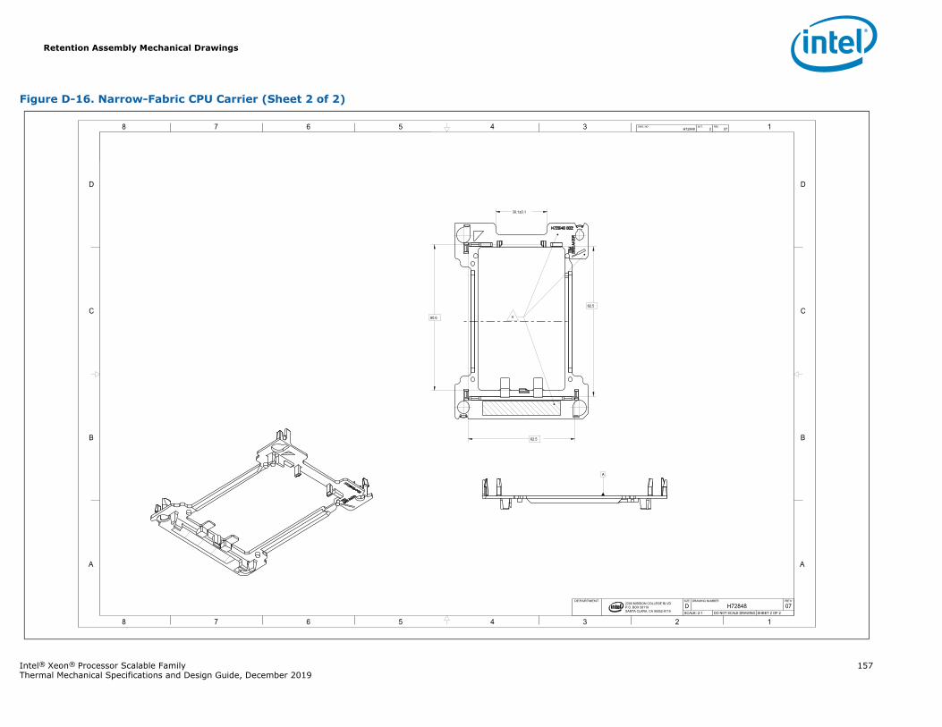
Retention Assembly Mechanical Drawings
Intel® Xeon® Processor Scalable Family 157Thermal Mechanical Specifications and Design Guide, December 2019
Figure D-16. Narrow-Fabric CPU Carrier (Sheet 2 of 2)
1345678
B
C
D
A
12345678
B
C
D
A
2200 MISSION COLLEGE BLVD.P.O. BOX 58119SANTA CLARA, CA 95052-8119
R
82.5
62.5
80.6
30.1±0.1
A
H72848 2 07DWG. NO SHT. REV
SHEET 2 OF 2DO NOT SCALE DRAWINGSCALE: 2:107H72848DREVDRAWING NUMBERSIZEDEPARTMENT
4
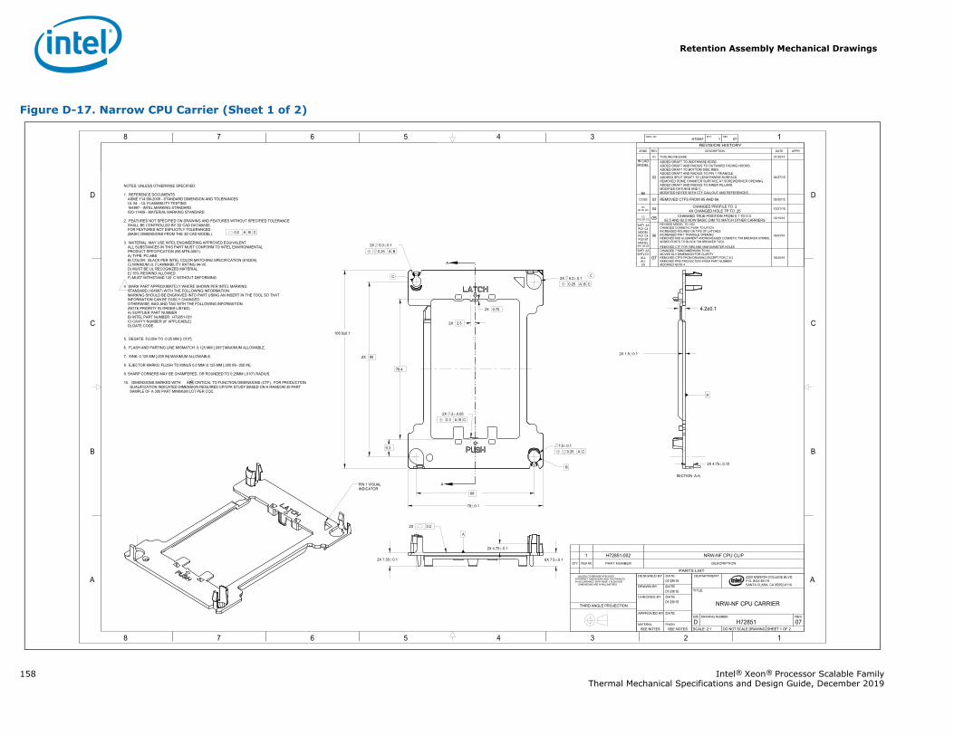
Retention Assembly Mechanical Drawings
158 Intel® Xeon® Processor Scalable FamilyThermal Mechanical Specifications and Design Guide, December 2019
Figure D-17. Narrow CPU Carrier (Sheet 1 of 2)
A
A
1345678
B
C
D
A
12345678
B
C
D
A 2200 MISSION COLLEGE BLVD.P.O. BOX 58119SANTA CLARA, CA 95052-8119
R
0.25 A B
2X 95
76.4
78 0.1
68
2X 2.5
2X 0.75
108.0±0.1
9.3
2X 1.5 0.1
2X 5.0 0.1
0.25 A B C2X 8.2 0.1
0.25 A C7.0 0.1
6X 7.5 0.12X 7.35 0.1
2X 4.75 0.1
4.2±0.1
2X 4.75 0.10
0.3 A B C2X 2 0.05
A
A
H72851 1 07DWG. NO SHT. REV
SHEET 1 OF 2DO NOT SCALE DRAWINGSCALE: 2:107H72851DREVDRAWING NUMBERSIZE
NRW-NF CPU CARRIER
TITLE
DEPARTMENT
SEE NOTESSEE NOTESFINISHMATERIAL
-DATEAPPROVED BY
01/29/15DATECHECKED BY
01/29/15DATEDRAWN BY
01/29/15DATEDESIGNED BY UNLESS OTHERWISE SPECIFIED
INTERPRET DIMENSIONS AND TOLERANCES IN ACCORDANCE WITH ASME Y14.5M-2009 DIMENSIONS ARE IN MILLIMETERS
THIRD ANGLE PROJECTION
REVISION HISTORYZONE REV DESCRIPTION DATE APPR
- 01 TOOLING RELEASE 01/29/15IN CADMODEL
B8
02
ADDED DRAFT TO WIDTHWISE EDGE.ADDED DRAFT AND RADIUS TO OUTWARD FACING HOOKS.ADDED DRAFT TO BOTTOM SIDE RIBS.ADDED DRAFT AND RADIUS TO PIN 1 TRIANGLE.ADDDED SPLIT DRAFT TO LENGTHWISE SURFACE.REMOVED SOME CHAMFER SURFACE AT SCREWDRIVER OPENING.ADDED DRAFT AND RADIUS TO INNER PILLARS.MODIFIED DATUM B AND CMODIFIED NOTES WITH CTF CALLOUT AND REFERENCES.
04/27/15
C3 B2 03 REMOVED CTFS FROM 95 AND 68. 05/20/15
B3B1,D1,D3 04 CHANGED PROFILE TO .2
4X CHANGED HOLE TP TO .25 10/21/15
C2PG2 B7,C5 05 CHANGED TRUE POSITION FROM 0.1 TO 0.3.
62.5 AND 82.5 NOW BASIC DIM TO MATCH OTHER CARRIERS 02/10/16
SHT1 A3PG1 C4MODELPG1 C4PG2 B7MODEL
SH1 B3,D5
06
REVISED MODEL TO -002CHANGED COSMETIC PUSH TO LATCHINCREASED ROUNDS ON TIPS OF LATCHESINCREASED PIN 1 TRIANGLE OPENINGREMOVED MID ALIGNMENT ANDINCREASED COSMETIC TIM BREAKER SYMBOLADDED POSTS TO BLOCK TIM BREAKER TOOLREMOVED CTF FOR 7MM AND 5MM DIAMETER HOLES
06/03/16
SHT1 A3SHT2 D7
ALLALLC8
07CHANGED 7.5MM DIMENSION TO 6XMOVED 62.5 DIMENSION FOR CLARITYREMOVED CTFS FROM DRAWING EXCEPT FOR 8.2REMOVED PRE PRODUCTION FROM PART NUMBERMODIFIED NOTE 4.
06/20/16
NOTES; UNLESS OTHERWISE SPECIFIED:
1. REFERENCE DOCUMENTSASME Y14.5M-2009 - STANDARD DIMENSION AND TOLERANCESUL 94 - UL FLAMABILITY TESTING164997 - INTEL MARKING STANDARDISO-11469 - MATERIAL MARKING STANDARD
2. FEATURES NOT SPECIFIED ON DRAWING AND FEATURES WITHOUT SPECIFIED TOLERANCESHALL BE CONTROLLED BY 3D CAD DATABASE.FOR FEATURES NOT EXPLICITLY TOLERANCED :(BASIC DIMENSIONS FROM THE 3D CAD MODEL).
3. MATERIAL: MAY USE INTEL ENGINEERING APPROVED EQUIVALENT.ALL SUBSTANCES IN THIS PART MUST CONFORM TO INTEL ENVIRONMENTALPRODUCT SPECIFICATION (BS-MTN-0001).A) TYPE: PC-ABSB) COLOR: BLACK PER INTEL COLOR MATCHING SPECIFICATION (610204).C) MINIMUM UL FLAMMABILITY RATING 94-V0D) MUST BE UL RECOGNIZED MATERIAL.E) 15% REGRIND ALLOWED.F) MUST WITHSTAND 120 C WITHOUT DEFORMING
4 MARK PART APPROXIMATELY WHERE SHOWN PER INTEL MARKING STANDARD (164997) WITH THE FOLLOWING INFORMATION. MARKING SHOULD BE ENGRAVED INTO PART USING AN INSERT IN THE TOOL SO THAT INFORMATION CAN BE EASILY CHANGED. OTHERWISE, BAG AND TAG WITH THE FOLLOWING INFORMATION. (NOTE PRIORITY IN ORDER LISTED)
A) SUPPLIER PART NUMBERB) INTEL PART NUMBER: H72851-001C) CAVITY NUMBER (IF APPLICABLE)D) DATE CODE
5. DEGATE: FLUSH TO -0.25 MM [-.010"].
6. FLASH AND PARTING LINE MISMATCH: 0.125 MM [.005"] MAXIMUM ALLOWABLE.
7. SINK: 0.125 MM [.005 IN] MAXIMUM ALLOWABLE.
8. EJECTOR MARKS: FLUSH TO MINUS 0.0 MM/-0.125 MM [.000 IN/-.005 IN].
9. SHARP CORNERS MAY BE CHAMFERED, OR ROUNDED TO 0.25MM (.010") RADIUS.
10. DIMENSIONS MARKED WITH ARE CRITICAL TO FUNCTION DIMENSIONS (CTF). FOR PRODUCTION QUALIFICATION INDICATED DIMENSION REQUIRES CP/CPK STUDY BASED ON A RANDOM 30 PART SAMPLE OF A 300 PART MINIMUM LOT PER CQC.
0.2 A B C
PIN 1 VISUALINDICATOR
2X 0.2
SECTION A-A
C
B
C
C
PARTS LIST
DESCRIPTIONPART NUMBERITEM NOQTY
NRW- CPU CLIPH72851-0021
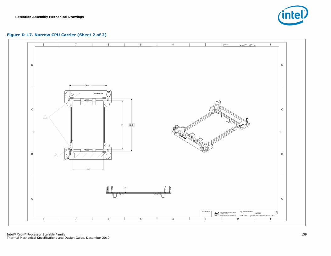
Retention Assembly Mechanical Drawings
Intel® Xeon® Processor Scalable Family 159Thermal Mechanical Specifications and Design Guide, December 2019
Figure D-17. Narrow CPU Carrier (Sheet 2 of 2)
1345678
B
C
D
A
12345678
B
C
D
A
2200 MISSION COLLEGE BLVD.P.O. BOX 58119SANTA CLARA, CA 95052-8119
R
76
51
82.5
62.5
A
H72851 2 07DWG. NO SHT. REV
SHEET 2 OF 2DO NOT SCALE DRAWINGSCALE: 2:107H72851DREVDRAWING NUMBERSIZEDEPARTMENT
4
4
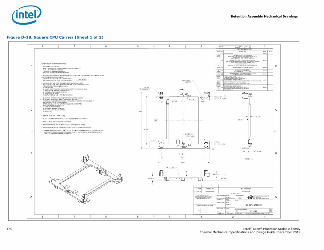
Retention Assembly Mechanical Drawings
160 Intel® Xeon® Processor Scalable FamilyThermal Mechanical Specifications and Design Guide, December 2019
Figure D-18. Square CPU Carrier (Sheet 1 of 2)
A
A
1345678
B
C
D
A
12345678
B
C
D
A 2200 MISSION COLLEGE BLVD.P.O. BOX 58119SANTA CLARA, CA 95052-8119
R
88±0.1
91±0.1
76.4
2X 2.5
2X 79
2X 0.75
76
2X 7.35 0.1 6X 7.5 0.1
4X 4.75 0.1
1.3
2X 4 0.1
0.25 A B5.0 0.1
0.25 A C7.0 0.1
0.25 A B C2X 8.2 0.1
2X 4.75 0.10
0.3 A B C2X 2.0 0.05
A
A
H72853 1 07DWG. NO SHT. REV
SHEET 1 OF 2DO NOT SCALE DRAWINGSCALE: 2:107H72853DREVDRAWING NUMBERSIZE
SQ CPU CARRIER
TITLE
PMCI
DEPARTMENT
SEE NOTESSEE NOTESFINISHMATERIAL
-DATEAPPROVED BY
02/26/15DATECHECKED BY
02/26/15DATEDRAWN BY
02/26/15DATEDESIGNED BY UNLESS OTHERWISE SPECIFIED
INTERPRET DIMENSIONS AND TOLERANCES IN ACCORDANCE WITH ASME Y14.5M-1994 DIMENSIONS ARE IN MILLIMETERS
THIRD ANGLE PROJECTION
REVISION HISTORYZONE REV DESCRIPTION DATE APPR
- 01 TOOLING RELEASE 02/26/15
IN CADMODEL
B8
02
ADDED DRAFT TO WIDTHWISE EDGE.ADDED DRAFT AND RADIUS TO OUTWARD FACING HOOKS.
ADDED DRAFT TO BOTTOM SIDE RIBS.ADDED DRAFT AND RADIUS TO PIN 1 TRIANGLE.
ADDDED SPLIT DRAFT TO LENGTHWISE SURFACE.REMOVED SOME CHAMFER SURFACE AT SCREWDRIVER OPENING.
ADDED DRAFT AND RADIUS TO INNER PILLARS.MODIFIED DATUM B AND C
MODIFIED NOTES WITH CTF CALLOUT AND REFERENCES.
04/27/15
C5 B4 03 REMOVED CTFS FROM 79 AND 76 05/21/15
B4B2,D2,D5 04 CHANGED PROFILE TO .2
4X CHANGED HOLE TP TO .25 10/21/15
C3PG2 C6 05 CHANGED TRUE POSITION FROM 0.1 TO 0.3.
REMOVED PROFILE TOLERANCE 02/10/16
SHT1 A3PG1 C4MODELPG1 C3PG2 C5MODEL
SH1 B3,D5
06
REVISED MODEL TO -002CHANGED COSMETIC PUSH TO LATCHINCREASED ROUNDS ON TIPS OF LATCHESINCREASED PIN 1 TRIANGLE OPENINGREMOVED MID ALIGNMENT ANDINCREASED COSMETIC TIM BREAKER SYMBOLADDED POSTS TO BLOCK TIM BREAKER TOOLREMOVED CTF FOR 7MM AND 5MM DIAMETER HOLES
06/03/16
SHT1 A2SHT2 B6
ALLALLC8
07CHANGED 7.5MM DIMENSION TO 6XMOVED 62.3 DIMENSION FOR CLARITY.REMOVED CTFS FROM DRAWING EXCEPT FOR 8.2REMOVED PRE PRODUCTION FROM PART NUMBERMODIFIED NOTE 4.
06/20/16
NOTES; UNLESS OTHERWISE SPECIFIED:
1. REFERENCE DOCUMENTSASME Y14.5M-2009 - STANDARD DIMENSION AND TOLERANCESUL 94 - UL FLAMABILITY TESTING164997 - INTEL MARKING STANDARDISO-11469 - MATERIAL MARKING STANDARD
2. FEATURES NOT SPECIFIED ON DRAWING AND FEATURES WITHOUT SPECIFIED TOLERANCE SHALL BECONTROLLED BY 3D CAD DATABASE. FOR FEATURES NOT EXPLICITLY TOLERANCED : (BASIC DIMENSIONS FROM THE 3D CAD MODEL).
3. MATERIAL: MAY USE INTEL ENGINEERING APPROVED EQUIVALENT.ALL SUBSTANCES IN THIS PART MUST CONFORM TO INTEL ENVIRONMENTALPRODUCT SPECIFICATION (BS-MTN-0001).A) TYPE: PC-ABSB) COLOR: BLACK PER INTEL COLOR MATCHING SPECIFICATION (610204).C) MINIMUM UL FLAMMABILITY RATING 94-V0D) MUST BE UL RECOGNIZED MATERIAL.E) 15% REGRIND ALLOWED.F) MUST WITHSTAND 12O C WITHOUT DEFORMING
4 MARK PART APPROXIMATELY WHERE SHOWN PER INTEL MARKING STANDARD (164997) WITH THE FOLLOWING INFORMATION. MARKING SHOULD BE ENGRAVED INTO PART USING AN INSERT IN THE TOOL SO THAT INFORMATION CAN BE EASILY CHANGED. OTHERWISE, BAG AND TAG WITH THE FOLLOWING INFORMATION. (NOTE PRIORITY IN ORDER LISTED)
A) SUPPLIER PART NUMBERB) INTEL PART NUMBER: H72853-001C) CAVITY NUMBER (IF APPLICABLE)D) DATE CODE
5. DEGATE: FLUSH TO -0.25 MM [-.010"].
6. FLASH & PARTING LINE MISMATCH: 0.125 MM [.005"] MAXIMUM ALLOWABLE.
7. SINK: 0.125 MM [.005 IN] MAXIMUM ALLOWABLE.
8. EJECTOR MARKS: FLUSH TO MINUS 0.0 MM/-0.125 MM [.000 IN/-.005 IN].
9. SHARP CORNERS MAY BE CHAMFERED, OR ROUNDED TO 0.25MM (.010") RADIUS.
10. DIMENSIONS MARKED WITH ARE CRITICAL TO FUNCTION DIMENSIONS (CTF). FOR PRODUCTION QUALIFICATION INDICATED DIMENSION REQUIRES CP/CPK STUDY BASED ON A RANDOM 30 PART SAMPLE OF A 300 PART MINIMUM LOT PER CQC.
0.2 A B C
2X
PIN 1 VISUALINDICATOR
SECTION A-A
2X 0.2
B
C
C
C
PARTS LIST
DESCRIPTIONPART NUMBERITEM NOQTY
Q CPU CLIPH72853-002TOP
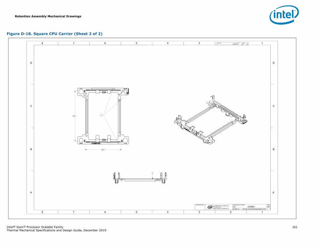
Retention Assembly Mechanical Drawings
Intel® Xeon® Processor Scalable Family 161Thermal Mechanical Specifications and Design Guide, December 2019
Figure D-18. Square CPU Carrier (Sheet 2 of 2)
1345678
B
C
D
A
12345678
B
C
D
A
2200 MISSION COLLEGE BLVD.P.O. BOX 58119SANTA CLARA, CA 95052-8119
R
82.3
62.3
A
H72853 2 07DWG. NO SHT. REV
SHEET 2 OF 2DO NOT SCALE DRAWINGSCALE: 2:107H72853DREVDRAWING NUMBERSIZEDEPARTMENT
4
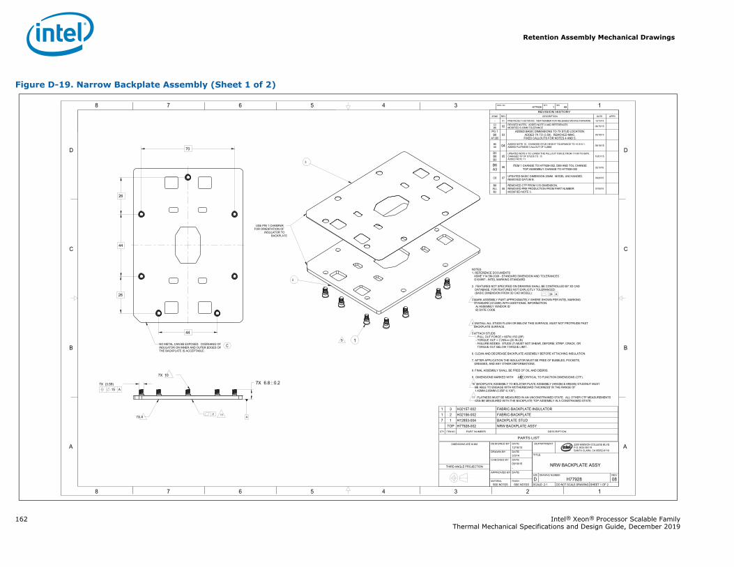
Retention Assembly Mechanical Drawings
162 Intel® Xeon® Processor Scalable FamilyThermal Mechanical Specifications and Design Guide, December 2019
Figure D-19. Narrow Backplate Assembly (Sheet 1 of 2)
1345678
B
C
D
A
12345678
B
C
D
A 2200 MISSION COLLEGE BLVD.P.O. BOX 58119SANTA CLARA, CA 95052-8119
R
.24 A
.2
.15 A 7X (3.59) 7X 6.8 0.2
44
26
26
44
70
A
H77928 1 08DWG. NO SHT. REV
SHEET 1 OF 2DO NOT SCALE DRAWINGSCALE: 2:108H77928DREVDRAWING NUMBERSIZE
NRW BACKPLATE ASSY
TITLE
DEPARTMENT
SEE NOTESSEE NOTESFINISHMATERIAL
DATEAPPROVED BY
-09/18/15DATECHECKED BY
3/3/14DATEDRAWN BY
12/16/13DATEDESIGNED BYDIMENSIONS ARE IN MM
THIRD ANGLE PROJECTION
REVISION HISTORYZONE REV DESCRIPTION DATE APPR
- 01 PREVIOUSLY H32155-002. NEW NUMBER FOR RELEASES MOVING FORWARD. 12/12/14
C2B6 02 REVISED NOTES. ADDED NOTE 9 AND REFERENCES
MODIFIED 6.33MM TOLERANCE 04/15/15
PG 1B8
A7,B503
ADDED BASIC DIMENSIONS TO 7X STUD LOCATION.ADDED 7X TO (3.59). REMOVED MMC.
FIXED CALLOUTS FOR NOTES 4 AND 5.05/18/15
B6A6 04 ADDED NOTE 10. CHANGED STUD HEIGHT TOLERANCE TO +0.3/-0.1.
ADDED FLATNESS CALLOUT OF 0.2MM. 09/18/15
B3B8B3
05UPDATED NOTE 4 TO LOWER THE PULLOUT FORCE FROM 1110N TO 667N.CHANGED TP OF STUDS TO .15ADDED NOTE 11.
10/01/15
B6A3 06 ITEM 1 CHANGE TO H77928-002, DIM AND TOL CHANGE
TOP ASSEMBLY CHANGE TO H77928-002 02/10/16
C8 07 UPDATED BASIC DIMENSION 26MM. MODEL UNCHANGED.REMOVED DATUM B. 06/20/16
B8ALLB2
08REMOVED CTF FROM 3.59 DIMENSION, REMOVED PRE PRODUCTION FROM PART NUMBERMODIFIED NOTE 3.
07/08/16
NOTES1. REFERENCE DOCUMENTS
ASME Y14.5M-2009 - STANDARD DIMENSION AND TOLERANCESG164997 - INTEL MARKING STANDARD
2. FEATURES NOT SPECIFIED ON DRAWING SHALL BE CONTROLLED BY 3D CADDATABASE. FOR FEATURES NOT EXPLICITLY TOLERANCED:
(BASIC DIMENSION FROM 3D CAD MODEL):
3 MARK ASSEMBLY PART APPROXIMATELY WHERE SHOWN PER INTEL MARKING STANDARD (G14599) WITH ADDITIONAL INFORMATION:
A) ASSEMBLY VENDOR IDB) DATE CODE
4 INSTALL ALL STUDS FLUSH OR BELOW THIS SURFACE, MUST NOT PROTRUDE PAST BACKPLATE SURFACE.
5 ATTACH STUDS:- PULL OUT FORCE > 667N (150 LBF)- TORQUE OUT > 2.25N-m (20 IN-LB)- FAILURE MODES: STUDS (7) MUST NOT SHEAR, DEFORM, STRIP, CRACK, OR
TORQUE-OUT BELOW TORQUE LIMIT.
6. CLEAN AND DEGREASE BACKPLATE ASSEMBLY BEFORE ATTACHING INSULATION.
7. AFTER APPLICATION THE INSULATOR MUST BE FREE OF BUBBLES, POCKETS,GREASES, AND ANY OTHER DEFORMATIONS.
8. FINAL ASSEMBLY SHALL BE FREE OF OIL AND DEBRIS.
9. DIMENSIONS MARKED WITH ARE CRITICAL TO FUNCTION DIMENSIONS (CTF).
10 BACKPLATE ASSEMBLY TO BOLSTER PLATE ASSEMBLY (H95384 & H95385) STUD/NUT MUST BE ABLE TO ENGAGE WITH MOTHERBOARD THICKNESS' IN THE RANGE OF 1.42MM-2.69MM (0.056"-0.106").
11 FLATNESS MUST BE MEASURED IN AN UNCONSTRAINED STATE. ALL OTHER CTF MEASUREMENTS CAN BE MEASURED WITH THE BACKPLATE TOP ASSEMBLY IN A CONSTRAINED STATE.
5
11
NO METAL CAN BE EXPOSED. OVERHANG OF INSULATOR ON INNER AND OUTER EDGES OF THE BACKPLATE IS ACCEPTABLE.
2
3
USE PIN 1 CHAMFER FOR ORIENTATION OF
INSULATOR TO BACKPLATE
1
7X 4
7X 10 C
C
PARTS LIST
DESCRIPTIONPART NUMBERITEM NOQTY
NRW BACKPLATE ASSYH77928-002TOPBACKPLATE STUDH12853-00417FABRIC-BACKPLATEH32156-00221FABRIC-BACKPLATE-INSULATORH32157-00231
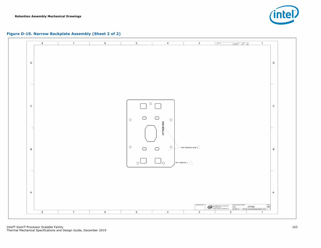
Retention Assembly Mechanical Drawings
Intel® Xeon® Processor Scalable Family 163Thermal Mechanical Specifications and Design Guide, December 2019
Figure D-19. Narrow Backplate Assembly (Sheet 2 of 2)
1345678
B
C
D
A
12345678
B
C
D
A
2200 MISSION COLLEGE BLVD.P.O. BOX 58119SANTA CLARA, CA 95052-8119
R
H77928 2 08DWG. NO SHT. REV
SHEET 2 OF 2DO NOT SCALE DRAWINGSCALE: 2:108H77928DREVDRAWING NUMBERSIZEDEPARTMENT
PIN 1 MARKING 3
PART MARKING ZONE 3
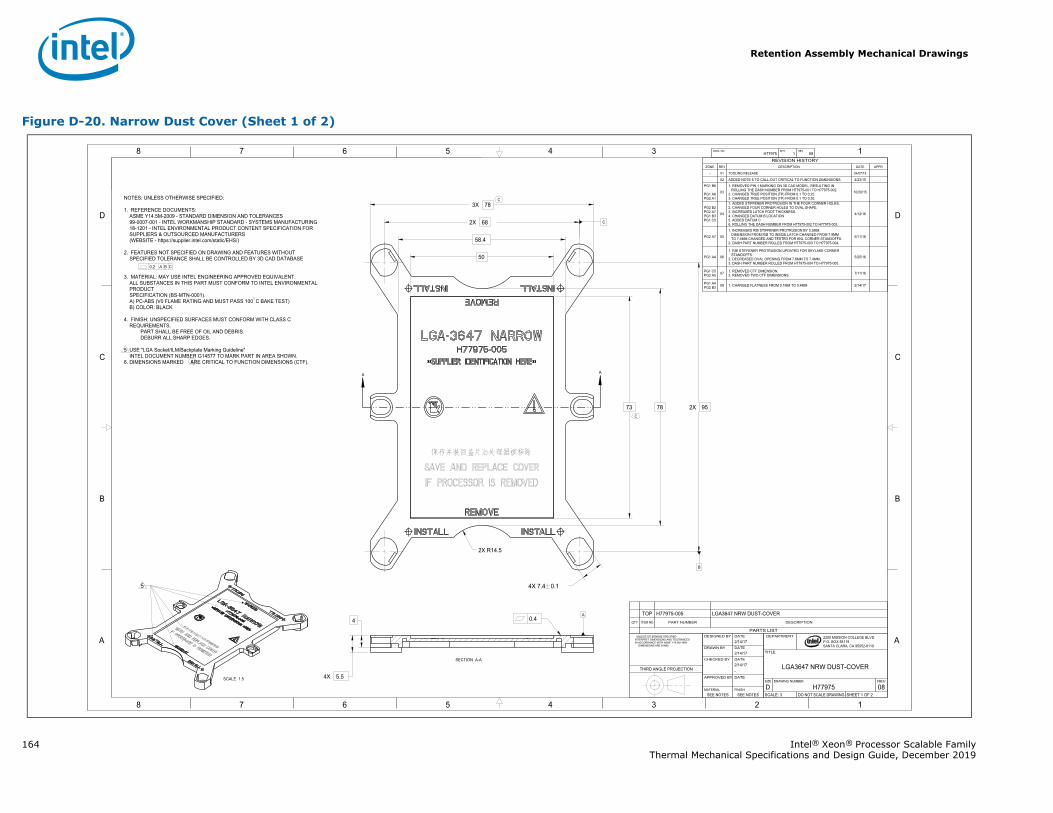
Retention Assembly Mechanical Drawings
164 Intel® Xeon® Processor Scalable FamilyThermal Mechanical Specifications and Design Guide, December 2019
Figure D-20. Narrow Dust Cover (Sheet 1 of 2)
A A
1345678
B
C
D
A
12345678
B
C
D
A
B
C
2200 MISSION COLLEGE BLVD.P.O. BOX 58119SANTA CLARA, CA 95052-8119
R
0.2 A B C
0.4
3X 78
78
58.4
50
73
4
4X 5.5
2X R14.5
2X 95
2X 68
4X 7.4 0.1
A
H77975 1 08DWG. NO SHT. REV
SHEET 1 OF 2DO NOT SCALE DRAWINGSCALE: 308H77975DREVDRAWING NUMBERSIZE
LGA3647 NRW DUST-COVER
TITLE
DEPARTMENT
SEE NOTESSEE NOTESFINISHMATERIAL
DATEAPPROVED BY
-2/14/17 DATECHECKED BY
2/14/17 DATEDRAWN BY
2/14/17DATEDESIGNED BY UNLESS OTHERWISE SPECIFIED
INTERPRET DIMENSIONS AND TOLERANCES IN ACCORDANCE WITH ASME Y14.5M-1994 DIMENSIONS ARE IN MM
THIRD ANGLE PROJECTION
PARTS LIST
DESCRIPTIONPART NUMBERITEM NOQTY
LGA3647 NRW DUST-COVERH77975-005TOP
REVISION HISTORYZONE REV DESCRIPTION DATE APPR
- 01 TOOLING RELEASE 04/07/15
02 ADDED NOTE 6 TO CALL-OUT CRITICAL TO FUNCTION DIMENSIONS. 4/23/15PG1 B6
PG1 A6PG2 A1
03
1. REMOVED PIN 1 MARKING ON 3D CAD MODEL, RESULTING INROLLING THE DASH NUMBER FROM H77975-001 TO H77975-002.
2. CHANGED TRUE POSITION (TP) FROM 0.1 TO 0.25.3. CHANGED TRUE POSITION (TP) FROM 0.1 TO 0.30.
10/20/15
PG2 B2PG2 A7PG1 B3PG1 C5
04
1. ADDED STIFFENER PROTRUSION IN THE FOUR CORNER HOLES.2. CHANGED FOUR CORNER HOLES TO OVAL SHAPE.3. INCREASED LATCH FOOT THICKNESS.4. CHANGED DATUM B LOCATION5. ADDED DATUM C6. ROLLING THE DASH NUMBER FROM H77975-002 TO H77975-003.
4/12/16
PG2 A7 05
1. INCREASED RIB STIFFENER PROTRUSION BY 0.5MM.DIMENSION FROM RIB TO INSIDE LATCH CHANGED FROM 7.9MMTO 7.4MM CHANGED AND TESTED FOR KNL CORNER STANDOFFS.
2. DASH PART NUMBER ROLLED FROM H77975-003 TO H77975-004.
5/11/16
PG1 A4 06
1. RIB STIFFENER PROTRUSION UPDATED FOR SKYLAKE CORNERSTANDOFFS.
2. DECREASED OVAL OPENING FROM 7.6MM TO 7.4MM.3. DASH PART NUMBER ROLLED FROM H77975-004 TO H77975-005.
5/25/16
PG1 C5PG2 A5 07 1. REMOVED CTF DIMENSION.
2. REMOVED TWO CTF DIMENSIONS. 7/11/16
PG1 A4PG2 B3 08 1. CHANGED FLATNESS FROM 0.1MM TO 0.4MM 2/14/17
NOTES: UNLESS OTHERWISE SPECIFIED:
1. REFERENCE DOCUMENTS:ASME Y14.5M-2009 - STANDARD DIMENSION AND TOLERANCES99-0007-001 - INTEL WORKMANSHIP STANDARD - SYSTEMS MANUFACTURING18-1201 - INTEL ENVIRONMENTAL PRODUCT CONTENT SPECIFICATION FORSUPPLIERS & OUTSOURCED MANUFACTURERS(WEBSITE - https://supplier.intel.com/static/EHS/)
2. FEATURES NOT SPECIFIED ON DRAWING AND FEATURES WITHOUTSPECIFIED TOLERANCE SHALL BE CONTROLLED BY 3D CAD DATABASE
3. MATERIAL: MAY USE INTEL ENGINEERING APPROVED EQUIVALENT.ALL SUBSTANCES IN THIS PART MUST CONFORM TO INTEL ENVIRONMENTALPRODUCTSPECIFICATION (BS-MTN-0001).A) PC-ABS (V0 FLAME RATING AND MUST PASS 100 C BAKE TEST)B) COLOR: BLACK
4. FINISH: UNSPECIFIED SURFACES MUST CONFORM WITH CLASS CREQUIREMENTS.
PART SHALL BE FREE OF OIL AND DEBRIS. DEBURR ALL SHARP EDGES.
5 USE "LGA Socket/ILM/Backplate Marking Guideline" INTEL DOCUMENT NUMBER G14577 TO MARK PART IN AREA SHOWN.6. DIMENSIONS MARKED ARE CRITICAL TO FUNCTION DIMENSIONS (CTF).
SECTION A-A
SCALE 1.5
5
C
C
C
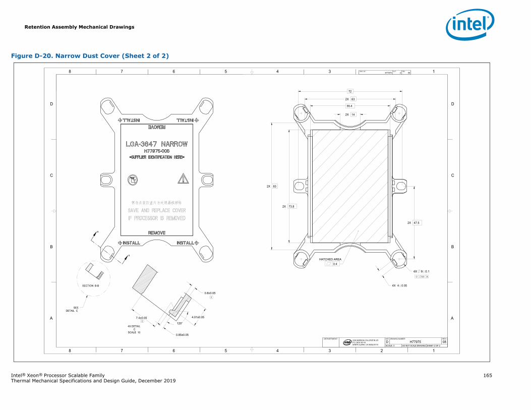
Retention Assembly Mechanical Drawings
Intel® Xeon® Processor Scalable Family 165Thermal Mechanical Specifications and Design Guide, December 2019
Figure D-20. Narrow Dust Cover (Sheet 2 of 2)
B
B
1345678
B
C
D
A
12345678
B
C
D
A
2200 MISSION COLLEGE BLVD.P.O. BOX 58119SANTA CLARA, CA 95052-8119
R
0.3 A
HATCHED AREA0.4
2X 73.8
2X 83
2X 63
55.4
2X 14
72
4X 4 0.05
2X 47.5
4X 9 0.1
0.8±0.05
0.85±0.05
120°
4.01±0.057.4±0.05
H77975 2 08DWG. NO SHT. REV
SHEET 2 OF 2DO NOT SCALE DRAWINGSCALE: 308H77975DREVDRAWING NUMBERSIZEDEPARTMENT
SECTION B-B
SEE DETAIL C
4X DETAIL C
SCALE 10
C
C
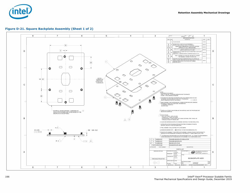
Retention Assembly Mechanical Drawings
166 Intel® Xeon® Processor Scalable FamilyThermal Mechanical Specifications and Design Guide, December 2019
Figure D-21. Square Backplate Assembly (Sheet 1 of 2)
1345678
B
C
D
A
12345678
B
C
D
A 2200 MISSION COLLEGE BLVD.P.O. BOX 58119SANTA CLARA, CA 95052-8119
R
.24 A
.2
.15 A 6X (3.59) 6X 6.8 0.2
2
2X 44
26
25
70
A
H78197 1 07DWG. NO SHT. REV
SHEET 1 OF 2DO NOT SCALE DRAWINGSCALE: 2:107H78197DREVDRAWING NUMBERSIZE
SQ BACKPLATE ASSY
TITLE
DEPARTMENT
SEE NOTESSEE NOTESFINISHMATERIAL
DATEAPPROVED BY
-09/18/15 DATECHECKED BY
4/15/14DATEDRAWN BY
12/16/13DATEDESIGNED BYDIMENSIONS ARE IN MM
THIRD ANGLE PROJECTION
REVISION HISTORYZONE REV DESCRIPTION DATE APPR
- 01 TOOLING RELEASE 12/14/14
B2B6 02 MODIFIED NOTE 2, 4 AND ITS CALLOUT REFERENCES.
MODIFIED 6.33MM TOLERANCE. ADDED CTF DIMENSIONS. 04/24/15
PG1PG1 B8 03 ADDED BASIC DIMENSIONS TO 6X STUD LOCATION.
ADDED 6X TO (3.59). REMOVED MMC. 05/18/15
B6A6 04 ADDED NOTE 10. CHANGED TOLERANCE ON STUD HEIGHT TO +0.3/-0.1.
ADDED FLATNESS CALLOUT OF 0.2MM. 09/18/15
B3B8
A3,C305
UPDATED NOTE 4 TO LOWER THE PULLOUT FORCE FROM 1110N TO 267N.CHANGED TP TO .15ADDED NOTE 11, MODIFIED PROFILE TOLERANCE IN NOTE 2 TO .24.
10/01/15
B6A3 06 ITEM 1 CHANGED TO H12853-004, DIM AND TOL CHANGE
TOP ASSEMBLY CHANGE TO H78197-002 02/10/16
SHT1B8
ALLB3
07
MODIFIED STUD BASIC DIMENSIONS BACK TO CENTER, NOMODEL CHANGE. REMOVED DATUM B. REMOVED CTF FROM 3.59REMOVED PRE PRODUCTION FROM PART NUMBERMODIFIED NOTE 3
06/20/16
6X 10
NOTES1. REFERENCE DOCUMENTS
ASME Y14.5M-2009 - STANDARD DIMENSION AND TOLERANCESG164997 - INTEL MARKING STANDARD
2. FEATURES NOT SPECIFIED ON DRAWING SHALL BE CONTROLLED BY 3D CADDATABASE. FOR FEATURES NOT EXPLICITLY TOLERANCED:(BASIC DIMENSION FROM 3D CAD MODEL):
3 MARK ASSEMBLY PART APPROXIMATELY WHERE SHOWN PER INTEL MARKING STANDARD (G14599) WITH ADDITIONAL INFORMATION:
A) ASSEMBLY VENDOR IDB) DATE CODE
4 INSTALL ALL STUDS FLUSH OR BELOW THIS SURFACE, MUST NOT PROTRUDE PAST BACKPLATE SURRFACE.
5 ATTACH STUDS:- PULL OUT FORCE > 667N (150 LBF)- TORQUE OUT > 2.25N-m (20 IN-LBF)- FAILURE MODES: STUDS (6) MUST NOT SHEAR, DEFORM, STRIP, CRACK, OR
TORQUE-OUT BELOW TORQUE LIMIT.
6. CLEAN AND DEGREASE BACKPLATE ASSEMBLY BEFORE ATTACHING INSULATION.
7. AFTER APPLICATION THE INSULATOR MUST BE FREE OF BUBBLES, POCKETS,GREASES, AND ANY OTHER DEFORMATIONS.
8. FINAL ASSEMBLY SHALL BE FREE OF OIL AND DEBRIS.
9. DIMENSION MARKED WITH ARE CRITICAL TO FUNCTION DIMENSIONS (CTF).
10 BACKPLATE ASSEMBLY TO BOLSTER PLATE ASSEMBLY (H95386) STUD/NUT MUST BE ABLE TO ENGAGE WITH MOTHERBOARD THICKNESS' IN THE RANGE OF 1.42MM-2.69MM (0.056"-0.106").
11 FLATNESS MUST BE MEASURED IN AN UNCONSTRAINED STATE. ALL OTHER CTF MEASUREMENTS CAN BE MEASURED WITH THE BACKPLATE TOP ASSEMBLY IN A CONSTRAINED STATE.
5
11
NO METAL CAN BE EXPOSED. OVERHANG OF INSULATOR ON INNER AND OUTER EDGES OF THE BACKPLATE IS ACCEPTABLE.
2
3
USE PIN 1 CHAMFER FOR ORIENTATION
OF INSULATOR TO BACKPLATE
1
6X 4
C
C
PARTS LIST
DESCRIPTIONPART NUMBERITEM NOQTY
SQ BACKPLATE ASSYH78197-002TOPBACKPLATE STUDH12853-00416SQUARE-BACKPLATEH43623-00121SQUARE-BACKPLATE-INSULATORH43624-00131
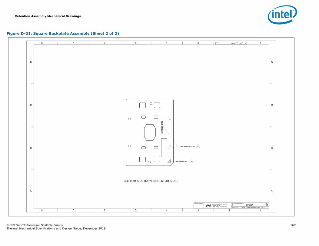
Retention Assembly Mechanical Drawings
Intel® Xeon® Processor Scalable Family 167Thermal Mechanical Specifications and Design Guide, December 2019
Figure D-21. Square Backplate Assembly (Sheet 2 of 2)
1345678
B
C
D
A
12345678
B
C
D
A
2200 MISSION COLLEGE BLVD.P.O. BOX 58119SANTA CLARA, CA 95052-8119
R
H78197 2 07DWG. NO SHT. REV
SHEET 2 OF 2DO NOT SCALE DRAWINGSCALE: 2:107H78197DREVDRAWING NUMBERSIZEDEPARTMENT
BOTTOM SIDE (NON-INSULATOR SIDE)
3
3PIN 1 MARKING
PART MARKING ZONE
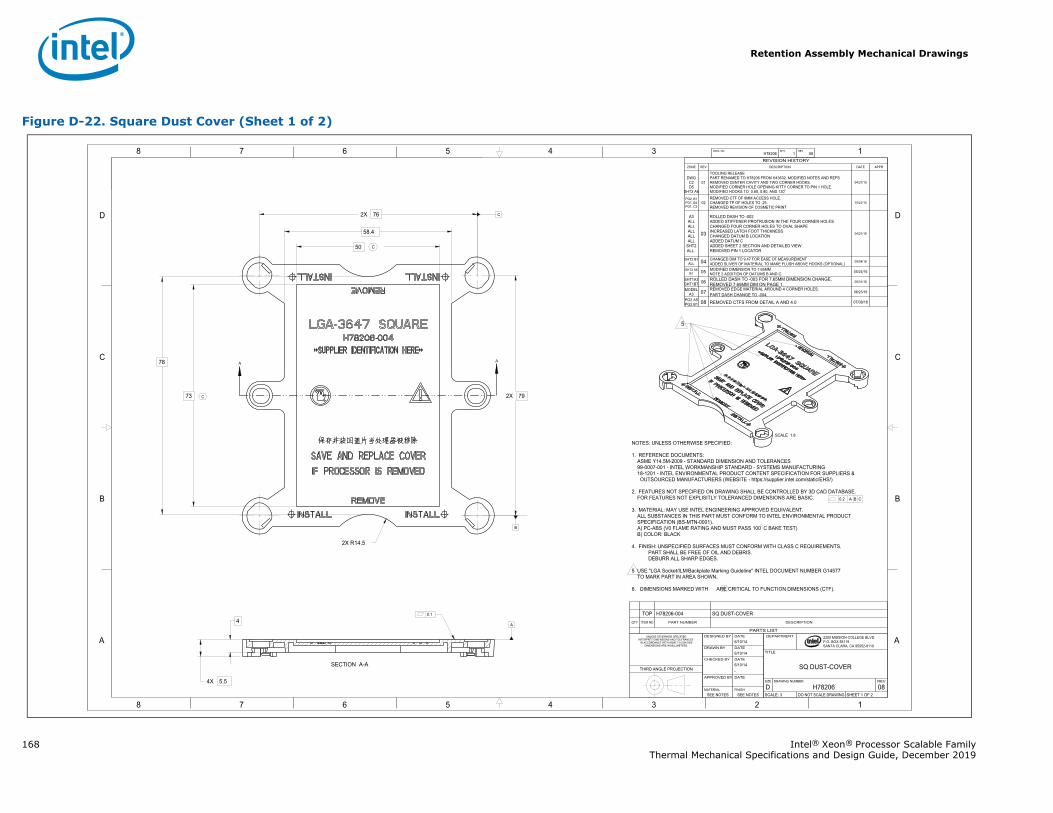
Retention Assembly Mechanical Drawings
168 Intel® Xeon® Processor Scalable FamilyThermal Mechanical Specifications and Design Guide, December 2019
Figure D-22. Square Dust Cover (Sheet 1 of 2)
A A
1345678
B
C
D
A
12345678
B
C
D
A
C
2200 MISSION COLLEGE BLVD.P.O. BOX 58119SANTA CLARA, CA 95052-8119
R
0.2 A B C
0.1
78
58.4
50
73
4X 5.5
2X 79
2X 76
2X R14.5
4
B
A
H78206 1 08DWG. NO SHT. REV
SHEET 1 OF 2DO NOT SCALE DRAWINGSCALE: 308H78206DREVDRAWING NUMBERSIZE
SQ DUST-COVER
TITLE
DEPARTMENT
SEE NOTESSEE NOTESFINISHMATERIAL
DATEAPPROVED BY
-6/10/14 DATECHECKED BY
6/10/14 DATEDRAWN BY
6/10/14DATEDESIGNED BYUNLESS OTHERWISE SPECIFIED
INTERPRET DIMENSIONS AND TOLERANCES IN ACCORDANCE WITH ASME Y14.5M-2009
DIMENSIONS ARE IN MILLIMETERS.
THIRD ANGLE PROJECTION
PARTS LIST
DESCRIPTIONPART NUMBERITEM NOQTY
SQ DUST-COVERH78206-004TOP
REVISION HISTORYZONE REV DESCRIPTION DATE APPR
DWGC2D5
SHT2 A6
01
TOOLING RELEASEPART RENAMED TO H78206 FROM H43632. MODIFIED NOTES AND REFSREMOVED CENTER CAVITY AND TWO CORNER HOOKS.MODIFIED CORNER HOLE OPENING KITTY CORNER TO PIN 1 HOLE.MODIFIED HOOKS TO 0.85, 0.80, AND 120
04/27/15
PG2, B1PG1, B4PG1, C2
02REMOVED CTF OF 9MM ACCESS HOLE.CHANGED TP OF HOLES TO .25.REMOVED REVISION OF COSMETIC PRINT
10/21/15
A3ALLALLALLALLALL
SHT2ALL
03
ROLLED DASH TO -002ADDED STIFFENER PROTRUSION IN THE FOUR CORNER HOLESCHANGED FOUR CORNER HOLES TO OVAL SHAPEINCREASED LATCH FOOT THICKNESSCHANGED DATUM B LOCATIONADDED DATUM CADDED SHEET 2 SECTION AND DETAILED VIEW REMOVED PIN 1 LOCATOR
04/21/16
SHT2 B1ALL 04 CHANGED DIM TO 9.47 FOR EASE OF MEASUREMENT
ADDED SLIVER OF MATERIAL TO MAKE FLUSH ABOVE HOOKS (OPTIONAL) 05/04/16
SHT2 A6B1 05 MODIFIED DIMENSION TO 7.65MM
NOTE 2 ADDITION OF DATUMS B AND C. 05/24/16
SHT1A3SHT1B7 06 ROLLED DASH TO -003 FOR 7.65MM DIMENSION CHANGE,
REMOVED 7.65MM DIM ON PAGE 1.05/31/16
MODELA3 07 REMOVED EDGE MATERIAL AROUND 4 CORNER HOLES.
PART DASH CHANGE TO -004. 06/23/16
PG2 A5PG2 B1 08 REMOVED CTFS FROM DETAIL A AND 4.0 07/08/16
NOTES: UNLESS OTHERWISE SPECIFIED:
1. REFERENCE DOCUMENTS:ASME Y14.5M-2009 - STANDARD DIMENSION AND TOLERANCES99-0007-001 - INTEL WORKMANSHIP STANDARD - SYSTEMS MANUFACTURING18-1201 - INTEL ENVIRONMENTAL PRODUCT CONTENT SPECIFICATION FOR SUPPLIERS &
OUTSOURCED MANUFACTURERS (WEBSITE - https://supplier.intel.com/static/EHS/)
2. FEATURES NOT SPECIFIED ON DRAWING SHALL BE CONTROLLED BY 3D CAD DATABASE.FOR FEATURES NOT EXPLISITLY TOLERANCED DIMENSIONS ARE BASIC.
3. MATERIAL: MAY USE INTEL ENGINEERING APPROVED EQUIVALENT.ALL SUBSTANCES IN THIS PART MUST CONFORM TO INTEL ENVIRONMENTAL PRODUCTSPECIFICATION (BS-MTN-0001).A) PC-ABS (V0 FLAME RATING AND MUST PASS 100 C BAKE TEST)B) COLOR: BLACK
4. FINISH: UNSPECIFIED SURFACES MUST CONFORM WITH CLASS C REQUIREMENTS. PART SHALL BE FREE OF OIL AND DEBRIS. DEBURR ALL SHARP EDGES.
5 USE "LGA Socket/ILM/Backplate Marking Guideline" INTEL DOCUMENT NUMBER G14577 TO MARK PART IN AREA SHOWN.
6. DIMENSIONS MARKED WITH ARE CRITICAL TO FUNCTION DIMENSIONS (CTF).
SECTION A-A
SCALE 1.8
5
C
C
C
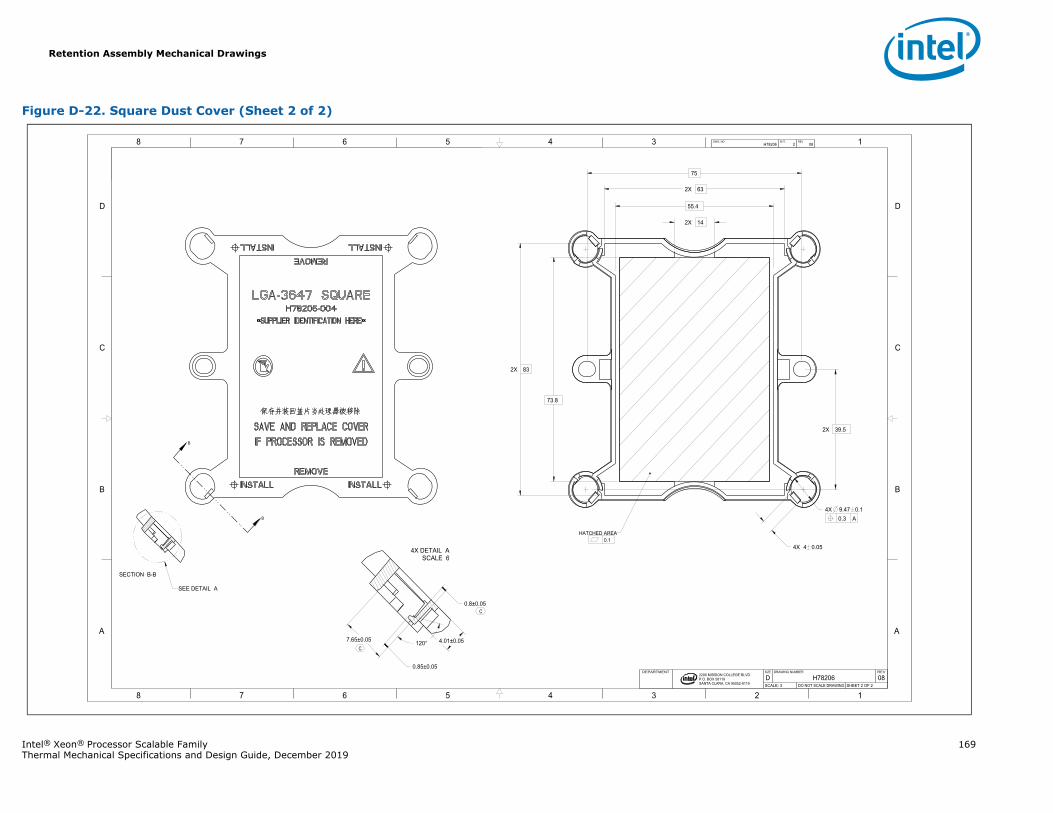
Retention Assembly Mechanical Drawings
Intel® Xeon® Processor Scalable Family 169Thermal Mechanical Specifications and Design Guide, December 2019
Figure D-22. Square Dust Cover (Sheet 2 of 2)
B
B
1345678
B
C
D
A
12345678
B
C
D
A
2200 MISSION COLLEGE BLVD.P.O. BOX 58119SANTA CLARA, CA 95052-8119
R
73.8
2X 83
2X 63
55.4
2X 14
75
4X 4 0.05
2X 39.5
0.3 A4X 9.47 0.1
0.8±0.05
4.01±0.057.65±0.05 120°
0.85±0.05
H78206 2 08DWG. NO SHT. REV
SHEET 2 OF 2DO NOT SCALE DRAWINGSCALE: 308H78206DREVDRAWING NUMBERSIZEDEPARTMENT
HATCHED AREA0.1
SECTION B-B
SEE DETAIL A
SCALE 64X DETAIL A
C
C
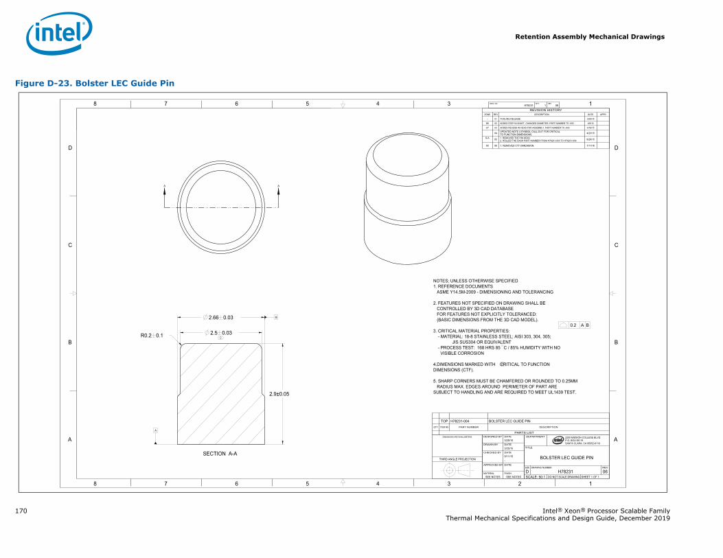
Retention Assembly Mechanical Drawings
170 Intel® Xeon® Processor Scalable FamilyThermal Mechanical Specifications and Design Guide, December 2019
Figure D-23. Bolster LEC Guide Pin
A A
1345678
B
C
D
A
12345678
B
C
D
A
B
2200 MISSION COLLEGE BLVD.P.O. BOX 58119SANTA CLARA, CA 95052-8119
R
0.2 A B
R0.2 0.1 2.5 0.03
2.66 0.03
2.9±0.05
A
H78231 1 06DWG. NO SHT. REV
SHEET 1 OF 1DO NOT SCALE DRAWINGSCALE: 50:106H78231DREVDRAWING NUMBERSIZE
BOLSTER LEC GUIDE PIN
TITLE
DEPARTMENT
SEE NOTESSEE NOTESFINISHMATERIAL
DATEAPPROVED BY
-9/11/15DATECHECKED BY
3/25/15DATEDRAWN BY
3/25/15DATEDESIGNED BYDIMENSIONS ARE IN MILLIMETERS.
THIRD ANGLE PROJECTION
PARTS LIST
DESCRIPTIONPART NUMBERITEM NOQTY
BOLSTER LEC GUIDE PINH78231-004TOP
REVISION HISTORYZONE REV DESCRIPTION DATE APPR
- 01 TOOLING RELEASE 3/25/15
B6 02 ADDED STEP IN SHAFT, CHANGED DIAMETER, PART NUMBER TO -002 4/6/15
A7 03 ADDED RECESS IN HEAD FOR ASSEMBLY, PART NUMBER TO -003 4/16/15
04 UPDATED NOTE 4 SYMBOL CALL-OUT FOR CRITICALTO FUNCTION DIMENSIONS. 4/23/15
6-A 05 1. REMOVED THE PIN HEAD2. ROLLED THE DASH PART NUMBER FROM H78231-003 TO H78231-004 8/28/15
A5 06 1. REMOVED CTF DIMENSION. 7/11/16
NOTES; UNLESS OTHERWISE SPECIFIED1. REFERENCE DOCUMENTS
ASME Y14.5M-2009 - DIMENSIONING AND TOLERANCING
2. FEATURES NOT SPECIFIED ON DRAWING SHALL BECONTROLLED BY 3D CAD DATABASEFOR FEATURES NOT EXPLICITLY TOLERANCED:(BASIC DIMENSIONS FROM THE 3D CAD MODEL).
3. CRITICAL MATERIAL PROPERTIES:- MATERIAL: 18-8 STAINLESS STEEL; AISI 303, 304, 305;
JIS SUS304 OR EQUIVALENT- PROCESS TEST: 168 HRS 85 C / 85% HUMIDITY WITH NOVISIBLE CORROSION
4.DIMENSIONS MARKED WITH CRITICAL TO FUNCTION DIMENSIONS (CTF).
5. SHARP CORNERS MUST BE CHAMFERED OR ROUNDED TO 0.25MMRADIUS MAX. EDGES AROUND PERIMETER OF PART ARE
SUBJECT TO HANDLING AND ARE REQUIRED TO MEET UL1439 TEST.
SECTION A-A
C
C
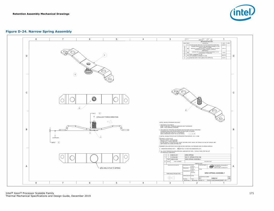
Retention Assembly Mechanical Drawings
Intel® Xeon® Processor Scalable Family 171Thermal Mechanical Specifications and Design Guide, December 2019
Figure D-24. Narrow Spring Assembly
1345678
B
C
D
A
12345678
B
C
D
A 2200 MISSION COLLEGE BLVD.P.O. BOX 58119SANTA CLARA, CA 95052-8119
R
A
A
( 8) WELD STUD TO SPRING
5.9±0.2
0±0.2
H95014 1 05DWG. NO SHT. REV
SHEET 1 OF 1DO NOT SCALE DRAWINGSCALE: 4:105H95014DREVDRAWING NUMBERSIZE
NRW SPRING ASSEMBLY
TITLE
DEPARTMENT
SEE NOTESSEE NOTESFINISHMATERIAL
DATEAPPROVED BY
-09/18/15DATECHECKED BY
2/25/14DATEDRAWN BY
2/23/14DATEDESIGNED BYDIMENSIONS ARE IN MILLIMETERS
THIRD ANGLE PROJECTION
PARTS LIST
DESCRIPTIONPART NUMBERITEM NOQTY
SPRING ASSEMBLYH95014-004TOPSKT-P, SPRING STUD, M4J13164-00211
SPRINGH95016-00121
REVISION HISTORYZONE REV DESCRIPTION DATE APPR
- 01 TOOLING RELEASE, PREVIOUSLY H32164-005, NEW PARTS IN BOM TABLE 09/04/15A3B6B3B2A3
02CHANGED SPRING STUD TO -002, AND SPRING ASSEMBLY TO -002
HEIGHT CHANGE TO 5.525MM.MODIFIED TOLERANCE ON NOTE 3, MODIFIED CALLOUT OF NOTE 5.
CHANGED NOTE 2 FRAME CONTROL TO PROFILE.ADDED NOTE 7.
10/01/15
A3A3 03 CHANGED ITEM 1 TO J13164-001, REVISED TOP ASSEMBLY TO -003
CHANGED NOTE 7 TO REQUIRED. 11/24/15
A3A3 04 ITEM 1 CHANGED TO -002
TOP ASSEMBLY CHANGED TO -004 06/03/16
A3 05 MODIFIED NOTE 7 FOR LUBRICATION APPROVAL 06/23/16
NOTES, UNLESS OTHERWISE SPECIFIED
1. REFERENCE DOCUMENTSASME Y14.5M-2009 - STANDARD DIMENSION AND TOLERANCESI64997 - INTEL MARKING STANDARD
2. FEATURES NOT SPECIFIED ON DRAWING AND FEATURES WITHOUT SPECIFIEDTOLERANCE SHALL BE CONTROLLED BY 3D CAD MODEL DATABASE.FOR FEATURES NOT EXPLICITLY TOLERANCED:(BASIC DIMENSIONS FROM THE 3D CAD MODEL)
3 INSTALL M4 MALE STUD FLUSH TO SPRING BOTTOM SURFACE, +0.0 / -0.1MM
4 M4 MALE ATTACH STUD:- PULLOUT FORCE > 1000N (225LBF)- TORQUE OUT > 2.25N-m (20IN-LBF)- FAILURE MODES: STUDS MUST NOT SHEAR, DEFORM, STRIP, CRACK, OR TORQUE OUT BELOW TORQUE LIMIT.- LIMITS BASED ON 3 SIGMA DISTRIBUTION.
5 MINIMIZE DISCLORATION OF WELD AND NO WELD MATERIAL ON THREADED SIDE OF SPRING SURFACE.
6. DIMENSIONS MARKED WITH ARE CRITICAL TO FUNCTION DIMENSIONS (CTF).
7 ALL STUD THREADS REQUIRE APPROVED LUBRICANTS BY INTEL. CONTACT INTEL FOR THE LIST OF APPROVED LUBRICANTS.
.2 A
2 SURFACES
2
1
4 PULLOUT FORCE DIRECTION
3
7
55
C
C
C
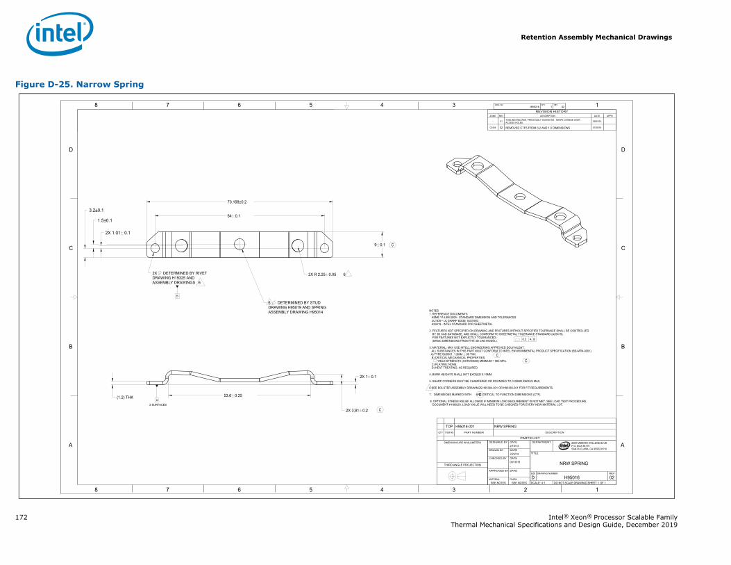
Retention Assembly Mechanical Drawings
172 Intel® Xeon® Processor Scalable FamilyThermal Mechanical Specifications and Design Guide, December 2019
Figure D-25. Narrow Spring
1345678
B
C
D
A
12345678
B
C
D
A
B
2200 MISSION COLLEGE BLVD.P.O. BOX 58119SANTA CLARA, CA 95052-8119
R
9 0.1
64 0.1
70.168±0.2
3.2±0.1
2X DETERMINED BY RIVETDRAWING H19325 ANDASSEMBLY DRAWINGS 6
6 DETERMINED BY STUDDRAWING H95019 AND SPRINGASSEMBLY DRAWING H95014
2X R 62.25 0.05
(1.2) THK
2X 3.81 0.2
53.6 0.25
2X 1.01 0.1
1.5±0.1
2X 1 0.1
A
H95016 1 02DWG. NO SHT. REV
SHEET 1 OF 1DO NOT SCALE DRAWINGSCALE: 4:102H95016DREVDRAWING NUMBERSIZE
NRW SPRING
TITLE
DEPARTMENT
SEE NOTESSEE NOTESFINISHMATERIAL
-DATEAPPROVED BY
-09/18/15DATECHECKED BY
2/25/14DATEDRAWN BY
2/16/13DATEDESIGNED BYDIMENSIONS ARE IN MILLIMETERS
THIRD ANGLE PROJECTION
REVISION HISTORYZONE REV DESCRIPTION DATE APPR
- 01 TOOLING RELEASE, PREVIOUSLY H32165-003. SHAPE CHANGE OVER ACCESS HOLES. 09/04/15
C8 B4 02 REMOVED CTFS FROM 3.2 AND 1.0 DIMENSIONS 07/08/16
NOTES1. REFERENCE DOCUMENTS
ASME Y14.5M-2009 - STANDARD DIMENSION AND TOLERANCESUL1439 - UL SHARP EDGE TESTINGA29419 - INTEL STANDARD FOR SHEETMETAL
2. FEATURES NOT SPECIFIED ON DRAWING AND FEATURES WITHOUT SPECIFIED TOLERANCE SHALL BE CONTROLLEDBY 3D CAD DATABASE, AND SHALL CONFORM TO SHEETMETAL TOLERANCE STANDARD (A29419).FOR FEATURES NOT EXPLICITLY TOLERANCED : (BASIC DIMENSIONS FROM THE 3D CAD MODEL).
3. MATERIAL: MAY USE INTELL ENGINEERING APPROVED EQUIVALENT.ALL SUBSTANCES IN THIS PART MUST CONFORM TO INTEL ENVIRONMENTAL PRODUCT SPECIFICATION (BS-MTN-0001).A) TYPE SUS301, 1.2MM .05 THK.B) CRITICAL MECHANICAL PROPERTIES:
YIELD STRENGTH (ASTM D638) MINIMUM = 965 MPa.C) PLATING: NONE.D) HEAT TREATING: AS REQUIRED
4. BURR HEIGHTS SHALL NOT EXCEED 0.15MM.
5. SHARP CORNERS MUST BE CHAMFERED OR ROUNDED TO 0.25MM RADIUS MAX.
6 SEE BOLSTER ASSEMBLY DRAWINGS H95384-001 OR H95385-001 FOR FIT REQUIREMENTS.
7. DIMENSIONS MARKED WITH ARE CRITICAL TO FUNCTION DIMENSIONS (CTF).
8. OPTIONAL STRESS RELIEF ALLOWED IF MINIMUM LOAD REQUIREMENT IS NOT MET. SEE LOAD TEST PROCEDURE, DOCUMENT # H95020. LOAD VALUE WILL NEED TO BE CHECKED FOR EVERY NEW MATERIAL LOT.
0.2 A B
2 SURFACES
C
C
C
CC
PARTS LIST
DESCRIPTIONPART NUMBERITEM NOQTY
SPRINGH95016-001TOP
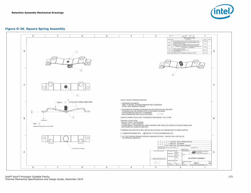
Retention Assembly Mechanical Drawings
Intel® Xeon® Processor Scalable Family 173Thermal Mechanical Specifications and Design Guide, December 2019
Figure D-26. Square Spring Assembly
1345678
B
C
D
A
12345678
B
C
D
A 2200 MISSION COLLEGE BLVD.P.O. BOX 58119SANTA CLARA, CA 95052-8119
R
A
0±0.2
5.65±0.2
8 WELD STUD TO SPRING
H95017 1 05DWG. NO SHT. REV
SHEET 1 OF 1DO NOT SCALE DRAWINGSCALE: 4:105H95017DREVDRAWING NUMBERSIZE
SQ SPRING ASSEMBLY
TITLE
DEPARTMENT
SEE NOTESSEE NOTESFINISHMATERIAL
DATEAPPROVED BY
-06/10/14DATECHECKED BY
06/10/14DATEDRAWN BY
06/10/14DATEDESIGNED BYDIMENSIONS ARE IN MILLIMETERS
THIRD ANGLE PROJECTION
REVISION HISTORYZONE REV DESCRIPTION DATE APPR
- 01 TOOLING RELEASE, PREVIOUSLY H43629. CHANGED BOM TABLE ITEMS. 09/18/15B2C7B4
B4,A402
CHANGED SPRING STUD TO -002, AND SPRING ASSEMBLY TO -002.HEIGHT CHANGE TO 5.525MM.MODIFIED TOLERANCE ON NOTE 3, MODIFIED CALLOUT OF NOTE 5.UPDATED NOTE 2 TO STANDARD NOTE CALLOUT. ADDED NOTE 7.
10/01/15
A3 03 CHANGED ITEM 2 TO J13165-001, TOP ASSEMBLY NOW H95017-003.CHANGED NOTE 7 TO REQUIRED. 11/24/15
A3A3A3
04ITEM 2 CHANGED TO -002TOP ASSEMBLY CHANGED TO -004MODIFIED NOTE 7
06/03/16
B8, B7 05 ADDED NOTE TO 0 DIMENSION, ADDED CTF TO 5.65 07/08/16
NOTES, UNLESS OTHERWISE SPECIFIED
1. REFERENCE DOCUMENTSASME Y14.5M-2009 - STANDARD DIMENSION AND TOLERANCESG14599 - INTEL MARKING STANDARD
2. FEATURES NOT SPECIFIED ON DRAWING AND FEATURES WITHOUT SPECIFIEDTOLERANCE SHALL BE CONTROLLED BY 3D CAD MODEL DATABASE.FOR FEATURES NOT EXPLICITLY TOLERANCED:(BASIC DIMENSIONS FROM THE 3D CAD MODEL)
3 INSTALL M4 MALE STUD FLUSH TO SPRING BOTTOM SURFACE, +0.00 / -0.1MM
4 M4 MALE ATTACH STUD:- PULLOUT FORCE > 1000N (225LBF)- TORQUE OUT > 2.25N-m (20IN-LBF)- FAILURE MODES: STUDS MUST NOT SHEAR, DEFORM, STRIP, CRACK, OR TORQUE OUT BELOW TORQUE LIMIT.- LIMITS BASED ON 3 SIGMA DISTRIBUTION.
5 MINIMIZE DISCLORATION OF WELD AND NO WELD MATERIAL ON THREADED SIDE OF SPRING SURFACE.
6. DIMENSIONS MARKED WITH ARE CRITICAL TO FUNCTION DIMENSIONS (CTF).
7 ALL STUD THREADS REQUIRE APPROVED LUBRICANTS BY INTEL. CONTACT INTEL FOR THE LIST OF APPROVED LUBRICANTS. .
4 PULLOUT FORCE DIRECTION
2 SURFACES
.2 A
DIMENSION FROM DATUM A TO STUD HEAD
5
2
1
3
7
5
C
C
C
PARTS LIST
DESCRIPTIONPART NUMBERITEM NOQTY PER ASSY
-001-002-003
SQ SPRING ASSEMBLYH95017-004TOPSPRINGH95018-0011
SKT-P, SPRING STUD, M4J13165-0022
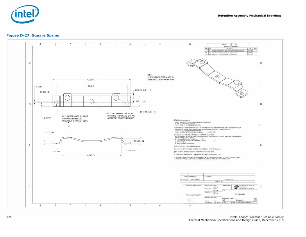
Retention Assembly Mechanical Drawings
174 Intel® Xeon® Processor Scalable FamilyThermal Mechanical Specifications and Design Guide, December 2019
Figure D-27. Square Spring
1345678
B
C
D
A
12345678
B
C
D
A
B
2200 MISSION COLLEGE BLVD.P.O. BOX 58119SANTA CLARA, CA 95052-8119
R
64±0.1
2X 7.73 0.1
53.6±0.25
70.2±0.35
3.4 0.1
2X 1 0.1
2X 3.93 0.1
1.1±0.1
2X 3.81 0.2
9±0.1
2X 64.5 0.05
A
(1.2) THK
H95018 1 03DWG. NO SHT. REV
SHEET 1 OF 1DO NOT SCALE DRAWINGSCALE: 4:103H95018DREVDRAWING NUMBERSIZE
SQ SPRING
TITLE
DEPARTMENT
SEE NOTESSEE NOTESFINISHMATERIAL
-DATEAPPROVED BY
-09/18/15DATECHECKED BY
06/10/14DATEDRAWN BY
06/10/14DATEDESIGNED BYDIMENSIONS ARE IN MILLIMETERS
THIRD ANGLE PROJECTION
REVISION HISTORYZONE REV DESCRIPTION DATE APPR
- 01 TOOLING RELEASE, PREVIOUSLY H43630. SHAPE CHANGE AROUND ACCES HOLES. 09/18/15
C8 02 UDPATED MODEL OUTER RADIUS TO ALL 1.0MM, MODIFIED HOLE LOCATION FOR MODEL TO 3.73MM. DIMENSION STILL DRIVEN BY NOTE 6. 10/01/15
C8 B5 03 REMOVED CTFS FROM 3.4 AND 1.0 DIMENSION 07/08/16
0.2 A B
NOTES1. REFERENCE DOCUMENTS
ASME Y14.5M-2009 - STANDARD DIMENSION AND TOLERANCESUL1439 - UL SHARP EDGE TESTINGA29419 - INTEL STANDARD FOR SHEETMETAL
2. FEATURES NOT SPECIFIED ON DRAWING AND FEATURES WITHOUT SPECIFIED TOLERANCE SHALL BE CONTROLLEDBY 3D CAD DATABASE, AND SHALL CONFORM TO SHEETMETAL TOLERANCE STANDARD (A29419).FOR FEATURES NOT EXPLICITLY TOLERANCED :(BASIC DIMENSIONS FROM THE 3D CAD MODEL).
3. MATERIAL: MAY USE INTELL ENGINEERING APPROVED EQUIVALENT.ALL SUBSTANCES IN THIS PART MUST CONFORM TO INTEL ENVIRONMENTAL PRODUCT SPECIFICATION (BS-MTN-0001).
A) TYPE SUS301, 1.2MM .05 THK.B) CRITICAL MECHANICAL PROPERTIES:
YIELD STRENGTH (ASTM D638) MINIMUM = 965 MPa.C) PLATING: NONE.D) HEAT TREATING: AS REQUIRED
4. BURR HEIGHTS SHALL NOT EXCEED 0.15MM.
5. SHARP CORNERS MUST BE CHAMFERED OR ROUNDED TO 0.25MM RADIUS MAX.
6 SEE BOLSTER ASSEMBLY DRAWING H95386 FOR FIT REQUIREMENTS.
7. DIMENSIONS MARKED WITH ARE CRITICAL TO FUNCTION DIMENSIONS (CTF).
8. OPTIONAL STRESS RELIEF ALLOWED IF MINIMUM LOAD REQUIREMENT IS NOT MET. SEE LOAD TEST PROCEDURE,DOCUMENT # H95020. LOAD VALUE WILL NEED TO BE CHECKED FOR EVERY NEW MATERIAL LOT.
2 SURFACES
6 DETERMINED BY STUDDRAWING H78186AND SPRINGASSEMBLY DRAWING H95017
2X DETERMINED BY RIVETDRAWING H19325 ANDASSEMBLY DRAWING H95017
2X PLACEMENT DETERMINED BYASSEMBLY DRAWING H78203
CC
C
C
C
PARTS LIST
DESCRIPTIONPART NUMBERITEM NOQTY
SPRINGH95018-001TOP
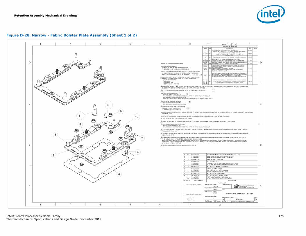
Retention Assembly Mechanical Drawings
Intel® Xeon® Processor Scalable Family 175Thermal Mechanical Specifications and Design Guide, December 2019
Figure D-28. Narrow - Fabric Bolster Plate Assembly (Sheet 1 of 2)
1345678
B
C
D
A
12345678
B
C
D
A 2200 MISSION COLLEGE BLVD.P.O. BOX 58119SANTA CLARA, CA 95052-8119
R
H95384 1 08DWG. NO SHT. REV
SHEET 1 OF 2DO NOT SCALE DRAWINGSCALE: 2:108H95384DREVDRAWING NUMBERSIZE
NRW-F BOLSTER PLATE ASSY
TITLE
DEPARTMENT
SEE NOTESSEE NOTESFINISHMATERIAL
-DATEAPPROVED BY
-2/14/17DATECHECKED BY
2/14/17DATEDRAWN BY
12/16/13DATEDESIGNED BYDIMENSIONS ARE IN MILLIMETERS
THIRD ANGLE PROJECTION
REVISION HISTORYZONE REV DESCRIPTION DATE APPR
- 01 TOOLING RELEASE, PREVIOUSLY H78902. ADDED NOTE 14. 09/12/15
B3PG2, A6
PG2 B5,B7,D7B3
02TOP ASSEMBLY DASH ROLLED TO -002 FOR ITEM 5, 6, AND 8 CHANGE.
FLATNESS CHANGE TO 1.0, ADDED NOTE 15.GUIDE POST AND CORNER STANDOFF TP CHANGE TO .25
ADDED NOTE 16.
10/01/15
A3 03 ITEM 8 CHANGE TO H95014-003, TOP ASSEMBLY CHANGE TO H95384-003. 11/24/15
B3SHT2 B2 04 ADDED NOTE 17, PAGE 2 SEQUENCING UPDATED.
ADDED VEW, DIM, AND CTF TO POST PRE CONDITIONING 12/16/15
PG2 B2PG2 05 REMOVED CTF FROM PRE CONDITIONING DIM AND MADE REFERENCE
REMOVED BALLOONS 2-7 FOR SEQUENCING NOTE 16. 02/10/16
SHT1 A3SHT2 B7
SHT1 C3SHT2
06
ITEM 8 CHANGE TO H95014-004, TOP ASSEMBLY CHANGE TO H95384-004CHANGED DATUM B TO CORNER STANDOFFS. MEASUREMENTS TAKEN FROM CENTER OF PART.CHANGED NOTE #8 PULLOUT FORCE TO 100LBFMODIFIED TRUE POSITION TOLERANCES FOR GUIDE POSTS, CORNERSTANDOFFS, AND SPRING STUDS
06/03/16
PG2 07ADDED SECONDARY DATUM TO GEOMETRIC TOLERANCE OF SPRING STUDS AND GUIDE POSTS. MOVED CTF FROM GUIDE POSTS TO CORNER STANDOFFS.REMOVED CTF FROM SPRING STUD POSITION CTF TO BOLSTER FRAME GAP DIMENSION.REMOVED PRE PRODUCTION FROM PART NUMBER.
06/20/16
SHT 1 C4SHT 1 C8SHT 1 B7SHT 2 B6
08MODIFIED NOTE 9.CLEAN AND DEGREASE BOLSTER ASSEMBLY BEFORE ATTACHING INSULATION.ALL EXTERNAL THREADS TO BE COATED WITH
APPROVED LUBRICANT AS SPECIFIED IN DOCUMENT J36336. 2/14/17
NOTES; UNLESS OTHERWISE SPECIFIED:
1. REFERENCE DOCUMENTSASME Y14.5M-2009 - STANDARD DIMENSION ANDTOLERANCES 164997 - INTEL MARKING STANDARD
2. FEATURES NOT SPECIFIED ON DRAWING SHALL BE CONTROLLED BY3D CAD DATABASE. FOR FEATURES NOT EXPLICITLY TOLERANCED:
(BASIC DIMENSIONS FROM THE 3D CAD DATABASE)
3 MARK ASSEMBLY PART APPROXIMATELY WHERE SHOWN PER INTEL MARKING STANDARD (164997) WITH ADDITIONAL INFORMATION:
A) ASSEMBLY VENDOR IDB) DATE CODEC) DISPLAYED TEXTD) DISPLAYED PIN-1 MARKING
4. DIMENSIONS MARKED ARE CRITICAL TO FUNCTION DIMENSION (CTF). FOR PRODUCTION QUALIFICATION INDICATED DIMENSION REQUIRES CP/CPK STUDY BASED ON A RANDOM 30 PART SAMPLE OF A 300 PART MINIMUM LOT PER CQC.
5 ALL STUDS/RIVETS/POSTS/WELDS TO BE FLUSH TO THIS SURFACE, +0.00 / -0.25
6 SPRING RIVETS (INDIVIDUAL):- PULLOUT FORCE > 500N (112LBF)- FAILURE MODES: MUST NOT SHEAR, DEFORM, STRIP, OR CRACK BELOW FORCE LIMIT.- LIMITS BASED ON 3 SIGMA DISTRIBUTION- RIVET HEAD SOLID HEIGHT MUST BE GREATER THAN OR EQUAL TO SPRING TOP SURFACE.
7 NUT/COLLAR SEPARATION FORCE- PUSHOUT FORCE > 222N (50LBF)- LIMITS BASED ON 3 SIGMA DISTRIBUTION
8 CORNER STANDOFF SEPARATION FORCE-PULLOUT FORCE > 445N (100LBF)-TORQUE OUT > 2.25 N-m (20IN-LBF)
9. CLEAN AND DEGREASE BOLSTER ASSEMBLY BEFORE ATTACHING INSULATION.ALL EXTERNAL THREADS TO BE COATED WITH APPROVED LUBRICANT AS SPECIFIED INDOCUMENT J36336.
10.AFTER APPLICATION THE INSULATOR MUST BE FREE OF BUBBLES, POCKETS, CREASES, AND ANY OTHER DEFORMATIONS.
11.FINAL ASSEMBLY SHALL BE FREE OF OIL AND DEBRIS.
12.PRESS FIT BOLSTER-LEC GUIDE PIN (H78231) INTO BOLSTER PLATE. FINAL ASSEMBLY MUST HAVE PIN FLUSH WITH BOLSTER FLANGE.
13.POST SEPARATION FORCE (INDIVIDUAL):- PUSHOUT FORCE > 89N (20LBF)- FAILURE MODES: MUST NOT SHEAR, DEFORM, STRIP, OR CRACK BELOW FORCE LIMIT.
14.BACKPLATE ASSEMBLY (H77928) TO BOLSTER PLATE ASSEMBLY STUD/NUT MUST BE ABLE TO ENGAGE WITH MOTHERBOARD THICKNESS' IN THE RANGE OF1.42MM-2.59MM (0.056"-0.102").
15.FLATNESS MUST BE MEASURED IN AN UNCONSTRAINED STATE. ALL OTHER CTF MEASUREMENTS CAN BE MEASURED WITH THE BOLSTER TOP ASSEMBLY IN ACONSTRAINED STATE.
16.WHEN INSTALLING BOLSTER PLATE TO BACKPLATE (H77928) THERE MUST BE NO DEBRIS WHEN ASSEMBLING 2 CYCLES IN ANY SEQUENCE, OR 6 CYCLESWHEN SEQUENCING IS IMPLEMENTED. SEQUENCING SHOWN ON PAGE 2.NO DEBRIS ( ANYTHING GREATER THAN .5MM DIAMETER OR LENGTH) IS MEASURED WITH NAKED EYE AT 2 FEET AWAY, WITH DIRECT OVERHEAD LIGHTINGUNDER COOL WHITE FLOURESCENT LIGHT CONDITIONS (60-120 FT-CANDLE (645-1293 LUX)) OR EQUIVALENT. VIEWING TIME SHALL BE ONE VISUAL PASS OF5-7 SECONDS FOR EACH SURFACE.
17. SEE PRE-CONDITIONING REQUIREMENT ON PAGE 2, ZONE B2.
0.2 A B
1
3
52
9
10
8
7
6
4
C
C
C
C
C
PARTS LIST
DESCRIPTIONPART NUMBERITEM NOQTY
BOLSTER PLATE ASSEMBLYH95384-004TOPBOLSTER LARGE GUIDE POSTG94443-00311BOLSTER LEC GUIDE PINH78231-00422BOLSTER SMALL GUIDE POSTG93935-00331SKT-P, SPRING RIVETH19325-00143BOLSTER CORNER STANDOFFH96570-00252NARROW NON FABRIC BOLSTER INSULATORH64296-00261BOLSTER PLATEH32162-00371
SPRING ASSEMBLYH95014-00482SOCKET P M3 BOLSTER CAPTIVE NUTH19328-00297SOCKET P M3 BOLSTER CAPTIVE NUT COLLARH19329-003103
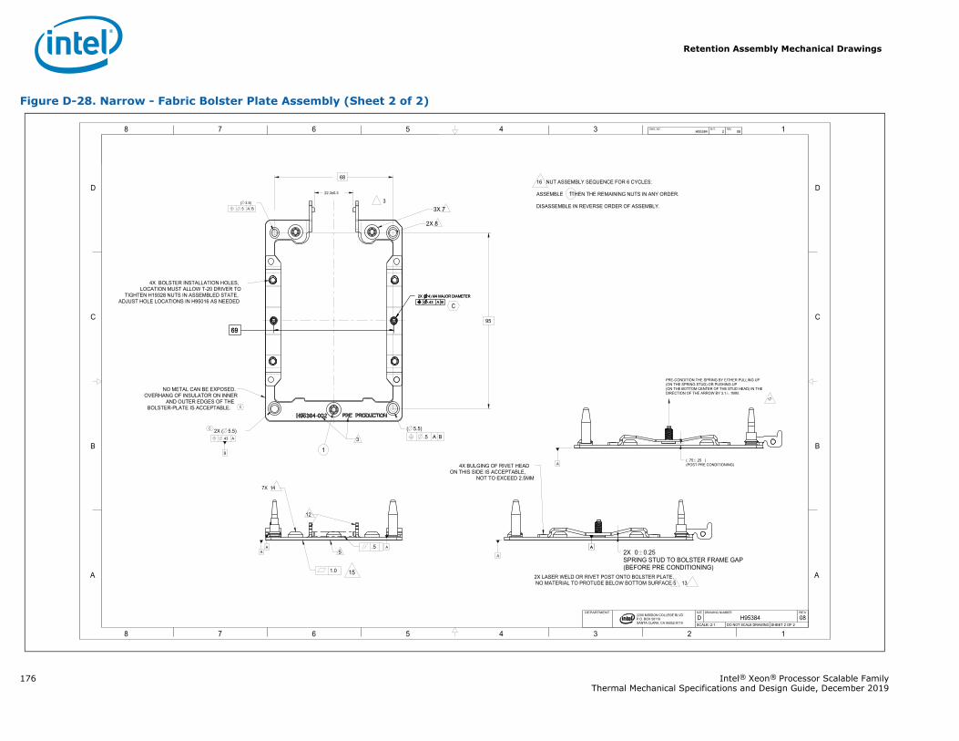
Retention Assembly Mechanical Drawings
176 Intel® Xeon® Processor Scalable FamilyThermal Mechanical Specifications and Design Guide, December 2019
Figure D-28. Narrow - Fabric Bolster Plate Assembly (Sheet 2 of 2)
1345678
B
C
D
A
12345678
B
C
D
A
B
2200 MISSION COLLEGE BLVD.P.O. BOX 58119SANTA CLARA, CA 95052-8119
R
.5
.43 A
1.0
A AA
AA
A
95
68
.5 A B( 5.5)
4X BOLSTER INSTALLATION HOLES,LOCATION MUST ALLOW T-20 DRIVER TO
TIGHTEN H19328 NUTS IN ASSEMBLED STATE,ADJUST HOLE LOCATIONS IN H95016 AS NEEDED
6969
2X SPRING STUD TO BOLSTER FRAME GAP(BEFORE PRE CONDITIONING)
0 0.25
.5 A B( 3.5)
.43 A B 2X ( 4) M4 MAJOR DIAMETER
.43 A B 2X ( 4) M4 MAJOR DIAMETER
22.3±0.3
( ) (POST PRE CONDITIONING)
.75 .25
2X ( 5.5)
H95384 2 08DWG. NO SHT. REV
SHEET 2 OF 2DO NOT SCALE DRAWINGSCALE: 2:108H95384DREVDRAWING NUMBERSIZEDEPARTMENT
15
16 NUT ASSEMBLY SEQUENCE FOR 6 CYCLES:
ASSEMBLE THEN THE REMAINING NUTS IN ANY ORDER.
DISASSEMBLE IN REVERSE ORDER OF ASSEMBLY.
1
A
PRE-CONDITION THE SPRING BY EITHER PULLING UP (ON THE SPRING STUD) OR PUSHING UP(ON THE BOTTOM CENTER OF THE STUD HEAD) IN THE DIRECTION OF THE ARROW BY 3.1 .1MM.
17
NO METAL CAN BE EXPOSED.OVERHANG OF INSULATOR ON INNER
AND OUTER EDGES OF THE BOLSTER-PLATE IS ACCEPTABLE.
3
33X 7
2X 8
1
5
12
7X 14
2X LASER WELD OR RIVET POST ONTO BOLSTER PLATE, NO MATERIAL TO PROTUDE BELOW BOTTOM SURFACE 5 13
4X BULGING OF RIVET HEAD ON THIS SIDE IS ACCEPTABLE,
NOT TO EXCEED 2.5MM
C
C
C
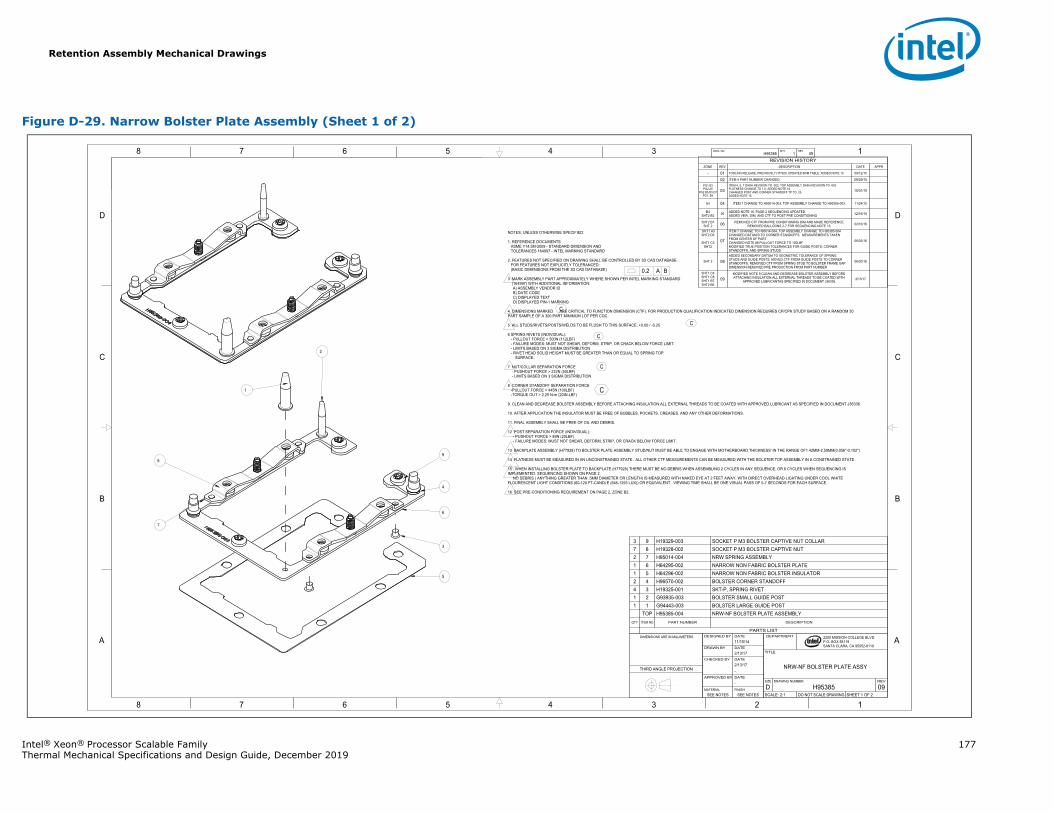
Retention Assembly Mechanical Drawings
Intel® Xeon® Processor Scalable Family 177Thermal Mechanical Specifications and Design Guide, December 2019
Figure D-29. Narrow Bolster Plate Assembly (Sheet 1 of 2)
1345678
B
C
D
A
12345678
B
C
D
A 2200 MISSION COLLEGE BLVD.P.O. BOX 58119SANTA CLARA, CA 95052-8119
R
H95385 1 09DWG. NO SHT. REV
SHEET 1 OF 2DO NOT SCALE DRAWINGSCALE: 2:109H95385DREVDRAWING NUMBERSIZE
NRW-NF BOLSTER PLATE ASSY
TITLE
DEPARTMENT
SEE NOTESSEE NOTESFINISHMATERIAL
-DATEAPPROVED BY
-2/13/17DATECHECKED BY
2/13/17DATEDRAWN BY
11/15/14DATEDESIGNED BY DIMENSIONS ARE IN MILLIMETERS
THIRD ANGLE PROJECTION
REVISION HISTORYZONE REV DESCRIPTION DATE APPR
- 01 TOOLING RELEASE, PREVIOUSLY H77929. UPDATED BOM TABLE. ADDED NOTE 13. 09/12/15
02 ITEM 4 PART NUMBER CHANGED. 09/29/15PG1 B3PG2 A5
PG2 B5,D5,D7PG1, B4
03ITEM 4, 5, 7 DASH REVISION TO -002, TOP ASSEMBLY DASH REVISION TO -002FLATNESS CHANGE TO 1.0, ADDED NOTE 14.CHANGED POST AND CORNER STANDOFF TP TO .25.ADDED NOTE 15.
10/01/15
A3 04 ITEM 7 CHANGE TO H95014-003, TOP ASSEMBLY CHANGE TO H95385-003. 11/24/15
B4SHT2 B2 05 ADDED NOTE 16, PAGE 2 SEQUENCING UPDATED
ADDED VEW, DIM, AND CTF TO POST PRE CONDITIONING 12/16/15
SHT2 B1SHT 2 06 REMOVED CTF FROM PRE CONDITIONING DIM AND MADE REFERENCE.
REMOVED BALLOONS 2-7 FOR SEQUENCING NOTE 15. 02/10/16
SHT1 A3SHT2 D5
SHT1 C3SHT2
07
ITEM 7 CHANGE TO H95014-004, TOP ASSEMBLY CHANGE TO H95385-004CHANGED DATUM B TO CORNER STANDOFFS. MEASUREMENTS TAKEN FROM CENTER OF PART.CHANGED NOTE #8 PULLOUT FORCE TO 100LBFMODIFIED TRUE POSITION TOLERANCES FOR GUIDE POSTS, CORNERSTANDOFFS, AND SPRING STUDS
06/03/16
SHT 2 08ADDED SECONDARY DATUM TO GEOMETRIC TOLERANCE OF SPRING STUDS AND GUIDE POSTS. MOVED CTF FROM GUIDE POSTS TO CORNER STANDOFFS. REMOVED CTF FROM SPRING STUD TO BOLSTER FRAME GAP DIMENSION.REMOVED PRE PRODUCTION FROM PART NUMBER
06/20/16
SHT1 C4SHT1 C8SHT1 B7SHT2 B6
09MODIFIED NOTE 9.CLEAN AND DEGREASE BOLSTER ASSEMBLY BEFORE ATTACHING INSULATION.ALL EXTERNAL THREADS TO BE COATED WITH
APPROVED LUBRICANTAS SPECIFIED IN DOCUMENT J36336.2/13/17
NOTES; UNLESS OTHERWISE SPECIFIED:
1. REFERENCE DOCUMENTSASME Y14.5M-2009 - STANDARD DIMENSION ANDTOLERANCES 164997 - INTEL MARKING STANDARD
2. FEATURES NOT SPECIFIED ON DRAWING SHALL BE CONTROLLED BY 3D CAD DATABASE.FOR FEATURES NOT EXPLICITLY TOLERANCED:
(BASIC DIMENSIONS FROM THE 3D CAD DATABASE)
3 MARK ASSEMBLY PART APPROXIMATELY WHERE SHOWN PER INTEL MARKING STANDARD (164997) WITH ADDITIONAL INFORMATION:
A) ASSEMBLY VENDOR IDB) DATE CODEC) DISPLAYED TEXTD) DISPLAYED PIN-1 MARKING
4. DIMENSIONS MARKED ARE CRITICAL TO FUNCTION DIMENSION (CTF). FOR PRODUCTION QUALIFICATION INDICATED DIMENSION REQUIRES CP/CPK STUDY BASED ON A RANDOM 30PART SAMPLE OF A 300 PART MINIMUM LOT PER CQC.
5 ALL STUDS/RIVETS/POSTS/WELDS TO BE FLUSH TO THIS SURFACE, +0.00 / -0.25
6 SPRING RIVETS (INDIVIDUAL):- PULLOUT FORCE > 500N (112LBF)- FAILURE MODES: MUST NOT SHEAR, DEFORM, STRIP, OR CRACK BELOW FORCE LIMIT.- LIMITS BASED ON 3 SIGMA DISTRIBUTION- RIVET HEAD SOLID HEIGHT MUST BE GREATER THAN OR EQUAL TO SPRING TOP
SURFACE.
7 NUT/COLLAR SEPARATION FORCE- PUSHOUT FORCE > 222N (50LBF)- LIMITS BASED ON 3 SIGMA DISTRIBUTION
8 CORNER STANDOFF SEPARATION FORCE-PULLOUT FORCE > 445N (100LBF)-TORQUE OUT > 2.25 N-m (20IN-LBF)
9. CLEAN AND DEGREASE BOLSTER ASSEMBLY BEFORE ATTACHING INSULATION.ALL EXTERNAL THREADS TO BE COATED WITH APPROVED LUBRICANT AS SPECIFIED IN DOCUMENT J36336.
10. AFTER APPLICATION THE INSULATOR MUST BE FREE OF BUBBLES, POCKETS, CREASES, AND ANY OTHER DEFORMATIONS.
11. FINAL ASSEMBLY SHALL BE FREE OF OIL AND DEBRIS.
12 POST SEPARATION FORCE (INDIVIDUAL):- PUSHOUT FORCE > 89N (20LBF)- FAILURE MODES: MUST NOT SHEAR, DEFORM, STRIP, OR CRACK BELOW FORCE LIMIT.
13 BACKPLATE ASSEMBLY (H77928) TO BOLSTER PLATE ASSEMBLY STUD/NUT MUST BE ABLE TO ENGAGE WITH MOTHERBOARD THICKNESS' IN THE RANGE OF1.42MM-2.59MM(0.056"-0.102").
14 FLATNESS MUST BE MEASURED IN AN UNCONSTRAINED STATE. ALL OTHER CTF MEASUREMENTS CAN BE MEASURED WITH THE BOLSTER TOP ASSEMBLY IN A CONSTRAINED STATE.
15 WHEN INSTALLING BOLSTER PLATE TO BACKPLATE (H77928) THERE MUST BE NO DEBRIS WHEN ASSEMBLING 2 CYCLES IN ANY SEQUENCE, OR 6 CYCLES WHEN SEQUENCING IS IMPLEMENTED. SEQUENCING SHOWN ON PAGE 2. NO DEBRIS ( ANYTHING GREATER THAN .5MM DIAMETER OR LENGTH) IS MEASURED WITH NAKED EYE AT 2 FEET AWAY, WITH DIRECT OVERHEAD LIGHTING UNDER COOL WHITE FLOURESCENT LIGHT CONDITIONS (60-120 FT-CANDLE (645-1293 LUX)) OR EQUIVALENT. VIEWING TIME SHALL BE ONE VISUAL PASS OF 5-7 SECONDS FOR EACH SURFACE.
16 SEE PRE-CONDITIONING REQUIREMENT ON PAGE 2, ZONE B2.
0.2 A B
1
4
7
8 9
3
2
5
6
C
C
C
C
C
PARTS LIST
DESCRIPTIONPART NUMBERITEM NOQTY
BOLSTER PLATE ASSEMBLYH95385-004TOPBOLSTER LARGE GUIDE POSTG94443-00311BOLSTER SMALL GUIDE POSTG93935-00321SKT-P, SPRING RIVETH19325-00134BOLSTER CORNER STANDOFFH96570-00242NARROW NON FABRIC BOLSTER INSULATORH64296-00251NARROW NON FABRIC BOLSTER PLATEH64295-00261
SPRING ASSEMBLYH95014-00472SOCKET P M3 BOLSTER CAPTIVE NUTH19328-00287SOCKET P M3 BOLSTER CAPTIVE NUT COLLARH19329-00393
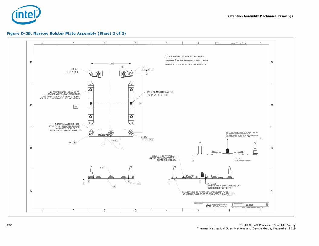
Retention Assembly Mechanical Drawings
178 Intel® Xeon® Processor Scalable FamilyThermal Mechanical Specifications and Design Guide, December 2019
Figure D-29. Narrow Bolster Plate Assembly (Sheet 2 of 2)
1345678
B
C
D
A
12345678
B
C
D
A
B
2200 MISSION COLLEGE BLVD.P.O. BOX 58119SANTA CLARA, CA 95052-8119
R
.43 A
1.0AAA A
A
A
95
68
.5 A B( 5.5)
4X BOLSTER INSTALLATION HOLES,LOCATION MUST ALLOW T-20 DRIVER TO
TIGHTEN H19328 NUTS IN ASSEMBLED STATE,ADJUST HOLE LOCATIONS IN H95016 AS NEEDED
69
2X SPRING STUD TO BOLSTER FRAME GAP(BEFORE PRE CONDITIONING)
0 0.25
.5 A B ( 3.5)
.43 A B ( 4) M4 MAJOR DIAMETER
( )(POST PRE CONDITIONING)
.75 .25
2X ( 5.5)
H95385 2 09DWG. NO SHT. REV
SHEET 2 OF 2DO NOT SCALE DRAWINGSCALE: 2:109H95385DREVDRAWING NUMBERSIZEDEPARTMENT
2X
2X
14
15 NUT ASSEMBLY SEQUENCE FOR 6 CYCLES:
ASSEMBLE THEN REMAINING NUTS IN ANY ORDER
DISASSEMBLE IN REVERSE ORDER OF ASSEMBLY.
1
A
PRE-CONDITION THE SPRING BY EITHER PULLING UP (ON THE SPRING STUD) OR PUSHING UP(ON THE BOTTOM CENTER OF THE STUD HEAD) IN THE DIRECTION OF THE ARROW BY 3.1 .1MM.
16
NO METAL CAN BE EXPOSED.OVERHANG OF INSULATOR ON INNER
AND OUTER EDGES OF THE BOLSTER-PLATE IS ACCEPTABLE.
3
3
83X 7
1
5
7X 13
2X LASER WELD OR RIVET POST ONTO BOLSTER PLATE, NO MATERIAL TO PROTUDE BELOW BOTTOM SURFACE 5 12
4X BULGING OF RIVET HEAD ON THIS SIDE IS ACCEPTABLE
NOT TO EXCEED 2.5MM
C
C
C
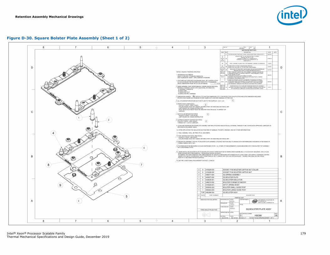
Retention Assembly Mechanical Drawings
Intel® Xeon® Processor Scalable Family 179Thermal Mechanical Specifications and Design Guide, December 2019
Figure D-30. Square Bolster Plate Assembly (Sheet 1 of 2)
1345678
B
C
D
A
12345678
B
C
D
A 2200 MISSION COLLEGE BLVD.P.O. BOX 58119SANTA CLARA, CA 95052-8119
R
H95386 1 08DWG. NO SHT. REV
SHEET 1 OF 2DO NOT SCALE DRAWINGSCALE: 2:108H95386DREVDRAWING NUMBERSIZE
SQ BOLSTER PLATE ASSY
TITLE
DEPARTMENT
SEE NOTESSEE NOTESFINISHMATERIAL
-DATEAPPROVED BY
-02/14/17DATECHECKED BY
2/14/17DATEDRAWN BY
6/10/14DATEDESIGNED BYDIMENSIONS ARE IN MILLIMETERS
THIRD ANGLE PROJECTION
REVISION HISTORYZONE REV DESCRIPTION DATE APPR
- 01 TOOLING RELEASE, PREVIOUSLY H78203. UPDATED BOM TABLE. ADDED NOTE 13. 09/18/15
A3A3
PG2 A5PG2
PG1 B3
02
UPDATED ITEM 7 TO -002, UPDATED ITEM 4 TO H96570.UPDATED TOP ASSY TO -002.
CHANGED FLATNESS TO 1.0, ADDED NOTE 14.CHANGED TP OF POSTS AND STANDOFFS TO .25
ADDED NOTE 15.
10/05/15
A3 03 ITEM 7 CHANGE TO H95017-003, TOP ASSEMBLY CHANGE TO H95386-003. 11/24/15
B3SHT2 B2 04 ADDED NOTE 16, PAGE 2 SEQUENCING UPDATED.
ADDED VEW, DIM, AND CTF TO POST PRE CONDITIONING 12/16/15
SHT2 B1SHT 2 05 REMOVED CTF FROM PRE CONDITIONING DIM AND MADE REFERENCE.
REMOVED BALLOONS 3-6 FROM SEQUENCING NOTE 15. 02/10/16
SHT1 A3SHT2 D4
SHT1 C3SHT2
06
ITEM 7 CHANGE TO H95017-004, TOP ASSEMBLY CHANGE TO H95386-004CHANGED DATUM B TO CORNER STANDOFFS. MEASUREMENTS TAKEN FROM CENTER OF PART.CHANGED NOTE #8 PULLOUT FORCE TO 100LBFMODIFIED TRUE POSITION TOLERANCES FOR GUIDE POSTS, CORNERSTANDOFFS, AND SPRING STUDS
06/03/16
SHT2 07ADDED SECONDARY DATUM TO GEOMETRIC TOLERANCE OF SPRING STUDS AND GUIDE POSTS.MOVED CTF FROM GUIE POSTS TO CORNER STANDOFFS. REMOVED CTF FROM SPRING STUD TO BOLSTER FRAMEGAP DIMENSION. REMOVED PRE PRODUCTION FROM PART NUMBER.
06/20/16
SHT1 C4SHT1 C6SHT1 B8SHT2 B6
08MODIFIED NOTE 9 TO CLEAN AND DEGREASE BACKPLATE ASSEMBLY
BEFORE ATTACHING INSULATION.ALL EXTERNAL THREADS TO BE COATED WITH APPROVED LUBRICANT AS SPECIFIED IN DOCUMENT J36336.
2/14/17
.2 A B
7
NOTES; UNLESS OTHERWISE SPECIFIED:
1. REFERENCE DOCUMENTSASME Y14.5M-2009 - STANDARD DIMENSIONAND TOLERANCES 164997 - INTEL MARKING STANDARD
2. FEATURES NOT SPECIFIED ON DRAWING SHALL BE CONTROLLED BY3D CAD DATABASE.FOR FEATURES NOT EXPLICITLY TOLERANCED:(BASIC DIMENSIONS FROM THE 3D CAD DATABASE)
3 MARK ASSEMBLY PART APPROXIMATELY WHERE SHOWN PER INTEL MARKING STANDARD (164997) WITH ADDITIONAL INFORMATION:
A) ASSEMBLY VENDOR IDB) DATE CODEC) DISPLAYED TEXTD) DISPLAYED PIN-1 MARKING
4. DIMENSIONS MARKED ARE CRITICAL TO FUNCTION DIMENSION (CTF). FOR PRODUCTION QUALIFICATION INDICATED DIMENSION REQUIRES CP/CPK STUDY BASED ON A RANDOM 30 PART SAMPLE OF A 300 PART MINIMUM LOT PER CQC.
5 ALL STUDS/RIVETS/POSTS/WELDS TO BE FLUSH TO THIS SURFACE, +0.00 / -0.25
6 SPRING RIVETS (INDIVIDUAL):- PULLOUT FORCE > 500N (112LBF)- FAILURE MODES: MUST NOT SHEAR, DEFORM, STRIP, OR CRACK BELOW FORCE LIMIT.- LIMITS BASED ON 3 SIGMA DISTRIBUTION- RIVET HEAD SOLID HEIGHT MUST BE GREATER THAN OR EQUAL TO SPRING TOP
SURFACE.
7 NUT/COLLAR SEPARATION FORCE- PUSHOUT FORCE > 222N (50LBF)- LIMITS BASED ON 3 SIGMA DISTRIBUTION
8 CORNER STANDOFF SEPARATION FORCE-PULLOUT FORCE > 445N (100LBF)-TORQUE OUT > 2.25 N-m (20IN-LBF)
9. CLEAN AND DEGREASE BOLSTERPLATE ASSEMBLY BEFORE ATTACHING INSULATION.ALL EXTERNAL THREADS TO BE COATED WITH APPROVED LUBRICANT ASSPECIFIED IN DOCUMENT J36336.
10. AFTER APPLICATION THE INSULATOR MUST BE FREE OF BUBBLES, POCKETS, CREASES, AND ANY OTHER DEFORMATIONS.
11. FINAL ASSEMBLY SHALL BE FREE OF OIL AND DEBRIS.
12 POST SEPARATION FORCE (INDIVIDUAL):- PUSHOUT FORCE > 89N (20LBF)- FAILURE MODES: MUST NOT SHEAR, DEFORM, STRIP, OR CRACK BELOW FORCE LIMIT.
13 BACKPLATE ASSEMBLY (H78197) TO BOLSTER PLATE ASSEMBLY STUD/NUT MUST BE ABLE TO ENGAGE WITH MOTHERBOARD THICKNESS' IN THE RANGE OF 1.42MM-2.59MM (0.056"-0.102").
14 FLATNESS MUST BE MEASURED IN AN UNCONSTRAINED STATE. ALL OTHER CTF MEASUREMENTS CAN BE MEASURED WITH THE BOLSTER TOP ASSEMBLY IN A CONSTRAINED STATE.
15 WHEN INSTALLING BOLSTER PLATE TO BACKPLATE (H78197) THERE MUST BE NO DEBRIS WHEN ASSEMBLING 2 CYCLES IN ANY SEQUENCE, OR 6 CYCLES WHEN SEQUENCING IS IMPLEMENTED. SEQUENCING SHOWN ON PAGE 2. NO DEBRIS ( ANYTHING GREATER THAN .5MM DIAMETER OR LENGTH) IS MEASURED WITH NAKED EYE AT 2 FEET AWAY, WITH DIRECT OVERHEAD LIGHTING UNDER COOL WHITE FLOURESCENT LIGHT CONDITIONS (60-120 FT-CANDLE (645-1293 LUX)) OR EQUIVALENT. VIEWING TIME SHALL BE ONE VISUAL PASS OF 5-7 SECONDS FOR EACH SURFACE.
16 SEE PRE-CONDITIONING REQUIREMENT ON PAGE 2, ZONE B2.
1 2
3
6
4
5
8
9
C
C
C
C
C
PARTS LIST
DESCRIPTIONPART NUMBERITEM NOQTY
SQ BOLSTER ASSYH95386-004TOPBOLSTER LARGE GUIDE POSTG94443-00311BOLSTER SMALL GUIDE POSTG93935-00321SKT-P, SPRING RIVETH19325-00134BOLSTER CORNER STANDOFFH96570-00242SQ BOLSTER INSULATORH43628-00151SQ BOLSTER PLATEH43627-00261SQ SPRING ASSEMBLYH95017-00472SOCKET P M3 BOLSTER CAPTIVE NUTH19328-00286SOCKET P M3 BOLSTER CAPTIVE NUT COLLARH19329-00392
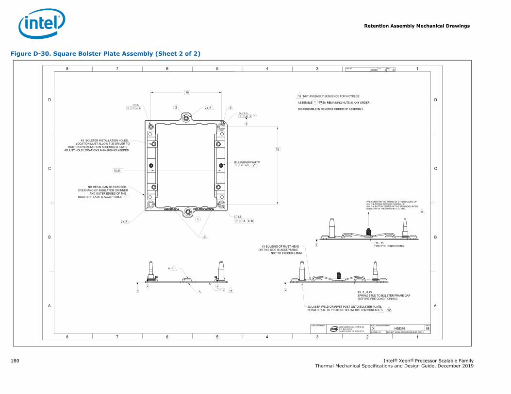
Retention Assembly Mechanical Drawings
180 Intel® Xeon® Processor Scalable FamilyThermal Mechanical Specifications and Design Guide, December 2019
Figure D-30. Square Bolster Plate Assembly (Sheet 2 of 2)
1345678
B
C
D
A
12345678
B
C
D
A
B
2200 MISSION COLLEGE BLVD.P.O. BOX 58119SANTA CLARA, CA 95052-8119
R
.43 A
1A
AA
A
76
79
.5 A B( 5.5)
75.25
2X SPRING STUD TO BOLSTER FRAME GAP(BEFORE PRE CONDITIONING)
0 0.25
.5 A B( 3.5)
.43 A B ( 4) M4 MAJOR DIAMETER
( )(POST PRE CONDITIONING)
.75 .25
2X ( 5.5)
H95386 2 08DWG. NO SHT. REV
SHEET 2 OF 2DO NOT SCALE DRAWINGSCALE: 2:108H95386DREVDRAWING NUMBERSIZEDEPARTMENT
2X
12
14
15 NUT ASSEMBLY SEQUENCE FOR 6 CYCLES:
ASSEMBLE THEN REMAINING NUTS IN ANY ORDER.
DISASSEMBLE IN REVERSE ORDER OF ASSEMBLY.
1
A
PRE-CONDITION THE SPRING BY EITHER PULLING UP (ON THE SPRING STUD) OR PUSHING UP(ON THE BOTTOM CENTER OF THE STUD HEAD) IN THE DIRECTION OF THE ARROW BY 3.1 .1MM.
16
2
NO METAL CAN BE EXPOSED.OVERHANG OF INSULATOR ON INNER
AND OUTER EDGES OF THE BOLSTER-PLATE IS ACCEPTABLE.
4X BOLSTER INSTALLATION HOLES,LOCATION MUST ALLOW T-20 DRIVER TO
TIGHTEN H19328 NUTS IN ASSEMBLED STATE,ADJUST HOLE LOCATIONS IN H43630 AS NEEDED
3
3
2X 7
2X 7
1
2
5
6X 13
2X LASER WELD OR RIVET POST ONTO BOLSTER PLATE,NO MATERIAL TO PROTUDE BELOW BOTTOM SURFACE 5
4X BULGING OF RIVET HEAD ON THIS SIDE IS ACCEPTABLE
NOT TO EXCEED 2.5MM
C
C
C
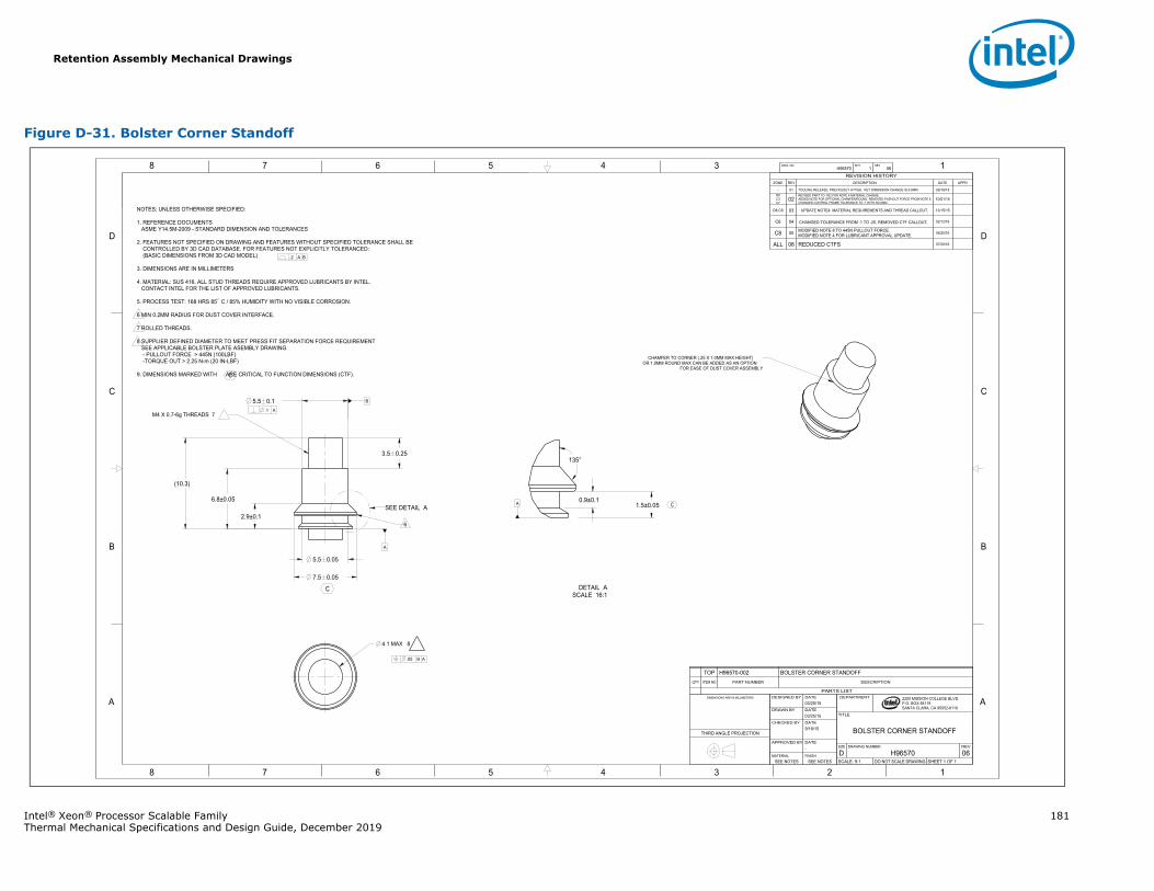
Retention Assembly Mechanical Drawings
Intel® Xeon® Processor Scalable Family 181Thermal Mechanical Specifications and Design Guide, December 2019
Figure D-31. Bolster Corner Standoff
1345678
B
C
D
A
12345678
B
C
D
A
B
2200 MISSION COLLEGE BLVD.P.O. BOX 58119SANTA CLARA, CA 95052-8119
R
.2 A B
.05 B A
.1 A
5.5 0.1
2.9±0.1
135°
1.5±0.05
3.5 0.25
0.9±0.1
7.5 0.05
6.8±0.05
4.1 MAX 8
5.5 0.05
A
A
(10.3)
H96570 1 06DWG. NO SHT. REV
SHEET 1 OF 1DO NOT SCALE DRAWINGSCALE: 9:106H96570DREVDRAWING NUMBERSIZE
BOLSTER CORNER STANDOFF
TITLE
DEPARTMENT
SEE NOTESSEE NOTESFINISHMATERIAL
-DATEAPPROVED BY
9/18/15DATECHECKED BY
03/25/15DATEDRAWN BY
03/25/15DATEDESIGNED BYDIMENSIONS ARE IN MILLIMETERS
THIRD ANGLE PROJECTION
REVISION HISTORYZONE REV DESCRIPTION DATE APPR
- 01 TOOLING RELEASE, PREVIOUSLY H77926. KEY DIMENSION CHANGE IS 6.8MM. 09/18/15D8C3C7
02REVISED PART TO -002 FOR NOTE 4 MATERIAL CHANGE.ADDED NOTE FOR OPTIONAL CHAMFER/ROUND, REMOVED PUSHOUT FORCE FROM NOTE 8.CHANGED CONTROL FRAME TOLERANCE TO .1 WITH NO MMC.
10/01/15
D8,C8 03 UPDATE NOTE4 MATERIAL REQUIREMENTS AND THREAD CALLOUT. 12/15/15
C6 04 CHANGED TOLERANCE FROM .1 TO .25, REMOVED CTF CALLOUT. 02/12/16
C8 05 MODIFIED NOTE 8 TO 445N PULLOUT FORCE.MODIFIED NOTE 4 FOR LUBRICANT APPROVAL UPDATE. 06/20/16
ALL 06 REDUCED CTFS 07/20/16
NOTES; UNLESS OTHERWISE SPECIFIED:
1. REFERENCE DOCUMENTSASME Y14.5M-2009 - STANDARD DIMENSION AND TOLERANCES
2. FEATURES NOT SPECIFIED ON DRAWING AND FEATURES WITHOUT SPECIFIED TOLERANCE SHALL BECONTROLLED BY 3D CAD DATABASE. FOR FEATURES NOT EXPLICITLY TOLERANCED:
(BASIC DIMENSIONS FROM 3D CAD MODEL)
3. DIMENSIONS ARE IN MILLIMETERS
4. MATERIAL: SUS 416, ALL STUD THREADS REQUIRE APPROVED LUBRICANTS BY INTEL.CONTACT INTEL FOR THE LIST OF APPROVED LUBRICANTS.
5. PROCESS TEST: 168 HRS 85 C / 85% HUMIDITY WITH NO VISIBLE CORROSION.
6 MIN 0.2MM RADIUS FOR DUST COVER INTERFACE.
7 ROLLED THREADS.
8 SUPPLIER DEFINED DIAMETER TO MEET PRESS FIT SEPARATION FORCE REQUIREMENT SEE APPLICABLE BOLSTER PLATE ASEMBLY DRAWING.
- PULLOUT FORCE > 445N (100LBF)-TORQUE OUT > 2.25 N-m (20 IN-LBF)
9. DIMENSIONS MARKED WITH ARE CRITICAL TO FUNCTION DIMENSIONS (CTF).
SEE DETAIL A
M4 X 0.7-6g THREADS 7
6
CHAMFER TO CORNER (.25 X 1.0MM MAX HEIGHT) OR 1.0MM ROUND MAX CAN BE ADDED AS AN OPTION
FOR EASE OF DUST COVER ASSEMBLY
SCALE 16:1DETAIL AC
C
C
PARTS LIST
DESCRIPTIONPART NUMBERITEM NOQTY
BOLSTER CORNER STANDOFFH96570-002TOP
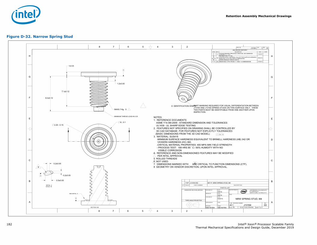
Retention Assembly Mechanical Drawings
182 Intel® Xeon® Processor Scalable FamilyThermal Mechanical Specifications and Design Guide, December 2019
Figure D-32. Narrow Spring Stud
BB
8 7 6 5 4 3 2
H
G
F
E
D
C
B
A
8 7 6 5 4 3 2 1
H
G
F
E
D
C
B
A
0.2 A
1.2±0.05
7.1±0.12
8 0.1
1±0.05
8.2±0.12
2.25 0.15
0.2±0.05
0.2±0.05
0.5±0.05
A
A
A
J13164 1 03DWG. NO SHT. REV
R 2200 MISSION COLLEGE BLVD.P.O. BOX 58119SANTA CLARA, CA 95052-8119
DEPARTMENT
TITLE
NRW SPRING STUD, M4SIZE DRAWING NUMBER REV
A1 J13164 03SCALE: 15 DO NOT SCALE DRAWING SHEET 1 OF 1SEE NOTESSEE NOTES
FINISHMATERIAL-DATEAPPROVED BY-9/30/15DATECHECKED BY5/9/14DATEDRAWN BY5/9/14DATEDESIGNED BYDIMENSIONS ARE IN MILLIMETERS
THIRD ANGLE PROJECTION
PARTS LIST
DESCRIPTIONPART NUMBERITEM NOQTY
SKT-P, SPRING STUD, M4J13164-002TOP
REVISION HISTORYZONE REV DESCRIPTION DATE APPR
F7 01 TOOLING RELEASE, PREVIOUSLY H95019-002. KEY DIMENSION CHANGED 7.1 0.12. 11/23/15
B3D4
E6, F8E6
02REVISED PART TO -002UPDATED NOTE 3 MATERIAL CALLOUT FOR SURFACE HARDNESSREMOVED CTFS FOR 8 AND 8.2 DIMENSIONSADDED MINIMUM THREAD LEAD IN
06/03/16
F7 G7 03 REMOVED CTFS FROM 7.1 AND 1.0 DIMENSIONS 07/08/16
NOTES:1. REFERENCE DOCUMENTS
ASME Y14.5M-2009 - STANDARD DIMENSION AND TOLERANCESUL1439 - UL SHARP EDGE TESTING
2. FEATURES NOT SPECIFIED ON DRAWING SHALL BE CONTROLLED BY3D CAD DATABASE. FOR FEATURES NOT EXPLICITLY TOLERANCED:
(BASIC DIMENSIONS FROM THE 3D CAD MODEL) 3. MATERIAL: SUS416
-MINIMUM SURFACE HARDNESS EQUIVALENT TO BRINELL HARDNESS (HB) 342 OR VICKERS HARDNESS (HV) 360.
-CRITICAL MATERIAL PROPERTIES: 400 MPA MIN YIELD STRENGTH- PROCESS TEST: 168 HRS 85 C / 85% HUMIDITY WITH NO
VISIBLE CORROSION4. REFERENCE AND NON-DIMENSIONED FEATURES MAY BE MODIFIED
PER INTEL APPROVAL5 ROLLED THREADS6 NOT USED.7. DIMENSIONS MARKED WITH ARE CRITICAL TO FUNCTION DIMENSIONS (CTF).8 GEOMETRY ON VENDOR DISCRETION, UPON INTEL APPROVAL.
M4X0.7-6g 5
MINIMUM THREAD LEAD-IN 0.25
PART MARKING REQUIRED FOR VISUAL DIFFERENTIATION BETWEEN J13164 AND J13165 SPRING STUDS ON THIS SURFACE ONLY. THESE TWO PARTS MUST BE IDENTIFIABLE FROM ONE ANOTHER UPON INSPECTION.
8 IDENTIFICATION SHAPE
SECTION B-B
SEE DETAIL A
SCALE 40DETAIL A
8
C
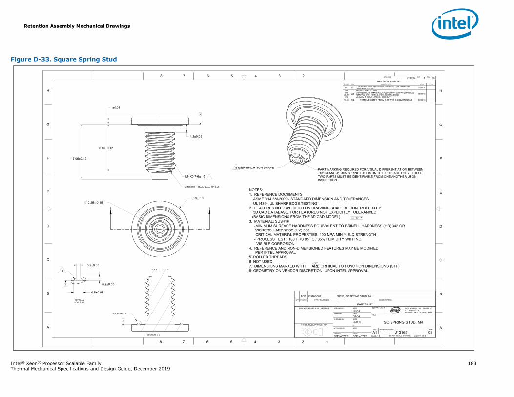
Retention Assembly Mechanical Drawings
Intel® Xeon® Processor Scalable Family 183Thermal Mechanical Specifications and Design Guide, December 2019
Figure D-33. Square Spring Stud
BB
8 7 6 5 4 3 2
H
G
F
E
D
C
B
A
8 7 6 5 4 3 2 1
H
G
F
E
D
C
B
A
0.2 A
1.2±0.05
6.85±0.12
8 0.1
1±0.05
7.95±0.12
2.25 0.15
0.2±0.05
0.2±0.05
0.5±0.05
A
A
A
J13165 1 03DWG. NO SHT. REV
R 2200 MISSION COLLEGE BLVD.P.O. BOX 58119SANTA CLARA, CA 95052-8119
DEPARTMENT
TITLE
SQ SPRING STUD, M4SIZE DRAWING NUMBER REV
A1 J13165 03SCALE: 15 DO NOT SCALE DRAWING SHEET 1 OF 1SEE NOTESSEE NOTES
FINISHMATERIAL-DATEAPPROVED BY-9/30/15DATECHECKED BY5/9/14DATEDRAWN BY5/9/14DATEDESIGNED BYDIMENSIONS ARE IN MILLIMETERS
THIRD ANGLE PROJECTION
PARTS LIST
DESCRIPTIONPART NUMBERITEM NOQTY
SKT-P, SPRING STUD, M4J13165-002TOP
REVISION HISTORYZONE REV DESCRIPTION DATE APPR
F8 01 TOOLING RELEASE, PREVIOUSLY H95019-002. KEY DIMENSION CHANGED 6.85 0.12. 11/30/15
B3D3
E6, F8E6
02REVISED PART TO -002UPDATED NOTE 3 MATERIAL CALLOUT FOR SURFACE HARNESSREMOVED CTFS FOR 8.0 AND 7.95 DIMENSIONSMINIMUM THREAD LEAD-ON CALLOUT
06/03/16
F7,G7 03 REMOVED CTFS FROM 6.85 AND 1.0 DIMENSIONS 07/08/16
NOTES:1. REFERENCE DOCUMENTS
ASME Y14.5M-2009 - STANDARD DIMENSION AND TOLERANCESUL1439 - UL SHARP EDGE TESTING
2. FEATURES NOT SPECIFIED ON DRAWING SHALL BE CONTROLLED BY3D CAD DATABASE. FOR FEATURES NOT EXPLICITLY TOLERANCED:
(BASIC DIMENSIONS FROM THE 3D CAD MODEL) 3. MATERIAL: SUS416
-MINIMUM SURFACE HARDNESS EQUIVALENT TO BRINELL HARDNESS (HB) 342 OR VICKERS HARDNESS (HV) 360.
-CRITICAL MATERIAL PROPERTIES: 400 MPA MIN YIELD STRENGTH- PROCESS TEST: 168 HRS 85 C / 85% HUMIDITY WITH NO
VISIBLE CORROSION4. REFERENCE AND NON-DIMENSIONED FEATURES MAY BE MODIFIED
PER INTEL APPROVAL5 ROLLED THREADS6 NOT USED.7. DIMENSIONS MARKED WITH ARE CRITICAL TO FUNCTION DIMENSIONS (CTF).8 GEOMETRY ON VENDOR DISCRETION, UPON INTEL APPROVAL.
M4X0.7-6g 5
MINIMUM THREAD LEAD-ON 0.25
PART MARKING REQUIRED FOR VISUAL DIFFERENTIATION BETWEEN J13164 AND J13165 SPRING STUDS ON THIS SURFACE ONLY. THESE TWO PARTS MUST BE IDENTIFIABLE FROM ONE ANOTHER UPON INSPECTION.
8 IDENTIFICATION SHAPE
SECTION B-B
SEE DETAIL A
SCALE 40DETAIL A
8
C
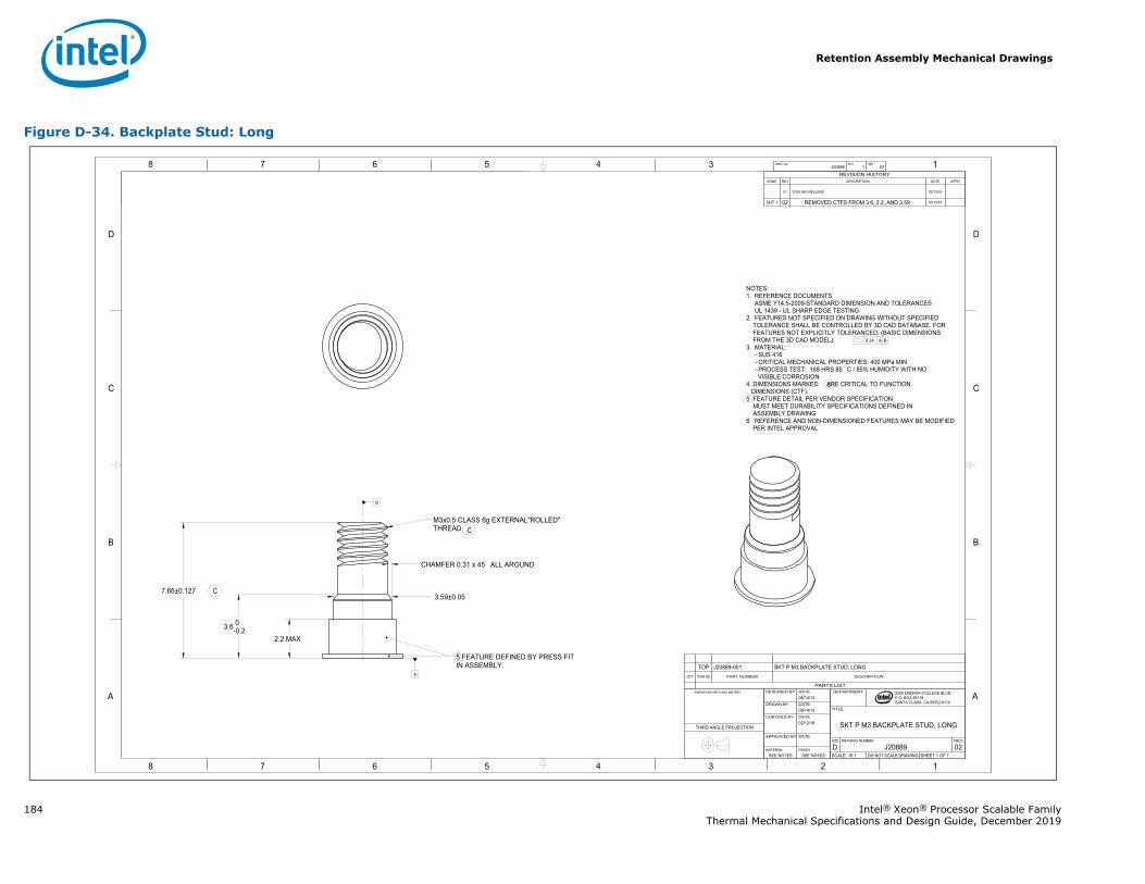
Retention Assembly Mechanical Drawings
184 Intel® Xeon® Processor Scalable FamilyThermal Mechanical Specifications and Design Guide, December 2019
Figure D-34. Backplate Stud: Long
1345678
B
C
D
A
12345678
B
C
D
A 2200 MISSION COLLEGE BLVD.P.O. BOX 58119SANTA CLARA, CA 95052-8119
R
0.24 A B
7.66±0.127
3.6 0-0.2
2.2 MAX
3.59±0.05
CHAMFER 0.31 x 45 ALL AROUND
A
J20889 1 02DWG. NO SHT. REV
SHEET 1 OF 1DO NOT SCALE DRAWINGSCALE: 16:102J20889DREVDRAWING NUMBERSIZE
SKT P M3 BACKPLATE STUD, LONG
TITLE
DEPARTMENT
SEE NOTESSEE NOTESFINISHMATERIAL
-DATEAPPROVED BY
02/12/16DATECHECKED BY
08/14/13DATEDRAWN BY
08/14/13DATEDESIGNED BY DIMENSIONS ARE IN MILLIMETERS
THIRD ANGLE PROJECTION
REVISION HISTORYZONE REV DESCRIPTION DATE APPR
- 01 TOOLING RELEASE 02/12/16
SHT 1 02 REMOVED CTFS FROM 3.6, 2.2, AND 3.59 07/13/16
NOTES:1. REFERENCE DOCUMENTS
ASME Y14.5-2009-STANDARD DIMENSION AND TOLERANCESUL 1439 - UL SHARP EDGE TESTING
2. FEATURES NOT SPECIFIED ON DRAWING WITHOUT SPECIFIEDTOLERANCE SHALL BE CONTROLLED BY 3D CAD DATABASE. FORFEATURES NOT EXPLICITLY TOLERANCED: (BASIC DIMENSIONSFROM THE 3D CAD MODEL):
3. MATERIAL:- SUS 416- CRITICAL MECHANICAL PROPERTIES: 400 MPa MIN- PROCESS TEST: 168 HRS 85 C / 85% HUMIDITY WITH NOVISIBLE CORROSION
4. DIMENSIONS MARKED ARE CRITICAL TO FUNCTION DIMENSIONS (CTF). 5 FEATURE DETAIL PER VENDOR SPECIFICATION MUST MEET DURABILITY SPECIFICATIONS DEFINED IN ASSEMBLY DRAWING6. REFERENCE AND NON-DIMENSIONED FEATURES MAY BE MODIFIED
PER INTEL APPROVAL
M3x0.5 CLASS 6g EXTERNAL"ROLLED" THREAD
5 FEATURE DEFINED BY PRESS FITIN ASSEMBLY.
C
C
C
B
PARTS LIST
DESCRIPTIONPART NUMBERITEM NOQTY
SKT P M3 BACKPLATE STUD, LONGJ20889-001TOP
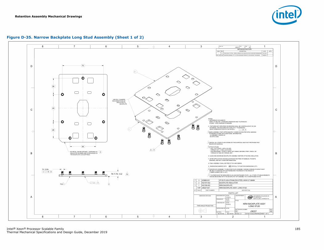
Retention Assembly Mechanical Drawings
Intel® Xeon® Processor Scalable Family 185Thermal Mechanical Specifications and Design Guide, December 2019
Figure D-35. Narrow Backplate Long Stud Assembly (Sheet 1 of 2)
1345678
B
C
D
A
12345678
B
C
D
A 2200 MISSION COLLEGE BLVD.P.O. BOX 58119SANTA CLARA, CA 95052-8119
R
.24 A
.2
.15 A 7X (3.59)
7X 7.74 0.2
44
26
26
44
70
A
J36227 1 02DWG. NO SHT. REV
SHEET 1 OF 2DO NOT SCALE DRAWINGSCALE: 2:102J36227DREVDRAWING NUMBERSIZE
NRW BACKPLATE ASSYLONG STUD
TITLE
DEPARTMENT
SEE NOTESSEE NOTESFINISHMATERIAL
DATEAPPROVED BY
-09/18/15DATECHECKED BY
3/3/14DATEDRAWN BY
12/16/13DATEDESIGNED BYDIMENSIONS ARE IN MM
THIRD ANGLE PROJECTION
REVISION HISTORYZONE REV DESCRIPTION DATE APPR
- 01 PREVIOUSLY H77928. ADDED LONGER STUD LENGTHS FOR THICKER MOTHERBOARDS 07/13/16
SHT1 B6 02 MODIFIED NOMINAL TO 7.74 FOR INCREASED PRESS FIT STUD HEIGHT TOLERANCE 09/08/16
NOTES1. REFERENCE DOCUMENTS
ASME Y14.5M-2009 - STANDARD DIMENSION AND TOLERANCESG164997 - INTEL MARKING STANDARD
2. FEATURES NOT SPECIFIED ON DRAWING SHALL BE CONTROLLED BY 3D CADDATABASE. FOR FEATURES NOT EXPLICITLY TOLERANCED:
(BASIC DIMENSION FROM 3D CAD MODEL):
3 MARK ASSEMBLY PART APPROXIMATELY WHERE SHOWN PER INTEL MARKING STANDARD (G14599) WITH ADDITIONAL INFORMATION:
A) ASSEMBLY VENDOR IDB) DATE CODE
4 INSTALL ALL STUDS FLUSH OR BELOW THIS SURFACE, MUST NOT PROTRUDE PAST BACKPLATE SURFACE.
5 ATTACH STUDS:- PULL OUT FORCE > 667N (150 LBF)- TORQUE OUT > 2.25N-m (20 IN-LBF)- FAILURE MODES: STUDS (7) MUST NOT SHEAR, DEFORM, STRIP, CRACK, OR
TORQUE-OUT BELOW TORQUE LIMIT.
6. CLEAN AND DEGREASE BACKPLATE ASSEMBLY BEFORE ATTACHING INSULATION.
7. AFTER APPLICATION THE INSULATOR MUST BE FREE OF BUBBLES, POCKETS,GREASES, AND ANY OTHER DEFORMATIONS.
8. FINAL ASSEMBLY SHALL BE FREE OF OIL AND DEBRIS.
9. DIMENSIONS MARKED WITH ARE CRITICAL TO FUNCTION DIMENSIONS (CTF).
10 BACKPLATE ASSEMBLY TO BOLSTER PLATE ASSEMBLY (H95384 & H95385) STUD/NUT MUST BE ABLE TO ENGAGE WITH MOTHERBOARD THICKNESS' IN THE RANGE OF 2.36MM-3.63MM (0.093"-0.143").
11 FLATNESS MUST BE MEASURED IN AN UNCONSTRAINED STATE. ALL OTHER CTF MEASUREMENTS CAN BE MEASURED WITH THE BACKPLATE TOP ASSEMBLY IN A CONSTRAINED STATE.
5
11
NO METAL CAN BE EXPOSED. OVERHANG OF INSULATOR ON INNER AND OUTER EDGES OF THE BACKPLATE IS ACCEPTABLE.
1
2
USE PIN 1 CHAMFER FOR ORIENTATION OF
INSULATOR TO BACKPLATE
3
7X 4
10
C
C
PARTS LIST
DESCRIPTIONPART NUMBERITEM NOQTY
NRW BACKPLATE ASSYJ36227-001TOPBACKPLATEH32156-00211
BACKPLATE-INSULATORH32157-00221STUD,FLUSH,STAINLESS STEEL,M3X0.5,7.66MMJ20889-00137
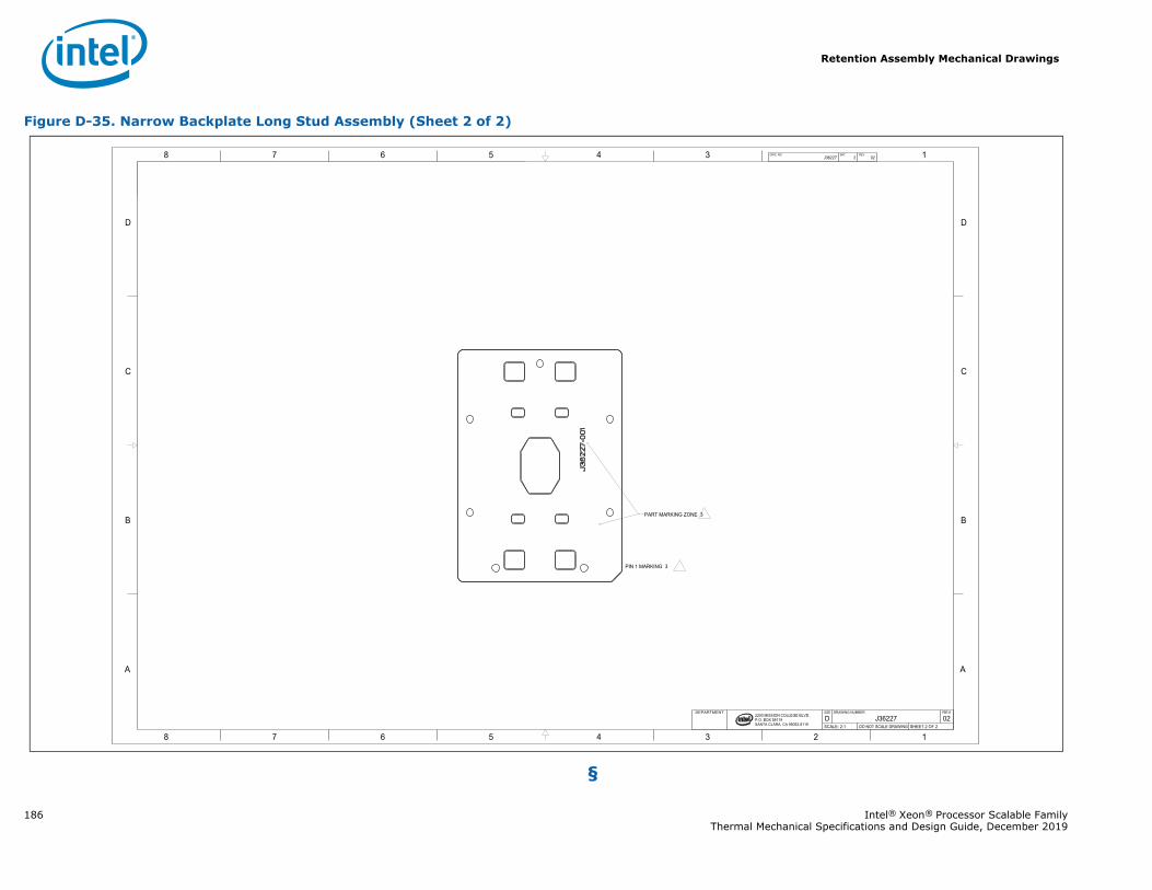
Retention Assembly Mechanical Drawings
186 Intel® Xeon® Processor Scalable FamilyThermal Mechanical Specifications and Design Guide, December 2019
§
Figure D-35. Narrow Backplate Long Stud Assembly (Sheet 2 of 2)
1345678
B
C
D
A
12345678
B
C
D
A
2200 MISSION COLLEGE BLVD.P.O. BOX 58119SANTA CLARA, CA 95052-8119
R
J36227 2 02DWG. NO SHT. REV
SHEET 2 OF 2DO NOT SCALE DRAWINGSCALE: 2:102J36227DREVDRAWING NUMBERSIZEDEPARTMENT
PIN 1 MARKING 3
PART MARKING ZONE 3
Heatsink Mechanical Drawings
Intel® Xeon® Processor Scalable Family 187Thermal Mechanical Specifications and Design Guide, December 2019
E Heatsink Mechanical Drawings
E.1 Heatsink DrawingsTable E-1 lists the reference heatsink mechanical drawings that are used in the Intel® Xeon® Processor Scalable Family-based platform.
Table E-1. Heatsink Drawings List
Description Figure
2U Heatsink Assembly Figure E-1
2U Heatsink Heatpipe: Small Figure E-2
2U Heatsink Heatpipe: Large Figure E-3
2U Heatsink Copper Slug Figure E-4
2U Heatsink Aluminum Base Figure E-5
2U Heatsink Fin Assembly Figure E-6
Delrin Heatsink Washer Figure E-7
TIM PCM45F Figure E-8
1U Heatsink Assembly Figure E-9
1U Heatsink Figure E-10
1U Extruded Heatsink Assembly Figure E-11
1U Extruded Heatsink Figure E-12
Square Tower Heatsink Figure E-13
Square Tower Heatsink Assembly Figure E-14
Square Tower Copper Slug Figure E-15
Square Tower Heat Pipe 1 Figure E-16
Square Tower Heat Pipe 2 Figure E-17
Square Tower Fin Stack Assembly Figure E-18
Square Tower Heatsink Aluminum Frame Base Figure E-19
Square Tower Heatsink Bracket Figure E-20
Heatsink Label Figure E-21
Square Tower Heatsink Label Figure E-22
Heatsink Collar Figure E-23
Heatsink Nut Figure E-24
Extruded Aluminum Heatsink Label Figure E-25
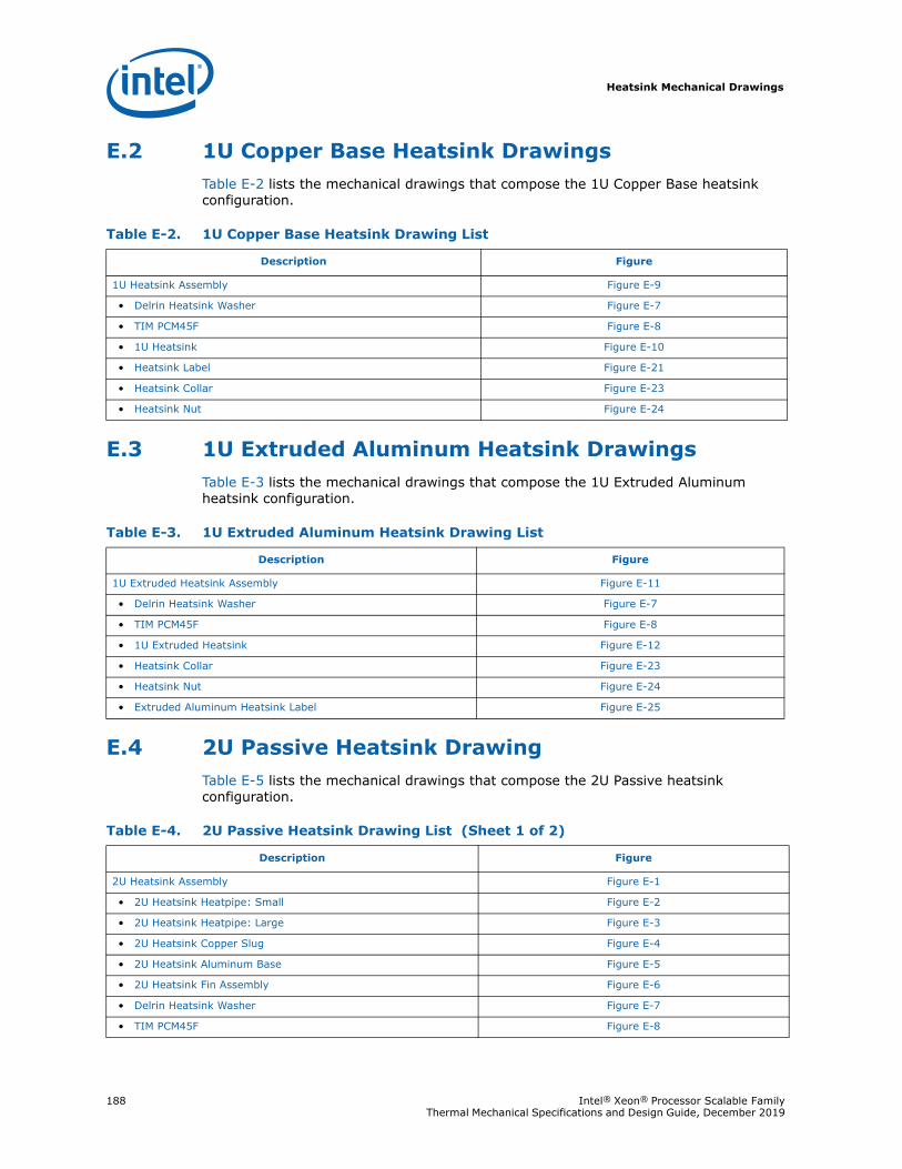
Heatsink Mechanical Drawings
188 Intel® Xeon® Processor Scalable Family Thermal Mechanical Specifications and Design Guide, December 2019
E.2 1U Copper Base Heatsink DrawingsTable E-2 lists the mechanical drawings that compose the 1U Copper Base heatsink configuration.
E.3 1U Extruded Aluminum Heatsink DrawingsTable E-3 lists the mechanical drawings that compose the 1U Extruded Aluminum heatsink configuration.
E.4 2U Passive Heatsink DrawingTable E-5 lists the mechanical drawings that compose the 2U Passive heatsink configuration.
Table E-2. 1U Copper Base Heatsink Drawing List
Description Figure
1U Heatsink Assembly Figure E-9
• Delrin Heatsink Washer Figure E-7
• TIM PCM45F Figure E-8
• 1U Heatsink Figure E-10
• Heatsink Label Figure E-21
• Heatsink Collar Figure E-23
• Heatsink Nut Figure E-24
Table E-3. 1U Extruded Aluminum Heatsink Drawing List
Description Figure
1U Extruded Heatsink Assembly Figure E-11
• Delrin Heatsink Washer Figure E-7
• TIM PCM45F Figure E-8
• 1U Extruded Heatsink Figure E-12
• Heatsink Collar Figure E-23
• Heatsink Nut Figure E-24
• Extruded Aluminum Heatsink Label Figure E-25
Table E-4. 2U Passive Heatsink Drawing List (Sheet 1 of 2)
Description Figure
2U Heatsink Assembly Figure E-1
• 2U Heatsink Heatpipe: Small Figure E-2
• 2U Heatsink Heatpipe: Large Figure E-3
• 2U Heatsink Copper Slug Figure E-4
• 2U Heatsink Aluminum Base Figure E-5
• 2U Heatsink Fin Assembly Figure E-6
• Delrin Heatsink Washer Figure E-7
• TIM PCM45F Figure E-8
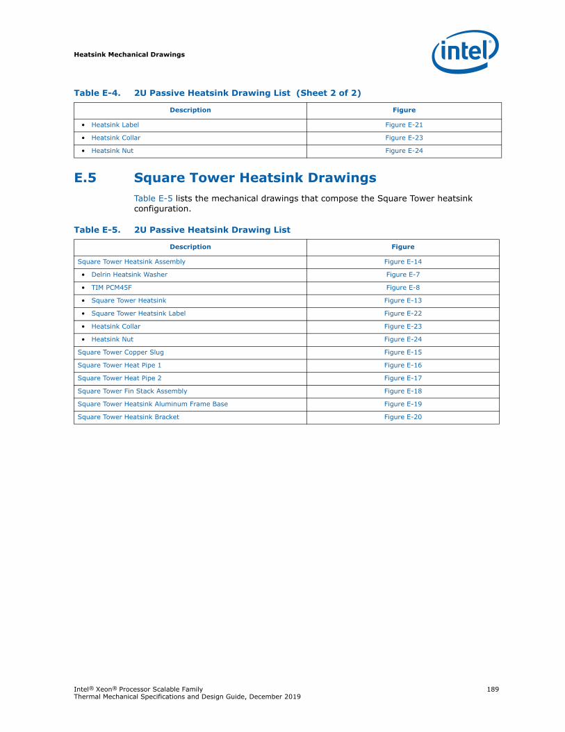
Heatsink Mechanical Drawings
Intel® Xeon® Processor Scalable Family 189Thermal Mechanical Specifications and Design Guide, December 2019
E.5 Square Tower Heatsink DrawingsTable E-5 lists the mechanical drawings that compose the Square Tower heatsink configuration.
• Heatsink Label Figure E-21
• Heatsink Collar Figure E-23
• Heatsink Nut Figure E-24
Table E-4. 2U Passive Heatsink Drawing List (Sheet 2 of 2)
Description Figure
Table E-5. 2U Passive Heatsink Drawing List
Description Figure
Square Tower Heatsink Assembly Figure E-14
• Delrin Heatsink Washer Figure E-7
• TIM PCM45F Figure E-8
• Square Tower Heatsink Figure E-13
• Square Tower Heatsink Label Figure E-22
• Heatsink Collar Figure E-23
• Heatsink Nut Figure E-24
Square Tower Copper Slug Figure E-15
Square Tower Heat Pipe 1 Figure E-16
Square Tower Heat Pipe 2 Figure E-17
Square Tower Fin Stack Assembly Figure E-18
Square Tower Heatsink Aluminum Frame Base Figure E-19
Square Tower Heatsink Bracket Figure E-20
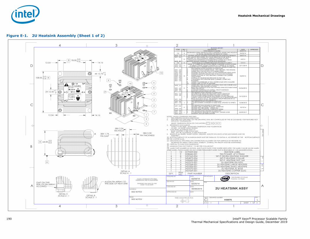
Heatsink Mechanical Drawings
190 Intel® Xeon® Processor Scalable FamilyThermal Mechanical Specifications and Design Guide, December 2019
Figure E-1. 2U Heatsink Assembly (Sheet 1 of 2)
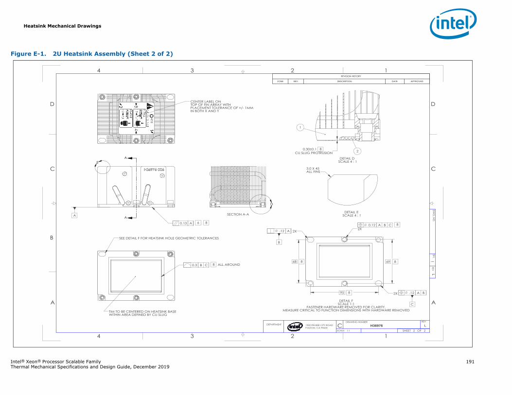
Heatsink Mechanical Drawings
Intel® Xeon® Processor Scalable Family 191Thermal Mechanical Specifications and Design Guide, December 2019
Figure E-1. 2U Heatsink Assembly (Sheet 2 of 2)
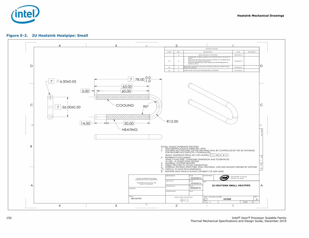
Heatsink Mechanical Drawings
192 Intel® Xeon® Processor Scalable FamilyThermal Mechanical Specifications and Design Guide, December 2019
Figure E-2. 2U Heatsink Heatpipe: Small
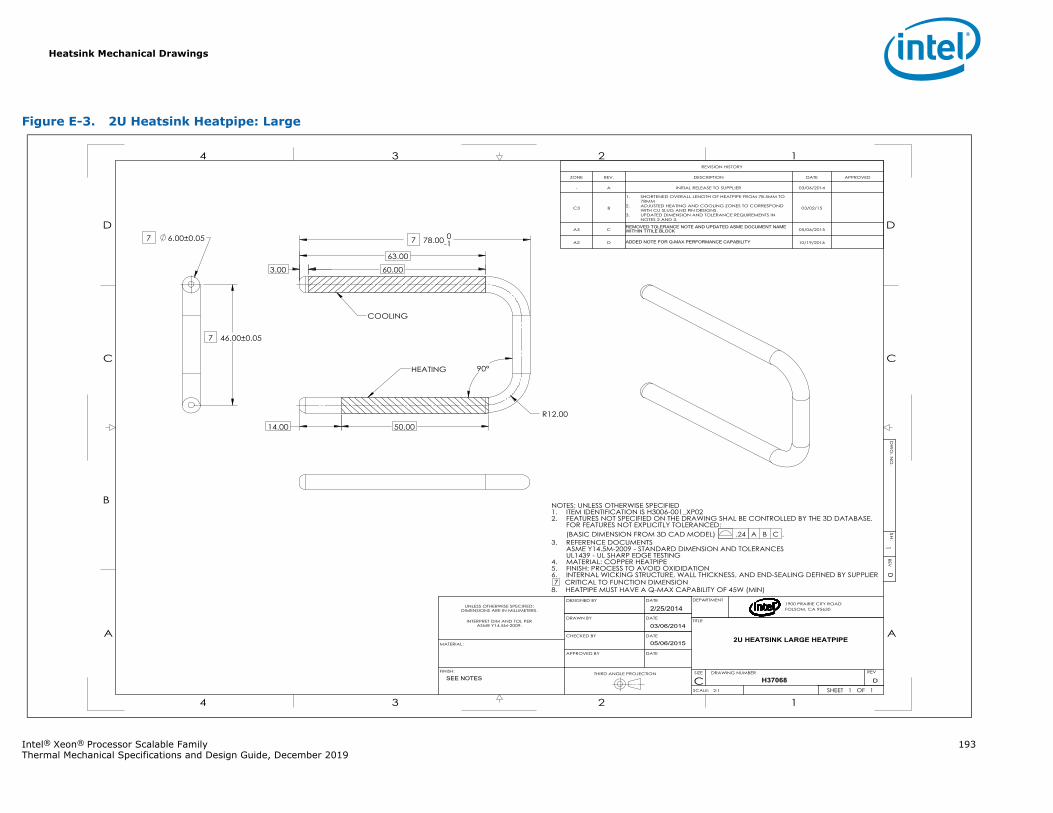
Heatsink Mechanical Drawings
Intel® Xeon® Processor Scalable Family 193Thermal Mechanical Specifications and Design Guide, December 2019
Figure E-3. 2U Heatsink Heatpipe: Large
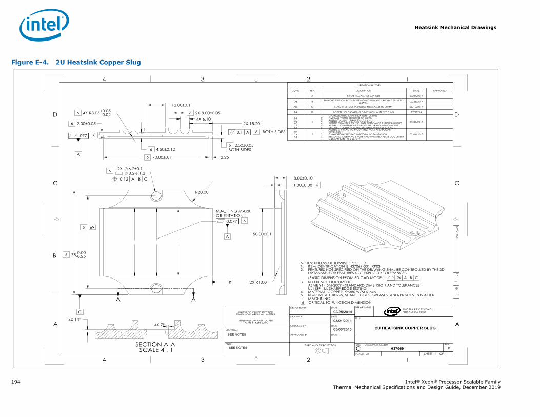
Heatsink Mechanical Drawings
194 Intel® Xeon® Processor Scalable FamilyThermal Mechanical Specifications and Design Guide, December 2019
Figure E-4. 2U Heatsink Copper Slug
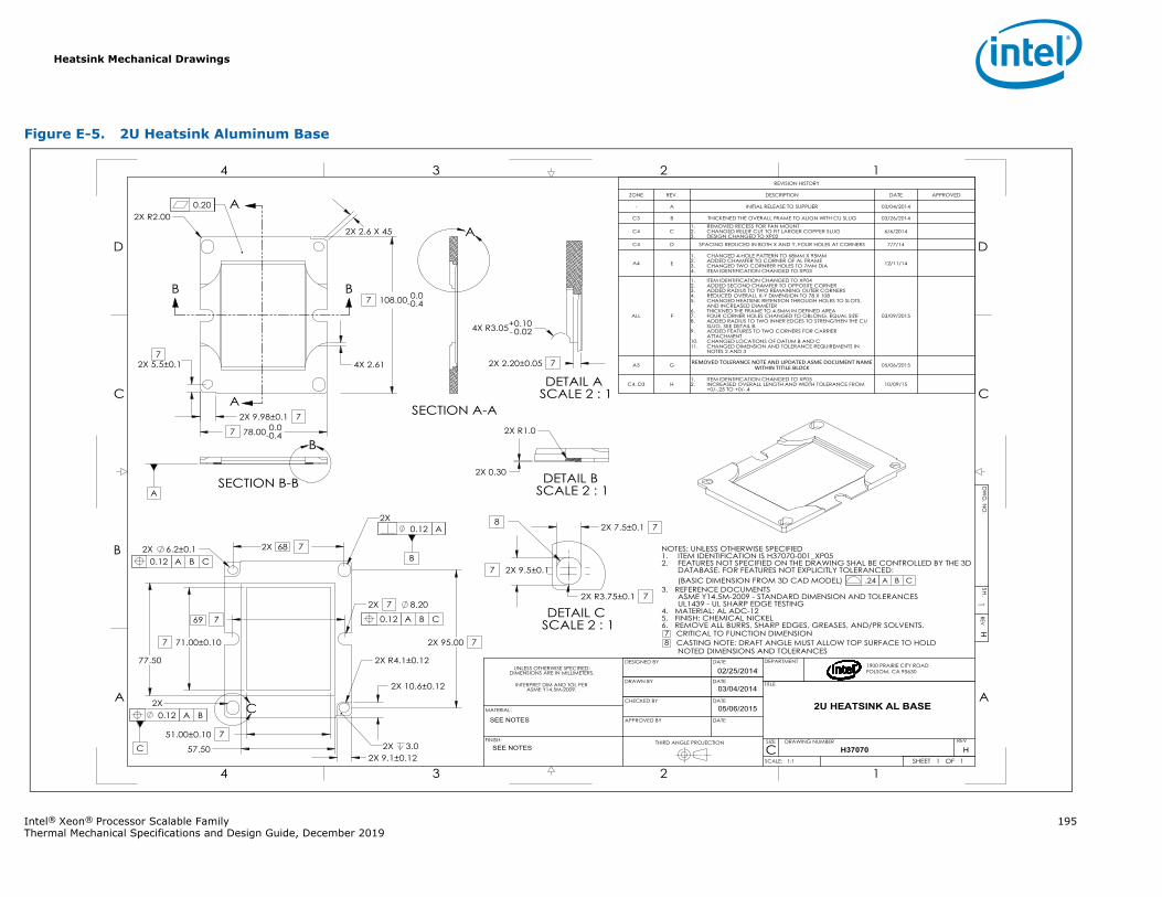
Heatsink Mechanical Drawings
Intel® Xeon® Processor Scalable Family 195Thermal Mechanical Specifications and Design Guide, December 2019
Figure E-5. 2U Heatsink Aluminum Base
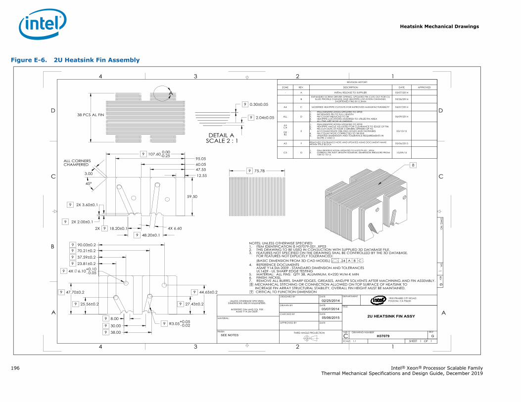
Heatsink Mechanical Drawings
196 Intel® Xeon® Processor Scalable FamilyThermal Mechanical Specifications and Design Guide, December 2019
Figure E-6. 2U Heatsink Fin Assembly
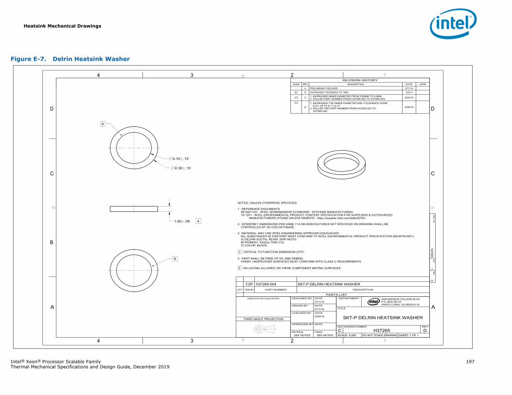
Heatsink Mechanical Drawings
Intel® Xeon® Processor Scalable Family 197Thermal Mechanical Specifications and Design Guide, December 2019
Figure E-7. Delrin Heatsink Washer
A
4
B
3
C
D
4 3
2 1
A
2
C
1
D
2200 MISSION COLLEGE BLVD.P.O. BOX 58119SANTA CLARA, CA 95052-8119
R
6.10 .10
8.30 .10
41.00 .05
H372651
DDW
G. NO
SHT.REV
SHEET 1 OF 1DO NOT SCALE DRAWINGSCALE: 8.000DH37265C
REVDRAWING NUMBERSIZE
SKT-P DELRIN HEATSINK WASHER
TITLE
DEPARTMENT
SEE NOTESSEE NOTESFINISHMATERIAL
DATEAPPROVED BY
2/20/14 DATECHECKED BY
2/11/14DATEDRAWN BY
2/11/14DATEDESIGNED BYDIMENSIONS ARE IN MILLIMETERS
THIRD ANGLE PROJECTION
PARTS LIST
DESCRIPTIONPART NUMBERITEM NOQTY
SKT-P DELRIN HEATSINK WASHERH37265-004TOP
REVISION HISTORYZONE REV DESCRIPTION DATE APPR
- A PRELIMINARY RELEASE 2/11/14
B3 B INCREASED THICKNESS TO 1MM 3/5/14
C3 C 1. INCREASED INNER DIAMETER FROM 5.65MM TO 6.0MM2. ROLLED PART NUMBER FROM H37265-002 TO H37265-003. 9/24/15
C3
D
1. INCREASED THE INNER DIAMETER AND TOLERANCE FROM6.0+/-.05 TO 6.1+/-0.10
2. ROLLED THE PART NUMBER FROM H37265-003 TOH37265-004.
9/30/15
NOTES; UNLESS OTHERWISE SPECIFIED:
1. REFERENCE DOCUMENTS99-0007-001 - INTEL WORKMANSHIP STANDARD - SYSTEMS MANUFACTURING18-1201 - INTEL ENVIRONMENTAL PRODUCT CONTENT SPECIFICATION FOR SUPPLIERS & OUTSOURCED
MANUFACTURERS (FOUND ON EHS WEBSITE - https://supplier.intel.com/static/EHS/)
2. INTERPRET DIMENSIONS PER ASME Y14.5M-2009.FEATURES NOT SPECIFIED ON DRAWING SHALL BECONTROLLED BY 3D CAD DATABASE.
3. MATERIAL: MAY USE INTEL ENGINEERING APPROVED EQUIVALENT.ALL SUBSTANCES IN THIS PART MUST CONFORM TO INTEL ENVIRONMENTAL PRODUCT SPECIFICATION (BS-MTN-0001).A) DELRIN ACETAL RESIN. 500P NC010.B) PIGMENT: EAGLE 7058 (1%)C) COLOR: BLACK.
4 CRITICAL TO FUNCTION DIMENSION (CTF).
5. PART SHALL BE FREE OF OIL AND DEBRIS.FINISH: UNSPECIFIED SURFACES MUST CONFORM WITH CLASS C REQUIREMENTS.
6 NO GATING ALLOWED ON THESE COMPONENT MATING SURFACES.
6
6
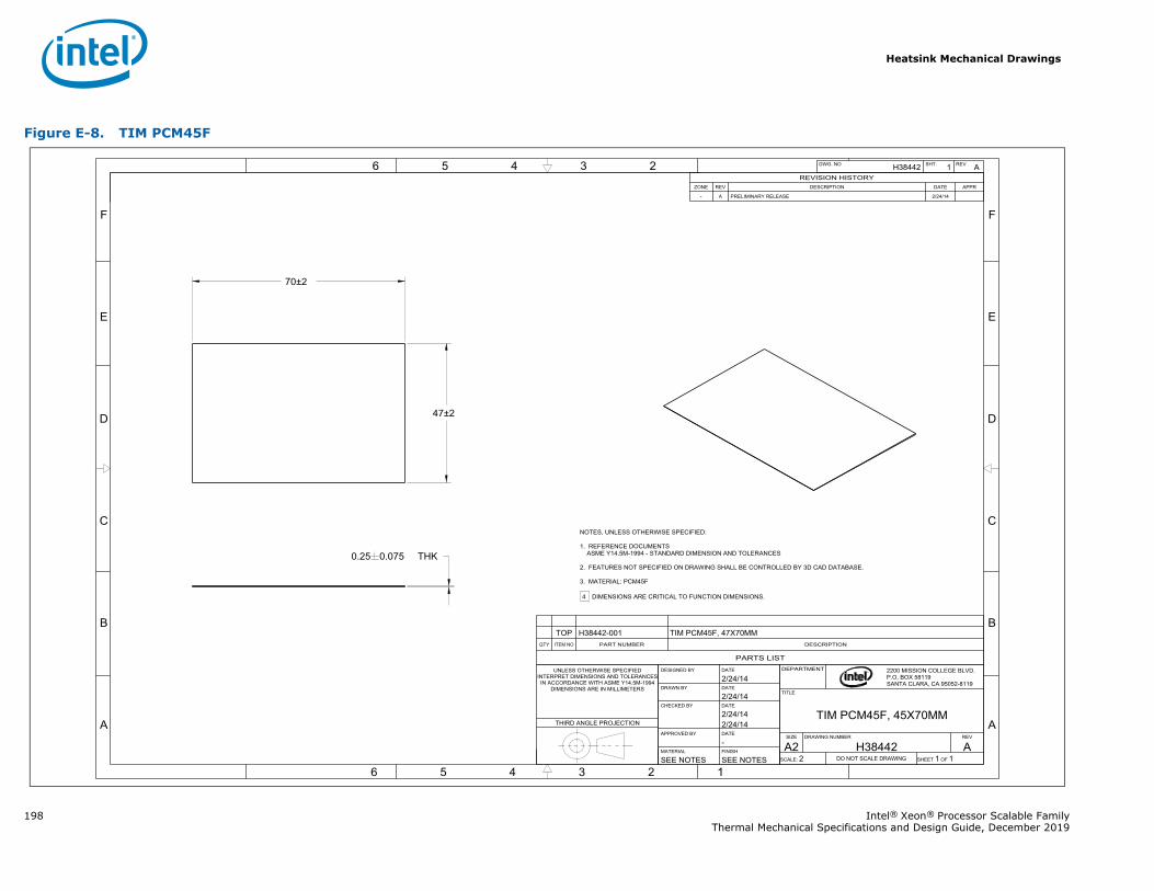
Heatsink Mechanical Drawings
198 Intel® Xeon® Processor Scalable FamilyThermal Mechanical Specifications and Design Guide, December 2019
Figure E-8. TIM PCM45F
6 5 4 3 2
6 5 4 3 2 1
F
E
D
C
B
A
F
E
D
C
B
A
70±2
47±2
THK0.25 0.075
H38442 1 A DWG. NO SHT. REV
R 2200 MISSION COLLEGE BLVD.P.O. BOX 58119SANTA CLARA, CA 95052-8119
DEPARTMENT
TITLE
TIM PCM45F, 45X70MMSIZE DRAWING NUMBER REV
A2 H38442 ASCALE: 2 DO NOT SCALE DRAWING SHEET 1 OF 1SEE NOTESSEE NOTES
FINISHMATERIAL-DATEAPPROVED BY2/24/142/24/14DATECHECKED BY2/24/14DATEDRAWN BY2/24/14DATEDESIGNED BYUNLESS OTHERWISE SPECIFIED
INTERPRET DIMENSIONS AND TOLERANCESIN ACCORDANCE WITH ASME Y14.5M-1994
DIMENSIONS ARE IN MILLIMETERS
THIRD ANGLE PROJECTION
PARTS LIST
DESCRIPTIONPART NUMBERITEM NOQTY
TIM PCM45F, 47X70MMH38442-001TOP
REVISION HISTORYZONE REV DESCRIPTION DATE APPR
- A PRELIMINARY RELEASE 2/24/14
NOTES, UNLESS OTHERWISE SPECIFIED:
1. REFERENCE DOCUMENTSASME Y14.5M-1994 - STANDARD DIMENSION AND TOLERANCES
2. FEATURES NOT SPECIFIED ON DRAWING SHALL BE CONTROLLED BY 3D CAD DATABASE.
3. MATERIAL: PCM45F
4 DIMENSIONS ARE CRITICAL TO FUNCTION DIMENSIONS.
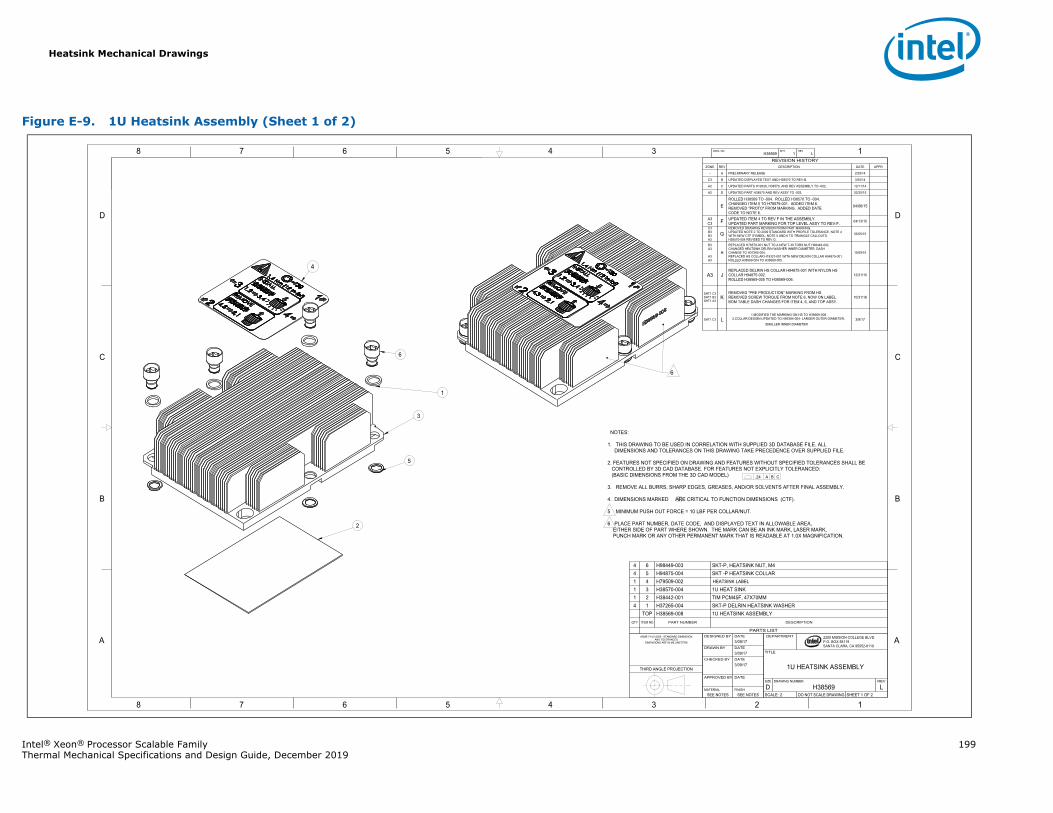
Heatsink Mechanical Drawings
Intel® Xeon® Processor Scalable Family 199Thermal Mechanical Specifications and Design Guide, December 2019
Figure E-9. 1U Heatsink Assembly (Sheet 1 of 2)
1345678
B
C
D
A
12345678
B
C
D
A 2200 MISSION COLLEGE BLVD.P.O. BOX 58119SANTA CLARA, CA 95052-8119
R
H38569 1 LDWG. NO SHT. REV
SHEET 1 OF 2DO NOT SCALE DRAWINGSCALE: 2LH38569D
REVDRAWING NUMBERSIZE
1U HEATSINK ASSEMBLY
TITLE
DEPARTMENT
SEE NOTESSEE NOTESFINISHMATERIAL
DATEAPPROVED BY
3/09/17 DATECHECKED BY
3/09/17DATEDRAWN BY
3/09/17DATEDESIGNED BYASME Y14.5-2009 - STANDARD DIMENSION
AND TOLERANCESDIMENSIONS ARE IN MILLIMETERS
THIRD ANGLE PROJECTION
PARTS LIST
DESCRIPTIONPART NUMBERITEM NOQTY
1U HEATSINK ASSEMBLYH38569-008TOPSKT-P DELRIN HEATSINK WASHERH37265-00414TIM PCM45F, 47X70MMH38442-001211U HEAT SINKH38570-00431
H79509-00241SKT -P HEATSINK COLLARH94875-00454SKT-P, HEATSINK NUT, M4H98449-00364
REVISION HISTORYZONE REV DESCRIPTION DATE APPR
- A PRELIMINARY RELEASE 2/25/14
C3 B UPDATED DISPLAYED TEXT AND H38570 TO REV-B. 3/25/14
A2 C UPDATED PARTS H19326, H38570, AND REV ASSEMBLY TO -002, 12/11/14
A2 D UPDATED PART H38570 AND REV ASSY TO -003. 02/20/15
EROLLED H38569 TO -004. ROLLED H38570 TO -004.CHANGED ITEM 5 TO H78579-001. ADDED ITEM 6.REMOVED "PROTO" FROM MARKING. ADDED DATECODE TO NOTE 6.
04/06/15
A3C3 F UPDATED ITEM 4 TO REV F IN THE ASSEMBLY.
UPDATED PART MARKING FOR TOP LEVEL ASSY TO REV-F. 04/13/15
C3B3B3A3
GREMOVED DRAWING REVISION FROM PART MARKING.UPDATED NOTE 2 TO 2009 STANDARD WITH PROFILE TOLERANCE, NOTE 4 WITH NEW CTF SYMBOL, NOTE 5 AND 6 TO TRIANGLE CALLOUTS.H38570-004 REVISED TO REV G.
05/05/15
B3A3
A3A3
H
REPLACED H78579-001 NUT TO A NEW T-30 TORX NUT H98449-002.CHANGED HEATSINK DELRIN WASHER INNER DIAMETER, DASHCHANGE TO H37265-004.REPLACED HS COLLAR H19327-001 WITH NEW DELRIN COLLAR H94875-001.ROLLED H38569-004 TO H38569-005.
10/09/15
A3 JREPLACED DELRIN HS COLLAR H94875-001 WITH NYLON HSCOLLAR H94875-002.ROLLED H38569-005 TO H38569-006.
12/21/15
SHT1 C3SHT1 B3SHT1 A3
KREMOVED "PRE PRODUCTION" MARKING FROM HS.REMOVED SCREW TORQUE FROM NOTE 6, NOW ON LABEL.BOM TABLE DASH CHANGES FOR ITEM 4, 6, AND TOP ASSY.
10/31/16
SHT1 C3 L1.MODIFIED THE MARKING ON HS TO H38569-008.
2.COLLAR DESIGN UPDATED TO H95384-004- LARGER OUTER DIAMETER,SMALLER INNER DIAMETER .
3/9/17
NOTES:
1. THIS DRAWING TO BE USED IN CORRELATION WITH SUPPLIED 3D DATABASE FILE. ALLDIMENSIONS AND TOLERANCES ON THIS DRAWING TAKE PRECEDENCE OVER SUPPLIED FILE.
2. FEATURES NOT SPECIFIED ON DRAWING AND FEATURES WITHOUT SPECIFIED TOLERANCES SHALL BECONTROLLED BY 3D CAD DATABASE. FOR FEATURES NOT EXPLICITLY TOLERANCED:
(BASIC DIMENSIONS FROM THE 3D CAD MODEL)
3. REMOVE ALL BURRS, SHARP EDGES, GREASES, AND/OR SOLVENTS AFTER FINAL ASSEMBLY.
4. DIMENSIONS MARKED ARE CRITICAL TO FUNCTION DIMENSIONS (CTF).
5 MINIMUM PUSH OUT FORCE = 10 LBF PER COLLAR/NUT.
6 PLACE PART NUMBER, DATE CODE, AND DISPLAYED TEXT IN ALLOWABLE AREA, EITHER SIDE OF PART WHERE SHOWN. THE MARK CAN BE AN INK MARK, LASER MARK, PUNCH MARK OR ANY OTHER PERMANENT MARK THAT IS READABLE AT 1.0X MAGNIFICATION.
.24 A B C
HEATSINK LABEL
1
2
6
5
3
4
6
C
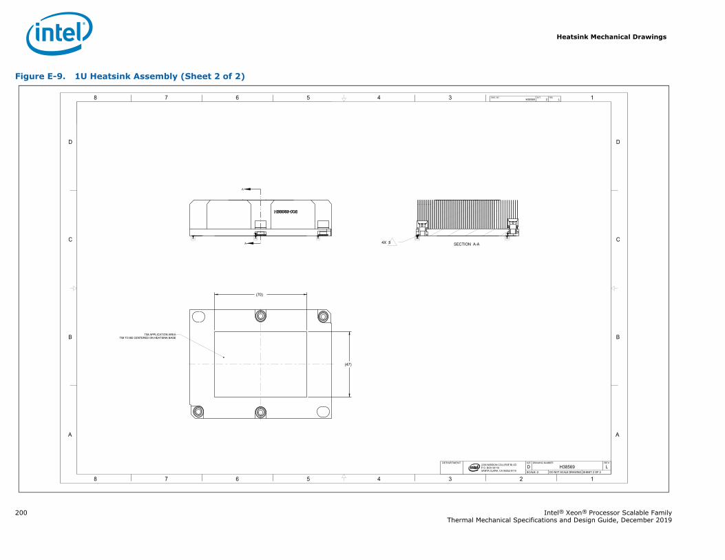
Heatsink Mechanical Drawings
200 Intel® Xeon® Processor Scalable FamilyThermal Mechanical Specifications and Design Guide, December 2019
Figure E-9. 1U Heatsink Assembly (Sheet 2 of 2)
A
A
1345678
B
C
D
A
12345678
B
C
D
A
2200 MISSION COLLEGE BLVD.P.O. BOX 58119SANTA CLARA, CA 95052-8119
R
AAAA A
AA A
(47)
(70)
H38569 2 LDWG. NO SHT. REV
SHEET 2 OF 2DO NOT SCALE DRAWINGSCALE: 2LH38569D
REVDRAWING NUMBERSIZEDEPARTMENT
TIM TO BE CENTERED ON HEATSINK BASETIM APPLICATION AREA
SECTION A-A4X 5
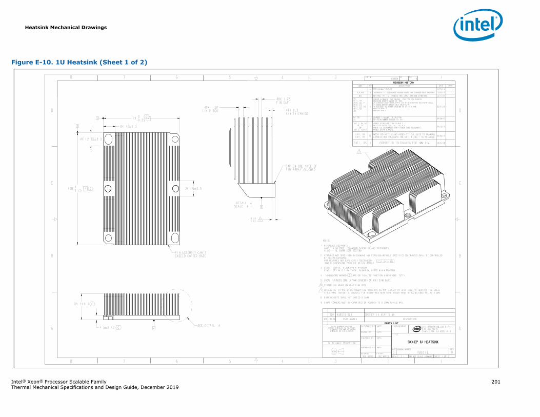
Heatsink Mechanical Drawings
Intel® Xeon® Processor Scalable Family 201Thermal Mechanical Specifications and Design Guide, December 2019
Figure E-10. 1U Heatsink (Sheet 1 of 2)
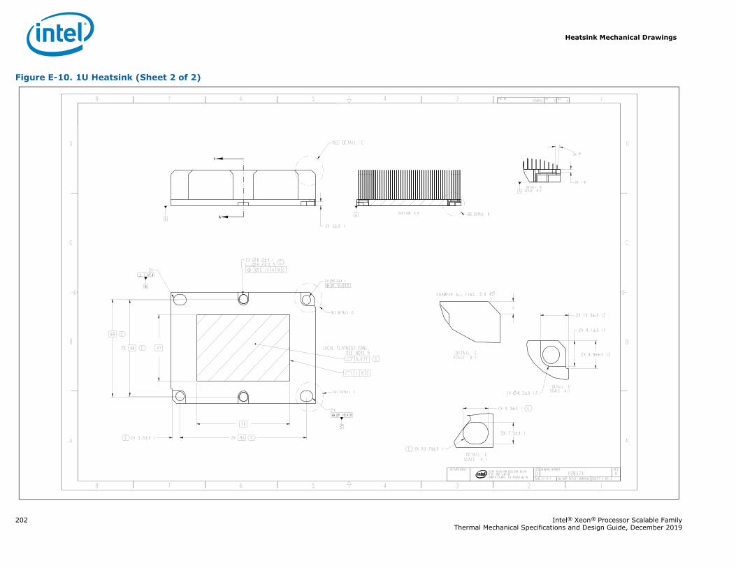
Heatsink Mechanical Drawings
202 Intel® Xeon® Processor Scalable FamilyThermal Mechanical Specifications and Design Guide, December 2019
Figure E-10. 1U Heatsink (Sheet 2 of 2)
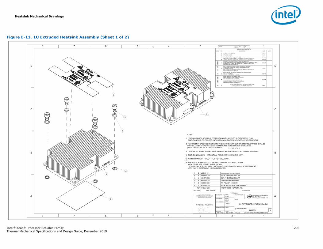
Heatsink Mechanical Drawings
Intel® Xeon® Processor Scalable Family 203Thermal Mechanical Specifications and Design Guide, December 2019
Figure E-11. 1U Extruded Heatsink Assembly (Sheet 1 of 2)
1345678
B
C
D
A
12345678
B
C
D
A 2200 MISSION COLLEGE BLVD.P.O. BOX 58119SANTA CLARA, CA 95052-8119
R
H45651 1 IDWG. NO SHT. REV
SHEET 1 OF 2DO NOT SCALE DRAWINGSCALE: 2IH45651D
REVDRAWING NUMBERSIZE
1U EXTRUDED HEATSINK ASM
TITLE
DEPARTMENT
SEE NOTESSEE NOTESFINISHMATERIAL
DATEAPPROVED BY
3/09/17DATECHECKED BY
3/09/17DATEDRAWN BY
3/09/17DATEDESIGNED BYUNLESS OTHERWISE SPECIFIED
INTERPRET DIMENSIONS AND TOLERANCES IN ACCORDANCE WITH ASME Y14.5M-2009
DIMENSIONS ARE IN MILLIMETERS
THIRD ANGLE PROJECTION
PARTS LIST
DESCRIPTIONPART NUMBERITEM NOQTY
U EXTRUDED HEATSINK ASMH45651-006TOPSKT-P DELRIN HEATSINK WASHERH37265-00414TIM PCM45F, 47X70MMH38442-001211U EXTRUDED HEATSINKH45653-00231SKT -P HEATSINK COLLARH94875-00444SKT-P, HEATSINK NUT, M4H98449-00354
J45423-00161
REVISION HISTORYZONE REV DESCRIPTION DATE APPR
- A PRELIMINARY RELEASE 4/28/14
- B UPDATED H45653 11/4/14
- C UPDATED PARTS H19326 AND H45653 12/11/14
D UPDATED: NOTES, ASSEMBLY NUMBER TO -002, PART H45653-002ADDED LABEL AND HARDWARE, CHANGED NUT TO H78579-001 04/07/15
C3B3B3A3
E
REMOVED DRAWING REVISION FROM PART MARKING.UPDATED NOTE 2 TO 2009 STANDARD WITH PROFILE TOLERANCE, NOTE 4 WITH NEW CTF SYMBOL, NOTE 5 AND 6 TO TRIANGLE CALLOUTS.H45653-002 REVISED TO REV E.
05/05/15
B3A3
A3A3
F
REPLACED H78579-001 NUT TO A NEW T-30 TORX NUT H98449-002.CHANGED HEATSINK DELRIN WASHER INNER DIAMETER, DASHCHANGE TO H37265-004.REPLACED HS COLLAR H19327-001 WITH NEW DELRIN COLLAR H94875-001.ROLLED H45651-002 TO H45651-003.
10/11/15
A3 GREPLACED DELRIN HS COLLAR H94875-001 WITH NYLON HS COLLAR H94875-002.ROLLED H45651-003 TO H45651-004.
12/21/15
A3B3A3C3B3A3
H
ITEM 5 HEATSINK NUT IS NOW -003.ITEM 6 HEATSINK LABEL IS NOW J45423-001.TOP ASSEMBLY NOW H45651-005.PRE PRODUCTION REMOVED FROM PN.NOTE 6 UPDATED, TORQUE SPEC REMOVED.H45653-002 REVISION CHANGE TO -F.
10/26/16
C3 I 1.ITEM INDENTIFICATION UPDATED TO H45651-0062.COLLAR DESIGN UPDATED TO H94875-004. 3/9/17
NOTES:
1. THIS DRAWING TO BE USED IN CORRELATION WITH SUPPLIED 3D DATABASE FILE. ALLDIMENSIONS AND TOLERANCES ON THIS DRAWING TAKE PRECEDENCE OVER SUPPLIED FILE.
2. FEATURES NOT SPECIFIED ON DRAWING AND FEATURES WITHOUT SPECIFIED TOLERANCES SHALL BECONTROLLED BY 3D CAD DATABASE. FOR FEATURES NOT EXPLICITLY TOLERANCED:
(BASIC DIMENSIONS FROM THE 3D CAD MODEL)
3. REMOVE ALL BURRS, SHARP EDGES, GREASES, AND/OR SOLVENTS AFTER FINAL ASSEMBLY.
4. DIMENSIONS MARKED ARE CRITICAL TO FUNCTION DIMENSIONS (CTF).
5 MINIMUM PUSH OUT FORCE = 10 LBF PER COLLAR/NUT.
6 PLACE PART NUMBER, DATE CODE, AND DISPLAYED TEXT IN ALLOWABLE AREA, EITHER SIDE OF PART WHERE SHOWN. THE MARK CAN BE AN INK MARK, LASER MARK, PUNCH MARK OR ANY OTHER PERMANENT MARK THAT IS READABLE AT 1.0X MAGNIFICATION.
.24 A B C
EXTRUDED AL HEATSINK LABEL
6
3
1
5
2
4
6
C
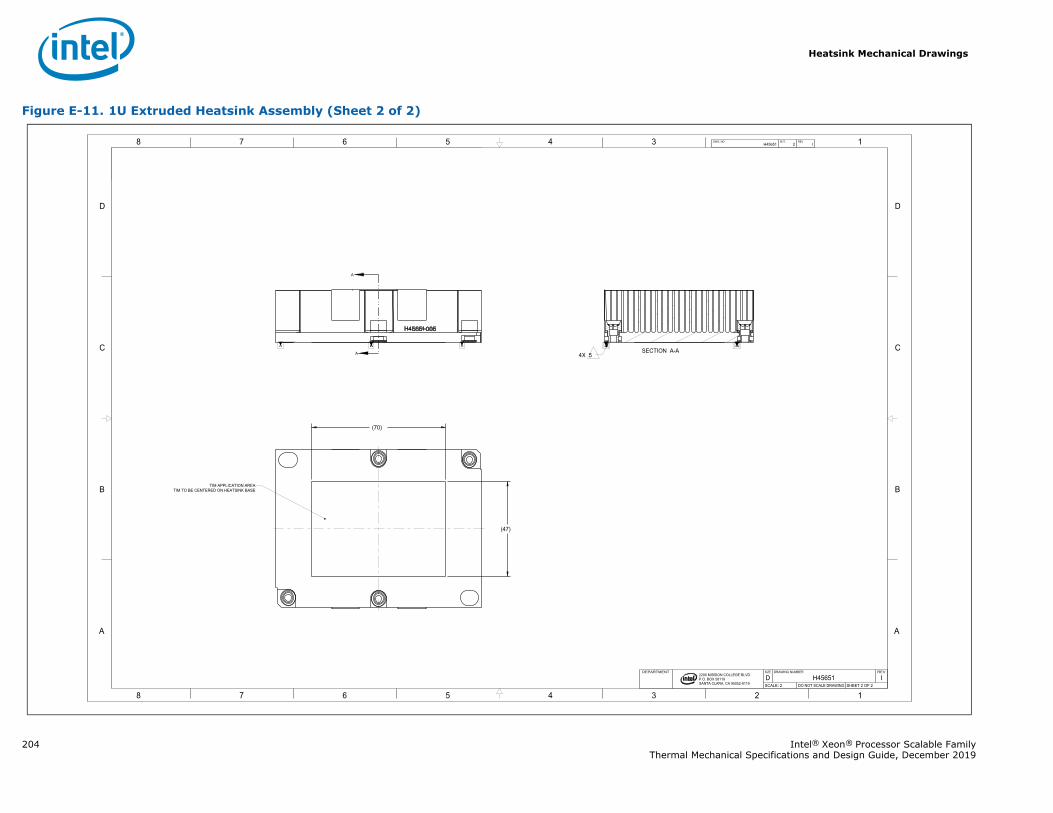
Heatsink Mechanical Drawings
204 Intel® Xeon® Processor Scalable FamilyThermal Mechanical Specifications and Design Guide, December 2019
Figure E-11. 1U Extruded Heatsink Assembly (Sheet 2 of 2)
A
A
1345678
B
C
D
A
12345678
B
C
D
A
2200 MISSION COLLEGE BLVD.P.O. BOX 58119SANTA CLARA, CA 95052-8119
R
A AAA AA AA
(47)
(70)
H45651 2 IDWG. NO SHT. REV
SHEET 2 OF 2DO NOT SCALE DRAWINGSCALE: 2IH45651D
REVDRAWING NUMBERSIZEDEPARTMENT
TIM TO BE CENTERED ON HEATSINK BASETIM APPLICATION AREA
SECTION A-A4X 5
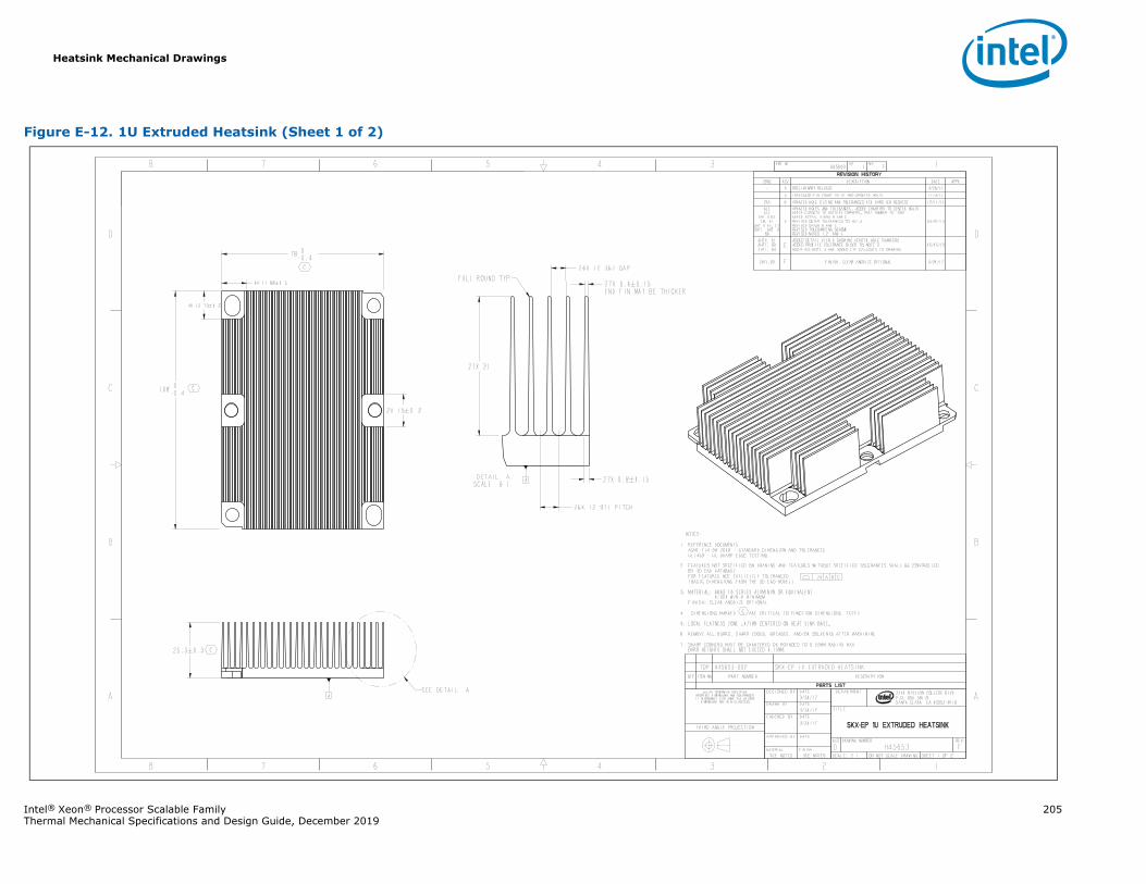
Heatsink Mechanical Drawings
Intel® Xeon® Processor Scalable Family 205Thermal Mechanical Specifications and Design Guide, December 2019
Figure E-12. 1U Extruded Heatsink (Sheet 1 of 2)
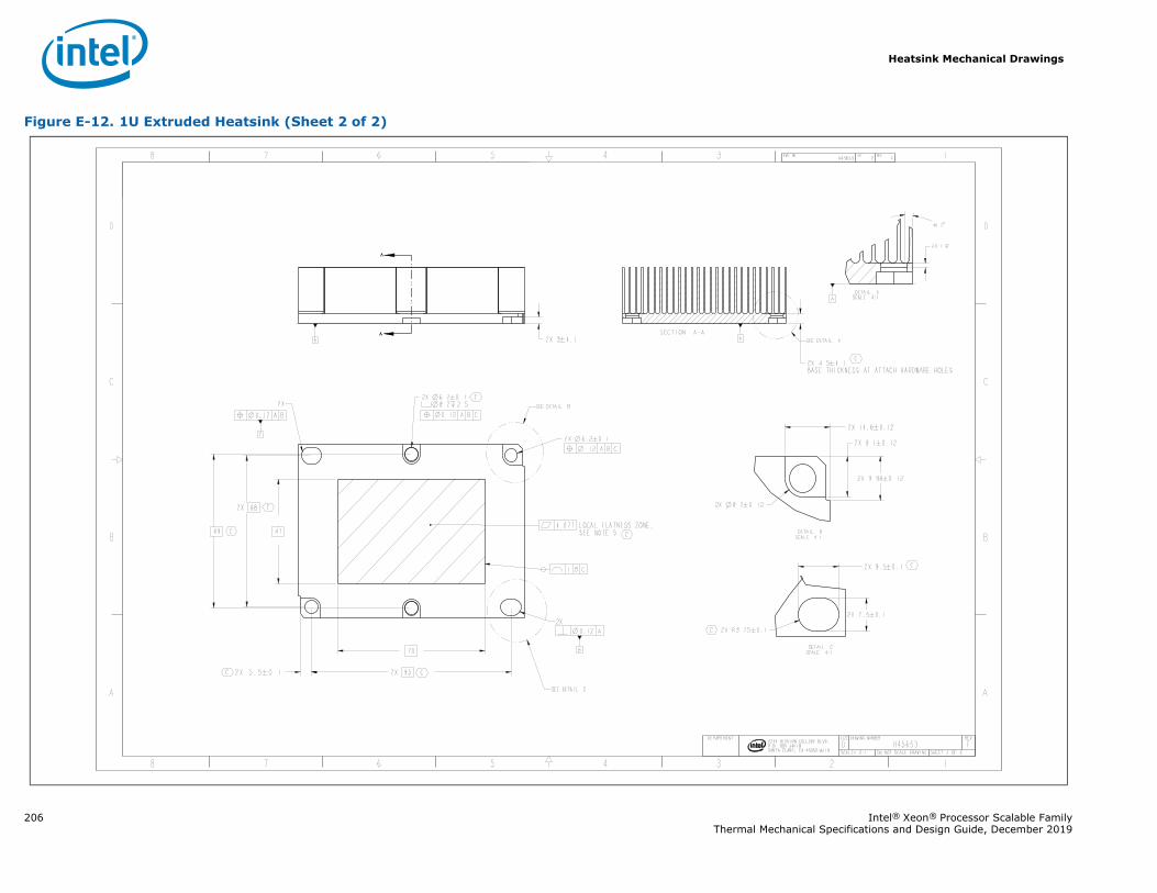
Heatsink Mechanical Drawings
206 Intel® Xeon® Processor Scalable FamilyThermal Mechanical Specifications and Design Guide, December 2019
Figure E-12. 1U Extruded Heatsink (Sheet 2 of 2)
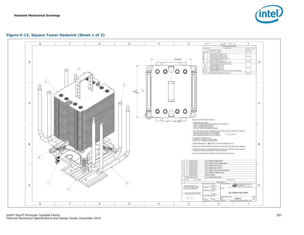
Heatsink Mechanical Drawings
Intel® Xeon® Processor Scalable Family 207Thermal Mechanical Specifications and Design Guide, December 2019
Figure E-13. Square Tower Heatsink (Sheet 1 of 2)
1345678
B
C
D
A
12345678
B
C
D
A 2200 MISSION COLLEGE BLVD.P.O. BOX 58119SANTA CLARA, CA 95052-8119
R
(10)
90 0-0.4
73.5±0.2
H49014 1 FDWG. NO SHT. REV
SHEET 1 OF 2DO NOT SCALE DRAWINGSCALE: 2:1FH49014D
REVDRAWING NUMBERSIZE
SQ TOWER HEATSINK
TITLE
DEPARTMENT
SEE NOTESSEE NOTESFINISHMATERIAL
--DATEAPPROVED BY
01/06/16
DATECHECKED BY
01/06/16DATEDRAWN BY
06/10/14DATEDESIGNED BY
UNLESS OTHERWISE SPECIFIED INTERPRET DIMENSIONS AND TOLERANCES IN ACCORDANCE WITH ASME Y14.5M-2009 MEET UL 1439 - UL SHARP EDGE TESTING DIMENSIONS ARE IN MILLIMETERS
THIRD ANGLE PROJECTION
REVISION HISTORYZONE REV DESCRIPTION DATE APPR
- A PRELIMINARY RELEASE 06/10/14SH1, C5SH2, B6 B UPDATED TOLERANCES 07/07/14
D8A5C5B8B3
C
ITEM 3 H50726-001 UPDATED TO -002ITEM 4 H50723-001 UPDATED TO -002ITEM 5 H50725-001 UPDATED TO -002ITEM 6 H50727-001 UPDATED TO -002UPDATED NOTES AND SYMBOLS IN NOTES.
06/15/15
B3A3D7
DTOP ASSY CHANGE TO -003ITEM 6 H50727-002 UPDATED TO -003 SHEET 2 TOLERANCE CHANGE 123.23 +0.50/-1.5
01/06/16
A3A3A3A3
SHT2 D7 SHT2 C5
E
TOP ASSEMBLY PART CHANGE TO -004H50586 CHANGE TO -002H50723 CHANGE TO -003H50725 CHANGE TO -003ADDED DIMENSION 119.23ADDED THREAD LOCK CALLOUT TO NOTE FOR 4 SCREWS
03/31/16
SHT2 D7 F MODIFIED TOLERANCES TO +0.5/-2.0 04/14/16
NOTES; UNLESS OTHERWISE SPECIFIED:
1. REFERENCE DOCUMENTSASME Y14.5M-2009 - STANDARD DIMENSION AND TOLERANCESUL1439 - UL SHARP EDGE TESTING164997 - INTEL MARKING STANDARDISO-11469 - MATERIAL MARKING STANDARD
2. FEATURES NOT SPECIFIED ON DRAWING AND FEATURES WITHOUT SPECIFIED TOLERANCESHALL BE CONTROLLED BY 3D CAD DATABASE.FOR FEATURES NOT EXPLICITLY TOLERANCED : (BASIC DIMENSIONS FROM THE 3D CAD MODEL).
3. CAST BASE: ALUMINUM ADC-12COPPER SLUG: COPPER, K=380 W/M-K MINFINS: QTY 58 , ALUMINUM, K=220 W/M-K MIN
4. DIMENSIONS MARKED ARE CRITICAL TO FUNCTION DIMENSION (CTF).
5. REMOVE ALL BURRS, SHARP EDGES, GREASES, AND/OR SOLVENTS AFTER FINAL ASSEMBLY.
6 BOTTOM SURFACE OF ALUMINUM BASE MUST BE PARALLEL TO DATUM A WITHIN .15MM, AS DEFINED BY THE BOTTOM SURFACE OF THE COPPER SLUG.
7 LOCAL FLATNESS ZONE OF 0.07MM ON COPPER SLUG BOTTOM SURFACE.
.24 A B C
1
2
3
4
5
7
6
C
C
PARTS LIST
DESCRIPTIONPART NUMBERITEM NOQTY
SQ TOWER HEAT SINKH49014-004TOPM3X5 SCREWH50732-00114SQ TOWER COPPER SLUGH50686-00221SQ TOWER FIN STACK ASSEMBLYH50726-00231SQ TOWER HEAT PIPE 1H50723-00342SQ TOWER HEAT PIPE 2H50725-00352SQ TOWER HS AL FRAME BASEH50727-00361SQ TOWER HS BRACKETH50781-00271
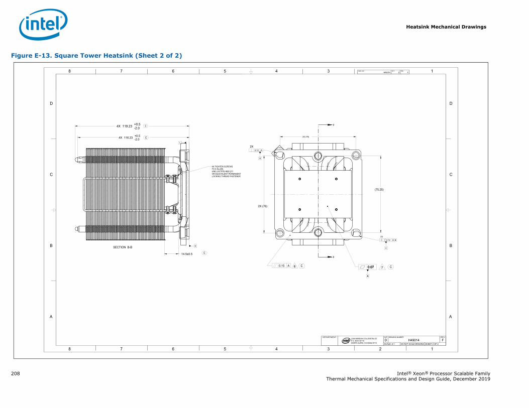
Heatsink Mechanical Drawings
208 Intel® Xeon® Processor Scalable FamilyThermal Mechanical Specifications and Design Guide, December 2019
Figure E-13. Square Tower Heatsink (Sheet 2 of 2)
B
B
1345678
B
C
D
A
12345678
B
C
D
A
A
0.07
B
C
2200 MISSION COLLEGE BLVD.P.O. BOX 58119SANTA CLARA, CA 95052-8119
R
A
0.070.15 A
0.12 A
0.12 A B
I
D
4X 116.23 +0.5-2.0
14.5±0.5
2X (79)
4X 119.23 +0.5-2.0
2X (76)
(75.25)
H49014 2 FDWG. NO SHT. REV
SHEET 2 OF 2DO NOT SCALE DRAWINGSCALE: 2:1FH49014D
REVDRAWING NUMBERSIZEDEPARTMENT
6 7
2X
2X
SECTION B-B
4X TIGHTEN SCREWSTO 8 IN-LBS,USE LOCTITE RED 271OR EQUIVALENT PERMANENTLOCKING THREAD FASTENER
C
C
CC
C
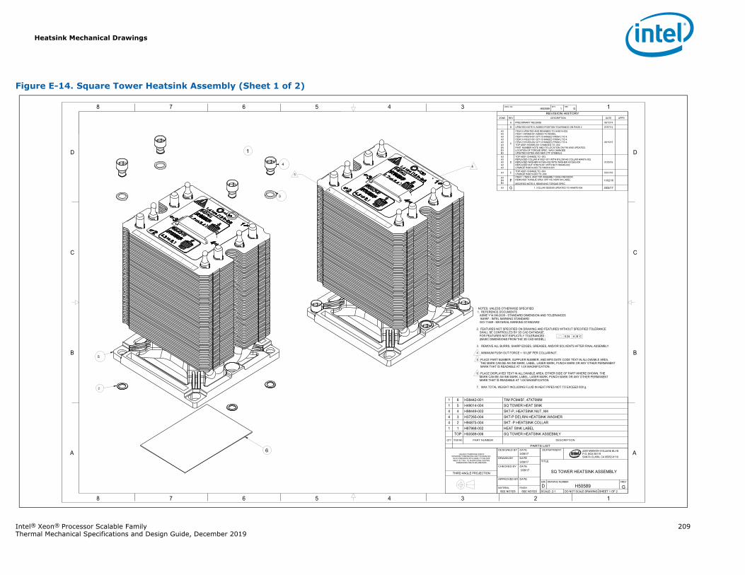
Heatsink Mechanical Drawings
Intel® Xeon® Processor Scalable Family 209Thermal Mechanical Specifications and Design Guide, December 2019
Figure E-14. Square Tower Heatsink Assembly (Sheet 1 of 2)
1345678
B
C
D
A
12345678
B
C
D
A 2200 MISSION COLLEGE BLVD.P.O. BOX 58119SANTA CLARA, CA 95052-8119
R
PRELIMINARY RELEASE 06/12/14
0.24 A B C
H50589 1 GDWG. NO SHT. REV
SHEET 1 OF 2DO NOT SCALE DRAWINGSCALE: 2:1GH50589D
REVDRAWING NUMBERSIZE
SQ TOWER HEATSINK ASSEMBLY
TITLE
DEPARTME
SEE NOTESSEE NOTESFINISHMATERIAL
-DATEAPPROVED BY
3/09/17DATECHECKED BY
3/09/17DATEDRAWN BY
3/09/17DATEDESIGNED BY
UNLESS OTHERWISE SPECIFINTERPRET DIMENSIONS AND TOLERANCES
IN ACCORDANCE WITH ASME Y14.5M-2009MEET UL 1439 - UL SHARP EDGE TESTING
DIMENSIONS ARE IN MILLIMETERS
THIRD ANGLE PROJECTION
PARTS LIST
DESCRIPTIONPART NUMBERITEM NOQTY
SQ TOWER HEATSINK ASSEBMLYH50589-006TOPHEAT SINK LABELH87868-00211SKT -P HEATSINK COLLARH94875-00424SKT-P DELRIN HEATSINK WASHERH37265-00434SKT-P, HEATSINK NUT, M4H98449-00344SQ TOWER HEAT SINKH49014-00451TIM PCM45F, 47X70MMH38442-00161
REVISION HISTORYZONE REV DESCRIPTION DATE APPR
A
- B UPDATED NOTE 6; ADDED POSITION TOLERANCE ON PAGE 2 07/07/14
A3A3A3A3A3A3D5D3B3
C
ITEM 5 UPDATED AND RENAMED TO H49014-002.ITEM 1 H87868-001 ADDED TO MODEL.ITEM 4 H78579-001 QTY CHANGED FROM 2 TO 4.ITEM 3 H19327-001 QTY CHANGED FROM 2 TO 4. ITEM 2 H37265-002 QTY CHANGED FROM 2 TO 4. TOP ASSY H50589-001 CHANGED TO -002.PART NUMBER NOTE AND ITS LOCATION ON FIN WAS UPDATED.LOCATION OF TORQUE SPEC WAS CHANGED.UPDATED NOTES AND NEW CTF SYMBOLS.
06/15/15
A3A3A3A3A3
D
TOP ASSY CHANGE TO -003.REPLACED COLLAR H19327-001 WITH NYLOM HS COLLAR H94875-002REPLACED WASHER H37265-002 WITH WASHER H37265-004REPLACED NUT H78579-001 WITH NUT H98449-002CHANGE H49014-002 TO H49014-003
01/05/16
A3 E TOP ASSY CHANGE TO -004CHANGE H49014-003 TO -004 03/31/16
A3D4B3
FITEM 1, ITEM 4, AND TOP ASSEMBLY DASH REVISIONREMOVED TORQUE SPEC OFF HS, NOW ON LABELMODIFIED NOTE 6, REMOVING TORQUE SPEC
11/02/16
A3 G 1. COLLAR DESIGN UPDATED TO H94875-004 3/03/17
NOTES; UNLESS OTHERWISE SPECIFIED:1. REFERENCE DOCUMENTS
ASME Y14.5M-2009 - STANDARD DIMENSION AND TOLERANCES164997 - INTEL MARKING STANDARDISO-11469 - MATERIAL MARKING STANDARD
2. FEATURES NOT SPECIFIED ON DRAWING AND FEATURES WITHOUT SPECIFIED TOLERANCESHALL BE CONTROLLED BY 3D CAD DATABASE.FOR FEATURES NOT EXPLICITLY TOLERANCED : (BASIC DIMENSIONS FROM THE 3D CAD MODEL)
3. REMOVE ALL BURRS, SHARP EDGES, GREASES, AND/OR SOLVENTS AFTER FINAL ASSEMBLY.
4. MINIMUM PUSH OUT FORCE = 10 LBF PER COLLAR/NUT.
5. PLACE PART NUMBER, SUPPLIER NUMBER, AND MFG DATE CODE TEXT IN ALLOWABLE AREA,THE MARK CAN BE AN INK MARK, LABEL, LASER MARK, PUNCH MARK OR ANY OTHER PERMANENTMARK THAT IS READABLE AT 1.0X MAGNIFICATION.
6. PLACE DISPLAYED TEXT IN ALLOWABLE AREA, EITHER SIDE OF PART WHERE SHOWN. THEMARK CAN BE AN INK MARK, LABEL, LASER MARK, PUNCH MARK OR ANY OTHER PERMANENTMARK THAT IS READABLE AT 1.0X MAGNIFICATION.
7. MAX TOTAL WEIGHT INCLUDING FLUID IN HEAT PIPES NOT TO EXCEED 600 g.
1
6
4
3
5
2
6
5
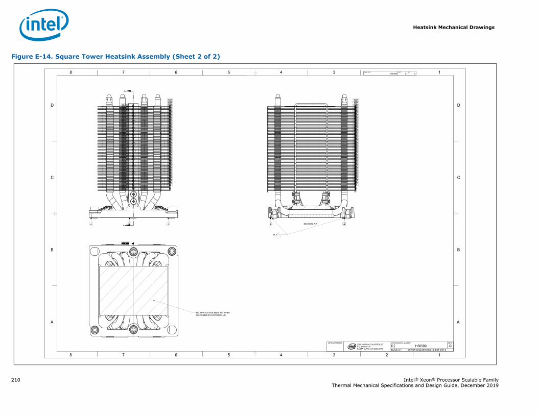
Heatsink Mechanical Drawings
210 Intel® Xeon® Processor Scalable FamilyThermal Mechanical Specifications and Design Guide, December 2019
Figure E-14. Square Tower Heatsink Assembly (Sheet 2 of 2)
A
A
1345678
B
C
D
A
12345678
B
C
D
A
2200 MISSION COLLEGE BLVD.P.O. BOX 58119SANTA CLARA, CA 95052-8119
R
TOP
FRONT
TOP
FRONT
TOP
FRONT
TOP
FRONT
TOP
FRONT
TOP
FRONT
TOP
FRONT
TOP
FRONT
TOP
FRONT
TOP
FRONT
TOP
FRONT
TOP
FRONT
TOP
FRONT
TOP
FRONT
TOP
FRONT
TOP
FRONT
TOP
FRONT
TOP
FRONT
TOP
FRONT
TOP
FRONT
TOP
FRONT
TOP
FRONT
TOP
FRONT
TOP
FRONT
TOP
FRONT
TOP
FRONT
TOP
FRONT
TOP
FRONT
TOP
FRONT
TOP
FRONT
TOP
FRONT
TOP
FRONT
TOP
FRONT
TOP
FRONT
TOP
FRONT
TOP
FRONT
TOP
FRONT
TOP
FRONT
TOP
FRONT
TOP
FRONT
TOP
FRONT
TOP
FRONT
TOP
FRONT
TOP
FRONT
TOP
FRONT
TOP
FRONT
TOP
FRONT
TOP
FRONT
TOP
FRONT
TOP
FRONT
TOP
FRONT
TOP
FRONT
TOP
FRONT
TOP
FRONT
TOP
FRONT
TOP
FRONT
TOP
FRONT
TOP
FRONT
AA AA
FRONTFRONTFRONTFRONTFRONTFRONTFRONTFRONTFRONTFRONTFRONTFRONTFRONTFRONTFRONTFRONTFRONTFRONTFRONTFRONTFRONTFRONTFRONTFRONTFRONTFRONTFRONTFRONTFRONTFRONTFRONTFRONTFRONTFRONTFRONTFRONTFRONT
TOPTOPTOPTOPTOPTOPTOPTOPTOPTOPTOPTOPTOPTOPTOPTOPTOPTOPTOPTOPTOPTOPTOPTOPTOPTOPTOPTOPTOPTOPTOPTOPTOPTOPTOPTOPTOPTOPTOPTOPTOPTOPTOPTOPTOPTOPTOPTOPTOPTOPTOPTOPTOPTOPTOPTOPTOPTOP
A AA A
H50589 2 GDWG. NO SHT. REV
SHEET 2 OF 2DO NOT SCALE DRAWINGSCALE: 2:1GH50589D
REVDRAWING NUMBERSIZEDEPARTMENT
TIM APPLICATION AREA TIM TO BECENTERED ON COPPER SLUG
SECTION A-A
4X 4
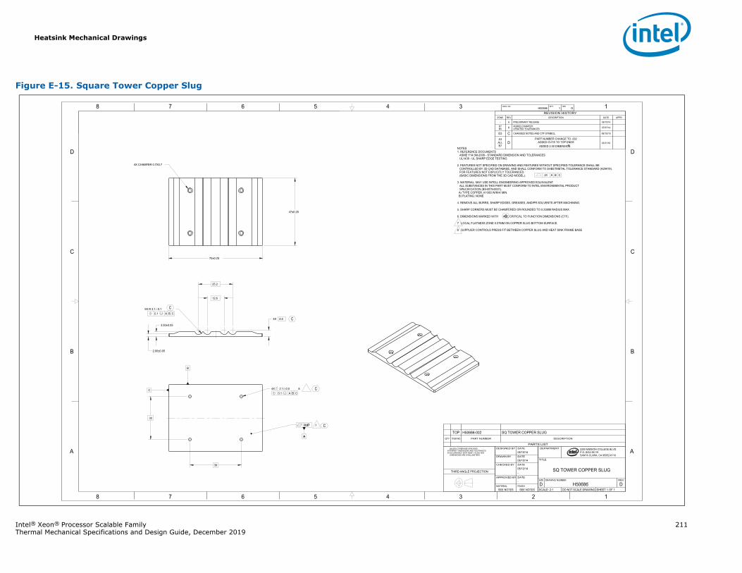
Heatsink Mechanical Drawings
Intel® Xeon® Processor Scalable Family 211Thermal Mechanical Specifications and Design Guide, December 2019
Figure E-15. Square Tower Copper Slug
1345678
B
C
D
A
12345678
B
C
D
A
A
0.07
2200 MISSION COLLEGE BLVD.P.O. BOX 58119SANTA CLARA, CA 95052-8119
R
A
0.07
B
C
70±0.25
4X 4.6
25.2
0.1 A B C5X R 3.1 0.1
0.1 A B C4X 82.1 0.5
38
30
47±0.25
2.00±0.05
12.6
3.50±0.05
H50686 1 DDWG. NO SHT. REV
SHEET 1 OF 1DO NOT SCALE DRAWINGSCALE: 2:1DH50686D
REVDRAWING NUMBERSIZE
SQ TOWER COPPER SLUG
TITLE
DEPARTMENT
SEE NOTESSEE NOTESFINISHMATERIAL
-DATEAPPROVED BY
-06/12/14DATECHECKED BY
06/10/14DATEDRAWN BY
06/10/14DATEDESIGNED BY UNLESS OTHERWISE SPECIFIED
INTERPRET DIMENSIONS AND TOLERANCES IN ACCORDANCE WITH ASME Y14.5M-1994 DIMENSIONS ARE IN MILLIMETERS
THIRD ANGLE PROJECTION
PARTS LIST
DESCRIPTIONPART NUMBERITEM NOQTY
SQ TOWER COPPER SLUGH50686-002TOP
REVISION HISTORYZONE REV DESCRIPTION DATE APPR
- A PRELIMINARY RELEASE 06/10/14
D7B5 B ADDED CHAMFER;
UPDATED TOLERANCES 07/07/14
D3 C CHANGED NOTES AND CTF SYMBOL. 06/15/15
A3ALLB7
DPART NUMBER CHANGE TO -002
ADDED CUTS TO TOP ENDSADDED 2.00 DIMENSION
03/31/16
NOTES1. REFERENCE DOCUMENTS ASME Y14.5M-2009 - STANDARD DIMENSION AND TOLERANCES UL1439 - UL SHARP EDGE TESTING
2. FEATURES NOT SPECIFIED ON DRAWING AND FEATURES WITHOUT SPECIFIED TOLERANCE SHALL BECONTROLLED BY 3D CAD DATABASE, AND SHALL CONFORM TO SHEETMETAL TOLERANCE STANDARD (A29419).FOR FEATURES NOT EXPLICITLY TOLERANCED :(BASIC DIMENSIONS FROM THE 3D CAD MODEL).
3. MATERIAL: MAY USE INTELL ENGINEERING APPROVED EQUIVALENT.ALL SUBSTANCES IN THIS PART MUST CONFORM TO INTEL ENVIRONMENTAL PRODUCTSPECIFICATION (BS-MTN-0001).A) TYPE COPPER, K=380 W/M-K MIN.B) PLATING: NONE
4. REMOVE ALL BURRS, SHARP EDGES, GREASES, AND/PR SOLVENTS AFTER MACHINING.
5. SHARP CORNERS MUST BE CHAMFERED OR ROUNDED TO 0.25MM RADIUS MAX.
6. DIMENSIONS MARKED WITH ARE CRITICAL TO FUNCTION DIMENSIONS (CTF).
7 LOCAL FLATNESS ZONE 0.07MM ON COPPER SLUG BOTTOM SURFACE.
8 SUPPLIER CONTROLS PRESS FIT BETWEEN COPPER SLUG AND HEAT SINK FRAME BASE
7
.24 A B C
4X CHAMFER 0.7X0.7
C
C
C
C
C
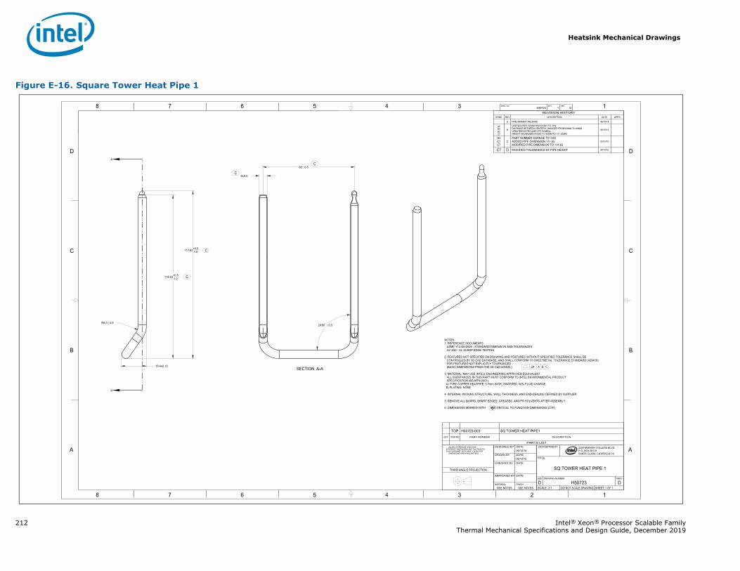
Heatsink Mechanical Drawings
212 Intel® Xeon® Processor Scalable FamilyThermal Mechanical Specifications and Design Guide, December 2019
Figure E-16. Square Tower Heat Pipe 1
A
A
1345678
B
C
D
A
12345678
B
C
D
A 2200 MISSION COLLEGE BLVD.P.O. BOX 58119SANTA CLARA, CA 95052-8119
R
114.63+0.5-1.0
18.4±0.15
R9.3 0.5
6±0.5
68 0.5
2X90 0.5
117.63+0.5-1.0
H50723 1 DDWG. NO SHT. REV
SHEET 1 OF 1DO NOT SCALE DRAWINGSCALE: 2:1DH50723D
REVDRAWING NUMBERSIZE
SQ TOWER HEAT PIPE 1
TITLE
DEPARTMENT
SEE NOTESSEE NOTESFINISHMATERIAL
-DATEAPPROVED BY
-
DATECHECKED BY
06/10/15DATEDRAWN BY
06/10/14DATEDESIGNED BY UNLESS OTHERWISE SPECIFIED
INTERPRET DIMENSIONS AND TOLERANCES IN ACCORDANCE WITH ASME Y14.5M-2009 DIMENSIONS ARE IN MILLIMETERS
THIRD ANGLE PROJECTION
PARTS LIST
DESCRIPTIONPART NUMBERITEM NOQTY
SQ TOWER HEAT PIPE1H50723-003TOP
REVISION HISTORYZONE REV DESCRIPTION DATE APPR
- A PRELIMINARY RELEASE 06/10/14
A3D5B3C7
B
UPDTED PART FROM H50723-001 TO -002.DISTANCE BETWEEN CENTERS CHANGED FROM 63MM TO 68MM.UPDATED NOTES AND CTF SYMBOL.HEIGHT INCREASED FROM 117.63MM TO 121.63MM
06/15/15
A3C7C7
CPART NUMBER CHANGE TO -003ADDED PIPE DIMENSION 117.63 MODIFIED PIPE DIMENSION TO 114.63
03/31/16
C7 D MODIFIED TOLERANCES OF PIPE HEIGHT 04/14/16
NOTES1. REFERENCE DOCUMENTS
ASME Y14.5M-2009 - STANDARD DIMENSION AND TOLERANCESUL1439 - UL SHARP EDGE TESTING
2. FEATURES NOT SPECIFIED ON DRAWING AND FEATURES WITHOUT SPECIFIED TOLERANCE SHALL BECONTROLLED BY 3D CAD DATABASE, AND SHALL CONFORM TO SHEETMETAL TOLERANCE STANDARD (A29419).FOR FEATURES NOT EXPLICITLY TOLERANCED :(BASIC DIMENSIONS FROM THE 3D CAD MODEL).
3. MATERIAL: MAY USE INTELL ENGINEERING APPROVED EQUIVALENT.ALL SUBSTANCES IN THIS PART MUST CONFORM TO INTEL ENVIRONMENTAL PRODUCTSPECIFICATION (BS-MTN-0001).A) TYPE COPPER HEATPIPE, 0.7mm WICK, SINTERED, 90% FLUID CHARGE.B) PLATING: NONE
4. INTERNAL WICKING STRUCTURE, WALL THICKNESS, AND END-SEALING DEFINED BY SUPPLIER.
5. REMOVE ALL BURRS, SHARP EDGES, GREASES, AND/PR SOLVENTS AFTER ASSEMBLY.
6. DIMENSIONS MARKED WITH ARE CRITICAL TO FUNCTION DIMENSIONS (CTF).
.24 A B CSECTION A-A
C
C
C
C
C
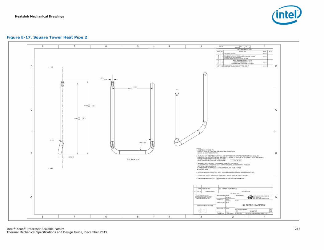
Heatsink Mechanical Drawings
Intel® Xeon® Processor Scalable Family 213Thermal Mechanical Specifications and Design Guide, December 2019
Figure E-17. Square Tower Heat Pipe 2
A
A
1345678
B
C
D
A
12345678
B
C
D
A 2200 MISSION COLLEGE BLVD.P.O. BOX 58119SANTA CLARA, CA 95052-8119
R
114.63+0.5-1.0
10.7±0.15
R9 0.5
6±0.5
68 0.5
2X90 0.5
117.63+0.5-1.0
H50725 1 DDWG. NO SHT. REV
SHEET 1 OF 1DO NOT SCALE DRAWINGSCALE: 2:1DH50725D
REVDRAWING NUMBERSIZE
SQ TOWER HEAT PIPE 2
TITLE
DEPARTMENT
SEE NOTESSEE NOTESFINISHMATERIAL
-DATEAPPROVED BY
-
DATECHECKED BY
06/10/15DATEDRAWN BY
06/10/14DATEDESIGNED BY UNLESS OTHERWISE SPECIFIED
INTERPRET DIMENSIONS AND TOLERANCES IN ACCORDANCE WITH ASME Y14.5M-2009 DIMENSIONS ARE IN MILLIMETERS
THIRD ANGLE PROJECTION
PARTS LIST
DESCRIPTIONPART NUMBERITEM NOQTY
SQ TOWER HEAT PIPE 2H50725-003TOP
REVISION HISTORYZONE REV DESCRIPTION DATE APPR
- A PRELIMINARY RELEASE 06/10/14
A3D5B3C7
B
UPDTED PART FROM H50725-001 TO -002.DISTANCE BETWEEN CENTERS CHANGED FROM 63MM TO 68MM.UPDATED NOTES AND CTF SYMBOL.HEIGHT INCREASED FROM 117.63MM TO 121.63MM
06/15/15
A3C7C7
CPART NUMBER CHANGE TO -003ADDED PIPE DIMENSION 117.63
MODIFIED PIPE DIMENSION TO 114.63 03/31/16
C7 D MODIFIED TOLERANCES OF PIPE HEIGHT 04/14/16
NOTES1. REFERENCE DOCUMENTS
ASME Y14.5M-2009 - STANDARD DIMENSION AND TOLERANCESUL1439 - UL SHARP EDGE TESTING
2. FEATURES NOT SPECIFIED ON DRAWING AND FEATURES WITHOUT SPECIFIED TOLERANCE SHALL BECONTROLLED BY 3D CAD DATABASE, AND SHALL CONFORM TO SHEETMETAL TOLERANCE STANDARD (A29419).FOR FEATURES NOT EXPLICITLY TOLERANCED :(BASIC DIMENSIONS FROM THE 3D CAD MODEL).
3. MATERIAL: MAY USE INTELL ENGINEERING APPROVED EQUIVALENT.ALL SUBSTANCES IN THIS PART MUST CONFORM TO INTEL ENVIRONMENTAL PRODUCTSPECIFICATION (BS-MTN-0001).A) TYPE COPPER HEATPIPE, 0.7mm WICK, SINTERED, 90% FLUID CHARGE.B) PLATING: NONE
4. INTERNAL WICKING STRUCTURE, WALL THICKNESS, AND END-SEALING DEFINED BY SUPPLIER.
5. REMOVE ALL BURRS, SHARP EDGES, GREASES, AND/PR SOLVENTS AFTER ASSEMBLY.
6. DIMENSIONS MARKED WITH ARE CRITICAL TO FUNCTION DIMENSIONS (CTF).
.24 A B CSECTION A-A
C
C
C
C
C
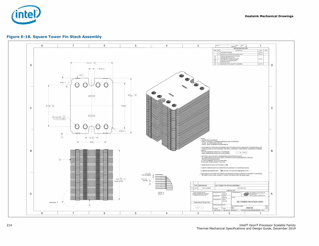
Heatsink Mechanical Drawings
214 Intel® Xeon® Processor Scalable FamilyThermal Mechanical Specifications and Design Guide, December 2019
Figure E-18. Square Tower Fin Stack Assembly
1345678
B
C
D
A
12345678
B
C
D
A 2200 MISSION COLLEGE BLVD.P.O. BOX 58119SANTA CLARA, CA 95052-8119
R
C
A
B
90 0-0.25
4X 68
0.1 A B C8X 6.2 0.05
73.5 0.1
75.25±0.1
2X 10 0.1
2X 50
FIN THICKNESS0.3 0.05
57 X 1.12FIN GAP58 PCS OF FIN
81.42 +0.5-1.2
2X 22
2X R5 0.1
4X 45 1
H50726 1 DDWG. NO SHT. REV
SHEET 1 OF 1DO NOT SCALE DRAWINGSCALE: 2:1DH50726D
REVDRAWING NUMBERSIZE
SQ TOWER FIN STACK ASSY
TITLE
DEPARTMENT
SEE NOTESSEE NOTESFINISHMATERIAL
-DATEAPPROVED BY
-06/10/15DATECHECKED BY
06/10/15DATEDRAWN BY
06/10/14DATEDESIGNED BY UNLESS OTHERWISE SPECIFIED
INTERPRET DIMENSIONS AND TOLERANCES IN ACCORDANCE WITH ASME Y14.5M-2009 DIMENSIONS ARE IN MILLIMETERS
THIRD ANGLE PROJECTION
REVISION HISTORYZONE REV DESCRIPTION DATE APPR
- A PRELIMINARY RELEASE 06/10/14
- B ADDED NOTCH FOR APPLYING SOLDER PASTE 07/07/14
B3A3A3
PARTB5A3
C
UPDATED NOTES AND NEW CTF SYMBOL.UPDATED H50726-001 TO -002UPDATED FIN QTY FROM 57 TO 58 PCS.HEAT PIPE HOLE LOCATION CHANGE.2X ADDED 10 CLEARANCE RADII.ADDED BOM TABLE
06/15/15
A6 D MODIFIED STACK HEIGHT TOLERANCE 04/14/16
NOTES1. REFERENCE DOCUMENTS ASME Y14.5M-2009 - STANDARD DIMENSION AND TOLERANCES UL1439 - UL SHARP EDGE TESTING A29419 - INTEL STANDARD FOR SHEETMETAL
2. FEATURES NOT SPECIFIED ON DRAWING AND FEATURES WITHOUT SPECIFIED TOLERANCE SHALL BECONTROLLED BY 3D CAD DATABASE, AND SHALL CONFORM TO SHEETMETAL TOLERANCE STANDARD
(A29419). FOR FEATURES NOT EXPLICITLY TOLERANCED : (BASIC DIMENSIONS FROM THE 3D CAD MODEL).
3. MATERIAL: MAY USE INTELL ENGINEERING APPROVED EQUIVALENT.ALL SUBSTANCES IN THIS PART MUST CONFORM TO INTEL ENVIRONMENTAL PRODUCTSPECIFICATION (BS-MTN-0001).
A) TYPE ALUMINUM 1100, K=220 W/M-K MIN.B) PLATING: NICKEL PLATED, 3~5um THK.
4. BURR HEIGHTS SHALL NOT EXCEED 0.15MM.
5. SHARP CORNERS MUST BE CHAMFERED OR ROUNDED TO 0.25MM RADIUS MAX.
6. DIMENSIONS MARKED WITH ARE CRITICAL TO FUNCTION DIMENSIONS (CTF).
8 MECHANICAL STITCHING OR CONNECTION REQUIRED ON SIDE SURFACE OF FIN ARRAY TO INCREASE FIN ARRAY STRUCTURAL STABILITY, OVERALL FIN HEIGHT MUST BE MAINTAINED.
.24 A B C
4X 8
SEE DETAIL A
SCALE 4:1DETAIL A
C
C
C
C
C
C
PARTS LIST
DESCRIPTIONPART NUMBERITEM NOQTY
SQ TOWER FIN STACK ASSEMBLYH50726-002TOP
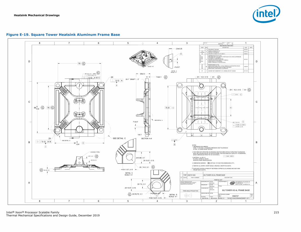
Heatsink Mechanical Drawings
Intel® Xeon® Processor Scalable Family 215Thermal Mechanical Specifications and Design Guide, December 2019
Figure E-19. Square Tower Heatsink Aluminum Frame Base
A
A
1345678
B
C
D
A
12345678
B
C
D
A
B
C
A
2200 MISSION COLLEGE BLVD.P.O. BOX 58119SANTA CLARA, CA 95052-8119
R
0.24 A B C
0.12 A
0.12 A B
0.12 A B C
0.25 A B C0.15 A
A
0.15
88 0-0.4 76
91 0-0.4
79
2X 6.2 0.12X 11.07 0.15
2X 9.98 0.12X 10.57 0.15
2X 7 0.1
2X 3.9 0.1
4X 4.5 0.1
26±0.3
7.8±0.1
7°±0.5°
1±0.1
75.25
38
4°±0.5°
2.8±0.25
2X 7.5 0.1
2X 9.5 0.1
2X 10.57 0.15
2X 12.07 0.15
2X R3.75 0.1
2X 2.58.2 0.12
30
4X 1.9 0.1
2X 3.08.2 0.12
2X THRU10.3 0.25 5.7
6.2 0.1
H50727 1 FDWG. NO SHT. REV
SHEET 1 OF 1DO NOT SCALE DRAWINGSCALE: 2:1FH50727D
REVDRAWING NUMBERSIZE
TITLE
SQ TOWER HS AL FRAME BASE
DEPARTMENT
SEE NOTESSEE NOTESFINISHMATERIAL
-DATEAPPROVED BY
-06/12/14DATECHECKED BY
06/10/14DATEDRAWN BY
06/10/14DATEDESIGNED BYUNLESS OTHERWISE SPECIFIED
INTERPRET DIMENSIONS AND TOLERANCES IN ACCORDANCE WITH ASME Y14.5-2009DIMENSIONS ARE IN MILLIMETERS
THIRD ANGLE PROJECTION
PARTS LIST
DESCRIPTIONPART NUMBERITEM NOQTY
SQ TOWER HS AL FRAME BASEH50727-003TOP
REVISION HISTORYZONE REV DESCRIPTION DATE APPR
- A PRELIMINARY RELEASE 06/10/14
C2C4;B2;B4 B ADDED FLATNESS OF 0.15;
UPDATED TOLERANCES 07/07/14
B4 C UPDATED FLATNESS TO 0.15, WAS 0.1 07/08/14
A3C8, B6C8, B6D6, B8B3MODELB5
D
CHANGED H50727-001 TO -002.REPLACED TWO SLOTS PER Ø 6.2 MM HOLES W/ Ø 8.2 MM COUNTERBORE.CUTS MADE TO 2 CORNERS.DATUMS B & C WERE RE DEFINED.UPDATED NOTES AND ADDED CTF SYMBOLS.ADDED DRAFTS TO THE MODELADDED CHAMFERS TO CENTER HOLES
06/15/15
A3ALLALLALL
EREVISED BASE TO -003ADDED ADDITIONAL WALL CUTOUT INSIDE OF 2X MOUNTING HOLESREDUCED MOUNTING HOLE OUTSIDE THICKNESSADDED DRAFT AND RADIUS TO UPRIGHTS
10/29/15
D7 F CHANGE TEXT DIAMETER TO 10.3, MODEL DID NOT CHANGE 01/11/16
NOTES1. REFERENCE DOCUMENTS
ASME Y14.5M-2009 - STANDARD DIMENSION AND TOLERANCESUL1439 - UL SHARP EDGE TESTING
2. FEATURES NOT SPECIFIED ON DRAWING AND FEATURES WITHOUT SPECIFIED TOLERANCESSHALL BE CONTROLLED BY 3D CAD DATA BASE. FOR FEATURES NOT EXPLICITY TOLERANCED:(BASIC DIMENSIONS FROM THE 3D CAD MODEL)
3. MATERIAL: AL ADC-12.PLATING: CHEMICAL NICKELSURFACE FINISH: BEAD BLASTED.
4. DIMENSIONS MARKED ARE CRITICAL TO FUNCTION DIMENSIONS (CTF).
5. REMOVE ALL BURRS, SHARP EDGES, GREASES, AND/PR SOLVENTS.
6 SUPPLIER CONTROLS PRESS FIT BETWEEN COPPER SLUG (H50686) AND HEAT SINK FRAME BASE (H50727).
2X
2X
SEE DETAIL CSEE DETAIL D
SCALE 4:1DETAIL C
SECTION A-A
2X 1 DRAFT .5
SEE DETAIL A
4X M3X0.5 THRU
0.15
SCALE 4:5
SCALE 4:1DETAIL A
6
SCALE 4:1DETAIL D
C
C
C
C
C
C
C
C
C
C
C
C
C
C
C
C
C
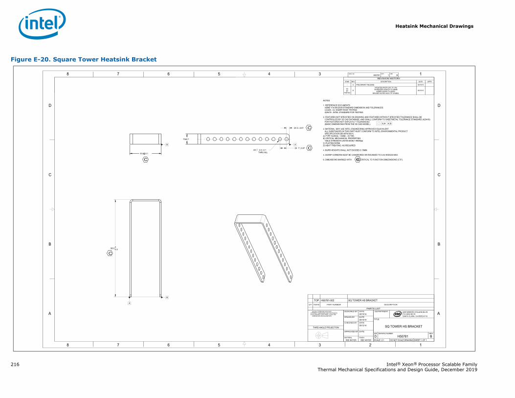
Heatsink Mechanical Drawings
216 Intel® Xeon® Processor Scalable FamilyThermal Mechanical Specifications and Design Guide, December 2019
Figure E-20. Square Tower Heatsink Bracket
1345678
B
C
D
A
12345678
B
C
D
A 2200 MISSION COLLEGE BLVD.P.O. BOX 58119SANTA CLARA, CA 95052-8119
R
0.24 A B
33.6 0.1
98.0 0-0.2
2X THRU ALL3.4 0.1
2X 7 0.07
2X 3 0.07
10±0.1
B
A
B
A
H50781 1 BDWG. NO SHT. REV
SHEET 1 OF 1DO NOT SCALE DRAWINGSCALE: 2:1BH50781D
REVDRAWING NUMBERSIZE
SQ TOWER HS BRACKET
TITLE
DEPARTMENT
SEE NOTESSEE NOTESFINISHMATERIAL
-DATEAPPROVED BY
-06/12/14DATECHECKED BY
06/10/14DATEDRAWN BY
06/10/14DATEDESIGNED BY UNLESS OTHERWISE SPECIFIED
INTERPRET DIMENSIONS AND TOLERANCES IN ACCORDANCE WITH ASME Y14.5M-1994 DIMENSIONS ARE MILLIMETERS
THIRD ANGLE PROJECTION
PARTS LIST
DESCRIPTIONPART NUMBERITEM NOQTY
Q TOWER HS BRACKETH50781-002TOP
REVISION HISTORYZONE REV DESCRIPTION DATE APPR
- A PRELIMINARY RELEASE 06/10/14
A3B7
PARTD3B
UPDATED H50781-001 TO -002INCREASED LENGTH TO 98MM
ADDED HOLES TO SIDES.REVISED NOTES AND CTF SYMBOL
06/15/15
NOTES
1. REFERENCE DOCUMENTSASME Y14.5M-2009-STANDARD DIMENSION AND TOLERANCESULI439 - UL SHARP EDGE TESTINGA29419 - INTEL STANDARD FOR TESTING
2. FEATURES NOT SPECIFIED ON DRAWING AND FEATURES WITHOUT SPECIFIED TOLERANCE SHALL BECONTROLLED BY 3D CAD DATABASE, AND SHALL CONFORM TO SHEETMETAL TOLERANCE STANDARD (A29419)FOR FEATURES NOT EXPLICITLY TOLERANCED:(BASIC DIMENSIONS FROM THE 3D CAD MODEL).
3. MATERIAL: MAY USE INTEL ENGINEERING APPROVED EQUIVALENT.ALL SUBSTANCES IN THIS PART MUST CONFORM TO INTEL ENVIRONMENTAL PRODUCTSPECIFICATION (BS-MTN-0001)
A) TYPE SUS304, 1.5MM .05 THK.B) CRITICAL MECHANICAL PROPERTIES:
YIELD STRENGTH (ASTM D638)>=900MpaC) PLATING:NONED) HEAT TREATING: AS REQUIRED
4. BURR HEIGHTS SHALL NOT EXCEED 0.15MM.
5. SHARP CORNERS MUST BE CHAMFERED OR ROUNDED TO 0.25 RADIUS MAX.
6. DIMENSIONS MARKED WITH ARE CRITICAL TO FUNCTION DIMESNSIONS (CTF).
C
C
C
C
C
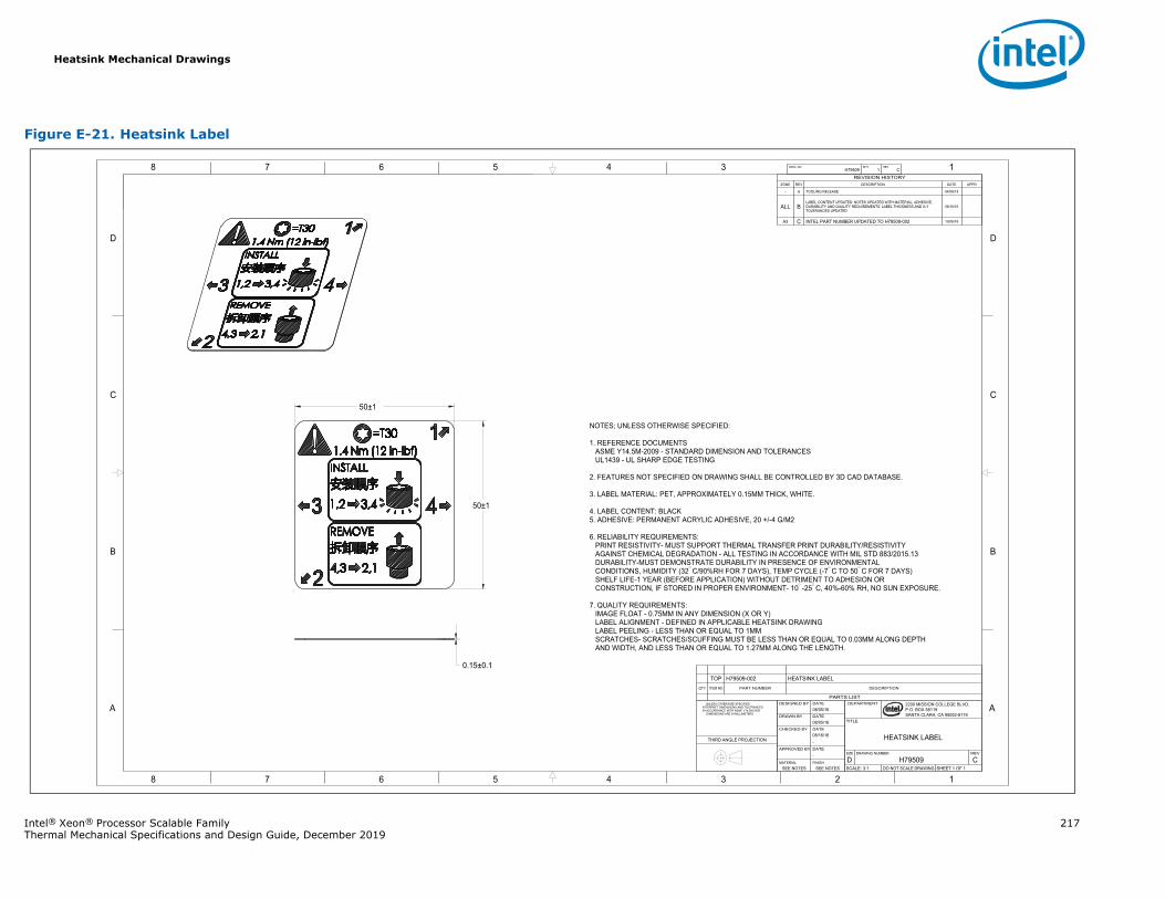
Heatsink Mechanical Drawings
Intel® Xeon® Processor Scalable Family 217Thermal Mechanical Specifications and Design Guide, December 2019
Figure E-21. Heatsink Label
1345678
B
C
D
A
12345678
B
C
D
A 2200 MISSION COLLEGE BLVD.P.O. BOX 58119SANTA CLARA, CA 95052-8119
R
0.15±0.1
50±1
50±1
H79509 1 CDWG. NO SHT. REV
SHEET 1 OF 1DO NOT SCALE DRAWINGSCALE: 3:1CH79509D
REVDRAWING NUMBERSIZE
HEATSINK LABEL
TITLE
DEPARTMENT
SEE NOTESSEE NOTESFINISHMATERIAL
-DATEAPPROVED BY
-08/16/16DATECHECKED BY
08/05/16DATEDRAWN BY
08/05/16DATEDESIGNED BY UNLESS OTHERWISE SPECIFIED
INTERPRET DIMENSIONS AND TOLERANCES IN ACCORDANCE WITH ASME Y14.5M-2009 DIMENSIONS ARE IN MILLIMETERS
THIRD ANGLE PROJECTION
PARTS LIST
DESCRIPTIONPART NUMBERITEM NOQTY
HEATSINK LABELH79509-002TOP
REVISION HISTORYZONE REV DESCRIPTION DATE APPR
- A TOOLING RELEASE 04/06/15
ALL BLABEL CONTENT UPDATED: NOTES UPDATED WITH MATERIAL, ADHESIVE,DURABILITY AND QUALITY REQUIREMENTS; LABEL THICKNESS AND X-YTOLERANCES UPDATED
08/16/16
A3 C INTEL PART NUMBER UPDATED TO H79509-002 10/06/16
NOTES; UNLESS OTHERWISE SPECIFIED:
1. REFERENCE DOCUMENTSASME Y14.5M-2009 - STANDARD DIMENSION AND TOLERANCESUL1439 - UL SHARP EDGE TESTING
2. FEATURES NOT SPECIFIED ON DRAWING SHALL BE CONTROLLED BY 3D CAD DATABASE.
3. LABEL MATERIAL: PET, APPROXIMATELY 0.15MM THICK, WHITE.
4. LABEL CONTENT: BLACK5. ADHESIVE: PERMANENT ACRYLIC ADHESIVE, 20 +/-4 G/M2
6. RELIABILITY REQUIREMENTS:PRINT RESISTIVITY- MUST SUPPORT THERMAL TRANSFER PRINT DURABILITY/RESISTIVITYAGAINST CHEMICAL DEGRADATION - ALL TESTING IN ACCORDANCE WITH MIL STD 883/2015.13DURABILITY-MUST DEMONSTRATE DURABILITY IN PRESENCE OF ENVIRONMENTALCONDITIONS, HUMIDITY (32 C/90%RH FOR 7 DAYS), TEMP CYCLE (-7 C TO 50 C FOR 7 DAYS)SHELF LIFE-1 YEAR (BEFORE APPLICATION) WITHOUT DETRIMENT TO ADHESION ORCONSTRUCTION, IF STORED IN PROPER ENVIRONMENT- 10 -25 C, 40%-60% RH, NO SUN EXPOSURE.
7. QUALITY REQUIREMENTS:IMAGE FLOAT - 0.75MM IN ANY DIMENSION (X OR Y)LABEL ALIGNMENT - DEFINED IN APPLICABLE HEATSINK DRAWINGLABEL PEELING - LESS THAN OR EQUAL TO 1MMSCRATCHES- SCRATCHES/SCUFFING MUST BE LESS THAN OR EQUAL TO 0.03MM ALONG DEPTHAND WIDTH, AND LESS THAN OR EQUAL TO 1.27MM ALONG THE LENGTH.
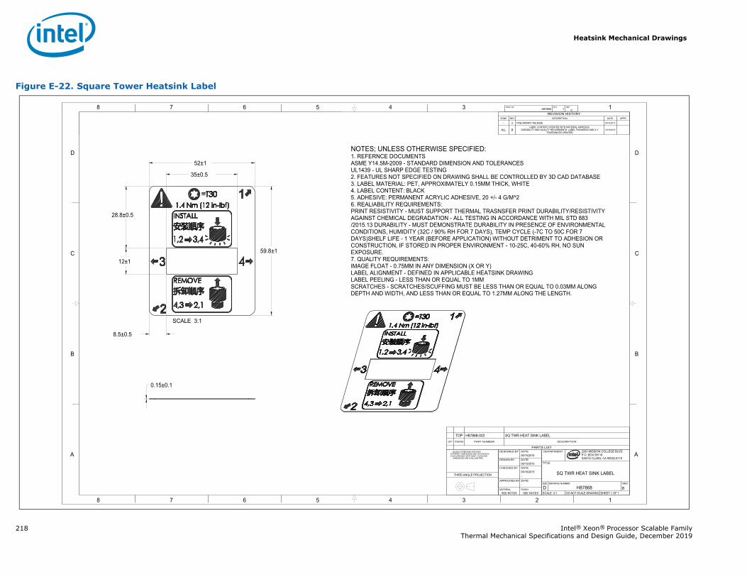
Heatsink Mechanical Drawings
218 Intel® Xeon® Processor Scalable FamilyThermal Mechanical Specifications and Design Guide, December 2019
Figure E-22. Square Tower Heatsink Label
1345678
B
C
D
A
12345678
B
C
D
A
59.8±1
52±1
35±0.5
12±1
0.15±0.1
28.8±0.5
8.5±0.5
H87868 1 BDWG. NO SHT. REV
SHEET 1 OF 1DO NOT SCALE DRAWINGSCALE: 3:1BH87868DREVDRAWING NUMBERSIZE
SQ TWR HEAT SINK LABEL
TITLE
DEPARTMENT
SEE NOTESSEE NOTESFINISHMATERIAL
-DATEAPPROVED BY
-06/16/2015DATECHECKED BY
06/15/2015DATEDRAWN BY
06/15/2015DATEDESIGNED BY UNLESS OTHERWISE SPECIFIED
INTERPRET DIMENSIONS AND TOLERANCES IN ACCORDANCE WITH ASME Y14.5M-2009 DIMENSIONS ARE IN MILLIMETERS
THIRD ANGLE PROJECTION
PARTS LIST
DESCRIPTIONPART NUMBERITEM NOQTY
SQ TWR HEAT SINK LABELH87868-002TOP
REVISION HISTORYZONE REV DESCRIPTION DATE APPR
- A PRELIMINARY RELEASE 05/16/2015
ALL BLABEL CONTENT UPDATED WITH MATERIAL ADHESIVE,
DURABILITY AND QUALITY REQUIRMENTS: LABEL THICKNESS AND X-YTOLERANCES UPDATED
10/19/2016
NOTES; UNLESS OTHERWISE SPECIFIED:1. REFERNCE DOCUMENTSASME Y14.5M-2009 - STANDARD DIMENSION AND TOLERANCESUL1439 - UL SHARP EDGE TESTING2. FEATURES NOT SPECIFIED ON DRAWING SHALL BE CONTROLLED BY 3D CAD DATABASE3. LABEL MATERIAL: PET, APPROXIMATELY 0.15MM THICK, WHITE4. LABEL CONTENT: BLACK5. ADHESIVE: PERMANENT ACRYLIC ADHESIVE, 20 +/- 4 G/M^26. REALIABILITY REQUIREMENTS:PRINT RESISTIVITY - MUST SUPPORT THERMAL TRASNSFER PRINT DURABILITY/RESISTIVITYAGAINST CHEMICAL DEGRADATION - ALL TESTING IN ACCORDANCE WITH MIL STD 883/2015.13 DURABILITY - MUST DEMONSTRATE DURABILITY IN PRESENCE OF ENVIRONMENTALCONDITIONS, HUMIDITY (32C / 90% RH FOR 7 DAYS), TEMP CYCLE (-7C TO 50C FOR 7DAYS)SHELF LIFE - 1 YEAR (BEFORE APPLICATION) WITHOUT DETRIMENT TO ADHESION ORCONSTRUCTION, IF STORED IN PROPER ENVIRONMENT - 10-25C, 40-60% RH, NO SUNEXPOSURE.7. QUALITY REQUIREMENTS:IMAGE FLOAT - 0.75MM IN ANY DIMENSION (X OR Y)LABEL ALIGNMENT - DEFINED IN APPLICABLE HEATSINK DRAWINGLABEL PEELING - LESS THAN OR EQUAL TO 1MMSCRATCHES - SCRATCHES/SCUFFING MUST BE LESS THAN OR EQUAL TO 0.03MM ALONGDEPTH AND WIDTH, AND LESS THAN OR EQUAL TO 1.27MM ALONG THE LENGTH.
SCALE 3:1
2200 MISSION COLLEGE BLVD.P.O. BOX 58119SANTA CLARA, CA 95052-8119
R
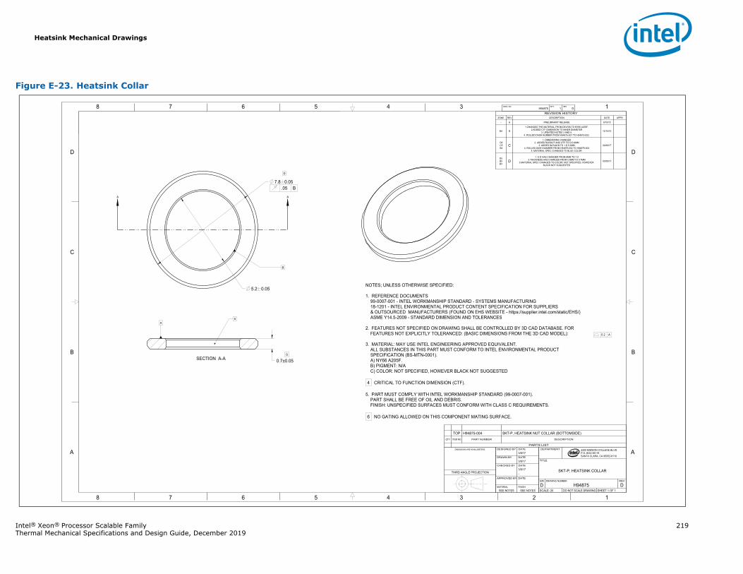
Heatsink Mechanical Drawings
Intel® Xeon® Processor Scalable Family 219Thermal Mechanical Specifications and Design Guide, December 2019
Figure E-23. Heatsink Collar
A A
1345678
B
C
D
A
12345678
B
C
D
A
B
2200 MISSION COLLEGE BLVD.P.O. BOX 58119SANTA CLARA, CA 95052-8119
R
0.2 A
0.7±0.05
5.2 0.05
.05 B7.8 0.05
A
H94875 1 DDWG. NO SHT. REV
SHEET 1 OF 1DO NOT SCALE DRAWINGSCALE: 25DH94875D
REVDRAWING NUMBERSIZE
SKT-P, HEATSINK COLLAR
TITLE
DEPARTMENT
SEE NOTESSEE NOTESFINISHMATERIAL
DATEAPPROVED BY
-3/8/17DATECHECKED BY
3/8/17DATEDRAWN BY
3/8/17DATEDESIGNED BYDIMENSIONS ARE IN MILLIMETERS.
THIRD ANGLE PROJECTION
PARTS LIST
DESCRIPTIONPART NUMBERITEM NOQTY
SKT-P, HEATSINK NUT COLLAR (BOTTOMSIDE)H94875-004TOP
REVISION HISTORYZONE REV DESCRIPTION DATE APPR
- A PRELIMINARY RELEASE 9/10/15
B4 B
1.CHANGED THE MATERIAL FROM DELRIN TO NY66 A205F.2.ADDED CTF DIMENSION TO INNER DIAMETER
3. UPDATED NOTES 3 AND 5.4. ROLLED DASH NUMBER FROM H94875-001 TO H94875-002.
12/15/15
D5 C5 B4
C1. DIMENSIONS CHANGED
2. ADDED RUNOUT AND CTF TO O.D 8MM3. ADDED DATUM B TO 1.D 5.2MM
4. ROLLED DASH NUMBER FROM H94875-002 TO H94875-0035. MATERIAL SPEC CHANGED TO BLUE COLOR.
02/06/17
D5B5B3
D1. O.D HAS CHANGED FROM 8MM TO 7.8
2.THICKNESS HAS CHANGED FROM 0.5MM TO 0.7MM3.MATERIAL SPEC CHANGED TO COLOR: NOT SPECIFIED, HOWEVER
BLACK NOT SUGGESTED
03/08/17
NOTES; UNLESS OTHERWISE SPECIFIED:
1. REFERENCE DOCUMENTS99-0007-001 - INTEL WORKMANSHIP STANDARD - SYSTEMS MANUFACTURING18-1201 - INTEL ENVIRONMENTAL PRODUCT CONTENT SPECIFICATION FOR SUPPLIERS& OUTSOURCED MANUFACTURERS (FOUND ON EHS WEBSITE - https://supplier.intel.com/static/EHS/)ASME Y14.5-2009 - STANDARD DIMENSION AND TOLERANCES
2. FEATURES NOT SPECIFIED ON DRAWING SHALL BE CONTROLLED BY 3D CAD DATABASE. FORFEATURES NOT EXPLICITLY TOLERANCED: (BASIC DIMENSIONS FROM THE 3D CAD MODEL):
3. MATERIAL: MAY USE INTEL ENGINEERING APPROVED EQUIVALENT.ALL SUBSTANCES IN THIS PART MUST CONFORM TO INTEL ENVIRONMENTAL PRODUCTSPECIFICATION (BS-MTN-0001).A) NY66 A205F.B) PIGMENT: N/AC) COLOR: NOT SPECIFIED, HOWEVER BLACK NOT SUGGESTED
4 CRITICAL TO FUNCTION DIMENSION (CTF).
5. PART MUST COMPLY WITH INTEL WORKMANSHIP STANDARD (99-0007-001).PART SHALL BE FREE OF OIL AND DEBRIS.FINISH: UNSPECIFIED SURFACES MUST CONFORM WITH CLASS C REQUIREMENTS.
6 NO GATING ALLOWED ON THIS COMPONENT MATING SURFACE.
6
D
DSECTION A-A
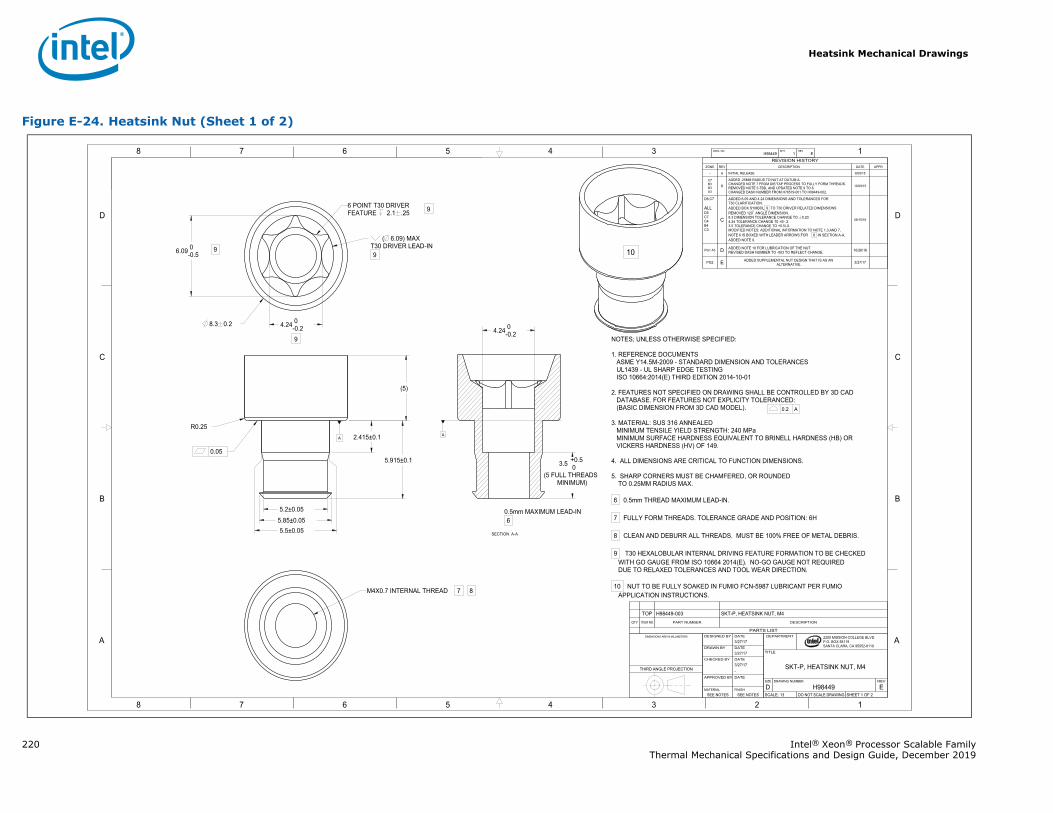
Heatsink Mechanical Drawings
220 Intel® Xeon® Processor Scalable FamilyThermal Mechanical Specifications and Design Guide, December 2019
Figure E-24. Heatsink Nut (Sheet 1 of 2)
1345678
B
C
D
A
12345678
B
C
D
A 2200 MISSION COLLEGE BLVD.P.O. BOX 58119SANTA CLARA, CA 95052-8119
R
0.2 A
0.05
8.3 0.2
2.415±0.1
5.915±0.1
5.5±0.05
(5 FULL THREADSMINIMUM)
3.5 +0.5 0
4.24 0-0.2
5.2±0.055.85±0.05
R0.25
4.24 0-0.2
6.09 0-0.5
AA
( 6.09) MAXT30 DRIVER LEAD-IN9
(5)
H98449 1 EDWG. NO SHT. REV
SHEET 1 OF 2DO NOT SCALE DRAWINGSCALE: 13EH98449D
REVDRAWING NUMBERSIZE
SKT-P, HEATSINK NUT, M4
TITLE
DEPARTMENT
SEE NOTESSEE NOTESFINISHMATERIAL
DATEAPPROVED BY
-3/27/17DATECHECKED BY
3/27/17DATEDRAWN BY
3/27/17DATEDESIGNED BYDIMENSIONS ARE IN MILLIMETERS
THIRD ANGLE PROJECTION
PARTS LIST
DESCRIPTIONPART NUMBERITEM NOQTY
SKT-P, HEATSINK NUT, M4H98449-003TOP
REVISION HISTORYZONE REV DESCRIPTION DATE APPR
- A INITIAL RELEASE 8/05/15
C7B3B3A3
B
ADDED .25MM RADIUS TO NUT AT DATUM A.CHANGED NOTE 7 FROM DIE/TAP PROCESS TO FULLY FORM THREADS.REMOVED NOTE 5-TBD, AND UPDATED NOTE 9 TO 8.CHANGED DASH NUMBER FROM H78579-001 TO H98449-002.
10/09/15
D8,C7
ALLD5C7C4B4C3
C
ADDED 6.09 AND 4.24 DIMENSIONS AND TOLERANCES FOR T30 CLARIFICATION.ADDED BOX SYMBOL 9 TO T30 DRIVER RELATED DIMENSIONSREMOVED 120 ANGLE DIMENSION.8.3 DIMENSION TOLERANCE CHANGE TO 0.20.4.24 TOLERANCE CHANGE T0 +0/-.2.3.5 TOLERANCE CHANGE TO +0.5/-0.MODIFIED NOTES: ADDITIONAL INFORMATION TO NOTE 1,3,AND 7,NOTE 6 IS BOXED WITH LEADER ARROWS FOR 6 IN SECTION A-A,ADDED NOTE 9.
08/15/16
PG1 A3 D ADDED NOTE 10 FOR LUBRICATION OF THE NUT. REVISED DASH NUMBER TO -003 TO REFLECT CHANGE. 10/26/16
PG2 E ADDED SUPPLEMENTAL NUT DESIGN THAT IS AS AN ALTERNATIVE. 3/27/17
NOTES; UNLESS OTHERWISE SPECIFIED:
1. REFERENCE DOCUMENTSASME Y14.5M-2009 - STANDARD DIMENSION AND TOLERANCESUL1439 - UL SHARP EDGE TESTINGISO 10664:2014(E) THIRD EDITION 2014-10-01
2. FEATURES NOT SPECIFIED ON DRAWING SHALL BE CONTROLLED BY 3D CADDATABASE. FOR FEATURES NOT EXPLICITY TOLERANCED:(BASIC DIMENSION FROM 3D CAD MODEL).
3. MATERIAL: SUS 316 ANNEALEDMINIMUM TENSILE YIELD STRENGTH: 240 MPaMINIMUM SURFACE HARDNESS EQUIVALENT TO BRINELL HARDNESS (HB) ORVICKERS HARDNESS (HV) OF 149.
4. ALL DIMENSIONS ARE CRITICAL TO FUNCTION DIMENSIONS.
5. SHARP CORNERS MUST BE CHAMFERED, OR ROUNDEDTO 0.25MM RADIUS MAX.
6 0.5mm THREAD MAXIMUM LEAD-IN.
7 FULLY FORM THREADS. TOLERANCE GRADE AND POSITION: 6H
8 CLEAN AND DEBURR ALL THREADS. MUST BE 100% FREE OF METAL DEBRIS.
9 T30 HEXALOBULAR INTERNAL DRIVING FEATURE FORMATION TO BE CHECKED WITH GO GAUGE FROM ISO 10664 2014(E). NO-GO GAUGE NOT REQUIRED DUE TO RELAXED TOLERANCES AND TOOL WEAR DIRECTION.
10 NUT TO BE FULLY SOAKED IN FUMIO FCN-5987 LUBRICANT PER FUMIO APPLICATION INSTRUCTIONS.
9
9
9 10
6 POINT T30 DRIVERFEATURE 2.1 .25
M4X0.7 INTERNAL THREAD 7 8
SECTION A-A
0.5mm MAXIMUM LEAD-IN 6
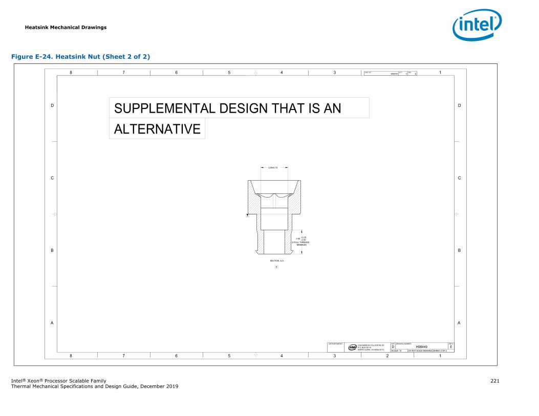
Heatsink Mechanical Drawings
Intel® Xeon® Processor Scalable Family 221Thermal Mechanical Specifications and Design Guide, December 2019
Figure E-24. Heatsink Nut (Sheet 2 of 2)
1345678
B
C
D
A
12345678
B
C
D
A
2200 MISSION COLLEGE BLVD.P.O. BOX 58119SANTA CLARA, CA 95052-8119
R
(5 FULL THREADS MINIMUM)
4.05 +0.35-0.05
4.05±0.15
A
H98449 2 EDWG. NO SHT. REV
SHEET 2 OF 2DO NOT SCALE DRAWINGSCALE: 13EH98449D
REVDRAWING NUMBERSIZEDEPARTMENT
E
SUPPLEMENTAL DESIGN THAT IS AN ALTERNATIVE
SECTION A-A
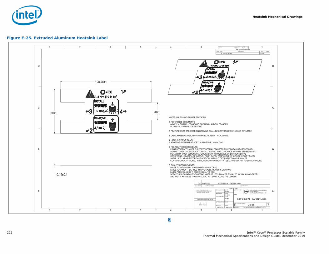
Heatsink Mechanical Drawings
222 Intel® Xeon® Processor Scalable FamilyThermal Mechanical Specifications and Design Guide, December 2019
§
Figure E-25. Extruded Aluminum Heatsink Label
1345678
B
C
D
A
12345678
B
C
D
A 2200 MISSION COLLEGE BLVD.P.O. BOX 58119SANTA CLARA, CA 95052-8119
R
20±1
108.28±1
50±1
0.15±0.1
J45423 1 ADWG. NO SHT. REV
SHEET 1 OF 1DO NOT SCALE DRAWINGSCALE: 3:1AJ45423D
REVDRAWING NUMBERSIZE
EXTRUDED AL HEATSINK LABEL
TITLE
DEPARTMENT
SEE NOTESSEE NOTESFINISHMATERIAL
-DATEAPPROVED BY
-10/24/16DATECHECKED BY
10/124/16DATEDRAWN BY
10/24/16DATEDESIGNED BY UNLESS OTHERWISE SPECIFIED
INTERPRET DIMENSIONS AND TOLERANCES IN ACCORDANCE WITH ASME Y14.5M-2009 DIMENSIONS ARE IN MILLIMETERS
THIRD ANGLE PROJECTION
PARTS LIST
DESCRIPTIONPART NUMBERITEM NOQTY
EXTRUDED AL HEATSINK LABELJ45423-001TOP
REVISION HISTORYZONE REV DESCRIPTION DATE APPR
- A TOOLING RELEASE 10/24/16
NOTES; UNLESS OTHERWISE SPECIFIED:
1. REFERENCE DOCUMENTSASME Y14.5M-2009 - STANDARD DIMENSION AND TOLERANCESUL1439 - UL SHARP EDGE TESTING
2. FEATURES NOT SPECIFIED ON DRAWING SHALL BE CONTROLLED BY 3D CAD DATABASE.
3. LABEL MATERIAL: PET, APPROXIMATELY 0.15MM THICK, WHITE.
4. LABEL CONTENT: BLACK5. ADHESIVE: PERMANENT ACRYLIC ADHESIVE, 20 +/-4 G/M2
6. RELIABILITY REQUIREMENTS:PRINT RESISTIVITY- MUST SUPPORT THERMAL TRANSFER PRINT DURABILITY/RESISTIVITYAGAINST CHEMICAL DEGRADATION - ALL TESTING IN ACCORDANCE WITH MIL STD 883/2015.13DURABILITY-MUST DEMONSTRATE DURABILITY IN PRESENCE OF ENVIRONMENTALCONDITIONS, HUMIDITY (32 C/90%RH FOR 7 DAYS), TEMP CYCLE (-7 C TO 50 C FOR 7 DAYS)SHELF LIFE-1 YEAR (BEFORE APPLICATION) WITHOUT DETRIMENT TO ADHESION ORCONSTRUCTION, IF STORED IN PROPER ENVIRONMENT- 10 -25 C, 40%-60% RH, NO SUN EXPOSURE.
7. QUALITY REQUIREMENTS:IMAGE FLOAT - 0.75MM IN ANY DIMENSION (X OR Y)LABEL ALIGNMENT - DEFINED IN APPLICABLE HEATSINK DRAWINGLABEL PEELING - LESS THAN OR EQUAL TO 1MMSCRATCHES- SCRATCHES/SCUFFING MUST BE LESS THAN OR EQUAL TO 0.03MM ALONG DEPTHAND WIDTH, AND LESS THAN OR EQUAL TO 1.27MM ALONG THE LENGTH.
Mechanical KOZs Drawings
Intel® Xeon® Processor Scalable Family 223Thermal Mechanical Specifications and Design Guide, December 2019
F Mechanical KOZs Drawings
F.1 Main Board Mechanical KOZsProcessor Heatsink Module (PHM) Keep-Out Zones are included in this chapter. Table F-1 lists the mechanical drawings included in this chapter-
Table F-1. Mechanical Keep-Out Zone Drawing List
Description Figure
KOZ: PHM 6 Holes Figure F-1
KOZ: PHM Narrow Backplate Figure F-2
KOZ: PHM Narrow Master Figure F-3
KOZ: PHM 7 Holes Figure F-4
KOZ: PHM Square Top Figure F-5
KOZ:PHM Square Backplate Figure F-6
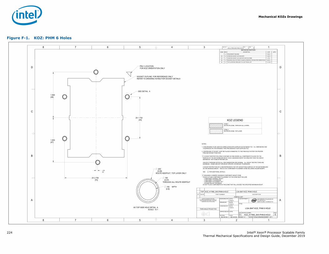
Mechanical KOZs Drawings
224 Intel® Xeon® Processor Scalable FamilyThermal Mechanical Specifications and Design Guide, December 2019
Figure F-1. KOZ: PHM 6 Holes
1345678
B
C
D
A
12345678
B
C
D
A 2200 MISSION COLLEGE BLVD.P.O. BOX 58119SANTA CLARA, CA 95052-8119
R
2X 2.756[70]
.150 NPTH[3.8]
.180[4.57]
THROUGH ALL ROUTE KEEPOUT
.200[5.08]
ROUTE KEEPOUT, TOP LAYER ONLY
2X 1.732[44]
1.890[48]
1.850[47]
.079[2]
KOZ_H17965_SKX-PHM-6-HOLE 1 EDWG. NO SHT. REV
SHEET 1 OF 1DO NOT SCALE DRAWINGSCALE: 3:1EKOZ_H17965_SKX-PHM-6-HOLED
REVDRAWING NUMBERSIZE
LGA-3647 KOZ, PHM 6 HOLE
TITLE
DEPARTMENT
SEE NOTESSEE NOTESFINISHMATERIAL
-DATEAPPROVED BY
-7/25/14DATECHECKED BY
7/25/13DATEDRAWN BY
7/24/13DATEDESIGNED BYUNLESS OTHERWISE SPECIFIED
INTERPRET DIMENSIONS AND TOLERANCES IN ACCORDANCE WITH ASME Y14.5M-1994
DIMENSIONS ARE IN INCHES [MM]
THIRD ANGLE PROJECTION
PARTS LIST
DESCRIPTIONPART NUMBERITEM NOQTY
LGA-3647 KOZ, PHM 6 HOLEKOZ_H17965_SKX-PHM-6-HOLETOP
REVISION HISTORYZONE REV DESCRIPTION DATE APPR
- A PRELIMINARY RELEASE 7/25/13
D5 B UPDATED SOCKET OUTLINE NOTE 10/2/13
D5 C UPDATED SOCKET OUTLINE NOTE AND FILE NAME 2/7/14
B6 D MODIFIED HOLE PATTERN TO MAKE ASYMETRIC FOR BOLSTER ORIENTATION 8/22/14
B4 E TOP LAYER RKO REDUCED TO 0.200" FROM 0.276" 11/13/14
NOTES:
1. THIS DRAWING TO BE USED IN CORRELATION WITH SUPPLIED 3D DATABASE FILE. ALL DIMENSIONS ANDTOLERANCES ON THIS DRAWING TAKE PRECEDENCE OVER SUPPLIED FILE.
2. CENTERLINE OF SOCKET MUST BE PLACED SYMMETRIC TO THE PHM HOLE PATTER FOR PROPERPHM AND SOCKET FUNCTION.
3 A HEIGHT RESTRICTION ZONE IS DEFINED AS ONE WHERE ALL COMPONENTS PLACED ON THE SURFACE OF THE MOTHERBOARD MUST HAVE A MAXIMUM HEIGHT NO GREATER THAN THE HEIGHT DEFINED BY THAT ZONE AFTER REFLOW.
UNLESS OTHERWISE NOTED ALL VIEW DIMENSIONS ARE NOMINAL. ALL HEIGHT RESTRICTIONS ARE MAXIMUMS. ZONES ARE NOT DRIVEN BY SPECIFIC OR IMPLIED TOLERANCES.
A HEIGHT RESTRICTION OF 0.0 MM REPRESENTS THE TOP (OR BOTTOM) SURFACE OF THE MOTHERBOARD AS THE MAXIMUM HEIGHT. THIS IS A NO COMPONENT PLACEMENT ZONE INCLUDING SOLDER BUMPS.
SEE 4 FOR ADDITIONAL DETAILS.
4 ASSUMING A GENERIC MAXIMUM COMPONENT HEIGHT ZONE. CHOICE OF AND COMPONENT PLACEMENT IN THIS ZONE MUST INCLUDE:
- COMPONENT NOMINAL HEIGHT- COMPONENT TOLERANCES- COMPONENT PLACEMENT TILT- SOLDER RELOW THICKNESS
DO NOT PLACE COMPONENTS IN THIS ZONE THAT WILL EXCEED THE SPECIFIED MAXIMUM HEIGHT.
SEE DETAIL A
SOCKET OUTLINE, FOR REFERENCE ONLYREFER TO DRAWING H37602 FOR SOCKET DETAILS
PIN-1 LOCATIONFOR KOZ ORIENTATION ONLY
SCALE 15:16X TOP SIDE HOLE DETAIL A
KOZ LEGENDZONE1:NO ROUTE ZONE, THROUGH ALL LAYERS
ZONE 2:NO ROUTE ZONE, TOP LAYER
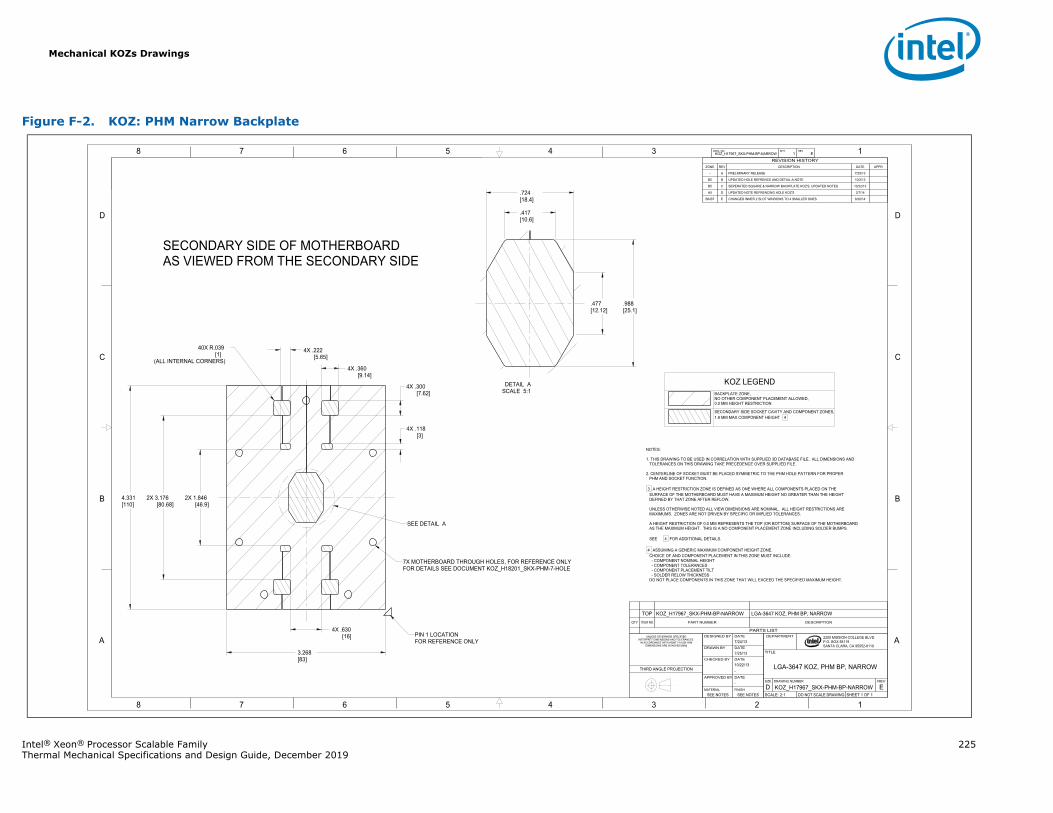
Mechanical KOZs Drawings
Intel® Xeon® Processor Scalable Family 225Thermal Mechanical Specifications and Design Guide, December 2019
Figure F-2. KOZ: PHM Narrow Backplate
1345678
B
C
D
A
12345678
B
C
D
A 2200 MISSION COLLEGE BLVD.P.O. BOX 58119SANTA CLARA, CA 95052-8119
R
2X 1.846[46.9]
4X .118[3]
.417[10.6]
.477[12.12]
.988[25.1]
.724[18.4]
40X R.039[1]
(ALL INTERNAL CORNERS)
4.331[110]
3.268[83]
2X 3.176[80.68]
4X .360[9.14]
4X .300[7.62]
4X .630[16]
4X .222[5.65]
KOZ_H17967_SKX-PHM-BP-NARROW 1 EDWG. NO SHT. REV
SHEET 1 OF 1DO NOT SCALE DRAWINGSCALE: 2:1EKOZ_H17967_SKX-PHM-BP-NARROWD
REVDRAWING NUMBERSIZE
LGA-3647 KOZ, PHM BP, NARROW
TITLE
DEPARTMENT
SEE NOTESSEE NOTESFINISHMATERIAL
-DATEAPPROVED BY
-10/22/13DATECHECKED BY
7/25/13DATEDRAWN BY
7/24/13DATEDESIGNED BYUNLESS OTHERWISE SPECIFIED
INTERPRET DIMENSIONS AND TOLERANCES IN ACCORDANCE WITH ASME Y14.5M-1994
DIMENSIONS ARE IN INCHES [MM]
THIRD ANGLE PROJECTION
PARTS LIST
DESCRIPTIONPART NUMBERITEM NOQTY
LGA-3647 KOZ, PHM BP, NARROWKOZ_H17967_ BP-NARROWTOP
REVISION HISTORYZONE REV DESCRIPTION DATE APPR
- A PRELIMINARY RELEASE 7/25/13
B5 B UPDATED HOLE REFRENCE AND DETAIL-A NOTE 10/2/13
B5 C SEPERATED SQUARE & NARROW BACKPLATE KOZ'S, UPDATED NOTES 10/22/13
A5 D UPDATED NOTE REFRENCING HOLE KOZ'S 2/7/14
B6-B7 E CHANGED INNER 2 SLOT WINDOWS TO 4 SMALLER ONES 8/20/14
NOTES:
1. THIS DRAWING TO BE USED IN CORRELATION WITH SUPPLIED 3D DATABASE FILE. ALL DIMENSIONS ANDTOLERANCES ON THIS DRAWING TAKE PRECEDENCE OVER SUPPLIED FILE.
2. CENTERLINE OF SOCKET MUST BE PLACED SYMMETRIC TO THE PHM HOLE PATTERN FOR PROPERPHM AND SOCKET FUNCTION.
3 A HEIGHT RESTRICTION ZONE IS DEFINED AS ONE WHERE ALL COMPONENTS PLACED ON THE SURFACE OF THE MOTHERBOARD MUST HAVE A MAXIMUM HEIGHT NO GREATER THAN THE HEIGHT DEFINED BY THAT ZONE AFTER REFLOW.
UNLESS OTHERWISE NOTED ALL VIEW DIMENSIONS ARE NOMINAL. ALL HEIGHT RESTRICTIONS ARE MAXIMUMS. ZONES ARE NOT DRIVEN BY SPECIFIC OR IMPLIED TOLERANCES.
A HEIGHT RESTRICTION OF 0.0 MM REPRESENTS THE TOP (OR BOTTOM) SURFACE OF THE MOTHERBOARD AS THE MAXIMUM HEIGHT. THIS IS A NO COMPONENT PLACEMENT ZONE INCLUDING SOLDER BUMPS.
SEE 4 FOR ADDITIONAL DETAILS.
4 ASSUMING A GENERIC MAXIMUM COMPONENT HEIGHT ZONE. CHOICE OF AND COMPONENT PLACEMENT IN THIS ZONE MUST INCLUDE:
- COMPONENT NOMINAL HEIGHT- COMPONENT TOLERANCES- COMPONENT PLACEMENT TILT- SOLDER RELOW THICKNESS
DO NOT PLACE COMPONENTS IN THIS ZONE THAT WILL EXCEED THE SPECIFIED MAXIMUM HEIGHT.
SECONDARY SIDE OF MOTHERBOARDAS VIEWED FROM THE SECONDARY SIDE
SEE DETAIL A
7X MOTHERBOARD THROUGH HOLES, FOR REFERENCE ONLYFOR DETAILS SEE DOCUMENT KOZ_H18201_SKX-PHM-7-HOLE
PIN 1 LOCATIONFOR REFERENCE ONLY
SCALE 5:1DETAIL A KOZ LEGEND
BACKPLATE ZONE,NO OTHER COMPONENT PLACEMENT ALLOWED,0.0 MM HEIGHT RESTRICTION
SECONDARY SIDE SOCKET CAVITY AND COMPONENT ZONES,1.8 MM MAX COMPONENT HEIGHT 4
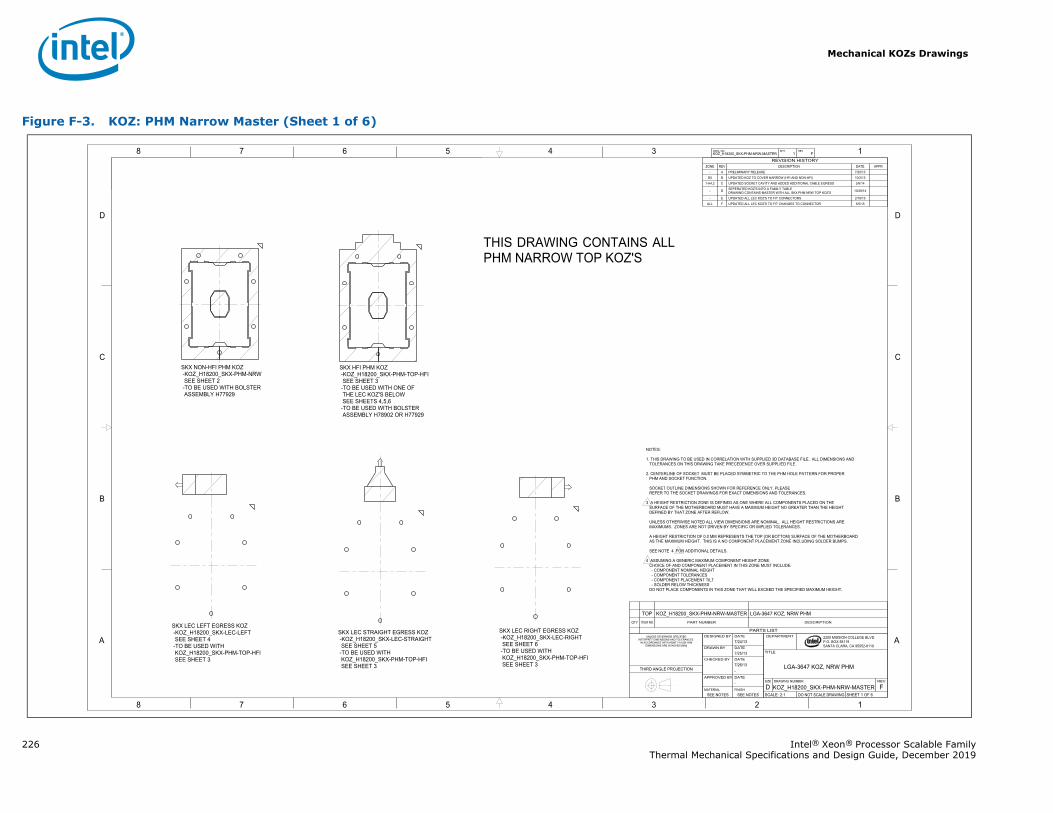
Mechanical KOZs Drawings
226 Intel® Xeon® Processor Scalable FamilyThermal Mechanical Specifications and Design Guide, December 2019
Figure F-3. KOZ: PHM Narrow Master (Sheet 1 of 6)
1345678
B
C
D
A
12345678
B
C
D
A 2200 MISSION COLLEGE BLVD.P.O. BOX 58119SANTA CLARA, CA 95052-8119
R
KOZ_H18200_SKX-PHM-NRW-MASTER 1 FDWG. NO SHT. REV
SHEET 1 OF 6DO NOT SCALE DRAWINGSCALE: 2:1FKOZ_H18200_SKX-PHM-NRW-MASTERD
REVDRAWING NUMBERSIZE
LGA-3647 KOZ, NRW PHM
TITLE
DEPARTMENT
SEE NOTESSEE NOTESFINISHMATERIAL
-DATEAPPROVED BY
-7/26/13DATECHECKED BY
7/25/13DATEDRAWN BY
7/24/13DATEDESIGNED BYUNLESS OTHERWISE SPECIFIED
INTERPRET DIMENSIONS AND TOLERANCES IN ACCORDANCE WITH ASME Y14.5M-1994
DIMENSIONS ARE IN INCHES [MM]
THIRD ANGLE PROJECTION
PARTS LIST
DESCRIPTIONPART NUMBERITEM NOQTY
LGA-3647 KOZ, NRW PHMKOZ_H18200_SKX-PHM-NRW-MASTERTOP
REVISION HISTORYZONE REV DESCRIPTION DATE APPR
- A PRELIMINARY RELEASE 7/25/13D5 B UPDATED KOZ TO COVER NARROW (HFI AND NON-HFI) 10/2/13
1-A4,2 C UPDATED SOCKET CAVITY AND ADDED ADDITIONAL CABLE EGRESS 2/6/14
- D SEPERATED KOZ'S INTO A FAMILY TABLEDRAWING CONTAINS MASTER WITH ALL SKX PHM NRW TOP KOZ'S 10/28/14
- E UPDATED ALL LEC KOZ'S TO FIT CONNECTORS 2/18/15ALL F UPDATED ALL LEC KOZ'S TO FIT CHANGES TO CONNECTOR 5/5/15
NOTES:
1. THIS DRAWING TO BE USED IN CORRELATION WITH SUPPLIED 3D DATABASE FILE. ALL DIMENSIONS ANDTOLERANCES ON THIS DRAWING TAKE PRECEDENCE OVER SUPPLIED FILE.
2. CENTERLINE OF SOCKET MUST BE PLACED SYMMETRIC TO THE PHM HOLE PATTERN FOR PROPERPHM AND SOCKET FUNCTION.
SOCKET OUTLINE DIMENSIONS SHOWN FOR REFERENCE ONLY. PLEASEREFER TO THE SOCKET DRAWINGS FOR EXACT DIMENSIONS AND TOLERANCES.
3 A HEIGHT RESTRICTION ZONE IS DEFINED AS ONE WHERE ALL COMPONENTS PLACED ON THE SURFACE OF THE MOTHERBOARD MUST HAVE A MAXIMUM HEIGHT NO GREATER THAN THE HEIGHT DEFINED BY THAT ZONE AFTER REFLOW.
UNLESS OTHERWISE NOTED ALL VIEW DIMENSIONS ARE NOMINAL. ALL HEIGHT RESTRICTIONS ARE MAXIMUMS. ZONES ARE NOT DRIVEN BY SPECIFIC OR IMPLIED TOLERANCES.
A HEIGHT RESTRICTION OF 0.0 MM REPRESENTS THE TOP (OR BOTTOM) SURFACE OF THE MOTHERBOARD AS THE MAXIMUM HEIGHT. THIS IS A NO COMPONENT PLACEMENT ZONE INCLUDING SOLDER BUMPS.
SEE NOTE 4 FOR ADDITIONAL DETAILS.
4 ASSUMING A GENERIC MAXIMUM COMPONENT HEIGHT ZONE. CHOICE OF AND COMPONENT PLACEMENT IN THIS ZONE MUST INCLUDE:
- COMPONENT NOMINAL HEIGHT- COMPONENT TOLERANCES- COMPONENT PLACEMENT TILT- SOLDER RELOW THICKNESS
DO NOT PLACE COMPONENTS IN THIS ZONE THAT WILL EXCEED THE SPECIFIED MAXIMUM HEIGHT.
THIS DRAWING CONTAINS ALL PHM NARROW TOP KOZ'S
SKX LEC STRAIGHT EGRESS KOZ-KOZ_H18200_SKX-LEC-STRAIGHTSEE SHEET 5-TO BE USED WITHKOZ_H18200_SKX-PHM-TOP-HFISEE SHEET 3
SKX LEC LEFT EGRESS KOZ-KOZ_H18200_SKX-LEC-LEFT SEE SHEET 4-TO BE USED WITH KOZ_H18200_SKX-PHM-TOP-HFI SEE SHEET 3
SKX LEC RIGHT EGRESS KOZ-KOZ_H18200_SKX-LEC-RIGHTSEE SHEET 6-TO BE USED WITHKOZ_H18200_SKX-PHM-TOP-HFISEE SHEET 3
SKX HFI PHM KOZ-KOZ_H18200_SKX-PHM-TOP-HFISEE SHEET 3
-TO BE USED WITH ONE OFTHE LEC KOZ'S BELOWSEE SHEETS 4,5,6
-TO BE USED WITH BOLSTERASSEMBLY H78902 OR H77929
SKX NON-HFI PHM KOZ-KOZ_H18200_SKX-PHM-NRWSEE SHEET 2-TO BE USED WITH BOLSTERASSEMBLY H77929
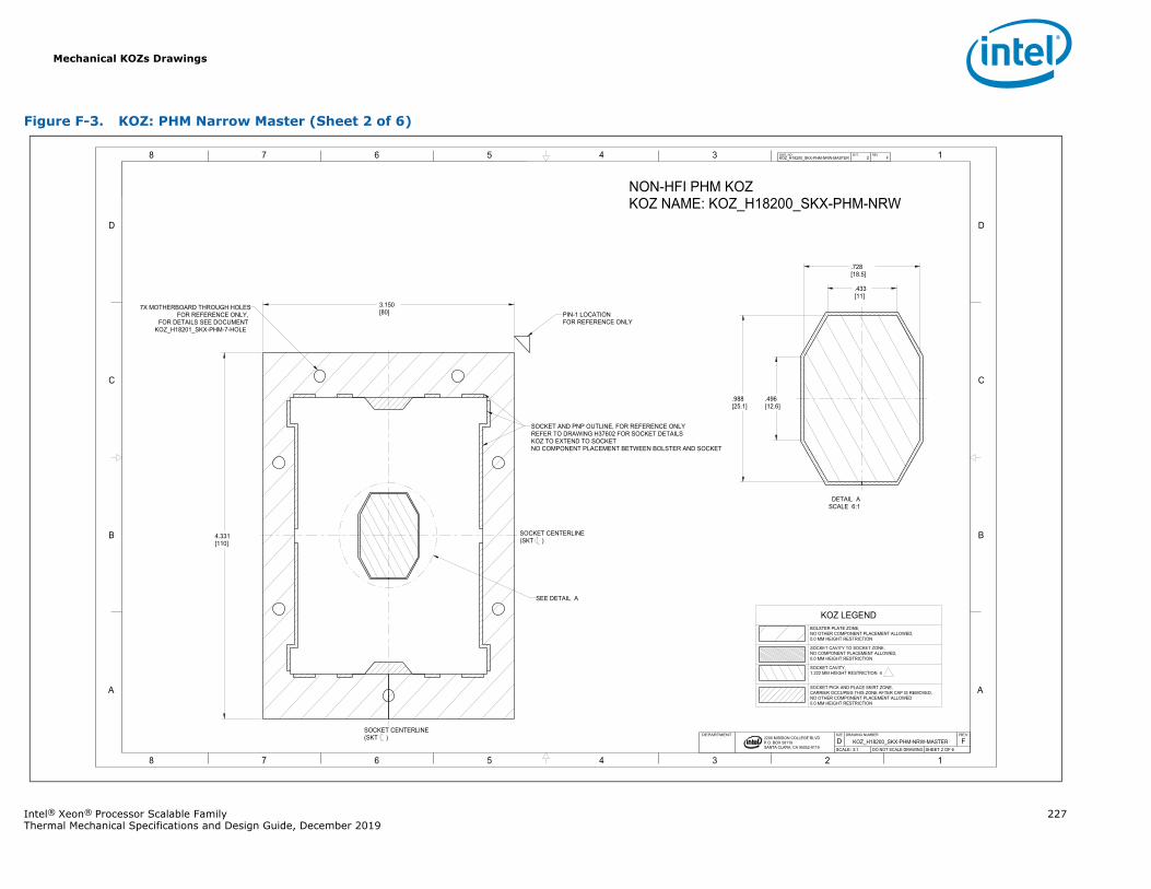
Mechanical KOZs Drawings
Intel® Xeon® Processor Scalable Family 227Thermal Mechanical Specifications and Design Guide, December 2019
Figure F-3. KOZ: PHM Narrow Master (Sheet 2 of 6)
1345678
B
C
D
A
12345678
B
C
D
A
2200 MISSION COLLEGE BLVD.P.O. BOX 58119SANTA CLARA, CA 95052-8119
R
NON-HFI PHM KOZKOZ NAME: KOZ_H18200_SKX-PHM-NRW
PIN-1 LOCATIONFOR REFERENCE ONLY
7X MOTHERBOARD THROUGH HOLES FOR REFERENCE ONLY,
FOR DETAILS SEE DOCUMENTKOZ_H18201_SKX-PHM-7-HOLE
SOCKET AND PNP OUTLINE, FOR REFERENCE ONLYREFER TO DRAWING H37602 FOR SOCKET DETAILSKOZ TO EXTEND TO SOCKETNO COMPONENT PLACEMENT BETWEEN BOLSTER AND SOCKET
3.150[80]
4.331[110]
.496[12.6]
.988[25.1]
.433[11]
.728[18.5]
KOZ_H18200_SKX-PHM-NRW-MASTER 2 FDWG. NO SHT. REV
SHEET 2 OF 6DO NOT SCALE DRAWINGSCALE: 3:1FKOZ_H18200_SKX-PHM-NRW-MASTERD
REVDRAWING NUMBERSIZEDEPARTMENT
SEE DETAIL A
SOCKET CENTERLINE(SKT )
SOCKET CENTERLINE(SKT )
SCALE 6:1DETAIL A
KOZ LEGENDBOLSTER PLATE ZONE,NO OTHER COMPONENT PLACEMENT ALLOWED,0.0 MM HEIGHT RESTRICTION
SOCKET CAVITY TO SOCKET ZONE,NO COMPONENT PLACEMENT ALLOWED,0.0 MM HEIGHT RESTRICTION
SOCKET CAVITY,1.222 MM HEIGHT RESTRICTION 4
SOCKET PICK AND PLACE SKIRT ZONE,CARRIER OCCUPIES THIS ZONE AFTER CAP IS REMOVED,NO OTHER COMPONENT PLACEMENT ALLOWED0.0 MM HEIGHT RESTRICTION
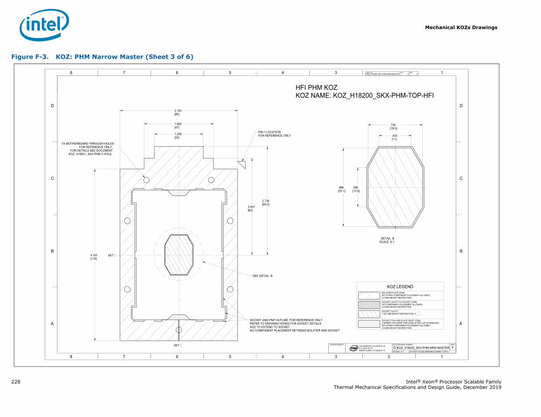
Mechanical KOZs Drawings
228 Intel® Xeon® Processor Scalable FamilyThermal Mechanical Specifications and Design Guide, December 2019
Figure F-3. KOZ: PHM Narrow Master (Sheet 3 of 6)
1345678
B
C
D
A
12345678
B
C
D
A
2200 MISSION COLLEGE BLVD.P.O. BOX 58119SANTA CLARA, CA 95052-8119
R
4.331[110]
1.299[33]
1.850[47]
3.150[80]
2.441[62]
2.736[69.5]
.728[18.5]
.433[11]
.496[12.6]
.988[25.1]
KOZ_H18200_SKX-PHM-NRW-MASTER 3 FDWG. NO SHT. REV
SHEET 3 OF 6DO NOT SCALE DRAWINGSCALE: 2:1FKOZ_H18200_SKX-PHM-NRW-MASTERD
REVDRAWING NUMBERSIZEDEPARTMENT
HFI PHM KOZKOZ NAME: KOZ_H18200_SKX-PHM-TOP-HFI
SEE DETAIL B
PIN-1 LOCATIONFOR REFERENCE ONLY
7X MOTHERBOARD THROUGH HOLES FOR REFERENCE ONLY,
FOR DETAILS SEE DOCUMENTKOZ_H18201_SKX-PHM-7-HOLE
SOCKET AND PNP OUTLINE, FOR REFERENCE ONLYREFER TO DRAWING H37602 FOR SOCKET DETAILSKOZ TO EXTEND TO SOCKETNO COMPONENT PLACEMENT BETWEEN BOLSTER AND SOCKET
SKT
SKT
SCALE 6:1DETAIL B
KOZ LEGENDBOLSTER PLATE ZONE,NO OTHER COMPONENT PLACEMENT ALLOWED,0.0 MM HEIGHT RESTRICTION
SOCKET CAVITY TO SOCKET ZONE,NO COMPONENT PLACEMENT ALLOWED,0.0 MM HEIGHT RESTRICTION
SOCKET CAVITY,1.222 MM HEIGHT RESTRICTION 4
SOCKET PICK AND PLACE SKIRT ZONE,CARRIER OCCUPIES THIS ZONE AFTER CAP IS REMOVED,NO OTHER COMPONENT PLACEMENT ALLOWED0.0 MM HEIGHT RESTRICTION
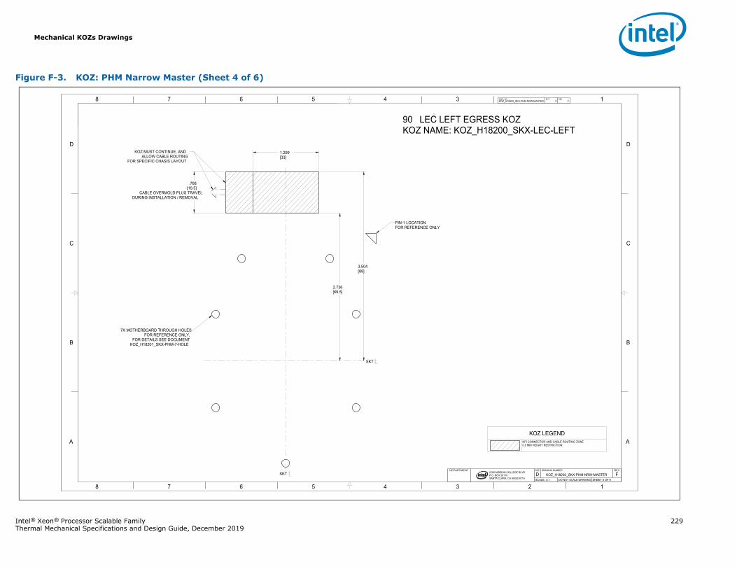
Mechanical KOZs Drawings
Intel® Xeon® Processor Scalable Family 229Thermal Mechanical Specifications and Design Guide, December 2019
Figure F-3. KOZ: PHM Narrow Master (Sheet 4 of 6)
1345678
B
C
D
A
12345678
B
C
D
A
2200 MISSION COLLEGE BLVD.P.O. BOX 58119SANTA CLARA, CA 95052-8119
R
90 LEC LEFT EGRESS KOZKOZ NAME: KOZ_H18200_SKX-LEC-LEFT
1.299[33]
2.736[69.5]
DURING INSTALLATION / REMOVALCABLE OVERMOLD PLUS TRAVEL
[19.5].768
3.504[89]
KOZ_H18200_SKX-PHM-NRW-MASTER 4 FDWG. NO SHT. REV
SHEET 4 OF 6DO NOT SCALE DRAWINGSCALE: 3:1FKOZ_H18200_SKX-PHM-NRW-MASTERD
REVDRAWING NUMBERSIZEDEPARTMENT
7X MOTHERBOARD THROUGH HOLES FOR REFERENCE ONLY,
FOR DETAILS SEE DOCUMENTKOZ_H18201_SKX-PHM-7-HOLE
KOZ MUST CONTINUE, AND ALLOW CABLE ROUTING
FOR SPECIFIC CHASIS LAYOUT
PIN-1 LOCATIONFOR REFERENCE ONLY
SKT
SKT
KOZ LEGENDHFI CONNECTOR AND CABLE ROUTING ZONE0.0 MM HEIGHT RESTRICTION
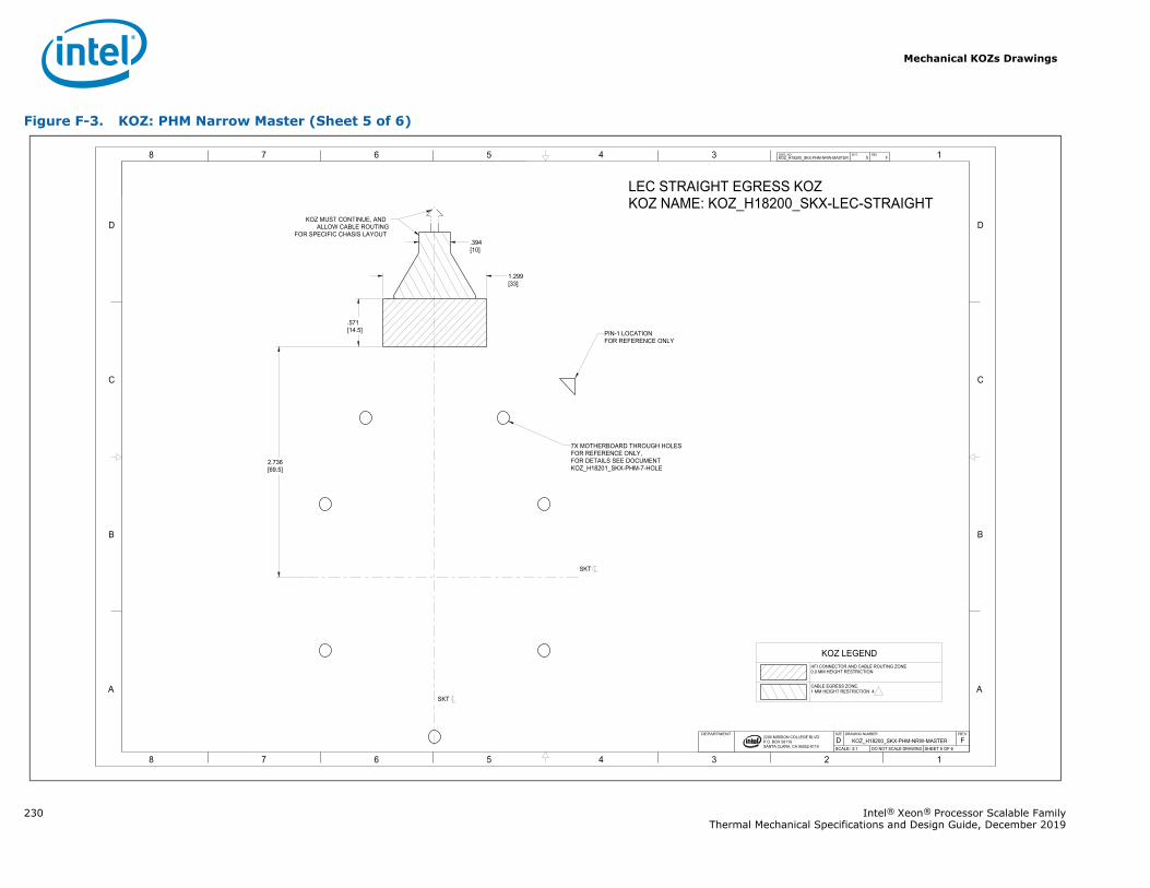
Mechanical KOZs Drawings
230 Intel® Xeon® Processor Scalable FamilyThermal Mechanical Specifications and Design Guide, December 2019
Figure F-3. KOZ: PHM Narrow Master (Sheet 5 of 6)
1345678
B
C
D
A
12345678
B
C
D
A
2200 MISSION COLLEGE BLVD.P.O. BOX 58119SANTA CLARA, CA 95052-8119
R
LEC STRAIGHT EGRESS KOZKOZ NAME: KOZ_H18200_SKX-LEC-STRAIGHT
7X MOTHERBOARD THROUGH HOLES FOR REFERENCE ONLY,FOR DETAILS SEE DOCUMENTKOZ_H18201_SKX-PHM-7-HOLE
KOZ MUST CONTINUE, AND ALLOW CABLE ROUTING
FOR SPECIFIC CHASIS LAYOUT.394[10]
2.736[69.5]
1.299[33]
.571[14.5]
KOZ_H18200_SKX-PHM-NRW-MASTER 5 FDWG. NO SHT. REV
SHEET 5 OF 6DO NOT SCALE DRAWINGSCALE: 3:1FKOZ_H18200_SKX-PHM-NRW-MASTERD
REVDRAWING NUMBERSIZEDEPARTMENT
PIN-1 LOCATIONFOR REFERENCE ONLY
SKT
SKT
KOZ LEGENDHFI CONNECTOR AND CABLE ROUTING ZONE0.0 MM HEIGHT RESTRICTION
CABLE EGRESS ZONE,1 MM HEIGHT RESTRICTION 4
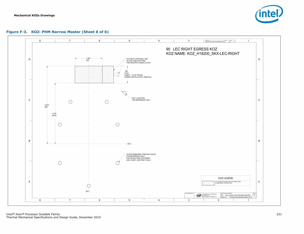
Mechanical KOZs Drawings
Intel® Xeon® Processor Scalable Family 231Thermal Mechanical Specifications and Design Guide, December 2019
Figure F-3. KOZ: PHM Narrow Master (Sheet 6 of 6)
1345678
B
C
D
A
12345678
B
C
D
A
2200 MISSION COLLEGE BLVD.P.O. BOX 58119SANTA CLARA, CA 95052-8119
R
90 LEC RIGHT EGRESS KOZKOZ NAME: KOZ_H18200_SKX-LEC-RIGHT
7X MOTHERBOARD THROUGH HOLES FOR REFERENCE ONLY,FOR DETAILS SEE DOCUMENTKOZ_H18201_SKX-PHM-7-HOLE
KOZ MUST CONTINUE, AND ALLOW CABLE ROUTING FOR SPECIFIC CHASIS LAYOUT
PIN-1 LOCATIONFOR REFERENCE ONLY
2.736[69.5]
.768[19.5]CABLE PLUS TRAVELDURING INSTALLATION / REMOVAL
1.299[33]
3.504[89]
KOZ_H18200_SKX-PHM-NRW-MASTER 6 FDWG. NO SHT. REV
SHEET 6 OF 6DO NOT SCALE DRAWINGSCALE: 3:1FKOZ_H18200_SKX-PHM-NRW-MASTERD
REVDRAWING NUMBERSIZEDEPARTMENT
SKT
SKT
KOZ LEGENDHFI CONNECTOR AND CABLE ROUTING ZONE0.0 MM HEIGHT RESTRICTION
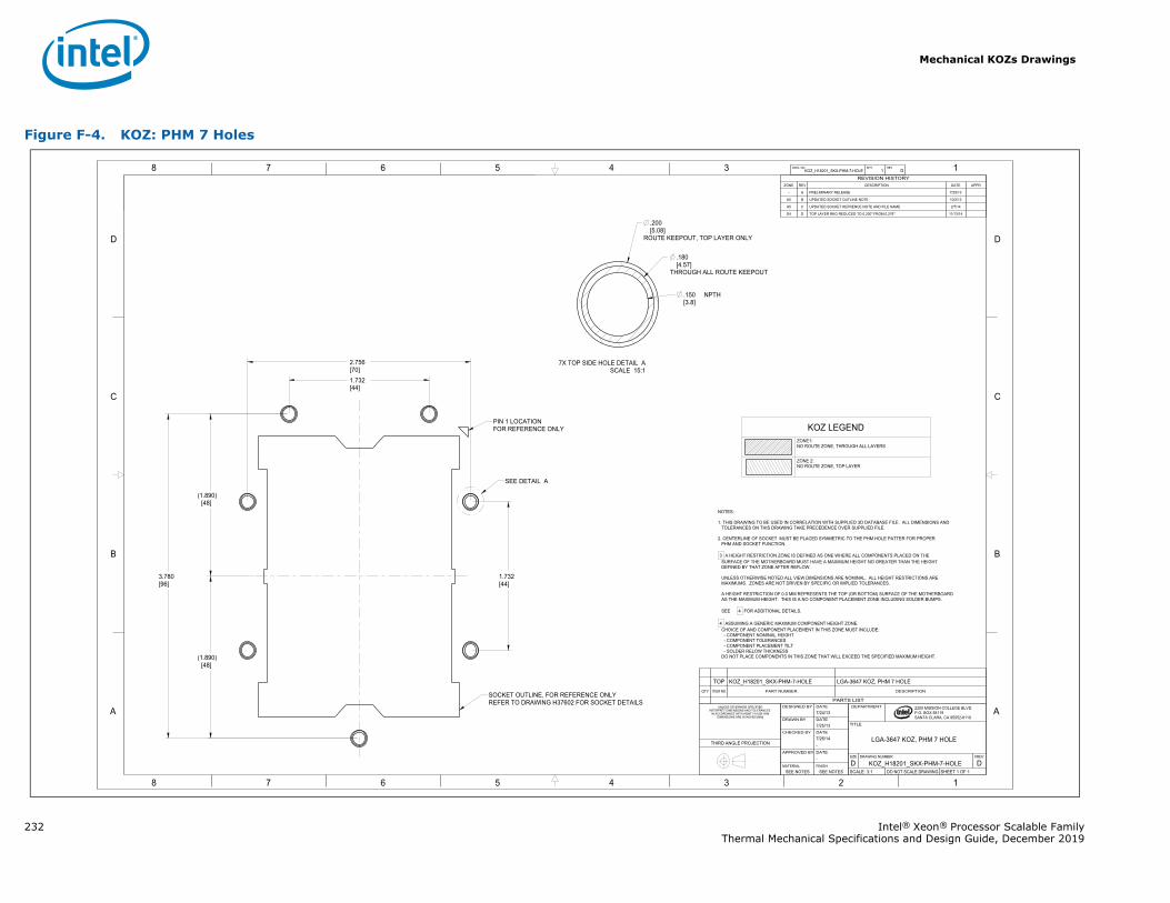
Mechanical KOZs Drawings
232 Intel® Xeon® Processor Scalable FamilyThermal Mechanical Specifications and Design Guide, December 2019
Figure F-4. KOZ: PHM 7 Holes
1345678
B
C
D
A
12345678
B
C
D
A 2200 MISSION COLLEGE BLVD.P.O. BOX 58119SANTA CLARA, CA 95052-8119
R
3.780[96]
.150 NPTH[3.8]
.180[4.57]
THROUGH ALL ROUTE KEEPOUT
.200[5.08]
ROUTE KEEPOUT, TOP LAYER ONLY
1.732[44]
2.756[70]
1.732[44]
(1.890)[48]
(1.890)[48]
KOZ_H18201_SKX-PHM-7-HOLE 1 DDWG. NO SHT. REV
SHEET 1 OF 1DO NOT SCALE DRAWINGSCALE: 3:1DKOZ_H18201_SKX-PHM-7-HOLED
REVDRAWING NUMBERSIZE
LGA-3647 KOZ, PHM 7 HOLE
TITLE
DEPARTMENT
SEE NOTESSEE NOTESFINISHMATERIAL
-DATEAPPROVED BY
-7/26/14DATECHECKED BY
7/25/13DATEDRAWN BY
7/24/13DATEDESIGNED BYUNLESS OTHERWISE SPECIFIED
INTERPRET DIMENSIONS AND TOLERANCES IN ACCORDANCE WITH ASME Y14.5M-1994
DIMENSIONS ARE IN INCHES [MM]
THIRD ANGLE PROJECTION
PARTS LIST
DESCRIPTIONPART NUMBERITEM NOQTY
LGA-3647 KOZ, PHM 7 HOLEKOZ_H18201_SKX-PHM-7-HOLETOP
REVISION HISTORYZONE REV DESCRIPTION DATE APPR
- A PRELIMINARY RELEASE 7/25/13
A5 B UPDATED SOCKET OUTLINE NOTE 10/2/13
A5 C UPDATED SOCKET REFRENCE NOTE AND FILE NAME 2/7/14
D4 D TOP LAYER RKO REDUCED TO 0.200" FROM 0.276" 11/13/14
NOTES:
1. THIS DRAWING TO BE USED IN CORRELATION WITH SUPPLIED 3D DATABASE FILE. ALL DIMENSIONS ANDTOLERANCES ON THIS DRAWING TAKE PRECEDENCE OVER SUPPLIED FILE.
2. CENTERLINE OF SOCKET MUST BE PLACED SYMMETRIC TO THE PHM HOLE PATTER FOR PROPERPHM AND SOCKET FUNCTION.
3 A HEIGHT RESTRICTION ZONE IS DEFINED AS ONE WHERE ALL COMPONENTS PLACED ON THE SURFACE OF THE MOTHERBOARD MUST HAVE A MAXIMUM HEIGHT NO GREATER THAN THE HEIGHT DEFINED BY THAT ZONE AFTER REFLOW.
UNLESS OTHERWISE NOTED ALL VIEW DIMENSIONS ARE NOMINAL. ALL HEIGHT RESTRICTIONS ARE MAXIMUMS. ZONES ARE NOT DRIVEN BY SPECIFIC OR IMPLIED TOLERANCES.
A HEIGHT RESTRICTION OF 0.0 MM REPRESENTS THE TOP (OR BOTTOM) SURFACE OF THE MOTHERBOARD AS THE MAXIMUM HEIGHT. THIS IS A NO COMPONENT PLACEMENT ZONE INCLUDING SOLDER BUMPS.
SEE 4 FOR ADDITIONAL DETAILS.
4 ASSUMING A GENERIC MAXIMUM COMPONENT HEIGHT ZONE. CHOICE OF AND COMPONENT PLACEMENT IN THIS ZONE MUST INCLUDE:
- COMPONENT NOMINAL HEIGHT- COMPONENT TOLERANCES- COMPONENT PLACEMENT TILT- SOLDER RELOW THICKNESS
DO NOT PLACE COMPONENTS IN THIS ZONE THAT WILL EXCEED THE SPECIFIED MAXIMUM HEIGHT.
SEE DETAIL A
SOCKET OUTLINE, FOR REFERENCE ONLYREFER TO DRAWING H37602 FOR SOCKET DETAILS
PIN 1 LOCATIONFOR REFERENCE ONLY
SCALE 15:17X TOP SIDE HOLE DETAIL A
KOZ LEGENDZONE1:NO ROUTE ZONE, THROUGH ALL LAYERS
ZONE 2:NO ROUTE ZONE, TOP LAYER
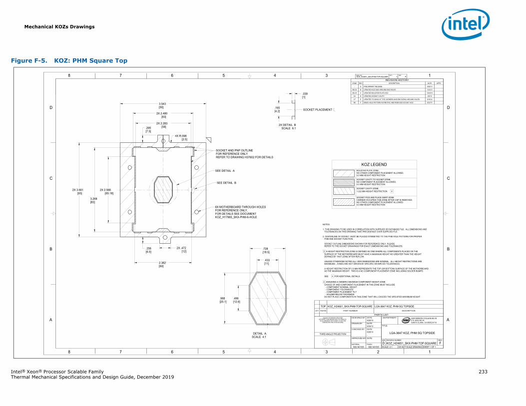
Mechanical KOZs Drawings
Intel® Xeon® Processor Scalable Family 233Thermal Mechanical Specifications and Design Guide, December 2019
Figure F-5. KOZ: PHM Square Top
1345678
B
C
D
A
12345678
B
C
D
A 2200 MISSION COLLEGE BLVD.P.O. BOX 58119SANTA CLARA, CA 95052-8119
R
3.543[90]
3.268[83]
2X 2.566[65.18]
.728[18.5]
.433[11]
.496[12.6]
.988[25.1]
2X 2.283[58]
2.362[60]
2X 2.480[63]
.165[4.2]
.039[1]
2X .472[12]
.295[7.5]
4X R.098[2.5]
2X 3.661[93]
.256[6.5]
KOZ_H24651_SKX-PHM-TOP-SQUARE 1 FDWG. NO SHT. REV
SHEET 1 OF 1DO NOT SCALE DRAWINGSCALE: 2:1FKOZ_H24651_SKX-PHM-TOP-SQUARED
REVDRAWING NUMBERSIZE
LGA-3647 KOZ, PHM SQ TOPSIDE
TITLE
DEPARTMENT
SEE NOTESSEE NOTESFINISHMATERIAL
-DATEAPPROVED BY
-9/26/13DATECHECKED BY
9/26/13DATEDRAWN BY
9/26/13DATEDESIGNED BYUNLESS OTHERWISE SPECIFIED
INTERPRET DIMENSIONS AND TOLERANCES IN ACCORDANCE WITH ASME Y14.5M-1994
DIMENSIONS ARE IN INCHES [MM]
THIRD ANGLE PROJECTION
PARTS LIST
DESCRIPTIONPART NUMBERITEM NOQTY
LGA-3647 KOZ, PHM SQ TOPSIDEKOZ_H24651_SKX-PHM-TOP-SQUARETOP
REVISION HISTORYZONE REV DESCRIPTION DATE APPR
- A PRELIMINARY RELEASE 9/26/13
B6,C6 B UPDATED KOZ SIZE AROUND END HOLES 10/4/13
B6,C6 C UPDATED BOLSTER PLATE KOZ 10/24/13
A4 D UPDATED SOCKET CAVITY 2/6/14
C7 E UPDATED TO 90X93 AT THE CORNERS AND END SIZING AROUND HOLES 6/18/14
B6 F MADE HOLE PATTERN ASYMETRIC AND REMOVED SOCKET KOZ 8/22/14
NOTES:
1. THIS DRAWING TO BE USED IN CORRELATION WITH SUPPLIED 3D DATABASE FILE. ALL DIMENSIONS ANDTOLERANCES ON THIS DRAWING TAKE PRECEDENCE OVER SUPPLIED FILE.
2. CENTERLINE OF SOCKET MUST BE PLACED SYMMETRIC TO THE PHM HOLE PATTERN FOR PROPERPHM AND SOCKET FUNCTION.
SOCKET OUTLINE DIMENSIONS SHOWN FOR REFERENCE ONLY. PLEASEREFER TO THE SOCKET DRAWINGS FOR EXACT DIMENSIONS AND TOLERANCES.
3 A HEIGHT RESTRICTION ZONE IS DEFINED AS ONE WHERE ALL COMPONENTS PLACED ON THE SURFACE OF THE MOTHERBOARD MUST HAVE A MAXIMUM HEIGHT NO GREATER THAN THE HEIGHT DEFINED BY THAT ZONE AFTER REFLOW.
UNLESS OTHERWISE NOTED ALL VIEW DIMENSIONS ARE NOMINAL. ALL HEIGHT RESTRICTIONS ARE MAXIMUMS. ZONES ARE NOT DRIVEN BY SPECIFIC OR IMPLIED TOLERANCES.
A HEIGHT RESTRICTION OF 0.0 MM REPRESENTS THE TOP (OR BOTTOM) SURFACE OF THE MOTHERBOARD AS THE MAXIMUM HEIGHT. THIS IS A NO COMPONENT PLACEMENT ZONE INCLUDING SOLDER BUMPS.
SEE 4 FOR ADDITIONAL DETAILS.
4 ASSUMING A GENERIC MAXIMUM COMPONENT HEIGHT ZONE. CHOICE OF AND COMPONENT PLACEMENT IN THIS ZONE MUST INCLUDE:
- COMPONENT NOMINAL HEIGHT- COMPONENT TOLERANCES- COMPONENT PLACEMENT TILT- SOLDER RELOW THICKNESS
DO NOT PLACE COMPONENTS IN THIS ZONE THAT WILL EXCEED THE SPECIFIED MAXIMUM HEIGHT.
SOCKET PLACEMENT
SEE DETAIL A
SEE DETAIL B
6X MOTHERBOARD THROUGH HOLES FOR REFERENCE ONLY,FOR DETAILS SEE DOCUMENTKOZ_H17965_SKX-PHM-6-HOLE
SOCKET AND PNP OUTLINEFOR REFERENCE ONLYREFER TO DRAWING H37602 FOR DETAILS
SCALE 4:1DETAIL A
SCALE 6:12X DETAIL B
KOZ LEGENDBOLSTER PLATE ZONE,NO OTHER COMPONENT PLACEMENT ALLOWED,0.0 MM HEIGHT RESTRICTION
SOCKET CAVITY TO SOCKET ZONE,NO COMPONENT PLACEMENT ALLOWED,0.0 MM HEIGHT RESTRICTION
SOCKET CAVITY ZONE,1.222 MM HEIGHT RESTRICTION 4
SOCKET PICK AND PLACE SKIRT ZONECARRIER OCCUPIES THIS ZONE AFTER CAP IS REMOVED,NO OTHER COMPONENT PLACEMENT ALLOWED0.0 MM HEIGHT RESTRICTION
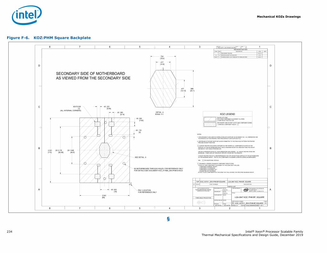
Mechanical KOZs Drawings
234 Intel® Xeon® Processor Scalable FamilyThermal Mechanical Specifications and Design Guide, December 2019
§
Figure F-6. KOZ:PHM Square Backplate
1345678
B
C
D
A
12345678
B
C
D
A 2200 MISSION COLLEGE BLVD.P.O. BOX 58119SANTA CLARA, CA 95052-8119
R
2X 1.846[46.9]
4X .118[3]
.417[10.6]
.477[12.12]
.988[25.1]
.724[18.4]
40X R.039[1]
(ALL INTERNAL CORNERS)
4.331[110]
3.543[90]
2X 3.176[80.68]
4X .360[9.14]
4X .300[7.62]
4X .630[16]
4X .222[5.65]
KOZ_H27511_SKX-PHM-BP-SQUARE 1 CDWG. NO SHT. REV
SHEET 1 OF 1DO NOT SCALE DRAWINGSCALE: 2:1CKOZ_H27511_SKX-PHM-BP-SQUARED
REVDRAWING NUMBERSIZE
LGA-3647 KOZ, PHM BP, SQUARE
TITLE
DEPARTMENT
SEE NOTESSEE NOTESFINISHMATERIAL
-DATEAPPROVED BY
--DATECHECKED BY
10/21/13DATEDRAWN BY
10/21/13DATEDESIGNED BYUNLESS OTHERWISE SPECIFIED
INTERPRET DIMENSIONS AND TOLERANCES IN ACCORDANCE WITH ASME Y14.5M-1994
DIMENSIONS ARE IN INCHES [MM]
THIRD ANGLE PROJECTION
PARTS LIST
DESCRIPTIONPART NUMBERITEM NOQTY
LGA-3647 KOZ, PHM BP, SQUAREKOZ_H27511_SKX-PHM-BP-SQUARETOP
REVISION HISTORYZONE REV DESCRIPTION DATE APPR
- A PRELIMINARY RELEASE 10/21/13
A5 B UPDATED SOCKET OUTLINE NOTE 2/7/14
B6-B7 C CHANGED INNER 2 SLOT WINDOWS TO 4 SMALLER ONES 8/22/14
NOTES:
1. THIS DRAWING TO BE USED IN CORRELATION WITH SUPPLIED 3D DATABASE FILE. ALL DIMENSIONS ANDTOLERANCES ON THIS DRAWING TAKE PRECEDENCE OVER SUPPLIED FILE.
2. CENTERLINE OF SOCKET MUST BE PLACED SYMMETRIC TO THE PHM HOLE PATTERN FOR PROPERPHM AND SOCKET FUNCTION.
3 A HEIGHT RESTRICTION ZONE IS DEFINED AS ONE WHERE ALL COMPONENTS PLACED ON THE SURFACE OF THE MOTHERBOARD MUST HAVE A MAXIMUM HEIGHT NO GREATER THAN THE HEIGHT DEFINED BY THAT ZONE AFTER REFLOW.
UNLESS OTHERWISE NOTED ALL VIEW DIMENSIONS ARE NOMINAL. ALL HEIGHT RESTRICTIONS ARE MAXIMUMS. ZONES ARE NOT DRIVEN BY SPECIFIC OR IMPLIED TOLERANCES.
A HEIGHT RESTRICTION OF 0.0 MM REPRESENTS THE TOP (OR BOTTOM) SURFACE OF THE MOTHERBOARD AS THE MAXIMUM HEIGHT. THIS IS A NO COMPONENT PLACEMENT ZONE INCLUDING SOLDER BUMPS.
SEE 4 FOR ADDITIONAL DETAILS.
4 ASSUMING A GENERIC MAXIMUM COMPONENT HEIGHT ZONE. CHOICE OF AND COMPONENT PLACEMENT IN THIS ZONE MUST INCLUDE:
- COMPONENT NOMINAL HEIGHT- COMPONENT TOLERANCES- COMPONENT PLACEMENT TILT- SOLDER RELOW THICKNESS
DO NOT PLACE COMPONENTS IN THIS ZONE THAT WILL EXCEED THE SPECIFIED MAXIMUM HEIGHT.
SECONDARY SIDE OF MOTHERBOARDAS VIEWED FROM THE SECONDARY SIDE
SEE DETAIL A
6X MOTHERBOARD THROUGH HOLES, FOR REFERENCE ONLYFOR DETAILS SEE DOCUMENT KOZ_H17965_SKX-PHM-6-HOLE
PIN 1 LOCATIONFOR REFERENCE ONLY
SCALE 5:1DETAIL A
KOZ LEGENDBACKPLATE ZONE,NO OTHER COMPONENT PLACEMENT ALLOWED,0.0 MM HEIGHT RESTRICTION
SECONDARY SIDE SOCKET CAVITY AND COMPONENT ZONES,1.8 MM MAX COMPONENT HEIGHT 4
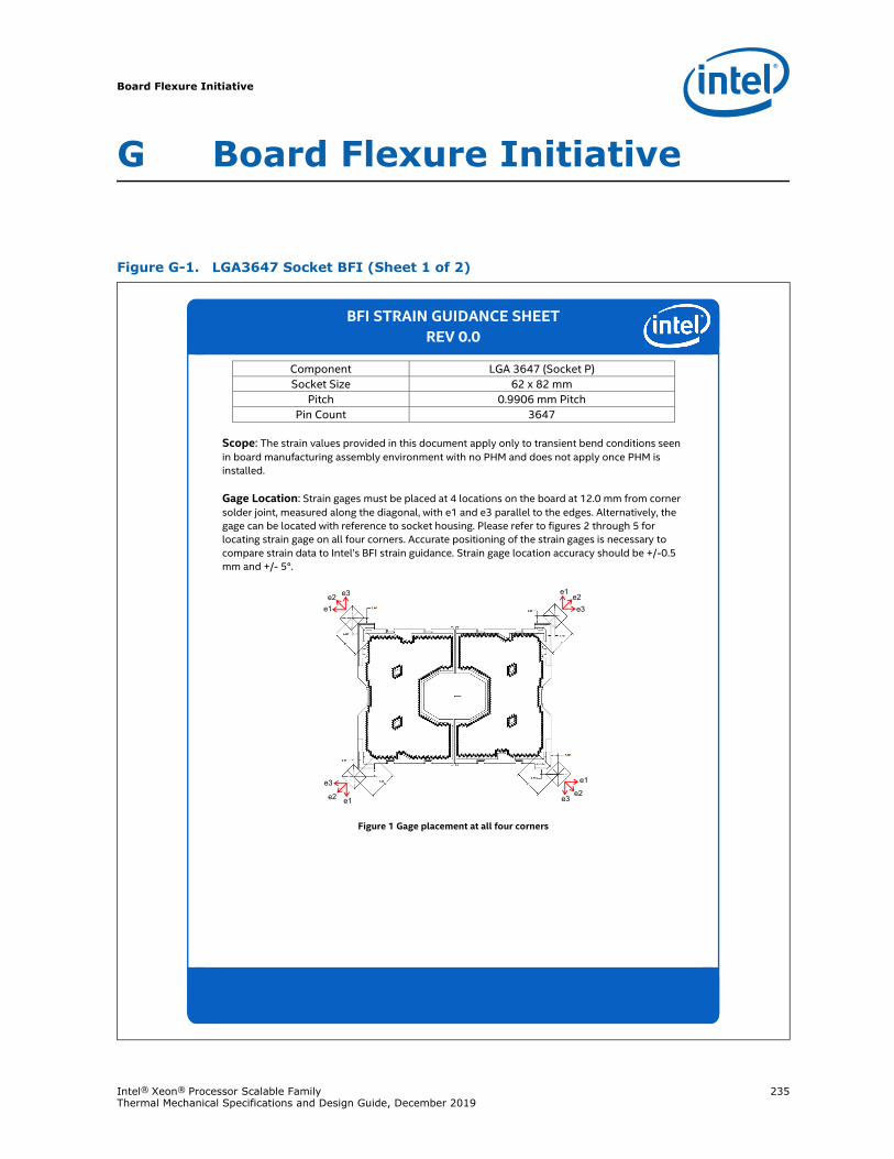
Board Flexure Initiative
Intel® Xeon® Processor Scalable Family 235Thermal Mechanical Specifications and Design Guide, December 2019
G Board Flexure Initiative
Figure G-1. LGA3647 Socket BFI (Sheet 1 of 2)
Scope: The strain values provided in this document apply only to transient bend conditions seen in board manufacturing assembly environment with no PHM and does not apply once PHM is installed.
Gage Location: Strain gages must be placed at 4 locations on the board at 12.0 mm from corner solder joint, measured along the diagonal, with e1 and e3 parallel to the edges. Alternatively, the gage can be located with reference to socket housing. Please refer to figures 2 through 5 for locating strain gage on all four corners. Accurate positioning of the strain gages is necessary to compare strain data to Intel’s BFI strain guidance. Strain gage location accuracy should be +/-0.5 mm and +/- 5°.
Figure 1 Gage placement at all four corners
Component LGA 3647 (Socket P) Socket Size 62 x 82 mm
Pitch 0.9906 mm Pitch Pin Count 3647
e1
e2e3
e1e2e3
BFI STRAIN GUIDANCE SHEET REV 0.0
e1e2 e3
e1e2
e3
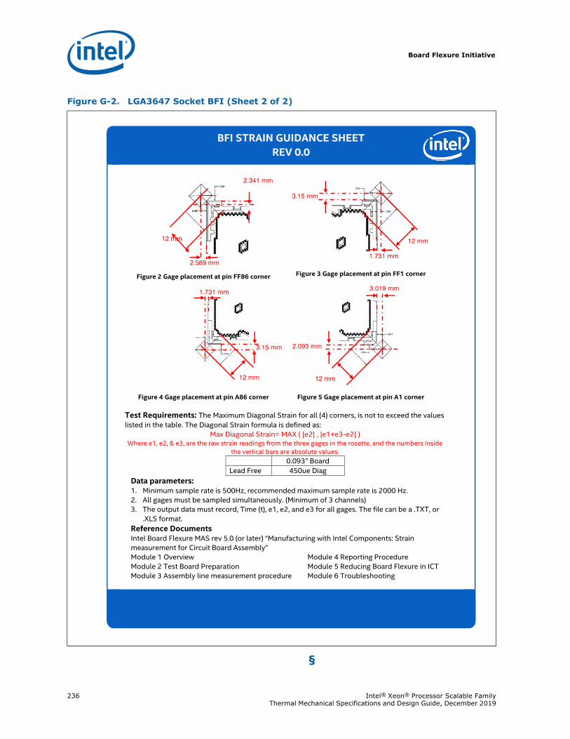
Board Flexure Initiative
236 Intel® Xeon® Processor Scalable Family Thermal Mechanical Specifications and Design Guide, December 2019
§
Figure G-2. LGA3647 Socket BFI (Sheet 2 of 2)
Figure 2 Gage placement at pin FF86 corner Figure 3 Gage placement at pin FF1 corner
Figure 4 Gage placement at pin A86 corner Figure 5 Gage placement at pin A1 corner
Test Requirements: The Maximum Diagonal Strain for all (4) corners, is not to exceed the values listed in the table. The Diagonal Strain formula is defined as:
Max Diagonal Strain= MAX ( |e2| , |e1+e3-e2| ) Where e1, e2, & e3, are the raw strain readings from the three gages in the rosette, and the numbers inside
the vertical bars are absolute values. 0.093” Board
Lead Free 450ue Diag Data parameters: 1. Minimum sample rate is 500Hz, recommended maximum sample rate is 2000 Hz.2. All gages must be sampled simultaneously. (Minimum of 3 channels)3. The output data must record, Time (t), e1, e2, and e3 for all gages. The file can be a .TXT, or
.XLS format.Reference Documents Intel Board Flexure MAS rev 5.0 (or later) “Manufacturing with Intel Components: Strain measurement for Circuit Board Assembly” Module 1 Overview Module 4 Reporting Procedure Module 2 Test Board Preparation Module 5 Reducing Board Flexure in ICT Module 3 Assembly line measurement procedure Module 6 Troubleshooting
BFI STRAIN GUIDANCE SHEET REV 0.0
2.341 mm
2.589 mm
12 mm
3.15 mm
1.731 mm
12 mm
12 mm
1.731 mm
3.15 mm
12 mm
3.019 mm
2.093 mm