integrating cad/cae design technology for design and
TRANSCRIPT
ISSN: 2277-3754
ISO 9001:2008 Certified International Journal of Engineering and Innovative Technology (IJEIT)
Volume 9, Issue 10, April 2020
DOI:10.17605/OSF.IO/XJMZE Page 20
Abstract— World is focusing more towards automation each
and every work of human is reduced by machine and computer.
Computer aided design and analysis become most important tool
in the field of engineering. Integrating computer aided parametric
technology and computer aided analysis collaborative technology
always eliminates costly try out and error process. In engineering
field computer aided design, analysis and manufacturing are
utilized in different ways to produce document and design, shaded
images animated display ,perform engineering analysis and to
perform process planning and NC code generation. In this work
some significant aspects of progressive tool are discussed and also
integrating CAD/CAE for design and analysis. The work starts
from study of component conceptual design process modeling
design verification and analysis.
Index Terms—Bending Tool, Cad, Auto Desk Inventor,
Process Planning, NC code generation.
I. INTRODUCTION
The present century is known for rapid development in the
field of computer in both hardware and software. It has
become the most important tool in technological
developments. The entry of computer in design and
manufacturing has led to the emergence of new areas known
as computer aided design and computer aided
manufacturing.Traditionaly design and manufacturing are
two distinct and separate activities. Integration of
CAD/CAE/CAM system is born for design analysis and
manufacturing of engineering product. Computer aided
design is the automation of design process. It is the
technology used to integrate the design activities with the help
of computer which includes transformation and modification
of images of part geometry and analysis of particular part to
verify whether the part is capable for that particular
enviorment.In this work computer aided design and analysis
technologies are integrating for design and analysis of
bending tool for pipe clamp. Solid modeling and FEM
analysis carried out in Auto desk inventor software.
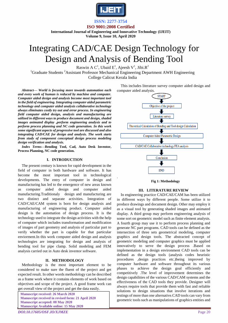
II. METHODOLOGY
Methodology is the most important element to be
considered to make sure the fluent of the project and get
expected result. In other words methodology can be described
as a frame work where it contains elements of work based on
objectives and scope of the project. A good frame work can
get overall view of the project and get the data easily.
This includes literature survey computer aided design and
computer aided analysis.
. Fig 1: Methodology
III. LITERATURE REVIEW
In engineering practice CAD/CAE/CAM has been utilized
in different ways by different people. Some utilize it to
produce drawings and document design. Other may employ it
as a visual tool by generating shaded images and animated
display. A third group may perform engineering analysis of
some sort on geometric model such as finite element analysis.
A fourth group may use it to perform process planning and
generate NC part programs. CAD tools can be defined as the
intersection of three sets geometrical modeling, computer
graphics and design tools. The abstracted concept of
geometric modeling and computer graphics must be applied
innovatively to serve the design process .Based on
implementation in a design environment CAD tools can be
defined as the design tools (analysis codes heuristic
procedures ,design practices etc.)being improved by
computer hardware and software throughout its various
phases to achieve the design goal efficiently and
competitively .The level of improvement determines the
design capabilities of the various CAD/CAM systems and the
effectiveness of the CAD tools they provide. Designer will
always require tools that provide them with fast and reliable
solutions to design situations that involve iterations and
testings of more than one alternative.CAD tools can vary from
geometric tools such as manipulations of graphics entities and
Integrating CAD/CAE Design Technology for
Design and Analysis of Bending Tool Raswin A C
1, Ubaid E
1, Ajeesh V
1, Jibi.R
2
1Graduate Students
2Assistant Professor Mechanical Engineering Department AWH Engineering
College Calicut Kerala India
Manuscript received: 26 March 2020
Manuscript received in revised form: 21 April 2020
Manuscript accepted: 08 May 2020
Manuscript Available online: 15 May 2020
ISSN: 2277-3754
ISO 9001:2008 Certified International Journal of Engineering and Innovative Technology (IJEIT)
Volume 9, Issue 10, April 2020
DOI:10.17605/OSF.IO/XJMZE Page 21
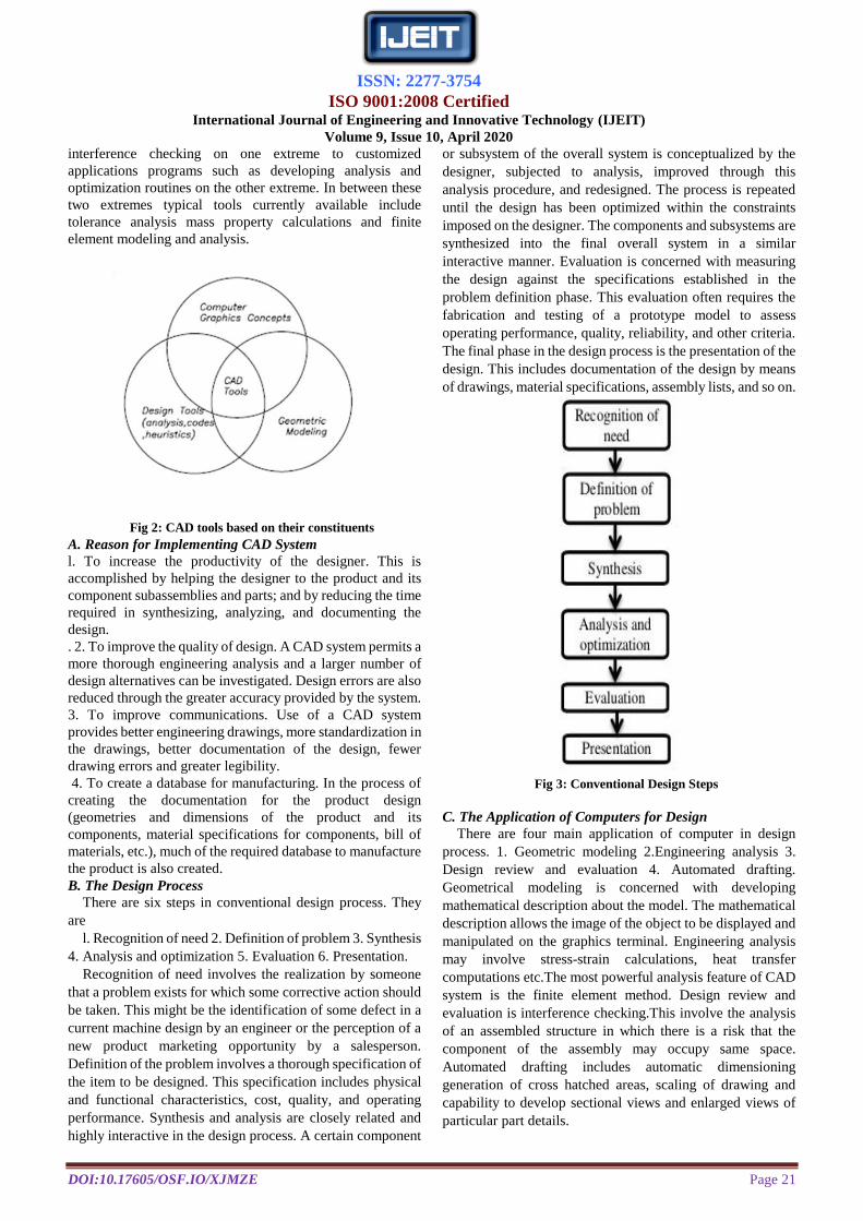
interference checking on one extreme to customized
applications programs such as developing analysis and
optimization routines on the other extreme. In between these
two extremes typical tools currently available include
tolerance analysis mass property calculations and finite
element modeling and analysis.
Fig 2: CAD tools based on their constituents
A. Reason for Implementing CAD System
l. To increase the productivity of the designer. This is
accomplished by helping the designer to the product and its
component subassemblies and parts; and by reducing the time
required in synthesizing, analyzing, and documenting the
design.
. 2. To improve the quality of design. A CAD system permits a
more thorough engineering analysis and a larger number of
design alternatives can be investigated. Design errors are also
reduced through the greater accuracy provided by the system.
3. To improve communications. Use of a CAD system
provides better engineering drawings, more standardization in
the drawings, better documentation of the design, fewer
drawing errors and greater legibility.
4. To create a database for manufacturing. In the process of
creating the documentation for the product design
(geometries and dimensions of the product and its
components, material specifications for components, bill of
materials, etc.), much of the required database to manufacture
the product is also created.
B. The Design Process
There are six steps in conventional design process. They
are
l. Recognition of need 2. Definition of problem 3. Synthesis
4. Analysis and optimization 5. Evaluation 6. Presentation.
Recognition of need involves the realization by someone
that a problem exists for which some corrective action should
be taken. This might be the identification of some defect in a
current machine design by an engineer or the perception of a
new product marketing opportunity by a salesperson.
Definition of the problem involves a thorough specification of
the item to be designed. This specification includes physical
and functional characteristics, cost, quality, and operating
performance. Synthesis and analysis are closely related and
highly interactive in the design process. A certain component
or subsystem of the overall system is conceptualized by the
designer, subjected to analysis, improved through this
analysis procedure, and redesigned. The process is repeated
until the design has been optimized within the constraints
imposed on the designer. The components and subsystems are
synthesized into the final overall system in a similar
interactive manner. Evaluation is concerned with measuring
the design against the specifications established in the
problem definition phase. This evaluation often requires the
fabrication and testing of a prototype model to assess
operating performance, quality, reliability, and other criteria.
The final phase in the design process is the presentation of the
design. This includes documentation of the design by means
of drawings, material specifications, assembly lists, and so on.
Fig 3: Conventional Design Steps
C. The Application of Computers for Design
There are four main application of computer in design
process. 1. Geometric modeling 2.Engineering analysis 3.
Design review and evaluation 4. Automated drafting.
Geometrical modeling is concerned with developing
mathematical description about the model. The mathematical
description allows the image of the object to be displayed and
manipulated on the graphics terminal. Engineering analysis
may involve stress-strain calculations, heat transfer
computations etc.The most powerful analysis feature of CAD
system is the finite element method. Design review and
evaluation is interference checking.This involve the analysis
of an assembled structure in which there is a risk that the
component of the assembly may occupy same space.
Automated drafting includes automatic dimensioning
generation of cross hatched areas, scaling of drawing and
capability to develop sectional views and enlarged views of
particular part details.
ISSN: 2277-3754
ISO 9001:2008 Certified International Journal of Engineering and Innovative Technology (IJEIT)
Volume 9, Issue 10, April 2020
DOI:10.17605/OSF.IO/XJMZE Page 22
Fig 4: Computer Aided Design Steps
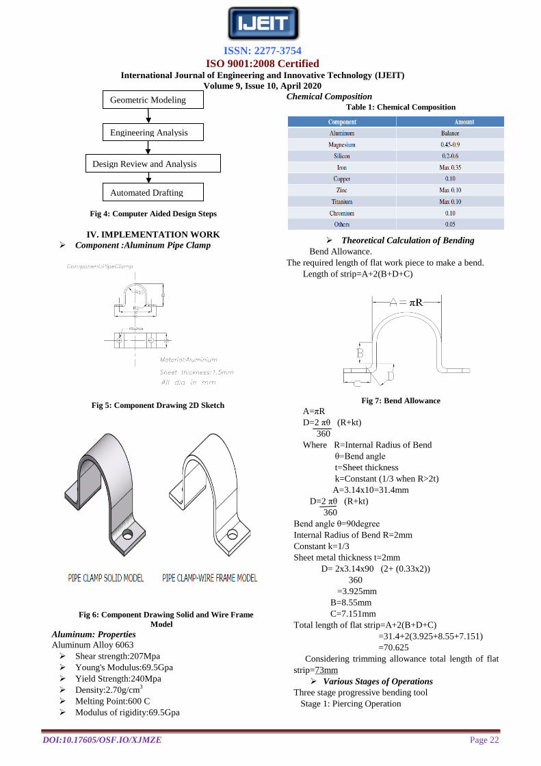
IV. IMPLEMENTATION WORK
Component :Aluminum Pipe Clamp
Fig 5: Component Drawing 2D Sketch
Fig 6: Component Drawing Solid and Wire Frame
Model
Aluminum: Properties
Aluminum Alloy 6063
Shear strength:207Mpa
Young's Modulus:69.5Gpa
Yield Strength:240Mpa
Density:2.70g/cm3
Melting Point:600 C
Modulus of rigidity:69.5Gpa
Chemical Composition
Table 1: Chemical Composition
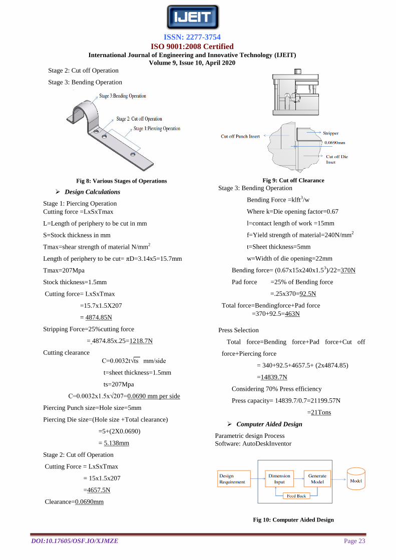
Theoretical Calculation of Bending
Bend Allowance.
The required length of flat work piece to make a bend.
Length of strip=A+2(B+D+C)
Fig 7: Bend Allowance
A=πR
D=2 πθ (R+kt)
360
Where R=Internal Radius of Bend
θ=Bend angle
t=Sheet thickness
k=Constant (1/3 when R>2t)
A=3.14x10=31.4mm
D=2 πθ (R+kt)
360
Bend angle θ=90degree
Internal Radius of Bend R=2mm
Constant k=1/3
Sheet metal thickness t=2mm
D= 2x3.14x90 (2+ (0.33x2))
360
=3.925mm
B=8.55mm
C=7.151mm
Total length of flat strip=A+2(B+D+C)
=31.4+2(3.925+8.55+7.151)
=70.625
Considering trimming allowance total length of flat
strip=73mm
Various Stages of Operations
Three stage progressive bending tool
Stage 1: Piercing Operation
Geometric Modeling
Engineering Analysis
Design Review and Analysis
Automated Drafting
ISSN: 2277-3754
ISO 9001:2008 Certified International Journal of Engineering and Innovative Technology (IJEIT)
Volume 9, Issue 10, April 2020
DOI:10.17605/OSF.IO/XJMZE Page 23
Stage 2: Cut off Operation
Stage 3: Bending Operation
Fig 8: Various Stages of Operations
Design Calculations
Stage 1: Piercing Operation
Cutting force =LxSxTmax
L=Length of periphery to be cut in mm
S=Stock thickness in mm
Tmax=shear strength of material N/mm2
Length of periphery to be cut= πD=3.14x5=15.7mm
Tmax=207Mpa
Stock thickness=1.5mm
Cutting force= LxSxTmax
=15.7x1.5X207
= 4874.85N
Stripping Force=25%cutting force
= 4874.85x.25=1218.7N
Cutting clearance
C=0.0032t√ts mm/side
t=sheet thickness=1.5mm
ts=207Mpa
C=0.0032x1.5x√207=0.0690 mm per side
Piercing Punch size=Hole size=5mm
Piercing Die size=(Hole size +Total clearance)
=5+(2X0.0690)
= 5.138mm
Stage 2: Cut off Operation
Cutting Force = LxSxTmax
= 15x1.5x207
=4657.5N
Clearance=0.0690mm
Fig 9: Cut off Clearance
Stage 3: Bending Operation
Bending Force =klft3/w
Where k=Die opening factor=0.67
l=contact length of work =15mm
f=Yield strength of material=240N/mm2
t=Sheet thickness=5mm
w=Width of die opening=22mm
Bending force= (0.67x15x240x1.53)/22=370N
Pad force =25% of Bending force
=.25x370=92.5N
Total force=Bendingforce+Pad force
=370+92.5=463N
Press Selection
Total force=Bending force+Pad force+Cut off
force+Piercing force
= 340+92.5+4657.5+ (2x4874.85)
=14839.7N
Considering 70% Press efficiency
Press capacity= 14839.7/0.7=21199.57N
=21Tons
Computer Aided Design
Parametric design Process
Software: AutoDeskInventor
Fig 10: Computer Aided Design
ISSN: 2277-3754
ISO 9001:2008 Certified International Journal of Engineering and Innovative Technology (IJEIT)
Volume 9, Issue 10, April 2020
DOI:10.17605/OSF.IO/XJMZE Page 24
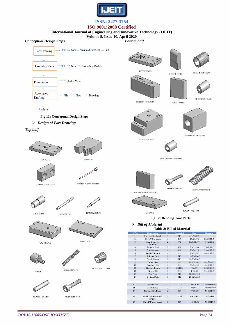
Conceptual Design Steps
Fig 11: Conceptual Design Steps
Design of Part Drawing
Top half
Bottom half
Fig 12: Bending Tool Parts
Bill of Material Table 2: Bill of Material
ISSN: 2277-3754
ISO 9001:2008 Certified International Journal of Engineering and Innovative Technology (IJEIT)
Volume 9, Issue 10, April 2020
DOI:10.17605/OSF.IO/XJMZE Page 25
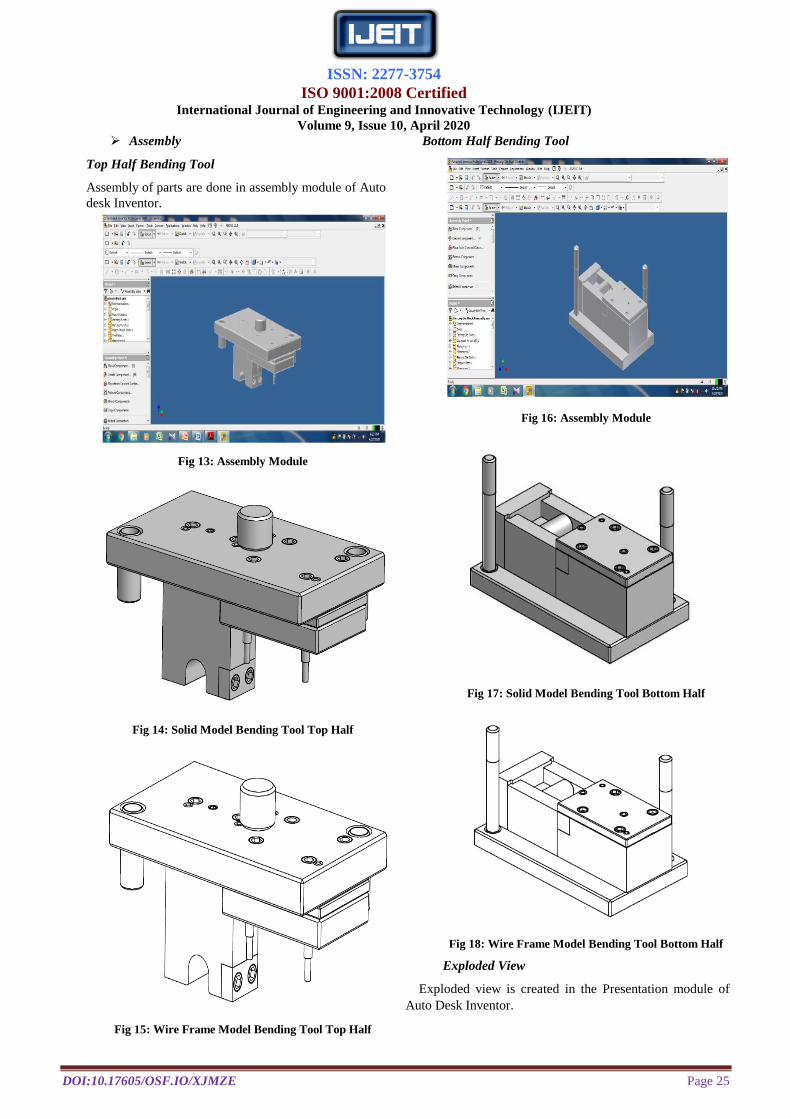
Assembly
Top Half Bending Tool
Assembly of parts are done in assembly module of Auto
desk Inventor.
Fig 13: Assembly Module
Fig 14: Solid Model Bending Tool Top Half
Fig 15: Wire Frame Model Bending Tool Top Half
Bottom Half Bending Tool
Fig 16: Assembly Module
Fig 17: Solid Model Bending Tool Bottom Half
Fig 18: Wire Frame Model Bending Tool Bottom Half
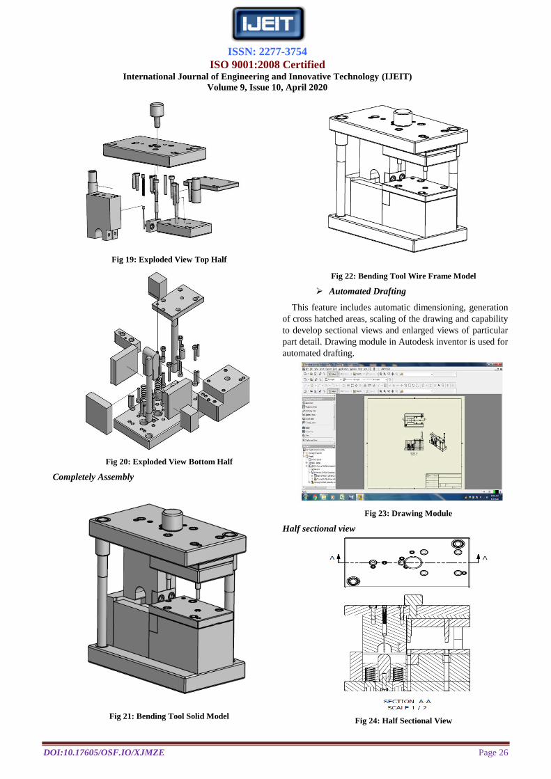
Exploded View
Exploded view is created in the Presentation module of
Auto Desk Inventor.
ISSN: 2277-3754
ISO 9001:2008 Certified International Journal of Engineering and Innovative Technology (IJEIT)
Volume 9, Issue 10, April 2020
DOI:10.17605/OSF.IO/XJMZE Page 26
Fig 19: Exploded View Top Half
Fig 20: Exploded View Bottom Half
Completely Assembly
Fig 21: Bending Tool Solid Model
Fig 22: Bending Tool Wire Frame Model
Automated Drafting
This feature includes automatic dimensioning, generation
of cross hatched areas, scaling of the drawing and capability
to develop sectional views and enlarged views of particular
part detail. Drawing module in Autodesk inventor is used for
automated drafting.
Fig 23: Drawing Module
Half sectional view
Fig 24: Half Sectional View
ISSN: 2277-3754
ISO 9001:2008 Certified International Journal of Engineering and Innovative Technology (IJEIT)
Volume 9, Issue 10, April 2020
DOI:10.17605/OSF.IO/XJMZE Page 27
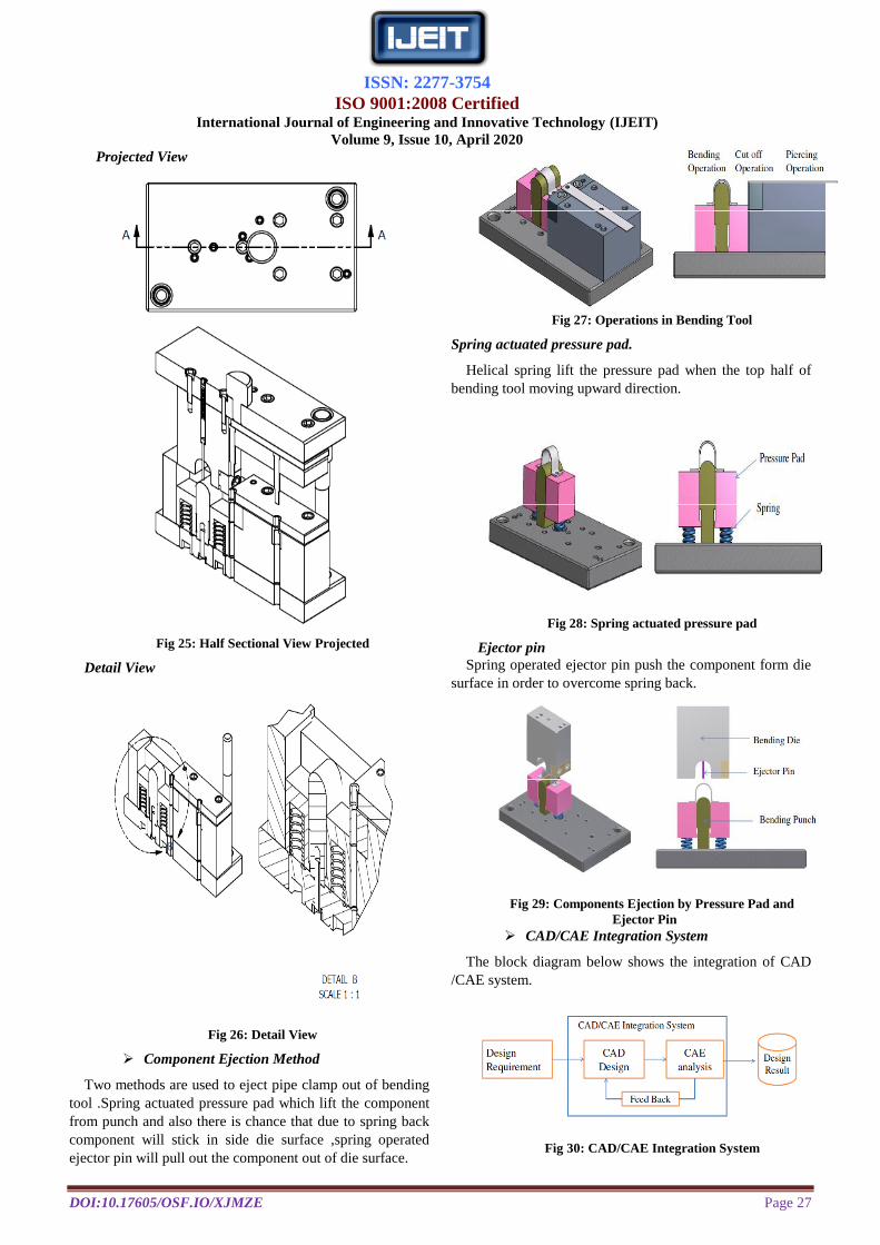
Projected View
Fig 25: Half Sectional View Projected
Detail View
Fig 26: Detail View
Component Ejection Method
Two methods are used to eject pipe clamp out of bending
tool .Spring actuated pressure pad which lift the component
from punch and also there is chance that due to spring back
component will stick in side die surface ,spring operated
ejector pin will pull out the component out of die surface.
Fig 27: Operations in Bending Tool
Spring actuated pressure pad.
Helical spring lift the pressure pad when the top half of
bending tool moving upward direction.
Fig 28: Spring actuated pressure pad
Ejector pin
Spring operated ejector pin push the component form die
surface in order to overcome spring back.
Fig 29: Components Ejection by Pressure Pad and
Ejector Pin
CAD/CAE Integration System
The block diagram below shows the integration of CAD
/CAE system.
Fig 30: CAD/CAE Integration System
ISSN: 2277-3754
ISO 9001:2008 Certified International Journal of Engineering and Innovative Technology (IJEIT)
Volume 9, Issue 10, April 2020
DOI:10.17605/OSF.IO/XJMZE Page 28
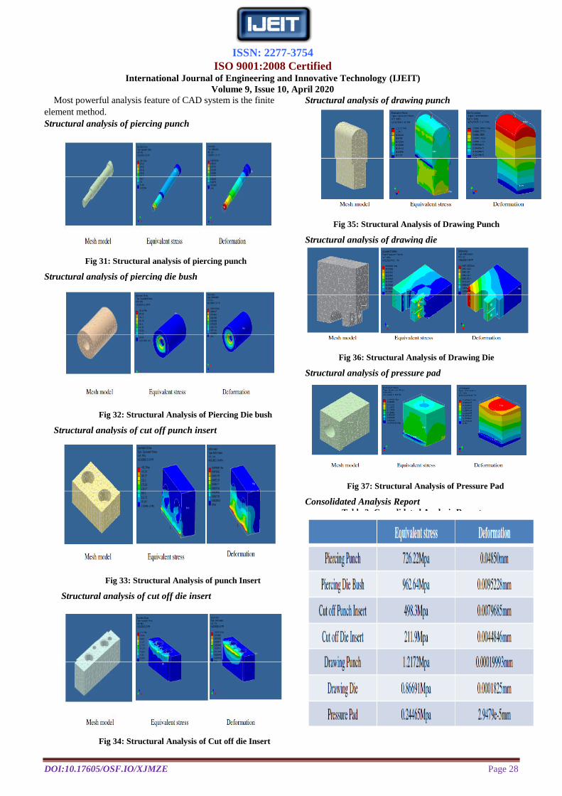
Most powerful analysis feature of CAD system is the finite
element method.
Structural analysis of piercing punch
Fig 31: Structural analysis of piercing punch
Structural analysis of piercing die bush
Fig 32: Structural Analysis of Piercing Die bush
Structural analysis of cut off punch insert
Fig 33: Structural Analysis of punch Insert
Structural analysis of cut off die insert
Fig 34: Structural Analysis of Cut off die Insert
Structural analysis of drawing punch
Fig 35: Structural Analysis of Drawing Punch
Structural analysis of drawing die
Fig 36: Structural Analysis of Drawing Die
Structural analysis of pressure pad
Fig 37: Structural Analysis of Pressure Pad
Consolidated Analysis Report Table 3: Consolidated Analysis Report
ISSN: 2277-3754
ISO 9001:2008 Certified International Journal of Engineering and Innovative Technology (IJEIT)
Volume 9, Issue 10, April 2020
DOI:10.17605/OSF.IO/XJMZE Page 29
V.CONCLUSION
By implementation of computer in design accuracy of
design is improved and design process time is reduced
drastically than by traditional method. Many design problems
which are complicated to eliminate by traditional methods are
eliminated by using CAD system.
Static structural analysis where carried main parts of
bending tool. Equivalent stress and deformation are
effectively analyzed.
VI.FUTURE WORK
CAE plays very significant role in the decision making of
various parameter of sheet metal forming processes and it
helps to designer during product design as well as tool design
stage to decide optimum and accurate process parameter.
CAE software such as hyper form, FEA used for formability
analysis and prediction of any defects during forming
operation.
REFERENCES
[1] Wei Xie and Liaojun Zhang 2019 IOP Conf. Ser.: Earth
Environ. Sci. 242 062076. ” A CAD/CAE integration
technology and its application in hydraulic engineering”.
[2] Ulhas K Annigeri, Y P Deepthi, raghavendra Ravi Kiran K”
Design, Development and Analysis of Forming Tool for Side
Panel of an Automobile. International Journal of Mechanical
and Production Engineering, ISSN: 2320-2092. Volume- 2,
Issue- 6, June-2014.
[3] Anudeep S N. Ramesha”Design and analysis of blanking and
bending press tool to produce anchor bracket component”
International Journal of Engineering Research & Technology
(IJERT) ISSN: 2278-0181 Vol. 4 Issue 04, April-2015.
[4] H. Ameresh, P.Hari Shankar” Progressive Tool Design and
Analysis for 49Lever 5 Stage Tools”. International Journal of
Computer Trends and Technology (IJCTT) – volume 4 Issue
7–July 2013.
[5] Sunny Sainoore, Dr. Gangadhar Angadi, Moin Ahmed
Khan” modelling and analysis of springback effect on rotavator
blade using deform 3D. International Research Journal of
Engineering and Technology (IRJET) e-ISSN: 2395-0056
AUTHOR BIOGRAPHY
Mr. Jibi. R Received M-tech in Production and
Industrial Engineering from SCMS School of
Engineering and Technology Ernakulum Kerala in
2013.Recieved B-tech Degree in Mechanical
Engineering from CUIET Malappuram Kerala in
2011 and Diploma in Tool and Die Making from
KELTRAC Alappuzha in 2008.He has published
Seven International journals and presented two article in International
conference. He has more than seven years experience in teaching and one
year Industrial experience in Press tool and Mold making. His interested area
is computer aided design and analysis, Production Technology and
Industrial Hydraulics. Currently he is working as an Assistant Professor in
the mechanical engineering department at AWH Engineering College
Calicut Kerala India.
Mr. Raswin A C Final year B-tech student in the Mechanical
Engineering Department at AWH Engineering College Calicut
Kerala India.
Mr. Ubaid E Final year B-tech student in the Mechanical
Engineering Department at AWH Engineering College Calicut
Kerala India.
Mr. Ajeesh V Final year B-tech student in the Mechanical
Engineering Department at AWH Engineering College Calicut
Kerala India