institut für informatik der technischen universität münchen
TRANSCRIPT
Institut fur Informatik
der Technischen Universitat Munchen
From Service Delivery to Web-Telecom
Converged Application Delivery in the
Telecommunication Industry
Christian Menkens
Vollstandiger Abdruck der von der Fakultat fur Informatik der Technischen Universitat
Munchen zur Erlangung des akademischen Grades eines
Doktors der Naturwissenschaften (Dr. rer. nat.)
genehmigten Dissertation.
Vorsitzender: ......................................
Prufer der Dissertation:
1. ......................................
2. ......................................
Die Dissertation wurde am ............................. bei der Technischen Universitat Munchen
eingereicht und durch die Fakultat fur Informatik am ............................. angenommen.

Abstract
The Web/Internet’s tremendous success at providing multimedia-communication services andapplications puts the traditional fixed and mobile Telecommunications industry at a crossroads.Since most innovation in this area has come from Application Service Providers (ASP) on theWeb/Internet, Communication Service Providers (CSP) have been pushed into being a mere ”BitPipe” for the Web/Internet’s innovative and successful services and applications.
The Telecommunications industry has started to acknowledge the disadvantages of this trans-formation. To regain flexibility and competitiveness, Telecommunication standardization bodieshave started to shift their focus towards adopting Web/Internet, Service Oriented Architecture(SOA) and Service Delivery Platform (SDP) technologies and concepts. That shift has led to acompatibility of Web/Internet and Telecommunication systems, which has enabled the concept ofWeb-Telecom Convergence. This allows developers to implement future innovative services andapplications by combining Telecommunication services, provided by CSPs, with Web/Internetservices, provided by ASPs.
The goal of the research work is to define and evaluate the concept and reference architectureof a Web-Telecom Convergence Application Delivery Platform (ADP) that supports developersat the development and delivery of Web-Telecom Converged applications. The work identifiesCSPs, ASPs, Device/Platform Manufacturers, Developers and End-Users as the most relevantstakeholders, and illustrates their major Web-Telecom Convergence related goals. It comparesand analyzes common Telecommunication SDP proposals and Web-Telecom Convergence con-cepts, and identifies that most of them are heavily Telecommunication and limited Web/Internetfocused. It identifies that all of them cover certain limited aspects of Web-Telecom Converged ap-plications, but none covers their whole spectrum end-to-end, ranging from the underlying accessnetworks over the Web/Internet and Telecommunication services to the clients on the end-users’devices.
The work defines a generic architecture for a distributed Web-Telecom Converged application thatcovers this whole spectrum end-to-end and fosters a clear separation of a collection of reusableand a collection of application-specific services. Based on that, it applies SOA concepts to extendexisting Telecommunication SDP proposals and Web-Telecom Convergence concepts to definethe logical reference architecture of the ADP. The ADP enables an end-to-end development anddelivery of such distributed Web-Telecom Converged applications by supporting the import andmanagement of reusable Web/Internet and Telecommunication services, the convergence of thoseservices in separated application-specific services and the delivery of the applications via cross-platform compatible end-user clients.
The work evaluates the defined ADP concept and reference architecture through the design of anexemplary technical architecture, the development of two platform prototype iterations and theimplementation of two Web-Telecom Convergence case-study application prototypes on top.

Acknowledgments
I conducted this research work as a research assistant at the Chair for Software and SystemsEngineering as well as a management team member at the Center for Digital Technology andManagement (CDTM) at the Technische Universitat Munchen (TUM). The underlying CDTMproject Telecom Service Enabler Architecture (TeSEA) was supported by Deutsche TelekomLaboratories.
As part of the CDTM management team, I experienced how many great things a small anddedicated group of highly motivated people can achieve. It was a tremendous pleasure to workwith everyone at the CDTM and TUM, and therefore, my special thanks go out to my wonderfulcolleagues Rebecca Ermecke, Fabian Dany, Andreas Schmid, Isabel Dorfler, Philip Mayrhofer,Bernhard Kirchmair, Benedikt Romer, Julian Sussmann, Marie-Luise Lorenz, Nikolaus Konrad,Uta Weber, Mark Bilandzic, Patrick Nepper, Florian Gall, Maximilian Engelken, Kilian Moserand Claudius Jablonka for their support and feedback, especially in the tough final months whenwriting my thesis.
I would like to thank my thesis advisors Prof. Dr. Dr. h.c. Manfred Broy and Prof. Dr. JorgEberspacher, who always engaged me in fruitful discussions and who provided invaluable feedbackfor guiding me towards my research goals.
Apart from my colleagues and advisors, my students Michael Wurtinger, Irina Todoran, Alexan-der Friedl, Tianyi Li and Chi Cuong Le have provided invaluable contributions to the success ofthe TeSEA project, and I would like to thank them for that.
My friends in Austria and Germany have always supported and encouraged me throughout thehighs and lows of my research project work. I thank you all for that.
I would like to especially thank my partner, Angela Schollig, for her tireless encouragement andstrength over the four years of research work and long-distance relationship between Munich andZurich.
To conclude, I would like to thank my parents Hannelore and Manfred Menkens for their contin-uous support throughout the many years of my education, studies and research, for their wisdomand for their generosity. To them I owe it all.

Contents
Abstract iii
Acknowledgments v
Acronyms xiii
1 Introduction 1
1.1 Problems and Motivation . . . . . . . . . . . . . . . . . . . . . . . . . . . . . . . . 3
1.1.1 Competition by Web/Internet Application Service Providers . . . . . . . . 3
1.1.2 Web-Telecom Service and Application Convergence . . . . . . . . . . . . . . 5
1.1.3 Third Party Developer Platforms . . . . . . . . . . . . . . . . . . . . . . . . 6
1.1.4 Developer Communities . . . . . . . . . . . . . . . . . . . . . . . . . . . . . 7
1.1.5 Application Stores . . . . . . . . . . . . . . . . . . . . . . . . . . . . . . . . 7
1.1.6 Cross-Platform Compatible Applications . . . . . . . . . . . . . . . . . . . . 9
1.1.7 Towards Proprietary Monopolies for Communication Services . . . . . . . . 9
1.1.8 Conclusion . . . . . . . . . . . . . . . . . . . . . . . . . . . . . . . . . . . . 10
1.2 Contributions . . . . . . . . . . . . . . . . . . . . . . . . . . . . . . . . . . . . . . . 10
1.3 Methodology and Approach . . . . . . . . . . . . . . . . . . . . . . . . . . . . . . . 11
1.3.1 Design Science . . . . . . . . . . . . . . . . . . . . . . . . . . . . . . . . . . 11
1.3.2 Research Approach . . . . . . . . . . . . . . . . . . . . . . . . . . . . . . . . 13
1.4 Structure of Thesis . . . . . . . . . . . . . . . . . . . . . . . . . . . . . . . . . . . . 15
2 Terminology, Definitions and Concepts 17
2.1 Distinction between Service and Application . . . . . . . . . . . . . . . . . . . . . . 17
2.2 Service Oriented Architectures . . . . . . . . . . . . . . . . . . . . . . . . . . . . . 18
2.2.1 SOA Manifesto . . . . . . . . . . . . . . . . . . . . . . . . . . . . . . . . . . 20
2.2.2 Web Service . . . . . . . . . . . . . . . . . . . . . . . . . . . . . . . . . . . . 20
2.2.3 SOA Triangular Model . . . . . . . . . . . . . . . . . . . . . . . . . . . . . . 20
2.2.4 Service Lifecycle . . . . . . . . . . . . . . . . . . . . . . . . . . . . . . . . . 21
viii Contents
2.2.5 Service Layers . . . . . . . . . . . . . . . . . . . . . . . . . . . . . . . . . . 23
2.3 Enterprise Service Bus . . . . . . . . . . . . . . . . . . . . . . . . . . . . . . . . . . 25
2.4 SOA Reference Architecture . . . . . . . . . . . . . . . . . . . . . . . . . . . . . . . 28
2.5 Service Delivery Platform . . . . . . . . . . . . . . . . . . . . . . . . . . . . . . . . 29
2.6 Device Centric vs. Service Delivery Platform Centric . . . . . . . . . . . . . . . . . 31
2.7 Application Lifecycle . . . . . . . . . . . . . . . . . . . . . . . . . . . . . . . . . . . 32
2.8 Convergence . . . . . . . . . . . . . . . . . . . . . . . . . . . . . . . . . . . . . . . . 33
2.8.1 Fixed-Mobile Convergence . . . . . . . . . . . . . . . . . . . . . . . . . . . . 33
2.8.2 Media-Telecom Convergence . . . . . . . . . . . . . . . . . . . . . . . . . . . 36
2.8.3 Web-Telecom Convergence . . . . . . . . . . . . . . . . . . . . . . . . . . . 36
3 Web-Telecom Convergence Stakeholder Goals 39
3.1 Communication Service Providers . . . . . . . . . . . . . . . . . . . . . . . . . . . . 40
3.2 Application Service Providers . . . . . . . . . . . . . . . . . . . . . . . . . . . . . . 43
3.3 Device and Platform Manufacturers . . . . . . . . . . . . . . . . . . . . . . . . . . 45
3.4 Developers . . . . . . . . . . . . . . . . . . . . . . . . . . . . . . . . . . . . . . . . . 49
3.5 End-Users . . . . . . . . . . . . . . . . . . . . . . . . . . . . . . . . . . . . . . . . . 57
3.6 Technology Providers, Content Providers, Advertisers . . . . . . . . . . . . . . . . 62
4 Analysis 63
4.1 The Evolution of Telecommunication Service and Application Development . . . . 63
4.1.1 Intelligent Networks . . . . . . . . . . . . . . . . . . . . . . . . . . . . . . . 64
4.1.2 Customized Applications for Mobile Enhanced Logic . . . . . . . . . . . . . 65
4.1.3 Telecommunication Information Networking Architecture . . . . . . . . . . 66
4.1.4 Open Application Programming Interface . . . . . . . . . . . . . . . . . . . 66
4.1.4.1 Parlay . . . . . . . . . . . . . . . . . . . . . . . . . . . . . . . . . . 66
4.1.4.2 Java API for Intelligent Networks . . . . . . . . . . . . . . . . . . 67
4.1.4.3 Conclusion . . . . . . . . . . . . . . . . . . . . . . . . . . . . . . . 68
4.1.5 Adoption of Web/Internet Servlet Development Concepts . . . . . . . . . . 69
4.1.6 Web Service-Based Concepts . . . . . . . . . . . . . . . . . . . . . . . . . . 69
4.1.7 Telecommunication Service Orchestration . . . . . . . . . . . . . . . . . . . 70
4.2 Evaluation of Web-Telecom Convergence Concepts and Platforms . . . . . . . . . . 71
4.2.1 Comparing Established Web-Telecom Convergence Platform Concepts . . . 71
4.2.1.1 Comparison Methodology . . . . . . . . . . . . . . . . . . . . . . . 71
4.2.1.2 Defining Comparison Methodology Parameters . . . . . . . . . . . 73
4.2.1.3 Comparison of Web-Telecom Convergence Platform Proposals . . 76
4.2.2 Discussing Web-Telecom Convergence Research Results . . . . . . . . . . . 77
Contents ix
4.2.3 Evaluation Conclusions . . . . . . . . . . . . . . . . . . . . . . . . . . . . . 78
4.3 Evaluation of Mobile Application Development Technologies . . . . . . . . . . . . . 79
4.3.1 Mobile Platforms . . . . . . . . . . . . . . . . . . . . . . . . . . . . . . . . . 80
4.3.2 Mobile Development Frameworks . . . . . . . . . . . . . . . . . . . . . . . . 83
5 Design of Web-Telecom Converged Applications 87
5.1 Web-Telecom Convergence Application Scenarios . . . . . . . . . . . . . . . . . . . 87
5.1.1 Unified Address Book . . . . . . . . . . . . . . . . . . . . . . . . . . . . . . 87
5.1.2 Social Notification Application . . . . . . . . . . . . . . . . . . . . . . . . . 88
5.1.3 Postal Service Notification . . . . . . . . . . . . . . . . . . . . . . . . . . . . 89
5.1.4 Dynamic Voice Mail Message . . . . . . . . . . . . . . . . . . . . . . . . . . 89
5.1.5 Automated Telephone Conference . . . . . . . . . . . . . . . . . . . . . . . 90
5.1.6 Click-to-Call Supplement to Business Software . . . . . . . . . . . . . . . . 90
5.2 Logical Reference Architecture of a Web-Telecom Converged Application . . . . . . 90
5.3 Technical Architecture of a Web-Telecom Converged Application . . . . . . . . . . 92
6 Requirements for a Web-Telecom Convergence Platform 95
6.1 Deriving Requirements from Stakeholder Goals . . . . . . . . . . . . . . . . . . . . 95
6.2 Deriving Requirements from Analysis and Applications Design . . . . . . . . . . . 101
7 Design of the Application Delivery Platform 103
7.1 Core Concepts of the Application Delivery Platform . . . . . . . . . . . . . . . . . 103
7.1.1 C1 - Extending the Concepts of Service Delivery Platform to an ApplicationDelivery Platform . . . . . . . . . . . . . . . . . . . . . . . . . . . . . . . . 103
7.1.2 C2 - Separation of Networks and Applications . . . . . . . . . . . . . . . . . 105
7.1.3 C3 - Layered Architecture . . . . . . . . . . . . . . . . . . . . . . . . . . . . 107
7.1.3.1 C3.1 - Web-Telecom Convergence on Lowest Platform Layer . . . 107
7.1.3.2 C3.2 - Separation of Shared and Application Services Layers . . . 108
7.1.3.3 C3.3 - The Introduction of the ISO/OSI Application Layer inTelecommunications . . . . . . . . . . . . . . . . . . . . . . . . . . 109
7.1.3.4 C3.4 - Quality of Service (QoS), Authentication, Authorization,Accounting (AAA), SCIM and PEEM Layers . . . . . . . . . . . . 110
7.1.4 C4 - Layered Telecommunication Standardization . . . . . . . . . . . . . . . 112
7.1.5 C5 - Scopes and Types of ADP Services . . . . . . . . . . . . . . . . . . . . 113
7.1.6 C6 - SOA Concepts-based Application Delivery Platform . . . . . . . . . . 115
7.1.7 C7 - Inside-Out through Telecommunication Service Exposure . . . . . . . 118
7.1.8 C8 - Outside-In through Semi-Automatic Service Import . . . . . . . . . . . 119
7.1.9 C9 - Internet of Services through a Collaboration of Platforms across Domains120
x Contents
7.1.10 C10 - Application Distribution . . . . . . . . . . . . . . . . . . . . . . . . . 120
7.1.11 C11 - Services and Applications Monitoring . . . . . . . . . . . . . . . . . . 121
7.2 Logical Reference Architecture of the Application Delivery Platform . . . . . . . . 122
7.2.1 Network Layer . . . . . . . . . . . . . . . . . . . . . . . . . . . . . . . . . . 123
7.2.2 Telecommunication Services Layer . . . . . . . . . . . . . . . . . . . . . . . 123
7.2.3 Web/Internet Services Layer . . . . . . . . . . . . . . . . . . . . . . . . . . 123
7.2.4 Shared Services Layer . . . . . . . . . . . . . . . . . . . . . . . . . . . . . . 123
7.2.5 Application Services Layer . . . . . . . . . . . . . . . . . . . . . . . . . . . 125
7.2.6 Client Proxy Layer . . . . . . . . . . . . . . . . . . . . . . . . . . . . . . . . 127
7.2.7 Thin Client Layer . . . . . . . . . . . . . . . . . . . . . . . . . . . . . . . . 127
7.3 Technical Architecture of the Application Delivery Platform . . . . . . . . . . . . . 127
7.3.1 Device Platforms and APIs Layer . . . . . . . . . . . . . . . . . . . . . . . . 129
7.3.2 Network Layer . . . . . . . . . . . . . . . . . . . . . . . . . . . . . . . . . . 129
7.3.3 Telecommunication Services Layer . . . . . . . . . . . . . . . . . . . . . . . 129
7.3.4 Web/Internet Services Layer . . . . . . . . . . . . . . . . . . . . . . . . . . 130
7.3.5 Shared Services Layer . . . . . . . . . . . . . . . . . . . . . . . . . . . . . . 130
7.3.6 Application Services Layer . . . . . . . . . . . . . . . . . . . . . . . . . . . 131
7.3.7 Client Proxy Layer . . . . . . . . . . . . . . . . . . . . . . . . . . . . . . . . 132
8 Validation and Evaluation of the Application Delivery Platform Concept 133
8.1 Requirements Assessment . . . . . . . . . . . . . . . . . . . . . . . . . . . . . . . . 133
8.2 Proof of Concept Prototypes . . . . . . . . . . . . . . . . . . . . . . . . . . . . . . 135
8.2.1 First Iteration Application Delivery Platform Prototype . . . . . . . . . . . 136
8.2.2 Unified Address Book Application Prototype . . . . . . . . . . . . . . . . . 137
8.2.3 Second Iteration Application Delivery Platform Prototype . . . . . . . . . . 138
8.2.3.1 Semi-Automatic Service Import . . . . . . . . . . . . . . . . . . . 139
8.2.3.2 Application Delivery Platform . . . . . . . . . . . . . . . . . . . . 141
8.2.4 Social Notification Application Prototype . . . . . . . . . . . . . . . . . . . 142
8.2.4.1 Motivation and Goals . . . . . . . . . . . . . . . . . . . . . . . . . 142
8.2.4.2 Component Architecture . . . . . . . . . . . . . . . . . . . . . . . 143
8.3 Core Concepts Assessment . . . . . . . . . . . . . . . . . . . . . . . . . . . . . . . . 144
9 Conclusion and Future Work 147
Appendix 149
A Web-Telecom Convergence Concepts and Platforms Evaluation Details 149
Contents xi
A.1 Business Requirements . . . . . . . . . . . . . . . . . . . . . . . . . . . . . . . . . . 149
A.2 Architectural Services . . . . . . . . . . . . . . . . . . . . . . . . . . . . . . . . . . 150
A.3 Quality Subfactors . . . . . . . . . . . . . . . . . . . . . . . . . . . . . . . . . . . . 152
B Service Description Languages Evaluation 155
C Mobile Application Development Technologies Evaluation Details 157
C.1 Mobile Platforms . . . . . . . . . . . . . . . . . . . . . . . . . . . . . . . . . . . . . 157
C.2 Cross-Platform Mobile Development Frameworks . . . . . . . . . . . . . . . . . . . 158
D Semi-Automatic Service Integration Prototype Template 161
E SNApp Exemplary Message Sequence of Facebook Support 163
F Related Technologies, Standards and Specifications 165
F.1 Internet and Telecommunication Protocols . . . . . . . . . . . . . . . . . . . . . . . 165
F.2 Multimedia Streaming Protocols . . . . . . . . . . . . . . . . . . . . . . . . . . . . 177
F.3 Voice-over-IP (VoIP) . . . . . . . . . . . . . . . . . . . . . . . . . . . . . . . . . . . 182
F.4 Mobile Web/Internet Access Network Technologies . . . . . . . . . . . . . . . . . . 185
F.5 Mobile IP Core Network Technologies . . . . . . . . . . . . . . . . . . . . . . . . . 190
F.6 Open Services Gateway Initiative (OSGi) . . . . . . . . . . . . . . . . . . . . . . . 210
F.7 Representational State Transfer (REST) . . . . . . . . . . . . . . . . . . . . . . . . 211
List of Figures 215
List of Tables 219
Listings 221
Bibliography 223

Acronyms
3GPP . . . . . . . . Third Generation Partnership Project [217]A4C . . . . . . . . . Authentication, Authorization, Accounting, Auditing and ChargingAAA . . . . . . . . Authentication, Authorization, AccountingAADM . . . . . . . Asset-Based Architecture Design Methodology for Rapid Telecom Ser-
vice Delivery Platform DevelopmentADP . . . . . . . . Application Delivery PlatformAJAX . . . . . . . . Asynchronous JavaScript and XML [75]ALM . . . . . . . . Application Lifecycle ManagementAPI . . . . . . . . . Application Programming InterfaceASP . . . . . . . . . Web/Internet Application Service ProviderBIS . . . . . . . . . Business Information SystemBPEL . . . . . . . . Business Process Execution Language [157]BSS . . . . . . . . . Business Support SystemCAB . . . . . . . . Converged Address Book [169]CAMEL . . . . . . Customized Applications for Mobile Enhanced LogicCAPEX . . . . . . . Capital ExpenditureCEP . . . . . . . . . Complex Event Processing [131, 137]CRM . . . . . . . . Customer Relationship ManagementCSCF . . . . . . . . Call Session Control FunctionCSP . . . . . . . . . Communication Service ProviderDoSAM . . . . . . . Domain Specific Software Architecture Comparison ModelDPE . . . . . . . . . Distributed Processing EnvironmentDSL . . . . . . . . . Digital Subscriber Line [100]EAI . . . . . . . . . Enterprise Application IntegrationEDA . . . . . . . . . Event Driven ArchitectureEDGE . . . . . . . . Enhanced Data Rates for GSM EvolutionEPC . . . . . . . . . Evolved Packet Core [160] [6] [65]EPS . . . . . . . . . Evolved Packet System [124]ERP . . . . . . . . . Enterprise Resource PlanningESB . . . . . . . . . Enterprise Service BusETSI . . . . . . . . European Telecommunications Standards InstituteFMC . . . . . . . . Fixed Mobile ConvergenceGGSN . . . . . . . Gateway GPRS Support NodeGPRS . . . . . . . . General Packet Radio ServiceGSM . . . . . . . . Global System for Mobile CommunicationGUI . . . . . . . . . Graphical User InterfaceHLR . . . . . . . . . Home Location RegisterHSDPA . . . . . . . High Speed Downlink Packet AccessHSOPA . . . . . . . High Speed OFDM Packet Access
xiv Acronyms
HSPA . . . . . . . . High Speed Packet Access [78] [33]HSS . . . . . . . . . Home Subscriber ServerHSUPA . . . . . . . High Speed Uplink Packet AccessHTML . . . . . . . Hypertext Markup Language [240]HTML5 . . . . . . . Hypertext Markup Language Version 5 [247]HTTP . . . . . . . . Hypertext Transfer Protocol [71]IaaS . . . . . . . . . Infrastructure-as-a-ServiceICT . . . . . . . . . Information and Communication TechnologyIDE . . . . . . . . . Integrated Development EnvironmentIDM . . . . . . . . . Identity ManagementIETF . . . . . . . . Internet Engineering Task ForceIMS . . . . . . . . . IP Multimedia Subsystem [213]IN . . . . . . . . . . Intelligent NetworkINAP . . . . . . . . IN Application ProtocolISDN . . . . . . . . Integrated Services Digital NetworkISP . . . . . . . . . Internet Service ProviderIT . . . . . . . . . . Information TechnologyITU . . . . . . . . . International Telecommunication UnionJAIN . . . . . . . . Java API for Intelligent NetworksJCA . . . . . . . . . JAIN Coordination and TransactionJCC . . . . . . . . . JAIN Call ControlJCP . . . . . . . . . Java Community ProcessJNI . . . . . . . . . Java Native InterfaceJSLEE . . . . . . . JAIN Service Logic Execution EnvironmentJSON . . . . . . . . JavaScript Object NotationJSR . . . . . . . . . Java Specification RequestLTE . . . . . . . . . Long Term Evolution [36] [147] [89] [186]MDA . . . . . . . . Model Driven ArchitectureMGCP . . . . . . . Media Gateway Control ProtocolMIMO . . . . . . . Multiple Input Multiple OutputMOM . . . . . . . . Message Oriented MiddlewareMSC . . . . . . . . Mobile Services Switching CenterMVC . . . . . . . . Model View Controller [201]MVNO . . . . . . . Mobile Virtual Network OperatorNDK . . . . . . . . Native Development KitNFC . . . . . . . . . Near Field CommunicationNGN . . . . . . . . Next Generation NetworkOEM . . . . . . . . Original Equipment ManufacturerOFDM . . . . . . . Orthogonal Frequency Division MultiplexingOFDMA . . . . . . Orthogonal Frequency Division Multiple AccessOIPF . . . . . . . . Open IPTV ForumOMA . . . . . . . . Open Mobile AllianceOMG . . . . . . . . Object Management GroupOPEX . . . . . . . . Operational ExpenditureOS . . . . . . . . . . Operating SystemOSA . . . . . . . . . Open Service AccessOSAG . . . . . . . . Open Service Access GatewayOSE . . . . . . . . . OMA Service Environment [163]OSGi . . . . . . . . Open Services Gateway Initiative [177]OSI . . . . . . . . . Open Systems InterconnectionOSPE . . . . . . . . OMA Service Provider Environment [168]
Acronyms xv
OSS . . . . . . . . . Operations Support SystemOTT . . . . . . . . . Over-the-TopPaaS . . . . . . . . Platform-as-a-ServicePBX . . . . . . . . . Personal Branch ExchangePDF . . . . . . . . . Policy Decision FunctionPEEM . . . . . . . Policy Evaluation Enforcement and Management [165]POTS . . . . . . . . Plain Old Telephone SystemPSTN . . . . . . . . Public Switched Telephone NetworkQoE . . . . . . . . . Quality of ExperienceQoS . . . . . . . . . Quality of ServiceRAN . . . . . . . . Radio Access NetworkRCS . . . . . . . . . Rich Communication SuiteREST . . . . . . . . Representational State Transfer [70]RFC . . . . . . . . . Request for CommentRNC . . . . . . . . Radio Network ControllerRPC . . . . . . . . Remote Procedure CallRSVP . . . . . . . . Resource Reservation Protocol [252]RTCP . . . . . . . . Real Time Control ProtocolRTP . . . . . . . . . Real Time Transport ProtocolRTSP . . . . . . . . Real Time Streaming ProtocolSaaS . . . . . . . . . Software-as-a-Service [202]SAE . . . . . . . . . System Architecture Evolution [160]SCE . . . . . . . . . Service Creation EnvironmentSCIM . . . . . . . . Service Capability Interaction Manager [225, 107, 146]SCP . . . . . . . . . Service Control PointSCXML . . . . . . . State Chart XML [146]SDE . . . . . . . . . Service Delivery Environment [7]SDF . . . . . . . . . Service Delivery Framework [222]SDK . . . . . . . . . Software Development KitSDL . . . . . . . . . Service Description LanguageSDLC . . . . . . . . Software Development LifecycleSDP . . . . . . . . . Service Delivery Platform [168] [163] [7] [222] [158] [132] [2] [148]SE . . . . . . . . . . Service Environment [163]SGCP . . . . . . . . Simple Gateway Control ProtocolSGSN . . . . . . . . Service GPRS Support NodeSIB . . . . . . . . . Service Independent Building BlockSIP . . . . . . . . . Session Initiation ProtocolSLA . . . . . . . . . Service Level AgreementSLF . . . . . . . . . Subscriber Location FunctionSOA . . . . . . . . . Service Oriented Architecture [66]SOAP . . . . . . . . Simple Object Access Protocol [241]SOARA . . . . . . . Service Oriented Architecture Reference Architecture [251]SPICE . . . . . . . Service Platform for Innovative Communication EnvironmentSQMM . . . . . . . Software Quality Metrics MethodologySS7 . . . . . . . . . Signaling System 7TCP/IP . . . . . . Transmission Control Protocol / Internet Protocol [228]TINA . . . . . . . . Telecommunications Information Networking ArchitectureTISPAN . . . . . . Telecoms and Internet converged Services and Protocols for Advanced
NetworksTMForum . . . . . Tele Management ForumUDP . . . . . . . . User Datagram Protocol
xvi Acronyms
UML . . . . . . . . Unified Modeling LanguageUMTS . . . . . . . Universal Mobile Telecommunication SystemURI . . . . . . . . . Uniform Resource IdentificationUTRAN . . . . . . UMTS Terrestrial Radio Access NetworkVOD . . . . . . . . Video-on-DemandVoIP . . . . . . . . Voice-over-IPW3C . . . . . . . . World Wide Web ConsortiumWAC . . . . . . . . Wholesale Applications Community [235]WADL . . . . . . . Web Application Description Language [180]WAP . . . . . . . . Wireless Access ProtocolWCDMA . . . . . . Wideband Code Division Multiple AccessWLAN . . . . . . . Wireless Local Area NetworkWSCI . . . . . . . . Web Service Choreography Interface [243]WSDL . . . . . . . Web Service Description Language [244]XCAP . . . . . . . XML Configuration Access Protocol [189]XDMS . . . . . . . XML Document Management ServerXML . . . . . . . . Extensible Markup Language
Chapter 1
Introduction
Over recent decades, modern Information and Communication Technologies (ICTs) have trans-formed the way in which we live, work and play. Fixed and mobile Telecommunications and theWeb/Internet have evolved to an integral component of our society and are steadily advancingtechnologically to provide an ever increasing number of innovative services and applications.
The currently used business model of Communication Service Provider (CSP) has been optimizedfrom the invention of the telephone in 1876 through the mass adoption of the mobile telephone.This Voice-Driven Circuit-Switched paradigm is based on vertical integration, charging based ontime, duration and distance as well as on the intelligence and control being located within theCSPs network. This forms a one-sided market revenue model where the CSPs buy equipmentand content from vendors and suppliers, integrate those to Telecommunication services and ap-plications on their fully owned and controlled networks, and bill their customers for the use theseservices and applications [148, 50].
With the Web/Internet research and developments starting in the 1950s a data-driven and packet-switched paradigm has emerged. This is characterized by a decoupling of services and applicationssuch as voice, data, video, images from the underlying data transfer networks. It is based on ahorizontal integration, flat-rate charges based on data rate or data volume, and the intelligencebeing located in the terminals connected at the edge of the networks [110, 128].
The Web/Internet becoming accessible to the general public at the beginning of the 1990s formsthe start of several transformations in the Telecommunications industry. At first the bound-aries were well-defined, CSPs were still offering simple communication services and applicationsto consumers and more complex communication and connectivity services and applications tobusinesses. Internet Service Providers (ISPs) were offering data connectivity for simple datadriven applications like E-Mail, Web Sites, Text Chat, etc. that were provided by Web/InternetApplication Service Providers (ASPs) [123].
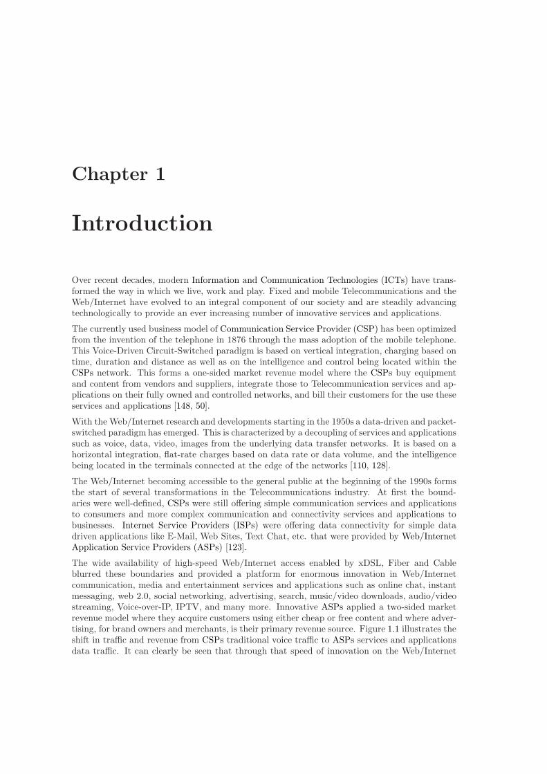
The wide availability of high-speed Web/Internet access enabled by xDSL, Fiber and Cableblurred these boundaries and provided a platform for enormous innovation in Web/Internetcommunication, media and entertainment services and applications such as online chat, instantmessaging, web 2.0, social networking, advertising, search, music/video downloads, audio/videostreaming, Voice-over-IP, IPTV, and many more. Innovative ASPs applied a two-sided marketrevenue model where they acquire customers using either cheap or free content and where adver-tising, for brand owners and merchants, is their primary revenue source. Figure 1.1 illustrates theshift in traffic and revenue from CSPs traditional voice traffic to ASPs services and applicationsdata traffic. It can clearly be seen that through that speed of innovation on the Web/Internet
2 Chapter 1. Introduction
data traffic has been growing rapidly while traffic and revenue from traditional services and ap-plications of CSPs like voice has declined from roughly 80% around the year 2000 to less than50% today [148, 123].
Figure 1.1: Ratio of Voice and Data Traffic and Revenue [38]
Many ASPs such as AOL, Yahoo, Google, Microsoft, Skype, Facebook etc. have played majorroles in the growth and spread of innovative Web/Internet communication, media and entertain-ment services and applications. As a reaction to the growth of data traffic and the prospects ofbusiness opportunities in this area, most CSPs expanded their service offerings to data traffic/vol-ume revenue models on their networks. Nevertheless, most CSPs were too slow to innovate newservices and applications around new business models within their Telecommunication networksand/or on the Web/Internet. Hence, in most cases, CSPs have not been the source of service andapplication innovation but have only provided the data transfer network (”bit pipe”) for thesenew over-the-top services and applications of ASPs. [193, 86, 23].
In parallel to the developments in the Fixed Telecommunication and the Web/Internet industry,in the Mobile Telecommunication industry a large penetration of mobile devices, in particularsmart phones, and the development of mobile broadband have been important factors for theincreasing emergence of innovative mobile applications and services [99, 50, 206].
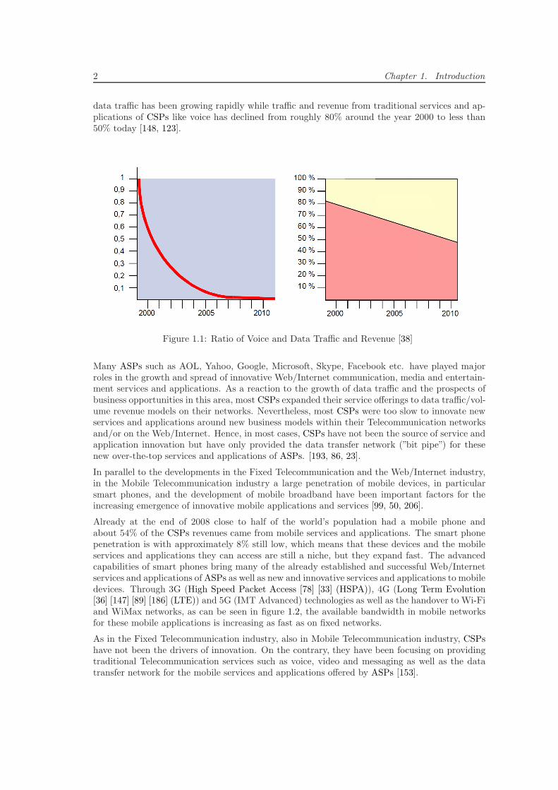
Already at the end of 2008 close to half of the world’s population had a mobile phone andabout 54% of the CSPs revenues came from mobile services and applications. The smart phonepenetration is with approximately 8% still low, which means that these devices and the mobileservices and applications they can access are still a niche, but they expand fast. The advancedcapabilities of smart phones bring many of the already established and successful Web/Internetservices and applications of ASPs as well as new and innovative services and applications to mobiledevices. Through 3G (High Speed Packet Access [78] [33] (HSPA)), 4G (Long Term Evolution[36] [147] [89] [186] (LTE)) and 5G (IMT Advanced) technologies as well as the handover to Wi-Fiand WiMax networks, as can be seen in figure 1.2, the available bandwidth in mobile networksfor these mobile applications is increasing as fast as on fixed networks.
As in the Fixed Telecommunication industry, also in Mobile Telecommunication industry, CSPshave not been the drivers of innovation. On the contrary, they have been focusing on providingtraditional Telecommunication services such as voice, video and messaging as well as the datatransfer network for the mobile services and applications offered by ASPs [153].
1.1. Problems and Motivation 3
Figure 1.2: Fixed and Mobile Bandwidth Evolution [150]
In contrast to ASPs on the Web/Internet and CSPs on their Fixed and Mobile Telecommunica-tion networks, mobile phone, especially smart phone, Original Equipment Manufacturers (OEMs)invented a device-centric revenue business model. This is characterized by building a large com-munity of mobile service and application developers around a smart phone software platform,implementing a revenue share model with those developers and, through OEM owned platform-specific application stores, realizing a direct distribution and sales channel for these new servicesand applications from the developers over the store right to the smart phones [148, 153].
1.1 Problems and Motivation
This section discusses the increasing competition between CSPs and ASPs at end-user multi-media communication services and applications. It outlines the CSPs plans to succeed in thiscompetition through the increase of services and applications innovation. It discusses their ideasof deploying Web-Telecom Convergence platforms, launching application stores and building de-veloper communities and highlights their major challenges, which also motivate this researchwork.
1.1.1 Competition by Web/Internet Application Service Providers
Today, high-speed Web/Internet access with speeds of up to tens or even hundreds of megabitsper second are typically available to end-user at home and work. This enables ASPs to deliverhigh-quality real-time audio/video multimedia services and applications over the Web/Internetper, so called, best-effort meaning without the need to control parameters or features of theunderlying data transfer network. By that, the services and applications and the network that ismostly provided by CSPs, are completely separated. The former major advantages and businessproposition of CSPs, to deliver higher quality Telecommunication services and applications byhaving full control over the services and applications, the network and its end-to-end connectionparameters (e.g. QoS) is rapidly diminishing. Nowadays, end-users often receive a similar QoSand Quality of Experience (QoE) from ASPs multimedia services and applications at a muchlower price or even for free [236, 128].
4 Chapter 1. Introduction
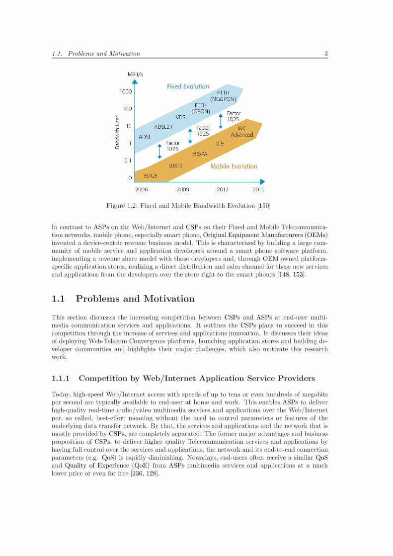
This increasing success of ASPs at providing real-time multimedia services and applications overthe Web/Internet poses an increasing threat and competition to the CSPs business models.Figure 1.3 illustrates the projected development of voice traffic in percent of total voice traffic inEurope. The bottom two segments show the CSPs traditional and enhanced voice traffic and thetop two segments the ASPs voice traffic over dedicated as well as in other Web/Internet servicesand applications embedded communication services and applications. It illustrates clearly thatASPs have already taken over a large amount of voice traffic from CSPs and that this trend iscontinuing and even accelerating. This, combined with large infrastructure investment in fixed(Digital Subscriber Line [100] (DSL), cable and fiber) and mobile (HSPA, LTE) access networks,the fact that voice and data services are increasingly seen as commodity by customers, the strongcompetition between CSPs and the resulting decline in prices for voice minutes, messaging anddata volume puts a heavy burden on CSPs business prospects.
Figure 1.3: Development of Voice Traffic [208]
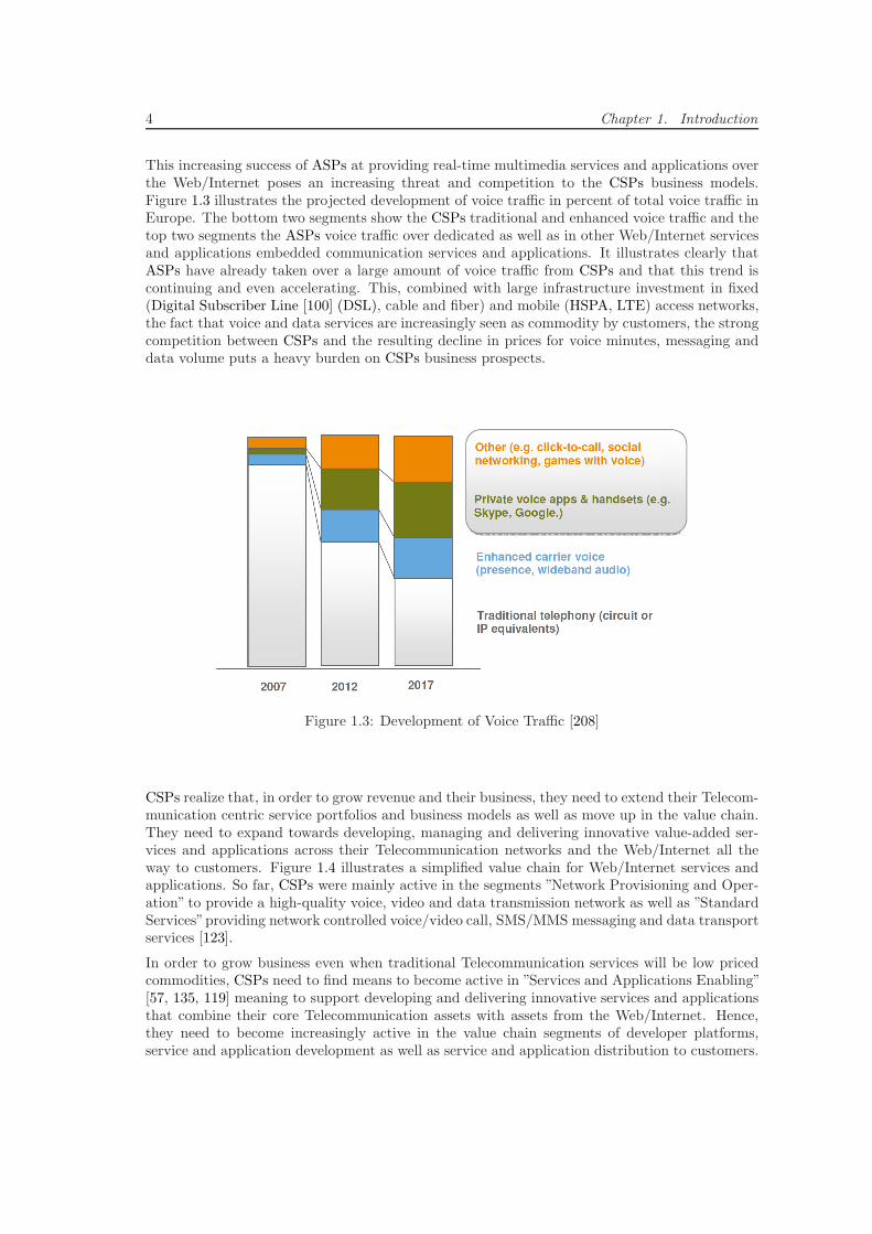
CSPs realize that, in order to grow revenue and their business, they need to extend their Telecom-munication centric service portfolios and business models as well as move up in the value chain.They need to expand towards developing, managing and delivering innovative value-added ser-vices and applications across their Telecommunication networks and the Web/Internet all theway to customers. Figure 1.4 illustrates a simplified value chain for Web/Internet services andapplications. So far, CSPs were mainly active in the segments ”Network Provisioning and Oper-ation” to provide a high-quality voice, video and data transmission network as well as ”StandardServices”providing network controlled voice/video call, SMS/MMS messaging and data transportservices [123].
In order to grow business even when traditional Telecommunication services will be low pricedcommodities, CSPs need to find means to become active in ”Services and Applications Enabling”[57, 135, 119] meaning to support developing and delivering innovative services and applicationsthat combine their core Telecommunication assets with assets from the Web/Internet. Hence,they need to become increasingly active in the value chain segments of developer platforms,service and application development as well as service and application distribution to customers.
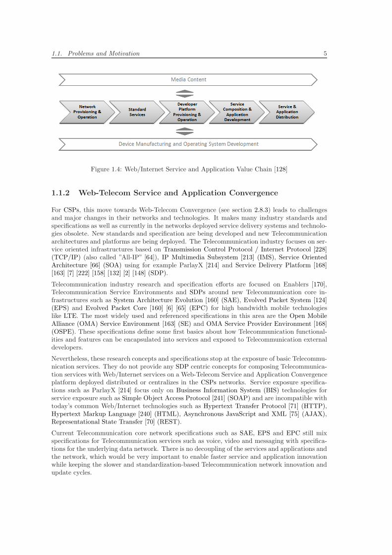
1.1. Problems and Motivation 5
Figure 1.4: Web/Internet Service and Application Value Chain [128]
1.1.2 Web-Telecom Service and Application Convergence
For CSPs, this move towards Web-Telecom Convergence (see section 2.8.3) leads to challengesand major changes in their networks and technologies. It makes many industry standards andspecifications as well as currently in the networks deployed service delivery systems and technolo-gies obsolete. New standards and specification are being developed and new Telecommunicationarchitectures and platforms are being deployed. The Telecommunication industry focuses on ser-vice oriented infrastructures based on Transmission Control Protocol / Internet Protocol [228](TCP/IP) (also called ”All-IP” [64]), IP Multimedia Subsystem [213] (IMS), Service OrientedArchitecture [66] (SOA) using for example ParlayX [214] and Service Delivery Platform [168][163] [7] [222] [158] [132] [2] [148] (SDP).
Telecommunication industry research and specification efforts are focused on Enablers [170],Telecommunication Service Environments and SDPs around new Telecommunication core in-frastructures such as System Architecture Evolution [160] (SAE), Evolved Packet System [124](EPS) and Evolved Packet Core [160] [6] [65] (EPC) for high bandwidth mobile technologieslike LTE. The most widely used and referenced specifications in this area are the Open MobileAlliance (OMA) Service Environment [163] (SE) and OMA Service Provider Environment [168](OSPE). These specifications define some first basics about how Telecommunication functional-ities and features can be encapsulated into services and exposed to Telecommunication externaldevelopers.
Nevertheless, these research concepts and specifications stop at the exposure of basic Telecommu-nication services. They do not provide any SDP centric concepts for composing Telecommunica-tion services with Web/Internet services on a Web-Telecom Service and Application Convergenceplatform deployed distributed or centralizes in the CSPs networks. Service exposure specifica-tions such as ParlayX [214] focus only on Business Information System (BIS) technologies forservice exposure such as Simple Object Access Protocol [241] (SOAP) and are incompatible withtoday’s common Web/Internet technologies such as Hypertext Transfer Protocol [71] (HTTP),Hypertext Markup Language [240] (HTML), Asynchronous JavaScript and XML [75] (AJAX),Representational State Transfer [70] (REST).
Current Telecommunication core network specifications such as SAE, EPS and EPC still mixspecifications for Telecommunication services such as voice, video and messaging with specifica-tions for the underlying data network. There is no decoupling of the services and applications andthe network, which would be very important to enable faster service and application innovationwhile keeping the slower and standardization-based Telecommunication network innovation andupdate cycles.
6 Chapter 1. Introduction
1.1.3 Third Party Developer Platforms
Telecommunication industry specifications and standards related to client devices like computers,(IP)TVs and mobile devices such as OMA Mobile Application Environment [173], OMA ClientProvisioning [167], OMA Device Management [162], OMA Software Component Management[166], OMA Software and Application Control Management [172] or OMA Browsing [174] arelimited to provisioning, configuration and in parts delivery of applications or components to clientdevices. They do not include any solutions or concepts for application development supportor application lifecycle management [11]. To support developers and CSPs at Web-TelecomConverged service and application development, management and distribution it is necessary tofocus on the whole Open Systems Interconnection (OSI) Application Layer [97]. This spans frombasic Web/Internet and Telecommunication services deployed and running on SDPs to managingthird party developer applications running on end-user devices and platforms.
Telecommunication industry specifications and standards related to Telecommunication servicesand applications do not discuss or specify any concepts or solutions for how developers couldbe supported at integrating exposed Telecommunication services into their innovative new Web-Telecom Converged services and applications. Hence, CSPs cannot provide any standardizedtools, environments or support that would help developers to overcome the barriers of inte-grating exposed Telecommunication services into their applications. Popular mobile applicationdevelopment platforms such as Apple iPhoneOS [14], Google Android [79], Symbian [220], MeeGo[219] and Windows Phone 7 [143] do not support Telecommunication industry specifications suchas IMS and/or Session Initiation Protocol (SIP) by default. Mobile application developers needto use external libraries such as PJSIP [181] or MJSIP [145] to develop applications that useservices from the Telecommunication industry.
Since Telecommunication standards and mobile application development platforms do not pro-vide any solutions, the mobile application development industry and so, most new and innova-tive mobile applications are oriented at Web/Internet instead of Telecommunication technologies,standards, specifications and protocols. Based on these, mobile application developers and ASPsdevelop over-the-top applications that use the Telecommunication networks only as bit pipes fordata transmission. This leads to a re-implementation and re-invention of existing Telecommunica-tion services based on Web/Internet technologies. This is problematic since existing Telecommu-nication services have typically a higher-level of quality and reliability [184] than the Web/Internettechnologies-based re-implementations. Hence, ideally, in innovative Web-Telecom Converged ap-plications, the high-quality services should be reused from CSPs and re-implementations shouldbe avoided. Mostly, these re-implemented and re-invented services are proprietary/incompatiblesolutions (e.g. Voice Call over Skype [21]) that limit the possibilities developers have for newapplications and so prevent the forthcoming of innovative Web-Telecom Converged Applications.
CSPs need to shift the developers’ orientation towards their Telecommunication services andapplications they are going to offer on SDPs. This can be done by adopting wide spread Web/In-ternet technologies, standards and protocols and by promoting them in the mobile applicationsdevelopment industry. Therefore, some CSPs such as British Telecom [50, 42], Orange [72, 49]and Deutsche Telekom [56, 60] have already been developing own proprietary developer platformsolutions for exposing some of their Telecommunication functionalities to Web/Internet devel-opers. These solutions are incompatible due to differing architecture concepts and technologiesand do not constitute SDPs for the development and deployment of innovative Web-TelecomConverged services. Unfortunately, these platforms foster the convergence of Web/Internet andTelecommunication services to be distributed and encapsulated within each single applicationrunning on a client device instead of central and shared on an SDP. This leads to applicationsthat are hard to maintain and for example need to be updated on all client devices when anyof the Telecommunication or Web/Internet services that are being converged in the applications
1.1. Problems and Motivation 7
change or are updated. Innovation through Web-Telecom Convergence only happens within theapplication on the client device and so, Web-Telecom Converged services cannot easily be lever-aged, reused and built upon by a community of third party developers. This leads to slowerservice and application innovation and, since developers need to redevelop Web-Telecom Con-verged services for every application, to fewer features and capabilities within new Web-TelecomConverged applications.
1.1.4 Developer Communities
ASPs have seen third party integration as a chance rather than a threat much earlier thanCSPs, they have established developer platforms around their successful services and applicationsand have leveraged their large existing user base to attract many developers and build largecommunities.
Developer communities of ASPs built around Web/Internet technologies oriented platforms aresuccessful. Communities such as Apple’s with around 28.000 developers developed around 134.000mobile applications for the iPhone [77] and Google’s with around 100.000 developers [55] developthousands of applications on the Web/Internet (Google Apps Marketplace [80]) as well as mobileapplications for the Android platform [231, 128].
As mentioned in the previous section, CSPs started their own proprietary developer platformsaround their exposed Telecommunication services. These platforms have active communities thatare smaller, less successful and some of them like British Telecom’s Web21C [153, 29, 42] wereeven stopped already. Orange’s Orange Partner [72, 49] community has around 600 developersregistered and Deutsche Telekom’s Developer Garden [56, 60] reports 1500 registered developers.Ribbit, a platform including a developer community that was bought by British Telecom afterWeb21C has around 21.000 developers that use the platform’s services in their applications.Vodafone’s Betavine [234, 239] is with around 20.000 developers and 7.000 applications the biggestand most successful CSP developer community [128].
Due to their mostly geographical focus on one or a couple of countries they operate Telecom-munication networks in, it is challenging for CSPs to build large scale or worldwide developercommunities. The only options to succeed are to cooperate with the large Web/Internet tech-nologies oriented communities of ASPs or to build a worldwide alliance of CSPs and build acommunity in cooperation. The latter is what the 2010 initiated and currently growing Whole-sale Applications Community [235] (WAC) represents. WAC has been assembled by 24 globallyactive and large CSPs such as AT&T, Vodafone, Deutsche Telekom, Docomo, China Mobile,Orange, Telefonica. So far it is not clear if this initiative can really draw developers’ orienta-tion more towards Web-Telecom Convergence and application development and distribution incooperation with CSPs [231, 114, 23].
1.1.5 Application Stores
With first versions of stores in Danger OS or online through Handango and GetJar, the worldwideapplication stores market was very immature and experimental through most of the 90s andbeginning of the 2000s [114, 232]. Nevertheless, it matured quickly by the launch of Apple’s AppStore [13] in 2007. By growing over thirteen thousand Apps per month the App Store has nowexceeded 200.000 applications and remains the undisputed leader of this market [231].
The Google Android Market [22] was started in 2008 and has, with over 25.000 Apps and 1.7million downloads per day, quickly been rising to the second most successful market. SinceAndroid OS and the Android Market are supported by several leading smart phone vendors such
8 Chapter 1. Introduction
as Motorola, HTC, Samsung, they are growing faster than the Apple App store and so, have thebiggest potential to compete with Apple. Unlike Apple, Google allows for multiple applicationstores to exist for Android. Independent stores such as AndSpot, SlideMe and AndAppStoreattract developers and users with better search and recommendation features [114, 23].
Far behind the two leaders, Nokia OVI Store is followed by Blackberry App World, Samsung, LGApp Stores, Windows Marketplace for Mobile, Sony Ericsson PlayNow and Palm App Catalogoffering a few thousand applications each.
For CSPs this quick development of this market puts an additional burden on their businessexpectations. They were to slow in developing own business in this market and now, are notthe ones that control the ecosystem and benefit from the unique differentiation and the brandloyalty an application store generates. Most applications distributed through application storesare over-the-top applications such as re-implementations of Telecommunication services that usethe CSPs networks only as bit pipe. In the future, this makes it even harder for CSPs to fullymonetize their hundreds of millions of investments in 3G and 4G mobile broadband technologiesand networks [231, 148].
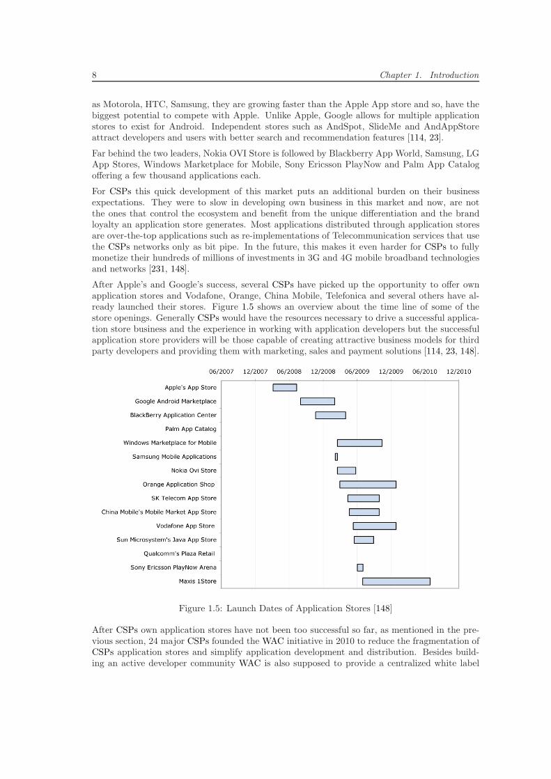
After Apple’s and Google’s success, several CSPs have picked up the opportunity to offer ownapplication stores and Vodafone, Orange, China Mobile, Telefonica and several others have al-ready launched their stores. Figure 1.5 shows an overview about the time line of some of thestore openings. Generally CSPs would have the resources necessary to drive a successful applica-tion store business and the experience in working with application developers but the successfulapplication store providers will be those capable of creating attractive business models for thirdparty developers and providing them with marketing, sales and payment solutions [114, 23, 148].
Figure 1.5: Launch Dates of Application Stores [148]
After CSPs own application stores have not been too successful so far, as mentioned in the pre-vious section, 24 major CSPs founded the WAC initiative in 2010 to reduce the fragmentation ofCSPs application stores and simplify application development and distribution. Besides build-ing an active developer community WAC is also supposed to provide a centralized white label
1.1. Problems and Motivation 9
application store solution that all partners can launch under their brands in their Telecommuni-cation networks. For application developers WAC will provide means to deploy their applicationscentrally once and to monetize applications sold through all associated partner application stores.
1.1.6 Cross-Platform Compatible Applications
The success of OEM owned application stores and the OEMs control of the whole ecosystemsallows them to promote their devices, software platforms and preferred development technologiesand so, generates a proprietary and closed technology platform for applications in their stores[91, 232].
Mobile application developers want to offer their innovative applications to an as broad as possiblebase of end-users independent of what client devices or software platforms they are using. Sincethe OEMs platforms are incompatible and applications cannot easily be moved from one toanother, they need to focus and learn every single platform’s technology and development toolsto port their applications. This requires a large amount of time and investments for every singleapplication and increases the time-to-market of applications as well as slows down applicationinnovation drastically [48, 47, 84].
CSPs want to offer their customers an as broad as possible selection of client devices and plat-forms that those can use on their Telecommunication networks. They do not want to be drawninto the rising competition of smart phone OEMs, their application stores and software platformsbut want to offer their customers the most innovative devices with access to the most innovativeapplications. CSPs want to offer their customers applications that they can use across all devices,platforms and screens such as IPTV, smart phone, PC, laptop, tablet they own. The incompati-bility of the different OEMs platforms, their application stores and their device centric conceptsdo not allow that. Hence, CSPs favored SDP centric concepts that would allow the developmentof cross-platform compatible Web-Telecom Converged applications is being pushed further to thebackground at developers and customers.
As mentioned earlier, in 2010 24 major CSPs initiated the WAC. One of its goals is to encourageopen standardized technologies and to provide commercial models complimentary to the ones ofthe OEMs. It should allow developers to deploy applications across multiple devices and multiplenetwork operators without the need to negotiate with each of them [114, 23, 47]. WAC does notpromote an SDP centric development concept and focuses heavily on the client centric mobileapplication development based on technologies adopted from Web/Internet development. Nev-ertheless, CSP might be able to combine it with their future SDP centric concepts to build anenvironment for cross-platform compatible Web-Telecom Convergence for services and applica-tions.
1.1.7 Towards Proprietary Monopolies for Communication Services
It took a lot of effort over the last decades to turn the Telecommunication monopolies worldwideinto an open Telecommunications market that allows competition and innovation. Nevertheless,even when exploiting their monopolies, CSPs have always seen the need of worldwide com-patibility of their technologies and systems. Even though it has slowed down innovation andtime-to-market, standardization of technologies and systems that enable modern fixed and mo-bile Telecommunication services has always been a priority. Due to that, today, end-users canuse a single mobile device or computer to connect to communication and mobile Web/Internetservices of almost all CSPs worldwide.
10 Chapter 1. Introduction
Since the Web/Internet has been separated from the Telecommunication networks technologicallyand conceptually over the last decades, atWeb/Internet ASPs a different, mostly market and usersdriven, mindset has developed. As mentioned in the previous sections, they built some innovative(communication) applications and services and re-invented existing Telecommunication servicesbased on their own proprietary technologies and protocols on the Internet. This has resulted ina collection of incompatible applications and services that implement similar services and thatcompete for end-users worldwide. Success is often measured by the number of users that areregistered or that are using a service regularly. In addition, business models are often based onadvertisement targeted at those users and so, ASPs running these services are not interested incollaborating with others since they need to lock their users to their service in order to generaterevenue. Typical examples of such proprietary and incompatible services on the Web/Internetand mobile Web/Internet are Skype, Google Talk, Facebook, Google+, StudiVZ, ICQ, MSN,Xing, LinkedIn, WhatsApp.
ASPs providing such services and applications are aiming to build new types of monopolies theyfully control. Even worse than CSPs in the past, by technology and business model design, theyare not planning to build cooperations, define worldwide standards together or enable compati-bility between each other. Further, they do not plan to open their systems so others can use themas ”defacto standards” on the Web/Internet for innovative applications and services. Their goalsare to compete on the Web/Internet services and applications market and succeed by maximizingthe market-share/user-base of their fully closed and controlled service or application.
Through that, ASPs build even stronger monopolies than CSPs ever did and end-users are lockedinto these services and applications much tighter than into the CSPs worldwide compatible mobileand fixed Telecommunication networks. For end-users, this development has been very disadvan-tageous, but since it conflicts with their business and success strategies, ASPs don’t seem to caretoo much about their users’ needs in this respect. For example, for end-users, this developmentinduces very high switching costs and made moving from one service to another almost impos-sible. The end-user would not only have to move his/her account to the new service, but wouldalso need to convince all his/her communication partners to move their accounts, or to createnew accounts as well.
1.1.8 Conclusion
Once, means to solve most of these major problems for CSPs are found, these current transfor-mations in the Telecommunication industry and on the Web/Internet combined with the rise ofthese powerful programmable platforms for computers, (IP)TVs [98] and mobile devices such asLinux [218], iOS [14], Android [79], Symbian [220], MeeGo [219], Windows Phone 7 [143] providethe opportunities to form an environment for application developers and innovative visionariesthat has never been available before. Such an environment can lead to unprecedented possibilitiesfor the development of innovative distributed, ubiquitous and mobile services/applications acrossTelecommunication networks and the Web/Internet and can put the CSPs in a central positionof the technology as well as business opportunities around them.
1.2 Contributions
The goal of this research is to bring Telecommunication service development closer together withWeb/Internet and mobile application development. It applies the Web-Telecom Convergenceconcept to conceptualize and design an Application Delivery Platform (ADP) that extends cur-rent Telecommunication ADP concepts and solutions with SOA and Web/Internet services and
1.3. Methodology and Approach 11
technology concepts.
The work is based on a specification of common and new terminology, definitions and concepts,and on a thorough analysis of the current challenges of stakeholders in the Telecommunicationsindustry, of SDP and Web-Telecom Convergence concepts and platforms, of Telecommunica-tion service and application development concepts and technologies, and of mobile applicationdevelopment concepts and technologies.
It develops the design of a logical and exemplary technical architecture of a generic Web-TelecomConverged application. It derives requirements and develops the design of core concepts, areference architecture and an exemplary technical architecture of the ADP. Thereby, this workfocuses on the development of Telecommunication network and application separation concepts,the design of a SOA-based layered ADP reference architecture and the development of a semi-automatic outside-in service import concept. For supplementary components of the ADP itidentifies, summarizes and integrates existing proposals and solutions.
The work evaluates the ADP by assessing the requirements and core concepts, and implementingand deploying two iterations of ADP prototypes combined with the development of two exemplarycase-study prototypes on top of the platform prototypes.
1.3 Methodology and Approach
This section provides a theoretical summary of the Design Science/Design Research methodologyand illustrates how its central aspects were applied in the approach to conceptualize and prototypea Web-Telecom Convergence Application Delivery Platform.
1.3.1 Design Science
Within Design Science/ Design Research, ”knowledge and understanding of a problem domainand its solution are achieved in the building and application of the designed artifact” [87, p.77]. So the goal of the Design Science paradigm is the development of useful solutions based oninformation technology. Within Design Research these solutions should be examined through thebuilding and the evaluation of artifacts using models, methods or systems [238, p. 281]. ”Design,[...], is concerned with how things ought to be, with devising artifacts to attain goals” [200, p.114].
Behavioral science and Design Science complement one another. Behavioral science tries topredict why an artifact works and Design Science’s aim is to determine how well an artifactworks. Therefore Hevner et al. state that the goal of behavioral science is truth and the goal ofDesign Science is utility [87, p. 80]. However there is an exchange between the two disciplinesas it is important to understand why an artifact does solve a certain problem in order to be ableto design new artifacts that tackle the problem even more effectively. And vice versa, the DesignScience can have an impact on the behavioral science as ”utility informs theory” [87, p. 80] aswell.
Design Research can be seen as a process and as an artifact, and product respectively, at thesame time. During the design process the researcher builds an innovative product, i.e. theartifact. Afterwards the designed artifact will be evaluated. This evaluation ”provides feedbackinformation and a better understanding of the problem in order to improve both the quality ofthe product and the design process” [87, p. 78]. Similarly Collins et al. refer to Design Researchas an ”approach of progressive refinement” [46, p. 18]. A first version of a design is put intothe world. The researcher then sees how the design works and constantly revises it based on
12 Chapter 1. Introduction
evaluation and experience. Thus the focus on progressive refinements enables the researcher tobuild more robust designs over time.
According to Hevner et al. there are seven guidelines that enable the researchers to conductDesign Research in an effective way [87, pp. 82].
• The Design Science researcher has to build a viable artifact. This could either be a construct,a model, a method or an instantiation.
• The research effort should tackle important and relevant problems by developing technology-based solutions.
• In the evaluation phase, the researcher has to demonstrate the utility, quality, and efficacyof the designed artifact using well executed evaluation methods. The goal of this phase isto provide feedback to the design and construction phase and thus to facilitate a higherquality of the design process and the artifact.
• Hevner et al. identify three areas of potential contributions of effective Design Research: (i)The artifact itself as it might help other researchers to build good artifacts, (ii) design foun-dations, i.e. knowledge about how to build good artifacts, and (iii) design methodologies,i.e. knowledge and methods that help to evaluate the artifact.
• The researcher must apply rigorous methods when it comes to building as well as evaluatingthe designed artifact.
• Design Research is seen as an iterative search process.
• The researcher has to present the results to technology oriented as well as managementoriented audiences.
Design Research has several distinct advantages. Within a short period of time the user willhave an actual hands-on experience [103, p. 305]. Hence, the researcher will have no difficultiesexplaining a theoretical application or a specification. The user will not have to be able toexplicitly articulate his or her needs but will experience a real-world artifact instead. The DesignResearch approach generates immediate feedback and so has the potential to fail fast and toquickly incorporate improvements on the way to a better artifact [1]. Therefore it is a powerfultool as ”it is both imaginative and empirical” [106, p. 39] at the same time.
Nevertheless, Design Research is a very complex and time consuming approach. There might bemuch iteration, as for example several ones for the building and for the evaluation phase, neededbefore an appropriate artifact is built. From a researcher’s perspective, Design Science is verydemanding as theoretical knowledge as well as practical skills are required.
Certainly there are limitations to the application of Design Research. Hence, in some cases DesignScience needs to be complemented with other methods such as Action Research, QuantitativeResearch and Qualitative Research [26]. In various phases of the design process the researcher hasto use well-proven methods that ensure the building and construction of good artifacts. Empiricaland qualitative methods should be adopted when it comes to phases like problem identificationand also the evaluation of an artifact [87, p. 77].
Summing up, the scientific paradigm of Design Research is focused on the development of useful ITsolutions following an iterative process of gathering knowledge, building artifacts and evaluatingthese artifacts. Abowd et al. wrap it up in their claim: ”Do not spend too much time predictingthe future; aim to invent it” [1].
1.3. Methodology and Approach 13
1.3.2 Research Approach
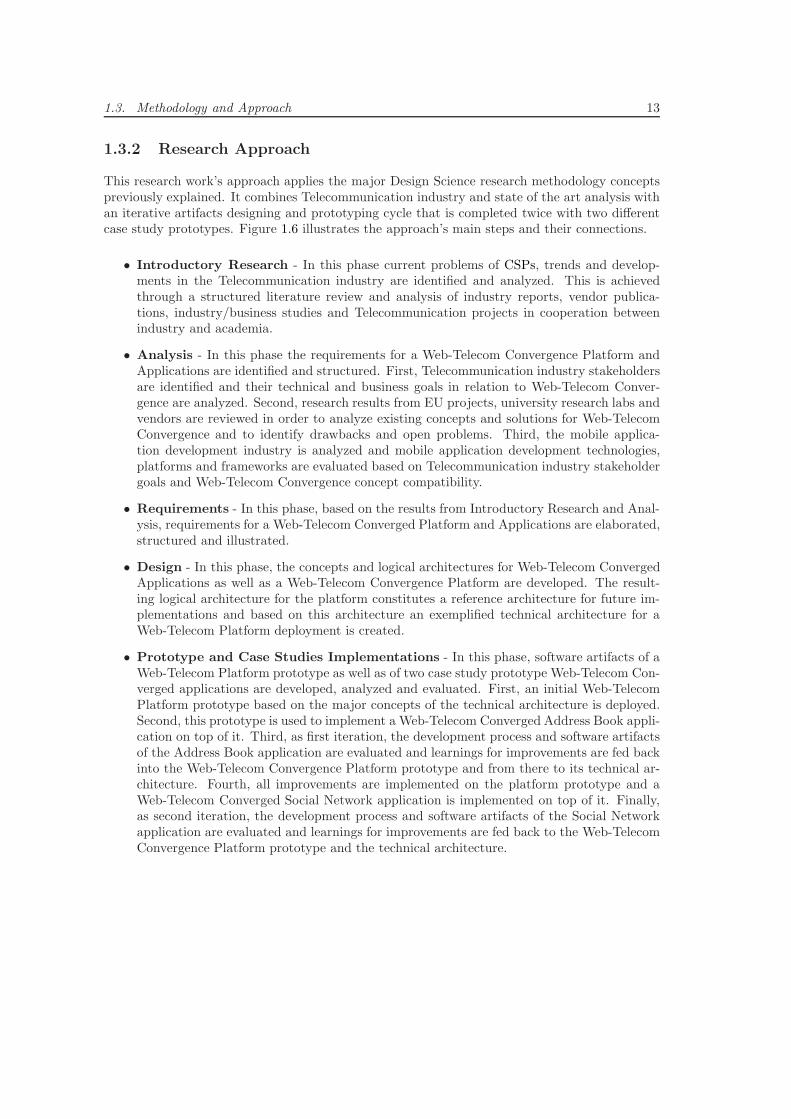
This research work’s approach applies the major Design Science research methodology conceptspreviously explained. It combines Telecommunication industry and state of the art analysis withan iterative artifacts designing and prototyping cycle that is completed twice with two differentcase study prototypes. Figure 1.6 illustrates the approach’s main steps and their connections.
• Introductory Research - In this phase current problems of CSPs, trends and develop-ments in the Telecommunication industry are identified and analyzed. This is achievedthrough a structured literature review and analysis of industry reports, vendor publica-tions, industry/business studies and Telecommunication projects in cooperation betweenindustry and academia.
• Analysis - In this phase the requirements for a Web-Telecom Convergence Platform andApplications are identified and structured. First, Telecommunication industry stakeholdersare identified and their technical and business goals in relation to Web-Telecom Conver-gence are analyzed. Second, research results from EU projects, university research labs andvendors are reviewed in order to analyze existing concepts and solutions for Web-TelecomConvergence and to identify drawbacks and open problems. Third, the mobile applica-tion development industry is analyzed and mobile application development technologies,platforms and frameworks are evaluated based on Telecommunication industry stakeholdergoals and Web-Telecom Convergence concept compatibility.
• Requirements - In this phase, based on the results from Introductory Research and Anal-ysis, requirements for a Web-Telecom Converged Platform and Applications are elaborated,structured and illustrated.
• Design - In this phase, the concepts and logical architectures for Web-Telecom ConvergedApplications as well as a Web-Telecom Convergence Platform are developed. The result-ing logical architecture for the platform constitutes a reference architecture for future im-plementations and based on this architecture an exemplified technical architecture for aWeb-Telecom Platform deployment is created.
• Prototype and Case Studies Implementations - In this phase, software artifacts of aWeb-Telecom Platform prototype as well as of two case study prototype Web-Telecom Con-verged applications are developed, analyzed and evaluated. First, an initial Web-TelecomPlatform prototype based on the major concepts of the technical architecture is deployed.Second, this prototype is used to implement a Web-Telecom Converged Address Book appli-cation on top of it. Third, as first iteration, the development process and software artifactsof the Address Book application are evaluated and learnings for improvements are fed backinto the Web-Telecom Convergence Platform prototype and from there to its technical ar-chitecture. Fourth, all improvements are implemented on the platform prototype and aWeb-Telecom Converged Social Network application is implemented on top of it. Finally,as second iteration, the development process and software artifacts of the Social Networkapplication are evaluated and learnings for improvements are fed back to the Web-TelecomConvergence Platform prototype and the technical architecture.
14 Chapter 1. Introduction
Figure 1.6: Thesis Research Approach
1.4. Structure of Thesis 15
1.4 Structure of Thesis
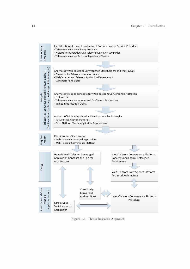
This section provides an overview about the structure of this thesis document and illustrates, infigure 1.7, how the different chapters build upon each other’s results.
Figure 1.7: Relations between Chapters
Chapter 1 - Introductionmotivates this thesis by discussing the major problems the Telecom-munication industry faces today, presents an overview about this thesis’ contributions andpresents this work’s Design Science-based research methodology and applied research ap-proach.
Chapter 2 - Terminology, Definitions and Concepts defines important terms and theirdisjunction for this research work, discusses existing SOA-related concepts that are an es-sential foundation for this research work’s contributions, and illustrates existing as wellas introduces new concepts for application architectures, application lifecycles and conver-gence.
Chapter 3 - Web-Telecom Convergence Stakeholder Goals presents an overview aboutall stakeholders that are relevant for future Web-Telecom Convergence Applications or aWeb-Telecom Convergence Platform. It structures the stakeholders, summarizes their maincharacteristics and identifies their major Web-Telecom Convergence related goals.
Chapter 4 - Analysis presents an overview about the evolution of Telecommunication ser-vices and applications development and evaluates Web-Telecom Convergence concepts andplatforms as well as mobile application development technologies.
The overview introduces the evolution from early purely Telecommunication specific ser-vice and application development concepts, over software engineering and business infor-mation system development inspired concepts, to Web/Internet service and applicationdevelopment-based concepts.
The evaluation of Web-Telecom Convergence concepts compares the most widely refer-enced and recognized SDP proposals using an architecture comparison methodology com-posed from three popular methodology proposals. This comparison is a fully self-containedprocess within the chapter and provides an overview about the level of fulfillment andcompleteness of major SDP requirements and components. In addition to the SDPs, theevaluation discusses widely referenced and recognized Web-Telecom Convergence researchresults qualitatively. From both, it draws Web-Telecom Convergence focused evaluationconclusions.
16 Chapter 1. Introduction
The evaluation of mobile application development technologies identifies the major platform-specific development technologies as well as cross-platform development frameworks. Itdefines structured evaluation and comparison criteria for both categories and evaluates thetechnologies and frameworks independently. From there, it draws Web-Telecom Conver-gence focused evaluation conclusions.
Chapter 5 - Design of a Web-Telecom Converged Application introduces some newand innovative exemplary Web-Telecom Converged application scenarios and defines a newgeneric Web-Telecom Converged applications architecture. It leverages selected conceptsand results from chapters 2, 3 and 4 to define a new logical reference architecture as wellas a new exemplary technical architecture for future Web-Telecom Converged applications.
Chapter 6 - Requirements for a Web-Telecom Convergence Platform derives therequirements for a new Web-Telecom Convergence platform that can host and deliver Web-Telecom Converged applications according to chapter 5. It leverages the stakeholders’ goalsfrom chapter 3, the state-of-the-art analysis results from chapter 4 and the applicationsarchitecture concepts from chapter 5.
Chapter 7 - Design of Application Delivery Platform introduces the new ADP conceptand defines a logical reference architecture as well as an exemplary technical architecturefor it. It leverages concepts from chapter 2 as well as first iteration prototype results fromchapter 8 to fulfill the ADP requirements defined in chapter 6. The chapter presents thecore concepts for the ADP design and architecture in detail and applies those to definethe logical reference architecture. From there, it discusses implementation, deployment andsystem components decisions to derive an exemplary technical architecture.
Chapter 8 - Validation and Evaluation assesses the level of fulfillment of the requirementsfrom chapter 6 in the core concept from chapter 7. To validate the ADP concepts fromchapter 7, it illustrates two iterations of development and deployment of an ADP prototype.For every iteration, a certain Web-Telecom Converged application scenario is selected fromchapter 5, implemented, and deployed on top of the ADP prototype. For the first itera-tion, a Web-Telecom Converged Unified Address Book scenario is selected. For the seconditeration, a Web-Telecom Converged Social Notification Application scenario is selected.Finally, it assesses the level of fulfillment and implementation of the core concepts fromchapter 7 in the two iterations of ADP prototypes.
Chapter 9 - Conclusion and Future Work illustrates an overview about the learnings andresults from this research work, illustrates areas and ideas for future research projects anddiscusses how a commercial ADP product could be deployed, managed and operated by aCSP, ASP or independent provider in the future.
Chapter 2
Terminology, Definitions andConcepts
2.1 Distinction between Service and Application
This section provides a distinction between the terms service and application for this researchwork and compares them to the typical usage of the term service in the Telecommunication in-dustry.
Service
In this work, adapted from [242] [246] [245], a service is defined as ”an abstract resource thatrepresents a capability of performing tasks that form a coherent functionality from the point ofview of providers entities and requesters entities”. It is a software artifact designed to supportinteroperable machine-to-machine interaction over a network. It has a clearly defined interfacedescribed in a machine-processable format and is designed to be reused by other services orapplications. Services interact in a manner defined by its interface descriptions using messagesover defined protocols and related standards. A service can be deployed and managed by a servicelifecycle management system such as an SDP.
Application
In this work, an application is defined as a software artifact designed to support interoperablehuman-to-machine interaction through an end-user client device or software. It is not designed tobe reused by other services or applications but it reuses none to many services. End-users haveuniversal access to an application through their clients and interact with an application throughone to many (graphical) user-interfaces on different types of end-user clients and platforms.
Telecommunication Service
As illustrated in [133], [110] and [140], in the Telecommunication industry, a service describes andcontrols a capability/functionality that is offered by a CSP through the combination of worldwidestandardized protocols, hardware/software systems deployed in Telecommunication core networksand service specific user-interfaces on end-user devices or software clients. A Telecommunicationservice fulfills the special purpose of abstracting from the pure system capabilities and realizingthe end-to-end exchange of information in a standardized way. Hence, a Telecommunicationservice is delivered to and meant to be used by an end-user though its user-interface and is
18 Chapter 2. Terminology, Definitions and Concepts
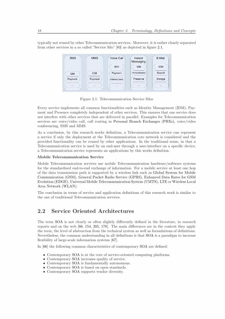
typically not reused by other Telecommunication services. Moreover, it is rather clearly separatedfrom other services in a so called ”Service Silo” [83] as depicted in figure 2.1.
Figure 2.1: Telecommunication Service Silos
Every service implements all common functionalities such as Identity Management (IDM), Pay-ment and Presence completely independent of other services. This ensures that one service doesnot interfere with other services that are delivered in parallel. Examples for Telecommunicationservices are voice/video call, call routing in Personal Branch Exchanges (PBXs), voice/videoconferencing, SMS and MMS.
As a conclusion, by this research works definition, a Telecommunication service can representa service if only the deployment at the Telecommunication core network is considered and theprovided functionality can be reused by other applications. In the traditional sense, in that aTelecommunication service is used by an end-user through a user-interface on a specific device,a Telecommunication service represents an applications by this works definition.
Mobile Telecommunication Service
Mobile Telecommunication services use mobile Telecommunication hardware/software systemsfor the standardized end-to-end exchange of information. For a mobile service at least one hopof the data transmission path is supported by a wireless link such as Global System for MobileCommunication (GSM), General Packet Radio Service (GPRS), Enhanced Data Rates for GSMEvolution (EDGE), Universal Mobile Telecommunication System (UMTS), LTE orWireless LocalArea Network (WLAN).
The conclusion in terms of service and application definitions of this research work is similar tothe one of traditional Telecommunication services.
2.2 Service Oriented Architectures
The term SOA is not clearly or often slightly differently defined in the literature, in researchreports and on the web [66, 154, 205, 178]. The main differences are in the context they applythe term, the level of abstraction from the technical system as well as formulations of definitions.Nevertheless, the common understanding in all definitions is that SOA is a paradigm to increaseflexibility of large-scale information systems [67].
In [66] the following common characteristics of contemporary SOA are defined:
• Contemporary SOA is at the core of service-oriented computing platforms.• Contemporary SOA increases quality of service.• Contemporary SOA is fundamentally autonomous.• Contemporary SOA is based on open standards.• Contemporary SOA supports vendor diversity.
2.2. Service Oriented Architectures 19
• Contemporary SOA fosters intrinsic interoperability.• Contemporary SOA promotes discovery.• Contemporary SOA promotes federation.• Contemporary SOA promotes architectural composability.• Contemporary SOA fosters inherent reusability.• Contemporary SOA emphasizes extensibility.• Contemporary SOA supports a service-oriented business modeling paradigm.• Contemporary SOA implements layers of abstraction.• Contemporary SOA promotes loose coupling throughout the enterprise.• Contemporary SOA promotes organizational agility.• Contemporary SOA is a building block.• Contemporary SOA is an evolution.• Contemporary SOA is still maturing.• Contemporary SOA is an achievable ideal.
SOA does not define a concrete software architecture or reference but a set of guiding principlesand methodologies that promote the design and development of applications based on interoper-able and loosely coupled services [115]. The services implement self-contained and well-definedbusiness functionalities and can be reused for different purposes by other services and applica-tions. The basis for the interoperability of SOA services is their formally defined services inter-faces (Contracts) that are independent of the underlying protocols, programming technologies orplatforms [68].
In [66] the following widely regarded guiding principles for development, maintenance and usageof SOA, common to all SOA platforms, are defined.
• Standardized Service Contract - Services express their purpose and capabilities via aservice contract. The contract expresses service functionality, data types and data modelsas well as specific usage policies.
• Loose Coupling - Services maintain a relationship that minimizes dependencies and areonly required to keep an awareness of each other. The principle promotes the independentdesign and evolution of a service’s logic and implementation while still guaranteeing baselineinteroperability with consumers that have come to rely on the service’s capabilities.
• Service Abstraction - Derived from the software design principle of information hiding,services are required to hide as many internal details as possible from external entities. Ser-vice contracts only contain essential information and information about services is limitedto what is published in service contracts. This directly enables and preserves the previouslydescribed principle of loose coupling.
• Service Reusability - Services contain and express agnostic logic and can be positionedas reusable enterprise resources.
• Service Autonomy - The underlying logic of any service needs to have a significant degreeof control over its environment and resources in order to ensure its ability to consistentlyand reliably perform their capabilities.
• Service Statelessness - Services minimize resource consumption by deferring the man-agement of state information when necessary.
• Service Discoverability - Services are supplemented with communicative meta-data bywhich they can be effectively discovered and interpreted.
• Service Composability - Services are effective composition participants, regardless of thesize and complexity of the composition.
20 Chapter 2. Terminology, Definitions and Concepts
2.2.1 SOA Manifesto
The SOA Manifesto [17] is a collection of 6 value statements and 14 principles that were definedby 17 leaders of the SOA industry in 2009 and that has been signed by over 800 supporters fromthe software industry so far. At that time, when SOA suffered a lack of clarity and directionthose specialists combined their efforts to define a common understanding and direction for thewhole industry.
The following value statements were defined:
• Business Value over Technical Strategy
• Strategic Goals over Project Specific Benefits
• Intrinsic Interoperability over Custom Integration
• Shared Services over Specific Purpose Implementations
• Flexibility over Optimization
• Evolutionary Refinement over Pursuit of Initial Perfection
2.2.2 Web Service
In this context, a Web Service is a technical concept to realize a SOA. It is a software artifactdesigned to support interoperable machine-to-machine interaction over a network using standard-ized communication protocols. It can be implemented in any programming technology but hasan interface precisely described in a standardized machine-processable format (specifically WebService Description Language [244] (WSDL)). Other systems interact with the Web Service ina manner prescribed by its interface description using SOAP-messages, typically conveyed us-ing HTTP with an Extensible Markup Language (XML) serialization in conjunction with otherWeb-related standards [242, 246, 245].
In contrast, a RESTful Web Service [180] uses the increasingly spreading REST architecturalprinciples instead of WSDL and SOAP. It is designed to focus on a system’s resources, includinghow resource states are addressed and transferred over HTTP by a wide range of clients writtenin different languages.
2.2.3 SOA Triangular Model
Traditionally, the simple end-to-end Requestor - Provider model [66] illustrated on the top offigure 2.2 was used to define the information exchange for services. In this model, the Providernotifies all connected Requestors about the specifics of the service interface and those use thisinformation to invoke the service.
Through the evolution of SOA concepts this model has evolved to the triangular model [61, 251,205] illustrated on the bottom of figure 2.2. This model builds the basis for distributed servicecreation, registration, discovery and composition and defines three roles based on their behaviorand responsibilities: Service Provider, Service Registry and Service Requestor.
• Service Provider - Hosts the implementations of services, publishes services at a ServiceRegistry and provides the service to Requestors that invoke it.
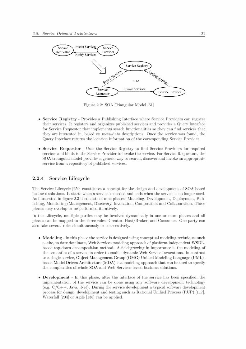
2.2. Service Oriented Architectures 21
Figure 2.2: SOA Triangular Model [61]
• Service Registry - Provides a Publishing Interface where Service Providers can registertheir services. It registers and organizes published services and provides a Query Interfacefor Service Requestor that implements search functionalities so they can find services thatthey are interested in, based on meta-data descriptions. Once the service was found, theQuery Interface returns the location information of the corresponding Service Provider.
• Service Requestor - Uses the Service Registry to find Service Providers for requiredservices and binds to the Service Provider to invoke the service. For Service Requestors, theSOA triangular model provides a generic way to search, discover and invoke an appropriateservice from a repository of published services.
2.2.4 Service Lifecycle
The Service Lifecycle [250] constitutes a concept for the design and development of SOA-basedbusiness solutions. It starts when a service is needed and ends when the service is no longer used.As illustrated in figure 2.3 it consists of nine phases: Modeling, Development, Deployment, Pub-lishing, Monitoring/Management, Discovery, Invocation, Composition and Collaboration. Thesephases may overlap or be performed iteratively.
In the Lifecycle, multiple parties may be involved dynamically in one or more phases and allphases can be mapped to the three roles: Creator, Host/Broker, and Consumer. One party canalso take several roles simultaneously or consecutively.
• Modeling - In this phase the service is designed using conceptual modeling techniques suchas the, to date dominant, Web Services modeling approach of platform-independent WSDL-based top-down decomposition method. A field growing in importance is the modeling ofthe semantics of a service in order to enable dynamic Web Service invocations. In contrastto a single service, Object Management Group (OMG) Unified Modeling Language (UML)-based Model Driven Architecture (MDA) is a modeling approach that can be used to specifythe complexities of whole SOA and Web Services-based business solutions.
• Development - In this phase, after the interface of the service has been specified, theimplementation of the service can be done using any software development technology(e.g. C/C++, Java, .Net). During the service development a typical software developmentprocess for design, development and testing such as Rational Unified Process (RUP) [117],Waterfall [204] or Agile [138] can be applied.
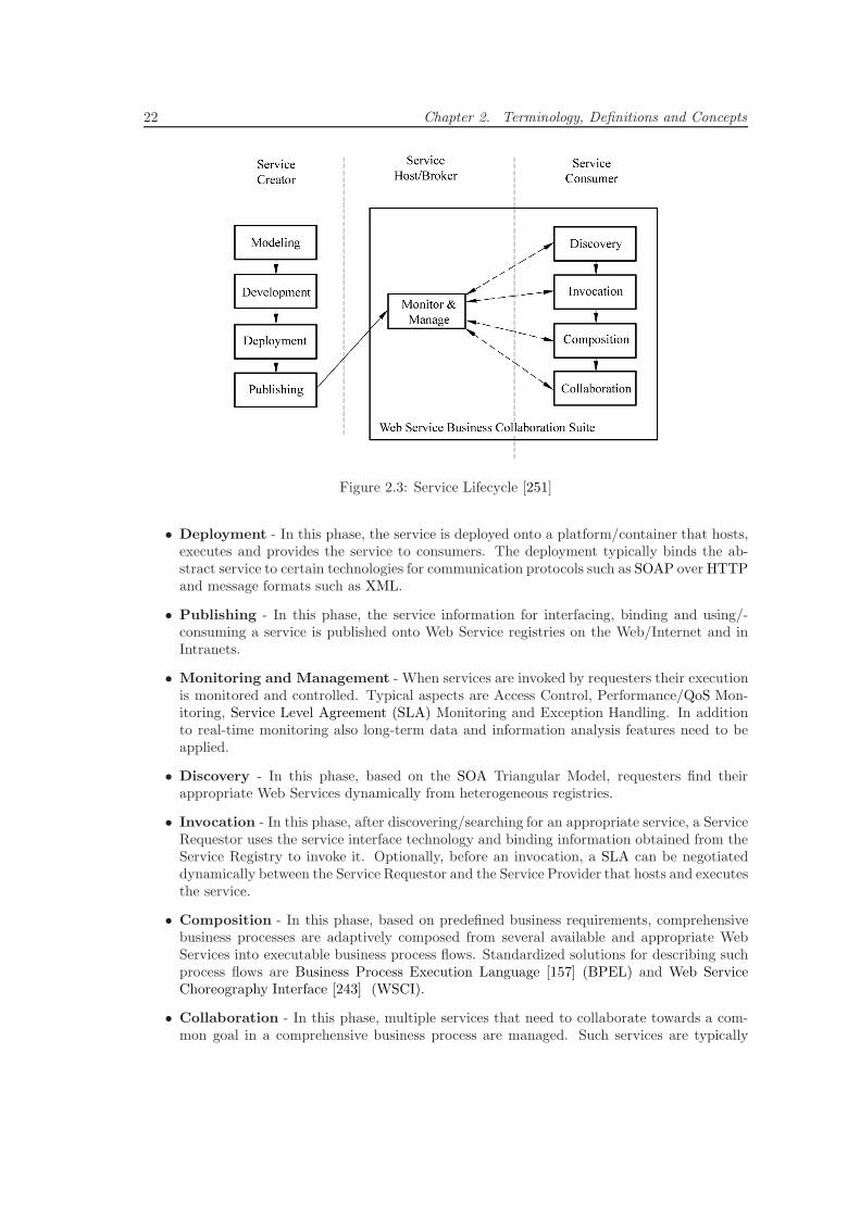
22 Chapter 2. Terminology, Definitions and Concepts
Figure 2.3: Service Lifecycle [251]
• Deployment - In this phase, the service is deployed onto a platform/container that hosts,executes and provides the service to consumers. The deployment typically binds the ab-stract service to certain technologies for communication protocols such as SOAP over HTTPand message formats such as XML.
• Publishing - In this phase, the service information for interfacing, binding and using/-consuming a service is published onto Web Service registries on the Web/Internet and inIntranets.
• Monitoring and Management - When services are invoked by requesters their executionis monitored and controlled. Typical aspects are Access Control, Performance/QoS Mon-itoring, Service Level Agreement (SLA) Monitoring and Exception Handling. In additionto real-time monitoring also long-term data and information analysis features need to beapplied.
• Discovery - In this phase, based on the SOA Triangular Model, requesters find theirappropriate Web Services dynamically from heterogeneous registries.
• Invocation - In this phase, after discovering/searching for an appropriate service, a ServiceRequestor uses the service interface technology and binding information obtained from theService Registry to invoke it. Optionally, before an invocation, a SLA can be negotiateddynamically between the Service Requestor and the Service Provider that hosts and executesthe service.
• Composition - In this phase, based on predefined business requirements, comprehensivebusiness processes are adaptively composed from several available and appropriate WebServices into executable business process flows. Standardized solutions for describing suchprocess flows are Business Process Execution Language [157] (BPEL) and Web ServiceChoreography Interface [243] (WSCI).
• Collaboration - In this phase, multiple services that need to collaborate towards a com-mon goal in a comprehensive business process are managed. Such services are typically
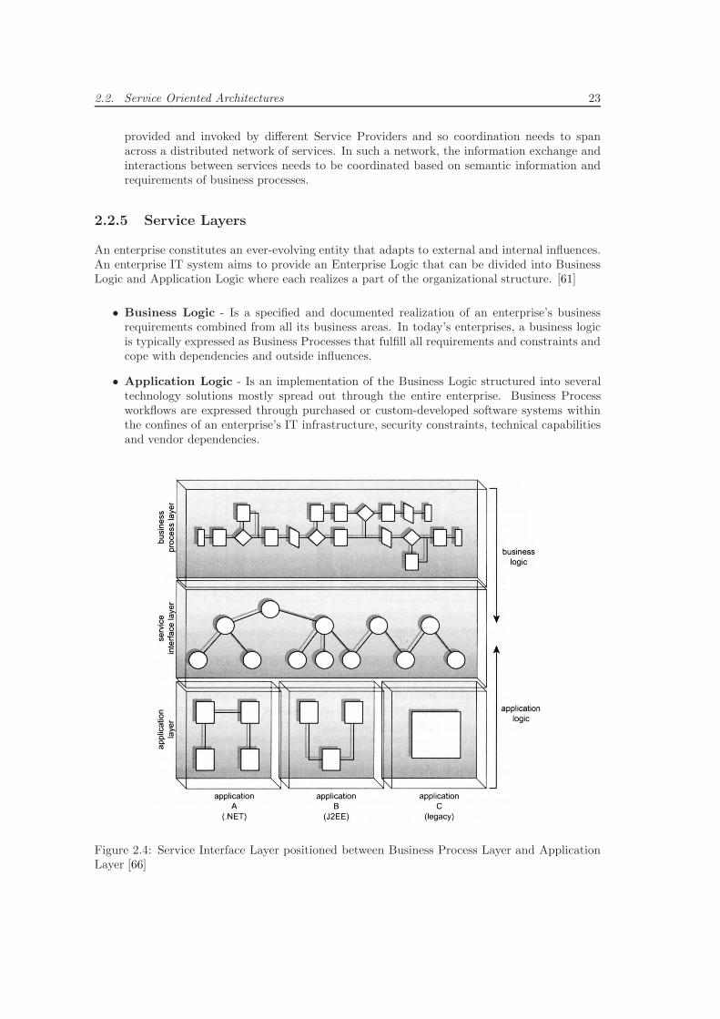
2.2. Service Oriented Architectures 23
provided and invoked by different Service Providers and so coordination needs to spanacross a distributed network of services. In such a network, the information exchange andinteractions between services needs to be coordinated based on semantic information andrequirements of business processes.
2.2.5 Service Layers
An enterprise constitutes an ever-evolving entity that adapts to external and internal influences.An enterprise IT system aims to provide an Enterprise Logic that can be divided into BusinessLogic and Application Logic where each realizes a part of the organizational structure. [61]
• Business Logic - Is a specified and documented realization of an enterprise’s businessrequirements combined from all its business areas. In today’s enterprises, a business logicis typically expressed as Business Processes that fulfill all requirements and constraints andcope with dependencies and outside influences.
• Application Logic - Is an implementation of the Business Logic structured into severaltechnology solutions mostly spread out through the entire enterprise. Business Processworkflows are expressed through purchased or custom-developed software systems withinthe confines of an enterprise’s IT infrastructure, security constraints, technical capabilitiesand vendor dependencies.
Figure 2.4: Service Interface Layer positioned between Business Process Layer and ApplicationLayer [66]
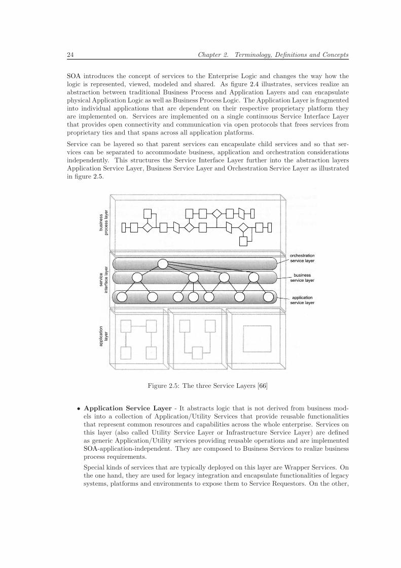
24 Chapter 2. Terminology, Definitions and Concepts
SOA introduces the concept of services to the Enterprise Logic and changes the way how thelogic is represented, viewed, modeled and shared. As figure 2.4 illustrates, services realize anabstraction between traditional Business Process and Application Layers and can encapsulatephysical Application Logic as well as Business Process Logic. The Application Layer is fragmentedinto individual applications that are dependent on their respective proprietary platform theyare implemented on. Services are implemented on a single continuous Service Interface Layerthat provides open connectivity and communication via open protocols that frees services fromproprietary ties and that spans across all application platforms.
Service can be layered so that parent services can encapsulate child services and so that ser-vices can be separated to accommodate business, application and orchestration considerationsindependently. This structures the Service Interface Layer further into the abstraction layersApplication Service Layer, Business Service Layer and Orchestration Service Layer as illustratedin figure 2.5.
Figure 2.5: The three Service Layers [66]
• Application Service Layer - It abstracts logic that is not derived from business mod-els into a collection of Application/Utility Services that provide reusable functionalitiesthat represent common resources and capabilities across the whole enterprise. Services onthis layer (also called Utility Service Layer or Infrastructure Service Layer) are definedas generic Application/Utility services providing reusable operations and are implementedSOA-application-independent. They are composed to Business Services to realize businessprocess requirements.
Special kinds of services that are typically deployed on this layer are Wrapper Services. Onthe one hand, they are used for legacy integration and encapsulate functionalities of legacysystems, platforms and environments to expose them to Service Requestors. On the other,
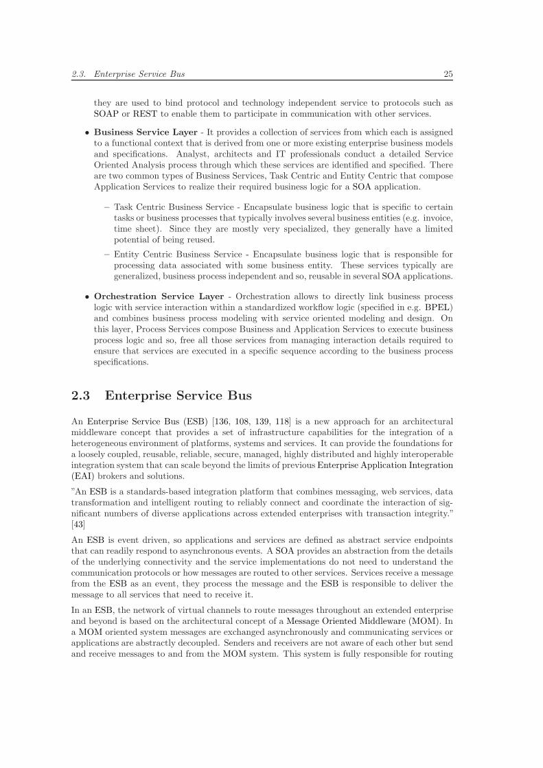
2.3. Enterprise Service Bus 25
they are used to bind protocol and technology independent service to protocols such asSOAP or REST to enable them to participate in communication with other services.
• Business Service Layer - It provides a collection of services from which each is assignedto a functional context that is derived from one or more existing enterprise business modelsand specifications. Analyst, architects and IT professionals conduct a detailed ServiceOriented Analysis process through which these services are identified and specified. Thereare two common types of Business Services, Task Centric and Entity Centric that composeApplication Services to realize their required business logic for a SOA application.
– Task Centric Business Service - Encapsulate business logic that is specific to certaintasks or business processes that typically involves several business entities (e.g. invoice,time sheet). Since they are mostly very specialized, they generally have a limitedpotential of being reused.
– Entity Centric Business Service - Encapsulate business logic that is responsible forprocessing data associated with some business entity. These services typically aregeneralized, business process independent and so, reusable in several SOA applications.
• Orchestration Service Layer - Orchestration allows to directly link business processlogic with service interaction within a standardized workflow logic (specified in e.g. BPEL)and combines business process modeling with service oriented modeling and design. Onthis layer, Process Services compose Business and Application Services to execute businessprocess logic and so, free all those services from managing interaction details required toensure that services are executed in a specific sequence according to the business processspecifications.
2.3 Enterprise Service Bus
An Enterprise Service Bus (ESB) [136, 108, 139, 118] is a new approach for an architecturalmiddleware concept that provides a set of infrastructure capabilities for the integration of aheterogeneous environment of platforms, systems and services. It can provide the foundations fora loosely coupled, reusable, reliable, secure, managed, highly distributed and highly interoperableintegration system that can scale beyond the limits of previous Enterprise Application Integration(EAI) brokers and solutions.
”An ESB is a standards-based integration platform that combines messaging, web services, datatransformation and intelligent routing to reliably connect and coordinate the interaction of sig-nificant numbers of diverse applications across extended enterprises with transaction integrity.”[43]
An ESB is event driven, so applications and services are defined as abstract service endpointsthat can readily respond to asynchronous events. A SOA provides an abstraction from the detailsof the underlying connectivity and the service implementations do not need to understand thecommunication protocols or how messages are routed to other services. Services receive a messagefrom the ESB as an event, they process the message and the ESB is responsible to deliver themessage to all services that need to receive it.
In an ESB, the network of virtual channels to route messages throughout an extended enterpriseand beyond is based on the architectural concept of a Message Oriented Middleware (MOM). Ina MOM oriented system messages are exchanged asynchronously and communicating services orapplications are abstractly decoupled. Senders and receivers are not aware of each other but sendand receive messages to and from the MOM system. This system is fully responsible for routing
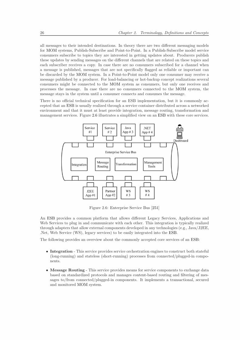
26 Chapter 2. Terminology, Definitions and Concepts
all messages to their intended destinations. In theory there are two different messaging modelsfor MOM systems, Publish-Subscribe and Point-to-Point. In a Publish-Subscribe model serviceconsumers subscribe to topics they are interested in getting updates about. Producers publishthese updates by sending messages on the different channels that are related on these topics andeach subscriber receives a copy. In case there are no consumers subscribed for a channel whena message is published, messages that are not specifically flagged as reliable or important canbe discarded by the MOM system. In a Point-to-Point model only one consumer may receive amessage published by a producer. For load-balancing or hot-backup concept realizations severalconsumers might be connected to the MOM system as consumers, but only one receives andprocesses the message. In case there are no consumers connected to the MOM system, themessage stays in the system until a consumer connects and consumes the message.
There is no official technical specification for an ESB implementation, but it is commonly ac-cepted that an ESB is usually realized through a service container distributed across a networkedenvironment and that it must at least provide integration, message routing, transformation andmanagement services. Figure 2.6 illustrates a simplified view on an ESB with these core services.
Figure 2.6: Enterprise Service Bus [251]
An ESB provides a common platform that allows different Legacy Services, Applications andWeb Services to plug in and communicate with each other. This integration is typically realizedthrough adapters that allow external components developed in any technologies (e.g., Java/J2EE,.Net, Web Service (WS), legacy services) to be easily integrated into the ESB.
The following provides an overview about the commonly accepted core services of an ESB:
• Integration - This service provides service orchestration engines to construct both stateful(long-running) and stateless (short-running) processes from connected/plugged-in compo-nents.
• Message Routing - This service provides means for service components to exchange databased on standardized protocols and manages content-based routing and filtering of mes-sages to/from connected/plugged-in components. It implements a transactional, securedand monitored MOM system.

2.3. Enterprise Service Bus 27
• Transformation - This service transparently mediates between differences in technologies,protocols and formats of messages between connected/plugged-in components. Examplesare different XML Schemas for XML-based messages.
• Management Tools - This service provides real-time monitoring and management capa-bilities for system health and availability and includes functionalities to ensure configurablesecurity control and management. It works in conjunction with a Dashboard that aggre-gated services from multiple sources connected/plugged-in to the ESB and allows developersto create SOA applications rapidly, often supported through a graphical service composi-tion/orchestration user-interface. Using the dashboard, message formats, specific routingpolicies and necessary message transformation rules can be specified, configured and/orimplemented.
Figure 2.7: Enterprise Application Integration (EAI) across Partner Companies through Enter-prise Service Buses (ESBs) [43]
Several software vendors offer commercial ESB platforms and advanced ones offer a numberof additional value-added services. Typical ones are services for provisioning, discovering anddynamically integrating services, for dynamically adjusting SLAs based on performance and errorevents, for controlling service components interactions/invocations and for detecting, distributingand triggering a complex series of interrelated service events though Complex Event Processing[131, 137] (CEP) in an Event Driven Architecture (EDA) [37, 141].
When moving the focus from a single company with one location deploying an ESB to a multi-location company or a network of companies, further advantages of the ESB concept becomeclear. As illustrated in figure 2.7 departments or companies distributed all over the world areable to connect their independently deployed ESBs in the same transparent, loosely coupled,reusable, reliable, secure, managed, highly distributed and highly interoperable way as a singleESB connects services.
In this example a network of companies from different industry areas are collaborating and builta common ESB that allows them to specify business processes and create SOA-based applicationsthat span across all companies and departments. As further illustrated at the Semiconductorscompany, also legacy systems can be included using adapters and Integration Brokers.
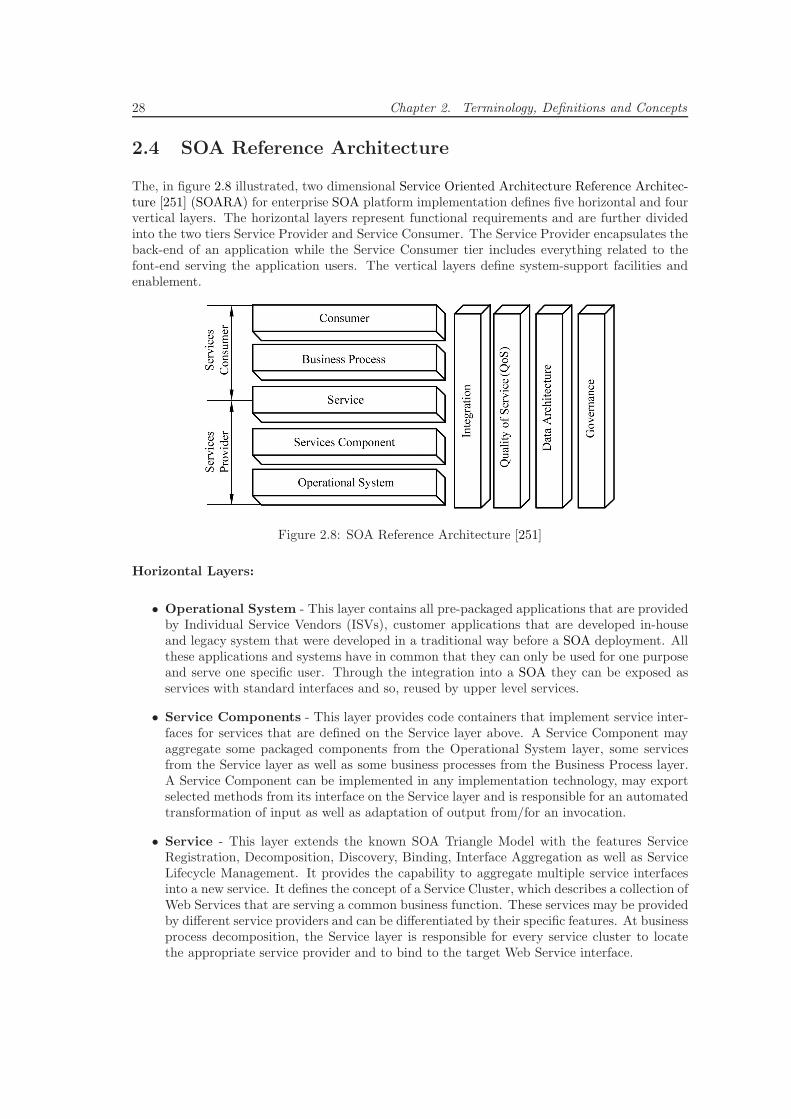
28 Chapter 2. Terminology, Definitions and Concepts
2.4 SOA Reference Architecture
The, in figure 2.8 illustrated, two dimensional Service Oriented Architecture Reference Architec-ture [251] (SOARA) for enterprise SOA platform implementation defines five horizontal and fourvertical layers. The horizontal layers represent functional requirements and are further dividedinto the two tiers Service Provider and Service Consumer. The Service Provider encapsulates theback-end of an application while the Service Consumer tier includes everything related to thefont-end serving the application users. The vertical layers define system-support facilities andenablement.
Figure 2.8: SOA Reference Architecture [251]
Horizontal Layers:
• Operational System - This layer contains all pre-packaged applications that are providedby Individual Service Vendors (ISVs), customer applications that are developed in-houseand legacy system that were developed in a traditional way before a SOA deployment. Allthese applications and systems have in common that they can only be used for one purposeand serve one specific user. Through the integration into a SOA they can be exposed asservices with standard interfaces and so, reused by upper level services.
• Service Components - This layer provides code containers that implement service inter-faces for services that are defined on the Service layer above. A Service Component mayaggregate some packaged components from the Operational System layer, some servicesfrom the Service layer as well as some business processes from the Business Process layer.A Service Component can be implemented in any implementation technology, may exportselected methods from its interface on the Service layer and is responsible for an automatedtransformation of input as well as adaptation of output from/for an invocation.
• Service - This layer extends the known SOA Triangle Model with the features ServiceRegistration, Decomposition, Discovery, Binding, Interface Aggregation as well as ServiceLifecycle Management. It provides the capability to aggregate multiple service interfacesinto a new service. It defines the concept of a Service Cluster, which describes a collection ofWeb Services that are serving a common business function. These services may be providedby different service providers and can be differentiated by their specific features. At businessprocess decomposition, the Service layer is responsible for every service cluster to locatethe appropriate service provider and to bind to the target Web Service interface.
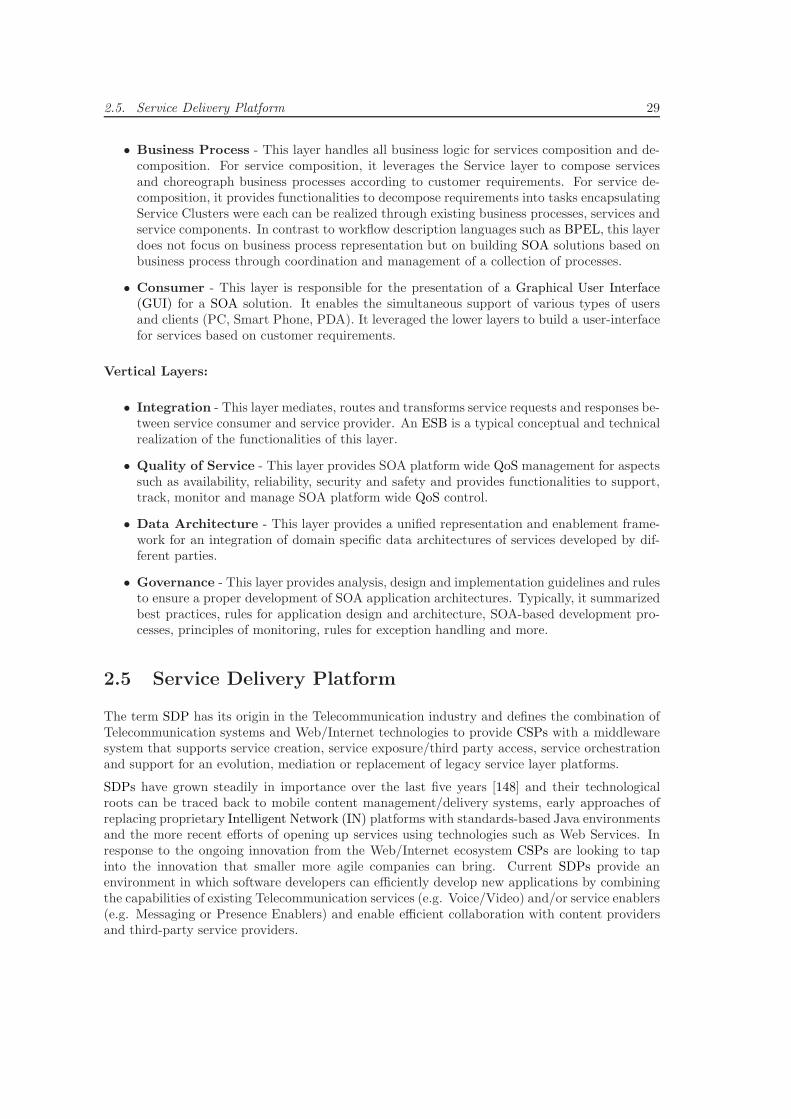
2.5. Service Delivery Platform 29
• Business Process - This layer handles all business logic for services composition and de-composition. For service composition, it leverages the Service layer to compose servicesand choreograph business processes according to customer requirements. For service de-composition, it provides functionalities to decompose requirements into tasks encapsulatingService Clusters were each can be realized through existing business processes, services andservice components. In contrast to workflow description languages such as BPEL, this layerdoes not focus on business process representation but on building SOA solutions based onbusiness process through coordination and management of a collection of processes.
• Consumer - This layer is responsible for the presentation of a Graphical User Interface(GUI) for a SOA solution. It enables the simultaneous support of various types of usersand clients (PC, Smart Phone, PDA). It leveraged the lower layers to build a user-interfacefor services based on customer requirements.
Vertical Layers:
• Integration - This layer mediates, routes and transforms service requests and responses be-tween service consumer and service provider. An ESB is a typical conceptual and technicalrealization of the functionalities of this layer.
• Quality of Service - This layer provides SOA platform wide QoS management for aspectssuch as availability, reliability, security and safety and provides functionalities to support,track, monitor and manage SOA platform wide QoS control.
• Data Architecture - This layer provides a unified representation and enablement frame-work for an integration of domain specific data architectures of services developed by dif-ferent parties.
• Governance - This layer provides analysis, design and implementation guidelines and rulesto ensure a proper development of SOA application architectures. Typically, it summarizedbest practices, rules for application design and architecture, SOA-based development pro-cesses, principles of monitoring, rules for exception handling and more.
2.5 Service Delivery Platform
The term SDP has its origin in the Telecommunication industry and defines the combination ofTelecommunication systems and Web/Internet technologies to provide CSPs with a middlewaresystem that supports service creation, service exposure/third party access, service orchestrationand support for an evolution, mediation or replacement of legacy service layer platforms.
SDPs have grown steadily in importance over the last five years [148] and their technologicalroots can be traced back to mobile content management/delivery systems, early approaches ofreplacing proprietary Intelligent Network (IN) platforms with standards-based Java environmentsand the more recent efforts of opening up services using technologies such as Web Services. Inresponse to the ongoing innovation from the Web/Internet ecosystem CSPs are looking to tapinto the innovation that smaller more agile companies can bring. Current SDPs provide anenvironment in which software developers can efficiently develop new applications by combiningthe capabilities of existing Telecommunication services (e.g. Voice/Video) and/or service enablers(e.g. Messaging or Presence Enablers) and enable efficient collaboration with content providersand third-party service providers.
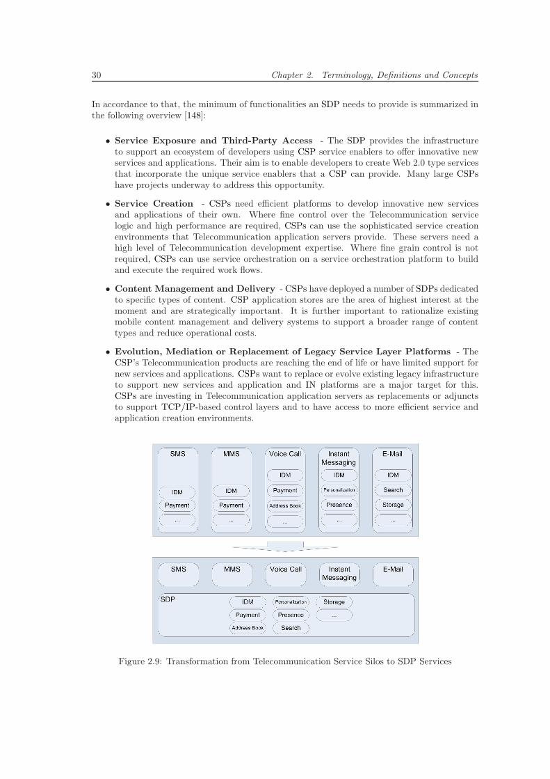
30 Chapter 2. Terminology, Definitions and Concepts
In accordance to that, the minimum of functionalities an SDP needs to provide is summarized inthe following overview [148]:
• Service Exposure and Third-Party Access - The SDP provides the infrastructureto support an ecosystem of developers using CSP service enablers to offer innovative newservices and applications. Their aim is to enable developers to create Web 2.0 type servicesthat incorporate the unique service enablers that a CSP can provide. Many large CSPshave projects underway to address this opportunity.
• Service Creation - CSPs need efficient platforms to develop innovative new servicesand applications of their own. Where fine control over the Telecommunication servicelogic and high performance are required, CSPs can use the sophisticated service creationenvironments that Telecommunication application servers provide. These servers need ahigh level of Telecommunication development expertise. Where fine grain control is notrequired, CSPs can use service orchestration on a service orchestration platform to buildand execute the required work flows.
• Content Management and Delivery - CSPs have deployed a number of SDPs dedicatedto specific types of content. CSP application stores are the area of highest interest at themoment and are strategically important. It is further important to rationalize existingmobile content management and delivery systems to support a broader range of contenttypes and reduce operational costs.
• Evolution, Mediation or Replacement of Legacy Service Layer Platforms - TheCSP’s Telecommunication products are reaching the end of life or have limited support fornew services and applications. CSPs want to replace or evolve existing legacy infrastructureto support new services and application and IN platforms are a major target for this.CSPs are investing in Telecommunication application servers as replacements or adjunctsto support TCP/IP-based control layers and to have access to more efficient service andapplication creation environments.
Figure 2.9: Transformation from Telecommunication Service Silos to SDP Services
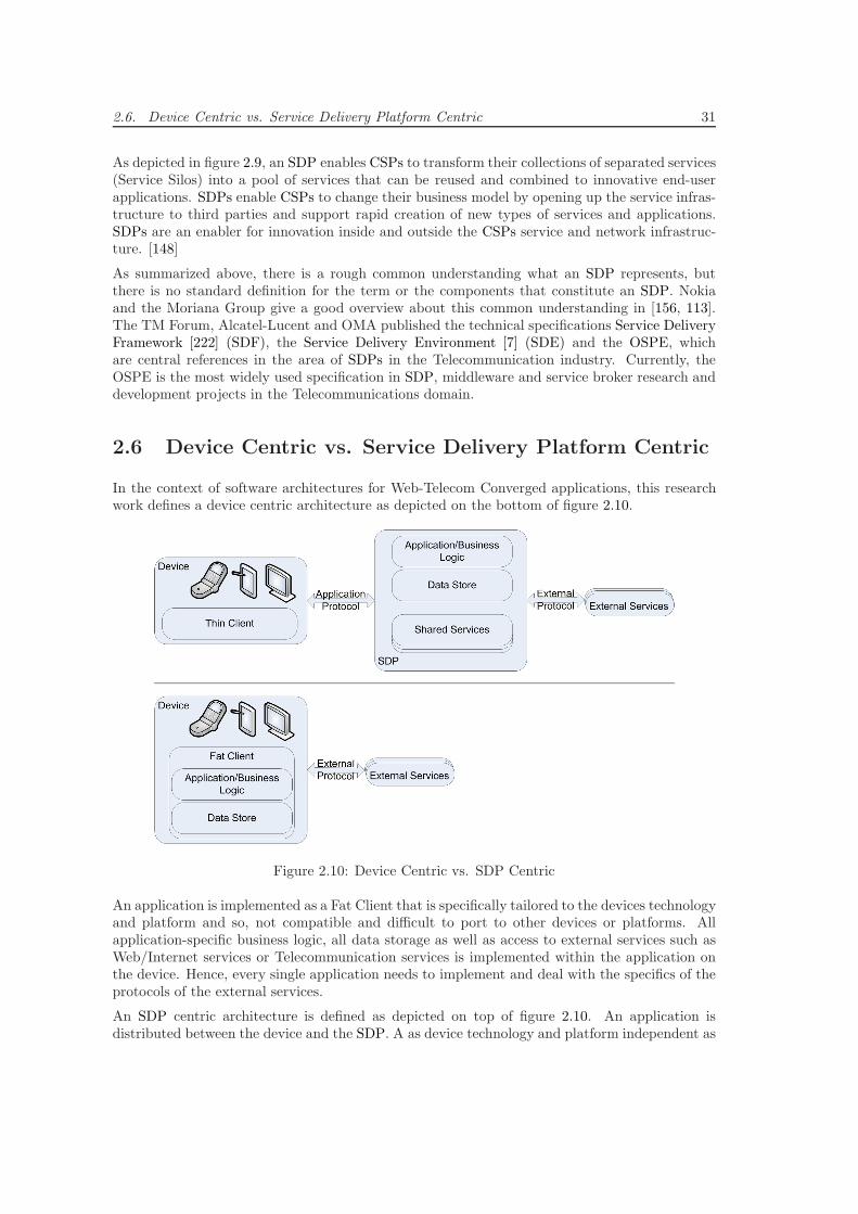
2.6. Device Centric vs. Service Delivery Platform Centric 31
As depicted in figure 2.9, an SDP enables CSPs to transform their collections of separated services(Service Silos) into a pool of services that can be reused and combined to innovative end-userapplications. SDPs enable CSPs to change their business model by opening up the service infras-tructure to third parties and support rapid creation of new types of services and applications.SDPs are an enabler for innovation inside and outside the CSPs service and network infrastruc-ture. [148]
As summarized above, there is a rough common understanding what an SDP represents, butthere is no standard definition for the term or the components that constitute an SDP. Nokiaand the Moriana Group give a good overview about this common understanding in [156, 113].The TM Forum, Alcatel-Lucent and OMA published the technical specifications Service DeliveryFramework [222] (SDF), the Service Delivery Environment [7] (SDE) and the OSPE, whichare central references in the area of SDPs in the Telecommunication industry. Currently, theOSPE is the most widely used specification in SDP, middleware and service broker research anddevelopment projects in the Telecommunications domain.
2.6 Device Centric vs. Service Delivery Platform Centric
In the context of software architectures for Web-Telecom Converged applications, this researchwork defines a device centric architecture as depicted on the bottom of figure 2.10.
Figure 2.10: Device Centric vs. SDP Centric
An application is implemented as a Fat Client that is specifically tailored to the devices technologyand platform and so, not compatible and difficult to port to other devices or platforms. Allapplication-specific business logic, all data storage as well as access to external services such asWeb/Internet services or Telecommunication services is implemented within the application onthe device. Hence, every single application needs to implement and deal with the specifics of theprotocols of the external services.
An SDP centric architecture is defined as depicted on top of figure 2.10. An application isdistributed between the device and the SDP. A as device technology and platform independent as
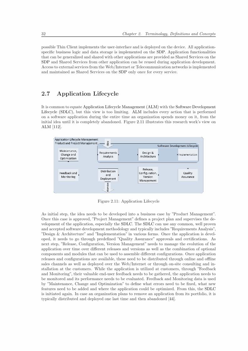
32 Chapter 2. Terminology, Definitions and Concepts
possible Thin Client implements the user-interface and is deployed on the device. All application-specific business logic and data storage is implemented on the SDP. Application functionalitiesthat can be generalized and shared with other applications are provided as Shared Services on theSDP and Shared Services from other application can be reused during application development.Access to external services from the Web/Internet or Telecommunication networks is implementedand maintained as Shared Services on the SDP only once for every service.
2.7 Application Lifecycle
It is common to equate Application Lifecycle Management (ALM) with the Software DevelopmentLifecycle (SDLC), but this view is too limiting. ALM includes every action that is performedon a software application during the entire time an organization spends money on it, from theinitial idea until it is completely abandoned. Figure 2.11 illustrates this research work’s view onALM [112].
Figure 2.11: Application Lifecycle
As initial step, the idea needs to be developed into a business case by ”Product Management”.Once this case is approved, ”Project Management” defines a project plan and supervises the de-velopment of the application, especially the SDLC. The SDLC can use any common, well provenand accepted software development methodology and typically includes ”Requirements Analysis”,”Design & Architecture” and ”Implementation” in various forms. Once the application is devel-oped, it needs to go through predefined ”Quality Assurance” approvals and certifications. Asnext step, ”Release, Configuration, Version Management” needs to manage the evolution of theapplication over time over different releases and versions as well as the combination of optionalcomponents and modules that can be used to assemble different configurations. Once applicationreleases and configurations are available, these need to be distributed through online and offlinesales channels as well as deployed over the Web/Internet or through on-site consulting and in-stallation at the customers. While the application is utilized at customers, through ”Feedbackand Monitoring”, their valuable end-user feedback needs to be gathered, the application needs tobe monitored and its performance needs to be evaluated. Feedback and Monitoring data is usedby ”Maintenance, Change and Optimization” to define what errors need to be fixed, what newfeatures need to be added and where the application could be optimized. From this, the SDLCis initiated again. In case an organization plans to remove an application from its portfolio, it istypically distributed and deployed one last time and then abandoned [44].
2.8. Convergence 33
2.8 Convergence
The word convergence is derived from the Latin word ”convergere”, which means ”to incline to-gether”. In the Telecommunication industry convergence defines the growing together of Telecom-munication, Internet andMedia technologies, services and applications. It can be seen as to enablethe possibility to seamlessly provide all services on all networks and platforms to the end-userswithout any restrictions.
This research work distinguishes three types of convergence, (i) convergence of fixed (wireline)and mobile (wireless) networks, (ii) convergence of Telecommunication, media and broadcastingservices and (iii) convergence of Web/Internet and Telecommunication services.
2.8.1 Fixed-Mobile Convergence
Since the introduction of digital mobile Telecommunication networks based on the GSM standardin Germany in the 1990s, fixed and mobile Telecommunication networks evolved independentlyin parallel. Fixed and mobile services were offered by different providers or by strictly separatedsubsidiaries of one CSP such as Deutsche Telekom. Through convergent devices, applicationsand technologies, Fixed Mobile Convergence (FMC) enables a ubiquitous and seamless deliveryof the same end-user centric Telecommunication services over the fixed as well as the mobileTelecommunication networks. This opens new possibilities for flexible, intuitive and innovativeprivate and enterprise communication services [193].
The evolution of FMC can roughly be structured in the following three stages [153]:
Virtual Convergence In this stage, fixed and mobile networks are virtually connected throughsimple service forwarding mechanisms such as call forwarding. One example (O2 Genion Product)would be that end-users receive a fixed as well as a mobile phone number for their mobile devices.Based on certain predefined rules such as being in a geographical region, calls to the fixed phonenumber are forwarded to the mobile device or, if this is disconnected, to the voice mailbox [59].
Functional Convergence In this stage several functionalities of the fixed and the mobileTelecommunication networks are centralized. Call signaling functionalities are combined, so asingle phone number for end-users is able to ring at all of their mobile as well as fixed phones.Billing systems are connected, so end-users are able to receive a single bill for both networks. Thevoice mailbox is centralized, so all messages for fixed and mobile phone numbers are stored at oneplace and accessible from both networks. Basic information management systems are introducedcentrally, so end-users can manage the same address books and even calendars from their fixedand mobile devices [10].
Full Convergence In this stage, fixed and increasingly mobile broadband Web/Internet con-nections are widespread, Telecommunication service and application alternatives are offered byASPs through Web/Internet technologies and Telecommunication service revenues are declin-ing. Core network technologies and system of fixed as well as mobile Telecommunication sys-tems are fully converged by migrating them to novel Web/Internet technologies (TCP/IP)-basedTelecommunication specifications and standards. This promises a more efficient developmentand delivery of personalized ubiquitous Telecommunication services. At the same time, througha simplified network structure and reduced bandwidth requirements, it reduces Capital Expendi-ture (CAPEX) and Operational Expenditure (OPEX) costs. By leveraging Web/Internet tech-nologies, not only fixed and mobile Telecommunication networks are converged, but also non-
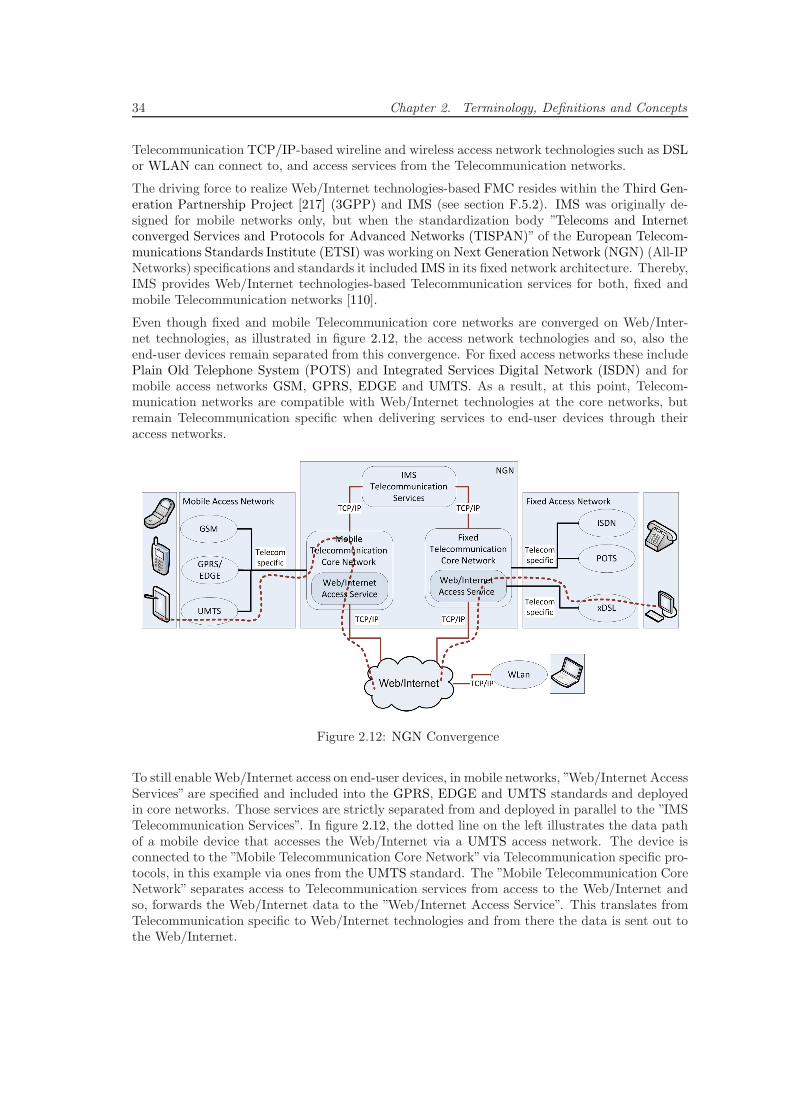
34 Chapter 2. Terminology, Definitions and Concepts
Telecommunication TCP/IP-based wireline and wireless access network technologies such as DSLor WLAN can connect to, and access services from the Telecommunication networks.
The driving force to realize Web/Internet technologies-based FMC resides within the Third Gen-eration Partnership Project [217] (3GPP) and IMS (see section F.5.2). IMS was originally de-signed for mobile networks only, but when the standardization body ”Telecoms and Internetconverged Services and Protocols for Advanced Networks (TISPAN)” of the European Telecom-munications Standards Institute (ETSI) was working on Next Generation Network (NGN) (All-IPNetworks) specifications and standards it included IMS in its fixed network architecture. Thereby,IMS provides Web/Internet technologies-based Telecommunication services for both, fixed andmobile Telecommunication networks [110].
Even though fixed and mobile Telecommunication core networks are converged on Web/Inter-net technologies, as illustrated in figure 2.12, the access network technologies and so, also theend-user devices remain separated from this convergence. For fixed access networks these includePlain Old Telephone System (POTS) and Integrated Services Digital Network (ISDN) and formobile access networks GSM, GPRS, EDGE and UMTS. As a result, at this point, Telecom-munication networks are compatible with Web/Internet technologies at the core networks, butremain Telecommunication specific when delivering services to end-user devices through theiraccess networks.
Figure 2.12: NGN Convergence
To still enable Web/Internet access on end-user devices, in mobile networks, ”Web/Internet AccessServices” are specified and included into the GPRS, EDGE and UMTS standards and deployedin core networks. Those services are strictly separated from and deployed in parallel to the ”IMSTelecommunication Services”. In figure 2.12, the dotted line on the left illustrates the data pathof a mobile device that accesses the Web/Internet via a UMTS access network. The device isconnected to the ”Mobile Telecommunication Core Network”via Telecommunication specific pro-tocols, in this example via ones from the UMTS standard. The ”Mobile Telecommunication CoreNetwork” separates access to Telecommunication services from access to the Web/Internet andso, forwards the Web/Internet data to the ”Web/Internet Access Service”. This translates fromTelecommunication specific to Web/Internet technologies and from there the data is sent out tothe Web/Internet.
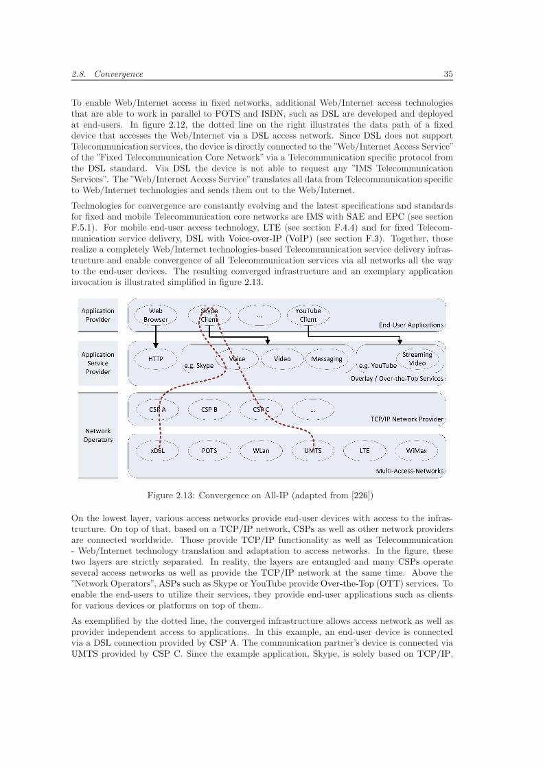
2.8. Convergence 35
To enable Web/Internet access in fixed networks, additional Web/Internet access technologiesthat are able to work in parallel to POTS and ISDN, such as DSL are developed and deployedat end-users. In figure 2.12, the dotted line on the right illustrates the data path of a fixeddevice that accesses the Web/Internet via a DSL access network. Since DSL does not supportTelecommunication services, the device is directly connected to the ”Web/Internet Access Service”of the ”Fixed Telecommunication Core Network”via a Telecommunication specific protocol fromthe DSL standard. Via DSL the device is not able to request any ”IMS TelecommunicationServices”. The ”Web/Internet Access Service”translates all data from Telecommunication specificto Web/Internet technologies and sends them out to the Web/Internet.
Technologies for convergence are constantly evolving and the latest specifications and standardsfor fixed and mobile Telecommunication core networks are IMS with SAE and EPC (see sectionF.5.1). For mobile end-user access technology, LTE (see section F.4.4) and for fixed Telecom-munication service delivery, DSL with Voice-over-IP (VoIP) (see section F.3). Together, thoserealize a completely Web/Internet technologies-based Telecommunication service delivery infras-tructure and enable convergence of all Telecommunication services via all networks all the wayto the end-user devices. The resulting converged infrastructure and an exemplary applicationinvocation is illustrated simplified in figure 2.13.
Figure 2.13: Convergence on All-IP (adapted from [226])
On the lowest layer, various access networks provide end-user devices with access to the infras-tructure. On top of that, based on a TCP/IP network, CSPs as well as other network providersare connected worldwide. Those provide TCP/IP functionality as well as Telecommunication- Web/Internet technology translation and adaptation to access networks. In the figure, thesetwo layers are strictly separated. In reality, the layers are entangled and many CSPs operateseveral access networks as well as provide the TCP/IP network at the same time. Above the”Network Operators”, ASPs such as Skype or YouTube provide Over-the-Top (OTT) services. Toenable the end-users to utilize their services, they provide end-user applications such as clientsfor various devices or platforms on top of them.
As exemplified by the dotted line, the converged infrastructure allows access network as well asprovider independent access to applications. In this example, an end-user device is connectedvia a DSL connection provided by CSP A. The communication partner’s device is connected viaUMTS provided by CSP C. Since the example application, Skype, is solely based on TCP/IP,
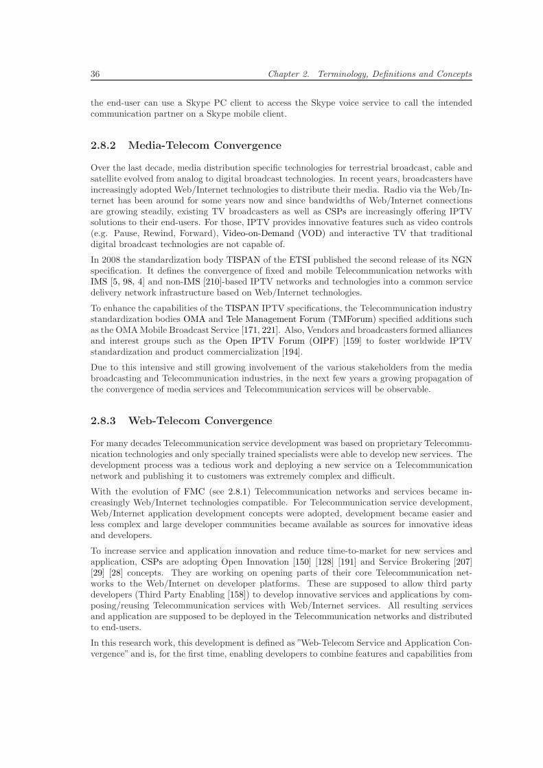
36 Chapter 2. Terminology, Definitions and Concepts
the end-user can use a Skype PC client to access the Skype voice service to call the intendedcommunication partner on a Skype mobile client.
2.8.2 Media-Telecom Convergence
Over the last decade, media distribution specific technologies for terrestrial broadcast, cable andsatellite evolved from analog to digital broadcast technologies. In recent years, broadcasters haveincreasingly adopted Web/Internet technologies to distribute their media. Radio via the Web/In-ternet has been around for some years now and since bandwidths of Web/Internet connectionsare growing steadily, existing TV broadcasters as well as CSPs are increasingly offering IPTVsolutions to their end-users. For those, IPTV provides innovative features such as video controls(e.g. Pause, Rewind, Forward), Video-on-Demand (VOD) and interactive TV that traditionaldigital broadcast technologies are not capable of.
In 2008 the standardization body TISPAN of the ETSI published the second release of its NGNspecification. It defines the convergence of fixed and mobile Telecommunication networks withIMS [5, 98, 4] and non-IMS [210]-based IPTV networks and technologies into a common servicedelivery network infrastructure based on Web/Internet technologies.
To enhance the capabilities of the TISPAN IPTV specifications, the Telecommunication industrystandardization bodies OMA and Tele Management Forum (TMForum) specified additions suchas the OMAMobile Broadcast Service [171, 221]. Also, Vendors and broadcasters formed alliancesand interest groups such as the Open IPTV Forum (OIPF) [159] to foster worldwide IPTVstandardization and product commercialization [194].
Due to this intensive and still growing involvement of the various stakeholders from the mediabroadcasting and Telecommunication industries, in the next few years a growing propagation ofthe convergence of media services and Telecommunication services will be observable.
2.8.3 Web-Telecom Convergence
For many decades Telecommunication service development was based on proprietary Telecommu-nication technologies and only specially trained specialists were able to develop new services. Thedevelopment process was a tedious work and deploying a new service on a Telecommunicationnetwork and publishing it to customers was extremely complex and difficult.
With the evolution of FMC (see 2.8.1) Telecommunication networks and services became in-creasingly Web/Internet technologies compatible. For Telecommunication service development,Web/Internet application development concepts were adopted, development became easier andless complex and large developer communities became available as sources for innovative ideasand developers.
To increase service and application innovation and reduce time-to-market for new services andapplication, CSPs are adopting Open Innovation [150] [128] [191] and Service Brokering [207][29] [28] concepts. They are working on opening parts of their core Telecommunication net-works to the Web/Internet on developer platforms. These are supposed to allow third partydevelopers (Third Party Enabling [158]) to develop innovative services and applications by com-posing/reusing Telecommunication services with Web/Internet services. All resulting servicesand application are supposed to be deployed in the Telecommunication networks and distributedto end-users.
In this research work, this development is defined as ”Web-Telecom Service and Application Con-vergence” and is, for the first time, enabling developers to combine features and capabilities from
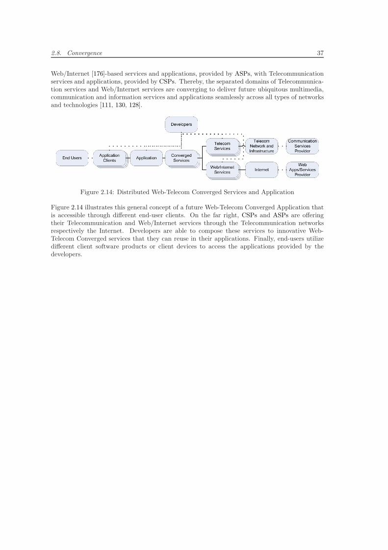
2.8. Convergence 37
Web/Internet [176]-based services and applications, provided by ASPs, with Telecommunicationservices and applications, provided by CSPs. Thereby, the separated domains of Telecommunica-tion services and Web/Internet services are converging to deliver future ubiquitous multimedia,communication and information services and applications seamlessly across all types of networksand technologies [111, 130, 128].
Figure 2.14: Distributed Web-Telecom Converged Services and Application
Figure 2.14 illustrates this general concept of a future Web-Telecom Converged Application thatis accessible through different end-user clients. On the far right, CSPs and ASPs are offeringtheir Telecommunication and Web/Internet services through the Telecommunication networksrespectively the Internet. Developers are able to compose these services to innovative Web-Telecom Converged services that they can reuse in their applications. Finally, end-users utilizedifferent client software products or client devices to access the applications provided by thedevelopers.

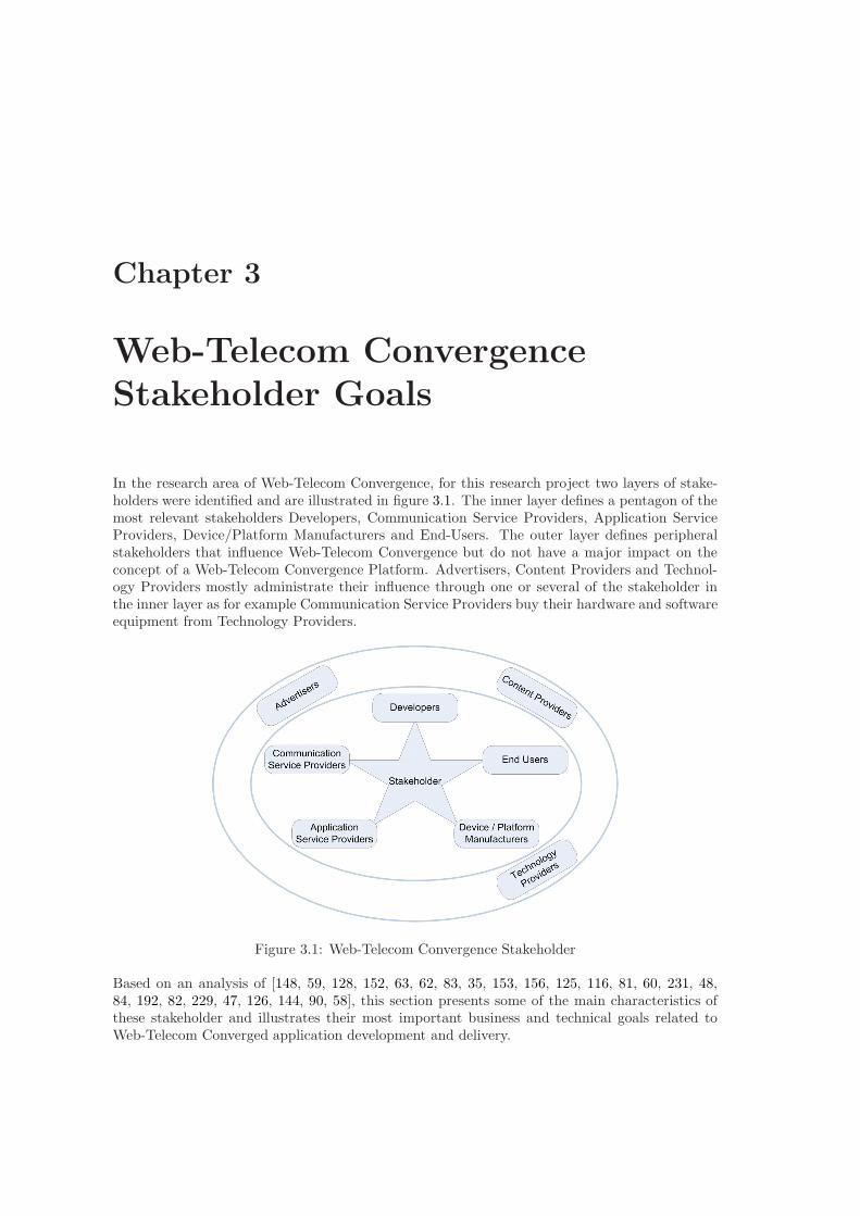
Chapter 3
Web-Telecom ConvergenceStakeholder Goals
In the research area of Web-Telecom Convergence, for this research project two layers of stake-holders were identified and are illustrated in figure 3.1. The inner layer defines a pentagon of themost relevant stakeholders Developers, Communication Service Providers, Application ServiceProviders, Device/Platform Manufacturers and End-Users. The outer layer defines peripheralstakeholders that influence Web-Telecom Convergence but do not have a major impact on theconcept of a Web-Telecom Convergence Platform. Advertisers, Content Providers and Technol-ogy Providers mostly administrate their influence through one or several of the stakeholder inthe inner layer as for example Communication Service Providers buy their hardware and softwareequipment from Technology Providers.
Figure 3.1: Web-Telecom Convergence Stakeholder
Based on an analysis of [148, 59, 128, 152, 63, 62, 83, 35, 153, 156, 125, 116, 81, 60, 231, 48,84, 192, 82, 229, 47, 126, 144, 90, 58], this section presents some of the main characteristics ofthese stakeholder and illustrates their most important business and technical goals related toWeb-Telecom Converged application development and delivery.
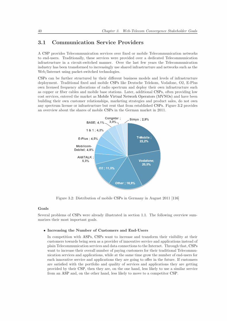
40 Chapter 3. Web-Telecom Convergence Stakeholder Goals
3.1 Communication Service Providers
A CSP provides Telecommunication services over fixed or mobile Telecommunication networksto end-users. Traditionally, these services were provided over a dedicated Telecommunicationinfrastructure in a circuit-switched manner. Over the last few years the Telecommunicationindustry has been transformed to increasingly use shared infrastructure and networks such as theWeb/Internet using packet-switched technologies.
CSPs can be further structured by their different business models and levels of infrastructuredeployment. Traditional fixed and mobile CSPs like Deutsche Telekom, Vodafone, O2, E-Plusown licensed frequency allocations of radio spectrum and deploy their own infrastructure suchas copper or fiber cables and mobile base stations. Later, additional CSPs, often providing lowcost services, entered the market as Mobile Virtual Network Operators (MVNOs) and have beenbuilding their own customer relationships, marketing strategies and product sales, do not ownany spectrum license or infrastructure but rent that from established CSPs. Figure 3.2 providesan overview about the shares of mobile CSPs in the German market in 2011.
Figure 3.2: Distribution of mobile CSPs in Germany in August 2011 [116]
Goals
Several problems of CSPs were already illustrated in section 1.1. The following overview sum-marizes their most important goals.
• Increasing the Number of Customers and End-Users
In competition with ASPs, CSPs want to increase and transform their visibility at theircustomers towards being seen as a provider of innovative service and applications instead ofplain Telecommunication services and data connections to the Internet. Through that, CSPswant to increase their overall number of paying customers for their traditional Telecommu-nication services and applications, while at the same time grow the number of end-users foreach innovative service and applications they are going to offer in the future. If customersare satisfied with the portfolio and quality of services and applications they are gettingprovided by their CSP, then they are, on the one hand, less likely to use a similar servicefrom an ASP and, on the other hand, less likely to move to a competitor CSP.
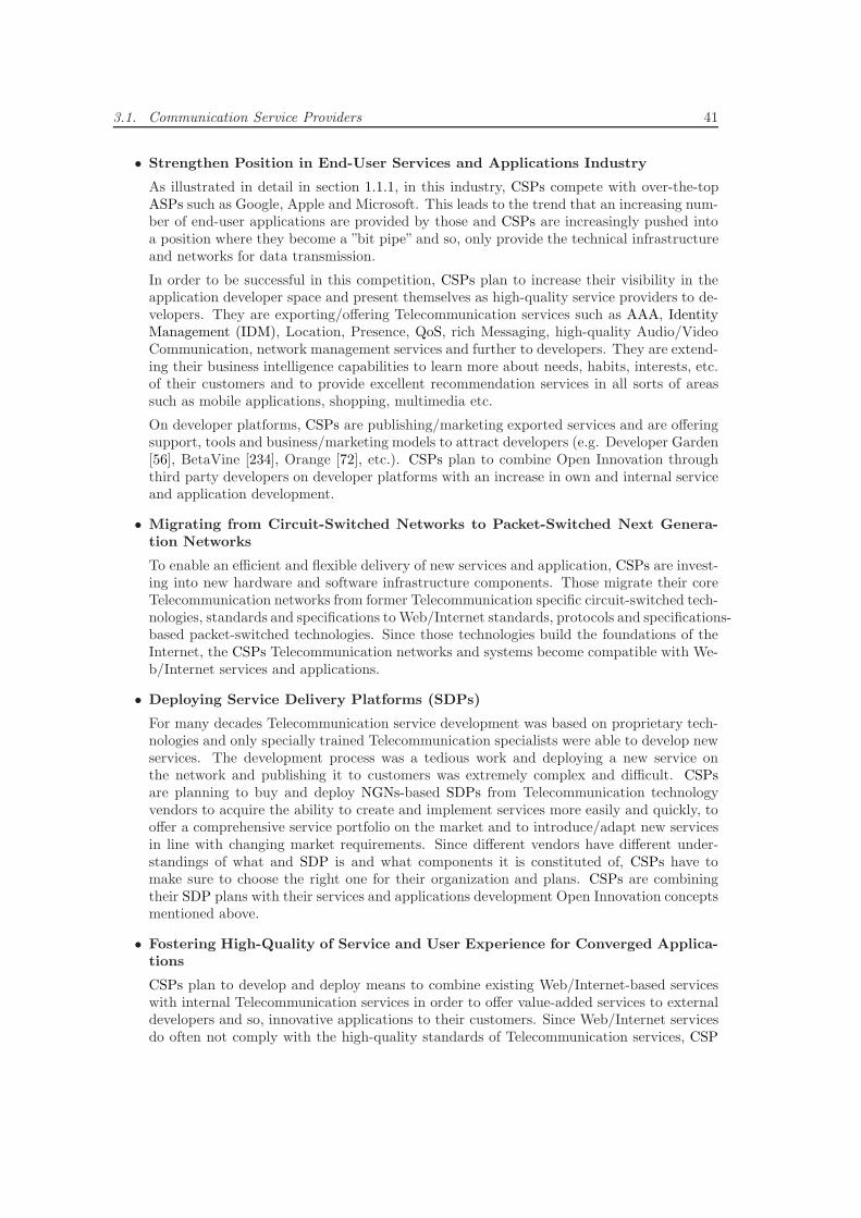
3.1. Communication Service Providers 41
• Strengthen Position in End-User Services and Applications Industry
As illustrated in detail in section 1.1.1, in this industry, CSPs compete with over-the-topASPs such as Google, Apple and Microsoft. This leads to the trend that an increasing num-ber of end-user applications are provided by those and CSPs are increasingly pushed intoa position where they become a ”bit pipe” and so, only provide the technical infrastructureand networks for data transmission.
In order to be successful in this competition, CSPs plan to increase their visibility in theapplication developer space and present themselves as high-quality service providers to de-velopers. They are exporting/offering Telecommunication services such as AAA, IdentityManagement (IDM), Location, Presence, QoS, rich Messaging, high-quality Audio/VideoCommunication, network management services and further to developers. They are extend-ing their business intelligence capabilities to learn more about needs, habits, interests, etc.of their customers and to provide excellent recommendation services in all sorts of areassuch as mobile applications, shopping, multimedia etc.
On developer platforms, CSPs are publishing/marketing exported services and are offeringsupport, tools and business/marketing models to attract developers (e.g. Developer Garden[56], BetaVine [234], Orange [72], etc.). CSPs plan to combine Open Innovation throughthird party developers on developer platforms with an increase in own and internal serviceand application development.
• Migrating from Circuit-Switched Networks to Packet-Switched Next Genera-tion Networks
To enable an efficient and flexible delivery of new services and application, CSPs are invest-ing into new hardware and software infrastructure components. Those migrate their coreTelecommunication networks from former Telecommunication specific circuit-switched tech-nologies, standards and specifications to Web/Internet standards, protocols and specifications-based packet-switched technologies. Since those technologies build the foundations of theInternet, the CSPs Telecommunication networks and systems become compatible with We-b/Internet services and applications.
• Deploying Service Delivery Platforms (SDPs)
For many decades Telecommunication service development was based on proprietary tech-nologies and only specially trained Telecommunication specialists were able to develop newservices. The development process was a tedious work and deploying a new service onthe network and publishing it to customers was extremely complex and difficult. CSPsare planning to buy and deploy NGNs-based SDPs from Telecommunication technologyvendors to acquire the ability to create and implement services more easily and quickly, tooffer a comprehensive service portfolio on the market and to introduce/adapt new servicesin line with changing market requirements. Since different vendors have different under-standings of what and SDP is and what components it is constituted of, CSPs have tomake sure to choose the right one for their organization and plans. CSPs are combiningtheir SDP plans with their services and applications development Open Innovation conceptsmentioned above.
• Fostering High-Quality of Service and User Experience for Converged Applica-tions
CSPs plan to develop and deploy means to combine existing Web/Internet-based serviceswith internal Telecommunication services in order to offer value-added services to externaldevelopers and so, innovative applications to their customers. Since Web/Internet servicesdo often not comply with the high-quality standards of Telecommunication services, CSP
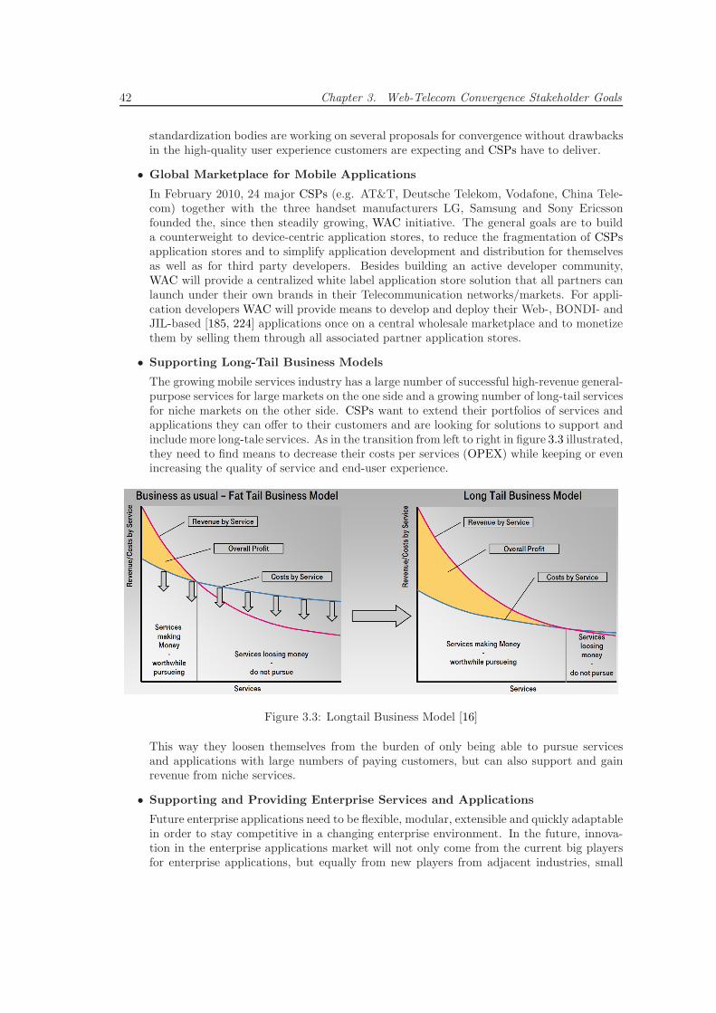
42 Chapter 3. Web-Telecom Convergence Stakeholder Goals
standardization bodies are working on several proposals for convergence without drawbacksin the high-quality user experience customers are expecting and CSPs have to deliver.
• Global Marketplace for Mobile Applications
In February 2010, 24 major CSPs (e.g. AT&T, Deutsche Telekom, Vodafone, China Tele-com) together with the three handset manufacturers LG, Samsung and Sony Ericssonfounded the, since then steadily growing, WAC initiative. The general goals are to builda counterweight to device-centric application stores, to reduce the fragmentation of CSPsapplication stores and to simplify application development and distribution for themselvesas well as for third party developers. Besides building an active developer community,WAC will provide a centralized white label application store solution that all partners canlaunch under their own brands in their Telecommunication networks/markets. For appli-cation developers WAC will provide means to develop and deploy their Web-, BONDI- andJIL-based [185, 224] applications once on a central wholesale marketplace and to monetizethem by selling them through all associated partner application stores.
• Supporting Long-Tail Business Models
The growing mobile services industry has a large number of successful high-revenue general-purpose services for large markets on the one side and a growing number of long-tail servicesfor niche markets on the other side. CSPs want to extend their portfolios of services andapplications they can offer to their customers and are looking for solutions to support andinclude more long-tale services. As in the transition from left to right in figure 3.3 illustrated,they need to find means to decrease their costs per services (OPEX) while keeping or evenincreasing the quality of service and end-user experience.
Figure 3.3: Longtail Business Model [16]
This way they loosen themselves from the burden of only being able to pursue servicesand applications with large numbers of paying customers, but can also support and gainrevenue from niche services.
• Supporting and Providing Enterprise Services and Applications
Future enterprise applications need to be flexible, modular, extensible and quickly adaptablein order to stay competitive in a changing enterprise environment. In the future, innova-tion in the enterprise applications market will not only come from the current big playersfor enterprise applications, but equally from new players from adjacent industries, small
3.2. Application Service Providers 43
companies or independent developers. Most legacy and current Information Technology(IT) concepts and infrastructures are not able to cope with these new requirements. Enter-prises are reorganizing their IT departments in order to evaluate or launch cloud computingstrategies to outsource IT infrastructures, services and applications immediately or in thefuture. In this transforming enterprise environment CSPs plan to take a significant role inthe value chain and to generate additional revenue through two strategies, (i) collaboratingwith ASPs and enterprises and supporting their services and applications through cloudcomputing offerings or (ii) competing with ASPs and providing services and applicationsto enterprise customers themselves.
CSPs drive standardization in cloud computing Infrastructure-as-a-Service (IaaS) andPlatform-as-a-Service (PaaS) areas focusing at enterprise application provisioning, manage-ment, hosting, maintenance, delivery, etc. Thus, they achieve credibility and a competitiveadvantage over other players (e.g. Microsoft with Azure, Google with AppEngine, Ama-zon with Web Services) when offering enterprise products in the cloud computing indus-try. They can combine their existing technologies, platforms and third party developmentconcepts with flexible, scaleable, professional and SLA-backed cloud computing infrastruc-ture/platform offerings. Thereby, on the one hand, enabling a cooperation with ASPs andenterprises by creating a platform for managing their existing services and applications.While, on the other hand, allowing professional and independent developers to develop anddeploy innovative enterprise services and applications on top of their platforms.
CSPs extend their internal services and applications development departments and com-bine these with their technologies, platforms, future cloud computing infrastructures andthird party development concepts. Through that, they will be able to develop a selection ofhigh-quality enterprise applications that they can offer and provide to enterprise customersdirectly. Hence, since enterprise customers are more willing to pay for services and appli-cations than private customers, CSPs can apply a traditional business model to generatemore revenue through new services and applications.
3.2 Application Service Providers
Traditionally, an ASP is defined as a company that offers computer-based services/applicationsto consumers via a data network. Today, through the spreading of cloud computing, an ASPcan be defined as a Software-as-a-Service [202] (SaaS) provider offering services/applicationsthat are accessible as on-demand software over the Internet. Through the reduced effort andlower costs of the distribution of the software over the Internet, ASPs can base their softwaredevelopment on a larger number of customers and so, provide higher quality software for a lowerprice than traditional software companies. Consumers use thin software clients on their clientdevices such as PCs or smart phones to work with the software. Nowadays, web browsers are themost popular universal thin software clients than can be used to access Web/Internet-based SaaSproducts. Popular ASP companies in the B2B and B2C industries are Salesforce, SAP, Oracle,Zoho, Google, Microsoft, Facebook, Xing, LinkedIn, Skype, Twitter, etc.
In the B2B industry, ASPs satisfy the growing need of enterprises to reduce their large invest-ments in IT hardware and software upgrades (nowadays often surpassing budgets of mid-sizedcompanies), to transform those into running costs on a per-use, monthly or yearly basis and toreduce in-house IT hardware and software management complexity, effort and expenditures. Theresponsibility for IT hardware and software availability, management, maintenance, technicalsupport, security, safety, stability, etc. is shifted from the enterprise to the SaaS providing ASP.They typically offer specialized enterprise applications for Enterprise Resource Planning (ERP),Customer Relationship Management (CRM), project management, process management, etc.
44 Chapter 3. Web-Telecom Convergence Stakeholder Goals
or enterprise grade productivity applications such as office suits, collaboration tools, knowledgemanagement, unified communications etc.
In the B2C industry, ASPs are typically relatively young companies that work in a rapidly chang-ing market and that need to be able to adapt their business models fast and often. They satisfythe growing need of private users to be entertained or to work with personal data using any deviceand from anywhere in the world through free or relatively cheap Web/Internet technologies andmostly web browser-based applications. They typically offer innovative productivity, communi-cation, media and entertainment applications such as web mail, office suits, social networking,VoIP, instant messaging, music/video downloads/streaming, IPTV etc.
Goals
The following overview summarizes the ASPs most important goals.
• Competition for Subscribers/Users in B2C Market
On the Internet, private customers expect free or ”freemium” applications for their per-sonal use. Hence, nowadays, most ASPs base their B2C business models on non-customerfocused revenues such as advertisement, access to customers or selling customers’ informa-tion. Ultimately, success of an application is often measured by number or user registered,or number of users that use the application regularly. Due to that, ASPs ultimate goal is tomaximize the number of users that use their applications, to draw them to their advertise-ments supported application user-interface and to lock them to their applications as tightas possible.
• Building Monopoly Applications in B2C Market
ASPs are trying to build monopolies in the areas in which their applications fulfill the users’needs and to lock the users to their applications. An open platform/technology or any stan-dardization together with competitors or partners from other fields is contradicting withthe ASPs business models and success factors for their applications. Hence, most commu-nication services provided by ASPs such as Skype, MSN and GoogleTalk are incompatibleand isolated. Most ASPs did not yet figure out how to combine openness with their busi-ness models and so, are not even trying to use their successful applications to define open”defacto” technology standards on the Internet. Some ASPs, especially in the social net-works area, started providing Application Programming Interfaces (APIs) to connect otherapplications or websites to their applications to provide them with features such as authen-tication using an existing profile. These connections are basically unidirectional towardsthe ASPs applications and aim at drawing more users, user generated content and user con-text information (e.g. browsing history, interests, location information, social attributes)to the ASPs applications. Hence, cooperation between ASPs applications and competitorsor partner companies is difficult, very limited and if there is one, mostly unidirectional orbased on financial compensation of some sort.
• Convergence of Communication and Information
Traditionally, for users, the Web/Internet has been a medium and source for all kinds ofinformation. Through the spreading of Web 2.0 concepts, users are shifting into an activerole where they are publishing general or even personal information on Web/Internet-basedapplications provided by ASPs. Today, with the ubiquitous availability of broadband fixedand mobile data networks, ASPs are providing sophisticated and innovative Web/Internet-based communication applications and combine them with their already existing Web 2.0information applications.
3.3. Device and Platform Manufacturers 45
• Fostering Third Party Development and Integration
ASPs have recognized the value of third party developers and integration much earlier thanCSPs. Over the last decade, they have built many mature developer platforms (e.g. GoogleCode, Facebook, MSDN, DeveloperForce) that allow rapid service and application creationbased on common Web/Internet technologies. These platforms have specifically low entrybarriers for third party developers to allow them to drive innovation by extending/enhanc-ing the applications and technologies the ASPs already offer. Based on the successful AppStore examples from Device/Platform Manufacturers, ASPs are starting to build market-places on top of their developer platforms (e.g. Google Apps Marketplace, Windows AzureAppFabric, Salesforce AppExchange and DeveloperForce) in order to provide third partydevelopers with a distribution channel to customers. Since enterprise customers are typi-cally more willing to pay for a high-quality service or application than private users, mostof the ASPs platforms have been focusing on providing high-quality enterprise servicesand applications. Several have created a two-sided market with third party developers ondeveloper platforms on one side and small/medium size enterprises on application mar-ketplaces on the other side. The values of the ASPs developer communities are growingsteadily. Hence, they are going to nurture this excellent source of innovation even more inthe future.
• Expansion to Mobile Web/Internet
Established ASPs are adjusting and extending their applications and platforms to providetheir users access through mobile devices such as smart phones or tablets. Some ASPstailor their applications to provide a good user experience when accessed by mobile devicebrowsers. Most develop specialized apps for mobile platforms such as Android, iOS, Win-dows Phone to provide their users with access to their application. Popular services suchas Facebook announced more than 100 million users accessing their applications over themobile Web/Internet regularly. This number is expected to be growing rapidly and ASPsare going to focus even more on application delivery using the mobile Internet.
• Fostering Use of Context Information in B2C Industry
Context aware computing has evolved from traditional applications such as portal person-alization and has become a disruptive technology that has the potential to improve userexperience drastically, to build up loyalty and to provide a competitive advantage. ASPsare aiming to include context data elements such as location, presence, social attributesand other environmental information from various sources into their applications. Theywill be able to anticipate their end-users momentary needs and based on those providesophisticated and situation-aware applications.
3.3 Device and Platform Manufacturers
Device Manufacturers (OEMs) design and produce the high-end consumer devices (e.g. mobilephones, smart phones, tablets, IPTVs, etc.) that are used to access current Telecommunicationas well as Web/Internet services and applications. They build their sophisticated technology so-lutions according to worldwide fixed and mobile Telecommunication standards and specificationsthat are defined by industry associations/unions/partnerships/alliances/communities (e.g. ITU,3GPP, GSMA) they are mostly also part of. Device manufacturers have to cope with shorteningproduct lifecycles that require them to launch new products with up-to-date designs and new/en-hanced hardware features such as faster/multicore CPUs, enhanced screen sizes and resolutions,high-definition cameras or Near Field Communication (NFC) components several times a year.The overall market for innovative, sophisticated high-end devices has been growing rapidly over
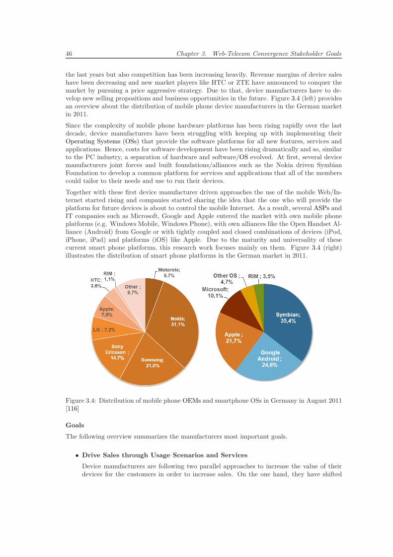
46 Chapter 3. Web-Telecom Convergence Stakeholder Goals
the last years but also competition has been increasing heavily. Revenue margins of device saleshave been decreasing and new market players like HTC or ZTE have announced to conquer themarket by pursuing a price aggressive strategy. Due to that, device manufacturers have to de-velop new selling propositions and business opportunities in the future. Figure 3.4 (left) providesan overview about the distribution of mobile phone device manufacturers in the German marketin 2011.
Since the complexity of mobile phone hardware platforms has been rising rapidly over the lastdecade, device manufacturers have been struggling with keeping up with implementing theirOperating Systems (OSs) that provide the software platforms for all new features, services andapplications. Hence, costs for software development have been rising dramatically and so, similarto the PC industry, a separation of hardware and software/OS evolved. At first, several devicemanufacturers joint forces and built foundations/alliances such as the Nokia driven SymbianFoundation to develop a common platform for services and applications that all of the memberscould tailor to their needs and use to run their devices.
Together with these first device manufacturer driven approaches the use of the mobile Web/In-ternet started rising and companies started sharing the idea that the one who will provide theplatform for future devices is about to control the mobile Internet. As a result, several ASPs andIT companies such as Microsoft, Google and Apple entered the market with own mobile phoneplatforms (e.g. Windows Mobile, Windows Phone), with own alliances like the Open Handset Al-liance (Android) from Google or with tightly coupled and closed combinations of devices (iPod,iPhone, iPad) and platforms (iOS) like Apple. Due to the maturity and universality of thesecurrent smart phone platforms, this research work focuses mainly on them. Figure 3.4 (right)illustrates the distribution of smart phone platforms in the German market in 2011.
Figure 3.4: Distribution of mobile phone OEMs and smartphone OSs in Germany in August 2011[116]
Goals
The following overview summarizes the manufacturers most important goals.
• Drive Sales through Usage Scenarios and Services
Device manufacturers are following two parallel approaches to increase the value of theirdevices for the customers in order to increase sales. On the one hand, they have shifted
3.3. Device and Platform Manufacturers 47
their advertisements and selling propositions from hardware features centric campaigns touse-case and added value centric campaigns. They are using the new hardware and softwarefeatures, including their common platforms, to develop and advertise the most appealingand innovative every-day or business usage scenarios in which the device supports thecustomers. Through that they are trying to increase the demand and adoption of high-enddevices in the society in order to archive a wider market penetration.
On the other hand, many device manufacturers such as Nokia, shift their focus from thein-house development of semiconductors to new sources of revenue in the domain of (mo-bile) services they can offer in combination with their devices. They outsource their devicemanufacturing and enlarge their software services and applications divisions. ASPs, suchas Google or Apple, that entered the platform manufacturers market in the last couple ofyears, have been building popular proprietary information, data and multimedia servicesand applications such as Search, E-Mail, Contacts, Maps, Messaging, VoIP on top of theWeb/Internet over the last decade. They are using these now to revolutionize the Telecom-munications and (mobile) Web/Internet industry though high-tech service platforms withdiverse innovative and advanced mobile services and applications. Through providing suchvalue-added services, applications and platforms with the devices, manufacturers are plan-ning to intensify their relations to customers, increase the overall value of their devices andultimately increase device sales, their customer base and service/application users.
• Provide Excellent User Experience
Device and platform manufacturers are constantly striving to provide their customer withthe best user experience possible on their devices, meaning the best combination of user-interface design and usability. With the increase in diverse high-tech hardware features,services and applications on the devices, the complexity for creating an excellent user ex-perience has been rising constantly. With the maturation of touch screen technology in thelast years, a major shift from small screen keyboard/keypad devices to large screen touchdevices has taken place. In contrast to the static layout of keyboards/keypads, the dynamicnature of touch interfaces allows manufacturers to create an excellent and intuitive user ex-perience for modern devices and platforms even when they are filled with large collectionsof diverse high-tech features, services and applications.
• Provide Open vs. Closed Platforms
In the platform manufacturer market approaches for how much access or influence on aplatform customers, partners or third party developers get diverge drastically. On the onehand manufacturers like Apple or RIM follow a ”Closed Platform” approach that ensuresthem to have full control of all hardware and software features of their platforms. Theyare designing their own hardware devices and are implementing their software platformsin-house without company external influences. They are certain that only through suchtightly coupled hardware and software development their excellent features, services andapplications provided together with an excellent user experience are possible. A few yearsago, these manufacturers adopted third party service and application development includingplatform-specific application stores for their platforms. Even though this was a small breakin their closed ideology, they still aim to control as much about the third party servicesand applications as possible. They limit the developers’ access to platform and hardwarefeatures wherever they identify a possible loss of control over their platforms and restrictany adaptation of pre-installed platform features. They enforce testing and certification ofall applications before they are allowed to be distributed through their applications storesand limit or define the types of content the services and applications are allowed to provideto the end-users.
48 Chapter 3. Web-Telecom Convergence Stakeholder Goals
On the other hand, platform manufacturers like Google and Microsoft follow different levelsof an ”Open Platform” approach that enables them to work closely with partners and de-velopers to enable high-end devices with excellent features, services and applications. Someof their platforms are open source projects, maintained and developed by an alliance ofdevice manufacturers, platform manufacturers and developers. They aim at reducing thecomplexity of the mobile world by setting standards for a platform that consolidates theheavily fragmented mobile devices and platforms market. Other platforms are closed sourceprojects that are maintained and developed in-house by a platform manufacturer. The plat-form manufacturers aim at establishing cooperations with many device manufacturers whouse their platforms to run their devices. Through that they can broaden the user base fortheir legacy Internet-based services and applications (e.g. Search, Maps, E-Mail, Calendar,Office, VoIP), acquire mobile customers for those and target business models like adver-tisement towards them. Similar to above, also these platform manufacturers adopted thirdparty service and application development including platform-specific application stores. Incontrast, here developers gain almost full access to platform and hardware features and areeven encouraged to extend or substitute pre-installed features, services or applications ofthe platform. The platform manufacturers’ influence on applications on their applicationstores is very limited and the stores are generally open to all sorts of applications with alltypes of content. Quality assurance is driven by the market participants through rating,ranking and feedback mechanisms.
• Foster Third Party Development
Platform manufacturers have gained positive experience with their shift of service and appli-cation innovation and development towards external third party developers. They are goingto foster their existing developer communities by continuously enhancing their hardware andsoftware platform technologies, promoting new features to the worldwide developer com-munities and providing easy-to-use, top-quality developer tools for their platforms. Somemanufacturers are planning to implement innovation processes such as ”Open Innovation”that allows them to bring company-internal innovation, services, applications and featurestogether with external developers in a more efficient way.
All platform manufacturers are trying to attract many skilled and innovative developers togrow the developer communities around their platforms and to assure a continuous processof innovation. Developers have become a major success factor for a manufacturers’ platformand so, for platform manufacturers, they are seen as a specific group of customers that hasto be won and convinced of their product. Competition for developers in this market willgrow.
• Foster Platform-Specific Application Stores
Through the combination of application store concepts and third party development, plat-form manufacturers have created a very successful distribution channel for applicationsdirectly accessible from the devices that run their platforms. By utilizing a revenue sharemodel with developers, they have created a win-win situation for both sides and so, attractmany professional and leisure developers. The worldwide generated revenue through thestores of, for example, 4.2 billion USD in 2009 is typically only a fraction of the platformmanufacturers’ total revenue. Nevertheless, the conveniently accessible large selection ofthird party applications for their platforms attracts customers to buy devices that are basedon their platforms, builds a direct access to these customers and increases brand aware-ness and loyalty. Hence, platform manufacturers are going to foster their platform-specificapplication stores and are unlikely to build any cooperations between platforms and stores.
3.4. Developers 49
• Dominate Mobile Advertisement Market
As illustrated in the previous section, on the Internet, many ASPs apply an advertisement-based business model for their B2C services and applications. The ASPs that becameplatform manufacturers are now pushing to bring this business model to their platforms,which will lead to a rapid growth of advertisement over the next years. The platform man-ufacturers control their platforms and so, in some ways, the access to their customers. Toalso control advertisement, they are integrating easy-to-use advertisement feature APIs intotheir platforms Software Development Kits (SDKs), which allow targeting customers moreprecisely and efficiently with advertisement. This enables developers to integrate adver-tisement into their applications. Thereby, platform manufacturers provide the developerswith means to finance their applications while at the same time, they further control anddominate the advertisement market on their platforms.
• Foster Cooperations with Content Providers
Content providers are continuously looking for new profitable distribution channels for theirmultimedia content. Especially now, when print media revenues decline they are looking forways to distribute more of their content digitally. Several platform manufacturers realizedthis need and positioned their platforms as future media content platforms that can beused to distribute high-quality multimedia content through multimedia applications ontheir application stores. Platform manufacturers are partnering with content providersto distribute multimedia content to customers and to generate revenue for both sides.However, some platform manufacturers are following a very stringed concept defining verystrictly what types of content can be distributed in what ways and for what price. Othersare following a very open concept allowing content providers to distribute their contentaccording to their individual innovative ideas, marketing and business plans. Nevertheless,media content providers will use these platforms, partnerships and their own applicationsextensively to distribute multimedia content in the future.
• Foster Device Distribution Partnerships with CSPs
Traditionally, close cooperations with CSPs have been very important distribution chan-nels for device manufacturers. CSP have been subsidizing devices so customers could buythem in combination with a Telecommunication services contract at a low price. Devicemanufacturers rarely sold devices independent of CSPs and they put limited effort into ownmarketing of devices. The CSPs were the ones with direct access to customers and devicemanufacturers were eager to cooperate with them in order to sell devices. Hence, CSPswere in control of the terms and conditions of these cooperations.
With the introduction of the iPhone by Apple in 2007, this CSPs centric model shifted to amore balanced. Device manufacturers have started to market their devices independentlyand CSPs have been eager to collaborate in order to offer these popular devices, sometimeseven exclusively, to their existing and potentially new customers. This fact that somedevice manufacturers established own marketing and distribution efforts leads to risingCSP-independent sales of devices. Nevertheless, a collaboration between them and CSPswill continue to be an important worldwide distribution channel for their devices and asuccess factor of their business.
3.4 Developers
Developers are conceptualizing, designing and implementing services and applications based onplatforms, technologies, services and devices provided by CSPs, ASPs or device/platform man-ufacturers. Often developers are roughly divided into two groups, Commercial/Professional and
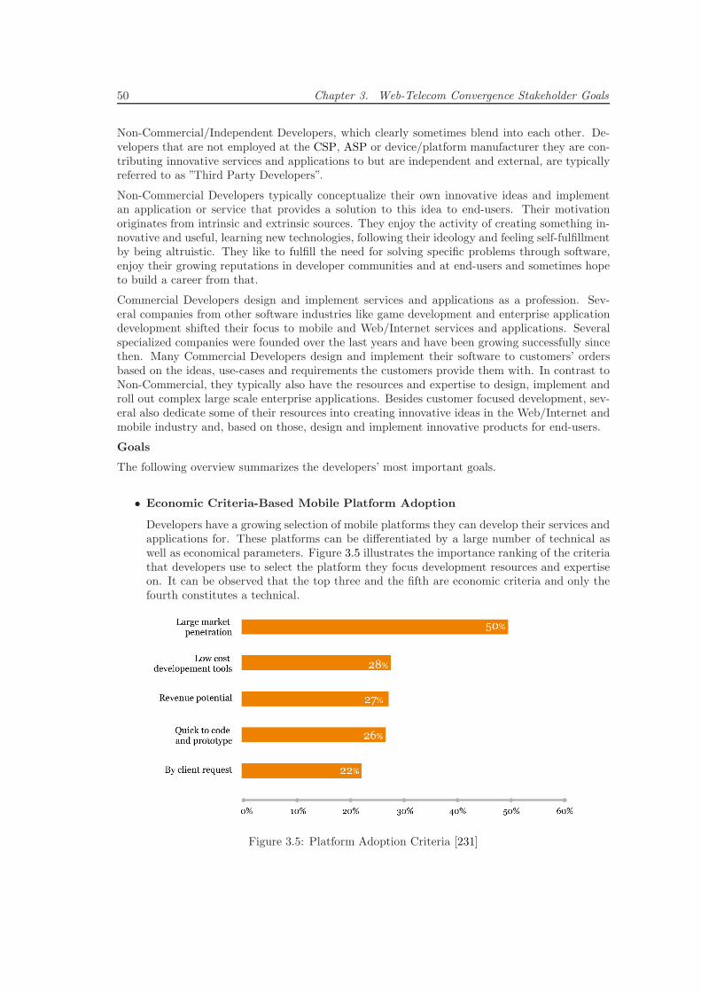
50 Chapter 3. Web-Telecom Convergence Stakeholder Goals
Non-Commercial/Independent Developers, which clearly sometimes blend into each other. De-velopers that are not employed at the CSP, ASP or device/platform manufacturer they are con-tributing innovative services and applications to but are independent and external, are typicallyreferred to as ”Third Party Developers”.
Non-Commercial Developers typically conceptualize their own innovative ideas and implementan application or service that provides a solution to this idea to end-users. Their motivationoriginates from intrinsic and extrinsic sources. They enjoy the activity of creating something in-novative and useful, learning new technologies, following their ideology and feeling self-fulfillmentby being altruistic. They like to fulfill the need for solving specific problems through software,enjoy their growing reputations in developer communities and at end-users and sometimes hopeto build a career from that.
Commercial Developers design and implement services and applications as a profession. Sev-eral companies from other software industries like game development and enterprise applicationdevelopment shifted their focus to mobile and Web/Internet services and applications. Severalspecialized companies were founded over the last years and have been growing successfully sincethen. Many Commercial Developers design and implement their software to customers’ ordersbased on the ideas, use-cases and requirements the customers provide them with. In contrast toNon-Commercial, they typically also have the resources and expertise to design, implement androll out complex large scale enterprise applications. Besides customer focused development, sev-eral also dedicate some of their resources into creating innovative ideas in the Web/Internet andmobile industry and, based on those, design and implement innovative products for end-users.
Goals
The following overview summarizes the developers’ most important goals.
• Economic Criteria-Based Mobile Platform Adoption
Developers have a growing selection of mobile platforms they can develop their services andapplications for. These platforms can be differentiated by a large number of technical aswell as economical parameters. Figure 3.5 illustrates the importance ranking of the criteriathat developers use to select the platform they focus development resources and expertiseon. It can be observed that the top three and the fifth are economic criteria and only thefourth constitutes a technical.
Figure 3.5: Platform Adoption Criteria [231]
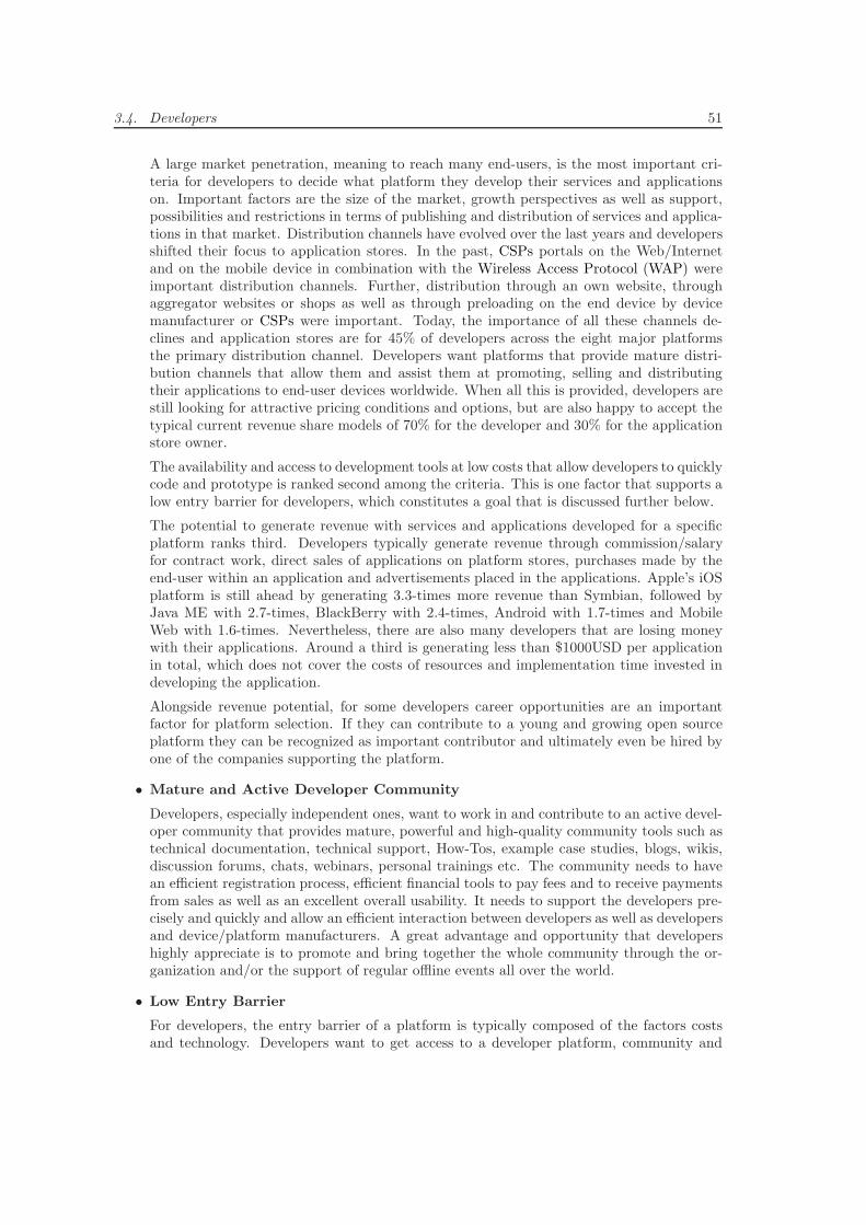
3.4. Developers 51
A large market penetration, meaning to reach many end-users, is the most important cri-teria for developers to decide what platform they develop their services and applicationson. Important factors are the size of the market, growth perspectives as well as support,possibilities and restrictions in terms of publishing and distribution of services and applica-tions in that market. Distribution channels have evolved over the last years and developersshifted their focus to application stores. In the past, CSPs portals on the Web/Internetand on the mobile device in combination with the Wireless Access Protocol (WAP) wereimportant distribution channels. Further, distribution through an own website, throughaggregator websites or shops as well as through preloading on the end device by devicemanufacturer or CSPs were important. Today, the importance of all these channels de-clines and application stores are for 45% of developers across the eight major platformsthe primary distribution channel. Developers want platforms that provide mature distri-bution channels that allow them and assist them at promoting, selling and distributingtheir applications to end-user devices worldwide. When all this is provided, developers arestill looking for attractive pricing conditions and options, but are also happy to accept thetypical current revenue share models of 70% for the developer and 30% for the applicationstore owner.
The availability and access to development tools at low costs that allow developers to quicklycode and prototype is ranked second among the criteria. This is one factor that supports alow entry barrier for developers, which constitutes a goal that is discussed further below.
The potential to generate revenue with services and applications developed for a specificplatform ranks third. Developers typically generate revenue through commission/salaryfor contract work, direct sales of applications on platform stores, purchases made by theend-user within an application and advertisements placed in the applications. Apple’s iOSplatform is still ahead by generating 3.3-times more revenue than Symbian, followed byJava ME with 2.7-times, BlackBerry with 2.4-times, Android with 1.7-times and MobileWeb with 1.6-times. Nevertheless, there are also many developers that are losing moneywith their applications. Around a third is generating less than $1000USD per applicationin total, which does not cover the costs of resources and implementation time invested indeveloping the application.
Alongside revenue potential, for some developers career opportunities are an importantfactor for platform selection. If they can contribute to a young and growing open sourceplatform they can be recognized as important contributor and ultimately even be hired byone of the companies supporting the platform.
• Mature and Active Developer Community
Developers, especially independent ones, want to work in and contribute to an active devel-oper community that provides mature, powerful and high-quality community tools such astechnical documentation, technical support, How-Tos, example case studies, blogs, wikis,discussion forums, chats, webinars, personal trainings etc. The community needs to havean efficient registration process, efficient financial tools to pay fees and to receive paymentsfrom sales as well as an excellent overall usability. It needs to support the developers pre-cisely and quickly and allow an efficient interaction between developers as well as developersand device/platform manufacturers. A great advantage and opportunity that developershighly appreciate is to promote and bring together the whole community through the or-ganization and/or the support of regular offline events all over the world.
• Low Entry Barrier
For developers, the entry barrier of a platform is typically composed of the factors costsand technology. Developers want to get access to a developer platform, community and
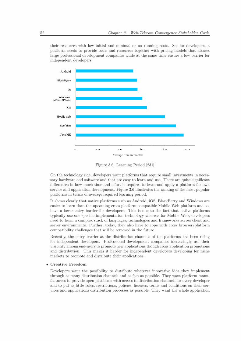
52 Chapter 3. Web-Telecom Convergence Stakeholder Goals
their resources with low initial and minimal or no running costs. So, for developers, aplatform needs to provide tools and resources together with pricing models that attractlarge professional development companies while at the same time ensure a low barrier forindependent developers.
Figure 3.6: Learning Period [231]
On the technology side, developers want platforms that require small investments in neces-sary hardware and software and that are easy to learn and use. There are quite significantdifferences in how much time and effort it requires to learn and apply a platform for ownservice and application development. Figure 3.6 illustrates the ranking of the most popularplatforms in terms of average required learning period.
It shows clearly that native platforms such as Android, iOS, BlackBerry and Windows areeasier to learn than the upcoming cross-platform compatible Mobile Web platform and so,have a lower entry barrier for developers. This is due to the fact that native platformstypically use one specific implementation technology whereas for Mobile Web, developersneed to learn a complex stack of languages, technologies and frameworks across client andserver environments. Further, today, they also have to cope with cross browser/platformcompatibility challenges that will be removed in the future.
Recently, the entry barrier at the distribution channels of the platforms has been risingfor independent developers. Professional development companies increasingly use theirvisibility among end-users to promote new applications though cross application promotionsand distribution. This makes it harder for independent developers developing for nichemarkets to promote and distribute their applications.
• Creative Freedom
Developers want the possibility to distribute whatever innovative idea they implementthrough as many distribution channels and as fast as possible. They want platform manu-facturers to provide open platforms with access to distribution channels for every developerand to put as little rules, restrictions, policies, licenses, terms and conditions on their ser-vices and applications distribution processes as possible. They want the whole application
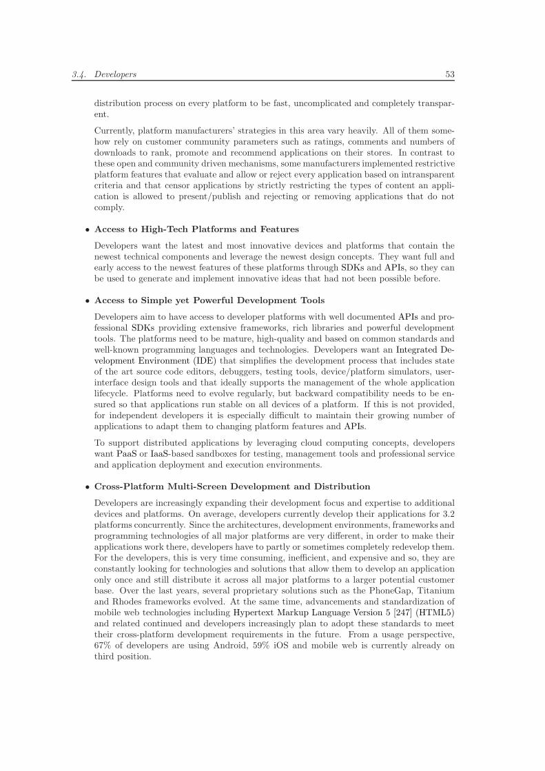
3.4. Developers 53
distribution process on every platform to be fast, uncomplicated and completely transpar-ent.
Currently, platform manufacturers’ strategies in this area vary heavily. All of them some-how rely on customer community parameters such as ratings, comments and numbers ofdownloads to rank, promote and recommend applications on their stores. In contrast tothese open and community driven mechanisms, some manufacturers implemented restrictiveplatform features that evaluate and allow or reject every application based on intransparentcriteria and that censor applications by strictly restricting the types of content an appli-cation is allowed to present/publish and rejecting or removing applications that do notcomply.
• Access to High-Tech Platforms and Features
Developers want the latest and most innovative devices and platforms that contain thenewest technical components and leverage the newest design concepts. They want full andearly access to the newest features of these platforms through SDKs and APIs, so they canbe used to generate and implement innovative ideas that had not been possible before.
• Access to Simple yet Powerful Development Tools
Developers aim to have access to developer platforms with well documented APIs and pro-fessional SDKs providing extensive frameworks, rich libraries and powerful developmenttools. The platforms need to be mature, high-quality and based on common standards andwell-known programming languages and technologies. Developers want an Integrated De-velopment Environment (IDE) that simplifies the development process that includes stateof the art source code editors, debuggers, testing tools, device/platform simulators, user-interface design tools and that ideally supports the management of the whole applicationlifecycle. Platforms need to evolve regularly, but backward compatibility needs to be en-sured so that applications run stable on all devices of a platform. If this is not provided,for independent developers it is especially difficult to maintain their growing number ofapplications to adapt them to changing platform features and APIs.
To support distributed applications by leveraging cloud computing concepts, developerswant PaaS or IaaS-based sandboxes for testing, management tools and professional serviceand application deployment and execution environments.
• Cross-Platform Multi-Screen Development and Distribution
Developers are increasingly expanding their development focus and expertise to additionaldevices and platforms. On average, developers currently develop their applications for 3.2platforms concurrently. Since the architectures, development environments, frameworks andprogramming technologies of all major platforms are very different, in order to make theirapplications work there, developers have to partly or sometimes completely redevelop them.For the developers, this is very time consuming, inefficient, and expensive and so, they areconstantly looking for technologies and solutions that allow them to develop an applicationonly once and still distribute it across all major platforms to a larger potential customerbase. Over the last years, several proprietary solutions such as the PhoneGap, Titaniumand Rhodes frameworks evolved. At the same time, advancements and standardization ofmobile web technologies including Hypertext Markup Language Version 5 [247] (HTML5)and related continued and developers increasingly plan to adopt these standards to meettheir cross-platform development requirements in the future. From a usage perspective,67% of developers are using Android, 59% iOS and mobile web is currently already onthird position.
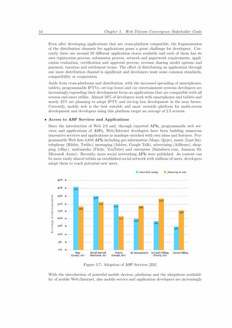
54 Chapter 3. Web-Telecom Convergence Stakeholder Goals
Even after developing applications that are cross-platform compatible, the fragmentationof the distribution channels for applications poses a great challenge for developers. Cur-rently there are around 50 different application stores available and each of them has itsown registration process, submission process, artwork and paperwork requirements, appli-cation evaluation, certification and approval process, revenue sharing model options andpayment, taxation and settlement terms. The effort of distributing an application throughone more distribution channel is significant and developers want some common standards,compatibility or cooperation.
Aside from cross-platforms and distribution, with the increased spreading of smartphones,tablets, programmable IPTVs, set-top boxes and car entertainment systems developers areincreasingly expending their development focus on applications that are compatible with allscreens end-users utilize. Almost 50% of developers work with smartphones and tablets andnearly 25% are planning to adopt IPTV and set-top box development in the near future.Currently, mobile web is the best suitable and most versatile platform for multi-screendevelopment and developers using this platform target an average of 2.5 screens.
• Access to ASP Services and Applications
Since the introduction of Web 2.0 and, through exported APIs, programmable web ser-vices and applications of ASPs, Web/Internet developers have been building numerousinnovative services and applications as mashups enriched with own ideas and features. Pro-grammable Web lists 4,658 APIs including geo information (Maps, Qype), music (Last.fm),telephony (Ribbit, Twilio), messaging (Jabber, Google Talk), advertising (AdSense), shop-ping (eBay), multimedia (Flickr, YouTube) and enterprise (Salesforce.com, Amazon S3,Microsoft Azure). Recently, more social networking APIs were published. As content canbe more easily shared within an established social network with millions of users, developersadopt them to reach potential new users.
Figure 3.7: Adoption of ASP Services [231]
With the introduction of powerful mobile devices, platforms and the ubiquitous availabil-ity of mobile Web/Internet, also mobile service and application developers are increasingly
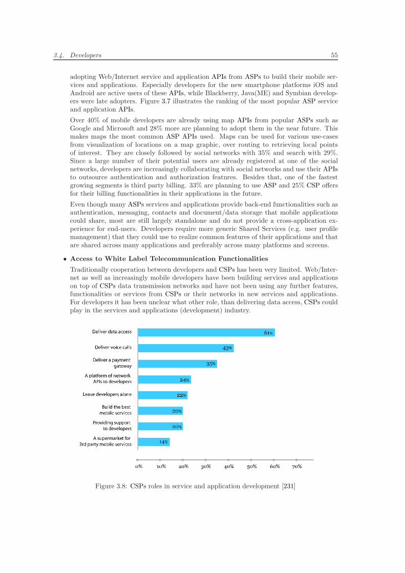
3.4. Developers 55
adopting Web/Internet service and application APIs from ASPs to build their mobile ser-vices and applications. Especially developers for the new smartphone platforms iOS andAndroid are active users of these APIs, while Blackberry, Java(ME) and Symbian develop-ers were late adopters. Figure 3.7 illustrates the ranking of the most popular ASP serviceand application APIs.
Over 40% of mobile developers are already using map APIs from popular ASPs such asGoogle and Microsoft and 28% more are planning to adopt them in the near future. Thismakes maps the most common ASP APIs used. Maps can be used for various use-casesfrom visualization of locations on a map graphic, over routing to retrieving local pointsof interest. They are closely followed by social networks with 35% and search with 29%.Since a large number of their potential users are already registered at one of the socialnetworks, developers are increasingly collaborating with social networks and use their APIsto outsource authentication and authorization features. Besides that, one of the fastestgrowing segments is third party billing. 33% are planning to use ASP and 25% CSP offersfor their billing functionalities in their applications in the future.
Even though many ASPs services and applications provide back-end functionalities such asauthentication, messaging, contacts and document/data storage that mobile applicationscould share, most are still largely standalone and do not provide a cross-application ex-perience for end-users. Developers require more generic Shared Services (e.g. user profilemanagement) that they could use to realize common features of their applications and thatare shared across many applications and preferably across many platforms and screens.
• Access to White Label Telecommunication Functionalities
Traditionally cooperation between developers and CSPs has been very limited. Web/Inter-net as well as increasingly mobile developers have been building services and applicationson top of CSPs data transmission networks and have not been using any further features,functionalities or services from CSPs or their networks in new services and applications.For developers it has been unclear what other role, than delivering data access, CSPs couldplay in the services and applications (development) industry.
Figure 3.8: CSPs roles in service and application development [231]
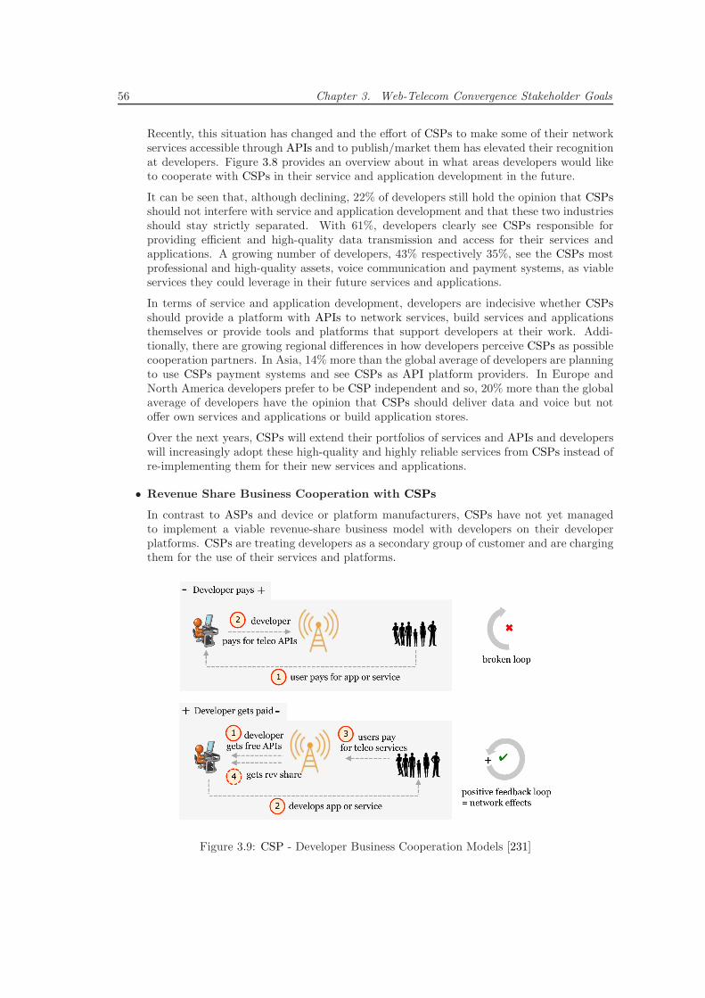
56 Chapter 3. Web-Telecom Convergence Stakeholder Goals
Recently, this situation has changed and the effort of CSPs to make some of their networkservices accessible through APIs and to publish/market them has elevated their recognitionat developers. Figure 3.8 provides an overview about in what areas developers would liketo cooperate with CSPs in their service and application development in the future.
It can be seen that, although declining, 22% of developers still hold the opinion that CSPsshould not interfere with service and application development and that these two industriesshould stay strictly separated. With 61%, developers clearly see CSPs responsible forproviding efficient and high-quality data transmission and access for their services andapplications. A growing number of developers, 43% respectively 35%, see the CSPs mostprofessional and high-quality assets, voice communication and payment systems, as viableservices they could leverage in their future services and applications.
In terms of service and application development, developers are indecisive whether CSPsshould provide a platform with APIs to network services, build services and applicationsthemselves or provide tools and platforms that support developers at their work. Addi-tionally, there are growing regional differences in how developers perceive CSPs as possiblecooperation partners. In Asia, 14% more than the global average of developers are planningto use CSPs payment systems and see CSPs as API platform providers. In Europe andNorth America developers prefer to be CSP independent and so, 20% more than the globalaverage of developers have the opinion that CSPs should deliver data and voice but notoffer own services and applications or build application stores.
Over the next years, CSPs will extend their portfolios of services and APIs and developerswill increasingly adopt these high-quality and highly reliable services from CSPs instead ofre-implementing them for their new services and applications.
• Revenue Share Business Cooperation with CSPs
In contrast to ASPs and device or platform manufacturers, CSPs have not yet managedto implement a viable revenue-share business model with developers on their developerplatforms. CSPs are treating developers as a secondary group of customer and are chargingthem for the use of their services and platforms.
Figure 3.9: CSP - Developer Business Cooperation Models [231]
3.5. End-Users 57
Developers are requesting a drastic shift in this model and want to be seen as resellers ofCSPs network services/APIs that elevate service usage and/or network traffic for CSPs.Thereby, driving more end-users to CSPs core business and increasing revenue. CSPsneed to establish partner programs with developers and share the additional revenue thattheir services and applications generate with them. Developers want to focus on inventinginnovative services and applications that leverage CSP services and APIs instead of worryingabout their associated costs. Figure 3.9 illustrates the two different models.
In the currently applied model, illustrated on top, developers are responsible for paying theCSPs for service APIs usage, hence they need to charge their users to cover these costs.This model does not encourage developers to include any CSP services into their servicesor applications. It entails costs from the start and increases charging/billing complexity forthe developers but generates additional revenue mainly for the CSPs.
In the, for developers, optimal model, illustrated on the bottom, developers are enabledto use CSPs service APIs at no costs. Developers implement and distribute services andapplications leveraging CSP services to end-users. Those pay CSPs directly for the usageand developers receive a revenue share from that. This model builds a positive feedback loopthat generates network effects, meaning it encourages all parties to foster their partnershipsas well as to constantly expand service and application development.
• Deliver Enterprise Grade Business Applications
As already discussed in section 3.1, innovation in the enterprise applications market will notonly come from the current big players for enterprise applications, but equally from newplayers from adjacent industries, small companies or independent developers. As notedin section 3.2, through third-party developer platforms, many professional developers andincreasingly independent developers are already contributing new features or services toenterprise applications provided by ASPs. They are interested in continuing these contri-butions while at the same time, in developing completely new innovative enterprise servicesand applications independent of existing ASP applications. In order to provide high-qualityenterprise services and applications that are customizable to the specific requirements ofthe enterprise customers, developers want flexible, scaleable, professional and SLA-backedcloud computing infrastructures/platforms as foundation for their services and applications.To keep maximum flexibility at selecting and switching between cooperation partners, de-velopers require an increase in standardization in cloud computing IaaS and PaaS areas. Itis necessary especially in those focusing at enterprise service and application provisioning,deployment, hosting, execution, management, maintenance and delivery.
3.5 End-Users
End-users are individuals that use the innovative applications created and distributed by devel-opers on their devices such as laptops, netbooks, smart phones or tablets. Roughly, end-users canbe divided into the two categories, (i) Private End-Users who use their applications for personaltasks and use-cases such as communication and entertainment, and (ii) Enterprise End-Userswho use their applications for business tasks and use-cases at work. In recent years these bound-aries have become increasingly blurred since many end-users have started to request from theiremployers to being able to use for work the same devices, tools and applications to which theyhave become accustomed to in their private lives. In the literature, there is typically a distinctionbetween the customer who acquires and pays for a product and the end-user who utilizes it. Inthe following of this research work this distinction is disregarded.
58 Chapter 3. Web-Telecom Convergence Stakeholder Goals
Goals
The following overview summarizes the end-users most important goals.
• Sophisticated and Innovative Services and Applications for Private End-Users
End-users want providers to offer innovative and mature productivity, communication, me-dia and entertainment applications that support them in their daily life tasks and use-cases.They want applications that fully leverage all new opportunities that the latest high-endhardware and software features embedded in their latest home and mobile devices have tooffer.
For their personal productivity tasks and use-cases, end-users want powerful applicationssuch as office suits, task management and collaboration tools that they can use at homeand mobile.
End-users want multimedia entertainment applications that allow them to consume mul-timedia streaming content from anyone and anywhere, to create and publish their ownmultimedia content worldwide, to watch high-quality IPTV at home and mobile and toaccess and manage one’s personal multimedia seamlessly anytime and anywhere.
End-users want innovative quick, open and easy communication solutions. With 85%, e-mail is still the most utilized communication system on the Internet. Increasingly, end-usersare preferring VoIP solutions such as Skype over traditional Telecommunication services.They want ubiquitous communication features such as video call, conference call and instantmessaging on the Web/Internet as well as on all of their personal home and mobile devices.
Social networking has become increasingly successful over the last years with current growthrates of 200% and above. Social networks fulfill the end-users needs to extend their offlinesocial environment and to increase their interaction with other users on the Web/Internet.End-users want social networking features and applications to organize their personal con-tacts, to communicate and stay in touch with friends and colleagues, to share informationand multimedia content and to find users with similar interests. End-users want to usetheir social communities as information and recommendation sources in various areas suchas product and service recommendations and discussions, updates about upcoming partiesand events and more.
End-users increasingly want to learn from other users on the Web/Internet as well as sharetheir own knowledge with others on sites like Wikipedia. They are publishing Web 2.0-based User Generated Content on the Web/Internet in blogs, wikis, photos sharing sites,online/streaming music/video portals, journalism/news sites, forums, social networks andsimilar. They are tagging, sharing and commenting content they regard as interesting orimportant for others. End-users want similar possibilities and features in future applicationsfor their home and mobile devices.
End-users increasingly utilize mobile Web/Internet applications for their high-end mobiledevices. Especially location-based, video/audio communication, multimedia, instant mes-saging and social networking applications are rising quickly. Upcoming technologies andfeatures such as mobile payment, IPTV and augmented reality applications will follow soon.
• Low Costs for Services and Applications for Private End-Users
On the Web/Internet advertisement revenue-based business models are widespread and ac-cepted by providers as well as end-users. They are accustomed to receiving the applicationsfor their personal use free of charge and that in return those are augmented with adver-tisements in diverse ways. Payment plans on a per-use or monthly basis, are typically onlynecessary if end-users want to remove the advertisements or access some premium featuresthe applications offer in addition.
3.5. End-Users 59
It can be observed that this trend spreads to mobile applications and the mobile Web/In-ternet. Two thirds of Web/Internet end-users in the US and Germany and three quartersof 13 to 24 year olds in the US would like to keep their digital content and applicationsfreely accessible and would choose advertisement-based models over end-user-paid ones.
Nevertheless, the acceptance of advertisement on mobile devices highly depends on theway it is conveyed and presented. End-user do not want any TextMessaging-based adver-tisements sent to their mobile devices since they feel this to be too intrusive and privacyinvasive. Fortunately, the latest mobile devices with large touch screens provide enoughscreen space to present advertisements in a similar way as on the Web/Internet browser ona traditional computer. This form of advertisements in applications is increasingly acceptedby end-users and therefore increasingly used by developers.
• Sophisticated and Innovative Services and Applications for Enterprise End-Users
The percentage of enterprises with broadband Web/Internet access has remained nearlyconstant for a few years now whereas the one for mobile Web/Internet access has beenrising constantly to over 60% today.
For enterprise end-users the overall ”cost to benefit ratio” influences buying decisions forapplications most. Enterprise end-users require all applications to meet high standardsregarding data security and privacy and especially for critical processes all applicationsneed to be highly reliable. An easy integration of new applications into the existing ITinfrastructure of the enterprise needs to be guaranteed and B2B interoperability needs tobe ensured through standardization.
Enterprise end-users want innovative business applications that enable an effective and inte-grated data management across the whole enterprise. Applications need to lead to efficiencyimprovements in the enterprises primary activities and tasks such as unified communica-tions, logistics, CRM, ERP, knowledge management, supply chain management (includingB2B E-Commerce and E-Procurement Marketplaces), sales and marketing. Enterprise end-users are increasingly requesting mobility solutions for their business applications to supporttheir mobile and distributed workforce.
Over recent years, social networking has become increasingly important for enterprise end-users in a B2B and also B2C environment. Collaboration with other enterprises is crucialand professional social networking tools such as Xing or LinkedIn enable enterprise end-users. Increasingly, enterprises need to use social networks to communicate with theircustomers in order to market their products, publish information or provide support. En-terprise end-users require applications that support them in both, the B2B and B2C sectorsocial networking.
• Excellent Usability and Quality of Experience
Usability and QoE have become increasingly important for the acceptance and success ofnew applications. Advancements in multimodal user-interface technologies such as touch,voice and haptic together with technological advancements at device displays and comput-ing hardware capabilities have transformed traditional small screen keyboard-based user-interfaces to large screen touch-based user-interfaces. This has enabled application devel-oper to provide such excellent user experiences that would not have been possible a fewyears back. Hence today, for every new application they utilize, end-users expect certainhigh levels of usability and QoE that are similar to the ones they experience at the latestapplications on state-of-the-art platforms such as iOS, Android and Windows Phone 7.
60 Chapter 3. Web-Telecom Convergence Stakeholder Goals
• Cross-Platform and Cross-Screen Applications
End-users utilize an increasing number of devices with an increasing number of availablescreen sizes such as PCs, laptops, netbooks, smart phones, tablets, IPTVs and car enter-tainment dashboards to work with their personal and business applications. From variousmanufacturers, there is a growing number of competing and mostly incompatible platformsavailable for all these devices.
End-users do not want to be put in the middle of the competition between device andplatform manufacturers and do not want to make their decisions about devices based onthe platform compatibility of applications they intent to make use of. End-users want everyavailable application to be fully accessible from all of their devices simultaneously with allof their application data and settings fully synchronized.
End-users do not want to be bound to a specific device or platform manufacturer, but wantto freely move any applications including all related data and settings to any additional ornew device they might purchase and utilize in the future.
• Cross-Application Features
Most current Web/Internet and mobile applications are explicitly separated from each otherand are managing their application data and settings independently. Some of the latestapplications leveraging cloud computing concepts provided by ASPs, share data such assign-on credentials, profile information, contacts, events/tasks, documents, multimedia,etc. End-users experience the benefits of application features and data to be shared acrossseveral applications and across the Web/Internet and their mobile devices. For futureapplications, end-users want more innovative cross-application features that relieve themfrom managing their personal data for each application independently.
• Access Network Independent Applications
Typically, applications provided by CSPs are limited to their, mostly regional, networksand so, only accessible through end-user devices that are connected to these networks.Applications provided by ASPs are typically accessible by all end-user devices connectedto the Web/Internet worldwide.
To ensure the end-users worldwide mobility, they need to be able to switch between net-works, even across providers, arbitrarily without any interruption in their applications.Hence, they want access-network and provider independent applications.
• Growing Influence on Application Development
In a few years, the majority of end-users will be from the generation of digital natives andwill have grown up with technology, computers, the Web/Internet and smart phones. Agrowing number will become consumers and producers at the same time (Prosumers) andwill develop or want to customize their, sometimes long-tale and niche, applications them-selves. Future applications need to provide these possibilities and enable personalization,customization and even extension through visual tools (e.g. Yahoo Pipes [209], MicrosoftPopFly [249], IBM Mashup Center [95]) as well as end-user software development.
• Discovering Suitable Applications from a Large Selection
For end-users, the primary decision characteristic for a mobile device is the selection ofapplications that is available for the platform the device is based on. For the most popularplatforms iOS, Android andWindows Phone 7 selections exceed 500.000, 400.000 and 50.000respectively.
This growing selection of applications is offered on proprietary application stores that arejust as strictly separated and incompatible as the platforms themselves. With their goal to
3.5. End-Users 61
have ”Cross-Platform and Cross-Screen Applications” (see above), end-users also want tohave consolidated application stores that are easy to access and offer as well as distributeall available applications to all of their devices.
To cope with the large selection of applications in such a consolidated application store,end-users require means to find, retrieve, install and configure relevant and suitable appli-cations for their personal and business tasks. In current stores, roughly 90% of end-usersaccept features such as community ratings, community reviews, discussion forums and socialrecommendations whereas only 54% trust application advertisements. In order to advanceapplication discovery features, end-users must be willing to share certain information suchas personal interests, buying habits, their social network, their location with ASPs andCSPs. Thereby, those can use their business intelligence systems to realize excellent dis-covery features.
Current application stores apply different levels of certification for applications in terms ofstability, virus scans, malicious code identification, etc. End-users want a certain level ofquality assurance and certification for all applications on a consolidated application store.
• Trust and Security
Many future applications will reveal most of their potential and benefits only when workingwith or sharing personal end-user data such as their social network, interests, habits, profileinformation, etc. End-users require high privacy protection, trust and security standard-s/guarantees from the application developers and ultimately providers.
• Home and Mobile Office
Mobile Web/Internet access among German companies has significantly increased over thelast three years. Companies worldwide are increasingly equipping their employees withlaptops and mobile phones instead of workstation computers and fixed office phones. Thenumber of people working primarily mobile is predicted to grow to nearly 1.2 billion in2013.
Mobile working can be categorized in the four types, (i) ”Full Mobility”that is characterizedby a high degree of mobility and frequent changes of the workplace, (ii) ”Site Mobility” thatis characterized by mobility in geographically restricted areas (e.g. hospitals), (iii) ”MultiLocation Workplace” that is characterized by regular travels between fixed locations wherework is carried out for a certain period of time, and (iv) ”Networked Workplace” that ischaracterized by limited physical mobility while working collaboratively with many sitesusing online IT systems and applications. Enterprise end-users will need business applica-tions that can cope with all these mobile working models. Future enterprise applicationswill need to cope with novel and often complex requirements due to increasing mobility.
Concepts from (ii) are already evolving new forms of offices. In a large number of enterprises,workers are already sharing desks and choose a different workplace regularly in order towork close to the people they are collaborating with on projects and tasks. For specialpurposes, there are rooms specifically designed for concentrated working, meetings andconferences.
Home office work, as an instance of (iii), is increasingly offered by companies today. Enter-prise end-user need sophisticated applications that connect them from home to the corporatenetwork and allow efficient multimedia communication, interaction and collaboration.
End-users especially in category (i), but also in (iii), are traveling between workplacesregularly. They need enterprise applications that let them work on their business tasksefficiently and securely while using public mobile Web/Internet access in train stations, atairports, in hotels and other public places.
62 Chapter 3. Web-Telecom Convergence Stakeholder Goals
3.6 Technology Providers, Content Providers, Advertisers
Technology Providers are Telecommunication equipment, network equipment, server hard-ware and mobile device vendors as well as software companies. CSPs, ASPs and device/platformmanufacturers are their customers and end-users. They are closely working together with themin terms of technology research, hardware/software system development and standardization.Thereby they use their insights into the industry in order to identify system requirements and toprovide innovative technology products that fulfill those. Technology Providers are commercial-izing hardware and software products to equip their end-users with the IT infrastructure theyneed to provide services and applications to their private and enterprise end-users.
Content Providers create and distribute media content such as text, images, music and film/-movie/video in different formats such as print media, music/video discs, digital media throughdifferent distribution channels such as online, store, mail order. Many are confronted with de-clining revenues and difficult business situations in their respective markets. Print media isincreasingly substituted by online media and so, advertisement revenues of publishers are de-clining. The music and film industry needs to cope with the increase in illegal distribution oftheir content on peer-to-peer networks as well as with an increasing competition through usergenerated audio/video content sites. Content Providers are commonly looking for new profitableways to offer their content. On the one hand, they are planning to publish their own innovativemobile applications to allow end-users to consume their content for a fee or financed throughadvertisement. On the other hand, they are offering their digital content as a service and areextending their cooperations with mobile application developers, CSPs and ASPs so they includethe content into their end-user applications.
Advertisers are entities such as companies or individuals that market their products and servicesin CSPs’, ASPs’ and developers’ services and applications through various types of paid adver-tisements. For providers and developers advertisers can constitute a profitable revenue source.Hence, they provide increasingly sophisticated tools and technologies for them, so they can runtheir campaigns highly efficient and precisely aimed at their target customer groups.
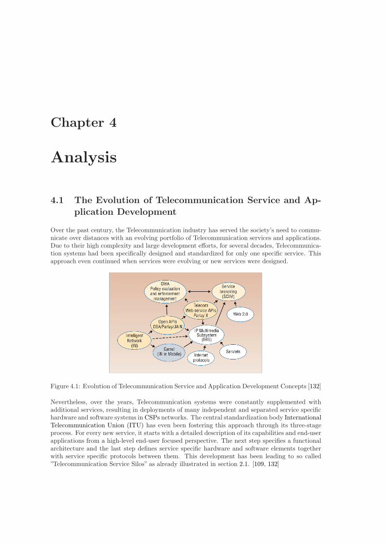
Chapter 4
Analysis
4.1 The Evolution of Telecommunication Service and Ap-
plication Development
Over the past century, the Telecommunication industry has served the society’s need to commu-nicate over distances with an evolving portfolio of Telecommunication services and applications.Due to their high complexity and large development efforts, for several decades, Telecommunica-tion systems had been specifically designed and standardized for only one specific service. Thisapproach even continued when services were evolving or new services were designed.
Figure 4.1: Evolution of Telecommunication Service and Application Development Concepts [132]
Nevertheless, over the years, Telecommunication systems were constantly supplemented withadditional services, resulting in deployments of many independent and separated service specifichardware and software systems in CSPs networks. The central standardization body InternationalTelecommunication Union (ITU) has even been fostering this approach through its three-stageprocess. For every new service, it starts with a detailed description of its capabilities and end-userapplications from a high-level end-user focused perspective. The next step specifies a functionalarchitecture and the last step defines service specific hardware and software elements togetherwith service specific protocols between them. This development has been leading to so called”Telecommunication Service Silos” as already illustrated in section 2.1. [109, 132]
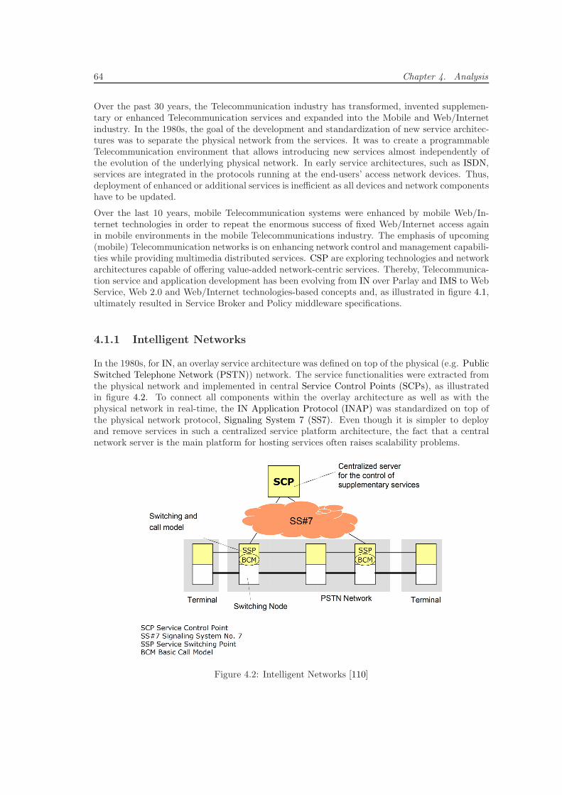
64 Chapter 4. Analysis
Over the past 30 years, the Telecommunication industry has transformed, invented supplemen-tary or enhanced Telecommunication services and expanded into the Mobile and Web/Internetindustry. In the 1980s, the goal of the development and standardization of new service architec-tures was to separate the physical network from the services. It was to create a programmableTelecommunication environment that allows introducing new services almost independently ofthe evolution of the underlying physical network. In early service architectures, such as ISDN,services are integrated in the protocols running at the end-users’ access network devices. Thus,deployment of enhanced or additional services is inefficient as all devices and network componentshave to be updated.
Over the last 10 years, mobile Telecommunication systems were enhanced by mobile Web/In-ternet technologies in order to repeat the enormous success of fixed Web/Internet access againin mobile environments in the mobile Telecommunications industry. The emphasis of upcoming(mobile) Telecommunication networks is on enhancing network control and management capabili-ties while providing multimedia distributed services. CSP are exploring technologies and networkarchitectures capable of offering value-added network-centric services. Thereby, Telecommunica-tion service and application development has been evolving from IN over Parlay and IMS to WebService, Web 2.0 and Web/Internet technologies-based concepts and, as illustrated in figure 4.1,ultimately resulted in Service Broker and Policy middleware specifications.
4.1.1 Intelligent Networks
In the 1980s, for IN, an overlay service architecture was defined on top of the physical (e.g. PublicSwitched Telephone Network (PSTN)) network. The service functionalities were extracted fromthe physical network and implemented in central Service Control Points (SCPs), as illustratedin figure 4.2. To connect all components within the overlay architecture as well as with thephysical network in real-time, the IN Application Protocol (INAP) was standardized on top ofthe physical network protocol, Signaling System 7 (SS7). Even though it is simpler to deployand remove services in such a centralized service platform architecture, the fact that a centralnetwork server is the main platform for hosting services often raises scalability problems.
Figure 4.2: Intelligent Networks [110]
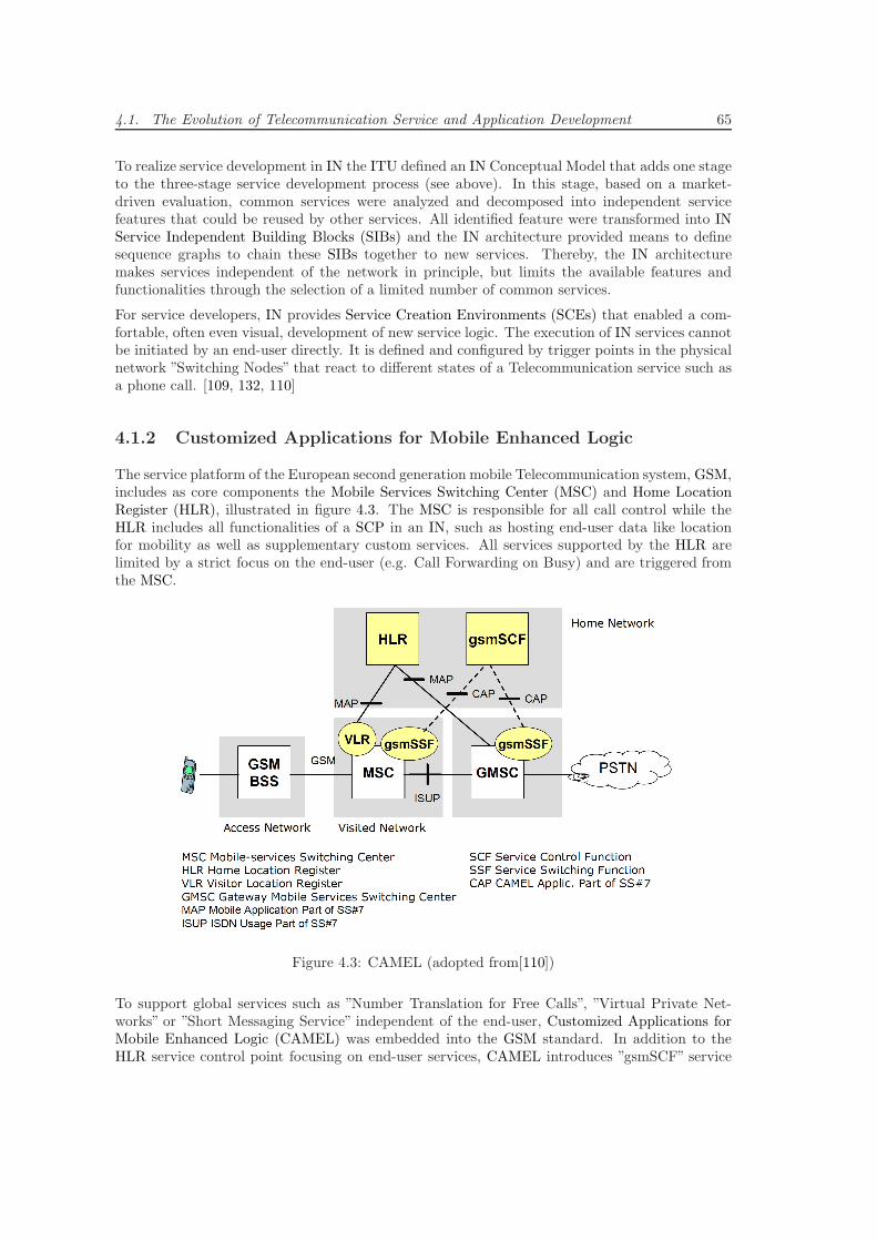
4.1. The Evolution of Telecommunication Service and Application Development 65
To realize service development in IN the ITU defined an IN Conceptual Model that adds one stageto the three-stage service development process (see above). In this stage, based on a market-driven evaluation, common services were analyzed and decomposed into independent servicefeatures that could be reused by other services. All identified feature were transformed into INService Independent Building Blocks (SIBs) and the IN architecture provided means to definesequence graphs to chain these SIBs together to new services. Thereby, the IN architecturemakes services independent of the network in principle, but limits the available features andfunctionalities through the selection of a limited number of common services.
For service developers, IN provides Service Creation Environments (SCEs) that enabled a com-fortable, often even visual, development of new service logic. The execution of IN services cannotbe initiated by an end-user directly. It is defined and configured by trigger points in the physicalnetwork ”Switching Nodes” that react to different states of a Telecommunication service such asa phone call. [109, 132, 110]
4.1.2 Customized Applications for Mobile Enhanced Logic
The service platform of the European second generation mobile Telecommunication system, GSM,includes as core components the Mobile Services Switching Center (MSC) and Home LocationRegister (HLR), illustrated in figure 4.3. The MSC is responsible for all call control while theHLR includes all functionalities of a SCP in an IN, such as hosting end-user data like locationfor mobility as well as supplementary custom services. All services supported by the HLR arelimited by a strict focus on the end-user (e.g. Call Forwarding on Busy) and are triggered fromthe MSC.
Figure 4.3: CAMEL (adopted from[110])
To support global services such as ”Number Translation for Free Calls”, ”Virtual Private Net-works” or ”Short Messaging Service” independent of the end-user, Customized Applications forMobile Enhanced Logic (CAMEL) was embedded into the GSM standard. In addition to theHLR service control point focusing on end-user services, CAMEL introduces ”gsmSCF” service
66 Chapter 4. Analysis
control points that cover global services independent from basic call control. In order to triggersuch services, the ”gsmSSF” service switching function was added to the MSC to detect servicerequests. [109, 132, 110]
4.1.3 Telecommunication Information Networking Architecture
In the mid-90s, the concept of a Distributed Processing Environment (DPE) was introduced inthe software development industry. In a DPE, a middleware, such as CORBA by the OMG,supports the development of a distributed system. This middleware manages system componentsthat are distributed over several heterogeneous platforms without requiring any adaption at theend-user applications. For such as distributed system, the DPE manages the collaboration ofall components including the exchange of information in standardized messages using abstractcommunication concepts such as Remote Procedure Call (RPC). [109, 132, 110]
The goal behind the definition of Telecommunications Information Networking Architecture(TINA) was to standardize a global architecture for multimedia Telecommunication systemsbased on the latest software concepts and technologies. TINA applies a common software modelto all components such as end-user device applications, service components and switching nodes,which enables CSPs to assemble new services from reusable, distributed and interacting compo-nents. The overall structure of TINA is composed from three architecture components, (i) the”Computing Architecture” that describes the distributed system based on the DPE concept as anapplication of distributed object-oriented software design through an extension of CORBA, (ii)the ”Service Architecture” that describes the component-based platform responsible for servicedelivery and (iii) the ”Network Resource Architecture” that manages and controls all physicalnetwork components and resources. [109, 132, 110]
With the quick evolution of Telecommunication systems to Web/Internet technologies and theinitial incompatibility of TINA with those, TINA was never implemented and deployed outsideof research labs. Nevertheless it provided many concepts and architecture ideas that were reusedby later Telecommunication standards such as Parlay, IMS and SAE.
4.1.4 Open Application Programming Interface
In the software development industry, object-oriented programming became increasingly ac-cepted. Newly available programming languages like C++ and Java enabled concepts of powerfuldistributed middleware platforms that could be used for scalable and distributed service delivery.Just as intended with TINA, a few years earlier, these make service development easier thanwith traditional IN and define a clear abstraction of the services from the underlying physicalnetwork, signaling protocols and transport protocols (e.g. ISDN, SIP, INAP). These technologiesintroduced the concept of creating own APIs for a software system to the Telecommunicationindustry. Thereby, for the first time, non-Telecommunication expert third party service providerscould be provided with access to features of CSPs networks and service platforms. [109, 132, 110]
4.1.4.1 Parlay
Parlay [214] is a Telecommunication standard standardized in 1998 by the Parlay Consortium,which was composed from operators and manufacturers worldwide. Parlay standardizes an APIthat provides access to network-internal data as well as market-oriented Telecommunication re-lated control and monitoring capabilities such as Call Control, User Interaction, Conferencing,Messaging, Location Information, Charging, Presence Information and Group List / Address
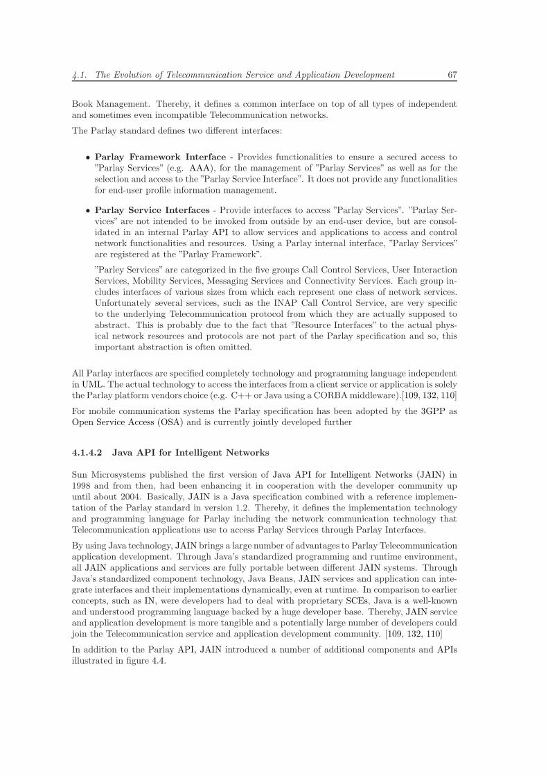
4.1. The Evolution of Telecommunication Service and Application Development 67
Book Management. Thereby, it defines a common interface on top of all types of independentand sometimes even incompatible Telecommunication networks.
The Parlay standard defines two different interfaces:
• Parlay Framework Interface - Provides functionalities to ensure a secured access to”Parlay Services” (e.g. AAA), for the management of ”Parlay Services” as well as for theselection and access to the ”Parlay Service Interface”. It does not provide any functionalitiesfor end-user profile information management.
• Parlay Service Interfaces - Provide interfaces to access ”Parlay Services”. ”Parlay Ser-vices” are not intended to be invoked from outside by an end-user device, but are consol-idated in an internal Parlay API to allow services and applications to access and controlnetwork functionalities and resources. Using a Parlay internal interface, ”Parlay Services”are registered at the ”Parlay Framework”.
”Parley Services” are categorized in the five groups Call Control Services, User InteractionServices, Mobility Services, Messaging Services and Connectivity Services. Each group in-cludes interfaces of various sizes from which each represent one class of network services.Unfortunately several services, such as the INAP Call Control Service, are very specificto the underlying Telecommunication protocol from which they are actually supposed toabstract. This is probably due to the fact that ”Resource Interfaces” to the actual phys-ical network resources and protocols are not part of the Parlay specification and so, thisimportant abstraction is often omitted.
All Parlay interfaces are specified completely technology and programming language independentin UML. The actual technology to access the interfaces from a client service or application is solelythe Parlay platform vendors choice (e.g. C++ or Java using a CORBAmiddleware).[109, 132, 110]
For mobile communication systems the Parlay specification has been adopted by the 3GPP asOpen Service Access (OSA) and is currently jointly developed further
4.1.4.2 Java API for Intelligent Networks
Sun Microsystems published the first version of Java API for Intelligent Networks (JAIN) in1998 and from then, had been enhancing it in cooperation with the developer community upuntil about 2004. Basically, JAIN is a Java specification combined with a reference implemen-tation of the Parlay standard in version 1.2. Thereby, it defines the implementation technologyand programming language for Parlay including the network communication technology thatTelecommunication applications use to access Parlay Services through Parlay Interfaces.
By using Java technology, JAIN brings a large number of advantages to Parlay Telecommunicationapplication development. Through Java’s standardized programming and runtime environment,all JAIN applications and services are fully portable between different JAIN systems. ThroughJava’s standardized component technology, Java Beans, JAIN services and application can inte-grate interfaces and their implementations dynamically, even at runtime. In comparison to earlierconcepts, such as IN, were developers had to deal with proprietary SCEs, Java is a well-knownand understood programming language backed by a huge developer base. Thereby, JAIN serviceand application development is more tangible and a potentially large number of developers couldjoin the Telecommunication service and application development community. [109, 132, 110]
In addition to the Parlay API, JAIN introduced a number of additional components and APIsillustrated in figure 4.4.
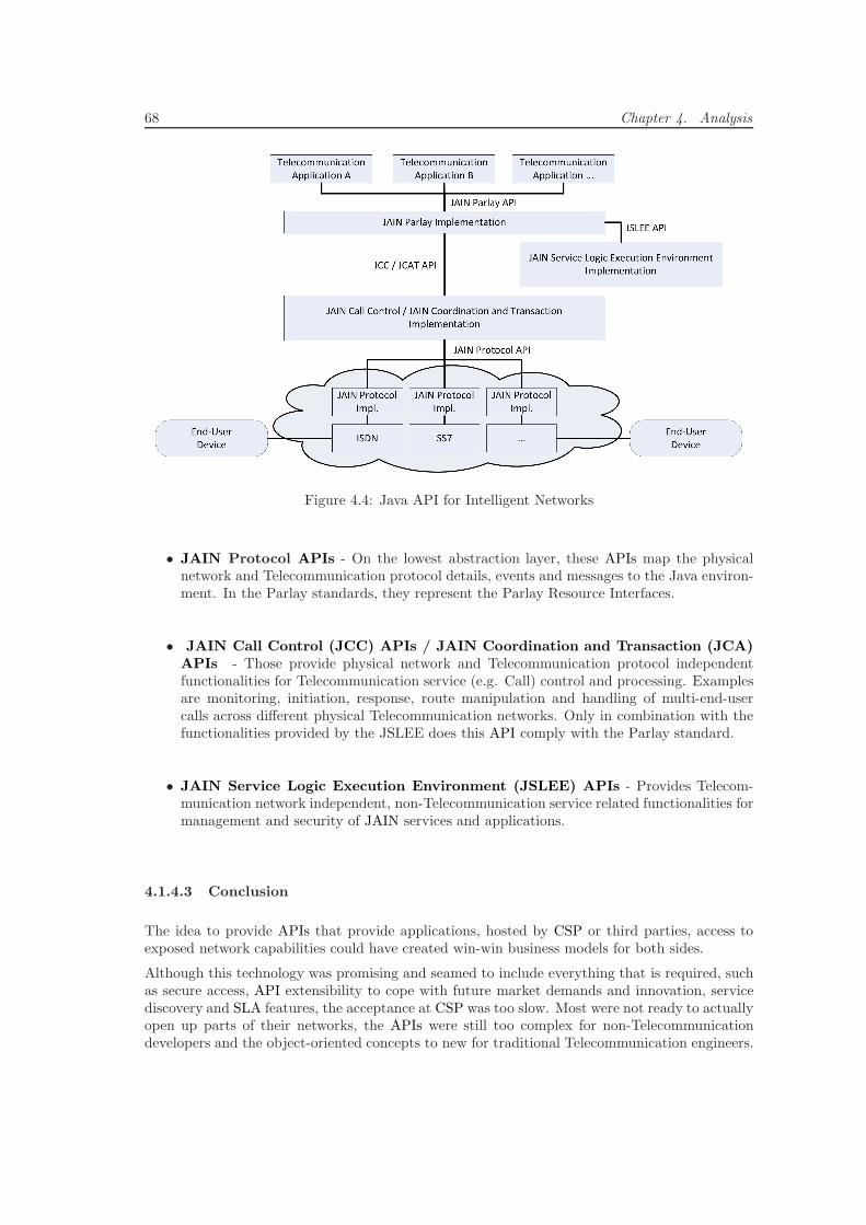
68 Chapter 4. Analysis
Figure 4.4: Java API for Intelligent Networks
• JAIN Protocol APIs - On the lowest abstraction layer, these APIs map the physicalnetwork and Telecommunication protocol details, events and messages to the Java environ-ment. In the Parlay standards, they represent the Parlay Resource Interfaces.
• JAIN Call Control (JCC) APIs / JAIN Coordination and Transaction (JCA)APIs - Those provide physical network and Telecommunication protocol independentfunctionalities for Telecommunication service (e.g. Call) control and processing. Examplesare monitoring, initiation, response, route manipulation and handling of multi-end-usercalls across different physical Telecommunication networks. Only in combination with thefunctionalities provided by the JSLEE does this API comply with the Parlay standard.
• JAIN Service Logic Execution Environment (JSLEE) APIs - Provides Telecom-munication network independent, non-Telecommunication service related functionalities formanagement and security of JAIN services and applications.
4.1.4.3 Conclusion
The idea to provide APIs that provide applications, hosted by CSP or third parties, access toexposed network capabilities could have created win-win business models for both sides.
Although this technology was promising and seamed to include everything that is required, suchas secure access, API extensibility to cope with future market demands and innovation, servicediscovery and SLA features, the acceptance at CSP was too slow. Most were not ready to actuallyopen up parts of their networks, the APIs were still too complex for non-Telecommunicationdevelopers and the object-oriented concepts to new for traditional Telecommunication engineers.
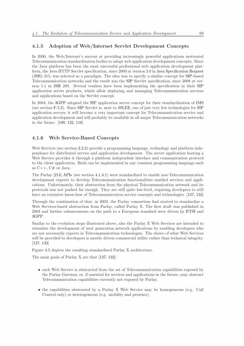
4.1. The Evolution of Telecommunication Service and Application Development 69
4.1.5 Adoption of Web/Internet Servlet Development Concepts
In 2000, the Web/Internet’s success at providing increasingly powerful applications motivatedTelecommunication standardization bodies to adopt web application development concepts. Sincethe Java platform has been the most successful professional web application development plat-form, the Java HTTP Servlet specification, since 2009 at version 3.0 in Java Specification Request(JSR) 315, was selected as a paradigm. The idea was to specify a similar concept for SIP-basedTelecommunication networks and the result was the SIP Servlet specification, since 2008 at ver-sion 1.1 in JSR 289. Several vendors have been implementing the specification in their SIPapplication server products, which allow deploying and managing Telecommunication servicesand applications based on the Servlet concept.
In 2004, the 3GPP adopted the SIP application server concept for their standardization of IMS(see section F.5.2). Since SIP Servlet is, next to JSLEE, one of just very few technologies for SIPapplication servers, it will become a very important concept for Telecommunication service andapplication development and will probably be available in all major Telecommunication networksin the future. [109, 132, 110]
4.1.6 Web Service-Based Concepts
Web Services (see section 2.2.2) provide a programming language, technology and platform inde-pendence for distributed service and application development. The server application hosting aWeb Service provides it through a platform independent interface and communication protocolto the client application. Both can be implemented in any common programming language suchas C++, C# or Java.
The Parlay [214] APIs (see section 4.1.4.1) were standardized to enable non-Telecommunicationdevelopment experts to develop Telecommunication functionalities enabled services and appli-cations. Unfortunately, their abstraction from the physical Telecommunication network and itsprotocols was not pushed far enough. They are still quite low-level, requiring developers to stillhave an extensive know-how of Telecommunication service concepts and technologies. [127, 132]
Through the combination of that, in 2002, the Parlay consortium had started to standardize aWeb Services-based abstraction from Parlay, called Parlay X. The first draft was published in2003 and further enhancements on the path to a European standard were driven by ETSI and3GPP.
Similar to the evolution steps illustrated above, also the Parlay X Web Services are intended tostimulate the development of next generation network applications by enabling developers whoare not necessarily experts in Telecommunication technologies. The choice of what Web Serviceswill be provided to developers is mostly driven commercial utility rather than technical integrity.[127, 132]
Figure 4.5 depicts the resulting standardized Parlay X architecture.
The main goals of Parlay X are that [127, 132]:
• each Web Service is abstracted from the set of Telecommunication capabilities exposed bythe Parlay Gateway, or, if essential for services and applications in the future, may abstractTelecommunication capabilities currently not exposed by Parlay.
• the capabilities abstracted by a Parlay X Web Service may be homogeneous (e.g. CallControl only) or heterogeneous (e.g. mobility and presence)
70 Chapter 4. Analysis
Figure 4.5: Parlay X Architecture
• it is preferred that Parlay X Web Services implement a synchronous message request/re-sponses model that is initiated by the service or application.
• it is preferred that Parlay X Web Services are implemented stateless and that invocationsare uncorrelated.
• a Parlay X Web Service is neither service or application nor network technology or protocolspecific.
• Parlay X Web Services are not unnecessarily complicated or overloaded and so, shouldsupport 80% of services and applications through only 20% of their functionalities.
• the set of Parlay X Web Services has to be extensible by proven, reliable and standardcompliant Web Services provided by third parties.
Through the use of Web Service technologies, further enhancements could easily be achieved byadopting concepts from Web Service-based BIS development. One such concept is the applicationof an ESB (see section 2.3) to abstract and manage the link between Parlay X Web Services, WebService-based third party services and applications as well as CSP internal Web Service-basedOperations Support System (OSS) and Business Support System (BSS). [179]
4.1.7 Telecommunication Service Orchestration
Service orchestration has been an important concept in BIS development long before the Telecom-munications industry felt the need for it. In an early version, the IMS specification standardizesa Trigger Point-based mechanism, adopted from IN, that allows developers to define triggersbased on Telecommunication signaling protocol (e.g. SIP) states and event. This allows servicesand applications to chain IMS application servers and so, in some sense, to orchestrate theirfunctionalities. [155]
Since the initiation of this mechanisms the need for a more flexible and, from signaling protocolsabstracted, way to orchestrate services has arisen. In the current version of the IMS standard
4.2. Evaluation of Web-Telecom Convergence Concepts and Platforms 71
the Service Broker concept from BIS development was introduced by the Service CapabilityInteraction Manager [225, 107, 146] (SCIM) component (see section F.5.3.2). Since, in thisstandard, the SCIM is not specified in detail, but only the basic functionalities are outlined, theactual realization, architectural decisions and choice of technologies is left to vendors providingan IMS implementation. This results in a broad range of heavily varying products using all sortsof Telecommunication technologies such as Parlay/OSA, Parlay X, JAIN as well as various BIStechnologies such as BPEL or WSCI that all claim to implement a SCIM [230].
4.2 Evaluation of Web-Telecom Convergence Concepts andPlatforms
This section introduces and discusses the most relevant state-of-the-art concepts for Web-TelecomConvergence that are currently available from Telecommunication standardization bodies as wellas from research institutes.
4.2.1 Comparing EstablishedWeb-Telecom Convergence Platform Con-cepts
In this section, the evaluation and comparison of the established Web-Telecom Convergence Plat-form proposals ”OMA Service Environment [163] (OSE) [164, 163]” [163], the ”Fraunhofer FOKUSSOA Telco Playground [29, 135, 28]” and the ” Service Platform for Innovative CommunicationEnvironment (SPICE) [93, 92, 211]”, conducted in the CDTM research project [125], is presented.
4.2.1.1 Comparison Methodology
The topic of software architecture evaluation and comparison has been mainly driven by the ITindustry and IT consulting in cooperation with academia. Thereby, most architecture evaluationmethodology concepts have been derived from industry projects at IT companies on deployedand productive software systems.
The evaluation methodology of this section is based on the ”Domain Specific Software Architec-ture Comparison Model (DoSAM)” [24] supplemented by the ”Asset-Based Architecture DesignMethodology for Rapid Telecom Service Delivery Platform Development (AADM)” [196, 9], forthe elicitation of the functional requirements, and by the IEEE Standards for a ”Software QualityMetrics Methodology (SQMM)” [203], to define quality attributes for the comparison. Figure 4.6provides an overview of the designed architecture evaluation and comparison process.
The process can roughly be divided into two parts. In the first part, until the ”Two DimensionalEvaluation Framework”, a, as complete as possible, Telecommunication domain specific summaryof business and functional requirements for a generic Web-Telecom Convergence Platform iscompiled. In the second part, this summary is used to qualitatively evaluate the fulfillment ofthese requirements for every Web-Telecom Convergence Platform proposal and to generate aconsolidated comparison.
Business Requirements To enable new business from new market opportunities, IT systemsneed to support business processes of a company in all forms. Therefore, the elicitation of thecore Business Requirements is the first step of this evaluation process. They are seen as a highlevel, and in a company’s core business applicable, abstraction of the underlying software features
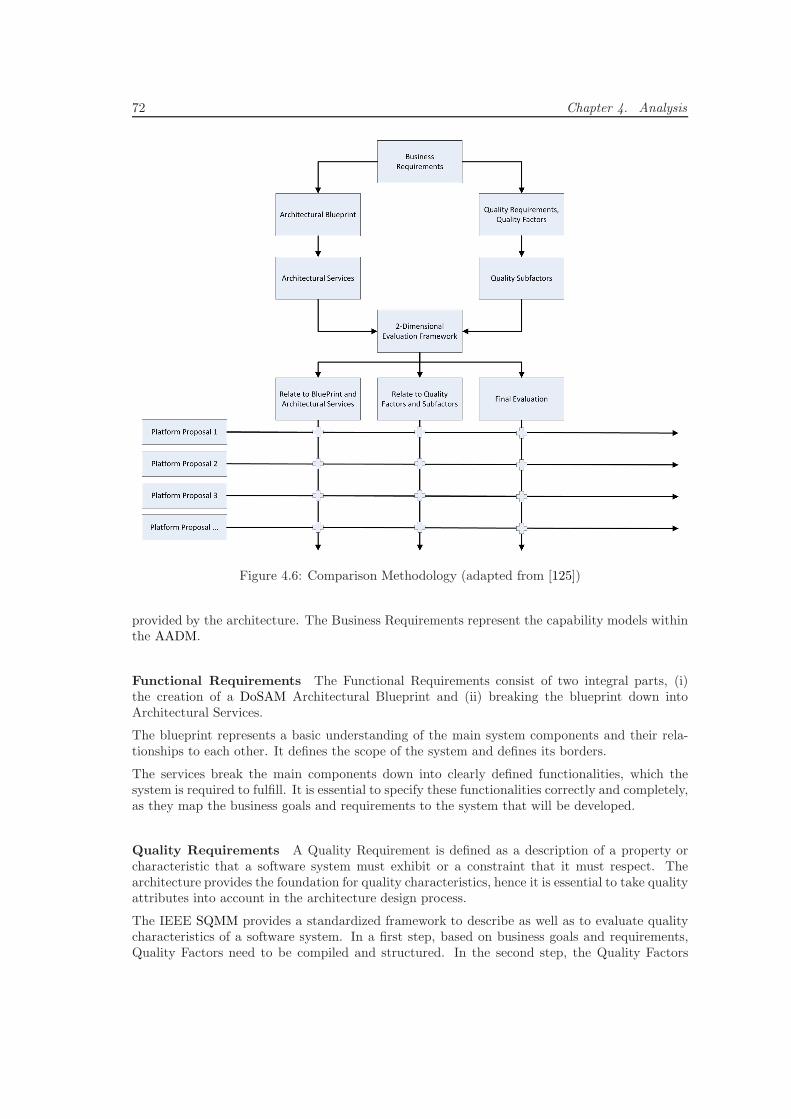
72 Chapter 4. Analysis
Figure 4.6: Comparison Methodology (adapted from [125])
provided by the architecture. The Business Requirements represent the capability models withinthe AADM.
Functional Requirements The Functional Requirements consist of two integral parts, (i)the creation of a DoSAM Architectural Blueprint and (ii) breaking the blueprint down intoArchitectural Services.
The blueprint represents a basic understanding of the main system components and their rela-tionships to each other. It defines the scope of the system and defines its borders.
The services break the main components down into clearly defined functionalities, which thesystem is required to fulfill. It is essential to specify these functionalities correctly and completely,as they map the business goals and requirements to the system that will be developed.
Quality Requirements A Quality Requirement is defined as a description of a property orcharacteristic that a software system must exhibit or a constraint that it must respect. Thearchitecture provides the foundation for quality characteristics, hence it is essential to take qualityattributes into account in the architecture design process.
The IEEE SQMM provides a standardized framework to describe as well as to evaluate qualitycharacteristics of a software system. In a first step, based on business goals and requirements,Quality Factors need to be compiled and structured. In the second step, the Quality Factors
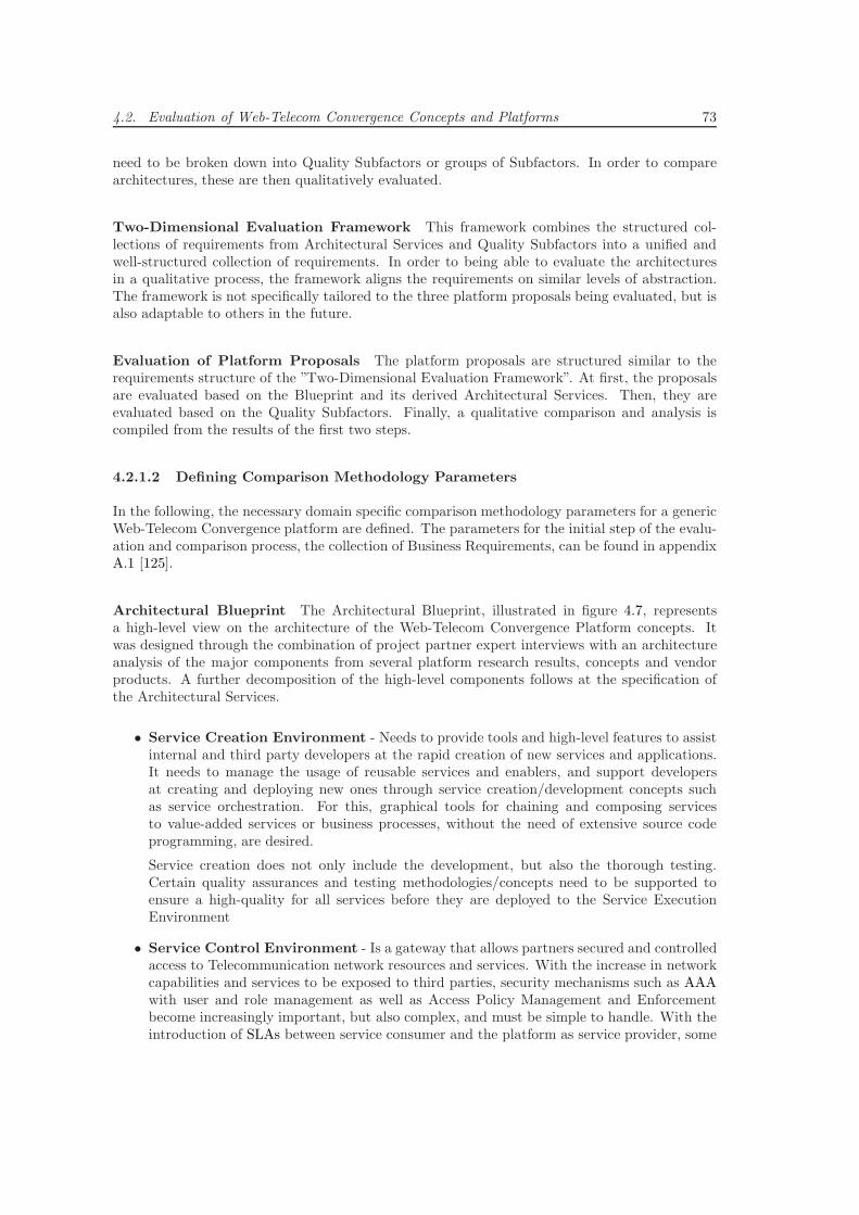
4.2. Evaluation of Web-Telecom Convergence Concepts and Platforms 73
need to be broken down into Quality Subfactors or groups of Subfactors. In order to comparearchitectures, these are then qualitatively evaluated.
Two-Dimensional Evaluation Framework This framework combines the structured col-lections of requirements from Architectural Services and Quality Subfactors into a unified andwell-structured collection of requirements. In order to being able to evaluate the architecturesin a qualitative process, the framework aligns the requirements on similar levels of abstraction.The framework is not specifically tailored to the three platform proposals being evaluated, but isalso adaptable to others in the future.
Evaluation of Platform Proposals The platform proposals are structured similar to therequirements structure of the ”Two-Dimensional Evaluation Framework”. At first, the proposalsare evaluated based on the Blueprint and its derived Architectural Services. Then, they areevaluated based on the Quality Subfactors. Finally, a qualitative comparison and analysis iscompiled from the results of the first two steps.
4.2.1.2 Defining Comparison Methodology Parameters
In the following, the necessary domain specific comparison methodology parameters for a genericWeb-Telecom Convergence platform are defined. The parameters for the initial step of the evalu-ation and comparison process, the collection of Business Requirements, can be found in appendixA.1 [125].
Architectural Blueprint The Architectural Blueprint, illustrated in figure 4.7, representsa high-level view on the architecture of the Web-Telecom Convergence Platform concepts. Itwas designed through the combination of project partner expert interviews with an architectureanalysis of the major components from several platform research results, concepts and vendorproducts. A further decomposition of the high-level components follows at the specification ofthe Architectural Services.
• Service Creation Environment - Needs to provide tools and high-level features to assistinternal and third party developers at the rapid creation of new services and applications.It needs to manage the usage of reusable services and enablers, and support developersat creating and deploying new ones through service creation/development concepts suchas service orchestration. For this, graphical tools for chaining and composing servicesto value-added services or business processes, without the need of extensive source codeprogramming, are desired.
Service creation does not only include the development, but also the thorough testing.Certain quality assurances and testing methodologies/concepts need to be supported toensure a high-quality for all services before they are deployed to the Service ExecutionEnvironment
• Service Control Environment - Is a gateway that allows partners secured and controlledaccess to Telecommunication network resources and services. With the increase in networkcapabilities and services to be exposed to third parties, security mechanisms such as AAAwith user and role management as well as Access Policy Management and Enforcementbecome increasingly important, but also complex, and must be simple to handle. With theintroduction of SLAs between service consumer and the platform as service provider, some
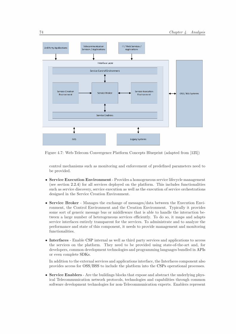
74 Chapter 4. Analysis
Figure 4.7: Web-Telecom Convergence Platform Concepts Blueprint (adapted from [125])
control mechanisms such as monitoring and enforcement of predefined parameters need tobe provided.
• Service Execution Environment - Provides a homogeneous service lifecycle management(see section 2.2.4) for all services deployed on the platform. This includes functionalitiessuch as service discovery, service execution as well as the execution of service orchestrationsdesigned in the Service Creation Environment.
• Service Broker - Manages the exchange of messages/data between the Execution Envi-ronment, the Control Environment and the Creation Environment. Typically it providessome sort of generic message bus or middleware that is able to handle the interaction be-tween a large number of heterogeneous services efficiently. To do so, it maps and adaptsservice interfaces entirely transparent for the services. To administrate and to analyze theperformance and state of this component, it needs to provide management and monitoringfunctionalities.
• Interfaces - Enable CSP internal as well as third party services and applications to accessthe services on the platform. They need to be provided using state-of-the-art and, fordevelopers, common development technologies and programming languages bundled in APIsor even complete SDKs.
In addition to the external services and applications interface, the Interfaces component alsoprovides access for OSS/BSS to include the platform into the CSPs operational processes.
• Service Enablers - Are the buildings blocks that expose and abstract the underlying phys-ical Telecommunication network protocols, technologies and capabilities through commonsoftware development technologies for non-Telecommunication experts. Enablers represent
4.2. Evaluation of Web-Telecom Convergence Concepts and Platforms 75
reusable Telecommunication specific service components, which can be used to build higher-level services through composition or to build complete Telecommunication applications.
The parameters for the next step of the process, the Architectural Services, are derived from theblueprint. An overview about these can be found in appendix A.2.
Quality Factors In parallel to the functional aspects of a Web-Telecom Convergence platform,also the quality aspects are taken into account. As parameters for this step, the following QualityFactors were identified as the most important ones [125]:
• Interoperability - The platform has to include the ability to adjust to different end-userapplications, devices, partner platforms, underlying networks as well as legacy systems andnetworks. It has to provide open standardized interfaces to be combined with platforms ofCSP and ASP partners in the future. It has to provide standardized interfaces to attractthird party developers, leading to more innovative services and applications.
• Reliability - The platform has to have the ability to operate correctly without failure overa defined period of time. It needs to ensure a consistent and stable environment for thedeployment, execution and the delivery of its services. It has to ensure a reliable delivery ofmessages between services on the platform as well as between the platform and third partyservices and applications.
• Availability - The platform needs to provide a high degree, to which it is operational andaccessible for use. In the Telecommunication industry this is means it needs to achieve nearcarrier grade (99,999%) availability. It needs to be tolerant to system failures and overloadsituations, and be capable of solving and isolating problems to ensure the availability of theplatform. Since contractual measurements of availability are usually included in SLAs, theplatform needs to include the functionalities to provide monitoring information in order toanalyze the availability status of the platform constantly.
• Usability - The platform needs to provide a high measurable quality of end-users experiencein interaction with devices, platform functionalities, services and data. It needs to be easyfor developers to create and deploy services on the platform. The platform needs to abstractfrom Telecommunication technology specifics in a meaningful way, so developers can quicklyadopt service and application development in this, for them, new environment. It needs toprovide mature and powerful services and enablers that are simple to adopt and integrateinto other services and applications to ensure a fast time to market.
• Security - The platform needs to provide the ability to resist unauthorized attempts ofusage or behavior modification, while still providing services to legitimate end-users. Dataintegrity and confidentiality play major roles on every professional software platform. State-of-the-art mechanisms for configuring and enforcing permissions for users, groups and rolesneed to be provided.
• Performance - To comply with Telecommunication standards, the platform should per-form in near real time, which is measured by the maximum response time of deployedservices. Especially platform internal functionalities such as access and authorization func-tions should not impact the performance of services. This is especially crucial, because theplatform has to manage high volumes of data in a high number of transactions.
• Scalability - The platform needs to exhibit the ability to function without degradationof quality attributes when the platform is changed in size due to an increase in volume.
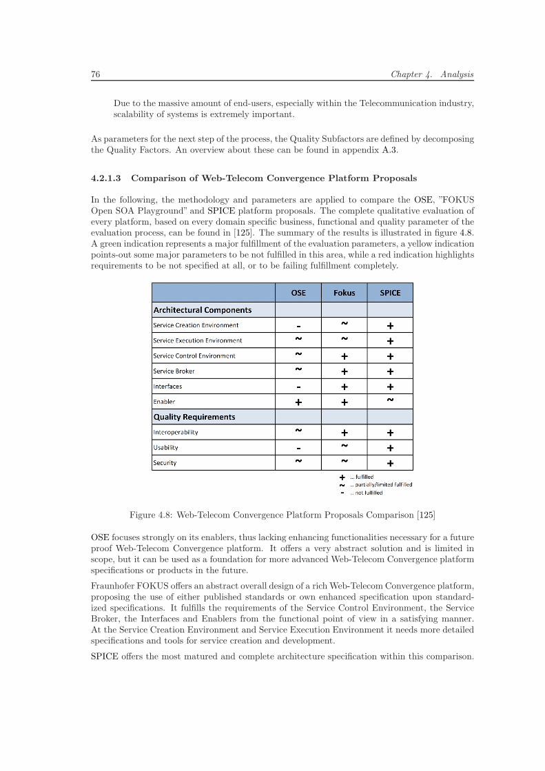
76 Chapter 4. Analysis
Due to the massive amount of end-users, especially within the Telecommunication industry,scalability of systems is extremely important.
As parameters for the next step of the process, the Quality Subfactors are defined by decomposingthe Quality Factors. An overview about these can be found in appendix A.3.
4.2.1.3 Comparison of Web-Telecom Convergence Platform Proposals
In the following, the methodology and parameters are applied to compare the OSE, ”FOKUSOpen SOA Playground” and SPICE platform proposals. The complete qualitative evaluation ofevery platform, based on every domain specific business, functional and quality parameter of theevaluation process, can be found in [125]. The summary of the results is illustrated in figure 4.8.A green indication represents a major fulfillment of the evaluation parameters, a yellow indicationpoints-out some major parameters to be not fulfilled in this area, while a red indication highlightsrequirements to be not specified at all, or to be failing fulfillment completely.
Figure 4.8: Web-Telecom Convergence Platform Proposals Comparison [125]
OSE focuses strongly on its enablers, thus lacking enhancing functionalities necessary for a futureproof Web-Telecom Convergence platform. It offers a very abstract solution and is limited inscope, but it can be used as a foundation for more advanced Web-Telecom Convergence platformspecifications or products in the future.
Fraunhofer FOKUS offers an abstract overall design of a rich Web-Telecom Convergence platform,proposing the use of either published standards or own enhanced specification upon standard-ized specifications. It fulfills the requirements of the Service Control Environment, the ServiceBroker, the Interfaces and Enablers from the functional point of view in a satisfying manner.At the Service Creation Environment and Service Execution Environment it needs more detailedspecifications and tools for service creation and development.
SPICE offers the most matured and complete architecture specification within this comparison.
4.2. Evaluation of Web-Telecom Convergence Concepts and Platforms 77
Besides the Enabler requirements, in which it lacks more detailed specifications, SPICE fulfillsthe requirements in every other category on functional as well as quality side.
4.2.2 Discussing Web-Telecom Convergence Research Results
V. Danciu, et. al. discuss in [52] the abstraction and composition of existing cloud services ina new Cloud Broker middleware. This Cloud Broker manages Authentication, Authorization,Accounting, Auditing and Charging (A4C), and dynamically discovers/selects, aggregates, bindsand manages cloud services. It provides compositions of these cloud services to mobile applica-tions transparently. For a dynamic composition of services according to a changing environmentand requirements, the Cloud Broker provides workflow-based orchestration components and tools.The Cloud Broker focuses on shared Web/Internet services and leaves shared Telecommunicationservices, application-specific services and cross-platform client development aspects out of scope.
N. Blum, et. al. propose in [30] and [27] a SDF based on SOA concepts and present a prototypeimplementation and test-bed deployment. Their platform allows for an autonomous compositionof Telecommunication services within the Telecommunication domain using SOA service descrip-tion and orchestration concepts. Web-Telecom Convergence of services and applications is outof scope of their platform. They define it as to take place on layers above their Service DeliveryFramework, which developers should design themselves.
N. Blum, et. al. present in [28] a concept for a policy-based service broker that allows for anintegration of Telecommunication services based on IMS enablers into Web/Internet mashups andother third party applications. The broker mediates between the real-time Telecommunicationservices and third party applications. The broker’s policies serve as service access definitions aswell as an expression for user/service specific capabilities and rules.
F. Deinert, et. al. propose in [54] an approach to combine Web 2.0 enabled widgets withTelecommunication services exposed by an IMS. They introduce a new abstraction layer withinterfaces and a widget engine that provides access to the Telecommunication services. It allowsrapid development of Web 2.0 widget applications but is restricted to use-cases where widgetsare suitable as end-user clients.
J. Yang and H. Park propose in [248] an Open Service Access Gateway (OSAG) that allowsTelecommunication operators to leverage W3C Web Services to provide integrated services. Itfurther describes how Telecommunication and W3C Web Services can be combined on the OSAGto build Web-Telecom Converged services and how applications can use these services throughdefined interfaces. An application architecture or end-user client support is out of scope of thisresearch work.
C. Gbaguidi, et. al. propose in [76] the concept of Hybrid Services as services that span acrossmultiple, especially IP-based, networks such as telephone, Web/Internet and cellular. Theydescribe an architecture for the provisioning of such services. Their architecture allows theprogramming of new elements of the platform in order to develop new services that can usedin new applications. Further, they introduce a concept of orchestration on Telecommunicationfeatures such as call control, security, address translation etc. and expose them as higher-levelservices for reuse. Finally, they implement a Java-based prototype of the platform and a prototypeservice/application on top.
X. Shao, et. al. describe in [195] an integrated Telecommunication and IT SDP for convergingIMS Services, W3C Web Service and underlying services. They propose a combination of theirSIP-based Micro Service Orchestration with a Service Bus to achieve the orchestration. At theend, they present a prototype multimedia service implementation and discuss the support of theirSDP for rapid development and deployment of new Web-Telecom Converged multimedia services.
78 Chapter 4. Analysis
H. Ohnishi, et. al. present in [158] a SDP concept that goes beyond the ones discussed insection 2.5. Their goal was to develop an SDP architecture that co-exists with Enterprise andWeb/Internet architectures and so, they use Enterprise/Internet compatible Web/Internet andW3C Web Service technologies such as ParlayX, BPEL [157], ESB [43] and WSDL to realize theirSDP. They extend the technologies used in order to fulfill Telecommunication service specificrequirements identified from a CSP’s viewpoint.
4.2.3 Evaluation Conclusions
In this section the current state-of-the-art of Web-Telecom Convergence was presented and eval-uated by comparing the three most popular Web-Telecom Convergence Platform concepts as wellas discussing the most widespread and recognized research results. By additionally taking intoaccount less recognized but relevant supplementary research results from [163, 168, 170, 120, 3,94, 39, 105, 122, 227, 132, 19, 129, 31, 32, 253, 69, 182, 20], the following summary discusses themost important conclusions that can be drawn.
• No End-to-End Platform Concepts - The concepts evaluated in this section do notspecify any solutions or architectures that would allow to design and build an applicationfrom the low-level ”end” of the physical Telecommunication all the way to the highest-level”end”, the end-user application on the end-user devices. They do not provide concepts andsolutions for reusing Web/Internet as well as Telecommunication services, for security, forscalability, for data/message transmission in a distributed application, for the integratedsoftware development process on the platform and more.
• No Distinction Between Services and Applications - The concepts evaluated inthis section do not separate between functionality that can be reused by other services orapplications and functionality that is applications specific and useless for other services orapplications. The first is typically encapsulated in services whereas the later is typicallyencapsulated in the client and server parts of a distributed application.
• No Clear Separation of Network and Application - The concepts evaluated in thissection do not separate services that abstract from physical core Telecommunication net-work capabilities, technologies and protocols, from those that provide higher-level func-tionalities for applications. Further, most don’t even include into their concepts, the ap-plications that ultimately deliver the implemented functionality to the end-users on theirdevices.
• No Cross-Platform Support - The concepts evaluated in this section do not provideany concept or solutions for end-user client development and distribution. Hence, theydo not provide any concept or solution for platform features, components or services thatwould support developers at providing end-user clients that are able to run seamlessly, inparallel and fully synchronized across all the various types of client devices and platforms.Further, they do not provide any platform features that would support the transformationand adaptation of the service/application content or data to different types of end-userclients.
• No Application Lifecycle Support - The concepts evaluated in this section do notsupport the lifecycle of the end-user applications. They only cover the initial steps byabstracting from the Telecommunication capabilities and providing reusable services forthem. They do not provide developers with any concepts or support for end-user applicationdevelopment, hosting, distribution, etc.
4.3. Evaluation of Mobile Application Development Technologies 79
• Limited Cross-Access Networks Support - Most concepts evaluated in this sectiondo not include any concepts or solutions for how to allow seamless service and applicationaccess from across heterogeneous operators domains as well as from the Telecommunicationnetworks independent Web/Internet. They do not include solutions for how to migratecomponents like security, charging and accounting from an access network provider levelto a higher and provider abstracted level so they can be used seamlessly across providers’domains worldwide.
• Limited SOA Concepts Adoption - Most concepts evaluated in this section adopt,mostly technical, SOA concepts only for Telecommunication network abstraction serviceexposure as proposed in Parlay X (see section 4.1.6). They do not adopt supplementaryconcepts such as the SOA Triangular Model, SOA Service Layers or a SOA Reference Ar-chitecture (see section 2.2) to structure their platforms better in order to build Telecommu-nication applications that are provided to the end-users completely based on SOA concepts.
• Limited Web/Internet Services Support - Most concepts evaluated in this section donot include concepts or solution to dynamically import services from other domains thatare outside of the platform or the network of the CSP. They do not support an import ofexternal Web/Internet services into the platform in order to manage them with the toolsthe platform provides. They do not support to compose them with Telecommunicationservices to value-added reusable services or full end-user applications right on the platform.Most propose the Web-Telecom Convergence to take place above the platform they arespecifying. For the evaluated concepts the scope for Web-Telecom Convergence is mostlyvery limited, often it is completely out of scope.
• Limited Service and Application Developer Support - Most concepts evaluated inthis section do not provide any tools or solutions to support end-user application devel-opment. They do not provide any concepts for the service and application deploymentprocess such as SDKs, service and application hosting, beta testing and live roll-out. Mostdon’t provide means for service publishing, discovery and access/invocation for applicationdevelopers and their applications. For all concepts evaluated, binding SLA negotiation,supervision and enforcement are out of scope.
This Web-Telecom Convergence Concepts and Platform evaluation, the comparison results, thediscussions above and this summary of conclusions build the foundation for this research work’srequirements definitions and platform design presented in the following chapters.
4.3 Evaluation of Mobile Application Development Tech-
nologies
For every Web-Telecom Converged application, the client applications deployed on the end-users’devices are an essential part of the distributed application. In order to identify, support andprovide developers with the most suitable technologies and tools to create application clientswith great user experiences, the currently available technologies and tools need to be structured,compared and evaluated.
This section summarizes the two-part evaluation of development platforms and frameworks con-ducted in the CDTM project [121]. In the first part, the evaluation introduces the currently mostsuccessful mobile device platforms and structures the comparison of their technological detailsinto 4 categories, 18 criteria and 44 sub-criteria. Following that, for each platform, it rates the
80 Chapter 4. Analysis
criteria’s and sub-criteria’s individual availability, fulfillment or maturity by distributing pointsin the range from 0 to 3.
In the second part, the evaluation introduces the currently most popular mobile developmentframeworks. Similar to the first part, it structures their technological details by deriving 4categories, 19 criteria and 25 sub-criteria. Following that, similar to the first part, it rates thecriteria and sub-criteria for each framework.
From the resulting structured rating tables, criteria or sub-criteria that may be important for acertain mobile development use-case, such as Web-Telecom Converged application clients, can beselected or weighted. Thereby, both mobile platforms as well as mobile development frameworkscan be compared and evaluated explicitly for this use-case. See section C for the completecomparison tables.
4.3.1 Mobile Platforms
The evaluation focused on the three popular and fast spreading mobile platforms iOS from Apple,Android from Google and Windows Phone 7 from Microsoft.
• Apple iOS
iOS is a proprietary mobile platform developed, maintained and fully controlled by Applethat can only run on devices designed and sold by Apple. Originally, it was designed andcreated for the introduction of the iPhone in 2007. Three years later, it had been extendedto other Apple devices like the newly introduced iPad, iPod Touch and Apple TV.
By the end of Q3 2011 Apple had shipped 146 million devices and published about 500,000applications on the Apple App Store. Apple controls applications and digital content forthe iOS through the App Store and iTunes, which are the only places where end-users canpurchase, download and install applications or content [231, 233, 232].
The iOS is based on a scaled-down version of Apple’s Mac OS X desktop/laptop platformthat was optimized for touch-screen user-interfaces and adapted to cope with the limitationsof mobile device hardware resources. Technologies shared between iOS and Mac OS Xinclude the OS X kernel, BSD sockets for networking, Objective-C and C/C++ compilersfor native performance. Apple distributes open source portions of the kernel and Mac OSX through its sponsoring of the Darwin project.
The iOS belongs to the newest generation of operating systems that contain five lay-ers: the kernel, the middleware layer, the Application Execution Environment (AEE),the application/user-interface framework and the application suite layer. For developingnative iPhone/iPad iOS applications, Apple provides an SDK for Mac OS. This contains alltools a developer needs to create an iOS application, such as the IDE Xcode, a simulator,a user-interface builder and analysis tools to both optimize and monitor iOS applicationsfor memory leaks in real time. In addition, recently, Dashcode, an IDE that simplifies thedevelopment of future web-based iPhone and iPad applications, was added.
• Google Android
The Android OS was originally developed by Android Inc., which was acquired by Googlein 2005. Following the acquisition, the Open Handset Alliance was created by Google tofoster and distribute Android to manufacturers, CSPs, developers and end-users. Androidis fully open-source and every device manufacturer can adapt it to fulfill his user experienceand business requirements. Therefore, Android applications can be downloaded from thecentral Android Market or installed from an Android Application Package (APK) and runon various different mobile and tablet devices from various different manufacturers.
4.3. Evaluation of Mobile Application Development Technologies 81
Android was launched in November 2007 and since then, 225 million devices have been soldand 300,000 applications have been published on the Android Market. Roughly 10 billionAndroid applications have been downloaded, and in Q4 2010, with 32.9 million shipments,the Android platform outran Nokia’s Symbian platform with 31 million shipments andbecame the leader of the smartphone platforms market.
Similar to iOS, Android is a new generation mobile operating system with five layers.Android relies on Linux version 2.6 for the core system and all libraries on the middlewarelayer are written in C/C++ and used by components of the AEE on top. The middlewareprovides support for audio and video multimedia, 2D and 3D graphics, wireless, networking,location services, sensors, Bluetooth, etc.
The application framework and pre-installed applications are written in Java and typically,third-party developers create their Android applications in Java as well. Every Java ap-plication on the Android platform runs as an independent process with an independentinstance of the Dalvik virtual machine executing the application. For special purposes,through the Android Native Development Kit (NDK) or the Java Native Interface (JNI),the platform can also run performance-critical C/C++ components or applications.
For developers, Google provides a mature SDK that is built around an Eclipse IDE Androidplugin and includes a wide range of powerful tools for developing, testing, debugging anddeploying Android applications.
The Android platform is distributed with pre-installed applications that integrate the plat-form with many Google cloud services such as Google Search, Google Voice/Talk, GoogleMaps, Google Mail, Google Calendar/Contacts, Android Market etc.
• Microsoft Windows Phone 7
Windows Phone 7 is a mobile device platform that is designed, developed and controlledby Microsoft and was launched at the end of 2008. Based on the experience from previousWindows Mobile versions, Microsoft created a Windows Phone 7 certification standard thatenables all device manufacturers to deployWindows Phone 7 on their certified devices. Since2011, Nokia is the largest device manufacturing partner of Microsoft. Since the platformslaunch, 10 million devices have been sold and about 30,000 mobile applications have beenpublished in the Windows Phone 7 Marketplace.
The Windows Phone 7 platform architecture is built upon the four components Runtimes,Tools, Portal and Cloud Services. Runtimes support developers in writing secure and graph-ically rich applications. As Tools the platform provides two well-known Microsoft IDEs:Visual Studio and Expression Blend. Portal Services help developers to manage applicationlifecycles in the Marketplace and Cloud services connect the platform to Microsoft Azure.
Microsoft offers two frameworks for developing Windows Phone 7 applications, Silverlightand XNA (XNA is Not an Acronym). Web developers know Silverlight as a powerfulframework for creating rich web-based user-interfaces. Silverlight was extended for WindowsPhone 7 to enable developers to create innovative applications with a great user experience.XNA is Microsoft’s game platform that was originally developed for the Xbox. It supportsboth 2D sprite-based and 3D graphics with a traditional game-loop software architecture.XNA was extended from the Xbox game console to enable developers develop applicationsfor Window Phone 7 and Zune HD environments.
Figure 4.9 provides a consolidated overview of the results of the evaluation of these three plat-forms. A detailed overview can be found in section C. An extended discussion of the results anda detailed explanation of the categories, criteria and sub-criteria is illustrated in [121].
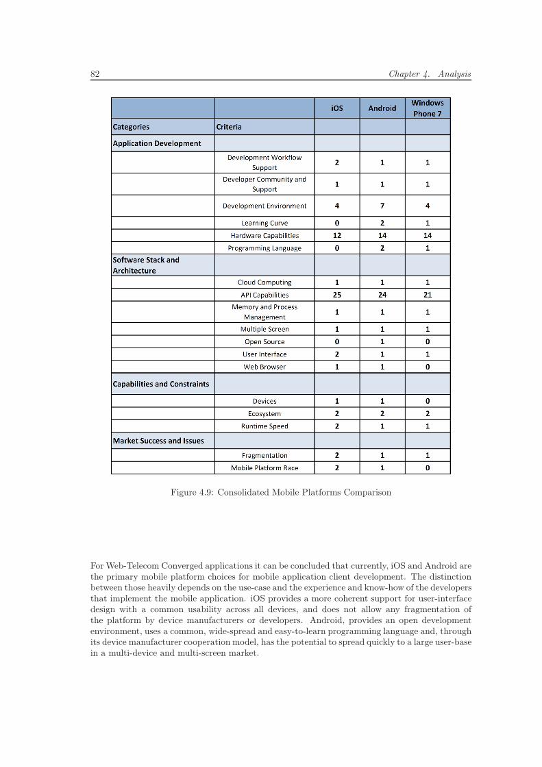
82 Chapter 4. Analysis
Figure 4.9: Consolidated Mobile Platforms Comparison
For Web-Telecom Converged applications it can be concluded that currently, iOS and Android arethe primary mobile platform choices for mobile application client development. The distinctionbetween those heavily depends on the use-case and the experience and know-how of the developersthat implement the mobile application. iOS provides a more coherent support for user-interfacedesign with a common usability across all devices, and does not allow any fragmentation ofthe platform by device manufacturers or developers. Android, provides an open developmentenvironment, uses a common, wide-spread and easy-to-learn programming language and, throughits device manufacturer cooperation model, has the potential to spread quickly to a large user-basein a multi-device and multi-screen market.
4.3. Evaluation of Mobile Application Development Technologies 83
4.3.2 Mobile Development Frameworks
The evaluation focused on the four most popular, most mature and fastest spreading mobiledevelopment frameworks PhoneGap, Titanium, RhoMobile and WAC.
• PhoneGap
PhoneGap intends to bridge the gap between Web/Internet technologies and native mobileapplication development while providing access to more platform and device capabilitiesthan current HTML5 applications have. It is a mobile application development frameworkthat enables developer to implement mobile web applications that are able to run across sev-eral native platforms that have access to platform APIs, services and hardware capabilities,and that can be published in the platforms’ respective App Stores. PhoneGap leveragesthe Web/Internet technologies HTML and JavaScript that many developers either alreadyknow or easily learn.
PhoneGap was created by Nitobi, which was acquired by Adobe in October 2011. It wasinitially developed for the iPhone and was soon extended to support many other mobileplatforms like Android, Windows Phone 7, Blackberry, WebOS, etc. PhoneGap is an opensource project and was contributed to the Apache Software Foundation (ASF) under thename Apache Callback in October 2011.
PhoneGap supports the native mobile development IDEs XCode, Eclipse, Visual Studio,etc. Alternatively, developers can write HTML and JavaScript files in any editor of theirchoice and upload them to the Web/Internet-based PhoneGap Build Service. The Servicecompiles the application files and returns a distributable application package.
Since PhoneGap applications are basically Web/Internet technologies-based applications,developers can use many other powerful JavaScript-based libraries such as jQuery, MooTools,XUI, jQTouch, etc. to enrich their applications. In addition, PhoneGap enables develop-ers to extend the PhoneGap framework to provide additionally desired functionalities bywriting and sharing plug-ins.
• Titanium
Titanium is a, partly commercialized, open-source and Web/Internet technologies-based(HTML, JavaScript, CSS, etc.) mobile development framework for building native desk-top and mobile applications. It offers a free Community Edition ready for building anddistributing applications as well as commercial Professional and Enterprise Editions thatprovide additional support and services.
A Titanium-based application can be deployed and run on the three desktop/laptop plat-forms Windows, Mac OS X and Linux as well as on the two mobile platforms iOS andAndroid. A package that supports the Blackberry platform will be released in the nearfuture. For developers, Titanium offers a package of the Titanium Studio IDE togetherwith an SDK that provides an application development API.
The Titanium Studio is a powerful Eclipse-based IDE that is built upon the patent-pendingdevelopment technology acquired from Aptana. It provides development support featureslike a simulator, compiler, debug/test, deploy, repository support, etc.
The Titanium SDK provides a platform-independent API that abstracts access to nativeuser-interface components as well as to platform and hardware capabilities such as sound,file system, network, local database, 2D and 3D animations, camera etc.
In addition to Studio and SDK, Titanium offers the commercial Appcelerator Network,which is a cloud service for testing, packing, distribution and analytics for desktop andmobile applications.
84 Chapter 4. Analysis
• RhoMobile Rhodes
Rhodes is a mobile application development framework created by RhoMobile. Rhodesaims to offer a complete suite of products for building and managing enterprise mobileapplications. It was initially released in December 2008, is available for the major mobileplatforms iOS, Android, Windows Phone 7 and Blackberry and is a commercially-supportedopen-source product licensed under the MIT License.
Rhodes is a framework that fosters a Model-View-Controller pattern to clearly separatebusiness logic from presentation and that supports the programming languages HTML,CSS, JavaScript and Ruby.
It offers its own Object-Relation Mapping (ORM) solution Rhom to simplify databaseaccess as well as its own GUI logic concept Embedded Ruby (ERB) to support developers atimplementing logic on the application front-end. Rhodes provides RhoSync, a cloud serviceto synchronize data of mobile platforms and allows extending the application developmentframework through native extension.
Applications built by Rhodes are platform-specific native applications that have access toplatform and hardware capabilities such as GPS, maps, camera, calendar, etc. They arecompiled into Ruby byte code, which can be executed by the Ruby runtime that is includedin the Rhodes versions for the different mobile platform.
For developers, RhoMobile provides the state-of-the-art Rhodes Studio IDE for Windowsand Mac OS X.
• Wholesale Application Community (WAC)
As briefly illustrated in section 3.1, WAC is an open global alliance that was created bythe world’s largest CSPs and device manufacturers such as AT&T, Vodafone, DoCoMo,Deutsche Telekom, Nokia, Samsung to support developers at creating and distributingcompelling future mobile applications and digital content.
WAC’s four major goals are to enlarge the worldwide market for mobile applications, tostandardize mobile technologies, to give developers more opportunities to distribute theirapplications and to encourage the use of CSPs’ network APIs.
The WAC application development framework is based on the five specifications (i) thestandardized Web/Internet technologies HTML5 and JavaScript that many developers al-ready know and that are easy to learn, (ii) the device APIs Bondi and JIL that provideaccess to platform and hardware capabilities through JavaScript, (iii) the OneAPI that pro-vides access to CSPs’ network capabilities, (iv) the Compliance certification that ensuresthat Web/Internet technology runtimes are consistent across platforms and devices, and(v) the security policies.
For developers, WAC provides an SDK that is compatible with most common desktop/lap-top platforms and a development plugin for the popular IDE Eclipse. A final WAC appli-cation is packaged according to the World Wide Web Consortium (W3C) Widget standardin a WGT file format. WAC provides a WGT runtime for most current mobile platformsand a web-based WGT emulator for testing and debugging. Before an application can bedistributed through the WAC App Store it needs to pass the WAC testing and certificationprocess.
Figure 4.10 provides a consolidated overview of the results of the evaluation of these four frame-works. A detailed overview can be found in section C. An extended discussion of the results andan explanation of the categories, criteria and sub-criteria is illustrated in [121].
For Web-Telecom Converged applications it can be concluded that current mobile developmentframeworks are mature enough to support probably most of the possible future applications
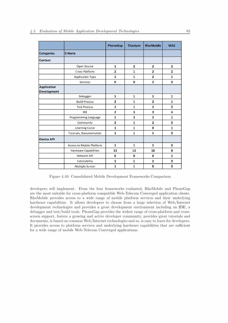
4.3. Evaluation of Mobile Application Development Technologies 85
Figure 4.10: Consolidated Mobile Development Frameworks Comparison
developers will implement. From the four frameworks evaluated, RhoMobile and PhoneGapare the most suitable for cross-platform compatible Web-Telecom Converged application clients.RhoMobile provides access to a wide range of mobile platform services and their underlyinghardware capabilities. It allows developers to choose from a large selection of Web/Internetdevelopment technologies and provides a great development environment including an IDE, adebugger and test/build tools. PhoneGap provides the widest range of cross-platform and cross-screen support, fosters a growing and active developer community, provides great tutorials anddocuments, is based on common Web/Internet technologies and so, is easy to learn for developers.It provides access to platform services and underlying hardware capabilities that are sufficientfor a wide range of mobile Web-Telecom Converged applications.

Chapter 5
Design of Web-TelecomConverged Applications
This section develops the very general concept of Web-Telecom Convergence from section 2.8.3further and applies it to the development of an application. It provides an overview about afew exemplary Web-Telecom Convergence application scenarios that will be used as case studiesthroughout the rest of this research work. Further, it presents a generic logical architectureof a distributed application that builds its application logic upon the convergence of servicesand functionalities from the Web/Internet with some from Telecommunications. Finally, thisarchitecture is mapped to a technical architecture of one of the applications scenarios.
5.1 Web-Telecom Convergence Application Scenarios
This section presents some exemplary scenarios that illustrate how Web-Telecom Convergencecould be used in future innovative application development.
5.1.1 Unified Address Book
By using many Web/Internet service and hardware devices, a typical end-user has a number ofdifferent address books stored under different Web/Internet accounts, in CSP managed Telecom-munication address books as well as on different devices such as smart phones, tablets, laptops,etc. The concept of the Unified Address Book is to tap into all these source of contact data andprovide them as one well sorted and structured address book in an end-user application on alldevices and screens. In figure 5.1 the concept is illustrated as a one- and a two-level approachincorporating exemplary contact data sources.
The Address Book services aggregate the contacts data from the sources below, synchronize datachanges in both ways and (semi-)automatically map data sources with each other in order tocombine data for the same contact into only one contact data element. In the one-level approach(top), there is only one service interface, so all applications have access to the whole collectionof contacts data from all types of sources. In the two-level approach (bottom), there is notjust a Unified Address Book service that provides the whole data collection, but there are alsoWeb/Internet, Device and Telecommunication Address Book services that provide only subsets.Thereby, applications can choose to only retrieve the collection of contact data they can or would
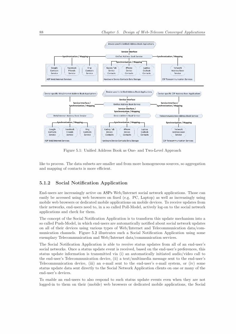
88 Chapter 5. Design of Web-Telecom Converged Applications
Figure 5.1: Unified Address Book as One- and Two-Level Approach
like to process. The data subsets are smaller and from more homogeneous sources, so aggregationand mapping of contacts is more efficient.
5.1.2 Social Notification Application
End-users are increasingly active on ASPs Web/Internet social network applications. Those caneasily be accessed using web browsers on fixed (e.g. PC, Laptop) as well as increasingly usingmobile web browsers or dedicated mobile applications on mobile devices. To receive updates fromtheir networks, end-users need to, in a so called Poll-Model, actively log-on to the social networkapplications and check for them.
The concept of the Social Notification Application is to transform this update mechanism into aso called Push-Model, in which end-users are automatically notified about social network updateson all of their devices using various types of Web/Internet and Telecommunication data/com-munication channels. Figure 5.2 illustrates such a Social Notification Application using someexemplary Telecommunication and Web/Internet data/communication services.
The Social Notification Application is able to receive status updates from all of an end-user’ssocial networks. Once a status update event is received, based on the end-user’s preferences, thisstatus update information is transmitted via (i) an automatically initiated audio/video call tothe end-user’s Telecommunication device, (ii) a text/multimedia message sent to the end-user’sTelecommunication device, (iii) an e-mail sent to the end-user’s e-mail system, or (iv) somestatus update data sent directly to the Social Network Application clients on one or many of theend-user’s devices.
To enable an end-users to also respond to such status update events even when they are notlogged-in to them on their (mobile) web browsers or dedicated mobile applications, the Social
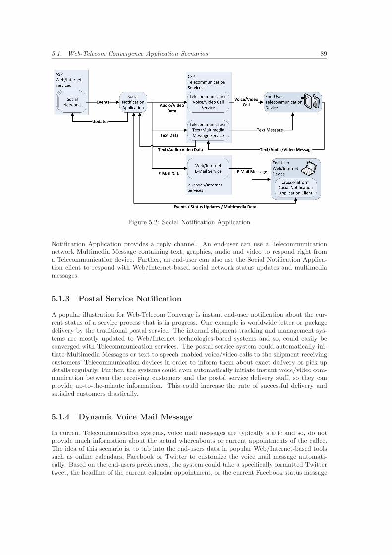
5.1. Web-Telecom Convergence Application Scenarios 89
Figure 5.2: Social Notification Application
Notification Application provides a reply channel. An end-user can use a Telecommunicationnetwork Multimedia Message containing text, graphics, audio and video to respond right froma Telecommunication device. Further, an end-user can also use the Social Notification Applica-tion client to respond with Web/Internet-based social network status updates and multimediamessages.
5.1.3 Postal Service Notification
A popular illustration for Web-Telecom Converge is instant end-user notification about the cur-rent status of a service process that is in progress. One example is worldwide letter or packagedelivery by the traditional postal service. The internal shipment tracking and management sys-tems are mostly updated to Web/Internet technologies-based systems and so, could easily beconverged with Telecommunication services. The postal service system could automatically ini-tiate Multimedia Messages or text-to-speech enabled voice/video calls to the shipment receivingcustomers’ Telecommunication devices in order to inform them about exact delivery or pick-updetails regularly. Further, the systems could even automatically initiate instant voice/video com-munication between the receiving customers and the postal service delivery staff, so they canprovide up-to-the-minute information. This could increase the rate of successful delivery andsatisfied customers drastically.
5.1.4 Dynamic Voice Mail Message
In current Telecommunication systems, voice mail messages are typically static and so, do notprovide much information about the actual whereabouts or current appointments of the callee.The idea of this scenario is, to tab into the end-users data in popular Web/Internet-based toolssuch as online calendars, Facebook or Twitter to customize the voice mail message automati-cally. Based on the end-users preferences, the system could take a specifically formatted Twittertweet, the headline of the current calendar appointment, or the current Facebook status message
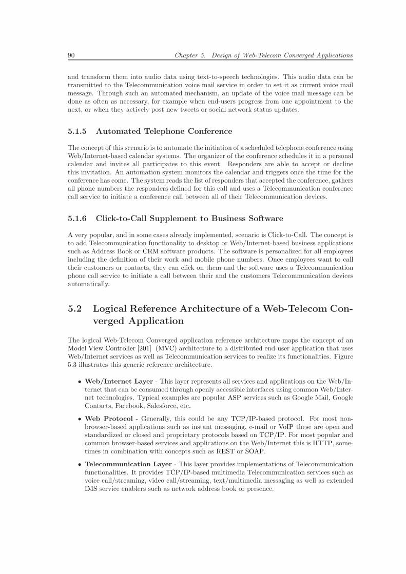
90 Chapter 5. Design of Web-Telecom Converged Applications
and transform them into audio data using text-to-speech technologies. This audio data can betransmitted to the Telecommunication voice mail service in order to set it as current voice mailmessage. Through such an automated mechanism, an update of the voice mail message can bedone as often as necessary, for example when end-users progress from one appointment to thenext, or when they actively post new tweets or social network status updates.
5.1.5 Automated Telephone Conference
The concept of this scenario is to automate the initiation of a scheduled telephone conference usingWeb/Internet-based calendar systems. The organizer of the conference schedules it in a personalcalendar and invites all participates to this event. Responders are able to accept or declinethis invitation. An automation system monitors the calendar and triggers once the time for theconference has come. The system reads the list of responders that accepted the conference, gathersall phone numbers the responders defined for this call and uses a Telecommunication conferencecall service to initiate a conference call between all of their Telecommunication devices.
5.1.6 Click-to-Call Supplement to Business Software
A very popular, and in some cases already implemented, scenario is Click-to-Call. The concept isto add Telecommunication functionality to desktop or Web/Internet-based business applicationssuch as Address Book or CRM software products. The software is personalized for all employeesincluding the definition of their work and mobile phone numbers. Once employees want to calltheir customers or contacts, they can click on them and the software uses a Telecommunicationphone call service to initiate a call between their and the customers Telecommunication devicesautomatically.
5.2 Logical Reference Architecture of a Web-Telecom Con-verged Application
The logical Web-Telecom Converged application reference architecture maps the concept of anModel View Controller [201] (MVC) architecture to a distributed end-user application that usesWeb/Internet services as well as Telecommunication services to realize its functionalities. Figure5.3 illustrates this generic reference architecture.
• Web/Internet Layer - This layer represents all services and applications on the Web/In-ternet that can be consumed through openly accessible interfaces using commonWeb/Inter-net technologies. Typical examples are popular ASP services such as Google Mail, GoogleContacts, Facebook, Salesforce, etc.
• Web Protocol - Generally, this could be any TCP/IP-based protocol. For most non-browser-based applications such as instant messaging, e-mail or VoIP these are open andstandardized or closed and proprietary protocols based on TCP/IP. For most popular andcommon browser-based services and applications on the Web/Internet this is HTTP, some-times in combination with concepts such as REST or SOAP.
• Telecommunication Layer - This layer provides implementations of Telecommunicationfunctionalities. It provides TCP/IP-based multimedia Telecommunication services such asvoice call/streaming, video call/streaming, text/multimedia messaging as well as extendedIMS service enablers such as network address book or presence.
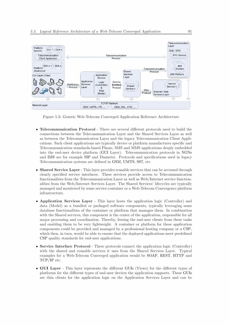
5.2. Logical Reference Architecture of a Web-Telecom Converged Application 91
Figure 5.3: Generic Web-Telecom Converged Application Reference Architecture
• Telecommunication Protocol - There are several different protocols used to build theconnections between the Telecommunication Layer and the Shared Services Layer as wellas between the Telecommunication Layer and the legacy Telecommunication Client Appli-cations. Such client applications are typically device or platform manufacturer specific andTelecommunication standards-based Phone, SMS and MMS applications deeply embeddedinto the end-user device platform (GUI Layer). Telecommunication protocols in NGNsand IMS are for example SIP and Diameter. Protocols and specifications used in legacyTelecommunication systems are defined in GSM, UMTS, SS7, etc.
• Shared Service Layer - This layer provides reusable services that can be accessed throughclearly specified service interfaces. These services provide access to Telecommunicationfunctionalities from the Telecommunication Layer as well as Web/Internet service function-alities from the Web/Internet Services Layer. The Shared Services’ lifecycles are typicallymanaged and monitored by some service container or a Web-Telecom Convergence platforminfrastructure.
• Application Services Layer - This layer hosts the application logic (Controller) anddata (Model) as a bundled or packaged software components, typically leveraging somedatabase functionalities of the container or platform that manages them. In combinationwith the Shared services, this component is the center of the application, responsible for allmajor processing and coordination. Thereby, freeing the end-user clients from these tasksand enabling them to be very lightweight. A container or platform for these applicationcomponents could be provided and managed by a professional hosting company or a CSP,which then, in turn, would be able to ensure that the deployed applications meet predefinedCSP quality standards for end-user applications.
• Service Interface Protocol - These protocols connect the application logic (Controller)with the shared and reusable services it uses from the Shared Services Layer. Typicalexamples for a Web-Telecom Converged application would be SOAP, REST, HTTP andTCP/IP etc.
• GUI Layer - This layer represents the different GUIs (Views) for the different types ofplatforms for the different types of end-user devices the application supports. These GUIsare thin clients for the application logic on the Application Services Layer and can be
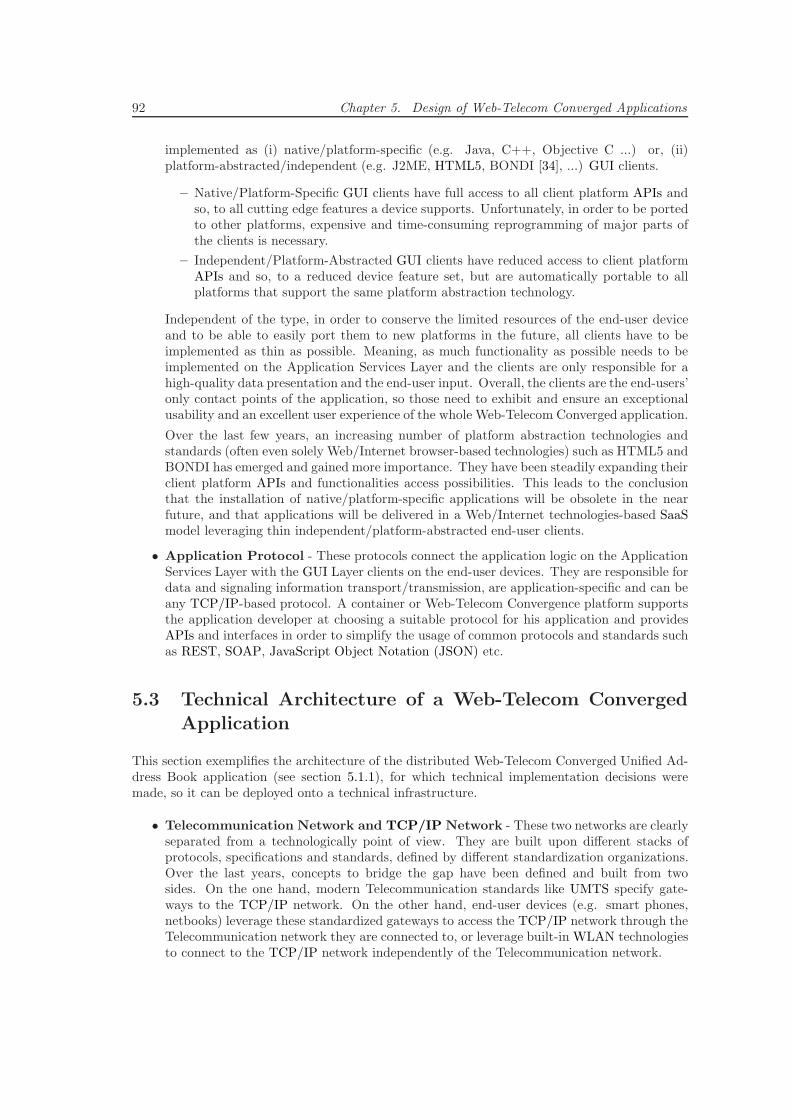
92 Chapter 5. Design of Web-Telecom Converged Applications
implemented as (i) native/platform-specific (e.g. Java, C++, Objective C ...) or, (ii)platform-abstracted/independent (e.g. J2ME, HTML5, BONDI [34], ...) GUI clients.
– Native/Platform-Specific GUI clients have full access to all client platform APIs andso, to all cutting edge features a device supports. Unfortunately, in order to be portedto other platforms, expensive and time-consuming reprogramming of major parts ofthe clients is necessary.
– Independent/Platform-Abstracted GUI clients have reduced access to client platformAPIs and so, to a reduced device feature set, but are automatically portable to allplatforms that support the same platform abstraction technology.
Independent of the type, in order to conserve the limited resources of the end-user deviceand to be able to easily port them to new platforms in the future, all clients have to beimplemented as thin as possible. Meaning, as much functionality as possible needs to beimplemented on the Application Services Layer and the clients are only responsible for ahigh-quality data presentation and the end-user input. Overall, the clients are the end-users’only contact points of the application, so those need to exhibit and ensure an exceptionalusability and an excellent user experience of the whole Web-Telecom Converged application.
Over the last few years, an increasing number of platform abstraction technologies andstandards (often even solely Web/Internet browser-based technologies) such as HTML5 andBONDI has emerged and gained more importance. They have been steadily expanding theirclient platform APIs and functionalities access possibilities. This leads to the conclusionthat the installation of native/platform-specific applications will be obsolete in the nearfuture, and that applications will be delivered in a Web/Internet technologies-based SaaSmodel leveraging thin independent/platform-abstracted end-user clients.
• Application Protocol - These protocols connect the application logic on the ApplicationServices Layer with the GUI Layer clients on the end-user devices. They are responsible fordata and signaling information transport/transmission, are application-specific and can beany TCP/IP-based protocol. A container or Web-Telecom Convergence platform supportsthe application developer at choosing a suitable protocol for his application and providesAPIs and interfaces in order to simplify the usage of common protocols and standards suchas REST, SOAP, JavaScript Object Notation (JSON) etc.
5.3 Technical Architecture of a Web-Telecom Converged
Application
This section exemplifies the architecture of the distributed Web-Telecom Converged Unified Ad-dress Book application (see section 5.1.1), for which technical implementation decisions weremade, so it can be deployed onto a technical infrastructure.
• Telecommunication Network and TCP/IP Network - These two networks are clearlyseparated from a technologically point of view. They are built upon different stacks ofprotocols, specifications and standards, defined by different standardization organizations.Over the last years, concepts to bridge the gap have been defined and built from twosides. On the one hand, modern Telecommunication standards like UMTS specify gate-ways to the TCP/IP network. On the other hand, end-user devices (e.g. smart phones,netbooks) leverage these standardized gateways to access the TCP/IP network through theTelecommunication network they are connected to, or leverage built-in WLAN technologiesto connect to the TCP/IP network independently of the Telecommunication network.
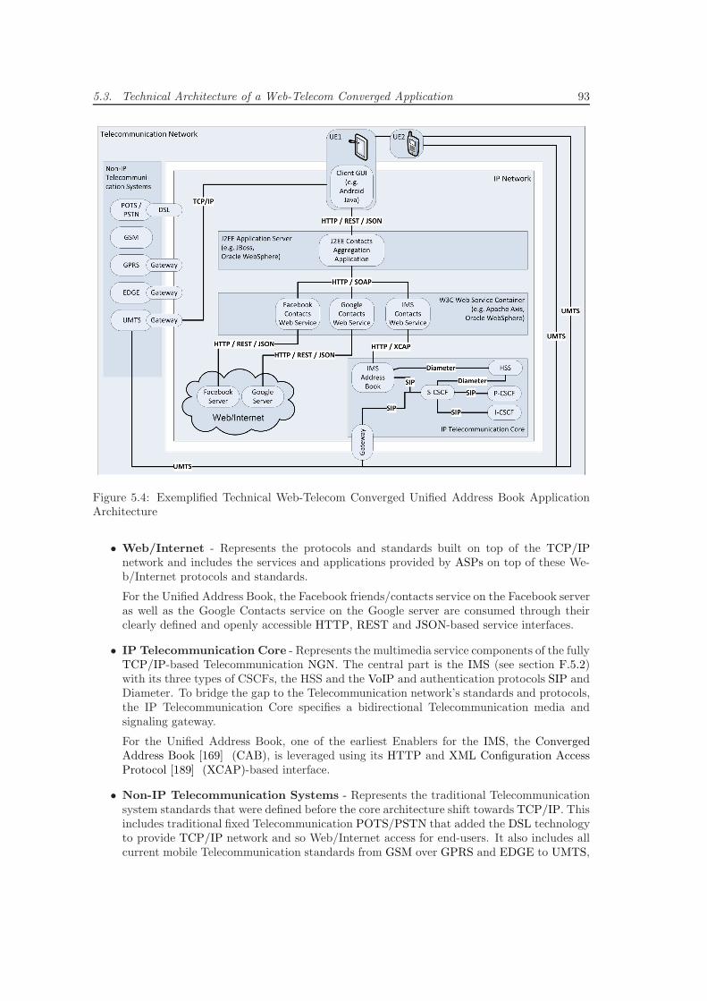
5.3. Technical Architecture of a Web-Telecom Converged Application 93
Figure 5.4: Exemplified Technical Web-Telecom Converged Unified Address Book ApplicationArchitecture
• Web/Internet - Represents the protocols and standards built on top of the TCP/IPnetwork and includes the services and applications provided by ASPs on top of these We-b/Internet protocols and standards.
For the Unified Address Book, the Facebook friends/contacts service on the Facebook serveras well as the Google Contacts service on the Google server are consumed through theirclearly defined and openly accessible HTTP, REST and JSON-based service interfaces.
• IP Telecommunication Core - Represents the multimedia service components of the fullyTCP/IP-based Telecommunication NGN. The central part is the IMS (see section F.5.2)with its three types of CSCFs, the HSS and the VoIP and authentication protocols SIP andDiameter. To bridge the gap to the Telecommunication network’s standards and protocols,the IP Telecommunication Core specifies a bidirectional Telecommunication media andsignaling gateway.
For the Unified Address Book, one of the earliest Enablers for the IMS, the ConvergedAddress Book [169] (CAB), is leveraged using its HTTP and XML Configuration AccessProtocol [189] (XCAP)-based interface.
• Non-IP Telecommunication Systems - Represents the traditional Telecommunicationsystem standards that were defined before the core architecture shift towards TCP/IP. Thisincludes traditional fixed Telecommunication POTS/PSTN that added the DSL technologyto provide TCP/IP network and so Web/Internet access for end-users. It also includes allcurrent mobile Telecommunication standards from GSM over GPRS and EDGE to UMTS,
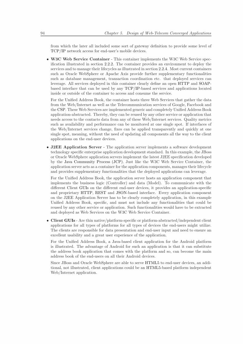
94 Chapter 5. Design of Web-Telecom Converged Applications
from which the later all included some sort of gateway definition to provide some level ofTCP/IP network access for end-user’s mobile devices.
• W3C Web Service Container - This container implements the W3C Web Service spec-ification illustrated in section 2.2.2. The container provides an environment to deploy theservices and to manage their lifecycles as illustrated in section 2.2.4. Most current containerssuch as Oracle WebSphere or Apache Axis provide further supplementary functionalitiessuch as database management, transaction coordination etc. that deployed services canleverage. All services deployed in this container clearly define an open HTTP and SOAP-based interface that can be used by any TCP/IP-based services and applications locatedinside or outside of the container to access and consume the service.
For the Unified Address Book, the container hosts three Web Services that gather the datafrom the Web/Internet as well as the Telecommunication services of Google, Facebook andthe CSP. TheseWeb Services are implemented generic and completely Unified Address Bookapplication-abstracted. Thereby, they can be reused by any other service or application thatneeds access to the contacts data from any of these Web/Internet services. Quality metricssuch as availability and performance can be monitored at one single spot. If interfaces ofthe Web/Internet services change, fixes can be applied transparently and quickly at onesingle spot, meaning, without the need of updating all components all the way to the clientapplications on the end-user devices.
• J2EE Application Server - The application server implements a software developmenttechnology specific enterprise application development standard. In this example, the JBossor Oracle WebSphere application servers implement the latest J2EE specification developedby the Java Community Process (JCP). Just like the W3C Web Service Container, theapplication server acts as a container for the application components, manages their lifecycleand provides supplementary functionalities that the deployed applications can leverage.
For the Unified Address Book, the application server hosts an application component thatimplements the business logic (Controller) and data (Model). To communicate with thedifferent Client GUIs on the different end-user devices, it provides an application-specificand proprietary HTTP, REST and JSON-based interface. Every application componenton the J2EE Application Server has to be clearly completely application, in this exampleUnified Address Book, specific, and must not include any functionalities that could bereused by any other service or application. Such functionalities would have to be extractedand deployed as Web Services on the W3C Web Service Container.
• Client GUIs - Are thin native/platform-specific or platform-abstracted/independent clientapplications for all types of platforms for all types of devices the end-users might utilize.The clients are responsible for data presentation and end-user input and need to ensure anexcellent usability and a great user experience of the application.
For the Unified Address Book, a Java-based client application for the Android platformis illustrated. The advantage of Android for such an application is that it can substitutethe address book application that comes with the platform and so, can become the mainaddress book of the end-users on all their Android devices.
Since JBoss and Oracle WebSphere are able to serve HTML5 to end-user devices, an addi-tional, not illustrated, client applications could be an HTML5-based platform independentWeb/Internet application.
Chapter 6
Requirements for a Web-TelecomConvergence Platform
In this chapter, the results from the ”Stakeholder Goals” as well as from the ”Analysis” and the”Design of Web-Telecom Convergence Applications” are transformed into two structured sets ofrequirements for an optimal Web-Telecom Convergence platform.
6.1 Deriving Requirements from Stakeholder Goals
This section illustrates the process that derives a first set of requirements for the Web-TelecomConvergence platform from the major goals of the identified stakeholders, illustrated in chapter3. It applies results and learnings from definitions and concepts in chapter 2, evaluations inchapter 4 and Web-Telecom Converged applications design in chapter 5 to define the followingset of requirements.
Figure 6.1: Requirements derived from major Stakeholder Goals
For clarity reasons, the process is divided into three independent parts that are discussed consec-utively based on figures 6.1, 6.2 and 6.3. The figures illustrate the stakeholder goals, the resultingrequirements and the primary mapping paths, for which the previous results and learnings were
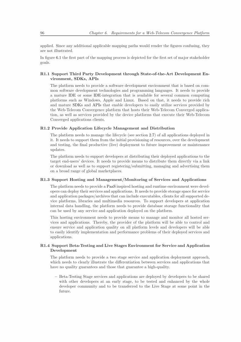
96 Chapter 6. Requirements for a Web-Telecom Convergence Platform
applied. Since any additional applicable mapping paths would render the figures confusing, theyare not illustrated.
In figure 6.1 the first part of the mapping process is depicted for the first set of major stakeholdergoals.
R1.1 Support Third Party Development through State-of-the-Art Development En-vironment, SDKs, APIs
The platform needs to provide a software development environment that is based on com-mon software development technologies and programming languages. It needs to providea mature IDE or some IDE-integration that is available for several common computingplatforms such as Windows, Apple and Linux. Based on that, it needs to provide richand mature SDKs and APIs that enable developers to easily utilize services provided bythe Web-Telecom Convergence platform that hosts their Web-Telecom Converged applica-tion, as well as services provided by the device platforms that execute their Web-TelecomConverged applications clients.
R1.2 Provide Application Lifecycle Management and Distribution
The platform needs to manage the lifecycle (see section 2.7) of all applications deployed init. It needs to support them from the initial provisioning of resources, over the developmentand testing, the final productive (live) deployment to future improvement or maintenanceupdates.
The platform needs to support developers at distributing their deployed applications to thetarget end-users’ devices. It needs to provide means to distribute them directly via a linkor download as well as to support registering/submitting, managing and advertising themon a broad range of global marketplaces.
R1.3 Support Hosting and Management/Monitoring of Services and Applications
The platform needs to provide a PaaS inspired hosting and runtime environment were devel-opers can deploy their services and applications. It needs to provide storage space for serviceand application packages/archives that can include executables, clients for all supported de-vice platforms, libraries and multimedia resources. To support developers at applicationinternal data handling, the platform needs to provide database storage functionality thatcan be used by any service and application deployed on the platform.
This hosting environment needs to provide means to manage and monitor all hosted ser-vices and applications. Thereby, the provider of the platform will be able to control andensure service and application quality on all platform levels and developers will be ableto easily identify implementation and performance problems of their deployed services andapplications.
R1.4 Support Beta-Testing and Live Stages Environment for Service and ApplicationDevelopment
The platform needs to provide a two stage service and application deployment approach,which needs to clearly illustrate the differentiation between services and applications thathave no quality guarantees and those that guarantee a high-quality.
– Beta-Testing Stage services and applications are deployed by developers to be sharedwith other developers at an early stage, to be tested and enhanced by the wholedeveloper community and to be transferred to the Live Stage at some point in thefuture.
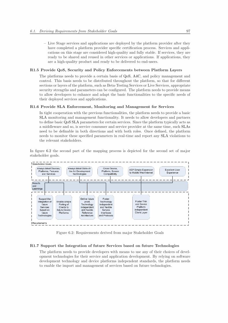
6.1. Deriving Requirements from Stakeholder Goals 97
– Live Stage services and applications are deployed by the platform provider after theyhave completed a platform provider specific certification process. Services and appli-cations on this stage are considered high-quality and fully stable. If services, they areready to be shared and reused in other services or applications. If applications, theyare a high-quality product and ready to be delivered to end-users.
R1.5 Provide QoS, Security and Policy Enforcements between Platform Layers
The platforms needs to provide a certain basis of QoS, A4C, and policy management andcontrol. This basis needs to be distributed throughout the platform, so that for differentsections or layers of the platform, such as Beta-Testing Services or Live Services, appropriatesecurity strengths and parameters can be configured. The platform needs to provide meansto allow developers to enhance and adapt the basic functionalities to the specific needs oftheir deployed services and applications.
R1.6 Provide SLA Enforcement, Monitoring and Management for Services
In tight cooperation with the previous functionalities, the platform needs to provide a basicSLA monitoring and management functionality. It needs to allow developers and partnersto define basic QoS SLA parameters for certain services. Since the platform typically acts asa middleware and so, is service consumer and service provider at the same time, such SLAsneed to be definable in both directions and with both roles. Once defined, the platformneeds to monitor these specified parameters in real-time and report any SLA violations tothe relevant stakeholders.
In figure 6.2 the second part of the mapping process is depicted for the second set of majorstakeholder goals.
Figure 6.2: Requirements derived from major Stakeholder Goals
R1.7 Support the Integration of future Services based on future Technologies
The platform needs to provide developers with means to use any of their choices of devel-opment technologies for their service and application development. By relying on softwaredevelopment technology and device platforms independent standards, the platform needsto enable the import and management of services based on future technologies.
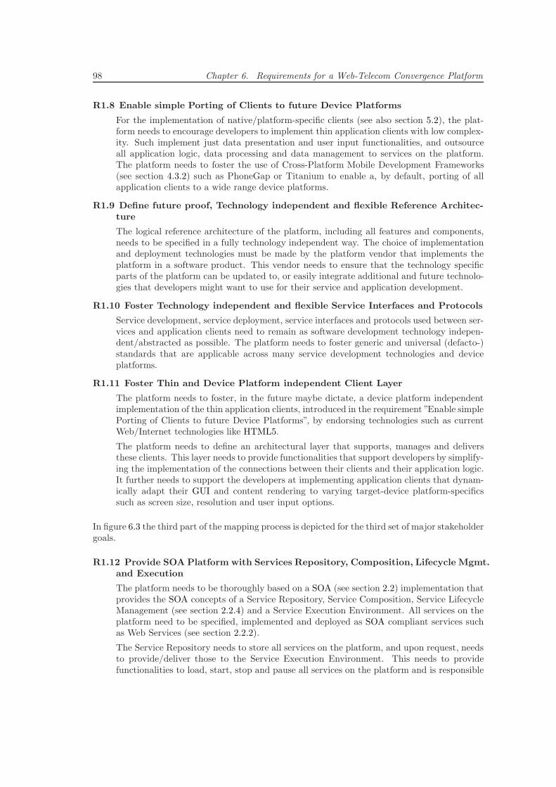
98 Chapter 6. Requirements for a Web-Telecom Convergence Platform
R1.8 Enable simple Porting of Clients to future Device Platforms
For the implementation of native/platform-specific clients (see also section 5.2), the plat-form needs to encourage developers to implement thin application clients with low complex-ity. Such implement just data presentation and user input functionalities, and outsourceall application logic, data processing and data management to services on the platform.The platform needs to foster the use of Cross-Platform Mobile Development Frameworks(see section 4.3.2) such as PhoneGap or Titanium to enable a, by default, porting of allapplication clients to a wide range device platforms.
R1.9 Define future proof, Technology independent and flexible Reference Architec-ture
The logical reference architecture of the platform, including all features and components,needs to be specified in a fully technology independent way. The choice of implementationand deployment technologies must be made by the platform vendor that implements theplatform in a software product. This vendor needs to ensure that the technology specificparts of the platform can be updated to, or easily integrate additional and future technolo-gies that developers might want to use for their service and application development.
R1.10 Foster Technology independent and flexible Service Interfaces and Protocols
Service development, service deployment, service interfaces and protocols used between ser-vices and application clients need to remain as software development technology indepen-dent/abstracted as possible. The platform needs to foster generic and universal (defacto-)standards that are applicable across many service development technologies and deviceplatforms.
R1.11 Foster Thin and Device Platform independent Client Layer
The platform needs to foster, in the future maybe dictate, a device platform independentimplementation of the thin application clients, introduced in the requirement ”Enable simplePorting of Clients to future Device Platforms”, by endorsing technologies such as currentWeb/Internet technologies like HTML5.
The platform needs to define an architectural layer that supports, manages and deliversthese clients. This layer needs to provide functionalities that support developers by simplify-ing the implementation of the connections between their clients and their application logic.It further needs to support the developers at implementing application clients that dynam-ically adapt their GUI and content rendering to varying target-device platform-specificssuch as screen size, resolution and user input options.
In figure 6.3 the third part of the mapping process is depicted for the third set of major stakeholdergoals.
R1.12 Provide SOA Platform with Services Repository, Composition, Lifecycle Mgmt.and Execution
The platform needs to be thoroughly based on a SOA (see section 2.2) implementation thatprovides the SOA concepts of a Service Repository, Service Composition, Service LifecycleManagement (see section 2.2.4) and a Service Execution Environment. All services on theplatform need to be specified, implemented and deployed as SOA compliant services suchas Web Services (see section 2.2.2).
The Service Repository needs to store all services on the platform, and upon request, needsto provide/deliver those to the Service Execution Environment. This needs to providefunctionalities to load, start, stop and pause all services on the platform and is responsible
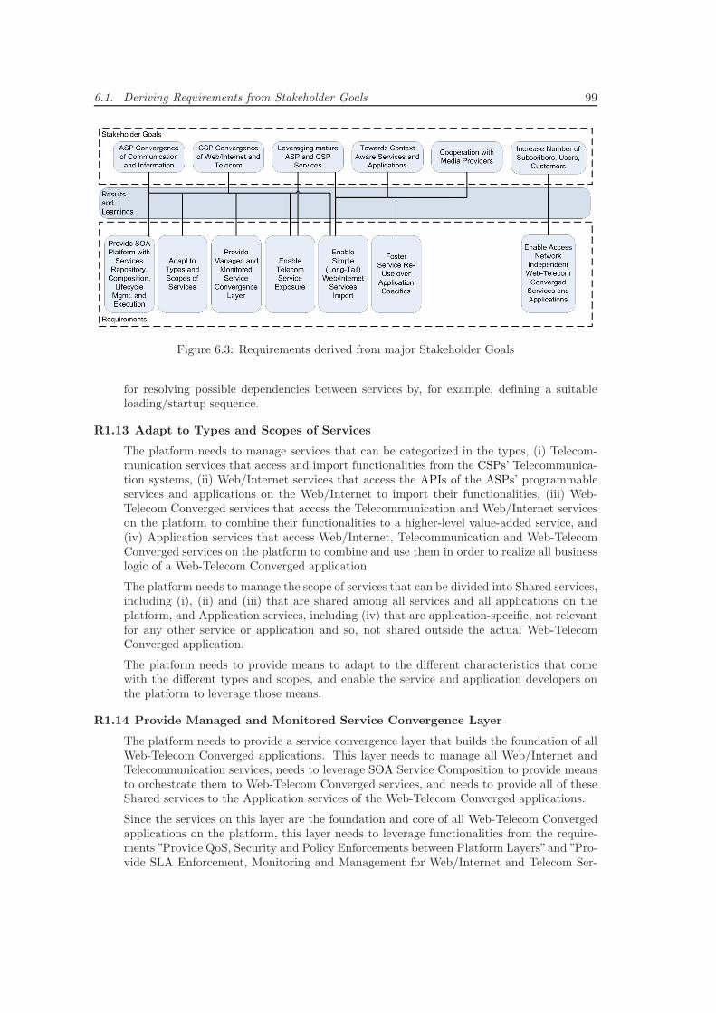
6.1. Deriving Requirements from Stakeholder Goals 99
Figure 6.3: Requirements derived from major Stakeholder Goals
for resolving possible dependencies between services by, for example, defining a suitableloading/startup sequence.
R1.13 Adapt to Types and Scopes of Services
The platform needs to manage services that can be categorized in the types, (i) Telecom-munication services that access and import functionalities from the CSPs’ Telecommunica-tion systems, (ii) Web/Internet services that access the APIs of the ASPs’ programmableservices and applications on the Web/Internet to import their functionalities, (iii) Web-Telecom Converged services that access the Telecommunication and Web/Internet serviceson the platform to combine their functionalities to a higher-level value-added service, and(iv) Application services that access Web/Internet, Telecommunication and Web-TelecomConverged services on the platform to combine and use them in order to realize all businesslogic of a Web-Telecom Converged application.
The platform needs to manage the scope of services that can be divided into Shared services,including (i), (ii) and (iii) that are shared among all services and all applications on theplatform, and Application services, including (iv) that are application-specific, not relevantfor any other service or application and so, not shared outside the actual Web-TelecomConverged application.
The platform needs to provide means to adapt to the different characteristics that comewith the different types and scopes, and enable the service and application developers onthe platform to leverage those means.
R1.14 Provide Managed and Monitored Service Convergence Layer
The platform needs to provide a service convergence layer that builds the foundation of allWeb-Telecom Converged applications. This layer needs to manage all Web/Internet andTelecommunication services, needs to leverage SOA Service Composition to provide meansto orchestrate them to Web-Telecom Converged services, and needs to provide all of theseShared services to the Application services of the Web-Telecom Converged applications.
Since the services on this layer are the foundation and core of all Web-Telecom Convergedapplications on the platform, this layer needs to leverage functionalities from the require-ments ”Provide QoS, Security and Policy Enforcements between Platform Layers”and ”Pro-vide SLA Enforcement, Monitoring and Management for Web/Internet and Telecom Ser-
100 Chapter 6. Requirements for a Web-Telecom Convergence Platform
vices” to precisely monitor all available service parameters in real-time and to inform allrelevant stakeholders about their status and possible problems.
R1.15 Enable Telecom Service Exposure
The platform needs to be fully compatible with current TCP/IP-based Telecommunicationprotocols and systems. It needs to be able to access Telecommunication functionalitieswithin the Telecommunication systems’ Cores and Enablers, and import them into theplatform. It needs to expose these functionalities as shared Telecommunication services toall other shared as well as all application-specific services on the platform.
R1.16 Enable Simple (Long-Tail) Web/Internet Services Import
For mature, successful and widespread Web/Internet services and applications, the plat-form needs to provide means to manually and programmatically access and import theirfull functionalities into the platform. The platform needs to provide these imported func-tionalities as shared Web/Internet services to all other shared as well as application-specificservices on the platform.
For long-tail niche-market Web/Internet services and applications, a manual import is toocostly, so the platform needs to provide a (semi-) automatic way to import their mainfunctionalities. Similar to above, it also needs to provide them as shared Web/Internetservices to all other shared as well as application-specific services on the platform.
R1.17 Foster Service Reuse over Application Specifics
In accordance to the concepts illustrated in the SOA Manifesto in section 2.2.1, the plat-form needs to foster a large collection of shared Web/Internet, Telecommunication andWeb-Telecom Converged services to be deployed and managed on the convergence layer.By aggregating and sharing all services on a common layer, the platform needs to fosterthe innovative combination of their multimedia and communication functionalities as wellas their available data, such as context information, in future Web-Telecom Convergedapplications.
The platform needs to support and encourage the developers to divide their Web-TelecomConverged applications into reusable and application-specific functionalities. These needto be implemented and deployed as separated shared and application-specific services onthe platform. To foster such a separation, the platform needs to support the developers bysimplifying the implementation of the connection between the platform’s Shared Servicesand the developers own application-specific services.
R1.18 Enable Access Network Independent Web-Telecom Converged Services andApplications
The platform needs to support the successful ”App Development” concepts that were in-troduced by modern smartphone platforms such as iOS, Android and Windows Phone 7.By abstracting from the underlying wireless data networks and technologies, these con-cepts support developers to mainly focus on creating and implementing innovative end-userapplication ideas on these modern platforms.
As discussed in sections 1.1 and 2.1, in contrast to how traditional Telecommunicationservices and applications were specified, and to enable rapid Web-Telecom Converged ap-plication innovation, the platform needs to support that applications can be implementedcompletely decoupled from the details of the shared underlying data or Telecommunicationnetworks and systems. The underlying networks and systems need to be abstracted by theplatform and the Web-Telecom Converged applications can choose to leverage and accessnetworks functionalities and network parameters such as latency or available bandwidth ifnecessary for the implementation of certain functionalities.
6.2. Deriving Requirements from Analysis and Applications Design 101
The platform needs to provide and deliver all deployedWeb-Telecom Converged applicationsto any supported end-user device connected via any TCP/IP-compatible access networkworldwide.
6.2 Deriving Requirements from Analysis and ApplicationsDesign
In this section, from the analysis in chapter 4 and the applications design in chapter 5, a secondset of requirements is derived. Results and learnings from definitions and concepts in chapter 2combined with results from the CDTM research project in [152] are applied to define the followingset of requirements. This set is limited to supplementary requirements that have not yet beenderived in the previous section.
R2.1 Provide Layered Architecture
The platform needs to be designed in a strictly layered architecture inspired by SOA Ser-vice Layers concepts presented in sections 2.2.5. The platform needs to, at least, clearlydistinguish between the domains Data and Telecommunication networks, Web/Internet ser-vices and applications, Telecommunication systems and services, Shared and Applicationservices, Web-Telecom Converged applications and end-user clients.
R2.2 Dictate a Separation of Networks and Services/Applications
The platform needs to ensure that all services and applications delivered to the end-users’devices abide by the platform’s layered architecture concepts. It needs to ensure thatthe underlying networks and systems are abstracted by the bottom layers of the platformand that no application bypasses any of the platform’s layers. It needs to ensure thatnone implements or uses any Web/Internet or Telecommunication services, standards orprotocols directly within an application or application client implementation, but insteadutilizes the platforms functionalities and services to access network features.
R2.3 Foster Equal Treatment of Applications on Device Platforms
The platform needs to foster that all services and applications are delivered to the end-users equally. On the devices’ software platforms, services and applications provided by aCSP, such as Voice/Video Call and TextMessaging, should not receive any advantages orpreferred treatment over any Web-Telecom Converged applications.
For end-users, all services and applications installed on a device platform should be pre-sented and accessible in similar ways, on modern smart phones typically as ”App” shortcutsor ”Web App” links.
For developers, all services and applications installed on a device platform should be ableto access the same platform and API functionalities and features with the same optionsand rights.
R2.4 Provide High Performance and Reliability
The platform needs to ensure that performance and reliability of all Web-Telecom Con-verged applications are similar compared to what end-users experience from traditionalTelecommunication services and applications on fixed and mobile Telecommunication net-works. The platform needs to support developers at achieving and monitoring the high-quality standards defined and required from traditional Telecommunication services andapplications.
102 Chapter 6. Requirements for a Web-Telecom Convergence Platform
R2.5 Foster Personalized Services and Applications
The platform needs to provide functionalities and services that allow developers to per-sonalize Web-Telecom Converged services and applications deployed on the platform. Itneeds to support combining end-user related internal context data with context data fromexternal services or applications provided by ASPs or CSPs.
R2.6 Foster Applications with an Exceptional User Experience
The platform needs to foster Web-Telecom Converged application client technologies thatenable developer to provide an exceptional user experience within their applications. Theplatform needs to support, on the one hand, native smart phone technologies that currentlystill have some advantages over Web/Internet-based ones, but also Web/Internet-basedtechnologies such as HTML5 that are rising rapidly through ongoing standardization andtheir utilization in Cross-PlatformMobile Development Frameworks (see section 4.3.2) suchas PhoneGap or Titanium.
R2.7 Publish, Advertise, Discover, Access and Compose Services Across Domains
The platform needs to provide means to enable different individual deployments of theplatform from different vendors to collaborate across their individual domains. It needsto support the distributed publishing, advertising, discovering, accessing and composingof all heterogeneous Shared Services on all platform deployments by leveraging SOA ESBconcepts illustrated in section 2.3.
Chapter 7
Design of the ApplicationDelivery Platform
This chapter illustrates the design of the Web-Telecom Converged ADP that extends existingTelecommunication SDP proposals and Web-Telecom Convergence concepts to deliver Web-Telecom Converged applications end-to-end. It provides an overview about the core conceptsof the ADP, illustrates the logical reference architecture and presents an exemplary technicalarchitecture.
7.1 Core Concepts of the Application Delivery Platform
This section summarizes the major core concepts that were derived from the learnings and resultsof the analysis, design and requirements in chapters 4, 5 and 6. They build the foundation forthe design of the logical and technical ADP architectures.
7.1.1 C1 - Extending the Concepts of Service Delivery Platform to anApplication Delivery Platform
As discussed in sections 2.5 and 4.2, current SDPs focus on delivering services to any applicationthat end-users use to utilize the service. For the SDP, everything beyond the service itself, suchas applications that reuse it or application clients that allow end-users to utilize it, are typicallycompletely out of scope.
SDPs are typically designed for one specific domain such as Telecommunications or Web/Internet.The majority of current SDP concepts and solutions exist for the Telecommunications industry,and none of those are designed to bridge the technological and conceptual gaps between theTelecommunications domain and other domains such as the Web/Internet.
The ADP extends these existing SDP concepts by
• focusing on the delivery of entire Web-Telecom Converged applications to end-users’ devices.
• bridging the technological gap between Telecommunications and Web/Internet by buildingupon common TCP/IP-based technologies.
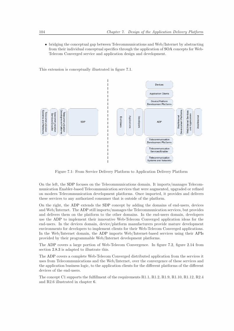
104 Chapter 7. Design of the Application Delivery Platform
• bridging the conceptual gap between Telecommunications and Web/Internet by abstractingfrom their individual conceptual specifics through the application of SOA concepts for Web-Telecom Converged service and application design and development.
This extension is conceptually illustrated in figure 7.1.
Figure 7.1: From Service Delivery Platform to Application Delivery Platform
On the left, the SDP focuses on the Telecommunications domain. It imports/manages Telecom-munication Enabler-based Telecommunication services that were augmented, upgraded or refinedon modern Telecommunication development platforms. Once imported, it provides and deliversthese services to any authorized consumer that is outside of the platform.
On the right, the ADP extends the SDP concept by adding the domains of end-users, devicesandWeb/Internet. The ADP still imports/manages the Telecommunication services, but providesand delivers them on the platform to the other domains. In the end-users domain, developersuse the ADP to implement their innovative Web-Telecom Converged application ideas for theend-users. In the devices domain, device/platform manufacturers provide mature developmentenvironments for developers to implement clients for their Web-Telecom Converged applications.In the Web/Internet domain, the ADP imports Web/Internet-based services using their APIsprovided by their programmable Web/Internet development platforms.
The ADP covers a large portion of Web-Telecom Convergence. In figure 7.2, figure 2.14 fromsection 2.8.3 is adapted to illustrate this.
The ADP covers a complete Web-Telecom Converged distributed application from the services ituses from Telecommunications and the Web/Internet, over the convergence of these services andthe application business logic, to the application clients for the different platforms of the differentdevices of the end-users.
The concept C1 supports the fulfillment of the requirements R1.1, R1.2, R1.9, R1.10, R1.12, R2.4and R2.6 illustrated in chapter 6.
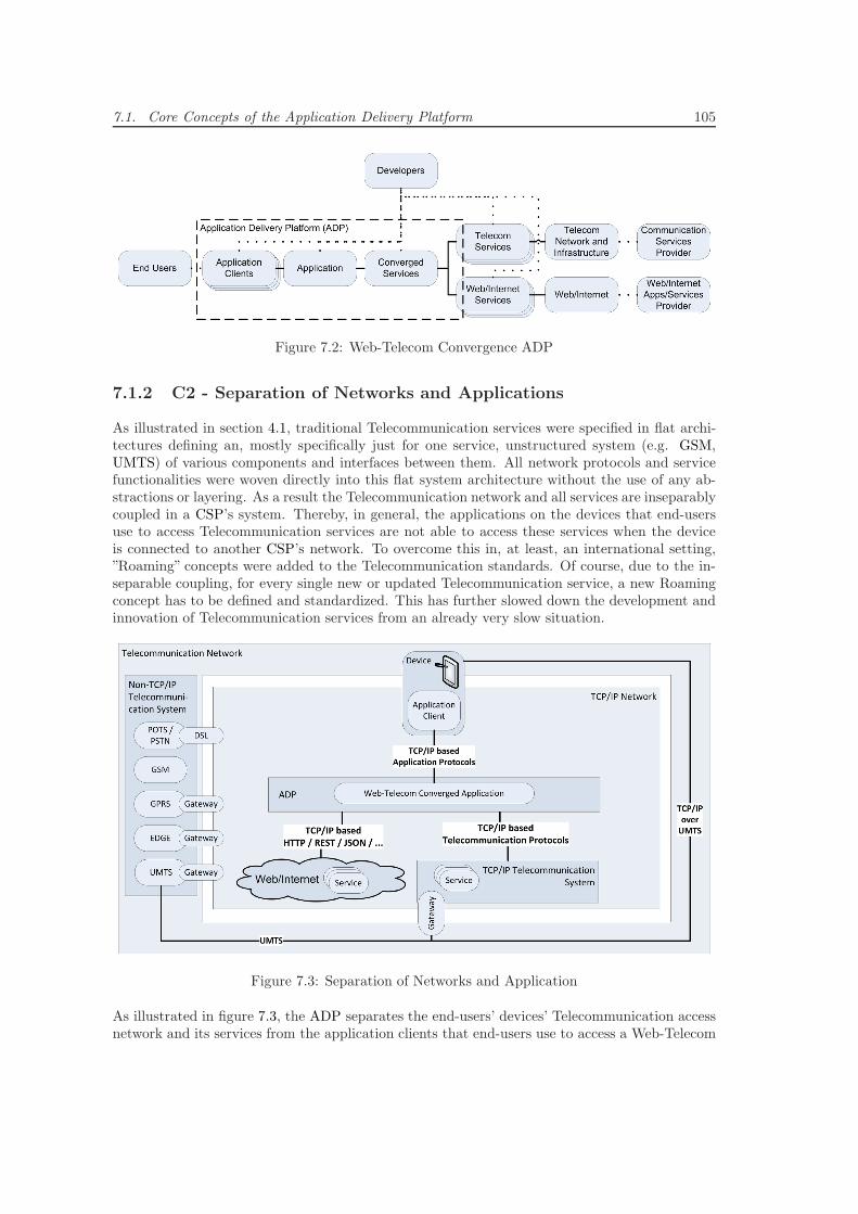
7.1. Core Concepts of the Application Delivery Platform 105
Figure 7.2: Web-Telecom Convergence ADP
7.1.2 C2 - Separation of Networks and Applications
As illustrated in section 4.1, traditional Telecommunication services were specified in flat archi-tectures defining an, mostly specifically just for one service, unstructured system (e.g. GSM,UMTS) of various components and interfaces between them. All network protocols and servicefunctionalities were woven directly into this flat system architecture without the use of any ab-stractions or layering. As a result the Telecommunication network and all services are inseparablycoupled in a CSP’s system. Thereby, in general, the applications on the devices that end-usersuse to access Telecommunication services are not able to access these services when the deviceis connected to another CSP’s network. To overcome this in, at least, an international setting,”Roaming” concepts were added to the Telecommunication standards. Of course, due to the in-separable coupling, for every single new or updated Telecommunication service, a new Roamingconcept has to be defined and standardized. This has further slowed down the development andinnovation of Telecommunication services from an already very slow situation.
Figure 7.3: Separation of Networks and Application
As illustrated in figure 7.3, the ADP separates the end-users’ devices’ Telecommunication accessnetwork and its services from the application clients that end-users use to access a Web-Telecom
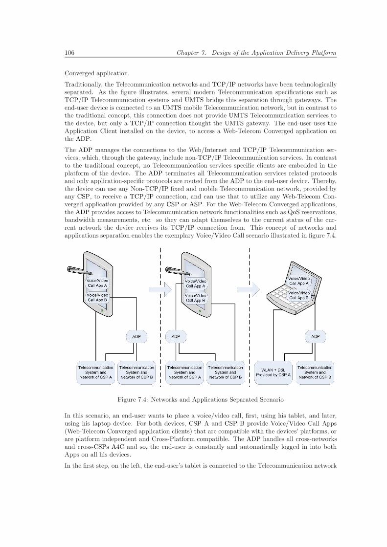
106 Chapter 7. Design of the Application Delivery Platform
Converged application.
Traditionally, the Telecommunication networks and TCP/IP networks have been technologicallyseparated. As the figure illustrates, several modern Telecommunication specifications such asTCP/IP Telecommunication systems and UMTS bridge this separation through gateways. Theend-user device is connected to an UMTS mobile Telecommunication network, but in contrast tothe traditional concept, this connection does not provide UMTS Telecommunication services tothe device, but only a TCP/IP connection thought the UMTS gateway. The end-user uses theApplication Client installed on the device, to access a Web-Telecom Converged application onthe ADP.
The ADP manages the connections to the Web/Internet and TCP/IP Telecommunication ser-vices, which, through the gateway, include non-TCP/IP Telecommunication services. In contrastto the traditional concept, no Telecommunication services specific clients are embedded in theplatform of the device. The ADP terminates all Telecommunication services related protocolsand only application-specific protocols are routed from the ADP to the end-user device. Thereby,the device can use any Non-TCP/IP fixed and mobile Telecommunication network, provided byany CSP, to receive a TCP/IP connection, and can use that to utilize any Web-Telecom Con-verged application provided by any CSP or ASP. For the Web-Telecom Converged applications,the ADP provides access to Telecommunication network functionalities such as QoS reservations,bandwidth measurements, etc. so they can adapt themselves to the current status of the cur-rent network the device receives its TCP/IP connection from. This concept of networks andapplications separation enables the exemplary Voice/Video Call scenario illustrated in figure 7.4.
Figure 7.4: Networks and Applications Separated Scenario
In this scenario, an end-user wants to place a voice/video call, first, using his tablet, and later,using his laptop device. For both devices, CSP A and CSP B provide Voice/Video Call Apps(Web-Telecom Converged application clients) that are compatible with the devices’ platforms, orare platform independent and Cross-Platform compatible. The ADP handles all cross-networksand cross-CSPs A4C and so, the end-user is constantly and automatically logged in into bothApps on all his devices.
In the first step, on the left, the end-user’s tablet is connected to the Telecommunication network
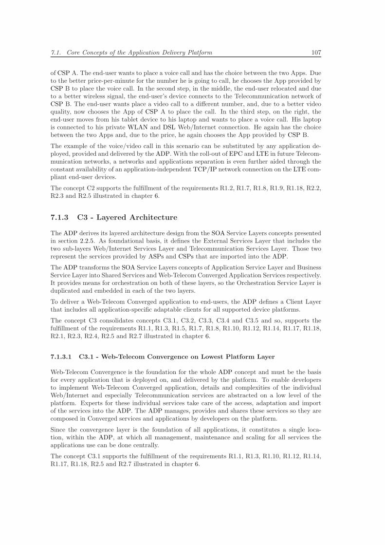
7.1. Core Concepts of the Application Delivery Platform 107
of CSP A. The end-user wants to place a voice call and has the choice between the two Apps. Dueto the better price-per-minute for the number he is going to call, he chooses the App provided byCSP B to place the voice call. In the second step, in the middle, the end-user relocated and dueto a better wireless signal, the end-user’s device connects to the Telecommunication network ofCSP B. The end-user wants place a video call to a different number, and, due to a better videoquality, now chooses the App of CSP A to place the call. In the third step, on the right, theend-user moves from his tablet device to his laptop and wants to place a voice call. His laptopis connected to his private WLAN and DSL Web/Internet connection. He again has the choicebetween the two Apps and, due to the price, he again chooses the App provided by CSP B.
The example of the voice/video call in this scenario can be substituted by any application de-ployed, provided and delivered by the ADP. With the roll-out of EPC and LTE in future Telecom-munication networks, a networks and applications separation is even further aided through theconstant availability of an application-independent TCP/IP network connection on the LTE com-pliant end-user devices.
The concept C2 supports the fulfillment of the requirements R1.2, R1.7, R1.8, R1.9, R1.18, R2.2,R2.3 and R2.5 illustrated in chapter 6.
7.1.3 C3 - Layered Architecture
The ADP derives its layered architecture design from the SOA Service Layers concepts presentedin section 2.2.5. As foundational basis, it defines the External Services Layer that includes thetwo sub-layers Web/Internet Services Layer and Telecommunication Services Layer. Those tworepresent the services provided by ASPs and CSPs that are imported into the ADP.
The ADP transforms the SOA Service Layers concepts of Application Service Layer and BusinessService Layer into Shared Services and Web-Telecom Converged Application Services respectively.It provides means for orchestration on both of these layers, so the Orchestration Service Layer isduplicated and embedded in each of the two layers.
To deliver a Web-Telecom Converged application to end-users, the ADP defines a Client Layerthat includes all application-specific adaptable clients for all supported device platforms.
The concept C3 consolidates concepts C3.1, C3.2, C3.3, C3.4 and C3.5 and so, supports thefulfillment of the requirements R1.1, R1.3, R1.5, R1.7, R1.8, R1.10, R1.12, R1.14, R1.17, R1.18,R2.1, R2.3, R2.4, R2.5 and R2.7 illustrated in chapter 6.
7.1.3.1 C3.1 - Web-Telecom Convergence on Lowest Platform Layer
Web-Telecom Convergence is the foundation for the whole ADP concept and must be the basisfor every application that is deployed on, and delivered by the platform. To enable developersto implement Web-Telecom Converged application, details and complexities of the individualWeb/Internet and especially Telecommunication services are abstracted on a low level of theplatform. Experts for these individual services take care of the access, adaptation and importof the services into the ADP. The ADP manages, provides and shares these services so they arecomposed in Converged services and applications by developers on the platform.
Since the convergence layer is the foundation of all applications, it constitutes a single loca-tion, within the ADP, at which all management, maintenance and scaling for all services theapplications use can be done centrally.
The concept C3.1 supports the fulfillment of the requirements R1.1, R1.3, R1.10, R1.12, R1.14,R1.17, R1.18, R2.5 and R2.7 illustrated in chapter 6.
108 Chapter 7. Design of the Application Delivery Platform
7.1.3.2 C3.2 - Separation of Shared and Application Services Layers
The ADP fosters reuse of functionalities and services over application-specific and proprietaryimplementations. Therefore, it encourages developers to separate all functionalities that couldbe reused by other applications from their own application implementations and to deploy themonto Shared and Application Services layers.
• Shared Services Layer - It hosts and manages all services that are shared across allWeb-Telecom Converged applications. This includes all Web-Telecom Convergence relatedservices discussed in the previous section as well as Web/Internet and Telecommunicationindependent Business services that provide some functionality that can be valuable formany applications on the ADP.
Since all applications on the platform are relying on these services, quality assurance andmaintenance are exceptionally important. In order to make these factors explicit to devel-opers, the ASP distinguishes between a Beta and a Live Services Layer.
– Beta Services Layer - Hosts services that are typically early implementations ofsome functionality that are still in development and that must be further enhanced,maintained and tested by the whole developer community on the ADP. Services onthis layer are deployed by the developers themselves and do not provide any qualityguarantees or SLAs.
– Live Services Layer - Hosts services that are stable versions of an implementationof some functionality and that provide certain quality guarantees and/or SLAs to theconsumers. The ADP provider must define an inspection and testing process to certifythe ”Live”status of a service. Only the ADP provider deploys new or updated certifiedservices on this layer.
• Application Services Layer - It hosts and manages all services a Web-Telecom Convergedapplication uses to implement those application-specific parts of its business logic thatare not provided by any Shared services and not implemented in the application clients.Services on this layer are only shared within their Web-Telecom Converged ApplicationService collection and not accessible from Application services of other applications or fromany Shared services. The layer clearly separates the collections of Application services andprovides management functionalities for the individual services.
Through the separation of Shared and Application Services Layers, developers can achieve afaster innovation cycle through re-using a growing collection of Shared services and so, lessimplementation effort for new applications.
Traditionally, Telecommunication services have been implementing explicitly high-quality stan-dards [184], and end-users are expecting the same from future applications that are developedby third-party developers and delivered to them by the ADP. Through the certification, main-tenance and quality assurances of Live Shared Services, Web-Telecom Converged applicationscan achieve an increased overall quality. Through the central location of problem/bug fixing,maintenance and updating of Shared Services, all Web-Telecom Converged application that usea Shared Services are always fixed, maintained and updated quickly at once.
The concept C3.2 supports the fulfillment of the requirements R1.1, R1.3, R1.7, R1.8, R1.10,R1.12, R1.17 and R2.7 illustrated in chapter 6.
7.1. Core Concepts of the Application Delivery Platform 109
7.1.3.3 C3.3 - The Introduction of the ISO/OSI Application Layer in Telecommu-nications
As introduced in sections above, traditionally, Telecommunication standardization defined aTelecommunication system always in combination with a fixed set of Telecommunication servicesthat are tightly woven into the whole system architecture. The actual client applications on thedevices that end-users use to utilize these Telecommunication services were typically out of scopeof the standard. It was the device/platform vendors’ responsibility to implement these applica-tion clients for their device platforms according to the Telecommunication standards. Thereby,on most device platforms, these client applications are deeply embedded into the platform andcannot be substituted by updated or improved versions. This hinders the development and distri-bution of innovative ideas and slows down the whole innovation cycle in the Telecommunicationindustry dramatically.
The Android platform provides an open device platform concept that allows, on the one hand,developers to develop concurrent versions of such Telecommunication service application clients,and, on the other hand, end-users to substitute the standard client application on their devices.
The ADP fosters the concept of open device platforms and defines a Client Layer that hosts andmanages all application clients for all Web-Telecom Converged applications. The ADP definesapplication clients as the ”Views”of a Web-Telecom Converged application. They are responsiblefor presenting all application data in a state-of-the-art form, for providing a GUI for the end-users and, since they are the only contact point to the end-users, for realizing an exceptionalusability and user experience for the Web-Telecom Converged application. All data processingand business logic functionalities are completely out of scope of application clients and must beimplemented in Application services on the Application Services Layer.
With the different concepts for mobile application development, evaluated in section 4.3, a varietyof application client types can be distinguished.
• Platform-Specific/Native Application Clients - These application clients are imple-mented with device platform-specific implementation technologies, SDKs and APIs, and, asnative software, can be executed only on the platform they were developed for. Examplesare most of the current ”Apps” that an end-user can find in the marketplaces of the modernsmart phone platforms Android, iOS, Windows Phone 7 and Blackberry.
The major advantage of native application clients is that they can use every technologicalfeature of the platforms directly, and thereby, can always provide cutting edge technol-ogy innovation to the end-users. Since providing an application client for as many deviceplatforms as possible is the goal of every Web-Telecom Converged application, the use ofsophisticated technological platform features of one platform can lead to major problemswhen porting the client to other platforms. Thus, for the application client implementation,instead of exhausting every breakthrough feature of a single device platform, it is necessaryto stick to the smallest possible set of common features of the platforms. A further chal-lenge at developing an application client for an ADP compliant Web-Telecom Convergedapplication is to keep it as thin and easily portable to other device platforms as possible,meaning to refrain from implementing any data processing and business logic and to sticksolely to GUI and data presentation.
• Platform-Abstracted/Independent Application Clients - The idea of these applica-tion clients is to implement a software once and being able to execute it, without the needof porting or adapting, on many, ideally all, device platforms end-users use. Currently,there are two different types of platform-abstracted application clients.
110 Chapter 7. Design of the Application Delivery Platform
– Cross-Platform Native Application Clients - These clients are implemented us-ing a mobile cross-platform development framework that cross-compiles their, oftenplatform-abstracted, source code into native software compatible with the selection ofdevice platforms the individual framework supports. Most current frameworks aim atengaging Web/Internet developers in mobile application development, and thereforeleverage state-of-the-art Web/Internet technologies such as HTML5 and JavaScriptfor their application development.
The major advantage of this approach is that typically, these frameworks, in addition toWeb/Internet standards, provide proprietary SDKs and APIs that bring the differencesof the device platforms they support, especially their technological features, onto acommon ground. Thereby, they typically provide more access to device platformfeatures than current Mobile Web Application technologies.
Their major disadvantages are that they are only partially compliant to standards,such as Web/Internet technology standards, and for a large part proprietary and in-compatible with concurrent frameworks or technologies. The most popular frameworkssupport the major mobile device platforms Android, iOS, Blackberry, Windows Phone7, but still, the framework needs to support the device platforms and applications needto be compiled for every platform separately. Thus, they do not enable truly platformindependent application clients that can run seamlessly across all types of devices anend-user might use in the lifetime of a Web-Telecom Converged application.
– Mobile Web Application Clients - These clients are mobile web browser-basedapplications, implemented using state-of-the-artWeb/Internet technologies and hostedand delivered by a Web/Internet technologies compliant web-server.
Their major advantages are that they are, by default, compatible with all device plat-forms that provide an up-to-date Web/Internet technologies compliant web browser.Developers can implement them so that they adapt to device specifics, like screen sizeor user input options, dynamically and automatically while being delivered over thenetwork.
Their current disadvantages are that they are delivered over an HTTP connection andtherefore not as reactive, graphically appealing and user friendly as native applicationsrunning on the devices. Their access to technological features of the device platformis limited by what current Web/Internet standards, and especially the mobile webbrowsers, provide. Currently, there is a strong impulse in the development of mature,rich and powerful Web/Internet technologies that is illustrated by the fast developmentof HTML5. In the near future, such new technologies can enable application clientsthat are at least as appealing and powerful as current native applications. Once theseworldwide technology standards are adopted by all device/platform vendors, thesetechnologies enable truly device platform independent application clients for Web-Telecom Converged applications.
The concept C3.3 supports the fulfillment of the requirements R1.1, R1.7, R1.8, R2.3, R2.5 andR2.6 illustrated in chapter 6.
7.1.3.4 C3.4 - QoS, AAA, SCIM and PEEM Layers
The ADP ensures a carrier grade QoS for all Live Services (see concept C3.2) as well as allhigh-quality Web-Telecom Converged applications that are delivered to end-users. It imple-ments state-of-the-art QoS technologies [51] and protocols (e.g. Resource Reservation Protocol[252] (RSVP)), and accesses, leverages and manages the varying QoS features of the underly-
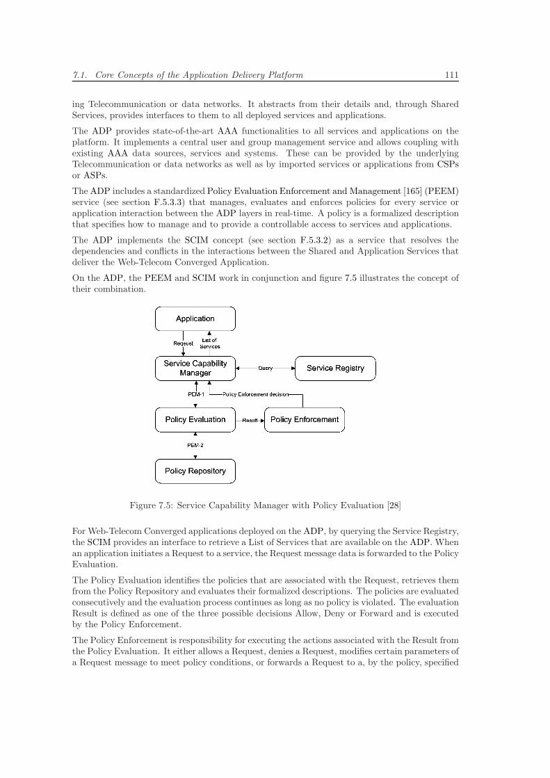
7.1. Core Concepts of the Application Delivery Platform 111
ing Telecommunication or data networks. It abstracts from their details and, through SharedServices, provides interfaces to them to all deployed services and applications.
The ADP provides state-of-the-art AAA functionalities to all services and applications on theplatform. It implements a central user and group management service and allows coupling withexisting AAA data sources, services and systems. These can be provided by the underlyingTelecommunication or data networks as well as by imported services or applications from CSPsor ASPs.
The ADP includes a standardized Policy Evaluation Enforcement and Management [165] (PEEM)service (see section F.5.3.3) that manages, evaluates and enforces policies for every service orapplication interaction between the ADP layers in real-time. A policy is a formalized descriptionthat specifies how to manage and to provide a controllable access to services and applications.
The ADP implements the SCIM concept (see section F.5.3.2) as a service that resolves thedependencies and conflicts in the interactions between the Shared and Application Services thatdeliver the Web-Telecom Converged Application.
On the ADP, the PEEM and SCIM work in conjunction and figure 7.5 illustrates the concept oftheir combination.
Figure 7.5: Service Capability Manager with Policy Evaluation [28]
For Web-Telecom Converged applications deployed on the ADP, by querying the Service Registry,the SCIM provides an interface to retrieve a List of Services that are available on the ADP. Whenan application initiates a Request to a service, the Request message data is forwarded to the PolicyEvaluation.
The Policy Evaluation identifies the policies that are associated with the Request, retrieves themfrom the Policy Repository and evaluates their formalized descriptions. The policies are evaluatedconsecutively and the evaluation process continues as long as no policy is violated. The evaluationResult is defined as one of the three possible decisions Allow, Deny or Forward and is executedby the Policy Enforcement.
The Policy Enforcement is responsibility for executing the actions associated with the Result fromthe Policy Evaluation. It either allows a Request, denies a Request, modifies certain parameters ofa Request message to meet policy conditions, or forwards a Request to a, by the policy, specified
112 Chapter 7. Design of the Application Delivery Platform
target. This might be either a specific service or a composed service possibly even executed by aworkflow engine (see concept C6).
A Policy Management service provides an XCAP-based access to the Policy Repository and allowsdeployment, modification and removal of policies.
The concept C3.4 supports the fulfillment of the requirements R1.5, R2.4 and R2.6 illustrated inchapter 6.
7.1.4 C4 - Layered Telecommunication Standardization
A full separation of networks and applications enables the full potential and maximizes the speedof technology, service and end-user application innovation. The prime example for this is theWeb/Internet, where the standardized generic underlying data networks and protocols such asTCP/IP and HTTP enable a completely open worldwide services and applications innovationplatform.
The downside of such an environment is that all ASPs on the platform are driven by their indi-vidual business goals and success factors, which typically lead them to pursuing a maximizationof their applications end-user base, while at the same time, locking them to their proprietaryapplications. As a result, most ASPs are not cooperating with any of their competitors and areeven prohibiting any compatibility and interoperability of their services or applications. Thereby,end-users are unable to switch ASPs or to even connect to end-users that are subscribed to ap-plications provided by another ASP. Prominent examples are that Skype end-users are unableto establish a communication channel to end-users using GoogleTalk, Apple FaceTime or anySIP standard compliant VoIP application, or that Facebook end-users are unable to share andinteract with end-users on other social networks such as Google+, Orkut, Xing or LinkedIn.
Telecommunication networks are geographically fragmented by the CSPs that deployed and op-erate the networks. Technologically, the networks are standardized worldwide, fully interoperableand so, end-users can move with their devices from one CSP’s network to another and still ac-cess their Telecommunication services and applications. Nevertheless, unfortunately through thedeclining, but still existing, excessive roaming costs CSPs charge from each other, in reality, thisgreat concept is drastically constricted for end-users.
Telecommunication services and applications are developed and then standardized in conjunctionwith the Telecommunication system they are intended to be deployed on. Thereby, the level andspeed of innovation is drastically limited compared to the Web/Internet. Nevertheless, for end-users, this worldwide compatibility and interoperability of all Telecommunication services andapplications across all CSPs-based on a simple phone number is a huge advantage compared toWeb/Internet applications.
The differences can be summarized in:
On the Web/Internet the network is technologically standardized and unified worldwide, but theapplications are fragmented by ASPs business goals.
In Telecommunications, the network is fragmented by CSPs business goals, but the applicationsare technologically standardized and unified worldwide.
The guiding principle for Web-Telecom Convergence standardization is to find the narrow balancebetween retaining the interoperability advantages that Telecommunication standardization bringsto end-users while providing a platform that maximizes the potential and speed of applicationinnovation.
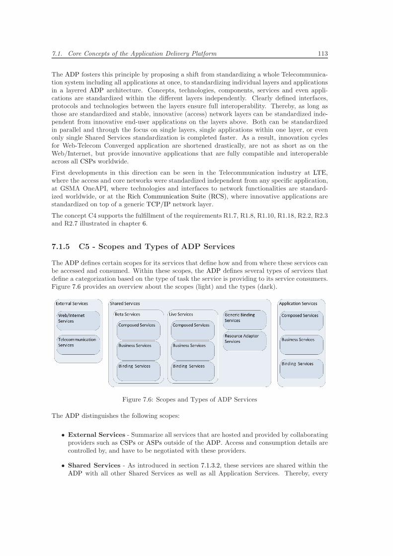
7.1. Core Concepts of the Application Delivery Platform 113
The ADP fosters this principle by proposing a shift from standardizing a whole Telecommunica-tion system including all applications at once, to standardizing individual layers and applicationsin a layered ADP architecture. Concepts, technologies, components, services and even appli-cations are standardized within the different layers independently. Clearly defined interfaces,protocols and technologies between the layers ensure full interoperability. Thereby, as long asthose are standardized and stable, innovative (access) network layers can be standardized inde-pendent from innovative end-user applications on the layers above. Both can be standardizedin parallel and through the focus on single layers, single applications within one layer, or evenonly single Shared Services standardization is completed faster. As a result, innovation cyclesfor Web-Telecom Converged application are shortened drastically, are not as short as on theWeb/Internet, but provide innovative applications that are fully compatible and interoperableacross all CSPs worldwide.
First developments in this direction can be seen in the Telecommunication industry at LTE,where the access and core networks were standardized independent from any specific application,at GSMA OneAPI, where technologies and interfaces to network functionalities are standard-ized worldwide, or at the Rich Communication Suite (RCS), where innovative applications arestandardized on top of a generic TCP/IP network layer.
The concept C4 supports the fulfillment of the requirements R1.7, R1.8, R1.10, R1.18, R2.2, R2.3and R2.7 illustrated in chapter 6.
7.1.5 C5 - Scopes and Types of ADP Services
The ADP defines certain scopes for its services that define how and from where these services canbe accessed and consumed. Within these scopes, the ADP defines several types of services thatdefine a categorization based on the type of task the service is providing to its service consumers.Figure 7.6 provides an overview about the scopes (light) and the types (dark).
Figure 7.6: Scopes and Types of ADP Services
The ADP distinguishes the following scopes:
• External Services - Summarize all services that are hosted and provided by collaboratingproviders such as CSPs or ASPs outside of the ADP. Access and consumption details arecontrolled by, and have to be negotiated with these providers.
• Shared Services - As introduced in section 7.1.3.2, these services are shared within theADP with all other Shared Services as well as all Application Services. Thereby, every
114 Chapter 7. Design of the Application Delivery Platform
service on the ADP can access and consume all Shared Services to compose them into newservices, or to implement the business logic of a Web-Telecom Converged application.
– Beta Services - These services are still in active development and do not provide anyquality or stability guarantees. All developers on the ADP can develop, maintain anddeploy these services themselves.
– Live Services - These services completed a certification process that was designedby the ADP provider. These services are stable, tested and should provide somequality guarantees. Developers develop and maintain these services, submit them forcertification and the ADP provider deploys them after they passed.
• Application Services - As introduced in section 7.1.3.2, these services represent a setof services that implement the business logic and data management of a Web-TelecomConverged application. They only implement application-specific functionality and so, arenot relevant for any other services or applications on the ADP. Therefore, the sets of servicesof the applications are strictly separated from each other, and Application Services are onlyaccessible from within the same set of an application.
The ADP distinguishes the following types:
• Telecommunication Services - These services are exposed by CSPs on their Inside-OutSDP solutions. They constitute Telecommunication end-user services such as Voice/VideoCall, SMS, etc. as well as Telecommunication network services such as QoS management,A4C, etc. They provide Web/Internet technologies, typically TCP/IP,-based well-definedservice interfaces to configure and consume them.
• Web/Internet Services - These services provide programmable access to certain func-tionalities and features of ASPs’ Web/Internet applications. They are offered through We-b/Internet technologies-based APIs, possibly including SDKs, hosted on ASPs’ developerplatforms.
• Resource Adaptor Services - To import External Services into the ADP, Resource Adap-tor Services are used. They access the exposed interfaces of the CSPs’ TelecommunicationServices as well as the APIs of the ASPs’ programmable Web/Internet Services to importtheir Telecommunications and Web/Internet functionalities. They manage and monitor theconnections to the External Services and, due to their scope as Shared Service, generallymap the External Services’ interfaces, protocols and data to ADP internal interfaces thatall services on the ADP can consume.
• Business Services - These services provide certain shared functionalities fully indepen-dent of External Services. They typically provide functionalities that were separated fromWeb-Telecom Converged business logic and generalized.
• Composed Services - These services combine Shared Services as well as, within a Web-Telecom Converged application, Application Services, to higher-level value-added services.When they combine Web/Internet and Telecommunication Resource Adaptor Services, theyrepresent Web-Telecom Converged Services, the basis of Web-Telecom Convergence and theapplications on the ADP.
• Generic Binding Services - On the ADP, service implementations are independentand separated from service interface and protocol standards and technologies. In order toprovide a selection of interface and protocol options, Generic Binding Services implementtheir standards and technologies in generic Shared Services that can be reused by all serviceson the ADP.
7.1. Core Concepts of the Application Delivery Platform 115
• Binding Services - In order to provide interfaces based on specific interface and protocoltechnology standards, these services attach Shared and Application Services to the GenericBinding Services.
The concept C5 supports the fulfillment of the requirements R1.2, R1.4, R1.13 and R1.17 illus-trated in chapter 6.
7.1.6 C6 - SOA Concepts-based Application Delivery Platform
The ADP applies SOA concepts end-to-end from the Telecommunication, Web/Internet andConverged services domains through the Web-Telecom Converged applications domain all theway to the client applications domain on the end-users device platforms. In addition, it takesinto account the high state-of-the-art Telecommunication services and applications QoS standards[184], such as real-time performance and availability that end-users expect from Web-TelecomConverged applications. Therefore, the ADP is built upon a customized and extended carrier-grade SOA platform implementation.
From the general SOA and service definitions and concepts in sections 2.2 and 2.2.4 the followingbase concepts can be derived. These constitute the core of the ADP SOA environment and are,at least, provided by the underlying SOA platform implementation.
• Service Creation and Service Repository
The ADP SOA is built upon popular, standardized and state-of-the-art software develop-ment technologies. It provides SDKs, tools, support and an active developer communityand thereby, provides a familiar Service Creation and application development platform forthird party developers.
The ADP provides a carrier-grade Service Repository that hosts all Shared and Applicationservices. Thereby, for beta testing, during service or application development, as well as forlive deployment, at product launch, it allows third party developers to continuously deploytheir services on a carrier-grade platform.
All hosted services are exported, and so, made accessible for other services or applications,according to the Service Exposure concept illustrated below.
• Service Execution
The ADP provides a Service Execution component that allows developers to continuouslytest and run their services on a carrier-grade platform. In conjunction with the ServiceRepository, this component supports, at least, the in figure 7.7 illustrated service executioncycle.
In order to deploy a service, the software artifact (e.g. library, software bundle, class files)is installed on the ADP. The platform resolves all dependencies and hosts the services inthe Service Repository. The Service Execution component can load it from there and startit. If the Starting procedure was successful, the service is Active as long as it is not stoppedby the Service Execution component. Once the Stopping procedure was successful it isreturned to the Service Repository. From there, the software artifact can be uninstalledand thereby, removed from the ADP.
• Service Composition/Orchestration
The ADP enables developers to compose/orchestrate services of any type to more complexservices of the same or any other type. To realize this, it differentiates between the followingtwo approaches of Service Composition/Orchestration.
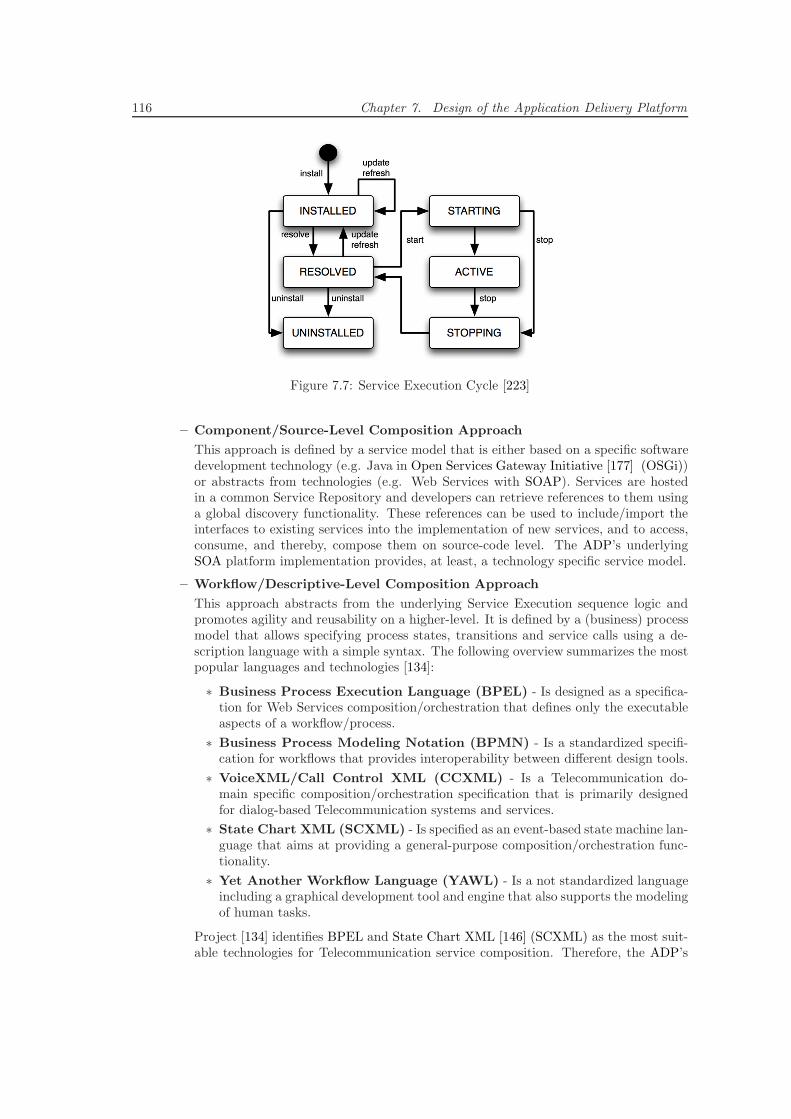
116 Chapter 7. Design of the Application Delivery Platform
Figure 7.7: Service Execution Cycle [223]
– Component/Source-Level Composition Approach
This approach is defined by a service model that is either based on a specific softwaredevelopment technology (e.g. Java in Open Services Gateway Initiative [177] (OSGi))or abstracts from technologies (e.g. Web Services with SOAP). Services are hostedin a common Service Repository and developers can retrieve references to them usinga global discovery functionality. These references can be used to include/import theinterfaces to existing services into the implementation of new services, and to access,consume, and thereby, compose them on source-code level. The ADP’s underlyingSOA platform implementation provides, at least, a technology specific service model.
– Workflow/Descriptive-Level Composition Approach
This approach abstracts from the underlying Service Execution sequence logic andpromotes agility and reusability on a higher-level. It is defined by a (business) processmodel that allows specifying process states, transitions and service calls using a de-scription language with a simple syntax. The following overview summarizes the mostpopular languages and technologies [134]:
∗ Business Process Execution Language (BPEL) - Is designed as a specifica-tion for Web Services composition/orchestration that defines only the executableaspects of a workflow/process.
∗ Business Process Modeling Notation (BPMN) - Is a standardized specifi-cation for workflows that provides interoperability between different design tools.
∗ VoiceXML/Call Control XML (CCXML) - Is a Telecommunication do-main specific composition/orchestration specification that is primarily designedfor dialog-based Telecommunication systems and services.
∗ State Chart XML (SCXML) - Is specified as an event-based state machine lan-guage that aims at providing a general-purpose composition/orchestration func-tionality.
∗ Yet Another Workflow Language (YAWL) - Is a not standardized languageincluding a graphical development tool and engine that also supports the modelingof human tasks.
Project [134] identifies BPEL and State Chart XML [146] (SCXML) as the most suit-able technologies for Telecommunication service composition. Therefore, the ADP’s
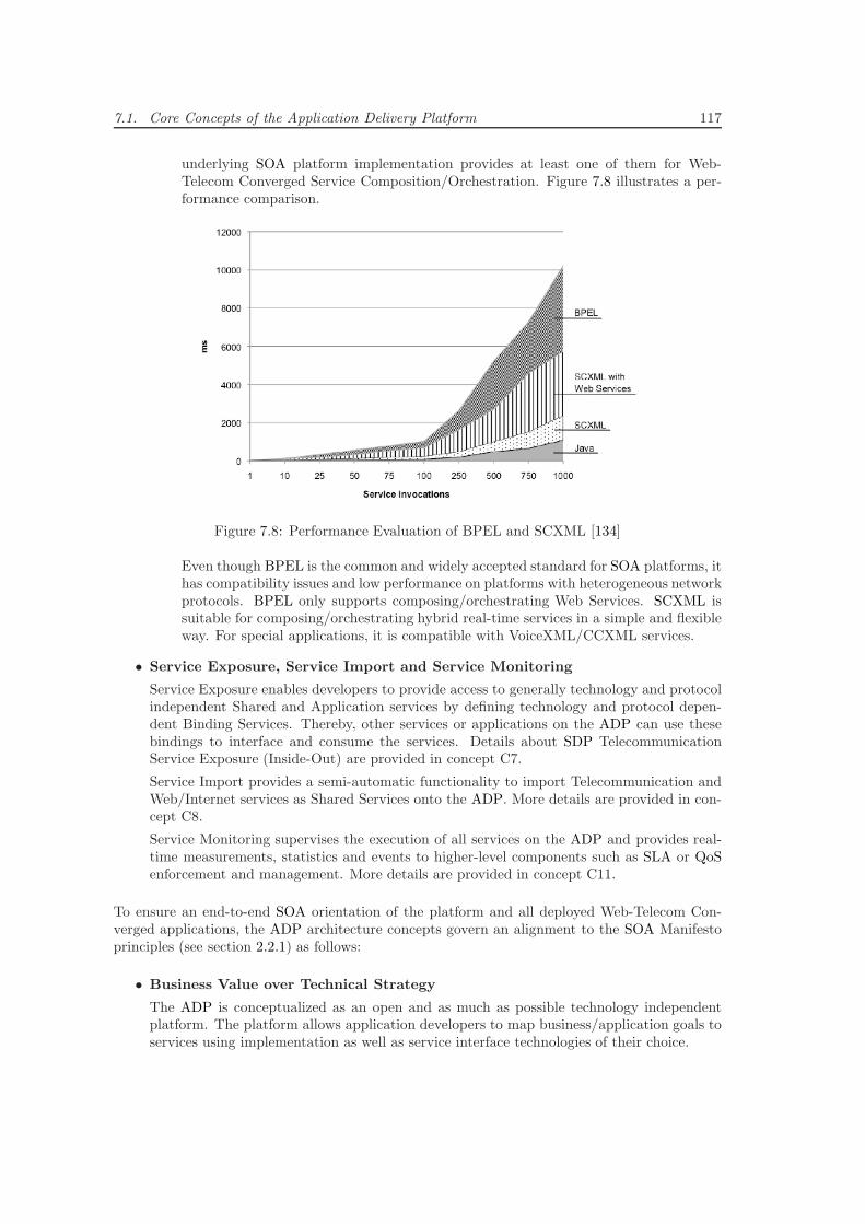
7.1. Core Concepts of the Application Delivery Platform 117
underlying SOA platform implementation provides at least one of them for Web-Telecom Converged Service Composition/Orchestration. Figure 7.8 illustrates a per-formance comparison.
Figure 7.8: Performance Evaluation of BPEL and SCXML [134]
Even though BPEL is the common and widely accepted standard for SOA platforms, ithas compatibility issues and low performance on platforms with heterogeneous networkprotocols. BPEL only supports composing/orchestrating Web Services. SCXML issuitable for composing/orchestrating hybrid real-time services in a simple and flexibleway. For special applications, it is compatible with VoiceXML/CCXML services.
• Service Exposure, Service Import and Service Monitoring
Service Exposure enables developers to provide access to generally technology and protocolindependent Shared and Application services by defining technology and protocol depen-dent Binding Services. Thereby, other services or applications on the ADP can use thesebindings to interface and consume the services. Details about SDP TelecommunicationService Exposure (Inside-Out) are provided in concept C7.
Service Import provides a semi-automatic functionality to import Telecommunication andWeb/Internet services as Shared Services onto the ADP. More details are provided in con-cept C8.
Service Monitoring supervises the execution of all services on the ADP and provides real-time measurements, statistics and events to higher-level components such as SLA or QoSenforcement and management. More details are provided in concept C11.
To ensure an end-to-end SOA orientation of the platform and all deployed Web-Telecom Con-verged applications, the ADP architecture concepts govern an alignment to the SOA Manifestoprinciples (see section 2.2.1) as follows:
• Business Value over Technical Strategy
The ADP is conceptualized as an open and as much as possible technology independentplatform. The platform allows application developers to map business/application goals toservices using implementation as well as service interface technologies of their choice.
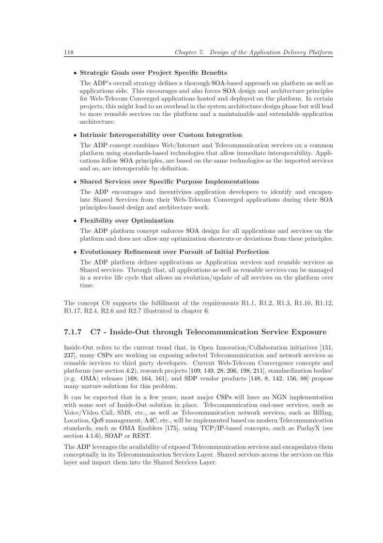
118 Chapter 7. Design of the Application Delivery Platform
• Strategic Goals over Project Specific Benefits
The ADP’s overall strategy defines a thorough SOA-based approach on platform as well asapplications side. This encourages and also forces SOA design and architecture principlesfor Web-Telecom Converged applications hosted and deployed on the platform. In certainprojects, this might lead to an overhead in the system architecture design phase but will leadto more reusable services on the platform and a maintainable and extendable applicationarchitecture.
• Intrinsic Interoperability over Custom Integration
The ADP concept combines Web/Internet and Telecommunication services on a commonplatform using standards-based technologies that allow immediate interoperability. Appli-cations follow SOA principles, are based on the same technologies as the imported servicesand so, are interoperable by definition.
• Shared Services over Specific Purpose Implementations
The ADP encourages and incentivizes application developers to identify and encapsu-late Shared Services from their Web-Telecom Converged applications during their SOAprinciples-based design and architecture work.
• Flexibility over Optimization
The ADP platform concept enforces SOA design for all applications and services on theplatform and does not allow any optimization shortcuts or deviations from these principles.
• Evolutionary Refinement over Pursuit of Initial Perfection
The ADP platform defines applications as Application services and reusable services asShared services. Through that, all applications as well as reusable services can be managedin a service life cycle that allows an evolution/update of all services on the platform overtime.
The concept C6 supports the fulfillment of the requirements R1.1, R1.2, R1.3, R1.10, R1.12,R1.17, R2.4, R2.6 and R2.7 illustrated in chapter 6.
7.1.7 C7 - Inside-Out through Telecommunication Service Exposure
Inside-Out refers to the current trend that, in Open Innovation/Collaboration initiatives [151,237], many CSPs are working on exposing selected Telecommunication and network services asreusable services to third party developers. Current Web-Telecom Convergence concepts andplatforms (see section 4.2), research projects [109, 149, 28, 206, 198, 211], standardization bodies’(e.g. OMA) releases [168, 164, 161], and SDP vendor products [148, 8, 142, 156, 88] proposemany mature solutions for this problem.
It can be expected that in a few years, most major CSPs will have an NGN implementationwith some sort of Inside-Out solution in place. Telecommunication end-user services, such asVoice/Video Call, SMS, etc., as well as Telecommunication network services, such as Billing,Location, QoS management, A4C, etc., will be implemented based on modern Telecommunicationstandards, such as OMA Enablers [175], using TCP/IP-based concepts, such as ParlayX (seesection 4.1.6), SOAP or REST.
The ADP leverages the availability of exposed Telecommunication services and encapsulates themconceptually in its Telecommunication Services Layer. Shared services access the services on thislayer and import them into the Shared Services Layer.
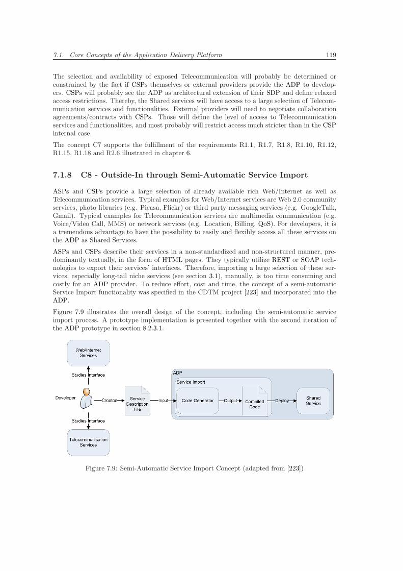
7.1. Core Concepts of the Application Delivery Platform 119
The selection and availability of exposed Telecommunication will probably be determined orconstrained by the fact if CSPs themselves or external providers provide the ADP to develop-ers. CSPs will probably see the ADP as architectural extension of their SDP and define relaxedaccess restrictions. Thereby, the Shared services will have access to a large selection of Telecom-munication services and functionalities. External providers will need to negotiate collaborationagreements/contracts with CSPs. Those will define the level of access to Telecommunicationservices and functionalities, and most probably will restrict access much stricter than in the CSPinternal case.
The concept C7 supports the fulfillment of the requirements R1.1, R1.7, R1.8, R1.10, R1.12,R1.15, R1.18 and R2.6 illustrated in chapter 6.
7.1.8 C8 - Outside-In through Semi-Automatic Service Import
ASPs and CSPs provide a large selection of already available rich Web/Internet as well asTelecommunication services. Typical examples for Web/Internet services are Web 2.0 communityservices, photo libraries (e.g. Picasa, Flickr) or third party messaging services (e.g. GoogleTalk,Gmail). Typical examples for Telecommunication services are multimedia communication (e.g.Voice/Video Call, MMS) or network services (e.g. Location, Billing, QoS). For developers, it isa tremendous advantage to have the possibility to easily and flexibly access all these services onthe ADP as Shared Services.
ASPs and CSPs describe their services in a non-standardized and non-structured manner, pre-dominantly textually, in the form of HTML pages. They typically utilize REST or SOAP tech-nologies to export their services’ interfaces. Therefore, importing a large selection of these ser-vices, especially long-tail niche services (see section 3.1), manually, is too time consuming andcostly for an ADP provider. To reduce effort, cost and time, the concept of a semi-automaticService Import functionality was specified in the CDTM project [223] and incorporated into theADP.
Figure 7.9 illustrates the overall design of the concept, including the semi-automatic serviceimport process. A prototype implementation is presented together with the second iteration ofthe ADP prototype in section 8.2.3.1.
Figure 7.9: Semi-Automatic Service Import Concept (adapted from [223])
120 Chapter 7. Design of the Application Delivery Platform
• The import process starts when a developer identifies a Web/Internet or Telecommunicationservice that he would like to include into his Web-Telecom Converged application on theADP. He studies the interface descriptions and technical details of the service. Thesedescriptions are typically textual information about the service protocol, service resourceand mandatory/optional parameters including their names, types, value ranges and more.
• The developer creates an ADP Service Import compatible text-based Service DescriptionFile according to the interface details he previously studied. In [223], several service de-scription languages were compared and evaluated. Web Application Description Language[180] (WADL) was identified as the most suitable language (see section B) and therefore,an ADP Service Import component needs to, at least, support this language. Since WADLis currently spreading fast on the Web/Internet, it can be assumed that in the future, de-velopers do not need to write their WADL Service Description File themselves, but canretrieve it from the providing ASPs or CSPs for all their services automatically.
• The Service Description File is analyzed and processed by an ADP compatible Code Genera-tor. This Code Generator automatically generates source code according to the implementa-tion technology selected for the ADP. The generated source code links the service endpointsof the external Web/Internet or Telecommunication service with a generated ADP-internalResource Adaptor implementation. The Resource Adapter provides ADP implementationtechnology-based access to the external service’s functionalities on the ADP.
• The generated source code is compiled and packaged into a Shared Service that is compatiblewith the SOA environment selected for the ADP. This Shared Service exports the ResourceAdaptor’s interface and can be deployed on the ADP’s Service Repository.
The concept C8 supports the fulfillment of the requirements R1.1, R1.7, R1.10, R1.12, R1.16 andR2.6 illustrated in chapter 6.
7.1.9 C9 - Internet of Services through a Collaboration of Platformsacross Domains
To enable a seamless collaboration with other platforms, the ADP’s SOA concepts are extendedby the concept of an ESB on the Shared Services layer. As illustrated in section 2.3, ESBsprovide means to flexibly connect them with each other across multiple deployments, companies,providers and domains. Hence, they are able to create a unified service platform across multipleADP deployments. Thereby, developers on all collaborating ADPs are able to discover, access andutilize all Shared Services from all connected ADP deployments. This enables the creation of anopen and worldwide Internet of Services that manages and provides state-of-the-art Web/Internetand Telecommunication services that are ready to be utilized in any future innovative Web-Telecom Converged applications.
The concept C9 supports the fulfillment of the requirement R2.7 illustrated in chapter 6.
7.1.10 C10 - Application Distribution
For the currently most successful mobile device platforms, the integration of a well designedand implemented Application Distribution concept, in form of the App Store at Apple or An-droid Market at Google, has become a major competitive advantage. To provide developerswith powerful tools to distribute their Web-Telecom Converged applications to end-users, andto provide end-users with powerful tools to easily discover and install Web-Telecom Converged
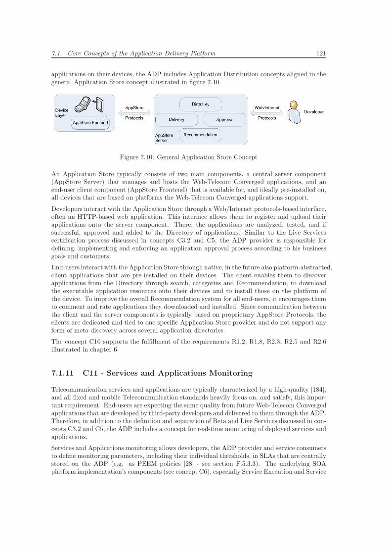
7.1. Core Concepts of the Application Delivery Platform 121
applications on their devices, the ADP includes Application Distribution concepts aligned to thegeneral Application Store concept illustrated in figure 7.10.
Figure 7.10: General Application Store Concept
An Application Store typically consists of two main components, a central server component(AppStore Server) that manages and hosts the Web-Telecom Converged applications, and anend-user client component (AppStore Frontend) that is available for, and ideally pre-installed on,all devices that are based on platforms the Web-Telecom Converged applications support.
Developers interact with the Application Store through a Web/Internet protocols-based interface,often an HTTP-based web application. This interface allows them to register and upload theirapplications onto the server component. There, the applications are analyzed, tested, and ifsuccessful, approved and added to the Directory of applications. Similar to the Live Servicescertification process discussed in concepts C3.2 and C5, the ADP provider is responsible fordefining, implementing and enforcing an application approval process according to his businessgoals and customers.
End-users interact with the Application Store through native, in the future also platform-abstracted,client applications that are pre-installed on their devices. The client enables them to discoverapplications from the Directory through search, categories and Recommendation, to downloadthe executable application resources onto their devices and to install those on the platform ofthe device. To improve the overall Recommendation system for all end-users, it encourages themto comment and rate applications they downloaded and installed. Since communication betweenthe client and the server components is typically based on proprietary AppStore Protocols, theclients are dedicated and tied to one specific Application Store provider and do not support anyform of meta-discovery across several application directories.
The concept C10 supports the fulfillment of the requirements R1.2, R1.8, R2.3, R2.5 and R2.6illustrated in chapter 6.
7.1.11 C11 - Services and Applications Monitoring
Telecommunication services and applications are typically characterized by a high-quality [184],and all fixed and mobile Telecommunication standards heavily focus on, and satisfy, this impor-tant requirement. End-users are expecting the same quality from future Web-Telecom Convergedapplications that are developed by third-party developers and delivered to them through the ADP.Therefore, in addition to the definition and separation of Beta and Live Services discussed in con-cepts C3.2 and C5, the ADP includes a concept for real-time monitoring of deployed services andapplications.
Services and Applications monitoring allows developers, the ADP provider and service consumersto define monitoring parameters, including their individual thresholds, in SLAs that are centrallystored on the ADP (e.g. as PEEM policies [28] - see section F.5.3.3). The underlying SOAplatform implementation’s components (see concept C6), especially Service Execution and Service
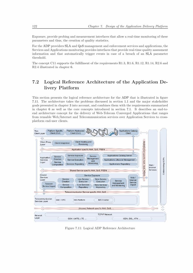
122 Chapter 7. Design of the Application Delivery Platform
Exposure, provide probing and measurement interfaces that allow a real-time monitoring of theseparameters and thus, the creation of quality statistics.
For the ADP providers SLA and QoS management and enforcement services and applications, theServices and Applications monitoring provides interfaces that provide real-time quality assessmentinformation and that automatically trigger events in case of a breach of an SLA parameterthreshold.
The concept C11 supports the fulfillment of the requirements R1.3, R1.6, R1.12, R1.14, R2.6 andR2.4 illustrated in chapter 6.
7.2 Logical Reference Architecture of the Application De-
livery Platform
This section presents the logical reference architecture for the ADP that is illustrated in figure7.11. The architecture takes the problems discussed in section 1.1 and the major stakeholdergoals presented in chapter 3 into account, and combines them with the requirements summarizedin chapter 6 as well as the core concepts introduced in section 7.1. It describes an end-to-end architecture concept for the delivery of Web-Telecom Converged Applications that rangesfrom reusable Web/Internet and Telecommunication services over Application Services to cross-platform end-user clients.
Figure 7.11: Logical ADP Reference Architecture
7.2. Logical Reference Architecture of the Application Delivery Platform 123
7.2.1 Network Layer
This layer is the foundation of all Telecommunication systems and Web/Internet infrastructures.It defines, standardizes and provides all means (e.g. protocols, data formats, interfaces, ...) forservice and application signaling as well as service and application data transport. For end-user client device connectivity, it includes specifications and standards for mobile access networktechnologies such as GSM, UMTS and LTE as well as fixed access network technologies such asISDN, DSL and WLAN.
7.2.2 Telecommunication Services Layer
Telecommunication systems based on GSM and UMTS are closed systems with limited/restrictedaccess to, and no access from, TCP/IP-based networks such as the Web/Internet. AdvancedTelecommunication system specifications such as LTE are more open, and so, the interoper-ability to and from TCP/IP networks is greatly improved. Due to most CSPs’ business goals,Telecommunication service access is still mostly limited to end-user clients that reside within thenetwork of the respective CSP. Nevertheless, the improved interoperability with TCP/IP removesmost technical restrictions to access such Telecommunication services from future applicationson TCP/IP-based networks.
Through recent Telecommunication concepts, specifications and standards such as Next Genera-tion All-IP Networks, EPC, SAE, LTE and IMS, this layer represents a TCP/IP-based Telecom-munication system architecture. This includes control and signaling capabilities for real-timeTelecommunication and multimedia services such as Voice Call/Streaming, Video Call/Stream-ing, Text/Multimedia Messaging etc. IMS Enablers and SIP Application Servers provide meansfor Telecommunication system customization, Telecommunication services extensions, Web/In-ternet technologies-based Telecommunication services exposure as well as Telecommunicationapplications development. Thereby, this layer provides access to all TCP/IP-based Telecommu-nication services that are accessible from CSPs’ Telecommunication networks.
7.2.3 Web/Internet Services Layer
Web/Internet services and applications are based on protocols that run directly on top of TCP/IP.Thereby, they provide and deliver their functionality in a universally accessible way for all end-user clients connected to the Web/Internet.
This layer provides access to all TCP/IP-based services and applications offered by ASPs on theWeb/Internet. These services and applications use OSI Application Layer [97] protocols such asHTTP to provide access for end-user clients and to exchange/transfer service and applicationdata. Reusable services use defacto Web/Internet service interface technology standards suchas REST and data formats such as JSON to expose their functionalities to other services andapplications on the Web/Internet.
7.2.4 Shared Services Layer
This layer hosts application-independent Shared Services that are specified and implemented bydevelopers for developers, ready to be reused, and shared among all applications on the ADP. TheADP concept encourages and supports developers at identifying and extracting reusable businesslogic and functionalities from their applications, at encapsulating them in Shared Services, andso, at providing them to the whole developer community.
124 Chapter 7. Design of the Application Delivery Platform
This layer distinguishes and physically separates the two scopes, Beta and Live, for all SharedServices. Beta Services are solely experimental or are still under active development/testingand service developers are working on enhancing them to the Live stage. Live Services are finaland stable services that are managed and monitored by the ADP (provider) and that ensure acontinuous high-quality.
This layer is the foundation of the concept of Web-Telecom Convergence. External Web/Inter-net and Telecommunication services are accessed, imported and wrapped by Resource AdapterShared Services, and through the composition of these imported services, Web-Telecom Con-verged Composed Shared Services are created.
In detail, this layer defines the following components:
• Service Creation - This component provides functionalities, interfaces and tools forShared Service identification, specification, development (SDKs, APIs, Protocol Stacksetc.), testing (IDEs, Simulators) and deployment (e.g. Developer Platform GUI) on theADP. It supports the creation and deployment of a new and independent Shared Servicefrom scratch, of a Shared Service from a Service Composition as well as of a Shared Servicefrom a Service Import of an external Web/Internet or Telecommunication service.
• Service Composition - This component enables developers to compose services from al-ready deployed Shared Services. It supports the two common approaches, Component/Source-Level Composition and Workflow/Descriptive-Level Composition. Thereby, the componentprovides the means to describe (workflow-based approach) or implement (component-basedapproach) Web-Telecom Converged Services by composing Resource Adapter Shared Ser-vices that import Web/Internet or Telecommunication services.
• Live/Beta Services Repository - These components host, physically separated, thepackaged executable files and resources of all Shared Live and Beta Services on the ADP.For other ADP components such as Service Execution or Service Exposure, they provideaccess to the service packages as well as to the service and service interface descriptionsand meta information.
• Live/Beta Service Execution - These components provide interfaces to, and manage,the whole service execution cycle of all Shared Live and Beta Services in conjunction withthe Services Repositories. As illustrated in core concept C6, this includes at least serviceinstallation, resolving, starting, activating, stopping and uninstalling. The componentsphysically separate the two different scopes of the Shared Services and apply suitable exe-cution monitoring and management parameters and criteria accordingly.
• Service Exposure - This component provides Application Services Layer services withaccess to the Shared Beta and Live Services on this layer. It provides a shared collection ofGeneric Binding Services that implements a large selection of common Web/Internet tech-nologies and protocols. Shared Service developers can implement Shared Service-specificBinding Services that leverage the Generic Binding Services to bind their Shared Servicesto their individual selection of technologies and protocols. Thereby, Application Services onthe Application Services Layer can access the exposed Shared Services according to theirspecified interfaces through their bound interface technologies and protocols.
• Service Management and Monitoring - This component provides the developers andADP provider with interfaces and functionalities to define, manage, monitor and analyzeShared Beta and Live Service Execution, QoS and SLA parameters and metrics such asscalability, availability, performance, exceptions, etc.
7.2. Logical Reference Architecture of the Application Delivery Platform 125
• Web/Internet and Telecom Service Import - These components provide function-alities to semi-automatically import Telecommunication as well as Web/Internet servicesinto the ADP. They use textual descriptions of the external services’ interfaces to generateResource Adapter Shared Services. These generated services are deployed in the ServicesRepository and are from there, similar to all manually implemented or composed SharedServices, available for Service Execution, Service Composition and Service Exposure.
Developers can leverage theWeb/Internet and Telecommunication Resource Adapter SharedServices to develop value-added composed Web-Telecom Converged Shared Services. Thesecan then be reused on the Application Services Layer to implement innovative Web-TelecomConverged Applications.
7.2.5 Application Services Layer
The functionalities this layer provides are divided into two general parts. (i) This layer hoststhe application-specific Application Services that implement application business logic and datamanagement, and that are encouraged to reuse Shared Services from the Shared Services Layer.It strictly separates all deployed Web-Telecom Converged applications, hosts them physicallyseparated and prohibits all access between Application Services across applications. (ii) Forevery Web-Telecom Converged application, this layer hosts version-managed application bundlesthat include all associated executable Application Services’ files, all resources as well as end-userclients that are distributable and deployable on all device platforms the application supports. Inaddition to hosting, this layer provides functionalities that enable the distribution of Web-TelecomConverged application clients to the end-users’ devices across all supported device platforms.
In detail, this layer consists of the following components:
• Service Creation - This component provides functionalities, interfaces and tools for Ap-plication Service specification, development (SDKs, APIs, Protocol Stacks etc.), testing(IDEs, Simulators) and deployment (e.g. Developer Platform GUI). It supports the cre-ation and deployment of new Application Services from scratch as well as from ServiceCompositions, and provides tools and functionalities (e.g. service interface protocol/tech-nology implementation, SDKs, APIs) to connect Application Services to exposed SharedServices on the Shared Services Layer.
• Service Composition - This component enables developers to compose Application Ser-vices from already deployed Application Services within one individual Web-Telecom Con-verged application. It supports the two common approaches, Component/Source-LevelComposition and Workflow/Descriptive-Level Composition. Thereby, the component pro-vides the means to describe (workflow-based approach) or implement (component-basedapproach) Composed Application Services.
• Services Repository - This component hosts, physically separated for each individualWeb-Telecom Converged applications, the packaged executable files and resources of allApplication Services for all applications deployed on the ADP. It provides access to theindividual Application Service packages as well as to the service and service interface de-scriptions and meta information.
• Service Execution - This component provides interfaces to, and manages, the wholeservice execution cycle of all Application Services in conjunction with the Services Reposi-tory. As illustrated in core concept C6, this includes at least service installation, resolving,starting, activating, stopping and uninstalling. The component separates and executes theApplication Services according to the Web-Telecom Converged application they belong to,
126 Chapter 7. Design of the Application Delivery Platform
and ensures that access between services within the same application is assisted, but acrossapplications prohibited.
• Service Exposure - This component provides Thin Client Layer and Client Proxy Layerclients with access to the Application Services on this layer. It leverages the shared collec-tion of Generic Binding Services that implements a large selection of common Web/Internettechnologies and protocols from the Shared Services Layer. This enables developers to im-plement Application Service-specific Binding Services that bind their Application Servicesto selected technologies and protocols. Thereby, clients can access the exposed ApplicationServices according to their specified interfaces through their bound interface technologiesand protocols.
• Service Management and Monitoring - This component provides the developers andADP provider with interfaces and functionalities to define, manage, monitor and analyzeApplication Service Execution, QoS and SLA parameters and metrics such as scalability,availability, performance, exceptions, etc.
Service Management and Monitoring is tightly integrated into the Web-Telecom Convergedapplication development and Application Services Creation processes. It is an essential partof the application certification process that approves an application to be deployed in theApplications Repository and to be distributed through the Applications Catalog.
• Applications Repository - This component hosts version-managed application bundles ofall approvedWeb-Telecom Converged Applications. These include all associated executableApplication Services’ files, all resources as well as end-user clients for all supported deviceplatforms.
This component provides interfaces and functionalities to provide textual descriptions, de-scriptive multimedia resources and meta information about each application to other com-ponents such as the Applications Catalog. These descriptions are defined by the developersand/or ADP providers and help developers, the ADP provider or end-users to better un-derstand the ideas and functionalities of all available Web-Telecom Converged applications.
• Application Lifecycle Management - In accordance to the concept defined in section2.7, this component manages application lifecycle tasks such as development, version man-agement, quality assurance, maintenance or distribution of new and updated versions ofapplications. It interfaces the Applications Repository component for application metainformation such as versions, supported client platforms, etc. as well as the ApplicationsCatalog component for application distribution, update management, etc. functionalities.
• Applications Catalog - This component gathers and summarizes descriptions and metainformation such as application idea and functionality, client platforms support, versionsand available updates for all approved Web-Telecom Converged applications on the ADP.From the gathered data, it builds and provides a browseable and searchable catalog thatlists details about all applications.
This component provides interfaces and functionalities to distribute the Web-Telecom Con-verged applications’ clients, or their updates, to the end-users’ client devices/platforms.Thereby, it enables the Client Layer Applications Catalog Client to download and installapplication clients, including their updates, from the Applications Repository applicationbundle onto the end-users’ client devices.
To realize a feedback channel for developers and ADP providers, this component providesbug-report, recommendation, user-ranking and user-commenting functionalities for all de-ployed Web-Telecom Converged applications.
7.3. Technical Architecture of the Application Delivery Platform 127
7.2.6 Client Proxy Layer
This layer supports the ADP paradigm of thin platform-dependent or platform-independentclients on end-user devices. It supports the developers at keeping platform dependencies inend-user clients as small as possible while also keeping the business logic and data managementimplementations in the Application Services on the Application Services Layer device platform-independent. This layer provides the developers with server-side development components thatcan be used to adapt their platform-dependent clients to the specifics of the different deviceplatforms as well as to develop platform-independent clients that can be rendered on all deviceplatforms.
The Client Adaptation component provides adaptation support for platform-dependent thinclients. Since device platforms are very different in terms of screen sizes, processing capabilities,memory, battery power, user-interface technologies and concepts etc., this component allows de-velopers to implement client adapters on server-side that adapt data, interactions, user-interfaces,etc. to the specifics of the different platforms.
The Client Hosting and Rendering component provides a hosting environment for platform-independent clients. Such clients are deployed on the server-side and only the GUI is transmittedto, and rendered on, the end-users’ devices’ platforms. Examples for that are clients developedusing existing Web/Internet technologies such as HTML/AJAX rendered in a browser as well asupcoming Web/Internet technologies such as HTML5/BONDI etc. rendered in a browser, widgetengine or similar. The component allows developers to deploy different platform-adapted versionsof their clients as well as dynamically adapting clients that adapt to the different rendering engineson the different platforms automatically.
7.2.7 Thin Client Layer
This layer hosts and executes platform-dependent and renders (e.g. browser, widget engine)platform-independent Web-Telecom Converged Application clients on the end-users’ devices. Forclient lifecycle management, it hosts the Applications Catalog client that allows end-users to, forexample, discover, search, download, install, update, rank, comment and remove Web-TelecomConverged Application clients.
In addition, some end-user devices also run (mostly pre-installed by the device manufacturer orCSP) native and platform-dependent Telecommunication clients such as LTE or UMTS Voice/VideoCall clients. These connect directly to the Telecommunication Services Layer and access Telecom-munication control and signaling system components directly in order to implement real-timeTelecommunication Services and Applications most efficiently.
7.3 Technical Architecture of the Application Delivery Plat-form
This section illustrates an exemplary technical architecture of the ADP. It makes technology andvendor decisions for layers and components of the logical reference architecture, and provides anoverview about the components and platform services that must, at least, be deployed in order tofulfill the requirements and realize the core concepts from chapter 6 and section 7.1. A detailedspecification or standardization proposal for all components, services, protocols, data formatsand interfaces of an ADP is out of scope of this research project and may be part of future work.
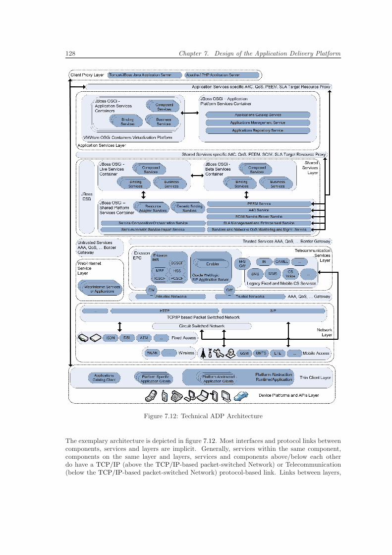
128 Chapter 7. Design of the Application Delivery Platform
Figure 7.12: Technical ADP Architecture
The exemplary architecture is depicted in figure 7.12. Most interfaces and protocol links betweencomponents, services and layers are implicit. Generally, services within the same component,components on the same layer and layers, services and components above/below each otherdo have a TCP/IP (above the TCP/IP-based packet-switched Network) or Telecommunication(below the TCP/IP-based packet-switched Network) protocol-based link. Links between layers,
7.3. Technical Architecture of the Application Delivery Platform 129
services and components that are further spread out over the architecture are made explicitthrough line connections and explained in more detail below.
7.3.1 Device Platforms and APIs Layer
This Layer represents the different fixed and mobile devices, their various platforms and theplatforms’ APIs. The latter can be used by developers to develop Web-Telecom Convergedapplication clients on the Thin Client Layer. This layer contains the following three differentcomponents.
• Platform-Abstracted Application Clients - These clients are developed with one ofthe mobile development frameworks compared and evaluated in section 4.3.2. Since theyare platform abstracted, they need to be executed by a Platform Abstraction Runtime/Ap-plication such as a browser or virtual machine. For the, according to the comparison andevaluation, two most suitable frameworks, RhoMobile and PhoneGap, these are a Rubyvirtual machine and a HTML5/JavaScript runtime respectively.
• Platform-Specific Application Clients - These clients are developed using platform-specific and native application development technologies and tools. The most popularplatforms are compared and evaluated in section 4.3.1, which shows that the most suitablefor native Web-Telecom Converged application clients are currently iOS and Android.
• Applications Catalog Client - This client connects to the Applications Catalog Serviceon the Application Services Layer’s Application Platform Services Container using an ADPvendor implementation specific protocol. It is part of the realization of concept C10 fromsection 7.1, and is, at least, able to retrieve information about all available Web-TelecomConverged applications, transfer them to the device platform and install them.
7.3.2 Network Layer
This layer encapsulates all access and data transfer networks related to Web-Telecom Conver-gence. The Mobile Access Network provides GSM, UMTS and LTE technologies and protocolsto connect mobile devices to the platform. It provides circuit-switched Network access for legacymobile Telecommunication services such as Voice, SMS, etc. as well as packet-switched Networkaccess to TCP/IP/SIP-based EPC and IMS Telecommunication services. The Fixed Access Net-work provides DSL, ISDN, etc. technologies to connect fixed, including WLAN, devices to theplatform. It provides circuit-switched Network access for legacy fixed Telecommunication servicessuch as Voice, ISDN services, etc. as well as packet-switched Network access to TCP/IP/SIP-based VoIP services as well as the Web/Internet.
7.3.3 Telecommunication Services Layer
This layer encapsulates all Web-Telecom Convergence related Telecommunication systems, com-ponents and services and is divided into the following two parts.
• Evolved Packet Core - The EPC builds the foundation for the IMS, which provides allpacket-switched standard Telecommunication services, as well as for the SIP ApplicationServer, which enables an extension of the IMS through Enablers. It provides and managesgateways to trusted (e.g. SIM-Card authenticated mobile access) as well as untrusted (e.g.
130 Chapter 7. Design of the Application Delivery Platform
unauthenticated WLAN or DSL access) networks. These ensure AAA between the layersand QoS control, management and assurance on the Network Layer.
For the EPC and IMS implementations, the most wide-spread vendor product implementa-tions by Ericsson were selected. The IMS must, at least, provide the three interconnectedCall Session Control Functions (CSCFs), the user identities managing Home SubscriberServer (HSS) and the multimedia data processing Media Resource Function. For the ASthe popular Oracle WebLogic product was selected, and the deployed Enablers provide ac-cessible interfaces to the standard IMS Telecommunication services as well as to extendedservices. Thereby, they realize a part of core concept C7.
• Legacy Fixed and Mobile Circuit-Switched Services - These services are providedby currently deployed Telecommunication systems that are based on legacy Telecommuni-cation standards and specifications. To access these services from the TCP/IP-based EPCTelecommunication platform, a Media Gateway and a Signaling Gateway are deployed inbetween them.
7.3.4 Web/Internet Services Layer
This layer encapsulates all programmable Web/Internet service and applications that provide anaccessible TCP/IP-based API.
7.3.5 Shared Services Layer
This layer encapsulates the four components that enable services that are shared across the wholeADP, even across collaborating ADPs, according to the core concepts C1, C2, C3.2, C3.4, C5,C6, C7, C8, C9 and C11.
• Enterprise Service Bus - As illustrated in concept C9, the ESB enables a collaborationof ADPs worldwide. It connects the Shared Services Layers of cooperating ADPs transpar-ently, and enables an immediate utilization of all Shared Services from all ADPs. For theESB implementation the wide-spread and feature-rich commercial JBoss implementationwas selected.
The Services Containers are based on JBoss OSGi product deployments that provide a broadfoundation of SOA concepts. They realize a major part of the core concepts C1, C6 and C11.
• Beta and Live Services Containers - The two containers host Live and Beta SharedServices are linked through the common distributed OSGi technology. Thereby, Live andBeta Services are strictly physically separated, and different suitable management, moni-toring, SLA and quality parameters can be applied independently. Both containers hostShared Services from concept C5 types Binding Services, Business Services and ComposedServices.
• Shared Platform Services Container - This container hosts auxiliary Shared Servicesthat implement ADP functionalities as well as universal Shared Services that implementfunctionalities that Live and Beta Services utilize. The container is linked to the Beta andLive Services Containers through the common distributed OSGi technology.
– Resource Adapter Services - These universal Shared Services are generated anddeployed by the Semi-Automatic Service Import Services and enable access to external
7.3. Technical Architecture of the Application Delivery Platform 131
Web/Internet and Telecommunication Services. They access the external services viatheir TCP/IP-based protocols and import them as technology and protocol bindingindependent services. Thereby, they realize parts of core concepts C7 and C3.1. Typ-ical interface technologies that are supported are HTTP, REST, JSON, SOAP andSIP.
– Generic Binding Services - These universal Shared Services provide technology andprotocol implementations that can be utilized by other Shared Services to bind them-selves to a selected technology and/or protocol through a Binding Service. Thereby,they realize a part of core concept C7. Typical protocol implementations that areprovided include HTTP, REST and SOAP.
– Service Composition/Orchestration Service - This auxiliary Shared Service pro-vides component and workflow-based service composition functionalities according tocore concept C6. If useful, with graphical composition tools for the ADP provider anddevelopers.
– Semi-Automatic Service Import Service - This auxiliary Shared Service providesa Service Description Language (SDL)-based service import functionality according tocore concept C8.
The Target Resource Proxy intercepts all requests from the Application Services Layer andforwards them for further processing to the five services: PEEM Service, A4C Service,SCIM Service Broker Service, SLA Management and Enforcement Service and Services andNetworks QoS Monitoring and Management Service. Each service analysis and transformsthe request according to its functionality, and if the request is processed successfully andpermitted, it is forwarded to the target Shared Service.
– PEEM Service - This auxiliary Shared Service provides PEEM functionalities, asillustrated in section F.5.3.3, according to core concept C3.4.
– A4C Service - This auxiliary Shared Service provides A4C functionalities accordingto core concept C3.4.
– SCIM Service Broker Service - This auxiliary Shared Service provides SCIM func-tionalities, as illustrated in section F.5.3.2, according to core concept C3.4.
– SLA Management and Enforcement Service - This auxiliary Shared Serviceprovides SLA functionalities according to core concept C11.
– Services and Networks QoS Monitoring and Management Service - This aux-iliary Shared Service provides QoS and monitoring functionalities according to coreconcepts C3.4 and C11. It interfaces the Telecommunication Services and Web/Inter-net Services Layers to control, manage and assure QoS parameters for ADP servicesand applications.
7.3.6 Application Services Layer
This layer encapsulates the two components that enable ADP services that are specific to oneWeb-Telecom Converged application, according to the core concepts C1, C2, C3.2, C3.3, C3.4,C5, C6, C10 and C11. The arbitrary number of Services Containers are based on JBoss OSGiproduct deployments that provide a broad foundation of SOA concepts. They realize a majorpart of the core concepts C1, C6 and C11.
• VMWare OSGi Containers Virtualization Platform - This platform creates, ex-ecutes and manages a virtualized JBoss OSGi Application Services Container for every
132 Chapter 7. Design of the Application Delivery Platform
Web-Telecom Converged application on the ADP. All containers are physically separatedand technologically not linked within the Virtualization Platform. Thereby, the ADP en-sures that each Web-Telecom Converged application is executed and managed completelyseparated from all other applications, that no Application Service can be accesses from out-side the individual application container and that the ADP is easily automatically scaleable.All virtualized containers host Application Services from concept C5 types Binding Services,Business Services and Composed Services.
• Application Platform Services Container - This container provides the three auxiliaryservices Applications Catalog Service, Applications Management Service and ApplicationsRepository Service to realize application hosting, delivery and distribution according tocore concepts C1, C2, C3.2, C3.3, C10 and C11.
The Applications Catalog Service is linked to the Applications Catalog Client on the ThinClient Layer. It provides information about all available and device platform compatibleapplications in the Applications Repository, recommendation details for applications andthe application client software implementation that is transferred to the device platforms.
The Applications Management Service provides recommendation system functionalities,application certification functionalities, and manages the lifecycles of all applications ac-cording to requirement R1.2 and section 2.7. It accesses the application package in theApplications Repository to load all Application Services of an application, and passes themon to the corresponding Application Services Container that manages them. It loads thedevice platform compatible application client software implementation from the applica-tion package in the Applications Repository, and passes it on to the Applications CatalogService that transfers it.
The Applications Repository Service hosts for all certified Web-Telecom Converged applica-tions all Application Services and client software implementations as application packages.
7.3.7 Client Proxy Layer
This layer enables developers to move device capabilities and device platforms specific renderingand adaption GUI logic onto the ADP. Thereby, it increases platform-abstraction and cross-platform compatibility of application clients according to core concepts C2, C3.3 and C10. De-velopers can implement their adaptive client GUI logic as Java Servlets and JSPs on Tomcat oras PHP components on Apache.
Chapter 8
Validation and Evaluation of theApplication Delivery PlatformConcept
This chapter presents the evaluation and validation of the ADP concepts. Initially, it assessesthe level of fulfillment of the requirements within the ADP core concepts and the logical andtechnical architectures. Then, it presents two iterations of proof-of-concept ADP prototype im-plementations that each include a proof-of-concept Web-Telecom Converged application scenarioimplementation deployed on top. Finally, it assesses the level of implementation and validationof the ADP core concepts for the two iterations.
8.1 Requirements Assessment
This section presents an assessment of the level of fulfillment of the requirements that wereintroduced in chapter 6. Figure 8.1 illustrates three assessment views, (i) what core concepts fromsection 7.1 support the fulfillment of which requirement, (ii) to what level a requirement is fulfilledin the logical ADP reference architecture from section 7.2 or the technical ADP architecture fromsection 7.3, and (iii), as combination of (i) and (ii), to what level a requirement is fulfilled overallin this research work.
In the following, partially and not fulfilled requirements are discussed in more detail:
• R1.4 - In the technical architecture, only one service container is defined to host andmanage all Shared Services. Within this container, according to the logical architecture,design and implementation decisions for a separation of Beta and Live Services would needto be made by a vendor that would implement and provide an ADP product.
• R1.5 - Concepts C3 and C3.4 as well as the logical and technical architectures cover secu-rity and policy enforcements of this requirement through an introduction of the officiallystandardized OMA PEEM (see also section F.5.3.3). In concept C6, a QoS-related evalua-tion of SOA concepts and technologies is discussed. Nevertheless, the architectures do notinclude any recent innovative QoS concepts, protocols or technologies, which would need tobe included by an ADP vendor to create a viable product.
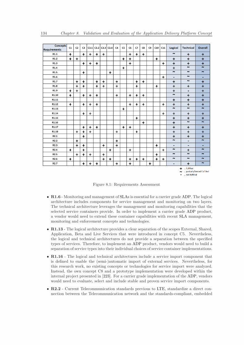
134 Chapter 8. Validation and Evaluation of the Application Delivery Platform Concept
Figure 8.1: Requirements Assessment
• R1.6 - Monitoring and management of SLAs is essential for a carrier grade ADP. The logicalarchitecture includes components for service management and monitoring on two layers.The technical architecture leverages the management and monitoring capabilities that theselected service containers provide. In order to implement a carrier grade ADP product,a vendor would need to extend these container capabilities with recent SLA management,monitoring and enforcement concepts and technologies.
• R1.13 - The logical architecture provides a clear separation of the scopes External, Shared,Application, Beta and Live Services that were introduced in concept C5. Nevertheless,the logical and technical architectures do not provide a separation between the specifiedtypes of services. Therefore, to implement an ADP product, vendors would need to build aseparation of service types into their individual choices of service container implementations.
• R1.16 - The logical and technical architectures include a service import component thatis defined to enable the (semi-)automatic import of external services. Nevertheless, forthis research work, no existing concepts or technologies for service import were analyzed.Instead, the own concept C8 and a prototype implementation were developed within theinternal project presented in [223]. For a carrier grade implementation of the ADP, vendorswould need to evaluate, select and include stable and proven service import components.
• R2.2 - Current Telecommunication standards previous to LTE, standardize a direct con-nection between the Telecommunication network and the standards-compliant, embedded
8.2. Proof of Concept Prototypes 135
and proprietary Telecommunication clients on the end-user device. The logical and techni-cal architectures provide the possibility to fully separate the underlying networks from theapplications, but they cannot force developers to omit this direct connection that bypassesall layers.
• R2.3 - Current Telecommunication standards previous to LTE, standardize Telecommuni-cation applications as whole systems that are utilized by standards-compliant, embeddedand proprietary Telecommunication clients on the end-user device. Therefore, on currentmobile platforms, third-party applications are currently treated differently than embeddedpre-installed applications. The logical and technical architecture fully support platform-abstracted as well as platform-specific third-party application concepts and technologies.
• R2.4 - Several concepts introduce certain aspects of performance and reliability consider-ations, but the logical and technical architectures do not include carrier grade componentswith these functionalities. Vendors would need to consider and evaluate performance andreliability aspects of their individual choices of carrier-grade components that they wouldbe planning to leverage to implement their ADP products.
• R2.5 - Through the Shared Services Layer, all Web-Telecom Converged applications canutilize end-user and group account management services from Telecommunication as wellas Web/Internet services for implementing personalization features. Nevertheless, this re-search work does not evaluate recent sophisticated end-user context data management con-cepts and technologies and so, the logical and technical architectures do not define anydedicated context management components. A vendor would need to provide a state-of-the-art end-user context data management service as a Live Shared Service with an ADPproduct.
• R2.6 - Enabling innovative applications to combine the newest Telecommunication as wellas Web/Internet services, together with carrier grade SLA and QoS monitoring and en-forcement provides a good basis for a great user experience. To ensure an exceptional userexperience, the provider of an ADP platform needs to foster user experience governancewithin its developer community. There are many technical, but also usability and user-interface design aspects to an excellent user experience that cannot be covered by a logicalor technical architecture.
• R2.7 - The logical architecture defines a generic service-import component that can alsobe used for the conjunction of ADPs across domains. The technical architecture leveragesthe proven and defacto-standardized concept of an ESB (see section 2.3) to realize thisfunctionality. This research work does not evaluate different recent concepts or technologiesthat allow publishing, discovering, accessing and composing services across domains.
8.2 Proof of Concept Prototypes
This section illustrates the results of the two-iteration process of ADP and Web-Telecom Con-verged application prototype development. In the first iteration, a basic ADP prototype includ-ing a Unified Address Book application prototype was implemented. In the second iteration, aSemi-Automatic Service Import prototype and an enhanced ADP prototype including a SocialNotification Application prototype were implemented.
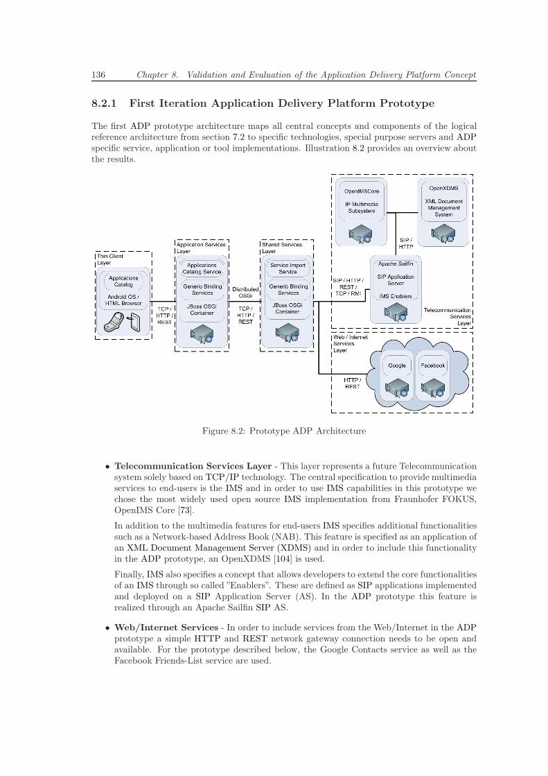
136 Chapter 8. Validation and Evaluation of the Application Delivery Platform Concept
8.2.1 First Iteration Application Delivery Platform Prototype
The first ADP prototype architecture maps all central concepts and components of the logicalreference architecture from section 7.2 to specific technologies, special purpose servers and ADPspecific service, application or tool implementations. Illustration 8.2 provides an overview aboutthe results.
Figure 8.2: Prototype ADP Architecture
• Telecommunication Services Layer - This layer represents a future Telecommunicationsystem solely based on TCP/IP technology. The central specification to provide multimediaservices to end-users is the IMS and in order to use IMS capabilities in this prototype wechose the most widely used open source IMS implementation from Fraunhofer FOKUS,OpenIMS Core [73].
In addition to the multimedia features for end-users IMS specifies additional functionalitiessuch as a Network-based Address Book (NAB). This feature is specified as an application ofan XML Document Management Server (XDMS) and in order to include this functionalityin the ADP prototype, an OpenXDMS [104] is used.
Finally, IMS also specifies a concept that allows developers to extend the core functionalitiesof an IMS through so called ”Enablers”. These are defined as SIP applications implementedand deployed on a SIP Application Server (AS). In the ADP prototype this feature isrealized through an Apache Sailfin SIP AS.
• Web/Internet Services - In order to include services from the Web/Internet in the ADPprototype a simple HTTP and REST network gateway connection needs to be open andavailable. For the prototype described below, the Google Contacts service as well as theFacebook Friends-List service are used.
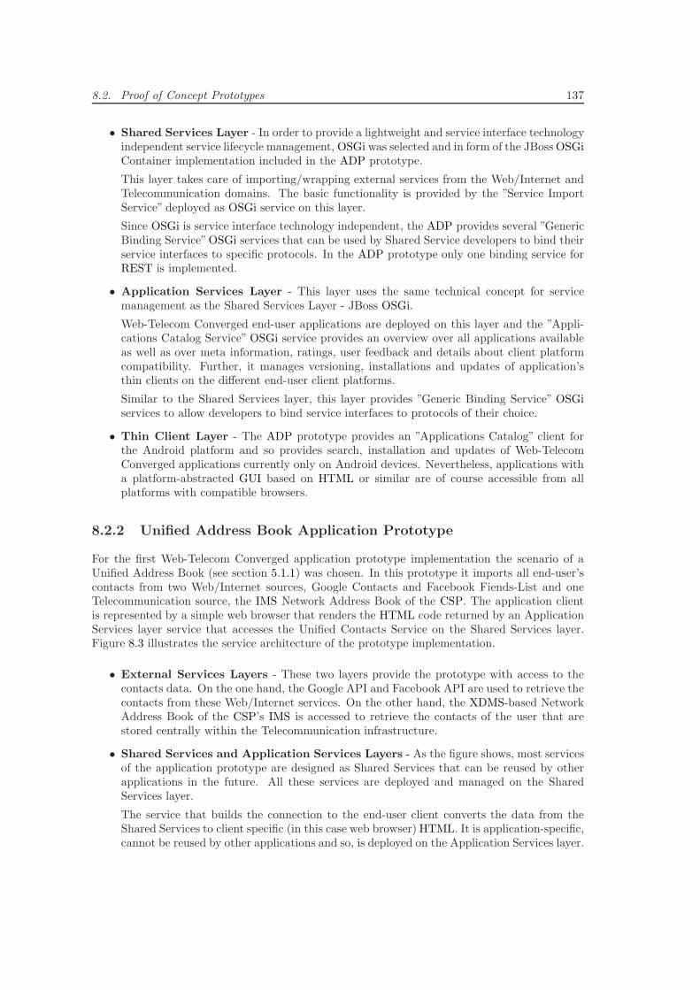
8.2. Proof of Concept Prototypes 137
• Shared Services Layer - In order to provide a lightweight and service interface technologyindependent service lifecycle management, OSGi was selected and in form of the JBoss OSGiContainer implementation included in the ADP prototype.
This layer takes care of importing/wrapping external services from the Web/Internet andTelecommunication domains. The basic functionality is provided by the ”Service ImportService” deployed as OSGi service on this layer.
Since OSGi is service interface technology independent, the ADP provides several ”GenericBinding Service”OSGi services that can be used by Shared Service developers to bind theirservice interfaces to specific protocols. In the ADP prototype only one binding service forREST is implemented.
• Application Services Layer - This layer uses the same technical concept for servicemanagement as the Shared Services Layer - JBoss OSGi.
Web-Telecom Converged end-user applications are deployed on this layer and the ”Appli-cations Catalog Service” OSGi service provides an overview over all applications availableas well as over meta information, ratings, user feedback and details about client platformcompatibility. Further, it manages versioning, installations and updates of application’sthin clients on the different end-user client platforms.
Similar to the Shared Services layer, this layer provides ”Generic Binding Service” OSGiservices to allow developers to bind service interfaces to protocols of their choice.
• Thin Client Layer - The ADP prototype provides an ”Applications Catalog” client forthe Android platform and so provides search, installation and updates of Web-TelecomConverged applications currently only on Android devices. Nevertheless, applications witha platform-abstracted GUI based on HTML or similar are of course accessible from allplatforms with compatible browsers.
8.2.2 Unified Address Book Application Prototype
For the first Web-Telecom Converged application prototype implementation the scenario of aUnified Address Book (see section 5.1.1) was chosen. In this prototype it imports all end-user’scontacts from two Web/Internet sources, Google Contacts and Facebook Fiends-List and oneTelecommunication source, the IMS Network Address Book of the CSP. The application clientis represented by a simple web browser that renders the HTML code returned by an ApplicationServices layer service that accesses the Unified Contacts Service on the Shared Services layer.Figure 8.3 illustrates the service architecture of the prototype implementation.
• External Services Layers - These two layers provide the prototype with access to thecontacts data. On the one hand, the Google API and Facebook API are used to retrieve thecontacts from these Web/Internet services. On the other hand, the XDMS-based NetworkAddress Book of the CSP’s IMS is accessed to retrieve the contacts of the user that arestored centrally within the Telecommunication infrastructure.
• Shared Services and Application Services Layers - As the figure shows, most servicesof the application prototype are designed as Shared Services that can be reused by otherapplications in the future. All these services are deployed and managed on the SharedServices layer.
The service that builds the connection to the end-user client converts the data from theShared Services to client specific (in this case web browser) HTML. It is application-specific,cannot be reused by other applications and so, is deployed on the Application Services layer.
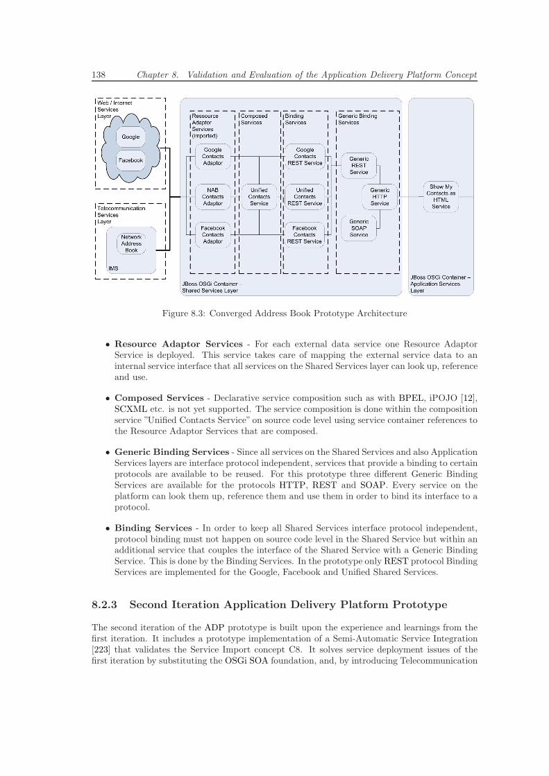
138 Chapter 8. Validation and Evaluation of the Application Delivery Platform Concept
Figure 8.3: Converged Address Book Prototype Architecture
• Resource Adaptor Services - For each external data service one Resource AdaptorService is deployed. This service takes care of mapping the external service data to aninternal service interface that all services on the Shared Services layer can look up, referenceand use.
• Composed Services - Declarative service composition such as with BPEL, iPOJO [12],SCXML etc. is not yet supported. The service composition is done within the compositionservice ”Unified Contacts Service” on source code level using service container references tothe Resource Adaptor Services that are composed.
• Generic Binding Services - Since all services on the Shared Services and also ApplicationServices layers are interface protocol independent, services that provide a binding to certainprotocols are available to be reused. For this prototype three different Generic BindingServices are available for the protocols HTTP, REST and SOAP. Every service on theplatform can look them up, reference them and use them in order to bind its interface to aprotocol.
• Binding Services - In order to keep all Shared Services interface protocol independent,protocol binding must not happen on source code level in the Shared Service but within anadditional service that couples the interface of the Shared Service with a Generic BindingService. This is done by the Binding Services. In the prototype only REST protocol BindingServices are implemented for the Google, Facebook and Unified Shared Services.
8.2.3 Second Iteration Application Delivery Platform Prototype
The second iteration of the ADP prototype is built upon the experience and learnings from thefirst iteration. It includes a prototype implementation of a Semi-Automatic Service Integration[223] that validates the Service Import concept C8. It solves service deployment issues of thefirst iteration by substituting the OSGi SOA foundation, and, by introducing Telecommunication
8.2. Proof of Concept Prototypes 139
multimedia services, it enhances the Telecommunication Services Layer to better match an actualCSP deployment [74].
8.2.3.1 Semi-Automatic Service Import
The concept C8 in section 7.1 illustrates a Service Description File and Code Generator-basedapproach for integrating external Telecommunication and Web/Internet services into the ADP.For the prototype implementation in the CDTM project [223], a simple XML-based SDL is derivedfrom WADL, and the template-based code generation engine Apache Velocity is selected from anevaluation of four code generation technologies. Figure 8.4 illustrates the technical architectureof the prototype implementation.
Figure 8.4: Semi-Automatic Service Import Prototype [223]
• Data Model - Is the textual description of the Telecommunication or Web/Internet serviceformulated according to the SDL specification.
• Template - Defines the mapping and transformation of the Data Model to Java sourcecode, and from there, to a compiled ADP SOA compatible and deployable service. Thetemplate is formulated in a proprietary Apache Velocity specific template language and isillustrated in section D. Since the ADP prototype uses an OSGi foundation, the templateis specifically tailored to generate OSGi compatible services.
• Engine - Is implemented based on Apache Velocity, parses the Data Model using the SimpleAPI for XML (SAX) and generates Java source code. It compiles the code and leveragesMaven, the Apache Felix Maven plugin and Apache Felix iPOJO to generate OSGi specificmeta-data and to build a deployable OSGi bundle. The prototypical Engine implementationsupports Telecommunication and Web/Internet services with REST interfaces and leveragesthe GlassFish Jersey framework in the generated source code to realize the interaction withthem.
• Target - Is the final OSGi compatible .jar bundle that contains all compiled Java classesand resources.
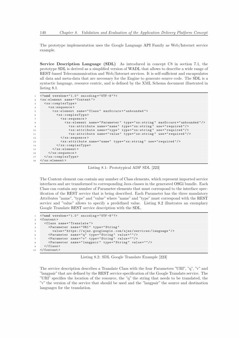
140 Chapter 8. Validation and Evaluation of the Application Delivery Platform Concept
The prototype implementation uses the Google Language API Family as Web/Internet serviceexample.
Service Description Language (SDL) As introduced in concept C8 in section 7.1, theprototype SDL is derived as a simplified version of WADL that allows to describe a wide range ofREST-based Telecommunication and Web/Internet services. It is self-sufficient and encapsulatesall data and meta-data that are necessary for the Engine to generate source code. The SDL is asyntactic language, resource centric, and is defined by the XML Schema document illustrated inlisting 8.1.
1 <?xml version="1.0" encoding ="UTF -8"?>
2 <xs:element name="Content ">
3 <xs:complexType>
4 <xs:sequence >
5 <xs:element name="Class " maxOccurs =" unbounded ">
6 <xs:complexType>
7 <xs:sequence >
8 <xs:element name="Parameter " type="xs:string " maxOccurs ="unbounded "/>
9 <xs:attribute name="name" type="xs:string " use ="required "/>
10 <xs:attribute name="type" type="xs:string " use ="required "/>
11 <xs:attribute name="value" type="xs:string " use="required "/>
12 </xs:sequence >
13 <xs:attribute name="name" type=" xs:string " use="required "/>
14 </ xs:complexType>
15 </xs:element >
16 </xs:sequence >
17 </ xs:complexType>
18 </xs:element >
Listing 8.1: Prototypical ADP SDL [223]
The Content element can contain any number of Class elements, which represent imported serviceinterfaces and are transformed to corresponding Java classes in the generated OSGi bundle. EachClass can contain any number of Parameter elements that must correspond to the interface spec-ification of the REST service that is being described. Each Parameter has the three mandatoryAttributes ”name”, ”type” and ”value”where ”name” and ”type”must correspond with the RESTservice and ”value” allows to specify a predefined value. Listing 8.2 illustrates an exemplaryGoogle Translate REST service description with the SDL.
1 <?xml version="1.0" encoding ="UTF -8"?>
2 <Content >
3 <Class name="Translate ">
4 <Parameter name="URI" type="String "
5 value="https: //ajax. googleapis .com/ajax/services /language "/>
6 <Parameter name="q" type="String " value=""/>
7 <Parameter name="v" type="String " value=""/>
8 <Parameter name="langpair " type="String " value=""/>
9 </Class >
10 </Content >
Listing 8.2: SDL Google Translate Example [223]
The service description describes a Translate Class with the four Parameters ”URI”, ”q”, ”v” and”langpair”that are defined by the REST service specification of the Google Translate service. The”URI” specifies the location of the resource, the ”q” the string that needs to be translated, the”v” the version of the service that should be used and the ”langpair” the source and destinationlanguages for the translation.
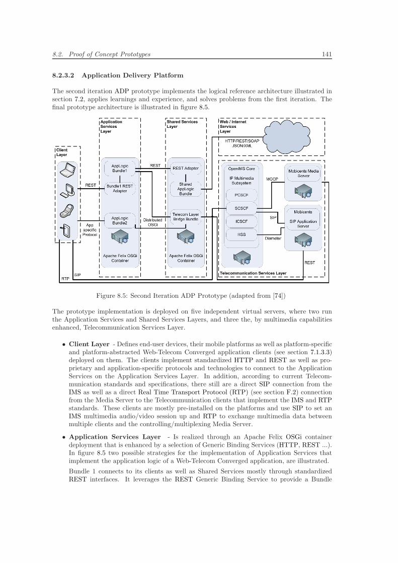
8.2. Proof of Concept Prototypes 141
8.2.3.2 Application Delivery Platform
The second iteration ADP prototype implements the logical reference architecture illustrated insection 7.2, applies learnings and experience, and solves problems from the first iteration. Thefinal prototype architecture is illustrated in figure 8.5.
Figure 8.5: Second Iteration ADP Prototype (adapted from [74])
The prototype implementation is deployed on five independent virtual servers, where two runthe Application Services and Shared Services Layers, and three the, by multimedia capabilitiesenhanced, Telecommunication Services Layer.
• Client Layer - Defines end-user devices, their mobile platforms as well as platform-specificand platform-abstracted Web-Telecom Converged application clients (see section 7.1.3.3)deployed on them. The clients implement standardized HTTP and REST as well as pro-prietary and application-specific protocols and technologies to connect to the ApplicationServices on the Application Services Layer. In addition, according to current Telecom-munication standards and specifications, there still are a direct SIP connection from theIMS as well as a direct Real Time Transport Protocol (RTP) (see section F.2) connectionfrom the Media Server to the Telecommunication clients that implement the IMS and RTPstandards. These clients are mostly pre-installed on the platforms and use SIP to set anIMS multimedia audio/video session up and RTP to exchange multimedia data betweenmultiple clients and the controlling/multiplexing Media Server.
• Application Services Layer - Is realized through an Apache Felix OSGi containerdeployment that is enhanced by a selection of Generic Binding Services (HTTP, REST ...).In figure 8.5 two possible strategies for the implementation of Application Services thatimplement the application logic of a Web-Telecom Converged application, are illustrated.
Bundle 1 connects to its clients as well as Shared Services mostly through standardizedREST interfaces. It leverages the REST Generic Binding Service to provide a Bundle
142 Chapter 8. Validation and Evaluation of the Application Delivery Platform Concept
1 REST Adapter service interface that the clients can use to connect. It connects to theShared AppLogic Bundle through the REST Adapter service interface this provides. Only tothe Telecom Layer Bridge Shared Service, Bundle 1 connects through the non-standardizedDistributed OSGi feature of the platform.
Bundle 2 does not leverage any standardized technologies, but implements an application-specific protocol that its clients need to support in order to connect. To connect to theTelecom Layer Bridge Shared Service, it leverages the non-standardized Distributed OSGifeature of the platform.
• Shared Services Layer - Is realized through an Apache Felix OSGi container deploymentthat is enhanced by a selection of Generic Binding Services (HTTP, REST ...).
The Shared AppLogic Bundle service leverages the REST Generic Binding Service to pro-vide a REST Adapter service interface that Application Services can use to connect. Ituses REST or SOAP to import Web/Internet Service functionalities.
The Telecom Layer Bridge Shared Service does not leverage any Generic Binding Service,but simply relies on the Distributed OSGi feature to enable other service to connect to it.It uses REST to import Telecommunication Service functionalities.
• Telecommunication Services Layer - Consists of the three components IMS, SIP Ap-plication Server and Media Server.
The IMS is realized through an OpenIMSCore deployment that provides standards com-pliant test-bed implementations of the interconnected P-, I- and S-CSCFs as well as theend-user identity and authentication managing HSS (see section F.5.2).
The SIP AS is realized through a JBoss Mobicents SIP Application Server and hosts theREST interfaces to the Telecommunication Services that are provided by the Telecommu-nication Services Layer. It interfaces the IMS platform, which implements the Telecommu-nication Services, through SIP and Diameter.
The Media Server is realized through a JBoss Mobicents Media Server that manages, con-trols, routes and multiplexes multiple RTP and Real Time Streaming Protocol (RTSP)(see section F.2) multimedia data streams of multiple IMS sessions. It is controlled by theIMS through a Media Gateway Control Protocol (MGCP) interface (see section F.1.5) andexchanges multimedia data with client applications through RTP streams.
• Web/Internet Services Layer - Represents all Web/Internet Services that are accessiblethrough REST or SOAP interfaces and so, can be imported through Resource AdapterServices (e.g. the Shared AppLogic Bundle) as Shared Services into the ADP.
8.2.4 Social Notification Application Prototype
To validate the concepts and functionalities of the deployed ADP prototype and according tothe scenario presented in 5.1.2, in the CDTM project [74], a prototype of a Social NotificationApplication (SNApp) was developed and deployed on top of the ADP prototype.
8.2.4.1 Motivation and Goals
Over the last decade, social networking has been growing rapidly and applications/platformshave become extremely popular. Today, basic social networking functionalities such as sharing,commenting and building a circle of friends, cannot only be found in the large social networkapplications Facebook and Google+, but also in regular Web/Internet applications like YouTube
8.2. Proof of Concept Prototypes 143
or Flickr as well as upcoming smaller-scale applications. As a result of this high level of socialnetworking across multiple applications and platforms, end-users are overloaded by the amountof news, events and updates from their networking partners that they have to manually filter andprocess.
SNApp’s goal is to reduce this overload by gathering social networking information from thedifferent platforms an end-user is active on, and selectively actively notifying him about onlythose news, events and updates that are relevant for him. SNApp provides a Web/Internettechnologies-based application that enables end-users to manage personal filter criteria for socialnetwork news, updates and events together with their preferred notification channel(s) TextMes-sage, E-Mail or automated Audio Phone Call. Thereby, end-users can precisely filter what socialnetwork information they would like to receive from whom on what communication channel. Allunwanted information is automatically filtered out. In addition to notifying, for every receivedsocial network information, SNApp enables end-users to quickly respond via the communicationchannels SMS, MMS, Voice/Video Phone Call, E-Mail, SNApp’s mobile application or SNApp’sWeb/Internet applications. Section E illustrates a typical SNApp social network informationpush sequence.
8.2.4.2 Component Architecture
The layered logical reference architecture of the ADP, illustrated in section 7.2, dictates mostof the layout of the distributed component architecture of SNApp. Figure 8.6 illustrates thedistribution of the collection of SNApp services onto the Shared, Application, Web/Internet,Telecommunication and Client Services Layers. In addition, it illustrates the Database and IMScomponents the application leverages.
• Web/Internet Services Layer - Represents all social network applications and platformsthat provide an accessible and programmable interface. This is ideally based on standard-ized Web/Internet technologies such as REST or SOAP. The prototype implementation ofSNApp accesses only the main functionalities of the Facebook application.
• Telecommunication Services Layer - Consists of the three components IMS Core,SIP Application Server (AS) and Media Server. The IMS provides the SIP-based standardTelecommunication services TextMessage, MultimediaMessage and Voice/Video Call. TheSIP AS hosts the Message and PhoneCall Services that are implemented as SIP Servlets,access the IMS Telecommunication services and expose/provide them as REST interfacesto the Shared and Application Services. The PhoneCall Service needs to transform thenotification information text data into audio data that can be streamed to an end-usersTelecommunication client. It uses the Text-to-Speech Service on the Media Server to trans-form the text data and streams the resulting audio data to the client via RTP.
• Shared Services Layer - Contains all services that are implemented generic, without anySNApp application specifics, and shared/accessible by all future applications on the ADP.In addition to the shared E-Mail Service, Generic Persistence Service, Facebook Service,TextMessage Service and AudioNotification Service that implement certain functionalitiesan application can utilize, the Generic Binding Service ”Generic REST Service” enablesShared Services to bind to the REST technology to be accessible from the ApplicationServices Layer via REST. In the prototype implementation, only the Facebook Service isbound to REST via the Facebook-Service REST Adapter Binding Service.
• Application Services Layer - Contains all services that are SNApp specific and thatare not accessible by any future applications on the ADP. The Application Services SNApp
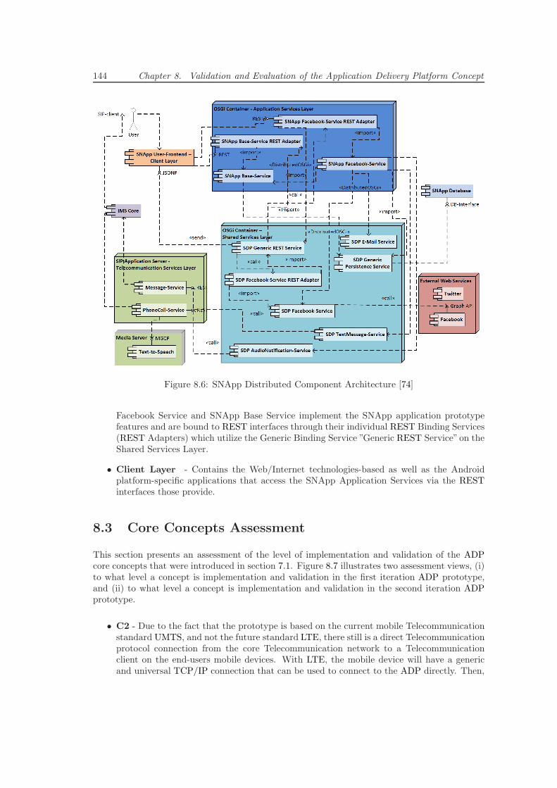
144 Chapter 8. Validation and Evaluation of the Application Delivery Platform Concept
Figure 8.6: SNApp Distributed Component Architecture [74]
Facebook Service and SNApp Base Service implement the SNApp application prototypefeatures and are bound to REST interfaces through their individual REST Binding Services(REST Adapters) which utilize the Generic Binding Service ”Generic REST Service”on theShared Services Layer.
• Client Layer - Contains the Web/Internet technologies-based as well as the Androidplatform-specific applications that access the SNApp Application Services via the RESTinterfaces those provide.
8.3 Core Concepts Assessment
This section presents an assessment of the level of implementation and validation of the ADPcore concepts that were introduced in section 7.1. Figure 8.7 illustrates two assessment views, (i)to what level a concept is implementation and validation in the first iteration ADP prototype,and (ii) to what level a concept is implementation and validation in the second iteration ADPprototype.
• C2 - Due to the fact that the prototype is based on the current mobile Telecommunicationstandard UMTS, and not the future standard LTE, there still is a direct Telecommunicationprotocol connection from the core Telecommunication network to a Telecommunicationclient on the end-users mobile devices. With LTE, the mobile device will have a genericand universal TCP/IP connection that can be used to connect to the ADP directly. Then,
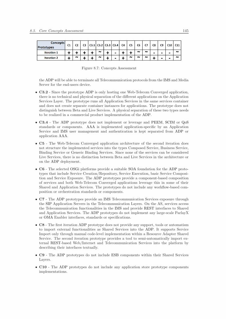
8.3. Core Concepts Assessment 145
Figure 8.7: Concepts Assessment
the ADP will be able to terminate all Telecommunication protocols from the IMS and MediaServer for the end-users device.
• C3.2 - Since the prototype ADP is only hosting one Web-Telecom Converged application,there is no technical and physical separation of the different applications on the ApplicationServices Layer. The prototype runs all Application Services in the same services containerand does not create separate container instances for applications. The prototype does notdistinguish between Beta and Live Services. A physical separation of these two types needsto be realized in a commercial product implementation of the ADP.
• C3.4 - The ADP prototype does not implement or leverage and PEEM, SCIM or QoSstandards or components. AAA is implemented application-specific by an ApplicationService and IMS user management and authentication is kept separated from ADP orapplication AAA.
• C5 - The Web-Telecom Converged application architecture of the second iteration doesnot structure the implemented services into the types Composed Service, Business Service,Binding Service or Generic Binding Services. Since none of the services can be consideredLive Services, there is no distinction between Beta and Live Services in the architecture oron the ADP deployment.
• C6 - The selected OSGi platforms provide a suitable SOA foundation for the ADP proto-types that include Service Creation/Repository, Service Execution, basic Service Composi-tion and Service Exposure. The ADP prototypes provide a component-based compositionof services and both Web-Telecom Converged applications leverage this in some of theirShared and Application Services. The prototypes do not include any workflow-based com-position or orchestration standards or components.
• C7 - The ADP prototypes provide an IMS Telecommunication Services exposure throughthe SIP Application Servers in the Telecommunication Layers. On the AS, services accessthe Telecommunication functionalities in the IMS and provide REST interfaces to Sharedand Application Services. The ADP prototypes do not implement any large-scale ParlayXor OMA Enabler interfaces, standards or specifications.
• C8 - The first iteration ADP prototype does not provide any support, tools or automatismto import external functionalities as Shared Services into the ADP. It supports ServiceImport only through manual code-level implementation within a Resource Adapter SharedService. The second iteration prototype provides a tool to semi-automatically import ex-ternal REST-based Web/Internet and Telecommunication Services into the platform bydescribing their interfaces textually.
• C9 - The ADP prototypes do not include ESB components within their Shared ServicesLayers.
• C10 - The ADP prototypes do not include any application store prototype componentsimplementations.
146 Chapter 8. Validation and Evaluation of the Application Delivery Platform Concept
• C11 - The OSGi platforms provide a basic service management and monitoring founda-tion including a Web/Internet-based user-interface. The platforms provide programmableinterfaces to service status and real-time service monitoring functionalities, but the ADPprototypes do not implement any processing or evaluation of the provided data. The ADPprototypes do not implement any SLA management, monitoring or enforcement standards,concepts or specifications.
Chapter 9
Conclusion and Future Work
This research work identified and analyzed current problems within the Telecommunication in-dustry and proposed as solution the design of an ADP that extends existing SDPs, Web-TelecomConvergence and SOA concepts in Telecommunications. The work analyzed the Web-TelecomConvergence related goals of the major stakeholders, combined these with an evaluation of ex-isting Web-Telecom Convergence and Mobile Application Development concepts, and illustratedhow the requirements for an ADP can be derived from that. From the requirements, eleven coreconcepts for an ADP design were created, and from these, a logical reference architecture and anexemplary technical architecture for an ADP were developed.
The ADP concepts and architectures were validated and evaluated in two iterations of ADP pro-totype implementations that each included the implementation and deployment of an exemplaryWeb-Telecom Converged application prototype on top of the platform. The application prototypeimplementations showed that the use of an ADP enhances the architecture, and so, maintain-ability of future applications as well as that it reduces the development time of new applicationsby leveraging a growing pool of powerful Shared Services. The assessments of the requirementsand core concepts showed that the ADP is a feasible concept that is able to fulfill many of therequirements and goals, and so, provides great advantages for all major stakeholders.
Future work may include the extension of the ADP prototype through a set of imported Telecom-munication and Web/Internet services. Especially real-time Telecommunication features such asVoice/Video and Conference Call or Instant Messaging features from the Web/Internet. Thiswill allow an extended investigation of real-time concepts and requirements. In addition to ser-vices, upcoming client platforms such as smartphones, laptops, PCs, tablets and IPTVs may beincluded in future Web-Telecom Converged application scenario prototype implementations.
Future work may include enhancements of the QoS, SLA, Monitoring and AAA concepts througha thorough evaluation of existing proposals and standards in this area.
Future work may include a prototypical implementation of the application store concept as well asenhance the concept to a Meta-Store concept that realizes interfaces to the existing distributionchannels of the different platforms (e.g. Apple App Store, Android Market, etc.).
Future work may investigate workflow-based service composition and orchestration concepts,standards and solutions including an integration, and evaluation of the usefulness, of graphicalcomposition tools.
From the core concepts, logical reference architecture and exemplary technical architecture de-veloped in this research work, future work may derive and create a precise specification/standard
148 Chapter 9. Conclusion and Future Work
for all components, services, protocols, data formats and interfaces of the ADP.
In the future, a commercial ADP product could be implemented by a Telecommunication orApplication Server vendor, and be deployed by a CSP, a CSP’s subsidiary focusing on innovationand developer integration, or an independent Telecommunication or Web/Internet provider. Inorder to deploy an ADP implementation successfully the provider needs to adopt the mindset ofWeb/Internet service providers and fulfill all non-technical organizational, business and gover-nance related stakeholder goals that are out of scope of the technical requirements and conceptsof the ADP.
The provider needs to allow Beta Services and Applications development and distribution in shortand unrestricted prototyping development cycles. It needs to attract a maximum of applicationdevelopers by conveying an open and innovative mindset with a maximum of openness, flexibilityand support, and a minimum of bureaucracy, binding contracts and costs.
The provider needs to successfully convey and advertise to developers the advantages of using anADP, as a hosted and managed Web-Telecom Converged Application environment that providesaccess to a huge number of ready-to-use stable services. Further, it needs to offer incentives andtools for platform contributions, especially on the Shared Services Layer, and needs to manageall Shared Services and premium Live Applications with the highest possible quality.
An ADP deployment will only be successfully if application developers fulfill all non-technical end-user goals that are out of scope of the technical requirements and concepts of the ADP. Developerneed to see the advantages and abide by the Web-Telecom Converged Application architecturethe ADP defines and governs. They need to be supported at identifying and distinguishingShared from Application Services. They need to adopt an open source community mindset andshare their services in the whole ADP community in order to allow a collective and constantmaintenance of Shared Services and Applications.
Appendix A
Web-Telecom ConvergenceConcepts and PlatformsEvaluation Details
A.1 Business Requirements
These business goals drive every implementation of a Web-Telecom Convergence Platform archi-tecture implementation (adapted from [125]):
• Improve market position - With the implementation of a modern platform, the telecom-munication operator aims for expanding market share in operating markets, entering newmarkets and reducing time to markets of new products.
• Generation of new revenue streams - With the convergence of different networks, thetelecommunication operator is able to generate new revenue streams from new entertain-ment services, advertising and content services.
• Transforming business models - Today, 40% of the operators that have deployed a platformexpect it to allow them to transform their business models and to drive new revenues fromthird party application and services. The new business models need to include revenuesplitting with third party service providers.
• Reduce Total cost of Ownership - Total cost of ownership describes the total cost of aninformation technology product over its lifecycle.
It comprises of the following points:
– Reduce cost of development - Additionally to the cost of development, the operatoris required to manage flexible sourcing alternatives. Therefore, the system should bebased on open standards to increase interoperability and portability.
– Reduce cost of deployment, operations and maintenance - Especially the ease of in-stallation and the ease of repair as well as the increase in flexibility and configurationpossibility is important to the telecommunication operator.
150 Appendix A. Web-Telecom Convergence Concepts and Platforms Evaluation Details
– Reduce cost of retirement - Dealing with legacy is one of the most important aspectsof a platform. From the business perspective it means to either to retire older sys-tems, find a smooth transition to follow on systems and in the end to replace legacysystems/moving to a new system.
• Improve capability and quality of system - Business requires an increase in performance,reliability and availability of the system with new software architecture. Security, safetyscalability, extensibility as well as internationalization possibly of the system are necessary.
• Support improved business processes - The software architecture is supposed to supportdistributed development and maintain jobs of workforce on legacy system.
• Widening the range of service sources - To produce a large number of services and appli-cations, one of the most important goals for a platform is to attract as much third-partycontent and as many service providers as possible.
• Globalization - Many CSPs operate in various countries and therefore, the platform mustbe specified so that it can be deployed in different countries and regions to save costs andto interconnect platform.
• Resolving vendor lock-in - Legacy platform usually fails in time-consuming service creationand lacks of service portability, soaring service OPEX throughout the operation. Evenannual maintenance fees of these legacy systems can surpass total cost of new service plat-form. Therefore, the telecommunication operator needs to gain financial and technologicalfreedom in choosing the best of breed solutions provided by vendors.
A.2 Architectural Services
Service Creation Environment
• Managing usage of internal reusable service building blocks
• Development tools to assists easy service building blocks development• High level features, which allow to efficiently reuse existing building blocks• Managing functionality for reusable service building blocks• Service publishing• Service composition• Service discovery• SLA agreement• Service repository
• Designing orchestration of services
• GUI enabling orchestration of service components and integrating• External services without having to develop low-level code• Tools on mock-up of service composition• Enabling mapping of service requirements to service Logic
• Service testing
• Managing functionalities and reporting capabilities for third-party developers
Service Execution Environment
• Homogeneous end-to-end service lifecycle management
• Service discovery and service description
A.2. Architectural Services 151
• Service deployment
• Service orchestration
• Creation of new business processes• Control of workflow regulation of services• Service composition from multiple service enablers• Binding component between service repositories offering description of available ser-vices
• Deliver mobile content/messaging
• Delivery of voice and data services
• Service fulfillment
• Tracing and log services
Service Control Environment
• Security
• Authentication, authorization, auditing• Service capability access control• Network access and protection• Privacy and integrity
• Service control and monitoring
• Monitoring and enforcement of Service Level Agreement (SLA)• Service access• Service profile management• Service monitoring• Network overlay service controlling
• User and roles management
• User access• User profile management• Participant roles and authorization management• Addition and removal of participants• Support of participant interaction• Subscriber management• Single-sign on
• Policy management
• Policy evaluation• Policy enforcement• Event handling• Key management• ID federation
• Other
• Traffic control of each component, priority control and flow control
Service Broker
• Communication among diverse implementations of layers, platforms, service enablers andinterfaces
• Management and monitoring of middleware
• Service interaction
• Resource delegation
152 Appendix A. Web-Telecom Convergence Concepts and Platforms Evaluation Details
• Service mobility to be exchanged throughout different devices
• Messaging bus transmitting the messages among components of the SDP
• Interconnecting internal application and service enabler
Interfaces
• Facilitating rapid OSS/BSS integration
• Integration with various, legacy systems
• Provision of open API platform
• Interface with external application and third-party service providers
• Network and device independence
Enablers
• Reusable service component, which can be composed to more advanced VAS
• Facilitate development, deployment and operation of services
• Expose simple standardized API, abstracting from underlying network
• Capabilities
• Hiding non-relevant programming support details and provide a high level method of de-scribing services
• Standardized interfaces linking application to network elements
A.3 Quality Subfactors
Interoperability
• Device and network independence
• Industry standards to enable current and future technologies
• Enable integration of legacy systems
• Enable ”write once runs anywhere” principle
• Multi-Vendor products support
• Interface with IMS and use IMS capability
Reliability
• Carrier-grade or near carrier-grade level of reliability
• Consistent and stable environment
• Service reliability
• Failure management
Availability
• Tolerant to system failures and overload
• Capable of quickly solving and isolating problems
A.3. Quality Subfactors 153
Usability
• Enable non-experts to use platform
• Abstract from network and telecommunication knowledge
• Rapid development of services
Security
• Secure access to network resources and service enabler
• Data integrity
• Confidentiality
• Authentication
• Authorization
• Encryption
• Enablement of interoperability between different security domains
• Secure communication between cross-organizational services and to third party applica-tion/service providers
• Trust building procedure for external services
• Support of different certifiers and different trust models
Performance
• Perform near real-time
• Low latency, thus high throughout should not affect performance
• Addressing high volume of data and transaction
Scalability
• Addressing the needs of different networks and future technologies
• No loss of performance with increase in number of users and numbers of transactions

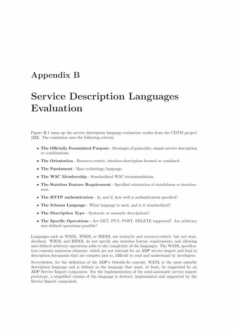
Appendix B
Service Description LanguagesEvaluation
Figure B.1 sums up the service description language evaluation results from the CDTM project[223]. The evaluation uses the following criteria:
• The Officially Formulated Purpose - Strategies of generality, simple service descriptionor combinations.
• The Orientation - Resource-centric, interface-description focused or combined.
• The Fundament - Base technology/language.
• The W3C Membership - Standardized W3C recommendation.
• The Stateless Feature Requirement - Specified orientation of statefulness or stateless-ness.
• The HTTP authentication - Is, and if, how well is authentication specified?
• The Schema Language - What language is used, and is it standardized?
• The Description Type - Syntactic or semantic descriptions?
• The Specific Operations - Are GET, PUT, POST, DELETE supported? Are arbitraryuser-defined operations possible?
Languages such as WADL, WRDL or RIDDL are syntactic and resource-centric, but not stan-dardized. WRDL and RIDDL do not specify any stateless feature requirements, and allowinguser-defined arbitrary operations adds to the complexity of the languages. The WADL specifica-tion contains numerous elements, which are not relevant for an ADP service import and lead todescription documents that are complex and so, difficult to read and understand by developers.
Nevertheless, for the definition of the ADP’s Outside-In concept, WADL is the most suitabledescription language and is defined as the language that must, at least, be supported by anADP Service Import component. For the implementation of the semi-automatic service importprototype, a simplified version of the language is derived, implemented and supported by theService Import component.
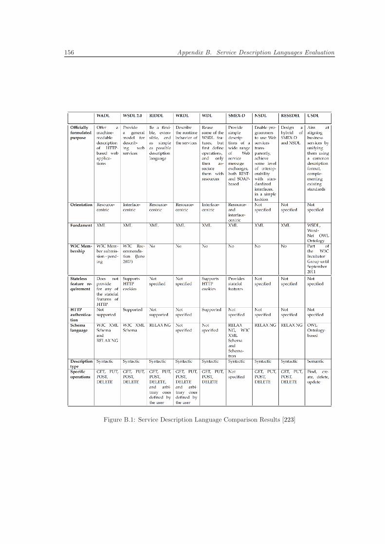
156 Appendix B. Service Description Languages Evaluation
Figure B.1: Service Description Language Comparison Results [223]
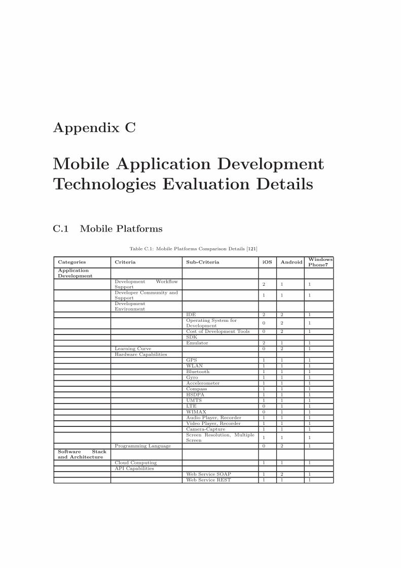
Appendix C
Mobile Application DevelopmentTechnologies Evaluation Details
C.1 Mobile Platforms
Table C.1: Mobile Platforms Comparison Details [121]
Categories Criteria Sub-Criteria iOS AndroidWindowsPhone7
ApplicationDevelopment
Development WorkflowSupport
2 1 1
Developer Community andSupport
1 1 1
DevelopmentEnvironment
IDE 2 2 1Operating System forDevelopment
0 2 1
Cost of Development Tools 0 2 1SDKEmulator 2 1 1
Learning Curve 0 2 1Hardware Capabilities
GPS 1 1 1WLAN 1 1 1Bluetooth 1 1 1Gyro 1 1 1Accelerometer 1 1 1Compass 1 1 1HSDPA 1 1 1UMTS 1 1 1LTE 0 1 1WIMAX 0 1 1Audio Player, Recorder 1 1 1Video Player, Recorder 1 1 1Camera-Capture 1 1 1Screen Resolution, MultipleScreen
1 1 1
Programming Language 0 2 1Software Stackand Architecture
Cloud Computing 1 1 1API Capabilities
Web Service SOAP 1 2 1Web Service REST 1 1 1
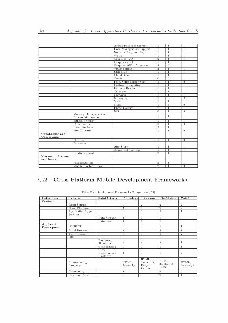
158 Appendix C. Mobile Application Development Technologies Evaluation Details
Access Database Servers 1 1 1Data Management Support 1 1 1Network Programming 1 1 1WI-FI 1 1 1Graphics - 2D 2 1 1Graphics - 3D 1 1 1Graphics API - Animation 2 0 1Video Formats 2 1 1USB Host 1 1 1Cloud Sync 1 1 1Game 0 0 1Face/Voice Recognition 1 1 0Gesture Recognition 1 1 1Barcode Reader 1 1 1Calendar 1 1 1Contacts 1 1 1Messaging 1 2 2VoIP 1 1 1Maps 1 2 0Photo Gallery 2 1 1NFC 0 1 0
Memory Management andProcess Management
1 1 1
Multiple Screen 1 1 1Open Source 0 1 0User-Interfaces 2 1 1Web Browser 1 1 0
Capabilities andConstraints
Devices 1 1 0Ecosystem
App Store 1 1 1Supported Services 1 1 1
Runtime Speed 2 1 1Market Successand Issues
Fragmentation 2 1 1Mobile Platform Race 2 1 0
C.2 Cross-Platform Mobile Development Frameworks
Table C.2: Development Frameworks Comparison [121]
Categories Criteria Sub-Criteria PhoneGap Titanium RhoMobile WACContext
Open Source 1 2 2 2Cross-Platform 2 1 2 2Application Type 1 1 2 1Services
Data Storage 0 0 1 0Data Sync 0 0 1 0
ApplicationDevelopment
Debugger 1 1 1 1
Build Process 2 1 2 1Test Process 1 1 1 2IDE
Emulator,Simulator
1 1 1 1
Code Editing 1 1 1 1CrossDevelopmentPlatforms
0 1 1 2
ProgrammingLanguage
HTML,Javascript
HTML,Javascript,Ruby,Python
HTML,JavaScript,Ruby
HTML,Javascript
Community 2 1 2 0Learning Curve 1 1 0 1
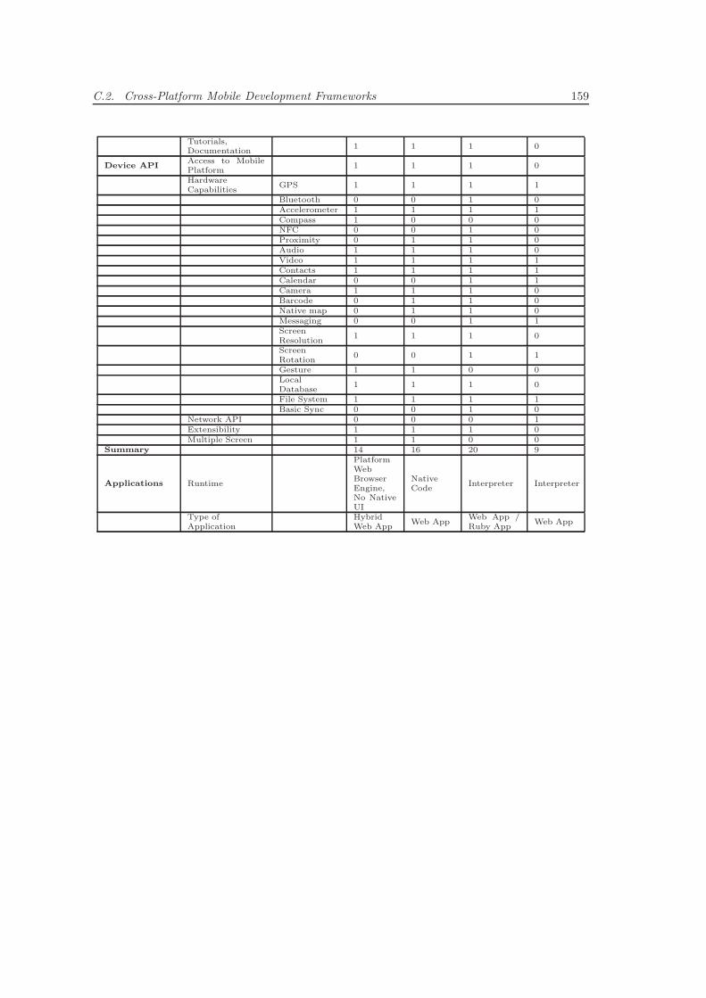
C.2. Cross-Platform Mobile Development Frameworks 159
Tutorials,Documentation
1 1 1 0
Device APIAccess to MobilePlatform
1 1 1 0
HardwareCapabilities
GPS 1 1 1 1
Bluetooth 0 0 1 0Accelerometer 1 1 1 1Compass 1 0 0 0NFC 0 0 1 0Proximity 0 1 1 0Audio 1 1 1 0Video 1 1 1 1Contacts 1 1 1 1Calendar 0 0 1 1Camera 1 1 1 0Barcode 0 1 1 0Native map 0 1 1 0Messaging 0 0 1 1ScreenResolution
1 1 1 0
ScreenRotation
0 0 1 1
Gesture 1 1 0 0LocalDatabase
1 1 1 0
File System 1 1 1 1Basic Sync 0 0 1 0
Network API 0 0 0 1Extensibility 1 1 1 0Multiple Screen 1 1 0 0
Summary 14 16 20 9
Applications Runtime
PlatformWebBrowserEngine,No NativeUI
NativeCode
Interpreter Interpreter
Type ofApplication
HybridWeb App
Web AppWeb App /Ruby App
Web App

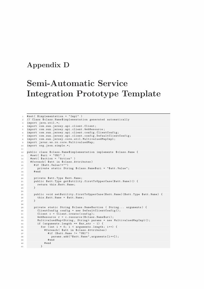
Appendix D
Semi-Automatic ServiceIntegration Prototype Template
1 #set( $implementation = "Impl" )
2 // Class $class.Name$implementation generated automatically
3 import java.util .*;
4 import com.sun .jersey .api.client .Client ;
5 import com.sun .jersey .api.client . WebResource ;
6 import com.sun .jersey .api.client .config .ClientConfig;
7 import com.sun .jersey .api.client .config .DefaultClientConfig;
8 import com.sun .jersey .core.util. MultivaluedMapImpl;
9 import javax.ws.rs.core.MultivaluedMap;
10 import org.json.simple .*;
11
12 public class $class.Name$implementation implements $class.Name {
13 #set( $uri = "URI" )
14 #set( $action = "Action " )
15 #foreach ( $att in $class. Attributes )
16 #if ($att.Value !="")
17 private static String $class.Name$uri = "$att .Value";
18 #end
19
20 private $att.Type $att.Name;
21 public $att.Type get$utility . firstToUpperCase($att.Name)() {
22 return this .$att.Name;
23 }
24
25 public void set$utility .firstToUpperCase($ att.Name)($att.Type $att .Name) {
26 this .$att.Name = $att.Name;
27 }
28
29 private static String $class.Name$action ( String ... arguments ) {
30 ClientConfig config = new DefaultClientConfig ();
31 Client c = Client .create (config );
32 WebResource r = c.resource ($class .Name$uri );
33 MultivaluedMap<String , String > params = new MultivaluedMapImpl ();
34 if (arguments .length == $nr_atr - 1) {
35 for (int i = 0; i < arguments .length ; i++) {
36 #foreach ( $att in $class.Attributes )
37 #if ($ att.Name != "URI")
38 params .add("$att.Name",arguments [i++]);
39 #end
40 #end
41 }
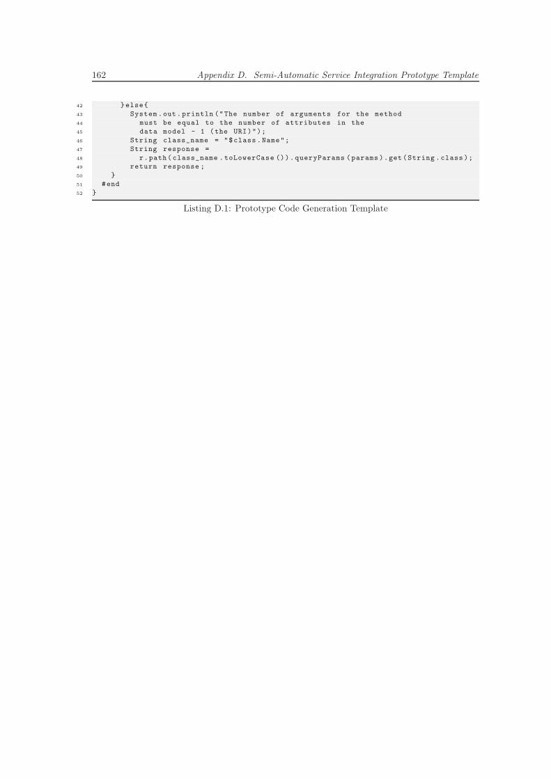
162 Appendix D. Semi-Automatic Service Integration Prototype Template
42 }else{
43 System .out.println ("The number of arguments for the method
44 must be equal to the number of attributes in the
45 data model - 1 (the URI)");
46 String class_name = "$class .Name";
47 String response =
48 r.path( class_name .toLowerCase ()).queryParams (params ).get (String .class );
49 return response ;
50 }
51 #end
52 }
Listing D.1: Prototype Code Generation Template
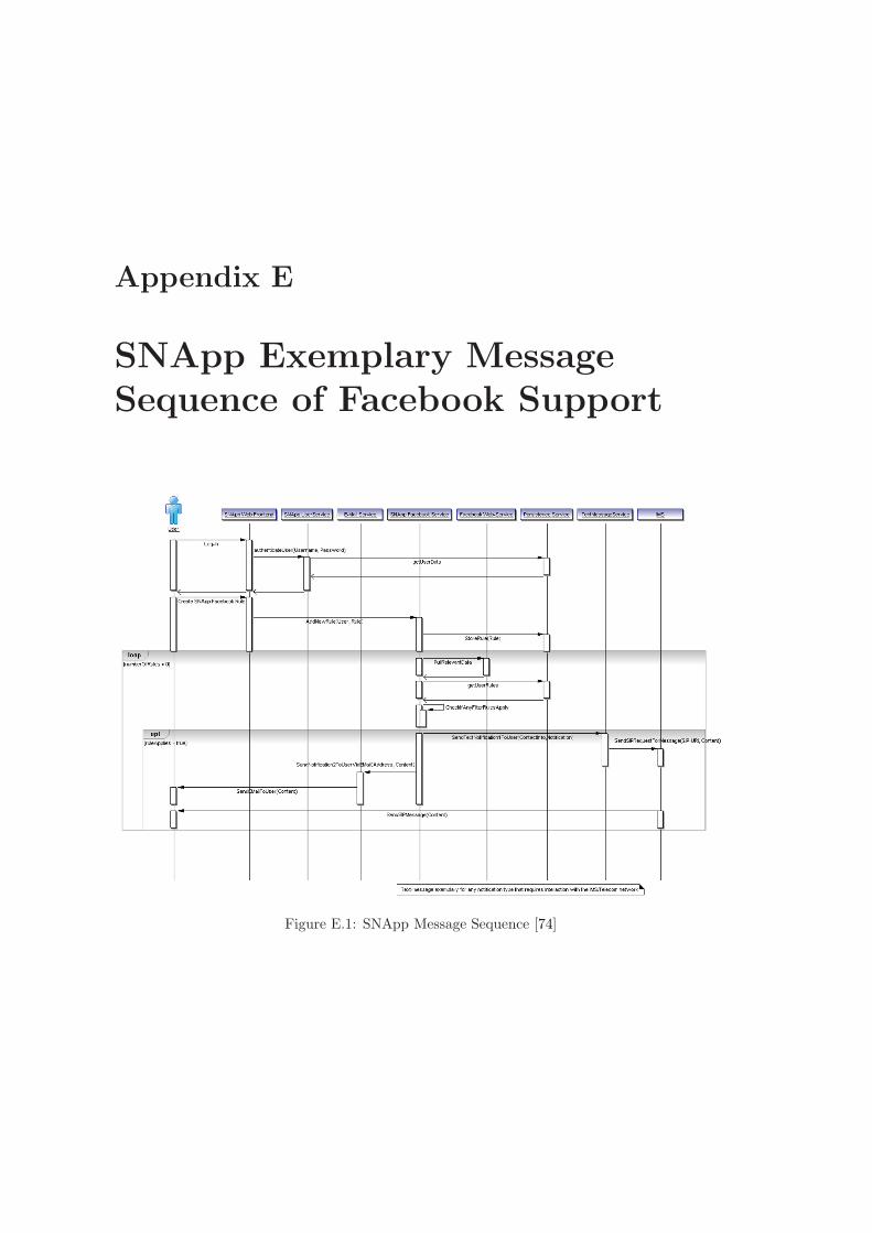
Appendix E
SNApp Exemplary MessageSequence of Facebook Support
Figure E.1: SNApp Message Sequence [74]

Appendix F
Related Technologies, Standardsand Specifications
This chapter describes the most important technology concepts that were used for the analysis,design and implementation of the ADP architecture and prototype. It gives an overview aboutthe concepts in general and describes the most important technical details of every concept.
F.1 Internet and Telecommunication Protocols
This section describes the most important specifications and protocols in the area of mobileapplication development for VoIP systems. This includes transport and call-control protocols aswell as specifications for server-side application development. It will be assumed that underlyingbasic protocols like IP, TCP and UDP are familiar. Information about them can be found in [53,page 161ff]
F.1.1 Hyper Text Transfer Protocol (HTTP)
HTTP is a text-based data transmission protocols for networks. It is mainly used to requestand receive web pages and other Web/Internet related data and transfer that data to and fromnetwork devices such as web-servers and PCs with web browsers etc. HTTP is an applicationlayer protocol and does not store or maintain any state information between requests, so anadditional session manager needs to be implemented on top of HTTP if session information isimportant for an application.
HTTP is mostly used but not limited to transfer Hypertext encoded in HTML. Through its pos-sible request extensions, additional header information and status codes it is possible to transferany type of data as payload with HTTP.
Currently there are two versions of HTTP used, HTTP/1.0 and HTTP/1.1. Version 1.0 opens anew TCP connection for every request sent from a client to a server whereas version 1.1 is ableto keep the TCP connection open while requests are sent to the same server. This eliminates alot of useless TCP handshakes between client and server and increases the data transfer speeddrastically. In addition to that HTTP/1.1 introduced new request methods that allow clients
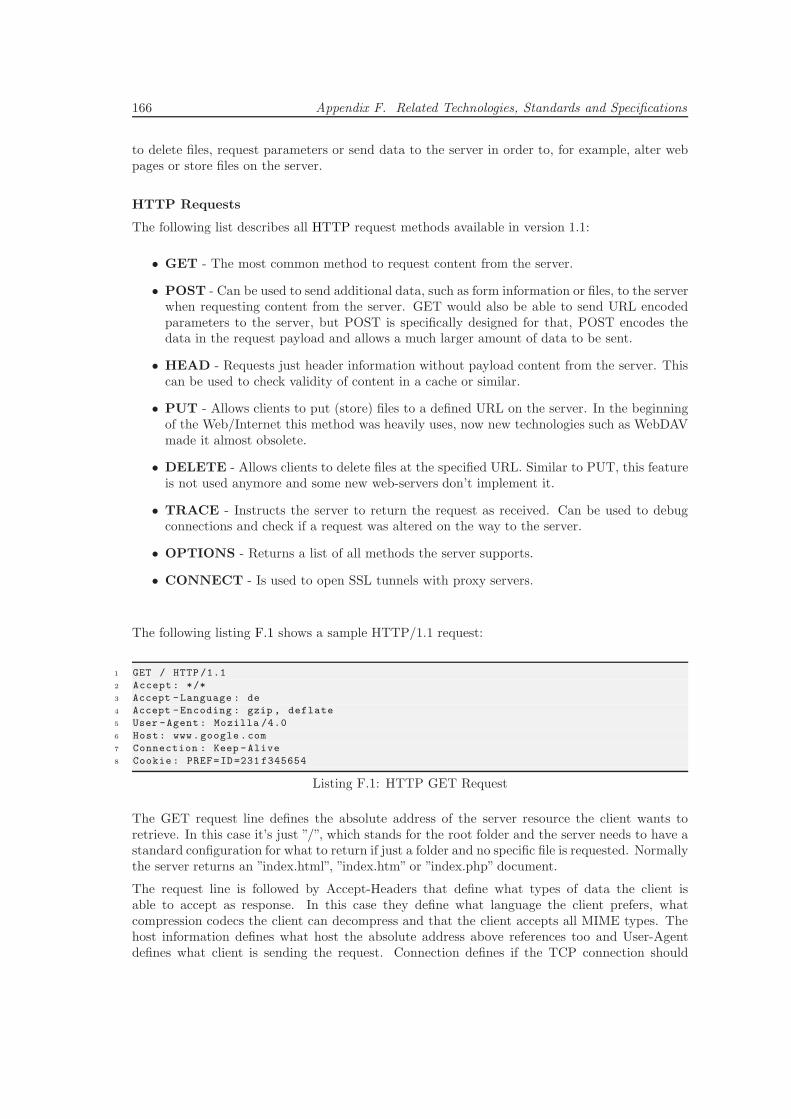
166 Appendix F. Related Technologies, Standards and Specifications
to delete files, request parameters or send data to the server in order to, for example, alter webpages or store files on the server.
HTTP Requests
The following list describes all HTTP request methods available in version 1.1:
• GET - The most common method to request content from the server.
• POST - Can be used to send additional data, such as form information or files, to the serverwhen requesting content from the server. GET would also be able to send URL encodedparameters to the server, but POST is specifically designed for that, POST encodes thedata in the request payload and allows a much larger amount of data to be sent.
• HEAD - Requests just header information without payload content from the server. Thiscan be used to check validity of content in a cache or similar.
• PUT - Allows clients to put (store) files to a defined URL on the server. In the beginningof the Web/Internet this method was heavily uses, now new technologies such as WebDAVmade it almost obsolete.
• DELETE - Allows clients to delete files at the specified URL. Similar to PUT, this featureis not used anymore and some new web-servers don’t implement it.
• TRACE - Instructs the server to return the request as received. Can be used to debugconnections and check if a request was altered on the way to the server.
• OPTIONS - Returns a list of all methods the server supports.
• CONNECT - Is used to open SSL tunnels with proxy servers.
The following listing F.1 shows a sample HTTP/1.1 request:
1 GET / HTTP /1.1
2 Accept : */*
3 Accept -Language : de
4 Accept -Encoding : gzip , deflate
5 User -Agent : Mozilla /4.0
6 Host: www.google .com
7 Connection : Keep -Alive
8 Cookie : PREF=ID=231 f345654
Listing F.1: HTTP GET Request
The GET request line defines the absolute address of the server resource the client wants toretrieve. In this case it’s just ”/”, which stands for the root folder and the server needs to have astandard configuration for what to return if just a folder and no specific file is requested. Normallythe server returns an ”index.html”, ”index.htm” or ”index.php” document.
The request line is followed by Accept-Headers that define what types of data the client isable to accept as response. In this case they define what language the client prefers, whatcompression codecs the client can decompress and that the client accepts all MIME types. Thehost information defines what host the absolute address above references too and User-Agentdefines what client is sending the request. Connection defines if the TCP connection should
F.1. Internet and Telecommunication Protocols 167
be kept open after this request and the Cookie information can be used as a session trackingmechanism or to store web site information on the client-side.
HTTP Response
Every HTTP request sent to a server is answered by a HTTP response sent back to the client.Every response contains a status code that defines the outcome of the request. In addition tothat, every successful response contains the requested content as payload.
Status codes from the same type are combined in five code families and the following list showsan overview of these families:
• 1XX - Information. Informs the client that the server is still processing the request andthat processing might take longer than normal. Such a request is necessary since after acertain time-out most clients assume the request was not successful and present an errormessage.
• 2XX - Success. The request was processed successfully and the response data is sent withresponse.
• 3XX - Redirect. The requested resource was moved to a different location and the clientneeds to request the resource again from the new location. The Location-Header field ofthe response tells the client where to find the requested resource now.
• 4XX - Client Error. Request processing was not successful due to an error caused by theclient. This can be for example a 404 response that defines that the client requests anunknown resource or a 403 response that defines that the resource is restricted and theclient is not allowed to retrieve it.
• 5XX - Server Error. The request could not be processed due to an error caused by theserver software. For example a 501 response informs the client that the server does nothave all features (programs or additional files) to process the request.
The following listing F.2 shows the HTTP response to the GET request shown above:
1 HTTP /1.1 302 Found
2 Location: http: //www .google .at/
3 Cache -Control: private
4 Content -Type: text/html
5 Server: gws
6 Transfer -Encoding: chunked
7 Content - Encoding: gzip
8 Date: Sun , 21 Oct 2007 11 :54:42 GMT
Listing F.2: HTTP 302 Redirect Response
In this case the Google server sends a 302 Redirect response and informs the client to request theresource from a different location: ”http://www.google.at/”. So the client (in this case a Firefoxweb browser) sends another GET request to the other host.
The following listing F.3 shows the HTTP/1.1 200 OK response from the second GET request:
1 HTTP /1.1 200 OK
2 Cache -Control: private
3 Content -Type: text/html; charset =UTF -8
4 Content - Encoding: gzip
168 Appendix F. Related Technologies, Standards and Specifications
5 Server: gws
6 Content -Length: 1945
7 Date: Sun , 21 Oct 2007 11 :54:42 GMT
8
9 <html><head><meta http -equiv="content -type" content ="text/html; charset =UTF -8"><
title >Google </title ><style >body ,td,a,p,.h{font -family:arial ,sans -serif }.h{font
-size:20px }.h{color: #3366 cc}.q{color: #00c}.ts td{padding:0 }.ts{border -
collapse:collapse}</style >
10 .....
11 </script >
12 </head><body bgcolor =# ffffff text =#000000 link =#0000 cc vlink =#551 a8b alink =# ff0000
onload ="sf();if( document .images ){new Image ().src =’/ images /nav_logo3 .png ’}"
topmargin =3 marginheight=3><div align=right id=guser style="font -size:84 %;
padding:0 0 4px" width =100% >
13 ...
14 </center ></body></html >
Listing F.3: HTTP 200 OK Response
This response informs the client that the request was processed successful, includes a lot of metainformation about the server and resource in the headers and contains the requested HTML website as payload.
F.1.2 Session Initiation Protocol (SIP)
SIP is an Internet Engineering Task Force (IETF) application-layer signaling and control protocolspecified in Request for Comment (RFC) 2543. It is used to establish, maintain, manage, alterand terminate multimedia sessions, which are used in IP telephony, audio and video conferencesand other similar applications involving audio and video data transmission/streaming.
SIP is a text-based protocol with a message syntax and header fields comparable to HTTP. SIPmessages are sent over TCP or UDP with possibly multiple messages carried in a single TCPconnection or UDP datagram. Since SIP messages can grow very large, which can be a problemover low bandwidth mobile device radio links, some new specifications propose compressions suchas DEFLATE to be used with SIP. These proposals are defined in the Signaling Compression[183] (SigComp) and Extended Operations [85] specifications.
SIP can be used to establish sessions and carry session descriptions in order to negotiate sessionparameters and details such as codecs etc. between end-points. It supports unicast and mul-ticast sessions as well as point-to-point and multi-point calls. Connections can be established,maintained and terminated using the following five SIP facets:
• User Location - Defines how and where to contact a user a client wants to call. Involvesclient software (can be multiple ones for one physical user) SIP registrations at RegistrarServers and ”DNS-like” resolving of SIP addresses in order to build a connection betweenthe users clients.
• User Capability - Defines compatible codecs and communication parameters for the au-dio/video session.
• User Availability - Defines state information for the different devices a physical user isregistered with. (e.g. offline, online, unavailable, available, busy, etc.)
• Call Setup - Defines signaling messages for call/session setup and communication param-eter negotiations.
F.1. Internet and Telecommunication Protocols 169
• Call Handling - Defines signaling messages for altering session parameters, moving ses-sions between registered devices, adding clients to a conference session/call, terminatingsessions etc.
SIP can be used in conjunction with other signaling protocols, such as H.323, RTSP, RTCP etc.,but it does not depend on any of these protocols.
Specifications, technologies and systems around VoIP are still being developed and extended andwill require additional signaling capabilities in the future. The extensibility of SIP enables suchdevelopment of incremental functionality. SIP message headers are versatile and one can registeradditional features with the Internet Assigned Numbers Authority (IANA). SIP’s message flexi-bility enables developers to construct advanced telephony applications and services.
SIP RequestsThe start line, often referred to as request line, distinguishes SIP requests from responses andcontains three components: a method name, a request-URI and the protocol version. They appearin that order and are separated by a single space character. The request line itself terminateswith a carriage return-line feed pair (CRLF):
• Method - indicates the type of request. Six are defined in the basic SIP specification[RFC3261]: the INVITE request, CANCEL request, ACK request and BYE request areused for session creation, modification and termination. The REGISTER request is usedto register a certain user’s contact information, and the OPTIONS request is used to queryservers for their capabilities. Other methods have been created as an extension to thestandard.
• Request-URI - is a SIP or a SIPS URI that identifies the requested resource.
• Protocol version - the current SIP version is 2.0. All standard compliant requests mustinclude this version information in the form of: ”SIP/2.0”.
SIP ResponsesThe start line, often referred to as request line, distinguishes SIP responses from requests andcontains three components: the protocol version, status code and reason phrase. They appear inthat order and are separated by a single space character. The status line itself terminates witha CRLF pair:
• Protocol version - this is identical to the protocol version in the request line.
• Status code - the status code is a three-digit code that identifies the nature of the response.It indicates the outcome of the request.
• Reason phrase - this is a free text field providing a short description of the status codemeant for human users/readers.
Status codes are classified into six classes (classes 2xx to 6xx are final responses):
• 1XX - provisional/informational responses. They indicate that the request was receivedand the recipient is continuing to process the request.
• 2Xx - success responses. The request was successfully received, understood and accepted.
170 Appendix F. Related Technologies, Standards and Specifications
• 3XX - redirection responses. Further action needs to be taken by the requester in order tocomplete the request.
• 4XX - client error responses. The request contains a syntax error. It can also indicate thatthe server cannot fulfill the request.
• 5XX - server error responses. The server failed to fulfill a valid request. It is the fault ofthe server.
• 6XX - global failure responses. The request cannot be fulfilled at any server. The serverresponding with this response class needs to have definitive information about the user.
The ”xx” are two digits that indicate the exact nature of the response: for example, a ”180”provisional response indicates ringing by the remote end, while a ”181” provisional responseindicates that a call is being forwarded.
HeaderEvery message contains a header with mandatory and optional fields that describe communica-tion, session and connection details. Message headers specify the calling party, called party, routeand message type of a call. Header fields also indicate message body characteristics and end witha CRLF pair. The headers section of a SIP message terminates with a CRLF as well.
The four groups of message headers are as follows:
• General headers - Apply to requests and responses.
• Entity headers - Define information about the message body type and length.
• Request headers - Enable clients to include additional request information.
• Response headers - Enable servers to include additional response information.
For more information about SIP requests and responses or the different header types and fieldssee [190] or [53, page 254ff].
The format of the header fields is as follows:
Header-name: header-value
Some headers are mandatory in every SIP request and response. Those headers and their formatsare listed below:
• To header - To: SIP-URI(;parameters)
• From header - From: SIP-URI(;parameters)
• Call-ID header - Call-ID: unique-id
• CSeq header - CSeq: digit method
• Via header - Via: SIP/2.0/[transport-protocol] sent-by(;parameters)
• Max-Forwards header - Max-Forwards: digit
• Contact header - Contact: SIP-URI(;parameters)
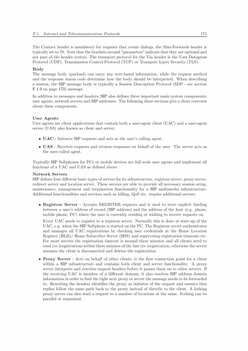
F.1. Internet and Telecommunication Protocols 171
The Contact header is mandatory for requests that create dialogs, the Max-Forwards header istypically set to 70. Note that the brackets around ”parameters”indicate that they are optional andnot part of the header syntax. The transport protocol for the Via header is the User DatagramProtocol (UDP), Transmission Control Protocol (TCP) or Transport Layer Security (TLS).
BodyThe message body (payload) can carry any text-based information, while the request methodand the response status code determine how the body should be interpreted. When describinga session, the SIP message body is typically a Session Description Protocol (SDP - see sectionF.1.3 on page 173) message.
In addition to messages and headers, SIP also defines three important main system components:user agents, network servers and SIP addresses. The following three sections give a short overviewabout these components.
User AgentsUser agents are client applications that contain both a user-agent client (UAC) and a user-agentserver (UAS) also known as client and server.
• UAC - Initiates SIP requests and acts as the user’s calling agent.
• UAS - Receives requests and returns responses on behalf of the user. The server acts asthe user-called agent.
Typically SIP Softphones for PCs or mobile devices are full scale user agents and implement allfunctions of a UAC and UAS as defined above.
Network ServersSIP defines four different basic types of servers for its infrastructure, registrar server, proxy server,redirect server and location server. These servers are able to provide all necessary session setup,maintenance, management and termination functionality for a SIP multimedia infrastructure.Additional functionalities and services such as billing, QoS etc. require additional servers.
• Registrar Server - Accepts REGISTER requests and is used to store explicit bindingbetween a user’s address of record (SIP address) and the address of the host (e.g. phone,mobile phone, PC) where the user is currently residing or wishing to receive requests on.
Every UAC needs to register to a registrar server. Normally this is done at start-up of theUAC, e.g. when the SIP Softphone is started on the PC. The Registrar server authenticatesand manages all UAC registrations by checking user credentials at the Home LocationRegister (HLR)/ Home Subscriber Server (HSS) and supervising registration timeouts etc.For most servers the registration timeout is around three minutes and all clients need tosend (re-)registrations within three minutes of the last (re-)registration, otherwise the serverassumes the client is disconnected and deletes the registration.
• Proxy Server - Acts on behalf of other clients, is the first connection point for a clientwithin a SIP infrastructure and contains both client and server functionality. A proxyserver interprets and rewrites request headers before it passes them on to other servers. Ifthe receiving UAC is member of a different domain, it also resolves SIP address domaininformation in order to find the right next proxy or server the message needs to be forwardedto. Rewriting the headers identifies the proxy as initiator of the request and ensures thatreplies follow the same path back to the proxy instead of directly to the client. A forkingproxy server can also send a request to a number of locations at the same. Forking can beparallel or sequential.
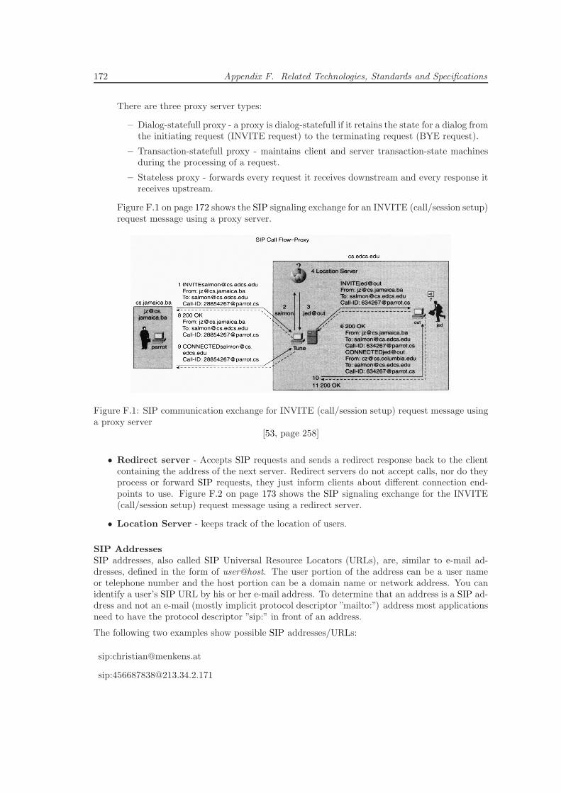
172 Appendix F. Related Technologies, Standards and Specifications
There are three proxy server types:
– Dialog-statefull proxy - a proxy is dialog-statefull if it retains the state for a dialog fromthe initiating request (INVITE request) to the terminating request (BYE request).
– Transaction-statefull proxy - maintains client and server transaction-state machinesduring the processing of a request.
– Stateless proxy - forwards every request it receives downstream and every response itreceives upstream.
Figure F.1 on page 172 shows the SIP signaling exchange for an INVITE (call/session setup)request message using a proxy server.
Figure F.1: SIP communication exchange for INVITE (call/session setup) request message usinga proxy server
[53, page 258]
• Redirect server - Accepts SIP requests and sends a redirect response back to the clientcontaining the address of the next server. Redirect servers do not accept calls, nor do theyprocess or forward SIP requests, they just inform clients about different connection end-points to use. Figure F.2 on page 173 shows the SIP signaling exchange for the INVITE(call/session setup) request message using a redirect server.
• Location Server - keeps track of the location of users.
SIP AddressesSIP addresses, also called SIP Universal Resource Locators (URLs), are, similar to e-mail ad-dresses, defined in the form of user@host. The user portion of the address can be a user nameor telephone number and the host portion can be a domain name or network address. You canidentify a user’s SIP URL by his or her e-mail address. To determine that an address is a SIP ad-dress and not an e-mail (mostly implicit protocol descriptor ”mailto:”) address most applicationsneed to have the protocol descriptor ”sip:” in front of an address.
The following two examples show possible SIP addresses/URLs:
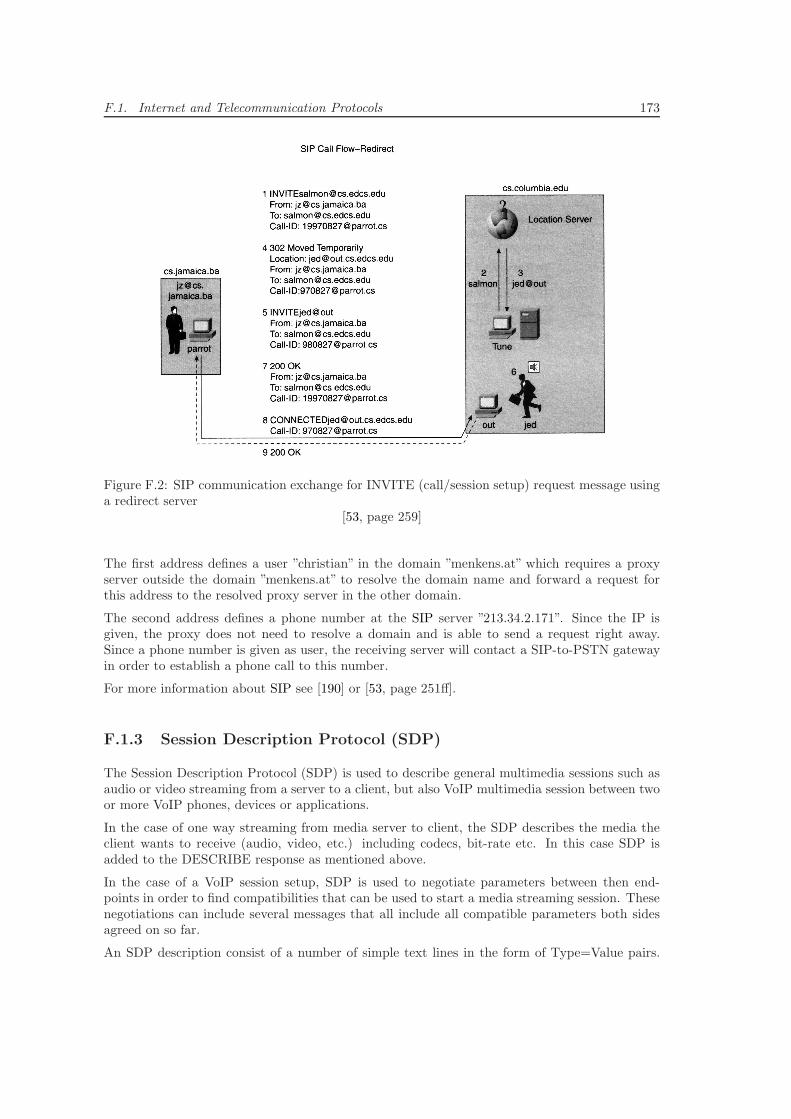
F.1. Internet and Telecommunication Protocols 173
Figure F.2: SIP communication exchange for INVITE (call/session setup) request message usinga redirect server
[53, page 259]
The first address defines a user ”christian” in the domain ”menkens.at” which requires a proxyserver outside the domain ”menkens.at” to resolve the domain name and forward a request forthis address to the resolved proxy server in the other domain.
The second address defines a phone number at the SIP server ”213.34.2.171”. Since the IP isgiven, the proxy does not need to resolve a domain and is able to send a request right away.Since a phone number is given as user, the receiving server will contact a SIP-to-PSTN gatewayin order to establish a phone call to this number.
For more information about SIP see [190] or [53, page 251ff].
F.1.3 Session Description Protocol (SDP)
The Session Description Protocol (SDP) is used to describe general multimedia sessions such asaudio or video streaming from a server to a client, but also VoIP multimedia session between twoor more VoIP phones, devices or applications.
In the case of one way streaming from media server to client, the SDP describes the media theclient wants to receive (audio, video, etc.) including codecs, bit-rate etc. In this case SDP isadded to the DESCRIBE response as mentioned above.
In the case of a VoIP session setup, SDP is used to negotiate parameters between then end-points in order to find compatibilities that can be used to start a media streaming session. Thesenegotiations can include several messages that all include all compatible parameters both sidesagreed on so far.
An SDP description consist of a number of simple text lines in the form of Type=Value pairs.
174 Appendix F. Related Technologies, Standards and Specifications
Type is always exactly one character and case sensitive. The following list describes some of themost important types of SDP (* marked ones are optional).
Session description
v= protocol version
o= owner/creator and session identifier
s= session name
i=* session information
u=* URI of description
e=* email address
p=* phone number
c=* connection information
b=* bandwidth information
<Block with one or more time descriptions>
z=* time zone adjustments
k=* encryption key
a=* zero or more session attribute lines
<Block with zero or more media descriptions>
Time description
t=* time the session is active
r=* zero or more repeat times
Media description
m= media name and transport address
i=* media title
c=* connection information
- optional if included at session level
b=* bandwidth information
k=* encryption key
a=* zero or more media attribute lines
F.1.4 Diameter
Diameter [40] is an authentication, authorization and accounting (AAA) protocol developed bythe Internet Engineering Task Force (IETF). Diameter is used to provide AAA services for arange of access technologies. Instead of building the protocol from scratch, Diameter is looselybased on the Remote Authentication Dial-In User Service (RADIUS) [187], which has previouslybeen used to provide AAA services for dial-up and terminal server access environments. As basicfoundation for the Diameter specification, the AAA Working Group first gathered requirementsfor AAA services as they apply to network access from different interest groups.
The final Diameter protocol is actually split into two parts: the Diameter base protocol andthe Diameter applications. The base protocol is needed for delivering Diameter data units,negotiating capabilities, handling errors and providing for extensibility. A Diameter applicationdefines application-specific functions and data units. Each Diameter application is specified
F.1. Internet and Telecommunication Protocols 175
separately. Currently, in addition to the base protocol, a few Diameter applications have beendefined and some are in the process of being defined:
• Mobile IP
• NASREQ
• Extensible Authentication Protocol (EAP)
• Diameter credit control
• Diameter SIP application
The Diameter base protocol uses both the Transmission Control Protocol (TCP) and the StreamControl Transmission Protocol (SCTP) as transport. However, SCTP is the preferred choice,mostly due to the connection oriented relationship that exists between Diameter peers. It isbeneficial to be able to categorize several independent streams to a single SCTP association,instead of keeping all streams open as independent TCP connections. Both Internet ProtocolSecurity (IPsec) and Transport Layer Security (TLS) are used for securing the connections.
Protocol componentsDiameter is a peer-to-peer protocol, so any Diameter node can initiate a request. Diameter hasthree different types of network nodes: servers, agents and clients.
A Diameter server services client requests within a realm, according to the used Diameter ap-plication and handles authentication, accounting and authorization requests for this particulardomain, or realm. All Diameter messages are routed according to the network access identifier(NAI) of a particular user.
A Diameter agent provides value-added services for clients and servers that include either relay,proxy, redirect or translation services.
Clients are generally the user or edge devices of a network that perform access control and origi-nate AAA requests. Typically, the Diameter client is a network access server (NAS) that performsAAA services for a particular access technology. The NAS needs to authenticate the terminalsthat are attached to a network before allocating network resources for them: for example, a Wire-less Local Area Network access point may need to ascertain the user’s identity before allowingaccess.
F.1.5 Simple Gateway Control Protocol (SGCP) and Media GatewayControl Protocol (MGCP)
Simple Gateway Control Protocol (SGCP) and MGCP are gateway control protocols designedto support gateways that have external intelligence (external call-control elements). Therefore,their use is prevalent in large trunking gateways and residential gateways. The following twosections give a short overview about these two protocols.
Simple Gateway Control ProtocolSGCP enables call-control elements to control connections between trunking, residential andaccess-type VoIP gateways. Although these gateways target different market segments, all ofthem convert time-division multiplexing (TDM) voice into packet voice. Call-control elementsare generally referred to as Media Gateway Controllers (MGCs) or call agents.
176 Appendix F. Related Technologies, Standards and Specifications
SGCP assumes an architecture whose call-control intelligence is outside of the gateway and ishandled by call agents. In this model, one or more call agents can participate in constructing acall. Synchronization among these call agents is assumed and is not covered by SGCP.
SGCP is used to establish, maintain and disconnect calls across an Internet Protocol (IP) network.This is accomplished by controlling the required connections between desired and correspond-ing endpoints. Authorization of calls and connections is outside of the scope of this protocol.SGCP does not contain a security mechanism for unauthorized call setup or interference but thespecification states that it is expected that all transactions are carried over secure Web/Internetconnections.
SGCP request and response messages are sent to IP addresses of specific endpoints using UDPand packet losses or delays are handled by repeating requests.
The basic constructs of SGCP are endpoints and connections. Connections exist in either point-to-point or multi-point form and groups of connections constitute a call, which is set up for oneor more call agents. Endpoints are sources or sinks of data that physically or logically existwithin an entity. Physical endpoints can be trunk circuits connecting gateways or phone switcheswhereas logical endpoints can be announcements stored in audio devices etc.
For more information about SGCP see [15] and[53, page 263ff].
Media Gateway Control ProtocolMGCP controls VoIP through external call-control elements. The first version of MGCP wasbased on the fusion of SGCP and the Internet Protocol Device Control (IPDC). Therefore, thedifferences between MGCP and SGCP are largely due to functionality inspired by IPDC.
MGCP utilizes the same connection model as SGCP, where the basic constructs are endpointsand connections, but enables connections to be established over several types of bearer networkslike:
• IP Networks - Transmission of audio over TCP/IP networks using RTP and UDP.
• ATM Networks - Audio transmission over an ATM network using ATM adaption Layer 2(AAAL2) or another adaption layer.
• Internal Connections - Transmission of packets across TDM backplane or bus of the gateway.
Similar to SGCP messages, MGCP messages are transmitted across the packet network overUDP but they can piggyback other messages. MGCP enables several messages to be sent to thesame gateway in one UDP packet. These piggyback messages should be processed as if they werereceived as several simultaneous messages.
In MGCP a formal wildcard structure, which was inspired by IPDC, was introduced. Call agentscan use wildcard convention when sending commands to gateways.
For more information about MGCP see [102] and[53, page 273ff].
SummarySGCP and MGCP are vital components used during the transition from a network whose compo-nents are in one monolithic platform to a network whose components are distributed. SGCP andMGCP form the basis for call agents and gateways to communicate. This is one of the keys toa distributed packet network. Currently dozens of vendors have written to the MGCP standard
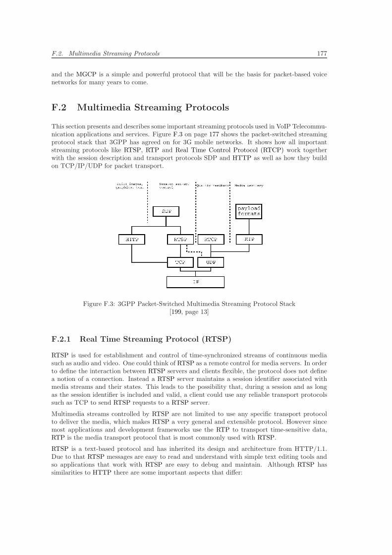
F.2. Multimedia Streaming Protocols 177
and the MGCP is a simple and powerful protocol that will be the basis for packet-based voicenetworks for many years to come.
F.2 Multimedia Streaming Protocols
This section presents and describes some important streaming protocols used in VoIP Telecommu-nication applications and services. Figure F.3 on page 177 shows the packet-switched streamingprotocol stack that 3GPP has agreed on for 3G mobile networks. It shows how all importantstreaming protocols like RTSP, RTP and Real Time Control Protocol (RTCP) work togetherwith the session description and transport protocols SDP and HTTP as well as how they buildon TCP/IP/UDP for packet transport.
Figure F.3: 3GPP Packet-Switched Multimedia Streaming Protocol Stack[199, page 13]
F.2.1 Real Time Streaming Protocol (RTSP)
RTSP is used for establishment and control of time-synchronized streams of continuous mediasuch as audio and video. One could think of RTSP as a remote control for media servers. In orderto define the interaction between RTSP servers and clients flexible, the protocol does not definea notion of a connection. Instead a RTSP server maintains a session identifier associated withmedia streams and their states. This leads to the possibility that, during a session and as longas the session identifier is included and valid, a client could use any reliable transport protocolssuch as TCP to send RTSP requests to a RTSP server.
Multimedia streams controlled by RTSP are not limited to use any specific transport protocolto deliver the media, which makes RTSP a very general and extensible protocol. However sincemost applications and development frameworks use the RTP to transport time-sensitive data,RTP is the media transport protocol that is most commonly used with RTSP.
RTSP is a text-based protocol and has inherited its design and architecture from HTTP/1.1.Due to that RTSP messages are easy to read and understand with simple text editing tools andso applications that work with RTSP are easy to debug and maintain. Although RTSP hassimilarities to HTTP there are some important aspects that differ:
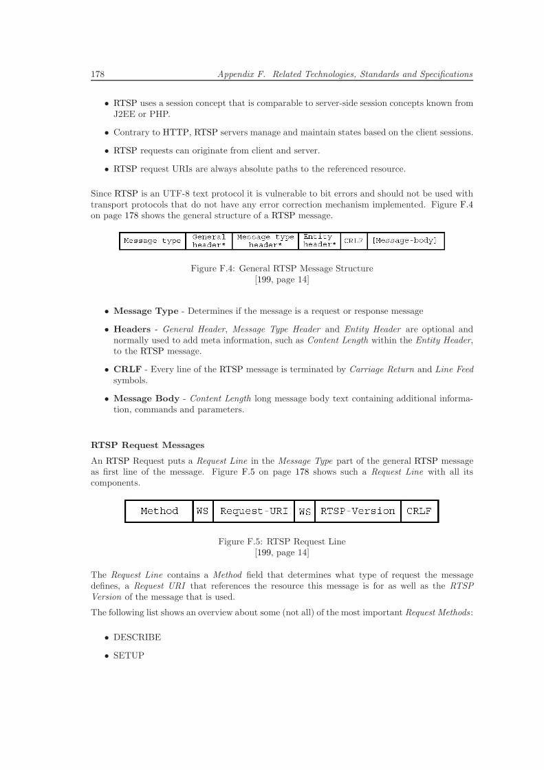
178 Appendix F. Related Technologies, Standards and Specifications
• RTSP uses a session concept that is comparable to server-side session concepts known fromJ2EE or PHP.
• Contrary to HTTP, RTSP servers manage and maintain states based on the client sessions.
• RTSP requests can originate from client and server.
• RTSP request URIs are always absolute paths to the referenced resource.
Since RTSP is an UTF-8 text protocol it is vulnerable to bit errors and should not be used withtransport protocols that do not have any error correction mechanism implemented. Figure F.4on page 178 shows the general structure of a RTSP message.
Figure F.4: General RTSP Message Structure[199, page 14]
• Message Type - Determines if the message is a request or response message
• Headers - General Header, Message Type Header and Entity Header are optional andnormally used to add meta information, such as Content Length within the Entity Header,to the RTSP message.
• CRLF - Every line of the RTSP message is terminated by Carriage Return and Line Feedsymbols.
• Message Body - Content Length long message body text containing additional informa-tion, commands and parameters.
RTSP Request Messages
An RTSP Request puts a Request Line in the Message Type part of the general RTSP messageas first line of the message. Figure F.5 on page 178 shows such a Request Line with all itscomponents.
Figure F.5: RTSP Request Line[199, page 14]
The Request Line contains a Method field that determines what type of request the messagedefines, a Request URI that references the resource this message is for as well as the RTSPVersion of the message that is used.
The following list shows an overview about some (not all) of the most important Request Methods :
• DESCRIBE
• SETUP
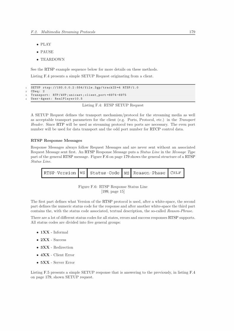
F.2. Multimedia Streaming Protocols 179
• PLAY
• PAUSE
• TEARDOWN
See the RTSP example sequence below for more details on these methods.
Listing F.4 presents a simple SETUP Request originating from a client.
1 SETUP rtsp: //193.0.0.2 :554/file.3gp/trackID =4 RTSP /1.0
2 CSeq: 2
3 Transport: RTP /AVP;unicast ; client_port =6974 -6975
4 User -Agent: RealPlayer10.5
Listing F.4: RTSP SETUP Request
A SETUP Request defines the transport mechanism/protocol for the streaming media as wellas acceptable transport parameters for the client (e.g. Ports, Protocol, etc.) in the TransportHeader. Since RTP will be used as streaming protocol two ports are necessary. The even portnumber will be used for data transport and the odd port number for RTCP control data.
RTSP Response Messages
Response Messages always follow Request Messages and are never sent without an associatedRequest Message sent first. An RTSP Response Message puts a Status Line in the Message Typepart of the general RTSP message. Figure F.6 on page 179 shows the general structure of a RTSPStatus Line.
Figure F.6: RTSP Response Status Line[199, page 15]
The first part defines what Version of the RTSP protocol is used, after a white-space, the secondpart defines the numeric status code for the response and after another white-space the third partcontains the, with the status code associated, textual description, the so-called Reason-Phrase.
There are a lot of different status codes for all states, errors and success responses RTSP supports.All status codes are divided into five general groups:
• 1XX - Informal
• 2XX - Success
• 3XX - Redirection
• 4XX - Client Error
• 5XX - Server Error
Listing F.5 presents a simple SETUP response that is answering to the previously, in listing F.4on page 179, shown SETUP request.
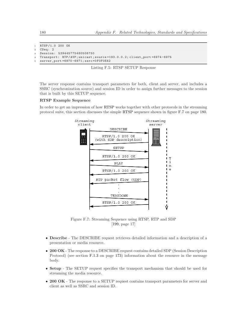
180 Appendix F. Related Technologies, Standards and Specifications
1 RTSP /1.0 200 OK
2 CSeq: 2
3 Session: 539445775480508750
4 Transport: RTP/AVP;unicast ;source =193.0.0.2; client_port =6974 -6975
5 server_port =6970 -6971; ssrc =0 F0F0E42
Listing F.5: RTSP SETUP Response
The server response contains transport parameters for both, client and server, and includes aSSRC (synchronization source) and session ID in order to assign further messages to the sessionthat is built by this SETUP sequence.
RTSP Example Sequence
In order to get an impression of how RTSP works together with other protocols in the streamingprotocol suite, this section discusses the simple RTSP sequence shown in figure F.7 on page 180.
Figure F.7: Streaming Sequence using RTSP, RTP and SDP[199, page 17]
• Describe - The DESCRIBE request retrieves detailed information and a description of apresentation or media resource.
• 200 OK - The response to a DESCRIBE request contains detailed SDP (Session DescriptionProtocol) (see section F.1.3 on page 173) information about the resource in the messagebody.
• Setup - The SETUP request specifies the transport mechanism that should be used forstreaming the media resource.
• 200 OK - The response to a SETUP request contains transport parameters for server andclient as well as SSRC and session ID.
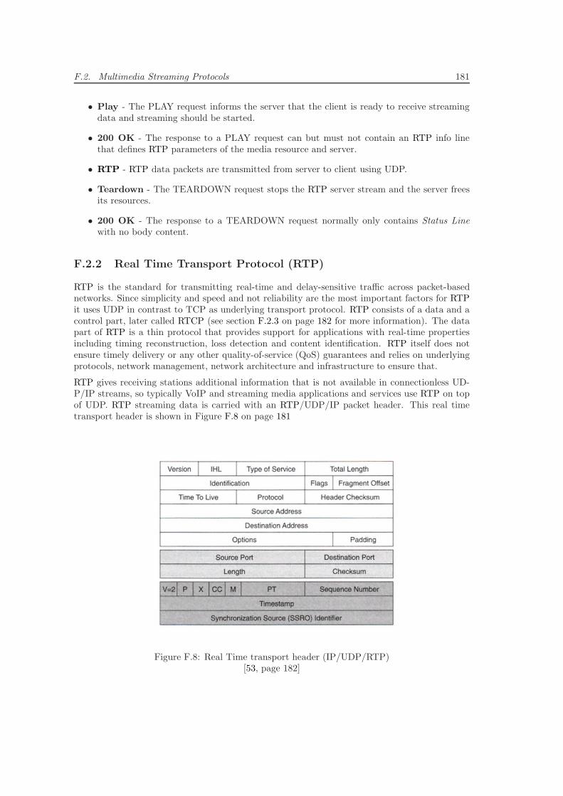
F.2. Multimedia Streaming Protocols 181
• Play - The PLAY request informs the server that the client is ready to receive streamingdata and streaming should be started.
• 200 OK - The response to a PLAY request can but must not contain an RTP info linethat defines RTP parameters of the media resource and server.
• RTP - RTP data packets are transmitted from server to client using UDP.
• Teardown - The TEARDOWN request stops the RTP server stream and the server freesits resources.
• 200 OK - The response to a TEARDOWN request normally only contains Status Linewith no body content.
F.2.2 Real Time Transport Protocol (RTP)
RTP is the standard for transmitting real-time and delay-sensitive traffic across packet-basednetworks. Since simplicity and speed and not reliability are the most important factors for RTPit uses UDP in contrast to TCP as underlying transport protocol. RTP consists of a data and acontrol part, later called RTCP (see section F.2.3 on page 182 for more information). The datapart of RTP is a thin protocol that provides support for applications with real-time propertiesincluding timing reconstruction, loss detection and content identification. RTP itself does notensure timely delivery or any other quality-of-service (QoS) guarantees and relies on underlyingprotocols, network management, network architecture and infrastructure to ensure that.
RTP gives receiving stations additional information that is not available in connectionless UD-P/IP streams, so typically VoIP and streaming media applications and services use RTP on topof UDP. RTP streaming data is carried with an RTP/UDP/IP packet header. This real timetransport header is shown in Figure F.8 on page 181
Figure F.8: Real Time transport header (IP/UDP/RTP)[53, page 182]
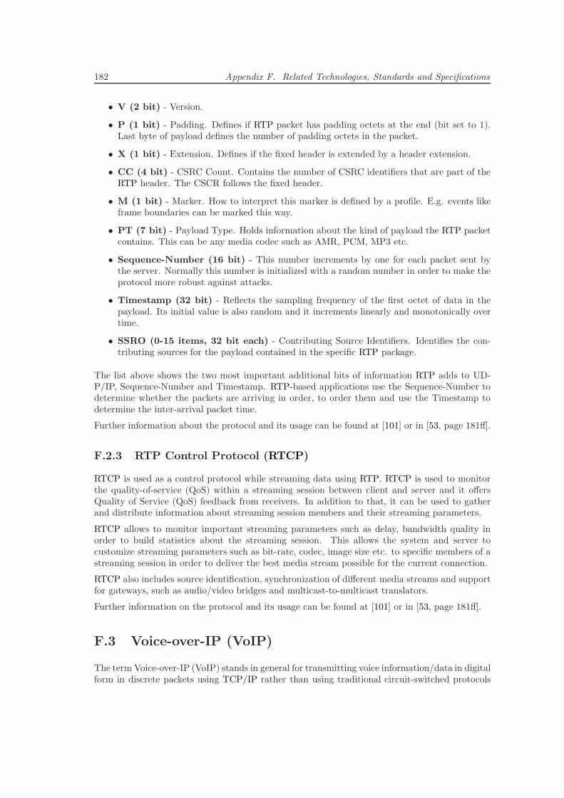
182 Appendix F. Related Technologies, Standards and Specifications
• V (2 bit) - Version.
• P (1 bit) - Padding. Defines if RTP packet has padding octets at the end (bit set to 1).Last byte of payload defines the number of padding octets in the packet.
• X (1 bit) - Extension. Defines if the fixed header is extended by a header extension.
• CC (4 bit) - CSRC Count. Contains the number of CSRC identifiers that are part of theRTP header. The CSCR follows the fixed header.
• M (1 bit) - Marker. How to interpret this marker is defined by a profile. E.g. events likeframe boundaries can be marked this way.
• PT (7 bit) - Payload Type. Holds information about the kind of payload the RTP packetcontains. This can be any media codec such as AMR, PCM, MP3 etc.
• Sequence-Number (16 bit) - This number increments by one for each packet sent bythe server. Normally this number is initialized with a random number in order to make theprotocol more robust against attacks.
• Timestamp (32 bit) - Reflects the sampling frequency of the first octet of data in thepayload. Its initial value is also random and it increments linearly and monotonically overtime.
• SSRO (0-15 items, 32 bit each) - Contributing Source Identifiers. Identifies the con-tributing sources for the payload contained in the specific RTP package.
The list above shows the two most important additional bits of information RTP adds to UD-P/IP, Sequence-Number and Timestamp. RTP-based applications use the Sequence-Number todetermine whether the packets are arriving in order, to order them and use the Timestamp todetermine the inter-arrival packet time.
Further information about the protocol and its usage can be found at [101] or in [53, page 181ff].
F.2.3 RTP Control Protocol (RTCP)
RTCP is used as a control protocol while streaming data using RTP. RTCP is used to monitorthe quality-of-service (QoS) within a streaming session between client and server and it offersQuality of Service (QoS) feedback from receivers. In addition to that, it can be used to gatherand distribute information about streaming session members and their streaming parameters.
RTCP allows to monitor important streaming parameters such as delay, bandwidth quality inorder to build statistics about the streaming session. This allows the system and server tocustomize streaming parameters such as bit-rate, codec, image size etc. to specific members of astreaming session in order to deliver the best media stream possible for the current connection.
RTCP also includes source identification, synchronization of different media streams and supportfor gateways, such as audio/video bridges and multicast-to-multicast translators.
Further information on the protocol and its usage can be found at [101] or in [53, page 181ff].
F.3 Voice-over-IP (VoIP)
The term Voice-over-IP (VoIP) stands in general for transmitting voice information/data in digitalform in discrete packets using TCP/IP rather than using traditional circuit-switched protocols
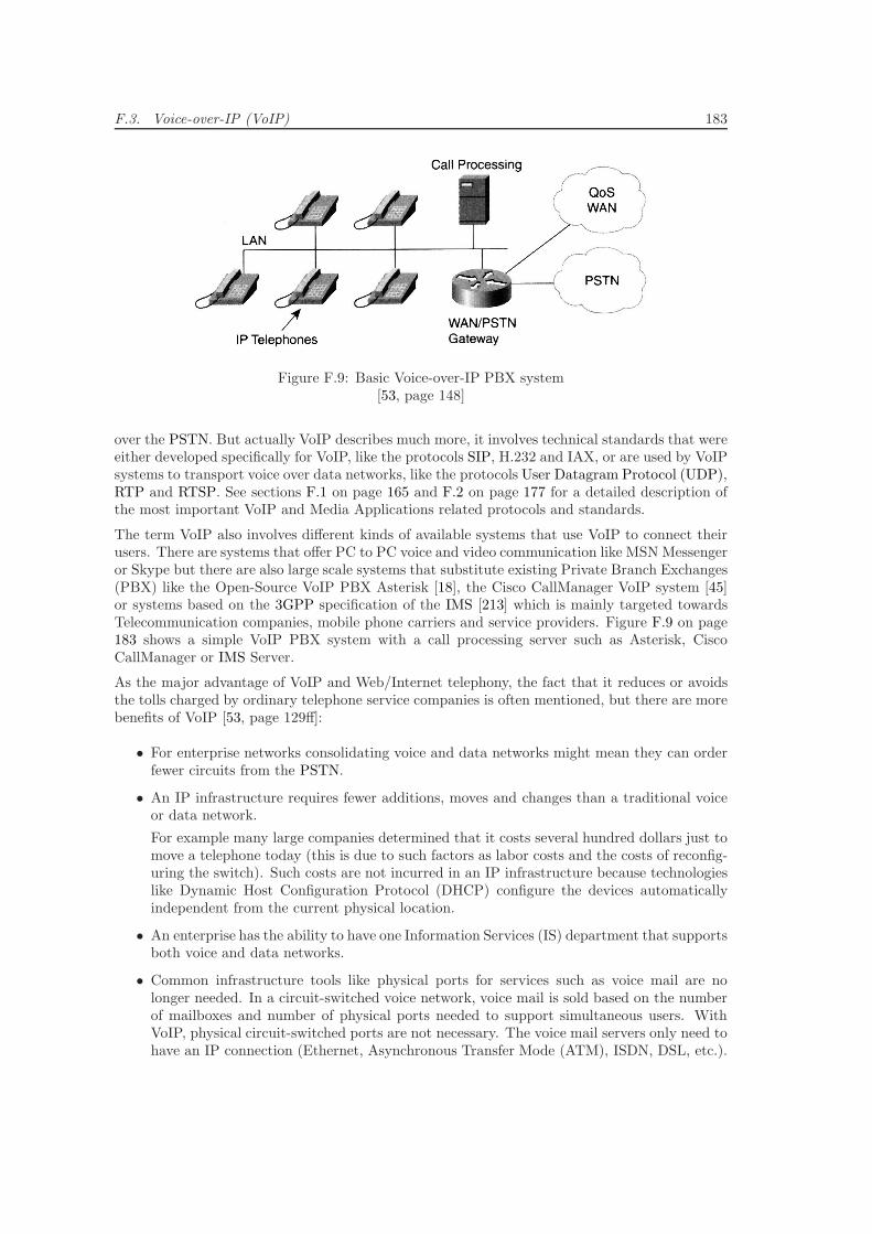
F.3. Voice-over-IP (VoIP) 183
Figure F.9: Basic Voice-over-IP PBX system[53, page 148]
over the PSTN. But actually VoIP describes much more, it involves technical standards that wereeither developed specifically for VoIP, like the protocols SIP, H.232 and IAX, or are used by VoIPsystems to transport voice over data networks, like the protocols User Datagram Protocol (UDP),RTP and RTSP. See sections F.1 on page 165 and F.2 on page 177 for a detailed description ofthe most important VoIP and Media Applications related protocols and standards.
The term VoIP also involves different kinds of available systems that use VoIP to connect theirusers. There are systems that offer PC to PC voice and video communication like MSN Messengeror Skype but there are also large scale systems that substitute existing Private Branch Exchanges(PBX) like the Open-Source VoIP PBX Asterisk [18], the Cisco CallManager VoIP system [45]or systems based on the 3GPP specification of the IMS [213] which is mainly targeted towardsTelecommunication companies, mobile phone carriers and service providers. Figure F.9 on page183 shows a simple VoIP PBX system with a call processing server such as Asterisk, CiscoCallManager or IMS Server.
As the major advantage of VoIP and Web/Internet telephony, the fact that it reduces or avoidsthe tolls charged by ordinary telephone service companies is often mentioned, but there are morebenefits of VoIP [53, page 129ff]:
• For enterprise networks consolidating voice and data networks might mean they can orderfewer circuits from the PSTN.
• An IP infrastructure requires fewer additions, moves and changes than a traditional voiceor data network.
For example many large companies determined that it costs several hundred dollars just tomove a telephone today (this is due to such factors as labor costs and the costs of reconfig-uring the switch). Such costs are not incurred in an IP infrastructure because technologieslike Dynamic Host Configuration Protocol (DHCP) configure the devices automaticallyindependent from the current physical location.
• An enterprise has the ability to have one Information Services (IS) department that supportsboth voice and data networks.
• Common infrastructure tools like physical ports for services such as voice mail are nolonger needed. In a circuit-switched voice network, voice mail is sold based on the numberof mailboxes and number of physical ports needed to support simultaneous users. WithVoIP, physical circuit-switched ports are not necessary. The voice mail servers only need tohave an IP connection (Ethernet, Asynchronous Transfer Mode (ATM), ISDN, DSL, etc.).
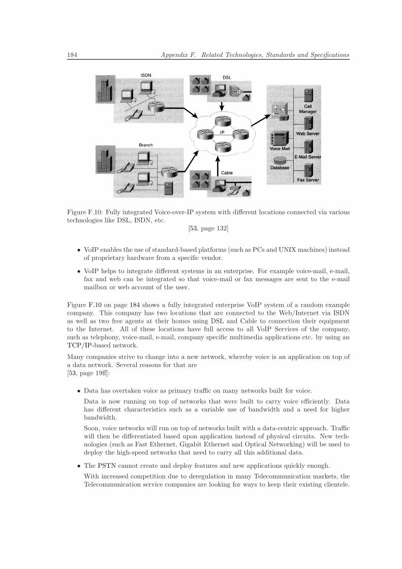
184 Appendix F. Related Technologies, Standards and Specifications
Figure F.10: Fully integrated Voice-over-IP system with different locations connected via varioustechnologies like DSL, ISDN, etc.
[53, page 132]
• VoIP enables the use of standard-based platforms (such as PCs and UNIX machines) insteadof proprietary hardware from a specific vendor.
• VoIP helps to integrate different systems in an enterprise. For example voice-mail, e-mail,fax and web can be integrated so that voice-mail or fax messages are sent to the e-mailmailbox or web account of the user.
Figure F.10 on page 184 shows a fully integrated enterprise VoIP system of a random examplecompany. This company has two locations that are connected to the Web/Internet via ISDNas well as two free agents at their homes using DSL and Cable to connection their equipmentto the Internet. All of these locations have full access to all VoIP Services of the company,such as telephony, voice-mail, e-mail, company specific multimedia applications etc. by using anTCP/IP-based network.
Many companies strive to change into a new network, whereby voice is an application on top ofa data network. Several reasons for that are[53, page 19ff]:
• Data has overtaken voice as primary traffic on many networks built for voice.
Data is now running on top of networks that were built to carry voice efficiently. Datahas different characteristics such as a variable use of bandwidth and a need for higherbandwidth.
Soon, voice networks will run on top of networks built with a data-centric approach. Trafficwill then be differentiated based upon application instead of physical circuits. New tech-nologies (such as Fast Ethernet, Gigabit Ethernet and Optical Networking) will be used todeploy the high-speed networks that need to carry all this additional data.
• The PSTN cannot create and deploy features and new applications quickly enough.
With increased competition due to deregulation in many Telecommunication markets, theTelecommunication service companies are looking for ways to keep their existing clientele.
F.4. Mobile Web/Internet Access Network Technologies 185
The primary method for keeping customers is by enticing them through new services andmedia applications.
The current ”not-full-IP” infrastructure allows only equipment vendors to develop applica-tions for their specific proprietary equipment, so it is very difficult for a company to meetall the needs of the customers. A more open infrastructure and platform, by which manyvendors can provide applications, enables more creative solutions and applications to bedeveloped.
• Data/Voice/Video (D/V/V) cannot converge on the PSTN as currently built.
With only an analog line to most homes, you cannot have data access, phone access andvideo access across one 56-kbps modem. High-speed broadband access, such as digitalsubscriber line (DSL), cable or high-speed wireless is needed to enable this convergence. Inthe backbone of the PSTN the convergence has already started.
• The architecture of the PSTN is not flexible enough to carry data.
Because the bearer channels (B channels and T1 circuits), call-control (SS7 and Q.931) andservice logic (applications) are tightly bounded in one closed platform it is not possible tomake minor changes that might improve audio quality.
New platform and infrastructure specifications such as the IMS, mentioned above, breakthis tightly bounded structure of the PSTN of today and allow an easy integration of allsorts of data services and media applications.
It is also important to note that circuit-switched calls require a permanent 64-kbps dedicatedcircuit between the two devices. Whether the caller or the person called is talking or not, this64-kbps connection cannot be used by any other party. This means that this bandwidth cannotbe used for any other purpose and the Telecommunication service company must bill the partiesfor consuming the whole resource. This leads to many reserved but unused connections that costa lot of money for carriers and customers and results in a very bad utilization of the whole PSTNinfrastructure.
Data networking, on the other hand, has the capability to use bandwidth only when it is required.This difference, although seemingly small, is a major benefit of packet-based voice and datanetworking (VoIP).
F.4 Mobile Web/Internet Access Network Technologies
Since the concepts of this research work need to support different mobile Web/Internet accessnetworks such as GPRS [215], EDGE [215], 3G [216], LTE [147] and WLAN, this chapter willbriefly summarize their most important facts.
Figure F.11 on page 186 presents a very simplified view of a mobile network architecture with3G and GSM/GPRS/EDGE access networks. One can see that UMTS Terrestrial Radio AccessNetwork (UTRAN) and GSM Base Station Subsystem (BSS) share the same GPRS backboneto transmit data. This GPRS backbone network is protected by a firewall with (sometimes)included NAT translation and is connected to the Web/Internet to access Web/Internet servicessuch as streaming audio and video services etc.
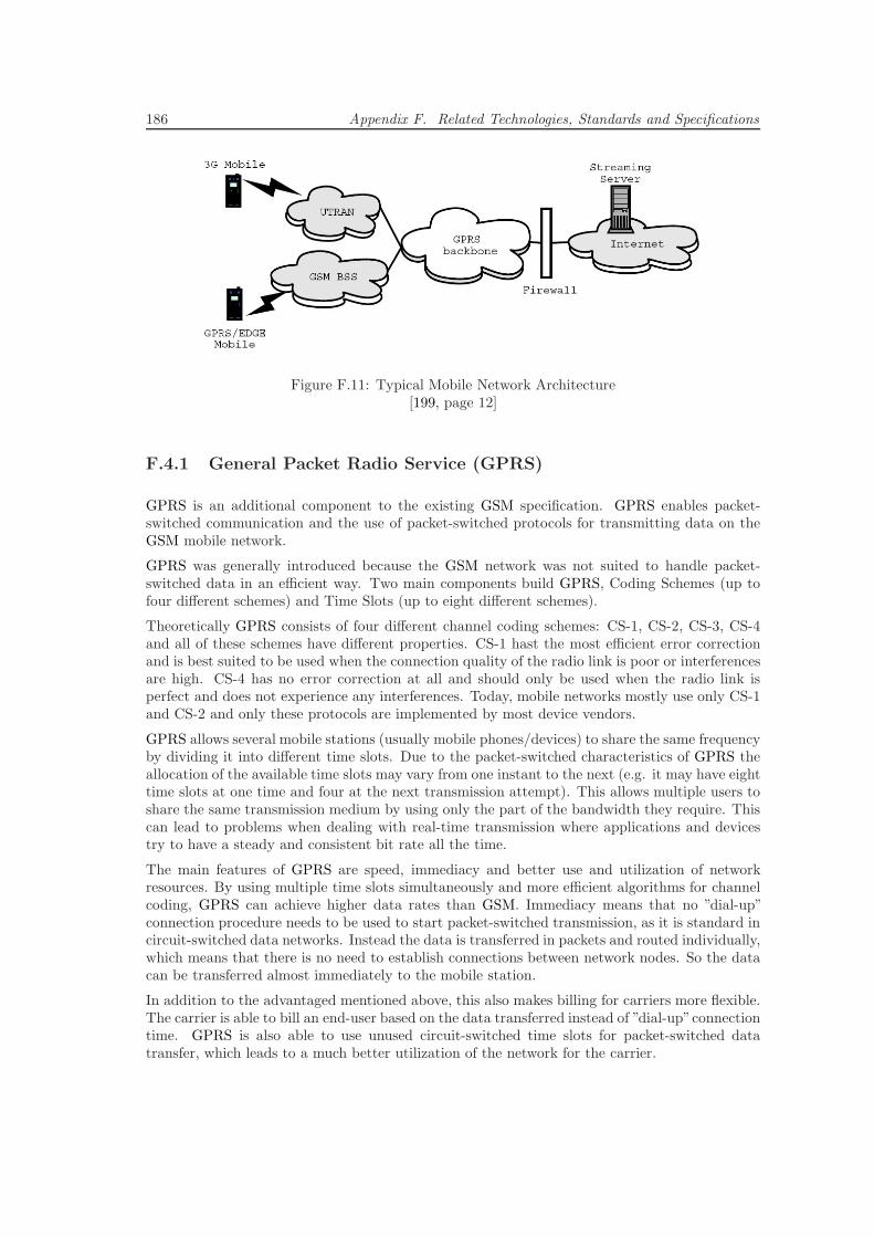
186 Appendix F. Related Technologies, Standards and Specifications
Figure F.11: Typical Mobile Network Architecture[199, page 12]
F.4.1 General Packet Radio Service (GPRS)
GPRS is an additional component to the existing GSM specification. GPRS enables packet-switched communication and the use of packet-switched protocols for transmitting data on theGSM mobile network.
GPRS was generally introduced because the GSM network was not suited to handle packet-switched data in an efficient way. Two main components build GPRS, Coding Schemes (up tofour different schemes) and Time Slots (up to eight different schemes).
Theoretically GPRS consists of four different channel coding schemes: CS-1, CS-2, CS-3, CS-4and all of these schemes have different properties. CS-1 hast the most efficient error correctionand is best suited to be used when the connection quality of the radio link is poor or interferencesare high. CS-4 has no error correction at all and should only be used when the radio link isperfect and does not experience any interferences. Today, mobile networks mostly use only CS-1and CS-2 and only these protocols are implemented by most device vendors.
GPRS allows several mobile stations (usually mobile phones/devices) to share the same frequencyby dividing it into different time slots. Due to the packet-switched characteristics of GPRS theallocation of the available time slots may vary from one instant to the next (e.g. it may have eighttime slots at one time and four at the next transmission attempt). This allows multiple users toshare the same transmission medium by using only the part of the bandwidth they require. Thiscan lead to problems when dealing with real-time transmission where applications and devicestry to have a steady and consistent bit rate all the time.
The main features of GPRS are speed, immediacy and better use and utilization of networkresources. By using multiple time slots simultaneously and more efficient algorithms for channelcoding, GPRS can achieve higher data rates than GSM. Immediacy means that no ”dial-up”connection procedure needs to be used to start packet-switched transmission, as it is standard incircuit-switched data networks. Instead the data is transferred in packets and routed individually,which means that there is no need to establish connections between network nodes. So the datacan be transferred almost immediately to the mobile station.
In addition to the advantaged mentioned above, this also makes billing for carriers more flexible.The carrier is able to bill an end-user based on the data transferred instead of ”dial-up”connectiontime. GPRS is also able to use unused circuit-switched time slots for packet-switched datatransfer, which leads to a much better utilization of the network for the carrier.
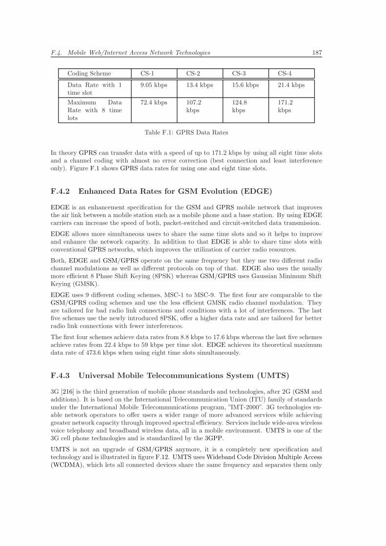
F.4. Mobile Web/Internet Access Network Technologies 187
Coding Scheme CS-1 CS-2 CS-3 CS-4
Data Rate with 1time slot
9.05 kbps 13.4 kbps 15.6 kbps 21.4 kbps
Maximum DataRate with 8 timelots
72.4 kbps 107.2kbps
124.8kbps
171.2kbps
Table F.1: GPRS Data Rates
In theory GPRS can transfer data with a speed of up to 171.2 kbps by using all eight time slotsand a channel coding with almost no error correction (best connection and least interferenceonly). Figure F.1 shows GPRS data rates for using one and eight time slots.
F.4.2 Enhanced Data Rates for GSM Evolution (EDGE)
EDGE is an enhancement specification for the GSM and GPRS mobile network that improvesthe air link between a mobile station such as a mobile phone and a base station. By using EDGEcarriers can increase the speed of both, packet-switched and circuit-switched data transmission.
EDGE allows more simultaneous users to share the same time slots and so it helps to improveand enhance the network capacity. In addition to that EDGE is able to share time slots withconventional GPRS networks, which improves the utilization of carrier radio resources.
Both, EDGE and GSM/GPRS operate on the same frequency but they use two different radiochannel modulations as well as different protocols on top of that. EDGE also uses the usuallymore efficient 8 Phase Shift Keying (8PSK) whereas GSM/GPRS uses Gaussian Minimum ShiftKeying (GMSK).
EDGE uses 9 different coding schemes, MSC-1 to MSC-9. The first four are comparable to theGSM/GPRS coding schemes and use the less efficient GMSK radio channel modulation. Theyare tailored for bad radio link connections and conditions with a lot of interferences. The lastfive schemes use the newly introduced 8PSK, offer a higher data rate and are tailored for betterradio link connections with fewer interferences.
The first four schemes achieve data rates from 8.8 kbps to 17.6 kbps whereas the last five schemesachieve rates from 22.4 kbps to 59 kbps per time slot. EDGE achieves its theoretical maximumdata rate of 473.6 kbps when using eight time slots simultaneously.
F.4.3 Universal Mobile Telecommunications System (UMTS)
3G [216] is the third generation of mobile phone standards and technologies, after 2G (GSM andadditions). It is based on the International Telecommunication Union (ITU) family of standardsunder the International Mobile Telecommunications program, ”IMT-2000”. 3G technologies en-able network operators to offer users a wider range of more advanced services while achievinggreater network capacity through improved spectral efficiency. Services include wide-area wirelessvoice telephony and broadband wireless data, all in a mobile environment. UMTS is one of the3G cell phone technologies and is standardized by the 3GPP.
UMTS is not an upgrade of GSM/GPRS anymore, it is a completely new specification andtechnology and is illustrated in figure F.12. UMTS uses Wideband Code Division Multiple Access(WCDMA), which lets all connected devices share the same frequency and separates them only
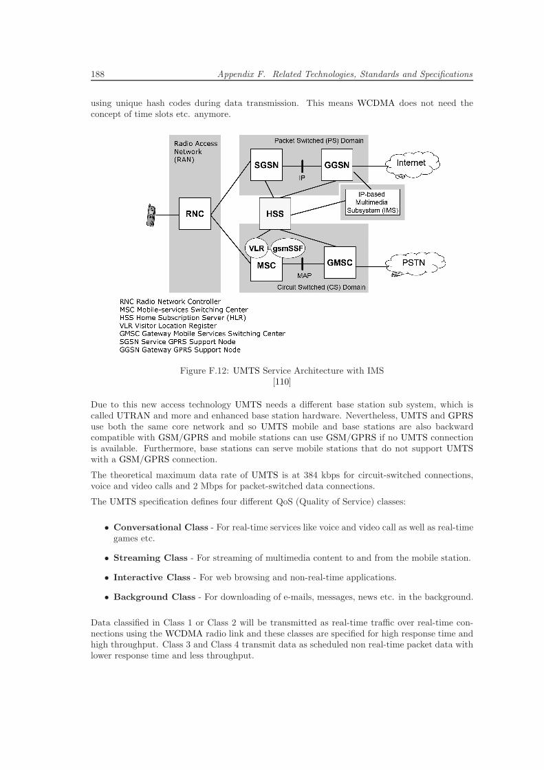
188 Appendix F. Related Technologies, Standards and Specifications
using unique hash codes during data transmission. This means WCDMA does not need theconcept of time slots etc. anymore.
Figure F.12: UMTS Service Architecture with IMS[110]
Due to this new access technology UMTS needs a different base station sub system, which iscalled UTRAN and more and enhanced base station hardware. Nevertheless, UMTS and GPRSuse both the same core network and so UMTS mobile and base stations are also backwardcompatible with GSM/GPRS and mobile stations can use GSM/GPRS if no UMTS connectionis available. Furthermore, base stations can serve mobile stations that do not support UMTSwith a GSM/GPRS connection.
The theoretical maximum data rate of UMTS is at 384 kbps for circuit-switched connections,voice and video calls and 2 Mbps for packet-switched data connections.
The UMTS specification defines four different QoS (Quality of Service) classes:
• Conversational Class - For real-time services like voice and video call as well as real-timegames etc.
• Streaming Class - For streaming of multimedia content to and from the mobile station.
• Interactive Class - For web browsing and non-real-time applications.
• Background Class - For downloading of e-mails, messages, news etc. in the background.
Data classified in Class 1 or Class 2 will be transmitted as real-time traffic over real-time con-nections using the WCDMA radio link and these classes are specified for high response time andhigh throughput. Class 3 and Class 4 transmit data as scheduled non real-time packet data withlower response time and less throughput.
F.4. Mobile Web/Internet Access Network Technologies 189
3G Enhancements [78]
High Speed Downlink Packet Access (HSDPA) is a 3G mobile telephony communications protocolin the High-Speed Packet Access (HSPA) family, which allows networks based on UMTS to havehigher data transfer speeds and capacities. Current HSDPA deployments support down-linkspeeds of 1.8, 3.6, 7.2 and 14.4 Mbps. HSDPA has been specified in the 3GPP release 5. Itintroduced new basic functions and is aimed to achieve peak data rates of 14.4 Mbps. Newlyintroduced are the High Speed Downlink Shared Channels (HS-DSCH), the adaptive modulationQPSK and 16QAM and the High Speed Medium Access protocol (MAC-HS) in base station.
High Speed Uplink Packet Access (HSUPA) is a 3G mobile telephony protocol in the HSPAfamily with up-link speeds of up to 5.76 Mbps. The specifications for HSUPA are included inUMTS release 6 standard published by 3GPP.
High Speed OFDM Packet Access (HSOPA) is a proposed part of 3GPP upgrade path for UMTS.HSOPA is also often referred to as Super 3G. If adopted, HSOPA succeeds HSDPA and HSUPAtechnologies specified in 3GPP releases 5 and 6. Unlike HSDPA or HSUPA, HSOPA is anentirely new air interface system, unrelated to and incompatible with WCDMA. It introducesantenna array technologies such as beam-forming and Multiple Input Multiple Output (MIMO)communications.
F.4.4 Long Term Evolution (LTE)
LTE constitutes the 3GPP WCDMA successor of UMTS, HSDPA, HSUPA and HSPA+ and isspecified in 3GPP Release 8. The official LTE working group formed by Nortel Networks was cre-ated in 2004 and their main goal was to bring the major advantages of the Orthogonal FrequencyDivision Multiplexing (OFDM) technology that was already leveraged in WLAN standards, tomobile Telecommunication networks.
In contrast to HSDPA, HSUPA and HSPA+, LTE is not designed as an adaptive evolution ofexisting concepts and technologies into an existing UMTS mobile Telecommunication network.LTE introduces a new technology for the wireless link layer that is incompatible with GSM andUMTS and so, requires the deployment of completely new mobile Telecommunication networkequipment.
LTE is specifically optimized for packet-based data services. It reduces latency and definesa Telecommunication network architecture that ensures that all data traffic passes a minimumnumber of network components. In an UMTS/HSPA network, an end-user device connects to theWeb/Internet through the four 3G components Gateway GPRS Support Node (GGSN), ServiceGPRS Support Node (SGSN), Radio Network Controller (RNC) and base station (NodeB). Inan LTE network, the base station (eNodeB) is directly connected to the Web/Internet gateway(Serving SAE Gateway) that connects the mobile Telecommunication networks to outside datanetworks (see section F.5.1).
The major technical advantages of LTE over HSPA are:
• The available bandwidth is increased by a factor of 10
• Downlink typical up to 100Mbit/s - theoretical limit is 326,4Mbit/s.
• Uplink up to 50Mbit/s - theoretical limit is 86,4Mbit/s.
• The network latency is reduced by a factor of 2 to 3: round trip below 10ms; delay below200ms.
• The spectrum efficiency is increased by a factor of 2 to 4.
190 Appendix F. Related Technologies, Standards and Specifications
The thereby enabled major features of LTE are:
• Optimized for packet-switched instead of circuit-switched traffic.
• Increased focus on personal and device mobility as well as related security aspects.
• Increased energy efficiency for end-user devices.
• Flexible frequency utilization between 1.25MHz and 20MHz.
• Increased flexibility in wireless network topology planning: optimal performance in 5kmcells; reduced performance with cells of up to 100km possible.
• Fewer interferences on the wireless link through enhanced Orthogonal Frequency DivisionMultiple Access (OFDMA) channel scheduling.
• Completely TCP/IP-based environment.
• Operation in parallel to other 3GPP standards such as GSM and UMTS possible.
• Reduction of Telecommunication network components.
• Higher data transmission rates through• Increased spectrum efficiency and broader frequency bands.• Downlink modulation from 4PSK over 16QAM to 64QAM including MIMO in 2x2and even 4x4 setups.
F.4.5 Wireless Local Area Network (WLAN) / Wireless Fidelity (Wi-Fi)
WLAN is the general term for Wireless Local Area Network, which means it is a technology toconnect computers to build a local network without wires. The term WLAN covers a whole setof specification that are all part of the IEEE 802.11 set of standards. It was developed by theIEEE LAN/MAN Standards Committee (IEEE 802) in the 5 GHz and 2.4 GHz public spectrumbands.
The 802.11 family includes over-the-air modulation techniques that use the same basic protocol.The most popular ones are those defined by the 802.11b and 802.11g protocols, which are amend-ments to the original standard. 802.11a was the first wireless networking standard, but 802.11bwas the first widely accepted one, followed by 802.11g and 802.11n.
Table F.2 on page 191 shows an overview about current and upcoming WLAN standards. Onecan see that the currently common standard 802.11g achieves a maximum data rate of up to 54Mbps, which is much higher than any current UMTS/(3G) technology deployed. Unfortunatelythis data rate is only achieved if the distance between mobile and base station is less than140 meters, which means WLAN is obviously not a technology designed for wide range mobilenetworks.
Nevertheless, some municipals such as New York, Toronto and others are planning to and havealready started to build a WLAN that covers the whole city including all districts and boroughs.Compared to wide range mobile networks such as UMTS or the newly introduced specificationsaround WIMAX [96], WLAN requires a lot more (but already quite cheap) base stations andequipment, but when completed, offers a reliable high speed connection for mobile devices.
F.5 Mobile IP Core Network Technologies
This section provides summaries of the current state-of-the-art concepts and technologies forTCP/IP-based Telecommunication core networks. It presents the SAE/EPC and the, built upon,
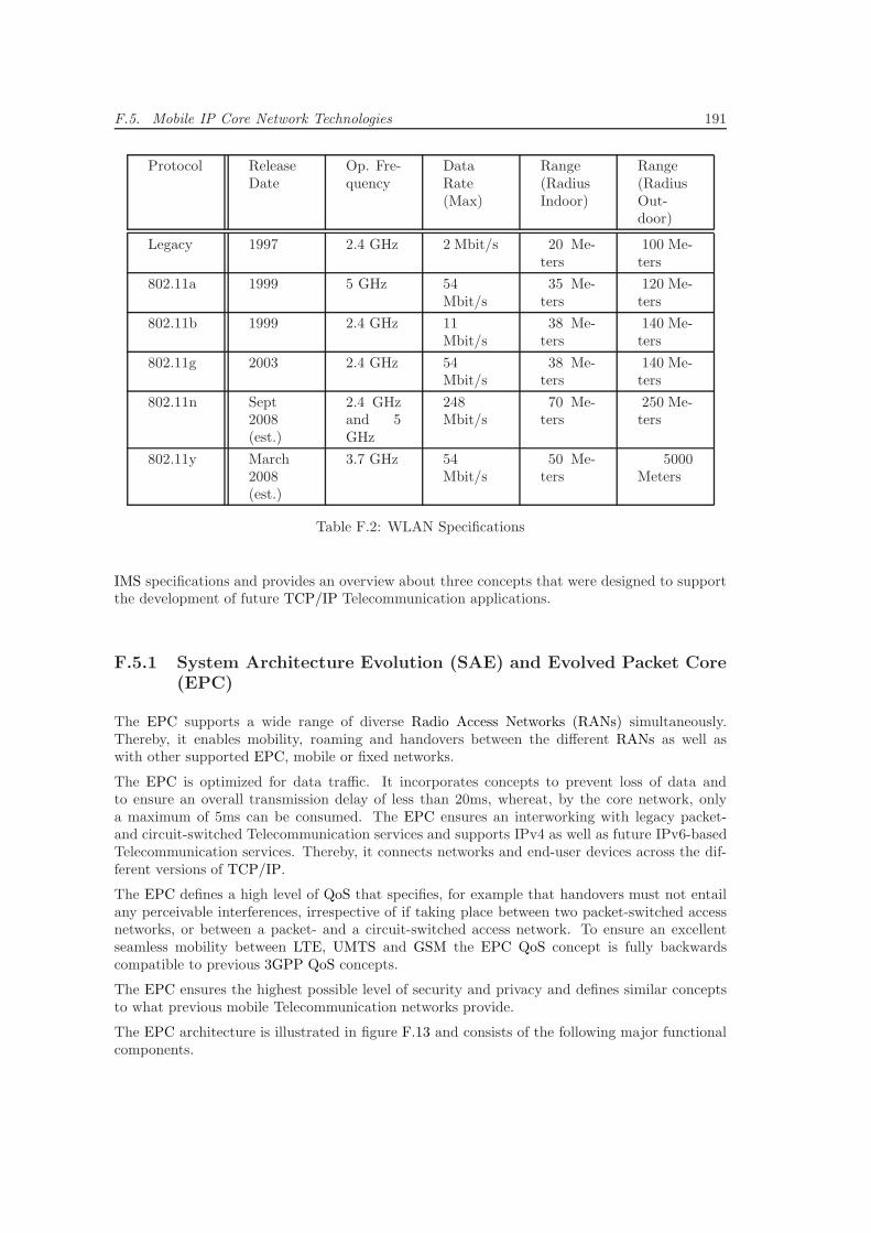
F.5. Mobile IP Core Network Technologies 191
Protocol ReleaseDate
Op. Fre-quency
DataRate(Max)
Range(RadiusIndoor)
Range(RadiusOut-door)
Legacy 1997 2.4 GHz 2 Mbit/s 20 Me-ters
100 Me-ters
802.11a 1999 5 GHz 54Mbit/s
35 Me-ters
120 Me-ters
802.11b 1999 2.4 GHz 11Mbit/s
38 Me-ters
140 Me-ters
802.11g 2003 2.4 GHz 54Mbit/s
38 Me-ters
140 Me-ters
802.11n Sept2008(est.)
2.4 GHzand 5GHz
248Mbit/s
70 Me-ters
250 Me-ters
802.11y March2008(est.)
3.7 GHz 54Mbit/s
50 Me-ters
5000Meters
Table F.2: WLAN Specifications
IMS specifications and provides an overview about three concepts that were designed to supportthe development of future TCP/IP Telecommunication applications.
F.5.1 System Architecture Evolution (SAE) and Evolved Packet Core(EPC)
The EPC supports a wide range of diverse Radio Access Networks (RANs) simultaneously.Thereby, it enables mobility, roaming and handovers between the different RANs as well aswith other supported EPC, mobile or fixed networks.
The EPC is optimized for data traffic. It incorporates concepts to prevent loss of data andto ensure an overall transmission delay of less than 20ms, whereat, by the core network, onlya maximum of 5ms can be consumed. The EPC ensures an interworking with legacy packet-and circuit-switched Telecommunication services and supports IPv4 as well as future IPv6-basedTelecommunication services. Thereby, it connects networks and end-user devices across the dif-ferent versions of TCP/IP.
The EPC defines a high level of QoS that specifies, for example that handovers must not entailany perceivable interferences, irrespective of if taking place between two packet-switched accessnetworks, or between a packet- and a circuit-switched access network. To ensure an excellentseamless mobility between LTE, UMTS and GSM the EPC QoS concept is fully backwardscompatible to previous 3GPP QoS concepts.
The EPC ensures the highest possible level of security and privacy and defines similar conceptsto what previous mobile Telecommunication networks provide.
The EPC architecture is illustrated in figure F.13 and consists of the following major functionalcomponents.
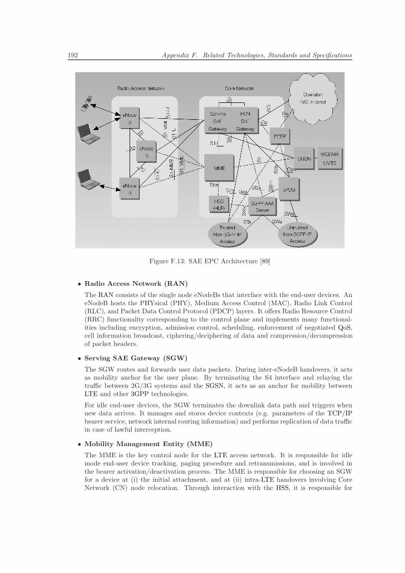
192 Appendix F. Related Technologies, Standards and Specifications
Figure F.13: SAE EPC Architecture [89]
• Radio Access Network (RAN)
The RAN consists of the single node eNodeBs that interface with the end-user devices. AneNodeB hosts the PHYsical (PHY), Medium Access Control (MAC), Radio Link Control(RLC), and Packet Data Control Protocol (PDCP) layers. It offers Radio Resource Control(RRC) functionality corresponding to the control plane and implements many functional-ities including encryption, admission control, scheduling, enforcement of negotiated QoS,cell information broadcast, ciphering/deciphering of data and compression/decompressionof packet headers.
• Serving SAE Gateway (SGW)
The SGW routes and forwards user data packets. During inter-eNodeB handovers, it actsas mobility anchor for the user plane. By terminating the S4 interface and relaying thetraffic between 2G/3G systems and the SGSN, it acts as an anchor for mobility betweenLTE and other 3GPP technologies.
For idle end-user devices, the SGW terminates the downlink data path and triggers whennew data arrives. It manages and stores device contexts (e.g. parameters of the TCP/IPbearer service, network internal routing information) and performs replication of data trafficin case of lawful interception.
• Mobility Management Entity (MME)
The MME is the key control node for the LTE access network. It is responsible for idlemode end-user device tracking, paging procedure and retransmissions, and is involved inthe bearer activation/deactivation process. The MME is responsible for choosing an SGWfor a device at (i) the initial attachment, and at (ii) intra-LTE handovers involving CoreNetwork (CN) node relocation. Through interaction with the HSS, it is responsible for
F.5. Mobile IP Core Network Technologies 193
authenticating end-users and devices. It terminates the S6a interface towards the HSS forroaming devices.
The MME terminates the Non-Access Stratum (NAS) signaling. It is responsible for thegeneration and allocation of temporary identities to devices, checks the authorization ofdevices and enforces device roaming restrictions. The MME is the termination point forciphering/integrity protection for NAS signaling, handles the security key management andsupports lawful interception of signaling.
By terminating the S3 interface from the SGSN, it provides the control plane functionalityfor mobility between LTE and 2G/3G access networks.
• Packet Data Network SAE Gateway (PDN GW)
The PDN GW is the point of exit and entry of end-user device data traffic and so, providesconnectivity between devices and external Packet Data Networks (PDN). A device may havesimultaneous connectivity with more than one PDN GW for accessing multiple PDNs. ThePDN GW performs device or end-user-based policy enforcement, packet filtering, chargingsupport, lawful interception and packet screening. It acts as anchor for mobility between3GPP and non-3GPP technologies such as WiMAX and 3GPP2 (CDMA 1X and EvDO).
F.5.2 IP Multimedia Subsystem (IMS)
The IMS standard defines a set of specifications for offering mobile and fixed Voice over IP(VoIP) and multimedia services. The IMS standard was introduced by the 3GPP as a part oftheir Release 5. It supports multiple access types, including GSM, GPRS, EDGE, UMTS, WLANand fixed broadband (e.g. DSL) access.
F.5.2.1 IMS Vision
In the move towards a converged network architecture, the IMS standard defines a generic NextGeneration Networking (NGN) architecture. It is a set of specifications for offering mobile andfixed Voice over IP (VoIP) and multimedia services. The IMS standard was introduced by the3GPP as a part of their standard in Release 5. The standard supports multiple access types,including GSM, GPRS, EDGE, WCDMA, UMTS, fixed broadband access and WLAN.
IMS truly merges the Web/Internet with the cellular world; it uses cellular technologies to provideubiquitous access and Web/Internet technologies to provide appealing services. It enables theintegration of different enabling services, such as presence [188], location [212], messaging [41],video, voice, picture and text into one application and supports charging and Quality of Service(QoS). IMS shortens application development time and supports standardized deployment andreuse of applications and services. IMS uses TCP/IP as its underlying network protocol andin IMS Release 5 the 3GPP has chosen the text-based SIP (see section 168 on page 168) assignaling protocol. This enables IMS applications to interact with any current and future We-b/Internet service by defining standard interfaces over an IP-based infrastructure. In addition tothat, SIP is based on a straightforward request-response interaction model making it simple andcomprehensible for developers.
F.5.2.2 IMS Architecture
The IMS architecture is derived from the SIP system architecture and servers summarized insection F.1.2 on page 168. The 3GPP extended the SIP architecture, defined new and more in
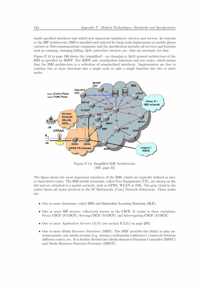
194 Appendix F. Related Technologies, Standards and Specifications
depth specified interfaces and added new important mandatory services and servers. In contrastto the SIP architecture, IMS is specified and tailored for large scale deployments at mobile phonecarriers or Telecommunications companies and the specification includes all services and featuressuch as roaming, charging/billing, QoS, subscriber services, etc. that are necessary for that.
Figure F.14 in page 194 shows the (simplified! - no charging or QoS) general architecture of theIMS as specified by 3GPP. The 3GPP only standardizes functions and not nodes, which meansthat the IMS architecture is a collection of standardized interfaces. Implementers are free tocombine two or more functions into a single node or split a single function into two or morenodes.
Figure F.14: Simplified IMS Architecture[197, page 35]
The figure shows the most important interfaces of the IMS, which are typically defined as two-or three-letter codes. The IMS mobile terminals, called User Equipments (UE), are shown on theleft and are attached to a packet network, such as GPRS, WLAN or DSL. The gray cloud in thecenter shows all nodes involved in the IP Multimedia (Core) Network Subsystem. These nodesare:
• One or more databases, called HSS and Subscriber Location Function (SLF).
• One or more SIP servers, collectively known as the CSCF. It comes in three variations:Proxy CSCF (P-CSCF), Serving CSCF (S-CSCF) and Interrogating CSCF (I-CSCF)
• One or more Application Servers (A/S) (see section F.5.3.1 on page 205).
• One or more Media Resource Functions (MRF). The MRF provides the ability to play an-nouncements, mix media streams (e.g. during a multimedia conference), transcode betweendifferent codecs, etc. It is further divided into Media Resource Function Controller (MRFC)and Media Resource Function Processor (MRFP).
F.5. Mobile IP Core Network Technologies 195
• One or more Breakout Gateway Control Functions (BGCF). The BGCF is essentially a SIPserver that includes routing functionality based on telephone numbers. It is only used insessions that are initiated by an IMS terminal and addressed to a user in a circuit-switchednetwork, such as the PSTN or the PLMN. The main functionality of the BGCF is to selectan appropriate network if a connection with the circuit-switched domain is requested as wellas to select an appropriate PSTN/CS gateway if a connection, within the same networkwhere the BGCF is located, is needed.
• One or more CS gateways. The CS gateway provides an interface towards a circuit-switchednetwork, allowing IMS terminals to make and receive calls to and from the PSTN (or anyother CS network). The CS gateway is decomposed into a Signaling Gateway (SGW), aMedia Gateway Controller Function (MGCF) and a Media Gateway (MGW).
Home Subscriber Server (HSS) and Subscriber Location Function (SLF)
The HSS is the central repository for user-related information (like the HLR for the GSM net-work). Among other items, it contains location information (contact address of users’ devices),security information (for authentication and authorization), user profile information (subscribedservices, policies, ...) and the S-CSCF assigned to the user. A network may contain more thanone HSS but all data related to a particular user is stored in a single HSS.
The SLF is a simple database that maps user addresses/identifications to HSSs. Networks withonly one HSS do not need an SLF. Both the HSS and the SLF implement the Diameter protocolwith an IMS-specific Diameter application so that other servers and services such as the S-CSCF,SIP A/S etc. within the system can access and alter the information.
Call Session Control Function (CSCF)
The CSCF, which is basically a SIP server, is one of the most essential functions in the IMS. TheCSCF processes SIP signaling messages in the IMS. There are three different types of CSCFs inan IMS, Proxy, Interrogating and Serving CSCF. As mentioned earlier, depending on the vendor(e.g. Siemens, Ericsson) and implementation architecture, these CSCF types are split into threephysical servers or combined into one or two servers.
Proxy CSCF (P-CSCF)The P-CSCF is the first point of contact in the signaling plane between the IMS terminal (e.g.mobile phone, IMS phone, PC etc.) and the IMS network. From the SIP point of view, theP-CSCF acts as an outbound/inbound SIP proxy server.
The following list describes some of the most important P-CSCF features:
• It is automatically allocated to an IMS terminal during network connection configuration(e.g. DHCP, wireless connection establishment, etc.) and before IMS registration and doesnot change for the duration of the registration/connection of the device.
• It authenticates the user and asserts the identity of the user to the rest of the IMS network.
• It verifies the correctness of SIP requests sent by the IMS terminal.
• It may compresses/decompress the SIP messages(SigComp [183]).
• It may include a Policy Decision Function (PDF).
• It might generate charging information at a charging collection node.
196 Appendix F. Related Technologies, Standards and Specifications
The P-CSCF may either be located in the network currently visited by an IMS mobile terminal(roaming) or in the home network of the IMS terminal/user. In case the underlying packetnetwork is based on GPRS/UMTS, the P-CSCF is always located in the same network where theGGSN is located and a carrier scale IMS network usually includes a number of P-CSCFs.
Interrogating CSCF (I-CSCF)The I-CSCF is a SIP proxy located at the edge of an administrative domain and the address ofthe I-CSCF is listed in the DNS records of the domain. When a SIP server follows the standardSIP procedures to find the next SIP hop for a particular message, the SIP server obtains theaddress of an I-CSCF of the destination domain via DNS lookup.
The I-CSCF uses Diameter to interface the SLF and/or the HSS in order to locate the messagerecipient and routes the messages to the appropriate destination (typically the S-CSCF assignedto the recipient at registration). The I-CSCF is usually located in the home network but in caseit is located in a visited network it may hide sensitive information about its domain (THIG).An IMS network will typically include a number of I-CSCFs in order to provide more than oneconnection points into the IMS domain.
Serving CSCF (S-CSCF)The S-CSCF is the central node of the signaling plane and is essentially a standard SIP serverwith additional functionalities. It performs session control and acts as a SIP registrar, i.e. itmaintains a binding between the user location (i.e. the IP address of the terminal the user islogged on) and the user’s SIP address of record (public user identity).
The S-CSCF uses Diameter to interface the HSS and download the authentication vectors anduser profiles of the served users in order to inform the HSS that this is the S-CSCF allocated to theuser for the duration of the registration. All SIP signaling sent and received by the IMS terminaltraverses the allocated S-CSCF and the S-CSCF inspects every SIP message and determineswhether the SIP signaling should visit one or more application servers (”service triggers” definedas part of the user profile). The S-CSCF is always located in the home network.
Policy Decision Function (PDF)
The role of the PDF is to inform the GGSN about the characteristics of the session a user agentis authorized to establish at a particular time. The GGSN uses this information to install packetfilters in its routing logic. If the user agent tries to do something unauthorized like sending mediaat an abundant data rate or to a different destination than the one indicated in the negotiationsearlier, the packet filters discard the user agent’s traffic.
In 3GPP IMS Release 6 the interfaces of the PDF are standardized. The IMS uses the COPS(Common Open Policy Service) protocol between the PDF and the GGSN (Go interface) andthe DIAMETER protocol between the PDF and the P-CSCF.
F.5.2.3 Identification in IMS
In any network there must be a possibility to uniquely identify users and so in the PSTN,for example, users are identified by the assigned telephone number. In addition to that, whena service is provided, it is also necessary to identify the service as well as additional serviceparameters and information. In the PSTN services are specified by special numbers, typicallyindicated through a special prefix and so IMS also specifies a mechanism to identify services.
F.5. Mobile IP Core Network Technologies 197
Public User IdentitiesThe IMS identifies its users deterministically by typically one or more Public User Identities,which can be:
• a SIP URI (as defined in RFC 3261)
• a TEL URI (as defined in RFC 2806)
Public User Identities are ”human readable” and are meant to be used as contact information onbusiness cards etc. Within the IMS, Public User Identities are used to route SIP signaling andfor the IMS what an MS-ISDN is for GSM.
When the Public User Identity is defined as a SIP URI, it typically has the form of sip:[email protected]. Additionally, it is possible to include a telephone number in a SIP URIusing the following format:sip:[email protected];user=phone. This format is needed due to the fact that SIPrequires the URI to be a valid SIP URI for registration. So it is not possible to register a TELURI in SIP directly.
When the Public User Identity is defined as a TEL URI, it typically has a form like tel:+49-89-63676190. Since PSTN numbers are represented by just digits, the TEL URIs are needed tomake a call from an IMS terminal to a PSTN phone as well as to connect phone calls from PSTNsubscribers to IMS users.
Private User IdentitiesThe IMS assigns a Private User Identity to every IMS subscriber at the IMS home network.In contrast to Public User Identities, Private User Identities are not SIP URIs or TEL URIs.Instead they are defined in the format of a Network Access Identifier (NAI) such as [email protected].
Private User Identities are exclusively used for subscription identification and authenticationpurposes and never used for routing SIP messages. A Private User Identity performs a similarfunction in the IMS as an IMSI (International Mobile Subscriber Identity) does in a GSM network.Typically users do not need to know their Private User Identity and similar to the IMSI, it couldbe stored in a smart card such as a phone SIM card.
The Relation between Public and Private User IDsIn earlier version of the IMS specification, operators would assign one or more Public UserIdentities and one Private User Identity to each user in their network. In the case of GSM/UMTSthe smart card (SIM) stores one Private User Identity and at least one Public User Identity. Incontrast to that, in IMS the HSS stores the Private User Identity and a collection of Public UserIdentities issued to that user.
In 3GPP Release 6 an IMS subscriber is not only issued one but a number of Private UserIdentities. This is necessary when using a mobile network such as UMTS and more than onemobile device. As mentioned above, with UMTS only one Private User Identity is stored on theSIM card, but users may have more than one phone and more than one SIM card that they use indifferent terminals. Figure F.15 on page 198 shows this relationship between subscriber, Privateand Public User Identities.
F.5.2.4 Roaming
Roaming support has been a general requirement since the second generation of cellular networksand users have to be able to roam to different networks (e.g. a user visiting a foreign country).
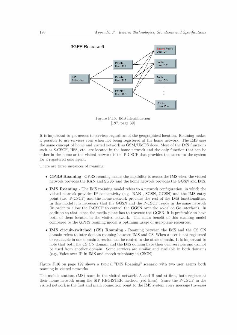
198 Appendix F. Related Technologies, Standards and Specifications
Figure F.15: IMS Identification[197, page 39]
It is important to get access to services regardless of the geographical location. Roaming makesit possible to use services even when not being registered at the home network. The IMS usesthe same concept of home and visited network as GSM/UMTS does. Most of the IMS functionssuch as S-CSCF, HSS, etc. are located in the home network and the only function that can beeither in the home or the visited network is the P-CSCF that provides the access to the systemfor a registered user agent.
There are three instances of roaming:
• GPRS Roaming - GPRS roaming means the capability to access the IMS when the visitednetwork provides the RAN and SGSN and the home network provides the GGSN and IMS.
• IMS Roaming - The IMS roaming model refers to a network configuration, in which thevisited network provides IP connectivity (e.g. RAN , SGSN, GGSN) and the IMS entrypoint (i.e. P-CSCF) and the home network provides the rest of the IMS functionalities.In this model it is necessary that the GGSN and the P-CSCF reside in the same network(in order to allow the P-CSCF to control the GGSN over the so-called Go interface). Inaddition to that, since the media plane has to traverse the GGSN, it is preferable to haveboth of them located in the visited network. The main benefit of this roaming modelcompared to the GPRS roaming model is optimum usage of user-plane resources.
• IMS circuit-switched (CS) Roaming - Roaming between the IMS and the CS CNdomain refers to inter-domain roaming between IMS and CS. When a user is not registeredor reachable in one domain a session can be routed to the other domain. It is important tonote that both the CS CN domain and the IMS domain have their own services and cannotbe used from another domain. Some services are similar and available in both domains(e.g., Voice over IP in IMS and speech telephony in CSCN).
Figure F.16 on page 199 shows a typical ”IMS Roaming” scenario with two user agents bothroaming in visited networks.
The mobile stations (MS) roam in the visited networks A and B and at first, both register attheir home network using the SIP REGISTER method (red lines). Since the P-CSCF in thevisited network is the first and main connection point to the IMS system every message traverses
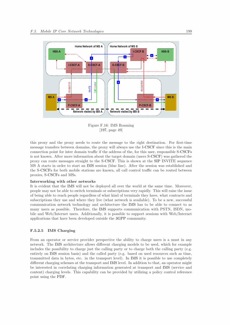
F.5. Mobile IP Core Network Technologies 199
Figure F.16: IMS Roaming[197, page 49]
this proxy and the proxy needs to route the message to the right destination. For first-timemessage transfers between domains, the proxy will always use the I-CSCF since this is the mainconnection point for inter domain traffic if the address of the, for this user, responsible S-CSCFsis not known. After more information about the target domain (users S-CSCF) was gathered theproxy can route messages straight to the S-CSCF. This is shown at the SIP INVITE sequenceMS A starts in order to start an IMS session (blue line). After the session was established andthe S-CSCFs for both mobile stations are known, all call control traffic can be routed betweenproxies, S-CSCFs and MSs.
Interworking with other networksIt is evident that the IMS will not be deployed all over the world at the same time. Moreover,people may not be able to switch terminals or subscriptions very rapidly. This will raise the issueof being able to reach people regardless of what kind of terminals they have, what contracts andsubscriptions they use and where they live (what network is available). To be a new, successfulcommunication network technology and architecture the IMS has to be able to connect to asmany users as possible. Therefore, the IMS supports communication with PSTN, ISDN, mo-bile and Web/Internet users. Additionally, it is possible to support sessions with Web/Internetapplications that have been developed outside the 3GPP community.
F.5.2.5 IMS Charging
From an operator or service provider perspective the ability to charge users is a must in anynetwork. The IMS architecture allows different charging models to be used, which for exampleincludes the possibility to charge just the calling party or to charge both the calling party (e.g.entirely on IMS session basis) and the called party (e.g. based on used resources such as time,transmitted data in bytes, etc. in the transport level). In IMS it is possible to use completelydifferent charging schemes at the transport and IMS level. In addition to that, an operator mightbe interested in correlating charging information generated at transport and IMS (service andcontent) charging levels. This capability can be provided by utilizing a policy control referencepoint using the PDF.
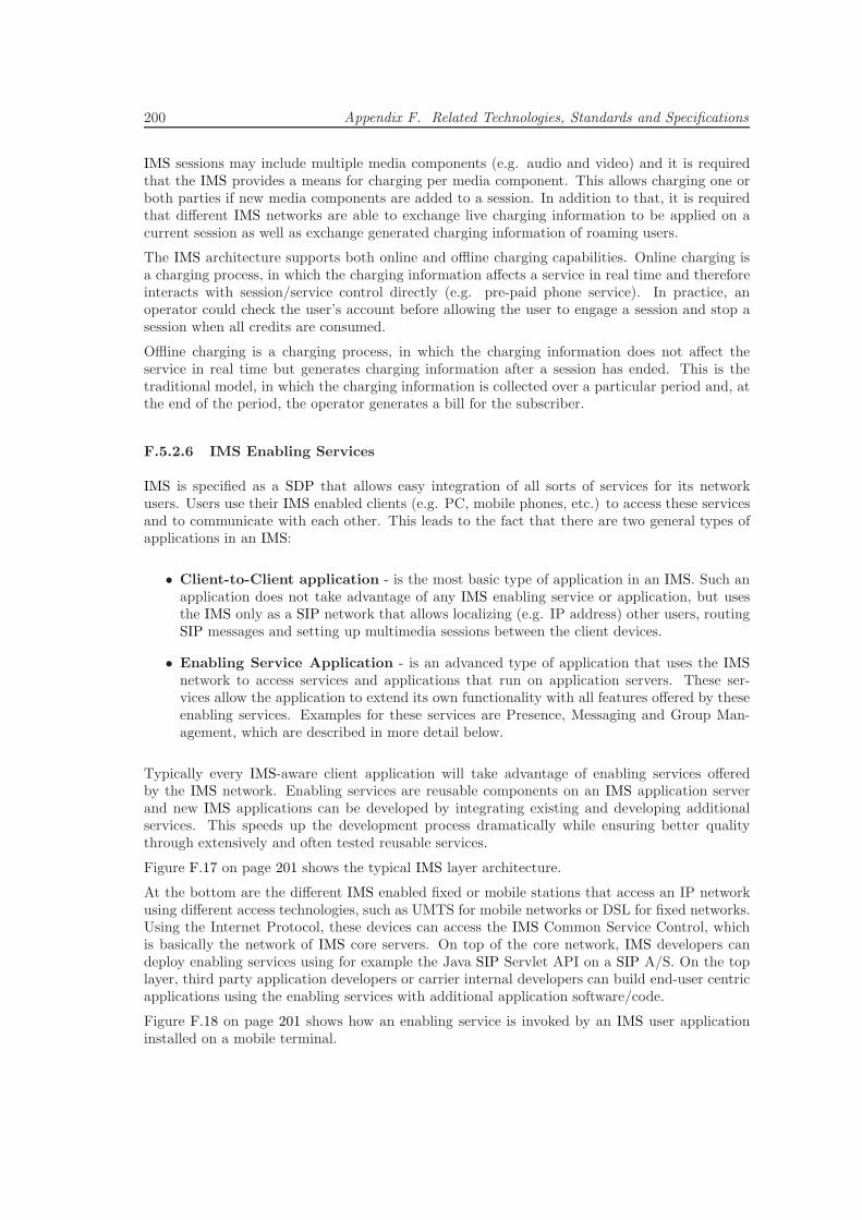
200 Appendix F. Related Technologies, Standards and Specifications
IMS sessions may include multiple media components (e.g. audio and video) and it is requiredthat the IMS provides a means for charging per media component. This allows charging one orboth parties if new media components are added to a session. In addition to that, it is requiredthat different IMS networks are able to exchange live charging information to be applied on acurrent session as well as exchange generated charging information of roaming users.
The IMS architecture supports both online and offline charging capabilities. Online charging isa charging process, in which the charging information affects a service in real time and thereforeinteracts with session/service control directly (e.g. pre-paid phone service). In practice, anoperator could check the user’s account before allowing the user to engage a session and stop asession when all credits are consumed.
Offline charging is a charging process, in which the charging information does not affect theservice in real time but generates charging information after a session has ended. This is thetraditional model, in which the charging information is collected over a particular period and, atthe end of the period, the operator generates a bill for the subscriber.
F.5.2.6 IMS Enabling Services
IMS is specified as a SDP that allows easy integration of all sorts of services for its networkusers. Users use their IMS enabled clients (e.g. PC, mobile phones, etc.) to access these servicesand to communicate with each other. This leads to the fact that there are two general types ofapplications in an IMS:
• Client-to-Client application - is the most basic type of application in an IMS. Such anapplication does not take advantage of any IMS enabling service or application, but usesthe IMS only as a SIP network that allows localizing (e.g. IP address) other users, routingSIP messages and setting up multimedia sessions between the client devices.
• Enabling Service Application - is an advanced type of application that uses the IMSnetwork to access services and applications that run on application servers. These ser-vices allow the application to extend its own functionality with all features offered by theseenabling services. Examples for these services are Presence, Messaging and Group Man-agement, which are described in more detail below.
Typically every IMS-aware client application will take advantage of enabling services offeredby the IMS network. Enabling services are reusable components on an IMS application serverand new IMS applications can be developed by integrating existing and developing additionalservices. This speeds up the development process dramatically while ensuring better qualitythrough extensively and often tested reusable services.
Figure F.17 on page 201 shows the typical IMS layer architecture.
At the bottom are the different IMS enabled fixed or mobile stations that access an IP networkusing different access technologies, such as UMTS for mobile networks or DSL for fixed networks.Using the Internet Protocol, these devices can access the IMS Common Service Control, whichis basically the network of IMS core servers. On top of the core network, IMS developers candeploy enabling services using for example the Java SIP Servlet API on a SIP A/S. On the toplayer, third party application developers or carrier internal developers can build end-user centricapplications using the enabling services with additional application software/code.
Figure F.18 on page 201 shows how an enabling service is invoked by an IMS user applicationinstalled on a mobile terminal.
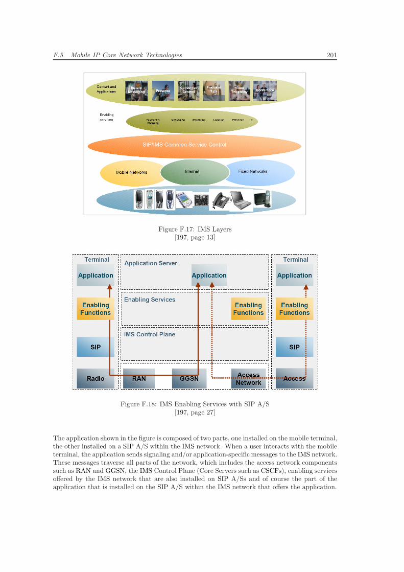
F.5. Mobile IP Core Network Technologies 201
Figure F.17: IMS Layers[197, page 13]
Figure F.18: IMS Enabling Services with SIP A/S[197, page 27]
The application shown in the figure is composed of two parts, one installed on the mobile terminal,the other installed on a SIP A/S within the IMS network. When a user interacts with the mobileterminal, the application sends signaling and/or application-specific messages to the IMS network.These messages traverse all parts of the network, which includes the access network componentssuch as RAN and GGSN, the IMS Control Plane (Core Servers such as CSCFs), enabling servicesoffered by the IMS network that are also installed on SIP A/Ss and of course the part of theapplication that is installed on the SIP A/S within the IMS network that offers the application.
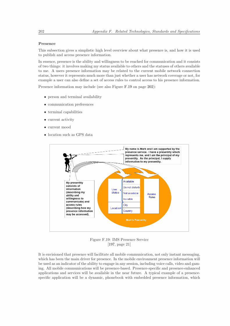
202 Appendix F. Related Technologies, Standards and Specifications
Presence
This subsection gives a simplistic high level overview about what presence is, and how it is usedto publish and access presence information.
In essence, presence is the ability and willingness to be reached for communication and it consistsof two things: it involves making my status available to others and the statuses of others availableto me. A users presence information may be related to the current mobile network connectionstatus, however it represents much more than just whether a user has network coverage or not, forexample a user can also define a set of access rules to control access to his presence information.
Presence information may include (see also Figure F.19 on page 202):
• person and terminal availability
• communication preferences
• terminal capabilities
• current activity
• current mood
• location such as GPS data
Figure F.19: IMS Presence Service[197, page 21]
It is envisioned that presence will facilitate all mobile communication, not only instant messaging,which has been the main driver for presence. In the mobile environment presence information willbe used as an indicator of the ability to engage in any session, including voice calls, video and gam-ing. All mobile communications will be presence-based. Presence-specific and presence-enhancedapplications and services will be available in the near future. A typical example of a presence-specific application will be a dynamic, phonebook with embedded presence information, which
F.5. Mobile IP Core Network Technologies 203
will be the initial information the user sees before establishing communication. This informationwill affect facts like the choice of communication method, the content of the communication,timing etc.
SIP for PresenceSIP has been extended for presence and an event package called ”presence” was added. Whensubscribing to such an event, a subscriber places the ”presence” token in the Event header ofthe SIP message. Some additional definitions were specified to describe the subscriber and thenotifier for the purpose of presence:
• Presentity - The presence entity is a resource that provides presence information to apresence service or server.
• Watchers - Are entities that request presence information about network resources suchas services and users. There are two kinds of watchers, called fetchers and subscribers. Afetcher simply requests the current value of some presentity’s presence information fromthe presence service. A special kind of fetcher is one that fetches information on a regularbasis. This is called a poller. In contrast to that a subscriber requests notifications fromthe presence service of all changes in a presentity’s presence information.
The 3GPP Release 6 specification defines two SIP entities for presence:
• Presence agent (PA) - capable of storing subscriptions and generating notifications (e.g.Presence Server).
• Presence user agent (PUA) - manipulates presence information for a presentity andpublishes such presence information (e.g. User Terminal).
For presence information the SIP NOTIFY request message body carries the presence stateinformation from the presence server to watching users. The state information is the presencestate of a presentity and is encoded as XML (Extensible Markup Language) document withthe Multipurpose Internet Mail Extension (MIME) type ”application/pidf+xml” as defined inthe Presence Information Data Format (PIDF) and can be extended with additional informationelements if necessary. In order to upload presence information from the presentity to the presenceserver, the SIP PUBLISH method, with presence state information as payload, is used.
Presence Service Architecture in IMSA user’s presence information can be obtained from a multiplicity of entities in the IMS network.It could be a PUA located in a foreign network, a PUA at the terminal or a PUA located as anentity in the network. The presence server itself is an example of an IMS application server orserver application. Watchers may be in the same home domain as the presentity or in a foreigndomain.
Security and Access ControlTo protect privacy and confidentiality, a presentity has full control over whether any group ofwatchers can access the published presence information. A presentity may give different watchersdifferent levels of access. A presentity can control (per watcher) which parts of the presenceinformation may be seen, may decide that specific watchers have restricted access and that somedo not have any access at all. In addition to that a presentity may also define presence informationand access rules so that different watchers are given different presence state information (e.g. Oneis told: not available, when at the same time others are told: available).
204 Appendix F. Related Technologies, Standards and Specifications
Messaging
In today’s world, both in the wired and wireless networks, there are many different types of mes-saging services and applications available. Unfortunately, the most popular Web/Internet-basedinstant messaging services are usually based upon closed and proprietary protocols (e.g. ICQ,MSN, Skype), which made it impossible for different service providers to allow interoperable mes-saging between their respective users. In addition to that, most Web/Internet-based messagingservices today do not take the wireless environment and the needs of operators to provide servicesthat are commercially viable (e.g. providing support for charging, etc.) into consideration.
Typical characteristics of instant messaging are instant delivery of the messages to the targetedrecipient(s) and interaction with presence information that allows users to see availability andstatus information. The expectations of messaging services in general differ in that some aredesigned to be used in what is perceived as ’real’ time (e.g. ICQ Chat, Skype Chat, MSN Chat),whereas others are designed as a ’mailbox’ service (e.g. E-Mail) where the messages are storedfor later collection or delivery.
The IMS Messaging service incorporates one or more of the following messaging types:
Immediate MessagingThe sender expects immediate message delivery in (almost) real-time. Typically the sender isaware of the availability of the recipient(s) through the use of a Presence service before sendingthis type of message. If the recipient is not available the message may be discarded or deferred.An immediate message may be deferred by the recipient’s network based on message filteringsettings defined by the recipient or by the recipient’s IMS service provider.
Immediate Messaging uses the SIP MESSAGE method for sending messages between peers. Thesending IMS user agent simply generates a MESSAGE request, fills in the desired content (e.g.text, audio, video, images), populates the request URI with the recipients address and routes themessage using the IMS core network to the receiving user agent.
Session-Based MessagingSession-based messaging relates to a familiar paradigm of messaging already in use in the Internet,the Internet Relay Chat (IRC). In this mode of messaging users participate in sessions, in whichthe main media component often consists of short textual messages. As in any other session amessage session has a well-defined lifetime (session setup till session closing). After the sessionwas set up between the participants, media flows directly from peers to peers and only peersparticipating in the session are allowed to send or able to receive messages. A peer can be anend-user’s user agent, or a messaging back-to-back user agent that manages a group chat orconference.
Session-based messaging forms a natural unison with conferencing as well. Using the conferencingfunctionality, session-based messaging can turn into a multi-party chat conference. In this modeit can enable applications similar to modern day voice conferences, which can include additionaldata channels that transfer audio, video, graphics, collaborative sketch boards, etc.
Deferred Delivery MessagingThe sender expects the network to deliver the message as soon as the recipient becomes available(store-and-forward delivery). The requirements for the ”deferred delivery messaging”are basicallythe same as for the well-known Multimedia Messaging Service (MMS).
Typically, IMS messaging is direct and in almost real-time between user agents. So, for thatto work, both agents need to be online during message exchange. For a deferred delivery it isnecessary to include a virtual agent (back-to-back messaging server/SIP A/S) that accepts allmessages for an offline user agent. This agent then forwards the stored messages, as soon as the
F.5. Mobile IP Core Network Technologies 205
recipient user agent registers with the IMS again.
Group Management
The IMS group management service provides an easy to use possibility to manage network-basedgroups that are personalized for every public user identification. The driver for specifying ageneric group management service in IMS was twofold: the same group created by a user (orservice provider) can be used in many services and the same group management functions canbe utilized independent of the service being used.
IMS group management allows managing an (almost) unlimited number of groups per user,adding/removing other users (buddies) to/from a group, defining different roles and rights tomembers of a group, setting group level information and properties, etc. The IMS group man-agement service is a generic capability that can be utilized in other IMS applications togetherwith other enabling services in order to implement comprehensive new applications or servicesquickly. Some examples for services/applications that use the IMS group management serviceare:
• Presence service - The Presentity is in control of who is able to see his presence infor-mation. The control is carried out via access control lists that can be managed with theIMS group management. A watcher can subscribe to a list of presentities instead of sub-scribing to every single presentity, one by one. The list can be managed with IMS groupmanagement.
• Chat - The administrator of the chat is able to control users that are allowed to participatein the chat. The control is carried out via access control lists, which can be managed withIMS group management.
• Messaging - In messaging the server may be able to distribute the messages to severalrecipients based on the delivery list. The content of the delivery list can be managed withIMS group management.
F.5.3 IP Telecommunication Application Development
This section provides a summary of the three concepts that support future TCP/IP-basedTelecommunication application development: SIP Application Servers, Service Capability In-teraction Managers and Policy Evaluation Enforcement and Management.
F.5.3.1 SIP Application Server (SIP A/S)
A SIP A/S is a SIP-based server and an entity in the network that hosts a wide range of value-added multimedia services and provides these services to end-users. A SIP A/S could be used toprovide presence, messaging and conferencing services.
An example of an application server that is being developed in 3GPP is the Voice Call ContinuityFunction (VCC Server). Depending on the actual service, the SIP A/S can operate in SIP proxymode, SIP UA (user agent) mode or SIP B2BUA (back-to-back user agent) mode. A SIP A/Scan be located in the home network or in an external third-party network. In addition to theSIP interface a SIP A/S may optionally provide an interface to the HSS that may be used todownload or upload user related data that stored in the HSS. If located in the home network, itcan query the HSS with the DIAMETER Sh interface (for a SIP A/S) or the Mobile ApplicationPart (MAP) interface (for IM-SSF).
Figure F.20 on page 206 shows the three different types of Application Servers.
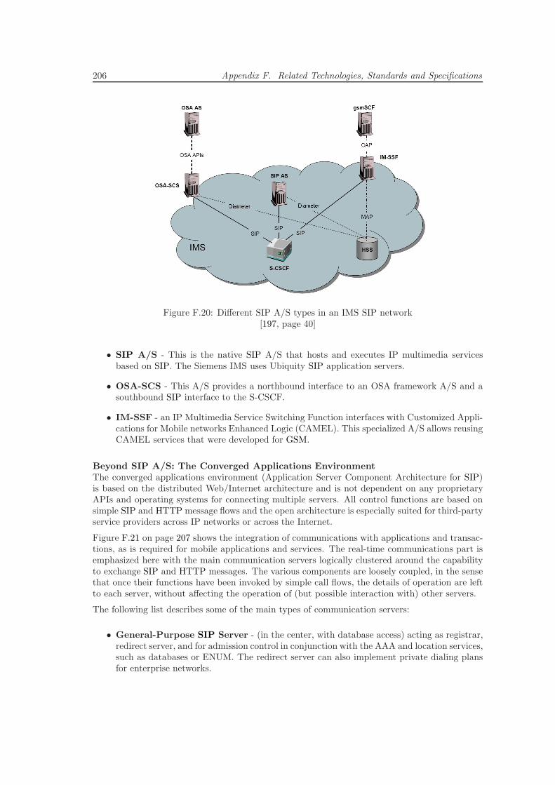
206 Appendix F. Related Technologies, Standards and Specifications
Figure F.20: Different SIP A/S types in an IMS SIP network[197, page 40]
• SIP A/S - This is the native SIP A/S that hosts and executes IP multimedia servicesbased on SIP. The Siemens IMS uses Ubiquity SIP application servers.
• OSA-SCS - This A/S provides a northbound interface to an OSA framework A/S and asouthbound SIP interface to the S-CSCF.
• IM-SSF - an IP Multimedia Service Switching Function interfaces with Customized Appli-cations for Mobile networks Enhanced Logic (CAMEL). This specialized A/S allows reusingCAMEL services that were developed for GSM.
Beyond SIP A/S: The Converged Applications EnvironmentThe converged applications environment (Application Server Component Architecture for SIP)is based on the distributed Web/Internet architecture and is not dependent on any proprietaryAPIs and operating systems for connecting multiple servers. All control functions are based onsimple SIP and HTTP message flows and the open architecture is especially suited for third-partyservice providers across IP networks or across the Internet.
Figure F.21 on page 207 shows the integration of communications with applications and transac-tions, as is required for mobile applications and services. The real-time communications part isemphasized here with the main communication servers logically clustered around the capabilityto exchange SIP and HTTP messages. The various components are loosely coupled, in the sensethat once their functions have been invoked by simple call flows, the details of operation are leftto each server, without affecting the operation of (but possible interaction with) other servers.
The following list describes some of the main types of communication servers:
• General-Purpose SIP Server - (in the center, with database access) acting as registrar,redirect server, and for admission control in conjunction with the AAA and location services,such as databases or ENUM. The redirect server can also implement private dialing plansfor enterprise networks.
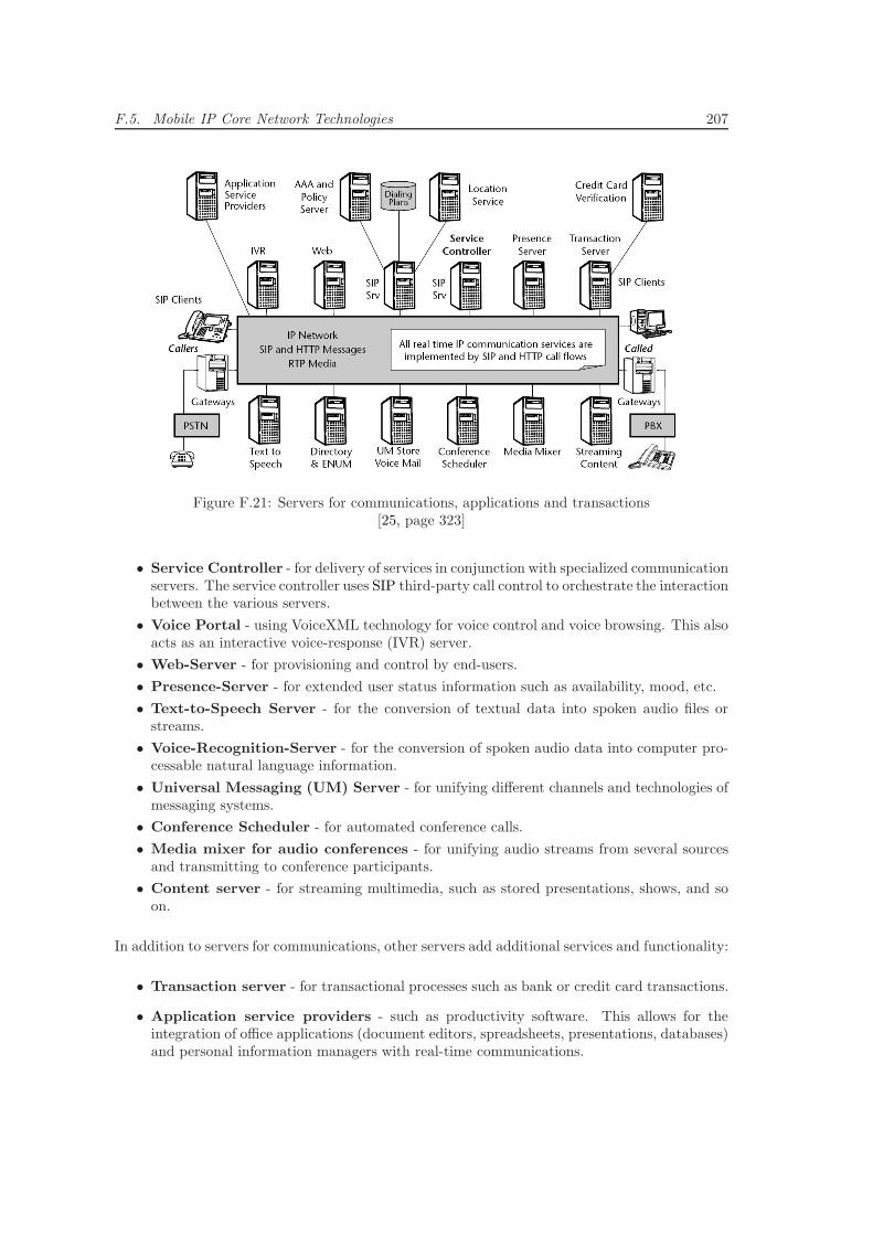
F.5. Mobile IP Core Network Technologies 207
Figure F.21: Servers for communications, applications and transactions[25, page 323]
• Service Controller - for delivery of services in conjunction with specialized communicationservers. The service controller uses SIP third-party call control to orchestrate the interactionbetween the various servers.
• Voice Portal - using VoiceXML technology for voice control and voice browsing. This alsoacts as an interactive voice-response (IVR) server.
• Web-Server - for provisioning and control by end-users.
• Presence-Server - for extended user status information such as availability, mood, etc.
• Text-to-Speech Server - for the conversion of textual data into spoken audio files orstreams.
• Voice-Recognition-Server - for the conversion of spoken audio data into computer pro-cessable natural language information.
• Universal Messaging (UM) Server - for unifying different channels and technologies ofmessaging systems.
• Conference Scheduler - for automated conference calls.
• Media mixer for audio conferences - for unifying audio streams from several sourcesand transmitting to conference participants.
• Content server - for streaming multimedia, such as stored presentations, shows, and soon.
In addition to servers for communications, other servers add additional services and functionality:
• Transaction server - for transactional processes such as bank or credit card transactions.
• Application service providers - such as productivity software. This allows for theintegration of office applications (document editors, spreadsheets, presentations, databases)and personal information managers with real-time communications.
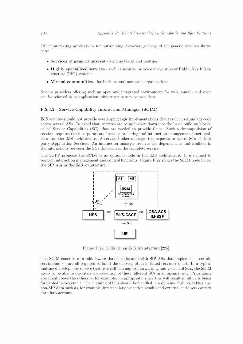
208 Appendix F. Related Technologies, Standards and Specifications
Other interesting applications for outsourcing, however, go beyond the generic services shownhere:
• Services of general interest - such as travel and weather
• Highly specialized services - such as security by voice recognition or Public Key Infras-tructure (PKI) systems
• Virtual communities - for business and nonprofit organizations
Service providers offering such an open and integrated environment for web, e-mail, and voicecan be referred to as application infrastructure service providers.
F.5.3.2 Service Capability Interaction Manager (SCIM)
IMS services should not provide overlapping logic implementations that result in redundant codeacross several ASs. To avoid that, services are being broken down into the basic building blocks,called Service Capabilities (SC), that are needed to provide them. Such a decomposition ofservices requires the incorporation of service brokering and interaction management functional-ities into the IMS architecture. A service broker manages the requests to access SCs of thirdparty Application Services. An interaction manager resolves the dependencies and conflicts inthe interactions between the SCs that deliver the complete service.
The 3GPP proposes the SCIM as an optional node in the IMS architecture. It is defined toperform interaction management and control functions. Figure F.22 shows the SCIM node belowthe SIP ASs in the IMS architecture.
Figure F.22: SCIM in an IMS Architecture [225]
The SCIM constitutes a middleware that is co-located with SIP ASs that implement a certainservice and so, are all required to fulfill the delivery of an initiated service request. In a typicalmultimedia telephony service that uses call barring, call forwarding and voicemail SCs, the SCIMneeds to be able to prioritize the execution of these different SCs in an optimal way. Prioritizingvoicemail above the others is, for example, inappropriate, since this will result in all calls beingforwarded to voicemail. The chaining of SCs should be handled in a dynamic fashion, taking alsonon-SIP data such as, for example, intermediary execution results and external end-users contextdata into account.
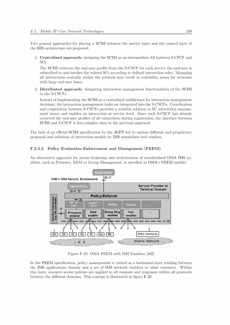
F.5. Mobile IP Core Network Technologies 209
Two general approaches for placing a SCIM between the service layer and the control layer ofthe IMS architecture are proposed:
1. Centralized approach: designing the SCIM as an intermediate AS between S-CSCF andSCs.
The SCIM retrieves the end-user profile from the S-CSCF for each service the end-user issubscribed to and invokes the related SCs according to defined interaction rules. Managingall interactions centrally within the network may result in scalability issues for networkswith large end-user bases.
2. Distributed approach: delegating interaction management functionalities of the SCIMto the S-CSCFs.
Instead of implementing the SCIM as a centralized middleware for interaction managementdecisions, the interaction management tasks are integrated into the S-CSCFs. Coordinationand cooperation between S-CSCFs provides a scalable solution to SC interaction manage-ment issues and enables an interaction at service level. Since each S-CSCF has alreadyretrieved the end-user profiles of all subscribers during registration, the interface betweenSCIM and S-CSCF is less complex than in the previous approach.
The lack of an official SCIM specification by the 3GPP led to various different and proprietaryproposals and solutions of interaction models by IMS researchers and vendors.
F.5.3.3 Policy Evaluation Enforcement and Management (PEEM)
An alternative approach for access brokering and orchestration of standardized OMA IMS en-ablers, such as Presence, XDM or Group Management, is specified in OMA’s PEEM enabler.
Figure F.23: OMA PEEM with IMS Enablers [165]
In the PEEM specification, policy management is viewed as a horizontal layer residing betweenthe IMS applications domain and a set of IMS network enablers or other resources. Withinthis layer, resource access policies are applied to all requests and responses within all protocolsbetween the different domains. This concept is illustrated in figure F.23.
210 Appendix F. Related Technologies, Standards and Specifications
F.6 Open Services Gateway Initiative (OSGi)
The OSGi service platform is a dynamic module system for the Java software development tech-nology. It implements a complete and dynamic service model, which enables the dynamic in-tegration and remote management of software services. Application lifecycle management ishandled via APIs that allow remote downloading of management policies. A service registryallows detecting the addition of new services as well as the removal of existing services.
The OSGi specifications are being developed further by the OSGi Alliance, an open standardsorganization founded in March 1999 and that has formerly been known as the Open ServicesGateway initiative. The organization is comprised of renowned companies such as Nokia, IBM,Oracle and Sun Microsystems. The OSGi specification is developed by the members in an openprocess and made available to the public free of charge under the OSGi Specification License.Several stable open-source implementations are available.
The OSGi specifications have evolved beyond the original focus of service gateways. Their appli-cations include mobile phones as well as the open source IDE Eclipse. Other application areasrange from automobiles, industrial automation and building automation to grid computing, fleetmanagement and application servers.
The central component of the OSGi service platform is the OSGi framework, which implementsa container where services can be installed and executed at runtime.
• Bundles are coherent units of software resources that can be independently installed anduninstalled on the OSGi framework. The resources contained in a bundle are initiallyinvisible to other bundles in the container. In order to make some available to otherbundles, the containing bundle must explicitly declare the ones that ought to be exported.Bundles, which intend on using another bundle’s exported resources, must explicitly importthe bundle in question.
Technically a bundle is a Java Archive (JAR) file, which includes a manifest file, Java Classfiles, libraries and media files that are necessary for the implementation of its functionality.A bundle may also include further JAR files itself. The manifest file describes meta-dataof the bundle such as name, libraries and dependencies.
• Services provide a possibility for decoupling modules on the OSGi framework. Servicesare available on the entire container and bundles can make use of them. An OSGi serviceis a Java object that is being made publicly known by an interface name. It needs to beregistered with the central service registry that is available across all bundles. Bundles thatneed a specific service are able to query the service registry and use the service withoutneeding to know which implementation of the service interface they are using. The OSGiservice platform provides a number of standard services that must be available on everyimplementation.
The architecture of the OSGi framework is illustrated in figure F.24.
• Services Layer
This layer specifies how bundles are connected dynamically within the framework and howthey are being used as OSGi services. Services can be registered and unregistered from theframework at any given time. This dynamic behavior implies that users of a service needto deal with the possibility of its disappearance at runtime. In order to support handlingof dynamic services, the specification describes three possibilities for a bundle to reactto changes in the service environment: Service Listener, Service Tracker and DeclarativeServices.
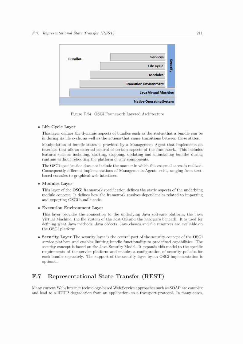
F.7. Representational State Transfer (REST) 211
Figure F.24: OSGi Framework Layered Architecture
• Life Cycle Layer
This layer defines the dynamic aspects of bundles such as the states that a bundle can bein during its life cycle, as well as the actions that cause transitions between those states.
Manipulation of bundle states is provided by a Management Agent that implements aninterface that allows external control of certain aspects of the framework. This includesfeatures such as installing, starting, stopping, updating and uninstalling bundles duringruntime without rebooting the platform or any components.
The OSGi specification does not include the manner in which this external access is realized.Consequently different implementations of Managements Agents exist, ranging from text-based consoles to graphical web interfaces.
• Modules Layer
This layer of the OSGi framework specification defines the static aspects of the underlyingmodule concept. It defines how the framework resolves dependencies related to importingand exporting OSGi bundle code.
• Execution Environment Layer
This layer provides the connection to the underlying Java software platform, the JavaVirtual Machine, the file system of the host OS and the hardware beneath. It is used fordefining what Java methods, Java objects, Java classes and file resources are available onthe OSGi platform.
• Security Layer The security layer is the central part of the security concept of the OSGiservice platform and enables limiting bundle functionality to predefined capabilities. Thesecurity concept is based on the Java Security Model. It expands this model to the specificrequirements of the service platform and enables a configuration of security policies foreach bundle separately. The support of the security layer by an OSGi implementation isoptional.
F.7 Representational State Transfer (REST)
Many current Web/Internet technology-basedWeb Service approaches such as SOAP are complexand lead to a HTTP degradation from an application- to a transport protocol. In many cases,
212 Appendix F. Related Technologies, Standards and Specifications
the Web/Internet technologies could provide the desired functionality and would be able to driveremote services themselves. The introduction of these additional layers of abstraction is oftenunnecessary overhead in design and implementation. Current Web/Internet technologies such asthe HTTP application protocol, the Uniform Resource Identification (URI) naming standard andXML are sufficient tools to define service interfaces and messages in a standardized and efficientmanner.
REST is an architectural style for distributed hypermedia systems in which requests and responsesbetween clients and servers are built around the transfer of representations of resources. Anarchitecture conforming to the REST architectural style is also called RESTful. The largestimplementation of a RESTful architecture is the Web/Internet, which is built upon the HTTPprotocol and the URI standard. REST itself is not limited to HTTP and may be based onother protocols that provide a uniform vocabulary for representational state transfer based onresources. A resource may be essentially any coherent and meaningful concept that can beaddressed. A representation of a resource is typically a document that captures the currentor intended state of a resource. Each resource is referenced with at least one global identifier(e.g. a URI). Manipulation of resources requires participants to communicate on a network usingstandardized interfaces to exchange representations of the resources.
F.7.1 REST Key Concepts
REST describes six constraints for RESTful architectures. Five of them are mandatory and anyservice that violates at least one of the mandatory cannot be referred to as fully RESTful. Theactual implementation of the components is open to designers and developers.
Client-Server Following the well-established design principle of separation of concerns, clientsare separated from servers by a uniform interface. GUI concerns are separated from data stor-age concerns in order to improve portability of the GUI and scalability of the server compo-nents. Decoupling of components also allows them to evolve independently, thus supporting theWeb/Internet-scale requirements of multiple organizational domains.
Stateless Communication must be stateless in nature and session state is kept entirely onthe client. Each request from client to server must contain all the information necessary tounderstand and process the request, without taking advantage of any stored context on theserver. Thereby, a monitoring system does not have to look beyond a single request in orderto determine the full nature of the request. This improves reliability by enabling partial faultrecovery and scalability by allowing servers to free resources as quickly as possible instead ofstoring session state information between requests.
Cacheable Data within a response must be implicitly or explicitly labeled as cacheable ornon-cacheable. Cacheable responses may be loaded from client caches for subsequent equivalentrequests. Non-cacheable responses need to be labeled in order to prevent clients from reusingoutdated data as response to equivalent requests. The advantages of adding cache constraintsare potentially increased efficiency, scalability and user-perceived performance through partial orcomplete elimination of selected client-server interactions within a series of interactions.
Uniform Interface REST applies the software engineering principle of Generality to compo-nent interfaces. Implementations are decoupled from the services they provide, respectively theservice interface they export. This enables multiple implementations for the same service interface
F.7. Representational State Transfer (REST) 213
and allows an independent evolution of the components as well as ensures a high maintainabilityand extensibility.
The guiding principles of the uniform interface:
• Identification of Resources - Individual resources can be deterministically referenced in re-quests by at least one globally unique identifier. For example using URIs in Web/Internettechnologies-based REST systems. Servers respond to requests for resources with a con-ceptual representation of the requested resource.
• Manipulation of Resources through Representations - Any client that holds a representationof a resource and the appropriate permissions has enough information to modify or deletethe resource on the server, including any meta-data attached.
• Self Descriptive Messages - Each message includes enough information to define how toprocess the message. Responses explicitly indicate their cacheability.
• Hypermedia as the Engine of Application State - Clients make state transitions only throughactions that are dynamically identified within hypermedia by the server (e.g. by hyperlinkswithin hypertext). Except for simple fixed entry points to the application, a client does notassume that any particular actions beyond those described in representations previouslyreceived from the server are available for a given resource.
Layered System The architecture is composed of hierarchical layers. These constrain com-ponent behavior such that components cannot interact beyond the immediate layer with whichthey are associated. Layers can be used to encapsulate legacy services as well as to protect newservices from legacy clients. Layers help to simplify components by moving infrequently usedfunctionality to a shared intermediary. Intermediaries can also be used to enforce security poli-cies as well as to improve system scalability by enabling load balancing across multiple networksand systems.
Code-On-Demand (optional) REST allows client functionality to be extended by download-ing and executing code in the form of applets or scripts. This simplifies client development andporting by reducing the amount of functionalities and capabilities required to be implemented.Allowing functionalities to be downloaded after deployment improves the overall system’s exten-sibility.
F.7.2 RESTful Web Services
Two main questions are answered differently by today’s Web Services:
1. How does a client convey its intentions to the server? (Method Information)
2. How does a client tell the server which part of the data set to operate on? (ScopingInformation)
The following summary describes how RESTful Web Services answer these questions by utilizingthe HTTP vocabulary and URI naming convention for representational state transfer of resources.
214 Appendix F. Related Technologies, Standards and Specifications
A RESTful Web Service is a service implemented using HTTP and the design principles of theREST architectural style. It is a collection of resources, with four defined aspects:
• Base URI for the Web Service, e.g. http://sdp.cdtm.de/TestService
• The supported Web/Internet media types supported by the Web Service, e.g. JSON, XML
• The set of operations supported by the Web Service, using only HTTP methods (e.g. POST,GET, PUT or DELETE)
• The API must be hypertext driven.
The answers to the two descriptive questions to a Web Service can be inferred from the RESTarchitectural principles and the above definition of a RESTful Web Service.
• Method information: is solely conveyed through the actual HTTP method. RPC-styleWeb Services, which define their own method vocabulary and convey method informationwithin a HTTP request elsewhere, are not considered RESTful.
• Scoping information: is placed in the URI-path, uniquely and deterministically identi-fying the requested set of resources.
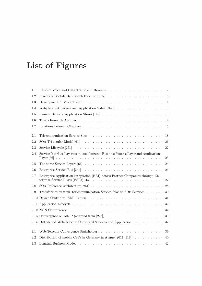
List of Figures
1.1 Ratio of Voice and Data Traffic and Revenue . . . . . . . . . . . . . . . . . . . . . 2
1.2 Fixed and Mobile Bandwidth Evolution [150] . . . . . . . . . . . . . . . . . . . . . 3
1.3 Development of Voice Traffic . . . . . . . . . . . . . . . . . . . . . . . . . . . . . . 4
1.4 Web/Internet Service and Application Value Chain . . . . . . . . . . . . . . . . . . 5
1.5 Launch Dates of Application Stores [148] . . . . . . . . . . . . . . . . . . . . . . . 8
1.6 Thesis Research Approach . . . . . . . . . . . . . . . . . . . . . . . . . . . . . . . 14
1.7 Relations between Chapters . . . . . . . . . . . . . . . . . . . . . . . . . . . . . . . 15
2.1 Telecommunication Service Silos . . . . . . . . . . . . . . . . . . . . . . . . . . . . 18
2.2 SOA Triangular Model [61] . . . . . . . . . . . . . . . . . . . . . . . . . . . . . . . 21
2.3 Service Lifecycle [251] . . . . . . . . . . . . . . . . . . . . . . . . . . . . . . . . . . 22
2.4 Service Interface Layer positioned between Business Process Layer and ApplicationLayer [66] . . . . . . . . . . . . . . . . . . . . . . . . . . . . . . . . . . . . . . . . . 23
2.5 The three Service Layers [66] . . . . . . . . . . . . . . . . . . . . . . . . . . . . . . 24
2.6 Enterprise Service Bus [251] . . . . . . . . . . . . . . . . . . . . . . . . . . . . . . . 26
2.7 Enterprise Application Integration (EAI) across Partner Companies through En-terprise Service Buses (ESBs) [43] . . . . . . . . . . . . . . . . . . . . . . . . . . . 27
2.8 SOA Reference Architecture [251] . . . . . . . . . . . . . . . . . . . . . . . . . . . . 28
2.9 Transformation from Telecommunication Service Silos to SDP Services . . . . . . . 30
2.10 Device Centric vs. SDP Centric . . . . . . . . . . . . . . . . . . . . . . . . . . . . . 31
2.11 Application Lifecycle . . . . . . . . . . . . . . . . . . . . . . . . . . . . . . . . . . . 32
2.12 NGN Convergence . . . . . . . . . . . . . . . . . . . . . . . . . . . . . . . . . . . . 34
2.13 Convergence on All-IP (adapted from [226]) . . . . . . . . . . . . . . . . . . . . . 35
2.14 Distributed Web-Telecom Converged Services and Application . . . . . . . . . . . . 37
3.1 Web-Telecom Convergence Stakeholder . . . . . . . . . . . . . . . . . . . . . . . . . 39
3.2 Distribution of mobile CSPs in Germany in August 2011 [116] . . . . . . . . . . . . 40
3.3 Longtail Business Model . . . . . . . . . . . . . . . . . . . . . . . . . . . . . . . . . 42
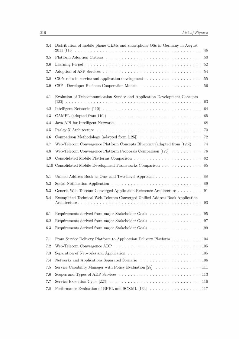
216 List of Figures
3.4 Distribution of mobile phone OEMs and smartphone OSs in Germany in August2011 [116] . . . . . . . . . . . . . . . . . . . . . . . . . . . . . . . . . . . . . . . . . 46
3.5 Platform Adoption Criteria . . . . . . . . . . . . . . . . . . . . . . . . . . . . . . . 50
3.6 Learning Period . . . . . . . . . . . . . . . . . . . . . . . . . . . . . . . . . . . . . . 52
3.7 Adoption of ASP Services . . . . . . . . . . . . . . . . . . . . . . . . . . . . . . . . 54
3.8 CSPs roles in service and application development . . . . . . . . . . . . . . . . . . 55
3.9 CSP - Developer Business Cooperation Models . . . . . . . . . . . . . . . . . . . . 56
4.1 Evolution of Telecommunication Service and Application Development Concepts[132] . . . . . . . . . . . . . . . . . . . . . . . . . . . . . . . . . . . . . . . . . . . . 63
4.2 Intelligent Networks [110] . . . . . . . . . . . . . . . . . . . . . . . . . . . . . . . . 64
4.3 CAMEL (adopted from[110]) . . . . . . . . . . . . . . . . . . . . . . . . . . . . . . 65
4.4 Java API for Intelligent Networks . . . . . . . . . . . . . . . . . . . . . . . . . . . . 68
4.5 Parlay X Architecture . . . . . . . . . . . . . . . . . . . . . . . . . . . . . . . . . . 70
4.6 Comparison Methodology (adapted from [125]) . . . . . . . . . . . . . . . . . . . . 72
4.7 Web-Telecom Convergence Platform Concepts Blueprint (adapted from [125]) . . . 74
4.8 Web-Telecom Convergence Platform Proposals Comparison [125] . . . . . . . . . . 76
4.9 Consolidated Mobile Platforms Comparison . . . . . . . . . . . . . . . . . . . . . . 82
4.10 Consolidated Mobile Development Frameworks Comparison . . . . . . . . . . . . . 85
5.1 Unified Address Book as One- and Two-Level Approach . . . . . . . . . . . . . . . 88
5.2 Social Notification Application . . . . . . . . . . . . . . . . . . . . . . . . . . . . . 89
5.3 Generic Web-Telecom Converged Application Reference Architecture . . . . . . . . 91
5.4 Exemplified Technical Web-Telecom Converged Unified Address Book ApplicationArchitecture . . . . . . . . . . . . . . . . . . . . . . . . . . . . . . . . . . . . . . . . 93
6.1 Requirements derived from major Stakeholder Goals . . . . . . . . . . . . . . . . . 95
6.2 Requirements derived from major Stakeholder Goals . . . . . . . . . . . . . . . . . 97
6.3 Requirements derived from major Stakeholder Goals . . . . . . . . . . . . . . . . . 99
7.1 From Service Delivery Platform to Application Delivery Platform . . . . . . . . . . 104
7.2 Web-Telecom Convergence ADP . . . . . . . . . . . . . . . . . . . . . . . . . . . . 105
7.3 Separation of Networks and Application . . . . . . . . . . . . . . . . . . . . . . . . 105
7.4 Networks and Applications Separated Scenario . . . . . . . . . . . . . . . . . . . . 106
7.5 Service Capability Manager with Policy Evaluation [28] . . . . . . . . . . . . . . . 111
7.6 Scopes and Types of ADP Services . . . . . . . . . . . . . . . . . . . . . . . . . . . 113
7.7 Service Execution Cycle [223] . . . . . . . . . . . . . . . . . . . . . . . . . . . . . . 116
7.8 Performance Evaluation of BPEL and SCXML [134] . . . . . . . . . . . . . . . . . 117
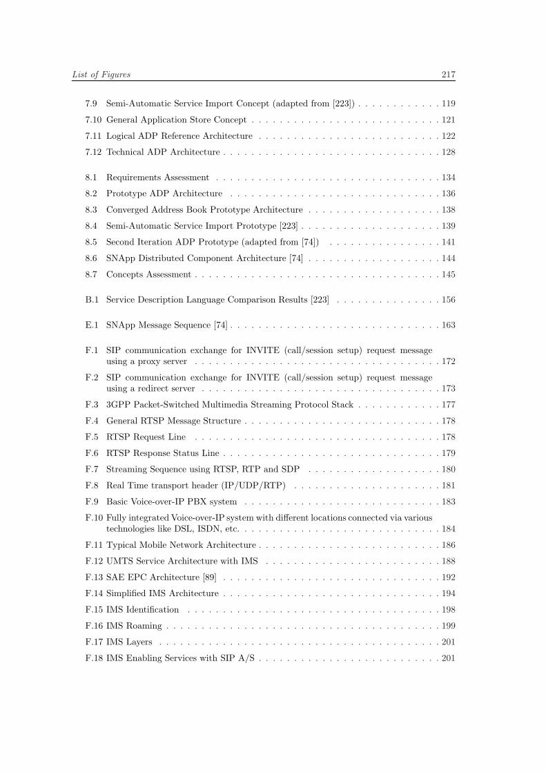
List of Figures 217
7.9 Semi-Automatic Service Import Concept (adapted from [223]) . . . . . . . . . . . . 119
7.10 General Application Store Concept . . . . . . . . . . . . . . . . . . . . . . . . . . . 121
7.11 Logical ADP Reference Architecture . . . . . . . . . . . . . . . . . . . . . . . . . . 122
7.12 Technical ADP Architecture . . . . . . . . . . . . . . . . . . . . . . . . . . . . . . . 128
8.1 Requirements Assessment . . . . . . . . . . . . . . . . . . . . . . . . . . . . . . . . 134
8.2 Prototype ADP Architecture . . . . . . . . . . . . . . . . . . . . . . . . . . . . . . 136
8.3 Converged Address Book Prototype Architecture . . . . . . . . . . . . . . . . . . . 138
8.4 Semi-Automatic Service Import Prototype [223] . . . . . . . . . . . . . . . . . . . . 139
8.5 Second Iteration ADP Prototype (adapted from [74]) . . . . . . . . . . . . . . . . 141
8.6 SNApp Distributed Component Architecture [74] . . . . . . . . . . . . . . . . . . . 144
8.7 Concepts Assessment . . . . . . . . . . . . . . . . . . . . . . . . . . . . . . . . . . . 145
B.1 Service Description Language Comparison Results [223] . . . . . . . . . . . . . . . 156
E.1 SNApp Message Sequence [74] . . . . . . . . . . . . . . . . . . . . . . . . . . . . . . 163
F.1 SIP communication exchange for INVITE (call/session setup) request messageusing a proxy server . . . . . . . . . . . . . . . . . . . . . . . . . . . . . . . . . . . 172
F.2 SIP communication exchange for INVITE (call/session setup) request messageusing a redirect server . . . . . . . . . . . . . . . . . . . . . . . . . . . . . . . . . . 173
F.3 3GPP Packet-Switched Multimedia Streaming Protocol Stack . . . . . . . . . . . . 177
F.4 General RTSP Message Structure . . . . . . . . . . . . . . . . . . . . . . . . . . . . 178
F.5 RTSP Request Line . . . . . . . . . . . . . . . . . . . . . . . . . . . . . . . . . . . 178
F.6 RTSP Response Status Line . . . . . . . . . . . . . . . . . . . . . . . . . . . . . . . 179
F.7 Streaming Sequence using RTSP, RTP and SDP . . . . . . . . . . . . . . . . . . . 180
F.8 Real Time transport header (IP/UDP/RTP) . . . . . . . . . . . . . . . . . . . . . 181
F.9 Basic Voice-over-IP PBX system . . . . . . . . . . . . . . . . . . . . . . . . . . . . 183
F.10 Fully integrated Voice-over-IP system with different locations connected via varioustechnologies like DSL, ISDN, etc. . . . . . . . . . . . . . . . . . . . . . . . . . . . . 184
F.11 Typical Mobile Network Architecture . . . . . . . . . . . . . . . . . . . . . . . . . . 186
F.12 UMTS Service Architecture with IMS . . . . . . . . . . . . . . . . . . . . . . . . . 188
F.13 SAE EPC Architecture [89] . . . . . . . . . . . . . . . . . . . . . . . . . . . . . . . 192
F.14 Simplified IMS Architecture . . . . . . . . . . . . . . . . . . . . . . . . . . . . . . . 194
F.15 IMS Identification . . . . . . . . . . . . . . . . . . . . . . . . . . . . . . . . . . . . 198
F.16 IMS Roaming . . . . . . . . . . . . . . . . . . . . . . . . . . . . . . . . . . . . . . . 199
F.17 IMS Layers . . . . . . . . . . . . . . . . . . . . . . . . . . . . . . . . . . . . . . . . 201
F.18 IMS Enabling Services with SIP A/S . . . . . . . . . . . . . . . . . . . . . . . . . . 201

218 List of Figures
F.19 IMS Presence Service . . . . . . . . . . . . . . . . . . . . . . . . . . . . . . . . . . . 202
F.20 Different SIP A/S types in an IMS SIP network . . . . . . . . . . . . . . . . . . . . 206
F.21 Servers for communications, applications and transactions . . . . . . . . . . . . . . 207
F.22 SCIM in an IMS Architecture [225] . . . . . . . . . . . . . . . . . . . . . . . . . . . 208
F.23 OMA PEEM with IMS Enablers [165] . . . . . . . . . . . . . . . . . . . . . . . . . 209
F.24 OSGi Framework Layered Architecture . . . . . . . . . . . . . . . . . . . . . . . . . 211
List of Tables
C.1 Mobile Platforms Comparison Details . . . . . . . . . . . . . . . . . . . . . . . . . 157
C.2 Development Frameworks Comparison . . . . . . . . . . . . . . . . . . . . . . . . . 158
F.1 GPRS Data Rates . . . . . . . . . . . . . . . . . . . . . . . . . . . . . . . . . . . . 187
F.2 WLAN Specifications . . . . . . . . . . . . . . . . . . . . . . . . . . . . . . . . . . . 191

Listings
8.1 Prototypical ADP SDL [223] . . . . . . . . . . . . . . . . . . . . . . . . . . . . . . 140
8.2 SDL Google Translate Example [223] . . . . . . . . . . . . . . . . . . . . . . . . . . 140
D.1 Prototype Code Generation Template . . . . . . . . . . . . . . . . . . . . . . . . . 161
F.1 HTTP GET Request . . . . . . . . . . . . . . . . . . . . . . . . . . . . . . . . . . . 166
F.2 HTTP 302 Redirect Response . . . . . . . . . . . . . . . . . . . . . . . . . . . . . . 167
F.3 HTTP 200 OK Response . . . . . . . . . . . . . . . . . . . . . . . . . . . . . . . . 167
F.4 RTSP SETUP Request . . . . . . . . . . . . . . . . . . . . . . . . . . . . . . . . . . 179
F.5 RTSP SETUP Response . . . . . . . . . . . . . . . . . . . . . . . . . . . . . . . . . 180

Bibliography
[1] G. D. Abowd, A. Dey, R. Orr, and J. Brotherton, “Context Awareness in Wearable andUbiquitous Computing,” Journal of Virtual Reality, vol. 3, no. 3, 1998.
[2] Accenture, “Supporting Cost-Effective Service Innovation in the All-IP Era,” Tech. Rep.,2010.
[3] V. Agarwal, K. Dasgupta, N. Karnik, A. Kumar, A. Kundu, S. Mittal, and B. Srivastava,“A service creation environment based on end to end composition of Web services,”Proceedings of the 14th international conference on World Wide Web - WWW ’05, p. 128,2005. [Online]. http://portal.acm.org/citation.cfm?doid=1060745.1060768
[4] A. Al-Hezmi, F. Carvalho de Gouveia, M. Sher, O. Friedrich, and T. Magedanz,“Provisioning IMS-based seamless triple play services over different access networks,”NOMS 2008 - 2008 IEEE Network Operations and Management Symposium, pp. 927–930,2008. [Online]. http://ieeexplore.ieee.org/lpdocs/epic03/wrapper.htm?arnumber=4575249
[5] A. Al-Hezmi, C. Riede, and T. Magedanz, “Session and Media Signaling for IPTV via IMS,”Proceedings of the First International Conference on MOBILe Wireless MiddleWARE,Operating Systems, and Applications, pp. 0–5, 2008. [Online]. http://eudl.eu/?id=2917
[6] Alcatel-Lucent, “Introduction to Evolved Packet Core,” Alcatel-Lucent, Tech. Rep., 2009.[Online]. http://www.3g4g.co.uk/Lte/LTE WP 0903 AlcatelLucent.pdf
[7] Alcatel-Lucent, “Service Delivery Environment (SDE),” 2010. [Online].http://www.alcatel-lucent.com/sde
[8] Alcatel-Lucent, “Alcatel-Lucent Open API Platform and Open API Service,” Alcatel-Lucent, Tech. Rep., 2011.
[9] Ali Arsanjani, Liang-Jie Zhang, Michael Ellis, Abdul Allam, and Kishore Channabasavaiah,“Design an SOA Solution using a Reference Architecture,” IBM, Tech. Rep., Mar. 2007.[Online]. http://www.ibm.com/developerworks/library/ar-archtemp/
[10] N. Amram and M. Fuchs, “Detailed Research Objectives and Requirements for the CoreNetwork Enhancements and New Entities,” C-Mobile, Tech. Rep., 2006.
[11] V. Andrikopoulos, A. Bucchiarone, E. D. Nitto, R. Kazhamiakin, S. Lane, V. Mazza,and I. Richardson, “Service Engineering,” in Service Research Challenges and Solutions.Springer, 2010, pp. 271–337.
[12] Apache Felix, “iPOJO,”2011. [Online]. http://felix.apache.org/site/apache-felix-ipojo.html
[13] Apple, “Apple App Store,”2010. [Online]. http://www.apple.com/iphone/apps-for-iphone/
224 Bibliography
[14] Apple, “iPhone OS,” 2010. [Online]. http://developer.apple.com/iphone/
[15] M. Arango and C. Huitema, “Simple Gateway Control Protocol (SGCP),” 1998.
[16] H. Arnold, “Auf dem Radar - Telco Service Architecture for Web X.0,” Deutsche TelekomLaboratories, Tech. Rep., 2010.
[17] A. Arsanjani, G. Booch, T. Boubez, P. C. Brown, D. Chappell, J. de Vadoss,T. Erl, N. Josuttis, D. Krafzig, M. Little, B. Loesgen, J. McKendrick, A. T. Manes,S. Ross-Talbot, S. Tilkov, C. Utschig-Utschig, and H. Wilhelmsen, “SOA Manifesto,” p. 1,2009. [Online]. http://www.soa-manifesto.org/
[18] Asterisk, “Asterisk Open Source PBX,” 2007.
[19] H. Baba, N. Takaya, I. Inoue, A. Kurokawa, L. Chong Chauvot, M. Le Clec, B. Fourestie,F. Forestier Husson, and N. Edel, “Web-IMS Convergence Architecture and Prototype,” inIEEE Globecom, 2010.
[20] A. Baravaglio, C. Licciardi, and C. Venezia, “Web Service Applicability inTelecommunication Service Platforms,” in International Conference on Next Gen-eration Web Services Practices (NWeSP’05). Ieee, 2005, pp. 39–44. [Online].http://ieeexplore.ieee.org/lpdocs/epic03/wrapper.htm?arnumber=1592404
[21] S. Baset and H. Schulzrinne, “An Analysis of the Skype Peer-to-Peer Internet Telephony Protocol,” CoRR, vol. abs/cs/041, 2004. [Online].http://dblp.uni-trier.de/db/journals/corr/corr0412.html#abs-cs-0412017
[22] A. Becker, “Die Architektur von Android,”Heise Mobil, pp. 1–10, 2011.
[23] S. Becot, I. Bedini, M. Belaunde, S. Marin, O. Rugnon, V. Hiribarren, B. Christophe,B. Molina, and G. Marton, “Empowering Telco Operator Convergence through a CommonMarketplace,” IEEE, 2010.
[24] K. Bergner, A. Rausch, M. Sihling, T. Ternite, R. Reussner, J. Mayer, J. Stafford, S. Over-hage, S. Becker, and P. Schroeder, Quality of Software Architectures and Software Quality,ser. Lecture Notes in Computer Science, R. Reussner, J. Mayer, J. A. Stafford, S. Overhage,S. Becker, and P. J. Schroeder, Eds. Berlin, Heidelberg: Springer Berlin Heidelberg,2005, vol. 3712. [Online]. http://www.springerlink.com/content/039c1akabt95l93y/
[25] A. Bien, Internet Communications using SIP. Wiley Publishing, 2006.
[26] M. Bilandzic, F. Dany, C. Menkens, and A. Schmid, “Design Research, Action Research,Qualitative and Quantitative Methods in Ubiquitous Computing,” Center for Digital Tech-nology and Management, Tech. Rep., 2010.
[27] N. Blum, I. Boldea, T. Magedanz, and T. Margaria, “Service-oriented Access
to Next Generation NetworksaATfrom Service Creation to Execution,” MobileNetworks and Applications, vol. 15, no. 3, pp. 356–365, Jan. 2010. [Online].http://www.springerlink.com/index/10.1007/s11036-010-0222-1
[28] N. Blum, I. Boldea, T. Magedanz, U. Staiger, and H. Stein, “A Service Broker ProvidingReal-Time Telecommunications Services for 3rd Party Services,” in 2009 33rd Annual IEEEInternational Computer Software and Applications Conference. Ieee, 2009, pp. 85–91.[Online]. http://ieeexplore.ieee.org/lpdocs/epic03/wrapper.htm?arnumber=5254143
[29] N. Blum, T. Magedanz, and F. Schreiner, “The Role of Service Brokers for ComposedServices in an Open Service Environment,”Telekommunikation Aktuell, no. 01, 2008.
Bibliography 225
[30] N. Blum, T. Magedanz, F. Schreiner, and S. Wahle, “A research infras-tructure for SOA-based Service Delivery Frameworks,” in 2009 5th Interna-tional Conference on Testbeds and Research Infrastructures for the Developmentof Networks & Communities and Workshops. Ieee, 2009, pp. 1–6. [Online].http://ieeexplore.ieee.org/lpdocs/epic03/wrapper.htm?arnumber=4976202
[31] C. Bo, Z. Yang, C. Junliang, Z. Peng, and D. Hua, “Design and Implementation of Web-Telecom Hybrid Services Bus based Execution Platform over Convergence Networks,” inIEEE Globecom 2010 Workshop on Multimedia Communications and Services, 2010.
[32] C. Bo, Z. Yang, Z. Peng, D. Hua, H. Xiaoxiao, W. Zheng, and C. Junliang, “Developmentof Web-Telecom based hybrid services orchestration and execution middleware over conver-gence networks,”Journal of Network and Computer Applications, vol. 33, no. 5, pp. 620–630,Sept. 2010. [Online]. http://linkinghub.elsevier.com/retrieve/pii/S1084804510000603
[33] F. Bohagen and J. Binningsbo, “HSPA and LTE aAS Future-proof Mobile BroadbandSolutions,”Telektronikk, vol. 2010, no. 1, pp. 1–18, 2010.
[34] BONDI, “BONDI - Open Mobile Terminal Platform,” 2011. [Online].http://bondidev.omtp.org/default.aspx
[35] I. Bose and C. Menkens, “Identifying Requirements for Mobile Distributed Applicationsand Service Delivery Platforms (SDP) derived from Stakeholder Goals,” Center for DigitalTechnology and Management, Tech. Rep., 2010.
[36] G. Brown, “LTE / SAE & the Evolved Packet Core: Technology Platforms & Implementa-tion Choices,” Heavy Reading on behalf of Alcatel-Lucent, Tech. Rep. April, 2009.
[37] R. Bruns and J. Dunkel, “Event-Driven Architecture und Complex Event Processing imUberblick,” in Event-Driven Architecture, ser. Xpert.press. Springer Berlin Heidelberg,2010, pp. 47–82. [Online]. http://dx.doi.org/10.1007/978-3-642-02439-9 3
[38] F. Bullingen and P. Stamm, “Entwicklungstrends im Telekommunikationssektor bis 2010,”Wissenschaftliches Institut fur Kommunikationsdienste, Tech. Rep., 2001.
[39] E. W. Burger, S. Rajasekar, P. O’Doherty, A. Lundqvist, and T. Gronberg, “A Telecom-munications Web Services Platform for Third Party Network Access and SOA-basedService Delivery,” in Proceedings of the 2007 Workshop on Middleware for next-generationconverged networks and applications - MNCNA ’07. New York, New York, USA: ACMPress, 2007, pp. 1–6. [Online]. http://portal.acm.org/citation.cfm?doid=1376878.1376888
[40] P. Calhoun, J. Loughney, and E. Guttman, “RFC3588 - Diameter Base Protocol,” Sept.2003.
[41] B. Campbell, “RFC3428 - Session Initiation Protocol (SIP) Extension for Instant Messag-ing,” 2002.
[42] D. Chakraborty, S. Goyal, S. Mittal, and S. Mukherjea, “On the Changing Face of ServiceComposition in Telecom,” in MNCNA, 2007.
[43] D. Chappell, Enterprise Service Bus: Theory in Practice. O’Reilly Media, 2004. [Online].http://www.citeulike.org/group/2314/article/224708?citation format=IEEEtran#
[44] D. Chappell, “What is Application Lifecycle Management?” Chappell and Associates, Tech.Rep., 2008.
[45] Cisco, “Cisco Unified Communication Manager,” 2007.
226 Bibliography
[46] A. Collins, D. Joseph, and K. Bielaczyc, “Design Research: Theoretical and MethodologicalIssues,”The Journal of the Learning Sciences, vol. 13, no. 1, pp. 15–42, 2004.
[47] A. Constantinou, “Apps is the new Web: Sowing the seeds for Web 3.0,” 2011. [Online].http://www.visionmobile.com/blog
[48] R. Copeland, “Telco App Stores - Friend or Foe ?” IEEE, 2010.
[49] C. Cordier and I. Douplitzky, “Orange and Web 2.0,” Orange, Tech. Rep., 2008.
[50] M. Cuevas, “Telcos exposing APIs,” British Telecom, Tech. Rep., 2009.
[51] R. Daher and D. Tavangarian, “Resource reservation and admission control in IEEE802.11 WLANs,” in Proceedings of the 3rd international conference on Quality of service inheterogeneous wired/wireless networks - QShine ’06. New York, New York, USA: ACMPress, Aug. 2006, p. 4. [Online]. http://dl.acm.org/citation.cfm?id=1185373.1185379
[52] V. A. Danciu, N. gentschen Felde, D. Kranzlmuller, M. Schiffers, and J. R.Watzl,“Der Cloud-Broker: dynamische Orchestrierung von Cloud-Diensten zu SmartMobileApps,” in Smart Mobile Apps, ser. Xpert.press, S. Verclas and C. Linnhoff-Popien,Eds. Berlin, Heidelberg: Springer Berlin Heidelberg, 2011, ch. 23. [Online].http://www.springerlink.com/index/10.1007/978-3-642-22259-7
[53] J. Davidson and J. Peters, Voice over IP Fundamentals. Cisco Press, 2004.
[54] F. Deinert, A. Murarasu, A. Bachmann, and T. Magedanz, “A Base Solution for ExposingIMS Telecommunication Services to Web 2.0 Enabled Applications,” in Mobilware, LNICST0007, 2009, pp. 1–14.
[55] Detecon, “Future Telco Service Architecture Market Analysis,” Deutsche Telekom Labora-tories, Tech. Rep., 2010.
[56] Deutsche Telekom AG, “Developer Garden,” 2010. [Online].http://www.developergarden.com
[57] Deutsche Telekom Laboratories, “ISA - Towards an Integrative Service Architecture forTelcos,” Tech. Rep., 2009.
[58] Deutsche Telekom Laboratories, “Connected Life and Work,” Tech. Rep., 2010.
[59] P. Dornbusch, U. Sandner, P. Sties, and M. Zundt, “Fixed Mobile Convergence,”Center forDigital Technology and Management, Tech. Rep., 2005.
[60] E. Drosos, “3rd Party Enabling - Integration von Telekom Services in offene Dienste- undAnwendungswelten,” Deutsche Telekom AG, Tech. Rep., 2010.
[61] M. Eisele and M. Pizka,“SOA Report - State of the Art Service-Orientierter Architekturen,”MSG Systems AG, Tech. Rep., 2007.
[62] M. El-Sayyad, C. Menkens, and K. Diepold, “Evaluating Cross-Platform Frameworks Basedon Identified Requirements for Mobile Platforms,”Center for Digital Technology and Man-agement, Tech. Rep., 2011.
[63] S. El-Sayyad, C. Menkens, and K. Diepold, “Identifying Requirements for Service Deliv-ery Platforms (SDP) Derived from Stakeholder Goals,” Center for Digital Technology andManagement, Tech. Rep., 2011.
Bibliography 227
[64] M. Ergen, “Basics of All-IP Networking,” in Mobile Broadband: IncludingWiMAX and LTE. Boston, MA: Springer US, 2009, pp. 67–105. [Online].http://www.springerlink.com/index/10.1007/978-0-387-68192-4
[65] Ericsson, “Evolved Packet Core,” Tech. Rep.
[66] T. Erl, Service-Oriented Architecture (SOA): Concepts, Technology, and Design. PrenticeHall, 2005.
[67] T. Erl, SOA: Principles of Service Design, 1st ed. Upper Saddle River, NJ, USA: PrenticeHall Press, 2007.
[68] T. Erl, SOA Design Patterns, 1st ed. Upper Saddle River, NJ, USA: Prentice Hall PTR,2009.
[69] P. Farley and M. Capp, “Mobile Web Services,” BT Technol-ogy Journal, vol. 23, no. 3, pp. 202–213, July 2005. [Online].http://www.springerlink.com/index/10.1007/s10550-005-0042-1
[70] R. T. Fielding, “Architectural Styles and the Design of Network-based Soft-ware Architectures,” PhD Thesis, University of California, Irvine, 2000. [Online].http://www.ics.uci.edu/˜fielding/pubs/dissertation/top.htm
[71] R. T. Fielding, J. Gettys, J. Mogul, H. Frystyk, L. Masinter, P. Leach, and T. Berners-Lee,“RFC2616 - Hypertext Transfer Protocol - (HTTP) 1.1,” Tech. Rep., 1999. [Online].http://www.w3.org/Protocols/rfc2616/rfc2616.html
[72] France Telecom SA Orange, “Orange Partner,” 2010. [Online].http://www.orangepartner.com
[73] Fraunhofer FOKUS, “The Open Source IMS Core Project,” 2011. [Online].http://www.openimscore.org
[74] A. Friedl, C. Menkens, and M. Broy, “Design and Implementation of Cross-Plattform Com-patible Web-Telecom-Converged End User Applications,” Center for Digital Technologyand Management, Tech. Rep., 2011.
[75] J. Garrett, “Ajax: A New Approach to Web Applications.” [Online].http://www.adaptivepath.com/ideas/e000385
[76] C. Gbaguidi, J.-P. Hubaux, M. Hamdi, and A. Tantawi, “A pro-grammable architecture for the provision of hybrid services,” IEEE Com-munications Magazine, vol. 37, no. 7, pp. 110–116, July 1999. [Online].http://ieeexplore.ieee.org/lpdocs/epic03/wrapper.htm?arnumber=774889
[77] GigaOM, “The Apple App Store Economy,” 2010. [Online].http://gigaom.com/2010/01/12/the-apple-app-store-economy/
[78] Global System for Mobile Communication (GSMA), “High Speed Packed Access (HSPA),”2007.
[79] Google, “Android,” 2010. [Online]. http://developer.android.com/
[80] Google, “Google Apps Marketplace,” 2011. [Online].www.google.com/enterprise/marketplace/
[81] Google GmbH, TNS Infratest GmbH, Otto Group, and Trend Buro, “Smartphone Nutzung2012,”Tech. Rep., 2011.
228 Bibliography
[82] J. Graf, “Es wird keine dauerhafte Appconomy geben,” pp. 2–7, 2010.
[83] P. Gutheim, R. Ermecke, C. Menkens, and A. Picot, “Evaluation of Business Enablers in theTelecommunication Industry: Applying a Software Quality Function Deployment Model,”Center for Digital Technology and Management, Tech. Rep., 2009.
[84] A. Hammershoj, A. Sapuppo, and R. Tadayoni, “Challenges for Mobile Application Devel-opment,” IEEE, 2010.
[85] H. Hannu, R. Price, and Z. Liu, “RFC3321 - Signaling Compression (SigComp) - ExtendedOperations,” 2003.
[86] F. Hartwig, “LTE VoIP Service,” Swisscom, Tech. Rep., 2009.
[87] A. R. Hevner, S. T. March, J. Park, and S. Ram, “Design Science in Information SystemsResearch,”MIS Quarterly, vol. 28, no. 1, pp. 77–105, 2004.
[88] Hewlett Packard, “A new approach to value-added services,” Tech. Rep., 2010.
[89] R. Hofstetter and R. Tanner, “Das Core-Netzwerk von LTE,” SEV Bulletin, no. 21, pp.22–25, 2008.
[90] A. Holzer and J. Ondrus, “Trends in Mobile Application Development,” in Mobilware 2009Workshops, 2009, pp. 55–64.
[91] P. Hoschka, “Mobile Web 2.0,”W3C, Tech. Rep., 2010.
[92] D. Hunor and S. Tarkoma, “SPICE Unified Architecture,” Nokia Siemens Networks, Tech.Rep., 2007.
[93] Hunor Demeter, “Mobile Service Platforms aAS Architecture Whitepaper,” SPICE, Tech.Rep. March, 2008.
[94] J. a. Hurtado, F. O. Martinez, O. M. Caicedo, and O. R. Rojas, “A SIP BasedNext Generation Services Platform,” in International Conference on Mobile UbiquitousComputing, Systems, Services and Technologies (UBICOMM’07). Ieee, Nov. 2007, pp. 160–165. [Online]. http://ieeexplore.ieee.org/lpdocs/epic03/wrapper.htm?arnumber=4402822
[95] IBM, “IBM Mashup Center,” 2011. [Online].http://www-01.ibm.com/software/info/mashup-center/
[96] Institute of Electrical and Electronics Engineers (IEEE), “802.16 (WIMAX),” 2007.
[97] International Organization for Standardization (ISO) and Open Systems Interconnection(OSI), “Basic Reference Model,” International Organization for Standardization (ISO),Open Systems Interconnection (OSI), Tech. Rep., 1994.
[98] International Telecommunication Union (ITU), “Proposed Definition and Description ofIPTV services for IPTV service scenario,” International Telecommunication Union (ITU),Tech. Rep., 2006.
[99] International Telecommunication Union (ITU), “Confronting the CRISIS - Its Impact onthe ICT Industry,” Tech. Rep., 2009.
[100] International Telecommunication Union (ITU), “Very high speed digital subscriber linetransceivers (VDSL),” 2010. [Online]. http://www.itu.int/rec/T-REC-G.993.1/en
Bibliography 229
[101] Internet Engineering Task Force (IETF), “RFC1889 - RTP: A Transport Protocol for Real-Time Applications,” 1996.
[102] Internet Engineering Task Force (IETF), “RFC3992 - MGCP Media Gateway Control Pro-tocol,” 2005.
[103] M. A. Janson and L. D. Smith, “Prototyping For Systems Development: A Critical Ap-praisal,”MIS Quarterly, vol. 9, no. 4, pp. 305–316, 1985.
[104] JBoss Mobicents, “Mobicents XML Document Management Server,” 2011. [Online].http://hudson.jboss.org/hudson/view/Mobicents
[105] G. Jie, C. Bo, C. Junliang, and Z. Lei, “A Template-Based Orchestra-tion Framework for Hybrid Services,” in 2008 Fourth Advanced InternationalConference on Telecommunications. Ieee, June 2008, pp. 315–320. [Online].http://ieeexplore.ieee.org/lpdocs/epic03/wrapper.htm?arnumber=4545547
[106] B. M. Johnson, “The Paradox of Design Research,” in Design Research: Methods and Per-spectives. MIT Press, 2003.
[107] E. Kayser, “Agile IMS Service Composition aAS How to Quicker Respond to New MarketDemand,” in ICIN, 2009.
[108] M. Keen, A. Acharya, S. Bishop, A. Hopkins, S. Milinski, C. Nott, R. Robinson, J. Adams,and P. Verschueren, Patterns : Implementing an SOA Using an Enterprise Service Bus.IBM, 2004.
[109] W. Kellerer, “Serverarchitektur zur netzunabhangigen Dienststeuerung in heterogenenKommunikationsnetzen,” PhD Thesis, Technische Universitaet Muenchen, 2002.
[110] W. Kellerer, “Mobile Service Platforms,” in 4G Technologies - Services with Initiative.Wiley Publishing, 2008, pp. 1–36.
[111] W. Kellerer and S. Arbanowski, “Advances in Service Platform Technologies For Next-Generation Mobile Systems,” IEEE Communications Magazine, no. August, 2006.
[112] F. Keuper, C. Oecking, and A. Degenhardt, Application Management. Challenges - ServiceCreation - Strategies. Gabler Verlag, 2011.
[113] K. Kimbler, “Moriana on SDP 2.0 Service Delivery Platforms - Definition and Evolution,”2010. [Online]. http://www.morianagroup.com/
[114] K. Kimbler, “App Store Strategies for Service Providers,” IEEE, pp. 1–5, 2010.
[115] M. Knoll, “Handbuch der Software-Architektur,”WIRTSCHAFTSINFORMATIK, vol. 48,no. 6, p. 454, 2006. [Online]. http://dx.doi.org/10.1007/s11576-006-0105-z
[116] S. Koebler, “Die Nutzer von Apps: Nutzertypen , Nutzungsverhalten , Usability , Zahlungs-bereitschaft,” Comscore, Tech. Rep., 2011.
[117] P. Kruchten, The Rational Unified Process: An Introduction. Addison-Wesley Professional,2000.
[118] I. Krueger, M. Meisinger, M. Menarini, and S. Pasco,“Rapid Systems of Systems Integration- Combining an Architecture-Centric Approach with Enterprise Service Bus Infrastructure,”2006 IEEE International Conference on Information Reuse & Integration, pp. 51–56, Sept.2006. [Online]. http://ieeexplore.ieee.org/lpdocs/epic03/wrapper.htm?arnumber=4018464
230 Bibliography
[119] D. Kruger,“T-Labs ProjectWeb X.0 Enabler Commercialization. The Essence of Enabling,”Deutsche Telekom Laboratories, Tech. Rep., 2010.
[120] N. Kryvinska, C. Strauss, B. Collini-Nocker, and P. Zinterhof, “A Sce-nario of Service-Oriented Principles Adaptation to the Telecom Providers Ser-vice Delivery Platform,” in 2010 Fifth International Conference on Soft-ware Engineering Advances. Ieee, Aug. 2010, pp. 265–271. [Online].http://ieeexplore.ieee.org/lpdocs/epic03/wrapper.htm?arnumber=5615724
[121] C. C. Le and C. Menkens, “Analyzing Development Platforms and Technologies for MobileApplications,” Center for Digital Technology and Management, Tech. Rep., 2012.
[122] H.-Y. Lee, R. Chen, and Y.-B. Lin, “An Internet-Mobile Platformfor NGN/IMS Applications,” in 2010 IEEE 7th International Confer-ence on E-Business Engineering. Ieee, Nov. 2010, pp. 364–368. [Online].http://ieeexplore.ieee.org/lpdocs/epic03/wrapper.htm?arnumber=5704341
[123] W. Lemstra, G.-J. D. Leeuw, E. V. D. Kar, and P. Brand, “Just Another DistributionChannel?” in Mobilware 2009 Workshops, 2009, pp. 1–12.
[124] P. Lescuyer and T. Lucidarme, Evolved packet system (EPS): The LTEand SAE evolution of 3G UMTS. John Wiley and Sons, 2008. [Online].http://books.google.com/books?id=gXAuo6c72nkC&pgis=1
[125] T. Li, C. Menkens, and M. Broy, “Comparison of Service-Oriented Architectures andexisting Architectures for Telecommunication Services in an Open Telecommunication-Infrastructure,” Center for Digital Technology and Management, Tech. Rep., 2009.
[126] J. Lind, “Platform X: How cross-platform tools can end the OS wars,”VisionMobile, Tech.Rep., 2011.
[127] H. Lofthouse, M. J. Yates, and R. Stretch,“ParlayXWeb Services,”BT Technology Journal,vol. 22, no. 1, pp. 81–86, 2004.
[128] M.-L. Lorenz, C. Menkens, J. Suß mann, and N. Konrad, “Developer Platforms and Com-munities in the Telecom,” Center for Digital Technology and Management, Tech. Rep.,2010.
[129] D. Lozano, L. A. Galindo, and L. Garcıa, “WIMS 2.0: Converging IMSand Web 2.0. Designing REST APIs for the Exposure of Session-Based IMSCapabilities,” in 2008 The Second International Conference on Next GenerationMobile Applications, Services, and Technologies. Ieee, 2008, pp. 18–24. [Online].http://ieeexplore.ieee.org/lpdocs/epic03/wrapper.htm?arnumber=4756408
[130] Z. Lozinski, “IMS and the Service Delivery Platform meet Web 2 . 0,” IBM, Tech. Rep.,2007.
[131] D. C. Luckham, The Power of Events: An Introduction to Complex Event Processing inDistributed Enterprise Systems. Boston, MA, USA: Addison-Wesley Longman PublishingCo., Inc., 2001.
[132] T. Magedanz, N. Blum, and S. Dutkowski, “Evolution of SOA Concepts inTelecommunications,” Computer, vol. 40, no. 11, pp. 46–50, Nov. 2007. [Online].http://ieeexplore.ieee.org/lpdocs/epic03/wrapper.htm?arnumber=4385256
Bibliography 231
[133] T. Magedanz, N. Blum, and S. Dutkowski, “Evolution of SOA Concepts inTelecommunications,” Computer, vol. 40, no. 11, pp. 46–50, Nov. 2007. [Online].http://ieeexplore.ieee.org/lpdocs/epic03/wrapper.htm?arnumber=4385256
[134] T. Magedanz, N. Blum, L. Lange, and A. Blotny, “Agile Dienstkomposition fur einen kon-vergierenden Web-Telco-Markt,” Fraunhofer FOKUS, Tech. Rep., 2010.
[135] T. Magedanz, E.-J. Steffens, N. Blum, L. Lange, and A. Blotny,“Platform Enabled ResourceCollaboration between Service Providers,” Fraunhofer FOKUS, Tech. Rep., 2010.
[136] J.-L. Marechaux,“Combining Service-Oriented Architecture and Event-Driven Architectureusing an Enterprise Service Bus,” IBM, Tech. Rep. April, 2006.
[137] A. Margara and G. Cugola, “Processing flows of information: from data stream to complexevent processing,” in Proceedings of the 5th ACM international conference on Distributedevent-based system, ser. DEBS ’11. New York, NY, USA: ACM, 2011, pp. 359–360.[Online]. http://doi.acm.org/10.1145/2002259.2002307
[138] R. Martin, Agile Software Development - Principles, Patterns, and Practices. PrenticeHall, 2002.
[139] F. Menge, “Enterprise Service Bus,” in Free and Open Source Conference, 2007.
[140] D. Messerschmitt, “The convergence of telecommunications and computing: what arethe implications today?” Proceedings of the IEEE, vol. 84, no. 8, pp. 1167–1186, 1996.[Online]. http://ieeexplore.ieee.org/lpdocs/epic03/wrapper.htm?arnumber=533962
[141] B. M. Michelson, “Event-Driven Architecture Overview - Event-Driven SOA Is Just Partof the EDA Story,” Patricia Seybold Group, Tech. Rep., 2006.
[142] Microsoft, “Service Delivery Broker,” Tech. Rep., 2010.
[143] Microsoft, “Windows Phone 7,” 2010. [Online]. http://www.windowsphone7series.com/
[144] C. Mims, “Das Comeback des mobilen Web,”Technology Review, 2011.
[145] MJSIP, “A Complete Java-based Implementation of a SIP Stack,” 2010. [Online].http://mjsip.org/
[146] S. Moro, S. Bouat, M.-P. Odini, and J. O. Connell, “Service Composition with Real TimeServices,” in ICIN, 2008.
[147] Motorola, “Long Term Evolution (LTE): A Technical Overview,” Tech. Rep., 2007.
[148] P. Mottishaw, “Next Generation Service Delivery Platforms,”Hewlett Packard, Tech. Rep.September, 2009.
[149] R. Mullins, F. Mahon, C. Kuhmuench, M. Crotty, J. Mitic, and T. Pfeifer, “Daidalos : APlatform for Facilitating Pervasive Services,” in IEEE Pervasive Computing, vol. 207, 2006,pp. 7–10.
[150] Munchner Kreis eV, Deutsche Telekom AG, TNS Infratest GmbH, and EICT GmbH,“Zukunft & Zukunftsfahigkeit der deutschen Informations- und Kommunikationstechnolo-gie,” Tech. Rep., 2008.
[151] Munchner Kreis eV, EICT GmbH, Deutsche Telekom AG, TNS Infratest GmbH, SiemensAG, Vodafone D2 GmbH, SAP AG, Telefonica O2 Germany, and Zweites Deutsches Fernse-hen, “Offen fur die Zukunft aAS Offen in die Zukunft. Kompetenz , Sicherheit und neueGeschaftsfelder,” Tech. Rep., 2010.
232 Bibliography
[152] C. Murillo, C. Menkens, and M. Morisio, “Requirements Analysis of a New Service DeliveryPlatform in the Evolved Telecommunications Market,” Center for Digital Technology andManagement, Tech. Rep., 2011.
[153] P. Nepper and N. Konrad, “The Future of the Web and its Value Creation for Telcos,”Center for Digital Technology and Management, Tech. Rep., 2009.
[154] Nicolai Josuttis, SOA in der Praxis. DPunkt, 2008. [Online].http://dpunkt.de/buecher/2734.html
[155] J. Niemoller, E. Freiter, K. Vandikas, R. Quinet, R. Levenshteyn, and I. Fikouras, “Com-position in Converged Service Networks: Requirements and Solutions,” Ericsson CorporateResearch, Tech. Rep., 2009.
[156] Nokia, “Service Delivery Platforms, Tech. Rep. 3, Mar. 2007. [Online].http://ieeexplore.ieee.org/lpdocs/epic03/wrapper.htm?arnumber=4150578
[157] Oasis, “Web Service Business Process Execution Language,” 2011. [Online].http://www.oasis-open.org/committees/tc home.php?wg abbrev=wsbpel
[158] H. Ohnishi, Y. Yamato, M. Kaneko, T. Moriya, M. Hirano, and H. Sunaga,“Service DeliveryPlatform for Telecom-Enterprise-Internet Combined Services,” in IEEE GLOBECOM2007-2007 IEEE Global Telecommunications Conference. Ieee, Nov. 2007, pp. 108–112.[Online]. http://ieeexplore.ieee.org/lpdocs/epic03/wrapper.htm?arnumber=4410938
[159] OIPF, “Open IPTV Forum,” 2012. [Online]. http://www.oipf.org/index.html
[160] M. Olsson, S. Sultana, S. Rommer, L. Frid, and C. Mulligan, SAE and the Evolved PacketCore - Driving the Mobile Broadband Revolution. Academic Press, 2009.
[161] Open Mobile Alliance (OMA), “OMA Web Services Enabler (OWSER): Core Specifica-tions,” Tech. Rep., 2006.
[162] Open Mobile Alliance (OMA), “OMA Device Management Bootstrap,” Tech. Rep., 2008.
[163] Open Mobile Alliance (OMA), “OMA Service Environment (OSE),” Tech. Rep., 2008.
[164] Open Mobile Alliance (OMA), “Parlay in OSE Architecture,” Tech. Rep., 2008.
[165] Open Mobile Alliance (OMA), “Policy Evaluation, Enforcement and Management Archi-tecture,” Tech. Rep., 2008.
[166] Open Mobile Alliance (OMA), “SCOMO Architecture,” Tech. Rep., 2008.
[167] Open Mobile Alliance (OMA), “Client Provisioning Architecture,” Tech. Rep., 2009.
[168] Open Mobile Alliance (OMA), “OMA Service Provider Environment Architecture,” Tech.Rep., 2009.
[169] Open Mobile Alliance (OMA), “Converged Address Book (CAB) Specification,”Tech. Rep.,2010.
[170] Open Mobile Alliance (OMA), “OMA Enabler Releases,” 2010. [Online].http://www.openmobilealliance.org/Technical/current releases.aspx
[171] Open Mobile Alliance (OMA), “OMA Mobile Broadcast Service,” 2010. [Online].http://www.openmobilealliance.org/Technical/release program/bcast v1 1.aspx
Bibliography 233
[172] Open Mobile Alliance (OMA), “SACMO Architecture,” Tech. Rep., 2010.
[173] Open Mobile Alliance (OMA),“Mobile Application Environment Specification,”Tech. Rep.,2011.
[174] Open Mobile Alliance (OMA), “OMA Browsing,” 2011. [Online].http://www.openmobilealliance.org/Technical/release program/browsing v2 1.aspx
[175] Open Mobile Alliance (OMA), “OMA Global Service Architecture Overview,” Tech. Rep.,2011.
[176] T. O’Reilly, “What Is Web 2.0,” pp. 0–48, 2005. [Online].http://oreilly.com/web2/archive/what-is-web-20.html
[177] OSGi Alliance, “The OSGi Service Platform,” 2011. [Online].http://www.osgi.org/Main/HomePage
[178] M. P. Papazoglou and W.-J. Heuvel, “Service oriented architectures: approaches,technologies and research issues,” The VLDB Journal, vol. 16, no. 3, pp. 389–415, Mar.2007. [Online]. http://www.springerlink.com/index/10.1007/s00778-007-0044-3
[179] Parlay, “Applying SOA to Telecom Service Creation and Deployment, Tech. Rep. October,2005.
[180] C. Pautasso, F. Leymann, and O. Zimmermann, “RESTful Web Services vs. Big Web Ser-vices: Making the Right Architectural Decision,” in ACM WWW 2008 - Web Engineering- Web Service Deployment, 2008, pp. 805–814.
[181] PJSIP, “Open Source SIP Stack and Media Stack for Presence, Instant Messaging, andMultimedia Communication,” 2010. [Online]. http://www.pjsip.org/
[182] T. Pollet, G. Maas, J. Marien, and A. Wambecq, “Telecom Services Deliveryin a SOA,” in 20th International Conference on Advanced Information Networkingand Applications - Volume 1 (AINA’06). Ieee, 2006, pp. 529–533. [Online].http://ieeexplore.ieee.org/lpdocs/epic03/wrapper.htm?arnumber=1620434
[183] R. Price, C. Bormann, and H. Hannu, “RFC3320 - Signaling Compression (SigComp),”2003.
[184] QuEST Forum, “The Telecom Quality Management System,” 1998. [Online].http://www.tl9000.org/
[185] T. Raby, “OMTP aAS Who Are We and BONDI,” OMTP, Tech. Rep. November, 2009.
[186] R. Riemer, “LTE-Grundlagen - LTE-Tutorial,” 2009. [Online].www.umtslink.at/content/lte-grundlagen-teil-1-278.html
[187] C. Rigney, S. Willens, and A. Rubens, “RFC2865 - Remote Authentication Dial In UserService (RADIUS),” 2000.
[188] J. Rosenberg, “RFC3856 - A Presence Event Package for the Session Initiation Protocol(SIP),” Aug. 2004.
[189] J. Rosenberg, “RFC4825 - The Extensible Markup Language (XML) Configuration AccessProtocol (XCAP),” IETF, Tech. Rep., 2007.
234 Bibliography
[190] J. Rosenberg, H. Schulzrinne, G. Camarillo, A. Johnston, J. Peterson, R. Sparks,M. Handley, and E. Schooler, “RFC3261 - Session Initiation Protocol (SIP),” Tech. Rep.,2002. [Online]. http://www.ietf.org/rfc/rfc3261.txt
[191] M. Schaer, “Open Service Infrastructures,” Sunrise, Tech. Rep., 2009.
[192] H. Schmidt, “Apps sind ein Ubergangsphanomen,” pp. 6–11, 2010.
[193] T. Schwabe, “Challenges of LTE and EPC Introduction,” Telefonica O2 Germany, Tech.Rep., 2010.
[194] E. Scotto, H. Grusdt, and M. Lott, “TV-Web-Telco Integration: The Next ConvergenceFrontier,” Nokia Siemens Networks, Tech. Rep., 2011.
[195] X. Shao, T. Y. Chai, T. K. Lee, L. H. Ngoh, L. Zhou, and M. Kirchberg,“An Integrated Telecom and IT Service Delivery Platform,” in 2008 IEEE Asia-Pacific Services Computing Conference. Ieee, Dec. 2008, pp. 391–396. [Online].http://ieeexplore.ieee.org/lpdocs/epic03/wrapper.htm?arnumber=4780706
[196] J. Shen, Q. Tian, X. Chen, C. Ying, and K. Chen, “An Asset-Based ArchitectureDesign Methodology for Rapid Telecom Service Delivery Platform Development,”Australian Software Engineering Conference (ASWEC’07), pp. 7–16, Apr. 2007. [Online].http://ieeexplore.ieee.org/lpdocs/epic03/wrapper.htm?arnumber=4159654
[197] Siemens AG, “IMS Introduction for Developers,” 2006.
[198] J. Sienel, A. L. Martın, C. B. Zorita, and B. C. Martınez, “OPUCE : A Telco-Driven ServiceMash-Up Approach,”Bell Labs Technical Journal, vol. 14, no. 1, pp. 203–218, 2009.
[199] M. Sillen and J. Nordlund, “Real-Time Audio Streaming in a Mobile Environment usingJ2ME,” 2005.
[200] H. A. Simon, “The Sciences of the Artificial,”The MIT Press, 1996.
[201] I. Singh, B. Stearns, and M. Johnson, Designing Enterprise Applications with the J2EEPlatform. Addison-Wesley Longman Publishing Co., Inc., Apr. 2002.
[202] Software and Information Industry Association, “Software as a Service : Strategic Back-grounder, Tech. Rep. February, 2001.
[203] Software Engineering Standards Committee, “Standards for a Software Quality MetricsMethodology,” IEEE, Tech. Rep., 2005.
[204] I. Sommerville, Software Engineering. Addison- Wesley Professional, 2000.
[205] G. Starke and S. Tilkov, SOA-Expertenwissen: Methoden, Konzepteund Praxis Serviceorientierter Architekturen. DPunkt Verlag, 2007. [Online].http://www.amazon.com/SOA-Expertenwissen/dp/3898644375
[206] E.-J. Steffens, J. Heuer, and H. Arnold, “ISA aAS Towards an Integra-tive Service Architecture for Telcos,” PIK - Praxis der Informationsverar-beitung und Kommunikation, vol. 33, no. 1, pp. 3–6, Jan. 2010. [Online].http://www.reference-global.com/doi/abs/10.1515/piko.2010.002
[207] H. Stein and N. Blum, “Service Broker for 3 Party Enabling,” Deutsche Telekom Labora-tories, Tech. Rep. 5, 2009.
Bibliography 235
[208] STL Partners Telco 2.0, “Voice & Messaging - A survey of operators and vendors acrossthe Telco industry,” Tech. Rep., 2008.
[209] K. Subramanian, “Microsoft Kills Yahoo Pipes Competitor,” Tech. Rep., 2011.
[210] A. Sur, F. Schaffa, J. McIntyre, J. Nogima, M. Alexander, and P. Dettori,“Extending the Service Bus for Successful and Sustainable IPTV Services,” IEEECommunications Magazine, vol. 46, no. 8, pp. 96–103, Aug. 2008. [Online].http://ieeexplore.ieee.org/lpdocs/epic03/wrapper.htm?arnumber=4597111
[211] S. Tarkoma, J. Rovira, E. Postmann, H. Rajasekaran, and E. Kovacs, “Creating ConvergedServices for IMS Using the SPICE Service Platform,”Nokia Siemens Networks, Tech. Rep.
[212] The 3rd Generation Partnership Project (3GPP), “Location Services (LCS) (Release 7) -3GPP TS 22.071 V7.4.0,” The 3rd Generation Partnership Project (3GPP), Tech. Rep.,2005.
[213] The 3rd Generation Partnership Project (3GPP), “IP Multimedia Subsystem (IMS) (Re-lease 7),” Apr. 2006.
[214] The 3rd Generation Partnership Project (3GPP), “Open Service Access (OSA) Parlay XWeb Services,” 2008. [Online]. http://www.3gpp.org/ftp/Specs/html-info/29-series.htm
[215] The 3rd Generation Partnership Project (3GPP), “General Packet Radio Service(GPRS) - Enhanced Data Rates for GSM Evolution (EDGE),” 2010. [Online].http://www.3gpp.org/article/gprs-edge
[216] The 3rd Generation Partnership Project (3GPP), “Universal Mobile TelecommunicationsSystem (UMTS),” 2010. [Online]. http://www.3gpp.org/article/umts
[217] The 3rd Generation Partnership Project (3GPP), “The 3rd Generation PartnershipProject (3GPP),” 2011. [Online]. http://www.3gpp.org/
[218] The Linux Foundation, “Linux,” 2010. [Online]. http://www.linuxfoundation.org/
[219] The Linux Foundation, “MeeGo OS,” 2010. [Online]. http://meego.com/
[220] The Symbian Foundation, “Symbian OS,” 2010. [Online]. http://www.symbian.org/
[221] TM Forum, “TR141 - SDF - Industry Groups Positioning Document,” TM Forum, Tech.Rep., 2008.
[222] TM Forum, “TMF061 - Service Delivery Framework Reference Architecture,” TM Forum,Tech. Rep., 2009.
[223] I. Todoran, C. Menkens, and H. Saikkonen,“Semi-Automatic Service Integration of Telecomand Internet Services in a Service Delivery Platform,” Center for Digital Technology andManagement, Tech. Rep., 2011.
[224] G. Trickey, “OneAPI : Simplifying Cross-Network Development,” GSMA, Tech. Rep.November, 2009.
[225] M. Tsietsi, A. Terzoli, and G. Wells, “Towards Service Capability Interaction Managementin IMS Networks,” Rhodes University, Tech. Rep., 2008.
[226] K. Tutschku, “Mobile Service Evolution and Research Trends in Future Internet Chair of,”Universitat Wien, Tech. Rep., 2011.
236 Bibliography
[227] Ubiquity, “Applying SOA Principals In Developing Advanced Telecom Applications,”Ubiq-uity, Tech. Rep., 2006.
[228] University of Southern California - Information Sciences Institute (USC), “RFC791 - Inter-net Protocol,” Sept. 1981.
[229] M. Vakulenko, “The mobile services landscape: Can OEMs compete with platform ven-dors?” VisionMobile, Tech. Rep., 2011.
[230] K. Vandikas, E. Freiter, R. Levenshteyn, R. Quinet, J. Niemoller, and I. Fikouras,“Blendingthe Telecommunication Domain with Web 2.0 Services,” in IEEE, 2010.
[231] VisionMobile, “HTML 5 and what it means for the mobile industry,” Tech. Rep., 2011.
[232] VisionMobile, “Market Maps, Tech. Rep. April, 2011.
[233] VisionMobile, “Mobile Platforms: The Clash of Ecosystems,” Tech. Rep., 2011.
[234] Vodafone RnD Labs, “Beta Vine.” [Online]. http://www.betavine.net
[235] WAC, “Wholesale Applications Community,” 2011. [Online]. http://www.wacapps.net
[236] J. G. Waclawsky,“IMS: A Critique Of The Grand Plan,”BUSINESS COMMUNICATIONSREVIEW, Aug. 2005.
[237] J. G. Waclawsky, “At The Network aAZ s Edge,” Business Communications Review, pp.30–35, 2007.
[238] T. Wilde and T. Hess, “Forschungsmethoden der Wirtschaftsinformatik: Eine empirischeUntersuchung,”Wirtschaftsinformatik, vol. 49, no. 4, pp. 280–287, 2007.
[239] S. Wolak and G. Gajigas, “BetaVine - Open Beta Test Platform,” Vodafone Group RnDLab, Tech. Rep. June, 2008.
[240] World Wide Web Consortium, “Hypertext Markup Language (HTML).” [Online].http://www.w3.org/html/wg/
[241] World Wide Web Consortium, “Simple Object Access Protocol (SOAP) Specifications,”2010. [Online]. http://www.w3.org/TR/soap/
[242] World Wide Web Consortium, “Web of Services,” 2010. [Online].http://www.w3.org/standards/webofservices/
[243] World Wide Web Consortium, “Web Service Choreography Interface,” 2010. [Online].http://www.w3.org/TR/wsci/
[244] World Wide Web Consortium, “Web Service Description Language (WSDL),” 2010.[Online]. http://www.w3.org/TR/wsdl
[245] World Wide Web Consortium, “Web Services Architecture,” 2010. [Online].http://www.w3.org/TR/ws-arch/#whatis
[246] World Wide Web Consortium, “Web Services Glossary,” 2010. [Online].http://www.w3.org/TR/ws-gloss/#defs
[247] World Wide Web Consortium, “Hypertext Markup Language (HTML) 5,” 2011. [Online].http://dev.w3.org/html5/spec/Overview.html
Bibliography 237
[248] J. Yang and H. Park, “A Design of Open Service Access Gateway forConverged Web Service,” in 2008 10th International Conference on Ad-vanced Communication Technology. Ieee, Feb. 2008, pp. 1807–1810. [Online].http://ieeexplore.ieee.org/lpdocs/epic03/wrapper.htm?arnumber=4494135
[249] J. Yu, B. Benatallah, F. Casati, and F. Daniel, “Understanding Mashup Development,”IEEE Internet Computing, vol. 12, no. 5, pp. 44–52, Sept. 2008. [Online].http://ieeexplore.ieee.org/lpdocs/epic03/wrapper.htm?arnumber=4620093
[250] L.-J. Zhang and J. M., “The Next Big Thing: Web Services Collaboration,” in Lecture Noteson Computer Science 2853. Springer, 2003, pp. 1–10.
[251] L.-J. Zhang, J. Zhang, and H. Cai, Services Computing. Springer, 2007.
[252] L. Zhang, D. Estrin, S. Berson, S. Herzog, and S. Jamin, “Resource ReSerVation Protocol(RSVP),” IETF, Tech. Rep., 1997. [Online]. http://tools.ietf.org/html/rfc2205
[253] Y. C. Zhou, L. Xue, X. P. Liu, X. N. Wang, X. X. Liang, and C. H. Sun, “Service Storm:A Self-Service Telecommunication Service Delivery Platform with Platform-as-a-ServiceTechnology,” in 2010 6th World Congress on Services. Ieee, July 2010, pp. 8–15. [Online].http://ieeexplore.ieee.org/lpdocs/epic03/wrapper.htm?arnumber=5575613