installation manual - pdf4pro
TRANSCRIPT
TecBrakeP.O. Box 27822Houston, Texas 77227
InstallationManual
Model T430A Engine Brakes
For CumminsNTC/88NT Series Engines
Engine Brakes
INSTALLATION MANUALTECBRAKE MODEL T430A ENGINE BRAKEFOR CUMMINS NTC/88NT SERIES ENGINE
SECTION 1- INTRODUCTION
The TecBrake T430A engine brake may be installed onpopular versions of the Cummins NTC/88NT seriesengine. It can not be installed on earlier versions of theCummins NTC series engines, which use a differentcylinder head configuration. The TecBrake applicationchart can be used to identify the engine model anddetermine if the engine is approved for installation of anengine brake.
The Model T430A engine brake will fit on NTC/88NTengines equipped with either Fixed Timing or Step TimingControl (STC). Earlier STC engine applications requiredthat the rear brake housing be connected to the StepTiming Control Valve. This is not required on the TecBrakeModel T430A.
NOTICEThe TecBrake Engine Brake is designed as a devicefor slowing a vehicle, not stopping it. It is to be usedin conjunction with, but not a substitute for thevehicle’s service brakes. The service brakes mustbe in good operating condition and used to bringthe vehicle to a complete stop.
Material Required
The TecBrake kit includes all of the parts required tomake an installation on the most common engineconfigurations.
Prior to making installation, determine the engine CPLnumber to verify that the engine brake being installed iscorrect for the engine. The CPL number can be found onthe engine identification plate that is located on theengine gear case flange.
Special Tools
The following special tools are required for installation:1. Crowfoot wrench- 9/16"2. Crowfoot wrench- 5/8"3. Socket, extra deep- 5/8"4. Feeler gauge- 0.018"5. STC Tappet setting tool- Cummins Part No.3822648
Recommended Torque Values
Crosshead Adj. Screw locknuts - 25 lbft (35 N*m)Engine Brake Hold-down Nuts - 60 lbft (80 N*m)Rocker Housing Studs- 70 lbft (95 N*m)Rocker Arm Adj. Screw Nuts - 45 lbft (60 N*m)Slave Piston Adj. Screw Nuts - 25 lbft (35 N*m)Fuel Pump Sw. Mtg. Brkt. Bolts- 100lbin (10 N*m)
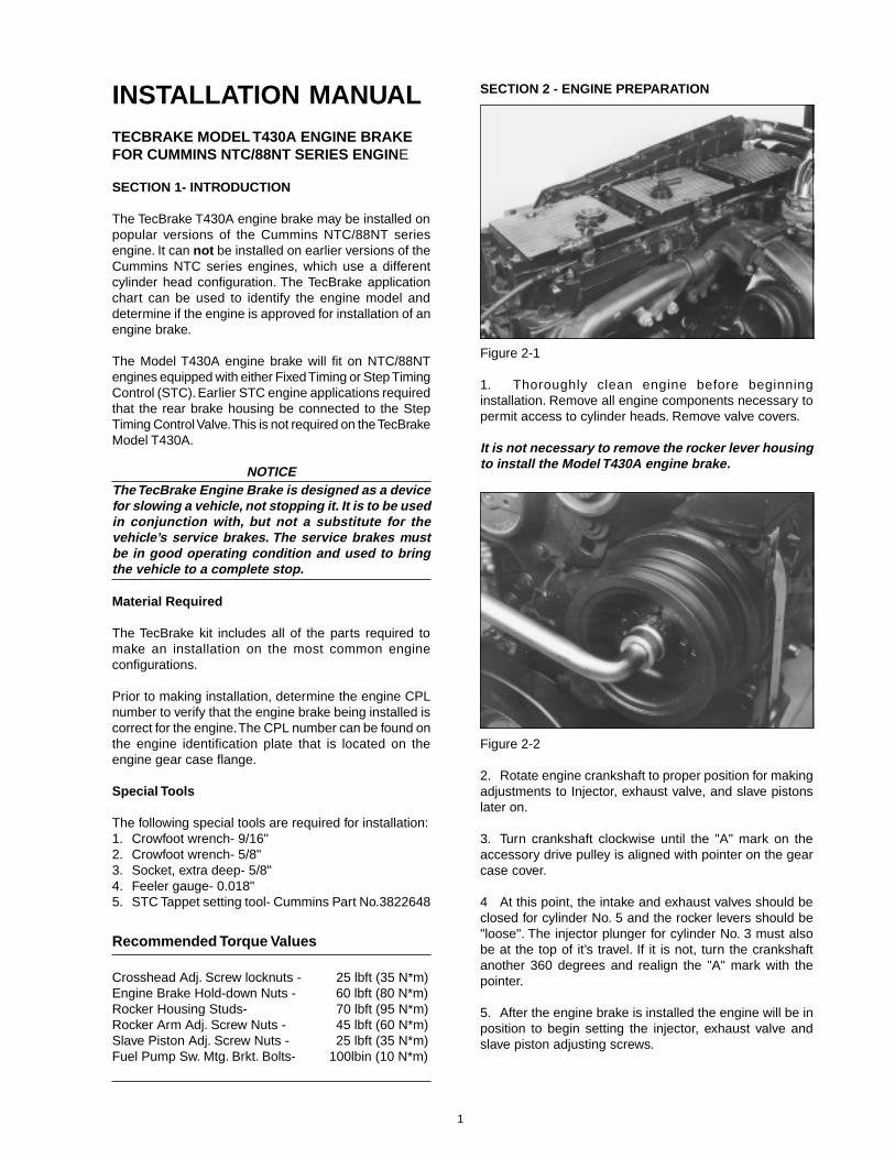
SECTION 2 - ENGINE PREPARATION
Figure 2-1
1. Thoroughly clean engine before beginninginstallation. Remove all engine components necessary topermit access to cylinder heads. Remove valve covers.
It is not necessary to remove the rocker lever housingto install the Model T430A engine brake.
Figure 2-2
2. Rotate engine crankshaft to proper position for makingadjustments to Injector, exhaust valve, and slave pistonslater on.
3. Turn crankshaft clockwise until the "A" mark on theaccessory drive pulley is aligned with pointer on the gearcase cover.
4 At this point, the intake and exhaust valves should beclosed for cylinder No. 5 and the rocker levers should be"loose". The injector plunger for cylinder No. 3 must alsobe at the top of it’s travel. If it is not, turn the crankshaftanother 360 degrees and realign the "A" mark with thepointer.
5. After the engine brake is installed the engine will be inposition to begin setting the injector, exhaust valve andslave piston adjusting screws.
1
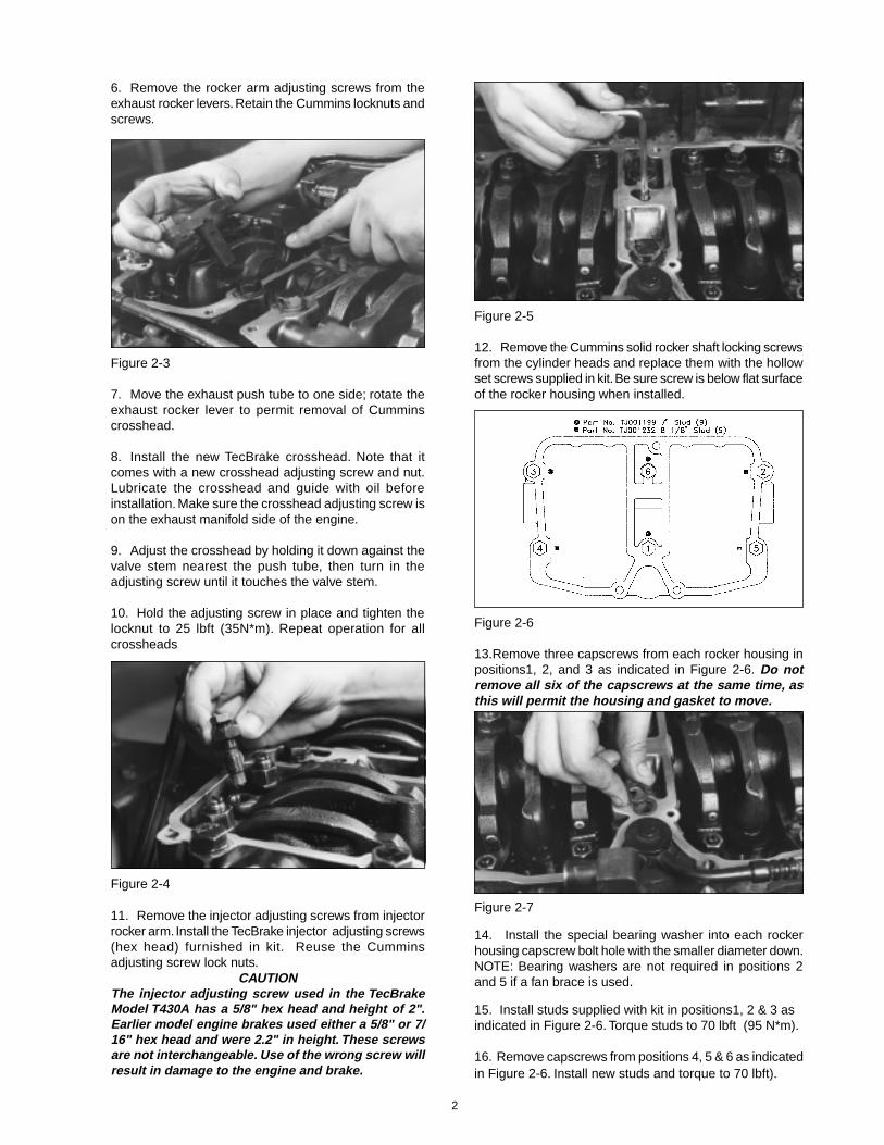
Figure 2-3
7. Move the exhaust push tube to one side; rotate theexhaust rocker lever to permit removal of Cumminscrosshead.
8. Install the new TecBrake crosshead. Note that itcomes with a new crosshead adjusting screw and nut.Lubricate the crosshead and guide with oil beforeinstallation. Make sure the crosshead adjusting screw ison the exhaust manifold side of the engine.
9. Adjust the crosshead by holding it down against thevalve stem nearest the push tube, then turn in theadjusting screw until it touches the valve stem.
10. Hold the adjusting screw in place and tighten thelocknut to 25 lbft (35N*m). Repeat operation for allcrossheads
6. Remove the rocker arm adjusting screws from theexhaust rocker levers. Retain the Cummins locknuts andscrews.
Figure 2-4
11. Remove the injector adjusting screws from injectorrocker arm. Install the TecBrake injector adjusting screws(hex head) furnished in kit. Reuse the Cumminsadjusting screw lock nuts.
CAUTIONThe injector adjusting screw used in the TecBrakeModel T430A has a 5/8" hex head and height of 2".Earlier model engine brakes used either a 5/8" or 7/16" hex head and were 2.2" in height. These screwsare not interchangeable. Use of the wrong screw willresult in damage to the engine and brake.
Figure 2-5
12. Remove the Cummins solid rocker shaft locking screwsfrom the cylinder heads and replace them with the hollowset screws supplied in kit. Be sure screw is below flat surfaceof the rocker housing when installed.
Figure 2-6
13.Remove three capscrews from each rocker housing inpositions1, 2, and 3 as indicated in Figure 2-6. Do notremove all six of the capscrews at the same time, asthis will permit the housing and gasket to move.
Figure 2-7
14. Install the special bearing washer into each rockerhousing capscrew bolt hole with the smaller diameter down.NOTE: Bearing washers are not required in positions 2and 5 if a fan brace is used.
15. Install studs supplied with kit in positions1, 2 & 3 asindicated in Figure 2-6. Torque studs to 70 lbft (95 N*m).
16. Remove capscrews from positions 4, 5 & 6 as indicatedin Figure 2-6. Install new studs and torque to 70 lbft).
2
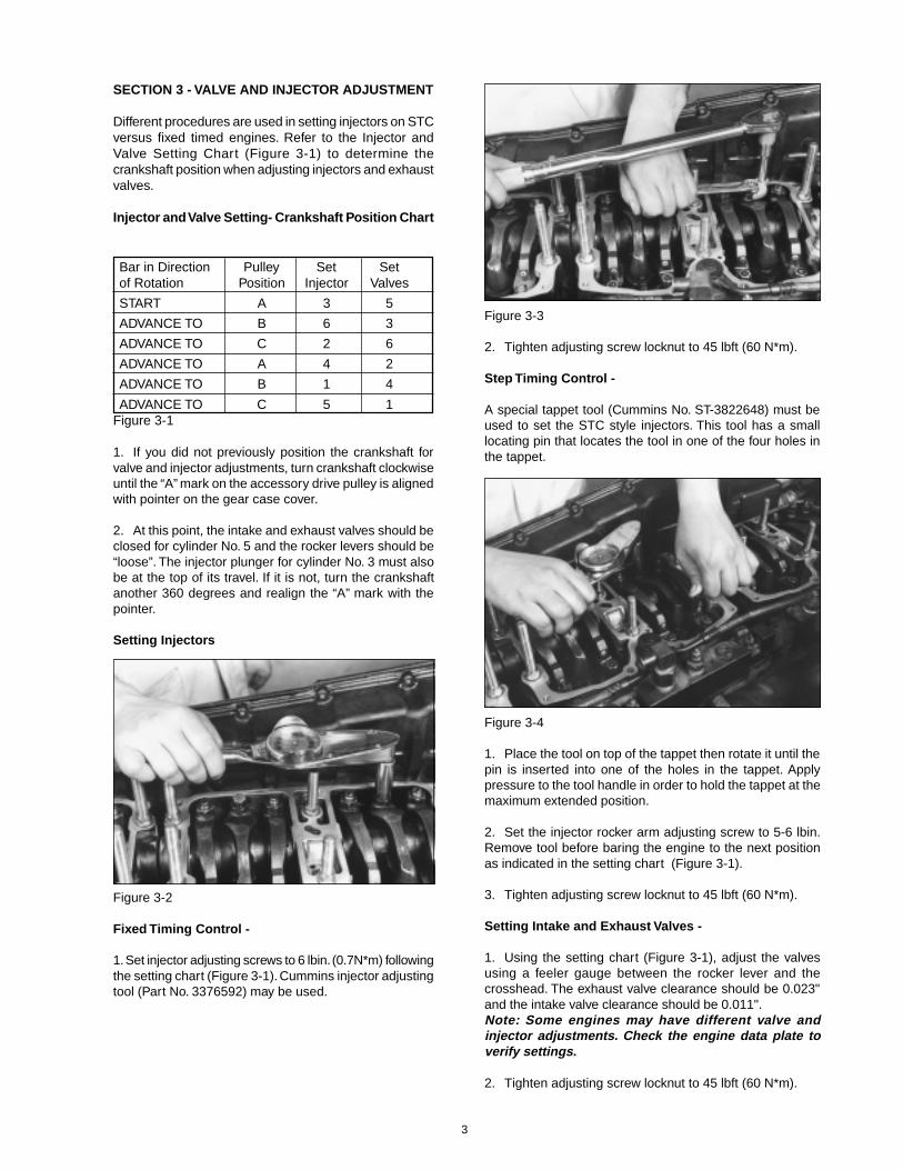
SECTION 3 - VALVE AND INJECTOR ADJUSTMENT
Different procedures are used in setting injectors on STCversus fixed timed engines. Refer to the Injector andValve Setting Chart (Figure 3-1) to determine thecrankshaft position when adjusting injectors and exhaustvalves.
Injector and Valve Setting- Crankshaft Position Chart
Bar in Direction Pulley Set Setof Rotation Position Injector Valves
START A 3 5
ADVANCE TO B 6 3
ADVANCE TO C 2 6
ADVANCE TO A 4 2
ADVANCE TO B 1 4
ADVANCE TO C 5 1Figure 3-1
1. If you did not previously position the crankshaft forvalve and injector adjustments, turn crankshaft clockwiseuntil the “A” mark on the accessory drive pulley is alignedwith pointer on the gear case cover.
2. At this point, the intake and exhaust valves should beclosed for cylinder No. 5 and the rocker levers should be“loose”. The injector plunger for cylinder No. 3 must alsobe at the top of its travel. If it is not, turn the crankshaftanother 360 degrees and realign the “A” mark with thepointer.
Setting Injectors
Figure 3-2
Fixed Timing Control -
1. Set injector adjusting screws to 6 lbin. (0.7N*m) followingthe setting chart (Figure 3-1). Cummins injector adjustingtool (Part No. 3376592) may be used.
Figure 3-3
2. Tighten adjusting screw locknut to 45 lbft (60 N*m).
Step Timing Control -
A special tappet tool (Cummins No. ST-3822648) must beused to set the STC style injectors. This tool has a smalllocating pin that locates the tool in one of the four holes inthe tappet.
Figure 3-4
1. Place the tool on top of the tappet then rotate it until thepin is inserted into one of the holes in the tappet. Applypressure to the tool handle in order to hold the tappet at themaximum extended position.
2. Set the injector rocker arm adjusting screw to 5-6 lbin.Remove tool before baring the engine to the next positionas indicated in the setting chart (Figure 3-1).
3. Tighten adjusting screw locknut to 45 lbft (60 N*m).
Setting Intake and Exhaust Valves -
1. Using the setting chart (Figure 3-1), adjust the valvesusing a feeler gauge between the rocker lever and thecrosshead. The exhaust valve clearance should be 0.023"and the intake valve clearance should be 0.011".Note: Some engines may have different valve andinjector adjustments. Check the engine data plate toverify settings.
2. Tighten adjusting screw locknut to 45 lbft (60 N*m).
3
SECTION 4 - INSTALLING THE BRAKE-
Figure 4-1
1. Install the engine brake housing gaskets. Make surethat the oil supply slots align correctly with the oil supplyscrews in the housings.
2. Before installing the brake housings, back out theslave adjusting screws (located above the slave piston)so that the slave pistons are fully retracted (up).
Figure 4-2
3. Place the engine brake housing on the rockerhousing. Check rocker levers to be sure there is nointerference.
Figure 4-3
4. If lifting or mounting brackets are used, install spacersas required.
Figure 4-4
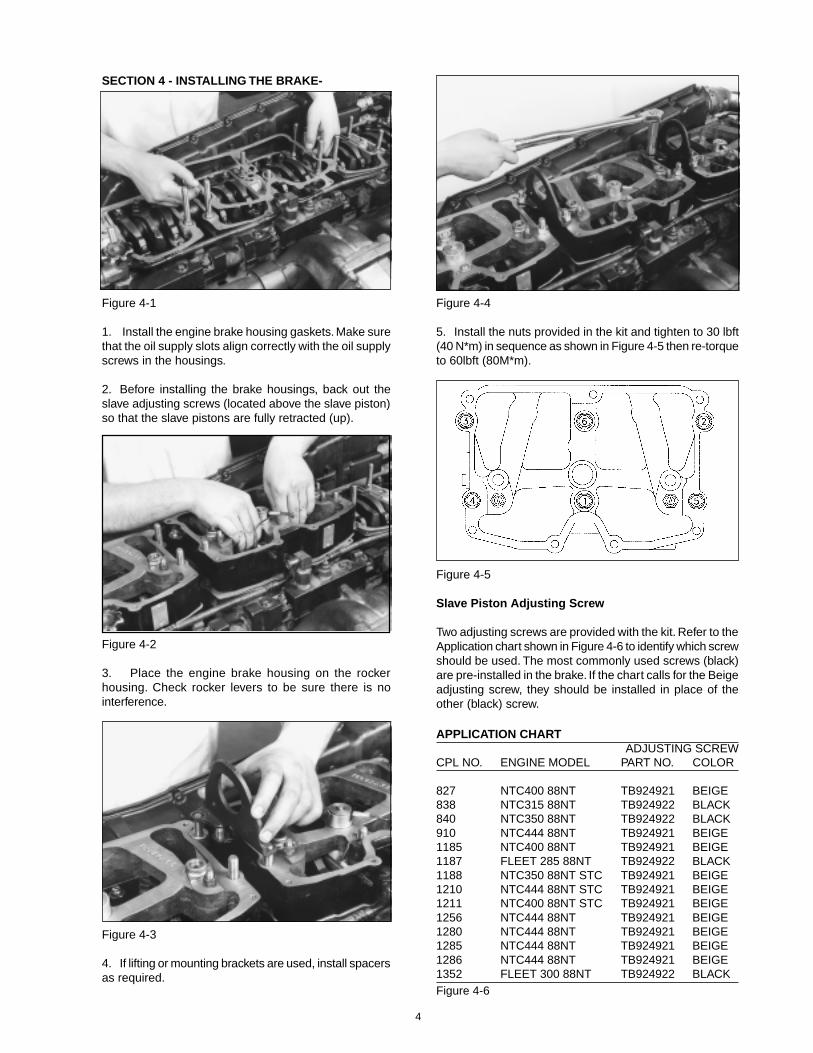
5. Install the nuts provided in the kit and tighten to 30 lbft(40 N*m) in sequence as shown in Figure 4-5 then re-torqueto 60lbft (80M*m).
Figure 4-5
Slave Piston Adjusting Screw
Two adjusting screws are provided with the kit. Refer to theApplication chart shown in Figure 4-6 to identify which screwshould be used. The most commonly used screws (black)are pre-installed in the brake. If the chart calls for the Beigeadjusting screw, they should be installed in place of theother (black) screw.
APPLICATION CHARTADJUSTING SCREW
CPL NO. ENGINE MODEL PART NO. COLOR
827 NTC400 88NT TB924921 BEIGE838 NTC315 88NT TB924922 BLACK840 NTC350 88NT TB924922 BLACK910 NTC444 88NT TB924921 BEIGE1185 NTC400 88NT TB924921 BEIGE1187 FLEET 285 88NT TB924922 BLACK1188 NTC350 88NT STC TB924921 BEIGE1210 NTC444 88NT STC TB924921 BEIGE1211 NTC400 88NT STC TB924921 BEIGE1256 NTC444 88NT TB924921 BEIGE1280 NTC444 88NT TB924921 BEIGE1285 NTC444 88NT TB924921 BEIGE1286 NTC444 88NT TB924921 BEIGE1352 FLEET 300 88NT TB924922 BLACKFigure 4-6
4
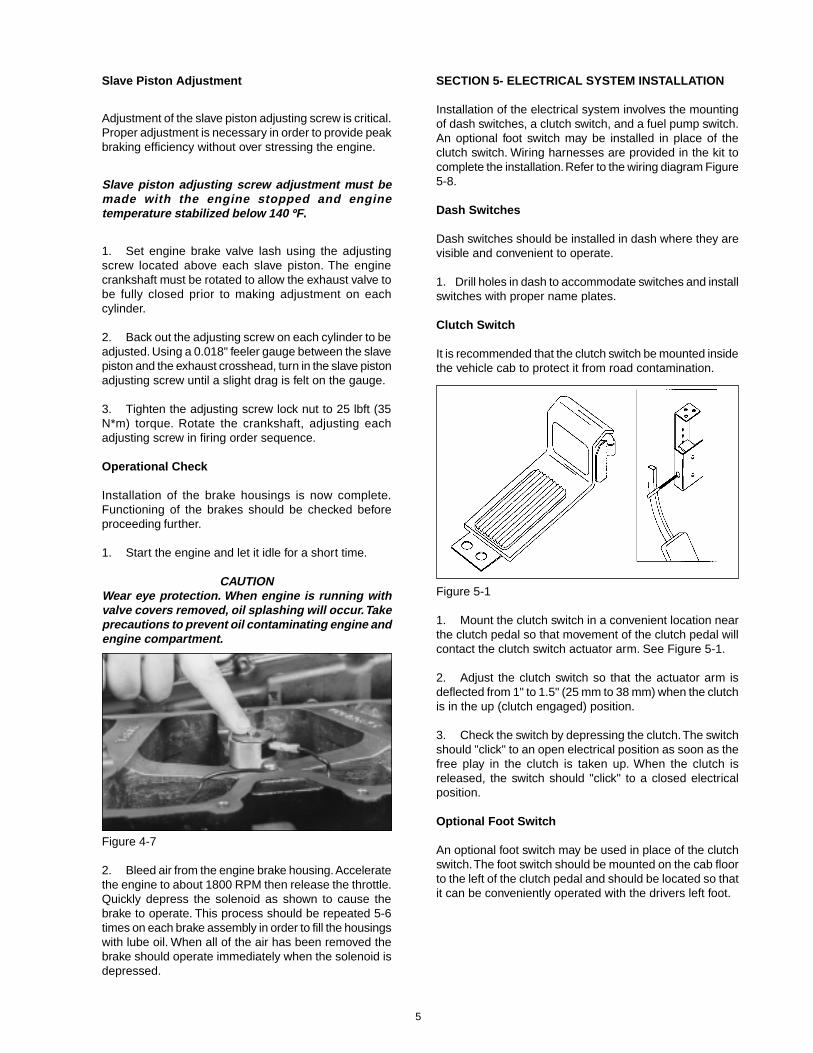
Figure 4-7
2. Bleed air from the engine brake housing. Acceleratethe engine to about 1800 RPM then release the throttle.Quickly depress the solenoid as shown to cause thebrake to operate. This process should be repeated 5-6times on each brake assembly in order to fill the housingswith lube oil. When all of the air has been removed thebrake should operate immediately when the solenoid isdepressed.
SECTION 5- ELECTRICAL SYSTEM INSTALLATION
Installation of the electrical system involves the mountingof dash switches, a clutch switch, and a fuel pump switch.An optional foot switch may be installed in place of theclutch switch. Wiring harnesses are provided in the kit tocomplete the installation. Refer to the wiring diagram Figure5-8.
Dash Switches
Dash switches should be installed in dash where they arevisible and convenient to operate.
1. Drill holes in dash to accommodate switches and installswitches with proper name plates.
Clutch Switch
It is recommended that the clutch switch be mounted insidethe vehicle cab to protect it from road contamination.
Figure 5-1
1. Mount the clutch switch in a convenient location nearthe clutch pedal so that movement of the clutch pedal willcontact the clutch switch actuator arm. See Figure 5-1.
2. Adjust the clutch switch so that the actuator arm isdeflected from 1" to 1.5" (25 mm to 38 mm) when the clutchis in the up (clutch engaged) position.
3. Check the switch by depressing the clutch. The switchshould "click" to an open electrical position as soon as thefree play in the clutch is taken up. When the clutch isreleased, the switch should "click" to a closed electricalposition.
Optional Foot Switch
An optional foot switch may be used in place of the clutchswitch. The foot switch should be mounted on the cab floorto the left of the clutch pedal and should be located so thatit can be conveniently operated with the drivers left foot.
Slave Piston Adjustment
Adjustment of the slave piston adjusting screw is critical.Proper adjustment is necessary in order to provide peakbraking efficiency without over stressing the engine.
Slave piston adjusting screw adjustment must bemade with the engine stopped and enginetemperature stabilized below 140 ºF .
1. Set engine brake valve lash using the adjustingscrew located above each slave piston. The enginecrankshaft must be rotated to allow the exhaust valve tobe fully closed prior to making adjustment on eachcylinder.
2. Back out the adjusting screw on each cylinder to beadjusted. Using a 0.018" feeler gauge between the slavepiston and the exhaust crosshead, turn in the slave pistonadjusting screw until a slight drag is felt on the gauge.
3. Tighten the adjusting screw lock nut to 25 lbft (35N*m) torque. Rotate the crankshaft, adjusting eachadjusting screw in firing order sequence.
Operational Check
Installation of the brake housings is now complete.Functioning of the brakes should be checked beforeproceeding further.
1. Start the engine and let it idle for a short time.
CAUTIONWear eye protection. When engine is running withvalve covers removed, oil splashing will occur. Takeprecautions to prevent oil contaminating engine andengine compartment.
5
Fuel Pump Switch
Figure 5-2
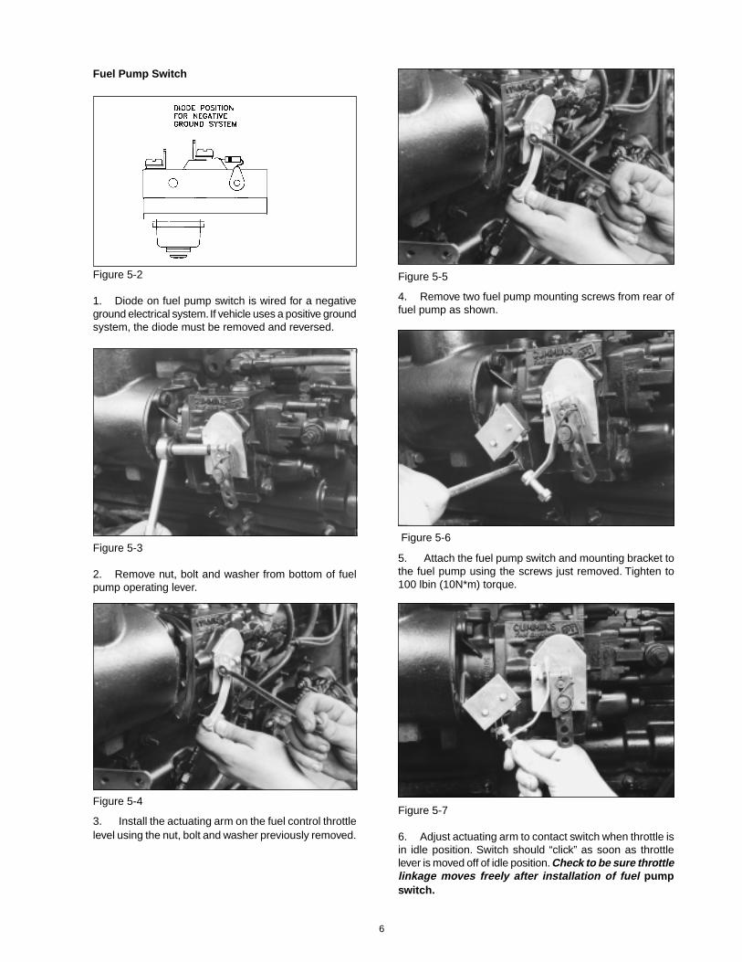
1. Diode on fuel pump switch is wired for a negativeground electrical system. If vehicle uses a positive groundsystem, the diode must be removed and reversed.
Figure 5-3
2. Remove nut, bolt and washer from bottom of fuelpump operating lever.
Figure 5-4
3. Install the actuating arm on the fuel control throttlelevel using the nut, bolt and washer previously removed.
Figure 5-5
4. Remove two fuel pump mounting screws from rear offuel pump as shown.
Figure 5-6
5. Attach the fuel pump switch and mounting bracket tothe fuel pump using the screws just removed. Tighten to100 lbin (10N*m) torque.
Figure 5-7
6. Adjust actuating arm to contact switch when throttle isin idle position. Switch should “click” as soon as throttlelever is moved off of idle position. Check to be sure throttlelinkage moves freely after installation of fuel pumpswitch.
6
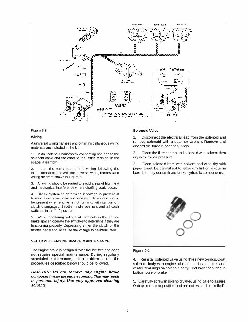
Figure 5-8
Wiring
A universal wiring harness and other miscellaneous wiringmaterials are included in the kit.
1. Install solenoid harness by connecting one end to thesolenoid valve and the other to the inside terminal in thespacer assembly.
2. Install the remainder of the wiring following theinstructions included with the universal wiring harness andwiring diagram shown in Figure 5-8.
3. All wiring should be routed to avoid areas of high heatand mechanical interference where chaffing could occur.
4. Check system to determine if voltage is present atterminals in engine brake spacer assembly. Voltage shouldbe present when engine is not running, with ignition on,clutch disengaged, throttle in idle position, and all dashswitches in the “on” position.
5. While monitoring voltage at terminals in the enginebrake spacer, operate the switches to determine if they arefunctioning properly. Depressing either the clutch or thethrottle pedal should cause the voltage to be interrupted.
SECTION 6 - ENGINE BRAKE MAINTENANCE
The engine brake is designed to be trouble free and doesnot require special maintenance. During regularlyscheduled maintenance, or if a problem occurs, theprocedures described below should be followed.
CAUTION: Do not remove any engine brakecomponent while the engine running. This may resultin personal injury. Use only approved cleaningsolvents.
Solenoid Valve
1. Disconnect the electrical lead from the solenoid andremove solenoid with a spanner wrench. Remove anddiscard the three rubber seal rings.
2. Clean the filter screen and solenoid with solvent thendry with low air pressure.
3. Clean solenoid bore with solvent and wipe dry withpaper towel. Be careful not to leave any lint or residue inbore that may contaminate brake hydraulic components.
Figure 6-1
4. Reinstall solenoid valve using three new o-rings. Coatsolenoid body with engine lube oil and install upper andcenter seal rings on solenoid body. Seat lower seal ring inbottom bore of brake.
5. Carefully screw in solenoid valve, using care to assureO-rings remain in position and are not twisted or “rolled”.
7
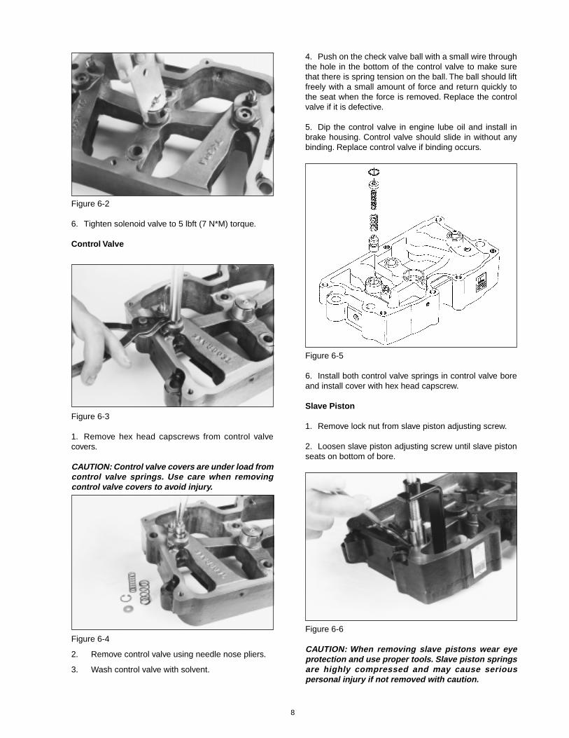
Figure 6-2
6. Tighten solenoid valve to 5 lbft (7 N*M) torque.
Control Valve
Figure 6-4
2. Remove control valve using needle nose pliers.
3. Wash control valve with solvent.
4. Push on the check valve ball with a small wire throughthe hole in the bottom of the control valve to make surethat there is spring tension on the ball. The ball should liftfreely with a small amount of force and return quickly tothe seat when the force is removed. Replace the controlvalve if it is defective.
5. Dip the control valve in engine lube oil and install inbrake housing. Control valve should slide in without anybinding. Replace control valve if binding occurs.
Figure 6-5
6. Install both control valve springs in control valve boreand install cover with hex head capscrew.
Slave Piston
1. Remove lock nut from slave piston adjusting screw.
2. Loosen slave piston adjusting screw until slave pistonseats on bottom of bore.
Figure 6-3
1. Remove hex head capscrews from control valvecovers.
CAUTION: Control valve covers are under load fromcontrol valve springs. Use care when removingcontrol valve covers to avoid injury.
Figure 6-6
CAUTION: When removing slave pistons wear eyeprotection and use proper tools. Slave piston springsare highly compressed and may cause seriouspersonal injury if not removed with caution.
8
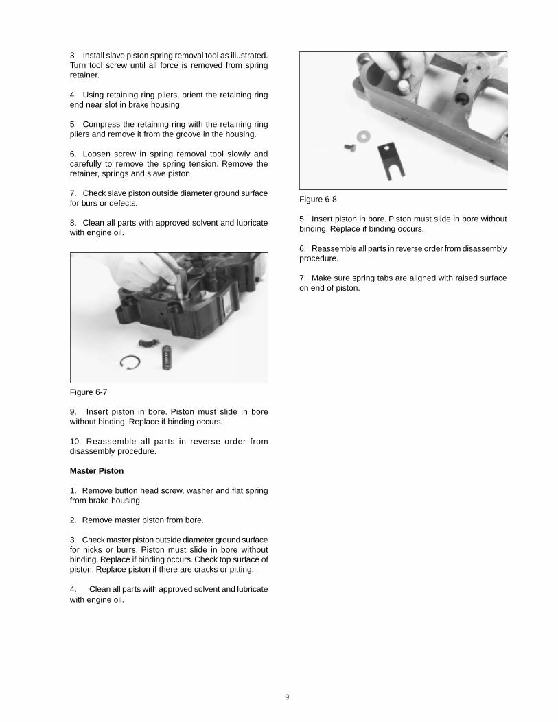
3. Install slave piston spring removal tool as illustrated.Turn tool screw until all force is removed from springretainer.
4. Using retaining ring pliers, orient the retaining ringend near slot in brake housing.
5. Compress the retaining ring with the retaining ringpliers and remove it from the groove in the housing.
6. Loosen screw in spring removal tool slowly andcarefully to remove the spring tension. Remove theretainer, springs and slave piston.
7. Check slave piston outside diameter ground surfacefor burs or defects.
8. Clean all parts with approved solvent and lubricatewith engine oil.
Figure 6-7
9. Insert piston in bore. Piston must slide in borewithout binding. Replace if binding occurs.
10. Reassemble all parts in reverse order fromdisassembly procedure.
Master Piston
1. Remove button head screw, washer and flat springfrom brake housing.
2. Remove master piston from bore.
3. Check master piston outside diameter ground surfacefor nicks or burrs. Piston must slide in bore withoutbinding. Replace if binding occurs. Check top surface ofpiston. Replace piston if there are cracks or pitting.
4. Clean all parts with approved solvent and lubricatewith engine oil.
Figure 6-8
5. Insert piston in bore. Piston must slide in bore withoutbinding. Replace if binding occurs.
6. Reassemble all parts in reverse order from disassemblyprocedure.
7. Make sure spring tabs are aligned with raised surfaceon end of piston.
9

TecBrake Inc. P.O. Box 27822 Houston, Texas 77227 ©1994 TecBrake, Inc. Bulletin No. TB990125 8/10/95