indexable tools a3 button, radius & square shoulder - dijet
TRANSCRIPT
DIJET CARBIDE TOOLSIndexable Tools A3Button, Radius &Square Shoulder
®
Indexable Tools A3 - B
utton, Radius &
Square Shoulder
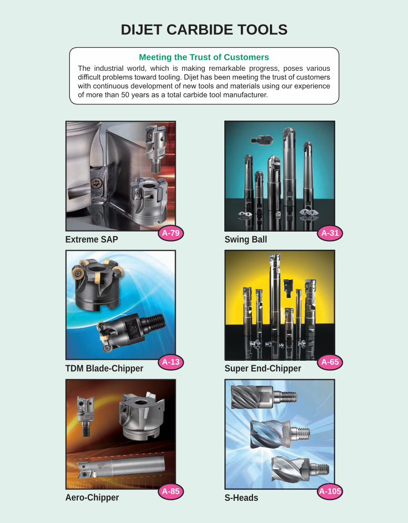
DIJET CARBIDE TOOLSMeeting the Trust of Customers
The industrial world, which is making remarkable progress, poses various difficult problems toward tooling. Dijet has been meeting the trust of customers with continuous development of new tools and materials using our experience of more than 50 years as a total carbide tool manufacturer.
TDM Blade-Chipper Super End-Chipper
Aero-Chipper
Swing Ball
S-Heads
Extreme SAPA-79
A-85 A-105
A-31
A-13 A-65
Face Milling Shoulder Milling
Shoulder Milling
Side Milling
Up & Down Milling
T - Slotting
V - Slotting
Drilling
Plunge Milling
Shoulder Milling Slotting Slotting Copy Milling Chamfering Spot Facing
Shoulder Milling Slotting Slotting Copy Milling Pocket Milling Under Milling Chamfering Helical Interpolation
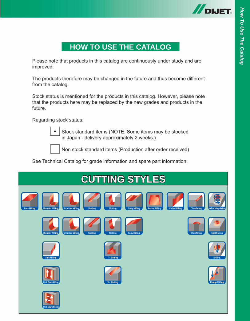
HOW TO USE THE CATALOGPlease note that products in this catalog are continuously under study and are improved.
The products therefore may be changed in the future and thus become different from the catalog.
Stock status is mentioned for the products in this catalog. However, please note that the products here may be replaced by the new grades and products in the future.
Regarding stock status:
Stock standard items (NOTE: Some items may be stocked in Japan - delivery approximately 2 weeks.)
Non stock standard items (Production after order received)
See Technical Catalog for grade information and spare part information.
CUTTING STYLES
•
Up & Down Milling
®H
ow To U
se The Catalog
® INDEXABLE TOOLS - BUTTONS & RADIUS
IT-1
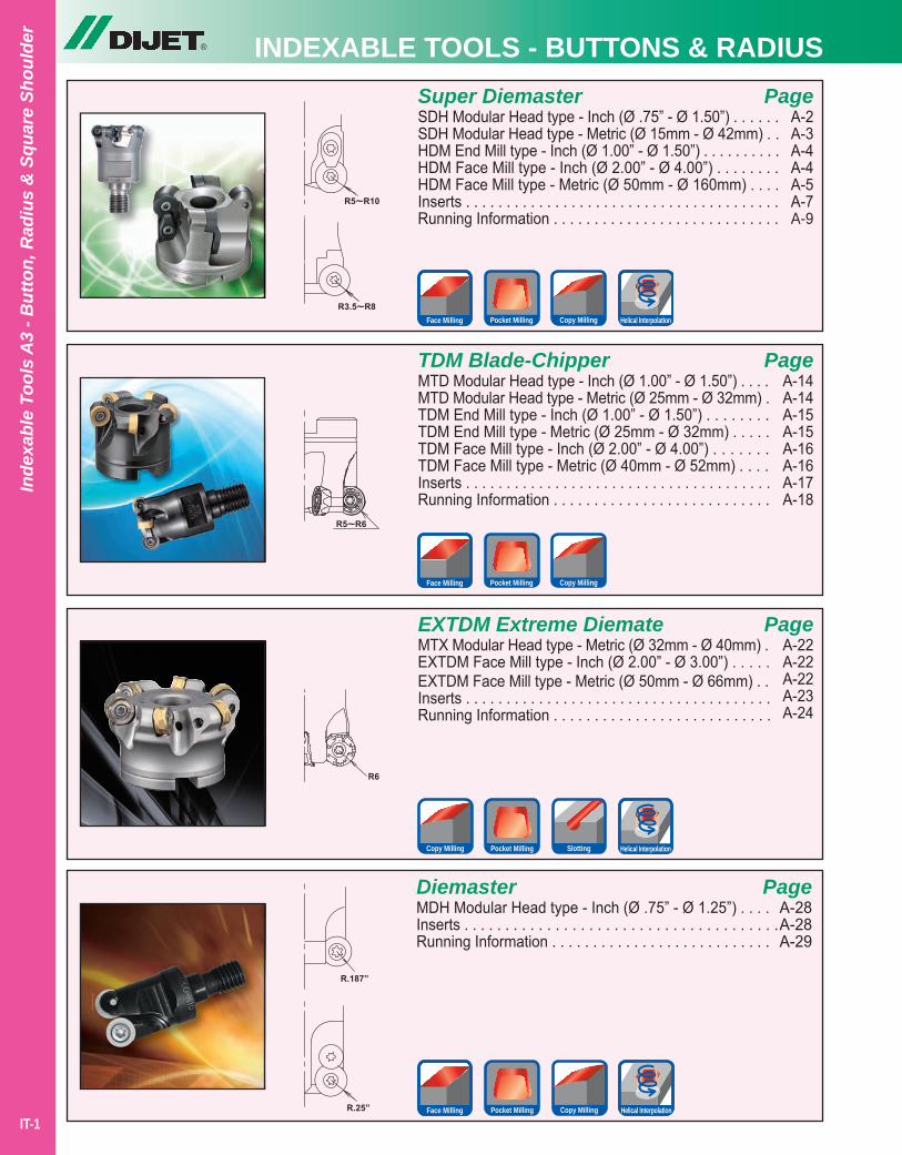
TDM Blade-ChipperMTD Modular Head type - Inch (Ø 1.00” - Ø 1.50”) . . . .MTD Modular Head type - Metric (Ø 25mm - Ø 32mm) .TDM End Mill type - Inch (Ø 1.00” - Ø 1.50”) . . . . . . . .TDM End Mill type - Metric (Ø 25mm - Ø 32mm) . . . . .TDM Face Mill type - Inch (Ø 2.00” - Ø 4.00”) . . . . . . .TDM Face Mill type - Metric (Ø 40mm - Ø 52mm) . . . .Inserts . . . . . . . . . . . . . . . . . . . . . . . . . . . . . . . . . . . . . .Running Information . . . . . . . . . . . . . . . . . . . . . . . . . . .
PageA-14A-14A-15A-15A-16A-16A-17A-18
Super DiemasterSDH Modular Head type - Inch (Ø .75” - Ø 1.50”) . . . . . .SDH Modular Head type - Metric (Ø 15mm - Ø 42mm) . .HDM End Mill type - Inch (Ø 1.00” - Ø 1.50”) . . . . . . . . . .HDM Face Mill type - Inch (Ø 2.00” - Ø 4.00”) . . . . . . . .HDM Face Mill type - Metric (Ø 50mm - Ø 160mm) . . . .Inserts . . . . . . . . . . . . . . . . . . . . . . . . . . . . . . . . . . . . . . .Running Information . . . . . . . . . . . . . . . . . . . . . . . . . . . .
PageA-2A-3A-4A-4A-5A-7A-9
EXTDM Extreme DiemateMTX Modular Head type - Metric (Ø 32mm - Ø 40mm) .EXTDM Face Mill type - Inch (Ø 2.00” - Ø 3.00”) . . . . .EXTDM Face Mill type - Metric (Ø 50mm - Ø 66mm) . .Inserts . . . . . . . . . . . . . . . . . . . . . . . . . . . . . . . . . . . . . .Running Information . . . . . . . . . . . . . . . . . . . . . . . . . . .
PageA-22A-22A-22A-23A-24
Copy Milling Pocket Milling Slotting
DiemasterMDH Modular Head type - Inch (Ø .75” - Ø 1.25”) . . . .Inserts . . . . . . . . . . . . . . . . . . . . . . . . . . . . . . . . . . . . . .Running Information . . . . . . . . . . . . . . . . . . . . . . . . . . .
PageA-28A-28A-29
Copy MillingPocket Milling Helical InterpolationFace Milling
Copy MillingPocket MillingFace Milling
Copy MillingPocket Milling Helical InterpolationFace Milling
Inde
xabl
e To
ols
A3
- But
ton,
Rad
ius
& S
quar
e Sh
ould
er
Helical Interpolation
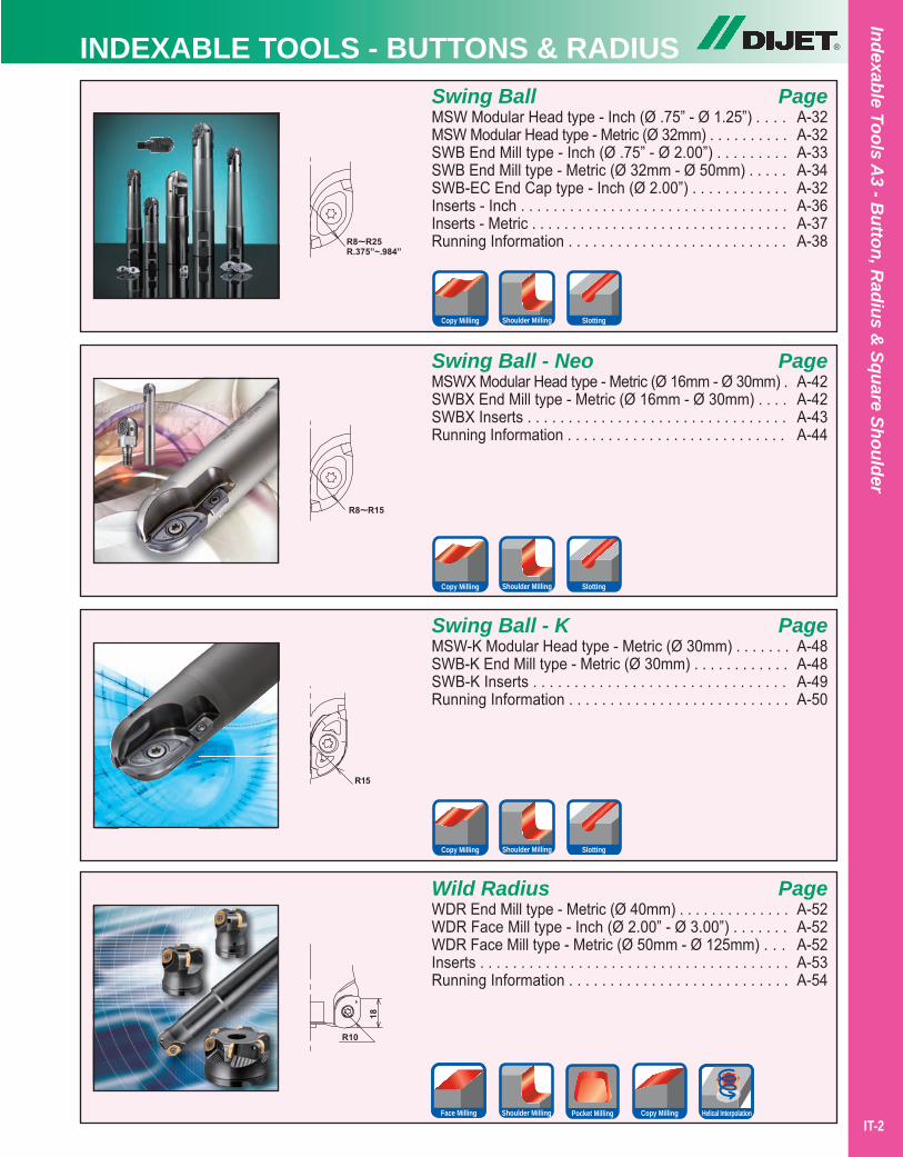
Swing BallMSW Modular Head type - Inch (Ø .75” - Ø 1.25”) . . . .MSW Modular Head type - Metric (Ø 32mm) . . . . . . . . . .SWB End Mill type - Inch (Ø .75” - Ø 2.00”) . . . . . . . . .SWB End Mill type - Metric (Ø 32mm - Ø 50mm) . . . . .SWB-EC End Cap type - Inch (Ø 2.00”) . . . . . . . . . . . .Inserts - Inch . . . . . . . . . . . . . . . . . . . . . . . . . . . . . . . . .Inserts - Metric . . . . . . . . . . . . . . . . . . . . . . . . . . . . . . . .Running Information . . . . . . . . . . . . . . . . . . . . . . . . . . .
Swing Ball - NeoMSWX Modular Head type - Metric (Ø 16mm - Ø 30mm) .SWBX End Mill type - Metric (Ø 16mm - Ø 30mm) . . . .SWBX Inserts . . . . . . . . . . . . . . . . . . . . . . . . . . . . . . . .Running Information . . . . . . . . . . . . . . . . . . . . . . . . . . .
Swing Ball - KMSW-K Modular Head type - Metric (Ø 30mm) . . . . . . .SWB-K End Mill type - Metric (Ø 30mm) . . . . . . . . . . . .SWB-K Inserts . . . . . . . . . . . . . . . . . . . . . . . . . . . . . . .Running Information . . . . . . . . . . . . . . . . . . . . . . . . . . .
Wild RadiusWDR End Mill type - Metric (Ø 40mm) . . . . . . . . . . . . . .WDR Face Mill type - Inch (Ø 2.00” - Ø 3.00”) . . . . . . .WDR Face Mill type - Metric (Ø 50mm - Ø 125mm) . . . Inserts . . . . . . . . . . . . . . . . . . . . . . . . . . . . . . . . . . . . . .Running Information . . . . . . . . . . . . . . . . . . . . . . . . . . .
PageA-32A-32A-33A-34A-32A-36A-37A-38
PageA-42A-42A-43A-44
PageA-48A-48A-49A-50
PageA-52A-52A-52A-53A-54
®INDEXABLE TOOLS - BUTTONS & RADIUSIndexable Tools A
3 - Button, R
adius & Square Shoulder
IT-2
Shoulder Milling SlottingCopy Milling
Shoulder Milling SlottingCopy Milling
Shoulder Milling SlottingCopy Milling
Shoulder Milling Pocket Milling Copy Milling Helical InterpolationFace Milling
® INDEXABLE TOOLS - SQUARE SHOULDER
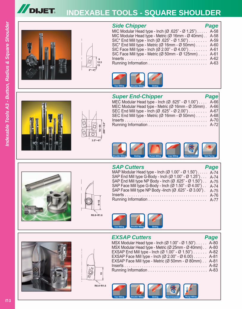
Super End-ChipperMEC Modular Head type - Inch (Ø .625” - Ø 1.00”) . . . .MEC Modular Head type - Metric (Ø 16mm - Ø 35mm) .SEC End Mill type - Inch (Ø .625” - Ø 2.00”) . . . . . . . .SEC End Mill type - Metric (Ø 16mm - Ø 50mm) . . . . .Inserts . . . . . . . . . . . . . . . . . . . . . . . . . . . . . . . . . . . . . .Running Information . . . . . . . . . . . . . . . . . . . . . . . . . . .
PageA-66A-66A-67A-68A-70A-72
PageA-58A-58A-59A-60A-61A-61A-62A-63
SAP CuttersMAP Modular Head type - Inch (Ø 1.00” - Ø 1.50”) . . . . .SAP End Mill type G-Body - Inch (Ø 1.00” - Ø 1.25”) . . .SAP End Mill type NP Body - Inch (Ø .625” - Ø 1.50”) . .SAP Face Mill type G-Body - Inch (Ø 1.50” - Ø 4.00”) . .SAP Face Mill type NP Body -Iinch (Ø .625” - Ø 3.00”) .Inserts . . . . . . . . . . . . . . . . . . . . . . . . . . . . . . . . . . . . . .Running Information . . . . . . . . . . . . . . . . . . . . . . . . . .
PageA-74A-74A-75A-74A-75A-76A-77
EXSAP CuttersMSX Modular Head type - Inch (Ø 1.00” - Ø 1.50”) . . . . .MSX Modular Head type - Metric (Ø 25mm - Ø 40mm) . .EXSAP End Mill type - Inch (Ø 1.00” - Ø 1.50”) . . . . . .EXSAP Face Mill type - Inch (Ø 2.00” - Ø 6.00) . . . . . .EXSAP Face Mill type - Metric (Ø 50mm - Ø 80mm) . .Inserts . . . . . . . . . . . . . . . . . . . . . . . . . . . . . . . . . . . . . .Running Information . . . . . . . . . . . . . . . . . . . . . . . . . . .
PageA-80A-80A-82A-81A-81A-82A-83
Inde
xabl
e To
ols
A3
- But
ton,
Rad
ius
& S
quar
e Sh
ould
er
Shoulder MillingFace Milling Slotting
Slotting Pocket Milling Copy Milling Helical InterpolationShoulder Milling
SlottingFace Milling Shoulder Milling
SlottingFace Milling Shoulder Milling Helical Interpolation Plunge Milling
Side ChipperMIC Modular Head type - Inch (Ø .625” - Ø 1.25”) . . . . .MIC Modular Head type - Metric (Ø 16mm - Ø 40mm) . .SIC* End Mill type - Inch (Ø .625” - Ø 1.50”) . . . . . . . .SIC* End Mill type - Metric (Ø 16mm - Ø 50mm) . . . . .SIC Face Mill type - Inch (Ø 2.00” - Ø 4.00”) . . . . . . . .SIC Face Mill type - Metric (Ø 50mm - Ø 125mm) . . . .Inserts . . . . . . . . . . . . . . . . . . . . . . . . . . . . . . . . . . . . . .Running Information . . . . . . . . . . . . . . . . . . . . . . . . . . .
IT-3
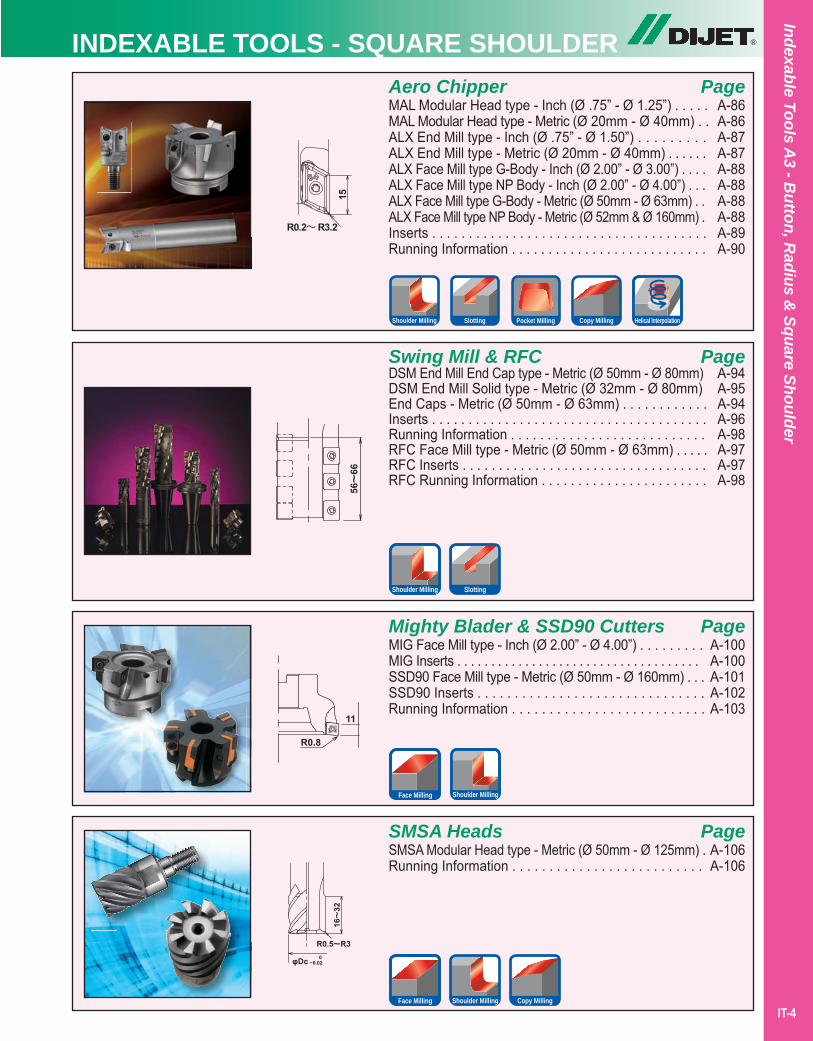
Aero ChipperMAL Modular Head type - Inch (Ø .75” - Ø 1.25”) . . . . .MAL Modular Head type - Metric (Ø 20mm - Ø 40mm) . .ALX End Mill type - Inch (Ø .75” - Ø 1.50”) . . . . . . . . .ALX End Mill type - Metric (Ø 20mm - Ø 40mm) . . . . . .ALX Face Mill type G-Body - Inch (Ø 2.00” - Ø 3.00”) . . . .ALX Face Mill type NP Body - Inch (Ø 2.00” - Ø 4.00”) . . .ALX Face Mill type G-Body - Metric (Ø 50mm - Ø 63mm) . .ALX Face Mill type NP Body - Metric (Ø 52mm & Ø 160mm) .Inserts . . . . . . . . . . . . . . . . . . . . . . . . . . . . . . . . . . . . . .Running Information . . . . . . . . . . . . . . . . . . . . . . . . . . .
Swing Mill & RFCDSM End Mill End Cap type - Metric (Ø 50mm - Ø 80mm)DSM End Mill Solid type - Metric (Ø 32mm - Ø 80mm)End Caps - Metric (Ø 50mm - Ø 63mm) . . . . . . . . . . . .Inserts . . . . . . . . . . . . . . . . . . . . . . . . . . . . . . . . . . . . . .Running Information . . . . . . . . . . . . . . . . . . . . . . . . . . .RFC Face Mill type - Metric (Ø 50mm - Ø 63mm) . . . . .RFC Inserts . . . . . . . . . . . . . . . . . . . . . . . . . . . . . . . . . .RFC Running Information . . . . . . . . . . . . . . . . . . . . . . .
Mighty Blader & SSD90 CuttersMIG Face Mill type - Inch (Ø 2.00” - Ø 4.00”) . . . . . . . . .MIG Inserts . . . . . . . . . . . . . . . . . . . . . . . . . . . . . . . . . . . .SSD90 Face Mill type - Metric (Ø 50mm - Ø 160mm) . . .SSD90 Inserts . . . . . . . . . . . . . . . . . . . . . . . . . . . . . . .Running Information . . . . . . . . . . . . . . . . . . . . . . . . . .
SMSA HeadsSMSA Modular Head type - Metric (Ø 50mm - Ø 125mm) . Running Information . . . . . . . . . . . . . . . . . . . . . . . . . .
PageA-86A-86A-87A-87A-88A-88A-88A-88A-89A-90
PageA-94A-95A-94A-96 A-98 A-97A-97A-98
PageA-100A-100A-101A-102A-103
PageA-106A-106
®INDEXABLE TOOLS - SQUARE SHOULDERIndexable Tools A
3 - Button, R
adius & Square Shoulder
IT-4
Slotting Helical InterpolationPocket Milling Copy MillingShoulder Milling
Shoulder Milling Slotting
Shoulder MillingFace Milling
Copy MillingShoulder MillingFace Milling
® INDEXABLE TOOLS - SQUARE SHOULDER
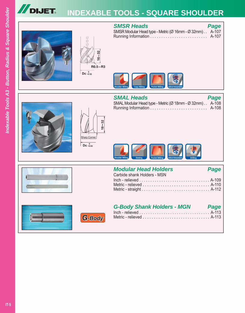
SMAL HeadsSMAL Modular Head type - Metric (Ø 18mm - Ø 32mm) . .Running Information . . . . . . . . . . . . . . . . . . . . . . . . . .
PageA-108A-108
PageA-107A-107
Inde
xabl
e To
ols
A3
- But
ton,
Rad
ius
& S
quar
e Sh
ould
er
SMSR HeadsSMSR Modular Head type - Metric (Ø 16mm - Ø 32mm) . .Running Information . . . . . . . . . . . . . . . . . . . . . . . . . .
IT-5
Helical InterpolationPocket MillingCopy MillingShoulder Milling
Slotting Helical InterpolationPocket MillingShoulder Milling Drilling
G-Body
Modular Head HoldersCarbide shank Holders - MSNInch - relieved . . . . . . . . . . . . . . . . . . . . . . . . . . . . . . . .Metric - relieved . . . . . . . . . . . . . . . . . . . . . . . . . . . . . .Metric - straight . . . . . . . . . . . . . . . . . . . . . . . . . . . . . . .
Page
A-109A-110A-112
G-Body Shank Holders - MGNInch - relieved . . . . . . . . . . . . . . . . . . . . . . . . . . . . . . . .Metric - relieved . . . . . . . . . . . . . . . . . . . . . . . . . . . . . .
PageA-113A-113
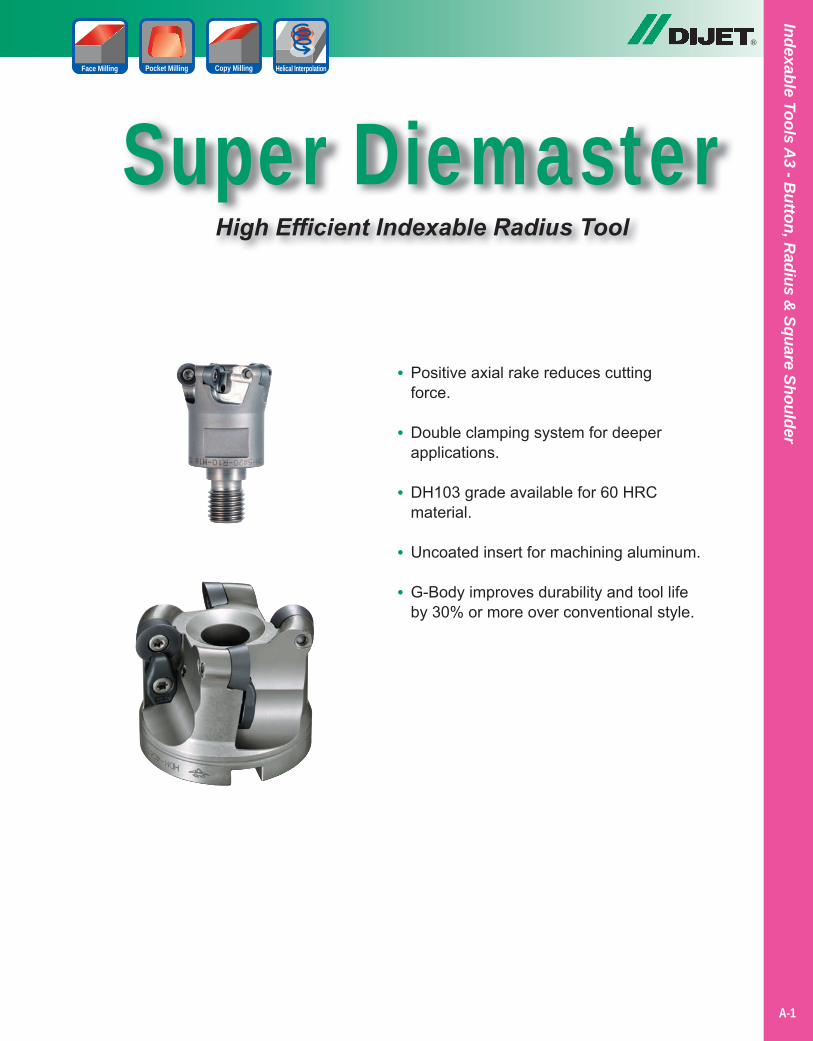
Super DiemasterHigh Efficient Indexable Radius Tool
®
Copy MillingPocket Milling Helical InterpolationFace Milling
• Positive axial rake reduces cutting force.
• Double clamping system for deeper applications.
• DH103 grade available for 60 HRC material.
• Uncoated insert for machining aluminum.
• G-Body improves durability and tool life by 30% or more over conventional style.
Indexable Tools A3 - B
utton, Radius &
Square Shoulder
A-1
Super Diemaster
®
Inde
xabl
e To
ols
A3
- But
ton,
Rad
ius
& S
quar
e Sh
ould
er
A-2
Copy MillingPocket Milling Helical InterpolationFace Milling
INCH
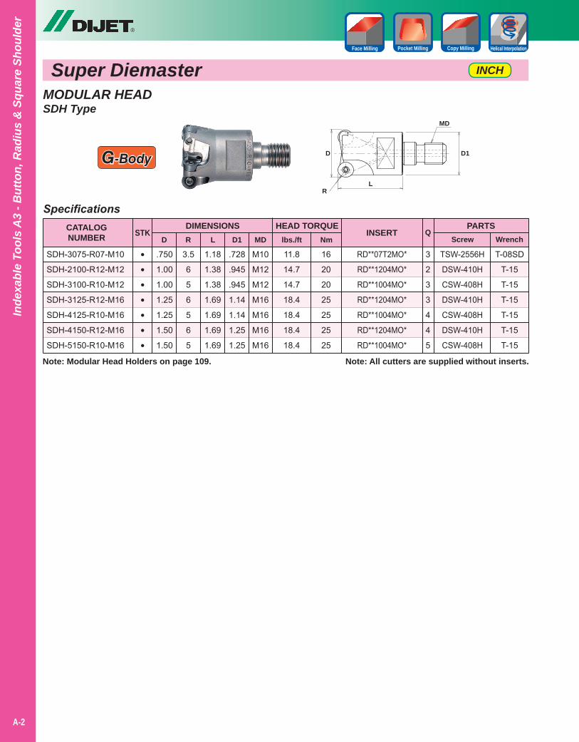
MODULAR HEADSDH Type
Note: All cutters are supplied without inserts.
T-08SD
T-15
T-15
T-15
T-15
T-15
T-15
Specifications
1.18
1.38
1.38
1.69
1.69
1.69
1.69
.750
1.00
1.00
1.25
1.25
1.50
1.50
3.5
6
5
6
5
6
5
.728
.945
.945
1.14
1.14
1.25
1.25
M10
M12
M12
M16
M16
M16
M16
CATALOGNUMBER
DIMENSIONSD
SDH-3075-R07-M10
SDH-2100-R12-M12
SDH-3100-R10-M12
SDH-3125-R12-M16
SDH-4125-R10-M16
SDH-4150-R12-M16
SDH-5150-R10-M16
RD**07T2MO*
RD**1204MO*
RD**1004MO*
RD**1204MO*
RD**1004MO*
RD**1204MO*
RD**1004MO*
PARTSScrew Wrench
STKR L D1
INSERT
TSW-2556H
DSW-410H
CSW-408H
DSW-410H
CSW-408H
DSW-410H
CSW-408H
•••••••
Q
3
2
3
3
4
4
5
MD
HEAD TORQUE
11.8
14.7
14.7
18.4
18.4
18.4
18.4
16
20
20
25
25
25
25
lbs./ft Nm
D
RL
D1
MD
G-Body
Note: Modular Head Holders on page 109.
®
A-3
Copy MillingPocket Milling Helical InterpolationFace Milling
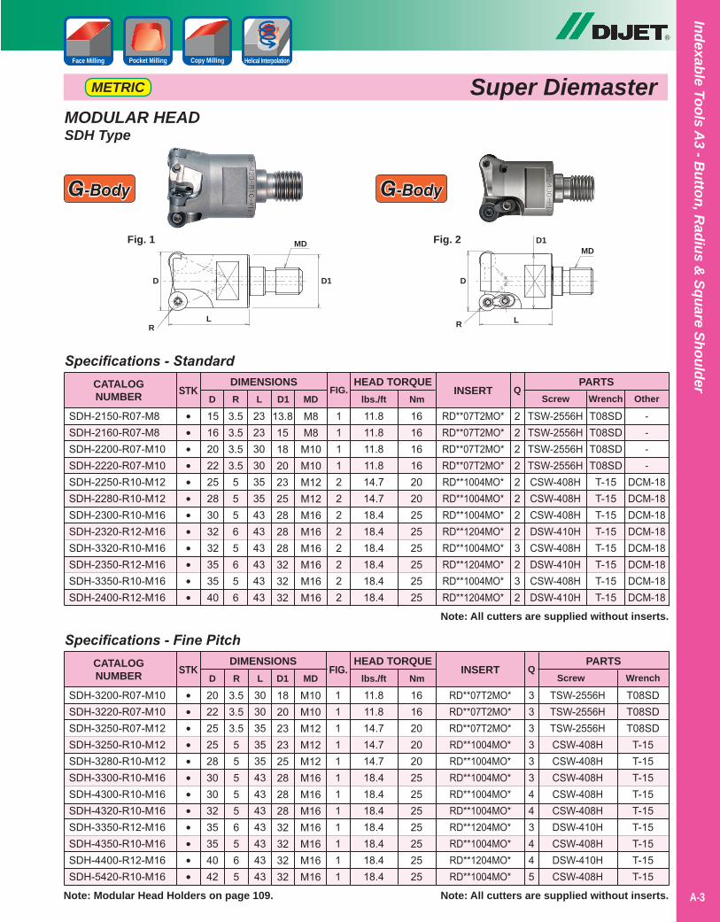
Super DiemasterMETRIC
MODULAR HEADSDH Type
T08SDT08SDT08SD
T-15T-15T-15T-15T-15T-15T-15T-15T-15
Specifications - Fine Pitch
303035353543434343434343
202225252830303235354042
3.53.53.5555556565
182023232528282832323232
M10M10M12M12M12M16M16M16M16M16M16M16
CATALOGNUMBER
DIMENSIONSD
SDH-3200-R07-M10SDH-3220-R07-M10SDH-3250-R07-M12SDH-3250-R10-M12SDH-3280-R10-M12SDH-3300-R10-M16SDH-4300-R10-M16SDH-4320-R10-M16SDH-3350-R12-M16SDH-4350-R10-M16SDH-4400-R12-M16SDH-5420-R10-M16
RD**07T2MO*RD**07T2MO*RD**07T2MO*RD**1004MO*RD**1004MO*RD**1004MO*RD**1004MO*RD**1004MO*RD**1204MO*RD**1004MO*RD**1204MO*RD**1004MO*
PARTSScrew Wrench
STKR L D1
INSERT
TSW-2556HTSW-2556HTSW-2556HCSW-408HCSW-408HCSW-408HCSW-408HCSW-408HDSW-410HCSW-408HDSW-410HCSW-408H
••••••••••••
Q
333333443445
MD
HEAD TORQUE
11.811.814.714.714.718.418.418.418.418.418.418.4
161620202025252525252525
lbs./ft Nm
Note: All cutters are supplied without inserts.
FIG.
Note: All cutters are supplied without inserts.
----
DCM-18DCM-18DCM-18DCM-18DCM-18DCM-18DCM-18DCM-18
T08SDT08SDT08SDT08SDT-15T-15T-15T-15T-15T-15T-15T-15
Specifications - Standard
232330303535434343434343
151620222528303232353540
3.53.53.53.555565656
13.81518202325282828323232
M8M8M10M10M12M12M16M16M16M16M16M16
CATALOGNUMBER
DIMENSIONSD
SDH-2150-R07-M8SDH-2160-R07-M8SDH-2200-R07-M10SDH-2220-R07-M10SDH-2250-R10-M12SDH-2280-R10-M12SDH-2300-R10-M16SDH-2320-R12-M16SDH-3320-R10-M16SDH-2350-R12-M16SDH-3350-R10-M16SDH-2400-R12-M16
RD**07T2MO*RD**07T2MO*RD**07T2MO*RD**07T2MO*RD**1004MO*RD**1004MO*RD**1004MO*RD**1204MO*RD**1004MO*RD**1204MO*RD**1004MO*RD**1204MO*
PARTSScrew Wrench
STKR L D1
INSERT
TSW-2556HTSW-2556HTSW-2556HTSW-2556HCSW-408HCSW-408HCSW-408HDSW-410HCSW-408HDSW-410HCSW-408HDSW-410H
••••••••••••
OtherQ
222222223232
MD
111122222222
FIG.HEAD TORQUE
11.811.811.811.814.714.718.418.418.418.418.418.4
161616162020252525252525
lbs./ft Nm
Fig. 1 Fig. 2
111111111111
D
RL
D1
MD
D
R L
D1MD
G-Body G-Body
Note: Modular Head Holders on page 109.
Indexable Tools A3 - B
utton, Radius &
Square Shoulder
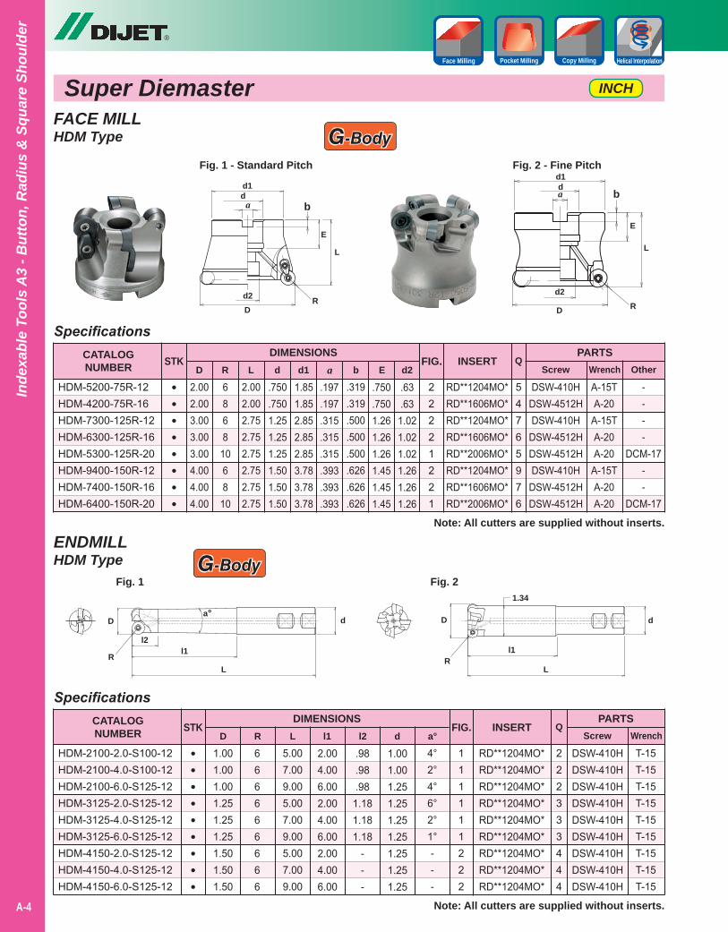
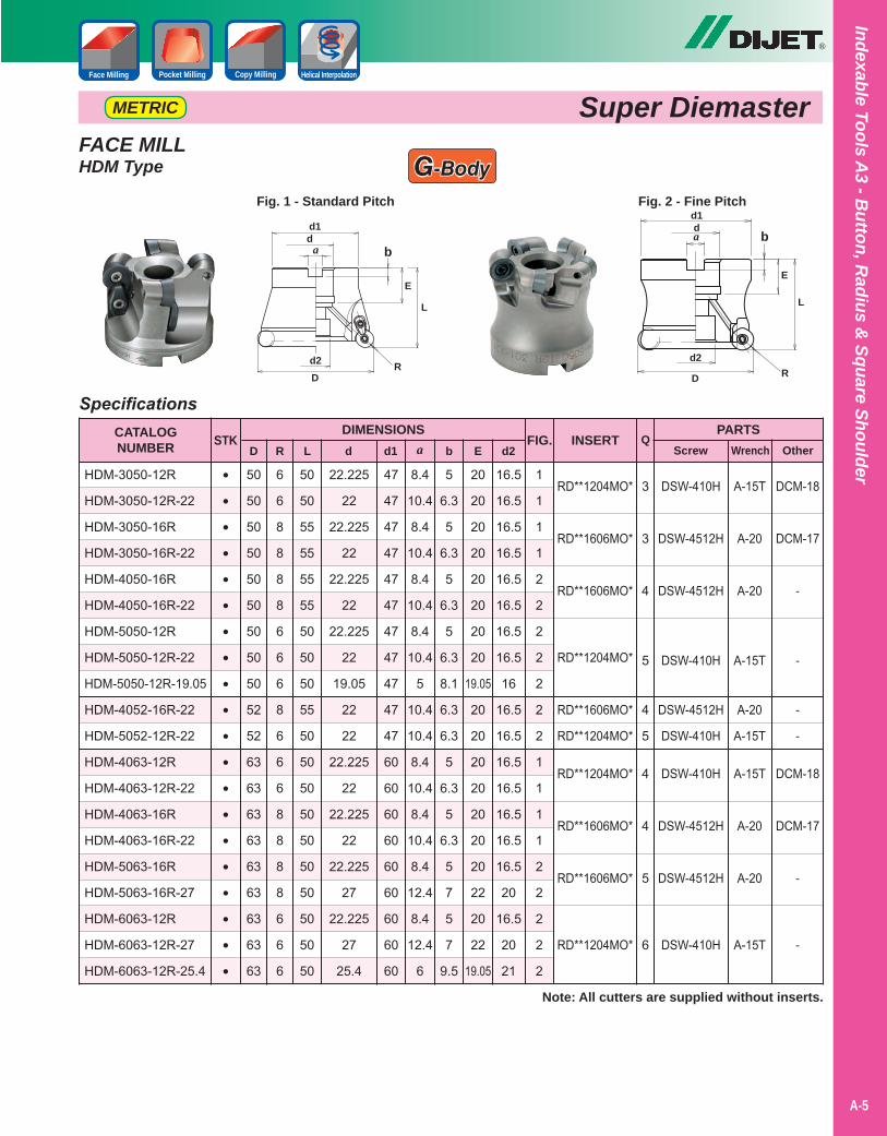
FACE MILLHDM Type
®
Super Diemaster
A-4
Copy MillingPocket Milling Helical InterpolationFace Milling
DR
L
da b
d1
E
d2
Fig. 1 - Standard Pitch Fig. 2 - Fine Pitch
D R
L
da bd1
E
d2
G-Body
----
DCM-17--
DCM-17
A-15TA-20
A-15TA-20A-20
A-15TA-20A-20
RD**1204MO*RD**1606MO*RD**1204MO*RD**1606MO*RD**2006MO*RD**1204MO*RD**1606MO*RD**2006MO*
DSW-410HDSW-4512HDSW-410H
DSW-4512HDSW-4512HDSW-410H
DSW-4512HDSW-4512H
54765976
.319
.319
.500
.500
.500
.626
.626
.626
2.002.002.752.752.752.752.752.75
2.002.003.003.003.004.004.004.00
6868
1068
10
.750
.7501.251.251.251.501.501.50
1.851.852.852.852.853.783.783.78
.197
.197
.315
.315
.315
.393
.393
.393
.750
.7501.261.261.261.451.451.45
.63
.631.021.021.021.261.261.26
Note: All cutters are supplied without inserts.
SpecificationsCATALOGNUMBER
DIMENSIONSD
HDM-5200-75R-12HDM-4200-75R-16HDM-7300-125R-12HDM-6300-125R-16HDM-5300-125R-20HDM-9400-150R-12HDM-7400-150R-16HDM-6400-150R-20
PARTSScrew Wrench
STKR L d a b
INSERT
••••••••
OtherQ
d1 E d2
22221221
FIG.
ENDMILLHDM Type
T-15T-15T-15T-15T-15T-15T-15T-15T-15
RD**1204MO*RD**1204MO*RD**1204MO*RD**1204MO*RD**1204MO*RD**1204MO*RD**1204MO*RD**1204MO*RD**1204MO*
DSW-410HDSW-410HDSW-410HDSW-410HDSW-410HDSW-410HDSW-410HDSW-410HDSW-410H
222333444
Note: All cutters are supplied without inserts.
SpecificationsCATALOGNUMBER
DIMENSIONS
HDM-2100-2.0-S100-12HDM-2100-4.0-S100-12HDM-2100-6.0-S125-12HDM-3125-2.0-S125-12HDM-3125-4.0-S125-12HDM-3125-6.0-S125-12HDM-4150-2.0-S125-12HDM-4150-4.0-S125-12HDM-4150-6.0-S125-12
PARTSScrew Wrench
INSERT Q
111111222
FIG.
4°2°4°6°2°1°---
5.007.009.005.007.009.005.007.009.00
1.001.001.001.251.251.251.501.501.50
666666666
2.004.006.002.004.006.002.004.006.00
.98
.98
.981.181.181.18
---
1.001.001.251.251.251.251.251.251.25
DSTK
R L l1 d
•••••••••
l2 a°
INCH
D
RL
d
l2
Fig. 1
a°
l1
D
RL
d
Fig. 21.34
l1
G-Body
Inde
xabl
e To
ols
A3
- But
ton,
Rad
ius
& S
quar
e Sh
ould
er
DCM-18
DCM-17
-
-
-
-
DCM-18
DCM-17
-
-
A-15T
A-20
A-20
A-15T
A-20
A-15T
A-15T
A-20
A-20
A-15T
RD**1204MO*
RD**1606MO*
RD**1606MO*
RD**1204MO*
RD**1606MO*
RD**1204MO*
RD**1204MO*
RD**1606MO*
RD**1606MO*
RD**1204MO*
DSW-410H
DSW-4512H
DSW-4512H
DSW-410H
DSW-4512H
DSW-410H
DSW-410H
DSW-4512H
DSW-4512H
DSW-410H
3
3
4
5
4
5
4
4
5
6
5
6.3
5
6.3
5
6.3
5
6.3
8.1
6.3
6.3
5
6.3
5
6.3
5
7
5
7
9.5
50
50
55
55
55
55
50
50
50
55
50
50
50
50
50
50
50
50
50
50
50
50
50
50
50
50
50
50
50
52
52
63
63
63
63
63
63
63
63
63
6
6
8
8
8
8
6
6
6
8
6
6
6
8
8
8
8
6
6
6
22.225
22
22.225
22
22.225
22
22.225
22
19.05
22
22
22.225
22
22.225
22
22.225
27
22.225
27
25.4
47
47
47
47
47
47
47
47
47
47
47
60
60
60
60
60
60
60
60
60
8.4
10.4
8.4
10.4
8.4
10.4
8.4
10.4
5
10.4
10.4
8.4
10.4
8.4
10.4
8.4
12.4
8.4
12.4
6
20
20
20
20
20
20
20
20
19.05
20
20
20
20
20
20
20
22
20
22
19.05
16.5
16.5
16.5
16.5
16.5
16.5
16.5
16.5
16
16.5
16.5
16.5
16.5
16.5
16.5
16.5
20
16.5
20
21
Note: All cutters are supplied without inserts.
SpecificationsCATALOGNUMBER
DIMENSIONSD
HDM-3050-12R
HDM-3050-12R-22
HDM-3050-16R
HDM-3050-16R-22
HDM-4050-16R
HDM-4050-16R-22
HDM-5050-12R
HDM-5050-12R-22
HDM-5050-12R-19.05
HDM-4052-16R-22
HDM-5052-12R-22
HDM-4063-12R
HDM-4063-12R-22
HDM-4063-16R
HDM-4063-16R-22
HDM-5063-16R
HDM-5063-16R-27
HDM-6063-12R
HDM-6063-12R-27
HDM-6063-12R-25.4
PARTSScrew Wrench
STKR L d a b
INSERT
••••••••••••••••••••
OtherQ
d1 E d2
1
1
1
1
2
2
2
2
2
2
2
1
1
1
1
2
2
2
2
2
FIG.
FACE MILLHDM Type
DR
L
da b
d1
E
d2
Fig. 1 - Standard Pitch Fig. 2 - Fine Pitch
D R
L
da bd1
E
d2
G-Body
®
A-5
Super DiemasterMETRIC
Indexable Tools A3 - B
utton, Radius &
Square Shoulder
Copy MillingPocket Milling Helical InterpolationFace Milling
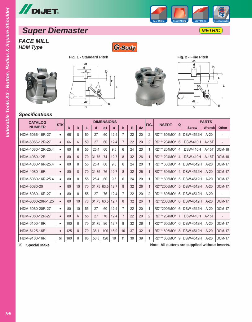
HDM-5066-16R-27
HDM-6066-12R-27
HDM-4080-12R-25.4
HDM-4080-12R
HDM-4080-16R-25.4
HDM-4080-16R
HDM-5080-16R-25.4
HDM-5080-20
HDM-6080-16R-27
HDM-6080-20R-1.25
HDM-6080-20R-27
HDM-7080-12R-27
HDM-6100-16R
HDM-8125-16R
HDM-9160-16R
®
Super Diemaster
A-6
7
7
6
8
6
8
6
8
7
8
7
7
8
10
11
50
50
55
70
55
70
55
70
55
70
55
55
70
70
80
66
66
80
80
80
80
80
80
80
80
80
80
100
125
160
8
6
6
6
8
8
8
10
8
10
10
6
8
8
8
27
27
25.4
31.75
25.4
31.75
25.4
31.75
27
31.75
27
27
31.75
38.1
50.8
60
60
60
74
60
76
60
63.5
76
63.5
60
76
96
100
120
12.4
12.4
9.5
12.7
9.5
12.7
9.5
12.7
12.4
12.7
12.4
12.4
12.7
15.9
19
22
22
24
32
24
32
24
32
22
32
22
22
32
37
39
Note: All cutters are supplied without inserts.
SpecificationsCATALOGNUMBER
DIMENSIONSD
PARTSScrew Wrench
STKR L d a b
INSERT
••••••••••••••
OtherQ
d1 E d2FIG.
METRIC
RD**1606MO*
RD**1204MO*
RD**1204MO*
RD**1204MO*
RD**1606MO*
RD**1606MO*
RD**1606MO*
RD**2006MO*
RD**1606MO*
RD**2006MO*
RD**2006MO*
RD**1204MO*
RD**1606MO*
RD**1606MO*
RD**1606MO*
20
20
20
26
20
26
20
26
20
26
20
20
26
32
39
2
2
1
1
1
1
1
1
2
1
1
2
1
1
1
-
-
DCM-18
DCM-18
DCM-17
DCM-17
DCM-17
DCM-17
-
DCM-17
DCM-17
-
DCM-17
DCM-17
DCM-17
A-20
A-15T
A-15T
A-15T
A-20
A-20
A-20
A-20
A-20
A-20
A-20
A-15T
A-20
A-20
A-20
DSW-4512H
DSW-410H
DSW-410H
DSW-410H
DSW-4512H
DSW-4512H
DSW-4512H
DSW-4512H
DSW-4512H
DSW-4512H
DSW-4512H
DSW-410H
DSW-4512H
DSW-4512H
DSW-4512H
5
6
4
4
4
4
5
5
6
6
6
7
6
8
9
FACE MILLHDM Type G-Body
Fig. 2 - Fine Pitch
D R
L
da bd1
E
d2
DR
L
da b
d1
E
d2
Fig. 1 - Standard Pitch
Copy MillingPocket Milling Helical InterpolationFace Milling
Special Make
Inde
xabl
e To
ols
A3
- But
ton,
Rad
ius
& S
quar
e Sh
ould
er
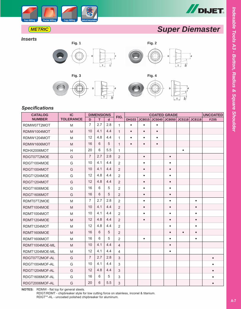
Inserts
SpecificationsCATALOGNUMBER
DIMENSIONS
RDMW07T2MOT
RDMW1004MOT
RDMW1204MOT
RDMW1606MOT
RDHX2006MOT
RDGT07T2MOE
RDGT1004MOE
RDGT1004MOT
RDGT1204MOE
RDGT1204MOT
RDGT1606MOE
RDGT1606MOT
RDMT07T2MOE
RDMT1004MOE
RDMT1004MOT
RDMT1204MOE
RDMT1204MOT
RDMT1606MOE
RDMT1606MOT
RDMT1004MOE-ML
RDMT1204MOE-ML
RDGT07T2MOF-AL
RDGT1004MOF-AL
RDGT1204MOF-AL
RDGT1606MOF-AL
RDGT2006MOF-AL
DH103 JC8015 JC5040 JC8050 JC5118 JC8118D T dCOATED GRADE UNCOATED
FZ05
•••••
FIG.
1
1
1
1
1
2
2
2
2
2
2
2
2
2
2
2
2
2
2
4
4
3
3
3
3
3
M
M
M
M
H
G
G
G
G
G
G
G
M
M
M
M
M
M
M
M
M
G
G
G
G
G
7
10
12
16
20
7
10
10
12
12
16
16
7
10
10
12
12
16
16
10
12
7
10
12
16
20
••••
••••
•••••••••••
•
••••
••••••••••••••••
•
•
•••••••
2.7
4.1
4.8
6
6
2.7
4.1
4.1
4.8
4.8
6
6
2.7
4.1
4.1
4.8
4.8
6
6
4.1
4.1
2.7
4.1
4.8
6
6
2.8
4.4
4.4
5
5.5
2.8
4.4
4.4
4.4
4.4
5
5
2.8
4.4
4.4
4.4
4.4
5
5
4.4
4.4
2.8
4.4
4.4
5
5.5
15°
D d
T
Fig. 1
15°
D d
T
Fig. 2
Fig. 3 Fig. 4
D Dd d
TT15
º
15º
ICTOLERANCE
®
A-7
Super DiemasterMETRIC
Indexable Tools A3 - B
utton, Radius &
Square Shoulder
NOTES: RDMW - flat top for general steels. RDGT/RDMT - chipbreaker style for low cutting force on stainless, inconel & titanium. RDGT**-AL - uncoated polished chipbreaker for aluminum.
Copy MillingPocket Milling Helical InterpolationFace Milling
Super Diemaster
®
A-8
METRIC
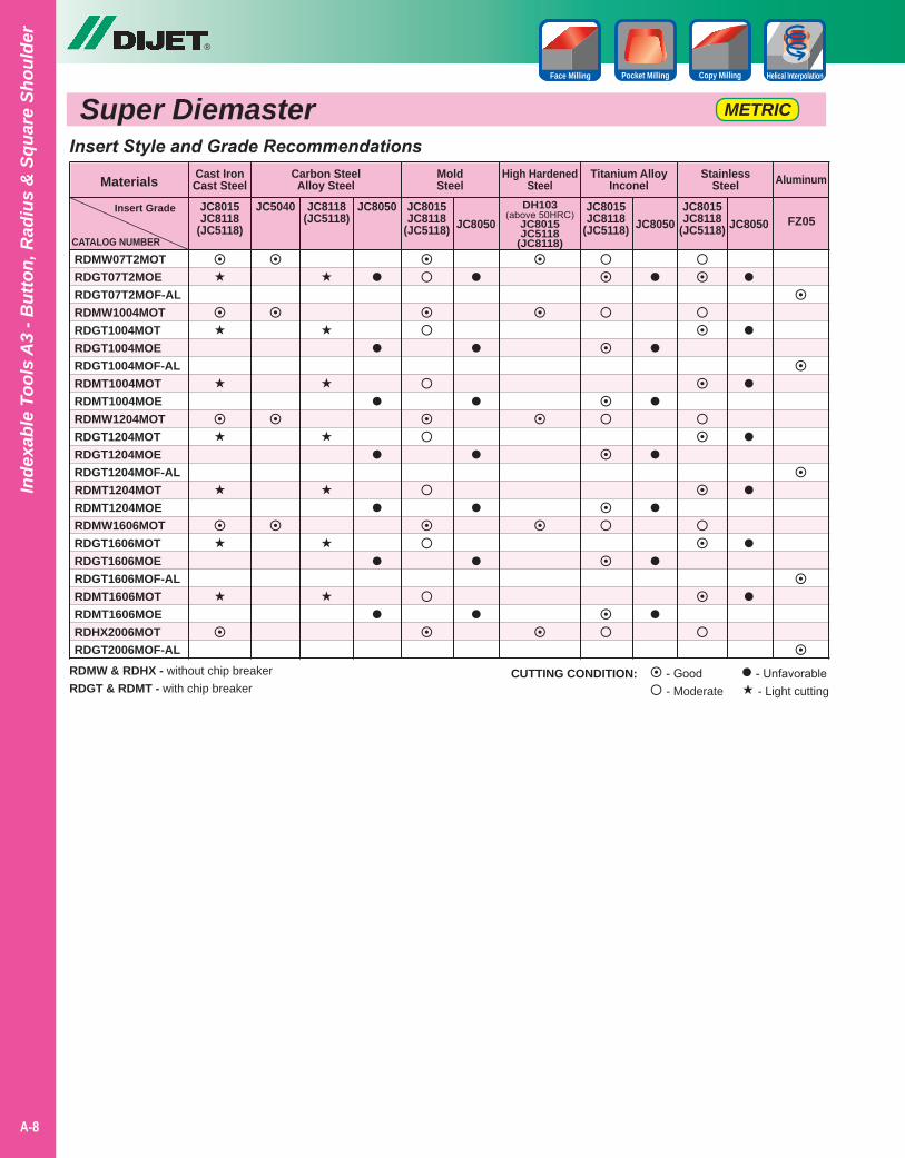
Insert Style and Grade Recommendations
JC8015JC8118
(JC5118)CATALOG NUMBERRDMW07T2MOTRDGT07T2MOERDGT07T2MOF-ALRDMW1004MOTRDGT1004MOTRDGT1004MOERDGT1004MOF-ALRDMT1004MOTRDMT1004MOERDMW1204MOTRDGT1204MOTRDGT1204MOERDGT1204MOF-ALRDMT1204MOTRDMT1204MOERDMW1606MOTRDGT1606MOTRDGT1606MOERDGT1606MOF-ALRDMT1606MOTRDMT1606MOERDHX2006MOTRDGT2006MOF-AL
Materials Cast IronCast Steel
Carbon SteelAlloy Steel
High HardenedSteel
Titanium AlloyInconel
StainlessSteel
JC5040 JC8118(JC5118)
JC8050
Aluminum
DH103(above 50HRC)
JC8015JC5118
(JC8118)
JC8015JC8118
(JC5118) JC8050JC8015JC8118
(JC5118) JC8050 FZ05
RDMW & RDHX - without chip breakerRDGT & RDMT - with chip breaker
- Good - Moderate
- Unfavorable - Light cutting
CUTTING CONDITION:
Inde
xabl
e To
ols
A3
- But
ton,
Rad
ius
& S
quar
e Sh
ould
er
Copy MillingPocket Milling Helical InterpolationFace Milling
Insert Grade
MoldSteel
JC8015JC8118
(JC5118) JC8050
®
A-9
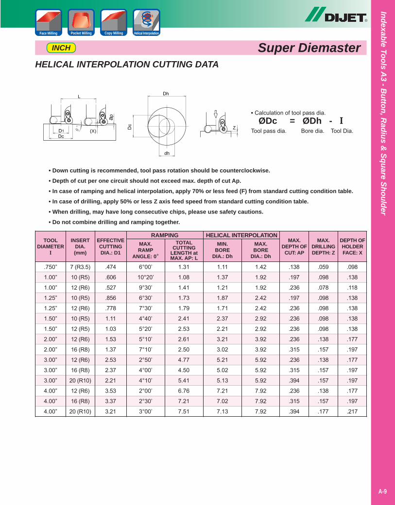
HELICAL INTERPOLATION CUTTING DATA
TOOLDIAMETER
I
RAMPING
.750”
1.00”
1.00”
1.25”
1.25”
1.50”
1.50”
2.00”
2.00”
3.00”
3.00”
3.00”
4.00”
4.00”
4.00”
7 (R3.5)
10 (R5)
12 (R6)
10 (R5)
12 (R6)
10 (R5)
12 (R5)
12 (R6)
16 (R8)
12 (R6)
16 (R8)
20 (R10)
12 (R6)
16 (R8)
20 (R10)
INSERTDIA.(mm)
MAX.RAMP
ANGLE: 0°
6°00’
10°20’
9°30’
6°30’
7°30’
4°40’
5°20’
5°10’
7°10’
2°50’
4°00’
4°10’
2°00’
2°30’
3°00’
HELICAL INTERPOLATION
• Down cutting is recommended, tool pass rotation should be counterclockwise.• Depth of cut per one circuit should not exceed max. depth of cut Ap.• In case of ramping and helical interpolation, apply 70% or less feed (F) from standard cutting condition table.• In case of drilling, apply 50% or less Z axis feed speed from standard cutting condition table.• When drilling, may have long consecutive chips, please use safety cautions.• Do not combine drilling and ramping together.
.474
.606
.527
.856
.778
1.11
1.03
1.53
1.37
2.53
2.37
2.21
3.53
3.37
3.21
EFFECTIVECUTTINGDIA.: D1
TOTALCUTTING
LENGTH atMAX. AP: L
1.31
1.08
1.41
1.73
1.79
2.41
2.53
2.61
2.50
4.77
4.50
5.41
6.76
7.21
7.51
MIN.BORE
DIA.: Dh
1.11
1.37
1.21
1.87
1.71
2.37
2.21
3.21
3.02
5.21
5.02
5.13
7.21
7.02
7.13
1.42
1.92
1.92
2.42
2.42
2.92
2.92
3.92
3.92
5.92
5.92
5.92
7.92
7.92
7.92
MAX.BORE
DIA.: Dh
.138
.197
.236
.197
.236
.236
.236
.236
.315
.236
.315
.394
.236
.315
.394
MAX.DEPTH OF
CUT: AP
.059
.098
.078
.098
.098
.098
.098
.138
.157
.138
.157
.157
.138
.157
.177
MAX.DRILLINGDEPTH: Z
.098
.138
.118
.138
.138
.138
.138
.177
.197
.177
.197
.197
.177
.197
.217
DEPTH OFHOLDERFACE: X
Super DiemasterINCH
Dh
Dc
dh
Z
L
ap
D1Dc
(X)θ°
• Calculation of tool pass dia. ØDc = ØDh - ITool pass dia. Bore dia. Tool Dia.
Indexable Tools A3 - B
utton, Radius &
Square Shoulder
Copy MillingPocket Milling Helical InterpolationFace Milling
®
A-10
Inde
xabl
e To
ols
A3
- But
ton,
Rad
ius
& S
quar
e Sh
ould
er
Copy MillingPocket Milling Helical InterpolationFace Milling
Super Diemaster METRIC
2022252528303232353540425050525263636666808080100125160
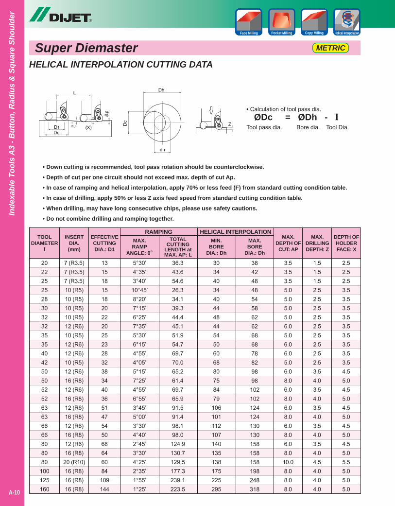
HELICAL INTERPOLATION CUTTING DATA
TOOLDIAMETER
I
RAMPING
7 (R3.5)7 (R3.5)7 (R3.5)10 (R5)10 (R5)10 (R5)10 (R5)12 (R6)10 (R5)12 (R6)12 (R6)10 (R5)12 (R6)16 (R8)12 (R6)16 (R8)12 (R6)16 (R8)12 (R6)16 (R8)12 (R6)16 (R8)20 (R10)16 (R8)16 (R8)16 (R8)
INSERTDIA.(mm)
MAX.RAMP
ANGLE: 0°
5°30’4°35’3°40’10°45’8°20’7°15’6°25’7°35’5°30’6°15’4°55’4°05’5°15’7°25’4°55’6°55’3°45’5°00’3°30’4°40’2°45’3°30’4°25’2°35’1°55’1°25’
HELICAL INTERPOLATION
• Down cutting is recommended, tool pass rotation should be counterclockwise.• Depth of cut per one circuit should not exceed max. depth of cut Ap.• In case of ramping and helical interpolation, apply 70% or less feed (F) from standard cutting condition table.• In case of drilling, apply 50% or less Z axis feed speed from standard cutting condition table.• When drilling, may have long consecutive chips, please use safety cautions.• Do not combine drilling and ramping together.
131518151820222025232832383440365147545068646084109144
EFFECTIVECUTTINGDIA.: D1
TOTALCUTTING
LENGTH atMAX. AP: L
36.343.654.626.334.139.344.445.151.954.769.770.065.261.469.765.991.591.498.198.0
124.9130.7129.5177.3239.1223.5
MIN.BORE
DIA.: Dh
30344034404448445450606880758479
106101112107140135138175225295
3842484854586262686878829898
102102124124130130158158158198248318
MAX.BORE
DIA.: Dh
3.53.53.55.05.05.05.06.05.06.06.05.06.08.06.08.06.08.06.08.06.08.010.08.08.08.0
MAX.DEPTH OF
CUT: AP
1.51.51.52.52.52.52.52.52.52.52.52.53.54.03.54.03.54.03.54.03.54.04.54.04.04.0
MAX.DRILLINGDEPTH: Z
2.52.52.53.53.53.53.53.53.53.53.53.54.55.04.55.04.55.04.55.04.55.05.55.05.05.0
DEPTH OFHOLDERFACE: X
• Calculation of tool pass dia. ØDc = ØDh - ITool pass dia. Bore dia. Tool Dia.
Dh
Dc
dh
Z
L
ap
D1Dc
(X)θ°
®
A-11
Indexable Tools A3 - B
utton, Radius &
Square Shoulder
Copy MillingPocket Milling Helical InterpolationFace Milling
Super Diemaster
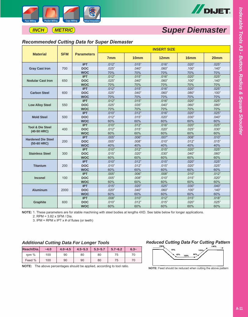
NOTE: 1. These parameters are for stable machining with steel bodies at lengths 4XD. See table below for longer applications.2. RPM = 3.82 x SFM / Dia.3. IPM = RPM x IPT x # of flutes (or teeth)
Reduced Cutting Data For Cutting Pattern
NOTE: Feed should be reduced when cutting the above patternNOTE: The above percentages should be applied, according to tool ratio.
Additional Cutting Data For Longer Tools
rpm %
Feed %
100
100
90
90
80
90
80
80
75
75
70
70
Reach/Dia. ~4.0 4.0~4.5 4.5~5.3 5.3~5.7 5.7~6.2 6.3~
Recommended Cutting Data for Super Diemaster
Gray Cast Iron
Nodular Cast Iron
Carbon Steel
Low Alloy Steel
Mold Steel
Tool & Die Steel(40-50 HRC)
Hardened Die Steel(50-60 HRC)
Stainless Steel
Titanium
Inconel
Aluminum
Graphite
Material SFMINSERT SIZE
Parameters7mm 10mm 12mm 16mm 20mm
700
650
600
550
500
400
200
300
200
100
2000
600
IPTDOCWOCIPT
DOCWOCIPT
DOCWOCIPT
DOCWOCIPT
DOCWOCIPT
DOCWOCIPT
DOCWOCIPT
DOCWOCIPT
DOCWOCIPT
DOCWOCIPT
DOCWOCIPT
DOCWOC
.012”
.025”70%.012”.025”70%.012”.025”70%.012”.025”70%.010”.012”60%.010”.012”60%.005”.005”40%.010”.015”60%.010”.010”60%.005”.005”60%.015”.020”60%.008”.010”60%
.015”
.040”70%.015”.040”70%.015”.040”70%.015”.035”70%.012”.015”60%.012”.015”60%.006”.008”40%.012”.020”60%.012”.012”60%.006”.008”60%.020”.040”60%.010”.012”60%
.016”
.060”70%.016”.060”70%.016”.060”70%.016”.040”70%.016”.020”60%.016”.020”60%.007”.010”40%.015”.030”60%.015”.015”60%.008”.010”60%.025”.060”60%.012”.015”60%
.020”
.100”70%.020”.100”70%.020”.080”70%.020”.060”70%.020”.030”60%.020”.025”60%.008”.012”40%.020”.040”60%.020”.020”60%.010”.015”60%.030”.100”60%.015”.020”60%
.025”
.140”70%.025”.140”70%.025”.100”70%.025”.080”70%.025”.040”60%.025”.030”60%.010”.015”40%.025”.060”60%.025”.025”60%.012”.020”60%.040”.140”60%.018”.025”60%
METRICINCH

Notes
A-40
®
A-12
Inde
xabl
e To
ols
A3
- But
ton,
Rad
ius
& S
quar
e Sh
ould
er
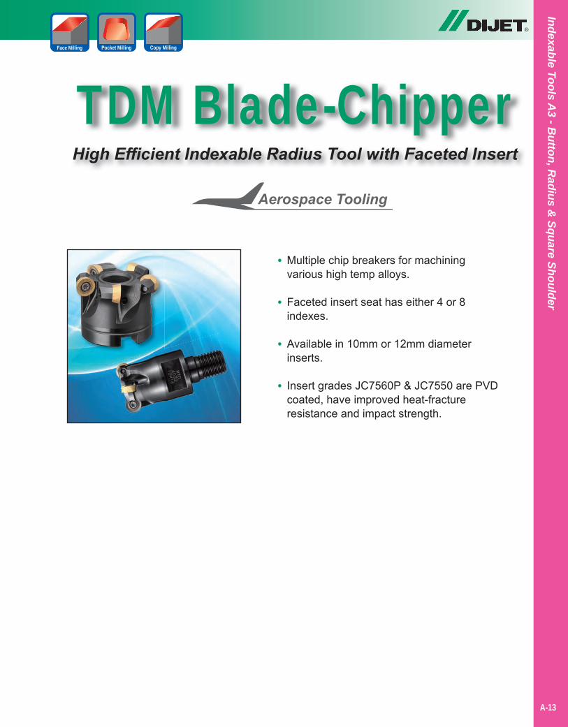
TDM Blade-ChipperHigh Efficient Indexable Radius Tool with Faceted Insert
®
Copy MillingPocket MillingFace Milling
• Multiple chip breakers for machining various high temp alloys.
• Faceted insert seat has either 4 or 8 indexes.
• Available in 10mm or 12mm diameter inserts.
• Insert grades JC7560P & JC7550 are PVD coated, have improved heat-fracture resistance and impact strength.
Indexable Tools A3 - B
utton, Radius &
Square Shoulder
A-13
®
A-14
Inde
xabl
e To
ols
A3
- But
ton,
Rad
ius
& S
quar
e Sh
ould
er
Copy MillingPocket MillingFace Milling
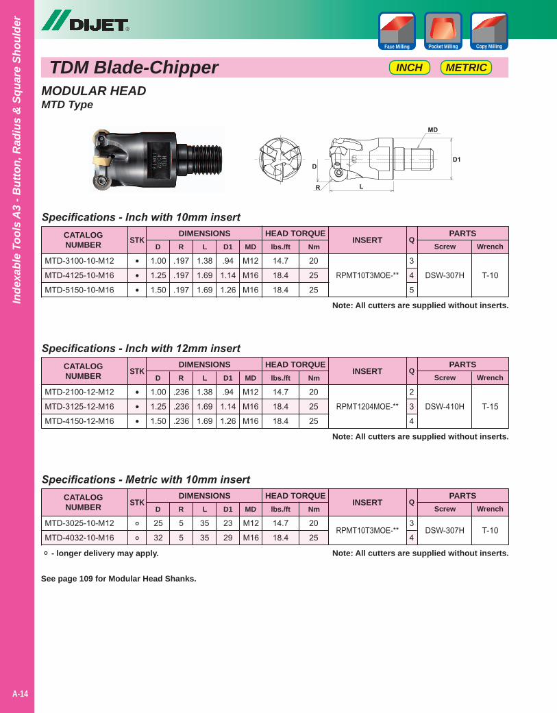
MODULAR HEADMTD Type
Note: All cutters are supplied without inserts.
Note: All cutters are supplied without inserts.
Note: All cutters are supplied without inserts.
T-10
T-15
T-10
Specifications - Inch with 10mm insert
Specifications - Inch with 12mm insert
Specifications - Metric with 10mm insert
1.38
1.69
1.69
1.38
1.69
1.69
35
35
1.00
1.25
1.50
1.00
1.25
1.50
25
32
.197
.197
.197
.236
.236
.236
5
5
.94
1.14
1.26
.94
1.14
1.26
23
29
M12
M16
M16
M12
M16
M16
M12
M16
CATALOGNUMBER
CATALOGNUMBER
CATALOGNUMBER
DIMENSIONS
DIMENSIONS
DIMENSIONS
D
D
D
MTD-3100-10-M12
MTD-4125-10-M16
MTD-5150-10-M16
MTD-2100-12-M12
MTD-3125-12-M16
MTD-4150-12-M16
MTD-3025-10-M12
MTD-4032-10-M16
RPMT10T3MOE-**
RPMT1204MOE-**
RPMT10T3MOE-**
PARTS
PARTS
PARTS
Screw
Screw
Screw
Wrench
Wrench
Wrench
STK
STK
STK
R
R
R
L
L
L
D1
D1
D1
INSERT
INSERT
INSERT
DSW-307H
DSW-410H
DSW-307H
•••
•••
°°
Q
Q
Q
3
4
5
2
3
4
3
4
MD
MD
MD
HEAD TORQUE
HEAD TORQUE
HEAD TORQUE
14.7
18.4
18.4
14.7
18.4
18.4
14.7
18.4
20
25
25
20
25
25
20
25
lbs./ft
lbs./ft
lbs./ft
Nm
Nm
Nm
See page 109 for Modular Head Shanks.
METRICINCH
° - longer delivery may apply.
TDM Blade-Chipper
®
A-15
Indexable Tools A3 - B
utton, Radius &
Square Shoulder
TDM Blade-ChipperMETRICINCH
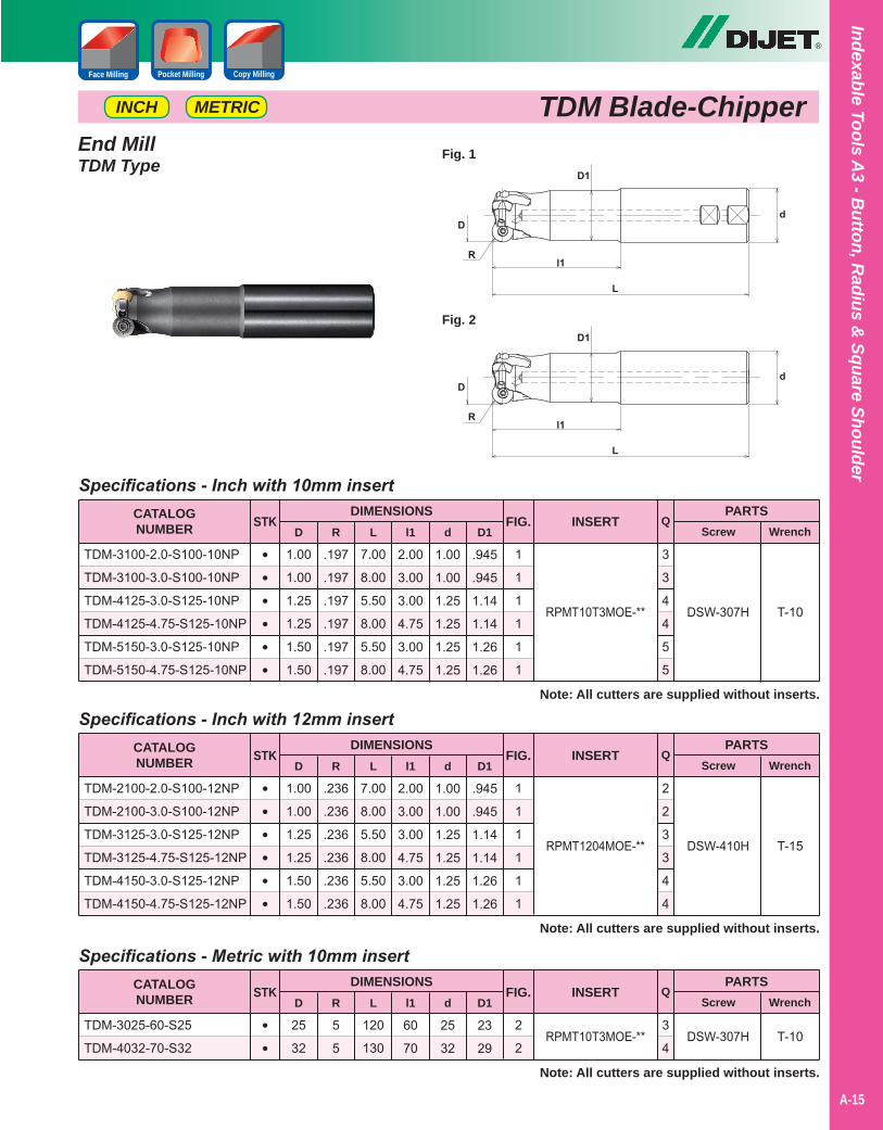
End MillTDM Type
Note: All cutters are supplied without inserts.
Note: All cutters are supplied without inserts.
Note: All cutters are supplied without inserts.
T-10
T-15
T-10
Specifications - Inch with 10mm insert
Specifications - Inch with 12mm insert
Specifications - Metric with 10mm insert
7.00
8.00
5.50
8.00
5.50
8.00
7.00
8.00
5.50
8.00
5.50
8.00
120
130
1.00
1.00
1.25
1.25
1.50
1.50
1.00
1.00
1.25
1.25
1.50
1.50
25
32
.197
.197
.197
.197
.197
.197
.236
.236
.236
.236
.236
.236
5
5
2.00
3.00
3.00
4.75
3.00
4.75
2.00
3.00
3.00
4.75
3.00
4.75
60
70
1.00
1.00
1.25
1.25
1.25
1.25
1.00
1.00
1.25
1.25
1.25
1.25
25
32
.945
.945
1.14
1.14
1.26
1.26
.945
.945
1.14
1.14
1.26
1.26
23
29
CATALOGNUMBER
CATALOGNUMBER
CATALOGNUMBER
DIMENSIONS
DIMENSIONS
DIMENSIONS
D
D
D
TDM-3100-2.0-S100-10NP
TDM-3100-3.0-S100-10NP
TDM-4125-3.0-S125-10NP
TDM-4125-4.75-S125-10NP
TDM-5150-3.0-S125-10NP
TDM-5150-4.75-S125-10NP
TDM-2100-2.0-S100-12NP
TDM-2100-3.0-S100-12NP
TDM-3125-3.0-S125-12NP
TDM-3125-4.75-S125-12NP
TDM-4150-3.0-S125-12NP
TDM-4150-4.75-S125-12NP
TDM-3025-60-S25
TDM-4032-70-S32
RPMT10T3MOE-**
RPMT1204MOE-**
RPMT10T3MOE-**
PARTS
PARTS
PARTS
Screw
Screw
Screw
Wrench
Wrench
Wrench
STK
STK
STK
R
R
R
L
L
L
l1
l1
l1
INSERT
INSERT
INSERT
DSW-307H
DSW-410H
DSW-307H
••••••
••••••
••
Q
Q
Q
3
3
4
4
5
5
2
2
3
3
4
4
3
4
d
d
d
D1
D1
D1
FIG.
FIG.
FIG.
1
1
1
1
1
1
1
1
1
1
1
1
2
2
Copy MillingPocket MillingFace Milling
Fig. 1
Fig. 2
®
A-16
Inde
xabl
e To
ols
A3
- But
ton,
Rad
ius
& S
quar
e Sh
ould
er
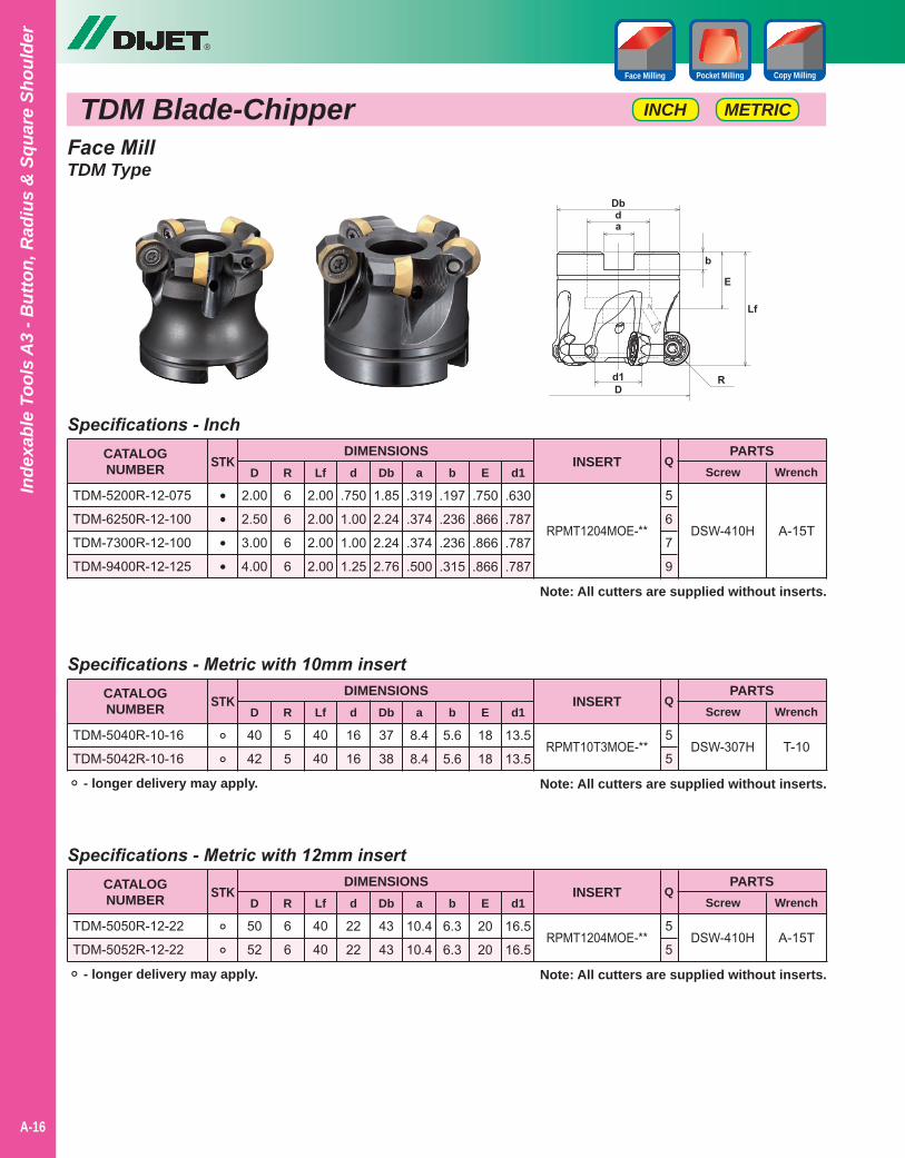
TDM Blade-ChipperFace MillTDM Type
Note: All cutters are supplied without inserts.
Note: All cutters are supplied without inserts.
Note: All cutters are supplied without inserts.
A-15T
T-10
A-15T
Specifications - Inch
Specifications - Metric with 10mm insert
Specifications - Metric with 12mm insert
2.00
2.00
2.00
2.00
40
40
40
40
2.00
2.50
3.00
4.00
40
42
50
52
6
6
6
6
5
5
6
6
.750
1.00
1.00
1.25
16
16
22
22
1.85
2.24
2.24
2.76
37
38
43
43
.319
.374
.374
.500
8.4
8.4
10.4
10.4
.197
.236
.236
.315
5.6
5.6
6.3
6.3
.750
.866
.866
.866
18
18
20
20
.630
.787
.787
.787
13.5
13.5
16.5
16.5
CATALOGNUMBER
CATALOGNUMBER
CATALOGNUMBER
DIMENSIONS
DIMENSIONS
DIMENSIONS
D
D
D
TDM-5200R-12-075
TDM-6250R-12-100
TDM-7300R-12-100
TDM-9400R-12-125
TDM-5040R-10-16
TDM-5042R-10-16
TDM-5050R-12-22
TDM-5052R-12-22
RPMT1204MOE-**
RPMT10T3MOE-**
RPMT1204MOE-**
PARTS
PARTS
PARTS
Screw
Screw
Screw
Wrench
Wrench
Wrench
STK
STK
STK
R
R
R
Lf
Lf
Lf
d
d
d
INSERT
INSERT
INSERT
DSW-410H
DSW-307H
DSW-410H
••••
°°
°°
Q
Q
Q
5
6
7
9
5
5
5
5
Db
Db
Db
a
a
a
b
b
b
E
E
E
d1
d1
d1
METRICINCH
° - longer delivery may apply.
° - longer delivery may apply.
Copy MillingPocket MillingFace Milling
®
A-17
Indexable Tools A3 - B
utton, Radius &
Square Shoulder
Copy MillingPocket MillingFace Milling
TDM Blade-ChipperMETRIC
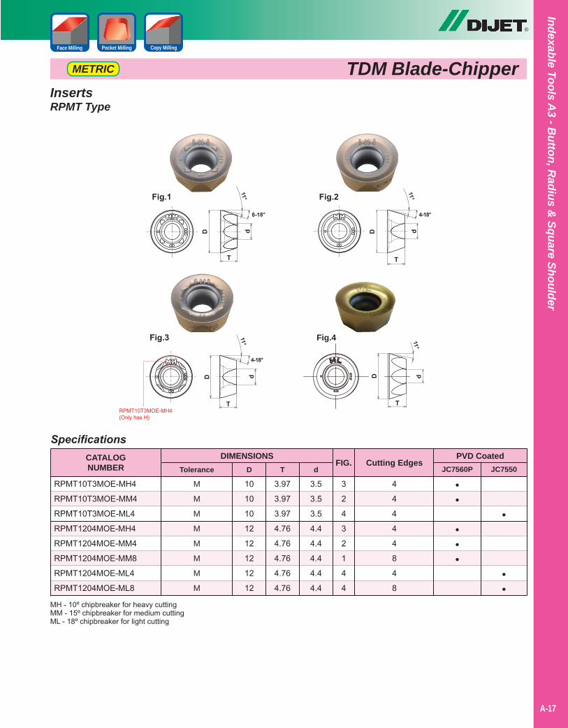
InsertsRPMT Type
Specifications
10
10
10
12
12
12
12
12
3.97
3.97
3.97
4.76
4.76
4.76
4.76
4.76
3.5
3.5
3.5
4.4
4.4
4.4
4.4
4.4
CATALOGNUMBER
DIMENSIONS
RPMT10T3MOE-MH4
RPMT10T3MOE-MM4
RPMT10T3MOE-ML4
RPMT1204MOE-MH4
RPMT1204MOE-MM4
RPMT1204MOE-MM8
RPMT1204MOE-ML4
RPMT1204MOE-ML8
PVD CoatedJC7560P JC7550
Cutting EdgesT d
FIG.
3
2
4
3
2
1
4
4
D
4
4
4
4
4
8
4
8
Tolerance
M
M
M
M
M
M
M
M
••
•••
•
••
MH - 10º chipbreaker for heavy cuttingMM - 15º chipbreaker for medium cuttingML - 18º chipbreaker for light cutting
Fig.4
RPMT10T3MOE-MH4(Only has H)
®
A-18
Inde
xabl
e To
ols
A3
- But
ton,
Rad
ius
& S
quar
e Sh
ould
er
TDM Blade-Chipper METRICINCH
Copy MillingPocket MillingFace Milling
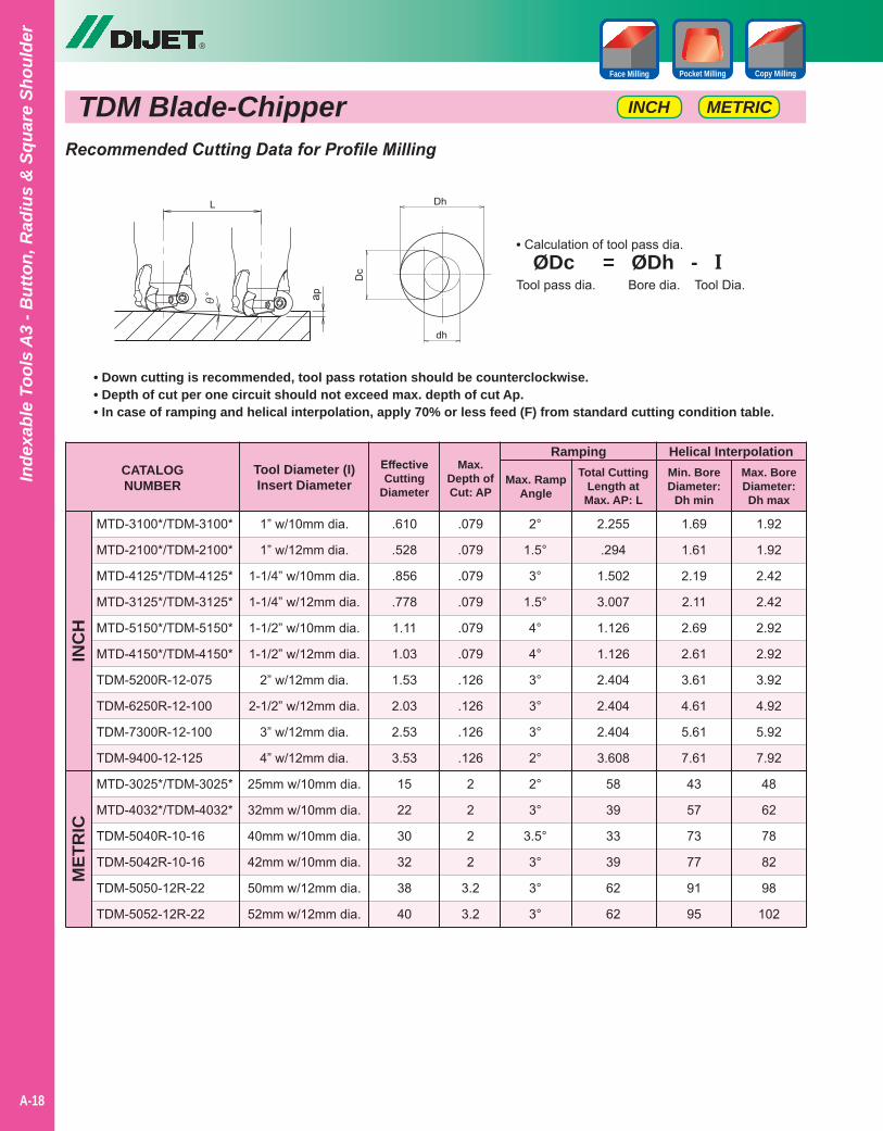
Recommended Cutting Data for Profile Milling
CATALOGNUMBER
Ramping
MTD-3100*/TDM-3100*
MTD-2100*/TDM-2100*
MTD-4125*/TDM-4125*
MTD-3125*/TDM-3125*
MTD-5150*/TDM-5150*
MTD-4150*/TDM-4150*
TDM-5200R-12-075
TDM-6250R-12-100
TDM-7300R-12-100
TDM-9400-12-125
MTD-3025*/TDM-3025*
MTD-4032*/TDM-4032*
TDM-5040R-10-16
TDM-5042R-10-16
TDM-5050-12R-22
TDM-5052-12R-22
INC
HM
ETR
IC
EffectiveCutting
Diameter
Tool Diameter (I)Insert Diameter
Max.Depth ofCut: AP
Max. RampAngle
.610
.528
.856
.778
1.11
1.03
1.53
2.03
2.53
3.53
15
22
30
32
38
40
1” w/10mm dia.
1” w/12mm dia.
1-1/4” w/10mm dia.
1-1/4” w/12mm dia.
1-1/2” w/10mm dia.
1-1/2” w/12mm dia.
2” w/12mm dia.
2-1/2” w/12mm dia.
3” w/12mm dia.
4” w/12mm dia.
25mm w/10mm dia.
32mm w/10mm dia.
40mm w/10mm dia.
42mm w/10mm dia.
50mm w/12mm dia.
52mm w/12mm dia.
.079
.079
.079
.079
.079
.079
.126
.126
.126
.126
2
2
2
2
3.2
3.2
2°
1.5°
3°
1.5°
4°
4°
3°
3°
3°
2°
2°
3°
3.5°
3°
3°
3°
Total CuttingLength at
Max. AP: L
2.255
.294
1.502
3.007
1.126
1.126
2.404
2.404
2.404
3.608
58
39
33
39
62
62
Helical InterpolationMin. BoreDiameter:
Dh min
1.69
1.61
2.19
2.11
2.69
2.61
3.61
4.61
5.61
7.61
43
57
73
77
91
95
1.92
1.92
2.42
2.42
2.92
2.92
3.92
4.92
5.92
7.92
48
62
78
82
98
102
• Down cutting is recommended, tool pass rotation should be counterclockwise.• Depth of cut per one circuit should not exceed max. depth of cut Ap.• In case of ramping and helical interpolation, apply 70% or less feed (F) from standard cutting condition table.
Max. BoreDiameter:Dh max
• Calculation of tool pass dia. ØDc = ØDh - ITool pass dia. Bore dia. Tool Dia.
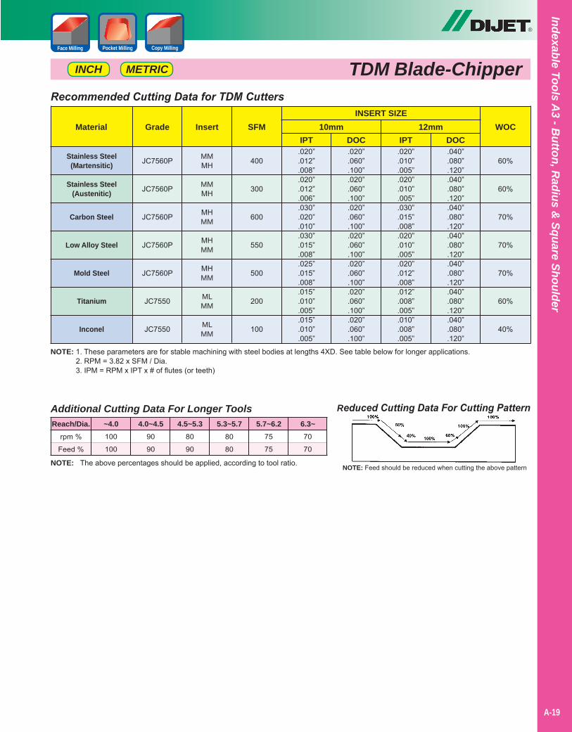
NOTE: 1. These parameters are for stable machining with steel bodies at lengths 4XD. See table below for longer applications.2. RPM = 3.82 x SFM / Dia.3. IPM = RPM x IPT x # of flutes (or teeth)
Reduced Cutting Data For Cutting Pattern
NOTE: Feed should be reduced when cutting the above patternNOTE: The above percentages should be applied, according to tool ratio.
Additional Cutting Data For Longer Tools
rpm %
Feed %
100
100
90
90
80
90
80
80
75
75
70
70
Reach/Dia. ~4.0 4.0~4.5 4.5~5.3 5.3~5.7 5.7~6.2 6.3~
Recommended Cutting Data for TDM Cutters
Stainless Steel(Martensitic)
Stainless Steel(Austenitic)
Carbon Steel
Low Alloy Steel
Mold Steel
Titanium
Inconel
MaterialINSERT SIZE
DOCIPTDOCIPTSFMInsertGrade WOC
.040”
.080”
.120”
.040”
.080”
.120”
.040”
.080”
.120”
.040”
.080”
.120”
.040”
.080”
.120”
.040”
.080”
.120”
.040”
.080”
.120”
.020”
.010”
.005”
.020”
.010”
.005”
.030”
.015”
.008”
.020”
.010”
.005”
.020”
.012”
.008”
.012”
.008”
.005”
.010”
.008”
.005”
.020”
.060”
.100”
.020”
.060”
.100”
.020”
.060”
.100”
.020”
.060”
.100”
.020”
.060”
.100”
.020”
.060”
.100”
.020”
.060”
.100”
.020”
.012”
.008”
.020”
.012”
.006”
.030”
.020”
.010”
.030”
.015”
.008”
.025”
.015”
.008”
.015”
.010”
.005”
.015”
.010”
.005”
400
300
600
550
500
200
100
MMMH
MMMH
MHMM
MHMM
MHMM
MLMM
MLMM
JC7560P
JC7560P
JC7560P
JC7560P
JC7560P
JC7550
JC7550
60%
60%
70%
70%
70%
60%
40%
10mm 12mm
®
A-19
Indexable Tools A3 - B
utton, Radius &
Square Shoulder
Copy MillingPocket MillingFace Milling
TDM Blade-ChipperMETRICINCH

Notes
A-40
®
A-20
Inde
xabl
e To
ols
A3
- But
ton,
Rad
ius
& S
quar
e Sh
ould
er
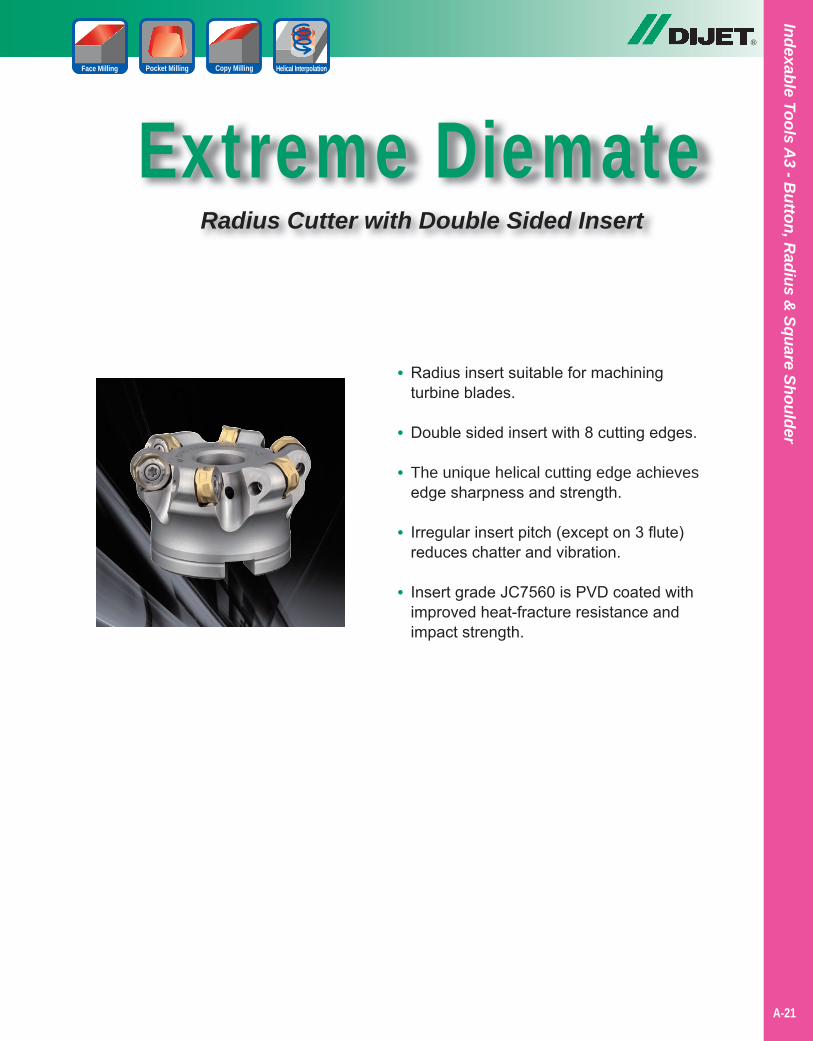
Extreme DiemateRadius Cutter with Double Sided Insert
®
• Radius insert suitable for machining turbine blades.
• Double sided insert with 8 cutting edges.
• The unique helical cutting edge achieves edge sharpness and strength.
• Irregular insert pitch (except on 3 flute) reduces chatter and vibration.
• Insert grade JC7560 is PVD coated with improved heat-fracture resistance and impact strength.
Indexable Tools A3 - B
utton, Radius &
Square Shoulder
A-21
Copy MillingPocket Milling Helical InterpolationFace Milling
®
A-22
Inde
xabl
e To
ols
A3
- But
ton,
Rad
ius
& S
quar
e Sh
ould
er
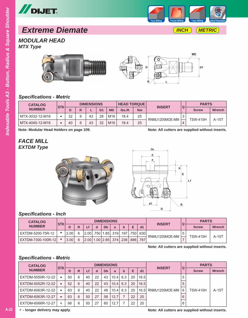
Extreme DiemateMODULAR HEADMTX Type
FACE MILLEXTDM Type
Note: All cutters are supplied without inserts.
A-15T
Specifications - Metric
43
43
32
40
6
6
28
32
M16
M16
CATALOGNUMBER
DIMENSIONSD
MTX-3032-12-M16
MTX-4040-12-M16RNMU1205MOE-MM
PARTSScrew Wrench
STKR L D1
INSERT
TSW-410H••
Q
3
4
MD
HEAD TORQUE
18.4
18.4
25
25
lbs./ft Nm
METRICINCH
Copy MillingPocket Milling Helical InterpolationFace Milling
Note: Modular Head Holders on page 109.
Note: All cutters are supplied without inserts.
A-15T
Specifications - Inch
2.00
2.00
2.00
3.00
6
6
.750
1.00
1.85
2.85
.319
.374
.197
.236
.750
.886
.630
.787
CATALOGNUMBER
DIMENSIONSD
EXTDM-5200-75R-12
EXTDM-7300-100R-12RNMU1205MOE-MM
PARTSScrew Wrench
STKR Lf d
INSERT
TSW-410H••
Q
5
7
Db a b E d1
° - longer delivery may apply. Note: All cutters are supplied without inserts.
A-15T
Specifications - Metric
40
40
40
50
50
50
52
63
63
66
6
6
6
6
6
22
22
22
27
27
43
43
48
58
60
10.4
10.4
10.4
12.7
12.7
6.3
6.3
6.3
7
7
20
20
20
22
22
16.5
16.5
16.5
20
20
CATALOGNUMBER
DIMENSIONSD
EXTDM-5050R-12-22
EXTDM-5052R-12-22
EXTDM-6063R-12-22
EXTDM-6063R-12-27
EXTDM-6066R-12-27
RNMU1205MOE-MM
PARTSScrew Wrench
STKR Lf d
INSERT
TSW-410H
••••°
Q
5
5
6
6
6
Db a b E d1
®
A-23
Indexable Tools A3 - B
utton, Radius &
Square Shoulder
Copy MillingPocket MillingFace Milling
Extreme DiemateMETRIC
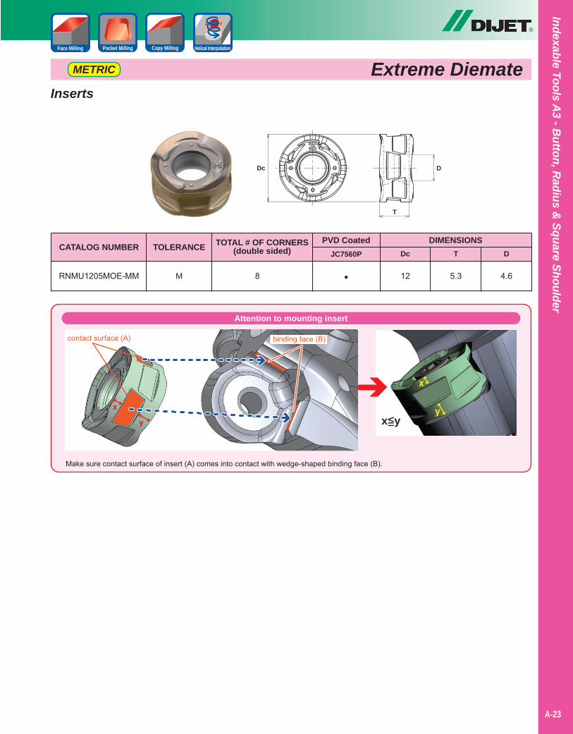
Inserts
4.65.312•8MRNMU1205MOE-MM
DIMENSIONSDTDc
CATALOG NUMBERPVD Coated
JC7560PTOLERANCE TOTAL # OF CORNERS
(double sided)
Attention to mounting insert
Make sure contact surface of insert (A) comes into contact with wedge-shaped binding face (B).
x<y=
contact surface (A)
D
T
Dc
binding face (B)
Helical Interpolation
®
A-24
Inde
xabl
e To
ols
A3
- But
ton,
Rad
ius
& S
quar
e Sh
ould
er
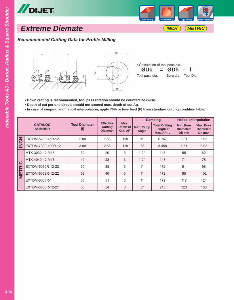
Recommended Cutting Data for Profile Milling
CATALOGNUMBER
Ramping
EXTDM-5200-75R-12
EXTDM-7300-100R-12
MTX-3032-12-M16
MTX-4040-12-M16
EXTDM-5050R-12-22
EXTDM-5052R-12-22
EXTDM-6063R-*
EXTDM-6066R-12-27
INC
HM
ETR
IC
EffectiveCutting
Diameter
Tool Diameter(I)
Max.Depth ofCut: AP
Max. RampAngle
1.53
2.53
20
28
38
40
51
54
2.00
3.00
32
40
50
52
63
66
.118
.118
3
3
3
3
3
3
1°
.8°
1.2°
1.2°
1°
1°
1°
.8°
Total CuttingLength at
Max. AP: L
6.767
8.458
143
143
172
172
172
215
Helical InterpolationMin. BoreDiameter:
Dh min
3.61
5.61
55
71
91
95
117
123
3.92
5.92
62
78
98
102
124
130
• Down cutting is recommended, tool pass rotation should be counterclockwise.• Depth of cut per one circuit should not exceed max. depth of cut Ap.• In case of ramping and helical interpolation, apply 70% or less feed (F) from standard cutting condition table.
Max. BoreDiameter:Dh max
Extreme Diemate METRICINCH
Copy MillingPocket Milling Helical InterpolationFace Milling
• Calculation of tool pass dia. ØDc = ØDh - ITool pass dia. Bore dia. Tool Dia.
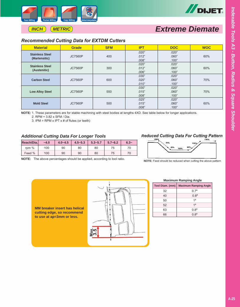
NOTE: 1. These parameters are for stable machining with steel bodies at lengths 4XD. See table below for longer applications.2. RPM = 3.82 x SFM / Dia.3. IPM = RPM x IPT x # of flutes (or teeth)
Recommended Cutting Data for EXTDM Cutters
Stainless Steel(Martensitic)
Stainless Steel(Austenitic)
Carbon Steel
Low Alloy Steel
Mold Steel
Material DOCIPTSFMGrade WOC.020”.060”.100”.020”.060”.100”.020”.060”.100”.020”.060”.100”.020”.060”.100”
.020”
.012”
.008”
.020”
.012”
.006”
.030”
.020”
.010”
.030”
.015”
.008”
.025”
.015”
.008”
400
300
600
550
500
JC7560P
JC7560P
JC7560P
JC7560P
JC7560P
60%
60%
70%
70%
60%
Reduced Cutting Data For Cutting Pattern
NOTE: Feed should be reduced when cutting the above patternNOTE: The above percentages should be applied, according to tool ratio.
Additional Cutting Data For Longer Tools
rpm %
Feed %
100
100
90
90
80
90
80
80
75
75
70
70
Reach/Dia. ~4.0 4.0~4.5 4.5~5.3 5.3~5.7 5.7~6.2 6.3~
MM breaker insert has helicalcutting edge, so recommendto use at ap=3mm or less.
324050526366
Tool Diam. (mm)
0.7º 0.8º1º1º
0.8º0.8º
Maximum Ramping Angle
Maximum Ramping Angle
®
A-25
Indexable Tools A3 - B
utton, Radius &
Square Shoulder
Copy MillingPocket MillingFace Milling
Extreme DiemateMETRICINCH
Helical Interpolation

Notes
A-40
®
A-26
Inde
xabl
e To
ols
A3
- But
ton,
Rad
ius
& S
quar
e Sh
ould
er
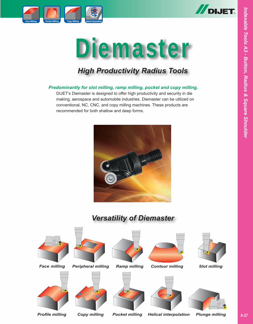
DiemasterHigh Productivity Radius Tools
Predominantly for slot milling, ramp milling, pocket and copy milling.DIJET’s Diemaster is designed to offer high productivity and security in diemaking, aerospace and automobile industries. Diemaster can be utilized onconventional, NC, CNC, and copy milling machines. These products arerecommended for both shallow and deep forms.
Versatility of Diemaster
®
A-27
Copy MillingPocket Milling Helical InterpolationFace Milling
Indexable Tools A3 - B
utton, Radius &
Square Shoulder
®
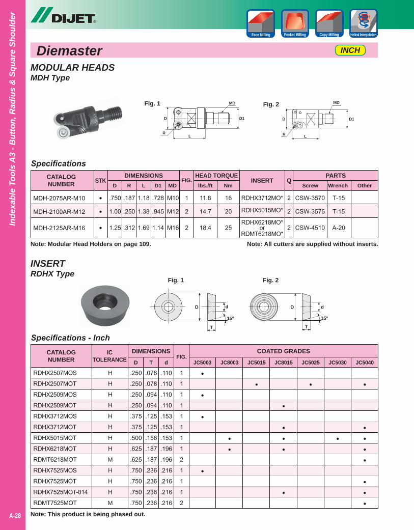
Diemaster INCH
Copy MillingPocket Milling Helical InterpolationFace Milling
A-28
Inde
xabl
e To
ols
A3
- But
ton,
Rad
ius
& S
quar
e Sh
ould
er
MODULAR HEADSMDH Type
Specifications
••
•
2
2
2
CSW-3570
CSW-3575
CSW-4510
T-15
T-15
A-20
RDHX3712MO*
RDHX5015MO*
RDHX6218MO*or
RDMT6218MO*
1
2
2
1.18
1.38
1.69
.750
1.00
1.25
.187
.250
.312
.728
.945
1.14
M10
M12
M16
CATALOGNUMBER D
PARTSScrew Wrench
STKR L D1 MD
FIG. INSERT
Note: All cutters are supplied without inserts.
OtherQ
MDH-2075AR-M10
MDH-2100AR-M12
MDH-2125AR-M16
DIMENSIONS
D
RL
D1
MDFig. 1
D
R L
D1
MDFig. 2
HEAD TORQUElbs./ft Nm
11.8
14.7
18.4
16
20
25
Note: Modular Head Holders on page 109.
INSERTRDHX Type
D
T
d
15º
D
T
d
15º
Fig. 1 Fig. 2
1
1
1
1
1
1
1
1
2
1
1
1
2
Specifications - Inch
.078
.078
.094
.094
.125
.125
.156
.187
.187
.236
.236
.236
.236
.250
.250
.250
.250
.375
.375
.500
.625
.625
.750
.750
.750
.750
.110
.110
.110
.110
.153
.153
.153
.196
.196
.216
.216
.216
.216
CATALOGNUMBER
COATED GRADES
JC5003 JC8003 JC5015 JC8015 JC5025 JC5030 JC5040D T dFIG.
RDHX2507MOS
RDHX2507MOT
RDHX2509MOS
RDHX2509MOT
RDHX3712MOS
RDHX3712MOT
RDHX5015MOT
RDHX6218MOT
RDMT6218MOT
RDHX7525MOS
RDHX7525MOT
RDHX7525MOT-014
RDMT7525MOT
DIMENSIONSICTOLERANCE
H
H
H
H
H
H
H
H
M
H
H
H
M
•
•
•
•
••
•
•
•••
•
•
•
•
••••
•••
Note: This product is being phased out.
®
A-29
Indexable Tools A3 - B
utton, Radius &
Square Shoulder
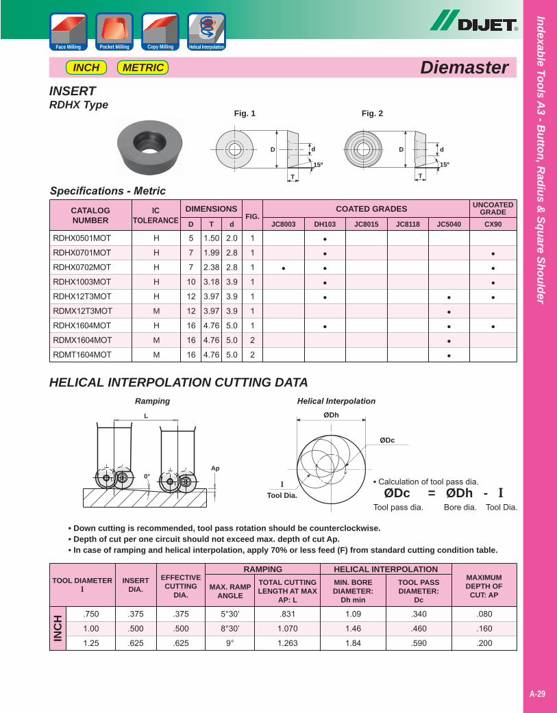
DiemasterMETRICINCH
HELICAL INTERPOLATION CUTTING DATA
TOOL DIAMETERI
RAMPING
.750
1.00
1.25
.375
.500
.625INC
H
INSERTDIA.
EFFECTIVECUTTING
DIA.MAX. RAMP
ANGLE
.375
.500
.625
5°30’
8°30’
9°
TOTAL CUTTINGLENGTH AT MAX
AP: L
.831
1.070
1.263
HELICAL INTERPOLATIONMIN. BOREDIAMETER:
Dh min
1.09
1.46
1.84
TOOL PASSDIAMETER:
Dc
.340
.460
.590
MAXIMUMDEPTH OF
CUT: AP
.080
.160
.200
• Down cutting is recommended, tool pass rotation should be counterclockwise.• Depth of cut per one circuit should not exceed max. depth of cut Ap.• In case of ramping and helical interpolation, apply 70% or less feed (F) from standard cutting condition table.
ØDh
ØDc
I
Tool Dia.
• Calculation of tool pass dia. ØDc = ØDh - ITool pass dia. Bore dia. Tool Dia.
Ramping Helical InterpolationL
Ap0°
Copy MillingPocket Milling Helical InterpolationFace Milling
INSERTRDHX Type
D
T
d
15º
D
T
d
15º
Fig. 1 Fig. 2
1
1
1
1
1
1
1
2
2
Specifications - Metric
1.50
1.99
2.38
3.18
3.97
3.97
4.76
4.76
4.76
5
7
7
10
12
12
16
16
16
2.0
2.8
2.8
3.9
3.9
3.9
5.0
5.0
5.0
CATALOGNUMBER
COATED GRADES
JC8003 DH103 JC8015 JC8118 JC5040 CX90D T dFIG.
RDHX0501MOT
RDHX0701MOT
RDHX0702MOT
RDHX1003MOT
RDHX12T3MOT
RDMX12T3MOT
RDHX1604MOT
RDMX1604MOT
RDMT1604MOT
DIMENSIONSICTOLERANCE
H
H
H
H
H
M
H
M
M
•
•••••
•
•••••
••••
•
UNCOATEDGRADE
®
INCH
Copy MillingPocket Milling Helical InterpolationFace Milling
A-30
Inde
xabl
e To
ols
A3
- But
ton,
Rad
ius
& S
quar
e Sh
ould
er
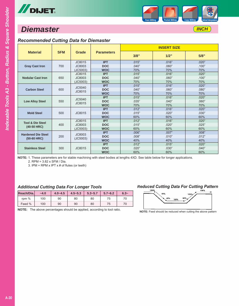
NOTE: 1. These parameters are for stable machining with steel bodies at lengths 4XD. See table below for longer applications.2. RPM = 3.82 x SFM / Dia.3. IPM = RPM x IPT x # of flutes (or teeth)
Reduced Cutting Data For Cutting Pattern
NOTE: Feed should be reduced when cutting the above patternNOTE: The above percentages should be applied, according to tool ratio.
Additional Cutting Data For Longer Tools
rpm %
Feed %
100
100
90
90
80
90
80
80
75
75
70
70
Reach/Dia. ~4.0 4.0~4.5 4.5~5.3 5.3~5.7 5.7~6.2 6.3~
Recommended Cutting Data for Diemaster
Gray Cast Iron
Nodular Cast Iron
Carbon Steel
Low Alloy Steel
Mold Steel
Tool & Die Steel(40-50 HRC)
Hardened Die Steel(50-60 HRC)
Stainless Steel
Material SFMINSERT SIZE
Parameters3/8” 1/2” 5/8”
700
650
600
550
500
400
200
300
IPTDOCWOCIPT
DOCWOCIPT
DOCWOCIPT
DOCWOCIPT
DOCWOCIPT
DOCWOCIPT
DOCWOCIPT
DOCWOC
.020”
.100”70%.020”.100”70%.020”.080”70%.020”.060”70%.020”.030”60%.020”.025”60%.008”.012”40%.020”.040”60%
.016”
.060”70%.016”.060”70%.016”.060”70%.016”.040”70%.016”.020”60%.016”.020”60%.007”.010”40%.015”.030”60%
.015”
.040”70%.015”.040”70%.015”.040”70%.015”.035”70%.012”.015”60%.012”.015”60%.006”.008”40%.012”.020”60%
Diemaster
Grade
JC8015JC8003
(JC5003)JC8015JC8003
(JC5003)
JC5040JC8015
JC5040JC8015
JC8015
JC8015JC8003
(JC5003)
JC8003(JC5003)
JC8015
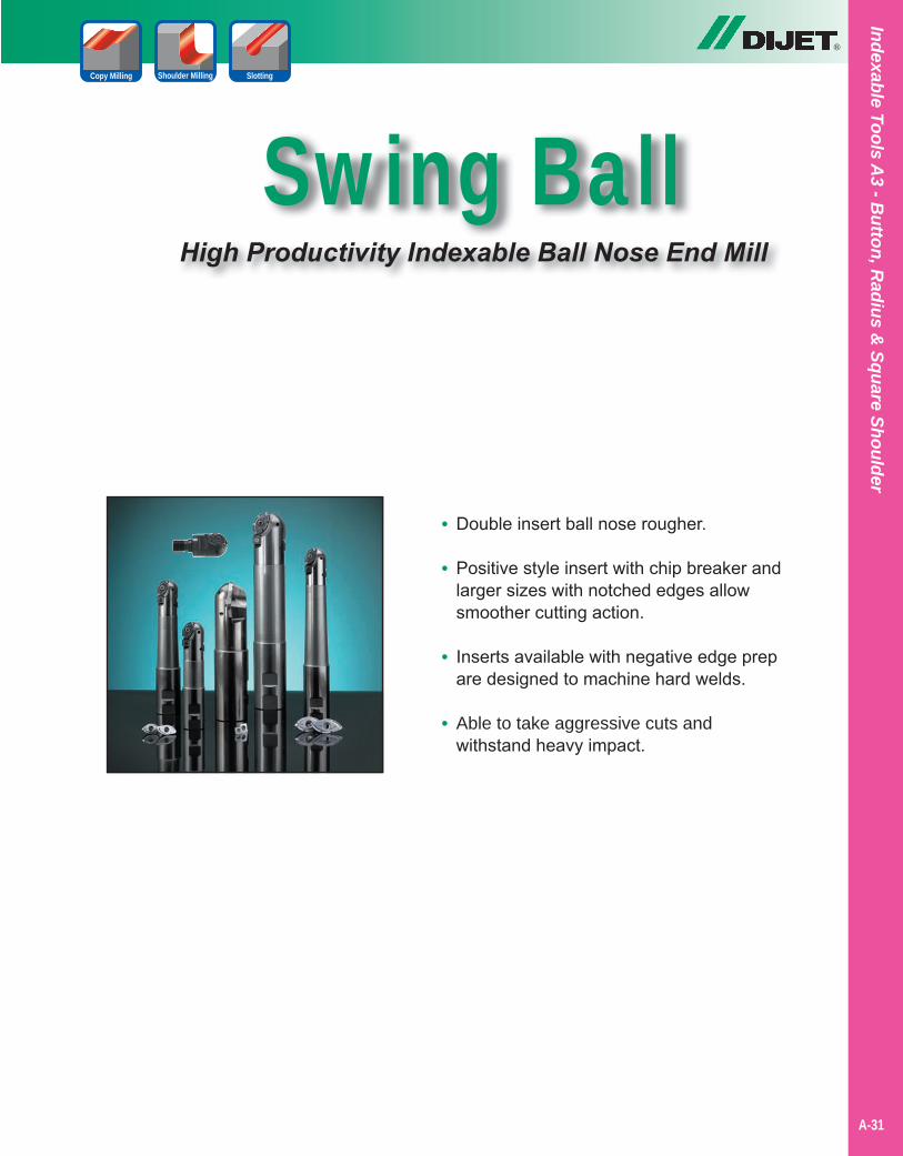
Swing BallHigh Productivity Indexable Ball Nose End Mill
®
Shoulder Milling SlottingCopy Milling
A-31
Indexable Tools A3 - B
utton, Radius &
Square Shoulder
• Double insert ball nose rougher.
• Positive style insert with chip breaker and larger sizes with notched edges allow smoother cutting action.
• Inserts available with negative edge prep are designed to machine hard welds.
• Able to take aggressive cuts and withstand heavy impact.
Swing Ball METRICINCH
®
A-32
Inde
xabl
e To
ols
A3
- But
ton,
Rad
ius
& S
quar
e Sh
ould
er
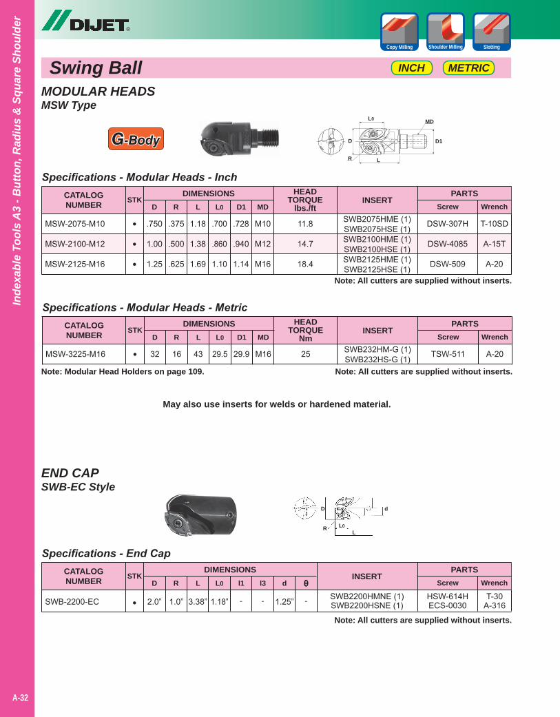
Shoulder Milling SlottingCopy Milling
SWB2200HMNE (1)SWB2200HSNE (1)
Specifications - End Cap
3.38”2.0” 1.0” 1.18” - -
CATALOGNUMBER
DIMENSIONSD
SWB-2200-EC
PARTSScrew WrenchR L L0 l1 l3
INSERT
HSW-614HECS-0030
STK
• 1.25”
d
-
θ
Note: All cutters are supplied without inserts.
T-30A-316
SWB2075HME (1)SWB2075HSE (1)SWB2100HME (1)SWB2100HSE (1)SWB2125HME (1)SWB2125HSE (1)
Specifications - Modular Heads - Inch
1.18
1.38
1.69
.750
1.00
1.25
.375
.500
.625
.700
.860
1.10
.728
.940
1.14
M10
M12
M16
CATALOGNUMBER
DIMENSIONSD
MSW-2075-M10
MSW-2100-M12
MSW-2125-M16
PARTSScrew WrenchR L L0 D1 MD
INSERT
DSW-307H
DSW-4085
DSW-509
STK
•
•
•Note: All cutters are supplied without inserts.
T-10SD
A-15T
A-20
HEADTORQUE
lbs./ft
11.8
14.7
18.4
SWB232HM-G (1)SWB232HS-G (1)
Specifications - Modular Heads - Metric
4332 16 29.5 29.9 M16
CATALOGNUMBER
DIMENSIONSD
MSW-3225-M16
PARTSScrew WrenchR L L0 D1 MD
INSERT
TSW-511
STK
• A-20
HEADTORQUE
Nm
25
Note: All cutters are supplied without inserts.
May also use inserts for welds or hardened material.
D
L0
d
LR
D
R L
L0
D1
MD
MODULAR HEADSMSW Type
END CAPSWB-EC Style
G-Body
Note: Modular Head Holders on page 109.
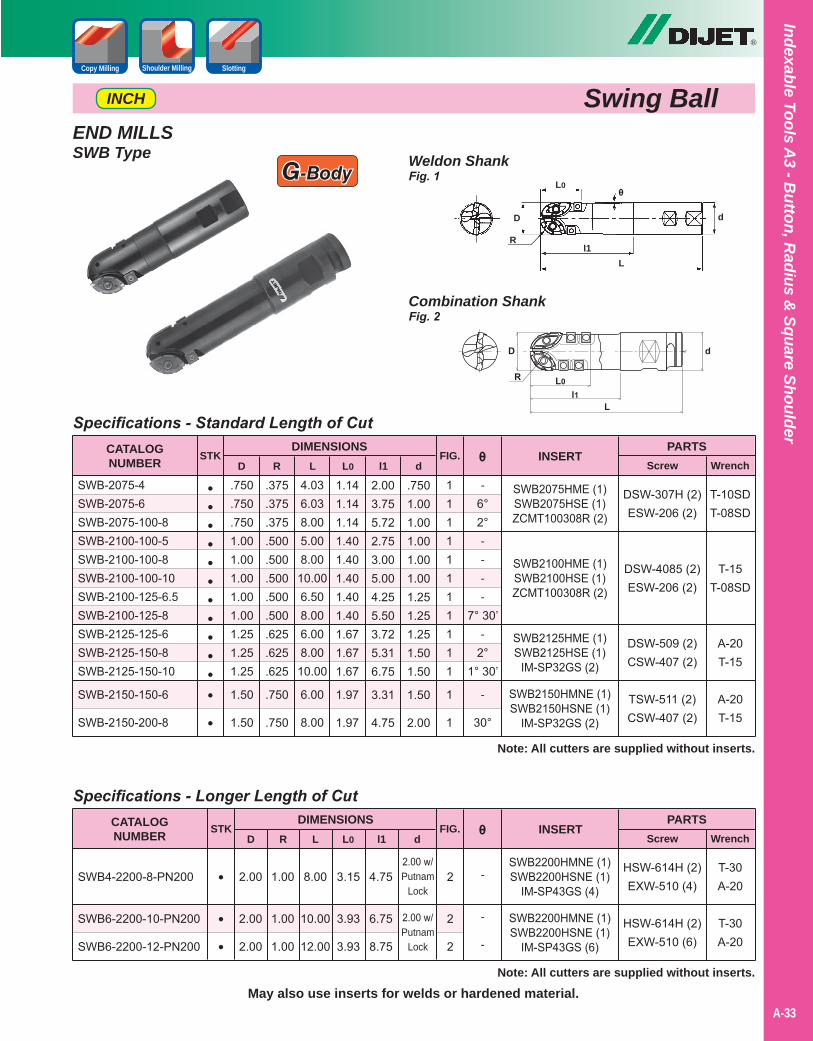
END MILLSSWB Type
Swing BallINCH
SWB2075HME (1)SWB2075HSE (1)ZCMT100308R (2)
SWB2100HME (1)SWB2100HSE (1)ZCMT100308R (2)
SWB2125HME (1)SWB2125HSE (1)
IM-SP32GS (2)
SWB2150HMNE (1)SWB2150HSNE (1)
IM-SP32GS (2)
T-10SDT-08SD
T-15T-08SD
A-20T-15
A-20T-15
11111111111
1
1
Specifications - Standard Length of Cut
4.036.038.005.008.0010.006.508.006.008.0010.00
6.00
8.00
.750
.750
.7501.001.001.001.001.001.251.251.25
1.50
1.50
.375
.375
.375
.500
.500
.500
.500
.500
.625
.625
.625
.750
.750
1.141.141.141.401.401.401.401.401.671.671.67
1.97
1.97
2.003.755.722.753.005.004.255.503.725.316.75
3.31
4.75
.7501.001.001.001.001.001.251.251.251.501.50
1.50
2.00
CATALOGNUMBER
DIMENSIONSD
SWB-2075-4SWB-2075-6SWB-2075-100-8SWB-2100-100-5SWB-2100-100-8SWB-2100-100-10SWB-2100-125-6.5SWB-2100-125-8SWB-2125-125-6SWB-2125-150-8SWB-2125-150-10
SWB-2150-150-6
SWB-2150-200-8
PARTSScrew WrenchR L L0 l1 d
FIG. INSERT
DSW-307H (2)ESW-206 (2)
DSW-4085 (2)ESW-206 (2)
DSW-509 (2)CSW-407 (2)
TSW-511 (2)CSW-407 (2)
θ
-6°2°----
7° 30’-
2°1° 30’
-
30°
SWB2200HMNE (1)SWB2200HSNE (1)
IM-SP43GS (4)
SWB2200HMNE (1)SWB2200HSNE (1)
IM-SP43GS (6)
Note: All cutters are supplied without inserts.May also use inserts for welds or hardened material.
T-30A-20
T-30A-20
2
2
2
Specifications - Longer Length of Cut
8.00
10.00
12.00
2.00
2.00
2.00
1.00
1.00
1.00
3.15
3.93
3.93
4.75
6.75
8.75
2.00 w/Putnam
Lock
2.00 w/Putnam
Lock
CATALOGNUMBER
DIMENSIONSD
SWB4-2200-8-PN200
SWB6-2200-10-PN200
SWB6-2200-12-PN200
PARTSScrew WrenchR L L0 l1 d
FIG. INSERT
HSW-614H (2)EXW-510 (4)
HSW-614H (2)EXW-510 (6)
θ
-
-
-
STK
••••••••••••
•
STK
•
•
•
Combination ShankFig. 2
Weldon ShankFig. 1
D
R
L
L0
l1
d
θ
Note: All cutters are supplied without inserts.
®
Shoulder Milling SlottingCopy Milling
A-33
Indexable Tools A3 - B
utton, Radius &
Square Shoulder
G-Body
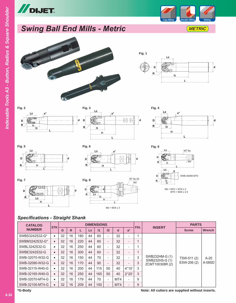
SWB232HM-G (1)SWB232HS-G (1)ZCMT100308R (2)
1111333399
Specifications - Straight Shank
32323232323232323232
16161616161616161616
180220250300150170200250179209
44444444444444444444
60606060709011516570100
------
5050--
3232323232324040
MT4MT4
------
4°10’2°20’
--
CATALOGNUMBER
DIMENSIONSD R L L0 l1 l3 d a°
SWBS3242S32-G*SWBM3242S32-G*SWBL3242S32-GSWBE3242S32-GSWB-32070-W32-GSWB-32090-W32-GSWB-32115-W40-GSWB-32165-W40-GSWB-32070-MT4-GSWB-32100-MT4-G
PARTSScrew Wrench
FIG. INSERTSTK
••••••••••
Note: All cutters are supplied without inserts.*G-Body
TSW-511 (2)ESW-206 (2)
A-20A-08SD
Swing Ball End Mills - Metric METRIC
®
A-34
Inde
xabl
e To
ols
A3
- But
ton,
Rad
ius
& S
quar
e Sh
ould
er
Shoulder Milling SlottingCopy Milling
D
R
L
L0
d
l1
Fig. 1
Fig. 3 Fig. 4
Fig. 6 Fig. 9
Fig. 8
Fig. 2
Fig. 5
Fig. 7 BT No.50Md
MT No.
Md
SWB-40090-MT5
Md = MT4 = M16 x 2 MT5 = M20 x 2.5
Md = M24 x 3
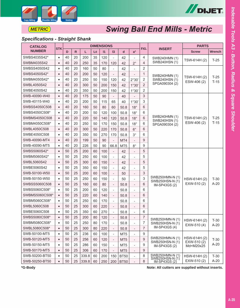
Swing Ball End Mills - Metric
SWB240HMN (1)SWB240HSN (1)
SWB240HMN (1)SWB240HSN (1)SPGA090304 (2)
SWB240HMN (1)SWB240HSN (1)SPGA090304 (2)
SWB250HMN-N (1)SWB250HSN-N (1)
IM-SP43GS (2)
SWB250HMN-N (1)SWB250HSN-N (1)
IM-SP43GS (4)
SWB250HMN-N (1)SWB250HSN-N (1)
IM-SP43GS (2)
SWB250HMN-N (1)SWB250HSN-N (1)
IM-SP43GS (2)
44212223366666699555533666666777999 988
Specifications - Straight Shank
4040404040404040404040404040404040505050505050505050505050505050505050505050
2020202020202020202020202020202020252525252525252525252525252525252525252525
200250160200250300350175200160200220250300350199226200250300350200250160200220250300350200250300236256286306
339.8339.8
35355050 50505050505050505050505050606060606060606060606060808080606060606060
12017080
1201502002009011580
1201401702202709090
10010015015010015080
120140170220270120170220100120150170200250
-120
--
120150150
-6560
100120150170170
-66.8
-------------------
150200
424242424242424040
50.850.850.850.850.850.8MT4MT5424242425050
50.850.850.850.850.850.850.850.850.8MT5MT5MT5MT5BT50BT50
-2°--
2°30’1°30’1°30’
-1°30’18°18°18°18°6°3°-
8°---------------------
CATALOGNUMBER
DIMENSIONSD R L L0 l1 l3 d a°
SWBS4035S42*SWBM4035S42SWBSS4050S42SWBS4050S42*SWBM4050S42*SWBL4050S42SWBE4050S42SWB-40090-W40SWB-40115-W40SWBSS4050C508SWBS4050C508*SWBMS4050C508SWBM4050C508*SWBL4050C508SWBE4050C508SWB-40090-MT4SWB-40090-MT5SWBS5060S42*SWBM5060S42*SWBL5060S42SWBE5060S42SWB-50100-W50SWB-50150-W50SWBSS5060C508SWBS5060C508*SWBMS5060C508*SWBM5060C508*SWBL5060C508SWBE5060C508SWBS5080C508*SWBM5080C508*SWBL5080C508*SWB-50100-MT5SWB-50120-MT5SWB-50150-MT5SWB-50170-MT5SWB-50200-BT50SWB-50250-BT50
PARTSScrew Wrench
FIG. INSERT
TSW-614H (2)
TSW-614H (2)ESW-406 (2)
TSW-614H (2)ESW-406 (2)
HSW-614H (2)EXW-510 (2)
HSW-614H (2)EXW-510 (4)
HSW-614H (2)EXW-510 (2)Md=M20x25
HSW-614H (2)EXW-510 (2)
STK
••••••••••••••••••••••••••••••••••••••
Note: All cutters are supplied without inserts.
®
Shoulder Milling SlottingCopy Milling
A-35
Indexable Tools A3 - B
utton, Radius &
Square Shoulder
METRIC
*G-Body
T-25
T-25T-15
T-25T-15
T-30A-20
T-30A-20
T-30A-20
T-30A-20
Swing Ball INCH
®
A-36
Inde
xabl
e To
ols
A3
- But
ton,
Rad
ius
& S
quar
e Sh
ould
er
Shoulder Milling SlottingCopy Milling
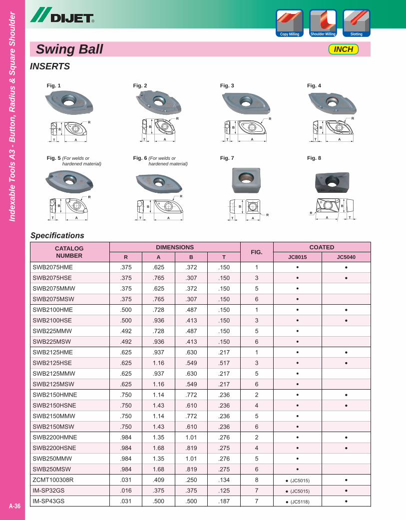
INSERTS
Specifications
.375
.375
.375
.375
.500
.500
.492
.492
.625
.625
.625
.625
.750
.750
.750
.750
.984
.984
.984
.984
.031
.016
.031
CATALOGNUMBER
DIMENSIONSR
SWB2075HME
SWB2075HSE
SWB2075MMW
SWB2075MSW
SWB2100HME
SWB2100HSE
SWB225MMW
SWB225MSW
SWB2125HME
SWB2125HSE
SWB2125MMW
SWB2125MSW
SWB2150HMNE
SWB2150HSNE
SWB2150MMW
SWB2150MSW
SWB2200HMNE
SWB2200HSNE
SWB250MMW
SWB250MSW
ZCMT100308R
IM-SP32GS
IM-SP43GS
.625
.765
.625
.765
.728
.936
.728
.936
.937
1.16
.937
1.16
1.14
1.43
1.14
1.43
1.35
1.68
1.35
1.68
.409
.375
.500
.372
.307
.372
.307
.487
.413
.487
.413
.630
.549
.630
.549
.772
.610
.772
.610
1.01
.819
1.01
.819
.250
.375
.500
.150
.150
.150
.150
.150
.150
.150
.150
.217
.517
.217
.217
.236
.236
.236
.236
.276
.275
.276
.275
.134
.125
.187
A B T
1
3
5
6
1
3
5
6
1
3
5
6
2
4
5
6
2
4
5
6
8
7
7
••••••••••••••••••••
• (JC5015)
• (JC5015)
• (JC5118)
FIG.JC8015 JC5040
••
••
••
••
••
•••
COATED
AT
R
B
Fig. 1 Fig. 2 Fig. 3 Fig. 4
Fig. 5 (For welds or hardened material)
Fig. 6 (For welds or hardened material)
Fig. 7 Fig. 8
AT
R
B
T A
R
B
T A
B
R
AT
R
B
AT
R
B
ATR
B
A TR
B
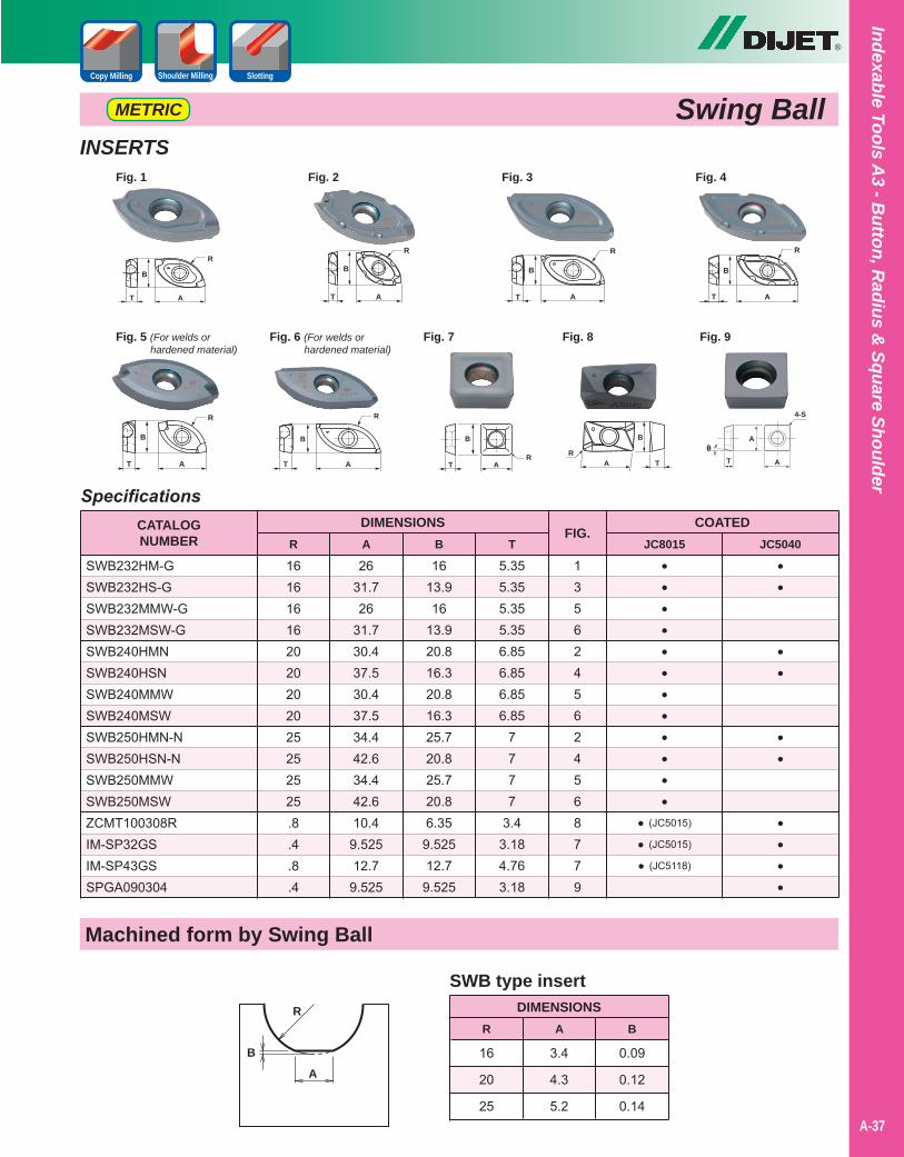
Fig. 5 (For welds or hardened material)
®
Swing BallShoulder Milling SlottingCopy Milling
METRIC
INSERTS
SpecificationsCATALOGNUMBER
DIMENSIONSR A B T
FIG.JC8015 JC5040
161616162020202025252525.8.4.8.4
SWB232HM-GSWB232HS-GSWB232MMW-GSWB232MSW-GSWB240HMNSWB240HSNSWB240MMWSWB240MSWSWB250HMN-NSWB250HSN-NSWB250MMWSWB250MSWZCMT100308RIM-SP32GSIM-SP43GSSPGA090304
2631.726
31.730.437.530.437.534.442.634.442.610.49.52512.79.525
1613.916
13.920.816.320.816.325.720.825.720.86.35
9.52512.7
9.525
5.355.355.355.356.856.856.856.85
7777
3.43.184.763.18
1356245624568779
••••••••••••
• (JC5015)
• (JC5015)
• (JC5118)
••
••
••
••••
COATED
AT
R
B
Fig. 1 Fig. 2 Fig. 3 Fig. 4
AT
R
B
T A
R
B
T A
B
R
AT
R
B
Fig. 6 (For welds or hardened material)
AT
R
B
Fig. 7
ATR
B
Fig. 8
A TR
B
T A
4-S
Aθ
Fig. 9
A-37
Indexable Tools A3 - B
utton, Radius &
Square Shoulder
R
AB
Machined form by Swing Ball
SWB type insert
16
20
25
DIMENSIONSR
3.4
4.3
5.2
0.09
0.12
0.14
A B

®
A-38
Inde
xabl
e To
ols
A3
- But
ton,
Rad
ius
& S
quar
e Sh
ould
er
NOTE: 1. These parameters are for stable machining with steel bodies at lengths 4XD. See table below for longer applications.2. RPM = 3.82 x SFM / Dia.3. IPM = RPM x IPT x # of flutes (or teeth)
Reduced Cutting Data For Cutting Pattern
NOTE: Feed should be reduced when cutting the above patternNOTE: The above percentages should be applied, according to tool ratio.
Additional Cutting Data For Longer Tools
rpm %
Feed %
100
100
90
90
80
90
80
80
75
75
70
70
Reach/Dia. ~4.0 4.0~4.5 4.5~5.3 5.3~5.7 5.7~6.2 6.3~
Recommended Cutting Data for Swing Ball
Gray Cast Iron
Nodular Cast Iron
Carbon Steel
Low Alloy Steel
Mold Steel
Tool & Die Steel(40-50 HRC)
Hardened DieSteel & Welds(50-60 HRC)
Stainless Steel
MaterialTool Diameter
Fig. 2Fig. 1Fig. 2Fig. 1SFMGradeInsert
700
650
600
550
500
400
200
300
JC8015
JC8015
JC5040
JC5040
JC5040
JC8015
JC8015
JC5040
Chipbreaker
Chipbreaker
Chipbreaker
Chipbreaker
Chipbreaker
Chipbreaker
MMW/MSW
Chipbreaker
3/4” 1”
Swing BallShoulder Milling SlottingCopy Milling
INCH
Parameters
No. 1Shoulder Cutting
No. 2Shoulder Cutting (Deep)
p d
pd
.005”
.800”
.120”
.005”
.800”
.120”
.004”
.800”
.120”
.004”
.800”
.120”
.004”
.600”
.100”
.004”
.250”
.060”N/AN/AN/AN/AN/AN/A
.008”
.240”
.200”
.008”
.240”
.200”
.007”
.240”
.200”
.007”
.240”
.200”
.006”
.200”
.120”
.005”
.120”
.160”
.003”
.120”
.120”
.005”
.120”
.160”
.005”
.625”
.080”
.005”
.625”
.080”
.004”
.625”
.080”
.004”
.625”
.080”
.004”
.500”
.080”
.004”
.200”
.060”N/AN/AN/AN/AN/AN/A
.008”
.200”
.160”
.007”
.200”
.160”
.006”
.200”
.160”
.006”
.200”
.160”
.006”
.160”
.100”
.005”
.080”
.120”
.003”
.080”
.120”
.004”
.080”
.120”
IPTDOC (d)WOC (p)
IPTDOC (d)WOC (p)
IPTDOC (d)WOC (p)
IPTDOC (d)WOC (p)
IPTDOC (d)WOC (p)
IPTDOC (d)WOC (p)
IPTDOC (d)WOC (p)
IPTDOC (d)WOC (p)
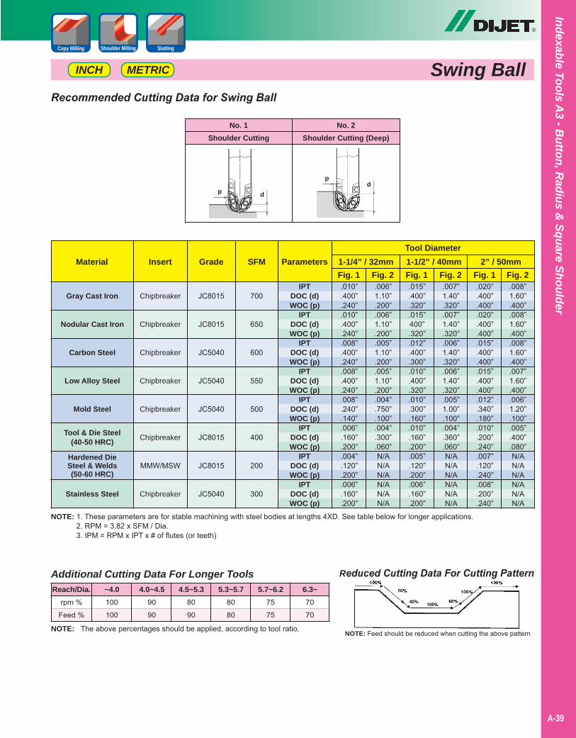
®
A-39
Indexable Tools A3 - B
utton, Radius &
Square Shoulder
Swing BallShoulder Milling SlottingCopy Milling
NOTE: 1. These parameters are for stable machining with steel bodies at lengths 4XD. See table below for longer applications.2. RPM = 3.82 x SFM / Dia.3. IPM = RPM x IPT x # of flutes (or teeth)
Reduced Cutting Data For Cutting Pattern
NOTE: Feed should be reduced when cutting the above patternNOTE: The above percentages should be applied, according to tool ratio.
Additional Cutting Data For Longer Tools
rpm %
Feed %
100
100
90
90
80
90
80
80
75
75
70
70
Reach/Dia. ~4.0 4.0~4.5 4.5~5.3 5.3~5.7 5.7~6.2 6.3~
Recommended Cutting Data for Swing Ball
Gray Cast Iron
Nodular Cast Iron
Carbon Steel
Low Alloy Steel
Mold Steel
Tool & Die Steel(40-50 HRC)
Hardened DieSteel & Welds(50-60 HRC)
Stainless Steel
MaterialTool Diameter
Fig. 2 Fig. 2 Fig. 2Fig. 1 Fig. 1 Fig. 1SFMGradeInsert
.010”
.400”
.240”
.010”
.400”
.240”
.008”
.400”
.240”
.008”
.400”
.240”
.008”
.240”
.140”
.006”
.160”
.200”
.004”
.120”
.200”
.006”
.160”
.200”
.006”1.10”.200”.006”1.10”.200”.005”1.10”.200”.005”1.10”.200”.004”.750”.100”.004”.300”.060”N/AN/AN/AN/AN/AN/A
.015”
.400”
.320”
.015”400”.320”.012”.400”.300”.010”.400”.320”.010”.300”.160”.010”.160”.200”.005”.120”.200”.006”.160”.200”
.007”1.40”.320”.007”1.40”.320”.006”1.40”.320”.006”1.40”.320”.005”1.00”.100”.004”.360”.060”N/AN/AN/AN/AN/AN/A
.020”
.400”
.400”
.020”
.400”
.400”
.015”
.400”
.400”
.015”
.400”
.400”
.012”
.340”
.180”
.010”
.200”
.240”
.007”
.120”
.240”
.008”
.200”
.240”
.008”1.60”.400”.008”1.60”.400”.008”1.60”.400”.007”1.60”.400”.006”1.20”.100”.005”.400”.080”N/AN/AN/AN/AN/AN/A
700
650
600
550
500
400
200
300
JC8015
JC8015
JC5040
JC5040
JC5040
JC8015
JC8015
JC5040
Chipbreaker
Chipbreaker
Chipbreaker
Chipbreaker
Chipbreaker
Chipbreaker
MMW/MSW
Chipbreaker
1-1/4” / 32mm 1-1/2” / 40mmParameters
IPTDOC (d)WOC (p)
IPTDOC (d)WOC (p)
IPTDOC (d)WOC (p)
IPTDOC (d)WOC (p)
IPTDOC (d)WOC (p)
IPTDOC (d)WOC (p)
IPTDOC (d)WOC (p)
IPTDOC (d)WOC (p)
No. 1Shoulder Cutting
No. 2Shoulder Cutting (Deep)
p d
pd
INCH
2” / 50mm
METRIC

Notes
A-40
®
A-40
Inde
xabl
e To
ols
A3
- But
ton,
Rad
ius
& S
quar
e Sh
ould
er

Swing Ball NeoBall Nose Rougher & Semi Finisher with Key
®
Shoulder Milling SlottingCopy Milling
A-41
Indexable Tools A3 - B
utton, Radius &
Square Shoulder
• High repeatability on insert mounting allows not only roughing but also semi-finishing.
• Unique key on body enables a stable roughing process & machining welded parts for 3D machining.
• New PVD coated grades; JC5240 for steel and JC8118 & JC8015 for cast iron, mold steel, welding & hardened die steel.
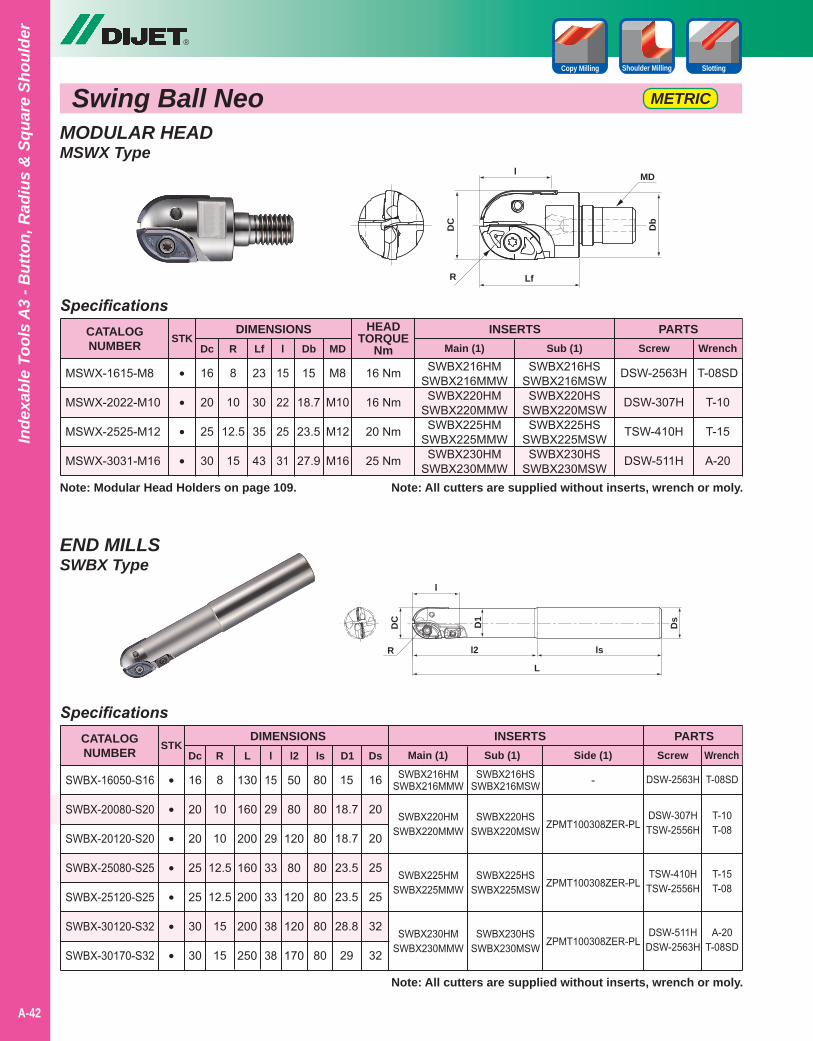
MODULAR HEADMSWX Type
END MILLSSWBX Type
Swing Ball Neo METRIC
SWBX216HMSWBX216MMWSWBX220HM
SWBX220MMWSWBX225HM
SWBX225MMWSWBX230HM
SWBX230MMW
SWBX216HSSWBX216MSW
SWBX220HSSWBX220MSW
SWBX225HSSWBX225MSW
SWBX230HSSWBX230MSW
SWBX216HSSWBX216MSWSWBX220HS
SWBX220MSWSWBX225HS
SWBX225MSWSWBX230HS
SWBX230MSW
Specifications
Specifications
23
30
35
43
130
160
200
160
200
200
250
16
20
25
30
16
20
20
25
25
30
30
8
10
12.5
15
8
10
10
12.5
12.5
15
15
15
22
25
31
15
29
29
33
33
38
38
15
18.7
23.5
27.9
50
80
120
80
120
120
170
M8
M10
M12
M16
80
80
80
80
80
80
80
15
18.7
18.7
23.5
23.5
28.8
29
16
20
20
25
25
32
32
CATALOGNUMBER
CATALOGNUMBER
DIMENSIONS
DIMENSIONS
Dc
Dc
MSWX-1615-M8
MSWX-2022-M10
MSWX-2525-M12
MSWX-3031-M16
SWBX-16050-S16
SWBX-20080-S20
SWBX-20120-S20
SWBX-25080-S25
SWBX-25120-S25
SWBX-30120-S32
SWBX-30170-S32
PARTS
PARTS
Screw
Screw
Wrench
Wrench
R
R
Lf
L
l
l
Db
l2
MD
ls D1 Ds
DSW-2563H
DSW-307H
TSW-410H
DSW-511H
STK
STK
•
•
•
•
•
•
•
•
•
•
•
Note: All cutters are supplied without inserts, wrench or moly.
Note: All cutters are supplied without inserts, wrench or moly.
T-08SD
T-10
T-15
A-20
T-08SD
T-10T-08
T-15T-08
A-20T-08SD
HEADTORQUE
Nm
16 Nm
16 Nm
20 Nm
25 Nm
®
A-42
Inde
xabl
e To
ols
A3
- But
ton,
Rad
ius
& S
quar
e Sh
ould
er
Shoulder Milling SlottingCopy Milling
INSERTS
INSERTS
Main (1)
Sub (1)
Sub (1)
Side (1)
Note: Modular Head Holders on page 109.
DSW-2563H
DSW-307HTSW-2556H
TSW-410HTSW-2556H
DSW-511HDSW-2563H
-
ZPMT100308ZER-PL
ZPMT100308ZER-PL
ZPMT100308ZER-PL
SWBX216HMSWBX216MMW
SWBX220HMSWBX220MMW
SWBX225HMSWBX225MMW
SWBX230HMSWBX230MMW
Main (1)
DC
R Lf
l
Db
MD
DC
R
L
l
D1
l2
Ds
ls
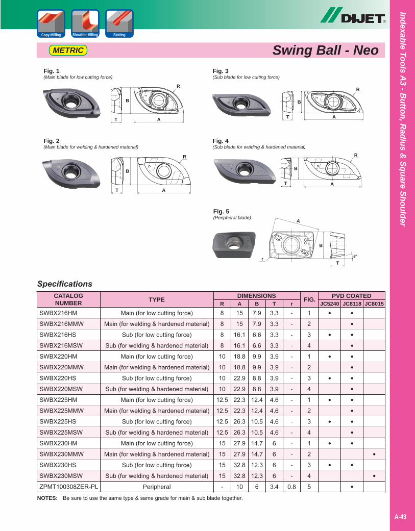
®
A-43
Indexable Tools A3 - B
utton, Radius &
Square Shoulder
Swing Ball - NeoMETRIC
Shoulder Milling SlottingCopy Milling
SpecificationsCATALOGNUMBER
DIMENSIONS
SWBX216HM
SWBX216MMW
SWBX216HS
SWBX216MSW
SWBX220HM
SWBX220MMW
SWBX220HS
SWBX220MSW
SWBX225HM
SWBX225MMW
SWBX225HS
SWBX225MSW
SWBX230HM
SWBX230MMW
SWBX230HS
SWBX230MSW
ZPMT100308ZER-PL
JC5240 JC8118 JC8015R A B T rPVD COATEDFIG.
1
2
3
4
1
2
3
4
1
2
3
4
1
2
3
4
5
Main (for low cutting force)
Main (for welding & hardened material)
Sub (for low cutting force)
Sub (for welding & hardened material)
Main (for low cutting force)
Main (for welding & hardened material)
Sub (for low cutting force)
Sub (for welding & hardened material)
Main (for low cutting force)
Main (for welding & hardened material)
Sub (for low cutting force)
Sub (for welding & hardened material)
Main (for low cutting force)
Main (for welding & hardened material)
Sub (for low cutting force)
Sub (for welding & hardened material)
Peripheral
•
•
•
•
•
•
•
•
•••••••••••••
•
•
•
•
8
8
8
8
10
10
10
10
12.5
12.5
12.5
12.5
15
15
15
15
-
15
15
16.1
16.1
18.8
18.8
22.9
22.9
22.3
22.3
26.3
26.3
27.9
27.9
32.8
32.8
10
7.9
7.9
6.6
6.6
9.9
9.9
8.8
8.8
12.4
12.4
10.5
10.5
14.7
14.7
12.3
12.3
6
3.3
3.3
3.3
3.3
3.9
3.9
3.9
3.9
4.6
4.6
4.6
4.6
6
6
6
6
3.4
-
-
-
-
-
-
-
-
-
-
-
-
-
-
-
-
0.8
TYPE
NOTES: Be sure to use the same type & same grade for main & sub blade together.
Fig. 2(Main blade for welding & hardened material)
T A
R
B
Fig. 1(Main blade for low cutting force)
T A
R
B
Fig. 4(Sub blade for welding & hardened material)
Fig. 3(Sub blade for low cutting force)
Fig. 5(Peripheral blade)
T A
R
B
T A
R
B
T
A
r
B
θ°
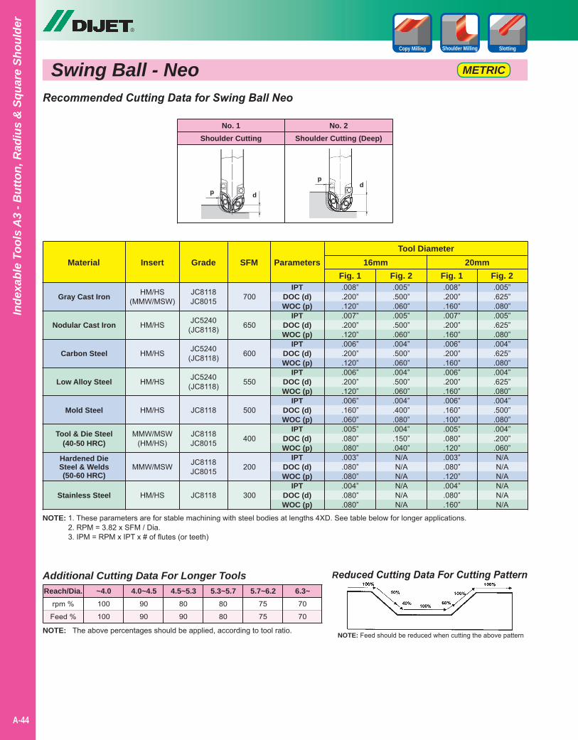
®
A-44
Inde
xabl
e To
ols
A3
- But
ton,
Rad
ius
& S
quar
e Sh
ould
er
NOTE: 1. These parameters are for stable machining with steel bodies at lengths 4XD. See table below for longer applications.2. RPM = 3.82 x SFM / Dia.3. IPM = RPM x IPT x # of flutes (or teeth)
Reduced Cutting Data For Cutting Pattern
NOTE: Feed should be reduced when cutting the above patternNOTE: The above percentages should be applied, according to tool ratio.
Additional Cutting Data For Longer Tools
rpm %
Feed %
100
100
90
90
80
90
80
80
75
75
70
70
Reach/Dia. ~4.0 4.0~4.5 4.5~5.3 5.3~5.7 5.7~6.2 6.3~
Recommended Cutting Data for Swing Ball Neo
Gray Cast Iron
Nodular Cast Iron
Carbon Steel
Low Alloy Steel
Mold Steel
Tool & Die Steel(40-50 HRC)
Hardened DieSteel & Welds(50-60 HRC)
Stainless Steel
MaterialTool Diameter
Fig. 2Fig. 1Fig. 2Fig. 1SFMGradeInsert
700
650
600
550
500
400
200
300
JC8118JC8015
JC5240(JC8118)
JC5240(JC8118)
JC5240(JC8118)
JC8118
JC8118JC8015
JC8118JC8015
JC8118
HM/HS(MMW/MSW)
HM/HS
HM/HS
HM/HS
HM/HS
MMW/MSW(HM/HS)
MMW/MSW
HM/HS
16mm 20mm
Swing Ball - NeoShoulder Milling SlottingCopy Milling
Parameters
No. 1Shoulder Cutting
No. 2Shoulder Cutting (Deep)
p d
pd
.005”
.625”
.080”
.005”
.625”
.080”
.004”
.625”
.080”
.004”
.625”
.080”
.004”
.500”
.080”
.004”
.200”
.060”N/AN/AN/AN/AN/AN/A
.008”
.200”
.160”
.007”
.200”
.160”
.006”
.200”
.160”
.006”
.200”
.160”
.006”
.160”
.100”
.005”
.080”
.120”
.003”
.080”
.120”
.004”
.080”
.160”
.005”
.500”
.060”
.005”
.500”
.060”
.004”
.500”
.060”
.004”
.500”
.060”
.004”
.400”
.080”
.004”
.150”
.040”N/AN/AN/AN/AN/AN/A
.008”
.200”
.120”
.007”
.200”
.120”
.006”
.200”
.120”
.006”
.200”
.120”
.006”
.160”
.060”
.005”
.080”
.080”
.003”
.080”
.080”
.004”
.080”
.080”
IPTDOC (d)WOC (p)
IPTDOC (d)WOC (p)
IPTDOC (d)WOC (p)
IPTDOC (d)WOC (p)
IPTDOC (d)WOC (p)
IPTDOC (d)WOC (p)
IPTDOC (d)WOC (p)
IPTDOC (d)WOC (p)
METRIC
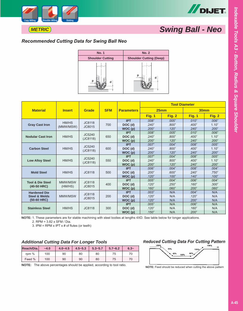
®
A-45
Indexable Tools A3 - B
utton, Radius &
Square Shoulder
Swing Ball - NeoShoulder Milling SlottingCopy Milling
NOTE: 1. These parameters are for stable machining with steel bodies at lengths 4XD. See table below for longer applications.2. RPM = 3.82 x SFM / Dia.3. IPM = RPM x IPT x # of flutes (or teeth)
Reduced Cutting Data For Cutting Pattern
NOTE: Feed should be reduced when cutting the above patternNOTE: The above percentages should be applied, according to tool ratio.
Additional Cutting Data For Longer Tools
rpm %
Feed %
100
100
90
90
80
90
80
80
75
75
70
70
Reach/Dia. ~4.0 4.0~4.5 4.5~5.3 5.3~5.7 5.7~6.2 6.3~
Recommended Cutting Data for Swing Ball Neo
Gray Cast Iron
Nodular Cast Iron
Carbon Steel
Low Alloy Steel
Mold Steel
Tool & Die Steel(40-50 HRC)
Hardened DieSteel & Welds(50-60 HRC)
Stainless Steel
MaterialTool Diameter
Fig. 2Fig. 1Fig. 2Fig. 1SFMGradeInsert
.006”1.10”.200”.006”1.10”.200”.005”1.10”.200”.005”1.10”.200”.004”.750”.100”.004”.300”.060”N/AN/AN/AN/AN/AN/A
.010”
.400”
.240”
.010”
.400”
.240”
.008”
.400”
.240”
.008”
.400”
.240”
.008”
.240”
.140”
.006”
.160”
.200”
.004”
.120”
.200”
.006”
.160”
.200”
.005”
.800”
.120”
.005”
.800”
.120”
.004”
.800”
.120”
.004”
.800”
.120”
.004”
.600”
.100”
.004”
.250”
.060”N/AN/AN/AN/AN/AN/A
.008”
.240”
.200”
.008”
.240”
.200”
.007”
.240”
.200”
.007”
.240”
.200”
.006”
.200”
.120”
.005”
.120”
.160”
.003”
.120”
.120”
.005”
.120”
.150”
700
650
600
550
500
400
200
300
JC8118JC8015
JC5240(JC8118)
JC5240(JC8118)
JC5240(JC8118)
JC8118
JC8118JC8015
JC8118JC8015
JC8118
HM/HS(MMW/MSW)
HM/HS
HM/HS
HM/HS
HM/HS
MMW/MSW(HM/HS)
MMW/MSW
HM/HS
25mm 30mmParameters
IPTDOC (d)WOC (p)
IPTDOC (d)WOC (p)
IPTDOC (d)WOC (p)
IPTDOC (d)WOC (p)
IPTDOC (d)WOC (p)
IPTDOC (d)WOC (p)
IPTDOC (d)WOC (p)
IPTDOC (d)WOC (p)
No. 1Shoulder Cutting
No. 2Shoulder Cutting (Deep)
p d
pd
METRIC

Notes
A-40
®
A-46
Inde
xabl
e To
ols
A3
- But
ton,
Rad
ius
& S
quar
e Sh
ould
er

Swing Ball - KBall Nose Rougher with Insert Key
®
Shoulder Milling SlottingCopy Milling
A-47
Indexable Tools A3 - B
utton, Radius &
Square Shoulder
• All the same features as our standard Swing Ball - plus keys.
• The key on the body provides a locked secured fit.
• Key gives added security for stable roughing and machining of welded parts.
• High repeatability on insert mounting.
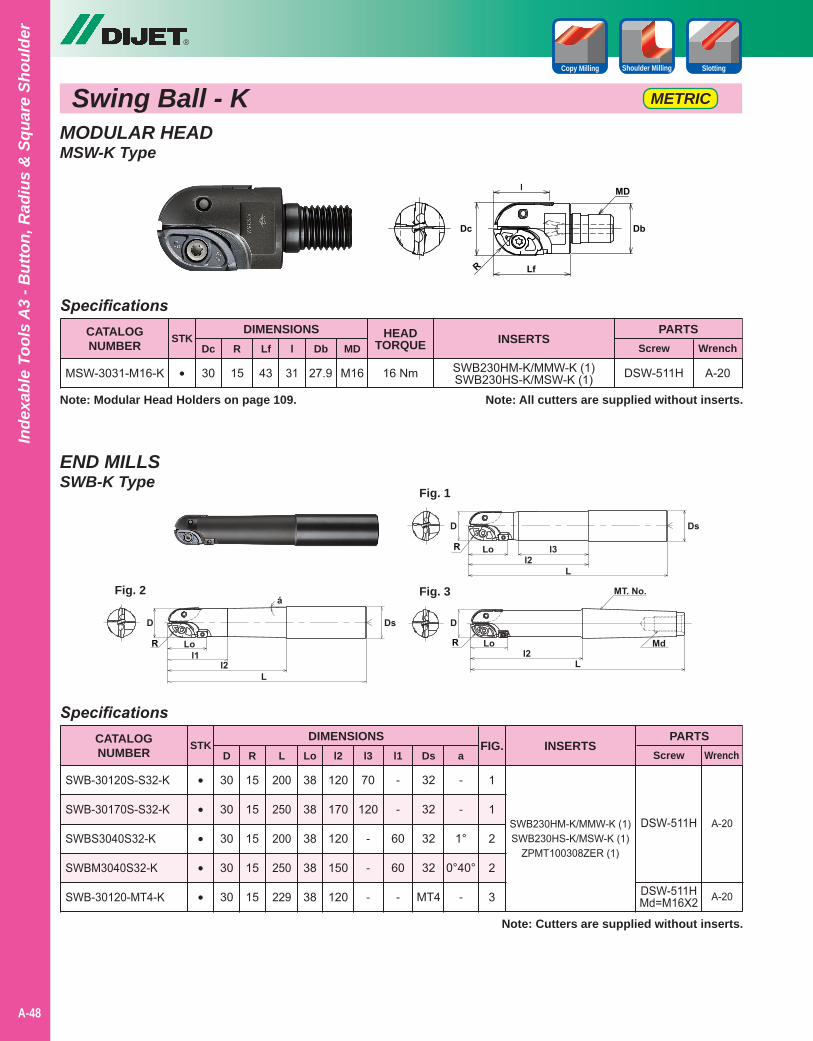
MODULAR HEADMSW-K Type
END MILLSSWB-K Type
Swing Ball - K METRIC
SWB230HM-K/MMW-K (1)SWB230HS-K/MSW-K (1)
Specifications
Specifications
43
15
15
15
15
15
30 15
30
30
30
30
30
31
200
250
200
250
229
27.9
38
38
38
38
38
M16
120
170
120
150
120
70
120
-
-
-
-
-
60
60
-
32
32
32
32
MT4
-
-
1°
0°40°
-
CATALOGNUMBER
CATALOGNUMBER
DIMENSIONS
DIMENSIONS
Dc
MSW-3031-M16-K
SWB-30120S-S32-K
SWB-30170S-S32-K
SWBS3040S32-K
SWBM3040S32-K
SWB-30120-MT4-K
PARTS
PARTS
Screw
Screw
Wrench
Wrench
R
D
Lf
R
l
L
Db
Lo
MD
l2 l3 l1 Ds a
DSW-511H
STK
STK
•
•
•
•
•
•
Note: All cutters are supplied without inserts.
Note: Cutters are supplied without inserts.
A-20
HEADTORQUE
16 Nm
®
A-48
Inde
xabl
e To
ols
A3
- But
ton,
Rad
ius
& S
quar
e Sh
ould
er
Shoulder Milling SlottingCopy Milling
INSERTS
INSERTS
Note: Modular Head Holders on page 109.
DSW-511H
DSW-511HMd=M16X2
SWB230HM-K/MMW-K (1)SWB230HS-K/MSW-K (1)
ZPMT100308ZER (1)
FIG.
1
1
2
2
3
A-20
A-20
Fig. 1
Fig. 3Fig. 2
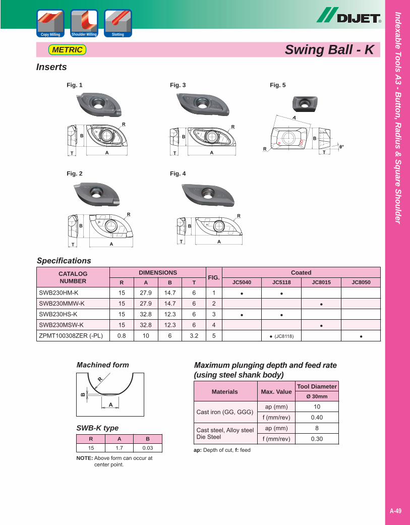
®
A-49
Indexable Tools A3 - B
utton, Radius &
Square Shoulder
Swing Ball - KMETRIC
Inserts
Specifications
15
15
15
15
0.8
27.9
27.9
32.8
32.8
10
14.7
14.7
12.3
12.3
6
6
6
6
6
3.2
CATALOGNUMBER
DIMENSIONS
SWB230HM-K
SWB230MMW-K
SWB230HS-K
SWB230MSW-K
ZPMT100308ZER (-PL)
CoatedJC5040 JC5118 JC8015 JC8050
FIG.
1
2
3
4
5
R A B T
•
•
•
•
• (JC8118)
•
••
Shoulder Milling SlottingCopy Milling
Fig. 1 Fig. 3 Fig. 5
Fig. 2 Fig. 4
NOTE: Above form can occur at center point.
SWB-K type
15 1.7 0.03
R A B
Maximum plunging depth and feed rate(using steel shank body)
ap (mm)
f (mm/rev)
ap (mm)
f (mm/rev)
10
0.40
8
0.30
Materials
Cast iron (GG, GGG)
Cast steel, Alloy steelDie Steel
Ø 30mm
Tool Diameter
Machined form
Max. Value
ap: Depth of cut, f: feed
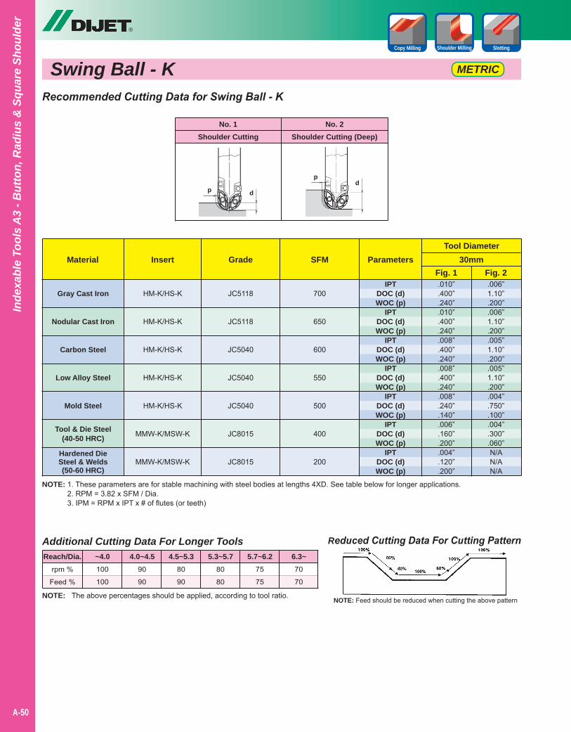
®
A-50
Inde
xabl
e To
ols
A3
- But
ton,
Rad
ius
& S
quar
e Sh
ould
er
NOTE: 1. These parameters are for stable machining with steel bodies at lengths 4XD. See table below for longer applications.2. RPM = 3.82 x SFM / Dia.3. IPM = RPM x IPT x # of flutes (or teeth)
Reduced Cutting Data For Cutting Pattern
NOTE: Feed should be reduced when cutting the above patternNOTE: The above percentages should be applied, according to tool ratio.
Additional Cutting Data For Longer Tools
rpm %
Feed %
100
100
90
90
80
90
80
80
75
75
70
70
Reach/Dia. ~4.0 4.0~4.5 4.5~5.3 5.3~5.7 5.7~6.2 6.3~
Recommended Cutting Data for Swing Ball - K
Gray Cast Iron
Nodular Cast Iron
Carbon Steel
Low Alloy Steel
Mold Steel
Tool & Die Steel(40-50 HRC)
Hardened DieSteel & Welds(50-60 HRC)
MaterialTool Diameter
Fig. 2SFMGradeInsert
.006”1.10”.200”.006”1.10”.200”.005”1.10”.200”.005”1.10”.200”.004”.750”.100”.004”.300”.060”N/AN/AN/A
.010”
.400”
.240”
.010”
.400”
.240”
.008”
.400”
.240”
.008”
.400”
.240”
.008”
.240”
.140”
.006”
.160”
.200”
.004”
.120”
.200”
JC5118
JC5118
JC5040
JC5040
JC5040
JC8015
JC8015
HM-K/HS-K
HM-K/HS-K
HM-K/HS-K
HM-K/HS-K
HM-K/HS-K
MMW-K/MSW-K
MMW-K/MSW-K
30mm
Swing Ball - K
Parameters
IPTDOC (d)WOC (p)
IPTDOC (d)WOC (p)
IPTDOC (d)WOC (p)
IPTDOC (d)WOC (p)
IPTDOC (d)WOC (p)
IPTDOC (d)WOC (p)
IPTDOC (d)WOC (p)
No. 1Shoulder Cutting
No. 2Shoulder Cutting (Deep)
p d
pd
Shoulder Milling SlottingCopy Milling
700
650
600
550
500
400
200
Fig. 1
METRIC

Wild RadiusRadius Cutter for High Efficient Roughing Applications
®
Indexable Tools A3 - B
utton, Radius &
Square Shoulder
• High body durability when compared to conventional ball nose preventing chatter.
• Improved machining efficiency with larger step over and 10mm corner radius.
• Key gives added security allowing stable machining and ease of changing insert corner.
• High repeatability on insert mounting.
Shoulder Milling Pocket Milling Copy Milling Helical InterpolationFace Milling
A-51
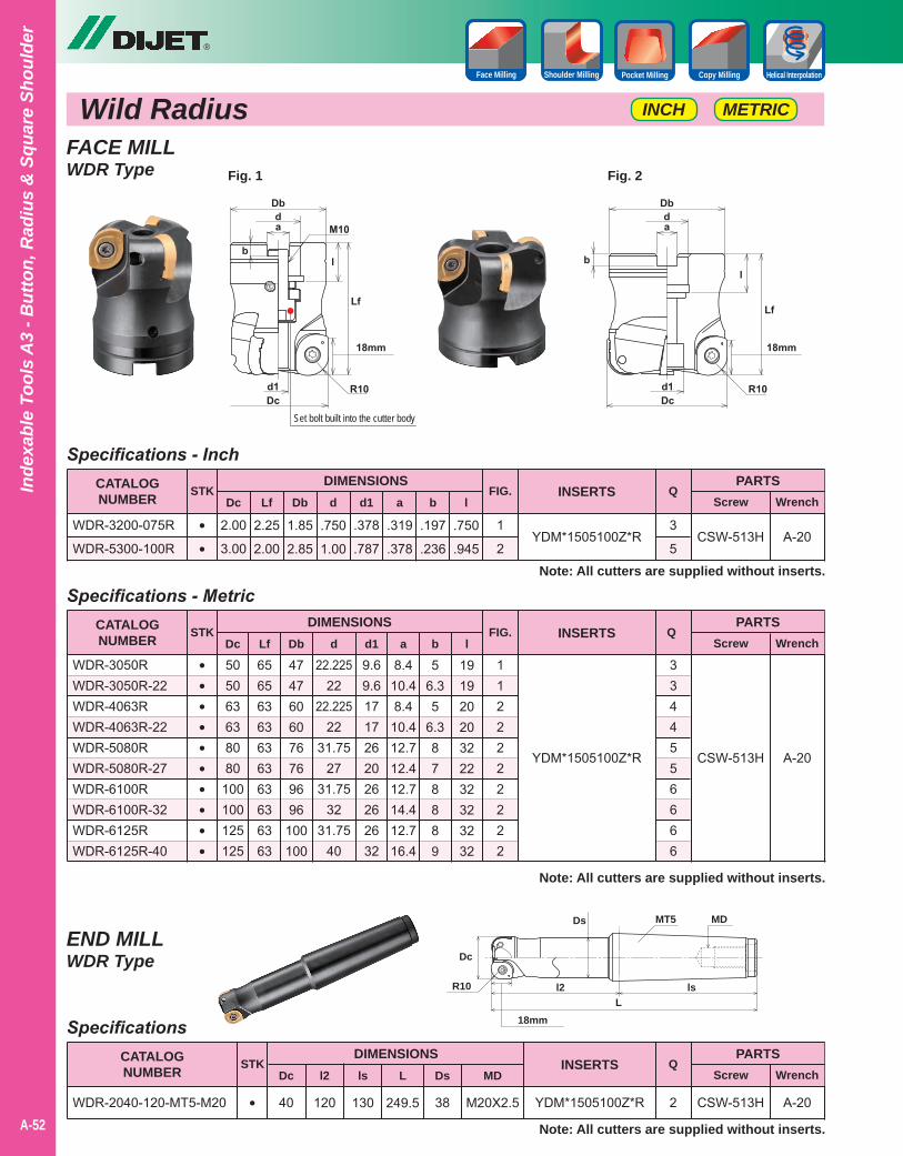
FACE MILLWDR Type
END MILLWDR Type
Wild Radius
YDM*1505100Z*R
YDM*1505100Z*R
YDM*1505100Z*R
Specifications - Inch
Specifications
Specifications - Metric
2.00
3.00
40
505063638080100100125125
2.25
2.00
120
65656363636363636363
1.85
2.85
130
4747606076769696100100
.750
1.00
249.5
22.22522
22.22522
31.7527
31.7532
31.7540
.378
.787
38
9.69.61717262026262632
.319
.378
M20X2.5
8.410.48.4
10.412.712.412.714.412.716.4
.197
.236
56.35
6.3878889
.750
.945
19192020322232323232
CATALOGNUMBER
CATALOGNUMBER
CATALOGNUMBER
DIMENSIONS
DIMENSIONS
DIMENSIONS
Dc
Dc
Dc
Lf
l2
Lf
Db
ls
Db
d
L
d
d1
Ds
d1
a
MD
a
b
b
l
l
WDR-3200-075R
WDR-5300-100R
WDR-2040-120-MT5-M20
WDR-3050RWDR-3050R-22WDR-4063RWDR-4063R-22WDR-5080RWDR-5080R-27WDR-6100RWDR-6100R-32WDR-6125RWDR-6125R-40
PARTS
PARTS
PARTS
Screw
Screw
Screw
Wrench
Wrench
Wrench
CSW-513H
CSW-513H
CSW-513H
STK
STK
STK
••
•
••••••••••
Note: All cutters are supplied without inserts.
Note: All cutters are supplied without inserts.
Note: All cutters are supplied without inserts.
A-20
A-20
A-20
®
A-52
Inde
xabl
e To
ols
A3
- But
ton,
Rad
ius
& S
quar
e Sh
ould
er
INSERTS
INSERTS
INSERTS
METRICINCH
Shoulder Milling Pocket Milling Copy Milling Helical InterpolationFace Milling
FIG.
FIG.
1
2
1122222222
Q
Q
Q
3
5
2
Fig. 1 Fig. 2
3344556666
Dc
l2 lsL
MT5 MD
R10
Ds
18mm
Set bolt built into the cutter body
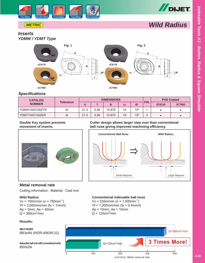
®
Indexable Tools A3 - B
utton, Radius &
Square Shoulder
Shoulder Milling Pocket Milling Copy Milling Helical InterpolationFace Milling
A-53
Wild RadiusMETRIC
Specifications
5.56
5.56
15.875
15.875
10
10
15º
15º
CATALOGNUMBER
DIMENSIONS
YDMW1505100ZTR
YDMT1505100ZER
PVD CoatedJC8118 JC7560
FIG.
1
2
A T B rƐ غ
••
••
InsertsYDMW / YDMT Type
Tolerance
21.5
21.5
M
M
Fig. 1 Fig. 2
Small Stepover Large Stepover
Conventional Ball Nose Wild Radius
Cutter design allows larger step over than conventionalball nose giving improved machining efficiency.
Double Key system preventsmovement of inserts.
Metal removal rateCutting information: Material - Cast Iron
Wild RadiusVc = 150m/min (n = 750min-1)Vf = 3,000mm/min (fz = 1mm/t)Ap = 3mm, Ae = 40mmQ = 360cm3/min
Results:
WILD RADIUSØ63x4N (WDR-4063R-22)
Indexable ball end mill (conventional tool)Ø50x2N
Conventional indexable ball noseVc = 235m/min (n = 1,500min-1)Vf = 1,200mm/min (fz = 0.4mm/t)Ap = 10mm, Ae = 10mmQ = 120cm3/min
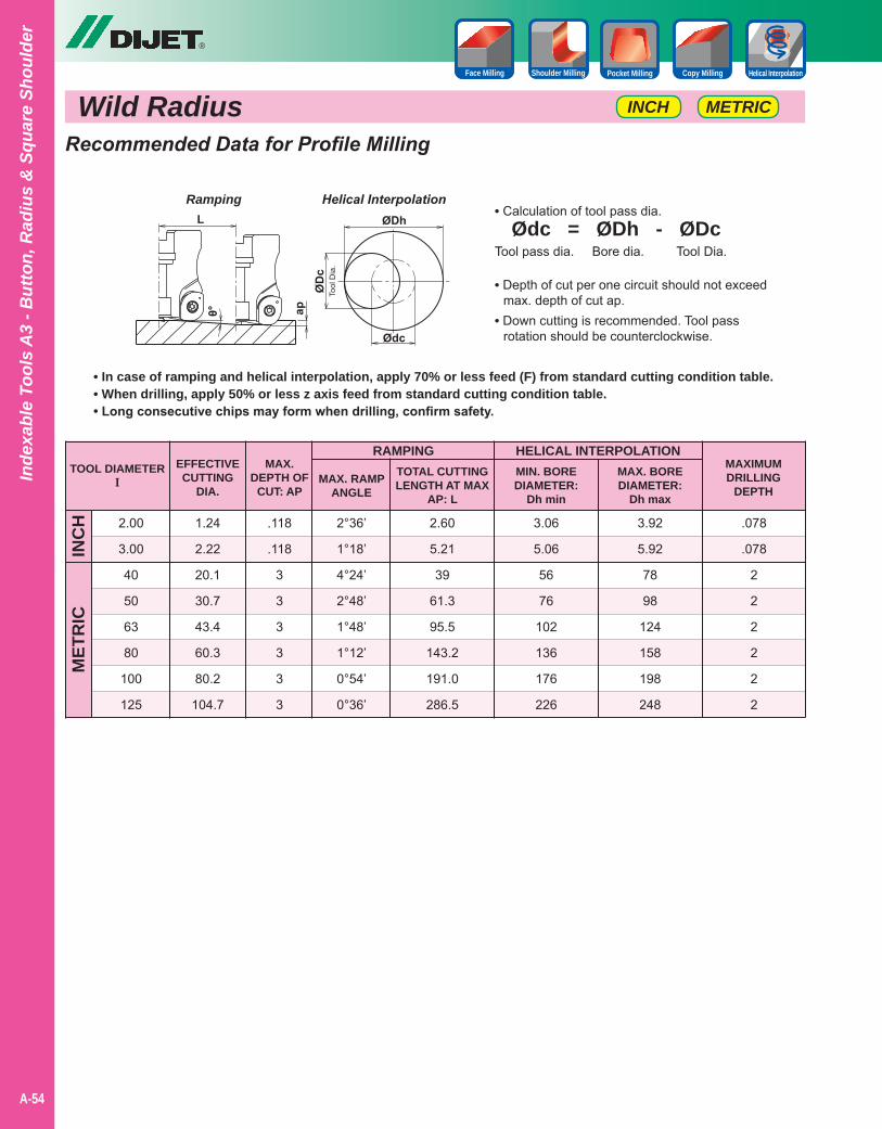
Wild Radius
®
A-54
Inde
xabl
e To
ols
A3
- But
ton,
Rad
ius
& S
quar
e Sh
ould
er
METRICINCH
Shoulder Milling Pocket Milling Copy Milling Helical InterpolationFace Milling
Recommended Data for Profile Milling
TOOL DIAMETERI
RAMPING
2.00
3.00
40
50
63
80
100
125
INC
HM
ETR
IC
EFFECTIVECUTTING
DIA.
MAX.DEPTH OF
CUT: APMAX. RAMP
ANGLE
1.24
2.22
20.1
30.7
43.4
60.3
80.2
104.7
.118
.118
3
3
3
3
3
3
2°36’
1°18’
4°24’
2°48’
1°48’
1°12’
0°54’
0°36’
TOTAL CUTTINGLENGTH AT MAX
AP: L
2.60
5.21
39
61.3
95.5
143.2
191.0
286.5
HELICAL INTERPOLATIONMIN. BOREDIAMETER:
Dh min
3.06
5.06
56
76
102
136
176
226
3.92
5.92
78
98
124
158
198
248
MAXIMUMDRILLING
DEPTH
.078
.078
2
2
2
2
2
2
• In case of ramping and helical interpolation, apply 70% or less feed (F) from standard cutting condition table.• When drilling, apply 50% or less z axis feed from standard cutting condition table.• Long consecutive chips may form when drilling, confirm safety.
• Calculation of tool pass dia. Ødc = ØDh - ØDcTool pass dia. Bore dia. Tool Dia.
Ramping Helical Interpolation
MAX. BOREDIAMETER:
Dh max
• Depth of cut per one circuit should not exceed max. depth of cut ap.• Down cutting is recommended. Tool pass rotation should be counterclockwise.
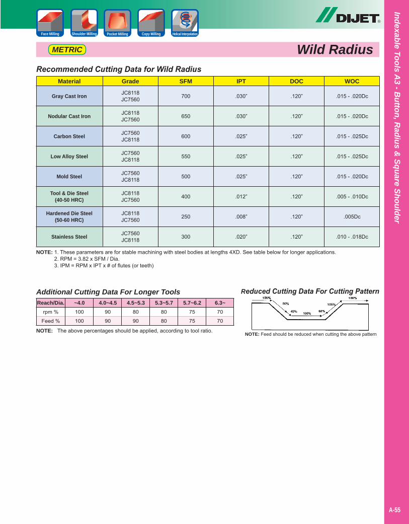
®
Indexable Tools A3 - B
utton, Radius &
Square Shoulder
Shoulder Milling Pocket Milling Copy Milling Helical InterpolationFace Milling
A-55
Wild RadiusMETRIC
NOTE: 1. These parameters are for stable machining with steel bodies at lengths 4XD. See table below for longer applications.2. RPM = 3.82 x SFM / Dia.3. IPM = RPM x IPT x # of flutes (or teeth)
Recommended Cutting Data for Wild Radius
Gray Cast Iron
Nodular Cast Iron
Carbon Steel
Low Alloy Steel
Mold Steel
Tool & Die Steel(40-50 HRC)
Hardened Die Steel(50-60 HRC)
Stainless Steel
Material DOCIPTSFMGrade WOC
.120”
.120”
.120”
.120”
.120”
.120”
.120”
.120”
.030”
.030”
.025”
.025”
.025”
.012”
.008”
.020”
700
650
600
550
500
400
250
300
JC8118JC7560
JC8118JC7560
JC7560JC8118
JC7560JC8118
JC7560JC8118
JC8118JC7560
JC8118JC7560
JC7560JC8118
.015 - .020Dc
.015 - .020Dc
.015 - .025Dc
.015 - .025Dc
.015 - .020Dc
.005 - .010Dc
.005Dc
.010 - .018Dc
Reduced Cutting Data For Cutting Pattern
NOTE: Feed should be reduced when cutting the above patternNOTE: The above percentages should be applied, according to tool ratio.
Additional Cutting Data For Longer Tools
rpm %
Feed %
100
100
90
90
80
90
80
80
75
75
70
70
Reach/Dia. ~4.0 4.0~4.5 4.5~5.3 5.3~5.7 5.7~6.2 6.3~

Notes
A-40
®
A-56
Inde
xabl
e To
ols
A3
- But
ton,
Rad
ius
& S
quar
e Sh
ould
er
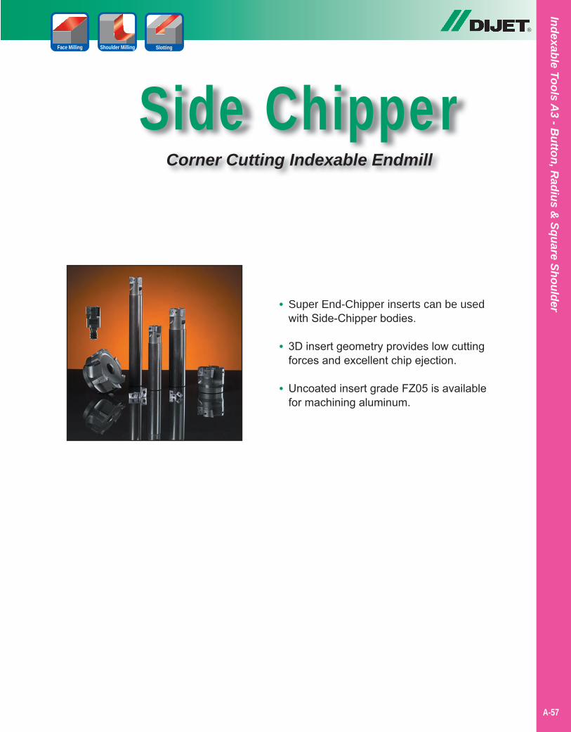
Side ChipperCorner Cutting Indexable Endmill
®
Indexable Tools A3 - B
utton, Radius &
Square Shoulder• Super End-Chipper inserts can be used with Side-Chipper bodies.
• 3D insert geometry provides low cutting forces and excellent chip ejection.
• Uncoated insert grade FZ05 is available for machining aluminum.
A-57
Shoulder MillingFace Milling Slotting
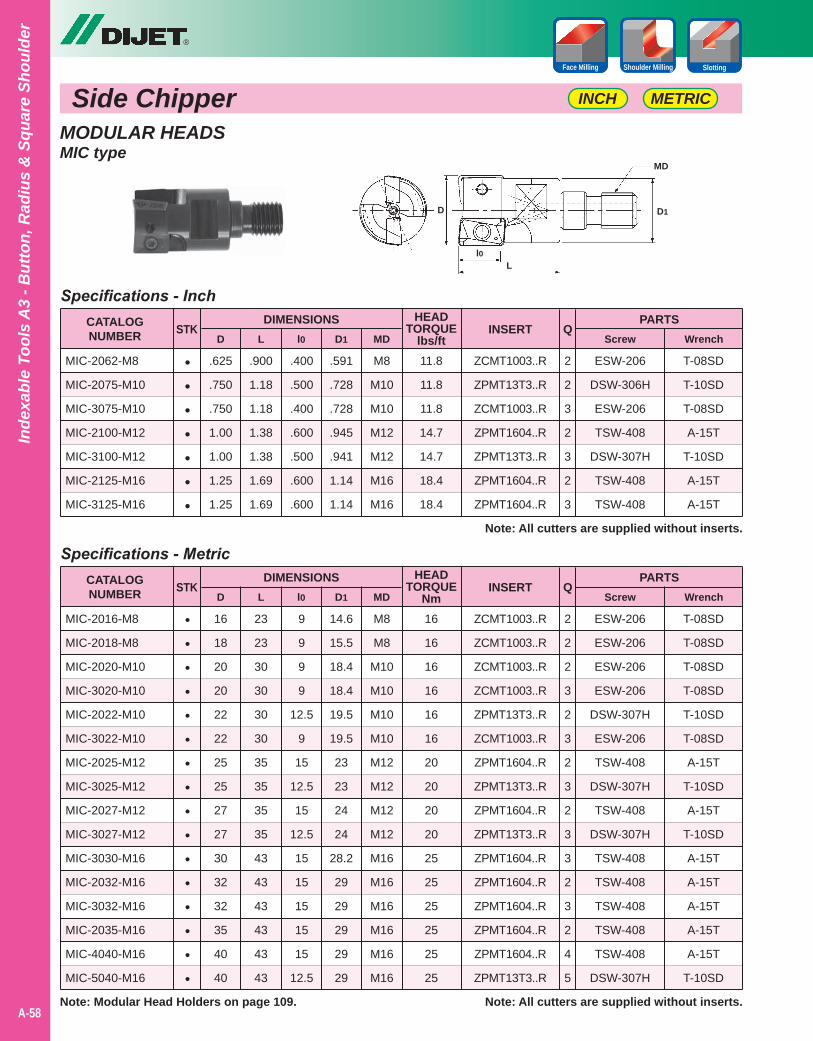
Side Chipper
®
A-58
Inde
xabl
e To
ols
A3
- But
ton,
Rad
ius
& S
quar
e Sh
ould
er
METRICINCH
Shoulder MillingFace Milling
MODULAR HEADSMIC type
l1L
ZCMT1003..R
ZPMT13T3..R
ZCMT1003..R
ZPMT1604..R
ZPMT13T3..R
ZPMT1604..R
ZPMT1604..R
Specifications - Inch
.400
.500
.400
.600
.500
.600
.600
.625
.750
.750
1.00
1.00
1.25
1.25
.900
1.18
1.18
1.38
1.38
1.69
1.69
.591
.728
.728
.945
.941
1.14
1.14
M8
M10
M10
M12
M12
M16
M16
CATALOGNUMBER D
PARTSScrew Wrench
STKL l0 D1 MD
HEADTORQUE
lbs/ftINSERT
Note: All cutters are supplied without inserts.
Q
MIC-2062-M8
MIC-2075-M10
MIC-3075-M10
MIC-2100-M12
MIC-3100-M12
MIC-2125-M16
MIC-3125-M16
DIMENSIONS
11.8
11.8
11.8
14.7
14.7
18.4
18.4
2
2
3
2
3
2
3
T-08SD
T-10SD
T-08SD
A-15T
T-10SD
A-15T
A-15T
•••••••
ESW-206
ESW-206
ESW-206
ESW-206
DSW-307H
ESW-206
TSW-408
DSW-307H
TSW-408
DSW-307H
TSW-408
TSW-408
TSW-408
TSW-408
TSW-408
DSW-307H
ZCMT1003..R
ZCMT1003..R
ZCMT1003..R
ZCMT1003..R
ZPMT13T3..R
ZCMT1003..R
ZPMT1604..R
ZPMT13T3..R
ZPMT1604..R
ZPMT13T3..R
ZPMT1604..R
ZPMT1604..R
ZPMT1604..R
ZPMT1604..R
ZPMT1604..R
ZPMT13T3..R
Specifications - Metric
9
9
9
9
12.5
9
15
12.5
15
12.5
15
15
15
15
15
12.5
16
18
20
20
22
22
25
25
27
27
30
32
32
35
40
40
23
23
30
30
30
30
35
35
35
35
43
43
43
43
43
43
14.6
15.5
18.4
18.4
19.5
19.5
23
23
24
24
28.2
29
29
29
29
29
M8
M8
M10
M10
M10
M10
M12
M12
M12
M12
M16
M16
M16
M16
M16
M16
CATALOGNUMBER D
PARTSScrew Wrench
STKL l0 D1 MD
HEADTORQUE
NmINSERT
Note: All cutters are supplied without inserts.
Q
MIC-2016-M8
MIC-2018-M8
MIC-2020-M10
MIC-3020-M10
MIC-2022-M10
MIC-3022-M10
MIC-2025-M12
MIC-3025-M12
MIC-2027-M12
MIC-3027-M12
MIC-3030-M16
MIC-2032-M16
MIC-3032-M16
MIC-2035-M16
MIC-4040-M16
MIC-5040-M16
DIMENSIONS
16
16
16
16
16
16
20
20
20
20
25
25
25
25
25
25
2
2
2
3
2
3
2
3
2
3
3
2
3
2
4
5
T-08SD
T-08SD
T-08SD
T-08SD
T-10SD
T-08SD
A-15T
T-10SD
A-15T
T-10SD
A-15T
A-15T
A-15T
A-15T
A-15T
T-10SD
••••••••••••••••
D
l0L
D1
MD
Slotting
Note: Modular Head Holders on page 109.
ESW-206
DSW-306H
ESW-206
TSW-408
DSW-307H
TSW-408
TSW-408
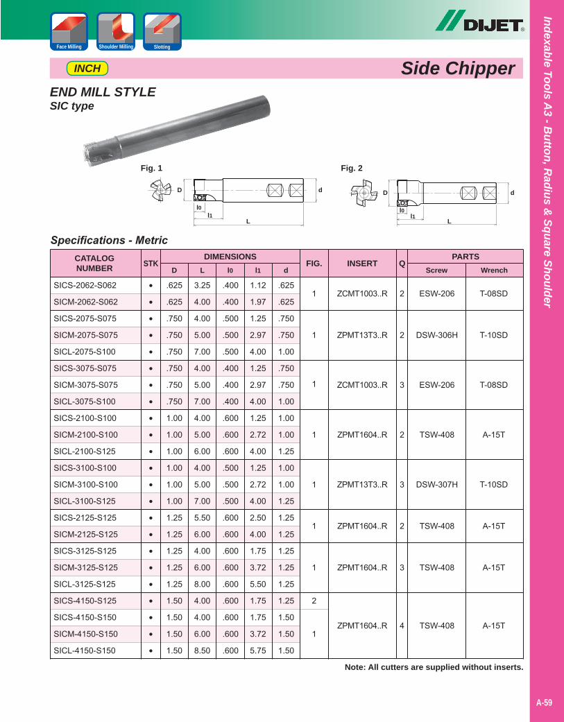
®
Shoulder MillingFace Milling Slotting
Indexable Tools A3 - B
utton, Radius &
Square Shoulder
END MILL STYLESIC type
•••••••••••••••••••••••
2
2
3
2
3
2
3
4
ESW-206
DSW-306H
ESW-206
TSW-408
DSW-307H
TSW-408
TSW-408
TSW-408
T-08SD
T-10SD
T-08SD
A-15T
T-10SD
A-15T
A-15T
A-15T
ZCMT1003..R
ZPMT13T3..R
ZCMT1003..R
ZPMT1604..R
ZPMT13T3..R
ZPMT1604..R
ZPMT1604..R
ZPMT1604..R
1
1
1
1
1
1
1
2
1
Specifications - Metric
.400
.400
.500
.500
.500
.400
.400
.400
.600
.600
.600
.500
.500
.500
.600
.600
.600
.600
.600
.600
.600
.600
.600
.625
.625
.750
.750
.750
.750
.750
.750
1.00
1.00
1.00
1.00
1.00
1.00
1.25
1.25
1.25
1.25
1.25
1.50
1.50
1.50
1.50
3.25
4.00
4.00
5.00
7.00
4.00
5.00
7.00
4.00
5.00
6.00
4.00
5.00
7.00
5.50
6.00
4.00
6.00
8.00
4.00
4.00
6.00
8.50
1.12
1.97
1.25
2.97
4.00
1.25
2.97
4.00
1.25
2.72
4.00
1.25
2.72
4.00
2.50
4.00
1.75
3.72
5.50
1.75
1.75
3.72
5.75
.625
.625
.750
.750
1.00
.750
.750
1.00
1.00
1.00
1.25
1.00
1.00
1.25
1.25
1.25
1.25
1.25
1.25
1.25
1.50
1.50
1.50
CATALOGNUMBER D
PARTSScrew Wrench
STKL l0 l1 d
FIG. INSERT
Note: All cutters are supplied without inserts.
Q
SICS-2062-S062
SICM-2062-S062
SICS-2075-S075
SICM-2075-S075
SICL-2075-S100
SICS-3075-S075
SICM-3075-S075
SICL-3075-S100
SICS-2100-S100
SICM-2100-S100
SICL-2100-S125
SICS-3100-S100
SICM-3100-S100
SICL-3100-S125
SICS-2125-S125
SICM-2125-S125
SICS-3125-S125
SICM-3125-S125
SICL-3125-S125
SICS-4150-S125
SICS-4150-S150
SICM-4150-S150
SICL-4150-S150
DIMENSIONS
Fig. 1
D
l0l1
L
d
Fig. 2
D
l0l1
L
d
INCH
A-59
Side Chipper
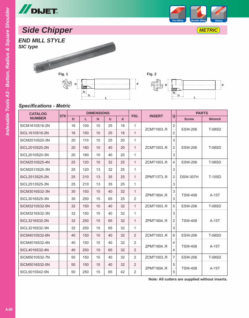
Side Chipper
®
Inde
xabl
e To
ols
A3
- But
ton,
Rad
ius
& S
quar
e Sh
ould
er
METRIC
Shoulder MillingFace Milling Slotting
2
2
3
2
3
4
3
2
3
3
3
5
3
2
3
6
4
4
7
5
5
END MILL STYLESIC type
ESW-206
ESW-206
ESW-206
DSW-307H
TSW-408
ESW-206
TSW-408
ESW-206
TSW-408
ESW-206
TSW-408
ZCMT1003..R
ZCMT1003..R
ZCMT1003..R
ZPMT13T3..R
ZPMT1604..R
ZCMT1003..R
ZPMT1604..R
ZCMT1003..R
ZPMT1604..R
ZCMT1003..R
ZPMT1604..R
Specifications - Metric
10
10
10
10
10
10
13
13
13
15
15
10
15
15
15
10
15
15
10
15
15
16
16
20
20
20
25
25
25
25
30
30
32
32
32
32
40
40
40
50
50
50
100
150
110
180
180
120
120
210
210
150
250
150
150
250
250
150
150
250
150
150
250
25
25
25
40
40
32
32
35
35
40
65
40
40
65
65
40
40
65
40
40
65
16
16
20
20
20
25
25
25
25
32
25
32
32
32
32
32
32
32
32
32
42
CATALOGNUMBER D
PARTSScrew Wrench
STKL l0 l1 d
FIG. INSERT
Note: All cutters are supplied without inserts.
Q
SICM1610S16-2N
SICL1610S16-2N
SICM2010S20-3N
SICL2010S20-2N
SICL2010S20-3N
SICM2510S25-4N
SICM2513S25-3N
SICL2513S25-2N
SICL2513S25-3N
SICM3016S32-3N
SICL3016S25-3N
SICM3210S32-5N
SICM3216S32-3N
SICL3216S32-2N
SICL3216S32-3N
SICM4010S32-6N
SICM4016S32-4N
SICL4016S32-4N
SICM5010S32-7N
SICM5016S32-5N
SICL5015S42-5N
DIMENSIONS
Fig. 2
D
l0l1
L
d
Fig. 1
D
l0l1
L
d
1
1
1
1
1
1
1
1
1
1
2
1
1
1
1
2
2
2
2
2
2
T-08SD
T-08SD
T-08SD
T-10SD
A-15T
T-08SD
A-15T
T-08SD
A-15T
T-08SD
A-15T
A-60
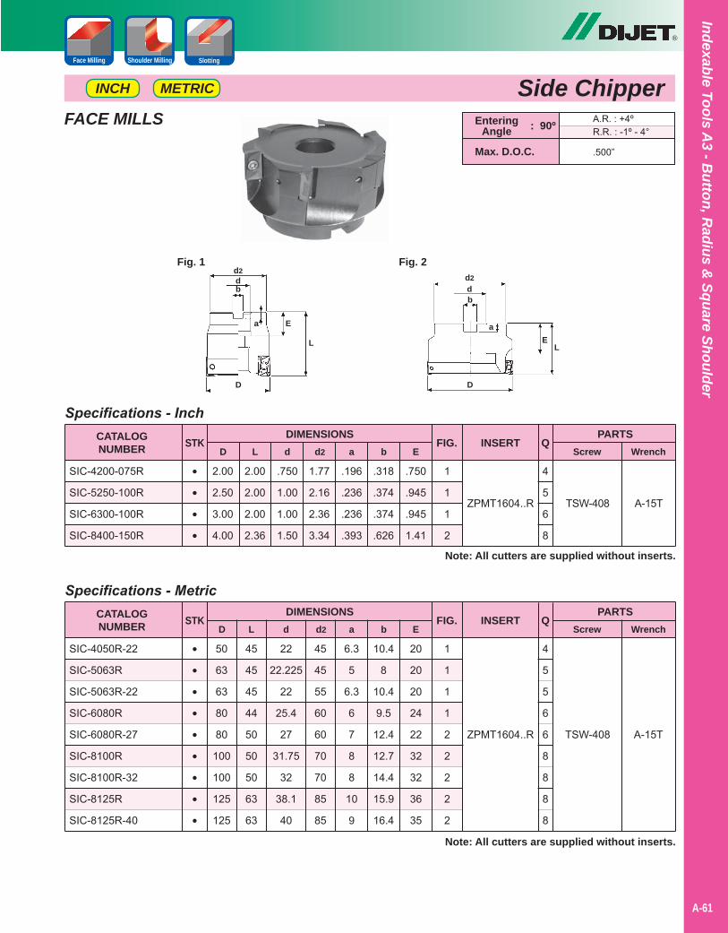
®
Indexable Tools A3 - B
utton, Radius &
Square Shoulder
A-61
Side ChipperShoulder MillingFace Milling Slotting
••••
TSW-408
Specifications - Inch
.750
1.00
1.00
1.50
2.00
2.50
3.00
4.00
2.00
2.00
2.00
2.36
1.77
2.16
2.36
3.34
.196
.236
.236
.393
CATALOGNUMBER D
PARTSScrew Wrench
STKL d d2 a
FIG. INSERT
Note: All cutters are supplied without inserts.
Q
SIC-4200-075R
SIC-5250-100R
SIC-6300-100R
SIC-8400-150R
DIMENSIONS
.318
.374
.374
.626
b
.750
.945
.945
1.41
E
1
1
1
2
ZPMT1604..R
4
5
6
8
A-15T
EnteringAngle
A.R. : +4ºR.R. : -1º - 4°
.500”Max. D.O.C.
: 90º
Fig. 1
D
L
dd2
a
b
E
Fig. 2
D
L
dd2
a
b
E
FACE MILLS
•••••••••
TSW-408
Specifications - Metric
22
22.225
22
25.4
27
31.75
32
38.1
40
50
63
63
80
80
100
100
125
125
45
45
45
44
50
50
50
63
63
45
45
55
60
60
70
70
85
85
6.3
5
6.3
6
7
8
8
10
9
CATALOGNUMBER D
PARTSScrew Wrench
STKL d d2 a
FIG. INSERT
Note: All cutters are supplied without inserts.
Q
SIC-4050R-22
SIC-5063R
SIC-5063R-22
SIC-6080R
SIC-6080R-27
SIC-8100R
SIC-8100R-32
SIC-8125R
SIC-8125R-40
DIMENSIONS
10.4
8
10.4
9.5
12.4
12.7
14.4
15.9
16.4
b E
1
1
1
1
2
2
2
2
2
ZPMT1604..R
4
5
5
6
6
8
8
8
8
20
20
20
24
22
32
32
36
35
A-15T
METRICINCH
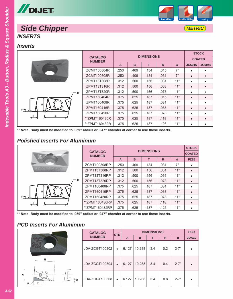
Side Chipper
®
A-62
Inde
xabl
e To
ols
A3
- But
ton,
Rad
ius
& S
quar
e Sh
ould
er
METRIC
Shoulder MillingFace Milling Slotting
INSERTS
CATALOGNUMBER
DIMENSIONS
ZCMT100304RZCMT100308RZPMT13T308RZPMT13T316RZPMT13T320RZPMT160404RZPMT160408RZPMT160416RZPMT160420R
**ZPMT160430R**ZPMT160432R
A
.250
.250
.312
.312
.312
.375
.375
.375
.375
.375
.375
B
.409
.409
.500
.500
.500
.625
.625
.625
.625
.625
.625
T
.134
.134
.156
.156
.156
.187
.187
.187
.187
.187
.187
R
.015
.031
.031
.063
.078
.015
.031
.063
.078
.118
.126
a7°7°11°11°11°11°11°11°11°11°11°
JC5015
•••••••••••
JC5040
STOCK
COATED
•••••••••••
** Note: Body must be modified to .059” radius or .047” chamfer at corner to use these inserts.
Polished Inserts For Aluminum
PCD Inserts For Aluminum
CATALOGNUMBER
CATALOGNUMBER
DIMENSIONS
DIMENSIONS
ZCMT100308RPZPMT13T308RPZPMT13T316RPZPMT13T320RPZPMT160408RPZPMT160416RPZPMT160420RP
**ZPMT160430RP**ZPMT160432RP
JDA-ZCGT100302
JDA-ZCGT100304
JDA-ZCGT100308
A
.250
.312
.312
.312
.375
.375
.375
.375
.375
6.127
6.127
6.127
B
B
.409
.500
.500
.500
.625
.625
.625
.625
.625
10.288
10.288
10.288
T
T
.134
.156
.156
.156
.187
.187
.187
.187
.187
3.4
3.4
3.4
R
R
.031
.031
.063
.078
.031
.063
.078
.118
.125
0.2
0.4
0.8
a
a
7°11°11°11°11°11°11°11°11°
2-7°
2-7°
2-7°
FZ15
JDA10
•••••••••
•
•
•
STOCK
COATED
PCD
** Note: Body must be modified to .059” radius or .047” chamfer at corner to use these inserts.
Inserts
A
BT
R
a
A
BT
R
a
A
B
TRa
•
•
•
ASTK
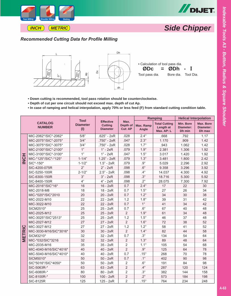
®
Indexable Tools A3 - B
utton, Radius &
Square Shoulder
A-63
Side ChipperShoulder MillingFace Milling Slotting
METRICINCH
Recommended Cutting Data for Profile Milling
CATALOGNUMBER
Ramping
MIC-2062*/SIC*-2062* MIC-2075*/SIC*-2075*MIC-3075*/SIC*-3075*MIC-2100*/SIC*-2100*MIC-3100*/SIC*-3100*MIC-*125*/SIC*-*125*SIC*-150*SIC-4200-075RSIC-5250-100RSIC-6300-150RSIC-8400-150RMIC-2016*/SIC*16*MIC-2018-M8MIC-*020*/SIC*2010MIC-2022-M10MIC-3022-M10SICM2510*MIC-2025-M12MIC-3025*/SIC*2513*MIC-2027-M12MIC-3027-M12MIC-3030-M16/SIC*3016*SICM3210*MIC-*032/SIC*3216MIC-2035-M16MIC-4040-M16/SIC*4016*MIC-5040-M16/SIC*4010*SICM5010*SIC*5016*/SIC*4050*SIC-5063R-*SIC-6080R-*SIC-8100R-*SIC-8125R
INC
HM
ETR
IC
EffectiveCutting
Diameter
ToolDiameter
(I)
Max.Depth ofCut: AP
Max. RampAngle
.625” - 2xR
.750” - 2xR
.750” - 2xR1” - 2xR1” - 2xR
1.25” - 2xR1.5” - 2xR2” - 2xR
2.5” - 2xR3” - 2xR4” - 2xR16 - 2xR18 - 2xR20 - 2xR22 - 2xR22 - 2xR25 - 2xR25 - 2xR25 - 2xR27 - 2xR27 - 2xR30 - 2xR32 - 2xR32 - 2xR35 - 2xR40 - 2xR40 - 2xR50 - 2xR50 - 2xR63 - 2xR80 - 2xR
100 - 2xR125 - 2xR
5/8”3/4”3/4”1”1”
1-1/4”1-1/2”
2”2-1/2”
3”4”1618202222252525272730323235404050506380100125
.028
.047
.028
.079
.047
.079
.079
.098
.098
.098
.0980.70.70.71.20.70.72
1.22
1.22
0.7222
0.70.722222
2.4°2.3°1.7°1.9°1.5°1.3°.9°.6°.4°.3°.2°
2.4°1.5°1.2°1.8°1°.6°
1.9°1.5°1.6°1.2°1.4°.3°
1.3°1.1°.9°
.15°.1°.6°.4°.3°.2°
.15°
Total CuttingLength at
Max. AP: L.668
1.170.943
2.3813.0173.4815.0299.358
14.03718.71628.075
1727343941676146725882
13489
105125268402191287382573764
Helical InterpolationMin. BoreDiameter:
Dh min.792.909
1.0621.3061.4201.8002.2963.2964.3005.3007.300
222630313440343738414454485464709084
120144184234
1.171.421.421.921.922.422.923.924.925.927.92303438424248484852525864646878789898
124158198248
• Down cutting is recommended, tool pass rotation should be counterclockwise.• Depth of cut per one circuit should not exceed max. depth of cut Ap.• In case of ramping and helical interpolation, apply 70% or less feed (F) from standard cutting condition table.
Max. BoreDiameter:Dh max
• Calculation of tool pass dia. ØDc = ØDh - ITool pass dia. Bore dia. Tool Dia.
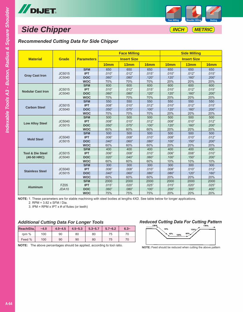
Side Chipper
®
A-64
Inde
xabl
e To
ols
A3
- But
ton,
Rad
ius
& S
quar
e Sh
ould
er
Shoulder MillingFace Milling Slotting
NOTE: 1. These parameters are for stable machining with steel bodies at lengths 4XD. See table below for longer applications.2. RPM = 3.82 x SFM / Dia.3. IPM = RPM x IPT x # of flutes (or teeth)
Reduced Cutting Data For Cutting Pattern
NOTE: Feed should be reduced when cutting the above patternNOTE: The above percentages should be applied, according to tool ratio.
Additional Cutting Data For Longer Tools
rpm %
Feed %
100
100
90
90
80
90
80
80
75
75
70
70
Reach/Dia. ~4.0 4.0~4.5 4.5~5.3 5.3~5.7 5.7~6.2 6.3~
Recommended Cutting Data for Side Chipper
Gray Cast Iron
Nodular Cast Iron
Carbon Steel
Low Alloy Steel
Mold Steel
Tool & Die Steel(40-50 HRC)
Stainless Steel
Aluminum
MaterialSide MillingFace Milling
16mm16mm 13mm13mm 10mm10mmGrade
650.015”.200”20%600
.015”
.200”20%550
.015”
.200”20%500
.012”
.200”20%500
.012”
.200”20%400
.010”
.200”10%300
.012”
.160”20%2000.025”.400”20%
650.015”.120”70%600
.015”
.120”70%550
.012”
.100”70%500
.012”
.100”60%500
.010”
.080”60%400
.010”
.060”60%300
.010”
.080”60%2000.025”.100”75%
650.012”.160”20%600
.012”
.160”20%550
.012”
.160”20%500
.010”
.160”20%500
.010”
.150”20%400
.008”
.150”10%300
.010”
.120”20%2000.020”.300”20%
650.012”.080”70%600
.012”
.080”70%550
.010”
.075”70%500
.010”
.075”60%500
.008”
.060”60%400
.008”
.040”60%300
.008”
.060”60%2000.020”.080”75%
650.010”.120”20%600
.010”
.120”20%550
.010”
.120”20%500
.008”
.120”20%500
.008”
.100”20%400
.006”
.100”10%300
.008”
.080”20%2000.015”.200”20%
650.010”.060”70%600
.010”
.060”70%550
.008”
.050”70%500
.008”
.050”60%500
.006”
.040”60%400
.006”
.020”60%300
.006”
.040”60%2000.015”.060”75%
JC5015JC5040
JC5015JC5040
JC5015JC5040
JC5040JC5015
JC5040JC5015
JC5015JC5040
JC5040JC5015
FZ05JDA10
Insert SizeInsert SizeParameters
SFMIPT
DOCWOCSFMIPT
DOCWOCSFMIPT
DOCWOCSFMIPT
DOCWOCSFMIPT
DOCWOCSFMIPT
DOCWOCSFMIPT
DOCWOCSFMIPT
DOCWOC
METRICINCH
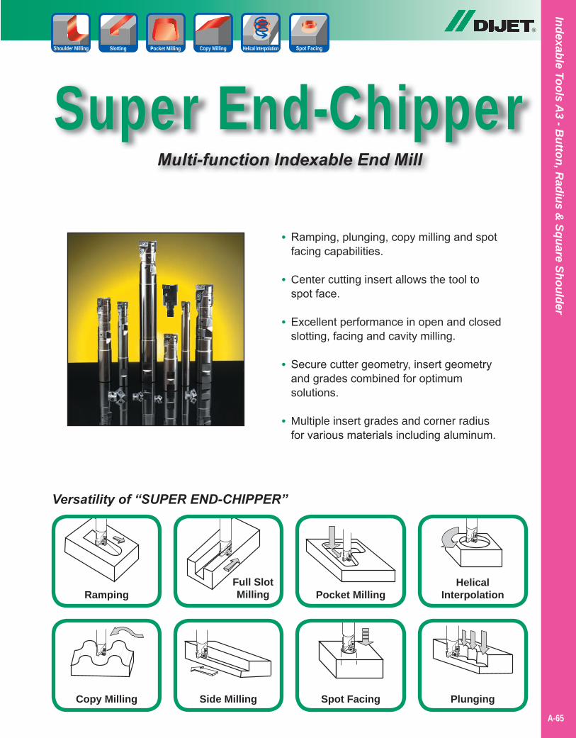
Indexable Tools A3 - B
utton, Radius &
Square Shoulder
A-65
Super End-ChipperMulti-function Indexable End Mill
®
Spot FacingSide Milling
Full SlotMilling Pocket Milling
HelicalInterpolation
PlungingCopy Milling
Ramping
Versatility of “SUPER END-CHIPPER”
Slotting Pocket Milling Copy Milling Helical Interpolation
• Ramping, plunging, copy milling and spot facing capabilities.
• Center cutting insert allows the tool to spot face.
• Excellent performance in open and closed slotting, facing and cavity milling.
• Secure cutter geometry, insert geometry and grades combined for optimum solutions.
• Multiple insert grades and corner radius for various materials including aluminum.
Shoulder Milling
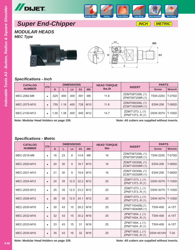
Super End-Chipper
®
A-66
Inde
xabl
e To
ols
A3
- But
ton,
Rad
ius
& S
quar
e Sh
ould
er
Slotting Pocket Milling Copy Milling Helical InterpolationShoulder Milling
METRICINCH
MODULAR HEADSMEC Type
M8
M10
M12
.625
.750
1.00
.300
.400
.500
.900
1.18
1.38
.591
.728
.945
Specifications - InchCATALOGNUMBER
MEC-2062-M8
MEC-2075-M10
MEC-2100-M12
PARTSScrew Wrench
Note: All cutters are supplied without inserts.
DIMENSIONSD L L0 D1
INSERTMD
STK
•
•
•
TSW-2250
ESW-206
DSW-307H
T-07SD
T-08SD
T-10SD
ZDMT08T208L (1)ZPMT09T208R (1)
ZDMT090308L (1)ZCMT100308R (1)
ZDMT13T3..L (1)ZPMT13T3..R (1)
HEAD TORQUElbs./ft
11.8
11.8
14.7
M8
M10
M10
M12
M12
M12
M16
M16
M16
M16
16
20
21
24
25
26
30
32
33
35
8
9
9
12.5
12.5
12.5
15
15
15
16
23
30
30
35
35
35
43
43
43
43
D
L
L0
D1
MD
14.8
18.7
19.6
22.2
23.2
24.1
28.2
30.2
31
32
Specifications - MetricCATALOGNUMBER
MEC-2016-M8
MEC-2020-M10
MEC-2021-M10
MEC-2024-M12
MEC-2025-M12
MEC-2026-M12
MEC-2030-M16
MEC-2032-M16
MEC-2033-M16
MEC-2035-M16
PARTSScrew Wrench
Note: All cutters are supplied without inserts.
DIMENSIONSD L L0 D1
INSERTMD
STK
•
•
•
•
•
•
•
•
•
•
TSW-2250
ESW-206
ESW-206
DSW-307H
DSW-307H
DSW-307H
TSW-408
TSW-408
TSW-408
DSW-4510H
T-07SD
T-08SD
T-08SD
T-10SD
T-10SD
T-10SD
A-15T
A-15T
A-15T
T-20
ZDMT08T208L (1)ZPMT09T208R (1)
ZDMT100308L (1)ZCMT100308R (1)
ZDMT100308L (1)ZCMT100308R (1)
ZDMT13T3..L (1)ZPMT13T3..R (1)
ZDMT13T3..L (1)ZPMT13T3..R (1)
ZDMT13T3..L (1)ZPMT13T3..R (1)
ZPMT150408L(1)ZPMT160408R (1)
ZPMT1604..L (1)ZPMT1604..R (1)
ZPMT1604..L (1)ZPMT1604..R (1)
ZPMT1805..L (1)ZPMT1705..R (1)
HEAD TORQUENm
16
16
16
20
20
20
25
25
25
25
Note: Modular Head Holders on page 109.
Note: Modular Head Holders on page 109.
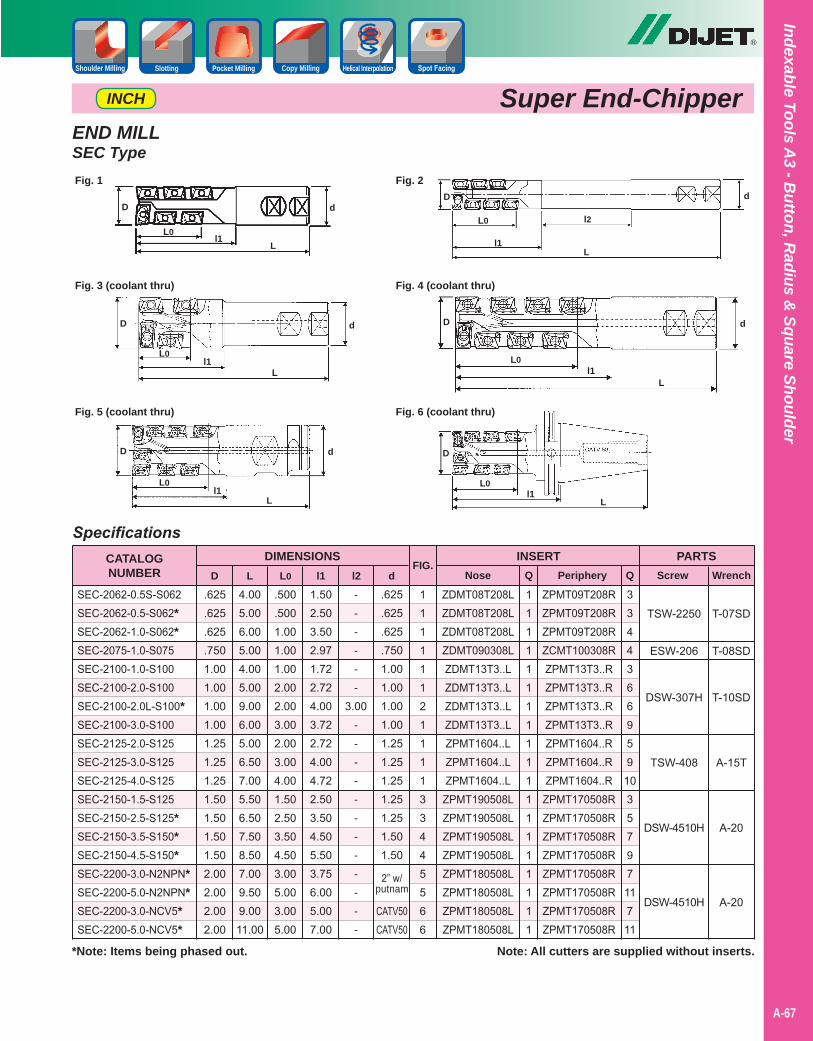
Indexable Tools A3 - B
utton, Radius &
Square Shoulder
A-67
®
Slotting Pocket Milling Copy Milling Helical InterpolationShoulder Milling
END MILLSEC Type
D
L
L0l1
Fig. 1 Fig. 2D
L
L0
l1
d
l2D
LL0
l1
d
Fig. 3 (coolant thru) Fig. 4 (coolant thru)
Fig. 5 (coolant thru) Fig. 6 (coolant thru)
D
L
L0l1
d D
L
L0l1
d
D
L
L0l1
d
T-07SD
T-08SD
T-10SD
A-15T
A-20
A-20
ZPMT09T208RZPMT09T208RZPMT09T208RZCMT100308RZPMT13T3..RZPMT13T3..RZPMT13T3..RZPMT13T3..RZPMT1604..RZPMT1604..RZPMT1604..RZPMT170508RZPMT170508RZPMT170508RZPMT170508RZPMT170508RZPMT170508RZPMT170508RZPMT170508R
SpecificationsCATALOGNUMBER
SEC-2062-0.5S-S062SEC-2062-0.5-S062*SEC-2062-1.0-S062*SEC-2075-1.0-S075SEC-2100-1.0-S100SEC-2100-2.0-S100SEC-2100-2.0L-S100*SEC-2100-3.0-S100SEC-2125-2.0-S125SEC-2125-3.0-S125SEC-2125-4.0-S125SEC-2150-1.5-S125SEC-2150-2.5-S125*SEC-2150-3.5-S150*SEC-2150-4.5-S150*SEC-2200-3.0-N2NPN*SEC-2200-5.0-N2NPN*SEC-2200-3.0-NCV5*SEC-2200-5.0-NCV5*
PARTSScrew Wrench
TSW-2250
ESW-206
DSW-307H
TSW-408
DSW-4510H
DSW-4510H
Note: All cutters are supplied without inserts.
ZDMT08T208LZDMT08T208LZDMT08T208LZDMT090308LZDMT13T3..LZDMT13T3..LZDMT13T3..LZDMT13T3..LZPMT1604..LZPMT1604..LZPMT1604..LZPMT190508LZPMT190508LZPMT190508LZPMT190508LZPMT180508LZPMT180508LZPMT180508LZPMT180508L
1111112111133445566
.500
.5001.001.001.002.002.003.002.003.004.001.502.503.504.503.005.003.005.00
.625
.625
.625
.7501.001.001.001.001.251.251.251.501.501.501.502.002.002.002.00
4.005.006.005.004.005.009.006.005.006.507.005.506.507.508.507.009.509.0011.00
1.502.503.502.971.722.724.003.722.724.004.722.503.504.505.503.756.005.007.00
------
3.00------------
.625
.625
.625
.7501.001.001.001.001.251.251.251.251.251.501.50
2” w/putnam
CATV50CATV50
DIMENSIONSD L L0 l1 l2 d
FIG.INSERT
Nose Q
1111111111111111111
Periphery Q
3344366959
103579711711
Super End-ChipperINCH
*Note: Items being phased out.
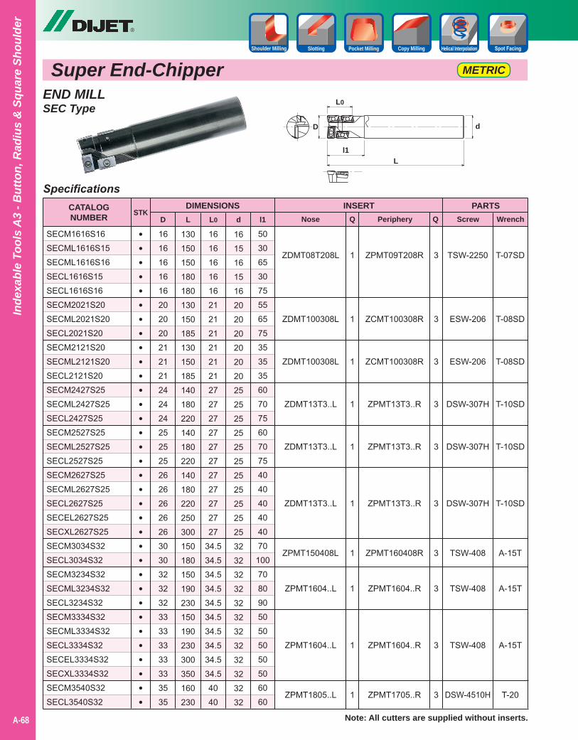
Super End-Chipper
®
A-68
Inde
xabl
e To
ols
A3
- But
ton,
Rad
ius
& S
quar
e Sh
ould
er
Slotting Pocket Milling Copy Milling Helical InterpolationShoulder Milling
METRIC
END MILLSEC Type
5030653075556575353535607075607075404040404070
10070809050505050506060
16161616162020202121212424242525252626262626303032323233333333333535
16161616162121212121212727272727272727272727
34.534.534.534.534.534.534.534.534.534.54040
130150150180180130150185130150185140180220140180220140180220250300150180150190230150190230300350160230
16151615162020202020202525252525252525252525323232323232323232323232
SpecificationsCATALOGNUMBER
SECM1616S16SECML1616S15SECML1616S16SECL1616S15SECL1616S16SECM2021S20SECML2021S20SECL2021S20SECM2121S20SECML2121S20SECL2121S20SECM2427S25SECML2427S25SECL2427S25SECM2527S25SECML2527S25SECL2527S25SECM2627S25SECML2627S25SECL2627S25SECEL2627S25SECXL2627S25SECM3034S32SECL3034S32SECM3234S32SECML3234S32SECL3234S32SECM3334S32SECML3334S32SECL3334S32SECEL3334S32SECXL3334S32SECM3540S32SECL3540S32
PARTSScrew Wrench
ZDMT08T208L
ZDMT100308L
ZDMT100308L
ZDMT13T3..L
ZDMT13T3..L
ZDMT13T3..L
ZPMT150408L
ZPMT1604..L
ZPMT1604..L
ZPMT1805..L
DIMENSIONSD L L0 d
INSERTNose Q Periphery Ql1
STK
••••••••••••••••••••••••••••••••••
1
1
1
1
1
1
1
1
1
1
ZPMT09T208R
ZCMT100308R
ZCMT100308R
ZPMT13T3..R
ZPMT13T3..R
ZPMT13T3..R
ZPMT160408R
ZPMT1604..R
ZPMT1604..R
ZPMT1705..R
3
3
3
3
3
3
3
3
3
3
TSW-2250
ESW-206
ESW-206
DSW-307H
DSW-307H
DSW-307H
TSW-408
TSW-408
TSW-408
DSW-4510H
T-07SD
T-08SD
T-08SD
T-10SD
T-10SD
T-10SD
A-15T
A-15T
A-15T
T-20
D
L
L0
d
l1
Note: All cutters are supplied without inserts.
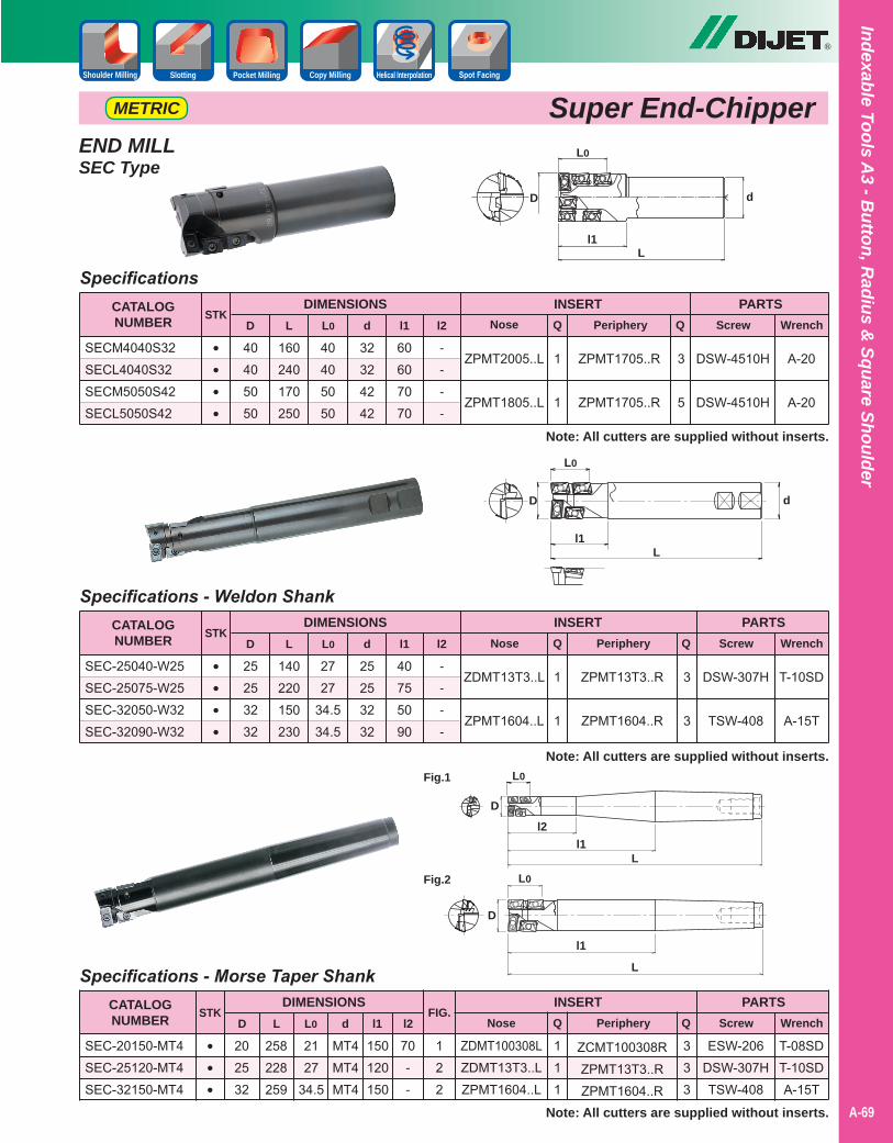
Indexable Tools A3 - B
utton, Radius &
Square Shoulder
A-69
®
Slotting Pocket Milling Copy Milling Helical InterpolationShoulder Milling
Super End-ChipperEND MILLSEC Type
----
60607070
40405050
40405050
160240170250
32324242
SpecificationsCATALOGNUMBER
SECM4040S32SECL4040S32SECM5050S42SECL5050S42
PARTSScrew Wrench
Note: All cutters are supplied without inserts.
ZPMT2005..L
ZPMT1805..L
DIMENSIONSD L L0 d
INSERTNose Q Periphery Ql1
STK
••••
1
1
ZPMT1705..R
ZPMT1705..R
3
5
DSW-4510H
DSW-4510H
A-20
A-20
l2
----
40755090
25253232
2727
34.534.5
140220150230
25253232
Specifications - Weldon ShankCATALOGNUMBER
SEC-25040-W25SEC-25075-W25SEC-32050-W32SEC-32090-W32
PARTSScrew Wrench
Note: All cutters are supplied without inserts.
ZDMT13T3..L
ZPMT1604..L
DIMENSIONSD L L0 d
INSERTNose Q Periphery Ql1
STK
••••
1
1
ZPMT13T3..R
ZPMT1604..R
3
3
DSW-307H
TSW-408
T-10SD
A-15T
l2
70--
150120150
202532
2127
34.5
258228259
MT4MT4MT4
Specifications - Morse Taper ShankCATALOGNUMBER
SEC-20150-MT4SEC-25120-MT4SEC-32150-MT4
PARTSScrew Wrench
Note: All cutters are supplied without inserts.
ZDMT100308LZDMT13T3..LZPMT1604..L
DIMENSIONSD L L0 d
INSERTNose Q Periphery Ql1
STK
•••
111
ZCMT100308RZPMT13T3..RZPMT1604..R
333
ESW-206DSW-307HTSW-408
T-08SDT-10SDA-15T
l2
D
L
L0
d
l1
D
L
L0
d
l1
D
L
L0
l1
D
L
L0
l2l1
FIG.
122
Fig.1
Fig.2
METRIC
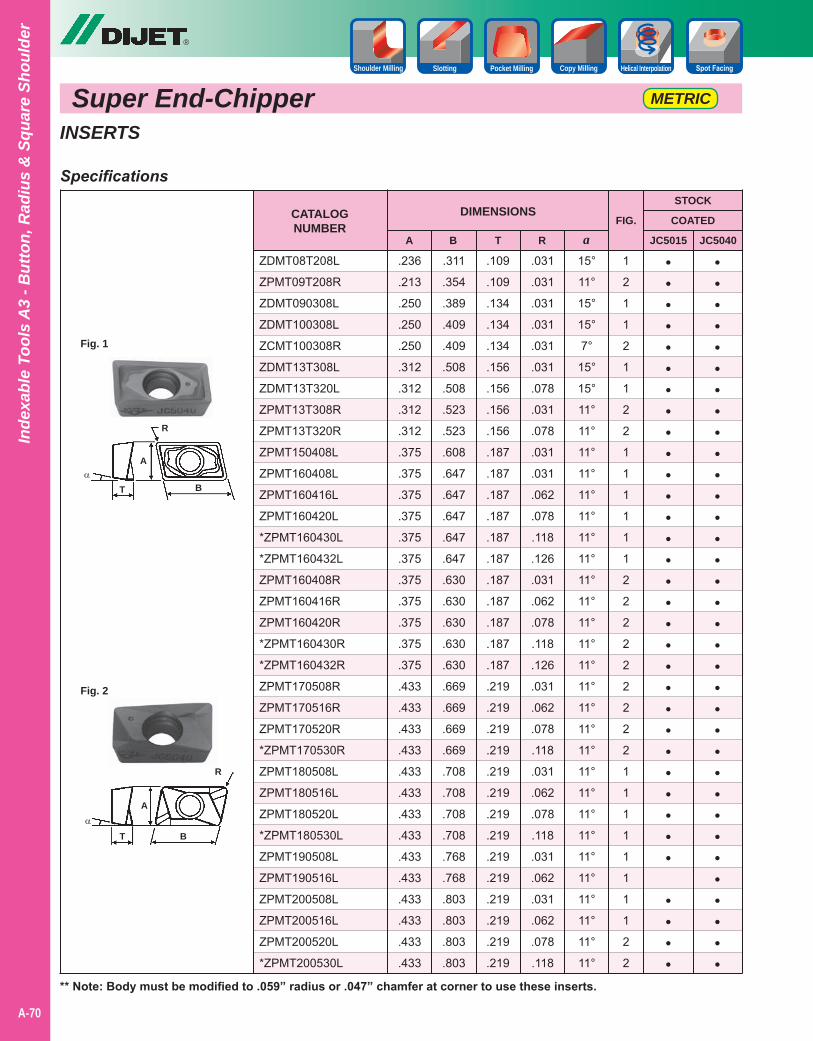
Super End-Chipper
®
A-70
Inde
xabl
e To
ols
A3
- But
ton,
Rad
ius
& S
quar
e Sh
ould
er
Slotting Pocket Milling Copy Milling Helical InterpolationShoulder Milling
METRIC
INSERTS
CATALOGNUMBER
DIMENSIONS
ZDMT08T208L
ZPMT09T208R
ZDMT090308L
ZDMT100308L
ZCMT100308R
ZDMT13T308L
ZDMT13T320L
ZPMT13T308R
ZPMT13T320R
ZPMT150408L
ZPMT160408L
ZPMT160416L
ZPMT160420L
*ZPMT160430L
*ZPMT160432L
ZPMT160408R
ZPMT160416R
ZPMT160420R
*ZPMT160430R
*ZPMT160432R
ZPMT170508R
ZPMT170516R
ZPMT170520R
*ZPMT170530R
ZPMT180508L
ZPMT180516L
ZPMT180520L
*ZPMT180530L
ZPMT190508L
ZPMT190516L
ZPMT200508L
ZPMT200516L
ZPMT200520L
*ZPMT200530L
A
.236
.213
.250
.250
.250
.312
.312
.312
.312
.375
.375
.375
.375
.375
.375
.375
.375
.375
.375
.375
.433
.433
.433
.433
.433
.433
.433
.433
.433
.433
.433
.433
.433
.433
B
.311
.354
.389
.409
.409
.508
.508
.523
.523
.608
.647
.647
.647
.647
.647
.630
.630
.630
.630
.630
.669
.669
.669
.669
.708
.708
.708
.708
.768
.768
.803
.803
.803
.803
T
.109
.109
.134
.134
.134
.156
.156
.156
.156
.187
.187
.187
.187
.187
.187
.187
.187
.187
.187
.187
.219
.219
.219
.219
.219
.219
.219
.219
.219
.219
.219
.219
.219
.219
R
.031
.031
.031
.031
.031
.031
.078
.031
.078
.031
.031
.062
.078
.118
.126
.031
.062
.078
.118
.126
.031
.062
.078
.118
.031
.062
.078
.118
.031
.062
.031
.062
.078
.118
a15°
11°
15°
15°
7°
15°
15°
11°
11°
11°
11°
11°
11°
11°
11°
11°
11°
11°
11°
11°
11°
11°
11°
11°
11°
11°
11°
11°
11°
11°
11°
11°
11°
11°
JC5015
•••••••••••••••••••••••••••••
••••
JC5040
STOCK
COATED
••••••••••••••••••••••••••••••••••
** Note: Body must be modified to .059” radius or .047” chamfer at corner to use these inserts.
Specifications
Fig. 2
A
BTα
R
Fig. 1
A
BTα
R
FIG.
1
2
1
1
2
1
1
2
2
1
1
1
1
1
1
2
2
2
2
2
2
2
2
2
1
1
1
1
1
1
1
1
2
2
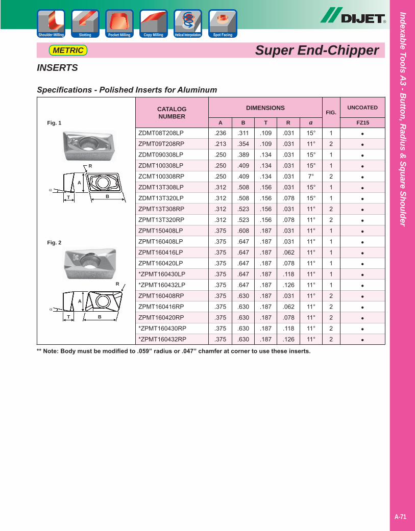
Indexable Tools A3 - B
utton, Radius &
Square Shoulder
A-71
®
Slotting Pocket Milling Copy Milling Helical InterpolationShoulder Milling
Super End-ChipperMETRIC
INSERTS
CATALOGNUMBER
DIMENSIONS
ZDMT08T208LP
ZPMT09T208RP
ZDMT090308LP
ZDMT100308LP
ZCMT100308RP
ZDMT13T308LP
ZDMT13T320LP
ZPMT13T308RP
ZPMT13T320RP
ZPMT150408LP
ZPMT160408LP
ZPMT160416LP
ZPMT160420LP
*ZPMT160430LP
*ZPMT160432LP
ZPMT160408RP
ZPMT160416RP
ZPMT160420RP
*ZPMT160430RP
*ZPMT160432RP
A
.236
.213
.250
.250
.250
.312
.312
.312
.312
.375
.375
.375
.375
.375
.375
.375
.375
.375
.375
.375
B
.311
.354
.389
.409
.409
.508
.508
.523
.523
.608
.647
.647
.647
.647
.647
.630
.630
.630
.630
.630
T
.109
.109
.134
.134
.134
.156
.156
.156
.156
.187
.187
.187
.187
.187
.187
.187
.187
.187
.187
.187
R
.031
.031
.031
.031
.031
.031
.078
.031
.078
.031
.031
.062
.078
.118
.126
.031
.062
.078
.118
.126
a15°
11°
15°
15°
7°
15°
15°
11°
11°
11°
11°
11°
11°
11°
11°
11°
11°
11°
11°
11°
FZ15
UNCOATED
••••••••••••••••••••
** Note: Body must be modified to .059” radius or .047” chamfer at corner to use these inserts.
Specifications - Polished Inserts for Aluminum
FIG.
1
2
1
1
2
1
1
2
2
1
1
1
1
1
1
2
2
2
2
2
Fig. 1
A
BTα
R
Fig. 2
A
BTα
R
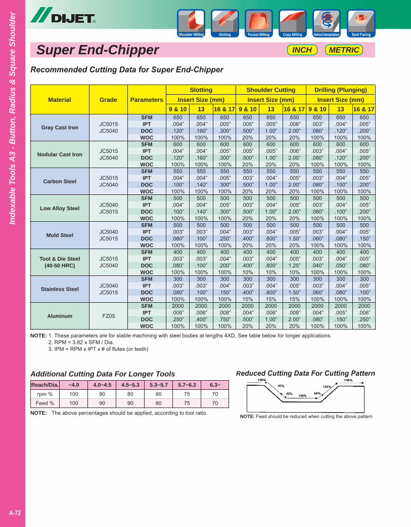
Super End-Chipper
®
A-72
Inde
xabl
e To
ols
A3
- But
ton,
Rad
ius
& S
quar
e Sh
ould
er
Slotting Pocket Milling Copy Milling Helical InterpolationShoulder Milling
METRICINCH
NOTE: 1. These parameters are for stable machining with steel bodies at lengths 4XD. See table below for longer applications.2. RPM = 3.82 x SFM / Dia.3. IPM = RPM x IPT x # of flutes (or teeth)
Reduced Cutting Data For Cutting Pattern
NOTE: Feed should be reduced when cutting the above patternNOTE: The above percentages should be applied, according to tool ratio.
Additional Cutting Data For Longer Tools
rpm %
Feed %
100
100
90
90
80
90
80
80
75
75
70
70
Reach/Dia. ~4.0 4.0~4.5 4.5~5.3 5.3~5.7 5.7~6.2 6.3~
Recommended Cutting Data for Super End-Chipper
Gray Cast Iron
Nodular Cast Iron
Carbon Steel
Low Alloy Steel
Mold Steel
Tool & Die Steel(40-50 HRC)
Stainless Steel
Aluminum
MaterialSlotting Shoulder Cutting Drilling (Plunging)
9 & 10 9 & 10 9 & 1013 13 1316 & 17 16 & 17 16 & 17Grade
650.004”.120”100%600
.004”
.120”100%550
.004”
.100”100%500
.004”
.100”100%500
.003”
.080”100%400
.003”
.080”100%300
.003”
.080”100%2000.006”.250”100%
650.005”.500”20%600
.005”
.500”20%550
.003”
.500”20%500
.003”
.500”20%500
.003”
.400”20%400
.003”
.400”10%300
.003”
.400”15%2000.004”.500”20%
650.003”.080”100%600
.003”
.080”100%550
.003”
.080”100%500
.003”
.080”100%500
.003”
.060”100%400
.003”
.040”100%300
.003”
.060”100%2000.004”.080”100%
650.004”.160”100%600
.004”
.160”100%550
.004”
.140”100%500
.004”
.140”100%500
.003”
.100”100%400
.003”
.100”100%300
.003”
.100”100%2000.006”.400”100%
650.005”1.00”20%600
.005”1.00”20%550
.004”1.00”20%500
.004”1.00”20%500
.004”
.800”20%400
.004”
.800”10%300
.004”
.800”15%2000.006”1.00”20%
650.004”.120”100%600
.004”
.120”100%550
.004”
.100”100%500
.004”
.100”100%500
.004”
.080”100%400
.004”
.050”100%300
.004”
.080”100%2000.005”.150”100%
650.005”.300”100%600
.005”
.300”100%550
.005”
.300”100%500
.005”
.300”100%500
.004”
.250”100%400
.004”
.200”100%300
.004”
.150”100%2000.008”.750”100%
650.006”2.00”20%600
.006”2.00”20%550
.005”2.00”20%500
.005”2.00”20%500
.005”1.50”20%400
.005”1.25”10%300
.005”1.50”15%2000.008”2.00”20%
650.005”.200”100%600
.005”
.200”100%550
.005”
.200”100%500
.005”
.200”100%500
.005”
.150”100%400
.005”
.080”100%300
.005”
.100”100%2000.006”.250”100%
JC5015JC5040
JC5015JC5040
JC5015JC5040
JC5040JC5015
JC5040JC5015
JC5015JC5040
JC5040JC5015
FZ05
Insert Size (mm) Insert Size (mm) Insert Size (mm)Parameters
SFMIPT
DOCWOCSFMIPT
DOCWOCSFMIPT
DOCWOCSFMIPT
DOCWOCSFMIPT
DOCWOCSFMIPT
DOCWOCSFMIPT
DOCWOCSFMIPT
DOCWOC

Indexable Tools A3 - B
utton, Radius &
Square Shoulder
A-73
SAP CuttersHigh Productivity & Multi-Functional
®
• 90 degree square shoulder rougher.
• Parallelogram shape insert is available in two sizes - 10mm and 16mm.
• Available in G-Body and NP body.
• Coolant thru bodies.
• Inserts capable of fitting into other brand bodies.
SlottingFace Milling Shoulder Milling
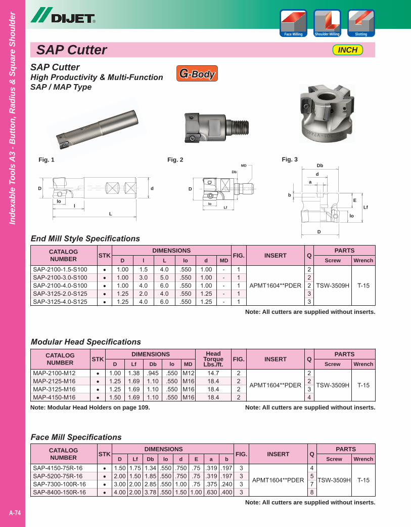
SAP Cutter
®
A-74
Inde
xabl
e To
ols
A3
- But
ton,
Rad
ius
& S
quar
e Sh
ould
er
INCH
SlottingFace Milling Shoulder Milling
SAP CutterHigh Productivity & Multi-FunctionSAP / MAP Type
G-Body
Modular Head Specifications
1.001.251.251.50
1.381.691.691.69
.9451.101.101.10
.550
.550
.550
.550
2222
2234
CATALOGNUMBER
DIMENSIONSD
MAP-2100-M12MAP-2125-M16MAP-3125-M16MAP-4150-M16
APMT1604**PDER
PARTSScrew Wrench
STK QLf Db lo
INSERT
TSW-3509H T-15
Note: All cutters are supplied without inserts.
••••
FIG.
Face Mill Specifications
1.502.003.004.00
1.751.502.002.00
1.341.852.853.78
.550
.550
.550
.550
.750
.7501.001.50
.75
.75
.751.00
.319
.319
.375
.630
.197
.197
.240
.400
3333
4578
CATALOGNUMBER
DIMENSIONSD
SAP-4150-75R-16SAP-5200-75R-16SAP-7300-100R-16SAP-8400-150R-16
APMT1604**PDER
PARTSScrew Wrench
STK QLf Db lo d b
INSERT
TSW-3509H T-15
Note: All cutters are supplied without inserts.
••••
FIG.E a
End Mill Style Specifications
1.001.001.001.251.25
1.53.04.02.04.0
4.05.06.04.06.0
.550
.550
.550
.550
.550
1.001.001.001.251.25
-----
11111
22233
CATALOGNUMBER
DIMENSIONSD
SAP-2100-1.5-S100SAP-2100-3.0-S100SAP-2100-4.0-S100SAP-3125-2.0-S125SAP-3125-4.0-S125
APMT1604**PDER
PARTSScrew Wrench
STK Ql L lo d MD
INSERT
TSW-3509H T-15
Note: All cutters are supplied without inserts.
•••••
FIG.
Fig. 1
D
lL
lo
d
Fig. 3
D
Lf
Db
lo
d
bE
a
Fig. 2
D
Db
Lflo
MD
HeadTorqueLbs./ft.
14.718.418.418.4
M12M16M16M16
MD
Note: Modular Head Holders on page 109.
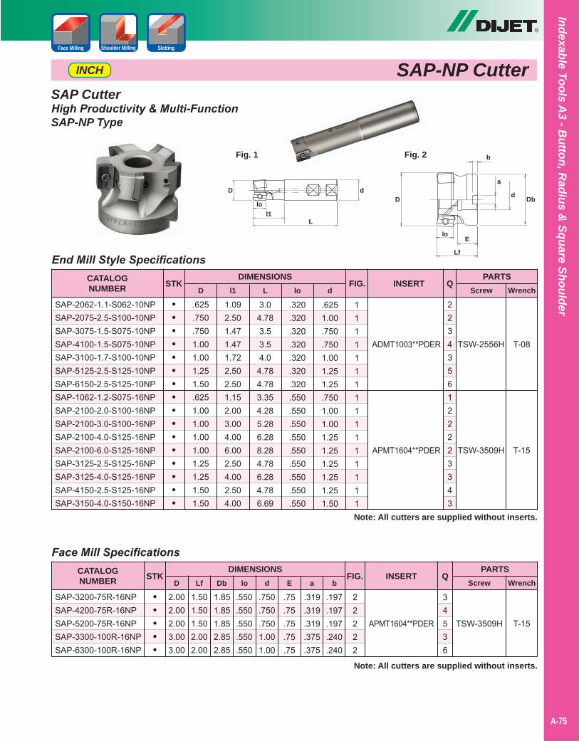
Indexable Tools A3 - B
utton, Radius &
Square Shoulder
A-75
®
SAP-NP CutterINCH
SAP CutterHigh Productivity & Multi-FunctionSAP-NP Type
End Mill Style Specifications
.625
.750
.7501.001.001.251.50.6251.001.001.001.001.251.251.501.50
1.092.501.471.471.722.502.501.152.003.004.006.002.504.002.504.00
3.04.783.53.54.0
4.784.783.354.285.286.288.284.786.284.786.69
.320
.320
.320
.320
.320
.320
.320
.550
.550
.550
.550
.550
.550
.550
.550
.550
.6251.00.750.7501.001.251.25.7501.001.001.251.251.251.251.251.50
1111111111111111
CATALOGNUMBER
DIMENSIONSD l1 L lo d
SAP-2062-1.1-S062-10NPSAP-2075-2.5-S100-10NPSAP-3075-1.5-S075-10NPSAP-4100-1.5-S075-10NPSAP-3100-1.7-S100-10NPSAP-5125-2.5-S125-10NPSAP-6150-2.5-S125-10NPSAP-1062-1.2-S075-16NPSAP-2100-2.0-S100-16NPSAP-2100-3.0-S100-16NPSAP-2100-4.0-S125-16NPSAP-2100-6.0-S125-16NPSAP-3125-2.5-S125-16NPSAP-3125-4.0-S125-16NPSAP-4150-2.5-S125-16NPSAP-3150-4.0-S150-16NP
ADMT1003**PDER
APMT1604**PDER
PARTSScrew Wrench
STK QINSERT
Note: All cutters are supplied without inserts.
••••••••••••••••
FIG.
Face Mill Specifications
2.002.002.003.003.00
1.501.501.502.002.00
1.851.851.852.852.85
.550
.550
.550
.550
.550
.750
.750
.7501.001.00
.75
.75
.75
.75
.75
.319
.319
.319
.375
.375
.197
.197
.197
.240
.240
22222
CATALOGNUMBER
DIMENSIONSD Lf Db lo d E a b
SAP-3200-75R-16NPSAP-4200-75R-16NPSAP-5200-75R-16NPSAP-3300-100R-16NPSAP-6300-100R-16NP
APMT1604**PDER
PARTSScrew Wrench
STK QINSERT
Note: All cutters are supplied without inserts.
•••••
FIG.
T-15
T-08
T-15
TSW-3509H
TSW-2556H
TSW-3509H
D
Ll1
d
lo
Fig. 1 Fig. 2
D
Lf
Db
lo
b
a
d
E
SlottingFace Milling Shoulder Milling
2234356122223343
34536
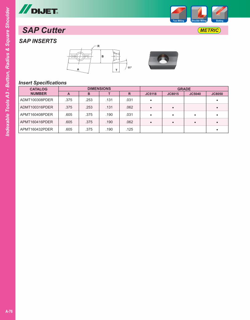
SAP Cutter
®
A-76
Inde
xabl
e To
ols
A3
- But
ton,
Rad
ius
& S
quar
e Sh
ould
er
SlottingFace Milling Shoulder Milling
SAP INSERTS
Insert SpecificationsCATALOGNUMBER
DIMENSIONS
ADMT100308PDER
ADMT100316PDER
APMT160408PDER
APMT160416PDER
APMT160432PDER
GRADEJC5040JC8015JC5118 JC8050
.253
.253
.375
.375
.375
.375
.375
.605
.605
.605
.131
.131
.190
.190
.190
.031
.062
.031
.062
.125
A B T R
••
•••
••••
•••••
A
B
T11°
R
METRIC
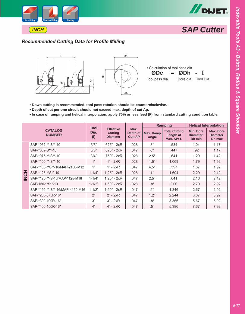
®
Indexable Tools A3 - B
utton, Radius &
Square Shoulder
A-77
SAP CutterINCH
Recommended Cutting Data for Profile Milling
CATALOGNUMBER
Ramping
SAP-*062-**-S**-10SAP-*062-S**-16SAP-*075-**-S**-10SAP-*100-**-S**-10SAP-*100-**S**-16/MAP-2100-M12SAP-*125-**S**-10SAP-*125-**-S-16/MAP-*125-M16SAP-150-**S**-10SAP-*150-**-S**-16/MAP-4150-M16SAP-*200-075R-16*SAP-*300-100R-16*SAP-*400-150R-16*
INC
H
EffectiveCutting
Diameter
ToolDia.(I)
Max.Depth ofCut: AP
Max. RampAngle
.625” - 2xR
.625” - 2xR
.750” - 2xR1” - 2xR1” - 2xR
1.25” - 2xR1.25” - 2xR1.50” - 2xR1.50” - 2xR
2” - 2xR3” - 2xR4” - 2xR
5/8”5/8”3/4”1”1”
1-1/4”1-1/4”1-1/2”1-1/2”
2”3”4”
.028
.047
.028
.028
.047
.028
.047
.028
.047
.047
.047
.047
3°6°
2.5°1.5°4.5°1°
2.5°.8°2°
1.2°.8°.5°
Total CuttingLength at
Max. AP: L
.534
.447
.6411.069.597
1.604.6412.00
1.3462.2443.3665.386
Helical InterpolationMin. BoreDiameter:
Dh min
1.04.92
1.291.791.672.292.162.792.673.675.677.67
1.171.171.421.921.922.422.422.922.923.925.927.92
• Down cutting is recommended, tool pass rotation should be counterclockwise.• Depth of cut per one circuit should not exceed max. depth of cut Ap.• In case of ramping and helical interpolation, apply 70% or less feed (F) from standard cutting condition table.
Max. BoreDiameter:Dh max
SlottingFace Milling Shoulder Milling
• Calculation of tool pass dia. ØDc = ØDh - ITool pass dia. Bore dia. Tool Dia.
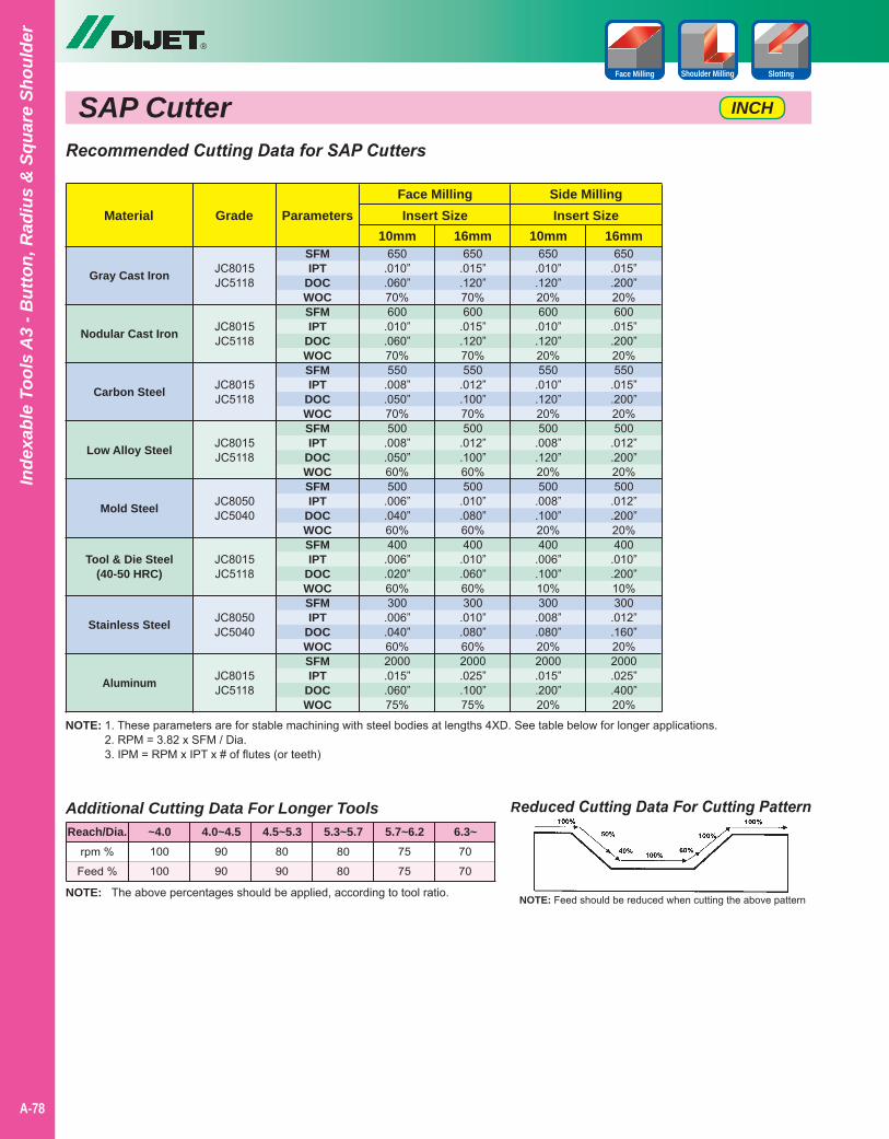
SAP Cutter
®
A-78
Inde
xabl
e To
ols
A3
- But
ton,
Rad
ius
& S
quar
e Sh
ould
er
INCH
NOTE: 1. These parameters are for stable machining with steel bodies at lengths 4XD. See table below for longer applications.2. RPM = 3.82 x SFM / Dia.3. IPM = RPM x IPT x # of flutes (or teeth)
Reduced Cutting Data For Cutting Pattern
NOTE: Feed should be reduced when cutting the above patternNOTE: The above percentages should be applied, according to tool ratio.
Additional Cutting Data For Longer Tools
rpm %
Feed %
100
100
90
90
80
90
80
80
75
75
70
70
Reach/Dia. ~4.0 4.0~4.5 4.5~5.3 5.3~5.7 5.7~6.2 6.3~
Recommended Cutting Data for SAP Cutters
Gray Cast Iron
Nodular Cast Iron
Carbon Steel
Low Alloy Steel
Mold Steel
Tool & Die Steel(40-50 HRC)
Stainless Steel
Aluminum
MaterialFace Milling Side Milling
10mm 10mm16mm 16mmGrade
650.010”.060”70%600
.010”
.060”70%550
.008”
.050”70%500
.008”
.050”60%500
.006”
.040”60%400
.006”
.020”60%300
.006”
.040”60%2000.015”.060”75%
650.010”.120”20%600
.010”
.120”20%550
.010”
.120”20%500
.008”
.120”20%500
.008”
.100”20%400
.006”
.100”10%300
.008”
.080”20%2000.015”.200”20%
650.015”.120”70%600
.015”
.120”70%550
.012”
.100”70%500
.012”
.100”60%500
.010”
.080”60%400
.010”
.060”60%300
.010”
.080”60%2000.025”.100”75%
650.015”.200”20%600
.015”
.200”20%550
.015”
.200”20%500
.012”
.200”20%500
.012”
.200”20%400
.010”
.200”10%300
.012”
.160”20%2000.025”.400”20%
JC8015JC5118
JC8015JC5118
JC8015JC5118
JC8015JC5118
JC8050JC5040
JC8015JC5118
JC8050JC5040
JC8015JC5118
Insert Size Insert SizeParameters
SFMIPT
DOCWOCSFMIPT
DOCWOCSFMIPT
DOCWOCSFMIPT
DOCWOCSFMIPT
DOCWOCSFMIPT
DOCWOCSFMIPT
DOCWOCSFMIPT
DOCWOC
SlottingFace Milling Shoulder Milling
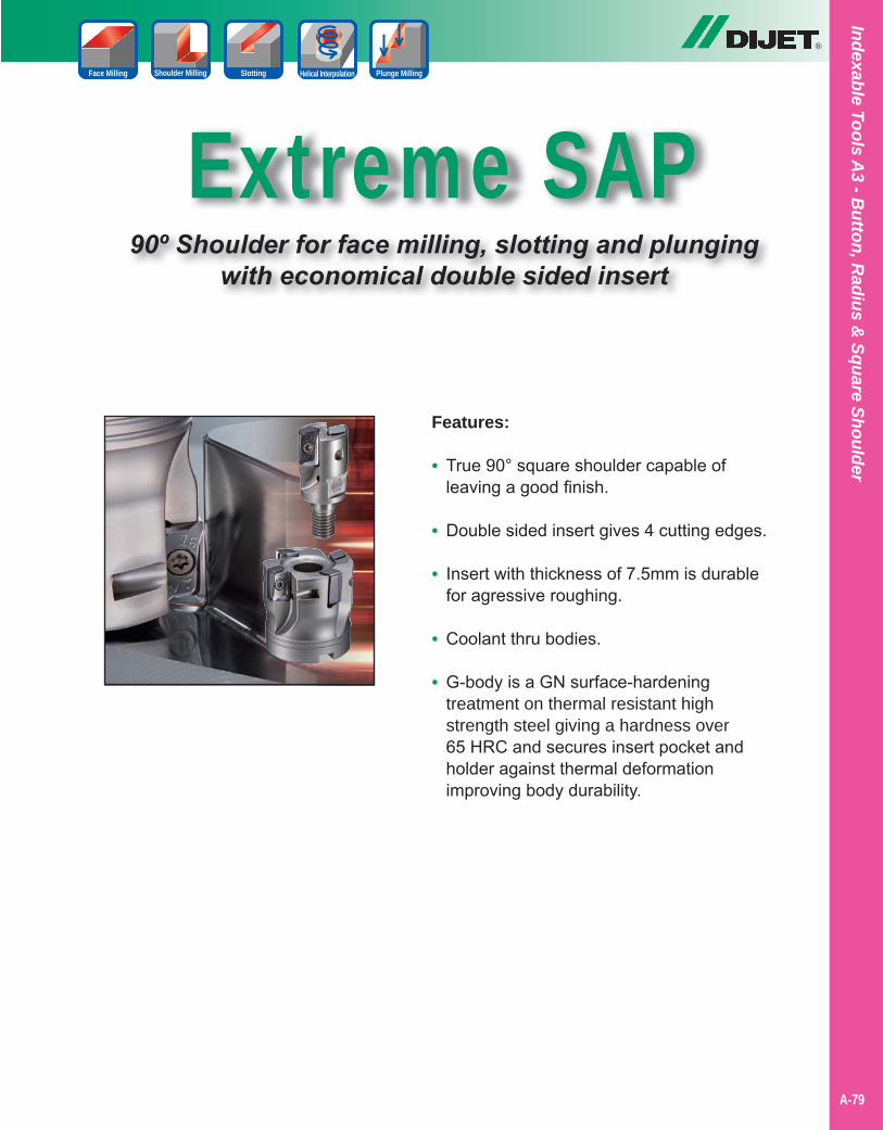
Indexable Tools A3 - B
utton, Radius &
Square Shoulder
A-79
Extreme SAP90º Shoulder for face milling, slotting and plunging
with economical double sided insert
®
Features:
• True 90° square shoulder capable of leaving a good finish.
• Double sided insert gives 4 cutting edges.
• Insert with thickness of 7.5mm is durable for agressive roughing.
• Coolant thru bodies.
• G-body is a GN surface-hardening treatment on thermal resistant high strength steel giving a hardness over 65 HRC and secures insert pocket and holder against thermal deformation improving body durability.
SlottingFace Milling Shoulder Milling Helical Interpolation Plunge Milling
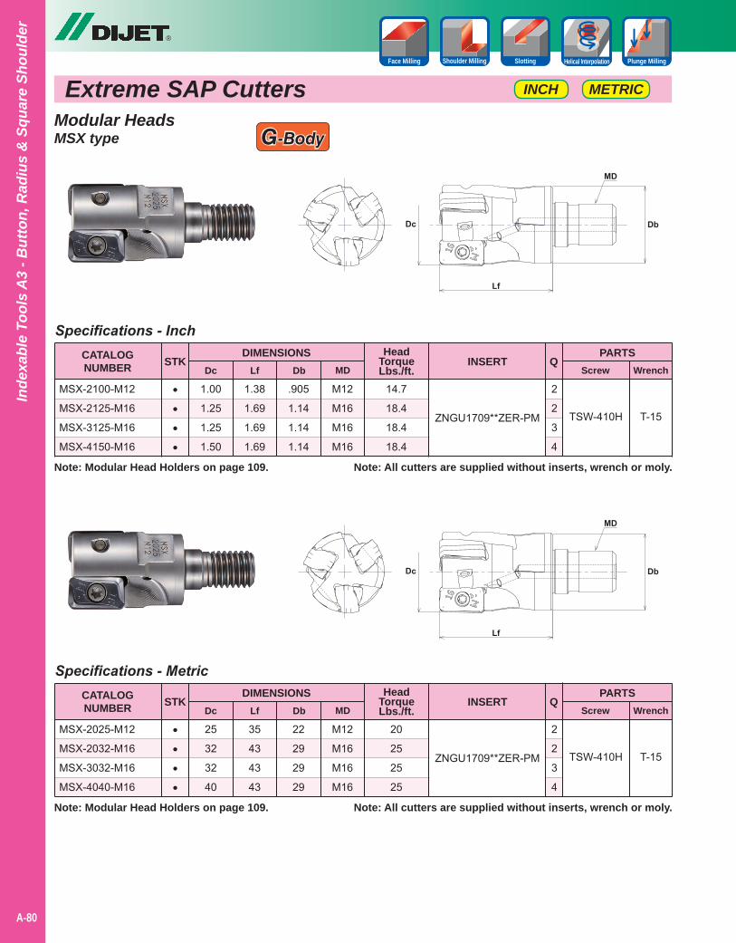
Extreme SAP Cutters
®
A-80
Inde
xabl
e To
ols
A3
- But
ton,
Rad
ius
& S
quar
e Sh
ould
er
Specifications - Inch
Specifications - Metric
1.00
1.25
1.25
1.50
25
32
32
40
1.38
1.69
1.69
1.69
35
43
43
43
.905
1.14
1.14
1.14
22
29
29
29
M12
M16
M16
M16
M12
M16
M16
M16
CATALOGNUMBER
CATALOGNUMBER
DIMENSIONS
DIMENSIONS
Dc
Dc
MSX-2100-M12
MSX-2125-M16
MSX-3125-M16
MSX-4150-M16
MSX-2025-M12
MSX-2032-M16
MSX-3032-M16
MSX-4040-M16
ZNGU1709**ZER-PM
ZNGU1709**ZER-PM
PARTS
PARTS
Screw
Screw
Wrench
Wrench
STK
STK
Q
Q
Lf
Lf
Db
Db
MD
MD
INSERT
INSERT
TSW-410H
TSW-410H
T-15
T-15
Note: All cutters are supplied without inserts, wrench or moly.
Note: All cutters are supplied without inserts, wrench or moly.
••••
••••
HeadTorqueLbs./ft.
HeadTorqueLbs./ft.
14.7
18.4
18.4
18.4
20
25
25
25
METRICINCH
Modular HeadsMSX type
2
2
3
4
2
2
3
4
Note: Modular Head Holders on page 109.
Note: Modular Head Holders on page 109.
SlottingFace Milling Shoulder Milling Helical Interpolation Plunge Milling
G-Body
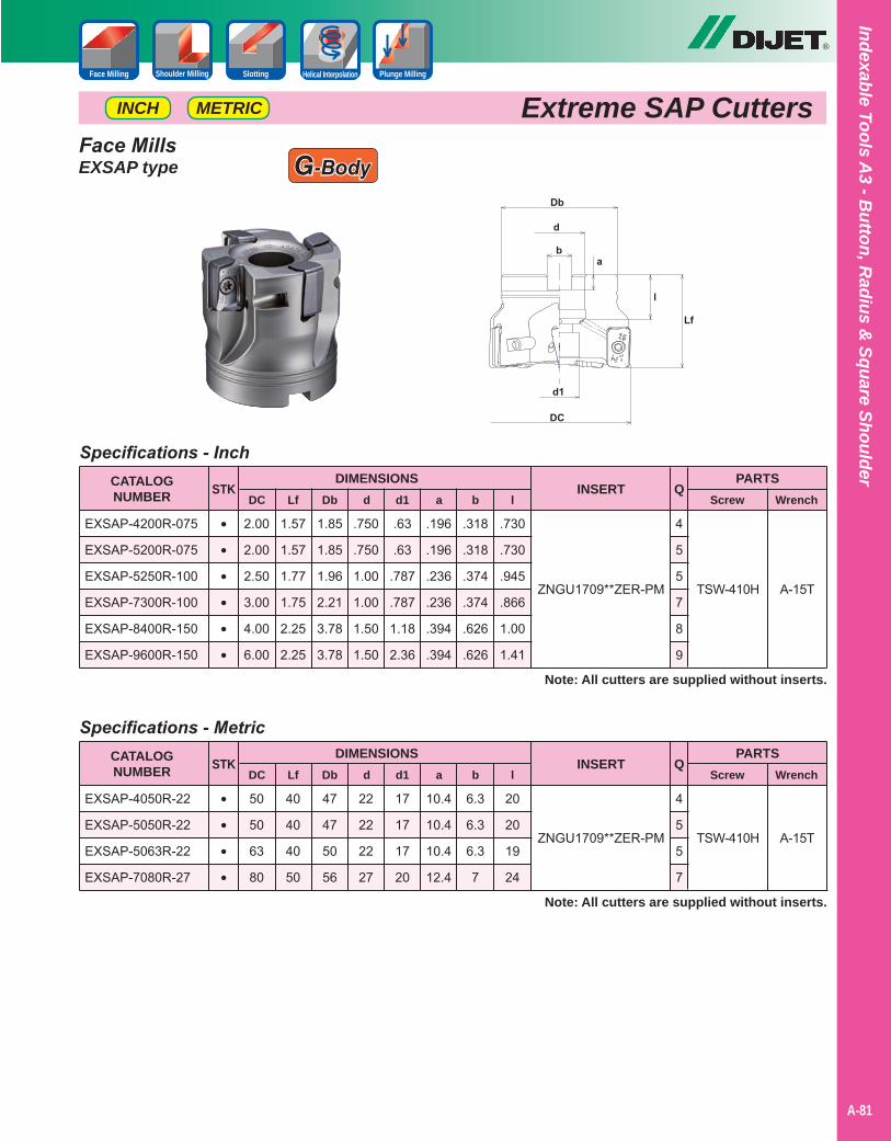
ZNGU1709**ZER-PM
ZNGU1709**ZER-PM
Indexable Tools A3 - B
utton, Radius &
Square Shoulder
A-81
®
••••••
••••
TSW-410H
TSW-410H
Specifications - Inch
Specifications - Metric
1.85
1.85
1.96
2.21
3.78
3.78
47
47
50
56
2.00
2.00
2.50
3.00
4.00
6.00
50
50
63
80
1.57
1.57
1.77
1.75
2.25
2.25
40
40
40
50
.750
.750
1.00
1.00
1.50
1.50
22
22
22
27
.63
.63
.787
.787
1.18
2.36
17
17
17
20
CATALOGNUMBER
CATALOGNUMBER
DC
DC
PARTS
PARTS
Screw
Screw
Wrench
Wrench
STK
STK
Lf
Lf
Db
Db
d
d
d1
d1
INSERT
INSERT
Note: All cutters are supplied without inserts.
Note: All cutters are supplied without inserts.
Q
Q
EXSAP-4200R-075
EXSAP-5200R-075
EXSAP-5250R-100
EXSAP-7300R-100
EXSAP-8400R-150
EXSAP-9600R-150
EXSAP-4050R-22
EXSAP-5050R-22
EXSAP-5063R-22
EXSAP-7080R-27
DIMENSIONS
DIMENSIONS
.196
.196
.236
.236
.394
.394
10.4
10.4
10.4
12.4
a
a
.318
.318
.374
.374
.626
.626
6.3
6.3
6.3
7
b
b
4
5
5
7
8
9
4
5
5
7
A-15T
A-15T
Extreme SAP CuttersMETRICINCH
.730
.730
.945
.866
1.00
1.41
20
20
19
24
l
l
Face MillsEXSAP type
SlottingFace Milling Shoulder Milling Helical Interpolation Plunge Milling
G-Body
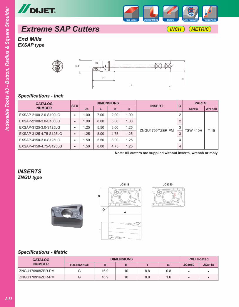
METRICINCH
SlottingFace Milling Shoulder Milling Helical Interpolation Plunge Milling
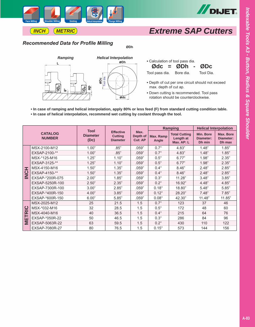
Recommended Data for Profile Milling
• In case of ramping and helical interpolation, apply 80% or less feed (F) from standard cutting condition table.• In case of helical interpolation, recommend wet cutting by coolant through the tool.
• Calculation of tool pass dia. Ødc = ØDh - ØDcTool pass dia. Bore dia. Tool Dia.
Ramping Helical Interpolation
• Depth of cut per one circuit should not exceed max. depth of cut ap.• Down cutting is recommended. Tool pass rotation should be counterclockwise.
Indexable Tools A3 - B
utton, Radius &
Square Shoulder
A-83
®
Extreme SAP CuttersMETRICINCH
SlottingFace Milling Shoulder Milling Helical Interpolation Plunge Milling
CATALOGNUMBER
Ramping
MSX-2100-M12EXSAP-2100-**MSX-*125-M16EXSAP-3125-**MSX-4150-M16EXSAP-4150-**EXSAP-*200R-075EXSAP-5250R-100EXSAP-7300R-100EXSAP-*400R-150EXSAP-*600R-150MSX-2025-M12MSX-*032-M16MSX-4040-M16EXSAP-*050R-22EXSAP-5063R-22EXSAP-7080R-27
INC
HM
ETR
IC
EffectiveCutting
Diameter
ToolDiameter
(Dc)
Max.Depth ofCut: AP
Max. RampAngle
.85”
.85”1.10”1.10”1.35”1.35”1.85”2.35”2.85”3.85”5.85”21.528.536.546.559.576.5
1.00”1.00”1.25”1.25”1.50”1.50”2.00”2.50”3.00”4.00”6.00”
253240506380
.059”
.059”
.059”
.059”
.059”
.059”
.059”
.059”
.059”
.059”
.059”1.51.51.51.51.51.5
0.7°0.7°0.5°0.5°0.4°0.4°0.3°0.2°
0.18°0.12°0.08°0.7°0.5°0.4°0.3°0.2°
0.15°
Total CuttingLength at
Max. AP: L4.83”4.83”6.77”6.77”8.46”8.46”11.28”16.92”18.80”28.20”42.30”
123172215286430573
Helical InterpolationMin. BoreDiameter:
Dh min1.48”1.48”1.98”1.98”2.48”2.48”3.48”4.48”5.48”7.48”11.48”
37486484110144
1.85”1.85”2.35”2.35”2.85”2.85”3.85”4.85”5.85”7.85”11.85”
46607696
122156
Max. BoreDiameter:Dh max
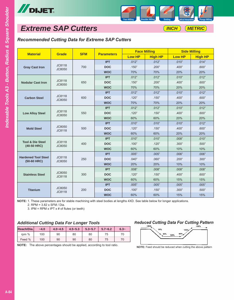
Extreme SAP Cutters
®
A-84
Inde
xabl
e To
ols
A3
- But
ton,
Rad
ius
& S
quar
e Sh
ould
er
METRICINCH
SlottingFace Milling Shoulder Milling Helical Interpolation Plunge Milling
NOTE: 1. These parameters are for stable machining with steel bodies at lengths 4XD. See table below for longer applications.2. RPM = 3.82 x SFM / Dia.3. IPM = RPM x IPT x # of flutes (or teeth)
Reduced Cutting Data For Cutting Pattern
NOTE: Feed should be reduced when cutting the above patternNOTE: The above percentages should be applied, according to tool ratio.
Additional Cutting Data For Longer Tools
rpm %
Feed %
100
100
90
90
80
90
80
80
75
75
70
70
Reach/Dia. ~4.0 4.0~4.5 4.5~5.3 5.3~5.7 5.7~6.2 6.3~
Recommended Cutting Data for Extreme SAP Cutters
Gray Cast Iron
Nodular Cast Iron
Carbon Steel
Low Alloy Steel
Mold Steel
Tool & Die Steel(40-50 HRC)
Hardened Tool Steel(50-60 HRC)
Stainless Steel
Titanium
MaterialHigh HPHigh HP Low HPLow HP
Grade
.012”
.150”70%.012”.150”70%.012”.120”70%.012”.120”60%.010”.120”60%.010”.100”60%.005”.040”20%.008”.120”60%.005”.100”60%
.012”
.200”70%.012”.200”70%.012”.150”70%.012”.150”60%.010”.150”60%.010”.120”60%.005”.060”20%.008”.150”60%.005”.150”60%
.010”
.400”20%.010”.400”20%.010”.400”20%.010”.400”20%.010”.400”20%.008”.300”10%.006”.200”10%.008”.400”15%.005”.300”15%
.014”
.600”20%.012”.600”20%.012”.600”20%.012”.600”20%.012”.600”20%.010”.500”10%.006”.300”10%.008”.600”15%.005”.500”15%
JC8118JC8050
JC8118JC8050
JC8118JC8050
JC8118JC8050
JC8050JC8118
JC8118JC8050
JC8118JC8050
JC8050JC8118
JC8050JC8118
Side MillingFace MillingSFM Parameters
IPTDOCWOCIPT
DOCWOCIPT
DOCWOCIPT
DOCWOCIPT
DOCWOCIPT
DOCWOCIPT
DOCWOCIPT
DOCWOCIPT
DOCWOC
700
650
600
550
500
400
250
300
200

Aero-ChipperHigh Precision & High Efficient Machining
on Aerospace Tooling
®
• High precision true 90 degree shoulder milling with ground insert capable of roughing and finishing.
• Sharp, uncoated grade FZ05 for aluminum and grade JC5118 for abrasive aluminum.
• Nine different corner radius available.
• Key in inserts gives added security allowing high velocity revolution specifications.
• Coolant thru bodies available in G-Body or NP body.
Indexable Tools A3 - B
utton, Radius &
Square Shoulder
A-85
Slotting Helical InterpolationPocket Milling Copy MillingShoulder Milling
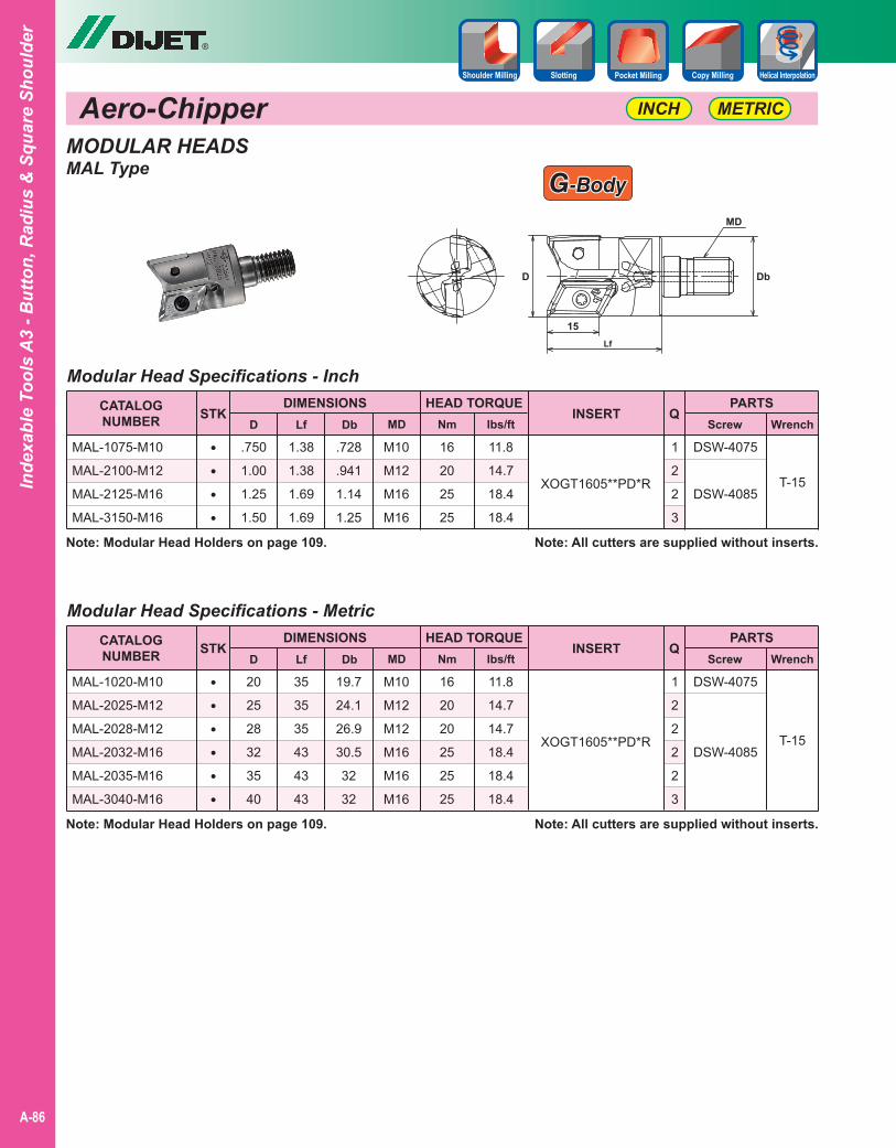
Aero-Chipper
®
A-86
Inde
xabl
e To
ols
A3
- But
ton,
Rad
ius
& S
quar
e Sh
ould
er
METRICINCH
MODULAR HEADSMAL Type
Slotting Helical InterpolationPocket Milling Copy MillingShoulder Milling
Modular Head Specifications - Inch
Modular Head Specifications - Metric
.750
1.00
1.25
1.50
20
25
28
32
35
40
1.38
1.38
1.69
1.69
35
35
35
43
43
43
.728
.941
1.14
1.25
19.7
24.1
26.9
30.5
32
32
M10
M12
M16
M16
M10
M12
M12
M16
M16
M16
CATALOGNUMBER
CATALOGNUMBER
DIMENSIONS
DIMENSIONS
D
D
MAL-1075-M10
MAL-2100-M12
MAL-2125-M16
MAL-3150-M16
MAL-1020-M10
MAL-2025-M12
MAL-2028-M12
MAL-2032-M16
MAL-2035-M16
MAL-3040-M16
XOGT1605**PD*R
XOGT1605**PD*R
PARTS
PARTS
Screw
Screw
Wrench
Wrench
STK
STK
Q
Q
Lf
Lf
Db
Db
MD
MD
INSERT
INSERT
DSW-4075
DSW-4085
DSW-4075
DSW-4085
T-15
T-15
Note: All cutters are supplied without inserts.
Note: All cutters are supplied without inserts.
••••
••••••
HEAD TORQUE
HEAD TORQUE
16
20
25
25
16
20
20
25
25
25
1
2
2
3
1
2
2
2
2
3
Note: Modular Head Holders on page 109.
Note: Modular Head Holders on page 109.
11.8
14.7
18.4
18.4
11.8
14.7
14.7
18.4
18.4
18.4
Nm
Nm
lbs/ft
lbs/ft
GG-Body-Body
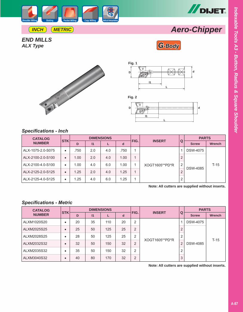
Indexable Tools A3 - B
utton, Radius &
Square Shoulder
A-87
®
Aero-ChipperMETRICINCH
Slotting Helical InterpolationPocket Milling Copy MillingShoulder Milling
END MILLSALX Type
Specifications - Inch
.750
1.00
1.00
1.25
1.25
2.0
2.0
4.0
2.0
4.0
4.0
4.0
6.0
4.0
6.0
.750
1.00
1.00
1.25
1.25
1
1
1
1
1
1
2
2
2
2
CATALOGNUMBER
DIMENSIONSD
ALX-1075-2.0-S075
ALX-2100-2.0-S100
ALX-2100-4.0-S100
ALX-2125-2.0-S125
ALX-2125-4.0-S125
XOGT1605**PD*R
PARTSScrew Wrench
STK Ql1 L d
INSERT
DSW-4075
DSW-4085T-15
Note: All cutters are supplied without inserts.
•••••
FIG.
Specifications - Metric
20
25
28
32
35
40
35
50
50
50
50
80
110
125
125
150
150
170
20
25
25
32
32
32
2
2
2
2
2
2
1
2
2
2
2
3
CATALOGNUMBER
DIMENSIONSD
ALXM1020S20
ALXM2025S25
ALXM2028S25
ALXM2032S32
ALXM2035S32
ALXM3040S32
XOGT1605**PD*R
PARTSScrew Wrench
STK Ql1 L d
INSERT
DSW-4075
DSW-4085T-15
Note: All cutters are supplied without inserts.
••••••
FIG.
G-Body
Fig. 2
D
l1
d
L
Fig. 1
D
l1
d
L
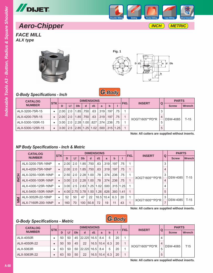
Aero-Chipper
®
A-88
Inde
xabl
e To
ols
A3
- But
ton,
Rad
ius
& S
quar
e Sh
ould
er
METRICINCH
Slotting Helical InterpolationPocket Milling Copy MillingShoulder Milling
FACE MILLALX type
Fig. 1
D
Lf
Dbd1 a
l
d
b
NP Body Specifications - Inch & Metric
2.00
2.00
2.50
3.00
3.00
4.00
52
160
2.0
2.0
2.0
2.0
2.5
2.75
50
70
1.85
1.85
2.28
2.28
2.83
3.78
47
100
.750
.750
1.00
1.00
1.25
1.50
22
50.8
.63
.63
.78
.78
1.02
1.26
16.5
72
.319
.319
.374
.374
.500
.626
10.4
19
.197
.197
.236
.236
.315
.393
6.3
11
.75
.75
.75
.75
1.25
1.41
20
43
1
1
1
1
1
1
1
1
CATALOGNUMBER
DIMENSIONSD
ALX-3200-75R-16NP
ALX-4200-75R-16NP
ALX-3250-100R-16NP
ALX-4300-100R-16NP
ALX-4300-125R-16NP
ALX-5400-150R-16NP
ALX-3052R-22-16NP
ALX-7160R-200-16NP
XOGT1605**PD*R
XOGT1605**PD*R
PARTSScrew Wrench
STK QLf Db d d1 a b l
INSERT
DSW-4085
DSW-4085
T-15
T-15
Note: All cutters are supplied without inserts.
••••••••
FIG.
G-Body Specifications - Inch
2.00
2.00
3.00
3.00
2.0
2.0
2.0
2.5
1.85
1.85
2.28
2.85
.750
.750
1.00
1.25
.63
.63
.827
1.02
.319
.319
.374
.500
.197
.197
.236
.315
.75
.75
.75
1.25
1
1
1
1
3
4
5
5
CATALOGNUMBER
DIMENSIONSD
ALX-3200-75R-15
ALX-4200-75R-15
ALX-5300-100R-15
ALX-5300-125R-15
XOGT1605**PD*R
PARTSScrew Wrench
STK QLf Db d d1 a b l
INSERT
DSW-4085 T-15
Note: All cutters are supplied without inserts.
••••
FIG.
G-Body
INC
H
G-Body Specifications - Metric
50
50
63
63
50
50
50
50
45
45
50
50
22.225
22
22.225
22
16.5
16.5
16.5
16.5
8.4
10.4
8.4
10.4
5
6.3
5
6.3
20
20
20
20
1
1
1
1
4
4
5
5
CATALOGNUMBER
DIMENSIONSD
ALX-4050R
ALX-4050R-22
ALX-5063R
ALX-5063R-22
XOGT1605**PD*R
PARTSScrew Wrench
STK QLf Db d d1 a b l
INSERT
DSW-4085 T15
Note: All cutters are supplied without inserts.
••••
FIG.
G-Body
MM
3
4
3
4
4
5
3
7
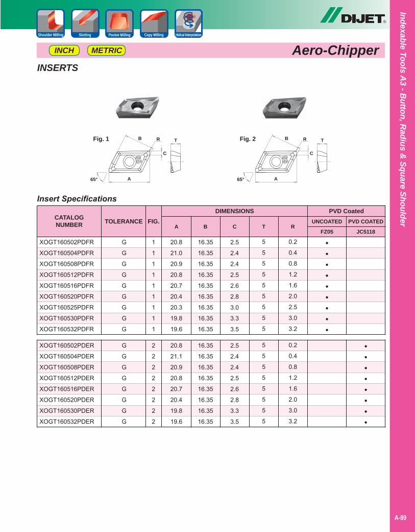
Indexable Tools A3 - B
utton, Radius &
Square Shoulder
A-89
®
Aero-ChipperMETRICINCH
Slotting Helical InterpolationPocket Milling Copy MillingShoulder Milling
Insert Specifications
20.8
21.0
20.9
20.8
20.7
20.4
20.3
19.8
19.6
20.8
21.1
20.9
20.8
20.7
20.4
19.8
19.6
16.35
16.35
16.35
16.35
16.35
16.35
16.35
16.35
16.35
16.35
16.35
16.35
16.35
16.35
16.35
16.35
16.35
2.5
2.4
2.4
2.5
2.6
2.8
3.0
3.3
3.5
2.5
2.4
2.4
2.5
2.6
2.8
3.3
3.5
5
5
5
5
5
5
5
5
5
5
5
5
5
5
5
5
5
0.2
0.4
0.8
1.2
1.6
2.0
2.5
3.0
3.2
0.2
0.4
0.8
1.2
1.6
2.0
3.0
3.2
CATALOGNUMBER
DIMENSIONS
XOGT160502PDFR
XOGT160504PDFR
XOGT160508PDFR
XOGT160512PDFR
XOGT160516PDFR
XOGT160520PDFR
XOGT160525PDFR
XOGT160530PDFR
XOGT160532PDFR
XOGT160502PDER
XOGT160504PDER
XOGT160508PDER
XOGT160512PDER
XOGT160516PDER
XOGT160520PDER
XOGT160530PDER
XOGT160532PDER
PVD Coated
FZ05 JC5118A B C T R
TOLERANCE
G
G
G
G
G
G
G
G
G
G
G
G
G
G
G
G
G
•••••••••
••••••••
INSERTS
FIG.
1
1
1
1
1
1
1
1
1
2
2
2
2
2
2
2
2
UNCOATED PVD COATED
A
B
C
TR
65°
Fig. 1
A
B
C
TR
65°
Fig. 2
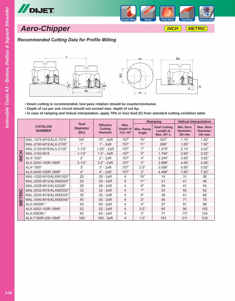
Aero-Chipper
®
A-90
Inde
xabl
e To
ols
A3
- But
ton,
Rad
ius
& S
quar
e Sh
ould
er
METRICINCH
Slotting Helical InterpolationPocket Milling Copy MillingShoulder Milling
• Down cutting is recommended, tool pass rotation should be counterclockwise.• Depth of cut per one circuit should not exceed max. depth of cut Ap.• In case of ramping and helical interpolation, apply 70% or less feed (F) from standard cutting condition table.
CATALOGNUMBER
Ramping
MAL-1075-M10/ALX-1075*MAL-2100-M12/ALX-2100*MAL-2125-M16/ALX-2125*MAL-3150-M16ALX-*200*ALX-3250-100R-16NPALX-*300*ALX-5400-150R-16NPMAL-1020-M10/ALXM1020*MAL-2025-M12/ALXM2025*MAL-2028-M12/ALX2028*MAL-2032-M16/ALXM2032*MAL-2035-M16/ALXM2035*MAL-3040-M16/ALXM3040*ALX-4050R-*ALX-3052-100R-16NPALX-5063R-*ALX-7160R-200-16NP
INC
HM
ETR
IC
EffectiveCutting
Diameter
ToolDiameter
(Dc)
Max.Depth ofCut: AP
Max. RampAngle
.75” - 2xR1” - 2xR
1.25” - 2xR1.5” - 2xR2” - 2xR
2.5” - 2xR3” - 2xR4” - 2xR20 - 2xR25 - 2xR28 - 2xR32 - 2xR35 - 2xR40 - 2xR50 - 2xR52 - 2xR63 - 2xR160 - 2xR
3/4”1”
1-1/4”1-1/2”
2”2-1/2”
3”4”202528323540505263160
.157”
.157”
.157”
.157”
.157”
.157”
.157”
.157”4444444444
16°11°7°5°4°3°
2.5°2°
16°11°9°7°6°5°4°
3.5°3°
1.5°
Total CuttingLength at
Max. AP: L.547”.808”
1.279”1.794”2.245”2.996”3.596”4.496”
142126333846576577
153
Helical InterpolationMin. BoreDiameter:
Dh min1.15”1.65”2.15”2.65”3.65”4.65”5.65”7.65”
3141475561719195117311
1.42”1.92”2.42”2.92”3.92”4.92”5.92”7.92”
38485462687898
102124318
Max. BoreDiameter:Dh max
Recommended Cutting Data for Profile Milling
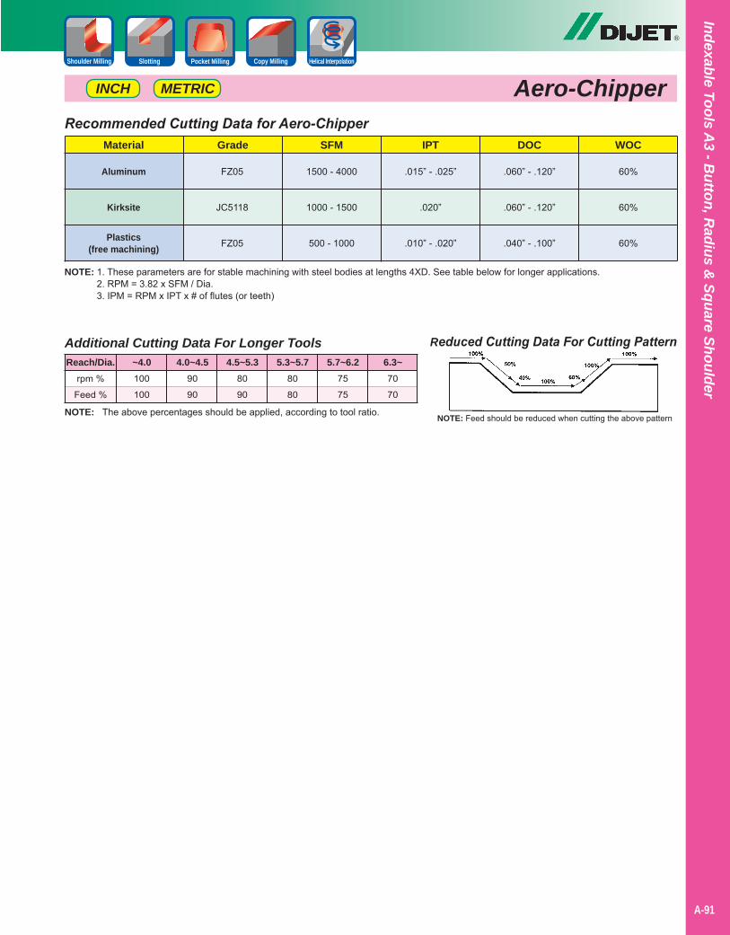
Indexable Tools A3 - B
utton, Radius &
Square Shoulder
A-91
®
Aero-ChipperMETRICINCH
Slotting Helical InterpolationPocket Milling Copy MillingShoulder Milling
NOTE: 1. These parameters are for stable machining with steel bodies at lengths 4XD. See table below for longer applications.2. RPM = 3.82 x SFM / Dia.3. IPM = RPM x IPT x # of flutes (or teeth)
Recommended Cutting Data for Aero-Chipper
Aluminum
Kirksite
Plastics(free machining)
Material DOCIPTSFMGrade WOC
.060” - .120”
.060” - .120”
.040” - .100”
.015” - .025”
.020”
.010” - .020”
1500 - 4000
1000 - 1500
500 - 1000
60%
60%
60%
Reduced Cutting Data For Cutting Pattern
NOTE: Feed should be reduced when cutting the above patternNOTE: The above percentages should be applied, according to tool ratio.
Additional Cutting Data For Longer Tools
rpm %
Feed %
100
100
90
90
80
90
80
80
75
75
70
70
Reach/Dia. ~4.0 4.0~4.5 4.5~5.3 5.3~5.7 5.7~6.2 6.3~
FZ05
JC5118
FZ05
Notes
A-40
®
A-92
Inde
xabl
e To
ols
A3
- But
ton,
Rad
ius
& S
quar
e Sh
ould
er
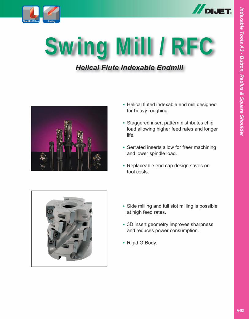
®
Indexable Tools A3 - B
utton, Radius &
Square Shoulder
A-93
Shoulder Milling Slotting
Swing Mill / RFCHelical Flute Indexable Endmill
• Helical fluted indexable end mill designed for heavy roughing.
• Staggered insert pattern distributes chip load allowing higher feed rates and longer life.
• Serrated inserts allow for freer machining and lower spindle load.
• Replaceable end cap design saves on tool costs.
• Side milling and full slot milling is possible at high feed rates.
• 3D insert geometry improves sharpness and reduces power consumption.
• Rigid G-Body.
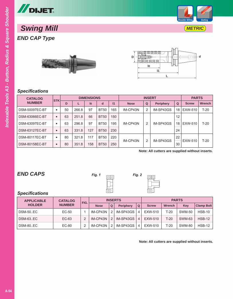
®
A-94
Inde
xabl
e To
ols
A3
- But
ton,
Rad
ius
& S
quar
e Sh
ould
er
Shoulder Milling Slotting
Swing Mill METRIC
END CAP Type
1
2
2
SpecificationsAPPLICABLE
HOLDERINSERTS
DSM-50..EC
DSM-63..EC
DSM-80..EC
PARTSScrew Wrench
FIG.Nose Q
2
2
2
IM-CP43N
IM-CP43N
IM-CP43N
Specifications
97
66
97
127
117
158
50
63
63
63
80
80
266.8
251.8
296.8
331.8
321.8
351.8
BT50
BT50
BT50
BT50
BT50
BT50
165
150
195
230
220
250
CATALOGNUMBER
DIMENSIONSD
DSM-50097EC-BT
DSM-63066EC-BT
DSM-63097EC-BT
DSM-63127EC-BT
DSM-80117EC-BT
DSM-80158EC-BT
PARTSScrew WrenchL l0 l1
INSERTSTK
••••••
d Nose Q Periphery Q
2
2
2
18
12
18
24
22
30
IM-CP43N
IM-CP43N
IM-CP43N
IM-SP43GS
IM-SP43GS
IM-SP43GS
EXW-510
EXW-510
EXW-510
T-20
T-20
T-20
Note: All cutters are supplied without inserts.
Note: All cutters are supplied without inserts.
END CAPS
D
L
l0l1
d
Fig. 1 Fig. 2
EC-50
EC-63
EC-80
CATALOGNUMBER Periphery Q
4
4
4
IM-SP43GS
IM-SP43GS
IM-SP43GS
Key Clamp Bolt
EXW-510
EXW-510
EXW-510
T-20
T-20
T-20
SWM-50
SWM-63
SWM-80
HSB-10
HSB-12
HSB-12
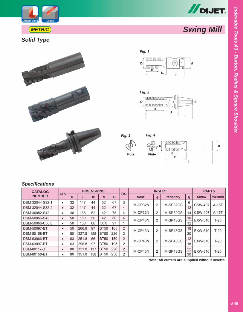
34441222222
Specifications
4444525666971586697117158
3232405050505063638080
147147165180180
266.8327.8251.8296.8321.8351.8
32324242
50.8BT50BT50BT50BT50BT50BT50
6767758097
165226150195220250
CATALOGNUMBER
DIMENSIONSD
DSM-32044-S32-1DSM-32044-S32-2DSM-40052-S42DSM-50056-S42DSM-50066-C50.8DSM-50097-BTDSM-50158-BTDSM-63066-BTDSM-63097-BTDSM-80117-BTDSM-80158-BT
PARTSScrew WrenchL l0 l1
FIG.INSERT
STK
•••••••••••
d Nose Q Periphery Q
2
2
2
2
2
2
612141012183012182230
IM-CP32N
IM-CP32N
IM-CP43N
IM-CP43N
IM-CP43N
IM-CP43N
IM-SP32GS
IM-SP32GS
IM-SP43GS
IM-SP43GS
IM-SP43GS
IM-SP43GS
CSW-407
CSW-407
EXW-510
EXW-510
EXW-510
EXW-510
Note: All cutters are supplied without inserts.
A-15T
A-15T
T-20
T-20
T-20
T-20
Fig. 1
D
L
l0l1
d
Fig. 4Fig. 3
Flute Flute
D
L
l0
d
Swing MillMETRIC
Solid Type
l1
Fig. 2
D
L
l0l1
d
®
Indexable Tools A3 - B
utton, Radius &
Square Shoulder
A-95
Shoulder Milling Slotting
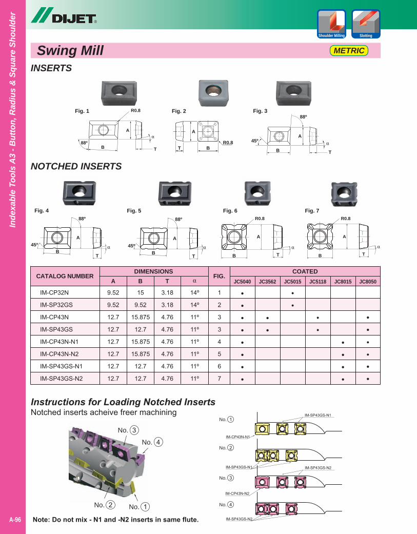
INSERTS
NOTCHED INSERTS
Fig. 2Fig. 1
A
R0.8
T
α
B88º
B
A
T
α45º
88ºFig. 3
R0.8T
A
B
CATALOG NUMBERDIMENSIONS
A B T α
IM-CP32N
IM-SP32GS
IM-CP43N
IM-SP43GS
IM-CP43N-N1
IM-CP43N-N2
IM-SP43GS-N1
IM-SP43GS-N2
9.52
9.52
12.7
12.7
12.7
12.7
12.7
12.7
15
9.52
15.875
12.7
15.875
15.875
12.7
12.7
3.18
3.18
4.76
4.76
4.76
4.76
4.76
4.76
14º
14º
11º
11º
11º
11º
11º
11º
1
2
3
3
4
5
6
7
FIG.JC3562
COATED
••
JC5040 JC5015 JC5118
••
••
JC8015
••••
••••••••
JC8050
••••••
Fig. 5 Fig. 6 Fig. 7
Instructions for Loading Notched InsertsNotched inserts acheive freer machining
Fig. 4
A
T
αB
45º
88º
A
T
αB
45º
88º
A
Tα
B
A
Tα
B
No.
IM-CP43N-N1
IM-SP43GS-N1
IM-SP43GS-N1 IM-SP43GS-N2
IM-CP43N-N2
IM-SP43GS-N2
1
No. 2
No. 3
No. 4No. 1No. 2
No. 3
No. 4
Note: Do not mix - N1 and -N2 inserts in same flute.
R0.8 R0.8
®
A-96
Inde
xabl
e To
ols
A3
- But
ton,
Rad
ius
& S
quar
e Sh
ould
er
Shoulder Milling Slotting
Swing Mill METRIC
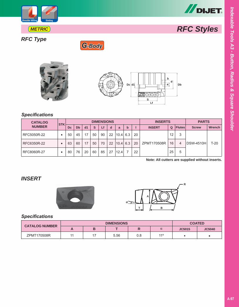
RFC StylesMETRIC
®
Indexable Tools A3 - B
utton, Radius &
Square Shoulder
A-97
Shoulder Milling Slotting
RFC Type
Specifications
17
17
20
50
63
80
45
60
76
50
50
60
90
70
85
CATALOGNUMBER
DIMENSIONSDc
RFC5050R-22
RFC6350R-22
RFC8060R-27
PARTSScrew WrenchDb d1 Lf
INSERTSSTK
•
•
•
S INSERT Q
ZPMT170508R
Note: All cutters are supplied without inserts.
12
16
25
DSW-4510H T-20
Flutes
3
4
5
22
22
27
d
10.4
10.4
12.4
a
6.3
6.3
7
b
20
20
22
l
G-Body
S
DbDcd
d1
Lf
b
a
l
A
BT
R
a
CATALOG NUMBERDIMENSIONS
A B T α
ZPMT170508R 11 17 5.56 11º
COATEDJC5015
•JC5040
•R
0.8
Specifications
INSERT
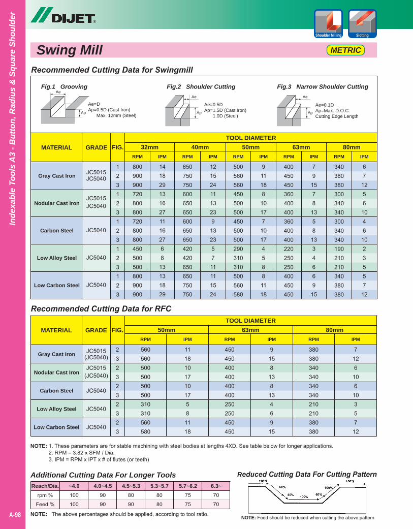
®
A-98
Inde
xabl
e To
ols
A3
- But
ton,
Rad
ius
& S
quar
e Sh
ould
er
Shoulder Milling Slotting
Swing Mill METRIC
Recommended Cutting Data for Swingmill
MATERIAL GRADE FIG.TOOL DIAMETER
32mm 40mm 50mm 63mm 80mm
Gray Cast Iron
Nodular Cast Iron
Carbon Steel
Low Alloy Steel
Low Carbon Steel
123123123123123
340380380300340340300340340190210210340380380
400450450360400400360400400220250250400450450
500560560450500500450500500290310310500560580
650750750600650650600650650420420650650750750
800900900720800800720800800450500500800900900
6712561046102355712
79
1578
1358
1334669
15
911188
1017 7
101745881118
1215241113239
13235711111524
14182913162711162768
13131829
RPMRPMRPMRPMRPM IPMIPMIPMIPMIPM
Ae=0.1DAp=Max. D.O.C.Cutting Edge Length
Ae=0.5DAp=1.5D (Cast Iron) 1.0D (Steel)
Ae
Ap
Ae
ApAp
AeFig.1 Grooving Fig.2 Shoulder Cutting Fig.3 Narrow Shoulder Cutting
Ae=DAp=0.5D (Cast Iron) Max. 12mm (Steel)
NOTE: 1. These parameters are for stable machining with steel bodies at lengths 4XD. See table below for longer applications.2. RPM = 3.82 x SFM / Dia.3. IPM = RPM x IPT x # of flutes (or teeth)
Reduced Cutting Data For Cutting Pattern
NOTE: Feed should be reduced when cutting the above patternNOTE: The above percentages should be applied, according to tool ratio.
Additional Cutting Data For Longer Tools
rpm %
Feed %
100
100
90
90
80
90
80
80
75
75
70
70
Reach/Dia. ~4.0 4.0~4.5 4.5~5.3 5.3~5.7 5.7~6.2 6.3~
Recommended Cutting Data for RFC
MATERIAL GRADE FIG.TOOL DIAMETER
50mm 63mm 80mm
JC5015(JC5040)
JC5015(JC5040)
JC5040
JC5040
JC5040
Gray Cast Iron
Nodular Cast Iron
Carbon Steel
Low Alloy Steel
Low Carbon Steel
2323232323
380380340340340340210210380380
450450400400400400250250450450
560560500500 500500310310560580
71261061035712
9158
138
13469
15
111810171017581118
RPMRPMRPM IPMIPMIPM
JC5015JC5040
JC5015JC5040
JC5040
JC5040
JC5040
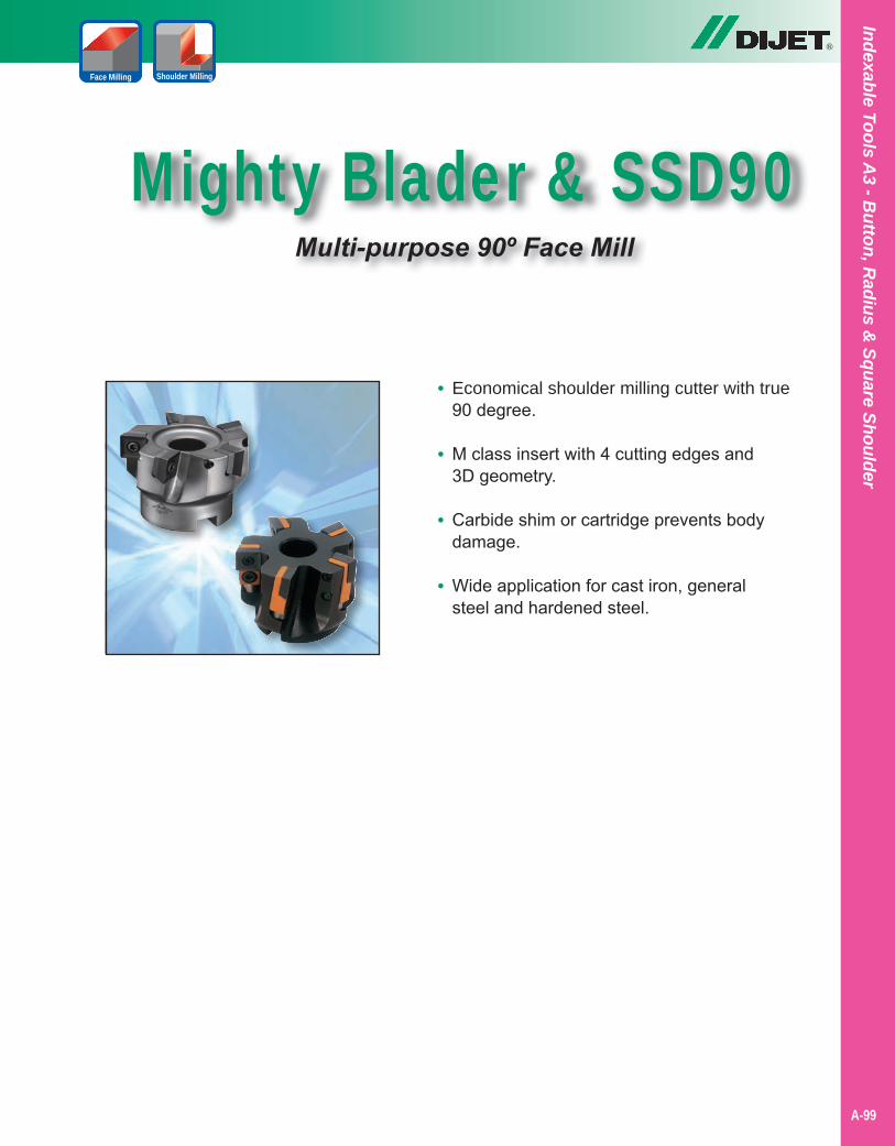
®
Indexable Tools A3 - B
utton, Radius &
Square Shoulder
A-99
Mighty Blader & SSD90Multi-purpose 90º Face Mill
Shoulder MillingFace Milling
• Economical shoulder milling cutter with true 90 degree.
• M class insert with 4 cutting edges and 3D geometry.
• Carbide shim or cartridge prevents body damage.
• Wide application for cast iron, general steel and hardened steel.
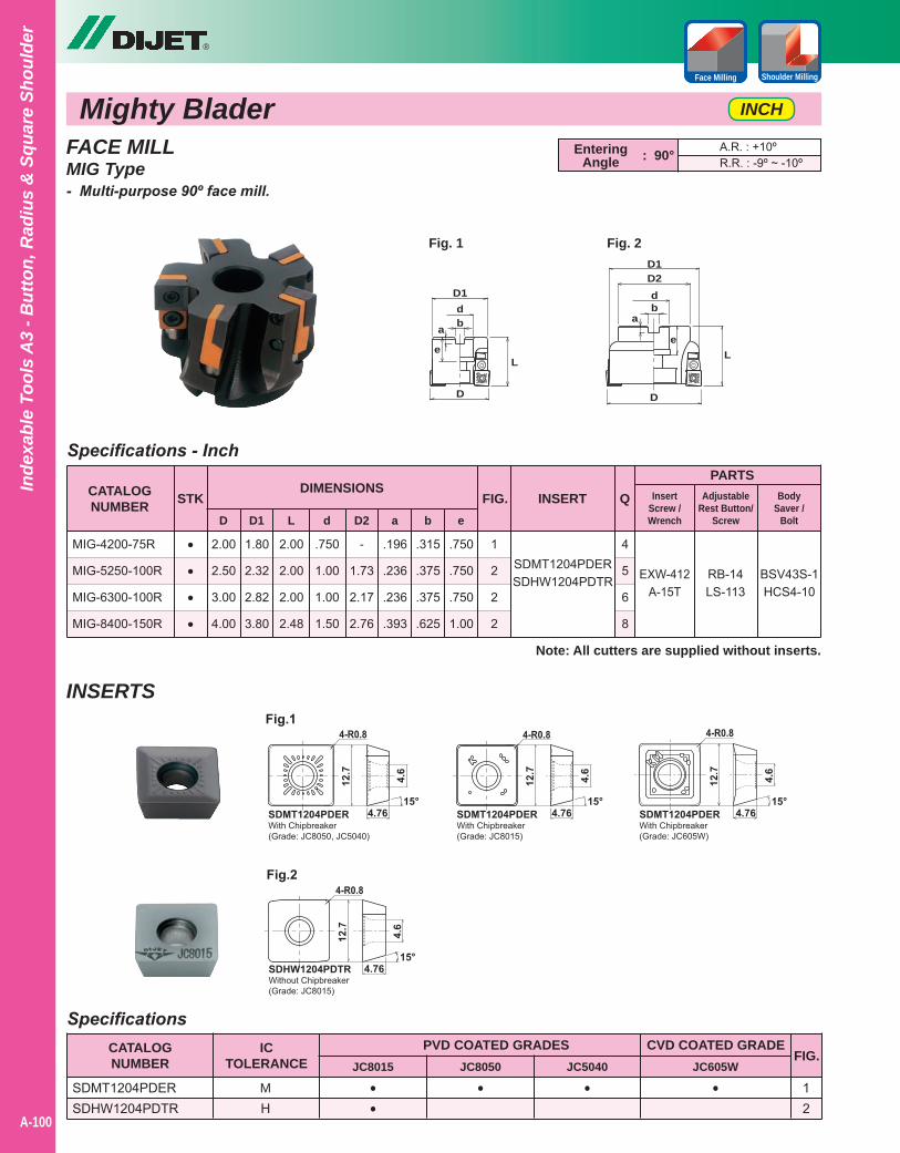
®
A-100
Inde
xabl
e To
ols
A3
- But
ton,
Rad
ius
& S
quar
e Sh
ould
er
Mighty Blader INCH
Shoulder MillingFace Milling
FACE MILLMIG Type- Multi-purpose 90º face mill.
Specifications - Inch
2.00
2.50
3.00
4.00
1.80
2.32
2.82
3.80
CATALOGNUMBER
DIMENSIONS
D
MIG-4200-75R
MIG-5250-100R
MIG-6300-100R
MIG-8400-150R
PARTSSTK
D1
INSERT
RB-14LS-113
Note: All cutters are supplied without inserts.
••••
BSV43S-1HCS4-10
FIG.
1
2
2
2
SDMT1204PDERSDHW1204PDTR
InsertScrew /Wrench
EXW-412A-15T
Q
4
5
6
8
2.00
2.00
2.00
2.48
L
.750
1.00
1.00
1.50
d
-
1.73
2.17
2.76
D2
.196
.236
.236
.393
a
.315
.375
.375
.625
b
.750
.750
.750
1.00
e
AdjustableRest Button/
Screw
BodySaver /
Bolt
EnteringAngle
A.R. : +10ºR.R. : -9º ~ -10º: 90°
Fig. 1
D
a b
e
D1d
L
D
ab
e
D1
d
L
D2
Fig. 2
INSERTS
SpecificationsCATALOGNUMBER
SDMT1204PDERSDHW1204PDTR
••
• • •
PVD COATED GRADESJC8015 JC8050 JC5040 JC605W
FIG.
12
ICTOLERANCE
MH
CVD COATED GRADE
(Grade: JC8015)(Grade: JC8050, JC5040)
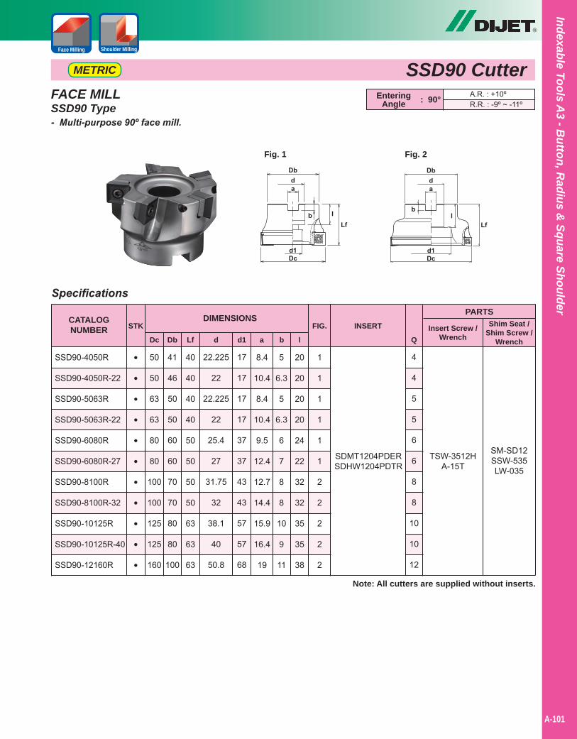
®
Indexable Tools A3 - B
utton, Radius &
Square Shoulder
A-101
Shoulder MillingFace Milling
SSD90 CutterMETRIC
Specifications
40
40
40
40
50
50
50
50
63
63
63
50
50
63
63
80
80
100
100
125
125
160
41
46
50
50
60
60
70
70
80
80
100
22.225
22
22.225
22
25.4
27
31.75
32
38.1
40
50.8
17
17
17
17
37
37
43
43
57
57
68
CATALOGNUMBER
DIMENSIONS
Dc
SSD90-4050R
SSD90-4050R-22
SSD90-5063R
SSD90-5063R-22
SSD90-6080R
SSD90-6080R-27
SSD90-8100R
SSD90-8100R-32
SSD90-10125R
SSD90-10125R-40
SSD90-12160R
PARTS
Insert Screw /WrenchDb Lf d1
STK
•
•
•
•
•
•
•
•
•
•
•
d
INSERT
Q
SDMT1204PDERSDHW1204PDTR
Note: All cutters are supplied without inserts.
4
4
5
5
6
6
8
8
10
10
12
TSW-3512HA-15T
SM-SD12SSW-535LW-035
8.4
10.4
8.4
10.4
9.5
12.4
12.7
14.4
15.9
16.4
19
a
5
6.3
5
6.3
6
7
8
8
10
9
11
b
20
20
20
20
24
22
32
32
35
35
38
1
1
1
1
1
1
2
2
2
2
2
l
EnteringAngle
A.R. : +10ºR.R. : -9º ~ -11º: 90°FACE MILL
SSD90 Type- Multi-purpose 90º face mill.
Shim Seat /Shim Screw /
Wrench
FIG.
Fig. 1 Fig. 2
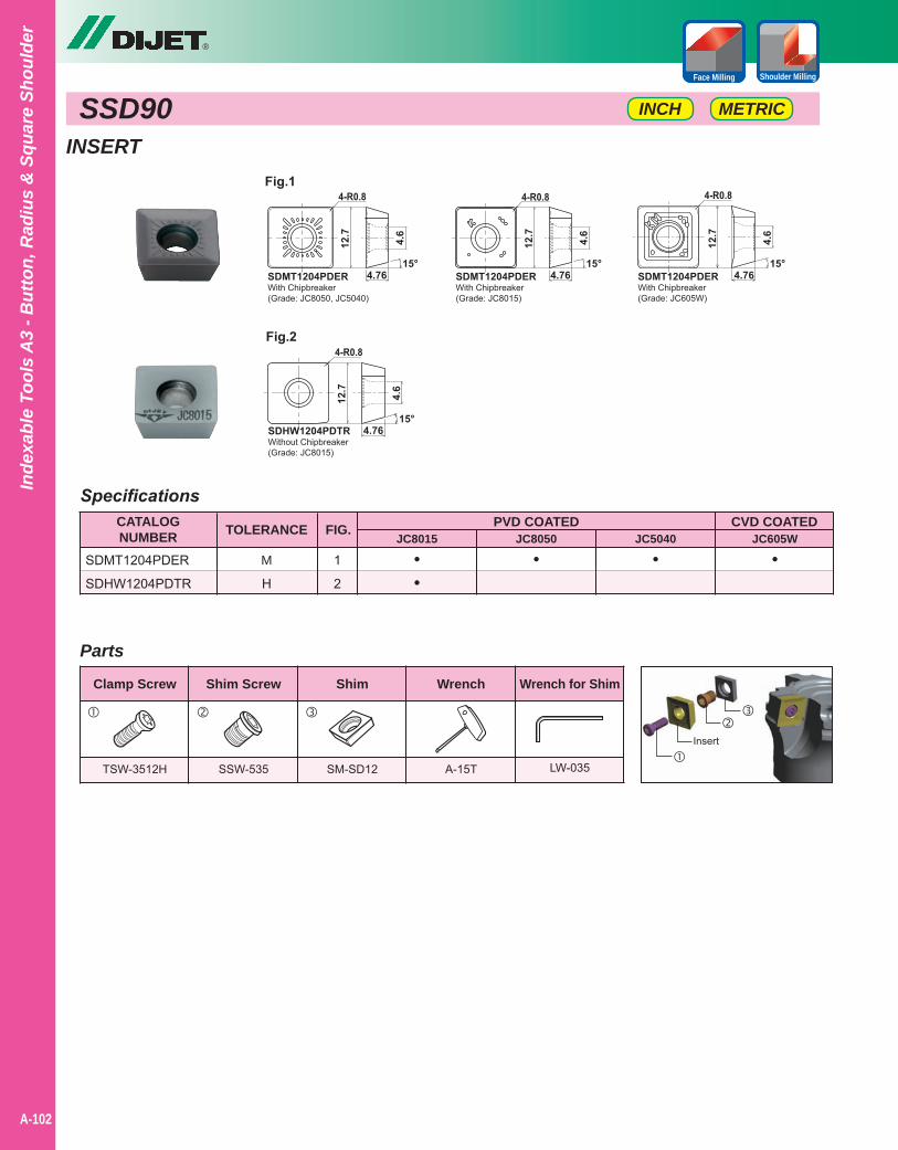
®
A-102
Inde
xabl
e To
ols
A3
- But
ton,
Rad
ius
& S
quar
e Sh
ould
er
SSD90 METRICINCH
Shoulder MillingFace Milling
INSERT
SpecificationsCATALOGNUMBER
SDMT1204PDER
SDHW1204PDTR
JC8015 JC8050 JC5040 JC605WPVD COATED CVD COATEDFIG.
1
2
M
H
••
• • •
TOLERANCE
Clamp Screw Shim Screw Shim Wrench Wrench for Shim
TSW-3512H SSW-535 SM-SD12 A-15T LW-035
Parts
Insert
(Grade: JC8015)(Grade: JC8050, JC5040)
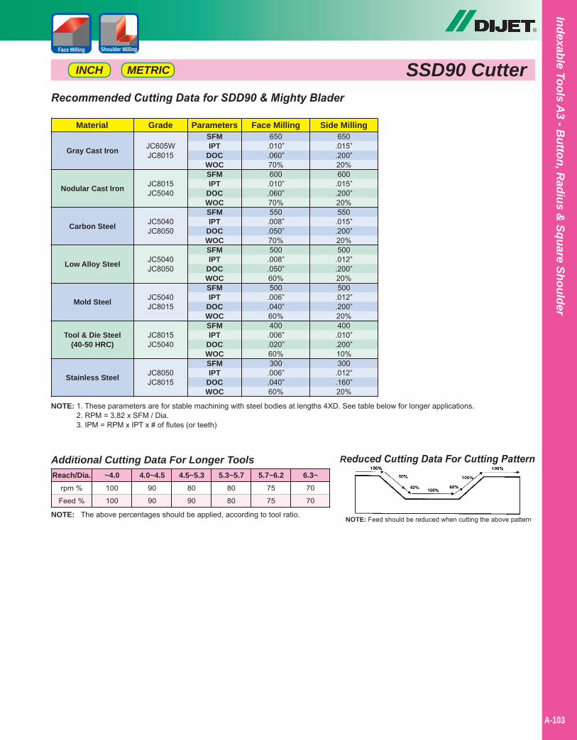
NOTE: 1. These parameters are for stable machining with steel bodies at lengths 4XD. See table below for longer applications.2. RPM = 3.82 x SFM / Dia.3. IPM = RPM x IPT x # of flutes (or teeth)
Reduced Cutting Data For Cutting Pattern
NOTE: Feed should be reduced when cutting the above patternNOTE: The above percentages should be applied, according to tool ratio.
Additional Cutting Data For Longer Tools
rpm %
Feed %
100
100
90
90
80
90
80
80
75
75
70
70
Reach/Dia. ~4.0 4.0~4.5 4.5~5.3 5.3~5.7 5.7~6.2 6.3~
Recommended Cutting Data for SDD90 & Mighty Blader
Gray Cast Iron
Nodular Cast Iron
Carbon Steel
Low Alloy Steel
Mold Steel
Tool & Die Steel(40-50 HRC)
Stainless Steel
Material Face Milling Side MillingGrade650
.010”
.060”70%600
.010”
.060”70%550
.008”
.050”70%500
.008”
.050”60%500
.006”
.040”60%400
.006”
.020”60%300
.006”
.040”60%
650.015”.200”20%600
.015”
.200”20%550
.015”
.200”20%500
.012”
.200”20%500
.012”
.200”20%400
.010”
.200”10%300
.012”
.160”20%
JC605WJC8015
JC8015JC5040
JC5040JC8050
JC5040JC8050
JC5040JC8015
JC8015JC5040
JC8050JC8015
ParametersSFMIPT
DOCWOCSFMIPT
DOCWOCSFMIPT
DOCWOCSFMIPT
DOCWOCSFMIPT
DOCWOCSFMIPT
DOCWOCSFMIPT
DOCWOC
®
Indexable Tools A3 - B
utton, Radius &
Square Shoulder
A-103
Shoulder MillingFace Milling
SSD90 CutterMETRICINCH

Notes
A-40
®
A-104
Inde
xabl
e To
ols
A3
- But
ton,
Rad
ius
& S
quar
e Sh
ould
er
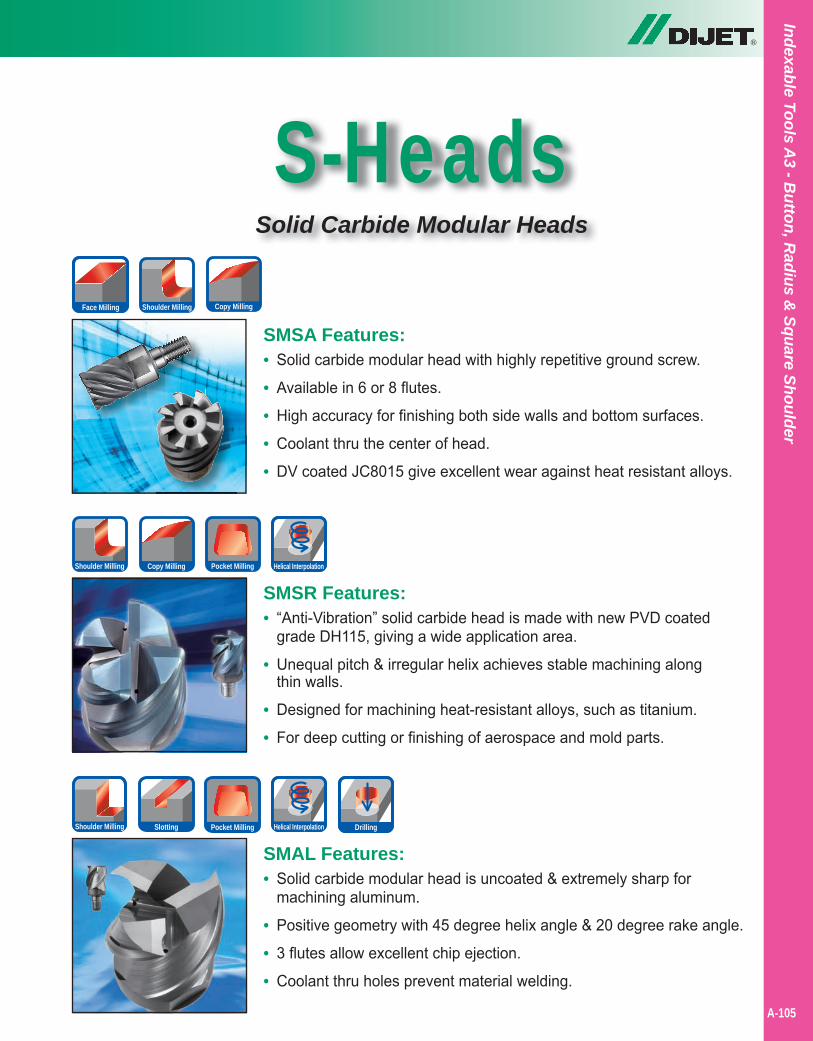
®
Indexable Tools A3 - B
utton, Radius &
Square Shoulder
S-HeadsSolid Carbide Modular Heads
SMSA Features:• Solid carbide modular head with highly repetitive ground screw.
• Available in 6 or 8 flutes.
• High accuracy for finishing both side walls and bottom surfaces.
• Coolant thru the center of head.
• DV coated JC8015 give excellent wear against heat resistant alloys.
SMSR Features:• “Anti-Vibration” solid carbide head is made with new PVD coated
grade DH115, giving a wide application area.
• Unequal pitch & irregular helix achieves stable machining alongthin walls.
• Designed for machining heat-resistant alloys, such as titanium.
• For deep cutting or finishing of aerospace and mold parts.
SMAL Features:• Solid carbide modular head is uncoated & extremely sharp for
machining aluminum.
• Positive geometry with 45 degree helix angle & 20 degree rake angle.
• 3 flutes allow excellent chip ejection.
• Coolant thru holes prevent material welding.
Copy MillingShoulder MillingFace Milling
Helical InterpolationPocket MillingCopy MillingShoulder Milling
Slotting Helical InterpolationPocket MillingShoulder Milling Drilling
A-105
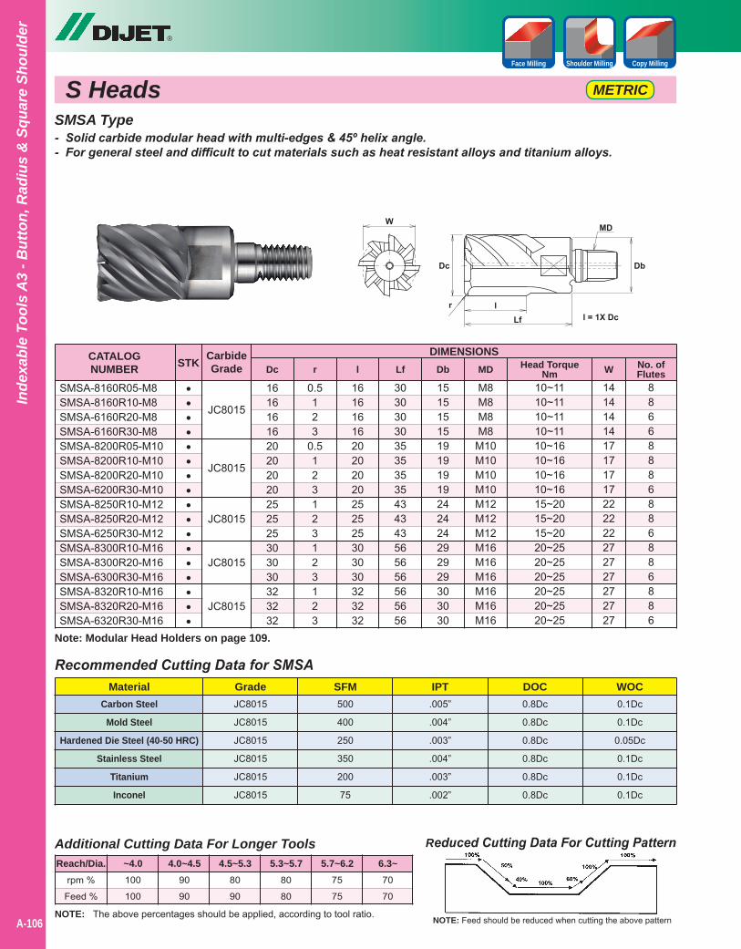
Carbon Steel
Mold Steel
Hardened Die Steel (40-50 HRC)
Stainless Steel
Titanium
Inconel
A-40
®
A-106
Inde
xabl
e To
ols
A3
- But
ton,
Rad
ius
& S
quar
e Sh
ould
er
Copy MillingShoulder MillingFace Milling
JC8015
JC8015
JC8015
JC8015
JC8015
CATALOGNUMBER
DIMENSIONS
SMSA-8160R05-M8SMSA-8160R10-M8SMSA-6160R20-M8SMSA-6160R30-M8SMSA-8200R05-M10SMSA-8200R10-M10SMSA-8200R20-M10SMSA-6200R30-M10SMSA-8250R10-M12SMSA-8250R20-M12SMSA-6250R30-M12SMSA-8300R10-M16SMSA-8300R20-M16SMSA-6300R30-M16SMSA-8320R10-M16SMSA-8320R20-M16SMSA-6320R30-M16
STK Dc r l Lf Db MD W No. ofFlutes
•••••••••••••••••
S Heads METRIC
SMSA Type- Solid carbide modular head with multi-edges & 45º helix angle.- For general steel and difficult to cut materials such as heat resistant alloys and titanium alloys.
Reduced Cutting Data For Cutting Pattern
NOTE: Feed should be reduced when cutting the above patternNOTE: The above percentages should be applied, according to tool ratio.
Additional Cutting Data For Longer Tools
rpm %
Feed %
100
100
90
90
80
90
80
80
75
75
70
70
Reach/Dia. ~4.0 4.0~4.5 4.5~5.3 5.3~5.7 5.7~6.2 6.3~
Recommended Cutting Data for SMSAMaterial Grade SFM IPT DOC WOC
JC8015
JC8015
JC8015
JC8015
JC8015
JC8015
500
400
250
350
200
75
.005”
.004”
.003”
.004”
.003”
.002”
0.8Dc
0.8Dc
0.8Dc
0.8Dc
0.8Dc
0.8Dc
0.1Dc
0.1Dc
0.05Dc
0.1Dc
0.1Dc
0.1Dc
1616161620202020252525303030323232
0.5123
0.5123123123123
1616161620202020252525303030323232
3030303035353535434343565656565656
1515151519191919242424292929303030
M8M8M8M8
M10M10M10M10M12M12M12M16M16M16M16M16M16
10~1110~1110~1110~1110~1610~1610~1610~1615~2015~2015~2020~2520~2520~2520~2520~2520~25
1414141417171717222222272727272727
88668886886886886
CarbideGrade Head Torque
Nm
Note: Modular Head Holders on page 109.
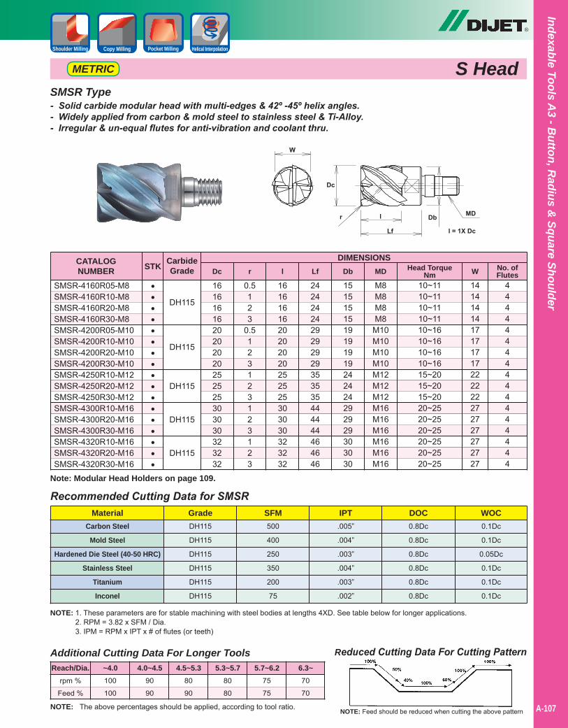
®
Indexable Tools A3 - B
utton, Radius &
Square Shoulder
A-107
S HeadMETRIC
SMSR Type- Solid carbide modular head with multi-edges & 42º -45º helix angles.- Widely applied from carbon & mold steel to stainless steel & Ti-Alloy.- Irregular & un-equal flutes for anti-vibration and coolant thru.
Carbon Steel
Mold Steel
Hardened Die Steel (40-50 HRC)
Stainless Steel
Titanium
Inconel
DH115
DH115
DH115
DH115
DH115
CATALOGNUMBER
DIMENSIONS
SMSR-4160R05-M8SMSR-4160R10-M8SMSR-4160R20-M8SMSR-4160R30-M8SMSR-4200R05-M10SMSR-4200R10-M10SMSR-4200R20-M10SMSR-4200R30-M10SMSR-4250R10-M12SMSR-4250R20-M12SMSR-4250R30-M12SMSR-4300R10-M16SMSR-4300R20-M16SMSR-4300R30-M16SMSR-4320R10-M16SMSR-4320R20-M16SMSR-4320R30-M16
STK Dc r l Lf Db MD W No. ofFlutes
•••••••••••••••••
Reduced Cutting Data For Cutting Pattern
NOTE: Feed should be reduced when cutting the above patternNOTE: The above percentages should be applied, according to tool ratio.
Additional Cutting Data For Longer Tools
rpm %
Feed %
100
100
90
90
80
90
80
80
75
75
70
70
Reach/Dia. ~4.0 4.0~4.5 4.5~5.3 5.3~5.7 5.7~6.2 6.3~
Recommended Cutting Data for SMSRMaterial Grade SFM IPT DOC WOC
DH115
DH115
DH115
DH115
DH115
DH115
500
400
250
350
200
75
.005”
.004”
.003”
.004”
.003”
.002”
0.8Dc
0.8Dc
0.8Dc
0.8Dc
0.8Dc
0.8Dc
0.1Dc
0.1Dc
0.05Dc
0.1Dc
0.1Dc
0.1Dc
1616161620202020252525303030323232
0.5123
0.5123123123123
1616161620202020252525303030323232
2424242429292929353535444444464646
1515151519191919242424292929303030
M8M8M8M8
M10M10M10M10M12M12M12M16M16M16M16M16M16
10~1110~1110~1110~1110~1610~1610~1610~1615~2015~2015~2020~2520~2520~2520~2520~2520~25
1414141417171717222222272727272727
44444444444444444
CarbideGrade Head Torque
Nm
NOTE: 1. These parameters are for stable machining with steel bodies at lengths 4XD. See table below for longer applications.2. RPM = 3.82 x SFM / Dia.3. IPM = RPM x IPT x # of flutes (or teeth)
Note: Modular Head Holders on page 109.
Helical InterpolationPocket MillingCopy MillingShoulder Milling
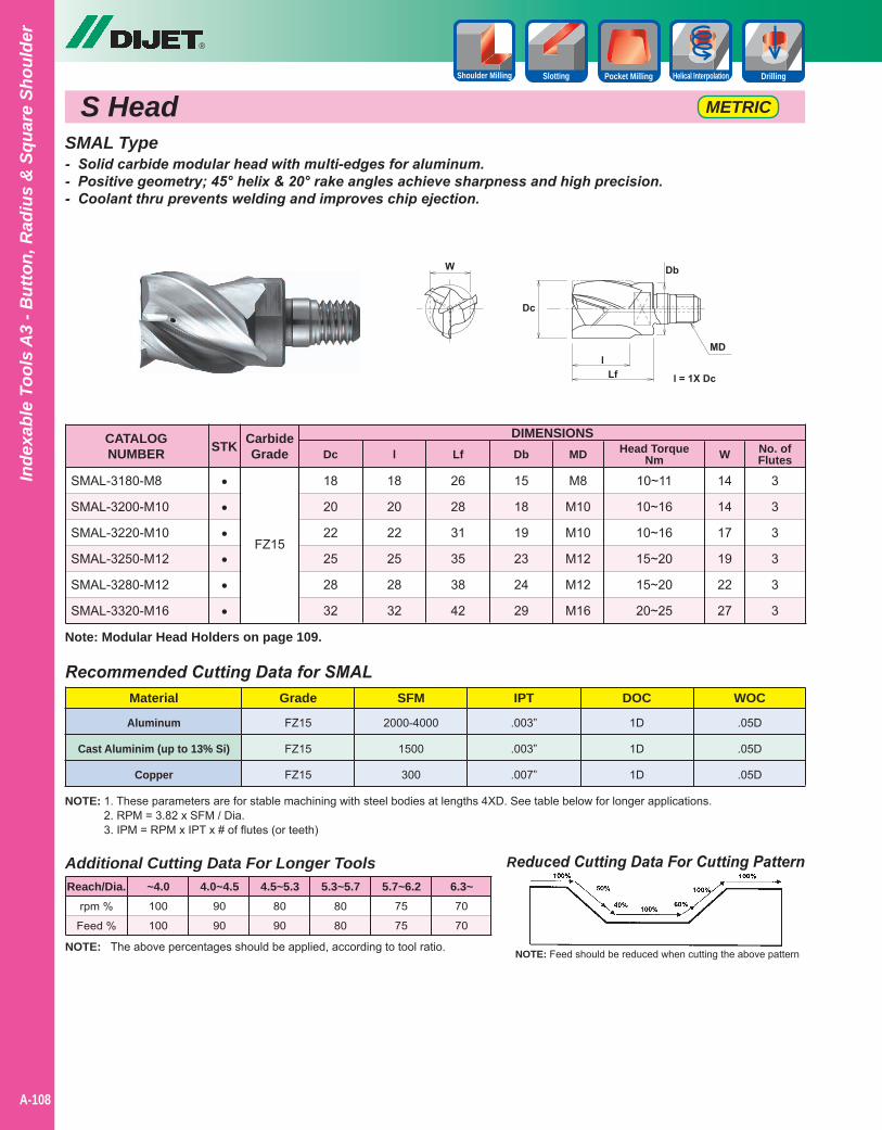
®
A-108
Inde
xabl
e To
ols
A3
- But
ton,
Rad
ius
& S
quar
e Sh
ould
er
FZ15
CATALOGNUMBER
DIMENSIONS
SMAL-3180-M8
SMAL-3200-M10
SMAL-3220-M10
SMAL-3250-M12
SMAL-3280-M12
SMAL-3320-M16
STK Dc l Lf Db MD W No. ofFlutes
••••••
S Head METRIC
SMAL Type- Solid carbide modular head with multi-edges for aluminum.- Positive geometry; 45° helix & 20° rake angles achieve sharpness and high precision.- Coolant thru prevents welding and improves chip ejection.
18
20
22
25
28
32
18
20
22
25
28
32
26
28
31
35
38
42
15
18
19
23
24
29
M8
M10
M10
M12
M12
M16
10~11
10~16
10~16
15~20
15~20
20~25
14
14
17
19
22
27
3
3
3
3
3
3
CarbideGrade Head Torque
Nm
Aluminum
Cast Aluminim (up to 13% Si)
Copper
Reduced Cutting Data For Cutting Pattern
NOTE: Feed should be reduced when cutting the above patternNOTE: The above percentages should be applied, according to tool ratio.
Additional Cutting Data For Longer Tools
rpm %
Feed %
100
100
90
90
80
90
80
80
75
75
70
70
Reach/Dia. ~4.0 4.0~4.5 4.5~5.3 5.3~5.7 5.7~6.2 6.3~
Recommended Cutting Data for SMALMaterial Grade SFM IPT DOC WOC
FZ15
FZ15
FZ15
2000-4000
1500
300
.003”
.003”
.007”
1D
1D
1D
.05D
.05D
.05D
NOTE: 1. These parameters are for stable machining with steel bodies at lengths 4XD. See table below for longer applications.2. RPM = 3.82 x SFM / Dia.3. IPM = RPM x IPT x # of flutes (or teeth)
Note: Modular Head Holders on page 109.
Slotting Helical InterpolationPocket MillingShoulder Milling Drilling
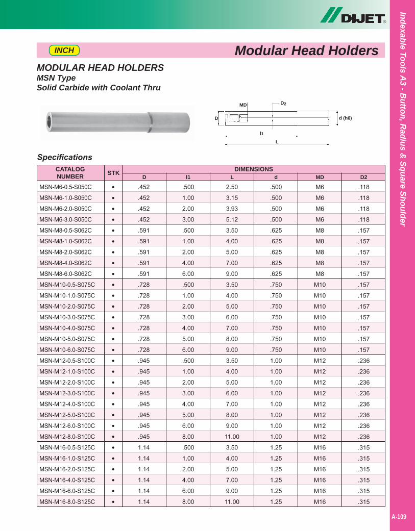
®
Indexable Tools A3 - B
utton, Radius &
Square Shoulder
A-109
MODULAR HEAD HOLDERSMSN TypeSolid Carbide with Coolant Thru
Modular Head HoldersINCH
D
l1
d (h6)
L
MD D2
.452
.452
.452
.452
.591
.591
.591
.591
.591
.728
.728
.728
.728
.728
.728
.728
.945
.945
.945
.945
.945
.945
.945
.945
1.14
1.14
1.14
1.14
1.14
1.14
SpecificationsCATALOGNUMBER
DIMENSIONS
MSN-M6-0.5-S050C
MSN-M6-1.0-S050C
MSN-M6-2.0-S050C
MSN-M6-3.0-S050C
MSN-M8-0.5-S062C
MSN-M8-1.0-S062C
MSN-M8-2.0-S062C
MSN-M8-4.0-S062C
MSN-M8-6.0-S062C
MSN-M10-0.5-S075C
MSN-M10-1.0-S075C
MSN-M10-2.0-S075C
MSN-M10-3.0-S075C
MSN-M10-4.0-S075C
MSN-M10-5.0-S075C
MSN-M10-6.0-S075C
MSN-M12-0.5-S100C
MSN-M12-1.0-S100C
MSN-M12-2.0-S100C
MSN-M12-3.0-S100C
MSN-M12-4.0-S100C
MSN-M12-5.0-S100C
MSN-M12-6.0-S100C
MSN-M12-8.0-S100C
MSN-M16-0.5-S125C
MSN-M16-1.0-S125C
MSN-M16-2.0-S125C
MSN-M16-4.0-S125C
MSN-M16-6.0-S125C
MSN-M16-8.0-S125C
D
.500
1.00
2.00
3.00
.500
1.00
2.00
4.00
6.00
.500
1.00
2.00
3.00
4.00
5.00
6.00
.500
1.00
2.00
3.00
4.00
5.00
6.00
8.00
.500
1.00
2.00
4.00
6.00
8.00
l1
2.50
3.15
3.93
5.12
3.50
4.00
5.00
7.00
9.00
3.50
4.00
5.00
6.00
7.00
8.00
9.00
3.50
4.00
5.00
6.00
7.00
8.00
9.00
11.00
3.50
4.00
5.00
7.00
9.00
11.00
L
.500
.500
.500
.500
.625
.625
.625
.625
.625
.750
.750
.750
.750
.750
.750
.750
1.00
1.00
1.00
1.00
1.00
1.00
1.00
1.00
1.25
1.25
1.25
1.25
1.25
1.25
M6
M6
M6
M6
M8
M8
M8
M8
M8
M10
M10
M10
M10
M10
M10
M10
M12
M12
M12
M12
M12
M12
M12
M12
M16
M16
M16
M16
M16
M16
.118
.118
.118
.118
.157
.157
.157
.157
.157
.157
.157
.157
.157
.157
.157
.157
.236
.236
.236
.236
.236
.236
.236
.236
.315
.315
.315
.315
.315
.315
d MD D2STK
••••••••••••••••••••••••••••• •
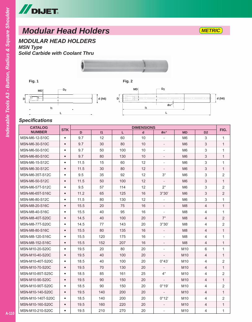
®
A-110
Inde
xabl
e To
ols
A3
- But
ton,
Rad
ius
& S
quar
e Sh
ould
er
D
l1
d (h6)
L
MD
Fig. 1
D
l1
d (h6)
L
MD
θn°
Fig. 2
D2D2
9.79.79.79.711.511.59.511.59.511.211.515.515.514.514.515.515.515.519.519.518.519.518.519.518.519.518.519.519.5
SpecificationsCATALOGNUMBER
DIMENSIONS
MSN-M6-12-S10CMSN-M6-30-S10CMSN-M6-50-S10CMSN-M6-80-S10CMSN-M6-15-S12CMSN-M6-30-S12CMSN-M6-35T-S12CMSN-M6-50-S12CMSN-M6-57T-S12CMSN-M6-65T-S16CMSN-M6-80-S12CMSN-M8-20-S16CMSN-M8-40-S16CMSN-M8-40T-S20CMSN-M8-77T-S20CMSN-M8-80-S16CMSN-M8-120-S16CMSN-M8-152-S16CMSN-M10-20-S20CMSN-M10-40-S20CMSN-M10-40T-S20CMSN-M10-70-S20CMSN-M10-85T-S25CMSN-M10-90-S20CMSN-M10-90T-S20CMSN-M10-140-S20CMSN-M10-140T-S20CMSN-M10-160-S20CMSN-M10-210-S20C
D1230508015303550576580204040778012015220404070859090140140160210
l16080
100130608092
1001141251307595
10014313517520780
100100130161150150200200220270
L1010101012121212121612161620201616162020202025202020202020
M6M6M6M6M6M6M6M6M6M6M6M8M8M8M8M8M8M8
M10M10M10M10M10M10M10M10M10M10M10
33333333333444444464444444444
11111121221112211111212121211
d MD D2STK FIG.
•••••••••••••••••••••••••••••
θn°------
3°-
2°3°30’
---
7°3°30’
-----
0°43’-
4°-
0°19’-
0°12’--
Modular Head Holders METRIC
MODULAR HEAD HOLDERSMSN TypeSolid Carbide with Coolant Thru
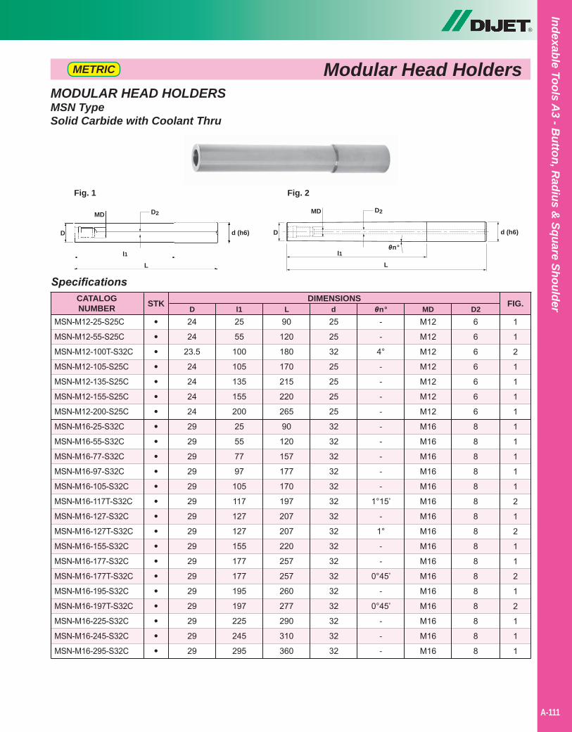
®
Indexable Tools A3 - B
utton, Radius &
Square Shoulder
A-111
MODULAR HEAD HOLDERSMSN TypeSolid Carbide with Coolant Thru
Modular Head Holders
D
l1
d (h6)
L
MD
Fig. 1
D
l1
d (h6)
L
MD
θn°
Fig. 2
D2D2
24
24
23.5
24
24
24
24
29
29
29
29
29
29
29
29
29
29
29
29
29
29
29
29
SpecificationsCATALOGNUMBER
DIMENSIONS
MSN-M12-25-S25C
MSN-M12-55-S25C
MSN-M12-100T-S32C
MSN-M12-105-S25C
MSN-M12-135-S25C
MSN-M12-155-S25C
MSN-M12-200-S25C
MSN-M16-25-S32C
MSN-M16-55-S32C
MSN-M16-77-S32C
MSN-M16-97-S32C
MSN-M16-105-S32C
MSN-M16-117T-S32C
MSN-M16-127-S32C
MSN-M16-127T-S32C
MSN-M16-155-S32C
MSN-M16-177-S32C
MSN-M16-177T-S32C
MSN-M16-195-S32C
MSN-M16-197T-S32C
MSN-M16-225-S32C
MSN-M16-245-S32C
MSN-M16-295-S32C
D25
55
100
105
135
155
200
25
55
77
97
105
117
127
127
155
177
177
195
197
225
245
295
l190
120
180
170
215
220
265
90
120
157
177
170
197
207
207
220
257
257
260
277
290
310
360
L25
25
32
25
25
25
25
32
32
32
32
32
32
32
32
32
32
32
32
32
32
32
32
M12
M12
M12
M12
M12
M12
M12
M16
M16
M16
M16
M16
M16
M16
M16
M16
M16
M16
M16
M16
M16
M16
M16
6
6
6
6
6
6
6
8
8
8
8
8
8
8
8
8
8
8
8
8
8
8
8
1
1
2
1
1
1
1
1
1
1
1
1
2
1
2
1
1
2
1
2
1
1
1
d MD D2STK FIG.
•••••••••••••••••••••••
θn°-
-
4°
-
-
-
-
-
-
-
-
-
1°15’
-
1°
-
-
0°45’
-
0°45’
-
-
-
METRIC
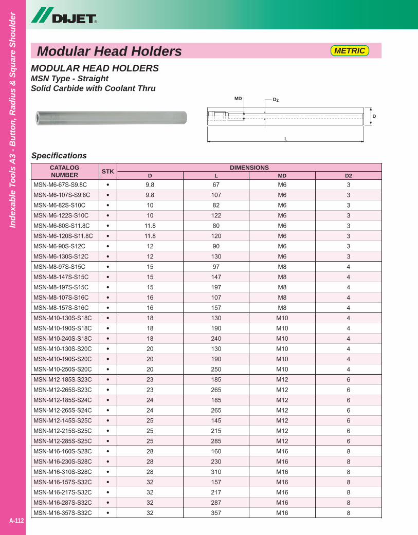
®
A-112
Inde
xabl
e To
ols
A3
- But
ton,
Rad
ius
& S
quar
e Sh
ould
er
Modular Head Holders METRIC
MODULAR HEAD HOLDERSMSN Type - StraightSolid Carbide with Coolant Thru
9.89.81010
11.811.8121215151516161818182020202323242425252528282832323232
SpecificationsCATALOGNUMBER
DIMENSIONS
MSN-M6-67S-S9.8CMSN-M6-107S-S9.8CMSN-M6-82S-S10CMSN-M6-122S-S10CMSN-M6-80S-S11.8CMSN-M6-120S-S11.8CMSN-M6-90S-S12CMSN-M6-130S-S12C MSN-M8-97S-S15CMSN-M8-147S-S15CMSN-M8-197S-S15CMSN-M8-107S-S16CMSN-M8-157S-S16CMSN-M10-130S-S18CMSN-M10-190S-S18CMSN-M10-240S-S18CMSN-M10-130S-S20CMSN-M10-190S-S20CMSN-M10-250S-S20CMSN-M12-185S-S23CMSN-M12-265S-S23CMSN-M12-185S-S24CMSN-M12-265S-S24CMSN-M12-145S-S25CMSN-M12-215S-S25CMSN-M12-285S-S25CMSN-M16-160S-S28CMSN-M16-230S-S28CMSN-M16-310S-S28CMSN-M16-157S-S32CMSN-M16-217S-S32CMSN-M16-287S-S32CMSN-M16-357S-S32C
D67
10782
12280
12090
13097
147197107157130190240130190250185265185265145215285160230310157217287357
LM6M6M6M6M6M6M6M6M8M8M8M8M8
M10M10M10M10M10M10M12M12M12M12M12M12M12M16M16M16M16M16M16M16
333333334444444444466666668888888
MD D2STK
•••••••••••••••••••••••••••••••••
MD
L
D
D2
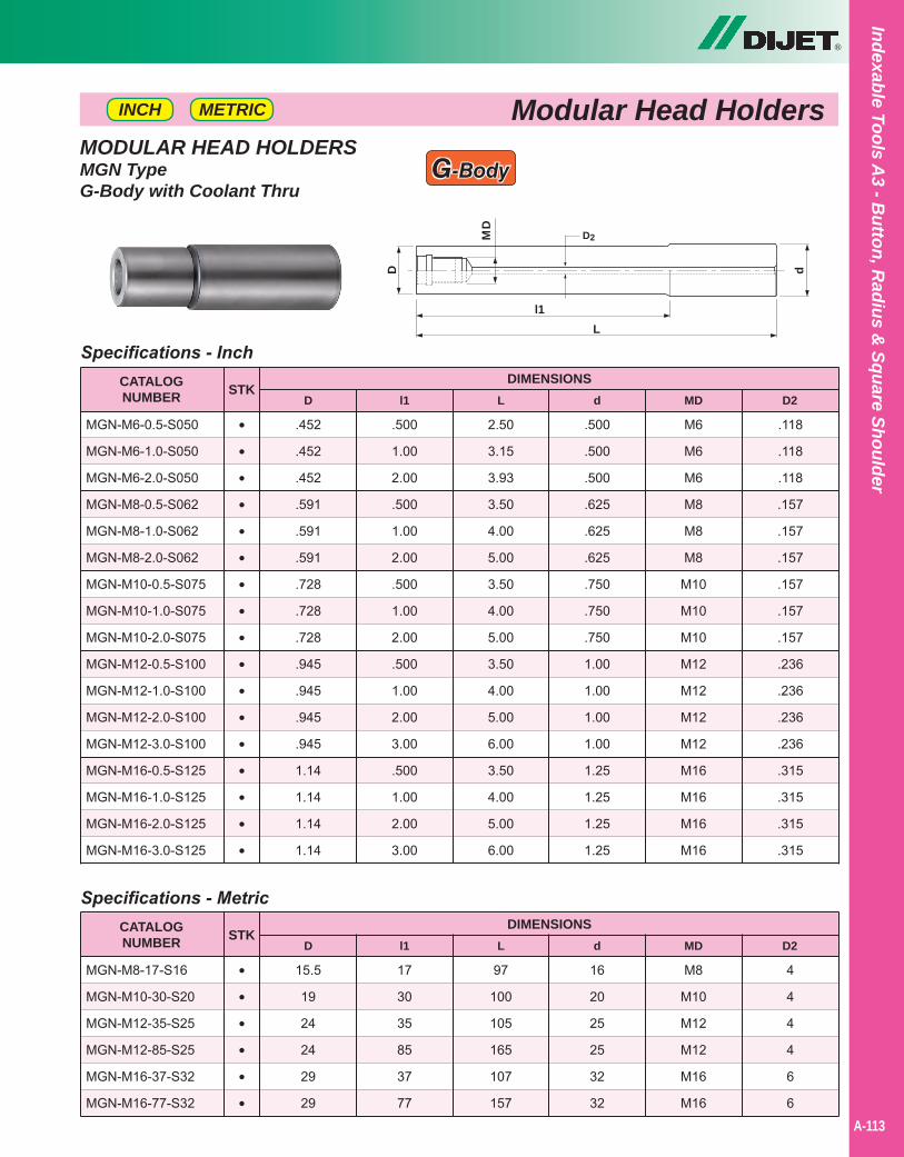
®
Indexable Tools A3 - B
utton, Radius &
Square Shoulder
A-113
MODULAR HEAD HOLDERSMGN TypeG-Body with Coolant Thru
Modular Head Holders
Specifications - Inch
2.50
3.15
3.93
3.50
4.00
5.00
3.50
4.00
5.00
3.50
4.00
5.00
6.00
3.50
4.00
5.00
6.00
.452
.452
.452
.591
.591
.591
.728
.728
.728
.945
.945
.945
.945
1.14
1.14
1.14
1.14
.500
1.00
2.00
.500
1.00
2.00
.500
1.00
2.00
.500
1.00
2.00
3.00
.500
1.00
2.00
3.00
.500
.500
.500
.625
.625
.625
.750
.750
.750
1.00
1.00
1.00
1.00
1.25
1.25
1.25
1.25
CATALOGNUMBER
DIMENSIONSD
MGN-M6-0.5-S050
MGN-M6-1.0-S050
MGN-M6-2.0-S050
MGN-M8-0.5-S062
MGN-M8-1.0-S062
MGN-M8-2.0-S062
MGN-M10-0.5-S075
MGN-M10-1.0-S075
MGN-M10-2.0-S075
MGN-M12-0.5-S100
MGN-M12-1.0-S100
MGN-M12-2.0-S100
MGN-M12-3.0-S100
MGN-M16-0.5-S125
MGN-M16-1.0-S125
MGN-M16-2.0-S125
MGN-M16-3.0-S125
STKl1 L d
•••••••••••••••••
M6
M6
M6
M8
M8
M8
M10
M10
M10
M12
M12
M12
M12
M16
M16
M16
M16
.118
.118
.118
.157
.157
.157
.157
.157
.157
.236
.236
.236
.236
.315
.315
.315
.315
MD D2
d
L
D
MD
l1
D2
Specifications - Metric
97
100
105
165
107
157
15.5
19
24
24
29
29
17
30
35
85
37
77
16
20
25
25
32
32
CATALOGNUMBER
DIMENSIONSD
MGN-M8-17-S16
MGN-M10-30-S20
MGN-M12-35-S25
MGN-M12-85-S25
MGN-M16-37-S32
MGN-M16-77-S32
STKl1 L d
••••••
M8
M10
M12
M12
M16
M16
4
4
4
4
6
6
MD D2
G-Body
METRICINCH
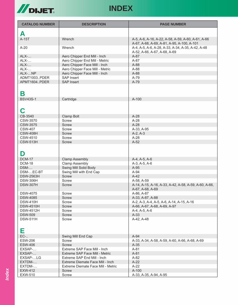
®INDEX
Inde
x
CATALOG NUMBER DESCRIPTION PAGE NUMBER
AA-15T Wrench A-5, A-6, A-16, A-22, A-58, A-59, A-60, A-61, A-66 A-67, A-68, A-69, A-81, A-95, A-100, A-101A-20 Wrench A-4, A-5, A-6, A-28, A-33, A-34, A-35, A-42, A-48 A-52, A-66, A-67, A-68, A-69ALX-… Aero Chipper End Mill - Inch A-87ALX-… Aero Chipper End Mill - Metric A-87ALX-… Aero Chipper Face Mill - Inch A-88ALX-… Aero Chipper Face Mill - Metric A-88ALX-…NP Aero Chipper Face Mill - Inch A-88ADMT1003..PDER SAP Insert A-79APMT1604..PDER SAP Insert A-79
BBSV43S-1 Cartridge A-100
CCB-3540 Clamp Bolt A-28CSW-3570 Screw A-28CSW-3575 Screw A-28CSW-407 Screw A-33, A-95CSW-408H Screw A-2, A-3CSW-4510 Screw A-28CSW-513H Screw A-52
DDCM-17 Clamp Assembly A-4, A-5, A-6DCM-18 Clamp Assembly A-3, A-5, A-6DSM-… Swing Mill Solid Body A-95DSM-…EC-BT Swing Mill with End Cap A-94DSW-2563H Screw A-42DSW-306H Screw A-58, A-59DSW-307H Screw A-14, A-15, A-16, A-33, A-42, A-58, A-59, A-60, A-66, A-67, A-68, A-69DSW-4075 Screw A-86, A-87DSW-4085 Screw A-33, A-87, A-88DSW-410H Screw A-2, A-3, A-4, A-5, A-6, A-14, A-15, A-16DSW-4510H Screw A-66, A-67, A-68, A-69, A-97DSW-4512H Screw A-4, A-5, A-6DSW-509 Screw A-33DSW-511H Screw A-42, A-48
EEC-.. Swing Mill End Cap A-94ESW-206 Screw A-33, A-34, A-58, A-59, A-60, A-66, A-68, A-69ESW-406 Screw A-35EXSAP-… Extreme SAP Face Mill - Inch A-81EXSAP-… Extreme SAP Face Mill - Metric A-81EXSAP-…LG Extreme SAP End Mill - Inch A-82EXTDM-… Extreme Diemate Face Mill - Inch A-22EXTDM-… Extreme Diemate Face Mill - Metric A-22EXW-412 Screw A-100EXW-510 Screw A-33, A-35, A-94, A-95
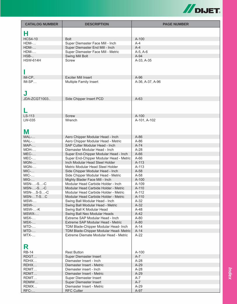
®
Index
CATALOG NUMBER DESCRIPTION PAGE NUMBER
HHCS4-10 Bolt A-100HDM-… Super Diemaster Face Mill - Inch A-4HDM-… Super Diemaster End Mill - Inch A-4HDM-… Super Diemaster Face Mill - Metric A-5, A-6HSB-.. Swing Mill Bolt A-94HSW-614H Screw A-33, A-35
IIM-CP.. Exciter Mill Insert A-96IM-SP… Multiple Family Insert A-36, A-37, A-96
JJDA-ZCGT1003.. Side Chipper Insert PCD A-63
LLS-113 Screw A-100LW-035 Wrench A-101, A-102
MMAL-… Aero Chipper Modular Head - Inch A-86MAL-… Aero Chipper Modular Head - Metric A-86MAP-… SAP Cutter Modular Head - Inch A-74MDH-… Diemaster Modular Head - Inch A-28MEC-… Super End-Chipper Modular Head - Inch A-66MEC-… Super End-Chipper Modular Head - Metric A-66MGN-… Inch Modular Head Steel Holder A-113MGN-… Metric Modular Head Steel Holder A-113MIC-… Side Chipper Modular Head - Inch A-58MIC-… Side Chipper Modular Head - Metric A-58MIG-… Mighty Blader Face Mill - Inch A-100MSN-…-S…-C Modular Head Carbide Holder - Inch A-109MSN-…-S…-C Modular Head Carbide Holder - Metric A-110MSN-…S-S…-C Modular Head Carbide Holder - Metric A-112MSN-…T-S…C Modular Head Carbide Holder - Metric A-110MSW-… Swing Ball Modular Head - Inch A-32MSW-... Swing Ball Modular Head - Metric A-32MSW-…-K Swing Ball K Modular Head A-48MSWX-… Swing Ball Neo Modular Heads A-42MSX-… Extreme SAP Modular Head - Inch A-80MSX-… Extreme SAP Modular Head - Metric A-80MTD-… TDM Blade-Chipper Modular Head- Inch A-14MTD-… TDM Blade-Chipper Modular Head- Metric A-14MTX-… Extreme Diemate Modular Head - Metric A-22
RRB-14 Rest Button A-100RDGT… Super Diemaster Insert A-7RDHX… Diemaster Insert - Inch A-28RDHX… Diemaster Insert - Metric A-29RDMT… Diemaster insert - Inch A-28RDMT… Diemaster Insert - Metric A-29RDMT… Super Diemaster Insert A-7RDMW… Super Diemaster Insert A-7RDMX… Diemaster Insert - Metric A-29RFC-… RFC Cutter A-97
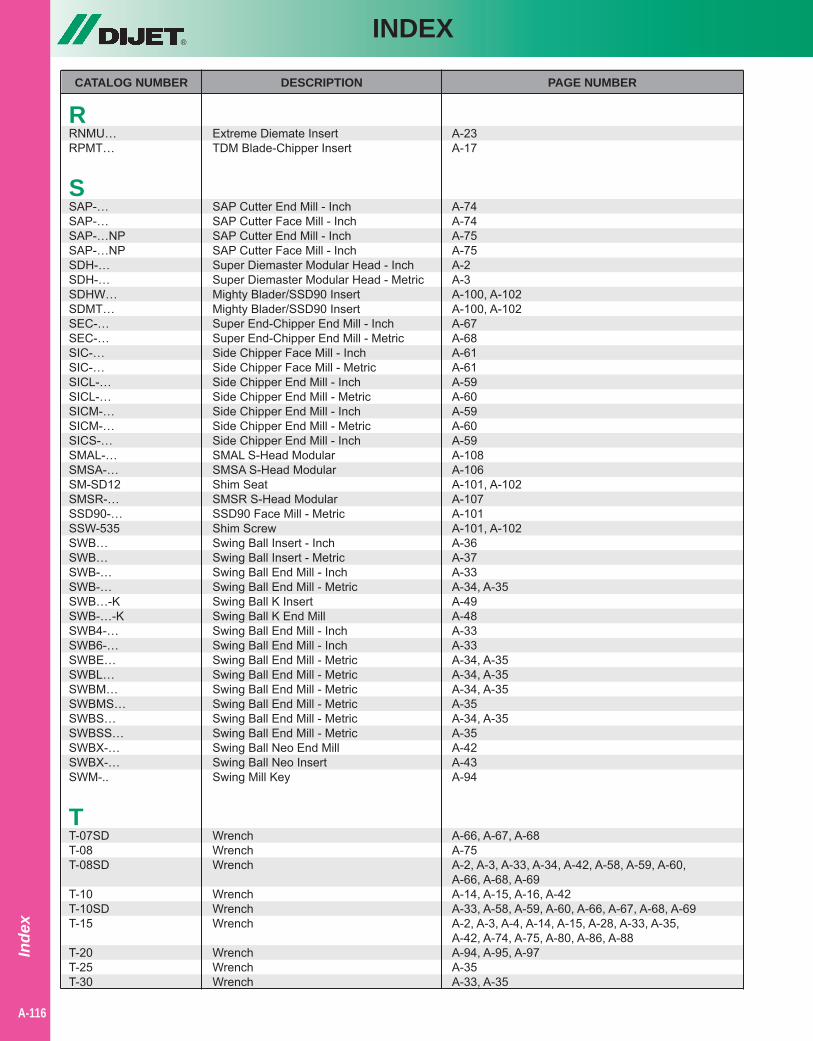
®INDEX
Inde
x
A-116
CATALOG NUMBER DESCRIPTION PAGE NUMBER
RRNMU… Extreme Diemate Insert A-23RPMT… TDM Blade-Chipper Insert A-17
SSAP-… SAP Cutter End Mill - Inch A-74SAP-… SAP Cutter Face Mill - Inch A-74SAP-…NP SAP Cutter End Mill - Inch A-75SAP-…NP SAP Cutter Face Mill - Inch A-75SDH-… Super Diemaster Modular Head - Inch A-2SDH-… Super Diemaster Modular Head - Metric A-3SDHW… Mighty Blader/SSD90 Insert A-100, A-102SDMT… Mighty Blader/SSD90 Insert A-100, A-102SEC-… Super End-Chipper End Mill - Inch A-67SEC-… Super End-Chipper End Mill - Metric A-68SIC-… Side Chipper Face Mill - Inch A-61SIC-… Side Chipper Face Mill - Metric A-61SICL-… Side Chipper End Mill - Inch A-59SICL-… Side Chipper End Mill - Metric A-60SICM-… Side Chipper End Mill - Inch A-59SICM-… Side Chipper End Mill - Metric A-60SICS-… Side Chipper End Mill - Inch A-59SMAL-… SMAL S-Head Modular A-108SMSA-… SMSA S-Head Modular A-106SM-SD12 Shim Seat A-101, A-102SMSR-… SMSR S-Head Modular A-107SSD90-… SSD90 Face Mill - Metric A-101SSW-535 Shim Screw A-101, A-102SWB… Swing Ball Insert - Inch A-36SWB… Swing Ball Insert - Metric A-37SWB-… Swing Ball End Mill - Inch A-33SWB-… Swing Ball End Mill - Metric A-34, A-35SWB…-K Swing Ball K Insert A-49SWB-…-K Swing Ball K End Mill A-48SWB4-… Swing Ball End Mill - Inch A-33SWB6-… Swing Ball End Mill - Inch A-33SWBE… Swing Ball End Mill - Metric A-34, A-35SWBL… Swing Ball End Mill - Metric A-34, A-35SWBM… Swing Ball End Mill - Metric A-34, A-35SWBMS… Swing Ball End Mill - Metric A-35SWBS… Swing Ball End Mill - Metric A-34, A-35SWBSS… Swing Ball End Mill - Metric A-35SWBX-… Swing Ball Neo End Mill A-42SWBX-… Swing Ball Neo Insert A-43SWM-.. Swing Mill Key A-94
TT-07SD Wrench A-66, A-67, A-68T-08 Wrench A-75T-08SD Wrench A-2, A-3, A-33, A-34, A-42, A-58, A-59, A-60, A-66, A-68, A-69T-10 Wrench A-14, A-15, A-16, A-42T-10SD Wrench A-33, A-58, A-59, A-60, A-66, A-67, A-68, A-69T-15 Wrench A-2, A-3, A-4, A-14, A-15, A-28, A-33, A-35, A-42, A-74, A-75, A-80, A-86, A-88T-20 Wrench A-94, A-95, A-97T-25 Wrench A-35T-30 Wrench A-33, A-35
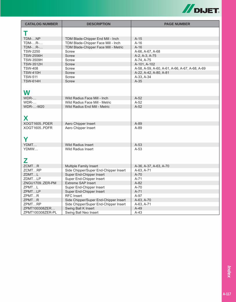
®
A-117
Index
CATALOG NUMBER DESCRIPTION PAGE NUMBER
TTDM-…NP TDM Blade-Chipper End Mill - Inch A-15TDM-…R-… TDM Blade-Chipper Face Mill - Inch A-16TDM-…R-… TDM Blade-Chipper Face Mill - Metric A-16TSW-2250 Screw A-66, A-67, A-68TSW-2556H Screw A-2, A-3, A-75TSW-3509H Screw A-74, A-75TSW-3512H Screw A-101, A-102TSW-408 Screw A-58, A-59, A-60, A-61, A-66, A-67, A-68, A-69TSW-410H Screw A-22, A-42, A-80, A-81TSW-511 Screw A-33, A-34TSW-614H Screw A-35
WWDR-… Wild Radius Face Mill - Inch A-52WDR-… Wild Radius Face Mill - Metric A-52WDR-…-M20 Wild Radius End Mill - Metric A-52
XXOGT1605..PDER Aero Chipper Insert A-89XOGT1605..PDFR Aero Chipper Insert A-89
YYDMT… Wild Radius Insert A-53YDMW… Wild Radius Insert A-53
ZZCMT…R Multiple Family Insert A-36, A-37, A-63, A-70ZCMT…RP Side Chipper/Super End-Chipper Insert A-63, A-71ZDMT…L Super End-Chipper Insert A-70ZDMT…LP Super End-Chipper Insert A-71ZNGU1709..ZER-PM Extreme SAP Insert A-82ZPMT…L Super End-Chipper Insert A-70ZPMT…LP Super End-Chipper Insert A-71ZPMT…R RFC Insert A-97ZPMT…R Side Chipper/Super End-Chipper Insert A-63, A-70ZPMT…RP Side Chipper/Super End-Chipper Insert A-63, A-71ZPMT100308ZER… Swing Ball K Insert A-49ZPMT100308ZER-PL Swing Ball Neo Insert A-43

Notes
A-40
®
A-118
Inde
xabl
e To
ols
A3
- But
ton,
Rad
ius
& S
quar
e Sh
ould
er

®
DIJET, INC. (USA)
DIJET INDUSTRIAL (JAPAN)
Mie Plant (Carbide)Mie Plant (Raw Material Powder) Tondabayashi Plant
Mie Plant (TA & IT Plant)
Oaska Plant (Carbide, CT, Wear Parts)

DIJET INDUSTRIAL CO., LTD.2-1-18, Kami-Higashi, Hirano-ku,Osaka 547-0002, JapanPhone: +81-6-6794-0167Fax: +81-6-6793-3930www.dijet.co.jp
DIJET INDUSTRIAL CO., LTD.Immarmannstr 940210 Düsseldorf, GermanyPhone: +49 (0) 211-50088820Fax: +49 (0) 211-50088823
DIJET, INC.45807 Helm Street, Plymouth, MI 48170Phone: 1-800-743-4538 Fax: 1-734-454-9395www.dijetusa.com
®
North America:
CanadaMexicoU.S.A.
South America:
Brazil
Africa:
South Africa
Asia:
ChinaIndonesiaJapanKoreaMalaysiaPhilippinesSingaporeTaiwanThailandVietnam
North East:
Russia
Europe:
Austria Germany NetherlandsBelgium Greece NorwayDenmark Holland PolandEngland Hungary PortugalFinland Italy SpainFrance Ireland Sweden Switzerland
WORLDWIDE DISTRIBUTION
No part of this catalog may be printed, copied or reproduced without the expressed written permission of DIJET, Inc.
Middle East:
IndiaIsraelPakistanTurkey