improvement of natural ventilation in south-facing rooms located in top floors in cairo, egypt
TRANSCRIPT
1
American Institute of Aeronautics and Astronautics
Improvement of Natural Ventilation in South-Facing Rooms
Located in Top Floors in Cairo, Egypt
A. Ashry Masoud1, A. H. Ibrahim
1
and
Essam E. Khalil2†
1,2
Cairo University, Faculty of engineering, Giza, Egypt † Principal Author, Email: [email protected]
This work presents an attempt to improve the natural ventilation in south-facing rooms
located in the top floors of buildings located in Cairo, Egypt. According to the city’s wind
rose in the hot humid months of summer, these rooms suffer from very low incoming air
velocity as well as high incident solar radiation, which results in massive air conditioning
loads in summer, that can be eliminated or reduced by improving the natural ventilation,
leading to energy conservation. The work focuses on a south-facing room, where the
neighbor’s room is facing north with a much higher incoming air velocity and shielding this
air stream from the neighbor’s room. The work investigates the effects of increasing the
height of the roof of the south-facing room located in the top floor, with respect to the north-
facing room, to allow introducing a vent in the other-wise closed north wall. This vent allows
admission of high-velocity air stream from the north direction into the room as well as it
changes the ventilation from single-sided ventilation to cross-ventilation in the south-facing
room. The simulation is carried-out numerically using steady, three-dimensional solution of
the continuity and Navier–Stokes equations using computational fluid mechanics and the k-ε
turbulence model under incompressible flow assumption and utilizing the Boussinesq’s
approximation. A room model with realistic dimensions and internal thermal loads have
been modeled inside a computational wind tunnel domain. The effects of changing the
window configurations (single/doubled, aligned/staggered, large/small and different heights)
have been studied. These results are contrasted to the case of the north-facing room and the
south-facing room without the vent. The results show that introducing the vent in the south-
facing room can significantly improve the ventilation by passive means and that this
improvement can improve for double windows rather than single window (with the same
total surface area) and that using staggered windows enhances the air distribution inside the
room more than the aligned windows. Increasing the total window area indeed improves the
ventilation and positioning the windows closer to the floor is preferred than closer to the
ceiling for the vent configuration used. The numerical simulations show that these
improvements can provide air distribution inside the south-facing room even better than in
the north-facing room.
50th AIAA Aerospace Sciences Meeting including the New Horizons Forum and Aerospace Exposition09 - 12 January 2012, Nashville, Tennessee
AIAA 2012-0646
Copyright © 2012 by the American Institute of Aeronautics and Astronautics, Inc. All rights reserved.
2
American Institute of Aeronautics and Astronautics
I. Introduction
URRENTLY, most of the buildings are ventilated with mechanical systems. Nearly 70% of the total energy
consumption in service and residential buildings can be attributed to HVAC systems (1)
. The use of natural
ventilation can reduce this load if it can provide satisfactory levels and distribution of air velocity inside the
room, satisfactory thermal comfort levels and ensures acceptable indoor air quality. Khedari (2)
studied the comfort
levels in naturally-ventilated spaces and suggested comfort levels of air velocities for different air temperatures.
However, the correct design of a naturally ventilated building is a challenging task, due to the complexity of the
physical mechanisms involved. The air flow through a window, door, or vent depends on the pressure difference at
both sides, which depends on the relative positions and area ratios of these, the relative position of the furniture as
well as the wind and buoyancy forces.
Several studies have considered the efficient energy utilization in air conditioned buildings in Egypt and the
life cost analysis of such buildings (3), (4)
. A Residential energy pattern consumption survey in Egypt
(5) revealed that
the residential consumption is about 36% of the total consumption, where lighting loads represent around 34% of the
total consumption followed by the refrigerators 22%, washing machines 18%, and air conditioning 12%. To meet
the increasing loads in Egypt, the generated power was 139 GWH in 2009-2010 up from 83 GWH in 2001-2002.
The demand per capita increased from 1350 KWH to 1950 KWH during the same period (6)
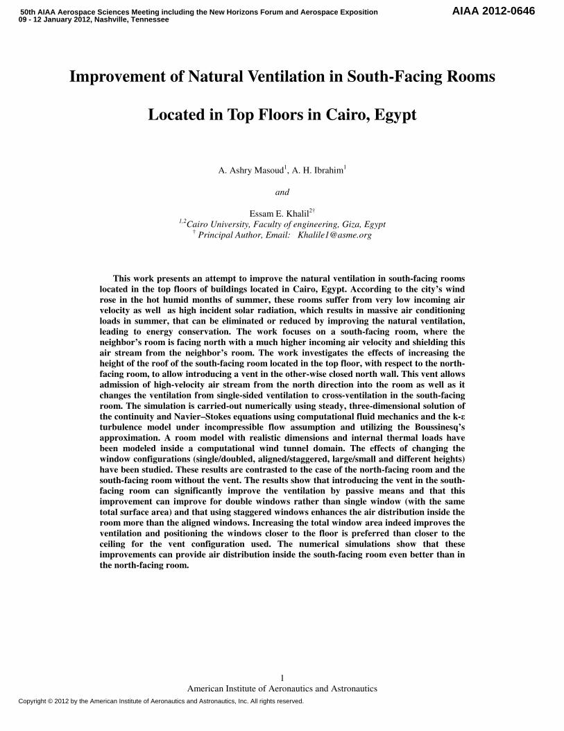
. The wind rose of the
city of Cairo averaged over the summer period is shown in Figure 1 (7)
.
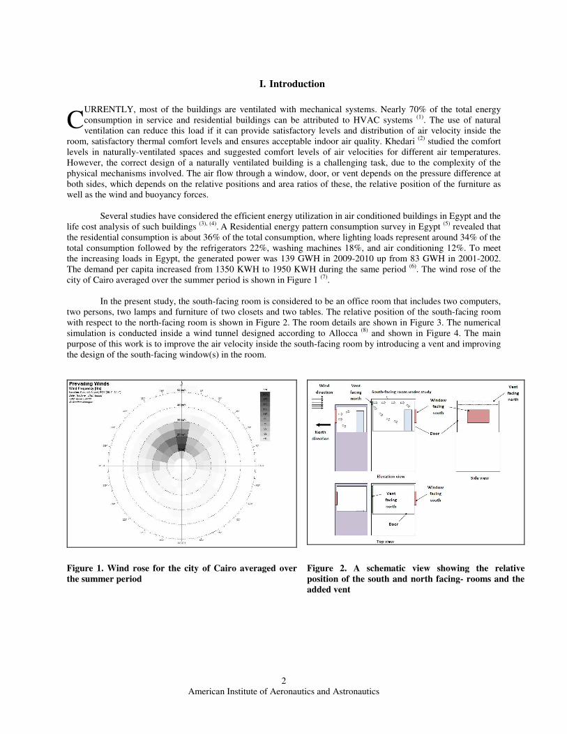
In the present study, the south-facing room is considered to be an office room that includes two computers,
two persons, two lamps and furniture of two closets and two tables. The relative position of the south-facing room
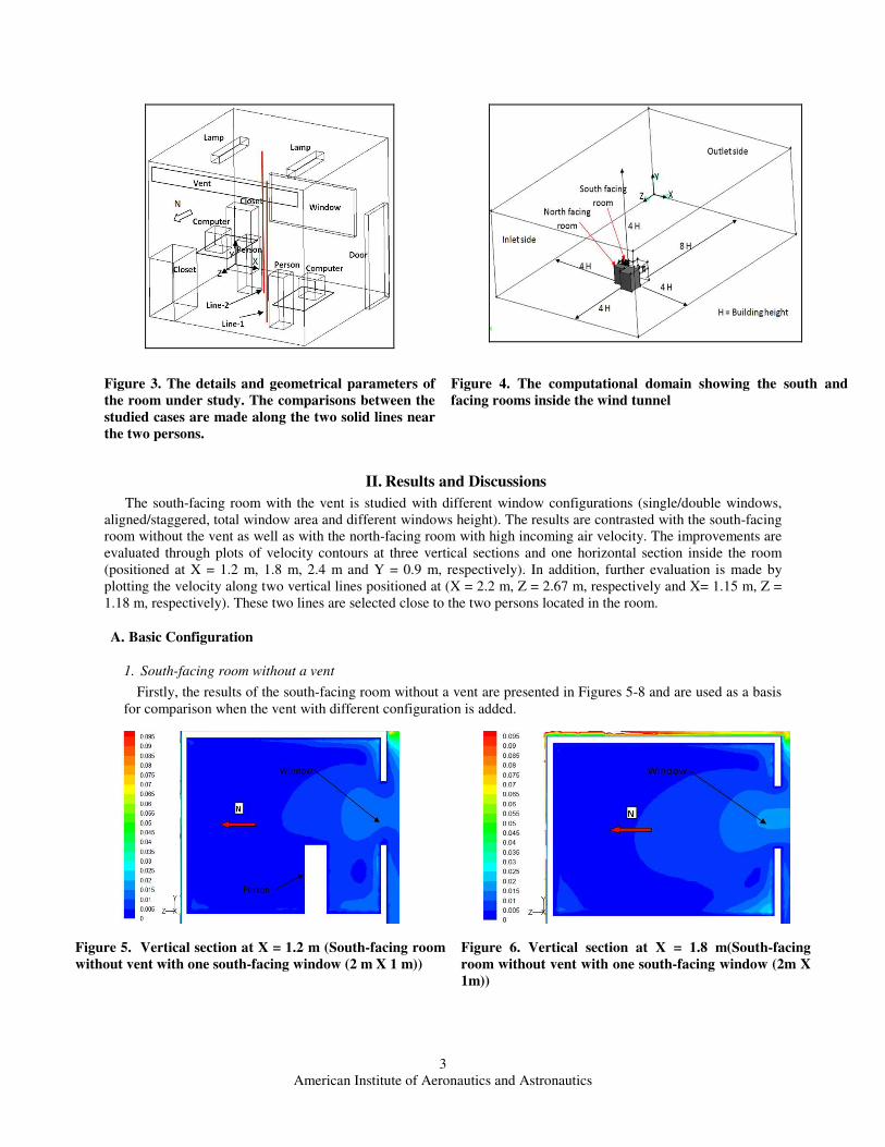
with respect to the north-facing room is shown in Figure 2. The room details are shown in Figure 3. The numerical
simulation is conducted inside a wind tunnel designed according to Allocca (8)
and shown in Figure 4. The main
purpose of this work is to improve the air velocity inside the south-facing room by introducing a vent and improving
the design of the south-facing window(s) in the room.
Figure 1. Wind rose for the city of Cairo averaged over
the summer period
Figure 2. A schematic view showing the relative
position of the south and north facing- rooms and the
added vent
C
3
American Institute of Aeronautics and Astronautics
Figure 3. The details and geometrical parameters of
the room under study. The comparisons between the
studied cases are made along the two solid lines near
the two persons.
Figure 4. The computational domain showing the south and
facing rooms inside the wind tunnel
II. Results and Discussions
The south-facing room with the vent is studied with different window configurations (single/double windows,
aligned/staggered, total window area and different windows height). The results are contrasted with the south-facing
room without the vent as well as with the north-facing room with high incoming air velocity. The improvements are
evaluated through plots of velocity contours at three vertical sections and one horizontal section inside the room
(positioned at X = 1.2 m, 1.8 m, 2.4 m and Y = 0.9 m, respectively). In addition, further evaluation is made by
plotting the velocity along two vertical lines positioned at (X = 2.2 m, Z = 2.67 m, respectively and X= 1.15 m, Z =
1.18 m, respectively). These two lines are selected close to the two persons located in the room.
A. Basic Configuration
1. South-facing room without a vent
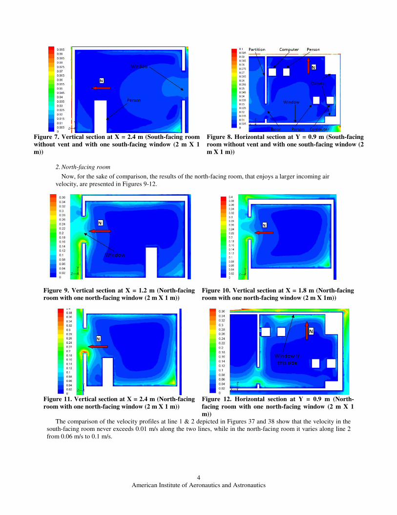
Firstly, the results of the south-facing room without a vent are presented in Figures 5-8 and are used as a basis
for comparison when the vent with different configuration is added.
Figure 5. Vertical section at X = 1.2 m (South-facing room
without vent with one south-facing window (2 m X 1 m))
Figure 6. Vertical section at X = 1.8 m(South-facing
room without vent with one south-facing window (2m X
1m))
4
American Institute of Aeronautics and Astronautics
Figure 7. Vertical section at X = 2.4 m (South-facing room
without vent and with one south-facing window (2 m X 1
m))
Figure 8. Horizontal section at Y = 0.9 m (South-facing
room without vent and with one south-facing window (2
m X 1 m))
2. North-facing room
Now, for the sake of comparison, the results of the north-facing room, that enjoys a larger incoming air
velocity, are presented in Figures 9-12.
Figure 9. Vertical section at X = 1.2 m (North-facing
room with one north-facing window (2 m X 1 m))
Figure 10. Vertical section at X = 1.8 m (North-facing
room with one north-facing window (2 m X 1m))
Figure 11. Vertical section at X = 2.4 m (North-facing
room with one north-facing window (2 m X 1 m))
Figure 12. Horizontal section at Y = 0.9 m (North-
facing room with one north-facing window (2 m X 1
m))
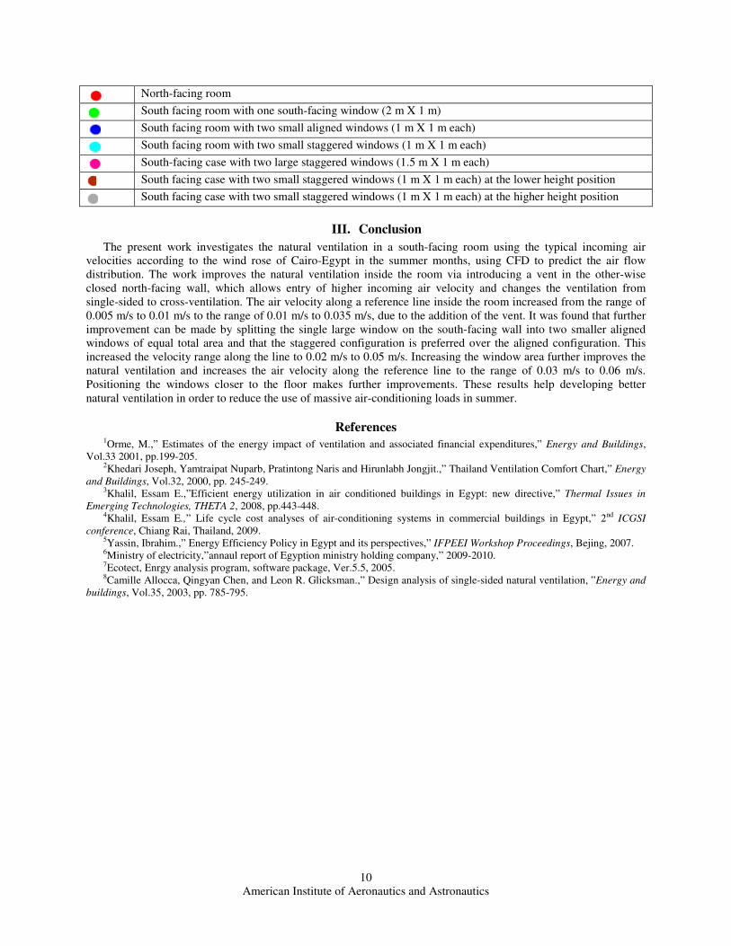
The comparison of the velocity profiles at line 1 & 2 depicted in Figures 37 and 38 show that the velocity in the
south-facing room never exceeds 0.01 m/s along the two lines, while in the north-facing room it varies along line 2
from 0.06 m/s to 0.1 m/s.
5
American Institute of Aeronautics and Astronautics
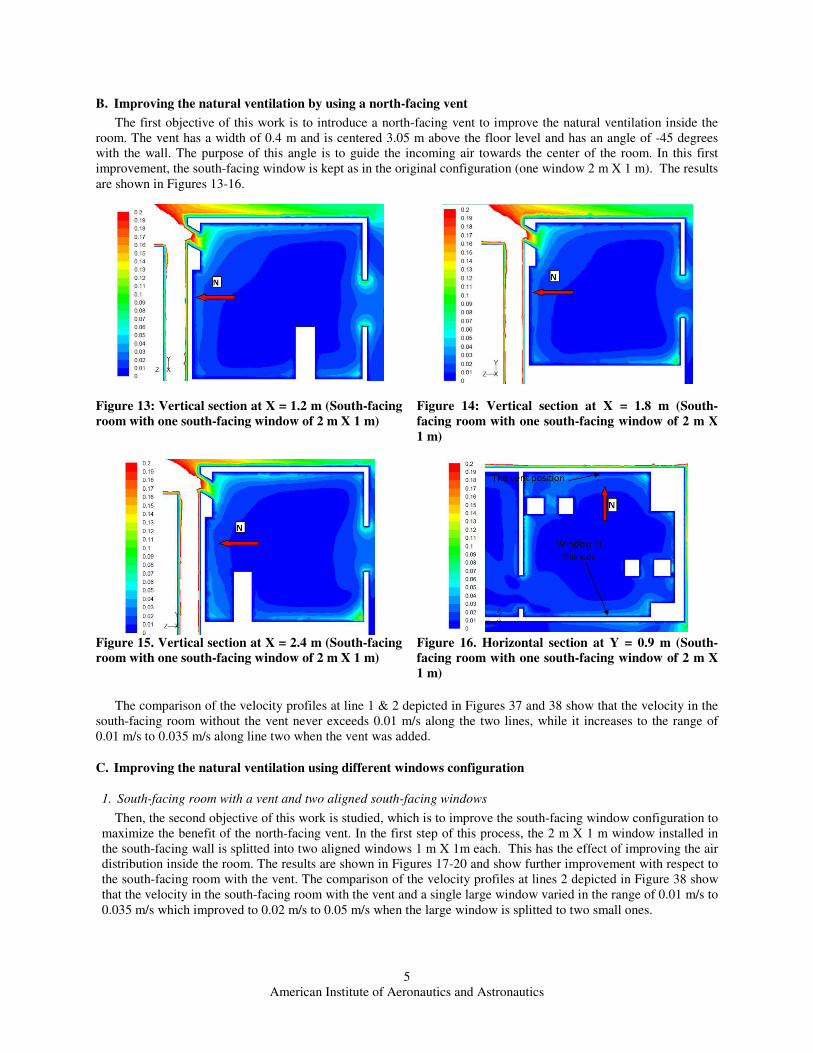
B. Improving the natural ventilation by using a north-facing vent
The first objective of this work is to introduce a north-facing vent to improve the natural ventilation inside the
room. The vent has a width of 0.4 m and is centered 3.05 m above the floor level and has an angle of -45 degrees
with the wall. The purpose of this angle is to guide the incoming air towards the center of the room. In this first
improvement, the south-facing window is kept as in the original configuration (one window 2 m X 1 m). The results
are shown in Figures 13-16.
Figure 13: Vertical section at X = 1.2 m (South-facing
room with one south-facing window of 2 m X 1 m)
Figure 14: Vertical section at X = 1.8 m (South-
facing room with one south-facing window of 2 m X
1 m)
Figure 15. Vertical section at X = 2.4 m (South-facing
room with one south-facing window of 2 m X 1 m)
Figure 16. Horizontal section at Y = 0.9 m (South-
facing room with one south-facing window of 2 m X
1 m)
The comparison of the velocity profiles at line 1 & 2 depicted in Figures 37 and 38 show that the velocity in the
south-facing room without the vent never exceeds 0.01 m/s along the two lines, while it increases to the range of
0.01 m/s to 0.035 m/s along line two when the vent was added.
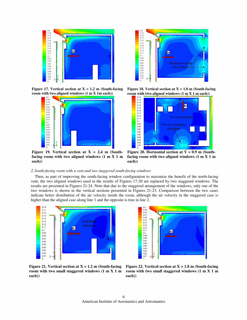
C. Improving the natural ventilation using different windows configuration
1. South-facing room with a vent and two aligned south-facing windows
Then, the second objective of this work is studied, which is to improve the south-facing window configuration to
maximize the benefit of the north-facing vent. In the first step of this process, the 2 m X 1 m window installed in
the south-facing wall is splitted into two aligned windows 1 m X 1m each. This has the effect of improving the air
distribution inside the room. The results are shown in Figures 17-20 and show further improvement with respect to
the south-facing room with the vent. The comparison of the velocity profiles at lines 2 depicted in Figure 38 show
that the velocity in the south-facing room with the vent and a single large window varied in the range of 0.01 m/s to
0.035 m/s which improved to 0.02 m/s to 0.05 m/s when the large window is splitted to two small ones.
6
American Institute of Aeronautics and Astronautics
Figure 17. Vertical section at X = 1.2 m (South-facing
room with two aligned windows (1 m X 1m each))
Figure 18. Vertical section at X = 1.8 m (South-facing
room with two aligned windows (1 m X 1 m each))
Figure 19. Vertical section at X = 2.4 m (South-
facing room with two aligned windows (1 m X 1 m
each))
Figure 20. Horizontal section at Y = 0.9 m (South-
facing room with two aligned windows (1 m X 1 m
each))
2. South-facing room with a vent and two staggered south-facing windows
Then, as part of improving the south-facing window configuration to maximize the benefit of the north-facing
vent, the two aligned windows used in the results of Figures 17-20 are replaced by two staggered windows. The
results are presented in Figures 21-24. Note that due to the staggered arrangement of the windows, only one of the
two windows is shown in the vertical sections presented in Figures 21-23. Comparison between the two cases
indicate better distribution of the air velocity inside the room, although the air velocity in the staggered case is
higher than the aligned case along line 1 and the opposite is true in line 2.
Figure 21. Vertical section at X = 1.2 m (South-facing
room with two small staggered windows (1 m X 1 m
each))
Figure 22. Vertical section at X = 1.8 m (South-facing
room with two small staggered windows (1 m X 1 m
each))
7
American Institute of Aeronautics and Astronautics
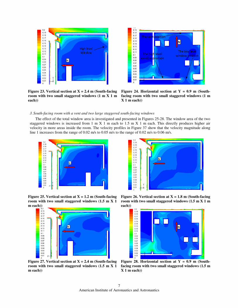
Figure 23. Vertical section at X = 2.4 m (South-facing
room with two small staggered windows (1 m X 1 m
each))
Figure 24. Horizontal section at Y = 0.9 m (South-
facing room with two small staggered windows (1 m
X 1 m each))
3. South-facing room with a vent and two large staggered south-facing windows
The effect of the total window area is investigated and presented in Figures 25-28. The window area of the two
staggered windows is increased from 1 m X 1 m each to 1.5 m X 1 m each. This directly produces higher air
velocity in more areas inside the room. The velocity profiles in Figure 37 show that the velocity magnitude along
line 1 increases from the range of 0.02 m/s to 0.05 m/s to the range of 0.02 m/s to 0.06 m/s.
Figure 25. Vertical section at X = 1.2 m (South-facing
room with two small staggered windows (1.5 m X 1
m each))
Figure 26. Vertical section at X = 1.8 m (South-facing
room with two small staggered windows (1.5 m X 1 m
each))
Figure 27. Vertical section at X = 2.4 m (South-facing
room with two small staggered windows (1.5 m X 1
m each))
Figure 28. Horizontal section at Y = 0.9 m (South-
facing room with two small staggered windows (1.5 m
X 1 m each))
8
American Institute of Aeronautics and Astronautics
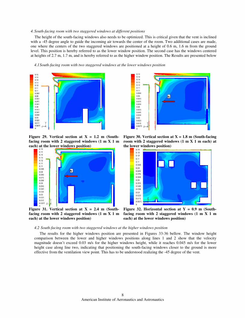
4. South-facing room with two staggered windows at different positions
The height of the south-facing windows also needs to be optimized. This is critical given that the vent is inclined
with a -45 degree angle to guide the incoming air towards the center of the room. Two additional cases are made,
one where the centers of the two staggered windows are positioned at a height of 0.6 m, 1.6 m from the ground
level. This position is hereby referred to as the lower window position. The second case has the windows centered
at heights of 2.7 m, 1.7 m, and is hereby referred to as the higher window position. The Results are presented below
4.1 South-facing room with two staggered windows at the lower windows position
Figure 29. Vertical section at X = 1.2 m (South-
facing room with 2 staggered windows (1 m X 1 m
each) at the lower windows position)
Figure 30. Vertical section at X = 1.8 m (South-facing
room with 2 staggered windows (1 m X 1 m each) at
the lower windows position)
Figure 31. Vertical section at X = 2.4 m (South-
facing room with 2 staggered windows (1 m X 1 m
each) at the lower windows position)
Figure 32. Horizontal section at Y = 0.9 m (South-
facing room with 2 staggered windows (1 m X 1 m
each) at the lower windows position)
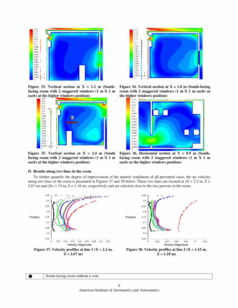
4.2 South-facing room with two staggered windows at the higher windows position
The results for the higher windows position are presented in Figures 33-36 bellow. The window height
comparison between the lower and higher windows positions along lines 1 and 2 show that the velocity
magnitude doesn’t exceed 0.03 m/s for the higher windows height, while it reaches 0.045 m/s for the lower
height case along line two, indicating that positioning the south-facing windows closer to the ground is more
effective from the ventilation view point. This has to be understood realizing the -45 degree of the vent.
9
American Institute of Aeronautics and Astronautics
Figure 33. Vertical section at X = 1.2 m (South-
facing room with 2 staggered windows (1 m X 1 m
each) at the higher windows position)
Figure 34. Vertical section at X = 1.8 m (South-facing
room with 2 staggered windows (1 m X 1 m each) at
the higher windows position)
Figure 35. Vertical section at X = 2.4 m (South
facing room with 2 staggered windows (1 m X 1 m
each) at the higher windows position)
Figure 36. Horizontal section at Y = 0.9 m (South-
facing room with 2 staggered windows (1 m X 1 m
each) at the higher windows position)
D. Results along two lines in the room
To further quantify the degree of improvement of the natural ventilation of all presented cases, the air velocity
along two lines in the room is presented in Figures 37 and 38 below. These two lines are located at (X = 2.2 m, Z =
2.67 m) and (X= 1.15 m, Z = 1.18 m), respectively and are selected close to the two persons in the room.
Figure 37. Velocity profiles at line 1 (X = 2.2 m,
Z = 2.67 m)
Figure 38. Velocity profiles at line 2 (X = 1.15 m,
Z = 1.18 m)
South-facing room without a vent
10
American Institute of Aeronautics and Astronautics
North-facing room
South facing room with one south-facing window (2 m X 1 m)
South facing room with two small aligned windows (1 m X 1 m each)
South facing room with two small staggered windows (1 m X 1 m each)
South-facing case with two large staggered windows (1.5 m X 1 m each)
South facing case with two small staggered windows (1 m X 1 m each) at the lower height position
South facing case with two small staggered windows (1 m X 1 m each) at the higher height position
III. Conclusion
The present work investigates the natural ventilation in a south-facing room using the typical incoming air
velocities according to the wind rose of Cairo-Egypt in the summer months, using CFD to predict the air flow
distribution. The work improves the natural ventilation inside the room via introducing a vent in the other-wise
closed north-facing wall, which allows entry of higher incoming air velocity and changes the ventilation from
single-sided to cross-ventilation. The air velocity along a reference line inside the room increased from the range of
0.005 m/s to 0.01 m/s to the range of 0.01 m/s to 0.035 m/s, due to the addition of the vent. It was found that further
improvement can be made by splitting the single large window on the south-facing wall into two smaller aligned
windows of equal total area and that the staggered configuration is preferred over the aligned configuration. This
increased the velocity range along the line to 0.02 m/s to 0.05 m/s. Increasing the window area further improves the
natural ventilation and increases the air velocity along the reference line to the range of 0.03 m/s to 0.06 m/s.
Positioning the windows closer to the floor makes further improvements. These results help developing better
natural ventilation in order to reduce the use of massive air-conditioning loads in summer.
References 1Orme, M.,” Estimates of the energy impact of ventilation and associated financial expenditures,” Energy and Buildings,
Vol.33 2001, pp.199-205. 2Khedari Joseph, Yamtraipat Nuparb, Pratintong Naris and Hirunlabh Jongjit.,” Thailand Ventilation Comfort Chart,” Energy
and Buildings, Vol.32, 2000, pp. 245-249. 3Khalil, Essam E.,”Efficient energy utilization in air conditioned buildings in Egypt: new directive,” Thermal Issues in
Emerging Technologies, THETA 2, 2008, pp.443-448. 4Khalil, Essam E.,” Life cycle cost analyses of air-conditioning systems in commercial buildings in Egypt,” 2nd ICGSI
conference, Chiang Rai, Thailand, 2009. 5Yassin, Ibrahim.,” Energy Efficiency Policy in Egypt and its perspectives,” IFPEEI Workshop Proceedings, Bejing, 2007.
6Ministry of electricity,”annaul report of Egyption ministry holding company,” 2009-2010. 7Ecotect, Enrgy analysis program, software package, Ver.5.5, 2005. 8Camille Allocca, Qingyan Chen, and Leon R. Glicksman.,” Design analysis of single-sided natural ventilation, ”Energy and
buildings, Vol.35, 2003, pp. 785-795.