important information - bitsavers
TRANSCRIPT
, ,
112670-074 r
TECHNICAL MANUAL
TAPE READER
MODEL: RRS7200BEX/660/D-A
IMPORTANT INFORMATION Changes to the equipment which are made between manual
printings are listed in an addendum at the rear ofthe manual.
As a convenience, a list of change pages is givenasthe last
page in the manual. It is recommended that each of these
pages be marked "Refer to Addendum" -so that these changes
can be identified.
EX-CELL-O CORPORATION REMEX
1733 Alton St •• P.O. Box C-19533 .'rvlne, CA 92713

Copyright@ 1977 by REMEX, a Unit of Ex-Cell-O
Corporation. Printed in the United States of America.
All rights reserved. This book or parts thereof may
not be reproduced in any form without permission of
the publishers.
l l
BAliANwi The following section is part of the Standard Terms and Conditions ond covers only the Warranty. The reader should refer to the complete Standard Terms and Conditions for the entire sales agreement.
The Seller warrants to the original Buyer only, that the Product, except as to software and firmware, is free from defects in workmanship and material under normal use and service. The Seller's obligation under this warranty shall be limited to furnishing a replacement for, or at the Se lIer's option repairing any Product or any part or parts thereof, which prove defective within 90 days* from the date of shipment by the Se lIer f provided such Product or such part or parts are returned to the Se lIer transportation prepaid.
The Seller warrants, for a period of thirty (30) days from the date of shipment by the Se Iler to the origina I Buyer on Iy, that the software and firmware Products are free from defects in workmanship and material. Seller's obligation under this warranty shall be limited to correcting any of said defects or replacing the software or firmware. Said warranty shall be void and of no effect whatsoever in the event that changes or additions have been made to the software or firmware (or in the event that the software or firmware product has been adapted by the Buyer) to serve a function not within the system specifications of the Seller.
All replacement Products or parts thereof furnished under this warranty wi" be invoiced in the usual manner and adiustments will be made after the Product or part thereof claimed to be defective has been returned to, and inspected at, the Seller's plant. Replacements shall be furnished under this warranty F. O. B. Buyer's plant, and the Seller shall not be responsible for installation costs. (For all international transactions, replacement shall be furnished F .0. B. Seller's plant and Buyer is responsible for all customs and brokerage fees.) The Buyer shall be liable for all freight inspection and hand ling costs if such Product or such part or parts do not prove to be defecti ve. In no event will any claim for labor in removing or replacing a defective Product or part for incidental or consequential damages be allowed. No warranty is made as to any Product or part which has not been installed, operated, or maintained in accordance with Seller's instructions or the instructions contained in its operations or maintenance manuals, when furnished by the Se lIer I or which has been subject to misuse, abuse, accident, or alteration or to improper or negligent use, maintenance, storage, transportation or hand ling.
This warranty is in lieu of all other warranties expresses or implied, including any warranty of merchantability or fitness for a particular purpose, and the Seller neither assumes, nor authorizes any person or firm to assume for it, any other or further ob I igation or liabi lity in connection with the sales, installation or use of any product.
UNDER NO CIRCUMSTANCES SHALL SELLER OR ANY AFFILIATE OF SELLER HAVE ANY LIABILITY WHATSOEVER FOR LOSS OF USE OR FOR ANY INDIRECT, INCIDENTAL OR CONSEQUENTIAL DAMAGES.
*AII paper tape products are covered under this warranty for a period of one year, excepting punch mechanisms, lamps and fuses which are warranted for a period of 90 days. Flexible disk drives are warranted for a period of 180 doys.

FOR YOUR SAFETY
Before undertaking any maintenance procedure, whether it be a specific trouble-
shooting or maintenance procedure described herein or an exploratory procedure
aimed at determining whether there has been a malfunction, read the applicable
section of this manual and note carefully the ~ and
~ contained therein.
The equipment described in this manual contains voltages hazardous to human life
and safety and may contain mechanical components capable of infli ding personal
injury. The cautionary and warning notes are included in this manual to alert oper-
ator and maintenance personnel to the electrical and mechanical hazards and thus
prevent persanal injury and damage to equipment.
l
Section
1.1
1.2
1.3
1.4
1.5
1.6
1.7
1.8
II
2. 1·
2.2
2.3
2.4
2.4.1
2.5
JfI
3. 1
3.2
3.3
3.3. 1 3.3.2 3.3;3 3.3.4 3.3.5 3.3.6
3.4 3.5 3.6
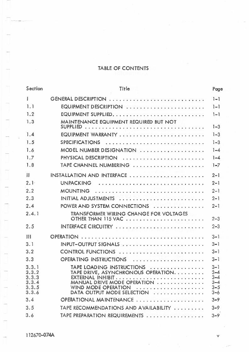
TABLE OF CONTENTS
Title
GENERAL DESCRIPTION
EQUIPMENT DESCRIPTION ........•..............
EQUIPMENT SUPPLIED .............••.•..•.•••.•.
MAINTENANCE EQUIPMENT REQUIRED BUT NOT SUPPLIED ..........•........................
EQUIPMENT WARRANTY .......•......••.•.......
SPECIFICATIONS ...•..•.•...••...............
MODEL NUMBER DESIGNATION ..•.....•.•...••...
PHYSICAL DESCRIPTION .........••..•..........
TAPE CHANNEL NUMBERING .................... .
INSTALLATION AND INTERFACE ...........•.•.......•
UNPACKING •......••.•.•........••..•.•.••
MOUNTING ...•.•.........•.•..•.•......•..
IN IT IAL ADJUSTMENTS ......•.•..•.............
POWER AND SYSTEM CONNECTIONS ....•......... .
TRANSFORMER WIRING CHANGE FOR VOLTAGES OTHER THAN 115 VAC ....•.•.•...........•..
INTERFACE CIRCU ITRY ...••.••.•.••.•..••.......
OPERATION .......•.........•.....••••.•.•.....
INPUT-OUTPUT S !GNALS ......•......•..........
CONTROL FUNCTIONS ......••..•.•.....••.....
OPERA TING INSTRUCTIONS ......•....•.••......
TAPE LOAD ING INSTRUCTIONS •...•••.••...... TAPE DRIVE, ASYNCHRONOUS OPERATION ........ . EXTERNAL INHIBIT ...........•..•........... MANUAL DRIVE MODE OPERA TION .•.•.•........ WIND MOD E OPERATION .....•........•..... DATA OUTPUT MODE SELECTION ..•............
OPERA T10NAL MAINTENANCE ....•...............
TAPE RECOMMENDATIONS AND AVAILABILITY ........ .
TAPE PREPARATION REQUIREMENTS ...............•.
112670-074A
Page
1-1 1-1
1-1
1-3 1-3
1-3
1-4
1-4 1-7
2-1
2-1
2-1 2-1 2-1
2-3
2-3
3 .. 1
3-1
3-1 3-1
3-1 3-4 3-4 3-4 3-5 3-6 3-9
3-9 3-9
v
Section
IV
4.1
4. 1. 1 4.1.2 4. i.3 4. 1.4 4. 1.5
4.2
4.3
4.3.1
4.3.1.1 4.3.1.2 4 .3.1.3
4.3.2 4.3.3
4.4
4.4. 1
V
5. 1
5. 2
5.2. 1
5.2.1.1 5.2.1.2 5.2.1.3 5.2.1.4
5.2.2 5.2.3
5.3
5.4 5.5 5.6 5.7
vi
TABLE OF CONTENTS (CONTINUED)
Title
THEORY OF OPERA TION •..•..•....•..•.•.•...•....
BLOCK DIAGRAM DESCRIPTION •..••.••.••••..•.•..
TAPE DRIVE .......•...................... WIND OPERATION ......••..•.•.•••••••.... READ ER INH IBIT 45 •......••.•.•••••..••••... TAPE READING ...•......••••••...••..••.. SPOOLER BLOCK DIAGRAM ....•..••••.•.•••...
llG HT SOURCE ....•.•....•.•.••..•.•.•.......
CIRCUIT CARD DESCRIPTIONS ....•...•.••••......•
READER CIRCUITRY .......••.•••••.......•.•.
Drive Circuits ............................... . Wind Circuits ............................. . Tape Reading Circuits •..•..•.•.•.••••.••••.•.
SPOOLER CIRCUITRY •...•..•...•.•..•..•..... POWER SUPPLY •.•.•...••.••...•..•.•..••..
MECHAN ICAL THEORY OF OPERATION •.•...•..•.....
TAPE TENSION •...•.•.•••..••.••..•.••....
MAINTENANCE ...••............•................
GENERAL ....•.•.•.•......••..•....••......
PREVENTIVE MAINTENANCE ..•.••.....•..........
CLEAN ING ...•...•....•....•.•..•........
Readhead Assembly Cleaning ....•.•.••••.••••... Sprocket Cleaning ...•......•.••••••.•.•..•.. T ape Inspect ion ..••........ ~ • • • • • . • . • . . . . . . General Cleaning •...•••••••••.••••••.•.•.••
LUBRICATION ••....•.••..•..••............ POWER SUPPLY VOLTAGES .....•.••...•..••....
TROUBLE SHOOTING ...•..•.••.••.••.•.•••.....
READER ALIGNMENT ...•..••..•••..•.•••..•....
READER LAMP VOLTAGE ADJUSTMENT •••••••••.•....
SERVO ALIGNMENT ...•..•...•..•.•..........•
ARM SPRING TENSION ADJUSTMENT .•.••••.........
Page
4-1
4-1
4-1 4-1 4-3/4-4 4-3/4-4 4-3/4-4
4-3/4-4
4-7
4-7
4-7 4-8 4-9
4-10 4-10 4-11 4-11
5-1
5-1
5-1 5-2
5-4 5-4 5-4 5-4
5-4 5 ... 5
5-5
5-9 5-15
5-15
5-15
li2670-074A
-:
-- -~--,.-- --
Section
5.8
5.9
VI
6. 1
6.2 6.2. 1 6.2.2 6.2.3 6.2.4 6.2.5 6.3
6.3. 1 6.3.2 6.3.3 6.3.4
VII
7.1 7.2
VIII
8. 1
TABLE OF CONTENTS (CONTINUED)
Title
SPOOLER TAPE ARM AND ROLLER ALIGNMENT
TAPE SPLICING .•....... •.•••• .•..............
PARTS REPLACEMENT .•..•..•.•..........•.........
GENERAL ....•.......•.•.••.•••.............
READER PARTS REPLACEMENT ..................... .
READHEAD MECHANISM DISASSEMBLY ...........• READER CARD REPLACEMENT •......•........... READER LAMP REPLACEMENT ........•.......... MOTOR AND/OR SPROCKET REPLACEMENT ..•...... TRANSFORMER REPLACEMENT ...•..•...........
SPOOLER PARTS REPLACEMENT .•...•..•.•........•
POTENTIOMETER REPLACEMENT •.......•....•... FRONT PANEL AND CHASSIS SEPARATION ........ . SERVO MOTOR REPLACEMENT .•.•.•••..••...... TAPE ARM PLACEMENT .......•....•.........
PARTS LIST .••...•........•.......••............
GENERAL .. ...•. •. ....... •..... ............
K IT OF PARTS .....•.....••••..•........•.....
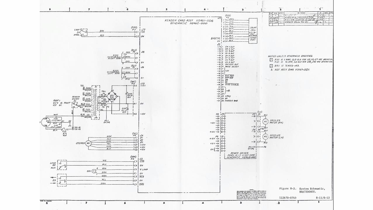
SCHEMATIC DRAWINGS ...•...•..•...•.............
GENERAL ..•.•..•....•.•.••...•...•.. ..•. ...
112670-074A
Page
5-16
5-16
6-1 6-1
6-1 6-1 6-2 6-2 6-3 6-3 6-4 6-4 6-4 6-5 6-5 7-1
7-1 7-1 8-1/8-2
8-1/8-2
vii
\
Figure
1-1 1-2 1-3 1-4
2-1
2-2
3-1 3-2
4-1 4-2 4-3 5-0 5-1 5-2 5-3 5-4 5-5 5-6
6-1
7-1 7-2 7-3 7-4 7-5
8-1 8-2 8-3
viii
LIST OF fLLUSTRA TIONS
Title
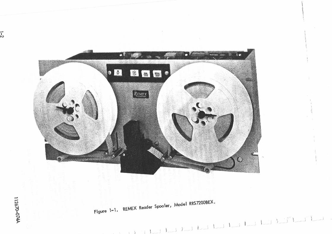
REMEX Reader Spoo ler, Mode I RRSnOOBEX ............•... Installation Drawing, Model RRS7200BEX ................ . Model Number Coding for RRS7200 ....••...••...•...••.. Tape Channe I Numbering . . . . . . . . • . . • . • . . . . . . . . . . . . . •
Reader Connections to .External Equipment. See Table 3-1 for Signal Descriptions ............................ . Recommended Interface Circvitry ............. , .. , ..... .
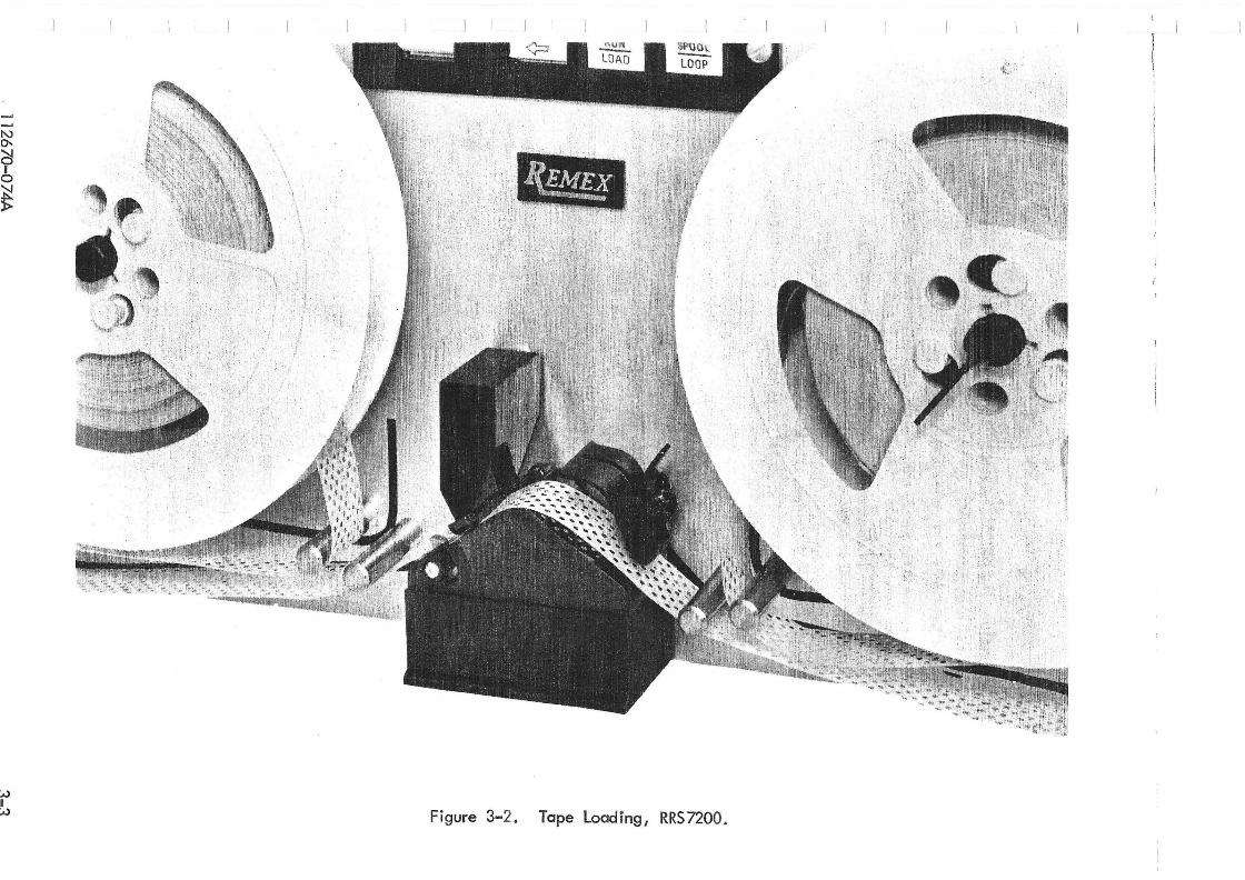
Timing Diagram' for RRS7200 ......•••.••.•..••....... Tape Load ing, RRS7200 ....•.....•.•....•...... , ...•
Block Diagram Reader Circuitry .. , ....•.•.•.•..•....... Block Diagram, Spooler Circuitry ....••..•...•..•....... Timing Diagram, Reader Card 112461-4 . , ......•. , ....... . Brush Insertion for Readheadhead Cleaning .•..•••••••••••.•• Sprocket Re lation to the Tape Rid ing Surface ., .•...•.•..... Checking the Sprocket in Relation to Tape Riding Surface ...... .. A lignment of the Sprocket with the Light Columns ......•. , .. . Adjustment of the Upper Tape Guide ........•............ Photocell Output Test Circuit ........•...•.......• , ... Tape Splicing Procedure ..•...•..•........•.........
T ape Arm Assemb Iy . . . . • . • . . . . . . . . . • . . • . . . ~ . . . , . . , .
Readhead Mechanism and Step Motor Assembly ............. . RRS7200 Front View of Front Pane I ..................... . RRS7200 Rear View of Front Panel ..................... . RRS7200 Chassis Assembly ...•........•....•....... , .. RRS7200 Rear View , , ....... , . , ......•.............
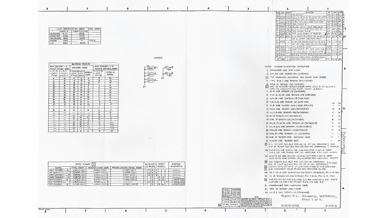
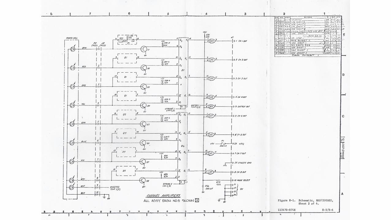
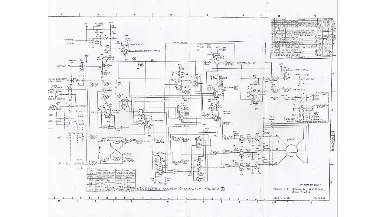
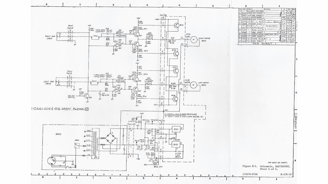
S chemati c, RRS7200BEX , Sheet 1 of 3 ..........•........ I.C. Module Outlines and Truth Tables ..........•........ Standard Schematic Symbols, Sheet 1 of 2 ....••••.........
Page
1-2 1-5 1-6 1-7
2 ... 2 2-4
3-2 3-3
4-2 4-2 4-5/4-6 5-5 5-11 5-11 5-12 5-12 5-14 5-17
6-6
7-7/7-8 7-9 7-10 7-11 7-12
8-3/8-4 8-9/8-10 8-11
1 12670-074F
Table
1-1 1-2
3-1 3-2 3-3 3-4
5-1 5-2 5-3 5-4
6-1
LIST OF TABLES
Title
Items Included with the RRS7200 ... 0 0 0 0 0 • 0 0 0 • 0 0 0 0 0 0 0 • 0 0 0 •
Specifications of the REMEX Reader, Model RRS7200BEX 0 0 • 0 • 0 0 ••
Interface Signa I Description 0 0 0 0 0 0 0 0 • 0 • 0 0 0 0 0 0 0 0 0 0 •••• 0 •
Front Pane I Contro Is .... 0 0 •• 0 0 • 0 •••• 0 0 0 0 • 0 •• 0 • 0 0 • 0 • 0
Modes of Operation 0 •• 0 •• 0 0 • 0 0 0 0 0 0 0 0 0 0 0 0 0 0 0 0 • 0 0 ••••
Recommended Tapes o. 0 0 0 • 0 0 • 0 ••• 0 0 0 • 0 0 0 0 ••• 0 ••••• 0 •
Maintenance Equipment Required .... 0 •••••• 0 • 0 0 • 0 0 ••••••
Preventive Maintenance Schedule and Log . 0 •• 0 •• 0 0 •••••• 0 ••
Power Supply Voltage Locations, Reader Card 0 0 • 0 '0 0 •• 0 0 • 0 •••
Trouble Shooting ...•.• 0 • 0 ' . ' 0 0 •• 0 0 0 0 •• 0 •• 0 0 • 0 0 0 ••• 0 0
Transformer Wire Connections .. 0 0 0 •• 0 ••• 0 •••• 0 ••• 0 ••• 0 •
Page
1-1 1-3
3-6 3-8 3-8 3-9
5-1 5-3 5-5 5-6
6-3
7-1 Recommended Spare Parts 0 •••••••• 0 •• 0 0 •• 0 •••• ~ 0 •• 0 0 o. 7-2 7-2 Parts List RRS7200BEX .•. 0 • 0 0 ••• 0 0 0 0 0 •• 0 0 0 0 0 ••••• 0 •• 0 7-3 7-3 Parts List Reader Circuit Card 112461-4 0 0 0 ••• 0 0 •••• 0 • 0 •• o. 7-13
112670-074A ix

l
--, I
SECTION 1
GENERAL DESCRIPTIO N
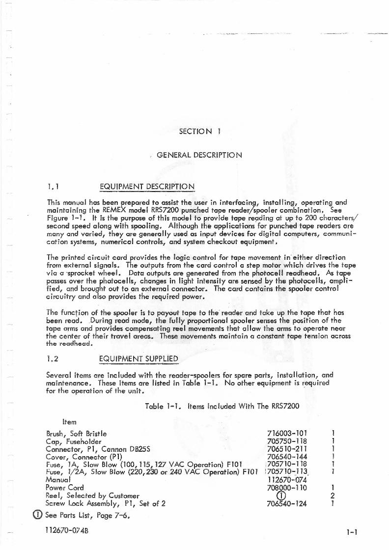
1.1 EQUIPMENT DESCRIPTION
This manual has been prepared to a~sist th~ user in interfacin~, installing, operating and maintaining the REMEX madel RRS7200 punched tape reader/spooler combination. See Figure 1-1. It is the purpose of this model to provide tape reading at up to 200 characters/ second speed along with spooling. Although the applications for punched tape readers are many and varied, they are generally used as input devices for digital computers, communication systems, numerical controls, and system checkout equipment.
The printed circuit card provides the logic control for tape movement in-either direction from external signals. The outputs from the card control a step motor which drives the tape via a -sprocket wheel. Data outputs are generated from the photocell readhead. As tape passes over the photocells, changes in light intensity are sensed by the photocells, amplified, and brought out to an external connector. The card contains the spooler control circuitry and also provides the required power.
The function of the spooler is to payout tape to the- reader and take up the tape that has been read. During read mode, the fully proportional spooler senses the position of the tape arms and provides compensating reel movements that allow the arms to operate near the center of their travel areas.. These movements maintain a constant tape tension across the readhead.
1.2 EQUIPMENT SUPPLIED
Several items are included with the reader-spoolers for spare parts, installation, and maintenance. These items are listed in Table 1-1. No other equipment is required for the operation of the unit.
Table 1-1. Items Included With The RRS7200
Item
Brush, Soft Bristle Cap, Fuseholder Connector, PI, Cannon DB25S Cover, Connector (PI) Fuse, lA, Slow Blow (100,115,127 VAC Operation) FI01 Fuse, l/2A, Slow Blow (220,230 or 240 VAC Operation) F101 Manual Power Cord Reel, Selected by Customer Screw Lock Assembly, PI, Set of 2
<D See Parts List I Page 7-6.
112670-074B
716003-101 705750-118 706510-211 706540-144
:705710-118 ! 705710-113. 1 }2670-074 708000-110
(j) 706540-124
1 2 1
1-1
--..--------
x uJ
£:Q
0 0 ~ '" eo:: eo:: -
G)
-0
~ "" ~
0 8-'" "" G) -0
0 G
) eo:: X
~
"
uJ
CI/!
.-I .-G
)
'"' ::> .f!! \.l-
1 12670-0 74A
1-2
1.3 MAINTENANCE EQUIPMENT REQUIRED BUT NOT SUPPLIED
The maintenance procedures in Section 5 require equipment that is not suppl ied. This equi·pment is listed in Table 5-1.
1.4 EQU IPMENT WARRANTY
A statement covering the warranty of this equipment is given on page iii (second page in book). It should be read and understood. All preventive maintenance procedures must be performed as outlined in Section 5.2 during the warranty period in order that the warranty remain in effect. Any questions arising concerning the warranty should be directed to the REMEX Service Department.
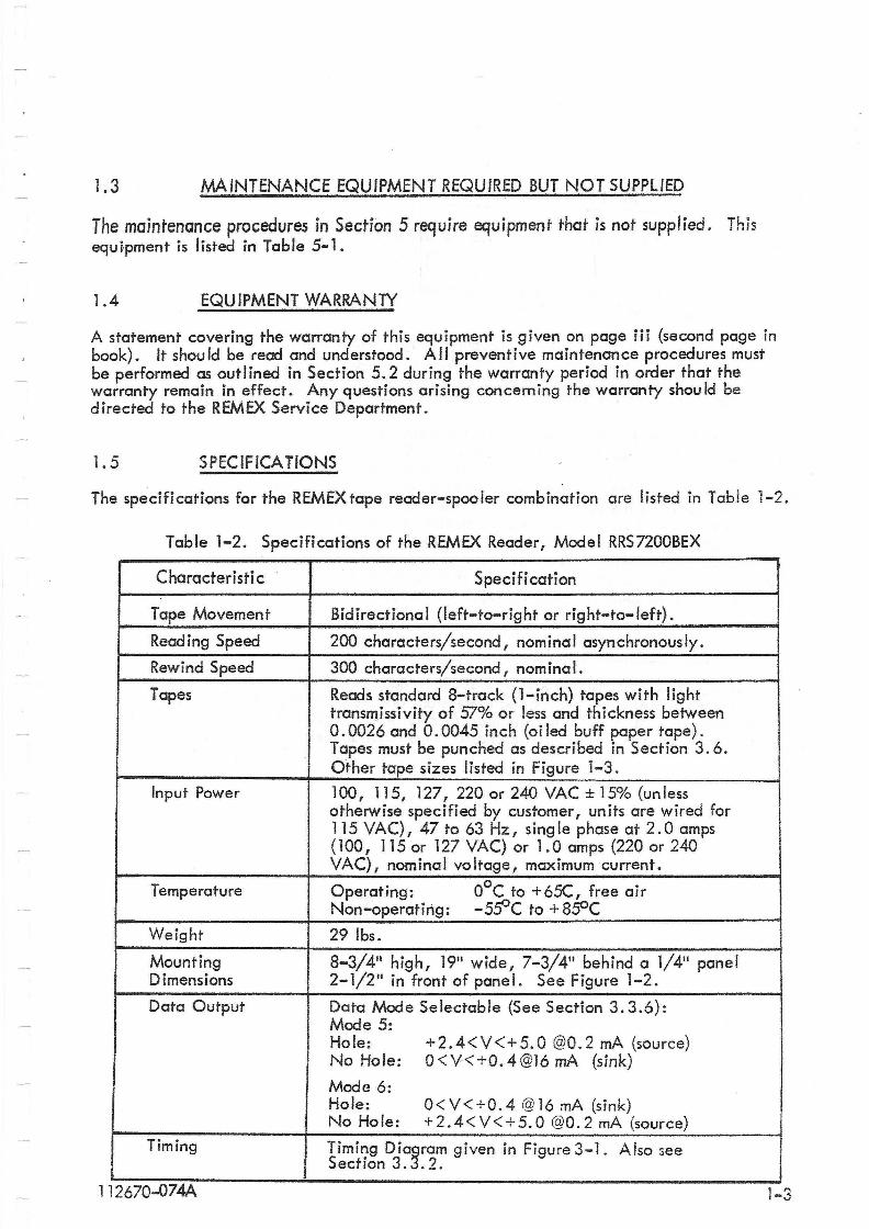
1.5 SPECIFICA TIONS
The specifications for the REMEX tape reader-spooler combination are listed in Table 1-2.
Table 1-2. Specifications of the REMEX Reader, Model RRS7200BEX
Characteristi c Specification
Tape Movement Bidirectional {left-to-right or right-to-Ieft}.
Reading Speed 200 characters/second, nominal asynchronously.
Rewind Speed 300 characters/second, nominal.
Tapes Reads standard 8-track (l-inch) tapes with light transmissivity of 57% or less and thickness between 0.0026 and 0.0045 inch (oi led buff paper tape). Tapes must be punched as described in Section 3.6. Other tape sizes listed in Figure 1-3.
Input Power 100, 115, 127, 220 or 240 VAC ± 15% (unless otherwise specified by customer, units are wired for 115 VAC), 47 to 63 Hz, single phase at 2.0 amps ( 100, 115 or 127 VAC) or 1. a amps (220 or 240 vAeL nominal voltage, maximum current.
Temperature Operating: OOC to +65C, free air Non-operating: -5SOC to + 8se'C
Weight 291bs.
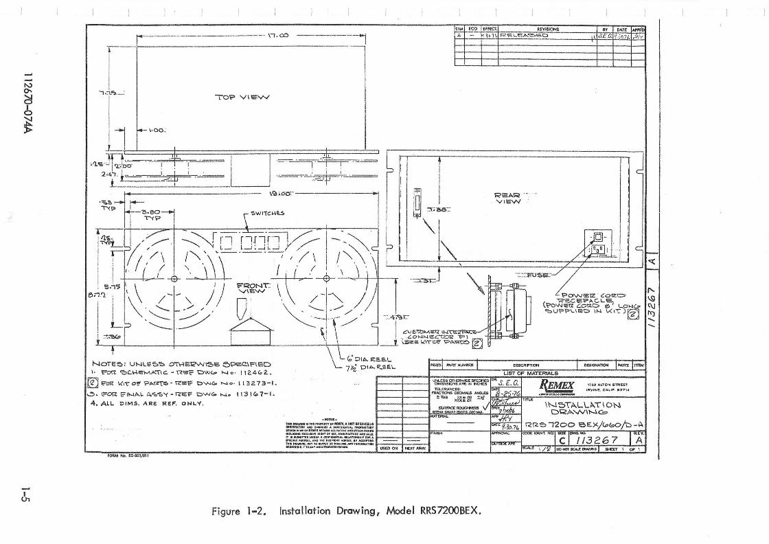
Mounting 8-3/411 high, 19" wide, 7-3/4" behind a 1/4" panel Dimensions 2-1/2" in front of panel. See Figure 1-2.
Data Output Dato Mcx::le Selectable (See Section 3.3.6): Mode 5: Hole: +2.4<V<+5.0 @0.2 rnA (source) No Hole: 0<V<+O.4@16 mA (sink)
Mode 6: Hole: O<V<+0.4 @16 rnA (sink) No Hole: +2.4<V<+5.0 @O.2 rnA (source)
Timing Timing Dia~ram given in Figure 3-1. Also see
I I Section 3. .2.
112670-074A 1-3

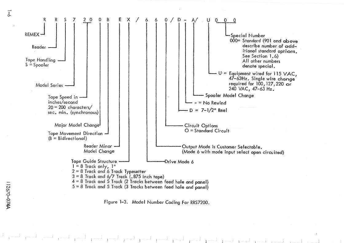
1.6 MODEL NUMBER DESIGNATION
The REMtx model des:gncs.ion i~ u£@d to code the basic functions and configurations of a particular product line. The model number codes for the RRS7200 are shown in Figure 1-3. An X in a particular digit designator (as used in many parts of this manual, especially in the parts list) denotes any of the combinations for that digit given in Figure 1-3 applies in the instance cited.
Always' consu It the serial number tag for proper voltage and frequency to be used and for model identification. Failure to do so could result in damage to the unit. The serial tag is located on o!,\e of the rear surfaces. In all correspondence, always refer to the complete model number, !ncluding the mode and the special number and the unit's serial number.
The last three digits of the model number denote either a standard unit (000 or 901 and higher) or a special (all other numbers). Units with 000 indicate standard units with no additional options other than those coded in the model number structure. Units with 901 and higher are used to indicate the number of standard options (used only on standard units) which are not coded in the model number. These are listed on the serial tag below the model number in the form of a series of three digit numbers depending upon the number of options used . For example, a unit with 902 would list two three digit numbers. Becuase the list of possible options is constantly changing, it is not included in the manual. Generally, this list consists of special customer requirements that do not affect the operation of the unit and include such things as special paint,no logo, mill edge panel, etc.
1.7 PHYSICAL DESCRIPTION
The REMEX tape reederlspooler mOdel RRS7200BEl 16601D-A is mounted on a 19-inch panel with a height of 8-3/4 inches. Detailed dimensions are shown in Figure 1-2. The front panel contains the tape reading and transport mechanism. The lamp is accessible from the rear of the front panel. The electronic chassis is mounted at the rear of the unit. .
1-4 112670-116A
'" 0--
~ b ~
&
r-r----~·-" .. ·--·------·--.. \/.00 ------~~ .. ~1
.,.:l!; . ....: To'? VIEVV
'- ' -~-r '! : '-I~ '.=",""'-'.- ffF=""'=-= I "-r
'~.iF eo - \21 .... O'O:--~ : I ~ _" '~' a'" "'. SWI'TCI-lt,S ." v", .... _
~p I I
I-- \·00:
Jl :t=-,,-l~ r-.t..!.... _ _ . Jill ,ii -1 T ,...:.-.=-:-= . ,~
,I}.s· I '2.";00' I l .2'4"7 · l~· ... 1:-:t1
.L_-=---==:_I
~!S~f!~IE:r'I_ .. _. _. __ ~EVISIQNS
REA.R VIEW
~y o.o.Te IA7"b! '\'./' ,' ., . ," ".kE . 1·,0.7(, . :liY
J
~.- -~ r--- ":-=--1,./' I - ~ II \ ~~_ , ' ".- . ~ "1 r1 r-Wlf'
~/ / -, E- . II'; /\ 1"-,' ,'='-l~-!~','/ \ i /,,-~, _ I h ~d Ijc-I ' I .-11 ~ I i r' ./ 1 \ \ '\ \ 1 77 ~
1 \ ') F~
I L 1\ !- - ,» QY I JJt~1 ~ ( .. ---- .. ---. "- __ .. ", . . '?O'N"17. '::017.0 eo' l..O .... c,.1 r;'\J
, ~ ~ /" L -::'.4.;<:\.1:: <;:'U~~I...I .. t:> l\o..l \r(\")~ I'f)
~.~ J ~ , ~ .c~~~~~_g;~~~ ~ _ l:selO. \(1"C"Of' 1?"'''''''C-5 ~
NOTee.; UNLe;'O~ OTI4E1C"NISe. e)Pe.C.\r'IE:D \. Fori: 'OC.14EM,c...,\C, ~ ~EF 'Ow,,", \0...10' 112.4G.'2..
@ji;::-Oll: \(\TOt"'?A~6-~IiSC:: OVoJGo "'0 ' 1132.73-1.
..,::,. c=orz I?'II--JA.L ~~"5'( -r2e:1? t:>VoJGo No 113\1<>7-1.
4 . A~L PIMS. ARE. RE.F. ONLY.
fORM No, EO 603/01 t
Figure 1-2.
\ \ C;'Dlo!>. ~e.aL I 1 I L 7Yi .D' .... R..e:e.L"Ecm ..... "TNU .. """ I OESC"'",,::>N I DES""",TION I"""" I ....... LIST OF MATERIALS
REMEX 1?:U ALTON ST~l!n
I TOL.£RANCES: :r IR\IINE. CALI". Gl27,.. FR1G11ONS OECIMAJ..S -'N3L£S "_.U.DIM~_
I----ll----i :tV32 XX:!:02. ±Ih" TITLE
XXU.ol .j \N;:-;'TJ:>...LLII-TION ....~"":.~~w.x DRA'-NINC'=:>
W-URIAi.
.............. ...,.;.:':;';. ......... ,"'<,,'" RR';:';> "1200 6E.X/l.&>f::>Oju-C\ :::::~~M::~7:~::r:t~::~J---~~---tF~IN~i~"'---------k~~~~~~i~~,<NQT~rn~~~~~----~,-~~ z.:~~~.:.~= T~:O:.~:;;~:;:,T:-~~ I--:::=:-ir-=-:::--i Tltlt COIWfiIIMO, HOT TO ."""~v (UI OISC1.OQ ""\I' IH:fO~tlllH 1-----if----1 MGAACHMClI1TO,...YUlWl'JItO!I1110f'll_, USED ON NEXT AS$(
Installation Drawing, Model RRS7200BEX.
I I
I 0-.
N 0-.
2:l I o N
~
R R S 720 DB E X / 6 6 0 / 0 - A/ U 0 0 0
L,edal Number REMEXJ J Reader
000= Standard (901 and above describe n'umber of additional standard options. See Section 1.6)
Tape Handling S ;::: Spooler
Model Series
Tape Speed in inches/second 20 = 200 characters/ sec. min. (synchronous)
Major Model Change
Tape Movement Direction (B = Bidirectional)
A II other numbers denote special.
U' = Equipment wired for 115 VAe , 47-63Hz. Single wire change required for 100,127,220 or 240 VAC, 47-63 Hz.
Spooler Model Change
- = No Rewind
o = 7-1/2 11 Reel
1..-__ Circuit Options o = Standard Circuit
Reader Minor Model Change
'------ Output Mode is Customer Selectable. (Mode 6 with mode input select open circuited)
Tape Guide Structure ---I Drive Mode 6 1 = 8 Track only, 1" 2 = 8 Track and 6 Track Typesetter 3 = 8 Track and 6/7 Track (.875 inch tape) 4 = 8 Track and 5 Track (2 Tracks between feed hole and panel) 5 = 8 Track and 5 Track (3 Tracks between feed hole and panel)
Figure 1-3. Model Number Coding For RRS7200.
, j J ! , )
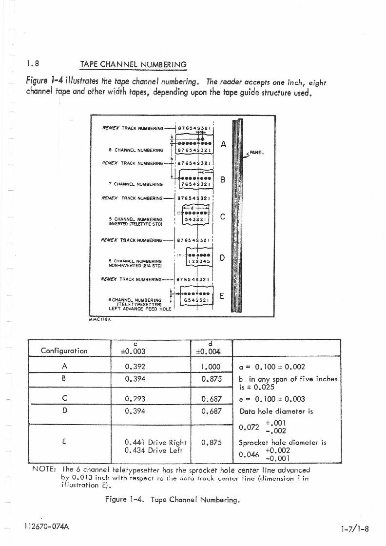
1.8 TAPE CHANNEL NUMBERING
Figure J-4 illustrates the tape channel numbering. The reader accepts one inch, eight channel tape and other width tapes, depending upon the tape guide structure used.
I
Configuration
A
B
C
D
E
R£M£X TRACK NUM8ERING-j 876545032 I I
8 CHANNEL NUMBERING
b j I R£M£X TRACK NUMBERING~' B 1654 S 3 2 I !
I' I I
7 CHANNEL NUMBERING
R£M£X I
TRACK NUMBERING- 81654S321 :
A
B
5 CHANNEL NUMBERING INVERTED (TELETYPE STOl
I I C ---""-;-1 I
R£M£X rftACKNUMBERING- 81654$321 I
f 6 CHI~~~~l;-~~~~~~~~ f LEFT ADVANCE FEED HOLE
MMCl18A
c
I I
i ••••••• 654S321
d
D
E
±0.003 ±0.004
0.392 1.000
0.394 0.875
0.293 0.687
0.394 0.687
0.441 Drive Right 0.875 0.434 Drive Left
Pl\NEL
a = 0.100 ± 0.002
b in any span of five inches is ± 0.025
e = O. 100 ± 0.003
Data hole diameter is
0.072 +.001 -.002
Sprocket hole diameter is
o 046 +0.002 • -0.001
NOTE: The 6 channel teletypesetter has the sprocket hole center line advanced by 0.013 inch with respect to the data track center line (dimension f in illustration E).
Figure 1-4. Tape Channel Numbering.
112670-074A 1-7/1-8

-,
SECTION II
INSTAlLA TJON AND INTERFACE
2. 1 UNPACKING
To provide the most protection during transit I specially designed and reinforced packing cartons are used to sh ip the REM EX punched tape reader/spoo ler. Those items I isted in Table 1-1 are also packed with the unit. When removing the unit from the carton, the reader-spooler shou Id be lifted with both hands under it. Never lift or attempt to carry. the unit by any of the covers, drive assembly, arms or other delicate parts. Carefully inspect the unit for any apparent damage as soon as it is removed from the carton. Check the equipment supplied list in Table 1-1 against the kit of parts supplied with the reader. In the event the equipment has been damaged as a result of shipping, the carrier and REMEX must be notified as soon as possible .
2.2 MOUNTING
The reader/spooler mounts in a standard 19-inch rack with mounting holes provided. To ensure a minimum transmission of acoustical noise and vibration to other equipment I the reader should be securely mounted. When mounting the unit in a closed cabinet I adequate air circulation should be supplied so that the unit does not exceed the ambient temperature specification listed in Table 1-2.
2.3 IN ITIAl ADJUSTMENTS
Each reader has been accurately adjusted and aligned before leaving the factory. No adjustment or calibaration should be required prior to installation or use . However, the proper fuse from the kit of parts requires installation. Refer to Section 2.4.
2.4 POWER AND SYSTEM CONN ECTIONS
InputAC power (refer to Table 1-2) is applied through the A.C. connector at the rear .
112670-074A
All units come wired for 115 VAC, 47-63 Hz operation. if another voltage isto be used, a wire change on the transformer must be made as described in Section 2.4. 1. In addition, before operating the system , the proper fuse value (as indicated in Table 1-1) must be inserted from the kit of parts. Discard the other fuse (unless, of course, a different voltage operation is ant icipated).
2-1
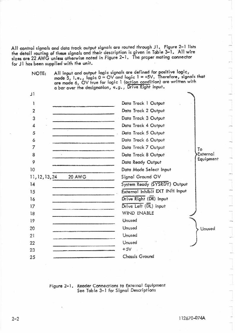
All control signals and data track output signals are routed through J 1. Figure 2-1 lists the detail routing of these signals and their description is given in Table 3-1. All wire sizes are 22 AWG unless otherwise noted in Figure 2-1. The proper mating connector for Jl has been supplied with the unit.
NOTE: All input and output logic signals are defined for positive logic, mode 5, i.e., logic 0 = OV and logic 1 = +5V. Therefore, signals that are mode 6, OV true for logic 1 (action condition) are written with a bar over the designation, e.g. , Ddve Right Input.
2-2
Jl
1
2
3 4
5
6
7
8
9
10
To External "Equipment
11,1 2,13,24 20AWG
Data Track 1 Output
Data Track 2 Output
Data Track 3 Output
Data Track 4 Output
Data Track 5 Output
Data Track 6 Output
Data Track 7 Output
Data Track 8 Output
Data Ready Output
Data Mode Select Input
Signal Ground OV
14 15 16
17
18
19
20 21
22 23
25
System Ready (SYSRDY) Output
External Inhibit EXT INH Input
Drive Right (DR) Input
Drive Left (DL) Input
WIND ENABLE
Unused
Unused
Unused
Unused
+5V '
Chassis Ground
Figure 2-1. "Reader Connections ro Exrernal Equipment See Tab Ie 3-1 for Signal Descriptions
Unused
112670-074A
2,4,1 TRANSFO~MfR WIRING CHANGE fOR VOLTAGfS OTHfR THAN ll~ YA~
All units come from the factory with a transformer which allows any of five input voltages to be used: 100, 115, 127, 220 or 240 VAC, 47-63 Hz. Unless othelWise directed by the customer I all units leave the factory wired for 115 VAC. If it becomes necessary to operate on one of the other four voltages, a simple wire change is required.
~ Make sure the power plug is disconnected before making the change.
Power from the AC plug is applied through 51 to TB1-B2 via a white/black wire. See system schematic, Figure 8-2. It is necessary, then to change the white/black wire at T81-82 to TB1-85 for 100 VAC, to TB1-C5 for 127 VAC, to TB1-C1 for 220 VAC or to TBI-Dl for 240 VAC. In addition, the 1-1/2 amp fuse from the kit of parts must be substituted for the 3 amp fuse at F 1 when using 220 or 240 VAC.
2.5 INTERFACE CIRCUITRY
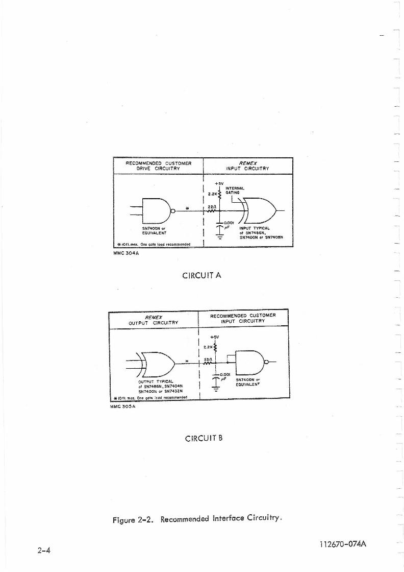
Figure 2-2 illustrates suggested drive and output circuitry with which to interface with the REMEX circuitry. Note the termination network for ~he output signals. This should be incorporated into the user's equipmen~ for maximum noise elimination. Table 3-1 lists which circuit is used with each input or output.
NOTE: All input and output logic signals are defined for positive logic (mode 5), i.e., logic 0 = OVand logic 1 = +5V. Therefore, signals that are OV true (mode 6) for logic 1 (action condition) are written with a bar over the designation, e.g' l Drive Right Input.
RECOMMENDED CUSTOMER DRIVE CIRCUITRy
SN7400N or EQUIVALENT
* 10tt. max. One qQte load recommended
MMC 304A
FiE"ME"X INPUT CIRCUITRY
INPUT TYPICAL of SN7486N, SN7400N or SN7408N
CIRCUIT A
FiE"ME"X OUTPUT CIRCUITRY
OUTPUT TYPICAL of SN7486N, SN7404N SN7400N or SN7432N
*
RECOMMENDED CUSTOMER INPUT CIRCUITRY
SN1400N or EQUIVALENT
* 10 ft. :nc-s. One gate :eod recom.mended
MMC 305A
CIRCUIT B
Figure 2-2. Recommended Interface Circuitry.
2-4 112670-074A
SECTION III
OPERATION
3.1 INPUT-OUTPUT SIGNALS
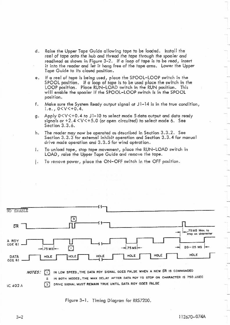
Tab le 3-1 lists those input and output signals which are routed through connector J1. The definition and/or usage of these signals are also included in the table. Figure 3-1 shows the timing diagram .for these signals.
3.2 CONTROL FUNCTIONS
Table 3-2 lists the operating controls located on the front panel. A description of the controls and their functions is also included. It is recommended that the reader review the functions of these controls before operating the unit.
3. 3 OPERATING INSTRUCTIONS
The following procedure should be used when loading and reading a tape:
3.3.1 TAPE LOADING INSTRUCTIONS
All units come wired for 115 VAC, 47-63 Hz operation. If another voltage is to be used, a wire change on the transformer must be made as described in Section 2.4. 1. In addition, before operating the system, the proper fuse value (as indicated in Table 1-1) must be inserted from the kit of parts. Discord the other fuse (unless, or course, a different voltage operation is anticipated).
a. Connect J1/P1 and plug the line coreL See Caution in Section 2.4 .
r:=J Steps band c should be performed in the order stated. If step c were performed first (ON-OFF in the ON position with LOOPSPOOL in SPOOL),> the spooler would be enabled and any movement of the tape arms could cause rapid rotation of the hub assembly resulting in possible personal injury.
b. Place the RUN-LOAD switch in the LOAD position.
c. PI~ce the ON-OFF switch into the ON position. This will apply power to the
d .
e.
f.
g.
h.
I.
i·
Raise the Upper Tape Guide allowing tape to be loaded. Install the ree I of tope onto the hub and thread the tope through the speo ler and read head as shown in Figure 3-2. If a loop of tape is to be read I insert it into the reader and let it hang free of the tape arms. Lower the Upper T ape Guide to its closed position.
If a reel of tape is being used I place the SPOOL-LOOP switch in the SPOOL position. If a loop of tape is to be used place the switch in the LOOP position. Place RUN-LOAD switch in the RUN position. This wi" enable the spooler jf the SPOOL-LOOP switch is in the SPOOL position.
Make sure the System Ready output signa I at J 1-14 is in the true cond ition, i.e., O<V<+0.4.
Apply 0<V<+0.4 to J1-10 to select mode 5 data output and data ready signals or +2.4 <V<+5. 0 (or open circuited) to select mode 6. See Section 3.3.6.
The reader may now be operated as described in Section 3.3.2. See Section 3.3.3 for external inhibit operation and Section 3.3.4 for manual drive mode operation and 3.3.5 for wind operation.
To unload tape, stop tape movement, place the RUN-LOAD switch in LOAD I raise the Upper Tape Guide and remove the tape.
To remove power I place the ON-OFF switch in the OFF position.
~~~--------------~r~L ________________________ _ ND ENABLE I
o DR -. ru~-~f ~L _________ ~nL..~ ___ _
'-------- 1--.75M5 Max. to
A ROY .-J ODE 6)
DATA ODE 6)
u o
LJ -l.15MSf-
I stop on character
U---.il .--l 20- 25 MS I-
HOLE
NorES: [!] IN LOW SPEED. THE DATA ROY SIGNAL GOES FALSE WHEN A NEW DR is COMMANDED
2 IN 80TH MODES. THE MAX DELAY AFTER DATA ROY TO STOP ON CHARACTER IS 750 JJSEC
Ie 402A o DRiVE SIGNAL MUST REMAIN TRUE UNTIL DATA ROY GOES FALSE
Figure 3-1. Timing Diagram for RRS7200.
3-2 1 12670-074A
1126
70
-07
4A
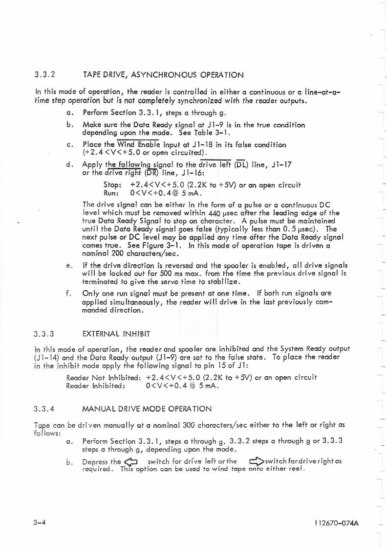
3.3.2 TAPE DRIVE, ASYNCHRONOUS OPERATION
In this mode of operation, the reader is controlled in either a continuous or a line-at-atime step operation but is not completely synchronized with the reader outputs.
a.
b.
c.
d.
Perform Section 3.3. 1, steps a through g.
Make sure the Data Ready signal at Jl-9 is in the true condition depending upon the mode. See Table 3-1.
Place the Wind Enable input at J 1-18 in its false condition (+2.4 <V<+5.0 or open circuited).
Apply the followine...1Jgnal to the d-:-r-iv-e--:':-ef~t (DL) line, Jl-17 or the drive right (DR) liner J 1-16:
Stop: +2.4<V<+5.0 (2.2K to +5V) or an open circuit Run: 0<V<+0.4@ 5 mAo
The drive signal can be either in the form of a pu Ise or a continuous DC level which must be removed within 440 Ilsec after the leading edge of the true Data Ready Signal to stop on character. A pulse must be maintained unti I the Data Ready signa I goes fa Ise (typ i co lIy less than O. 5 Ilsec). The next pu Ise or DC level may be applied any time after the Data Ready signa I comes true. See Figure 3-1. In this mode of operation tape is driven a nominal 200 characters/sec.
e . If the drive direction is reversed and the spooler is enabled, all drive signals wi" be locked out for 500 ms max. from the time the previous drive signal is terminated to give the servo time to stabilize.
f. Only one run signal must be present at one time. If both run signals are applied simultaneously, the reader will drive in the last previously commanded direction.
3.3.3 EXTERNAL INHIBIT
In this mode of operation, the reader and spooler are inhibited and the System Ready output (Jl-14) and the Data Ready output (Jl-9) are set to the false state. To place the reader in the inhibit mode apply the following signal to pin 15 of Jl:
Reader Not Inhibited: +2.4<V<+5.0 (2.2K to +5V) or an open circuit Reader Inhibited: 0<V<+0.4 @ 5 mAo
3.3.4 MANUAL DRIVE MODE OPERATION
Tape can be driven manually at a nominal 300 characters/sec either to the left or right as fo lIows:
a. Perform Section 3.3.1, steps a through g. 3.3.2 steps a through g or 3.3.3 steps a through g, depending upon the mode.
b. Depress the ¢ switch for drrve left or the Qswitch fordrive right as required. This option cen be used to wind tape onto either reel.
3-4 1 12670-074A
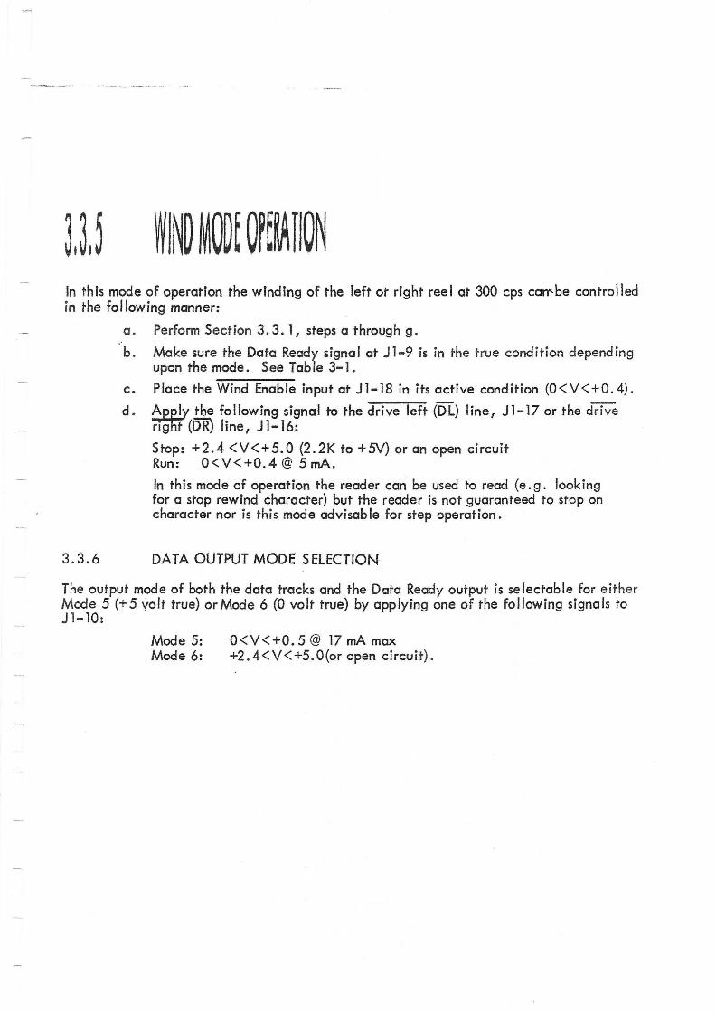
In this mode of operation the winding of the left or right reel at 300 cps can"-be controlled in the following manner:
3.3.6
a. Perform Sect ion 3. 3. 1, steps a throug h g.
b. Make sure the Data Ready signal at Jl-9 is in the true condition depending upon the mode. See Table 3-1.
c. Place the Wind Enable input at J1-18 in its active condition (O<V<+O.4) .
d. ~ the following signal to the drive left (OL) line, J1-17 or the drive rrgflf (DR) line, J 1-16:
Stop: +2.4 <V<+5.0 (2.2K to +5V) or an open circuit Run: O<V<+O.4 @ 5 mAe
In this mode of operation the reader can be used to read (e. g. looking for a stop rewind character) but the reader is not guaranteed to stop on character nor is this mode advisable for step operation.
DATA OUTPUT MODE SELECTION
The output mode of both the data tracks and the Data Ready output is selectable for either Mode 5 (+ 5 volt true) or Mode 6 (0 volt true) by applying one of the following signals to J 1-10:
Mode 5: Mode 6:
0<V<+0.5 @ 17 rnA max +2.4<V<+5.0(or open circuit) .
w , 0-
f',.)
0-
Ci b ~ »
Connector/ Pin
Jl-1 thru Jl-8
Jl-9
Jl-lO
J 1- 11 thru J1-13,Jl-24
Jl-14
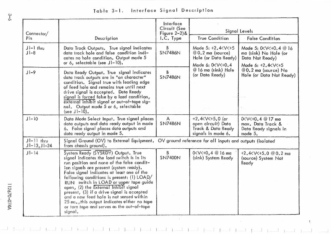
Table 3-1. I n t e r foe e S i g n a IDe s c r. i p t ion
~--~-.~----- ---
Interface Circuit (See
Signal Levels Figure 2-2)& Description I.C. Type True Condition False Condition
Data Track Outputs. True signal indicates B Mode 5: +2.4<V<+5 Mode 5: O<V<+O.4 @ 16 data track hole and false condition indi- SN7486N @ 0.2 ma(source) ma (sink) No Hole (or cates no hole condition. Output mode 5 Hole (or Data Ready) Data Not Ready) or 6, selectable (see Jl-10). Mode 6: O<V< +0.4 Mode 6: +2.4<V<+5
Data Ready Output. True signal indicates B @ 16 ma (sink) Hole @ O. 2 ma (source) No
data track outputs are in lion character" SN7486N (or Data Ready) Hole (or Data Not Ready)
condition. Signal true with leading edge of feed hole and remains true unti I next drive signal is accepted. Data Ready signal is forced false by a load condition, exte rnal inhibit signal or out-of-tape sig-nal. Output mode 5 or 6, selectable
I (see J l- lO).
Data Mode Select Input. True signal places A +2.4<V<+5.0 (or O<V<+O.4 @ 17 rna data outputs and data ready output in mode SN7486N open circuit) Data max. Data Track & 6. Folse signal places data outputs and Track & Data Ready Data Ready signals in data ready output, in mode 5. signals in mode 6. mode 5.
Signal Ground (OV) to External Equipment. from chassis ground).
OV ground reference for all inputs and outputs (isolated
System Ready (SYSRDY) Output . True B O<V<+O,4 @ 16 rna +2.4<V<+5.0 @O.2 ma signal indicates the load switch is in its SN7400N (sink) System Ready (source) System Not run posit ion and none of the false condit- Ready ion signals are present (system ready). False signal indicates at least one of the fol lowing conditions is present : (1) LOAp/ RUN switch in LOAD or ueper tape guide open, (2) the External Inhibit signal present, (3) if a drive signal is accepted and a new feed hole is not sensed within 25 ms. I this output indicates either no tope or torn lope and serves as the out-of-tape signa l.
,-------
N 0-
~ I o
~
V.) I "'-l
Connector/ Pin
Jl ... 15
Jl-16
JI-17
Jl-18
J 1-19 thru Jl-22
JI-23
Jl-25
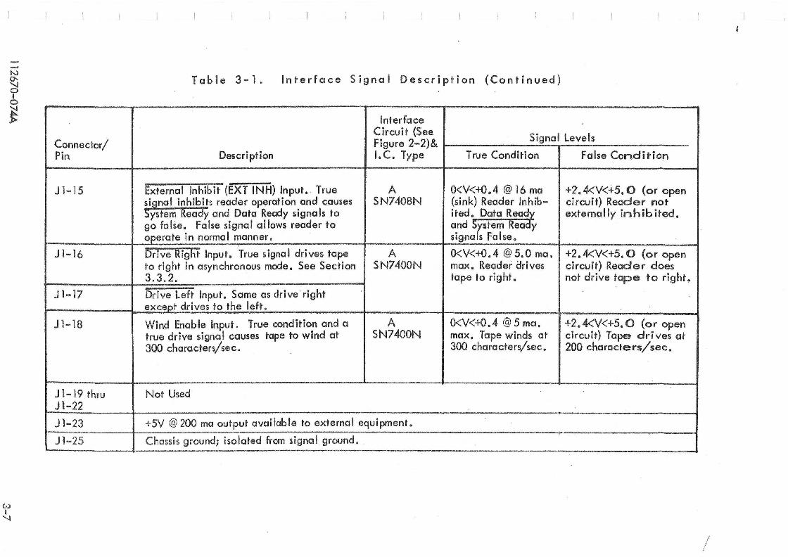
Table 3-1. Interface S ignal Description (Continued)
Interface Circuit (See
Signal Levels Figure 2-2)& Description I. C. Type True Condition False Condition
External Inhibit (EXT INH) Input. True A 0<V<-K).4 @ 16 ma +2.4<V<+5,O {or open signal inhibits reader operation and causes SN7408N (sink) Reade.' Inhib- circuit} Reader not System Ready and Data Ready signals to ited. Data Rea~ externally inhibited. go false. False signal allows reader to and System Ready operate in normal manner. signals False.
brive Right Input. True signal drives tape A O<V<+O.4 @ 5.0 mo. +2.4<V<+5.0 (or open to right in asynchronous mode. See Section SN7400N max. Reader arives circuit) Reader does 3.3.2. tape to right. not drive tape to right ~ --Dri ve Left Inpu t. S arne as dri ve right except drives to the left.
Wind Enable Input. True condition and a A O<V<+0.4 @ 5 ma, +2. 4<V<+5. 0 (or open true drive signal causes tape to wind at SN7400N max. Tape winds at circuit) Tape drives at 300 characters/sec. 300 characters/sec. 200 characters/sec.
Not Used
+5V@ 200 ma output available to external equipment. \\.-
Chassis ground; isolated from signa l ground . ~--. - - . .-..J
/
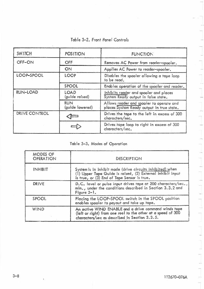
Table 3-2. Front Panel Controls
SWITCH POSITION FUNCTIOJ\
OFF-ON OFF Removes AC Power from reader-spoo ler •
ON Applies AC Power to reader-spooler.
LOOP-SPOOL LOOP Disables the spooler allowing a tape loop to be read.
SPOOL Enab les operation of the spooler and reader.
RUN-LOAD LOAD Inhibits reader and spooler and places (guide raised) System Ready output in false state.
! RUN AllowSI reader and spooler to operate and (guide lowered) places 5ystem Ready output in true state.
DRIVE CONTROL <J==:1 Drives [the tape to the left in excess of 300
characters/sec.
c={> Drives [tape loop to right in excess of 300 characters/sec.
Table 3-3. Modes of Operation
MODES OF OPERATION DESCRIPTION
INHIBIT System is in Inhibit mode (drive circuits inhibited) when (1) Upper Tape Guide is raised, (2) External Inhibit input is true, or (3) End of Tape Sensor is true.
DRIVE D. C. level or pulse input drives tape at 200 characters/sec. , min. I under the conditions described in Section 3.3.2 and Figure 3-1.
SPOOL Placing the LOOP-SPOOL switch in the SPOOL position enables spooler to payout and take up tape.
WIND An active WIND ENABLE and a drive command winds tape (left or right) from one ree I to the other at a speed of 300 characters/sec as described In Section 3.3.5.
3-8 1 1 2670-076A
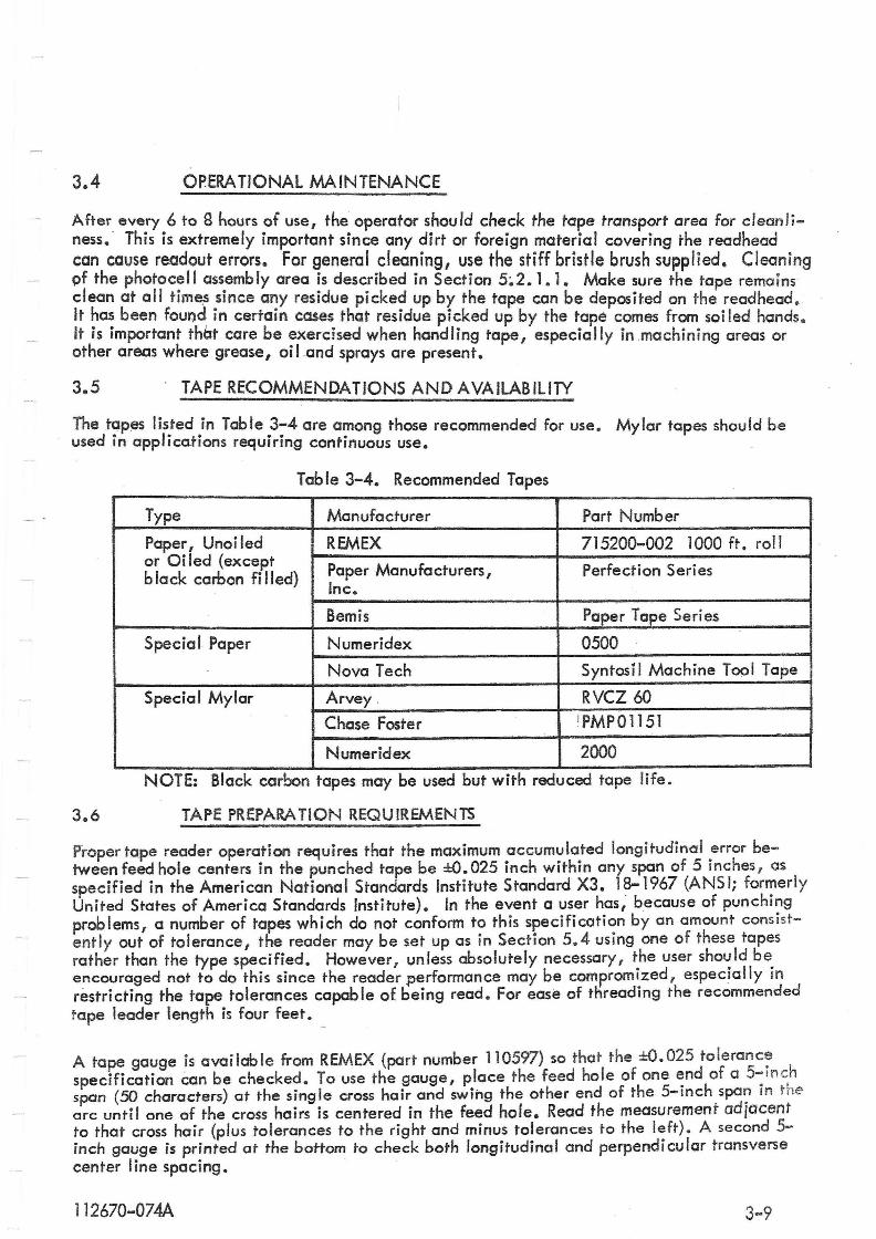
3.4 OPERA TIONAl MAINTENANCE
After every 6 to 9 hours of use, the operator should check the tape transport area for clean liness. This is extremely important since any dirt or foreign material covering the readhead can cause readout errors. For general cleaning , use the stiff bristle brush supplied. Cleaning pf the photoc:" ass.embly area !s desc.ribed in Section 5~2. 1. 1. Make sure the tape rema ins clean at all tJme;s .slnce a~y residue plcke? up by the tape can be deposited on the readhead . It ~a~ been found In certamcases that residue picked up by the tape comes from soi led hands . It IS Important that care be exercised when handling tape, especially in .machining areas or other areas where grease, oil and sprays are present.
3.5 . TAPE RECOMMENDATIONS AND AVAILABllIlY
The tapes listed in Table 3-4 are among those recommended for use. Mylar tapes should be used in applications requiring continuous use.
Table 3-4. Recommended Tapes
Type Manufacturer Part Number
Paper, Uno i led REMEX 715200-002 1000 ft. roll or Oiled (except Paper Manufacturers, Perfection Series b lack carbon fi lied)
Inc.
Bemis Paper Tape Seri es
Special Paper Numeridex 0500
Nova Tech Syntosil Machine Top I Tape
Special Mylar Arvey . RVCZ 60
Chase Foster IPMP01151
Numeridex 2000
NOTE: Black carbon tapes may be used but with reduced tape life.
3.6 TAPE PREPARA TlON REQUIREMENTS
Proper tape reader operation requires that the maximum accumulated longitudinal error between feed hole centers in the punched tape be ±O.025 inch within any span of 5 inches, as specified in the American National Standards Institute Standard X3. 18-1967 (ANSI; formerly United States of America Standards Institute). In the event a user has; because of punching problems, a number of tapes which do not conform to this specification by an amount consistently out of tolerance, the reader may be set up as in Section 5.4 using one of these tapes ra ther than the type specified. However I un less absolute Iy necessary, the user shou Id be enco~r~ged not to do this since the reader p~rformance may be comprom~zed, especially in restn ctmg the tape tolerances capab Ie of bemg read. For ease of threading the recommended tape leader length is four feet .
A tape gauge is available from REMEX (part number 110597) so that the ±O.025 to leranc: specification can be checked. To use the gauge, place the feed hole of one end of a 5-mch span (50 characters) at the single cross hair and swing the other end of the 5-inch span in the arc until one of the cross hairs is centered in the feed hole. Read the measurement ad;acent to that cross hair (plus tolerances to the right and minus tolerances TO the left). A second 5-inch gauge is printed at the bottom to check both longitudinal and perpendicular transverse center I ine spacing.
] 12670-074A 3-9

-==========="-"=." -"~==:.::::= ... ::'::=-'::~~::~-.... ::: ..... =--.:.= ...... :'=.: ..... :::::=: . . . ~======== ... -.~ ..... ~ .. :.:=. ....... ~ .... §-_.§._. §·····-§-.:.·§·:::::§-·.::::§:::=---§:--··s:·······~· · ·· · · .......... '
L L L t.C' L ____
! . I
L
i . L
u 1 '
b
I : ~
! : ~
, :' I . t..:
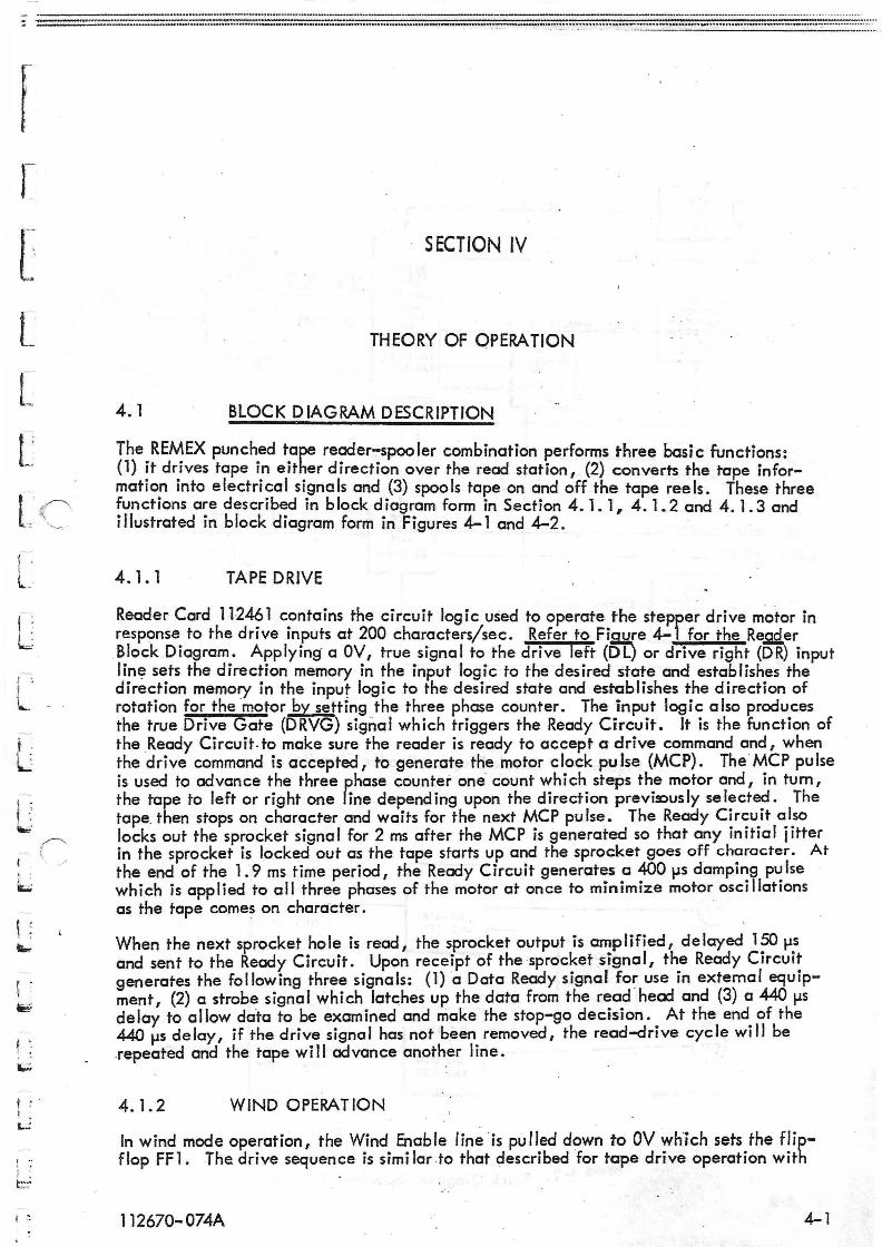
SECTION IV
THEORY OF OPERATION
4. 1 BLOCK DIAGRAM DESCRIPTION
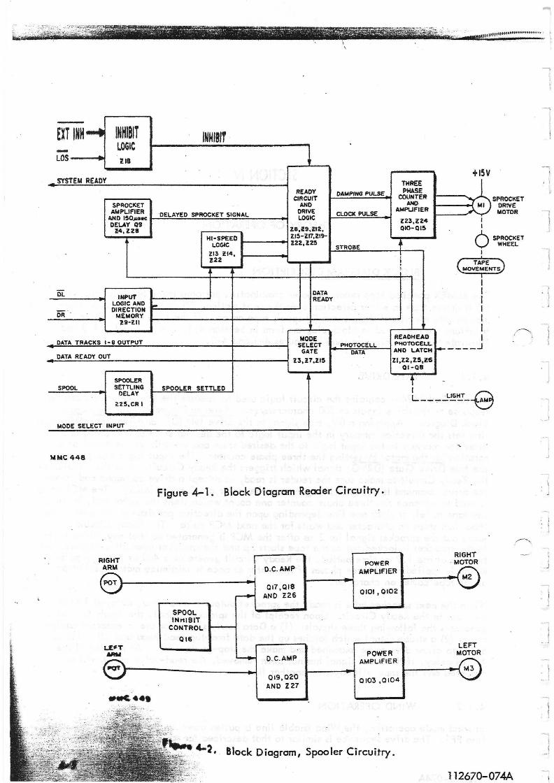
The REMEX punched tape reader-spooler combination performs three basic functions: (1) it drives tape in either direction over the read station, (2) converts the tape information into electrical signals and (3) spools tape on and off the tape reels. These three functions are described in block diagram form in Section 4. 1. 1, 4. 1.2 and 4. 1.3 and illustrated in block diagram form in Figures 4- 1 and 4-2. .
4. 1. 1 TAPE DRIVE
Reader Card 11-2461 contains the circuit logic used to operate the stepper drive motor in response to the drive inputs at 200 characters/sec. Refer to Fi~e 4-1 for the Ress;Ler Block Diagram. Applying' a OV, true signal to the drive left (DL) or drive right (DR) input lin~ sets the direction memory in the input logic to the desired state and establishes the direction memory in the input logic to the desired state and establishes the direction of rotation for the motor by setting the three phase counter. The input logic a Iso produces the true Drive Gate (DRVG) signal which triggers the Ready Circuit. It is the function of the Ready Circuit. to make sure the reader is ready to accept a drive command and, when the drive command is accepted, to generate the motor clock pulse (MCP). TheMCP pulse is used to advance the three phase counter one count which steps the motor and, in tum, the tape to left or right one line depending upon the direction previlOusly selected. The tape. then stops on character and waits for the next MCP pulse. The Ready Circuit also locks out the sprocket signal for 2 ms after the MCP is generated so that any initial jitter in the sprocket is locked out as the tape starts up and the sprocket goes off character. At the end of the 1.9 ms time period, the Ready Circuit generates a 400 tJs damping pulse which is applied to all three phases of the motor at once to minimize motor oscillations as the tape comes on character. .
When the next sprocket hole is read, the sprocket output is amplified, delayed 150 tJs and sent to the Ready Circuit. Upon receipt of the sprocket signal, the Ready Circuit generates the following three signals: (1) a Data Ready signal for use in external equipment, (2) c strobe signa I whi ch latches up the data from the read hecx:l and (3) c 440 tJS delay to allow data to be examined and make the stop-go decision. At the end of the 440 tJS delay, if the drive signal has not been removed, the read-drive cycle will be repeated and the tape will advance another line.
4. 1.2 WIND OPERATION . .
In wind mode operation, the Wind Enable line is pulled down to OV wh"ich sets the flipflop FF1. The drive sequence is similcrto that described for tape drive operation with
112670-074A 4-1
.. '!. ... -- . '
-EXT INH .... INHIBIT
- LOGIC lOS .
III
SYSTEM READY
SPROCKET AMPLIFIER
AHO 150,uaec DELAY Q9
i!4,l28
OL INPUT LOGIC AND
OR DIRECTION MEMORY :n-ll!
DATA TRACKS 1-8 OUTPUT
DATA ReADY OUT
SPOOLER SPOOL
~ SETTLING
DELAY
HS,CR I
MODE SELECT INPUT
MMC 448
RIGHT f4RM
INHIBIT
READY DAMPING PULSE CIRCUIT
AND DRIVE CLOCK PULSE DELAYED SPROCKET SIGNAL LOGIC
18,it9,llZ, lIS-lI7,lI9-HI-SPEED
I.CGIC Z22,lZS STR08E
113 ll4, 122
j
DATA READY ..
MODE SELECT PHOTOCEI.L
GATE DATA 13,H,llS
SPOOLER SETTLED
THREE PHASE
COUNTER NIO·
AMPUFlER
l2~,Z24 OIO-OI~
t !
READHEAO P~TOC£LL
AND LATCH
II,I2, ZS,Z6 01-C8
t I
+15V
loll
I I
6 I
SPROCKET DR!VE MOTOR
SPROCKET WHEEL
( TAPE MOVEME NTS
I I I I I I I
f------'
-L __ .,.._L!,t!~_ AM -e
Figure 4-1. Block Diagram Reader Circuitry.
D_C_AMP POWER
AMPLIFIER
RIGHT MOTOR
POT~--------------------~~ 017,018 AND Z26
SPOOL lNttlB1T
CONTROL ..... -.....,
QI6
D.C_AMP
019 , 020 AND Z27
-I 0101,0102
POWER -AMPLIFIER
0103,0104
Block Diogram, Spooler Circuitry.
LEFT MOTOR
112670-074A
, \
_ J
.J
. J
I _J
_ .J
I ..l
the following exceptions: (1) the damping pulse is inhibited and (2) after the initial MCP pu Ise starts the motor advancing, a second clock pu Ise is generated CIS soon as the tape goes off character. This sets the three phase counter one count ahead of the line to which the tape is advancing. When that line is reached, the motor will not stop, unless the drive signal is removed, but will continue rotating one line more. Again when the tape goes off character, the counter is again pu Ised. In this manner the counter is always one count ahead of the line being read on the tape. If, during the 440 fJs data sampling period, the reader drive signal is removed, single-shot SS7 is triggered which inhibits the input memory via the Reverse Lock (REV LK) to allow a settling time of 45 ms. SS7 also triggers SS8 causing the counter to back up one count and the motor to stop on character.
4.1.3 READER INHIBIT
The reader can be inhibited by any ~ of three methods: (1) placing the LOAD-RUN switch, 52, in LOAD r causing the LDS to be generated! (2) a true ( OV r rternal Inhibit signal applied to J 1-15. Items 1 and 2 are gated to form the Inhibit (INH . signal which inhibits both the Wind Enable Logic and the Ready Circuit and places the System Ready (SYSRDY) in the false state. The System Ready also goes false if I after receipt of a drive signal r no new sprocket is sensed within 35 ms max, indicating that the reader is out of tape.
4. 1.4 TAPE READ iNG
The readhead is located under the fiber optic light source and contains photovoltaic cells which are used to sense the punched tape perforations. As tape is advanced over the read head I by the sprocket drive, the photovoltaic cells are energized by the light source when the correspond ing ho les are present in the tape. Outputs from the read head are then applied to the data track amplifiers and latch circuits. A true +5V, Strobe signal locks up the two latch circuits, Z2 and Z6, thereby storing that line of data. The latch circuit outputs are applied to the Mode Select gates which produces either mode 5 and 6 outputs depend ing upon the leve I app lied to the Mode Se lect input. At the same time I the Data Ready output signal goes true and it too is gated with the Mode Select signal.
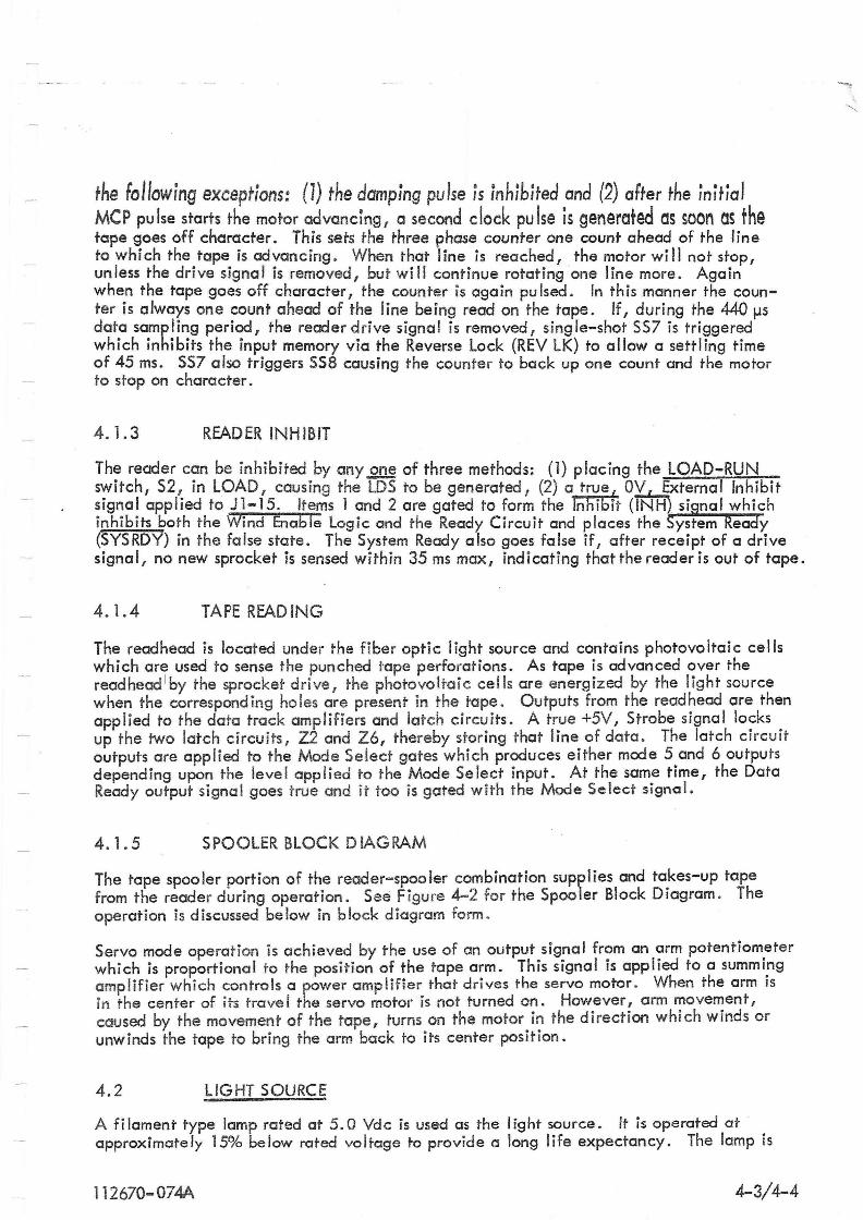
4 .1 .5 SPOOLER BLOCK DIAGRAM
The tape spooler portion of the reader-spooler combination supplies and takes-up tape from the reader during operation. See Figure 4-2 for the Spooler Block Diagram. The operation is discussed below in block diagram form.
Servo mode operation is achieved by the use of an output signal from an arm potentiometer which is proportional to the position of the tape arm. This signal is applied to a summi.ng amplifier which controls a power amplifier that drives the servo motor. When the arm IS
in the center of its trove I the servo motor is not turned on. However I arm movement, caused by the movement of the tape, turns on the motor in the direction which winds or unwinds the tape to bring the arm back to its center position.
4.2 LIGHT SOURCE
A fi lament type lamp rated at 5.0 Vdc is used as the I ight source. It is operated at approximately 15% below rated voltage to provide a long life expectancy. The lamp is
112670-074A 4-3/4-4

mounted in a sleeve at the rear of the front panel. A lens contained in the lamp focuses the light to the fiber optics system which, in turn, conducts the light to the photocells.
4.3 CIRCUIT CARD DESCRIPTIONS
4.3.1 READER CIRCUITRY
The reader c ircui try on PC card 112461 is used: (1) to generate output signals used to drive the stepping motor in response to the drive signal inputs and (2) to provide amp lification and gating of the readhead data output signals .
4. 3 .1.1 Drive Circuits
During the following description, refer to Figure 4-3 which shows the waveforms and timing diagrams for the drive, step and wind operations. This figure is intended as a guide to show the sequence of events and which signals initiate other signals. It must be cautioned that due to the wide range of pulse widths, no attempt has been made to draw the time axis to exact scale. Refer also to the schematic, Figure 8-1, sheet 1, during this description.
Normal operation begins with the loading of the tape. Placing the RUN/LOAD switch (52) in the LOAD position c_auses OV to be applied to Z18-1 and in turn places Z18-3 (the inhibit INH line) at OV. An external inhibifSTgnal applied to Z18-2 produces the same resu It .
The INH signal is applied to Z18-4, Z12-9, and Z22-13 (FF2). The inhibit signal performs the following functions: (1) it clears and inhibits flip-flop FF2, thereby preventing recognition of any srrocket signal, (2) through Z18-6 and Z12-11 it causes the Reader . Ready (RRDY) signa to drop to OV thus ~reventing recognition of the Drive (DRVG) signal, (3) through Z18-6 it places the ata Ready (DATRDY) signal at OV thereby inhibiting data, and (4) through FF2, which is held in the cleared state , and Z16-8, it clears and inhibits SS 1, th\Js preventing recognition of any signal. The inhibit signal is also appI!ed to Z12-9 causing a false System Ready (SYSRDY) to be generated. After the tape has been loaded, placing the RUN/LOAD switch in the RUN position makes the reader operational.
With the inhibiting signals removed, the SYSRDY, DATRDY, and RRD'L.signals are true allowing the drive signal to be recognized. Application of a true OV DL signal at J1-17 sets the directi9n flip-flop, composed of Z10 and Z11, to the drie-Ieft state . This places the clockwise (CW) line at ZlO-ll at OV and the Direction (DRCTN) line at Z15-3 at +5V. A +5V DRCTN signal sets up the three phase counter, composed of FF3, FF4, Z19 to energ ize the motor phases in the sequence which drives the tape to the left, i. e . , phase 3, phase 2 and then phase 1 (drive right is the reverse order). The counter is advanced one count with each clock pulse received from SS2 as described in a subsequent paragraph.
The OV, DL signal also generates the OV true Drive Gate (DRVG) signal at Z9-6 which is used to trigger the single shot 551 at input ~Output 551 then goes to OV which sets flip-Flop FF2, resulting in the negative going FF2 signal which triggers 552 . The SS2 output, in tum, is applied to the three phase counter through Z19-11 causing the counter to step one count .
1 1 2670-074 A 4-7
-A new motor phase is now energized which moves the tape one line to the left. FF2 Qiso CQvses the DATRDY sisnal to 90 false (OV) through Z18-6; FF2 causes the SSYRDY signal to go false (+5V) through 216-6 and Z12-9. ~~2 srays locked in fhe ~et eondition unti I SS 1 times out (approximate Iy 2 ms). As a resu It, any noise or start up jitter from the sprocket signal is prevented from generating a true Data Ready signal.
The positive going edge of the FF2 signal also triggers SS9 which is a retriggerable sing leshot timed for 23 ms. Output SS9 is combined with FF2 to produce End of Tape signal at Z16-6. If SS9 is not retriggered within 23 ms and if no sprocket s~nal is sensed (FF2 remains high) then Z16-6 drops to OV. This places the System Rea y signal at Z12-8 in the + 5V fa Ise state, indicating that the system is not ready.
At the end of the 2 ms period, FF2 is released, but by this time the tape is up to speed and the only signal available to reset FF2is the posit~ going edge of the Sprocket Delay signal from SS4. The positive going edge of the SS 1 signal is used to trigger sing Ie-shot 553. As a result 553 is held at OV for 725 tJS and is applied as a negative OR combination to Z24-13, Z24-4, and Z24-1 causing the remaining two motor windings which are not
. energized during a given phase sequence to become energized for 1 ms. This momentary energ iz ing of a II three motor phases dampens the inherent osci I lations present in a I I stepping motors as the tope moves on character.
When the next line is read I the negative going edge of the Sprocket signa I triggers the 150 IJs Sprocket Delay single-shot SS4. This delay is required when using a feed hole advanced tape to electronically delay the feed hole and make sure all data is latched before the sprocket is recognized. With standard in-line feed holes this serves only to add an extra safety marg in. At the end of the 150 lJS de lay, the posi t i ve go ing edge of SS4 resets FF2. The resulting positive going edge of FF2 is used two places: (1) to trigger single-shot SS5 and (2) to generate the positive going DATRDY signal through Z18-6 (and the OV Strobel and Strobe 2 signals at Z4-2 and Z4-4). The inverse OV, FF2 signal places the SYSRDY signal in the true OV condition through Z16-6 and Z12-8 and Z4-12. The functions of SS5 is to provide a 440 lJS delay by holding the RRDY line at OV. This allows the external equipment to ~amine the data and make the go/no-go decision_ If the decision to stop is mode, the DL input line must be taken high within 440 iJS (actually 490 but conservatively specified at 440 lJs). Otherwise, when SS5 times out 1 the positive going RRDY wi II trigger 5S 1 and repeat the tape advance cycle. If the drive line is taken false and then returned to the true state during the 440 tJs period of 555, 5S5 wiJl be reset by the signal from Z9-8 applied to Z17-3 and the next drive sequence wi /I begin immediately.
4.3.1. 2 Wind Circuits
During normal operation up to 200 cps the Wind Enable line is taken high (or open circu ited). A OV signal applied to Jl-18 and a true drive input cause the reader to wind . tape at a nominal 300 characters/sec. Applying OV to Z13-5 causes Z13-6 to go to +5V and, in turn, Zl4-3 goes to +5V provided the drive signal is present (DRV is +5V at Z14-2). When the first MCP signal is generated, 552 drops to OV and is inverted to +5V at Z13-11. This signal, gated with the +5V at Z13-2, results in Z13-3 dropping to OV and setting flip-flop FF1.
This flip-flop is used to modify the previously described low speed drive sequence by performing the following functions: (1) FFl inhibits the 725 iJs damping pulse S53, (2) FFl enables gate Z16-9 so that as soon as flip-flop FF2 is set by 55}, the FF2 output f
112670-074A
through Z 16-9 clears 55 t and removes the 2 ms hold off, (3) after the first MCP is generated at Z21-12, FF1 at Z18-13 holds Z21-9 low so that the only trigger pulses applied to SS2 is via SS6 (discussed in the next paragraph)are recognized, and (4) ffl enables 5S6 so that it is triggered on the positive going edge of the SPRKT signal.
When the tape moves off character, the positive going SPRKT signal triggers the 1570 ~s one-shot 5S6. At the end of 5S6time, the positive going SS6 signal triggers SS2 which generates a second clock pulse. The clock pulse is also applied to the counter and advances it one count ahead of the phase to which the motor is being advanced. Thus, when the next character is reached, if the reader has not been to Id to stop, the motor wi II continue advancing to the next character without stopping. Each time the tape goes off character, the counter will again be pu Ised causing it to a Iways be one count ahead. It shou Id be noted that after the initial MCP is generated by FF2 going low, FF2 does not generate any more MCP pu Ises on subsequent lines since Z18-13 is held low. This coupled with the absence of the motor damping pu Ise SS3 allows the reader to drive tape in excess of 300 characters/sec.
If, during the period that FF2 is set, the drive signal is removed, the DRV signal will drop to OV and trigger single-shot SS7. The resulting negative going SS7 performs the following functions: (1) provides a 45 ms inhibit to the REVLK line and therefore to the drive logic which allows the motor to settle before the next drive signal is recognized, (2) reverses the DRCTN line at Zl5-3, (3) triggers single-shot SS8, and (4) inhibits any drive signal at Z9-5. With the DRCTN line reversed, the negative going SS8 signal causes the three phase counter to back up one count which puts it in phase with the existing motor position, causing it to stop. SS8 is also used to reset the High Speed flip-flop FF 1. When 5S7 times out, the REVLK signal returns to +5V and the reader is ready to accept the next drive signal.
4.3.1.3 Tape Reading Circuits
Nine photovoltaic cells in the readhead assembly sense the perforations in the tape. Refer to Figure 8-1, sheet 2. An illumination system consisting of a lamp and fiber optics provides a continuous beam which covers the area of the photocells. The tape is driven over the top of the photoce II b lock and when a ho Ie appears between the photoce II and the I ight source, the photoce II becomes energ ized.
Each cell output is applied to an amplifier-latch circuit, Q 1-Q8, Z2 and Z6. Track 1 is used in the following discussion since it is typical of tracks 1-8 (the Sprocket signal is deve loped differently as described in a subsequent paragraph). When track 1 becomes energized, the negative going signal at the cathode of the photocell turns off Q1. Q1 is interconnected with the D3 input and Q3 output of Z2 in a manner which allows Q1 and the first stage of Z2 to function as a Schmitt trigger. Z2 follows all changes in the photocell output until the OV strobe 1 signal (see Section 4.3.1. 1) is generated which locks up Z2 .
Track 1 output at 03 is +5\1 true and is gated with the Mode Select signal at Z3-1 and 2. A OV Mode Select input provides a mode 5 output at J 1-1 (i. e., OV for no hole and + 5V for hole). Conversely I when the Mode Select signal is + 5V, J 1-1 wi II produce a Mode 6 output (i. e., + 5V for no hole and OV for hole). The DATRDY output is gated in the same manner as the track outputs at Z15, pins 4 and 5.
The sprocket track is somewhat different than the other eight tracks in that its Schmitt trigger uses an inverter, Z4, rather than part of a latch and is independent of either the
112670-074A 4-9
Strobe or DATRDY signals. See Figure 8-1, sheet 1. It is also used only as an internal logic signal and is not gated with the Mode Select signal. Both the SPRKT and SPRKT signals are generated and used in the internal logic.
4.3.2 SPOOLER CIRCUITRY
The spooler circuitry is designed to control the payout and take-up of the spooler motors during.5>peration of the unit. Since there are two identical spooler motors and two identical control_circuits only one side will be discussed. The following discussion pertains to the left side (refer to Figure 8-1, sheet 3) during the following description.
In operation, the RUN/LOAD switch is set to the LOAD position (see Figure 8-1, sheet 1) while the tape is loaded on the unit. This generates the Spool Inhibit (SPlINH) signal which is applied to Q16 (Figure 8-1, sheet 3). This in turn causes Q16 to clamp the inpLits to Z27-3, the base of Q19 and the base of Q20 to a bias condition such that the motor drive transistors Q103 and Q014 produce OVat their collectors. This condition
. produces OV across the spooler motor M3 regardless of the position of the left arm potentiometer during the tape loading operation.
After the tape is loaded, the RUN/LOAD switch is p laced in the RUN position, thereby removing the SPLINH signal. The tape arm potentiometer is now the controlling component for the motor control circuit. Assume for the purposes of this discussion that the tape arm is in the slack position. This wi II make the center arm of the potentiometer more positive and this positive voltage is applied to Z27-2 causing the operational amplifier output at Z27-6 to go in the negative direction. The negative going output of the operational amplifier tends to fum Q20 on while Q19 tends to turn off. When Q20 goes into conduction its collector goes in the positive direction and this in tum turns Q104 on, causing Q104's collector to move in the positive direction. At the same time Q19 is tending to conduct I~ss and the Q19 collector goes in a positive direction, allowing Q103 to begin to turn off . The result is the negative going direction of the collector of Q 103 and Q 104. The motor M3 drives in the direction required to take the slack out of the tape and the tape arm is consequently moved to its center position. This reverses the offcenter bias condition described above and the jUDction of the collectors of Q 103 and Q 104 moves toward zero. Since the purpose of the circuit and motors is to maintain a slight tension on the tape, a slight negative voltage remains on M3, sufficient to main-tain the proper tension.
When the tape reader sprocket moves the tape in a direction that tightens the tape the process described is reversed, Q103 and Q104 collectors are driven in a positive direction, and M3 thus runs in the direction required to payout tape.
4.3.3 POWER SUPPLY
The power supply provides the regulated DC voltages required to operate the logic, the spoo Jer dri ve ci rcu its and the spoo ler motors. The major components of the powe r supp Iy consists of power transformer T 1 (Figure 8-1, sheet 3), bridge rectifier BR 1 T main fj Iter capacitors C 102 and C 103, and the output regu lators Z 10 1 and Z 102.
The transformer is a step-down transformer designed to convert the AC line voltage to approximately 33 VAC. The transformer is provided with a tapped primary winding to accomodate a variety of input voltages. The voltage from the transformer secondary is
4-10 1 1 2670-074A
rectified by BRl and filtered by C102 and Ci03. The resultant + 15 and -15 Vdc is used !o provide power to the spooler circuit and motors. The + 15 Vdc is also applied to the mputs of the 5V regulators Z101 and Z102. Z101 provides regulation of the 5 Vdc logic power while ~102 provides the regulated voltage for the reader lamp. Z101 is not adjustable and provIdes regulated 5 Vdc for the logic circuitry. Z 102 is provided with a voltage level adjustment R63 for varying the lamp brilliance . . This makes it possible to adjust the lamp voltage to approximately 4.3 Vdc thereby extending lamp life expectancy. The lamp voltage shou Id not be adjusted higher than 4.7 Vdc .
4.4 MECHANICAL THEORY OF OPERA TION
4.4. 1 TAPE TENSION
Tape hand ling, at all speeds, requires that the proper tape tension be maintained. This is especially true where rapid, hi-torque starting, reversal of direction, and stopping is necessary. For example, in order for the tape to be moved over the readhead in a sfartstop "geneva" mechanism fashion, the tape must have a certain tension applied in order to flow smoothly.
Assume that a full reel of tape is loaded on the right hand reel and an empty ree I is placed on the left spind Ie. As the tape is moved from right to left during servo mode 1 it passes by a number of points which require different tension. As the tape is wound on the left hand reel, it starts winding on a small diameter since the reel is nearly empty. This means that the take up motor, if it were a fixed power or constant torque motor, would have a greater wind torque advantage when the reel was empty than when the reel was nearly fu II. To over come this effect of varying tape diameter I a variable torque motion is used which is controlled by the position of the tape tension sensing arm. This arm indicates to the motor when and how much tape to take up by means of a potentiometer attached to the arm which controls a dc servo. When the reader stepper motor drives tape toward the left reel, the tape sensor arm senses the slack in the tape causing the take-up motor to rotate counterclockwise. This takes the slack out of the tape and moves the sensor arm back to its mid-range.
Thus it can be seen that the tension applied to the tape by the sensor arm is the tension at which the tape passes the read head . The tape sensor arms are adjusted so that with the step'per motor stopped I the torque motor applies just the amount of tension to the tape required to hold the tape sensor arms in their approximate mid-position. Since the takeup and supply motors always return their arm to the mid-position, it is evident that the tension applied to the tape across the readhead is a function of the tape arm return spring tension.
I] 12670-074A 4-11

SECTION V
MAINTENANCE
5. 1 GENERAL
The REMEX punched tape reader-spooler has been designed to keep maintenance as simple and infrequent as possible. Table 5-1 lists the maintenance equipment required for the various procedures. To prolong the life of the equipment and minimize down-time, , certain checks and preventive procedures are set up in Section 5.2 and Table 5-2 with suggested schedules. Section 5.3 outlines possible malfunctions along with probable causes and remedies. The remaining sections describe the required adjustment procedures. Replacement procedures are given in Section 6.
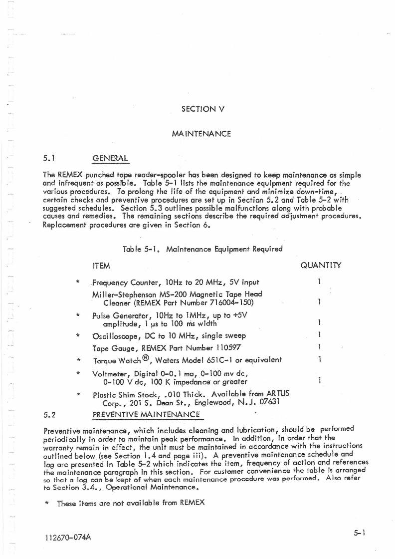
Table 5-1. Maintenance Equipment Required
ITEM QUANTllY
* .Frequency Counter 110Hz to 20 MHz, 5V input
Miller-Stephenson MS-200 Magnetic Tape Head . Cleaner (REMEX Part Number 716004-150)
* ,Pu Ise Generator 110Hz to 1 MHz I up to +5V amplitude, 1 ~s to 100 ms width
* Oscilloscope, DC to 10 MHz, single sweep
Tape Gauge, REMEX Part Number 110597
* Torque Watch ®, Water.s Model 651C-l or equivalent 1
* Voltmeter, Digital 0-0. 1 ma, 0-100 mv dc, 0-100 V dc, 100 K impedance' or greater
* Plastic Shim Stock, .010 Thick. Available from ARTUS Corp., 201 S. Dean St., Englewood, N.J. 07631
5.2 PREVENTIVE MAINTENANCE
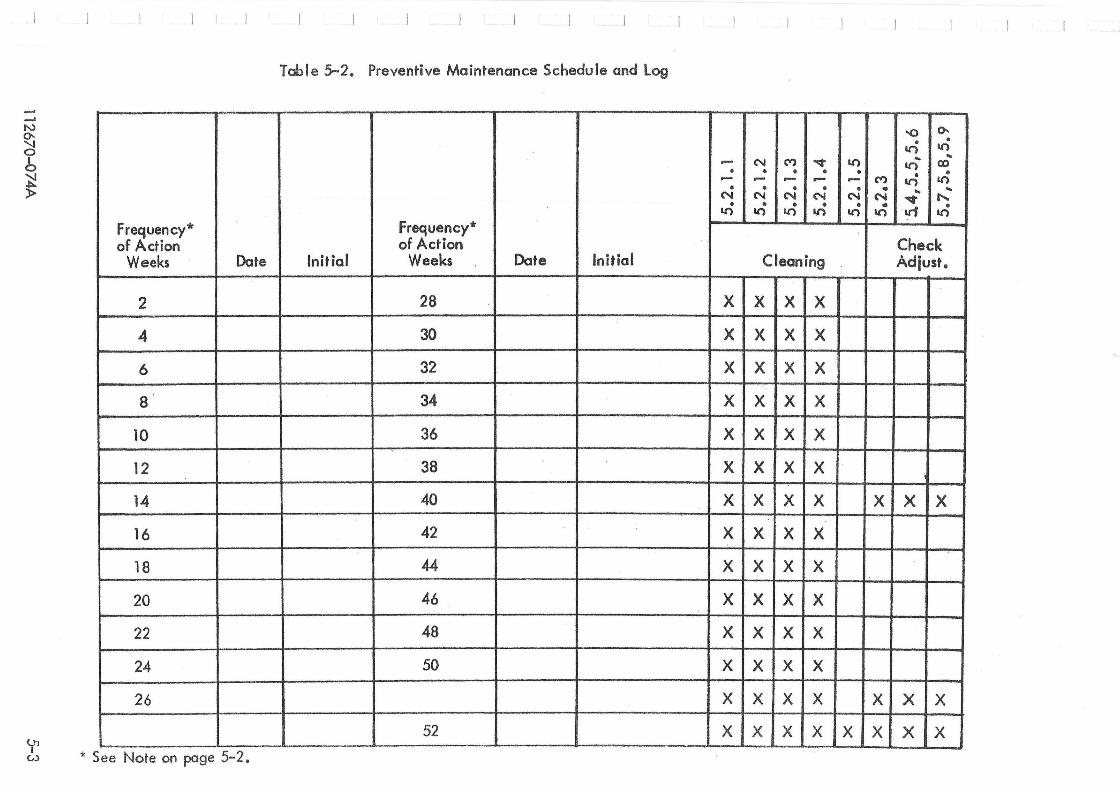
Preventive maintenance, which includes cleaning and lubrication, should be performed periodically in order to maintain peak performance. In addition, in order that the warranty remain in effect, the unit must be maintained in accordance with the instructions outlined below (see Section 1.4 and page iii). A preventive maintenance schedule and log are presented in Table 5-2 which indicates the item, frequency of action and references the maintenance paragraph in this section. For customer convenience the table is arranged so that a log can be kept of when each maintenance procedure WQS performed. Also refer to Section 3.4., Operational Maintenance.
* These items are not available from REMEX
11 2670-074A 5-1
5.2. 1
NOTE
The frequency of cleaning as Hsted in TobIe 5-2 has been adopted for clean environmental conditions and usage. These items, however, may vary greatly from one installation to another. For example, a reader used in a machine shop to program numerical controls may require maintenance procedures considerably more frequently.
CLEANING
~ In all cleaning procedures, avoid usi.[lg cleaning methods and materials other than those recommended in this manual. Do not use ethyl alcohol or denatured alcohol as the d~naturjng agents vary and may damage the reader. Certa; n cleaning compounds will damage parts of the reader, especially in the readout assemb Iy area. REMEX primarily recommends the use of Mi Iler-Stephenson MS-200 Magneti c Tape Head Cleaner (REMEX Part Number 716004-150) for most areas requiring cleaning. However I due to the degreasing nature of the cleaner I it shou Id not be used in areas· where the spray may come in contact with bearings or other oil{;;d 12.9.W. This cleaner may be obtained from REMEX or directly from Miller-Stephenson Chemical Company at one of the fol lowing locations:
1001 East First Street Los Angeles, California 90012
Route 7
1350 W. Fullerton Avenue Chicago, Illinois 60614
Danbury, Connecticut 06810
To use the cleaner, hold the spray can 4 to 6 inches away from the area to be cleaned and allow spray to flush the dirt off. If a heavy buildup is present, loosen with the spray mist and scrub with a cotton swab. A 6-inch pin-point, spray nozzle extension is available for hard-to-reach areas or for delicate applications. Avoid spraying on lubricated surfaces or parts and on the lamp assemb ly and lens.
If the Miller-Stephenson cleaner is not available, a small amount of isopropyl alcohol applied to a clean, lint-free cloth or cotton swab may also be used. However, it should be used carefully and sparingly since damage to the photocell and the finish on the plastic cover may result. Use only clear, unadulterated isopropyl alcohol.
5-2 112670-074A
. ...,
N 0-
~ b ~ »
01
Frequency* of Action
Weeks Date
2
4
6
8
10
12
14
16
18
20
22
24
26
~ * See Note on page 5-2.
Table 5-2. Preventive Maintenance Schedule and log
..... • -•
N •
1O
Frequency* of Action
Initial Weeks Dote Initial
28 X
30 X
32 X
34 X
36 X
38 X
40 X
42 X
44 X
46 X
48 X
50 X
X
52 X --~~----~~-~-~ ------- - -----.--~-- .. - -----
-0 0-• •
t.(') 1O .. .. N M ~ 1O t.(') 00
• • • • • • ..... - ..... ..- M t.(') 1O • • • • • .. ..
N N N N N ~ r... • • • • • • 1O 1O 1.0 1.0 1.0 tr1 1O
Check Cleaning Adiust.
X X X
X X X
X X X
X X X
X X X
X X X ! I
X X X X X X
X X X
X X X
X X X
X X X
X X X
X X X X X X
X X X X X X X
5.2.1.1 Readhead Assembly Cleaning
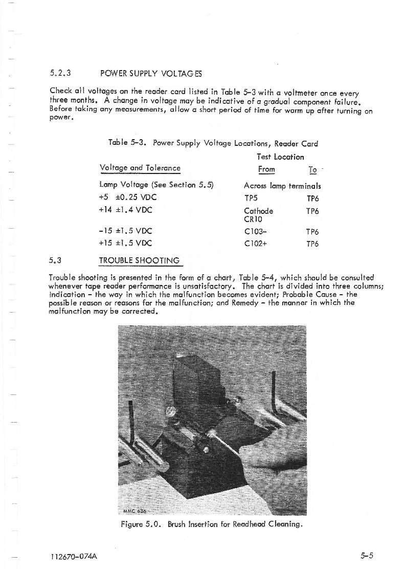
The top surface of the read head assembly should be cleaned every two weeks (for most installations having clean environments; dirtier environments which contain dust oil and sprays~ su~h as machin~ng areas, may require cleaning as much as every eight hours). Cleaning IS extremely Important because any dirt or foreign material in this area can create errors in readout. Use the bristle brush supplied or the cleaning materials and methods described in ~ectiori 5.2.1 and clean the surfaces of the readhead assembly and the upper tape gUIde assembly. Care should be exercised so that no residue remains from the recommended cleaning materials when the cleaning operation is completed. Figure 5-0 shows the brush inserted between the reodhead and tape guide when cleaning the the read head assembly. Pr:oper cJeaning requires_ that -the brush -be rotate<:J Ci~ leCist two . revolutions and moved in and out. Remove the residue with compressed air ..
5.2.1.2 Sprocket Cleaning
The sprocket wheel should be checked for cleanliness every two weeks. Depending upon tape conditions, accumulations may bui Id up 'on the sprocket and be transferred to the sprocket holes in the tape which may cause readout errors. Use the recommended cleaning materials described in the caution in Section 5.2. L Care should be taken so that the alignment of the sprocket wheel is not disturbed. If the sprocket wheel requires adjustment, refer to Section 5.4.
5.2.1.3 Tape Inspection
Repeated handling and usage of the tape leads to a build up of grease, oi I and dirt on the tape. When the build up becomes excessive, this material will become lod-ged in the tape transport areas and could cause tape reading errors. To prevent this, the tape should be thoroughly inspected every two weeks and repunched as required.
5.2.1.4 General Cleaning
The entire reader should be cleaned every year. Use the following procedure:
5.2.2
Using the bristle brush supplied with the unit and/or compressed air, remove all dust and dirt, paying particular attention to all moving parts. Use the recommended materials described in the caution in Section 5.2 to remove any grease or other accumulations. When cleaning, use care not to damage components on the circuit board.
LUBRICATION
Except tor the bearing shaft assembly, all points of rotation have permanentl~ lubricated bearings and should not require lubricat!on for the life of the part: Th.e beann~ s~ould be lubricated every six months by applYing one or two drops of cling 011 to the inSide surface of the bearing (part no. 112694-1).
5-4 112670-074F
~
\
5.2.3 POWER SUPPLY VOL TAG ES
Check all voltages on the reader card listed in Table 5-3 with a voltmeter once every three mont.hs. A change in voltage may be indicative of a gradual component failure. Before taking any measurements, allow a short period of time for warm up after turning on power.
Table 5-3. Power Supply Voltage Locations, Reader Card
Test Location Voltage and Tolerance From To .
Lamp Voltage (See Section 5.5) Across lamp term ina Is
+5 ±O.25 VDC TP5 TP6
+14 ±1.4 VDC Cathode TP6 CR10
-15±1.5VDC C103- TP6
+15 ±1.5 VDC CI02+ TP6
5.3 TROUBLE SHOOTING
Trouble shooting is presented in the form of a chart r Table 5-4, which should be consulted whenever tape reader performance is unsatisfactory. The chart is divided into three columns; Indication - the way in which the malfunction becomes evident; Probab Ie Cause - the possib Ie reason or reasons for the malfunction; and Remedy - the manner in which the malfunction may be corrected.
Figure 5.0. Brush Insertion for Readhead Cleaning.
J 12670-074A 5-5
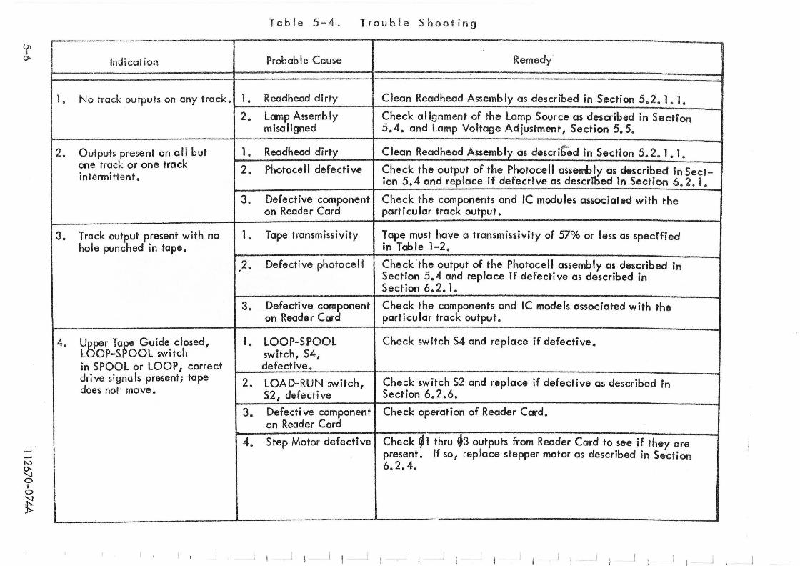
~ 0-
N 0-
~ I o ~ »
1 •
2.
3.
4.
Indication
No track outputs on any track. 1 •
2.
Outputs present on all but 1. one track or one track 2. intermittent.
3.
T rack output present with no 1 • hole punched in tape.
2.
3.
Upper Ta~e Guide closed, 1. LOOP-S OOL switch in SPOOL or LOOP, correct drive signals present; tope 2. does not move.
3.
4.
Table 5-4 . Trouble Shooting -e_ .
Probable Cause Remedy
Readhead dirty Clean Readhead Assembly as described in Section 5.2. 1. 1.
Lamp Assemb Iy misaligned
Check al ignment of the Lamp Source as described in Section 5.4. and Lamp Voltage Adjustment I Section 5.5.
Readhead dirty Clean Readhead Assembly as described in Section 5.2. 1. 1.
Photocell defective Check the output of the Photocell assembly as described in Sect-ion 5.4 and replace if defective as described in Section 6.2. 1.
Defective component Check the components and IC modules associated with the on Reader Card particular track output.
Tape transmissivity Tape must have a transmissivity of 57% or less as specified in Tobie 1-2.
Defective photocell Check the output of the Photocell assembly as described in Section 5.4 and replace if defecti ve as described in Section 6.2.1.
Defecti ve component Check the components and IC models associated with the on Reader Card particular track output.
LOOP-SPOOL Check switch S4 and replace if defective. I
switch, 54, defective.
LOAD-RUN switch, Check switch 52 and replace if defective as described in S2, defecti ve Section 6.2.6.
Defecti ve component Check operation of Reader Cord. on Reader Cord
Step Motor defective Check ~1 thru ~3 outputs from Reader Card to see if they are present. If so, replace stepper motor as described in Section 6.2.4.
-- --~-
I I I I J I I J I I I ! I I j I J I J I
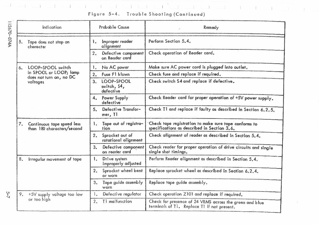
"-> 0-
~ I o
~
'f "-..l
Indication
5, Tape does not stop on character
6. LOOP-SPOOL switch in SPOOL or LOOP; lamp does not turn on, no DC voltages
7. Continuous tape speed less than 180 characters/second
8. Irregu lar movement of tape
9. +5V supply voltage too low or too high
L-.-___ __
I
Figure 5- 4. Trouble Shooting (Conti.nued)
Probab Ie Cause /' Remedy
1. Improper reader Perform Section 5.4. alignmenr
2. Defective com/onent Check operation of Reader card. on Reader car
1. No AC power Make sure AC power cord is plugged' into outlet.
2. Fuse Fl blown Check fuse and replace if required.
3. LOOP-SPOOL Check switch S4 and replace if defective., switch, 54, defective
4. Power Supply Check Reader card for proper operation of +5V power supply. defective
5. Defecti ve Transfor- Check T1 and replace if faulty as described in Section 6.2.5. mer, 11
1. Tape out of registra- . Check tape registration to make sure tape conforms to tion specifications as described in Section 3.6.
2. Sprocket out of Check alignment of reader as described in Section 5.4. rotational alignment
3. Defective component Check reader for proper operation of drive circuits and single on reader card ' single shot timings.
1. Dri ve system improperly adjusted
Perform Reader alignment as described in Section 5.4.
2. Sprocket whee I bent Replace sprocket wheel as described in Section 6.2.4. or worn
3. Tape guide assemb Iy R~place tape guide assembly. worn
I. Defective regulator Check operation Z101 and replace if required.
2. T 1 malfunction Check for presence of 24 VRMS across the green and blue termina ls of n. Replace Tl if not present.
------ .-~----- --. - ~-
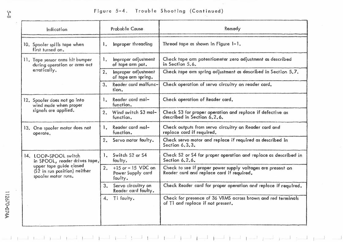
<r 00
tv 0-. "'-..l o 6 ~ »
Figure 5-4 . Trouble Shooting (Continued)
Indication Probab I e Cause , Remedy I
10. Spooler spi lis tape when 1 • Improper threading Thread tape as shown in Figure 1- 1. fi rst turned on.
11. Tape ,sensor arms h it bumper 1 • Improper adjustment Check tape arm potentiometer zero adjustment as described during operation or arms act of tape arm pot. in Secti on 5.6. erratically. 2. Improper adjustment Check tape arm spring adjustment as described in Section 5.7.
of tape arm spring.
3. Reader card malfunc- Check operation of servo circuitry on reader card. tion.
12. Spooler does not go into 1 • Reader card mal- Check operation of Reader card. wind mode when proper function. signals ore applied. 2. Wind switch S3 mal- Check S3 for proper operation and replace if defective as
function. described in Section 6.2.6.
13. One spooler motor does not 1 • Reader card rna 1- Check outputs from servo circuitry on Reader card and operate. function. replace card if required.
2. Servo motor fau Ity. Check servo motor and replace if required as described in Section 6.3.3 •
..
1( lOOP-SPOOL switch 1. 5witch S2 or S4 Check 52 or 54 for proper operation and replace as described in in SPOOL, reader drives tape, faulty. Section 6.2.6. upper tape guide closed 2. +15 or - ,15 VDC on Check to see if proper power supply voltages are present on (52 in run position) neither Power Supply card Reader card and replace card if required. spooler motor runs. faulty.
3. Servo circuitry on Check Reader card for proper operation and replace if requ ired. Reader card faulty.
4. T 1 faulty. Check for presence of 36 VRMS across brown and red terminals of T 1 and replace if not present.
'----- -I I I I j I I J I I , I , I
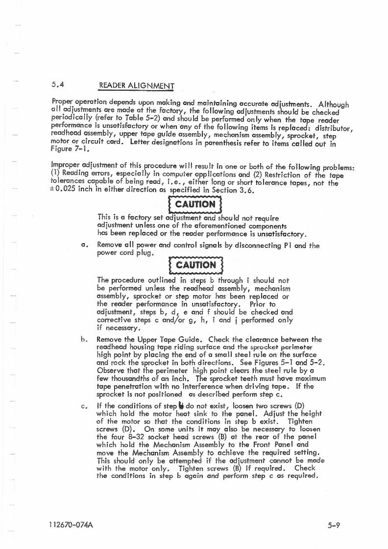
5.4 READER ALIGNMENT
Proper operation depends upon making and maintaining accurate adjustments. Although all adjustments are mode at the factory, the following adjustments should be checked periodically (refer to Table 5-2) and should be performed only when the tope reader performance is unsatisfactory or when 'any of the following items is replaced: distributor, read head assembly, upper tope guide assembly, mechanism assembly, sprocket, step motor or circuit card. letter designations in parenthesis refer to items called out in Figure 7-1.
Improper adjustment of this procedure will result in one or both of the following problems: (1) Reading errors, especially in computer applications and (2) Restriction of the tope tolerances capable of being read , i.e., either long or short tolerance tapes, not the ±O.025 inch in either direction as specified in Section 3.6.
a.
b.
c.
1 1 2670-074A
~ This is a factory set adjustment and shou Id not require adjustment unless one of the aforementioned components has been replaced or the reader performance is unsatisfactory.
Remove all power and control signals by disconnecting PI and the power cord plug.
The procedure outlined in steps b through i should not be performed unless the read head assembly, mechanism assembly, sprocket or step motor has been replaced or the reader performance in unsatisfactory. Prior to adjustment, steps b, d, e and f shou ld be checked and corrective steps c and/or g, h, i and j performed only if necessary.
Remove the Upper Tape Guide. Check the clearance between the read head housing tape riding surface and the sprocket perimeter high point by placing the end of a small steel rule on the surface and rock the sprocket in both directions. See Figures 5-1 and 5-2 . Observe that the perimeter high point clears the steel rule by a few thousandths of an inch. The sprocket teeth must have maximum tope penetration with no interference when driving tape. If the sprocket is not positioned as described perform step c.
If the conditions of step It do not exist , loosen two screws (D) which hold the motor heat sink to the panel. Adjust the height of the motor so that the conditions in step b exist. Tighten screws (D). On some units it may also be necessary to loosen the four 8-32 socket head screws (B) at the rear of the pane I which hold the Mechanism Assembly to the Front Panel and move the Mechanism Assembly to achieve the required setting. This shou Id only be atte';1pted if the adius.tment ~annot be mode with the motor only. Tighten screws (B) If required. Ch.eck the conditions in step b again and perform step c as required.
5-9
5-10
L=:J If the motor has been running for a period of time it or the heat sink may be too hot to touch comfortably. Allow sufficient time for the motor and heat sink to cool before any adjustment or use a cloth or pair of gloves.
d. Insert a loop of tape known to have been punched to within :1:0.0025 inch in a 5-inch span (0.05% error).
e.
f.
g.
h.
i.
I·
k. I.
NOif Since repeatability of the feedhole placement in either direction is essential, a tape whose accumu lated error in a 5-inch span is consider- . ably better than :1:0.025 inches (as specified- in Section 3.6) must be used in this procedure. Remex specifies a tape known to be punched to within :1:0.0025 inch in a 5-inch span (:1:0.05% tolerance). Note that most Remex punches are specified at :1:0.025 and therefore these tapes should not be used for this adjustment unless the tape has been checked on a reg istration gauge and found to be within :1:0.0025 inch.
Loosen nut (T) which holds the fiber optics light source to the reader pane I and rotate the light source away from the light tunne Is.
With the rear edge of the tape parallel to the front panel, align the holes over the light columns in the readout assembly so that they are concentric. See Figure 5-3. The tape must remain parallel to the front panel so that no skew is present. With the tape in this position, the sprocket teeth shou Id be centered in the sprocket holes in the tape. Skewing is indicated by tracks 1 and 8 not being concentric.
If the conditions of step f do not exist 1 loosen theJ:~o set screws (J) which hold the sprocket to the motor shaft and move the sprocket in orout on the shaft unti I the teeth are centered in the feed ho les and the tape holes remain concentric with the light tunnels. Tighten screws (J). Recheck the adjustment and readjust as required.
Connect the power plug and place the POWER switch into the ON position. The motor shou Id be energized.
loosen the single screw (S) which holds the motor to the heat sink (some earlier models may have two sets screws).
Rotate the motor so that the holes in the tape are concentric with the I ight co lumns in the read head and the sprocket teeth are centered in the feed holes. Tighten the set screws. Recheck the adjustment and readjust as required.
Remove the 0.05% tape .
Place the POWER switch in the OFF position.
112670-o74A
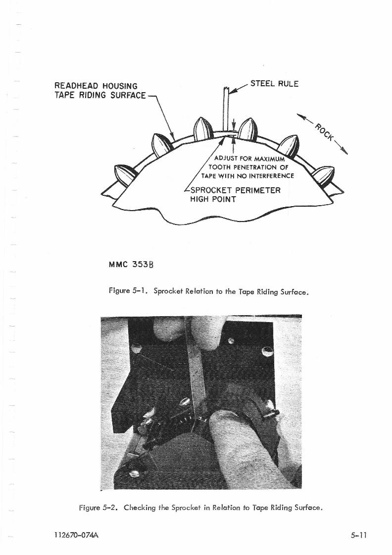
REAOHEAO HOUSING TAPE RIDING SURFACE
MMC 3538
STEEL RULE
ADJUST FOR MAXIMUM TOOTH PENETRATION Of
TAPE WITH NO INTERFERENCE
SPROCKET PERIMETER HIGH POINT
Figure 5-1. Sprocket Relation to the Tape Riding Surface.
Figure 5-2. Checking the Sprocket in Relation to Tape Riding Surface.
112670-074A 5-11
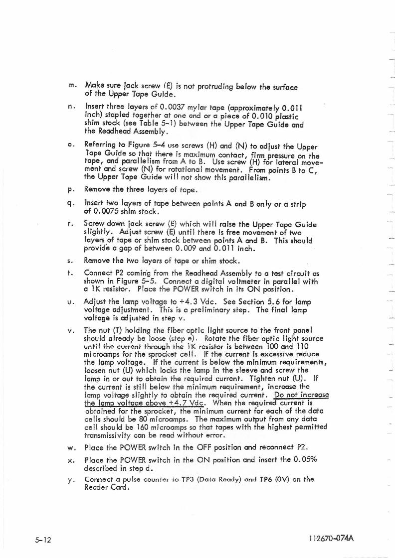
m. Make sure jack screw (E) is not protruding below the surface of the Upper Tape Guide.
n. ~nsert three layers of 0.0037 mylar tape (approximately 0.011 Inch) stapled together at one end or a piece of 0.010 plastic shim stock (see Table 5-1) between the Upper Tape Guide and the Readhead Assembly.
o. Referring to Figure 5-4 use screws (H) and (N) to adjust the Upper Tape Guide so that there is maximum contact firm pressure on the tape, and parallelism from A to B. Use scr~ (H) for lateral movement and sc(ew (N) for rotational movement. From points B to C the Upper Tape Guide will not show this parallelism. '
p. Remove the three layers of tape.
q. Insert two layers of tape between points A and Bon Iy or a strip of 0.0075 shim stock.
r. Screw down jack screw (E) which will raise the Upper Tape Guide slightly. Adjust screw (E) until there is free movement of two layers ,of tape or shim stock between poi"ts A and B. This should provide a gap of between 0.009 and 0.011 inch.
s . Remove the two layers of tape or shim stock.
t. Connect P2 comin'g from the Readhead Assembly to a test circuit as shown in Figure 5-5. Connect a digital voltmeter in parallel with a 1 K resistor. Place the POWER switch in its ON position.
u. Adjust the lamp voltage to +4.3 Vdc. See Section 5.6 for lamp voltage adjustment. This is a preliminary step. The final lamp voltage is adjusted in step v.
v. The nut (T) holding the fiber optic light source to the front panel should already be loose (step e). Rotate the fiber optic light source until the current through the lK resistor is between 100 and 110 microamps for the sprocket cell. If the current is excessive reduce the lamp voltage. If the current is below the minimum requirements, loosen nut (U) which locks the lamp in the sleeve and screw the lamp in or out to obtain the required current. Tighten nut (U). If the current is still below the minimum requirement, increase the lamp voltage slightly to obtain the required current. Do not increase the lam2 voltage above +4.7 Vdc. When the required current is obtained for the sprocket, the minimum current for each of the data cells should be 80 microamps. The maximum output from any data cell should be 160 microamps so that tapes with the highest permitted transmissivity can be read without error.
w. Place the POWER switch in the OFF position and reconnect P2.
x. Place the POWER switch in the ON position and insert the 0.05% described in step d.
y. Connect a pulse counter to TP3 (Data Ready) and TP6 (OV) on the Reader Card.
5- 12 112670-074A
MMC512
TAPE HOLES AND
SPROCKET TOOTH CENTERED IN FEED HOLE
GUIDE ALL HOLE TAPE
TAPE EDGE PARALLEL . TO fRONT OF PANEL
(t 0.05"4 REGISTRATION)
NOTE: UPPER TAPE GUIDE AND FIBER OPTIC LIGHT SOURCE REMOVED FOR CLARITY
Figure 5-3. Alignment of the Sprocket with the light Columns.
H{SCREWSJ N(SCREW}
MYLAR TAPE E (.lACK SCREW)
E
MMC 446A
Figure 5-4. Adjustment of the Upper Tape Guide.
112670-074A 5-13
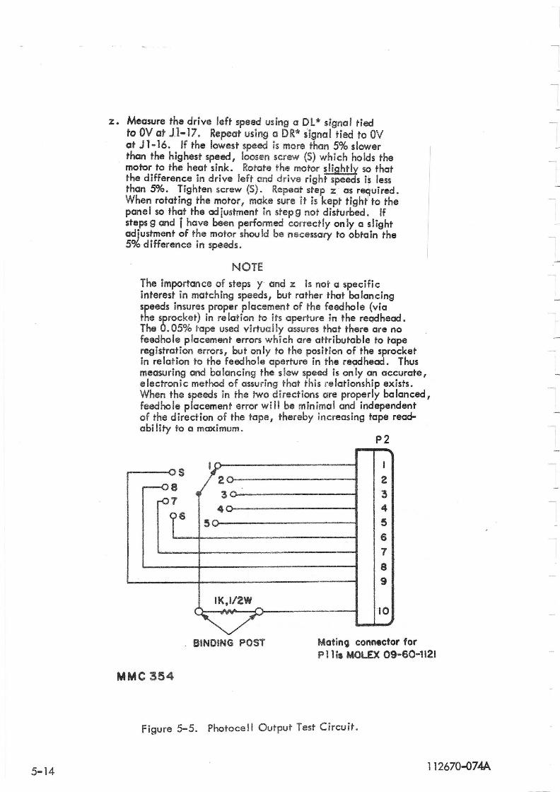
5-14
z. Measure the drive left speed using a Dl * signal tied to OV at J.1-17. Repeat using a DR* signal tied to OV at J 1-16. If the lowest speed is more than 5% slower than the highest speed, loosen screw (5) which holds the motor to the heat sink. Rotate the motor slightly so that the difference in drive left and drive right speeds is less than 5%. Tighten screw (5). Repeat step z as required. When rotating the motor 1 make sure it is kept tight' to the panel so that the adjustment in stepg not disturbed. If steps 9 and i have been performed correctly only a slight adjustment of the motor shou Id be necessary to obtain the 5% difference in speeds.
NOTE The importance of steps y and z is not a specific interest in matching speeds, but rather that balancing speeds insures proper placement of the feedhole (via the sprocket) in re lation to its aperture in the reCldhead. The 0.05% tape used virtually assures that there are no feedhole placement errors which are attributable to tape registration errors, but only to the position of the sprocket in relation to the feedhole aperture in the readhead. Thus measuring and balancing the slew speed is only an accurate, electronic method of assuring that this re lationship exists. When the speeds in the two directions are properly balanced, feedhole placement error will be minimal and independent of the direction of the tape, thereby increasing tape readability to a maximum.
P2
I I ~s
2~ 2 -08
r07 ~ 3 ..... 3
4"" 4
16 50 5
6 7
8 9
IK,1/2W ( , .....
~ 10
B'INOING POST Mating connector for P 11 i, MOLEX 09-60-1121
MMC 354
Figure 5-5. Photocell Output Test Circuit.
112670-074A
5.5 READER tAMP VOLTAGE ADJUSTMENT
The following procedure should be used when adjusting the readerfcimp ~o"tage:
5.6
a. Place the ON-OFF switch to its ON position. The reader lamp should come on.
b. Place a digital voltmeter across the lamp terminals.
c. Adjust R63 on the Reader card until the meter reads +4.3 ±O. 1 Vdc.
d . Remove the meter leads.
NOTE
The reader lamp voltage may require further adjustment to increase the photocell outputs. See Section 5.4, step v. Do not increase the voltage above +4.7 Vdc.
SERVO ALIGNMENT
Alignment of the servo system is performed' in the following manner:
a. Place the ON-:-.OFF switch in the OFF position.
b. Remove all tape and reels from the reader-spooler.
c . Place the SPOOL-LOOP switch in SPOOL and the OFF-ON switch in ON and place the RUN-LOAD switch in RUN position! . .
d. Rotate the left and right tape sensing arms to the center of their travel arc. Secure the arms in this position with a rubber band loop around the tape rollers.
e. If the left motor rotates when the arm is positioned in the center of its trave I arc I perform steps f and g.
f. Loosen the set screw which holds the coupling to the potentiometer shaft .
g . Rotate the shaft of the potentiometer unti I the left motor stops rotating. Tighten set screw (A).
h. Repeat steps e,f and g for the right arm.
5.7 ARM SPRING TENS ION ADJUSTMENT
Tension of the tape sensing arm spring is measured at the roller on the end of the arm.
a. Place the OFF-ON switch in the OFF position.
b. Attach a tension gauge to the tape arm ro Iler on the left arm using a piece of tape around the roller.
c. Pu" on the gauge perpend i cu lady to the tape arm and I ift the arm up off the outer stop. Note the gauge reading which should be between 4 and 5 ounces. Do not allow the tension of the arm on the switch to interfere with the measurements.
112670-074A 5-15
d. If the tension measurements do not agree with the specifications noted in step c, adjust the screw holding the arm spring up or down in the slotway until the conditions of step c is met.
e. Repeat steps b through d for the right arm.
5.8 SPOOLER TAPE ARM AND ROLLER ALIGNMENT
The tape rollers and the arm rollers should be positioned so that paper tape moves through the drive mechanism flat in either direction, without wave. Mylar tape may have a slight wave. All tape shou Id run through The head without excessive edge guiding, preferably with a slight tendency of guiding toward the panel.
To accomplish this alignment, a small amount of bending at the end of the tape arm may be required. However I the arm itself must be parallel to the pane lover its entire length. In addition, the distance from the front surface of the arm to the inside edge of the roller must be between O. 190 and 0.205 inch. This is improtant when a new roller has been installed and is accomplished by placing 1 or 2 713600-149 washers between the spacer and roller as shown in Figure 6-1 and as described in Section 6.3.4. The roller must also remain perpendicular to the front panel.
5.9 TAPE SPLICING
If tape breakage occurs, this break may result in damage to one, two or possibly three characters. When spiicing tape for this reader, great care shou Id be used to ensure that the proper sprocket hole spacing be preserved. A lap splice should not be used; use only a butt type splice. To repair the tape without loss of characters, the process shown in Figure 5-6·1s recommended and is accomplished as follows:
5-16
a. Bring the tape ends together as shown in Figure 5-6A.
b. Make a sketch of character(s) at the break (A-B-C) and five additional characters to the left (5-4-3-2-1) and five to the right (1-2-3-4-5) of the broken character{s) (A-B-C).
c. Place the left end of the broken tape over a section of blank tape containing only feed holes so that at least eight or ten feed holes in each tape are aligned with one another as shown in Figure 5-6B. Cut the tapes at the third undamaged character (A-B-C). Use care to insure that feed holes are aligned and make cut through the center of th~ ho les in the thi rd undamaged character. Characters 5, 4 and ha If of 3 should remain on the broken tape.
d. Place the right end of the broken tape over the section of blank tape so that at least eight or ten feed holes are aligned with one another. Feed holes for one-half of 3, 2 and 1 on the blank tape cut in sfep c should be visible to the left of the broken tape end as shown in Figure 5-6C. Cut the tapes at the third undamaged character to the right of the damaged character. Be sure that feed holes are aligned and make the cut through the center of the holes in the third undamaged character.
NOTE
One ha If of character 3 and characters 4 and 5 shou Id remain in the broken tape.
112670-074A
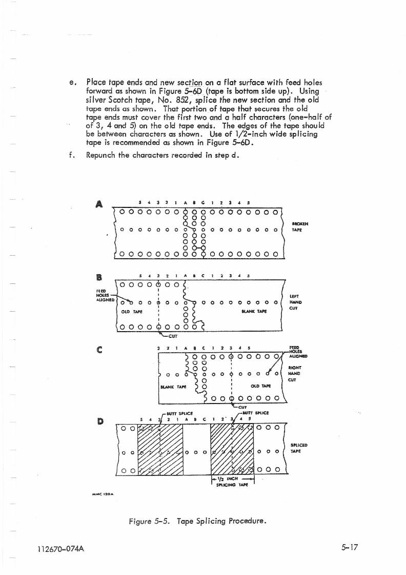
e. Place tape ends and new sectjQ£}on a flat surface with feed holes forward as shown in Figure ~6D_ (tape is bottom side up). Using . silver Scotch tape, No. 852, splice the new section and the old tape ends as shown. That portionof tape that secures the old tape ends must cover the first two and a half characters (one-half of of 3, 4 and 5) on the old tape ends. The edges of the tape shou Id be between characters as shown. Use of 1/2-:-inch wide splicing tape is recommended as shown in Figure 5-60.
f. Repunch the characters recorded in step d.
A s 4 3 2 1 II. • C 1 2 ) 4 , 0000000 0000000000
00 00
0 0 0 0 0 0 0 0 0 0 0 0 0 o 0 0 0 0 0 0 0 0
000000000 00000000
B 5 4 3 2 1 A I C 1 ~ 3 4 " ,
0 0 0) 0 0 o 0 0 0 o 0 0 0 0 I
OLD TII.I'I! , IlAHIt TAPI I
I
0000 00 CuT
C 3 2 1 II. • C I 2 3 4 5
0000 00 00
0 0 0 o 0 ~ 0 0 0
0 RANK TAPI! 0
D
.MMC 120A
Figure 5-5. Tape Splicing Procedure.
1 1 2670-074A
IIK)II:IH TAPI!
lIPT HAND CUT
f!l!D HOlES AUGNID
lIGHT HAND
CUT
SPl.IClf) TAPE
5-17

6. 1 GENERAL
SECTION VI
PARTS REPLACEMENT
REMEX maintains service facilities at its manufacturing location and at service cent~rs in major population areas for repair or replacement of components for their products. It is recommended that one of these centers be contacted for assistance in case of equipment malfunction. For the locations of service facilities in any area, contact REMEX at the addr-ess or telephone listed on the title page of the manual. Please direct inquiries to the attention of the Servi ce Department.
When any parts of the reader require rep lacement or disassembly, the procedures below should be followed closely. The warnings and cautions are included to protect personnel and equipment. Notes are included to assist persons unfamiliar with the equipment. Before attempting any procedure, all instructions for that disassembly should be read and understood.
Quantities of replaceable items suggested as spares are listed in Table 7-1. All system components are identified in Section VII of this manual, along with i llustrations showing part locations . This information may be used to locate parts below unit level if replacement is requ ired.
6.2
6.2. 1
Potentially dangerous line voltage is applied to components within this equipment. If adjustments must be performed with power applied, these points must be located and avoided. High voltage can be accidentally contacted at TB 1, at the OFF-OI\4 switch/wiring c'onnections, and on the circuit card (rear of the Unit).
READER PARTS REPLACEMENT
READHEAD MECHANISM DISASSEMBLY
This procedure is required when replacing the Upper Tape Guide Assembly I the Readhead Assembly (consisting of the Readhead Housing, Photocell Assembly and light Columns), or the Mechanism Assembly (cons,isting of the Mounting Block, Tape Guide Cam,. Tape Tape Guide Actuator I Slide and Spring). For ease of assembly, it is recommended that the Readhead Assembly (part number 110459-3) and Mechanism Assembly (part number 112346-1) be replaced as a complete assembly. Figure 7-1 should be folded out from Section ~ to follow during this procedure. The following procedure is recommended when replaCing any of the above mentioned items:
a. Remove all power and control signals by disconnecting Pl and the power cord.
b. Disconnect P2 and P3 from the circuit card.
1 1 2670-074A 6-1
c. Remove two 4-40 round head screws (C and F, Figure 7-1) which hold the Readhead Assembly to the Mechanism Assembly.
d. Loosen the two 8-32 socket head screws (Item B, Figure 7-1) which hold the Mechanism Assembly to the Front Panel at the rear of the Front Panel. The entire Readhead Mechanism Assembly consisting of the Tape Guide Assemb ly, the Readhead Assembly, and the . Mechan ism Assemb!y is now free to be removed from the pane I.
e. Remove the two 4-40 binder head screws (Item H, Figure 7-1) which hold the Tape Guide Assembly to the Mechanism Assembly. If no further disassembly is required, install the new Upper Tape Guide Assembly and perform the reverse of steps e through c. Perform the Upper Tape Guide adjustment Procedure.
f. From the underside of the Mechanism Assembly remove the two 4-40 round head screws (Item I, Figure 7-1) which hold the Readhead Assembly to the Mechanism Assembly. The Reahhead Assembly and the Mechanism Assembly are now separated and can be replaced as individual assemblies. It is not recommended that Mechanism Assembly be disassembled beyond this level.
g. Reassemb Iy is the reverse of steps g I f, e I d and c.
h. Perform Section 5.4.
6.2.2 READER CARD REPLACEMENT
The following procedure is recommended when removing the Reader Card:
a. Remove all power and control signals by disconnecting Pl and the power cord.
b. Disconnect plugs from the circuit card and powe r driver board.
c. Remove the 4-40 round head screws and nylon washers which hold the Reader Card to the Chassis and P. C. Board spacers.
d. Reassembly is the reverse of steps c and b.
e. Perform Section 5.5 and 5.6.
6.2.3 READER LAMP REPLACEMENT
a. Remove ail power and control signals by disconnecting Pl and the Power cord .
b. Slide the two terminals off at the rear of the lamp.
e. Unscrew the lamp from the sleeve.
d. Replacement is the reverse of steps c, b and then a.
e. Perform Section 5.4 steps t, u and v .
6-2 112670-074A
6.2.4 MOTOR AND/OR SPROCKET REPLACEMENT
The following procedure is recommended when replacing the mOfor and/or sprocket:
a. Remove all power and control signals.
lI=::D If the motor has been runn ing for a period of time, it or the heat sink may be too hot to touch· comfortably. Allow sufficient time for the motor and heat sink to cool before any adjustment or use a cloth or pair of gloves.
b. Loosen the set screw (Item R, Figure 7-1) which holds the motor to the heat sink and back the motor out slightly.
c. Loosen the two set screws (Item J, Figure 7-1) which hold the sprocket to the motor shaft and if on Iy the sprocket needs replacing proceed to step e.
d. Install the new motor by performing the reverse of step b. The motor should be up flush against the panel. Tighten set screw R.
e. Install the sprocket wheel so that: (1) distance from the rear of the sprocket to the front panel is 0.862 inch (see Figure 7-1) and (2) the 1/8 long set screw tightens on the flat of the motor shaft. Tighten the set screws J.
f. Perform Section 5.4.
6.2.5 TRANSFORMER REPLACEMENT
The following procedure is recommended when replacing the transformer:
a. Remove all power and control signals by disconnecting Pl and the power cord.
b. Disconnect the transformer leads attached to TS 1 and BR 1 .
c. Loosen the four 10-24 binder head screws which hold the transformer to the chassis and remove the transformer.
d. Install the new transformer by performing the reverse of steps c, b and then a. Refer to Table 6-1 for transformer wire connections.
Table 6-1. Transformer Wire Connections
T1 Wire Color TB 1 Terminal T1 Wire Color TSl Terminal
White/Orange TB1-A4 Brown TB1-F5 White/Yellow TS 1-85 White/Green TS 1-81 Orange TB1-E5 White/Blue TS1-C5 Yellow BRl-2 Wh i te/Vio let TBl-C1 White/Gray TB1-Dl
112670-074A 6-3
6.3 SPOOLER PARTS REPLACEMENT
6.3. 1 POTENTIOMETER REPLACEMENT
The following procedure is recommended "when replacing a potentiometer. It is recommended that the entire potentiometer ass~mbly 112857-1 be replaced (inc ludes connector, contacts and retainer). -
a. Remove all power and control signals by disconnecting P1 and the power cord.
b. Unsolder the wires at termnals 1, 2 and 3 on the potentiometer. Note orientation of terminals and which wires go to which terminals.
c. Loosen set screw whi cn holds the bearing shaft assemb Iy to the potentiometer shaft.
d. Loosen binder head 6-32 screw which holds the potentiometer assembly to the bracket. Back the potentiometer out from the bracket.
e. Install an ohmmeter across terminals 2 and 2 on the new potentiometer and rotate the shaft until the meter reads 5K.
f. Insta II the new potentiometer into the coup ling and bracket by perform ing the reverse of steps d and c. Care shou Id be used so that the potentiometer shaft is not rotated and that the orientation of the term ina Is as noted in step b are observed.
g. Perform Section 5.6.
6.3.2 FRONT PANEL AND CHASSIS SEPARATION
The fo I low ing procedure is recommended when separat ing ~he front pane I from the chassis.
a. Remove all power and control signals by disconnecting Pl and the power cord.
b. Disconnect the following connectors J2/P2, J3/P3, J4/P4, J5/P5, J6/P6 and J7/P7 on the reader card.
c. Disconnect J9/P9, J10/PlO and Jll/Pl1 on the Power Driver card.
d. Disconnect the two wires coming from the ON-OFF switch, S 1, at TB1-1 and TBl-5.
e. Remove the four screws which hold the front panel to the chassis.
f. Remove the arm spring from the spring adjustment screw .
g. The front panel and chassis (with the Reader Card attached) can now be separated.
h. Reassemb ly is the reverse of steps e, f, d, c, b and then a. Perform Section 5 . 7 .
6-4 112670-,074A
- -----------~.
6.3.3 SERVO MOTOR REPLACEMENT
The following procedure is recommended when replacing either servo motor assembly. When reploc ing the motor, it is recommended that the entire 110829-1 motor assembly (including connector and hub assembly) be replaced .
a. Separate the front panel and chassis. Refer to Section 6.3.2.
b. Remove the four 10-32 binder head screws which hold the motor to the front panel. Note the orientation of the motor so that the new motor will be installed the same way.
c. Insta II the new motor by perform ing the reverse of steps b and then a.
6.3.4 TAPE ARM REPLACEMENT
The following procedure is recommended when replacing the tape arm.
o. Remove all power and control signals by disconnecting Pl and the power cord.
b. Remove the 6-32 x 3/8 flat head screw (C) which holds the arm assembly to the bearing shaft assembly. See Figure 6-l.
c. Remove the grip ring which holds the roller to the tape arm.
d. The arm and roller are now free for replacement as required.
e. Reassemb Iy is the reverse of steps c, b and then a. When insta" ing the ro lIer make sure the distance between the front of the arm and the rear of the roller is between 0.190 and 0.205 inch as shown in Figure 6-1. This is accomplished by placing 1 or 2 washers (Remex Part No. 713600-149) between the spacer and the roller to obtain the desired dimension. See Section 5.8.
f. Check the adjustment in Section 5.6 and readjust as required.
112670-D74A 6-5
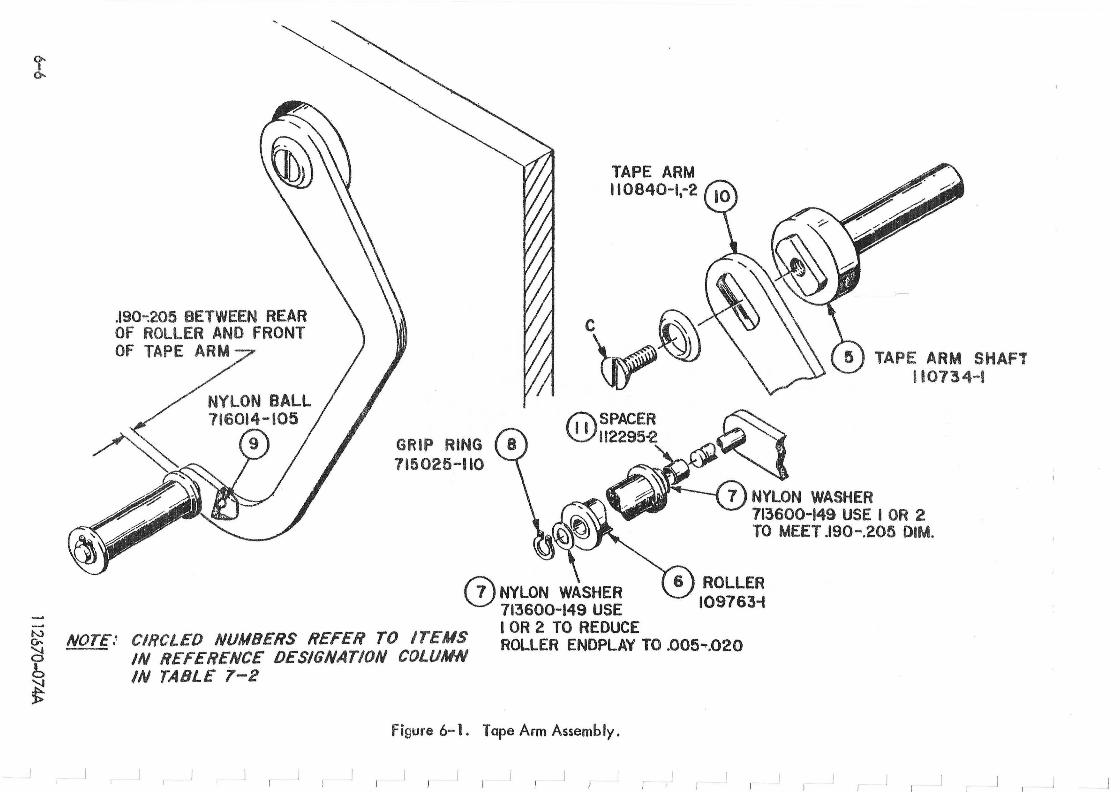
<t ~
-
.190-:205 BETWEEN REAR OF ROLLER AND fRONT OF TAPE ARM
NYLON BALL 716014-105
/'"
9 GRIP RING 115025~110
TAPE ARM 110840-1.-2
a 1 TAPE ARM SHAFT 110734-1
t:':\SPACER ~ \!.!J1I2295-2 ~~
~~ NYLON WASHER I OR 2 ' ~ \.!...J 713600-T'4~9g:~05 DIM. l . TO MEE .
(2) NYLON WASHER 713600-149 USE
ROLLER 109763;
~ NOTE.~ CIRCLED NUMBERS REFER TO ITEMS lOR 2 TO REDUCE IN REFERENCE DESIGNATION COLUMN ROLLER ENDPLAY TO .005"'.020 ~
b ~
IN TABLE 1-2
figure 6- 1. Tape Arm Assembly.
, I
SECTION VII
PARTS LIS T
7 . 1 GENERAL
Listed in Table 7-2 are the elec;tronic and mechanical parts used in the RRS7200BEX. Standard hardware items are not listed. Indented items are part of the assembly under which they are indented and the quantity of these items are per each assembly. Table 7-1 lists the recommended spare parts and the quantity column denotes the number recommended. Figures 7-1 through 7-4 illustrate the parts listed in Table 7-2. Those items identified by a broken arrow indicate the approximate location of parts not visible in the photograph.
Reference designations refer to the parts illustrated in Figures 7-1 through 7-4 (circled number designations in Figure 7.1; letter designations in Figure 7-1 refer to hardware items referenced in Sections 5 and 6). The reference designations include a figure number and a part designation number which appear on that figure to indicate the location of the part. For example, a 7-1; 12 appearing in the reference designation column indicates that the item listed in the description column can be located in Figure 7-1, Item 12. All electronic components are identified by letter-number combinations (such as S 1 and Tl) in the Reference Designation column and mechanical parts are identified by number. Refere~ce designations contained in parenthesis are associated or function with the parenthical item. These items are generally individual items and are not part of an assembly but for reference are related back to the associated item. All items are available from Spares Order Desk, REMEX, 1733 Alton Street, P. O. Box C19533, Irvine, Califomia 92713.
Tab Ie 7-3 contains the components used on the reader card.
7.2 KIT OF PARTS
The kit of parts contains items used for installation and maintenance and is shipped with the unit. Refer to Table 1-1.
1 12670-074A 7-1
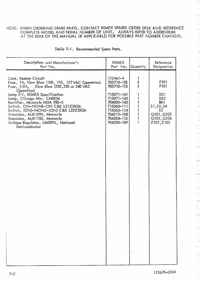
;
I !
'-lOTE: WHEN ORDERING SPARE PARTS, CONTACT REMEX SPARES ORDER DESK AND REFERENCE COMPLETE MODEL AND SERIAL NUMBER OF UNIT. ALWAYS REFER TO ADDENDUM AT THE REAR OF THE MANUAL (IF APPLICABLE) FOR POSSIBLE PART NUMBER CHANGES.
Table 7-1. Recommended Spare Parts.
Description. and Manufacturer's REMEX Reference Part No. Part No. Quantity Designation
Card, Reader Circuit 112461-4 1 Fuse, lA, Slow Blow (100, 115, 127VAC Operation) 705710-118 5 F10l Fuse I 1/2A, S low Blow (220,230 or 240 VAC 705710-113 5 FlO1
Operation) Lamp 5 V, REMEX Specification 715071-141 1 DS1 Lamp, Chicago Min. CM8536 715071-143 1 DS2 Rectifier I Motorola MDA 980-2 704005-143 1 BRI Switch, ON-NONE-ON C&K L21Z3X36 715063-111 1 51,52,54 Switch, (ON)-NONE-(ON) C&K L25Z3X36 715063 ... 114 1 S3 Trans j stor I MJ E 1090 I Motoro 10 704212-108 1 0101,0103 Transistor, MJEllOO, Motorola 704204-·115 1 0102,0104 Voltage Regulator, lM309K, National 704520-109 1 Z101,Z102
Semi conductor
,
7-2 112670-0748
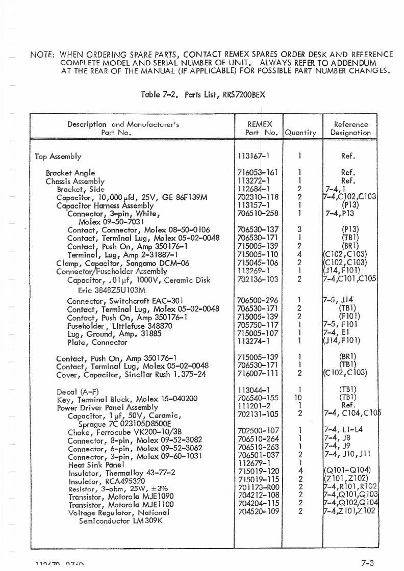
NOTE: WHEN ORDERING SPARE PARTS, CONTACT REMEX SPARES ORDER DESK AND REfERENCE COMPLETE MODEL AND SERIAL NUMBER OF UNIT. ALWAYS REFER TO ADDENDUM AT THE REAR OF THE MANUAL (IF APPLICABLE) FOR POSSIBLE PART NUMBER CHANGES.
Table 7-2. Parts List, RRS7200BEX
Description and Manufacturer 's REMEX Reference Part No. Part No. Quantity Designation
Top Assembly 1l31bll 1 Ref.
Bracket Ang Ie 716053-161 1 Ref. Chassis Assembly 11327~-1 1 Ref.
Bracket, Side 112684-1 2 7-4,1 Capacitor, lO,000l-lfd, 25V, GE 8bF139M 702310-118 2 7-4,C,102,C.103 Capacitor Harness Assembly 113157-1 1 (PI3)
Connector I 3-pin, White I 706510-258 1 7-4, P13 Mo lex 09-50-7031
Contact, Connector, Molex 08-50-0106 706530-137 3 (P13) Contact, Terminal Lug, Molex 05-02-0048 706530-171 1 (TB 1) Contact, Push On, Amp 350176-1 715005-139 2 (BR 1) Terminal, Lug, Amp 2-31887-1 715005-110 4 CI02,C 103)
Clamp, CiFacitor, Sangamo DCM-06 7]5045-106 2 C102,C103) Connector useholder Assembly 113269-1 1 J14,FlO1)
Capacitor, .Oll-'f, 1000V, Ceramic Disk 702136-103 2 7-4,(10 l,C 105
Erie 3848Z5U103M Cormector, Switchcraft EAC-30 1 706500-296 1 7-5,114 Contact, Terminal Lug, Molex 05-02-0048 706530-171 2 (TB1) Contact, Push On, Amp 350176-1 715005-139 2 (F 101) Fuseholder, littlefuse 348870 705750-117 1 7-5, FlOl Lug, Ground, Amp. 31885 - 715005-107 1 7-4, E 1 Plate, Connector 113274-1 1 (J14,F101)
Contact, Push On, Amp 350176-1 715005-139 1 (BR1) Contact, Terminal Lug, Molex 05-02-0048 706530-171 1 (TB1) Cover I Capacitor, Sincliar Rush 1.375-24 716007-111 2 (C102 ,C 103)
Decal (A-F) 113044-1 1 (TB1) Key, Terminal Block, Molex 15-040200 706540-155 10 (TB1) Power Driver Panel Assembly 111201-2 1 Ref.
Capacitor, l11f, 50V, Ceramic, 702131-105 2 7-4, C104,C10) Sprague 7C 023105D8500E
1 7-4, ll-l4 Choke, Ferrocube VK2oo-1O/3B 702500-107 Connector, 8-pin, Molex 09-52-3082 706510-264 1 7-4, J8 Connector, 6-pin, Molex 09-52-3062 706510-263 1 7-4, J9 Connector, 3-pin, Molex 09-60-1031 706501-037 2 7-4, JlO,J11 Heat Sink Panel 112679-1 1 Insulator, Thermalloy 43-77-2 715019-120 4 (Q101-Q104)
Insu lator, RCA495320 715019-115 -2 (Z101,Z102) Res i stor, 3-0 hm, 25W, ± 3<>10 701173-ROO 2 7-4,R101,R 102 Transistor, Motorola MJE1090 704212-108 2 7-4,Q 10 1,Q 103 Transistor, Motorola MJE1100 704204-115 2 7-4,Q102,Q104 Voltage Regu lator, Notional 704520-109 2 7-4,Z 10 l,Z 102
Semiconductor LM 309K
11'1L"71'\ I'\,An 7-3
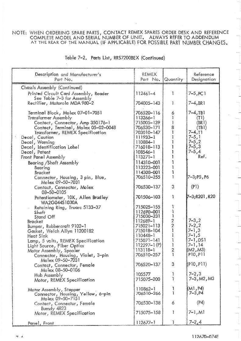
,
I
! I
I I
NOTE: WHEN ORDERING SPARE PARTS, CONTACT REMEX SPARES ORDER DESK AND REFERENCE COMPLETE MODEL AND SERIAL NUMBER OF UNIT. ALWAYS REFER TO ADDENDUM AT THE REAR OF THE MANUAL OF APPUCABlE) FOR POSSiBLE PARi NUMBER CHANGES.
Table 7-2. Parts list, RRS7200BEX (Continued)
Description and Manufacturer's REMEX Reference Part No. Part No. Quantity Designation
Chassis Assembly (Continued) Printed Circuit Card Assembl~{ Reader 112461-4 1 7-5 ,PC 1
See Table 7-3 for Assemb y Rectifier 1 Motorola MDA 980-2 704005-143 1 7-4,BRl
,
Terminal Block, Molex 07-01-7051 706520-116 6 7-4,TBl Transformer Assembly 113266-1 1 (Tl)
Contact 1 Connector 1 Amp 350176-1 715005-139 1 (BR1) Contact, Terminal, Molex 05-02-0048 706530-171 8 (TB1) Transformer, REMEX Specification 703010-147 1 7-4, Tl
Decal t Caution 111933-J 1 7-5,1 Decal, Warning 110884-1 1 7-5,2 Decal, Identification Label 716018-113 1 7-5 3 I
Deco I, Patent 108546-1 1 7-5,4 Front Panel Assembly 113271-1 Ref. 1
Bearing /Shaft Assembly 114310-001 1 Bearing 113223-001 1 Bracket 114308-001 1 Connector 1 Hous ing, 3 p in I Blue I
Molex 09-50-7031 706510-255 1 7-3;P5 ,P6
Contact, Connector 1 Molex 706530-137 3 (Pl) 08-50-0105
Potentiometer, 10K, Allen Bradley 701506-103 1 7-3;R201 ,R20 WA2G044S 1 030A
Retaining Ring, Truarc 5133-37 715025-155 1 Shaft 112690-001 1 Stand Off 715030-231 1
Bracket 112689-1 2 7-3,2 Bumker, Rubbercraft 9102-1 715021-113 2 7-2,2 Gas et, Welch Allyn 11200182 715018-104 1 7-1,3 Heat Sink 110448-1 1 7-1,5 Lamp 1 5 vo its T REMEX Specifi cation 715071-141 1 7-1, DS 1 Light Source, Fiber O~tics 112297.;..1 {P} 1 7-1,14 Motor Assembly, Spoo er 113118-1 2 M2,M3)
Connector, Housing, Violet, 3-pin 706510-257 1 PlO,Pll Mo lex 09-50-7031
Contact f Connector, Female 706520-137 3 PlO I Pll) Mo lex 08-50-0106
Hub Assembly 105577 1 7-2,3 Motor I REMEX Specification 715075-200 1 7-3,M2,M3
Motor Assemb Iy I Stepper 110862-1 1 Ml,P4) Connector, Housing r Yellow, 6-pin 706510-266 1 7-3,P4
Molex 09-50-7151 Contact I Connector I Female 706530-138 6 (P4)
Burndy 4823 Motor 1 REMEX Specification 715075-158 1 7-1 ,M 1
Panel, Front 112677-1 1 7-2,4
"7 A 112670-074-E
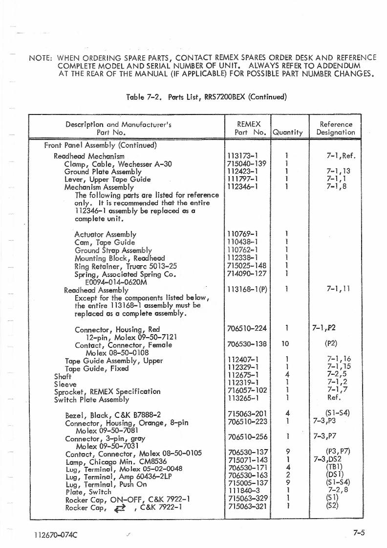
NOTE: WHEN ORDERING SPARE PARTS, CONTACT REMEX SPARES ORDER DESK AND REFERENCE COMPLETE MODEL AND SERIAL NUMBER OF UNIT. ALWAYS REFER TO ADDENDUM AT THE REAR OF THE MANUAL (IF APPLICABLE) FOR POSSIBLE PART NUMBER CHANGES.
Table 7-2. Parts List, RRS7200BEX (Continued)
Description and Manufacturer's REMEX Reference Part No. Part No. Quantity Designati on
Front Panel Assembly (Continued)
Readhead Mechanism 113173-1 1 7-1 ,Ref. Clamp, Cable, Wechesser A-30 715040-139 1 Ground Plate Assembly 112423-1 1 7-1,13 Lever, Upper Tape Guide 111797-1 1 7-1,1 Mechanism Assembly 112346-1 1 7-1,8
The following parts are listed for reference . only. It is recommended that the entire
112346-1 assembly be replaced as a complete unit.
Actuator Assembly 110769-1 1 Cam, Tape Guide 110438- 1 1 Ground Strap Assembly 110762-1 1 Mounting Block, Readhead 112338-1 1 Ring Retainer, Truarc 5013-25 715025-148 1 Spring, Associated Spring Co. 714090-127 1
EOO94-014-0620M Readhead Assembly 113168-1 (P) 1 7-1,11
Except for the components listed below, the entire 113168-1 assembly must be replaced as a complete assembly.
Connector, Hous ing, Red 706510-224 1 7-1,P2 12-pin, Molex 09-50-7121
Contact, Connector, Female 706530-138 10 (P2) Mo lex 08-50-0108
Tape Guide Assembly, Upper 112407-1 1 7-1,16 Tape Guide, Fixed 112329-1 1 7-1,15
Shaft 112675-1 4 7-2,5 Sleeve 112319-1 1 7-1,2 Sprocket, REMEX Specification 716057-102 1 7-1,7 Switch Plate Assembly 113265-1 1 Ref.
Bezel, Black, C&K B7888-2 715063-201 4 (S 1-54) Connector, Housing, Orange, 8-pin 706510-223 1 7-3,P3
Mo lex 09-50-7081 Connector, 3-pin, gray 706510-256 1 7-3,P7
Mo lex 09-50-7031 (P3, P7} Contact, Connector, Mo lex 08-50-0105 706530-137 9
Lamp, Chicago Min. CM8536 715071-143 1 7-3,DS2 Lug, Terminal, Molex 05-02-0048 706530-171 4 (TB1) LU9t Terminal, Amp 60436-2LP 706530-163 2 (DS 1) Lug, Terminal, Push On 715005-137 9 (51-54) Plate, Switch 111840-3 1 7-2,8 Rocker Cap, ON-OFF, C&K 7922-1 715063-329 1 (S 1) Rocker Cap, C~ , C &K 7922- 1 715063-321 1 (52)
112670"'()74C J ' 7-5
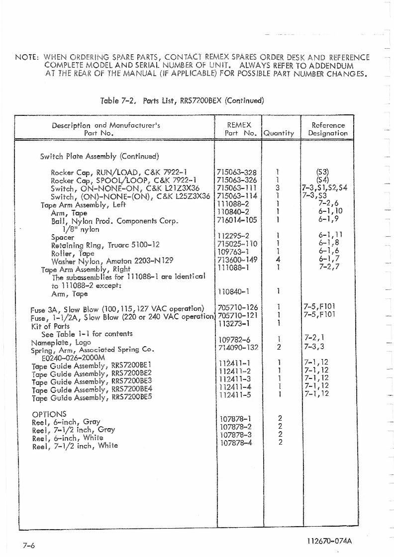
NOTE: WHEN ORDERING SPARE PARTS, CONTACT REMEX SPARES ORDER DESK AND REFERENCE COMPLETE MODEL AND SERIAL NUMBER OF UNIT. ALWAYS REFER TO ADDENDUM AT THE REAR OF THE MANUAL (IF APPLICABLE) FOR POSSIBLE PART NUMBER CHANGES.
Table 7-2. Ports List I RRS7200BEX (Continued)
Description and Manufacturer's REMEX Reference Part No. Part No. Quantity Designation
Switch Plate Assembly (Continued)
Rocker Cap, RUN/LOAD, C&K 7922-1 715063-328 1 (53) Rocker Capi SPOOL/lOOP, C&K 7922-1 715063-326 1 (S4) Switch, ON-NONE-ON, C&K L21Z3X36 715063-111 3 7-3,S 1,521 S4 Switch, (ON)-NONE-(ON), C&K L25Z3X36 715063-114 1 7-3,S3
Tape Arm Assembly f Left 111088-2 1 7-2,6 Arm, Tape 110840-2 1 6-1, 10 Ball, Nylon Prod. Components Corp. 716014-105 1 6-1,9
1/8" nylon 112295-2 1 6-1,11 Spacer
Retaining Ring, Truorc 5100-12 715025-110 1 6-1,8
Roller I Tape 109763-1 1 6-1,6 Washer Nylon t Amaton 2203-N 129 713600-149 4 6-1,7
Tape Arm Assembly, Right 111088-1 1 7-2,7 The subassemblies for 111088-1 are identical to 111088-2 except:
110840-1 1 Arm, Tape
Fuse 3Ar S low Blow (100 I 115 r 127 VAC operation) 705710-126 1 7-5,F101 Fuse, 1-1/2A, Slow Blow (220 or 240 VAC operation 705710-121 1 7-5,F101
Kit of Parts 113273-1 1 See Table 1-1 for contents 7-2,1
Nemep late! Logo 109782-6 1 Sprin9[ Arm, Associated Spring Co. 714090-132 2 7-3,3
E0240-026-2000M 112411-1 7-1,12 Tope Guide Assembly f RRS7200BE 1 1
Tape Guide Assembly, RRS7200BE2 112411-2 1 7-1,12
Tape Guide Assembly I RRS7200BE3 112411-3 1 7-1,12
Tape Guide Assembly r RRS7200BE4 112411-4 1 7-1,12
Tape Guide AssemblYi RRS7200BE5 112411-5 1 7-1,12
OPTIONS 107878-1 2 Reel, 6-inch, Gray Reel, 7-1/2 inch, Gray 107878-2 2
Reel, 6-inch, White 107878-3 2
Reel, 7-1/2 inch, White 107878-4 2
I
7-6 112670-074A
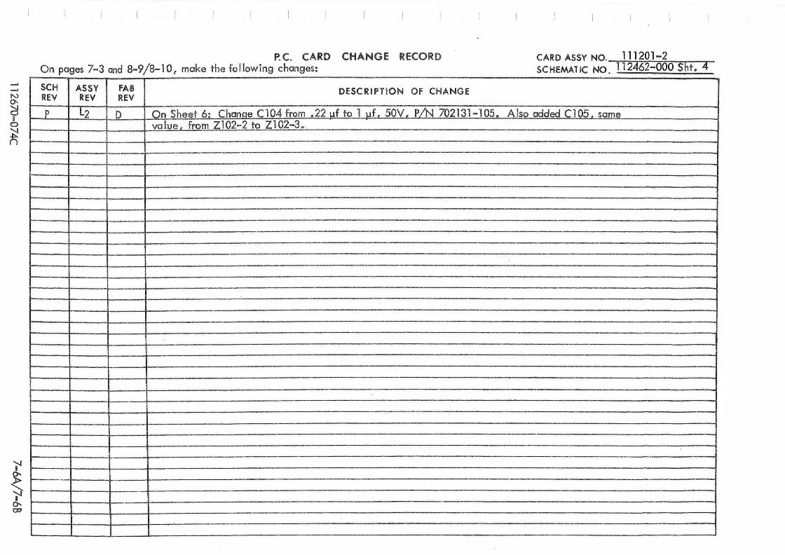
..... N 0-
~ I o
~
I" ~ "I" 0-. co
P. C. CARD CHANGE RECORD On pages 7-3 and 8-9/8-10, make the fo llowing changes-
CARD ASSY NO. 111201-2 SCHEMATIC NO 112462-000 Sht. 4 . .
SCH ASSY FAB DESCRIPTION OF CHANGE REV REV REV
P L2 D On Sheet 6: Change C104 from .221Jf to 1 IJf! 50V, PiN 702131-105. Also added Cl05, same value, from Z102-2 to Z102-3.
-
.-
, .. L- ____

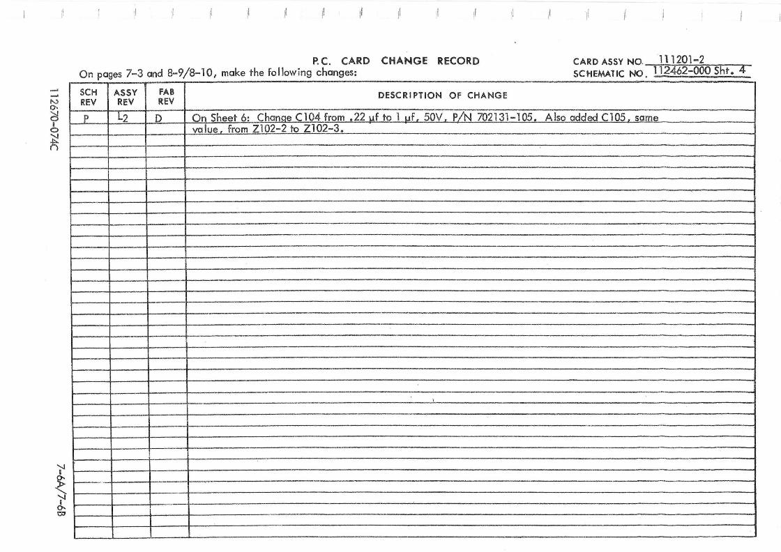
...... -"
'" 0-
C5 I o
~
'jI
~ 0-07
:
~ Ir
P. C. CARD CHANGE RECORD On pages 7-3 and 8-9/8-10, make the following changes·
CARD ASSY NO. 111201-2 SCHEMATIC NO 112462-000 Sht:T .
SCH ASSY FAB DESCRIPTION OF CHANGE REV REV REV
I' L2 D On Sheet 6: ChanQe C104 from .22 uf to 1 uf. SOV PiN 702131-105. Also added ClOS. same value from Z102- 2 to Z102-3.
-
1
- " ---
-

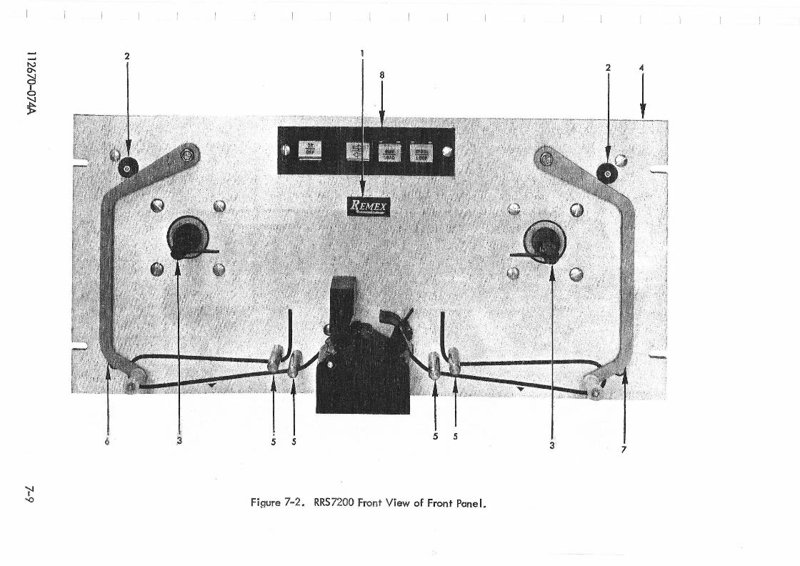
112670-074A
- c 2 u.. ..... o ~ ;;;
7-9
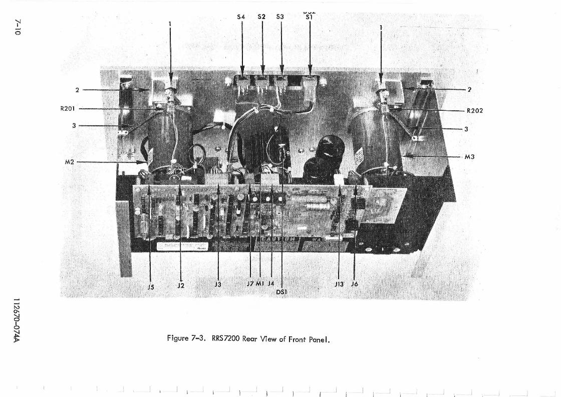
(J o
..... "'-., 0-
~ I o
~
54 52 53 ~Sl'" -.!.~.-.-,..:-~- ,
Figure 7-3. RRS7200 Rear View of Front Panel.
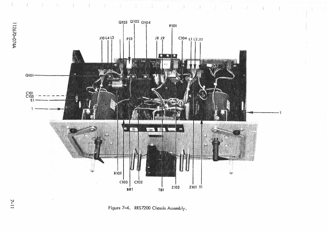
N 0-;:;l I o
~
'J'l
QlO l -~----=---
CIOI Cl05 ,- - _. -- - -. El-----
1 ·--
, ~
JIO L4 L3
Ql02 Ql
Rl02
C103 I . C102
BRI
Cl04 11 L2 J11
TSI ZI01 Tl
Figure 7-4. RRS7200 Chassis Assembly.
.~.
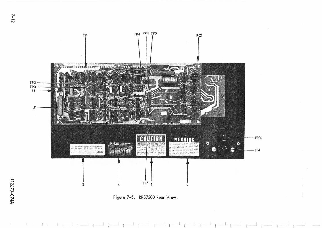
'J'I '"
--'" 0-.
~ I
0
~
TP2"--~ TP3·----i
Fl II
J1---
I ,
TPl
3
I 1 I )
TP4 R63 TP5 PCI
FIOl
J14
4 TP6 1 2
Figure 7-5. RRS 7200 Rear View.
I l I I I I j i J I I I J I J I J I I I I ) J I
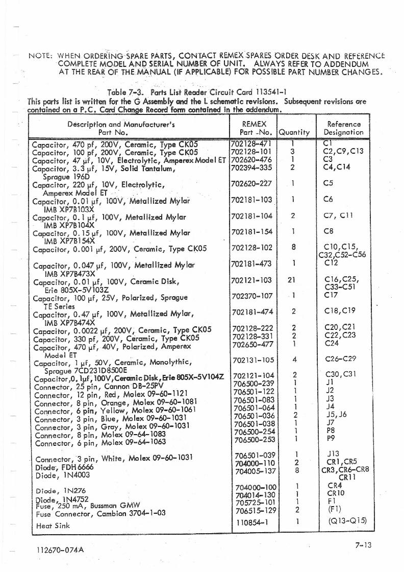
NOTE: WHEN ORDERiNG-SPARE PARTS, CONTACT REMEXSPARES ORDER DESK AND REFERENCt COMPLETE ,,-,\QDEL ANPSERIAL NUMBER OF UNIT. ALWAYS REFER TO ADDENDUM AT THE REA~ OF THE MANUAL (IF APPLICABLE) FOR POSSIBLE PART NUMBER CHANGES .
Table 7-3. POrts list Reader Circuit Card 113541-1 This parts list is written for theG Assembly and the L schematic revisions. Subsequent revisions are contained on a P.C. Card Change Record form contained in the addendum.
Description and -Manufacturer' 5
Part No.
Capacitor, 470 pf, 200V I Ceramic, Type CK05 Capacitor I 100 pf, 200V, Ceramic, Type CK05 -Capacitor, 47 ~f, lOV, Electrolytic, Ampe.rex Mode I ET Capacitor, 3.3 I-If, l5V, Solid Tantalum,
Sprague 196D Capacitor, 220l-lf, lOY, Electrolytic,
Amperex Model ET -.' -• . -Capacitor, O.Oll-lf,lOOY,Metallized Mylar
1MB XP7B 103X Capacitor, O. 1 I-If, 100Y, Metallized Mylar
1MB XP7B 104X Capacitor, 0.151-1f, lOOY, Metallized Mylar
1MB XP7B 154X . - -Capacitor, 0.001 I-If, 200Y,Ceramic, Type CK05
Capaci tor, O. 047 1-1 f I 1 OOV, Meta II ized My lar 1MB XP7B473X
Capacitor I 0.01 I-If, 100 V , Ceramic Disk, Erie 805X-5V103Z
Capacitor, 100 I-If I 25V, Po larized, Sprague TE Series
Capacitor, 0.471-1f, 100V, Metallized Mylar, 1MB XP7B474X
Capacitor, 0.00221-1f, 200V,Ceramic, Type CK05 Capacitor, 330 pf, 200V I Ceramic, Type CK05 Capacitor, 470 l-lf, 4OV, Pol.arized, Amperex
Model ET Capacitor, 1 Ilf, ::tJV, Ceramic, Monolythic,
Sprague 7CD231D8500E Capacitor,O.1I-1f ,100V;CerainicPisk,&ie805X-5V104Z Connector, 25 pin I CannonDB-25PV . Connector, 12 pin, Red, Molex 09-60-1121 Connector, 8 pin, Orange, Molex 09-60-1081 Connector, 6 pin, Yellow, Molex 09-60-1061 Connector, 3 pin, Blue, Molex 09-60-1031 Connector, 3 pin, Gray, Mo lex 09-60-1031 Connector, 8 pin, Molex 09-64-1083 Connector l 6 pin, Mo/ex 09-64-1063
Connector, 3 pin, White, Molex 09-60-1031 Diode-, FDH6666 Diode, 1N4003
Diode, lN276 Diode, 1 N4752 Fuse, 250 mA, Bussman GMW Fuse Connector I Cambion 3704-1-03
Heat Sink
112670-074A
REMEX Part -No.
702128-471 702128-101 702620-476 702394-335
702620-227
702181-103
702181-104
702181-154
702128-102
702181-473
702121-103
702370-107
702181-474
702128-222 702128-331 702650-477
702131-105
702121-104 706500-239 706501-122 706501-083 706501-064 706501-036 706501-038 706500-254 706500-253
706501-039 704000-110 704005-137
704000-100 704014-130 705725-101 706515-129
110854-1
Quantity
1 3 1 2
1
2
8
1
21
. 1
2
2 2 1
4
2 1 1 1 1 2 1 1 1
1 2 8
1 1 1 2 1
Reference Designation
C1 C2,C9,Cl3 C3 C4,C14
C5
C6
C7, C 11
C8
ClO,C15, C32,C52-C56
C12
C 16,C25, C33-C51 C17
C18,C19
C20,C21 C22,C23 C24
C26-C29
C30,C31 J1 J2 J3 J4 J5,J6 J7 P8 P9
J13 CR1,CR5
CR3 , CR6-CR8 CRll
CR4 eRI0 Fl (F 1)
(Q 13-Q 15)
7-13
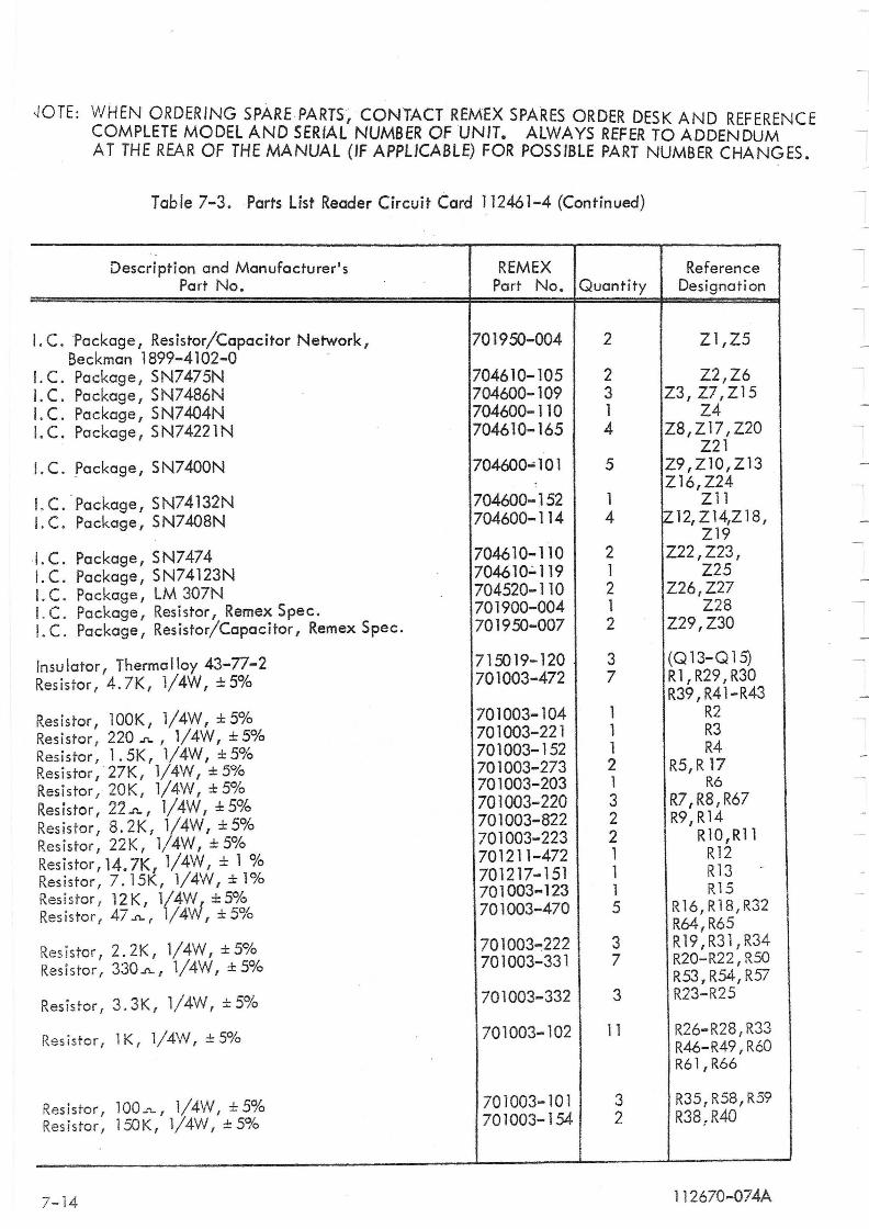
~OTE: WHEN ORDERING SPARE PARTS/CONTACT REMEX SPARES ORDER DESK AND REFERENCE COMPLETE MODEL AND SERIAL NUMBER OF UNIT. ALWAYS REFER TO ADDENDUM A T THE REAR OF THE MANUAL (IF APPLICABLE) FOR POSSIBLE PART NUMBER CHANGES.
Table 7-3. Parts List Reader Circuit Card 112461-4 (Continued)
Description and Manufacturer's Port No.
I.c. "Package, Resistor/Capacitor Network, Beckman 1899-4102-0
I. C. Package, SN7475N I. C. Package I S N7486N I.C. Package, SN7404N I.C. Package, SN74221N
I. C. Package, S N7400N
I. C. Package I SN74132N I. C. Package, S N7408N
I. C. Package I SN7474 I. C. Package, SN74123N I. C. Package / LM 307N I. C. Package/Resistor, Remex Spec . I. C. Package, Resistor/Capacitor, Remex Spec.
Insulator, ThermCilloy 43-77-2 Resistor, 4 . 7K , 1/4W, ±5%
Resistor, lOOK, l/4W, ± 5% Resistor, 220..n.. / 1/4W, ± 5% Resistor, 1.5K, 1/4W,±5% Resistor I · 27K, 1/ 4W I ± 5% Resistor, 20K, 1/4W, ±5% Resistor , 22.n.., l/4W, ±S% Resistor, 8.2K, 1/4W, ±5% Resistor, 22K, 1/4W, ± 5% Resistor, 14.7K, 1/4W, ± 1 % Resistor, 7. 15K, 1/4W, ± 1% Resistor, 12K, l/4W, ±5% Resistor, 47.n.., 1/4W, ±5%
Resistor, 2.2K, l/4W, ±5% Resistor, 330.n.., 1/4W, ±5%
Resistor, 3.3K/ 1/4W, ±5%
Resistor, lK, 1/4W, ±5%
Resistor, 100_'\. I 1/4W I ± 5% Resistor, 150K/ 1/4W/ ±5%
7-14
REMEX Port No. Quantity
701950-004
704610-105 704600-109 704600-110 704610-165
704600-101
704600-152 704600-114
704610-110 704610.;.119 704520-110 701900-004 701950-007
715019-120 701003-472
701003-104 701003-221 701003-152 701003-273 701003-203 701003-220 701003-822 701003-223 701211-472 701217-151 701003-123 701003-470
701003~222 701003-331
701003-332
701003-102
701003-101 701003-154
2
2 3 1 4
5
1 4
2 1 2 1 2
3 7
1 1 1 2 1 3 2 2 1 1 1 5
3 7
3
11
3 2
Reference Designati on
Z1,Z5
Z2/Z6 Z3, Z7/Z15
Z4 Z8/Z17/ Z20
Z21 Z9 ,ZlO, Z 13 Z16,Z24
Z 11 IZ 12, Z 14,Z 18,
Z19 Z22, Z23,
Z25 Z26,Z27
Z28 Z29,Z30
(Q13-Q15) Rl,R29,R30 R39,R41-R43
R2 R3 R4
R5, R 17 R6
R7,R8,R67 R9,R14
RI0,Rl1 R12 R13 . R15
R16,R18,R32 R64,R65 R 19, R3 1 , R34 R20-R22, R50 R53 1 R54, R57 R23-R25
R26-R28,R33 R46-R49,R60 R61/R66
R35, R58, R59 R38:R40
112670-074A
---- ' - ......... -. . ..:. --'-------
SECTION VIII
SCHEMATIC DRAWINGS
8 . 1 GENERAL
Figures 8-1 through 8-3 contain the schematic diagrams for Model RRS7200. Note that only sheets 1, 3, 5 and 6 of drawing 112462 are applicable to the RRS7200 and appear in the manual on pages 8-3/8-4, 8-5/8-6, 8-7/8-8 and 8-9/8-10, respectively. Figure 8-2 contains the overall system schematic. Figure 8-3 illustrates the I.C. Module outlines and truth tables which are reproduced courtesy of Texas Instruments, except for 9602 which is reproduced courtesy of Fairchild Semiconductor.
11 2670-074A 8-1/8-2
-- --- -

\, ... .