image enhancement and image hiding based on linear image fusion
TRANSCRIPT

2
Image Enhancement and Image Hiding Based on Linear Image Fusion
Cheng-Hsiung Hsieh1 and Qiangfu Zhao2 1Chaoyang University of Technology
2The University of Aizu 1Taiwan
2Japan
1. Introduction This chapter presents image enhancement and image hiding approaches based on linear image fusion (LIF). Most of materials presented here have been published in (Hsieh et al., 2008; Hsieh et al., 2010; Kondo and Zhao, 2006). Apparently, image enhancement, image morphing, and image hiding are completely different technologies for different applications, they can actually be unified under the core of LIF, and this unification can be helpful in other related researches. The reason we use LIF is its simplicity and low computational cost. By our observations, LIF generally has satisfactory performance provided that appropriate source images are used. This motivates the image enhancement approaches presented in this chapter. Note that the intermediate image generated by image morphing, in which LIF plays a fundamental role, can be a way to hide images, an LIF based approach to image hiding is presented in this chapter as well. This chapter consists of five sections. Section 1 gives introductions related to image enhancement and image hiding. Section 2 reviews LIF which is the core for the given applications. Then image enhancement approaches based on LIF are introduced in Section 3. Section 4 presents an image hiding approach based on LIF. Finally, conclusion and future work are mentioned in Section 5.
1.1 Image enhancement 1.1.1 High dynamic range imaging enhancement Nowadays, CCD sensors have been extensively applied to capture an image in many scenarios such as digital camera and surveillance systems. In general cases, CCD sensors work well in automatic exposure mode. However, CCD sensors may fail to appropriately present pixels when they are saturated to the maximum or minimum values. One example is that an image is taken in a high contrast or high dynamic range situation. Though the automatic exposure control tries to determine an appropriate exposure value, the captured image still suffers from missing details in overexposed and underexposed areas. To deal with the cases when automatic exposure mode is not suitable, an image fusion approach is sought. Since a satisfactory image cannot be obtained in one shot, multiple images are used in image fusion generally. Recently, two approaches based on image fusion have been reported to get rid of high dynamic range imaging problem. In (Tang and Zhao, 2007), an

Image Fusion
24
image fusion approach to relieve the problem of overexposure and underexposure was presented which was based on wavelet-based contourlet transform. In (Kao, 2007), a real-time image fusion approach was proposed to solve exposure problem in an image with high dynamic range, where medians of source images were manipulated. In (Tang and Zhao, 2007; Kao, 2007), image fusion requires a mechanism to determine how the information is fused. In this chapter, an image fusion approach is proposed for the problem in high dynamic range imaging where no mechanism is needed to determine the way to fuse source images. Besides, two source images are taken with different exposures to benefit LIF since they are of detail-complementary property (DCP). The concept of DCP will be described later in Section 3. It will show that a pair of source images with DCP is appropriate for LIF and generally leads good results.
1.1.2 Contrast enhancement An objective of image enhancement is to improve the visual quality of images. Among image enhancement schemes, contrast enhancement is a popular approach and has been widely used in many display related fields, such as consumer electronics, medical analysis, and so on. It is well-known that the contrast in an image is related to its dynamic range of histogram distribution. That is, an image with wider histogram dynamic range generally has better contrast. Consequently, to enhance the contrast in an image can be achieved by expanding its histogram distribution. Because of its simplicity, the conventional histogram equalization (CHE) is very popular which expands the histogram to its admissible extremes. Though the image contrast is enhanced, however a poor equalized image may be obtained because of the unsuitable histogram distribution for the CHE. Note that the visual quality of histogram equalized image can be improved by restricting the dynamic range or by modifying the original histogram distribution. Recently, several HE-based approaches have been presented to improve the performance of the CHE. In (Kim, 1997), taking the brightness shift into account, the approach called mean preserving bi-histogram equalization (BBHE) was proposed to enhance image contrast while preserving the mean brightness. In the BBHE, the histogram was partitioned into two portions based on the mean brightness value of a given image. Then the CHE was performed on each of the two sub-histograms. In light of the BBHE, several variations were reported. In (Wan et al., 1999), the histogram was partitioned into two sub-histograms by the median, instead of the mean, of brightness in a given image. In (Chen and Ramli, 2003), a recursive mean-separate histogram equalization approach was reported where the histogram of a given image was partitioned into sub-histograms in a number of two’s power. Note that the histogram spike generally causes visual problems in the CHE. In (Wang and Ward, 2007), the distribution of pixel values was modified through weighting and thresholding before histogram equalization. To consider the histogram spike, in (Ibrahim and Kong, 2007) a Gaussian filter was introduced to smooth the histogram distribution first. Then the smoothened histogram was partitioned and the partitioned histogram was equalized. In (Kim and Chung, 2008), the histogram of an image was weighted by a normalized power law function while the recursive partition was performed based on the mean or the median of the image brightness. In (Arici et al., 2009), a histogram modification approach based on an optimization scheme was proposed where the level of contrast enhancement, noise robustness, white/black stretching, and mean-brightness preservation were all under consideration. In (Ooi et al., 2009), the bi-histogram equalization with a plateau level was proposed. In the approach, two

Image Enhancement and Image Hiding Based on Linear Image Fusion
25
stages were involved: input histogram subdivision and sub-histogram clipping based on the plateau value. Generally speaking, HE-based approaches manipulated the histogram of input image by histogram partitioning, histogram modification with weighting or filtering, to improve the performance of the image contrast enhancement. In (Chen et al., 2010), an image enhancement based on linear image fusion was presented where an adaptive weight was employed on a pixel-by-pixel basis. In our experiences on the approach of (Chen et al., 2010), it shows that the fused images is of good visual quality when source images are appropriate but anomaly pixels are found in homogenous area if source images are not suitable for the approach. A fixed weight may avoid the problem or a better adaptive way should be sought. In Section 3.2, a simple contrast enhancement approach will be presented which is based on detail-complementary property (DCP) and LIF. Though simple, the proposed approach will be justified effective in the improvement of image visual quality.
1.2 Image hiding with morphing technology Image morphing is a technology for generating a sequence of images from a source image and a target image. This technology has been used mainly for producing moving pictures. In our study, it is noticed that the intermediate images generated by morphing can actually be used to hide the source or the target image. In image morphing, many intermediate images can be generated using different morphing rates. With LIF, the morphing rate, denoted by α , represents the contribution portion of the source image for synthesizing an intermediate image while the contribution portion of the target image is (1- α ). Therefore, image morphing is a variation of LIF where two input images, source image and target image, are different. To generate images of natural looking, both source image and target image are first warped based on a common skeleton. This skeleton is usually determined by using a set of characteristic points or characteristic lines. The first step in morphing is to obtain the skeleton of the intermediate image. By sharing the same skeleton, the warped source image and the warped target image are found. With LIF, the warped images are then used to generate intermediate images with different morphing rates. Then intermediate images can be used to hide the source (or target) image. In other words, image hiding can be achieved by the morphing technology based on LIF. To recover the source (or target) image from an intermediate image, the target (or the source) image, the skeletons, and the morphing rate are required. With those information, the source (or target) image can be found by the de-morphing. Though image warping is generally not reversible, and some information in input images may be lost in the warping process, the original images can be recovered almost perfectly in general. With the morphing technology, an image hiding approach is developed and applied to steganography where the target (or the source) image, the feature vectors, e.g. skeletons, of the source and the target images, and the morphing rate are considered as the stego keys. A steganograhic approach based on image morphing will be proposed in Section 4.
2. Linear image fusion
The main objective of image fusion is to integrate information or details from different source images of a scene to form an image with better visual quality. A general expression to obtain a fused image fI with two source images is given as

Image Fusion
26
1 2( , )f f=I I I (1)
where 1I and 2I are two source images and (.)f is a function to fuse the source images. Eq. (1) suggests that the fused image fI is significantly affected by function (.)f and source images 1I and 2I . Therefore, how to find an appropriate fusion function and source images is a fundamental issue for a successful image fusion. In this chapter, we will employ the linear interpolation as (.)f in Eq. (1). With 1I and 2I , the fused image fI by the linear interpolation is found as
-1 2(1 )f α α= +I I I (2)
where 1≤≤0 α is a weighting factor. The image fusion based on linear interpolation is called linear image fusion (LIF). Though simple, LIF generally has satisfactory performance if appropriate source images can be found. In Section 3, two ways to obtain appropriate source images are introduced. Interesting enough, the fused image fI can be considered as a morphed image when source images 1I and 2I are different object images, e.g. face images of different persons. Since fI is somewhere between 1I and 2I , and different from either 1I or 2I , it thus can be used to hide 1I or 2I . The idea will be described and applied to steganography in Section 4.
3. Image enhancement based on LIF One of objectives in image enhancement is to improve visual quality of an image for human viewers. An image with better visual quality can be obtained by image fusion through combining information from different source images. Thus, in this section, LIF will be applied to image enhancement where source images play an important role. Two image enhancement approaches based on LIF are proposed in this section. The first approach is to deal with the problem in high dynamic range imaging while the second approach provides a way to enhance contrast of a given image. The two approaches based on LIF are described in Section 3.1 and Section 3.2, respectively.
3.1 Image enhancement based on LIF with two source images, IE/LIF_2 In this section, an approach to image enhancement based on LIF with two source images is proposed which is abbreviated IE/LIF_2. The motivation is given in Section 3.1.1 and the proposed IE/LIF_2 is described in Section 3.1.2. Then simulation results are provided to justify the IE/LIF_2 in Section 3.1.3.
3.1.1 Motivation of IE/LIF_2 As mentioned previously, LIF will have satisfactory performance if suitable source images can be found. It is observed that source images of detail-complementary property (DCP) are appropriate for LIF. In the proposed IE/LIF_2, source images of DCP are obtained through different exposure settings. As an example, two images taken with different exposures are shown in Fig. 2. In Fig. 2(a), the image is underexposed while the image in Fig. 2(b) is overexposed. Note that the details of both images are of a sort of complementary property. For instance, the details of sign board area can be found in Fig. 2(a) while other details found in Fig. 2(b). The example in Fig. 2 demonstrates the idea of DCP. In light of DCP, the

Image Enhancement and Image Hiding Based on Linear Image Fusion
27
fused image by LIF will combine details from Fig. 2(a) and Fig. 2(b). For example, the details of sign board area come from Fig. 2(a) and the details of building and road are from Fig. 2(b). This is verified by the result shown in Fig. 3(b). The proposed approach to image enhancement based on LIF with two source images is abbreviated as IE/LIF_2 whose illustration is depicted in Fig. 1 where darkF and lightF denote the underexposed source image and the overexposed source image, respectively. And fusedF stands for the fused image. It will show that the IE/LIF_2 is able to deal with the problem in high dynamic range imaging.
),( jiFdark
),( jiFfused ),( jiFlight
darkF fusedF lightF
Fig. 1. An illustration of IE/LIF_2
3.1.2 The proposed IE/LIF_2 approach In this section, the proposed IE/LIF_2 approach is introduced. In the proposed approach, LIF with two source images are employed. In practice, LIF is implemented on a pixel-by-pixel basis. That is, two pixels, one pixel from the first source image and the other form the second source image, are fused to find the corresponding pixel in the fused image. Fig. 1 shows the idea where ),( jiFdark and ),( jiFlight denote elements of the underexposed source image and the overexposed source image, respectively. ),( jiFfused are elements of the fused image. Assume source images are of RGB format. With source images darkF and lightF , the implementation steps of IE/LIF_2 for each component are given as follows. Step 1. Input a two-pixel pair from source images, )},(),,({= jiFjiF lightdarkx , where ),( jiFdark
and ),( jiFlight denote the ),( ji pixel in darkF and lightF , respectively. Step 2. By LIF described in Section 2, the fused pixel ),( jiFfused is found, where darkF and
lightF are considered as 1I and 2I in Eq. (2), respectively. Step 3. On a pixel-by-pixel basis, continue Steps 1 and 2 until all fused pixels ),( jiFfused are
found. Note that in the IE/LIF_2 there is no mechanism to determine how to fuse the source images as in (Tang and Zhao, 2007; Kao, 2007). The weighting factor α in LIF is the only parameter needed to be determined in the IE/LIF_2. By our experiences, 4.0=α is a good choice for most of cases. That is, more portion is taken from the overexposed source image in the fused image. Though simple, the proposed IE/LIF_2 approach will be shown effective in high dynamic range imaging in Section 3.1.3.
3.1.3 Simulation results for the IE/LIF_2 In this section, two high contrast examples are provided to justify the proposed IE/LIF_2 approach whose results are also compared with those from (Kao, 2007) which is abbreviated

Image Fusion
28
as RTIF here. In the simulation, the parameter 4.0=α is used in LIF. For the first example, source images darkF and lightF of 7-11 are taken on some street at night which are shown in Fig. 2(a) and Fig. 2(b), respectively. In Figure 2(a), the image is underexposed. Therefore lots of areas cannot be seen but the details of bright area, like sign boards, are found. On the other hand, the image in Fig. 2(b) is overexposed where details of dark area, like building and road, can be seen and the bright parts lose their details because of saturation. The two source images darkF and lightF reveal the DCP and it is expected that a good fused image can be obtained by LIF. The fused images of 7-11 by the RTIF and the IE/LIF_2 are shown in Fig. 3(a) and Fig. 3(b), respectively. By the results, the fused image from the IE/LIF_2 is better than that from the RTIF since better visual quality with more details are found in the IE/LIF_2.
(a) Source image darkF (b) Source image lightF
Fig. 2. Source images of 7-11
(a) by the RTIF (b) by the IE/LIF_2
Fig. 3. Fused images of 7-11
For the second example, outdoor building images are taken from indoor through a window with different exposure settings. Two source images darkF and lightF are given in Fig. 4(a) and Fig. 4(b). In this example, it is almost impossible to capture both building outside and textbook inside clearly in one shot. Once one is obtained, the other is lost. Thus two or more source images are required for different parts of details. Note that source image in Fig. 4(a) and Fig. 4(b) show the DCP and thus a good result is expected for LIF. The fused images for

Image Enhancement and Image Hiding Based on Linear Image Fusion
29
the RTIF and the IE/LIF_2 are given in Fig. 5(a) and Fig. 5(b), respectively. As one may see, better details of outside building are for the IE/LIF_2 while details of textbook are similar for both approaches. Consequently, the one from the IE/LIF_2 has better visual quality than that for the RTIF.
(a) Source image darkF (b) Source image lightF
Fig. 4. Source images of Building
(a) by the RTIF (b) by the IE/LIF_2
Fig. 5. Fused images of Building In summary, the simulation results indicate that the proposed IE/LIF_2, though simple, is able to effectively deal with the problem of high dynamic range imaging and outperforms the RTIF in the given examples.
3.2 Image enhancement based on LIF with single source image, IE/LIF_1 In Section 3.1, the IE/LIF_2 is proposed to deal with the problem in high dynamic range imaging. This section will propose an approach to contrast enhancement based on LIF where only single source image is available. This approach is called image enhancement based on LIF with single source image and abbreviated as IE/LIF_1. Unlike the IE/LIF_2, the IE/LIF_1 is not for images of high dynamic range but provides a way to enhance contrast in a given image. When details in the given image are lost, it is impossible to make any enhancement in the IE/LIF_1 since only single source image is available. In other words, the IE/LIF_1 will use similar approach as in the IE/LIF_2 to enhance contrast in a

Image Fusion
30
given image. Since only single source image 1I is available in the IE/LIF_1, the problem now is how to fine another source image, i.e., 2I in Eq. (2), from the available source image. Moreover, images 1I and 2I should have the DCP for better result in LIF. These issues are going to be discussed later. This section is organized as follows. Motivation of IE/LIF_1 is described in Section 3.2.1 and its implementation steps are stated in Section 3.2.2. Then simulations to verify the proposed IE/LIF_1 are given in Section 3.2.3.
3.2.1 Motivation of IE/LIF_1 The motivation for the proposed IE/LIF_1 approach is based on the following observation. Note that the conventional histogram equalizaion (CHE) is able to enhance the contrast in a given image. Thus the details which are not obvious may be revealed after the CHE, though some other details may be lost because of over enhancement. That is, the CHE reveals the details hard to perceive in the original image while destroys some details in the original image. The revealed details in the equalized image are desired in the image fusion. Roughly speaking, the original image can be divided into two types of regions: the region with good details and the region with poor details. This is also true for its equalized image. Interesting enough, there is a kind of complementary between details in the original image and its equalized image by the CHE. In other words, when a region in one image is of poor details its counterpart shows good details in general. Thus, the DCP is revealed between the original image and its equalized image by the CHE. That is, the DCP is obtained through the CHE in the IE/LIF_1 while by exposure setting in the IE/LIF_2. To show the DCP by the CHE, Airplane in Fig. 6 is given as an example. In Fig. 6(a), the original Airplane has good details around the airplane while with poor details in the field. On the other hand, as shown in Fig. 6(b) the equalized image by the CHE loses the details of airplane but has better details in the field. The images of Airplane in Fig. 6(a) and Fig. 6(b) demonstrates the DCP which motivates the proposed IE/LIF_1 approach. Since the details in the original image and its equalized image by the CHE are of DCP, it gives us a hope that LIF would be good to obtain a fused image with better visual quality than the original image. This idea is justified as follows.
(a) Original (b) by the CHE
Fig. 6. Images of Airplane

Image Enhancement and Image Hiding Based on Linear Image Fusion
31
By Eq. (2), here the original image oI takes the place of 1I and the equalized image of oI by the CHE, hI , replaces 2I . With 7.0=α , the fused image fI is shown in Fig. 7. As expected, both details in the original image and its equalized image are found in the fused image. That is, the fused image shows both details around the airplane and in the field. This justifies the idea just described.
Fig. 7. Fused Airplane by LIF
3.2.2 The proposed IE/LIF_1 approach In this section, the proposed IE/LIF_1 approach is descried. Suppose the original image oI is of bitmap format, i.e., in RGB color space. Since R-, G-, and B-component are processed similarly in the proposed IE/LIF_1, thus only one component, oX , is considered in the following. The implementation steps for the IE/LIF_1 approach are described as follows. Step 1. Input the original image oX . Step 2. Perform the CHE on oX and the equalized image is denoted as hX . Step 3. With a user-defined α , obtain the fused image fX as in Eq. (2). The block diagram for the proposed IE/LIF_1 approach is depicted in Fig. 8.
R
LIF
LIF
LIF
CHE
CHE
CHE
G
B
oI fI
Fig. 8. The block diagram for the IE/LIF_1 Note that two stages involved in the proposed IE/LIF_1 approach are the CHE and the LIF. Both of them are of low computational complexity and easy to implement in the hardware. Thus, it is easy to apply the proposed IE/LIF_1 approach in the real-world applications where computational complexity and hardware cost are limited. Moreover, there is only one

Image Fusion
32
parameter α in the proposed IE/LIF_1 approach needed to be determined. Note that the overall visual quality of the original image is generally better than that in the equalized image. Thus, the value of α is set greater than 0.5 which takes more portion from the original image than that from the equalized image in LIF. By our experiences, weighting factor 7.0=α works well for most of cases. This will be justified in the following section.
3.2.3 Simulation results for the IE/LIF_1 In this section, the proposed IE/LIF_1 approach is verified by two examples, images Girl and River. The parameter α in the proposed IE/LIF_1 approach is set to 0.7 for all simulations. The original images, the equalized images by the CHE, and the fused or enhanced images by the IE/LIF_1, are shown in Fig. 9 and Fig. 10, respectively. Moreover, to compare the results by the IE/LIF_1 with HE-based approach, one recently reported approach in (Wang and Ward, 2007) is employed to enhance the images as well. The enhanced images are also shown in Fig. 9 and Fig. 10 where the approach in (Wang and Ward, 2007) is denoted as WTHE. Discussions on the results are given in the following. Image Girl in Fig. 9(a) was taken indoors under fluorescent light. By the CHE, the enhanced image is given in Fig. 9(b) where some details are revealed and some details, like the cake, are lost. Fortunately, the details lost in the equalized Girl by the CHE can be found in the original image. By fusing the two images, the fused Girl with better visual quality is obtained as shown in Fig. 9(c). Fig. 9(d) shows the enhanced images from the WTHE. As shown in Fig 9(d), the contrast is enhanced but the color fades and over enhancement, like the cake, results. By the results, the enhanced image by the proposed IE/LIF_1 is of better visual quality than the original Girl and that from the WTHE.
(a) Original (b) by the CHE
(c) by the IE/LIF_1 (d) by the WTHE
Fig. 9. Images of Girl

Image Enhancement and Image Hiding Based on Linear Image Fusion
33
As the second example, image River was taken outdoors at night. In this example, the DCP is revealed as shown in Fig. 10(a) and Fig. 10(b). In the enhanced River by the IE/LIF_1, the original image provides the details of brighter area while the equalized River by the CHE contributes the details of darker area in general. This results in better visual quality of the enhanced River as shown in Fig. 10(c). On the other hand, the enhanced image shown in Fig. 10(d) is over enhanced in the light area and the color fading is found after the WTHE. Thus, better enhanced image is for the proposed IE/LIF_1 approach.
(a) Original (b) by the CHE
(c) by the IE/LIF_1 (d) by the WTHE
Fig. 10. Images of River To sum up, simulation results suggest that the proposed IE/LIF_1 is able to enhance image contrast for the given examples and has better visual quality than those from the compared HE-based approach, i.e., the WTHE. Besides, there is a fundamental difference between the IE/IFLI_2 and the IE/IFLI_1. For the IE/IFLI_2, two source images are employed and thus more information can be found in the fused image. Consequently, the IE/IFLI_2 is able to deal with the problem in high dynamic range imaging. On the other hand, in the IE/IFLI_1 there is only one source image available and the second source image is derived from the available source image. Thus, only image contrast in the given image can be enhanced. In other words, the IE/LIF_1 gives a way to contrast enhancement for the given image. Even the IE/LIF_2 and the IE/LIF_1 both are based on LIF, they are fundamentally different from each other as described above.
4. Image hiding with morphing technology based on LIF, IH/LIF This section presents an approach to image hiding with morphing technology based on LIF. The approach is abbreviated as IH/LIF. In Section 4.1, the IH/LIF is described. Then a way

Image Fusion
34
to apply the IH/LIF to steganography is given in Section 4.2 where motivation and a proposed steganographic approach are described. Finally, a scenario for the proposed steganographic approach is given in Section 4.3.
4.1 The proposed IH/LIF approach The image morphing consists of two stages: warping and fusion. Two images are involved in the morphing process, i.e. a source image sI and a target image tI . Based on sI and tI , an intermediate image mI is generated which is then used to hide the source image or target image. In the warping stage, a common skeleton is found based on characteristic points or characteristic lines in sI and tI . Suppose sF and tF are the skeletons of the source image
sI , and the target image tI , respectively. Then the skeleton of the intermediate image mI , which is considered as the common skeleton, is found as
-(1 )m s tα α= +F F F (3)
where 1<<0 α is a morphing rate. Based on mF and sF , the source image sI is warped to w
sI . Similarly, the target image tI is warped to wtI through mF and tF . After warping, w
sI , wtI and mI share the same skeleton, and thus an intermediate image with natural looking
can be obtained by LIF as
-(1 )w wm s tα α= +I I I (4)
In Eq. (4), the morphing rate α represents the contribution of the source image to synthesizing intermediate image mI and the contribution of the target image is (1- α ). Note that image morphing can be considered as a variation of IE/LIF_2 where two input images, i.e. the warped source image and the warped target image, are different. Fig. 11 shows an example of image morphing. In Fig. 11, the left image is the source image, the right image is the target image, and the small images are the intermediate images generated using different morphing rates, from 0 to 1. Note that in Fig. 11 the intermediate images, especially those close to the center, can be used to hide the source (or target) image. That is, image hiding can be achieved by morphing technology based on LIF.
Fig. 11. An example of image morphing

Image Enhancement and Image Hiding Based on Linear Image Fusion
35
To reconstructed the source (or target) image from the intermediate image, the target (or the source) image, the skeletons, and the morphing rate are required. The process to reconstruct the source (or target) image is called de-morphing, that is, inverse of morphing. The implementation steps of de-morphing to recontruct the source image are given as follows. Step 1. Input the warped target image w
tI . Step 2. Obtain the warped source image w
sI as
αα wtm
ws /])1([= III -- (5)
Step 3. Calculate the skeleton of the source image as
αα tms /])1([= FFF -- (6)
Step 4. Find the source image as
),,(= smwss dewarp FFII (7)
where (.)dewarp is a function to de-warp the source image. Fig. 12 shows an example of de-morphing. As described previously, the source image can be recontructed almost perfectly except the borders.
(a) Source image (b) Reconstructed image
Fig. 12. An example of image de-morphing
4.2 Application of IH/LIF to steganography In light of the IH/LIF, a steganographic approach based on image morphing is proposed here. The motivation is given in Section 4.2.1 and the proposed steganographic approach is introduced in Section 4.2.2.
4.2.1 Motivation Steganography is a technology to hide messages in such a way that no one except the authorized recipient knows the existence of the messages. The block diagram of steganography is shown in Fig. 13. In steganography, the secret message is often hidden in some cover message. In general, larger cover message relative to the secret message can hide the latter easier. For instance, an image in general contains more data than a text and thus an image is often used as the cover message to hide some text data. Usually, the cover image is

Image Fusion
36
not changed visually after hiding the secret data. By this doing, the objective of steganography is achieved.
Fig. 13. The block diagram of steganography
Though the steganography is able to hide messages in cover messages, there are at least two problems in the framework of steganography. First, to hide an image using existing steganographic approaches is very difficult unless the size of the secret image is much smaller than that of the cover image. For example, a 1024×768 color image, with 3 bytes per pixel, has the potential to hide 294,912 bytes of information, if 3 bits are used for each pixel. In this case, the size of the secret image should be smaller than or equal to 1/8 of the size of the cover image. Consequently, in the framework of steganography, it is a challenge to embed a secret image into a cover image when both images of same size. Another problem in existing steganographic approaches is that partial hiding of messages is not allowed. However, there are cases in which partial hiding is required. A scenario might be doctor’s co-examination on medical images. In this case, one doctor may hide the patient's personal information (e.g., the patient’s face image) while keeping the sickness information (e.g., face color) “readable“ to other doctors. In the conventional steganographic approaches, the image data of the patient must be hidden completely in the cover data, and be recovered completely when the recipients want to see the data. To solve the two problems just described, Section 4.2.2 proposes a steganographic approach based on image morphing. Morphing is a technology that transforms from a source image to a target image. So far, morphing is mainly used for producing animation movies or special TV programs. Here, morphing technology will be applied to image hiding where the two problems mentioned above can be solved as follows. First, a morphed image, which is one of the intermediate images between the source image and the target image, can be used as the stego data. The source image here is the secret image to be hidden. Upon receiving the morphed image, the source image can be recovered through de-morphing based on four stego keys, that is, the morphing rate, the feature vector (skeleton) of the morphed image, the feature vector (skeleton) of the target image and the target image. Note that, the source image, the target image, and the morphed image are of the same size. Thus, the first problem is sovled by the proposed steganographic approach based on image morphing.
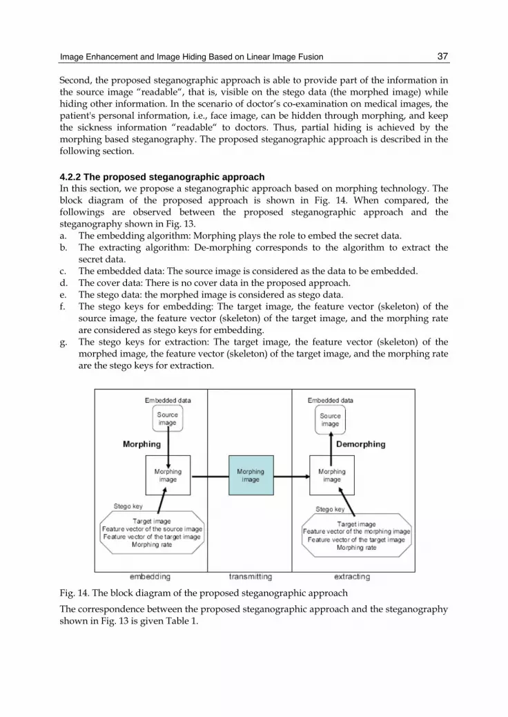
Image Enhancement and Image Hiding Based on Linear Image Fusion
37
Second, the proposed steganographic approach is able to provide part of the information in the source image “readable“, that is, visible on the stego data (the morphed image) while hiding other information. In the scenario of doctor’s co-examination on medical images, the patient's personal information, i.e., face image, can be hidden through morphing, and keep the sickness information “readable“ to doctors. Thus, partial hiding is achieved by the morphing based steganography. The proposed steganographic approach is described in the following section.
4.2.2 The proposed steganographic approach In this section, we propose a steganographic approach based on morphing technology. The block diagram of the proposed approach is shown in Fig. 14. When compared, the followings are observed between the proposed steganographic approach and the steganography shown in Fig. 13. a. The embedding algorithm: Morphing plays the role to embed the secret data. b. The extracting algorithm: De-morphing corresponds to the algorithm to extract the
secret data. c. The embedded data: The source image is considered as the data to be embedded. d. The cover data: There is no cover data in the proposed approach. e. The stego data: the morphed image is considered as stego data. f. The stego keys for embedding: The target image, the feature vector (skeleton) of the
source image, the feature vector (skeleton) of the target image, and the morphing rate are considered as stego keys for embedding.
g. The stego keys for extraction: The target image, the feature vector (skeleton) of the morphed image, the feature vector (skeleton) of the target image, and the morphing rate are the stego keys for extraction.
Fig. 14. The block diagram of the proposed steganographic approach
The correspondence between the proposed steganographic approach and the steganography shown in Fig. 13 is given Table 1.

Image Fusion
38
Table 1. Correspondence between the proposed and conventional steganography
Two things should be noticed in the proposed steganographic approach. First, without cover data, the proposed approach is able to cover an image using much less data when compared with conventional steganographic approaches. In other words, the capacity of the proposed approach is very high. In the proposed approach, the morphed image plays the roles of cover data and stego data. To cover an image, only two images of same size and some morphing parameters are required. As described earlier, the stego keys for extraction include the target image, the feature vectors of the target image and the morphed image, and the morphing rate. The data amount of stego keys is relatively big which makes the morphing based steganography even securer than conventional approaches. In short, the proposed approach provides a way to embed an image into another image with same size where the conventional steganographic approaches fail to. Second, in the conventional steganography the secret data is completely hidden in the cover data so that the stego data and the cover data look similarly. Only the recipient who has the stego key can extract the secret data. In the proposed morphing based steganography, the morphed image (the stego data) has certain similarity with the source image (the secret data) which is controlled by the morphing rate. This seems to be one defect of the morphing based steganography, but it is not. Even the morphed image has certain similarity with the source image, it is simply another natural image. For face images, the morphed image is just the face of another person who may not exist at all. Therefore, one is not able to extract the source image or even may not know the existence of the source image by the morphed image. This property of partial hiding or revealing in the propsed steganographic can be applied in the real world cases. One scenario to apply the partial hiding property is given in the following section.
4.3 A scenario for the proposed steganographic approach A scenarios for the proposed steganographic approach is given in this section. The scenario related to doctor’s co-examination is shown in Fig. 15. In this scenario, doctor A may share the sickness information of a patient to doctor B while hiding the individual information of the patient, i.e., face image. In Fig. 15, S+sick is the face image of the patient and M+sick is the corresponding morphed image. In this case, doctor B may examine the sickness of the

Image Enhancement and Image Hiding Based on Linear Image Fusion
39
patient without knowing who he/she is. This is impossible for conventional steganographic approaches. More details are given in the following.
Fig. 15. Scenario to share sickness information while hiding the patient’s face image
Fig. 16 shows the morphed images of a patient with different morphing rates. In the example, the painted part is considered as important clue for the sickness. While the morphing rate approaches to 1, the morphed image approaches to the target image in which there is no clue of sickness at all. That is, the individual information of the patient can be hidden completely with a morphing rate close to one. However, the sickness information on the face image is disappeared as well. The reason can be explained by Eq. (4). When the morphing rate is close to one, the morphed image is constructed almost from the target image alone.
Fig. 16. Morphed image of a patient with different morphing rates
This problem can be solved by separating the sickness part from the face image of the patient. During morphing, the warped source image and the warped target are combined to form the morphed image for all pixels except the region of sickness part in the warped source image which is then added to the morphed image. Fig. 17 shows a way that sickness part is separated, warped and added to the morphed image. In Fig. 17, Ssick is the sickness part of the source image, and Wsick is the warped sickness part. In fact, the sickness part is warped in the same way as the source image. First of all, the sickness part is separated from
Fig. 17. A way that sick part is separated, warped and added to the morphed image

Image Fusion
40
the image of the patient. Next, morphing is performed for all pixels except the sickness part. Then the sickness part is warped and added to the morphed image. By separating the sickness part, the morphed image can hide the face image of the patient and reveal the sickness part. Fig. 18 shows several morphed images of a patient generated with various morphing rates by the way shown in Fig. 17. In Fig. 18, the patient’s face is hidden by an appropriate morphing rate, say 0.8. Moreover, the sickness part can be retained in the morphed image since it is added directly to the morphed image after warping. In this way, a doctor can share the sickness information to another doctor while hiding the information of the patient.
Fig. 18. Morphed images of a patient with separated sick part and different morphing rates
5. Conclusion and future work This chapter presented approaches to image enhancement and image hiding based on linear image fusion (LIF). Though simple, LIF showed its effectiveness on image enhancement and image hiding. In image enhancement, LIF has been shown having good performance when source images are of detail-complementary property (DCP). In image hiding, a morphing technology based on LIF was given from which a stegnograhpic approach was developed. Conclusions and future works for the proposed image enhancement and image hiding approaches are described, respectively, in the following. For image enhancement, the IE/LIF_2 and IE/LIF_1 were presented. Note that DCP benefits the result of LIF. By different exposure settings, two source images of DCP were obtained in the IE/LIF_2. Then LIF was applied to fuse the two source images with an appropriate weighting factor. It showed good results in the given examples and better visaul quality was for the proposed IE/LIF_2 when compared with the approach in (Kao, 2007). Simulation results suggested that the problem in high dynamic range imaging can be solved by the IE/LIF_2. When only a single source image was available, the IE/LIF_1 was applied to enhance contrast and therefore visual quality. In the proposed IE/LIF_1, a source image for LIF was derived from the available image by the conventional histogram equalization (CHE). The reason using the CHE was that the original image and the equalized image shows the DCP. In light of DCP, LIF may have good performance generally. As expected, simulation results of the given examples had justified the idea. When compared with the HE-based approach in (Wang and Ward, 2007), the IE/LIF_1 showed its supirority for better visual quality. Consequently, the IE/LIF_1 provides a good way to improve visual quality of images through contrast enhancement. No matter in the IE/LIF_2 or the IE/LIF_1, the weighting factor in LIF is fixed and determined by our rule of thumb. In the future, a mechanism to adaptively determine the weighting factor will be devised.

Image Enhancement and Image Hiding Based on Linear Image Fusion
41
Note that the morphing technology based on LIF can be a way to hide images. The proposed image hiding approach called IH/LIF was developed. Then a steganographic approach based on IH/LIF was developed. When compared with conventional steganographic approaches, there are at least two advantages for the proposed approach. First, by morphing technology it is possible to embed a secret image whose size is same as the cover image in the framework of steganography where the stego keys are the morphing rate, the target image, the feature vector of the target image and the feature vector of the morphed image. With the stego keys, the secret imag can be extracted through de-morphing. Second, the proposed steganographic approach provides a way to partial hiding or revealing the secret image. The basic idea is to process the two kinds of information, separately. That is, perform morphing for the information to be hidden, and warping for the information to be revealed. A scenario was given for the proposed steganographic approach. In the future, the proposed approach will be extended to other types of data, like music and video, where a proper morphing or transformation should be sought.
6. Acknowledgement This work was partially supported by National Science Council of the Republic of China under grant NSC 96-2221-E-324-044 and by the 2010 visiting researcher program in the University of Aizu, Japan, and as a part of cooperative research results with the System Intelligence Laboratory in the Universtiy of Aizu.
7. References Arici, T.; Dikbas, S.; Altunbasak, Y. (2009). A Histogram Modification Framework and Its
Application for Image Contrast Enhancement, IEEE Transactions on Image Processing, Vol. 18, No. 9, pp. 1921-1935, 2009, ISSN 1057-7149.
Chen, Q.; Xu, X.; Sun, Q.; Xia, D. (2010). A Solution to the Deficiencies of Image Enhancement, Signal Processing, Vol. 90, Issue 1, pp. 44-56, 2010, ISSN 0165-1684.
Chen, S.-D.; Ramli, R. (2003). Contrast Enhancement Using Recursive Mean-Separate Histogram Equalization for Scalable Brightness Preservation, IEEE Transactions on Consumer Electronics, Vol. 49, No. 4, pp.1301-1309, 2003, ISSN 0098-3063.
Hsieh, C.-H.; Chen, B.-C.; Lin, C.-M.; Zhao Q. F. (2010). Detail Aware Contrast Enhancement with Linear Image Fusion, Proceedings of International Symposium on Aware Computing, pp. 1-5, ISBN 978-1-4244-8312-9, Tainan, Taiwan, November 2010.
Hsieh, C.-H.; Chen, P.-W.; Lan, C.-W.; Hsiung, K.-C. (2008). Image Fusion Based on Grey Polynomial Interpolation, Proceedings of International Conference on Intelligent Systems Design and Applications, pp. 19-22, ISBN 978-0-7695-3382-7, Kaohsiung, Taiwan, November 2008.
Ibrahim, H.; Kong, N. S. P. (2007). Brightness Preserving Dynamic Histogram Iqualization for Image Contrast Enhancement,” IEEE Transactions on Consumer Electronics, Vol. 53, No. 4, pp. 1752-1758, 2007, ISSN 0098-3063.
Kao, W.-C. (2007). Real-time Image Fusion and Adaptive Exposure Control for Smart Surveillance Systems, Electronics Letters, Vol. 43, No. 18, pp. 975-976, August 2007, ISSN 0013-5194.

Image Fusion
42
Kim, M.; Chung, M. G. (2008). Recursively Separated and Weighted Histogram Equalization for Brightness Preservation and Contrast Enhancement, IEEE Transactions on Consumer Electronics, Vol. 54, No. 3, pp. 1389-1397, 2008, ISSN 0098-3063.
Kim,Y.-T. (1997). Contrast Enhancement Using Brightness Preserving Bi-Histogram Equalization, IEEE Transactions on Consumer Electronics, Vol. 43, No. 1, pp.1-8, 1997, ISSN 0098-3063.
Kondo, S.; Zhao Q. F.; (2006). A Novel Steganographic Technique Based on Image Morphing, Proceedings of International Conference on Ubiquitous Intelligence and Computing, pp. 806-815, ISBN 3-540-38091-4, Wuhan and Three Gorges, China, September 2006. (Lecture Notes in Computer Science 4159, Springer)
Ooi, C. H.; Kong, P.; Sia, N.; Haidi, I. (2009). Bi-Histogram Equalization with a Plateau limit for Digital Image Enhancement, IEEE Transactions on Consumer Electronics, Vol.55, No.4, pp. 2072-2080, 2009, ISSN 0098-3063.
Tang, L.; Zhao, Z.-G. (2007). The Wavelet-based Contourlet Transform for Image Fusion, Proceedings of Eighth ACIS International Conference on Software Engineering, Artificial Intelligence, Networking, and Parallel/Distributed Computing, pp. 59-64, ISBN 0-7695-2909-7, Qingdao, China, July 2007.
Wan, Y.; Chen, Q.; Zhang, B. (1999). Image Enhancement Based on Equal Area Dualistic Sub-Image Histogram Equalization Method, IEEE Transactions on Consumer Electronics, Vol. 45, No. 1, pp.68-75, 1999, ISSN 0098-3063.
Wang, Q.; Ward, R. K. (2007). Fast Image/Video Contrast Enhancement Based on Weighted Thresholded Histogram Equalization, IEEE Transactions on Consumer Electronics, Vol. 53, No. 2, pp. 757 – 764, 2007, ISSN 0098-3063.