image-based surface detail transfer
TRANSCRIPT
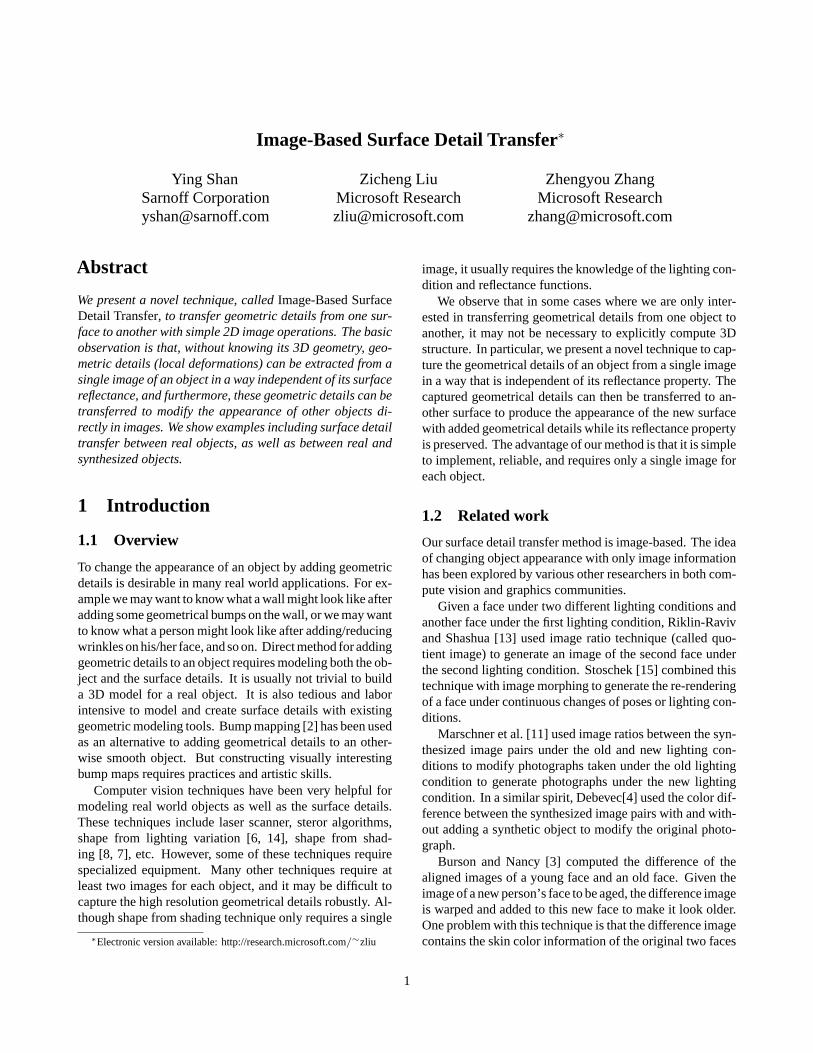
Image-Based Surface Detail Transfer∗
Ying Shan Zicheng Liu Zhengyou ZhangSarnoff Corporation Microsoft Research Microsoft [email protected] [email protected] [email protected]
Abstract
We present a novel technique, called Image-Based SurfaceDetail Transfer, to transfer geometric details from one sur-face to another with simple 2D image operations. The basicobservation is that, without knowing its 3D geometry, geo-metric details (local deformations) can be extracted from asingle image of an object in a way independent of its surfacereflectance, and furthermore, these geometric details can betransferred to modify the appearance of other objects di-rectly in images. We show examples including surface detailtransfer between real objects, as well as between real andsynthesized objects.
1 Introduction
1.1 Overview
To change the appearance of an object by adding geometricdetails is desirable in many real world applications. For ex-ample we may want to know what a wall might look like afteradding some geometrical bumps on the wall, or we may wantto know what a person might look like after adding/reducingwrinkles on his/her face, and so on. Direct method for addinggeometric details to an object requires modeling both the ob-ject and the surface details. It is usually not trivial to builda 3D model for a real object. It is also tedious and laborintensive to model and create surface details with existinggeometric modeling tools. Bump mapping [2] has been usedas an alternative to adding geometrical details to an other-wise smooth object. But constructing visually interestingbump maps requires practices and artistic skills.
Computer vision techniques have been very helpful formodeling real world objects as well as the surface details.These techniques include laser scanner, steror algorithms,shape from lighting variation [6, 14], shape from shad-ing [8, 7], etc. However, some of these techniques requirespecialized equipment. Many other techniques require atleast two images for each object, and it may be difficult tocapture the high resolution geometrical details robustly. Al-though shape from shading technique only requires a single
∗Electronic version available: http://research.microsoft.com/∼zliu
image, it usually requires the knowledge of the lighting con-dition and reflectance functions.
We observe that in some cases where we are only inter-ested in transferring geometrical details from one object toanother, it may not be necessary to explicitly compute 3Dstructure. In particular, we present a novel technique to cap-ture the geometrical details of an object from a single imagein a way that is independent of its reflectance property. Thecaptured geometrical details can then be transferred to an-other surface to produce the appearance of the new surfacewith added geometrical details while its reflectance propertyis preserved. The advantage of our method is that it is simpleto implement, reliable, and requires only a single image foreach object.
1.2 Related work
Our surface detail transfer method is image-based. The ideaof changing object appearance with only image informationhas been explored by various other researchers in both com-pute vision and graphics communities.
Given a face under two different lighting conditions andanother face under the first lighting condition, Riklin-Ravivand Shashua [13] used image ratio technique (called quo-tient image) to generate an image of the second face underthe second lighting condition. Stoschek [15] combined thistechnique with image morphing to generate the re-renderingof a face under continuous changes of poses or lighting con-ditions.
Marschner et al. [11] used image ratios between the syn-thesized image pairs under the old and new lighting con-ditions to modify photographs taken under the old lightingcondition to generate photographs under the new lightingcondition. In a similar spirit, Debevec[4] used the color dif-ference between the synthesized image pairs with and with-out adding a synthetic object to modify the original photo-graph.
Burson and Nancy [3] computed the difference of thealigned images of a young face and an old face. Given theimage of a new person’s face to be aged, the difference imageis warped and added to this new face to make it look older.One problem with this technique is that the difference imagecontains the skin color information of the original two faces
1
so that the skin color of the new face may be modified bythe aging process (dark skin becomes light skin, etc).
Liu et al.[10] used the image ratio between a neutral faceand an expression face of the same person (called expressionratio image) to modify a different person’s neutral face imageand generate facial expression details.
Our work is closely related to [10] and [3] in that weall deal with surface deformations. However, our methoddifferentiates from these two work and all the related workmentioned above in that we only require one source im-age. Our key observation is that the smoothing in the imagedomain corresponds to the smoothing in the geometrical do-main when the surface reflectance is smooth. This point willbe detailed mathematically in Section 3.
1.3 Paper organization
The remainder of this paper is organized as follows. Wereview related work on image ratios in Section 1.2. Wedescribe the technique of surface detail transfer in Section 2.The implementations are discussed in Section3. The resultsare shown in Section 4. Finally we conclude the paper inSection 5 with discussions on the limitations of our methodand future directions.
2 Image-Based Surface Detail Trans-fer
In this section, we describe the technique of Image-BasedSurface Detail Transfer (IBSDT) to transfer the geometricdetails between the images of two surfaces without their 3Dinformation.
2.1 Notation and Problem Statement
For any point P on a surface S, let n(P) denote its normal.Assume there are m point light sources. Let li(P),1 ≤ i ≤m, denote the light direction from P to the ith light source,and li its intensity. Suppose the surface is diffused, and letρ(P) be its reflectance coefficient at P. Under Lambertianmodel, the recorded intensity of point P in the image I is
I(p) = ρ(P)m∑
i=1
li n(P) · li(P) (1)
where p = C(P) is the 2D projection of P onto the image,and C(·) is the camera projection function.
Two surfaces S1 and S2 are said to be aligned if thereexists a one-to-one mapping F such that for all P1 ∈ S1 andP2 = F(P1) ∈ S2
‖P1 − P2‖ ≤ ε (2)
where ε is a small positive, and furthermore, there existneighborhoods Θ(P1) of P1 and Θ(P2) of P2 such that
‖n(P1) − n(P2)‖ ≤ δ (3)
where δ is a small positive, and n(P1) and n(P2) are themean normal defined in the neighborhoods of Θ(P1) andΘ(P2), respectively.
The problem can then be stated as the following. Givenimages I1 and I2 of two aligned surfaces S1 and S2, respec-tively, what is the new image I ′
2 of S2 if we modify its surfacenormal such that
n′2(P2) = n1(P1) (4)
where P1 and P2 are the corresponding points defined by themapping F.
2.2 A Geometric Viewpoint
The following discussion assumes a single point light sourceto simplify the derivation. Extension to multiple lightsources is straight forward. Because the distance betweenP1 and P2 is small according to Eq. (2), it is reasonable toassume that the light is always sitting far away enough suchthat ε dl, where dl is the average distance from light tothe points. This leads to the approximation l(P1) ≈ l(P2).From Eq. (1) and (4), we then have
I ′2(p2)
I2(p2)≡ ρ(P2) l n′
2(P2) · l(P2)ρ(P2) l n2(P2) · l(P2)
≈ ρ(P1) l n1(P1) · l(P1)ρ(P2) l n2(P2) · l(P2)
ρ(P2)ρ(P1)
≡ I1(p1) ρ(P2)I2(p2) ρ(P1)
(5)
where ρ has the same meaning as in the Eq. (1), p1 =C1(P1), p2 = C2(P2), and I1, I2, and I ′
2 have the samemeaning as in the problem statement. Notice that the C(·)functions are different for the two surfaces. This is becausethe images I1 and I2 of the surfaces could be taken by twodifferent cameras. This leads to
I ′2(p2) ≈ I1(p1) ρ(P2)
ρ(P1)(6)
In order to compute the ratio of ρ(P1) and ρ(P2), let usdefine the smoothed image of I as
I(p) ≡∑
q∈Ω(p)
w(q) I(q) (7)
where Ω(p) = C(Θ(P)) is the neighborhood of p, and w(·)is the kernel function of a smooth filter, say, a Gaussianfilter or an average filter. Assuming that the size of Θ(P)
2
is relatively small as compared with its distance to the lightsource, we have l(P) ≈ l(Q),∀Q ∈ Θ(P). Also assumingthat ρ(P) ≈ ρ(Q),∀Q ∈ Θ(P), from Eq. (7) and Eq. (1), itis then obvious that
I(p) ≈ ρ(P) l
(∑Q∈Θ
w(C(Q))n(Q)
)· l(P) (8)
where∑
Q∈Θ w(C(Q))n(Q) = n(P), and n(P) is the meannormal as mentioned in the problem statement. For surfaceS1 and S2, we then have
I2(p2)I1(p1)
≈ ρ(P2) l n(P2) · l(P2)ρ(P1) l n(P1) · l(P1)
(9)
Since the two surfaces are aligned, we have l(P1) ≈ l(P2),and n(P2) ≈ n(P1). Equation (9) can then be rewritten as
ρ(P2)ρ(P1)
≈ I2(p)I1(p)
(10)
Substituting Eq. (10) into Eq. (6) leads to
I ′2(p2) ≈ I1(p1)
I1(p1)I2(p2) (11)
Eq. (11) shows that the transfer of surface normal can beapproximated by some simple operations on the images ofthe surfaces.
2.3 An Intuitive Signal Processing Viewpoint
We now rewrite Eq. (11) as
I ′2(p) ≈ I1(p)
I1(p)I2(p) ≡
(1 +
I1(p) − I1(p)I1(p)
)I2(p)
(12)From signal processing view point, Eq. (12) simply substi-tutes the high frequency components of I2 with those fromI1. The high frequency components I1 − I1 in I1 is normal-ized by I1 in order to cancel the intensity scale differencebetween the low frequency components of I2 and I1. Gen-erally, I1 could be any image, regardless of the conditionsgiven in the previous section. But the resultant image couldbe meaningless because of the inconsistency between thetransferred detailed components from I1 and native low fre-quency components on the I2. This happens when I1 and I2are the images of two surfaces that are not aligned.
3 Implementation
Given images I1 and I2 of similar shapes, to perform surfacedetail transfer, we first need to align the two images. For sim-ple geometrical shapes such as rectangles and spheres, we
usually only need to perform global transformations includ-ing rotation, translation, and scaling. For more complicatedshapes such as human faces, we first manually put markerson the boundaries and the feature points, and then obtainpixel alignment through image warping [16, 1, 9]. In ourimplementation, we use a simple triangulation-based imagewarping method. Once the alignment is done, we can thenrun a Gaussian filter with a user specified σ on I1, and I2 toobtain I1 and I2. Finally we apply Equation (11) to obtainI ′2.
Intuitively, the σ of the Gaussian filter controls how muchgeometrical smoothing we perform on the surface of I1. Soit determines the scale of the surface details to be transferred.A small σ allows fine geometrical details to be transferredwhile a large σ allows only large scale geometrical defor-mations to be transferred.
4 Results
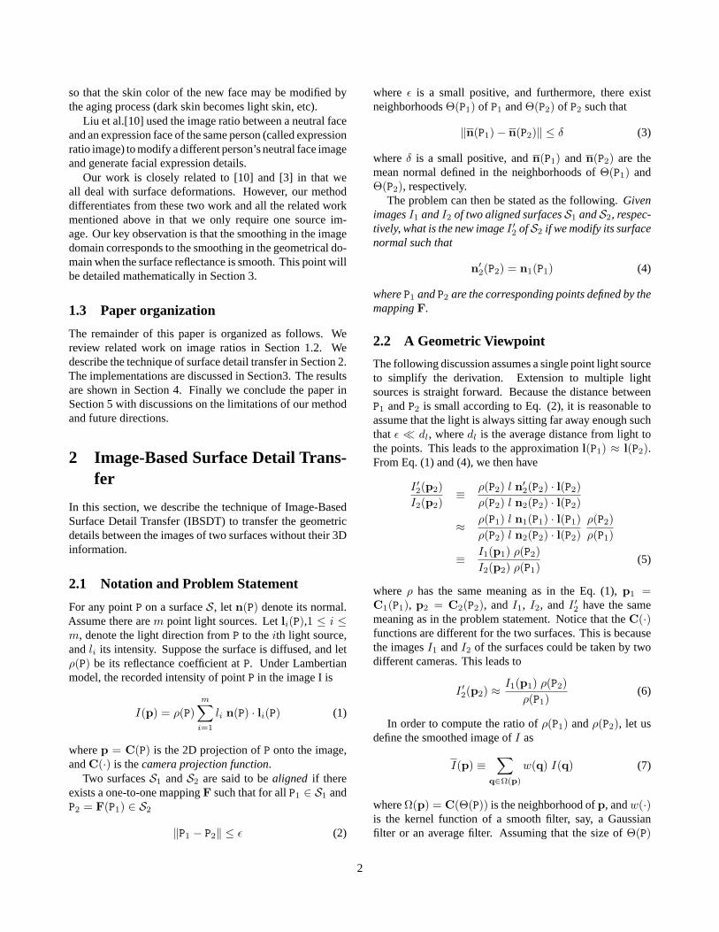
Figure 1 shows the results of transferring the geometricaldetails of a synthetic sphere to a nectarine. The bumps onthe synthetic sphere are generated by using bump mappingtechnique. The surface reflectance property on the synthe-sized sphere is set to be uniform. We put a point light sourceon top of the sphere so that its lighting condition is somewhatclose to the lighting condition of the nectarine. We can seethat the bumps on the synthetic sphere are transferred nicelyto the nectarine except at the bottom where the syntheticsphere is basically dark. The sizes of the image are 614 by614 pixels, and σ is 8.
Figure 2 shows the results of transferring the geometricaldetails of a real orange to the same nectarine as in Figure 1.The bumps on the oranges are transferred faithfully to thenectarine. The image dimensions and σ are the same asin Figure 1. This example also reveals a limitation of ouralgorithm: the high lights on the orange are transferred tothe nectarine. The reason is that the high lights are treatedas being caused by geometrical variations.
Figure 3 shows the results of transferring the geometricaldetails of a tissue to an synthetic rectangle. We can see thatonly the geometrical bumps on the tissues are transferredto the rectangle while the material color of the rectangle ispreserved.
Figure 4 shows the results of geometric detail transferringfrom the same tissue to the image of a piece of wood. Bothpictures are taken under the same lighting conditions. Wecan see the the small bumps on the tissues are transferred tothe wood while the wood texture is preserved.
Figure 5 shows the result of transferring the geometricaldetails of the same tissue to a table surface. This table surfacehas a different texture pattern than the wood in Figure 4. Itis interesting to compare the results (the images on the right)
3
Figure 1: Left: synthetic sphere with many small bumps generated by
Figure 2: Left: photograph of an orange. Middle: photograph of a nectarine. Right: The synthesized image obtained bytransferring the geometrical details of the orange to the nectarine.
in Figure 4 with Figure 5,and notice that they have the samegeometrical bumps but different material properties.
One interesting application of IBSDT is aging effect syn-thesis. Geometrically, the difference between an old per-son’s skin surface and a young person’s skin surface is thatthe old person’s skin surface has more bumps than the youngface. If we transfer the bumps of an old person’s skin sur-face to a young person’s face, the young person’s face willbecome bumpy and look older. Conversely, we can also re-place the bumps of an old person’s skin surface with thatof the young person’s face so that the old person’s face getssmoother and look younger. So we can apply the surface de-tails transfer technique as described in the previous sectionon human faces to generate aging effects. The alignment isdone by first marking face boundaries and face features suchas eyes, noses, and mouths, and then use triangulation-basedimage warping to warp I1 toward I2. We only apply IBSDTto pixels inside of the face boundary. In addition, the pixelsin the regions of the two brows, the two eye balls, nose top,and the mouth are not modified by IBSDT either.
Figure 6 shows the aging effect synthesis results betweenthe faces of a young male (a) and an old male (d). For eachface, we experiment with different σ of the Gaussian filterduring the surface detail transfer. Images in the middle ((b)and (e)) are the results with σ = 3, and those on the right
((c) and (f)) with σ = 8. We can see that varying σ producesreasonable in-between aging effect such as (b) and (e).
Obviously, surface detail transfer plays an important rolewhen making a young person elder. However, it is less ap-parent why this technique is necessary to make an old personyounger. To clarify this point, we simply smooth Fig. (6)(d)without transferring surface details from Fig. (6)(a), whilemasking out the facial features as before. Figure (7) showsthe results with σ = 3 (left image) and σ = 8 (right image).As compared with the images in Fig. (6) (e) and (f) with thesame σs, we can see that images in Fig. (6) are much lesssharp and convincing.
5 Conclusion and Future Directions
We have developed a technique called Image-Based Sur-face Detail Transfer or IBSDT to transfer geometrical de-tails from one surface to the other without knowing the actualgeometric information of the surfaces. This technique is par-ticularly useful for adding geometric details to a real worldobject for which only a single image is available. It alsoprovides a simple way to capture geometrical details of realworld object and apply it to other synthetic or real worldobjects.
4
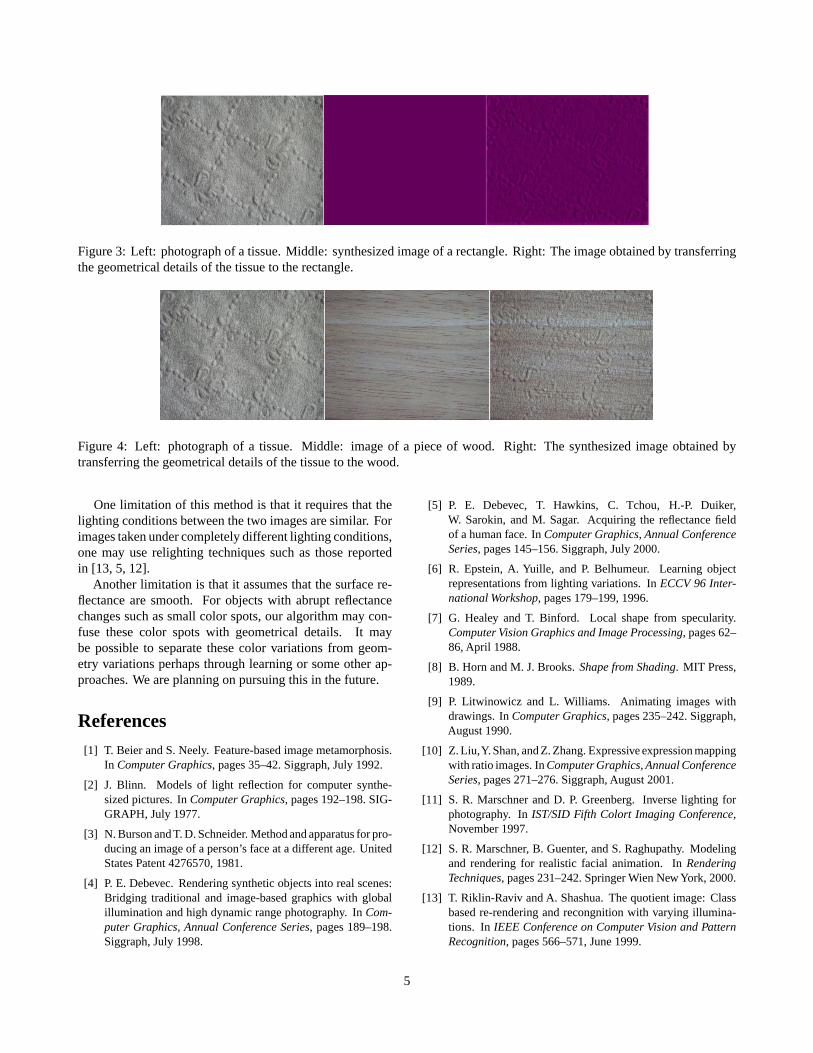
Figure 3: Left: photograph of a tissue. Middle: synthesized image of a rectangle. Right: The image obtained by transferringthe geometrical details of the tissue to the rectangle.
Figure 4: Left: photograph of a tissue. Middle: image of a piece of wood. Right: The synthesized image obtained bytransferring the geometrical details of the tissue to the wood.
One limitation of this method is that it requires that thelighting conditions between the two images are similar. Forimages taken under completely different lighting conditions,one may use relighting techniques such as those reportedin [13, 5, 12].
Another limitation is that it assumes that the surface re-flectance are smooth. For objects with abrupt reflectancechanges such as small color spots, our algorithm may con-fuse these color spots with geometrical details. It maybe possible to separate these color variations from geom-etry variations perhaps through learning or some other ap-proaches. We are planning on pursuing this in the future.
References[1] T. Beier and S. Neely. Feature-based image metamorphosis.
In Computer Graphics, pages 35–42. Siggraph, July 1992.
[2] J. Blinn. Models of light reflection for computer synthe-sized pictures. In Computer Graphics, pages 192–198. SIG-GRAPH, July 1977.
[3] N. Burson and T. D. Schneider. Method and apparatus for pro-ducing an image of a person’s face at a different age. UnitedStates Patent 4276570, 1981.
[4] P. E. Debevec. Rendering synthetic objects into real scenes:Bridging traditional and image-based graphics with globalillumination and high dynamic range photography. In Com-puter Graphics, Annual Conference Series, pages 189–198.Siggraph, July 1998.
[5] P. E. Debevec, T. Hawkins, C. Tchou, H.-P. Duiker,W. Sarokin, and M. Sagar. Acquiring the reflectance fieldof a human face. In Computer Graphics, Annual ConferenceSeries, pages 145–156. Siggraph, July 2000.
[6] R. Epstein, A. Yuille, and P. Belhumeur. Learning objectrepresentations from lighting variations. In ECCV 96 Inter-national Workshop, pages 179–199, 1996.
[7] G. Healey and T. Binford. Local shape from specularity.Computer Vision Graphics and Image Processing, pages 62–86, April 1988.
[8] B. Horn and M. J. Brooks. Shape from Shading. MIT Press,1989.
[9] P. Litwinowicz and L. Williams. Animating images withdrawings. In Computer Graphics, pages 235–242. Siggraph,August 1990.
[10] Z. Liu,Y. Shan, and Z. Zhang. Expressive expression mappingwith ratio images. In Computer Graphics, Annual ConferenceSeries, pages 271–276. Siggraph, August 2001.
[11] S. R. Marschner and D. P. Greenberg. Inverse lighting forphotography. In IST/SID Fifth Colort Imaging Conference,November 1997.
[12] S. R. Marschner, B. Guenter, and S. Raghupathy. Modelingand rendering for realistic facial animation. In RenderingTechniques, pages 231–242. Springer Wien New York, 2000.
[13] T. Riklin-Raviv and A. Shashua. The quotient image: Classbased re-rendering and recongnition with varying illumina-tions. In IEEE Conference on Computer Vision and PatternRecognition, pages 566–571, June 1999.
5
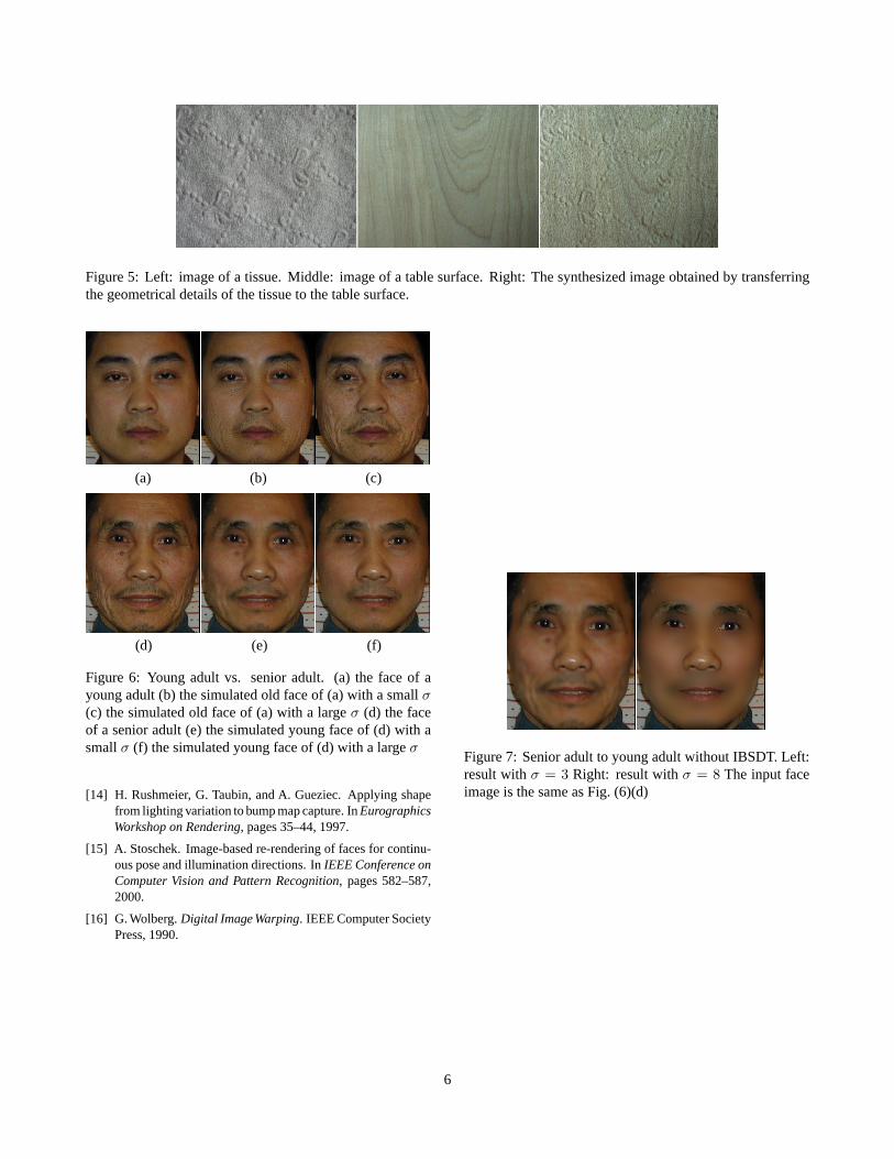
Figure 5: Left: image of a tissue. Middle: image of a table surface. Right: The synthesized image obtained by transferringthe geometrical details of the tissue to the table surface.
(a) (b) (c)
(d) (e) (f)
Figure 6: Young adult vs. senior adult. (a) the face of ayoung adult (b) the simulated old face of (a) with a small σ(c) the simulated old face of (a) with a large σ (d) the faceof a senior adult (e) the simulated young face of (d) with asmall σ (f) the simulated young face of (d) with a large σ
[14] H. Rushmeier, G. Taubin, and A. Gueziec. Applying shapefrom lighting variation to bump map capture. In EurographicsWorkshop on Rendering, pages 35–44, 1997.
[15] A. Stoschek. Image-based re-rendering of faces for continu-ous pose and illumination directions. In IEEE Conference onComputer Vision and Pattern Recognition, pages 582–587,2000.
[16] G. Wolberg. Digital Image Warping. IEEE Computer SocietyPress, 1990.
Figure 7: Senior adult to young adult without IBSDT. Left:result with σ = 3 Right: result with σ = 8 The input faceimage is the same as Fig. (6)(d)
6