ila c perientiln - world radio history
TRANSCRIPT
YOUR ONE -STOP SOURCE OF ELE TRONICS INFORMATION
AUGUST 1985 $1.95 CANADA $2.50
II Sun
THE MAGAZINE FOR ELECTRONICS & COMPUTER ENTHUSIASTS
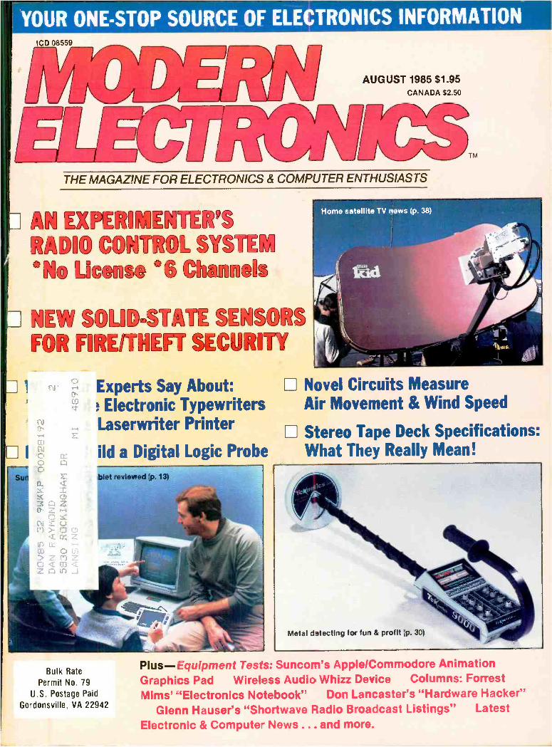
ila C PERIENTILN RAD1© gATTRO1 "q1 License '6 `;Ikinnels
G1sW SOLID.ST& ¿ SENSORS FOR FIRE/THEFT SECURITY
Experts Say About: I Electronic Typewriters Laserwriter Printer
ild a Digital Logic Probe
evned',p. i3)
I I
Home satellite TV news (p. 38)
Novel Circuits Measure Air Movement & Wind Speed
Stereo Tape Deck Specifications: What They Really Mean!
Bulk Rate
Permit No. 79
U.S. Postage Paid
Gordonsville, VA 22942
Metal d 3tecting for fun & profit :p. 30)
Plus- Equipment Tests: Suncom's Apple /Commodore Animation Graphics Pad Wireless Audio Whizz Device Columns: Forrest Mims' `Electronics Notebook" Don Lancaster's "Hardware Hacker"
Glenn Hauser's "Shortwave Radio Broadcast Listings" Latest Electronic & Computer News ... and more.
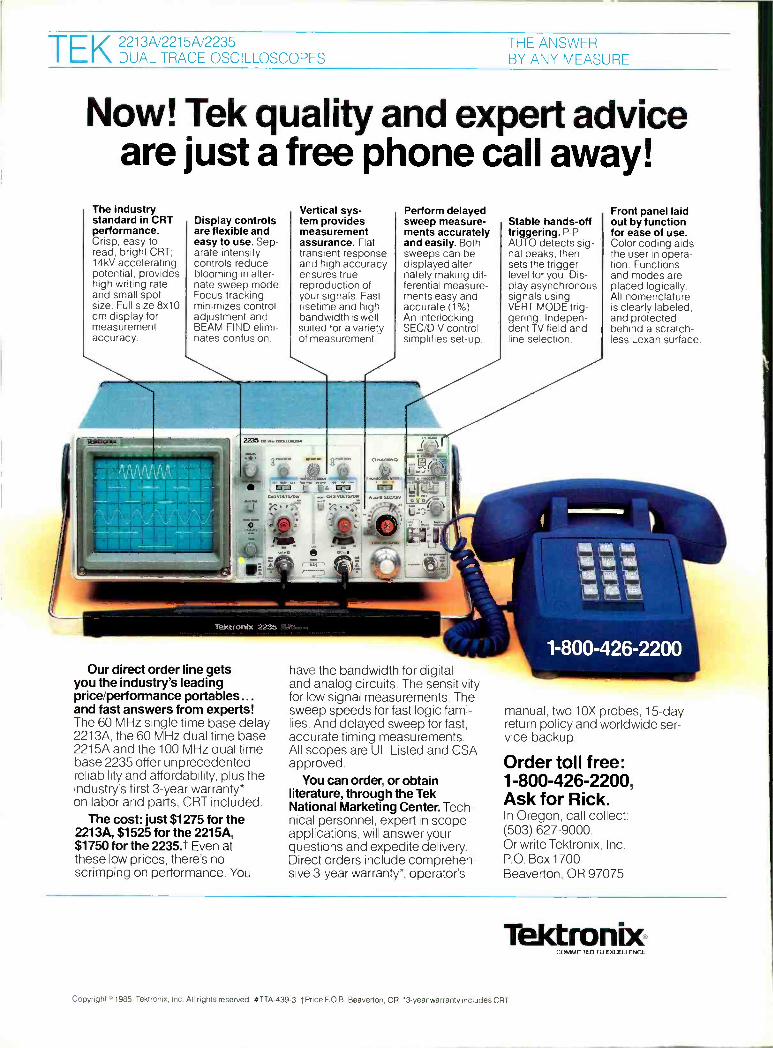
THE ANSWER TEK DUAL TRACE OSCILLOSCOPES BY ANY MEASURE
Now! Tek quality and expert advice are just a free phone call away!
The industry standard in CRT performance. Crisp, easy -to- read, bright CRT; 14kV accelerating potential, provides high writing rate and small spot size. Full size 8x10 cm display for measurement accuracy.
Display controls are flexible and easy to use. Sep- arate intensity controls reduce blooming in alter- nate sweep mode. Focus tracking minimizes control adjustment and BEAM FIND elimi- nates confusion.
Vertical sys- tem provides measurement assurance. Flat transient response and high accuracy ensures true reproduction of your signals. Fast risetime and high bandwidth is well suited for a variety of measurement.
Perform delayed sweep measure- ments accurately and easily. Both sweeps can be displayed alter- nately making dif- ferential measure- ments easy and accurate (1 %). An interlocking SEC /DIV control simplifies set -up.
Stable hands -off triggering. P -P AUTO detects sig- nal peaks, then sets the trigger level for you. Dis- play asynchronous signals using VERT MODE trig- gering. Indepen- dent TV field and line selection.
Front panel laid out by function for ease of use. Color coding aids the user in opera- tion. Functions and modes are placed logically. All nomenclature is clearly labeled, and protected behind a scratch - less Lexan surface.
22355 a., L--=J
1 VOLTS/DIV.
Tektronix 2235
Our direct order line gets you the industry's leading price/performance portables... and fast answers from experts! The 60 MHz single time base delay 2213A, the 60 MHz dual time base 2215A and the 100 MHz dual time base 2235 offer unprecedented reliability and affordability, plus the industry's first 3 -year warranty* on labor and parts, CRT included.
The cost: just $1275 for the 2213A, $1525 for the 2215A, $1750 for the 2235.t Even at these low prices, there's no scrimping on performance. You
have the bandwidth for digital and analog circuits. The sensitivity for low signal measurements. The sweep speeds for fast logic fami- lies. And delayed sweep for fast, accurate timing measurements. All scopes are UL Listed and CSA approved.
You can order, or obtain literature, through the Tek National Marketing Center. Tech- nical personnel, expert in scope applications, will answer your questions and expedite delivery. Direct orders include comprehen- sive 3 -year warranty*, operator's
manual, two 10X probes, 15 -day return policy and worldwide ser- vice backup.
Order toll free: 1- 800 -426 -2200, Ask for Rick. In Oregon, call collect: (503) 627 -9000. Or write Tektronix, Inc. P.O. Box 1700 Beaverton, OR 97075
Téktronbc f.OMMIT TEO TO EXCELLENCE
Copyright o 1985, Tektronix, Inc. All rights reserved. #TTA- 439 -3. tPrice F.O.B. Beaverton, OR. `3 -year warranty includes CRT.
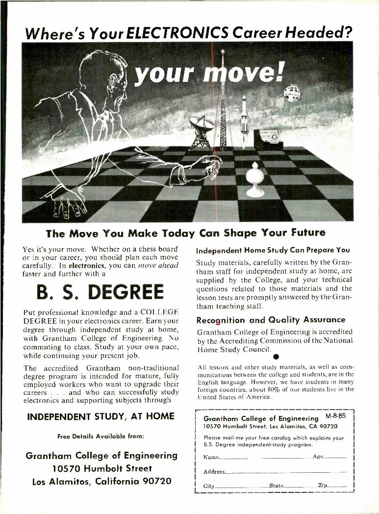
Where's Your ELECTRONICS Career Headed?
The Move You Make Today Can Shape Your Future Yes it's your move. Whether on a chess board or in your career, you should plan each move carefully. In electronics, you can move ahead faster and further with a
B. S. DEGREE Put professional knowledge and a COLLEGE DEGREE in your electronics career. Earn your degree through independent study at home, with Grantham College of Engineering. No commuting to class. Study at your own pace, while continuing your present job.
The accredited Grantham non -traditional degree program is intended for mature, fully employed workers who want to upgrade their careers . . . and who can successfully study electronics and supporting subjects through
INDEPENDENT STUDY, AT HOME
Free Details Available from:
Grantham College of Engineering 10570 Humbolt Street
Los Alamitos, California 90720
Independent Home Study Can Prepare You
Study materials, carefully written by the Gran- tham staff for independent study at home, are supplied by the College, and your technical questions related to those materials and the lesson tests are promptly answered by the Gran- tham teaching staff.
Recognition and Quality Assurance Grantham College of Engineering is accredited by the Accrediting Commission of the National Home Study Council.
All lessons and other study materials, as well as com- munications between the college and students, are in the English language. However, we have students in many foreign countries; about 80% of our students live in the United States of America.
L
Grantham College of Engineering M"8"85 10570 Humbolt Street, Los Alamitos, CA 90720
Please mail me your free catalog which explains your B.S. Degree independent -study program.
Name Age
Address
City State Zip
111111117Milmcs THE MAGAZINE FOR ELECTRONICS 8 COMPUTER ENTHUSIASTS
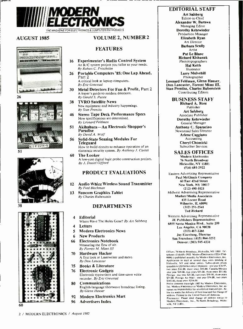
AUGUST 1985
26
51
38
60
VOLUME 2, NUMBER 2
FEATURES
16 Experimenter's Radio Control System An R/C system project you tailor to your needs. By Robert C. Frostholm
26 Portable Computers '85: One Lap Ahead, Part 2 A critical look at laptop computers. By Eric Grevstad
30 Metal Detectors For Fun & Profit, Part 2 A buyer's guide to modern detectors. By Gerald S. Pattee
38 TVRO Satellite News New equipment and industry happenings. By Stan Prentiss
46 Stereo Tape Deck Performance Specs How specifications are determined. By Leonard Feldman
51 Akihabara -An Electronic Shopper's Paradise By David A. Wolf
56 Solid -State Sensing Modules For Teleguard How to build circuits to enhance operation of an electronic security system. By Anthony J. Caristi
60 The Looker A low -cost digital logic probe construction project. By J. Daniel Gifford
PRODUCT EVALUATIONS
12 Audio Whizz Wireless Sound Transmitter By Fred Blechman
13 Suncom Graphics Tablet By Charles Rubenstein
DEPARTMENTS
4 Editorial Where Have The Holes Gone? By Art Salsberg
4 Letters 5 Modern Electronics News 6 New Products
66 Electronics Notebook Measuring the flow of air. By Forrest M. Mims III
70 Hardware Hacker A first look at Laserwriter and more. By Don Lancaster
75 Books & Literature 76 Electronic Gadgets
Electronic typewriters and time -saver voice recorder. By Eric Grevstad
80 Communications English -language shortwave broadcast listing. By Glenn Hauser
92 Modern Electronics Mart 96 Advertisers Index
2 / MODERN ELECTRONICS / August 1985
EDITORIAL STAFF Art Salsberg
Editor -in -Chief Alexander W. Burawa
Managing Editor Dorothy Kehrwieder Production Manager
Elizabeth Ryan Art Director
Barbara Scully Artist
Pat Le Blanc Richard Kishanuk Phototypographers
Hal Keith Illustrator
Larry Mulvehill Photographer
Leonard Feldman, Glenn Hauser, Don Lancaster, Forrest Mims III, Stan Prentiss, Charles Rubenstein
Contributing Editors
BUSINESS STAFF Richard A. Ross
Publisher Art Salsberg
Associate Publisher Dorothy Kehrwieder
General Manager Anthony C. Sparacino Newsstand Sales Director
Arlene Caggiano Accounting
Cheryl Chomicki Subscriber Services
SALES OFFICES Modern Electronics 76 North Broadway Hicksville, NY 11801
(516) 681-2922
Eastern Advertising Representative Paul McGinnis Company
60 East 42nd Street New York, NY 10017
(212) 490 -1021 Midwest Advertising Representative
Market /Media Associates 435 Locust Road
Wilmette, IL 60091 (312) 251-2541 Ted Rickard
Western Advertising Representative JE Publishers Representatives
6855 Santa Monica Blvd., Suite 200 Los Angeles, CA 90038
(213) 467 -2266 Jay Eisenberg, Director
San Francisco: (415) 864 -3252 Denver: (303) 595 -4331
Offices: 76 North Broadway, Hicksville, NY 1 1801. Te!-
ephone: (516) 681 -2922. Modern Electronics (ISSN 0748-
9889) is published monthly by Modern Electronics, Inc. Application to mail at second class rates pending at
Hicksville, NY and other points. Subscription prices
(payable in US Dollars only): Domestic - one year S16.97,
two years 531.00, three years $45.00; Canada /Mexico -one year 519.00, two years 535.00, three years $51.00; Foreign - one year 521.00, two years 559.00, three years
557.00. Foreign Air Mail - one year $74.00, two years
S145.00, three years S216.00. Entire contents copyright 1985 by Modern Electronics, Inc. Modern Electronics or Modern Electronics, Inc. as-
sumes no responsibility for unsolicited manuscripts. Al- low six weeks for delivery of first issue and for change of address. Printed in the United States of America. Postmaster: Please send change of address notice to
Modern Electronics, Inc., 76 North Broadway, Hicks- ville, NY 11801.
x
Ì 1 PINECOM INTERNATIONAL, INC. 12603 CRENSHAW BOULEVARD HAWTHORNE. CALIFORNIA 90250(213) 679 -9999
MARK IV - 15 STEP LED POWER LEVEL INDICATOR KIT This new stereo indicator kit consists of 36 4 -color
LED's (15 per channel) to indicate the sound level out- put of your amplifier from - 36dB to + 3dB. Comes with
a well designed silk screen printed plastic panel and has a selector switch to allow floating or gradual out- put indicating. Power supply is 6 -12VDC with THG on
board input sensitivity controls. This unit can work with
any amplifier from 1W to 200W. Kit includes 70 pcs
driver transistors, 38 pcs matched 4 -color LED's, all
electronic components, PC board and front panel.
MARK IV KIT $31.50
TA -1000 KIT
$51.95
Power Transformer
$24.00 ea.
100W CLASS A
POWER AMP KIT Dynamic Bias Class "A" circuit design makes this
unit unique in its class. Crystal clear, 100 wafts power output will satisfy the most picky fans. A perfect combination with the TA -1020 low TIM stereo pre - amp. Specifications Output power 100W RMS into 8í1.
125W RMS into 41f Frequency response 10Hz- 100KHz THD less than 0.01% S/N ratio
better than 8048 Input sensitivity 1V max. Power
supply 40V at 5A.
20 STEPS BAR /DOT AUDIO LEVEL DISPLAY KIT
This new designed audio level display unit is using a
new integrated circuit from National Semiconductor to
drive 20 pieces of color LED's (green, yellow and red)
on each channel. It provides two types of display methods for selection 'bar' or 'clot'. The display range is from - 57dB to OdB. Kit is good for any amplifier from 2 watts to 200 wattsl Power supply requires 12VAC or
DC. So it is great for cars as well) Kit comes with printed circuit board, all LED's, electronic components, switch- es, and silk screen printed professional front panel.
MODEL TY -45 $38.50
LOW TIM DC STEREO PRE-AMP KIT TA -2800 Incorporates brand -new DC design that gives a fre- quency response from 0- 100KHz x0.5dB. Added features like tone defeat and loudness control let you tailor your own frequency supplies to eliminate power fluctuations! Specifications: THD/TIM less than .005% Fre- quency response DC to 100KHz -0.5dB RIM deviation x0.2dB S/N ratio better than 7048 Sensitivity; Phone 2mV 47Kft, Aux 100mV 100Kí2 Output level 1.3V Max output 15V Tone controls: Bass 1-10dB (u 50Hz, Treble x10dB (a 15Hz Power supply z24VDC (u 0.5A. Kit comes with regulated power supply. All you need is a 48VCT transformer o, 0.5A.
Only $44.50 Transformer
$4.50 ea.
DISCO LIGHT ORGAN KIT
^' ..
COLOR MONT CONTROLLER TT-tfi
The TY -23B Color Light Organ is designed for use at home, party, disco or commercial advertise- ment purpose. It gives you the moving light effect coordinated with the frequency of the music
changes. When music or an audio signal input is fed into this unit, it will be divided into High, Medium
and Low frequency by means of an electronic equalizer circuit to drive three groups of light bulbs.
Each group of lights has an independent sensitivity control.
Besides working as a Color Light Organ, the TV -23B also can be used in "Light Chaser" mode
to perform light effects for signs as follows: (1) Switch on one after the other. (2) Flashes all together.
(3) Switch off one after the other. Flashing rate can be controlled. The output power of this unit
is 3,000 watts (110V) which is 30 100 watt color spot lights or 600 5 watt light bulbs. Build one
of these color organs today and enjoy watching your music. Great for school projects! All elec-
tronic parts, metal case, predrilled pc board and instructions come with kit.
TY -23B DISCO LIGHT ORGAN KIT $64.50
TY -41 INFRA -RED REMOTE SWITCH KIT
This infra -red remote control switch kit is suitable for many kinds of electrical and electronic applications, such as light controller, garage door opener, TV on /off, alarm system and many others. It does not use any antenna to transmit the signal, but it transmits an in-
visable light signal so the receiver can pick it up as tar as 30 ft. away. Kit comes with all electronic com- ponents, pc board, relay and the infra -red LED.
7Y -41 INFRA -RED SWITCH KIT $23.50
SEND ONE DOLLAR FOR OUR DETAIL CATALOG
Inside California Outside Calif. (incl. Mexico 8 Canada) Overseas
0 -15 VOLT 2AMP REGULATED POWER SUPPLY KIT This is a professional power supply kit. Output voltage adjustable from 0- 15VDC. Output current
also can be limited to two range sections such as 200mA and 2A. An elaborated protection system
also designed to give out a beeping sound and a flashing LED warning will appear when output
was over loaded or short circuited. High stability and reliability resulting from employing a high
quality voltage regulator IC. The front panel of the power supply is well designed with output ter-
minals, on /off switch, voltage adjusting control, jumbo size meter for reading both AMPs and VOLTs,
Also with a volt/amp switch as well as current limit
select switch, Kit comes with refined metal case,
silver color with sand brushed front panel, all elec-
tronic parts, pc board, 3" jumbo size meter,
transformer, circuit diagram and instructions.
TR -100 KIT
$59.50
DIGITAL PANEL METER KIT
31/2 Digit Multi -Use Danel Meter. The TY -43 digital panel meter kit using the IC 7107 ND converter from Intersi! is a principal component which direct drives a
16mm high 3e2 digit LED display. The unit needs very few external components and is extremely easy to
assemble and adjust. You can produce various kinds of voltage, current and resistance measuring meters, by adding a limited number of components, you can even change it into a thermometer, frequency counter and capacitor meter. (Application Circuit diagrams enclosed with kit).
Input sensitivity is DC j 199.9MV full scale Input impedance is 10rr ohms Operating source is 5 - 6VDC a 150MA Overall size: 1%" x 4"
TY -43 DIGITAL PANEL METER KIT $31.50
80W + 80W STEREO AMPLIFIER KIT PRE -AMP - TONE CONTROLS - POWER AMP
TA -800 is an 80 watts + 80 watts stereo. The Low T.I.M. preamplifier employs a low distortion linear
I.C. (LM4558) and three negative type tone controls for High, Medium and Low frequency control.
The rear power amplifier uses newly developed high frequency darlington hybrid type transistors
(AN7337/AN7338) in a push -pull circuit. There is also on board speaker protector to generate
a delay time between the speakers and the
amplifier. Large aluminum heat sink, which is
mounted on pc board, requires no external hook-
up wires. The kit comes with instructions, all
electronic parts, predrilled pc board, and heat
sinks. Power transformer not included. Easy to
build, guaranteed to work.
TA -800 KIT
$65.00 Transformer (52VCT 4A) $22.50
* SPECIAL * Excellent Price! Model 001 -0034 $29.50 per Kit Transformer $10.50 ea.
TA -322 30 WATTS TOTAL 15W + 15W STEREO AMP KIT
This is a solid state all transistor circuitry with on board stereo pre -amp for most microphone or phone input. Power output employs a heavy duty Power Hybrid IC. Four built on board controls for, volume, balance, treble and bass. Power supply requires 48VCT 2.5A transformer. THD of less than 0.1 between 100Hz -10KHz at full power (15 Watts
15 Watts loaded into 8fI).
MAGNETIC HEAD EQUALIZER Standard RIRA curve for all kinds of magnetic heads 3
stages crossover circuit for best results Output voltage guaranteed to be stable without any oscillation Power Supply. 24 V.D.C.
MODEL: MA -142 Part #370-370 $6.95 ea.
0 -30VDC POWER SUPPLY KIT
-a
_tt P
This kit includes a high efficency regulating circuitry. By using the IC 723 and darlington power transistor to pro- vide a stable and ripple free DC voltage from 0 - 30 volts at 3 amps or 0 - 15 volts at 5 amps (depends on the
power transformer used, not included with kit). Overload and short circuit protection also featured on this kit. Easy to build! Guaranteed to work) All electronic parts, pc board, heat sink for power transistor, instructions in-
cluded.
TR-355 POWER SUPPLY KIT $14.50 24VCT Transformer (for 0 -30V) $10.50
Shipping 8 Handling Charges Under $50.00 Over 550.00 Minimum Order 510.00 /Calif. Residents
Purchase Purchase add 6.5% Sales Tax. Phone Orders Accepted 10% 5% on VISA or MC ONLY. NO C.O.D.'s. Prices sub- 1 5% 10% ject to change without notice. 25% 2046 CIRCLE NO. 175 ON FREE INFORMATION CARD
60W +60W O.T.L. AMP Ste,eu pre -amp +tone control + power amp. All in on
unit, fully assembled! Compact in size: 7 "x4W/4"x21/2".
Can be fitted into most cabinets. Power transistors using 25C1667 X 4 to give a max output of 60W +60W 180)
Frequency response: 20Hz-85KHz( - 1dB) Total
harmonic distortion: 0.02%(1 KHz) SignaUNoise Ratio: 88 dB (open loop) Tone control: 100 Hzx 16 dB 10
KHze I4dB Dynamic range: 60 dB Power Supply: 48V-70V5 Amp. Filter Capacitor:4700 p 75V or better.
MODEL:
SA -4520
Part #370 -0350 $39.95 ea. 1 Transformer Part #670-0230... 522.50 ea. 2 Filter Capacitor 4700µF 70V $6.50 ea.
STEREO MIC. AND ECHO MIXER FOR STEREO AMPLIFIER SYSTEM The circuitry employs all integrated circuits, BBD type
echo circuit. echo time can be adjusted (max. .30
Msec.) Also with a microphone preamp on the board Fully assembled.
s.
MODEL: MX205 Part #370 -0360 $29.95 ea.
LOW T.I.M.
TRANSISTORS
100W + 100W
Employs Hitachi low noise I.C. for pre -amp Max
output 16 V P -P (non distortion) With hi -low fitter, and
tone defeat circuit Rear power amp with short circult protection Giant heat sink for maximum results Tone controls x t4dB All components (except pots for vol-
ure, and tone controls) are pre -assembled, the quality is guaranteed. Power supply DC 1- 35V -50V
MODEL: SA802C Part #370 -0340 $85.00
POWER TRANSFORMER (68V -80V CT 6 AMP)
Part #670 -0220 $24.50
STORE HOURS MON -FRI -10-7
SAT -10 -6
V Where Have The Holes Gone?
Get ready for a major change in your electronics repair life as more and more manufacturers turn to surface -mounted devices (SMD). These parts, with their curled connection legs, attach directly to a printed- circuit board's foil pattern . . .
so drilled holes for pushing through com- ponent wire leads for soldering on the op- posite side aren't needed.
"So what!" you say? So the SMD leads are spaced more closely than conven- tional integrated- circuit leads are. So the devices themselves can be packed more tightly on a pc board, leaving you less room to remove and install them.
In fact, you won't be able to safely re- move or install most SMDs with your present soldering equipment. You'll re- quire new low -watt solder irons! Think about it a moment. With SMDs mounted on board footprint pads atop the copper foil, how can you change all the solder connections into a molten state simultan- eously to remove the device? It's not as if
the connections were there in the clear for you to apply a solder- iron's removal - block tip while pulling upward on the component's body on the other side of the board.
What you'll need in order to work on SMDs is a clamping -like solder iron much like giant tweezers, with an L -tip on one end and an inverted -L on the other to heat up all SMD connections at once. The tips will have to be the proper dimensions, of course, but so do spin -tight tool inserts for driving different nut sizes.
Perhaps you think that holeless pc boards are just a wild dream or limited to some military applications. If you do, you're wrong. They're here now in elec- tronic entertainment equipment and spreading out everywhere else. Estimates are that about 50% of components shipped within five years will be surface - mountable types. (It's said to be at the 5% mark at this time.)
Manufacturers can't afford not to
change to surface -mounted devices for a number of competitive reasons: more electronic functions can be put into a single package, more packages can be put on a pc board, pc -board holes don't have to be drilled, and production equipment takes up less space.
The pace to SMDs is quickening as the number of components packaged for sur- face mounting increases. Automated production equipment developers have already moved in with about a dozen new pick- and -place SMD machines. So have makers of reels that can hold thousands of SMDs on vinyl carrier tape for blind- ingly fast pick- and -place work -to 6,000 parts per hour!
Good luck!
dia.er
IIIIIIIIILETTERSIIIIIII The Way To Go
Please keep the emphasis on electronics in your "magazine for electronics & com- puter enthusiasts." It's not that I'm unin- terested in computers (I subscribe to micro magazines, have two micros, disk and tape drivers, and fiddle with BASIC, Pascal, Pilot, assembly language, and machine language) but I want broader - spectrum editorial coverage too. Now, perhaps I can go back to a Number One: Modern Electronics.
Michael M. Meyers Montclair, NJ
I just want to add my own congratula- tions to the many you folks must be re- ceiving over the recent issues of your splendid magazine. Us ordinary people out here enjoy doing projects and pur- chase much of the equipment advertised in such technical publications. The pro- jects authored by Anthony J. Caristi are to me by far the most useful and well thought out. He does not talk down to hobbyists, yet spells everything out as if he were anticipating snafus and wants the
hobbyist like me to have the thrill of see- ing something really useful come to frui- tion. Mims, Lancaster, Hauser, and Feld- man are great too, and deserve their steadily growing fine reputations.
Porter C. Holman New York, NY
I was impressed with Fred Blechman's review of the Sinclair QL computer. It was very fair. He mentions the unit he re- viewed was the English version. Some changes do exist between the UK and the U.S. one.
I am one of the first to receive the U.S. model QL and would like to point out some of the changes. First, the U.S. QL comes with version 2.00 of all four appli- cation programs. With this upgrade, code has been compressed and speeded up. Secondly, SuperBasic also is the newest version. Print VER$ will return the ver- sion `code.' With `JS' you get the `WHEN' construct along with 25 extra SuperBasic keywords to help in identifing type of error during error trapping.
As of this writing I know of two com-
panies besides Sinclair who carry QL soft- ware and hardware in the U.S., including disk drives.
Robert Woodring Tonawanda, NY
Likes Surround Sound * Thank you for the article in February's Modern Electronics about the "Sur- round Sound" enhancer project. Articles like this is one reason why I subscribe to Modern Electronics.
M. Smith Industry, CA
Corrections A True -rms Adapter (June 1985). Fig. 1:
delete line connection to OFF (S1B). P. 59: change col. I to "half cycle = Vp." Col. 1- should read "C.F. =1 /')" and fol- lowing should read "For a C.F. of 7," the error is -1 % and for a C.F. of" last par- agraph on box -expressions should have square -root sign completed. Parts list: RI thru R4 should be metal film; Cl thru C4 should be rated at 1 kV, 100 V, 50 V and 10 V, respectively.
4 / MODERN ELECTRONICS / August 1985
8 -mm VIDEO. The 8 -mm video format is heating up the VCR battle with so many new products coming up, both machines and software. Dealers are confused with three formats, none compatible with another. Sony unveiled a tiny handheld 8 -mm camcorder and a longer -playing tape (2 hours, up from 12). Kodak, in turn, introduced a stand -alone 8 -mm VCR chock full of features- - digital stereo sound, two -piece system for lightweight portable recording, and much more.
CB -RADIO LIVES. CB radio may not be the raging delight of the populace any longer, but it still moves along on our highways. REACT International, a volunteer emergency communications organization founded in 1962, has 1,000 teams and 15,000 members in the U.S. and Canada who monitor Citizens Band Radio Channel 9, the FCC -designated emergency call station. They also provide communications for special events, such as March of Dimes Walkathons, Chicago's Americas Marathon, and similar activities. For membership info, contact REACT Internation, P.O. Box 115, Northbrook, IL 60062.
APPLICATION -SPECIFIC IC'S. With large cell libraries and sophisticated computer -aided design and engineering machines, creating i ntegrated cir- cuits is not the chore it once was. As a result, a company such as Oki Semiconductor is setting up a separate business unit to support small -box designers. Oki figures that five years from now applications- specific devices will account for almost half the world market for ICs.
COLOR TV REPLACEMENT. Half the color -TV sets bought 15 years ago are still used, while four out of five purchased 10 years back are being used, ac- cording to a recent EIA Consumer Electronics Group study. Among other in- teresting findings: 46% of color -TV households have more than one color TV set; 12% have three or more. Impressive color -TV set longevity notwith- standing, the study reveals that about 40% of color TV receivers bought in 1984 were replacements for sets that went out of use.
SHORTER LIFE IN MEMORY -CHIP LANE. Manufacturers of memory chips could once figure many years of solid business for their designs. BLt movement from the new 256K -bit chips to the next level, 1 -Mb, will be here by the time you can say 1987. Prices of dynamic 256 K chips are dropping fast.
MULTICHANNEL TV SOUND. More than 200 TV broadcast stations are expected to transmit TV sound in stereo by 1986. As a result, many more new TV re- ceivers are coming equipped for reception of MTS, which also accommodates bilingual TV broadcasts. To underscore this, Zenith Electronics' 1986 line of color -TV sets includes 14 models with built -in ITS facilities.
FCC SUPPORTS SATELLITE TV DISHES. In an interesting move that has aroused the ire of many local zoning boards, the Federal Communications Commission has a proposal out to eliminate local restrictions on home satellite TV antenna dishes. It's collecting comments relating to the rule proposal.
August 1985 1 MODERN ELECTRONICS / 5
IIIIIIREW PRODLTS/llhfl
For more information on products described, please circle the appropri- ate number on the Free Information Card bound into this issue or write to the manufacturer.
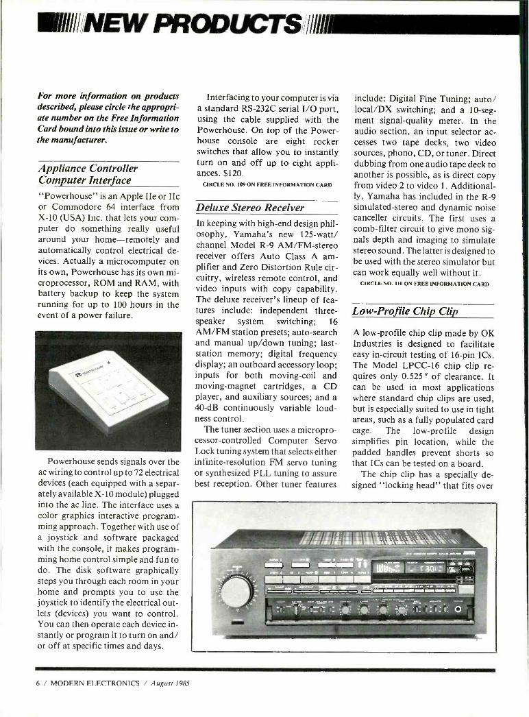
Appliance Controller Computer Interface "Powerhouse" is an Apple IIe or IIc or Commodore 64 interface from X -10 (USA) Inc. that lets your com- puter do something really useful around your home -remotely and automatically control electrical de- vices. Actually a microcomputer on its own, Powerhouse has its own mi- croprocessor, ROM and RAM, with battery backup to keep the system running for up to 100 hours in the event of a power failure.
Powerhouse sends signals over the ac wiring to control up to 72 electrical devices (each equipped with a separ- ately available X -10 module) plugged into the ac line. The interface uses a color graphics interactive program- ming approach. Together with use of a joystick and software packaged with the console, it makes program- ming home control simple and fun to do. The disk software graphically steps you through each room in your home and prompts you to use the joystick to identify the electrical out- lets (devices) you want to control. You can then operate each device in- stantly or program it to turn on and/ or off at specific times and days.
Interfacing to your computer is via a standard RS -232C serial I/O port, using the cable supplied with the Powerhouse. On top of the Power- house console are eight rocker switches that allow you to instantly turn on and off up to eight appli- ances. $120.
CIRCLE NO. 109 ON FREE INFORMATION CARD
Deluxe Stereo Receiver In keeping with high -end design phil- osophy, Yamaha's new 125 -watt/ channel Model R -9 AM /FM- stereo receiver offers Auto Class A am- plifier and Zero Distortion Rule cir- cuitry, wireless remote control, and video inputs with copy capability. The deluxe receiver's lineup of fea- tures include: independent three - speaker system switching; 16 AM /FM station presets; auto -search and manual up /down tuning; last - station memory; digital frequency display; an outboard accessory loop; inputs for both moving -coil and moving- magnet cartridges, a CD player, and auxiliary sources; and a 40 -dB continuously variable loud- ness control.
The tuner section uses a micropro- cessor- controlled Computer Servo Lock tuning system that selects either infinite- resolution FM servo tuning or synthesized PLL tuning to assure best reception. Other tuner features
include: Digital Fine Tuning; auto/ local/DX switching; and a 10 -seg- ment signal- quality meter. In the audio section, an input selector ac- cesses two tape decks, two video sources, phono, CD, or tuner. Direct dubbing from one audio tape deck to another is possible, as is direct copy from video 2 to video 1. Additional- ly, Yamaha has included in the R -9 simulated- stereo and dynamic noise canceller circuits. The first uses a comb -filter circuit to give mono sig- nals depth and imaging to simulate stereo sound. The latter is designed to be used with the stereo simulator but can work equally well without it.
CIRCLE NO. 110 ON FREE INFORMATION CARD
Low -Profile Chip Clip
A low- profile chip clip made by OK Industries is designed to facilitate easy in- circuit testing of 16 -pin ICs. The Model LPCC -16 chip clip re- quires only 0.525 " of clearance. It can be used in most applications where standard chip clips are used, but is especially suited to use in tight areas, such as a fully populated card cage. The low- profile design simplifies pin location, while the padded handles prevent shorts so that ICs can be tested on a board.
The chip clip has a specially de- signed "locking head" that fits over
6 / MODERN ELECTRONICS / August 1985
the IC under test, a 24 " ribbon cable and a 16 -pin DIP plug. Any and all IC pins to which the chip clip is con- nected can be tested via numbered pins on the device's DIP plug. $14.95.
CIRCLE NO. 111 ON FREE INFORMATION CARD
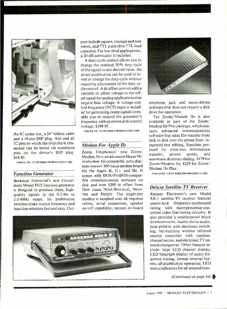
Function Generator Beckman Industrial's new Circuit - mate Model FG2 function generator is designed to produce clean, high - quality signals in the 0.2 -Hz to 2.0 -MHz range. Its pushbutton switches make output frequency and function selection fast and easy. Out-
puts include square, triangle and sine waves, and TTL pulse (five TTL load capacity). For low -level applications, a 20 -dB attenuator is included.
A duty -cycle control allows you to change the nominal 50% duty cycle of the signal to any desired value. An invert pushbutton can be used to in- vert or change the duty cycle without requiring adjustment of the duty cy-
cle control. A dc offset control adds a variable dc offset voltage to the off- set signal for analog applications that require bias voltage. A voltage con- trol frequency (VCF) input is includ- ed for generating sweep signals to en- able you to control the generator's frequency with an external dc control voltage. $199.95.
CIRCLE NO. 112 ON FREE INFORMATION CARD
Modem For Apple Its Zoom Telephonics' new Zoom/ Modem IIe is an advanced Hayes Mi- cromodem IIe- compatible auto -dial/ auto -answer 300 -baud modem board for the Apple II, II + and IIe. It comes with DOS /ProDOS- compat- ible communications software on disk and over $200 in offers from Dow Jones News /Retrieval, News - Net and Delphi. The single -slot modem is supplied with all required cables, serial connection, speaker on /off capability, second on -board
telephone jack and menu -driven software that does not require a disk drive for operation.
The Zoom /Modem IIe is also available as part of the Zoom/ Modem IIe Plus package, which con- tains advanced communications software that adds file- transfer from disk to disk over the phone lines, in- tegrated text editing, Xmodem pro- tocol for error -free information transfer, printer access, and automatic directory dialing. $179 for Zoom /Modem IIe; $229 for Zoom/ Modem IIe Plus.
CIRCLE NO. 113 ON FREE INFORMATION CARD
Deluxe Satellite -TV Receiver Ramsey Electronic's new Model XR -1 satellite -TV receiver features quartz -lock frequency- synthesized tuning with microprocessor-con - trolled video fine tuning circuitry. It also provides a weatherproof block downconverter, matrix stereo audio, dual polarity with electronic switch- ing, full- function wireless infrared remote controller with random - channel access, and electronic TV an- tenna changeover. Other features in- clude: large LED channel display; LED bargraph display of audio fre- quency tuning; format reversal but- ton; all- pushbutton operation; LED status indicators for all selected func-
(Continued on page 84)
August 1985 / MODERN ELECTRONICS / 7
training at home, you
Move up to a high paying And you can start by actually building ypur
own 16 -bit IBM -compatible computer! You can create your own bright, high paying future as
an NRI trained computer service technician. The govern- ment now reports that computer service and repair is tie. fastest growing career field. The biggest growth in jobs between now and 1995, according to Department of Laba estimates, will occur in the computer service and repair business, where demand for trained technicians will actrualy double during the next 10 years! There is still plenty of room for you to get in on the action -if you get the proper training now.
Total computer systems training, only from NRI
If you really want to learn how to work on com- puters, you have to get inside one! And only NRI takes you inside a computer, as powerful and advanced as the Sanyo MBC- 550 -2. As part of your training, you'll build this Sanyo, which experts have hailed as the "most intriguing" of all the new IBM -compatibles. Computer critics say, "The Sanyo even surpasses the IBM PC in
computing speed and graphics quality." This hands -on experience is backed up with
training in programming, circuit design and peripherals. Only NRI gives you such in -depth total systems training.
The kiid of understarding built only through experience
Even if you've never had any previous training in elec- ror_icr, you can succeed with NR: -training. You'll start with he basics, rapidly building on the irndamentals of elec- tror_ics intil you master such advanced concepts as digital
logic, mice processor design, and cczrputer memory.
You'll build and test advanced electronic
circuits using the exclusive NRI Discovery Labe and professional Digital Multimeter,
both of which are yours -o keep.
You 1 assemble Sanyo's intellige -t keyboard, install the power sipply and disk drive, and interface the high resolution
monitor-all the while -performing hands-on
experiments and demonstrations that
career servicing computers. fine tune your computer skills. And you also get over $1,000 worth of software, including WordStar and CalcStar.
Learn to service today's computers As you train with your Sanyo, you'll gain the
knowledge you need to become a computer profes- sional. You'll learn to program in BASIC and machine language. You'll use utility programs to check out the operation of the Sanyo's 8088 microprocessor (the same chip used in the IBM PC). You'll learn how to debug programs and write your own new software.
Most importantly, you'll understand the prin- ciples common to all computers. Only a person who fully understands all the fundamentals can hope to be able to tackle all computers. NRI makes sure that you'll get the training you need to maintain, troubleshoot and service computers.
Learn at home in spare time With NRI training, you'll learn at home on your own
time. That means your preparation for a new career or part -time job doesn't have to interfere with your current job. You'll learn at your own pace, in the comfort and convenience of your own home. No classroom pressures, na rigid night school schedules. You're always backed up by the NRI staff and especially your NRI instructor, who will
answer questions, give you guidance and be available for special help if you need it.
Let others worry about computers taking their jobs. With NRI training, you'll soon have computers making good paying jobs for you.
Send for free NRI catalog Send the post -paid reply card today for
NRI's 100 -page catalog, that gives all
the facts about computer training plus career training in Robotics, Data Com-
munications, TVNideo Servicing and many other fields If some other ambitious person
beat you to the card, write to NRI at the address below.
MISCHOOLS
McGraw -Hill Continuing Education Center 3939 Wisconsin Avenue, NW Washington, DC 20016
We'll Give You Tomorrow. i }n ii I IBM is a Registered Trademark of International Business Machines Corporation.
August 1985 / MODERN ELECTRONICS / 11
iiiIii' PRODUCT EVALUATIONS/IllIll1111=1
Video /Audio A Wireless Sound Transmitter
FM wireless transmitters like the Audio Whizz examined here have always been welcome devices for applications where it's impractical or undesirable to run cable or wires. This wireless device is de- signed to accept a broad range of audio signals, from a few millivolts to a few volts, and "broadcast" them for pickup by any nearby FM radio set to the proper frequency. In this case, the desired fre- quency is at the low end of the standard FM broadcast band.
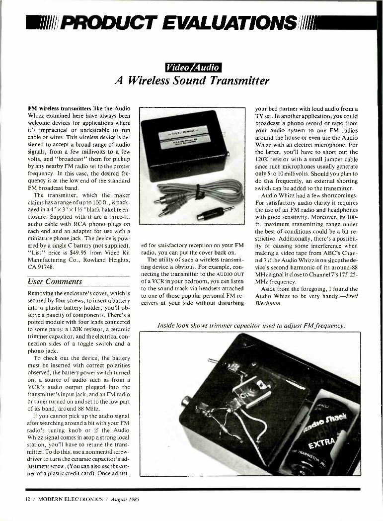
The transmitter, which the maker claims has a range of up to 100 ft., is pack- aged in a 4 " x 3 " x 1' /a "black bakelite en- closure. Supplied with it are a three -ft. audio cable with RCA phono plugs on each end and an adapter for use with a miniature phone jack. The device is pow- ered by a single C battery (not supplied). "List" price is $49.95 from Video Kit Manufacturing Co., Rowland Heights, CA 91748.
User Comments Removing the enclosure's cover, which is secured by four screws, to insert a battery into a plastic battery holder, you'll ob- serve a paucity of components. There's a potted module with four leads connected to some parts: a 120K resistor, a ceramic trimmer capacitor, and the electrical con- nection sides of a toggle switch and a phono jack.
To check out the device, the battery must be inserted with correct polarities observed, the battery power switch turned on, a source of audio such as from a VCR's audio output plugged into the transmitter's input jack, and an FM radio or tuner turned on and set to the low part of its band, around 88 MHz.
If you cannot pick up the audio signal after searching around a bit with your FM radio's tuning knob or if the Audio Whizz signal comes in atop a strong local station, you'll have to retune the trans- mitter. To do this, use a nonmental screw- driver to turn the ceramic capacitor's ad- justment screw. (You can also use the cor- ner of a plastic credit card). Once adjust-
ed for satisfactory reception on your FM radio, you can put the cover back on.
The utility of such a wireless transmit- ting device is obvious. For example, con- necting the transmitter to the AUDIO OUT
of a VCR in your bedroom, you can listen to the sound track via headsets attached to one of those popular personal FM re- ceivers at your side without disturbing
your bed partner with loud audio from a TV set. In another application, you could broadcast a phono record or tape from your audio system to any FM radios around the house or even use the Audio Whizz with an electret microphone. For the latter, you'll have to short out the 120K resistor with a small jumper cable since such microphones usually generate only 5 to 10 millivolts. Should you plan to do this frequently, an external shorting switch can be added to the transmitter.
Audio Whizz had a few shortcomings. For satisfactory audio clarity it requires the use of an FM radio and headphones with good sensitivity. Moreover, its 100 - ft. maximum transmitting range under the best of conditions could be a bit re- strictive. Additionally, there's a possibil- ity of causing some interference when making a video tape from ABC's Chan- nel 7 if the Audio Whizz is on since the de- vice's second harmonic of its around -88 MHz signal is close to Channel 7's 175.25 - MHz frequency.
Aside from the foregoing, I found the Audio Whizz to be very handy. -Fred Blechman.
Inside look shows trimmer capacitor used to adjust FM frequency.
12 / MODERN ELECTRONICS / August 1985
Computers
Suncom's Graphic Tablet
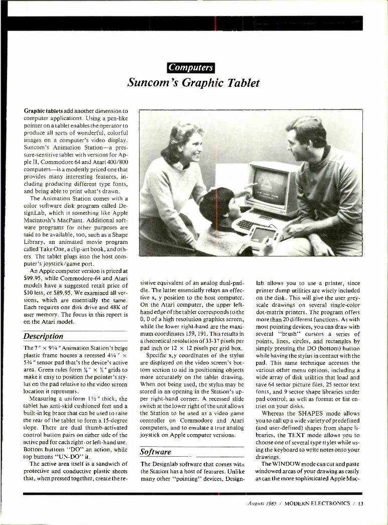
Graphic tablets add another dimension to computer applications. Using a pen -like pointer on a tablet enables the operator to produce all sorts of wonderful, colorful images on a computer's video display. Suncom's Animation Station -a pres- sure- sensitive tablet with versions for Ap- ple II, Commodore 64 and Atari 400 /800 computers -is a modestly priced one that provides many interesting features, in- cluding producing different type fonts, and being able to print what's drawn.
The Animation Station comes with a color software disk program called De- signLab, which is something like Apple Macintosh's MacPaint. Additional soft- ware programs for other purposes are said to be available, too, such as a Shape Library, an animated movie program called Take One, a clip -art book, and oth- ers. The tablet plugs into the host corn - puter's joystick /game port.
An Apple computer version is priced at $99.95, while Commodore -64 and Atari models have a suggested retail price of $10 less, or $89.95. We examined all ver- sions, which are essentially the same. Each requires one disk drive and 48K of user memory. The focus in this report is on the Atari model.
Description The 7 " x 9' /a " Animation Station's beige plastic frame houses a recessed 43/4 " x 5 3/4 " sensor pad that's the device's active area. Green rules form % " x % " grids to make it easy to position the pointer's sty- lus on the pad relative to the video screen location it represents.
Measuring a uniform l''/ " thick, the tablet has anti -skid cushioned feet and a built -in leg brace that can be used to raise the rear of the tablet to form a 15- degree slope. There are dual thumb -activated control button pairs on either side of the active pad for each right- or left -hand use. Bottom buttons "DO" an action, while top buttons "UN -DO" it.
The active area itself is a sandwich of protective and conductive plastic sheets that, when pressed together, create the re-
sistive equivalent of an analog dual -pad- dle. The latter essentially relays an effec- tive x, y position to the host computer. On the Atari computer, the upper left - hand edge of the tablet corresponds to the 0, 0 of a high resolution graphics screen, while the lower right -hand are the maxi- mum coordinates 159, 191. This results in a theoretical resolution of 33 -37 pixels per pad inch or 12 x 12 pixels per grid box.
Specific x,y coordinates of the stylus are displayed on the video screen's bot- tom section to aid in positioning objects more accurately on the tablet drawing. When not being used, the stylus may be stored in an opening in the Station's up- per right -hand corner. A recessed slide switch at the lower right of the unit allows the Station to be used as a video game controller on Commodore and Atari computers, and to emulate a true analog joystick on Apple computer versions.
Software The Designlab software that comes with the Station has a host of features. Unlike many other "pointing" devices, Design-
lab allows you to use a printer, since printer dump utilities are wisely included on the disk. This will give the user grey - scale drawings on several single -color dot -matrix printers. The program offers more than 20 different functions. As with most pointing devices, you can draw with several "brush" cursors a series of points, lines, circles, and rectangles by simply pressing the DO (bottom) button while having the stylus in contact with the pad. This same technique accesses the various other menu options, including a wide array of disk utilities that load and save 64 sector picture files, 25 sector text fonts, and 9 sector shape libraries under pad control, as well as format or list en- tries on your disks.
Whereas the SHAPES mode allows you to call up a wide variety of predefined (and user -defined) shapes from shape li- braries, the TEXT mode allows you to choose one of several type styles while us- ing the keyboard to write notes onto your drawings.
The WINDOW mode can cut and paste windowed areas of your drawing as easily as can the more sophisticated Apple Mac-
August 1985 / MODERN ELECTRONICS / 13
PRODUCT EVALUATIONS
Paint. You can employ this function to make multiple copies or just for reposi- tioning. SPRAY allows you to become a graffiti artist with the equivalent to an aerosal -can paint brush; SCROLL lets
you "microposition" your drawing on the screen, shifting it up, down, right, or left. This program's ZOOM mode, unlike other similar commands, lets you see the macro -picture as well as the zoomed -in portion, move around the picture, and change to one of four available colors in
this mode. Portions of the picture are erased in
both this and other modes by selecting the background color as your drawing color. Your COLOR palate allows simultane- ous use of 4 different colors /hues (3 plus background) selected from 16 colors and 16 luminances. Drawing is accomplished as if in layers as far as color is concerned, so if you change a layer's color, all draw- ing with that color changes.
Conclusions The Animation Stations worked fine, proving that a good computer peripheral need not be very costly. Color graphics were exceptionally good on both a video monitor and a 13 " TV receiver. I even tried the Apple version on a monochrome monitor and was able to perform all func- tions minus seeing color variations.
Of course, the Animation Station's utility is limited to the capabilities of the host computer. Thus, diagonal lines are relegated to a series of jagged straight ones, circles to ovals, and other generally less accurate renditions than one might wish for.
For all such shortcomings, however, given the low cost of the Stations and all
the nice things it permits one to do well
and easily on low -cost computers, Sun - corn's Stations are certainly worthwhile additions to computers they're designed to work with. For many people, such a
graphics tablet could well renew one's in-
terest in their home computer. -Charles Rubenstein
CIRCLE 20 ON FREE INFORMATION CARD
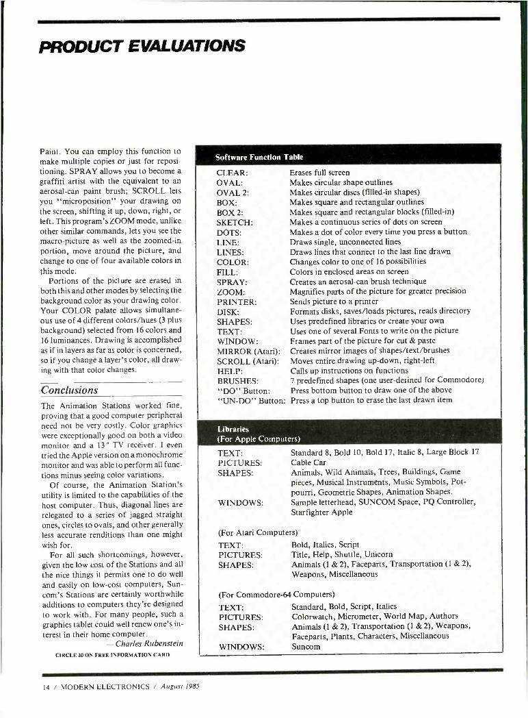
Software Function Table
CLEAR: OVAL: OVAL 2:
BOX: BOX 2:
SKETCH: DOTS: LINE: LINES: COLOR: FILL: SPRAY: ZOOM: PRINTER: DISK: SHAPES: TEXT: WINDOW: MIRROR (Atari): SCROLL (Atari): HELP: BRUSHES: "DO" Button: "UN -DO" Button:
Erases full screen Makes circular shape outlines Makes circular discs (filled -in shapes) Makes square and rectangular outlines Makes square and rectangular blocks (filled -in) Makes a continuous series of dots on screen Makes a dot of color every time you press a button Draws single, unconnected lines Draws lines that connect to the last line drawn Changes color to one of 16 possibilities Colors in enclosed areas on screen Creates an aerosal -can brush technique Magnifies parts of the picture for greater precision Sends picture to a printer Formats disks, saves /loads pictures, reads directory Uses predefined libraries or create your own Uses one of several Fonts to write on the picture Frames part of the picture for cut & paste Creates mirror images of shapes /text /brushes Moves entire drawing up -down, right -left Calls up instructions on functions 7 predefined shapes (one user-defined for Commodore) Press bottom button to draw one of the above Press a top button to erase the last drawn item
Libraries (For Apple Computers)
TEXT: PICTURES: SHAPES:
WINDOWS:
Standard 8, Bold 10, Bold 17, Italic 8, Large Block 17
Cable Car Animals, Wild Animals, Trees, Buildings, Game pieces, Musical Instruments, Music Symbols, Pot- pourri, Geometric Shapes, Animation Shapes. Sample letterhead, SUNCOM Space, PQ Controller, Starfighter Apple
(For Atari Computers)
TEXT: PICTURES: SHAPES:
Bold, Italics, Script Title, Help, Shuttle, Unicorn Animals (1 & 2), Faceparts, Transportation (1 & 2),
Weapons, Miscellaneous
(For Commodore -64 Computers)
TEXT: Standard, Bold, Script, Italics PICTURES: Colorwatch, Micrometer, World Map, Authors SHAPES: Animals (1 & 2), Transportation (1 & 2), Weapons,
Faceparts, Plants, Characters, Miscellaneous WINDOWS: Suncom
14 / MODERN ELECTRONICS / August 1985
QUALITY COMPONENTS - NOT MAIL ORDER "SECONDS"
ARIES ZERO INSERTION FORCE SOCKETS- cam actuated, true zero Insertion - tin plated solder tail pins - capable of being plugged into dip sockets, including wire wrap.
Stock No of No. Pins 1 -9 10 -49 50
11055 24 4 98 54.35 53.90 11056 28 515 4.50 405 11057 40 6 81 5.95 5.35 11058 64 12.02 10.50 9.45
IC- KOOLERS' from UNITRACK dissipate over z watts of neat nom
Inaproducing longer lee
Weer penlormance
heanlckomeron- heat n collected from lop
dd bottom of IC and espot. woveshake
Stock No nICsPncs
22225 14 5.29 22226 18 .29
WILD ROVER Touch switch capsule Operating
of a motion
evere005 rrm Extreme's. fast on and oll weh low noise Normally open -
rated 115 VAC, 1 6 amp-30 milllohm re. 5/stance - 615 radius by 160 thick Stock No. 1.9 10 8 Up
12098 $1.42 51.28
SCREW MACHINED SOCKET - 5 ti PINS, loose. packaged in bags Of I - 100 Stock No. 11310 is solder tall with gold collet nn shell. Stock No. 11311 iswire wrap with gold collet +) gold shell
T y Stock No Descnmbon t 6.g 5 sees 10 680.
310 Bp:I.UO 11311 g80w.ems e a.95 3 495 23.93
von I. n 95 to 9.S0 a,. - 3 X 4 Elastomeric Keyboards Esci keyboard ras a p.c (ward, elastomerK pad with Contacts, ABS bodies and double shot molded keys Max rating: 12 VDC @ 20mA Contact Ree: bes than Stock Operating TK Price 500 ohms Bounce: less 11ío1 1mó14ó8 a e :.smm e+. as i:50 Than 10 m sec. 11292 408 5S.5mm 95
SUB CUB I ana SUB 6 Digit LSI Counter Modules with LCD Readouts CUB II are high and Associated Stock No. Description Price quality, complete LSI Complete Function 545.00 Counter Modules with Mounting Assemblies 51070
Evaluation Kit (includes batteries but does not include display counter) Mounting P.C. Board 7.50 only SUB -CUB I display 18.00 counter module only SUB-CUB!! display 24.00 counter module only Panel Bezel 12,00 Evaluation Kit for SUB -CUB II (does not Include SUB -CUB II counter module) DATA SHEET
LCD readout. Modules plug in p.c. board (Stock No. 51071). SUB CUB I Complete function evaluation kit (Stock No. 51070) contains: P.C. board4.5V battery and variable frequency oscillator to supply train of count pulses. Stock No. 51070 has LATCH, RESET and TEST functions (3 buttons). P.C. board unplugs for bread- board work.
51071
51072
51073
51074
SUB CUB II 51075 .25
The Battery Just Wrap- Tool New battery powered moi wraps insulated wire and 025 square posts without need Ito r pre- c
wi a0mg and pre. smppng Complete
4hbn and 1001130 AWG were Stock No Description Price
.. 13340 Gallery lust lie bit
and lco n n wire f10.30 13342 suet eit 17.54 13342 í001t due remaaem entwir 7.54 13343 10011 wine replacement wire 7.54 13344 t0011 yellow ,o,4,4emenf wire 754 13335 1000 red rnniaemem our- 7 54
OK MACHINE AND TOOL
MICRO Charte' CO101101 8 t' a I I" chaos eliminate the need to stumble through manuals and llC t, summaries Fully decoded ' instant access totally comprehensive gives pin outs. cycle times, buy notes etc. etc \li¡k-- Stock No Reference Once 23010 Zab CPU 23011 00/30400853 "rs 23012 6502 MS100
55
5 95 23013 Sae and rem...
Send 51 00 postage and handling for FREE COMPLETE CATALOG which Includes coupon for Si 00 OFF purchase
TI WIRE WRAP SOCKETS Tin plated phosphor bronze contact -3 wrap 100 Stock
No Pins 1'99 -499 500 No Stock
11301 8 5.40 5.36 5.30 11302 14 .59 .54 .45 11303 16 .64 .58 .48 11304 18 .73 .66 .55 11305 20 .99 .90 .75 11308 22 1.12 1.02 .85 11307 24 1.25 1.14 .95 11308 28 1.52 1.38 1.15 11309 40 2.05 1.86 1.55
SINGLE ROW' 'k`..,, SOCKETS
gotsato. Both styles break able to any number of contact nosnions wanted
OS,
IC INSERTION/ EXTRACTION KIT Inc es DIP IC extractors and
{amers to accommodate all ICs nom 14 to 40 pins Tools that engage conduct ive su daces are CMOS safe and include ground Ing lags
x030950 $41.34
SINTE
23014 S7400TTLPinoo s9s U N 23015 essecugontnms 595
5 95
23018 wordsatéareh.euoma.emP
Strip of 25 collet sockets/pins- mount odd- centercomponents easily. Gold plated contacts.
Stock No. 1-24 25 50 10240 $1 .70 51 .50 51.30
Sto Strip Of 40 pins with single beam sockets Tin plated contacts
Stock No 1-99 100 500 1000 10850 51.09 5.90 5.82 5.72
PIN FORMING TOOL puts IC's on their yt true row to row r spacing. One side is for. 300 centers, Flip tool ONE TOOL DOES over for devices 8 thru 40 PINS! 600 centers. Put device
In tool and squeeze. stock No. Price
Hand Tool iloss 912.95 NEW' ANTI- STATIC MODEL 10200 $14.95
SOCKET WRAP ID
Dip sockeesieea plastic panels with numbered holes in pin iota
ris Slip Onto socket before I 1,33 wire wrapping to identify pins 11100 .
Also write On them for location. IC pan number. (unction. etc ,
Simplifies initial wire seracPing ' l' troubleshooting and repair $1.95 per pack
C28 8th St., Box 410 CO. Frençhtown. NJ 08825
TI LOW PROFILE SOCKETS Tin plated copper alloy 688 contact pins with gas tight seal. Stock 100-
No No pins 1.24 25 -99 999 11201 8 $.10 5.09 8.08 11202 14 .14 .13 ,12 11203 18 .16 .15 ,14 11204 18 .18 .17 .15 11205 20 .20 .18 .16 11208 22 .22 .20 .18 11207 24 .24 .22 .20 11208 28 .28 .26 ,25 11209 40 .40 .37 .33
OPCOA
r_ 'c 'mr
Single Digit Displays - Common Cathode Stock No. 12082 12085 12087 12089
Color Red
1
$1.12 100
S .99 Green 1.84 1.83 Yellow 1.92 1.70 Orange 2.08 1.84
Right Angle Socket for Above Displays
Stock No 1 100 11010 51.245.99
OPTEL LCD's with pins
Stock No. 47005 irk 47005 47006
Stock No. 47006 47007 B.B:B.B
Desenptlon 1 10 3`11 dig, 5' S 5.95$ 5.50 4 dig, 5" 5.95 5.50 4 dig.. 7 11.90 11.00
8 818 B Stock No. 47007
TH ERMOPROBE: Identifies Deed Components - Replaces Volt Meters! Identity dead components which do not Omit heat. Just point thermistor probe, -
within 1/16" of board - move over components and see _ _ 4J: ,rt which are 5100k No. Peloe dead 22300 621.95 `-
Scotchfleoa Breadboard Systems Basic kit comes with 24 various Dual Sockets, 40 various Plug Strips. wire and tools. Kit can be used with any of the six boards.
Stock No. Description 03500 Basic Kit 03511 Basic board, 45 x 5.5 03508 Intel SBC-8010 Board. 12 s 6.75 03507 Motorola M -6800 Board. 9.75 a 6 03506 5-100 Board. 10 x 5.3 03509 Z -80 Board. 7 7 0 7 5 03510 Eurocard Board. 6.3 x 3.9
TOLL 800 -526 -5960
Price $79.95
19.50 84.95 42.95 38.95 39.95 21.95
we accept VISA. MC C.O.D.. CHECK. or M.O. INCLUDE SHIPPING CHARGES
FREE In NJ (201) 996-4093 to 5100. -5300
ó,O052 525V ó4O0
CIRCLE 95 ON FREE INFORMATION CARD
Over 75,000 active amateurs in over 125 countries throughout the world read and enjoy a different kind of ham magazine every month. They read CQ.
It's more than just a magazine. It's an institution.
SUBSCRIBE TODAY!
m z
CO
U
N E t6
z
m m
ñ
n IV
T Ü
O 888
tom 0 X `N Z
....
Y > > rs N 0-
August 1985 / MODERN ELECTRONICS / 15
ELECTRONICS MODERN August 1985
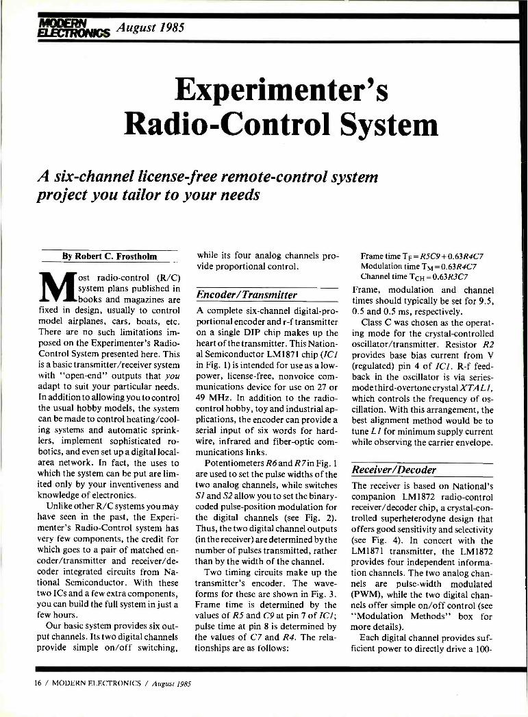
Experimenter's Radio -Control System
A six -channel license free remote -control system project you tailor to your needs
By Robert C. Frostholm
Most
radio -control (R /C) system plans published in books and magazines are
fixed in design, usually to control model airplanes, cars, boats, etc. There are no such limitations im- posed on the Experimenter's Radio - Control System presented here. This is a basic transmitter /receiver system with "open -end" outputs that you adapt to suit your particular needs. In addition to allowing you to control the usual hobby models, the system can be made to control heating /cool- ing systems and automatic sprink- lers, implement sophisticated ro- botics, and even set up a digital local - area network. In fact, the uses to which the system can be put are lim- ited only by your inventiveness and knowledge of electronics.
Unlike other R/C systems you may have seen in the past, the Experi- menter's Radio -Control system has very few components, the credit for which goes to a pair of matched en- coder /transmitter and receiver /de- coder integrated circuits from Na- tional Semiconductor. With these two ICs and a few extra components, you can build the full system in just a few hours.
Our basic system provides six out- put channels. Its two digital channels provide simple on /off switching,
while its four analog channels pro- vide proportional control.
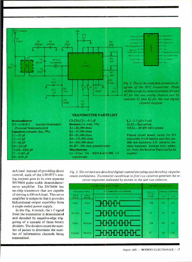
Encoder /Transmitter A complete six -channel digital -pro- portional encoder and r -f transmitter on a single DIP chip makes up the heart of the transmitter. This Nation- al Semiconductor LM1871 chip (ICI in Fig. 1) is intended for use as a low - power, license -free, nonvoice com- munications device for use on 27 or 49 MHz. In addition to the radio - control hobby, toy and industrial ap- plications, the encoder can provide a serial input of six words for hard- wire, infrared and fiber -optic com- munications links.
Potentiometers R6 and R7in Fig. 1
are used to set the pulse widths of the two analog channels, while switches SI and S2 allow you to set the binary - coded pulse -position modulation for the digital channels (see Fig. 2). Thus, the two digital channel outputs (in the receiver) are determined by the number of pulses transmitted, rather than by the width of the channel.
Two timing circuits make up the transmitter's encoder. The wave- forms for these are shown in Fig. 3. Frame time is determined by the values of R5 and C9 at pin 7 of ICI; pulse time at pin 8 is determined by the values of C7 and R4. The rela- tionships are as follows:
Frame time TF = R5C9 + 0.63R4C7 Modulation time TM = 0.63R4C7 Channel time TCH = 0.63R3C7
Frame, modulation and channel times should typically be set for 9.5, 0.5 and 0.5 ms, respectively.
Class C was chosen as the operat- ing mode for the crystal -controlled oscillator /transmitter. Resistor R2 provides base bias current from V (regulated) pin 4 of ICI. R -f feed- back in the oscillator is via series - mode third -overtone crystal XTAL 1,
which controls the frequency of os- cillation. With this arrangement, the best alignment method would be to tune LI for minimum supply current while observing the carrier envelope.
Receiver /Decoder The receiver is based on National's companion LM1872 radio -control receiver /decoder chip, a crystal -con- trolled superheterodyne design that offers good sensitivity and selectivity (see Fig. 4). In concert with the LM1871 transmitter, the LM1872 provides four independent informa- tion channels. The two analog chan- nels are pulse -width modulated (PWM), while the two digital chan- nels offer simple on /off control (see "Modulation Methods" box for more details).
Each digital channel provides suf- ficient power to directly drive a 100-
16 / MODERN ELECTRONICS / August 1985
Antenna
L2 2 7p
Cl 33n_
_..
C5 C6
2200pF 22C0pF
+9V
C4 XTAL1 49.405 M H z
(0V
220 pF
C2
47pF
C3 621E
1--)I C10 .1yr"
F2 47K
Semiconductors ICI -LM 1871 encoder /transmitter
(National Semiconductor) Capacitors (ceramic disc, 507o)
CI -33 pF C2-47 pF C3 -62 pF C4 -220 pF C5,C6 -2200 pF C7 -0.005 AF
R5 200K
C9 IA,F
((
F' 3
31K -^.n.\
C7 -
005pF
TRANSMITTER PART LIST
C9,C10,C11 -0.1 µF Resistors (l/ -watt, 507o)
R1-20,000 ohms R2- 47,000 ohms R3- 91,000 ohms R4- 100,00 ) ohms R5- 200,00 ohms R6,R7 -500 -ohm potentiometer Miscellaneous LI -Toko No. KEN-K46:5..1 BE r -f
Channel 3
Channel 2
Chanrr
t e+V. fregulatert
:hannel A ADD logrc B
Frame turner
Dulse timer
Ground
Channel 4
Channel 5
Modulator output
Modulator fuit,,
r -f output
Bra.
F.g. 1. This is .'he complete schematic di- agram of the R/C transmitter. Pulse widths are set by potentiometers R6 and R7 for the two cnahg channel and by switches SI and S2 for the two digital
channel outputs.
L2 -2.7- d-1 r -f toil SI,S2 -Spst switch XTAL -49.405 M1=z crystal
Printed circuit board; socket for ICI :o,tional); 9 -volt battery and clip; suit- able size endosare; 2 -ft. antenna; ma- :hine hardware hookup wire, solder; etc. Note: See Receiver Parts List for kit supplier.
mA load. Instead of providing direct control, each of the LM1872's ana- log outputs goes to its own separate SN76604 pulse -width demodulator/ servo amplifier. The SN76604 has on -chip transistors that are capable of driving a 400 -mA load. This servo amplifier is unique in that it provides bidirectional output capability from a single -ended power supply.
In the Fig. 4 circuit, the r -f signal from the transmitter is demodulated and decoded by negative -edge trig- gering of a cascade of three binary dividers. The dividers count the num- ber of pulses to determine the num- ber of information channels being transmitted.
Fig. 2. Shown here are detailsof digital channel encoding and decoding via pulse - count modulation. Transmitter conditions in first two columns generate the re-
ceiver responses indicated by entries in the last two columns.
PIN CONDI -1ON3 TI: "N9U17TED WAVEFOHIaI
PIN 5 ICH Al
PIN 4 (CH BI
Open
Ground
Open
Ofen
Open
.round
Ground round
31NA ìY PUL` E
COUNT
100
10
CH C CH B
Orr Off
On Off
Off On
An On
August 1985 ! MODERN ELECTRONICS / 17
What can you do Just about
CE can show you how. Computer tech nology Satellite communications. Cable television. Cellular radio Digital electronics. Robotics. Just a few cf the hottest career areas in electronics. The ones eerybody is talking about. The ones that are changing the way we live, the way we do be siness, the way we enter- tain ourselves. The best way to start a career in any of them? By learling the basic electrcnics theory and principles of how they worK from CIE.
Join a leader. Leading the world in specialized electronics train- ing, CIE is the largest school of its kind wit- over 25,000 studen_s at home and abroad. And with over 50 years of experience teatting electronics to thousands cf men and women through proven
methods of independent si r i without class- room sessions.
Learn as much as you want. when you want. Whether you're interested in learning new skills or upgrading old ones, earning a diploma or an A.A.S. degree, CIE can match your needs with courses and programs that let you start where you want, go as far as you wart from a basic beginner course all the way to CIES Associate in Applied Science Degree in Electronics -a comprehensive program that prepares you for advanced electronics careers.
Custom training equipment helps you learn. CIE believes in the importance of learning by
with electronics? anything.
doing. So most of our courses include special- ized training laboratories keyed to specific less- ons for practical experience through teaching experiments. Our CIE Microprocessor, for example, comes fully assembled and ready to use to teach you how a computer CPU works through a series of experiments you perform on your own.
Are you ready? If you're ready to do something now about your future, there's no waiting to enroll with CIE. Get all the information you need to enroll simply by calling us toll -free at 1- 800 -321 -2155 (in Ohio, 1 -800- 362- 2105). Or mail in the handy reply coupon or card to Cleveland Institute of Electronics, 1776 East 17th Street, Cleveland, Ohio 44114. CIRCLE 79 ON FREE INFORMATION CARD
Worlid Headquarters Cleveland Institute of Electronics, Inc. 1776 East 17th Street Cleveland, Ohio 44114
L] Please send me your CIE Off- Campus Studies Catalog, including details about the Associate Degree program. I understand there is no cost for the catalog and a CIE representative may call, but there is no obligation.
Print Name
Address Apt. No.
City_ State Zip
Age Area Codez Phone No
Check box for G.I. Bill bulletin on Educational Benefits
Veteran I I Active Duty
MAIL TODAY! MO-38
LM 1872
Pin 7
150ms to On 190ms to Off
LM 1872 Pin 9
2.7K 390
(A) RELAY DRIVER
25pF
50ms to On 200ms to Off
51K 30K
(BI SOUND EFFECTS CIRCUIT DRIVER -
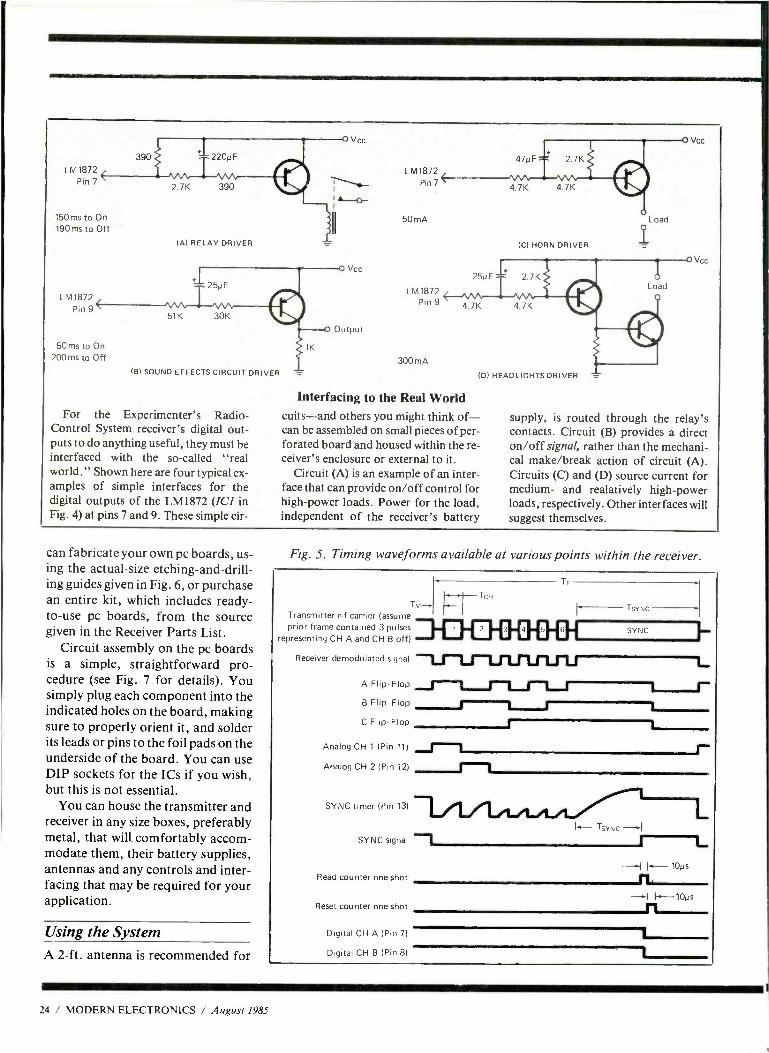
For the Experimenter's Radio - Control System receiver's digital out- puts to do anything useful, they must be interfaced with the so- called "real world." Shown here are four typical ex- amples of simple interfaces for the digital outputs of the LM 1872 (ICI in Fig. 4) at pins 7 and 9. These simple cir-
1K
V cc
Vcc
Output
LM1872 Pin 7(
50 mA
300 mA
47µF 2.7 K
4.7K 4.7K
(
(C) HORN DRIVER
Load
O Vcc
25µF 2 /K
Pin 9 4.7K 4.7K
d
(D) HEADLIGHTS DRIVER
Interfacing to the Real World cuits -and others you might think of- can be assembled on small pieces of per- forated board and housed within the re- ceiver's enclosure or external to it.
Circuit (A) is an example of an inter- face that can provide on /off control for high -power loads. Power for the load, independent of the receiver's battery
Vcr,
supply, is routed through the relay's contacts. Circuit (B) provides a direct on /off signal, rather than the mechani- cal make /break action of circuit (A). Circuits (C) and (D) source current for medium- and realatively high -power loads, respectively. Other interfaces will suggest themselves.
can fabricate your own pc boards, us- ing the actual -size etching- and -drill- ing guides given in Fig. 6, or purchase an entire kit, which includes ready - to -use pc boards, from the source given in the Receiver Parts List.
Circuit assembly on the pc boards is a simple, straightforward pro- cedure (see Fig. 7 for details). You simply plug each component into the indicated holes on the board, making sure to properly orient it, and solder its leads or pins to the foil pads on the underside of the board. You can use DIP sockets for the ICs if you wish, but this is not essential.
You can house the transmitter and receiver in any size boxes, preferably metal, that will comfortably accom- modate them, their battery supplies, antennas and any controls and inter- facing that may be required for your application.
Using the System A 2 -ft. antenna is recommended for
Fig. 5. Timing waveforms available at various points within the receiver.
TM4 Transmitter r -f carrier (assume prior frame contained 3 pulses
representing CH A and CH B off)
Receiver demodulated signal
TF
TSYNC
III IN 1 I 1 1 SYNC
A Flip -Flop f B Flip -Flop 1
C Flip -Flop
u Analog CH 1 (Pin 111 fÌ Analog CH 2 (Pin 12) Ì SYNC timer (Pin 13) I f , . I
SYNC signal J I
Read counter one shot
Reset counter one shot
Digital CH A (Pin 7)
Digital CH B (Pin 8)
L
I--- 10 .:,
f7. I -10,:
n t
24 / MODERN ELECTRONICS / August 1985
ea
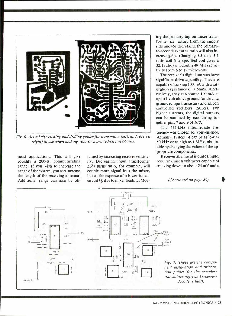
Fig. 6. Actual -size etching -and drilling guides for transmitter (left) and receiver (right) to use when making your own printed- circuit boards.
most applications. This will give roughly a 200 -ft. communicating range. If you wish to increase the range of the system, you can increase the length of the receiving antenna. Additional range can also be ob-
tained by increasing receiver sensitiv- ity. Decreasing input transformer L5's turns ratio, for example, will couple more signal into the mixer, but at the expense of a lower tuned- circuit Q, due to mixer loading. Mov-
ing the primary tap on mixer trans- former L3 farther from the supply side and /or decreasing the primary - to- secondary turns ratio will also in- crease gain. Changing L3 to a 5:1 ratio coil (the specified coil gives a 32:1 ratio) will double 49 -MHz sensi- tivity from 6 to 12 microvolts.
The receiver's digital outputs have significant drive capability. They are capable of sinking 100 mA with a sat- uration resistance of 7 ohms. Alter- natively, they can source 100 mA at up to 1 volt above ground for driving grounded npn transistors and silicon controlled rectifiers (SCRs). For higher currents, the digital outputs can be summed by connecting to- gether pins 7 and 9 of IC2.
The 455 -kHz intermediate fre- quency was chosen for convenience. Actually, system i -f can be as low as 50 kHz or as high as 1 MHz, obtain- able by changing the values of the ap- propriate components.
Receiver alignment is quite simple, requiring just a voltmeter capable of tracking down to about 25 mV and a
(Continued on page 89)
R7-1
6
-RI-
.14.
) qV.
6V 4- R10
C26 R24 --N. (25 R23
GNO-
Analog outputs
II I
103
L4
3
xI -R12- -R26-
C23 C27
R11
_ I_ R26-
IC2
-C18-
Ei I
Jal x
117
C30
IC4
Digital
Digital
output 2
SAnten
Fig. 7. These are the compo- nent installation and orienta- tion guides for the encoder/ transmitter (left) and receiver/
decoder (right).
August 1985 / MODERN ELECTRONICS / 25
Computers
Portable Computers '85: One Lap Ahead
Part 2 (Conclusion)
By Eric Grevstad
Last month, we gave you a brief history of the evolving con- cept of "portable" computers
and then concentrated attention on the modern true portable -the stand- alone laptop you can use anywhere. In this installment, we'll tell you about the laptops already competing for your dollars and give you some insights on new models being readied for marketing later on this year or early next year.
This Year's Candidates Turning to today's laptop comput- ers, the first new portables for 1985 turned the tables on the DG /One and IBM gossip at the upper end of the market. Three portable pioneers re- affirmed their commitment to the under -$1000 category, with second - generation machines that feature flip -up LCD screens.
The most familiar is the Tandy 200 ($999), which is a Model 100 with the complaints answered. Judging 80- column LCD characters just too small for comfortable reading, Tan- dy stayed with its 40- column width, but doubled the vertical measure to 16 lines. Simultaneously, small im- provements to the 100's other defi- ciencies were made: a modem that supports tone as well as pulse dialing, handier cursor movement keys for the keyboard, and 24K RAM ex- pandable to 72K (in three banks).
The Tandy's Microsoft ROMware
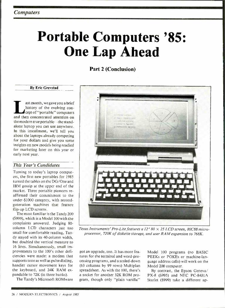
Texas Instruments' Pro -Lite features a 12" 80 x 25 LCD screen, 80088 micro- processor, 720K of diskette storage, and user RAM expansion to 768K.
got an upgrade, too. It has more fea- tures for the terminal and word -pro- cessing programs, and a scaled -down (63 columns by 99 rows) Multiplan spreadsheet. As with the 100, there's a socket for another 32K ROM pro- gram, though only "plain vanilla"
Model 100 programs (no BASIC PEEKs or POKEs or machine -lan- guage address calls) will work on the Model 200 computer.
By contrast, the Epson Geneva/ PX -8 ($995) and NEC PC -8401A Starlet ($999) take a different ap-
26 / MODERN ELECTRONICS / August 1985
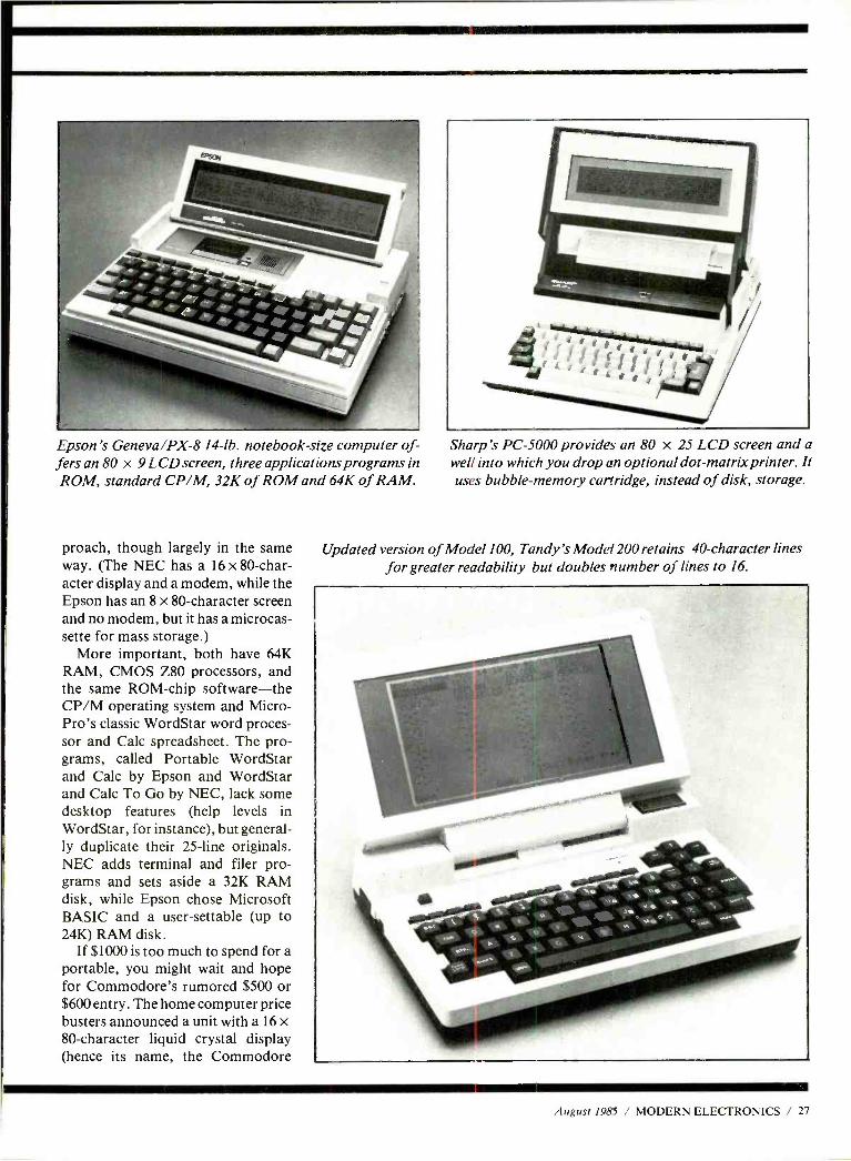
Epson's Geneva/PX-8 14-1b. notebook -size computer of- fers an 80 x 9 LCD screen, three applications programs in ROM, standard CP /M, 32K of ROM and 64K of RAM.
proach, though largely in the same way. (The NEC has a 16 x 80 -char- acter display and a modem, while the Epson has an 8 x 80- character screen and no modem, but it has a microcas- sette for mass storage.)
More important, both have 64K RAM, CMOS Z80 processors, and the same ROM -chip software -the CP /M operating system and Micro - Pro's classic WordStar word proces- sor and Calc spreadsheet. The pro- grams, called Portable WordStar and Calc by Epson and WordStar and Calc To Go by NEC, lack some desktop features (help levels in WordStar, for instance), but general- ly duplicate their 25 -line originals. NEC adds terminal and filer pro- grams and sets aside a 32K RAM disk, while Epson chose Microsoft BASIC and a user -settable (up to 24K) RAM disk.
If $1000 is too much to spend for a portable, you might wait and hope for Commodore's rumored $500 or $600 entry. The home computer price busters announced a unit with a 16 x 80- character liquid crystal display (hence its name, the Commodore
Sharp's PC -5000 provides an 80 x 25 LCD screen and a well into which you drop an optional dot -matrix printer. It uses bubble -memory cartridge, instead of disk, storage.
Updated version of Model 100, Tandy's Model 200 retains 40- character lines for greater readability but doubles number of lines to 16.
August 1985 / MODERN ELECTRONICS / 27
Between myself and Modern Electron- ics staffers, we've used or observed op- eration of most of the portable comput- ers on the market. Here are some quick impressions.
The TRS -80 Model 100 is showing its age, we'll grant you: a modest 8 -line, 40- column display, 32K RAM maxi- mum, and clumsy cassette tapes for mass storage. But third -party products have fixed the latter two problems, and Tandy's price cuts have created a bar- gain -$599 with 24K RAM, a first -rate keyboard, a text editor, and built -in modem that make the 100 a fine note - taking and telecommunications ma- chine. Also, this computer is compactly built, unlike later models that feature adjustable displays.
Tandy's latest portable, the Model 200, corrects some shortcomings ex- hibited by the 100, such as having more RAM, ROM, and a 16 -line display. It's also bigger, due to its hinged display and, of course, pricier. Complain all you want about the limitations of 40- character lines: bigger characters are easier to read.
Epson's Geneva /PX -8 is a big im- provement over its pioneer HX -20 port- able. Besides a fairly legible 8 x 80 -char- acter LCD, the $995 machine offers a slow- but -useful microcassette drive, a
Hands -On Impressions versatile operating menu, and CP /M 2.2, BASIC, and Micropro's full -fea- tured Portable WordStar and Portable Calc. A drawback of this computer is that there are only two sockets for the four ROM software capsules.
Too bad, though, that the PX -8 doesn't have a built -in modem or a parallel printer interface. Even so, the under -$1000 laptop's on -board mass storage makes it worth a try, though its keyboard travel is a bit shallow and stiff for comfortable typing.
If you're willing to give up BASIC, NEC's PC -8401A Starlet offers similar software (plus a filer program), a full set of input /output ports that include par- allel and serial interfaces, a built -in mo- dem, and a 16 -line screen. It's a neat package, though like others of its kind not as compact as the Tandy 100... nor as easy to read, tiltable display or no.
Sharp's PC -5000 is a novel portable with its bubble memory. The unit worked nicely, though there is some question as to the future of this type of user memory. For its $1695 price you also get MS -DOS and a slew of software.
Next up in price is Data General /One, a $2895 package that's also supplied with MS -DOS, word processing, and communications software . . . and a 3 / " disk drive. Its 25 -line x 80- column
screen emulates what the conventional business computers feature. But legibil- ity of characters on its LCD screen leaves much to be desired.
It's $2995 price needs cutting, but otherwise the Hewlett- Packard HP -110 has few faults: a skimpy word processor (HP's MemoMaker) and poor success at sharing IBM PC programs (though a $150 interface card makes swapping data files easy).
Past that, HP's is one of the best -en- gineered portables around: a fairly readable 16 x 80 screen, 272K of user memory, and the best menu or operat- ing system shell I've seen: Personal Ap- plications Manager (PAM), which con- trols everything from setting up RAM disks to keeping tabs on battery charge. Thanks to the 110's mighty ROM and 80086 chip, Lotus 1 -2 -3 loads and runs faster in your lap than on a desktop.
Fast typists will find the keyboard a bit stiff, and I found myself preferring the HP's program menu and built -in software to its limited MS -DOS talents -which is why I call it the ultimate Model 100, rather than a laptop PC. That doesn't make it any less desirable, though I wish I'd had Hewlett Pack - ard's external disk drive and the chance to try some other software. The Osborne 3, by contrast, is defi-
Hewlett -Packard's 9 -lb. The Portable comes with three built -in software packages and an 80 x 16 LCD screen.
NEC's Model PC -8401A offers full 64K of RAM, built -in business software, 300 -baud modem, 80 x 16LCDscreen.
28 / MODERN ELECTRONICS / August 1985
nitely a would -be desktop: awkward in your lap, but ready to run standard 5'/ -inch floppy disks. I spent a week with an early production model, which impressed me as a reasonably handy traveler, and ran about half of my MS- DOS library (flunking with graphics programs and software written specially for IBM hardware).
The keyboard was crowded by re- sponsive, and the 16 x 80 screen's world map, desk clock, and calculator dis- tracted me from its incredibly noisy disk drives. But the $2595 Osborne's slow screen response dropped half the char- acters I typed. Without more debug- ging, I doubt the 3 will pull its own in the marketplace.
And finally there's the Grid Com- pass, the highest priced portable of the lot at $4995. Everything else aside (like mucho RAM, a 300 /1200 -baud modem, and so on), my reaction to it is much the same as anyone else's: "I can see, I can see!" Any LCD screen literally pales next to an ELD, which is the computer's hallmark.
We'll have to wait on the newly an- nounced portables: Morrow's "Super Pivot" glow -in- the -dark screen and Grid Systems' new gas- plasma- screen port- able, among the offerings.
-Eric Grevstad.
Counterpoint
While I agree with Eric's comments, there's more to portable computers than meets the eye. In fact, what meets the eye is a major consideration.
Using the Tandy /Radio Shack Model 100 when it debuted, I was struck by the limitations of the LCD screen, the 40- column by 8 -line display, the ab- sence of on -board mass storage, and its low memory capacity. Nonetheless, it could be a handy machine, I felt, es- pecially if there was a home or office computer system that could provide download and upload facilities. Carry- ing along a small portable cassette re- corder would solve a need for more memory, too.
My reservations about the 100 were soon countered by more advanced por- tables reaching the market. Now I could use a portable that featured a full 80 characters, just like I'd see on 8 % "-
wide paper, as well as many more lines. You know what? I have to twist and turn to read the smaller characters dis- played, and even with a tilt screen, you can keep your 80- character format with current LCD screens! Tandy /Radio Shack was smart to retain only 40 char- acters per line.
Then came models with more RAM
power, more built -in programs, and now floppy -disk provisions. Real oper- ating systems like CP /M and MS -DOS, too. You know what, again? The ma- chines are no longer little portables to be tucked into one's attache case. They're cases unto themselves. This reminds me of the evolution of portable TV receiv- ers, which quickly became 19 "- screen, very heavy models, with a handle stuck on its top. Portable?
Given what I see to date, at the price, I
just don't like 'em ... at all. Given my druthers, I'll take a "transportable" any day and forego inputting data while on the fly. A Compaq or Zenith trans- portable would do just fine, thank you, or some equivalent to them. I haven't seen George Morrow's new Pivot or Zenith's version of it, so comments here don't apply. The new Tandy 200 is okay by me, with mixed emotions on 40 col- umns (I can read it, but what you see is not what you get).
Oh, for the good old days! Come to think of it, they're still here since the original TRS -100 is still around at a massive discount now. So I take back my three wishes when I first worked with the 100. If I want truly portable computing and easier -to -read display, at a modest price, I'd take the 100 at this point in time. -Art Salsberg.
LCD), 32K RAM, a modem, and word -processing, spreadsheet, data- base, communications, and appoint- ment software in 96K of ROM. The machine should be Commodore 64 compatible; I hope, however, that the built -in software isn't the awful stuff from the Plus /4.
Big Disks & Backlighting While CP /M and Commodore in- vade one end of the market, MS -DOS tightens its grip on the other. The DG /One and its IBM ghost rival may make 3 V2 "microfloppies a standard, but three new portables aim for PC compatibility by running off -the- shelf 5 " disks.
The slickest is the Datavue 25, sold by Quadram Corp. ($2195 with 128K RAM and one drive). The Datavue resembles a lunchbox with a 25 x 80- character screen; like the DG /One, it's built around Intel's 80088, the CMOS version of the PC's micropro- cessor. There's also a PCjr -style cordless infrared keyboard.
At 14 pounds, the Datavue is better slung over your shoulder than put in your briefcase. With a nondetach- able keyboard and nine fewer display lines, it would be a triplet for two 16 x 80- character models, the Os- borne 3 and Morrow Pivot (each $2595 with 128K and two drives).
Both models, designed by a Cali-
fornia subcontractor, feature an 80086 CPU, skinny one -third -height floppy drives, and ROM software that includes a calculator, phone dialer, and deluxe world map and desk clock. Osborne offers expan- sion to 512K and two drives ($3395).
Morrow, which goes up to 640K and two drives ($2795), promises su- perior readability, thanks to a "secret" backlighting technique, turning its LCD into bright charac- ters on a black background. Chair- man George Morrow boasts that the trick costs far less than an electro-
(Continued on page 86)
August 1985 / MODERN ELECTRONICS / 29
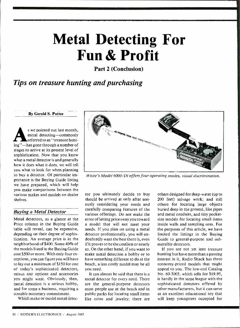
Metal Detecting For Fun & Profit
Part 2 (Conclusion)
Tips on treasure hunting and purchasing
By Gerald S. Pattee
As we pointed out last month, metal detecting -commonly referred to as "treasure hunt-
ing" -has gone through a number of stages to arrive at its present level of sophistication. Now that you know what a metal detector is and generally how it does what it does, we will tell you what to look for when planning to buy a detector. Of particular im- portance is the Buying Guide listing we have prepared, which will help you make comparisons between the various makes and models on dealer shelves.
Buying a Metal Detector Metal detectors, as a glance at the Price column in the Buying Guide table will reveal, can be expensive, depending on their degree of sophis- tication. An average price is in the neighborhood of $400. Some 40% of the models listed in the Buying Guide cost $500 or more. With only four ex- ceptions, you can figure you will have to lay out a minimum of $150 for one of today's sophisticated detectors, minus any options and accessories you might want. Obviously, then, metal detection is a serious hobby, and for some a business, requiring a sizeable monetary commitment.
Which make or model metal detec-
White's Model 6000 /Di offers four operating modes, visual discrimination.
tor you ultimately decide to buy should be arrived at only after seri- ously considering your needs and carefully comparing features of the various offerings. Do not make the error of letting price sway you toward a model that will not meet your needs. If you plan on using a metal detector professionally, you will un- doubtedly want the best there is, even if it proves to be the costliest or nearly so. On the other hand, if you want to make metal detection a hobby or to have something different to do at the beach, a less costly model may be all you need.
It can almost be said that there is a metal detector for every need. There are the general -purpose detectors most people use at the beach and in public parks for locating small items like coins and jewelry; there are
others designed for deep -water (up to 200 feet) salvage work; and still others for locating large objects buried deep in the ground, like pipes and metal conduits, and tiny pocket - size models for locating small items inside walls and sampling ores. For the purposes of this article, we have limited the listings in the Buying Guide to general -purpose and sub- mersible detectors.
If you are not yet into treasure hunting but have more than a passing interest in it, Radio Shack has three economy -priced models that might appeal to you. The low -end Catalog No. 60 -3003, which sells for $19.95, is hardly in the same league with the sophisticated detectors offered by other manufacturers, but it can serve as an excellent educational toy that will keep youngsters occupied for
30 / MODERN ELECTRONICS / August 1985
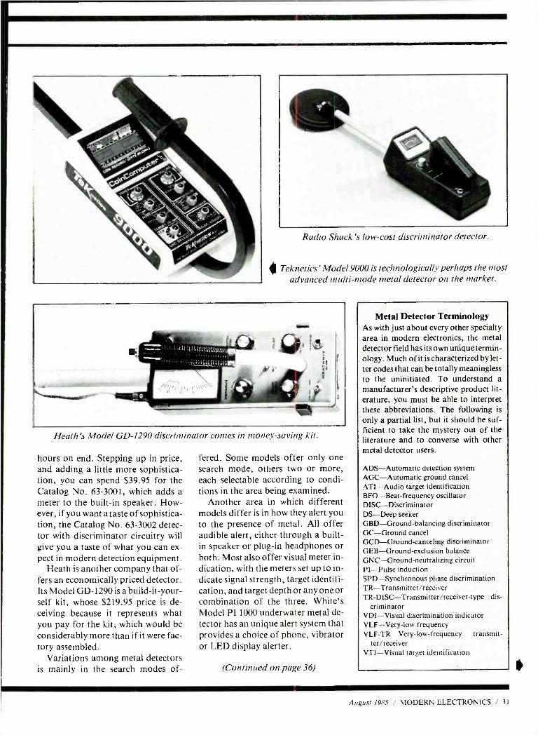
Radio Shack's low -cost discriminator detector.
Teknetics' Model 9000 is technologically perhaps the most advanced multi -mode metal detector on the market.
I I O1111 11,141;411
Heath's Model GD -1290 discriminator comes in money- saving kit.
hours on end. Stepping up in price, and adding a little more sophistica- tion, you can spend $39.95 for the Catalog No. 63 -3001, which adds a meter to the built -in speaker. How- ever, if you want a taste of sophistica- tion, the Catalog No. 63 -3002 detec- tor with discriminator circuitry will give you a taste of what you can ex- pect in modern detection equipment.
Heath is another company that of- fers an economically priced detector. Its Model GD -1290 is a build -it -your- self kit, whose $219.95 price is de- ceiving because it represents what you pay for the kit, which would be considerably more than if it were fac- tory assembled.
Variations among metal detectors is mainly in the search modes of-
fered. Some models offer only one search mode, others two or more, each selectable according to condi- tions in the area being examined.
Another area in which different models differ is in how they alert you to the presence of metal. All offer audible alert, either through a built - in speaker or plug -in headphones or both. Most also offer visual meter in- dication, with the meters set up to in- dicate signal strength, target identifi- cation, and target depth or any one or combination of the three. White's Model PI 1000 underwater metal de- tector has an unique alert system that provides a choice of phone, vibrator or LED display alerter.
(Continued on page 36)
Metal Detector Terminology As with just about every other specialty area in modern electronics, the metal detector field has its own unique termin- ology. Much of it is characterized by let- ter codes that can be totally meaningless to the uninitiated. To understand a
manufacturer's descriptive product lit- erature, you must be able to interpret these abbreviations. The following is
only a partial list, but it should be suf- ficient to take the mystery out of the literature and to converse with other metal detector users.
ADS -Automatic detection system AGC- Automatic ground cancel ATI -Audio target identification BFO- Beat -frequency oscillator DISC -Discriminator DS -Deep seeker GBD- Ground -balancing discriminator GC- Ground cancel GCD- Ground -canceling discriminator GEB- Ground -exclusion balance GNC- Ground -neutralizing circuit PI -Pulse induction SPD- Synchronous phase discrimination TR- Transmitter /receiver TR- DISC -Transmitter /receiver -type dis-
criminator VDI- Visual discrimination indicator VLF -Very -low frequency VLF -TR- Very -low- frequency transmit-
ter /receiver VTI- Visual target identification
August 1985 / MODERN ELECTRONICS / 31
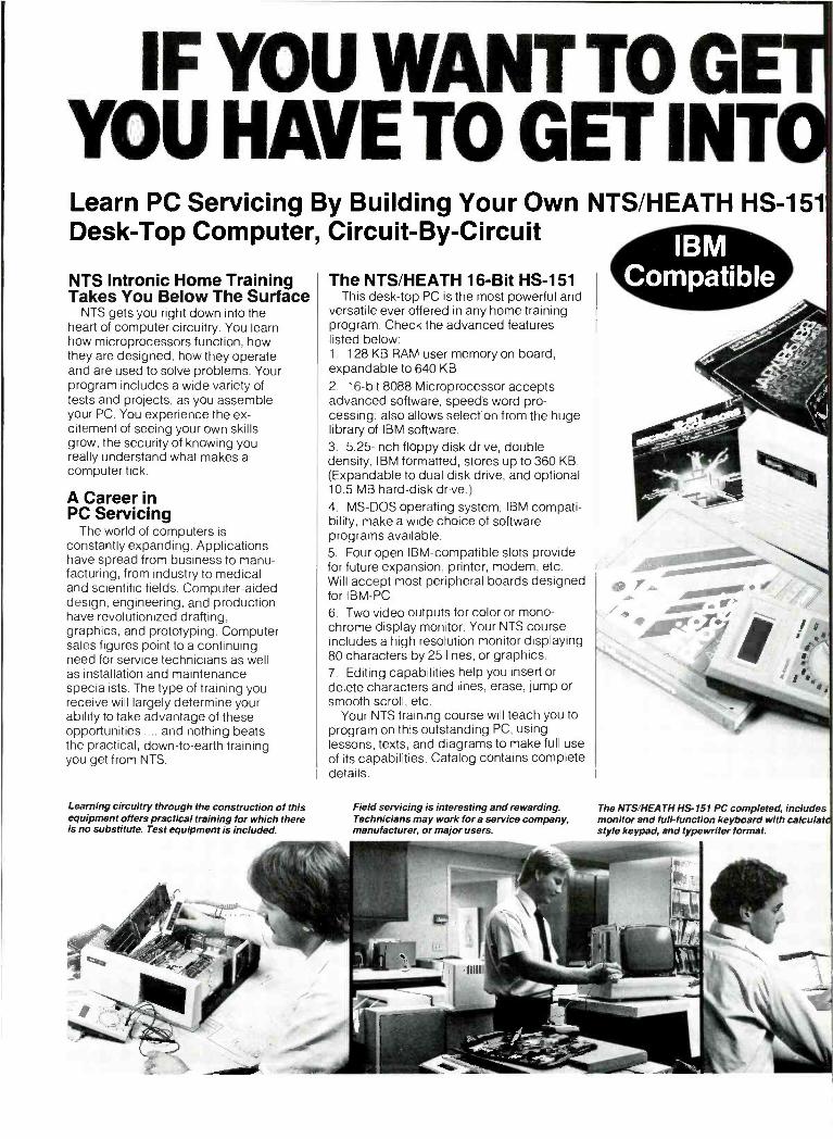
IF YOU WANT TO GE YOU HAVE TO GET INT Learn PC Servicing By Building Your Own NTS /HEATH HS -151 Desk -Top Computer, Circuit -By- Circuit
NTS Intronic Home Training Takes You Below The Surface
NTS gets you right down into the heart of computer circuitry. You learn how microprocessors function, how they are designed, how they operate and are used to solve problems. Your program includes a wide variety of tests and projects, as you assemble your PC. You experience the ex- citement of seeing your own skills grow, the security of knowing you really understand what makes a computer tick.
A Career in PC Servicing
The world of computers is constantly expanding. Applications have spread from business to manu- facturing, from industry to medical and scientific fields. Computer -aided design, engineering, and production have revolutionized drafting, graphics, and prototyping. Computer sales figures point to a continuing need for service technicians as well as installation and maintenance specialists. The type of training you receive will largely determine your ability to take advantage of these opportunities .... and nothing beats the practical, down -to -earth training you get from NTS.
Learning circuitry through the construction of this equipment offers practical training for which there is no substitute. Test equipment is included.
The NTS /HEATH 16 -Bit HS -151 This desk -top PC is the most powerful and
versatile ever offered in any home training program. Check the advanced features listed below: 1. 128 KB RAM user memory on board, expandable to 640 KB
2. 16 -bit 8088 Microprocessor accepts advanced software, speed's word pro- cessing; also allows selection from the huge library of IBM software. 3. 5.25 -inch floppy disk drive, double density, IBM formatted, stores up to 360 KB. (Expandable to dual disk drive, and optional 10.5 MB hard -disk drive.) 4. MS -DOS operating system, IBM compati- bility, make a wide choice of software programs available. 5. Four open IBM -compatible slots provide for future expansion, printer, modem, etc. Will accept most peripheral boards designed for IBM -PC.
6. Two video outputs for color or mono- chrome display monitor. Your NTS course includes a high resolution monitor displaying 80 characters by 25 lines, or graphics. 7. Editing capabilities help you insert or delete characters and lines, erase, jump or smooth scroll, etc.
Your NTS training course will teach you to program on this outstanding PC, using lessons, texts, and diagrams to make full use of its capabilities. Catalog contains complete details.
Field servicing is interesting and rewarding. Technicians may work fora service company, manufacturer, or major users.
The NTS /HEATH HS -151 PC completed, includes monitor and full- function keyboard with calculat style keypad, and typewriter format.
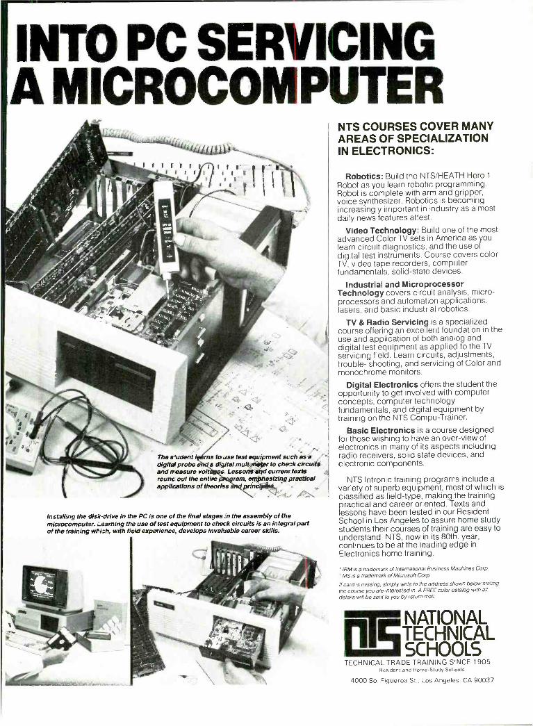
INTO PC SERVICING A MICROCOMPUTER
The s-udent I rns to , se test equipment St ch as a digits+ probe a é digital mull meter to check circuits and n easure volt s. Lessons ar d currenr texts rounc out the entire ram, emphasizing practical applications of theoriss princlpfs, -
lnsta!Lng the disk -drive in the PC is one of the final stages n the assembly of the microcomputer. yearning the use of test equipment to check circuits is an integral part of the (training which, with field experience develops invaluable career skills.
NTS COURSES COVER MANY AREAS OF SPECIALIZATION IN ELECTRONICS:
Robotics: Build the NTS /HEATH Hero 1
Robot as you learn robotic programming. Robot is complete with arm and gripper, voice synthesizer. Robotics is becoming increasingly important in industry as almost daily news features attest.
Video Technology: Build one of the most advanced Color TV sets in America as you learn circuit diagnostics, and the use of digital test instruments. Course covers color TV, video tape recorders, computer fundamentals, solid -state devices.
Industrial and Microprocessor Technology covers circuit analysis, micro- processors and automation applications, lasers, and basic industrial robotics.
TV & Radio Servicing is a specialized course offering an excellent foundation in the use and application of both analog and digital test equipment as applied to the TV servicing field. Learn circuits, adjustments, trouble- shooting, and servicing of Color and monochrome monitors.
Digital Electronics offers the student the opportunity to get involved with computer concepts, computer technology fundamentals, and digital equipment by training on the NTS Compu- Trainer.
Basic Electronics is a course designed for those wishing to have an over -view of electronics in many of its aspects including radio receivers, solid state devices, and electronic components.
NTS Intronic training programs include a variety of superb equipment, most of which is classified as field -type, making the training practical and career oriented. Texts and lessons have been tested in our Resident School in Los Angeles to assure home study students their courses of training are easy to understand NTS, now in its 80th. year, continues to be at the leading edge in Electronics home training.
' IBM is a trademark of International Business Machines Corp.
' MS is a trademark of Microsoft Corp.
If card is missing, simply write to the address shown below stating the course you are interested in. A FREE color catalog with all details will be sent to you by return mail
NATIONAL TECHNICAL SCHOOLS
TECHNICAL TRADE TRAINING SINCE 1905 Resident and Home -Study Schools
4000 So. Figueroa St., Los Angeles, CA 90037
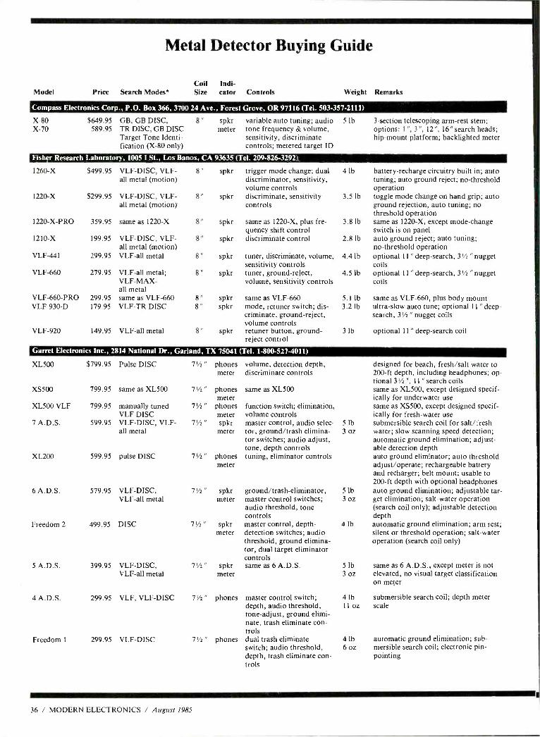
Model
Metal Detector Buying Guide
Price Search Modes* Coil Indi- Size cator Controls Weight Remarks
Compass Electronics Corp., P.O. Box 366, 3700 24 Ave., Forest Grove, OR 97116 (Tel. 503- 357 -2111)
X-80 X-70
$649.95 589.95
GB, GB DISC, TR DISC, GB DISC Target Tone Identi- fication (X -80 only)
8" spkr meter
variable auto tuning; audio tone frequency & volume, sensitivity, discriminate controls; metered target ID
5 lb 3- section telescoping arm -rest stem; options: 1", 3 ", 12 ", 16 " search heads; hip -mount platform; backlighted meter
Fisher Research Laboratory, 1005 I St., Los Banos, CA 9363S (T el. 209-826-3292)
1260 -X $499.95 VLF -DISC, VLF - all metal (motion)
spkr
1220 -X $299.95 VLF -DISC, VLF- all metal (motion)
8" spkr
1220 -X -PRO 359.95 same as 1220 -X 8" spkr
1210 -X 199.95 VLF -DISC, VLF - all metal (motion)
8" spkr
VLF -441 299.95 VLF -all metal 8" spkr
VLF -660 279.95 VLF -all metal; 8" spkr VLF -MAX- all metal
VLF -660 -PRO 299.95 same as VLF -660 8" spkr VLF -930 -D 179.95 VLF -TR DISC 8" spkr
VLF -920 149.95 VLF -all metal 8" spkr
trigger mode change; dual discriminator, sensitivity, volume controls discriminate, sensitivity controls
same as 1220 -X, plus fre- quency shift control discriminate control
tuner, discriminate, volume, sensitivity controls tuner, ground- reject, volume, sensitivity controls
same as VLF -660 mode, retuner switch; dis- criminate, ground- reject, volume controls retuner button, ground - reject control
4 lb battery- recharge circuitry built in; auto tuning; auto ground reject; no- threshold operation
3.5 lb toggle mode change on hand grip; auto ground rejection, auto tuning; no threshold operation
3.8 lb same as 1220 -X, except mode -change switch is on panel
2.8 lb auto ground reject; auto tuning; no- threshold operation
4.4 lb optional 11" deep -search, 31/2 " nugget coils
4.5 lb optional 11" deep -search, 31/2 " nugget coils
5.1 lb same as VLF -660, plus body mount 3.2 lb ultra -slow auto tune; optional 11" deep -
search, 31/2 " nugget coils
3 lb optional 11" deep- search coil
Garret Electronics Inc., 2814 National Dr., Garl and, TX 75041 (Tel. 1- 800 -527 -4011)
XL500 $799.95 Pulse DISC 71/2 " phones meter
XS500 799.95 same as XL500 71/2 " phones meter
XL500 VLF 799.95 manually tuned VLF DISC
71/2 " phones meter
7 A.D.S. 599.95 VLF -DISC, VLF - all metal
71/2 " spkr meter
XL200 599.95 pulse DISC 7 % " phones meter
6 A.D.S. 579.95 VLF -DISC, VLF -all metal
7' " spkr meter
Freedom 2 499.95 DISC 7'/ " spkr meter
5 A.D.S. 399.95 VLF -DISC, VLF -all metal
7' " spkr meter
4 A.D.S. 299.95 VLF, VLF -DISC 71/2 " phones
Freedom 1 299.95 VLF -DISC 7'h" phones
volume, detection depth, discriminate controls
same as XL500
function switch; elimination, volume controls master control, audio selec- tor, ground /trash elimina- tor switches; audio adjust, tone, depth controls tuning, eliminator controls
ground /trash -eliminator, master control switches; audio threshold, tone controls master control, depth - detection switches; audio threshold, ground elimina- tor, dual target eliminator controls same as 6 A.D.S.
master control switch; depth, audio threshold, tone -adjust, ground elimi- nate, trash eliminate con- trols dual trash eliminate switch; audio threshold, depth, trash eliminate con- trols
designed for beach, fresh /salt water to 200 -ft depth, including headphones; op- tional 31/2 ", 11 " search coils same as XL500, except designed specif- ically for underwater use same as XS500, except designed specif- ically for fresh -water use
5 lb submersible search coil for salt /fresh 3 oz water; slow scanning speed detection;
automatic ground elimination; adjust- able detection depth auto ground eliminator; auto threshold adjust /operate; rechargeable battery and recharger; belt mount; usable to 200 -ft depth with optional headphones
5 lb auto ground elimination; adjustable tar - 3 oz get elimination; salt -water operation
(search coil only); adjustable detection depth
4 lb automatic ground elimination; arm rest; silent or threshold operation; salt -water operation (search coil only)
5 lb same as 6 A.D.S., except meter is not 3 oz elevated, no visual target classification
on meter
4 lb submersible search coil; depth meter 11 oz scale
4 lb automatic ground elimination; sub - 6 oz mersible search coil; electronic pin-
pointing
36 / MODERN ELECTRONICS / August 1985
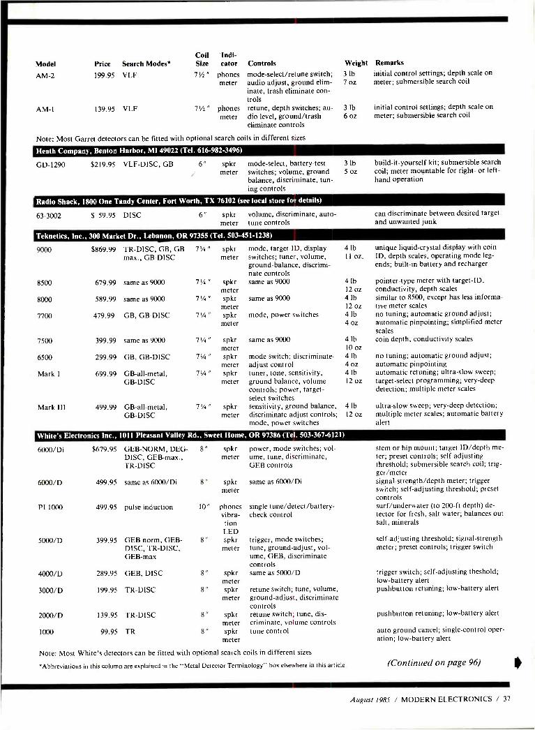
Model
AM -2
AM-1
Coil -Indi- Price Search Modes* Size cator Controls
199.95 VLF 71/2" phones mode -select /retune switch; meter audio adjust, ground elim-
inate, trash eliminate con- trols
71/2 " phones retune, depth switches; au- meter dio level, ground /trash
eliminate controls
139.95 VLF
Note: Most Garret detectors can be fitted with optional search coils in different sizes
Weight
3 lb 7 oz
Remarks
initial control settings; depth scale on meter; submersible search coil
3 lb initial control settings; depth scale on 6 oz meter; submersible search coil
Heath Company, Benton Harbor, MI 49022 (Tel. 616- 982 -3496)
GD-1290 $219.95 VLF -DISC, GB 6" spkr meter
mode -select, battery -test switches; volume, ground balance, discriminate, tun- ing controls
3 lb build -it- yourself kit; submersible search 5 oz coil; meter mountable for right- or left -
hand operation
Radio Shack, 1800 One Tandy Center, Fort Worth, TX 76102 (see local store for details)
63 -3002 $ 59.95 DISC 6" spkr volume, discriminate, auto - meter tune controls
can discriminate between desired target and unwanted junk
Teknetics, Inc., 300 Market Dr., Lebanon, OR 97355 (Tel. 503- 451 -1238)
9000 $869.99 TR -DISC, GB, GB max., GB -DISC
7'/4" spkr meter
8500 679.99 same as 9000 7'/4 " spkr meter
8000 589.99 same as 9000 7'/4 " spkr meter
7700 479.99 GB, GB-DISC 7'/4 " spkr meter
7500 399.99 same as 9000 71/4 " spkr meter
6500 299.99 GB, GB -DISC 7' /4 " spkr meter
Mark I 699.99 GB -all- metal, GB -DISC
7' /4 " spkr meter
Mark Ill 499.99 GB -all- metal, GB -DISC
7'/4" spkr meter
mode, target ID, display switches; tuner, volume, ground -balance, discrimi- nate controls same as 9000
same as 9000
mode, power switches
same as 9000
mode switch; discriminate - adjust control tuner, tone, sensitivity, ground balance, volume controls; power, target - select switches sensitivity, ground balance, discriminate -adjust controls; mode, power switches
4 lb unique liquid- crystal display with coin 11 oz. ID, depth scales, operating mode leg-
ends; built -in battery and recharger
4 lb pointer -type meter with target -ID, 12 oz conductivity, depth scales 4 lb similar to 8500, except has less informa- 12 oz tive meter scales 4 lb no tuning; automatic ground adjust; 4 oz automatic pinpointing; simplified meter
scales coin depth, conductivity scales 4 lb
10 oz 4 lb 4 oz 4 lb 12 oz
no tuning; automatic ground adjust; automatic pinpointing automatic retuning; ultra -slow sweep; target -select programming; very -deep detection; multiple meter scales
4 lb ultra -slow sweep; very -deep detection; 12 oz multiple meter scales; automatic battery
alert
White's Electronics Inc., 1011 Pleasant Valley Rd., Sweet Home, OR 97386 (Tel. 503- 367 -6121)
6000/ Di $679.95 GEB -NORM, DEG- 8 "
DISC, GEB -max., TR -DISC
6000 /D 499.95 same as 6000 /Di
PI 1000 499.95 pulse induction
5000 /D 399.95
4000 /D 289.95 GEB, DISC
3000 /D 199.95 TR -DISC
2000 /D 139.95 TR -DISC
1000 99.95 TR
GEB-norm, GEB- DISC, TR-DISC, GEB-max
spkr meter
power, mode switches; vol- urne, tune, discriminate, GEB controls
8" spkr same as 6000 /Di meter
10" phones single tune /detect /battery- vibra - check control tion LED
8 " spkr trigger, mode switches; meter tune, ground- adjust, vol-
ume, GEB, discriminate controls
8 " spkr same as 5000 /D meter
8 " spkr retune switch; tune, volume, meter ground- adjust, discriminate
controls 8 " spkr retune switch; tune, dis-
meter criminate, volume controls 8 " spkr tune control
meter
Note: Most White's detectors can be fitted with optional search coils in different sizes
*Abbreviations in this column are explained in the "Metal Detector Terminology" box elsewhere in this article.
stem or hip mount; target ID /depth me- ter; preset controls; self- adjusting threshold; submersible search coil; trig- ger /meter signal- strength /depth meter; trigger switch; self- adjusting threshold; preset controls surf /underwater (to 200 -ft depth) de- tector for fresh, salt water; balances out salt, minerals
self -adjusting threshold; signal- strength meter; preset controls; trigger switch
trigger switch; self- adjusting theshold; low- battery alert pushbutton retuning; low- battery alert
pushbutton retuning; low -battery alert
auto ground cancel; single- control oper- ation; low- battery alert
(Continued on page 96)
August 1985 / MODERN ELECTRONICS / 37
38 / MODERN ELECTRONICS / August 1985
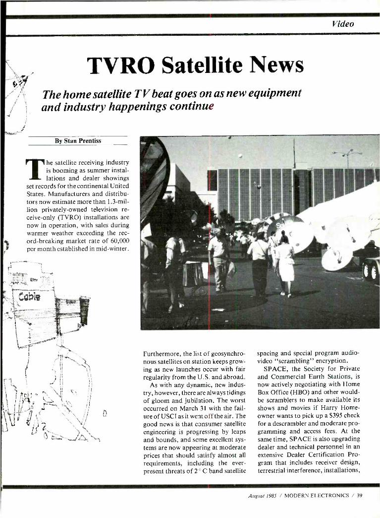
Video
TYRO Satellite News The home satellite TV beat goes on as new equipment and industry happenings continue
By Stan Prentiss
The satellite receiving industry is booming as summer instal- lations and dealer showings
set records for the continental United States. Manufacturers and distribu- tors now estimate more than 1.3 -mil- lion privately -owned television re- ceive -only (TVRO) installations are now in operation, with sales during warmer weather exceeding the rec- ord- breaking market rate of 60,000 per month established in mid -winter.
sr
o
Furthermore, the list of geosynchro- nous satellites on station keeps grow- ing as new launches occur with fair regularity from the U.S. and abroad.
As with any dynamic, new indus- try, however, there are always tidings of gloom and jubilation. The worst occurred on March 31 with the fail- ure of USCI as it went off the air. The good news is that consumer satellite engineering is progressing by leaps and bounds, and some excellent sys- tems are now appearing at moderate prices that should satisfy almost all requirements, including the ever - present threats of 2° C band satellite
spacing and special program audio - video "scrambling" encryption.
SPACE, the Society for Private and Commercial Earth Stations, is now actively negotiating with Home Box Office (HBO) and other would - be scramblers to make available its shows and movies if Harry Home- owner wants to pick up a $395 check for a descrambler and moderate pro- gramming and access fees. At the same time, SPACE is also upgrading dealer and technical personnel in an extensive Dealer Certification Pro- gram that includes receiver design, terrestrial interference, installations,
August 1985 / MODERN ELECTRONICS / 39
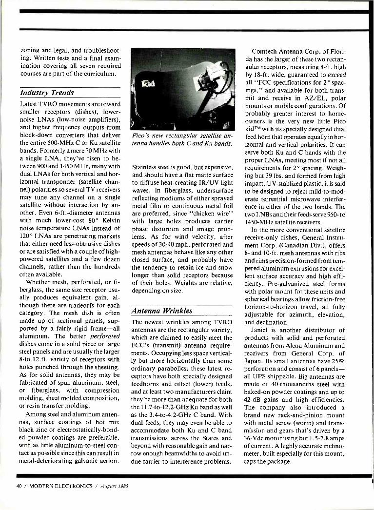
zoning and legal, and troubleshoot- ing. Written tests and a final exam- ination covering all seven required courses are part of the curriculum.
Industry Trends Latest TVRO movements are toward smaller receptors (dishes), lower - noise LNAs (low -noise amplifiers), and higher frequency outputs from block -down converters that deliver the entire 500 -MHz C or Ku satellite bands. Formerly a mere 70 MHz with a single LNA, they've risen to be- tween 900 and 1450 MHz, many with dual LNAs for both vertical and hor- izontal transponder (satellite chan- nel) polarities so several TV receivers may tune any channel on a single satellite without interaction by an- other. Even 6 -ft.- diameter antennas with much lower -cost 80 ° Kelvin noise temperature LNAs instead of 120 ° LNAs are penetrating markets that either need less- obtrusive dishes or are satisfied with a couple of high - powered satellites and a few dozen channels, rather than the hundreds often available.
Whether mesh, perforated, or fi- berglass, the same size receptor usu- ally produces equivalent gain, al- though there are tradeoffs for each category. The mesh dish is often made up of sectional panels, sup- ported by a fairly rigid frame -all aluminum. The better perforated dishes come in a solid piece or large steel panels and are usually the larger 8- to- 12 -ft. variety of receptors with holes punched through the sheeting. As for solid antennas, they may be fabricated of spun aluminum, steel, or fiberglass, with compression molding, sheet molded composition, or resin transfer molding.
Among steel and aluminum anten- nas, surface coatings of hot mix black zinc or electrostatically -bond- ed powder coatings are preferable, with as little aluminum -to -steel con- tact as possible since this can result in metal- deteriorating galvanic action.
Pico's new rectangular satellite an- tenna handles both C and Ku bands.
Stainless steel is good, but expensive, and should have a flat matte surface to diffuse heat -creating IR /UV light waves. In fiberglass, undersurface reflecting mediums of either sprayed metal film or continuous metal foil are preferred, since "chicken wire" with large holes produces carrier phase distortion and image prob- lems. As for wind velocity, after speeds of 30 -40 mph, perforated and mesh antennas behave like any other closed surface, and probably have the tendency to retain ice and snow longer than solid receptors because of their holes. Weights are relative, depending on size.
Antenna Wrinkles The newest wrinkles among TVRO antennas are the rectangular variety, which are claimed to easily meet the FCC's (transmit) antenna require- ments. Occupying less space vertical- ly but more horizontally than some ordinary parabolics, these latest re- ceptors have both specially designed feedhorns and offset (lower) feeds, and at least two manufacturers claim they're more than adequate for both the 11.7 -to -12.2 -GHz Ku band as well as the 3.4- to- 4.2 -GHz C band. With dual feeds, they may even be able to accommodate both Ku and C band transmissions across the States and beyond with reasonable gain and nar- row enough beamwidths to avoid un- due carrier -to- interference problems.
Comtech Antenna Corp. of Flori- da has the larger of these two rectan- gular receptors, measuring 8 -ft. high by 18 -ft. wide, guaranteed to exceed all "FCC specifications for 2 ° spac- ings," and available for both trans- mit and receive in AZ /EL, polar mounts or mobile configurations. Of probably greater interest to home- owners is the very new little Pico kidTM with its specially designed dual feed horn that operates equally in hor- izontal and vertical polarities. It can serve both Ku and C bands with the proper LNAs, meeting most if not all requirements for 2 ° spacing. Weigh- ing but 39 lbs. and formed from high impact, UV- stablized plastic, it is said to be designed to reject mild- to -mod- erate terrestrial microwave interfer- ence in either of the two bands. The two LNBs and their feeds serve 950- to 1450 -MHz satellite receivers.
In the more conventional satellite receive -only dishes, General Instru- ment Corp. (Canadian Div.), offers 8- and 10 -ft. mesh antennas with ribs and rims precision- formed from tem- pered aluminum extrusions for excel- lent surface accuracy and high effi- ciency. Pre -galvanized steel forms with polar mount for these units and spherical bearings allow friction -free horizon -to- horizon travel, all fully adjustable for azimuth, elevation, and declination.
Janiel is another distributor of products with solid and perforated antennas from Alcoa Aluminum and receivers from General Corp. of Japan. Its small antennas have 25% perforation and consist of 6 panels - all UPS shippable. Big antennas are made of 40- thousandths steel with baked -on powder coatings and up to 42 -dB gains and high efficiencies. The company also introduced a brand new rack -and -pinion mount with metal screw (worm) and trans- mission and gears that's driven by a 36 -Vdc motor using but 1.5 -2.8 amps of current. A highly accurate inclino- meter, built especially for this mount, caps the package.
40 / MODERN ELECTRONICS / August 1985
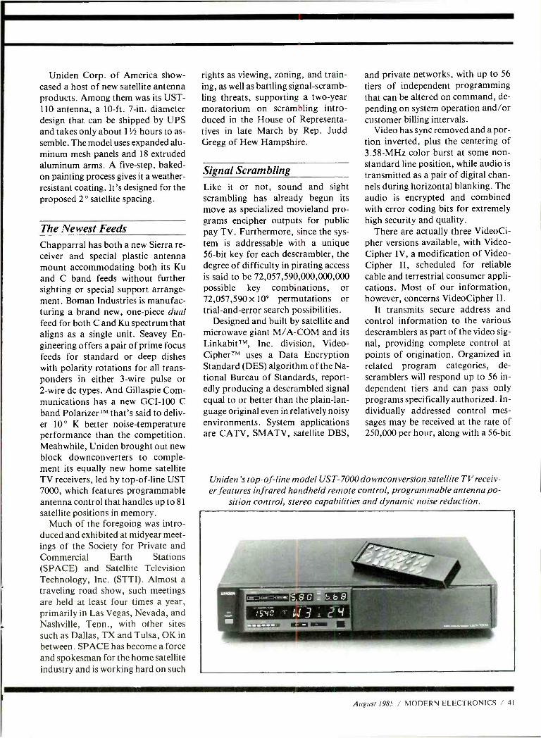
Uniden Corp. of America show- cased a host of new satellite antenna products. Among them was its UST - 110 antenna, a 10 -ft. 7 -in. diameter design that can be shipped by UPS and takes only about 1'h hours to as- semble. The model uses expanded alu- minum mesh panels and 18 extruded aluminum arms. A five -step, baked - on painting process gives it a weather - resistant coating. It's designed for the proposed 2 ° satellite spacing.
The Newest Feeds Chapparral has both a new Sierra re- ceiver and special plastic antenna mount accommodating both its Ku and C band feeds without further sighting or special support arrange- ment. Boman Industries is manufac- turing a brand new, one -piece dual feed for both C and Ku spectrum that aligns as a single unit. Seavey En- gineering offers a pair of prime focus feeds for standard or deep dishes with polarity rotations for all trans- ponders in either 3 -wire pulse or 2 -wire dc types. And Gillaspie Com- munications has a new GCI -100 C band PolarizerTM that's said to deliv- er 10 ° K better noise -temperature performance than the competition. Meahwhile, Uniden brought out new block downconverters to comple- ment its equally new home satellite TV receivers, led by top -of -line UST 7000, which features programmable antenna control that handles up to 81
satellite positions in memory. Much of the foregoing was intro-
duced and exhibited at midyear meet- ings of the Society for Private and Commercial Earth Stations (SPACE) and Satellite Television Technology, Inc. (STTI). Almost a traveling road show, such meetings are held at least four times a year, primarily in Las Vegas, Nevada, and Nashville, Tenn., with other sites such as Dallas, TX and Tulsa, OK in between. SPACE has become a force and spokesman for the home satellite industry and is working hard on such
rights as viewing, zoning, and train- ing, as well as battling signal- scramb- ling threats, supporting a two -year moratorium on scrambling intro- duced in the House of Representa- tives in late March by Rep. Judd Gregg of Hew Hampshire.
Signal Scrambling Like it or not, sound and sight scrambling has already begun its move as specialized movieland pro- grams encipher outputs for public pay TV. Furthermore, since the sys- tem is addressable with a unique 56 -bit key for each descrambler, the degree of difficulty in pirating access is said to be 72,057,590,000,000,000 possible key combinations, or 72,057,590 x 10' permutations or trial- and -error search possibilities.
Designed and built by satellite and microwave giant M /A -COM and its LinkabitTM, Inc. division, Video- CipherTM uses a Data Encryption Standard (DES) algorithm of the Na- tional Bureau of Standards, report- edly producing a descrambled signal equal to or better than the plain -lan- guage original even in relatively noisy environments. System applications are CATV, SMATV, satellite DBS,
and private networks, with up to 56
tiers of independent programming that can be altered on command, de- pending on system operation and /or customer billing intervals.
Video has sync removed and a por- tion inverted, plus the centering of 3.58 -MHz color burst at some non- standard line position, while audio is
transmitted as a pair of digital chan- nels during horizontal blanking. The audio is encrypted and combined with error coding bits for extremely high security and quality.
There are actually three VideoCi- pher versions available, with Video - Cipher IV, a modification of Video - Cipher II, scheduled for reliable cable and terrestrial consumer appli- cations. Most of our information, however, concerns VideoCipher II.
It transmits secure address and control information to the various descramblers as part of the video sig- nal, providing complete control at points of origination. Organized in related program categories, de- scramblers will respond up to 56 in- dependent tiers and can pass only programs specifically authorized. In- dividually addressed control mes- sages may be received at the rate of 250,000 per hour, along with a 56 -bit
Uniden's top -of -line model UST- 7000 downconversion satellite TVreceiv- er features infrared handheld remote control, programmable antenna po-
sition control, stereo capabilities and dynamic noise reduction.
August 1985 / MODERN ELECTRONICS / 41
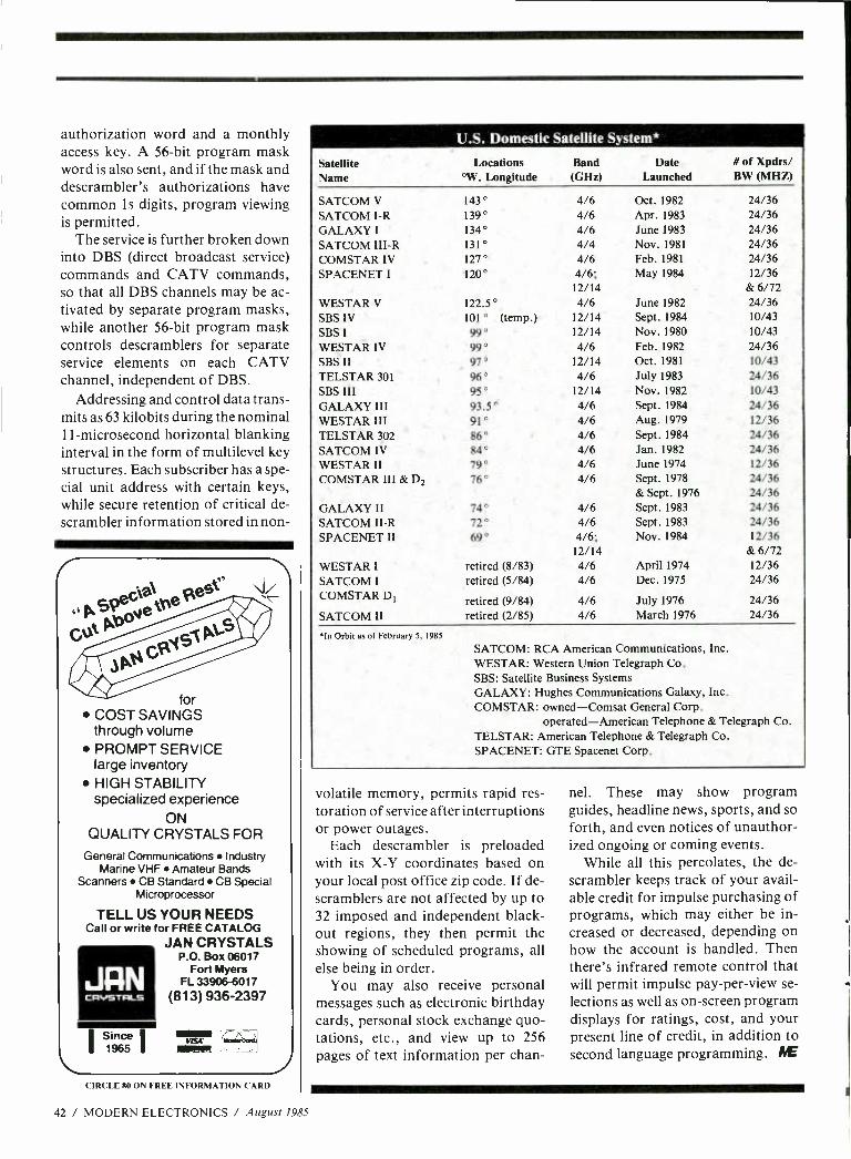
JFIN CRVSTRLS
authorization word and a monthly access key. A 56 -bit program mask word is also sent, and if the mask and descrambler's authorizations have common 1 s digits, program viewing is permitted.
The service is further broken down into DBS (direct broadcast service) commands and CATV commands, so that all DBS channels may be ac- tivated by separate program masks, while another 56 -bit program mask controls descramblers for separate service elements on each CATV channel, independent of DBS.
Addressing and control data trans- mits as 63 kilobits during the nominal 11- microsecond horizontal blanking interval in the form of multilevel key structures. Each subscriber has a spe- cial unit address with certain keys, while secure retention of critical de- scrambler information stored in non-
for COST SAVINGS through volume PROMPT SERVICE large inventory HIGH STABILITY specialized experience
ON QUALITY CRYSTALS FOR
General Communications Industry Marine VHF Amateur Bands
Scanners CB Standard CB Special Microprocessor
TELL US YOUR NEEDS Call or write for FREE CATALOG
JAN CRYSTALS P.O. Box 06017
Fort Myers FL 33906 -6017
(813) 936 -2397
I Since 1965
tllvac ra.r.ormi.
CIRCLE 80 ON FREE INFORMATION CARD
42 / MODERN ELECTRONICS / August 1985
Satellite Name
U.S. Domestic Satellite System*
Locations °W. Longitude
SATCOM V
SATCOM I-R GALAXY I
SATCOM III-R COMSTAR IV SPACENET I
WESTAR V
SBS IV SBS I
WESTAR IV SBS II TELSTAR 301
SBS III GALAXY III WESTAR III TELSTAR 302 SATCOM IV WESTAR II COMSTAR III & D2
GALAXY II SATCOM II-R SPACENET II
WESTAR I
SATCOM I
COMSTAR DI
SATCOM II
143° 139° 134° 131° 127° 120°
122.5° 101° (temp.) 99° 99° 97° 96° 95° 93.5° 91° 86° 84° 79° 76°
74° 72° 69°
retired (8/83) retired (5/84)
retired (9/84) retired (2/85)
In Orbit as of February 5, 1985
Band (GHz)
Date Launched
# of Xpdrs/ BW (MHZ)
4/6 Oct. 1982 24/36 4/6 Apr. 1983 24/36 4/6 June 1983 24/36 4/4 Nov. 1981 24/36 4/6 Feb. 1981 24/36 4/6; May 1984 12/36 12/14 & 6/72 4/6 June1982 24/36
12/14 Sept. 1984 10/43 12/14 Nov. 1980 10/43 4/6 Feb. 1982 24/36
12/14 Oct. 1981 10/43 4/6 July 1983 24/36
12/14 Nov. 1982 10/43 4/6 Sept. 1984 24/36 4/6 Aug. 1979 12/36 4/6 Sept. 1984 24/36 4/6 Jan. 1982 24/36 4/6 June 1974 12/36 4/6 Sept. 1978 24/36
& Sept. 1976 24/36 4/6 Sept. 1983 24/36 4/6 Sept. 1983 24/36 4/6; Nov. 1984 12/36 12/14 & 6/72 4/6 April 1974 12/36 4/6 Dec. 1975 24/36
4/6 July 1976 24/36 4/6 March 1976 24/36
SATCOM: RCA American Communications, Inc. WESTAR: Western Union Telegraph Co. SBS: Satellite Business Systems GALAXY: Hughes Communications Galaxy, Inc. COMSTAR: owned- Comsat General Corp.
operated -American Telephone & Telegraph Co. TELSTAR: American Telephone & Telegraph Co. SPACENET: GTE Spacenet Corp.
volatile memory, permits rapid res- toration of service after interruptions or power outages.
Each descrambler is preloaded with its X -Y coordinates based on your local post office zip code. If de- scramblers are not affected by up to 32 imposed and independent black- out regions, they then permit the showing of scheduled programs, all else being in order.
You may also receive personal messages such as electronic birthday cards, personal stock exchange quo- tations, etc., and view up to 256 pages of text information per chan-
nel. These may show program guides, headline news, sports, and so forth, and even notices of unauthor- ized ongoing or coming events.
While all this percolates, the de- scrambler keeps track of your avail- able credit for impulse purchasing of programs, which may either be in- creased or decreased, depending on how the account is handled. Then there's infrared remote control that will permit impulse pay -per -view se- lections as well as on- screen program displays for ratings, cost, and your present line of credit, in addition to second language programming. IYE
A Great Gift Idea DON'T LET THE ELECTRONICS REVOLUTION PASS YOU OR A FRIEND BY! SUBSCRIBE TO
UIIfVWXJERN
Now you can reach out every month and learn about the latest innovations in consumer electronics and personal computers- what's new, how products and circuits work, and what leading authorities think of them.
*Stereo *Video *Home & Car Electronics *Test Instruments *Circuitry & Devices *Servicing
*Personal Computers *Communications *Construction Projects In every issue, authors lucidly explain how exciting, new
electronics ideas are applied ... issue forthright buying counsel ... present complete plans to build electronic devices to enhance products, even unique ones that are not yet being sold in the marketplace.
Feature articles, tutorials, and construction projects are the hallmarks of MODERN ELECTRONICS, the new monthly magazine for electronics and computer enthusiasts. Covering the entire spectrum of these fields, you'll gather insights in every important area to help you make buying decisions for work and play purposes ... improve performance of your present equipment ... increase your electronics competence
. and add to your practical and intellectual knowledge of electronics and computers.
To be sure you get this valuable information delivered to you regularly, and share the experiences of our writers and edi- tors- Forrest Mims, Len Feldman, Stan Prentiss, Charles Ru- benstein, Glenn Hauser, and many others -you can subscribe to MODERN ELECTRONICS today. As a Charter Subscriber, you'll save 45% off the newsstand price when you buy a one - year subscription for only $12.97. Or save 51% when you sub- scribe for two years at $22.97.
Just fill out the coupon and mail with your check, money order, or credit card information (Visa or MasterCard) to enter your Charter Subscription. Do it today to ensure earliest delivery!
MODERN ELECTRONICS 76 North Broadway, Hicksville, NY 11801
Please send me Modern Electronics for 2 Years 1 Year
Name
Street
City
State Zip
2 Years (24 issues) 522.970
1 Year (12 issues) $12.970
Charge My Order To: Payment Enclosed S
MasterCard
VISA My accorti cuber b:
H 1 1 1 1 { 1 1 1 1 1 1 1 1
PACKED WITH MORE THAN
5,000 QUALITY ELECTRONIC PARTS AND
ACCESSORIBS! Look inside our new 132 page catalog, which offers over 300 new items. You'll find a full line of test equipment, computer accessories, speakers, CATV equipment, television parts and many more, along with the largest selection of original Japanese semiconductors in the country. All of them at unbelievably low prices.
CALL TODAY FOR YOUR FREE COPY OF CATALOG #10!
MCM ELECTRONICS 858 E. Congress Park Drive Centerville, Ohio 45459 513- 434 -0031
CALL TOLL FREE 1- 800 -543 -4330
(IN OHIO CALL 1- 800 - 762 -4315) (IN HAWAII OR ALASKA 1 -800- 858 -1849)
SOURCE NO ME -6
CIRCLE 85 ON FREE INFORMATION CARD
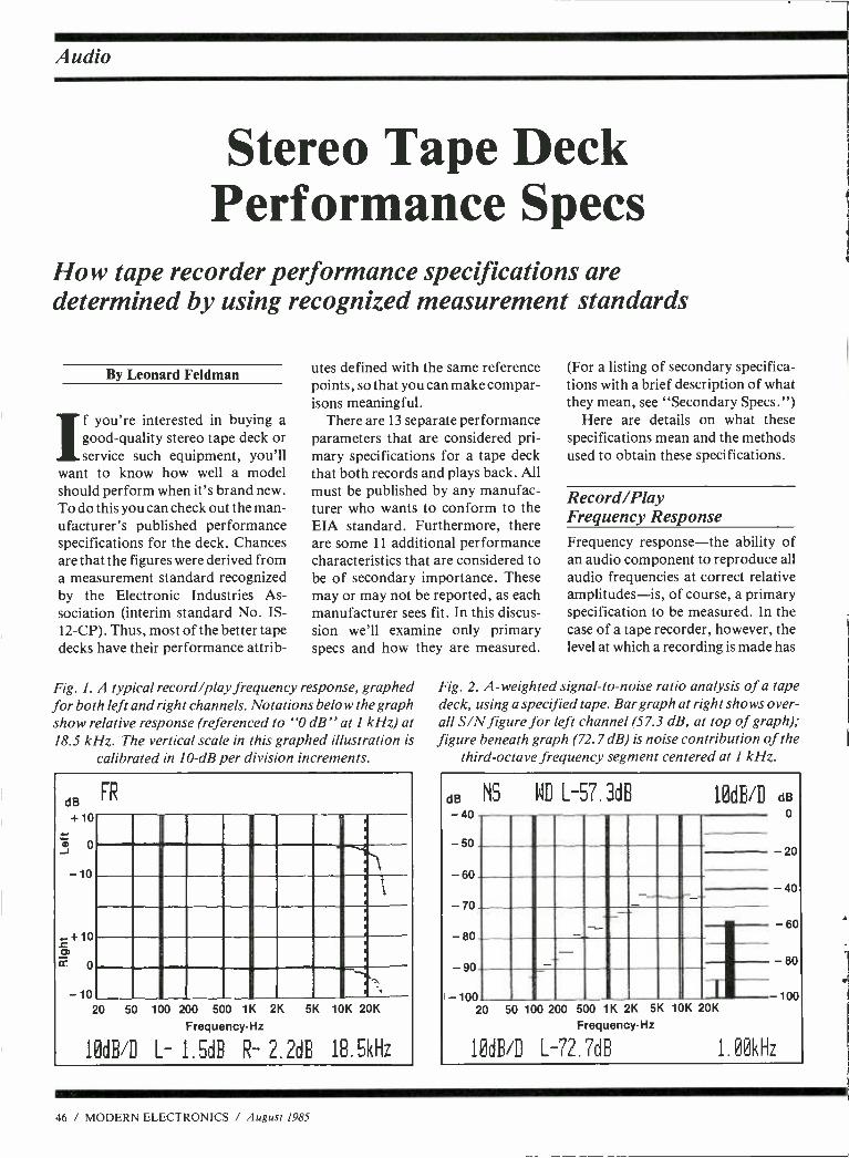
Audio
Stereo Tap e Deck Performance Specs
How tape recorder performance specifications are determined by using recognized measurement standards
By Leonard Feldman
If you're interested in buying a good -quality stereo tape deck or service such equipment, you'll
want to know how well a model should perform when it's brand new. To do this you can check out the man- ufacturer's published performance specifications for the deck. Chances are that the figures were derived from a measurement standard recognized by the Electronic Industries As- sociation (interim standard No. IS- 12-CP). Thus, most of the better tape decks have their performance attrib-
utes defined with the same reference points, so that you can make compar- isons meaningful.
There are 13 separate performance parameters that are considered pri- mary specifications for a tape deck that both records and plays back. All must be published by any manufac- turer who wants to conform to the EIA standard. Furthermore, there are some 11 additional performance characteristics that are considered to be of secondary importance. These may or may not be reported, as each manufacturer sees fit. In this discus- sion we'll examine only primary specs and how they are measured.
Fig. 1. A typical record /play frequency response, graphed for both left and right channels. Notations below the graph show relative response (referenced to "0 dB" at 1 kHz) at 18.5 kHz. The vertical scale in this graphed illustration is
calibrated in 10 -dB per division increments.
dB FR
+10
-10
-10
. . , . . ,
(
-
--..,-g,- I`
i
_ I__
- y -
_ 20 50 100 200 500 1K 2K 5K 10K 20K
Frequency-Hz
10dB/D L- 1. 5dB R- 2.2dB 18.5kHz
(For a listing of secondary specifica- tions with a brief description of what they mean, see "Secondary Specs.")
Here are details on what these specifications mean and the methods used to obtain these specifications.
Record /Play Frequency Response Frequency response -the ability of an audio component to reproduce all audio frequencies at correct relative amplitudes -is, of course, a primary specification to be measured. In the case of a tape recorder, however, the level at which a recording is made has
Fig. 2. A- weighted signal -to -noise ratio analysis of a tape deck, using a specified tape. Bar graph at right shows over- all S/N figure for left channel (57.3 dB, at top of graph); figure beneath graph (72.7 dB) is noise contribution of the
third -octave frequency segment centered at I kHz.
dB NS WD L-57.3dB 10dB/D dB o -40
- 50 20
- 60 --.- 40
- 70
60 - 80
90 80
-100 100 20 50 100 200 500 1K 2K 5K 10K 20K
Frequency -Hz
10dB/D L-72.7818 1. 00kHz
46 / MODERN ELECTRONICS / August 1985
'corder Specifications a lot to do with the way the measured frequency response will appear.
When you try to record very high levels of high frequencies onto mag- netic tape -particularly onto cassette tapes -the tape tends to become "saturated." This causes response at those high frequencies to be lowered or attenuated instead of remaining constant or flat. To avoid this prob- lem, the measurement standard al- low us to test the frequency response of cassette decks at 25 -dB below "reference level." This is rational- ized by observing that high frequen- cies in music are seldom as great in amplitude as low and mid- frequen- cies are.)
But what is "reference level "? To begin with, it is not the level at which a given cassette deck's recording level meters read "0 dB." The 0 -dB meter readings on most recorders are arbi- trary, and not the same from one model to another. Magnetization level can be described in absolute terms, however, by a quantity called nanowebers -per -meter (abbreviated as nWb /m). For cassette recorders, the reference level has been estab- lished as 400 nWb /m. As long as all manufacturers regard that level as the reference level and back down to
25 dB from that point when mea- suring record /playback frequency response, consumers will get a fair comparison of the frequency -re- sponse capabilities of one recorder against those of another. Ideally, a manufacturer should furnish a graph, or curve of frequency response, such as that shown in Fig. 1.
If such a curve is not supplied, the manufacturer may state the response in verbal terms, such as:
R/P Response, (using) XYZ Type Q Tape: 35 Hz to 15 kHz, + 0 dB, 3 dB
Notice that the tape type and brand used in making the measurement must be stated, as must the plus and minus deviation from flat or uniform re- sponse throughout the frequency range be stated.
M re Tape -R
In addition to the primary specifica- tions described in detail, a manufacturer of home tape recorders has the option of supplying as many as 14 additional speci- fications, several of which represent multiple sets of information. Many of these additional specifications are self - explanatory, and are simply listed below without any details concerning them. A few may seem strange to you if you are not very familiar with tape recorder tech- nology, and these are briefly defined.
Secondary Specifications 1. Tape Speed Error. 2. Fast Forward and Fast Rewind
times. 3. Playback Frequency Response
with Noise Reduction Activated. 4. Headphone Output Level. 5. Loudspeaker Output Level (if
built -in speaker is present). 6. Line Output Impedance (helpful
in matching with other corn - ponents).
7. Record /Playback Channel Sepa- ration and Cross -talk (for stereo units).
8. Maximum Line Input Level. 9. Line and Microphone Input Im-
pedance. 10. Erasure (completeness of erasure
of tape, stated in dB)
In addition to the above secondary specifications, the following additional performance specifications are listed and described in the new tape measurement standard: Indicator Response Time and MPX Attenuation.
While many audio tape recorders now employ fast -acting electronic recording level indicators such as LEDs or floures- cent bar graphs, others continue to use mechanical level meters. Regardless of the type of metering system used, it is
worthwhile to know just how quickly the meters or indicators respond to an actual change of signal level.
A complex toneburst signal is used to
determine the ballistics of the metering system and duration of the tone burst re-
quired to cause the meter system to read "0 dB" when a signal level of + 2 dB is
applied to the system. This is considered to be the indicator response time of the metering system. If quoted at all in a manufacturer's published specifications, it is to be given in milliseconds.
In a somewhat similar way, it is possi- ble to measure the indicator decay time: the time it takes for the indicator to re- cede from its steady state reading by 20 dB. The test of this decay time is done by steadily increasing the interval between one -second -long tone bursts and ob- serving the meter reading. When it reaches 20 dB just prior to the begin- ning of the ensuring tone burst, the time between tone bursts is listed as the decay time of the particular indicator or me- tering system.
Another secondary specification hav- ing to do with the tape deck's metering system is called Indicator Calibration Error. Specified in dB, it is the greatest deviation observed between the actual input level and the meter reading from nominal 0 dB recording level down to a 10 dB recording level.
The last of the optionally reportable secondary specifications that a tape deck manufacturer may want to list is
called: MPX Attenuation. If a tape recorder has an MPX (multi-
plex) filter in its circuitry to eliminate the 19 -kHz pilot signal present in FM- stereo transmissions, it will attenuate any 19 -kHz input to the recorder. Thus, any filter that does a good job of atten- uating 19 kHz is also likely to attenuate (albeit to a lesser degree) other wanted audio frequencies. A statement of the MPX Attenuation characteristics of a recorder having such a filter should therefore include the amount of atten- uation that will take place for 15 -kHz signals as well as for 19 -kHz signals when the filter is turned on.
If the tape recorder is equipped with a noise reduction system, such as Dolby or dbx, record /play re- sponse must also be stated for the deck with its noise -reduction circuit-
ry activated. Playback -only frequen- cy response must also be stated. For this purpose, standard prerecorded test tapes are used. If the tape deck has provisions for different basic
August 1985 / MODERN ELECTRONICS / 47
Tape Makes The Difference
You may have noticed that some specifications discussed require that the manufacturer list the brand and type of tape used to make the measurement that determined the specification. When it comes to tape recorders, the tape you use in them can influence the perfor- mance of the recorder fully as much as (if not more than) the recorder's cir- cuitry. To begin with, there are differ- ences between tapes made by one manu- facturer and those made by another. Beyond that, there are also basic or generic types of audio tape.
The International Electrotechnical Commission (IEC), a world standard - making body of scientists, has divided audio tape into four basic types. They are numbered, appropriately: Types I, II, III and IV. Furthermore, the IEC has selected certain batches of tapes, made by specific manufacturers, as the "ref- erence" tapes for these four types.
Type I tape is basically a tape that
uses ferric -oxide magnetic particles as the magentic medium. Such tapes re- quire a specific amount of high -fre- quency "bias" applied to them during recording. They also require frequency tailoring known as equalization during playback. The equalization is defined as a time constant, in this case 120 micro- seconds. The time constant defines the rate at which high frequencies are rolled off or attenuated by the playback elec- tronics, thereby compensating for a ris- ing response at high frequencies during recording.
While the amount of equalization is
fixed for each tape type, the amount of bias will vary slightly even within one tape category. That's why some tape re- corders haver vernier bias controls in addition to the basic switch positions for each tape type. But if a recorder has only fixed bias settings, those settings are supposed to be optimized for the standard "batches" which the IEC se-
lected as "reference" tapes for each tape type. Tape manufacturers, in turn, are supposed to make their tapes so that they, too, will operate optimally when bias is set for the "standard" tapes. Of course, some variation can be expected, even from one batch to the next and be- tween different tape manufacturers. That's why serious recording enthusiasts who own tape recorders that only have fixed tape selector switches try to find out what tape a manufacturer used when calibrating his products. The "of- ficially recognized" IEC reference tape for Type I tape was made by BASF, as was the "reference" for Type II tape.
Type II tape uses either chromium di- oxide particles or cobalt- treated ferric oxide particles. Tapes using either of these magnetic particles require a higher bias than does tape using ferric -oxide particles. Type II tapes are generally preferred by serious recordists for their somewhat better frequency response
types of tape requiring different set- tings of the deck's equalization switch, then playback response must be given for each such setting and type of tape. For example, a deck that can handle ferric -oxide, chrom- ium- dioxide (or equal) and metal - particle tape would have to have three separate playback responses quoted for it.
Record /Play Signal -to -Noise Level This measurement gives you an idea of how much residual tape noise or hiss you will hear when using a given tape with the tape deck being de- scribed. The measurement is ad- justed by "A- weighting" it to take into account the fact that not all noise frequencies are equally annoying to human ears. Of course, the term sig- nal -to -noise ratio means that we not only have to measure noise level, but
that we must have a signal level against which to compare the noise. As before, that signal level is the new- ly established magnetization ref- erence level of 400 nWb /m (for cas- sette tape decks). An example of a properly stated A- weighted S/N ratio would be:
A- weighted S /N, Record /Play, using X tape with (or without) Y
noise reduction: 57.5 dB. In my own tests of signal /to noise,
I generally go a step further and pro- vide an analysis graph that also shows frequency distribution of that noise, as illustrated in Fig. 2.
Distortion Harmonic distortion is measured by first recording a midfrequency tone onto a defined type and brand of tape. Then, during playback of the recording, distortion is measured us- ing a distortion of total distortion, many manufacturers measure only
third -harmonic or second- and third - harmonic distortion, since these two distortion components constitute the major forms that occur when using a tape recorder. The distortion rating is supposed to be quoted in the fol- lowing form:
Distortion at reference level (400 n Wb /meter, for cassette decks), X brand tape, at I kHz (the usu-
al frequency used): Y%
In the above, X is the brand and type of tape used for the test and Y is ex- pressed as a percentage.
The plots in Figs. 3A and 3B show how distortion rises as a function of recorded level. For both graphs (3A is 3rd harmonic distortion; 3B is 2nd harmonic distortion), the dotted line cursor has been set to "0 dB." This, in turn, represents the required 400 nWb /m reference level. The percen- tages apprearing at the top of each graph are the measured distortion level at reference level -in this case
48 / MODERN ELECTRONICS / August 1985
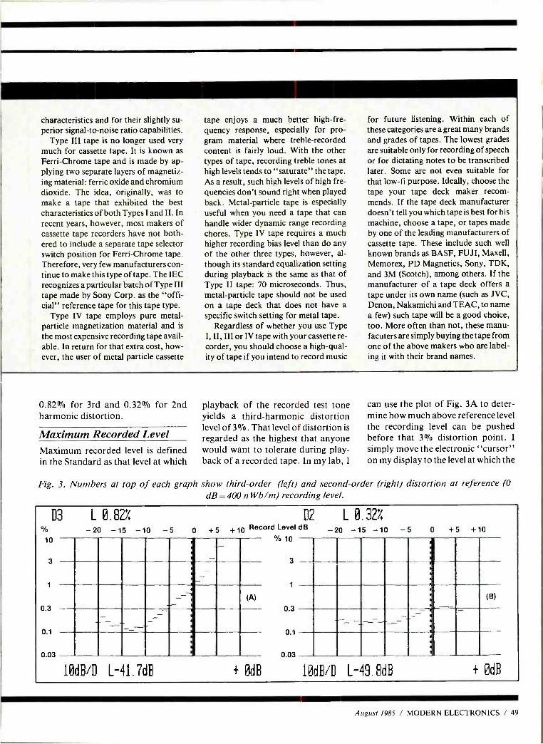
characteristics and for their slightly su- perior signal -to -noise ratio capabilities.
Type III tape is no longer used very much for cassette tape. It is known as Ferri -Chrome tape and is made by ap- plying two separate layers of magnetiz- ing material: ferric oxide and chromium dioxide. The idea, originally, was to make a tape that exhibited the best characteristics of both Types I and II. In recent years, however, most makers of cassette tape recorders have not both- ered to include a separate tape selector switch position for Ferri- Chrome tape. Therefore, very few manufacturers con- tinue to make this type of tape. The IEC recognizes a particular batch of Type III tape made by Sony Corp. as the "offi- cial" reference tape for this tape type.
Type IV tape employs pure metal - particle magnetization material and is
the most expensive recording tape avail- able. In return for that extra cost, how- ever, the user of metal particle cassette
0.82% for 3rd and 0.32% for 2nd harmonic distortion.
Maximum Recorded Level Maximum recorded level is defined in the Standard as that level at which
tape enjoys a much better high -fre- quency response, especially for pro- gram material where treble- recorded content is fairly loud. With the other types of tape, recording treble tones at high levels tends to "saturate" the tape. As a result, such high levels of high fre- quencies don't sound right when played back. Metal -particle tape is especially useful when you need a tape that can handle wider dynamic range recording chores. Type IV tape requires a much higher recording bias level than do any of the other three types, however, al- though its standard equalization setting during playback is the same as that of Type II tape: 70 microseconds. Thus, metal -particle tape should not be used on a tape deck that does not have a specific switch setting for metal tape.
Regardless of whether you use Type I, II, III or IV tape with your cassette re- corder, you should choose a high -qual- ity of tape if you intend to record music
playback of the recorded test tone yields a third -harmonic distortion level of 3 %. That level of distortion is regarded as the highest that anyone would want to tolerate during play- back of a recorded tape. In my lab, I
for future listening. Within each of these categories are a great many brands and grades of tapes. The lowest grades are suitable only for recording of speech or for dictating notes to be transcribed later. Some are not even suitable for that low -fi purpose. Ideally, choose the tape your tape deck maker recom- mends. If the tape deck manufacturer doesn't tell you which tape is best for his machine, choose a tape, or tapes made by one of the leading manufacturers of cassette tape. These include such well known brands as BASF, FUJI, Maxell, Memorex, PD Magnetics, Sony, TDK, and 3M (Scotch), among others. If the manufacturer of a tape deck offers a tape under its own name (such as JVC, Denon, Nakamichi and TEAC, to name a few) such tape will be a good choice, too. More often than not, these manu- facuters are simply buying the tape from one of the above makers who are label- ing it with their brand names.
can use the plot of Fig. 3A to deter- mine how much above reference level the recording level can be pushed before that 3% distortion point. I
simply move the electronic "cursor" on my display to the level at which the
Fig. 3. Numbers at top of each graph show third -order (left) and second -order fright) distortion at reference (0
dB = 400 n Wb /m) recording level.
D3 L 0. 82%
10
3
1
0.3
0.1
0.03
-20 -15 -10 -5 D2 L 0.3Z/
0 + 5 + 10 Record Level ,1B
10
3
1
0.3
0.1
0.03
ti
_--ti ;
(A)
10dB/D L-41.7dB + 0dB
-20 -15 -10 -5 0 +5 +10
10dB/D L-49.8dB + 0dB
August 1985 / MODERN ELECTRONICS / 49
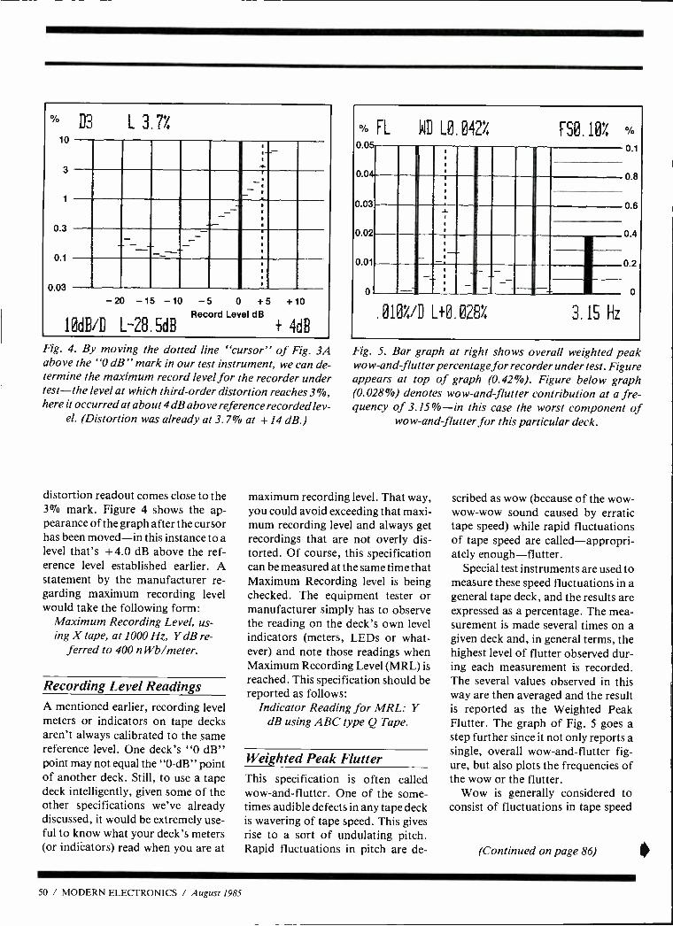
°'O D3 L 3.7% 10
3
0.3
0.1
0.03
-20 -15 -10 -5 0 +5 +10 Record Level dB
10dB/D L-28, 5dB + 4dB
Fig. 4. By moving the dotted line "cursor" of Fig. 3A above the "0 dB" mark in our test instrument, we can de- termine the maximum record level for the recorder under test -the level at which third -order distortion reaches 3 %, here it occurred at about 4 dB above reference recorded lev-
el. (Distortion was already at 3.7% at + 14 dB.)
distortion readout comes close to the 3% mark. Figure 4 shows the ap- pearance of the graph after the cursor has been moved -in this instance to a level that's + 4.0 dB above the ref- erence level established earlier. A statement by the manufacturer re- garding maximum recording level would take the following form:
Maximum Recording Level, us- ing X tape, at 1000 Hz, Y dB re-
ferred to 400 n Wb /meter.
Recording Level Readings
A mentioned earlier, recording level meters or indicators on tape decks aren't always calibrated to the same reference level. One deck's "0 dB" point may not equal the "0 -dB" point of another deck. Still, to use a tape deck intelligently, given some of the other specifications we've already discussed, it would be extremely use- ful to know what your deck's meters (or indicators) read when you are at
% FL WD L0 042% F50.10! 0/0
0.05-
0.04-
0.03
0.02
0.01
0.1
0.8
1 0.6
0 4
- 0 2
0
.010%/D L+0.028i 3.15 Hz
Fig. 5. Bar graph at right shows overall weighted peak wow-and-flutter percentage for recorder under test. Figure appears at top of graph (0.42 %). Figure below graph (0.028 %) denotes wow-and-flutter contribution at a fre- quency of 3.15 % -in this case the worst component of
wow-and-flutter for this particular deck.
maximum recording level. That way, you could avoid exceeding that maxi- mum recording level and always get recordings that are not overly dis- torted. Of course, this specification can be measured at the same time that Maximum Recording level is being checked. The equipment tester or manufacturer simply has to observe the reading on the deck's own level indicators (meters, LEDs or what- ever) and note those readings when Maximum Recording Level (MRL) is reached. This specification should be reported as follows:
Indicator Reading for MRL: Y dB using ABC type Q Tape.
Weighted Peak Flutter
This specification is often called wow -and -flutter. One of the some- times audible defects in any tape deck is wavering of tape speed. This gives rise to a sort of undulating pitch. Rapid fluctuations in pitch are de-
scribed as wow (because of the wow - wow -wow sound caused by erratic tape speed) while rapid fluctuations of tape speed are called- appropri- ately enough- flutter.
Special test instruments are used to measure these speed fluctuations in a general tape deck, and the results are expressed as a percentage. The mea- surement is made several times on a given deck and, in general terms, the highest level of flutter observed dur- ing each measurement is recorded. The several values observed in this way are then averaged and the result is reported as the Weighted Peak Flutter. The graph of Fig. 5 goes a step further since it not only reports a single, overall wow- and -flutter fig- ure, but also plots the frequencies of the wow or the flutter.
Wow is generally considered to consist of fluctuations in tape speed
(Continued on page 86)
50 / MODERN ELECTRONICS / August 1985
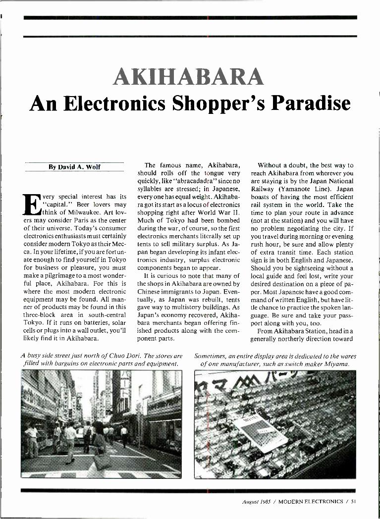
AKIHABARA An Electronics Shopper's Paradise
By David A. Wolf
Every special interest has its "capital." Beer lovers may think of Milwaukee. Art lov-
ers may consider Paris as the center of their universe. Today's consumer electronics enthusiasts must certainly consider modern Tokyo as their Mec- ca. In your lifetime, if you are fortun- ate enough to find yourself in Tokyo for business or pleasure, you must make a pilgrimage to a most wonder- ful place, Akihabara. For this is where the most modern electronic equipment may be found. All man- ner of products may be found in this three -block area in south -central Tokyo. If it runs on batteries, solar cells or plugs into a wall outlet, you'll likely find it in Akihabara.
The famous name, Akihabara, should rolls off the tongue very quickly, like "abracadadra" since no syllables are stressed; in Japanese, every one has equal weight. Akihaba- ra got its start as a locus of electronics shopping right after World War II. Much of Tokyo had been bombed during the war, of course, so the first electronics merchants literally set up tents to sell military surplus. As Ja- pan began developing its infant elec- tronics industry, surplus electronic components began to appear.
It is curious to note that many of the shops in Akihabara are owned by Chinese immigrants to Japan. Even- tually, as Japan was rebuilt, tents gave way to multistory buildings. As Japan's economy recovered, Akiha- bara merchants began offering fin- ished products along with the com- ponent parts.
Without a doubt, the best way to reach Akihabara from wherever you are staying is by the Japan National Railway (Yamanote Line). Japan boasts of having the most efficient rail system in the world. Take the time to plan your route in advance (not at the station) and you will have no problem negotiating the city. If you travel during morning or evening rush hour, be sure and allow plenty of extra transit time. Each station sign is in both English and Japanese. Should you be sightseeing without a local guide and feel lost, write your desired destination on a piece of pa- per. Most Japanese have a good com- mand of written English, but have lit- tle chance to practice the spoken lan- guage. Be sure and take your pass- port along with you, too.
From Akihabara Station, head in a generally northerly direction toward
A busy side street just north of Chuo Dori. The stores are Sometimes, an entire display area is dedicated to the wares filled with bargains on electronic parts and equipment. of one manufacturer, such as switch maker Miyama.
August 1985 / MODERN ELECTRONICS / 51
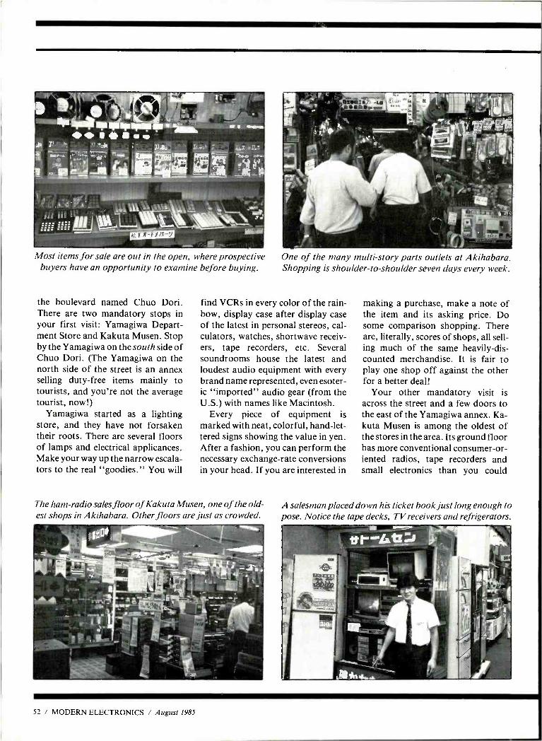
1 II I
apwolovi""A !dit
i ..._ ... , ,----`--`--.,,,
owismo Most items for sale are out in the open, where prospective
buyers have an opportunity to examine before buying.
the boulevard named Chuo Dori. There are two mandatory stops in your first visit: Yamagiwa Depart- ment Store and Kakuta Musen. Stop by the Yamagiwa on the south side of Chuo Dori. (The Yamagiwa on the north side of the street is an annex selling duty -free items mainly to tourists, and you're not the average tourist, now!)
Yamagiwa started as a lighting store, and they have not forsaken their roots. There are several floors of lamps and electrical applicances. Make your way up the narrow escala- tors to the real "goodies." You will
One of the many multi -story parts outlets at Akihabara. Shopping is shoulder -to- shoulder seven days every week.
find VCRs in every color of the rain- bow, display case after display case of the latest in personal stereos, cal- culators, watches, shortwave receiv- ers, tape recorders, etc. Several soundrooms house the latest and loudest audio equipment with every brand name represented, even esoter- ic "imported" audio gear (from the U.S.) with names like Macintosh.
Every piece of equipment is marked with neat, colorful, hand -let- tered signs showing the value in yen. After a fashion, you can perform the necessary exchange -rate conversions in your head. If you are interested in
The ham -radio sales floor of Kakuta Musen, one of the old- est shops in Akihabara. Other floors are just as crowded.
making a purchase, make a note of the item and its asking price. Do some comparison shopping. There are, literally, scores of shops, all sell- ing much of the same heavily -dis- counted merchandise. It is fair to play one shop off against the other for a better deal!
Your other mandatory visit is across the street and a few doors to the east of the Yamagiwa annex. Ka- kuta Musen is among the oldest of the stores in the area. Its ground floor has more conventional consumer -or- iented radios, tape recorders and small electronics than you could
A salesman placed down his ticket book just long enough to pose. Notice the tape decks, TV receivers and refrigerators.
52 / MODERN ELECTRONICS / August 1985
dream possible. The next several floors contain computers, video games, electronic components, ra- dio- control models and ham radio gear. The components are sold pri- marily from bins, as they used to be sold in the U.S. Very little merchan- dise is blister -packaged. There are small plastic dishes in which you may collect just the part necessary for your project. Many times, an entire section is dedicated to the products of one manufacturer.
If you can't find the right part at Kakuta, there are several large, mul- ti- floored complexes of booths spe- cializing in particular types of com- ponents. Don't let the austerity of the booths fool you. Some of the propri- etors of these booths are very wealthy. The top two floors of Kaku- ta house the radio -controlled models and ham radio departments. The prices of this equipment are the low- est I've ever seen! Before making a purchase, make sure that your new- found bargain is compatible with U.S. line voltage (115 Vac) and fre- quency assignments. Japan's line voltage is 100 Vac and the broadcast bands are a little different.
Okay, you've visited the two land- marks in Akihabara, and made your way off the street, away from the bulk of the tourists. If you find some- thing you really like, I encourage you to do some comparison shopping. Find out who has the lowest price and try a little bargaining. The Japanese are polite but skillful negotiators. Depending on the shop and the sales- person, you might end up saving a lit- tle more, especially if you pay in cash (expect to pay a 3 to 4% premium if you use a credit card).
Since you will be taking your trea- sure out of the country, show your passport, so that the Japanese feder- al tax will be subtracted from the sell- ing price. The salesperson will attach a form to your passport that will be collected as you leave Japan. A suc-
cessful deal is always concluded with smiles, a bow and, maybe, a hand- shake. Save your receipts to make the U.S. Customs check as trouble -free as possible. Even the most well -or- ganized person will have a little trou- ble filling out the customs declara- tion form after the all -night flight from Tokyo.
If you are a camera buff, as many electronics enthusiasts are, you must travel across town to Yodobashi Camera in the Shinjuku area. Yodo- bashi has become so well- known, that it is now a stop on many sightsee- ing tours. Prices are definitely higher than they were just a few years ago.
Frequently you will find similar prices on basic camera bodies in the U.S., but Yodobashi can't be beat for prices on lenses and other acces- sories. I would even suggest making Yodobashi your first stop so that you can document your travels with pho- tos taken with your new camera!
You now have a head start on your own shopping adventure in the most exciting collection of electronics spe- cialty shops in the world- Akiha- bara. Even the most jaded electronics professional will marvel at what he will find. Like other visitors, you will wish you had brought more money and had more room in your luggage.
ALL MAKES
ALL MODELS
7 DAY TURNAROUND
FLAT RATE PRICING
BY MODEL
RAIL FOR INFORMATION
THE CONVERTER SHOP"
794 Franklin Lakes Ave
Franklin Lakes, NJ 07417
Tel. (201) 848 -8229
Need A Storage Scope?
The Model 601 Scope Memory converts your oscilloscope into a
storage scope. With the Scope Memory you can capture & display transiants, pulses and low fre- quency signals. Stores both analog & digital signals in a single sweep.
Features include a 1.4 MHZ sample rate, 2K memory, pre and
post trigger capabilities.
Price $515 Plus Shipping
S/HEX INC. 2340 State Road 580 Suite 241
Clearwater, Florida 33515 (813) 797 -9589
CIRCLE 93 ON FREE INFORMATION CARD
August 1985 / MODERN ELECTRONICS / 55
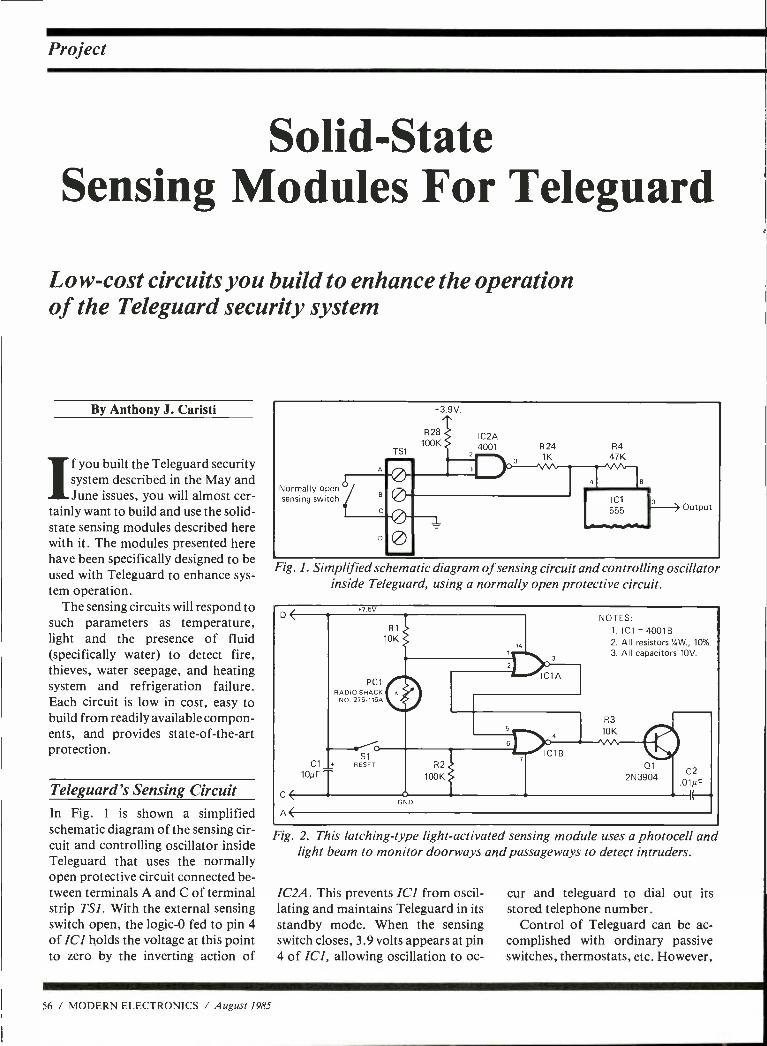
Project
Solid -State Sensing Modules For Teleguard
Low -cost circuits you build to enhance the operation of the Teleguard security system
By Anthony J. Caristi
If you built the Teleguard security system described in the May and June issues, you will almost cer-
tainly want to build and use the solid - state sensing modules described here with it. The modules presented here have been specifically designed to be used with Teleguard to enhance sys- tem operation.
The sensing circuits will respond to such parameters as temperature, light and the presence of fluid (specifically water) to detect fire, thieves, water seepage, and heating system and refrigeration failure. Each circuit is low in cost, easy to build from readily available compon- ents, and provides state -of- the -art protection.
Teleguard's Sensing Circuit In Fig. 1 is shown a simplified schematic diagram of the sensing cir- cuit and controlling oscillator inside Teleguard that uses the normally open protective circuit connected be- tween terminals A and C of terminal strip TS1. With the external sensing switch open, the logic -0 fed to pin 4 of IC1 holds the voltage at this point to zero by the inverting action of
56 / MODERN ELECTRONICS / August 1985
Normally open sensing switch
Lt
+3.9V.
R28 100K
TS1
IC2A 4001 R24 R4
1K 1K 47K
Output
Fig. 1. Simplified schematic diagram of sensing circuit and controlling oscillator inside Teleguard, using a normally open protective circuit.
7.5V.
C
A<
PC1 RADIO SHACK
NO. 276 -116A
S1 C1 RESET
10µF T
GND
14
IC1A
NOTES: 1. IC1 = 4001B 2. All resistors %W., 10%.
3. All capacitors 10V.
R3 10K
01 C2
2N3904 01NF
Fig. 2. This latching -type light- activated sensing module uses a photocell and light beam to monitor doorways and passageways to detect intruders.
IC2A. This prevents IC] from oscil- lating and maintains Teleguard in its standby mode. When the sensing switch closes, 3.9 volts appears at pin 4 of IC1, allowing oscillation to oc-
cur and teleguard to dial out its stored telephone number.
Control of Teleguard can be ac- complished with ordinary passive switches, thermostats, etc. However,
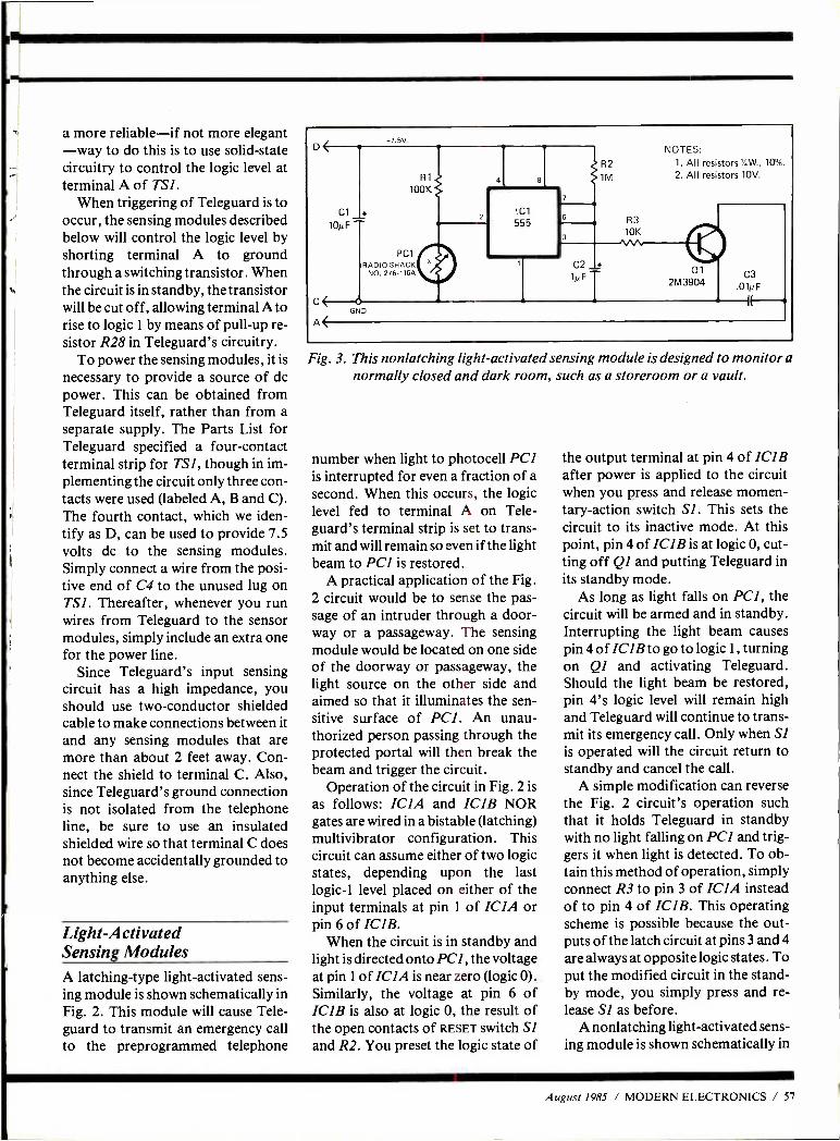
OM
a more reliable -if not more elegant -way to do this is to use solid -state circuitry to control the logic level at terminal A of TSI.
When triggering of Teleguard is to occur, the sensing modules described below will control the logic level by shorting terminal A to ground through a switching transistor. When the circuit is in standby, the transistor will be cut off, allowing terminal A to rise to logic 1 by means of pull -up re- sistor R28 in Teleguard's circuitry.
To power the sensing modules, it is
necessary to provide a source of dc power. This can be obtained from Teleguard itself, rather than from a separate supply. The Parts List for Teleguard specified a four -contact terminal strip for TSI, though in im- plementing the circuit only three con- tacts were used (labeled A, B and C). The fourth contact, which we iden- tify as D, can be used to provide 7.5 volts dc to the sensing modules. Simply connect a wire from the posi- tive end of C4 to the unused lug on TSI. Thereafter, whenever you run wires from Teleguard to the sensor modules, simply include an extra one for the power line.
Since Teleguard's input sensing circuit has a high impedance, you should use two- conductor shielded cable to make connections between it and any sensing modules that are more than about 2 feet away. Con- nect the shield to terminal C. Also, since Teleguard's ground connection is not isolated from the telephone line, be sure to use an insulated shielded wire so that terminal C does not become accidentally grounded to anything else.
Light- Activated Sensing Modules A latching -type light- activated sens- ing module is shown schematically in Fig. 2. This module will cause Tele- guard to transmit an emergency call to the preprogrammed telephone
7.5V.
c( A(
R1
100K
Cl 10µ F
PC1 RADIO SHACK
NO. 276 -116A
o GND
Ic1 555
NOTES: R2 1. All resistors Y,W., 10 %.
2. All resistors 10V. 1M
C2
1N F
R3 10K
O1 C3 2M3904 O1NF
Fig. 3. This nonlatching light- activated sensing module is designed to monitor a normally closed and dark room, such as a storeroom or a vault.
number when light to photocell PCI is interrupted for even a fraction of a second. When this occurs, the logic level fed to terminal A on Tele- guard's terminal strip is set to trans- mit and will remain so even if the light beam to PCI is restored.
A practical application of the Fig. 2 circuit would be to sense the pas- sage of an intruder through a door- way or a passageway. The sensing module would be located on one side of the doorway or passageway, the light source on the other side and aimed so that it illuminates the sen- sitive surface of PCI. An unau- thorized person passing through the protected portal will then break the beam and trigger the circuit.
Operation of the circuit in Fig. 2 is
as follows: ICIA and ICIB NOR gates are wired in a bistable (latching) multivibrator configuration. This circuit can assume either of two logic states, depending upon the last logic -1 level placed on either of the input terminals at pin 1 of ICIA or pin 6 of ICIB.
When the circuit is in standby and light is directed onto PCI, the voltage at pin 1 of ICIA is near zero (logic 0). Similarly, the voltage at pin 6 of ICIB is also at logic 0, the result of the open contacts of RESET switch Si and R2. You preset the logic state of
the output terminal at pin 4 of ICIB after power is applied to the circuit when you press and release momen- tary- action switch SI. This sets the circuit to its inactive mode. At this point, pin 4 of ICIB is at logic 0, cut- ting off QI and putting Teleguard in its standby mode.
As long as light falls on PCI, the circuit will be armed and in standby. Interrupting the light beam causes pin 4 of ICIB to go to logic 1, turning on QI and activating Teleguard. Should the light beam be restored, pin 4's logic level will remain high and Teleguard will continue to trans- mit its emergency call. Only when SI is operated will the circuit return to standby and cancel the call.
A simple modification can reverse the Fig. 2 circuit's operation such that it holds Teleguard in standby with no light falling on PCI and trig- gers it when light is detected. To ob- tain this method of operation, simply connect R3 to pin 3 of ICIA instead of to pin 4 of ICIB. This operating scheme is possible because the out- puts of the latch circuit at pins 3 and 4
are always at opposite logic states. To put the modified circuit in the stand- by mode, you simply press and re- lease Si as before.
A nonlatching light- activated sens- ing module is shown schematically in
August 1985 / MODERN ELECTRONICS / 57
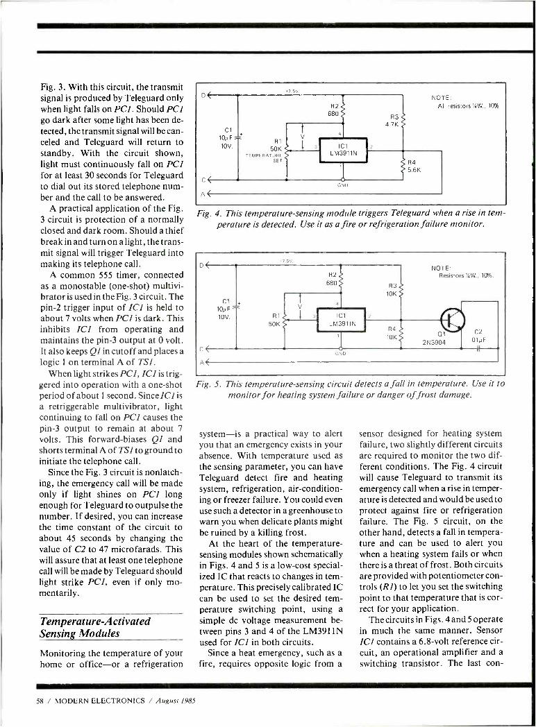
Fig. 3. With this circuit, the transmit signal is produced by Teleguard only when light falls on PCI. Should PCI go dark after some light has been de- tected, the transmit signal will be can- celed and Teleguard will return to standby. With the circuit shown, light must continuously fall on PCI for at least 30 seconds for Teleguard to dial out its stored telephone num- ber and the call to be answered.
A practical application of the Fig. 3 circuit is protection of a normally closed and dark room. Should a thief break in and turn on a light, the trans- mit signal will trigger Teleguard into making its telephone call.
A common 555 timer, connected as a monostable (one -shot) multivi- brator is used in the Fig. 3 circuit. The pin -2 trigger input of ICI is held to about 7 volts when PC1 is dark. This inhibits ICI from operating and maintains the pin -3 output at 0 volt. It also keeps Ql in cutoff and places a
logic 1 on terminal A of TS1. When light strikes PCI, ICI is trig-
gered into operation with a one -shot period of about 1 second. Since ICI is a retriggerable multivibrator, light continuing to fall on PCI causes the pin -3 output to remain at about 7
volts. This forward- biases QI and shorts terminal A of TSl to ground to initiate the telephone call.
Since the Fig. 3 circuit is nonlatch- ing, the emergency call will be made only if light shines on PCI long enough for Teleguard to outpulse the number. If desired, you can increase the time constant of the circuit to about 45 seconds by changing the value of C2 to 47 microfarads. This will assure that at least one telephone call will be made by Teleguard should light strike PCI, even if only mo- mentarily.
Temperature- Activated Sensing Modules
Monitoring the temperature of your home or office -or a refrigeration
.7.5V.
c<
A<
Cl 10/1F
10V. R1
50K TEMPERATURE
SET
R2 680
3
4
IC1
LM3911N
NOTE: All resistors 4W., 100,
R3 4.7K
t N D
R4 5.6K
Fig. 4. This temperature- sensing module triggers Teleguard when a rise in tem- perature is detected. Use it as a fire or refrigeration failure monitor.
/ 5V.
Cl 10uF^ 10v hl
50K
R2
680 R3
10K
NOTE: Resistors %W., 10 %.
cz
IC1
LM3911N
2N 3904 .01NF
GND
58 / MODERN ELECTRONICS / August 1985
Fig. 5. This temperature- sensing circuit detects a fall in temperature. Use it to monitor for heating system failure or danger of frost damage.
system -is a practical way to alert you that an emergency exists in your absence. With temperature used as the sensing parameter, you can have Teleguard detect fire and heating system, refrigeration, air- condition- ing or freezer failure. You could even use such a detector in a greenhouse to warn you when delicate plants might be ruined by a killing frost.
At the heart of the temperature - sensing modules shown schematically in Figs. 4 and 5 is a low -cost special- ized IC that reacts to changes in tern - perature. This precisely calibrated IC can be used to set the desired tern - perature switching point, using a simple dc voltage measurement be- tween pins 3 and 4 of the LM3911N used for ICI in both circuits.
Since a heat emergency, such as a fire, requires opposite logic from a
sensor designed for heating system failure, two slightly different circuits are required to monitor the two dif- ferent conditions. The Fig. 4 circuit will cause Teleguard to transmit its emergency call when a rise in temper- ature is detected and would be used to protect against fire or refrigeration failure. The Fig. 5 circuit, on the other hand, detects a fall in tempera- ture and can be used to alert you when a heating system fails or when there is a threat of frost. Both circuits are provided with potentiometer con- trols (R1) to let you set the switching point to that temperature that is cor- rect for your application.
The circuits in Figs. 4 and 5 operate in much the same manner. Sensor ICI contains a 6.8 -volt reference cir- cuit, an operational amplifier and a switching transistor. The last con-
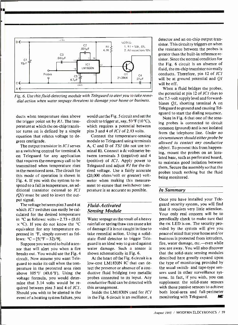
C( A(
Cl .
1oi.F
.1 001µF
Ici L M 1830N
H1
4. /K
NOTES: 1. R1= %W.,5 %.
2. All capacitors 10V.
C5'111 4.7µF T
GND
01 C4 2N3904 01NF (--
Fig. 6. Use this fluid-detecting module with Teleguard to alert you to take reme- dial action when water seepage threatens to damage your home or business.
ducts when temperature rises above the trigger point set by RI. The tern- perature at which the on -chip transis- tor turns on is defined by a simple equation that relates voltage to de- grees centigrade.
The output transistor in ICl serves as a switching control for terminal A on Teleguard for any application that requires the emergency call to be transmitted when temperature rises in the monitored area. The circuit for this mode of operation is shown in Fig. 4. If you wish the system to re- spond to a fall in temperature, an ad- ditional transistor external to ICI (Q1) must be used to invert the out- put signal.
The voltage between pins 3 and 4 at which ICI switches can easily be cal- culated for the desired temperature in °C as follows: volts = 2.73 + (0.01 x °C). If you do not know the °C
equivalent for any temperature ex- pressed in °F, simply convert as fol- lows: °C = [5( °F - 32)/9].
Suppose you wanted to build a sen- sor that will alert you when a fire breaks out. You would use the Fig. 4 circuit. Now assume you want Tele- guard to make its call when the tem- perature in the protected area rises above 105 °F (40.6 °F). Using the voltage formula, you would deter- mine that 3.14 volts would be re- quired between pins 3 and 4 of ICI. Should you wish to be alerted in the event of a heating system failure, you
would use the Fig. 5 circuit and set the circuit to trigger at, say, 50 °F (10 °C), which requires a potential between pins 3 and 4 of ICI of 2.83 volts.
Connect the temperature- sensing module to Teleguard using terminals A, C and D of TS1 (do not use ter- minal B). Connect a dc voltmeter be- tween terminals 3 (negative) and 4 (positive) of ICI. Apply power to Teleguard and adjust RI for the de- sired voltage. Use a fairly accurate (20,000 ohms /volt or greater) volt- meter when making this measure- ment to ensure that switchover tem- perature is as accurate as possible.
Fluid -Activated Sensing Module
Water seepage as the result of a heavy rainfall or spring thaw can cause a lot of damage if it is not caught in time to take remedial action. Using a solid - state fluid detector to trigger Tele- guard is an ideal way to guard against water damage. Such a sensor is shown schematically in Fig. 6.
At the heart of the Fig. 6 circuit is a low -cost LM1830N IC that can de- tect the presence or absence of a con- ductive fluid bridging two metallic probes connected to its input. Any conductive fluid can be detected with this arrangement.
Inside the LM 1830N used for ICI in the Fig. 6 circuit is an oscillator, a
detector and an on -chip output tran- sistor. This circuitry triggers on when the resistance between the probes is
greater than the built -in reference re- sistor. Since the normal condition for the Fig. 6 circuit is an absence of fluid, the on -chip transistor normally conducts. Therefore, pin 12 of ICI will be at ground potential and QI will be off.
When a fluid bridges the probes, the potential at pin 12 of ICl rises to the 7.5 -volt supply level and forward - biases Ql, shorting terminal A on Teleguard to ground and causing Tel - eguard to start the dialing sequence.
Note in Fig. 6 that one of the sens- ing probes is connected to circuit common (ground) and is not isolated from the telephone line. Under no circumstances should either probe be allowed to contact any conductive object. To prevent this from happen- ing, mount the probes on an insu- lated base, such as perforated board, to maintain good isolation between them. Secure the assembly so that the probes touch nothing but the fluid being monitored.
In Summary
Once you have installed your Tele- guard security system, you will find that it requires very little attention. Your only real concern will be to perodically check to make sure that the OK LED is on. The security pro- vided by the system will give you peace of mind that your home and /or business is protected from intruders, fire, water damage, etc. -even while you are away. You will also discover that the solid -state sensing modules described here greatly expand upon the type of monitoring provided by the usual switch- and tape -type sen- sors used in other surveillance sys- tems. In fact, if you wish, you can supplement the solid -state sensors with those passive sensors to achieve both local-area and full -perimeter monitoring with Teleguard. AE
August 1985 / MODERN ELECTRONICS / 59
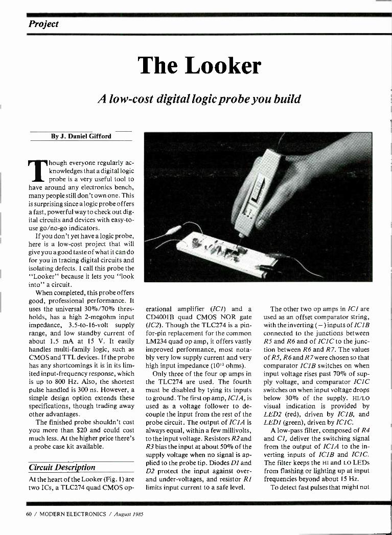
Project
The Looker A low -cost digital logic probe you build
By J. Daniel Gifford
Though everyone regularly ac- knowledges that a digital logic probe is a very useful tool to
have around any electronics bench, many people still don't own one. This is surprising since a logic probe offers a fast, powerful way to check out dig- ital circuits and devices with easy -to- use go /no -go indicators.
If you don't yet have a logic probe, here is a low -cost project that will give you a good taste of what it can do for you in tracing digital circuits and isolating defects. I call this probe the "Looker" because it lets you "look into" a circuit.
When completed, this probe offers good, professional performance. It uses the universal 30 %/7007o thres- holds, has a high 2- megohm input impedance, 3.5 -to -16 -volt supply range, and low standby current of about 1.5 mA at 15 V. It easily handles multi -family logic, such as CMOS and TTL devices. If the probe has any shortcomings it is in its lim- ited input- frequency response, which is up to 800 Hz. Also, the shortest pulse handled is 300 ns. However, a simple design option extends these specifications, though trading away other advantages.
The finished probe shouldn't cost you more than $20 and could cost much less. At the higher price there's a probe case kit available.
Circuit Description At the heart of the Looker (Fig. 1) are two ICs, a TLC274 quad CMOS op-
erational amplifier (ICI) and a CD4001B quad CMOS NOR gate (1C2). Though the TLC274 is a pin - for -pin replacement for the common LM234 quad op amp, it offers vastly improved performance, most nota- bly very low supply current and very high input impedance (10" ohms).
Only three of the four op amps in the TLC274 are used. The fourth must be disabled by tying its inputs to ground. The first op amp, ICIA, is used as a voltage follower to de- couple the input from the rest of the probe circuit. The output of ICIA is always equal, within a few millivolts, to the input voltage. Resistors R2 and R3 bias the input at about 50% of the supply voltage when no signal is ap- plied to the probe tip. Diodes DI and D2 protect the input against over - and under -voltages, and resistor RI limits input current to a safe level.
The other two op amps in ICI are used as an offset comparator string, with the inverting ( -) inputs of IC1B connected to the junctions between RS and R6 and of ICI C to the junc- tion between R6 and R 7. The values of RS, R6 and R 7were chosen so that comparator ICIB switches on when input voltage rises past 70% of sup- ply voltage, and comparator ICIC switches on when input voltage drops below 30% of the supply. HI /LO visual indication is provided by LED2 (red), driven by IC1B, and LEDI (green), driven by ICI C.
A low -pass filter, composed of R4 and Cl, deliver the switching signal from the output of ICIA to the in- verting inputs of IC1B and ICIC. The filter keeps the HI and LO LEDs from flashing or lighting up at input frequencies beyond about 15 Hz.
To detect fast pulses that might not
60 / MODERN ELECTRONICS / August 1985
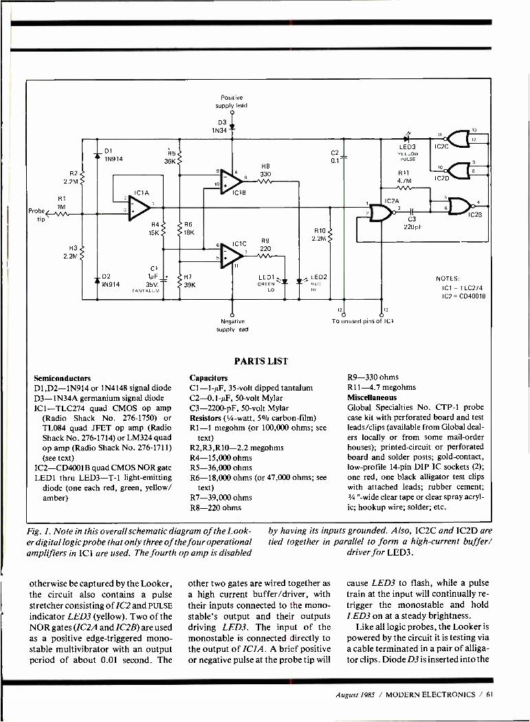
Probe tip
Positive supply lead
O
D3 1N34
D2 =1N914
R5
36K C2
0.1 -
R6
18K
Cl 1µF1
35V. TANTALUM
R7
39K LEDI GREEN *
LO
R10 2.2M
LED2 RED HI
LED3 YELLOW
PULSE
R11
4.7M
IC2A
1,
n 12
IC2C
10 S
IC2D
C3
220 pF
4
IC2B
NOTES:
ICI = TLC274 IC2 = CD4001B
Semiconductors D1,D2 -1N914 or 1N4148 signal diode D3 -1N34A germanium signal diode ICI- TLC274 quad CMOS op amp
(Radio Shack No. 276 -1750) or TL084 quad JFET op amp (Radio Shack No. 276 -1714) or LM324 quad op amp (Radio Shack No. 276 -1711) (see text)
IC2- CD4001 B quad CMOS NOR gate LED 1 thru LED3 -T -1 light- emitting
diode (one each red, green, yellow/ amber)
o Negative
supply lead
PARTS LIST
Capacitors C1 -1 -AF, 35 -volt dipped tantalum C2- 0.1 -µF, 50 -volt Mylar C3- 2200 -pF, 50 -volt Mylar Resistors (1/4 -watt, 5% carbon -film) R1 -1 megohm (or 100,000 ohms; see
text) R2,R3,R10 -2.2 megohms R4- 15,000 ohms R5- 36,000 ohms R6- 18,000 ohms (or 47,000 ohms; see
text) R7- 39,000 ohms R8 -220 ohms
12 13
O o To unused pins of IC1
R9 -330 ohms R11 -4.7 megohms Miscellaneous Global Specialties No. CTP -1 probe case kit with perforated board and test leads /clips (available from Global deal- ers locally or from some mail -order houses); printed- circuit or perforated board and solder posts; gold- contact, low -profile 14 -pin DIP IC sockets (2);
one red, one black alligator test clips with attached leads; rubber cement; 3/4 " -wide clear tape or clear spray acryl- ic; hookup wire; solder; etc.
Fig. 1. Note in this overall schematic diagram of the Look- er digital logic probe that only three of the four operational amplifiers in IC 1 are used. The fourth op amp is disabled
otherwise be captured by the Looker, the circuit also contains a pulse stretcher consisting of IC2 and PULSE
indicator LED3 (yellow). Two of the NOR gates (IC2A and IC2B) are used as a positive edge- triggered mono - stable multivibrator with an output period of about 0.01 second. The
by having its inputs grounded. Also, IC2C and IC2D are tied together in parallel to form a high- current buffer/
driver for LED3.
other two gates are wired together as a high current buffer /driver, with their inputs connected to the mono - stable's output and their outputs driving LED3. The input of the monostable is connected directly to the output of ICIA. A brief positive or negative pulse at the probe tip will
cause LED3 to flash, while a pulse train at the input will continually re- trigger the monostable and hold LED3 on at a steady brightness.
Like all logic probes, the Looker is
powered by the circuit it is testing via a cable terminated in a pair of alliga- tor clips. Diode D3 is inserted into the
August 1985 / MODERN ELECTRONICS / 61
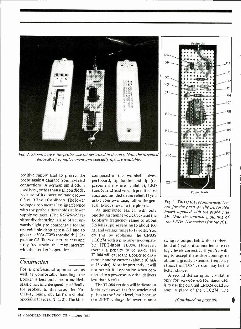
Fig. 2. Shown here is the probe case kit described in the text. Note the threaded removable tip; replacement and specialty tips are available.
positive supply lead to protect the probe against damage from reversed connections. A germanium diode is used here, rather than a silicon diode, because of its lower voltage drop - 0.3 vs. 0.7 volt for silicon. The lower voltage drop means less interference with the probe's thresholds at lower supply voltages. (The R5/R6/R 7 re- sistor divider string is also offset up- wards slightly to compensate for the unavoidable drop across D3 and to give true 30 %/70% thresholds.) Ca- pacitor C2 filters out transients and stray frequencies that may interfere with the Looker's operation.
Construction For a professional appearance, as well as comfortable handling, the Looker is best built into a molded - plastic housing designed specifically for probes. In this case, the No. CTP -1, logic probe kit from Global Specialties is ideal (Fig. 2). The kit is
composed of the two shell halves, perfboard, tip holder and tip (re- placement tips are available), LED support and lead set with preattached clips and molded strain relief. If you make your own case, follow the gen- eral layout shown in the photos.
As mentioned earlier, with only one design change you can extend the Looker's frequency range to about 3.5 MHz, pulse sensing to about 100 ns, and voltage range to 18 volts. You do this by replacing the CMOS TLC274 with a pin- for -pin -compati- ble JFET -input TL084. However, there's a penalty to be paid. The TL084 will cause the Looker to draw more standby current (about 10 mA at 15 volts). More importantly, it will not permit full operation when con- nected to a power source that delivers less than 6 volts.
The TL084 version will indicate HI
logic levels as well as frequencies and pulses at the 5 -volt level, but because the JFET voltage follower cannot
Fig. 3. This is the recommended lay- out for the parts on the perforated board supplied with the probe case kit. Note the unusual mounting of the LEDs. Use sockets for the ICs.
swing its output below the LO thres- hold at 5 volts, it cannot indicate LO
logic levels correctly. If you're will- ing to accept these shortcomings to obtain a greatly extended frequency range, the TL084 version may be the better choice.
A second design option, suitable only for very -low- performance use, is to use the original LM324 quad op amp in place of the TLC274. The
(Continued on page 90)
62 / MODERN ELECTRONICS / August 1985
Better FM Reception From Your Clock Radio. The FM antenna in most clock radios consists of a piece of wire wrapped tightly around the power cord, but not electrically connected to it, as pictured. Its purpose is to pick up FM signals through the power cord and the house wiring. This is adequate for nearby FM stations, but not for fringe areas.
Fortunately, it is easy to add an ex- ternal antenna. Just remove the wire that wraps around the power cord, noting where it was connected to the circuit board. Then connect your new antenna line to the circuit board in the same place, as illustrated.
Tips & Techniques
As an antnena, try a piece of wire about 30" long. Start with it oriented straight up and down, but experiment to find the position that gives the strongest signal. Although 30" is the correct length for a quarter -wave ver-
Add 30" wire or
other antenna
Remove original r
anteni;a loop;
11t Line cord
Circuit hoard
1r Power r.. transformer
tical antenna at 98 MHz, a longer wire antenna may work better under some conditions. Alternatively, you can use a telescoping antenna from a junked portable radio or TV set. -Michael A. Covington, Athens, GA
.... from the publishers of x"
LI5IE uni Here's what you've been looking lor- an all new hard -hitting monthly magazine which gives a unique insider's view of what's really going on in the world of communications. POP' COMM is your primary source of information - bigger and better than any communications magazine, with exciting coverage of scanners, shortwave broadcast & utility stations,
POPULAR OMMvi1ICINI;jQ_..
spy stations, pirate and clandestine broadcasters, Trelye RTTY monitoring, survivalist communications systems, FCC news, wiretapping and bugging, voice scrambling/unscrambling, surveillance / undercover communications, satellite & cable TV, sophisticated telephones, & more. What you've been looking for all along! Take advantage of substantial savings over the newsstand price by subscribing now. Don't miss out on even one single issue of POPULAR COMMUNICATIONS - order your subscription now.
Issues
SIJBKIUBE Now Zit SAVEI
> z
>
a d-10 _ z
ó Á 5
a g C C EJ . v E v ? u
Z ó
co o - a c z r: 1 Q C
,-L.). Ú ó o î c a Mr Z ,';',
ç rq . ', d
Q ó v f q ó [ °d = r
Q c c g.
Ó î a =°_ _o ° ' ci.
Ev 4 .2 yc L 7
W tN d
U c E z_ "0 g -3
c w ¿ c Ñ A
ú
O
O O ~ d
i;
L u 9 A
irV i É d á É á á Z uri (L)
August 1985 / MODERN ELECTRONICS / 65
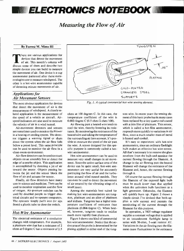
1 NOTEBOOK //1111
Measuring the Flow of Air
By Forrest M. Mims III
T here are various applications for devices that detect the movement of air. This month's column will
discuss some of them and describe two simple devices you can build to measure the movement of air. One device is a cup anemometer patterned after those mete- orologists use to measure windspeed. The other is a hot -wire anemometer capable of detecting minute movements of air.
Applications for Air Movement Sensors The most obvious application for devices that detect the movement of air is the measurement of windspeed. A closely re- lated application is the measurement of the speed of a vehicle or aircraft. Air- speed indicators are also used to measure the velocity of air in a wind tunnel.
Air- movement detectors and sensors are sometimes used to monitor the blower in a heating or cooling system. The detec- tor triggers a warning signal or shuts down the system when the air flow falls below a preset level. This same principle can be used to monitor the air flow in a clean-room environment.
Air -flow detectors can be used to count objects on an assembly line or detect the edge of a nearby object. This application is accomplished by directing a jet of air toward the sensor. Objects passing be- tween the jet and the sensor block the flow of air and actuate the sensor.
Finally, air -flow detectors have many uses in science and medicine. They can be used to monitor respiration and the flow of oxygen. Air- pressure switches can be used by disabled people to trigger elec- trical circuits and to operate computers. The operator simply puffs into (or sips from) a plastic tube to close the switch.
Hot -Wire Anemometer The electrical resistance of a conductor changes with temperature. For example, a platinum wire that has a resistance of 2 ohms at-0 degree C has a resistance of 2.5
Fig. 1. A typical commercial hot -wire sensing element.
ohms at 100 degrees C. In this case, the temperature coefficient of the wire is 0.002 /degree C (0.5 ohm /2 ohm /100).
Air flowing past a heated wire tends to cool the wire, thereby lowering its resis- tance. By monitoring the resistance of the heated wire and taking the temperature of the surrounding air into account, it's pos- sible to measure the speed of the air past the wire. A sensor designed for this spe- cific purpose is commonly called a hot - wire anemometer.
Hot -wire anemometers can be used to measure very small changes in air move- ment. Since the active surface area of the device can be quite small, hot -wire ane- mometers are very useful for accurately portraying the flow of air and the turbu- lence around wind tunnel models. They can even be used to detect the movement of air created by the vibrating wings of a small insect.
Among the materials best suited for making hot wire -anemometers are tung- sten, platinum and an alloy of platinum and iridium. Tungsten has a higher tem- perature coefficient of resistance than platinum (0.004 /degree C). When heat- ed, however, tungsten tends to oxidize much more rapidly than platinum.
Figure 1 shows one kind of commercial hot -wire anemometer. Notice that the ac- tive area of the probe is determined by the plating applied to either end of the tung-
sten wire. In recent years the sensing ele- ment of this basic probe has in many cases been replaced by a tiny quartz rod coated with a thin film of platinum. This sensor, which is called a hot -film anemometer, responds more quickly to variations in air flow, since a much smaller mass of metal is heated and cooled.
It's easy to experiment with hot -wire anemometry, since an ordinary flashlight bulb makes an effective hot wire sensor. All that's necessary is to remove the glass envelope from the bulb and monitor the current flowing through the filament. A change in the air flowing past the heated filament will change the resistance of the filament and, hence, the current flowing through it.
Of course the current flowing through the filament of the exposed light bulb must be much lower than that applied when the unbroken bulb functions as a light generator. Otherwise, the filament will quickly burn up. Figure 2 shows a simple circuit I've devised that both ap- plies a safe current and permits the monitoring of the current through the filament for this purpose.
In operation, a 7805 voltage regulator supplies a constant voltage that is applied to an incandescent flashlight lamp in series with 50 -ohm, 5 -watt resistor RI. Variations in the air flowing past the fila- ment cause fluctuations in the resistance
66 / MODERN ELECTRONICS / August 1985
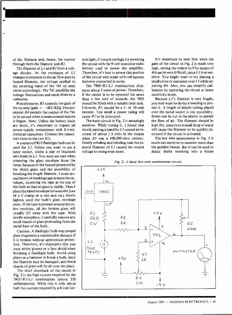
of the filament and, hence, the current through both the filament and RI.
The filament of LI and RI form a volt- age divider. As the resistance of LI changes in response to the air flow past its heated filament, the voltage applied to the inverting input of the 741 op amp varies accordingly. The 741 amplifies the voltage fluctuations and sends them to a voltmeter.
Potentiometer RS controls the gain of the op amp [gain = - (R5 /R2)]. Potenti- ometer R4 permits the output of the 741
to be zeroed when a measurement session is begun. Note: Unless the battery leads are short, it's important to bypass all power- supply connections with 0.1 -mi- crofarad capacitors. Connect the capaci- tors close to the two ICs.
A common PR 13 flashlight bulb can be used for LI. Unless you want to use a lamp socket, solder a pair of insulated wire leads to Ll. You must use care when removing the glass envelope from the lamp, because of the hazard presented by the sharp glass and the possibility of breaking the fragile filament. I wrap sev- eral layers of masking tape around the en- velope, squeezing the tape at the top of the bulb so that no glass is visible. Then I
place the taped envelope between the jaws of a C -clamp or a vise and very slowly tighten until the bulb's glass envelope pops. If the tape is pressed around the en- tire envelope, all the broken glass will usually lift away with the tape. With needle- nosepliers, I carefully remove any small shards of glass protruding from the metal base of the bulb.
Caution: A flashlight bulb may propel glass fragments a considerable distance if it is broken without appropriate protec- tion. Therefore, it's imperative that you wear safety glasses or a face shield when breaking a flashlight bulb. Avoid using pliers or a hammer to break a bulb, since the filament may be damaged, and sharp shards of glass will fly all over the place.
The chief drawback of the circuit in Fig. 2 is the high current required by the 7805/RI/LI combination (about 250 milliamperes). While this is only about half the current required by a 6 -volt lan-
tern light, it's much too high for powering the circuit with the 9 -volt transistor radio battery used to power the amplifier. Therefore, it's best to power this portion of the circuit with a pair of 6 -volt lantern batteries connected in series.
The 7805/RI/LI combination dissi- pates about 3 watts of power. Therefore, if the circuit is to be operated for more than a few tens of seconds, the 7805 should be fitted with a suitable heat sink. Likewise, RI should be a 5- or 10 -watt resistor. Too small a power rating will cause RI to be destroyed.
The basic circuit in Fig. 2 is amazingly sensitive. While testing it, I found that slowly passing a hand by LI caused an in- crease of about 1.5 volts in the output when RS was a 100,000 -ohm resistor. Gently exhaling and inhaling near the ex- posed filament of LI caused the output voltage to swing even more.
It's important to note that when the gain of the circuit in Fig. 2 is made very high, setting the output to 0 by means of R4 can be very difficult, since Ll is so sen- sitive. You might want to try placing a small cover or container over LI while ad- justing R4. Also, you can simplify cali- bration by operating the circuit at lower sensitivity levels.
Because LI's filament is very fragile, you may want to devise a housing to pro- tect it. A length of plastic tubing placed over the metal socket is one possibility. Holes can be cut in the plastic to permit the flow of air. The filament should be kept dry, since even a small drop of water will cause the filament to be quickly de- stroyed if the circuit is activated.
The hot wire anemometer in Fig. 2 is
much too sensitive to monitor more than the gentlest breeze. But it can be used to detect drafts sneaking into a house
Fig. 2. A basic hot -wire anemometer circuit.
GtiD
+12
IN
7 805
OuT
RL SOJZ
W
LI (SEE TEXT
R2
1K
3
R41
1oK
ti
Y
-9 V
100K
VOLTMETER
August 1985 / MODERN ELECTRONICS / 67
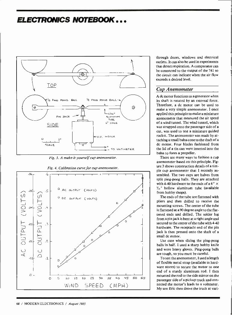
ELECTRONICS NOTEBOOK ...
AMA O
TOP
%¿ PIn)G Pots-) G HALL %L PING R>NG CALL *.
PIN TACK
SIDE
O
SCALE
i 3 /Ic"
ALumi NuM To BE
6' LONG
p.e. MOTOR
t TO VOLT M ETE R
Fig. 3. A make-it-yourself cup anemometer.
Fig. 4. Calibration curve for cup anemometer.
through doors, windows and electrical outlets. It can also be used in experiments that detect respiration. A comparator can be connected to the output of the 741 so the circuit can indicate when the air flow exceeds a desired level.
Cup Anemometer A dc motor functions as a generator when its shaft is rotated by an external force. Therefore, a dc motor can be used to make a very simple anemometer. I once applied this principle to make a miniature anemometer that measured the air speed of a wind tunnel. The wind tunnel, which was strapped onto the passenger side of a car, was used to test a miniature guided rocket. The anemometer was made by at- taching a small balsa cone to the shaft of a dc motor. Four blades fashioned from the lid of a tin can were inserted into the balsa to form a propeller.
There are many ways to fashion a cup anemometer based on this principle. Fig- ure 3 shows construction details of a sim- ple cup anemometer that I recently as- sembled. The two cups are halves from split ping -pong balls. They are attached with 4-40 hardware to the ends of a 6" x
6 " hollow aluminum tube (available from hobby shops).
The ends of the tube are flattened with pliers and then drilled to receive the mounting screws. The center of the tube is flattened at a 90 degree angle to the flat- tened ends and drilled. The solder lug from a pin jack is bent at a right angle and secured to the center of the tube with 4-40 hardware. The receptacle end of the pin jack is then pressed onto the shaft of a small dc motor.
Use care when slicing the ping -pong balls in half. I used a sharp hobby knife and wore heavy gloves. Ping -pong balls are tough, so you must be careful.
To test the anemometer, I used a length of flexible metal strap (available in hard- ware stores) to secure the motor to one end of a sturdy aluminum rod. I then mounted the rod to the side mirror on the passenger side of a pickup truck and con- nected the motor's leads to a voltmeter. My son Eric then drove the truck at vari-
68 / MODERN ELECTRONICS / August 1985
ous speeds on a still day, while I recorded voltage readings.
Figure 4 is a graph that shows the ac and dc readings Eric and I obtained dur- ing the test session. The cups begin to ro- tate when the wind speed reaches 3 to 4
mph. The speed at which your anemome- ter begins to rotate and the slope of the calibration curve is dependent upon the motor you use. The output from the mo- tor is reasonably linear. This corresponds nicely with results I obtained with the wind tunnel anemometer described above.
During the tests, I noted some fluctua- tions of the voltage output at certain speeds. When this occurred, the voltage reading would jump back and forth over a range of a few tens of millivolts. There- fore, I recorded what appeared to be the average voltage.
The anemometer in Fig. 3 can be im- proved by adding another pair of cups. In
its present configuration, the cups don't always turn when the wind is below 10
mph unless they are perpendicular to the oncoming wind. The motor must be pro- tected from rain should this anemometer be installed outdoors. One possibility would be to install a split ping -pong ball over the top of the motor. It could be mounted to the 4 -40 hardware that holds the pin jack in place. The split ball should rotate with the cups and keep rain from entering the top of the motor.
Going Further You can find much more information about devices that detect and measure the flow of air at any good library. An ex- cellent article on hot -wire anemometry is
"Hot Wire and Hot Film Anemometry" by Eric Nelson (Sensors, September 1984, Pp. 17 through 22).
The Sharper Image (680 Davis St., San
Francisco, CA and other stores in Hous- ton, Denver and Los Angeles) sells the TurboMeterTM, a compact anemometer with a shrouded fan and a digital readout. This unit, which measures winds up to 100 mph, sells for $79 (plus $3.50 post- age). The TurboMeter and other ane- mometers are sold also by Edmund Scien- tific (101 E. Gloucester Pike, Barrington, NJ 08007).
For more information about Honey- well's ultra- sensitive air pressure switch, see "The Forrest Mims Circuit Scrap- book" (McGraw -Hill, 1983, Pp. 138 -140). Included in this reference are experimen- tal circuits that permit disabled people to control external devices by puffing into or sipping from a plastic tube. Also in- cluded is an experimental respiration de- tector circuit. The wind tunnel anemome- ter mentioned above is also described in
this book (Pp. 133 to 134). AE
Computer problems?
DON'T BLAME THE SOFTWARE! Isolators prevent:
CPU /printer /disk interaction Lightning or spike damage AC power line disturbances RFI -EMI interference
Commercial Grade Isolators ISO -I 3 Isolated Sockets ISO -2 2 Isolated Socket Banks, 6 Sockets
Industrial Grade Isolators ISO -3 3 Double Isolated Sockets ISO -11 2 Double Isolated Banks, 6 Sockets
Laboratory Grade Isolators ISO- 17 4 Quad Isolated Sockets I50 -18 2 Quad Isolated Banks, 6 Sockets
$ 81.95 $ 81.95
$122.95 $122.95
$213.95 $180.95
Circuit Breaker, any model (Add -CB) Add $ 11.00
Remote Switch, any model (Add -RS) Add $ 20.00
Electronic Specialists, Inc. 171 S. Main St., Box 389, Natick, Mass. 01780 (617) 655 -1532
Toll Free Order Desk 1- 800 -225 -4876 MasterCard, VISA, American Express
CIRCLE 53 ON FREE INFORMATION CARO
FREE 1985 CATALOG JUST CLIP AND RETURN THIS COUPON
THIS MONTH'S SPECIALS 4116 16K 150ns 1.25
4164 64K 150ns 1.75 41256 256K 150ns 7.95
2708 1K x 8 350ns 8K 5.95 2716 2K x 8 450ns 16K 3.60
2732A 4K x 8 300ns 32K 4.90 2764 8K x 8 300ns 64K 4.95
2712816K x 8 300ns 128K 7.95 27256 32K x 8 250ns 256K 17.95
27512 64K x 8 250ns 512K 85.50 WE ALSO STOCK_._
010
Books Breadboard & Accessories
Capacitors Chemicals Connectors
Crystals Plugs & Jacks Fans
Enclosures Filters Fuses Heat
Shrink Tubing Heat Sinks Kits
Knobs Peripherals Probes Opto
PCB Products Potentiometers
Power Supplies Relays Resistors
Cable Assembles Sockets...
USA P.O BOX 9100
WESTBOROUGH, MASS 1- 800 -343 -0874
0111*
Active CANADA 5651 FERRIER ST.
MONTREAL, QUEBEC 1 -800- 361 -5884
SELF SERVE STORES LOCATED NEAR YOU. JUST CALL... WESTBOROUGH 07 IAWA EDMONTON
366 -9684 728 -7900 438 -5888 BELLEVUE 881 -8191
MONTREAL 731 -7441
TORONTO CALGARY 977 -7692 235 -5300
DOWNSVIEW VANCOUVER 630 -0400 438 -3321 8 Mt
August 1985 / MODERN ELECTRONICS / 69
IIDHARDW/1RE HACKER/11111111111==
Getting computer and peripheral schematics, a first look at the Laserwriter, innermost secrets of power supply design, methods of video sync separation and combination.
By Don Lancaster
There's been a lot of reader feedback on the low- pressure pneumatics we looked at a few columns back. It seems that a lot of other hobbyists in wildly different fields also have dibs on air pressure as a substi- tute for electromechanical stuff. For in- stance, a player piano is nothing but a bunch of low- pressure pneumatics, and there are lots of enthusiasts around who rebuild or restore these instruments. There's an outfit called, of all things, the Player Piano Company. In its catalog, you will find all sorts of low -pressure pneumatic goodies and ideas.
Great stuff. Seems the largest of the radio -con-
trolled model planes are also going pneu- matic for such things as landing -gear con- trols. Bryon Originals is one source. These systems tend to run at much higher pressures than you can handle with one of those 25 cent EGR valves. Since the EGR valve is really intended for vacuum use, when you reverse it for low- pressure ro- botics, the valve will "crack" around 11
psi or so. The model -plane people often run their equipment at 100 psi.
A very few model -railroad people also use medium -pressure air for such things as turnout switches and roundhouse doors that slowly and smoothly open. One company involved with these prod- ucts is Del -Aire Products. This time, the pressure is up to around 50 psi, mostly be- cause they insist on the tiniest cylinders possible. For instance, at 5 psi, you can get 5 pounds of force with a cylinder that is 1 inch square. Go to 50 psi, and you only need an area of 0.1 square inch. This can be done with a square cylinder only 0.33 inch on a side.
On to this months goodies .. .
Where do I get a schematic for a computer or printer? The first and most obvious place to look is in the technical or repair manuals for
`1 pLE r`44
4) r 4
: 4-_)
TINAJA C QUESTING
S. I. G. Al.
Fig. 1. A snappy Laserwriter image done with Applewriter on an Apple Ile. Print time was 17 seconds and materials cost was less than four cents. Though shown in black and white, the original was done in two colors.
the microcomputer or printer in which you are interested. Normally, the techni- cal stuff is held back, and you get charged extra to access this information.
Some computer stores do not want you to know these manuals even exist because they cut dearly into their service profits. The trick is to call the manufacturer di- rectly. Should they try to shuttle you off on a local dealer, tell them you are from Littlefield, Arizona, or some similiar "non- urban" area. If that fails to get results, get on a modem line or a club SIG and holler for help.
As examples, Apple has its Ile Techni- cal Reference Manual (#A2L2005) and separately available pair of Ilc Technical Reference Manuals (#A2L4030). Getting hold of these has loosened up bunches, and they should now be available at most technical bookstores, newly reprinted by Addison Wesley.
One of the best -kept secrets around is the Sams series of Computerfacts. These are similar to the older Photofacts that are essential for radio and television re-
pair. A typical Computerfact packet con- tains a complete, large and well -or- ganized schematic, disassembly instruc- tions, parts lists, troubleshooting guides, the whole bit.
There are 43 of these packets available so far. As typical ferinstances, the Apple He version is #8920 and the original Im- agewriter printer is #8941. The brand - new Imagewriter II packet is in the works and should be available by the time you read this. Cost is around $20 each.
Sadly, there is not an Apple III packet available. I sure have gotten a lot of help line calls from orphaned III people, who are desperately clawing at anything at all they can get their hands on. The Macin- tosh packet is not yet ready.
What's the real word on the Laserwriter? I've had mine for only a week or so. But, my, oh my, what a machine!
Kiddies, the price of typesetting with full graphics has just dropped below a dollar a page. Not one red cent more.
Where to even begin. The Laserwriter sets any size type you
like, mixed with any style of graphics in any size you can imagine in any config- uration. You can easily do such things as homecoming posters and sidewalk -to- sidewalk centenial banners. Signs of any size and shape are trivial. There's even a neat Postscript procedure that will auto- matically chop up the sign or poster into as many 8' V2 "x 11 " pieces required. Later, you tape the pages back together to get up to whatever size you need.
It is trivially easy to move, spin, repeat or stretch an image every which way. You can have any shade of gray you want, and even four colors with repeated passes are possible. Variable size and slant text along a circular or even an aribtrary path is easily done.
One thing not well known (guess why ?) is that Applewriter on an Apple Ile does as good, if not better, a job than the Mac-
70 / MODERN ELECTRONICS / August 1985

RC = 0.7 ( DC + 2 )
DC =(1.4RC)-2
(A) Full -wave bridge; use magic rule.
RC=1.4(DC+1) DC=(0.7RC)-1
(B) Full -wave, center -tapped; use magic rule.
RC=0.7(DC+1) DC=(1.4RC)-1
(C) Half -wave; use double the magic rule.
Fig. 2. Shown here are the three most popularly used power supply circuits.
Intosh does in driving the Laserwriter, in- cluding graphics so fancy that they are not available out of any of the common Mac programs.
We'll note in passing that MacPaint has no way to handle the high- resolution alphabets, MacWrite isn't good at larger or integrated graphics, and MacDraw is a cruel joke at best.
HIRES dumps or any other bit -mapped graphics are done by converting them to hex ASCII character pairs that are easily handled by Applewriter and its WPL su- pervisory language.
TheAppletalk network stuff is also not needed. In fact, it can severely limit what you can do with the Laserwriter. Among
A 10,000 Microfarad Capacitor will give one volt of ripple under a one ampere load.
Fig. 3. The magic "10k" rule for power supply filter capacitor design. Use this rule only when designing a 50- or 60 -hertz full -wave power supply. When designing a half -wave
power supply, double the capacitance.
other things, it excludes you from using the so- called Diablo emulation mode.
And yes, I'll put my money where my mouth is.
I have five Laserwriter images created with Applewriter on a Ile. I'll be glad to send you free copies of them. I'll also gladly give a free Sams book to anyone who can show me any way at all to do these on a Mac that is even remotely as cheap, as easy, as powerful, and as con- venient as using Applewriter on a Ile.
Figure 1 shows a typical image. This was done on a Ile under Applewriter. Once you know exactly what you are do- ing and have built up a library of goodies, this complex an image should take you around 10 minutes to program and 17
seconds to print. Materials cost is under four cents for a single color, and under seven for two.
One neat thing that is not at all obvious is that it does not matter what order you put the image onto the Laserwriter's bit - map. You are free to, say, do your back- grounds first, artwork second, your headlines third, and your fine print last. More importantly, you do a form letter by putting the letter in the printer and changing only the name and address for each repeated pass. AIIe, again with Ap- plewriter, can process hundreds, or even thousands, of letters at a whack.
Watching customized form lettrs quietly pour out of a machine at an eight-
copy -per -minute rate is a joy to behold. Yes, I have automatic software for both form letters and envelopes -call or write.
There are some problems though. The quality is not quite what a print house would call "typeset," since the resolution is "only" 300 dots per inch. A printer might call this "tabloid" quality. One way to beat this is to work double or triple size and then photo- reduce the result.
Another way is to find one of the many "real" typesetting machines that speak the same Postscript language the Laser - writer does. Once you have exactly what you want, the same software on the same machine can give you good typeset qual- ity, say to 2400 dpi and beyond.
A second obvious problem is that there is no way to tractor feed anything, so things like envelopes, labels, or business cards have to be hand fed. And hand feeding requires custom programming.
Turning to nit picking, the laser engine itself shows some truly bizarre human en- gineering. You need continuous access to all four sides and the top of the printer, including the ability to simultaneously observe status lights at both the front and the back of the machine. An unreachable and often -used selector switch requires that you add a shaft extender before you can even put a knob on it, let alone use it.
The paper tray is far too shallow to the point of being a joke. An unnecessary "U" turn in the paper path adds to the
August 1985 / MODERN ELECTRONICS / 71
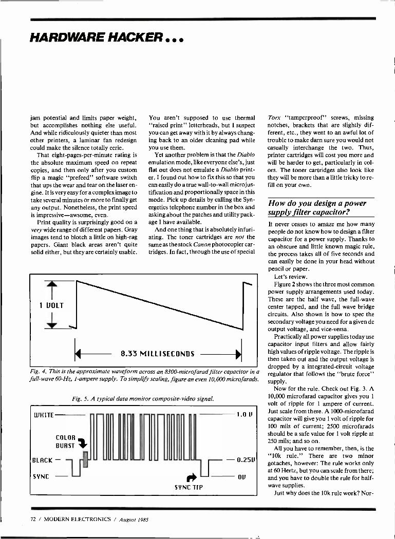
HARDWARE HACKER ..
jam potential and limits paper weight, but accomplishes nothing else useful. And while ridiculously quieter than most other printers, a laminar fan redesign could make the silence totally eerie.
That eight -pages -per- minute rating is
the absolute maximum speed on repeat copies, and then only after you custom flip a magic "prefeed" software switch that ups the wear and tear on the laser en- gine. It is very easy for a complex image to take several minutes or more to finally get any output. Nonetheless, the print speed is impressive -awsome, even.
Print quality is surprisingly good on a very wide range of different papers. Gray images tend to blotch a little on high -rag papers. Giant black areas aren't quite solid either, but they are certainly usable.
You aren't supposed to use thermal "raised print" letterheads, but I suspect you can get away with it by always chang- ing back to an older cleaning pad while you use them.
Yet another problem is that the Diablo emulation mode, like everyone else's, just flat out does not emulate a Diablo print- er. I found out how to fix this so that you can easily do a true wall -to -wall microjus- tification and proportionally space in this mode. Pick up details by calling the Syn- ergetics telephone number in the box and asking about the patches and utility pack- age I have available.
And one thing that is absolutely infuri- ating. The toner cartridges are not the same as the stock Canon photocopier car- tridges. In fact, through the use of special
Fig. 4. This is the approximate waveform across an 8300 -microfarad filter capacitor in a full -wave 60 -Hz, 1- ampere supply. To simplify scaling, figure an even 10,000 microfarads.
Fig. 5. A typical data monitor composite -video signal.
WHITE
COLOR
BURST
BLRCK -- SYNC
r
SYNC TIP
1.0 U
- 0.25U
OU
Torx "tamperproof" screws, missing notches, brackets that are slightly dif- ferent, etc., they went to an awful lot of trouble to make darn sure you would not casually interchange the two. Thus, printer cartridges will cost you more and will be harder to get, particularly in col- ors. The toner cartridges also look like they will be more than a little tricky to re- fill on your own.
How do you design a power supply filter capacitor? It never ceases to amaze me how many people do not know how to design a filter capacitor for a power supply. Thanks to an obscure and little known magic rule, the process takes all of five seconds and can easily be done in your head without pencil or paper.
Let's review. Figure 2 shows the three most common
power supply arrangements used today. These are the half wave, the full -wave center tapped, and the full wave bridge circuits. Also shown is how to spec the secondary voltage you need for a given dc output voltage, and vice -versa.
Practically all power supplies today use capacitor input filters and allow fairly high values of ripple voltage. The ripple is
then taken out and the output voltage is dropped by a integrated- circuit voltage regulator that follows the "brute force" supply.
Now for the rule. Check out Fig. 3. A 10,000 microfarad capacitor gives you 1
volt of ripple for 1 ampere of current. Just scale from there. A 1000 -microfarad capacitor will give you 1 volt of ripple for 100 mils of current; 2500 microfarads should be a safe value for I volt ripple at 250 mils; and so on.
All you have to remember, then, is the "10k rule." There are two minor gotaches, however: The rule works only at 60 Hertz, but you can scale from there; and you have to double the rule for half - wave supplies.
Just why does the 10k rule work? Nor-
72 / MODERN ELECTRONICS / August 1985
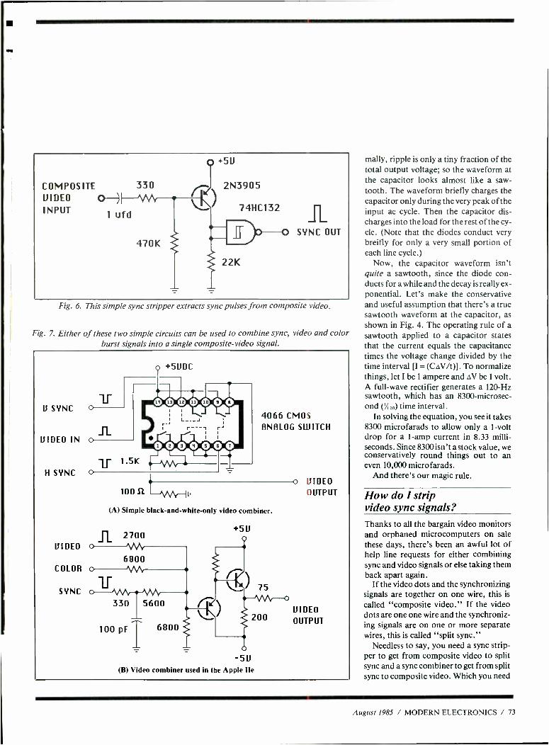
COMPOSITE 330 VIDEO O INPUT
1 u f d
470K
0 +5U
r--? 2N3905
74HC132
22K
SYNC OUT
Fig. 6. This simple sync stripper extracts sync pulses from composite video.
Fig. 7. Either of these two simple circuits can be used to combine sync, video and color burst signals into a single composite -video signal.
U SYNC
VIDEO IN
H SYNC
VIDEO
COLOR
SYNC
4066 CMOS ANALOG SWITCH
10012
(A) Simple black- and -white -only video combiner.
-5V (B) Video combiner used in the Apple Ile
o VIDEO OUTPUT
VIDEO
OUTPUT
mally, ripple is only a tiny fraction of the total output voltage; so the waveform at the capacitor looks almost like a saw - tooth. The waveform briefly charges the capacitor only during the very peak of the input ac cycle. Then the capacitor dis- charges into the load for the rest of the cy- cle. (Note that the diodes conduct very breifly for only a very small portion of each line cycle.)
Now, the capacitor waveform isn't quite a sawtooth, since the diode con- ducts for a while and the decay is really ex- ponential. Let's make the conservative and useful assumption that there's a true sawtooth waveform at the capacitor, as shown in Fig. 4. The operating rule of a sawtooth applied to a capacitor states that the current equals the capacitance times the voltage change divided by the time interval [I = (CAV /t)]. To normalize things, let I be 1 ampere and AV be 1 volt. A full -wave rectifier generates a 120 -Hz sawtooth, which has an 8300- microsec- ond ('' /,,a) time interval.
In solving the equation, you see it takes 8300 microfarads to allow only a 1 -volt drop for a 1 -amp current in 8.33 milli- seconds. Since 8300 isn't a stock value, we conservatively round things out to an even 10,000 microfarads.
And there's our magic rule.
How do I strip video sync signals? Thanks to all the bargain video monitors and orphaned microcomputers on sale these days, there's been an awful lot of help line requests for either combining sync and video signals or else taking them back apart again.
If the video dots and the synchronizing signals are together on one wire, this is
called "composite video." If the video dots are one one wire and the synchroniz- ing signals are on one or more separate wires, this is called "split sync."
Needless to say, you need a sync strip- per to get from composite video to split sync and a sync combiner to get from split sync to composite video. Which you need
August 1985 / MODERN ELECTRONICS / 73
HARDWARE HACKER ...
depends on which bargain parts you hap- pen to be using.
If you are interested in only black -and- white video directly cabled to a monitor, sync stripping or combination is no big deal. It's only when you need noise -free over -the -air transmission, color or gray - scale that things get messy.
Figure 5 shows a "typical" combined video signal. Normally, the signal is 1 volt high. Sync pulses are at 0 volt, with the horizontal sync pulses being around five microseconds wide, and the vertical sync pulses being a fancy waveform that lasts around 200 microseconds. Video black is
around 0.25 volt, and full white is at 1
volt. Gray is between white and black. The time between horizontal sync
pulses is usually around 63 microseconds (15.735 kHz) for standard video, but can
ELECTRONIC
SALVAGE PARTS
Below Wholesale
Electronic Prices Slashed!
Condensors Capacitators IC's Transistors Diodes Tripiers Controls
Resistors Speakers Yokes Antenna Rods Fuses CAN and Lots of Goodies!
You name it, we've got it. and cheaper
call or write for free catalogue
E.S.P. 2706 Middle Country Road
Centereach, N.Y. 11720 (516) 467 -9852 (800) 645 -5030
CIRCLE NO. i 08 ON FREE INFORMATION CARD
Addison Wesley General Books Div. Reading, MA 01867 (617) 894 -3700
Byron Originals Hiways 59 and 75
Ida Grove, IA 51445 (712) 364-3164
Del Aire Products 407 North 7th Street Allentown, PA 18102 (215) 432-9975
NAMES AND NUMBERS
Inside Laserwriter 467 Saratoga Road S621 San Jose, CA 951129 (408) 966 -1010
Motorola Semiconductor Box 20912 Phoenix, AZ 85018 (602) 244 -6900
Postscript (Adobe) 1870 Embarcadero Road S120 Palo Alto, CA 94303 (415) 852 -0271
Player Piano Company 704 East Douglas Wichita, KS 67202 (316) 263 -3241
Howard W. Sams 4300 West 62nd Street Indianapolis, IN 46206 (800) 428 -SAMS
Synergetics Box 809 Thatcher, AZ 85552 (602) 428 -4073
be much less for high -resolution monitors that run at higher sweep frequencies. The vertical sync pulse rate is usually 16.7 mil- liseconds (59.95 or 60 Hz). The time be- tween vertical pulses is called a field.
Sometimes, two fields are interlaced in- to a single frame. Interlace does not work well with dot -matrix characters; so most micro uses of video do not involve the in- terlace technique.
Should color be used, there is a color burst tacked onto the back porch of the horizontal sync pulse. This is an 8 -cycle burst of 3.579545 MHz that is used to syn- chronize the color circuits of the display or monitor if it is using NTSC (never the same color) stock video.
NTSC video is limited in bandwidth and color resolution, so you cannot nor- mally get more than 40 dot -matrix char- acters across a color TV screen. To beat this limit, fancy monitors use RGB video in which individual signals are sent di- rectly to the red, green, and blue guns. Each gun then behaves as if it is really re- ceiving high -bandwidth B&W video. Only at the screen is the color sorted out.
Figure 6 shows a simple sync stripper that will split the sync pulse from a com- posite -video signal. The transistor and in- put coupling capacitor act as a "leaky dc restorer" and only the very sync tips get highly amplified. The output Schmitt trigger then further cleans up the signal and inverts it to positive -going sync.
Note that the value of the bias resistor
on the transistor is much higher than nor- mal. You want the transistor to amplify only the negative -most sync tips. This re- sistor's value can be adjusted for the best operation.
Note also that you can use the other Schmitt triggers in the quad package to seperate the vertical from the horizontal sync. Just how you do this depends on what polarity signals you want, but the key is to stall half a horizontal time and then check for a high level. If high, you have vertical sync.
Much more information on simple video interface appears in my TV Type- writer Cookbook (Sams #21313).
Combining sync is just about as easy as stripping sync. Usually, you will have a video signal, a horizontal sync signal, a vertical sync signal, and an optional color burst on seperate lines, and you want to merge them into a single output line.
Figure 7 shows two circuits for doing this. The first uses a single CMOS analog switch to combine everything. This one may be slightly low in bandwidth and is
black -and -white only, but is sure is sim- ple. The second is the sync combiner used in later versions of the Apple IIe.
If you have to get fancier, Motorola is now second sourcing some very interest- ing and very complicated integrated cir- cuits that do all sorts of neat video things "by the rules." Be sure to check out their MC1374, MC1377, TDA3301, TDA3303, TDA3330, and TDA3333 in particular.
74 / MODERN ELECTRONICS / August 1985
1111111/ BOOKS i/il
The latest technical books and lit- erature in the electronics and com- puter field.
Guide To Local Area Networks by TJ Byers. (Prentice -Hall; 182 pages; $14.95 soft cover, $24.95 hard cover.)
What is a local area network (LAN)? Who needs or can benefit by it? How is one set up? If you (or your employer) have more than one mi- crocomputer in a given location and would like them to link together to communicate with each other and /or to share hardware and software re- sources, this book will provide the answers to these and many more questions. Written to help the busi- nessman who has decided to join the computer revolution (and to entice those who have not yet made the commitment), this book will step you through the ins and outs of local area networking. It assumes no prior knowledge of LANs and, thus, starts from square one by introducing at the outset the concept of networking. Written in a brisk style, it gets right down to cases, stepping quickly through each topic and introducing each successive thought only after prior groundwork has been set.
This is a relatively nontechnical overview of local area networking, but it does manage to impart quite a bit of technical detail, though with- out dry prose and cluttering theories. The major value of this book is that is provides practical guidance on which you can base intelligent decisions. Not only does it tell you what types of LANs are available and their weak and strong points, it also gives an ex- tensive listing of LAN vendors.
Tricks Of The Burglar Alarm Trade. (Mentor Publications; soft cover; 91
pages; $14.95.) Most books about burglar alarms
go heavy on electronics theory and construction and pay only lip service to the practical considerations of sen- sor selection and system installation. This large- format (8'h " x 11 ') book addresses the weak areas in such
books and, therefore, should be con- sidered in addition to them. It fo- cuses on sensor selection to suit vari- ous needs and conditions, installa- tion procedures, and the special tools required to do the job. Detailed in- structions are provided for applying window foil, installing locks, run- ning wiring from sensors to the con- trol unit, and more -all from the professional's point of view.
Virtually every type of sensor is de- scribed, along with its strong and weak points. Additionally, the book gives details on how to run hidden wiring. An important topic is cover- age of a common weakness (and how to eliminate it) of typical alarm systems that make them vulnerable to bypassing. Since this book is
meant for the nontechnical installer, very basic instructions for using a meter and troubleshooting a system are provided.
The book is heavily illustrated with informative drawings that both sup- port and clarify information given in the text. Type is apparently set by a near -letter -quality dot -matrix print- er, which is not as classy as that of typical books, though it is still easily readable.
NEW LITERATURE Video Accessories Catalog. This new 38 -page catalog from RCA is printed in full color and provides illustrations and explanations of nearly 180 products for use with VCRs, video cameras and TV re- ceivers. The listed accessories are de- signed to simplify installation, improve operation, expand usage and protect video equipment. New entries include up- dated VCR cases, video camera cases, stereo microphones, broadcast stereo adapters, accessory kits, replacement and extension cables for RCA's "Dimensia" system, as well as numerous hardware items. For a free copy of Form No. 1J7674, write to: RCA Distributor and Special Products Div., Deptford, NJ 08096, Attn.: Sales Promotion Services.
Test Instrument Catalog. Nineteen new products are featured in Leader Instru-
ment's new 1985 catalog. The 80 -page catalog details complete features, specifi- cations and applications on more than 100 products in the Leader line. Among the new products highlighted are a 35 -MHz two -channel oscilloscope and an economically priced 100 -MHz three - channel dual -timebase scope. Other new products include a programmable video generator system designed for testing monochrome and color CRT monitors normally associated with computer sys- tems and workstations and a new line of signal and sweep generators. For a free copy of the catalog, write to: Leader In- struments Corp., 389 Oser Ave., Haup- pauge, NY 11788.
Holding Device /Work Positioner Cata- log. Holding devices /work positioners, presses, and accessories are the subjects of a new 12 -page, two -color catalog (No. 182) from PanaVise. The fully illustrated catalog breaks down the company's products by phases. Each of the four phases keynotes the selection of heads, bases, base mounts and accessories rec- ommended for different needs. A "road - map" inside the front cover shows the number of different combinations that are available. Products listed and de- scribed are for all types of hobbies, though there are a number that are of specific interest to the electronic hobbyist and technician. Among these are circuit board holders that serve as "third hands" and a new "Chassis Mount" that handles large items weighing up to 100 lbs. For a copy of Catalog No. 182, write to: Pana- Vise Products Inc., 2850 E. 29 St., Long Beach, CA 90806.
Printed Circuit Manual /Catalog. Bishop Graphics' No. 107A Printed Circuit Technical Manual & Catalog contains a wealth of pc -board design and drafting techniques, tips, reference tables, charts and practical theories in an easy- to -fol- low, fully illustrated format. Listed and fully described are the company's full line artwork patterns for creating artwork masters, detailed specifications and prices on a wide selection of new Bishop patterns designed to increase pc board de- sign efficiency, and more than 20,000 printed circuit aids. For a free copy of publication No. 107A, write to: Bishop Graphics, Inc., 5388 Sterling Center Dr., P.O. Box 5007, Westlake Village, CA 91359.
August 1985 / MODERN ELECTRONICS / 75
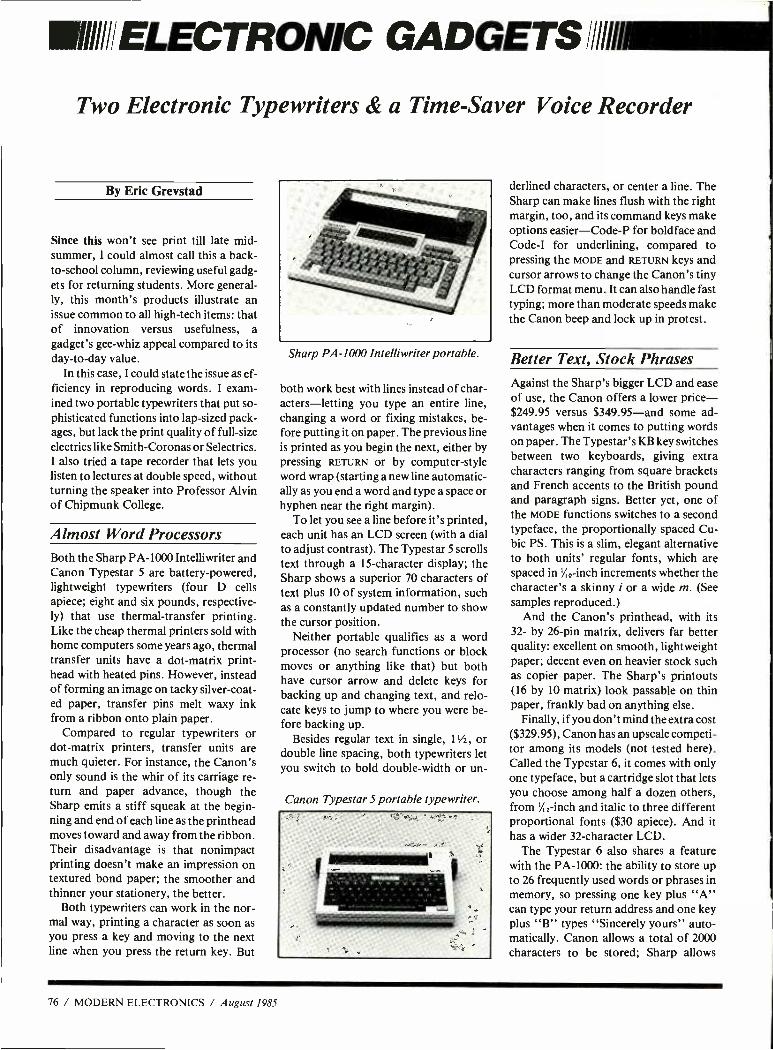
IIIII/ELECTRONIC GADGETS/Ill/il
Two Electronic Typewriters & a Time -Saver Voice Recorder
By Eric Grevstad
Since this won't see print till late mid- summer, I could almost call this a back - to- school column, reviewing useful gadg- ets for returning students. More general- ly, this month's products illustrate an issue common to all high -tech items: that of innovation versus usefulness, a gadget's gee -whiz appeal compared to its day -to -day value.
In this case, I could state the issue as ef- ficiency in reproducing words. I exam- ined two portable typewriters that put so- phisticated functions into lap -sized pack- ages, but lack the print quality of full -size electrics like Smith -Coronas or Selectrics. I also tried a tape recorder that lets you listen to lectures at double speed, without turning the speaker into Professor Alvin of Chipmunk College.
Almost Word Processors Both the Sharp PA -1000 Intelliwriter and Canon Typestar 5 are battery- powered, lightweight typewriters (four D cells apiece; eight and six pounds, respective- ly) that use thermal- transfer printing. Like the cheap thermal printers sold with home computers some years ago, thermal transfer units have a dot -matrix print - head with heated pins. However, instead of forming an image on tacky silver -coat- ed paper, transfer pins melt waxy ink from a ribbon onto plain paper.
Compared to regular typewriters or dot -matrix printers, transfer units are much quieter. For instance, the Canon's only sound is the whir of its carriage re- turn and paper advance, though the Sharp emits a stiff squeak at the begin- ning and end of each line as the printhead moves toward and away from the ribbon. Their disadvantage is that nonimpact printing doesn't make an impression on textured bond paper; the smoother and thinner your stationery, the better.
Both typewriters can work in the nor- mal way, printing a character as soon as you press a key and moving to the next line when you press the return key. But
Sharp PA -1000 Intelliwriter portable.
both work best with lines instead of char- acters- letting you type an entire line, changing a word or fixing mistakes, be- fore putting it on paper. The previous line is printed as you begin the next, either by pressing RETURN or by computer -style word wrap (starting a new line automatic- ally as you end a word and type a space or hyphen near the right margin).
To let you see a line before it's printed, each unit has an LCD screen (with a dial to adjust contrast). The Typestar 5 scrolls text through a 15- character display; the Sharp shows a superior 70 characters of text plus 10 of system information, such as a constantly updated number to show the cursor position.
Neither portable qualifies as a word processor (no search functions or block moves or anything like that) but both have cursor arrow and delete keys for backing up and changing text, and relo- cate keys to jump to where you were be- fore backing up.
Besides regular text in single, 1 V2, or double line spacing, both typewriters let you switch to bold double -width or un-
Canon Typestar 5 portable typewriter.
derlined characters, or center a line. The Sharp can make lines flush with the right margin, too, and its command keys make options easier- Code -P for boldface and Code -I for underlining, compared to pressing the MODE and RETURN keys and cursor arrows to change the Canon's tiny LCD format menu. It can also handle fast typing; more than moderate speeds make the Canon beep and lock up in protest.
Better Text, Stock Phrases Against the Sharp's bigger LCD and ease of use, the Canon offers a lower price - $249.95 versus $349.95 -and some ad- vantages when it comes to putting words on paper. The Typestar's KB key switches between two keyboards, giving extra characters ranging from square brackets and French accents to the British pound and paragraph signs. Better yet, one of the MODE functions switches to a second typeface, the proportionally spaced Cu- bic PS. This is a slim, elegant alternative to both units' regular fonts, which are spaced in ' %o -inch increments whether the character's a skinny i or a wide m. (See samples reproduced.)
And the Canon's printhead, with its 32- by 26 -pin matrix, delivers far better quality: excellent on smooth, lightweight paper; decent even on heavier stock such as copier paper. The Sharp's printouts (16 by 10 matrix) look passable on thin paper, frankly bad on anything else.
Finally, if you don't mind the extra cost ($329.95), Canon has an upscale competi- tor among its models (not tested here). Called the Typestar 6, it comes with only one typeface, but a cartridge slot that lets you choose among half a dozen others, from V,,2 -inch and italic to three different proportional fonts ($30 apiece). And it has a wider 32- character LCD.
The Typestar 6 also shares a feature with the PA -1000: the ability to store up to 26 frequently used words or phrases in memory, so pressing one key plus "A" can type your return address and one key plus "B" types "Sincerely yours" auto- matically. Canon allows a total of 2000 characters to be stored; Sharp allows
76 / MODERN ELECTRONICS / August 1985
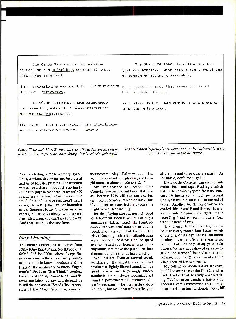
The Canon Typestar 5, in addition to regular and underlined Courier 10 type, offers the same font
The Sharp PA -1000H Intelliwriter has
just one typeface, with continuous underlining
or broken underlining available,
in double -width letters or a 1ightface mode that _avec batteries 1 ilce these _ b,,t is harder to read,
There's also Cubic PS, a proportionally spaced
and fancier font, suitable for business letters or for
Modern Electronics manuscripts.
It, too, can appear in double - width characters_ See?
C) r d o u b l e- w i d t h 1 e t t e r l -
Canon Typestar's32 x 26 pin matrix print head delivers far better print quality (left) than does Sharp Intelliwriter's printhead
2200, including a 27th memory space. Thus, a whole document can be created and saved for later printing. The function works like a charm, though it's no fun to edit a two -page letter or report for only 70 characters at a time. Conclusions: The small, "smart" typewriters aren't smart enough to justify their rather immodest prices. Some are better (and costlier) than others, but us guys always wind up too frustrated when you can't go all the way. And that, sadly, is the case here.
Easy Listening This month's other product comes from JS &A (One JS&A Plaza, Northbrook, IL 60062, 312 -564- 7000), where Joseph Su- garman remains the king of witty, wordy ads about little -known products and the trials of the mail -order business. Sugar - man's "Products That Think" catalogs have veered heavily toward health and fit- ness items lately, but my favorite headline is still the one about JS&A's first impres- sion of the Magic Stat programmable
(right). Canon's quality is excellent on smooth, lightweight paper, and is decent even on heavier paper.
thermostat: "Magic Baloney .... It has no digital readout, an ugly case, and a stu- pid name. It almost made us sick."
My first reaction to JS&A's Time Cruncher was less violent but still skepti- cal, because $239 will buy not one but eight voice recorders at Radio Shack. But if you listen to many lectures, your time might be worth crunching.
Besides playing tapes at normal speed (or 80- percent speed if you're learning a language or taking notes), the JS&A re- corder lets you accelerate up to double speed, hearing a tape in half the time. The trick to keeping such talk intelligible is an adjustable pitch control; slide the speed lever alone and your lecturer turns into a chipmunk, but move the pitch lever into alignment and he sounds like himself.
Well, almost. Even at normal speed, switching on the variable speed control produces a slightly filtered sound; at high speed, voices are surprisingly under- standable, but not always recognizable. I
found a particularly dull member of a
conference panel to be intelligible at dou- ble speed, but lost most of his colleagues
at the one and three -quarters mark. (As for music, don't even try it.)
Even so, the Cruncher can save consid- erable time -and tape. Pushing a switch halves the recording speed from the stan- dard 1' /, inches to 1/,6 inch per second (though it disables auto stop at the end of tapes). Another switch, once you've re- corded sides A and B and flipped the cas- sette to side A again, minutely shifts the recording head to accommodate four tracks instead of two.
This means that you can buy a one - hour cassette, record four hours' worth of material on it (if you're vigilant about turning it over), and listen to them in two hours. That may be pushing your luck; traces of other tracks showed up as back- ground noise when I listened at moderate volume, but the "A, speed worked fine when I settled for two tracks.
My college lecture -hall days are over, but I'll be sorry to give the Time Cruncher back. I've held it at the ready while watch- ing TV, but never caught a fast -talking Federal Express commercial that I could record and then hear at double speed. PE
August 1985 / MODERN ELECTRONICS / 79
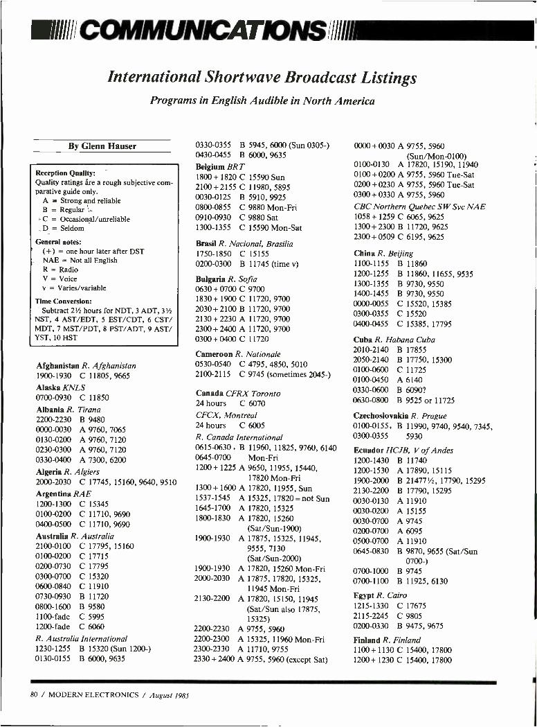
IIihI/ COMMUNICATIONS all
International Shortwave Broadcast Listings Programs in English Audible in North America
By Glenn Hauser
Reception Quality: Quality ratings are a rough subjective com- parative guide only.
A = Strong and reliable B = Regular C = Occasional /unreliable D = Seldom
General notes: ( +) = one hour later after DST NAE = Not all English R = Radio V = Voice v = Varies /variable
Time Conversion: Subtract 21/2 hours for NDT, 3 ADT, 3'h
NST, 4 AST /EDT, 5 EST /CDT, 6 CST/ MDT, 7 MST /PDT, 8 PST /ADT, 9 AST/ YST, 10 HST
Afghanistan R. Afghanistan 1900 -1930 C 11805, 9665
Alaska KNLS 0700 -0930 C 11850
Albania R. Tirana 2200 -2230 B 9480 0000 -0030 A 9760, 7065 0130 -0200 A 9760, 7120 0230 -0300 A 9760, 7120 0330 -0400 A 7300, 6200
Algeria R. Algiers 2000 -2030 C 17745, 15160, 9640, 9510
Argentina RAE 1200 -1300 C 15345 0100 -0200 C 11710, 9690 0400 -0500 C 11710, 9690
Australia R. Australia 2100 -0100 0100 -0200 0200 -0730 0300 -0700 0600 -0840 0730 -0930 0800 -1600 1100 -fade 1200 -fade
C 17795, 15160 C 17715 C 17795 C 15320 C 11910 B 11720 B 9580 C 5995 C 6060
R. Australia International 1230 -1255 B 15320 (Sun 1200 -) 0130 -0155 B 6000, 9635
0330 -0355 B
0430 -0455 B
Belgium BRT 1800+ 1820 C 2100 +2155 C 0030 -0125 B
0800 -0855 C 0910 -0930 C 1300 -1355 C
5945, 6000 (Sun 0305 -) 6000, 9635
15590 Sun 11980, 5895 5910, 9925 9880 Mon -Fri 9880 Sat 15590 Mon -Sat
Brasil R. Nacional, Brasilia 1750 -1850 C 15155 0200 -0300 B 11745 (time y)
Bulgaria R. Sofia 0630 + 0700 C 9700 1830 + 1900 C 11720, 9700 2030 + 2100 B 11720, 9700 2130 + 2230 A 11720, 9700 2300+2400A 11720, 9700 0300 + 0400 C 11720
Cameroon R. Nationale 0530 -0540 C 4795, 4850, 5010 2100 -2115 C 9745 (sometimes 2045 -)
Canada CFRX Toronto 24 hours C 6070
CFCX, Montreal 24 hours C 6005
R. Canada International 0615 -0630, B 11960, 11825, 9760, 6140 0645 -0700 Mon -Fri 1200 + 1225 A 9650, 11955, 15440,
17820 Mon -Fri 1300+ 1600 A 17820, 11955, Sun 1537 -1545 A 15325, 17820 = not Sun 1645 -1700 A 17820, 15325 1800 -1830 A 17820, 15260
(Sat /Sun -1900) 1900 -1930 A 17875, 15325, 11945,
9555, 7130 (Sat /Sun -2000)
1900 -1930 A 17820, 15260 Mon -Fri 2000 -2030 A 17875, 17820, 15325,
11945 Mon -Fri 2130 -2200 A 17820, 15150, 11945
(Sat /Sun also 17875, 15325)
2200 -2230 A 9755, 5960 2200 -2300 A 15325, 11960 Mon -Fri 2300 -2330 A 11710, 9755 2330 +2400 A 9755, 5960 (except Sat)
0000 +0030 A 9755, 5960 (Sun /Mon -0100)
0100 -0130 A 17820, 15190, 11940 0100 + 0200 A 9755, 5960 Tue -Sat 0200 +0230 A 9755, 5960 Tue -Sat 0300 +0330 A 9755, 5960
CBC Northern Quebec SW Svc NAE 1058 + 1259 C 6065, 9625 1300 + 2300 B 11720, 9625 2300+ 0509 C 6195, 9625
China R. Beijing 1100 -1155 B 11860 1200 -1255 B 11860, 11655, 9535 1300 -1355 B 9730, 9550 1400 -1455 B 9730, 9550 0000 -0055 C 15520, 15385 0300 -0355 C 15520 0400 -0455 C 15385, 17795
Cuba R. Habana Cuba 2010 -2140 2050 -2140 0100 -0600 0100 -0450 0330 -0600 0630 -0800
B 17855 B 17750, 15300 C 11725 A 6140 B 6090? B 9525 or 11725
Czechoslovakia R. Prague 0100 -0155, B 11990, 9740, 9540, 7345, 0300 -0355 5930
Ecuador HCJB, V of Andes 1200 -1430 B 11740 1200 -1530 A 17890, 15115 1900 -2000 B 214771/2, 17790, 15295 2130 -2200 B 17790, 15295 0030 -0130 A 11910 0030 -0200 A 15155 0030 -0700 A 9745 0200 -0700 A 6095 0500 -0700 A 11910 0645 -0830 B 9870, 9655 (Sat /Sun
0700 -) 0700 -1000 B 9745 0700 -1100 B 11925, 6130
Egypt R. Cairo 1215 -1330 C 17675 2115 -2245 C 9805 0200 -0330 B 9475, 9675
Finland R. Finland 1100+1130 C 15400, 17800 1200+1230C 15400, 17800
80 / MODERN ELECTRONICS / August 1985
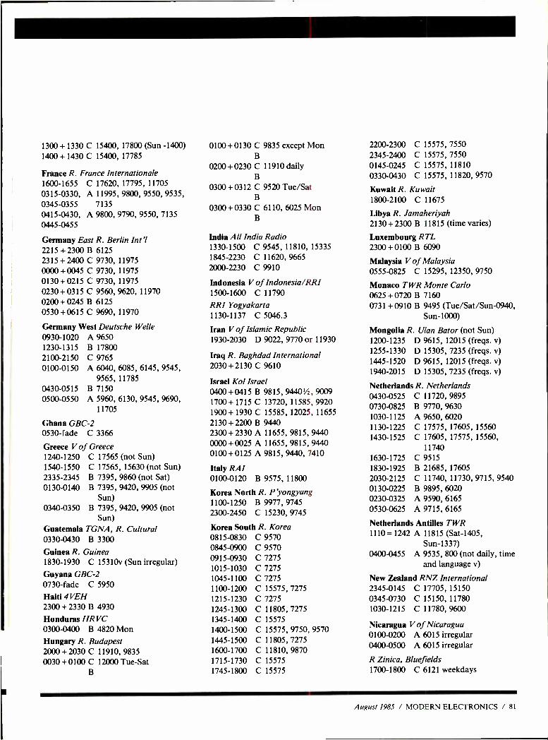
1300+ 1330 C 15400, 17800 (Sun -1400) 1400+ 1430 C 15400, 17785
France R. France Internationale 1600 -1655 C 17620, 17795, 11705 0315 -0330, A 11995,9800,9550,9535, 0345 -0355 7135 0415 -0430, A 9800, 9790, 9550, 7135 0445 -0455
Germany East R. Berlin Intl 2215 + 2300 B 6125 2315 + 2400 C 9730, 11975 0000+0045 C 9730, 11975 0130 + 0215 C 9730, 11975 0230 + 0315 C 9560, 9620, 11970 0200+ 0245 B 6125 0530 +0615 C 9690, 11970
Germany West Deutsche Welle
0930 -1020 1230 -1315 2100 -2150 0100 -0150
0430 -0515 0500 -0550
A 9650 B 17800 C 9765 A 6040, 6085, 6145, 9545,
9565, 11785 B 7150 A 5960, 6130, 9545, 9690,
11705
Ghana GBC -2 0530 -fade C 3366
Greece V of Greece 1240 -1250 C 17565 (not Sun) 1540 -1550 C 17565, 15630 (not Sun) 2335 -2345 B 7395, 9860 (not Sat) 0130 -0140 B 7395, 9420, 9905 (not
Sun) 0340 -0350 B 7395, 9420, 9905 (not
Sun) Guatemala TGNA, R. Cultural 0330 -0430 B 3300
Guinea R. Guinea 1830 -1930 C 15310v (Sun irregular)
Guyana GBC -2 0730 -fade C 5950
Haiti 4VEH 2300+ 2330 B 4930
Honduras HR VC 0300 -0400 B 4820 Mon Hungary R. Budapest 2000 + 2030 C 11910, 9835 0030 + 0100 C 12000 Tue -Sat
B
0100 +0130 C 9835 except Mon B
0200 +0230 C 11910 daily B
0300 + 0312 C 9520 Tue /Sat B
0300 + 0330 C 6110, 6025 Mon B
India All India Radio 1330 -1500 C 9545, 11810, 15335 1845 -2230 C 11620, 9665 2000 -2230 C 9910
Indonesia V of Indonesia /RRI 1500 -1600 C 11790
RRI Yogyakarta 1130 -1137 C 5046.3
Iran V of Islamic Republic 1930 -2030 D 9022, 9770 or 11930
Iraq R. Baghdad International 2030 + 2130 C 9610
Israel Kol Israel 0400 + 0415 B 9815, 94401/2, 9009 1700+ 1715 C 13720, 11585, 9920 1900+ 1930 C 15585, 12025, 11655 2130 + 2200 B 9440 2300 + 2330 A 11655, 9815, 9440 0000 + 0025 A 11655, 9815, 94.40
0100 +0125 A 9815, 9440, 7410
Italy RAI 0100 -0120 B 9575, 11800
Korea North R. Pyongyang 1100 -1250 B 9977, 9745 2300 -2450 C 15230, 9745
Korea South R. Korea 0815 -0830 0845 -0900 0915 -0930 1015 -1030 1045 -1100 1100 -1200 1215 -1230 1245 -1300 1345 -1400 1400 -1500 1445 -1500 1600 -1700 1715 -1730 1745 -1800
C 9570 C 9570 C 7275 C 7275 C 7275 C 15575, 7275 C 7275 C 11805, 7275 C 15575 C 15575, 9750, 9570 C 11805, 7275 C 11810, 9870 C 15575 C 15575
2200 -2300 C 15575, 7550 2345 -2400 C 15575, 7550 0145 -0245 C 15575, 11810
0330 -0430 C 15575, 11820, 9570
Kuwait R. Kuwait 1800 -2100 C 11675
Libya R. Jamaheriyah 2130 + 2300 B 11815 (time varies)
Luxembourg RTL 2300 + 0100 B 6090
Malaysia V of Malaysia 0555 -0825 C 15295, 12350, 9750
Monaco TWR Monte Carlo 0625+0720B 7160 0731 +0910 B 9495 (Tue /Sat /Sun -0940,
Sun -1000)
Mongolia R. Ulan Bator (not Sun) 1200 -1235 D 9615, 12015 (freqs. v) 1255 -1330 D 15305, 7235 (freqs. v) 1445 -1520 D 9615, 12015 (freqs. v) 1940 -2015 D 15305, 7235 (freqs. v)
Netherlands R. Netherlands 0430 -0525 0730 -0825 1030 -1125 1130 -1225 1430 -1525
1630 -1725 1830 -1925 2030 -2125 0130 -0225 0230 -0325 0530 -0625
C 11720, 9895 B 9770, 9630 A 9650, 6020 C 17575, 17605, 15560 C 17605, 17575, 15560,
11740 C 9515 B 21685, 17605 C 11740, 11730, 9715, 9540 B 9895, 6020 A 9590, 6165 A 9715, 6165
Netherlands Antilles TWR 1110 = 1242 A 11815 (Sat -1405,
Sun -1337) 0400 -0455 A 9535, 800 (not daily, time
and language NO
New Zealand RNZ International 2345 -0145 C 17705, 15150 0345 -0730 C 15150, 11780 1030 -1215 C 11780,9600
Nicaragua V of Nicaragua 0100 -0200 A 6015 irregular 0400 -0500 A 6015 irregular
R Zinica, Bluefields 1700 -1800 C 6121 weekdays
August 1985 / MODERN ELECTRONICS / 81
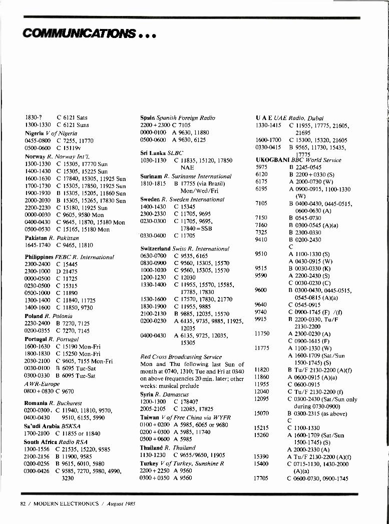
COMMUNICATIONS
1830 -? C 6121 Sats 1300 -1330 C 6121 Suns Nigeria V of Nigeria 0455 -0800 C 7255, 11770 0500 -0600 C 15119v
Norway R. Norway Int'l. 1300 -1330 C 15305, 17770 Sun 1400 -1430 C 15305, 15225 Sun 1600 -1630 1700 -1730 1900 -1930 2000 -2030 2200 -2230 0000 -0030 0400 -0430 0500-0530
C 17840, 15305, 11925 Sun C 15305, 17850, 11925 Sun B 15305, 15205, 11860 Sun B 15305, 15265, 17830 Sun C 15180, 11925 Sun C 9605, 9580 Mon C 9645, 11870, 15180 Mon C 15165, 15180 Mon
Pakistan R. Pakistan 1645 -1740 C 9465, 11810
Philippines FEBC R. International 2300 -2400 2300 -1000 0000 -0500 0230 -0500 0500 -1000 1300 -1400 1400 -1600
C 15445 D 21475 C 11725 C 15315 C 11890 C 11840, 11725 C 11850, 9730
Poland R. Polonia 2230 -2400 B 7270, 7125 0200 -0355 C 7270, 7145
Portugal R. Portugal 1600 -1630 C 15190 Mon -Fri 1800 -1830 C 15250 Mon -Fri 2030 -2100 C 9605, 7155 Mon -Fri 0030 -0100 B 6095 Tue -Sat 0300 -0330 B 6095 Tue -Sat A WR- Europe 0800 + 0830 C 9670
Romania R. Bucharest 0200 -0300, C 11940, 11810, 9570, 0400 -0430 9510, 6155, 5990
Sa'udi Arabia BSKSA 1700 -2100 C 11855 or 11840
South Africa Radio RSA 1300 -1556 C 21535, 15220, 9585 2100 -2156 B 11900,9585 0200 -0256 B 9615, 6010, 5980 0300 -0426 C 9585, 7270, 5980, 4990,
3230
Spain Spanish Foreign Radio 2200 + 2300 C 7105 0000 -0100 A 9630, 11880 0500 -0600 A 9630, 6125
Sri Lanka SLBC 1030 -1130 C 11835, 15120, 17850
NAE Surinam R. Suriname International 1810 -1815 B 17755 (via Brasil)
Mon /Wed /Fri Sweden R. Sweden International 1400 -1430 C 15345 2300 -2330 C 11705, 9695 0230 -0300 C 11705, 9695,
17840 = SSB 0330 -0400 C 11705
Switzerland Swiss R. International 0630 -0700 C 9535, 6165 0830 -0900 C 9560, 15305, 15570 1000 -1030 C 9560, 15305, 15570 1200 -1230 C 12030 1330 -1400 C 11955, 15570, 15585,
17785, 17830 1530 -1600 C 17570, 17830, 21770 1830 -1900 C 11955, 9885 2100 -2130 B 9885, 12035, 15570 0200 -0230 A 6135, 9735, 9885, 11925,
12035 0400 -0430 A 6135, 9725, 12035,
15305
Red Cross Broadcasting Service Mon and Thu following last Sun of month at 0740, 1310; Tue and Fri at 0340 on above frequencies 20 min. later; other weeks: musical prelude Syria R. Damascus 1200 -1300 C 17840? 2005 -2105 C 12085, 17825
Taiwan V of Free China via WYFR 0100 + 0200 A 5985, 6065 or 9680 0200 +0300 A 5985, 11740 0500 + 0600 A 5985
Thailand R. Thailand 1130 -1230 C 9655/9650,11905 Turkey V of Turkey, Sunshine R 2200 + 2250 A 9560 0300 + 0350 A 9560
U A E UAE Radio, Dubai 1330 -1415 C 11955, 17775, 21605,
21695 1600 -1700 C 15300, 15320, 21605 0330 -0415 B 9565, 11730, 15435,
17775 UKOGBANI BBC World Service 5975 6120 6175 6195
7105
B 2245-0545 B 2200+0330 (S) A 2000-0730 (W) A 0900-0915, 1100-1330
(W) B 0400-0430, 0445-0515,
0600-0630 (A) 7150 B 0545-0730 7160 B 0300-0545 (A)(a) 7325 B 2300-0330 9410 B 0200-2430
C 9510 A 1100-1330 (S)
A 0430-0915 (W) 9515 B 0030-0330(K) 9590 A 2200-2430 (S)
C 0030-0230 (C) 9600 B 0300-0430,0445-0515,
0545-0815 (A)(a) 9640 C 0545-0915 9740 C 0900-1745 (F) /(f) 9915 B 2200-0330, Tu/F
2130-2200 11750 A 2300-0230 (A)
C 0900-1615 (F) 11775 A 1100-1330 (W)
A 1600-1709 (Sat/Sun 1500-1745) (S)
11820 B Tu/F 2130-2200 (A)(f) 11860 A 0600-0915 (A)(a) 11955 C 0600-0915 12040 C Tu/F 2130-2200 (f) 12095 C 0300-2430 (Sat/Sun only
during 0730-0900) 15070 B 0300-2315 (as above)
C 15215 C 1100-1330 15260 A 1600-1709 (Sat/Sun
1500-1745) (S) A 2000-2330 (A)
15390 A Tu/F 2130-2200 (A)(f) 15400 C 0715-1130,1430-2000
(A)(a) 17705 C 0600-0730,0900-1745
82 / MODERN ELECTRONICS / August 1985
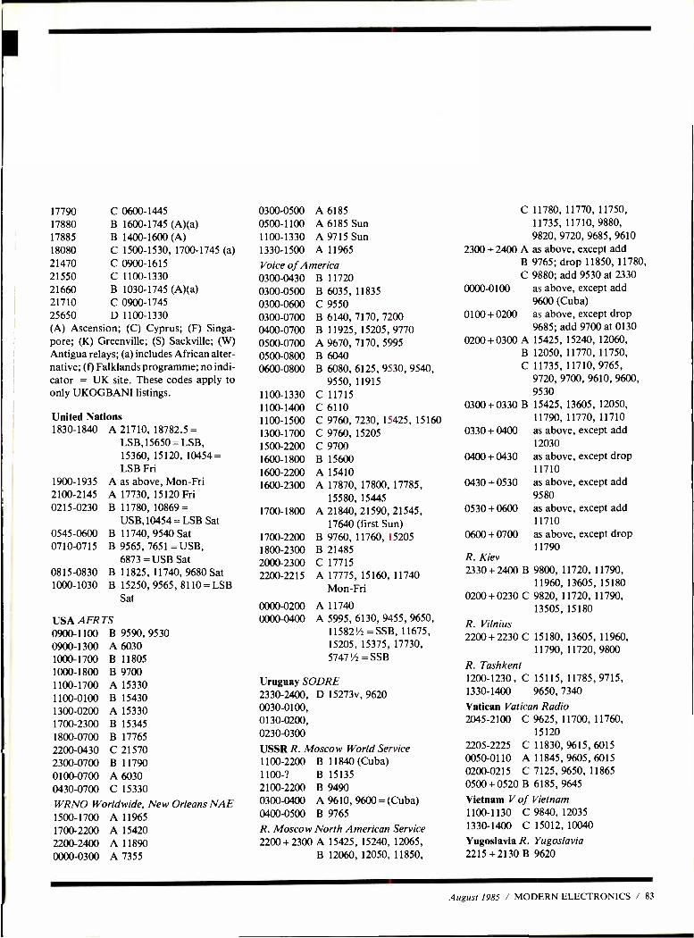
17790 C 0600 -1445 17880 B 1600 -1745 (A)(a) 17885 B 1400- 1600(A) 18080 C 1500 -1530,1700 -1745 (a) 21470 C 0900 -1615 21550 C 1100 -1330 21660 B 1030-1745 (A)(a) 21710 C 0900 -1745 25650 D 1100 -1330 (A) Ascension; (C) Cyprus; (F) Singa- pore; (K) Greenville; (S) Sackville; (W) Antigua relays; (a) includes African alter- native; (f) Falklands programme; no indi- cator = UK site. These codes apply to only UKOGBANI listings.
United Nations 1830 -1840
1900 -1935 2100 -2145 0215 -0230
0545 -0600 0710 -0715
0815 -0830 1000 -1030
A 21710, 18782.5 = LSB,15650 = LSB, 15360, 15120, 10454 = LSB Fri
A as above, Mon -Fri A 17730, 15120 Fri B 11780, 10869 =
USB,10454 = LSB Sat B 11740, 9540 Sat B 9565, 7651 =USB,
6873 = USB Sat B 11825, 11740, 9680 Sat B 15250, 9565, 8110 =LSB
Sat
USA AFRTS
0300-0500 A 6185 0500-1100 A 6185 Sun 1100-1330 A 9715 Sun 1330-1500 A 11965
Voice of America 0300-0430 B 11720 0300-0500 B 6035, 11835 0300-0600 C 9550 0300-0700 B 6140, 7170, 7200 0400-0700 B 11925, 15205, 9770 0500-0700 A 9670, 7170, 5995 0500-0800 B 6040 0600-0800 B 6080, 6125, 9530, 9540,
9550, 11915 1100-1330 C 11715 1100-1400 C 6110 1100-1500 C 9760, 7230, 15425, 15160 1300-1700 C 9760, 15205 1500-2200 C 9700 1600-1800 B 15600 1600-2200 A 15410 1600-2300 A 17870, 17800, 17785,
15580, 15445 1700-1800 A 21840,21590,21545,
17640 (first Sun) 1700-2200 B 9760, 11760, 15205 1800-2300 B 21485 2000-2300 C 17715
2200-2215 A 17775, 15160, 11740 Mon-Fri
0000 -0200 0000 -0400
A 11740 A 5995, 6130, 9455, 9650,
0900 -1100 0900 -1300 1000 -1700 1000 -1800
B 9590, 9530 A 6030 B 11805 B 9700
115821/2 = SSB, 11675, 15205, 15375, 17730, 57471/2 =SSB
1100 -1700 A 15330 Uruguay SODRE
1100 -0100 B 15430 2330 -2400, D 15273v, 9620
1300 -0200 A 15330 0030 -0100,
1700 -2300 B 15345 0130 -0200,
1800 -0700 B 17765 0230 -0300
2200 -0430 C 21570 USSR R. Moscow World Service 2300 -0700 B 11790 1100 -2200 B 11840(Cuba) 0100 -0700 A 6030 1100 -? B 15135
0430 -0700 C 15330 2100 -2200 B 9490
WRNO Worldwide, New Orleans NAE 0300 -0400 A 9610, 9600 = (Cuba)
1500 -1700 A 11965 0400 -0500 B 9765
1700 -2200 A 15420 R. Moscow North American Service 2200 -2400 A 11890 2200 +2300 A 15425, 15240, 12065,
0000 -0300 A 7355 B 12060, 12050, 11850,
C 11780, 11770, 11750, 11735, 11710, 9880, 9820, 9720, 9685, 9610
2300 + 2400 A as above, except add B 9765; drop 11850, 11780, C 9880; add 9530 at 2330
0000 -0100 as above, except add 9600 (Cuba) as above, except drop 9685; add 9700 at 0130
0200 + 0300 A 15425, 15240, 12060, B 12050, 11770, 11750, C 11735, 11710, 9765,
9720, 9700, 9610, 9600, 9530
0300 +0330 B 15425, 13605, 12050, 11790,11770,11710 as above, except add 12030 as above, except drop 11710 as above, except add 9580 as above, except add 11710 as above, except drop 11790
0100 + 0200
0330 + 0400
0400 + 0430
0430 + 0530
0530 +0600
0600+ 0700
R. Kiev 2330 + 2400 B 9800, 11720, 11790,
11960, 13605, 15180 0200+ 0230 C 9820, 11720, 11790,
13505, 15180
R. Vilnius 2200 + 2230 C 15180, 13605, 11960,
11790, 11720, 9800
R. Tashkent 1200 -1230, C 15115, 11785, 9715, 1330 -1400 9650, 7340
Vatican Vatica n Radio 2045 -2100 C 9625, 11700, 11760,
15120 2205 -2225 C 11830, 9615, 6015 0050 -0110 A 11845,9605,6015 0200 -0215 C 7125, 9650, 11865
0500 + 0520 B 6185, 9645
Vietnam V of 1100 -1130 C 1330 -1400 C
Yugoslavia R. 2215 +2130 B
Vietnam 9840, 12035 15012, 10040
Yugoslavia 9620
August 1985 / MODERN ELECTRONICS / 83
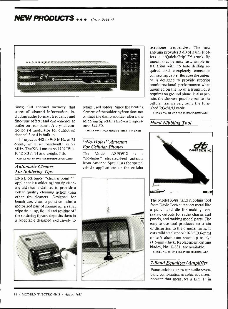
NEW PRODL TS (from page 7)
tions; full channel memory that stores all channel information, in- cluding audio format, frequency and fine -tune offset; and convenience ac outlet on rear panel. A crystal -con- trolled r -f modulator for output on channel 3 or 4 is built in.
I -f input is 440 to 940 MHz at 75 ohms, while i -f bandwidth is 27 MHz. The XR -1 measures 113/4 "W x 10 "D x 3'/4 "H and weighs 7 lb.
CIRCLE NO. 114 ON FREE INFORMATION CARD
Automatic Cleaner For Soldering Tips
Elvo Electronics' "clean -o- point "® appliance is a soldering iron tip clean- ing aid that is claimed to provide a better quality cleaning action than other tip cleaners. Designed for bench use, clean -o -point contains a motorized pair of sponge rollers that wipe tin -alloy, liquid and residue off the soldering tip and deposits them in a receptacle designed exclusively to
retain used solder. Since the heating element of the soldering iron does not contact the damp sponge rollers, the soldering tip retains an even tempera- ture. $44.50.
CIRCLE NO. 115 ON FREE INFORMATION CARD
"No- Holes " Antenna For Cellular Phones The Model ASPD912 is a "no- holes" elevated -feed antenna from Antenna Specialists for special vehicle applications or the cellular
telephone frequencies. The new antenna provides 3 dB of gain. It of- fers a "Quick -Grip "TM trunk lip mount that permits fast, simple in- stallation with no hole drilling re- quired and completely concealed connecting cable. Because the anten- na is designed to provide superior omnidirectional performance when mounted on the lip of a trunk lid, it requires no ground plane. It also per- mits the shortest possible run to the cellular transceiver, using the furn- ished RG -58/U cable.
CIRCLE NO. 116 ON FREE INFORMATION CARD
Hand Nibbling Tool
The Model K -88 hand nibbling tool from Davie Tech cuts sheet metal like a punch and die for making tem- plates, cutouts for radio chassis and panels, and making model parts. The easy -to -use tool produces no strain or distortion to the original form. It cuts mild steel up to 0.023 " (0.6 -mm) or soft aluminum sheet up to '/,6" (1.6 -mm) thick. Replacement cutting blades, No. K -881, are available.
CIRCLE NO. 117 ON FREE INFORMATION CARD
7 -Band Equalizer /Amplifier Panasonic has a new car audio seven - band combination graphic equalizer/ booster that measures a slim 1 " in
84 / MODERN ELECTRONICS / August 1985
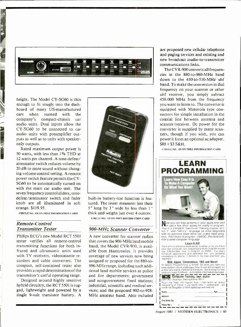
1
height. The Model CY -SG60 is thin enough to fit snugly into the dash- board of many US- manufactured cars when teamed with the company's compact- chassis car audio units. Dual inputs allow the CY -SG60 to be connected to car audio units with preamplifier out- puts as well as to units with speaker - only outputs.
Rated maximum output power is 50 watts, with less than 1% THD at 12 watts per channel. A tone -defeat/ attenuator switch reduces volume by 20 dB to mute sound without chang- ing volume control setting. A remote power switch feature permits the CY- SG60 to be automatically turned on with the main car audio unit. The seven frequency control sliders, tone - defeat /attenuator switch and fader knob are all illuminated in soft orange. $119.95.
CIRCLE NO. 118 ON FREE INFORMATION CARD
Remote - Control Transmitter Tester Philips ECG's new Model RCT 5501 tester verifies all remote -control transmitting functions for both in- frared and ultransonic units used with TV receivers, videocassette re- corders and cable converters. The compact, self- contained tester also provides a rapid determination of the transmitter's useful operating range.
Designed around highly sensitive hybrid circuitry, the RCT 5501 is rug- ged, lightweight and powered by a single 9 -volt transistor battery. A
built -in battery -test function is fea- tured. The tester measures less than 5 " long by 3 " wide by less than 1 "
thick and weighs just over 4 ounces. CIRCLE NO. 119 ON FREE INFORMATION CARD
900 -MHz Scanner Converter A new converter for scanner radios that covers the 900 -MHz land mobile band, the Model CVR -900, is avail- able from Hamtronics. It provides coverage of new services now being assigned or proposed for the 880 -to- 996 -MHz range, including such addi- tional land mobile services as police and fire departments; government and nongovernment fixed stations; industrial, scientific and medical ser- vices; and the proposed 902- to -928- MHz amateur band. Also included
are proposed new cellular telephone and paging services and existing and new broadcast studio -to- transmitter communications links.
The CVR -900 converts all frequen- cies in the 880 -to -960 -MHz band down to the 430 -to -510 -MHz uhf band. To make the conversion in dial frequency on your scanner or other uhf receiver, you simply subract 450.000 MHz from the frequency you want to listen to. The converter is
equipped with Motorola type con- nectors for simple installation in the coaxial line between antenna and scanner /receiver. Dc power for the converter is supplied by many scan- ners, though if you wish, you can power it from an optional ac adapter. $88 + $3 S &H.
CIRCLE NO. 120 ON FREE INFORMATION CARD
LEARN PROGRAMMING
Lear How Easy ft To Make A Computer Do What You Want!
Now you can train at home in your spare time and in just a few short weeks be ready to program.
This is a complete "hands -on" training course, writ- ten in "user- friendly" language so even beginners with no previous experience can make rapid prog- ress. You'll learn to program in BASIC, the most com- monly used computer language.
Learn It All! Even with no previous experience. whether or not you have your own computer, our independent study program shows you step -by -step how to program in BASIC. You learn computer applications and operation too...with personal counseling by phone, in person or by mail whenever you request it.
IBM, Apple, Commodore, TRS and More! All BASIC Programming is similar. So once you learn our easy system, you'll understand how to use and program on almost any brand of personal computer. Send today for free facts and color brochure...a complete information package.
Ì uCS Computer Training, Dept. 01075 1 swce ,.r, Scranton, Pennsylvania 18515
Rush me free information how I can learn all about computing at home in my spare time. I understand I am under no obligation and no salesman will visit me.
Name Age
Address
City/Stale Zip
LPhone No I I
August 1985 / MODERN ELECTRONICS / 85
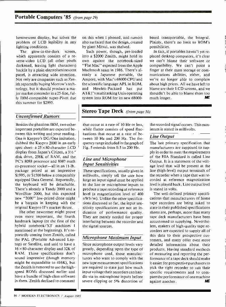
Portable Computers '85 (from page 29)
luminescent display, but solves the problem of LCD legibility in any lighting conditions.
The glow -in- the -dark screen, which apparently consists of a re- verse -video LCD (all other pixels darkened, leaving light characters) backlit by a plain electroluminescent panel, is attracting wide attention. Not only are companies such as Zen- ith reportedly buying Morrow's tech- nology, but it should produce a ma- jor market contender in a 25 -line, ful- ly IBM -compatible super -Pivot due this summer for $2995.
Unconfirmed Rumors
Besides the phantom IBM, two other important portables are expected be- tween this writing and your reading. One is Kaypro's DG /One imitation, dubbed the Kaypro 2000 in an early spec sheet: a 25 x 80- character LCD display from Japan's Citizen, a 3''A "
disk drive, 256K of RAM, and the PC's 8088 processor and 8087 math co- processor socket -all in an 11 -1b. package priced at an impressive $1995, or $1500 below a comparably equipped Data General. Reportedly, the keyboard will be detachable. There's already a Tandy 2000 and a WordStar 2000, but this expected new "2000" low- priced clone might be a bargain in keeping with the original Kaypro II's market thrust.
The other newcomer might prove even more important, the fourth landmark laptop (or the first of the hybrid notebook /XT machines I
mentioned at the beginning). It's re- portedly coming from Zenith, called the PAL (Portable Advanced Lap- top) or Satellite, and said to have a 16 x 80- character display and 32K of RAM. Those specifications don't sound impressive (though memory might be expandable to 416K), but the Zenith is rumored to use the high- speed ROMs discussed earlier and have a bundle of high -class software in them. Zenith declined to comment
on this when I phoned, and rumors also surfaced that the design, created by giant Mitsui, was shelved.
Such power, though, pre -loaded into a $2000 Zenith, might hold its own against the notebook -sized "Flat Mac" expected from the Apple Maclntosh team in 1986. There's al- ready a Japanese portable, the Ampere, with Mac's 68000 CPU and the scientific language APL in ROM, and Hewlett- Packard has put AT &T's multitasking Unix operating system into ROM for its new 68000-
based transportable, the Integral. Plainly, there's no limit to ROM's possibilities.
In fact, if portables haven't yet re- placed desktop computers, it's clear we can't blame their software or compatibility. We can't point a finger at their mass storage or com- munications abilities, either, and we're no longer able to complain about high prices. All we have left to blame are their LCD screens, and we shouldn't be able to blame them too much longer. NE
Stereo Tape Deck (from page 50)
that occur at a rate of 10 Hz or less, while flutter consists of speed fluc- tuations that occur at a rate of be- tween 10 Hz and 200 Hz. The fre- quency range included in the graph of Fig. 5 extends from 0.5 to 200 Hz.
Line and Microphone Input Sensitivities These specifications, usually given in millivolts, simply tell the user how large an input signal must be applied to the line or microphone inputs to produce a tape recording at reference level (a magnetization level of 400 nWb /m). Unlike the other specifica- tions discussed so far, the input sen- sitivity specifications are not an in- dication of performance quality. They are merely needed for proper interfacing between the recorder and the signal sources.
Microphone Maximum Input Since microphone output levels vary greatly, depending upon the type of microphone used, those manufac- turers who want to comply with the new tape measurement specifications are required to state just how much input voltage their recorders can han- dle via its microphone inputs before severe clipping or 5% distortion of
the recorded signal occurs. This max- imum is stated in millivolts.
Line Output The last primary specification that manufacturers are supposed to sup- ply in order to meet the requirements of the EIA Standard is called Line Output. It is a statement of the volt- age level that will be present at the line (high -level) output terminals of the recorder when a tape that was re- corded at reference magnetization level is played back. Line output level is stated in volts.
The well- defined primary specifi- cations that manufacturers of home tape recorders are being asked to state in their published specifications sheets are, perhaps, more than many tape deck manufacturers have been accustomed to supplying. Neverthe- less, makers of high -quality tape re- corders are expected to supply all of this data to their prospective cus- tomers, and many offer even more detailed information about their products. Having standard methods of measuring and reporting the per- formance of a tape deck should make it easier for prospective purchasers to pick the right recorder to suit their specific requirements and to com- pare the performance of one machine against another. IYE
86 / MODERN ELECTRONICS / August 1985
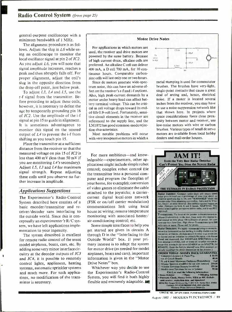
Radio Control System (from page 25)
general -purpose oscilloscope with a minimum bandwidth of 1 MHz.
The alignment procedure is as fol- lows. Adjust the slug in L6 while us- ing an oscilloscope to monitor the local oscillator signal at pin 2 of IC2. As you adjust L6, you will note that signal amplitude increases, reaches a peak and then abruptly falls off. For proper alignment, adjust the coil's slug in the opposite direction from the drop -off point, just below peak.
To adjust L3, L4 and L5, use the r -f signal from the transmitter. Be- fore proceding to adjust these coils, however, it is necessary to defeat the agc by temporarily grounding pin 16
of IC2. Use the amplitude of the i -f signal at pin 15 to guide in alignment. It is sometimes advantageous to monitor this signal on the unused output of L4 to prevent the i -f from shifting as you touch pin 15.
Place the transmitter at a sufficient distance from the receiver so that the measured voltage on pin 15 of IC2 is less than 400 mV (less than 50 mV if you are monitoring L4's secondary). Adjust L5, L3 and L4 for maximum signal strength. Repeat adjusting these coils until you observe no fur- ther increase in amplitude.
Applications Suggestions The Experimenter's Radio -Control System described here consists of a basic encoder /transmitter and re- ceiver /decoder sans interfacing to the outside world. Since this is con- ceptually an experimenter's R/C sys- tem, we have left applications imple- mentation to your ingenuity.
The system described is excellent for remote radio control of the usual model airplanes, boats, cars, etc. By
adding some very minor interface cir- cuitry at the decoder outputs of IC3 and IC4, it is possible to remotely control lights, appliances, heating systems, automatic sprinkler systems and much more. For such applica- tions, no modification of the trans- mitter is necessary.
Motor Drive Notes
For applications in which motors are used, the receiver and drive motors are powered by the same battery. Because of high current drain, alkaline cells are preferred. An alkaline C cell can deliver 400 mA, a D cell 700 mA, for 10 con- tinuous hours. Comparable carbon - zinc cells will last only one or two hours.
Since dc motors generate wide -spec- trum noise, this can have an adverse ef- fect on the receiver's r -f and i -f sections. Also, high peak -current demands by a motor under heavy load can affect bat- tery terminal voltage. This can be criti- cal as cell voltage drops toward its end - of -life 0.9 -volt level. Fortunately, sensi- tive circuit elements in the receiver are referenced to the supply line, and the LM 1872 has good common -mode rejec- tion characteristics.
Most notable problems will occur with very inexpensive motors in which a
IEI
Motor
metal stamping is used for commutator brushes. The brushes have very- light, single -point contacts that cause a great deal of arcing and, hence, electrical noise. If a motor is located several inches from the receiver, you may have to use a noise -suppression network like that shown here. In projects where space considerations force close prox- imity between motor and receiver, use low -noise motors with wire or carbon brushes. Various types of small dc servo motors are available from local hobby dealers and mail -order houses.
For more ambitious -and know- ledgeable- experimenters, other ap- plications might include simple robot control; complex robot control (tie the transmitter into a personal corn - puter and program the floorplan of your home, for example); conversion of video games to eliminate the cable attached to the joysticks; a carrier - current digital local -area network (FSK or on /off carrier modulation) communications link using local house ac wiring; remote temperature monitoring with associated heater/ air- conditioning control; etc.
Some simple interfaces to help you get started are given in circuits A through D in the "Interfacing to the Outside World" box. If your pri- mary interest is to adapt the system for motor drive (as needed for model airplanes, boats and cars), important information is given in the "Motor Drive Notes" box.
Whichever way you decide to use the Experimenter's Radio -Control System, you will find it both highly flexible and eminently adaptable. DYE
- JAlVI 11 : 11111111111/
Even the Very Best Radar Detector Can't Protect You from the Newest Radar
THE ULTIMATE IN RADAR PROTECTION
Radar Jammer: Compact under -dash unit causes speed
radar guns to read out a percentage of your true speed. or whatever speed you dia. in. Or, new "SCRAMBLE" mode will prevent radar from obtaining any reading. Activated by W sis-
tier, Escort, or other detector. Best defense against instant on radar. Operates on both X and K bands. WARNING: This device is not legal for use against police radar, and is not FCC approved.
Transmitters: The heart of the jammer is the microwaveos- cillator (transmitter). In the past, these were very expens ve,
and limited to only atout 100 milliwatts of power. We r ow have our own Low cost, High Power Transmitters up to 300
milliwatts or more. Please call for prices.
Radar Detectors: We highly recommend using a remote de-
tector that is mounted ao that nothing is readily vivable to ei her
the police, or thieves. IA dash mount detector is an invita ion to thieves and an irritation to police!) We agree with Mator Trend and Autoweek that WHISTLER SPECTRUM is the
best detector available, and we know of no other remote de-
tector that is even in the same LEAGUE as the SPECTRUM REMOTE. Order the hest J'or yourself jnow. (Our detectors are
already modified for direct connection to the jammer.)
ORDER TODAY -MONEY BACK GUARANTEE 0 Complete Literatu-e & Plans Pkg. S 14.95
LI Set of Circuit Boards 44.00
E, X and K -band Microwave Oscillators (transmitters) Call Whistler Spectrum (modified for use with Jammer) 251.00
L' Whistler Spectrum Remote (modified) 257.00
D Modify your Spectrum for use w /jammer 51.00
CALL or seid the following information: Items Ordered Name Shipping Adcress Payment: Check, Money Order, VISA or MC (Maid.. card number. expiration date. and signature)
. $BND TO: Oregon Microwave Inc. . 9513 S.W. Harbor Blvd. ,199M
Portland. OR 97219 ORDER LINE: (583) 626ó764 "Formerly Philips Dnsrrument Design Co.
CIRCLE NO. 107 ON FREE INFORMATION CARD
August 1985 / MODERN ELECTRONICS / 89
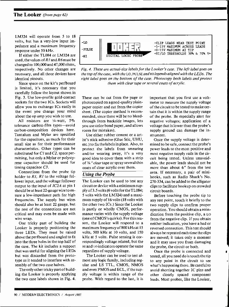
The Looker (from page 62)
LM324 will operate from 5 to 18
volts, but has a very -low input im- pedance and a maximum frequency response under 50 kHz.
If either the TL084 or LM324 are used, the values of R1 and R6 must be changed to 100,000 and 47,000 ohms, respectively. No other changes are necessary, and all three devices have identical pinouts.
Since space on the kit's perfboard is limited, it's necessary that you carefully follow the layout shown in Fig. 3. Use low- profile gold- contact sockets for the two ICs. Sockets will allow you to exchange ICs easily in the event you change your mind about the op amp you wish to use.
All resistors are '/ -watt, 5% tolerance carbon -film types -avoid carbon -composition devices here. Tantalum and Mylar are specified for the capacitors, as much for their small size as for their performance characteristics. Other types can be substituted for Cl and C2, space per- mitting, but only a Mylar or polysty- rene capacitor should be used for timing capacitor C3.
Connections from the probe tip holder to R1, R1 to the voltage fol- lower input, and the voltage follower output to the input of IC2A at pin 1
should be at least 22 -gauge wire to en- sure a low- impedance path for high frequencies. The supply bus wires should also be at least 22 gauge, but the rest of the connections are not critical and may even be made with wire wrap.
One tricky part of building the Looker is properly positioning the three LEDs. They must be raised above the perfboard and angled to fit into the three holes in the top half of the case. The kit includes a support that was useful for aligning the LEDs but was discarded from the proto- type as it tended to interfere with as- sembly of the two case halves.
The only other tricky part of build- ing the Looker is properly applying the two case labels shown in Fig. 4.
-LO
-PULSE
-HI
NNNER DIGITAL LOGIC PROBE
-CLIP LEADS NEAR TEST POINT -5-15V MAXIMUM ACROSS LEADS -0 -15V MAXIMUM AT TIP -HI /LO THRESHOLDS 30% & 70% V+
Fig. 4. These are actual -size labels for the Looker's case. The left label goes on the top of the case, with the LO, PULSE and HI legends aligned with the LEDs. The right label goes on the bottom of the case. Photocopy both labels and protect
them with clear tape or several coats of acrylic.
These can be cut from the page or photocopied on a good -quality plain - paper copier and cut from the copier sheet. (The copier method is recom- mended, since there will be no bleed - through from backside images, lets you use color bond paper, and allows room for mistakes).
Use either rubber cement or a art- ist's stick adhesive (Glue Stic, UHU, etc.) to fix the labels in place. Also, to protect the labels from smearing and /or wearing away, it's a very good idea to cover them with a strip of 1/4 "clear tape or spray several thin coats of clear acrylic over them.
Using the Probe The Looker can be used to test any circuit or device with a minimum sup- ply of 3.5 volts (6 volts for the TL084; 5 volts with the LM324) and a maxi- mum supply of 16 volts (18 volts with the other two ICs.) Since the Looker is partly or wholly CMOS, perfor- mance varies with the supply voltage (one of CMOS's quirks). For this rea- son, the Looker will respond to a maximum frequency of 800 kHz at 15
volts, 500 kHz at 10 volts, and 150 kHz at 5 volts. Pulse sensing is cor- respondingly voltage related, but the HI and LO indicators operate the same regardless of supply voltage.
The Looker can be used to test al- most any logic family, including reg- ular and LS TTL, CMOS, NMOS and even PMOS and ECL, if the sup- ply voltage is within range of the probe. With regard to the last, it is
important that you first use a volt- meter to measure the supply voltage of the circuit to be tested to make cer- tain that it is within the supply range of the probe. Be especially alert for negative voltages; application of a voltage that is lower than the probe's supply ground can damage the in- strument.
Once the supply voltage is deter- mined to be safe, connect the probe's power leads to the most positive and most negative supply rails in the cir- cuit being tested. Unless unavoid- able, the power leads should not be more than about 6" from the test area. If necessary, a pair of mini - hooks, such as Radio Shack's No. 270 -334, can be added to the alligator clips to facilitate hookup on crowded circuit boards.
Before touching the probe tip to any test point, touch it briefly to the two supply clips to confirm proper operation. You should obtain a HI in- dication from the positive clip, a LO
from the negative clip. If you obtain neither indication, you have a bad or reversed connection. This test should always be repeated each time the clips are moved; it takes only a moment and it may save you from damaging the probe, the circuit or both.
Once the probe is connected and tested, all you need do is touch the tip to any point in the circuit to see what's happening there. Be careful to avoid shorting together IC pins and other closely spaced component leads. Most probes, like the Looker,
90 / MODERN ELECTRONICS / August 1985
have very high input impedance and will disturb the circuit under test only minimally, if at all.
Although you can't determine fre- quency with a logic probe, you can trace a waveform through a circuit to see where it goes, disappears or goes awry. A common indication is to have the probe indicate all HI or all LO
conditions for every point in a circuit or pins on an IC. This means that the circuit or IC is lacking a ground or positive supply voltage.
There are seven basic responses a probe can give. With a schematic dia- gram or other documentation and a little practice, you'll soon learn to in- terpret them:
(1) No indication at all -the point being tested is dead or is at a voltage level between the two thresholds (see 7 below).
(2) Steady HI indication -the point under test is at a voltage level
greater than 70% of the supply (log - ic-1 for most circuits).
(3) Steady LO indication -the point under test is at a voltage level less than 30% of the supply (logic -0 for most circuits).
(4) Steady HI with flashing PULSE
indication -the presence of a nega- tive pulse or pulses at that point.
(5) Steady LO with flashing PULSE
indication -the presence of a posi- tive pulse or pulses at that point. [Note: The probe point must be held firmly against the test point to elimi- nate the chance of false pulse indica- tions. Many probes -including the Looker -may flash the PULSE indi- cator when the tip is touched to or re- moved from the test point.]
(6) Steady PULSE indication -the presence of a frequency between 0 Hz and maximum range of the probe at that point. The presence of a steady HI or LO simultaneously may mean a
frequency that's slightly out of range for the probe, a frequency with a strong dc component, a very high or very low duty cycle, or a waveform with its amplitude biased toward one end of the supply.
(7) Flickering PULSE indication - may indicate a frequency that's out of range of a voltage that's between the thesholds. This shouldn't be in- terpreted as a valid state. Use a volt- meter or frequency counter to check.
Conclusions If you've never used a logic probe be- fore, you will be surprised how quickly and easily it can give a com- prehensive look at the operation of a digital circuit. With a schematic dia- gram or a timing chart of a circuit and a logic pulser for signal injection, you will find that a logic probe is particu- larly useful in design /experiment work as well as for troubleshooting.
SUBSCRIBER SERVICE
CHANGE OF ADDRESS
MODERN ELECTRONICS 76 N. Broadway, Hicksville, NY 11801
Planning to move? Please let us know six weeks In advance so you won't miss a single issue of MODERN ELECTRONICS Attach old label and print new address In space provided. Also include your mailing label whenever you write concerning your subscription to ensure prompt service on your Inquiry.
ATTACH LABEL HERE
PLEASE PRINT NAME
ADDRESS
CITY STATE
DATE ZIP
The one thing we make that you have to
replace every year.
The new and ex- panded ECG Semiconductors Master Guide. The Master Replacement Guide for 1985. 656 pages. More than 3,500 differ- ent ECG devices- includ- ing more than 400 new ones. And every part meets or exceeds the original JEDEC or appli- cation specs. All in all, replacement coverage for more than 227,000 indus- try types.
And everything in the book is cross -referenced
SO you can find what
you want fast. Your Philips
ECG distributor has a copy for you. Call us for his name and location at 1 -800- 225 -8326 (in Massachusetts, dial 617 -890- 6107) . Or send $3.25 to Philips ECG, Marketing Services Center, 70 Empire Drive, West Seneca, NY 14224. If It'sBC,It fits . And it works.
PhilipsECG A North American Company
Oethea/.eatto ¿'zteilettce. CIRCLE 40 ON FREE INFORMATION CARD
August 1985 / MODERN ELECTRONICS / 91
AFFORDABLE ROBOTS Computerized (and logic- controlled) battery robot kits that teach the basic principles of robotic sensing and locomotion. Pre -assembled pc boards. hardware and mechanical -drive systems that can be handled by anyone. Basic hand tools required for assembly. r`' '_
PIPER -MOUSE SOUND SENSOR Supersonic Robot controlled by a
sound sensor. Whistle commands turning stop and go. $39.95
MEMOCON- CRAWLER PROGRAMABLE Memory controlled through key - board for forward, right, left,
..- pause, buzzer and light. With RAM, 256 x 4 bit memory. $69.95 if w- OPTIONAL INTERFACE
sit IBM (Specify) $39.95
CIRCULAR REMOTE CONTROL -- Super Robot mysteriously rolls r left, right, forward, or round and t . . round by hand -held remote.$64.95
- LINE TRACER ß, INFRA -RED SENSOR
Guided by infra -red light sensor. Robot automatically follows any line drawn on white paper. $37.95
OUR NEW CATALOG FREE with Order HOBBY KITS - CAR STEREOS- CB'S
RAOAR DETECTORS - ALARMS - ACCESSORIES Add $3.00 per kit, shipping & handling.
NY State residents add sales tax.
TOLL FREE ORDER HOTLINE: r -.1- 800 -645 -4441 Nationwide ` 4 1 -800- 632 -4441 N.Y. State =
or order by mail - charge - check - money order
Electromania 51 SUNRISE HIGHWAY, LYNBROOK, N.Y. 11563
CIRCLE 51 ON FREE INFORMATION CARD
MODERN ELECTRONICS MART Classified Commercial Rates: 90¢ per word, 15 -word minimum ($13.50) prepaid, (Word count includes name and address.) First word only is set boldface caps at no charge. Add 20% for additional boldface words.
Mart Display Rates: I" x 1 col., $120; 2 " x 1 col., $230; 3 " x 1 col., $330. Prepayment dis- count 5% for 6 issues; 10% for 12 issues prepaid at once. (All advertisers with PO Box addresses must supply permanent address and telephone number. Copy is subject to publisher approval.)
Mailing Information: Copy must be received by the publisher by the 20th of the third month preceding the cover date. Send Advertising material with check or money order to: Modern Electronics, Classified Department, 76 North Broadway, Hicksville, NY 11801.
VIDEO ZENITH SSAVI MANUAL. Original man- ual used by technicians. Theory of scram- bling, schematics, parts list, repair. For UHF and cable. For speedy delivery send $15.00 cash or money order. BAY STATE ELEC- TRONICS, PO Box 263, Accord, MA 02018.
HOME Satellite Handbook has everything you need to know about Satellite Television. $10.00, SV Box 422, Seaford, New York 11783.
SINE WAVE PATENT SECRETS complete- ly explains how their box works including au- thorization control; $6.00. S/W problem manual explains trouble shooting hookup; $4.00. Both, $8.00. Signal, Box 2512 -M, Cul- ver City, CA 90231.
PANASONIC ZENITH GE SYLVANIA QUASAR MAGNAVOX RCA SHARP HITACHI PHILCO SANYO SONY SAMSUNG SAMPO MGA TOSHIBA GOLDSTAR EXACT ORIGINAL PARTS FOR TV AND VCR. CALL NOW 800 -874- 1765 NY ONLY 800- 874 -1764.
SATELLITE TELEVISION, Everyones Guide. $2.50 Money -back guarantee. SAT/ FLORIDA, 2910 SE 19 Avenue, Gainesville, FL 32601.
UNIQUE Satellite TV Manual for deal- ers /hobbyists. Includes step -by -step instruc- tions for system installation & tuning, pur- chasing, marketing, complete list of distribu- tors & equipment plus more. Rush $19.95 to SATELLITE COM. NETWORK, 204 W. 20th St., New York, NY 10011
CABLE Converters to Scramblers. Lowest Price. Dealer inquiries accepted. Quantity dis- counts. FREE CATALOG. P G Video Corp., 61 Gatchell St., Dept. ME, Buffalo, NY 14212.
CABLE TV Secrets - the outlaw publication the Cable Companies tried to Ban. HBO, Movie Channel, Showtime, Descramblers, Converters, etc. Suppliers list included. $8.95. Cable Facts, Box 711 -ME, Pataskala, Ohio 43062.
CABLE and Subscription TV secret manual. Build your own descramblers, converters -
HBO, Showtime, Movie Channel, UHF. Lat- est theory, schematics, instructions, suppliers list. Send $8.95 to CABLETRONICS, Box 30502ME, Bethesda, MD 20814.
BUILD Your Own Satellite TV Receiving Sys- tern And Save! Instruction manuals, schemat- ics, circuit boards, parts kits! Send stamped envelope for complete product listing: XAN- DI, Box 25647, Dept. 30D, Tempe, AZ 85282.
Order Form Please print in block letters.
MODERN ELECTRONICS 76 North Broadway, Hicksville, NY 11801
Name
Street
City
State Zip
1 2 3 4 5
6 7 8 9 10
11 12 13 14 15
16 17 18 19 20
21 22 23 24 25
CIRCLE 94 ON FREE INFORMATION CARD 92 / MODERN ELECTRONICS / August 1985
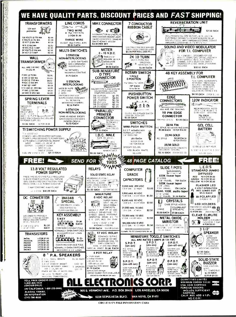
WE HAVE QUALITY PARTS, DISCOUNT PRICES AND FAST SHIPPING! TRANSFORMERS
120 volt primaries I.II
5.6 VOLTS @ 750 MA 6 VOLTS @ 150 MA 12 VCT @200 MA
18 V. @650 MA 18 VOLTS @ 1 AMP 24 VOLTS @ 250 MA 24 VCT @ I AMP
$3.00 $1.25 $2.00
$3.50 $4.50 $2.50 54.50
WALL TRANSFORMER
ALL ARE 115 VAC PLUG IN
4 VDC @ 70 MA
6 VAC @ 500 MA 6VDC@ 750 MA 9VDC @500 MA 9 VAC @1 AMP 12.5 VAC @ 265 MA 17 VAC @ 500 MA 24 VAC @ 250 MA
$2.00 $3.50 $8.50 $5.00 $3.00 $2.50 $4.00 $3.00
SPRING LEVER TERMINALS
TWO COLOR ER
TERMINALS
I NRMI MINARS
ON A STURDY 2 3/4" . 3 3/4' BAKELITE PLATE ° GREAT FOR SPEAKER ENCLOSURES OR POWER SUPPLIES.
$1.00 EACH 10 FOR 0900
LINE CORDS
TWO WIRE 6' 18ga TWO WIRE
3 FOR $1.00
THREE WIRE 8 FOOT 18ga THREE WIRE
$2.00 EACH
MULTI -SWITCHES
3 STATION NON -INTERLOCKING
3 - 2PDT SWITCHES. EATE
4' "11 INDEPENDENTLY EACH OPR S
13/4" BETWEEN MOUNTING CENTERS
51.75 EACH
s STATION INTERLOCKING
MADE BY ALPS. 3- 2PDT AND 2 - 6PDT 11
SWITCHES ON FULLY INTERLOCKING ASSEMBLY
31/4" BETWEEN MOUNTING CENTERS.
$2.50 EACH
5 STATION NON -INTERLOCKING SAME AS ABOVE, EXCEPT EACH SWITCH OPERATES
INDEPENDENTLY $2.50 EACH
TI SWITCHING POWER SUPPLY TI # 1053214 -2 COMPACT, WELL -REGULATED SWITCHING POWER SUPPLY DESIGNED TO POWER TEXAS
INSTRUMENTS COMPUTER EQUIPMENT. INPUT: 14VAC -25. VAC AT IA OUTPUT: + I2VDC AT 350MA
+ 5VDC AT I.2A - 5VDC AT 200MA
SIZE. 43 4,4" v I v," $5.00 EACH
MIKE CONNECTOR
5 CONDUCTOR IN -LINE PLUG AND CHASSIS MOUNT JACK. TWIST LOCK STYLE, SAME AS SWITCHCRAFT 12CL5M. $2.50 PER SET
METER 0 - 15 V.D.C.
THIS 2 -1/4" SQUARE METE, MEASURES 0-15 VDC.
$4.50 EACH
SUB -MINIATURE D TYPE
CONNECTOR 44 11k) c3 SOLDER TYPE SUB -MINIATURE
CONNECTORS USED FOR COMPUTER HOOK UPS.
DB -15 PLUG $2.75 DB -15 SOCKET $4.00 DB -15 HOOD $1.50 DB -25 PLUG $2.75 DB -25 SOCKET $3.50 DB -25 HOOD $1.25
"PARALLEL" PRINTER
CONNECTOR SOLDER STYLE 36 PIN MALE USED ON "PARALLEL" DATA CABLES
55.50 EACH eÌ '
I.D.C. MALE SAME AS ABOVE.
$5.00 EACH
FREE! `ajp. SEND FOR
13.8 VOLT REGULATED POWER SUPPLY
THESE ARE SOLID STATE FULLY REGULATED 13.8 VDC POWER SUPPLIES. ALL FEATURE 100% SOLID STATE CONSTRUCTION, FUSE PROTECTION, L.E.D. POWER INDICATOR.
2 AMP CONSTANT. 4 AMP SURGE.
UL LISTED $18.00 EACH
DC CONVERTER
DESIGNED TO PROVIDE A STEADY s5 VDC@ 240 MA FROM A BATTERY SUPPLY OF 35 TO 6.25 V.
2 1/16" X 1 1/16" X
1 11/16" HIGH. $1.50 EACH
TRANSISTORS 2N706 2N2222A PN2222 2612904 2N2905 2N2907
4 FOR $1.00 3 FOR $1.00 4 FOR $1.00 3 FOR $1.00 3 FOR $1.00 3 FOR $1.00
1N4148 SPECIAL
45" SPACING P.C. LEADS 1000 FOR $10.00
10,000 FOR $585.00
KEY ASSEMBLY 5 KEY
$1.00 EACH
`+. 4 r r/ r°r CONTAINS 5 SINGLE -POLE
NORMALLY OPEN SWITCHES. MEASURES 3 3/4" LONG 6 KEY
$1.25 EACH
CONTAINS 6 SINGLE -POLE NORMALLY OPEN SWITCHES.
MEASURES 4 1/4" LONG
8 ' P.A. SPEAKERS C.T.S. MODEL 803079 55.00 EACH
8 OHMS COIL 3.0 OZ FERRITE MAGNET CASE OF
TYPICAL RESPONSE RANGE: 8 SPEAKERS 100 - 10,000 HZ. $32.00
POWER RATING 15 WATTS MAX.
DRILLED TO MDWT LINE
WILL PRESS FIT ON STANDA RI:
RIBBON CABLE
7 CONDUCTOR RIBBON CABLE
SPECTRA -STRIP RED MARKER STRIP. 28 GA STRANDED WIRE. $5.00 PER ROLL (100 FT.)
2K 10 TURN MULTI -TURN POT
Ep6 y y SPECTROL ',MOD 534-7161
55.00 EACH
ROTARY SWITCH 1P1LE
6 POSITION q 114" DIA x 11/2" HIGH
759 EACH 10 for $6.00
REVERBERATION UNIT
$7.50 EACH
ACCUTRONICS COIL SPRING TYPE UNITS. USED IN ELECTRONIC ORGANS TO PROVIDE ACOUSTIC DELAY SOUND EFFECTS. INPUT IMPEDANCE 8 OHMS, OUTPUT IMPEDANCE 2250 OHMS. 4I /2" x 161Á"x 15/16:
SOUND AND VIDEO MODULATOR FOR T.I. COMPUTER
T.I. a UM1381 -1. DESIGNED FOR USE WITH TT COMPUTERS CAN BE USED WITH VIDEO SOURCES BUILT -IN A/B SWITCH. CHANNEL 3 OR 4 SELECTION SWITCH. OPERATES ON 12 VDC. HOOK UP DIAGRAM INCLUDED
$10.00 EACH
48 KEY ASSEMBLY FOR T.I. COMPUTER
NEW TEXAS INSTRUMENTS KEYBOARD. UNENCODED. 48 S. P.S.T. MECHANICAL SWITCHES TERMINATES TO 15 PIN CONNECTOR_ SOLID METAL FRAME 4" X 9f
$6.50 EACH 2 FOR $11.00 PUSHBUTTON POWER SWITCH
DOUBLE POLE POWER SWITCH PUSH -ON PUSH OFF $1 00 EACH
SWITCHES MINI -PUSH BUTTON S. PS. T. MOMENTARY NORMALLY OPEN 1/4" BUSHING
354 EACH 10 FOR $3.25
100 FOR $30.00
SPECIFY COLOR: RED. BLACK, WHITE.
YELLOW
RELAYS
SOLID STATE RELAY
HEINEMANN ELECTRIC #I01-SA -140 -5 AMP CONTROL: 3 -32VDC LOAD: 140VAC 5 AMPS SIZE: 2" X 1 "X 3" HIGH
$5.00 EACH 10 FOR $45.00
MINIATURE 6 VDC RELAY
SUPER SMALL SPDT RELAY; GOLD COBALT CONTACTS.
RATED 1 AMP AT 30 VDC; HIGHLY SENSITIVE, TTL DIRECT DRIVE POSSIBLE, OPERATES FROM 4.3 TO 6 V, COIL RES. 220 OHM.
erii?
1 3/16" = 13/32" * 7/16" AROMAT a RSD-6V
$1.50 EACH 10 FOR $13.50
t*S
13 VDC RELAY CONTACT: S.P.N.C. 10 AMP @ 120 VAC ENERGIZE COIL TO OPEN CONTACT
13 VDC 650 OHMS SPECIAL PRICE $1.00 EACH
4 PDT RELAY 14 pin style 3 amp contacts 24 volt d.c. or 120 volt a.c. coil Used but fully tested
$1.70 EACH specify coil voltage
. 1
Illi
EDGE CONNECTORS
ALL ARE 156" SPACING
10 PIN EDGE CONNECTOR
TRW v50- 10 -A -20 $2.00 EACH
22/44 TIN P.C. STYLE; NO MOUNTING EARS
$1.50 EACH 10 FOR $14.00
22/44 GOLD PC. STYLE $2.00 EACH
10 FOR $18.00
28/56 GOLD 28/56 GOLD PLATED CONTACTS 156 CONTACT SPACING.
$2.50 EACH 10 FOR $22.00
120V INDICATOR
NEON INDICATOR. RATED 120 V 1/3 W. MOUNTS IN 5/16" HOLE. -. RED LENS.
756 EACH 10 FOR $7.00 100 FOR $65.00
GEL CELL BATTERY
12 VDC @ 2.6 AMP HOUR
5 S /8" X 2 1/4" X 3 3/4" 525.00 EACH
48 PAGE CATALOG -1(11610 FREE! COMPUTER
GRADE
CAPACITORS
2,000 mfd. 200 VDC 1 3/4" DIA. 5" HIGH $2.00
3,600 mfd. 40 VDC 1 3/8 "DIA.. 3 3/4" HIGH $1.00
6,400 mid. 60 VDC 13/8" DIA. -41/4" HIGH $2.50
31,000 mfd. 15 VDC 1 3/4" DIA. . 4' HIGH $2.50
72,000 mfd. 15 VDC 2" DIA.. 4 3/8" HIGH $3.50
185,000 mfd. 6 VDC 21/2 "DIA. . 41/2 "HIGH $1.50
CLAMPS TO FIT CAPACITORS SOC .a.
SLIDE POTS
100K linear tape 2" LONG
1 5/8 TRAVEL 754 EACH 500K linear taper
2 7/8" LONG 1 3/4" TRAVEL 754 EACH
DUAL 100K audio taper 3 1/2" LONG 2 1/2" TRAVEL. $1.50 EACH
CRYSTALS CASE STYLE HC33 /U
COLORBURST 2 MHZ 3579.545 KC
$3.50 EACH $1.00 EACH
METAL OXIDE VARISTOR
POPULAR GE 4 130LA10A VARISTOR. 5/8" ^IAMETER.
51.25 EACH
MINIATURE TOGGLE SWITCHES ALL ARE RATED 5 AMPS @ 125 VAC
S.P.D.T. S.P.D.T. ;J S.P. D. T. (on -on)
P C STYLE. NON -THREADED BUSHING 750 EACH I O FOR $7 00
S.P.D.T. (on- off -on) NON -THREADED BUSHING P.0 STYLE 754 EACH
(on -on) SOLDER LUG TERMINALS $1.00 EACH 10 FOR $9.00 100 FOR $80.
(on- Off -on) SOLDER LUG TERMINALS $1.00 EACH 10 FOR S9 00 100 FOR $80.00
S.P.D.T. (on -On)
PC LUGS. THREADED BUSHING 57.00 EACH
LARGE QUANTITIES AVAILABLE ; °1 10 FOR 39.00
MATCHING TRANSFORMERS. SOCKETS FOR RELAY see 4.1, 10 FOR $7 00 Y U P 100 FOR SRO 00
TOLL FREE ORDERS ONLY I. 800 -826 -5432 (ORDER ONLY) (IN CALIFORNIA: 1 -800- 258 -6666)
ALASKA. HAWAII. OR INFORMATION (213) 380-8000
D.P.D.T. (on -on) SOLDER LUG TERMINALS. $2.00 EACH 10 FOR 31900 105 FOR 518000
ALL ELECTRORICS CORP. pCp1 OH'
905 S. VERMONT AVE. P.O. BOX 20406 LOS ANGELES, CA 90006
111111111110. 6228 SEPULVEDA BLVD. VAN NUYS, CA 91411
L. E. D: S STANDARD JUMBO
DIFFUSED RED 10 FOR $1.50
GREEN 10 FOR $2.00 YELLOW 10 FOR $2.00
FLASHER LED 5 VOLT OPERATION
1 RED JUMBO SIZE $1.00 EACH
BI POLAR LED 2 FOR 51.70
LED HOLDERS TWO PIECE HOLDER e 8 FOR JUMBO LED 10 FOR 656 200 FOR $1000
CLEAR CLIPLITE HOLDER
MAKE LED A FANCY INDICATOR. CLEAR. 4 FOR $1.00
3 1/2" SPEAKER
x)_
) B OHM IMPEDANCE, FULL RANGE SPEAKER. 8 02 MAGNET. 4" DIAGONAL
MOUNTING CENTERS.
$2.50 EACH 10 FOR $20.00
SOLID STATE BUZZER STAR BSMB -O6L. 6 VDC. TTL COMPATIBLE. $1.00 EACH
10 FOR $9.00
e QUANTITIES LIM TED MINIMUM ORDER $10.00 USA: 53.00 SHIPPING FOREIGN ORDERS
INCLUDE SUFFICIENT SHIPPING
CALIF. RES. ADD 6 1/2 °° NO C.O.D.!
WS.
CIRCLE 56 ON FREE INFORMATION CARD
E/ SPEAKER CATALOGIM 1001 bargains in electronics. Save up to 50% call toll free 1 -800 -346- 2433 for ordering only. Order by VISA/MC /AMX. No COD's. Missouri, Alaska, Hawaii call 1 -816- 842 -5092, or write McGee Radio, 1901 McGee In
K.C., MO 64108. Postage for catalog $1.00. 111100
CABLE TV EQUIPMENT
Jerrold, Hamlin, Zenith -Many Others! Factory Units/ Lowest Dealer Prices. Complete illustrated catalog, $2.00.
Pacific Cable Co., Inc., 73251/2 Reseda Blvd., #503 Reseda, CA 91335 (818) 346 -5071
REVERBERATION FOR ORGANS
Solid state with controls for rever- beration and room size. EVERY ORGAN SHOULD OWN ONE. Send for free flyer-
DEVTRONIX ORGANS, INC. 6101 WAREHOUSE WAY
SACRAMENTO, CALIFORNIA 95826
Quality Microwave TV Antennas
Multi -Channel 1.9 to 2.7 GHz 40dB Gain True Parabolic 20 Inch Dish
Complete System $84.95 (Shipping incl.) Dealerships. Oty. Pricing. Replacement Parts
Phllllps -Tech Electronics P.O. 60E 34772 Phoenix. AZ 85067
LIFETIME 16021947 -7700 4300 Credit all phone orders!'
WARRANTY MasterCard Visa C00's
TUNEABLE notch filters, brochure $1.00. D.K. Video, Box 63/6025, Margate, FL 33063.305- 752 -9202.
COMPUTERS BUILD YOUR OWN COMMODORE 64 NUMERIC KEYPAD -Fully program- mable. Uses joystick ports without voiding warranty or interfering with normal program operation. Complete details and software list- ing for $5.00. For prerecorded disk send addi- tional $10.00. SIMCO SCIENTIFIC, 5757 Bobby Dale Lane, Chattanooga, Tennessee 37415.
n a m pl (a
cn
m
N
z 3 m
ABSOLUTE IIe /IIc RESET To the "old" monitor ROM. Don Lancaster puts you back in total control. Capture routines, source code, detailed instructions, bonus book, $19.95. SYNERGETICS, Box 809 -ME, Thatcher, AZ 85552. VISA /MC. (602) 428 -4073.
CONTROL your world with your computer! Control up to 48 devices easily. Complete plans, schematics, programs $9.95. SASE for more information. B&W Electronics, 3621 Lowden, Kalamazoo, MI 49008
AWII TOOLKITS Eight Diskette sides crammed full of APPLEWRITERTM goodies: patches - sourcecode - microjustify -proportional space - disassembly script -an- swers - self -prompting glossaries - bonus book - bunches more. $39.50 for either DOS 3.3e or ProDOS 2.0 versions. SYNERGETICS, Box 809 -ME, Thatcher, AZ 85552. VISA /MC. (602) 428-4074.
APPLE OWNERS: Hard -sided carrying cases for Macintosh $100, Macintosh and external drive $130, and IIc $100. Send check or money order, or MC /Visa accepted. Justin Case Manufacturing Corp., 334 Main Street, Port Washington, NY 11050 (or telephone 516- 883- 2299).
NEW for 1986! ! "SPARTACADE." Sixteen ready to type in games for 3K VIC20. Includes Spider's Web, Dragster. Send $5.95 to Vision Mechanics, POB 2286, Richmond, CA 94802.
TI -99/4A Software /Hardware bargains. Hard to find items. Huge selection. Fast Ser- vice. Free Catalog. TYNAMIC, Box 690, Hicksville, NY 11801.
US $8.00 including disk thousand name brand programs for Apple IBM -PC details US $1.00 Reliant P.O. Box 33610 Sheungway Hongkong.
ELECTRONICS ELECTRONIC HOBBYIST: You can be- come a part of our information network, share your ideas, and have access to unique and fascinating projects. Send $1.00 and be a part of the network today. T &K Specialty, 6888 Kent Dr., Baker, LA 70714.
IIIIll/E 6 N. Broadway, Hicksville, NY 11801
FREE INFORMATION SERVICE For further information on products, dealers, or literature in this issue, circle the appropriate numbers below. Be sure to include your name and address before mailing.
13
25
37
49
61
73
85
97
109
121
133
145
157
169
2
14
28
38
50
82
74
86
98
110
122 134
146 158
170
3
15
27
39
51
63
75
87 99
111
123
135
147
159
171
"BIONIC" EARS. HEAR LEAVES FALL FROM QUARTER MILE. AUTOMATIC LEVEL CONTROL FM WIRELESS MI- CROPHONE. COMPLETE INFORMA- TIONAL PLANS PACKAGE. BOARD, MOST PARTS FROM RADIO SHACK. $7.95 PLUS $1.50 SHIPPING. DIRIJO CORP., BOX 212, LOWELL, NC 28098.
SAVE ON POWER COSTS. Innovative solid state device converts two 12 volt batteries into regenerating energy system. Run lights, ra- dios, TV's, motors indefinitely. Like having your own power plant. Build it! Info $2 re- fundable with order. JGC Associates, Post - Tel Center, 2210 Wilshire Blvd., Suite 878 -B, Santa Monica, CA 90403 -5784.
BUILD your own solid state laser! Easy plans only $5.00. H.A.S. Technologies, Box 81201, Corpus Christi, Texas 78412.
PICTURE Flyer lists quality electronic sur- plus at low prices. Since 1970. Send for the last 3 issues. Star -Tronics, Box 683, McMinnville, OR 97128.
AUTOMOTIVE radio replacement parts. Delco, Ford Chrysler, Panasonic, etc. Laran Electronics, 3768 Boston Rd., Bronx, NY 10469 (212) 881 -9600; NY State: 800 -446- 4430; National: 800- 223 -8314.
ELECTRONIC CATALOG. Over 4,500 items. Parts & components. Everything need- ed by the hobbyist or technician. $2.00 post- age & handling (U.S. Only), refundable with first $15.00 order. T &M Electronics, Dept. M, 472 East Main St., Patchogue, NY 11772. (516) 289 -2520.
COMMUNICATIONS "SCANNERS /SHORTWAVE" Regency, Bearcat, Sony, Kenwood, Icom, Yaesu, Pana- sonic, Antennas, CBs, MFJ, MUCH MORE, True Discount Prices AND FREE SHIPPING to 48 States. Big 25 Page Picture Catalog $1.00 (REFUNDABLE). Galaxy Electronics, Box 1202, Akron, Ohio 44309. (216- 376 -2402) 9 -5 PM EST. WE PRE -TEST!!
CB RADIO MODIFICATIONS! Increase channels, range, privacy. Conversion hard- ware, books, plans, kits, repairs. Catalog $2. CBCI, Box 31500ME, Phoenix, AZ 85046.
COMMUNICATIONS plans, kits, books. 1750 Meter transceivers, AM /FM broadcast transmitters, ham /CB amplifiers, surveillance bugs,much more! Catalog $1.00. PANCOM, Box 130 -ME8, Paradise, CA 95969.
MOBILE Telephone Interconnect interfaces with ham, business band 2 -way radios. Plans $9.95. Parts available. Current Development Corp., PO Box 384, Westmoreland, NY 13490.
4
16
28
40
52
b4 76
as 100
112
124
136
148
160
172
5
17
29
41
53
65 77
ea 101
113
125
137
149
161
173
6
18
30
42
54
66 78
90 102
114
12f 138
150
162
174
7
19
31
43
56
67
79
91
103
115 127
139
151
163
175
8
20
32
44
56
68
80
92
104
116
128
140
152
164
176
9
21
33
45
57
eo
81
93 105
117
129
141
153
165
177
10
22 34
46
58
70
82
94
106
118
130
142
154
166
178
11
23
35
47
59
71
83
95 107
119 131
143
155 167
179
12
24
36 48
80
72
84
96 106
120
132 144
156
168
180
MISCELLANEOUS CORRESPONDENCE to Asia for lasting re- lationship. Free Information. AAWS -ME, Box 2777; Orcutt, CA 93455 -0777 Tel. No. 805- 937 -5230.
ASIAN LADIES want correspondence for friendship, marriage. SUNSHINE INTER- NATIONAL, Dept. TR, Box 260, North Hollywood, CA 91603.
CASES: Carrying, Shipping, Special -pur- pose. Stock ... Custom. For more informa- tion, contact Justin Case Manufacturing Corp., 334 Main Street, Port Washington, NY 11050.
94 / MODERN ELECTRONICS / August 1985
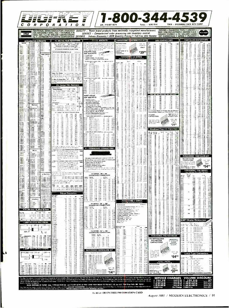
C O R P O R A T I O N I 1- 800 -344 -453 9
AK, 21&881.6674 Telex - 62827914 TWX - 9103508982 DICI KEY CORP
.. NATIONAL SEMICONDUCTOR PANASOE OUALITY - Name brand products rom nationally recognized manufacturers. DIODES DIAMOND TOOL UNGAR -- - OK MACHINE EWC, INC. INTERSiI Al ' iIES CW INDUSTRIES AMDEK G.E.
V/SA EAC INC. J. W. MILLER AAVID ENGINE SERVICE - Computerized order processing and inventory contro% 1NGAR YAGEO J. W. MILLER LUXO
Pricing Toll Free 800 Number E F JOHNSON *ATLANTIC SEMICONDU( SAVINGS - Volume Discounts OEM Quantity GÇ CHEMICALS ARIES PLESSEY -'.
INTEGRATED CIRCUITS
._
7sMx
i%. METAL FILM RESISTORS ,,. c.rNf.a :,.
` nm1 w.a..av mw p. o ls pA VALUE TAM
T I I C. SOCKETS «..nn c«p. 3,prp
Cont. . an
SOLDER TAIL
.a
DIP SOCKETS
t..a.re. cwocsnxalpoo
np.n TAR ....a... 6606 ep^. 01111
Aoebw ¡ .p0
®n bpnwa
=I . 3
P F6200.K
ONLY
í16 CAPACITO.
DISC C C AP A CITORS . - TANTALUM LUM CAP A CIT ORS
v. T- E Lk'', P
1i Pi6N
66peN ne 6 nTx 69101 i
27411.4 - kwlxx 2ID
2
° x
N N
N b N.
Mw tM)müR
3 03
2
] `°X T 96
W 10q
W BW
64. nw = 6O6 600 ,,win w 500
á 82W 00
u.. I
I 221p 2A1
¿p é' m
T ID
°
'
EIS Pj-só 60 .160
46
75 627.76
326 4111' 1`
n n. 4000 CMON
) )
9 R.5
11.8 2] a .0 ® en2
en PANASONIC LS SERIES
u a
® 1. 191
b zm 2 '
mA ;0 16 10
° , % %% 1
q 15 24 2
W
,0 6
.
ñ ñ a q
.
y
]
q
A .A 1m0 3í 1 9u
22
2m
1 1
s.
5
é
é
-
f
iijñ
v m
in é
7
1
u
ñ
i
iä
n m m
3. 70 m3 CO
PANASONIC V SERIES
eap
1g
1131
06 17 10
O 1
.
-
15
j
s
u v
ñ
.
34,33.06
.s ó w A II.
:ii"1á ms. 48 75 431175 51 75 66
ú l
26
25137416
2 ®
033376 n 9. iÁ
1nP 181
9. 1.68 .83
L
b MA1T
1
) Acn
x C2 j
2a
n` %OA ., xa 1a: .0. % W 667812 90
e ..
á
667820 90
024
® .
IDa 5.
Now To Onion e^eun.n ,..w .+u x2 m Order and
ieweNml0eJ. l I
6
tt é II 702.50
é fit.' 6m 22060
535.
ó ó m °
6132.0.641 1 79
15 2 61
.s : 543902 9o: .N
6.33. x LIMO.. 1.
:93
1.163370 7 43 06337160 1.65 xm%
r'c iMa.lSlg MNOiS
L643407-12
e bn á
bné
- N
m
2069 b2
_
40710 50
WDI . -------------- u
aan god.
.ade
.a.a. 78 ` w = gaaD .
WIRE WRAP - DIP SOCKETS I ee.,. -
yq
rr
e .°°
9
Rr¡
a.
ll 1II
lI l
l
Pd
ñ m
j00 102
m p 1x0 464....
1 V 83 00
N ó
D 0
6
K. wora9ecp u
KSM32066 "i Carbon Film Resistors
p
W m 5m
;:ñ 7m L w
0 a m y ß
6 2 96 :°"ela..a a . ar.rRiE e
110 DISC ut CAPACITORS un
34 C0.1-61T
.o. 2r a4a
03 Lt é 9 2%W V
..ax.. 114069 6.004
ß so ffiro
24 50 % mW 73 CO
32 50 262 50
96. ®. 75
MO CO
e
é
é
Nq
% 0 nt Temp A><
«. e,. -MO to 154C
reTM.0
5
m
. H
0-1
d
1Am Mi m Me.a
ar 5o 9.63 0.6 792 na a I ° raw a.wr. "á
° ...p.1.,ta ...paá ..esa....s ` 01
TIN PLATED WIR M
M'
Nam..
.awe
.wM IN
.aM
.1
ey wi 076. w
307 56
b N
W 3021 73
Aw 3N. n 0 b
iW5y v %
°
p 1 kíN -kl.m
52906 203 _ 1466.7576 5.43
VwNr Oh. m e ?4 K
e éb a
_.02
i F
x
1333416-16 1 06 U63416-10 1 05
3186 1 38
LM3mK _ ,613.3
351364 .1766
, ,0
5.64
264391660
L.351.5 1. L160976 .77
463,366 22 00
164666C6
iree7e cMqc cOi vaá
M2cPN6í500 t7 äc
6M210
tr.= kMNON
3. L131.706
,-.5271. 5.
93.8 2.01
M6 MMm kAmN
7 25 non MOW Ë66 0 ö S 1@60 Ú1 ÿ
ié
70 W rme 22 ñ
22
' 202 50
i ú ñ
Á
226 07 `áw b o106
b1 3.76
0 vé «ego
e
_ _ n _m _ 1N _ 1x
s 1 m3q
_ 1 áM
. - 2a 16 w M -) 2b 22K 206 er % 270 2.K MK 2gx I.W
MetazeolyeserCapai M1 103 31.1341. aT M. Fa
% 303 75 p2.2 3 3 ó s é0
% .a Á
W
W
CO
nqe 673 CO
1e0 nON Nm ®ro 31
m000 6.000 .2014 4638713
N
16
T - 1.2M
K >M -ú á
N ]. .qK >M
-7.5 -98 -620 75
,,,,00 0, b "7- 10
n
D 46 301 06 a1
ICO 22 1 N 3.85 73 70 063 OP
'
! 8 :
.
% 24 P.
467,66 á 4647556 466706 4.
% 4012021 2.00
6
3.
- - e
0 bu9 q mé
95
I.r 6
63 22 60 Wm 06 . W 26m W m
50 283 60 52073 1 0 50 MI CO
R AC q T I EDGEeDARD CONNECTORS
RELIABLE C083-SmOexr CONTACT
l .o krl.ru.a.d.emwene.
. CoppeCopper-n.3.1-3. CA 7a+r. . M.e.mra 463.0 aaa. .c.ae......a
OTe m ,.^. .,. e p <,^.., .n . n.
..m.n 1po.mnmam.«.p. v m. ... ph rows.
Mbo -
CO..
o 3 60
x x
pwN
` :.rna N N
.N
- s®k.- s
fi
6
aTOAaoMNar CASSON nuL MAIO
5, rows, or for fowl of 306 pa.
.. « 1 « m.. 3m
p112Rt Ner%.ww n n tw w
22.u..lNodn e0 r. 1w p6 da 5a0 6..n0%.aa.naa w.
1.alswl.... to e10K .rm áiú K w dN.al..14 xaa
° 6% m% :;As
II6:W
PANASONIC T I T
N TANTALUM CAPACITORS CAT.NO.
U M
y E-KIT
A
t85 wo. e,f6KOMIT v
® á . ®
'
A ® i 1 n ié 0g
1
b1 :n v ® ® MO
.
3 50
33 37 3 10 73 47 in as 1.74 260 47 43 3 83 30 65
2N .
]0 .63 Im 1 6 1.01
>m e - .m N
n ÿ 4183
.93 M
54164 400 IS .56 4 116 38 98 330 76
Y
n N é A 13.0 A7
% .m e
.016.90
.2 22 m. %
PANASONIC TOW SERIES
. 1 n
A/D4D/A .
Po®[wl f MaCr%.6 I66 1a
T CCIM .C3511670375
AmO w p
DAC06353C6 2 63
n ci
6C10II.C6 1.33146 3
x 2 5670 2
n
.aee«me. Wn 6«25c1ppd.
14 SERIES .10í'e.20E EDGESOARDCONNECTORS . i.w--
w
2tln e
IDrb ID SN m öA
%m öb a% 37 93 ö% m Oq N.m con 6 61 40 öN .& 46
m@
. .
e MA iA b
e tl uo 7
m N öO 9b C5-43 800
MN CO3.6 10. stl C650 60000 9 %ID m
....,ö .,.p .. 4 SERIES 15 áC'
EDOEBOARD CONNECTORS
10/20 6-10 4. 4120 7210
ié 20100
á m á i
465 NW 00
3D m . 51 70
%rA ö3e2: 5
ú u e 0
1030 107.50
DN SERIES .100 K .]00"
OESOARD CONNECTORS
'. 7 . o. u. n c
0. ä
CO
m arq a 07/ m 25
m da.mn.wbs dwww .0 . gONn 2 3 _91 68 00
6 9 D
66. MO 2.50 19.23 1730 237 CO
13000 4 14 31.81 7117
OM brM _. . -
. CO
10.07 96 CO
07 23 al 213 06 6 36 56 320 CO
106- Silicon Transistors
Er p . 1.me
N3065 ] 02 151 20 1e..m 0 173,76
n.A 21
.401 .27 220 10.90 133 25
n
m n
2N m m 2
ID é3D
s » sm mm
A
kMmx 06.2603N 1.24
661B9 ¿ 2%7
7
L
A 4116200n5ec16384.1DRam
N .03
2 m q0
L et NO 00
¡ N .
1.25
1 B
tm
`i 2
.kó
216.... v 0+on
w . r rmen.. vracm.xr.aae :are '.p "W ...rr . U Yoh. e.u.11xmre
°Yw: e.w..w 30p°
wo
m 2
la 612
@n 41166 NO 1 72 67 13 215 00 076 40 iá O 1
67 N >% 1
-_ 258
rv° i6 209m 23 26
1 :90 ro
AMP Champ Connectors 1e15 mK ORA ANS %.1:417
%
655 m m á e
>
51 n
m bny
46500 .5. .75 7 00 60 00 660 00
n % A %
w s6
1 ® s
s% 8.0.. 26 762 7730 2676
1 AMP SILICON RECTIFIERS
- 1.100--j205 xa . .M warm
p . «. 3 BO
Ee Cs 1,900
.a -- - - - 89 52 40
m
é
M' ¡ .g34, L.107 50e N
Al.
'
41313 ip
s1e15 %
Cafe Scr. to.
1 es Screw. Bed 3 67
Yen. .n50 m
pcé`eOÓ Board 8.1 637 6016 Ana. é 6
-- 1330.03410 va. 113 riso Imo mo. PANASONIC POLYESTER (IT
170 MALLIZED ET POLYESTER
CAPACITORS pA.m
7.
a
k$
. i. 8d ¡
CAT O ba EKT
t e5
,.,., .
CAT NO. 3]50P-n
ONLY M 637 95
Bo, CAPACITORS
MOM 63 813.3 PO-41 .63 7.00 0 03 515 00
64003 200 PN 00. .93 7 60 66 03 563 W 7N m 6.6 80316V 130-41 I:00 600 93.50 OP.
6400
7
m éW w1
o_ m 5m n ii
ple 12 1 08 9 16 86.60 °i oó7
OM 13 1 19 10 23 74.40
1 AMP ILICON RECTIFIERS
1.000--.375-- -1.000
n
é ë
3,
m
0631.1 ú rMab
b 28 2 62 II
1.117
33 3 15 27 00 247 60
; 71.3. 6 6m no
E N CO T n9C A % 6m Snm 1.1..
% Oq nm TIP1C
W 0 Wm m C m %o p52 dM
ELECTRONIC HARDWARE (IT
..nK1m3,^ 100
46" x 1
32, . .
n, ß,s ' x._
" CAT. 1600-KIT A
N^
p.5
7 °66 0 619 = .
24 2 21
q 775 3729
v 6 6.6 e: 5 .n p«,
Latch Type C r ectorS ... P.xa..* M1
N =.a1eM."g
x. 9.tl
I
.210 - -- pe..r .a IAw
,743-400 Pw
' 1 3 Amp 10061V Pan
A W 402 x" n e D1
ro ., mó n 746 00
.. 3N .n, n R 64 3103 95 2
4 a P.nn e 8 2
% K.O 36 n 6a .i
Mounting Hardware Available Separately.
ND Ionowing the pan number After writing your order, total all of the discountable items and apply the appropriate dbc0unt. To this subtotal, add the rlo6d60011nt681e
dharge.WepayNlehippklgaM insurance to addresses in the tl.SA., Gonads and Mexico when check or money ordeaccompanies ortle.DigiKayOn.yships orders
Hawaii. Canada and Moco. WHEN ORDERING BY PNONE, CALI 1.8003444530 INC WI 218.881.187q. BY MAIL SEND YOUR ORDER T0: DIG4KEY, P.O. Na 877, Thiel
You may pay by Chwk, Iwnay or0er. Mnta Charge, V190 or C.O.D. D/GAKEY GUARANTEE: Any parts or products purc6asad Irpm Dpi.Key Mal prove to .. . .. .. . ..... . ... .. .. . .. .. .. ,: . .r92.: L ...2.. '
SERVICE CHARGES VOLUME DISCOUNT items. Then add the service í 0.00-9 9.99 Add 32.00 8 0.00-4 99.99 NET
within the c°nnnentalU.S.Alaska. i10.00-325.00 Add 30.75 9100.00-9249.99 Less 10%
River Falls. MN 56701. 4 25.00-449.99 Add 90.50 9 250.00-4499.99 Less 15%
be defecnvp WM be repaae0 or ,plun0 4 W.00-489.99 Add 90.25 9 500.00-4999.99 Less 20"/r 110008Up No Charge 41000 B UP Less25°/,
CI 4CLE 100 ON FREE INFORMATION CARD August 1985 / MODERN ELECTRONICS / 95
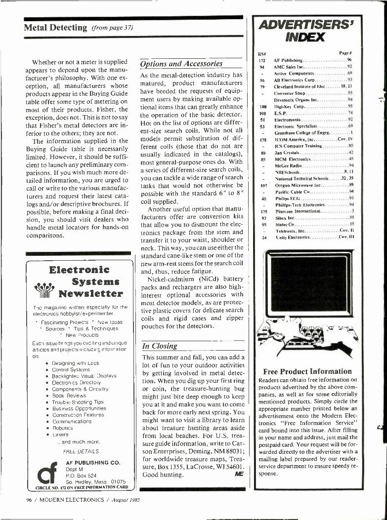
Metal Detecting (from page 37)
Whether or not a meter is supplied appears to depend upon the manu- facturer's philosophy. With one ex- ception, all manufacturers whose products appear in the Buying Guide table offer some type of metering on most of their products. Fisher, the exception, does not. This is not to say that Fisher's metal detectors are in- ferior to the others; they are not.
The information supplied in the Buying Guide table is necessarily limited. However, it should be suffi- cient to launch any preliminary com- parisons. If you wish much more de- tailed information, you are urged to call or write to the various manufac- turers and request their latest cata- logs and /or descriptive brochures. If possible, before making a final deci- sion, you should visit dealers who handle metal locators for hands -on comparisons.
Electronic tit. Systems rr Newsletter
The magazine written especially for the
electronics hobbyist /experimenter.
' Fascinating Projects * New Ideas
Sources Tips & Techniques New Products
Each issue brings you exciting and unique articles and projects including information on:
Designing with Leds
Control Systems Backlighted Visual Displays Electronics Directory Components & Circuitry Book Reviews Trouble- Shooting Tips Business Opportunities Construction Features Communications Robotics Lasers
... and much more.
FREE DETAILS
AF PUBLISHING CO. Dept M
P.O. Box 524 So. Hadley, Mass. 01075
CIRCLE NO. 172 ON FREE INFORMATION CARD
Options and Accessories
96 / MODERN ELECTRONICS / August 1985
As the metal- detection industry has matured, product manufacturers have heeded the requests of equip- ment users by making available op- tional items that can greatly enhance the operation of the basic detector. Hot on the list of options are differ- ent -size search coils. While not all
models permit substitution of dif- ferent coils (those that do not are usually indicated in the catalogs), most general -purpose ones do. With a series of different -size search coils, you can tackle a wide range of search tasks that would not otherwise be possible with the standard 6" to 8" coil supplied.
Another useful option that manu- facturers offer are conversion kits that allow you to dismount the elec- tronics package from the stem and transfer it to your waist, shoulder or neck. This way, you can use either the standard cane -like stem or one of the new arm -rest stems for the search coil and, thus, reduce fatigue.
Nickel- cadmium (NiCd) battery packs and rechargers are also high - interest optional accessories with most detector models, as are protec- tive plastic covers for delicate search coils and rigid cases and zipper pouches for the detectors.
In Closing This summer and fall, you can add a lot of fun to your outdoor activities by getting involved in metal detec- tion. When you dig up your first ring or coin, the treasure -hunting bug might just bite deep enough to keep you at it and make you want to come back for more early next spring. You might want to visit a library to learn about treasure hunting areas aside from local beaches. For U.S. trea- sure guide information, write to Car- son Enterprises, Deming, NM 88031; for worldwide treasure maps, Trea- sure, Box 1355, LaCrosse, WI 54601. Good hunting.
ADVERTISERS' I
INDEX RS# Page #
172 AF Publishing 96
94 AMC Sales Inc 92
Active Components 69
56 All Electronics Corp 93
79 Cleveland Institute of Elec 18, 21
Converter Shop 55
Devtronix Organs Inc 94
100 Digi -Key Corp 95
108 E.S.P. 74
51 Electromania 92
53 Electronic Specialists 69
Grantham College of Engrg 1
178 ICOM America, Inc Coy. IV
ICS Computer Training 85
80 Jan Crystals 42
85 MCM Electronics 45
McGee Radio 94
NRI Schools 8,11
National Technical Schools 32, 35
107 Oregon Microwave Inc 89
Pacific Cable Co 94
40 Philips ECG 91
Phillips -Tech Electronics 94
175 Pinecom International 3
93 Sibex Inc 55
95 Sintec Co 15
Tektronix, Inc Coy. Il 24 Unity Electronics Cov. III
Free Product Information Readers can obtain free information on products advertised by the above com- panies, as well as for some editorially mentioned products. Simply circle the appropriate number printed below an advertisement onto the Modern Elec- tronics "Free Information Service" card bound into this issue. After filling in your name and address, just mail the postpaid card. Your request will be for- warded directly to the advertiser with a
mailing label prepared by our reader - service department to ensure speedy re-
sponse.
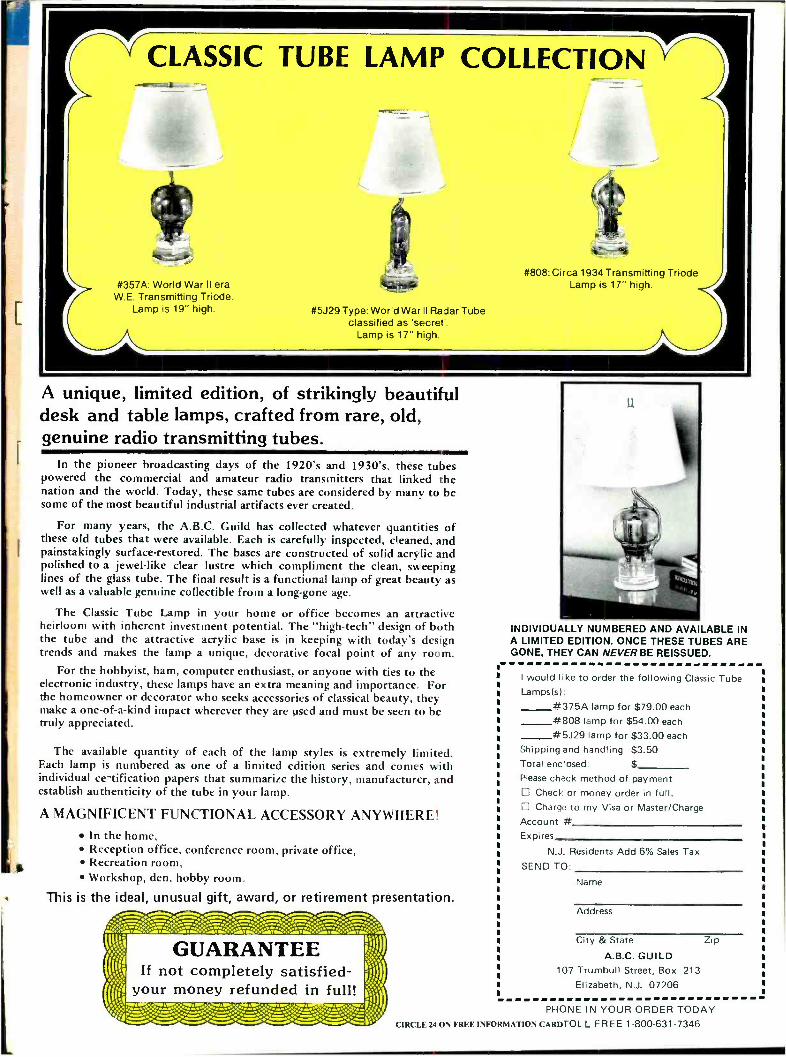
GUARANTEE If not completely satisfied-
1 your money refunded in full! 4 'll1j
CLASSIC TUBE LAMP COLLECTION
#357A: World War II era W.E. Transmitting Triode.
Lamp is 19" high.
#808: Circa 1934 Transmitting Triode Lamp is 17" high.
#5J29 Type: World War II Radar Tube classified as 'secret'.
Lamp is 17" high.
A unique, limited edition, of strikingly beautiful desk and table lamps, crafted from rare, old, genuine radio transmitting tubes.
In the pioneer broadcasting days of the 1920's and 1930's, these tubes powered the commercial and amateur radio transmitters that linked the nation and the world. Today, these same tubes are considered by many to be some of the most beautiful industrial artifacts ever created.
For many years, the A.B.C. Guild has collected whatever quantities of these old tubes that were available. Each is carefully inspected, cleaned, and painstakingly surface- restored. The bases are constructed of solid acrylic and polished to a jewel -like clear lustre which compliment the clean, sweeping lines of the glass tube. The final result is a functional lamp of great beauty as well as a valuable genuine collectible from a long -gone age.
The Classic Tube Lamp in your home or office becomes an attractive heirloom with inherent investment potential. The "high- tech" design of both the tube and the attractive acrylic base is in keeping with today's design trends and makes the lamp a unique, decorative focal point of any room.
For the hobbyist, ham, computer enthusiast, or anyone with ties to the electronic industry, these lamps have an extra meaning and importance. For the homeowner or decorator who seeks accessories of classical beauty, they make a one -of -a -kind impact wherever they are used and must be seen to be truly appreciated.
The available quantity of each of the lamp styles is extremely limited. Each lamp is numbered as one of a limited edition series and comes with individual ce-tification papers that summarize the history, manufacturer, and establish authenticity of the tube in your lamp.
A MAGNIFICENT FUNCTIONAL ACCESSORY ANYWHERE! In the home, Reception office, conference room, private office, Recreation room, Workshop, den, hobby room.
This is the ideal, unusual gift, award, or retirement presentation.
INDIVIDUALLY NUMBERED AND AVAILABLE IN A LIMITED EDITION. ONCE THESE TUBES ARE GONE, THEY CAN NEVER BE REISSUED.
I would like to order the following Classic Tube Lamps(s):
#375A lamp for $79.00 each
#808 lamp for $54.00 each
#5J29 lamp for $33.00 each
Shipping and handling $3.50 Total enclosed: $
Please check method of payment Check or money order in full. Charge to my Visa or Master /Charge
Account # Expires
N.J. Residents Add 6% Sales Tax
SEND TO:
Name
Address
City & State
A.B.C. GUILD 107 Trumbull Street, Box 213
Elizabeth, N.J. 07206
Zip
PHONE IN YOUR ORDER TODAY CIRCLE 24 ON FREE INFORMATION CARDTOL L FREE 1 -800- 631 -7346
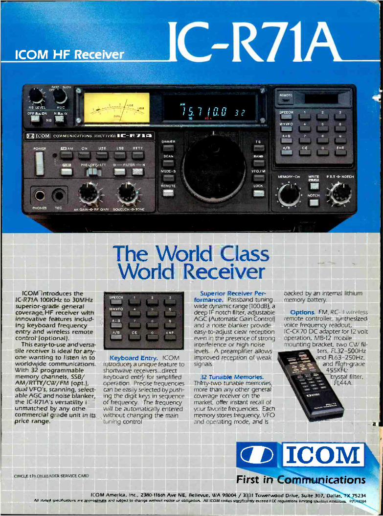
ICOM
ICOM HF Receiver
OFF LON NLW ® NB ® i ICOM] COMMUNICATIONS RECEIVE,t C R 11Fa
rur.c PRENOFFIATT W-FILTER-N
i'`bI 1 R 7 4 1
M
/ \ / \ AF GAIN -} RE GAIN SOUELCH 31-TONE. PHONES REC
DIMMER
SCAN
MODE -S
REMOTE
TS
BAND
VFO /M
LOCK
MEMORY -CH
NOTCH
ICOM introduces the IC -R71A 100KHz to 30MHz superior -grade general coverage HF receiver with innovative features includ- ing keyboard frequency entry and wireless remote control (optional).
This easy -to-use and versa- tile receiver is ideal for any- one wanting to listen in to worldwide communications. With 32 programmable memory channels, SSB/ AM /RTTY /CW /FM (opt.), dual VFO's, scanning, select- able AGC and noise blanker, the IC- R71A's versatility is unmatched by any other commercial grade unit in its price range.
CIRCLE 178 ON READER SERVICE CARD
The World Class World Receiver
Keyboard Entry. ICOM introduces a unique feature to shortwave receivers...direct keyboard entry for simplified operation. Precise frequencies can be easily selected by push- ing the digit keys in sequence of frequency. The frequency will be automatically entered without changing the main tuning control.
Superior Receiver Per- formance. Passband tuning, wide dynamic range(100dB), a deep IF notch filter, adjustable AGC (Automatic Gain Control) and a noise blanker provide easy -to- adjust clear reception even in the presence of strong interference or high noise levels. A preamplifier allows improved reception of weak signals.
32 Tunable Memories. Thirty-two tunable memories, more than any other general coverage receiver on the market, offer instant recall of your favorite frequencies. Each memory stores frequency, VFO and operating mode, and is
CID
backed by an internal lithium memory battery.
Options. FM, RC -11 wireless remote controller, synthesized voice frequency readout, IC -CK70 DC adapter for 12 volt operation, MB -12 mobile mounting bracket, two CW fil-
ters, FL32 -500Hz and FL63- 250Hz,
and high -grade 455KHz
crystal filter, FL44A.
First in Communications ICOM America, Inc., 2380 -116th Ave NE, Bellevue, WA 98004 / 3331 Towerwood Drive, Suite 307, Dallas, TX 75234
All stated specifications are approximate and subject to change without notice or obligation. All ICOM radios significantly exceed FCC regulations limiting spurious emissions. R71A1084