iecc - residential / irc - energy - international code council
TRANSCRIPT
2019 GROUP B PROPOSED CHANGES TO THE I-CODES ALBUQUERQUE COMMITTEE ACTION HEARINGS
April 28 - May 8, 2019 Albuquerque Convention Center, Albuquerque, NM
IECC - Residential / IRC - Energy
2018-2019 Code Development Cycle, Group B (2019) Proposed Changes to the 2019 International Codes
First Printing
Publication Date: March 2019
Copyright © 2019 by
International Code Council, Inc.
ALL RIGHTS RESERVED. This 2018-2019 Code Development Cycle, Group B (2019) Proposed Changes to the 2019 International Codes is a copyrighted work owned by the International Code Council, Inc. (“ICC”). Without advance written permission from the ICC, no part of this book may be reproduced, distributed, or transmitted in any form or by any means, including, without limitations, electronic, optical or mechanical means (by way of example and not limitation, photocopying, or recording by or in an information storage retrieval system). For information on use rights and permissions, please contact: ICC Publications, 4051 Flossmoor Road, Country Club Hills IL, 60478. Phone 1-888-ICC-SAFE (422-7233).
Trademarks: “International Code Council,” the “International Code Council” logo, “ICC,” the “ICC” logo and other names and trademarks appearing in this book are registered trademarks of the International Code Council, Inc., and/or its licensors (as applicable), and may not be used without permission.
PRINTED IN THE U.S.A.
2019 GROUP B – PROPOSED CHANGES TO THE INTERNATIONAL ENERGY CONSERVATION CODE
INTERNATIONAL ENERGY CONSERVATION COMMITTEE - RESIDENTIAL / INTERNATIONAL RESIDENTIAL CODE -
ENERGY Robert Austin, Chair Code Specialist NJ Department of Community Affairs, Division of Codes and Standards Trenton, NJ
Kirk Nagle, Vice Chair Plan Examiner City of Aurora Aurora, CO
Gina L. Bocra, RA Chief Sustainability Officer New York Department of Buildings New York, NY
Bridget Herring Energy Programs Coordinator City of Asheville Asheville, NC
Jim Meyers, CGP Director Building Efficiency Programs Southwest Energy Efficiency Project (SWEEP) Boulder, CO
Robert Parks Rep: National Association of Home Builders Healthy Homes of Louisiana, LLC West Monroe, LA
Dean Potter Vice President, Home Production & Quality Assurance Processes K. Hovnanian® Companies, LLC. Matawan, NJ
Richard Potts II, CBO Code Development and Technical Support Administrator Virginia Department of Housing Community Development Richmond, VA
Scott Roeber, RA Architect/Principal Hudson Valley Architecture, PLLC Saugerties, NY
Gil Rossmiller Plans Examiner Colorado Code Consulting, LLC Denver, CO
Lee Schwartz Rep: National Association of Home Builders Executive Vice President for Governmental Relations Home Builders Association of Michigan Lansing, MI
Jim Zengel, CGB, CGP Rep: National Association of Home Builders President Zengel Group Dayton, OH
Staff Secretariat: Michelle Britt, LEED AP Director, Energy Programs Technical Services International Code Council ICC Field Office-Boise Boise, Idaho
Kermit Robinson Senior Technical Staff International Code Council Western Regional Office Brea, CA
ICC COMMITTEE ACTION HEARINGS ::: April, 2019 RE1
TENTATIVE ORDER OF DISCUSSION 2019 PROPOSED CHANGES TO THE
INTERNATIONAL ENERGY CONSERVATION CODE – RESIDENTIAL
AND INTERNATIONAL RESIDENTIAL CODE - ENERGY
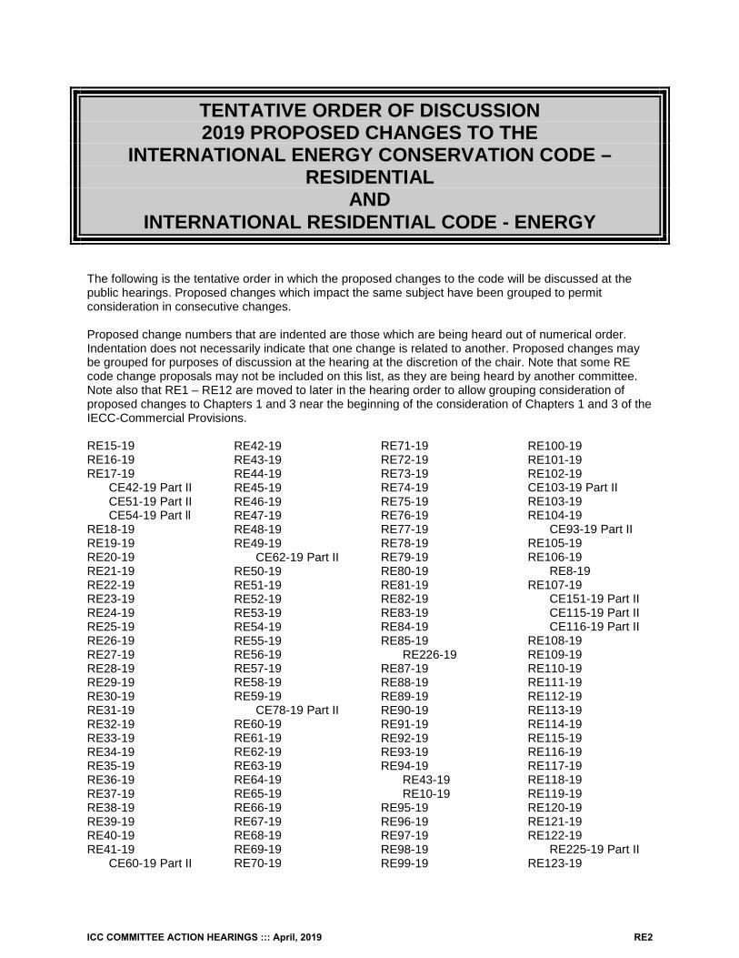
The following is the tentative order in which the proposed changes to the code will be discussed at the public hearings. Proposed changes which impact the same subject have been grouped to permit consideration in consecutive changes.
Proposed change numbers that are indented are those which are being heard out of numerical order. Indentation does not necessarily indicate that one change is related to another. Proposed changes may be grouped for purposes of discussion at the hearing at the discretion of the chair. Note that some RE code change proposals may not be included on this list, as they are being heard by another committee. Note also that RE1 – RE12 are moved to later in the hearing order to allow grouping consideration of proposed changes to Chapters 1 and 3 near the beginning of the consideration of Chapters 1 and 3 of the IECC-Commercial Provisions.
RE15-19 RE16-19 RE17-19
CE42-19 Part II CE51-19 Part II CE54-19 Part ll
RE18-19 RE19-19 RE20-19 RE21-19 RE22-19 RE23-19 RE24-19 RE25-19 RE26-19 RE27-19 RE28-19 RE29-19 RE30-19 RE31-19 RE32-19 RE33-19 RE34-19 RE35-19 RE36-19 RE37-19 RE38-19 RE39-19 RE40-19 RE41-19
CE60-19 Part II
RE42-19 RE43-19 RE44-19 RE45-19 RE46-19 RE47-19 RE48-19 RE49-19
CE62-19 Part II RE50-19 RE51-19 RE52-19 RE53-19 RE54-19 RE55-19 RE56-19 RE57-19 RE58-19 RE59-19
CE78-19 Part II RE60-19 RE61-19 RE62-19 RE63-19 RE64-19 RE65-19 RE66-19 RE67-19 RE68-19 RE69-19 RE70-19
RE71-19 RE72-19 RE73-19 RE74-19 RE75-19 RE76-19 RE77-19 RE78-19 RE79-19 RE80-19 RE81-19 RE82-19 RE83-19 RE84-19 RE85-19
RE226-19 RE87-19 RE88-19 RE89-19 RE90-19 RE91-19 RE92-19 RE93-19 RE94-19
RE43-19 RE10-19
RE95-19 RE96-19 RE97-19 RE98-19 RE99-19
RE100-19 RE101-19 RE102-19 CE103-19 Part II RE103-19 RE104-19
CE93-19 Part II RE105-19 RE106-19
RE8-19 RE107-19
CE151-19 Part II CE115-19 Part II CE116-19 Part II
RE108-19 RE109-19 RE110-19 RE111-19 RE112-19 RE113-19 RE114-19 RE115-19 RE116-19 RE117-19 RE118-19 RE119-19 RE120-19 RE121-19 RE122-19
RE225-19 Part II RE123-19
ICC COMMITTEE ACTION HEARINGS ::: April, 2019 RE2
CE150-19 Part II RE124-19 RE125-19
CE159-19 Part II RE126-19 RE127-19 RE128-19
P1-19 RE129-19 RE130-19 RE131-19 RE132-19 Part I RE132-19 Part II RE133-19 RE134-19 RE135-19 RE136-19 RE137-19 RE138-19 RE139-19 RE140-19 RE141-19 RE142-19 RE143-19
CE160-19 Part II RE144-19 RE145-19
RE7-19 RE146-19 RE147-19
CE217-19 Part II RE148-19 RE149-19 RE150-19 RE151-19 RE152-19 RE153-19 RE154-19 RE155-19 RE156-19 RE157-19 RE158-19 RE159-19 RE160-19 RE161-19
CE248-19 Part II RE162-19 RE163-19 RE164-19 RE165-19 RE166-19 RE167-19 RE168-19 RE169-19 RE170-19 RE171-19
RE172-19 RE173-19 RE174-19 RE175-19 RE176-19 RE177-19 RE178-19 RE179-19 RE180-19 RE181-19 RE182-19 RE183-19 RE184-19 RE185-19 RE186-19 RE187-19 RE188-19 RE189-19 RE190-19 RE191-19 RE192-19 RE193-19 RE194-19 RE195-19 RE196-19 RE197-19 RE198-19 RE199-19 RE200-19 RE201-19 RE202-19 RE203-19 RE204-19 RE205-19 RE206-19 RE207-19 RE208-19 RE209-19 RE210-19 RE211-19 RE212-19 RE213-19 RE214-19 RE215-19 RE216-19 RE217-19
CE251-19 Part ll CE253-19 Part II
RE218-19 RE219-19 RE220-19 RE221-19 RE222-19
ADM43-19 Part IV RE223-19
CE259-19 Part II
RE224-19 Part ll CE1-19 Part I ADM9-19 Part III ADM10-19 Part IV ADM46 Part IV CE3-19 Part II CE4-19 Part I CE5-19 Part II CE6-19 Part II CE7-19 Part Il CE8-19 Part II CE9 -19 Part II CE10-19 Part II RE1-19 CE11-19 Part II CE12-19 Part II CE13-19 Part II CE15-19 Part II RE2-19 ADM33-19 Part III RE3-19 CE16-19 Part II ADM31-19 Part III CE17-19 Part II ADM41-19 Part IV ADM40-19 Part IV CE18-19 Part II CE20-19 Part II CE19-19 Part II RE4-19 CE23-19 Part II CE22-19 Part ll RE5-19 CE29-19 Part ll CE30-19 Part II CE31-19 Part II CE28-19 Part II RE9-19 Part I RE6-19 CE32-19 Part II ADM5-19 Part III CE34-19 Part II CE36-19 Part ll CE37-19 Part II RE12-19 RE11-19 CE40-19 Part II RE13-19 RE14-19
ICC COMMITTEE ACTION HEARINGS ::: April, 2019 RE3
ICC International Code Council, Inc.500 New Jersey Avenue NW 6th Floor
Washington DC 20001
RE1-19IECC: R102.1.1 (IRC N1101.4), Chapter 6RE (IRC Chapter 44)
Proponent: Craig Conner, representing self ([email protected])
2018 International Energy Conservation CodeRevise as follows:
R102.1.1 (IRC N1101.4) Above code programs. The code official or other authority having jurisdiction shall be permitted to deem a national, stateor local energy-efficiency program to exceed the energy efficiency required by this code. Buildings approved in writing by such an energy-efficiencyprogram shall be considered to be in compliance with this code. The requirements identified as “mandatory” in Chapter 4 shall be met. Buildings withwritten documentation of compliance with ICC 700 at the silver level or above shall be deemed to comply with this code.
Add new text as follows:
700-15: National Green Building Standard
Reason: This adds the specific option for ICC's above code green standard for residences, the National Green Building Standard. ICC 700 has itsown “mandatory” items. Citing ICC 700 in code will mean code enforecment will not need to verify that this above code standard meets code.
Bibliography: http://www.nahbclassic.org/form.aspx?formID=18173
Cost Impact: The code change proposal will decrease the cost of constructionThis is an option and therefore will not affect cost unless it is chosen. For some this may be a less expesive option, especially if they are choosing tobe in compliance with ICC 700
Analysis: The referenced standard, ICC 700-2015, is currently referenced in other 2018 I-codes.
Proposal # 5505
RE1-19
ICC COMMITTEE ACTION HEARINGS ::: April, 2019 RE4
RE2-19IECC: R103.2.2 (IRC N1101.5.2) (New)
Proponent: Robby Schwarz, EnergyLogic, representing EnergyLogic ([email protected])
2018 International Energy Conservation CodeR103.2 (IRC N1101.5) Information on construction documents. Construction documents shall be drawn to scale on suitable material. Electronicmedia documents are permitted to be submitted where approved by the code official. Construction documents shall be of sufficient clarity to indicatethe location, nature and extent of the work proposed, and show in sufficient detail pertinent data and features of the building, systems and equipmentas herein governed. Details shall include the following as applicable:
1. Insulation materials and their R-values.2. Fenestration U-factors and solar heat gain coefficients (SHGC).3. Area-weighted U-factor and solar heat gain coefficients (SHGC) calculations.4. Mechanical system design criteria.5. Mechanical and service water-heating systems and equipment types, sizes and efficiencies.6. Equipment and system controls.7. Duct sealing, duct and pipe insulation and location.8. Air sealing details.
R103.2.1 (IRC N1101.5.1) Building thermal envelope depiction. The building thermal envelope shall be represented on the constructiondocuments.
Add new text as follows:
R103.2.2 (IRC N1101.5.2) Vapor management declaration. A vapor management strategy shall be documented on the construction documents.The following shall be addressed:
1. Type and class of vapor retarder used throughout the building, or listed per assembly, to manage moisture migration via diffusion as requiredby Section R402.1.1.
2. Vapor retarder installation scope of work to ensure proper installation.3. Whole house ventilation strategy to be used in accordance with Section R403.6 and Section M1505.3 of the International Residential Code to
ensure background ventilation moisture control.4. Spot/local exhaust ventilation strategy to be used in accordance with Section M1505.4.4 of the International Residential Code to
manage/remove moisture as it is created5. Flashing and weather resistant barrier type and installation details.
Reason: Currently the IRC allows one of three vapor retarder strategies to be used in a residential dwelling unit all of which require different levels ofinstallation execution and coordination with the rest of the structure and systems that are built and the energy code features that are required by theIECC. In addition, the three strategies only address diffusion which is one of two means of moisture transport that is occurring in a dwelling unit.Moisture moves in a house by diffusion (which the vapor retarder addresses) but also with air. How we expect to control these two moisturetransport mechanisms should be made prominent on the plan set to create more efficient and durable structures. This is especially true since moremoisture flows into building assemblies through air transport than by the process of diffusion. This code change proposal promotes a subtle shift inour thinking to understand that moisture management is a combination of components and systems working together to protect the building frommoisture related failures.In the prescriptive section R402.1.1 Vapor retarders are required to be installed and the section refers you to the IRC and the IBC. Vapor Retardersdiscussed in these sections are an important part of gaining control and predictability of the moisture movement within a dwelling unit, but there is achoice that must be made as to which class of retarder will be installed. The installation of class 1 versus class 3 vapor retarder is significantlydifferent and impacts the efficiency and durability of the structure differently.
This declaration will drive moisture management considerations into the design process resulting in assemblies that will be more moisture resistantand more efficient.
The scope of work requirement will better ensure that especially class 1 vapor retarders are installed to limit the ability of air and moisture frombypassing them and being trapped within assemblies. Is should also create a better understanding of where a class 1 vapor retarder should orshould not be installed in different climate zones. For example, in climate zone 5 along the front range in Colorado we often see unsealed class 1vapor retarders (6 mil poly) installed behind drywall on exterior walls, but no vapor retarder installed in other parts of the exterior wall assembly suchas rim joist or exterior walls in bathrooms. This declaration would elevate the inconsistency of placement of vapor retarders as their installationwould be more clearly thought out on the plan set than it has ever been in the past.
Whole house and spot/local ventilation are another important part of the moisture management strategy. From a whole house ventilation perspective,the code gives three choices of strategies that can be used, some of which work better in certain climate zones than others. The vapor
ICC COMMITTEE ACTION HEARINGS ::: April, 2019 RE5
management declaration, would bring the decision on systems that will be installed to the fore font for review by the plans examiner allowing forconversation prior to building the structure.
Cost Impact: The code change proposal will increase the cost of constructionThere would be a small cost increase associated with this proposal as the proposal merely brings existing requirements together to be reported onthe plan set. I estimate that this would require no more than 1 hour of time of the designer or architect. Approximately $100 - $200.
Proposal # 4536
RE2-19
ICC COMMITTEE ACTION HEARINGS ::: April, 2019 RE6
RE3-19IECC: R105.2.5
Proponent: Marilyn Williams, representing NEMA ([email protected])
2018 International Energy Conservation CodeRevise as follows:
R105.2.5 Final inspection. The building shall have a final inspection and shall not be occupied until approved. The final inspection shall includeverification of the installation of all required building systems, equipment and controls and their proper operation and the required number efficacy ofhigh-efficacy lamps luminaires and fixtures. lamps.
Reason: 1. Increase energy efficiency2. Reduce inconsistency and application confusion in compliance
3. Increase code interpretation and usability
4. Resolve compliance with application, approval and inspection
Another proposal has been submitted concerning Section R404.1 Lighting equipment (Mandatory)
Cost Impact: The code change proposal will not increase or decrease the cost of constructionToday's cost to use the more efficient LED lamps and luminaires is now equal to or lower than the cost of CFL lamps.
Proposal # 4551
RE3-19
ICC COMMITTEE ACTION HEARINGS ::: April, 2019 RE7
RE4-19IECC: R202 (IRC N1101.6)(New)
Proponent: John Woestman, representing Extruded Polystyrene Foam Association ([email protected])
2018 International Energy Conservation Code
SECTION R202 (IRC N1101.6) GENERAL DEFINITIONS
Add new definition as follows:
CAVITY INSULATION. Insulating material located between framing members.
Reason: The purpose of this proposal is to coordinate with the definition in IECC-C by adding a definition to IECC-R for cavity insulation tocomplement the existing definition for continuous insulation. Cavity insulation and continuous insulation relate to the location of insulation materials,not specific material types. Adding this definition will help clarify the code in regard to terms used to explain where insulation components are islocated.
Cost Impact: The code change proposal will not increase or decrease the cost of constructionThe proposal only provides a new definition without any material change to the code or costs of compliance. There should be no cost implications.
Proposal # 5244
RE4-19
ICC COMMITTEE ACTION HEARINGS ::: April, 2019 RE8
RE5-19IECC: R202 (IRC N1101.6)(New)
Proponent: Amanda Hickman, The Hickman Group, representing Reflective Insulation Manufacturers Association International([email protected])
2018 International Energy Conservation Code
SECTION R202 (IRC N1101.6) GENERAL DEFINITIONS
Add new definition as follows:
EMITTANCE. The ratio of the radiant heat flux emitted by a specimen to that emitted by a blackbody at the same temperature and under the sameconditions.
Reason: This definition is needed because the term emittance is used in various sections of the code and in the definition for radiant barrier andreflective insulation. It is consistent with the definition found in the 2021 IBC, ASHRAE and ASTM standards.The term emittance is used in numerous sections of this code including for: Building Envelope Requirements, Equipment Buildings, Roof SolarReflectance and Thermal Emittance, Minimum Roof Reflectance and Emittance Options, Specifications for the Standard Reference and ProposedDesigns, Roofs, and for Specifications for the Standard Reference and Proposed Designs, Walls above-grade.
Cost Impact: The code change proposal will not increase or decrease the cost of constructionAdding a definition of EMITTANCE will neither increase or decrease construction costs. This is only a definition and is identical to the definition foundin the 2021 IBC and existing ASHRAE and ASTM standards.
Proposal # 4106
RE5-19
ICC COMMITTEE ACTION HEARINGS ::: April, 2019 RE9
RE6-19IECC: R202 (IRC N1101.6)
Proponent: Jennifer Hatfield, representing American Architectural Manufacturers Association ([email protected])
2018 International Energy Conservation Code
SECTION R202 (IRC N1101.6) GENERAL DEFINITIONS
Revise as follows:
FENESTRATION. Products classified as either vertical fenestration or skylights.Skylights. Glass or other transparent or translucent glazing material installed at a slope of less than 60 degrees (1.05 rad) from horizontal,
including unit skylights, tubular daylighting devices, and glazing materials in solariums, sunrooms, roofs and sloped walls.
Vertical fenestration. Windows that are fixed or operable, opaque doors, glazed doors, glazed block and combination opaque/glazed doorscomposed of glass or other transparent or translucent glazing materials and installed at a slope of not less than 60 degrees (1.05 rad) fromhorizontal.
Reason: This revision clarifies the types of products that are included in the category of "skylights" and brings the IECC Residential definition inalignment with what is in the 2018 IECC Commercial definition for "skylights" along with providing consistency with the second sentence found in thedefinition of "skylights and sloped glazing" in the IRC and IBC.The intent of this change, which was accepted into the 2018 IECC Commercial, IBC and IRC definitions, was to clarify what constitutes skylights andsloped glazing, and to specifically clarify that tubular daylighting devices are to be included within that definition. This clarification is importantbecause all fenestration, both vertical and skylights and sloped glazing, are required to be installed in such a manner as to preserve the integrity ofthe wall or roof.
Approval of this proposal will clarify that tubular daylighting devices are to be installed in such a manner as to preserve the weather resitant barrier ofthe roof in residential construction and ensure alignment with the other codebook definitions.
Bibliography: 2018 IECC, Section C202, Skylights; 2018 IBC, Section 202, [BS] Skylights and Sloped Glazing; and 2018 IRC, Section R202, [RB]Skylights and Sloped Glazing
Cost Impact: The code change proposal will not increase or decrease the cost of constructionThe proposal will not increase the cost of construction and simply clarifies which products fall under the category of "skylights" and by default, whichdo not. There will not be an impact to the cost of construction.
Proposal # 5246
RE6-19
ICC COMMITTEE ACTION HEARINGS ::: April, 2019 RE10
RE7-19IECC: R202 (IRC N1101.6), R404.1 (IRC N1104.1)
Proponent: Eric Makela, New Buildings Institute, representing New Buildings Institute ([email protected])
2018 International Energy Conservation Code
SECTION R202 (IRC N1101.6) GENERAL DEFINITIONS
Revise as follows:
HIGH-EFFICACY LAMPS. LIGHT SOURCES. Compact fluorescent lamps, light-emitting diode (LED) lamps, T-8 or smaller diameter linearfluorescent lamps, or other lamps with an efficacy of not less than the following: 65 lumens per watt, or luminaires with an efficacy of not less than 45lumens per watt.
1. 1.60 lumens per watt for lamps over 40 watts.2. 2.50 lumens per watt for lamps over 15 watts to 40 watts.3. 3.40 lumens per watt for lamps 15 watts or less.
R404.1 (IRC N1104.1) Lighting equipment (Mandatory). Not less than 90 percent of the permanently installed lighting fixtures shall contain onlyhigh-efficacy lamps.lighting sources.
Reason: The lighting section includes a requirement for a minimum percentage of "high efficiency lamps." However, the definition of "high efficacylamps" has not been updated to reflect the changes in the market due to increased federal minimums and greater availability/affordability of LEDlighting. Because of this, the code is actually becoming less stringent as the baseline for lighting equipment is raised.The proposal solves this problem by updating the definitions with lighting requirements that reflect what is actually "high-efficacy" in today's market.The proposal also simplifies the definition by reducing the number of wattage categories. The categories in the residential code are an artifact ofincandescent and early compact fluorescent lamp wattages. As lamps have gotten more efficient, the higher wattage categories have become lessmeaningful. As lamps have gotten more efficient, the higher wattage categories have become less meaningful. Even a “100W equivalent” LED lampand “60W equivalent” CFL lamps generally uses 15W or less, which is the lower category in the existing definition. As a result, the categories havebecome largely meaningless.
The proposal also accommodates high efficacy luminaires. Many luminaires on the market do not include lamps and include integrated LEDsinstead. The way the current code language is written, these efficient lighting products cannot be used to meet the lighting efficiency requirements inthe code. The proposal changes the term in the definition to be more inclusive, adds an efficacy requirement for integrated luminaires, and updatesthe code language to reflect this update.
Cost Impact: The code change proposal will increase the cost of constructionThis change could potentially increase the cost of construction because it requires higher efficacy lighting (lamps and/or fixtures), which will likelyeliminate some lower-end CFL options and/or push builders to newer LED technologies. However, the cost of LEDs has been steadily declining overthe last several years and is expected to continue to decline. Based on an analysis by the U.S. Department of Energy’s Building Energy CodesProgram conducted during the 2018 IECC Code Development cycle, the estimated and projected prices for LEDs were $4.84 per lamp compared toCFLs at $3.10 per lamp. However, the rapid expansion of the LED lighting market has changed the economics. A spot check of Home Depot in early2019 showed that a warm white, 60W equivalent A-lamp is as low as $1.24 for both CFL and LED when purchased in packs. And, LEDs are actuallycheaper than CFLs at some sources. At 1000bulbs.com, on online retailer, the same lamps are $1.79/bulb for CFL and $0.99 for LED. Therefore,this code change may actually reduce the cost of construction.
Proposal # 5184
RE7-19
ICC COMMITTEE ACTION HEARINGS ::: April, 2019 RE11
RE8-19IECC: R202 (IRC N1101.6), R105.2.4, R403.1.1 (IRC N1103.1.1)
Proponent: Sharon Bonesteel, representing Salt River Project ([email protected]); John Umphress([email protected])
2018 International Energy Conservation Code
SECTION R202 (IRC N1101.6) GENERAL DEFINITIONS
Add new definition as follows:
PROGRAMMABLE COMMUNICATING THERMOSTAT. A whole building or dwelling unit thermostat that can be monitored and controlledremotely.
SECTION R105 INSPECTIONS
Revise as follows:
R105.2.4 Mechanical rough-in inspection. Inspections at mechanical rough-in shall verify compliance as required by the code and approvedplans and specifications as to installed HVAC equipment type and size, required controls, system insulation and corresponding R-value, system airleakage control, programmable communicating thermostats, dampers, whole-house ventilation, and minimum fan efficiency.
Exception: Systems serving multiple dwelling units shall be inspected in accordance with Section C105.2.4.
SECTION R403 (IRC N1103) SYSTEMS
R403.1.1 (IRC N1103.1.1) Programmable communicating thermostat. The thermostat controlling the primary heating or cooling system of thedwelling unit shall be capable of communicating with sources external to the HVAC system and function as a basic thermostat in the absence ofcommunicating with external sources. The thermostat shall be capable of controlling the heating and cooling system on a daily schedule to maintaindifferent temperature set points at different times of the day. This The thermostat shall include the capability to set back or temporarily operate thesystem and provide remote access to maintain zone temperatures of not less than 55°F (13°C) to not greater than 85°F (29°C). The thermostatshall be programmed initially by the manufacturer with a heating temperature setpoint of not greater than 70°F (21°C) and a cooling temperaturesetpoint of not less than 78°F (26°C).
Exception: Heating and cooling systems with proprietary internal thermostat communication functions.
Reason: Reason: This proposal adds a requirement for residential buildings to provide a communicating programmable thermostat. Communicatingthermostats have become commonplace and are available from electronic stores to home improvement stores increasing brand awareness andlarge growth with installations in existing residential buildings.The U.S. EPA Energy Star website lists a large number of connected and smart thermostats and product manufacturers continue to add moredevices and improve the depth of price points for these thermostats.
As home automation has increased in homes new products have been released that allow for occupant comfort, ease of use, convenience, securityand simplicity in use. Sales of home automation products and services are projected to continue exponential growth. The use of a connectedthermostat can provide energy savings for the occupants and support utilities with their demand programs if the occupant chooses to participate.
Many studies have taken place across the U.S. on these newer thermostat devices and energy savings has been seen in the study results. Ifactual savings are only a fraction of the study savings, the payback period is very short.
This proposal also retains some requirements from the programmable thermostat requirements in the 2018 IECC. The term and definition“programmable communicating thermostat” is taken from ICC700- National Green Building Standard (NGBS).
The exception allows use of non-connected thermostats if heating or cooling system requires a proprietary control or don’t support all of thefunctionality of the heating or cooling system.
This proposal is modeled after Austin, Texas energy code amendment for connected thermostats.
Potential savings opportunities:
ICC COMMITTEE ACTION HEARINGS ::: April, 2019 RE12
The technical energy savings potential of these individual approaches ranges from 0.3 to 1.1 quads, or 1-5% of the total primary energy consumedby U.S. homes in 2015. Put another way, saving one quad per year is equivalent to the energy consumed by about 3 million people, the electricityproduced by 250 coal fired power plants or 56 million metric tons (MMT) of CO2 emissions (DOE 2012) - Fraunhofer USA Center for SustainableEnergy Systems
The Florida PDR project showed average cooling energy savings of 9.6% (498 kWh/year), but with a very high degree of variation. Median savingswere 6.3% (219 kWh/year). Particularly given the very short Florida winter heating season. Average savings were 9.5% (39kWh/year) although themedian was higher, at 18.5% (35 kWh/year). Space heating savings from the Nest ….. average savings were 9.5% (39kWh/year) although themedian was higher, at 18.5% (35 kWh/year). – Florida Solar Energy Center
6% heating savings and 14% cooling savings - 2015 AESP Conference
Average annual gas savings per home as high at 6.0% - Energy Trust of Oregon
Bibliography: Bibliography:1. Fraunhofer USA Center for Sustainable Energy Systems - "Energy Savings from Five Home Automation Technologies" April 2016,
https://bit.ly/2C9Jc2z2. Florida Solar Energy Center - 2016 ACEEE Summer Study on Energy Efficiency in Buildings - “Evaluation of the Space Heating and Cooling
Energy Savings of Smart Thermostats in a Hot-Humid Climate using Long-term Data” https://bit.ly/2Fmx0io3. AESP Conference February 2015 - Cadmus Presentation – C. Aarish – “Wi-Fi Connected Thermostats” show 6% heating savings and 14%
cooling savings”4. Nest Learning Thermostat Pilot Program Savings Assessment, Bonneville Power Administration & Franklin Public Utility District, November
2016, https://bit.ly/2ADdN8Z5. Energy Trust of Oregon, Apex Analytics - Smart Thermostat Pilot Evaluation, March 2016, https://bit.ly/2Ri6gGN6. CLEAResult - Smart Thermostats, June 2015, https://bit.ly/2sk6ZbI7. Cadmus – NIPSCO Indiana pilot study, 2014, https://bit.ly/2RkWq7e
Cost Impact: The code change proposal will increase the cost of constructionCost Impact: A builder entry communicating programmable thermostat can add $50+ over the cost of a typical weekly programmable thermostat.Cost information available at many online retailers comparing weekly programmable thermostats to connected thermostats.
Proposal # 5480
RE8-19
ICC COMMITTEE ACTION HEARINGS ::: April, 2019 RE13
RE9-19 Part IPART I — IECC: Part I: R202 (IRC N1101.6)IRC: Part II: R202
PART II — IRC: R202
Proponent: Donald Sivigny, representing State of MN and Association of Minnesota Building Officials ([email protected])
THIS IS A 2 PART CODE CHANGE. PART I WILL BE HEARD BY THE IECC- RESIDENTIAL COMMITTEE. PART II WILL BE HEARD BY THEIRC BUILDING COMMITTEE. SEE THE TENTATIVE HEARING ORDER FOR THESE COMMITTEES.
2018 International Energy Conservation Code
SECTION R202 (IRC N1101.6) GENERAL DEFINITIONS
Revise as follows:
ROOF RE-COVER. RECOVER. The process of installing an additional roof covering over a prepared an existing roof covering without removingthe existing roof covering.
Proposal # 5367
RE9-19 Part I
ICC COMMITTEE ACTION HEARINGS ::: April, 2019 RE14
RE9-19 Part IIIRC: R202
Proponent: Donald Sivigny, representing State of MN and Association of Minnesota Building Officials ([email protected])
2018 International Residential CodeRevise as follows:
[RB] ROOF RECOVER. The process of installing an additional roof covering over a prepared an existing roof covering without removing theexisting roof covering.
Reason: This simply changing the language in the definition chapter of the IECC-R (and IRC Chapter 11) to be consistent with definition in IECC-C.This is in conjunction with another proposal to change the definition in IRC Chapter 2 in the same manner so that all are uniform for better codecompliance and enforcement.
Cost Impact: The code change proposal will not increase or decrease the cost of constructionAs this is only aligning a definition across multiple codes, there is no change in technical requirements. Thu, there is no impact to constructioncosts.
Proposal # 5765
RE9-19 Part II
ICC COMMITTEE ACTION HEARINGS ::: April, 2019 RE15
RE10-19IECC: R202 (IRC N1101.6) )(New)
Proponent: Hope Medina, representing Self ([email protected])
2018 International Energy Conservation Code
SECTION R202 (IRC N1101.6) GENERAL DEFINITIONS
Add new definition as follows:
SAMPLING. A process where fewer than 100 percent of a builder’s dwellings, dwelling units, or sleeping units are randomly inspected and ortested to evaluate compliance with the requirements of this code.
Reason: This definition is to clarify that the practice of sampling includes more than just blower door testing. The approved third party would havethe opprtunity to sample any requirement of the code in a developement or building. This is a conept that needs to be made apparent to everyonewho uses the code.
Cost Impact: The code change proposal will not increase or decrease the cost of constructionnew definition
Proposal # 5507
RE10-19
ICC COMMITTEE ACTION HEARINGS ::: April, 2019 RE16
RE11-19IECC: R202 (IRC N1101.6)(New), R303.1.1 (IRC N1101.10.1)
Proponent: Amanda Hickman, The Hickman Group, representing Reflective Insulation Manufacturers Association International([email protected])
2018 International Energy Conservation Code
SECTION R202 (IRC N1101.6) GENERAL DEFINITIONS
Add new definition as follows:
ENCLOSED REFLECTIVE AIR SPACE. An unventilated cavity with a low-emittance surface bounded on all sides by building components.
REFLECTIVE INSULATION. A material installed in an assembly consisting of one or more enclosed reflective air spaces with a surfaceemittance of 0.1 or less.
Revise as follows:
R303.1.1 (IRC N1101.10.1) Building thermal envelope insulation. An R-value identification mark shall be applied by the manufacturer to eachpiece of building thermal envelope insulation that is 12 inches (305 mm) or greater in width. Alternatively, the insulation installers shall provide acertification that indicates the type, manufacturer and R-value of insulation installed in each element of the building thermal envelope. For blown-in orsprayed fiberglass and cellulose insulation, the initial installed thickness, settled thickness, settled R-value, installed density, coverage area andnumber of bags installed shall be indicated on the certification. For sprayed polyurethane foam (SPF) insulation, the installed thickness of the areascovered and the R-value of the installed thickness shall be indicated on the certification. For reflective insulation, the number of reflective sheets, thenumber and thickness of the enclosed reflective air spaces and the R-value for the installed assembly, shall be listed on the certification. Forinsulated siding, the R-value shall be on a label on the product’s package and shall be indicated on the certification. The insulation installer shall sign,date and post the certification in a conspicuous location on the job site.
Exception: For roof insulation installed above the deck, the R-value shall be labeled as required by the material standards specified in Table1508.2 of the International Building Code or Table R906.2 of the International Residential Code, as applicable.
Reason: The section at present incorporates requirements that are specific to blown or sprayed fiberglass, cellulose insulation and sprayedpolyurethane foam insulation together with general requirements for thermal envelope insulation materials. However, the code is silent on reflectiveinsulations.The proposal adds specific requirements similar to those for the other insulation materials (as well as appropriate definitions) for a type of material,(reflective insulation) that has been in the market place for over 25 years and has had nationwide distribution and installation. These products arewell established and have two associated ASTM Standards, ASTM C727, Standard Practice for Installation and Use of Reflective Insulation inBuilding Constructions, and ASTM C1224, Standard Specification for Reflective Insulation for Building Applications.
The U.S. Department of Energy’s website on weatherizing homes: https://www.energy.gov/energysaver/weatherize/insulation/types-insulationincludes the advantages of reflective insulation systems. It states that reflective systems are most effective in preventing downward heat flow butthat the effectiveness depends on spacing. This is the critical reason this code change is needed.
Many states and jurisdictional codes already include references on reflective insulation; the list follows:
IBC: 2018 – Section 720, Section 2614
Florida
2017 Florida Building Code, Energy Conservation, 6 Edition
R303.1.1 Building thermal envelope insulationTable R303.2.1 Insulation Installation StandardsR303.2.1.2 Substantial Contact
2017 Florida Building Code, Building, 6 Edition
Section 2614 Reflective Plastic Core InsulationSection 720 Thermal and Sound-Insulating Materials
th
th
ICC COMMITTEE ACTION HEARINGS ::: April, 2019 RE17
Minnesota
2015 Minnesota Building Code
Section 720 Thermal and Sound-Insulating MaterialsSection 2613 Reflective Plastic Core InsulationThermal Insulation Standards 2015, Section 7640.0130, Subpart 7
California
Title 24, 2016, Reference Residential Appendices
RA4.3 Envelope Measures
Cost Impact: The code change proposal will not increase or decrease the cost of constructionThis proposal will not increase the cost of construction because only information regarding reflective insulation is being added.
Proposal # 4105
RE11-19
ICC COMMITTEE ACTION HEARINGS ::: April, 2019 RE18
ASTM ASTM International100 Barr Harbor Drive, P.O. Box C700West Conshohocken, PA 19428-2959
RE12-19IECC: R202 (1101.6) (New), R303.1.1.2 (N1101.10.1.1.2) (New), Chapter 6 (IRC Chapter 44)(New)
Proponent: Amanda Hickman, The Hickman Group, representing Reflective Insulation Manufacturers Association International([email protected])
2018 International Energy Conservation Code
SECTION R202 (IRC N1101.6) GENERAL DEFINITIONS
Add new definition as follows:
RADIANT BARRIER. A material having a low emittance surface of 0.1 or less installed in building assemblies.
Add new text as follows:
R303.1.1.2 (IRC N1101.10.1.1.2) Radiant barrier. Where installed, radiant barriers shall comply with the requirements of ASTM C1313/C1313M andshall have an emittance of 0.1 or less.
Add new standard(s) as follows:
C1313/C1313M-13: Standard Specification for Sheet Radiant Barriers for Building Construction Applications
Reason: This proposal DOES NOT require the use of radiant barriers. But rather requires that WHEN radiant barriers are used, they comply withthe appropriate ASTM standard. Furthermore this proposal provides important information to the code user and code enforcement communityregarding radiant barriers.Radiant barriers are typically installed in attics to reduce summer heat gains through the roof. According to the DOE’s website:https://www.energy.gov/energysaver/weatherize/insulation/radiant-barriers, Radiant barriers help to reduce cooling costs by reducing radiant heatgain. To be effective, radiant barriers are very dependent of their installation because their reflective surface must face an air space.
Radiant barriers follow two ASTM Standards – ASTM C1313/C1313M, "Standard Specification for Sheet Radiant Barriers for Building ConstructionApplications," and ASTM C1743, "Standard Practice for Installation and Use of Radiant Barrier Systems (RBS) in Residential Building Construction".
The proposed language is being included in this section specifically because the American Society for Testing and Materials (ASTM) classifiesradiant barriers as thermal insulation. The ASTM committee C16 on Thermal Insulation includes published standards for this product. SubcommitteeC16.21 deals specifically with reflective products, which include reflective insulation, radiant barrier and interior radiation control coatings. C16.21develops standards and practices for these reflective building material thermal insulating products.
The Federal Trade Commission includes radiant barrier products in “CFR Part 460 Labeling and Advertising of Home Insulation: TradeRegulation Rule”.
Radiant barrier products include a surface with an emittance of 0.1 or less that is installed in roof assemblies or attics with the low-emittance surfacefacing an open or ventilated air space. The low emittance material can be bonded to plastic film, woven fabric, reinforced paper, OSB or plywood.The thermal performance of radiant barriers depends on emittance and location in the attic, wall or roof assembly. Radiant barriers arepredominantly installed in attic spaces below the roof deck. The low-emittance surface of radiant barrier products dramatically reduces the heat gainby radiation into the structure and attic HVAC ducts. For this reason, radiant barriers are especially effective in warm sunny climates where theyprovide reduced use of air conditioning. Radiant barrier products that are available include single-sheet material, multi-layer assemblies and woodsheathing with attached aluminum film or foil. The single sheet material is installed in roof assemblies by attaching directly to the roof deck, inbetween the rafters or trusses or to the underside of the rafters or trusses. The foil-faced sheathing is installed with the low-emittance side of thesheathing or panel facing toward the attic space to create a radiant barrier. Attic radiant barriers are in extensive use. These products have been onthe market for several decades and are used by 87 of the top 100 US Builders. They have an established history and have been accepted intoseveral regional code requirements. Over one billion square feet of the product is being installed annually.
Many state and jurisdictional codes already include references on radiant barriers. These are the state and city codes that include radiant barrier:
IBC: 2018 Section 1509 Radiant Barriers Installed Above Deck
ICC COMMITTEE ACTION HEARINGS ::: April, 2019 RE19
Hawaii - Chapter 181 of Title 3, 2015, Section 407.2, Table 407.1
Texas
The Code of the City of Austin, Texas, Supplement 1342018, Chapter 25-12, Article 12, Section R402.6
Florida
2017 Florida Building Code, Energy Conservation, 6 Edition
Section 405.7.1 Installation Criteria for homes claiming the radiant barrier optionFigure R405.7.1 Acceptable attic radiant barrier configurationsTable R303.2.1 Insulation Installation Standards
California
Title 24, 2016, Part 6, Subchapter 1, Definition Radiant Barrier
Cost Impact: The code change proposal will not increase or decrease the cost of constructionThis proposal will not increase the cost of construction because it only adds informational language regarding radiant barriers.
Analysis: A review of the standard proposed for inclusion in the code, ASTM C1313/C1313M-2013, with regard to the ICC criteria for referencedstandards (Section 3.6 of CP#28) will be posted on the ICC website on or before April 2, 2019.
Proposal # 4108
RE12-19
th
ICC COMMITTEE ACTION HEARINGS ::: April, 2019 RE20
RE13-19IECC: R303.1.3 (IRC N1101.10.3)
Proponent: Shaunna Mozingo, City of Westminster, representing Colorado Chapter of ICC Energy Code Development Committee([email protected])
2018 International Energy Conservation CodeRevise as follows:
R303.1.3 (IRC N1101.10.3) Fenestration product rating. U-factors of fenestration products such as windows, doors and skylights shall bedetermined in accordance with NFRC 100.
Exception: Where required, garage door U-factors shall be determined in accordance with either NFRC 100 or ANSI/DASMA 105.
U-factors shall be determined by an accredited, independent laboratory, and labeled and certified by the manufacturer.
Products lacking such a labeled U-factor shall be assigned the maximum U factor from Section R402.5. Opaque doors lacking a default U-factorfrom Table R303.1.3(1) or label shall be assigned a default U-factor from Table R303.1.3 (2). The solar heat gain coefficient (SHGC) and visibletransmittance (VT) of glazed fenestration products such as windows, glazed doors and skylights shall be determined in accordance with NFRC 200by an accredited, independent laboratory, and labeled and certified by the manufacturer. Products lacking such a labeled SHGC shall be assignedthe maximum SHGC from Section R402.5.
Exception: For existing buildings complying with Chapter 5, products lacking a labeled U-factor. SHGC or VT shall be assigned a default U-factor, SHGC or VT from Table Tables R303.1.3 (1) through (3).
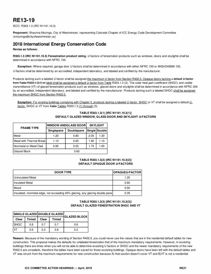
TABLE R303.1.3(1) [IRC N1101.10.3(1)]DEFAULT GLAZED WINDOW, GLASS DOOR AND SKYLIGHT U-FACTORS
FRAME TYPEWINDOW ANDGLASS DOOR SKYLIGHT
Singlepane Doublepane Single Double
Metal 1.20 0.80 2.00 1.30
Metal with Thermal Break 1.10 0.65 1.90 1.10
Nonmetal or Metal Clad 0.95 0.55 1.75 1.05
Glazed Block 0.60
TABLE R303.1.3(2) [IRC N1101.10.3(2)]DEFAULT OPAQUE DOOR U-FACTORS
DOOR TYPE OPAQUEU-FACTOR
Uninsulated Metal 1.20
Insulated Metal 0.60
Wood 0.50
Insulated, nonmetal edge, not exceeding 45% glazing, any glazing double pane 0.35
TABLE R303.1.3(3) [IRC N1101.10.3(3)]DEFAULT GLAZED FENESTRATION SHGC AND VT
SINGLE GLAZED DOUBLE GLAZEDGLAZED BLOCK
Clear Tinted Clear Tinted
SHGC 0.8 0.7 0.7 0.6
VT 0.6 0.3 0.6 0.3
Reason: Because of the mandatory wording of Section R402.5, you could never use the values that are in the residential default tables for newconstruction. This proposal makes the defaults for unlabeled fenestration that of the maximum mandatory requirements. However, in exsistingbuildings there are times when you will not be able to determine exsisting U factors or SHGC and the newer mandatory requirements of the newR402.5 are unrealistic, therefore the tables have been saved for those exsisting buildings. Opaque doors have been left with the default tables andVT was struck from the maximum requirements for new construction because A) that section doesn't cover VT and B)VT is not a residential
ICC COMMITTEE ACTION HEARINGS ::: April, 2019 RE21
requirement anyway.The proposal changes the references to the tables, however the tables remain the same.
Cost Impact: The code change proposal will not increase or decrease the cost of constructionBecause of the mandatory maximums set in R402.5 you could never use these default tables for new construction.
Staff Analysis: TABLE R303.1.3(1) [IRC N1101.10.3(1)] through R303.1.3(3) [IRC N1101.10.3(3)] remain unchanged.
Proposal # 5321
RE13-19
ICC COMMITTEE ACTION HEARINGS ::: April, 2019 RE22
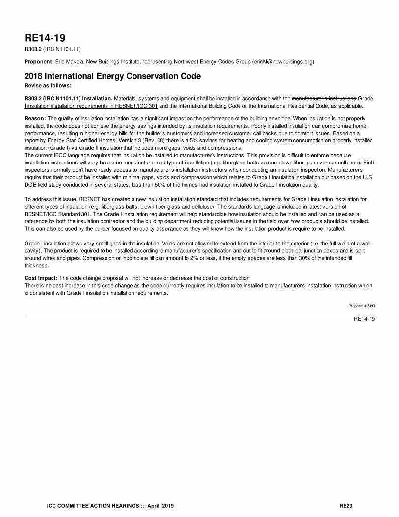
RE14-19R303.2 (IRC N1101.11)
Proponent: Eric Makela, New Buildings Institute, representing Northwest Energy Codes Group ([email protected])
2018 International Energy Conservation CodeRevise as follows:
R303.2 (IRC N1101.11) Installation. Materials, systems and equipment shall be installed in accordance with the manufacturer’s instructions GradeI insulation installation requirements in RESNET/ICC 301 and the International Building Code or the International Residential Code, as applicable.
Reason: The quality of insulation installation has a significant impact on the performance of the building envelope. When insulation is not properlyinstalled, the code does not achieve the energy savings intended by its insulation requirements. Poorly installed insulation can compromise homeperformance, resulting in higher energy bills for the builder’s customers and increased customer call backs due to comfort issues. Based on areport by Energy Star Certified Homes, Version 3 (Rev. 08) there is a 5% savings for heating and cooling system consumption on properly installedinsulation (Grade I) vs Grade II insulation that includes more gaps, voids and compressions.The current IECC language requires that insulation be installed to manufacturer’s instructions. This provision is difficult to enforce becauseinstallation instructions will vary based on manufacturer and type of installation (e.g. fiberglass batts versus blown fiber glass versus cellulose). Fieldinspectors normally don’t have ready access to manufacturer’s installation instructors when conducting an insulation inspection. Manufacturersrequire that their product be installed with minimal gaps, voids and compression which relates to Grade I Insulation installation but based on the U.S.DOE field study conducted in several states, less than 50% of the homes had insulation installed to Grade I insulation quality.
To address this issue, RESNET has created a new insulation installation standard that includes requirements for Grade I insulation installation fordifferent types of insulation (e.g. fiberglass batts, blown fiber glass and cellulose). The standards language is included in latest version ofRESNET/ICC Standard 301. The Grade I installation requirement will help standardize how insulation should be installed and can be used as areference by both the insulation contractor and the building department reducing potential issues in the field over how products should be installed.This can also be used by the builder focused on quality assurance as they will know how the insulation product is require to be installed.
Grade I insulation allows very small gaps in the insulation. Voids are not allowed to extend from the interior to the exterior (i.e. the full width of a wallcavity). The product is required to be installed according to manufacturer’s specification and cut to fit around electrical junction boxes and is splitaround wires and pipes. Compression or incomplete fill can amount to 2% or less, if the empty spaces are less than 30% of the intended fillthickness.
Cost Impact: The code change proposal will not increase or decrease the cost of constructionThere is no cost increase in this code change as the code currently requires insulation to be installed to manufacturers installation instruction whichis consistent with Grade I insulation installation requirements.
Proposal # 5193
RE14-19
ICC COMMITTEE ACTION HEARINGS ::: April, 2019 RE23
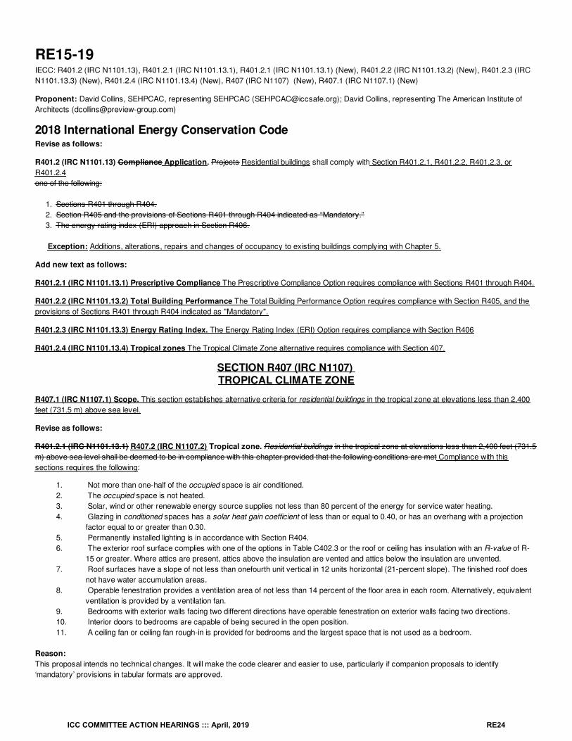
RE15-19IECC: R401.2 (IRC N1101.13), R401.2.1 (IRC N1101.13.1), R401.2.1 (IRC N1101.13.1) (New), R401.2.2 (IRC N1101.13.2) (New), R401.2.3 (IRCN1101.13.3) (New), R401.2.4 (IRC N1101.13.4) (New), R407 (IRC N1107) (New), R407.1 (IRC N1107.1) (New)
Proponent: David Collins, SEHPCAC, representing SEHPCAC ([email protected]); David Collins, representing The American Institute ofArchitects ([email protected])
2018 International Energy Conservation CodeRevise as follows:
R401.2 (IRC N1101.13) Compliance Application. Projects Residential buildings shall comply with Section R401.2.1, R401.2.2, R401.2.3, orR401.2.4one of the following:
1. Sections R401 through R404.2. Section R405 and the provisions of Sections R401 through R404 indicated as “Mandatory.”3. The energy rating index (ERI) approach in Section R406.
Exception: Additions, alterations, repairs and changes of occupancy to existing buildings complying with Chapter 5.
Add new text as follows:
R401.2.1 (IRC N1101.13.1) Prescriptive Compliance The Prescriptive Compliance Option requires compliance with Sections R401 through R404.
R401.2.2 (IRC N1101.13.2) Total Building Performance The Total Building Performance Option requires compliance with Section R405, and theprovisions of Sections R401 through R404 indicated as "Mandatory".
R401.2.3 (IRC N1101.13.3) Energy Rating Index. The Energy Rating Index (ERI) Option requires compliance with Section R406
R401.2.4 (IRC N1101.13.4) Tropical zones The Tropical Climate Zone alternative requires compliance with Section 407.
SECTION R407 (IRC N1107) TROPICAL CLIMATE ZONE
R407.1 (IRC N1107.1) Scope. This section establishes alternative criteria for residential buildings in the tropical zone at elevations less than 2,400feet (731.5 m) above sea level.
Revise as follows:
R401.2.1 (IRC N1101.13.1) R407.2 (IRC N1107.2) Tropical zone. Residential buildings in the tropical zone at elevations less than 2,400 feet (731.5m) above sea level shall be deemed to be in compliance with this chapter provided that the following conditions are met Compliance with thissections requires the following:
1. Not more than one-half of the occupied space is air conditioned.2. The occupied space is not heated.3. Solar, wind or other renewable energy source supplies not less than 80 percent of the energy for service water heating.4. Glazing in conditioned spaces has a solar heat gain coefficient of less than or equal to 0.40, or has an overhang with a projection
factor equal to or greater than 0.30.5. Permanently installed lighting is in accordance with Section R404.6. The exterior roof surface complies with one of the options in Table C402.3 or the roof or ceiling has insulation with an R-value of R-
15 or greater. Where attics are present, attics above the insulation are vented and attics below the insulation are unvented.7. Roof surfaces have a slope of not less than onefourth unit vertical in 12 units horizontal (21-percent slope). The finished roof does
not have water accumulation areas.8. Operable fenestration provides a ventilation area of not less than 14 percent of the floor area in each room. Alternatively, equivalent
ventilation is provided by a ventilation fan.9. Bedrooms with exterior walls facing two different directions have operable fenestration on exterior walls facing two directions.10. Interior doors to bedrooms are capable of being secured in the open position.11. A ceiling fan or ceiling fan rough-in is provided for bedrooms and the largest space that is not used as a bedroom.
Reason:This proposal intends no technical changes. It will make the code clearer and easier to use, particularly if companion proposals to identify‘mandatory’ provisions in tabular formats are approved.
ICC COMMITTEE ACTION HEARINGS ::: April, 2019 RE24
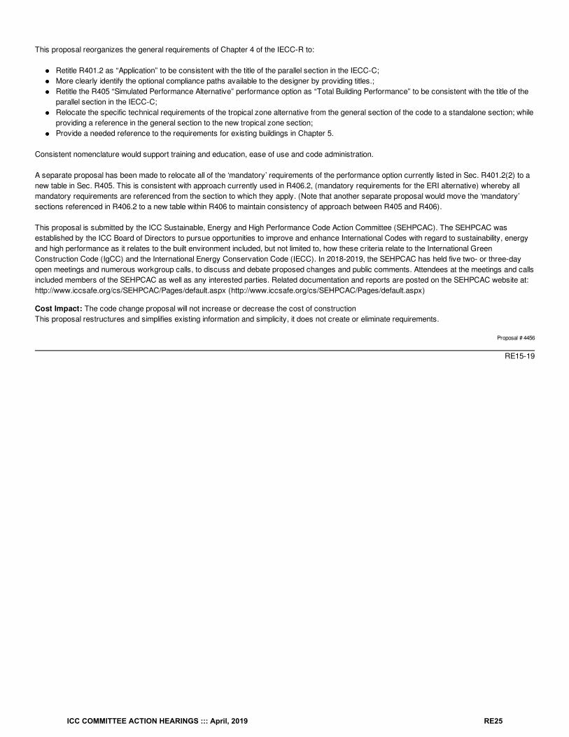
This proposal reorganizes the general requirements of Chapter 4 of the IECC-R to:
Retitle R401.2 as “Application” to be consistent with the title of the parallel section in the IECC-C;More clearly identify the optional compliance paths available to the designer by providing titles.;Retitle the R405 “Simulated Performance Alternative” performance option as “Total Building Performance” to be consistent with the title of theparallel section in the IECC-C;Relocate the specific technical requirements of the tropical zone alternative from the general section of the code to a standalone section; whileproviding a reference in the general section to the new tropical zone section;Provide a needed reference to the requirements for existing buildings in Chapter 5.
Consistent nomenclature would support training and education, ease of use and code administration.
A separate proposal has been made to relocate all of the ‘mandatory’ requirements of the performance option currently listed in Sec. R401.2(2) to anew table in Sec. R405. This is consistent with approach currently used in R406.2, (mandatory requirements for the ERI alternative) whereby allmandatory requirements are referenced from the section to which they apply. (Note that another separate proposal would move the ‘mandatory’sections referenced in R406.2 to a new table within R406 to maintain consistency of approach between R405 and R406).
This proposal is submitted by the ICC Sustainable, Energy and High Performance Code Action Committee (SEHPCAC). The SEHPCAC wasestablished by the ICC Board of Directors to pursue opportunities to improve and enhance International Codes with regard to sustainability, energyand high performance as it relates to the built environment included, but not limited to, how these criteria relate to the International GreenConstruction Code (IgCC) and the International Energy Conservation Code (IECC). In 2018-2019, the SEHPCAC has held five two- or three-dayopen meetings and numerous workgroup calls, to discuss and debate proposed changes and public comments. Attendees at the meetings and callsincluded members of the SEHPCAC as well as any interested parties. Related documentation and reports are posted on the SEHPCAC website at:http://www.iccsafe.org/cs/SEHPCAC/Pages/default.aspx (http://www.iccsafe.org/cs/SEHPCAC/Pages/default.aspx)
Cost Impact: The code change proposal will not increase or decrease the cost of constructionThis proposal restructures and simplifies existing information and simplicity, it does not create or eliminate requirements.
Proposal # 4456
RE15-19
ICC COMMITTEE ACTION HEARINGS ::: April, 2019 RE25
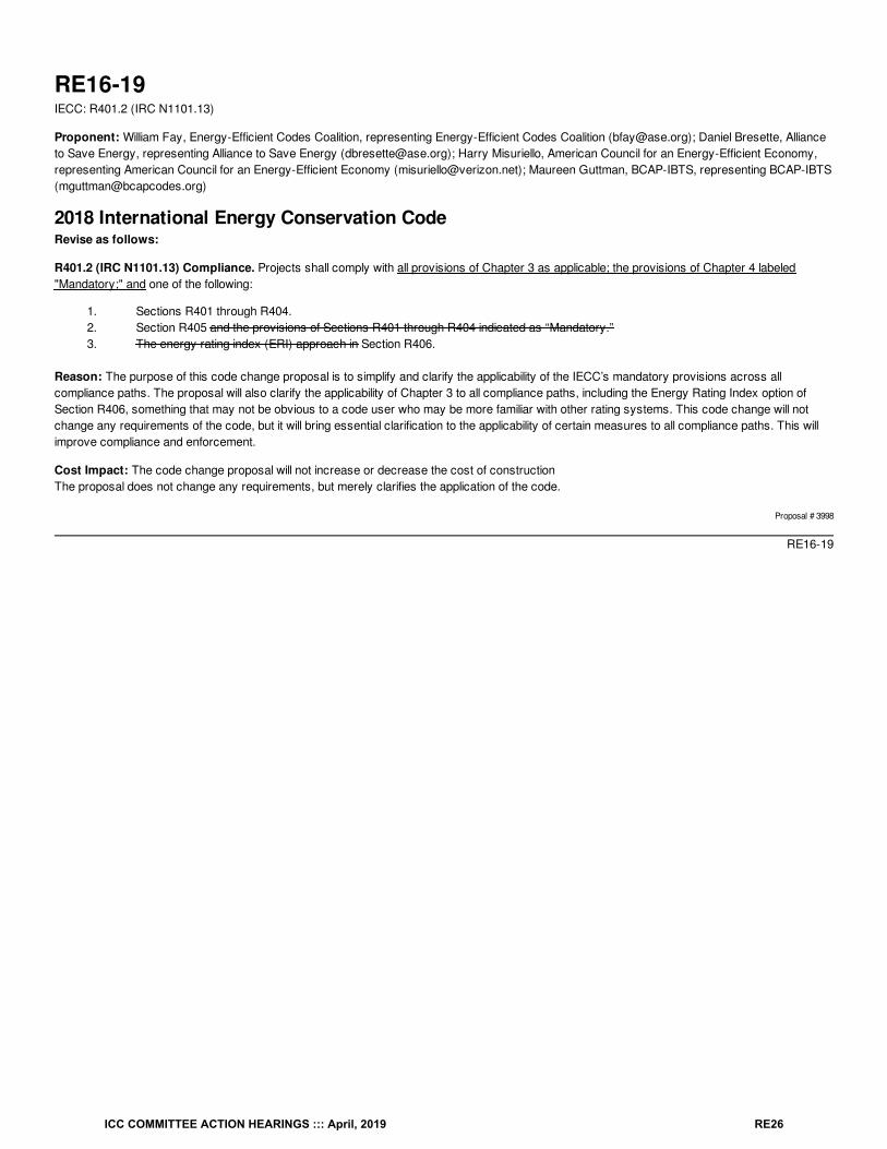
RE16-19IECC: R401.2 (IRC N1101.13)
Proponent: William Fay, Energy-Efficient Codes Coalition, representing Energy-Efficient Codes Coalition ([email protected]); Daniel Bresette, Allianceto Save Energy, representing Alliance to Save Energy ([email protected]); Harry Misuriello, American Council for an Energy-Efficient Economy,representing American Council for an Energy-Efficient Economy ([email protected]); Maureen Guttman, BCAP-IBTS, representing BCAP-IBTS([email protected])
2018 International Energy Conservation CodeRevise as follows:
R401.2 (IRC N1101.13) Compliance. Projects shall comply with all provisions of Chapter 3 as applicable; the provisions of Chapter 4 labeled"Mandatory;" and one of the following:
1. Sections R401 through R404.2. Section R405 and the provisions of Sections R401 through R404 indicated as “Mandatory.”3. The energy rating index (ERI) approach in Section R406.
Reason: The purpose of this code change proposal is to simplify and clarify the applicability of the IECC’s mandatory provisions across allcompliance paths. The proposal will also clarify the applicability of Chapter 3 to all compliance paths, including the Energy Rating Index option ofSection R406, something that may not be obvious to a code user who may be more familiar with other rating systems. This code change will notchange any requirements of the code, but it will bring essential clarification to the applicability of certain measures to all compliance paths. This willimprove compliance and enforcement.
Cost Impact: The code change proposal will not increase or decrease the cost of constructionThe proposal does not change any requirements, but merely clarifies the application of the code.
Proposal # 3998
RE16-19
ICC COMMITTEE ACTION HEARINGS ::: April, 2019 RE26
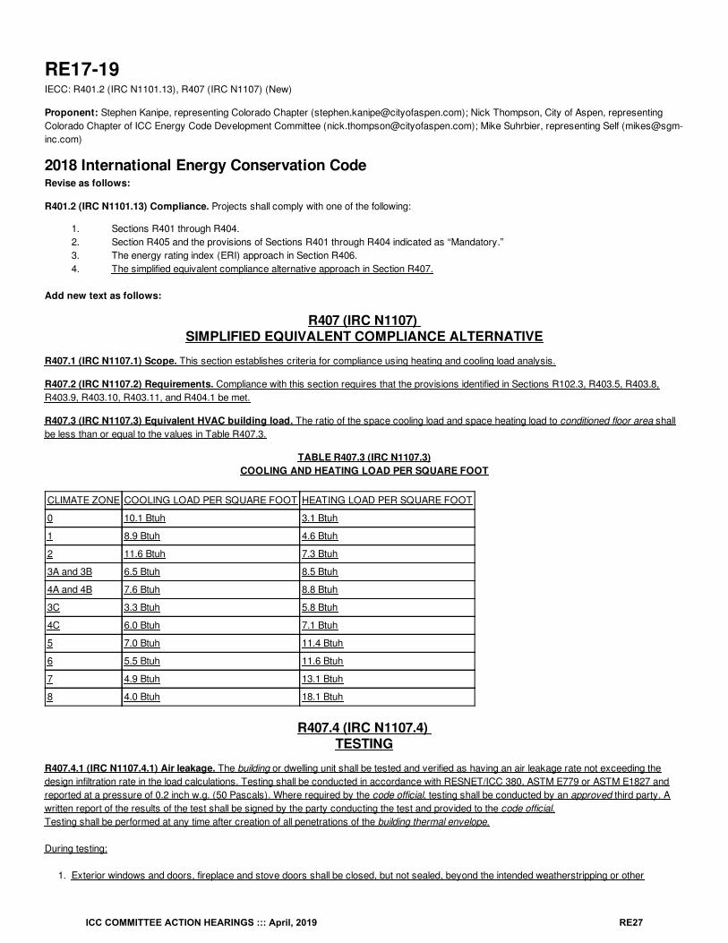
RE17-19IECC: R401.2 (IRC N1101.13), R407 (IRC N1107) (New)
Proponent: Stephen Kanipe, representing Colorado Chapter ([email protected]); Nick Thompson, City of Aspen, representingColorado Chapter of ICC Energy Code Development Committee ([email protected]); Mike Suhrbier, representing Self ([email protected])
2018 International Energy Conservation CodeRevise as follows:
R401.2 (IRC N1101.13) Compliance. Projects shall comply with one of the following:
1. Sections R401 through R404.2. Section R405 and the provisions of Sections R401 through R404 indicated as “Mandatory.”3. The energy rating index (ERI) approach in Section R406.4. The simplified equivalent compliance alternative approach in Section R407.
Add new text as follows:
R407 (IRC N1107) SIMPLIFIED EQUIVALENT COMPLIANCE ALTERNATIVE
R407.1 (IRC N1107.1) Scope. This section establishes criteria for compliance using heating and cooling load analysis.
R407.2 (IRC N1107.2) Requirements. Compliance with this section requires that the provisions identified in Sections R102.3, R403.5, R403.8,R403.9, R403.10, R403.11, and R404.1 be met.
R407.3 (IRC N1107.3) Equivalent HVAC building load. The ratio of the space cooling load and space heating load to conditioned floor area shallbe less than or equal to the values in Table R407.3.
TABLE R407.3 (IRC N1107.3)COOLING AND HEATING LOAD PER SQUARE FOOT
CLIMATE ZONE COOLING LOAD PER SQUARE FOOT HEATING LOAD PER SQUARE FOOT
0 10.1 Btuh 3.1 Btuh
1 8.9 Btuh 4.6 Btuh
2 11.6 Btuh 7.3 Btuh
3A and 3B 6.5 Btuh 8.5 Btuh
4A and 4B 7.6 Btuh 8.8 Btuh
3C 3.3 Btuh 5.8 Btuh
4C 6.0 Btuh 7.1 Btuh
5 7.0 Btuh 11.4 Btuh
6 5.5 Btuh 11.6 Btuh
7 4.9 Btuh 13.1 Btuh
8 4.0 Btuh 18.1 Btuh
R407.4 (IRC N1107.4) TESTING
R407.4.1 (IRC N1107.4.1) Air leakage. The building or dwelling unit shall be tested and verified as having an air leakage rate not exceeding thedesign infiltration rate in the load calculations. Testing shall be conducted in accordance with RESNET/ICC 380, ASTM E779 or ASTM E1827 andreported at a pressure of 0.2 inch w.g. (50 Pascals). Where required by the code official, testing shall be conducted by an approved third party. Awritten report of the results of the test shall be signed by the party conducting the test and provided to the code official.Testing shall be performed at any time after creation of all penetrations of the building thermal envelope.
During testing:
1. Exterior windows and doors, fireplace and stove doors shall be closed, but not sealed, beyond the intended weatherstripping or other
ICC COMMITTEE ACTION HEARINGS ::: April, 2019 RE27
infiltration control measures.2. Dampers including exhaust, intake, makeup air, backdraft and flue dampers shall be closed, but not sealed beyond intended infiltration control
measures.3. Interior doors, where installed at the time of the test, shall be open.4. Exterior or interior terminations for continuous ventilation systems shall be sealed.5. Heating and cooling systems, where installed at the time of the test, shall be turned off.6. Supply and return registers, where installed at the time of the test, shall be fully open.
R407.4.1 (IRC N1107.4.1) Duct leakage. Ducts shall be tested in accordance with R403.3.3 and R403.3.4.
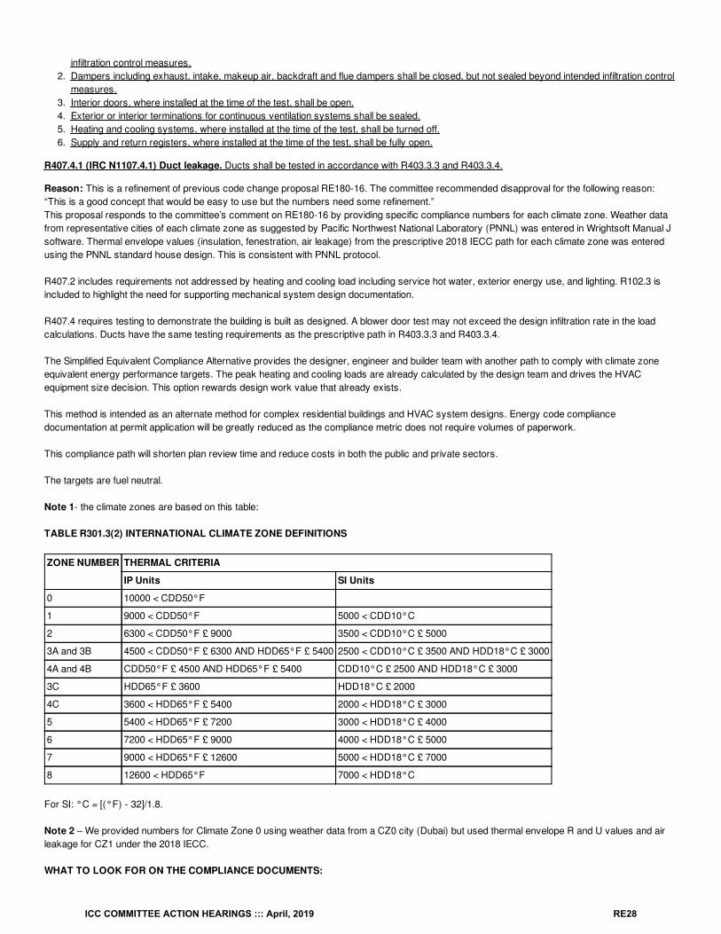
Reason: This is a refinement of previous code change proposal RE180-16. The committee recommended disapproval for the following reason:“This is a good concept that would be easy to use but the numbers need some refinement.”This proposal responds to the committee’s comment on RE180-16 by providing specific compliance numbers for each climate zone. Weather datafrom representative cities of each climate zone as suggested by Pacific Northwest National Laboratory (PNNL) was entered in Wrightsoft Manual Jsoftware. Thermal envelope values (insulation, fenestration, air leakage) from the prescriptive 2018 IECC path for each climate zone was enteredusing the PNNL standard house design. This is consistent with PNNL protocol.
R407.2 includes requirements not addressed by heating and cooling load including service hot water, exterior energy use, and lighting. R102.3 isincluded to highlight the need for supporting mechanical system design documentation.
R407.4 requires testing to demonstrate the building is built as designed. A blower door test may not exceed the design infiltration rate in the loadcalculations. Ducts have the same testing requirements as the prescriptive path in R403.3.3 and R403.3.4.
The Simplified Equivalent Compliance Alternative provides the designer, engineer and builder team with another path to comply with climate zoneequivalent energy performance targets. The peak heating and cooling loads are already calculated by the design team and drives the HVACequipment size decision. This option rewards design work value that already exists.
This method is intended as an alternate method for complex residential buildings and HVAC system designs. Energy code compliancedocumentation at permit application will be greatly reduced as the compliance metric does not require volumes of paperwork.
This compliance path will shorten plan review time and reduce costs in both the public and private sectors.
The targets are fuel neutral.
Note 1- the climate zones are based on this table:
TABLE R301.3(2) INTERNATIONAL CLIMATE ZONE DEFINITIONS
ZONE NUMBER THERMAL CRITERIA
IP Units SI Units
0 10000 < CDD50°F
1 9000 < CDD50°F 5000 < CDD10°C
2 6300 < CDD50°F £ 9000 3500 < CDD10°C £ 5000
3A and 3B 4500 < CDD50°F £ 6300 AND HDD65°F £ 5400 2500 < CDD10°C £ 3500 AND HDD18°C £ 3000
4A and 4B CDD50°F £ 4500 AND HDD65°F £ 5400 CDD10°C £ 2500 AND HDD18°C £ 3000
3C HDD65°F £ 3600 HDD18°C £ 2000
4C 3600 < HDD65°F £ 5400 2000 < HDD18°C £ 3000
5 5400 < HDD65°F £ 7200 3000 < HDD18°C £ 4000
6 7200 < HDD65°F £ 9000 4000 < HDD18°C £ 5000
7 9000 < HDD65°F £ 12600 5000 < HDD18°C £ 7000
8 12600 < HDD65°F 7000 < HDD18°C
For SI: °C = [(°F) - 32]/1.8.
Note 2 – We provided numbers for Climate Zone 0 using weather data from a CZ0 city (Dubai) but used thermal envelope R and U values and airleakage for CZ1 under the 2018 IECC.
WHAT TO LOOK FOR ON THE COMPLIANCE DOCUMENTS:
ICC COMMITTEE ACTION HEARINGS ::: April, 2019 RE28
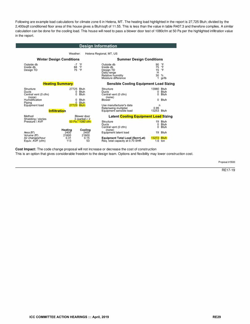
Following are example load calculations for climate zone 6 in Helena, MT. The heating load highlighted in the report is 27,725 Btuh; divided by the2,400sqft conditioned floor area of this house gives a Btuh/sqft of 11.55. This is less than the value in table R407.3 and therefore complies. A similarcalculation can be done for the cooling load. This house will need to pass a blower door test of 1080cfm at 50 Pa per the highlighted infiltration valuein the report.
Cost Impact: The code change proposal will not increase or decrease the cost of constructionThis is an option that gives considerable freedom to the design team. Options and flexibility may lower construction cost.
Proposal # 5533
RE17-19
ICC COMMITTEE ACTION HEARINGS ::: April, 2019 RE29
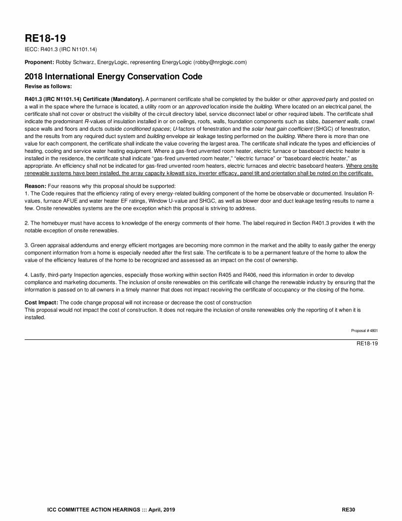
RE18-19IECC: R401.3 (IRC N1101.14)
Proponent: Robby Schwarz, EnergyLogic, representing EnergyLogic ([email protected])
2018 International Energy Conservation CodeRevise as follows:
R401.3 (IRC N1101.14) Certificate (Mandatory). A permanent certificate shall be completed by the builder or other approved party and posted ona wall in the space where the furnace is located, a utility room or an approved location inside the building. Where located on an electrical panel, thecertificate shall not cover or obstruct the visibility of the circuit directory label, service disconnect label or other required labels. The certificate shallindicate the predominant R-values of insulation installed in or on ceilings, roofs, walls, foundation components such as slabs, basement walls, crawlspace walls and floors and ducts outside conditioned spaces; U-factors of fenestration and the solar heat gain coefficient (SHGC) of fenestration,and the results from any required duct system and building envelope air leakage testing performed on the building. Where there is more than onevalue for each component, the certificate shall indicate the value covering the largest area. The certificate shall indicate the types and efficiencies ofheating, cooling and service water heating equipment. Where a gas-fired unvented room heater, electric furnace or baseboard electric heater isinstalled in the residence, the certificate shall indicate “gas-fired unvented room heater,” “electric furnace” or “baseboard electric heater,” asappropriate. An efficiency shall not be indicated for gas-fired unvented room heaters, electric furnaces and electric baseboard heaters. Where onsiterenewable systems have been installed, the array capacity kilowatt size, inverter efficacy, panel tilt and orientation shall be noted on the certificate.
Reason: Four reasons why this proposal should be supported:1. The Code requires that the efficiency rating of every energy-related building component of the home be observable or documented. Insulation R-values, furnace AFUE and water heater EF ratings, Window U-value and SHGC, as well as blower door and duct leakage testing results to name afew. Onsite renewables systems are the one exception which this proposal is striving to address.
2. The homebuyer must have access to knowledge of the energy comments of their home. The label required in Section R401.3 provides it with thenotable exception of onsite renewables.
3. Green appraisal addendums and energy efficient mortgages are becoming more common in the market and the ability to easily gather the energycomponent information from a home is especially needed after the first sale. The certificate is to be a permanent feature of the home to allow thevalue of the efficiency features of the home to be recognized and assessed as an impact on the cost of ownership.
4. Lastly, third-party Inspection agencies, especially those working within section R405 and R406, need this information in order to developcompliance and marketing documents. The inclusion of onsite renewables on this certificate will change the renewable industry by ensuring that theinformation is passed on to all owners in a timely manner that does not impact receiving the certificate of occupancy or the closing of the home.
Cost Impact: The code change proposal will not increase or decrease the cost of constructionThis proposal would not impact the cost of construction. It does not require the inclusion of onsite renewables only the reporting of it when it isinstalled.
Proposal # 4801
RE18-19
ICC COMMITTEE ACTION HEARINGS ::: April, 2019 RE30
RE19-19IECC: R401.3 (IRC N1101.14)
Proponent: donald sivigny, State of MN, representing State of MN and Association of Minnesota Building Officials ([email protected])
2018 International Energy Conservation CodeRevise as follows:
R401.3 (IRC N1101.14) Certificate (Mandatory). A permanent building certificate shall be completed by the builder or other approved party andposted on a wall in the space where the furnace is located, a utility room or an approved location inside the building. building. Where located on anelectrical panel, the certificate shall not cover or obstruct the visibility of the circuit directory label, service disconnect label , or other required labels.The certificate shall indicate the predominant R-values :
1. The date the certificate is installed;2. The dwelling address;3. Residential contractor name and contractor license number, or homeowner name, if acting as the general contractor;4. The predominant installed R-values, their location, and type of insulation installed in or on ceilings, roofs, walls , rim/band joist, foundation
components such as slabs, basement walls, crawl space walls and floors and ,5. ducts outside conditioned spaces; U-factors of6. U-factors for fenestration and the solar heat gain coefficient (SHGC) of fenestration ;7. , and the results from of any required duct system and building envelope air leakage testing done on the building.8. The types, and efficiencies, input ratings, manufacturers, and model numbers and efficiencies of heating, cooling, and service water heating
equipment.9. The structure’s calculated heat loss, calculated cooling load, and calculated heat gain.
10. The certificate shall list the mechanical ventilation system type, location, and capacity11. The building's designated continuous and total ventilation rates.12. The type, size, and location of any make-up air system installed and Combustion air as required for the building
performed on the building. Where there is more than one value for each component, the certificate shall indicate list the value covering the largestarea.
The certificate shall indicate the types and efficiencies of heating, cooling and service water heating equipment. Where a gas-fired unvented roomheater, electric furnace or baseboard electric heater is installed in the residence, the certificate shall indicate “gas-fired unvented room heater, ”“electric furnace” or “baseboard electric heater,” as appropriate.
An efficiency shall not be indicated for gas-fired unvented room heaters, electric furnaces and or electric baseboard heaters.
Reason: The language in section R401.3 is revised by replacing the word “permanent” in the first sentence with the word “building.” This change isnecessary because the term “permanent certificate” is not used in the industry while the term “building certificate” is, and building certificate is thecorrect term to be used, in that pertains to the document being referenced in this section. The term “permanent” is an ambiguous term in that oneperson’s definition of permanent is very different than another person’s definition of permanent. Using the term building certificate will add toconsistency of the code because we do define the term “Building” in the code.Additional required items are added to the IECC list of certificate requirements: the date the certificate is posted so that the building is complete andall the information needed can be added to the certificate; the contractor name and license number or the homeowner name and contact information(if acting as the general contractor)[1]; the insulation product and R-values in the Rim/Band joist area because the Rim/Band joist area is typicallyinsulated with a different system or product that the rest of the home; information on the buildings mechanical ventilation system because thissystem is an important component of the buildings air quality and durability as required by other provisions of the code; and input rating, modelnumbers, and equipment efficiencies of all the heating and cooling equipment.
These requirements provide consistency with regard to building certificate requirements and a builder can now use the Certificate as a checklist forinformation that is required at permit application time. Without this information it is virtually impossible to do a complete and proper plan review andknow how the building is being built. (See Example )
Cost Impact: The code change proposal will decrease the cost of constructionThese items are already being calculated and done as part of the building’s construction. All this change is doing is asking for the information at thetime of permit application. It is important to design the building and then build to it instead of building it and then trying to make it work with the design.Providing this information up front assures that the building is designed properly and it the specs it will need to be built and inspected to.
Proposal # 5128
RE19-19
ICC COMMITTEE ACTION HEARINGS ::: April, 2019 RE31
RE20-19IECC: R401.3 (IRC N1101.14)
Proponent: Jason Vandever, representing Self ([email protected])
2018 International Energy Conservation CodeRevise as follows:
R401.3 (IRC N1101.14) Certificate (Mandatory). A permanent certificate shall be completed by the builder or other approved party and posted ona wall in the space where the furnace is located, a utility room or an approved location inside the building. Where located on an electrical panel, thecertificate shall not cover or obstruct the visibility of the circuit directory label, service disconnect label or other required labels. The certificate shallindicate the predominant R-values of insulation installed in or on ceilings, roofs, walls, foundation components such as slabs, basement walls, crawlspace walls and floors and ducts outside conditioned spaces; U-factors of fenestration and the solar heat gain coefficient (SHGC) of fenestration,and the results from any required duct system and building envelope air leakage testing performed on the building. Where there is more than onevalue for each component, the certificate shall indicate the value covering the largest area. The certificate shall indicate the types and efficiencies ofheating, cooling and service water heating equipment. Where a gas-fired unvented room heater, electric furnace or baseboard electric heater isinstalled in the residence, the certificate shall indicate “gas-fired unvented room heater,” “electric furnace” or “baseboard electric heater,” asappropriate. An efficiency shall not be indicated for gas-fired unvented room heaters, electric furnaces and electric baseboard heaters. Thecertificate shall indicate the name of the builder who applied for the building permit, the code edition under which the structure was permitted and thecompliance path used.
Reason: This is potentially valuable information to the homeowner or future contractor working on the home
Bibliography: N/A
Cost Impact: The code change proposal will not increase or decrease the cost of constructionAdding a few items to a certification sheet doesn't cost anything. It is only documentation.
Proposal # 5566
RE20-19
ICC COMMITTEE ACTION HEARINGS ::: April, 2019 RE32
RE21-19IECC: R401.3 (IRC N1101.14)
Proponent: William Fay, Energy-Efficient Codes Coalition, representing Energy-Efficient Codes Coalition ([email protected]); Daniel Bresette, Allianceto Save Energy, representing Alliance to Save Energy ([email protected]); Harry Misuriello, representing American Council for an Energy-EfficientEconomy ([email protected]); Maureen Guttman, BCAP-IBTS, representing BCAP-IBTS ([email protected])
2018 International Energy Conservation CodeRevise as follows:
R401.3 (IRC N1101.14) Certificate (Mandatory). A permanent certificate shall be completed by the builder or other approved party and posted ona wall in the space where the furnace is located, a utility room or an approved location inside the building. Where located on an electrical panel, thecertificate shall not cover or obstruct the visibility of the circuit directory label, service disconnect label or other required labels. The certificate shallindicate the predominant R-values of insulation installed in or on ceilings, roofs, walls, foundation components such as slabs, basement walls, crawlspace walls and floors and ducts outside conditioned spaces; U-factors of fenestration and the solar heat gain coefficient (SHGC) of fenestration,and the results from any required duct system and building envelope air leakage testing performed on the building. Where there is more than onevalue for each any component of the building envelope, the certificate shall indicate both the value covering the largest area and the area-weightedaverage value if available. The certificate shall indicate the types , sizes and efficiencies of heating, cooling and service water heating equipment.Where a gas-fired unvented room heater, electric furnace or baseboard electric heater is installed in the residence, the certificate shall indicate “gas-fired unvented room heater,” “electric furnace” or “baseboard electric heater,” as appropriate. An efficiency shall not be indicated for gas-firedunvented room heaters, electric furnaces and electric baseboard heaters. For buildings where an Energy Rating Index score is determined inaccordance with Section R406, the Energy Rating Index score, both with and without any on-site generation, shall be listed on the certificate.
Reason: The purpose of this code change proposal is to make minor but important updates to the certificate that will reflect changes made to theIECC in recent code cycles and include other information that will be beneficial for compliance purposes and for future homeowners. Mostimportantly, for homes with an Energy Rating Index score, the certificate will be required to provide the actual ERI score achieved with and withouton-site generation (since the compliance requirements are different under each option). This proposal would also require the certificate to provideadditional detail on thermal envelope efficiency (where available) and HVAC equipment size. This information should all be readily available atconstruction, and it will take very little effort to transfer it onto the permanent certificate. However, this information may be difficult or impossible torecreate down the road and will be useful for maintenance and future replacement. These are all reasonable improvements to the certificate that willbenefit all future owners of the home.
Cost Impact: The code change proposal will not increase or decrease the cost of constructionThe information required by this proposal will already be available at construction. The only change is to require the information to be recorded onthe permanent certificate. Over the useful life of the home, we expect that putting this information in one place could save a homeowner significantmoney and effort.
Proposal # 3976
RE21-19
ICC COMMITTEE ACTION HEARINGS ::: April, 2019 RE33
RE22-19IECC: R402.1 (IRC N1102.1)
Proponent: William Fay, Energy-Efficient Codes Coalition, representing Energy-Efficient Codes Coalition ([email protected]); Daniel Bresette, Allianceto Save Energy, representing Alliance to Save Energy ([email protected]); Maureen Guttman, BCAP-IBTS, representing BCAP-IBTS([email protected]); Harry Misuriello, American Council for an Energy-Efficient Economy, representing American Council for an Energy-Efficient Economy ([email protected])
2018 International Energy Conservation CodeRevise as follows:
R402.1 (IRC N1102.1) General (Prescriptive). The building thermal envelope shall comply with the requirements of Sections R402.1.1 throughR402.1.5.
Exceptions:
1. The following low-energy buildings, or portions thereof, separated from the remainder of the building by building thermal envelopeassemblies complying with this section shall be exempt from the building thermal envelope provisions of Section R402.1.1. Those with a peak design rate of energy usage less than 3.4 Btu/h · ft (10.7 W/m ) or 1.0 watt/ft of floor area for
space-conditioning purposes.1.2. Those that do not contain conditioned space.
2. Log homes The prescriptive R-value requirement in Table R402.1.2 shall not apply to the opaque walls of log homes where thewalls are constructed from logs at least 7 inches in diameter and the homes are designed in accordance with ICC 400.
Reason: The purpose of this code change proposal is to clarify, narrow and place reasonable limits on the log homes exception that was added tothe 2018 IECC, which will help improve compliance and enforcement, save energy, and improve comfort. Specifically, the proposal will limit theexception to opaque wall R-values, where there are 7-inch or greater diameter logs, rather than permit an exception to all thermal enveloperequirements for any log home.Prior to the 2018 IECC, log homes were required to comply with the same requirements as all other homes. The current overly broad exception wasadded in 2018, which reduced the energy efficiency requirements for certain log homes and shifted part of compliance from the IECC to ICC 400.The exception, as currently contained in Section R402.1, may be seen as somewhat ambiguous as to which components of the log home areexempt from the IECC requirements. A strict reading of the actual language of Section R402.1 (which we believe is the correct reading) would onlysubstitute the prescriptive component R-values and U-factors in ICC-400 for the values contained in Sections R402.1.1 through R402.1.5. Theremaining requirements in the IECC – including air leakage testing, duct tightness and testing, equipment sizing, etc. -- would still apply. However,some have suggested that the current code language completely exempts log homes from all IECC thermal envelope requirements in favor of ICC-400 – a huge expansion of the exception that would permit these homes to waste substantially more energy than a home built to the IECC. Ourproposal would resolve this issue.
In addition, although we can appreciate the difficulty of achieving code-compliant prescriptive wall R-values in solid log structures, we believe it isunnecessary to exempt these homes from all thermal envelope or any other efficiency requirements – particularly those unrelated to the log walls.By limiting the exception to the opaque walls, this proposal will retain reasonable IECC efficiency requirements for all other parts of the log home asthey existed prior to establishing the exception.
This proposal uses 7-inch diameter logs as the cutoff for the exception to help ensure at least some minimum degree of efficiency in the walls. TheR-value for wood ranges between 1.41 per inch for most softwoods and 0.71 for most hardwoods. See https://www.energy.gov/energysaver/types-homes/energy-efficiency-log-homes At a 7-inch diameter, the best possible U-factor for a log wall aligns with an R-13 wall (0.084). Depending on thetype of wood, the insulating value of the 7-inch log wall could be much less. While these R-values are equal to or substantially less than even theleast stringent wood frame wall R-values for climate zones 1 and 2 (R-13), we recognize that there is some additional benefit from log walls withregard to thermal mass. Only log walls thick enough to maintain a reasonable level of efficiency, however, should qualify for the exemption. Webelieve that the 7-inch proposed minimum diameter is a reasonable compromise.
It should be kept in mind that for log homes that do not fall within this exception, the IECC offers a range of additional compliance options, includingthe Total UA, performance path, or ERI option to provide ample trade-off flexibility without sacrificing any energy efficiency.
Bibliography: Energy Efficiency in Log Homes, Dep’t of Energy, https://www.energy.gov/energysaver/types-homes/energy-efficiency-log-homes(last accessed Dec. 30, 2018).
Cost Impact: The code change proposal will increase the cost of constructionFor those log homes that would utilize the exception but may no longer qualify, additional costs may be incurred to bring the home into compliance,although the cost would be no greater than before the exception was established in 2018. However, the proposal will reduce operating costs andimprove comfort for actual log homeowners and other occupants who will benefit from lower energy costs over the 70 to 100 year expected usefullifetime of a well-built log home.
2 2 2
ICC COMMITTEE ACTION HEARINGS ::: April, 2019 RE34
Proposal # 3977
RE22-19
ICC COMMITTEE ACTION HEARINGS ::: April, 2019 RE35
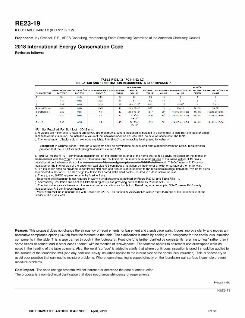
RE23-19IECC: TABLE R402.1.2 (IRC N1102.1.2)
Proponent: Jay Crandell, P.E., ARES Consulting, representing Foam Sheathing Committee of the American Chemistry Council
2018 International Energy Conservation CodeRevise as follows:
Reason: This proposal does not change the stringency of requirements for basement and crawlspace walls. It does improve clarity and moves analternative compliance option (13+5ci) from the footnote to the table. The clarification is made by adding a ‘ci’ designator for the continuous insulationcomponents in the table. This is also carried through in the footnote ‘c’. Footnote ‘c’ is further clarified by consistently referring to “wall” rather than insome cases basement and in other cases “home” with no mention of “crawlspace”. The footnote applies to basement and crawlspace walls asnoted in the heading of the table columns. Also, the word “surface” is added to clarify that where continuous insulation is used it should be applied tothe surface of the foundation wall (and any additional cavity insulation applied to the interior side of the continuous insulation). This is necessary toavoid poor practice that can lead to moisture problems. Where foam sheathing is placed directly on the foundation wall surface it can help preventmoisture problems.
Cost Impact: The code change proposal will not increase or decrease the cost of constructionThe proposal is a non-technical clarification that does not change stringency of requirements.
Proposal # 4513
RE23-19
ICC COMMITTEE ACTION HEARINGS ::: April, 2019 RE36
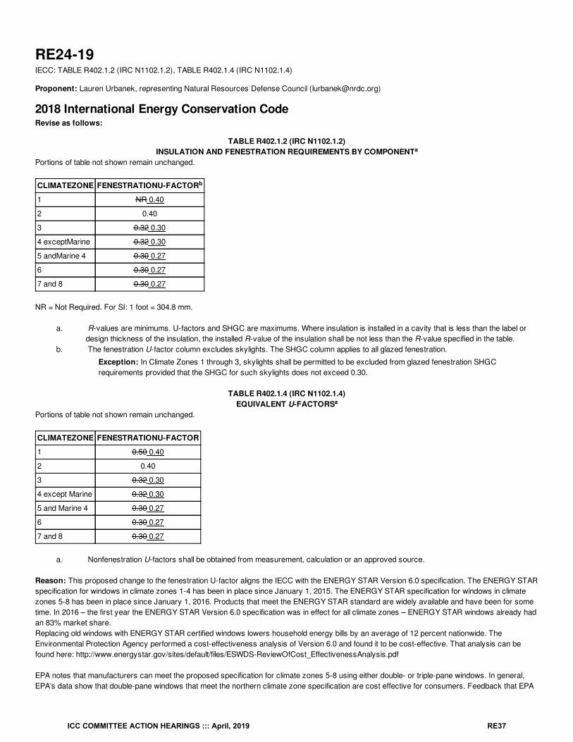
RE24-19IECC: TABLE R402.1.2 (IRC N1102.1.2), TABLE R402.1.4 (IRC N1102.1.4)
Proponent: Lauren Urbanek, representing Natural Resources Defense Council ([email protected])
2018 International Energy Conservation CodeRevise as follows:
TABLE R402.1.2 (IRC N1102.1.2)INSULATION AND FENESTRATION REQUIREMENTS BY COMPONENT
Portions of table not shown remain unchanged.
CLIMATEZONE FENESTRATIONU-FACTOR
1 NR 0.40
2 0.40
3 0.32 0.30
4 exceptMarine 0.32 0.30
5 andMarine 4 0.30 0.27
6 0.30 0.27
7 and 8 0.30 0.27
NR = Not Required. For SI: 1 foot = 304.8 mm.
a. R-values are minimums. U-factors and SHGC are maximums. Where insulation is installed in a cavity that is less than the label ordesign thickness of the insulation, the installed R-value of the insulation shall be not less than the R-value specified in the table.
b. The fenestration U-factor column excludes skylights. The SHGC column applies to all glazed fenestration.
Exception: In Climate Zones 1 through 3, skylights shall be permitted to be excluded from glazed fenestration SHGCrequirements provided that the SHGC for such skylights does not exceed 0.30.
TABLE R402.1.4 (IRC N1102.1.4)EQUIVALENT U-FACTORS
Portions of table not shown remain unchanged.
CLIMATEZONE FENESTRATIONU-FACTOR
1 0.50 0.40
2 0.40
3 0.32 0.30
4 except Marine 0.32 0.30
5 and Marine 4 0.30 0.27
6 0.30 0.27
7 and 8 0.30 0.27
a. Nonfenestration U-factors shall be obtained from measurement, calculation or an approved source.
Reason: This proposed change to the fenestration U-factor aligns the IECC with the ENERGY STAR Version 6.0 specification. The ENERGY STARspecification for windows in climate zones 1-4 has been in place since January 1, 2015. The ENERGY STAR specification for windows in climatezones 5-8 has been in place since January 1, 2016. Products that meet the ENERGY STAR standard are widely available and have been for sometime. In 2016 – the first year the ENERGY STAR Version 6.0 specification was in effect for all climate zones – ENERGY STAR windows already hadan 83% market share.Replacing old windows with ENERGY STAR certified windows lowers household energy bills by an average of 12 percent nationwide. TheEnvironmental Protection Agency performed a cost-effectiveness analysis of Version 6.0 and found it to be cost-effective. That analysis can befound here: http://www.energystar.gov/sites/default/files/ESWDS-ReviewOfCost_EffectivenessAnalysis.pdf
EPA notes that manufacturers can meet the proposed specification for climate zones 5-8 using either double- or triple-pane windows. In general,EPA’s data show that double-pane windows that meet the northern climate zone specification are cost effective for consumers. Feedback that EPA
a
b
a
ICC COMMITTEE ACTION HEARINGS ::: April, 2019 RE37
has received from stakeholders confirms that new glass technologies, improvements in frame performance, and/or better spacer performance canhelp many product lines meet the proposed Northern Zone criteria with double-pane windows.
Bibliography: Environmental Protection Agency. Energy Star Windows Unit Shipment Data. 2016. Retrieved on December 15, 2018 fromhttps://www.energystar.gov/ia/partners/downloads/unit_shipment_data/2016_USD_Summary_Report.pdf?8fd5-1967Environmental Protection Agency. Energy Star Windows Version 6.0 Cost Effectiveness. Retrieved on December 15, 2018 fromhttp://www.energystar.gov/sites/default/files/ESWDS-ReviewOfCost_EffectivenessAnalysis.pdf
Cost Impact: The code change proposal will increase the cost of constructionThe code change proposal may increase the cost of construction. Given the level of market penetration of ENERGY STAR products, by the time the2021 code is adopted many builders will already be meeting the improved requirements. In some limited cases, builders may incur increased costs.EPA estimates that there is a cost of $20 per window to go from the 2009 code requirements to ENERGY STAR Version 6.0. However, the U-factorrequirements in the 2018 code are already significantly more stringent than the 2009 code requirements, so we would expect the marginal cost perwindow to be less.
Proposal # 5551
RE24-19
ICC COMMITTEE ACTION HEARINGS ::: April, 2019 RE38
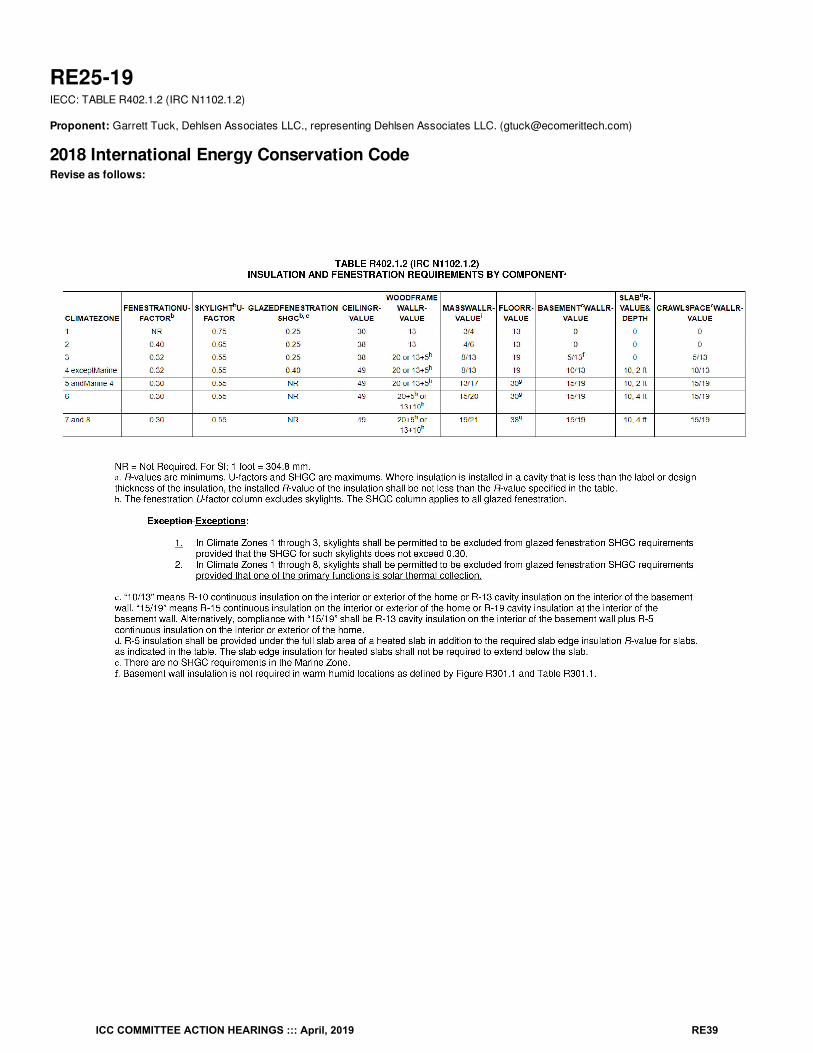
RE25-19IECC: TABLE R402.1.2 (IRC N1102.1.2)
Proponent: Garrett Tuck, Dehlsen Associates LLC., representing Dehlsen Associates LLC. ([email protected])
2018 International Energy Conservation CodeRevise as follows:
ICC COMMITTEE ACTION HEARINGS ::: April, 2019 RE39
Reason: Exception: In Climate Zones 1 through 8, skylights shall be permitted to be excluded from glazed fenestrationSHGC requirements provided that one of the primary functions is solar thermal collection.1. Skylight/solar thermal collector combination units have two primary functions, collect thermal energy, and provide light. The amount of thermalenergy collection and light transmittance is directly related to the amount of solar irradiance incident on the unit. As the solar irradiance incident onthe unit increases, both the thermal energy collection and light transmittance increases. The thermal energy that is collected is transferred to anHTF (heat transfer fluid) and diverted away from the unit into a storage tank. During this process, G the incident solar radiation on the insidepane of the skylight is a function of the G total incident solar radiation and the G solar radiation transmitted (G = G - G ).Unlike a normal skylight, skylight/solar thermal collector combination units have the ability to divert the total incident solar radiation away from theskylight and into an HTF where it can be stored and utilized for domestic hot water needs.
2. Currently, there is no test standard for skylight/solar thermal collector combination units to measure how the SHGC of the unit changes over timeas a result of the collect.
IPS
TISR SRT IPS TISR SRT
ICC COMMITTEE ACTION HEARINGS ::: April, 2019 RE40
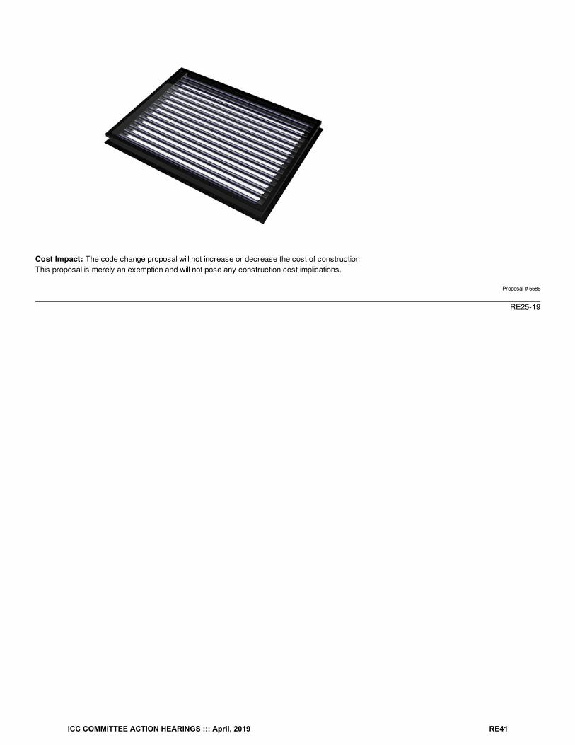
Cost Impact: The code change proposal will not increase or decrease the cost of constructionThis proposal is merely an exemption and will not pose any construction cost implications.
Proposal # 5586
RE25-19
ICC COMMITTEE ACTION HEARINGS ::: April, 2019 RE41
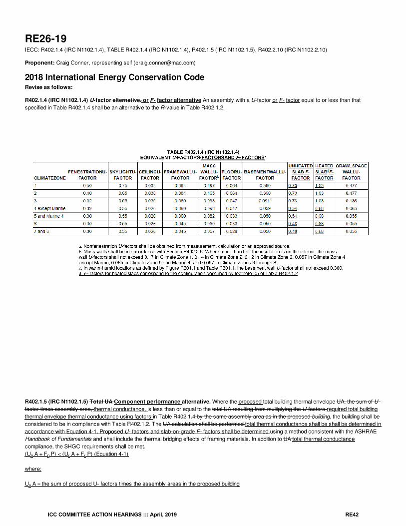
RE26-19IECC: R402.1.4 (IRC N1102.1.4), TABLE R402.1.4 (IRC N1102.1.4), R402.1.5 (IRC N1102.1.5), R402.2.10 (IRC N1102.2.10)
Proponent: Craig Conner, representing self ([email protected])
2018 International Energy Conservation CodeRevise as follows:
R402.1.4 (IRC N1102.1.4) U-factor alternative. or F- factor alternative An assembly with a U-factor or F- factor equal to or less than thatspecified in Table R402.1.4 shall be an alternative to the R-value in Table R402.1.2.
R402.1.5 (IRC N1102.1.5) Total UA Component performance alternative. Where the proposed total building thermal envelope UA, the sum of U-factor times assembly area, thermal conductance, is less than or equal to the total UA resulting from multiplying the U-factors required total buildingthermal envelope thermal conductance using factors in Table R402.1.4 by the same assembly area as in the proposed building, the building shall beconsidered to be in compliance with Table R402.1.2. The UA calculation shall be performed total thermal conductance shall be shall be determined inaccordance with Equation 4-1. Proposed U- factors and slab-on-grade F- factors shall be determined using a method consistent with the ASHRAEHandbook of Fundamentals and shall include the thermal bridging effects of framing materials. In addition to UA total thermal conductancecompliance, the SHGC requirements shall be met.(U A + F P) < (U A + F P) (Equation 4-1)
where:
U A = the sum of proposed U- factors times the assembly areas in the proposed building
p p r r
p
ICC COMMITTEE ACTION HEARINGS ::: April, 2019 RE42
F P = the sum of proposed F- factors times the slab-on-grade perimeter lengths in the proposed building
U A = the sum of U- factors in Table R402.1.4 times the same assembly areas as in the proposed building
F P = the sum of F- factors in Table R402.1.4 times the slab-on-grade perimeter lengths as in the proposed building
R402.2.10 (IRC N1102.2.10) Slab-on-grade floors. Slab-on-grade floors in contact with the ground with a floor surface less than 12 within 24inches (305 600 mm) above or below grade shall be insulated in accordance with Table R402.1.2. The insulation shall extend downward from the topof the slab on the outside or inside of the foundation wall. Insulation located below grade shall be extended the distance provided in Table R402.1.2by any combination of vertical insulation, insulation extending under the slab or insulation extending out from the building. building. Insulationextending away from the building shall be protected by pavement or by not less than 10 inches (254 mm) of soil. The top edge of the insulationinstalled between the exterior wall and the edge of the interior slab shall be permitted to be cut at a 45-degree (0.79 rad) angle away from the exteriorwall. Slab-edge insulation is not required in jurisdictions designated by the code official as having a very heavy termite infestation.
Reason: to clarify how slab-on-grade UA calculations are to be done and provide an approved source for F- factor data. Although standardcalculation procedures (such as ASHRAE's) cover the incorporation of slab conductances, and existing tools (such as REScheck) supportslab perimeter insulation tradeoffs in the UA alternative, the code currently gives little direction on slab-on-grade component performancecalculations. This clarifies the slab calculation. This is clarification only; there is no direct impact on energy use.
Cost Impact: The code change proposal will not increase or decrease the cost of constructionThere is no cost impact since there is no change in requirements. This just clarifies how insulation for slab on grade can be treated in the UAtradeoff calculation.
Proposal # 5667
RE26-19
p
r
r
ICC COMMITTEE ACTION HEARINGS ::: April, 2019 RE43
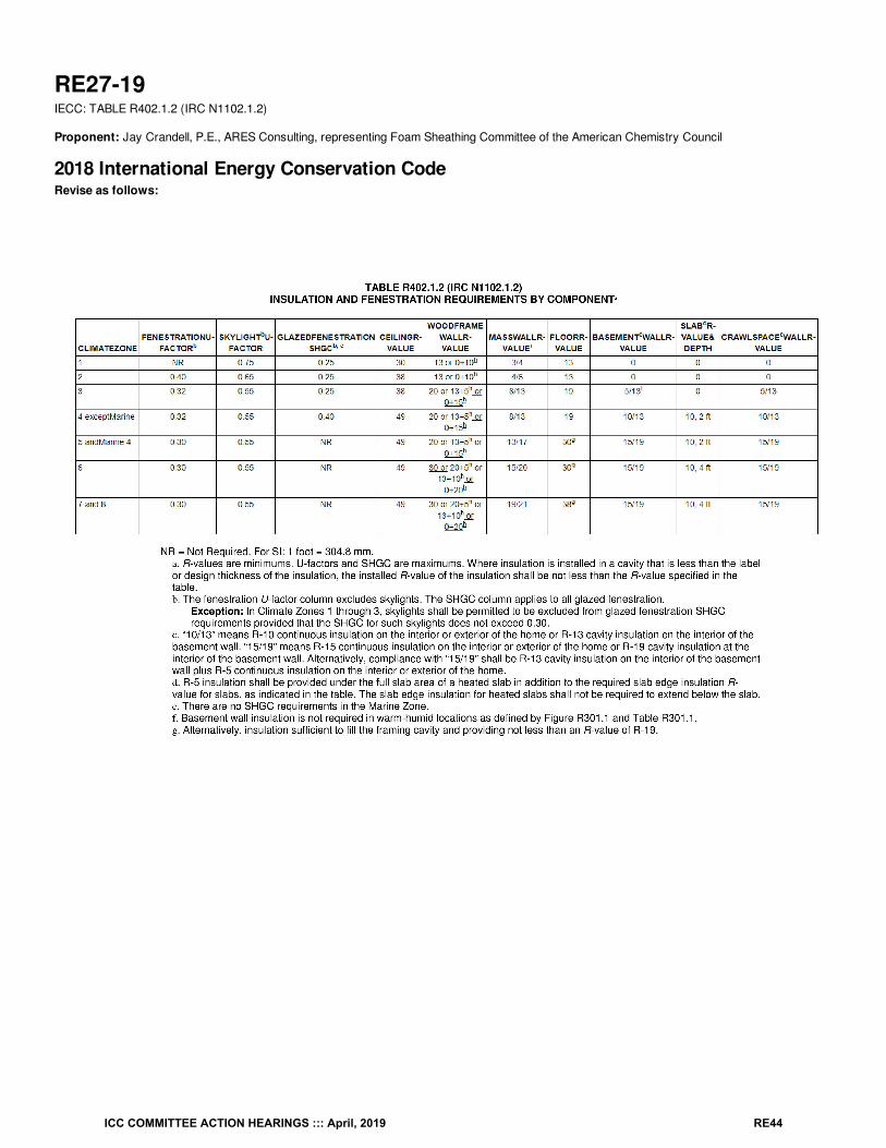
RE27-19IECC: TABLE R402.1.2 (IRC N1102.1.2)
Proponent: Jay Crandell, P.E., ARES Consulting, representing Foam Sheathing Committee of the American Chemistry Council
2018 International Energy Conservation CodeRevise as follows:
ICC COMMITTEE ACTION HEARINGS ::: April, 2019 RE44
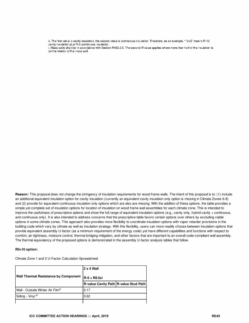
Reason: This proposal does not change the stringency of insulation requirements for wood frame walls. The intent of this proposal is to: (1) includean additional equivalent insulation option for cavity insulation (currently an equivalent cavity insulation only option is missing in Climate Zones 6-8)and (2) provide for equivalent continuous insulation only options which are also are missing. With the addition of these options, the table provides asimple yet complete set of insulation options for location of insulation on wood frame wall assemblies for each climate zone. This is intended toimprove the usefulness of prescriptive options and show the full range of equivalent insulation options (e.g., cavity only, hybrid cavity + continuous,and continuous only). It is also intended to address concerns that the prescriptive table favors certain options over others by excluding viableoptions in some climate zones. This approach also provides more flexibility to coordinate insulation options with vapor retarder provisions in thebuilding code which vary by climate as well as insulation strategy. With this flexibility, users can more readily choose between insulation options thatprovide equivalent assembly U-factor (as a minimum requirement of the energy code) yet have different capabilities and functions with respect tocomfort, air-tightness, moisture control, thermal bridging mitigation, and other factors that are important to an overall code-compliant wall assembly.The thermal equivalency of the proposed options is demonstrated in the assembly U-factor analysis tables that follow.
R0+10 option:
Climate Zone 1 and 2 U-Factor Calculation Spreadsheet
Wall Thermal Resistance by Component
2 x 4 Wall
R-0 + R8.5ci
R-value Cavity Path R-value Stud Path
Wall - Outside Winter Air Film 0.17
Siding - Vinyl 0.62
A
A
ICC COMMITTEE ACTION HEARINGS ::: April, 2019 RE45
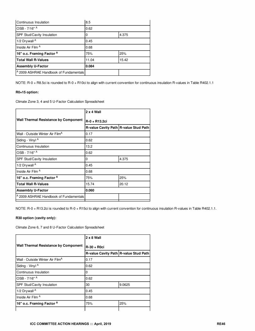
Continuous Insulation 8.5
OSB - 7/16" 0.62
SPF Stud/Cavity Insulation 0 4.375
1/2 Drywall 0.45
Inside Air Film 0.68
16" o.c. Framing Factor 75% 25%
Total Wall R-Values 11.04 15.42
Assembly U-Factor 0.084
2009 ASHRAE Handbook of Fundamentals
NOTE: R-0 + R8.5ci is rounded to R-0 + R10ci to align with current convention for continuous insulation R-values in Table R402.1.1
R0+15 option:
Climate Zone 3, 4 and 5 U-Factor Calculation Spreadsheet
Wall Thermal Resistance by Component
2 x 4 Wall
R-0 + R13.2ci
R-value Cavity Path R-value Stud Path
Wall - Outside Winter Air Film 0.17
Siding - Vinyl 0.62
Continuous Insulation 13.2
OSB - 7/16" 0.62
SPF Stud/Cavity Insulation 0 4.375
1/2 Drywall 0.45
Inside Air Film 0.68
16" o.c. Framing Factor 75% 25%
Total Wall R-Values 15.74 20.12
Assembly U-Factor 0.060
2009 ASHRAE Handbook of Fundamentals
NOTE: R-0 + R13.2ci is rounded to R-0 + R15ci to align with current convention for continuous insulation R-values in Table R402.1.1.
R30 option (cavity only):
Climate Zone 6, 7 and 8 U-Factor Calculation Spreadsheet
Wall Thermal Resistance by Component
2 x 8 Wall
R-30 + R0ci
R-value Cavity Path R-value Stud Path
Wall - Outside Winter Air Film 0.17
Siding - Vinyl 0.62
Continuous Insulation 0
OSB - 7/16" 0.62
SPF Stud/Cavity Insulation 30 9.0625
1/2 Drywall 0.45
Inside Air Film 0.68
16" o.c. Framing Factor 75% 25%
A
A
A
A
A
A
A
A
A
A
A
A
A
A
A
A
A
A
ICC COMMITTEE ACTION HEARINGS ::: April, 2019 RE46
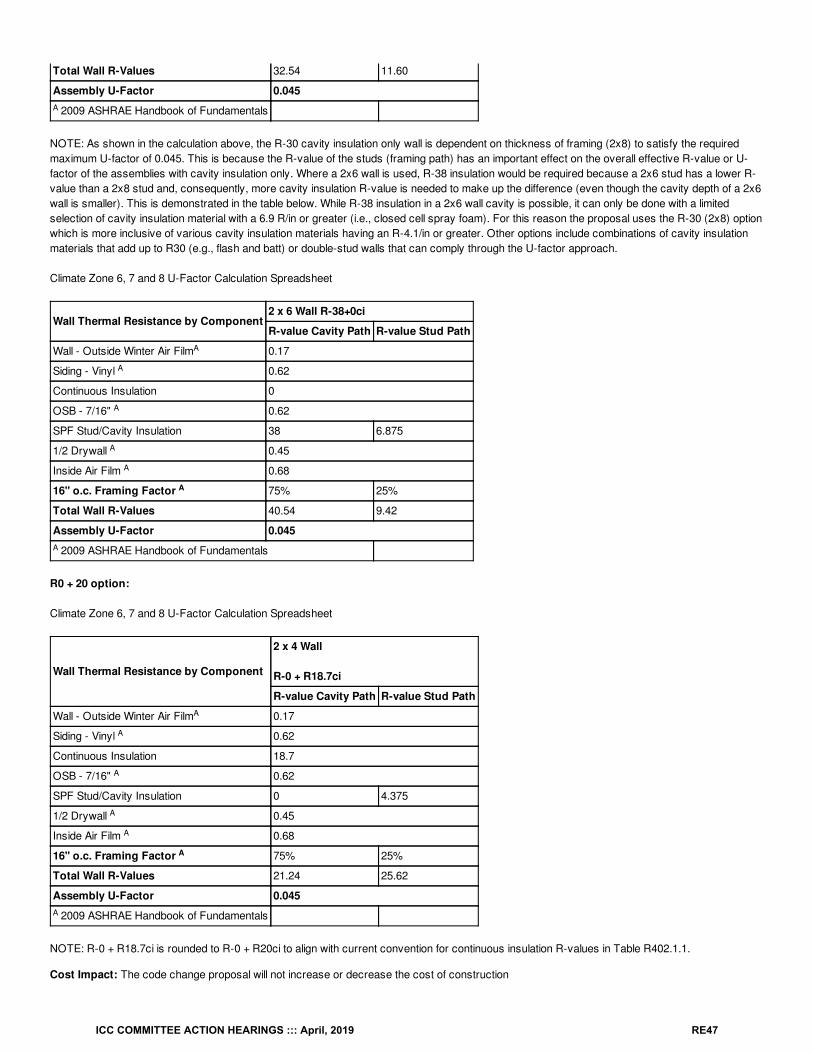
Total Wall R-Values 32.54 11.60
Assembly U-Factor 0.045
2009 ASHRAE Handbook of Fundamentals
NOTE: As shown in the calculation above, the R-30 cavity insulation only wall is dependent on thickness of framing (2x8) to satisfy the requiredmaximum U-factor of 0.045. This is because the R-value of the studs (framing path) has an important effect on the overall effective R-value or U-factor of the assemblies with cavity insulation only. Where a 2x6 wall is used, R-38 insulation would be required because a 2x6 stud has a lower R-value than a 2x8 stud and, consequently, more cavity insulation R-value is needed to make up the difference (even though the cavity depth of a 2x6wall is smaller). This is demonstrated in the table below. While R-38 insulation in a 2x6 wall cavity is possible, it can only be done with a limitedselection of cavity insulation material with a 6.9 R/in or greater (i.e., closed cell spray foam). For this reason the proposal uses the R-30 (2x8) optionwhich is more inclusive of various cavity insulation materials having an R-4.1/in or greater. Other options include combinations of cavity insulationmaterials that add up to R30 (e.g., flash and batt) or double-stud walls that can comply through the U-factor approach.
Climate Zone 6, 7 and 8 U-Factor Calculation Spreadsheet
Wall Thermal Resistance by Component2 x 6 Wall R-38+0ci
R-value Cavity Path R-value Stud Path
Wall - Outside Winter Air Film 0.17
Siding - Vinyl 0.62
Continuous Insulation 0
OSB - 7/16" 0.62
SPF Stud/Cavity Insulation 38 6.875
1/2 Drywall 0.45
Inside Air Film 0.68
16" o.c. Framing Factor 75% 25%
Total Wall R-Values 40.54 9.42
Assembly U-Factor 0.045
2009 ASHRAE Handbook of Fundamentals
R0 + 20 option:
Climate Zone 6, 7 and 8 U-Factor Calculation Spreadsheet
Wall Thermal Resistance by Component
2 x 4 Wall
R-0 + R18.7ci
R-value Cavity Path R-value Stud Path
Wall - Outside Winter Air Film 0.17
Siding - Vinyl 0.62
Continuous Insulation 18.7
OSB - 7/16" 0.62
SPF Stud/Cavity Insulation 0 4.375
1/2 Drywall 0.45
Inside Air Film 0.68
16" o.c. Framing Factor 75% 25%
Total Wall R-Values 21.24 25.62
Assembly U-Factor 0.045
2009 ASHRAE Handbook of Fundamentals
NOTE: R-0 + R18.7ci is rounded to R-0 + R20ci to align with current convention for continuous insulation R-values in Table R402.1.1.
Cost Impact: The code change proposal will not increase or decrease the cost of construction
A
A
A
A
A
A
A
A
A
A
A
A
A
A
A
ICC COMMITTEE ACTION HEARINGS ::: April, 2019 RE47
The proposal merely provides additional equivalent options for compliance to ensure no one approach or insulation material or its location on or in anassembly is preferentially treated over another in any of the climate zones.
Proposal # 4509
RE27-19
ICC COMMITTEE ACTION HEARINGS ::: April, 2019 RE48
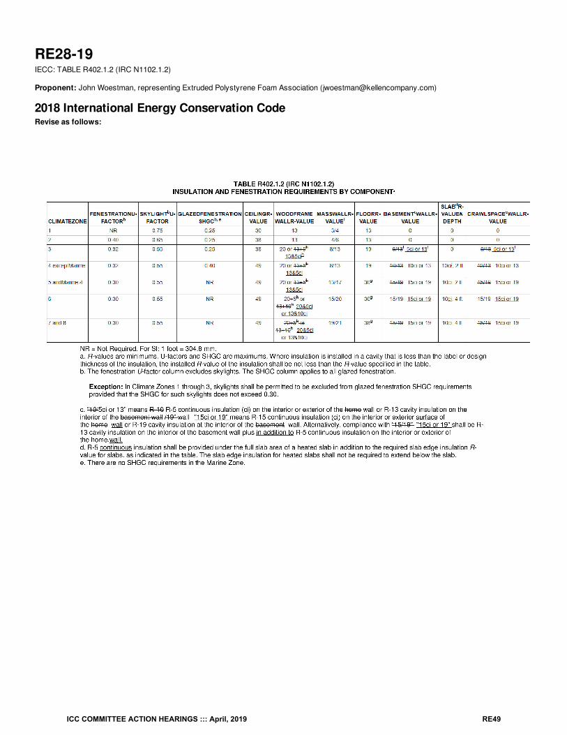
RE28-19IECC: TABLE R402.1.2 (IRC N1102.1.2)
Proponent: John Woestman, representing Extruded Polystyrene Foam Association ([email protected])
2018 International Energy Conservation CodeRevise as follows:
ICC COMMITTEE ACTION HEARINGS ::: April, 2019 RE49
Reason: This proposal is a clarification of insulation requirements in relation to cavity and continuous insulation applications. This proposal isintended to clarify compliance with Section R402.1.3.In Table R402.1.2, “ci” is inserted wherever continuous insulation is a prescriptive requirement and / or option. Also, the “+” in several cells isreplaced with “&” to more appropriately indicate the continuous insulation (ci), along with the cavity insulation, are both required where the CZrequires both. In footnote “c” replacing “and” with “in addition to” to clearly communicate in these situations both cavity insulation and continuousinsulation are required.
In the basement and crawl space wall columns, the “/” is replace with “or” to clearly communicate either is acceptable (ci or cavity insulation).
Also, suggesting a bit of cleanup in footnote “c”. Footnote “c” is used for Basement Wall R-value and for Crawl Space Wall R-value. Use of“basement” in the footnote is not quite accurate since this footnote applies equally to basement or crawlspace walls. And, use of “home” is toobroad. It seems the use of “wall” is better than the current text. And, in footnote “c” replacing “and” with “in addition to” to clearly communicate inthese situations both cavity insulation and continuous insulation are required.
In the crawl space wall column, inserting footnote “f” similar to where footnote “f” is placed in the basement wall column, and modifying footnote “f” toinclude crawl space walls. It seems logical that crawl space wall insulation would be required – or not required – per the same criteria as basementwalls.
Cost Impact: The code change proposal will not increase or decrease the cost of constructionThere should be no cost implications as no technical changes are intended.
However, if adding footnote “f” to the crawl space wall column is a technical change, this proposal would decrease the cost of construction.
Proposal # 5233
ICC COMMITTEE ACTION HEARINGS ::: April, 2019 RE50

RE28-19
ICC COMMITTEE ACTION HEARINGS ::: April, 2019 RE51
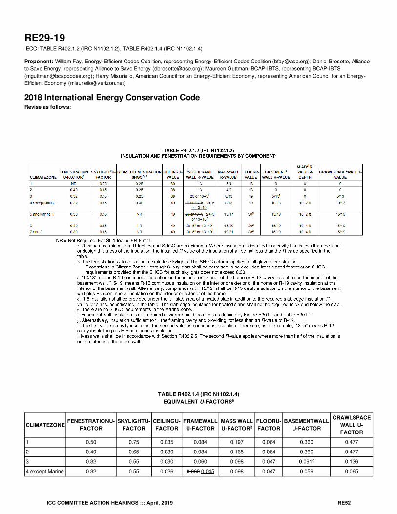
RE29-19IECC: TABLE R402.1.2 (IRC N1102.1.2), TABLE R402.1.4 (IRC N1102.1.4)
Proponent: William Fay, Energy-Efficient Codes Coalition, representing Energy-Efficient Codes Coalition ([email protected]); Daniel Bresette, Allianceto Save Energy, representing Alliance to Save Energy ([email protected]); Maureen Guttman, BCAP-IBTS, representing BCAP-IBTS([email protected]); Harry Misuriello, American Council for an Energy-Efficient Economy, representing American Council for an Energy-Efficient Economy ([email protected])
2018 International Energy Conservation CodeRevise as follows:
TABLE R402.1.4 (IRC N1102.1.4)EQUIVALENT U-FACTORS
CLIMATEZONEFENESTRATIONU-
FACTORSKYLIGHTU-
FACTORCEILINGU-FACTOR
FRAMEWALLU-FACTOR
MASS WALLU-FACTOR
FLOORU-FACTOR
BASEMENTWALLU-FACTOR
CRAWLSPACEWALL U-FACTOR
1 0.50 0.75 0.035 0.084 0.197 0.064 0.360 0.477
2 0.40 0.65 0.030 0.084 0.165 0.064 0.360 0.477
3 0.32 0.55 0.030 0.060 0.098 0.047 0.091 0.136
4 except Marine 0.32 0.55 0.026 0.060 0.045 0.098 0.047 0.059 0.065
a
b
c
ICC COMMITTEE ACTION HEARINGS ::: April, 2019 RE52
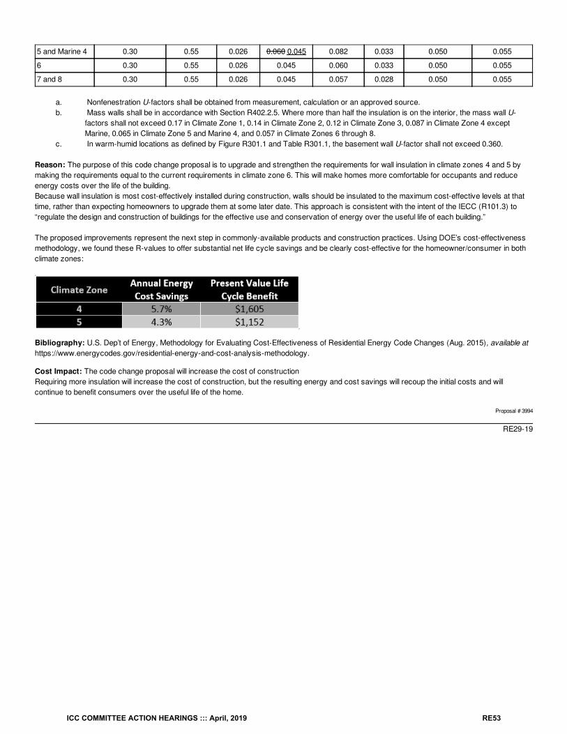
5 and Marine 4 0.30 0.55 0.026 0.060 0.045 0.082 0.033 0.050 0.055
6 0.30 0.55 0.026 0.045 0.060 0.033 0.050 0.055
7 and 8 0.30 0.55 0.026 0.045 0.057 0.028 0.050 0.055
a. Nonfenestration U-factors shall be obtained from measurement, calculation or an approved source.b. Mass walls shall be in accordance with Section R402.2.5. Where more than half the insulation is on the interior, the mass wall U-
factors shall not exceed 0.17 in Climate Zone 1, 0.14 in Climate Zone 2, 0.12 in Climate Zone 3, 0.087 in Climate Zone 4 exceptMarine, 0.065 in Climate Zone 5 and Marine 4, and 0.057 in Climate Zones 6 through 8.
c. In warm-humid locations as defined by Figure R301.1 and Table R301.1, the basement wall U-factor shall not exceed 0.360.
Reason: The purpose of this code change proposal is to upgrade and strengthen the requirements for wall insulation in climate zones 4 and 5 bymaking the requirements equal to the current requirements in climate zone 6. This will make homes more comfortable for occupants and reduceenergy costs over the life of the building.Because wall insulation is most cost-effectively installed during construction, walls should be insulated to the maximum cost-effective levels at thattime, rather than expecting homeowners to upgrade them at some later date. This approach is consistent with the intent of the IECC (R101.3) to“regulate the design and construction of buildings for the effective use and conservation of energy over the useful life of each building.”
The proposed improvements represent the next step in commonly-available products and construction practices. Using DOE’s cost-effectivenessmethodology, we found these R-values to offer substantial net life cycle savings and be clearly cost-effective for the homeowner/consumer in bothclimate zones:
Bibliography: U.S. Dep’t of Energy, Methodology for Evaluating Cost-Effectiveness of Residential Energy Code Changes (Aug. 2015), available athttps://www.energycodes.gov/residential-energy-and-cost-analysis-methodology.
Cost Impact: The code change proposal will increase the cost of constructionRequiring more insulation will increase the cost of construction, but the resulting energy and cost savings will recoup the initial costs and willcontinue to benefit consumers over the useful life of the home.
Proposal # 3994
RE29-19
ICC COMMITTEE ACTION HEARINGS ::: April, 2019 RE53
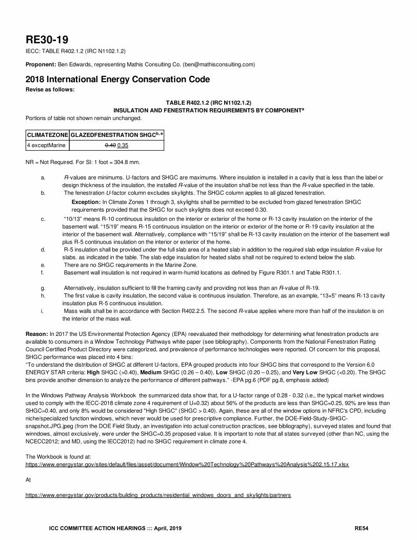
RE30-19IECC: TABLE R402.1.2 (IRC N1102.1.2)
Proponent: Ben Edwards, representing Mathis Consulting Co. ([email protected])
2018 International Energy Conservation CodeRevise as follows:
TABLE R402.1.2 (IRC N1102.1.2)INSULATION AND FENESTRATION REQUIREMENTS BY COMPONENT
Portions of table not shown remain unchanged.
CLIMATEZONE GLAZEDFENESTRATION SHGC
4 exceptMarine 0.40 0.35
NR = Not Required. For SI: 1 foot = 304.8 mm.
a. R-values are minimums. U-factors and SHGC are maximums. Where insulation is installed in a cavity that is less than the label ordesign thickness of the insulation, the installed R-value of the insulation shall be not less than the R-value specified in the table.
b. The fenestration U-factor column excludes skylights. The SHGC column applies to all glazed fenestration.
Exception: In Climate Zones 1 through 3, skylights shall be permitted to be excluded from glazed fenestration SHGCrequirements provided that the SHGC for such skylights does not exceed 0.30.
c. “10/13” means R-10 continuous insulation on the interior or exterior of the home or R-13 cavity insulation on the interior of thebasement wall. “15/19” means R-15 continuous insulation on the interior or exterior of the home or R-19 cavity insulation at theinterior of the basement wall. Alternatively, compliance with “15/19” shall be R-13 cavity insulation on the interior of the basement wallplus R-5 continuous insulation on the interior or exterior of the home.
d. R-5 insulation shall be provided under the full slab area of a heated slab in addition to the required slab edge insulation R-value forslabs. as indicated in the table. The slab edge insulation for heated slabs shall not be required to extend below the slab.
e. There are no SHGC requirements in the Marine Zone.f. Basement wall insulation is not required in warm-humid locations as defined by Figure R301.1 and Table R301.1.
g. Alternatively, insulation sufficient to fill the framing cavity and providing not less than an R-value of R-19.h. The first value is cavity insulation, the second value is continuous insulation. Therefore, as an example, “13+5” means R-13 cavity
insulation plus R-5 continuous insulation.i. Mass walls shall be in accordance with Section R402.2.5. The second R-value applies where more than half of the insulation is on
the interior of the mass wall.
Reason: In 2017 the US Environmental Protection Agency (EPA) reevaluated their methodology for determining what fenestration products areavailable to consumers in a Window Technology Pathways white paper (see bibliography). Components from the National Fenestration RatingCouncil Certified Product Directory were categorized, and prevalence of performance technologies were reported. Of concern for this proposal,SHGC performance was placed into 4 bins:“To understand the distribution of SHGC at different U-factors, EPA grouped products into four SHGC bins that correspond to the Version 6.0ENERGY STAR criteria: High SHGC (>0.40), Medium SHGC (0.26 – 0.40), Low SHGC (0.20 – 0.25), and Very Low SHGC (<0.20). The SHGCbins provide another dimension to analyze the performance of different pathways.” -EPA pg.6 (PDF pg.8, emphasis added)
In the Windows Pathway Analysis Workbook the summarized data show that, for a U-factor range of 0.28 - 0.32 (i.e., the typical market windowsused to comply with the IECC-2018 climate zone 4 requirement of U=0.32) about 56% of the products are less than SHGC=0.25, 92% are less thanSHGC=0.40, and only 8% would be considered "High SHGC" (SHGC > 0.40). Again, these are all of the window options in NFRC's CPD, includingniche/specialized function windows, which never would be used for prescriptive compliance. Further, the DOE-Field-Study-SHGC-snapshot.JPG.jpeg (from the DOE Field Study, an investigation into actual construction practices, see bibliography), surveyed states and found thatwinndows, almost exclusively, were under the SHGC=0.35 proposed value. It is important to note that all states surveyed (other than NC, using theNCECC2012; and MD, using the IECC2012) had no SHGC requirement in climate zone 4.
The Workbook is found at:https://www.energystar.gov/sites/default/files/asset/document/Window%20Technology%20Pathways%20Analysis%202.15.17.xlsx
At
https://www.energystar.gov/products/building_products/residential_windows_doors_and_skylights/partners
a
b, e
ICC COMMITTEE ACTION HEARINGS ::: April, 2019 RE54
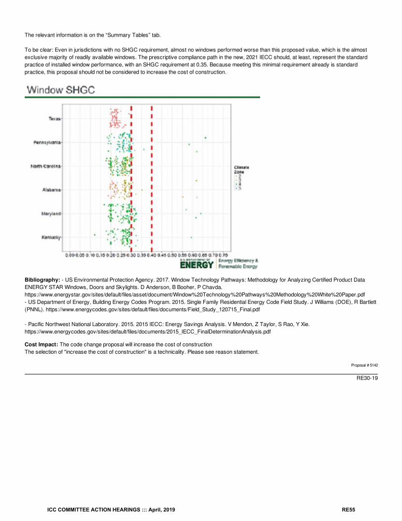
The relevant information is on the “Summary Tables” tab.
To be clear: Even in jurisdictions with no SHGC requirement, almost no windows performed worse than this proposed value, which is the almostexclusive majority of readily available windows. The prescriptive compliance path in the new, 2021 IECC should, at least, represent the standardpractice of installed window performance, with an SHGC requirement at 0.35. Because meeting this minimal requirement already is standardpractice, this proposal should not be considered to increase the cost of construction.
Bibliography: - US Environmental Protection Agency. 2017. Window Technology Pathways: Methodology for Analyzing Certified Product DataENERGY STAR Windows, Doors and Skylights. D Anderson, B Booher, P Chavda.https://www.energystar.gov/sites/default/files/asset/document/Window%20Technology%20Pathways%20Methodology%20White%20Paper.pdf- US Department of Energy, Building Energy Codes Program. 2015. Single Family Residential Energy Code Field Study. J Williams (DOE), R Bartlett(PNNL). https://www.energycodes.gov/sites/default/files/documents/Field_Study_120715_Final.pdf
- Pacific Northwest National Laboratory. 2015. 2015 IECC: Energy Savings Analysis. V Mendon, Z Taylor, S Rao, Y Xie.https://www.energycodes.gov/sites/default/files/documents/2015_IECC_FinalDeterminationAnalysis.pdf
Cost Impact: The code change proposal will increase the cost of constructionThe selection of "increase the cost of construction" is a technicality. Please see reason statement.
Proposal # 5142
RE30-19
ICC COMMITTEE ACTION HEARINGS ::: April, 2019 RE55
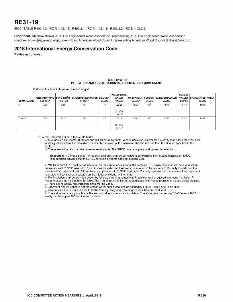
RE31-19IECC: TABLE R402.1.2 (IRC N1102.1.2), R402.2.1 (IRC N1102.1.1), R402.2.2 (IRC N1102.2.2)
Proponent: Matthew Brown, APA-The Engineered Wood Association, representing APA-The Engineered Wood Association([email protected]); Loren Ross, American Wood Council, representing American Wood Council ([email protected])
2018 International Energy Conservation CodeRevise as follows:
ICC COMMITTEE ACTION HEARINGS ::: April, 2019 RE56
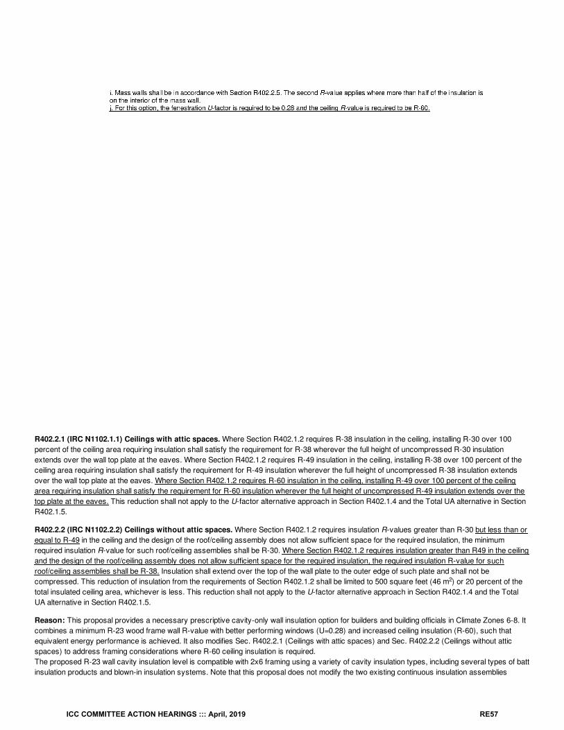
R402.2.1 (IRC N1102.1.1) Ceilings with attic spaces. Where Section R402.1.2 requires R-38 insulation in the ceiling, installing R-30 over 100percent of the ceiling area requiring insulation shall satisfy the requirement for R-38 wherever the full height of uncompressed R-30 insulationextends over the wall top plate at the eaves. Where Section R402.1.2 requires R-49 insulation in the ceiling, installing R-38 over 100 percent of theceiling area requiring insulation shall satisfy the requirement for R-49 insulation wherever the full height of uncompressed R-38 insulation extendsover the wall top plate at the eaves. Where Section R402.1.2 requires R-60 insulation in the ceiling, installing R-49 over 100 percent of the ceilingarea requiring insulation shall satisfy the requirement for R-60 insulation wherever the full height of uncompressed R-49 insulation extends over thetop plate at the eaves. This reduction shall not apply to the U-factor alternative approach in Section R402.1.4 and the Total UA alternative in SectionR402.1.5.
R402.2.2 (IRC N1102.2.2) Ceilings without attic spaces. Where Section R402.1.2 requires insulation R-values greater than R-30 but less than orequal to R-49 in the ceiling and the design of the roof/ceiling assembly does not allow sufficient space for the required insulation, the minimumrequired insulation R-value for such roof/ceiling assemblies shall be R-30. Where Section R402.1.2 requires insulation greater than R49 in the ceilingand the design of the roof/ceiling assembly does not allow sufficient space for the required insulation, the required insulation R-value for suchroof/ceiling assemblies shall be R-38. Insulation shall extend over the top of the wall plate to the outer edge of such plate and shall not becompressed. This reduction of insulation from the requirements of Section R402.1.2 shall be limited to 500 square feet (46 m ) or 20 percent of thetotal insulated ceiling area, whichever is less. This reduction shall not apply to the U-factor alternative approach in Section R402.1.4 and the TotalUA alternative in Section R402.1.5.
Reason: This proposal provides a necessary prescriptive cavity-only wall insulation option for builders and building officials in Climate Zones 6-8. Itcombines a minimum R-23 wood frame wall R-value with better performing windows (U=0.28) and increased ceiling insulation (R-60), such thatequivalent energy performance is achieved. It also modifies Sec. R402.2.1 (Ceilings with attic spaces) and Sec. R402.2.2 (Ceilings without atticspaces) to address framing considerations where R-60 ceiling insulation is required.The proposed R-23 wall cavity insulation level is compatible with 2x6 framing using a variety of cavity insulation types, including several types of battinsulation products and blown-in insulation systems. Note that this proposal does not modify the two existing continuous insulation assemblies
2
ICC COMMITTEE ACTION HEARINGS ::: April, 2019 RE57
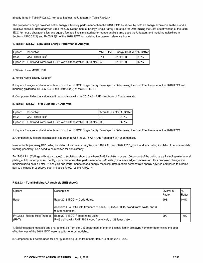
already listed in Table R402.1.2, nor does it affect the U-factors in Table R402.1.4.
The proposed change provides better energy efficiency performance than the 2018 IECC as shown by both an energy simulation analysis and aTotal UA analysis. Both analyses used the U.S. Department of Energy Single Family Prototype for Determining the Cost Effectiveness of the 2018IECC for house characteristics and square footage The simulated performance analysis also used the U-factors and modeling guidelines inSections R405.5.2(1) and R405.5.2(2) of the 2018 IECC for modeling the base or reference home.
1. Table R402.1.2 - Simulated Energy Performance Analysis
Option: Description: MMBTU/YR Energy Cost YR % Better
Base Base 2018 IECC 87.4 $1309.00 0.0%
Option 2 R-23 wood frame wall, U-.28 vertical fenestration, R-60 attic 85.9 $1292.00 0.3%
1. Whole Home MMBTU/YR
2. Whole Home Energy Cost/YR
3. Square footages and attributes taken from the US DOE Single Family Prototype for Determining the Cost Effectiveness of the 2018 IECC andmodeling guidelines in R405.5.2(1) and R405.5.2(2) of the 2018 IECC.
4. Component U-factors calculated in accordance with the 2015 ASHRAE Handbook of Fundamentals.
2. Table R402.1.2 -Total Building UA Analysis
Option: Description: Overall U-Factor % Better
Base Base 2018 IECC 313 0.0%
Option 2 R-23 wood frame wall, U-.28 vertical fenestration, R-60 attic 309 1.3%
1. Square footages and attributes taken from the US DOE Single Family Prototype for Determining the Cost Effectiveness of the 2018 IECC.
2. Component U-factors calculated in accordance with the 2015 ASHRAE Handbook of Fundamentals.
New footnote j requires R60 ceiling insulation. This means that Section R402.2.2.1 and R402.2.2.2, which address ceiling insulation to accommodateframing geometry, also need to be modified for consistency.
For R402.2.1, (Ceilings with attic spaces), calculations show that where R-49 insulation covers 100 percent of the ceiling area, including exterior wallplates, at full, uncompressed depth, it provides equivalent performance to R-60 with typical eave edge compression. This proposed change wasmodeled using both a Total UA analysis and Performance based energy modeling. Both models demonstrate energy savings compared to a homebuilt to the base prescriptive path in Tables R402.1.2 and R402.1.4.
R402.2.1 - Total Building UA Analysis (REScheck):
Option: Description: Overall U-Factor
%Better
Base Base 2018 IECC - Code Home:
(Includes R-49 attic with Standard trusses, R-20+5 (U-0.45) wood frame walls, and U-0.30 fenestration.)
293 0.0%
R402.2.1- Raised Heel Trusses(RHT)
Base 2018 IECC code home using:R-49 ceiling with RHT, R-23 wood frame wall, U-.28 fenestration.
290 1.0%
1. Building square footages and characteristics from the U.S department of energy’s single family prototype home for determining the costeffectiveness of the 2018 IECC were used for energy modeling.
2. Component U-Factors used for energy modeling taken from table R402.1.4 of the 2018 IECC.
1 2
3
4
1
2
1,2
1,3
ICC COMMITTEE ACTION HEARINGS ::: April, 2019 RE58
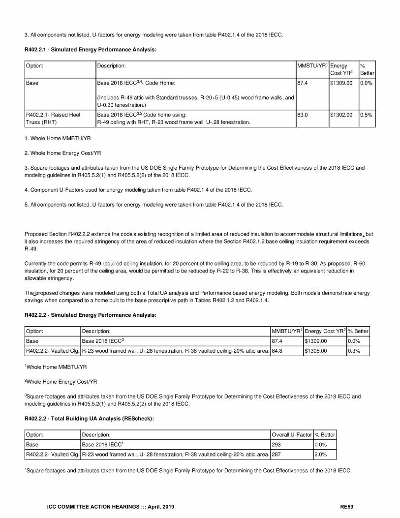
3. All components not listed, U-factors for energy modeling were taken from table R402.1.4 of the 2018 IECC.
R402.2.1 - Simulated Energy Performance Analysis:
Option: Description: MMBTU/YR EnergyCost YR
%Better
Base Base 2018 IECC - Code Home:
(Includes R-49 attic with Standard trusses, R-20+5 (U-0.45) wood frame walls, andU-0.30 fenestration.)
87.4 $1309.00 0.0%
R402.2.1- Raised HeelTruss (RHT)
Base 2018 IECC Code home using:R-49 ceiling with RHT, R-23 wood frame wall, U-.28 fenestration.
83.0 $1302.00 0.5%
1. Whole Home MMBTU/YR
2. Whole Home Energy Cost/YR
3. Square footages and attributes taken from the US DOE Single Family Prototype for Determining the Cost Effectiveness of the 2018 IECC andmodeling guidelines in R405.5.2(1) and R405.5.2(2) of the 2018 IECC.
4. Component U-Factors used for energy modeling taken from table R402.1.4 of the 2018 IECC.
5. All components not listed, U-factors for energy modeling were taken from table R402.1.4 of the 2018 IECC.
Proposed Section R402.2.2 extends the code’s existing recognition of a limited area of reduced insulation to accommodate structural limitations, butit also increases the required stringency of the area of reduced insulation where the Section R402.1.2 base ceiling insulation requirement exceedsR-49.
Currently the code permits R-49 required ceiling insulation, for 20 percent of the ceiling area, to be reduced by R-19 to R-30. As proposed, R-60insulation, for 20 percent of the ceiling area, would be permitted to be reduced by R-22 to R-38. This is effectively an equivalent reduction inallowable stringency.
The proposed changes were modeled using both a Total UA analysis and Performance based energy modeling. Both models demonstrate energysavings when compared to a home built to the base prescriptive path in Tables R402.1.2 and R402.1.4.
R402.2.2 - Simulated Energy Performance Analysis:
Option: Description: MMBTU/YR Energy Cost YR % Better
Base Base 2018 IECC 87.4 $1309.00 0.0%
R402.2.2- Vaulted Clg. R-23 wood framed wall, U-.28 fenestration, R-38 vaulted ceiling-20% attic area. 84.8 $1305.00 0.3%
Whole Home MMBTU/YR
Whole Home Energy Cost/YR
Square footages and attributes taken from the US DOE Single Family Prototype for Determining the Cost Effectiveness of the 2018 IECC andmodeling guidelines in R405.5.2(1) and R405.5.2(2) of the 2018 IECC.
R402.2.2 - Total Building UA Analysis (REScheck):
Option: Description: Overall U-Factor % Better
Base Base 2018 IECC 293 0.0%
R402.2.2- Vaulted Clg. R-23 wood framed wall, U-.28 fenestration, R-38 vaulted ceiling-20% attic area. 287 2.0%
Square footages and attributes taken from the US DOE Single Family Prototype for Determining the Cost Effectiveness of the 2018 IECC.
1
2
3,4
3,5
1 2
3
1
2
3
1
1
ICC COMMITTEE ACTION HEARINGS ::: April, 2019 RE59
Cost Impact: The code change proposal will not increase or decrease the cost of constructionWhile it has the potential to decrease the cost of construction, the proposal cannot increase construction costs since it merely adds anotherprescriptive option for builders.
Proposal # 5185
RE31-19
ICC COMMITTEE ACTION HEARINGS ::: April, 2019 RE60
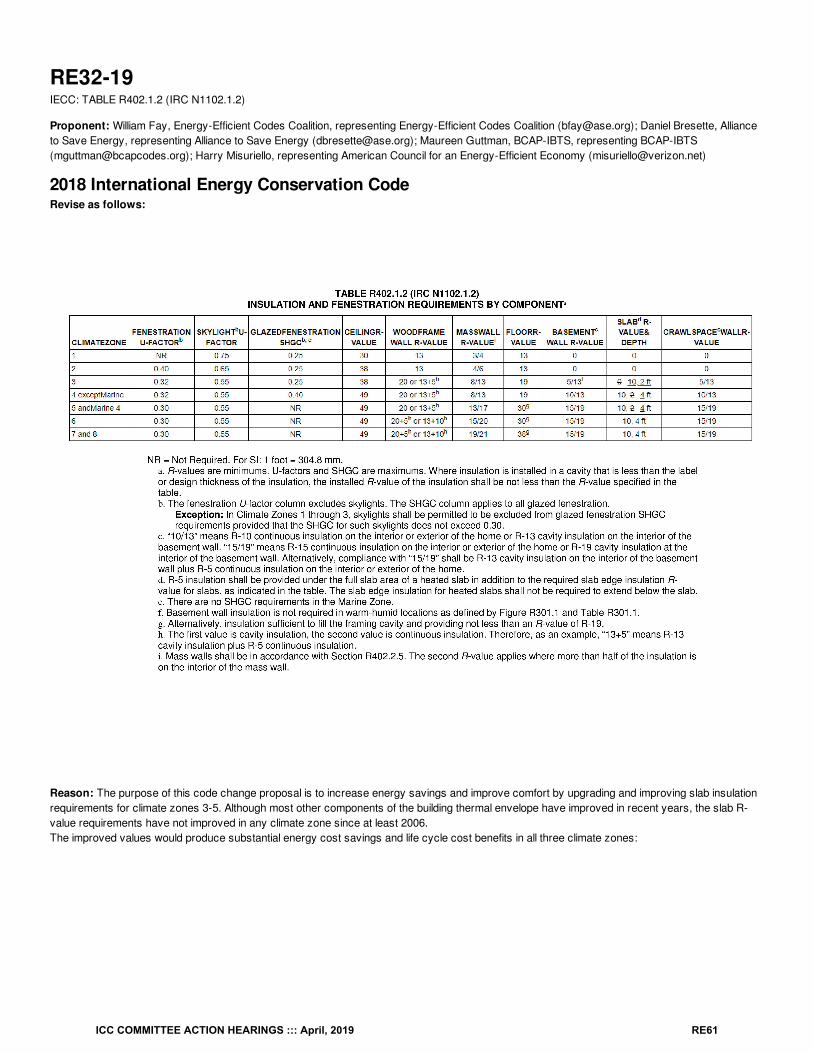
RE32-19IECC: TABLE R402.1.2 (IRC N1102.1.2)
Proponent: William Fay, Energy-Efficient Codes Coalition, representing Energy-Efficient Codes Coalition ([email protected]); Daniel Bresette, Allianceto Save Energy, representing Alliance to Save Energy ([email protected]); Maureen Guttman, BCAP-IBTS, representing BCAP-IBTS([email protected]); Harry Misuriello, representing American Council for an Energy-Efficient Economy ([email protected])
2018 International Energy Conservation CodeRevise as follows:
Reason: The purpose of this code change proposal is to increase energy savings and improve comfort by upgrading and improving slab insulationrequirements for climate zones 3-5. Although most other components of the building thermal envelope have improved in recent years, the slab R-value requirements have not improved in any climate zone since at least 2006.The improved values would produce substantial energy cost savings and life cycle cost benefits in all three climate zones:
ICC COMMITTEE ACTION HEARINGS ::: April, 2019 RE61
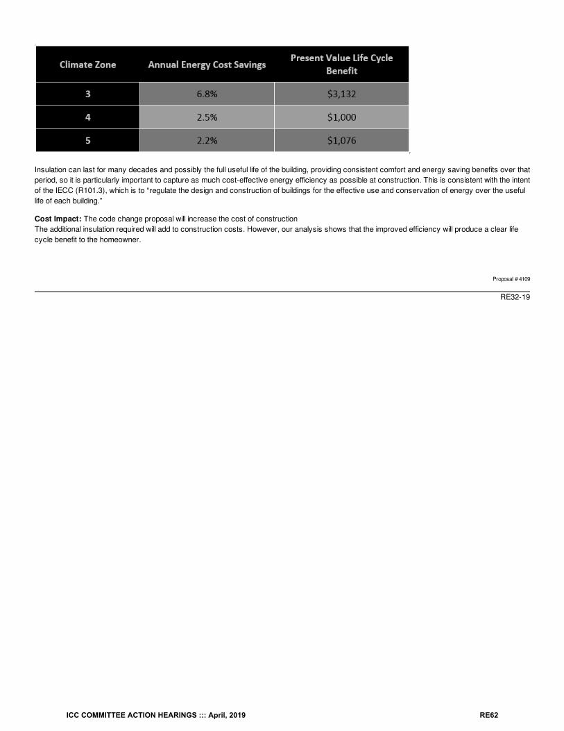
Insulation can last for many decades and possibly the full useful life of the building, providing consistent comfort and energy saving benefits over thatperiod, so it is particularly important to capture as much cost-effective energy efficiency as possible at construction. This is consistent with the intentof the IECC (R101.3), which is to “regulate the design and construction of buildings for the effective use and conservation of energy over the usefullife of each building.”
Cost Impact: The code change proposal will increase the cost of constructionThe additional insulation required will add to construction costs. However, our analysis shows that the improved efficiency will produce a clear lifecycle benefit to the homeowner.
Proposal # 4109
RE32-19
ICC COMMITTEE ACTION HEARINGS ::: April, 2019 RE62
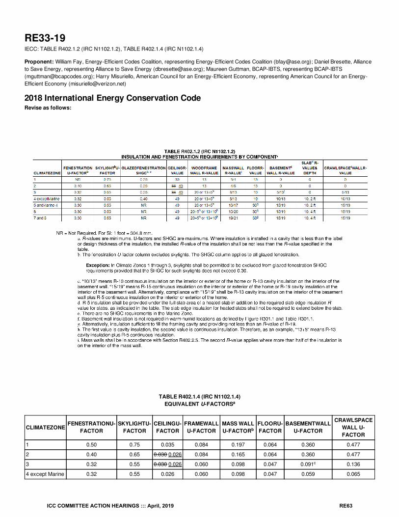
RE33-19IECC: TABLE R402.1.2 (IRC N1102.1.2), TABLE R402.1.4 (IRC N1102.1.4)
Proponent: William Fay, Energy-Efficient Codes Coalition, representing Energy-Efficient Codes Coalition ([email protected]); Daniel Bresette, Allianceto Save Energy, representing Alliance to Save Energy ([email protected]); Maureen Guttman, BCAP-IBTS, representing BCAP-IBTS([email protected]); Harry Misuriello, American Council for an Energy-Efficient Economy, representing American Council for an Energy-Efficient Economy ([email protected])
2018 International Energy Conservation CodeRevise as follows:
TABLE R402.1.4 (IRC N1102.1.4)EQUIVALENT U-FACTORS
CLIMATEZONEFENESTRATIONU-
FACTORSKYLIGHTU-
FACTORCEILINGU-FACTOR
FRAMEWALLU-FACTOR
MASS WALLU-FACTOR
FLOORU-FACTOR
BASEMENTWALLU-FACTOR
CRAWLSPACEWALL U-FACTOR
1 0.50 0.75 0.035 0.084 0.197 0.064 0.360 0.477
2 0.40 0.65 0.030 0.026 0.084 0.165 0.064 0.360 0.477
3 0.32 0.55 0.030 0.026 0.060 0.098 0.047 0.091 0.136
4 except Marine 0.32 0.55 0.026 0.060 0.098 0.047 0.059 0.065
a
b
c
ICC COMMITTEE ACTION HEARINGS ::: April, 2019 RE63
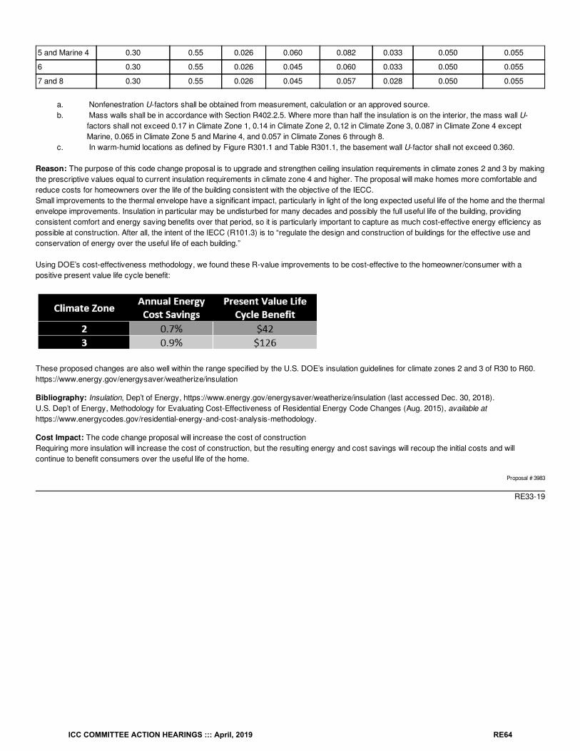
5 and Marine 4 0.30 0.55 0.026 0.060 0.082 0.033 0.050 0.055
6 0.30 0.55 0.026 0.045 0.060 0.033 0.050 0.055
7 and 8 0.30 0.55 0.026 0.045 0.057 0.028 0.050 0.055
a. Nonfenestration U-factors shall be obtained from measurement, calculation or an approved source.b. Mass walls shall be in accordance with Section R402.2.5. Where more than half the insulation is on the interior, the mass wall U-
factors shall not exceed 0.17 in Climate Zone 1, 0.14 in Climate Zone 2, 0.12 in Climate Zone 3, 0.087 in Climate Zone 4 exceptMarine, 0.065 in Climate Zone 5 and Marine 4, and 0.057 in Climate Zones 6 through 8.
c. In warm-humid locations as defined by Figure R301.1 and Table R301.1, the basement wall U-factor shall not exceed 0.360.
Reason: The purpose of this code change proposal is to upgrade and strengthen ceiling insulation requirements in climate zones 2 and 3 by makingthe prescriptive values equal to current insulation requirements in climate zone 4 and higher. The proposal will make homes more comfortable andreduce costs for homeowners over the life of the building consistent with the objective of the IECC.Small improvements to the thermal envelope have a significant impact, particularly in light of the long expected useful life of the home and the thermalenvelope improvements. Insulation in particular may be undisturbed for many decades and possibly the full useful life of the building, providingconsistent comfort and energy saving benefits over that period, so it is particularly important to capture as much cost-effective energy efficiency aspossible at construction. After all, the intent of the IECC (R101.3) is to “regulate the design and construction of buildings for the effective use andconservation of energy over the useful life of each building.”
Using DOE’s cost-effectiveness methodology, we found these R-value improvements to be cost-effective to the homeowner/consumer with apositive present value life cycle benefit:
These proposed changes are also well within the range specified by the U.S. DOE’s insulation guidelines for climate zones 2 and 3 of R30 to R60.https://www.energy.gov/energysaver/weatherize/insulation
Bibliography: Insulation, Dep’t of Energy, https://www.energy.gov/energysaver/weatherize/insulation (last accessed Dec. 30, 2018).U.S. Dep’t of Energy, Methodology for Evaluating Cost-Effectiveness of Residential Energy Code Changes (Aug. 2015), available athttps://www.energycodes.gov/residential-energy-and-cost-analysis-methodology.
Cost Impact: The code change proposal will increase the cost of constructionRequiring more insulation will increase the cost of construction, but the resulting energy and cost savings will recoup the initial costs and willcontinue to benefit consumers over the useful life of the home.
Proposal # 3983
RE33-19
ICC COMMITTEE ACTION HEARINGS ::: April, 2019 RE64
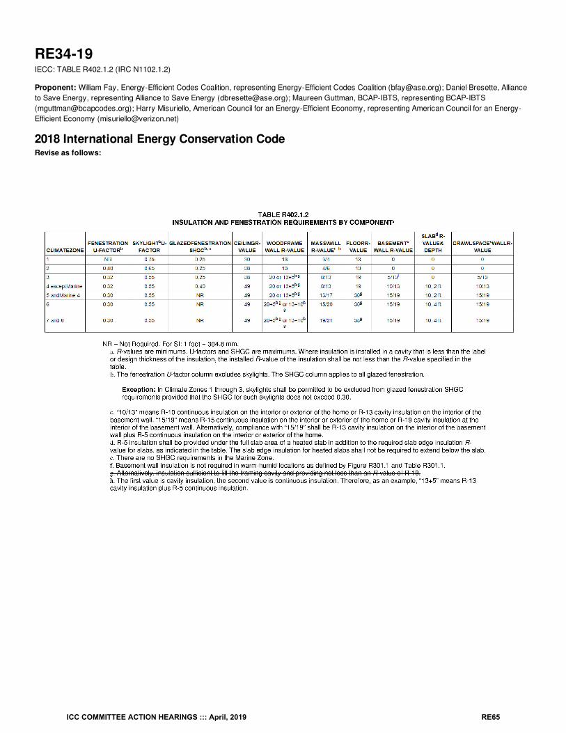
RE34-19IECC: TABLE R402.1.2 (IRC N1102.1.2)
Proponent: William Fay, Energy-Efficient Codes Coalition, representing Energy-Efficient Codes Coalition ([email protected]); Daniel Bresette, Allianceto Save Energy, representing Alliance to Save Energy ([email protected]); Maureen Guttman, BCAP-IBTS, representing BCAP-IBTS([email protected]); Harry Misuriello, American Council for an Energy-Efficient Economy, representing American Council for an Energy-Efficient Economy ([email protected])
2018 International Energy Conservation CodeRevise as follows:
ICC COMMITTEE ACTION HEARINGS ::: April, 2019 RE65
Reason: The purpose of this code change proposal is to improve the efficiency of homes in the coldest climate zones by removing an exceptionthat allows weaker floor insulation R-values with no corresponding improvements elsewhere in the building. The current footnote “g” to TableR402.1.2 is a loophole that permits builders to reduce floor insulation (which will lead to a less comfortable home and increased energy costs),simply because of design choices made by the builder. Indeed, this exception allows builders in climate zones 7 and 8 to install half the insulationrequired by code.The proposal above does not prohibit a builder from continuing to build floors with any specific floor joist thickness. However, if adequate insulationcannot be installed in the floor cavity, the energy efficiency losses must be accounted for elsewhere in the thermal envelope through a trade-off.
Cost Impact: The code change proposal will increase the cost of constructionHowever, the proposal will only increase construction costs for homes that might have taken advantage of this exception in the prescriptive pathbecause it will require the installation of insulation sufficient to meet the R-value requirement in Table R402.1.2. However, this change will notincrease costs for homes built to all other compliance paths in the IECC, since the footnote exception already does not apply to those homes. Webelieve the elimination of this exception will provide homeowners with the superior comfort and energy and cost-savings they expect from a code-compliant home.
Proposal # 4015
RE34-19
ICC COMMITTEE ACTION HEARINGS ::: April, 2019 RE66
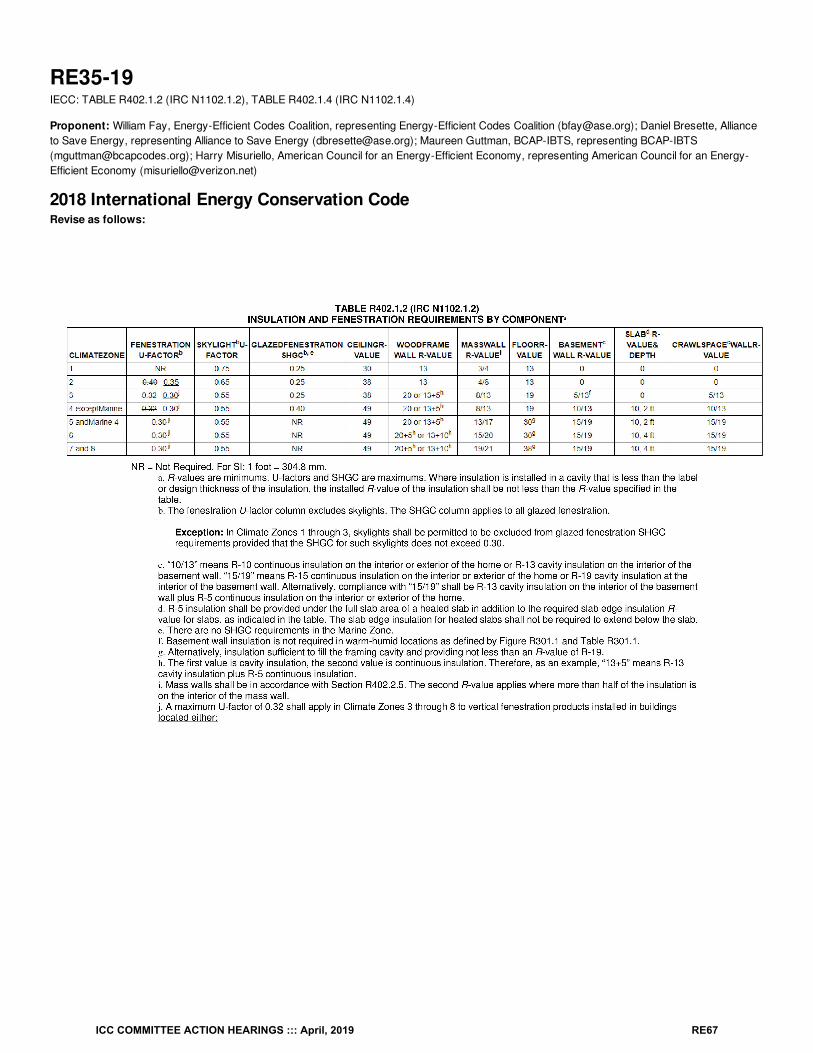
RE35-19IECC: TABLE R402.1.2 (IRC N1102.1.2), TABLE R402.1.4 (IRC N1102.1.4)
Proponent: William Fay, Energy-Efficient Codes Coalition, representing Energy-Efficient Codes Coalition ([email protected]); Daniel Bresette, Allianceto Save Energy, representing Alliance to Save Energy ([email protected]); Maureen Guttman, BCAP-IBTS, representing BCAP-IBTS([email protected]); Harry Misuriello, American Council for an Energy-Efficient Economy, representing American Council for an Energy-Efficient Economy ([email protected])
2018 International Energy Conservation CodeRevise as follows:
ICC COMMITTEE ACTION HEARINGS ::: April, 2019 RE67
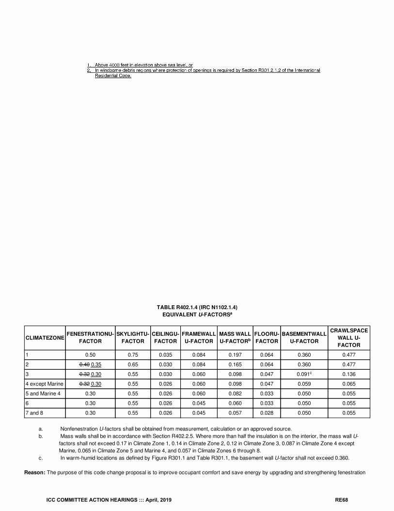
TABLE R402.1.4 (IRC N1102.1.4)EQUIVALENT U-FACTORS
CLIMATEZONEFENESTRATIONU-
FACTORSKYLIGHTU-
FACTORCEILINGU-FACTOR
FRAMEWALLU-FACTOR
MASS WALLU-FACTOR
FLOORU-FACTOR
BASEMENTWALLU-FACTOR
CRAWLSPACEWALL U-FACTOR
1 0.50 0.75 0.035 0.084 0.197 0.064 0.360 0.477
2 0.40 0.35 0.65 0.030 0.084 0.165 0.064 0.360 0.477
3 0.32 0.30 0.55 0.030 0.060 0.098 0.047 0.091 0.136
4 except Marine 0.32 0.30 0.55 0.026 0.060 0.098 0.047 0.059 0.065
5 and Marine 4 0.30 0.55 0.026 0.060 0.082 0.033 0.050 0.055
6 0.30 0.55 0.026 0.045 0.060 0.033 0.050 0.055
7 and 8 0.30 0.55 0.026 0.045 0.057 0.028 0.050 0.055
a. Nonfenestration U-factors shall be obtained from measurement, calculation or an approved source.b. Mass walls shall be in accordance with Section R402.2.5. Where more than half the insulation is on the interior, the mass wall U-
factors shall not exceed 0.17 in Climate Zone 1, 0.14 in Climate Zone 2, 0.12 in Climate Zone 3, 0.087 in Climate Zone 4 exceptMarine, 0.065 in Climate Zone 5 and Marine 4, and 0.057 in Climate Zones 6 through 8.
c. In warm-humid locations as defined by Figure R301.1 and Table R301.1, the basement wall U-factor shall not exceed 0.360.
Reason: The purpose of this code change proposal is to improve occupant comfort and save energy by upgrading and strengthening fenestration
a
b
c
ICC COMMITTEE ACTION HEARINGS ::: April, 2019 RE68
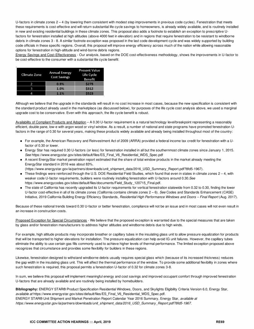
U-factors in climate zones 2 – 4 (by lowering them consistent with modest step improvements in previous code cycles). Fenestration that meetsthese requirements is cost-effective and will return substantial life cycle savings to homeowners, is already widely available, and is routinely installedin new and existing residential buildings in these climate zones. This proposal also adds a footnote to establish an exception to prescriptive U-factors for fenestration installed at high altitudes (above 4000 feet in elevation) and in regions that require fenestration to be resistant to windbornedebris in climate zones 3 - 8. A similar footnote exception was proposed in the last code development cycle and was widely supported by buildingcode officials in these specific regions. Overall, this proposal will improve energy efficiency across much of the nation while allowing reasonableoptions for fenestration in high-altitude and wind-borne debris regions.Energy Savings and Cost-Effectiveness - Our analysis, based on the DOE cost-effectiveness methodology, shows the improvements in U-factor tobe cost-effective to the consumer with a substantial life cycle benefit:
Although we believe that the upgrade in the standards will result in no cost increase in most cases, because the new specification is consistent withthe standard product already used in the marketplace (as discussed below), for purposes of the life cycle cost analysis above, we used a marginalupgrade cost to be conservative. Even with this approach, the life cycle benefit is robust.
Availability of Compliant Products and Adoption – A 0.30 U-factor requirement is a natural technology level/breakpoint representing a reasonablyefficient, double pane, low-e with argon wood or vinyl window. As a result, a number of national and state programs have promoted fenestration U-factors in the range of 0.30 for several years, making these products widely available and already being installed throughout most of the country:
For example, the American Recovery and Reinvestment Act of 2009 (ARRA) provided a federal income tax credit for fenestration with a U-factor of 0.30 or lower.Energy Star has required 0.30 U-factors (or less) for fenestration installed in all but the southernmost climate zones since January 1, 2015.See https://www.energystar.gov/sites/default/files/ES_Final_V6_Residential_WDS_Spec.pdfA recent EnergyStar market penetration report estimated that the share of total window products in the market already meeting theEnergyStar standard in 2016 was about 83%.(https://www.energystar.gov/ia/partners/downloads/unit_shipment_data/2016_USD_Summary_Report.pdf?8fd5-1967).These findings were reinforced through the U.S. DOE Residential Field Studies, which found that even in states in climate zones 2 – 4, withweaker code U-factor requirements, builders were routinely installing fenestration with U-factors around 0.30.Seehttps://www.energycodes.gov/sites/default/files/documents/Field_Study_120715_Final.pdf.The state of California has recently upgraded its U-factor requirements for vertical fenestration statewide from 0.32 to 0.30, finding the lowerU-factor cost-effective in all of its climate zones (California contains climate zones 2 – 6). See Codes and Standards Enhancement (CASE)Initiative, 2019 California Building Energy Efficiency Standards, Residential High Performance Windows and Doors – Final Report (Aug. 2017).
Because of these national trends toward 0.30 U-factor or better fenestration, compliance will not be an issue and in most cases will not even result inan increase in construction costs.
Proposed Exception for Special Circumstances - We believe that the proposed exception is warranted due to the special measures that are takenby glass and/or fenestration manufacturers to address higher altitudes and windborne debris due to high winds.
For example, high altitude products may incorporate breather or capillary tubes in the insulating glass unit to allow pressure equalization for productsthat will be transported to higher elevations for installation. The pressure equalization can help avoid IG unit failures. However, the capillary tubeseliminate the ability to use certain gas fills commonly used to achieve higher levels of thermal performance. The limited exception proposed aboverecognizes that circumstance and provides some flexibility for builders in these regions.
Likewise, fenestration designed to withstand windborne debris usually requires special glass which (because of its increased thickness) reducesthe gap width in the insulating glass unit. This will affect the thermal performance of the window. To provide some additional flexibility in zones wheresuch fenestration is required, this proposal permits a fenestration U-factor of 0.32 for climate zones 3-8.
In sum, we believe this proposal will implement meaningful energy and cost savings and improved occupant comfort through improved fenestrationU-factors that are already available and are routinely being installed by homebuilders.
Bibliography: ENERGY STAR® Product Specification Residential Windows, Doors, and Skylights Eligibility Criteria Version 6.0, Energy Star,available at https://www.energystar.gov/sites/default/files/ES_Final_V6_Residential_WDS_Spec.pdf.ENERGY STAR® Unit Shipment and Market Penetration Report Calendar Year 2016 Summary, Energy Star, available athttps://www.energystar.gov/ia/partners/downloads/unit_shipment_data/2016_USD_Summary_Report.pdf?8fd5-1967.
ICC COMMITTEE ACTION HEARINGS ::: April, 2019 RE69
Single Family Residential Energy Code Field Study, Building Energy Codes Program, available athttps://www.energycodes.gov/sites/default/files/documents/Field_Study_120715_Final.pdf.
Codes and Standards Enhancement (CASE) Initiative, 2019 California Building Energy Efficiency Standards, Residential High Performance Windowsand Doors – Final Report (Aug. 2017).
U.S. Dep’t of Energy, Methodology for Evaluating Cost-Effectiveness of Residential Energy Code Changes (Aug. 2015), available athttps://www.energycodes.gov/residential-energy-and-cost-analysis-methodology.
Cost Impact: The code change proposal will increase the cost of constructionIt is possible that requiring more efficient fenestration may, in some cases, increase the cost of construction (and, as a result, we used an upgradecost in our life cycle cost/benefit analysis), but in any event, the resulting energy and cost savings will overwhelmingly recoup the initial costs andwill continue to benefit consumers over the useful life of the home. Moreover, it should also be noted that we would expect that the U-factor reductionwill not increase costs in most cases, since the standard market products, with very high market penetration, already typically hit the proposedimproved U-factor levels. We also note that for builders in high-altitude or wind-borne debris regions, the new footnote will provide additional flexibilityand will likely serve to reduce costs.
Proposal # 3986
RE35-19
ICC COMMITTEE ACTION HEARINGS ::: April, 2019 RE70
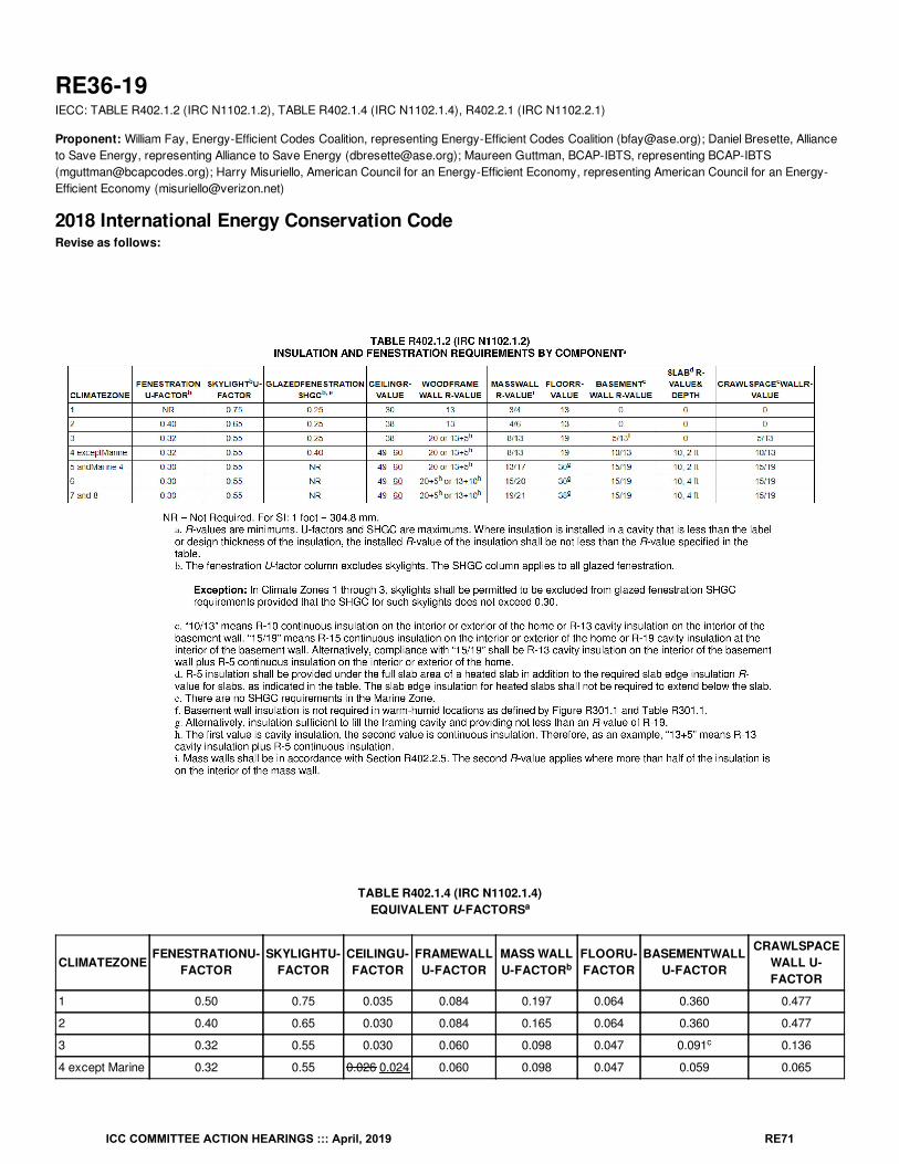
RE36-19IECC: TABLE R402.1.2 (IRC N1102.1.2), TABLE R402.1.4 (IRC N1102.1.4), R402.2.1 (IRC N1102.2.1)
Proponent: William Fay, Energy-Efficient Codes Coalition, representing Energy-Efficient Codes Coalition ([email protected]); Daniel Bresette, Allianceto Save Energy, representing Alliance to Save Energy ([email protected]); Maureen Guttman, BCAP-IBTS, representing BCAP-IBTS([email protected]); Harry Misuriello, American Council for an Energy-Efficient Economy, representing American Council for an Energy-Efficient Economy ([email protected])
2018 International Energy Conservation CodeRevise as follows:
TABLE R402.1.4 (IRC N1102.1.4)EQUIVALENT U-FACTORS
CLIMATEZONEFENESTRATIONU-
FACTORSKYLIGHTU-
FACTORCEILINGU-FACTOR
FRAMEWALLU-FACTOR
MASS WALLU-FACTOR
FLOORU-FACTOR
BASEMENTWALLU-FACTOR
CRAWLSPACEWALL U-FACTOR
1 0.50 0.75 0.035 0.084 0.197 0.064 0.360 0.477
2 0.40 0.65 0.030 0.084 0.165 0.064 0.360 0.477
3 0.32 0.55 0.030 0.060 0.098 0.047 0.091 0.136
4 except Marine 0.32 0.55 0.026 0.024 0.060 0.098 0.047 0.059 0.065
a
b
c
ICC COMMITTEE ACTION HEARINGS ::: April, 2019 RE71
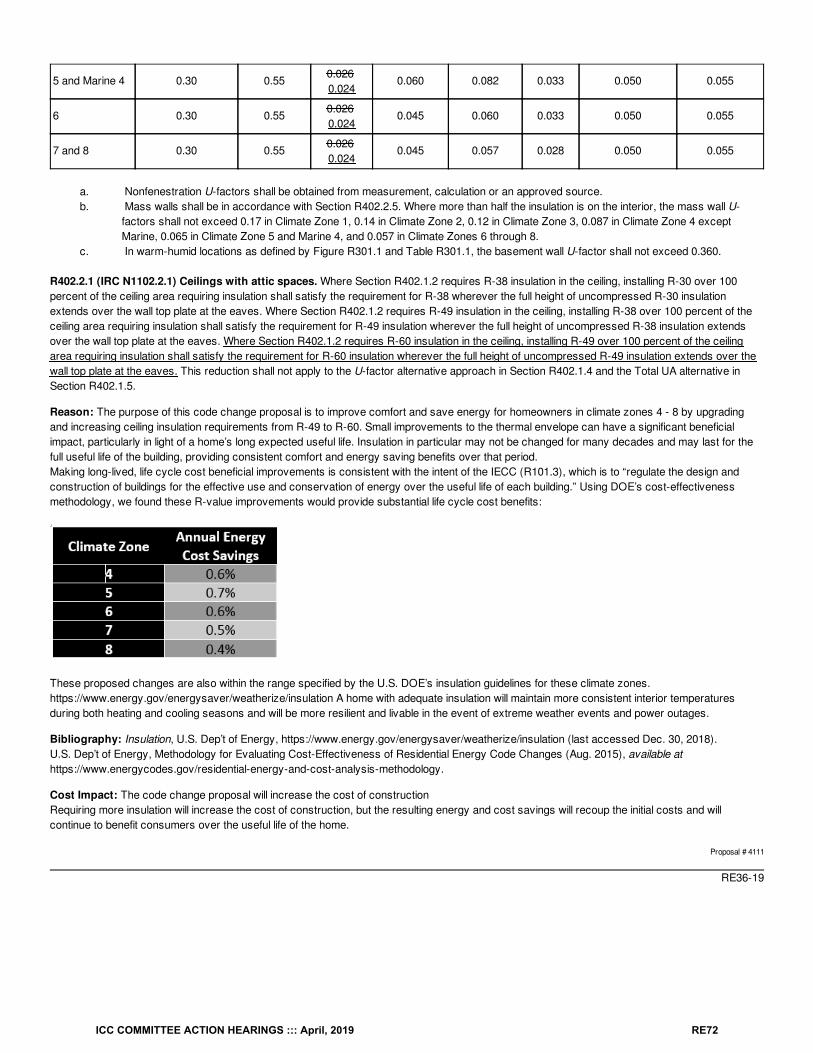
5 and Marine 4 0.30 0.550.026 0.024
0.060 0.082 0.033 0.050 0.055
6 0.30 0.550.026 0.024
0.045 0.060 0.033 0.050 0.055
7 and 8 0.30 0.550.026 0.024
0.045 0.057 0.028 0.050 0.055
a. Nonfenestration U-factors shall be obtained from measurement, calculation or an approved source.b. Mass walls shall be in accordance with Section R402.2.5. Where more than half the insulation is on the interior, the mass wall U-
factors shall not exceed 0.17 in Climate Zone 1, 0.14 in Climate Zone 2, 0.12 in Climate Zone 3, 0.087 in Climate Zone 4 exceptMarine, 0.065 in Climate Zone 5 and Marine 4, and 0.057 in Climate Zones 6 through 8.
c. In warm-humid locations as defined by Figure R301.1 and Table R301.1, the basement wall U-factor shall not exceed 0.360.
R402.2.1 (IRC N1102.2.1) Ceilings with attic spaces. Where Section R402.1.2 requires R-38 insulation in the ceiling, installing R-30 over 100percent of the ceiling area requiring insulation shall satisfy the requirement for R-38 wherever the full height of uncompressed R-30 insulationextends over the wall top plate at the eaves. Where Section R402.1.2 requires R-49 insulation in the ceiling, installing R-38 over 100 percent of theceiling area requiring insulation shall satisfy the requirement for R-49 insulation wherever the full height of uncompressed R-38 insulation extendsover the wall top plate at the eaves. Where Section R402.1.2 requires R-60 insulation in the ceiling, installing R-49 over 100 percent of the ceilingarea requiring insulation shall satisfy the requirement for R-60 insulation wherever the full height of uncompressed R-49 insulation extends over thewall top plate at the eaves. This reduction shall not apply to the U-factor alternative approach in Section R402.1.4 and the Total UA alternative inSection R402.1.5.
Reason: The purpose of this code change proposal is to improve comfort and save energy for homeowners in climate zones 4 - 8 by upgradingand increasing ceiling insulation requirements from R-49 to R-60. Small improvements to the thermal envelope can have a significant beneficialimpact, particularly in light of a home’s long expected useful life. Insulation in particular may not be changed for many decades and may last for thefull useful life of the building, providing consistent comfort and energy saving benefits over that period.Making long-lived, life cycle cost beneficial improvements is consistent with the intent of the IECC (R101.3), which is to “regulate the design andconstruction of buildings for the effective use and conservation of energy over the useful life of each building.” Using DOE’s cost-effectivenessmethodology, we found these R-value improvements would provide substantial life cycle cost benefits:
These proposed changes are also within the range specified by the U.S. DOE’s insulation guidelines for these climate zones.https://www.energy.gov/energysaver/weatherize/insulation A home with adequate insulation will maintain more consistent interior temperaturesduring both heating and cooling seasons and will be more resilient and livable in the event of extreme weather events and power outages.
Bibliography: Insulation, U.S. Dep’t of Energy, https://www.energy.gov/energysaver/weatherize/insulation (last accessed Dec. 30, 2018).U.S. Dep’t of Energy, Methodology for Evaluating Cost-Effectiveness of Residential Energy Code Changes (Aug. 2015), available athttps://www.energycodes.gov/residential-energy-and-cost-analysis-methodology.
Cost Impact: The code change proposal will increase the cost of constructionRequiring more insulation will increase the cost of construction, but the resulting energy and cost savings will recoup the initial costs and willcontinue to benefit consumers over the useful life of the home.
Proposal # 4111
RE36-19
ICC COMMITTEE ACTION HEARINGS ::: April, 2019 RE72
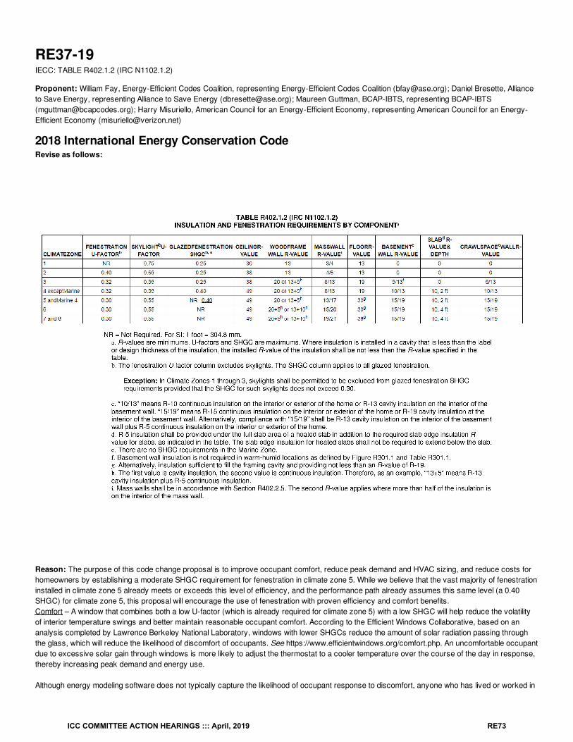
RE37-19IECC: TABLE R402.1.2 (IRC N1102.1.2)
Proponent: William Fay, Energy-Efficient Codes Coalition, representing Energy-Efficient Codes Coalition ([email protected]); Daniel Bresette, Allianceto Save Energy, representing Alliance to Save Energy ([email protected]); Maureen Guttman, BCAP-IBTS, representing BCAP-IBTS([email protected]); Harry Misuriello, American Council for an Energy-Efficient Economy, representing American Council for an Energy-Efficient Economy ([email protected])
2018 International Energy Conservation CodeRevise as follows:
Reason: The purpose of this code change proposal is to improve occupant comfort, reduce peak demand and HVAC sizing, and reduce costs forhomeowners by establishing a moderate SHGC requirement for fenestration in climate zone 5. While we believe that the vast majority of fenestrationinstalled in climate zone 5 already meets or exceeds this level of efficiency, and the performance path already assumes this same level (a 0.40SHGC) for climate zone 5, this proposal will encourage the use of fenestration with proven efficiency and comfort benefits.Comfort – A window that combines both a low U-factor (which is already required for climate zone 5) with a low SHGC will help reduce the volatilityof interior temperature swings and better maintain reasonable occupant comfort. According to the Efficient Windows Collaborative, based on ananalysis completed by Lawrence Berkeley National Laboratory, windows with lower SHGCs reduce the amount of solar radiation passing throughthe glass, which will reduce the likelihood of discomfort of occupants. See https://www.efficientwindows.org/comfort.php. An uncomfortable occupantdue to excessive solar gain through windows is more likely to adjust the thermostat to a cooler temperature over the course of the day in response,thereby increasing peak demand and energy use.
Although energy modeling software does not typically capture the likelihood of occupant response to discomfort, anyone who has lived or worked in
ICC COMMITTEE ACTION HEARINGS ::: April, 2019 RE73
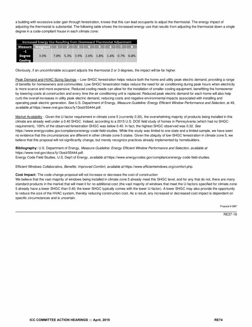
a building with excessive solar gain through fenestration, knows that this can lead occupants to adjust the thermostat. The energy impact ofadjusting the thermostat is substantial. The following table shows the increased energy use that results from adjusting the thermostat down a singledegree in a code-compliant house in each climate zone:
Obviously, if an uncomfortable occupant adjusts the thermostat 2 or 3 degrees, the impact will be far higher.
Peak Demand and HVAC Sizing Savings – Low-SHGC fenestration helps reduce both the home and utility peak electric demand, providing a rangeof benefits for homeowners and communities. Low-SHGC fenestration helps reduce the need for air conditioning during peak hours when electricityis more scarce and more expensive. Reduced cooling needs can allow for the installation of smaller cooling equipment, benefitting the homeownerby lowering costs at construction and every time the air conditioning unit is replaced. Reduced peak electric demand for each home will also helpcurb the overall increases in utility peak electric demand, reducing costs and negative environmental impacts associated with installing andoperating peak electric generation. See U.S. Department of Energy, Measure Guideline: Energy Efficient Window Performance and Selection, at 49,available at https://www.nrel.gov/docs/fy13osti/55444.pdf.
Market Availability - Given the U-factor requirement in climate zone 5 (currently 0.30), the overwhelming majority of products being installed in thisclimate are already well under a 0.40 SHGC. Indeed, according to a 2015 U.S. DOE field study of homes in Pennsylvania (which had no SHGCrequirement), 100% of the observed fenestration SHGC was below 0.40. In fact, the highest SHGC observed was 0.32. Seehttps://www.energycodes.gov/compliance/energy-code-field-studies. While this study was limited to one state and a limited sample, we have seenno evidence that the circumstances are different in other climate zone 5 states. Given the ubiquity of low-SHGC fenestration in climate zone 5, webelieve that this proposal will not significantly change, but merely recognize practices already implemented by homebuilders.
Bibliography: U.S. Department of Energy, Measure Guideline: Energy Efficient Window Performance and Selection, available athttps://www.nrel.gov/docs/fy13osti/55444.pdf.Energy Code Field Studies, U.S. Dep’t of Energy, available at https://www.energycodes.gov/compliance/energy-code-field-studies.
Efficient Windows Collaborative, Benefits: Improved Comfort, available at https://www.efficientwindows.org/comfort.php.
Cost Impact: The code change proposal will not increase or decrease the cost of constructionWe believe that the vast majority of windows being installed in climate zone 5 already meet this SHGC level, and for any that do not, there are manystandard products in the market that will meet it for no additional cost (the vast majority of windows that meet the U-factors specified for climate zone5 already have a lower SHGC than 0.40; the lower SHGC typically comes with the lower U-factor). A lower SHGC may also provide the opportunityto reduce the size of the HVAC system, thereby reducing construction cost. As a result, any increased or decreased cost impact is dependent onspecific circumstances and is uncertain.
Proposal # 3987
RE37-19
ICC COMMITTEE ACTION HEARINGS ::: April, 2019 RE74
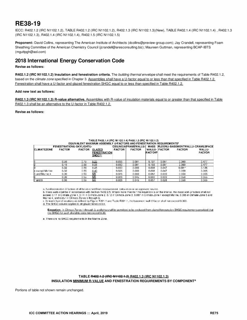
RE38-19IECC: R402.1.2 (IRC N1102.1.2), TABLE R402.1.2 (IRC N1102.1.2), R402.1.3 (IRC N1102.1.3)(New), TABLE R402.1.4 (IRC N1102.1.4) , R402.1.3(IRC N1102.1.3), R402.1.4 (IRC N1102.1.4), R402.1.5 (IRC N1102.1.5)
Proponent: David Collins, representing The American Institute of Architects ([email protected]); Jay Crandell, representing FoamSheathing Committee of the American Chemistry Council ([email protected]); Maureen Guttman, representing BCAP-IBTS([email protected])
2018 International Energy Conservation CodeRevise as follows:
R402.1.2 (IRC N1102.1.2) Insulation and fenestration criteria. The building thermal envelope shall meet the requirements of Table R402.1.2,based on the climate zone specified in Chapter 3. Assemblies shall have a U-factor equal to or less than that specified in Table R402.1.2.Fenestration shall have a U-factor and glazed fenestration SHGC equal to or less than specified in Table R402.1.2.
Add new text as follows:
R402.1.3 (IRC N1102.1.3) R-value alternative. Assemblies with R-value of insulation materials equal to or greater than that specified in TableR402.1.3 shall be an alternative to the U-factor in Table R402.1.2.
Revise as follows:
TABLE R402.1.2 (IRC N1102.1.2) R402.1.3 (IRC N1102.1.3)INSULATION MINIMUM R-VALUE AND FENESTRATION REQUIREMENTS BY COMPONENT
Portions of table not shown remain unchanged.
a
ICC COMMITTEE ACTION HEARINGS ::: April, 2019 RE75
R402.1.3 (IRC N1102.1.3) R402.1.4 (IRC N1102.1.4) R-value computation. Insulation material used in layers, such as framing cavity insulation orcontinuous insulation, shall be summed to compute the corresponding component R-value. The manufacturer’s settled R-value shall be used forblown-in insulation. Computed R-values shall not include an R-value for other building materials or air films. Where insulated siding is used for thepurpose of complying with the continuous insulation requirements of Table R402.1.2 R402.1.3, the manufacturer’s labeled R-value for the insulatedsiding shall be reduced by R-0.6.
R402.1.4 (IRC N1102.1.4) U-factor alternative. An assembly with a U-factor equal to or less than that specified in Table R402.1.4 shall be analternative to the R-value in Table R402.1.2.
R402.1.5 (IRC N1102.1.5) Total UA alternative. Where the total building thermal envelope UA, the sum of U-factor times assembly area, is lessthan or equal to the total UA resulting from multiplying the U-factors in Table R402.1.4 R402.1.2 by the same assembly area as in the proposedbuilding, the building shall be considered to be in compliance with Table R402.1.2. The UA calculation shall be performed using a method consistentwith the ASHRAE Handbook of Fundamentals and shall include the thermal bridging effects of framing materials. In addition to UA compliance, theSHGC requirements shall be met.
Reason: This proposal does not change the stringency of the R-value and U-factor requirements. This proposal organizes the envelope thermalrequirements such that the basis of performance (and any other means of compliance) is founded on U-factors which completely define anassembly’s performance. The R-value approach is kept to provide pre-determined solutions (easy to look up) and it is based on the U-factorrequirements as it should be (and the same would apply to any other equivalent R-value solution that one might propose as an alternative forcompliance). This approach does not change the prescriptive R-value approach or the ability to use it for simple solutions. Instead, it better ensuresthat the R-values used are a derivative of the intended performance levels that are non-material specific and represented by the assembly U-factors. Also, fenestration and SHGC requirements are included in the U-factor table because they are currently omitted. The SHGC values (andfootnotes) are consistent with those in the current R-value table.
Cost Impact: The code change proposal will not increase or decrease the cost of constructionThis porposal does not change the stringency of R-value and U-factor requirements, but it will ensure that alternate R-value solutions areappropriately based on the U-factor requirements, including those that are predetermined in the R-value table which is kept to maintain a simplemeans of compliance.
Proposal # 4514
RE38-19
ICC COMMITTEE ACTION HEARINGS ::: April, 2019 RE76
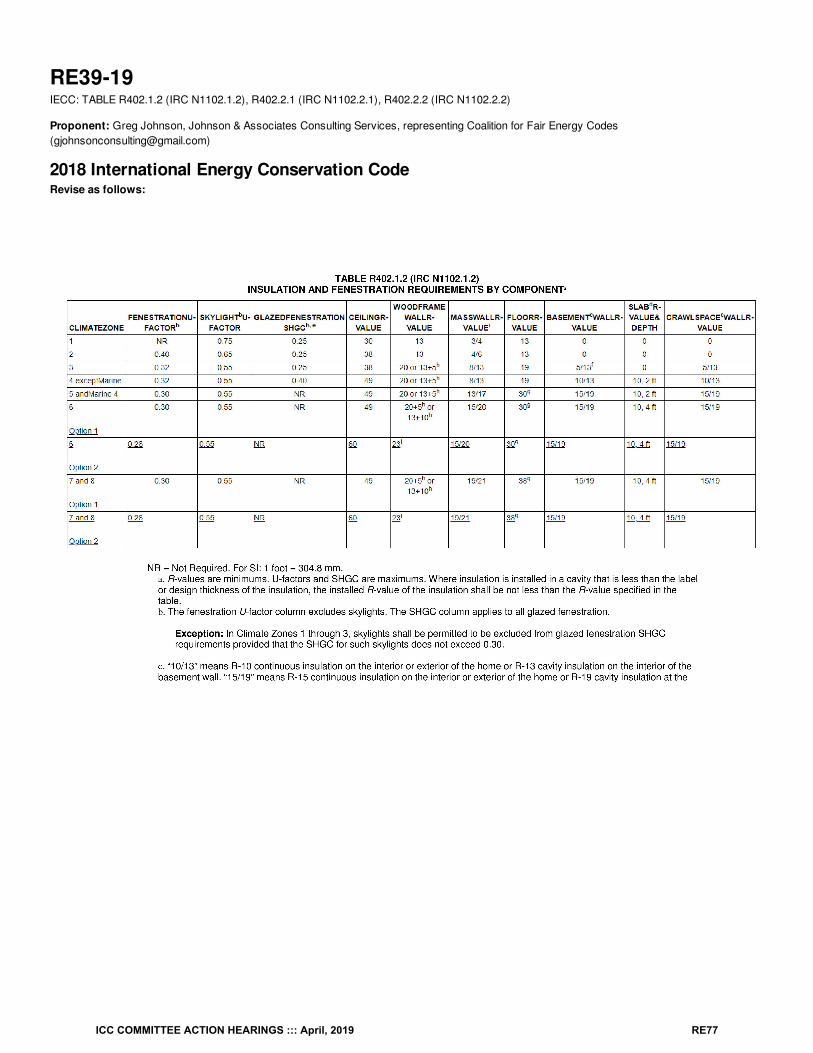
RE39-19IECC: TABLE R402.1.2 (IRC N1102.1.2), R402.2.1 (IRC N1102.2.1), R402.2.2 (IRC N1102.2.2)
Proponent: Greg Johnson, Johnson & Associates Consulting Services, representing Coalition for Fair Energy Codes([email protected])
2018 International Energy Conservation CodeRevise as follows:
ICC COMMITTEE ACTION HEARINGS ::: April, 2019 RE77
R402.2.1 (IRC N1102.2.1) Ceilings with attic spaces. Where Section R402.1.2 requires R-38 insulation in the ceiling, installing R-30 over 100percent of the ceiling area requiring insulation shall satisfy the requirement for R-38 wherever the full height of uncompressed R-30 insulationextends over the wall top plate at the eaves. Where Section R402.1.2 requires R-49 insulation in the ceiling, installing R-38 over 100 percent of theceiling area requiring insulation shall satisfy the requirement for R-49 insulation wherever the full height of uncompressed R-38 insulation extendsover the wall top plate at the eaves. Where Section R402.1.2 requires R-60 insulation in the ceiling, installing R-49 over 100 percent of the ceilingarea requiring insulation shall satisfy the requirement for R-60 insulation wherever the full height of uncompressed R-49 insulation extends over thetop plate at the eaves. This reduction shall not apply to the U-factor alternative approach in Section R402.1.4 and the Total UA alternative in SectionR402.1.5.
R402.2.2 (IRC N1102.2.2) Ceilings without attic spaces. Where Section R402.1.2 requires insulation R-values greater than R-30 in the ceilingand the design of the roof/ceiling assembly does not allow sufficient space for the required insulation, the minimum required insulation R-value forsuch roof/ceiling assemblies shall be R-30. Where Section R402.1.2 requires insulation greater than R49 in the ceiling and the design of theroof/ceiling assembly does not allow sufficient space for the required insulation, the required insulation R-value for such roof/ceiling assemblies shallbe R38. Insulation shall extend over the top of the wall plate to the outer edge of such plate and shall not be compressed. This reduction of insulationfrom the requirements of Section R402.1.2 shall be limited to 500 square feet (46 m2) or 20 percent of the total insulated ceiling area, whichever isless. This reduction shall not apply to the U-factor alternative approach in Section R402.1.4 and the Total UA alternative in Section R402.1.5.
Reason: This proposal will save energy by providing a critically needed prescriptive cavity-only wall insulation option for Climate Zones 6-8 for themany builders and building officials that rely on the prescriptive table.This new option provides equivalent energy performance by combining a minimum R23 wood frame wall R-value with better performing windows(U=0.28) and increased ceiling insulation (R60), such that equivalent energy performance is achieved.
The proposed R23 wall cavity insulation level is compatible with 2x6 framing using a variety of cavity insulation types, including several types of battinsulation products and blown-in insulation systems.
ICC COMMITTEE ACTION HEARINGS ::: April, 2019 RE78
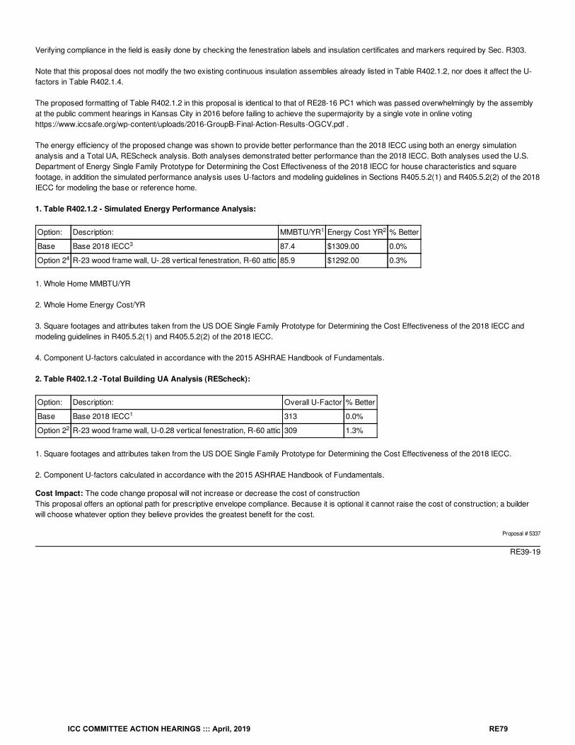
Verifying compliance in the field is easily done by checking the fenestration labels and insulation certificates and markers required by Sec. R303.
Note that this proposal does not modify the two existing continuous insulation assemblies already listed in Table R402.1.2, nor does it affect the U-factors in Table R402.1.4.
The proposed formatting of Table R402.1.2 in this proposal is identical to that of RE28-16 PC1 which was passed overwhelmingly by the assemblyat the public comment hearings in Kansas City in 2016 before failing to achieve the supermajority by a single vote in online votinghttps://www.iccsafe.org/wp-content/uploads/2016-GroupB-Final-Action-Results-OGCV.pdf .
The energy efficiency of the proposed change was shown to provide better performance than the 2018 IECC using both an energy simulationanalysis and a Total UA, REScheck analysis. Both analyses demonstrated better performance than the 2018 IECC. Both analyses used the U.S.Department of Energy Single Family Prototype for Determining the Cost Effectiveness of the 2018 IECC for house characteristics and squarefootage, in addition the simulated performance analysis uses U-factors and modeling guidelines in Sections R405.5.2(1) and R405.5.2(2) of the 2018IECC for modeling the base or reference home.
1. Table R402.1.2 - Simulated Energy Performance Analysis:
Option: Description: MMBTU/YR Energy Cost YR % Better
Base Base 2018 IECC 87.4 $1309.00 0.0%
Option 2 R-23 wood frame wall, U-.28 vertical fenestration, R-60 attic 85.9 $1292.00 0.3%
1. Whole Home MMBTU/YR
2. Whole Home Energy Cost/YR
3. Square footages and attributes taken from the US DOE Single Family Prototype for Determining the Cost Effectiveness of the 2018 IECC andmodeling guidelines in R405.5.2(1) and R405.5.2(2) of the 2018 IECC.
4. Component U-factors calculated in accordance with the 2015 ASHRAE Handbook of Fundamentals.
2. Table R402.1.2 -Total Building UA Analysis (REScheck):
Option: Description: Overall U-Factor % Better
Base Base 2018 IECC 313 0.0%
Option 2 R-23 wood frame wall, U-0.28 vertical fenestration, R-60 attic 309 1.3%
1. Square footages and attributes taken from the US DOE Single Family Prototype for Determining the Cost Effectiveness of the 2018 IECC.
2. Component U-factors calculated in accordance with the 2015 ASHRAE Handbook of Fundamentals.
Cost Impact: The code change proposal will not increase or decrease the cost of constructionThis proposal offers an optional path for prescriptive envelope compliance. Because it is optional it cannot raise the cost of construction; a builderwill choose whatever option they believe provides the greatest benefit for the cost.
Proposal # 5337
RE39-19
1 2
3
4
1
2
ICC COMMITTEE ACTION HEARINGS ::: April, 2019 RE79
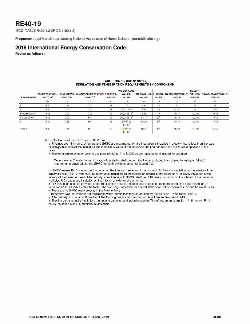
RE40-19IECC: TABLE R402.1.2 (IRC N1102.1.2)
Proponent: Joel Martell, representing National Association of Home Builders ([email protected])
2018 International Energy Conservation CodeRevise as follows:
ICC COMMITTEE ACTION HEARINGS ::: April, 2019 RE80
Reason: This proposal is an energy neutral change based on calculations from ASHRAE. Insulation that is R-19 that is compressed in a 2 x 6 wallwith stud spacing at 24 o.c. performs like R-18. The ASHRAE Handbook of Fundamentals and ASHRAE Transaction 1995 Volume 101, Part 2assumes that wood framed walls have a framing factor of 25%. Meaning 25 percent of the wall area consists of structural framing members and theremainder of the wall is a cavity suitable for installing insulation. When calculating the U-factor for a w all assembly, a high framing factor increasesthe overall assembly U-Factor. Reducing the framing factor will also provide an increase in the thermal performance of the w all.This proposal provides an option for a thermally equivalent tradeoff for 2x6 w all assemblies which have reduced framing factors and insulationperforming like a R-18 insulator.
Below are the calculations showing equal U-Factors for both assemblies (0.060).
ICC COMMITTEE ACTION HEARINGS ::: April, 2019 RE81
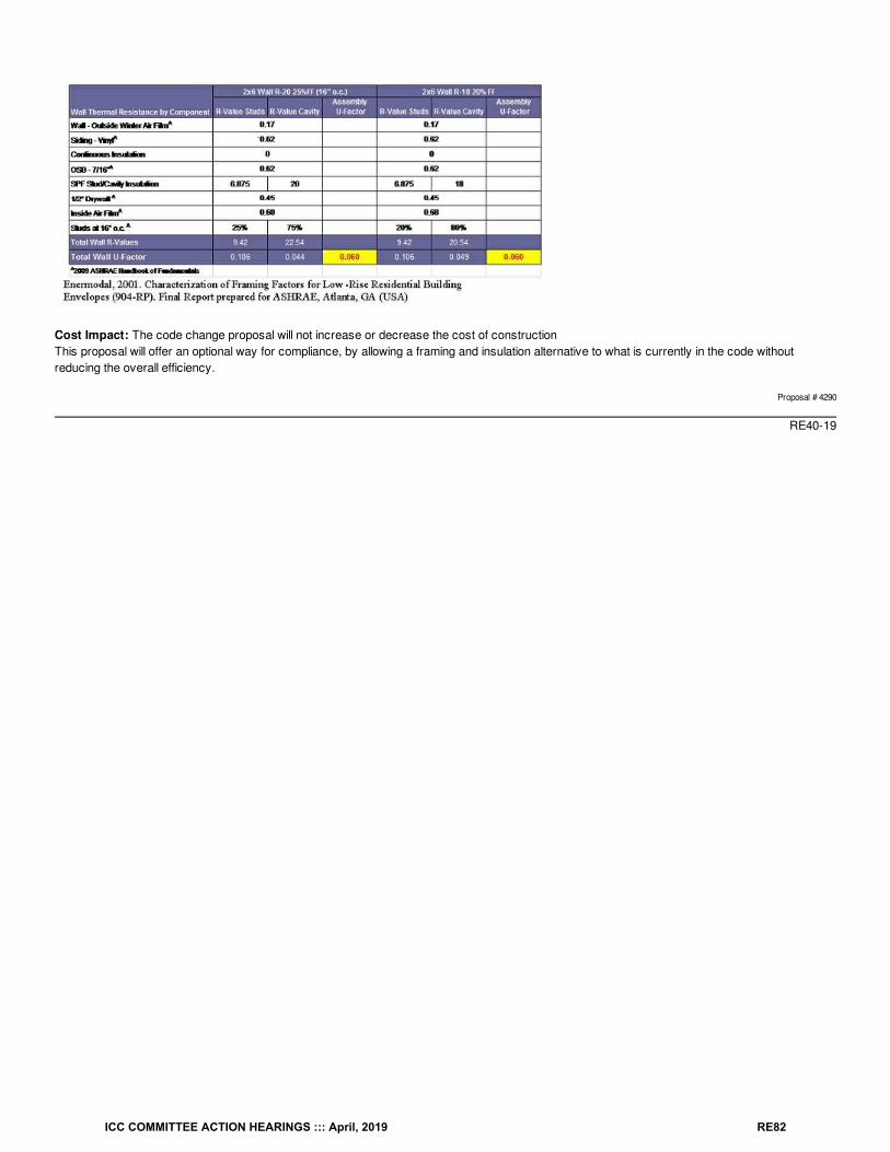
Cost Impact: The code change proposal will not increase or decrease the cost of constructionThis proposal will offer an optional way for compliance, by allowing a framing and insulation alternative to what is currently in the code withoutreducing the overall efficiency.
Proposal # 4290
RE40-19
ICC COMMITTEE ACTION HEARINGS ::: April, 2019 RE82
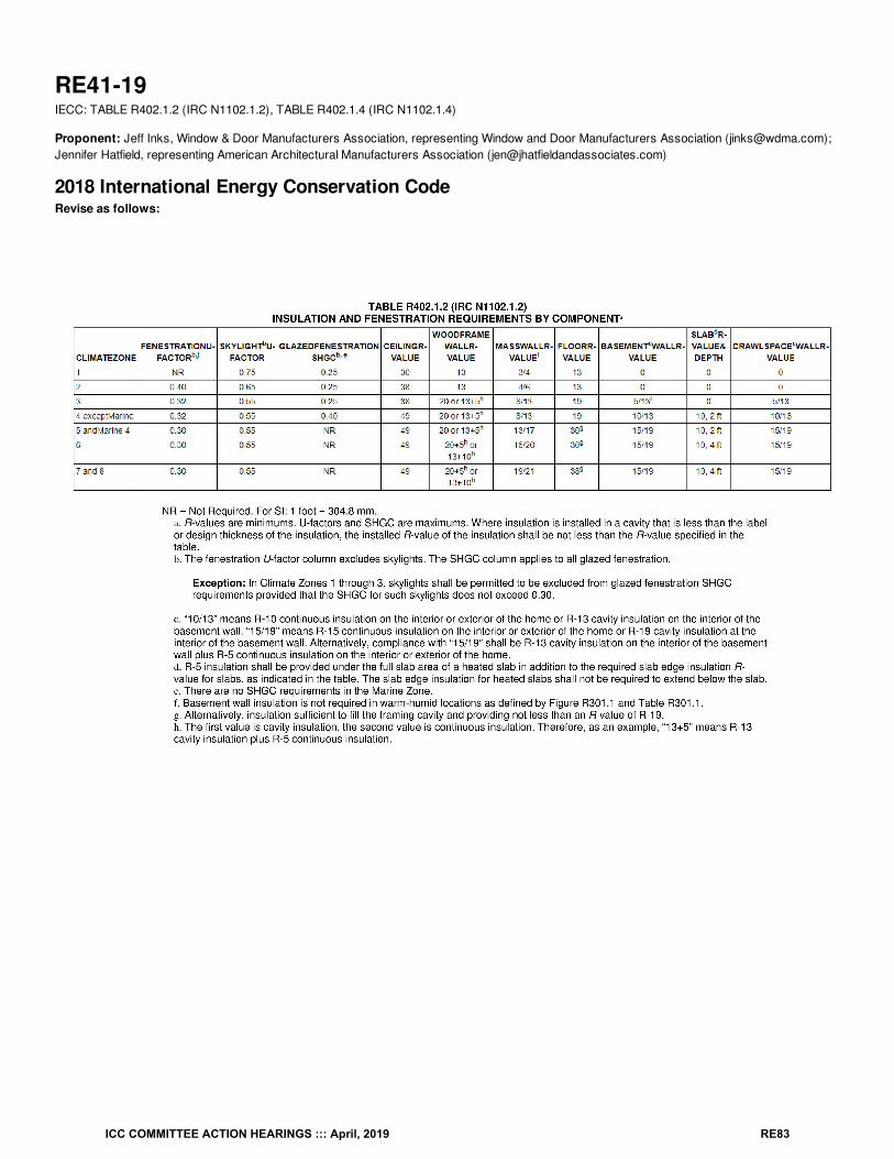
RE41-19IECC: TABLE R402.1.2 (IRC N1102.1.2), TABLE R402.1.4 (IRC N1102.1.4)
Proponent: Jeff Inks, Window & Door Manufacturers Association, representing Window and Door Manufacturers Association ([email protected]);Jennifer Hatfield, representing American Architectural Manufacturers Association ([email protected])
2018 International Energy Conservation CodeRevise as follows:
ICC COMMITTEE ACTION HEARINGS ::: April, 2019 RE83
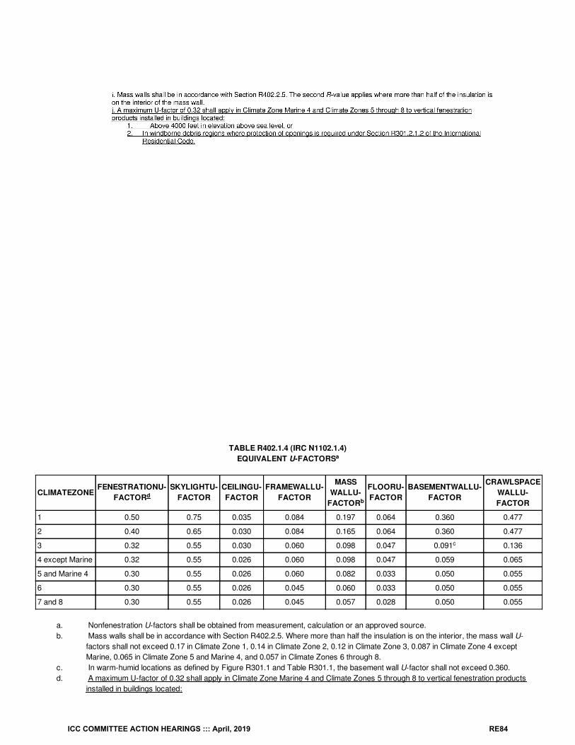
TABLE R402.1.4 (IRC N1102.1.4)EQUIVALENT U-FACTORS
CLIMATEZONEFENESTRATIONU-
FACTORSKYLIGHTU-
FACTORCEILINGU-FACTOR
FRAMEWALLU-FACTOR
MASSWALLU-
FACTOR
FLOORU-FACTOR
BASEMENTWALLU-FACTOR
CRAWLSPACEWALLU-FACTOR
1 0.50 0.75 0.035 0.084 0.197 0.064 0.360 0.477
2 0.40 0.65 0.030 0.084 0.165 0.064 0.360 0.477
3 0.32 0.55 0.030 0.060 0.098 0.047 0.091 0.136
4 except Marine 0.32 0.55 0.026 0.060 0.098 0.047 0.059 0.065
5 and Marine 4 0.30 0.55 0.026 0.060 0.082 0.033 0.050 0.055
6 0.30 0.55 0.026 0.045 0.060 0.033 0.050 0.055
7 and 8 0.30 0.55 0.026 0.045 0.057 0.028 0.050 0.055
a. Nonfenestration U-factors shall be obtained from measurement, calculation or an approved source.b. Mass walls shall be in accordance with Section R402.2.5. Where more than half the insulation is on the interior, the mass wall U-
factors shall not exceed 0.17 in Climate Zone 1, 0.14 in Climate Zone 2, 0.12 in Climate Zone 3, 0.087 in Climate Zone 4 exceptMarine, 0.065 in Climate Zone 5 and Marine 4, and 0.057 in Climate Zones 6 through 8.
c. In warm-humid locations as defined by Figure R301.1 and Table R301.1, the basement wall U-factor shall not exceed 0.360.d. A maximum U-factor of 0.32 shall apply in Climate Zone Marine 4 and Climate Zones 5 through 8 to vertical fenestration products
installed in buildings located:
a
db
c
ICC COMMITTEE ACTION HEARINGS ::: April, 2019 RE84
1. Above 4000 feet in elevation above sea level, or2. In windborne debris regions where protection of openings is required under Section R301.2.1.2 of the International
Residential Code.
Reason: High altitude products generally require breather or capillary tubes in the insulating glass unit to allow pressure equalization when theproducts are transported to higher elevations for installation. The pressure equalization is necessary to avoid breakage. However, the tubeseliminate the ability to use gas fills commonly used to achieve higher levels of thermal performance. Meanwhile, windborne debris protectionrequirements for fenestration are typically met by the use of laminated glass which reduces the gap width in the insulating glass unit and thus thethermal performance. This footnote provides a reasonably limited and needed exception for products installed above 4000 ft above sea level inclimate zones Marine4 zones 5-8, and for products that must meet windborne debris protection requirements.
Cost Impact: The code change proposal will decrease the cost of constructionThis will avoid the need for costly redesign of products, e.g., larger frame sizes for impact resistant fenestration, or the need for fenestrationproducts to be installed above 4000 ft to be manufactured in a location above 4000 ft.
Proposal # 5382
RE41-19
ICC COMMITTEE ACTION HEARINGS ::: April, 2019 RE85
RE42-19IECC: R402.2.1 (IRC N1102.2.1), R402.2.2 (IRC N1102.2.2)
Proponent: Darren Meyers, P.E., IECC_LLC representing the National Roofing Contractors Association, representing the National RoofingContractors Association ([email protected])
2018 International Energy Conservation CodeRevise as follows:
R402.2.1 (IRC N1102.2.1) Ceilings with attic spaces. Where Section R402.1.2 requires R-38 insulation in the ceiling attic, installing R-30 over 100percent of the ceiling attic area requiring insulation shall satisfy the requirement for R-38 wherever the full height of uncompressed R-30 insulationextends over the wall top plate at the eaves. Where Section R402.1.2 requires R-49 insulation in the ceiling attic, installing R-38 over 100 percent ofthe ceiling attic area requiring insulation shall satisfy the requirement for R-49 insulation wherever the full height of uncompressed R-38 insulationextends over the wall top plate at the eaves. This reduction shall not apply to the U-factor alternative approach in Section R402.1.4 and the Total UAalternative in Section R402.1.5.
R402.2.2 (IRC N1102.2.2) Ceilings without attics attic spaces. Where Section R402.1.2 requires insulation R-values greater than R-30 in theceiling interstitial space above a ceiling and below the structural roof deck and the design of the roof/ceiling assembly does not allow sufficient spacefor the required insulation, the minimum required insulation R-value for such roof/ceiling assemblies shall be R-30. Insulation shall extend over thetop of the wall plate to the outer edge of such plate and shall not be compressed. This reduction of insulation from the requirements of SectionR402.1.2 shall be limited to 500 square feet (46 m2) or 20 percent of the total insulated ceiling area, whichever is less. This reduction shall not applyto the U-factor alternative approach in Section R402.1.4 and the Total UA alternative in Section R402.1.5.
Reason: This code change proposal is intended to provide clarity consistent with roofing terminology used every day by roofing industry- anddesign-professionals across the country.
Cost Impact: The code change proposal will not increase or decrease the cost of constructionThere is no cost implication aligned with this proposal. Rather, it is an exercise steeped in clarification and consistency across the ICC Family ofInternational Codes.
Proposal # 5274
RE42-19
ICC COMMITTEE ACTION HEARINGS ::: April, 2019 RE86
RE43-19IECC: R103.2 (IRC N1101.5), R202 (IRC N1101.6), R401.2.2 (IRC N1101.13.2) (New), R401.2.2.1 (N1101.13.2.2.1) (New), R405.4.2 (IRCN1105.4.2)
Proponent: Robby Schwarz, EnergyLogic, representing EnergyLogic ([email protected])
2018 International Energy Conservation CodeRevise as follows:
R103.2 (IRC N1101.5) Information on construction documents. Construction documents shall be drawn to scale on suitable material. Electronicmedia documents are permitted to be submitted where approved by the code official. Construction documents shall be of sufficient clarity to indicatethe location, nature and extent of the work proposed, and show in sufficient detail pertinent data and features of the building, systems and equipmentas herein governed. Details shall include the following as applicable:
1. Insulation materials and their R-values.2. Fenestration U-factors and solar heat gain coefficients (SHGC).3. Area-weighted U-factor and solar heat gain coefficients (SHGC) calculations.4. Mechanical system design criteria.5. Mechanical and service water-heating systems and equipment types, sizes and efficiencies.6. Equipment and system controls.7. Duct sealing, duct and pipe insulation and location.8. Air sealing details.9. Batch sampling plan (where applicable)
SECTION R202 (IRC N1101.6) GENERAL DEFINITIONS
Add new definition as follows:
BATCH SAMPLING. Verification of energy code requirements when fewer than 100 percent of every dwelling or dwelling unit, within a sampledproject are inspected, tested, or modeled for compliance.
Add new text as follows:
R401.2.2 (IRC N1101.13.2) Batch sampling. Batch sampling to determine energy code compliance shall only be allowed for stacked multiple-familydwelling unit projects within the same subdivision or community.
Exceptions:
1. Where sampling of energy compliance items for other than sections R402.4 and R403.3.3, an approved sampling plan shall beincluded in the construction documents and approved by the code official.
2. Where sampling is proposed for other than stacked multiple-family dwelling unit projects, an approved sampling plan shall beincluded in the construction documents and approved by the code official.
R401.2.2.1 (N1101.13.2.2.1) Sampling process. The sampling process shall follow these steps.1. After five consecutive dwellings or dwelling units demonstrate compliance with the code without an incidence of failure, then only one dwelling
or dwelling unit in subsequent batches of five dwelling units is required to demonstrate compliance through testing and inspection.2. The remaining four units in the sampling batch shall be considered to be in compliance with the code when the one sampled unit in the batch of
five dwelling units has demonstrated compliance.3. Where the one dwelling or dwelling unit tested and inspected in the batch of five fails to demonstrate compliance with the code then that unit
and 3 consecutive dwellings or dwelling units shall demonstrate compliance without incidence of failure before batch sampling is allowed tocontinue.
Exception: An approved sampling plan shall be used as an alternative to Section R401.2.2.1.
Revise as follows:
R405.4.2 (IRC N1105.4.2) Compliance report. Compliance software tools shall generate a report that documents that the proposed designcomplies with Section R405.3. A compliance report on the proposed design shall be submitted with the application for the building permit. Uponcompletion of the building, a compliance report based on the as-built condition of the building shall be submitted to the code official before a certificateof occupancy is issued. Batch sampling of buildings to determine energy code compliance shall only be allowed for stacked multiple-family units.Compliance reports shall include information in accordance with Sections R405.4.2.1 and R405.4.2.2. Where the proposed design of a building couldbe built on different sites where the cardinal orientation of the building on each site is different, compliance of the proposed design for the purposes of
ICC COMMITTEE ACTION HEARINGS ::: April, 2019 RE87
the application for the building permit shall be based on the worst-case orientation, worst-case configuration, worst-case building air leakage andworst- case duct leakage. Such worst-case parameters shall be used as inputs to the compliance software for energy analysis.
Reason: Currently, sampling is only addressed within the Simulated Performance Path section R405 of the IECC. It states, “Batch sampling ofbuildings to determine energy code compliance shall only be allowed for stacked multiple-family units.” Narrowing the allowance for sampling tostacked multi-family units makes a lot of sense but narrowing sampling to only the Simulated Performance path does not. This proposal broadensthe ability to sample dwelling units regardless of the pathway used to navigate the IECC.In researching this proposal, it became evident that sampling means something different to the code compliance community than it does to theverification and builder program community. My discussions with the code compliance community indicated that they believe that sampling is only atool that is used for lessening the requirement of blower door and duct leakage testing every permitted dwelling unit. The verification and builderprogram community, on the other hand, uses sampling to verify compliance of any requirement of compliance. Therefore, this proposal states thatsampling used for anything other than blower door or duct leakage testing must have a sampling plan submitted at permitting that is approved by theauthority having jurisdiction. In this way, it is ultimately up to the jurisdiction to determine their comfort level with the use of sampling for other codecompliance feature and building types than diagnostic testing and stacked multi-family dwelling units.
Currently, the code does not define in any way what sampling means. The second half of this proposal defines the minimum requirements forsampling, which not only offers guidance to the jurisdiction for what to expect but also offers a baseline for which to assess the merits of submittedsampling plans which may be submitted to potentially broaden the scope of what could be sampled.
In specific markets, such as Phoenix Arizona, sampling is a common occurrence and in others, it never occurs. This proposal ensures thatregardless of where it is used that there is a common understanding of what it is and how it can be used for code compliance in comparison tocompliance with programs such as EnergyStar or LEED for homes.
Cost Impact: The code change proposal will not increase or decrease the cost of constructionIt is not clear how to assess the cost impact of a proposal like this as it depends completely on the quality of the installation of the code requireditem. If everything passes inspection the first time it can save money due to requiring fewer inspections, but if something fails it must be tested 3more times and it could increase cost. The most important aspect of the proposal is not associated with cost it is associated with the ability to usesampling regardless of the compliance path chosen.
Proposal # 4805
RE43-19
ICC COMMITTEE ACTION HEARINGS ::: April, 2019 RE88
RE44-19IECC: R402.2.3 (IRC N1102.2.3)
Proponent: Robby Schwarz, EnergyLogic, representing EnergyLogic ([email protected])
2018 International Energy Conservation CodeRevise as follows:
R402.2.3 (IRC N1102.2.3) Eave baffle. For air-permeable insulations in vented attics, a baffle shall be installed adjacent to soffit and eave vents.Baffles shall maintain an a net free area opening equal or greater than the size of the vent. The baffle shall extend over the top of the attic insulation.The baffle shall be permitted to be any solid material. The baffle shall be installed to the outer edge of the exterior wall top plate so as to providemaximum space for attic insulation coverage over the top plate. Where soffit venting is not continuous, baffles shall be installed continuously toprevent ventilation air in the eave soffit from bypassing the baffle.
Reason: The objective of the attic eave baffles is to provide a continuous pathway for air flow from the eave vent to the ridge or pot vent locatedhigher up on the roof without allowing air to migrate through the insulation that is used, thus reducing the insulations ability to retard heat flow. Inorder to ventilate the attic according to the IRC section R806.2 a minimum net free area is called out. For air to go out of the roof vent air must enterthrough the eave vent and if the net free area is not equal at the eave vent and the path the air takes from the eave to the roof vent above theinsulation, the IRC required ventilation can not occur. Thus, the inclusion of the language “net free area” for the defined ventilation created with thebaffle.In the IECC section R402.2.2 the code states “Insulation shall extend over the top plate of the wall plate to the outer edge of such plate and shall notbe compressed.” This section is discussing installation not related R-value requirements that may change depending on the IECC compliancepathway. This proposal adds an installation instruction to better ensure that attic insulation can be installed, as much as possible over, the top plateto achieve the energy savings of the installation.
IRC Section R806.3 states that, “Where eave or cornice vents are installed, blocking, bridging and insulation shall not block the free flow of air.”When air enters non-continuous attic eave vents and fills the eave with air that air travels both through the designated space created by the eavebaffles and through the surrounding insulation in adjacent bays. The insulation is slowing or “blocking” the free flow of air that section R806.3 is tryingto preserve. In addition, ventilated attics use the depth of the installed insulation to overcome the performance implications of not being able toenclose the insulation on the attic ventilation side. The intrusion of eave vent ventilation into the attic insulation at the drywall plane separating theattic from conditioned space below degrades the ability of the insulation to inhibit the flow of energy and achieve the desired R-value. This proposaluses continuous baffles to better ensure that eave ventilation passes cleanly over the top of all installed insulation bettering the performance of theventilation system and the installed insulation.
Cost Impact: The code change proposal will increase the cost of constructionDepending on the design of the attic eave ventilation system minimal cost increases could be incurred from requiring the installation of continuoussoffit baffles. However, cost of ownership would go down in relationship to the first cost as the ability of the insulation to reduce heat lose wouldincrease.
Proposal # 4800
RE44-19
ICC COMMITTEE ACTION HEARINGS ::: April, 2019 RE89

RE45-19IECC: R402.2.3 (IRC N1102.2.3)
Proponent: Shaunna Mozingo, City of Westminster, representing Colorado Chapter of ICC Energy Code Development Committee([email protected])
2018 International Energy Conservation CodeRevise as follows:
R402.2.3 (IRC N1102.2.3) Eave baffle. (Mandatory) For air-permeable insulations in vented attics, a baffle shall be installed adjacent to soffit andeave vents. Baffles shall maintain an opening equal or greater than the size of the vent. The baffle shall extend over the top of the attic insulation.The baffle shall be permitted to be any solid material.
Reason: Because Section R402.2 Specific Insulation Requirements (Prescrpitive), is marked prescriptive R402.2.3 automatically becomesprescriptive but there is no reason that Eave Baffles should be allowed to be traded off. We understand that the SEHPCAC committee is putting fortha proposal to revise all of the prescriptive verses mandatory requirements, which we approve of, but it may not pass, so we are doing this as a backup plan.
Cost Impact: The code change proposal will increase the cost of constructionTruly there should be no cost impact because eave baffles should have always been installed. However, if someone was trading them off therewould be a cost for installing a baffle now. The cost is dependent on the material used, it could be as simple as a piece of cardboard. So, the costwould be for the labor.
Proposal # 5312
RE45-19
ICC COMMITTEE ACTION HEARINGS ::: April, 2019 RE90
RE46-19IECC: R402.2.4 (IRC N1102.2.4) (New), R402.2.4 (IRC N1102.2.4)
Proponent: David Collins, SEHPCAC, representing SEHPCAC ([email protected]); David Collins, representing The American Institute ofArchitects ([email protected])
2018 International Energy Conservation CodeAdd new text as follows:
R402.2.4 (IRC N1102.2.4) Access hatches and doors. Access hatches and doors from conditioned to unconditioned spaces such as attics andcrawlspaces shall be insulated to the same level required for the wall or ceiling R-value in Table R402.1.2 in which they are installed.
Exception: Vertical doors providing access from conditioned spaces to unconditioned spaces that comply with the fenestration requirements ofTable R402.1.2 based on the applicable climate zone specified in Chapter 3
Revise as follows:
R402.2.4 (IRC N1102.2.4) R402.2.4.1 (IRC N1102.4.1) Access hatches and doors. doors installation (Mandatory). Access hatches and doorsfrom conditioned spaces to unconditioned spaces such as attics and crawl spaces shall be weatherstripped and insulated to a level equivalent to theinsulation on the surrounding surfaces. weatherstripped. Access that prevents damaging or compressing the insulation shall be provided to allequipment. Where loose-fill insulation is installed, a wood-framed or equivalent baffle or retainer shall be installed to prevent the loose-fill insulationfrom spilling into the living space when the attic access is opened. The baffle or retainer shall provide a permanent means of maintaining the installedRvalue of the loose-fill insulation.
Exception: Vertical doors providing access from conditioned spaces to unconditioned spaces that comply with the fenestration requirements ofTable R402.1.2 based on the applicable climate zone specified in Chapter 3.
Reason: R402.2.4 includes both prescriptive provisions (required insulation levels) and non-tradeable (mandatory) installation specifications.This proposal does not add new requirements; rather, it separates the prescriptive and mandatory provisions into separate sections.
The insulation installation requirements of new Sec. R402.2.4.1 have no value or metric that can be used for modeling purposes; they are non-tradeable (mandatory).
Note that the SEHPCAC has a proposal to eliminate the use of the labels "prescriptive “and "mandatory" in favor of a tabular method of identifyingnon-tradeable requirements. If that proposal is successful, ICC staff have stated that sections being individually approved to be labeled as‘mandatory’ will instead have their respective section numbers added to the new C407.2 table of requirements that are non-tradeable in theperformance path.
This proposal is submitted by the ICC Sustainable, Energy and High Performance Code Action Committee (SEHPCAC). The SEHPCAC wasestablished by the ICC Board of Directors to pursue opportunities to improve and enhance International Codes with regard to sustainability, energyand high performance as it relates to the built environment included, but not limited to, how these criteria relate to the International GreenConstruction Code (IgCC) and the International Energy Conservation Code (IECC). In 2018-2019, the SEHPCAC has held five two- or three-dayopen meetings and numerous workgroup calls, to discuss and debate proposed changes and public comments. Attendees at the meetings and callsincluded members of the SEHPCAC as well as any interested parties. Related documentation and reports are posted on the SEHPCAC website at:http://www.iccsafe.org/cs/SEHPCAC/Pages/default.aspx (http://www.iccsafe.org/cs/SEHPCAC/Pages/default.aspx)
Cost Impact: The code change proposal will increase the cost of constructionThe code change may increase construction costs for a subset of buildings that may have been designed using the Total Building Performance orEIR compliance methods that included did not include weatherstripping or baffles around the applicable hatches and doors.
Proposal # 4494
RE46-19
ICC COMMITTEE ACTION HEARINGS ::: April, 2019 RE91
RE47-19IECC: R402.2.4 (IRC N1102.2.4)
Proponent: Stephen Skalko, representing Marwin Company ([email protected])
2018 International Energy Conservation CodeRevise as follows:
R402.2.4 (IRC N1102.2.4) Access hatches and doors. Access doors from conditioned spaces to unconditioned spaces such as attics and crawlspaces shall be weatherstripped and insulated to a level equivalent to the insulation on the surrounding surfaces. Access that prevents damaging orcompressing the insulation shall be provided to all equipment. Where loose-fill insulation is installed, a wood-framed or equivalent baffle or retainershall be installed to prevent the loose-fill insulation from spilling into the living space when the attic access is opened. The baffle or retainer shallprovide a permanent means of maintaining the installed Rvalue of the loose-fill insulation.
Exception Exceptions:
1. Vertical doors providing access from conditioned spaces to unconditioned spaces that comply with the fenestration requirementsof Table R402.1.2 based on the applicable climate zone specified in Chapter 3.
2. In Climate Zones 1 through 4 horizontal pull-down stair-type access hatches in ceiling assemblies that provide access fromconditioned to unconditioned spaces shall not be required to comply with the insulation level of the surrounding surfaces providedthe hatch meets all of the following:
2.1. The average U-factor of the hatch shall not exceed U-0.10 or have an average insulation R-value less than R-10.2.2. Not less than 75 percent of the panel area shall have an insulation R-value of at least R-13.2.3. The net area of the framed opening shall be less than or equal to 13.5 square feet, and2.4. The perimeter of the hatch edge shall be weatherstripped.
The reduction shall not apply to the U-factor alternative approach in Section R402.1.4 or the total UA alternative in Section R402.1.5.
Reason: A code change similar to this proposal was submitted to the IECC and IRC during the 2016 Group B code cycle (RE50-16). At the CodeAction Hearing in Louisville, KY the IECC Code Development Committee (CDC) saw the logic of the proposal and recommended the change forApproval As Submitted. The CDC reason given was:The practical implications outweigh the minimal loss of insulation R-value. Experience with products that can comply with these requirements is asuperior method as compared what has been done in the past and provides for a long-term solution.
Their reason is consistent with our experience that the added insulation requirement in section R402.2.4 (N1102.2.4) is frequently achieved with“field crafted detachable apparatuses”. Unfortunately, over time these are commonly discarded or worse, set aside compressing adjacent ceilinginsulation thus defeating the intended benefit. The objective of this proposal is to address this field modification issue and provide for a morepermanent installed solution.
During the 2015 ICC code development cycle for the IRC and the IECC an exception was added to the ceiling insulation requirements for verticaldoors providing access to attic areas in IECC Section R402.2.4 and IRC Section N1102.2.4. This exception was based on the premise that verticalattic access doors between conditioned and unconditioned spaces can be treated as fenestration. Horizontally positioned attic access hatches area similar issue. These horizontal hatches are being required to have insulation levels that match the surrounding ceiling which is significantly morestringent than skylight fenestration products located in these same ceiling assemblies.
For example, in Table R402.1.2 (N1102.1.2) Skylights are required to meet a U-factor that ranges from 0.75 in Climate Zone 1 to 0.55 in ClimateZone 8. In addition, Section R402.3.3 (N1102.3.3) allows up to 15 square feet of the fenestration per dwelling unit (which includes skylights) to beexempt from the requirements in Table R402.1.2 N1102.1.2). It does not make sense to require R-30 to R-49 insulation for a pull down stair typeaccess hatch in an insulated ceiling when one can have a skylight up to 15 square feet in area that is exempt from the envelope requirements or thathas a U-FACTOR of 0.55-0.75 (less than R-2). Insulating pull down stair access hatches to the levels specified in N1102.2.4 (R402.2.4), comparedto the skylights insulation requirements is expensive, and in many cases not practical.
Because affordable, pre-manufactured pull-down stair access systems are not readily available to meet the R-30 to R-49 target field customizationof access hatches is sometimes employed to achieve these performance levels. Inspection and verification for compliance becomes a challenge.As noted previously, long term system performance of these field customized entry devices may also vary. Commonly these “field crafteddetachable apparatuses” are designed to be removed for attic access and placed on the adjacent attic joists. This results in the insulation beingcompressed thus reducing its effectiveness. Also providing sufficient air sealing around the hatch that remains durable long term is difficult. Finally,removal of the insulated covers for access may present a safety hazard to service personnel, inspectors and building owners having to stand onladders while removing the hatches.
ICC COMMITTEE ACTION HEARINGS ::: April, 2019 RE92
Quality standardized manufactured pull down stair systems however provide a safer, permanent access with proven performance for the life of thestructure. Factory built energy rated access systems provide consistent air sealing performance and ensure consistent energy performance whilehelping to maintain air quality through reduced air infiltration.
This proposal provides a solution by permitting a reasonable reduction in the insulation values for pull down stair access hatches that are less thanor equal to 13.5 square feet (approximately 30” X 64”) in attic ceilings. This maximum size accommodates most manufactured products available.The U-value specified at U-0.10 is less stringent than the U-values specified for the insulated ceilings but is far more stringent than those permittedfor skylights in all Climate Zones. Too the size limit is more stringent than that permitted for skylights which can have one unit up to 15 square feet insize exempted from the code requirements while all other skylights are less stringent than the pull down stair assembly proposed. Finally, theproposal also does not allow this reduction to be factored into the U-Factor alternative calculation procedure in R4002.1.4 (N1102.1.4) or the totalUA alternative procedure in R402.1.5 (N1102.1.5). This is consistent with the limitations in Section R402.2.1 (N1102.2.1) for ceilings with atticspaces and in Section R402.3.3 (N1102.3.3) for skylights.
Though the previous code change RE50-16 was recommended for approval as submitted a public comment was submitted. At the Public CommentHearing (PCH) in Kansas City, MO the commenter raised concerns about the impact of such reduced insulation levels in cold climates. Themembership overturned the action of the committee and RE50-16 was disapproved.
The intent of this proposal is the same as the original proposal previously approved by the IECC Code Development Committee with two basicimprovements.
1. The criteria that horizontal pull-down stair-type access hatches must meet has been formatted in a list format to aid the code user in determiningthe requirements to be met by this exception.
2. The reduced insulation level for these horizontal pull-down stair-type access hatches is limited to Climate Zones 1-4 in response to previousobjections for this exception in cold climates.
Recommend the IECC Code Development Committee again take action to Approve As Submitted.
Cost Impact: The code change proposal will decrease the cost of constructionThe reduced cost of field installed apparatuses and insulation will offset the cost of the pull-down stair
Proposal # 5561
RE47-19
ICC COMMITTEE ACTION HEARINGS ::: April, 2019 RE93
RE48-19IECC: R402.2.4 (IRC N1102.2.4)
Proponent: Shaunna Mozingo, City of Westminster, representing Colorado Chapter of ICC Energy Code Development Committee([email protected])
2018 International Energy Conservation CodeRevise as follows:
R402.2.4 (IRC N1102.2.4) Access hatches and doors. (Mandatory) Access doors from conditioned spaces to unconditioned spaces such asattics and crawl spaces shall be weatherstripped and insulated to a level equivalent to the insulation on the surrounding surfaces. Access thatprevents damaging or compressing the insulation shall be provided to all equipment. Where loose-fill insulation is installed, a wood-framed orequivalent baffle or retainer shall be installed to prevent the loose-fill insulation from spilling into the living space when the attic access is opened. Thebaffle or retainer shall provide a permanent means of maintaining the installed Rvalue of the loose-fill insulation.
Exception: Vertical doors providing access from conditioned spaces to unconditioned spaces that comply with the fenestration requirements ofTable R402.1.2 based on the applicable climate zone specified in Chapter 3.
Reason: Because Section R402.2 Specific Insulation Requirements (Prescrpitive), is marked prescriptive R402.2.4 automatically becomesprescriptive but there is no reason that Access Hatches and Door Sealing and Insulation level should be allowed to be traded off. We understandthat the SEHPCAC committee is putting forth a proposal to revise all of the prescriptive verses mandatory requirements, which we approve of, but itmay not pass, so we are doing this as a back up plan.
Cost Impact: The code change proposal will increase the cost of constructionThere is no reason that this should increase cost because it's mandatory that you seal the thermal envelope, and you always have to provideinsulation in a vented attic, the level just depends on which path you choose. But, people will argue that since it was prescriptive you didn't reallyhave to do it, so there could be a charge for weather stripping and insulation, amount dependent on material used.
Proposal # 5315
RE48-19
ICC COMMITTEE ACTION HEARINGS ::: April, 2019 RE94
RE49-19IECC: R402.2.4 (IRC N1102.2.4)
Proponent: Robby Schwarz, EnergyLogic, representing EnergyLogic ([email protected])
2018 International Energy Conservation CodeRevise as follows:
R402.2.4 (IRC N1102.2.4) Access hatches hatch doors and doors. insulation retention. Access Vertical or horizontal access doors fromconditioned spaces to unconditioned spaces such as attics and crawl spaces shall be weatherstripped and insulated to a level equivalent to theinsulation on the surrounding surfaces. Access that prevents damaging or compressing the insulation shall be provided to all equipment. Whereloose-fill insulation is installed, a wood-framed or equivalent baffle , retainer, or retainer dam shall be installed to prevent the loose-fill insulation fromspilling into the living space when the attic access is opened. , from higher to lower sections of the attic, and from attics covering conditioned spacesto unconditioned spaces. The baffle or retainer shall provide a permanent means of maintaining the installed Rvalue of the loose-fill insulation.
Exception: Vertical doors providing access from conditioned spaces to unconditioned spaces that comply with the fenestration requirements ofTable R402.1.2 based on the applicable climate zone specified in Chapter 3.
Reason: This section of the code is solely about the installation of insulation in the attic and retaining it in its installed location to ensure that itperforms as intended by the manufacturer. The use of wooden or equivalent baffle retainer or insulation dam to hold insulation in place at the attichatch needs to be expanded to include insulation that is installed in raised ceilings or separating conditioned from unconditioned spaces. Theinclusion of additional language to this proposal improves how insulation will perform when installed in these locations.
Cost Impact: The code change proposal will increase the cost of constructionAttention to detail in installation dams and baffles will initially take slightly more labor but will be negligible once methods are in place to do it right thefirst time. The cost of ownership and cost of builder warranty is lowered.
Proposal # 4799
RE49-19
ICC COMMITTEE ACTION HEARINGS ::: April, 2019 RE95
RE50-19IECC: R202 (IRC N1101.6), R402.2.5 (IRC N1102.2.5)
Proponent: Felix Zemel, representing ICC Region 6 -- North East Regional Coalition ([email protected]); Peter Zvingilas, ICC Region6- North East Regional Coalition, Town of Groton and Voluntown CT ([email protected])
2018 International Energy Conservation CodeRevise as follows:
R402.2.5 (IRC N1102.2.5) Mass walls. Mass walls where used as a component of the building thermal envelope shall be one of the following:
1. Above-ground walls of concrete block, concrete, insulated concrete form, masonry cavity, brick but not brick veneer, adobe,compressed earth block, rammed earth, solid timber , mass timber, or solid logs.
2. Any wall having a heat capacity greater than or equal to 6 Btu/ft2 ● °F (123 kJ/m ● K).
Add new definition as follows:
MASS TIMBER Structural elements of Type IV construction primarily of solid, built-up, panelized or engineered wood products that meet minimumcross-section dimensions of Type IV construction, as defined in the International Building Code
Reason: This new term, as approved in the 2018 Group A Code Hearings for the IBC, adds a new type of construction into the residentialprovisions of the IECC. By adding this definition, the subsequent definitions of mass walls can be updated to include mass walls. Addition of masstimber into the prescriptive list of materials that are considered mass walls will make it possible for any material meeting the IBC definition of masstimber to be used without additional testing for heat capacity.
Cost Impact: The code change proposal will decrease the cost of constructionBy adding mass timber into the prescriptive list of materials constituting a mass wall, builders will be able to use mass timber for building envelopefeatures without requiring additional testing for heat capacity of the material. By saving on this testing, the cost of construction is expected todecrease.
Proposal # 4765
RE50-19
2
ICC COMMITTEE ACTION HEARINGS ::: April, 2019 RE96
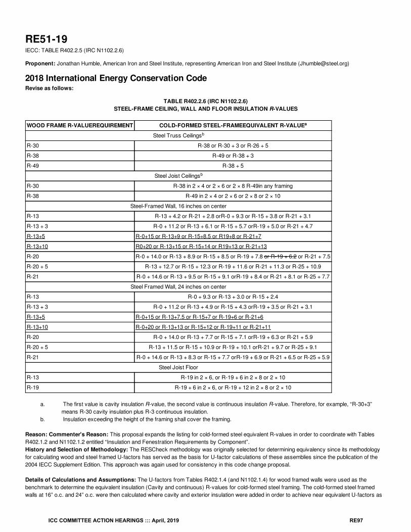
RE51-19IECC: TABLE R402.2.5 (IRC N1102.2.6)
Proponent: Jonathan Humble, American Iron and Steel Institute, representing American Iron and Steel Institute ([email protected])
2018 International Energy Conservation CodeRevise as follows:
TABLE R402.2.6 (IRC N1102.2.6)STEEL-FRAME CEILING, WALL AND FLOOR INSULATION R-VALUES
WOOD FRAME R-VALUEREQUIREMENT COLD-FORMED STEEL-FRAMEEQUIVALENT R-VALUE
Steel Truss Ceilings
R-30 R-38 or R-30 + 3 or R-26 + 5
R-38 R-49 or R-38 + 3
R-49 R-38 + 5
Steel Joist Ceilings
R-30 R-38 in 2 × 4 or 2 × 6 or 2 × 8 R-49in any framing
R-38 R-49 in 2 × 4 or 2 × 6 or 2 × 8 or 2 × 10
Steel-Framed Wall, 16 inches on center
R-13 R-13 + 4.2 or R-21 + 2.8 orR-0 + 9.3 or R-15 + 3.8 or R-21 + 3.1
R-13 + 3 R-0 + 11.2 or R-13 + 6.1 or R-15 + 5.7 orR-19 + 5.0 or R-21 + 4.7
R-13+5 R-0+15 or R-13+9 or R-15+8.5 or R19+8 or R-21+7
R-13+10 R0+20 or R-13+15 or R-15+14 or R19+13 or R-21+13
R-20 R-0 + 14.0 or R-13 + 8.9 or R-15 + 8.5 or R-19 + 7.8 or R-19 + 6.2 or R-21 + 7.5
R-20 + 5 R-13 + 12.7 or R-15 + 12.3 or R-19 + 11.6 or R-21 + 11.3 or R-25 + 10.9
R-21 R-0 + 14.6 or R-13 + 9.5 or R-15 + 9.1 orR-19 + 8.4 or R-21 + 8.1 or R-25 + 7.7
Steel Framed Wall, 24 inches on center
R-13 R-0 + 9.3 or R-13 + 3.0 or R-15 + 2.4
R-13 + 3 R-0 + 11.2 or R-13 + 4.9 or R-15 + 4.3 orR-19 + 3.5 or R-21 + 3.1
R-13+5 R-0+15 or R-13+7.5 or R-15+7 or R-19+6 or R-21+6
R-13+10 R-0+20 or R-13+13 or R-15+12 or R-19+11 or R-21+11
R-20 R-0 + 14.0 or R-13 + 7.7 or R-15 + 7.1 orR-19 + 6.3 or R-21 + 5.9
R-20 + 5 R-13 + 11.5 or R-15 + 10.9 or R-19 + 10.1 orR-21 + 9.7 or R-25 + 9.1
R-21 R-0 + 14.6 or R-13 + 8.3 or R-15 + 7.7 orR-19 + 6.9 or R-21 + 6.5 or R-25 + 5.9
Steel Joist Floor
R-13 R-19 in 2 × 6, or R-19 + 6 in 2 × 8 or 2 × 10
R-19 R-19 + 6 in 2 × 6, or R-19 + 12 in 2 × 8 or 2 × 10
a. The first value is cavity insulation R-value, the second value is continuous insulation R-value. Therefore, for example, “R-30+3”means R-30 cavity insulation plus R-3 continuous insulation.
b. Insulation exceeding the height of the framing shall cover the framing.
Reason: Commenter's Reason: This proposal expands the listing for cold-formed steel equivalent R-values in order to coordinate with TablesR402.1.2 and N1102.1.2 entitled “Insulation and Fenestration Requirements by Component”.History and Selection of Methodology: The RESCheck methodology was originally selected for determining equivalency since its methodologyfor calculating wood and steel framed U-factors has served as the basis for U-factor calculations of these assemblies since the publication of the2004 IECC Supplement Edition. This approach was again used for consistency in this code change proposal.
Details of Calculations and Assumptions: The U-factors from Tables R402.1.4 (and N1102.1.4) for wood framed walls were used as thebenchmark to determine the equivalent insulation (Cavity and continuous) R-values for cold-formed steel framing. The cold-formed steel framedwalls at 16” o.c. and 24” o.c. were then calculated where cavity and exterior insulation were added in order to achieve near equivalent U-factors as
a
b
b
ICC COMMITTEE ACTION HEARINGS ::: April, 2019 RE97
for wood framed wall assemblies. This resulted in R-values and U-factors for cold-formed steel framed walls that can be considered comparable towood wall assemblies.
In addition to the above modification, we are also proposing the deletion of the R-19+6.2 assembly configuration for the Wood 16 O/C category R-20.After a re-analysis we found that the U-factor is higher than the wood assembly U-factor comparison sufficient enough to recommend its departure.
Conclusion: Adopting the proposed modifications is intended to provide related prescriptive for cold-formed steel framed assembly optionsconsistent with the options listed for wood framed assemblies in the opaque thermal envelope tables.
Bibliography: Bartlett, R., Connell, L.M., Gowri, K., Lucas, R.G., Schultz, R.W., Taylor, Z.T., Wilberg, J.D., "Methodology for Developing theREScheck Software through Version 4.4.3", U.S. Department of Energy, Washington, DC, contracted through the Pacific Northwest NationalLaboratory, Richland, WA, September 2012.
Cost Impact: The code change proposal will not increase or decrease the cost of constructionThis section provides information that was not previously set forth in the code, and does not change the requirements of current code, thus there isno cost impact when compared with present requirements.
Proposal # 4026
RE51-19
ICC COMMITTEE ACTION HEARINGS ::: April, 2019 RE98
RE52-19IECC: R402.2.7 (IRC N1102.2.7)
Proponent: William Fay, Energy-Efficient Codes Coalition, representing Energy-Efficient Codes Coalition ([email protected]); Daniel Bresette, Allianceto Save Energy, representing Alliance to Save Energy ([email protected]); Maureen Guttman, BCAP-IBTS, representing BCAP-IBTS([email protected]); Harry Misuriello, American Council for an Energy-Efficient Economy, representing American Council for an Energy-Efficient Economy ([email protected])
2018 International Energy Conservation CodeDelete without substitution:
R402.2.7 Walls with partial structural sheathing. Where Section R402.1.2 requires continuous insulation on exterior walls and structuralsheathing covers 40 percent or less of the gross area of all exterior walls, the required continuous insulation R-value shall be permitted to bereduced by an amount necessary, but not more than R-3 to result in a consistent total sheathing thickness on areas of the walls covered bystructural sheathing. This reduction shall not apply to the U-factor alternative in Section R402.1.4 and the Total UA alternative in Section R402.1.5.
Reason: The purpose of this code change proposal is to improve efficiency by eliminating an unnecessary prescriptive exception to the wallinsulation requirements. The IECC currently allows an exception to the otherwise reasonable wall insulation requirements, which results indecreased energy efficiency in up to 40% of the wall area without any corresponding improvements elsewhere in the building.We do not believe it is appropriate to weaken the code simply because of a design choice made by the builder, even if it is a common constructionpractice. Given the broad range of trade-off options available through the Total UA path, DOE’s REScheck software, the performance path, and theEnergy Rating Index, we believe it is no longer necessary to carve out specific exceptions like this when an energy-neutral trade-off could easily beperformed in one of these alternative paths.
Cost Impact: The code change proposal will increase the cost of constructionConstruction costs could be increased for the subset of homes that might have taken advantage of this exception in the prescriptive path because itwill require the installation of insulation sufficient to meet the R-value requirement in Table R402.1.2. However, this change will not increase costs forhomes built to all other compliance paths in the IECC, since the footnote exception already does not apply to those homes. We believe theelimination of this exception will provide homeowners with the superior energy and cost-savings they expect from a code-compliant home.
Proposal # 4014
RE52-19
ICC COMMITTEE ACTION HEARINGS ::: April, 2019 RE99
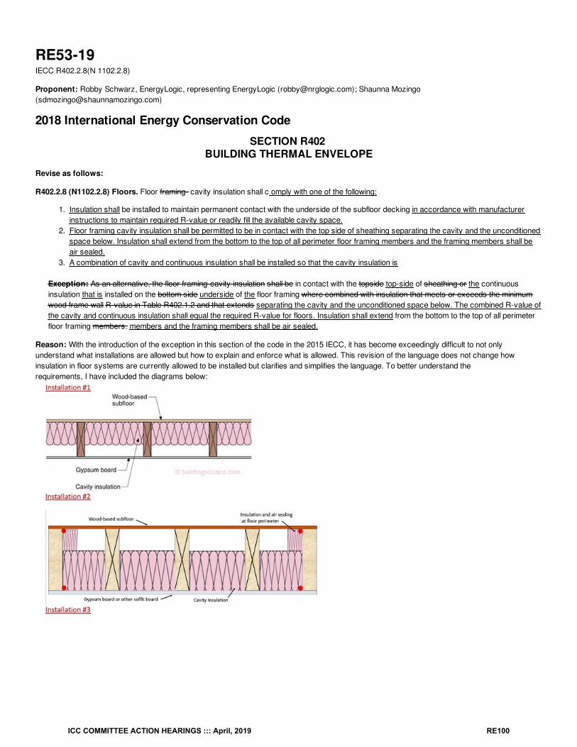
RE53-19IECC R402.2.8(N 1102.2.8)
Proponent: Robby Schwarz, EnergyLogic, representing EnergyLogic ([email protected]); Shaunna Mozingo([email protected])
2018 International Energy Conservation Code
SECTION R402 BUILDING THERMAL ENVELOPE
Revise as follows:
R402.2.8 (N1102.2.8) Floors. Floor framing- cavity insulation shall c omply with one of the following:
1. Insulation shall be installed to maintain permanent contact with the underside of the subfloor decking in accordance with manufacturerinstructions to maintain required R-value or readily fill the available cavity space.
2. Floor framing cavity insulation shall be permitted to be in contact with the top side of sheathing separating the cavity and the unconditionedspace below. Insulation shall extend from the bottom to the top of all perimeter floor framing members and the framing members shall beair sealed.
3. A combination of cavity and continuous insulation shall be installed so that the cavity insulation is
Exception: As an alternative, the floor framing-cavity insulation shall be in contact with the topside top-side of sheathing or the continuousinsulation that is installed on the bottom side underside of the floor framing where combined with insulation that meets or exceeds the minimumwood frame wall R-value in Table R402.1.2 and that extends separating the cavity and the unconditioned space below. The combined R-value ofthe cavity and continuous insulation shall equal the required R-value for floors. Insulation shall extend from the bottom to the top of all perimeterfloor framing members. members and the framing members shall be air sealed.
Reason: With the introduction of the exception in this section of the code in the 2015 IECC, it has become exceedingly difficult to not onlyunderstand what installations are allowed but how to explain and enforce what is allowed. This revision of the language does not change howinsulation in floor systems are currently allowed to be installed but clarifies and simplifies the language. To better understand therequirements, I have included the diagrams below:
ICC COMMITTEE ACTION HEARINGS ::: April, 2019 RE100
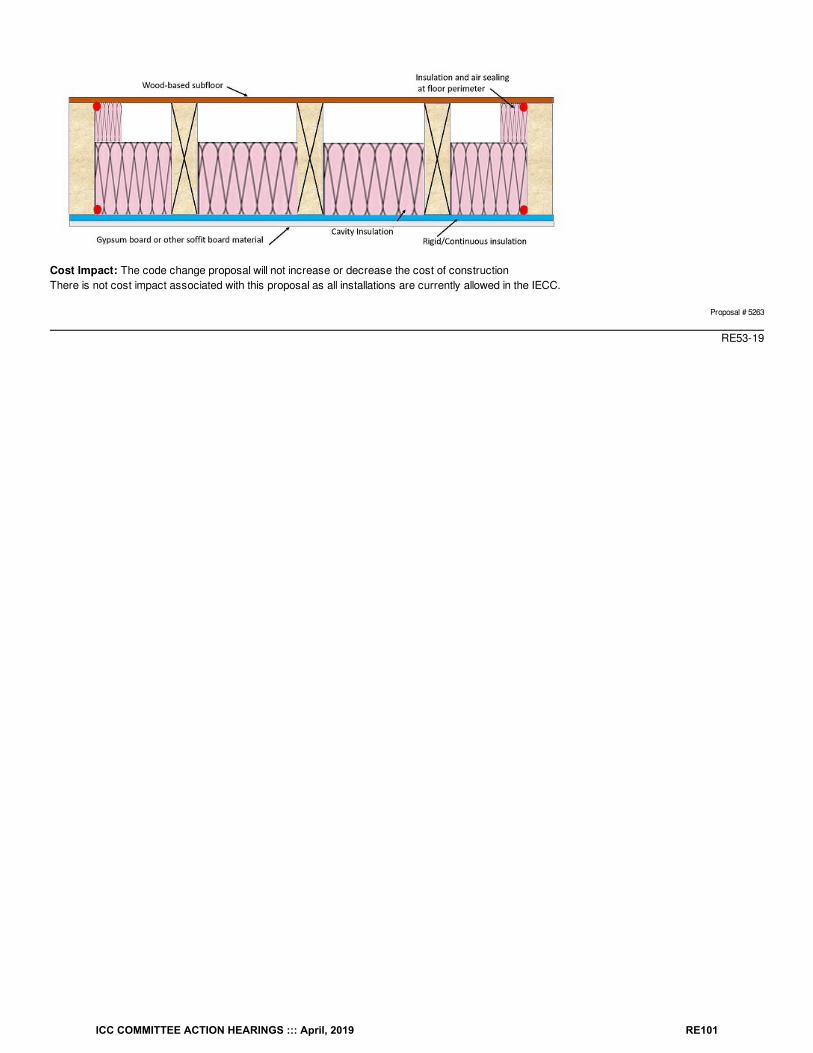
Cost Impact: The code change proposal will not increase or decrease the cost of constructionThere is not cost impact associated with this proposal as all installations are currently allowed in the IECC.
Proposal # 5263
RE53-19
ICC COMMITTEE ACTION HEARINGS ::: April, 2019 RE101
RE54-19IECC: R402.2.9 (IRC N1102.2.9)
Proponent: Robby Schwarz, EnergyLogic, representing EnergyLogic ([email protected])
2018 International Energy Conservation CodeRevise as follows:
R402.2.9 (IRC N1102.2.9) Basement walls. Walls associated with conditioned basements shall be insulated from the top of the basement wall downto 10 feet (3048 mm) below grade or to the basement floor, whichever is less. Walls associated with unconditioned basements shall comply with thisrequirement except where the floor overhead is insulated in accordance with Sections R402.1.2 and R402.2.8. comply with the followingrequirements:
1. Basement walls that define the building thermal envelope shall be insulated. The R-value shall be in accordance with the compliance path thatis defined at the time of obtaining the building permit. Unconditioned basements shall comply with the floor insulation requirements of SectionR402.2.8.
2. Unfinished basement walls that define the building thermal envelope shall have insulation that is permanently fastened to the wall. Theinsulation shall cover the exposed portion of the top of the foundation wall not covered by the sill plate, and extend downward to the finishedfloor below.
3. Finished basement walls that define the building thermal envelope shall be Insulated with material that fully fills the framed stud cavity of thefinished wall or material that upon installation fully fills the available space. A 1 in. (25 mm) gap is allowed between the framed cavity andinsulation, and the concrete foundation wall. Insulation shall be installed between framed bottom plates and the foundation floor when floatingwalls are used. Insulation shall be installed at the top of the foundation wall not covered by the sill plate.
Reason: This section of the code defines required installation requirements of the code that are not defined by manufacturer instructions. Since thesection does not define R-value requirements requirement #1 defines that the R-value installed needs to be in accordance with the compliance paththat is used. Requirement #2 is specific to installation requirements for unfinished basement walls and requirement #3 is specific to installationrequirements for finished basement walls. All requirements ensure that if the basement wall defines the building thermal envelope it is completelyinsulated and that there are no thermal bypasses allowed in the installation.
Cost Impact: The code change proposal will not increase or decrease the cost of constructionThere is no cost impact associated with this code proposal as it only clarifies the existing installation requirements of the code that are notadequately defined in the current section of the code
Proposal # 4798
RE54-19
ICC COMMITTEE ACTION HEARINGS ::: April, 2019 RE102
RE55-19IECC: R402.2.9 (IRC N1102.2.9)
Proponent: Darren Meyers, P.E., International Energy Conservation Consultants LLC, representing Self ([email protected])
2018 International Energy Conservation CodeRevise as follows:
R402.2.9 (IRC N1102.2.9) Basement walls. Walls associated with conditioned basements shall be insulated from the top of the basement wall downto 10 feet (3048 mm) below grade or to the basement floor, whichever is less. Walls associated with unconditioned basements shall comply with thisrequirement except where :
1. the floor overhead, including the underside stairway stringer leading to the basement, is insulated in accordance with Sections R402.1.2 andapplicable provisions of R402.2, and R402.2.8.
2. there are no uninsulated duct, domestic hot water, or hydronic heating surfaces exposed to the basement, and3. there are no HVAC supply or return diffusers serving the basement, and4. the walls surrounding the stairway and adjacent to conditioned space are insulated in accordance with Sections R402.1.2 and applicable
provisions of R402.2, and5. the door(s) leading to the basement from conditioned spaces are insulated in accordance with Sections R402.1.2 and applicable provisions of
R402.2, and weatherstripped in accordance with Section R402.4, and6. the building thermal envelope separating the basement from adjacent conditioned spaces complies with Section R402.4.
Reason: It is outrightly false to presume that the simple act of insulating the floor over the basement absolves one from considering the basementan extension of "conditioned space." This proposal offers an outline of the appropriate characteristics that must be present in order to "willfully andknowingly" remove a basement from consideration as an extension of "conditioned space."
Cost Impact: The code change proposal will increase the cost of constructionOne has to presume that if the entirety of the country and affected territories were utilizing the provisions of Section R402.2.9 "as written," that thecode change proposed would increase the cost of construction. Our belief is that a significant majority of the country enforcing the 2018 IECC has alevel of sophistication consistent with the concepts of thermal and pressure boundaries proposed. As such, we believe, the code change proposalwill not increase the cost of construction.
Proposal # 5460
RE55-19
ICC COMMITTEE ACTION HEARINGS ::: April, 2019 RE103
RE56-19IECC: R402.2.9 (IRC N1102.2.9)
Proponent: donald sivigny, State of MN, representing State of MN and Association of Minnesota Building Officials ([email protected])
2018 International Energy Conservation CodeRevise as follows:
R402.2.9 (IRC N1102.2.9) Basement walls. Walls associated with conditioned basements shall be insulated from the top of the basement wall downto 10 feet (3048 mm) below grade or to the basement floor top of footing, whichever is less. Foundation insulation shall be installed in accordancewith the manufacturer’s instructions. Walls associated with unconditioned basements shall comply with this requirement except where the flooroverhead is insulated in accordance with Sections R402.1.2 and R402.2.8.
Reason: The language in the IECC requirement is revised by replacing the phrase “or to the basement floor” with “or to the top of the footing.” Thetop of the footing is lower than the basement floor. This modification is necessary because the foundation system must be protected from heat lossbeyond the top the basement floor system. By providing insulation to the top of the footing, heat loss at the intersection of the concrete floor and thefoundation wall is reduced. This heat loss can create durability and moisture issues at the Foundation wall which will encourage mold growth. Thesection is further amended by adding a sentence that states, “Foundation insulation shall be installed according to the manufacturer’s installationinstructions.” This additional requirement is necessary because if the manufacturer’s instructions are not followed, the product may not perform as itis intended.
Cost Impact: The code change proposal will not increase or decrease the cost of constructionThe code (Section R303.2) currently requires products to be installed in accordance with the manufacturer’s instructions. The proposal simplyreinforces the requirement to ensure that the insulation performs as intended. As such, no additional materials or installation labor are necessary.
Proposal # 5129
RE56-19
ICC COMMITTEE ACTION HEARINGS ::: April, 2019 RE104
RE57-19IECC: R402.4.1.1 (IRC N1102.4.1.1)
Proponent: Aaron Gary, representing Self ([email protected])
2018 International Energy Conservation CodeRevise as follows:
R402.4.1.1 (IRC N1102.4.1.1) Installation. The components of the building thermal envelope as indicated in Table R402.4.1.1 shall be installed inaccordance with Grade l as defined by RESNET/ICC 301 Appendix A, the manufacturer’s instructions and the criteria indicated in Table R402.4.1.1,as applicable to the method of construction. Where required by the code official, an approved third party shall inspect all components and verifycompliance.
Reason: Unlike the ERI path, the Prescriptive and Performance path assume that envelope insulation is always installed as intended. Pointing onlyto the manufacturer's instructions however makes this very hard to manage for contractors and code officials as there is no central repository ofmanufacturer's instructions for them to easily reference nor do they usually have time to read more than what is clearly and simply stated in tehCode. Supplementing the manufacturer's installation instructions with something that is easy for all involved to reference and developed for ICC 700(an ANSI approved standard that many of the insulation manufacturer's contributed to) would greatly increase the ease of use of the Code. Usableand understandable Code would lead to better installations and enforcement. The end result then would not be predicted savings (as models alreadyassumes a near perfection which is rarely achieved in real life) but actual energy savings to the end user, i.e. the home owner or apartment dweller.
Cost Impact: The code change proposal will not increase or decrease the cost of constructionIf the manufacturer's instructions are already being met, then this code proposal will not increase or decrease the cost of construction.
Proposal # 4560
RE57-19
ICC COMMITTEE ACTION HEARINGS ::: April, 2019 RE105
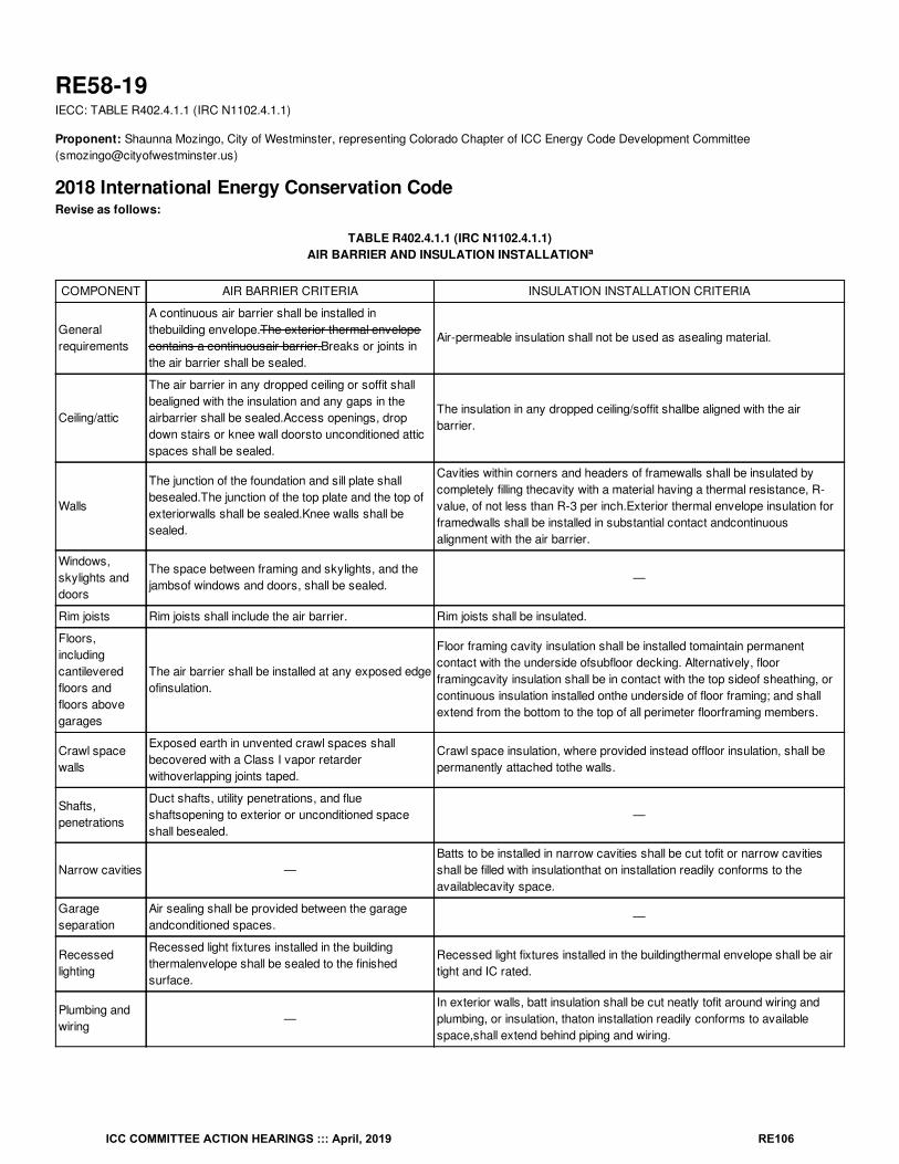
RE58-19IECC: TABLE R402.4.1.1 (IRC N1102.4.1.1)
Proponent: Shaunna Mozingo, City of Westminster, representing Colorado Chapter of ICC Energy Code Development Committee([email protected])
2018 International Energy Conservation CodeRevise as follows:
TABLE R402.4.1.1 (IRC N1102.4.1.1)AIR BARRIER AND INSULATION INSTALLATION
COMPONENT AIR BARRIER CRITERIA INSULATION INSTALLATION CRITERIA
Generalrequirements
A continuous air barrier shall be installed inthebuilding envelope.The exterior thermal envelopecontains a continuousair barrier.Breaks or joints inthe air barrier shall be sealed.
Air-permeable insulation shall not be used as asealing material.
Ceiling/attic
The air barrier in any dropped ceiling or soffit shallbealigned with the insulation and any gaps in theairbarrier shall be sealed.Access openings, dropdown stairs or knee wall doorsto unconditioned atticspaces shall be sealed.
The insulation in any dropped ceiling/soffit shallbe aligned with the airbarrier.
Walls
The junction of the foundation and sill plate shallbesealed.The junction of the top plate and the top ofexteriorwalls shall be sealed.Knee walls shall besealed.
Cavities within corners and headers of framewalls shall be insulated bycompletely filling thecavity with a material having a thermal resistance, R-value, of not less than R-3 per inch.Exterior thermal envelope insulation forframedwalls shall be installed in substantial contact andcontinuousalignment with the air barrier.
Windows,skylights anddoors
The space between framing and skylights, and thejambsof windows and doors, shall be sealed.
—
Rim joists Rim joists shall include the air barrier. Rim joists shall be insulated.
Floors,includingcantileveredfloors andfloors abovegarages
The air barrier shall be installed at any exposed edgeofinsulation.
Floor framing cavity insulation shall be installed tomaintain permanentcontact with the underside ofsubfloor decking. Alternatively, floorframingcavity insulation shall be in contact with the top sideof sheathing, orcontinuous insulation installed onthe underside of floor framing; and shallextend from the bottom to the top of all perimeter floorframing members.
Crawl spacewalls
Exposed earth in unvented crawl spaces shallbecovered with a Class I vapor retarderwithoverlapping joints taped.
Crawl space insulation, where provided instead offloor insulation, shall bepermanently attached tothe walls.
Shafts,penetrations
Duct shafts, utility penetrations, and flueshaftsopening to exterior or unconditioned spaceshall besealed.
—
Narrow cavities —Batts to be installed in narrow cavities shall be cut tofit or narrow cavitiesshall be filled with insulationthat on installation readily conforms to theavailablecavity space.
Garageseparation
Air sealing shall be provided between the garageandconditioned spaces.
—
Recessedlighting
Recessed light fixtures installed in the buildingthermalenvelope shall be sealed to the finishedsurface.
Recessed light fixtures installed in the buildingthermal envelope shall be airtight and IC rated.
Plumbing andwiring
—In exterior walls, batt insulation shall be cut neatly tofit around wiring andplumbing, or insulation, thaton installation readily conforms to availablespace,shall extend behind piping and wiring.
a
ICC COMMITTEE ACTION HEARINGS ::: April, 2019 RE106
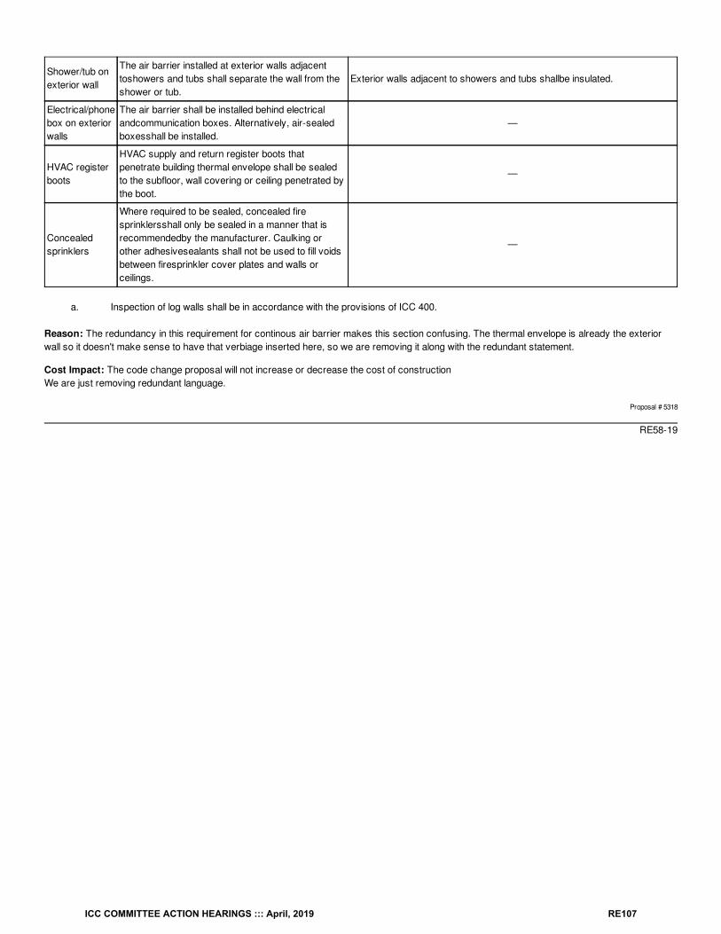
Shower/tub onexterior wall
The air barrier installed at exterior walls adjacenttoshowers and tubs shall separate the wall from theshower or tub.
Exterior walls adjacent to showers and tubs shallbe insulated.
Electrical/phonebox on exteriorwalls
The air barrier shall be installed behind electricalandcommunication boxes. Alternatively, air-sealedboxesshall be installed.
—
HVAC registerboots
HVAC supply and return register boots thatpenetrate building thermal envelope shall be sealedto the subfloor, wall covering or ceiling penetrated bythe boot.
—
Concealedsprinklers
Where required to be sealed, concealed firesprinklersshall only be sealed in a manner that isrecommendedby the manufacturer. Caulking orother adhesivesealants shall not be used to fill voidsbetween firesprinkler cover plates and walls orceilings.
—
a. Inspection of log walls shall be in accordance with the provisions of ICC 400.
Reason: The redundancy in this requirement for continous air barrier makes this section confusing. The thermal envelope is already the exteriorwall so it doesn't make sense to have that verbiage inserted here, so we are removing it along with the redundant statement.
Cost Impact: The code change proposal will not increase or decrease the cost of constructionWe are just removing redundant language.
Proposal # 5318
RE58-19
ICC COMMITTEE ACTION HEARINGS ::: April, 2019 RE107
RE59-19IECC: R402.2.9 (IRC N1102.2.9) (New), R402.2.9 (IRC N1102.2.9)
Proponent: David Collins, SEHPCAC, representing SEHPCAC ([email protected]); David Collins, representing The American Institute ofArchitects ([email protected])
2018 International Energy Conservation CodeAdd new text as follows:
R402.2.9 (IRC N1102.2.9) Basement Walls Basement walls shall be insulated in accordance with Table R402.1.2.
Exception: Basement walls associated with unconditioned basements where the floor overhead is insulated in accordance with SectionsR402.1.2 and R402.2.8.
Revise as follows:
R402.2.9 (IRC N1102.2.9) R402.2.9.1 (IRC N1102.2.9.1) Basement walls insulation installation (Mandatory). Walls associated with conditionedbasements Where basement walls are insulated, the insulation shall be insulated installed from the top of the basement wall down to 10 feet (3048mm) below grade or to the basement floor, whichever is less. Walls associated with unconditioned basements shall comply with this requirementexcept where the floor overhead is insulated in accordance with Sections R402.1.2 and R402.2.8.
Reason: R402.2.9 includes both prescriptive provisions (required insulation levels) and non-tradeable (mandatory) installation specifications.This proposal does not add new requirements; rather, it separates the prescriptive and mandatory provisions into separate sections.
The insulation installation requirements of new Sec. R402.2.9.1 have no value or metric that can be used for modeling purposes; they are non-tradeable (mandatory).
Note that the SEHPCAC has a proposal to eliminate the use of the labels "prescriptive “and "mandatory" in favor of a tabular method of identifyingnon-tradeable requirements. If that proposal is successful, ICC staff have stated that sections being individually approved to be labeled as‘mandatory’ will instead have their respective section numbers added to the new C407.2 table of requirements that are non-tradeable in theperformance path.
This proposal is submitted by the ICC Sustainable, Energy and High Performance Code Action Committee (SEHPCAC). The SEHPCAC wasestablished by the ICC Board of Directors to pursue opportunities to improve and enhance International Codes with regard to sustainability, energyand high performance as it relates to the built environment included, but not limited to, how these criteria relate to the International GreenConstruction Code (IgCC) and the International Energy Conservation Code (IECC). In 2018-2019, the SEHPCAC has held five two- or three-dayopen meetings and numerous workgroup calls, to discuss and debate proposed changes and public comments. Attendees at the meetings and callsincluded members of the SEHPCAC as well as any interested parties. Related documentation and reports are posted on the SEHPCAC website at:http://www.iccsafe.org/cs/SEHPCAC/Pages/default.aspx (http://www.iccsafe.org/cs/SEHPCAC/Pages/default.aspx)
Cost Impact: The code change proposal will increase the cost of constructionThe code change may increase construction costs for a subset of buildings that may have been designed using the Total Building Performance orEIR compliance methods that did not follow the basement wall insulation installations provisions contained in this section.
Proposal # 4495
RE59-19
ICC COMMITTEE ACTION HEARINGS ::: April, 2019 RE108
RE60-19IECC: R402.2.10, R402.2.10.1 (IRC N1102.2.10.1) (New)
Proponent: David Collins, SEHPCAC, representing SEHPCAC ([email protected]); David Collins, representing The American Institute ofArchitects ([email protected])
2018 International Energy Conservation CodeRevise as follows:
R402.2.10 (IRC N1102.2.10) Slab-on-grade floors. Slab-on-grade floors with a floor surface less than 12 inches (305 mm) below grade shall beinsulated in accordance with Table R402.1.2. The insulation shall extend downward from the top of the slab on the outside or inside of the foundationwall. Insulation located below grade shall be extended the distance provided in Table R402.1.2 by any combination of vertical insulation, insulationextending under the slab or insulation extending out from the building. Insulation extending away from the building shall be protected by pavement orby not less than 10 inches (254 mm) of soil. The top edge of the insulation installed between the exterior wall and the edge of the interior slab shall bepermitted to be cut at a 45-degree (0.79 rad) angle away from the exterior wall.
Exception: Slab-edge insulation is not required in jurisdictions designated by the code official as having a very heavy termite infestation.
Add new text as follows:
R402.2.10.1 (IRC N1102.2.10.1) Slab-on-grade floor insulation installation (Mandatory) Where installed, the insulation shall extend downwardfrom the top of the slab on the outside or inside of the foundation wall. Insulation located below grade shall be extended the distance provided inTable R402.1.2 by any combination of vertical insulation, insulation extending under the slab or insulation extending out from the building. Insulationextending away from the building shall be protected by pavement or by not less than 10 inches (254 mm) of soil. The top edge of the insulationinstalled between the exterior wall and the edge of the interior slab shall be permitted to be cut at a 45-degree (0.79 rad) angle away from the exteriorwall.
Reason: R402.2.10 includes both prescriptive provisions (insulation levels) and non-tradeable (mandatory) installation specifications, plus anembedded exception for termite infestations.This proposal does not add new requirements; rather, it separates the prescriptive and mandatory provisions into separate sections and clarifies theexception to required insulation in jurisdictions designated by the code official as having a very heavy termite infestation.
The insulation installation requirements of new Sec. R402.2.10.1 have no value or metric that can be used for modeling purposes; they are non-tradeable (mandatory).
Note that the SEHPCAC has a proposal to eliminate the use of the labels "prescriptive “and "mandatory" in favor of a tabular method of identifyingnon-tradeable requirements. If that proposal is successful, ICC staff have stated that sections being individually approved to be labeled as‘mandatory’ will instead have their respective section numbers added to the new C407.2 table of requirements that are non-tradeable in theperformance path.
This proposal is submitted by the ICC Sustainable, Energy and High Performance Code Action Committee (SEHPCAC). The SEHPCAC wasestablished by the ICC Board of Directors to pursue opportunities to improve and enhance International Codes with regard to sustainability, energyand high performance as it relates to the built environment included, but not limited to, how these criteria relate to the International GreenConstruction Code (IgCC) and the International Energy Conservation Code (IECC). In 2018-2019, the SEHPCAC has held five two- or three-dayopen meetings and numerous workgroup calls, to discuss and debate proposed changes and public comments. Attendees at the meetings and callsincluded members of the SEHPCAC as well as any interested parties. Related documentation and reports are posted on the SEHPCAC website at:http://www.iccsafe.org/cs/SEHPCAC/Pages/default.aspx (http://www.iccsafe.org/cs/SEHPCAC/Pages/default.aspx)
Cost Impact: The code change proposal will increase the cost of constructionThe code change may increase construction costs for a subset of buildings that may have been designed using the Total Building Performance orEIR compliance methods that included slab on grade with insulation installed not in accordance with the provisions of this section.
Proposal # 4496
RE60-19
ICC COMMITTEE ACTION HEARINGS ::: April, 2019 RE109
RE61-19IECC: R402.2.11 (IRC N1102.2.11)
Proponent: Robby Schwarz, EnergyLogic, representing EnergyLogic ([email protected])
2018 International Energy Conservation CodeRevise as follows:
R402.2.11 (IRC N1102.2.11) Crawl space walls. As an alternative to insulating floors over crawl spaces, crawl space walls shall be insulatedprovided that the crawl space is not vented to the outdoors. Crawl space wall insulation shall be permanently fastened to the wall and shall extenddownward from the floor to the finished grade elevation and then vertically or horizontally for not less than an additional 24 inches (610 mm). sill plateon top of the crawlspace wall to the floor of the crawlspace. Exposed earth in unvented crawl space foundations shall be covered with a continuousClass I vapor retarder in accordance with the International Building Code or International Residential Code , as applicable. Joints of the vaporretarder shall overlap by 6 inches (153 mm) and be sealed or taped. The edges of the vapor retarder shall extend not less than 6 inches (153 mm)up stem walls and shall be attached and sealed to the stem walls.
Reason: The foundation of an unvented conditioned crawlspace must be insulated to have a continuous building thermal envelope. It is less clear ifthe floor of the crawlspace needs to be insulated. However, what is known is that the extension of the wall insulation 24” horizontally over the dirt orvapor retarder on the dirt floor inside the crawlspace is not being enforced with any regularity. When using the Ekotrope or REMRate modelingsoftware to demonstrate compliance with the cost compliance report used in Section R405 it is easy to demonstrate no value associated with the24” of extended insulation. The crawlspace dirt floor is 3-5 feet below grade and it is not required to be insulated fully. Similarly, there is norequirement to insulate the concrete floor in a basement that is eight feet below grade. If there were a requirement there would be countlessarguments regarding the cost-effectiveness of the insulation. This proposal aims to take the 24” extension of insulation out of the code in order tofully focus on insulating the portion of the foundation that is associated with the majority of the heat loss or gain.On the other side of the equation, when portions of concrete foundation walls are not insulated such as the top of the foundation adjacent to the sillplate it is easy to demonstrate value for the installation of insulation. IR camera imaging, as well as Ekotrope and REMRate modeling, candemonstrate the impact of small portions of uninsulated building thermal envelope.
Cost Impact: The code change proposal will not increase or decrease the cost of constructionWould be cost saving associated with this proposal as the 24” extension of insulation over the floor of the crawlspace would be removed as arequirement from the code while asking for a small portion of insulation to be installed at the top of the foundation wall.
Proposal # 4795
RE61-19
ICC COMMITTEE ACTION HEARINGS ::: April, 2019 RE110
RE62-19IECC: R402.2.11 (IRC N1102.2.11) (New), R402.2.11 (IRC N1102.2.11)
Proponent: David Collins, SEHPCAC, representing SEHPCAC ([email protected]); David Collins, representing The American Institute ofArchitects ([email protected])
2018 International Energy Conservation CodeAdd new text as follows:
R402.2.11 (IRC N1102.2.11) Crawl space walls. Crawl space walls shall be insulated in accordance with Table R402.1.2.
Exception: Crawlspace walls associated with a crawlspace that is vented to the outdoors and the floor overhead is insulated in accordance withSections R402.1.2 and R402.2.8.
Revise as follows:
R402.2.11 (IRC N1102.2.11) R402.2.11.1 (IRC N1102.2.11.1) Crawl space walls. walls insulation installation (Mandatory). As an alternative toinsulating floors over crawl spaces, crawl space walls shall be insulated provided that the crawl space is not vented to the outdoors. Crawl Wherecrawl space wall insulation is installed, it shall be permanently fastened to the wall and shall extend downward from the floor to the finished gradeelevation and then vertically or horizontally for not less than an additional 24 inches (610 mm). Exposed earth in unvented crawl space foundationsshall be covered with a continuous Class I vapor retarder in accordance with the International Building Code or International Residential Code , asapplicable. Joints of the vapor retarder shall overlap by 6 inches (153 mm) and be sealed or taped. The edges of the vapor retarder shall extend notless than 6 inches (153 mm) up stem walls and shall be attached to the stem walls.
Reason: Originally drafted as one section, the language included both prescriptive provisions (insulation levels) and mandatory insulationinstallation, and an embedded exception. This proposal does not add new requirements, it separates the prescriptive and mandatory provisons aswell as the exception.This proposal is submitted by the ICC Sustainable, Energy and High Performance Code Action Committee (SEHPCAC). The SEHPCAC wasestablished by the ICC Board of Directors to pursue opportunities to improve and enhance International Codes with regard to sustainability, energyand high performance as it relates to the built environment included, but not limited to, how these criteria relate to the International GreenConstruction Code (IgCC) and the International Energy Conservation Code (IECC). In 2018-2019, the SEHPCAC has held five two- or three-dayopen meetings and numerous workgroup calls, to discuss and debate proposed changes and public comments. Attendees at the meetings and callsincluded members of the SEHPCAC as well as any interested parties. Related documentation and reports are posted on the SEHPCAC website at:http://www.iccsafe.org/cs/SEHPCAC/Pages/default.aspx (http://www.iccsafe.org/cs/SEHPCAC/Pages/default.aspx)
Cost Impact: The code change proposal will not increase or decrease the cost of constructionThe code change may increase construction costs for a subset of buildings that may have been designed using the Total Building Performance orEIR compliance methods that included slab on grade with insulation installed not in accordance with the provisions of this section.
Proposal # 4698
RE62-19
ICC COMMITTEE ACTION HEARINGS ::: April, 2019 RE111
RE63-19IECC: R402.2.14 (IRC N1102.2.14) (New)
Proponent: John Woestman, representing Extruded Polystyrene Foam Association ([email protected])
2018 International Energy Conservation CodeAdd new text as follows:
R402.2.14 (IRC N1102.2.14) Airspaces. Where the thermal properties of airspaces are used to comply with this code in accordance with SectionR401.2, such airspaces shall be enclosed in an unventilated cavity constructed to minimize air-flow into and out of the enclosed air space. Airflowshall be deemed minimized when the enclosed airspace is located on the interior side of the continuous air-barrier and is bounded on all sides bybuilding components.
Exception: The thermal resistance of airspaces located on the exterior side of the continuous air barrier and adjacent to and behind the exteriorwall-covering material shall be determined in accordance with ASTM C1363 modified with an airflow entering the bottom and exiting the top of theairspace at an air movement rate of not less than 70 mm/second.
Reason: This proposal is identical to requirements for airspaces added to the 2018 IECC-C (Section 402.2.7). It also is consistent with ASHRAE90.1-2016 (Section A9.4.2) which was the basis for IECC-C Section 402.2.7. These provisions will ensure that the R-value of airspaces are properlyaccounted for when used as an optional means of energy code compliance.
Cost Impact: The code change proposal will not increase or decrease the cost of constructionThe proposal provides needed requirements for the additional and optional use of airspaces as a supplemental means of energy code compliance.This proposal may add an option that’s currently not in the code.
Proposal # 5239
RE63-19
ICC COMMITTEE ACTION HEARINGS ::: April, 2019 RE112
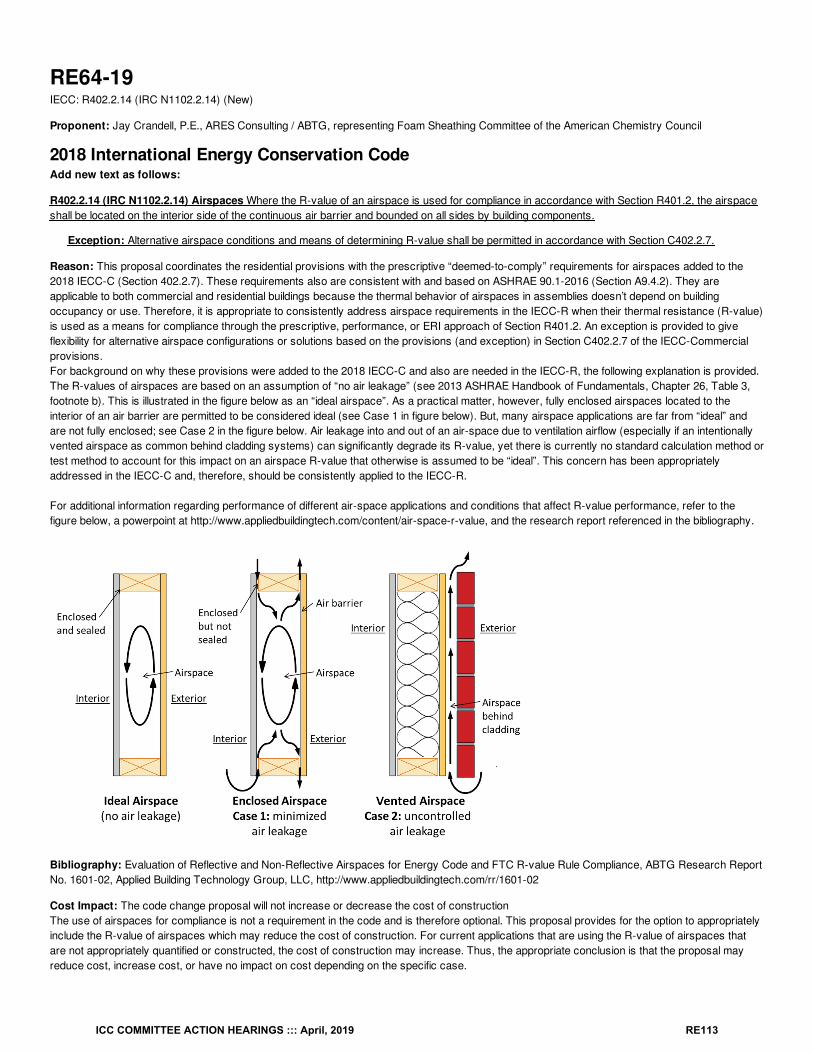
RE64-19IECC: R402.2.14 (IRC N1102.2.14) (New)
Proponent: Jay Crandell, P.E., ARES Consulting / ABTG, representing Foam Sheathing Committee of the American Chemistry Council
2018 International Energy Conservation CodeAdd new text as follows:
R402.2.14 (IRC N1102.2.14) Airspaces Where the R-value of an airspace is used for compliance in accordance with Section R401.2, the airspaceshall be located on the interior side of the continuous air barrier and bounded on all sides by building components.
Exception: Alternative airspace conditions and means of determining R-value shall be permitted in accordance with Section C402.2.7.
Reason: This proposal coordinates the residential provisions with the prescriptive “deemed-to-comply” requirements for airspaces added to the2018 IECC-C (Section 402.2.7). These requirements also are consistent with and based on ASHRAE 90.1-2016 (Section A9.4.2). They areapplicable to both commercial and residential buildings because the thermal behavior of airspaces in assemblies doesn’t depend on buildingoccupancy or use. Therefore, it is appropriate to consistently address airspace requirements in the IECC-R when their thermal resistance (R-value)is used as a means for compliance through the prescriptive, performance, or ERI approach of Section R401.2. An exception is provided to giveflexibility for alternative airspace configurations or solutions based on the provisions (and exception) in Section C402.2.7 of the IECC-Commercialprovisions.For background on why these provisions were added to the 2018 IECC-C and also are needed in the IECC-R, the following explanation is provided.The R-values of airspaces are based on an assumption of “no air leakage” (see 2013 ASHRAE Handbook of Fundamentals, Chapter 26, Table 3,footnote b). This is illustrated in the figure below as an “ideal airspace”. As a practical matter, however, fully enclosed airspaces located to theinterior of an air barrier are permitted to be considered ideal (see Case 1 in figure below). But, many airspace applications are far from “ideal” andare not fully enclosed; see Case 2 in the figure below. Air leakage into and out of an air-space due to ventilation airflow (especially if an intentionallyvented airspace as common behind cladding systems) can significantly degrade its R-value, yet there is currently no standard calculation method ortest method to account for this impact on an airspace R-value that otherwise is assumed to be “ideal”. This concern has been appropriatelyaddressed in the IECC-C and, therefore, should be consistently applied to the IECC-R.
For additional information regarding performance of different air-space applications and conditions that affect R-value performance, refer to thefigure below, a powerpoint at http://www.appliedbuildingtech.com/content/air-space-r-value, and the research report referenced in the bibliography.
Bibliography: Evaluation of Reflective and Non-Reflective Airspaces for Energy Code and FTC R-value Rule Compliance, ABTG Research ReportNo. 1601-02, Applied Building Technology Group, LLC, http://www.appliedbuildingtech.com/rr/1601-02
Cost Impact: The code change proposal will not increase or decrease the cost of constructionThe use of airspaces for compliance is not a requirement in the code and is therefore optional. This proposal provides for the option to appropriatelyinclude the R-value of airspaces which may reduce the cost of construction. For current applications that are using the R-value of airspaces thatare not appropriately quantified or constructed, the cost of construction may increase. Thus, the appropriate conclusion is that the proposal mayreduce cost, increase cost, or have no impact on cost depending on the specific case.
ICC COMMITTEE ACTION HEARINGS ::: April, 2019 RE113
Proposal # 4510
RE64-19
ICC COMMITTEE ACTION HEARINGS ::: April, 2019 RE114
ASTM ASTM International100 Barr Harbor Drive, P.O. Box C700
West Conshohocken PA 19428-2959
RE65-19IECC: R202 (IRC N1101.6), R402.3 (IRC N1102.3) (New), ASTM Chapter 6 (IRC Chapter 44)
Proponent: Amanda Hickman, The Hickman Group, representing Reflective Insulation Manufacturers Association International([email protected])
2018 International Energy Conservation Code
SECTION R202 (IRC N1101.6) GENERAL DEFINITIONS
Add new definition as follows:
RADIANT BARRIER. A material having a low emittance surface of 0.1 or less installed in building assemblies.
Add new text as follows:
R402.3 (IRC N1102.3) Radiant barriers (Mandatory). Where installed to reduce thermal radiation, radiant barriers shall be installed in accordancewith ASTM C1743.
Add new standard(s) as follows:
ASTM C1743: Standard Practice for Installation and Use of Radiant Barrier Systems (RBS) in Residential Building Construction
Reason: This proposal DOES NOT require the use of radiant barriers. But rather requires that WHEN radiant barriers are used, they comply withthe appropriate ASTM standard. Furthermore this proposal provides important information to the code user and code enforcement communityregarding radiant barriers.Radiant barriers follow two ASTM Standards – ASTM C1313/C1313M, "Standard Specification for Sheet Radiant Barriers for Building ConstructionApplications," and ASTM C1743, "Standard Practice for Installation and Use of Radiant Barrier Systems (RBS) in Residential Building Construction".
The definition for "Radiant Barrier" was approved in the last cycle and is included in the 2015 IBC.
The proposed language is being included in this section specifically because the American Society for Testing and Materials (ASTM) classifiesradiant barriers as thermal insulation. The ASTM committee C16 on Thermal Insulation includes published standards for this product. SubcommitteeC16.21 deals specifically with reflective products, which include reflective insulation, radiant barrier and interior radiation control coatings. C16.21develops standards and practices for these reflective building material thermal insulating products.
The Federal Trade Commission includes radiant barrier products in “CFR Part 460 Labeling and Advertising of Home Insulation: TradeRegulation Rule”.
Radiant barrier products include a surface with an emittance of 0.1 or less that is installed in roof assemblies or attics with the low-emittance surfacefacing an open or ventilated air space. The low emittance material can be bonded to plastic film, woven fabric, reinforced paper, OSB or plywood.The thermal performance of radiant barriers depends on emittance and location in the attic, wall or roof assembly. Radiant barriers arepredominantly installed in attic spaces below the roof deck. The low-emittance surface of radiant barrier products dramatically reduces the heat gainby radiation into the structure and attic HVAC ducts. For this reason, radiant barriers are especially effective in warm sunny climates where theyprovide reduced use of air conditioning. Radiant barrier products that are available include single-sheet material, multi-layer assemblies and woodsheathing with attached aluminum film or foil. The single sheet material is installed in roof assemblies by attaching directly to the roof deck, inbetween the rafters or trusses or to the underside of the rafters or trusses. The foil-faced sheathing is installed with the low-emittance side of thesheathing or panel facing toward the attic space to create a radiant barrier. Attic radiant barriers are in extensive use. These products have been onthe market for several decades and are used by 87 of the top 100 US Builders. They have an established history and have been accepted intoseveral regional code requirements. Over one billion square feet of the product is being installed annually.
Many state and jurisdictional codes already include references on radiant barriers. These are the state and city codes that include radiant barrier:
IBC: 2018 Section 1509 Radiant Barriers Installed Above Deck
Hawaii
ICC COMMITTEE ACTION HEARINGS ::: April, 2019 RE115
Chapter 181 of Title 3, 2015, Section 407.2, Table 407.1
Texas
The Code of the City of Austin, Texas, Supplement 134-2018, Chapter 25-12, Article 12, Section R402.6
Florida
2017 Florida Building Code, Energy Conservation, 6 Edition
Section 405.7.1 Installation Criteria for homes claiming the radiant barrier option
Figure R405.7.1 Acceptable attic radiant barrier configurations
Table R303.2.1 Insulation Installation Standards
California
Title 24, 2016, Part 6, Subchapter 1, Definition Radiant Barrier
Title 24, 2016, Part 6, Subchapter 2, Section 110.8 Mandatory requirements for insulation, roofing products, and radiant barriers
Title 24, 2016, Part 6, Subchapter 8, Section 150.1 (c), Prescriptive standards / component packages
Title 24, 2016, Reference Residential Appendices, Radiant Barriers
Cost Impact: The code change proposal will not increase or decrease the cost of constructionThis proposal will not increase the cost of construction because it only adds informational language regarding radiant barriers.
Proposal # 4482
RE65-19
th
ICC COMMITTEE ACTION HEARINGS ::: April, 2019 RE116
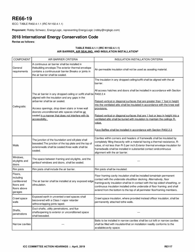
RE66-19IECC: TABLE R402.4.1.1 (IRC N1102.4.1.1)
Proponent: Robby Schwarz, EnergyLogic, representing EnergyLogic ([email protected])
2018 International Energy Conservation CodeRevise as follows:
TABLE R402.4.1.1 (IRC N1102.4.1.1)AIR BARRIER, AIR SEALING, AND INSULATION INSTALLATION
COMPONENT AIR BARRIER CRITERIA INSULATION INSTALLATION CRITERIA
Generalrequirements
A continuous air barrier shall be installed inthebuilding envelope.The exterior thermal envelopecontains a continuousair barrier.Breaks or joints inthe air barrier shall be sealed.
Air-permeable insulation shall not be used as asealing material.
Ceiling/attic
The air barrier in any dropped ceiling or soffit shall bealigned with the insulation and any gaps in theairbarrier shall be air sealed.
Access openings, drop down stairs or knee walldoorsto unconditioned attic spaces shall be airsealed in a manner that does not interfere with itsaccessibility.
The insulation in any dropped ceiling/soffit shall be aligned with the airbarrier.
All access hatches and doors shall be installed in accordance with SectionR402.2.4
Raised vertical or diagonal surfaces that are greater than 1’ foot in heightinto the ventilated attic shall be insulated in accordance with the knee wallprovisions.
Raised vertical or diagonal surfaces that are 1 foot or less in height into aventilated attic shall be buried with insulation to maintain the ceilings R-value.
Eave Baffles shall be installed in accordance with Section R402.2.3
Walls
The junction of the foundation and sill plate shallbesealed.The junction of the top plate and the top ofexteriorwalls shall be sealed.Knee walls shall besealed.
Cavities within corners and headers of framewalls shall be insulated bycompletely filling thecavity with a material having a thermal resistance, R-value, of not less than R-3 per inch.Exterior thermal envelope insulation forframedwalls shall be installed in substantial contact andcontinuousalignment with the air barrier.
Windows,skylights anddoors
The space between framing and skylights, and thejambsof windows and doors, shall be sealed.
—
Rim joists Rim joists shall include the air barrier. Rim joists shall be insulated.
Floors,includingcantileveredfloors andfloors abovegarages
The air barrier shall be installed at any exposed edgeofinsulation.
Floor framing cavity insulation shall be installed tomaintain permanentcontact with the underside ofsubfloor decking. Alternatively, floorframingcavity insulation shall be in contact with the top sideof sheathing, orcontinuous insulation installed onthe underside of floor framing; and shallextend from the bottom to the top of all perimeter floorframing members.
Crawl spacewalls
Exposed earth in unvented crawl spaces shallbecovered with a Class I vapor retarderwithoverlapping joints taped.
Crawl space insulation, where provided instead offloor insulation, shall bepermanently attached tothe walls.
Shafts,penetrations
Duct shafts, utility penetrations, and flueshaftsopening to exterior or unconditioned spaceshall besealed.
—
Narrow cavities —Batts to be installed in narrow cavities shall be cut tofit or narrow cavitiesshall be filled with insulationthat on installation readily conforms to theavailablecavity space.
a
ICC COMMITTEE ACTION HEARINGS ::: April, 2019 RE117
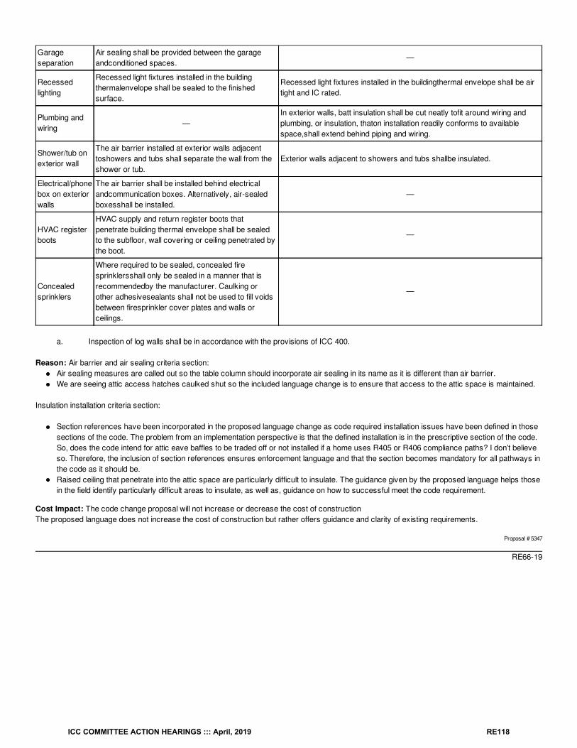
Garageseparation
Air sealing shall be provided between the garageandconditioned spaces.
—
Recessedlighting
Recessed light fixtures installed in the buildingthermalenvelope shall be sealed to the finishedsurface.
Recessed light fixtures installed in the buildingthermal envelope shall be airtight and IC rated.
Plumbing andwiring
—In exterior walls, batt insulation shall be cut neatly tofit around wiring andplumbing, or insulation, thaton installation readily conforms to availablespace,shall extend behind piping and wiring.
Shower/tub onexterior wall
The air barrier installed at exterior walls adjacenttoshowers and tubs shall separate the wall from theshower or tub.
Exterior walls adjacent to showers and tubs shallbe insulated.
Electrical/phonebox on exteriorwalls
The air barrier shall be installed behind electricalandcommunication boxes. Alternatively, air-sealedboxesshall be installed.
—
HVAC registerboots
HVAC supply and return register boots thatpenetrate building thermal envelope shall be sealedto the subfloor, wall covering or ceiling penetrated bythe boot.
—
Concealedsprinklers
Where required to be sealed, concealed firesprinklersshall only be sealed in a manner that isrecommendedby the manufacturer. Caulking orother adhesivesealants shall not be used to fill voidsbetween firesprinkler cover plates and walls orceilings.
—
a. Inspection of log walls shall be in accordance with the provisions of ICC 400.
Reason: Air barrier and air sealing criteria section:Air sealing measures are called out so the table column should incorporate air sealing in its name as it is different than air barrier.We are seeing attic access hatches caulked shut so the included language change is to ensure that access to the attic space is maintained.
Insulation installation criteria section:
Section references have been incorporated in the proposed language change as code required installation issues have been defined in thosesections of the code. The problem from an implementation perspective is that the defined installation is in the prescriptive section of the code.So, does the code intend for attic eave baffles to be traded off or not installed if a home uses R405 or R406 compliance paths? I don’t believeso. Therefore, the inclusion of section references ensures enforcement language and that the section becomes mandatory for all pathways inthe code as it should be.Raised ceiling that penetrate into the attic space are particularly difficult to insulate. The guidance given by the proposed language helps thosein the field identify particularly difficult areas to insulate, as well as, guidance on how to successful meet the code requirement.
Cost Impact: The code change proposal will not increase or decrease the cost of constructionThe proposed language does not increase the cost of construction but rather offers guidance and clarity of existing requirements.
Proposal # 5347
RE66-19
ICC COMMITTEE ACTION HEARINGS ::: April, 2019 RE118
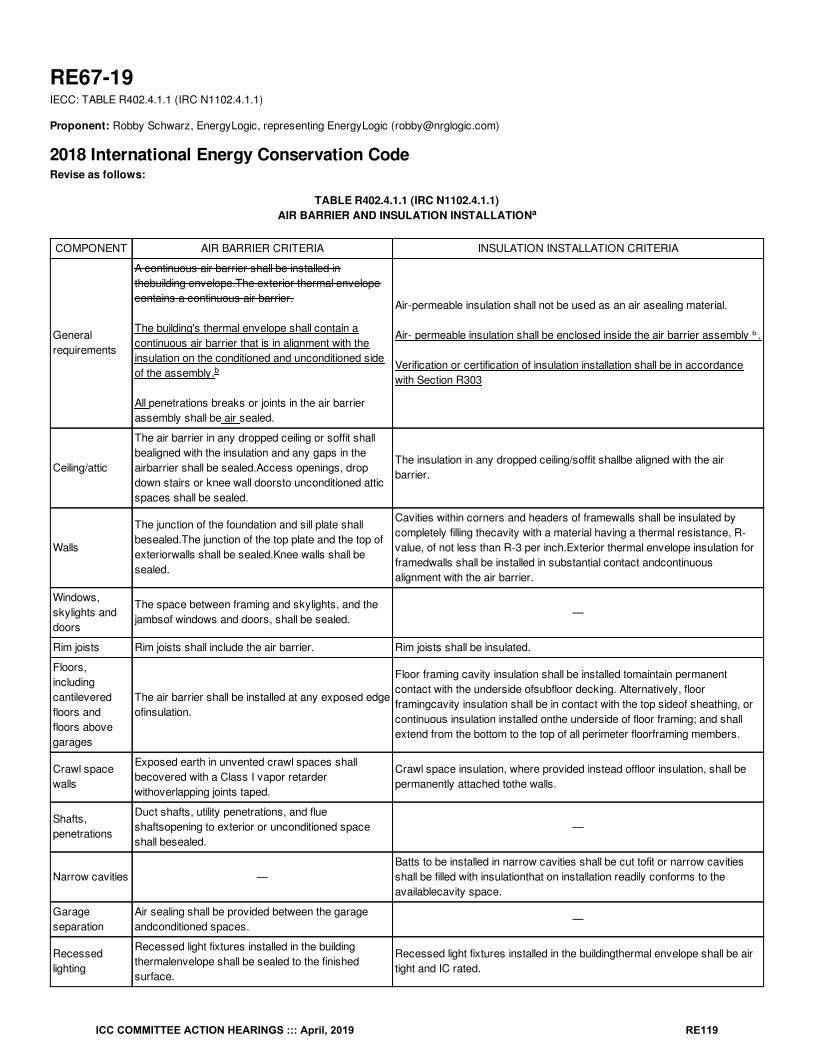
RE67-19IECC: TABLE R402.4.1.1 (IRC N1102.4.1.1)
Proponent: Robby Schwarz, EnergyLogic, representing EnergyLogic ([email protected])
2018 International Energy Conservation CodeRevise as follows:
TABLE R402.4.1.1 (IRC N1102.4.1.1)AIR BARRIER AND INSULATION INSTALLATION
COMPONENT AIR BARRIER CRITERIA INSULATION INSTALLATION CRITERIA
Generalrequirements
A continuous air barrier shall be installed inthebuilding envelope.The exterior thermal envelopecontains a continuous air barrier.
The building's thermal envelope shall contain acontinuous air barrier that is in alignment with theinsulation on the conditioned and unconditioned sideof the assembly.
All penetrations breaks or joints in the air barrierassembly shall be air sealed.
Air-permeable insulation shall not be used as an air asealing material.
Air- permeable insulation shall be enclosed inside the air barrier assembly ᵇ .
Verification or certification of insulation installation shall be in accordancewith Section R303
Ceiling/attic
The air barrier in any dropped ceiling or soffit shallbealigned with the insulation and any gaps in theairbarrier shall be sealed.Access openings, dropdown stairs or knee wall doorsto unconditioned atticspaces shall be sealed.
The insulation in any dropped ceiling/soffit shallbe aligned with the airbarrier.
Walls
The junction of the foundation and sill plate shallbesealed.The junction of the top plate and the top ofexteriorwalls shall be sealed.Knee walls shall besealed.
Cavities within corners and headers of framewalls shall be insulated bycompletely filling thecavity with a material having a thermal resistance, R-value, of not less than R-3 per inch.Exterior thermal envelope insulation forframedwalls shall be installed in substantial contact andcontinuousalignment with the air barrier.
Windows,skylights anddoors
The space between framing and skylights, and thejambsof windows and doors, shall be sealed.
—
Rim joists Rim joists shall include the air barrier. Rim joists shall be insulated.
Floors,includingcantileveredfloors andfloors abovegarages
The air barrier shall be installed at any exposed edgeofinsulation.
Floor framing cavity insulation shall be installed tomaintain permanentcontact with the underside ofsubfloor decking. Alternatively, floorframingcavity insulation shall be in contact with the top sideof sheathing, orcontinuous insulation installed onthe underside of floor framing; and shallextend from the bottom to the top of all perimeter floorframing members.
Crawl spacewalls
Exposed earth in unvented crawl spaces shallbecovered with a Class I vapor retarderwithoverlapping joints taped.
Crawl space insulation, where provided instead offloor insulation, shall bepermanently attached tothe walls.
Shafts,penetrations
Duct shafts, utility penetrations, and flueshaftsopening to exterior or unconditioned spaceshall besealed.
—
Narrow cavities —Batts to be installed in narrow cavities shall be cut tofit or narrow cavitiesshall be filled with insulationthat on installation readily conforms to theavailablecavity space.
Garageseparation
Air sealing shall be provided between the garageandconditioned spaces.
—
Recessedlighting
Recessed light fixtures installed in the buildingthermalenvelope shall be sealed to the finishedsurface.
Recessed light fixtures installed in the buildingthermal envelope shall be airtight and IC rated.
a
b
ICC COMMITTEE ACTION HEARINGS ::: April, 2019 RE119
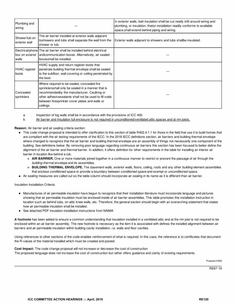
Plumbing andwiring
—In exterior walls, batt insulation shall be cut neatly tofit around wiring andplumbing, or insulation, thaton installation readily conforms to availablespace,shall extend behind piping and wiring.
Shower/tub onexterior wall
The air barrier installed at exterior walls adjacenttoshowers and tubs shall separate the wall from theshower or tub.
Exterior walls adjacent to showers and tubs shallbe insulated.
Electrical/phonebox on exteriorwalls
The air barrier shall be installed behind electricalandcommunication boxes. Alternatively, air-sealedboxesshall be installed.
—
HVAC registerboots
HVAC supply and return register boots thatpenetrate building thermal envelope shall be sealedto the subfloor, wall covering or ceiling penetrated bythe boot.
—
Concealedsprinklers
Where required to be sealed, concealed firesprinklersshall only be sealed in a manner that isrecommendedby the manufacturer. Caulking orother adhesivesealants shall not be used to fill voidsbetween firesprinkler cover plates and walls orceilings.
—
a. Inspection of log walls shall be in accordance with the provisions of ICC 400.b. Air barrier and Insulation full enclosure is not required in unconditioned/ventilated attic spaces and at rim joists.
Reason: Air barrier and air sealing criteria section:This code change proposal is intended to offer clarification to this section of table R402.4.1.1 for those in the field that use it to build homes thatare compliant with the air testing requirements of the IECC. In the 2018 IECC definitions section, air barriers and building thermal envelopewhere changed to recognize that the air barrier and building thermal envelope are an assembly of things not necessarily one component of thebuilding. See definitions below. By removing poor language regarding continuous air barriers this section has been focused to better define thealignment of the air barrier and thermal barrier. In addition, it offers definition for other requirements in the table for installing an interior airbarrier in location like behind a tub.
AIR BARRIER. One or more materials joined together in a continuous manner to restrict or prevent the passage of air through thebuilding thermal envelope and its assemblies.BUILDING THERMAL ENVELOPE. The basement walls, exterior walls, floors, ceiling, roofs and any other building element assembliesthat enclose conditioned space or provide a boundary between conditioned space and exempt or unconditioned space.
Air sealing measures are called out so the table column should incorporate air sealing in its name as it is different than air barrier.
Insulation Installation Criteria:
Manufactures of air permeable insulation have begun to recognize that their installation literature must incorporate language and picturesshowing that air permeable insulation must be enclosed inside of air barrier assemblies. This table promotes this installation instruction inlocation such as behind tubs, on attic knee walls, etc. Therefore, the general section should begin with an overarching statement that stateshow air permeable insulation shall be installed.See attached PDF insulation installation instructions from NAIMA
A footnote has been added to ensure a common understanding that insulation installed in a ventilated attic and at the rim joist is not required to beenclosed within an air barrier assembly. The new footnote is necessary as the item it is associated with defines the installed alignment between airbarriers and air permeable insulation within building cavity installation, i.e. walls and floor cavities.
Using references to other sections of the code enables reinforcement of what is required. In this case, the reference is to certificates that documentthe R-values of the material installed which must be created and posted.
Cost Impact: The code change proposal will not increase or decrease the cost of constructionThe proposed language does not increase the cost of construction but rather offers guidance and clarity of existing requirements.
Proposal # 5345
RE67-19
ICC COMMITTEE ACTION HEARINGS ::: April, 2019 RE120
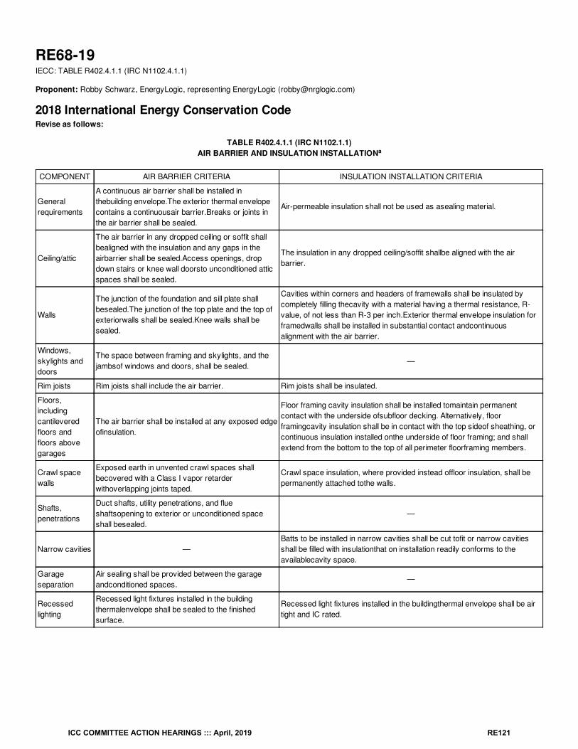
RE68-19IECC: TABLE R402.4.1.1 (IRC N1102.4.1.1)
Proponent: Robby Schwarz, EnergyLogic, representing EnergyLogic ([email protected])
2018 International Energy Conservation CodeRevise as follows:
TABLE R402.4.1.1 (IRC N1102.1.1)AIR BARRIER AND INSULATION INSTALLATION
COMPONENT AIR BARRIER CRITERIA INSULATION INSTALLATION CRITERIA
Generalrequirements
A continuous air barrier shall be installed inthebuilding envelope.The exterior thermal envelopecontains a continuousair barrier.Breaks or joints inthe air barrier shall be sealed.
Air-permeable insulation shall not be used as asealing material.
Ceiling/attic
The air barrier in any dropped ceiling or soffit shallbealigned with the insulation and any gaps in theairbarrier shall be sealed.Access openings, dropdown stairs or knee wall doorsto unconditioned atticspaces shall be sealed.
The insulation in any dropped ceiling/soffit shallbe aligned with the airbarrier.
Walls
The junction of the foundation and sill plate shallbesealed.The junction of the top plate and the top ofexteriorwalls shall be sealed.Knee walls shall besealed.
Cavities within corners and headers of framewalls shall be insulated bycompletely filling thecavity with a material having a thermal resistance, R-value, of not less than R-3 per inch.Exterior thermal envelope insulation forframedwalls shall be installed in substantial contact andcontinuousalignment with the air barrier.
Windows,skylights anddoors
The space between framing and skylights, and thejambsof windows and doors, shall be sealed.
—
Rim joists Rim joists shall include the air barrier. Rim joists shall be insulated.
Floors,includingcantileveredfloors andfloors abovegarages
The air barrier shall be installed at any exposed edgeofinsulation.
Floor framing cavity insulation shall be installed tomaintain permanentcontact with the underside ofsubfloor decking. Alternatively, floorframingcavity insulation shall be in contact with the top sideof sheathing, orcontinuous insulation installed onthe underside of floor framing; and shallextend from the bottom to the top of all perimeter floorframing members.
Crawl spacewalls
Exposed earth in unvented crawl spaces shallbecovered with a Class I vapor retarderwithoverlapping joints taped.
Crawl space insulation, where provided instead offloor insulation, shall bepermanently attached tothe walls.
Shafts,penetrations
Duct shafts, utility penetrations, and flueshaftsopening to exterior or unconditioned spaceshall besealed.
—
Narrow cavities —Batts to be installed in narrow cavities shall be cut tofit or narrow cavitiesshall be filled with insulationthat on installation readily conforms to theavailablecavity space.
Garageseparation
Air sealing shall be provided between the garageandconditioned spaces.
—
Recessedlighting
Recessed light fixtures installed in the buildingthermalenvelope shall be sealed to the finishedsurface.
Recessed light fixtures installed in the buildingthermal envelope shall be airtight and IC rated.
a
ICC COMMITTEE ACTION HEARINGS ::: April, 2019 RE121
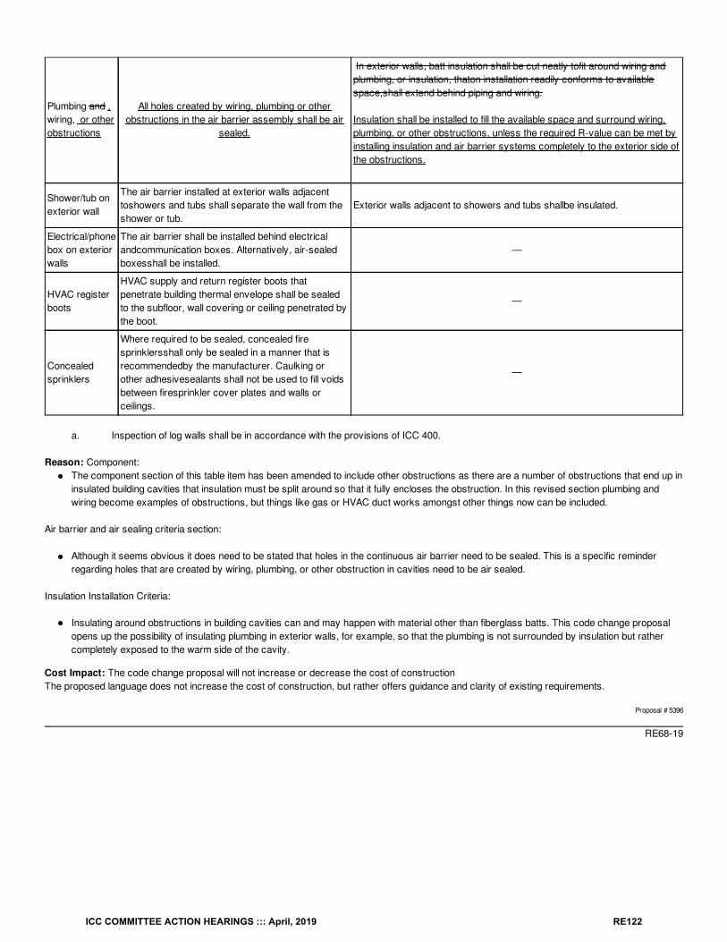
Plumbing and ,wiring, or otherobstructions
All holes created by wiring, plumbing or otherobstructions in the air barrier assembly shall be air
sealed.
In exterior walls, batt insulation shall be cut neatly tofit around wiring andplumbing, or insulation, thaton installation readily conforms to availablespace,shall extend behind piping and wiring.
Insulation shall be installed to fill the available space and surround wiring,plumbing, or other obstructions, unless the required R-value can be met byinstalling insulation and air barrier systems completely to the exterior side ofthe obstructions.
Shower/tub onexterior wall
The air barrier installed at exterior walls adjacenttoshowers and tubs shall separate the wall from theshower or tub.
Exterior walls adjacent to showers and tubs shallbe insulated.
Electrical/phonebox on exteriorwalls
The air barrier shall be installed behind electricalandcommunication boxes. Alternatively, air-sealedboxesshall be installed.
—
HVAC registerboots
HVAC supply and return register boots thatpenetrate building thermal envelope shall be sealedto the subfloor, wall covering or ceiling penetrated bythe boot.
—
Concealedsprinklers
Where required to be sealed, concealed firesprinklersshall only be sealed in a manner that isrecommendedby the manufacturer. Caulking orother adhesivesealants shall not be used to fill voidsbetween firesprinkler cover plates and walls orceilings.
—
a. Inspection of log walls shall be in accordance with the provisions of ICC 400.
Reason: Component:The component section of this table item has been amended to include other obstructions as there are a number of obstructions that end up ininsulated building cavities that insulation must be split around so that it fully encloses the obstruction. In this revised section plumbing andwiring become examples of obstructions, but things like gas or HVAC duct works amongst other things now can be included.
Air barrier and air sealing criteria section:
Although it seems obvious it does need to be stated that holes in the continuous air barrier need to be sealed. This is a specific reminderregarding holes that are created by wiring, plumbing, or other obstruction in cavities need to be air sealed.
Insulation Installation Criteria:
Insulating around obstructions in building cavities can and may happen with material other than fiberglass batts. This code change proposalopens up the possibility of insulating plumbing in exterior walls, for example, so that the plumbing is not surrounded by insulation but rathercompletely exposed to the warm side of the cavity.
Cost Impact: The code change proposal will not increase or decrease the cost of constructionThe proposed language does not increase the cost of construction, but rather offers guidance and clarity of existing requirements.
Proposal # 5396
RE68-19
ICC COMMITTEE ACTION HEARINGS ::: April, 2019 RE122
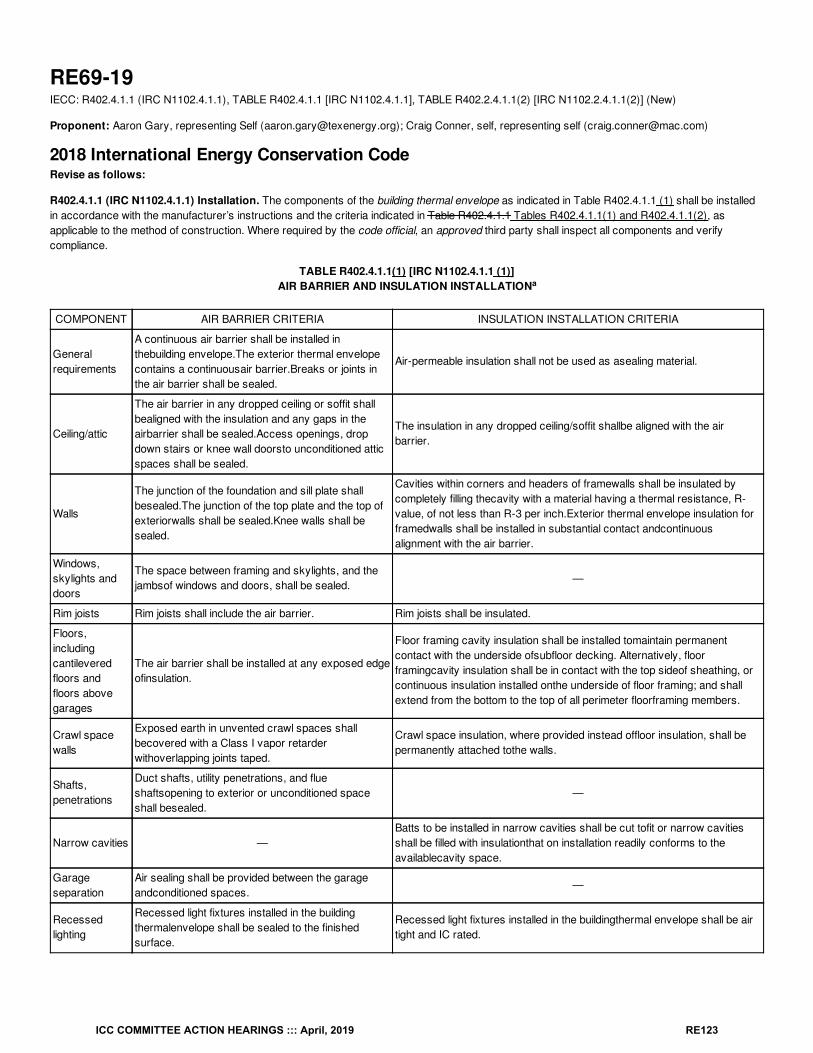
RE69-19IECC: R402.4.1.1 (IRC N1102.4.1.1), TABLE R402.4.1.1 [IRC N1102.4.1.1], TABLE R402.2.4.1.1(2) [IRC N1102.2.4.1.1(2)] (New)
Proponent: Aaron Gary, representing Self ([email protected]); Craig Conner, self, representing self ([email protected])
2018 International Energy Conservation CodeRevise as follows:
R402.4.1.1 (IRC N1102.4.1.1) Installation. The components of the building thermal envelope as indicated in Table R402.4.1.1 (1) shall be installedin accordance with the manufacturer’s instructions and the criteria indicated in Table R402.4.1.1 Tables R402.4.1.1(1) and R402.4.1.1(2), asapplicable to the method of construction. Where required by the code official, an approved third party shall inspect all components and verifycompliance.
TABLE R402.4.1.1(1) [IRC N1102.4.1.1 (1)]AIR BARRIER AND INSULATION INSTALLATION
COMPONENT AIR BARRIER CRITERIA INSULATION INSTALLATION CRITERIA
Generalrequirements
A continuous air barrier shall be installed inthebuilding envelope.The exterior thermal envelopecontains a continuousair barrier.Breaks or joints inthe air barrier shall be sealed.
Air-permeable insulation shall not be used as asealing material.
Ceiling/attic
The air barrier in any dropped ceiling or soffit shallbealigned with the insulation and any gaps in theairbarrier shall be sealed.Access openings, dropdown stairs or knee wall doorsto unconditioned atticspaces shall be sealed.
The insulation in any dropped ceiling/soffit shallbe aligned with the airbarrier.
Walls
The junction of the foundation and sill plate shallbesealed.The junction of the top plate and the top ofexteriorwalls shall be sealed.Knee walls shall besealed.
Cavities within corners and headers of framewalls shall be insulated bycompletely filling thecavity with a material having a thermal resistance, R-value, of not less than R-3 per inch.Exterior thermal envelope insulation forframedwalls shall be installed in substantial contact andcontinuousalignment with the air barrier.
Windows,skylights anddoors
The space between framing and skylights, and thejambsof windows and doors, shall be sealed.
—
Rim joists Rim joists shall include the air barrier. Rim joists shall be insulated.
Floors,includingcantileveredfloors andfloors abovegarages
The air barrier shall be installed at any exposed edgeofinsulation.
Floor framing cavity insulation shall be installed tomaintain permanentcontact with the underside ofsubfloor decking. Alternatively, floorframingcavity insulation shall be in contact with the top sideof sheathing, orcontinuous insulation installed onthe underside of floor framing; and shallextend from the bottom to the top of all perimeter floorframing members.
Crawl spacewalls
Exposed earth in unvented crawl spaces shallbecovered with a Class I vapor retarderwithoverlapping joints taped.
Crawl space insulation, where provided instead offloor insulation, shall bepermanently attached tothe walls.
Shafts,penetrations
Duct shafts, utility penetrations, and flueshaftsopening to exterior or unconditioned spaceshall besealed.
—
Narrow cavities —Batts to be installed in narrow cavities shall be cut tofit or narrow cavitiesshall be filled with insulationthat on installation readily conforms to theavailablecavity space.
Garageseparation
Air sealing shall be provided between the garageandconditioned spaces.
—
Recessedlighting
Recessed light fixtures installed in the buildingthermalenvelope shall be sealed to the finishedsurface.
Recessed light fixtures installed in the buildingthermal envelope shall be airtight and IC rated.
a
ICC COMMITTEE ACTION HEARINGS ::: April, 2019 RE123
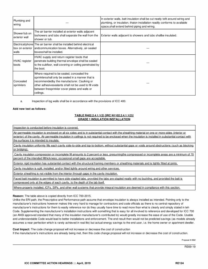
Plumbing andwiring
—In exterior walls, batt insulation shall be cut neatly tofit around wiring andplumbing, or insulation, thaton installation readily conforms to availablespace,shall extend behind piping and wiring.
Shower/tub onexterior wall
The air barrier installed at exterior walls adjacenttoshowers and tubs shall separate the wall from theshower or tub.
Exterior walls adjacent to showers and tubs shallbe insulated.
Electrical/phonebox on exteriorwalls
The air barrier shall be installed behind electricalandcommunication boxes. Alternatively, air-sealedboxesshall be installed.
—
HVAC registerboots
HVAC supply and return register boots thatpenetrate building thermal envelope shall be sealedto the subfloor, wall covering or ceiling penetrated bythe boot.
—
Concealedsprinklers
Where required to be sealed, concealed firesprinklersshall only be sealed in a manner that isrecommendedby the manufacturer. Caulking orother adhesivesealants shall not be used to fill voidsbetween firesprinkler cover plates and walls orceilings.
—
a. Inspection of log walls shall be in accordance with the provisions of ICC 400.
Add new text as follows:
TABLE R402.2.4.1.1(2) [IRC N1102.2.4.1.1(2)]GRADE 1 INSULATION INSTALLATION
Inspection is conducted before insulation is covered.
Air-permeable insulation is enclosed on all six sides and is in substantial contact with the sheathing material on one or more sides (interior orexterior) of the cavity. Air permeable insulation in ceilings is not required to be enclosed when the insulation is installed in substantial contact withthe surfaces it is intended to insulate.
Cavity insulation uniformly fills each cavity side-to-side and top-to-bottom, without substantial gaps or voids around obstructions (such as blockingor bridging).
Cavity insulation compression or incomplete fill amounts to 2 percent or less, presumingthe compressed or incomplete areas are a minimum of 70percent of the intended fillthickness; occasional small gaps are acceptable.
Exterior rigid insulation has substantial contact with the structural framing members or sheathing materials and is tightly fitted at joints.
Cavity insulation is split, installed, and/or fitted tightly around wiring and other services.
Exterior sheathing is not visible from the interior through gaps in the cavity insulation.
Faced batt insulation is permitted to have side-stapled tabs, provided the tabs are stapled neatly with no buckling, and provided the batt iscompressed only at the edges of each cavity, to the depth of the tab itself.
Where properly installed, ICFs, SIPs, and other wall systems that provide integral insulation are deemed in compliance with this section.
Reason: The table above is copied directly from ICC 700-2015.Unlike the ERI path, the Prescriptive and Performance path assume that envelope insulation is always installed as intended. Pointing only to themanufacturer's instructions however makes this very hard to manage for contractors and code officials as there is no central repository ofmanufacturer's instructions for them to easily reference nor do they usually have time to read more than what is clearly and simply stated in tehCode. Supplementing the manufacturer's installation instructions with something that is easy for all involved to reference and developed for ICC 700(an ANSI approved standard that many of the insulation manufacturer's contributed to) would greatly increase the ease of use of the Code. Usableand understandable Code would lead to better installations and enforcement. The end result then would not be predicted savings (as models alreadyassumes a near perfection which is rarely achieved in real life) but actual energy savings to the end user, i.e. the home owner or apartment dweller.
Cost Impact: The code change proposal will not increase or decrease the cost of constructionIf the manufacturer's instructions are already being met, then this code change proposal will not increase or decrease the cost of construction.
Proposal # 4562
RE69-19
ICC COMMITTEE ACTION HEARINGS ::: April, 2019 RE124
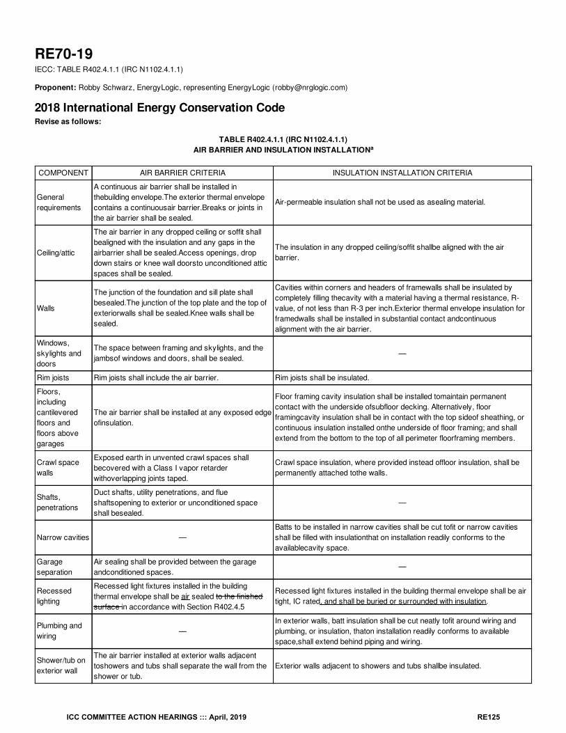
RE70-19IECC: TABLE R402.4.1.1 (IRC N1102.4.1.1)
Proponent: Robby Schwarz, EnergyLogic, representing EnergyLogic ([email protected])
2018 International Energy Conservation CodeRevise as follows:
TABLE R402.4.1.1 (IRC N1102.4.1.1)AIR BARRIER AND INSULATION INSTALLATION
COMPONENT AIR BARRIER CRITERIA INSULATION INSTALLATION CRITERIA
Generalrequirements
A continuous air barrier shall be installed inthebuilding envelope.The exterior thermal envelopecontains a continuousair barrier.Breaks or joints inthe air barrier shall be sealed.
Air-permeable insulation shall not be used as asealing material.
Ceiling/attic
The air barrier in any dropped ceiling or soffit shallbealigned with the insulation and any gaps in theairbarrier shall be sealed.Access openings, dropdown stairs or knee wall doorsto unconditioned atticspaces shall be sealed.
The insulation in any dropped ceiling/soffit shallbe aligned with the airbarrier.
Walls
The junction of the foundation and sill plate shallbesealed.The junction of the top plate and the top ofexteriorwalls shall be sealed.Knee walls shall besealed.
Cavities within corners and headers of framewalls shall be insulated bycompletely filling thecavity with a material having a thermal resistance, R-value, of not less than R-3 per inch.Exterior thermal envelope insulation forframedwalls shall be installed in substantial contact andcontinuousalignment with the air barrier.
Windows,skylights anddoors
The space between framing and skylights, and thejambsof windows and doors, shall be sealed.
—
Rim joists Rim joists shall include the air barrier. Rim joists shall be insulated.
Floors,includingcantileveredfloors andfloors abovegarages
The air barrier shall be installed at any exposed edgeofinsulation.
Floor framing cavity insulation shall be installed tomaintain permanentcontact with the underside ofsubfloor decking. Alternatively, floorframingcavity insulation shall be in contact with the top sideof sheathing, orcontinuous insulation installed onthe underside of floor framing; and shallextend from the bottom to the top of all perimeter floorframing members.
Crawl spacewalls
Exposed earth in unvented crawl spaces shallbecovered with a Class I vapor retarderwithoverlapping joints taped.
Crawl space insulation, where provided instead offloor insulation, shall bepermanently attached tothe walls.
Shafts,penetrations
Duct shafts, utility penetrations, and flueshaftsopening to exterior or unconditioned spaceshall besealed.
—
Narrow cavities —Batts to be installed in narrow cavities shall be cut tofit or narrow cavitiesshall be filled with insulationthat on installation readily conforms to theavailablecavity space.
Garageseparation
Air sealing shall be provided between the garageandconditioned spaces.
—
Recessedlighting
Recessed light fixtures installed in the buildingthermal envelope shall be air sealed to the finishedsurface in accordance with Section R402.4.5
Recessed light fixtures installed in the building thermal envelope shall be airtight, IC rated, and shall be buried or surrounded with insulation.
Plumbing andwiring
—In exterior walls, batt insulation shall be cut neatly tofit around wiring andplumbing, or insulation, thaton installation readily conforms to availablespace,shall extend behind piping and wiring.
Shower/tub onexterior wall
The air barrier installed at exterior walls adjacenttoshowers and tubs shall separate the wall from theshower or tub.
Exterior walls adjacent to showers and tubs shallbe insulated.
a
ICC COMMITTEE ACTION HEARINGS ::: April, 2019 RE125
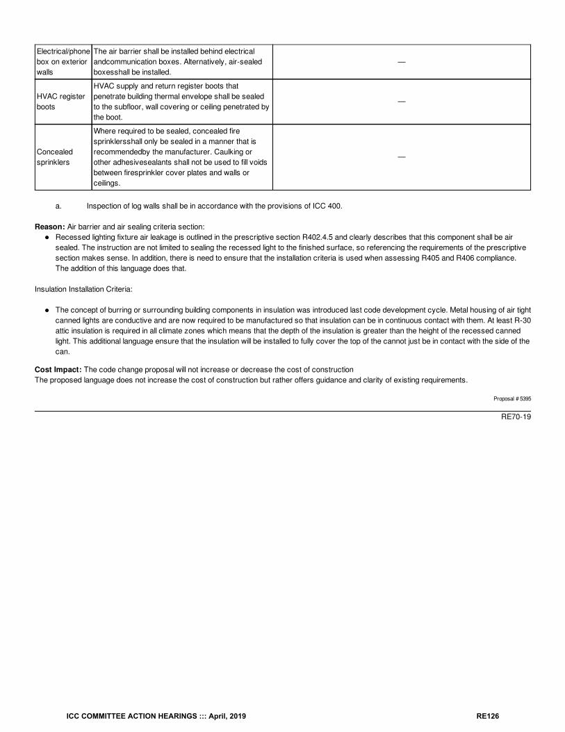
Electrical/phonebox on exteriorwalls
The air barrier shall be installed behind electricalandcommunication boxes. Alternatively, air-sealedboxesshall be installed.
—
HVAC registerboots
HVAC supply and return register boots thatpenetrate building thermal envelope shall be sealedto the subfloor, wall covering or ceiling penetrated bythe boot.
—
Concealedsprinklers
Where required to be sealed, concealed firesprinklersshall only be sealed in a manner that isrecommendedby the manufacturer. Caulking orother adhesivesealants shall not be used to fill voidsbetween firesprinkler cover plates and walls orceilings.
—
a. Inspection of log walls shall be in accordance with the provisions of ICC 400.
Reason: Air barrier and air sealing criteria section:Recessed lighting fixture air leakage is outlined in the prescriptive section R402.4.5 and clearly describes that this component shall be airsealed. The instruction are not limited to sealing the recessed light to the finished surface, so referencing the requirements of the prescriptivesection makes sense. In addition, there is need to ensure that the installation criteria is used when assessing R405 and R406 compliance.The addition of this language does that.
Insulation Installation Criteria:
The concept of burring or surrounding building components in insulation was introduced last code development cycle. Metal housing of air tightcanned lights are conductive and are now required to be manufactured so that insulation can be in continuous contact with them. At least R-30attic insulation is required in all climate zones which means that the depth of the insulation is greater than the height of the recessed cannedlight. This additional language ensure that the insulation will be installed to fully cover the top of the cannot just be in contact with the side of thecan.
Cost Impact: The code change proposal will not increase or decrease the cost of constructionThe proposed language does not increase the cost of construction but rather offers guidance and clarity of existing requirements.
Proposal # 5395
RE70-19
ICC COMMITTEE ACTION HEARINGS ::: April, 2019 RE126
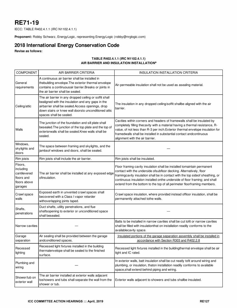
RE71-19IECC: TABLE R402.4.1.1 (IRC N1102.4.1.1)
Proponent: Robby Schwarz, EnergyLogic, representing EnergyLogic ([email protected])
2018 International Energy Conservation CodeRevise as follows:
TABLE R402.4.1.1 (IRC N1102.4.1.1)AIR BARRIER AND INSULATION INSTALLATION
COMPONENT AIR BARRIER CRITERIA INSULATION INSTALLATION CRITERIA
Generalrequirements
A continuous air barrier shall be installed inthebuilding envelope.The exterior thermal envelopecontains a continuousair barrier.Breaks or joints inthe air barrier shall be sealed.
Air-permeable insulation shall not be used as asealing material.
Ceiling/attic
The air barrier in any dropped ceiling or soffit shallbealigned with the insulation and any gaps in theairbarrier shall be sealed.Access openings, dropdown stairs or knee wall doorsto unconditioned atticspaces shall be sealed.
The insulation in any dropped ceiling/soffit shallbe aligned with the airbarrier.
Walls
The junction of the foundation and sill plate shallbesealed.The junction of the top plate and the top ofexteriorwalls shall be sealed.Knee walls shall besealed.
Cavities within corners and headers of framewalls shall be insulated bycompletely filling thecavity with a material having a thermal resistance, R-value, of not less than R-3 per inch.Exterior thermal envelope insulation forframedwalls shall be installed in substantial contact andcontinuousalignment with the air barrier.
Windows,skylights anddoors
The space between framing and skylights, and thejambsof windows and doors, shall be sealed.
—
Rim joists Rim joists shall include the air barrier. Rim joists shall be insulated.
Floors,includingcantileveredfloors andfloors abovegarages
The air barrier shall be installed at any exposed edgeofinsulation.
Floor framing cavity insulation shall be installed tomaintain permanentcontact with the underside ofsubfloor decking. Alternatively, floorframingcavity insulation shall be in contact with the top sideof sheathing, orcontinuous insulation installed onthe underside of floor framing; and shallextend from the bottom to the top of all perimeter floorframing members.
Crawl spacewalls
Exposed earth in unvented crawl spaces shallbecovered with a Class I vapor retarderwithoverlapping joints taped.
Crawl space insulation, where provided instead offloor insulation, shall bepermanently attached tothe walls.
Shafts,penetrations
Duct shafts, utility penetrations, and flueshaftsopening to exterior or unconditioned spaceshall besealed.
—
Narrow cavities —Batts to be installed in narrow cavities shall be cut tofit or narrow cavitiesshall be filled with insulationthat on installation readily conforms to theavailablecavity space.
Garageseparation
Air sealing shall be provided between the garageandconditioned spaces.
Insulated portions of the garage separation assembly shall be installed inaccordance with Section R303 and R402.2.8
Recessedlighting
Recessed light fixtures installed in the buildingthermalenvelope shall be sealed to the finishedsurface.
Recessed light fixtures installed in the buildingthermal envelope shall be airtight and IC rated.
Plumbing andwiring
—In exterior walls, batt insulation shall be cut neatly tofit around wiring andplumbing, or insulation, thaton installation readily conforms to availablespace,shall extend behind piping and wiring.
Shower/tub onexterior wall
The air barrier installed at exterior walls adjacenttoshowers and tubs shall separate the wall from theshower or tub.
Exterior walls adjacent to showers and tubs shallbe insulated.
a
ICC COMMITTEE ACTION HEARINGS ::: April, 2019 RE127
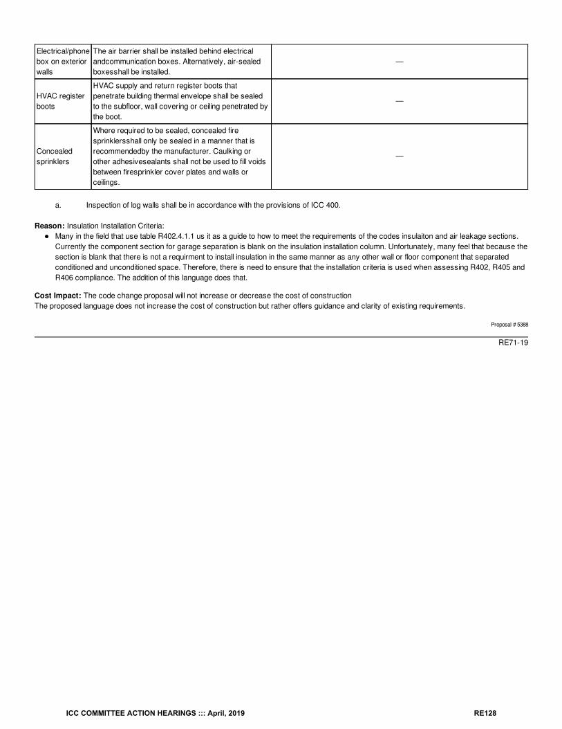
Electrical/phonebox on exteriorwalls
The air barrier shall be installed behind electricalandcommunication boxes. Alternatively, air-sealedboxesshall be installed.
—
HVAC registerboots
HVAC supply and return register boots thatpenetrate building thermal envelope shall be sealedto the subfloor, wall covering or ceiling penetrated bythe boot.
—
Concealedsprinklers
Where required to be sealed, concealed firesprinklersshall only be sealed in a manner that isrecommendedby the manufacturer. Caulking orother adhesivesealants shall not be used to fill voidsbetween firesprinkler cover plates and walls orceilings.
—
a. Inspection of log walls shall be in accordance with the provisions of ICC 400.
Reason: Insulation Installation Criteria:Many in the field that use table R402.4.1.1 us it as a guide to how to meet the requirements of the codes insulaiton and air leakage sections.Currently the component section for garage separation is blank on the insulation installation column. Unfortunately, many feel that because thesection is blank that there is not a requirment to install insulation in the same manner as any other wall or floor component that separatedconditioned and unconditioned space. Therefore, there is need to ensure that the installation criteria is used when assessing R402, R405 andR406 compliance. The addition of this language does that.
Cost Impact: The code change proposal will not increase or decrease the cost of constructionThe proposed language does not increase the cost of construction but rather offers guidance and clarity of existing requirements.
Proposal # 5388
RE71-19
ICC COMMITTEE ACTION HEARINGS ::: April, 2019 RE128
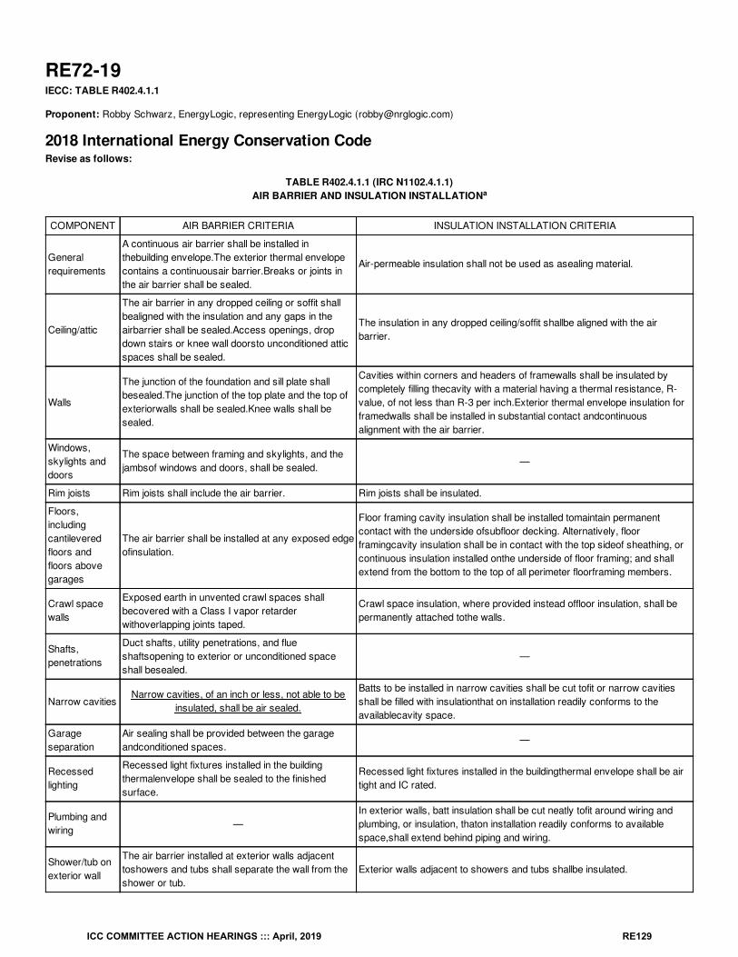
RE72-19IECC: TABLE R402.4.1.1
Proponent: Robby Schwarz, EnergyLogic, representing EnergyLogic ([email protected])
2018 International Energy Conservation CodeRevise as follows:
TABLE R402.4.1.1 (IRC N1102.4.1.1)AIR BARRIER AND INSULATION INSTALLATION
COMPONENT AIR BARRIER CRITERIA INSULATION INSTALLATION CRITERIA
Generalrequirements
A continuous air barrier shall be installed inthebuilding envelope.The exterior thermal envelopecontains a continuousair barrier.Breaks or joints inthe air barrier shall be sealed.
Air-permeable insulation shall not be used as asealing material.
Ceiling/attic
The air barrier in any dropped ceiling or soffit shallbealigned with the insulation and any gaps in theairbarrier shall be sealed.Access openings, dropdown stairs or knee wall doorsto unconditioned atticspaces shall be sealed.
The insulation in any dropped ceiling/soffit shallbe aligned with the airbarrier.
Walls
The junction of the foundation and sill plate shallbesealed.The junction of the top plate and the top ofexteriorwalls shall be sealed.Knee walls shall besealed.
Cavities within corners and headers of framewalls shall be insulated bycompletely filling thecavity with a material having a thermal resistance, R-value, of not less than R-3 per inch.Exterior thermal envelope insulation forframedwalls shall be installed in substantial contact andcontinuousalignment with the air barrier.
Windows,skylights anddoors
The space between framing and skylights, and thejambsof windows and doors, shall be sealed.
—
Rim joists Rim joists shall include the air barrier. Rim joists shall be insulated.
Floors,includingcantileveredfloors andfloors abovegarages
The air barrier shall be installed at any exposed edgeofinsulation.
Floor framing cavity insulation shall be installed tomaintain permanentcontact with the underside ofsubfloor decking. Alternatively, floorframingcavity insulation shall be in contact with the top sideof sheathing, orcontinuous insulation installed onthe underside of floor framing; and shallextend from the bottom to the top of all perimeter floorframing members.
Crawl spacewalls
Exposed earth in unvented crawl spaces shallbecovered with a Class I vapor retarderwithoverlapping joints taped.
Crawl space insulation, where provided instead offloor insulation, shall bepermanently attached tothe walls.
Shafts,penetrations
Duct shafts, utility penetrations, and flueshaftsopening to exterior or unconditioned spaceshall besealed.
—
Narrow cavitiesNarrow cavities, of an inch or less, not able to be
insulated, shall be air sealed.
Batts to be installed in narrow cavities shall be cut tofit or narrow cavitiesshall be filled with insulationthat on installation readily conforms to theavailablecavity space.
Garageseparation
Air sealing shall be provided between the garageandconditioned spaces.
—
Recessedlighting
Recessed light fixtures installed in the buildingthermalenvelope shall be sealed to the finishedsurface.
Recessed light fixtures installed in the buildingthermal envelope shall be airtight and IC rated.
Plumbing andwiring
—In exterior walls, batt insulation shall be cut neatly tofit around wiring andplumbing, or insulation, thaton installation readily conforms to availablespace,shall extend behind piping and wiring.
Shower/tub onexterior wall
The air barrier installed at exterior walls adjacenttoshowers and tubs shall separate the wall from theshower or tub.
Exterior walls adjacent to showers and tubs shallbe insulated.
a
ICC COMMITTEE ACTION HEARINGS ::: April, 2019 RE129
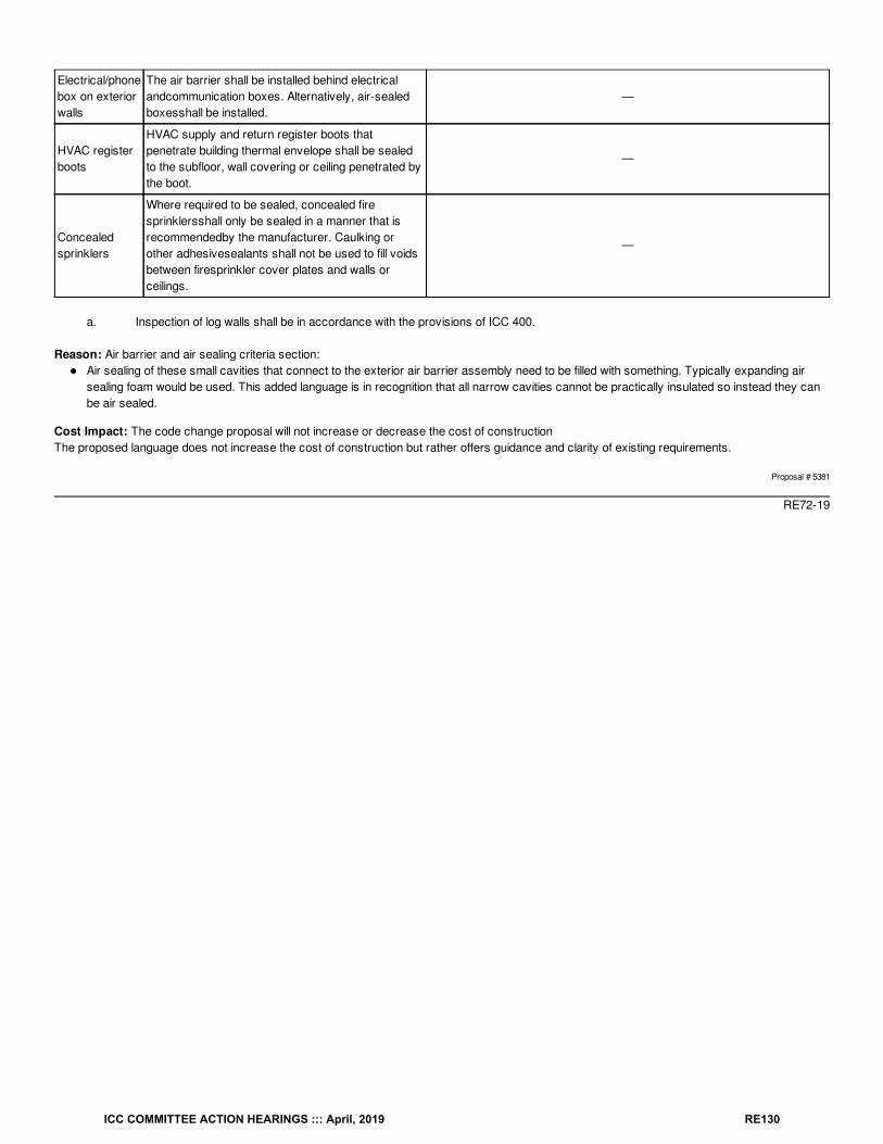
Electrical/phonebox on exteriorwalls
The air barrier shall be installed behind electricalandcommunication boxes. Alternatively, air-sealedboxesshall be installed.
—
HVAC registerboots
HVAC supply and return register boots thatpenetrate building thermal envelope shall be sealedto the subfloor, wall covering or ceiling penetrated bythe boot.
—
Concealedsprinklers
Where required to be sealed, concealed firesprinklersshall only be sealed in a manner that isrecommendedby the manufacturer. Caulking orother adhesivesealants shall not be used to fill voidsbetween firesprinkler cover plates and walls orceilings.
—
a. Inspection of log walls shall be in accordance with the provisions of ICC 400.
Reason: Air barrier and air sealing criteria section:Air sealing of these small cavities that connect to the exterior air barrier assembly need to be filled with something. Typically expanding airsealing foam would be used. This added language is in recognition that all narrow cavities cannot be practically insulated so instead they canbe air sealed.
Cost Impact: The code change proposal will not increase or decrease the cost of constructionThe proposed language does not increase the cost of construction but rather offers guidance and clarity of existing requirements.
Proposal # 5381
RE72-19
ICC COMMITTEE ACTION HEARINGS ::: April, 2019 RE130
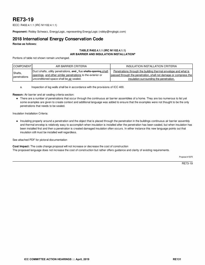
RE73-19IECC: R402.4.1.1 (IRC N1102.4.1.1)
Proponent: Robby Schwarz, EnergyLogic, representing EnergyLogic ([email protected])
2018 International Energy Conservation CodeRevise as follows:
TABLE R402.4.1.1 (IRC N1102.4.1.1)AIR BARRIER AND INSULATION INSTALLATION
Portions of table not shown remain unchanged.
COMPONENT AIR BARRIER CRITERIA INSULATION INSTALLATION CRITERIA
Shafts,penetrations
Duct shafts, utility penetrations, and , flue shafts opening shaftopenings, and other similar penetrations to the exterior orunconditioned space shall be air sealed.
Penetrations through the building thermal envelope and what ispassed through the penetration, shall not damage or compress the
insulation surrounding the penetration.
a. Inspection of log walls shall be in accordance with the provisions of ICC 400.
Reason: Air barrier and air sealing criteria section:There are a number of penetrations that occur through the continuous air barrier assemblies of a home. They are too numerous to list yetsome examples are given to create context and additional language was added to ensure that the examples were not thought to be the onlypenetrations that needs to be sealed.
Insulation Installation Criteria:
Insulating properly around a penetration and the object that is placed through the penetration in the buildings continuous air barrier assemblyand thermal envelop is relatively easy to accomplish when insulation is installed after the penetration has been sealed, but when insulation hasbeen installed first and then a penetration is created damaged insulation often occurs. In either instance this new language points out thatinsulation still must be installed well regardless.
See attached PDF for pictoral documentation
Cost Impact: The code change proposal will not increase or decrease the cost of constructionThe proposed language does not increase the cost of construction but rather offers guidance and clarity of existing requirements.
Proposal # 5375
RE73-19
a
ICC COMMITTEE ACTION HEARINGS ::: April, 2019 RE131
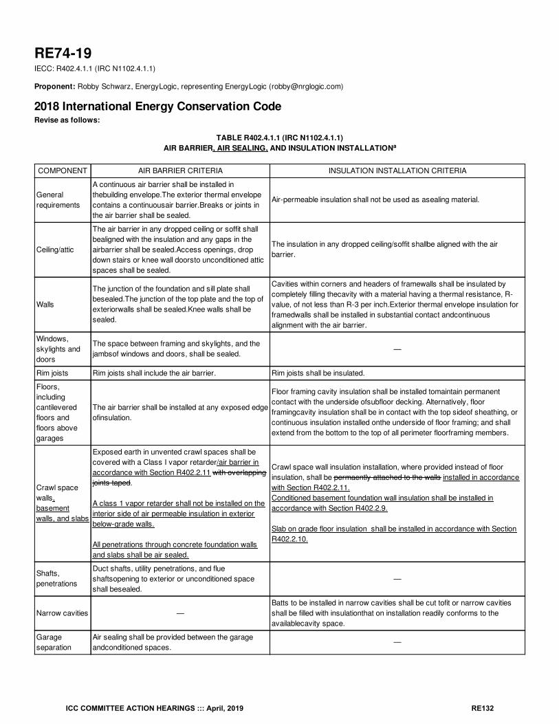
RE74-19IECC: R402.4.1.1 (IRC N1102.4.1.1)
Proponent: Robby Schwarz, EnergyLogic, representing EnergyLogic ([email protected])
2018 International Energy Conservation CodeRevise as follows:
TABLE R402.4.1.1 (IRC N1102.4.1.1)AIR BARRIER, AIR SEALING, AND INSULATION INSTALLATION
COMPONENT AIR BARRIER CRITERIA INSULATION INSTALLATION CRITERIA
Generalrequirements
A continuous air barrier shall be installed inthebuilding envelope.The exterior thermal envelopecontains a continuousair barrier.Breaks or joints inthe air barrier shall be sealed.
Air-permeable insulation shall not be used as asealing material.
Ceiling/attic
The air barrier in any dropped ceiling or soffit shallbealigned with the insulation and any gaps in theairbarrier shall be sealed.Access openings, dropdown stairs or knee wall doorsto unconditioned atticspaces shall be sealed.
The insulation in any dropped ceiling/soffit shallbe aligned with the airbarrier.
Walls
The junction of the foundation and sill plate shallbesealed.The junction of the top plate and the top ofexteriorwalls shall be sealed.Knee walls shall besealed.
Cavities within corners and headers of framewalls shall be insulated bycompletely filling thecavity with a material having a thermal resistance, R-value, of not less than R-3 per inch.Exterior thermal envelope insulation forframedwalls shall be installed in substantial contact andcontinuousalignment with the air barrier.
Windows,skylights anddoors
The space between framing and skylights, and thejambsof windows and doors, shall be sealed.
—
Rim joists Rim joists shall include the air barrier. Rim joists shall be insulated.
Floors,includingcantileveredfloors andfloors abovegarages
The air barrier shall be installed at any exposed edgeofinsulation.
Floor framing cavity insulation shall be installed tomaintain permanentcontact with the underside ofsubfloor decking. Alternatively, floorframingcavity insulation shall be in contact with the top sideof sheathing, orcontinuous insulation installed onthe underside of floor framing; and shallextend from the bottom to the top of all perimeter floorframing members.
Crawl spacewalls,basementwalls, and slabs
Exposed earth in unvented crawl spaces shall becovered with a Class I vapor retarder/air barrier inaccordance with Section R402.2.11 with overlappingjoints taped.
A class 1 vapor retarder shall not be installed on theinterior side of air permeable insulation in exteriorbelow-grade walls.
All penetrations through concrete foundation wallsand slabs shall be air sealed.
Crawl space wall insulation installation, where provided instead of floorinsulation, shall be permaently attached to the walls installed in accordancewith Section R402.2.11.Conditioned basement foundation wall insulation shall be installed inaccordance with Section R402.2.9.
Slab on grade floor insulation shall be installed in accordance with SectionR402.2.10.
Shafts,penetrations
Duct shafts, utility penetrations, and flueshaftsopening to exterior or unconditioned spaceshall besealed.
—
Narrow cavities —Batts to be installed in narrow cavities shall be cut tofit or narrow cavitiesshall be filled with insulationthat on installation readily conforms to theavailablecavity space.
Garageseparation
Air sealing shall be provided between the garageandconditioned spaces.
—
a
ICC COMMITTEE ACTION HEARINGS ::: April, 2019 RE132
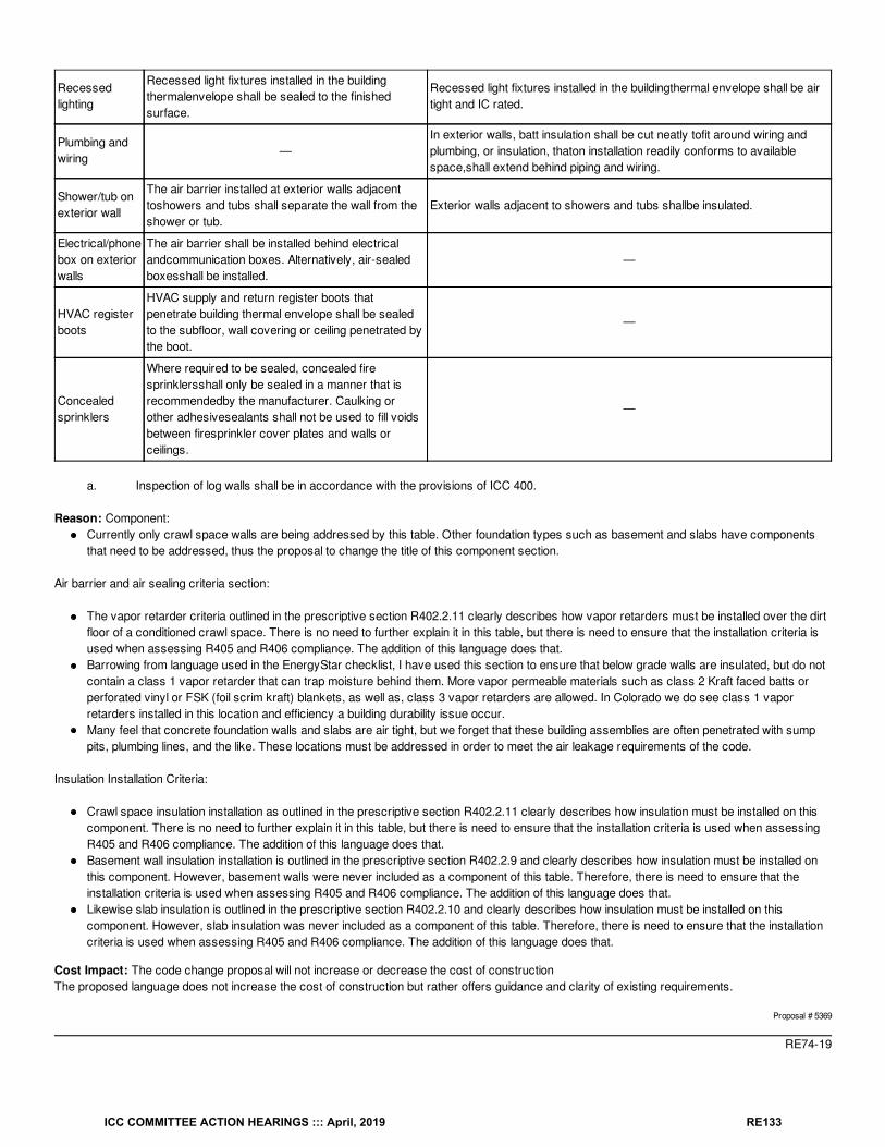
Recessedlighting
Recessed light fixtures installed in the buildingthermalenvelope shall be sealed to the finishedsurface.
Recessed light fixtures installed in the buildingthermal envelope shall be airtight and IC rated.
Plumbing andwiring
—In exterior walls, batt insulation shall be cut neatly tofit around wiring andplumbing, or insulation, thaton installation readily conforms to availablespace,shall extend behind piping and wiring.
Shower/tub onexterior wall
The air barrier installed at exterior walls adjacenttoshowers and tubs shall separate the wall from theshower or tub.
Exterior walls adjacent to showers and tubs shallbe insulated.
Electrical/phonebox on exteriorwalls
The air barrier shall be installed behind electricalandcommunication boxes. Alternatively, air-sealedboxesshall be installed.
—
HVAC registerboots
HVAC supply and return register boots thatpenetrate building thermal envelope shall be sealedto the subfloor, wall covering or ceiling penetrated bythe boot.
—
Concealedsprinklers
Where required to be sealed, concealed firesprinklersshall only be sealed in a manner that isrecommendedby the manufacturer. Caulking orother adhesivesealants shall not be used to fill voidsbetween firesprinkler cover plates and walls orceilings.
—
a. Inspection of log walls shall be in accordance with the provisions of ICC 400.
Reason: Component:Currently only crawl space walls are being addressed by this table. Other foundation types such as basement and slabs have componentsthat need to be addressed, thus the proposal to change the title of this component section.
Air barrier and air sealing criteria section:
The vapor retarder criteria outlined in the prescriptive section R402.2.11 clearly describes how vapor retarders must be installed over the dirtfloor of a conditioned crawl space. There is no need to further explain it in this table, but there is need to ensure that the installation criteria isused when assessing R405 and R406 compliance. The addition of this language does that.Barrowing from language used in the EnergyStar checklist, I have used this section to ensure that below grade walls are insulated, but do notcontain a class 1 vapor retarder that can trap moisture behind them. More vapor permeable materials such as class 2 Kraft faced batts orperforated vinyl or FSK (foil scrim kraft) blankets, as well as, class 3 vapor retarders are allowed. In Colorado we do see class 1 vaporretarders installed in this location and efficiency a building durability issue occur.Many feel that concrete foundation walls and slabs are air tight, but we forget that these building assemblies are often penetrated with sumppits, plumbing lines, and the like. These locations must be addressed in order to meet the air leakage requirements of the code.
Insulation Installation Criteria:
Crawl space insulation installation as outlined in the prescriptive section R402.2.11 clearly describes how insulation must be installed on thiscomponent. There is no need to further explain it in this table, but there is need to ensure that the installation criteria is used when assessingR405 and R406 compliance. The addition of this language does that.Basement wall insulation installation is outlined in the prescriptive section R402.2.9 and clearly describes how insulation must be installed onthis component. However, basement walls were never included as a component of this table. Therefore, there is need to ensure that theinstallation criteria is used when assessing R405 and R406 compliance. The addition of this language does that.Likewise slab insulation is outlined in the prescriptive section R402.2.10 and clearly describes how insulation must be installed on thiscomponent. However, slab insulation was never included as a component of this table. Therefore, there is need to ensure that the installationcriteria is used when assessing R405 and R406 compliance. The addition of this language does that.
Cost Impact: The code change proposal will not increase or decrease the cost of constructionThe proposed language does not increase the cost of construction but rather offers guidance and clarity of existing requirements.
Proposal # 5369
RE74-19
ICC COMMITTEE ACTION HEARINGS ::: April, 2019 RE133
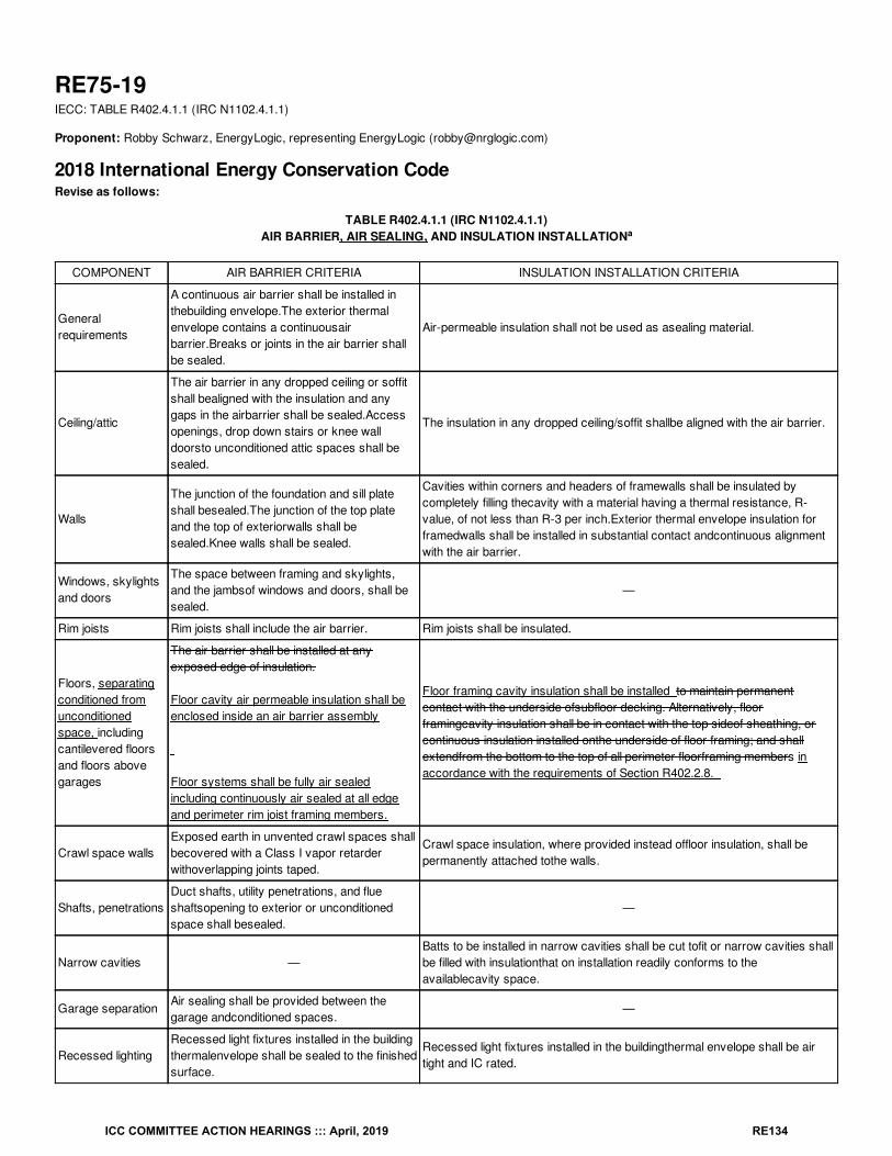
RE75-19IECC: TABLE R402.4.1.1 (IRC N1102.4.1.1)
Proponent: Robby Schwarz, EnergyLogic, representing EnergyLogic ([email protected])
2018 International Energy Conservation CodeRevise as follows:
TABLE R402.4.1.1 (IRC N1102.4.1.1)AIR BARRIER, AIR SEALING, AND INSULATION INSTALLATION
COMPONENT AIR BARRIER CRITERIA INSULATION INSTALLATION CRITERIA
Generalrequirements
A continuous air barrier shall be installed inthebuilding envelope.The exterior thermalenvelope contains a continuousairbarrier.Breaks or joints in the air barrier shallbe sealed.
Air-permeable insulation shall not be used as asealing material.
Ceiling/attic
The air barrier in any dropped ceiling or soffitshall bealigned with the insulation and anygaps in the airbarrier shall be sealed.Accessopenings, drop down stairs or knee walldoorsto unconditioned attic spaces shall besealed.
The insulation in any dropped ceiling/soffit shallbe aligned with the air barrier.
Walls
The junction of the foundation and sill plateshall besealed.The junction of the top plateand the top of exteriorwalls shall besealed.Knee walls shall be sealed.
Cavities within corners and headers of framewalls shall be insulated bycompletely filling thecavity with a material having a thermal resistance, R-value, of not less than R-3 per inch.Exterior thermal envelope insulation forframedwalls shall be installed in substantial contact andcontinuous alignmentwith the air barrier.
Windows, skylightsand doors
The space between framing and skylights,and the jambsof windows and doors, shall besealed.
—
Rim joists Rim joists shall include the air barrier. Rim joists shall be insulated.
Floors, separatingconditioned fromunconditionedspace, includingcantilevered floorsand floors abovegarages
The air barrier shall be installed at anyexposed edge of insulation.
Floor cavity air permeable insulation shall beenclosed inside an air barrier assembly
Floor systems shall be fully air sealedincluding continuously air sealed at all edgeand perimeter rim joist framing members.
Floor framing cavity insulation shall be installed to maintain permanentcontact with the underside ofsubfloor decking. Alternatively, floorframingcavity insulation shall be in contact with the top sideof sheathing, orcontinuous insulation installed onthe underside of floor framing; and shallextendfrom the bottom to the top of all perimeter floorframing members inaccordance with the requirements of Section R402.2.8.
Crawl space wallsExposed earth in unvented crawl spaces shallbecovered with a Class I vapor retarderwithoverlapping joints taped.
Crawl space insulation, where provided instead offloor insulation, shall bepermanently attached tothe walls.
Shafts, penetrationsDuct shafts, utility penetrations, and flueshaftsopening to exterior or unconditionedspace shall besealed.
—
Narrow cavities —Batts to be installed in narrow cavities shall be cut tofit or narrow cavities shallbe filled with insulationthat on installation readily conforms to theavailablecavity space.
Garage separationAir sealing shall be provided between thegarage andconditioned spaces.
—
Recessed lightingRecessed light fixtures installed in the buildingthermalenvelope shall be sealed to the finishedsurface.
Recessed light fixtures installed in the buildingthermal envelope shall be airtight and IC rated.
a
ICC COMMITTEE ACTION HEARINGS ::: April, 2019 RE134
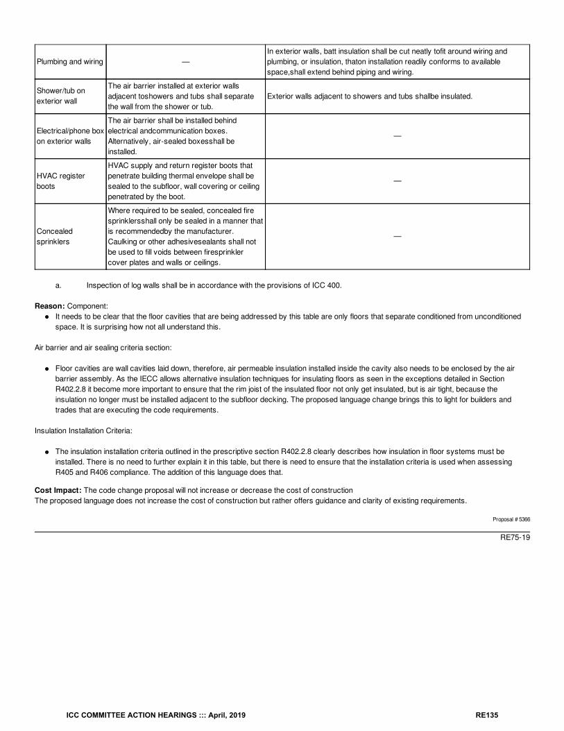
Plumbing and wiring —In exterior walls, batt insulation shall be cut neatly tofit around wiring andplumbing, or insulation, thaton installation readily conforms to availablespace,shall extend behind piping and wiring.
Shower/tub onexterior wall
The air barrier installed at exterior wallsadjacent toshowers and tubs shall separatethe wall from the shower or tub.
Exterior walls adjacent to showers and tubs shallbe insulated.
Electrical/phone boxon exterior walls
The air barrier shall be installed behindelectrical andcommunication boxes.Alternatively, air-sealed boxesshall beinstalled.
—
HVAC registerboots
HVAC supply and return register boots thatpenetrate building thermal envelope shall besealed to the subfloor, wall covering or ceilingpenetrated by the boot.
—
Concealedsprinklers
Where required to be sealed, concealed firesprinklersshall only be sealed in a manner thatis recommendedby the manufacturer.Caulking or other adhesivesealants shall notbe used to fill voids between firesprinklercover plates and walls or ceilings.
—
a. Inspection of log walls shall be in accordance with the provisions of ICC 400.
Reason: Component:It needs to be clear that the floor cavities that are being addressed by this table are only floors that separate conditioned from unconditionedspace. It is surprising how not all understand this.
Air barrier and air sealing criteria section:
Floor cavities are wall cavities laid down, therefore, air permeable insulation installed inside the cavity also needs to be enclosed by the airbarrier assembly. As the IECC allows alternative insulation techniques for insulating floors as seen in the exceptions detailed in SectionR402.2.8 it become more important to ensure that the rim joist of the insulated floor not only get insulated, but is air tight, because theinsulation no longer must be installed adjacent to the subfloor decking. The proposed language change brings this to light for builders andtrades that are executing the code requirements.
Insulation Installation Criteria:
The insulation installation criteria outlined in the prescriptive section R402.2.8 clearly describes how insulation in floor systems must beinstalled. There is no need to further explain it in this table, but there is need to ensure that the installation criteria is used when assessingR405 and R406 compliance. The addition of this language does that.
Cost Impact: The code change proposal will not increase or decrease the cost of constructionThe proposed language does not increase the cost of construction but rather offers guidance and clarity of existing requirements.
Proposal # 5366
RE75-19
ICC COMMITTEE ACTION HEARINGS ::: April, 2019 RE135

RE76-19IECC: TABLE R402.4.1.1 (IRC N1102.4.1.1)
Proponent: Robby Schwarz, EnergyLogic, representing EnergyLogic ([email protected])
2018 International Energy Conservation CodeRevise as follows:
TABLE R402.4.1.1 (IRC N1102.4.1.1)AIR BARRIER AND INSULATION INSTALLATION
COMPONENT AIR BARRIER CRITERIA INSULATION INSTALLATION CRITERIA
Generalrequirements
A continuous air barrier shall be installed inthebuilding envelope.The exterior thermal envelopecontains a continuousair barrier.Breaks or joints inthe air barrier shall be sealed.
Air-permeable insulation shall not be used as asealing material.
Ceiling/attic
The air barrier in any dropped ceiling or soffit shallbealigned with the insulation and any gaps in theairbarrier shall be sealed.Access openings, dropdown stairs or knee wall doorsto unconditioned atticspaces shall be sealed.
The insulation in any dropped ceiling/soffit shallbe aligned with the airbarrier.
Walls
The junction of the foundation and sill plate shallbesealed.The junction of the top plate and the top ofexteriorwalls shall be sealed.Knee walls shall besealed.
Cavities within corners and headers of framewalls shall be insulated bycompletely filling thecavity with a material having a thermal resistance, R-value, of not less than R-3 per inch.Exterior thermal envelope insulation forframedwalls shall be installed in substantial contact andcontinuousalignment with the air barrier.
Windows,skylights anddoors
The space between framing and skylights, and thejambsof windows and doors, shall be sealed.
—
Rim joists Rim joists shall include the air barrier. Rim joists shall be insulated.
Floors,includingcantileveredfloors andfloors abovegarages
The air barrier shall be installed at any exposed edgeofinsulation.
Floor framing cavity insulation shall be installed tomaintain permanentcontact with the underside ofsubfloor decking. Alternatively, floorframingcavity insulation shall be in contact with the top sideof sheathing, orcontinuous insulation installed onthe underside of floor framing; and shallextend from the bottom to the top of all perimeter floorframing members.
Crawl spacewalls
Exposed earth in unvented crawl spaces shallbecovered with a Class I vapor retarderwithoverlapping joints taped.
Crawl space insulation, where provided instead offloor insulation, shall bepermanently attached tothe walls.
Shafts,penetrations
Duct shafts, utility penetrations, and flueshaftsopening to exterior or unconditioned spaceshall besealed.
—
Narrow cavities —Batts to be installed in narrow cavities shall be cut tofit or narrow cavitiesshall be filled with insulationthat on installation readily conforms to theavailablecavity space.
Garageseparation
Air sealing shall be provided between the garageandconditioned spaces.
—
Recessedlighting
Recessed light fixtures installed in the buildingthermalenvelope shall be sealed to the finishedsurface.
Recessed light fixtures installed in the buildingthermal envelope shall be airtight and IC rated.
Plumbing andwiring
—In exterior walls, batt insulation shall be cut neatly tofit around wiring andplumbing, or insulation, thaton installation readily conforms to availablespace,shall extend behind piping and wiring.
Shower/tub onexterior wall
The air barrier installed at exterior walls adjacenttoshowers and tubs shall separate the wall from theshower or tub.
Exterior walls adjacent to showers and tubs shallbe insulated.
a
ICC COMMITTEE ACTION HEARINGS ::: April, 2019 RE136
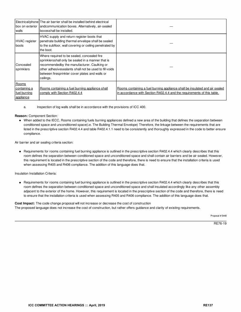
Electrical/phonebox on exteriorwalls
The air barrier shall be installed behind electricalandcommunication boxes. Alternatively, air-sealedboxesshall be installed.
—
HVAC registerboots
HVAC supply and return register boots thatpenetrate building thermal envelope shall be sealedto the subfloor, wall covering or ceiling penetrated bythe boot.
—
Concealedsprinklers
Where required to be sealed, concealed firesprinklersshall only be sealed in a manner that isrecommendedby the manufacturer. Caulking orother adhesivesealants shall not be used to fill voidsbetween firesprinkler cover plates and walls orceilings.
—
Roomscontaining afuel burningappliance
Rooms containing a fuel burning appliance shallcomply with Section R402.4.4
Rooms containing a fuel burning appliance shall be insulated and air sealedin accordance with Section R402.4.4 and the requirements of this table.
a. Inspection of log walls shall be in accordance with the provisions of ICC 400.
Reason: Component Section:When added to the IECC, Rooms containing fuels burning appliances defined a new area of the building that defines the separation betweenconditioned space and unconditioned space(i.e. The Building Thermal Envelope) Therefore, the linkage between the requirements that arelisted in the prescriptive section R402.4.4 and table R402.4.1.1 need to be consistently and thoroughly expressed in the code to better ensurecompliance.
Air barrier and air sealing criteria section:
Requirements for rooms containing fuel burning appliance is outlined in the prescriptive section R402.4.4 which clearly describes that thisroom defines the separation between conditioned space and unconditioned space and shall contain air barriers and be air sealed. However,this requirement is located in the prescriptive section of the code and therefore, there is need to ensure that the installation criteria is usedwhen assessing R405 and R406 compliance. The addition of this language does that.
Insulation Installation Criteria:
Requirements for rooms containing fuel burning appliance is outlined in the prescriptive section R402.4.4 which clearly describes that thisroom defines the separation between conditioned space and unconditioned space and shall insulated accordingly like any other assemblyadjacent to the exterior of the home. However, this requirement is located in the prescriptive section of the code and therefore, there is needto ensure that the installation criteria is used when assessing R405 and R406 compliance. The addition of this language does that.
Cost Impact: The code change proposal will not increase or decrease the cost of constructionThe proposed language does not increase the cost of construction, but rather offers guidance and clarity of existing requirements.
Proposal # 5448
RE76-19
ICC COMMITTEE ACTION HEARINGS ::: April, 2019 RE137
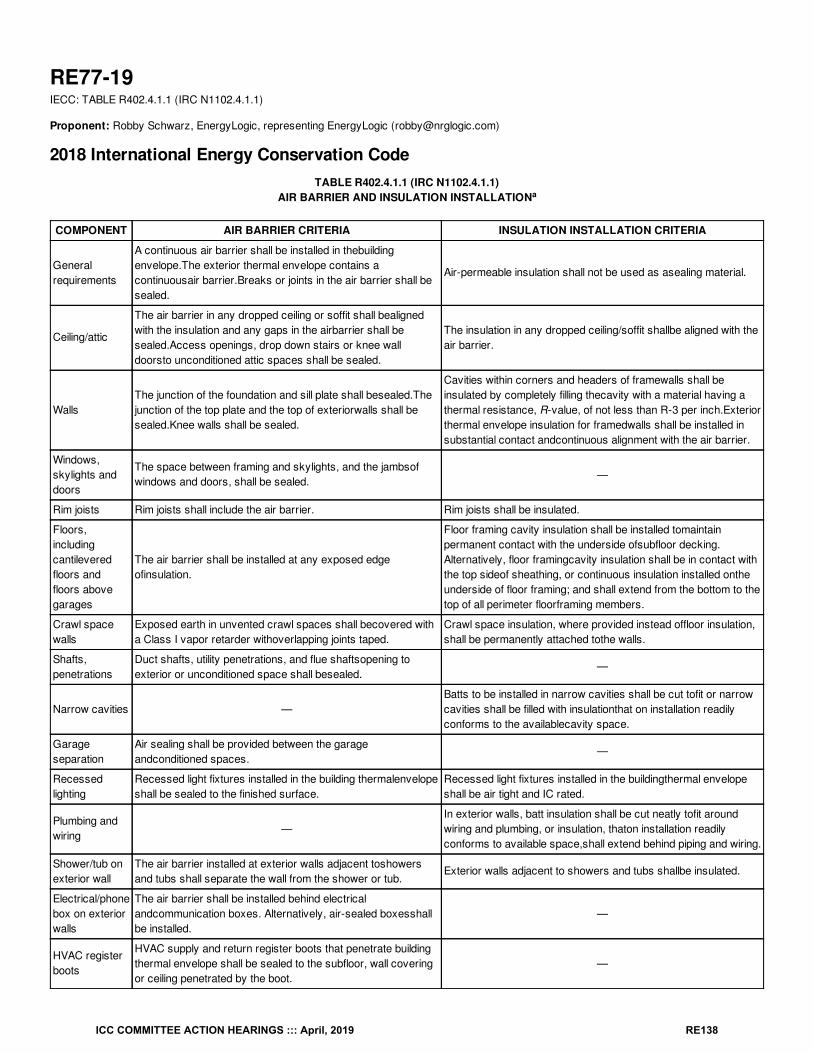
RE77-19IECC: TABLE R402.4.1.1 (IRC N1102.4.1.1)
Proponent: Robby Schwarz, EnergyLogic, representing EnergyLogic ([email protected])
2018 International Energy Conservation CodeTABLE R402.4.1.1 (IRC N1102.4.1.1)
AIR BARRIER AND INSULATION INSTALLATION
COMPONENT AIR BARRIER CRITERIA INSULATION INSTALLATION CRITERIA
Generalrequirements
A continuous air barrier shall be installed in thebuildingenvelope.The exterior thermal envelope contains acontinuousair barrier.Breaks or joints in the air barrier shall besealed.
Air-permeable insulation shall not be used as asealing material.
Ceiling/attic
The air barrier in any dropped ceiling or soffit shall bealignedwith the insulation and any gaps in the airbarrier shall besealed.Access openings, drop down stairs or knee walldoorsto unconditioned attic spaces shall be sealed.
The insulation in any dropped ceiling/soffit shallbe aligned with theair barrier.
WallsThe junction of the foundation and sill plate shall besealed.Thejunction of the top plate and the top of exteriorwalls shall besealed.Knee walls shall be sealed.
Cavities within corners and headers of framewalls shall beinsulated by completely filling thecavity with a material having athermal resistance, R-value, of not less than R-3 per inch.Exteriorthermal envelope insulation for framedwalls shall be installed insubstantial contact andcontinuous alignment with the air barrier.
Windows,skylights anddoors
The space between framing and skylights, and the jambsofwindows and doors, shall be sealed.
—
Rim joists Rim joists shall include the air barrier. Rim joists shall be insulated.
Floors,includingcantileveredfloors andfloors abovegarages
The air barrier shall be installed at any exposed edgeofinsulation.
Floor framing cavity insulation shall be installed tomaintainpermanent contact with the underside ofsubfloor decking.Alternatively, floor framingcavity insulation shall be in contact withthe top sideof sheathing, or continuous insulation installed ontheunderside of floor framing; and shall extend from the bottom to thetop of all perimeter floorframing members.
Crawl spacewalls
Exposed earth in unvented crawl spaces shall becovered witha Class I vapor retarder withoverlapping joints taped.
Crawl space insulation, where provided instead offloor insulation,shall be permanently attached tothe walls.
Shafts,penetrations
Duct shafts, utility penetrations, and flue shaftsopening toexterior or unconditioned space shall besealed.
—
Narrow cavities —Batts to be installed in narrow cavities shall be cut tofit or narrowcavities shall be filled with insulationthat on installation readilyconforms to the availablecavity space.
Garageseparation
Air sealing shall be provided between the garageandconditioned spaces.
—
Recessedlighting
Recessed light fixtures installed in the building thermalenvelopeshall be sealed to the finished surface.
Recessed light fixtures installed in the buildingthermal envelopeshall be air tight and IC rated.
Plumbing andwiring
—In exterior walls, batt insulation shall be cut neatly tofit aroundwiring and plumbing, or insulation, thaton installation readilyconforms to available space,shall extend behind piping and wiring.
Shower/tub onexterior wall
The air barrier installed at exterior walls adjacent toshowersand tubs shall separate the wall from the shower or tub.
Exterior walls adjacent to showers and tubs shallbe insulated.
Electrical/phonebox on exteriorwalls
The air barrier shall be installed behind electricalandcommunication boxes. Alternatively, air-sealed boxesshallbe installed.
—
HVAC registerboots
HVAC supply and return register boots that penetrate buildingthermal envelope shall be sealed to the subfloor, wall coveringor ceiling penetrated by the boot.
—
a
ICC COMMITTEE ACTION HEARINGS ::: April, 2019 RE138
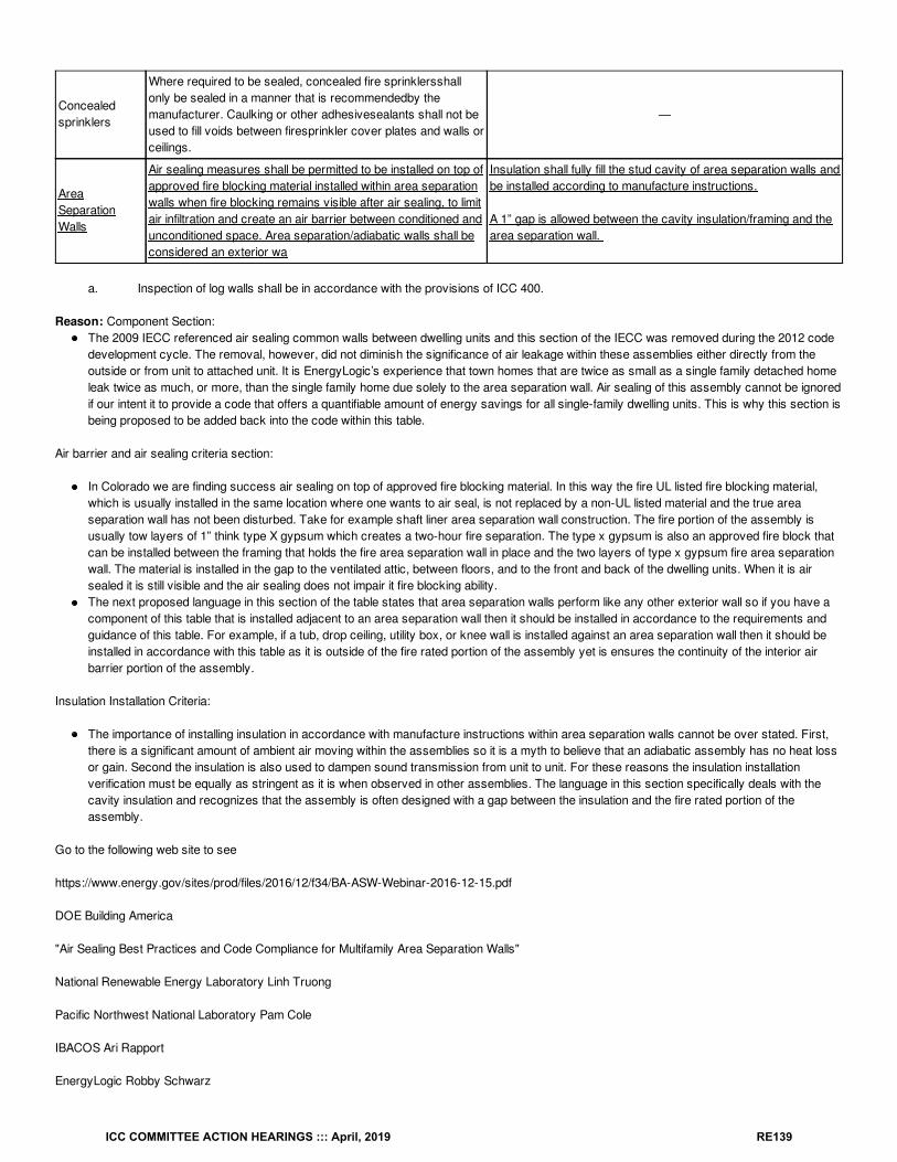
Concealedsprinklers
Where required to be sealed, concealed fire sprinklersshallonly be sealed in a manner that is recommendedby themanufacturer. Caulking or other adhesivesealants shall not beused to fill voids between firesprinkler cover plates and walls orceilings.
—
AreaSeparationWalls
Air sealing measures shall be permitted to be installed on top ofapproved fire blocking material installed within area separationwalls when fire blocking remains visible after air sealing, to limitair infiltration and create an air barrier between conditioned andunconditioned space. Area separation/adiabatic walls shall beconsidered an exterior wa
Insulation shall fully fill the stud cavity of area separation walls andbe installed according to manufacture instructions.
A 1” gap is allowed between the cavity insulation/framing and thearea separation wall.
a. Inspection of log walls shall be in accordance with the provisions of ICC 400.
Reason: Component Section:The 2009 IECC referenced air sealing common walls between dwelling units and this section of the IECC was removed during the 2012 codedevelopment cycle. The removal, however, did not diminish the significance of air leakage within these assemblies either directly from theoutside or from unit to attached unit. It is EnergyLogic’s experience that town homes that are twice as small as a single family detached homeleak twice as much, or more, than the single family home due solely to the area separation wall. Air sealing of this assembly cannot be ignoredif our intent it to provide a code that offers a quantifiable amount of energy savings for all single-family dwelling units. This is why this section isbeing proposed to be added back into the code within this table.
Air barrier and air sealing criteria section:
In Colorado we are finding success air sealing on top of approved fire blocking material. In this way the fire UL listed fire blocking material,which is usually installed in the same location where one wants to air seal, is not replaced by a non-UL listed material and the true areaseparation wall has not been disturbed. Take for example shaft liner area separation wall construction. The fire portion of the assembly isusually tow layers of 1” think type X gypsum which creates a two-hour fire separation. The type x gypsum is also an approved fire block thatcan be installed between the framing that holds the fire area separation wall in place and the two layers of type x gypsum fire area separationwall. The material is installed in the gap to the ventilated attic, between floors, and to the front and back of the dwelling units. When it is airsealed it is still visible and the air sealing does not impair it fire blocking ability.The next proposed language in this section of the table states that area separation walls perform like any other exterior wall so if you have acomponent of this table that is installed adjacent to an area separation wall then it should be installed in accordance to the requirements andguidance of this table. For example, if a tub, drop ceiling, utility box, or knee wall is installed against an area separation wall then it should beinstalled in accordance with this table as it is outside of the fire rated portion of the assembly yet is ensures the continuity of the interior airbarrier portion of the assembly.
Insulation Installation Criteria:
The importance of installing insulation in accordance with manufacture instructions within area separation walls cannot be over stated. First,there is a significant amount of ambient air moving within the assemblies so it is a myth to believe that an adiabatic assembly has no heat lossor gain. Second the insulation is also used to dampen sound transmission from unit to unit. For these reasons the insulation installationverification must be equally as stringent as it is when observed in other assemblies. The language in this section specifically deals with thecavity insulation and recognizes that the assembly is often designed with a gap between the insulation and the fire rated portion of theassembly.
Go to the following web site to see
https://www.energy.gov/sites/prod/files/2016/12/f34/BA-ASW-Webinar-2016-12-15.pdf
DOE Building America
"Air Sealing Best Practices and Code Compliance for Multifamily Area Separation Walls"
National Renewable Energy Laboratory Linh Truong
Pacific Northwest National Laboratory Pam Cole
IBACOS Ari Rapport
EnergyLogic Robby Schwarz
ICC COMMITTEE ACTION HEARINGS ::: April, 2019 RE139
Additional Resource:
https://basc.pnnl.gov/code-compliance/air-sealing-and-insulating-common-walls-party-walls-multi-family-buildings-code
Cost Impact: The code change proposal will not increase or decrease the cost of constructionThe proposed language does not increase the cost of construction, but rather offers guidance and clarity of existing requirements.
Proposal # 5445
RE77-19
ICC COMMITTEE ACTION HEARINGS ::: April, 2019 RE140
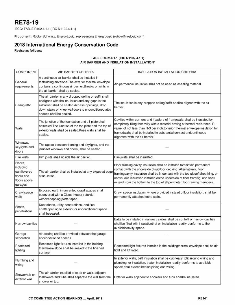
RE78-19IECC: TABLE R402.4.1.1 (IRC N1102.4.1.1)
Proponent: Robby Schwarz, EnergyLogic, representing EnergyLogic ([email protected])
2018 International Energy Conservation CodeRevise as follows:
TABLE R402.4.1.1 (IRC N1102.4.1.1)AIR BARRIER AND INSULATION INSTALLATION
COMPONENT AIR BARRIER CRITERIA INSULATION INSTALLATION CRITERIA
Generalrequirements
A continuous air barrier shall be installed inthebuilding envelope.The exterior thermal envelopecontains a continuousair barrier.Breaks or joints inthe air barrier shall be sealed.
Air-permeable insulation shall not be used as asealing material.
Ceiling/attic
The air barrier in any dropped ceiling or soffit shallbealigned with the insulation and any gaps in theairbarrier shall be sealed.Access openings, dropdown stairs or knee wall doorsto unconditioned atticspaces shall be sealed.
The insulation in any dropped ceiling/soffit shallbe aligned with the airbarrier.
Walls
The junction of the foundation and sill plate shallbesealed.The junction of the top plate and the top ofexteriorwalls shall be sealed.Knee walls shall besealed.
Cavities within corners and headers of framewalls shall be insulated bycompletely filling thecavity with a material having a thermal resistance, R-value, of not less than R-3 per inch.Exterior thermal envelope insulation forframedwalls shall be installed in substantial contact andcontinuousalignment with the air barrier.
Windows,skylights anddoors
The space between framing and skylights, and thejambsof windows and doors, shall be sealed.
—
Rim joists Rim joists shall include the air barrier. Rim joists shall be insulated.
Floors,includingcantileveredfloors andfloors abovegarages
The air barrier shall be installed at any exposed edgeofinsulation.
Floor framing cavity insulation shall be installed tomaintain permanentcontact with the underside ofsubfloor decking. Alternatively, floorframingcavity insulation shall be in contact with the top sideof sheathing, orcontinuous insulation installed onthe underside of floor framing; and shallextend from the bottom to the top of all perimeter floorframing members.
Crawl spacewalls
Exposed earth in unvented crawl spaces shallbecovered with a Class I vapor retarderwithoverlapping joints taped.
Crawl space insulation, where provided instead offloor insulation, shall bepermanently attached tothe walls.
Shafts,penetrations
Duct shafts, utility penetrations, and flueshaftsopening to exterior or unconditioned spaceshall besealed.
—
Narrow cavities —Batts to be installed in narrow cavities shall be cut tofit or narrow cavitiesshall be filled with insulationthat on installation readily conforms to theavailablecavity space.
Garageseparation
Air sealing shall be provided between the garageandconditioned spaces.
—
Recessedlighting
Recessed light fixtures installed in the buildingthermalenvelope shall be sealed to the finishedsurface.
Recessed light fixtures installed in the buildingthermal envelope shall be airtight and IC rated.
Plumbing andwiring
—In exterior walls, batt insulation shall be cut neatly tofit around wiring andplumbing, or insulation, thaton installation readily conforms to availablespace,shall extend behind piping and wiring.
Shower/tub onexterior wall
The air barrier installed at exterior walls adjacenttoshowers and tubs shall separate the wall from theshower or tub.
Exterior walls adjacent to showers and tubs shallbe insulated.
a
ICC COMMITTEE ACTION HEARINGS ::: April, 2019 RE141
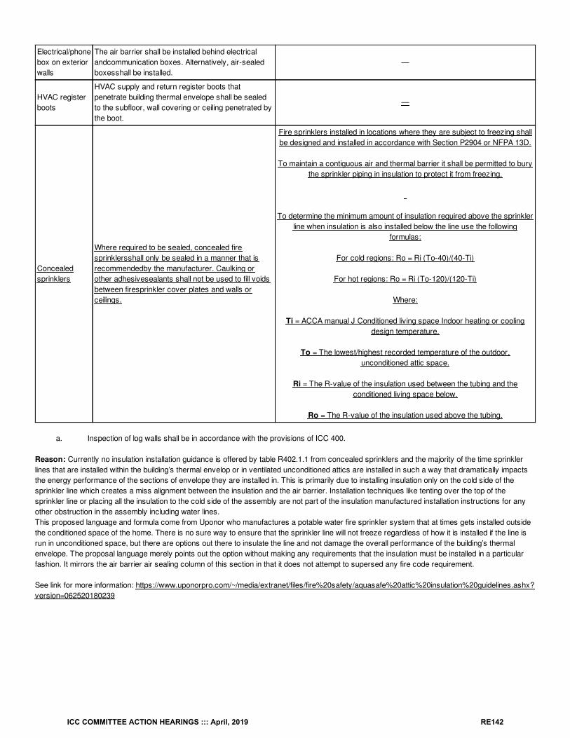
Electrical/phonebox on exteriorwalls
The air barrier shall be installed behind electricalandcommunication boxes. Alternatively, air-sealedboxesshall be installed.
—
HVAC registerboots
HVAC supply and return register boots thatpenetrate building thermal envelope shall be sealedto the subfloor, wall covering or ceiling penetrated bythe boot.
—
Concealedsprinklers
Where required to be sealed, concealed firesprinklersshall only be sealed in a manner that isrecommendedby the manufacturer. Caulking orother adhesivesealants shall not be used to fill voidsbetween firesprinkler cover plates and walls orceilings.
Fire sprinklers installed in locations where they are subject to freezing shallbe designed and installed in accordance with Section P2904 or NFPA 13D.
To maintain a contiguous air and thermal barrier it shall be permitted to burythe sprinkler piping in insulation to protect it from freezing.
To determine the minimum amount of insulation required above the sprinklerline when insulation is also installed below the line use the following
formulas:
For cold regions: Ro = Ri (To-40)/(40-Ti)
For hot regions: Ro = Ri (To-120)/(120-Ti)
Where:
Ti = ACCA manual J Conditioned living space Indoor heating or coolingdesign temperature.
To = The lowest/highest recorded temperature of the outdoor,unconditioned attic space.
Ri = The R-value of the insulation used between the tubing and theconditioned living space below.
Ro = The R-value of the insulation used above the tubing.
a. Inspection of log walls shall be in accordance with the provisions of ICC 400.
Reason: Currently no insulation installation guidance is offered by table R402.1.1 from concealed sprinklers and the majority of the time sprinklerlines that are installed within the building’s thermal envelop or in ventilated unconditioned attics are installed in such a way that dramatically impactsthe energy performance of the sections of envelope they are installed in. This is primarily due to installing insulation only on the cold side of thesprinkler line which creates a miss alignment between the insulation and the air barrier. Installation techniques like tenting over the top of thesprinkler line or placing all the insulation to the cold side of the assembly are not part of the insulation manufactured installation instructions for anyother obstruction in the assembly including water lines.This proposed language and formula come from Uponor who manufactures a potable water fire sprinkler system that at times gets installed outsidethe conditioned space of the home. There is no sure way to ensure that the sprinkler line will not freeze regardless of how it is installed if the line isrun in unconditioned space, but there are options out there to insulate the line and not damage the overall performance of the building’s thermalenvelope. The proposal language merely points out the option without making any requirements that the insulation must be installed in a particularfashion. It mirrors the air barrier air sealing column of this section in that it does not attempt to supersed any fire code requirement.
See link for more information: https://www.uponorpro.com/~/media/extranet/files/fire%20safety/aquasafe%20attic%20insulation%20guidelines.ashx?version=062520180239
ICC COMMITTEE ACTION HEARINGS ::: April, 2019 RE142
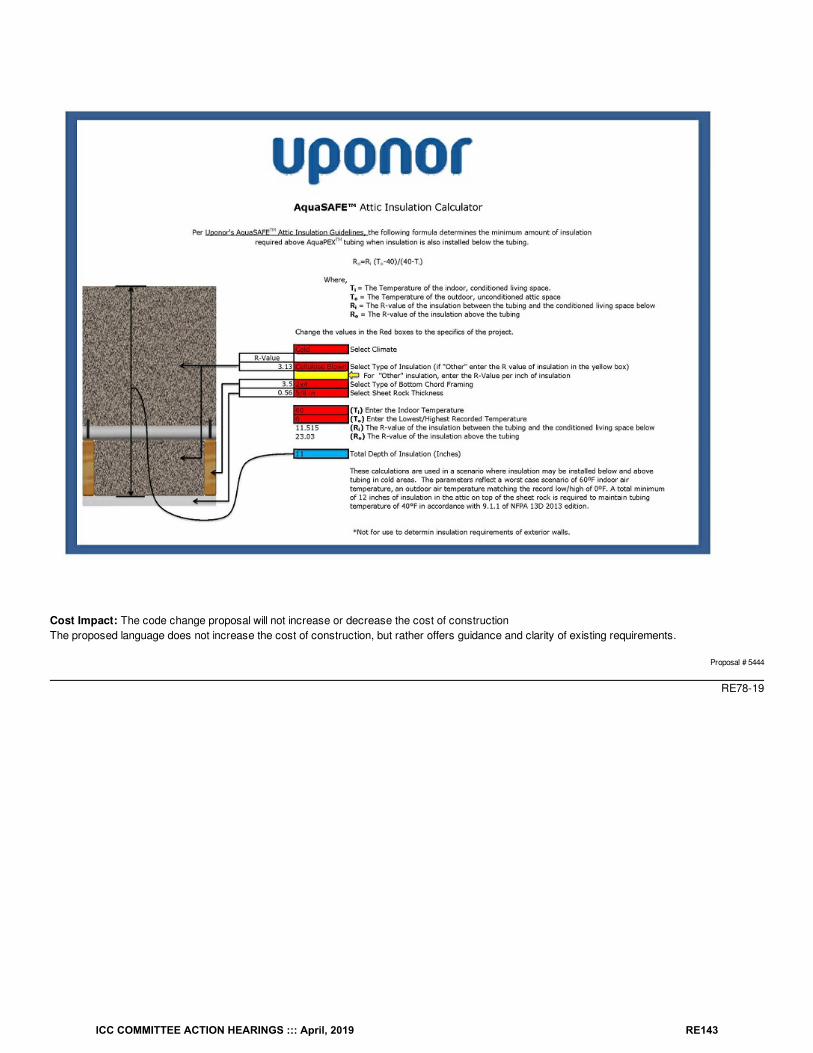
Cost Impact: The code change proposal will not increase or decrease the cost of constructionThe proposed language does not increase the cost of construction, but rather offers guidance and clarity of existing requirements.
Proposal # 5444
RE78-19
ICC COMMITTEE ACTION HEARINGS ::: April, 2019 RE143

RE79-19IECC: TABLE R402.4.1.1 (IRC N1102.4.1.1)
Proponent: Robby Schwarz, EnergyLogic, representing EnergyLogic ([email protected])
2018 International Energy Conservation CodeRevise as follows:
TABLE R402.4.1.1 (IRC N1102.4.1.1)AIR BARRIER AND INSULATION INSTALLATION
COMPONENT AIR BARRIER CRITERIA INSULATION INSTALLATION CRITERIA
Generalrequirements
A continuous air barrier shall be installed inthebuilding envelope.The exterior thermal envelopecontains a continuousair barrier.Breaks or joints inthe air barrier shall be sealed.
Air-permeable insulation shall not be used as asealing material.
Ceiling/attic
The air barrier in any dropped ceiling or soffit shallbealigned with the insulation and any gaps in theairbarrier shall be sealed.Access openings, dropdown stairs or knee wall doorsto unconditioned atticspaces shall be sealed.
The insulation in any dropped ceiling/soffit shallbe aligned with the airbarrier.
Walls
The junction of the foundation and sill plate shallbesealed.The junction of the top plate and the top ofexteriorwalls shall be sealed.Knee walls shall besealed.
Cavities within corners and headers of framewalls shall be insulated bycompletely filling thecavity with a material having a thermal resistance, R-value, of not less than R-3 per inch.Exterior thermal envelope insulation forframedwalls shall be installed in substantial contact andcontinuousalignment with the air barrier.
Windows,skylights anddoors
The space between framing and skylights, and thejambsof windows and doors, shall be sealed.
—
Rim joists Rim joists shall include the air barrier. Rim joists shall be insulated.
Floors,includingcantileveredfloors andfloors abovegarages
The air barrier shall be installed at any exposed edgeofinsulation.
Floor framing cavity insulation shall be installed tomaintain permanentcontact with the underside ofsubfloor decking. Alternatively, floorframingcavity insulation shall be in contact with the top sideof sheathing, orcontinuous insulation installed onthe underside of floor framing; and shallextend from the bottom to the top of all perimeter floorframing members.
Crawl spacewalls
Exposed earth in unvented crawl spaces shallbecovered with a Class I vapor retarderwithoverlapping joints taped.
Crawl space insulation, where provided instead offloor insulation, shall bepermanently attached tothe walls.
Shafts,penetrations
Duct shafts, utility penetrations, and flueshaftsopening to exterior or unconditioned spaceshall besealed.
—
Narrow cavities —Batts to be installed in narrow cavities shall be cut tofit or narrow cavitiesshall be filled with insulationthat on installation readily conforms to theavailablecavity space.
Garageseparation
Air sealing shall be provided between the garageandconditioned spaces.
—
Recessedlighting
Recessed light fixtures installed in the buildingthermalenvelope shall be sealed to the finishedsurface.
Recessed light fixtures installed in the buildingthermal envelope shall be airtight and IC rated.
Plumbing andwiring
—In exterior walls, batt insulation shall be cut neatly tofit around wiring andplumbing, or insulation, thaton installation readily conforms to availablespace,shall extend behind piping and wiring.
Shower/tub onexterior wall
The air barrier installed at exterior walls adjacenttoshowers and tubs shall separate the wall from theshower or tub.
Exterior walls adjacent to showers and tubs shallbe insulated.
a
ICC COMMITTEE ACTION HEARINGS ::: April, 2019 RE144
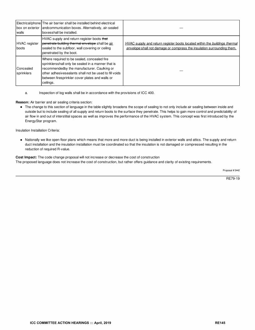
Electrical/phonebox on exteriorwalls
The air barrier shall be installed behind electricalandcommunication boxes. Alternatively, air-sealedboxesshall be installed.
—
HVAC registerboots
HVAC supply and return register boots thatpenetrate building thermal envelope shall be airsealed to the subfloor, wall covering or ceilingpenetrated by the boot.
HVAC supply and return register boots located within the buildings thermalenvelope shall not damage or compress the insulation surrounding them.
Concealedsprinklers
Where required to be sealed, concealed firesprinklersshall only be sealed in a manner that isrecommendedby the manufacturer. Caulking orother adhesivesealants shall not be used to fill voidsbetween firesprinkler cover plates and walls orceilings.
—
a. Inspection of log walls shall be in accordance with the provisions of ICC 400.
Reason: Air barrier and air sealing criteria section:The change to this section of language in the table slightly broadens the scope of sealing to not only include air sealing between inside andoutside but to include sealing of all supply and return boots to the surface they penetrate. This helps to gain more control and predictability ofair flow in and out of interstitial spaces as well as improves the performance of the HVAC system. This concept was first introduced by theEnergyStar program.
Insulation Installation Criteria:
Nationally we like open floor plans which means that more and more duct is being installed in exterior walls and attics. The supply and returnduct installation and the insulation installation must be coordinated so that the insulation is not damaged or compressed resulting in thereduction of required R-value.
Cost Impact: The code change proposal will not increase or decrease the cost of constructionThe proposed language does not increase the cost of construction, but rather offers guidance and clarity of existing requirements.
Proposal # 5442
RE79-19
ICC COMMITTEE ACTION HEARINGS ::: April, 2019 RE145
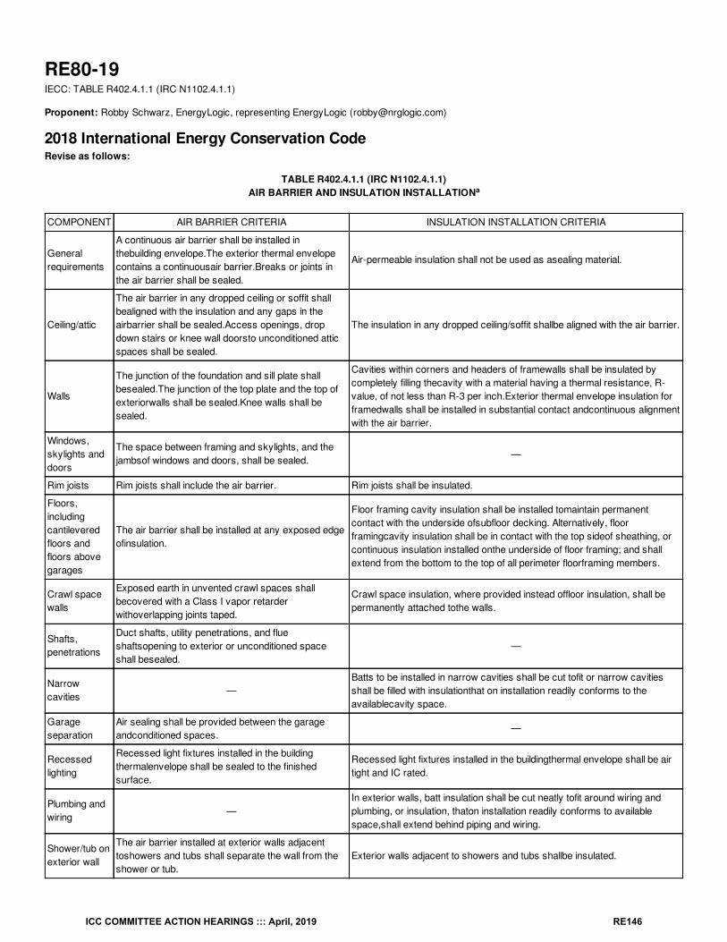
RE80-19IECC: TABLE R402.4.1.1 (IRC N1102.4.1.1)
Proponent: Robby Schwarz, EnergyLogic, representing EnergyLogic ([email protected])
2018 International Energy Conservation CodeRevise as follows:
TABLE R402.4.1.1 (IRC N1102.4.1.1)AIR BARRIER AND INSULATION INSTALLATION
COMPONENT AIR BARRIER CRITERIA INSULATION INSTALLATION CRITERIA
Generalrequirements
A continuous air barrier shall be installed inthebuilding envelope.The exterior thermal envelopecontains a continuousair barrier.Breaks or joints inthe air barrier shall be sealed.
Air-permeable insulation shall not be used as asealing material.
Ceiling/attic
The air barrier in any dropped ceiling or soffit shallbealigned with the insulation and any gaps in theairbarrier shall be sealed.Access openings, dropdown stairs or knee wall doorsto unconditioned atticspaces shall be sealed.
The insulation in any dropped ceiling/soffit shallbe aligned with the air barrier.
Walls
The junction of the foundation and sill plate shallbesealed.The junction of the top plate and the top ofexteriorwalls shall be sealed.Knee walls shall besealed.
Cavities within corners and headers of framewalls shall be insulated bycompletely filling thecavity with a material having a thermal resistance, R-value, of not less than R-3 per inch.Exterior thermal envelope insulation forframedwalls shall be installed in substantial contact andcontinuous alignmentwith the air barrier.
Windows,skylights anddoors
The space between framing and skylights, and thejambsof windows and doors, shall be sealed.
—
Rim joists Rim joists shall include the air barrier. Rim joists shall be insulated.
Floors,includingcantileveredfloors andfloors abovegarages
The air barrier shall be installed at any exposed edgeofinsulation.
Floor framing cavity insulation shall be installed tomaintain permanentcontact with the underside ofsubfloor decking. Alternatively, floorframingcavity insulation shall be in contact with the top sideof sheathing, orcontinuous insulation installed onthe underside of floor framing; and shallextend from the bottom to the top of all perimeter floorframing members.
Crawl spacewalls
Exposed earth in unvented crawl spaces shallbecovered with a Class I vapor retarderwithoverlapping joints taped.
Crawl space insulation, where provided instead offloor insulation, shall bepermanently attached tothe walls.
Shafts,penetrations
Duct shafts, utility penetrations, and flueshaftsopening to exterior or unconditioned spaceshall besealed.
—
Narrowcavities
—Batts to be installed in narrow cavities shall be cut tofit or narrow cavitiesshall be filled with insulationthat on installation readily conforms to theavailablecavity space.
Garageseparation
Air sealing shall be provided between the garageandconditioned spaces.
—
Recessedlighting
Recessed light fixtures installed in the buildingthermalenvelope shall be sealed to the finishedsurface.
Recessed light fixtures installed in the buildingthermal envelope shall be airtight and IC rated.
Plumbing andwiring
—In exterior walls, batt insulation shall be cut neatly tofit around wiring andplumbing, or insulation, thaton installation readily conforms to availablespace,shall extend behind piping and wiring.
Shower/tub onexterior wall
The air barrier installed at exterior walls adjacenttoshowers and tubs shall separate the wall from theshower or tub.
Exterior walls adjacent to showers and tubs shallbe insulated.
a
ICC COMMITTEE ACTION HEARINGS ::: April, 2019 RE146
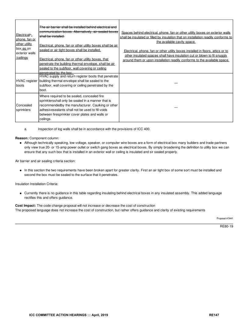
Electrical/ ,phone, fan orother utilitybox es onexterior walls/ceilings
The air barrier shall be installed behind electrical andcommunication boxes. Alternatively, air-sealed boxesshall be installed.
Electrical, phone, fan or other utility boxes shall be airsealed or air tight boxes shall be installed.
Electrical, phone, fan or other utility boxes, thatpenetrate the building thermal envelope, shall be airsealed to the subfloor, wall covering or ceilingpenetrated by the box.
Spaces behind electrical, phone, fan or other utility boxes on exterior wallsshall be insulated or filled by insulation that on installation readily conforms to
the available cavity space.
Electrical, phone, fan or other utility boxes installed in floors, attics or toother insulated spaces shall have insulation cut or blown to fit snuggly
around them or upon installation readily conforms to the available space.
HVAC registerboots
HVAC supply and return register boots that penetratebuilding thermal envelope shall be sealed to thesubfloor, wall covering or ceiling penetrated by theboot.
—
Concealedsprinklers
Where required to be sealed, concealed firesprinklersshall only be sealed in a manner that isrecommendedby the manufacturer. Caulking or otheradhesivesealants shall not be used to fill voidsbetween firesprinkler cover plates and walls orceilings.
—
a. Inspection of log walls shall be in accordance with the provisions of ICC 400.
Reason: Component column:Although technically speaking, low voltage, speaker, or computer wire boxes are a form of electrical box many builders and trade partnersonly view true 20- or 15-amp power outlet or switch gang boxes as electrical boxes. By simply broadening the definition to utility box we canensure that any such box that is installed in an exterior wall or ceiling is insulated and sir sealed properly.
Air barrier and air sealing criteria section:
In this section the two requirements have been broken apart for greater clarity. First an air tight box of some sort must be installed andsecond the box must be sealed to the surface that it penetrates.
Insulation Installation Criteria:
Currently there is no guidance in this table regarding insulating behind electrical boxes in any insulated assembly. This added languagerectifies this and offers guidance.
Cost Impact: The code change proposal will not increase or decrease the cost of constructionThe proposed language does not increase the cost of construction, but rather offers guidance and clarity of existing requirements
Proposal # 5441
RE80-19
ICC COMMITTEE ACTION HEARINGS ::: April, 2019 RE147
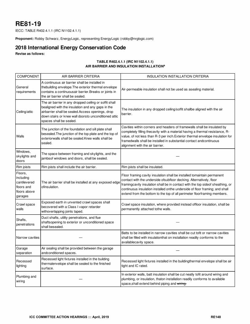
RE81-19IECC: TABLE R402.4.1.1 (IRC N1102.4.1.1)
Proponent: Robby Schwarz, EnergyLogic, representing EnergyLogic ([email protected])
2018 International Energy Conservation CodeRevise as follows:
TABLE R402.4.1.1 (IRC N1102.4.1.1)AIR BARRIER AND INSULATION INSTALLATION
COMPONENT AIR BARRIER CRITERIA INSULATION INSTALLATION CRITERIA
Generalrequirements
A continuous air barrier shall be installed inthebuilding envelope.The exterior thermal envelopecontains a continuousair barrier.Breaks or joints inthe air barrier shall be sealed.
Air-permeable insulation shall not be used as asealing material.
Ceiling/attic
The air barrier in any dropped ceiling or soffit shallbealigned with the insulation and any gaps in theairbarrier shall be sealed.Access openings, dropdown stairs or knee wall doorsto unconditioned atticspaces shall be sealed.
The insulation in any dropped ceiling/soffit shallbe aligned with the airbarrier.
Walls
The junction of the foundation and sill plate shallbesealed.The junction of the top plate and the top ofexteriorwalls shall be sealed.Knee walls shall besealed.
Cavities within corners and headers of framewalls shall be insulated bycompletely filling thecavity with a material having a thermal resistance, R-value, of not less than R-3 per inch.Exterior thermal envelope insulation forframedwalls shall be installed in substantial contact andcontinuousalignment with the air barrier.
Windows,skylights anddoors
The space between framing and skylights, and thejambsof windows and doors, shall be sealed.
—
Rim joists Rim joists shall include the air barrier. Rim joists shall be insulated.
Floors,includingcantileveredfloors andfloors abovegarages
The air barrier shall be installed at any exposed edgeofinsulation.
Floor framing cavity insulation shall be installed tomaintain permanentcontact with the underside ofsubfloor decking. Alternatively, floorframingcavity insulation shall be in contact with the top sideof sheathing, orcontinuous insulation installed onthe underside of floor framing; and shallextend from the bottom to the top of all perimeter floorframing members.
Crawl spacewalls
Exposed earth in unvented crawl spaces shallbecovered with a Class I vapor retarderwithoverlapping joints taped.
Crawl space insulation, where provided instead offloor insulation, shall bepermanently attached tothe walls.
Shafts,penetrations
Duct shafts, utility penetrations, and flueshaftsopening to exterior or unconditioned spaceshall besealed.
—
Narrow cavities —Batts to be installed in narrow cavities shall be cut tofit or narrow cavitiesshall be filled with insulationthat on installation readily conforms to theavailablecavity space.
Garageseparation
Air sealing shall be provided between the garageandconditioned spaces.
—
Recessedlighting
Recessed light fixtures installed in the buildingthermalenvelope shall be sealed to the finishedsurface.
Recessed light fixtures installed in the buildingthermal envelope shall be airtight and IC rated.
Plumbing andwiring
—In exterior walls, batt insulation shall be cut neatly tofit around wiring andplumbing, or insulation, thaton installation readily conforms to availablespace,shall extend behind piping and wiring.
a
ICC COMMITTEE ACTION HEARINGS ::: April, 2019 RE148
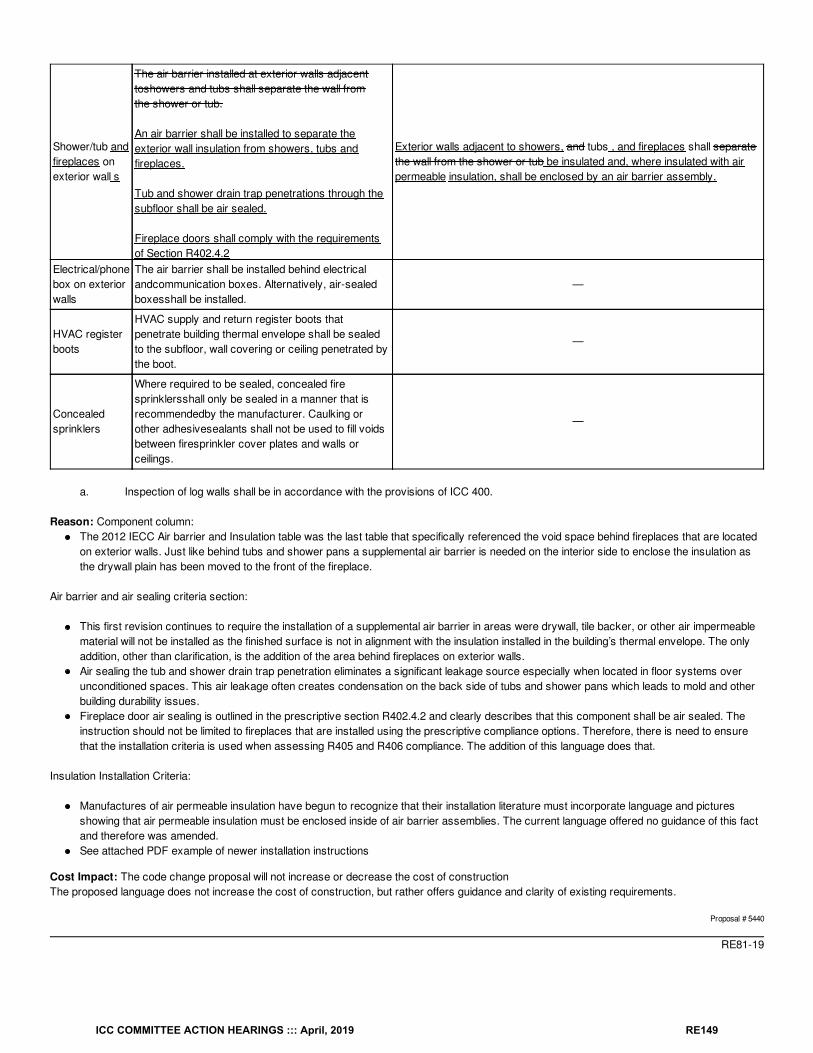
Shower/tub andfireplaces onexterior wall s
The air barrier installed at exterior walls adjacenttoshowers and tubs shall separate the wall fromthe shower or tub.
An air barrier shall be installed to separate theexterior wall insulation from showers, tubs andfireplaces.
Tub and shower drain trap penetrations through thesubfloor shall be air sealed.
Fireplace doors shall comply with the requirementsof Section R402.4.2
Exterior walls adjacent to showers, and tubs , and fireplaces shall separatethe wall from the shower or tub be insulated and, where insulated with airpermeable insulation, shall be enclosed by an air barrier assembly.
Electrical/phonebox on exteriorwalls
The air barrier shall be installed behind electricalandcommunication boxes. Alternatively, air-sealedboxesshall be installed.
—
HVAC registerboots
HVAC supply and return register boots thatpenetrate building thermal envelope shall be sealedto the subfloor, wall covering or ceiling penetrated bythe boot.
—
Concealedsprinklers
Where required to be sealed, concealed firesprinklersshall only be sealed in a manner that isrecommendedby the manufacturer. Caulking orother adhesivesealants shall not be used to fill voidsbetween firesprinkler cover plates and walls orceilings.
—
a. Inspection of log walls shall be in accordance with the provisions of ICC 400.
Reason: Component column:The 2012 IECC Air barrier and Insulation table was the last table that specifically referenced the void space behind fireplaces that are locatedon exterior walls. Just like behind tubs and shower pans a supplemental air barrier is needed on the interior side to enclose the insulation asthe drywall plain has been moved to the front of the fireplace.
Air barrier and air sealing criteria section:
This first revision continues to require the installation of a supplemental air barrier in areas were drywall, tile backer, or other air impermeablematerial will not be installed as the finished surface is not in alignment with the insulation installed in the building’s thermal envelope. The onlyaddition, other than clarification, is the addition of the area behind fireplaces on exterior walls.Air sealing the tub and shower drain trap penetration eliminates a significant leakage source especially when located in floor systems overunconditioned spaces. This air leakage often creates condensation on the back side of tubs and shower pans which leads to mold and otherbuilding durability issues.Fireplace door air sealing is outlined in the prescriptive section R402.4.2 and clearly describes that this component shall be air sealed. Theinstruction should not be limited to fireplaces that are installed using the prescriptive compliance options. Therefore, there is need to ensurethat the installation criteria is used when assessing R405 and R406 compliance. The addition of this language does that.
Insulation Installation Criteria:
Manufactures of air permeable insulation have begun to recognize that their installation literature must incorporate language and picturesshowing that air permeable insulation must be enclosed inside of air barrier assemblies. The current language offered no guidance of this factand therefore was amended.See attached PDF example of newer installation instructions
Cost Impact: The code change proposal will not increase or decrease the cost of constructionThe proposed language does not increase the cost of construction, but rather offers guidance and clarity of existing requirements.
Proposal # 5440
RE81-19
ICC COMMITTEE ACTION HEARINGS ::: April, 2019 RE149
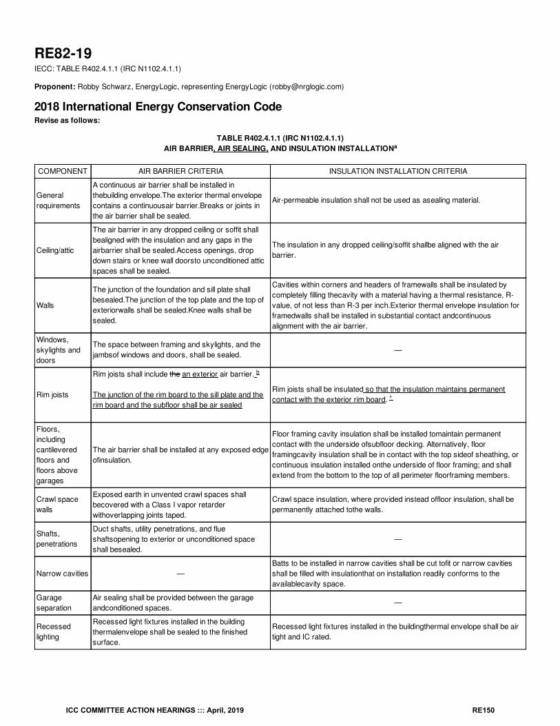
RE82-19IECC: TABLE R402.4.1.1 (IRC N1102.4.1.1)
Proponent: Robby Schwarz, EnergyLogic, representing EnergyLogic ([email protected])
2018 International Energy Conservation CodeRevise as follows:
TABLE R402.4.1.1 (IRC N1102.4.1.1)AIR BARRIER, AIR SEALING, AND INSULATION INSTALLATION
COMPONENT AIR BARRIER CRITERIA INSULATION INSTALLATION CRITERIA
Generalrequirements
A continuous air barrier shall be installed inthebuilding envelope.The exterior thermal envelopecontains a continuousair barrier.Breaks or joints inthe air barrier shall be sealed.
Air-permeable insulation shall not be used as asealing material.
Ceiling/attic
The air barrier in any dropped ceiling or soffit shallbealigned with the insulation and any gaps in theairbarrier shall be sealed.Access openings, dropdown stairs or knee wall doorsto unconditioned atticspaces shall be sealed.
The insulation in any dropped ceiling/soffit shallbe aligned with the airbarrier.
Walls
The junction of the foundation and sill plate shallbesealed.The junction of the top plate and the top ofexteriorwalls shall be sealed.Knee walls shall besealed.
Cavities within corners and headers of framewalls shall be insulated bycompletely filling thecavity with a material having a thermal resistance, R-value, of not less than R-3 per inch.Exterior thermal envelope insulation forframedwalls shall be installed in substantial contact andcontinuousalignment with the air barrier.
Windows,skylights anddoors
The space between framing and skylights, and thejambsof windows and doors, shall be sealed.
—
Rim joists
Rim joists shall include the an exterior air barrier.
The junction of the rim board to the sill plate and therim board and the subfloor shall be air sealed
Rim joists shall be insulated so that the insulation maintains permanentcontact with the exterior rim board.
Floors,includingcantileveredfloors andfloors abovegarages
The air barrier shall be installed at any exposed edgeofinsulation.
Floor framing cavity insulation shall be installed tomaintain permanentcontact with the underside ofsubfloor decking. Alternatively, floorframingcavity insulation shall be in contact with the top sideof sheathing, orcontinuous insulation installed onthe underside of floor framing; and shallextend from the bottom to the top of all perimeter floorframing members.
Crawl spacewalls
Exposed earth in unvented crawl spaces shallbecovered with a Class I vapor retarderwithoverlapping joints taped.
Crawl space insulation, where provided instead offloor insulation, shall bepermanently attached tothe walls.
Shafts,penetrations
Duct shafts, utility penetrations, and flueshaftsopening to exterior or unconditioned spaceshall besealed.
—
Narrow cavities —Batts to be installed in narrow cavities shall be cut tofit or narrow cavitiesshall be filled with insulationthat on installation readily conforms to theavailablecavity space.
Garageseparation
Air sealing shall be provided between the garageandconditioned spaces.
—
Recessedlighting
Recessed light fixtures installed in the buildingthermalenvelope shall be sealed to the finishedsurface.
Recessed light fixtures installed in the buildingthermal envelope shall be airtight and IC rated.
a
b
ᵇ
ICC COMMITTEE ACTION HEARINGS ::: April, 2019 RE150
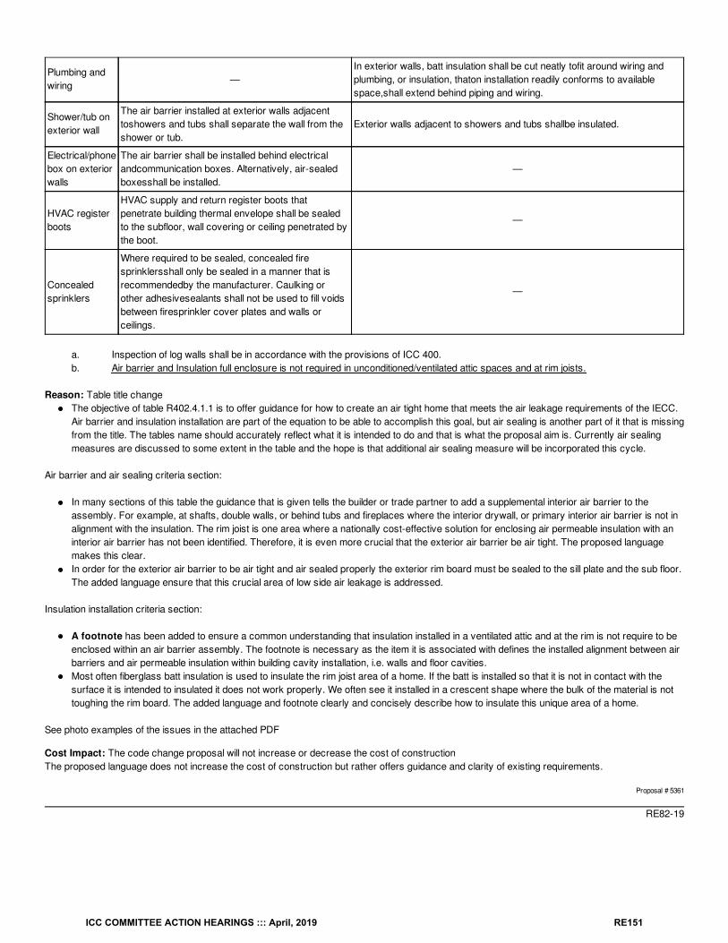
Plumbing andwiring
—In exterior walls, batt insulation shall be cut neatly tofit around wiring andplumbing, or insulation, thaton installation readily conforms to availablespace,shall extend behind piping and wiring.
Shower/tub onexterior wall
The air barrier installed at exterior walls adjacenttoshowers and tubs shall separate the wall from theshower or tub.
Exterior walls adjacent to showers and tubs shallbe insulated.
Electrical/phonebox on exteriorwalls
The air barrier shall be installed behind electricalandcommunication boxes. Alternatively, air-sealedboxesshall be installed.
—
HVAC registerboots
HVAC supply and return register boots thatpenetrate building thermal envelope shall be sealedto the subfloor, wall covering or ceiling penetrated bythe boot.
—
Concealedsprinklers
Where required to be sealed, concealed firesprinklersshall only be sealed in a manner that isrecommendedby the manufacturer. Caulking orother adhesivesealants shall not be used to fill voidsbetween firesprinkler cover plates and walls orceilings.
—
a. Inspection of log walls shall be in accordance with the provisions of ICC 400.b. Air barrier and Insulation full enclosure is not required in unconditioned/ventilated attic spaces and at rim joists.
Reason: Table title changeThe objective of table R402.4.1.1 is to offer guidance for how to create an air tight home that meets the air leakage requirements of the IECC.Air barrier and insulation installation are part of the equation to be able to accomplish this goal, but air sealing is another part of it that is missingfrom the title. The tables name should accurately reflect what it is intended to do and that is what the proposal aim is. Currently air sealingmeasures are discussed to some extent in the table and the hope is that additional air sealing measure will be incorporated this cycle.
Air barrier and air sealing criteria section:
In many sections of this table the guidance that is given tells the builder or trade partner to add a supplemental interior air barrier to theassembly. For example, at shafts, double walls, or behind tubs and fireplaces where the interior drywall, or primary interior air barrier is not inalignment with the insulation. The rim joist is one area where a nationally cost-effective solution for enclosing air permeable insulation with aninterior air barrier has not been identified. Therefore, it is even more crucial that the exterior air barrier be air tight. The proposed languagemakes this clear.In order for the exterior air barrier to be air tight and air sealed properly the exterior rim board must be sealed to the sill plate and the sub floor.The added language ensure that this crucial area of low side air leakage is addressed.
Insulation installation criteria section:
A footnote has been added to ensure a common understanding that insulation installed in a ventilated attic and at the rim is not require to beenclosed within an air barrier assembly. The footnote is necessary as the item it is associated with defines the installed alignment between airbarriers and air permeable insulation within building cavity installation, i.e. walls and floor cavities.Most often fiberglass batt insulation is used to insulate the rim joist area of a home. If the batt is installed so that it is not in contact with thesurface it is intended to insulated it does not work properly. We often see it installed in a crescent shape where the bulk of the material is nottoughing the rim board. The added language and footnote clearly and concisely describe how to insulate this unique area of a home.
See photo examples of the issues in the attached PDF
Cost Impact: The code change proposal will not increase or decrease the cost of constructionThe proposed language does not increase the cost of construction but rather offers guidance and clarity of existing requirements.
Proposal # 5361
RE82-19
ICC COMMITTEE ACTION HEARINGS ::: April, 2019 RE151
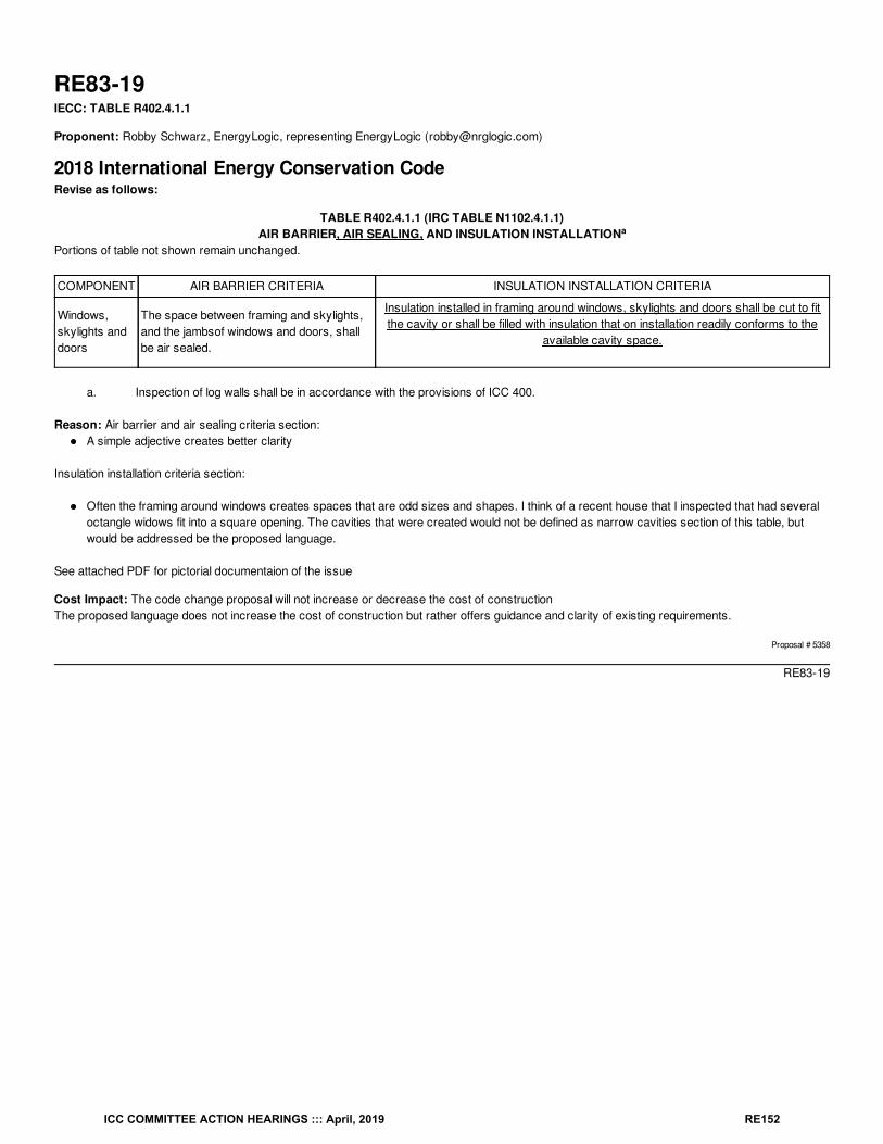
RE83-19IECC: TABLE R402.4.1.1
Proponent: Robby Schwarz, EnergyLogic, representing EnergyLogic ([email protected])
2018 International Energy Conservation CodeRevise as follows:
TABLE R402.4.1.1 (IRC TABLE N1102.4.1.1)AIR BARRIER, AIR SEALING, AND INSULATION INSTALLATION
Portions of table not shown remain unchanged.
COMPONENT AIR BARRIER CRITERIA INSULATION INSTALLATION CRITERIA
Windows,skylights anddoors
The space between framing and skylights,and the jambsof windows and doors, shallbe air sealed.
Insulation installed in framing around windows, skylights and doors shall be cut to fitthe cavity or shall be filled with insulation that on installation readily conforms to the
available cavity space.
a. Inspection of log walls shall be in accordance with the provisions of ICC 400.
Reason: Air barrier and air sealing criteria section:A simple adjective creates better clarity
Insulation installation criteria section:
Often the framing around windows creates spaces that are odd sizes and shapes. I think of a recent house that I inspected that had severaloctangle widows fit into a square opening. The cavities that were created would not be defined as narrow cavities section of this table, butwould be addressed be the proposed language.
See attached PDF for pictorial documentaion of the issue
Cost Impact: The code change proposal will not increase or decrease the cost of constructionThe proposed language does not increase the cost of construction but rather offers guidance and clarity of existing requirements.
Proposal # 5358
RE83-19
a
ICC COMMITTEE ACTION HEARINGS ::: April, 2019 RE152
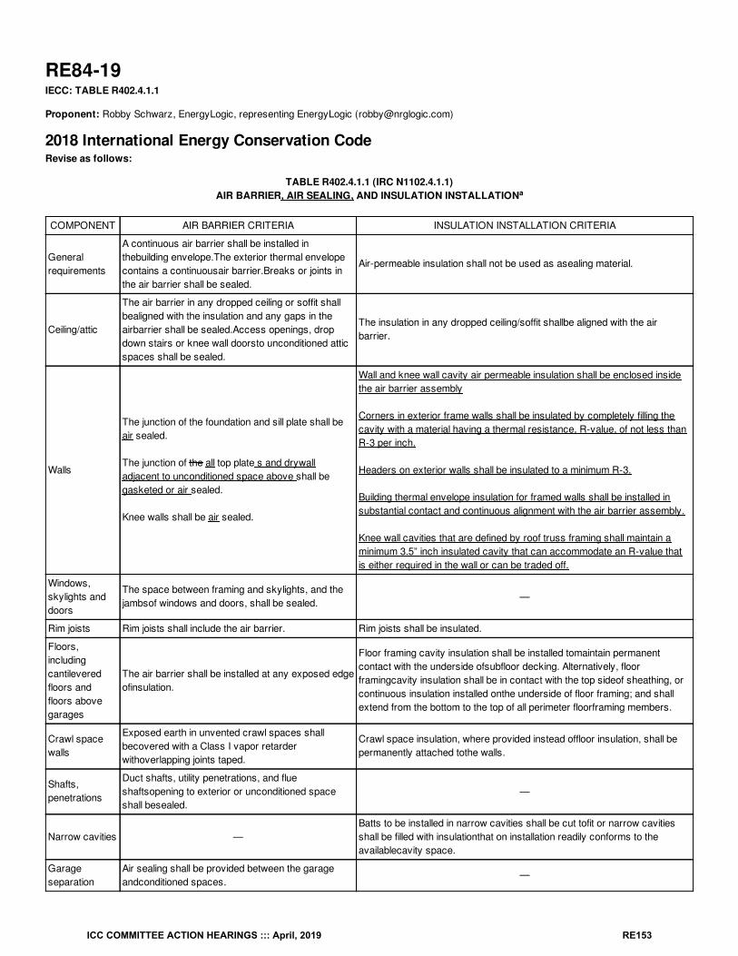
RE84-19IECC: TABLE R402.4.1.1
Proponent: Robby Schwarz, EnergyLogic, representing EnergyLogic ([email protected])
2018 International Energy Conservation CodeRevise as follows:
TABLE R402.4.1.1 (IRC N1102.4.1.1)AIR BARRIER, AIR SEALING, AND INSULATION INSTALLATION
COMPONENT AIR BARRIER CRITERIA INSULATION INSTALLATION CRITERIA
Generalrequirements
A continuous air barrier shall be installed inthebuilding envelope.The exterior thermal envelopecontains a continuousair barrier.Breaks or joints inthe air barrier shall be sealed.
Air-permeable insulation shall not be used as asealing material.
Ceiling/attic
The air barrier in any dropped ceiling or soffit shallbealigned with the insulation and any gaps in theairbarrier shall be sealed.Access openings, dropdown stairs or knee wall doorsto unconditioned atticspaces shall be sealed.
The insulation in any dropped ceiling/soffit shallbe aligned with the airbarrier.
Walls
The junction of the foundation and sill plate shall beair sealed.
The junction of the all top plate s and drywalladjacent to unconditioned space above shall begasketed or air sealed.
Knee walls shall be air sealed.
Wall and knee wall cavity air permeable insulation shall be enclosed insidethe air barrier assembly
Corners in exterior frame walls shall be insulated by completely filling thecavity with a material having a thermal resistance, R-value, of not less thanR-3 per inch.
Headers on exterior walls shall be insulated to a minimum R-3.
Building thermal envelope insulation for framed walls shall be installed insubstantial contact and continuous alignment with the air barrier assembly.
Knee wall cavities that are defined by roof truss framing shall maintain aminimum 3.5” inch insulated cavity that can accommodate an R-value thatis either required in the wall or can be traded off.
Windows,skylights anddoors
The space between framing and skylights, and thejambsof windows and doors, shall be sealed.
—
Rim joists Rim joists shall include the air barrier. Rim joists shall be insulated.
Floors,includingcantileveredfloors andfloors abovegarages
The air barrier shall be installed at any exposed edgeofinsulation.
Floor framing cavity insulation shall be installed tomaintain permanentcontact with the underside ofsubfloor decking. Alternatively, floorframingcavity insulation shall be in contact with the top sideof sheathing, orcontinuous insulation installed onthe underside of floor framing; and shallextend from the bottom to the top of all perimeter floorframing members.
Crawl spacewalls
Exposed earth in unvented crawl spaces shallbecovered with a Class I vapor retarderwithoverlapping joints taped.
Crawl space insulation, where provided instead offloor insulation, shall bepermanently attached tothe walls.
Shafts,penetrations
Duct shafts, utility penetrations, and flueshaftsopening to exterior or unconditioned spaceshall besealed.
—
Narrow cavities —Batts to be installed in narrow cavities shall be cut tofit or narrow cavitiesshall be filled with insulationthat on installation readily conforms to theavailablecavity space.
Garageseparation
Air sealing shall be provided between the garageandconditioned spaces.
—
a
ICC COMMITTEE ACTION HEARINGS ::: April, 2019 RE153
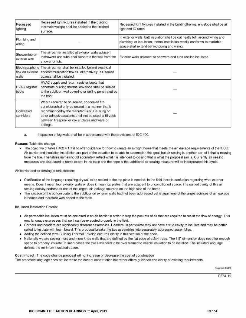
Recessedlighting
Recessed light fixtures installed in the buildingthermalenvelope shall be sealed to the finishedsurface.
Recessed light fixtures installed in the buildingthermal envelope shall be airtight and IC rated.
Plumbing andwiring
—In exterior walls, batt insulation shall be cut neatly tofit around wiring andplumbing, or insulation, thaton installation readily conforms to availablespace,shall extend behind piping and wiring.
Shower/tub onexterior wall
The air barrier installed at exterior walls adjacenttoshowers and tubs shall separate the wall from theshower or tub.
Exterior walls adjacent to showers and tubs shallbe insulated.
Electrical/phonebox on exteriorwalls
The air barrier shall be installed behind electricalandcommunication boxes. Alternatively, air-sealedboxesshall be installed.
—
HVAC registerboots
HVAC supply and return register boots thatpenetrate building thermal envelope shall be sealedto the subfloor, wall covering or ceiling penetrated bythe boot.
—
Concealedsprinklers
Where required to be sealed, concealed firesprinklersshall only be sealed in a manner that isrecommendedby the manufacturer. Caulking orother adhesivesealants shall not be used to fill voidsbetween firesprinkler cover plates and walls orceilings.
—
a. Inspection of log walls shall be in accordance with the provisions of ICC 400.
Reason: Table title changeThe objective of table R402.4.1.1 is to offer guidance for how to create an air tight home that meets the air leakage requirements of the IECC.Air barrier and insulation installation are part of the equation to be able to accomplish this goal, but air sealing is another part of it that is missingfrom the title. The tables name should accurately reflect what it is intended to do and that is what the proposal aim is. Currently air sealingmeasures are discussed to some extent in the table and the hope is that additional air sealing measure will be incorporated this cycle.
Air barrier and air sealing criteria section:
Clarification of the language requiring drywall to be sealed to the top plate is needed. In the field there is confusion regarding what exteriormeans. Does it mean four exterior walls or does it mean top plates that are adjacent to unconditioned space. The gained clarity of this airsealing activity addresses one of the largest air leakage sources on the high side of the home.The junction of the bottom plate to the subfloor on exterior walls had not been addressed yet is again one of the larges sources of air leakagein homes and therefore was added to the table.
Insulation Installation Criteria:
Air permeable insulation must be enclosed in an air barrier in order to trap the pockets of air that are required to resist the flow of energy. Thisnew language expresses that so it can be executed properly in the field.Corners and headers are significantly different assemblies. Headers, in particulate may not have a true cavity to insulate and may be bettersuited to insulate with foam board. This proposal breaks the two assemblies into separately addressed assemblies.Adding the defined term Building Thermal Envelop ensures clarity in this section of the code.Nationally we are seeing more and more knee walls that are defined by the flat edge of a 2x4 truss. The 1.5” dimension does not offer enoughspace to properly insulate. In such cases the truss will need to be over framed to enable insulation to be installed. The included languagedefines the minimum insulated space.
Cost Impact: The code change proposal will not increase or decrease the cost of constructionThe proposed language does not increase the cost of construction but rather offers guidance and clarity of existing requirements.
Proposal # 5350
RE84-19
ICC COMMITTEE ACTION HEARINGS ::: April, 2019 RE154
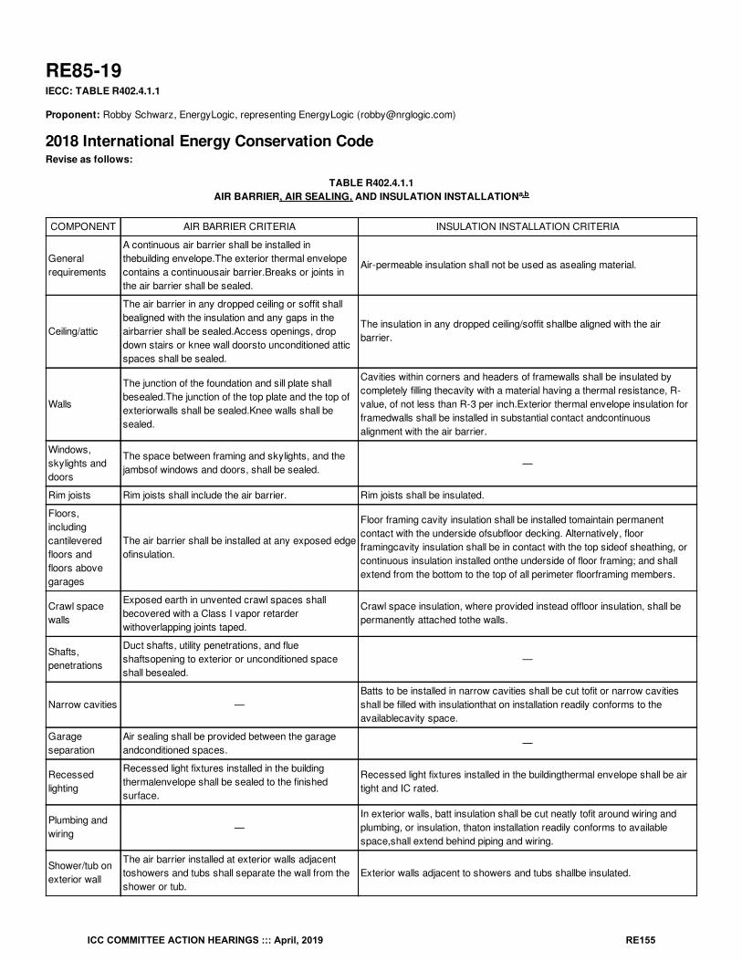
RE85-19IECC: TABLE R402.4.1.1
Proponent: Robby Schwarz, EnergyLogic, representing EnergyLogic ([email protected])
2018 International Energy Conservation CodeRevise as follows:
TABLE R402.4.1.1AIR BARRIER, AIR SEALING, AND INSULATION INSTALLATION
COMPONENT AIR BARRIER CRITERIA INSULATION INSTALLATION CRITERIA
Generalrequirements
A continuous air barrier shall be installed inthebuilding envelope.The exterior thermal envelopecontains a continuousair barrier.Breaks or joints inthe air barrier shall be sealed.
Air-permeable insulation shall not be used as asealing material.
Ceiling/attic
The air barrier in any dropped ceiling or soffit shallbealigned with the insulation and any gaps in theairbarrier shall be sealed.Access openings, dropdown stairs or knee wall doorsto unconditioned atticspaces shall be sealed.
The insulation in any dropped ceiling/soffit shallbe aligned with the airbarrier.
Walls
The junction of the foundation and sill plate shallbesealed.The junction of the top plate and the top ofexteriorwalls shall be sealed.Knee walls shall besealed.
Cavities within corners and headers of framewalls shall be insulated bycompletely filling thecavity with a material having a thermal resistance, R-value, of not less than R-3 per inch.Exterior thermal envelope insulation forframedwalls shall be installed in substantial contact andcontinuousalignment with the air barrier.
Windows,skylights anddoors
The space between framing and skylights, and thejambsof windows and doors, shall be sealed.
—
Rim joists Rim joists shall include the air barrier. Rim joists shall be insulated.
Floors,includingcantileveredfloors andfloors abovegarages
The air barrier shall be installed at any exposed edgeofinsulation.
Floor framing cavity insulation shall be installed tomaintain permanentcontact with the underside ofsubfloor decking. Alternatively, floorframingcavity insulation shall be in contact with the top sideof sheathing, orcontinuous insulation installed onthe underside of floor framing; and shallextend from the bottom to the top of all perimeter floorframing members.
Crawl spacewalls
Exposed earth in unvented crawl spaces shallbecovered with a Class I vapor retarderwithoverlapping joints taped.
Crawl space insulation, where provided instead offloor insulation, shall bepermanently attached tothe walls.
Shafts,penetrations
Duct shafts, utility penetrations, and flueshaftsopening to exterior or unconditioned spaceshall besealed.
—
Narrow cavities —Batts to be installed in narrow cavities shall be cut tofit or narrow cavitiesshall be filled with insulationthat on installation readily conforms to theavailablecavity space.
Garageseparation
Air sealing shall be provided between the garageandconditioned spaces.
—
Recessedlighting
Recessed light fixtures installed in the buildingthermalenvelope shall be sealed to the finishedsurface.
Recessed light fixtures installed in the buildingthermal envelope shall be airtight and IC rated.
Plumbing andwiring
—In exterior walls, batt insulation shall be cut neatly tofit around wiring andplumbing, or insulation, thaton installation readily conforms to availablespace,shall extend behind piping and wiring.
Shower/tub onexterior wall
The air barrier installed at exterior walls adjacenttoshowers and tubs shall separate the wall from theshower or tub.
Exterior walls adjacent to showers and tubs shallbe insulated.
a,b
ICC COMMITTEE ACTION HEARINGS ::: April, 2019 RE155
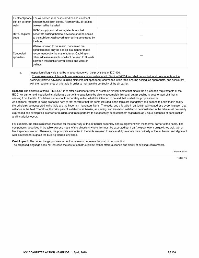
Electrical/phonebox on exteriorwalls
The air barrier shall be installed behind electricalandcommunication boxes. Alternatively, air-sealedboxesshall be installed.
—
HVAC registerboots
HVAC supply and return register boots thatpenetrate building thermal envelope shall be sealedto the subfloor, wall covering or ceiling penetrated bythe boot.
—
Concealedsprinklers
Where required to be sealed, concealed firesprinklersshall only be sealed in a manner that isrecommendedby the manufacturer. Caulking orother adhesivesealants shall not be used to fill voidsbetween firesprinkler cover plates and walls orceilings.
—
a. Inspection of log walls shall be in accordance with the provisions of ICC 400.b.The requirements of this table are mandatory in accordance with Section R402.4 and shall be applied to all components of thebuilding’s thermal envelope. Building elements not specifically addressed in the table shall be sealed, as appropriate, and consistentwith the requirements of this table in order to maintain the continuity of the air barrier.
Reason: The objective of table R402.4.1.1 is to offer guidance for how to create an air tight home that meets the air leakage requirements of theIECC. Air barrier and insulation installation are part of the equation to be able to accomplish this goal, but air sealing is another part of it that ismissing from the title. The tables name should accurately reflect what it is intended to do and that is what the proposal aim is.An additional footnote is being proposed here to first reiterate that the items included in this table are mandatory and second to show that in realitythe principals demonstrated in the table are the important mandatory items. The code, and this table in particular cannot address every situation thatwill arise in the field. Therefore, the principals of installation air barrier, air sealing, and insulation installation demonstrated in the table must be clearlyexpressed and exemplified in order for builders and trade partners to successfully executed them regardless as unique instances of constructionand installation occur.
For example, the table reinforces the need for the continuity of the air barrier assembly and its alignment with the thermal barrier of the home. Thecomponents described in the table express many of the situations where this must be executed but it can’t explain every unique knee wall, tub, orfire fireplace surround. Therefore, the principals embodies in the table are used to successfully execute the continuity of the air barrier and alignmentwith insulation throughout the building thermal envelope.
Cost Impact: The code change proposal will not increase or decrease the cost of constructionThe proposed language does not increase the cost of construction but rather offers guidance and clarity of existing requirements.
Proposal # 5342
RE85-19
ICC COMMITTEE ACTION HEARINGS ::: April, 2019 RE156
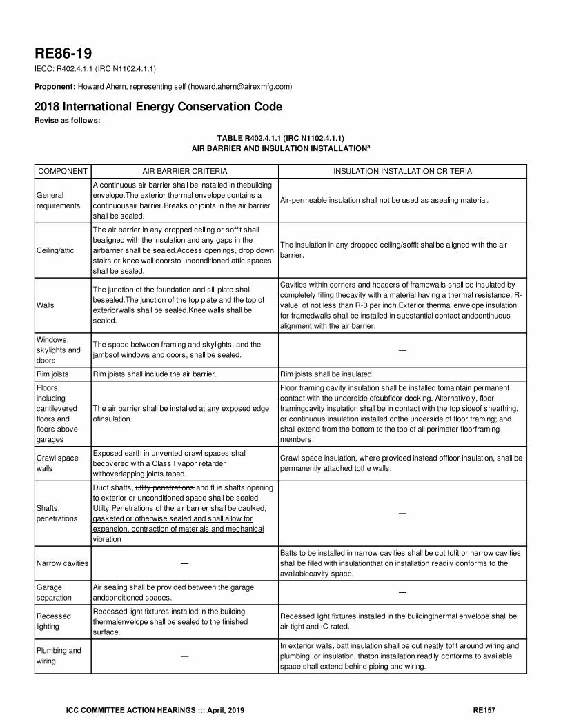
RE86-19IECC: R402.4.1.1 (IRC N1102.4.1.1)
Proponent: Howard Ahern, representing self ([email protected])
2018 International Energy Conservation CodeRevise as follows:
TABLE R402.4.1.1 (IRC N1102.4.1.1)AIR BARRIER AND INSULATION INSTALLATION
COMPONENT AIR BARRIER CRITERIA INSULATION INSTALLATION CRITERIA
Generalrequirements
A continuous air barrier shall be installed in thebuildingenvelope.The exterior thermal envelope contains acontinuousair barrier.Breaks or joints in the air barriershall be sealed.
Air-permeable insulation shall not be used as asealing material.
Ceiling/attic
The air barrier in any dropped ceiling or soffit shallbealigned with the insulation and any gaps in theairbarrier shall be sealed.Access openings, drop downstairs or knee wall doorsto unconditioned attic spacesshall be sealed.
The insulation in any dropped ceiling/soffit shallbe aligned with the airbarrier.
Walls
The junction of the foundation and sill plate shallbesealed.The junction of the top plate and the top ofexteriorwalls shall be sealed.Knee walls shall besealed.
Cavities within corners and headers of framewalls shall be insulated bycompletely filling thecavity with a material having a thermal resistance, R-value, of not less than R-3 per inch.Exterior thermal envelope insulationfor framedwalls shall be installed in substantial contact andcontinuousalignment with the air barrier.
Windows,skylights anddoors
The space between framing and skylights, and thejambsof windows and doors, shall be sealed.
—
Rim joists Rim joists shall include the air barrier. Rim joists shall be insulated.
Floors,includingcantileveredfloors andfloors abovegarages
The air barrier shall be installed at any exposed edgeofinsulation.
Floor framing cavity insulation shall be installed tomaintain permanentcontact with the underside ofsubfloor decking. Alternatively, floorframingcavity insulation shall be in contact with the top sideof sheathing,or continuous insulation installed onthe underside of floor framing; andshall extend from the bottom to the top of all perimeter floorframingmembers.
Crawl spacewalls
Exposed earth in unvented crawl spaces shallbecovered with a Class I vapor retarderwithoverlapping joints taped.
Crawl space insulation, where provided instead offloor insulation, shall bepermanently attached tothe walls.
Shafts,penetrations
Duct shafts, utlity penetrations and flue shafts openingto exterior or unconditioned space shall be sealed.Utilty Penetrations of the air barrier shall be caulked,gasketed or otherwise sealed and shall allow forexpansion, contraction of materials and mechanicalvibration
—
Narrow cavities —Batts to be installed in narrow cavities shall be cut tofit or narrow cavitiesshall be filled with insulationthat on installation readily conforms to theavailablecavity space.
Garageseparation
Air sealing shall be provided between the garageandconditioned spaces.
—
Recessedlighting
Recessed light fixtures installed in the buildingthermalenvelope shall be sealed to the finishedsurface.
Recessed light fixtures installed in the buildingthermal envelope shall beair tight and IC rated.
Plumbing andwiring
—In exterior walls, batt insulation shall be cut neatly tofit around wiring andplumbing, or insulation, thaton installation readily conforms to availablespace,shall extend behind piping and wiring.
a
ICC COMMITTEE ACTION HEARINGS ::: April, 2019 RE157
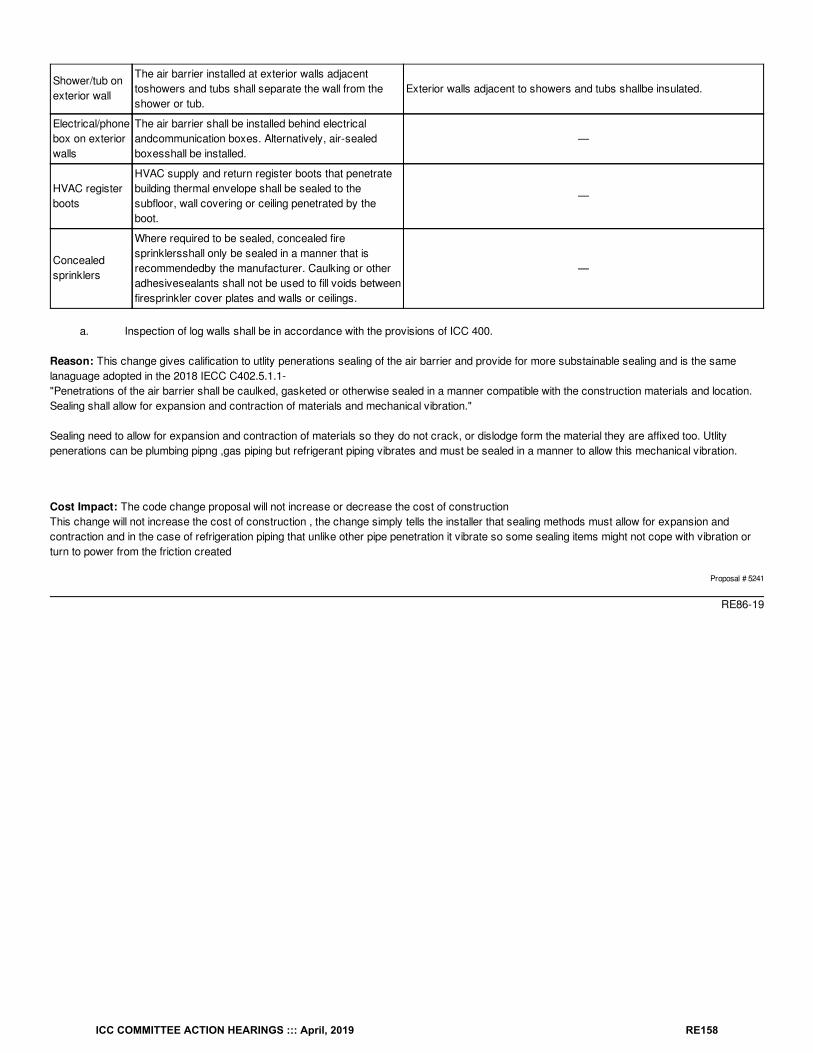
Shower/tub onexterior wall
The air barrier installed at exterior walls adjacenttoshowers and tubs shall separate the wall from theshower or tub.
Exterior walls adjacent to showers and tubs shallbe insulated.
Electrical/phonebox on exteriorwalls
The air barrier shall be installed behind electricalandcommunication boxes. Alternatively, air-sealedboxesshall be installed.
—
HVAC registerboots
HVAC supply and return register boots that penetratebuilding thermal envelope shall be sealed to thesubfloor, wall covering or ceiling penetrated by theboot.
—
Concealedsprinklers
Where required to be sealed, concealed firesprinklersshall only be sealed in a manner that isrecommendedby the manufacturer. Caulking or otheradhesivesealants shall not be used to fill voids betweenfiresprinkler cover plates and walls or ceilings.
—
a. Inspection of log walls shall be in accordance with the provisions of ICC 400.
Reason: This change gives calification to utlity penerations sealing of the air barrier and provide for more substainable sealing and is the samelanaguage adopted in the 2018 IECC C402.5.1.1- "Penetrations of the air barrier shall be caulked, gasketed or otherwise sealed in a manner compatible with the construction materials and location.Sealing shall allow for expansion and contraction of materials and mechanical vibration."
Sealing need to allow for expansion and contraction of materials so they do not crack, or dislodge form the material they are affixed too. Utlitypenerations can be plumbing pipng ,gas piping but refrigerant piping vibrates and must be sealed in a manner to allow this mechanical vibration.
Cost Impact: The code change proposal will not increase or decrease the cost of constructionThis change will not increase the cost of construction , the change simply tells the installer that sealing methods must allow for expansion andcontraction and in the case of refrigeration piping that unlike other pipe penetration it vibrate so some sealing items might not cope with vibration orturn to power from the friction created
Proposal # 5241
RE86-19
ICC COMMITTEE ACTION HEARINGS ::: April, 2019 RE158
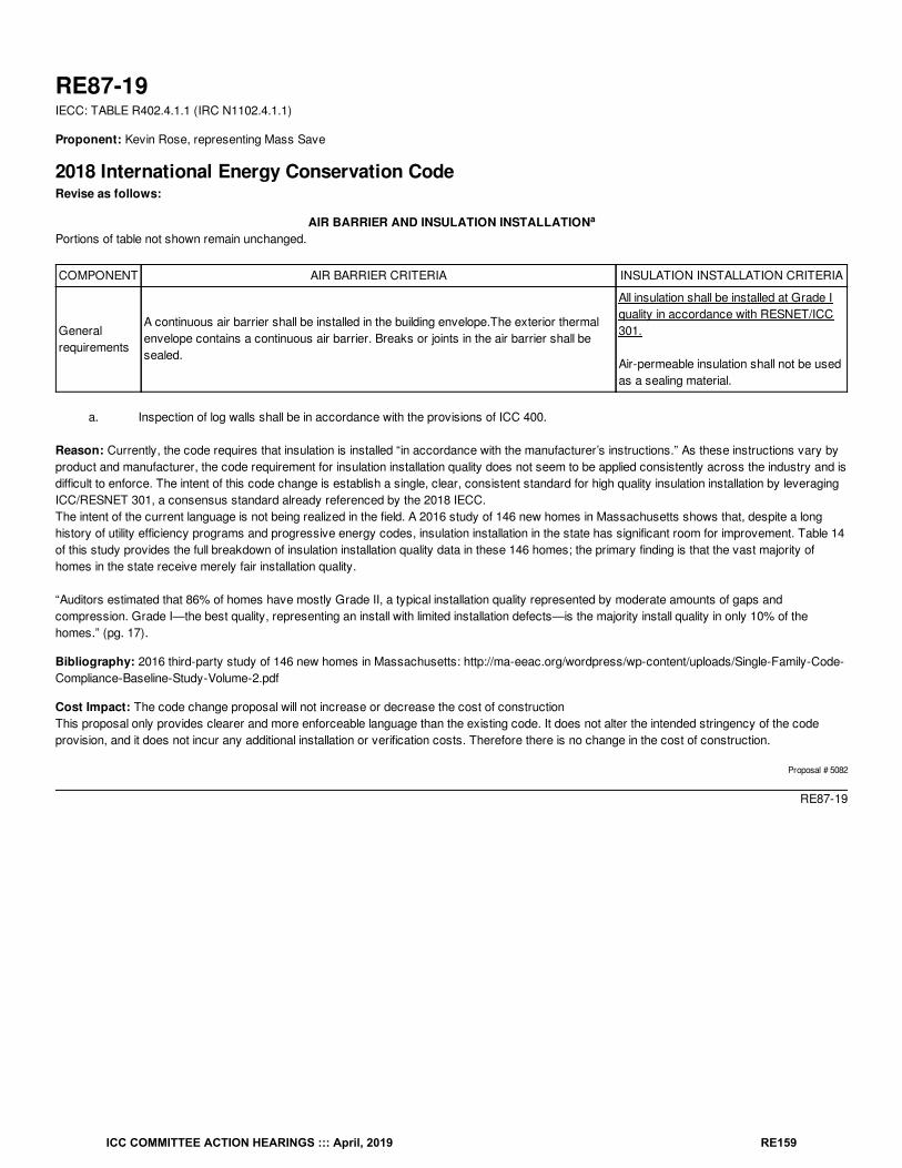
RE87-19IECC: TABLE R402.4.1.1 (IRC N1102.4.1.1)
Proponent: Kevin Rose, representing Mass Save
2018 International Energy Conservation CodeRevise as follows:
AIR BARRIER AND INSULATION INSTALLATIONPortions of table not shown remain unchanged.
COMPONENT AIR BARRIER CRITERIA INSULATION INSTALLATION CRITERIA
Generalrequirements
A continuous air barrier shall be installed in the building envelope.The exterior thermalenvelope contains a continuous air barrier. Breaks or joints in the air barrier shall besealed.
All insulation shall be installed at Grade Iquality in accordance with RESNET/ICC301.
Air-permeable insulation shall not be usedas a sealing material.
a. Inspection of log walls shall be in accordance with the provisions of ICC 400.
Reason: Currently, the code requires that insulation is installed “in accordance with the manufacturer’s instructions.” As these instructions vary byproduct and manufacturer, the code requirement for insulation installation quality does not seem to be applied consistently across the industry and isdifficult to enforce. The intent of this code change is establish a single, clear, consistent standard for high quality insulation installation by leveragingICC/RESNET 301, a consensus standard already referenced by the 2018 IECC.The intent of the current language is not being realized in the field. A 2016 study of 146 new homes in Massachusetts shows that, despite a longhistory of utility efficiency programs and progressive energy codes, insulation installation in the state has significant room for improvement. Table 14of this study provides the full breakdown of insulation installation quality data in these 146 homes; the primary finding is that the vast majority ofhomes in the state receive merely fair installation quality.
“Auditors estimated that 86% of homes have mostly Grade II, a typical installation quality represented by moderate amounts of gaps andcompression. Grade I—the best quality, representing an install with limited installation defects—is the majority install quality in only 10% of thehomes.” (pg. 17).
Bibliography: 2016 third-party study of 146 new homes in Massachusetts: http://ma-eeac.org/wordpress/wp-content/uploads/Single-Family-Code-Compliance-Baseline-Study-Volume-2.pdf
Cost Impact: The code change proposal will not increase or decrease the cost of constructionThis proposal only provides clearer and more enforceable language than the existing code. It does not alter the intended stringency of the codeprovision, and it does not incur any additional installation or verification costs. Therefore there is no change in the cost of construction.
Proposal # 5082
RE87-19
a
ICC COMMITTEE ACTION HEARINGS ::: April, 2019 RE159
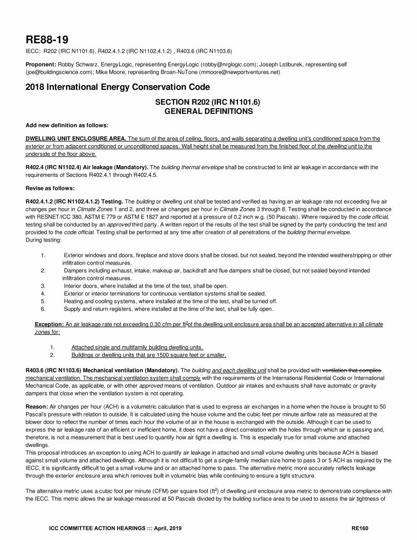
RE88-19IECC: R202 (IRC N1101.6), R402.4.1.2 (IRC N1102.4.1.2) , R403.6 (IRC N1103.6)
Proponent: Robby Schwarz, EnergyLogic, representing EnergyLogic ([email protected]); Joseph Lstiburek, representing self([email protected]); Mike Moore, representing Broan-NuTone ([email protected])
2018 International Energy Conservation Code
SECTION R202 (IRC N1101.6) GENERAL DEFINITIONS
Add new definition as follows:
DWELLING UNIT ENCLOSURE AREA. The sum of the area of ceiling, floors, and walls separating a dwelling unit’s conditioned space from theexterior or from adjacent conditioned or unconditioned spaces. Wall height shall be measured from the finished floor of the dwelling unit to theunderside of the floor above.
R402.4 (IRC N1102.4) Air leakage (Mandatory). The building thermal envelope shall be constructed to limit air leakage in accordance with therequirements of Sections R402.4.1 through R402.4.5.
Revise as follows:
R402.4.1.2 (IRC N1102.4.1.2) Testing. The building or dwelling unit shall be tested and verified as having an air leakage rate not exceeding five airchanges per hour in Climate Zones 1 and 2, and three air changes per hour in Climate Zones 3 through 8. Testing shall be conducted in accordancewith RESNET/ICC 380, ASTM E 779 or ASTM E 1827 and reported at a pressure of 0.2 inch w.g. (50 Pascals). Where required by the code official,testing shall be conducted by an approved third party. A written report of the results of the test shall be signed by the party conducting the test andprovided to the code official. Testing shall be performed at any time after creation of all penetrations of the building thermal envelope.During testing:
1. Exterior windows and doors, fireplace and stove doors shall be closed, but not sealed, beyond the intended weatherstripping or otherinfiltration control measures.
2. Dampers including exhaust, intake, makeup air, backdraft and flue dampers shall be closed, but not sealed beyond intendedinfiltration control measures.
3. Interior doors, where installed at the time of the test, shall be open.4. Exterior or interior terminations for continuous ventilation systems shall be sealed.5. Heating and cooling systems, where installed at the time of the test, shall be turned off.6. Supply and return registers, where installed at the time of the test, shall be fully open.
Exception: An air leakage rate not exceeding 0.30 cfm per ft of the dwelling unit enclosure area shall be an accepted alternative in all climatezones for:
1. Attached single and multifamily building dwelling units.2. Buildings or dwelling units that are 1500 square feet or smaller.
R403.6 (IRC N1103.6) Mechanical ventilation (Mandatory). The building and each dwelling unit shall be provided with ventilation that compliesmechanical ventilation. The mechanical ventilation system shall comply with the requirements of the International Residential Code or InternationalMechanical Code, as applicable, or with other approved means of ventilation. Outdoor air intakes and exhausts shall have automatic or gravitydampers that close when the ventilation system is not operating.
Reason: Air changes per hour (ACH) is a volumetric calculation that is used to express air exchanges in a home when the house is brought to 50Pascal’s pressure with relation to outside. It is calculated using the house volume and the cubic feet per minute airflow rate as measured at theblower door to reflect the number of times each hour the volume of air in the house is exchanged with the outside. Although it can be used toexpress the air leakage rate of an efficient or inefficient home, it does not have a direct correlation with the holes through which air is passing and,therefore, is not a measurement that is best used to quantify how air tight a dwelling is. This is especially true for small volume and attacheddwellings.This proposal introduces an exception to using ACH to quantify air leakage in attached and small volume dwelling units because ACH is biasedagainst small volume and attached dwellings. Although it is not difficult to get a single-family median size home to pass 3 or 5 ACH as required by theIECC, it is significantly difficult to get a small volume and or an attached home to pass. The alternative metric more accurately reflects leakagethrough the exterior enclosure area which removes built in volumetric bias while continuing to ensure a tight structure.
The alternative metric uses a cubic foot per minute (CFM) per square foot (ft ) of dwelling unit enclosure area metric to demonstrate compliance withthe IECC. This metric allows the air leakage measured at 50 Pascals divided by the building surface area to be used to assess the air tightness of
2
2
2
ICC COMMITTEE ACTION HEARINGS ::: April, 2019 RE160
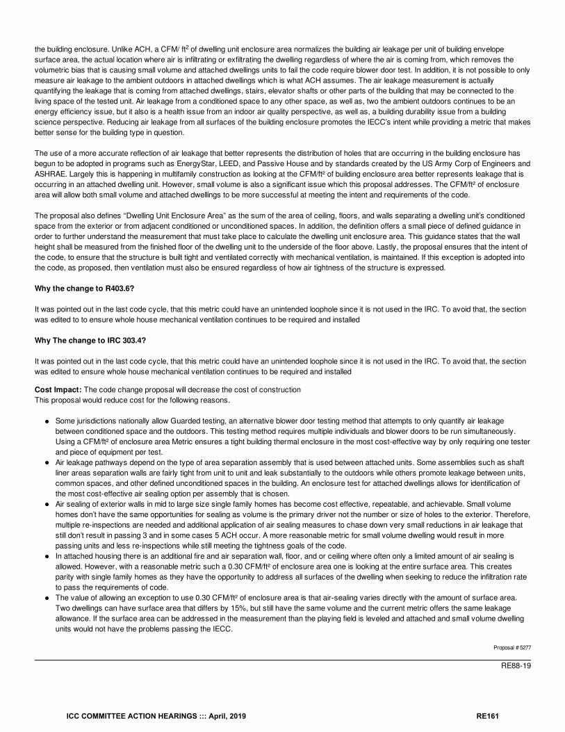
the building enclosure. Unlike ACH, a CFM/ ft of dwelling unit enclosure area normalizes the building air leakage per unit of building envelopesurface area, the actual location where air is infiltrating or exfiltrating the dwelling regardless of where the air is coming from, which removes thevolumetric bias that is causing small volume and attached dwellings units to fail the code require blower door test. In addition, it is not possible to onlymeasure air leakage to the ambient outdoors in attached dwellings which is what ACH assumes. The air leakage measurement is actuallyquantifying the leakage that is coming from attached dwellings, stairs, elevator shafts or other parts of the building that may be connected to theliving space of the tested unit. Air leakage from a conditioned space to any other space, as well as, two the ambient outdoors continues to be anenergy efficiency issue, but it also is a health issue from an indoor air quality perspective, as well as, a building durability issue from a buildingscience perspective. Reducing air leakage from all surfaces of the building enclosure promotes the IECC’s intent while providing a metric that makesbetter sense for the building type in question.
The use of a more accurate reflection of air leakage that better represents the distribution of holes that are occurring in the building enclosure hasbegun to be adopted in programs such as EnergyStar, LEED, and Passive House and by standards created by the US Army Corp of Engineers andASHRAE. Largely this is happening in multifamily construction as looking at the CFM/ft² of building enclosure area better represents leakage that isoccurring in an attached dwelling unit. However, small volume is also a significant issue which this proposal addresses. The CFM/ft² of enclosurearea will allow both small volume and attached dwellings to be more successful at meeting the intent and requirements of the code.
The proposal also defines “Dwelling Unit Enclosure Area” as the sum of the area of ceiling, floors, and walls separating a dwelling unit’s conditionedspace from the exterior or from adjacent conditioned or unconditioned spaces. In addition, the definition offers a small piece of defined guidance inorder to further understand the measurement that must take place to calculate the dwelling unit enclosure area. This guidance states that the wallheight shall be measured from the finished floor of the dwelling unit to the underside of the floor above. Lastly, the proposal ensures that the intent ofthe code, to ensure that the structure is built tight and ventilated correctly with mechanical ventilation, is maintained. If this exception is adopted intothe code, as proposed, then ventilation must also be ensured regardless of how air tightness of the structure is expressed.
Why the change to R403.6?
It was pointed out in the last code cycle, that this metric could have an unintended loophole since it is not used in the IRC. To avoid that, the sectionwas edited to to ensure whole house mechanical ventilation continues to be required and installed
Why The change to IRC 303.4?
It was pointed out in the last code cycle, that this metric could have an unintended loophole since it is not used in the IRC. To avoid that, the sectionwas edited to ensure whole house mechanical ventilation continues to be required and installed
Cost Impact: The code change proposal will decrease the cost of constructionThis proposal would reduce cost for the following reasons.
Some jurisdictions nationally allow Guarded testing, an alternative blower door testing method that attempts to only quantify air leakagebetween conditioned space and the outdoors. This testing method requires multiple individuals and blower doors to be run simultaneously.Using a CFM/ft² of enclosure area Metric ensures a tight building thermal enclosure in the most cost-effective way by only requiring one testerand piece of equipment per test.Air leakage pathways depend on the type of area separation assembly that is used between attached units. Some assemblies such as shaftliner areas separation walls are fairly tight from unit to unit and leak substantially to the outdoors while others promote leakage between units,common spaces, and other defined unconditioned spaces in the building. An enclosure test for attached dwellings allows for identification ofthe most cost-effective air sealing option per assembly that is chosen.Air sealing of exterior walls in mid to large size single family homes has become cost effective, repeatable, and achievable. Small volumehomes don’t have the same opportunities for sealing as volume is the primary driver not the number or size of holes to the exterior. Therefore,multiple re-inspections are needed and additional application of air sealing measures to chase down very small reductions in air leakage thatstill don’t result in passing 3 and in some cases 5 ACH occur. A more reasonable metric for small volume dwelling would result in morepassing units and less re-inspections while still meeting the tightness goals of the code.In attached housing there is an additional fire and air separation wall, floor, and or ceiling where often only a limited amount of air sealing isallowed. However, with a reasonable metric such a 0.30 CFM/ft² of enclosure area one is looking at the entire surface area. This createsparity with single family homes as they have the opportunity to address all surfaces of the dwelling when seeking to reduce the infiltration rateto pass the requirements of code.The value of allowing an exception to use 0.30 CFM/ft² of enclosure area is that air-sealing varies directly with the amount of surface area.Two dwellings can have surface area that differs by 15%, but still have the same volume and the current metric offers the same leakageallowance. If the surface area can be addressed in the measurement than the playing field is leveled and attached and small volume dwellingunits would not have the problems passing the IECC.
Proposal # 5277
RE88-19
2
ICC COMMITTEE ACTION HEARINGS ::: April, 2019 RE161
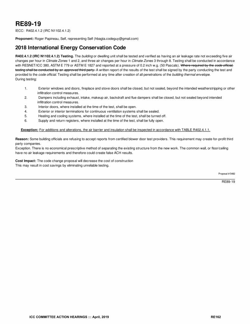
RE89-19IECC: R402.4.1.2 (IRC N1102.4.1.2)
Proponent: Roger Papineau, Self, representing Self ([email protected])
2018 International Energy Conservation CodeR402.4.1.2 (IRC N1102.4.1.2) Testing. The building or dwelling unit shall be tested and verified as having an air leakage rate not exceeding five airchanges per hour in Climate Zones 1 and 2, and three air changes per hour in Climate Zones 3 through 8. Testing shall be conducted in accordancewith RESNET/ICC 380, ASTM E 779 or ASTM E 1827 and reported at a pressure of 0.2 inch w.g. (50 Pascals). Where required by the code official,testing shall be conducted by an approved third party. A written report of the results of the test shall be signed by the party conducting the test andprovided to the code official. Testing shall be performed at any time after creation of all penetrations of the building thermal envelope.During testing:
1. Exterior windows and doors, fireplace and stove doors shall be closed, but not sealed, beyond the intended weatherstripping or otherinfiltration control measures.
2. Dampers including exhaust, intake, makeup air, backdraft and flue dampers shall be closed, but not sealed beyond intendedinfiltration control measures.
3. Interior doors, where installed at the time of the test, shall be open.4. Exterior or interior terminations for continuous ventilation systems shall be sealed.5. Heating and cooling systems, where installed at the time of the test, shall be turned off.6. Supply and return registers, where installed at the time of the test, shall be fully open.
Exception: For additions and alterations, the air barrier and insulation shall be inspected in accordance with TABLE R402.4.1.1.
Reason: Some building officials are refusing to accept reports from certified blower door test providers. This requirement may create for-profit thirdparty companies.Exception. There is no economical prescriptive method of separating the existing structure from the new work. The common wall, or floor/ceilinghave no air leakage requirements and therefore could create false ACH results.
Cost Impact: The code change proposal will decrease the cost of constructionThis may result in cost savings by eliminating unreliable testing.
Proposal # 5482
RE89-19
ICC COMMITTEE ACTION HEARINGS ::: April, 2019 RE162
RE90-19IECC: R202 (IRC N1101.6) , R402.4.1.2 (IRC N1102.4.1.2) , R403.6 (IRC N1102.6)
Proponent: Robby Schwarz, EnergyLogic, representing EnergyLogic ([email protected]); Joseph Lstiburek, representing self([email protected]); Mike Moore, representing Broan-NuTone ([email protected])
2018 International Energy Conservation Code
SECTION R202 (IRC N1101.6) GENERAL DEFINITIONS
Add new definition as follows:
DWELLING UNIT ENCLOSURE AREA. The sum of the area of ceiling, floors, and walls separating a dwelling unit’s conditioned space from theexterior or from adjacent conditioned or unconditioned spaces. Wall height shall be measured from the finished floor of the dwelling unit to theunderside of the floor above.
Revise as follows:
R402.4.1.2 (IRC N1102.4.1.2) Testing. The building or dwelling unit shall be tested and verified as having an air leakage rate not exceeding five airchanges per hour or 0.28 cubic feet per minute (CFM) per square foot (ft ) of dwelling unit enclosure area in Climate Zones 1 and 2, and three airchanges per hour or 0.17 CFM per (ft ) of dwelling unit enclosure area in Climate Zones 3 through 8. Testing shall be conducted in accordance withRESNET/ICC 380, ASTM E 779 or ASTM E 1827 and reported at a pressure of 0.2 inch w.g. (50 Pascals). Where required by the code official,testing shall be conducted by an approved third party. A written report of the results of the test shall be signed by the party conducting the test andprovided to the code official. Testing shall be performed at any time after creation of all penetrations of the building thermal envelope.During testing:
1. Exterior windows and doors, fireplace and stove doors shall be closed, but not sealed, beyond the intended weatherstripping or otherinfiltration control measures.
2. Dampers including exhaust, intake, makeup air, backdraft and flue dampers shall be closed, but not sealed beyond intendedinfiltration control measures.
3. Interior doors, where installed at the time of the test, shall be open.4. Exterior or interior terminations for continuous ventilation systems shall be sealed.5. Heating and cooling systems, where installed at the time of the test, shall be turned off.6. Supply and return registers, where installed at the time of the test, shall be fully open.
R403.6 (IRC N1102.6) Mechanical ventilation (Mandatory). The building and each dwelling unit shall be provided with ventilation that compliesmechanical ventilation. The mechanical ventilation system shall comply with the requirements of the International Residential Code or InternationalMechanical Code, as applicable, or with other approved means of ventilation. Outdoor air intakes and exhausts shall have automatic or gravitydampers that close when the ventilation system is not operating.
Reason: Air changes per hour (ACH) is a volumetric metric that is useful for air quality measurements in buildings but is not the correct expressionof air leakage from an energy or building durability perspective. This proposal introduces the ability to use an alternative cubic foot per minute (CFM)per square foot (ft ) of dwelling unit enclosure area metric for measuring air leakage in a building. In this way, the air leakage measured at 50Pascals divided by the building surface area is used to assess the airtightness of the construction and building envelope. Unlike ACH, a CFM/ ft ofdwelling unit enclosure area metric normalizes the building air leakage per unit of building envelope surface area; the actual location where air isinfiltrating or exfiltrating the building. To this end, the proposal also defines “Dwelling Unit Enclosure Area” as the sum of the area of ceiling, floors,and walls separating a dwelling unit’s conditioned space from the exterior or from adjacent conditioned or unconditioned spaces. In addition, thedefinition offers guidance to further understand the measurement that must take place to calculate the dwelling unit enclosure area. This guidancestates that the wall height shall be measured from the finished floor of the dwelling unit to the underside of the floor above. Lastly, the proposalensures that the intent of the code, to ensure that the structure is built tight and ventilated correctly with mechanical ventilation, is maintained. If anadditional option is adopted into the code, as proposed, then ventilation must also be ensured regardless of how air tightness of the structure isexpressed.Since 1980, The Energy Conservatory, has not only been a leader in air leakage science, but also one of the prominent manufacturers of the blowerdoor air measurement tool. In their article, “Which Is A Better Metric For Measuring Airtightness: ACH @ 50 Pa Or CFM/ Ft² Of Surface Area @ 50Pa?”, which is adapted and added to in this reason statement, we get the basis of the argument for the introduction of a new metric into theInternational Energy Conservation Code for the measurement of air leakage.
To paraphrase, when measuring the airtightness of a building the objective is to learn how much leakage is occurring across the building’s enclosurearea. It is analogous to moisture permeability or the measurement of moisture across the building’s enclosure area and thermal transmittance, therate at which heat is transferred across the building enclosure area. The rate of air leakage or tightness does not depend on the volume of thestructure as defined by the building’s enclosure area but does depend on the holes associated with the surface area of the structure. Air
2
2
2
2
ICC COMMITTEE ACTION HEARINGS ::: April, 2019 RE163
permeability of a material is typically measured as the flow per area at a given pressure difference across the material. U value measurements aresimilar. If we want a metric to use to measure the airtightness quality of construction of the exterior enclosure of buildings it makes sense to use ametric that equates flow to the size and number of holes in the building’s thermal enclosure.
The article continues with an example to help demonstrate how volume is not proportional to surface area:
Comparison between ACH50 and CFM50/ft² for a 2000 ft² home at 3 ACH50
House Is 50 X 40 X 8
Volume = 16,000 ft³
Surface Area = 50 X 40 X 2 + 180 X 8 = 5440 ft²
CFM50 = (3 X 16000)/60 = 800 CFM
CFM50/ft2 = 800/5440 = 0.147 CFM50/ft²
Increase height to 2 story at 3 ACH50
House Is 50 X 40 X 16 Volume = 32,000 ft³
Surface area = 50 X 40 X 2 + 180 X 16 = 6880 ft²
CFM50 = (3 X 32000)/60 = 1600 cfm
CFM50/ft2 = 1600/6880 = 0.233 CFM50/ft²
In this example, when the volume is doubled, the surface area increased by 26%. And when the ACH50 stays the same, the CFM/ ft² of surfacearea increased by 58%. I have attached an Excel spreadsheet calculator that further defines the disconnect between ACH and CFM/ ft² of surfacearea to further elaborate the issue. In the attached calculator you can change the ratio of width and length of the building to see the effect on theresulting expressions of air leakage. An independent yet similar calculator can be found at this Residential Energy Dynamic linkhttp://www.residentialenergydynamics.com/REDCalcFree/Tools/AirLeakageMetrics
The primary purpose of this code change proposal is to introduce the CFM/ft² of surface area metric into the code. Deciding on where to set theminimum allowable leakage rate is difficult largely due to the earlier volume and surface area discussion. Both tests are performed at a pressuredifferential of 0.2 inch water gauge (50 Pa), which is a the traditional residential testing pressure so an attempt was made to align the introduction of aCFM/ft² of surface area metric with the existing ACH50 matric of 3 and 5 air changes per hour. ACH being a volumetric measurement penalizedsmall volume dwelling units so a decision was made to concentrate on a size range of dwellings between 2500 and 5500 square feet. By doing thisand using the attached conditioned floor space to shell area calculator we were able to see that little variation occurred between ACH and CFM/ft² ofsurface area metric when changing the size ratio of the modeled house within this house size range. By rounding up, the proposal is using .17CFM/ft² of surface area metric to align with 3 ACH and .28 CFM/ft² of surface area metric to align with 5 ACH. By using these numbers, smallvolume homes, while not having a volumetric penalty, are allowed to be a little more leaky and large volume homes must achieve just about thesame level of tightness if not a slight bit more. As the average home size in the United States is approximately just less than 2500 square feet thiscode change proposals purpose of introducing a better measurement metric without removing the codes traditional measurement methodology,provid additional flexibility while maintaining similar stringency.
The Energy Conservatory suggests that the use of Air Changes per Hour at 50 Pa (ACH50) started approximately 60 years ago by researcherswho were interested in ways to predict the natural infiltration rate of buildings, which at the time was most commonly measured in Air Changes perHour. At the time air quality in buildings was being studied and the metric made sense. If a pollutant is released in a building, the time for theconcentration to decay by a certain percentage depends on the infiltration measured in air changes per hour. The analysis of a tracer gas decaytest gives a result in air changes per hour. So, when they started measuring airtightness, for use in estimating natural infiltration in air changes perhour, it made sense to use ACH50 as the metric.
However, as discussed earlier, two homes with the same volume can have very different surface areas and holes associated with the buildingenclosure area.
ICC COMMITTEE ACTION HEARINGS ::: April, 2019 RE164
Value is gained by including a surface area-based metric in that air-sealing varies directly with the amount of surface area not the amount of volumein the dwelling. Two buildings can have surface areas that differs by 15%, but have the same volume and the current metric offers the same leakageallowance. Therefore, if the purpose of measuring air leakage is to determine something about the construction quality, air leakage rate, energyefficiency and building durability the metric should be associated with the flow of air through holes in the enclosure. To quantify these things ACH isthe wrong metric. It does not tell you anything about the quantity and air leakage through holes in the building. Conversely, the CFM/ ft² of surfacearea metric concretely expresses the quantity of air leakage throught the building’s exterior enclosure. When an enclosure is tight more energy isconserved as well as allowing better control and predictability of air flow, thermal flow, and moisture flow.
Many standards are now using square foot of enclosure area instead of ACH. Examples include EnergyStar, US Army Corp of Engineers, LEED,US Passive House and ASHRAE 62.2. This proposal is the first step to bring this better expression of air leakage into the code. It has been createdin such a way that options are maintained allowing jurisdictions and building professionals flexibility in defining air leakage requirements.
Link to Energy Conservatory article from which portions of this reason statement have been added:
https://support.energyconservatory.com/hc/en-us/articles/204176240-Which-is-a-better-metric-for-measuring-airtightness-ACH-50-Pa-or-CFM-ft-of-surface-area-50-Pa-
Why the change to R403.6?
It was pointed out in the last code cycle, that this metric could have an unintended loophole since it is not used in the IRC. To avoid that, the sectionwas edited to to ensure whole house mechanical ventilation continues to be required and installed
Why The change to IRC 303.4?
It was pointed out in the last code cycle, that this metric could have an unintended loophole since it is not used in the IRC. To avoid that, the sectionwas edited to ensure whole house mechanical ventilation continues to be required and installed. In a companion change RB71-19, I have proposedchanges to IRC R303.4 as a correlary to this change in the IECC.
Cost Impact: The code change proposal will not increase or decrease the cost of constructionThere should be no cost implication associated with the adoption of this proposed language. Dwellings will continue to need to be tested and testingprices will not change due to an additional option for how to express the results of the test.
Proposal # 5276
RE90-19
ICC COMMITTEE ACTION HEARINGS ::: April, 2019 RE165
RE91-19IIECC: R202 (IRC N1101.6), R402.4.1.2 (IRC N1102.4.1.2), R403.6 (IRC N1103.6)
Proponent: Gayathri Vijayakumar, Steven Winter Associates, Inc., representing Steven Winter Associates, Inc. ([email protected]); JosephLstiburek, Building Science Corporation, representing self ([email protected]); Joel Martell, NAHB, representing NAHB ([email protected]);Robby Schwarz, EnergyLogic, representing EnergyLogic ([email protected]); Mike Moore, Newport Ventures, representing Broan-NuTone([email protected])
2018 International Energy Conservation Code
SECTION R202 (IRC N1101.6) GENERAL DEFINITIONS
DWELLING UNIT. A single unit providing complete independent living facilities for one or more persons, including permanent provisions for living,sleeping, eating, cooking and sanitation.
RESIDENTIAL BUILDING. For this code, includes detached one- and two-family dwellings and townhouses as well as Group R-2, R-3 and R-4buildings three stories or less in height above grade plane.
Add new definition as follows:
DWELLING UNIT ENCLOSURE AREA. The sum of the areas of the walls, floors, ceilings, and any other building element assemblies thatenclose the conditioned space of the dwelling unit or provide a boundary between the conditioned space of the dwelling unit and exterior or adjacentconditioned or unconditioned spaces.
R402.4 (IRC N1102.4) Air leakage (Mandatory). The building thermal envelope shall be constructed to limit air leakage in accordance with therequirements of Sections R402.4.1 through R402.4.5.
R402.4.1 (IRC N1102.4.1) Building thermal envelope. The building thermal envelope shall comply with Sections R402.4.1.1 and R402.4.1.2. Thesealing methods between dissimilar materials shall allow for differential expansion and contraction.
Revise as follows:
R402.4.1.2 (IRC N1102.4.1.2) Testing. The building or dwelling unit shall be tested and verified as having an air leakage rate not exceeding five airchanges per hour in Climate Zones 1 and 2, and three air changes per hour in Climate Zones 3 through 8. Testing shall be conducted in accordancewith RESNET/ICC 380, ASTM E 779 or ASTM E 1827 and reported at a pressure of 0.2 inch w.g. (50 Pascals).
Exception: For dwelling units other than detached one-family dwellings, an air leakage rate not exceeding 0.3 cfm per ft of the dwelling unitenclosure area shall be an accepted alternative in all Climate Zones . Testing shall be conducted in accordance with ANSI/RESNET/ICC 380,ASTM E779 or ASTM E1827 and reported at a pressure of 0.2 inch w.g. (50 Pascals).
Where required by the code official, testing shall be conducted by an approved third party. A written report of the results of the test shall be signedby the party conducting the test and provided to the code official. Testing shall be performed at any time after creation of all penetrations of thebuilding thermal envelope.
During testing:
1. Exterior windows and doors, fireplace and stove doors shall be closed, but not sealed, beyond the intended weatherstripping or otherinfiltration control measures.
2. Dampers including exhaust, intake, makeup air, backdraft and flue dampers shall be closed, but not sealed beyond intendedinfiltration control measures.
3. Interior doors, where installed at the time of the test, shall be open.4. Exterior or interior terminations for continuous ventilation systems shall be sealed.5. Heating and cooling systems, where installed at the time of the test, shall be turned off.6. Supply and return registers, where installed at the time of the test, shall be fully open.
R403.6 (IRC N1103.6) Mechanical ventilation (Mandatory). The building Each dwelling unit shall be provided with ventilation that compliesmechanical ventilation. The mechanical ventilation system shall comply with the requirements of the International Residential Code or InternationalMechanical Code , as applicable, or with other approved means of ventilation. Outdoor air intakes and exhausts shall have automatic or gravitydampers that close when the ventilation system is not operating.
Reason: Why allow a different metric than ACH50?A surface area based metric is more appropriate than a volume based metric since air-sealing varies directly with the amount of surface area.Depending on the floor plan, two apartments can have total surface area that differ by 15-25%, but still have the same volume and floor area. The
2
ICC COMMITTEE ACTION HEARINGS ::: April, 2019 RE166
current volume-based metric (3 or 5 ACH50) results in the same maximum air leakage allowed for these two different apartments, yet oneapartment has significantly more surface area which to seal, making it inherently more difficult to achieve compliance. While this logic holds true fordetached homes as well, in this proposal, this metric is being proposed for attached units only. Other proposals have been submitted to propose thismetric for detached homes as well.
Is this cfm50/ft2 metric used anywhere else?
The metric proposed in this "Exception" has been successfully used in above-code multifamily programs since 2005 (ENERGY STAR MultifamilyHigh Rise, LEED, and Passive House). It is also used in the Commercial provisions of IECC (C402.5), but at 75 Pa instead of 50 Pa. Forcomparison, 0.3 cfm50/ ft2 of dwelling unit enclosure area proposed here is the same as the commercial requirements for EXTERIOR envelope (0.4cfm75/ft2), but this proposal requires it on ALL surfaces of the apartment enclosure, resulting in dwelling units that are individually sealed as tight asa commercial building's exterior envelope.
Will this create a challenge for code officials or individuals conducting the tests?
This metric is already reported on many air leakage reports that code officials receive today, so there is no change in reporting or effort inconducting the tests. Testing results are measured in CFM50, not ACH50. This CFM50 test value is translated into multiple metrics, and just aseasily can be translated to CFM50/ft2 as ACH50.
Will this result in more efficient buildings?
While many focus on air leakage to the outdoors, air leakage within a multifamily building also results in energy losses. Conditioned air can leakto/from a dwelling unit to another vacant (unconditioned) unit, or the unheated stairwell or elevator shaft, the non conditioned corridor, or laundryroom.
This proposal seeks to provide a reasonable alternative metric that will encourage builders to air seal and test successfully at the dwelling unit levelinstead of testing at the building level and potentially missing significant leakage pathways within the building that cause energy loss. Testing at thedwelling unit will result in tighter dwelling units and in the process, tighter buildings.
Why the change to R403.6?
It was pointed out in the last code cycle, that this metric could have an unintended loophole since it is not used in the IRC. To avoid that, the sectionwas edited to avoid any potential loophole.
Cost Impact: The code change proposal will not increase or decrease the cost of constructionSince this metric is simply an alternative to the current dwelling unit tests allowed, there is no change in costs.
Proposal # 4640
RE91-19
ICC COMMITTEE ACTION HEARINGS ::: April, 2019 RE167
RE92-19IECC: SECTION R202, (New), R402.4, R402.4.1.2, SECTION R403, R403.6
Proponent: Robby Schwarz, EnergyLogic, representing EnergyLogic ([email protected])
2018 International Energy Conservation Code
SECTION R202 (IRC N1101.6) GENERAL DEFINITIONS
Add new text as follows:
DWELLING UNIT ENCLOSURE AREA. The sum of the area of ceiling, floors, and walls separating a dwelling unit’s conditioned space from theexterior or from adjacent conditioned or unconditioned spaces. Wall height shall be measured from the finished floor of the dwelling unit to theunderside of the floor above.
Revise as follows:
R402.4 (IRC N1101.6) Air leakage (Mandatory). The building thermal envelope shall be constructed to limit air leakage in accordance with therequirements of Sections R402.4.1 through R402.4.5.
R402.4.1.2 (IRC N1102.4.1.2) Testing. The building or dwelling unit shall be tested and verified as having an air leakage rate not exceeding five airchanges per hour or 0.28 cubic feet per minute (CFM) per square foot (ft ) of dwelling unit enclosure area in Climate Zones 1 and 2, and three airchanges per hour or 0.17 CFM per (ft ) of dwelling unit enclosure area in in Climate Zones 3 through 8. Testing shall be conducted in accordancewith RESNET/ICC 380, ASTM E 779 or ASTM E 1827 and reported at a pressure of 0.2 inch w.g. (50 Pascals). Where required by the code official,testing shall be conducted by an approved third party. A written report of the results of the test shall be signed by the party conducting the test andprovided to the code official. Testing shall be performed at any time after creation of all penetrations of the building thermal envelope.During testing:
1. Exterior windows and doors, fireplace and stove doors shall be closed, but not sealed, beyond the intended weatherstripping or otherinfiltration control measures.
2. Dampers including exhaust, intake, makeup air, backdraft and flue dampers shall be closed, but not sealed beyond intendedinfiltration control measures.
3. Interior doors, where installed at the time of the test, shall be open.4. Exterior or interior terminations for continuous ventilation systems shall be sealed.5. Heating and cooling systems, where installed at the time of the test, shall be turned off.6. Supply and return registers, where installed at the time of the test, shall be fully open.
SECTION R403 (IRC N1103) SYSTEMS
R403.6 (IRC N1103.6) Mechanical ventilation (Mandatory). The building Each dwelling unit shall be provided with mechanical ventilation thatcomplies . The mechanical ventilation system shall comply with the requirements of the International Residential Code or International MechanicalCode , as applicable, or with other approved means of ventilation. Outdoor air intakes and exhausts shall have automatic or gravity dampers thatclose when the ventilation system is not operating.
Reason: Air changes per hour (ACH) is a volumetric metric that is useful for air quality measurements in buildings but is not the correct expressionof air leakage from an energy or building durability perspective. This proposal introduces the ability to use an alternative cubic foot per minute (CFM)per square foot (ft ) of dwelling unit enclosure area metric for measuring air leakage in a building. In this way, the air leakage measured at 50Pascals divided by the building surface area is used to assess the airtightness of the construction and building envelope. Unlike ACH, a CFM/ ft ofdwelling unit enclosure area metric normalizes the building air leakage per unit of building envelope surface area; the actual location where air isinfiltrating or exfiltrating the building. To this end, the proposal also defines “Dwelling Unit Enclosure Area” as the sum of the area of ceiling, floors,and walls separating a dwelling unit’s conditioned space from the exterior or from adjacent conditioned or unconditioned spaces. In addition, thedefinition offers guidance to further understand the measurement that must take place to calculate the dwelling unit enclosure area. This guidancestates that the wall height shall be measured from the finished floor of the dwelling unit to the underside of the floor above. Lastly, the proposalensures that the intent of the code, to ensure that the structure is built tight and ventilated correctly with mechanical ventilation, is maintained. If anadditional option is adopted into the code, as proposed, then ventilation must also be ensured regardless of how air tightness of the structure isexpressed.Since 1980, The Energy Conservatory, has not only been a leader in air leakage science, but also one of the prominent manufacturers of the blowerdoor air measurement tool. In their article, “Which Is A Better Metric For Measuring Airtightness: ACH @ 50 Pa Or CFM/ Ft² Of Surface Area @ 50Pa?”, which is adapted and added to in this reason statement, we get the basis of the argument for the introduction of a new metric into theInternational Energy Conservation Code for the measurement of air leakage.
2
2
2
2
ICC COMMITTEE ACTION HEARINGS ::: April, 2019 RE168
To paraphrase, when measuring the airtightness of a building the objective is to learn how much leakage is occurring across the building’s enclosurearea. It is analogous to moisture permeability or the measurement of moisture across the building’s enclosure area and thermal transmittance, therate at which heat is transferred across the building enclosure area. The rate of air leakage or tightness does not depend on the volume of thestructure as defined by the building’s enclosure area but does depend on the holes associated with the surface area of the structure. Airpermeability of a material is typically measured as the flow per area at a given pressure difference across the material. U value measurements aresimilar. If we want a metric to use to measure the airtightness quality of construction of the exterior enclosure of buildings it makes sense to use ametric that equates flow to the size and number of holes in the building’s thermal enclosure.
The article continues with an example to help demonstrate how volume is not proportional to surface area:
Comparison between ACH50 and CFM50/ft² for a 2000 ft² home at 3 ACH50
House Is 50 X 40 X 8
Volume = 16,000 ft³
Surface Area = 50 X 40 X 2 + 180 X 8 = 5440 ft²
CFM50 = (3 X 16000)/60 = 800 CFM
CFM50/ft2 = 800/5440 = 0.147 CFM50/ft²
Increase height to 2 story at 3 ACH50
House Is 50 X 40 X 16 Volume = 32,000 ft³
Surface area = 50 X 40 X 2 + 180 X 16 = 6880 ft²
CFM50 = (3 X 32000)/60 = 1600 cfm
CFM50/ft2 = 1600/6880 = 0.233 CFM50/ft²
In this example, when the volume is doubled, the surface area increased by 26%. And when the ACH50 stays the same, the CFM/ ft² of surfacearea increased by 58%. I have attached an Excel spreadsheet calculator that further defines the disconnect between ACH and CFM/ ft² of surfacearea to further elaborate the issue. In the attached calculator you can change the ratio of width and length of the building to see the effect on theresulting expressions of air leakage. An independent yet similar calculator can be found at this Residential Energy Dynamic linkhttp://www.residentialenergydynamics.com/REDCalcFree/Tools/AirLeakageMetrics
The primary purpose of this code change proposal is to introduce the CFM/ft² of surface area metric into the code. Deciding on where to set theminimum allowable leakage rate is difficult largely due to the earlier volume and surface area discussion. Both tests are performed at a pressuredifferential of 0.2 inch water gauge (50 Pa), which is a the traditional residential testing pressure so an attempt was made to align the introduction of aCFM/ft² of surface area metric with the existing ACH50 matric of 3 and 5 air changes per hour. ACH being a volumetric measurement penalizedsmall volume dwelling units so a decision was made to concentrate on a size range of dwellings between 2500 and 5500 square feet. By doing thisand using the attached conditioned floor space to shell area calculator we were able to see that little variation occurred between ACH and CFM/ft² ofsurface area metric when changing the size ratio of the modeled house within this house size range. By rounding up, the proposal is using .17CFM/ft² of surface area metric to align with 3 ACH and .28 CFM/ft² of surface area metric to align with 5 ACH. By using these numbers, smallvolume homes, while not having a volumetric penalty, are allowed to be a little more leaky and large volume homes must achieve just about thesame level of tightness if not a slight bit more. As the average home size in the United States is approximately just less than 2500 square feet thiscode change proposals purpose of introducing a better measurement metric without removing the codes traditional measurement methodology,provid additional flexibility while maintaining similar stringency.
The Energy Conservatory suggests that the use of Air Changes per Hour at 50 Pa (ACH50) started approximately 60 years ago by researcherswho were interested in ways to predict the natural infiltration rate of buildings, which at the time was most commonly measured in Air Changes perHour. At the time air quality in buildings was being studied and the metric made sense. If a pollutant is released in a building, the time for theconcentration to decay by a certain percentage depends on the infiltration measured in air changes per hour. The analysis of a tracer gas decaytest gives a result in air changes per hour. So, when they started measuring airtightness, for use in estimating natural infiltration in air changes perhour, it made sense to use ACH50 as the metric.
However, as discussed earlier, two homes with the same volume can have very different surface areas and holes associated with the building
ICC COMMITTEE ACTION HEARINGS ::: April, 2019 RE169
enclosure area.
Value is gained by including a surface area-based metric in that air-sealing varies directly with the amount of surface area not the amount of volumein the dwelling. Two buildings can have surface areas that differs by 15%, but have the same volume and the current metric offers the same leakageallowance. Therefore, if the purpose of measuring air leakage is to determine something about the construction quality, air leakage rate, energyefficiency and building durability the metric should be associated with the flow of air through holes in the enclosure. To quantify these things ACH isthe wrong metric. It does not tell you anything about the quantity and air leakage through holes in the building. Conversely, the CFM/ ft² of surfacearea metric concretely expresses the quantity of air leakage throught the building’s exterior enclosure. When an enclosure is tight more energy isconserved as well as allowing better control and predictability of air flow, thermal flow, and moisture flow.
Many standards are now using square foot of enclosure area instead of ACH. Examples include EnergyStar, US Army Corp of Engineers, LEED,US Passive House and ASHRAE 62.2. This proposal is the first step to bring this better expression of air leakage into the code. It has been createdin such a way that options are maintained allowing jurisdictions and building professionals flexibility in defining air leakage requirements.
Link to Energy Conservatory article from which portions of this reason statement have been added:
https://support.energyconservatory.com/hc/en-us/articles/204176240-Which-is-a-better-metric-for-measuring-airtightness-ACH-50-Pa-or-CFM-ft-of-surface-area-50-Pa-
Cost Impact: The code change proposal will not increase or decrease the cost of constructionThere should be no cost implication associated with the adoption of this proposed language. Dwellings will continue to need to be tested and testingprices will not change due to an additional option for how to express the results of the test.
Proposal # 4783
RE92-19
ICC COMMITTEE ACTION HEARINGS ::: April, 2019 RE170
RE93-19IECC: R402.4.1.2 (IRC N1102.4.1.2)
Proponent: Aaron Gary, representing Self ([email protected])
2018 International Energy Conservation CodeRevise as follows:
R402.4.1.2 (IRC N1102.4.1.2) Testing. The building or dwelling unit shall be tested and verified as having an air leakage rate not exceeding five airchanges per hour , or 0.32 cfm/ft of enclosure bounding the dwelling for dwellings 1,600 square feet or less, in Climate Zones 1 and 2, and three airchanges per hour , or 0.23 cfm/ft of enclosure bounding the dwelling for dwellings 1,600 square feet or less, in Climate Zones 3 through 8. Testingshall be conducted in accordance with RESNET/ICC 380, ASTM E 779 or ASTM E 1827 and reported at a pressure of 0.2 inch w.g. (50 Pascals).Where required by the code official, testing shall be conducted by an approved third party. A written report of the results of the test shall be signedby the party conducting the test and provided to the code official. Testing shall be performed at any time after creation of all penetrations of thebuilding thermal envelope.During testing:
1. Exterior windows and doors, fireplace and stove doors shall be closed, but not sealed, beyond the intended weatherstripping or otherinfiltration control measures.
2. Dampers including exhaust, intake, makeup air, backdraft and flue dampers shall be closed, but not sealed beyond intendedinfiltration control measures.
3. Interior doors, where installed at the time of the test, shall be open.4. Exterior or interior terminations for continuous ventilation systems shall be sealed.5. Heating and cooling systems, where installed at the time of the test, shall be turned off.6. Supply and return registers, where installed at the time of the test, shall be fully open.
Reason: All homes and apartments are required to be built tight. What is the most appropriate measurement of tightness is open for debate evenwithin the Code where the metric is dependent on which section being referenced. The different metrics are important though because none of themare perfect and some are more applicable to one building type or another. For example, we believe that small homes and apartments are penalizedby the ACH metric. A home that is 1600 sq. feet vs. a home that is 3,000 sq. feet can have the same level of attention to detail regarding the airsealing of a home, yet due to the decreased volume of the smaller home, the smaller dwelling will have a much harder time meeting it’s ACH target.When volume is the deciding factor in the air leakage, this will always be the case. This built-in bias for larger homes with the ACH metric is becausethe ratio of surface area of the envelope (or walls bounding the dwelling) to the volume is not a linear relationship. Further the number of penetrationsrequired by Code that can not be sealed effectively (exhaust ducts, mechanical ventilation intakes, fire-sprinkler penetrations, etc.) and theinstances of penetrations that result in inadvertent leakage (plumbing penetrations, electrical penetrations, windows, doors, etc.) may be similar for asmall dwelling as a large dwelling. For example: A house that is 1,000 square feet or 6,000 square feet will most often have one kitchen with all itsassociated openings and penetrations.The infiltration metric we are proposing is derived from the ACH equivalencies accepted in ICC 700-2020 (which is currently in its first PublicComment). We are proposing that this equivalency only be accepted for dwellings under 1,600 sq. ft. though because 1) we believe the smalldwellings are the ones being penalized by the ACH metric and 2) this leakage metric would result is less stringent leakage targets at larger dwellingvolumes.
Cost Impact: The code change proposal will not increase or decrease the cost of constructionThis code change will decrease the cost of construction for dwellings under 1600 sq. ft. by setting a air leakage target that is meaningul andachievable.
Proposal # 4564
RE93-19
2
2
ICC COMMITTEE ACTION HEARINGS ::: April, 2019 RE171
RE94-19IECC: R402.4.1.3 (IRC N1102.4.1.3) (New)
Proponent: Robert Schwarz, representing EnergyLogic ([email protected])
2018 International Energy Conservation CodeR402.4 Air leakage (Mandatory). The building thermal envelope shall be constructed to limit air leakage in accordance with the requirements ofSections R402.4.1 through R402.4.5.
R402.4.1.2 Testing. The building or dwelling unit shall be tested and verified as having an air leakage rate not exceeding five air changes per hour inClimate Zones 1 and 2, and three air changes per hour in Climate Zones 3 through 8. Testing shall be conducted in accordance with RESNET/ICC380, ASTM E 779 or ASTM E 1827 and reported at a pressure of 0.2 inch w.g. (50 Pascals). Where required by the code official, testing shall beconducted by an approved third party. A written report of the results of the test shall be signed by the party conducting the test and provided to thecode official. Testing shall be performed at any time after creation of all penetrations of the building thermal envelope.During testing:
1. Exterior windows and doors, fireplace and stove doors shall be closed, but not sealed, beyond the intended weatherstripping or otherinfiltration control measures.
2. Dampers including exhaust, intake, makeup air, backdraft and flue dampers shall be closed, but not sealed beyond intendedinfiltration control measures.
3. Interior doors, where installed at the time of the test, shall be open.4. Exterior or interior terminations for continuous ventilation systems shall be sealed.5. Heating and cooling systems, where installed at the time of the test, shall be turned off.6. Supply and return registers, where installed at the time of the test, shall be fully open.
Add new text as follows:
R402.4.1.3 (IRC N1102.4.1.3) Testing Garage Separation. The integrity of the air barrier assembly between dwelling units and attached garagesshall pass a two-part test.
1. While conducting the air leakage test as described in Section R402.4.1.2 the air barrier separation between the house and the garage shall betested to ensure that the house in reference to the garage is ≥ 45 Pascals of pressure when the house is held at 50 Pascals of pressure inrelation to outside. All operable garage openings to the outside shall be closed during the test.
2. If test number 1 passes, the test shall be performed a second time with the garage vehicle door open to the ambient outside. The two testresults shall not differ by more than 6 percent.
Reason: The energy code, like all code, is about health, safety, comfort, durability, as well as efficiency. The garage is the largest potential sourceof pollutants and carbon monoxide in the house and it has been codified in table R402.4.1.1 to ensure that the air in the garage is separated from thehouse. Air from an attached garage can enter the living space of the home if there are bypasses in the air barrier between the two spaces and if thehome is at a negative pressure with respect to the garage. Negative pressures may be due to natural forces or to mechanical depressurization ofthe house with respect to the garage caused by appliances like rangehood fans, clothes dryers, bath fans, crawlspace ventilation or whole houseventilation systems, as well as, unbalanced HVAC systems. Unfortunately, there is no way to be sure that separation has been achieved, in thislocation, unless the separation is tested. Fortunately testing for separation between the house and garage is simple and is made even more practicaldue to the requirement to blower door test for every home.The surest way to keep garage pollutants out of the house is to build a detached garage. Since most houses are designed with attached garages,planning ahead of construction to make sure a continuous air barrier is installed between the house and the garage makes sense. This proposal willpromote such planning.
To ensure that there is not a false positive result Building America research has determined that the test requires two steps. First, while the house isat 50 Pascals of pressure with regards to outside during the blower door test a zonal pressure test is performed by installing a tube between thehouse and the garage. (Usually under the door between the house and the garage) If the garage is clearly outside, the measurement between thehouse and the garage should also be 50 Pascals of pressure. The closer the measurement is to zero the more connected the garage is to thehouse. This code proposal requires that the results of the first test be ≥ 45 pascals which is an indication that the air barrier assembly between thehouse and garage is sound. The first test is performed when all openings between the garage and the outside are closed. Second, this test isrepeated with the overhead vehicle door open. If the results of the second test are greater than 6% the connection between the house and thegarage tests fails. The rationale for the second test is to guard against false positive results that can occur while performing the first test.
If we continue to require separation between the house and the garage from an energy efficiency perspective, we must also test to ensure it from ahealth and safety perspective in order to maintain the intent of the IECC. Programs such as the EPA Indoor Air Plus and the DOE Zero EnergyReady Home program have incorporated the protocol described above to test for this separation. In addition, Jurisdictions around the country, suchas Fort Collins Colorado have amended the IECC to require this test as they realize the energy and health and safety implications.
ICC COMMITTEE ACTION HEARINGS ::: April, 2019 RE172
People have asked if garage separation is really an issue. Past research, as pointed out in the Building America Program research paper titled “AirLeakage and Air Transfer between Garage and Living Space” says yes. An excerpt of a study done by S.J. Emmerich used in the Building Americapaper, reports that polluted garage air infiltrated into living quarters was as much as 45% of total house infiltration. See the attached research paperfor more evidence of carbon monoxide and other pollutants traveling between attached garages and the house and the bibliography of numerousstudies that have documented that pollutants from the garage are capable of migrating into the house.
The problem is that one cannot know for sure if the garage is connected to the house unless one tests. The complexities of the assembliesseparating the house and the garage, with dropped ceilings, pipe, ducts, wiring and who knows what else penetrating the buildings thermal envelopeand air barrier systems, make it an extremely difficult part of the house to seal. What we do know is that automobiles are the largest source ofcarbon monoxide in our home and they are parked in attached garages. We also know that other pollutants such as gasoline, pesticides, and paintsare stored in attached garages. Therefore, to not test is clearly against the health and safety intent of the code and ultimately places builders andhomebuyers at risk.
Resources:
US Department of Energy Building Technologies Office
Building America Program
“Air Leakage and Air Transfer between Garage and Living Space”
Armin Rudd Building Science Corporation
September 2014
Air Sealing and Insulating Garage Walls - Code Compliance Briefhttps://basc.pnnl.gov/code-compliance/air-sealing-and-insulating-garage-walls-code-compliance-briefOverview:
The intent of this brief is to provide code-specific information about air sealing and insulating garage walls to help ensure that the measure will beaccepted as being in compliance with the code. Providing notes for code officials on how to plan reviews and conduct field inspections can helpbuilders or remodelers with proposed designs and installations and provide jurisdictional officials with information for acceptance. Providing the sameinformation to all interested parties (e.g., code officials, builders, designers, etc.) is expected to result in increased compliance and fewer innovationsbeing questioned at the time of plan review and/or field inspection.
As in other parts of the home, sealing and insulating the walls and ceiling of your garage can be an effective way to improve energy efficiency in ahome. In addition, properly isolating and air sealing attached garages from the living space is critical for preventing the potential infiltration of carbonmonoxide and other contaminants into the home. Open joist bays above the garage that extend into living spaces need to be blocked and air sealedat the garage wall. Seams along the rim joist, top plate, sill plate, and foundation wall should be caulked or sealed. If there is living space above thegarage, extra care should be taken to seal all seams and any holes in the subfloor, and any doors between the house and the garage should beweather stripped and have a tight-fitting threshold sweep.
Insulation and air-sealing requirements for garage walls shared with conditioned space are found in the International Energy Conservation Code(IECC) and International Residential Code (IRC). Even though each version of the 2009, 2012, and 2015 IECC/IRC codes has included provisionsthat the building thermal envelope should be durably sealed to limit infiltration, the language related to air barriers and insulation in the 2009 versionwas somewhat vague and did not specify specific components of the building thermal envelope. The 2012 IECC/IRC added more specific languageregarding areas of the building thermal envelope that should be sealed and expanded upon those areas that are now included in the 2015 IECC/IRCas well. This brief provides an overview of the 2009 through 2015 IRC/IECC code requirements related to air sealing and insulating attached garagewalls.
Cost Impact: The code change proposal will increase the cost of constructionThe cost implication of this proposal is small as this test must be performed at the same time as the blower door test described in sectionR4052.4.1.2. The garage separation test will add approximately 15 minutes to the testing that is already being performed so may add between $25and $50. If the test fails it is an indication that already required code air sealing scopes of work are not being performed properly. This should requiregreater attention to detail rather than additional cost from the air sealing contractor.
Proposal # 4773
1
ICC COMMITTEE ACTION HEARINGS ::: April, 2019 RE173
RE94-19
ICC COMMITTEE ACTION HEARINGS ::: April, 2019 RE174
RE95-19IECC: R402.4.1.3 (IRC N1102.4.1.3) (New), R402.4.1.3.1 (IRC N1102.4.1.3.1) (New), R402.4.1.3.2 (IRC N1102.4.1.3.2) (New)
Proponent: Aaron Gary, Tempo Partners, representing Self ([email protected])
2018 International Energy Conservation CodeAdd new text as follows:
R402.4.1.3 (IRC N1102.4.1.3) Sampling options for R2 multifamily dwelling units. For buildings having three or more dwelling units, a minimumof 15% of the dwelling units in each building must be tested as required by Section R402.4.1.2. Prior to beginning sampling for testing, “Initial Testing”is required for each multifamily property. “Initial Testing” shall consist of the 3rd party testing contractor performing the required tests on at leastthree consecutive dwelling units. Test results from the “Initial Testing” must satisfy minimum code requirements before sampling is permitted.Dwelling units selected for the “Initial Testing” must be within the same building. Dwelling units selected for “Initial Testing” shall not be included in a“sample group” or counted toward the minimum 15% of dwelling units tested. The building official shall randomly select the three dwelling units for“Initial Testing.” The building official may delegate the random selection to the designated 3rd party testing contractor.
R402.4.1.3.1 (IRC N1102.4.1.3.1) Sample group Identification and Sampling. The builder shall identify a "sample group" which may be abuilding, floor, fire area or portion thereof. All of the dwelling units within the “sample group” must be at the same stage of construction and must beready for testing. The building official shall randomly select at least 15% of dwelling units from each “sample group” for testing. The building officialmay delegate the random selection to the designated 3rd party testing contractor.If each tested dwelling unit within a “sample group” meets the minimum code requirements, then all dwelling units in the “sample group” areconsidered to meet the minimum code requirements.
Before a building may be deemed compliant with the testing as required, each “sample group” must be deemed compliant with the minimum coderequirements. The sum total of all of the tested dwelling units across all “sample groups” shall not be less than a minimum of 15% of the dwellingunits in a building.
R402.4.1.3.2 (IRC N1102.4.1.3.2) Failure to Meet Code Requirement(s). If any dwelling units within the identified “sample group” fail to meet acode requirement as determined by testing, the builder will be directed to correct the cause(s) of failure, and 30% of the remaining dwelling units inthe “sample group” will be randomly selected for testing by the building official, or third-party testing contractor, regarding the specific cause(s) offailure.If any failures occur in the additional dwelling units, all remaining dwelling units in the sample group must be individually tested for code compliance.
A multifamily property with three failures within a 90-day period is no longer eligible to use the sampling protocol in that community or project untilsuccessfully repeating "Initial Testing." Sampling may be reinstated after at least three consecutive dwelling units are individually verified to meet allcode requirements.
A Certificate of Occupancy may not may be issued for any building until testing has been performed and deemed to satisfy the minimum coderequirements on the dwelling unit(s) identified for testing.
Reason: For many multifamily (R2 classifications) projects, it is very costly and time consuming to test each dwelling unit for projects where theremay be dozens of dwelling units in each building. Considering that the same tradesman generally constructs a building, it is reasonable to deem thatconstruction practices are consistent and that if a reasonable sampling of units tested pass then all units would pass. These amendments (originallydrafted by the North Texas Council of Governments Energy and Green Advisory Board) or are very similar ordinances, have been acceptedacross Texas by the EHJs including the City of Dallas, the City of Austin, and the City of San Antonio.
Cost Impact: The code change proposal will decrease the cost of constructionThis code change proposal will streamline the cost and time required to conduct on-site verification of Code which will result in lower testing costsand faster construction timelines.
Proposal # 4588
RE95-19
ICC COMMITTEE ACTION HEARINGS ::: April, 2019 RE175
RE96-19IECC: R402.4 (IRC N1102.4), R402.4.1 (IRC N1102.4.1), R402.4.1.1 (IRC N1102.4.1.1) , R402.4.1.2 (IRC N1102.4.1.2) , R402.4.1.3 (IRCN1102.4.1.3) (New)
Proponent: William Fay, Energy-Efficient Codes Coalition, representing Energy-Efficient Codes Coalition ([email protected]); Daniel Bresette, Allianceto Save Energy, representing Alliance to Save Energy ([email protected]); Maureen Guttman, BCAP-IBTS, representing BCAP-IBTS([email protected]); Harry Misuriello, American Council for an Energy-Efficient Economy, representing American Council for an Energy-Efficient Economy ([email protected])
2018 International Energy Conservation CodeRevise as follows:
R402.4 (IRC N1102.4) Air leakage (Mandatory) . The building thermal envelope shall be constructed to limit air leakage in accordance with therequirements of Sections R402.4.1 through R402.4.5.
R402.4.1 (IRC N1102.4.1) Building thermal envelope. The building thermal envelope shall comply with Sections R402.4.1.1 and R402.4.1.2.through R402.4.1.3. The sealing methods between dissimilar materials shall allow for differential expansion and contraction.
R402.4.1.1 (IRC N1102.4.1.1) Installation (Mandatory). The components of the building thermal envelope as indicated in Table R402.4.1.1 shall beinstalled in accordance with the manufacturer’s instructions and the criteria indicated in Table R402.4.1.1, as applicable to the method ofconstruction. Where required by the code official, an approved third party shall inspect all components and verify compliance.
R402.4.1.2 (IRC N1102.4.1.2) Testing (Mandatory). The building or dwelling unit shall be tested and verified as having an air leakage rate notexceeding five air changes per hour in Climate Zones 1 and 2, and three air changes per hour in Climate Zones 3 through 8. for air leakage. Themaximum air leakage rate for any building or dwelling unit under any compliance path shall not exceed 5.0 air changes per hour. Testing shall beconducted in accordance with RESNET/ICC 380, ASTM E 779 or ASTM E 1827 and reported at a pressure of 0.2 inch w.g. (50 Pascals). Whererequired by the code official, testing shall be conducted by an approved third party. A written report of the results of the test shall be signed by theparty conducting the test and provided to the code official. Testing shall be performed at any time after creation of all penetrations of the buildingthermal envelope.During testing:
1. Exterior windows and doors, fireplace and stove doors shall be closed, but not sealed, beyond the intended weatherstripping or otherinfiltration control measures.
2. Dampers including exhaust, intake, makeup air, backdraft and flue dampers shall be closed, but not sealed beyond intendedinfiltration control measures.
3. Interior doors, where installed at the time of the test, shall be open.4. Exterior or interior terminations for continuous ventilation systems shall be sealed.5. Heating and cooling systems, where installed at the time of the test, shall be turned off.6. Supply and return registers, where installed at the time of the test, shall be fully open.
Add new text as follows:
R402.4.1.3 (IRC N1102.4.1.3) Leakage Rate (Prescriptive). The building or dwelling unit shall have an air leakage rate not exceeding 5.0 airchanges per hour in Climate Zones 1 and 2, and 3.0 air changes per hour in Climate Zones 3 through 8, when tested in accordance with SectionR402.4.1.2.
Reason: The purpose of the code change proposal is to increase flexibility by modifying the mandatory value for air leakage to permit limited trade-off against other features of the home and establishing a prescriptive value at the same level as the current mandatory value. Specifically, theproposal would allow a trade-off option for air tightness up to 5 ACH50, while maintaining the baseline prescriptive value for trade-offs at 3 ACH50 inclimate zones 3-8.Because the current air leakage requirements are mandatory, builders have limited recourse if a finished home fails to meet the required leakagelevel or if the size or design features of the home make air tightness more challenging. This proposal will allow air leakage to be traded off up to adesignated maximum level through either the performance path or the ERI, as long as builders account for the efficiency losses by improving otherbuilding components. If a builder believes that the particular design characteristics or size of a home or dwelling unit will make it more difficult toachieve 3 ACH50, this flexibility will allow the builder to hedge against a failure to meet the prescriptive leakage by implementing modestimprovements elsewhere in the home and complying by the performance path or ERI.
This change should improve adoption and enforcement of the code requirements. The proposal responds to complaints that the current mandatorylevel of air leakage at 3 ACH is too stringent in some cases. It will allow jurisdictions to adopt the 3 ACH requirement with the recognition that if abuilder has difficulty meeting it, they have other compliance options. Moreover, this proposal makes the code’s air leakage requirements consistentwith other requirements where there is a mandatory level at some value above the prescriptive level.
ICC COMMITTEE ACTION HEARINGS ::: April, 2019 RE176
This proposal also clarifies the maximum air leakage rates as 3.0 and 5.0 air changes per hour. While most code users understand the maximum airleakage rates as already being at 3.0 and 5.0 changes per hour, the addition of another digit will pre-empt any “round up” vs. “round-down”arguments from code users, providing additional support for building code officials who are simply trying to enforce the code. This part of theproposal does not change any actual requirements, but rather provides clarification and reduces inconsistency and confusion.
Cost Impact: The code change proposal will not increase or decrease the cost of constructionThe proposal is intended to be cost-neutral, but provide increased flexibility and improve compliance and enforcement. In some cases, builders maybe able to reduce cost by trading off air leakage for other efficiency improvements.
Proposal # 3993
RE96-19
ICC COMMITTEE ACTION HEARINGS ::: April, 2019 RE177
RE97-19IECC: R402.4.1.2 (IRC N1102.4.1.2)
Proponent: Aaron Gary, representing Self ([email protected])
2018 International Energy Conservation CodeRevise as follows:
R402.4.1.2 (IRC N1102.4.1.2) Testing. The building or dwelling unit shall be tested and verified as having an air leakage rate not exceeding five airchanges per hour in Climate Zones 1 and 2, and three air changes per hour in Climate Zones 3 through 8. Testing shall be conducted in accordancewith RESNET/ICC 380, ASTM E 779 or ASTM E 1827 and reported at a pressure of 0.2 inch w.g. (50 Pascals). Where required by the code official,testing Testing shall be conducted by an approved third party. party that is certified to perform air infiltration testing by a national or stateorganization. The third-party entity may not be employed, or have financial interest in the company that constructs the building or dwelling unit. Awritten report of the results of the test shall be signed by the party conducting the test and provided to the code official. Testing shall be performed atany time after creation of all penetrations of the building thermal envelope.During testing:
1. Exterior windows and doors, fireplace and stove doors shall be closed, but not sealed, beyond the intended weatherstripping or otherinfiltration control measures.
2. Dampers including exhaust, intake, makeup air, backdraft and flue dampers shall be closed, but not sealed beyond intendedinfiltration control measures.
3. Interior doors, where installed at the time of the test, shall be open.4. Exterior or interior terminations for continuous ventilation systems shall be sealed.5. Heating and cooling systems, where installed at the time of the test, shall be turned off.6. Supply and return registers, where installed at the time of the test, shall be fully open.
Reason: The International Residential Code (IRC) and International Energy Conservation Code (IECC) includes enhanced emphasis on envelopeinfiltration and duct leakage. Significant changes in the residential energy requirements include more frequent requirement of performance testing forleakage. Residential Duct systems must be tested unless all ducts and equipment are located within the conditioned space. Envelope testing isrequired to demonstrate compliance with maximum allowable leakage rate. This language puts the regulatory authority on notice that the testingrequires specialized credentials and establishes a conflict of interest baseline.
Cost Impact: The code change proposal will not increase or decrease the cost of constructionThe code change propsoal will not increase or decrease the cost of construction.
Proposal # 4592
RE97-19
ICC COMMITTEE ACTION HEARINGS ::: April, 2019 RE178
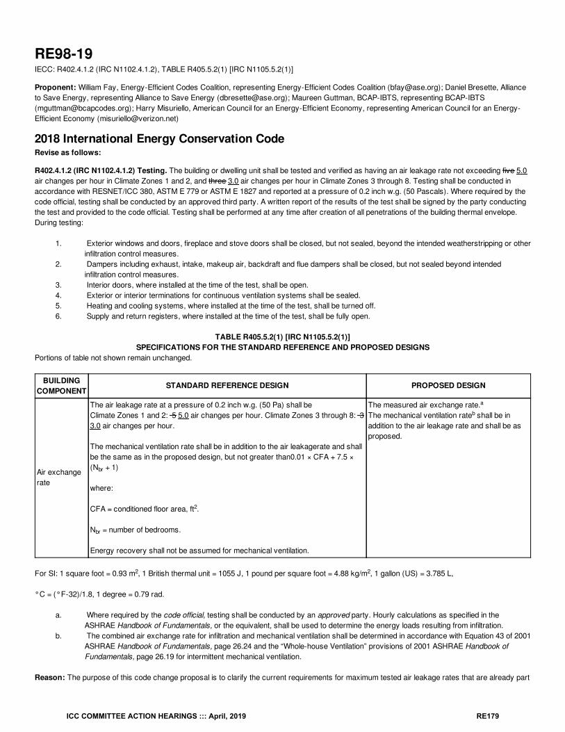
RE98-19IECC: R402.4.1.2 (IRC N1102.4.1.2), TABLE R405.5.2(1) [IRC N1105.5.2(1)]
Proponent: William Fay, Energy-Efficient Codes Coalition, representing Energy-Efficient Codes Coalition ([email protected]); Daniel Bresette, Allianceto Save Energy, representing Alliance to Save Energy ([email protected]); Maureen Guttman, BCAP-IBTS, representing BCAP-IBTS([email protected]); Harry Misuriello, American Council for an Energy-Efficient Economy, representing American Council for an Energy-Efficient Economy ([email protected])
2018 International Energy Conservation CodeRevise as follows:
R402.4.1.2 (IRC N1102.4.1.2) Testing. The building or dwelling unit shall be tested and verified as having an air leakage rate not exceeding five 5.0air changes per hour in Climate Zones 1 and 2, and three 3.0 air changes per hour in Climate Zones 3 through 8. Testing shall be conducted inaccordance with RESNET/ICC 380, ASTM E 779 or ASTM E 1827 and reported at a pressure of 0.2 inch w.g. (50 Pascals). Where required by thecode official, testing shall be conducted by an approved third party. A written report of the results of the test shall be signed by the party conductingthe test and provided to the code official. Testing shall be performed at any time after creation of all penetrations of the building thermal envelope.During testing:
1. Exterior windows and doors, fireplace and stove doors shall be closed, but not sealed, beyond the intended weatherstripping or otherinfiltration control measures.
2. Dampers including exhaust, intake, makeup air, backdraft and flue dampers shall be closed, but not sealed beyond intendedinfiltration control measures.
3. Interior doors, where installed at the time of the test, shall be open.4. Exterior or interior terminations for continuous ventilation systems shall be sealed.5. Heating and cooling systems, where installed at the time of the test, shall be turned off.6. Supply and return registers, where installed at the time of the test, shall be fully open.
TABLE R405.5.2(1) [IRC N1105.5.2(1)]SPECIFICATIONS FOR THE STANDARD REFERENCE AND PROPOSED DESIGNS
Portions of table not shown remain unchanged.
BUILDINGCOMPONENT
STANDARD REFERENCE DESIGN PROPOSED DESIGN
Air exchangerate
The air leakage rate at a pressure of 0.2 inch w.g. (50 Pa) shall beClimate Zones 1 and 2: 5 5.0 air changes per hour. Climate Zones 3 through 8: 33.0 air changes per hour.
The mechanical ventilation rate shall be in addition to the air leakagerate and shallbe the same as in the proposed design, but not greater than0.01 × CFA + 7.5 ×(N + 1)
where:
CFA = conditioned floor area, ft .
N = number of bedrooms.
Energy recovery shall not be assumed for mechanical ventilation.
The measured air exchange rate.The mechanical ventilation rate shall be inaddition to the air leakage rate and shall be asproposed.
For SI: 1 square foot = 0.93 m , 1 British thermal unit = 1055 J, 1 pound per square foot = 4.88 kg/m , 1 gallon (US) = 3.785 L,
°C = (°F-32)/1.8, 1 degree = 0.79 rad.
a. Where required by the code official, testing shall be conducted by an approved party. Hourly calculations as specified in theASHRAE Handbook of Fundamentals, or the equivalent, shall be used to determine the energy loads resulting from infiltration.
b. The combined air exchange rate for infiltration and mechanical ventilation shall be determined in accordance with Equation 43 of 2001ASHRAE Handbook of Fundamentals, page 26.24 and the “Whole-house Ventilation” provisions of 2001 ASHRAE Handbook ofFundamentals, page 26.19 for intermittent mechanical ventilation.
Reason: The purpose of this code change proposal is to clarify the current requirements for maximum tested air leakage rates that are already part
br
2
br
a
b
2 2
ICC COMMITTEE ACTION HEARINGS ::: April, 2019 RE179
of the IECC and to ensure that buildings achieve the efficiency intended by the code. Specifically, the code proposal adds “.0” to the specifiedrequirements to clarify that values above 3.0 or 5.0 are not allowed. While most users understand based on the current language that the air leakagemay not exceed 3 or 5 air changes per hour (depending on climate zone), the addition of another digit will pre-empt any claim that a tested valueabove these maximums, such as 5.4 ACH, will meet the 5 ACH maximum. By cutting off these “round off” arguments from code users, this changewill provide additional support for building code officials who are simply trying to enforce the code. This proposed clarification will not change anysubstantive requirements of the code but will improve compliance and enforcement and eliminate any confusion.
Cost Impact: The code change proposal will not increase or decrease the cost of constructionIt merely serves to clarify a current requirement to avoid confusion and inconsistent enforcement.
Proposal # 3989
RE98-19
ICC COMMITTEE ACTION HEARINGS ::: April, 2019 RE180
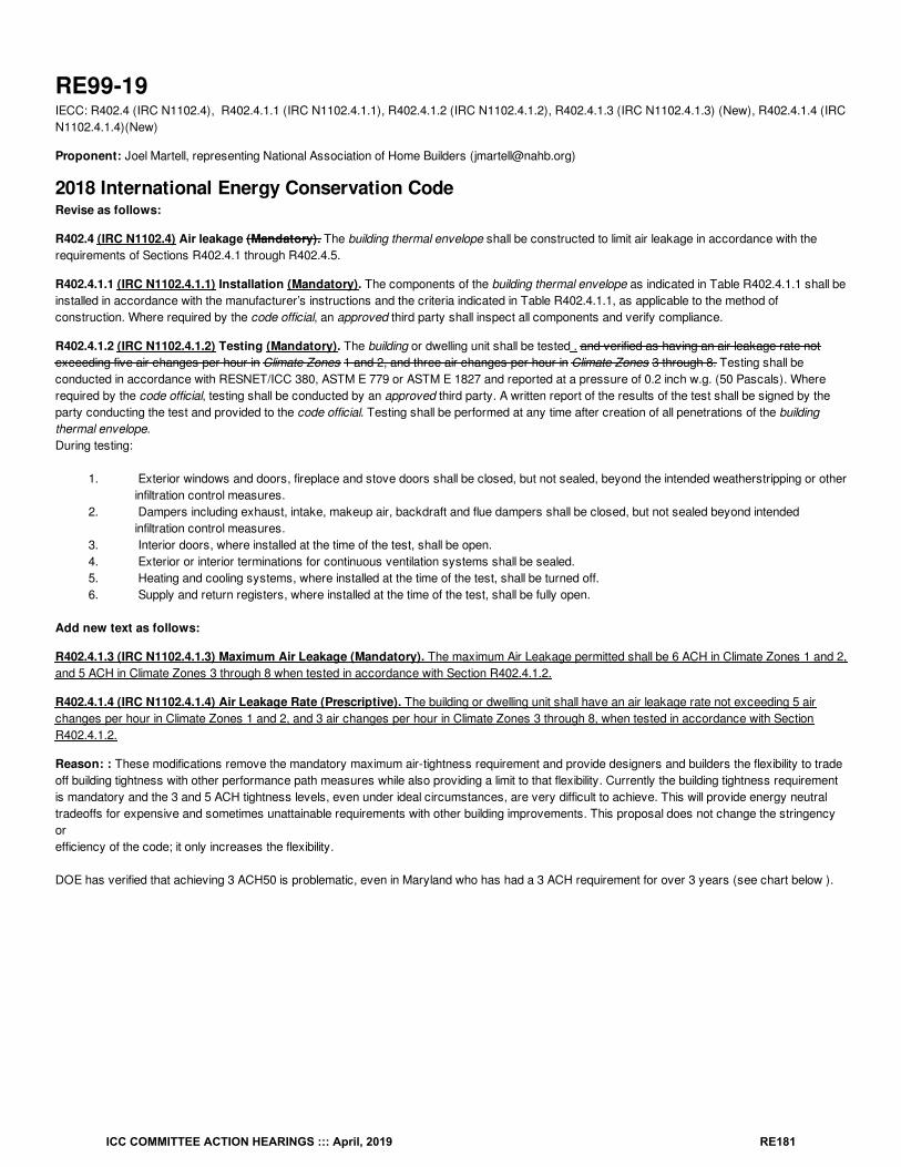
RE99-19IECC: R402.4 (IRC N1102.4), R402.4.1.1 (IRC N1102.4.1.1), R402.4.1.2 (IRC N1102.4.1.2), R402.4.1.3 (IRC N1102.4.1.3) (New), R402.4.1.4 (IRCN1102.4.1.4)(New)
Proponent: Joel Martell, representing National Association of Home Builders ([email protected])
2018 International Energy Conservation CodeRevise as follows:
R402.4 (IRC N1102.4) Air leakage (Mandatory). The building thermal envelope shall be constructed to limit air leakage in accordance with therequirements of Sections R402.4.1 through R402.4.5.
R402.4.1.1 (IRC N1102.4.1.1) Installation (Mandatory). The components of the building thermal envelope as indicated in Table R402.4.1.1 shall beinstalled in accordance with the manufacturer’s instructions and the criteria indicated in Table R402.4.1.1, as applicable to the method ofconstruction. Where required by the code official, an approved third party shall inspect all components and verify compliance.
R402.4.1.2 (IRC N1102.4.1.2) Testing (Mandatory). The building or dwelling unit shall be tested . and verified as having an air leakage rate notexceeding five air changes per hour in Climate Zones 1 and 2, and three air changes per hour in Climate Zones 3 through 8. Testing shall beconducted in accordance with RESNET/ICC 380, ASTM E 779 or ASTM E 1827 and reported at a pressure of 0.2 inch w.g. (50 Pascals). Whererequired by the code official, testing shall be conducted by an approved third party. A written report of the results of the test shall be signed by theparty conducting the test and provided to the code official. Testing shall be performed at any time after creation of all penetrations of the buildingthermal envelope.During testing:
1. Exterior windows and doors, fireplace and stove doors shall be closed, but not sealed, beyond the intended weatherstripping or otherinfiltration control measures.
2. Dampers including exhaust, intake, makeup air, backdraft and flue dampers shall be closed, but not sealed beyond intendedinfiltration control measures.
3. Interior doors, where installed at the time of the test, shall be open.4. Exterior or interior terminations for continuous ventilation systems shall be sealed.5. Heating and cooling systems, where installed at the time of the test, shall be turned off.6. Supply and return registers, where installed at the time of the test, shall be fully open.
Add new text as follows:
R402.4.1.3 (IRC N1102.4.1.3) Maximum Air Leakage (Mandatory). The maximum Air Leakage permitted shall be 6 ACH in Climate Zones 1 and 2,and 5 ACH in Climate Zones 3 through 8 when tested in accordance with Section R402.4.1.2.
R402.4.1.4 (IRC N1102.4.1.4) Air Leakage Rate (Prescriptive). The building or dwelling unit shall have an air leakage rate not exceeding 5 airchanges per hour in Climate Zones 1 and 2, and 3 air changes per hour in Climate Zones 3 through 8, when tested in accordance with SectionR402.4.1.2.
Reason: : These modifications remove the mandatory maximum air-tightness requirement and provide designers and builders the flexibility to tradeoff building tightness with other performance path measures while also providing a limit to that flexibility. Currently the building tightness requirementis mandatory and the 3 and 5 ACH tightness levels, even under ideal circumstances, are very difficult to achieve. This will provide energy neutraltradeoffs for expensive and sometimes unattainable requirements with other building improvements. This proposal does not change the stringencyorefficiency of the code; it only increases the flexibility.
DOE has verified that achieving 3 ACH50 is problematic, even in Maryland who has had a 3 ACH requirement for over 3 years (see chart below ).
ICC COMMITTEE ACTION HEARINGS ::: April, 2019 RE181
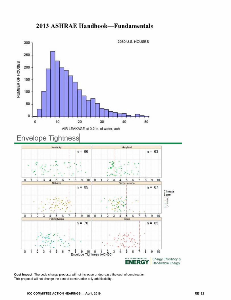
Cost Impact: The code change proposal will not increase or decrease the cost of constructionThis proposal will not change the cost of construction only add flexibility.
ICC COMMITTEE ACTION HEARINGS ::: April, 2019 RE182
Proposal # 4292
RE99-19
ICC COMMITTEE ACTION HEARINGS ::: April, 2019 RE183
RE100-19IECC: R402.4.1.2 (IRC N1102.4.1.2), R402.2.13 (IRC N1102.2.13), R402.3.5 (IRC N1102.3.5)
Proponent: Darren Meyers, P.E., International Energy Conservation Consultants LLC, representing Self ([email protected])
2018 International Energy Conservation CodeRevise as follows:
R402.4.1.2 (IRC N1102.4.1.2) Testing. The building or dwelling unit shall be tested and verified as having an air leakage rate not exceeding five airchanges per hour in Climate Zones 1 and 2, and three air changes per hour in Climate Zones 3 through 8. Testing shall be conducted in accordancewith RESNET/ICC 380, ASTM E 779 or ASTM E 1827 and reported at a pressure of 0.2 inch w.g. (50 Pascals). Where required by the code official,testing shall be conducted by an approved third party. A written report of the results of the test shall be signed by the party conducting the test andprovided to the code official. Testing shall be performed at any time after creation of all penetrations of the building thermal envelope. have beensealed.
Exception: For heated, attached private garages and heated, detached private garages accessory to 1- and 2-family dwellings andtownhouses not more than 3 stories above grade plane in height, building envelope tightness and insulation installation shall be consideredacceptable where the items in Table R402.4.1.1, applicable to the method of construction, are field verified. Where required by the code official,an approved third party independent from the installer shall inspect both air barrier and insulation installation criteria. Heated, attached privategarage space and heated, detached private garage space shall be thermally isolated from all other habitable, conditioned spaces in accordancewith Sections R402.2.13 and R402.3.5, accordingly.
During testing:
1. Exterior windows and doors, fireplace and stove doors shall be closed, but not sealed, beyond the intended weatherstripping or otherinfiltration control measures.
2. Dampers including exhaust, intake, makeup air, backdraft and flue dampers shall be closed, but not sealed beyond intendedinfiltration control measures.
3. Interior doors, where installed at the time of the test, shall be open.4. Exterior or interior terminations for continuous ventilation systems shall be sealed.5. Heating and cooling systems, where installed at the time of the test, shall be turned off.6. Supply and return registers, where installed at the time of the test, shall be fully open.
R402.2.13 (IRC N1102.2.13) Sunroom insulation. Sunrooms enclosing conditioned space and heated garages shall meet the insulationrequirements of this code.
Exception: For sunrooms and heated garages provided with thermal isolation, and enclosing conditioned space, the following exceptions to theinsulation requirements of this code shall apply:
1. The minimum ceiling insulation R-values shall be R-19 in Climate Zones 1 through 4 and R-24 in Climate Zones 5 through 8.2. The minimum wall insulation R-value shall be R-13 in all climate zones. Walls separating a sunroom or heated garage with a
thermal isolation from conditioned space shall comply with the building thermal envelope requirements of this code.
R402.3.5 (IRC N1102.3.5) Sunroom fenestration. Sunrooms and heated garages enclosing conditioned space shall comply with the fenestrationrequirements of this code.
Exception: In Climate Zones 2 through 8, for sunrooms and heated garages with thermal isolation and enclosing conditioned space, thefenestration U-factor shall not exceed 0.45 and the skylight U-factor shall not exceed 0.70.
New fenestration separating the a sunroom or heated garage with thermal isolation from conditioned space shall comply with the building thermalenvelope requirements of this code.
Reason: We, in Illinois and Iowa, have found that the addition of a reasonable, provision regulating "heated garages," results in improved levels ofcompliance assessment.
Cost Impact: The code change proposal will increase the cost of constructionIt is likely that the creation of the thermally-isolated "heated garage" provisions will result in less "illegitimate" applications or "non-applications" forpermit and inspection of newly heated, existing garages utilized for either hobby or workshop or rendering during hunting season.
Proposal # 5647
RE100-19
ICC COMMITTEE ACTION HEARINGS ::: April, 2019 RE184
RE101-19IECC: R402.4.1.2 (IRC N1102.4.1.2)
Proponent: Darren Meyers, P.E., International Energy Conservation Consultants LLC, representing Self ([email protected])
2018 International Energy Conservation CodeRevise as follows:
R402.4.1.2 (IRC N1102.4.1.2) Testing. The building or dwelling unit shall be tested and verified as having an air leakage rate not exceeding five airchanges per hour in Climate Zones 1 and 2, and three air changes per hour in Climate Zones 3 through 8. Testing shall be conducted in accordancewith RESNET/ICC 380, ASTM E 779 or ASTM E 1827 and reported at a pressure of 0.2 inch w.g. (50 Pascals). Where required by the code official,testing shall be conducted by an approved third party. A written report of the results of the test shall be signed by the party conducting the test andprovided to the code official. Testing shall be performed at any time after creation of all penetrations of the building thermal envelope. have beensealed.
Exception: For additions , alterations , renovations or repairs to existing buildings, building thermal envelope tightness and insulation installationshall be considered acceptable when the items in Table R402.4.1.1, applicable to the method of construction, are field verified. Where requiredby the code official , an approved third party independent from the installer shall inspect both air barrier and insulation installation criteria.
During testing:
1. Exterior windows and doors, fireplace and stove doors shall be closed, but not sealed, beyond the intended weatherstripping or otherinfiltration control measures.
2. Dampers including exhaust, intake, makeup air, backdraft and flue dampers shall be closed, but not sealed beyond intendedinfiltration control measures.
3. Interior doors, where installed at the time of the test, shall be open.4. Exterior or interior terminations for continuous ventilation systems shall be sealed.5. Heating and cooling systems, where installed at the time of the test, shall be turned off.6. Supply and return registers, where installed at the time of the test, shall be fully open.
Reason: Should a bedroom addition to a farmhouse originally constructed in 1950's rural america be required to be blower door tested to 3.0ACH50? We think not. Accordingly, a reasonable middle ground is offered.
Cost Impact: The code change proposal will decrease the cost of constructionWhile interpreted literally, a blower door test is required for new construction, including additions.
Proposal # 5636
RE101-19
ICC COMMITTEE ACTION HEARINGS ::: April, 2019 RE185
RE102-19IECC: R402.4.1.2.1 (IRC N1102.4.1.2.1) (New)
Proponent: Joel Martell, representing National Association of Home Builders ([email protected])
2018 International Energy Conservation CodeAdd new text as follows:
R402.4.1.2.1 (IRC N1102.4.1.2.1) Multi-unit buildings and single family attached buildings Multi-unit buildings and single family attachedbuildings shall be tested as a single zone, multiple zones, or as individual dwelling units in accordance with ASTM E779.
Reason: This proposal is very clear and straight forward, it helps to clarify testing in multi-unit buildings. The ASTM E779 standard is referenced inR402.4.1.2 and this standard allows for single, or multiple zone testing. This proposal is just adding clarification to the code for a method that isalready allowed. Currently the IECC treats low -rise multifamily buildings of three stories or less like single-family homes and multifamily buildings offour stories or more like commercial buildings. Regardless of height, all multifamily buildings have the same airtightness testing complications toaddress. Large multiple dwelling buildings are often tested as isolated test zones due to the nature of the actual testing procedures and availableequipment needed to depressurize large volumes of conditioned space and this proposal would recognize this challenge for those conducting thetesting. By approving this proposal, low -rise multifamily buildings, two-unit dwellings and town houses will avoid these complications, but still be heldto the same level of performance as high-rise (R-2) residential as w ell as commercial buildings
Cost Impact: The code change proposal will not increase or decrease the cost of constructionThis proposal will not change the cost of construction. It is adds clarification to something that is already allowed in the code.
Proposal # 4318
RE102-19
ICC COMMITTEE ACTION HEARINGS ::: April, 2019 RE186
RE103-19IECC: R402.4.2 (New),
R402.4.6
(New)
Proponent: Marilyn Williams, representing NEMA
2018 International Energy Conservation CodeR402.4.2 Fireplaces. New wood-burning fireplaces shall have tight-fitting flue dampers or doors, and outdoor combustion air. Where using tight-fitting doors on factory-built fireplaces listed and labeled in accordance with UL 127, the doors shall be tested and listed for the fireplace.
Add new text as follows:
R402.4.6 Electrical and Communication Outlet Boxes (air-sealed boxes). Electrical and communication outlet boxes installed in the buildingthermal envelope shall lbe sealed to limit air leakage between conditioned and unconditioned spaces. Electrical and communication outlet boxesshall be tested in accordance with NEMA OS 4, Requirements for Air-Sealed Boxes for Electrical and Communication Applications, and shall havean air leakage rate of not greater than 2.0 cfm (0.944 L/s) at a pressure differential of 1.57 psf (75 Pa). Electrical and communication outlet boxesshall be marked "NEMA OS 4" or "OS 4" in accordance with NEMA OS 4. Electrical and communication outlet boxes shall be installed per themanufacturer's instructions and with any supplied components required to achieve compliance with NEMA OS 4.
Reason: Similar to Section R402.4.5 for recessed lighting a new section for electrical and communications outlet boxes is being proposed to limit airleakage when installed in the building thermal envelop. "Air-sealed boxes" are identified in Table R402.4.1.1. This new section defines an air-sealedbox.Sealing air-barrier penetrations is not always as simple as applying more insulation, caulk, or expanding foam. Electrical and communication outletboxes, having design features that effective seal the air-barrier penetrations, also reduce potentially undesirable effects that can result from the useof unspecified sealing techniques.
NEMA OS 4-2016, Requirements for Air-Sealed Boxes for Electrical and Communication Applications, was developed by the NEMA Outlet andSwitch Box Section. In the preparation of NEMA OS 4, input of users and other interested parties was sought and evaluated.
Cost Impact: The code change proposal will not increase or decrease the cost of constructionAn outlet box with an alternative means of sealing needs to be used if a vapor barrier box is not.
Proposal # 4077
RE103-19
ICC COMMITTEE ACTION HEARINGS ::: April, 2019 RE187
RE104-19IECC: R402.4.6 (IRC N1102.4.6) (New)
Proponent: donald sivigny, State of MN, representing State of MN and Association of Minnesota Building Officials ([email protected])
2018 International Energy Conservation CodeAdd new text as follows:
R402.4.6 (IRC N1102.4.6) Replacement fenestration Where a fenestration unit is replaced, the new unit shall meet the applicable requirements forU-factor and SHGC in Table R402.1.1.
Reason: When windows are replace, many times the replacement window is installed into the existing frame of the existing window. In such a casethe existing window frame now becomes part of the wall assembly, and the new frame and window sash are considered a new fenestration product.In such cases this would require the new fenestration product (new frame, sash, glazing etc.) to meet the U-factor requirements of Table R402.1.2or R402.1.4 of this code. If you are only replacing the glass or one portion of the window, this is not a replacement fenestration, it would then be arepair, and not a replacement
Cost Impact: The code change proposal will increase the cost of constructionAlthough a replacement window that complies with the newest code will cost more than one than a replacement window that only complies with lessstringent, older codes, the cost differential isn’t that significant as compared to the energy savings (pay-back) over the life of the up-to-current-codewindow.
Proposal # 5131
RE104-19
ICC COMMITTEE ACTION HEARINGS ::: April, 2019 RE188
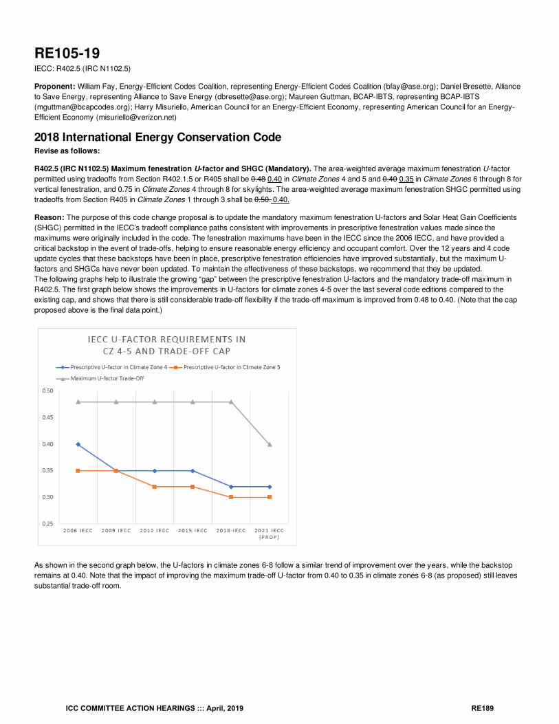
RE105-19IECC: R402.5 (IRC N1102.5)
Proponent: William Fay, Energy-Efficient Codes Coalition, representing Energy-Efficient Codes Coalition ([email protected]); Daniel Bresette, Allianceto Save Energy, representing Alliance to Save Energy ([email protected]); Maureen Guttman, BCAP-IBTS, representing BCAP-IBTS([email protected]); Harry Misuriello, American Council for an Energy-Efficient Economy, representing American Council for an Energy-Efficient Economy ([email protected])
2018 International Energy Conservation CodeRevise as follows:
R402.5 (IRC N1102.5) Maximum fenestration U-factor and SHGC (Mandatory). The area-weighted average maximum fenestration U-factorpermitted using tradeoffs from Section R402.1.5 or R405 shall be 0.48 0.40 in Climate Zones 4 and 5 and 0.40 0.35 in Climate Zones 6 through 8 forvertical fenestration, and 0.75 in Climate Zones 4 through 8 for skylights. The area-weighted average maximum fenestration SHGC permitted usingtradeoffs from Section R405 in Climate Zones 1 through 3 shall be 0.50. 0.40.
Reason: The purpose of this code change proposal is to update the mandatory maximum fenestration U-factors and Solar Heat Gain Coefficients(SHGC) permitted in the IECC’s tradeoff compliance paths consistent with improvements in prescriptive fenestration values made since themaximums were originally included in the code. The fenestration maximums have been in the IECC since the 2006 IECC, and have provided acritical backstop in the event of trade-offs, helping to ensure reasonable energy efficiency and occupant comfort. Over the 12 years and 4 codeupdate cycles that these backstops have been in place, prescriptive fenestration efficiencies have improved substantially, but the maximum U-factors and SHGCs have never been updated. To maintain the effectiveness of these backstops, we recommend that they be updated.The following graphs help to illustrate the growing “gap” between the prescriptive fenestration U-factors and the mandatory trade-off maximum inR402.5. The first graph below shows the improvements in U-factors for climate zones 4-5 over the last several code editions compared to theexisting cap, and shows that there is still considerable trade-off flexibility if the trade-off maximum is improved from 0.48 to 0.40. (Note that the capproposed above is the final data point.)
As shown in the second graph below, the U-factors in climate zones 6-8 follow a similar trend of improvement over the years, while the backstopremains at 0.40. Note that the impact of improving the maximum trade-off U-factor from 0.40 to 0.35 in climate zones 6-8 (as proposed) still leavessubstantial trade-off room.
ICC COMMITTEE ACTION HEARINGS ::: April, 2019 RE189
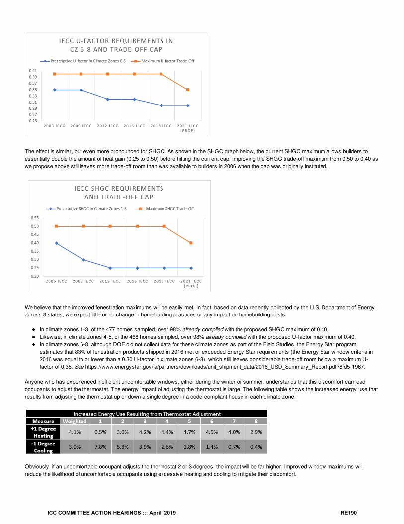
The effect is similar, but even more pronounced for SHGC. As shown in the SHGC graph below, the current SHGC maximum allows builders toessentially double the amount of heat gain (0.25 to 0.50) before hitting the current cap. Improving the SHGC trade-off maximum from 0.50 to 0.40 aswe propose above still leaves more trade-off room than was available to builders in 2006 when the cap was originally instituted.
We believe that the improved fenestration maximums will be easily met. In fact, based on data recently collected by the U.S. Department of Energyacross 8 states, we expect little or no change in homebuilding practices or any impact on homebuilding costs.
In climate zones 1-3, of the 477 homes sampled, over 98% already complied with the proposed SHGC maximum of 0.40.Likewise, in climate zones 4-5, of the 468 homes sampled, over 98% already complied with the proposed U-factor maximum of 0.40.In climate zones 6-8, although DOE did not collect data for these climate zones as part of the Field Studies, the Energy Star programestimates that 83% of fenestration products shipped in 2016 met or exceeded Energy Star requirements (the Energy Star window criteria in2016 was equal to or lower than a 0.30 U-factor in climate zones 6-8), which still leaves considerable trade-off room below a maximum U-factor of 0.35. See https://www.energystar.gov/ia/partners/downloads/unit_shipment_data/2016_USD_Summary_Report.pdf?8fd5-1967.
Anyone who has experienced inefficient uncomfortable windows, either during the winter or summer, understands that this discomfort can leadoccupants to adjust the thermostat. The energy impact of adjusting the thermostat is large. The following table shows the increased energy use thatresults from adjusting the thermostat up or down a single degree in a code-compliant house in each climate zone:
Obviously, if an uncomfortable occupant adjusts the thermostat 2 or 3 degrees, the impact will be far higher. Improved window maximums willreduce the likelihood of uncomfortable occupants using excessive heating and cooling to mitigate their discomfort.
ICC COMMITTEE ACTION HEARINGS ::: April, 2019 RE190
We expect this to be an easy-to-implement improvement given the current state of practice, but an important update to the code, that will ensurelong-term benefits for all homes with little or no additional cost.
Bibliography: ENERGY STAR® Unit Shipment and Market Penetration Report Calendar Year 2016 Summary, Energy Star, available athttps://www.energystar.gov/ia/partners/downloads/unit_shipment_data/2016_USD_Summary_Report.pdf?8fd5-1967.
Cost Impact: The code change proposal will not increase or decrease the cost of constructionBecause this is only a change to a trade-off backstop and not a code requirement (the prescriptive requirement is already more efficient than theproposed new backstop level), and because such a high percentage of homebuilders are likely already meeting or exceeding this requirement, weexpect no real cost impact in most cases.
Proposal # 3985
RE105-19
ICC COMMITTEE ACTION HEARINGS ::: April, 2019 RE191
RE106-19IECC: R403.1.1 (IRC N1103.1.1)
Proponent: David Collins, SEHPCAC, representing SEHPCAC ([email protected]); David Collins, representing The American Institute ofArchitects ([email protected])
2018 International Energy Conservation CodeRevise as follows:
R403.1.1 (IRC N1103.1.1) Programmable thermostat. The thermostat controlling the primary heating or cooling system of the dwelling unit shall becapable of controlling the heating and cooling system on a daily schedule to maintain different temperature set points at different times of the day.providing a 5:2 (weekdays:weekends) programmable schedule, and at least 2 programmable schedules per day, This thermostat shall include thecapability to set back or temporarily operate the system to maintain zone temperatures of not less than 55°F (13°C) to not greater than 85°F(29°C). The thermostat shall be programmed initially by the manufacturer with a heating temperature setpoint of not greater than 70°F (21°C) and acooling temperature setpoint of not less than 78°F (26°C).
Reason: This code change clarifies the intended operational capability of programmable thermostats by distinquishing between weekday andweekend occupancy schedules along with at least 2 programmable schedules per day. The change also accounts for the capabilities of smartthermostatic controls that auto-adjust based on daily and weekly occupancy patterns. Finally, the manufacturer's initial programmed settingrequirement is deleted.This proposal is submitted by the ICC Sustainable, Energy and High Performance Code Action Committee (SEHPCAC). The SEHPCAC wasestablished by the ICC Board of Directors to pursue opportunities to improve and enhance International Codes with regard to sustainability, energyand high performance as it relates to the built environment included, but not limited to, how these criteria relate to the International GreenConstruction Code (IgCC) and the International Energy Conservation Code (IECC). In 2018-2019, the SEHPCAC has held five two- or three-dayopen meetings and numerous workgroup calls, to discuss and debate proposed changes and public comments. Attendees at the meetings and callsincluded members of the SEHPCAC as well as any interested parties. Related documentation and reports are posted on the SEHPCAC website at:http://www.iccsafe.org/cs/SEHPCAC/Pages/default.aspx (http://www.iccsafe.org/cs/SEHPCAC/Pages/default.aspx)
Cost Impact: The code change proposal will increase the cost of constructionThis requirement will increase costs for the subset of buildings not currently constructed with weekday:weekend programmable thermostats.
Proposal # 4758
RE106-19
ICC COMMITTEE ACTION HEARINGS ::: April, 2019 RE192
RE107-19IECC: R403.1.3 (N1103.1.3) (New), R403.10.1 (1103.10.1)
Proponent: Nicholas O'Neil, NW Energy Codes Group, representing NW Energy Codes Group ([email protected])
2018 International Energy Conservation CodeAdd new text as follows:
R403.1.3 (IRC N1103.1.3) Continuously Burning Pilot Lights The natural gas systems and equipment listed below are not permitted to havecontinuously burning pilot lights:
1. Fan-type central furnaces.2. Household cooking appliances.
Exception:Household cooking appliances without electrical supply voltage connections and in which each pilot light consumesless than 150 Btu/hr.
3. Pool heaters.4. Spa heaters.5. Fireplaces.
Revise as follows:
R403.10.1 (N1103.10.1) Heaters. The electric power to heaters shall be controlled by a readily accessible on-off switch that is an integral part of theheater mounted on the exterior of the heater, or external to and within 3 feet (914 mm) of the heater. Operation of such switch shall not change thesetting of the heater thermostat. Such switches shall be in addition to a circuit breaker for the power to the heater. Gas-fired heaters shall not beequipped with continuously burning ignition pilots.
Reason: Standing pilot lights are no longer necessary with many gas-fired appliances offering alternative ignition methods. Some models relycompletely on intermittent ignition, while others allow standing pilots to operate for a few hours after shutdown and then use electronic ignition to re-start. This proposal saves energy by eliminating the wasted energy of a pilot light during the numerous hours per year when the appliance is non-operational.
Cost Impact: The code change proposal will increase the cost of constructionThis prohibition is not expected to add significant cost to any gas-fired appliance listed in the proposal. Past efficiency studies have shown $100increase in price for fireplaces in particular to move from a standard continuously lit pilot light to an intermittent ignition system.
Proposal # 4941
RE107-19
ICC COMMITTEE ACTION HEARINGS ::: April, 2019 RE193
RE108-19IECC: R403.2 (IRC N1103.2)
Proponent: Roger Mitchell, Mitchell's Heating and Cooling, representing Self ([email protected])
2018 International Energy Conservation CodeRevise as follows:
R403.2 (IRC N1103.2) Hot water boiler outdoor temperature setback. reset. Hot water boilers that supply heat to the building through one- ortwo-pipe heating systems shall have an outdoor setback control that decreases the boiler water temperature based on the outdoor temperature.The manufacturer shall equip each gas, oil and electric boiler (other than a boiler equipped with a tankless domestic water heating coil) withautomatic means of adjusting the water temperature supplied by the boiler to ensure incremental change of the inferred heat load will cause anincremental change in the temperature of the water supplied by the boiler. This can be accomplished with outdoor reset, indoor reset or watertemperature sensing.
Reason: The current standard from the DOE allows for a broader scope in control schemes to meet all the control strategies available in themarketplace. The exception for domestic hot water needs to be included to allow the sale of boilers with integrated domestic hot water production.Currently over 40,000 units are sold per year with domestic hot water coils. The standard from the DOE was updated after the EnergyIndependence act of 2007 with a implementation date of 2012. This change will bring the IECC code in uniformity with the DOE.
Cost Impact: The code change proposal will not increase or decrease the cost of constructionAlingment of the standard to the DOE standard will not increase costs because all of the Heating equipment being installed has the proper controls tomeet the DOE standard. No additional components will be required if both standards are the same.
Proposal # 3788
RE108-19
ICC COMMITTEE ACTION HEARINGS ::: April, 2019 RE194
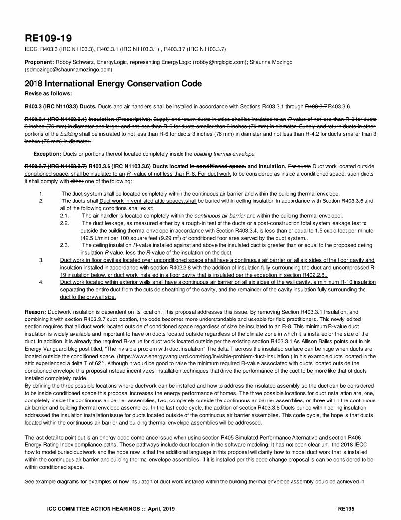
RE109-19IECC: R403.3 (IRC N1103.3), R403.3.1 (IRC N1103.3.1) , R403.3.7 (IRC N1103.3.7)
Proponent: Robby Schwarz, EnergyLogic, representing EnergyLogic ([email protected]); Shaunna Mozingo([email protected])
2018 International Energy Conservation CodeRevise as follows:
R403.3 (IRC N1103.3) Ducts. Ducts and air handlers shall be installed in accordance with Sections R403.3.1 through R403.3.7 R403.3.6.
R403.3.1 (IRC N1103.3.1) Insulation (Prescriptive). Supply and return ducts in attics shall be insulated to an R-value of not less than R-8 for ducts3 inches (76 mm) in diameter and larger and not less than R-6 for ducts smaller than 3 inches (76 mm) in diameter. Supply and return ducts in otherportions of the building shall be insulated to not less than R-6 for ducts 3 inches (76 mm) in diameter and not less than R-4.2 for ducts smaller than 3inches (76 mm) in diameter.
Exception: Ducts or portions thereof located completely inside the building thermal envelope.
R403.3.7 (IRC N1103.3.7) R403.3.6 (IRC N1103.3.6) Ducts located in conditioned space. and insulation. For ducts Duct work located outsideconditioned space, shall be insulated to an R -value of not less than R-8. For duct work to be considered as inside a conditioned space, such ductsit shall comply with either one of the following:
1. The duct system shall be located completely within the continuous air barrier and within the building thermal envelope.2. The ducts shall Duct work in ventilated attic spaces.shall be buried within ceiling insulation in accordance with Section R403.3.6 and
all of the following conditions shall exist:2.1. The air handler is located completely within the continuous air barrier and within the building thermal envelope..2.2. The duct leakage, as measured either by a rough-in test of the ducts or a post-construction total system leakage test to
outside the building thermal envelope in accordance with Section R403.3.4, is less than or equal to 1.5 cubic feet per minute(42.5 L/min) per 100 square feet (9.29 m ) of conditioned floor area served by the duct system..
2.3. The ceiling insulation R-value installed against and above the insulated duct is greater than or equal to the proposed ceilinginsulation R-value, less the R-value of the insulation on the duct.
3. Duct work in floor cavities located over unconditioned space shall have a continuous air barrier on all six sides of the floor cavity andinsulation installed in accordance with section R402.2.8 with the addition of insulation fully surrounding the duct and uncompressed R-19 insulation below, or duct work installed in a floor cavity that is insulated per the exception in section R402.2.8..
4. Duct work located within exterior walls shall have a continuous air barrier on all six sides of the wall cavity, a minimum R-10 insulationseparating the entire duct from the outside sheathing of the cavity, and the remainder of the cavity insulation fully surrounding theduct to the drywall side.
Reason: Ductwork insulation is dependent on its location. This proposal addresses this issue. By removing Section R403.3.1 Insulation, andcombining it with section R403.3.7 duct location, the code becomes more understandable and useable for field practitioners. This newly editedsection requires that all duct work located outside of conditioned space regardless of size be insulated to an R-8. This minimum R-value ductinsulation is widely available and important to have on ducts located outside regardless of the climate zone in which it is installed or the size of theduct. In addition, it is already the required R-value for duct work located outside per the existing section R403.3.1 As Allison Bailes points out in hisEnergy Vanguard blog post titled, “The invisible problem with duct insulation” The delta T across the insulated surface can be huge when ducts arelocated outside the conditioned space. (https://www.energyvanguard.com/blog/invisible-problem-duct-insulation ) In his example ducts located in theattic experienced a delta T of 62°. Although it would be good to raise the minimum required R-value associated with ducts located outside theconditioned envelope this proposal instead incentivizes installation techniques that drive the performance of the duct to be more like that of ductsinstalled completely inside.By defining the three possible locations where ductwork can be installed and how to address the insulated assembly so the duct can be consideredto be inside conditioned space this proposal increases the energy performance of homes. The three possible locations for duct installation are, one,completely inside the continuous air barrier assemblies, two, completely outside the continuous air barrier assemblies, or three within the continuousair barrier and building thermal envelope assemblies. In the last code cycle, the addition of section R403.3.6 Ducts buried within ceiling insulationaddressed the insulation installation issue for ducts located outside of the continuous air barrier assemblies. This code cycle, the hope is that ductslocated within the continuous air barrier and building thermal envelope assemblies will be addressed.
The last detail to point out is an energy code compliance issue when using section R405 Simulated Performance Alternative and section R406Energy Rating Index compliance paths. These pathways include duct location in the software modeling. It has not been clear until the 2018 IECChow to model buried ductwork and the hope now is that the additional language in this proposal will clarify how to model duct work that is installedwithin the continuous air barrier and building thermal envelope assemblies. If it is installed per this code change proposal is can be considered to bewithin conditioned space.
See example diagrams for examples of how insulation of duct work installed within the building thermal envelope assembly could be achieved in
2
ICC COMMITTEE ACTION HEARINGS ::: April, 2019 RE195
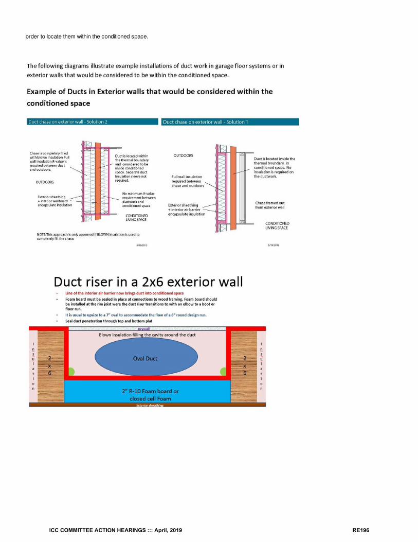
order to locate them within the conditioned space.
ICC COMMITTEE ACTION HEARINGS ::: April, 2019 RE196
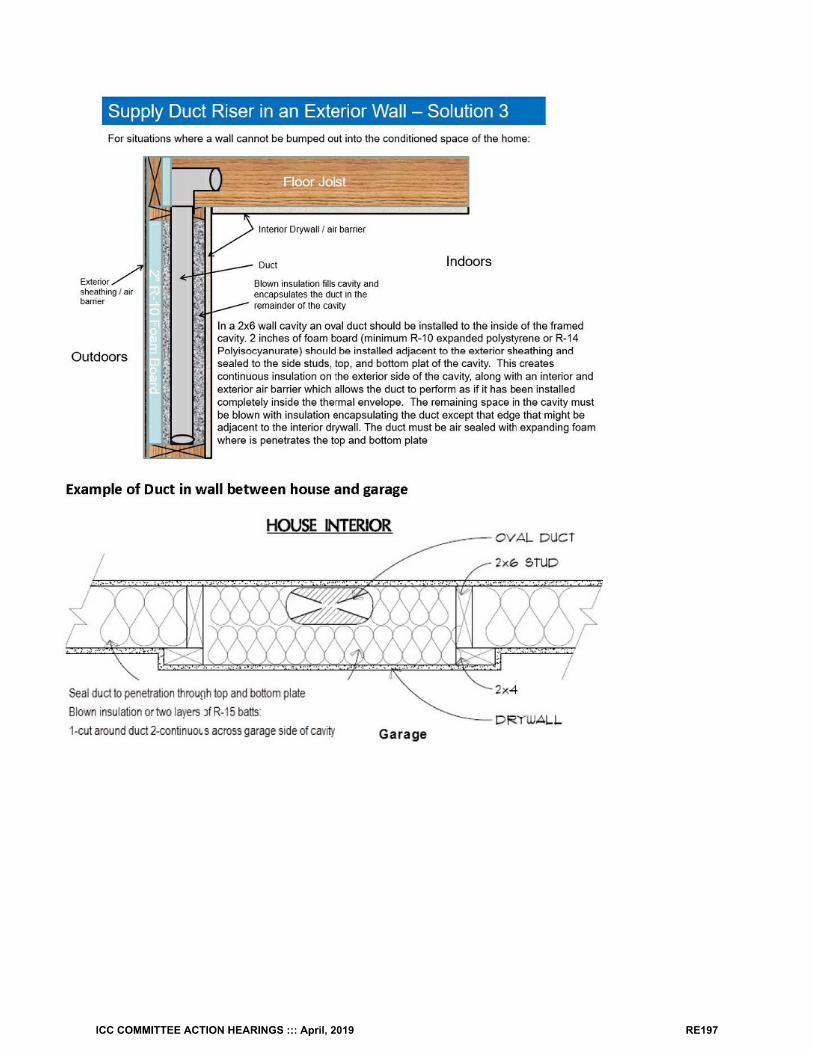
ICC COMMITTEE ACTION HEARINGS ::: April, 2019 RE197
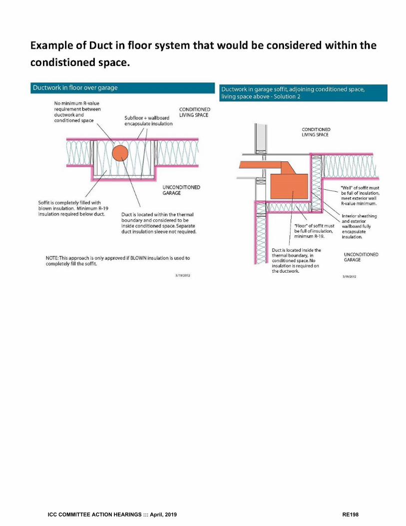
ICC COMMITTEE ACTION HEARINGS ::: April, 2019 RE198
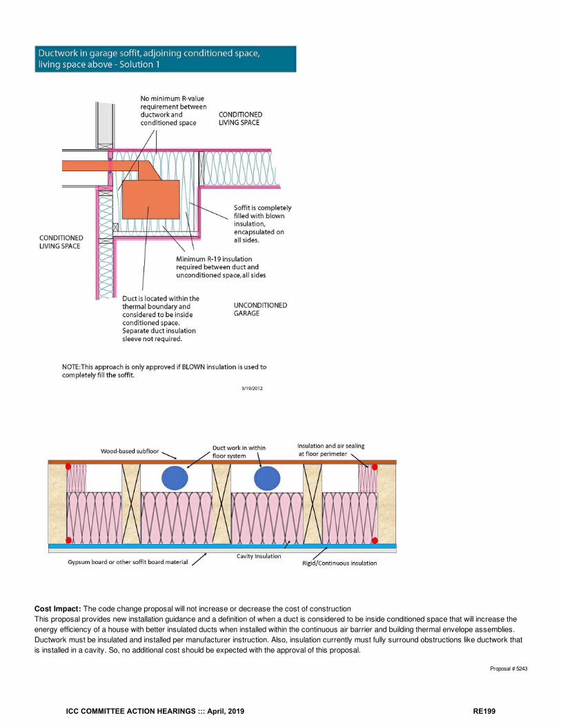
Cost Impact: The code change proposal will not increase or decrease the cost of constructionThis proposal provides new installation guidance and a definition of when a duct is considered to be inside conditioned space that will increase theenergy efficiency of a house with better insulated ducts when installed within the continuous air barrier and building thermal envelope assemblies.Ductwork must be insulated and installed per manufacturer instruction. Also, insulation currently must fully surround obstructions like ductwork thatis installed in a cavity. So, no additional cost should be expected with the approval of this proposal.
Proposal # 5243
ICC COMMITTEE ACTION HEARINGS ::: April, 2019 RE199

RE109-19
ICC COMMITTEE ACTION HEARINGS ::: April, 2019 RE200
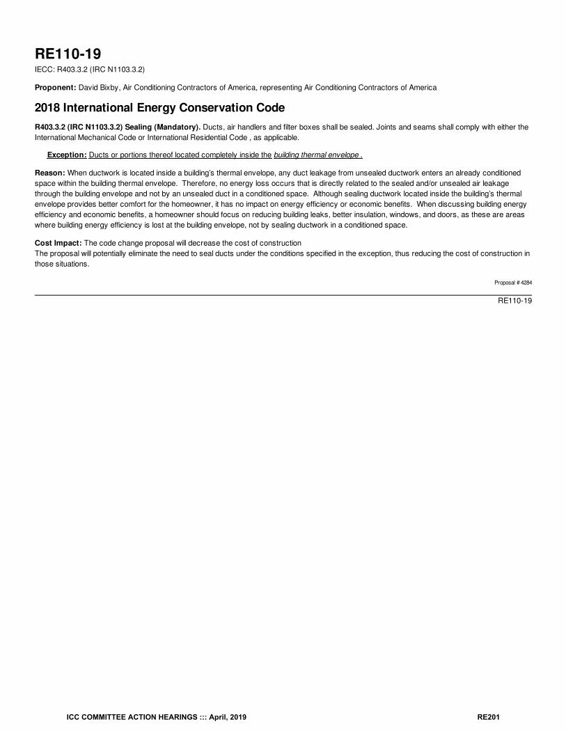
RE110-19IECC: R403.3.2 (IRC N1103.3.2)
Proponent: David Bixby, Air Conditioning Contractors of America, representing Air Conditioning Contractors of America
2018 International Energy Conservation CodeR403.3.2 (IRC N1103.3.2) Sealing (Mandatory). Ducts, air handlers and filter boxes shall be sealed. Joints and seams shall comply with either theInternational Mechanical Code or International Residential Code , as applicable.
Exception: Ducts or portions thereof located completely inside the building thermal envelope .
Reason: When ductwork is located inside a building’s thermal envelope, any duct leakage from unsealed ductwork enters an already conditionedspace within the building thermal envelope. Therefore, no energy loss occurs that is directly related to the sealed and/or unsealed air leakagethrough the building envelope and not by an unsealed duct in a conditioned space. Although sealing ductwork located inside the building’s thermalenvelope provides better comfort for the homeowner, it has no impact on energy efficiency or economic benefits. When discussing building energyefficiency and economic benefits, a homeowner should focus on reducing building leaks, better insulation, windows, and doors, as these are areaswhere building energy efficiency is lost at the building envelope, not by sealing ductwork in a conditioned space.
Cost Impact: The code change proposal will decrease the cost of constructionThe proposal will potentially eliminate the need to seal ducts under the conditions specified in the exception, thus reducing the cost of construction inthose situations.
Proposal # 4284
RE110-19
ICC COMMITTEE ACTION HEARINGS ::: April, 2019 RE201
RE111-19IECC: R403.3.1 (IRC N1103.3.1), R403.3.1.1 (IRC N1103.3.1.1) (New), R403.3.1.2 (IRC N1103.3.1.2) (New), R405.2 (IRC N1105.2), R406.2 (IRCN1106.2)
Proponent: David Collins, representing SEHPCAC ([email protected]); David Collins, representing The American Institute of Architects([email protected])
2018 International Energy Conservation CodeRevise as follows:
R403.3 (IRC N1103.3) Ducts. Ducts and air handlers shall be installed in accordance with Sections R403.3.1 through R403.3.7.
R403.3.1 (IRC N1103.3.1) Insulation (Prescriptive). Ducts shall be insulated in accordance with Sections R403.3.1.1 or R403.3.1.2. Supply andreturn ducts in attics shall be insulated to an R-value of not less than R-8 for ducts 3 inches (76 mm) in diameter and larger and not less than R-6 forducts smaller than 3 inches (76 mm) in diameter. Supply and return ducts in other portions of the building shall be insulated to not less than R-6 forducts 3 inches (76 mm) in diameter and not less than R-4.2 for ducts smaller than 3 inches (76 mm) in diameter.
Exception: Ducts or portions thereof located completely inside the building thermal envelope.
Add new text as follows:
R403.3.1.1 (IRC N1103.3.1.1) Supply and return ducts not completely in thermal envelope (Mandatory). Ducts not completely inside thebuilding thermal envelope shall be insulated to an R-value of not less than R-6
R403.3.1.2 (IRC N1103.3.1.2) Supply and return ducts in the building (Prescriptive) Supply and return ducts partially or fully inside the buildingshall be insulated as follows:
1. Supply and return ducts in attics shall be insulated to an R-value of not less than R-8 for ducts 3 inches (76 mm) in diameter and larger andnot less than R-6 for ducts smaller than 3 inches (76 mm) in diameter.
2. Supply and return ducts in other portions of the building shall be insulated to not less than R-6 for ducts 3 inches (76 mm) in diameter and notless than R-4.2 for ducts smaller than 3 inches (76 mm) in diameter.
Exception: Ducts or portions of ducts located completely inside the building thermal envelope in accordance with section R403.3.7..
Revise as follows:
R405.2 (IRC N1105.2) Mandatory requirements. Compliance with this section requires that the mandatory provisions identified in Section R401.2be met. Supply and return ducts not completely inside the building thermal envelope shall be insulated to an R-value of not less than R-6.
R406.2 (IRC N1106.2) Mandatory requirements. Compliance with this section requires that the provisions identified in Sections R401 throughR404 indicated as “Mandatory” and Section R403.5.3 be met. The building thermal envelope shall be greater than or equal to levels of efficiency andSolar Heat Gain Coefficients in Table 402.1.1 or 402.1.3 of the 2009 International Energy Conservation Code .
Exception: Supply and return ducts not completely inside the building thermal envelope shall be insulated to an R-value of not less than R-6.
Reason: This proposal consolidates all duct insulation requirements within one section.The requirements for ducts not completely inside of the thermal envelope of the proposed R403.3.1.1 are currently identified as mandatory in bothR405.2 and in R406.2, (in a confusing exception) and are labeled as such in this proposal.
The current Sec. R403.3.1 prescriptive insulation requirements for ducts partially or fully inside the building are separated into the proposedR403.3.1.2 (1) requirements for ducts in attics and R403.3.1.2 (2) ducts within other portions of the building.
The current exception to insulation requirements for ducts located completely inside the thermal envelope is maintained but a reference to theapplicable section, R403.3.7, is provided for clarity.
Consolidation of requirements will make the code easier to use and enforce.
Note that companion proposals submitted by the SEHPCAC eliminate the use of the ‘mandatory’ (non-tradeable) and ‘prescriptive’ (tradeable) labelsin favor of tabular identification of ‘mandatory’ sections. ICC staff have stated that if both proposals are approved the ‘mandatory’ label will beeditorially deleted in favor of the new R405.2 and R406.2 tabular listings. Since all ‘mandatory’ sections would be identified in those new tables nosections will need to be separately identified as ‘prescriptive’ and those labels can also be removed.
This proposal is submitted by the ICC Sustainable, Energy and High Performance Code Action Committee (SEHPCAC). The SEHPCAC wasestablished by the ICC Board of Directors to pursue opportunities to improve and enhance International Codes with regard to sustainability, energyand high performance as it relates to the built environment included, but not limited to, how these criteria relate to the International Green
ICC COMMITTEE ACTION HEARINGS ::: April, 2019 RE202
Construction Code (IgCC) and the International Energy Conservation Code (IECC). In 2018-2019, the SEHPCAC has held five two- or three-dayopen meetings and numerous workgroup calls, to discuss and debate proposed changes and public comments. Attendees at the meetings and callsincluded members of the SEHPCAC as well as any interested parties. Related documentation and reports are posted on the SEHPCAC website at:http://www.iccsafe.org/cs/SEHPCAC/Pages/default.aspx (http://www.iccsafe.org/cs/SEHPCAC/Pages/default.aspx)
Cost Impact: The code change proposal will not increase or decrease the cost of constructionThe is a reorganization of current provisions for greater clarify and enhanced enforcement. There are no proposed changes to the requirements.
Proposal # 4459
RE111-19
ICC COMMITTEE ACTION HEARINGS ::: April, 2019 RE203
RE112-19IECC: R403.3.3 (IRC N1103.3.3), R403.3.4 (IRC N1103.3.4)
Proponent: William Fay, Energy-Efficient Codes Coalition, representing Energy-Efficient Codes Coalition ([email protected]); Daniel Bresette, Allianceto Save Energy, representing Alliance to Save Energy ([email protected]); Maureen Guttman, BCAP-IBTS, representing BCAP-IBTS([email protected]); Harry Misuriello, American Council for an Energy-Efficient Economy, representing American Council for an Energy-Efficient Economy ([email protected])
2018 International Energy Conservation CodeR403.3 (IRC N1103.3) Ducts. Ducts and air handlers shall be installed in accordance with Sections R403.3.1 through R403.3.7.
R403.3.1 (IRC N1103.3.1) Insulation (Prescriptive). Supply and return ducts in attics shall be insulated to an R-value of not less than R-8 for ducts3 inches (76 mm) in diameter and larger and not less than R-6 for ducts smaller than 3 inches (76 mm) in diameter. Supply and return ducts in otherportions of the building shall be insulated to not less than R-6 for ducts 3 inches (76 mm) in diameter and not less than R-4.2 for ducts smaller than 3inches (76 mm) in diameter.
Exception: Ducts or portions thereof located completely inside the building thermal envelope.
R403.3.2 (IRC N1103.3.2) Sealing (Mandatory). Ducts, air handlers and filter boxes shall be sealed. Joints and seams shall comply with either theInternational Mechanical Code or International Residential Code , as applicable.
R403.3.2.1 (IRC N1103.3.2.1) Sealed air handler. Air handlers shall have a manufacturer’s designation for an air leakage of not greater than 2percent of the design airflow rate when tested in accordance with ASHRAE 193.
Revise as follows:
R403.3.3 (IRC N1103.3.3) Duct testing (Mandatory). Ducts shall be pressure tested to determine air leakage by one of the following methods:
1. Rough-in test: Total leakage shall be measured with a pressure differential of 0.1 inch w.g. (25 Pa) across the system, including themanufacturer’s air handler enclosure if installed at the time of the test. Registers shall be taped or otherwise sealed during the test.
2. Postconstruction test: Total leakage shall be measured with a pressure differential of 0.1 inch w.g. (25 Pa) across the entire system,including the manufacturer’s air handler enclosure. Registers shall be taped or otherwise sealed during the test.
Exceptions Exception:
1. A duct air-leakage test shall not be required where the ducts and air handlers are located entirely within the building thermalenvelope.2. A duct air-leakage test shall not be required for ducts serving heat or energy recovery ventilators that are not integrated withducts serving heating or cooling systems.
A written report of the results of the test shall be signed by the party conducting the test and provided to the code official.
R403.3.4 (IRC N1103.3.4) Duct leakage (Prescriptive). The total leakage of the ducts, where measured in accordance with Section R403.3.3, shallbe as follows:
1. Rough-in test: The total leakage shall be less than or equal to 4 cubic feet per minute (113.3 L/min) per 100 square feet (9.29 m ) ofconditioned floor area where the air handler is installed at the time of the test. Where the air handler is not installed at the time of thetest, the total leakage shall be less than or equal to 3 cubic feet per minute (85 L/min) per 100 square feet (9.29 m ) of conditionedfloor area.
2. Postconstruction test: Total leakage shall be less than or equal to 4 cubic feet per minute (113.3 L/min) per 100 square feet (9.29 m )of conditioned floor area.3. Test for ducts within thermal envelope: Where all ducts and air handlers are located entirely within the building thermal envelope,total leakage shall be less than or equal to 8.0 cubic feet per minute (226.6 L/min) per 100 square feet (9.29 m ) of conditioned floorarea.
Reason: The purpose of this code change proposal is to help ensure occupant comfort, proper heating and cooling system performance, andresulting long-term energy savings by requiring a duct leakage test for all new homes, including homes with all ducts inside conditioned space. Thisaction will also help reduce the likelihood of builder callbacks for poorly-functioning, uncomfortable HVAC systems. The IECC currently exemptshomes from duct testing requirements where the air handler and all ducts are located inside conditioned space. Although moving all ducts insideconditioned space may have a positive impact on energy efficiency overall, this practice alone cannot guarantee that the ducts will be tight enough todeliver conditioned air to all occupied areas of the home. Uncomfortable occupants commonly adjust thermostat settings to counteract the effect ofpoor delivery of conditioned air, leading to huge losses in energy efficiency. And these homes are at far greater risk for builder callback. Thisproposal will improve building quality and keep occupants more comfortable by requiring a duct test for all new homes, although the allowable
2
2
2
2
ICC COMMITTEE ACTION HEARINGS ::: April, 2019 RE204
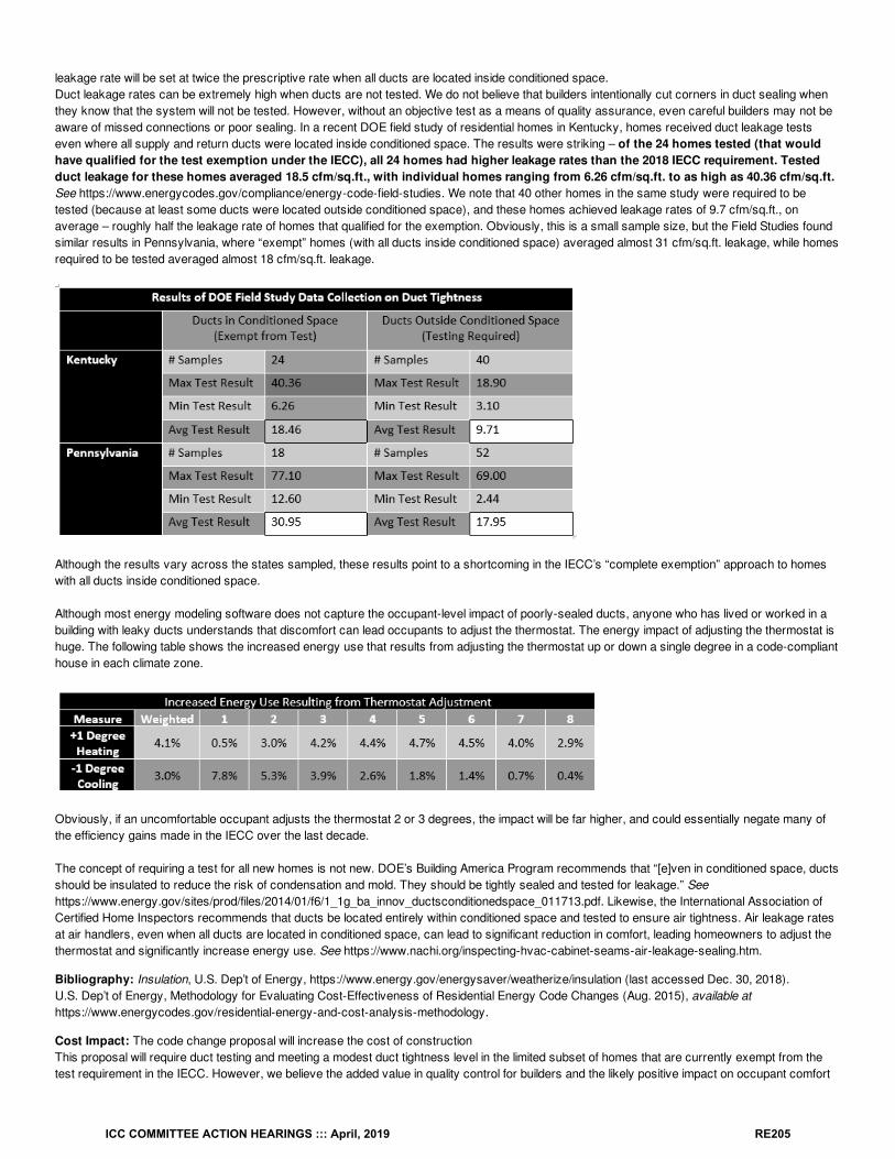
leakage rate will be set at twice the prescriptive rate when all ducts are located inside conditioned space.Duct leakage rates can be extremely high when ducts are not tested. We do not believe that builders intentionally cut corners in duct sealing whenthey know that the system will not be tested. However, without an objective test as a means of quality assurance, even careful builders may not beaware of missed connections or poor sealing. In a recent DOE field study of residential homes in Kentucky, homes received duct leakage testseven where all supply and return ducts were located inside conditioned space. The results were striking – of the 24 homes tested (that wouldhave qualified for the test exemption under the IECC), all 24 homes had higher leakage rates than the 2018 IECC requirement. Testedduct leakage for these homes averaged 18.5 cfm/sq.ft., with individual homes ranging from 6.26 cfm/sq.ft. to as high as 40.36 cfm/sq.ft.See https://www.energycodes.gov/compliance/energy-code-field-studies. We note that 40 other homes in the same study were required to betested (because at least some ducts were located outside conditioned space), and these homes achieved leakage rates of 9.7 cfm/sq.ft., onaverage – roughly half the leakage rate of homes that qualified for the exemption. Obviously, this is a small sample size, but the Field Studies foundsimilar results in Pennsylvania, where “exempt” homes (with all ducts inside conditioned space) averaged almost 31 cfm/sq.ft. leakage, while homesrequired to be tested averaged almost 18 cfm/sq.ft. leakage.
Although the results vary across the states sampled, these results point to a shortcoming in the IECC’s “complete exemption” approach to homeswith all ducts inside conditioned space.
Although most energy modeling software does not capture the occupant-level impact of poorly-sealed ducts, anyone who has lived or worked in abuilding with leaky ducts understands that discomfort can lead occupants to adjust the thermostat. The energy impact of adjusting the thermostat ishuge. The following table shows the increased energy use that results from adjusting the thermostat up or down a single degree in a code-complianthouse in each climate zone.
Obviously, if an uncomfortable occupant adjusts the thermostat 2 or 3 degrees, the impact will be far higher, and could essentially negate many ofthe efficiency gains made in the IECC over the last decade.
The concept of requiring a test for all new homes is not new. DOE’s Building America Program recommends that “[e]ven in conditioned space, ductsshould be insulated to reduce the risk of condensation and mold. They should be tightly sealed and tested for leakage.” Seehttps://www.energy.gov/sites/prod/files/2014/01/f6/1_1g_ba_innov_ductsconditionedspace_011713.pdf. Likewise, the International Association ofCertified Home Inspectors recommends that ducts be located entirely within conditioned space and tested to ensure air tightness. Air leakage ratesat air handlers, even when all ducts are located in conditioned space, can lead to significant reduction in comfort, leading homeowners to adjust thethermostat and significantly increase energy use. See https://www.nachi.org/inspecting-hvac-cabinet-seams-air-leakage-sealing.htm.
Bibliography: Insulation, U.S. Dep’t of Energy, https://www.energy.gov/energysaver/weatherize/insulation (last accessed Dec. 30, 2018).U.S. Dep’t of Energy, Methodology for Evaluating Cost-Effectiveness of Residential Energy Code Changes (Aug. 2015), available athttps://www.energycodes.gov/residential-energy-and-cost-analysis-methodology.
Cost Impact: The code change proposal will increase the cost of constructionThis proposal will require duct testing and meeting a modest duct tightness level in the limited subset of homes that are currently exempt from thetest requirement in the IECC. However, we believe the added value in quality control for builders and the likely positive impact on occupant comfort
ICC COMMITTEE ACTION HEARINGS ::: April, 2019 RE205
and energy savings will easily outweigh the cost of the test and any remedial efforts to improve duct tightness.
Proposal # 4006
RE112-19
ICC COMMITTEE ACTION HEARINGS ::: April, 2019 RE206
RE113-19IECC: R403.3.3 (IRC N1103.3.3)
Proponent: Aaron Gary, representing Self ([email protected])
2018 International Energy Conservation CodeRevise as follows:
R403.3.3 (IRC N1103.3.3) Duct testing (Mandatory). Ducts shall be pressure tested to determine air leakage by one of the following methods:
1. Rough-in test: Total leakage shall be measured with a pressure differential of 0.1 inch w.g. (25 Pa) across the system, including themanufacturer’s air handler enclosure if installed at the time of the test. Registers shall be taped or otherwise sealed during the test.
2. Postconstruction test: Total leakage shall be measured with a pressure differential of 0.1 inch w.g. (25 Pa) across the entire system,including the manufacturer’s air handler enclosure. Registers shall be taped or otherwise sealed during the test.
Exceptions:
1. A duct air-leakage test shall not be required where the ducts and air handlers are located entirely within the building thermalenvelope.
2. A duct air-leakage test shall not be required for ducts serving heat or energy recovery ventilators that are not integrated withducts serving heating or cooling systems.
A written report of the results of the test shall be signed by the approved third party conducting the test , that has been certified to perform ducttesting by a national or state organization, and provided to the code official. The approved third party may not be employed or have any financialinterest in the company the constructing the building.
Reason: The International Residential Code (IRC) and International Energy Conservation Code (IECC) includes enhanced emphasis on envelopeinfiltration and duct leakage. Significant changes in the residential energy requirements include more frequent requirement of performance testing forleakage. Residential Duct systems must be tested unless all ducts and equipment are located within the conditioned space. Envelope testing isrequired to demonstrate compliance with maximum allowable leakage rate. This language puts the regulatory authority on notice that the testingrequires specialized credentials and establishes a conflict of interest baseline.
Cost Impact: The code change proposal will not increase or decrease the cost of constructionThis code proposal does not change the requirement for duct testing to be conducted and therefore should not increase or decrease the cost ofconstruction. It does however change who conducts the test such that the installation contractor is not self-certifying compliance with Code. Thischange aligns section R403.3 for duct leakage testing with Section R402.4 Air Leakage such that both would require that testing be conducted by anapproved third party.
Proposal # 4593
RE113-19
ICC COMMITTEE ACTION HEARINGS ::: April, 2019 RE207
ASTM ASTM International100 Barr Harbor Drive, P.O. Box C700
West Conshohocken PA 19428-2959
RE114-19IECC: R403.3.3 (IRC N1103.3.3),Chapter 6RE (IRC Chapter 44) (New)
Proponent: Ryan Meres, RESNET, representing RESNET ([email protected])
2018 International Energy Conservation CodeRevise as follows:
R403.3.3 (IRC N1103.3.3) Duct testing (Mandatory). Ducts shall be pressure tested in accordance with ANSI/RESNET/ICC 380 or ASTM E1554to determine air leakage by one of the following methods:
1. Rough-in test: Total leakage shall be measured with a pressure differential of 0.1 inch w.g. (25 Pa) across the system, including themanufacturer’s air handler enclosure if installed at the time of the test. Registers shall be taped or otherwise sealed during the test.
2. Postconstruction test: Total leakage shall be measured with a pressure differential of 0.1 inch w.g. (25 Pa) across the entire system,including the manufacturer’s air handler enclosure. Registers shall be taped or otherwise sealed during the test.
Exceptions:
1. A duct air-leakage test shall not be required where the ducts and air handlers are located entirely within the building thermalenvelope.
2. A duct air-leakage test shall not be required for ducts serving heat or energy recovery ventilators that are not integrated withducts serving heating or cooling systems.
A written report of the results of the test shall be signed by the party conducting the test and provided to the code official.
Add new text as follows:
E1554/E1554M-13:: Standard Test Methods for Determining Air Leakage of Air Distribution Systems by Fan Pressurization
Reason: Section 403.3.3, Duct testing, currently provides no guidance for testing duct systems to determine if they meet the maximum ductleakage rate. The current code language sets a duct leakage metric and essentially leaves it up to those that are testing the system to determinehow to arrive at the results. The lack of guidance can lead to inconsistent test results from house to house. This code change proposal solves thisproblem by requiring testing to conform to ANSI/RESNET/ICC Standard 380 - Standard for Testing Airtightness of Building Enclosures, Airtightnessof Heating and Cooling Air Distribution Systems, and Airflow of Mechanical Ventilation Systems OR ASTM E1554. Standard 380 provides astandardized methodology that is currently in use throughout the industry. The methodology will provide consistent results that can be replicated bytesting organizations and enforcement personnel.RESNET/ICC Standard 380 has been developed to provide a consensus national standard for consistent measurement of several air-flow relatedresidential building metrics. It builds off of existing American National Standards to provide standard procedures essential to the evaluation of theenergy performance of residential buildings energy.
ASTM Standard E1554-13, was most recently re-approved in 2018 and describes 4 different test methods (A, B, C, and D) for performing a ductleakage test. Method A requires multi-point testing of both the enclosure and the distribution system at a range of 5 to 50 Pa in 5 Pa incrementsusing both pressurization AND depressurization of the building enclosure AND distribution system. Method B requires a physical separation of thesupply and return distribution systems and that each are tested separately at a 25 Pa pressure difference, while measuring the pressure differencebetween any buffer zones and the outside. This procedure requires several iterations of each test (supply, return, buffer zone). Method C measuresdistribution system leakage to the outside using a 25 Pa pressure difference across the building enclosure with reference to the outside using alocation sheltered from wind and sunshine. The distribution system is tested at a 25 Pa pressure difference with reference to the outside and therecording of inside temperature, outside temperature, and barometric pressure at the start and end of each test. This method requires testing underpressurization, while Standard 380 allows pressurization or depressurization (field conditions may require depressurization in order to maintain sealson the supply outlets and return inlets). Method D measures total distribution system leakage at a 25 Pa pressure difference with reference to theoutside without using a fan (blower door) to create a 25 Pa pressure difference across the building enclosure to isolate leakage to the outside.
Although Standard 380 is a more industry-recognized standard, either Standard 308 or ASTM E1554 provide a consistent methodology for testingthe air leakage of duct systems.
Cost Impact: The code change proposal will not increase or decrease the cost of construction
ICC COMMITTEE ACTION HEARINGS ::: April, 2019 RE208
The protocol for duct testing described in Standard 380 is consistent with the testing protocols presented in RESNET certifications for HERS ratersand also with the Duct and Envelope Testing (DET) training sessions that are being deployed in several states to meet the testing needs of theIECC. This protocol is considered industry standard and will not increase the time for testing ductwork, so the cost of testing will not increase, butwill lead to more compliant duct systems for duct testing professionals that may not be following a protocol. The protocol does not change the targetduct air leakage rate so there are no additional costs to seal the duct system to make it code compliant. ASTM E1554 is offered as an alternativebecause it is another standard for testing duct systems for leakage.
Analysis: A review of the standard proposed for inclusion in the code, ASTM E1554/E1554M-2013, with regard to the ICC criteria for referencedstandards (Section 3.6 of CP#28) will be posted on the ICC website on or before April 2, 2019.
Proposal # 4900
RE114-19
ICC COMMITTEE ACTION HEARINGS ::: April, 2019 RE209
RE115-19IECC: R403.3.3 (IRC N1103.3), R403.3.4 (IRC N1103.3.4)
Proponent: William Fay, Energy-Efficient Codes Coalition, representing Energy-Efficient Codes Coalition ([email protected]); Daniel Bresette, Allianceto Save Energy, representing Alliance to Save Energy ([email protected]); Maureen Guttman, BCAP-IBTS, representing BCAP-IBTS([email protected]); Harry Misuriello, American Council for an Energy-Efficient Economy, representing American Council for an Energy-Efficient Economy ([email protected])
2018 International Energy Conservation CodeR403.3 Ducts. Ducts and air handlers shall be installed in accordance with Sections R403.3.1 through R403.3.7.
R403.3.1 Insulation (Prescriptive). Supply and return ducts in attics shall be insulated to an R-value of not less than R-8 for ducts 3 inches (76mm) in diameter and larger and not less than R-6 for ducts smaller than 3 inches (76 mm) in diameter. Supply and return ducts in other portions ofthe building shall be insulated to not less than R-6 for ducts 3 inches (76 mm) in diameter and not less than R-4.2 for ducts smaller than 3 inches (76mm) in diameter.
Exception: Ducts or portions thereof located completely inside the building thermal envelope.
R403.3.2 Sealing (Mandatory). Ducts, air handlers and filter boxes shall be sealed. Joints and seams shall comply with either the InternationalMechanical Code or International Residential Code , as applicable.
R403.3.2.1 Sealed air handler. Air handlers shall have a manufacturer’s designation for an air leakage of not greater than 2 percent of the designairflow rate when tested in accordance with ASHRAE 193.
Revise as follows:
R403.3.3 (IRC N1103.3) Duct testing (Mandatory). Ducts The ductwork in a building or dwelling unit shall be pressure tested to determine for airleakage . The maximum total leakage rate for ducts in any building or dwelling unit under any compliance path shall not exceed 8.0 cfm (226.5 L/min)per 100 square feet (9.29 m ) of conditioned floor area. Testing shall be conducted at the rough-in stage or post-construction by one of the followingmethods:
1. Rough-in test: Total leakage shall be measured with a pressure differential of 0.1 inch w.g. (25 Pa) across the system, including themanufacturer’s air handler enclosure if installed at the time of the test. Registers shall be taped or otherwise sealed during the test.
2. Postconstruction test: Total leakage shall be measured with a pressure differential of 0.1 inch w.g. (25 Pa) across the entire system,including the manufacturer’s air handler enclosure. Registers shall be taped or otherwise sealed during the test.
Exceptions:
1. A duct air-leakage test shall not be required where the ducts and air handlers are located entirely within the building thermalenvelope.
2. A duct air-leakage test shall not be required for ducts serving heat or energy recovery ventilators that are not integrated withducts serving heating or cooling systems.
A written report of the results of the test shall be signed by the party conducting the test and provided to the code official.
R403.3.4 (IRC N1103.3.4) Duct leakage (Prescriptive). The total leakage of the ducts, where measured in accordance with Section R403.3.3, shallbe as follows:
1. Rough-in test: The total leakage shall be less than or equal to 4 4.0 cubic feet per minute (113.3 L/min) per 100 square feet (9.29 m )of conditioned floor area where the air handler is installed at the time of the test. Where the air handler is not installed at the time of thetest, the total leakage shall be less than or equal to 3 3.0 cubic feet per minute (85 L/min) per 100 square feet (9.29 m ) of conditionedfloor area.
2. Postconstruction test: Total leakage shall be less than or equal to 4 4.0 cubic feet per minute (113.3 L/min) per 100 square feet (9.29m ) of conditioned floor area.
Reason: The purpose of this code change proposal is to help ensure long-term energy savings, occupant comfort and promote good buildingquality by establishing a maximum level of duct leakage permitted as a trade-off backstop for duct tightness. We propose a backstop that would stillpermit substantial flexibility – double the allowable leakage rate as the prescriptive requirement -- but that would establish a “worst case scenario” forall tested homes in all compliance paths.There is currently no upper limit on duct leakage in the IECC. In the 2012 IECC, all ducts (except those in conditioned space) were required on amandatory basis to meet the prescriptive levels. The mandatory nature of the requirement was removed in 2015, allowing duct tightness to be fullytraded off for other efficiency measures. We believe some trade-off is acceptable, but that a minimum level of duct tightness is necessary to ensuresome reasonable level of duct performance occurs in the home. When ducts are excessively leaky, there is no assurance that conditioned air is
2
2
2
2
ICC COMMITTEE ACTION HEARINGS ::: April, 2019 RE210
provided where it is needed for adequate comfort. The failure to properly distribute conditioned air is likely to result in excess energy usage when theoccupants adjust the thermostat to counter an inadequate distribution of conditioned air. Many of the intended benefits of high-performance homesare negated if occupants are uncomfortable and adjust the thermostat in response.
Cost Impact: The code change proposal will not increase or decrease the cost of constructionThe proposal is intended to be cost-neutral, since it does not change the prescriptive requirement, but will ensure that at least some reasonableattention has been paid to duct tightness. Because the new backstop will only apply in homes that are already required to have ducts tested, theonly potential cost would come in a situation where a builder has traded away the efficiency of the duct system for an improvement elsewhere in thehome at a lower cost such that the home would not even meet the weaker duct tightness level proposed here. However, in such cases, we believeowners and occupants of homes will benefit substantially from having an outer limit on duct leakage.
Proposal # 4003
RE115-19
ICC COMMITTEE ACTION HEARINGS ::: April, 2019 RE211
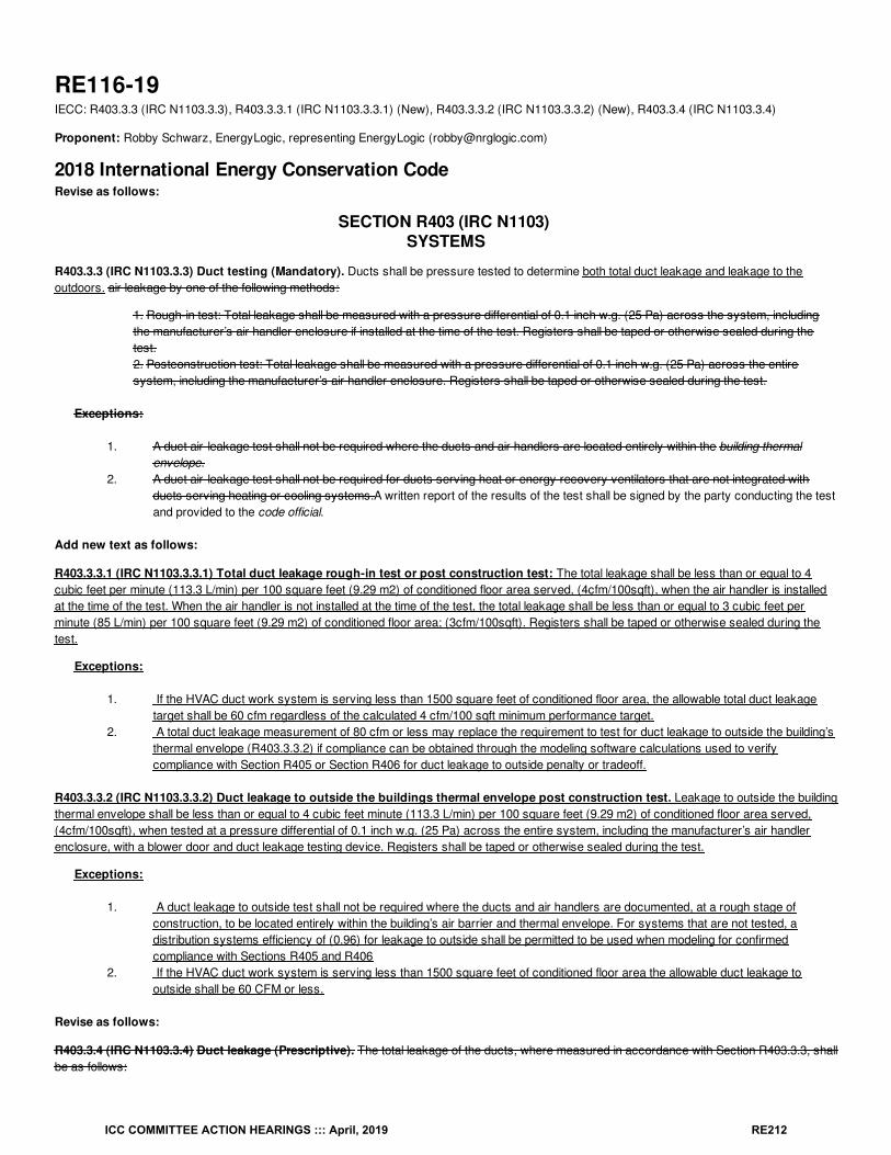
RE116-19IECC: R403.3.3 (IRC N1103.3.3), R403.3.3.1 (IRC N1103.3.3.1) (New), R403.3.3.2 (IRC N1103.3.3.2) (New), R403.3.4 (IRC N1103.3.4)
Proponent: Robby Schwarz, EnergyLogic, representing EnergyLogic ([email protected])
2018 International Energy Conservation CodeRevise as follows:
SECTION R403 (IRC N1103) SYSTEMS
R403.3.3 (IRC N1103.3.3) Duct testing (Mandatory). Ducts shall be pressure tested to determine both total duct leakage and leakage to theoutdoors. air leakage by one of the following methods:
1. Rough-in test: Total leakage shall be measured with a pressure differential of 0.1 inch w.g. (25 Pa) across the system, includingthe manufacturer’s air handler enclosure if installed at the time of the test. Registers shall be taped or otherwise sealed during thetest.2. Postconstruction test: Total leakage shall be measured with a pressure differential of 0.1 inch w.g. (25 Pa) across the entiresystem, including the manufacturer’s air handler enclosure. Registers shall be taped or otherwise sealed during the test.
Exceptions:
1. A duct air-leakage test shall not be required where the ducts and air handlers are located entirely within the building thermalenvelope.
2. A duct air-leakage test shall not be required for ducts serving heat or energy recovery ventilators that are not integrated withducts serving heating or cooling systems.A written report of the results of the test shall be signed by the party conducting the testand provided to the code official.
Add new text as follows:
R403.3.3.1 (IRC N1103.3.3.1) Total duct leakage rough-in test or post construction test: The total leakage shall be less than or equal to 4cubic feet per minute (113.3 L/min) per 100 square feet (9.29 m2) of conditioned floor area served, (4cfm/100sqft), when the air handler is installedat the time of the test. When the air handler is not installed at the time of the test, the total leakage shall be less than or equal to 3 cubic feet perminute (85 L/min) per 100 square feet (9.29 m2) of conditioned floor area; (3cfm/100sqft). Registers shall be taped or otherwise sealed during thetest.
Exceptions:
1. If the HVAC duct work system is serving less than 1500 square feet of conditioned floor area, the allowable total duct leakagetarget shall be 60 cfm regardless of the calculated 4 cfm/100 sqft minimum performance target.
2. A total duct leakage measurement of 80 cfm or less may replace the requirement to test for duct leakage to outside the building’sthermal envelope (R403.3.3.2) if compliance can be obtained through the modeling software calculations used to verifycompliance with Section R405 or Section R406 for duct leakage to outside penalty or tradeoff.
R403.3.3.2 (IRC N1103.3.3.2) Duct leakage to outside the buildings thermal envelope post construction test. Leakage to outside the buildingthermal envelope shall be less than or equal to 4 cubic feet minute (113.3 L/min) per 100 square feet (9.29 m2) of conditioned floor area served,(4cfm/100sqft), when tested at a pressure differential of 0.1 inch w.g. (25 Pa) across the entire system, including the manufacturer’s air handlerenclosure, with a blower door and duct leakage testing device. Registers shall be taped or otherwise sealed during the test.
Exceptions:
1. A duct leakage to outside test shall not be required where the ducts and air handlers are documented, at a rough stage ofconstruction, to be located entirely within the building’s air barrier and thermal envelope. For systems that are not tested, adistribution systems efficiency of (0.96) for leakage to outside shall be permitted to be used when modeling for confirmedcompliance with Sections R405 and R406
2. If the HVAC duct work system is serving less than 1500 square feet of conditioned floor area the allowable duct leakage tooutside shall be 60 CFM or less.
Revise as follows:
R403.3.4 (IRC N1103.3.4) Duct leakage (Prescriptive). The total leakage of the ducts, where measured in accordance with Section R403.3.3, shallbe as follows:
2
ICC COMMITTEE ACTION HEARINGS ::: April, 2019 RE212
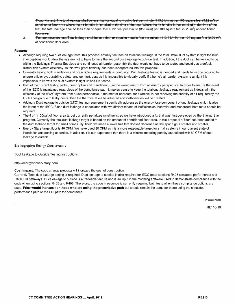
1. Rough-in test: The total leakage shall be less than or equal to 4 cubic feet per minute (113.3 L/min) per 100 square feet (9.29 m ) ofconditioned floor area where the air handler is installed at the time of the test. Where the air handler is not installed at the time of thetest, the total leakage shall be less than or equal to 3 cubic feet per minute (85 L/min) per 100 square feet (9.29 m ) of conditionedfloor area.
2. Postconstruction test: Total leakage shall be less than or equal to 4 cubic feet per minute (113.3 L/min) per 100 square feet (9.29 m )of conditioned floor area.
Reason:Although requiring two duct leakage tests, this proposal actually focuses on total duct leakage. If the total HVAC duct system is tight the built-in exceptions would allow the system not to have to have the second duct leakage to outside test. In addition, if the duct can be verified to bewithin the Building’s Thermal Envelope and continuous air barrier assembly the duct would not have to be tested and could you a defaultdistribution system efficiency. In this way great flexibility has been incorporated into this proposal.Currently having both mandatory and prescriptive requirements is confusing. Duct leakage testing is needed and needs to just be required toensure efficiency, durability, safety, and comfort. Just as it is impossible to visually verify if a home’s air barrier system is air tight it isimpossible to know if the duct system is tight unless it is tested.Both of the current testing paths, prescriptive and mandatory, use the wrong matrix from an energy perspective. In order to ensure the intentof the IECC is maintained regardless of the compliance path, it makes sense to keep the total duct leakage requirement as it deals with theefficiency of the HVAC system from a use perspective. If the master bedroom, for example, is not receiving the quantity of air required by theHVAC design due to leaky ducts, then the thermostat will be adjusted and inefficiencies will be created.Adding a Duct leakage to outside (LTO) testing requirement specifically addresses the energy lose component of duct leakage which is alsothe intent of the IECC. Since duct leakage is associated with two distinct means of inefficiencies, behavior and measured, both tests should berequired.The 4 cfm/100sqft of floor area target currently penalizes small units, so we have introduced a fix that was first developed by the Energy Starprogram. Currently the total duct leakage target is based on the amount of conditioned floor area. In this proposal a 'floor' has been added tothe duct leakage target for small homes. By 'floor', we mean a lower limit that doesn't decrease as the space gets smaller and smaller.Energy Stars target floor is 40 CFM. We have used 80 CFM as it is a more reasonable target for small systems in our current state ofinstallation and sealing expertise. In addition, it is our experience that there is a minimal modeling penalty associated with 80 CFM of ductleakage to outside.
Bibliography: Energy Conservatory
Duct Leakage to Outside Testing Instructions
http://energyconservatory.com
Cost Impact: The code change proposal will increase the cost of constructionCurrently Total duct leakage testing is required. Duct leakage to outside is also required for IECC code sections R405 simulated performance andR406 ERI pathways. Duct leakage to outside is a tradeable feature and is an input in the modeling software used to demonstrate compliance with thecode when using sections R405 and R406. Therefore, the code in essence is currently requiring both tests when these compliance options areused. Price would increase for those who are using the prescriptive path but should remain the same for those using the simulatedperformance path or the ERI path for compliance.
Proposal # 5281
RE116-19
2
2
2
ICC COMMITTEE ACTION HEARINGS ::: April, 2019 RE213
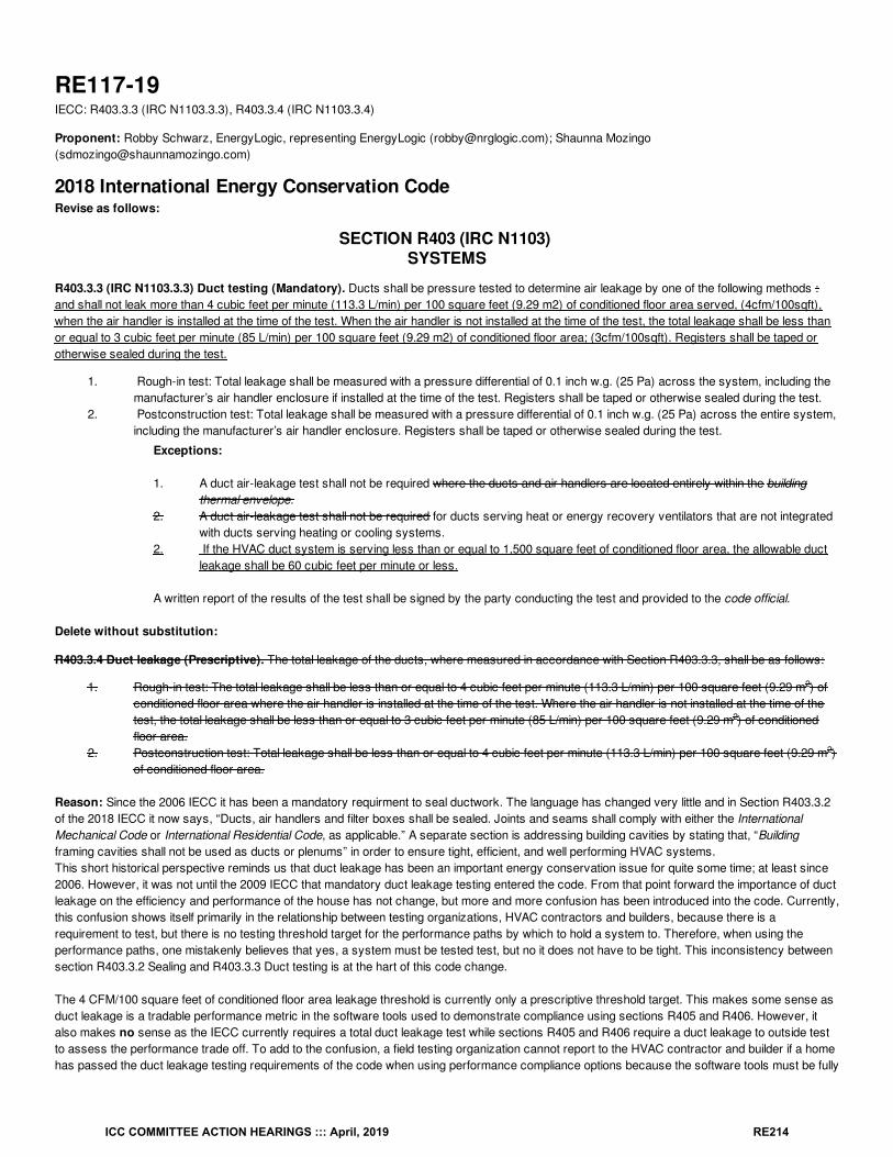
RE117-19IECC: R403.3.3 (IRC N1103.3.3), R403.3.4 (IRC N1103.3.4)
Proponent: Robby Schwarz, EnergyLogic, representing EnergyLogic ([email protected]); Shaunna Mozingo([email protected])
2018 International Energy Conservation CodeRevise as follows:
SECTION R403 (IRC N1103) SYSTEMS
R403.3.3 (IRC N1103.3.3) Duct testing (Mandatory). Ducts shall be pressure tested to determine air leakage by one of the following methods :and shall not leak more than 4 cubic feet per minute (113.3 L/min) per 100 square feet (9.29 m2) of conditioned floor area served, (4cfm/100sqft),when the air handler is installed at the time of the test. When the air handler is not installed at the time of the test, the total leakage shall be less thanor equal to 3 cubic feet per minute (85 L/min) per 100 square feet (9.29 m2) of conditioned floor area; (3cfm/100sqft). Registers shall be taped orotherwise sealed during the test.
1. Rough-in test: Total leakage shall be measured with a pressure differential of 0.1 inch w.g. (25 Pa) across the system, including themanufacturer’s air handler enclosure if installed at the time of the test. Registers shall be taped or otherwise sealed during the test.
2. Postconstruction test: Total leakage shall be measured with a pressure differential of 0.1 inch w.g. (25 Pa) across the entire system,including the manufacturer’s air handler enclosure. Registers shall be taped or otherwise sealed during the test.
Exceptions:
1. A duct air-leakage test shall not be required where the ducts and air handlers are located entirely within the buildingthermal envelope.
2. A duct air-leakage test shall not be required for ducts serving heat or energy recovery ventilators that are not integratedwith ducts serving heating or cooling systems.
2. If the HVAC duct system is serving less than or equal to 1,500 square feet of conditioned floor area, the allowable ductleakage shall be 60 cubic feet per minute or less.
A written report of the results of the test shall be signed by the party conducting the test and provided to the code official.
Delete without substitution:
R403.3.4 Duct leakage (Prescriptive). The total leakage of the ducts, where measured in accordance with Section R403.3.3, shall be as follows:
1. Rough-in test: The total leakage shall be less than or equal to 4 cubic feet per minute (113.3 L/min) per 100 square feet (9.29 m ) ofconditioned floor area where the air handler is installed at the time of the test. Where the air handler is not installed at the time of thetest, the total leakage shall be less than or equal to 3 cubic feet per minute (85 L/min) per 100 square feet (9.29 m ) of conditionedfloor area.
2. Postconstruction test: Total leakage shall be less than or equal to 4 cubic feet per minute (113.3 L/min) per 100 square feet (9.29 m )of conditioned floor area.
Reason: Since the 2006 IECC it has been a mandatory requirment to seal ductwork. The language has changed very little and in Section R403.3.2of the 2018 IECC it now says, “Ducts, air handlers and filter boxes shall be sealed. Joints and seams shall comply with either the InternationalMechanical Code or International Residential Code, as applicable.” A separate section is addressing building cavities by stating that, “Buildingframing cavities shall not be used as ducts or plenums” in order to ensure tight, efficient, and well performing HVAC systems.This short historical perspective reminds us that duct leakage has been an important energy conservation issue for quite some time; at least since2006. However, it was not until the 2009 IECC that mandatory duct leakage testing entered the code. From that point forward the importance of ductleakage on the efficiency and performance of the house has not change, but more and more confusion has been introduced into the code. Currently,this confusion shows itself primarily in the relationship between testing organizations, HVAC contractors and builders, because there is arequirement to test, but there is no testing threshold target for the performance paths by which to hold a system to. Therefore, when using theperformance paths, one mistakenly believes that yes, a system must be tested test, but no it does not have to be tight. This inconsistency betweensection R403.3.2 Sealing and R403.3.3 Duct testing is at the hart of this code change.
The 4 CFM/100 square feet of conditioned floor area leakage threshold is currently only a prescriptive threshold target. This makes some sense asduct leakage is a tradable performance metric in the software tools used to demonstrate compliance using sections R405 and R406. However, italso makes no sense as the IECC currently requires a total duct leakage test while sections R405 and R406 require a duct leakage to outside testto assess the performance trade off. To add to the confusion, a field testing organization cannot report to the HVAC contractor and builder if a homehas passed the duct leakage testing requirements of the code when using performance compliance options because the software tools must be fully
2
2
2
ICC COMMITTEE ACTION HEARINGS ::: April, 2019 RE214
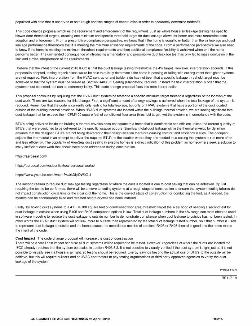
populated with data that is observed at both rough and final stages of construction in order to accurately determine tradeoffs.
This code change proposal simplifies the requirement and enforcement of the requirment. Just as whole house air leakage testing has specificblower door threshold targets, creating one minimum and specific threshold target for duct leakage allows for better and more streamline codeadoption and enforcement. From a prescriptive compliance perspective, we know that if the home is equal to or better than the air leakage and ductleakage performance thresholds that it is meeting the minimum efficiency requirements of the code. From a performance perspective we also needto know if the home is meeting the minimum threshold requirements and then additional compliance flexibility is achieved when or if the homeperforms better. The unintended consequence of introducing a mandatory and prescriptive duct leakage test has only led to mass confusion in thefield and a miss interpretation of the requirements.
I believe that the intent of the current 2018 IECC is that the duct leakage testing threshold is the 4% target. However, interpretation abounds. If thisproposal is adopted, testing organizations would be able to quickly determine if the home is passing or failing with out argument that tighter systemsare not required. Field interpretation from the HVAC contractor and builder side has not been that a specific leakage threshold target must beachieved or that the system must be sealed as Section R403.3.2 Sealing (Mandatory) requires. Instead the field interpretation is often that thesystem must be tested, but can be extremely leaky. This code change proposal fixes this miss interpretation.
This proposal continues by requiring that the HVAC duct system be tested to a specific minimum target threshold regardless of the location of theduct work. There are two reasons for this change. First, a significant amount of energy savings is achieved when the total leakage of the system isreduced. Remember that the code is currently only testing for total leakage, but only on HVAC systems that have a portion of the duct locatedoutside of the building thermal envelope. When HVAC duct systems are located within the buildings thermal envelop, we are seeing significate totalduct leakage that far exceed the 4 CFM/100 square feet of conditioned floor area threshold target, yet the system is in compliance with the code.
BTU’s being delivered inside the building’s thermal envelop does not equate to a home that is comfortable and efficient unless the correct quantity ofBTU’s that were designed to be delivered to the specific location occurs. Significant total duct leakage within the thermal envelop by definitionensures that the designed BTU’s are not being delivered to their design location therefore causing comfort and efficiency issues. The occupantadjusts the thermostat in an attempt to deliver the required BTU’s to the location where they are needed thus casing the system to run more oftenand less efficiently. The popularity of AreoSeal duct sealing in existing homes is a direct indication of this problem as homeowners seek a solution toleaky inefficient duct work that should have been addressed during construction.
https://aeroseal.com/
https://aeroseal.com/residential/how-aeroseal-works/
https://www.youtube.com/watch?v=06DlipDW0GU
The second reason to require duct leakage testing regardless of where the duct is located is due to cost saving that can be achieved. By justrequiring the test to be performed, there will be a move to testing systems at a rough stage of construction to ensure that system testing failures donot impact construction cycle time or the closing of the home. This is the correct stage of construction for conducting the test, as if needed, thesystem can be economically fixed and retested before drywall has been installed.
Lastly, by holding duct systems to a 4 CFM/100 square feet of conditioned floor area threshold target the likely hood of needing a second test forduct leakage to outside when using R405 and R406 compliance options is low. Total duct leakage numbers in the 4% range can most often be usedin software modeling to replace the duct leakage to outside number to demonstrate compliance when duct leakage to outside has not been tested. Inother words the HVAC duct system will not leak more to outside than represented by the total duct leakage tested number, so if that number is usedto represent duct leakage to outside and the home passes the compliance metrics of sections R405 or R406 then all is good and the home meetsthe intent of the code.
Cost Impact: The code change proposal will increase the cost of constructionThere will be a small cost impact because all duct systems will be required to be tested. However, regardless of where the ducts are located theIECC already requires that the system be sealed in section R403.3.2. It is not possible to visually verified if the duct system is tight just as it is notpossible to visually see if a house is air tight, so testing should be required. Energy savings beyond the actual loss of BTU’s to the outside will beachieve, but this will require builders and or HVAC contractors to pay testing organizations or third party approved agencies to verify the ductleakage of the system.
Proposal # 5270
RE117-19
ICC COMMITTEE ACTION HEARINGS ::: April, 2019 RE215
RE118-19IECC: R403.3.3 (IRC N1103.3.3)
Proponent: Mike Moore, Newport Ventures, representing Broan-NuTone ([email protected])
2018 International Energy Conservation CodeRevise as follows:
R403.3.3 (IRC N1103.3.3) Duct testing (Mandatory). Ducts shall be pressure tested to determine air leakage by one of the following methods:
1. Rough-in test: Total leakage shall be measured with a pressure differential of 0.1 inch w.g. (25 Pa) across the system, including themanufacturer’s air handler enclosure if installed at the time of the test. Registers shall be taped or otherwise sealed during the test.
2. Postconstruction test: Total leakage shall be measured with a pressure differential of 0.1 inch w.g. (25 Pa) across the entire system,including the manufacturer’s air handler enclosure. Registers shall be taped or otherwise sealed during the test.
Exceptions:
1. A duct air-leakage test shall not be required where the ducts and air handlers are located entirely within the building thermalenvelope.
2. A duct air-leakage test shall not be required for ducts serving heat or energy recovery ventilators ventilation systems that are notintegrated with ducts serving heating or cooling systems.
A written report of the results of the test shall be signed by the party conducting the test and provided to the code official.
Reason: Regardless of the ventilation system type specified, this section is not meant to verify leakage associated with ventilation systems(exhaust, supply, or balanced/HRV/ERV) that are separate from the ducts serving heating or cooling systems.
Cost Impact: The code change proposal will decrease the cost of constructionThis proposal will remove duct leakage verification testing that would otherwise unintentionally be applied to ventilation systems.
Proposal # 5118
RE118-19
ICC COMMITTEE ACTION HEARINGS ::: April, 2019 RE216
RE119-19IECC: R403.3.3 (IRC N1103.3.4), R403.3.3 (IRC N1103.3.4)
Proponent: Joel Martell, representing National Association of Home Builders ([email protected])
2018 International Energy Conservation CodeRevise as follows:
R403.3.3 (IRC N1103.3.3) Duct testing (Mandatory). Ducts shall be pressure tested to determine air leakage by one of the following methods:
1. Rough-in test: Total leakage shall be measured with a pressure differential of 0.1 inch w.g. (25 Pa) across the system, including themanufacturer’s air handler enclosure if installed at the time of the test. Registers shall be taped or otherwise sealed during the test.
2. Postconstruction test: Total leakage shall be measured with a pressure differential of 0.1 inch w.g. (25 Pa) across the entire system,including the manufacturer’s air handler enclosure. Alternatively, a duct leakage test to outside conditioned space with a pressuredifferential of 0.1 w.g. (25 Pa) with reference to the outside across the entire system including the manufacturers's air handlerenclosure. Registers shall be taped or otherwise sealed during the test.
Exceptions:
1. A duct air-leakage test shall not be required where the ducts and air handlers are located entirely within the building thermalenvelope.
2. A duct air-leakage test shall not be required for ducts serving heat or energy recovery ventilators that are not integrated withducts serving heating or cooling systems.
A written report of the results of the test shall be signed by the party conducting the test and provided to the code official.
R403.3.4 (IRC N1103.3.4) Duct leakage (Prescriptive). The total leakage of the ducts, where measured in accordance with Section R403.3.3, shallbe as follows:
1. Rough-in test: The total leakage shall be less than or equal to 4 cubic feet per minute (113.3 L/min) per 100 square feet (9.29 m ) ofconditioned floor area where the air handler is installed at the time of the test. Where the air handler is not installed at the time of thetest, the total leakage shall be less than or equal to 3 cubic feet per minute (85 L/min) per 100 square feet (9.29 m ) of conditionedfloor area.
2. Postconstruction test: Total leakage or leakage to outside conditioned space shall be less than or equal to 4 cubic feet per minute(113.3 L/min) per 100 square feet (9.29 m ) of conditioned floor area.
Reason: Allowing the option for measurement of duct leakage to the outside will give both HVAC installers and homeowners an accuratemeasurement of duct leaks to the exterior of the building. This is the only true testing method that measures energy loss as the method is measuringthe leakage outside the thermal envelope not from inside conditioned space. Duct leakage to the outdoors is an accepted duct testing method in theindustry and was allowed under Section 403.2.2 of the 2009 IECC and approved for the 2015 IECC by the committee, but withdrawn by theproponent. Proposed changes provide clarity as to what distribution system efficiency should be applied to the Standard Reference Design and howthe ducts should be modeled in the performance path.
Cost Impact: The code change proposal will not increase or decrease the cost of constructionThis proposal will not change the cost of construction. It will provide a testing method that measures the true energy loss of ducts.
Proposal # 4293
RE119-19
2
2
2
ICC COMMITTEE ACTION HEARINGS ::: April, 2019 RE217
RE120-19IECC: R403.3.4 (IRC N1103.3.4)
Proponent: William Fay, Energy-Efficient Codes Coalition, representing Energy-Efficient Codes Coalition ([email protected]); Daniel Bresette, Allianceto Save Energy, representing Alliance to Save Energy ([email protected]); Maureen Guttman, BCAP-IBTS, representing BCAP-IBTS([email protected]); Harry Misuriello, American Council for an Energy-Efficient Economy, representing American Council for an Energy-Efficient Economy ([email protected])
2018 International Energy Conservation CodeRevise as follows:
R403.3.4 (IRC N1103.3.4) Duct leakage (Prescriptive). The total leakage of the ducts, where measured in accordance with Section R403.3.3, shallbe as follows:
1. Rough-in test: The total leakage shall be less than or equal to 4 4.0 cubic feet per minute (113.3 L/min) per 100 square feet (9.29 m )of conditioned floor area where the air handler is installed at the time of the test. Where the air handler is not installed at the time of thetest, the total leakage shall be less than or equal to 3 3.0 cubic feet per minute (85 L/min) per 100 square feet (9.29 m ) of conditionedfloor area.
2. Postconstruction test: Total leakage shall be less than or equal to 4 4.0 cubic feet per minute (113.3 L/min) per 100 square feet (9.29m ) of conditioned floor area.
Reason: The purpose of this code change proposal is to clarify the current requirements for maximum duct leakage that are already part of theIECC and to ensure that buildings achieve the efficiency intended by the code by adding an additional digit. Specifically, the code proposal adds “.0”to the specified duct leakage rate to clarify that a value above 4.0 cfm (or 3.0 cfm where the air handler is not installed) is not allowed. While webelieve that the best interpretation of the current standard is that the duct leakage may not exceed 4.0, the addition of another digit will pre-empt anyclaim that a tested value above these maximums, such as 4.4, will meet the maximum. By preempting these “round off” arguments from code users,this change will provide additional support for building code officials who are simply trying to enforce the code. This proposed clarification will notchange any substantive requirements of the code but will improve compliance and enforcement and eliminate any confusion.
Cost Impact: The code change proposal will not increase or decrease the cost of constructionIt merely serves to clarify a current requirement to avoid confusion and inconsistent enforcement.
Proposal # 3995
RE120-19
2
2
2
ICC COMMITTEE ACTION HEARINGS ::: April, 2019 RE218

RE121-19IECC: R403.3.4.1 (IRC N1103.3.4.1) (New), R403.3.4.1.1 (IRC N1103.3.4.1.1) (New), R403.3.4.1.2 (IRC N1103.3.4.1.2) (New)
Proponent: Aaron Gary, representing Self ([email protected])
2018 International Energy Conservation CodeAdd new text as follows:
R403.3.4.1 (IRC N1103.3.4.1) Sampling options for R2 multifamily dwelling units. For buildings having three or more dwelling units, a minimumof 15% of the dwelling units in each building must be tested as required by Section R403.3.3. Prior to beginning sampling for testing, “Initial Testing”is required for each multifamily property. “Initial Testing” shall consist of the 3rd party testing contractor performing the required tests on at leastthree consecutive dwelling units. Test results from the “Initial Testing” must satisfy minimum code requirements before sampling is permitted.Dwelling units selected for the “Initial Testing” must be within the same building. Dwelling units selected for “Initial Testing” shall not be included in a“sample group” or counted toward the minimum 15% of dwelling units tested. The building official shall randomly select the three dwelling units for“Initial Testing.” The building official may delegate the random selection to the designated 3rd party testing contractor.
R403.3.4.1.1 (IRC N1103.3.4.1.1) Sample group Identification and Sampling The builder shall identify a "sample group" which may be a building,floor, fire area or portion thereof. All of the dwelling units within the “sample group” must be at the same stage of construction and must be ready fortesting. The building official shall randomly select at least 15% of dwelling units from each “sample group” for testing. The building official maydelegate the random selection to the designated 3rd party testing contractor.If each tested dwelling unit within a “sample group” meets the minimum code requirements, then all dwelling units in the “sample group” areconsidered to meet the minimum code requirements.
Before a building may be deemed compliant with the testing as required, each “sample group” must be deemed compliant with the minimum coderequirements. The sum total of all of the tested dwelling units across all “sample groups” shall not be less than a minimum of 15% of the dwellingunits in a building.
R403.3.4.1.2 (IRC N1103.3.4.1.2) Failure to Meet Code Requirement(s). If any dwelling units within the identified “sample group” fail to meet acode requirement as determined by testing, the builder will be directed to correct the cause(s) of failure, and 30% of the remaining dwelling units inthe “sample group” will be randomly selected for testing by the building official, or third-party testing contractor, regarding the specific cause(s) offailure.If any failures occur in the additional dwelling units, all remaining dwelling units in the sample group must be individually tested for code compliance.
A multifamily property with three failures within a 90-day period is no longer eligible to use the sampling protocol in that community or project untilsuccessfully repeating "Initial Testing." Sampling may be reinstated after at least three consecutive dwelling units are individually verified to meet allcode requirements.
A Certificate of Occupancy may not may be issued for any building until testing has been performed and deemed to satisfy the minimum coderequirements on the dwelling unit(s) identified for testing.
Reason: For many multifamily (R2 classifications) projects, it is very costly and time consuming to test each dwelling unit for projects where theremay be dozens of dwelling units in each building. Considering that the same tradesman generally constructs a building, it is reasonable to deem thatconstruction practices are consistent and that if a reasonable sampling of units tested pass then all units would pass. These amendments (originallydrafted by the North Texas Council of Governments Energy and Green Advisory Board) or are very similar ordinances, have been acceptedacross Texas by the EHJs including the City of Dallas, the City of Austin, and the City of San Antonio.
Cost Impact: The code change proposal will decrease the cost of constructionThis code change proposal will streamline the cost and time required to conduct on-site verification of Code which will result in lower testing costsand faster construction timelines
Proposal # 4589
RE121-19
ICC COMMITTEE ACTION HEARINGS ::: April, 2019 RE219
RE122-19IECC: R403.3.6.1 (IRC N1103.3.6.1)
Proponent: David Collins, SEHPCAC, representing SEHPCAC ([email protected]); David Collins, representing The American Institute ofArchitects ([email protected])
2018 International Energy Conservation CodeRevise as follows:
R403.3.6.1 (IRC N1103.3.6.1) Effective R-value of deeply buried ducts (Mandatory). Where using a simulated energy performance analysis,sections of ducts that are: installed in accordance with Section R403.3.6; located directly on, or within 5.5 inches (140 mm) of the ceiling; surroundedwith blown-in attic insulation having an R-value of R-30 or greater and located such that the top of the duct is not less than 3.5 inches (89 mm) belowthe top of the insulation, shall be considered as having an effective duct insulation R-value of R-25.
Reason: This section provides to installation details related to a calculation methodology to be used in specific circumstances. There is no value ormetric available for trade-offs in the performance path.As such SEHPCAC believes this is a mandated, non-tradeable methodology for calculating R-value, and should be labeled mandatory.
Note that the SEHPCAC has a proposal to eliminate the use of the labels "prescriptive “and "mandatory" in favor of a tabular method of identifyingnon-tradeable requirements. If that proposal is successful ICC staff have stated that sections being individually approved to be labeled as‘mandatory’ will instead have their respective section numbers added to the new C407.2 table of requirements that are non-tradeable in theperformance path
This proposal is submitted by the ICC Sustainable, Energy and High Performance Code Action Committee (SEHPCAC). The SEHPCAC wasestablished by the ICC Board of Directors to pursue opportunities to improve and enhance International Codes with regard to sustainability, energyand high performance as it relates to the built environment included, but not limited to, how these criteria relate to the International GreenConstruction Code (IgCC) and the International Energy Conservation Code (IECC). In 2018-2019, the SEHPCAC has held five two- or three-dayopen meetings and numerous workgroup calls, to discuss and debate proposed changes and public comments. Attendees at the meetings and callsincluded members of the SEHPCAC as well as any interested parties. Related documentation and reports are posted on the SEHPCAC website at:http://www.iccsafe.org/cs/SEHPCAC/Pages/default.aspx (http://www.iccsafe.org/cs/SEHPCAC/Pages/default.aspx)
Cost Impact: The code change proposal will not increase or decrease the cost of constructionThis does not change the design or construction requirements it makes mandatory the standard R-value calculation methodology
Proposal # 4480
RE122-19
ICC COMMITTEE ACTION HEARINGS ::: April, 2019 RE220
RE123-19IECC: R403.4.1 (IRC N1103.4.1)
Proponent: Howard Ahern, representing self ([email protected])
2018 International Energy Conservation CodeRevise as follows:
R403.4.1 (IRC N1103.4.1) Protection of piping insulation (Mandatory). Piping insulation exposed to weather shall be protected from damage,including that caused by sunlight, moisture, equipment maintenance and wind. The protection shall provide shielding from solar radiation that cancause degradation of the material. Adhesive tape shall be prohibited.
Reason: The protection of pipe insulation should be a Mandatory requirement just as the requirement to insulate pipes of the heating or coolingsystem. As the commercial IECC requires protection as mandatory this residential, section needs to as well. Energy saving for insulating piping ofheating and cooling systems is well researched and documented. Protecting this energy saving is crucial.
Example of saving from protecting the insulation can be measured in Dr Kourmohammadi PE, Ph.D. CPD, CIPE, CFPE LEED AP
“Insulation materials cannot endure physical impact or are fragile to many elements, i.e.
weather. Weather impact on insulation is very high. The sun enhances the transforms the
insulation from thermoplast (soft) foam to thermoset (brittle) foam property. The property
change also impacts the thermal conductivity of the material and consequently its
performance. Protective covers become the sacrificial lamb and provide the stability in
properties of the insulation.
Maintenance of pipes insulation is often non-existence. Aged insulation is generally
brittle, poorly reinstalled, and subject to damage to the weather.”
Paper on Protective covers which calculated the BTU and Electrical energy saving of exposed Freon lines for residential and multifamily purposes .
Freon lines exposed 3 ft to 5 ft
0.15/kwhr cost of electricity (peak demand cost can be at
0.25$/kwhr)
10 hours operation
365 days
¾” Freon line
½” insulation property 0.020227 Btu/(hr F ft)
For the California region it amounted to a $1.00 per foot annual savings
Example of cost saving average 5ft per unit in California with a population of 39 million and
If only half of the population for example had a heating and /Cooling system with an average of 5ft exposed piping with degraded or no insulation ,Protected pipe insulation would amount to an yearly electrical saving of $975,000,000
This is electrical saving and does not include the saving to home and building owners from not having a costly expenses of replacing insulation formaintenance
ICC COMMITTEE ACTION HEARINGS ::: April, 2019 RE221
Bibliography: Impact and Advantages ofRemovable Insulation Protective Covers
Dr. “Saum” K. Nourmohammadi, PEx3, Ph.D. CPD, CIPE, CFPE,
LEED AP
Cost Impact: The code change proposal will not increase or decrease the cost of constructionThis change will not increase the cost of construction as protection is required by this section and by pipe insulation manufactures
Proposal # 5240
RE123-19
ICC COMMITTEE ACTION HEARINGS ::: April, 2019 RE222
RE124-19IECC: R403.3.5 (IRC N1103.3.5)
Proponent: Ron Clements, Chesterfield County, representing Chesterfield County ([email protected])
2018 International Energy Conservation CodeDelete without substitution:
R403.3.5 Building cavities (Mandatory). Building framing cavities shall not be used as ducts or plenums.
Reason: Duct system construction methods and materials is outside the scope of IRC chapter 11. Duct system construction is within the scope ofIRC chapter 16. Section M1601.1.1 #7 allows the use of stud wall cavities for return air. This is a code correlation issue. If stud cavities should notbe used under any circumstance then M1601.1.1 should be amended.
Cost Impact: The code change proposal will decrease the cost of constructionIf approved this code change will allow use of wall cavity spaces as return duct plenums, which saves money that would need to be spent on returnduct work.
Proposal # 5613
RE124-19
ICC COMMITTEE ACTION HEARINGS ::: April, 2019 RE223
RE125-19IECC: R403.5.2 (IRC N1103.5.2)
Proponent: David Collins, SEHPCAC, representing SEHPCAC ([email protected]); David Collins, representing The American Institute ofArchitects ([email protected])
2018 International Energy Conservation CodeRevise as follows:
R403.5.2 (IRC N1103.5.2) Demand recirculation water systems (Mandatory). Demand Where installed, demand recirculation water systemsshall have controls that comply with both of the following:
1. The controls shall start the pump upon receiving a signal from the action of a user of a fixture or appliance, sensing the presence ofa user of a fixture or sensing the flow of hot or tempered water to a fixture fitting or appliance.
2. The controls shall limit the temperature of the water entering the cold water piping to not greater than 104ºF (40ºC).
Reason: There are no values or metrics for energy performance associated with Sec. R403.5.2. This means there is no value that can be used fortrade-offs in the performance path.Because the provisions of R403.5.2 cannot be feasibly modeled or traded they should be labeled as mandatory.
The words "where installed" were added to make clear that Demand Recirculation Systems themselves are not required to be installed, but thatwhere they are installed there is no value in trading the provisions in the performance path.
Note that the SEHPCAC has a proposal to eliminate the use of the labels "prescriptive “and "mandatory" in favor of a tabular method of identifyingnon-tradeable requirements. If that proposal is successful ICC staff have stated that sections being individually approved to be labeled as‘mandatory’ will instead have their respective section numbers added to the new C407.2 table of requirements that are non-tradeable in theperformance path.
This proposal is submitted by the ICC Sustainable, Energy and High Performance Code Action Committee (SEHPCAC). The SEHPCAC wasestablished by the ICC Board of Directors to pursue opportunities to improve and enhance International Codes with regard to sustainability, energyand high performance as it relates to the built environment included, but not limited to, how these criteria relate to the International GreenConstruction Code (IgCC) and the International Energy Conservation Code (IECC). In 2018-2019, the SEHPCAC has held five two- or three-dayopen meetings and numerous workgroup calls, to discuss and debate proposed changes and public comments. Attendees at the meetings and callsincluded members of the SEHPCAC as well as any interested parties. Related documentation and reports are posted on the SEHPCAC website at:http://www.iccsafe.org/cs/SEHPCAC/Pages/default.aspx (http://www.iccsafe.org/cs/SEHPCAC/Pages/default.aspx)
Cost Impact: The code change proposal will increase the cost of constructionThe code change may increase construction costs for a subset of buildings that may have been designed using the Total Building Performance orEIR compliance methods that included Demand recirculation water systems without the specified controls.
Proposal # 4484
RE125-19
ICC COMMITTEE ACTION HEARINGS ::: April, 2019 RE224
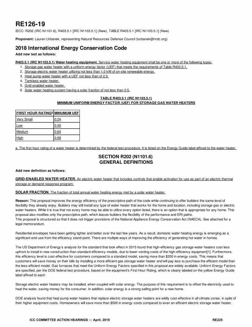
RE126-19IECC: R202 (IRC N1101.6), R403.5.1 [IRC N1103.5.1] (New), TABLE R403.5.1 [IRC N1103.5.1] (New)
Proponent: Lauren Urbanek, representing Natural Resources Defense Council ([email protected])
2018 International Energy Conservation CodeAdd new text as follows:
R403.5.1 (IRC N1103.5.1) Water heating equipment. Service water heating equipment shall be one or more of the following types:1. Storage gas water heater with a uniform energy factor (UEF) that meets the requirements of Table R403.5.1.2. Storage electric water heater utilizing not less than 1.0 kW of on-site renewable energy.3. Heat pump water heater with a UEF not less than of 2.0.4. Tankless water heater.5. Grid-enabled water heater.6. Solar water heating system having a solar fraction of not less than 0.5.
TABLE R403.5.1 (IRC N1103.5.1)MINIMUM UNIFORM ENERGY FACTOR (UEF) FOR STORAGE GAS WATER HEATERS
FIRST HOUR RATING MINUMUM UEF
Very Small 0.24
Low 0.50
Medium 0.64
High 0.68
a. The first hour rating of a water heater is determined by the federal test procedure. It is listed on the Energy Guide label affixed to the water heater.
SECTION R202 (N1101.6) GENERAL DEFINITIONS
Add new definition as follows:
GRID-ENABLED WATER HEATER. An electric water heater that includes controls that enable activation for use as part of an electric thermalstorage or demand response program.
SOLAR FRACTION. The fraction of total annual water heating energy met by a solar water heater.
Reason: This proposal improves the energy efficiency of the prescriptive path of the code while continuing to offer builders the same level offlexibility they already enjoy. Builders may still install any type of water heater that works for the home and location, including storage gas or electricwater heaters. While it is true that not every home may be able to utilize every option listed, there is an option that is appropriate for any home. Thisproposal also modifies only the prescriptive path, which leaves builders the flexibility of the performance and ERI paths.This proposal is structured so that it does not trigger provisions of the National Appliance Energy Conservation Act (NAECA). See attached for alegal memorandum.
Residential envelopes have been getting tighter and better over the last few years. As a result, domestic water heating energy is emerging as asignificant end-use from the efficiency stand-point. There are multiple ways of improving the efficiency of generating hot water in homes.
The US Department of Energy’s analysis for the standard that took effect in 2015 found that high-efficiency gas storage water heaters cost lessupfront to install in new construction than standard efficiency models, due to lower venting costs of the high-efficiency equipment[1]. Furthermore,this efficiency level is cost-effective for customers compared to a standard model, saving more than $200 in energy costs. This means thatcustomers will save money on their bills by installing a more efficient gas storage water heater and will pay less to purchase the efficient model thanthe less-efficient model. Gas furnaces that meet the Uniform Energy Factors specified in this proposal are widely available. Uniform Energy Factorsare specified, per the DOE federal test procedure, based on the equipment’s First Hour Rating, which is clearly labeled on the yellow Energy Guidelabel affixed to each
Storage electric water heaters may be installed, when coupled with solar energy. The purpose of this requirement is to offset the electricity used toheat the water, saving money for the consumer. In addition, solar energy is a strong selling point for a new home.
DOE analysis found that heat pump water heaters that replace electric storage water heaters are wildly cost-effective in all climate zones, in spite oftheir higher equipment costs. Homeowners will save more than $500 in energy costs compared to even an efficient electric storage water heater.
a
ICC COMMITTEE ACTION HEARINGS ::: April, 2019 RE225

Tankless water heaters were cost-effective in the warmer climate zones, but were not as cost-effective in the colder climate zones.
As part of DOE’s appliance and equipment standards initiative, stakeholders expressed the importance of electric resistance water heaters toelectric thermal storage (ETS) programs, so those grid-enabled water heaters are also incorporated into this proposal. Utilities use ETS programs,sometimes also known as load shifting or demand response programs, to manage peak demand load by limiting the times when certain appliancesare operated. In certain water-heater based ETS programs, a utility typically controls a water heater remotely to allow operation only when electricitydemand is during off-peak hours. During that off-peak operation, the electricity consumed is stored by the water heater as thermal energy for useduring peak hours when the utility prevents the water heater from using electricity.
A solar water heating system can be designed in a variety of different ways. They can directly heat the water using the sun, can indirectly transferheat from the sun to water in a storage tank, or can use pumps and valves to move water from collectors to a storage tank. They can have eithergas or electric backup heating capabilities. This proposal requires at least half of the total energy delivered to the water heater to be generatedthrough solar energy.
[1] U.S. Department of Energy, Energy Efficiency and Renewable Energy Office. Water Heater Technical Support Document Analytical Tools.Retrieved on January 11, 2019 from https://www.regulations.gov/document?D=EERE-2006-STD-0129-0046.
ICC COMMITTEE ACTION HEARINGS ::: April, 2019 RE226
ICC COMMITTEE ACTION HEARINGS ::: April, 2019 RE227
ICC COMMITTEE ACTION HEARINGS ::: April, 2019 RE228
Bibliography: U.S. Department of Energy, Energy Efficiency and Renewable Energy Office. Water Heater Technical Support Document AnalyticalTools. Retrieved on January 11, 2019 from https://www.regulations.gov/document?D=EERE-2006-STD-0129-0046.
Cost Impact: The code change proposal will not increase or decrease the cost of constructionThis proposal provides a list of options for a builder to choose from. In some instances the builder may choose an option which increasesconstruction costs, but there are many options that will not increase costs. For instance, the US Department of Energy’s analysis for the water
ICC COMMITTEE ACTION HEARINGS ::: April, 2019 RE229
heater standard that took effect in 2015 found that high-efficiency gas storage water heaters cost less upfront to install in new construction thanstandard efficiency models, due to lower venting costs of the high-efficiency equipment.
Proposal # 5421
RE126-19
ICC COMMITTEE ACTION HEARINGS ::: April, 2019 RE230
RE127-19IECC: R403.5.3 (IRC N1103.5.3)
Proponent: David Collins, SEHPCAC, representing SEHPCAC ([email protected]); David Collins, representing The American Institute ofArchitects ([email protected])
2018 International Energy Conservation CodeRevise as follows:
R403.5.3 (IRC N1103.5.3) Hot water pipe insulation (Prescriptive). Insulation for service hot water piping with a thermal resistance, R-value, ofnot less than R-3 shall be applied to the following:
1. Piping / inch (19.1 mm) and larger in nominal diameter located inside the conditioned space.2. Piping serving more than one dwelling unit.3. Piping located outside the conditioned space.4. Piping from the water heater to a distribution manifold.5. Piping located under a floor slab.6. Buried piping.7. Supply and return piping in circulation and recirculation systems other than cold water pipe return demand recirculation systems.
Reason: The change clarifies the intent of the requirements which require all piping in items 2 through 7 to be insulated regardless of pipe diameter.The exemption in item 7 is further clarified by not requiring insulation on the "cold water pipe return" in a demand recirculation system.This proposal is submitted by the ICC Sustainable, Energy and High Performance Code Action Committee (SEHPCAC). The SEHPCAC wasestablished by the ICC Board of Directors to pursue opportunities to improve and enhance International Codes with regard to sustainability, energyand high performance as it relates to the built environment included, but not limited to, how these criteria relate to the International GreenConstruction Code (IgCC) and the International Energy Conservation Code (IECC). In 2018-2019, the SEHPCAC has held five two- or three-dayopen meetings and numerous workgroup calls, to discuss and debate proposed changes and public comments. Attendees at the meetings and callsincluded members of the SEHPCAC as well as any interested parties. Related documentation and reports are posted on the SEHPCAC website at:http://www.iccsafe.org/cs/SEHPCAC/Pages/default.aspx (http://www.iccsafe.org/cs/SEHPCAC/Pages/default.aspx)
Cost Impact: The code change proposal will not increase or decrease the cost of constructionThis is a clarification only, not an additional design or constuction requirement.
Proposal # 4759
RE127-19
34
ICC COMMITTEE ACTION HEARINGS ::: April, 2019 RE231
RE128-19IEEC: R403.5.3 (IRC N1103.5.3)
Proponent: David Collins, SEHPCAC, representing SEHPCAC ([email protected]); David Collins, representing The American Institute ofArchitects ([email protected])
2018 International Energy Conservation CodeRevise as follows:
R403.5.3 (IRC N1103.5.3) Hot water pipe insulation (Prescriptive Mandatory). Insulation for hot water piping with a thermal resistance, R-value,of not less than R-3 shall be applied to the following:
1. Piping / inch (19.1 mm) and larger in nominal diameter.2. Piping serving more than one dwelling unit.3. Piping located outside the conditioned space.4. Piping from the water heater to a distribution manifold.5. Piping located under a floor slab.6. Buried piping.7. Supply and return piping in recirculation systems other than demand recirculation systems.
Reason: Because the provisions of R403.5.3 cannot be feasibly modeled or traded; and because of there is no design reason to attempt to model it,R403.5.3 should be labeled as mandatory.Note that the SEHPCAC has a proposal to eliminate the use of the labels "prescriptive “and "mandatory" in favor of a tabular method of identifyingnon-tradeable requirements. If that proposal is successful ICC staff have stated that sections being individually approved to be labeled as‘mandatory’ will instead have their respective section numbers added to the new C407.2 table of requirements that are non-tradeable in theperformance path.
This proposal is submitted by the ICC Sustainable, Energy and High Performance Code Action Committee (SEHPCAC). The SEHPCAC wasestablished by the ICC Board of Directors to pursue opportunities to improve and enhance International Codes with regard to sustainability, energyand high performance as it relates to the built environment included, but not limited to, how these criteria relate to the International GreenConstruction Code (IgCC) and the International Energy Conservation Code (IECC). In 2018-2019, the SEHPCAC has held five two- or three-dayopen meetings and numerous workgroup calls, to discuss and debate proposed changes and public comments. Attendees at the meetings and callsincluded members of the SEHPCAC as well as any interested parties. Related documentation and reports are posted on the SEHPCAC website at:http://www.iccsafe.org/cs/SEHPCAC/Pages/default.aspx (http://www.iccsafe.org/cs/SEHPCAC/Pages/default.aspx)
Cost Impact: The code change proposal will increase the cost of constructionAlthough SEHPCAC has been assured pipe insulation is industry practice, this code change may increase construction costs for a subset ofbuildings that were not insulating pipes.
Proposal # 4485
RE128-19
34
ICC COMMITTEE ACTION HEARINGS ::: April, 2019 RE232
RE129-19IECC: R403.5.4 (IRC N1103.5.4)
Proponent: David Collins, SEHPCAC, representing SEHPCAC ([email protected]); David Collins, representing The American Institute ofArchitects ([email protected])
2018 International Energy Conservation CodeRevise as follows:
R403.5.4 (IRC N1103.5.4) Drain water heat recovery units (Mandatory). Drain water heat recovery units shall comply with CSA B55.2. Drainwater heat recovery units shall be tested in accordance with CSA B55.1. Potable water-side pressure loss of drain water heat recovery units shallbe less than 3 psi (20.7 kPa) for individual units connected to one or two showers. Potable water-side pressure loss of drain water heat recoveryunits shall be less than 2 psi (13.8 kPa) for individual units connected to three or more showers.
Reason: Because the provisions of R403.5.4 cannot be feasibly modeled or traded; and because of there is no design reason to attempt to model it,R403.5.4 should be labeled as mandatory (non-tradeable).Note that the SEHPCAC has a proposal to eliminate the use of the labels "prescriptive “and "mandatory" in favor of a tabular method of identifyingnon-tradeable requirements. If that proposal is successful ICC staff have stated that sections being individually approved to be labeled as‘mandatory’ will instead have their respective section numbers added to the new C407.2 table of requirements that are non-tradeable in theperformance path
This proposal is submitted by the ICC Sustainable, Energy and High Performance Code Action Committee (SEHPCAC). The SEHPCAC wasestablished by the ICC Board of Directors to pursue opportunities to improve and enhance International Codes with regard to sustainability, energyand high performance as it relates to the built environment included, but not limited to, how these criteria relate to the International GreenConstruction Code (IgCC) and the International Energy Conservation Code (IECC). In 2018-2019, the SEHPCAC has held five two- or three-dayopen meetings and numerous workgroup calls, to discuss and debate proposed changes and public comments. Attendees at the meetings and callsincluded members of the SEHPCAC as well as any interested parties. Related documentation and reports are posted on the SEHPCAC website at:http://www.iccsafe.org/cs/SEHPCAC/Pages/default.aspx (http://www.iccsafe.org/cs/SEHPCAC/Pages/default.aspx)
Cost Impact: The code change proposal will increase the cost of constructionAlthough SEHPCAC has been assured this is standard industry practice, the code change may increase construction costs for a subset of buildingsthat may have been designed to include drain water heat recovery but not in accordance with the specified standard.
Proposal # 4487
RE129-19
ICC COMMITTEE ACTION HEARINGS ::: April, 2019 RE233
RE130-19IECC: R403.6.2 (IRC N1103.6.2) (New)
Proponent: Robby Schwarz, EnergyLogic, representing EnergyLogic ([email protected])
2018 International Energy Conservation CodeAdd new text as follows:
R403.6.2 (IRC N1103.6.2) Testing. Mechanical ventilation systems shall be tested and verified to provide the minimum ventilation flow ratesrequired by Section R403.6. Testing shall be performed according to the ventilation equipment manufacturer's instructions, or by using a flow hoodor box, flow grid, or other airflow measuring device at the mechanical ventilation fan's inlet terminals or grilles, outlet terminals or grilles, or in theconnected ventilation ducts. Where required by the code official, testing shall be conducted by an approved third party. A written report of the resultsof the test shall be signed by the party conducting the test and provided to the code official.
Exception: Kitchen range hoods that are ducted to the outside with 6” or larger duct and one or less 90° elbow or equivalent in the duct run areexempt from this requirement to test air flow.
Reason: As we continue to be guided by sound building science to build tight homes as required by the IECC to achieve better predictability andcontrol of air flow, thermal flow, and moisture flow spot/local and whole house ventilation becomes an even more crucial aspect of ensuring that thefull intent of the IECC is met. This includes durability, safety, healthy, flexibility in how we build, as well as, efficiency of the structure. If we do notmore actively ensure that the systems in our homes are not only there, but are also performing as intended we have missed the mark with regardsto the intent of the code and creating dwellings that are durable, safe, healthy, and efficient. The testing experience gained through the verification ofthe EnergyStar program has clearly demonstrated that ventilation fans are installed but are not performing as required by the code. Fan rated flowdoes not equate to the flow that is actually produced once a fan has been installed. The quality of the installation of the duct from the fan to thetermination of the duct to the outside, as well as, the quality of the termination device ultimately governs the amount of air that any fan can push.Simple cost-effective testing is available to ensure that the systems in our homes are not only there but have been installed in such a way that theywork as intended by the code.Allison Bailes Energy Vanguard blog post titled, “The 2 Main Problems With Kitchen Ventilation” which can be found herehttps://www.energyvanguard.com/blog/2-main-problems-kitchen-ventilation Offers additional rational regarding the consequences of poor ventilationfrom research conducted by Brett Singer and others at Lawrence Berkeley Laboratory. If you are interested there are additional links at the end ofhis post to related articles that further discuss this issue. I offer this background information to demonstrate that beyond the physical failure ofmeasured fan flow to meet the requirements of code, that there is an extensive study being produced on the effects of improper ventilation.Requiring testing of spot/local and whole house ventilation system will move the building industry into compliance with the code by offering directfeedback on the fan choice and the installation. In the most flexible way possible this feedback will guide fan choice and installation techniques thatwill become compliant with the code.
Cost Impact: The code change proposal will increase the cost of constructionThe cost implications of this code change are small. Qualified testing personnel are already available and at the building performing blower doorand duct leakage tests. Adding simple flow measurements of ventilation systems at the same time a blower door test occurs, for example, is notonly practical but cost-effective. An increase is cost of $25-$50 is well worth the reduction in builder risk, occupant health, and efficiency issues thatare associated with poor implementation of code required moisture and pollutant management.
Proposal # 5249
RE130-19
ICC COMMITTEE ACTION HEARINGS ::: April, 2019 RE234
RE131-19IECC: R403.6 (IRC N1103.6) (New), R403.6.1 (IRC N1103.6.1) (New), R403.6.1 (IRC N1103.6.1)
Proponent: Robby Schwarz, EnergyLogic, representing EnergyLogic ([email protected]); Shaunna Mozingo([email protected])
2018 International Energy Conservation CodeAdd new text as follows:
R403.6 (IRC N1103.6) Mechanical Ventilation (Mandatory). The building shall be provided with ventilation that meets the requirements of theInternational Residential Code or International Mechanical Code, as applicable, or with other approved means of ventilation. Outdoor air intakes andexhausts shall have automatic or gravity dampers that close when the ventilation system is not operating.
R403.6.1 (IRC N1103.6.1) Heat recovery ventilation (Prescriptive). The building shall be provided with a heat recovery or energy recoveryventilation system in climate zones 7 and 8. The system shall be balanced with a minimum sensible heat recovery efficiency of 65% at 32°F (0°C)and at rated airflow.
Revise as follows:
R403.6.1 (IRC N1103.6.1) R403.6.1.2 (IRC N1103.6.1.2) Whole-house mechanical ventilation system fan efficacy. Fans used to providewhole-house mechanical ventilation shall meet the efficacy requirements of Table R403.6.1.
Exception: Where an air handler that is integral to tested and listed HVAC equipment is used to provide whole-house mechanical ventilation, theair handler shall be powered by an electronically commutated motor.
Reason: How does the proposed measure compare to what’s required in current codes? The national model energy code for residential buildings,the International Energy Conservation Code (IECC), does not require heat recovery ventilation, though it does establish minimum efficacy ratings forHRV fans if a home has one. All new homes are currently required to have mechanical ventilation based on the International Residential Code (IRC),with continuous fresh air requirements ranging from 30 to 165 CFM depending on the home’s conditioned floor area and number of bedrooms. Fordwelling units between 1200 ft2 and 4500 ft2, with two to four bedrooms, the range is 45 to 90 CFM.Why is heat recovery a better approach to ventilation than alternatives?In years past, the overall leakiness of building envelopes provided sufficient fresh air for occupants, but brought with it substantial energy penaltiesand comfort issues from widely varying ventilation rates depending on outdoor temperature and wind speed. As construction practices have gainedbetter control of envelope leakage, mechanical ventilation systems have become a necessity and are required by modern building codes. Insufficiently cold climates, heat recovery can enhance comfort—as occupants are not subjected to uncomfortably cold supply air—and may be costeffective in their recovery of heat that would otherwise be exhausted.
HRVs have experienced significant growth in the residential market in recent years. This market is projected to continue growing at 11% per yearper MarketsandMarkets (2018). North America is the largest market in the world for HRVs.
ERVs are not considered in this paper because their performance and cost effectiveness is more dependent on local humidity and on the interplayof heating and cooling performance. These factors do not map as cleanly to the high-level climate zones typically used in state and local buildingenergy codes.
How is system performance demonstrated in the field?HRVs come in several forms, ranging from systems integrated into the HVAC distribution system, to separate systems with their own ductwork, tosimple unducted heat exchangers. System performance is easy to verify based on the unit’s nameplate performance ratings and straightforwardinspection of the installation.
Cost Impact: The code change proposal will not increase or decrease the cost of constructionThe cost of HRV equipment ranges from about $500 to a few thousand dollars, depending on the manufacturer, capacity, configuration, and thebase design of the home. The present analysis assumes a total measure cost of $1,500 for a single-point HRV system. NREL (2018) gives a costof $1,300, inclusive of equipment and installation. Russell, Sherman and Rudd (2007) found a similar cost of $1,350 including installation. Fixr.com(2018), a home remodeling website, gives a range of $1,200 to $1,550, inclusive of materials and installation. Moore (2018) suggests a typical costof $1,500. This analysis uses a primary first cost of $1,500 for an HRV in a typical dwelling unit as a best estimate that includes installation. It isacknowledged that real costs can vary greatly, especially if the cost of installation is minimized, as when the home was already designed to integrateventilation into the distribution system. In that case, the HRV cost can be quite low. To show the sensitivity of HRV cost effectiveness to first cost, asecondary cost of $500 was evaluated in addition to the primary cost of $1,500.
Cost-effectiveness: At a first cost of $1,500, the life-cycle cost of an HRV is negative (i.e., life-cycle savings is positive) in climate zones 7 and 8, asshown in Table 2 of the attached PNL Residential Heat Recovery Ventilation Technical Brief
Proposal # 4877
ICC COMMITTEE ACTION HEARINGS ::: April, 2019 RE235

RE131-19
ICC COMMITTEE ACTION HEARINGS ::: April, 2019 RE236
RE132-19 Part IPART I — IECC: R403.6 (IRC N1103.6)
PART II — IRC®: R303.4
Proponent: Mike Moore, representing Broan-NuTone ([email protected])
2018 International Energy Conservation CodeRevise as follows:
R403.6 (IRC N1103.6) Mechanical ventilation (Mandatory). The building Buildings and dwelling units shall be provided with mechanical ventilationthat complies with the requirements of the International Residential Code or International Mechanical Code, as applicable, or with other approvedmeans of ventilation. Outdoor air intakes and exhausts shall have automatic or gravity dampers that close when the ventilation system is notoperating.
Proposal # 5317
RE132-19 Part I
ICC COMMITTEE ACTION HEARINGS ::: April, 2019 RE237
RE132-19 Part IIIRC®: R303.4
Proponent: Mike Moore, representing Broan-NuTone ([email protected])
2018 International Residential CodeRevise as follows:
R303.4 Mechanical ventilation. Where the air infiltration rate of a dwelling unit is 5 air changes per hour or less where tested with a blower door ata pressure of 0.2 inch w.c (50 Pa) in accordance with Section N1102.4.1.2, the dwelling unit Dwelling units complying with Section N1102.4.1 shallbe provided with whole-house mechanical ventilation in accordance with Section M1505.4.
Reason: Changes to R303.4Section N1102.4 establishes MANDATORY requirements for air sealing of the building envelope, including mandatory requirements to follow the airbarrier and insulation installtion criteria in Table N1102.4.1.1 and the mandatory blower door testing and verification requirements in SectionN1102.4.1.2. Further, all dwelling units complying with Section N1102.4 require a blower door test with results that achieve 5 ACH50 or less. Thus,all dwelling units complying with Section N1102.4 already require whole-house mechanical ventilation. This change simplifies Section R303.4 andfuture-proofs the intent of the section by ensuring that tight dwelling units will continue to be provided with whole-house mechanical ventilation,regardless of the metric used to verify that the dwelling units are tight (e.g. there are several proposals being heard in Group B that would move fromthe metric of ACH50 to a metric of cfm50/ft2).
These changes are aligned with Group A action on proposal M20. M20 was approved and removed the specific reference to 5 ACH50 as the airleakage metric that triggers a mechanical ventilation requirement in Section 401.2 of the IMC as follows:
401.2 Ventilation required. Every occupied space shall be ventilated by natural means in accordance with Section 402 or by mechanical means inaccordance with Section 403. < Strikeout the following text: Where the air infiltration rate in a dwelling unit is less than 5 air changes per hour whentested with a blower door at a pressure of 0.2-inch water column (50 Pa) in accordance with Section R402.4.1.2 of the International EnergyConservation Code, the dwelling unit shall be ventilated by ... End strikeout section > Dwelling units complying with the air leakage requirements ofthe International Energy Conservation Code or ASHRAE 90.1 shall be ventilated by mechanical means in accordance with Section 403.
Changes to Section 403.6
In keeping with IRC Section R303.4 and IMC Section 401.2, the heading of section 403.6 requires "mechanical" ventilation for buildings complyingwith the IECC-Residential. To clarify that this is the intent of this section and is coordinated with the IRC and IMC (which contain mechanicalventilation requirements for buildings and dwelling units), the words "mechanical" and "dwelling units" are proposed for inclusion within the text ofR403.6.
These changes are aligned with Group A action on proposal M20. M20 was approved and removed the specific reference to 5 ACH50 as the airleakage metric that triggers a mechanical ventilation requirement in Section 401.2 of the IMC as follows:
401.2 Ventilation required. Every occupied space shall be ventilated by natural means in accordance with Section 402 or by mechanical means inaccordance with Section 403. < Strikeout the following text: Where the air infiltration rate in a dwelling unit is less than 5 air changes per hour whentested with a blower door at a pressure of 0.2-inch water column (50 Pa) in accordance with Section R402.4.1.2 of the International EnergyConservation Code, the dwelling unit shall be ventilated by ... End strikeout section > Dwelling units complying with the air leakage requirements ofthe International Energy Conservation Code or ASHRAE 90.1 shall be ventilated by mechanical means in accordance with Section 403.
Cost Impact: The code change proposal will not increase or decrease the cost of constructionThis proposal is a clarification of current requirements of the IRC, IMC, and IECC and does not increase or decrease the cost of construction.
Proposal # 5696
RE132-19 Part II
ICC COMMITTEE ACTION HEARINGS ::: April, 2019 RE238
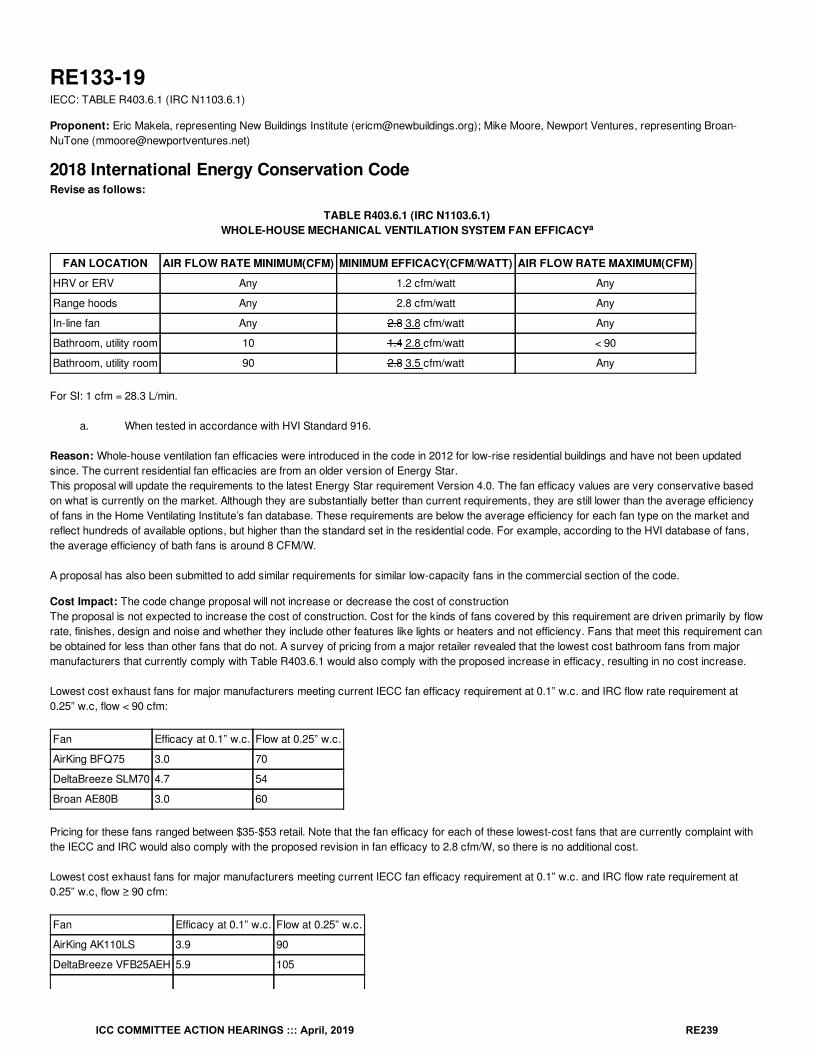
RE133-19IECC: TABLE R403.6.1 (IRC N1103.6.1)
Proponent: Eric Makela, representing New Buildings Institute ([email protected]); Mike Moore, Newport Ventures, representing Broan-NuTone ([email protected])
2018 International Energy Conservation CodeRevise as follows:
TABLE R403.6.1 (IRC N1103.6.1)WHOLE-HOUSE MECHANICAL VENTILATION SYSTEM FAN EFFICACY
FAN LOCATION AIR FLOW RATE MINIMUM(CFM) MINIMUM EFFICACY(CFM/WATT) AIR FLOW RATE MAXIMUM(CFM)
HRV or ERV Any 1.2 cfm/watt Any
Range hoods Any 2.8 cfm/watt Any
In-line fan Any 2.8 3.8 cfm/watt Any
Bathroom, utility room 10 1.4 2.8 cfm/watt < 90
Bathroom, utility room 90 2.8 3.5 cfm/watt Any
For SI: 1 cfm = 28.3 L/min.
a. When tested in accordance with HVI Standard 916.
Reason: Whole-house ventilation fan efficacies were introduced in the code in 2012 for low-rise residential buildings and have not been updatedsince. The current residential fan efficacies are from an older version of Energy Star.This proposal will update the requirements to the latest Energy Star requirement Version 4.0. The fan efficacy values are very conservative basedon what is currently on the market. Although they are substantially better than current requirements, they are still lower than the average efficiencyof fans in the Home Ventilating Institute’s fan database. These requirements are below the average efficiency for each fan type on the market andreflect hundreds of available options, but higher than the standard set in the residential code. For example, according to the HVI database of fans,the average efficiency of bath fans is around 8 CFM/W.
A proposal has also been submitted to add similar requirements for similar low-capacity fans in the commercial section of the code.
Cost Impact: The code change proposal will not increase or decrease the cost of constructionThe proposal is not expected to increase the cost of construction. Cost for the kinds of fans covered by this requirement are driven primarily by flowrate, finishes, design and noise and whether they include other features like lights or heaters and not efficiency. Fans that meet this requirement canbe obtained for less than other fans that do not. A survey of pricing from a major retailer revealed that the lowest cost bathroom fans from majormanufacturers that currently comply with Table R403.6.1 would also comply with the proposed increase in efficacy, resulting in no cost increase.
Lowest cost exhaust fans for major manufacturers meeting current IECC fan efficacy requirement at 0.1” w.c. and IRC flow rate requirement at0.25” w.c, flow < 90 cfm:
Fan Efficacy at 0.1” w.c. Flow at 0.25” w.c.
AirKing BFQ75 3.0 70
DeltaBreeze SLM70 4.7 54
Broan AE80B 3.0 60
Pricing for these fans ranged between $35-$53 retail. Note that the fan efficacy for each of these lowest-cost fans that are currently complaint withthe IECC and IRC would also comply with the proposed revision in fan efficacy to 2.8 cfm/W, so there is no additional cost.
Lowest cost exhaust fans for major manufacturers meeting current IECC fan efficacy requirement at 0.1” w.c. and IRC flow rate requirement at0.25” w.c, flow ≥ 90 cfm:
Fan Efficacy at 0.1” w.c. Flow at 0.25” w.c.
AirKing AK110LS 3.9 90
DeltaBreeze VFB25AEH 5.9 105
a
ICC COMMITTEE ACTION HEARINGS ::: April, 2019 RE239
Broan-NuTone AEN110 4.7 92
Pricing for these fans ranged between $89-$105 retail. Note that the fan efficacy for each of these lowest-cost fans that are currently complaint withthe IECC and IRC would also comply with the proposed revision in fan efficacy to 3.5 cfm/W, so there is no additional cost.
Source www.homedepot.com,pricing as of 1/9/2019.
Proposal # 5180
RE133-19
ICC COMMITTEE ACTION HEARINGS ::: April, 2019 RE240
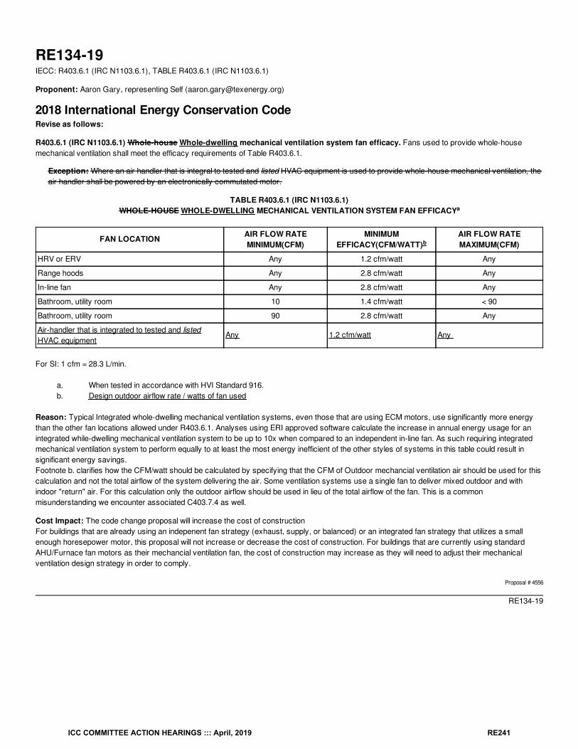
RE134-19IECC: R403.6.1 (IRC N1103.6.1), TABLE R403.6.1 (IRC N1103.6.1)
Proponent: Aaron Gary, representing Self ([email protected])
2018 International Energy Conservation CodeRevise as follows:
R403.6.1 (IRC N1103.6.1) Whole-house Whole-dwelling mechanical ventilation system fan efficacy. Fans used to provide whole-housemechanical ventilation shall meet the efficacy requirements of Table R403.6.1.
Exception: Where an air handler that is integral to tested and listed HVAC equipment is used to provide whole-house mechanical ventilation, theair handler shall be powered by an electronically commutated motor.
TABLE R403.6.1 (IRC N1103.6.1)WHOLE-HOUSE WHOLE-DWELLING MECHANICAL VENTILATION SYSTEM FAN EFFICACY
FAN LOCATION AIR FLOW RATEMINIMUM(CFM)
MINIMUMEFFICACY(CFM/WATT)
AIR FLOW RATEMAXIMUM(CFM)
HRV or ERV Any 1.2 cfm/watt Any
Range hoods Any 2.8 cfm/watt Any
In-line fan Any 2.8 cfm/watt Any
Bathroom, utility room 10 1.4 cfm/watt < 90
Bathroom, utility room 90 2.8 cfm/watt Any
Air-handler that is integrated to tested and listedHVAC equipment
Any 1.2 cfm/watt Any
For SI: 1 cfm = 28.3 L/min.
a. When tested in accordance with HVI Standard 916.b. Design outdoor airflow rate / watts of fan used
Reason: Typical Integrated whole-dwelling mechanical ventilation systems, even those that are using ECM motors, use significantly more energythan the other fan locations allowed under R403.6.1. Analyses using ERI approved software calculate the increase in annual energy usage for anintegrated while-dwelling mechanical ventilation system to be up to 10x when compared to an independent in-line fan. As such requiring integratedmechanical ventilation system to perform equally to at least the most energy inefficient of the other styles of systems in this table could result insignificant energy savings.Footnote b. clarifies how the CFM/watt should be calculated by specifying that the CFM of Outdoor mechancial ventilation air should be used for thiscalculation and not the total airflow of the system delivering the air. Some ventilation systems use a single fan to deliver mixed outdoor and withindoor "return" air. For this calculation only the outdoor airflow should be used in lieu of the total airflow of the fan. This is a commonmisunderstanding we encounter associated C403.7.4 as well.
Cost Impact: The code change proposal will increase the cost of constructionFor buildings that are already using an indepenent fan strategy (exhaust, supply, or balanced) or an integrated fan strategy that utilizes a smallenough horesepower motor, this proposal will not increase or decrease the cost of construction. For buildings that are currently using standardAHU/Furnace fan motors as their mechancial ventilation fan, the cost of construction may increase as they will need to adjust their mechanicalventilation design strategy in order to comply.
Proposal # 4556
RE134-19
a
b
ICC COMMITTEE ACTION HEARINGS ::: April, 2019 RE241
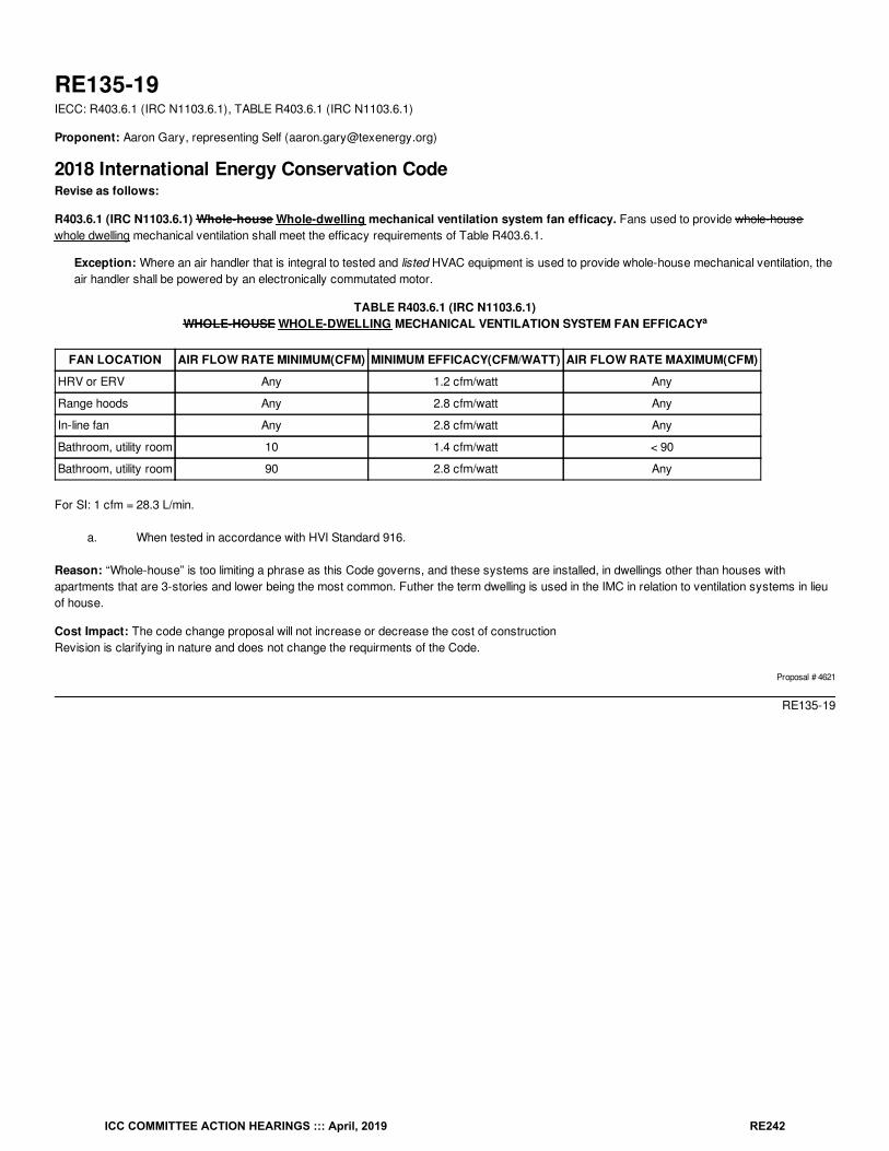
RE135-19IECC: R403.6.1 (IRC N1103.6.1), TABLE R403.6.1 (IRC N1103.6.1)
Proponent: Aaron Gary, representing Self ([email protected])
2018 International Energy Conservation CodeRevise as follows:
R403.6.1 (IRC N1103.6.1) Whole-house Whole-dwelling mechanical ventilation system fan efficacy. Fans used to provide whole-housewhole dwelling mechanical ventilation shall meet the efficacy requirements of Table R403.6.1.
Exception: Where an air handler that is integral to tested and listed HVAC equipment is used to provide whole-house mechanical ventilation, theair handler shall be powered by an electronically commutated motor.
TABLE R403.6.1 (IRC N1103.6.1)WHOLE-HOUSE WHOLE-DWELLING MECHANICAL VENTILATION SYSTEM FAN EFFICACY
FAN LOCATION AIR FLOW RATE MINIMUM(CFM) MINIMUM EFFICACY(CFM/WATT) AIR FLOW RATE MAXIMUM(CFM)
HRV or ERV Any 1.2 cfm/watt Any
Range hoods Any 2.8 cfm/watt Any
In-line fan Any 2.8 cfm/watt Any
Bathroom, utility room 10 1.4 cfm/watt < 90
Bathroom, utility room 90 2.8 cfm/watt Any
For SI: 1 cfm = 28.3 L/min.
a. When tested in accordance with HVI Standard 916.
Reason: “Whole-house” is too limiting a phrase as this Code governs, and these systems are installed, in dwellings other than houses withapartments that are 3-stories and lower being the most common. Futher the term dwelling is used in the IMC in relation to ventilation systems in lieuof house.
Cost Impact: The code change proposal will not increase or decrease the cost of constructionRevision is clarifying in nature and does not change the requirments of the Code.
Proposal # 4621
RE135-19
a
ICC COMMITTEE ACTION HEARINGS ::: April, 2019 RE242
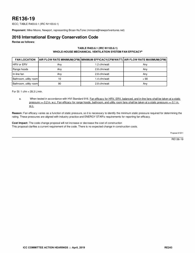
RE136-19IECC; TABLE R403.6.1 (IRC N1103.6.1)
Proponent: Mike Moore, Newport, representing Broan-NuTone ([email protected])
2018 International Energy Conservation CodeRevise as follows:
TABLE R403.6.1 (IRC N1103.6.1)WHOLE-HOUSE MECHANICAL VENTILATION SYSTEM FAN EFFICACY
FAN LOCATION AIR FLOW RATE MINIMUM(CFM) MINIMUM EFFICACY(CFM/WATT) AIR FLOW RATE MAXIMUM(CFM)
HRV or ERV Any 1.2 cfm/watt Any
Range hoods Any 2.8 cfm/watt Any
In-line fan Any 2.8 cfm/watt Any
Bathroom, utility room 10 1.4 cfm/watt < 90
Bathroom, utility room 90 2.8 cfm/watt Any
For SI: 1 cfm = 28.3 L/min.
a. When tested in accordance with HVI Standard 916. Fan efficacy for HRV, ERV, balanced, and in-line fans shall be taken at a staticpressure >= 0.2 in. w.c. Fan efficacy for range hoods, bathroom, and utility room fans shall be taken at a static pressure >= 0.1 in.w.c.
Reason: Fan efficacy varies as a function of static pressure, so it is necessary to identify the minimum static pressure required for determining therating. These pressures are aligned with industry practice and ENERGY STAR's requirements for reporting fan efficacy.
Cost Impact: The code change proposal will not increase or decrease the cost of constructionThis proposal clarifies a current requirement of the code. There is no expected change in construction costs.
Proposal # 5311
RE136-19
a
ICC COMMITTEE ACTION HEARINGS ::: April, 2019 RE243
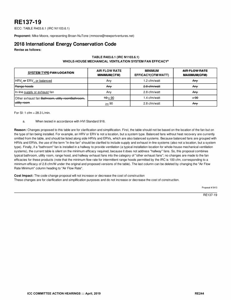
RE137-19IECC: TABLE R403.6.1 (IRC N1103.6.1)
Proponent: Mike Moore, representing Broan-NuTone ([email protected])
2018 International Energy Conservation CodeRevise as follows:
TABLE R403.6.1 (IRC N1103.6.1)WHOLE-HOUSE MECHANICAL VENTILATION SYSTEM FAN EFFICACY
SYSTEM TYPE FAN LOCATION AIR FLOW RATEMINIMUM(CFM)
MINIMUMEFFICACY(CFM/WATT)
AIR FLOW RATEMAXIMUM(CFM)
HRV, or ERV , or balanced Any 1.2 cfm/watt Any
Range hoods Any 2.8 cfm/watt Any
In-line supply or exhaust fan Any 2.8 cfm/watt Any
Other exhaust fan Bathroom, utility roomBathroom,utility room
10 < 90 1.4 cfm/watt < 90
>= 90 2.8 cfm/watt Any
For SI: 1 cfm = 28.3 L/min.
a. When tested in accordance with HVI Standard 916.
Reason: Changes proposed to this table are for clarification and simplification. First, the table should not be based on the location of the fan but onthe type of fan being installed. For example, an HRV or ERV is not a location, but a system type. Balanced fans without heat recovery are currentlyomitted from the table, and should be listed along side HRVs and ERVs, which are also balanced systems. Because balanced fans are grouped withHRVs and ERVs, the use of the term "in-line fan" should be clarified to include supply and exhaust in-line systems (also not a location, but a systemtype). Finally, if a "bathroom" fan is installed in a hallway to provide ventilation (a typical installation location for whole-house mechanical ventilationsystems), the current table is silent on the minimum efficacy required, because it does not address "hallway" fans. So, this proposal combinestypical bathroom, utility room, range hood, and hallway exhaust fans into the category of "other exhaust fans"; no changes are made to the fanefficacies for these products (note that the minimum flow rate for intermittent range hoods permitted by the IRC is 100 cfm, corresponding to aminimum efficacy of 2.8 cfm/W under the original and proposed versions of the table). The last column can be deleted by changing the "Air FlowRate Minimum" column heading to "Air Flow Rate".
Cost Impact: The code change proposal will not increase or decrease the cost of constructionThese changes are for clarification and simplification purposes and do not increase or decrease the cost of construction.
Proposal # 5413
RE137-19
a
ICC COMMITTEE ACTION HEARINGS ::: April, 2019 RE244
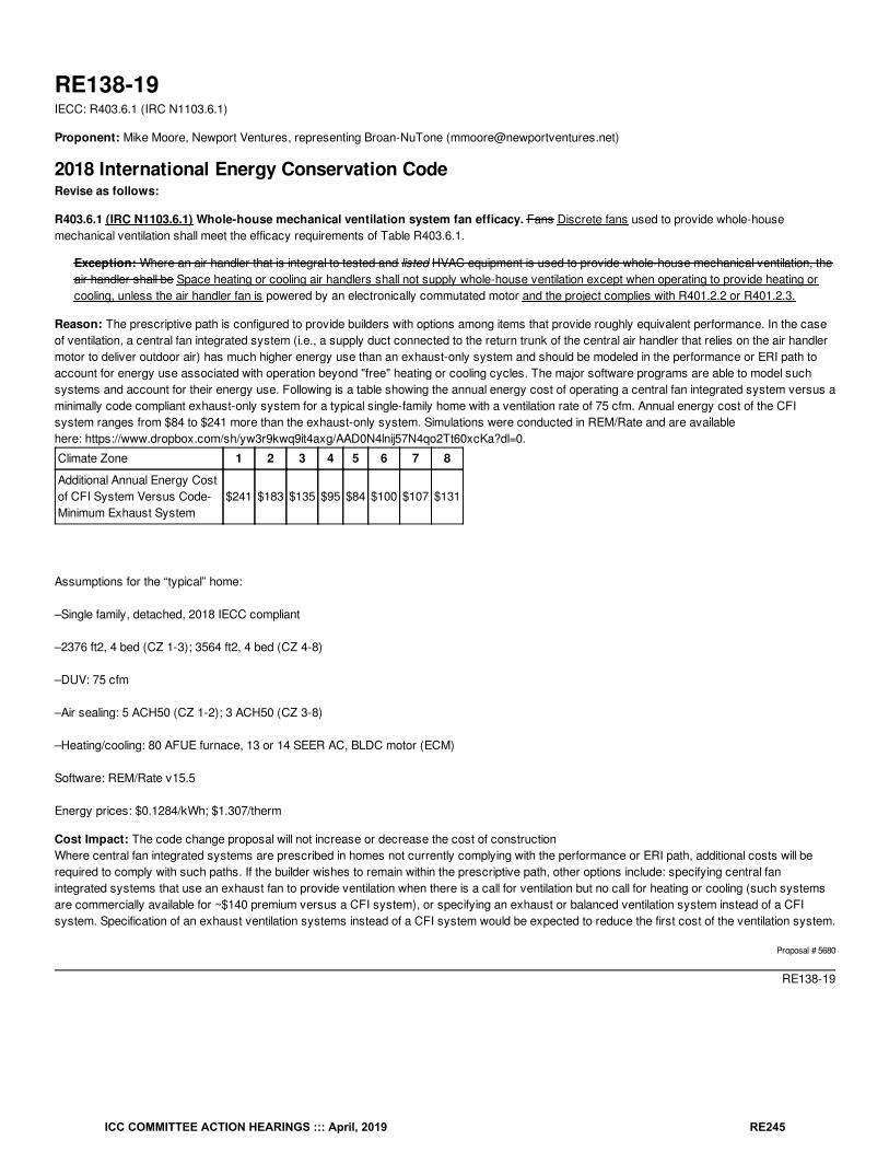
RE138-19IECC: R403.6.1 (IRC N1103.6.1)
Proponent: Mike Moore, Newport Ventures, representing Broan-NuTone ([email protected])
2018 International Energy Conservation CodeRevise as follows:
R403.6.1 (IRC N1103.6.1) Whole-house mechanical ventilation system fan efficacy. Fans Discrete fans used to provide whole-housemechanical ventilation shall meet the efficacy requirements of Table R403.6.1.
Exception: Where an air handler that is integral to tested and listed HVAC equipment is used to provide whole-house mechanical ventilation, theair handler shall be Space heating or cooling air handlers shall not supply whole-house ventilation except when operating to provide heating orcooling, unless the air handler fan is powered by an electronically commutated motor and the project complies with R401.2.2 or R401.2.3.
Reason: The prescriptive path is configured to provide builders with options among items that provide roughly equivalent performance. In the caseof ventilation, a central fan integrated system (i.e., a supply duct connected to the return trunk of the central air handler that relies on the air handlermotor to deliver outdoor air) has much higher energy use than an exhaust-only system and should be modeled in the performance or ERI path toaccount for energy use associated with operation beyond "free" heating or cooling cycles. The major software programs are able to model suchsystems and account for their energy use. Following is a table showing the annual energy cost of operating a central fan integrated system versus aminimally code compliant exhaust-only system for a typical single-family home with a ventilation rate of 75 cfm. Annual energy cost of the CFIsystem ranges from $84 to $241 more than the exhaust-only system. Simulations were conducted in REM/Rate and are availablehere: https://www.dropbox.com/sh/yw3r9kwq9it4axg/AAD0N4lnij57N4qo2Tt60xcKa?dl=0.
Climate Zone 1 2 3 4 5 6 7 8
Additional Annual Energy Costof CFI System Versus Code-Minimum Exhaust System
$241 $183 $135 $95 $84 $100 $107 $131
Assumptions for the “typical” home:
–Single family, detached, 2018 IECC compliant
–2376 ft2, 4 bed (CZ 1-3); 3564 ft2, 4 bed (CZ 4-8)
–DUV: 75 cfm
–Air sealing: 5 ACH50 (CZ 1-2); 3 ACH50 (CZ 3-8)
–Heating/cooling: 80 AFUE furnace, 13 or 14 SEER AC, BLDC motor (ECM)
Software: REM/Rate v15.5
Energy prices: $0.1284/kWh; $1.307/therm
Cost Impact: The code change proposal will not increase or decrease the cost of constructionWhere central fan integrated systems are prescribed in homes not currently complying with the performance or ERI path, additional costs will berequired to comply with such paths. If the builder wishes to remain within the prescriptive path, other options include: specifying central fanintegrated systems that use an exhaust fan to provide ventilation when there is a call for ventilation but no call for heating or cooling (such systemsare commercially available for ~$140 premium versus a CFI system), or specifying an exhaust or balanced ventilation system instead of a CFIsystem. Specification of an exhaust ventilation systems instead of a CFI system would be expected to reduce the first cost of the ventilation system.
Proposal # 5680
RE138-19
ICC COMMITTEE ACTION HEARINGS ::: April, 2019 RE245
RE139-19IECC: R403.6.1 (IRC N1103.6.1) (New)
Proponent: Mike Moore, Newport Ventures, representing Broan-NuTone ([email protected])
2018 International Energy Conservation CodeRevise as follows:
R403.6 (IRC N1103.6) Mechanical ventilation (Mandatory). The building shall be provided with ventilation that complies with the requirements ofthe International Residential Code or International Mechanical Code, as applicable, or with other approved means of ventilation. Outdoor air intakesand exhausts shall have automatic or gravity dampers that close when the ventilation system is not operating.
Add new text as follows:
R403.6.1 (IRC N1103.6.1) Heat or Energy Recovery Ventilation (Prescriptive). Dwelling units shall be provided with a heat recovery or energyrecovery ventilation system in climate zones 7 and 8. The system shall be balanced with a minimum sensible heat recovery efficiency of 65% at32°F (0°C) at a flow greater than or equal to the design airflow.
Reason: A recent study conducted by Pacific Northwest National Laboratory showed HRVs and ERVs to be cost effective in climate zones 7 and 8,with annual energy savings from $138 to $233 on an initial investment of ~$1500 installed (corresponding to a first cost premium of ~$840 versus anexhaust only system and one entry-level bath fan; yielding simple paybacks of 4-6 years). This proposal is aligned with recent changes acrossmost of Canada to require heat recovery ventilation for dwelling units. This proposal would require heat or energy recovery ventilators only for thosedwelling units following the prescriptive path in the coldest climate zones, which represents a conservative improvement to the code.
Bibliography: Taylor, T. 2018. Residential Heat Recovery Ventilation Technical Brief. Pacific Northwest National Laboratory. PNNL-28354. https://www.osti.gov/servlets/purl/1488935.
Cost Impact: The code change proposal will increase the cost of constructionThe first cost of construction (including costs for appliance, equipment, and installation) is expected to increase by ~$830 compared to an exhaust-only system. Based on PNNL's projected energy savings, this will be be recovered quickly, within 4-6 years. Assuming the $830 is financed in atraditional, 30-year mortgage at 4%, the annual energy savings of $138-$233 would generate $90 - $185 per year in cash flow for the home owner.
Proposal # 5673
RE139-19
ICC COMMITTEE ACTION HEARINGS ::: April, 2019 RE246
RE140-19IECC: R403.6.12 (IRC N1103.6.2) (New)
Proponent: Mike Moore, Newport Ventures, representing Broan-NuTone ([email protected])
2018 International Energy Conservation CodeR403.6.1 (IRC N1103.6.1) Whole-house mechanical ventilation system fan efficacy. Fans used to provide whole-house mechanical ventilationshall meet the efficacy requirements of Table R403.6.1.
Exception: Where an air handler that is integral to tested and listed HVAC equipment is used to provide whole-house mechanical ventilation, theair handler shall be powered by an electronically commutated motor.
Add new text as follows:
R403.6.2 (IRC N1103.6.2) Testing. Whole-house mechanical ventilation systems and outdoor air mechanical ventilation systems shall be testedand verified to provide the minimum ventilation flow rates required by Section R403.6. Testing shall be performed according to the ventilationequipment manufacturer's instructions, or by using a flow hood, flow grid, or other airflow measuring device at the mechanical ventilation fan's inletterminals or grilles, outlet terminals or grilles or in the connected ventilation ducts. Where required by the code official, testing shall be conducted byan approved third party. A written report of the results of the test shall be signed by the party conducting the test and provided to the code official.
Reason: If installed incorrectly, whole-house mechanical ventilation systems can fail to deliver the minimum outdoor air needed to provideacceptable indoor air quality. A recent study in Florida* found that only three of 21 whole house mechanical ventilation systems had a flow rate nearthe design level. Because these systems perform a vital function in supporting building durability and occupant health, these systems should beverified for flow when installed. This requirement and text are aligned with ASHRAE 62.2, Ventilation and Acceptable Indoor Air Quality in ResidentialBuildings.
Bibliography: *Sonne et al. (2015). Investigation of the Effectiveness and Failure Rates of Whole-House Mechanical Ventilation Systems in Florida.FSEC-CR-2002-15.http://www.fsec.ucf.edu/en/publications/pdf/FSEC-CR-2002-15.pdf.
Cost Impact: The code change proposal will increase the cost of constructionWill increase the cost of construction where testing is not currently provided. Testing the airflow of a whole house mechanical ventilation systemshould take about 15-20 minutes. Assuming a skilled labor rate of $35/hr, the incremental cost for the test is estimated at $9-$12. The test can becompleted by the same technician performing the blower door test. Also, there is no requirement for a third party to conduct the test, which can helpmoderate costs.
Proposal # 5420
RE140-19
ICC COMMITTEE ACTION HEARINGS ::: April, 2019 RE247
RE141-19IECC: R403.6.2 (IRC N1103.6.3) (New)
Proponent: Aaron Gary, representing Self ([email protected])
2018 International Energy Conservation CodeAdd new text as follows:
R403.6.2 (IRC N1103.6.3) Testing (Mandatory) The fans used to provide whole-dwelling mechanical ventilation shall be tested according to themanufacturer's instructions or RESNET/ICC 380. Testing shall be conducted by an approved third party. A written report of the results of the testshall be signed by the party conducting the test and provided to the code official.
Reason: Much blood has been spilled debating the appropriate amount of outdoor air that should be introduced into a dwelling via mechanicalventilation. While all this focus has been applied to the design calculations, much less has been turned to the actual air that is delivered by thesesystems. In my experience as a 3 party verifier and HVAC contractor, the amount of air that is actually being delivered is as crucial as selectingthe right design and equipment.The commissioning of these systems is simply not required by Code and therefore it is not happening for a majority of Code dwellings. When moreoutdoor air is provided than intended it can overwhelm the right-sized (R403.7) heating and cooling equipment’s ability to process this air. The impactis human comfort complaints, potential moisture issues in humid climates, and lost energy efficiency.
Further, 3rd party verification and testing of the mechanical ventilation system is already part of the ERI path through its inclusion inANSI/RESNET/ICC 301. It is not required however in the Prescriptive or Performance paths.
Cost Impact: The code change proposal will increase the cost of constructionThis proposal will increase the cost of construction for dwellings following the Prescriptive and Performance paths through the IECC not throughadditional or change in prodcut but by requiring additional testing similar to Air Leakage testing (R402.4) and Duct Leakage testing (R403.3.3). Thisproposal will not increase the cost of construction for dwellings following the ERI path through the IECC as this test is already mandatory underANSI/RESNET/ICC 301.
Proposal # 5545
RE141-19
rd
ICC COMMITTEE ACTION HEARINGS ::: April, 2019 RE248
RE142-19IECC: R403.6.2 (IRC N1103.6.2) (New)
Proponent: Darren Meyers, P.E., International Energy Conservation Consultants LLC, representing Self ([email protected])
2018 International Energy Conservation CodeAdd new text as follows:
R403.6.2 (IRC N1103.6.2) Airflow measurement. The airflow rate required is the quantity of outdoor ventilation air supplied and/or indoor airexhausted by the whole-house mechanical ventilation system installed, and shall be measured using a calibrated flow hood, flow grid, or other airflowmeasuring device. Ventilation airflow of systems with multiple operating modes shall be tested in all modes of operation designed to meet SectionR403.6. Where required by the code official, testing shall conducted by an approved third party. A written report of the results of the test, indicatingthe verified airflow rate, shall be signed by the party conducting the test and provided to the code official.
Reason: The proposal adds a provision establishing the "measurement" of airflow associated with the central energy-using system of the home, itsheating ventilation and air-conditioning system. The language, while derived from the provisions of ASHRAE Standard 62.2-2016, is written inuseable, understandable and enforceable, mandatory language.
Bibliography: 2017a. “Kentucky Residential Energy Code Field Study: Baseline Report.” Richland, WA: Pacific Northwest National Laboratory.2018. "Improving Residential Energy Code Compliance in KY and GA." Chicago, IL: Midwest Energy Efficiency Parnership.
2014. "Evaluation of Illinois Baseline Building Code Compliance." Sacramento, CA: ADM Associates, Inc.
2014. "International Residential Code - Mechanical Ventilation as Required by Iowa 2012 IECC, Section 403.5." Des Moines, IA: Iowa Department ofPublic SafetyState Fire Marshal Division.
2011. "Measuring a Baseline Compliance Rate for Residential and Non-Residential Buildings in Illinois Against the 2009 International EnergyConservation Code." Troy, IL: Association of Professional Energy Consultants, Inc.
Cost Impact: The code change proposal will increase the cost of constructionIECC_LLC has experience with the implementation training and technical support activities associated with State Energy Offices, State FireMarshall's Offices and Departments of Housing, Buildings and Construction for 2009 and 2012 IECC adoptions in Iowa, the 2009 and 2012 IECCadoptions in Kentucky, the 2012, 2015 and 2018 adoptions in Illinois and more recently the 2015 and 2018 adoptions throughout the greaterNashville, TN metro community. In conducting these activities, it is common to solicit, discuss and evaluate the pricing structures available in theresidential housing sector. The building diagnostic services discussed include a code-mandated blower door pressure test, a code-mandated ductpressure leakage test (pending location of ductwork), as well as services less commerciallized in the residential housing sector; infraredthermography and HVAC ventilation system airflow validation. It is common that when a code mandated test is "bundled" with one of the other homediagnostic services these price points are discounted.
Proposal # 5575
RE142-19
ICC COMMITTEE ACTION HEARINGS ::: April, 2019 RE249
ACCA Air Conditioning Contractors of America2800 Shirlington Road, Suite 300
Arlington, VA 22206
RE143-19IECC: R403.7 (IRC N1103.7), ACCA Chapter 6 (IRC Chapter 44)
Proponent: David Bixby, representing Air Conditioning Contractors of America
2018 International Energy Conservation CodeRevise as follows:
R403.7 (IRC N1103.7) Equipment sizing and efficiency rating (Mandatory). Heating and cooling equipment shall be sized in accordance withACCA Manual S based on building loads calculated in accordance with ACCA Manual J or other approved heating and cooling calculationmethodologies. New or replacement heating and cooling equipment shall have an efficiency rating equal to or greater than the minimum required byfederal law for the geographic location where the equipment is installed. Minimum criteria for the proper design, equipment selection, installation, andcommissioning of HVAC systems shall comply with ACCA 5 QI.
Add new standard(s) as follows:
ANSI/ACCA 5 QI -2010: HVAC Quality Installation Specifications
Reason: ANSI/ACCA 5 QI Standard (HVAC Quality Installation Specification) covers the initial HVAC system design, including system sizing,equipment selection, duct sizing, start-up and commissioning. It was developed by a broad coalition of industry stakeholders and is available for freedownload (www.acca.org/quality).In September 2014, the U.S. National Institute of Standards and Technology (NIST) published, “Sensitivity Analysis of Installation Faults on HeatPump Performance.” This report presents evidence that non-compliance with the ANSI/ACCA 5 QI Standard results in quantifiable increases inenergy usage and operating costs. The NIST report demonstrated that the increased energy consumption can be greater than 50% when multipledeficiencies (e.g., duct leakage, low refrigerant charge, equipment oversizing, airflow, etc.) are encountered. While the industry focuses onequipment efficiency, the real efficiency of the system (installed efficiency) is determined by its proper design, installation, and commissioning.
The ACCA 5 QI Standard has been adopted by the Consortium for Energy Efficiency (CEE; a consortium of utilities with programmatic efforts inenergy efficiency) as its definition for the minimum requirements for HVAC installations. In addition, the “HVAC Commissioning Checklist” for EPAEnergy Star® certified homes, Green Building Communities, and HERS Rating is embodied in the requirements of the ANSI/ACCA 5 QI protocol,thereby insuring the performance of HVAC systems in new homes.
Cost Impact: The code change proposal will not increase or decrease the cost of constructionCost of construction will be unaffected other than the extra time to properly design, size and install an HVAC system according to minimum industryaccepted practices.
Proposal # 4813
RE143-19
ICC COMMITTEE ACTION HEARINGS ::: April, 2019 RE250
RE144-19IECC: R403.12 (IRC N1103.12)
Proponent: David Collins, SEHPCAC, representing SEHPCAC ([email protected]); David Collins, representing The American Institute ofArchitects ([email protected])
2018 International Energy Conservation CodeRevise as follows:
R403.12 (IRC N1103.12) Residential pools and permanent residential spas (Mandatory). Residential swimming pools and permanentresidential spas that are accessory to detached one- and two-family dwellings and townhouses three stories or less in height above grade plane andthat are available only to the household and its guests shall be in accordance with APSP 15.
Reason: This section provides a reference to a specific standard with no alternative provided. The section provides no metrics or values that canbe used for calculations for trade-offs. Additionally, both R403.10 and R403.11, which address similiar subjects, are labeled mandatory and there isno reason for this to be inconsistent.Note, the SEHPCAC has a proposal to eliminate use of the labels "prescriptive" and "mandatory" in favor of a tabular method of identifying non-tradable requirements. If that proposal is successful ICC staff have stated that sections being individually approved as "mandatory" will instead havetheir respective section numbers added to the new C407.2 table of requirements that are non-tradeable in the performance path.
This proposal is submitted by the ICC Sustainable, Energy and High Performance Code Action Committee (SEHPCAC). The SEHPCAC wasestablished by the ICC Board of Directors to pursue opportunities to improve and enhance International Codes with regard to sustainability, energyand high performance as it relates to the built environment included, but not limited to, how these criteria relate to the International GreenConstruction Code (IgCC) and the International Energy Conservation Code (IECC). In 2018-2019, the SEHPCAC has held five two- or three-dayopen meetings and numerous workgroup calls, to discuss and debate proposed changes and public comments. Attendees at the meetings and callsincluded members of the SEHPCAC as well as any interested parties. Related documentation and reports are posted on the SEHPCAC website at:http://www.iccsafe.org/cs/SEHPCAC/Pages/default.aspx (http://www.iccsafe.org/cs/SEHPCAC/Pages/default.aspx)
Cost Impact: The code change proposal will not increase or decrease the cost of constructionThis code change proposal does not add to nor detract from design or construction requirements.
Proposal # 4704
RE144-19
ICC COMMITTEE ACTION HEARINGS ::: April, 2019 RE251
RE145-19IECC: R202, R404.1, R404.2 (New)
Proponent: Lauren Urbanek, representing Natural Resources Defense Council ([email protected])
2018 International Energy Conservation CodeAdd new definition as follows:
DIMMER. (IRC N1101.6). A control device that is capable of continuously varying the light output and energy use of light sources.
Revise as follows:
HIGH-EFFICACY LAMPS. (IRC N1101.6). Compact fluorescent lamps, light-emitting diode (LED) lamps, T-8 or smaller diameter linearfluorescent lamps, or other lamps Any lamps with an efficacy of not less than the following: 70 lumens per watt.
1. 1.60 lumens per watt for lamps over 40 watts.2. 2.50 lumens per watt for lamps over 15 watts to 40 watts.3. 3.40 lumens per watt for lamps 15 watts or less.
Add new definition as follows:
OCCUPANT SENSOR CONTROL. (IRC N1101.6). An automatic control device or system that detects the presence or absence of peoplewithin an area and causes lighting, equipment or appliances to be regulated accordingly.
Revise as follows:
R404.1 (IRC N1104.1) Lighting equipment (Mandatory). Not less than 90 percent of the All permanently installed lighting fixtures shall containonly high-efficacy lamps.
Add new text as follows:
R404.2 (IRC N1104.2) Lighting Controls (Mandatory). Permanently installed lighting fixtures shall be controlled with either a dimmer, an occupantsensor control, or other control that is installed or built into the fixture.Exception: Lighting controls shall not be required for the following:
1. Bathrooms2. Hallways3. Exterior lighting fixtures4. Lighting designed for safety or security
Reason: The purpose of this code change proposal is to increase lighting efficiency to better align with the current lighting market and upcomingchanges to lighting standards.DOE projects that light-emitting diode (LED) lighting will represent about half of the market share in 2020, and nearly 85% of the market share by2030[1]. Goldman Sachs projects an even faster uptake of LEDs, projecting a full market penetration by the early 2020s[2]. The current definition ofa “high efficacy lamp” in the energy code is outdated: it was added to the code in 2009, when LED market share was close to zero, and has notbeen updated since then. In fact, the definition no longer represents the “high efficacy” share of the market. New lighting standards will take effect in2020 that will eliminate all bulbs on the market with efficiencies lower than 45 lumens per watt. Therefore, by the time the 2021 code is published,some of the bulbs currently defined by the IECC as “high efficacy” will be illegal to sell. Given these market and standard changes, the definitionmust be updated to remain relevant.
Once the updated federal standard takes effect, the baseline, least-efficient bulb on the market will no longer be an incandescent or even a halogen,but a compact fluorescent light bulb. In many cases, LEDs are close in price to – or even cheaper than - CFL alternatives while being a clearlysuperior product. CFLs contain mercury, are slow to come to full light, and few models are dimmable. In contrast, LEDs come in a wide range of lightoutputs, bulb shapes, color temperatures, socket types, do not contain mercury, and the vast majority of models are dimmable. Virtually all LEDs onthe market today meet the 70 lumens per watt requirement specified in this proposal.
The table below summarizes a recent Home Depot search for a dimmable 60-watt equivalent bulb, one that gives off approximately 800 lumens oflight. The LED bulb is significantly more efficient and longer-lasting than the CFL or halogen option. Recent searches found that sale prices of LEDbulbs are often even lower than a halogen equivalent. Note that the CFL bulb is not dimmable; there was no equivalent dimmable CFL option. Aseparate search for dimmable CFL bulbs[3] shows that they are in the range of at least $7 per bulb and not widely available. The halogen option willnot be legal to sell starting January 1, 2020.
ICC COMMITTEE ACTION HEARINGS ::: April, 2019 RE252
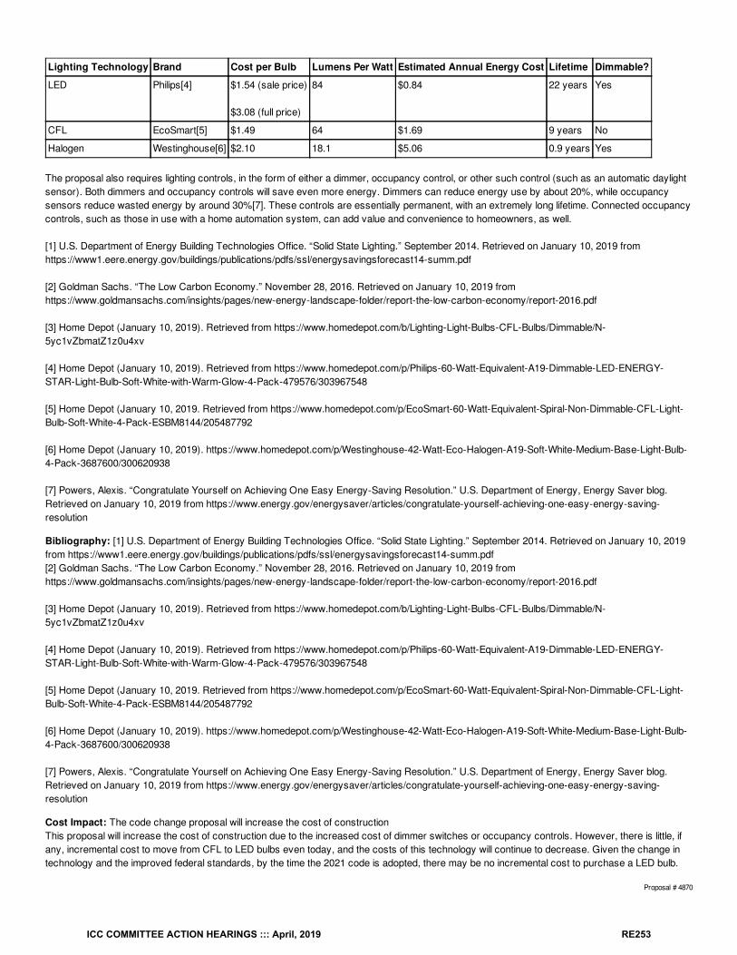
Lighting Technology Brand Cost per Bulb Lumens Per Watt Estimated Annual Energy Cost Lifetime Dimmable?
LED Philips[4] $1.54 (sale price)
$3.08 (full price)
84 $0.84 22 years Yes
CFL EcoSmart[5] $1.49 64 $1.69 9 years No
Halogen Westinghouse[6] $2.10 18.1 $5.06 0.9 years Yes
The proposal also requires lighting controls, in the form of either a dimmer, occupancy control, or other such control (such as an automatic daylightsensor). Both dimmers and occupancy controls will save even more energy. Dimmers can reduce energy use by about 20%, while occupancysensors reduce wasted energy by around 30%[7]. These controls are essentially permanent, with an extremely long lifetime. Connected occupancycontrols, such as those in use with a home automation system, can add value and convenience to homeowners, as well.
[1] U.S. Department of Energy Building Technologies Office. “Solid State Lighting.” September 2014. Retrieved on January 10, 2019 fromhttps://www1.eere.energy.gov/buildings/publications/pdfs/ssl/energysavingsforecast14-summ.pdf
[2] Goldman Sachs. “The Low Carbon Economy.” November 28, 2016. Retrieved on January 10, 2019 fromhttps://www.goldmansachs.com/insights/pages/new-energy-landscape-folder/report-the-low-carbon-economy/report-2016.pdf
[3] Home Depot (January 10, 2019). Retrieved from https://www.homedepot.com/b/Lighting-Light-Bulbs-CFL-Bulbs/Dimmable/N-5yc1vZbmatZ1z0u4xv
[4] Home Depot (January 10, 2019). Retrieved from https://www.homedepot.com/p/Philips-60-Watt-Equivalent-A19-Dimmable-LED-ENERGY-STAR-Light-Bulb-Soft-White-with-Warm-Glow-4-Pack-479576/303967548
[5] Home Depot (January 10, 2019. Retrieved from https://www.homedepot.com/p/EcoSmart-60-Watt-Equivalent-Spiral-Non-Dimmable-CFL-Light-Bulb-Soft-White-4-Pack-ESBM8144/205487792
[6] Home Depot (January 10, 2019). https://www.homedepot.com/p/Westinghouse-42-Watt-Eco-Halogen-A19-Soft-White-Medium-Base-Light-Bulb-4-Pack-3687600/300620938
[7] Powers, Alexis. “Congratulate Yourself on Achieving One Easy Energy-Saving Resolution.” U.S. Department of Energy, Energy Saver blog.Retrieved on January 10, 2019 from https://www.energy.gov/energysaver/articles/congratulate-yourself-achieving-one-easy-energy-saving-resolution
Bibliography: [1] U.S. Department of Energy Building Technologies Office. “Solid State Lighting.” September 2014. Retrieved on January 10, 2019from https://www1.eere.energy.gov/buildings/publications/pdfs/ssl/energysavingsforecast14-summ.pdf[2] Goldman Sachs. “The Low Carbon Economy.” November 28, 2016. Retrieved on January 10, 2019 fromhttps://www.goldmansachs.com/insights/pages/new-energy-landscape-folder/report-the-low-carbon-economy/report-2016.pdf
[3] Home Depot (January 10, 2019). Retrieved from https://www.homedepot.com/b/Lighting-Light-Bulbs-CFL-Bulbs/Dimmable/N-5yc1vZbmatZ1z0u4xv
[4] Home Depot (January 10, 2019). Retrieved from https://www.homedepot.com/p/Philips-60-Watt-Equivalent-A19-Dimmable-LED-ENERGY-STAR-Light-Bulb-Soft-White-with-Warm-Glow-4-Pack-479576/303967548
[5] Home Depot (January 10, 2019. Retrieved from https://www.homedepot.com/p/EcoSmart-60-Watt-Equivalent-Spiral-Non-Dimmable-CFL-Light-Bulb-Soft-White-4-Pack-ESBM8144/205487792
[6] Home Depot (January 10, 2019). https://www.homedepot.com/p/Westinghouse-42-Watt-Eco-Halogen-A19-Soft-White-Medium-Base-Light-Bulb-4-Pack-3687600/300620938
[7] Powers, Alexis. “Congratulate Yourself on Achieving One Easy Energy-Saving Resolution.” U.S. Department of Energy, Energy Saver blog.Retrieved on January 10, 2019 from https://www.energy.gov/energysaver/articles/congratulate-yourself-achieving-one-easy-energy-saving-resolution
Cost Impact: The code change proposal will increase the cost of constructionThis proposal will increase the cost of construction due to the increased cost of dimmer switches or occupancy controls. However, there is little, ifany, incremental cost to move from CFL to LED bulbs even today, and the costs of this technology will continue to decrease. Given the change intechnology and the improved federal standards, by the time the 2021 code is adopted, there may be no incremental cost to purchase a LED bulb.
Proposal # 4870
ICC COMMITTEE ACTION HEARINGS ::: April, 2019 RE253

RE145-19
ICC COMMITTEE ACTION HEARINGS ::: April, 2019 RE254
RE146-19IECC: R202 (IRC N1101.6), R404.2 (IRC N1104.2) (New), R404.2.1 (IRC N1104.2.1) (New), R404.2.2 (IRC N1104.2.2) (New)
Proponent: William Fay, Energy-Efficient Codes Coalition, representing Energy-Efficient Codes Coalition ([email protected]); Daniel Bresette, Allianceto Save Energy, representing Alliance to Save Energy ([email protected]); Maureen Guttman, BCAP-IBTS, representing BCAP-IBTS([email protected]); Harry Misuriello, American Council for an Energy-Efficient Economy, representing American Council for an Energy-Efficient Economy ([email protected])
2018 International Energy Conservation Code
SECTION R202 (IRC N1101.6) GENERAL DEFINITIONS
Add new definition as follows:
ELECTRIC VEHICLE. An automotive-type vehicle for on-road use, such as passenger automobiles, buses, trucks, vans, neighborhood electricvehicles, and electric motorcycles, primarily powered by an electric motor that draws current from a building electrical service, EVSE, arechargeable storage battery, a fuel cell, a photovoltaic array, or another source of electric current.
ELECTRIC VEHICLE SUPPLY EQUIPMENT (EVSE). The conductors, including the ungrounded, grounded, and equipment groundingconductors, and the electric vehicle connectors, attachment plugs, and all other fittings, devices, power outlets, or apparatus installed specifically forthe purpose of transferring energy between the premises wiring and the electric vehicle.
Add new text as follows:
R404.2 (IRC N1104.2) Electric vehicle ready parking (Mandatory). Where parking is provided, electric vehicle ready parking spaces shall beprovided in compliance with Sections R404.2.1 and R404.2.2. Where more than one parking facility is provided on a site, electric vehicle readyparking spaces shall be calculated separately for each parking facility.Exception: This section does not apply to parking spaces used exclusively for trucks or delivery vehicles.
R404.2.1 (IRC N1104.2.1) Electric vehicle ready parking spaces. Not less than two percent, but not less than one, parking spaces shall beelectric vehicle ready parking and shall comply with Section R404.2.2.
Exception: Single-family and two-family dwelling units shall provide a not less than one electric vehicle ready parking space.
R404.2.2 (IRC N1104.2.2) Electric vehicle service equipment (EVSE) ready circuit. Each electric vehicle ready parking space shall be providedwith a minimum 40-ampere branch circuit to accommodate a future dedicated Level 2 EVSE. The circuit shall terminate in a NEMA 6-50 or NEMA14-50 receptacle or a suitable electrical connector rated for 240 volts or greater service. The circuit shall have no other outlets. The service panelshall provide sufficient capacity and space to accommodate the circuit and over-current protective device. A permanent and visible label stating “EVREADY” shall be posted in a conspicuous place at both the service panel and the circuit termination point.
Reason: As of January 1, 2019, more than one million EVs are on U.S. roads. EEI and IEI estimate that the number of plug-in EVs will increase toabout seven million by 2025. See EEI and IEI, “Plug-in Electric Vehicle Sales Forecast Through 2025 and the Charging Infrastructure Required,”available athttp://www.edisonfoundation.net/iei/publications/Documents/IEI_EEI%20PEV%20Sales%20and%20Infrastructure%20thru%202025_FINAL%20(2).pdf.BNEF and Energy Innovation have recently released projections that show accelerated growth in EVs as a percentage of new car sales beginningaround the middle of the next decade. See BNEF, “Electric Vehicle Outlook: 2018,” available at https://bnef.turtl.co/story/evo2018?teaser=true, andEnergy Innovation, “The Future of Electric Vehicles in the U.S., available at https://energyinnovation.org/wp-content/uploads/2017/10/2017-09-13-Future-of-EVs-Research-Note_FINAL.pdf. By 2040 BNEF estimates that EVs will account for 58% of all new car sales by 2040. See BNEF, “ElectricVehicles to Accelerate to 54% of New Car Sales by 2040,” available at https://about.bnef.com/blog/electric-vehicles-accelerate-54-new-car-sales-2040/. A major driver of this steep EV sales trend will be a dramatic decrease in battery costs of more than 70 percent by 2030. See BNEF, “ElectricVehicle Outlook 2018.”The increase in EV sales will be accompanied by an increase in demand for on-site residential EV charging capacity. Up to 5.5 million chargers,which will be mostly installed in homes, will be required by 2025 to support a fleet of seven million EVs. See EEI and IEI, “Plug-in Electric VehicleSales Forecast Through 2025 and the Charging Infrastructure Required.” In the near term this will likely involve the installation of Level 2 chargers,which require an additional 240-volt circuit. The cost of retrofitting a home to accommodate a Level 2 charger, which can recover the full range of atypical EV in 10 hours or less, will be a financial burden on homeowners. Adding a requirement for EV-ready parking spaces to the code will facilitatefuture Level 2 charger installations, which will eventually become practically ubiquitous, at a much lower cost.
Increased adoption of EVs will have a positive effect on overall U.S. household energy spending and carbon emissions. In terms of energy savings,EV fuel economy is, on average, more than three times more efficient than conventional gasoline-fueled counterparts. Even when compared overthe full lifecycle of fuel production and use, the average EV consumes less than half the energy per vehicle mile traveled. See InsideEVs, “EfficiencyCompared: Battery-Electric 73%, Hydrogen 22%, ICE 13%,” available at https://insideevs.com/efficiency-compared-battery-electric-73-hydrogen-
ICC COMMITTEE ACTION HEARINGS ::: April, 2019 RE255
22-ice-13/, and Argonne National Laboratory, “Greenhouse Gases, Regulated Emissions, and Energy use in Transportation Model,” available athttps://greet.es.anl.gov/index.php. NRDC and EPRI found that if 50 percent of personal vehicle miles traveled were powered by electricity in 2050,the U.S. would realize annual emissions reductions of 550 million metric tons of carbon dioxide. See NRDC, “Study: Electric Vehicles CanDramatically Reduce Carbon Pollution from Transportation, and Improve Air Quality,” available at https://www.nrdc.org/experts/luke-tonachel/study-electric-vehicles-can-dramatically-reduce-carbon-pollution. The ideal solution would get this code change in place by the time adoption rates areexpected to accelerate, which would help facilitate adoption of EVs and therefore lead to more efficient energy consumption and lower householdcarbon emissions.
Bibliography: Argonne National Laboratory, “Greenhouse Gases, Regulated Emissions, and Energy use in Transportation Model,” available athttps://greet.es.anl.gov/index.php. Last accessed January 9, 2019.InsideEVs, “Efficiency Compared: Battery-Electric 73%, Hydrogen 22%, ICE 13%,” October 2, 2017, available at https://insideevs.com/efficiency-compared-battery-electric-73-hydrogen-22-ice-13/. Last accessed January 9, 2019.
Bloomberg New Energy Finance, “Electric Vehicle Outlook: 2018,” available at https://bnef.turtl.co/story/evo2018?teaser=true. Last accessedJanuary 9, 2019.
Bloomberg New Energy Finance, “Electric Vehicles to Accelerate to 54% of New Car Sales by 2040,” July 6, 2017, available athttps://about.bnef.com/blog/electric-vehicles-accelerate-54-new-car-sales-2040/. Last accessed January 9, 2019.
Edison Electric Institute and Institute for Electric Innovation, “Plug-in Electric Vehicle Sales Forecast Through 2025 and the Charging InfrastructureRequired,” June 2017, pgs. 1 and 9, available athttp://www.edisonfoundation.net/iei/publications/Documents/IEI_EEI%20PEV%20Sales%20and%20Infrastructure%20thru%202025_FINAL%20(2).pdf.Last accessed January 9, 2019.
Energy Innovation, “The Future of Electric Vehicles in the U.S., September 27, 2017, pg. 3, available at https://energyinnovation.org/wp-content/uploads/2017/10/2017-09-13-Future-of-EVs-Research-Note_FINAL.pdf. Last accessed January 9, 2019.
NRDC, “Study: Electric Vehicles Can Dramatically Reduce Carbon Pollution from Transportation, and Improve Air Quality,” available athttps://www.nrdc.org/experts/luke-tonachel/study-electric-vehicles-can-dramatically-reduce-carbon-pollution. Last accessed January 9, 2019.
Realtor.com, “Electric Car Charger Installation in Your Home: True Costs—and What You Need to Know,” November 2, 2017, available athttps://www.realtor.com/advice/home-improvement/installing-electric-vehicle-charger/. Last accessed January 9, 2019.
Cost Impact: The code change proposal will increase the cost of constructionThe additional branch circuit and associated wiring and conduit required to make parking spaces EV-ready will incrementally increase the cost ofconstruction. But the cost of a retrofit to add the electrical panel capacity for a common Level 2 charger will be much higher—up to $2,000. SeeRealtor.com, “Electric Car Charger Installation in Your Home: True Costs—and What You Need to Know,” available athttps://www.realtor.com/advice/home-improvement/installing-electric-vehicle-charger/.
Proposal # 5228
RE146-19
ICC COMMITTEE ACTION HEARINGS ::: April, 2019 RE256
RE147-19IECC: R404.2 (IRC N1104.2) (New), R404.2.1 (IRC N1104.2.1) (New), R404.2.2 (IRC N1104.2.2) (New), R404.2.3 (IRC N1104.2.3) (New)
Proponent: Lauren Urbanek, representing Natural Resources Defense Council ([email protected])
2018 International Energy Conservation CodeAdd new text as follows:
R404.2 (IRC N1104.2) Electric readiness (Mandatory) Systems using gas or propane water heaters, dryers, or conventional cooking equipmentto serve individual dwelling units shall comply with the requirements of Sections R404.2.1 and R404.2.2. All water heating systems shall comply withSection R404.2.3.
R404.2.1 (IRC N1104.2.1) Receptacle. A dedicated 125-volt, 20-amp electrical receptacle that is connected to the electric panel with a 120/240 volt3 conductor, 10 AWG copper branch circuit, shall be provided within 3 feet from each gas or propane water heater, dryer, and conventional cookingequipment, accessible with no obstructions.
R404.2.2 (IRC N1104.2.2) Electrification-ready circuits. Both ends of the unused conductors shall be labeled with the word “SPARE” and beelectrically isolated. A single pole circuit breaker space shall be reserved in the electrical panel adjacent to each circuit breaker for the branch circuitand labeled with the words “FUTURE 240V USE.”
R404.2.3 (IRC N1104.2.3) Water heater space. An indoor space that is at least 3 feet by 3 feet by 7 feet high shall be available within 3 feet of thewater heater.
Exception: The water heater space requirement does not need to be met where a heat pump water heater is installed.
Reason: This proposal enhances customer choice by making it easy for homeowners to choose either electric or gas appliances and water heatingequipment. By ensuring that a home built with gas or propane can easily accommodate future electric appliances and equipment, this proposalprotects homeowners from future costs, should natural gas become less affordable or even unavailable over the life of the building.As the electric grid becomes cleaner, and high-efficiency electric heat pump technology increasingly offers utility bill and pollution reduction benefitsover gas, more customers may want to transition from natural gas to electric space and water heating. Federal, state, and local environmental andpublic health policies may also encourage, or even require the transition in some areas over the life of the building. Electric-ready requirements willprotect customers from potential high retrofit costs.
Cost Impact: The code change proposal will increase the cost of constructionThe cost of meeting these electric-ready requirements when the house is being built, walls are open, and the trades are already on-site, is marginal.In comparison, the cost of retrofitting a building for these requirements can be orders of magnitude higher and act as a barrier for the homeowner tochoose electric appliances. Not making new buildings electric-ready would leave homeowners exposed to potentially high retrofit costs in the futureand will greatly inhibit customer choice.
Proposal # 5253
RE147-19
ICC COMMITTEE ACTION HEARINGS ::: April, 2019 RE257
RE148-19IECC: R404.1.1 (IRC N1104.1.1) (New)
Proponent: Eric Makela, representing New Buildings Institute ([email protected])
2018 International Energy Conservation CodeAdd new text as follows:
R404.1.1 (IRC N1104.1.1) Exterior lighting. Connected exterior lighting for Group R-2, R-3 and R-4 buildings shall comply with Section C405.4 ofthe International Energy Conservation Code—Commercial Provisions.
Exceptions:
1. Solar-powered lamps not connected to any electrical service.2. Luminaires controlled by a motion sensors.
Reason: The IECC does not have any specific requirements for exterior lighting for residential buildings. This may not be a significant issue forsingle-family homes, duplexes and townhomes, but it is quite significant for Type-R occupancies like multifamily that are far more likely to haveparking lots and other exterior lighting like their counterparts subject to the commercial code. A 4-story multifamily building with exactly the samesystems and layout would therefore be subject to exterior lighting requirements while a 3-story variation would not. This creates a loophole in thecode for low-rise R-occupancies.This proposal directs exterior lighting for these occupancies to the commercial code and its LPD requirements. Small R-occupancy buildings arelittle different than small commercial buildings which are already subject to those requirements. The proposal exempts solar-powered lighting andany lighting controlled by a motion sensor.
When applied to the low-rise multifamily prototype developed by Pacific Northwest National Laboratories for the code determination studies, thisrequirement saved up to 0.5% (based on climate zone) whole building energy over the 2015 IECC. Since both 2018 and 2015 lack exterior lightingrequirements, this is a reasonable approximation of savings.
Cost Impact: The code change proposal will increase the cost of constructionThis will increase the cost of construction. However, the proposal refers only R-occupancies to the existing commercial exterior lightingrequirements, which already cover smaller commercial buildings.
For example, a base light fixture cost for a 70 W halogen fixture is $118 .00 (https://www.lightingsupply.com/stonco-sla71mal-6) and the cost for anenhanced 80 W LED light fixture that will meet the proposed efficacy requirements is $158.33 (https://www.lightingsupply.com/best-lighting-products-ledmpal80-t-5k)
Proposal # 5187
RE148-19
ICC COMMITTEE ACTION HEARINGS ::: April, 2019 RE258
RE149-19IECC: R404.2 (IRC N1104.2) (New)
Proponent: Marilyn Williams, representing National Electrical Manufacturers Association ([email protected])
2018 International Energy Conservation CodeAdd new text as follows:
R404.2 (IRC N1104.2) Exterior lighting controls Where the total permanently installed Exterior lighting power is greater than 30 watts, the exteriorlighting permanently mounted to a residential building, or to other buildings on the same lot, shall comply with the following:
1. Lighting shall be controlled by a manual on and off switch which permits automatic shut off actions.2. Lighting shall automatically turn off when daylight is present during the daytime and satisfies the lighting needs.3. Lighting shall automatically turn off by time-switch control or when activity has not been detected for 15 minutes or more.4. Controls that override automatic shut off actions shall note be allowed unless the override automatically returns automatic control to its normal
operation within six twenty-four hours.
Reason: The increase in construction cost is due to the addition of a simple photocell or use of exterior lighting fixtures with integral photocell. Theseare inexpensive and readily available in many options at retailers and electrical distributors. Photocell costs are often under $10. Exterior lightfixtures with integral photocell (and often including a motion detector), are available for a total packaged cost from the sub $20 range, up to manytimes this cost based the fixture style, grade and aesthetics. The added cost of the controls is typically minimal, or an inseparable option includedwith the exterior lighting fixture altogether. The 2014 CEE report “Lighting Controls Market Characterization Report”, identifies the use of aphotosensor or timer can save, on the average, 15 up to 60KWh per year, based on the efficacy of the light source that is controlled.
Cost Impact: The code change proposal will increase the cost of constructionThe increase in construction cost is due to the addition of a simple photocell or use of exterior lighting fixtures with integral photocell. These areinexpensive and readily available in many options at retailers and electrical distributors. Photocell costs are often under $10. Exterior light fixtureswith integral photocell (and often including a motion detector), are available for a total packaged cost from the sub $20 range, up to many times thiscost based the fixture style, grade and aesthetics. The added cost of the controls is typically minimal, or an inseparable option included with theexterior lighting fixture altogether. The 2014 CEE report “Lighting Controls Market Characterization Report”, identifies the use of a photosensor ortimer can save, on the average, 15 up to 60KWh per year, based on the efficacy of the light source that is controlled.
Proposal # 4434
RE149-19
ICC COMMITTEE ACTION HEARINGS ::: April, 2019 RE259
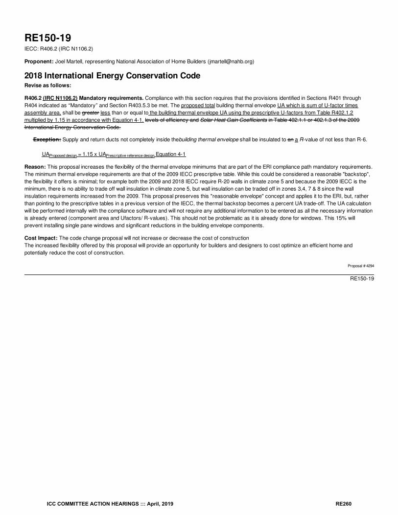
RE150-19IECC: R406.2 (IRC N1106.2)
Proponent: Joel Martell, representing National Association of Home Builders ([email protected])
2018 International Energy Conservation CodeRevise as follows:
R406.2 (IRC N1106.2) Mandatory requirements. Compliance with this section requires that the provisions identified in Sections R401 throughR404 indicated as “Mandatory” and Section R403.5.3 be met. The proposed total building thermal envelope UA which is sum of U-factor timesassembly area, shall be greater less than or equal to the building thermal envelope UA using the prescriptive U-factors from Table R402.1.2multiplied by 1.15 in accordance with Equation 4-1. levels of efficiency and Solar Heat Gain Coefficients in Table 402.1.1 or 402.1.3 of the 2009International Energy Conservation Code.
Exception: Supply and return ducts not completely inside thebuilding thermal envelope shall be insulated to an a R-value of not less than R-6.
UA = 1.15 x UA Equation 4-1
Reason: This proposal increases the flexibility of the thermal envelope minimums that are part of the ERI compliance path mandatory requirements.The minimum thermal envelope requirements are that of the 2009 IECC prescriptive table. While this could be considered a reasonable "backstop",the flexibility it offers is minimal; for example both the 2009 and 2018 IECC require R-20 walls in climate zone 5 and because the 2009 IECC is theminimum, there is no ability to trade off wall insulation in climate zone 5, but wall insulation can be traded off in zones 3,4, 7 & 8 since the wallinsulation requirements increased from the 2009. This proposal preserves this "reasonable envelope" concept and applies it to the ERI, but, ratherthan pointing to the prescriptive tables in a previous version of the IECC, the thermal backstop becomes a percent UA trade-off. The UA calculationwill be performed internally with the compliance software and will not require any additional information to be entered as all the necessary informationis already entered (component area and Ufactors/ R-values). This should not be problematic as it is already done for windows. This 15% willprevent installing single pane windows and significant reductions in the building envelope components.
Cost Impact: The code change proposal will not increase or decrease the cost of constructionThe increased flexibility offered by this proposal will provide an opportunity for builders and designers to cost optimize an efficient home andpotentially reduce the cost of construction.
Proposal # 4294
RE150-19
Proposed design Prescriptive reference design
ICC COMMITTEE ACTION HEARINGS ::: April, 2019 RE260
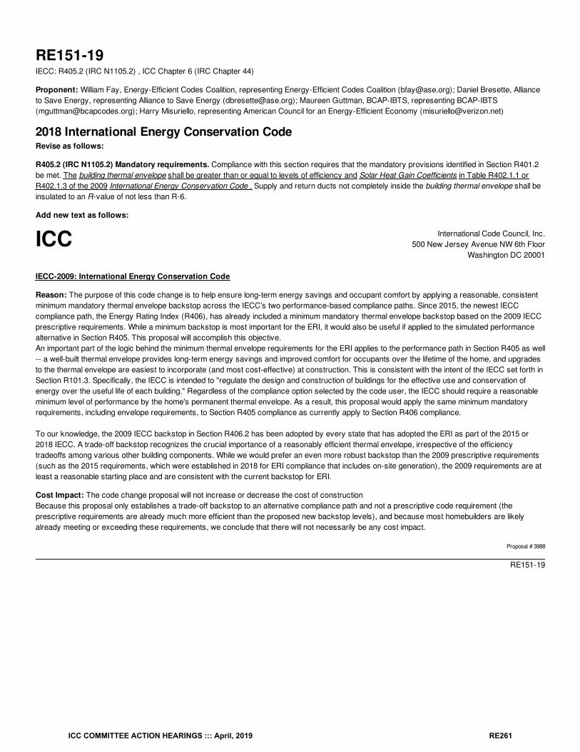
ICC International Code Council, Inc.500 New Jersey Avenue NW 6th Floor
Washington DC 20001
RE151-19IECC: R405.2 (IRC N1105.2) , ICC Chapter 6 (IRC Chapter 44)
Proponent: William Fay, Energy-Efficient Codes Coalition, representing Energy-Efficient Codes Coalition ([email protected]); Daniel Bresette, Allianceto Save Energy, representing Alliance to Save Energy ([email protected]); Maureen Guttman, BCAP-IBTS, representing BCAP-IBTS([email protected]); Harry Misuriello, representing American Council for an Energy-Efficient Economy ([email protected])
2018 International Energy Conservation CodeRevise as follows:
R405.2 (IRC N1105.2) Mandatory requirements. Compliance with this section requires that the mandatory provisions identified in Section R401.2be met. The building thermal envelope shall be greater than or equal to levels of efficiency and Solar Heat Gain Coefficients in Table R402.1.1 orR402.1.3 of the 2009 International Energy Conservation Code . Supply and return ducts not completely inside the building thermal envelope shall beinsulated to an R-value of not less than R-6.
Add new text as follows:
IECC-2009: International Energy Conservation Code
Reason: The purpose of this code change is to help ensure long-term energy savings and occupant comfort by applying a reasonable, consistentminimum mandatory thermal envelope backstop across the IECC’s two performance-based compliance paths. Since 2015, the newest IECCcompliance path, the Energy Rating Index (R406), has already included a minimum mandatory thermal envelope backstop based on the 2009 IECCprescriptive requirements. While a minimum backstop is most important for the ERI, it would also be useful if applied to the simulated performancealternative in Section R405. This proposal will accomplish this objective.An important part of the logic behind the minimum thermal envelope requirements for the ERI applies to the performance path in Section R405 as well-- a well-built thermal envelope provides long-term energy savings and improved comfort for occupants over the lifetime of the home, and upgradesto the thermal envelope are easiest to incorporate (and most cost-effective) at construction. This is consistent with the intent of the IECC set forth inSection R101.3. Specifically, the IECC is intended to "regulate the design and construction of buildings for the effective use and conservation ofenergy over the useful life of each building." Regardless of the compliance option selected by the code user, the IECC should require a reasonableminimum level of performance by the home's permanent thermal envelope. As a result, this proposal would apply the same minimum mandatoryrequirements, including envelope requirements, to Section R405 compliance as currently apply to Section R406 compliance.
To our knowledge, the 2009 IECC backstop in Section R406.2 has been adopted by every state that has adopted the ERI as part of the 2015 or2018 IECC. A trade-off backstop recognizes the crucial importance of a reasonably efficient thermal envelope, irrespective of the efficiencytradeoffs among various other building components. While we would prefer an even more robust backstop than the 2009 prescriptive requirements(such as the 2015 requirements, which were established in 2018 for ERI compliance that includes on-site generation), the 2009 requirements are atleast a reasonable starting place and are consistent with the current backstop for ERI.
Cost Impact: The code change proposal will not increase or decrease the cost of constructionBecause this proposal only establishes a trade-off backstop to an alternative compliance path and not a prescriptive code requirement (theprescriptive requirements are already much more efficient than the proposed new backstop levels), and because most homebuilders are likelyalready meeting or exceeding these requirements, we conclude that there will not necessarily be any cost impact.
Proposal # 3988
RE151-19
ICC COMMITTEE ACTION HEARINGS ::: April, 2019 RE261
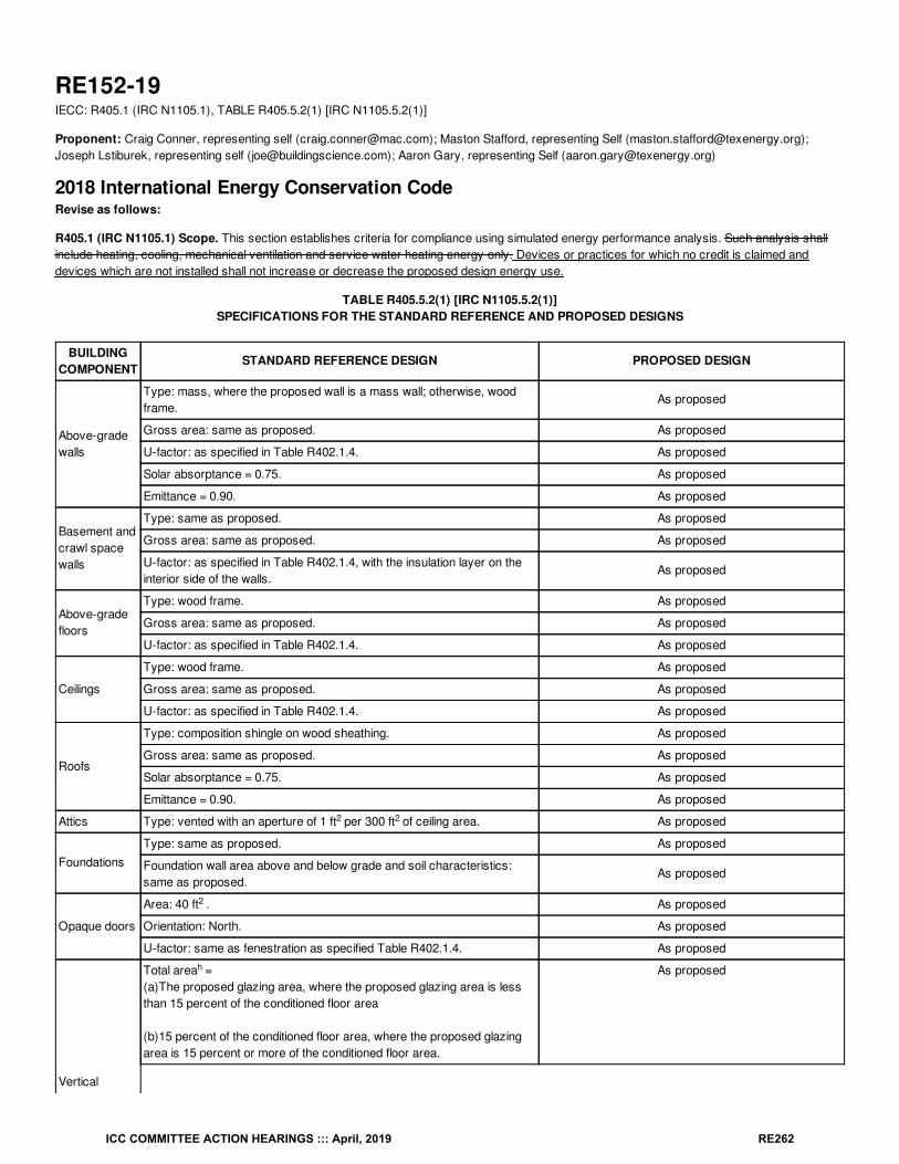
RE152-19IECC: R405.1 (IRC N1105.1), TABLE R405.5.2(1) [IRC N1105.5.2(1)]
Proponent: Craig Conner, representing self ([email protected]); Maston Stafford, representing Self ([email protected]);Joseph Lstiburek, representing self ([email protected]); Aaron Gary, representing Self ([email protected])
2018 International Energy Conservation CodeRevise as follows:
R405.1 (IRC N1105.1) Scope. This section establishes criteria for compliance using simulated energy performance analysis. Such analysis shallinclude heating, cooling, mechanical ventilation and service water heating energy only. Devices or practices for which no credit is claimed anddevices which are not installed shall not increase or decrease the proposed design energy use.
TABLE R405.5.2(1) [IRC N1105.5.2(1)]SPECIFICATIONS FOR THE STANDARD REFERENCE AND PROPOSED DESIGNS
BUILDINGCOMPONENT
STANDARD REFERENCE DESIGN PROPOSED DESIGN
Above-gradewalls
Type: mass, where the proposed wall is a mass wall; otherwise, woodframe.
As proposed
Gross area: same as proposed. As proposed
U-factor: as specified in Table R402.1.4. As proposed
Solar absorptance = 0.75. As proposed
Emittance = 0.90. As proposed
Basement andcrawl spacewalls
Type: same as proposed. As proposed
Gross area: same as proposed. As proposed
U-factor: as specified in Table R402.1.4, with the insulation layer on theinterior side of the walls.
As proposed
Above-gradefloors
Type: wood frame. As proposed
Gross area: same as proposed. As proposed
U-factor: as specified in Table R402.1.4. As proposed
Ceilings
Type: wood frame. As proposed
Gross area: same as proposed. As proposed
U-factor: as specified in Table R402.1.4. As proposed
Roofs
Type: composition shingle on wood sheathing. As proposed
Gross area: same as proposed. As proposed
Solar absorptance = 0.75. As proposed
Emittance = 0.90. As proposed
Attics Type: vented with an aperture of 1 ft per 300 ft of ceiling area. As proposed
FoundationsType: same as proposed. As proposed
Foundation wall area above and below grade and soil characteristics:same as proposed.
As proposed
Opaque doors
Area: 40 ft . As proposed
Orientation: North. As proposed
U-factor: same as fenestration as specified Table R402.1.4. As proposed
Verticalfenestration
Total area =(a)The proposed glazing area, where the proposed glazing area is lessthan 15 percent of the conditioned floor area
(b)15 percent of the conditioned floor area, where the proposed glazingarea is 15 percent or more of the conditioned floor area.
As proposed
2 2
2
h
ICC COMMITTEE ACTION HEARINGS ::: April, 2019 RE262
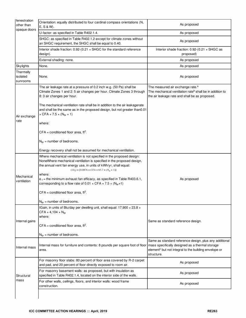
fenestrationother thanopaque doors
Orientation: equally distributed to four cardinal compass orientations (N,E, S & W).
As proposed
U-factor: as specified in Table R402.1.4. As proposed
SHGC: as specified in Table R402.1.2 except for climate zones withoutan SHGC requirement, the SHGC shall be equal to 0.40.
As proposed
Interior shade fraction: 0.92-(0.21 × SHGC for the standard referencedesign).
Interior shade fraction: 0.92-(0.21 × SHGC asproposed)
External shading: none. As proposed
Skylights None. As proposed
Thermallyisolatedsunrooms
None. As proposed
Air exchangerate
The air leakage rate at a pressure of 0.2 inch w.g. (50 Pa) shall beClimate Zones 1 and 2: 5 air changes per hour. Climate Zones 3 through8: 3 air changes per hour.
The mechanical ventilation rate shall be in addition to the air leakagerateand shall be the same as in the proposed design, but not greater than0.01× CFA + 7.5 × (N + 1)
where:
CFA = conditioned floor area, ft .
N = number of bedrooms.
Energy recovery shall not be assumed for mechanical ventilation.
The measured air exchange rate.The mechanical ventilation rate shall be in addition tothe air leakage rate and shall be as proposed.
Mechanicalventilation
Where mechanical ventilation is not specified in the proposed design:NoneWhere mechanical ventilation is specified in the proposed design,the annual vent fan energy use, in units of kWh/yr, shall equal:
where:e = the minimum exhaust fan efficacy, as specified in Table R403.6.1,corresponding to a flow rate of 0.01 × CFA + 7.5 × (N +1)
CFA = conditioned floor area, ft .
N = number of bedrooms.
As proposed
Internal gains
IGain, in units of Btu/day per dwelling unit, shall equal: 17,900 + 23.8 ×CFA + 4,104 × Nwhere:
CFA = conditioned floor area, ft .
N = number of bedrooms.
Same as standard reference design.
Internal massInternal mass for furniture and contents: 8 pounds per square foot of floorarea.
Same as standard reference design, plus any additionalmass specifically designed as a thermal storageelement but not integral to the building envelope orstructure.
Structuralmass
For masonry floor slabs: 80 percent of floor area covered by R-2 carpetand pad, and 20 percent of floor directly exposed to room air.
As proposed
For masonry basement walls: as proposed, but with insulation asspecified in Table R402.1.4, located on the interior side of the walls.
As proposed
For other walls, ceilings, floors, and interior walls: wood frameconstruction.
As proposed
br
2
br
a
b
f
br
2
br
br
2
br
c
ICC COMMITTEE ACTION HEARINGS ::: April, 2019 RE263
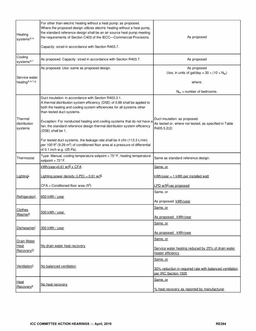
Heatingsystems
For other than electric heating without a heat pump: as proposed.Where the proposed design utilizes electric heating without a heat pump,the standard reference design shall be an air source heat pump meetingthe requirements of Section C403 of the IECC—Commercial Provisions.
Capacity: sized in accordance with Section R403.7.
As proposed
Coolingsystems
As proposed. Capacity: sized in accordance with Section R403.7. As proposed
Service waterheating
As proposed. Use: same as proposed design. As proposedUse, in units of gal/day = 30 + (10 × N )
where:
N = number of bedrooms.
Thermaldistributionsystems
Duct insulation: in accordance with Section R403.3.1.A thermal distribution system efficiency (DSE) of 0.88 shall be applied toboth the heating and cooling system efficiencies for all systems otherthan tested duct systems.
Exception: For nonducted heating and cooling systems that do not have afan, the standard reference design thermal distribution system efficiency(DSE) shall be 1.
For tested duct systems, the leakage rate shall be 4 cfm (113.3 L/min)per 100 ft (9.29 m ) of conditioned floor area at a pressure of differentialof 0.1 inch w.g. (25 Pa).
Duct insulation: as proposed.As tested or, where not tested, as specified in TableR405.5.2(2)
ThermostatType: Manual, cooling temperature setpoint = 75°F; heating temperaturesetpoint = 72°F.
Same as standard reference design.
Lighting
kWh/year=0.61 w/f x CFA
Lighting power density (LPD) = 0.61 w/f
CFA = Conditioned floor area (ft )
Same, or
kWh/year = 1 kWh per installed watt
LPD w/ft =as proposed
Refrigerator 650 kWh / yearSame, or
As proposed kWh/year
ClothesWasher
500 kWh / year Same, or
As proposed kWh/year
Dishwasher 300 kWh / yearSame, or
As proposed kWh/year
Drain WaterHeatRecovery
No drain water heat recovery
Same, or
Service water heating reduced by 25% of drain waterheater efficiency
Ventilation No balanced ventilation
Same, or
30% reduction in required rate with balanced ventilationper IRC Section 1505
HeatRecovery
No heat recoverySame, or
% heat recovery as reported by manufacturer
d, e
d, f
d, e, f, g
br
br
2 2
i
2
2
2 2
j
k
l
m
n
o
ICC COMMITTEE ACTION HEARINGS ::: April, 2019 RE264
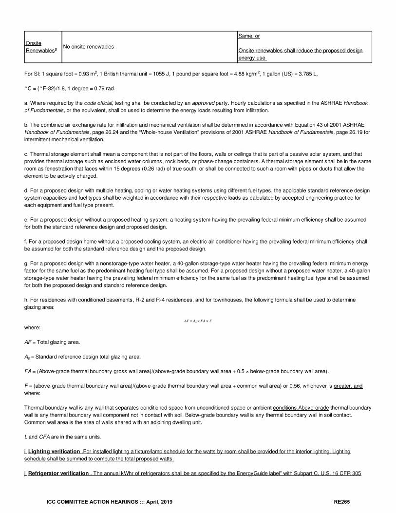
OnsiteRenewables
No onsite renewables
Same, or
Onsite renewables shall reduce the proposed designenergy use
For SI: 1 square foot = 0.93 m , 1 British thermal unit = 1055 J, 1 pound per square foot = 4.88 kg/m , 1 gallon (US) = 3.785 L,
°C = (°F-32)/1.8, 1 degree = 0.79 rad.
a. Where required by the code official, testing shall be conducted by an approved party. Hourly calculations as specified in the ASHRAE Handbookof Fundamentals, or the equivalent, shall be used to determine the energy loads resulting from infiltration.
b. The combined air exchange rate for infiltration and mechanical ventilation shall be determined in accordance with Equation 43 of 2001 ASHRAEHandbook of Fundamentals, page 26.24 and the “Whole-house Ventilation” provisions of 2001 ASHRAE Handbook of Fundamentals, page 26.19 forintermittent mechanical ventilation.
c. Thermal storage element shall mean a component that is not part of the floors, walls or ceilings that is part of a passive solar system, and thatprovides thermal storage such as enclosed water columns, rock beds, or phase-change containers. A thermal storage element shall be in the sameroom as fenestration that faces within 15 degrees (0.26 rad) of true south, or shall be connected to such a room with pipes or ducts that allow theelement to be actively charged.
d. For a proposed design with multiple heating, cooling or water heating systems using different fuel types, the applicable standard reference designsystem capacities and fuel types shall be weighted in accordance with their respective loads as calculated by accepted engineering practice foreach equipment and fuel type present.
e. For a proposed design without a proposed heating system, a heating system having the prevailing federal minimum efficiency shall be assumedfor both the standard reference design and proposed design.
f. For a proposed design home without a proposed cooling system, an electric air conditioner having the prevailing federal minimum efficiency shallbe assumed for both the standard reference design and the proposed design.
g. For a proposed design with a nonstorage-type water heater, a 40-gallon storage-type water heater having the prevailing federal minimum energyfactor for the same fuel as the predominant heating fuel type shall be assumed. For a proposed design without a proposed water heater, a 40-gallonstorage-type water heater having the prevailing federal minimum efficiency for the same fuel as the predominant heating fuel type shall be assumedfor both the proposed design and standard reference design.
h. For residences with conditioned basements, R-2 and R-4 residences, and for townhouses, the following formula shall be used to determineglazing area:
where:
AF = Total glazing area.
A = Standard reference design total glazing area.
FA = (Above-grade thermal boundary gross wall area)/(above-grade boundary wall area + 0.5 × below-grade boundary wall area).
F = (above-grade thermal boundary wall area)/(above-grade thermal boundary wall area + common wall area) or 0.56, whichever is greater. andwhere:
Thermal boundary wall is any wall that separates conditioned space from unconditioned space or ambient conditions.Above-grade thermal boundarywall is any thermal boundary wall component not in contact with soil. Below-grade boundary wall is any thermal boundary wall in soil contact.Common wall area is the area of walls shared with an adjoining dwelling unit.
L and CFA are in the same units.
i. Lighting verification .For installed lighting a fixture/lamp schedule for the watts by room shall be provided for the interior lighting. Lightingschedule shall be summed to compute the total proposed watts.
j. Refrigerator verification . The annual kWhr of refrigerators shall be as specified by the EnergyGuide label” with Subpart C, U.S. 16 CFR 305
p
2 2
s
ICC COMMITTEE ACTION HEARINGS ::: April, 2019 RE265

(Effective January 1, 2021).. Where there are multiple refrigerators, the annual kWhr shall be summed.
k. Clothes washer verification. The annual kWhr of clothes washers shall be as specified by the EnergyGuide label” with Subpart C, U.S. 16 CFR305 (Effective January 1, 2021). Where there are multiple clothes washers, the highest kWhr shall be used.
l. Dishwasher verification. The annual kWhr of dishwashers shall be as specified by the EnergyGuide label” with Subpart C, U.S. 16 CFR 305(Effective January 1, 2021). Where there are multiple dishwashers, the highest kWhr shall be used.
m. Drain water heat recovery. Drain water heat recovery unit efficiency shall be in accordance with Section R403.5.4 This credit shall require adrain water heat recovery unit be installed on all showers.
n. Balanced ventiliation verification . Ventilation shall be in accordance with IRC 1505 which allows a 30% reduction in ventilation rate. To receivethis credit exhaust-only bath fans shall be on a 20-minute timer or other device that shuts off the bath fan when not in use.
o. Heat recovery verification . Heat recovery ventilation or energy recovery ventilation shall be a reduction in energy use as specified by themanufacturer.
p. On-site renewables verification. Energy from on-site renewables shall be a reduction in the residence's energy use based on an approvedcalculation of on-site renewable energy production.
Reason: This code change proposal expands the performance calculation to include additional options for energy savings. In all cases theseoptions are neutral if not taken, but offer credits if taken. This change specifies efficiency measures in a way that makes them enforceable.Multiple jurisdictions reduce specific IECC/IRC energy requirements because those requirements seem difficult for some situations. For example airtightness and specific insulation levels are reduced in many jurisdictions. This code change gives the code user new options to increase energyefficiency in one area to compensate for another area.
The options in this proposal were picked because they have significant impact, can be specified in simple terms, and can be specified based onexisting tests or standards. The performance section user can use or not use any of these options. Options not used do not affect theperformance calculation, because the standard reference design and the proposed design become the same.
The ERI already includes the items listed here. The performance calculation should also include those items.
Several measures of efficiency in this change are based on existing tests or labels. Clothes washer, refrigerator and dishwasher annual energy useis on the federally required label. These are the yellow Energy Guide labels.
Lighting:
Lighting power density (LPD) is a concept usually applied to commercial spaces. The LPD for the reference design was selected based on TableC405.3.2.1 in the commercial IECC. The reference design (base case) of 0.61 was the lowest LPD from several that were similar to residentialspace. The similar values were “Dormitory” at 0.61; “Multifamily” at 0.68; and “Hotel/Motel” is 0.75.
The proposed lighting annual energy use is calculated as hours of use times watts. An average use of 1000 hours per year (2.74 hours per day) iswithin the reported range for actual light use and is presumed. Based on this use per day the proposed lighting annual energy use is simply 1 kWhper watt of installed lighting.
Lighting wattage will need to be verifiable, as lighting savings are based on the watts of installed lighting. Code officials are unlikely to have the timeto count watts in a house. A list of lighting by room would give enough detail to spot check one or more rooms in a house.
Refrigerator, Clothes Washer, and Dishwasher:
These appliances all required to have EnergyGuide labels by federal law. The EnergyGuide labels all have kWhr/year on the label.
Drain water heat recovery:
The drain water heat recover applies to showers. Showers average over 25% of the service hot water use in homes. The devices recover heatfrom water gong down the drain water and use it to preheat the incoming water. The heat recovery of a unit is rated by tests in CSA B55.1, which isalready required in the code. (Section R403.5.4).
Ventilation:
Balanced ventilation performs better, requires less ventilation and uses less energy. Approved group A code changes (M22 and RM22) specified
ICC COMMITTEE ACTION HEARINGS ::: April, 2019 RE266
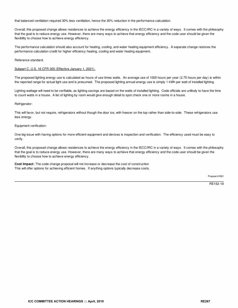
that balanced ventilation required 30% less ventilation, hence the 30% reduction in the performance calculation.
Overall, this proposed change allows residences to achieve the energy efficiency in the IECC/IRC in a variety of ways. It comes with the philosophythat the goal is to reduce energy use. However, there are many ways to achieve that energy efficiency and the code user should be given theflexibility to choose how to achieve energy efficiency.
The performance calculation should also account for heating, cooling, and water heating equipment efficiency. A separate change restores theperformance calculation credit for higher efficiency heating, cooling and water heating equipment.
Reference standard.
Subpart C, U.S. 16 CFR 305 (Effective January 1, 2021).
The proposed lighting energy use is calculated as hours of use times watts. An average use of 1000 hours per year (2.75 hours per day) is withinthe reported range for actual light use and is presumed. The proposed lighting annual energy use is simply 1 kWh per watt of installed lighting.
Lighting wattage will need to be verifiable, as lighting savings are based on the watts of installed lighting. Code officials are unlikely to have the timeto count watts in a house. A list of lighting by room would give enough detail to spot check one or more rooms in a house.
Refrigerator:
This will favor, but not require, refrigerators without though the door ice, with freezer on the top rather than side-to-side. These refrigerators useless energy.
Equipment verification:
One big issue with having options for more efficient equipment and devices is inspection and verification. The efficiency used must be easy toverify.
Overall, this proposed change allows residences to achieve the energy efficiency in the IECC/IRC in a variety of ways. It comes with the philosophythat the goal is to reduce energy use. However, there are many ways to achieve that energy efficiency and the code user should be given theflexibility to choose how to achieve energy efficiency.
Cost Impact: The code change proposal will not increase or decrease the cost of constructionThis will offer options for achieving efficient homes. If anything options typically decrease costs.
Proposal # 5521
RE152-19
ICC COMMITTEE ACTION HEARINGS ::: April, 2019 RE267
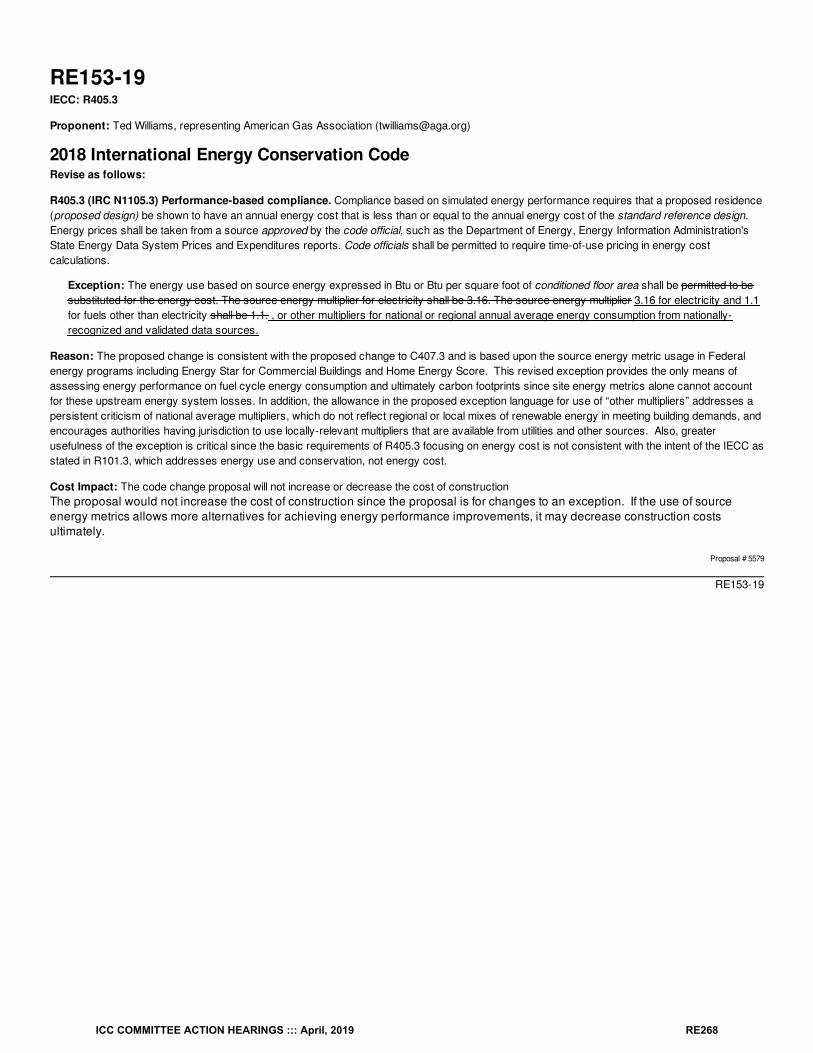
RE153-19IECC: R405.3
Proponent: Ted Williams, representing American Gas Association ([email protected])
2018 International Energy Conservation CodeRevise as follows:
R405.3 (IRC N1105.3) Performance-based compliance. Compliance based on simulated energy performance requires that a proposed residence(proposed design) be shown to have an annual energy cost that is less than or equal to the annual energy cost of the standard reference design.Energy prices shall be taken from a source approved by the code official, such as the Department of Energy, Energy Information Administration'sState Energy Data System Prices and Expenditures reports. Code officials shall be permitted to require time-of-use pricing in energy costcalculations.
Exception: The energy use based on source energy expressed in Btu or Btu per square foot of conditioned floor area shall be permitted to besubstituted for the energy cost. The source energy multiplier for electricity shall be 3.16. The source energy multiplier 3.16 for electricity and 1.1for fuels other than electricity shall be 1.1. , or other multipliers for national or regional annual average energy consumption from nationally-recognized and validated data sources.
Reason: The proposed change is consistent with the proposed change to C407.3 and is based upon the source energy metric usage in Federalenergy programs including Energy Star for Commercial Buildings and Home Energy Score. This revised exception provides the only means ofassessing energy performance on fuel cycle energy consumption and ultimately carbon footprints since site energy metrics alone cannot accountfor these upstream energy system losses. In addition, the allowance in the proposed exception language for use of “other multipliers” addresses apersistent criticism of national average multipliers, which do not reflect regional or local mixes of renewable energy in meeting building demands, andencourages authorities having jurisdiction to use locally-relevant multipliers that are available from utilities and other sources. Also, greaterusefulness of the exception is critical since the basic requirements of R405.3 focusing on energy cost is not consistent with the intent of the IECC asstated in R101.3, which addresses energy use and conservation, not energy cost.
Cost Impact: The code change proposal will not increase or decrease the cost of constructionThe proposal would not increase the cost of construction since the proposal is for changes to an exception. If the use of sourceenergy metrics allows more alternatives for achieving energy performance improvements, it may decrease construction costsultimately.
Proposal # 5579
RE153-19
ICC COMMITTEE ACTION HEARINGS ::: April, 2019 RE268
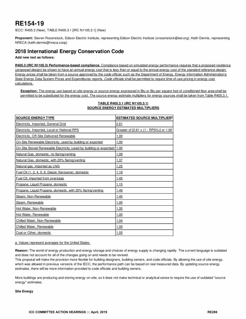
RE154-19IECC: R405.3 (New), TABLE R405.3.1 [IRC N1105.3.1] (New)
Proponent: Steven Rosenstock, Edison Electric Institute, representing Edison Electric Institute ([email protected]); Keith Dennis, representingNRECA ([email protected])
2018 International Energy Conservation CodeAdd new text as follows:
R405.3 (IRC N1105.3) Performance-based compliance. Compliance based on simulated energy performance requires that a proposed residence(proposed design) be shown to have an annual energy cost that is less than or equal to the annual energy cost of the standard reference design.Energy prices shall be taken from a source approved by the code official, such as the Department of Energy, Energy Information Administration’sState Energy Data System Prices and Expenditures reports. Code officials shall be permitted to require time-of-use pricing in energy costcalculations.
Exception: The energy use based on site energy or source energy expressed in Btu or Btu per square foot of conditioned floor area shall bepermitted to be substituted for the energy cost. The source energy estimate multipliers for energy sources shall be taken from Table R405.3.1.
TABLE R405.3.1 (IRC N1105.3.1)SOURCE ENERGY ESTIMATED MULTIPLIERS
SOURCE ENERGY TYPE ESTIMATED SOURCE MULTIPLIER
Electricity, Imported, General Grid 2.61
Electricity, Imported, Local or National RPS Greater of [2.61 x (1 - RPS%)] or 1.00
Electricity, Off-Site Delivered Renewable 1.00
On-Site Renewable Electricity, used by building or exported 1.00
On-Site Stored Renewable Electricity (used by building or exported) 1.00
Natural Gas, domestic, no flaring/venting 1.09
Natural Gas, domestic, with 20% flaring/venting 1.37
Natural gas, imported as LNG 1.25
Fuel Oil (1, 2, 4, 5, 6, Diesel, Kerosene), domestic 1.19
Fuel Oil, imported from overseas 1.45
Propane, Liquid Propane, domestic 1.15
Propane, Liquid Propane, domestic, with 20% flaring/venting 1.49
Steam, Non-Renewable 1.45
Steam, Renewable 1.00
Hot Water, Non-Renewable 1.35
Hot Water, Renewable 1.00
Chilled Water, Non-Renewable 1.04
Chilled Water, Renewable 1.00
Coal or Other, domestic 1.05
a. Values represent averages for the United States.
Reason: The world of energy production and energy storage and choices of energy supply is changing rapidly. The current language is outdatedand does not account for all of the changes going on and needs to be revised.This proposal will make the provision more flexible for building designers, building owners, and code officials. By allowing the use of site energy,which was allowed in previous versions of the IECC, the performance path can be based on real measured data. By updating source energyestimates, there will be more information provided to code officials and building owners.
More buildings are producing and storing energy on-site, so it does not make technical or analytical sense to require the use of outdated "sourceenergy" estimates.
Site Energy
a
ICC COMMITTEE ACTION HEARINGS ::: April, 2019 RE269
Allowing the use of site energy is more appropriate for buildings that are producing or storing energy on-site. In the future,many buildings will be producing energy and storing energy, along with consuming energy. Building systems may beconsuming energy that was produced from an off-site energy grid and/or produced from an on-site energy production systemand/or delivered from an off-site energy storage system (e.g., a grid battery or EV battery) and/or delivered from an on-siteenergy storage system, (e.g., and battery or fuel storage tank or thermal energy storage system). At the same time, thebuilding may be producing energy that is used by building equipment, sent to an on-site energy storage system, or exported toanother building (or buildings) or to the energy grid.
In a letter to DOE, ASHRAE said:
"the Society believes that the multiple and varying weighting factors and algorithms required for estimating sourceenergy conversions are often inconsistent and ultimately cloud and complicate understanding. Since source energy conversionfactors vary widely from place to place and across time, the use of fixed national average conversion factors could lead toinconsistent estimates of consumption."
"Thus, in this case the best method for determining if a building is a NZEB is to look at the energy crossing the boundary at thesite of the building; hence "site" energy is the best choice to use." (emphasis added)
Site energy was part of the exception for many years until it was removed. There are many reasons to allow siteenergy to be used as an alternative to source energy or energy costs:
-Site energy is an actual metric that can be measured and verified by code officials, while source energy is an estimate.
-Site energy information is credible, as it is shown on customers' energy bills on a monthly basis and used in otherconsensus-based code documents, such as ASHRAE 90.1, use site energy metrics for efficiency requirements.
-DOE uses site energy information in many of its energy efficiency and energy consumption publications, such as theResidential Energy Consumption Survey. DOE uses site energy for its appliance energy efficiency standards programand the FTC uses site energy on the yellow EnergyGuide labels found on consumer appliances. EPA uses site energy todetermine if an appliance or home qualifies for the Energy Star program.
-Site energy is reliable, since it can be measured by utilities, consumers, and independent 3 parties. In terms of energyefficiency upgrades, consumers rely on site energy information (amount used by older appliance or equipment comparedto new appliance or equipment) to help them make energy efficiency decisions.
-Site energy is replicable, as the units of measurement (kWh, therms, gallons, Btu's) can be used throughout the United States and are familiar toconsumers on their monthly energy bills. Source energy is not replicable, as different estimates must be used for different energy sources, anddifferent entities can make different assumptions about upstream production and delivery of different energy sources.
-Site energy is transparent and easy to understand. It can be based on meter readings or DOE test procedures or FTCEnergyGuide labels or Energy Star labels. It is the metric that allows people to easily compare energy efficiency optionsin the marketplace. It is the metric that allows people to make good economic choices when faced with competitivealternatives.
Source Energy Estimates
There are many ways to estimate upstream energy losses. The energy production industry is very dynamic and subject tosignificant changes. In the United States in 2018, there was a record amounts of natural gas produced from hydraulicfracturing production techniques. In 2018, there was a record amount of oil produced and imported from oil sands production.In 2018, there was a record amount of electricity produced from renewable forms of energy and a record amount of electricityproduced by combined-cycle natural gas turbines.
The values that are currently shown should be deleted and not used. The values shown are not consistent with values shown in other publisheddocuments. Many documents and articles have been published over the past several years with source energy estimates as shown in thebibliography. The current values in the IECC do not match and cannot be substantiated with any of these published documents.
Different fossil fuels have different upstream source estimates. In the current IECC, all fossil fuels are assumed to have the same multiplier. In otherdocuments, there is a large and statistically significant variation in the upstream estimates that will have a significant impact on energy performanceresults. As one example, for fuel oil and propane, EPA's Portfolio Manager uses a factor of 1.01 for both, while NREL used estimated values of 1.158and 1.151, while IGCC 2015 uses 1.19 for fuel oil and 1.15 for propane. The use of 3.16 for electricity is overstated for many parts of the UnitedStates and does not account for significant regional differences or the increase in the use of renewable power generation and combined cycle gas
ICC COMMITTEE ACTION HEARINGS ::: April, 2019 RE270
turbines.
In other publications and web sites, the estimates for electricity are shown on a national basis, a regional basis, or a state by state basis. This is dueto the variety of electric generation techniques which have upstream energy losses that can vary by orders of magnitude based on local conditions,regional conditions, physical location, season, month, week, or day, as well as hourly fluctuations in the amount of sunlight or wind speed.
The revisions to the values are based on reports published by the US Energy Information Administration, the US Department ofEnergy, the US Environmental Protection Agency, national labs, and other public sources of information. It is a technical factthat there are significant differences in terms of upstream estimates for electricity as well as fossil fuels. The newestimates provide more defensible and accurate estimates.
Bibliography: National Renewable Energy Laboratory NREL/TP-550-38617 "Source Energy and Emission Factors for Energy Use inBuildings" (June 2007)American Gas Association EA 2009-3 "A Comparison of Energy Use, Operating Costs, and Carbon Dioxide Emissions of HomeAppliances" (October 2009)Environmental Protection Agency "Energy Star Performance Ratings Methodology for Incorporating Source Energy Use"(August 2009 and 2017 update)National Renewable Energy Laboratory NREL/TP-550-47246 "Building America Research Benchmark Definition" (January 2010)International Code Council "International Green Construction Code" (May 2015)American Gas Association "Dispatching Direct Use", Table 1, (November 2015)
US Department of Energy "Accounting Methodology for Source Energy of Non-Combustible Renewable Electricity Generation" (October 2016)
Cost Impact: The code change proposal will not increase or decrease the cost of constructionThis proposal only provides another option for the simulation used for the performance path.
Proposal # 4672
RE154-19
ICC COMMITTEE ACTION HEARINGS ::: April, 2019 RE271
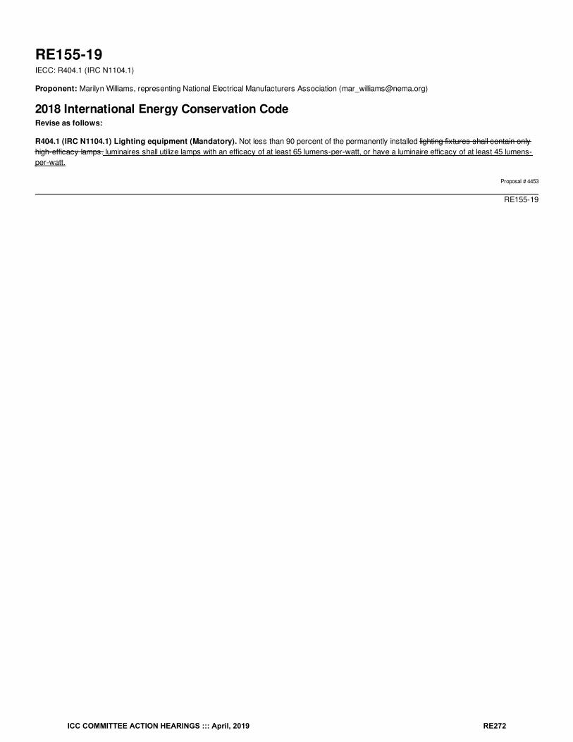
RE155-19IECC: R404.1 (IRC N1104.1)
Proponent: Marilyn Williams, representing National Electrical Manufacturers Association ([email protected])
2018 International Energy Conservation CodeRevise as follows:
R404.1 (IRC N1104.1) Lighting equipment (Mandatory). Not less than 90 percent of the permanently installed lighting fixtures shall contain onlyhigh-efficacy lamps. luminaires shall utilize lamps with an efficacy of at least 65 lumens-per-watt, or have a luminaire efficacy of at least 45 lumens-per-watt.
Proposal # 4453
RE155-19
ICC COMMITTEE ACTION HEARINGS ::: April, 2019 RE272
RE155-19IECC: R405.3 (IRC N1105.3)
Proponent: Charles Foster, representing self ([email protected])
2018 International Energy Conservation CodeRevise as follows:
R405.3 (IRC N1105.3) Performance-based compliance. Compliance based on simulated energy performance requires that a proposed residence(proposed design) be shown to have an annual energy cost that is less than or equal to the annual energy cost of the standard reference design.Energy prices shall be taken from a source approved by the code official, such as the Department of Energy, Energy Information Administration’sState Energy Data System Prices and Expenditures reports. Code officials shall be permitted to require time-of-use pricing in energy costcalculations.
Exception: The energy use based on source energy expressed in Btu or Btu per square foot of conditioned floor area shall be permitted to besubstituted for the energy cost. The source energy multiplier for electricity shall be 3.16. The source energy multiplier for fuels other thanelectricity shall be 1.1.
Reason: There is only one metric that consumers are concerned with. That metric is cost.The IECC and its predecessor the model energy code traditionally relied on energy costs to demonstrate compliance. During the 2015 code cycle,this section added the current exception for the use of source energy as an alternative to cost.
Source energy is a relatively complex exercise used to estimate the approximate amount of raw energy consumed in the delivery of energy toultimate customers. It is not a measurement nor a repeatable calculation across either geography or time.
Among its many limitations, source energy is particularly challenged when dealing with electricity as it treats electricity derived from renewables likesolar and wind the same as electricity from an old coal fired generator.
The U.S. Department of Energy recognizes this absurdity – of treating wind the same as coal – and several years ago published a report on thetopic. (SEE bibliography).
The overwhelming majority of jurisdictions using the IECC rely on cost.
There is no meaningful reason to keep the exception in the code and it should be removed.
Cost Impact: The code change proposal will not increase or decrease the cost of constructionThis proposal imposes no additional compliance requirements and, therefore, neither increases nor decreases the cost of construction.
Proposal # 4977
RE155-19
ICC COMMITTEE ACTION HEARINGS ::: April, 2019 RE273
RE156-19IECC: R405.4 (IRC N1105.4) (New)
Proponent: Joseph Cain, representing Solar Energy Industries Association (SEIA) ([email protected])
2018 International Energy Conservation CodeAdd new text as follows:
R405.4 (IRC N1105.4) On-site renewable energy. On-site renewable energy shall be considered as a reduction in energy use of the building.
Reason: The IECC should integrate energy efficiency measures and renewable energy systems. Builders should get credit for what they do.As presented by the Building Technologies Office of the Department of Energy's 2018 National Energy Codes Conference, according to the U.S.Energy Information Administration's AEO 2018 report, typical Residential End Uses include Space heating at 24% and Space cooling at 11%, for acombined space heating/cooling at 35% of all Residential Energy End Uses. Water heating accounts for 13.5% of Residential Energy End Uses.These figures illustrate that we have done a very good job of reducing regulated loads, such that unregulated loads now represent greater than 50%of all Residential Energy End Uses. Renewable energy systems can offset not only the unregulated loads, but can also offset the reduced regulatedloads.
Compliance measures and compliance paths that focus only on building envelope measures and discourage or penaliz e renewable energy sytems-- or fail to make renewable energy systems attractive to builders as a compliance option -are focused on solving 35% of the problem.The IECCshould encourage the use of energy efficiency plus renewable energy, to solve 100% of the problem.
Cost Impact: The code change proposal will not increase or decrease the cost of constructionInstallation of an on-site photovoltaic system could increase or decrease the overall first cost of construction.
Proposal # 5687
RE156-19
ICC COMMITTEE ACTION HEARINGS ::: April, 2019 RE274
RE157-19IECC: R405.4.2 (IRC N1105.4.2)
Proponent: William Fay, Energy-Efficient Codes Coalition, representing Energy-Efficient Codes Coalition ([email protected]); Daniel Bresette, Allianceto Save Energy, representing Alliance to Save Energy ([email protected]); Maureen Guttman, BCAP-IBTS, representing BCAP-IBTS([email protected]); Harry Misuriello, American Council for an Energy-Efficient Economy, representing American Council for an Energy-Efficient Economy ([email protected])
2018 International Energy Conservation CodeRevise as follows:
R405.4.2 (IRC N1105.4.2) Compliance report. Compliance software tools shall generate a report that documents that the proposed designcomplies with Section R405.3. A compliance report on the proposed design shall be submitted with the application for the building permit. Uponcompletion of the building, a compliance report based on the as-built condition of the building shall be submitted to the code official before a certificateof occupancy is issued. Batch sampling of buildings to determine energy code compliance shall only be allowed for stacked multiple-family units.Compliance reports shall include information in accordance with Sections R405.4.2.1 and R405.4.2.2. Where the proposed design of a building couldbe built on different sites where the cardinal orientation of the building on each site is different, compliance of the proposed design for the purposes ofthe application for the building permit shall be based on the worst-case orientation, worst-case configuration, worst-case building air leakage andworst- case duct leakage. Such worst-case parameters shall be used as inputs to the compliance software for energy analysis.
Reason: The purpose of this code change proposal is to remove confusing and incomplete language from the performance path regarding “batchsampling” of buildings. Section R405.4.2 contains orphan language that implies that batch sampling might be acceptable for stacked multiple familyunits, but there is no process or criteria for “batch sampling” defined anywhere in the IECC. Before any sort of sampling is allowed, a number of veryimportant questions must be addressed, such as which parts of the building may be batch sampled, what sample size must be collected, whathappens in the event of a failure, etc. Although some common voluntary programs permit sampling for certain specified measures, the IECC doesnot currently allow this practice and should not until these important questions are addressed. Moreover, we are concerned that batch samplingwould fail to ensure that every home meets the code, since presumably only some homes would be included in the sampling.
Cost Impact: The code change proposal will not increase or decrease the cost of constructionThis proposal cleans up excess language that refers to sampling practices that do not currently exist in the IECC.
Proposal # 4110
RE157-19
ICC COMMITTEE ACTION HEARINGS ::: April, 2019 RE275
RE158-19IECC: R405.4.2 (IRC N1105.4.2), R405.4.2.1 (IRC N1105.4.2.1), R405.4.2.2 (IRC N1105.4.2.2) , R405.4.3 (IRC N1105.4.3)
Proponent: Robby Schwarz, EnergyLogic, representing EnergyLogic ([email protected])
2018 International Energy Conservation CodeRevise as follows:
R405.4.2 (IRC N1105.4.2) Compliance report. Compliance software tools shall generate a report that documents that the proposed designcomplies with Section R405.3. A compliance report on the proposed design shall be submitted with the application for the building permit. Uponcompletion of the building, a confirmed compliance report based on the as-built confirmed condition of the building shall be submitted to the codeofficial before a certificate of occupancy is issued. Batch sampling of buildings to determine energy code compliance shall only be allowed forstacked multiple-family units. Compliance reports shall include information in accordance with Sections R405.4.2.1 and R405.4.2.2.Where the proposed design of a building could be built on different sites where the cardinal orientation of the building on each site is different,compliance of the proposed design for the purposes of the application for the building permit shall be based on the worst-case orientation, worst-case configuration, worst-case building air leakage and worst- case duct leakage. Such worst-case parameters shall be used as inputs to thecompliance software for energy analysis.
R405.4.2.1 (IRC N1105.4.2.1) Compliance report for permit application. A compliance report Compliance reports submitted with the applicationfor building permit shall include the following:
1. Building street address, or other building site identification.2. A statement indicating that the proposed design complies with Section R405.3. The name of the individual performing the analysis
and generating the compliance report.3. An inspection checklist documenting the building component characteristics of the proposed design as indicated in Table
R405.5.2(1). The inspection checklist shall show results for both the standard reference design and the proposed design with userinputs to the compliance software to generate the results. The name and version of the compliance software tool.
4. A site-specific energy analysis report that is in compliance with Section R405.3. If requested by the authority having jurisdiction,documentation of all inputs entered into the software used to produce the results for the reference design and/or the rated home.
5. The name of the individual performing the analysis and generating the report. A certificate indicating that the proposed designcomplies with Section R405.3. The certificate shall document the building components energy specifications that are included in thecalculation including, component level insulation R-values or U-factors, assumed duct system and building envelope air leakagetesting assumptions, as well as, the type and rated efficiencies of proposed heating, cooling, mechanical ventilation, and servicewater heating equipment to be installed. If onsite renewable energy systems will be installed the certificate shall report the type andproduction size of the proposed system.
6. The name and version of the compliance software tool. When a site-specific report is not generated, the proposed design shall bebased on the worst-case orientation and configuration of the rated home.
R405.4.2.2 (IRC N1105.4.2.2) Compliance Confirmed compliance report for certificate of occupancy. A confirmed compliance reportsubmitted for obtaining the certificate of occupancy shall be made site and address specific and include the following:
1. Building street address, or other building site identification.2. A statement indicating that the as-built building complies with Section R405.3. The name of the individual performing the analysis and
generating the report.3. A certificate indicating that the building passes the performance matrix for code compliance and indicating the energy saving features
of the buildings. The name and version of the compliance software tool.4. A site-specific energy analysis report that is in compliance with Section R405.3. If requested by the authority having jurisdiction,
documentation of all inputs entered into the software used to produce the results for the reference design and/or the rated home.5. The name of the individual performing the analysis and generating the report. A final confirmed certificate indicating compliance
based on inspection and statement indicating that the confirmed rated design of the built home complies with Section R405.3. Thecertificate shall report the energy features that were confirmed to be in the home including component level insulation R- values or U-factors, results from any required duct system and building envelope air leakage testing, as wells as the type and rated efficiencies ofthe heating, cooling, mechanical ventilation, and service water heating equipment installed.
6. The name and version of the compliance software tool. When onsite renewable energy systems have been installed, the certificateshall report the type and production size of the installed system.
R405.4.3 (IRC N1105.4.3) Additional documentation. The code official shall be permitted to require the following documents:
1. Documentation of the building component characteristics of the standard reference design.2. A certification signed by the builder providing the building component characteristics of the proposed design as given in TableR405.5.2(1).3. Documentation of the actual values used in the software calculations for the proposed design.
ICC COMMITTEE ACTION HEARINGS ::: April, 2019 RE276
Reason: EnergyLogic began to use the Section R405 Simulated Performance alternative and the cost compliance report with our Builder clients todemonstrate energy code compliance when the 2009 IECC was adopted by jurisdictions in the Denver Metro area. We fundamentally defined theprocess by which the path was used at the time as most jurisdictions did not have experience using it. Use of the pathway took off as wedemonstrated that the systems thinking, building science trade-off approach offered tremendous flexibility for how to build a cost-effective codecompliant house within a defined structure that ensured both jurisdictional and third-party stringent verification. Therefore, in the 2015 codedevelopment cycle we decided to define the process by which the Simulated Performance path was successfully being implemented in Colorado inthe body of the IECC to help jurisdictions and builders better understand how to implement the pathway to gain flexibility of choice and trade-off, aswell as, to ensure verification that backs it up for compliance.In the 2021 code adoption cycle, we propose to update the compliance requirements based on what we have learned over the years using the pathto help thousands of homes a year demonstrate compliance with the IECC. The changes we propose offer clarification and simplification rather thanactually changing what is required. For example, the use of the terms proposed and confirmed to refer to documents that must be part of thedocument set needed to obtain the building permit and certificate of occupancy is more clearly laid out. In addition, section R405.4.2.1 Compliancereport for permit application and section R405.4.2.2 Confirmed compliance report for certificate of occupancy, have been consolidated andreordered to more clearly identify for the jurisdiction having authority the documentation needed to be reviewed to demonstrate compliance.
Cost Impact: The code change proposal will not increase or decrease the cost of constructionThere is no cost implication with these changes to the code. The proposal does not add new requirements but rather cleans up the section for betterunderstanding and use by the jurisdictions and builders that choose it.
Proposal # 5254
RE158-19
ICC COMMITTEE ACTION HEARINGS ::: April, 2019 RE277
RE159-19IECC: R405.4.2.1
Proponent: Kirk Nagle, City of Aurora, representing Myself ([email protected])
2018 International Energy Conservation CodeRevise as follows:
R405.4.2.1 (IRC N1105.4.2.1) Compliance report for permit application. A compliance report submitted with the application for building permitshall include the following:
1. Building street address, or other building site identification.2. Declare simulated performance path3. A statement indicating that the proposed design complies with Section R405.3.4. An inspection checklist documenting the building component characteristics of the proposed design as indicated in Table
R405.5.2(1). The inspection checklist shall show results for both the standard reference design and the proposed design with userinputs to the compliance software to generate the results.
5. A site-specific energy analysis report that is in compliance with Section R405.3.6. The name of the individual performing the analysis and generating the report.7. The name and version of the compliance software tool.
Reason: This code change is being proposed to clarify the energy path to the code official and the documentation for permit. Many reports do notspecify the path that is being proposed and the code official has to contact the applicant to verify the energy path they are intending to use, tocomply with the energy code. By providing the method of compliance the code official can focus on the details of the report and this information willexpidate the permit process time.
Cost Impact: The code change proposal will increase the cost of constructionThis will increase the cost of construction by a very minor ammount, adding a data entry to report.
Proposal # 5660
RE159-19
ICC COMMITTEE ACTION HEARINGS ::: April, 2019 RE278
RE160-19IECC: R402.5 (IRC N1102.5), R405.5.2.1 (IRC N1105.5.2.1) (New)
Proponent: Darren Meyers, P.E., International Energy Conservation Consultants LLC, representing Self ([email protected])
2018 International Energy Conservation CodeRevise as follows:
R402.1.5 (IRC N1102.1.5) Total UA alternative. Where the total building thermal envelope UA, the sum of U-factor times assembly area, is lessthan or equal to the total UA resulting from multiplying the U-factors in Table R402.1.4 by the same assembly area as in the proposed building, thebuilding shall be considered to be in compliance with Table R402.1.2. The UA calculation shall be performed using a method consistent with theASHRAE Handbook of Fundamentals and shall include the thermal bridging effects of framing materials. In addition to UA compliance, the SHGCrequirements shall be met.
R402.5 (IRC N1102.5) R402.1.5.1 (IRC N1102.5.1) Maximum fenestration U-factor and SHGC (Mandatory). The area-weighted averagemaximum fenestration U-factor permitted using tradeoffs from Section R402.1.5 or R405 shall be 0.48 in Climate Zones 4 and 5 and 0.40 in ClimateZones 6 through 8 for vertical fenestration, and 0.75 in Climate Zones 4 through 8 for skylights. The area-weighted average maximum fenestrationSHGC permitted using tradeoffs from Section R405 in Climate Zones 1 through 3 shall be 0.50.
Add new text as follows:
R405.5.2.1 (IRC N1105.5.2.1) Maximum fenestration U-factor and SHGC (Mandatory) The area-weighted average maximum fenestration U-factor permitted using Section R405 shall be 0.48 in Climate Zones 4 and 5 and 0.40 in Climate Zones 6 through 8 for vertical fenestration, and 0.75in Climate Zones 4 through 8 for skylights. The area-weighted average maximum fenestration SHGC permitted using Section R405 in Climate Zones1 through 3 shall be 0.50.
Reason: This proposal relocates and apportions the provisions of Section R402.5 to their appropriate locations as they apply specifically to themethodologies therein. No change in stringency or applicability is proposed.
Cost Impact: The code change proposal will not increase or decrease the cost of constructionThere is no cost implication aligned with this proposal. Rather, it is an exercise steeped in clarification such that a provision "hanging" at the end ofSection R402, is appropriately assigned to the "Total UA Alternative" and the "Simulated Performance Alternative," accordingly. No change tostringency is proposed.
Proposal # 5459
RE160-19
ICC COMMITTEE ACTION HEARINGS ::: April, 2019 RE279
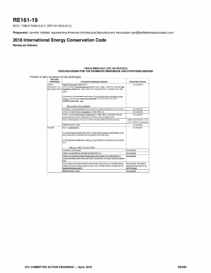
RE161-19IECC: TABLE R405.5.2(1) [IRC N1105.5.2(1)]
Proponent: Jennifer Hatfield, representing American Architectural Manufacturers Association ([email protected])
2018 International Energy Conservation CodeRevise as follows:
ICC COMMITTEE ACTION HEARINGS ::: April, 2019 RE280
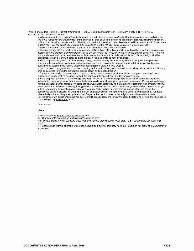
ICC COMMITTEE ACTION HEARINGS ::: April, 2019 RE281
Reason: The IECC residential simulated energy performance analysis standard reference design specification table has historically includedskylight area in the “Glazing” row, as reflected in the 2012 IECC:
ICC COMMITTEE ACTION HEARINGS ::: April, 2019 RE282
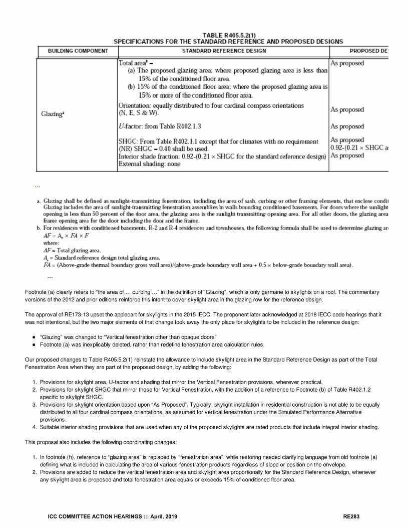
Footnote (a) clearly refers to “the area of … curbing …” in the definition of “Glazing”, which is only germane to skylights on a roof. The commentaryversions of the 2012 and prior editions reinforce this intent to cover skylight area in the glazing row for the reference design.
The approval of RE173-13 upset the applecart for skylights in the 2015 IECC. The proponent later acknowledged at 2018 IECC code hearings that itwas not intentional, but the two major elements of that change took away the only place for skylights to be included in the reference design:
“Glazing” was changed to “Vertical fenestration other than opaque doors”Footnote (a) was inexplicably deleted, rather than redefine fenestration area calculation rules.
Our proposed changes to Table R405.5.2(1) reinstate the allowance to include skylight area in the Standard Reference Design as part of the TotalFenestration Area when they are part of the proposed design, by adding the following:
1. Provisions for skylight area, U-factor and shading that mirror the Vertical Fenestration provisions, wherever practical.2. Provisions for skylight SHGC that mirror those for Vertical Fenestration, with the addition of a reference to Footnote (b) of Table R402.1.2
specific to skylight SHGC.3. Provisions for skylight orientation based upon “As Proposed”. Typically, skylight installation in residential construction is not able to be equally
distributed to all four cardinal compass orientations, as assumed for vertical fenestration under the Simulated Performance Alternativeprovisions.
4. Suitable interior shading provisions that are used when any of the proposed skylights are rated products that include integral interior shading.
This proposal also includes the following coordinating changes:
1. In footnote (h), reference to “glazing area” is replaced by “fenestration area”, while restoring needed clarifying language from old footnote (a)defining what is included in calculating the area of various fenestration products regardless of slope or position on the envelope.
2. Provisions are added to reduce the vertical fenestration area and skylight area proportionally for the Standard Reference Design, wheneverany skylight area is proposed and total fenestration area equals or exceeds 15% of conditioned floor area.
ICC COMMITTEE ACTION HEARINGS ::: April, 2019 RE283
Bibliography: 2012 IECC, Table R405.5.2(1)
Cost Impact: The code change proposal will not increase or decrease the cost of constructionThe code change proposal will not increase the cost of construction but rather reinstates language that was unintentionally removed.
Proposal # 5105
RE161-19
ICC COMMITTEE ACTION HEARINGS ::: April, 2019 RE284
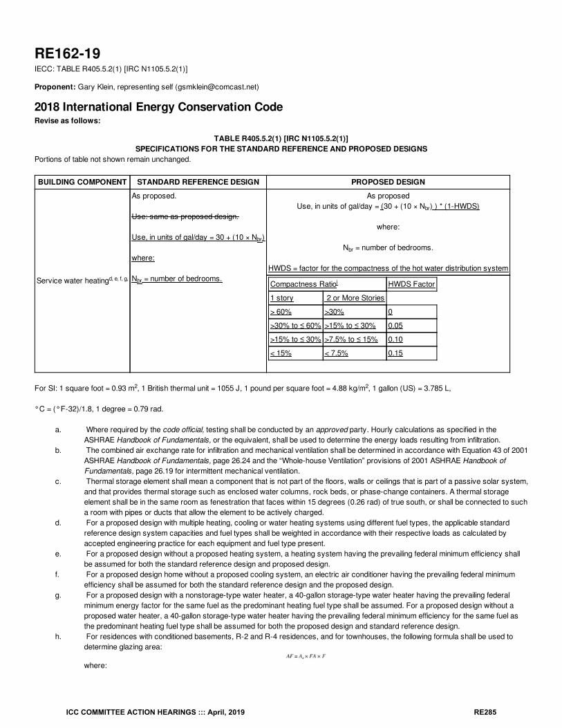
RE162-19IECC: TABLE R405.5.2(1) [IRC N1105.5.2(1)]
Proponent: Gary Klein, representing self ([email protected])
2018 International Energy Conservation CodeRevise as follows:
TABLE R405.5.2(1) [IRC N1105.5.2(1)]SPECIFICATIONS FOR THE STANDARD REFERENCE AND PROPOSED DESIGNS
Portions of table not shown remain unchanged.
BUILDING COMPONENT STANDARD REFERENCE DESIGN PROPOSED DESIGN
Service water heating
As proposed.
Use: same as proposed design.
Use, in units of gal/day = 30 + (10 × N )
where:
N = number of bedrooms.
As proposedUse, in units of gal/day = (30 + (10 × N ) ) * (1-HWDS)
where:
N = number of bedrooms.
HWDS = factor for the compactness of the hot water distribution system
Compactness Ratio HWDS Factor
1 story 2 or More Stories
> 60% >30% 0
>30% to ≤ 60% >15% to ≤ 30% 0.05
>15% to ≤ 30% >7.5% to ≤ 15% 0.10
< 15% < 7.5% 0.15
For SI: 1 square foot = 0.93 m , 1 British thermal unit = 1055 J, 1 pound per square foot = 4.88 kg/m , 1 gallon (US) = 3.785 L,
°C = (°F-32)/1.8, 1 degree = 0.79 rad.
a. Where required by the code official, testing shall be conducted by an approved party. Hourly calculations as specified in theASHRAE Handbook of Fundamentals, or the equivalent, shall be used to determine the energy loads resulting from infiltration.
b. The combined air exchange rate for infiltration and mechanical ventilation shall be determined in accordance with Equation 43 of 2001ASHRAE Handbook of Fundamentals, page 26.24 and the “Whole-house Ventilation” provisions of 2001 ASHRAE Handbook ofFundamentals, page 26.19 for intermittent mechanical ventilation.
c. Thermal storage element shall mean a component that is not part of the floors, walls or ceilings that is part of a passive solar system,and that provides thermal storage such as enclosed water columns, rock beds, or phase-change containers. A thermal storageelement shall be in the same room as fenestration that faces within 15 degrees (0.26 rad) of true south, or shall be connected to sucha room with pipes or ducts that allow the element to be actively charged.
d. For a proposed design with multiple heating, cooling or water heating systems using different fuel types, the applicable standardreference design system capacities and fuel types shall be weighted in accordance with their respective loads as calculated byaccepted engineering practice for each equipment and fuel type present.
e. For a proposed design without a proposed heating system, a heating system having the prevailing federal minimum efficiency shallbe assumed for both the standard reference design and proposed design.
f. For a proposed design home without a proposed cooling system, an electric air conditioner having the prevailing federal minimumefficiency shall be assumed for both the standard reference design and the proposed design.
g. For a proposed design with a nonstorage-type water heater, a 40-gallon storage-type water heater having the prevailing federalminimum energy factor for the same fuel as the predominant heating fuel type shall be assumed. For a proposed design without aproposed water heater, a 40-gallon storage-type water heater having the prevailing federal minimum efficiency for the same fuel asthe predominant heating fuel type shall be assumed for both the proposed design and standard reference design.
h. For residences with conditioned basements, R-2 and R-4 residences, and for townhouses, the following formula shall be used todetermine glazing area:
where:
d, e, f, g,
br
br
br
br
i
2 2
ICC COMMITTEE ACTION HEARINGS ::: April, 2019 RE285
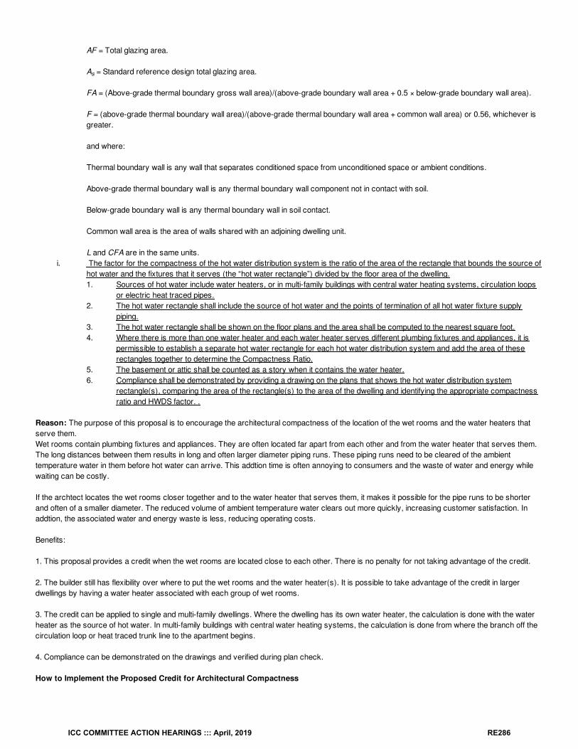
AF = Total glazing area.
A = Standard reference design total glazing area.
FA = (Above-grade thermal boundary gross wall area)/(above-grade boundary wall area + 0.5 × below-grade boundary wall area).
F = (above-grade thermal boundary wall area)/(above-grade thermal boundary wall area + common wall area) or 0.56, whichever isgreater.
and where:
Thermal boundary wall is any wall that separates conditioned space from unconditioned space or ambient conditions.
Above-grade thermal boundary wall is any thermal boundary wall component not in contact with soil.
Below-grade boundary wall is any thermal boundary wall in soil contact.
Common wall area is the area of walls shared with an adjoining dwelling unit.
L and CFA are in the same units.i. The factor for the compactness of the hot water distribution system is the ratio of the area of the rectangle that bounds the source of
hot water and the fixtures that it serves (the “hot water rectangle”) divided by the floor area of the dwelling.1. Sources of hot water include water heaters, or in multi-family buildings with central water heating systems, circulation loops
or electric heat traced pipes.2. The hot water rectangle shall include the source of hot water and the points of termination of all hot water fixture supply
piping.3. The hot water rectangle shall be shown on the floor plans and the area shall be computed to the nearest square foot.4. Where there is more than one water heater and each water heater serves different plumbing fixtures and appliances, it is
permissible to establish a separate hot water rectangle for each hot water distribution system and add the area of theserectangles together to determine the Compactness Ratio.
5. The basement or attic shall be counted as a story when it contains the water heater.6. Compliance shall be demonstrated by providing a drawing on the plans that shows the hot water distribution system
rectangle(s), comparing the area of the rectangle(s) to the area of the dwelling and identifying the appropriate compactnessratio and HWDS factor. .
Reason: The purpose of this proposal is to encourage the architectural compactness of the location of the wet rooms and the water heaters thatserve them.Wet rooms contain plumbing fixtures and appliances. They are often located far apart from each other and from the water heater that serves them.The long distances between them results in long and often larger diameter piping runs. These piping runs need to be cleared of the ambienttemperature water in them before hot water can arrive. This addtion time is often annoying to consumers and the waste of water and energy whilewaiting can be costly.
If the archtect locates the wet rooms closer together and to the water heater that serves them, it makes it possible for the pipe runs to be shorterand often of a smaller diameter. The reduced volume of ambient temperature water clears out more quickly, increasing customer satisfaction. Inaddtion, the associated water and energy waste is less, reducing operating costs.
Benefits:
1. This proposal provides a credit when the wet rooms are located close to each other. There is no penalty for not taking advantage of the credit.
2. The builder still has flexibility over where to put the wet rooms and the water heater(s). It is possible to take advantage of the credit in largerdwellings by having a water heater associated with each group of wet rooms.
3. The credit can be applied to single and multi-family dwellings. Where the dwelling has its own water heater, the calculation is done with the waterheater as the source of hot water. In multi-family buildings with central water heating systems, the calculation is done from where the branch off thecirculation loop or heat traced trunk line to the apartment begins.
4. Compliance can be demonstrated on the drawings and verified during plan check.
How to Implement the Proposed Credit for Architectural Compactness
s
ICC COMMITTEE ACTION HEARINGS ::: April, 2019 RE286
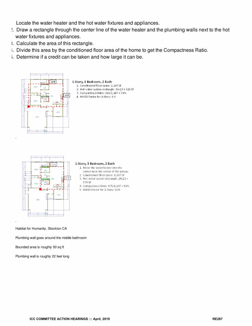
Locate the water heater and the hot water fixtures and appliances.2. Draw a rectangle through the center line of the water heater and the plumbing walls next to the hot
water fixtures and appliances.3. Calculate the area of this rectangle.4. Divide this area by the conditioned floor area of the home to get the Compactness Ratio.5. Determine if a credit can be taken and how large it can be.
Habitat for Humanity, Stockton CA
Plumbing wall goes around the middle bathroom
Bounded area is roughly 50 sq ft
Plumbing wall is roughly 22 feet long
ICC COMMITTEE ACTION HEARINGS ::: April, 2019 RE287
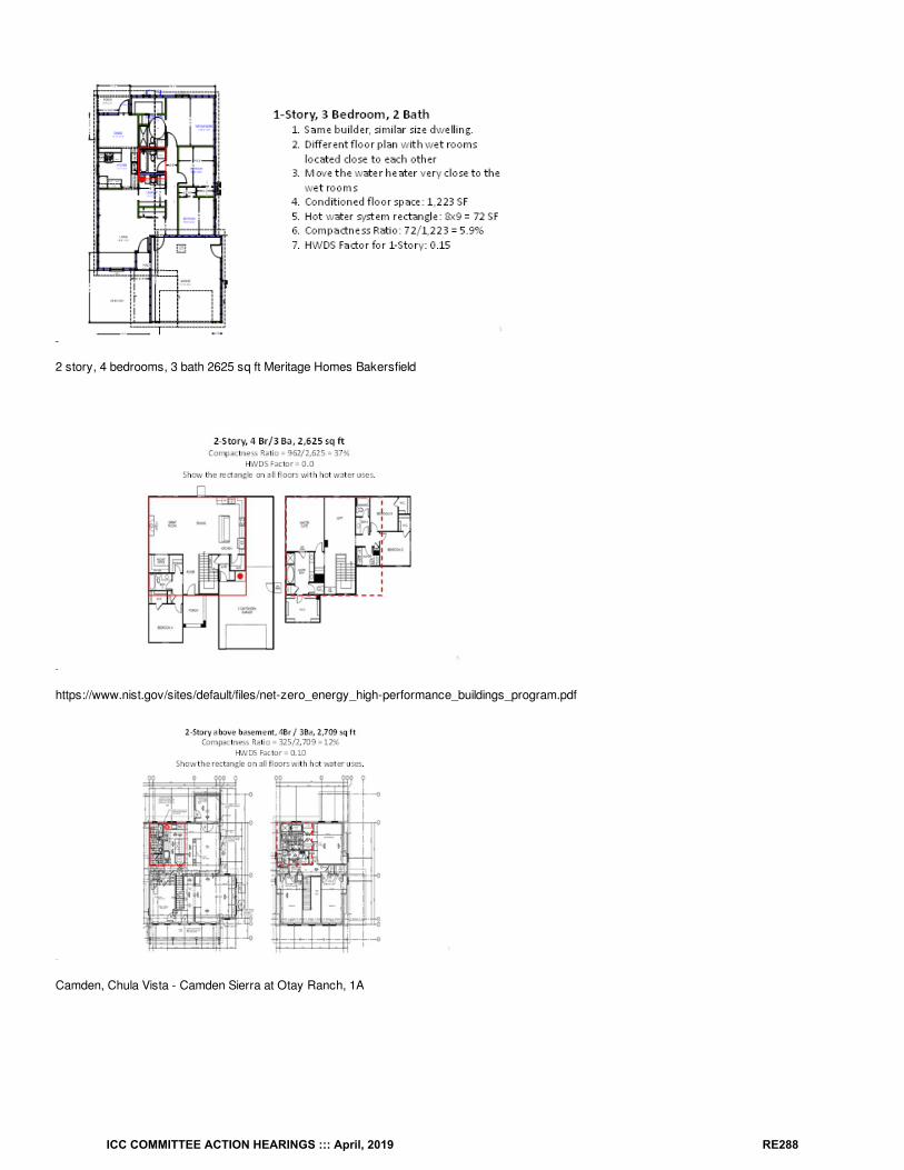
2 story, 4 bedrooms, 3 bath 2625 sq ft Meritage Homes Bakersfield
https://www.nist.gov/sites/default/files/net-zero_energy_high-performance_buildings_program.pdf
Camden, Chula Vista - Camden Sierra at Otay Ranch, 1A
ICC COMMITTEE ACTION HEARINGS ::: April, 2019 RE288
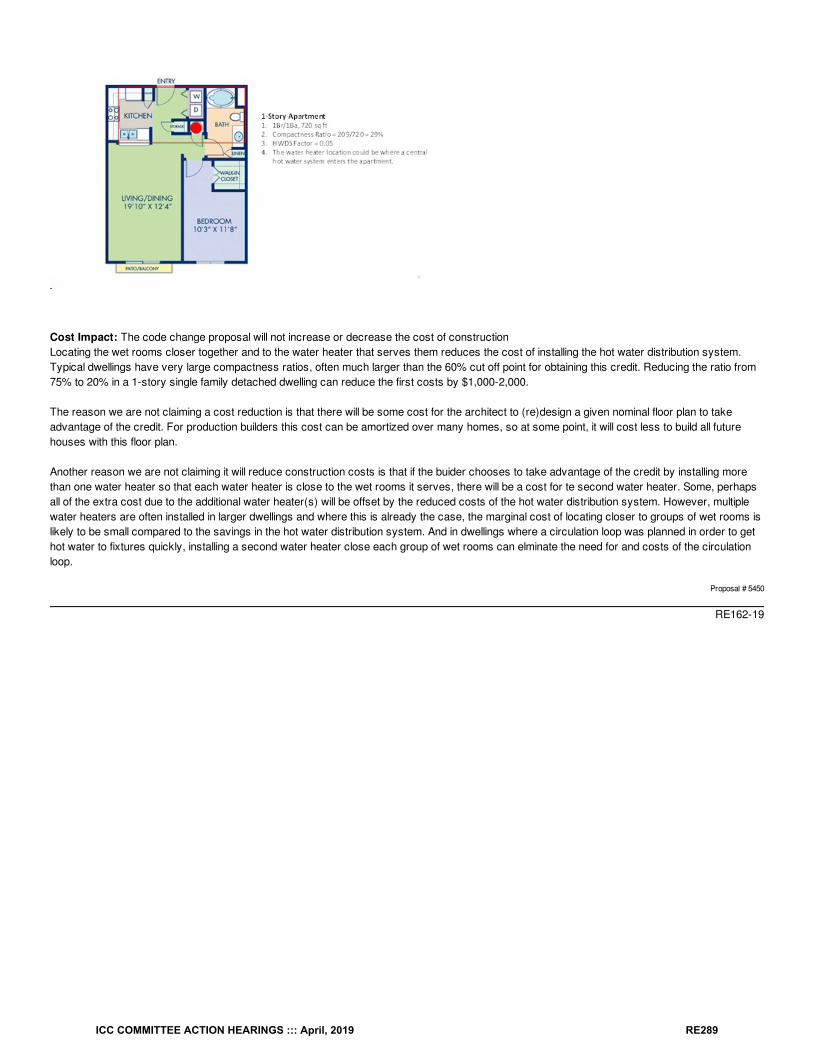
Cost Impact: The code change proposal will not increase or decrease the cost of constructionLocating the wet rooms closer together and to the water heater that serves them reduces the cost of installing the hot water distribution system.Typical dwellings have very large compactness ratios, often much larger than the 60% cut off point for obtaining this credit. Reducing the ratio from75% to 20% in a 1-story single family detached dwelling can reduce the first costs by $1,000-2,000.
The reason we are not claiming a cost reduction is that there will be some cost for the architect to (re)design a given nominal floor plan to takeadvantage of the credit. For production builders this cost can be amortized over many homes, so at some point, it will cost less to build all futurehouses with this floor plan.
Another reason we are not claiming it will reduce construction costs is that if the buider chooses to take advantage of the credit by installing morethan one water heater so that each water heater is close to the wet rooms it serves, there will be a cost for te second water heater. Some, perhapsall of the extra cost due to the additional water heater(s) will be offset by the reduced costs of the hot water distribution system. However, multiplewater heaters are often installed in larger dwellings and where this is already the case, the marginal cost of locating closer to groups of wet rooms islikely to be small compared to the savings in the hot water distribution system. And in dwellings where a circulation loop was planned in order to gethot water to fixtures quickly, installing a second water heater close each group of wet rooms can elminate the need for and costs of the circulationloop.
Proposal # 5450
RE162-19
ICC COMMITTEE ACTION HEARINGS ::: April, 2019 RE289
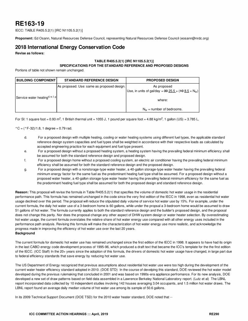
RE163-19IECC: TABLE R405.5.2(1) [IRC N1105.5.2(1)]
Proponent: Ed Osann, Natural Resources Defense Council, representing Natural Resources Defense Council ([email protected])
2018 International Energy Conservation CodeRevise as follows:
TABLE R405.5.2(1) [IRC N1105.5.2(1)]SPECIFICATIONS FOR THE STANDARD REFERENCE AND PROPOSED DESIGNS
Portions of table not shown remain unchanged.
BUILDING COMPONENT STANDARD REFERENCE DESIGN PROPOSED DESIGN
Service water heating
As proposed. Use: same as proposed design. As proposedUse, in units of gal/day = 30 25.5 + (10 8.5 × N )
where:
N = number of bedrooms.
For SI: 1 square foot = 0.93 m , 1 British thermal unit = 1055 J, 1 pound per square foot = 4.88 kg/m , 1 gallon (US) = 3.785 L,
°C = (°F-32)/1.8, 1 degree = 0.79 rad.
d. For a proposed design with multiple heating, cooling or water heating systems using different fuel types, the applicable standardreference design system capacities and fuel types shall be weighted in accordance with their respective loads as calculated byaccepted engineering practice for each equipment and fuel type present.
e. For a proposed design without a proposed heating system, a heating system having the prevailing federal minimum efficiency shallbe assumed for both the standard reference design and proposed design.
f. For a proposed design home without a proposed cooling system, an electric air conditioner having the prevailing federal minimumefficiency shall be assumed for both the standard reference design and the proposed design.
g. For a proposed design with a nonstorage-type water heater, a 40-gallon storage-type water heater having the prevailing federalminimum energy factor for the same fuel as the predominant heating fuel type shall be assumed. For a proposed design without aproposed water heater, a 40-gallon storage-type water heater having the prevailing federal minimum efficiency for the same fuel asthe predominant heating fuel type shall be assumed for both the proposed design and standard reference design.
Reason: This proposal will revise the formula in Table R405.5.2(1) that specifies the volume of domestic hot water usage in the residentialperformance path. This formula has remained unchanged in the code since the very first edition of the IECC in 1998, even as residential hot waterusage declined over this period. The proposal will reduce the stipulated daily volume of service hot water use by 15%. For example, under thecurrent formula, the daily hot water use of a 3-bedroom home is 60 gallons, while under the propsal a 3-bedroom home would be assumed to draw51 gallons of hot water. The formula currently applies to both the standard reference design and the builder's proposed design, and the proposaldoes not change this parity. Nor does the proposal change any other aspect of DHW system design or water heater selection. By overestimatinghot water usage, the current formula overstates the relative share of hot water energy use compared with all other energy uses included in theperformance path analysis. Revising this formula will make the characterization of hot water energy use more realistic, and acknowledge theprogress made in improving the efficiency of hot water use over the last 20 years.Background
The current formula for domestic hot water use has remained unchanged since the first edition of the IECC in 1998. It appears to have had its originin the last CABO energy code development process of 1995-96, which produced a draft text that became the ICC's template for the the first editionof the IECC. (ICC Staff) In the 20+ years since the adoption of this formula, the drivers of domestic hot water usage have changed, in large part dueto federal efficiency standards that save energy by reducing hot water use.
The US Department of Energy recognized that previous assumptions about residential hot water use were too high during the development of thecurrent water heater efficiency standard adopted in 2010. (DOE STD) In the course of develping this standard, DOE reviewed the hot water modeldeveloped during the previous rulemaking that concluded in 2001 and was based on 1990s-era appliance perfromance. For its new analysis, DOEdeveloped a new set of draw patterns based on field data assembled in a Lawrence Berkeley National Laboratory report. (Lutz et al) The LBNLreport incorporated data collected by 10 independent studies involving 142 houses averaging 3.04 occupants, and 1.5 million hot water draws. TheLBNL report found an average daily median volume of hot water use among its sample of 50.6 gallons.
In its 2009 Technical Support Document (DOE TSD) for the 2010 water heater standard, DOE noted that --
d, e, f, g
br
br
2 2
ICC COMMITTEE ACTION HEARINGS ::: April, 2019 RE290
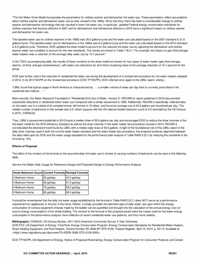
"The Hot Water Draw Model incorporates the parameters for clothes washer and dishwasher hot water use. These parameters reflect assumptionsabout clothes washer and dishwasher water use as they existed in the 1990s. Since that time, there has been a considerable change to clotheswasher and dishwasher technology that has resulted in lower hot water use. In particular, updated Federal energy conservation standards forclothes washers that became effective in 2007 and for dishwashers that will become effective in 2010 have a significant impact on clothes washerand dishwasher hot water use.
The baseline water use for clothes washers in the 1990s was 39.2 gallons/cycle and the water use calculated based on the 2007 standard is 21.0gallons/cycle. The baseline water use for dishwashers in the 1990s was 8.2 gallons/cycle and the water use calculated based on the 2010 standardis 6.5 gallons/cycle. Therefore, DOE updated the draw model to account for the reduced hot water use by adjusting the dishwasher and clotheswasher water use variables to account for the new standards. The results are shown in Table 7-B.3.1. For example, the impact on gas-fired storagewater heaters was a reduction of the average daily water use by 10.7 percent."
In the TSD's accompanying table, the results of these revisions to the draw model are shown for four types of water heater (gas-fired storage,electric, oil-fired, and gas instantaneous), with water use reductions for all of them clustering close to the average reduction of 10.1 percent for thegroup.
DOE took further note in the reduction in residential hot water use during the development of a revised test procedure for hot water heaters adoptedin 2014. In its 2013 NOPR on the revised test procedure (DOE TP NOPR), DOE referred once again to the LBNL report, stating --
"LBNL found that typical usage in North America is characterized by . . . a smaller volume of water per day than is currently prescribed in theresidential test method . . . "
More recently, the Water Research Foundation's "Residential End Use of Water, Version 2" (REUWS 2) report published in 2016 documentedsubstantial reductions in residential indoor water use compared with a similar assesment in 1999. Additionally, REUWS 2 specifically collected dataon hot water use in a subset of its sampled homes (94 homes in 10 cities), and found an average use of 45.5 gallons per household per day. Themedian number of bedrooms in this sample was 3.0, which squares with the US national median bedroom count of 3.0 recorded by the US Censusin 2015. (CENSUS)
Thus, LBNL's assessment published in 2010 found a median draw of 50.6 gallons per day and encouraged DOE to reduce the draw volumes in thehot water model for the 2010 efficiency standard as well as the draw volumes in the water heater test procedure revised in 2014. REUWS 2corroborated the downward trend found by LBNL with a median daily draw of 45.5 gallons. In light of the foundational role of the LBNL report in thedaily draw volumes used in both the current water heater standard and the water heater test procedure, this proposal achieves alignment betweenthe data relied upon by DOE and the water usage stipulated for the performance path analysis in Table R405.5.2(1) by reducing the constants in theformula by 15%.
Effects of Proposal
The effect of the revision of the formula on the assumed daily hot water use in homes of varying numbers of bedrooms can be seen in the followingtable.
Service Hot Water Daily Usage for Reference Design and Proposed Design in Energy Performance Analysis
Home Bedroom Count Current Formula Revised Formula
2 Bedroom Home 50 gal/day 42.5 gal/day
3 Bedroom Home 60 gal/day 51.0 gal/day
4 Bedroom Home 70 gal/day 59.5 gal/day
5 Bedroom Home 80 gal/day 68.0 gal/day
It should be remembered that the daily hot water usage established by the formula in Table R405.5.2(1) does NOT serve as a performancerequirement for appliances or fixtures in the home. Rather, it simply provides the deemed value of daily water use upon which the energyconsumption of various equipment choices made by the builder can be quantified and brought into the calculation of the annual energy cost (orsource energy consumption) of the whole building. The revision to the formula in this proposal would make the values used for hot water energyconsumption in the performance analysis more reflective of recent residential water use patterns, and thus more realistic.
Bibliography: CENSUS, US Census Bureau, 2011-2015 American Community Survey 5-Year Estimates.DOE STD, US Department of Energy, Final Rule, Energy Conservation Program: Energy Conservation Standards for Residential Water Heaters,Direct Heating Equipment, and Pool Heaters, Docket Number EE-2006-BT-STD-0129, Federal Register, April 10, 2010. p. 20112. Available at<https://www.regulations.gov/document?D=EERE-2006-STD-0129-0005>.
DOE TP NOPR, US Department of Energy, Notice of Proposed Rulemaking, Energy Conservation Program for Consumer Products and Certain
ICC COMMITTEE ACTION HEARINGS ::: April, 2019 RE291
Commercial and Industrial Equipment: Test Procedures for Residential and Commercial Water Heaters, Federal Register, November 4, 2013, p.66202. Available at <https://www.regulations.gov/document?D=EERE-2011-BT-TP-0042-0051>.
DOE TSD, US Department of Energy, Notice of Proposed Rulemaking, Technical Support Document, Energy Conservation Program for ConsumerProducts: Energy Conservation Standards for Residential Water Heaters, Direct Heating Equipment, and Pool Heaters, November 23, 2009.Available at <https://www.regulations.gov/document?D=EERE-2006-STD-0129-0170>.
ICC Staff, Personal communication in response to a code history question, Fred Grable e-mail, Dec. 17, 2018.
Lutz et al, Hot Water Draw Patterns in Single-Family Houses: Findings from Field Studies, Lawrence Berkeley National Laboratory, LBNL-4830E,May 2011. Available at <https://escholarship.org/us/item/2k24v1kj>.
REUWS 2, DeOreo et al, Residential End Uses of Water, Version 2, Water Research Council, Report 4309b, c. 2016. Available at<www.waterrf.org/Pages/Projects.aspx?PID=4309>.
Cost Impact: The code change proposal will not increase or decrease the cost of constructionThe proposal has no impact on the cost of construction. It revises the voluntary residential performance path by adjusting the volume of daily hotwater usage assumed for both the reference design and the builder's proposed design. It contains no requirement that would raise the cost of waterheating equipment.
Proposal # 5133
RE163-19
ICC COMMITTEE ACTION HEARINGS ::: April, 2019 RE292
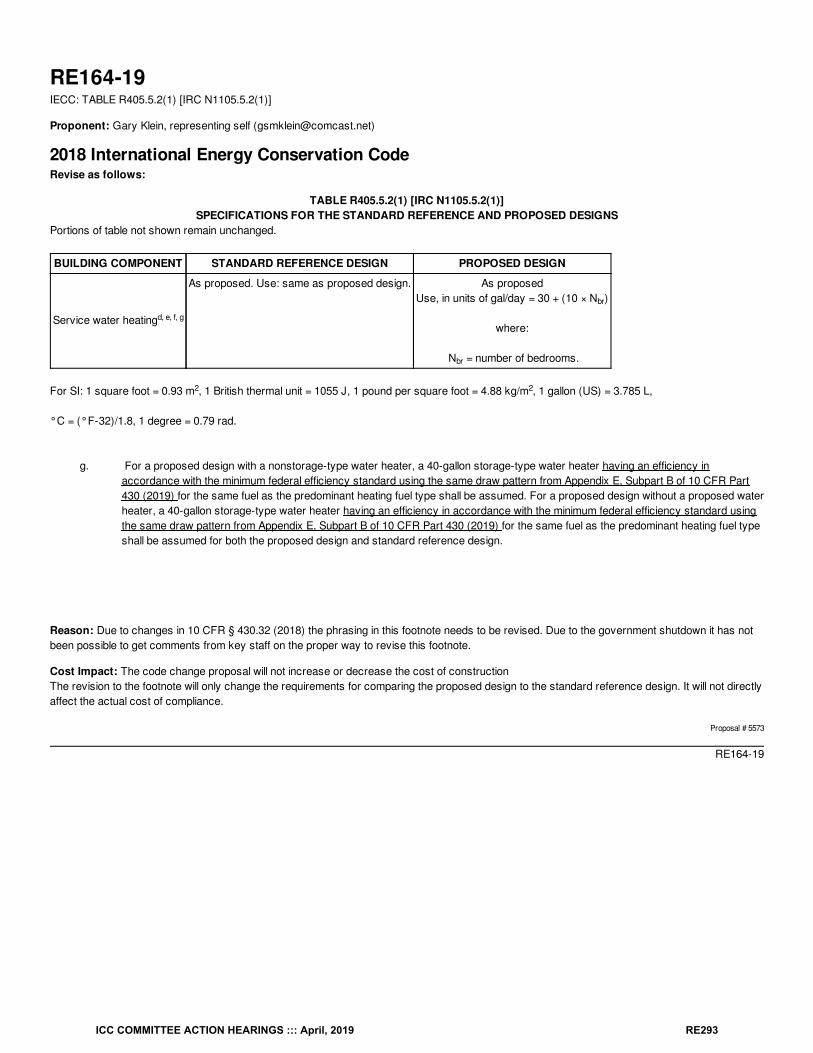
RE164-19IECC: TABLE R405.5.2(1) [IRC N1105.5.2(1)]
Proponent: Gary Klein, representing self ([email protected])
2018 International Energy Conservation CodeRevise as follows:
TABLE R405.5.2(1) [IRC N1105.5.2(1)]SPECIFICATIONS FOR THE STANDARD REFERENCE AND PROPOSED DESIGNS
Portions of table not shown remain unchanged.
BUILDING COMPONENT STANDARD REFERENCE DESIGN PROPOSED DESIGN
Service water heating
As proposed. Use: same as proposed design. As proposedUse, in units of gal/day = 30 + (10 × N )
where:
N = number of bedrooms.
For SI: 1 square foot = 0.93 m , 1 British thermal unit = 1055 J, 1 pound per square foot = 4.88 kg/m , 1 gallon (US) = 3.785 L,
°C = (°F-32)/1.8, 1 degree = 0.79 rad.
g. For a proposed design with a nonstorage-type water heater, a 40-gallon storage-type water heater having an efficiency in
accordance with the minimum federal efficiency standard using the same draw pattern from Appendix E, Subpart B of 10 CFR Part430 (2019) for the same fuel as the predominant heating fuel type shall be assumed. For a proposed design without a proposed waterheater, a 40-gallon storage-type water heater having an efficiency in accordance with the minimum federal efficiency standard usingthe same draw pattern from Appendix E, Subpart B of 10 CFR Part 430 (2019) for the same fuel as the predominant heating fuel typeshall be assumed for both the proposed design and standard reference design.
Reason: Due to changes in 10 CFR § 430.32 (2018) the phrasing in this footnote needs to be revised. Due to the government shutdown it has notbeen possible to get comments from key staff on the proper way to revise this footnote.
Cost Impact: The code change proposal will not increase or decrease the cost of constructionThe revision to the footnote will only change the requirements for comparing the proposed design to the standard reference design. It will not directlyaffect the actual cost of compliance.
Proposal # 5573
RE164-19
d, e, f, g
br
br
2 2
ICC COMMITTEE ACTION HEARINGS ::: April, 2019 RE293
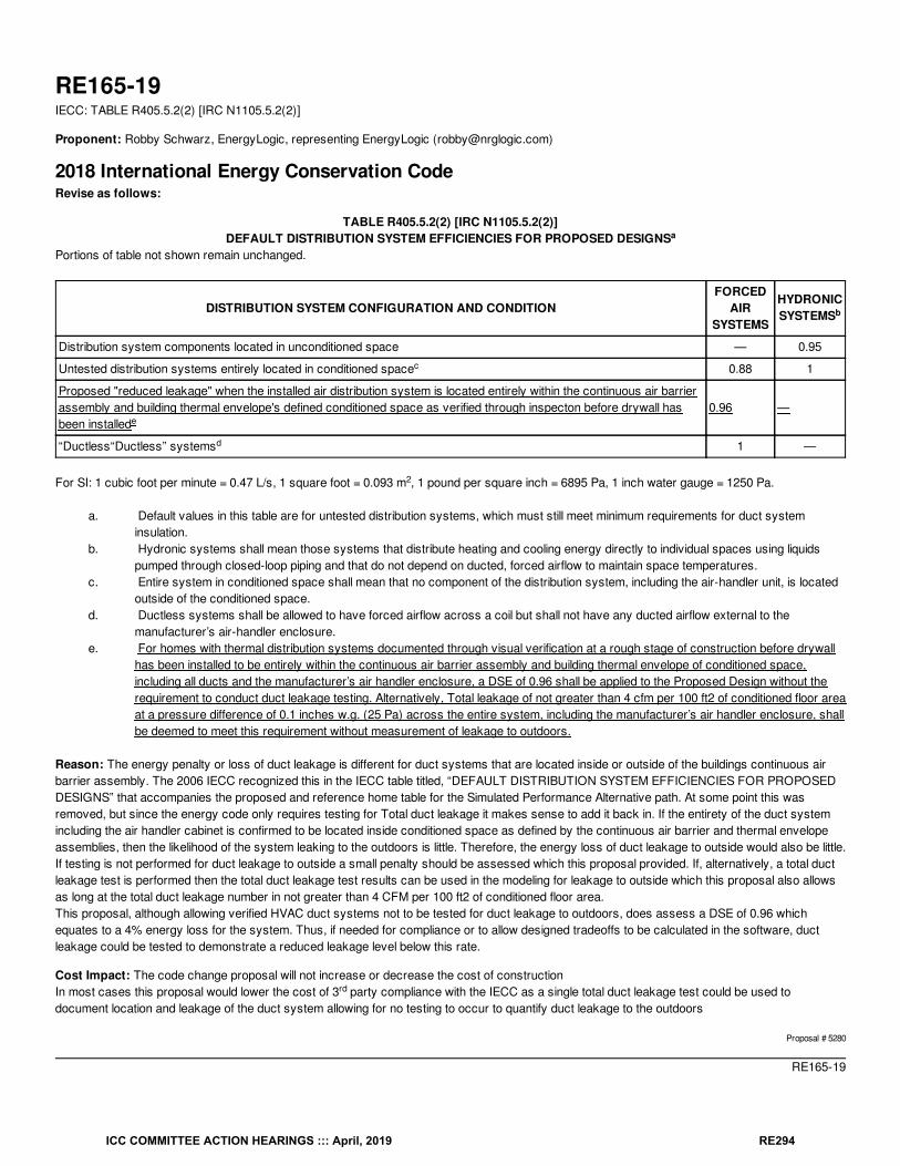
RE165-19IECC: TABLE R405.5.2(2) [IRC N1105.5.2(2)]
Proponent: Robby Schwarz, EnergyLogic, representing EnergyLogic ([email protected])
2018 International Energy Conservation CodeRevise as follows:
TABLE R405.5.2(2) [IRC N1105.5.2(2)]DEFAULT DISTRIBUTION SYSTEM EFFICIENCIES FOR PROPOSED DESIGNS
Portions of table not shown remain unchanged.
DISTRIBUTION SYSTEM CONFIGURATION AND CONDITIONFORCED
AIRSYSTEMS
HYDRONICSYSTEMS
Distribution system components located in unconditioned space — 0.95
Untested distribution systems entirely located in conditioned space 0.88 1
Proposed "reduced leakage" when the installed air distribution system is located entirely within the continuous air barrierassembly and building thermal envelope's defined conditioned space as verified through inspecton before drywall hasbeen installed
0.96 —
“Ductless“Ductless” systems 1 —
For SI: 1 cubic foot per minute = 0.47 L/s, 1 square foot = 0.093 m , 1 pound per square inch = 6895 Pa, 1 inch water gauge = 1250 Pa.
a. Default values in this table are for untested distribution systems, which must still meet minimum requirements for duct systeminsulation.
b. Hydronic systems shall mean those systems that distribute heating and cooling energy directly to individual spaces using liquidspumped through closed-loop piping and that do not depend on ducted, forced airflow to maintain space temperatures.
c. Entire system in conditioned space shall mean that no component of the distribution system, including the air-handler unit, is locatedoutside of the conditioned space.
d. Ductless systems shall be allowed to have forced airflow across a coil but shall not have any ducted airflow external to themanufacturer’s air-handler enclosure.
e. For homes with thermal distribution systems documented through visual verification at a rough stage of construction before drywallhas been installed to be entirely within the continuous air barrier assembly and building thermal envelope of conditioned space,including all ducts and the manufacturer’s air handler enclosure, a DSE of 0.96 shall be applied to the Proposed Design without therequirement to conduct duct leakage testing. Alternatively, Total leakage of not greater than 4 cfm per 100 ft2 of conditioned floor areaat a pressure difference of 0.1 inches w.g. (25 Pa) across the entire system, including the manufacturer’s air handler enclosure, shallbe deemed to meet this requirement without measurement of leakage to outdoors.
Reason: The energy penalty or loss of duct leakage is different for duct systems that are located inside or outside of the buildings continuous airbarrier assembly. The 2006 IECC recognized this in the IECC table titled, “DEFAULT DISTRIBUTION SYSTEM EFFICIENCIES FOR PROPOSEDDESIGNS” that accompanies the proposed and reference home table for the Simulated Performance Alternative path. At some point this wasremoved, but since the energy code only requires testing for Total duct leakage it makes sense to add it back in. If the entirety of the duct systemincluding the air handler cabinet is confirmed to be located inside conditioned space as defined by the continuous air barrier and thermal envelopeassemblies, then the likelihood of the system leaking to the outdoors is little. Therefore, the energy loss of duct leakage to outside would also be little.If testing is not performed for duct leakage to outside a small penalty should be assessed which this proposal provided. If, alternatively, a total ductleakage test is performed then the total duct leakage test results can be used in the modeling for leakage to outside which this proposal also allowsas long at the total duct leakage number in not greater than 4 CFM per 100 ft2 of conditioned floor area.This proposal, although allowing verified HVAC duct systems not to be tested for duct leakage to outdoors, does assess a DSE of 0.96 whichequates to a 4% energy loss for the system. Thus, if needed for compliance or to allow designed tradeoffs to be calculated in the software, ductleakage could be tested to demonstrate a reduced leakage level below this rate.
Cost Impact: The code change proposal will not increase or decrease the cost of constructionIn most cases this proposal would lower the cost of 3 party compliance with the IECC as a single total duct leakage test could be used todocument location and leakage of the duct system allowing for no testing to occur to quantify duct leakage to the outdoors
Proposal # 5280
RE165-19
a
b
c
e
d
2
rd
ICC COMMITTEE ACTION HEARINGS ::: April, 2019 RE294
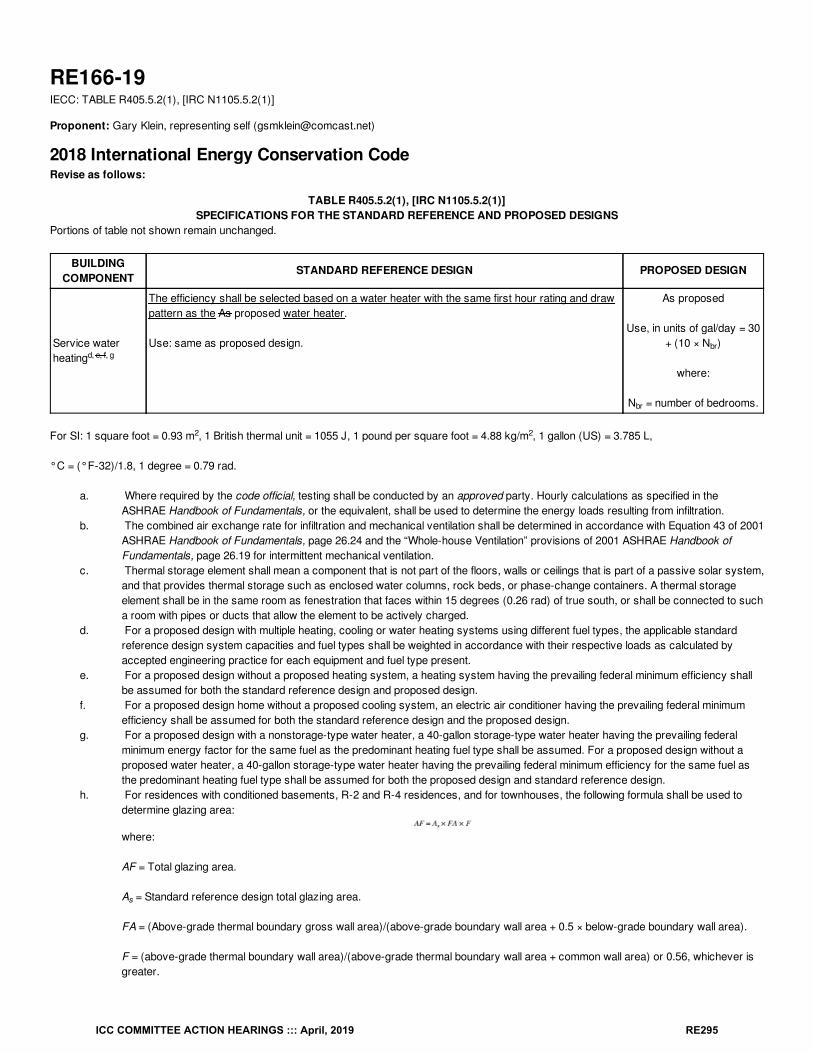
RE166-19IECC: TABLE R405.5.2(1), [IRC N1105.5.2(1)]
Proponent: Gary Klein, representing self ([email protected])
2018 International Energy Conservation CodeRevise as follows:
TABLE R405.5.2(1), [IRC N1105.5.2(1)]SPECIFICATIONS FOR THE STANDARD REFERENCE AND PROPOSED DESIGNS
Portions of table not shown remain unchanged.
BUILDINGCOMPONENT
STANDARD REFERENCE DESIGN PROPOSED DESIGN
Service waterheating
The efficiency shall be selected based on a water heater with the same first hour rating and drawpattern as the As proposed water heater.
Use: same as proposed design.
As proposed
Use, in units of gal/day = 30+ (10 × N )
where:
N = number of bedrooms.
For SI: 1 square foot = 0.93 m , 1 British thermal unit = 1055 J, 1 pound per square foot = 4.88 kg/m , 1 gallon (US) = 3.785 L,
°C = (°F-32)/1.8, 1 degree = 0.79 rad.
a. Where required by the code official, testing shall be conducted by an approved party. Hourly calculations as specified in theASHRAE Handbook of Fundamentals, or the equivalent, shall be used to determine the energy loads resulting from infiltration.
b. The combined air exchange rate for infiltration and mechanical ventilation shall be determined in accordance with Equation 43 of 2001ASHRAE Handbook of Fundamentals, page 26.24 and the “Whole-house Ventilation” provisions of 2001 ASHRAE Handbook ofFundamentals, page 26.19 for intermittent mechanical ventilation.
c. Thermal storage element shall mean a component that is not part of the floors, walls or ceilings that is part of a passive solar system,and that provides thermal storage such as enclosed water columns, rock beds, or phase-change containers. A thermal storageelement shall be in the same room as fenestration that faces within 15 degrees (0.26 rad) of true south, or shall be connected to sucha room with pipes or ducts that allow the element to be actively charged.
d. For a proposed design with multiple heating, cooling or water heating systems using different fuel types, the applicable standardreference design system capacities and fuel types shall be weighted in accordance with their respective loads as calculated byaccepted engineering practice for each equipment and fuel type present.
e. For a proposed design without a proposed heating system, a heating system having the prevailing federal minimum efficiency shallbe assumed for both the standard reference design and proposed design.
f. For a proposed design home without a proposed cooling system, an electric air conditioner having the prevailing federal minimumefficiency shall be assumed for both the standard reference design and the proposed design.
g. For a proposed design with a nonstorage-type water heater, a 40-gallon storage-type water heater having the prevailing federalminimum energy factor for the same fuel as the predominant heating fuel type shall be assumed. For a proposed design without aproposed water heater, a 40-gallon storage-type water heater having the prevailing federal minimum efficiency for the same fuel asthe predominant heating fuel type shall be assumed for both the proposed design and standard reference design.
h. For residences with conditioned basements, R-2 and R-4 residences, and for townhouses, the following formula shall be used todetermine glazing area:
where:
AF = Total glazing area.
A = Standard reference design total glazing area.
FA = (Above-grade thermal boundary gross wall area)/(above-grade boundary wall area + 0.5 × below-grade boundary wall area).
F = (above-grade thermal boundary wall area)/(above-grade thermal boundary wall area + common wall area) or 0.56, whichever isgreater.
d, e, f, gbr
br
2 2
s
ICC COMMITTEE ACTION HEARINGS ::: April, 2019 RE295
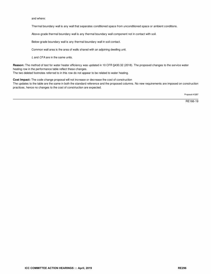
and where:
Thermal boundary wall is any wall that separates conditioned space from unconditioned space or ambient conditions.
Above-grade thermal boundary wall is any thermal boundary wall component not in contact with soil.
Below-grade boundary wall is any thermal boundary wall in soil contact.
Common wall area is the area of walls shared with an adjoining dwelling unit.
L and CFA are in the same units.
Reason: The method of test for water heater efficiency was updated in 10 CFR §430.32 (2018). The proposed changes to the service waterheating row in the performance table reflect these changes.The two deleted footnotes referred to in this row do not appear to be related to water heating.
Cost Impact: The code change proposal will not increase or decrease the cost of constructionThe updates to the table are the same in both the standard reference and the proposed columns. No new requirements are imposed on constructionpractices, hence no changes to the cost of constriuction are expected.
Proposal # 5287
RE166-19
ICC COMMITTEE ACTION HEARINGS ::: April, 2019 RE296
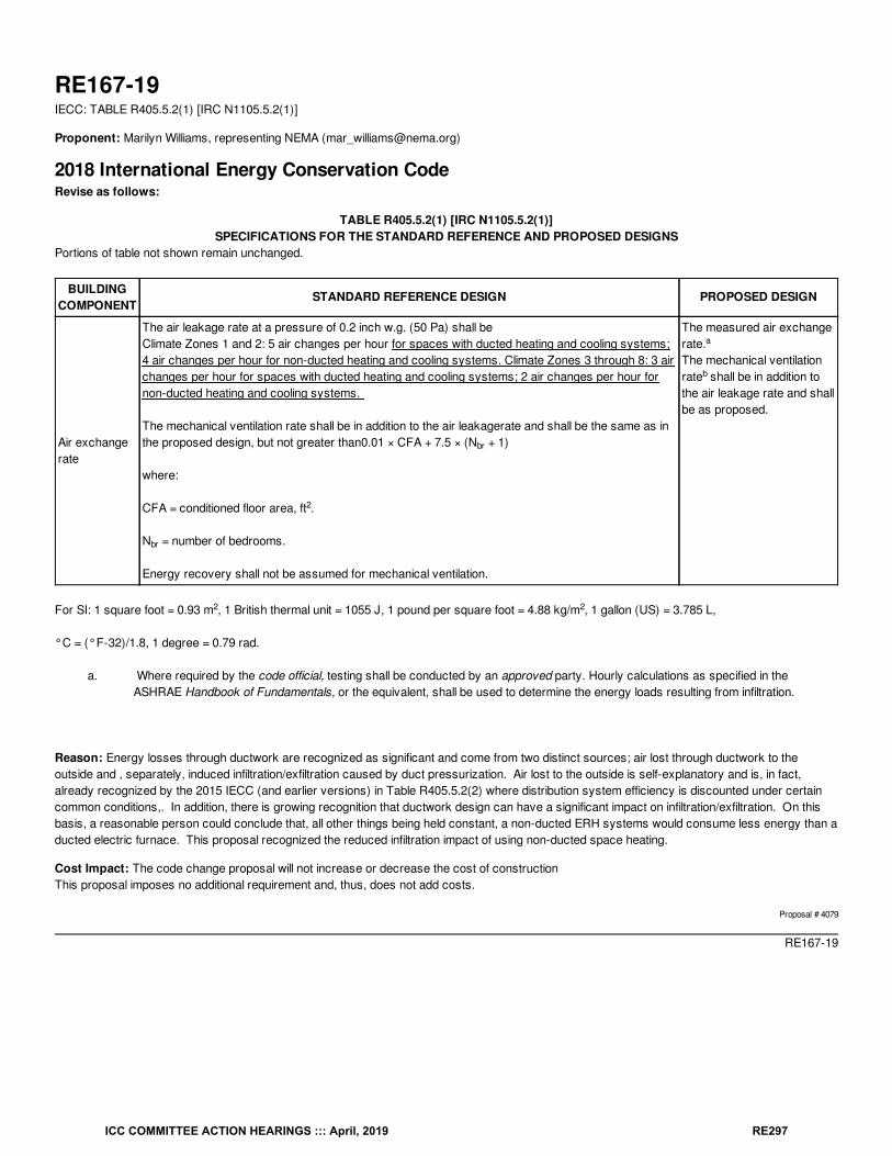
RE167-19IECC: TABLE R405.5.2(1) [IRC N1105.5.2(1)]
Proponent: Marilyn Williams, representing NEMA ([email protected])
2018 International Energy Conservation CodeRevise as follows:
TABLE R405.5.2(1) [IRC N1105.5.2(1)]SPECIFICATIONS FOR THE STANDARD REFERENCE AND PROPOSED DESIGNS
Portions of table not shown remain unchanged.
BUILDINGCOMPONENT
STANDARD REFERENCE DESIGN PROPOSED DESIGN
Air exchangerate
The air leakage rate at a pressure of 0.2 inch w.g. (50 Pa) shall beClimate Zones 1 and 2: 5 air changes per hour for spaces with ducted heating and cooling systems;4 air changes per hour for non-ducted heating and cooling systems. Climate Zones 3 through 8: 3 airchanges per hour for spaces with ducted heating and cooling systems; 2 air changes per hour fornon-ducted heating and cooling systems.
The mechanical ventilation rate shall be in addition to the air leakagerate and shall be the same as inthe proposed design, but not greater than0.01 × CFA + 7.5 × (N + 1)
where:
CFA = conditioned floor area, ft .
N = number of bedrooms.
Energy recovery shall not be assumed for mechanical ventilation.
The measured air exchangerate.The mechanical ventilationrate shall be in addition tothe air leakage rate and shallbe as proposed.
For SI: 1 square foot = 0.93 m , 1 British thermal unit = 1055 J, 1 pound per square foot = 4.88 kg/m , 1 gallon (US) = 3.785 L,
°C = (°F-32)/1.8, 1 degree = 0.79 rad.
a. Where required by the code official, testing shall be conducted by an approved party. Hourly calculations as specified in theASHRAE Handbook of Fundamentals, or the equivalent, shall be used to determine the energy loads resulting from infiltration.
Reason: Energy losses through ductwork are recognized as significant and come from two distinct sources; air lost through ductwork to theoutside and , separately, induced infiltration/exfiltration caused by duct pressurization. Air lost to the outside is self-explanatory and is, in fact, already recognized by the 2015 IECC (and earlier versions) in Table R405.5.2(2) where distribution system efficiency is discounted under certaincommon conditions,. In addition, there is growing recognition that ductwork design can have a significant impact on infiltration/exfiltration. On thisbasis, a reasonable person could conclude that, all other things being held constant, a non-ducted ERH systems would consume less energy than aducted electric furnace. This proposal recognized the reduced infiltration impact of using non-ducted space heating.
Cost Impact: The code change proposal will not increase or decrease the cost of constructionThis proposal imposes no additional requirement and, thus, does not add costs.
Proposal # 4079
RE167-19
br
2
br
a
b
2 2
ICC COMMITTEE ACTION HEARINGS ::: April, 2019 RE297
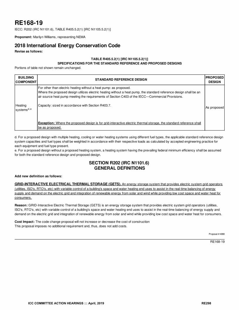
RE168-19IECC: R202 (IRC N1101.6), TABLE R405.5.2(1) [IRC N1105.5.2(1)]
Proponent: Marilyn Williams, representing NEMA
2018 International Energy Conservation CodeRevise as follows:
TABLE R405.5.2(1) [IRC N1105.5.2(1)]SPECIFICATIONS FOR THE STANDARD REFERENCE AND PROPOSED DESIGNS
Portions of table not shown remain unchanged.
BUILDINGCOMPONENT
STANDARD REFERENCE DESIGN PROPOSEDDESIGN
Heatingsystems
For other than electric heating without a heat pump: as proposed.Where the proposed design utilizes electric heating without a heat pump, the standard reference design shall be anair source heat pump meeting the requirements of Section C403 of the IECC—Commercial Provisions.
Capacity: sized in accordance with Section R403.7.
Exception: Where the proposed design is for grid-interactive electric thermal storage, the standard reference shallbe as proposed.
As proposed
d. For a proposed design with multiple heating, cooling or water heating systems using different fuel types, the applicable standard reference designsystem capacities and fuel types shall be weighted in accordance with their respective loads as calculated by accepted engineering practice foreach equipment and fuel type present.e. For a proposed design without a proposed heating system, a heating system having the prevailing federal minimum efficiency shall be assumedfor both the standard reference design and proposed design.
SECTION R202 (IRC N1101.6) GENERAL DEFINITIONS
Add new definition as follows:
GRID-INTERACTIVE ELECTRICAL THERMAL STORAGE (GETS). An energy storage system that provides electric system grid operators(utilities, ISO's, RTO's, etc) with variable control of a building's space and water heating end uses to assist in the real-time balancing of energysupply and demand on the electric grid and integration of renewable energy from solar and wind while providing low cost space and water heat forconsumers.
Reason: GRID-Interactive Electric Thermal Storage (GETS) is an energy storage system that provides electric system grid operators (utilities,ISO's, RTO's, etc) with variable control of a building's space and water heating end uses to assist in the real-time balancing of energy supply anddemand on the electric grid and integration of renewable energy from solar and wind while providing low cost space and water heat for consumers.
Cost Impact: The code change proposal will not increase or decrease the cost of constructionThis proposal imposes no additional requirement and, thus, does not add costs.
Proposal # 4080
RE168-19
d, e
ICC COMMITTEE ACTION HEARINGS ::: April, 2019 RE298
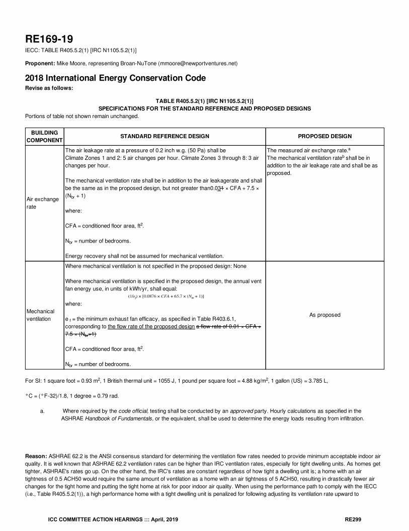
RE169-19IECC: TABLE R405.5.2(1) [IRC N1105.5.2(1)]
Proponent: Mike Moore, representing Broan-NuTone ([email protected])
2018 International Energy Conservation CodeRevise as follows:
TABLE R405.5.2(1) [IRC N1105.5.2(1)]SPECIFICATIONS FOR THE STANDARD REFERENCE AND PROPOSED DESIGNS
Portions of table not shown remain unchanged.
BUILDINGCOMPONENT
STANDARD REFERENCE DESIGN PROPOSED DESIGN
Air exchangerate
The air leakage rate at a pressure of 0.2 inch w.g. (50 Pa) shall beClimate Zones 1 and 2: 5 air changes per hour. Climate Zones 3 through 8: 3 airchanges per hour.
The mechanical ventilation rate shall be in addition to the air leakagerate and shallbe the same as in the proposed design, but not greater than0.031 × CFA + 7.5 ×(N + 1)
where:
CFA = conditioned floor area, ft .
N = number of bedrooms.
Energy recovery shall not be assumed for mechanical ventilation.
The measured air exchange rate.The mechanical ventilation rate shall be inaddition to the air leakage rate and shall be asproposed.
Mechanicalventilation
Where mechanical ventilation is not specified in the proposed design: None
Where mechanical ventilation is specified in the proposed design, the annual ventfan energy use, in units of kWh/yr, shall equal:
where:
e = the minimum exhaust fan efficacy, as specified in Table R403.6.1,corresponding to the flow rate of the proposed design a flow rate of 0.01 × CFA +7.5 × (N +1)
CFA = conditioned floor area, ft .
N = number of bedrooms.
As proposed
For SI: 1 square foot = 0.93 m , 1 British thermal unit = 1055 J, 1 pound per square foot = 4.88 kg/m , 1 gallon (US) = 3.785 L,
°C = (°F-32)/1.8, 1 degree = 0.79 rad.
a. Where required by the code official, testing shall be conducted by an approved party. Hourly calculations as specified in theASHRAE Handbook of Fundamentals, or the equivalent, shall be used to determine the energy loads resulting from infiltration.
Reason: ASHRAE 62.2 is the ANSI consensus standard for determining the ventilation flow rates needed to provide minimum acceptable indoor airquality. It is well known that ASHRAE 62.2 ventilation rates can be higher than IRC ventilation rates, especially for tight dwelling units. As homes gettighter, ASHRAE's rates go up. On the other hand, the IRC's rates are constant regardless of how tight a dwelling unit is; a home with an airtightness of 0.5 ACH50 would require the same amount of ventilation as a home with an air tightness of 5 ACH50, resulting in drastically fewer airchanges for the tight home and putting the tight home at risk for poor indoor air quality. When using the performance path to comply with the IECC(i.e., Table R405.5.2(1)), a high performance home with a tight dwelling unit is penalized for following adjusting its ventilation rate upward to
br
2
br
a
b
f
br
2
br
2 2
ICC COMMITTEE ACTION HEARINGS ::: April, 2019 RE299
compensate for the decrease in infiltration air changes. This table should not penalize homes for maintaining minimum IAQ in accordance with ANSIconsensus standards. As such, the flow rate for the reference home should still be equal to the proposed design homes flow rate, but should also becapped at the ASHRAE 62.2 rate. Under this scenario, flow rates for the proposed design exceeding the minimum ASHRAE flow rate (based on thesimplified compliance path equation of 0.3*CFA + 7.5*(Nbr+1)) will still be penalized for additional energy used.
Cost Impact: The code change proposal will not increase or decrease the cost of constructionThis proposal has no bearing on the cost of construction as it does not require builders to size ventilation systems differently. It simply permitsbuilders to not be penalized if electing to set ventilation air flow rates equal to that established within the ANSI consensus standard for minimumacceptable indoor air quality.
Proposal # 5416
RE169-19
ICC COMMITTEE ACTION HEARINGS ::: April, 2019 RE300
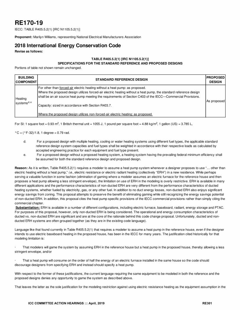
RE170-19IECC: TABLE R405.5.2(1) [IRC N1105.5.2(1)]
Proponent: Marilyn Williams, representing National Electrical Manufacturers Association
2018 International Energy Conservation CodeRevise as follows:
TABLE R405.5.2(1) [IRC N1105.5.2(1)]SPECIFICATIONS FOR THE STANDARD REFERENCE AND PROPOSED DESIGNS
Portions of table not shown remain unchanged.
BUILDINGCOMPONENT
STANDARD REFERENCE DESIGN PROPOSEDDESIGN
Heatingsystems
For other than forced-air electric heating without a heat pump: as proposed.Where the proposed design utilizes forced-air electric heating without a heat pump, the standard reference designshall be an air source heat pump meeting the requirements of Section C403 of the IECC—Commercial Provisions.
Capacity: sized in accordance with Section R403.7.
Where the proposed design utilizes non-forced-air electric heating; as proposed.
As proposed
For SI: 1 square foot = 0.93 m , 1 British thermal unit = 1055 J, 1 pound per square foot = 4.88 kg/m , 1 gallon (US) = 3.785 L,
°C = (°F-32)/1.8, 1 degree = 0.79 rad.
d. For a proposed design with multiple heating, cooling or water heating systems using different fuel types, the applicable standardreference design system capacities and fuel types shall be weighted in accordance with their respective loads as calculated byaccepted engineering practice for each equipment and fuel type present.
e. For a proposed design without a proposed heating system, a heating system having the prevailing federal minimum efficiency shallbe assumed for both the standard reference design and proposed design.
Reason: As it is written, Table R405.5.2(1) requires a modeler to assume a heat pump system whenever a designer proposes to use “… other thanelectric heating without a heat pump,” i.e., electric resistance or electric radiant heating (collectively “ERH”) in a new residence. While perhapsserving a valuable function in some fashion (elimination of gaming where a modeler assumes an electric furnace for the reference house and thenproposes a heat pump allowing a less stringent envelope), the limitation on use of ERH in the modeling is overly restrictive. ERH is available in manydifferent applications and the performance characteristics of non-ducted ERH are very different from the performance characteristics of ductedheating systems, whether fueled by electricity, gas, or any other fuel. In addition to no duct energy losses, non-ducted ERH also enjoys significantenergy savings from zoning. This proposal attempts to preserve the benefit of eliminating gaming while still recognizing the energy savings potentialof non-ducted ERH. In addition, this proposal cites the heat pump specific provisions of the IECC commercial provisions rather than simply citing thecommercial chapter. Substantiation: ERH is available in a number of different configurations, including electric furnace, baseboard, radiant, energy storage and PTAC.For purposes of this proposal, however, only non-ducted ERH is being considered. The operational and energy consumption characteristics ofducted vs. non-ducted ERH are significant and are at the core of the rationale behind this code change proposal. Unfortunately, ducted and non-ducted ERH systems are often grouped together (as they are in the existing code language).
Language like that found currently in Table R405.5.2(1) that requires a modeler to assume a heat pump in the reference house, even if the designerintends to use electric baseboard heating in the proposed house, has been in the IECC for many years. The justification cited historically for thatmodeling limitation is:
· That modelers will game the system by assuming ERH in the reference house but a heat pump in the proposed house, thereby allowing a lessstringent envelope, and/or
· That a heat pump will consume on the order of half the energy of an electric furnace installed in the same house so the code shoulddiscourage designers from specifying ERH and instead should specify a heat pump.
With respect to the former of these justifications, the current language requiring the same equipment to be modeled in both the reference and theproposed designs denies any opportunity to game the system as described above.
That leaves the latter as the sole justification for the modeling restriction against using electric resistance heating as the equipment assumption in the
d, e
2 2
ICC COMMITTEE ACTION HEARINGS ::: April, 2019 RE301
reference house. To some extent, this seems appropriate. If, for instance, in a heating dominated climate, a designer is proposing to install a ductedelectric furnace with central air-conditioning, then incenting that designer to use a heat pump instead would probably be expected to save significantamounts of energy at a relatively modest cost.
But there are significant operational and energy consumption characteristics that distinguish ducted from non-ducted ERH as described in moredetail below.
Ducted vs. non-ducted heating systems. Non-ducted ERH has significantly different operational and energy consumption characteristics fromducted heating systems.
Fan Power. Numerous studies over the last decade have identified furnace fan energy usage as more significant than before believed. As a result,the U.S. Department of Energy has initiated a rulemaking to establish a test procedure for determining furnace fan energy. Likewise, theEnvironmental Protection Agency now has an Energy Star rating for efficient furnace fans. Of course, non-ducted ERH like baseboard or radiantdoesn’t use a fan. On this basis, a reasonable person could conclude that, all other things being held constant, a non-ducted heating system(without a fan) would consume less energy than a ducted system with a fan using the same technology (gas, oil, electric resistance, etc.) .
Duct loss and fan induced infiltration. Energy losses through ductwork are recognized as significant and come from two distinct sources; airlost through ductwork to the outside and induced infiltration/exfiltration caused by duct pressurization. Air lost to the outside is self-explanatory andis, in fact, already recognized by the 2012 IECC (and earlier versions) in Table R405.5.2(2) where distribution system efficiency is discounted undercertain common conditions. In addition, there is growing recognition that ductwork design can have a significant impact on infiltration/exfiltration. Onthis basis, a reasonable person could conclude that, all other things being held constant, a non-ducted ERH system would consume less energythan a ducted electric furnace.
Zoning. Ducted, central heating, whether it be a ducted heat pump, electric furnace, gas furnace or other, is designed to serve large areas, mostoften an entire house. Non-ducted ERH, on the other hand, generally divides a house up into numerous independently controlled zones. The energyefficiency benefits of zoning are well documented as it allows users to heat only those areas that are occupied resulting in significant savings. Onthis basis, a reasonable person could conclude that, all other things being held constant, a zoned, non-ducted heating system would consume lessenergy than a ducted heating system using the same technology (gas, oil, electric resistance, etc.).
Additional considerations. Few people would argue that, at the margin, a zoned, non-ducted ERH would be expected to consume fewer btu’sover the course of a winter than a ducted electric furnace. In addition to these operational differences, however, (no fan energy, no duct losses,benefits of zoning), there are other reasons why ERH should be treated differently from ducted heating systems as noted below.
Cooling. There are still a non-trivial amount of new homes built in the United States every year without central cooling. According to the EIA, over800,000 new homes were built between 2000 and 2009 without air-conditioning. A recent study in the Pacific Northwest revealed a relationshipbetween increased use of cooling energy in homes that use heat pumps vis-à-vis electric furnaces. While there are a number of potentialexplanations, at least one explanation is that people using non-ducted ERH consciously decline to install air conditioning. Thus, incenting the use ofheat pumps over ERH may have the unintended result of increasing summer cooling energy.
Cooling dominated climate. In cooling dominated climates, with relatively few heating degree days (DOE Climate Zones 1 & 2), driving a builder touse a heat pump which would save relatively little – if any – heating energy due to the warm climate would result in fewer dollars for that builder tospend on other things like more attic insulation or higher SEER air-conditioning – something that would actually result in energy savings.
Non-ducted ERH has significantly different operating characteristics than ducted heating systems.
With respect to the assumption that a heat pump system will consume less than half the btus’s of an electric resistance heating system because theheat pump has a COP of 2 or better, this assumption may be valid for a comparison between a ducted heat pump and a ducted electric resistancefurnace, but it not accurate for non-ducted, zoned ERH (See Note 1 below)
In a study conducted by the National Association of Home Builders Research Center for the U.S. Department of Energy, an occupied house in theWashington, D.C. area was monitored for performance over a winter. The house contained three distinct heating systems; central electric heatpump, electric radiant heat, and electric baseboard heat. After the data was weather normalized, it revealed that, under actual homeowner controlledconditions, the electric radiant system used 33% percent less energy than the heat pump system and 52% less than the electric baseboard system.Thus, the heat pump only saved about 28% the energy consumed by the electric baseboard system.
Heat pumps are a great option when a person wants a central, ducted heating and cooling system but they having different operating characteristicsfrom a non-ducted heating system.
Note 1. Recent field data from a large survey of homes suggests that the actual (vs. theoretical) relationship may not be as well understood aspreviously believed. See study at http://www.nwcouncil.org/energy/rtf/meetings/2009/04/Draft%202008%20NEEM%20Study_040608.pdf (p. 21)where observed heat pump energy savings were far short of expectations and the report said
ICC COMMITTEE ACTION HEARINGS ::: April, 2019 RE302
“For the heat pump cases, however, the apparent similarity between electric resistance and heat pump systems suggest minimal savings for themore efficient heat pump option. Some form of behavioral ―takeback‖, poor heat pump installations or increased summer cooling load for heatpumps vis-à-vis resistance houses seem the likeliest explanations. Given that a number of the zone 1 sites (e.g.: Medford, Oregon; Yakima,Washington; and The Dalles, Oregon), have cooling climates, the latter seems plausible. A possible alternate contributing explanation is that theseheat pump units do not in fact achieve an average COP of as much as 2 under actual operating conditions. Field notes from heat pump cases in theOregon sample (a high percentage of heat pumps) mentioned occupants who complained about a lack of comfort to their heating contractor andwere told by their heating contractors to switch the heat pumps to run in electric resistance heating mode.”
Bibliography: Study of manufactured housing in the Pacific Northwest,http://www.nwcouncil.org/energy/rtf/meetings/2009/04/Draft%202008%20NEEM%20Study_040608.pdf
NAHB Radiant Heat Study, http://www.toolbase.org/PDF/CaseStudies/enerjoy_case_study.pdf
For an Alliance to Save Energy video on the benefits of zoning see http://www.energynow.com/video/2011/11/16/home-efficiency-tips-heating-and-cooling-zones where the moderator quotes the Department of Energy as saying that zoning can save up to 30% on home heating and cooling bills.
For information on duct leakage see http://www.greenbuildingadvisor.com/blogs/dept/musings/duct-leakage-testing. Also see EPA Energy Starguidance at http://www.energystar.gov/index.cfm?c=home_improvement.hm_improvement_ducts.
For information on fan induced infiltration into buildings see http://www.buildingscience.com/documents/digests/bsd-014-air-flow-control-in-buildings/files/bsd-014_air-flow-control_ed.pdf.
For an article on the significance of furnace fan energy see http://aceee.org/proceedings-paper/ss08/panel02/paper09. Also see U.S. Department ofEnergy Appliance Efficiency furnace fan docket at http://www1.eere.energy.gov/buildings/appliance_standards/residential/furnace_fans.html.
Cost Impact: The code change proposal will not increase or decrease the cost of constructionThis proposal imposes no additional requirement and, thus, does not add costs.
Proposal # 4081
RE170-19
ICC COMMITTEE ACTION HEARINGS ::: April, 2019 RE303
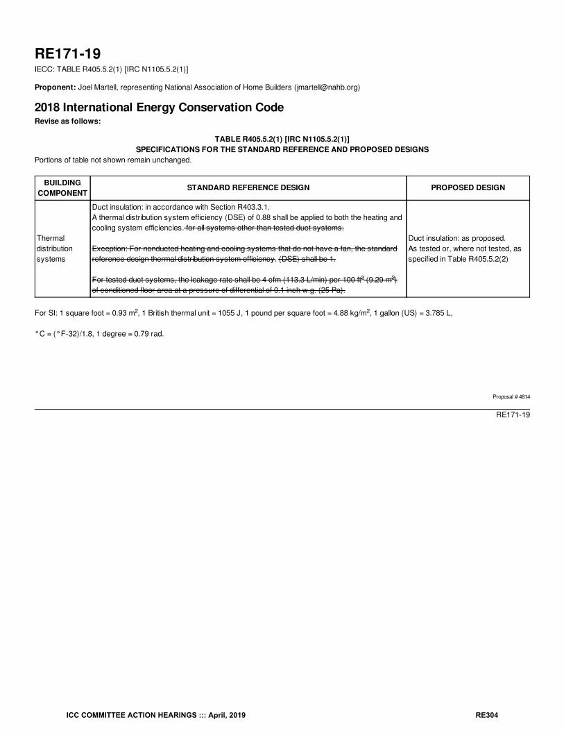
RE171-19IECC: TABLE R405.5.2(1) [IRC N1105.5.2(1)]
Proponent: Joel Martell, representing National Association of Home Builders ([email protected])
2018 International Energy Conservation CodeRevise as follows:
TABLE R405.5.2(1) [IRC N1105.5.2(1)]SPECIFICATIONS FOR THE STANDARD REFERENCE AND PROPOSED DESIGNS
Portions of table not shown remain unchanged.
BUILDINGCOMPONENT
STANDARD REFERENCE DESIGN PROPOSED DESIGN
Thermaldistributionsystems
Duct insulation: in accordance with Section R403.3.1.A thermal distribution system efficiency (DSE) of 0.88 shall be applied to both the heating andcooling system efficiencies. for all systems other than tested duct systems.
Exception: For nonducted heating and cooling systems that do not have a fan, the standardreference design thermal distribution system efficiency. (DSE) shall be 1.
For tested duct systems, the leakage rate shall be 4 cfm (113.3 L/min) per 100 ft (9.29 m )of conditioned floor area at a pressure of differential of 0.1 inch w.g. (25 Pa).
Duct insulation: as proposed.As tested or, where not tested, asspecified in Table R405.5.2(2)
For SI: 1 square foot = 0.93 m , 1 British thermal unit = 1055 J, 1 pound per square foot = 4.88 kg/m , 1 gallon (US) = 3.785 L,
°C = (°F-32)/1.8, 1 degree = 0.79 rad.
Proposal # 4814
RE171-19
2 2
2 2
ICC COMMITTEE ACTION HEARINGS ::: April, 2019 RE304
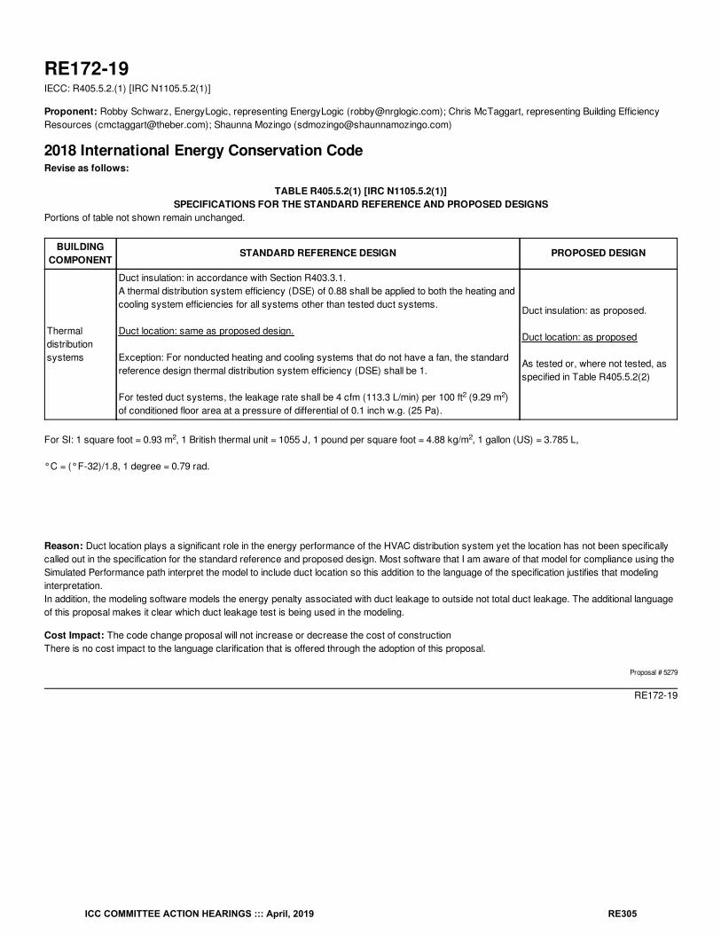
RE172-19IECC: R405.5.2.(1) [IRC N1105.5.2(1)]
Proponent: Robby Schwarz, EnergyLogic, representing EnergyLogic ([email protected]); Chris McTaggart, representing Building EfficiencyResources ([email protected]); Shaunna Mozingo ([email protected])
2018 International Energy Conservation CodeRevise as follows:
TABLE R405.5.2(1) [IRC N1105.5.2(1)]SPECIFICATIONS FOR THE STANDARD REFERENCE AND PROPOSED DESIGNS
Portions of table not shown remain unchanged.
BUILDINGCOMPONENT
STANDARD REFERENCE DESIGN PROPOSED DESIGN
Thermaldistributionsystems
Duct insulation: in accordance with Section R403.3.1.A thermal distribution system efficiency (DSE) of 0.88 shall be applied to both the heating andcooling system efficiencies for all systems other than tested duct systems.
Duct location: same as proposed design.
Exception: For nonducted heating and cooling systems that do not have a fan, the standardreference design thermal distribution system efficiency (DSE) shall be 1.
For tested duct systems, the leakage rate shall be 4 cfm (113.3 L/min) per 100 ft (9.29 m )of conditioned floor area at a pressure of differential of 0.1 inch w.g. (25 Pa).
Duct insulation: as proposed.
Duct location: as proposed
As tested or, where not tested, asspecified in Table R405.5.2(2)
For SI: 1 square foot = 0.93 m , 1 British thermal unit = 1055 J, 1 pound per square foot = 4.88 kg/m , 1 gallon (US) = 3.785 L,
°C = (°F-32)/1.8, 1 degree = 0.79 rad.
Reason: Duct location plays a significant role in the energy performance of the HVAC distribution system yet the location has not been specificallycalled out in the specification for the standard reference and proposed design. Most software that I am aware of that model for compliance using theSimulated Performance path interpret the model to include duct location so this addition to the language of the specification justifies that modelinginterpretation.In addition, the modeling software models the energy penalty associated with duct leakage to outside not total duct leakage. The additional languageof this proposal makes it clear which duct leakage test is being used in the modeling.
Cost Impact: The code change proposal will not increase or decrease the cost of constructionThere is no cost impact to the language clarification that is offered through the adoption of this proposal.
Proposal # 5279
RE172-19
2 2
2 2
ICC COMMITTEE ACTION HEARINGS ::: April, 2019 RE305
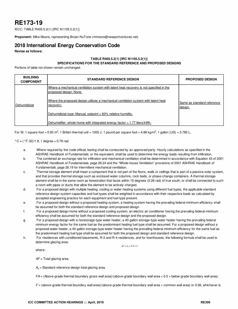
RE173-19IECC: TABLE R405.5.2(1) [IRC N1105.5.2(1)]
Proponent: Mike Moore, representing Broan-NuTone ([email protected])
2018 International Energy Conservation CodeRevise as follows:
TABLE R405.5.2(1) [IRC N1105.5.2(1)]SPECIFICATIONS FOR THE STANDARD REFERENCE AND PROPOSED DESIGNS
Portions of table not shown remain unchanged.
BUILDINGCOMPONENT
STANDARD REFERENCE DESIGN PROPOSED DESIGN
Dehumidistat
Where a mechanical ventilation system with latent heat recovery is not specified in theproposed design: None.
Where the proposed design utilizes a mechanical ventilation system with latent heatrecovery:
Dehumidistat type: Manual, setpoint = 60% relative humidity.
Dehumidifier: whole-home with integrated energy factor = 1.77 liters/kWh.
Same as standard referencedesign.
For SI: 1 square foot = 0.93 m , 1 British thermal unit = 1055 J, 1 pound per square foot = 4.88 kg/m , 1 gallon (US) = 3.785 L,
°C = (°F-32)/1.8, 1 degree = 0.79 rad.
a. Where required by the code official, testing shall be conducted by an approved party. Hourly calculations as specified in theASHRAE Handbook of Fundamentals, or the equivalent, shall be used to determine the energy loads resulting from infiltration.
b. The combined air exchange rate for infiltration and mechanical ventilation shall be determined in accordance with Equation 43 of 2001ASHRAE Handbook of Fundamentals, page 26.24 and the “Whole-house Ventilation” provisions of 2001 ASHRAE Handbook ofFundamentals, page 26.19 for intermittent mechanical ventilation.
c. Thermal storage element shall mean a component that is not part of the floors, walls or ceilings that is part of a passive solar system,and that provides thermal storage such as enclosed water columns, rock beds, or phase-change containers. A thermal storageelement shall be in the same room as fenestration that faces within 15 degrees (0.26 rad) of true south, or shall be connected to sucha room with pipes or ducts that allow the element to be actively charged.
d. For a proposed design with multiple heating, cooling or water heating systems using different fuel types, the applicable standardreference design system capacities and fuel types shall be weighted in accordance with their respective loads as calculated byaccepted engineering practice for each equipment and fuel type present.
e. For a proposed design without a proposed heating system, a heating system having the prevailing federal minimum efficiency shallbe assumed for both the standard reference design and proposed design.
f. For a proposed design home without a proposed cooling system, an electric air conditioner having the prevailing federal minimumefficiency shall be assumed for both the standard reference design and the proposed design.
g. For a proposed design with a nonstorage-type water heater, a 40-gallon storage-type water heater having the prevailing federalminimum energy factor for the same fuel as the predominant heating fuel type shall be assumed. For a proposed design without aproposed water heater, a 40-gallon storage-type water heater having the prevailing federal minimum efficiency for the same fuel asthe predominant heating fuel type shall be assumed for both the proposed design and standard reference design.
h. For residences with conditioned basements, R-2 and R-4 residences, and for townhouses, the following formula shall be used todetermine glazing area:
where:
AF = Total glazing area.
A = Standard reference design total glazing area.
FA = (Above-grade thermal boundary gross wall area)/(above-grade boundary wall area + 0.5 × below-grade boundary wall area).
F = (above-grade thermal boundary wall area)/(above-grade thermal boundary wall area + common wall area) or 0.56, whichever is
2 2
s
ICC COMMITTEE ACTION HEARINGS ::: April, 2019 RE306
greater.
and where:
Thermal boundary wall is any wall that separates conditioned space from unconditioned space or ambient conditions.
Above-grade thermal boundary wall is any thermal boundary wall component not in contact with soil.
Below-grade boundary wall is any thermal boundary wall in soil contact.
Common wall area is the area of walls shared with an adjoining dwelling unit.
L and CFA are in the same units.
Reason: Addressing latent loads associated with ventilation air can require a large amount of energy, especially in humid climates. Specification ofenergy recovery ventilators (ERVs) for mechanical ventilation can reduce the latent loads associated with ventilation air; however, there is no way toaccount for the ability of ERVs to reduce latent loads of ventilation air within Table N1105.5.2(1). This proposal establishes a method for accountingfor the latent energy savings of ERVs where specified in the proposed design. A target of 60% relative humidity is typical for the upper bound inresidential applications; above this level, there can be problems associated with moisture and condensation, negatively affecting building durabilityand indoor air quality; using a setpoint below this level can significantly increase energy use of the dehumidifier (and perhaps over-emphasize thebenefit of ERVs in typical residential applications). The energy factor used for the dehumidifier (1.77 liters/kWh) is identical to the minimum valuelisted in the code of federal regulations (10 CFR 430.32) for typical whole-home dehumidifiers (i.e., those with a case volume < 8 ft3).
Cost Impact: The code change proposal will decrease the cost of constructionWhere ERVs are specified, this measure can reduce the cost of construction by reducing the annual energy costs associated with the proposeddesign and permitting more flexibility in design.
Proposal # 5336
RE173-19
ICC COMMITTEE ACTION HEARINGS ::: April, 2019 RE307
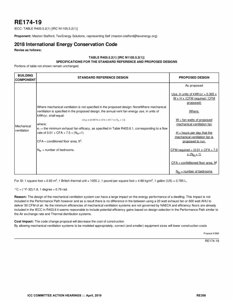
RE174-19IECC: TABLE R405.5.2(1) [IRC N1105.5.2(1)]
Proponent: Maston Stafford, TexEnergy Solutions, representing Self ([email protected])
2018 International Energy Conservation CodeRevise as follows:
TABLE R405.5.2(1) [IRC N1105.5.2(1)]SPECIFICATIONS FOR THE STANDARD REFERENCE AND PROPOSED DESIGNS
Portions of table not shown remain unchanged.
BUILDINGCOMPONENT
STANDARD REFERENCE DESIGN PROPOSED DESIGN
Mechanicalventilation
Where mechanical ventilation is not specified in the proposed design: NoneWhere mechanicalventilation is specified in the proposed design, the annual vent fan energy use, in units ofkWh/yr, shall equal:
where:e = the minimum exhaust fan efficacy, as specified in Table R403.6.1, corresponding to a flowrate of 0.01 × CFA + 7.5 × (N +1)
CFA = conditioned floor area, ft .
N = number of bedrooms.
As proposed
Use, in units of kWh/yr = 0.365 xW x H x (CFM required / CFM
proposed)
Where:
W = fan watts of proposedmechanical ventilation fan
H = hours per day that themechanical ventilation fan is
proposed to run.
CFM required = (0.01 x CFA + 7.5x (N + 1)
CFA = confiditioned floor area, ft
N = number of bedrooms
For SI: 1 square foot = 0.93 m , 1 British thermal unit = 1055 J, 1 pound per square foot = 4.88 kg/m , 1 gallon (US) = 3.785 L,
°C = (°F-32)/1.8, 1 degree = 0.79 rad.
Reason: The design of the mechanical ventilation system can have a large impact on the energy performance of a dwelling. This impact is notincluded in the Performance Path however and as a result there is no difference in the between using a 20 watt exhaust fan or 600 watt AHU todeliver 50 CFM of air. As the minimum efficiencies of mechanical ventilation systems are not governed by NAECA and efficiency floors are alreadyincluded in the IECC in R403.6 it seems reasonable to include potential efficiency gains based on design selection in the Performance Path similar tothe Air exchange rate and Thermal distribution systems.
Cost Impact: The code change proposal will decrease the cost of constructionBy allowing mechanical ventilation systems to be modeled appropriately, correct (and smaller) equipment sizes will lower construction costs
Proposal # 5560
RE174-19
f
br
2
br
br
2
br
2 2
ICC COMMITTEE ACTION HEARINGS ::: April, 2019 RE308
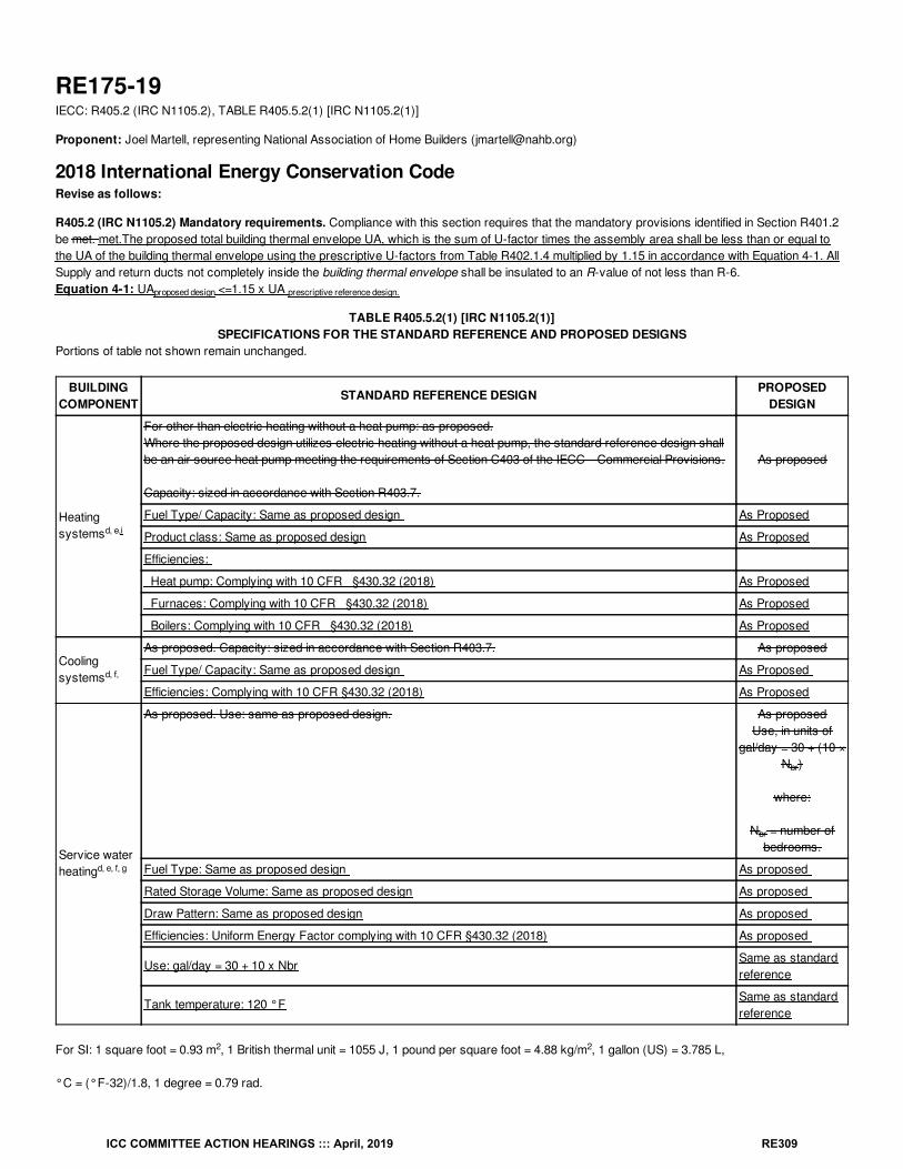
RE175-19IECC: R405.2 (IRC N1105.2), TABLE R405.5.2(1) [IRC N1105.2(1)]
Proponent: Joel Martell, representing National Association of Home Builders ([email protected])
2018 International Energy Conservation CodeRevise as follows:
R405.2 (IRC N1105.2) Mandatory requirements. Compliance with this section requires that the mandatory provisions identified in Section R401.2be met. met.The proposed total building thermal envelope UA, which is the sum of U-factor times the assembly area shall be less than or equal tothe UA of the building thermal envelope using the prescriptive U-factors from Table R402.1.4 multiplied by 1.15 in accordance with Equation 4-1. AllSupply and return ducts not completely inside the building thermal envelope shall be insulated to an R-value of not less than R-6.Equation 4-1: UA <=1.15 x UA
TABLE R405.5.2(1) [IRC N1105.2(1)]SPECIFICATIONS FOR THE STANDARD REFERENCE AND PROPOSED DESIGNS
Portions of table not shown remain unchanged.
BUILDINGCOMPONENT
STANDARD REFERENCE DESIGN PROPOSEDDESIGN
Heatingsystems
For other than electric heating without a heat pump: as proposed.Where the proposed design utilizes electric heating without a heat pump, the standard reference design shallbe an air source heat pump meeting the requirements of Section C403 of the IECC—Commercial Provisions.
Capacity: sized in accordance with Section R403.7.
As proposed
Fuel Type/ Capacity: Same as proposed design As Proposed
Product class: Same as proposed design As Proposed
Efficiencies:
Heat pump: Complying with 10 CFR §430.32 (2018) As Proposed
Furnaces: Complying with 10 CFR §430.32 (2018) As Proposed
Boilers: Complying with 10 CFR §430.32 (2018) As Proposed
Coolingsystems
As proposed. Capacity: sized in accordance with Section R403.7. As proposed
Fuel Type/ Capacity: Same as proposed design As Proposed
Efficiencies: Complying with 10 CFR §430.32 (2018) As Proposed
Service waterheating
As proposed. Use: same as proposed design. As proposedUse, in units of
gal/day = 30 + (10 ×N )
where:
N = number ofbedrooms.
Fuel Type: Same as proposed design As proposed
Rated Storage Volume: Same as proposed design As proposed
Draw Pattern: Same as proposed design As proposed
Efficiencies: Uniform Energy Factor complying with 10 CFR §430.32 (2018) As proposed
Use: gal/day = 30 + 10 x NbrSame as standardreference
Tank temperature: 120 °FSame as standardreference
For SI: 1 square foot = 0.93 m , 1 British thermal unit = 1055 J, 1 pound per square foot = 4.88 kg/m , 1 gallon (US) = 3.785 L,
°C = (°F-32)/1.8, 1 degree = 0.79 rad.
proposed design prescriptive reference design.
d, e,i
d, f,
d, e, f, g
br
br
2 2
ICC COMMITTEE ACTION HEARINGS ::: April, 2019 RE309
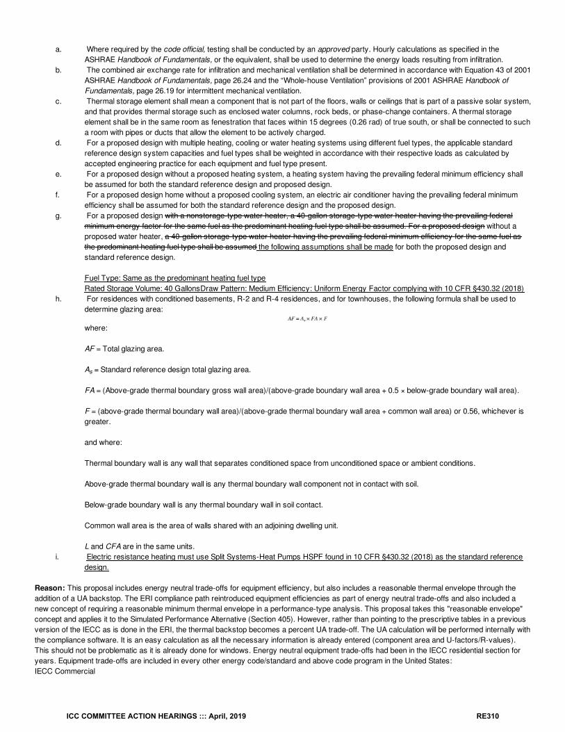
a. Where required by the code official, testing shall be conducted by an approved party. Hourly calculations as specified in theASHRAE Handbook of Fundamentals, or the equivalent, shall be used to determine the energy loads resulting from infiltration.
b. The combined air exchange rate for infiltration and mechanical ventilation shall be determined in accordance with Equation 43 of 2001ASHRAE Handbook of Fundamentals, page 26.24 and the “Whole-house Ventilation” provisions of 2001 ASHRAE Handbook ofFundamentals, page 26.19 for intermittent mechanical ventilation.
c. Thermal storage element shall mean a component that is not part of the floors, walls or ceilings that is part of a passive solar system,and that provides thermal storage such as enclosed water columns, rock beds, or phase-change containers. A thermal storageelement shall be in the same room as fenestration that faces within 15 degrees (0.26 rad) of true south, or shall be connected to sucha room with pipes or ducts that allow the element to be actively charged.
d. For a proposed design with multiple heating, cooling or water heating systems using different fuel types, the applicable standardreference design system capacities and fuel types shall be weighted in accordance with their respective loads as calculated byaccepted engineering practice for each equipment and fuel type present.
e. For a proposed design without a proposed heating system, a heating system having the prevailing federal minimum efficiency shallbe assumed for both the standard reference design and proposed design.
f. For a proposed design home without a proposed cooling system, an electric air conditioner having the prevailing federal minimumefficiency shall be assumed for both the standard reference design and the proposed design.
g. For a proposed design with a nonstorage-type water heater, a 40-gallon storage-type water heater having the prevailing federalminimum energy factor for the same fuel as the predominant heating fuel type shall be assumed. For a proposed design without aproposed water heater, a 40-gallon storage-type water heater having the prevailing federal minimum efficiency for the same fuel asthe predominant heating fuel type shall be assumed the following assumptions shall be made for both the proposed design andstandard reference design.
Fuel Type: Same as the predominant heating fuel typeRated Storage Volume: 40 GallonsDraw Pattern: Medium Efficiency: Uniform Energy Factor complying with 10 CFR §430.32 (2018)
h. For residences with conditioned basements, R-2 and R-4 residences, and for townhouses, the following formula shall be used todetermine glazing area:
where:
AF = Total glazing area.
A = Standard reference design total glazing area.
FA = (Above-grade thermal boundary gross wall area)/(above-grade boundary wall area + 0.5 × below-grade boundary wall area).
F = (above-grade thermal boundary wall area)/(above-grade thermal boundary wall area + common wall area) or 0.56, whichever isgreater.
and where:
Thermal boundary wall is any wall that separates conditioned space from unconditioned space or ambient conditions.
Above-grade thermal boundary wall is any thermal boundary wall component not in contact with soil.
Below-grade boundary wall is any thermal boundary wall in soil contact.
Common wall area is the area of walls shared with an adjoining dwelling unit.
L and CFA are in the same units.i. Electric resistance heating must use Split Systems-Heat Pumps HSPF found in 10 CFR §430.32 (2018) as the standard reference
design.
Reason: This proposal includes energy neutral trade-offs for equipment efficiency, but also includes a reasonable thermal envelope through theaddition of a UA backstop. The ERI compliance path reintroduced equipment efficiencies as part of energy neutral trade-offs and also included anew concept of requiring a reasonable minimum thermal envelope in a performance-type analysis. This proposal takes this "reasonable envelope"concept and applies it to the Simulated Performance Alternative (Section 405). However, rather than pointing to the prescriptive tables in a previousversion of the IECC as is done in the ERI, the thermal backstop becomes a percent UA trade-off. The UA calculation will be performed internally withthe compliance software. It is an easy calculation as all the necessary information is already entered (component area and U-factors/R-values).This should not be problematic as it is already done for windows. Energy neutral equipment trade-offs had been in the IECC residential section foryears. Equipment trade-offs are included in every other energy code/standard and above code program in the United States:IECC Commercial
s
ICC COMMITTEE ACTION HEARINGS ::: April, 2019 RE310
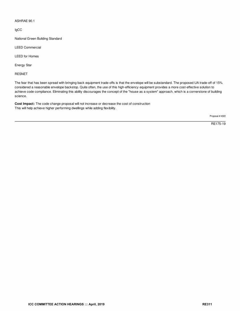
ASHRAE 90.1
IgCC
National Green Building Standard
LEED Commercial
LEED for Homes
Energy Star
RESNET
The fear that has been spread with bringing back equipment trade-offs is that the envelope will be substandard. The proposed UA trade-off of 15%considered a reasonable envelope backstop. Quite often, the use of this high-efficiency equipment provides a more cost-effective solution toachieve code compliance. Eliminating this ability discourages the concept of the "house as a system" approach, which is a cornerstone of buildingscience.
Cost Impact: The code change proposal will not increase or decrease the cost of constructionThis will help achieve higher performing dwellings while adding flexibility.
Proposal # 4322
RE175-19
ICC COMMITTEE ACTION HEARINGS ::: April, 2019 RE311
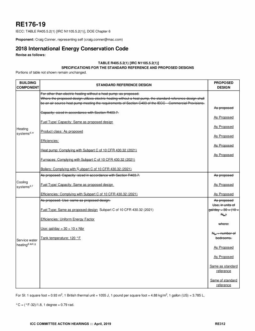
RE176-19IECC: TABLE R405.5.2(1) [IRC N1105.5.2(1)], DOE Chapter 6
Proponent: Craig Conner, representing self ([email protected])
2018 International Energy Conservation CodeRevise as follows:
TABLE R405.5.2(1) [IRC N1105.5.2(1)]SPECIFICATIONS FOR THE STANDARD REFERENCE AND PROPOSED DESIGNS
Portions of table not shown remain unchanged.
BUILDINGCOMPONENT
STANDARD REFERENCE DESIGN PROPOSEDDESIGN
Heatingsystems
For other than electric heating without a heat pump: as proposed.Where the proposed design utilizes electric heating without a heat pump, the standard reference design shallbe an air source heat pump meeting the requirements of Section C403 of the IECC—Commercial Provisions.
Capacity: sized in accordance with Section R403.7.
Fuel Type/ Capacity: Same as proposed design
Product class: As proposed
Efficiencies:
Heat pump: Complying with Subpart C of 10 CFR 430.32 (2021)
Furnaces: Complying with Subpart C of 10 CFR 430.32 (2021)
Boilers: Complying with S ubpart C of 10 CFR 430.32 (2021)
As proposed
As Proposed
As Proposed
As Proposed
As Proposed
As Proposed
Coolingsystems
As proposed. Capacity: sized in accordance with Section R403.7.
Fuel Type/ Capacity: Same as proposed design
Efficiencies: Complying with Subpart C of 10 CFR 430.32 (2021)
As proposed
As Proposed
As Proposed
Service waterheating
As proposed. Use: same as proposed design.
Fuel Type: Same as proposed design Subpart C of 10 CFR 430.32 (2021)
Efficiencies: Uniform Energy Factor
Use: gal/day = 30 + 10 x Nbr
Tank temperature: 120 °F
As proposedUse, in units of
gal/day = 30 + (10 ×N )
where:
N = number ofbedrooms.
As Proposed
As Proposed
Same as standardreference
Same of standardreference
For SI: 1 square foot = 0.93 m , 1 British thermal unit = 1055 J, 1 pound per square foot = 4.88 kg/m , 1 gallon (US) = 3.785 L,
°C = (°F-32)/1.8, 1 degree = 0.79 rad.
d, e
d, f
d, e, f, g
br
br
2 2
ICC COMMITTEE ACTION HEARINGS ::: April, 2019 RE312
d. For a proposed design with multiple heating, cooling or water heating systems using different fuel types, the applicable standardreference design system capacities and fuel types shall be weighted in accordance with their respective loads as calculated byaccepted engineering practice for each equipment and fuel type present.
e. For a proposed design without a proposed heating system, a heating system having the prevailing federal minimum efficiency shallbe assumed for both the standard reference design and proposed design.
f. For a proposed design home without a proposed cooling system, an electric air conditioner having the prevailing federal minimumefficiency shall be assumed for both the standard reference design and the proposed design.
g. For a proposed design with a nonstorage-type water heater,A 40-gallon storage-type water heater having the prevailing federalminimum energy factor for the with the same fuel as the predominant heating fuel type shall be assumed. For a proposed designwithout a proposed water heater, a 40-gallon storage-type water heater having the prevailing federal minimum efficiency for the samefuel as the predominant heating fuel type shall be assumed for both the proposed design and standard reference design. assumedfor the standard reference design. The minimum uniform energy factor shall be selected based on the Medium draw pattern found inSubpart C of 10 CFR 430.32 (2021). This water heater shall be used for the proposed water heater in the case of a proposed designwithout a proposed water heater.
Add new standard(s) as follows:
DOE U.S. Department of Energy 10 CFR, Part 430: Energy Conservation Program for Consumer Products: Test Procedures and Certification andEnforcement Requirement for Plumbing Products; and Certification and Enforcement Requirements for Residential Appliances.10 CFR, Part 431: Energy Efficiency Program for Certain Commercial and Industrial Equipment: Test Procedures andEfficiency Standards; FinalRules
Reason: Equipment efficiency is a key part of home energy efficiency. This proposal restores equipment efficiency to the performance calculation. This proposal also corrects a long-standing error in the code, that of citing “prevailing federal minimum efficiency”.
The code’s use of "prevailing federal minimum efficiency’" is inappropriate and may hamper adoption. Yes, this language has been used for sometime and is currently in three existing table footnotes, footnotes “e”, “f” and “g”. However, “prevailing” creates a problem. When states, countiesand cities adopt laws, they are obligated to make the exact content of the law available to the public. When the ‘prevailing’ federal minimumefficiency changes; the jurisdiction’s code also changes automatically. Changing the “prevailing” standard without any jurisdictional process meansanother body, which is not the legislative body of the jurisdiction, changes the laws within the jurisdiction without any public hearing or vote by thelocal legislative body. This is called an illegal delegation of legislative authority. This is why I-code referenced standards always come with adate/edition (see the referenced standard chapter). The I-codes don’t reference any old edition of a standard, they reference a specific edition ofthat standard.
The other problem with simply saying ‘prevailing federal minimum efficiency’ is that it doesn’t tell the designer or the code official where to find thosevalues. The solution is to cite the specific Federal law and date, just as is done with any standard referenced in the I-codes. Yes – this does lock inthe efficiency standard used for 3 years. But that is what we do for every other standard.
Equipment efficiency is a key part of home energy efficiency. More efficient equipment saves more energy. Significant energy savings is availablefor every type of equipment efficiency. A high-efficiency 95 AFUE furnace saves energy. A high-efficiency 19 SEER air conditioner saves energy. Ground source heat pumps save considerable energy. Solar water heating saves energy. Homes that use more efficient equipment should getcredit for choosing more efficient equipment. Equipment efficiency was a part of the residential IECC performance calculation in 2006 and prior. Equipment efficiency is part of the commercial IECC performance calculation, ASHRAE 90.1 and 90.2, to name a few.
Some argue that longer-life measures should not be traded for shorter-life measures. For example, don’t trade lower wall insulation for higherequipment efficiency. However the ERI allows one to trade higher-efficiency refrigerators, higher-efficiency clothes washers and higher-efficiencydishwashers for lower wall insulation. Clothes washers in particular are often moved with the owner when a house is sold. The lifetime of windowsis less than insulation, should we allow better windows to be traded for lower wall insulation? I’d argue to keep all tradeoffs. However, if one arguesto keep equipment efficiency tradeoffs out of Section R405 performance trades, then to be consistent one should also argue to keep equipmentefficiency, refrigerators, clothes washers and dishwashers out of the tradeoffs for insulation in the ERI.
Why was equipment efficiency taken out of after the 2006 residential IECC? In the proponent’s opinion one reason was to protect the market forsome types of products that thought equipment efficiency might compete and reduce their market share. For instance, some might use high
ICC COMMITTEE ACTION HEARINGS ::: April, 2019 RE313
efficiency equipment instead of higher levels of insulation. The goal of the code should be to deliver energy efficiency, not to protect products.
Moving to even higher levels of energy efficiency in the code will require restoring flexibility, part of which is equipment efficiency. If builders getcredit for what they do, be it equipment efficiency, solar, or whatever, then this proponent is comfortable asking them to achieve higher levels ofefficiency, even increasing requirements through code. However, without flexibility, then builders need more exceptions and lesser requirements tomake up for the flexibility they are denied by code. Without restoring flexibility, additional energy efficiency in code is much more difficult to achieve.
Cost Impact: The code change proposal will decrease the cost of constructionAllowing credit for high efficiency equipment will encourage energy efficiency and promote lower cost ways to get to energy efficient homes.
Staff Analysis: A review of the standard proposed for inclusion in the code, 10 CFR 430.32 (2021), with regard to the ICC criteria for referencedstandards (Section 3.6 of CP#28) will be posted on the ICC website on or before April 2, 2019.
Proposal # 5411
RE176-19
ICC COMMITTEE ACTION HEARINGS ::: April, 2019 RE314
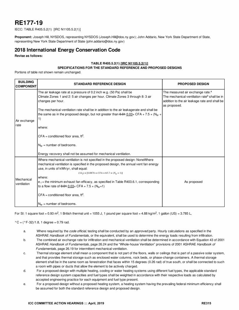
RE177-19IECC: TABLE R405.5.2(1) [IRC N1105.5.2(1)]
Proponent: Joseph Hill, NYSDOS, representing NYSDOS ([email protected]); John Addario, New York State Department of State,representing New York State Department of State ([email protected])
2018 International Energy Conservation CodeRevise as follows:
TABLE R405.5.2(1) [IRC N1105.5.2(1)]SPECIFICATIONS FOR THE STANDARD REFERENCE AND PROPOSED DESIGNS
Portions of table not shown remain unchanged.
BUILDINGCOMPONENT
STANDARD REFERENCE DESIGN PROPOSED DESIGN
Air exchangerate
The air leakage rate at a pressure of 0.2 inch w.g. (50 Pa) shall beClimate Zones 1 and 2: 5 air changes per hour. Climate Zones 3 through 8: 3 airchanges per hour.
The mechanical ventilation rate shall be in addition to the air leakagerate and shall bethe same as in the proposed design, but not greater than 0.01 0.03× CFA + 7.5 × (N +1)
where:
CFA = conditioned floor area, ft .
N = number of bedrooms.
Energy recovery shall not be assumed for mechanical ventilation.
The measured air exchange rate.The mechanical ventilation rate shall be inaddition to the air leakage rate and shall beas proposed.
Mechanicalventilation
Where mechanical ventilation is not specified in the proposed design: NoneWheremechanical ventilation is specified in the proposed design, the annual vent fan energyuse, in units of kWh/yr, shall equal:
where:e = the minimum exhaust fan efficacy, as specified in Table R403.6.1, correspondingto a flow rate of 0.01 0.03× CFA + 7.5 × (N +1)
CFA = conditioned floor area, ft .
N = number of bedrooms.
As proposed
For SI: 1 square foot = 0.93 m , 1 British thermal unit = 1055 J, 1 pound per square foot = 4.88 kg/m , 1 gallon (US) = 3.785 L,
°C = (°F-32)/1.8, 1 degree = 0.79 rad.
a. Where required by the code official, testing shall be conducted by an approved party. Hourly calculations as specified in theASHRAE Handbook of Fundamentals, or the equivalent, shall be used to determine the energy loads resulting from infiltration.
b. The combined air exchange rate for infiltration and mechanical ventilation shall be determined in accordance with Equation 43 of 2001ASHRAE Handbook of Fundamentals, page 26.24 and the “Whole-house Ventilation” provisions of 2001 ASHRAE Handbook ofFundamentals, page 26.19 for intermittent mechanical ventilation.
c. Thermal storage element shall mean a component that is not part of the floors, walls or ceilings that is part of a passive solar system,and that provides thermal storage such as enclosed water columns, rock beds, or phase-change containers. A thermal storageelement shall be in the same room as fenestration that faces within 15 degrees (0.26 rad) of true south, or shall be connected to sucha room with pipes or ducts that allow the element to be actively charged.
d. For a proposed design with multiple heating, cooling or water heating systems using different fuel types, the applicable standardreference design system capacities and fuel types shall be weighted in accordance with their respective loads as calculated byaccepted engineering practice for each equipment and fuel type present.
e. For a proposed design without a proposed heating system, a heating system having the prevailing federal minimum efficiency shallbe assumed for both the standard reference design and proposed design.
br
2
br
a
b
f
br
2
br
2 2
ICC COMMITTEE ACTION HEARINGS ::: April, 2019 RE315
f. For a proposed design home without a proposed cooling system, an electric air conditioner having the prevailing federal minimumefficiency shall be assumed for both the standard reference design and the proposed design.
g. For a proposed design with a nonstorage-type water heater, a 40-gallon storage-type water heater having the prevailing federalminimum energy factor for the same fuel as the predominant heating fuel type shall be assumed. For a proposed design without aproposed water heater, a 40-gallon storage-type water heater having the prevailing federal minimum efficiency for the same fuel asthe predominant heating fuel type shall be assumed for both the proposed design and standard reference design.
h. For residences with conditioned basements, R-2 and R-4 residences, and for townhouses, the following formula shall be used todetermine glazing area:
where:
AF = Total glazing area.
A = Standard reference design total glazing area.
FA = (Above-grade thermal boundary gross wall area)/(above-grade boundary wall area + 0.5 × below-grade boundary wall area).
F = (above-grade thermal boundary wall area)/(above-grade thermal boundary wall area + common wall area) or 0.56, whichever isgreater.
and where:
Thermal boundary wall is any wall that separates conditioned space from unconditioned space or ambient conditions.
Above-grade thermal boundary wall is any thermal boundary wall component not in contact with soil.
Below-grade boundary wall is any thermal boundary wall in soil contact.
Common wall area is the area of walls shared with an adjoining dwelling unit.
L and CFA are in the same units.
Reason: In 2012, the IRC and IECC were modified introducing "Whole House Mechanical Ventilation" which was required in one and two familydwelling units and townhouse construction, when tested to less than 5 ACH 50. This is essentially all such buildings as described. ASHRAE 62.2004was used as a basis for the rate of ventilation, which designated the ventilation rate of whole house ventilation at Q fan = 0.01A floor + 7.5 (BR + 1) .This version, is as acccording to the the 2012 IRC Code and Commentary. The more recent versions of ASHRAE 62.2-(2013 / 2016.) haverecognized the need to improve indoor air quality, have revised the rate of ventilation to Mechanical Ventilation Q fan = .0.03A floor + 7.5 (BR +1).This was done because the prior rate assumed a significant amount of outdoor air from infiltration, which due to improvements in the IECC, hassteadily dropped, necessitating an increase in the mechanical ventilation rate. It is therefore not appropriate in 2019 to still be referencing ventilationrates from those outdated standards This revised rate = 0.03A floor + 7.5 (BR + 1) is also contained in ANSI/RESNET ICC-2014 which sets R406.3Energy rating index at odds with itself, since there was a modification to the IECC code text of this section setting the ventilation rate back to Q fan =0.01A floor + 7.5 (BR + 1). This issue will likley be the focus of a code change proposal by the authors of the RESNET standard.
Bibliography: 2018 IECC
Cost Impact: The code change proposal will not increase or decrease the cost of constructionThe propsal modifes the rate of mechanical ventilation to be consistent with ANSI/RESNET/ICC-2014 which utilzes ASHRAE 62.2-2013 for it'sventilation standard . This modification does not impose a cost to the code.
Proposal # 4933
RE177-19
s
ICC COMMITTEE ACTION HEARINGS ::: April, 2019 RE316
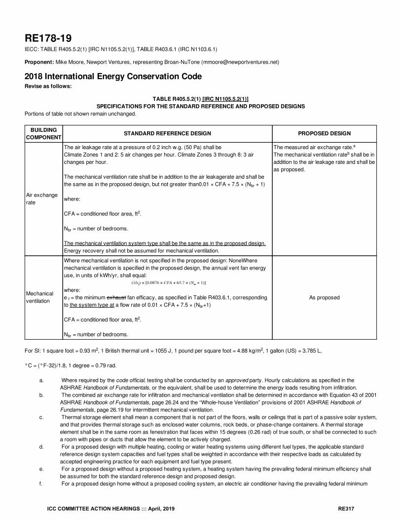
RE178-19IECC: TABLE R405.5.2(1) [IRC N1105.5.2(1)], TABLE R403.6.1 (IRC N1103.6.1)
Proponent: Mike Moore, Newport Ventures, representing Broan-NuTone ([email protected])
2018 International Energy Conservation CodeRevise as follows:
TABLE R405.5.2(1) [IRC N1105.5.2(1)]SPECIFICATIONS FOR THE STANDARD REFERENCE AND PROPOSED DESIGNS
Portions of table not shown remain unchanged.
BUILDINGCOMPONENT
STANDARD REFERENCE DESIGN PROPOSED DESIGN
Air exchangerate
The air leakage rate at a pressure of 0.2 inch w.g. (50 Pa) shall beClimate Zones 1 and 2: 5 air changes per hour. Climate Zones 3 through 8: 3 airchanges per hour.
The mechanical ventilation rate shall be in addition to the air leakagerate and shall bethe same as in the proposed design, but not greater than0.01 × CFA + 7.5 × (N + 1)
where:
CFA = conditioned floor area, ft .
N = number of bedrooms.
The mechanical ventilation system type shall be the same as in the proposed design.Energy recovery shall not be assumed for mechanical ventilation.
The measured air exchange rate.The mechanical ventilation rate shall be inaddition to the air leakage rate and shall beas proposed.
Mechanicalventilation
Where mechanical ventilation is not specified in the proposed design: NoneWheremechanical ventilation is specified in the proposed design, the annual vent fan energyuse, in units of kWh/yr, shall equal:
where:e = the minimum exhaust fan efficacy, as specified in Table R403.6.1, correspondingto the system type at a flow rate of 0.01 × CFA + 7.5 × (N +1)
CFA = conditioned floor area, ft .
N = number of bedrooms.
As proposed
For SI: 1 square foot = 0.93 m , 1 British thermal unit = 1055 J, 1 pound per square foot = 4.88 kg/m , 1 gallon (US) = 3.785 L,
°C = (°F-32)/1.8, 1 degree = 0.79 rad.
a. Where required by the code official, testing shall be conducted by an approved party. Hourly calculations as specified in theASHRAE Handbook of Fundamentals, or the equivalent, shall be used to determine the energy loads resulting from infiltration.
b. The combined air exchange rate for infiltration and mechanical ventilation shall be determined in accordance with Equation 43 of 2001ASHRAE Handbook of Fundamentals, page 26.24 and the “Whole-house Ventilation” provisions of 2001 ASHRAE Handbook ofFundamentals, page 26.19 for intermittent mechanical ventilation.
c. Thermal storage element shall mean a component that is not part of the floors, walls or ceilings that is part of a passive solar system,and that provides thermal storage such as enclosed water columns, rock beds, or phase-change containers. A thermal storageelement shall be in the same room as fenestration that faces within 15 degrees (0.26 rad) of true south, or shall be connected to sucha room with pipes or ducts that allow the element to be actively charged.
d. For a proposed design with multiple heating, cooling or water heating systems using different fuel types, the applicable standardreference design system capacities and fuel types shall be weighted in accordance with their respective loads as calculated byaccepted engineering practice for each equipment and fuel type present.
e. For a proposed design without a proposed heating system, a heating system having the prevailing federal minimum efficiency shallbe assumed for both the standard reference design and proposed design.
f. For a proposed design home without a proposed cooling system, an electric air conditioner having the prevailing federal minimum
br
2
br
a
b
f
br
2
br
2 2
ICC COMMITTEE ACTION HEARINGS ::: April, 2019 RE317
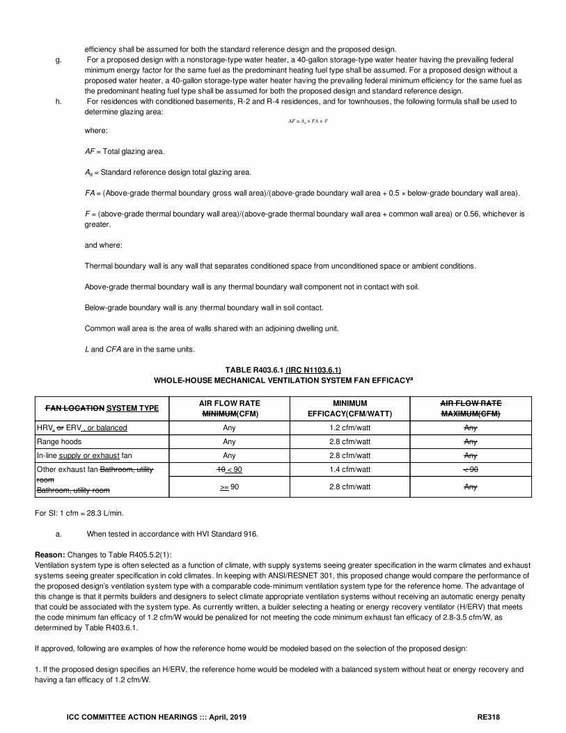
efficiency shall be assumed for both the standard reference design and the proposed design.g. For a proposed design with a nonstorage-type water heater, a 40-gallon storage-type water heater having the prevailing federal
minimum energy factor for the same fuel as the predominant heating fuel type shall be assumed. For a proposed design without aproposed water heater, a 40-gallon storage-type water heater having the prevailing federal minimum efficiency for the same fuel asthe predominant heating fuel type shall be assumed for both the proposed design and standard reference design.
h. For residences with conditioned basements, R-2 and R-4 residences, and for townhouses, the following formula shall be used todetermine glazing area:
where:
AF = Total glazing area.
A = Standard reference design total glazing area.
FA = (Above-grade thermal boundary gross wall area)/(above-grade boundary wall area + 0.5 × below-grade boundary wall area).
F = (above-grade thermal boundary wall area)/(above-grade thermal boundary wall area + common wall area) or 0.56, whichever isgreater.
and where:
Thermal boundary wall is any wall that separates conditioned space from unconditioned space or ambient conditions.
Above-grade thermal boundary wall is any thermal boundary wall component not in contact with soil.
Below-grade boundary wall is any thermal boundary wall in soil contact.
Common wall area is the area of walls shared with an adjoining dwelling unit.
L and CFA are in the same units.
TABLE R403.6.1 (IRC N1103.6.1)WHOLE-HOUSE MECHANICAL VENTILATION SYSTEM FAN EFFICACY
FAN LOCATION SYSTEM TYPE AIR FLOW RATE MINIMUM(CFM)
MINIMUMEFFICACY(CFM/WATT)
AIR FLOW RATEMAXIMUM(CFM)
HRV, or ERV , or balanced Any 1.2 cfm/watt Any
Range hoods Any 2.8 cfm/watt Any
In-line supply or exhaust fan Any 2.8 cfm/watt Any
Other exhaust fan Bathroom, utilityroomBathroom, utility room
10 < 90 1.4 cfm/watt < 90
>= 90 2.8 cfm/watt Any
For SI: 1 cfm = 28.3 L/min.
a. When tested in accordance with HVI Standard 916.
Reason: Changes to Table R405.5.2(1):Ventilation system type is often selected as a function of climate, with supply systems seeing greater specification in the warm climates and exhaustsystems seeing greater specification in cold climates. In keeping with ANSI/RESNET 301, this proposed change would compare the performance ofthe proposed design’s ventilation system type with a comparable code-minimum ventilation system type for the reference home. The advantage ofthis change is that it permits builders and designers to select climate appropriate ventilation systems without receiving an automatic energy penaltythat could be associated with the system type. As currently written, a builder selecting a heating or energy recovery ventilator (H/ERV) that meetsthe code minimum fan efficacy of 1.2 cfm/W would be penalized for not meeting the code minimum exhaust fan efficacy of 2.8-3.5 cfm/W, asdetermined by Table R403.6.1.
If approved, following are examples of how the reference home would be modeled based on the selection of the proposed design:
1. If the proposed design specifies an H/ERV, the reference home would be modeled with a balanced system without heat or energy recovery andhaving a fan efficacy of 1.2 cfm/W.
s
a
ICC COMMITTEE ACTION HEARINGS ::: April, 2019 RE318
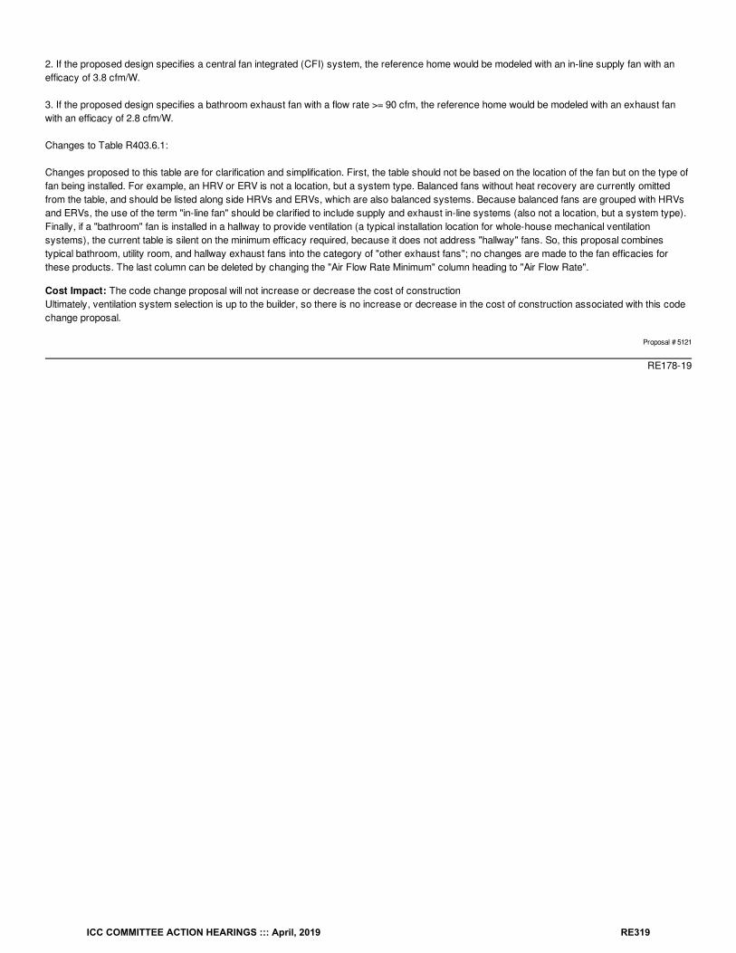
2. If the proposed design specifies a central fan integrated (CFI) system, the reference home would be modeled with an in-line supply fan with anefficacy of 3.8 cfm/W.
3. If the proposed design specifies a bathroom exhaust fan with a flow rate >= 90 cfm, the reference home would be modeled with an exhaust fanwith an efficacy of 2.8 cfm/W.
Changes to Table R403.6.1:
Changes proposed to this table are for clarification and simplification. First, the table should not be based on the location of the fan but on the type offan being installed. For example, an HRV or ERV is not a location, but a system type. Balanced fans without heat recovery are currently omittedfrom the table, and should be listed along side HRVs and ERVs, which are also balanced systems. Because balanced fans are grouped with HRVsand ERVs, the use of the term "in-line fan" should be clarified to include supply and exhaust in-line systems (also not a location, but a system type).Finally, if a "bathroom" fan is installed in a hallway to provide ventilation (a typical installation location for whole-house mechanical ventilationsystems), the current table is silent on the minimum efficacy required, because it does not address "hallway" fans. So, this proposal combinestypical bathroom, utility room, and hallway exhaust fans into the category of "other exhaust fans"; no changes are made to the fan efficacies forthese products. The last column can be deleted by changing the "Air Flow Rate Minimum" column heading to "Air Flow Rate".
Cost Impact: The code change proposal will not increase or decrease the cost of constructionUltimately, ventilation system selection is up to the builder, so there is no increase or decrease in the cost of construction associated with this codechange proposal.
Proposal # 5121
RE178-19
ICC COMMITTEE ACTION HEARINGS ::: April, 2019 RE319
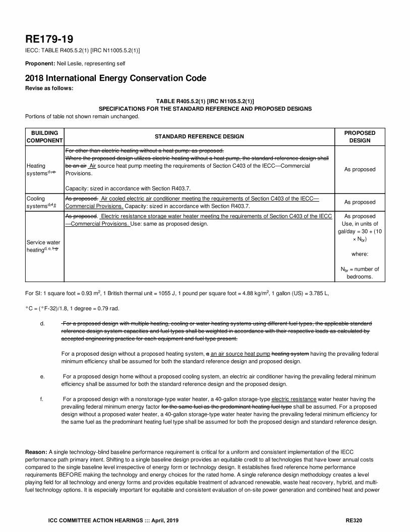
RE179-19IECC: TABLE R405.5.2(1) [IRC N11005.5.2(1)]
Proponent: Neil Leslie, representing self
2018 International Energy Conservation CodeRevise as follows:
TABLE R405.5.2(1) [IRC N1105.5.2(1)]SPECIFICATIONS FOR THE STANDARD REFERENCE AND PROPOSED DESIGNS
Portions of table not shown remain unchanged.
BUILDINGCOMPONENT
STANDARD REFERENCE DESIGN PROPOSEDDESIGN
Heatingsystems
For other than electric heating without a heat pump: as proposed.Where the proposed design utilizes electric heating without a heat pump, the standard reference design shallbe an air Air source heat pump meeting the requirements of Section C403 of the IECC—CommercialProvisions.
Capacity: sized in accordance with Section R403.7.
As proposed
Coolingsystems
As proposed. Air cooled electric air conditioner meeting the requirements of Section C403 of the IECC—Commercial Provisions. Capacity: sized in accordance with Section R403.7.
As proposed
Service waterheating
As proposed. Electric resistance storage water heater meeting the requirements of Section C403 of the IECC—Commercial Provisions. Use: same as proposed design.
As proposedUse, in units of
gal/day = 30 + (10× N )
where:
N = number ofbedrooms.
For SI: 1 square foot = 0.93 m , 1 British thermal unit = 1055 J, 1 pound per square foot = 4.88 kg/m , 1 gallon (US) = 3.785 L,
°C = (°F-32)/1.8, 1 degree = 0.79 rad.
d. For a proposed design with multiple heating, cooling or water heating systems using different fuel types, the applicable standardreference design system capacities and fuel types shall be weighted in accordance with their respective loads as calculated byaccepted engineering practice for each equipment and fuel type present. For a proposed design without a proposed heating system, a an air source heat pump heating system having the prevailing federalminimum efficiency shall be assumed for both the standard reference design and proposed design.
e. For a proposed design home without a proposed cooling system, an electric air conditioner having the prevailing federal minimumefficiency shall be assumed for both the standard reference design and the proposed design.
f. For a proposed design with a nonstorage-type water heater, a 40-gallon storage-type electric resistance water heater having theprevailing federal minimum energy factor for the same fuel as the predominant heating fuel type shall be assumed. For a proposeddesign without a proposed water heater, a 40-gallon storage-type water heater having the prevailing federal minimum efficiency forthe same fuel as the predominant heating fuel type shall be assumed for both the proposed design and standard reference design.
Reason: A single technology-blind baseline performance requirement is critical for a uniform and consistent implementation of the IECCperformance path primary intent. Shifting to a single baseline design provides an equitable credit to all technologies that have lower annual costscompared to the single baseline level irrespective of energy form or technology design. It establishes fixed reference home performancerequirements BEFORE making the technology and energy choices for the rated home. A single reference design methodology creates a levelplaying field for all technology and energy forms and provides equitable treatment of advanced renewable, waste heat recovery, hybrid, and multi-fuel technology options. It is especially important for equitable and consistent evaluation of on-site power generation and combined heat and power
d , e
d, f e
d, e, f, g
br
br
2 2
ICC COMMITTEE ACTION HEARINGS ::: April, 2019 RE320
systems.
Cost Impact: The code change proposal will not increase or decrease the cost of constructionOptions are already availabel in the current codde. This change merely provides a more equitable baseline for performance comparisons.
Staff Analysis: Current table note d is deleted and the remaining table notes were relettered.
Proposal # 4883
RE179-19
ICC COMMITTEE ACTION HEARINGS ::: April, 2019 RE321
RE180-19IECC: R405.3 (IRC N1105.3)
Proponent: Chris McTaggart, Building Efficiency Resources, representing Building Efficiency Resources ([email protected])
2018 International Energy Conservation CodeRevise as follows:
R405.3 (IRC N1105.3) Performance-based compliance. Compliance based on simulated energy performance requires that a proposed residence(proposed design) be shown to have an annual energy cost that is less than or equal to the annual energy cost of the standard reference design.Energy prices shall be taken from a source approved by the code official, such as the Department of Energy, Energy Information Administration’sState Energy Data System Prices and Expenditures reports. Code officials shall be permitted to require time-of-use pricing in energy costcalculations.
Exception: The energy use based on source energy expressed in Btu or Btu per square foot of conditioned floor area shall be permitted to besubstituted for the energy cost. that is less than or equal to the annual source energy use of the standard reference design . The source energymultiplier for electricity shall be 3.16. The source energy multiplier for fuels other than electricity shall be 1.1.
Reason: The current R405 option to demonstrate compliance using comparative annual energy cost between the proposed design and standardreference design introduces an inappropriate additional variable of utility costs that can radically confuse compliance.The ratios between fuel and electricity costs are constantly changing, which can result in a proposed design based on a builder's typical set ofarchitectural plans that achieves compliance on the day that the costs were aggregated, but which does not comply days or months after whencosts change. Therefore you can have two homes built from the say planset, with the same specs, built to the same code by the same builder in thesame geographic area with one being compliant and the other non-compliant, simply becuase of variations in the ratios of electric vs fuel costs overtime. Similarly, you could have two homes built from the say planset, with the same specs, built to the same code by the same builder at the exactsame time in the same geographic areat - but in different energy utility territories - with one being compliant and the other non-compliant, simplybecause they use different utility providers with differing costs.
Furthermore, it is an excessive burden for a code official to have to create and implement their own process for validating the energy utility cost dataused in the software file. For one, there is little guidance in the code for code officials for how to define what cost data or process ofcreating/maintaining cost data is acceptable. The current code suggests that EIA state-average data could be used, which is ok, but should this databe updated monthy? Annually? The EIA state-average data fluctuates month-by-month, and is often seasonal in nature; some software programsallow seasonal inputs, but again - is that what's expected or is it simply an annual average? How often should this cost data be updated? What if abarely-passing planset in a residential development no longer passess with updated energy cost data after the first year of a multi-year build out? Ifnot using EIA data, finding actual data from the specific utilities in question is a huge undertaking, as the fee, rate and tarrif sheets from utilites aretypically massive and complex.
There are simply too many questions, variables and outliers associated with cost-based compliance due to the variablility and ever changing natureof energy costs. This introduces confusion and a "wildcard" that the code official may not truly understand or understand how to reasonably assesswhat's fair and reasonable. The "x-factor" of energy costs and the relative difference between fuels and electricity introduce an independent variablethat really has to use when assessing building energy efficiency from a compliance standpoint. It is not reasonable to have a variable such as costbe able to change the same planset's compliance within the same code cycle depending on what and when cost data is pulled, and potentially utilityvs utility.
This proposal seeks to simplify the Performance compliance process by focusing on known, fixed energy use calculations, resulting in a compliancepath that is based exclusively on building energy characteristics and climate data. The proposal maintains the previous "exceptions" of using sourceenergy use or use per sqft of conditioned floor area (otherwise known as a source EUI). While there no doubt has been fair debate over timeregarding site vs source energy, electricity vs fuel source energy factors, total energy vs EUI, etc, this proposal does not seek to resolve thoseconflicts but instead elects to adopt the prevoius "exception" compliance options already adopted into previous energy codes.
To document the need for this change, I have uploaded two PDF compliance documents produced from REM/Rate software for a planset seeking tocomply with the current 2012 IECC with state amendments in Iowa. The proposed design complies with the code by achieving exact costcompliance in dollars as the standard reference design when using 2015 EIA state average cost data, which were the current costs at the time thisplanset was originally run in the software for compliance. When updating the model to only change costs to the most up-to-date EIA state data(2017), the home now does not comply with the code as the proposed design is estimated to cost more to operate than the standard referencedesign.
Currently, all software programs that are popularly used to demonstrate compliance (REM/Rate, REM/Design, Ekotrope, EnergyGauge) are set upto create R405 compliance reports exclusively compute cost compliance; they are not set up to express compliance using annual source energy.However, all of these software programs have the ability to configure the Performance compliance reports for either annual source energy or EUI.
Cost Impact: The code change proposal will not increase or decrease the cost of construction
ICC COMMITTEE ACTION HEARINGS ::: April, 2019 RE322
This proposal will have no impact on construction costs. There will be a minor cost to software providers to alter the Performance compliancecalculations to annual source energy or source EUI vs cost, but they will unlikley pass these costs down to their users. This proposal will save timeand money for code officials and AHJs by reducing the need for the code official to have to police energy cost data in Performance code software.
Proposal # 5478
RE180-19
ICC COMMITTEE ACTION HEARINGS ::: April, 2019 RE323
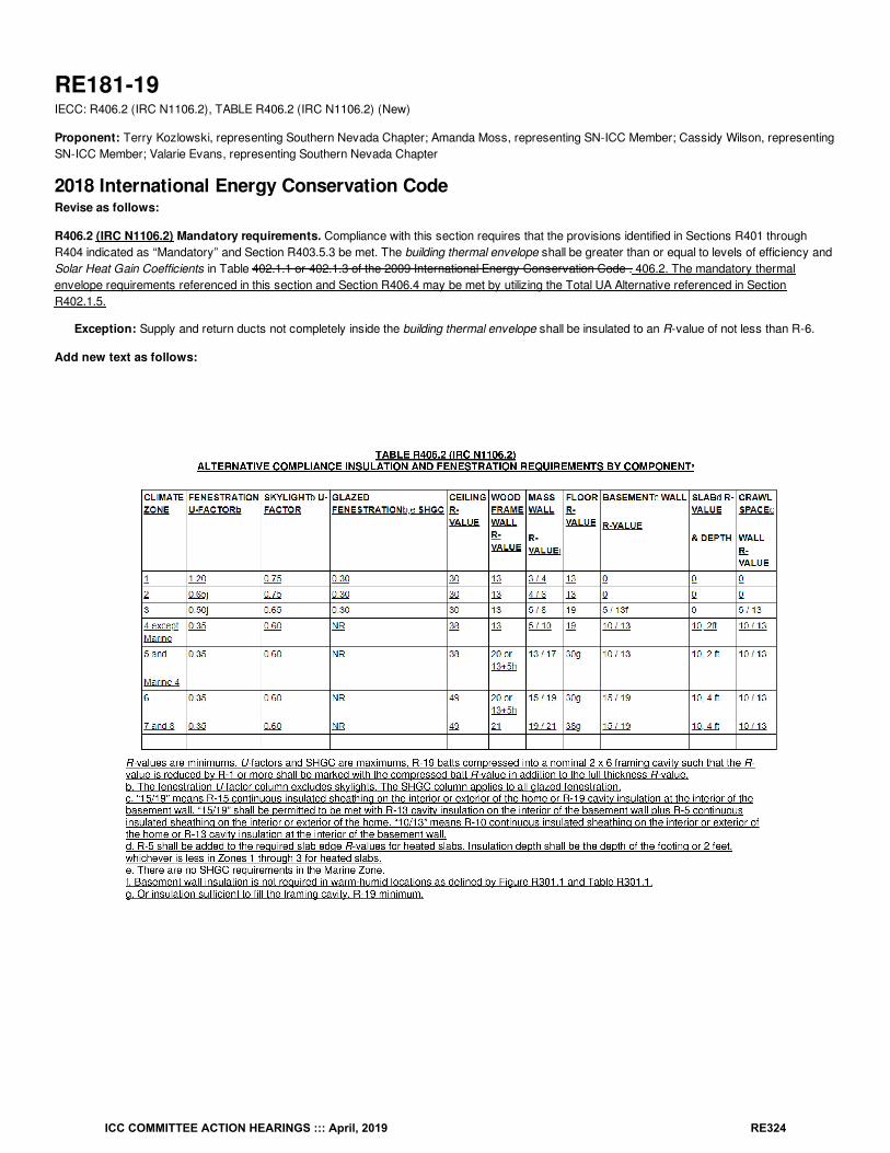
RE181-19IECC: R406.2 (IRC N1106.2), TABLE R406.2 (IRC N1106.2) (New)
Proponent: Terry Kozlowski, representing Southern Nevada Chapter; Amanda Moss, representing SN-ICC Member; Cassidy Wilson, representingSN-ICC Member; Valarie Evans, representing Southern Nevada Chapter
2018 International Energy Conservation CodeRevise as follows:
R406.2 (IRC N1106.2) Mandatory requirements. Compliance with this section requires that the provisions identified in Sections R401 throughR404 indicated as “Mandatory” and Section R403.5.3 be met. The building thermal envelope shall be greater than or equal to levels of efficiency andSolar Heat Gain Coefficients in Table 402.1.1 or 402.1.3 of the 2009 International Energy Conservation Code . 406.2. The mandatory thermalenvelope requirements referenced in this section and Section R406.4 may be met by utilizing the Total UA Alternative referenced in SectionR402.1.5.
Exception: Supply and return ducts not completely inside the building thermal envelope shall be insulated to an R-value of not less than R-6.
Add new text as follows:
ICC COMMITTEE ACTION HEARINGS ::: April, 2019 RE324
Reason: The UA Alternative in Section R402.1.5 meets the intent and energy performance of code, using UA value tradeoffs within the envelope todeliver maximum efficiency in delivering envelope performance.The UA Alternative should be available to residential builders regardless of whether the builder is using prescriptive, performance or ERI approachbecause it encourages innovation and response to individual market/climate factors without minimizing envelope performance. Furthermore,adoption of this approach in the base IECC will encourage adoption of base code, instead of individual jurisdictions lessening prescriptiverequirements of R406.4 to achieve the flexibility needed.
Using an approved energy simulation tool, a builder can trade-off elements of the building thermal envelope to achieve superior energy performance,while having the same overall UA value.
A requirement to refer to a previous code cycle for information requires multiple code books with multiple cycles which causes confusion. By addingthe information from the table in the 2009 IECC to the 2021 IECC, this allows the use of a single document.
Bibliography: R101.5.1 Compliance materials. The code official shall be permitted to approve specific computer software, worksheets,compliance manuals and other similar materials that meet the intent of this code.ENERGY SIMULATION TOOL. An approved software program or calculation-based methodology that projects the annual energy use of a building.
Cost Impact: The code change proposal will decrease the cost of constructionThis allows builders to adjust envelope features based on climate zone and orientation of a structure. The optimal delivery of envelope efficiencies inthat location and orientation could result in savings.
Proposal # 4346
RE181-19
ICC COMMITTEE ACTION HEARINGS ::: April, 2019 RE325
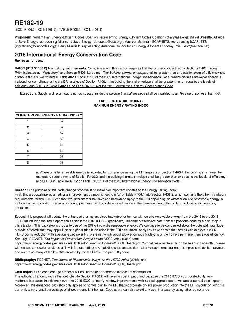
RE182-19IECC: R406.2 (IRC N1106.2) , TABLE R406.4 (IRC N1106.4)
Proponent: William Fay, Energy-Efficient Codes Coalition, representing Energy-Efficient Codes Coalition ([email protected]); Daniel Bresette, Allianceto Save Energy, representing Alliance to Save Energy ([email protected]); Maureen Guttman, BCAP-IBTS, representing BCAP-IBTS([email protected]); Harry Misuriello, representing American Council for an Energy-Efficient Economy ([email protected])
2018 International Energy Conservation CodeRevise as follows:
R406.2 (IRC N1106.2) Mandatory requirements. Compliance with this section requires that the provisions identified in Sections R401 throughR404 indicated as “Mandatory” and Section R403.5.3 be met. The building thermal envelope shall be greater than or equal to levels of efficiency andSolar Heat Gain Coefficients in Table 402.1.1 or 402.1.3 of the 2009 International Energy Conservation Code. Where on-site renewable energy isincluded for compliance using the ERI analysis of Section R406.4, the building thermal envelope shall be greater than or equal to the levels ofefficiency and SHGC in Table R402.1.2 or Table R402.1.4 of the 2018 International Energy Conservation Code.
Exception: Supply and return ducts not completely inside the building thermal envelope shall be insulated to an R-value of not less than R-6.
TABLE R406.4 (IRC N1106.4)MAXIMUM ENERGY RATING INDEX
CLIMATE ZONE ENERGY RATING INDEX
1 57
2 57
3 57
4 62
5 61
6 61
7 58
8 58
a. Where on-site renewable energy is included for compliance using the ERI analysis of Section R406.4, the building shall meet themandatory requirements of Section R406.2, and the building thermal envelope shall be greater than or equal to the levels of efficiencyand SHGC in Table R402.1.2 or Table R402.1.4 of the 2015 International Energy Conservation Code.
Reason: The purpose of this code change proposal is to make two important updates to the Energy Rating Index.First, this proposal makes an editorial improvement by moving footnote “a” of Table R406.4 into Section R406.2, which contains the other mandatoryrequirements for the ERI. Given that two different thermal envelope backstops apply to the ERI depending on whether on-site renewable energy isincluded in the calculation, it makes sense to put these two backstops side-by-side in the same section of the code to reduce or eliminate anyconfusion.
Second, this proposal will update the enhanced thermal envelope backstop for homes with on-site renewable energy from the 2015 to the 2018IECC, maintaining the same approach as set in the 2018 IECC – specifically, using the prescriptive path from the previous code as a backstop inthis situation. This backstop is crucial to use of the ERI with on-site renewable energy. We continue to be concerned about the potential magnitudeof trade-off credit that may apply if on-site generation is included in the ERI calculation. Analyses have shown that homes can achieve a 20-40HERS points reduction with average-sized solar PV systems, which would allow enormous trade-offs of the home’s permanent envelope efficiency.See, e.g., RESNET, The Impact of Photovoltaic Arrays on the HERS Index (2015); andhttps://www.energycodes.gov/sites/default/files/documents/ECodes2016_06_Haack.pdf. Without reasonable limits on these solar trade-offs, homeswith on-site generation could be built with far less efficiency, including substandard thermal envelopes, creating long-term problems for homeownersand reversing many of the benefits created by the IECC over the past 10 years.
Bibliography: RESNET, The Impact of Photovoltaic Arrays on the HERS Index (2015); andhttps://www.energycodes.gov/sites/default/files/documents/ECodes2016_06_Haack.pdf.
Cost Impact: The code change proposal will not increase or decrease the cost of constructionThe editorial change to move the footnote into Section R406.2 will have no cost impact, and because the 2018 IECC incorporated only verymoderate increases in efficiency over the 2015 IECC (primarily window improvements with no real upgrade cost), we expect no real cost impact.Moreover, this enhanced backstop only applies to homes built to the ERI that incorporate on-site power production into the ERI calculation, which iscurrently a very small percentage of all code-compliant homes. Code users can also avoid any cost increase by using other compliance
a
ICC COMMITTEE ACTION HEARINGS ::: April, 2019 RE326
alternatives.
Proposal # 4009
RE182-19
ICC COMMITTEE ACTION HEARINGS ::: April, 2019 RE327
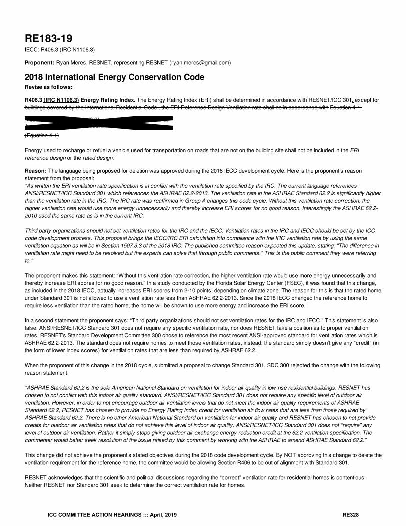
RE183-19IECC: R406.3 (IRC N1106.3)
Proponent: Ryan Meres, RESNET, representing RESNET ([email protected])
2018 International Energy Conservation CodeRevise as follows:
R406.3 (IRC N1106.3) Energy Rating Index. The Energy Rating Index (ERI) shall be determined in accordance with RESNET/ICC 301. except forbuildings covered by the International Residential Code , the ERI Reference Design Ventilation rate shall be in accordance with Equation 4-1.
(Equation 4-1)
Energy used to recharge or refuel a vehicle used for transportation on roads that are not on the building site shall not be included in the ERIreference design or the rated design.
Reason: The language being proposed for deletion was approved during the 2018 IECC development cycle. Here is the proponent’s reasonstatement from the proposal:“As written the ERI ventilation rate specification is in conflict with the ventilation rate specified by the IRC. The current language referencesANSI/RESNET/ICC Standard 301 which references the ASHRAE 62.2-2013. The ventilation rate in the ASHRAE Standard 62.2 is significantly higherthan the ventilation rate in the IRC. The IRC rate was reaffirmed in Group A changes this code cycle. Without this ventilation rate correction, thehigher ventilation rate would use more energy unnecessarily and thereby increase ERI scores for no good reason. Interestingly the ASHRAE 62.2-2010 used the same rate as is in the current IRC.
Third party organizations should not set ventilation rates for the IRC and the IECC. Ventilation rates in the IRC and IECC should be set by the ICCcode development process. This proposal brings the IECC/IRC ERI calculation into compliance with the IRC ventilation rate by using the sameventilation equation as will be in Section 1507.3.3 of the 2018 IRC. The published committee reason expected this update, stating: "The difference inventilation rate might need to be resolved but the experts can solve that through public comments." This is the public comment they were referringto.”
The proponent makes this statement: “Without this ventilation rate correction, the higher ventilation rate would use more energy unnecessarily andthereby increase ERI scores for no good reason.” In a study conducted by the Florida Solar Energy Center (FSEC), it was found that this change,as included in the 2018 IECC, actually increases ERI scores from 2-10 points, depending on climate zone. The reason for this is that the rated homeunder Standard 301 is not allowed to use a ventilation rate less than ASHRAE 62.2-2013. Since the 2018 IECC changed the reference home torequire less ventilation than the rated home, the home will be shown to use more energy and increase the ERI score.
In a second statement the proponent says: “Third party organizations should not set ventilation rates for the IRC and IECC.” This statement is alsofalse. ANSI/RESNET/ICC Standard 301 does not require any specific ventilation rate, nor does RESNET take a position as to proper ventilationrates. RESNET’s Standard Development Committee 300 chose to reference the most recent ANSI-approved standard for ventilation rates which isASHRAE 62.2-2013. The standard does not require homes to meet those ventilation rates, instead, the standard simply doesn’t give any “credit” (inthe form of lower index scores) for ventilation rates that are less than required by ASHRAE 62.2.
When the proponent of this change in the 2018 cycle, submitted a proposal to change Standard 301, SDC 300 rejected the change with the followingreason statement:
“ASHRAE Standard 62.2 is the sole American National Standard on ventilation for indoor air quality in low-rise residential buildings. RESNET haschosen to not conflict with this indoor air quality standard. ANSI/RESNET/ICC Standard 301 does not require any specific level of outdoor airventilation. However, in order to not encourage outdoor air ventilation levels that do not meet the indoor air quality requirements of ASHRAEStandard 62.2, RESNET has chosen to provide no Energy Rating Index credit for ventilation air flow rates that are less than those required byASHRAE Standard 62.2. There is no other American National Standard on ventilation for indoor air quality and RESNET has chosen to not providecredits for outdoor air ventilation rates that do not achieve this level of indoor air quality. ANSI/RESNET/ICC Standard 301 does not “require” anylevel of outdoor air ventilation. Rather it simply stops giving outdoor air exchange energy reduction credit at the 62.2 ventilation specification. Thecommenter would better seek resolution of the issue raised by this comment by working with the ASHRAE to amend ASHRAE Standard 62.2.”
This change did not achieve the proponent’s stated objectives during the 2018 code development cycle. By NOT approving this change to delete theventilation requirement for the reference home, the committee would be allowing Section R406 to be out of alignment with Standard 301.
RESNET acknowledges that the scientific and political discussions regarding the “correct” ventilation rate for residential homes is contentious.Neither RESNET nor Standard 301 seek to determine the correct ventilation rate for homes.
ICC COMMITTEE ACTION HEARINGS ::: April, 2019 RE328
At the time ANSI/RESNET/ICC 301-2014 was published, the published American National Standard for Ventilation and Acceptable Indoor Air Qualityin Low-Rise Residential Buildings was ASHRAE 62.2-2013. To align with published American National Standards for indoor air quality, RESNETchose to adopt the ventilation rates prescribed by ASHRAE 62.2-2013. RESNET considers this decision to be procedural. RESNET as anorganization acknowledges ventilation is important for homes that are built to modern building energy code standards, which require fairly tightenvelopes. However, RESNET is neutral regarding the “correct” ventilation rate. To facilitate this neutrality, RESNET Standards do not penalizehomes with ventilation rates that are less than ASHRAE 62.2-2013 Standard minimum ventilation rates but RESNET also does not provide energycredit for such homes.
Regardless of which rate may be best, the ERI calculation procedure does not establish requirements for home ventilation rates. Rather suchrequirements are established by building code authorities and model codes such as set forth in Section R403.6 of the 2018 IECC. The ventilationrates used in the ANSI/RESNET/ICC 301 procedure do not change or modify any requirements of building codes or standards.
Cost Impact: The code change proposal will not increase or decrease the cost of constructionThis code change proposal does not impact construction practices in any way and, therefore, does not increase the cost of construction. Theproposal only impacts how the home is modeled within the energy modeling software, but does not require a home to meet any specific ventilationrate.
Proposal # 4857
RE183-19
ICC COMMITTEE ACTION HEARINGS ::: April, 2019 RE329
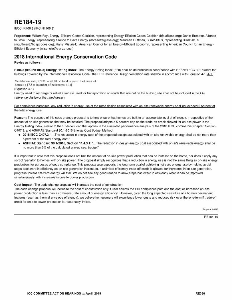
RE184-19IECC: R406.3 (IRC N1106.3)
Proponent: William Fay, Energy-Efficient Codes Coalition, representing Energy-Efficient Codes Coalition ([email protected]); Daniel Bresette, Allianceto Save Energy, representing Alliance to Save Energy ([email protected]); Maureen Guttman, BCAP-IBTS, representing BCAP-IBTS([email protected]); Harry Misuriello, American Council for an Energy-Efficient Economy, representing American Council for an Energy-Efficient Economy ([email protected])
2018 International Energy Conservation CodeRevise as follows:
R406.3 (IRC N1106.3) Energy Rating Index. The Energy Rating Index (ERI) shall be determined in accordance with RESNET/ICC 301 except forbuildings covered by the International Residential Code , the ERI Reference Design Ventilation rate shall be in accordance with Equation 4-1. 4-1.
(Equation 4-1)Energy used to recharge or refuel a vehicle used for transportation on roads that are not on the building site shall not be included in the ERIreference design or the rated design.
For compliance purposes, any reduction in energy use of the rated design associated with on-site renewable energy shall not exceed 5 percent ofthe total energy use.
Reason: The purpose of this code change proposal is to help ensure that homes are built to an appropriate level of efficiency, irrespective of theamount of on-site generation that may be installed. The proposal adopts a 5 percent cap on the trade-off credit allowed for on-site power in theEnergy Rating Index, similar to the 5 percent cap that applies in the simulated performance analysis of the 2018 IECC commercial chapter, SectionC407.3, and ASHRAE Standard 90.1-2016 Energy Cost Budget Method.
2018 IECC C407.3: “…The reduction in energy cost of the proposed design associated with on-site renewable energy shall be not more than5 percent of the total energy cost.”ASHRAE Standard 90.1-2016, Section 11.4.3.1: “…The reduction in design energy cost associated with on-site renewable energy shall beno more than 5% of the calculated energy cost budget.”
It is important to note that this proposal does not limit the amount of on-site power production that can be installed on the home, nor does it apply anysort of “penalty” to homes with on-site power. The proposal simply recognizes that a reduction in energy use is not the same thing as on-site energyproduction, for purposes of code compliance. This proposal also supports the long-term goal of achieving net zero energy use by helping avoidsteps backward in efficiency as on-site generation increases. If unlimited efficiency trade-off credit is allowed for increases in on-site generation,progress toward net-zero energy will stall. We do not see any good reason to allow steps backward in efficiency when it can be improvedsimultaneously with increases in on-site power production.
Cost Impact: The code change proposal will increase the cost of constructionThe code change proposal will increase the cost of construction only if user selects the ERI compliance path and the cost of increased on-sitepower production is less than a commensurate amount of energy efficiency. However, given the long expected useful life of a home’s permanentfeatures (such as thermal envelope efficiency), we believe homeowners will experience lower costs and reduced risk over the long-term if trade-offcredit for on-site power production is reasonably limited.
Proposal # 4013
RE184-19
ICC COMMITTEE ACTION HEARINGS ::: April, 2019 RE330
RE185-19IECC: R406.4 (IRC N1106.4) (New)
Proponent: Craig Conner, representing self ([email protected])
2018 International Energy Conservation CodeAdd new text as follows:
R406.4 (IRC N1106.4) Energy cost The ERI as specified by Section 4.1 of RESNET 301 shall be computed with the energy cost as specified bySection R405.3.
Reason: The ERI path energy cost calculation should be consistent with the energy cost calculation in the performance path (Section R405). RESNET created their own method, the "normalized Modified End Use Load”. The “normalized Modified End Use Load" is a complicatedcalculation that is inconsistent with the IECC’s performance calculation in R405. The RESNET calculation is shown below in the bibliography. TheERI cost calculation should be consistent with the cost calculation in the IECC’s performance calculation (Section R405).
Bibliography: Here is the normalized Modified End Use Load from RESNET 301 ANSI/RESNET/ICC 301-2019 page 17-18
http://www.resnet.us/blog/wp-content/uploads/2019/01/ANSIRESNETICC301-2019_vf1.23.19.pdf
ICC COMMITTEE ACTION HEARINGS ::: April, 2019 RE331
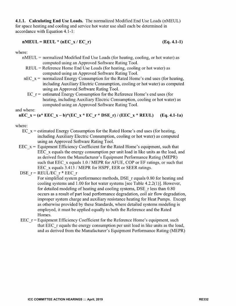
ICC COMMITTEE ACTION HEARINGS ::: April, 2019 RE332
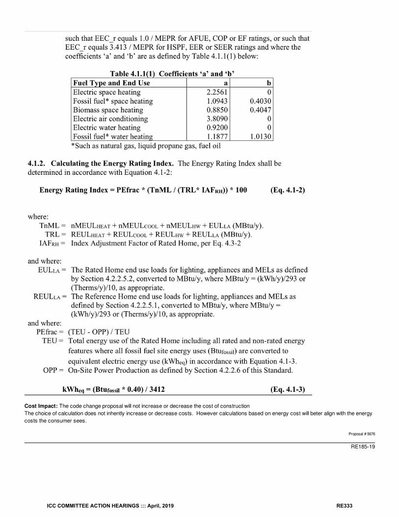
Cost Impact: The code change proposal will not increase or decrease the cost of constructionThe choice of calculation does not inhently increase or decrease costs. However calculations based on energy cost will beter align with the energycosts the consumer sees.
Proposal # 5676
RE185-19
ICC COMMITTEE ACTION HEARINGS ::: April, 2019 RE333
RE186-19IECC: R406.3 (IRC N1106.3)
Proponent: Craig Conner, representing self ([email protected]); Joseph Lstiburek, representing self ([email protected])
2018 International Energy Conservation CodeRevise as follows:
R406.3 (IRC N1106.3) Energy Rating Index. The Energy Rating Index (ERI) shall be determined in accordance with RESNET/ICC 301 except forbuildings covered by the International Residential Code, the ERI Reference Design Ventilation rate shall be in accordance with Equation 4-1.
(Equation 4-1)
Exceptions:
1. For Table 4.2.2(1) of RESNET/ICC 301, the Reference Home and Rated Home air exchange rates shall be as specified for the airexchange rates in Table R405.5.2(1) of this code.
2. For Table 4.3.1(1) of RESNET/ICC 301, the air exchange rate shall be as specified for the air exchange rate for the standardreference design in Table R405.5.2(1) of this code.
3. The proposed ventilation rate shall comply with the mechanical ventilation requirements of Section M1505 of the InternationalResidential Code or Section 403.3.3.2.1 of the International Mechanical Code.Energy used to recharge or refuel a vehicle used fortransportation on roads that are not on the building site shall not be included in the ERI reference design or the rated design.
Reason: RESNET/ICC 301 uses the ASHRAE 62.2 ventilation rate not the IRC and IMC ventilation rate. Following the ASHRAE 62.2 ventilation rateresults in over ventilation in hot humid climates and cold climates and excessive energy use in all climates. In hot humid climates the resulting partload humidity problems result in mold. In cold climates the high ventilation rates result in excessive dryness. Beyond the problems created by over ventilation, this is also a policy issue. Ventilation rates are set in the I-code development process, not byRESNET. The ERI is being used to show compliance with the I-codes. The IRC and the IMC set building code ventilation rates not RESNET. TheERI should be determined using building code ventilation rates specified by the IRC and the IMC not by RESNET.
RESNET/ICC 301 by following ASHRAE 62.2 also modifies the mechanical ventilation rate required based on infiltration measurements and thisresults in discouraging better building practices. Tighter houses are penalized compared to leakier houses which makes no sense. If a builderconstructs a leakier house then the mechanical ventilation rate is reduced according to RESNET/ICC 301 and ASHRAE 62.2. Infiltration should notbe relied on to provide ventilation in new code compliant house construction where enclosures are constructed to 3 ach@50 Pa and 5 ach@50Pa. Finally, ventilating at a higher, and unnecessary, ventilation rate wastes energy.
If RESNET has an issue with the IRC and the IMC ventilation rates then RESNET should change the ventilation rates using the ICC code changeprocess and not force the use of the ASHRAE 62.2 ventilation rates to judge I-code compliance.
The existing wording has proved confusing. The proposed wording is much clearer. This code change requires that the IRC and IMC ventilationrates be used to determine the ERI.
Cost Impact: The code change proposal will decrease the cost of constructionFor those who believe they have to use ASHRAE 62.2 ventilation rates this reduce costs. Even if done "right" over ventilation increases costs dueto the costs of dealing with excessive moisture, overly dry air, or mositure damage in some climates.
Proposal # 5587
RE186-19
ICC COMMITTEE ACTION HEARINGS ::: April, 2019 RE334
RE187-19IECC: R406.3 (IRC N1106.3)
Proponent: Amanda Hickman, The Hickman Group, representing The Leading Builders of America (LBA) ([email protected])
2018 International Energy Conservation CodeRevise as follows:
R406.3 (IRC N1106.3) Energy Rating Index. The Energy Rating Index (ERI) shall be determined in accordance with RESNET/ICC 301 except forbuildings covered by the International Residential Code, the ERI Reference Design Ventilation rate shall be in accordance with Equation 4-1.
(Equation 4-1)
Exceptions:
1. The infiltration and ventilation rate calculated in accordance with ANSI/RESNET/ICC 301 section 4.3.3.2.5 shall be permitted to beless than the rate allowed in ANSI/RESNET/ICC 301, provided the actual whole-house ventilation rate complies with themechanical ventilation requirements of the International Residential Code Section M1505 or the International Mechanical CodeSection 403.3.3.2.1.
2. For the purposes of calculating the ERI of the rated home, the greater of either the minimum allowable Air exchange rate specifiedby ANSI/RESNET/ICC 301 Table 4.2.2 (1) or the proposed ventilation rate of the Rated Home shall be used for The Air exchangerate in ANSI/RESNET/ICC 301 Table 4.2.2 (1).
Reason: This proposal corrects language that was introduced to this section last cycle that was intended to address the over-ventilation issue thatwas occurring. However, what was intended to fix to this problem, ended up creating another one. Separating the ventilation rates out from theANSI/RESNET/ICC 301 standard, created two sets of ERI scores (one in ICC and one in RESNET). This is causing huge confusion in the marketand with enforcement.This proposal introduces two exceptions that will simplify and clarify the language while resolving both issues. It corrects the over-ventilationproblem while eliminating the double ERI scores. Exception 1 is for the HERS raters, while Exception 2 is for the software programmers.
Cost Impact: The code change proposal will not increase or decrease the cost of constructionThis proposal only clarifies how to apply actual ventilation rate in the proposed design.
Proposal # 5335
RE187-19
ICC COMMITTEE ACTION HEARINGS ::: April, 2019 RE335

RE188-19IECC: TABLE R406.4 (IRC N1106.4)
Proponent: Craig Conner, representing self ([email protected])
2018 International Energy Conservation CodeRevise as follows:
TABLE R406.4 (IRC N1106.4)MAXIMUM ENERGY RATING INDEX
CLIMATE ZONE ENERGY RATING INDEX
1 57
2 57
3 57
4 62
5 61
6 61
7 58
8 58
a. Where on-site renewable energy is included for compliance using the ERI analysis of Section R406.4, the building shall meet the mandatoryrequirements of Section R406.2, and the building thermal envelope shall be greater than or equal to the levels of efficiency and SHGC in TableR402.1.2 or Table R402.1.4 of the 2015 International Energy Conservation Code.
Reason: The ERI is supposed to be flexible. However, this footnote does not allow reduction in even a single component R-value, even if thereduction was more than made up by another energy saving change. Where is the flexibility in the ERI? Every insulation R-value is the same forboth the 2015 and 2018 IECC, so none of the R-values can be reduced with the ERI. Section R402.1.5, "Total UA alternative", allows a UA tradeoff of one component U-factor provided it was made up by another componet. Likewisethe performance calculation in R405 would allow a component R-value below the R-value in the table, provided the overall building energy use metcode. There is no such restriction on tradeoffs in RESNET 301. Why can’t the “flexible” ERI in the IECC do the same?
There are multiple other reasons to delete the footnote. It is poor form to put significant requirements in a footnote, even more so for unneededrequirements. Is the SHGC even covered by the footnote? The footnote says to meet SHGC requirements in one of two tables, but Table 402.1.4does not even have an SHGC requirement. Finally naming another year’s IECC makes the code harder to use. Section R406 names both the 2009and 2015 IECC. Is the code user supposed to keep the 2009, 2015 and the upcoming 2021 IECC in order to use Section 406? The footnote isunnecessary and should be deleted.
Cost Impact: The code change proposal will not increase or decrease the cost of constructionThis removes a limitation on flexibility. If anything it will reduce costs.
Proposal # 5245
RE188-19
a
ICC COMMITTEE ACTION HEARINGS ::: April, 2019 RE336
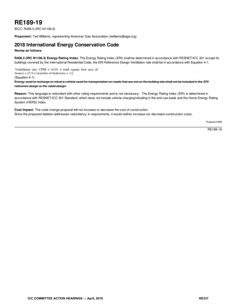
RE189-19IECC: R406.3 (IRC N1106.3)
Proponent: Ted Williams, representing American Gas Association ([email protected])
2018 International Energy Conservation CodeRevise as follows:
R406.3 (IRC N1106.3) Energy Rating Index. The Energy Rating Index (ERI) shall be determined in accordance with RESNET/ICC 301 except forbuildings covered by the International Residential Code, the ERI Reference Design Ventilation rate shall be in accordance with Equation 4-1.
(Equation 4-1)Energy used to recharge or refuel a vehicle used for transportation on roads that are not on the building site shall not be included in the ERIreference design or the rated design.
Reason: This language is redundant with other rating requirements and is not necessary. The Energy Rating Index (ERI) is determined inaccordance with RESNET/ICC 301 Standard, which does not include vehicle charging/refueling in the end use loads and the Home Energy RatingSystem (HERS) Index.
Cost Impact: The code change proposal will not increase or decrease the cost of constructionSince the proposed deletion addresses redundancy in requirements, it would neither increase nor decrease construction costs.
Proposal # 5593
RE189-19
ICC COMMITTEE ACTION HEARINGS ::: April, 2019 RE337
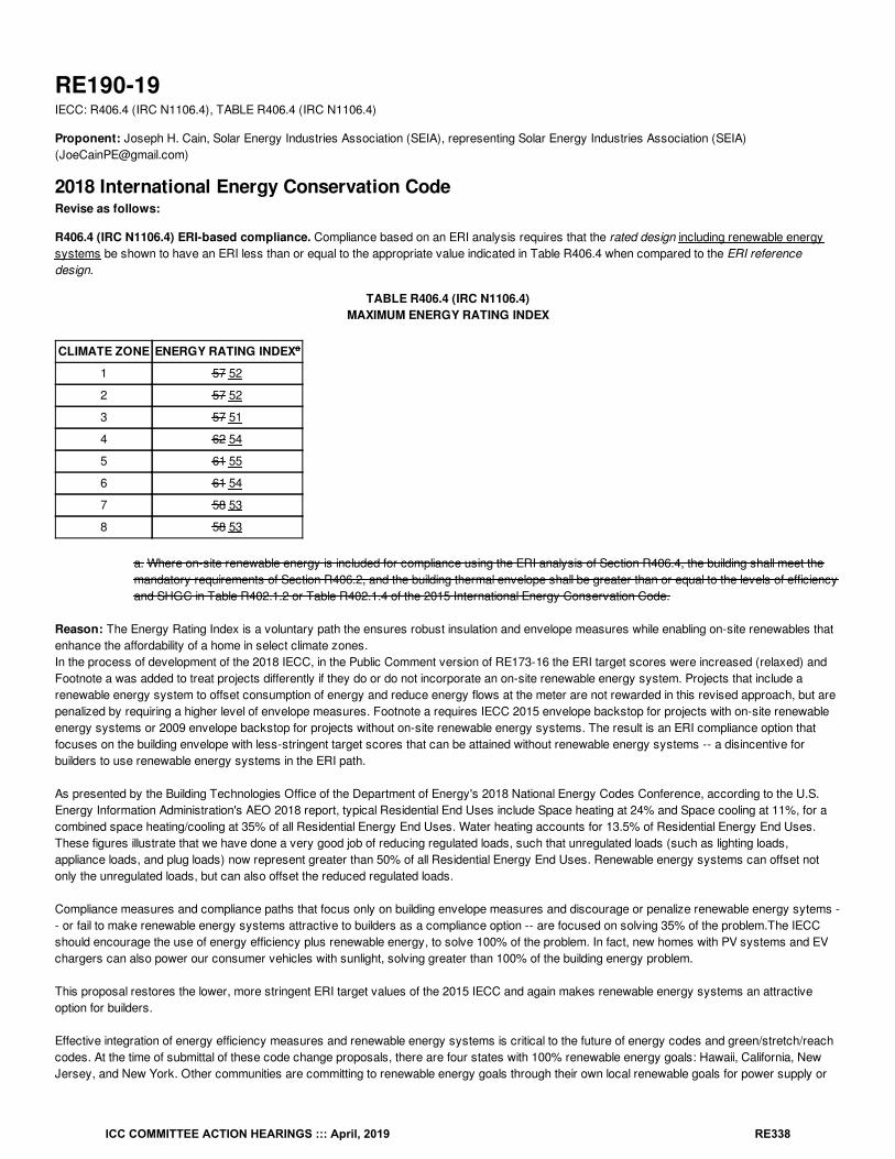
RE190-19IECC: R406.4 (IRC N1106.4), TABLE R406.4 (IRC N1106.4)
Proponent: Joseph H. Cain, Solar Energy Industries Association (SEIA), representing Solar Energy Industries Association (SEIA)([email protected])
2018 International Energy Conservation CodeRevise as follows:
R406.4 (IRC N1106.4) ERI-based compliance. Compliance based on an ERI analysis requires that the rated design including renewable energysystems be shown to have an ERI less than or equal to the appropriate value indicated in Table R406.4 when compared to the ERI referencedesign.
TABLE R406.4 (IRC N1106.4)MAXIMUM ENERGY RATING INDEX
CLIMATE ZONE ENERGY RATING INDEX
1 57 52
2 57 52
3 57 51
4 62 54
5 61 55
6 61 54
7 58 53
8 58 53
a. Where on-site renewable energy is included for compliance using the ERI analysis of Section R406.4, the building shall meet themandatory requirements of Section R406.2, and the building thermal envelope shall be greater than or equal to the levels of efficiencyand SHGC in Table R402.1.2 or Table R402.1.4 of the 2015 International Energy Conservation Code.
Reason: The Energy Rating Index is a voluntary path the ensures robust insulation and envelope measures while enabling on-site renewables thatenhance the affordability of a home in select climate zones. In the process of development of the 2018 IECC, in the Public Comment version of RE173-16 the ERI target scores were increased (relaxed) andFootnote a was added to treat projects differently if they do or do not incorporate an on-site renewable energy system. Projects that include arenewable energy system to offset consumption of energy and reduce energy flows at the meter are not rewarded in this revised approach, but arepenalized by requiring a higher level of envelope measures. Footnote a requires IECC 2015 envelope backstop for projects with on-site renewableenergy systems or 2009 envelope backstop for projects without on-site renewable energy systems. The result is an ERI compliance option thatfocuses on the building envelope with less-stringent target scores that can be attained without renewable energy systems -- a disincentive forbuilders to use renewable energy systems in the ERI path.
As presented by the Building Technologies Office of the Department of Energy's 2018 National Energy Codes Conference, according to the U.S.Energy Information Administration's AEO 2018 report, typical Residential End Uses include Space heating at 24% and Space cooling at 11%, for acombined space heating/cooling at 35% of all Residential Energy End Uses. Water heating accounts for 13.5% of Residential Energy End Uses.These figures illustrate that we have done a very good job of reducing regulated loads, such that unregulated loads (such as lighting loads,appliance loads, and plug loads) now represent greater than 50% of all Residential Energy End Uses. Renewable energy systems can offset notonly the unregulated loads, but can also offset the reduced regulated loads.
Compliance measures and compliance paths that focus only on building envelope measures and discourage or penalize renewable energy sytems -- or fail to make renewable energy systems attractive to builders as a compliance option -- are focused on solving 35% of the problem.The IECCshould encourage the use of energy efficiency plus renewable energy, to solve 100% of the problem. In fact, new homes with PV systems and EVchargers can also power our consumer vehicles with sunlight, solving greater than 100% of the building energy problem.
This proposal restores the lower, more stringent ERI target values of the 2015 IECC and again makes renewable energy systems an attractiveoption for builders.
Effective integration of energy efficiency measures and renewable energy systems is critical to the future of energy codes and green/stretch/reachcodes. At the time of submittal of these code change proposals, there are four states with 100% renewable energy goals: Hawaii, California, NewJersey, and New York. Other communities are committing to renewable energy goals through their own local renewable goals for power supply or
a
ICC COMMITTEE ACTION HEARINGS ::: April, 2019 RE338
for installation of renewable energy systems. Distributed Generation (DG) is an important component of these overall portfolio standards.
Bibliography: U.S. Energy Information Administration Annual Energy Outlook 2018https://www.eia.gov/outlooks/aeo/index.php
Cost Impact: The code change proposal will not increase or decrease the cost of constructionThis proposal encourages the installation of renewable energy systems, which provides more flexibility to the builder and could result in eitherincreased or decreased first cost of construction, depending on builder choices.
Proposal # 5582
RE190-19
ICC COMMITTEE ACTION HEARINGS ::: April, 2019 RE339
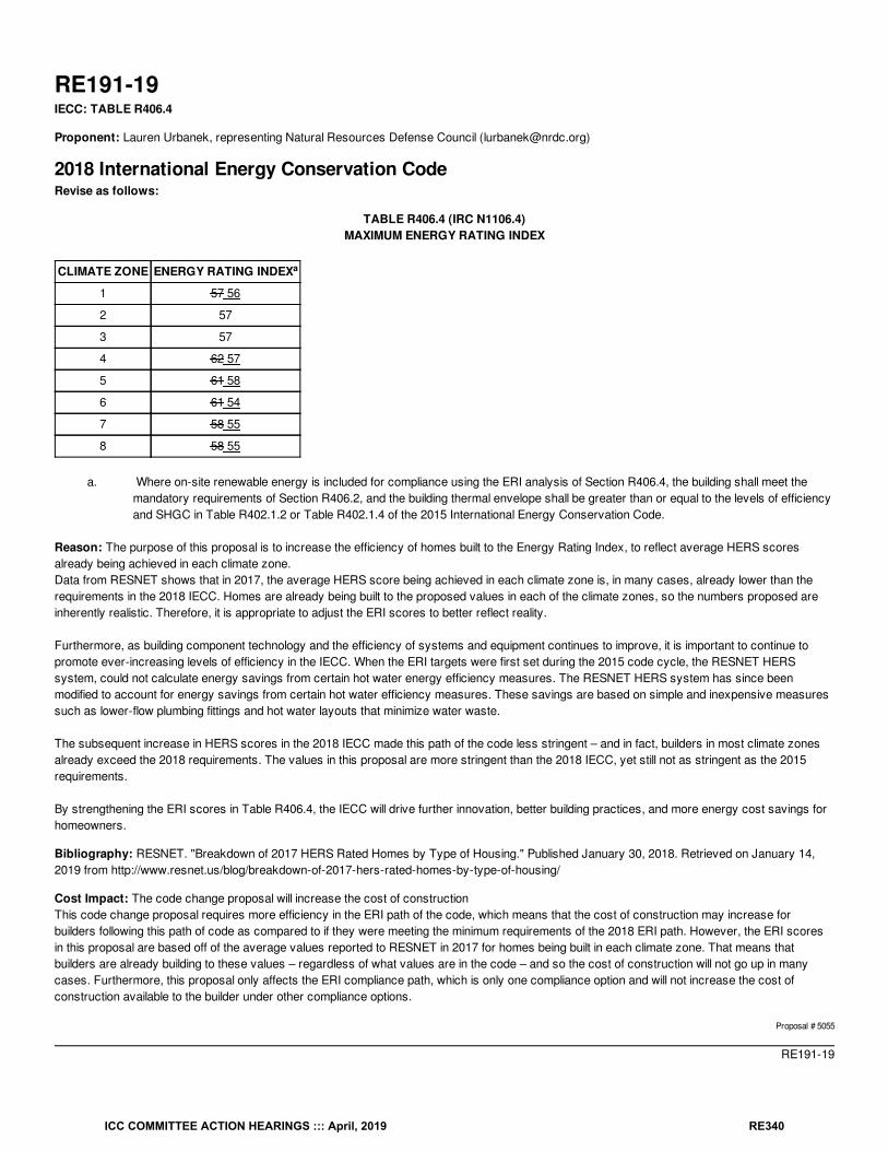
RE191-19IECC: TABLE R406.4
Proponent: Lauren Urbanek, representing Natural Resources Defense Council ([email protected])
2018 International Energy Conservation CodeRevise as follows:
TABLE R406.4 (IRC N1106.4)MAXIMUM ENERGY RATING INDEX
CLIMATE ZONE ENERGY RATING INDEX
1 57 56
2 57
3 57
4 62 57
5 61 58
6 61 54
7 58 55
8 58 55
a. Where on-site renewable energy is included for compliance using the ERI analysis of Section R406.4, the building shall meet themandatory requirements of Section R406.2, and the building thermal envelope shall be greater than or equal to the levels of efficiencyand SHGC in Table R402.1.2 or Table R402.1.4 of the 2015 International Energy Conservation Code.
Reason: The purpose of this proposal is to increase the efficiency of homes built to the Energy Rating Index, to reflect average HERS scoresalready being achieved in each climate zone.Data from RESNET shows that in 2017, the average HERS score being achieved in each climate zone is, in many cases, already lower than therequirements in the 2018 IECC. Homes are already being built to the proposed values in each of the climate zones, so the numbers proposed areinherently realistic. Therefore, it is appropriate to adjust the ERI scores to better reflect reality.
Furthermore, as building component technology and the efficiency of systems and equipment continues to improve, it is important to continue topromote ever-increasing levels of efficiency in the IECC. When the ERI targets were first set during the 2015 code cycle, the RESNET HERSsystem, could not calculate energy savings from certain hot water energy efficiency measures. The RESNET HERS system has since beenmodified to account for energy savings from certain hot water efficiency measures. These savings are based on simple and inexpensive measuressuch as lower-flow plumbing fittings and hot water layouts that minimize water waste.
The subsequent increase in HERS scores in the 2018 IECC made this path of the code less stringent – and in fact, builders in most climate zonesalready exceed the 2018 requirements. The values in this proposal are more stringent than the 2018 IECC, yet still not as stringent as the 2015requirements.
By strengthening the ERI scores in Table R406.4, the IECC will drive further innovation, better building practices, and more energy cost savings forhomeowners.
Bibliography: RESNET. "Breakdown of 2017 HERS Rated Homes by Type of Housing." Published January 30, 2018. Retrieved on January 14,2019 from http://www.resnet.us/blog/breakdown-of-2017-hers-rated-homes-by-type-of-housing/
Cost Impact: The code change proposal will increase the cost of constructionThis code change proposal requires more efficiency in the ERI path of the code, which means that the cost of construction may increase forbuilders following this path of code as compared to if they were meeting the minimum requirements of the 2018 ERI path. However, the ERI scoresin this proposal are based off of the average values reported to RESNET in 2017 for homes being built in each climate zone. That means thatbuilders are already building to these values – regardless of what values are in the code – and so the cost of construction will not go up in manycases. Furthermore, this proposal only affects the ERI compliance path, which is only one compliance option and will not increase the cost ofconstruction available to the builder under other compliance options.
Proposal # 5055
RE191-19
a
ICC COMMITTEE ACTION HEARINGS ::: April, 2019 RE340
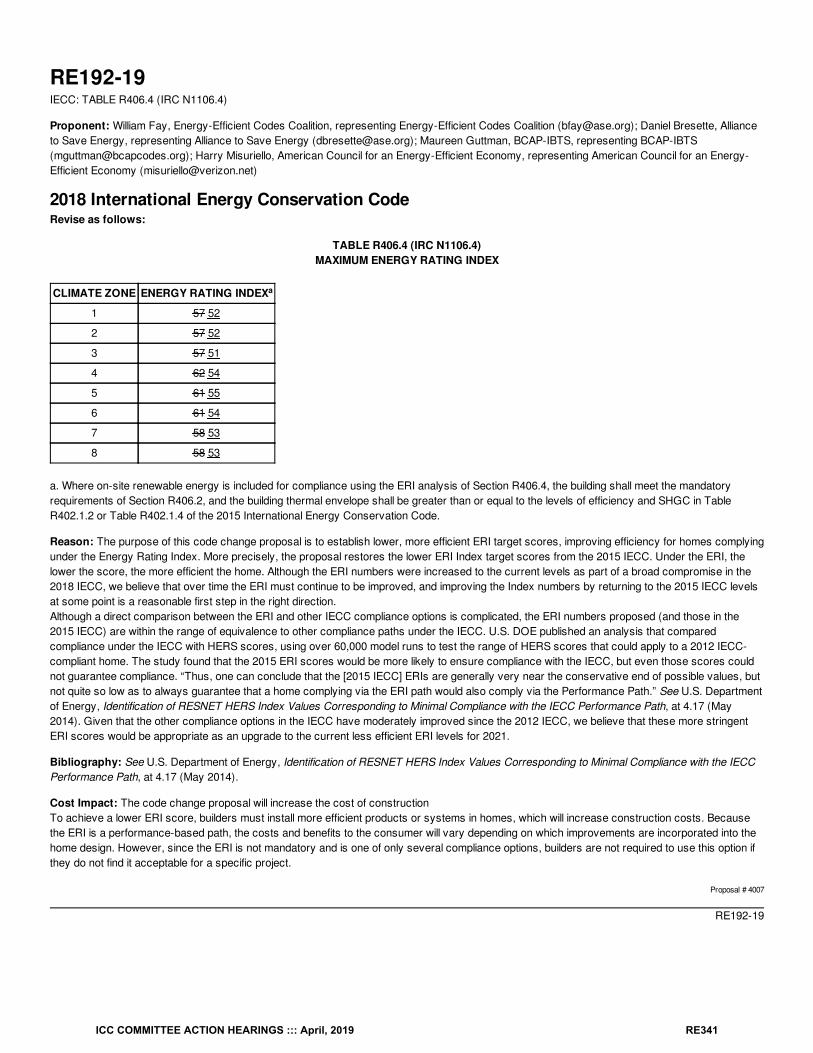
RE192-19IECC: TABLE R406.4 (IRC N1106.4)
Proponent: William Fay, Energy-Efficient Codes Coalition, representing Energy-Efficient Codes Coalition ([email protected]); Daniel Bresette, Allianceto Save Energy, representing Alliance to Save Energy ([email protected]); Maureen Guttman, BCAP-IBTS, representing BCAP-IBTS([email protected]); Harry Misuriello, American Council for an Energy-Efficient Economy, representing American Council for an Energy-Efficient Economy ([email protected])
2018 International Energy Conservation CodeRevise as follows:
TABLE R406.4 (IRC N1106.4)MAXIMUM ENERGY RATING INDEX
CLIMATE ZONE ENERGY RATING INDEX
1 57 52
2 57 52
3 57 51
4 62 54
5 61 55
6 61 54
7 58 53
8 58 53
a. Where on-site renewable energy is included for compliance using the ERI analysis of Section R406.4, the building shall meet the mandatoryrequirements of Section R406.2, and the building thermal envelope shall be greater than or equal to the levels of efficiency and SHGC in TableR402.1.2 or Table R402.1.4 of the 2015 International Energy Conservation Code.
Reason: The purpose of this code change proposal is to establish lower, more efficient ERI target scores, improving efficiency for homes complyingunder the Energy Rating Index. More precisely, the proposal restores the lower ERI Index target scores from the 2015 IECC. Under the ERI, thelower the score, the more efficient the home. Although the ERI numbers were increased to the current levels as part of a broad compromise in the2018 IECC, we believe that over time the ERI must continue to be improved, and improving the Index numbers by returning to the 2015 IECC levelsat some point is a reasonable first step in the right direction.Although a direct comparison between the ERI and other IECC compliance options is complicated, the ERI numbers proposed (and those in the2015 IECC) are within the range of equivalence to other compliance paths under the IECC. U.S. DOE published an analysis that comparedcompliance under the IECC with HERS scores, using over 60,000 model runs to test the range of HERS scores that could apply to a 2012 IECC-compliant home. The study found that the 2015 ERI scores would be more likely to ensure compliance with the IECC, but even those scores couldnot guarantee compliance. “Thus, one can conclude that the [2015 IECC] ERIs are generally very near the conservative end of possible values, butnot quite so low as to always guarantee that a home complying via the ERI path would also comply via the Performance Path.” See U.S. Departmentof Energy, Identification of RESNET HERS Index Values Corresponding to Minimal Compliance with the IECC Performance Path, at 4.17 (May2014). Given that the other compliance options in the IECC have moderately improved since the 2012 IECC, we believe that these more stringentERI scores would be appropriate as an upgrade to the current less efficient ERI levels for 2021.
Bibliography: See U.S. Department of Energy, Identification of RESNET HERS Index Values Corresponding to Minimal Compliance with the IECCPerformance Path, at 4.17 (May 2014).
Cost Impact: The code change proposal will increase the cost of constructionTo achieve a lower ERI score, builders must install more efficient products or systems in homes, which will increase construction costs. Becausethe ERI is a performance-based path, the costs and benefits to the consumer will vary depending on which improvements are incorporated into thehome design. However, since the ERI is not mandatory and is one of only several compliance options, builders are not required to use this option ifthey do not find it acceptable for a specific project.
Proposal # 4007
RE192-19
a
ICC COMMITTEE ACTION HEARINGS ::: April, 2019 RE341
ICC International Code Council, Inc.500 New Jersey Avenue NW 6th Floor
Washington DC 20001
RE193-19IECC: R406.2 (IRC N1106.2), ICC Chapter 6 (IRC Chapter 44)
Proponent: William Fay, Energy-Efficient Codes Coalition, representing Energy-Efficient Codes Coalition ([email protected]); Daniel Bresette, Allianceto Save Energy, representing Alliance to Save Energy ([email protected]); Maureen Guttman, BCAP-IBTS, representing BCAP-IBTS([email protected]); Harry Misuriello, American Council for an Energy-Efficient Economy, representing American Council for an Energy-Efficient Economy ([email protected])
2018 International Energy Conservation CodeRevise as follows:
R406.2 (IRC N1106.2) Mandatory requirements. Compliance with this section requires that the provisions identified in Sections R401 throughR404 indicated as “Mandatory” and Section R403.5.3 be met. The building thermal envelope shall be greater than or equal to levels of efficiency andSolar Heat Gain Coefficients in Table 402.1.1 or 402.1.3 of the 2009 2012 International Energy Conservation Code .
Exception: Supply and return ducts not completely inside the building thermal envelope shall be insulated to an R-value of not less than R-6.
IECC—09 IECC—12: 2009 2012 International Energy Conservation Code
Reason: The purpose of this code change proposal is to help ensure that homes built to the Energy Rating Index (ERI) incorporate a reasonablyefficient thermal envelope by updating the minimum thermal envelope backstop from the prescriptive level in the 2009 IECC to the 2012 edition of theIECC. We view this improvement as part of a broader effort to gradually improve the efficiency of the IECC and to reduce the likelihood that homeswill be built with below-average levels of efficiency in the thermal envelope. A robust thermal envelope is crucial to long-term energy conservation.The ERI gives builders an unprecedented amount of flexibility in achieving code compliance. Unlike other compliance methods, using the ERIcompliance path, builders may take credit for efficiency improvements in HVAC equipment, appliances, and lighting. To help reduce the risk of ahome being built with an exceptionally weak permanent thermal envelope, Section R406.2 currently requires an ERI-rated home to meet or exceedthe prescriptive thermal envelope requirements of the 2009 IECC. We believe this requirement is very easily achieved by the vast majority ofhomebuilders (some of whom are building beyond the code’s base requirements), but it is an important consumer protection all the same. State andlocal policymakers agree – to our knowledge, in every state in which the ERI has been adopted as part of a 2015 or 2018 IECC update, the 2009thermal envelope backstop has also been adopted.
The ERI thermal envelope backstop is now due for an update. By the time the 2021 IECC is finalized, the 2009 IECC will be 12 years old (and giventhe typical lag of state code adoption, the lag could be even longer).
The modification proposed above strikes a balance between efficiency and flexibility, while updating one of the IECC’s most important built-inbackstops. The building’s permanent thermal envelope will outlast many of the shorter-term improvements (such as HVAC equipment, lighting, andappliances).
Bibliography: U.S. Department of Energy, National Energy and Cost Savings for New Single- and Multifamily Homes: A Comparison of the 2006,2009, and 2012 editions of the IECC (April 2012) available athttps://www.energycodes.gov/sites/default/files/documents/NationalResidentialCostEffectiveness.pdf.
Cost Impact: The code change proposal will increase the cost of constructionHowever, the prescriptive requirements (including those for the thermal envelope) of the 2012 IECC have been found cost-effective by US DOE.See U.S. Department of Energy, National Energy and Cost Savings for New Single- and Multifamily Homes: A Comparison of the 2006, 2009, and2012 editions of the IECC (April 2012) available athttps://www.energycodes.gov/sites/default/files/documents/NationalResidentialCostEffectiveness.pdf. We believe that those who currently use theERI will be able to comply with 2012 IECC thermal envelope requirements with little or no additional effort. However, for those builders that wouldhave traded away more of the thermal envelope efficiency, the proposal above will apply a reasonable limit to these trade-offs.
Proposal # 4008
RE193-19
®
ICC COMMITTEE ACTION HEARINGS ::: April, 2019 RE342
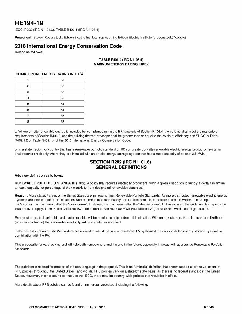
RE194-19IECC: R202 (IRC N1101.6), TABLE R406.4 (IRC N1106.4)
Proponent: Steven Rosenstock, Edison Electric Institute, representing Edison Electric Institute ([email protected])
2018 International Energy Conservation CodeRevise as follows:
TABLE R406.4 (IRC N1106.4)MAXIMUM ENERGY RATING INDEX
CLIMATE ZONE ENERGY RATING INDEX
1 57
2 57
3 57
4 62
5 61
6 61
7 58
8 58
a. Where on-site renewable energy is included for compliance using the ERI analysis of Section R406.4, the building shall meet the mandatoryrequirements of Section R406.2, and the building thermal envelope shall be greater than or equal to the levels of efficiency and SHGC in TableR402.1.2 or Table R402.1.4 of the 2015 International Energy Conservation Code.
b. In a state, region, or country that has a renewable portfolio standard of 50% or greater, on-site renewable electric energy production systemsshall receive credit only where they are installed with an on-site energy storage system that has a rated capacity of at least 3.5 kWh.
SECTION R202 (IRC N1101.6) GENERAL DEFINITIONS
Add new definition as follows:
RENEWABLE PORTFOLIO STANDARD (RPS). A policy that requires electricity producers within a given jurisdiction to supply a certain minimumamount, capacity, or percentage of their electricity from designated renewable resources.
Reason: More states / areas of the United States are increasing their Renewable Portfolio Standards. As more distributed renewable electric energysystems are installed, there are situations where there is too much supply and too little demand, especially in the fall, winter, and spring.In California, this has been called the "duck curve". In Hawaii, this has been called the "Nessie curve". In these cases, the grids are dealing with theissue of oversupply. In 2018, the California ISO had to curtail over 461,000 MWh (461 Million kWh) of solar and wind electric generation.
Energy storage, both grid-side and customer-side, will be needed to help address this situation. With energy storage, there is much less likelihood(or even no chance) that renewable electricity will be curtailed or not used.
In the newest version of Title 24, builders are allowed to adjust the size of residential PV systems if they also installed energy storage systems incombination with the PV.
This proposal is forward looking and will help both homeowners and the grid in the future, especially in areas with aggressive Renewable PortfolioStandards.
The definition is needed for support of the new language in the proposal. This is an "umbrella" definition that encompasses all of the variations ofRPS policies throughout the United States (and world). RPS policies vary on a state by state basis, as there is no federal standard in the UnitedStates. However, in other countries that use the IECC, there may be country-wide policies that would be in effect.
More details about RPS policies can be found on numerous web sites, including the following:
a,b
ICC COMMITTEE ACTION HEARINGS ::: April, 2019 RE343
https://www.eia.gov/todayinenergy/detail.php?id=4850 (US DOE/EIA article from 2012)
http://ncsolarcen-prod.s3.amazonaws.com/wp-content/uploads/2018/10/Renewable-Portfolio-Standards-2018.pdf
http://programs.dsireusa.org/system/program?type=38&
Bibliography: California ISO, "What the duck curve tells us about managing a green grid", 2016,https://www.caiso.com/Documents/FlexibleResourcesHelpRenewables_FastFacts.pdfNREL, "Overgeneration from Solar Energy in California: A Field Guide to the Duck Chart", November 2015https://www.nrel.gov/docs/fy16osti/65023.pdf
GTM, "Hawaii’s Solar-Grid Landscape and the ‘Nessie Curve’ ", February 10, 2014, https://www.greentechmedia.com/articles/read/hawaiis-solar-grid-landscape-and-the-nessie-curve
Cost Impact: The code change proposal will increase the cost of constructionBased on current battery technology and costs, the estimated cost impact will be approximately $1750 (3.5 kWh * $500/kWh installed) for homesthat are located in areas with high RPS requirements and that install on-site renewable electric energy generation systems.
Proposal # 4675
RE194-19
ICC COMMITTEE ACTION HEARINGS ::: April, 2019 RE344
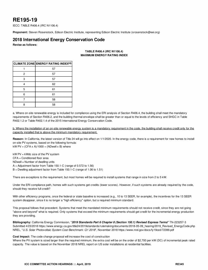
RE195-19IECC: TABLE R406.4 (IRC N1106.4)
Proponent: Steven Rosenstock, Edison Electric Institute, representing Edison Electric Institute ([email protected])
2018 International Energy Conservation CodeRevise as follows:
TABLE R406.4 (IRC N1106.4)MAXIMUM ENERGY RATING INDEX
CLIMATE ZONE ENERGY RATING INDEX
1 57
2 57
3 57
4 62
5 61
6 61
7 58
8 58
a. Where on-site renewable energy is included for compliance using the ERI analysis of Section R406.4, the building shall meet the mandatoryrequirements of Section R406.2, and the building thermal envelope shall be greater than or equal to the levels of efficiency and SHGC in TableR402.1.2 or Table R402.1.4 of the 2015 International Energy Conservation Code.
b. Where the installation of an on-site renewable energy system is a mandatory requirement in the code, the building shall receive credit only for thecapacity installed that is above the minimum mandatory requirement.
Reason: In California, the latest version of Title 24 will go into effect on 1/1/2020. In the energy code, there is a requirement for new homes to installon-site PV systems, based on the following formula:kW PV = (CFA x A)/1000 + (NDwell x B) where
kW PV = kWdc size of the PV systemCFA = Conditioned floor areaNDwell = Number of dwelling unitsA = Adjustment factor from Table 150.1-C (range of 0.572 to 1.56)B = Dwelling adjustment factor from Table 150.1-C (range of 1.06 to 1.51)
There are exceptions to the requirement, but most homes will be required to install systems that range in size from 2 to 5 kW.
Under the ERI compliance path, homes with such systems get credits (lower scores). However, if such systems are already required by the code,should they receive full credit?
With other efficiency programs, once the federal or state baseline is increased (e.g., 10 to 13 SEER, for example), the incentives for the 13 SEERsystem disappear, since it is no longer a "high efficiency" option, but a required minimum standard.
This proposal follows that precedent. Systems that meet the mandated minimum requirements should not receive credit, since they are not going"above and beyond" what is required. Only systems that exceed the minimum requirements should get credit for the incremental energy productionthey are providing.
Bibliography: California Energy Commission, "2019 Standards Part 6 Chapter 8 (Section 150.1) Revised Express Terms" TN-223257-3Submitted 4/23/2018 https://www.energy.ca.gov/title24/2019standards/rulemaking/documents/2018-05-09_hearing/2019_Revised_EnergyCode.phpNREL, "U.S. Solar Photovoltaic System Cost Benchmark: Q1 2018", November 2018 https://www.nrel.gov/docs/fy19osti/72399.pdf
Cost Impact: The code change proposal will increase the cost of constructionWhere the PV system is sized larger than the required minimum, the extra cost will be on the order of $2,700 per kW (DC) of incremental peak ratedcapacity. The value is based on the November 2018 NREL report on US solar installations at residential facilities.
a,b
ICC COMMITTEE ACTION HEARINGS ::: April, 2019 RE345
For example, if the minimum requirement is 3 kW (DC), and a 5 kW (DC) system is installed, the extra cost will be approximately $5,400.
Proposal # 4680
RE195-19
ICC COMMITTEE ACTION HEARINGS ::: April, 2019 RE346
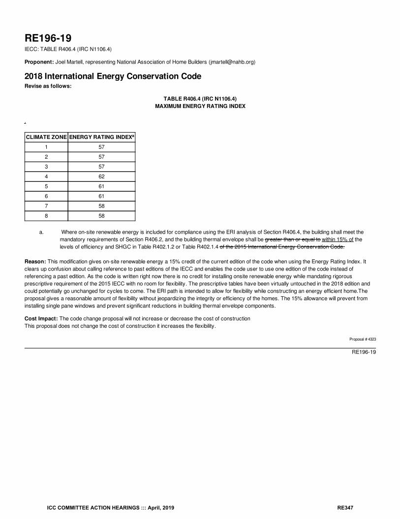
RE196-19IECC: TABLE R406.4 (IRC N1106.4)
Proponent: Joel Martell, representing National Association of Home Builders ([email protected])
2018 International Energy Conservation CodeRevise as follows:
TABLE R406.4 (IRC N1106.4)MAXIMUM ENERGY RATING INDEX
.
CLIMATE ZONE ENERGY RATING INDEX
1 57
2 57
3 57
4 62
5 61
6 61
7 58
8 58
a. Where on-site renewable energy is included for compliance using the ERI analysis of Section R406.4, the building shall meet themandatory requirements of Section R406.2, and the building thermal envelope shall be greater than or equal to within 15% of thelevels of efficiency and SHGC in Table R402.1.2 or Table R402.1.4 of the 2015 International Energy Conservation Code.
Reason: This modification gives on-site renewable energy a 15% credit of the current edition of the code when using the Energy Rating Index. Itclears up confusion about calling reference to past editions of the IECC and enables the code user to use one edition of the code instead ofreferencing a past edition. As the code is written right now there is no credit for installing onsite renewable energy while mandating rigorousprescriptive requirement of the 2015 IECC with no room for flexibility. The prescriptive tables have been virtually untouched in the 2018 edition andcould potentially go unchanged for cycles to come. The ERI path is intended to allow for flexibility while constructing an energy efficient home.Theproposal gives a reasonable amount of flexibility without jeopardizing the integrity or efficiency of the homes. The 15% allowance will prevent frominstalling single pane windows and prevent significant reductions in building thermal envelope components.
Cost Impact: The code change proposal will not increase or decrease the cost of constructionThis proposal does not change the cost of construction it increases the flexibility.
Proposal # 4323
RE196-19
a
ICC COMMITTEE ACTION HEARINGS ::: April, 2019 RE347
RE197-19IECC: R406.5 (IRC N1106.5)
Proponent: Ryan Meres, RESNET, representing RESNET ([email protected])
2018 International Energy Conservation CodeRevise as follows:
R406.5 (IRC N1106.5) Verification by approved agency. Verification of compliance with Section R406 shall be completed by an approved thirdparty. party, working under the auspices of an approved rating provider as defined in ANSI/RESNET/ICC 301.
Reason: In the 2018 IECC, Standard 301 is only referenced for the calculation of the ERI. However, there are many other aspects of Standard 301that address implementation items, like: inspection of minimum rated features, certified raters, approved rating providers and labeling. Without anyreference to some of these items in the code, there are no requirements other than an “approved” third party to verify compliance. Unfortunately,that provides little guidance to the local code official. In addition, there is currently no quality assurance requirements under the ERI path. Homescomplying with the ERI path will only be subject to quality assurance if they are using the HERS index and submit a “Confirmed” rating to RESNET.In Standard 301 an “Approved Rating Provider” is defined as: An approved entity responsible for the certification of home energy raters workingunder its auspices and who is responsible for the quality assurance of such Certified Raters and for the quality assurance of home energy ratingsproduced by such home energy raters.
In Standard 301 a “Certified Rater” is defined as: An individual who has become qualified to conduct home energy ratings through certification by anApproved Rating Provider.
In Standard 301 “Approved” is defined as: shall mean approved by an entity adopting and requiring the use of this Standard as a result ofinvestigation and tests conducted by the entity or by reason of accepted principles or tests by nationally recognized organizations.
After having the ERI path in the code for two cycles now, it has become clear that there is confusion about the nuances of its implementation in thefield. This change will help to clarify any confusion about who should be approved as a third party to verify compliance with the ERI path.
Cost Impact: The code change proposal will not increase or decrease the cost of constructionThe Home Energy Rating System (HERS) Index is the most common option for ERI compliance. All RESNET Certified HERS Raters are required towork under the auspices of a Quality Assurance Provider. Therefore, this proposal is simply recognizing an industry practice that already exists andwill not lead to any increase to the cost of construction.
Proposal # 4910
RE197-19
ICC COMMITTEE ACTION HEARINGS ::: April, 2019 RE348
RE198-19IECC: R406.5 (IRC N1106.5), ISO Chapter 6 (IRC Chapter 44)
Proponent: Aaron Gary, representing Self ([email protected])
2018 International Energy Conservation CodeRevise as follows:
R406.5 (IRC N1106.5) Verification by approved agency. Verification of compliance with Section R406 shall be completed by an approved thirdparty. party that has been accredited to ISO/IEC 17065.
Reason: The ERI path has been a welcome addition of the IECC. The DOE Home Energy Rating Variability Study[https://www.energycodes.gov/sites/default/files/documents/NECC2018_11_Williams.pdf] showed unacceptably high levels of variance inERI ratings however, which begs the question of if ERI is an acceptable and defendable means of consistently demonstrating CODE Compliance. Ithink the answer is that it CAN be oversight of the ERI is strengthened beyond what currently exists. Using an consensus body developedStandard, in the same vein as RESNET/ICC 380, NFRC 400 and HVI Standard 916, is a reasonable means of accomplishing this. Specifically usingthe ANSI-developed Standard (ISO/IEC 17065) that the EPA is already moving to include in to its ENERGY STAR for Homes program for theverifying the ERI of dwellings in the program is only logical choice.
Cost Impact: The code change proposal will not increase or decrease the cost of constructionThe code change proposal will not increase or decrease the cost of construction but it will increase the quality of service and results expected of3rd-party verifers.
Proposal # 4045
RE198-19
ICC COMMITTEE ACTION HEARINGS ::: April, 2019 RE349
RE199-19IECC: R406.5 (IRC N1106.5)
Proponent: Robby Schwarz, EnergyLogic, representing EnergyLogic ([email protected])
2018 International Energy Conservation CodeRevise as follows:
R406.5 (IRC N1106.5) Verification by approved agency. Verification of compliance with the Section R406 as outlined in Section R406.4 andR406.6 shall be completed by an approved third party. Verification of Section R406.2 shall be completed by the authority having jurisdiction or anapproved third party inspection agency per Section R105.4.
Reason: R406.5 Verification by an approved agency. Currently, this section is causing confusion between jurisdictions and approved third parties.Many jurisdictions believe that the third party is verifying all aspects of the energy code while many approved third parties believe they should onlygenerate the ERI score. This is leading to homes that are not getting fully code verified because fundamentally the development of an ERI scoresolely, and ERI Rating, is different from a full code compliance rating.The HERS Index benchmarks the efficiency of a home in comparison to a reference home that is based on the 2006 IECC. A HERS Rating is anasset rating of the energy features in a home. This means that in the process of a HERS Rating to generate the HERS Index a Rater does notnecessarily inspect to see if energy features governed by the code are installed according to requirements of the code. For example, the HERSRatings systems’ insulation installation grading criteria gives guidance on how to de-rate the R-value of poorly installed insulation. The Rater isrequired to give a grade 3 to poor installations. The HERS Index score is intended to evaluate the performance of what is installed. It is not intendedto determine if it was installed per the requirement of code. A code rating or evaluation for the generation of the ERI score, on the other hand, shouldonly use a grade 1 because only grade 1 installation of insulation meets the requirements of manufacturer instructions and therefore code. If a Raterwere to evaluate a home for an ERI score and come across grade 3 installation of insulation, the installation should fail the inspection and be re-installed to meet code requirements.
In this way, an ERI rating and a HERS rating are fundamentally different. One is held to a pass/fail requirement of code and the other is aquantification and evaluation of energy assets or components of the home. This small example demonstrates how the HERS index score and theERI score differ.
The language that is added to this section clearly defines that the generation of the ERI score is in the approved third parties’ scope of work and thatthe remainder of the code compliance verification be performed by the third party or not, depending on the agreement between the jurisdiction andthe third party.
Cost Impact: The code change proposal will not increase or decrease the cost of constructionThis code change proposal does not increase the cost of construction or the utilization of this pathway in the code. It merely defines how to use thepath to ensure compliance with the code.
Proposal # 5258
RE199-19
ICC COMMITTEE ACTION HEARINGS ::: April, 2019 RE350
RE200-19IECC: R406.5.1 (IRC N1106.5.1) (New)
Proponent: Ryan Meres, representing RESNET ([email protected])
2018 International Energy Conservation CodeAdd new text as follows:
R406.5.1 (IRC N1106.5.1) Quality Assurance Approved third party verifiers and all residential buildings demonstrating compliance with SectionR406 shall comply with the quality assurance requirements in accordance with ANSI/RESNET/ICC 301.
Reason: There has been confusion about the differences between ERI and HERS, especially when it comes to quality assurance requirements.Currently, under the 2018 IECC, a permit applicant could submit an ERI Compliance Report to demonstrate compliance with the energy code withoutany requirement subjecting that rating to quality assurance. The only way a home complying with the ERI path will be subject to quality assurance isif that home uses a HERS rating and a “confirmed” rating is submitted to RESNET. Sections 5.1.4.1.3 and 5.1.4.2.3 of ANSI/RESNET/ICC 301require that “Confirmed” and “Sampled” ratings be subject to Quality Assurance requirements “equivalent to Section 900 of the Mortgage IndustryNational Home Energy Rating Systems Standard.”One of the most important benefits of the ERI compliance path is the requirement for third party verification of compliance. Many local code officialsare under the misconception that all homes using the ERI for compliance are subject to quality assurance. Unfortunately, this is not true.
This proposal would require that the approved third party verifiers are working under a program that has quality assurance requirements; and thehomes they’re responsible for verifying are subject to those quality assurance standards.
Cost Impact: The code change proposal will not increase or decrease the cost of constructionThe Home Energy Rating System (HERS) Index is the most common option for ERI compliance. All RESNET Certified HERSRaters are required to work under the auspices of a Quality Assurance Provider. Therefore, this proposal is simplyrecognizing an industry practice that already exists and will not lead to any increase to the cost of construction.
Proposal # 4911
RE200-19
ICC COMMITTEE ACTION HEARINGS ::: April, 2019 RE351
RE201-19IECC: R406.5.2 (IRC N1106.5.2) (New)
Proponent: Ryan Meres, RESNET, representing RESNET ([email protected])
2018 International Energy Conservation CodeAdd new text as follows:
R406.5.2 (IRC N1106.5.2) Compliance documentation for certificate of occupancy. Third parties that have been approved to verify compliancewith R406 shall provide the following documentation to the code official, prior to issuance of a certificate of occupancy:
1. Documentation that the approved third party is certified by an approved rating provider in accordance with ANSI/RESNET/ICC 301;2. Documentation demonstrating that the mandatory requirements in R406.2 have been met;3. A compliance report in accordance with R406.6.2 that is clearly indicated as a “Confirmed Rating” or “Sampled Rating” as defined by
ANSI/RESNET/ICC 301;4. Documentation of air leakage testing results in accordance with R402.4.1.2;5. Documentation of duct leakage testing results in accordance with R403.3.3.
Reason: Despite education efforts, there is confusion among code officials and third party verifiers about the documentation that should be required,prior to the issuance of a certificate of occupancy, for compliance with the ERI path. Since this is still a relatively new compliance path for the IECC,the proponents of this proposal feel that it is necessary to provide guidance to local code officials and third party verifiers.This proposal seeks to add each of the proposed documentation items for the following reasons:
1. This provision ensures that third party verifiers are subject to quality assurance procedures2. This item ensures that third party verifiers are verifying the mandatory requirements of the IECC and not just what’s required to conduct the
rating3. ANSI/RESNET/ICC 301 only requires “Confirmed” and “Sampled” ratings to be subject to quality assurance, so this item ensures that third
parties are not submitting a “projected” rating to the code officials that is not subject to quality assurance4. Documenting the envelope air leakage results ensures that those numbers are in alignment with the figures used in obtaining the ERI score5. Documenting the duct leakage results ensures that those numbers are in alignment with the figures used in obtaining the ERI score.
Overall, this proposal will improve consistency among third parties and code officials in documenting compliance with the ERI path.
Cost Impact: The code change proposal will not increase or decrease the cost of constructionThis proposal does not add any construction requirements to the code. It simply requires that some basic documentation be submitted todemonstrate compliance with R406.
Proposal # 4912
RE201-19
ICC COMMITTEE ACTION HEARINGS ::: April, 2019 RE352
RE202-19IECC: R406.6.2
Proponent: Kirk Nagle, City of Aurora, representing Myself ([email protected])
2018 International Energy Conservation CodeRevise as follows:
R406.6.2 (IRC N1106.6.2) Compliance report. Compliance software tools shall generate a report that documents that the ERI of the rated designcomplies with Sections R406.3 and R406.4. The compliance documentation shall include the following information:
1. Address or other identification of the residential building.2. Declare Energy Rating Index on title page3. An inspection checklist documenting the building component characteristics of the rated design. The inspection checklist shall show
results for both the ERI reference design and the rated design, and shall document all inputs entered by the user necessary toreproduce the results.
4. Name of individual completing the compliance report.5. Name and version of the compliance software tool.
Exception: Where an otherwise identical building model is offered in multiple orientations, compliance for any orientation shall be permitted bydocumenting that the building meets the performance requirements in each of the four (north, east, south and west) cardinal orientations.
Reason: This code change is being proposed to clarify the energy path to the code official and the documentation for permit. Many reports do notspecify the path that is being proposed and the code official has to contact the applicant to verify the energy path they are intending to use, tocomply with the energy code. By providing the method of compliance the code official can focus on the details of the report and this information willexpidate the permit process time.
Cost Impact: The code change proposal will increase the cost of constructionThis will increase the cost of construction by a minor ammount, adding a data entry to the report.
Proposal # 5668
RE202-19
ICC COMMITTEE ACTION HEARINGS ::: April, 2019 RE353
RE203-19IECC: R406.6.2 (IRC N1106.6.2)
Proponent: William Fay, Energy-Efficient Codes Coalition, representing Energy-Efficient Codes Coalition ([email protected]); Daniel Bresette, Allianceto Save Energy, representing Alliance to Save Energy ([email protected]); Maureen Guttman, BCAP-IBTS, representing BCAP-IBTS([email protected]); Harry Misuriello, American Council for an Energy-Efficient Economy, representing American Council for an Energy-Efficient Economy ([email protected])
2018 International Energy Conservation CodeRevise as follows:
R406.6.2 (IRC N1106.6.2) Compliance report. Compliance software tools shall generate a report that documents that the ERI of the rated designcomplies with Sections R406.3 and R406.2 through R406.4. The compliance documentation shall include the following information:
1. Address or other identification of the residential building.2. An inspection checklist documenting the building component characteristics of the rated design. The inspection checklist shall show
results for both the ERI reference design and the rated design, and shall document all inputs entered by the user necessary toreproduce the results. The checklist shall document compliance with each requirement under Section R406.2
3. Name of individual completing the compliance report.4. Name and version of the compliance software tool.
Exception: Where an otherwise identical building model is offered in multiple orientations, compliance for any orientation shall be permitted bydocumenting that the building meets the performance requirements in each of the four (north, east, south and west) cardinal orientations.
Reason: The purpose of this proposal is to correct what we believe to be an omission in the Energy Rating Index compliance report and to provideadditional clarity and direction to software makers about how to incorporate the mandatory backstop provisions of the ERI into compliance software.The compliance report outlined in Section R406.6.2 does not currently require software to document whether the project complies with themandatory provisions of Section R406.2. The proposal above corrects this by adding Section R406.2 to the list of sections to be included in thecompliance report and adds the requirements of Section R406.2 to the inspection checklist.Although mandatory provisions and backstops have been a part of the IECC for many years, software designed for voluntary or "above-code"programs (such as HERS rating software) may not directly address mandatory items or treat them with the appropriate level of importance. Codeofficials understand very well that when a provision is listed as "mandatory," the building simply cannot achieve compliance without meeting thatprovision. Now that more and more code users are turning to software and rating professionals for code compliance, it is important to provideadditional details for software developers as to how to incorporate these important provisions.
Cost Impact: The code change proposal will not increase or decrease the cost of constructionNo code requirements are changed by this proposal, but the addition of the mandatory requirements to the compliance report and checklist will helpensure quality construction and facilitate code compliance.
Proposal # 4011
RE203-19
ICC COMMITTEE ACTION HEARINGS ::: April, 2019 RE354
RE204-19IECC: R202 (IRC N1101.6), R406.6.3 (IRC N1106.6.3) (New)
Proponent: jim edelson, representing New Buildings Institute ([email protected])
2018 International Energy Conservation Code
SECTION R202 (IRC N1101.6) GENERAL DEFINITIONS
Add new definition as follows:
RENEWABLE ENERGY CERTIFICATE (REC). An instrument that represents the environmental attributes of one megawatt hour of renewableenergy; also known as an energy attribute certificate (EAC).
Add new text as follows:
R406.6.3 (IRC N1106.6.3) Renewable energy certificates (RECs) documentation. Where onsite renewable energy is included in the calculationof an ERI, one of the following forms of documentation shall be provided to the code official:
1. Substantiation that the RECs associated with the onsite renewable energy are owned by, or retired on behalf of, the homeowner.2. A contract that conveys to the homeowner the RECs associated with the onsite renewable energy, or conveys to the homeowner an
equivalent quantity of RECs associated with other renewable energy.
Reason: This proposal impacts who may claim the environmental attributes of an onsite-renewable energy system. The environmental attributes ofsolar power, or other renewable energy, have market value that is reflected and transacted in RECs.When the installer, leasing company or financial agent in the solar panel transaction strips that value from the homeowner by taking posession of theRECs, according to the Federal Trade Commission the power produced by the solar panels on the house would have an "unqualified claim" asrenewable energy. To prevent this, the proposal ensures that environmental attributes are not double counted towards compliance with the IECC.While this proposal does not cite Green-E, the Green-E Standard describes the double counting that occurs when RECs have been transferred toanother party in the renewable transaction:
Examples of prohibited double uses include, but are not limited to:
1) When the same REC is sold by one party to more than one party, or any case where another party has a conflicting contract for the RECs or therenewable electricity;
2) When the same REC is claimed by more than one party, including any expressed or implied environmental claims made pursuant to electricitycoming from a renewable energy resource, environmental labeling or disclosure requirements. This includes representing the energy from whichRECs are derived as renewable in calculating another entity’s product or portfolio resource mix for the purposes of marketing or disclosure;
3) When the same REC is used by an electricity provider or utility to meet an environmental mandate, such as an RPS, and is also used to satisfycustomer sales under Green-e Energy; or
4) Use of one or more attributes of the renewable energy or REC by another party This includes when a REC is simultaneously sold to represent“renewable electricity” to one party, and one or more Attributes associated with the same MWh of generation (such as CO2 reduction) are also sold,to another party.
To prevent the situation where double counting is credited within the ERI calculation, thereby artificially reducing ERI scores and allowing the thehome to install fewer energy efficiency features than otherwise would be required, this proposal ensures that the homeowner retains posession ofthe RECs associated with onsite renewable energy systems. In the case where those RECs for the onsite system cannot by tranferred to thehomeowner, an equivalent quantity of RECs must be provided.
Bibliography: Federal Register, Volume 77, Number 197; October 11, 2012; 16 CFR Part 260; "Guides for the Use of Environmental MarketingPlans".Green-e Renewable Energy Standard for Canada and the United States, Version 3.2; March 20, 2018.
Cost Impact: The code change proposal will increase the cost of constructionThis proposal impacts who may claim the environmental attributes of an onsite-renewable energy system. The environmental attributes of the solarpower have market value, reflected in RECs. The cost of installing solar panels may be reduced when the installer, leasing company or financialagent strips that value from the homeowner by taking posession of the RECs.
Proposal # 5047
ICC COMMITTEE ACTION HEARINGS ::: April, 2019 RE355
RE204-19
ICC COMMITTEE ACTION HEARINGS ::: April, 2019 RE356
RE205-19IECC: R406.6.2 (IRC N1106.6.2), R406.6.2.1 (IRC N1106.6.2.1) (New), R406.6.2.2 (IRC N1106.6.2.2) (New)
Proponent: Robby Schwarz, EnergyLogic, representing EnergyLogic ([email protected])
2018 International Energy Conservation CodeRevise as follows:
R406.4 (IRC N1106.4) ERI-based compliance. Compliance based on an ERI analysis requires that the rated proposed design and confirmed builtdwelling be shown to have an ERI less than or equal to the appropriate value indicated in Table R406.4 when compared to the ERI reference design.
R406.6.2 (IRC N1106.6.2) Compliance report. Compliance software tools shall generate a report that documents that the home and the ERI scoreof the rated design complies with Sections R406.2, R406.3 and Section R406.4. The compliance Compliance documentation shall be created for theproposed design and shall be submitted with the application for the building permit. Confirmed compliance documents of the built dwelling unit shall becreated and submitted to the code official for review before a certificate of occupancy is issued. Compliance reports shall include information inaccordance with Sections R406.6.2.1 and R406.6.2.2. include the following information:
1. Address or other identification of the residential building.2. An inspection checklist documenting the building component characteristics of the rated design. The inspection checklist shallshow results for both the ERI reference design and the rated design, and shall document all inputs entered by the user necessary toreproduce the results.3. Name of individual completing the compliance report.4. Name and version of the compliance software tool.
Exception: Where an otherwise identical building model is offered in multiple orientations, compliance for any orientation shall be permitted bydocumenting that the building meets the performance requirements in each of the four (north, east, south and west) cardinal orientations.
Add new text as follows:
R406.6.2.1 (IRC N1106.6.2.1) Proposed compliance report for permit application. Compliance reports submitted with the application for abuilding permit shall include the following:
1. Building street address, or other building site identification.2. The name of the individual performing the analysis and generating the compliance report.3. The name and version of the compliance software tool.4. If requested by the authority having jurisdiction, documentation of all inputs entered into the software used to produce the results for the
reference design and/or the rated home.5. A certificate indicating that the proposed design has an ERI less than or equal to the appropriate score indicated in Table R406.4 when
compared to the ERI reference design. The certificate shall document the building component energy specifications that are included in thecalculation including, component level insulation R-values or U-factors, assumed duct system and building envelope air leakage testingresults, as well as the type and rated efficiencies of proposed heating, cooling, mechanical ventilation, and service water heating equipment tobe installed. If onsite renewable energy systems will be installed the certificate shall report the type and production size of the proposedsystem.
6. When a site-specific report is not generated, the proposed design shall be based on the worst-case orientation and configuration of the ratedhome.
R406.6.2.2 (IRC N1106.6.2.2) Confirmed compliance report for a certificate of occupancy. A confirmed compliance report submitted forobtaining the certificate of occupancy shall be made site and address specific and include the following:
1. Building street address or other building site identification.2. The name of the individual performing the analysis and generating the report.3. The name and version of the compliance software tool.4. If requested by the authority having jurisdiction, documentation of all inputs entered into the software used to produce the results for the
reference design and/or the rated home.5. A final confirmed certificate indicating that the confirmed rated design of the built home complies with Sections R406.2 and R406.4. The
certificate shall report the energy features that were confirmed to be in the home including component level insulation R- values or U-factors,results from any required duct system and building envelope air leakage testing, as wells as, the type and rated efficiencies of the heating,cooling, mechanical ventilation, and service water heating equipment installed. When onsite renewable energy systems have been installed onor in the home the certificate shall report the type and production size of the installed system.
Reason: The word Rating defines a process by which one can systematically and repeatably assess and inspect a home. One can perform a coderating, an energy rating, a program or EnergyStar rating, and so on. In this way the process of evaluation may differ in that an Energy Rating is anasset rating while a Code Rating is a compliance rating. So, although the evaluation can be different Ratings ensure that verification of installedfeatures is the same.
ICC COMMITTEE ACTION HEARINGS ::: April, 2019 RE357
Section R405 Simulated Performance Alternative and Section R406 Energy Rating Index Compliance Alternative both use a rating process forverifying compliance of the home, so the bulk of this code change proposal adds language to this section that is the same as used in Section R405to explain what is needed to demonstrate compliance for obtaining the building permit (proposed design) and what is needed in order to release thecertificate of occupancy (confirmed Reports).
Cost Impact: The code change proposal will not increase or decrease the cost of constructionThis code change proposal does not increase the cost of construction or the utilization of this pathway in the code. It merely defines how to use thepath to ensure compliance with the code.
Proposal # 5260
RE205-19
ICC COMMITTEE ACTION HEARINGS ::: April, 2019 RE358
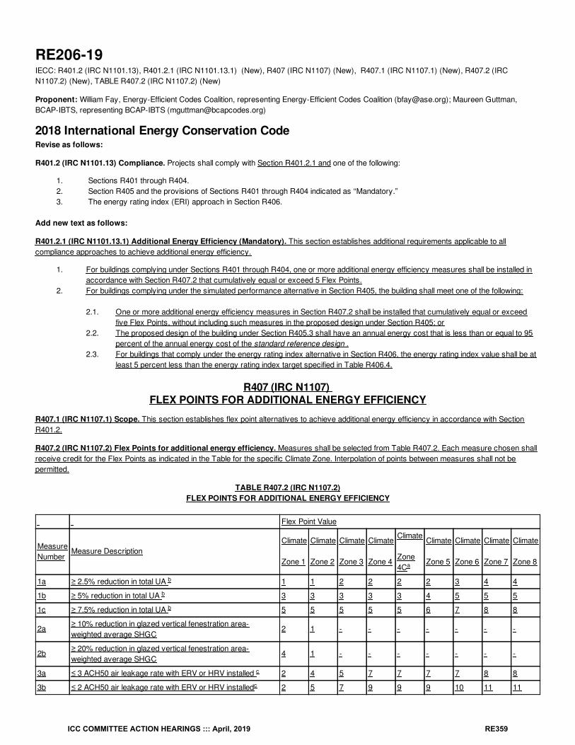
RE206-19IECC: R401.2 (IRC N1101.13), R401.2.1 (IRC N1101.13.1) (New), R407 (IRC N1107) (New), R407.1 (IRC N1107.1) (New), R407.2 (IRCN1107.2) (New), TABLE R407.2 (IRC N1107.2) (New)
Proponent: William Fay, Energy-Efficient Codes Coalition, representing Energy-Efficient Codes Coalition ([email protected]); Maureen Guttman,BCAP-IBTS, representing BCAP-IBTS ([email protected])
2018 International Energy Conservation CodeRevise as follows:
R401.2 (IRC N1101.13) Compliance. Projects shall comply with Section R401.2.1 and one of the following:
1. Sections R401 through R404.2. Section R405 and the provisions of Sections R401 through R404 indicated as “Mandatory.”3. The energy rating index (ERI) approach in Section R406.
Add new text as follows:
R401.2.1 (IRC N1101.13.1) Additional Energy Efficiency (Mandatory). This section establishes additional requirements applicable to allcompliance approaches to achieve additional energy efficiency.
1. For buildings complying under Sections R401 through R404, one or more additional energy efficiency measures shall be installed inaccordance with Section R407.2 that cumulatively equal or exceed 5 Flex Points.
2. For buildings complying under the simulated performance alternative in Section R405, the building shall meet one of the following:
2.1. One or more additional energy efficiency measures in Section R407.2 shall be installed that cumulatively equal or exceedfive Flex Points, without including such measures in the proposed design under Section R405; or
2.2. The proposed design of the building under Section R405.3 shall have an annual energy cost that is less than or equal to 95percent of the annual energy cost of the standard reference design .
2.3. For buildings that comply under the energy rating index alternative in Section R406, the energy rating index value shall be atleast 5 percent less than the energy rating index target specified in Table R406.4.
R407 (IRC N1107) FLEX POINTS FOR ADDITIONAL ENERGY EFFICIENCY
R407.1 (IRC N1107.1) Scope. This section establishes flex point alternatives to achieve additional energy efficiency in accordance with SectionR401.2.
R407.2 (IRC N1107.2) Flex Points for additional energy efficiency. Measures shall be selected from Table R407.2. Each measure chosen shallreceive credit for the Flex Points as indicated in the Table for the specific Climate Zone. Interpolation of points between measures shall not bepermitted.
TABLE R407.2 (IRC N1107.2)FLEX POINTS FOR ADDITIONAL ENERGY EFFICIENCY
Flex Point Value
MeasureNumber
Measure DescriptionClimate
Zone 1
Climate
Zone 2
Climate
Zone 3
Climate
Zone 4
Climate
Zone4C
Climate
Zone 5
Climate
Zone 6
Climate
Zone 7
Climate
Zone 8
1a ≥ 2.5% reduction in total UA 1 1 2 2 2 2 3 4 4
1b ≥ 5% reduction in total UA 3 3 3 3 3 4 5 5 5
1c ≥ 7.5% reduction in total UA 5 5 5 5 5 6 7 8 8
2a≥ 10% reduction in glazed vertical fenestration area-weighted average SHGC
2 1 - - - - - - -
2b≥ 20% reduction in glazed vertical fenestration area-weighted average SHGC
4 1 - - - - - - -
3a ≤ 3 ACH50 air leakage rate with ERV or HRV installed 2 4 5 7 7 7 7 8 8
3b ≤ 2 ACH50 air leakage rate with ERV or HRV installed 2 5 7 9 9 9 10 11 11
a
b
b
b
c
c
ICC COMMITTEE ACTION HEARINGS ::: April, 2019 RE359
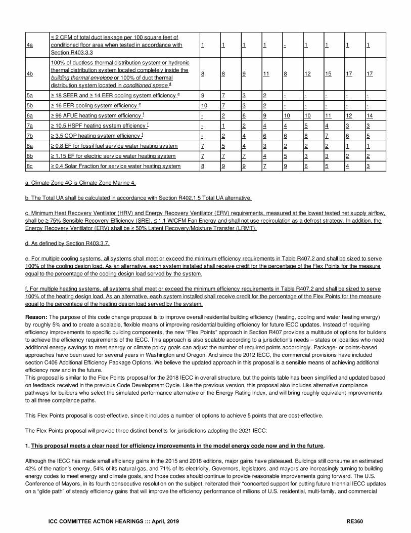
4a≤ 2 CFM of total duct leakage per 100 square feet ofconditioned floor area when tested in accordance withSection R403.3.3
1 1 1 1 - 1 1 1 1
4b
100% of ductless thermal distribution system or hydronicthermal distribution system located completely inside thebuilding thermal envelope or 100% of duct thermaldistribution system located in conditioned space
8 8 9 11 8 12 15 17 17
5a ≥ 18 SEER and ≥ 14 EER cooling system efficiency 9 7 3 2 - - - - -
5b ≥ 16 EER cooling system efficiency 10 7 3 2 - - - - -
6a ≥ 96 AFUE heating system efficiency - 2 6 9 10 10 11 12 14
7a ≥ 10.5 HSPF heating system efficiency - 1 2 4 4 5 4 3 3
7b ≥ 3.5 COP heating system efficiency - 2 4 6 6 8 7 6 5
8a ≥ 0.8 EF for fossil fuel service water heating system 7 5 4 3 2 2 2 1 1
8b ≥ 1.15 EF for electric service water heating system 7 7 7 4 5 3 3 2 2
8c ≥ 0.4 Solar Fraction for service water heating system 8 9 9 7 9 6 5 4 3
a. Climate Zone 4C is Climate Zone Marine 4.
b. The Total UA shall be calculated in accordance with Section R402.1.5 Total UA alternative.
c. Minimum Heat Recovery Ventilator (HRV) and Energy Recovery Ventilator (ERV) requirements, measured at the lowest tested net supply airflow,shall be ≥ 75% Sensible Recovery Efficiency (SRE), ≤ 1.1 W/CFM Fan Energy and shall not use recirculation as a defrost strategy. In addition, theEnergy Recovery Ventilator (ERV) shall be ≥ 50% Latent Recovery/Moisture Transfer (LRMT).
d. As defined by Section R403.3.7.
e. For multiple cooling systems, all systems shall meet or exceed the minimum efficiency requirements in Table R407.2 and shall be sized to serve100% of the cooling design load. As an alternative, each system installed shall receive credit for the percentage of the Flex Points for the measureequal to the percentage of the cooling design load served by the system.
f. For multiple heating systems, all systems shall meet or exceed the minimum efficiency requirements in Table R407.2 and shall be sized to serve100% of the heating design load. As an alternative, each system installed shall receive credit for the percentage of the Flex Points for the measureequal to the percentage of the heating design load served by the system.
Reason: The purpose of this code change proposal is to improve overall residential building efficiency (heating, cooling and water heating energy)by roughly 5% and to create a scalable, flexible means of improving residential building efficiency for future IECC updates. Instead of requiringefficiency improvements to specific building components, the new “Flex Points” approach in Section R407 provides a multitude of options for buildersto achieve the efficiency requirements of the IECC. This approach is also scalable according to a jurisdiction’s needs – states or localities who needadditional energy savings to meet energy or climate policy goals can adjust the number of required points accordingly. Package- or points-basedapproaches have been used for several years in Washington and Oregon. And since the 2012 IECC, the commercial provisions have includedsection C406 Additional Efficiency Package Options. We believe the updated approach in this proposal is a sensible means of achieving additionalefficiency now and in the future.This proposal is similar to the Flex Points proposal for the 2018 IECC in overall structure, but the points table has been simplified and updated basedon feedback received in the previous Code Development Cycle. Like the previous version, this proposal also includes alternative compliancepathways for builders who select the simulated performance alternative or the Energy Rating Index, and will bring roughly equivalent improvementsto all three compliance paths.
This Flex Points proposal is cost-effective, since it includes a number of options to achieve 5 points that are cost-effective.
The Flex Points proposal will provide three distinct benefits for jurisdictions adopting the 2021 IECC:
1. This proposal meets a clear need for efficiency improvements in the model energy code now and in the future.
Although the IECC has made small efficiency gains in the 2015 and 2018 editions, major gains have plateaued. Buildings still consume an estimated42% of the nation’s energy, 54% of its natural gas, and 71% of its electricity. Governors, legislators, and mayors are increasingly turning to buildingenergy codes to meet energy and climate goals, and those codes should continue to provide reasonable improvements going forward. The U.S.Conference of Mayors, in its fourth consecutive resolution on the subject, reiterated their “concerted support for putting future triennial IECC updateson a “glide path” of steady efficiency gains that will improve the efficiency performance of millions of U.S. residential, multi-family, and commercial
d
e
e
f
f
f
ICC COMMITTEE ACTION HEARINGS ::: April, 2019 RE360
buildings.” See 2018 U.S.C.M. Resolution 86 (June 11, 2018).
Several jurisdictions have already created or are in the process of creating package-based compliance paths or improved code provisions to meettheir policy needs. The result is improved efficiency, but a lack of consistency in both format and requirements. Incorporating Flex Points into the2021 IECC will not only provide a 5% boost in energy conservation but will also provide a realistic map for additional improvements going forward.And by providing more uniform targets for the efficiency of building components, this proposal will contribute to economies of scale, potentiallylowering prices for builders and ultimately consumers.
2. This proposal will provide maximum flexibility for builders to achieve improved efficiency.
Flex Points trusts that builders and design professionals will select the most cost-effective and sensible efficiency improvements for a given project.There are several alternatives for compliance in each climate zone, along with options to comply in a performance- or rating-based path. There arealternatives related to more insulation, more efficient windows, reduced air and duct leakage and improved equipment. We believe that this approachprovides the right incentives for builders to make long-lasting improvements in residential buildings that are in the best interests of homeowners.
The point values have been calculated based on the present value of energy cost savings over the current code (including relevant federalequipment efficiency standards) and reflect the estimated useful life of each measure over an assumed 30-year life of the building. While a 30-yearperiod is consistent with the typical life of a mortgage, it is a very conservative period given the likelihood that some measures will provide efficiencybenefits for decades beyond the initial 30-year period.
The analysis behind the flex points is based on the methodology and assumptions included in the U.S. Department of Energy’s Methodology forEvaluating Cost-Effectiveness of Residential Energy Code Changes, including the economic equations to obtain the present value of energy costswithin the calculation methodology. The energy consumption calculations take into consideration heating, cooling, and water heating energy, usingDOE-2 energy simulation across 105 TMY3 weather locations and 12 building types to account for varying stories, foundations, and fuel types foreach of the baseline and upgrade measures. The analysis compares the annual energy savings between a home with and without an efficiencymeasure over the useful life of the efficiency measure using useful life data from NAHB and other sources. Energy costs were calculated using themost recent national EIA projections for natural gas and electricity. Because the analysis uses readily-available and widely-accepted tools andmethodologies, we expect that future additions or changes will be straightforward.
3. This proposal will encourage efficiency improvements in building components that are currently difficult to regulate.
Flex Points addresses two issues that have complicated model energy codes for many years. First, innovative building practices or emergingtechnologies can benefit from being listed in codes, but states (and national code developing organizations) are reluctant to require new technologiesor practices before they are market-tested. As a result, there are high barriers to entry for new technologies, even when they could transform themarketplace and provide energy- or cost-saving benefits for homeowners. As an example, Heat Recovery Ventilators (HRVs) are cost-effectiveand reasonable for much of the country, but individual circumstances or climate conditions may favor another approach. Rather than require HRVsin every case, or most cases with exceptions, HRVs and Energy Recovery Ventilators are included as one of several options available to builders inevery climate zone. Not only will Flex Points create an opportunity for good technology to be used in more buildings, but it will open the door formarket forces to make these technologies more widely available (and presumably less expensive to consumers). As new technologies or practicesbecome available, these advances can be quickly and easily added into the Flex Points table, fast-tracking technology that is good for consumers.
Second, much of the heating, cooling, and water heating equipment installed in residential buildings is subject to federal preemption under theNational Appliance Energy Conservation Act. As has been debated at length in ICC Code Development hearings over the last 15 years, includingequipment efficiencies in performance trade-offs tends to weaken the efficiency of the energy code, since federal minimum efficiencies for nearlyevery covered product is well below the efficiency levels of commonly installed products. When these efficiency levels are used in trade-offbaselines, builders use the improved efficiency of common heating, cooling, and water heating products as a means of trading away efficiency ofmore permanent building components and features, even though the equipment would have been installed anyway. This “free ridership” may provideshort-term cost savings for homebuilders, but it saddles homeowners with unexpected high energy costs over the entire useful life of the building.Moreover, this equipment often carries a much shorter useful life, which is not typically captured in code compliance simulations.
Flex Points creates a new incentive to improve the efficiency of covered products without resulting in efficiency rollbacks elsewhere in the code.Heating, cooling, and water heating improvements (among others) are included among the Flex Points options with points calculated according toclimate-specific energy cost savings and the longevity of the equipment. As compared to the previous Flex Points proposal, the list of options hasbeen simplified and refocused on the equipment most likely to provide meaningful energy savings. Each of these upgrades will build upon the currentIECC efficiency, rather than trading it away.
In sum, we believe that this proposal will improve efficiency by roughly 5% while unlocking the competitive market for new technologies or buildingcomponents that are difficult to regulate and will provide a useful new tool for policymakers across the country – all without rolling back theeffectiveness or efficiency of the IECC.
Bibliography: Uniting Cities to Accelerate Focus on the Economic and Climate Benefits of Boosting America’s Building Energy Efficiency, 2019U.S.C.M. Resolution 86 (June 11, 2018), available at https://www.usmayors.org/the-conference/resolutions/?
ICC COMMITTEE ACTION HEARINGS ::: April, 2019 RE361
category=c9211&meeting=86th%20Annual%20Meeting.
Cost Impact: The code change proposal will increase the cost of constructionRequiring additional efficiency measures, such as more insulation, more efficient windows, reduced air leakage and duct leakage, and/or moreefficient equipment, to save 5% energy will increase the cost of construction, but the resulting energy and cost savings will recoup the initial costsand will continue to benefit consumers over the useful life of the home.
Proposal # 4253
RE206-19
ICC COMMITTEE ACTION HEARINGS ::: April, 2019 RE362
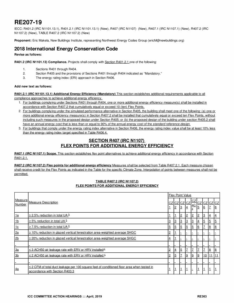
RE207-19IECC: R401.2 (IRC N1101.13.1), R401.2.1 (IRC N1101.13.1) (New), R407 (IRC N1107) (New), R407.1 (IRC N1107.1) (New), R407.2 (IRCN1107.2) (New), TABLE R407.2 (IRC N1107.2) (New)
Proponent: Eric Makela, New Buildings Institute, representing Northwest Energy Codes Group ([email protected])
2018 International Energy Conservation CodeRevise as follows:
R401.2 (IRC N1101.13) Compliance. Projects shall comply with Section R401.2.1 one of the following:
1. Sections R401 through R404.2. Section R405 and the provisions of Sections R401 through R404 indicated as “Mandatory.”3. The energy rating index (ERI) approach in Section R406.
Add new text as follows:
R401.2.1 (IRC N1101.13.1) Additional Energy Efficiency (Mandatory) This section establishes additional requirements applicable to allcompliance approaches to achieve additional energy efficiency.
1. For buildings complying under Sections R401 through R404, one or more additional energy efficiency measure(s) shall be installed inaccordance with Section R407.2 that cumulatively equal or exceed 10 (ten) Flex Points.
2. For buildings complying under the simulated performance alternative in Section R405, the building shall meet one of the following: (a) one ormore additional energy efficiency measure(s) in Section R407.2 shall be installed that cumulatively equal or exceed ten Flex Points, withoutincluding such measures in the proposed design under Section R405; or (b) the proposed design of the building under section R405.2 shallhave an annual energy cost that is less than or equal to 90% of the annual energy cost of the standard reference design.
3. For buildings that comply under the energy rating index alternative in Section R406, the energy rating index value shall be at least 10% lessthan the energy rating index target specified in Table R406.4.
SECTION R407 (IRC N1107) FLEX POINTS FOR ADDITIONAL ENERGY EFFICIENCY
R407.1 (IRC N1107.1) Scope. This section establishes flex point alternatives to achieve additional energy efficiency in accordance with SectionR401.2.1.
R407.2 (IRC N1107.2) Flex points for additional energy efficiency Measures shall be selected from Table R407.2.1. Each measure chosenshall receive credit for the Flex Points as indicated in the Table for the specific Climate Zone. Interpolation of points between measures shall not bepermitted.
TABLE R407.2 (IRC N1107.2)FLEX POINTS FOR ADDITIONAL ENERGY EFFICIENCY
MeasureNumber
Measure Description
Flex Point Value
CZ1
CZ2
CZ3
CZ4
CZ4C
CZ5
CZ6
CZ7
CZ8
1a ≥ 2.5% reduction in total UA 1 1 2 2 2 2 3 4 4
1b ≥ 5% reduction in total UA 3 3 3 3 3 4 5 5 5
1c ≥ 7.5% reduction in total UA 5 5 5 5 5 6 7 8 8
2a ≥ 10% reduction in glazed vertical fenestration area-weighted average SHGC 2 1 - - - - - - -
2b ≥ 20% reduction in glazed vertical fenestration area-weighted average SHGC 4 1 - - - - - - -
3a ≤ 3 ACH50 air leakage rate with ERV or HRV installed 2 4 5 7 7 7 7 8 8
3b ≤ 2 ACH50 air leakage rate with ERV or HRV installed 2 5 7 9 9 9 10 11 11
4a≤ 2 CFM of total duct leakage per 100 square feet of conditioned floor area when tested inaccordance with Section R403.3
1 1 1 1 - 1 1 1 1
a
b
b
b
c
c
ICC COMMITTEE ACTION HEARINGS ::: April, 2019 RE363
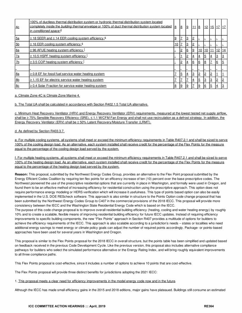
4c100% of ductless thermal distribution system or hydronic thermal distribution system locatedcompletely inside the building thermal envelope or 100% of duct thermal distribution system locatedin conditioned space
8 8 9 11 8 12 15 17 17
5a ≥ 18 SEER and ≥ 14 EER cooling system efficiency 9 7 3 2 - - - - -
5b ≥ 16 EER cooling system efficiency 10 7 3 2 - - - - -
6a ≥ 96 AFUE heating system efficiency - 2 6 9 10 10 11 12 14
7a ≥ 10.5 HSPF heating system efficiency - 1 2 4 4 5 4 3 3
7b ≥ 3.5 COP heating system efficiency - 2 4 6 6 8 7 6 5
8a ≥ 0.8 EF for fossil fuel service water heating system 7 5 4 3 2 2 2 1 1
8b ≥ 1.15 EF for electric service water heating system 7 7 7 4 5 3 3 2 2
8c ≥ 0.4 Solar Fraction for service water heating system 8 9 9 7 9 6 5 4 3
a. Climate Zone 4C is Climate Zone Marine 4.
b. The Total UA shall be calculated in accordance with Section R402.1.5 Total UA alternative.
c. Minimum Heat Recovery Ventilator (HRV) and Energy Recovery Ventilator (ERV) requirements, measured at the lowest tested net supply airflow,shall be ≥ 75% Sensible Recovery Efficiency (SRE), ≤ 1.1 W/CFM Fan Energy and shall not use recirculation as a defrost strategy. In addition, theEnergy Recovery Ventilator (ERV) shall be ≥ 50% Latent Recovery/Moisture Transfer (LRMT).
d. As defined by Section R403.3.7.
e. For multiple cooling systems, all systems shall meet or exceed the minimum efficiency requirements in Table R407.2.1 and shall be sized to serve100% of the cooling design load. As an alternative, each system installed shall receive credit for the percentage of the Flex Points for the measureequal to the percentage of the cooling design load served by the system.
f. For multiple heating systems, all systems shall meet or exceed the minimum efficiency requirements in Table R407.2.1 and shall be sized to serve100% of the heating design load. As an alternative, each system installed shall receive credit for the percentage of the Flex Points for the measureequal to the percentage of the heating design load served by the system.
Reason: This proposal, submitted by the Northwest Energy Codes Group, provides an alternative to the Flex Point proposal submitted by theEnergy Efficient Codes Coalition by requiring ten flex points for an efficency increase of ten (10) percent over the base prescriptive codes. TheNorthwest pioneered the use of the prescriptive residential options that are currently in place in Washington, and formally were used in Oregon, andfound them to be an effective method of increasing efficiency for residential construction using the prescriptive approach. This option does notrequire performance energy modeling or HERS verification which will increase it usefulness. This type of points based option can also be easilyimplemented in the U.S. DOE REScheck software. This approach is also similar in structure to the Points Option code change proposal that hasbeen submitted by the Northwest Energy Codes Group to C407 in the commercial provisions of the 2018 IECC. This proposal will provide moreconsistency between the IECC and the Washington State Residential Energy Code which is based on the IECC.The purpose of this code change proposal is to improve overall residential building efficiency (heating, cooling and water heating energy) by roughly10% and to create a scalable, flexible means of improving residential building efficiency for future IECC updates. Instead of requiring efficiencyimprovements to specific building components, the new “Flex Points” approach in Section R407 provides a multitude of options for builders toachieve the efficiency requirements of the IECC. This approach is also scalable according to a jurisdiction’s needs – states or localities who needadditional energy savings to meet energy or climate policy goals can adjust the number of required points accordingly. Package- or points-basedapproaches have been used for several years in Washington and Oregon.
This proposal is similar to the Flex Points proposal for the 2018 IECC in overall structure, but the points table has been simplified and updated basedon feedback received in the previous Code Development Cycle. Like the previous version, this proposal also includes alternative compliancepathways for builders who select the simulated performance alternative or the Energy Rating Index, and will bring roughly equivalent improvementsto all three compliance paths.
This Flex Points proposal is cost-effective, since it includes a number of options to achieve 10 points that are cost-effective.
The Flex Points proposal will provide three distinct benefits for jurisdictions adopting the 2021 IECC:
1. This proposal meets a clear need for efficiency improvements in the model energy code now and in the future.
Although the IECC has made small efficiency gains in the 2015 and 2018 editions, major gains have plateaued. Buildings still consume an estimated
d
e
e
f
f
f
ICC COMMITTEE ACTION HEARINGS ::: April, 2019 RE364
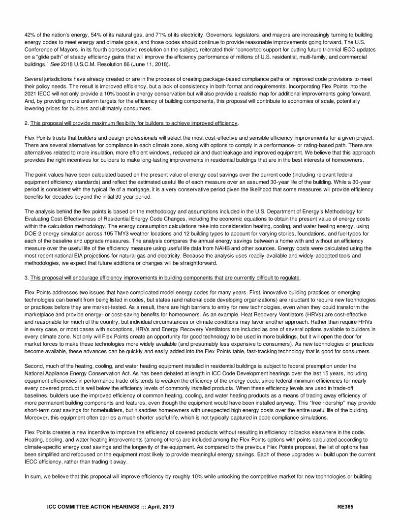
42% of the nation’s energy, 54% of its natural gas, and 71% of its electricity. Governors, legislators, and mayors are increasingly turning to buildingenergy codes to meet energy and climate goals, and those codes should continue to provide reasonable improvements going forward. The U.S.Conference of Mayors, in its fourth consecutive resolution on the subject, reiterated their “concerted support for putting future triennial IECC updateson a “glide path” of steady efficiency gains that will improve the efficiency performance of millions of U.S. residential, multi-family, and commercialbuildings.” See 2018 U.S.C.M. Resolution 86 (June 11, 2018).
Several jurisdictions have already created or are in the process of creating package-based compliance paths or improved code provisions to meettheir policy needs. The result is improved efficiency, but a lack of consistency in both format and requirements. Incorporating Flex Points into the2021 IECC will not only provide a 10% boost in energy conservation but will also provide a realistic map for additional improvements going forward.And, by providing more uniform targets for the efficiency of building components, this proposal will contribute to economies of scale, potentiallylowering prices for builders and ultimately consumers.
2. This proposal will provide maximum flexibility for builders to achieve improved efficiency.
Flex Points trusts that builders and design professionals will select the most cost-effective and sensible efficiency improvements for a given project.There are several alternatives for compliance in each climate zone, along with options to comply in a performance- or rating-based path. There arealternatives related to more insulation, more efficient windows, reduced air and duct leakage and improved equipment. We believe that this approachprovides the right incentives for builders to make long-lasting improvements in residential buildings that are in the best interests of homeowners.
The point values have been calculated based on the present value of energy cost savings over the current code (including relevant federalequipment efficiency standards) and reflect the estimated useful life of each measure over an assumed 30-year life of the building. While a 30-yearperiod is consistent with the typical life of a mortgage, it is a very conservative period given the likelihood that some measures will provide efficiencybenefits for decades beyond the initial 30-year period.
The analysis behind the flex points is based on the methodology and assumptions included in the U.S. Department of Energy’s Methodology forEvaluating Cost-Effectiveness of Residential Energy Code Changes, including the economic equations to obtain the present value of energy costswithin the calculation methodology. The energy consumption calculations take into consideration heating, cooling, and water heating energy, usingDOE-2 energy simulation across 105 TMY3 weather locations and 12 building types to account for varying stories, foundations, and fuel types foreach of the baseline and upgrade measures. The analysis compares the annual energy savings between a home with and without an efficiencymeasure over the useful life of the efficiency measure using useful life data from NAHB and other sources. Energy costs were calculated using themost recent national EIA projections for natural gas and electricity. Because the analysis uses readily-available and widely-accepted tools andmethodologies, we expect that future additions or changes will be straightforward.
3. This proposal will encourage efficiency improvements in building components that are currently difficult to regulate.
Flex Points addresses two issues that have complicated model energy codes for many years. First, innovative building practices or emergingtechnologies can benefit from being listed in codes, but states (and national code developing organizations) are reluctant to require new technologiesor practices before they are market-tested. As a result, there are high barriers to entry for new technologies, even when they could transform themarketplace and provide energy- or cost-saving benefits for homeowners. As an example, Heat Recovery Ventilators (HRVs) are cost-effectiveand reasonable for much of the country, but individual circumstances or climate conditions may favor another approach. Rather than require HRVsin every case, or most cases with exceptions, HRVs and Energy Recovery Ventilators are included as one of several options available to builders inevery climate zone. Not only will Flex Points create an opportunity for good technology to be used in more buildings, but it will open the door formarket forces to make these technologies more widely available (and presumably less expensive to consumers). As new technologies or practicesbecome available, these advances can be quickly and easily added into the Flex Points table, fast-tracking technology that is good for consumers.
Second, much of the heating, cooling, and water heating equipment installed in residential buildings is subject to federal preemption under theNational Appliance Energy Conservation Act. As has been debated at length in ICC Code Development hearings over the last 15 years, includingequipment efficiencies in performance trade-offs tends to weaken the efficiency of the energy code, since federal minimum efficiencies for nearlyevery covered product is well below the efficiency levels of commonly installed products. When these efficiency levels are used in trade-offbaselines, builders use the improved efficiency of common heating, cooling, and water heating products as a means of trading away efficiency ofmore permanent building components and features, even though the equipment would have been installed anyway. This “free ridership” may provideshort-term cost savings for homebuilders, but it saddles homeowners with unexpected high energy costs over the entire useful life of the building.Moreover, this equipment often carries a much shorter useful life, which is not typically captured in code compliance simulations.
Flex Points creates a new incentive to improve the efficiency of covered products without resulting in efficiency rollbacks elsewhere in the code.Heating, cooling, and water heating improvements (among others) are included among the Flex Points options with points calculated according toclimate-specific energy cost savings and the longevity of the equipment. As compared to the previous Flex Points proposal, the list of options hasbeen simplified and refocused on the equipment most likely to provide meaningful energy savings. Each of these upgrades will build upon the currentIECC efficiency, rather than trading it away.
In sum, we believe that this proposal will improve efficiency by roughly 10% while unlocking the competitive market for new technologies or building
ICC COMMITTEE ACTION HEARINGS ::: April, 2019 RE365
components that are difficult to regulate and will provide a useful new tool for policymakers across the country – all without rolling back theeffectiveness or efficiency of the IECC.
Bibliography: Uniting Cities to Accelerate Focus on the Economic and Climate Benefits of Boosting America’s Building Energy Efficiency, 2019U.S.C.M. Resolution 86 (June 11, 2018), available at https://www.usmayors.org/the-conference/resolutions/?category=c9211&meeting=86th%20Annual%20Meeting.
Cost Impact: The code change proposal will increase the cost of constructionThe code change proposal will increase the cost of construction. Requiring additional efficiency measures, such as more insulation, more efficientwindows, reduced air leakage and duct leakage, and/or more efficient equipment, to save 10% energy will increase the cost of construction, but theresulting energy and cost savings will recoup the initial costs and will continue to benefit consumers over the useful life of the home.
Proposal # 5152
RE207-19
ICC COMMITTEE ACTION HEARINGS ::: April, 2019 RE366
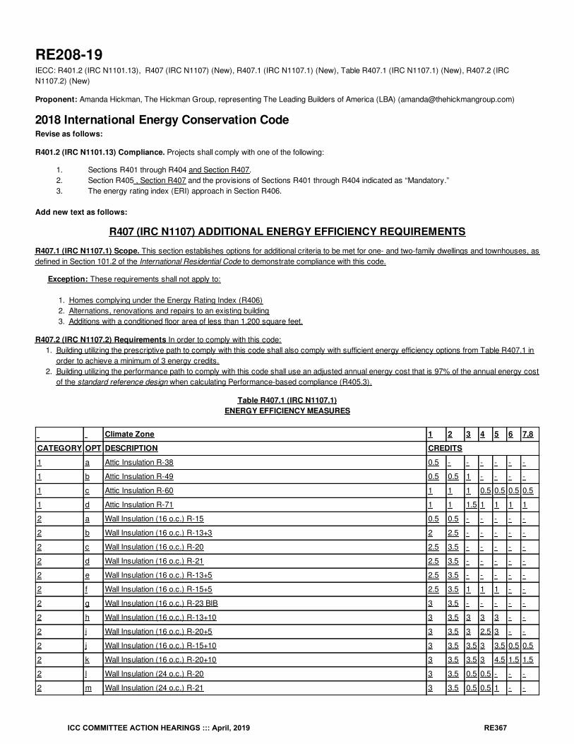
RE208-19IECC: R401.2 (IRC N1101.13), R407 (IRC N1107) (New), R407.1 (IRC N1107.1) (New), Table R407.1 (IRC N1107.1) (New), R407.2 (IRCN1107.2) (New)
Proponent: Amanda Hickman, The Hickman Group, representing The Leading Builders of America (LBA) ([email protected])
2018 International Energy Conservation CodeRevise as follows:
R401.2 (IRC N1101.13) Compliance. Projects shall comply with one of the following:
1. Sections R401 through R404 and Section R407.2. Section R405 , Section R407 and the provisions of Sections R401 through R404 indicated as “Mandatory.”3. The energy rating index (ERI) approach in Section R406.
Add new text as follows:
R407 (IRC N1107) ADDITIONAL ENERGY EFFICIENCY REQUIREMENTS
R407.1 (IRC N1107.1) Scope. This section establishes options for additional criteria to be met for one- and two-family dwellings and townhouses, asdefined in Section 101.2 of the International Residential Code to demonstrate compliance with this code.
Exception: These requirements shall not apply to:
1. Homes complying under the Energy Rating Index (R406)2. Alternations, renovations and repairs to an existing building3. Additions with a conditioned floor area of less than 1,200 square feet.
R407.2 (IRC N1107.2) Requirements In order to comply with this code:1. Building utilizing the prescriptive path to comply with this code shall also comply with sufficient energy efficiency options from Table R407.1 in
order to achieve a minimum of 3 energy credits.2. Building utilizing the performance path to comply with this code shall use an adjusted annual energy cost that is 97% of the annual energy cost
of the standard reference design when calculating Performance-based compliance (R405.3).
Table R407.1 (IRC N1107.1)ENERGY EFFICIENCY MEASURES
Climate Zone 1 2 3 4 5 6 7,8
CATEGORY OPT DESCRIPTION CREDITS
1 a Attic Insulation R-38 0.5 - - - - - -
1 b Attic Insulation R-49 0.5 0.5 1 - - - -
1 c Attic Insulation R-60 1 1 1 0.5 0.5 0.5 0.5
1 d Attic Insulation R-71 1 1 1.5 1 1 1 1
2 a Wall Insulation (16 o.c.) R-15 0.5 0.5 - - - - -
2 b Wall Insulation (16 o.c.) R-13+3 2 2.5 - - - - -
2 c Wall Insulation (16 o.c.) R-20 2.5 3.5 - - - - -
2 d Wall Insulation (16 o.c.) R-21 2.5 3.5 - - - - -
2 e Wall Insulation (16 o.c.) R-13+5 2.5 3.5 - - - - -
2 f Wall Insulation (16 o.c.) R-15+5 2.5 3.5 1 1 1 - -
2 g Wall Insulation (16 o.c.) R-23 BIB 3 3.5 - - - - -
2 h Wall Insulation (16 o.c.) R-13+10 3 3.5 3 3 3 - -
2 i Wall Insulation (16 o.c.) R-20+5 3 3.5 3 2.5 3 - -
2 j Wall Insulation (16 o.c.) R-15+10 3 3.5 3.5 3 3.5 0.5 0.5
2 k Wall Insulation (16 o.c.) R-20+10 3 3.5 3.5 3 4.5 1.5 1.5
2 l Wall Insulation (24 o.c.) R-20 3 3.5 0.5 0.5 - - -
2 m Wall Insulation (24 o.c.) R-21 3 3.5 0.5 0.5 1 - -
ICC COMMITTEE ACTION HEARINGS ::: April, 2019 RE367
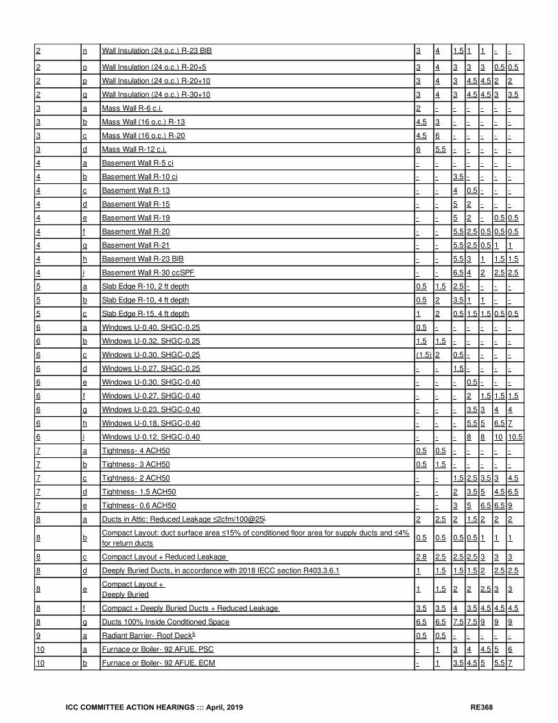
2 n Wall Insulation (24 o.c.) R-23 BIB 3 4 1.5 1 1 - -
2 o Wall Insulation (24 o.c.) R-20+5 3 4 3 3 3 0.5 0.5
2 p Wall Insulation (24 o.c.) R-20+10 3 4 3 4.5 4.5 2 2
2 q Wall Insulation (24 o.c.) R-30+10 3 4 3 4.5 4.5 3 3.5
3 a Mass Wall R-6 c.i. 2 - - - - - -
3 b Mass Wall (16 o.c.) R-13 4.5 3 - - - - -
3 c Mass Wall (16 o.c.) R-20 4.5 6 - - - - -
3 d Mass Wall R-12 c.i. 6 5.5 - - - - -
4 a Basement Wall R-5 ci - - - - - - -
4 b Basement Wall R-10 ci - - 3.5 - - - -
4 c Basement Wall R-13 - - 4 0.5 - - -
4 d Basement Wall R-15 - - 5 2 - - -
4 e Basement Wall R-19 - - 5 2 - 0.5 0.5
4 f Basement Wall R-20 - - 5.5 2.5 0.5 0.5 0.5
4 g Basement Wall R-21 - - 5.5 2.5 0.5 1 1
4 h Basement Wall R-23 BIB - - 5.5 3 1 1.5 1.5
4 i Basement Wall R-30 ccSPF - - 6.5 4 2 2.5 2.5
5 a Slab Edge R-10, 2 ft depth 0.5 1.5 2.5 - - - -
5 b Slab Edge R-10, 4 ft depth 0.5 2 3.5 1 1 - -
5 c Slab Edge R-15, 4 ft depth 1 2 0.5 1.5 1.5 0.5 0.5
6 a Windows U-0.40, SHGC-0.25 0.5 - - - - - -
6 b Windows U-0.32, SHGC-0.25 1.5 1.5 - - - - -
6 c Windows U-0.30, SHGC-0.25 (1.5) 2 0.5 - - - -
6 d Windows U-0.27, SHGC-0.25 - - 1.5 - - - -
6 e Windows U-0.30, SHGC-0.40 - - - 0.5 - - -
6 f Windows U-0.27, SHGC-0.40 - - - 2 1.5 1.5 1.5
6 g Windows U-0.23, SHGC-0.40 - - - 3.5 3 4 4
6 h Windows U-0.18, SHGC-0.40 - - - 5.5 5 6.5 7
6 i Windows U-0.12, SHGC-0.40 - - - 8 8 10 10.5
7 a Tightness- 4 ACH50 0.5 0.5 - - - - -
7 b Tightness- 3 ACH50 0.5 1.5 - - - - -
7 c Tightness- 2 ACH50 - - 1.5 2.5 3.5 3 4.5
7 d Tightness- 1.5 ACH50 - - 2 3.5 5 4.5 6.5
7 e Tightness- 0.6 ACH50 - - 3 5 6.5 6.5 9
8 a Ducts in Attic: Reduced Leakage ≤2cfm/100@25 2 2.5 2 1.5 2 2 2
8 bCompact Layout: duct surface area ≤15% of conditioned floor area for supply ducts and ≤4%for return ducts
0.5 0.5 0.5 0.5 1 1 1
8 c Compact Layout + Reduced Leakage 2.8 2.5 2.5 2.5 3 3 3
8 d Deeply Buried Ducts, in accordance with 2018 IECC section R403.3.6.1 1 1.5 1.5 1.5 2 2.5 2.5
8 eCompact Layout + Deeply Buried
1 1.5 2 2 2.5 3 3
8 f Compact + Deeply Buried Ducts + Reduced Leakage 3.5 3.5 4 3.5 4.5 4.5 4.5
8 g Ducts 100% Inside Conditioned Space 6.5 6.5 7.5 7.5 9 9 9
9 a Radiant Barrier- Roof Deck 0.5 0.5 - - - - -
10 a Furnace or Boiler- 92 AFUE, PSC - 1 3 4 4.5 5 6
10 b Furnace or Boiler- 92 AFUE, ECM - 1 3.5 4.5 5 5.5 7
j
k
ICC COMMITTEE ACTION HEARINGS ::: April, 2019 RE368
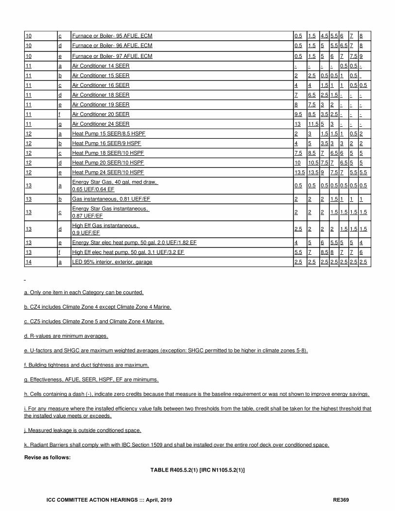
10 c Furnace or Boiler- 95 AFUE, ECM 0.5 1.5 4.5 5.5 6 7 8
10 d Furnace or Boiler- 96 AFUE, ECM 0.5 1.5 5 5.5 6.5 7 8
10 e Furnace or Boiler- 97 AFUE, ECM 0.5 1.5 5 6 7 7.5 9
11 a Air Conditioner 14 SEER - - - - 0.5 0.5 -
11 b Air Conditioner 15 SEER 2 2.5 0.5 0.5 1 0.5
11 c Air Conditioner 16 SEER 4 4 1.5 1 1 0.5 0.5
11 d Air Conditioner 18 SEER 7 6.5 2.5 1.5 - - -
11 e Air Conditioner 19 SEER 8 7.5 3 2 - - -
11 f Air Conditioner 20 SEER 9.5 8.5 3.5 2.5 - - -
11 g Air Conditioner 24 SEER 13 11.5 5 3 - - -
12 a Heat Pump 15 SEER/8.5 HSPF 2 3 1.5 1.5 1 0.5 2
12 b Heat Pump 16 SEER/9 HSPF 4 5 3.5 3 3 2 2
12 c Heat Pump 18 SEER/10 HSPF 7.5 8.5 7 6.5 6 5 5
12 d Heat Pump 20 SEER/10 HSPF 10 10.5 7.5 7 6.5 5 5
12 e Heat Pump 24 SEER/10 HSPF 13.5 13.5 9 7.5 7 5.5 5.5
13 aEnergy Star Gas, 40 gal, med draw, 0.65 UEF/0.64 EF
0.5 0.5 0.5 0.5 0.5 0.5 0.5
13 b Gas instantaneous, 0.81 UEF/EF 2 2 2 1.5 1 1 1
13 cEnergy Star Gas instantaneous, 0.87 UEF/EF
2 2 2 1.5 1.5 1.5 1.5
13 dHigh Eff Gas instantaneous, 0.9 UEF/EF
2.5 2 2 2 1.5 1.5 1.5
13 e Energy Star elec heat pump, 50 gal, 2.0 UEF/1.82 EF 4 5 6 5.5 5 5 4
13 f High Eff elec heat pump, 50 gal, 3.1 UEF/3.2 EF 5.5 7 8.5 8 7 7 6
14 a LED 95% interior, exterior, garage 2.5 2.5 2.5 2.5 2.5 2.5 2.5
a. Only one item in each Category can be counted.
b. CZ4 includes Climate Zone 4 except Climate Zone 4 Marine.
c. CZ5 includes Climate Zone 5 and Climate Zone 4 Marine.
d. R-values are minimum averages.
e. U-factors and SHGC are maximum weighted averages (exception: SHGC permitted to be higher in climate zones 5-8).
f. Building tightness and duct tightness are maximum.
g. Effectiveness, AFUE, SEER, HSPF, EF are minimums.
h. Cells containing a dash (-), indicate zero credits because that measure is the baseline requirement or was not shown to improve energy savings.
i. For any measure where the installed efficiency value falls between two thresholds from the table, credit shall be taken for the highest threshold thatthe installed value meets or exceeds.
j. Measured leakage is outside conditioned space.
k. Radiant Barriers shall comply with with IBC Section 1509 and shall be installed over the entire roof deck over conditioned space.
Revise as follows:
TABLE R405.5.2(1) [IRC N1105.5.2(1)]
ICC COMMITTEE ACTION HEARINGS ::: April, 2019 RE369
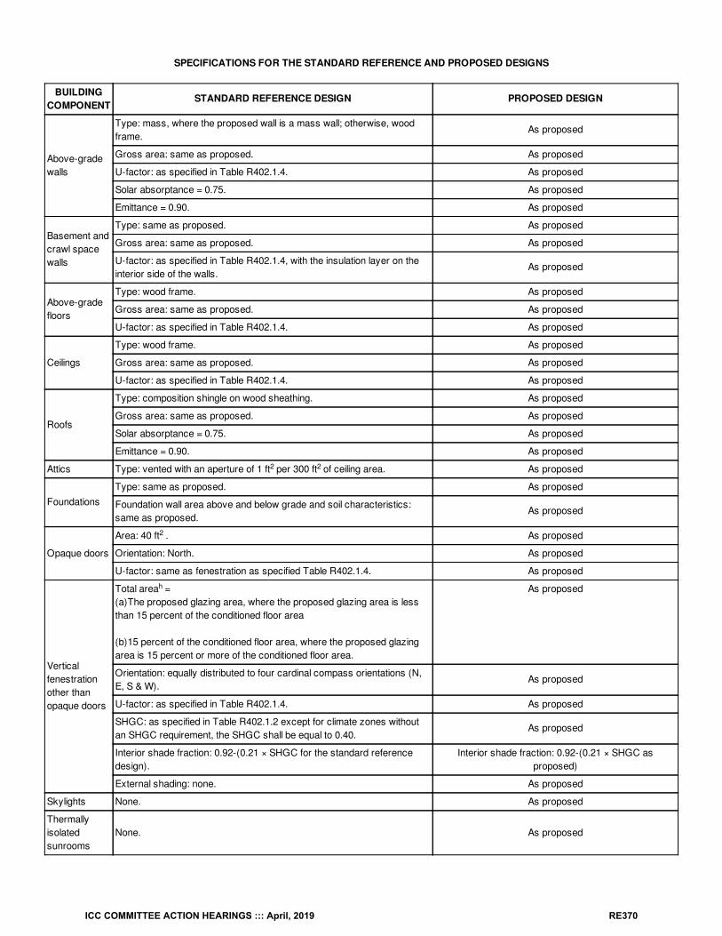
SPECIFICATIONS FOR THE STANDARD REFERENCE AND PROPOSED DESIGNS
BUILDINGCOMPONENT
STANDARD REFERENCE DESIGN PROPOSED DESIGN
Above-gradewalls
Type: mass, where the proposed wall is a mass wall; otherwise, woodframe.
As proposed
Gross area: same as proposed. As proposed
U-factor: as specified in Table R402.1.4. As proposed
Solar absorptance = 0.75. As proposed
Emittance = 0.90. As proposed
Basement andcrawl spacewalls
Type: same as proposed. As proposed
Gross area: same as proposed. As proposed
U-factor: as specified in Table R402.1.4, with the insulation layer on theinterior side of the walls.
As proposed
Above-gradefloors
Type: wood frame. As proposed
Gross area: same as proposed. As proposed
U-factor: as specified in Table R402.1.4. As proposed
Ceilings
Type: wood frame. As proposed
Gross area: same as proposed. As proposed
U-factor: as specified in Table R402.1.4. As proposed
Roofs
Type: composition shingle on wood sheathing. As proposed
Gross area: same as proposed. As proposed
Solar absorptance = 0.75. As proposed
Emittance = 0.90. As proposed
Attics Type: vented with an aperture of 1 ft per 300 ft of ceiling area. As proposed
FoundationsType: same as proposed. As proposed
Foundation wall area above and below grade and soil characteristics:same as proposed.
As proposed
Opaque doors
Area: 40 ft . As proposed
Orientation: North. As proposed
U-factor: same as fenestration as specified Table R402.1.4. As proposed
Verticalfenestrationother thanopaque doors
Total area =(a)The proposed glazing area, where the proposed glazing area is lessthan 15 percent of the conditioned floor area
(b)15 percent of the conditioned floor area, where the proposed glazingarea is 15 percent or more of the conditioned floor area.
As proposed
Orientation: equally distributed to four cardinal compass orientations (N,E, S & W).
As proposed
U-factor: as specified in Table R402.1.4. As proposed
SHGC: as specified in Table R402.1.2 except for climate zones withoutan SHGC requirement, the SHGC shall be equal to 0.40.
As proposed
Interior shade fraction: 0.92-(0.21 × SHGC for the standard referencedesign).
Interior shade fraction: 0.92-(0.21 × SHGC asproposed)
External shading: none. As proposed
Skylights None. As proposed
Thermallyisolatedsunrooms
None. As proposed
2 2
2
h
a
ICC COMMITTEE ACTION HEARINGS ::: April, 2019 RE370
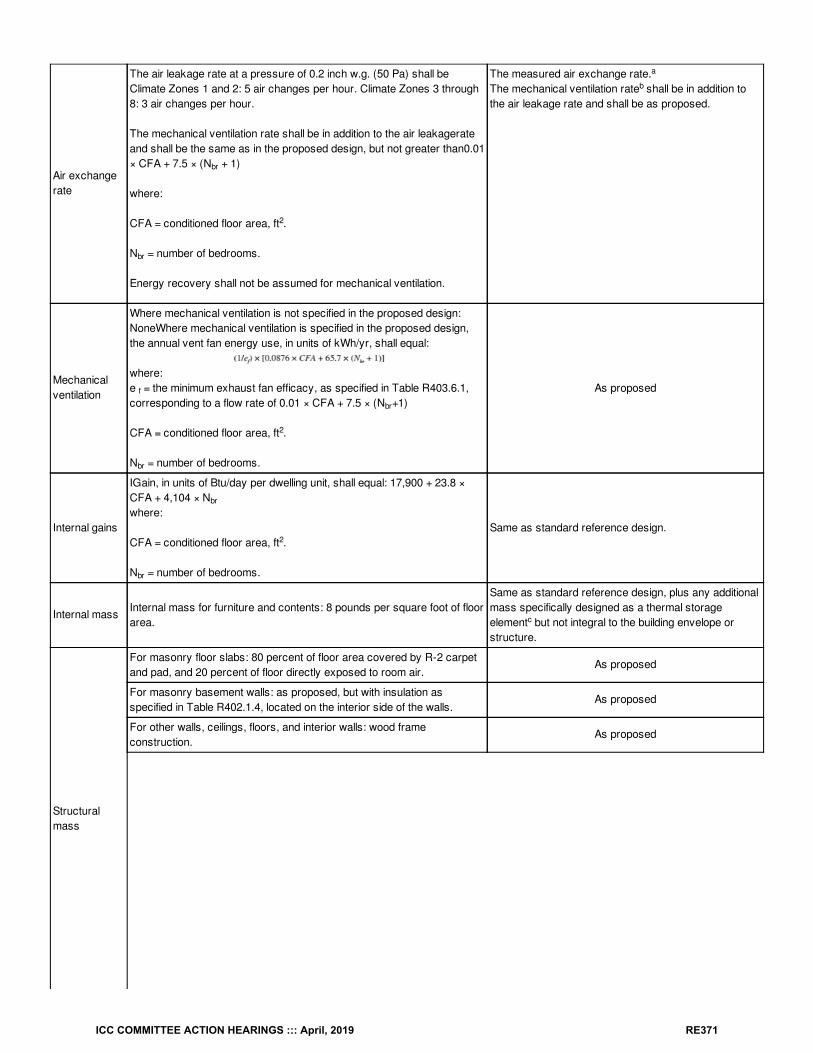
Air exchangerate
The air leakage rate at a pressure of 0.2 inch w.g. (50 Pa) shall beClimate Zones 1 and 2: 5 air changes per hour. Climate Zones 3 through8: 3 air changes per hour.
The mechanical ventilation rate shall be in addition to the air leakagerateand shall be the same as in the proposed design, but not greater than0.01× CFA + 7.5 × (N + 1)
where:
CFA = conditioned floor area, ft .
N = number of bedrooms.
Energy recovery shall not be assumed for mechanical ventilation.
The measured air exchange rate.The mechanical ventilation rate shall be in addition tothe air leakage rate and shall be as proposed.
Mechanicalventilation
Where mechanical ventilation is not specified in the proposed design:NoneWhere mechanical ventilation is specified in the proposed design,the annual vent fan energy use, in units of kWh/yr, shall equal:
where:e = the minimum exhaust fan efficacy, as specified in Table R403.6.1,corresponding to a flow rate of 0.01 × CFA + 7.5 × (N +1)
CFA = conditioned floor area, ft .
N = number of bedrooms.
As proposed
Internal gains
IGain, in units of Btu/day per dwelling unit, shall equal: 17,900 + 23.8 ×CFA + 4,104 × Nwhere:
CFA = conditioned floor area, ft .
N = number of bedrooms.
Same as standard reference design.
Internal massInternal mass for furniture and contents: 8 pounds per square foot of floorarea.
Same as standard reference design, plus any additionalmass specifically designed as a thermal storageelement but not integral to the building envelope orstructure.
Structuralmass
For masonry floor slabs: 80 percent of floor area covered by R-2 carpetand pad, and 20 percent of floor directly exposed to room air.
As proposed
For masonry basement walls: as proposed, but with insulation asspecified in Table R402.1.4, located on the interior side of the walls.
As proposed
For other walls, ceilings, floors, and interior walls: wood frameconstruction.
As proposed
br
2
br
a
b
f
br
2
br
br
2
br
c
ICC COMMITTEE ACTION HEARINGS ::: April, 2019 RE371
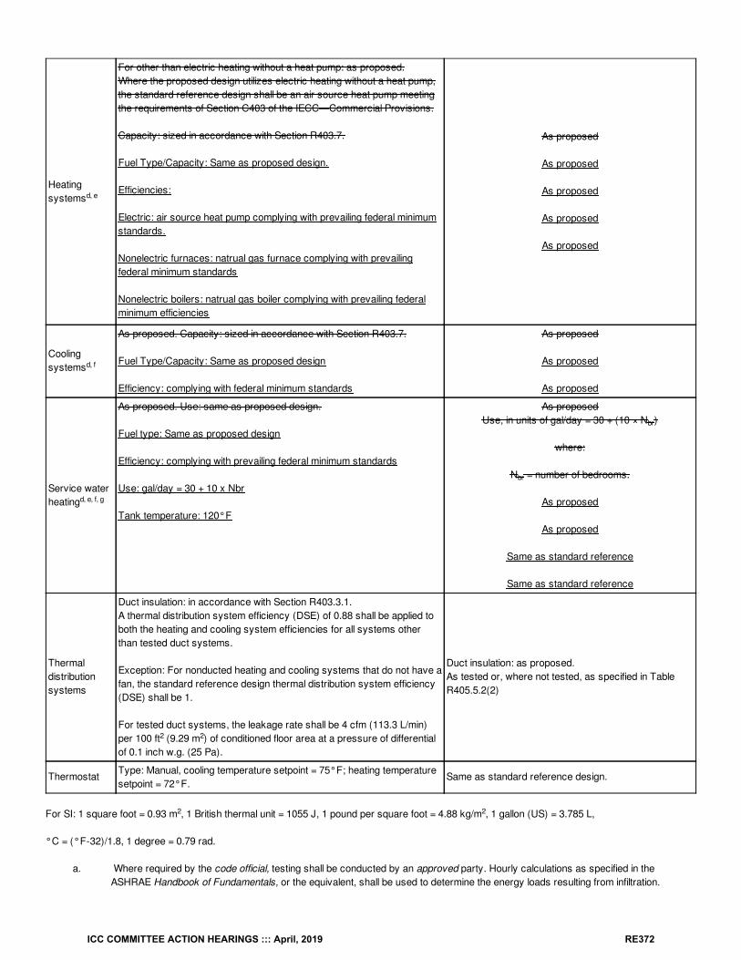
Heatingsystems
For other than electric heating without a heat pump: as proposed.Where the proposed design utilizes electric heating without a heat pump,the standard reference design shall be an air source heat pump meetingthe requirements of Section C403 of the IECC—Commercial Provisions.
Capacity: sized in accordance with Section R403.7.
Fuel Type/Capacity: Same as proposed design.
Efficiencies:
Electric: air source heat pump complying with prevailing federal minimumstandards.
Nonelectric furnaces: natrual gas furnace complying with prevailingfederal minimum standards
Nonelectric boilers: natrual gas boiler complying with prevailing federalminimum efficiencies
As proposed
As proposed
As proposed
As proposed
As proposed
Coolingsystems
As proposed. Capacity: sized in accordance with Section R403.7.
Fuel Type/Capacity: Same as proposed design
Efficiency: complying with federal minimum standards
As proposed
As proposed
As proposed
Service waterheating
As proposed. Use: same as proposed design.
Fuel type: Same as proposed design
Efficiency: complying with prevailing federal minimum standards
Use: gal/day = 30 + 10 x Nbr
Tank temperature: 120°F
As proposedUse, in units of gal/day = 30 + (10 × N )
where:
N = number of bedrooms.
As proposed
As proposed
Same as standard reference
Same as standard reference
Thermaldistributionsystems
Duct insulation: in accordance with Section R403.3.1.A thermal distribution system efficiency (DSE) of 0.88 shall be applied toboth the heating and cooling system efficiencies for all systems otherthan tested duct systems.
Exception: For nonducted heating and cooling systems that do not have afan, the standard reference design thermal distribution system efficiency(DSE) shall be 1.
For tested duct systems, the leakage rate shall be 4 cfm (113.3 L/min)per 100 ft (9.29 m ) of conditioned floor area at a pressure of differentialof 0.1 inch w.g. (25 Pa).
Duct insulation: as proposed.As tested or, where not tested, as specified in TableR405.5.2(2)
ThermostatType: Manual, cooling temperature setpoint = 75°F; heating temperaturesetpoint = 72°F.
Same as standard reference design.
For SI: 1 square foot = 0.93 m , 1 British thermal unit = 1055 J, 1 pound per square foot = 4.88 kg/m , 1 gallon (US) = 3.785 L,
°C = (°F-32)/1.8, 1 degree = 0.79 rad.
a. Where required by the code official, testing shall be conducted by an approved party. Hourly calculations as specified in theASHRAE Handbook of Fundamentals, or the equivalent, shall be used to determine the energy loads resulting from infiltration.
d, e
d, f
d, e, f, g
br
br
2 2
2 2
ICC COMMITTEE ACTION HEARINGS ::: April, 2019 RE372
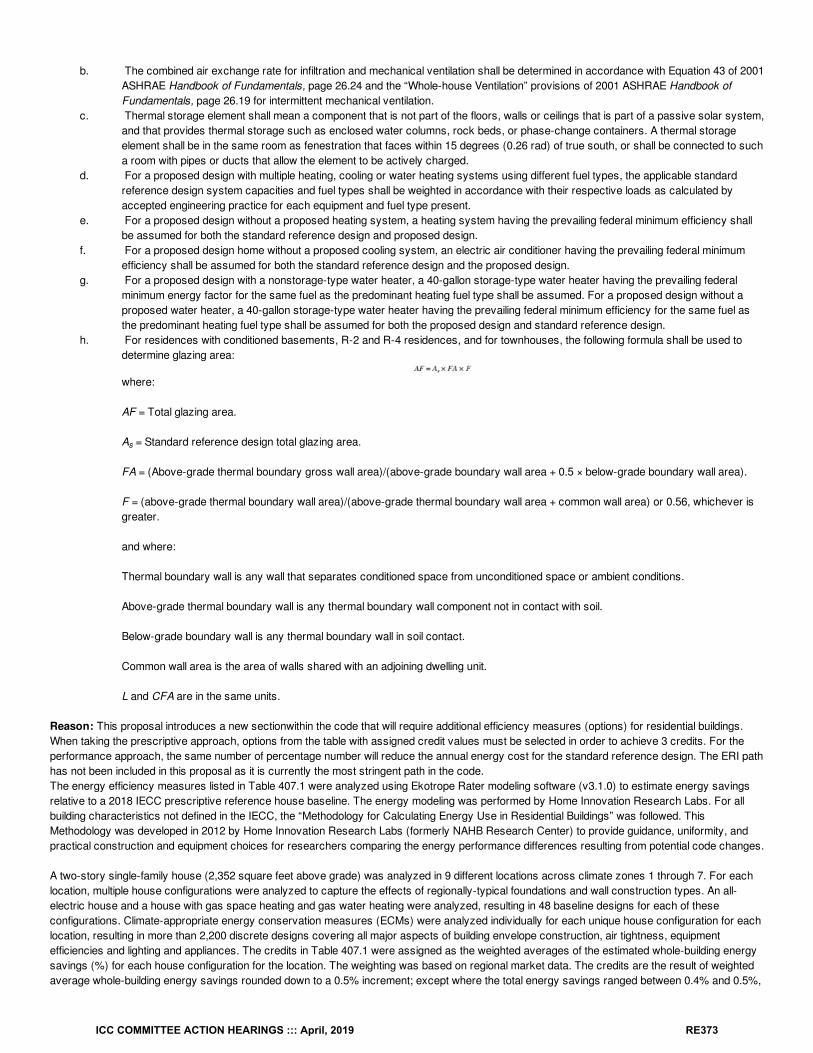
b. The combined air exchange rate for infiltration and mechanical ventilation shall be determined in accordance with Equation 43 of 2001ASHRAE Handbook of Fundamentals, page 26.24 and the “Whole-house Ventilation” provisions of 2001 ASHRAE Handbook ofFundamentals, page 26.19 for intermittent mechanical ventilation.
c. Thermal storage element shall mean a component that is not part of the floors, walls or ceilings that is part of a passive solar system,and that provides thermal storage such as enclosed water columns, rock beds, or phase-change containers. A thermal storageelement shall be in the same room as fenestration that faces within 15 degrees (0.26 rad) of true south, or shall be connected to sucha room with pipes or ducts that allow the element to be actively charged.
d. For a proposed design with multiple heating, cooling or water heating systems using different fuel types, the applicable standardreference design system capacities and fuel types shall be weighted in accordance with their respective loads as calculated byaccepted engineering practice for each equipment and fuel type present.
e. For a proposed design without a proposed heating system, a heating system having the prevailing federal minimum efficiency shallbe assumed for both the standard reference design and proposed design.
f. For a proposed design home without a proposed cooling system, an electric air conditioner having the prevailing federal minimumefficiency shall be assumed for both the standard reference design and the proposed design.
g. For a proposed design with a nonstorage-type water heater, a 40-gallon storage-type water heater having the prevailing federalminimum energy factor for the same fuel as the predominant heating fuel type shall be assumed. For a proposed design without aproposed water heater, a 40-gallon storage-type water heater having the prevailing federal minimum efficiency for the same fuel asthe predominant heating fuel type shall be assumed for both the proposed design and standard reference design.
h. For residences with conditioned basements, R-2 and R-4 residences, and for townhouses, the following formula shall be used todetermine glazing area:
where:
AF = Total glazing area.
A = Standard reference design total glazing area.
FA = (Above-grade thermal boundary gross wall area)/(above-grade boundary wall area + 0.5 × below-grade boundary wall area).
F = (above-grade thermal boundary wall area)/(above-grade thermal boundary wall area + common wall area) or 0.56, whichever isgreater.
and where:
Thermal boundary wall is any wall that separates conditioned space from unconditioned space or ambient conditions.
Above-grade thermal boundary wall is any thermal boundary wall component not in contact with soil.
Below-grade boundary wall is any thermal boundary wall in soil contact.
Common wall area is the area of walls shared with an adjoining dwelling unit.
L and CFA are in the same units.
Reason: This proposal introduces a new sectionwithin the code that will require additional efficiency measures (options) for residential buildings.When taking the prescriptive approach, options from the table with assigned credit values must be selected in order to achieve 3 credits. For theperformance approach, the same number of percentage number will reduce the annual energy cost for the standard reference design. The ERI pathhas not been included in this proposal as it is currently the most stringent path in the code.The energy efficiency measures listed in Table 407.1 were analyzed using Ekotrope Rater modeling software (v3.1.0) to estimate energy savingsrelative to a 2018 IECC prescriptive reference house baseline. The energy modeling was performed by Home Innovation Research Labs. For allbuilding characteristics not defined in the IECC, the “Methodology for Calculating Energy Use in Residential Buildings” was followed. ThisMethodology was developed in 2012 by Home Innovation Research Labs (formerly NAHB Research Center) to provide guidance, uniformity, andpractical construction and equipment choices for researchers comparing the energy performance differences resulting from potential code changes.
A two-story single-family house (2,352 square feet above grade) was analyzed in 9 different locations across climate zones 1 through 7. For eachlocation, multiple house configurations were analyzed to capture the effects of regionally-typical foundations and wall construction types. An all-electric house and a house with gas space heating and gas water heating were analyzed, resulting in 48 baseline designs for each of theseconfigurations. Climate-appropriate energy conservation measures (ECMs) were analyzed individually for each unique house configuration for eachlocation, resulting in more than 2,200 discrete designs covering all major aspects of building envelope construction, air tightness, equipmentefficiencies and lighting and appliances. The credits in Table 407.1 were assigned as the weighted averages of the estimated whole-building energysavings (%) for each house configuration for the location. The weighting was based on regional market data. The credits are the result of weightedaverage whole-building energy savings rounded down to a 0.5% increment; except where the total energy savings ranged between 0.4% and 0.5%,
s
ICC COMMITTEE ACTION HEARINGS ::: April, 2019 RE373
the values were rounded up to 0.5%.
In addition to individual measures, select packages of measures were also simulated for analysis across several climate zones. The comparison ofadditive energy savings from individual measures and the modeled net savings from packages of the same measures indicated that at the proposed3% incremental levels of improvement, a simple addition of energy savings from individual measures is an adequate representation of theircombined efficiency.
The energy performance target of 3% (or 3 credits) represents an incremental level of improvement that can be achieved through one or morecompliance options (individual measures or a combination of measures) that meet the cost effectiveness metrics of simple payback of 10-15 yearsdepending on the type of the measure.
The required credits and the paths to achieve these efficiency gains have been determined using current cost data provided by homebuilders fromacross the U.S. to have at a minimum a 10-year simple payback and to be cost effective when using the life cycle analysis method.
Cost Impact: The code change proposal will increase the cost of constructionThis proposal will increase the cost of construction. However, it has been determined, using current homebuilder cost data, that this proposalprovides paths with at least a 10-year (or better) simple payback. This proposal has also been determined to be cost effective using the life cycleanalysis method.
Proposal # 5329
RE208-19
ICC COMMITTEE ACTION HEARINGS ::: April, 2019 RE374
RE209-19IECC: R401.2, R401.2.1 (New), SECTION R407 (New), R407.1 (New), R407.2 (New), R407.2.1 (New), R407.2.2 (New), R407.2.3 (New),R407.2.4 (New), R407.2.5 (New)
Proponent: Daniel Bresette, Alliance to Save Energy, representing Alliance to Save Energy ([email protected]); Harry Misuriello, AmericanCouncil for an Energy-Efficient Economy, representing American Council for an Energy-Efficient Economy ([email protected])
2018 International Energy Conservation CodeRevise as follows:
R401.2 Compliance. Projects shall comply with Section R401.2.1 and one of the following:
1. Sections R401 through R404.2. Section R405 and the provisions of Sections R401 through R404 indicated as “Mandatory.”3. The energy rating index (ERI) approach in Section R406.
Add new text as follows:
R401.2.1 Additional Energy Efficiency (Mandatory). This section establishes additional requirements applicable to all compliance approaches toachieve additional energy efficiency.
1. For buildings complying under Sections R401 through R404, one of the Additional Efficiency Package Options shall be installedaccording to Section R407.2.
2. For buildings complying under the simulated performance alternative in Section R405, the building shall meet one of the following::
2.1. One of the Additional Efficiency Package Options in Section R407.2 shall be installed without including such measures in theproposed design under Section R405; or
2.2. The proposed design of the building under Section R405.3 shall have an annual energy cost that is less than or equal to 95percent of the annual energy cost of the standard reference design.
3. For buildings complying under the energy rating index alternative in Section R406, the energy rating index value shall be at least 5percent less than the energy rating index target specified in Table R406.4.
The option selected for compliance shall be identified in the Certificate required by Section R401.3.
SECTION R407 ADDITIONAL EFFICIENCY PACKAGE OPTIONS
R407.1 Scope. This section establishes Additional Efficiency Package Options to achieve additional energy efficiency in accordance with SectionR401.2.1.
R407.2 Additional Efficiency Package Options. Additional efficiency package options for compliance with Section R401.2.1 are set forth inSections R407.2.1 through R407.2.5.
R407.2.1 Enhanced envelope performance option. The total building thermal envelope UA, the sum of U-factor times assembly area, shall beless than or equal to 95 percent of the total UA resulting from multiplying the U-factors in Table R402.1.4 by the same assembly area as in theproposed building. The UA calculation shall be performed in accordance with Section R402.1.5. The area-weighted average SHGC of all glazedfenestration shall be less than or equal to 95 percent of the maximum glazed fenestration SHGC in Table R402.1.2.
R407.2.2 More efficient HVAC equipment performance option. Heating and cooling equipment shall meet or exceed one of the followingefficiencies:
1. Greater than or equal to 95 AFUE natural gas furnace and 16 SEER air conditioner.2. Greater than or equal to 10 HSPF / 16 SEER air source heat pump.3. greater than or equal to 3.5 COP ground source heat pump.
For multiple cooling systems, all systems shall meet or exceed the minimum efficiency requirements in this section and shall be sized to serve 100percent of the cooling design load. For multiple heating systems, all systems shall meet or exceed the minimum efficiency requirements in thissection and shall be sized to serve 100 percent of the heating design load.
R407.2.3 Reduced energy use in service water heating option. The hot water system shall meet or exceed one of the following efficiencies:1. Greater than or equal to 82 EF fossil fuel service water heating system.2. Greater than or equal to 2.0 EF electric service water heating system.3. Greater than or equal to 0.4 Solar Fraction solar water heating system.
ICC COMMITTEE ACTION HEARINGS ::: April, 2019 RE375
R407.2.4 More efficient duct thermal distribution system option. The thermal distribution system shall meet or exceed one of the followingefficiencies:
1. 100 percent of ducts and air handlers located entirely within the building thermal envelope.2. 100 percent of ductless thermal distribution system or hydronic thermal distribution system located completely inside the building thermal
envelope.3. 100 percent of duct thermal distribution system located in conditioned space as defined by Section R403.3.7.
R407.2.5 Improved air sealing and efficient ventilation system option. The measured air leakage rate shall be less than or equal to 3.0 ACH50,with either an Energy Recovery Ventilator (ERV) or Heat Recovery Ventilator (HRV) installed. Minimum HRV and ERV requirements, measured atthe lowest tested net supply airflow, shall be greater than or equal to 75 percent Sensible Recovery Efficiency (SRE), less than or equal to 1.1W/CFM Fan Energy and shall not use recirculation as a defrost strategy. In addition, the ERV shall be greater than or equal to 50 percent LatentRecovery/Moisture Transfer (LRMT).
Reason: The purpose of this code change proposal is to improve the energy efficiency of residential buildings by roughly 5% or more, and toprovide code users with flexibility to select the measures that make the most sense for each project. This proposal largely mirrors the format ofSection C406 Additional Efficiency Package Options—an approach to improving commercial buildings that has been included in the commercialenergy code since the 2012 IECC. Like Section C406, new Section R407 offers multiple straightforward improvements that will increase energysavings and reduce costs to the homeowner over the useful life of the building. In addition, Section R401.2.1 provides two additional means ofdemonstrating compliance: 1) code users may achieve a 5% improvement in the performance path; or 2) code users may comply by applying a 5%improvement in ERI Target score. The range of options will provide multiple paths for projects to achieve the intended improvement in the code.The technologies included in the packages of improvements are currently available in the relevant markets and the improved building practices havebeen proven feasible in residential buildings. However, many of these measures would be difficult to include in the current code format because offederal preemption of covered products, inapplicability to certain home designs, or other limitations. This proposal follows the lead of states likeOregon and Washington that have successfully created a list of options available to builders to meet the residential code improvements. Thisapproach increases flexibility for code users while advancing the code’s efficiency baseline.
Although the historic energy efficiency gains in the 2009 and 2012 IECC have been largely maintained in the 2015 and 2018 IECC, there is a clearneed for more substantial improvements in the 2021 IECC. It is well understood that buildings have an outsized impact on the nation’s energydemands. Buildings consume 42% of the nation’s energy, including 54% of the nation’s natural gas and 71% of its electricity. The nation’spolicymakers are increasingly turning to building energy codes as a means of addressing energy and climate goals. Several states have adoptedimprovements beyond the 2018 IECC, and the U.S. Conference of Mayors recently called for “putting future triennial IECC updates on a ‘glide path’of steady efficiency gains that will improve the efficiency performance of millions of U.S. residential, multi-family, and commercial buildings.” See2018 U.S.C.M. Resolution 86 (June 11, 2018). While a much larger improvement in overall efficiency is warranted, a roughly 5% improvementthrough the adoption of this proposal would be a step in the right direction.
This proposal provides policymakers with additional options for improving the code going forward. A jurisdiction could increase the number ofrequired options (and make a corresponding increase in the performance path and ERI required improvement). And as additional technologies andbuilding methods become available, more options may be added to the initial list of improvements. (For example, Section C406 was expanded from 5to 8 options in the 2018 IECC.) In sum, this proposal will allow the IECC to build upon recent improvements and create a new model for improvingand adding flexibility to residential building energy codes going forward.
Bibliography: Uniting Cities to Accelerate Focus on the Economic and Climate Benefits of Boosting America’s Building Energy Efficiency, 2019U.S.C.M. Resolution 86 (June 11, 2018), available at https://www.usmayors.org/the-conference/resolutions/?category=c9211&meeting=86th%20Annual%20Meeting.
Cost Impact: The code change proposal will increase the cost of constructionFor each climate zone, there are cost-effective options available that will generate energy savings and be cost effective over the useful life of thebuilding. Although the savings will vary based on the option selected and design choices made in the building, there are multiple sensible options forachieving improved efficiency in each climate zone. On a broader scale, these improvements will help curb the nation’s increasing demands forenergy and contribute to a more secure energy future.
Proposal # 4685
RE209-19
ICC COMMITTEE ACTION HEARINGS ::: April, 2019 RE376
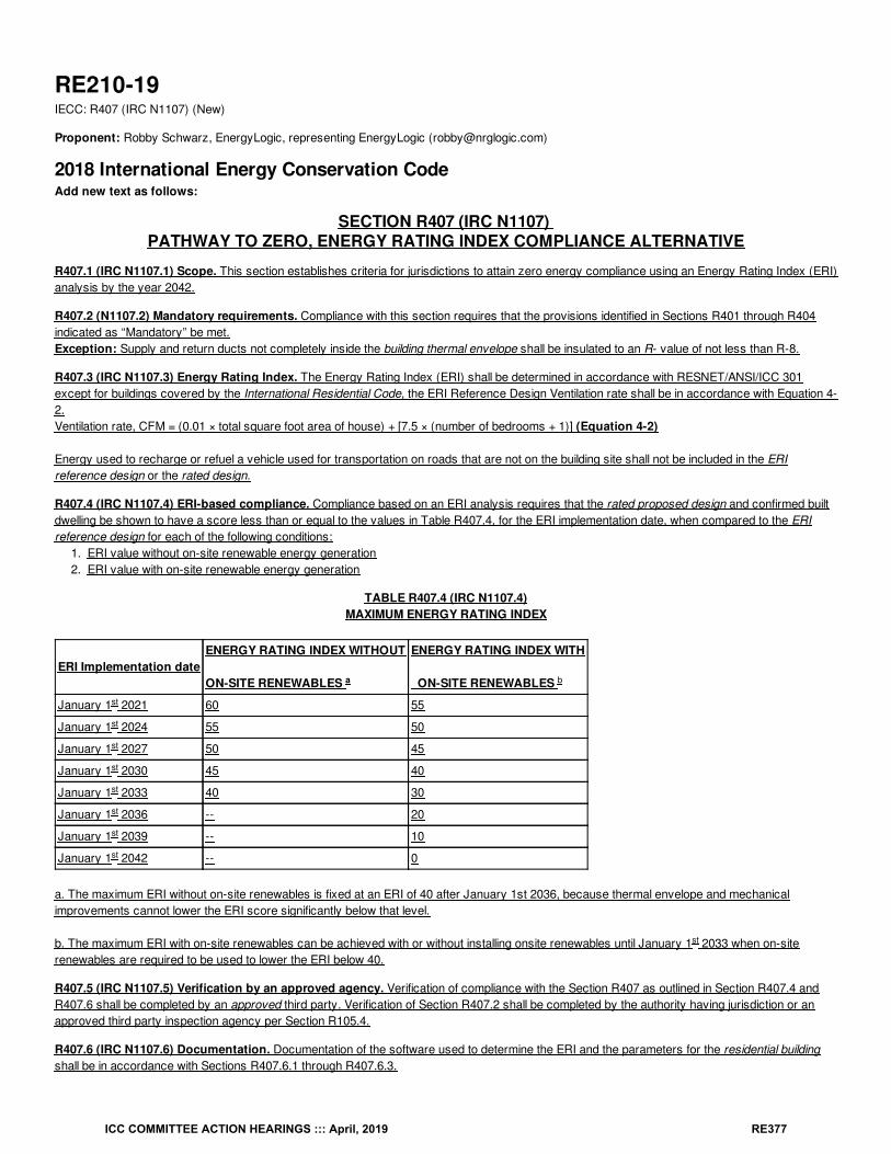
RE210-19IECC: R407 (IRC N1107) (New)
Proponent: Robby Schwarz, EnergyLogic, representing EnergyLogic ([email protected])
2018 International Energy Conservation CodeAdd new text as follows:
SECTION R407 (IRC N1107) PATHWAY TO ZERO, ENERGY RATING INDEX COMPLIANCE ALTERNATIVE
R407.1 (IRC N1107.1) Scope. This section establishes criteria for jurisdictions to attain zero energy compliance using an Energy Rating Index (ERI)analysis by the year 2042.
R407.2 (N1107.2) Mandatory requirements. Compliance with this section requires that the provisions identified in Sections R401 through R404indicated as “Mandatory” be met.Exception: Supply and return ducts not completely inside the building thermal envelope shall be insulated to an R- value of not less than R-8.
R407.3 (IRC N1107.3) Energy Rating Index. The Energy Rating Index (ERI) shall be determined in accordance with RESNET/ANSI/ICC 301except for buildings covered by the International Residential Code, the ERI Reference Design Ventilation rate shall be in accordance with Equation 4-2.Ventilation rate, CFM = (0.01 × total square foot area of house) + [7.5 × (number of bedrooms + 1)] (Equation 4-2)
Energy used to recharge or refuel a vehicle used for transportation on roads that are not on the building site shall not be included in the ERIreference design or the rated design.
R407.4 (IRC N1107.4) ERI-based compliance. Compliance based on an ERI analysis requires that the rated proposed design and confirmed builtdwelling be shown to have a score less than or equal to the values in Table R407.4, for the ERI implementation date, when compared to the ERIreference design for each of the following conditions:
1. ERI value without on-site renewable energy generation2. ERI value with on-site renewable energy generation
TABLE R407.4 (IRC N1107.4)MAXIMUM ENERGY RATING INDEX
ERI Implementation dateENERGY RATING INDEX WITHOUT
ON-SITE RENEWABLES
ENERGY RATING INDEX WITH
ON-SITE RENEWABLES
January 1 2021 60 55
January 1 2024 55 50
January 1 2027 50 45
January 1 2030 45 40
January 1 2033 40 30
January 1 2036 -- 20
January 1 2039 -- 10
January 1 2042 -- 0
a. The maximum ERI without on-site renewables is fixed at an ERI of 40 after January 1st 2036, because thermal envelope and mechanicalimprovements cannot lower the ERI score significantly below that level.
b. The maximum ERI with on-site renewables can be achieved with or without installing onsite renewables until January 1 2033 when on-siterenewables are required to be used to lower the ERI below 40.
R407.5 (IRC N1107.5) Verification by an approved agency. Verification of compliance with the Section R407 as outlined in Section R407.4 andR407.6 shall be completed by an approved third party. Verification of Section R407.2 shall be completed by the authority having jurisdiction or anapproved third party inspection agency per Section R105.4.
R407.6 (IRC N1107.6) Documentation. Documentation of the software used to determine the ERI and the parameters for the residential buildingshall be in accordance with Sections R407.6.1 through R407.6.3.
a b
st
st
st
st
st
st
st
st
st
ICC COMMITTEE ACTION HEARINGS ::: April, 2019 RE377
R407.6.1 (IRC N1107.6.1) Compliance software tools. Software tools used for determining ERI shall be approved software rating tools inaccordance with RESNET/ICC 301.
R407.6.2 (IRC N1107.6.2) Compliance report. Compliance software tools shall generate a report that documents that the home and ERI scorecomplies with Sections R407.2 through Section R407.4. The compliance documentation shall be created for the proposed design and submitted withthe application for the building permit. Confirmed compliance documents of the built dwelling unit shall be created and submitted to the code official forreview before a certificate of occupancy is issued. Compliance reports shall include information in accordance with Sections R407.6.2.1 andR407.6.2.2.
R407.6.2.1 (IRC N1107.6.2.1) Proposed Compliance report for permit application. Compliance reports submitted with the application for abuilding permit shall include the following:
1. Building street address, or other building site identification.2. The name of the individual performing the analysis and generating the compliance report.3. The name and version of the compliance software tool.4. If Requested by the authority having jurisdiction, documentation of all inputs entered into the software used to produce the results for the
reference design and/or the rated home.5. A certificate indicating that the proposed design has an ERI less than or equal to the appropriate scores indicated in Table R407.4 when
compared to the ERI reference design. The certificate shall document the building component energy specifications that are included in thecalculation including, component level insulation R-values or U-factors, assumed duct system and building envelope air leakage testingresults, as well as the type and rated efficiencies of proposed heating, cooling, mechanical ventilation, and service water heating equipment tobe installed. The type and production size of the proposed onsite renewable Energy systems shall be reported.
6. When a site-specific report is not generated, the proposed design shall be based on the worst-case orientation and configuration of the ratedhome.
R407.6.2.2 (IRC N1107.6.2.2) Confirmed Compliance report for a certificate of occupancy. A confirmed compliance report submitted forobtaining the certificate of occupancy shall be made site and address specific and include the following:
1. Building street address or other building site identification.2. The name of the individual performing the analysis and generating the report.3. The name and version of the compliance software tool.4. If requested by the authority having jurisdiction, documentation of all inputs entered into the software used to produce the results for the
reference design and/or the rated home.5. A final confirmed certificate indicating that the confirmed rated design of the built home complies with Sections R407.2 and R407.4. The
certificate shall report the energy features that were confirmed to be in the home including component level insulation R- values or U-factors,results from any required duct system and building envelope air leakage testing, as wells as, the type and rated efficiencies of the heating,cooling, mechanical ventilation, and service water heating equipment installed. The type and production size of the confirmed onsite renewableenergy systems shall be reported.
R407.6.3 (IRC N1107.6.3) Additional Documentation. The code official shall be permitted to require the following Documents:1. Documentation of the building component characteristics of the ERI reference design.2. A certification signed by the builder providing the building component characteristics of the rated design.3. Documentation of the actual values used in the software calculation for the rated design.
R407.6.4 (IRC N1107.6.4) Specific Approval. Performance analysis tools meeting the applicable section of Section R407 shall be approved.Documentation demonstrating the approval of the performance analysis with Section R407.6.1 shall be provided
R407.6.5 (IRC N407.6.5) Input values. Where calculation require input values not specified by Sections R402, R403, R404 and R405, those inputvalues shall be taken from RESNET/ICC 301.
Reason: As the Energy Rating Index (ERI) diverges from the Home Energy Rating System Index (HERS) it becomes important to realize thatalthough there are commonalities between the two, they are ultimately different from each other and should be thought of separately. As soon as theR406 ERI pathway was codified it locked in the ERI to a specific version of the RESNET/ANSI/ICC 301 standard while the HERS Index is based ona continually maintained version of the same ANSI 301 standard. Therefore, we now have divergent Index scores that mean different things.The HERS Index benchmarks the efficiency of a home in comparison to a reference home that is based on the 2006 IECC. A HERS Rating is anasset rating of the energy features in a home. This means that in the process of a HERS Rating to generate the HERS Index a Rater does notnecessarily inspect to see if energy features governed by the code are installed according to requirements of the code. For example, the HERSRatings systems’ insulation installation grading criteria gives guidance on how to de-rate the R-value of poorly installed insulation. The Rater isrequired to give a grade 3 to poor installations. The HERS Index score is intended to evaluate the performance of what is installed. It is not intendedto determine if it was installed per the requirement of code. A code rating or evaluation for the generation of the ERI score, on the other hand, shouldonly use a grade 1 because only grade 1 installation of insulation meets the requirements of manufacturer instructions and therefore code. If a Raterwere to evaluate a home for an ERI score and come across grade 3 installation of insulation, the installation should fail the inspection and be re-installed to meet code requirements. In this way, an ERI rating and a HERS rating are fundamentally different. One is held to a pass/fail requirementof code and the other is a quantification and evaluation of energy assets or components of the home. This small example demonstrates how theHERS index score and the ERI score differ.
ICC COMMITTEE ACTION HEARINGS ::: April, 2019 RE378
Another example that demonstrates a more pronounced difference between the indices is the codified ventilation requirements for the ERI score vs.the ventilation requirements for the HERS Index score. The ERI score uses the ASHRAE 62.2-2010 ventilation requirements while the HERS Indexuses the ASHRAE62.2-2013 ventilation requirements. This difference can result in over a 10-point difference in the scores.
Many are troubled by this divergence in the index scores, but I am not because the ERI and the HERS Index are fundamentally different if relatedsystems. The HERS Index has been adopted by builders and the public primarily as a sales and marketing tool and a means to compare theperformance of houses. The HERS Index score is quite good for these purposes. The ERI, like the area weighted u-values in section R402.1.5 TotalU-factor Alternative, or cost comparison in section R405 Simulated Performance Alternative is a matrix by which a home’s performance can becompared to demonstrate compliance with the code. It is not intended for marketing or public consumption and as the scores continue to diverge thepublic will continue to be unaware of the ERI score just as they are unaware of area weighted u-values and cost compliance. If a commonunderstanding can be created regarding this point then the ERI score can be a powerful tool to offer great flexibility for builders as well as a pathforward for the code and municipalities who choose to use it to achieve greater energy efficiency.
This proposal has been designed to leverage the unique nature of the ERI and the already codified mandatory aspects of the IECC, so as to offermunicipalities and builders an option that will continue the trend toward zero energy homes. As Section R407 is an optional pathway municipalitiesand builders can choose a code compliance path that allows great flexibility in energy specifications and design while the homebuilding industrylearns how to incorporate new technologies or better use old ones. The IECC’s emphasis on protecting the thermal envelope is protected not by apunitive R-value backstop, but rather by a before renewables ERI requirement. A Pre-renewables ERI score opens up flexibility through cost-effective energy tradeoffs that are the most flexible for the builder as they would include mechanical, thermal or conductive, convective lossesthrough envelope, along with duct tightness, lights, appliances, and more. Any feature that lowers the ERI can be used. This integrated energyevaluation acknowledges that the ERI of a home cannot be lowered beyond a certain threshold unless renewables are installed, but also sets thepre-renewable ERI at a level that ensures current levels of efficiency will be created as the starting point. For example, when a builder maximizesthe thermal envelope and mechanical efficiencies of their design the ERI cannot go lower than approximately 35-40. To get an ERI score below thatrange on-site renewables must be installed. In this way, R407, as proposed, ensures a sound building envelope and efficient mechanical systemsbefore renewables are considered.
The uniqueness of this proposal is that it creates a timeline by which a clear incremental approach for achieving increases in efficiencies that wouldlead to zero energy homes can be achieved. Although this will be new to the code development world, it is tremendously important to allow the pathto zero to be phased in and for giving builders and jurisdictions a timeline for planning to achieve the ultimate goal. This phased-in approach hasprecedence in two Colorado jurisdictions. The City of Boulder and Boulder County have both set a phased approach for attaining zero energy in theirmunicipalities.
Section R407 is optional so only those municipalities and builders that are searching for code compliant incremental approaches need take part. Ithas become a difficult argument to increase R-values, house tightness or duct leakage requirements in the 2021 IECC development cycle. This ERIapproach to Zero Energy offers a logical, market-driven approach that creates a timeline for achieving significant increases in efficiency whilesimultaneously giving industry time to adjust and provide cost-effective solutions. This proposal also guards against building poor thermal envelopesand offsetting with on-site renewable systems. This proposal offers builders the greatest flexibility to choose how to build to meet the requirements ofcode.
Cost Impact: The code change proposal will increase the cost of constructionThis R407 PATHWAY TO ZERO, ENERGY RATING INDEX COMPLIANCE ALTERNATIVE is just that and optional alternative path way to notonly demonstrate compliance with the IECC but to help jurisdictions that are interested define a measurable and incremental approach to create zeroenergy homes. This approach is being used in Colorado although it is true that cost of construction increases it is only required if the jurisdictionchooses to adopt the pathway.
Proposal # 5283
RE210-19
ICC COMMITTEE ACTION HEARINGS ::: April, 2019 RE379
RE211-19IECC: R501.2 (IRC N1107.2), R501.4 (IRC N1107.4), R502.1 (IRC N1108.1), R502.1.1 (IRC N1108.1.1), R502.1.1.1 (IRC N1108.1.1.1), R502.1.1.2(IRC N1108.1.1.2) , R502.1.1.3 (IRC N1108.1.1.3), R502.1.1.4 (IRC N1108.1.4), R502.1.2 (IRC 1102.1.2), R503.2 (IRC N1109.2), R503.1.2 (IRCN1109.1.2), R505.1 (IRC N1111.1), R505.2 (IRC N1111.2), R505.1.1 (IRC N1111.1.1)
Proponent: David Collins, representing SEHPCAC ([email protected]); David Collins, representing The American Institute of Architects([email protected])
2018 International Energy Conservation Code
SECTION R501 (IRC N1107) GENERAL
R501.1 (IRC N1107.1.1) Scope. The provisions of this chapter shall control the alteration, repair, addition and change of occupancy of existingbuildings and structures.
Revise as follows:
R501.2 (IRC N1107.2) R501.1.1 (IRC N1107.1.1) Existing buildings. General Except as specified in this chapter, this code shall not be used torequire the removal, alteration or abandonment of, nor prevent the continued use and maintenance of, an existing building or building system lawfullyin existence at the time of adoption of this code. Unaltered portions of the existing building or building supply system shall not be required to complywith this code.
R501.4 (IRC N1107.4) R501.2 (IRC N1107.2) Compliance. AlterationsAdditions, alterations repairs, additions and or changes of occupancy to, orrelocation of , existing buildings and structures shall comply with the provisions for alterations, repairs, additions and changes of occupancy orrelocation, respectively, in this code and the International Residential Code , International Building Code , International Existing Building Code ,International Fire Code , International Fuel Gas Code , International Mechanical Code , International Plumbing Code , International PropertyMaintenance Code , International Private Sewage Disposal Code and NFPA 70. Sections R502, R503, R504, or R505 respectively in this code.Changes where unconditioned space is changed to conditioned space shall comply with Section R502.
SECTION R502 (IRC N1108) ADDITIONS
Revise as follows:
R502.1 (IRC N1108.1) General. Additions to an existing building, building system or portion thereof shall conform to the provisions of this code asthose provisions relate to new construction without requiring the unaltered portion of the existing building or building system to comply with this code.Additions shall not create an unsafe or hazardous condition or overload existing building systems. An addition shall be deemed to comply with thiscode where the addition alone complies, where the existing building and addition comply with this code as a single building, or where the building withthe addition does not use more energy than the existing building. Additions shall be in accordance with Section R502.1.1 R502.2 or R502.1.2. R502.3
R503.2 (IRC N1109.2) R502.2 (IRC N1108.2) Change in space conditioning. Any nonconditioned or low-energy space that is altered to becomeconditioned space shall be required to be brought into full compliance with this code.
Exception Exceptions:
1. Where the simulated performance option in Section R405 is used to comply with this section, the annual energy cost of the proposeddesign is permitted to be 110 percent of the annual energy cost otherwise allowed by Section R405.3.
2. Where unconditioned space is changed to conditioned space , and the building envelope of the addition shall comply where the Total UA,as determined in Section R402.1.5, of the existing building and the addition , and any alterations that are part of the project, is less than orequal to the Total UA generated for the existing building .
3. Where unconditioned space is changed to conditioned space , the addition shall comply where the annual energy cost or energy use ofthe addition and the existing building , and any alterations that are part of the project, is less than or equal to the annual energy cost of theexisting building when modeled in accordance with Section R405. The addition and any alterations that are part of the project shall complywith Section R405 in its entirety.
R502.1.1 (IRC N1108.1.1) R502.3 (IRC N1108.3) Prescriptive compliance. Additions shall comply with Sections R502.1.1.1 R502.3.1 throughR502.1.1.4. R502.3.4
R502.1.1.1 (IRC N1108.1.1.1) R502.3.1 (IRC N1108.3.1) Building envelope. New building envelope assemblies that are part of the addition shallcomply with Sections R402.1, R402.2, R402.3.1 through R402.3.5, and R402.4.
Exception: New envelope assemblies are exempt from the requirements of R402.4.1.2. Where unconditioned space is changed to conditioned
ICC COMMITTEE ACTION HEARINGS ::: April, 2019 RE380
space, the building envelope of the addition shall comply where the Total UA, as determined in Section R402.1.5, of the existing building and theaddition, and any alterations that are part of the project, is less than or equal to the Total UA generated for the existing building.
R502.1.1.2 (IRC N1108.1.1.2) R502.3.2 (IRC N1108.3.2) Heating and cooling systems. New heating, cooling and duct systems that are HVACducts newly installed as part of the an addition shall comply with Section R403.
Exception: Where ducts from an existing heating and cooling system are extended to an addition, duct systems with less than 40 linear feet(12.19 m) in unconditioned spaces shall not be required to be tested in accordance with Section R403.3.3. .
R502.1.1.3 (IRC N1108.1.1.3) R502.3.3 (IRC 1108.3.3) Service hot water systems. New service hot water systems that are part of the additionshall comply with Section R403.4.
R502.1.1.4 (IRC N1108.1.4) R502.3.4 (IRC N1108.3.4) Lighting. New lighting systems that are part of the addition shall comply with SectionR404.1.
R502.1.2 (IRC N1108.1.2) Existing plus addition compliance (Simulated Performance Alternative). Where unconditioned space is changed toconditioned space, the addition shall comply where the annual energy cost or energy use of the addition and the existing building, and any alterationsthat are part of the project, is less than or equal to the annual energy cost of the existing building when modeled in accordance with Section R405.The addition and any alterations that are part of the project shall comply with Section R405 in its entirety.
SECTION R503 (IRC 1109) ALTERATIONS
Revise as follows:
R503.1.2 (IRC N1109.1.2) Heating and cooling systems. New heating, cooling and duct systems that are part of the HVAC ducts newly installed,as part of an alteration shall comply with Section R403.
Exception: Where ducts from an existing heating and cooling system are extended, duct systems with less than 40 linear feet (12.19 m) inunconditioned spaces shall not be required to be tested in accordance with Section R403.3.3. extended.
SECTION R505 (IRC N1111) CHANGE OF OCCUPANCY OR USE
Delete without substitution:
R505.1 General. Spaces undergoing a change in occupancy that would result in an increase in demand for either fossil fuel or electrical energy shallcomply with this code.
Revise as follows:
R505.2 (IRC N1111.2) R505.1 (IRC N1111.1) General. Any space that is converted to a dwelling unit or portion thereof from another use oroccupancy shall comply with this code.
Exception: Where the simulated performance option in Section R405 is used to comply with this section, the annual energy cost of theproposed design is permitted to be 110 percent of the annual energy cost allowed by Section R405.3.
Add new text as follows:
R505.1.1 (IRC N1111.1.1) Nonconditioned Space Any nonconditioned or low-energy space that is altered to become a conditioned space shallcomply with Section R502.
Reason: No advantage to any proprietary interests governed by the code is intended. The intent is strictly to make the IECC more understandableand easier to use; or, where technical change is proposed, to make the code more reasonable.Unlike the bulk of proposed SEHPCAC changes this proposal does have two technical changes incorporated:
It removes the requirement for additions to be air leakage tested per Sec. R402.4.1.2 Testing. It is unreasonable to expect an addition tocomply with air leakage testing when it is likely open to existing, and potentially much older, unsealed residential space.It removes the requirement for duct leakage testing on duct extensions. It is unreasonable to expect the sealing of sections of older, potentiallyconcealed, existing ducts from which new duct is to extend.
This change also:
Clarifies changes from unconditioned space to condition space must comply as additions.Consolidates all compliance provisions related to changes from unconditioned to conditioned space
ICC COMMITTEE ACTION HEARINGS ::: April, 2019 RE381
This proposal is submitted by the ICC Sustainable, Energy and High Performance Code Action Committee (SEHPCAC). The SEHPCAC wasestablished by the ICC Board of Directors to pursue opportunities to improve and enhance International Codes with regard to sustainability, energyand high performance as it relates to the built environment included, but not limited to, how these criteria relate to the International GreenConstruction Code (IgCC) and the International Energy Conservation Code (IECC). In 2018-2019, the SEHPCAC has held five two- or three-dayopen meetings and numerous workgroup calls, to discuss and debate proposed changes and public comments. Attendees at the meetings and callsincluded members of the SEHPCAC as well as any interested parties. Related documentation and reports are posted on the SEHPCAC website at:http://www.iccsafe.org/cs/SEHPCAC/Pages/default.aspx (http://www.iccsafe.org/cs/SEHPCAC/Pages/default.aspx)
Cost Impact: The code change proposal will not increase or decrease the cost of constructionThe two exemptions provided do not functionally change construction practices, neither the duct leakage of duct extensions and air leakage testingof envelope assemblies on additions is not feasible and therefor not current practice.
Proposal # 4699
RE211-19
ICC COMMITTEE ACTION HEARINGS ::: April, 2019 RE382
RE212-19IECC: R502.1 (IRC N1108.1), R502.1.1 (IRC N1108.1.1), R502.1.1.1 (IRC N1108.1.1.1), R502.1.2 (IRC N1108.1.2), R502.1.2.1 (IRC N1108.1.2.1)(New), R502.1.3 (IRC N1108.1.3) (New), R502.1.3.1 (IRC N1108.1.3.1) (New), R502.1.4 (IRC N1108.1.4) (New), R502.1.4.1 (IRC N1108.1.4.1)(New)
Proponent: Robby Schwarz, EnergyLogic, representing EnergyLogic ([email protected]); Shaunna Mozingo([email protected])
2018 International Energy Conservation Code
SECTION R502 ADDITIONS
Revise as follows:
R502.1 (IRC N1108.1) General. Additions to an existing building, building system or portion thereof shall conform to the provisions of this code asthose provisions relate to new construction without requiring the unaltered portion of the existing building or building system to comply with this code.code unless required to do so by the chosen compliance pathway. Additions shall not create an unsafe or hazardous condition or overload existingbuilding systems. An addition shall be deemed to comply with this code where the addition alone complies, where the existing building and additioncomply with this code as a single building, or where the building with the addition does not use more energy than the existing building. Additions shallbe in accordance with Section R502.1.1 or R502.1.2. by using either the prescriptive path in Section R502.1.1, simulated performance path inSection R502.1.2, or the energy rating index path In Section R502.1.3 .
R502.1.1 (IRC N1108.1.1) Prescriptive Additions prescriptive compliance. Additions shall comply with Sections R502.1.1.1 through R502.1.1.4.
R502.1.1.1 (IRC N1108.1.1.1) Building envelope. New building envelope assemblies that are part of the addition alone shall comply with theprescriptive Sections R402.1, R402.2, R402.3.1 through R402.3.5, and R402.4 , R402.3, and R402.4.1.1.
Exception: Where unconditioned space is changed to conditioned space, the building envelope of the addition shall comply where the Total UA,as determined in Section R402.1.5, of the existing building and the addition, and any alterations that are part of the project, is less than or equal tothe Total UA generated for the existing building.
R502.1.1.2 (IRC N1108.1.1.2) Heating and cooling systems. New heating, cooling and duct systems that are part of the addition shall comply withSection R403.
Exception: Where ducts from an existing heating and cooling system are extended to an addition, duct systems with less than 40 linear feet(12.19 m) in unconditioned spaces shall not be required to be tested in accordance with Section R403.3.3.
R502.1.1.3 (IRC N1108.1.1.3) Service hot water systems. New service hot water systems that are part of the addition shall comply with SectionR403.4.
R502.1.1.4 (IRC N1108.1.1.4) Lighting. New lighting systems that are part of the addition shall comply with Section R404.1.
Revise as follows:
R502.1.2 (IRC N1108.1.2) Existing plus addition compliance (Simulated Performance Alternative). Cost compliance verification shalldemonstrate that the existing building plus the addition does not use more energy than the existing building did prior to the addition. This methodrequires the project to create cost compliance verification at three stages:
1. A baseline cost compliance of the existing structure prior to construction.2. Projected cost compliance of the existing building plus the addition based on the proposed design for the building in its entirety.3. Confirmed cost compliance to verify whole building performance.Where unconditioned space is changed to conditioned space, the addition
shall comply where the annual energy cost or energy use of the addition and the existing building, and any alterations that are part of theproject, is less than or equal to the annual energy cost of the existing building when modeled in accordance with Section R405. The additionand any alterations that are part of the project shall comply with Section R405 in its entirety.
Add new text as follows:
R502.1.2.1 (IRC N1108.1.2.1) Reporting. Both the baseline and the projected cost compliance reports that include documentation of the proposeddesign shall be submitted with the construction documents. A confirmed cost compliance report shall be submitted prior to final inspection.
R502.1.3 (IRC N1108.1.3) Existing plus addition compliance (Energy Rating Index Alternative). An energy rating index score shalldemonstrate that the existing building plus the addition does not use more energy than the existing building did prior to the addition. This methodrequires the project to obtain an ERI score at three stages:
1. A baseline ERI of the existing structure prior to construction.
ICC COMMITTEE ACTION HEARINGS ::: April, 2019 RE383
2. A projected ERI of the existing building plus the addition based on the proposed design for the building in its entirety.3. A confirmed ERI to verify whole building performance.
R502.1.3.1 (IRC N1108.1.3.1) Reporting. Both the baseline and the projected ERI compliance reports that include documentation for the proposeddesign shall be submitted with the construction documents. A confirmed ERI report shall be submitted prior to final inspection.
R502.1.4 (IRC N1108.1.4) Existing plus addition compliance (Prescriptive). The existing building plus the addition shall demonstrate that thestructure in its entirety does not use more energy than the existing building did prior to adding the addition. All prescriptive measures shall beinstalled in the addition in accordance Section R402.1. A blower door test shall be performed to establish a baseline air leakage rate for the existingbuilding prior to construction. Prior to final building inspection, a blower door test shall be conducted on the existing building plus addition todemonstrate an air leakage rate equal to or less than the baseline measurement.
R502.1.4.1 (IRC N1108.1.4.1) Reporting. A baseline blower door testing report for the existing building prior to construction shall be submitted withthe construction documents. A confirmed blower door testing report shall be submitted after construction is complete and prior to final inspection.
Reason: The current existing buildings chapter 5 of the IECC has always struggled with clearly executing the energy code previsions on additionsto an existing building. A building science approach teaches us that the house is a system. Therefore, if an addition is added to an existing buildingthen the system’s configuration has changed and assessing compliance on a portion of the system becomes a problem. In really, it is not possible toassess a portion of the system separated from its entirety for energy code compliance. However, the code has established a method, but not aclear means for trying to do so.In one form or another the IECC has always stated that an addition shall be deemed to comply where the building with the addition does not usedmore energy than the existing building did without the addition. The proposal for this section leverages this language (or method) and the existingpaths (the means) in the code to offer better compliance mechanisms. The proposed Section R502.1.4 Existing plus addition compliance(Prescriptive), for example, uses a baseline pre-blower door test compared to a final confirmed blower door test to demonstrate if the final product isbetter than or equal to the existing benchmarked building. The assumption is that the prescriptive R-values, U-values, and installation requirementsfor the specification installed in the addition will be better than what has been installed in the existing portions of the building. Since it is not practicaland, in most cases, possible to perform a blower door on just the addition the requirement changes in order to use the blower door as a compliancemechanism.
A Simulated Performance and Energy Rating Index path have been added as alternative compliance mechanisms in this section of the code forthree reasons. First, the blower door is moved back to an assessment of energy performance rather than used as a compliance mechanism.Second, it is our experience that existing portions of a building are almost always touched during the creation of an addition on a building. Therefore,these compliance paths look at the entirety of the building rather than just the addition. Third, design flexibility is achieved when one is not required touse every portion of the prescriptive specification outlined in the code. The clear ability to use tradeoffs in existing buildings fits better with the realityof construction in this arena. Forth, these two pathways enable and encourage pre-planning as well as offer a very clear matrix of compliance. Thesoftware analysis to generate the proposed design for the existing building plus the addition clearly projects if the new building in its entirety, will bebetter than or equal to the existing benchmarked building. The projection enables the designer to forecast what in the existing building must beaddressed which helps create better building budgets and expectations. In addition, a variety of options can be presented to pick what in the existingand new sections of the building makes the most sense to address.
Cost Impact: The code change proposal will not increase or decrease the cost of constructionDemonstration of compliance with this code is required regardless, so adding additional options for demonstrating compliance would not add to thecost. It is not a certainty, but added flexibility could reduce the cost of construction as well as jurisdictional time spent on enforcement.
Proposal # 4747
RE212-19
ICC COMMITTEE ACTION HEARINGS ::: April, 2019 RE384
RE213-19IECC: R503.1.1 (IRC N1109.1.1)
Proponent: Robby Schwarz, EnergyLogic, representing EnergyLogic ([email protected]); Shaunna Mozingo([email protected])
2018 International Energy Conservation CodeRevise as follows:
SECTION R503 (IRC N1109) ALTERATIONS
R503.1 (IRC N1109.1) General. Alterations to any building or structure shall comply with the requirements of the code for new construction.Alterations shall be such that the existing building or structure is not less conforming to the provisions of this code than the existing building orstructure was prior to the alteration.Alterations to an existing building, building system or portion thereof shall conform to the provisions of this code as they relate to new constructionwithout requiring the unaltered portions of the existing building or building system to comply with this code. Alterations shall not create an unsafe orhazardous condition or overload existing building systems. Alterations shall be such that the existing building or structure does not use more energythan the existing building or structure prior to the alteration. Alterations to existing buildings shall comply with Sections R503.1.1 through R503.2.
R503.1.1 (IRC N1109.1.1) Building envelope. Building envelope assemblies that are part of the alteration shall comply with Section R402.1.2 orR402.1.4, Sections R402.2.1 through R402.2.13, R402.3.1, R402.3.2, R402.4.3 and R402.4.5. . A pre and post blower door test shall be completedwhen building thermal envelope alterations are performed. If the alteration results in a post blower door CFM50 measurement that is less that thebuilding airflow standard as set forth in Section R402.4.1.2, then combustion safety testing shall be performed and mechanical ventilation shall berecommended.
Exception: The following alterations shall not be required to comply with the requirements for new construction provided that the energy use ofthe building is not increased:
1. Storm windows installed over existing fenestration.2. Existing ceiling, wall or floor cavities exposed during construction provided that these cavities are filled with insulation.3. Construction where the existing roof, wall or floor cavity is not exposed.4. Roof re-cover.5. Roofs without insulation in the cavity and where the sheathing or insulation is exposed during reroofing shall be insulated either
above or below the sheathing.6. Surface-applied window film installed on existing single pane fenestration assemblies to reduce solar heat gain provided that the
code does not require the glazing or fenestration assembly to be replaced.
Reason: Alterations to the buildings thermal envelope inevitably impact the air tightness of the building and therefore the combustion safety of thebuilding. This section of the code is in existing buildings which is an indication that the majority of the structures have atmospherically ventedappliances. Specifically, atmospherically vented water heaters, which are the most likely appliance to back draft, are susceptible to pressurechanges in existing homes. Replacing windows, adding insulation, installing air tight IC rated can lights, or any individual building thermal envelopeupgrade, changes the dynamic in the building significantly to warrant preventative combustion safety testing and possibly mechanical ventilation.The proposed language continues to demonstrate the importance of energy codes relationship to health safety and durability as well as efficiency asdescribed in the code’s intent Section R101.3.
Cost Impact: The code change proposal will increase the cost of constructionCost would be impacted as the health and safety of the building to better ensure that the occupant was not poisoned by carbon monoxide wouldhave to be tested. This test cost approximately $200-400 if conducted as a stand-alone test. Many energy retrofit specialists and building envelopespecialists include this test as part of their service which brings down the cost.
Proposal # 4749
RE213-19
ICC COMMITTEE ACTION HEARINGS ::: April, 2019 RE385
RE214-19IECC: R502.1.1.1 (IRC N1108.1.1.1)
Proponent: Shaunna Mozingo, City of Westminster, representing Colorado Chapter of ICC Energy Code Development Committee([email protected])
2018 International Energy Conservation CodeRevise as follows:
R502.1.1.1 (IRC N1108.1.1.1) Building envelope. New building envelope assemblies that are part of the addition shall comply with SectionsR402.1, R402.2, R402.3.1 through R402.3.5, and R402.4.
Exception: Where unconditioned space is changed to conditioned space, the building envelope of the addition shall comply where the Total UA,as determined in Section R402.1.5, of the existing building and the addition, and any alterations that are part of the project, is less than or equal tothe Total UA generated for the existing building.
Reason: This section of the code is talking about additions, which is new construction. The exception is talking about a change in spaceconditioning, which takes place as an alteration not as new construction. It does not make sense to have this exception for additions.
Cost Impact: The code change proposal will not increase or decrease the cost of constructionThe exception wasn't addressing additions to begin with, so there should be no cost to remove it.
Proposal # 5320
RE214-19
ICC COMMITTEE ACTION HEARINGS ::: April, 2019 RE386
RE215-19IECC: R503.1 (IRC N1109.1)
Proponent: Shaunna Mozingo, City of Westminster, representing Colorado Chapter of ICC Energy Code Development Committee([email protected])
2018 International Energy Conservation CodeRevise as follows:
R503.1 (IRC N1109.1) General. Alterations to any building or structure shall comply with the requirements of the code for new construction , withoutrequiring the unaltered portions of the existing building or building system to comply with this code. Alterations shall be such that the existing buildingor structure is not less conforming to the provisions of this code than the existing building or structure was prior to the alteration.Alterations to an existing building, building system or portion thereof shall conform to the provisions of this code as they relate to new constructionwithout requiring the unaltered portions of the existing building or building system to comply with this code.
Alterations shall not create an unsafe or hazardous condition or overload existing building systems. Alterations shall be such that the existingbuilding or structure does not use more energy than the existing building or structure prior to the alteration. Alterations to existing buildings shallcomply with Sections R503.1.1 through R503.2.
Reason: Removing redundant language.
Cost Impact: The code change proposal will not increase or decrease the cost of constructionRemoving redundant language.
Proposal # 5328
RE215-19
ICC COMMITTEE ACTION HEARINGS ::: April, 2019 RE387
RE216-19IECC: R503.1.1.1 (IRC N1109.1.1.1)
Proponent: Shaunna Mozingo, representing Self ([email protected])
2018 International Energy Conservation CodeRevise as follows:
R503.1.1.1 (IRC N1109.1.1.1) Replacement fenestration. Where some or all of an existing fenestration unit is replaced with a new fenestrationproduct, including sash and glazing, the replacement fenestration unit shall meet the applicable requirements for U-factor and SHGC as specifiedTable R402.1.2. Where more than one replacement fenestration unit is to be installed, an area-weighted average of the U-factor, SHGC or both of allreplacement fenestration units shall be an alternative that can be used to show compliance.Where fenestration was previously used as a trade off in the building thermal envelope, the replacement fenestration shall have a U-Factor andSHGC equal to or less than the original fenestration U-Factor and SHGC.
Reason: If someone used good windows to get out of some insulation or to lower the insulation value and then they go to replace the windows butonly used todays code value there is a chance that they are making the building thermal envelope less conforming than it was at the time ofconstruction. Section 503.1 says that an alteration can never make a structure less conforming or use more energy.This can be easily enforced if a jurisdiction requires the mandatory certificates that are called out in R401.3 that let us know what U-Factors andSHGC went in to the thermal envelope. These certificates become more and more important as we alter our buildings and as we provide trade offssuch as window replacements.
Cost Impact: The code change proposal will not increase or decrease the cost of constructionBecause the energy code says that you can never make a building less conforming or use more energy, this new wording has always been impliedbut never written. Therefore, there should be no change in cost.
Proposal # 5331
RE216-19
ICC COMMITTEE ACTION HEARINGS ::: April, 2019 RE388
RE217-19IECC: R503.1.1 (IRC N1109.1.1)
Proponent: Darren Meyers, P.E., IECC_LLC representing the National Roofing Contractors Association, representing the National RoofingContractors Association ([email protected])
2018 International Energy Conservation CodeRevise as follows:
R503.1.1 (IRC N1109.1.1) Building envelope. Building envelope assemblies that are part of the alteration shall comply with Section R402.1.2 orR402.1.4, Sections R402.2.1 through R402.2.13, R402.3.1, R402.3.2, R402.4.3 and R402.4.5.
Exception: The following alterations shall not be required to comply with the requirements for new construction provided that the energy use ofthe building is not increased:
1. Storm windows installed over existing fenestration.2. Existing ceiling, wall or floor cavities exposed during construction provided that these cavities are filled with insulation.3. Construction where the existing roof, wall or floor cavity is not exposed.4. Roof re-cover.5. Roofs without insulation in the cavity and where the sheathing or insulation is exposed during reroofing shall be insulated either
above or below the sheathing. Roof replacement , where the required R -value of insulation entirely above the roof deck cannotbe provided due to thickness limitations presented by existing rooftop conditions, including an HVAC system or refrigerationequipment, skylight curb(s), low door or glazing heights, weep holes, parapet or roof flashing heights, the maximum approvedthickness of insulation compatible with the available space and existing uses shall be installed.
6. Surface-applied window film installed on existing single pane fenestration assemblies to reduce solar heat gain provided that thecode does not require the glazing or fenestration assembly to be replaced.
Reason: This proposal is based on CE287-16, and resubmitted for flat-roof residential applications where the required R-value of insulation entirelyabove the roof deck cannot be provided due to thickness limitations. CE287-16 received a Committee recommendation of “Disapproval,” a PublicComment recommendation of “As Modified by Public Comment” (AMPC), but ultimately did not receive the two-thirds necessary to prevail during the“Online Governmental Consensus Vote” (OGCV), leading to “Disapproval” as its Final Action.Specifically, the newly proposed exception addresses the AMPC and the challenge of constructability when installing additional roof insulation inreroofing situations including roof recover and roof replacement where existing conditions do not allow for the full thickness of insulation required byTable R402.1.2 or Table R402.1.4. Consider the square footage of residential buildings with flat roofs (i.e., “two-flats” and “three-flats”) constructedbefore an adoption of the 2009 IECC, that now require reroofing, without adequate “clear space” to accommodate up to 5+ inches (R-25-ish) or 6+inches (R-30-ish) of insulation as the IECC evolved thru 2012 to 2015 and now the 2018 Editions. The building stock now considered 10 to 20 to 30+years old, is far more likely to avail itself of skylight and structural curb heights, scupper and sump depths, door and window access thresholds thatwould turn into ponds, if five to six inches of insulation were "retroactively" foisted upon building ownership.
Moreover, if the IECC CDC were to consult the premise to Section R505.1, that "... [neither] an increase in demand for either fossil fuel [nor]electrical energy shall comply with this code," so long as the current level of insulation in the roof is replaced with an equivalent thickness/level/R-value of NEW! insulation product, you'd likely conclude that he newly proposed Exception 5 is a "do-no-harm" proposition.
Should the Committee agree with the newly proposed Exception 5, then the continuance of current Exception 5 is unnecessary, as both the currentException 4 (Roof re-cover) and the New! Exception 5 (Roof replacement) address all circumstances defined as Reroofing.
We believe the proposal makes clear that the maximum thickness of insulation compatible within the technically-feasible limitations of "availablespace" and maintaining "positive drainage" is to be installed.
Cost Impact: The code change proposal will not increase or decrease the cost of constructionThis change better positions the IECC to be clearer, more easily applied to reroofing, more competitive than the 90.1 Standard alternative on thisissue; thereby no cost impact when compared with current provisions.
Proposal # 5271
RE217-19
ICC COMMITTEE ACTION HEARINGS ::: April, 2019 RE389
RE218-19IECC: R503.1.4
Proponent: Marilyn Williams, representing National Electrical Manufacturers Association ([email protected])
2018 International Energy Conservation CodeRevise as follows:
R503.1.4 (IRC N1109.1.4) Lighting. New lighting systems that are part of the alteration shall comply with Section R404.1.R404.1.
Exception: Alterations that replace less than 50 10 percent of the luminaires in a space, provided that such alterations do not increase theinstalled interior lighting power.
Reason: Revising this language will:1. Increase energy efficiency
2. Reduce inconsistency and application confusion in compliance
3. Resolve compliance with application, approval and inspection.
This revised language aligns the residential lighting alteration section with the commercial lighting systems Section C503.6. It changes the lightingalteration exception from when less than 50 percent of the luminaires in the space are replaced, to when less than 10 percent are replaced. This willmake compliance and usability of the code easier as well as increase in the energy efficiency of alterations when 10 or less than 50 percent of theluminaires are replaced.
Cost Impact: The code change proposal will increase the cost of constructionThis code change proposal will increase the cost of construction for residential alterations that replace between 10 and 50 percent of luminaires in aspace.
Proposal # 4915
RE218-19
ICC COMMITTEE ACTION HEARINGS ::: April, 2019 RE390
RE219-19IECC: R503.1.1 (IRC N1109.1.1)
Proponent: Darren Meyers, P.E., IECC_LLC representing the National Roofing Contractors Association, representing the National RoofingContractors Association ([email protected])
2018 International Energy Conservation CodeRevise as follows:
R503.1.1 (IRC N1109.1.1) Building envelope. Building envelope assemblies that are part of the alteration shall comply with Section R402.1.2 orR402.1.4, Sections R402.2.1 through R402.2.13, R402.3.1, R402.3.2, R402.4.3 and R402.4.5.
Exception: The following alterations shall not be required to comply with the requirements for new construction provided that the energy use ofthe building is not increased:
1. Storm windows installed over existing fenestration.2. Existing ceiling, wall or floor cavities exposed during construction provided that these cavities are filled with insulation.3. Construction where the existing roof, wall or floor cavity is not exposed.4. Roof re-cover.5. Roofs without insulation in the cavity entirely above the roof deck and where the sheathing or insulation is exposed during
reroofing shall be insulated either above or below the sheathing.6. Surface-applied window film installed on existing single pane fenestration assemblies to reduce solar heat gain provided that the
code does not require the glazing or fenestration assembly to be replaced.
Reason: It is unclear as to the intended application of current Exception 5 to Section 503.1.1. We believe the Exception was intended to apply tolow-slope roof reroofing, as defined. However, with all roof re-covers addressed by current Exception 4, it is therefore likely current Exception 5 wasintended to apply solely to flat roof replacement operations.The overall outcome (i.e., fate) in applying Exception 5 to a low-slope roof replacement is seemingly to advise the roofing contractor to installreplacement insulation, at whichever thickness and R-value (i.e., recall this is an exception), either above or below the rafter-line.
Cost Impact: The code change proposal will not increase or decrease the cost of constructionThere is no cost implication aligned with this proposal. Rather, it is an exercise steeped in clarification and consistency across the ICC Family ofInternational Codes.
Proposal # 5269
RE219-19
ICC COMMITTEE ACTION HEARINGS ::: April, 2019 RE391
RE220-19IECC: R503.2 (N1109.2), R505.2 (IRC N1111.2)
Proponent: Robby Schwarz, EnergyLogic, representing EnergyLogic ([email protected]); Shaunna Mozingo([email protected])
2018 International Energy Conservation CodeRevise as follows:
SECTION R503 (IRC N1109) ALTERATIONS
R503.2 (IRC N1109.2) Change in space conditioning. Any nonconditioned or low-energy space that is altered to become conditioned space shallbe required to be brought into full compliance with this code.
Exception: Where the simulated performance option in Section R405 is used to comply with this section, the annual energy cost of theproposed design is permitted to be 110 percent of the annual energy cost otherwise allowed by Section R405.3. Spaces where compliance isdemonstrated using the compliance mechanisms in accordance with Section R502.
SECTION R505 (IRC N1111) CHANGE OF OCCUPANCY OR USE
R505.2 (IRC N1111.2) General. Any space that is converted to a dwelling unit or portion thereof from another use or occupancy shall comply withthis code.
Exception: Where the simulated performance option in Section R405 is used to comply with this section, the annual energy cost of theproposed design is permitted to be 110 percent of the annual energy cost allowed by Section R405.3. Spaces where compliance isdemonstrated using the compliance mechanisms in accordance with Section R502.
Reason: This proposed change to Alteration and Change of Occupancy or Use in this existing buildings chapter offers a more flexible alternativecompliance paths as outlined in the proposal for prescriptive, simulated performance, and energy rating index compliance paths in the Additionssection of Section R505 Existing Buildings Performance Compliance Alternative. If the proposal is not accepted this proposal will be removed fromconsideration.
Cost Impact: The code change proposal will not increase or decrease the cost of constructionDemonstration of compliance with this code is required regardless, so adding additional options for demonstrating compliance would not add to thecost. It is not a certainty, but added flexibility could reduce the cost of construction as well as jurisdictional time spent on enforcement.
Proposal # 4751
RE220-19
ICC COMMITTEE ACTION HEARINGS ::: April, 2019 RE392
RE221-19IECC: R505.1 (IRC N1107.1), R505.2 (IRC N1111.2)
Proponent: Shaunna Mozingo, representing Self ([email protected])
2018 International Energy Conservation CodeRevise as follows:
R505.1 (IRC N1107.1) General. Spaces undergoing a change in occupancy that would result in an increase in demand for either fossil fuel orelectrical energy shall comply with this code. R501.1.1.
R505.2 (IRC N1111.2) General. Any space that is converted to a dwelling unit or portion thereof from another use or occupancy shall comply withthis code. Section 501.1.1.
Exception: Where the simulated performance option in Section R405 is used to comply with this section, the annual energy cost of theproposed design is permitted to be 110 percent of the annual energy cost allowed by Section R405.3.
Reason: Sections R502.1 and R503.1 reference complying with the code for new construction without requiring unaltered portions of the building to"comply with this code". Section R503.2 requires the space to be brought in to "full compliance with this code". Section 505.1 and 505.2 say a spacehas to "comply with this code". What is all that saying?Many building departments read all of them to say the same thing that you have to be brought in to full compliance with the code. But if you look atthe scope of both of these sections, they all have a different intent. It's pretty clear that when dealing with additions and alterations you only have tofix what you touch. And it stands to reason in 503.2 that if you go from a building that didn't use energy to a building that does use energy you needto comply with the entire code. But when you get to a change of occupancy or use, the intent becomes less clear. It says you have to comply withthe code but does that mean "full code" like stated in 503.2 or "this code" like stated in 502 and 503?
Because 505 is dealing with a space that has already been conditioned (or you would be in 503.2) and its dealing with a change, we feel that theintent is truly that these spaces must comply with the code as it relates to exsisting buildings. Therefore, we have removed the confusing languageand inserted the section that tells you which sections of the code your exsisting building must comply with.
For those who interpreted this exsisting section to require all changes of occupancy or use to be brought in to full compliance they are not going tolike allowing unaltered portions to not be brought in to full compliance. But, we would say it never had to be or the wording in 503.2 would have beencarried over to 505. It is our intent that when changing an occupancy or use that increases the demand for either fossil fuel or electrical energy youonly have to change what the appropriate sections require you to change.
Changes in space conditioning are so different than changes of use. There's a big difference between a buidling that never complied versus abuilding that complied when it was built and is now changing its use. If you require every change of use to be brought in to 100% compliance you arediscouraging the re-use of exsisting buildings. It becomes cheaper to move in to a new building than to get the best we can out of an exsistingbuilding and move on.
Cost Impact: The code change proposal will decrease the cost of constructionComplying with only specific sections referenced in Chapter 5 instead of the entire code will likely decrease the cost of construction.
Proposal # 5332
RE221-19
ICC COMMITTEE ACTION HEARINGS ::: April, 2019 RE393
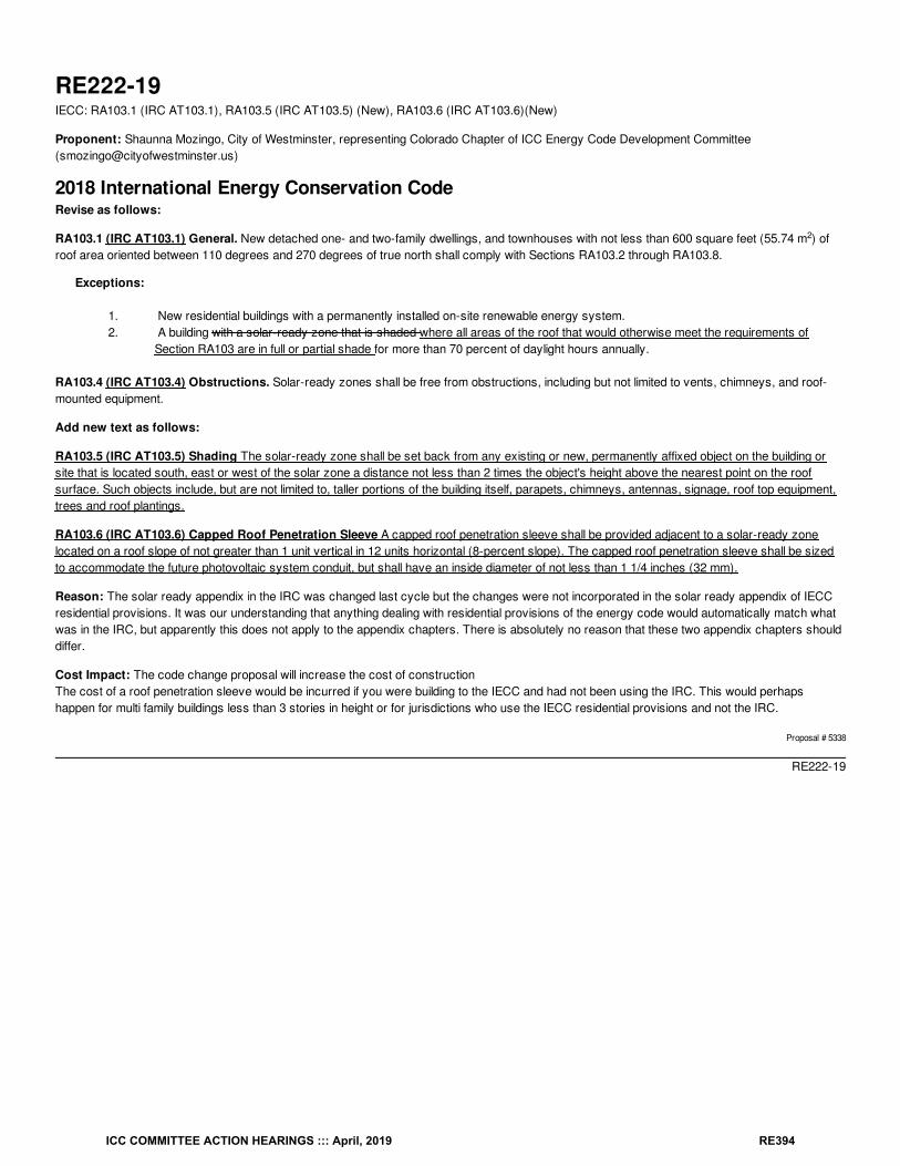
RE222-19IECC: RA103.1 (IRC AT103.1), RA103.5 (IRC AT103.5) (New), RA103.6 (IRC AT103.6)(New)
Proponent: Shaunna Mozingo, City of Westminster, representing Colorado Chapter of ICC Energy Code Development Committee([email protected])
2018 International Energy Conservation CodeRevise as follows:
RA103.1 (IRC AT103.1) General. New detached one- and two-family dwellings, and townhouses with not less than 600 square feet (55.74 m ) ofroof area oriented between 110 degrees and 270 degrees of true north shall comply with Sections RA103.2 through RA103.8.
Exceptions:
1. New residential buildings with a permanently installed on-site renewable energy system.2. A building with a solar-ready zone that is shaded where all areas of the roof that would otherwise meet the requirements of
Section RA103 are in full or partial shade for more than 70 percent of daylight hours annually.
RA103.4 (IRC AT103.4) Obstructions. Solar-ready zones shall be free from obstructions, including but not limited to vents, chimneys, and roof-mounted equipment.
Add new text as follows:
RA103.5 (IRC AT103.5) Shading The solar-ready zone shall be set back from any existing or new, permanently affixed object on the building orsite that is located south, east or west of the solar zone a distance not less than 2 times the object's height above the nearest point on the roofsurface. Such objects include, but are not limited to, taller portions of the building itself, parapets, chimneys, antennas, signage, roof top equipment,trees and roof plantings.
RA103.6 (IRC AT103.6) Capped Roof Penetration Sleeve A capped roof penetration sleeve shall be provided adjacent to a solar-ready zonelocated on a roof slope of not greater than 1 unit vertical in 12 units horizontal (8-percent slope). The capped roof penetration sleeve shall be sizedto accommodate the future photovoltaic system conduit, but shall have an inside diameter of not less than 1 1/4 inches (32 mm).
Reason: The solar ready appendix in the IRC was changed last cycle but the changes were not incorporated in the solar ready appendix of IECCresidential provisions. It was our understanding that anything dealing with residential provisions of the energy code would automatically match whatwas in the IRC, but apparently this does not apply to the appendix chapters. There is absolutely no reason that these two appendix chapters shoulddiffer.
Cost Impact: The code change proposal will increase the cost of constructionThe cost of a roof penetration sleeve would be incurred if you were building to the IECC and had not been using the IRC. This would perhapshappen for multi family buildings less than 3 stories in height or for jurisdictions who use the IECC residential provisions and not the IRC.
Proposal # 5338
RE222-19
2
ICC COMMITTEE ACTION HEARINGS ::: April, 2019 RE394
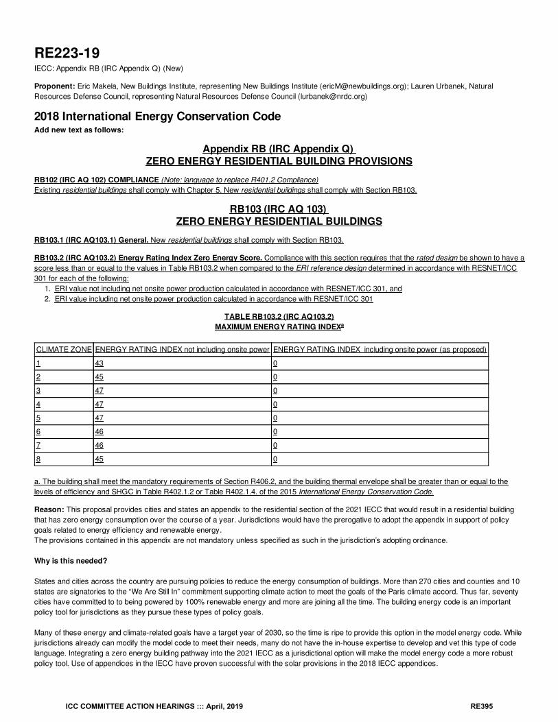
RE223-19IECC: Appendix RB (IRC Appendix Q) (New)
Proponent: Eric Makela, New Buildings Institute, representing New Buildings Institute ([email protected]); Lauren Urbanek, NaturalResources Defense Council, representing Natural Resources Defense Council ([email protected])
2018 International Energy Conservation CodeAdd new text as follows:
Appendix RB (IRC Appendix Q) ZERO ENERGY RESIDENTIAL BUILDING PROVISIONS
RB102 (IRC AQ 102) COMPLIANCE (Note: language to replace R401.2 Compliance)Existing residential buildings shall comply with Chapter 5. New residential buildings shall comply with Section RB103.
RB103 (IRC AQ 103) ZERO ENERGY RESIDENTIAL BUILDINGS
RB103.1 (IRC AQ103.1) General. New residential buildings shall comply with Section RB103.
RB103.2 (IRC AQ103.2) Energy Rating Index Zero Energy Score. Compliance with this section requires that the rated design be shown to have ascore less than or equal to the values in Table RB103.2 when compared to the ERI reference design determined in accordance with RESNET/ICC301 for each of the following:
1. ERI value not including net onsite power production calculated in accordance with RESNET/ICC 301, and2. ERI value including net onsite power production calculated in accordance with RESNET/ICC 301
TABLE RB103.2 (IRC AQ103.2)MAXIMUM ENERGY RATING INDEX
CLIMATE ZONE ENERGY RATING INDEX not including onsite power ENERGY RATING INDEX including onsite power (as proposed)
1 43 0
2 45 0
3 47 0
4 47 0
5 47 0
6 46 0
7 46 0
8 45 0
a. The building shall meet the mandatory requirements of Section R406.2, and the building thermal envelope shall be greater than or equal to thelevels of efficiency and SHGC in Table R402.1.2 or Table R402.1.4. of the 2015 International Energy Conservation Code.
Reason: This proposal provides cities and states an appendix to the residential section of the 2021 IECC that would result in a residential buildingthat has zero energy consumption over the course of a year. Jurisdictions would have the prerogative to adopt the appendix in support of policygoals related to energy efficiency and renewable energy.The provisions contained in this appendix are not mandatory unless specified as such in the jurisdiction’s adopting ordinance.
Why is this needed?
States and cities across the country are pursuing policies to reduce the energy consumption of buildings. More than 270 cities and counties and 10states are signatories to the “We Are Still In” commitment supporting climate action to meet the goals of the Paris climate accord. Thus far, seventycities have committed to to being powered by 100% renewable energy and more are joining all the time. The building energy code is an importantpolicy tool for jurisdictions as they pursue these types of policy goals.
Many of these energy and climate-related goals have a target year of 2030, so the time is ripe to provide this option in the model energy code. Whilejurisdictions already can modify the model code to meet their needs, many do not have the in-house expertise to develop and vet this type of codelanguage. Integrating a zero energy building pathway into the 2021 IECC as a jurisdictional option will make the model energy code a more robustpolicy tool. Use of appendices in the IECC have proven successful with the solar provisions in the 2018 IECC appendices.
a
ICC COMMITTEE ACTION HEARINGS ::: April, 2019 RE395
Including a zero energy building appendix in the model energy code can smooth the transition to zero energy for builders. Rather than jurisdictionsgoing alone— leading to a patchwork of zero energy residential code approaches—a single IECC appendix would provide consistent nationallanguage across the residential industry for manufacturers, builders and trades. Builders can standardize their construction practices acrossjurisdictions and states to meet these requirements. This makes education, incentive programs, and implementation significantly morestraightforward and cost-effective.
How the Zero Energy appendix works
While there are a number of definitions of “zero energy buildings” (also referred to as “zero net energy,” “net zero energy,” or simply, “net zero”), theAppendix is based on the Energy Rating Index (ERI) compliance path found in section R406 of the 2018 IECC. In principle, the proposal works asfollows:
1. Required ERI values are based on a highly efficient energy use performance level before considering on-site power generation.
2. The remaining energy use, on an annual level, is satisfied with on-site power generation.
The Energy Rating Index scores are set for a highly efficient level of energy consumption, which importantly, is still cost effective for thehomeowner. These scores, which range from 42 to 48 based on climate zone, were calculated based on a thorough analysis of HERS scoresnationwide, a survey of HERS scores for model high-performance home, modeling done for ASHRAE 90.2, and the U.S. DOE Zero Energy ReadyHome program.
On-site renewable energy capacity is then required to meet the remaining energy use, resulting in an Energy Rating Index score of zero. Softwarerequired in the RESNET 301 standard can easily generate an ERI score of the home before and after the inclusion of renewable energy (known asOnsite Power Production in HERS). All renewable energy is required to be on-site. The minimum envelope backstops required in section R406 arealso required in this appendix. Homes may use any fuel in accordance with RESNET 301 to comply with the Appendix.
Bibliography: Presentation: 90.2 Compliance Requirements. Results from EnergyGuage 5.0 Simulations and Economic Analysis SSPC 90.2Orlando Meetings January 25-26, 2016. P. Fairey. Florida Solar Energy Center.ASHRAE Standard 90.2018. Energy Efficient Design of Low-Rise Residential Buildings
Cost Impact: The code change proposal will increase the cost of constructionIf adopted by the state or jurisdiction, complying with this appendix will increase the first cost of construction but the Energy Rating Index values,before the addion of onsite power production, that have been selected were found to be cost effective based on information presented to theASHRAE Standard 90.2 committee. All of the ERI scores without onsite power production have been found to have Savings/Investment Ratios (SIR)of greater than 1.0.
Proposal # 5205
RE223-19
ICC COMMITTEE ACTION HEARINGS ::: April, 2019 RE396
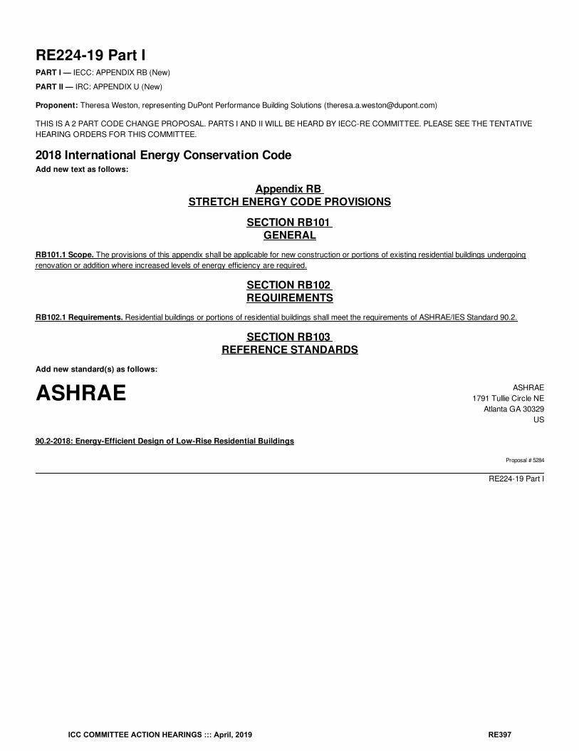
ASHRAE ASHRAE1791 Tullie Circle NE
Atlanta GA 30329US
RE224-19 Part IPART I — IECC: APPENDIX RB (New)
PART II — IRC: APPENDIX U (New)
Proponent: Theresa Weston, representing DuPont Performance Building Solutions ([email protected])
THIS IS A 2 PART CODE CHANGE PROPOSAL. PARTS I AND II WILL BE HEARD BY IECC-RE COMMITTEE. PLEASE SEE THE TENTATIVEHEARING ORDERS FOR THIS COMMITTEE.
2018 International Energy Conservation CodeAdd new text as follows:
Appendix RB STRETCH ENERGY CODE PROVISIONS
SECTION RB101 GENERAL
RB101.1 Scope. The provisions of this appendix shall be applicable for new construction or portions of existing residential buildings undergoingrenovation or addition where increased levels of energy efficiency are required.
SECTION RB102 REQUIREMENTS
RB102.1 Requirements. Residential buildings or portions of residential buildings shall meet the requirements of ASHRAE/IES Standard 90.2.
SECTION RB103 REFERENCE STANDARDS
Add new standard(s) as follows:
90.2-2018: Energy-Efficient Design of Low-Rise Residential Buildings
Proposal # 5284
RE224-19 Part I
ICC COMMITTEE ACTION HEARINGS ::: April, 2019 RE397
ASHRAE ASHRAE1791 Tullie Circle NE
Atlanta GA 30329US
RE224-19 Part IIIRC: APPENDIX U (New)
Proponent: Theresa Weston, representing DuPont Performance Building Solutions ([email protected])
2018 International Residential CodeAdd new text as follows:
Appendix U STRETCH ENERGY CODE PROVISIONS
SECTION AU101 GENERAL
AU101.1 Scope. The provisions of this appendix shall be applicable for new construction or portions of existing residential buildings undergoingrenovation or addition where increased levels of energy efficiency are required.
Revise as follows:
SECTION AU102 REQUIREMENTS
AU102.1 Requirements. Residential buildings or portions of residential buildings shall meet the requirements of ASHRAE/IES Standard 90.2.
SECTION AU103 REFERENCE STANDARDS
Add new standard(s) as follows:
90.2-2018: Energy-Efficient Design of Low-Rise Residential Buildings
Reason: Some jurisdictions are interested in adopting stretch energy codes. Providing a stretch code through the reference of ANSI/ASHRAE/IESStandard 90.2-2018 allows for a stretch code that is based on an ERI methodology that is compatible with the ERI pathway within the base IECC.The ERI levels specified within 90.2-2018 have been specified as Tier 3 within the CEE New Residential Construction Specification, while the IECC2018 ERI path is specified as Tier 1. (https://library.cee1.org/content/cee-residential-new-construction-specification/)
Cost Impact: The code change proposal will increase the cost of constructionThe cost of construction will increase in the jurisdictions which addopt the stretch code appendix, but Standard 90.2 has been analyzed to be costeffective. The cost effectiveness analysis is reported in FSEC-RR-584-15 Maximum Energy Efficiency Cost Effectiveness in New HomeConstruction, dated May 20, 2015 (available at http://www.fsec.ucf.edu/en/publications/pdf/FSEC-RR-584-15.pdf).
Staff Analysis: A review of the standard proposed for inclusion in the code, ASHRAE 90.2-2018, with regard to the ICC criteria for referencedstandards (Section 3.6 of CP#28) will be posted on the ICC website on or before April 2, 2019.
Proposal # 5810
RE224-19 Part II
ICC COMMITTEE ACTION HEARINGS ::: April, 2019 RE398
RE225-19IECC: R403.2 (IRC N1103.2)
Proponent: Donald Sivigny, representing State of MN and Association of Minnesota Building Officials ([email protected])
2018 International Energy Conservation CodeR403.2 (IRC N1103.2) Hot water boiler outdoor temperature setback. Hot water boilers that supply heat to the building through one- or two-pipeheating systems shall have an outdoor setback control that decreases the boiler water temperature based on the outdoor temperature.Exception: Boiler systems also used for domestic water heating.
Reason: This propsoal is a correlation to the IECC-C code proposal to provides clarity to the requirements.Why is the proposed code change a reasonable solution? It clarifies an exception.
Cost Impact: The code change proposal will decrease the cost of constructionThis code change exempts domestic water heating from adding these setback controls which costs money to install (and maintain). By not installingthem on the domestic water heating system it will save on costs of equipment.
Proposal # 5113
RE225-19
ICC COMMITTEE ACTION HEARINGS ::: April, 2019 RE399