ide 20 d / ide 30 d / ide 50 d / ide 60 d / ide 100 d
TRANSCRIPT
TRT-
BA-ID
E20D
-30D
-50D
-60D
-100
D-T
C210
914T
TRT0
3-00
8-EN
IDE 20 D / IDE 30 D / IDE 50 D / IDE 60 D /IDE 100 D
ENORIGINAL INSTRUCTIONSOIL HEATER
2 ENoil heater IDE 20 D / IDE 30 D / IDE 50 D / IDE 60 D / IDE 100 D
Table of contents
Notes regarding the instructions .......................................... 2
Safety ..................................................................................... 3
Information about the device................................................ 5
Transport and storage........................................................... 7
Assembly and start-up.......................................................... 7
Operation ............................................................................. 10
Errors and faults .................................................................. 11
Available accessories ......................................................... 12
Maintenance ........................................................................ 13
Technical annex................................................................... 15
Disposal ............................................................................... 29
Declaration of conformity ................................................... 29
Notes regarding the instructions
Symbols
Warning of electrical voltageThis symbol indicates dangers to the life and health ofpersons due to electrical voltage.
Warning of flammable substancesThis symbol indicates dangers to the life and health ofpersons due to flammable substances.
Warning of hot surfaceThis symbol indicates dangers to the life and health ofpersons due to hot surface.
WarningThis signal word indicates a hazard with an averagerisk level which, if not avoided, can result in seriousinjury or death.
CautionThis signal word indicates a hazard with a low risklevel which, if not avoided, can result in minor ormoderate injury.
NoteThis signal word indicates important information (e.g. material damage), but does not indicate hazards.
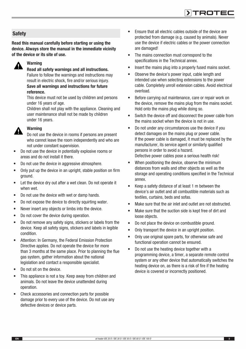
InfoInformation marked with this symbol helps you to carryout your tasks quickly and safely.
Follow the manualInformation marked with this symbol indicates that theinstructions must be observed.
Wear hearing protectionInformation marked with this symbol indicates that youshould wear hearing protection.
You can download the current version of the instructions andthe EU declaration of conformity via the following link:
IDE 20 D
https://hub.trotec.com/?id=41240
IDE 30 D
https://hub.trotec.com/?id=41241
IDE 50 D
https://hub.trotec.com/?id=41242
IDE 60 D
https://hub.trotec.com/?id=41243
IDE 100 D
https://hub.trotec.com/?id=41239
EN 3oil heater IDE 20 D / IDE 30 D / IDE 50 D / IDE 60 D / IDE 100 D
Safety
Read this manual carefully before starting or using thedevice. Always store the manual in the immediate vicinityof the device or its site of use.
WarningRead all safety warnings and all instructions.Failure to follow the warnings and instructions mayresult in electric shock, fire and/or serious injury.Save all warnings and instructions for futurereference.This device must not be used by children and personsunder 16 years of age.Children shall not play with the appliance. Cleaning anduser maintenance shall not be made by childrenunder 16 years.
WarningDo not use the device in rooms if persons are presentwho cannot leave the room independently and who arenot under constant supervision.
• Do not use the device in potentially explosive rooms orareas and do not install it there.
• Do not use the device in aggressive atmosphere.
• Only put up the device in an upright, stable position on firmground.
• Let the device dry out after a wet clean. Do not operate itwhen wet.
• Do not use the device with wet or damp hands.
• Do not expose the device to directly squirting water.
• Never insert any objects or limbs into the device.
• Do not cover the device during operation.
• Do not remove any safety signs, stickers or labels from thedevice. Keep all safety signs, stickers and labels in legiblecondition.
• Attention: In Germany, the Federal Emission ProtectionDirective applies. Do not operate the device for more than 3 months at the same place. Prior to planning the fluegas system, gather information about the nationallegislation and contact a responsible specialist.
• Do not sit on the device.
• This appliance is not a toy. Keep away from children andanimals. Do not leave the device unattended duringoperation.
• Check accessories and connection parts for possibledamage prior to every use of the device. Do not use anydefective devices or device parts.
• Ensure that all electric cables outside of the device areprotected from damage (e.g. caused by animals). Neveruse the device if electric cables or the power connectionare damaged!
• The mains connection must correspond to thespecifications in the Technical annex.
• Insert the mains plug into a properly fused mains socket.
• Observe the device's power input, cable length andintended use when selecting extensions to the powercable. Completely unroll extension cables. Avoid electricaloverload.
• Before carrying out maintenance, care or repair work onthe device, remove the mains plug from the mains socket.Hold onto the mains plug while doing so.
• Switch the device off and disconnect the power cable fromthe mains socket when the device is not in use.
• Do not under any circumstances use the device if youdetect damages on the mains plug or power cable. If the power cable is damaged, it must be replaced by themanufacturer, its service agent or similarly qualifiedpersons in order to avoid a hazard.Defective power cables pose a serious health risk!
• When positioning the device, observe the minimumdistances from walls and other objects as well as thestorage and operating conditions specified in the Technicalannex.
• Keep a safety distance of at least 1 m between thedevice's air outlet and all combustible materials such astextiles, curtains, beds and sofas.
• Make sure that the air inlet and outlet are not obstructed.
• Make sure that the suction side is kept free of dirt andloose objects.
• Do not place the device on combustible ground.
• Only transport the device in an upright position.
• Only use original spare parts, for otherwise safe andfunctional operation cannot be ensured.
• Do not use the heating device together with aprogramming device, a timer, a separate remote controlsystem or any other device that automatically switches theheating device on, as there is a risk of fire if the heatingdevice is covered or incorrectly positioned.
4 ENoil heater IDE 20 D / IDE 30 D / IDE 50 D / IDE 60 D / IDE 100 D
Intended useThe device was developed for the purpose of generating hot airand may only be used in roofed over outdoor areas or in well-ventilated interior spaces whilst adhering to the technical data.
The device is suited for heating large rooms such as tents,warehouses, workshops, construction sites, greenhouses oragricultural halls.
It is intended to be used without frequent site changes.
The device may only be used in rooms with sufficient fresh airsupply and exhaust discharge.
The device must only be operated with EL (ultra-light) fuel oil,kerosene and diesel, however not with petrol, heavy fuel oil etc.
Foreseeable misuse• Do not place any objects, e.g. clothing, on the device.
• Do not use this device in the vicinity of fuel, solvents,varnishes or other easily inflammable vapours or in roomswhere these substances are stored.
• Do not use the device out of doors.
• The device must not be positioned or operated in areaswith a high risk of fires or in potentially explosiveatmospheres.
• Do not use the device out of doors, unless under a roof.
• The device must not be operated in rooms with aninsufficient combustion air supply.
• Do not make any unauthorised modifications, alterations orstructural changes to the device.
Personnel qualificationsPeople who use this device must:• be aware of the dangers resulting from heat, fire hazard
and insufficient ventilation when working with oil heaters.
• be aware of the dangers that occur when handling fuelssuch as EL fuel oil or diesel.
• have read and understood the instructions, especially theSafety chapter.
Personal protective equipment
Wear hearing protectionWear appropriate hearing protection when workingwith the device.
Residual risks
Warning of electrical voltageWork on the electrical components must only becarried out by an authorised specialist company!
Warning of electrical voltageBefore any work on the device, remove the mains plugfrom the mains socket!Do not touch the mains plug with wet or damp hands.Hold onto the mains plug while pulling the power cableout of the mains socket.
Warning of flammable substancesHandling fuels entails a risk of fire.Take sufficient precautions when handling fuels suchas fuel oil, kerosene or diesel.Do not spill any diesel, kerosene or fuel oil! Do notinhale the vapours nor swallow any fuel! Avoid skincontact!
Warning of hot surfaceParts of the device, especially at the air outlet, becomevery hot during operation. There is a danger of burningand fire. Do not touch the device during operation!During operation observe a safety distance of at least 3 m to the device front! Observe the minimum distancefrom walls or other objects according to the technicaldata!
Warning of hot surfaceParts of this appliance can become very hot and causeburns. Particular attention is to be paid when there arechildren or vulnerable persons present!
Warning of hot surfaceImproper handling entails a risk of burning. Only usethe device as intended!
WarningImproper handling entails a risk of burning and electricshock.Only use the device as intended!
WarningDangers can occur at the device when it is used byuntrained people in an unprofessional or improper way!Observe the personnel qualifications!
WarningThe device is not a toy and does not belong in thehands of children.
WarningRisk of suffocation!Do not leave the packaging lying around. Children mayuse it as a dangerous toy.
EN 5oil heater IDE 20 D / IDE 30 D / IDE 50 D / IDE 60 D / IDE 100 D
WarningImproper installation entails a risk of fire.Do not place the device on combustible ground.Do not place the device on high-pile carpets.
WarningThe device must not be covered, there is an imminentfire hazard!
Behaviour in the event of an emergency1. In an emergency, disconnect the device from the mains
feed-in: Switch the device off and disconnect it from themains.
2. Remove persons from the danger area.3. Do not reconnect a defective device to the mains.
Overheating protectionThe device is provided with a safety thermostat which isactivated by overheating of the device (when exceeding theoperating temperature).
Investigate the cause of overheating.
If the safety thermostat does not switch in the event ofoverheating, the overheating protection will be tripped. In thatcase the device switches off completely. If so, please contactthe customer service to have the overheating protectionreplaced.
Information about the device
Device descriptionThe directly fired oil heaters IDE 20 D, IDE 30 D, IDE 50 D, IDE 60 D and IDE 100 D serve the purpose of heating the roomair so as to quickly heat large, well-ventilated rooms. The oilheaters run on EL fuel oil, kerosene or diesel, they must not beused with petrol, heavy fuel oil etc.
The devices are oil heaters with direct combustion to beinstalled in roofed outdoor areas or in rooms with a sufficientfresh air supply. The device IDE 100 D is further equipped with aDanfoss pump.
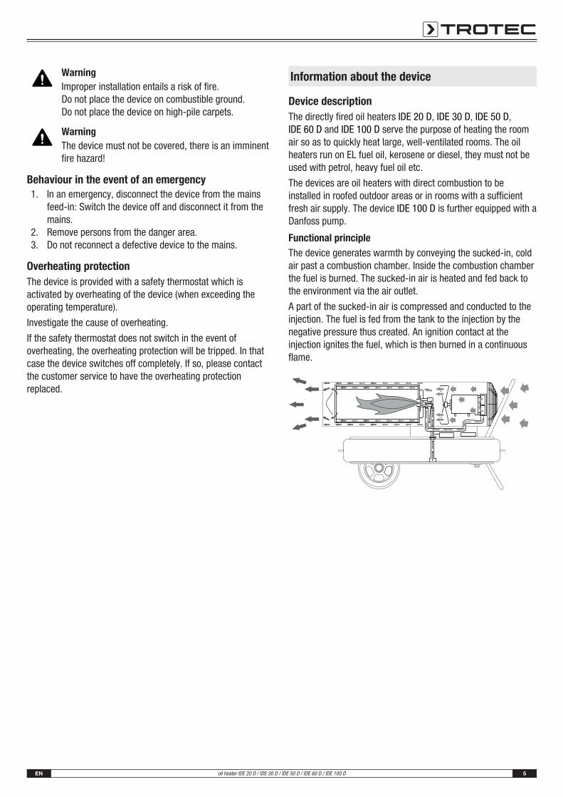
Functional principleThe device generates warmth by conveying the sucked-in, coldair past a combustion chamber. Inside the combustion chamberthe fuel is burned. The sucked-in air is heated and fed back tothe environment via the air outlet.
A part of the sucked-in air is compressed and conducted to theinjection. The fuel is fed from the tank to the injection by thenegative pressure thus created. An ignition contact at theinjection ignites the fuel, which is then burned in a continuousflame.
6 ENoil heater IDE 20 D / IDE 30 D / IDE 50 D / IDE 60 D / IDE 100 D
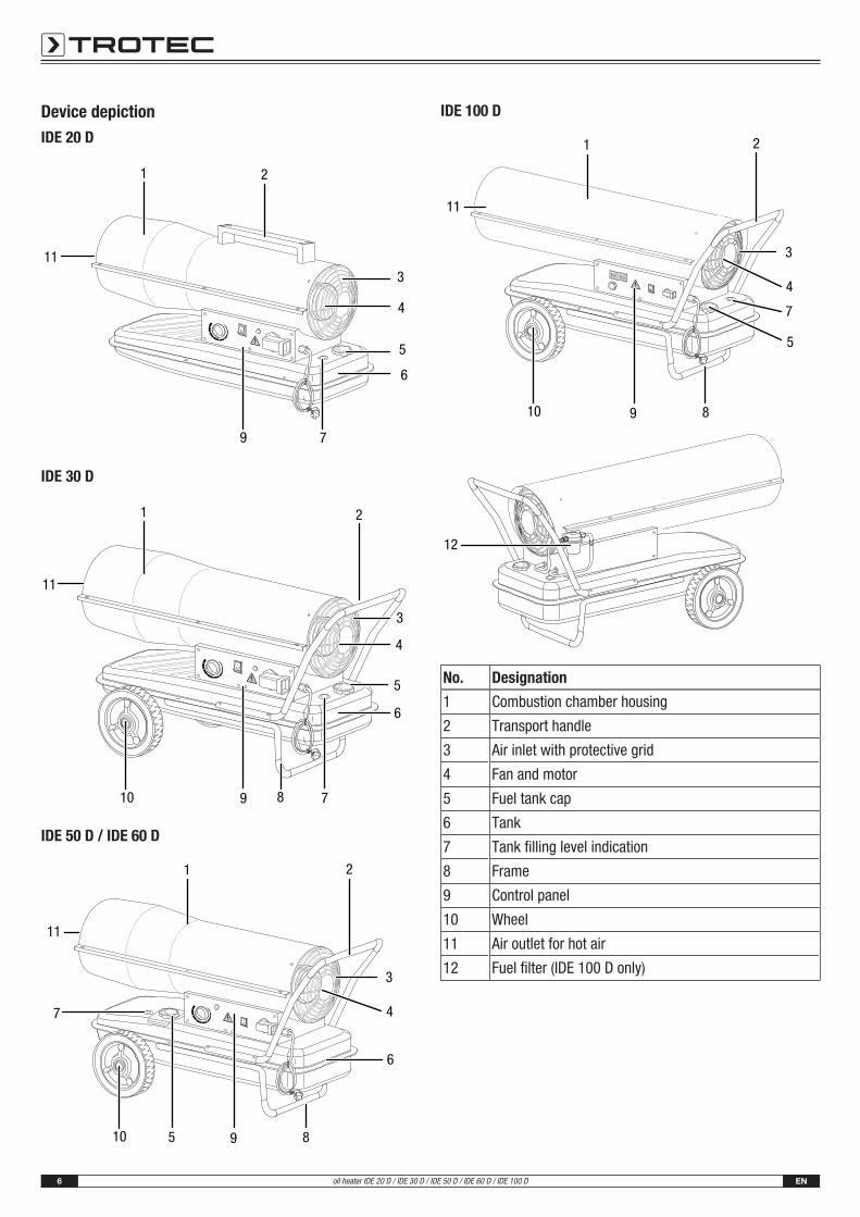
Device depictionIDE 20 D
1 2
3
4
5
6
79
11
IDE 30 D
1 2
3
4
5
6
79
11
810
IDE 50 D / IDE 60 D
1 2
3
4
5
6
7
8910
11
IDE 100 D
1 2
3
4
7
8910
11
5
12
No. Designation
1 Combustion chamber housing
2 Transport handle
3 Air inlet with protective grid
4 Fan and motor
5 Fuel tank cap
6 Tank
7 Tank filling level indication
8 Frame
9 Control panel
10 Wheel
11 Air outlet for hot air
12 Fuel filter (IDE 100 D only)
EN 7oil heater IDE 20 D / IDE 30 D / IDE 50 D / IDE 60 D / IDE 100 D
Transport and storage
NoteIf you store or transport the device improperly, thedevice may be damaged.Note the information regarding transport and storage ofthe device.
TransportTo make the device easier to transport, it is fitted with wheels.
To make the device easier to transport, it is fitted with a carryhandle.
Before transporting the device, observe the following:• Switch the device off.
• Hold onto the mains plug while pulling the power cable outof the mains socket.
• Do not use the power cable to drag the device.
• Allow the device to cool down sufficiently.
While transporting the device, observe the following:
IDE 20 D• Only transport the IDE 20 D by use of the transport
handle (2).
IDE 30 D / IDE 50 D / IDE 60 D / IDE 100 D• Slightly lift the device by the transport handle (2) until the
rear support no longer touches the ground.
• Wheel the device to the desired position.
StorageBefore storing the device, proceed as follows:• Hold onto the mains plug while pulling the power cable out
of the mains socket.
• Allow the device to cool down sufficiently.
When the device is not being used, observe the followingstorage conditions:• dry and protected from frost and heat
• in an upright position where it is protected from dust anddirect sunlight
• with a cover to protect it from invasive dust, if necessary
Assembly and start-up
Scope of delivery• 1 x Oil heater
• 1 x Carry handle (IDE 20 D only)
• 1 x Frame components (IDE 30 D / IDE 50 D / IDE 60 D /IDE 100 D only)
• 2 x Wheel (IDE 30 D / IDE 50 D / IDE 60 D / IDE 100 D only)
• 1 x Installation material
• 1 x Manual
Unpacking the device1. Open the cardboard box and take the device out.2. Completely remove the packaging.3. Fully unwind the power cable. Make sure that the power
cable is not damaged and that you do not damage it duringunwinding.
AssemblyUpon delivery the device is already partially preassembled.
In case of the devices IDE 30 D / 50 D / 60 D and 100 D, thewheels, axle, frame and transport handle still need to bemounted.
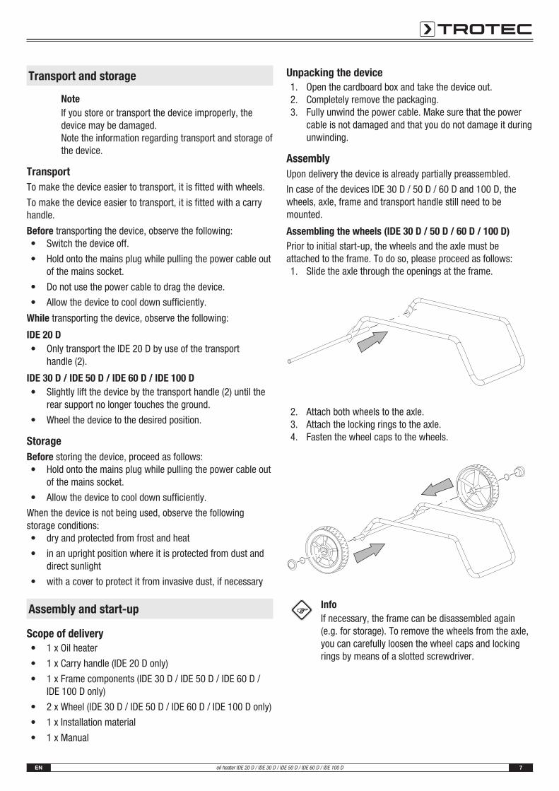
Assembling the wheels (IDE 30 D / 50 D / 60 D / 100 D)Prior to initial start-up, the wheels and the axle must beattached to the frame. To do so, please proceed as follows:1. Slide the axle through the openings at the frame.
2. Attach both wheels to the axle.3. Attach the locking rings to the axle.4. Fasten the wheel caps to the wheels.
InfoIf necessary, the frame can be disassembled again(e.g. for storage). To remove the wheels from the axle,you can carefully loosen the wheel caps and lockingrings by means of a slotted screwdriver.
8 ENoil heater IDE 20 D / IDE 30 D / IDE 50 D / IDE 60 D / IDE 100 D
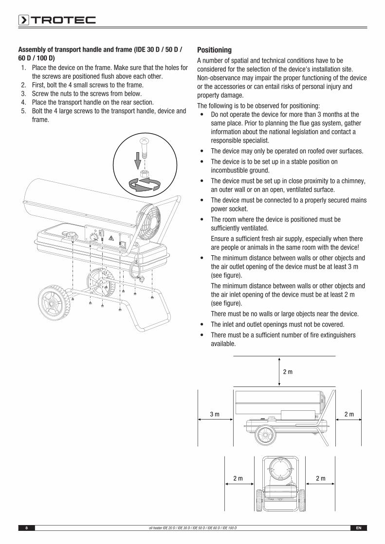
Assembly of transport handle and frame (IDE 30 D / 50 D /60 D / 100 D)1. Place the device on the frame. Make sure that the holes for
the screws are positioned flush above each other.2. First, bolt the 4 small screws to the frame.3. Screw the nuts to the screws from below.4. Place the transport handle on the rear section.5. Bolt the 4 large screws to the transport handle, device and
frame.
IDX 30 D
THERMOSTAT CONTROL
ROOM TEMP.
CLOSEOPEN
PositioningA number of spatial and technical conditions have to beconsidered for the selection of the device's installation site.Non-observance may impair the proper functioning of the deviceor the accessories or can entail risks of personal injury andproperty damage.
The following is to be observed for positioning:• Do not operate the device for more than 3 months at the
same place. Prior to planning the flue gas system, gatherinformation about the national legislation and contact aresponsible specialist.
• The device may only be operated on roofed over surfaces.
• The device is to be set up in a stable position onincombustible ground.
• The device must be set up in close proximity to a chimney,an outer wall or on an open, ventilated surface.
• The device must be connected to a properly secured mainspower socket.
• The room where the device is positioned must besufficiently ventilated.
Ensure a sufficient fresh air supply, especially when thereare people or animals in the same room with the device!
• The minimum distance between walls or other objects andthe air outlet opening of the device must be at least 3 m(see figure).
The minimum distance between walls or other objects andthe air inlet opening of the device must be at least 2 m(see figure).
There must be no walls or large objects near the device.
• The inlet and outlet openings must not be covered.
• There must be a sufficient number of fire extinguishersavailable.
25 30
3540
45
510
15
20
2 m
2 m
2 m2 m
3 m
EN 9oil heater IDE 20 D / IDE 30 D / IDE 50 D / IDE 60 D / IDE 100 D
Start-up• Check the scope of delivery of your device for
completeness. If an accessory part is missing, pleasecontact the Trotec customer service or the specialist dealerwhere you purchased the device.
• Check the device and its connection parts for potentialdamage.
• Observe the conditions described in the chapterPositioning.
• Fill the tank with EL fuel oil, kerosene or diesel asdescribed in chapter Assembly
• Check the device for its proper condition prior to start-upand at regular intervals during application.
• Check whether the characteristics of the power gridconform to those on the nameplate.
• Each time before you plug the mains plug into the mainssocket and switch on the device, make sure that the fan ismoving freely.
• Connect the power cable to a properly secured socket. Onconstruction sites, there must be a residual currentdevice (RCD) upstream of the socket in accordance withnational regulations (in Germany: VDE 0100/0105).
The device is now ready for operation.
Filling the tank
Warning of flammable substancesIn order to prevent fires, make sure that there are noignition sources near the tank.
The tank cover and the filling level indication of theIDE 20 D / IDE 30 D are located at the rear of the device, thoseof the IDE 50 D / IDE 60 D / IDE 100 D are located on the leftside of the control panel. The images in the description belowshow the IDE 100 D by way of example.ü Before attempting to fill the tank, wait until the device has
cooled down completely.ü Only use fuel suitable for the device (see technical data).1. Position the device on firm, level and incombustible
ground.
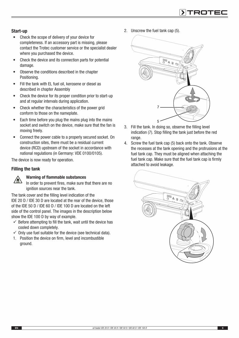
2. Unscrew the fuel tank cap (5).
THERMOSTAT CONTROL
CLOSEOPEN
5
7
3. Fill the tank. In doing so, observe the filling levelindication (7). Stop filling the tank just before the redrange.
4. Screw the fuel tank cap (5) back onto the tank. Observethe recesses at the tank opening and the protrusions at thefuel tank cap. They must be aligned when attaching thefuel tank cap. Make sure that the fuel tank cap is firmlyattached to avoid leakage.
10 ENoil heater IDE 20 D / IDE 30 D / IDE 50 D / IDE 60 D / IDE 100 D
OperationThe device may only be used by accordingly instructed persons.
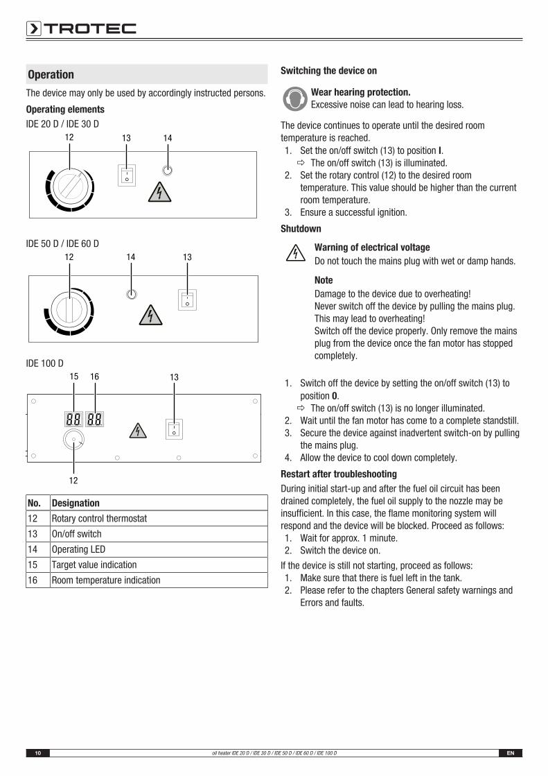
Operating elementsIDE 20 D / IDE 30 D
12 13 14
IDE 50 D / IDE 60 D12 14 13
IDE 100 D15 16 13
12
No. Designation
12 Rotary control thermostat
13 On/off switch
14 Operating LED
15 Target value indication
16 Room temperature indication
Switching the device on
Wear hearing protection.Excessive noise can lead to hearing loss.
The device continues to operate until the desired roomtemperature is reached.1. Set the on/off switch (13) to position I.
ð The on/off switch (13) is illuminated.2. Set the rotary control (12) to the desired room
temperature. This value should be higher than the currentroom temperature.
3. Ensure a successful ignition.
Shutdown
Warning of electrical voltageDo not touch the mains plug with wet or damp hands.
NoteDamage to the device due to overheating!Never switch off the device by pulling the mains plug.This may lead to overheating!Switch off the device properly. Only remove the mainsplug from the device once the fan motor has stoppedcompletely.
1. Switch off the device by setting the on/off switch (13) toposition 0.ð The on/off switch (13) is no longer illuminated.
2. Wait until the fan motor has come to a complete standstill.3. Secure the device against inadvertent switch-on by pulling
the mains plug.4. Allow the device to cool down completely.
Restart after troubleshootingDuring initial start-up and after the fuel oil circuit has beendrained completely, the fuel oil supply to the nozzle may beinsufficient. In this case, the flame monitoring system willrespond and the device will be blocked. Proceed as follows:1. Wait for approx. 1 minute.2. Switch the device on.
If the device is still not starting, proceed as follows:1. Make sure that there is fuel left in the tank.2. Please refer to the chapters General safety warnings and
Errors and faults.
EN 11oil heater IDE 20 D / IDE 30 D / IDE 50 D / IDE 60 D / IDE 100 D
Errors and faults
Warning of electrical voltageTasks which require the device to be opened mustonly be carried out by authorised specialistcompanies or by Trotec.
WarningRisk of injury due to improper repair!Never try to make any modifications or repairs on thedevice.Unauthorised modifications can lead to serious injuriesor death.Have a certified specialist workshop perform the repairwork.
The device has been checked for proper functioning severaltimes during production. If malfunctions occur nonetheless,check the device according to the following list.
The device does not start:• Check the power connection.
• Check the power cable and mains plug for damages.
• Check the on-site fusing.
Smoke and/or sparks are emitted during first use:• This is not a fault. These phenomena disappear after a
brief runtime.
Noise emission during ignition or cooling:• This is not a fault. The metal parts of the device expand
when heated and generate noise.
Sparks and/or flame may be issued from the device duringignition:• This is not a fault. Air might have accumulated in the lines.
Keep a safety distance to the device!
The flame in the combustion chamber does not ignite:• Check the filling level of the tank. Refill fuel if the tank is
empty (see chapter Maintenance).
• Check the fuel filter and the fuel pump for dirt. If it is dirty,please contact the customer service.
• Check the fuel for contaminations, e.g. dirt or water. Ifrequired, drain the fuel completely and fill in new fuel (seechapter Maintenance).
• Safety shutdown: if the flame dies during operation, theelectronics and the oil pump will be switched off.Investigate the cause on the basis of the following criteria:
– For qualified personnel only! Check the ignition: The distance between the twoignition electrodes should be 4 to 5 mm.
The flame goes out during combustion:• Make sure the air supply is unobstructed. If required, clean
the air intake opening.
• Check the filling level of the tank. Refill with fuel if the tankis empty (see chapter Operation).
• Check the fuel filter and the fuel pump for dirt. If it is dirty,please contact the customer service.
• Check the fuel for contaminations and replace it ifrequired.
• Power failure: In the event of a power failure the ignition isextinguished, the device switches off immediately. After apower failure the device will not restart automatically, ithas to be started via the on/off switch.
There is a fuel leak:• Check whether too much fuel was filled in. Drain the fuel if
necessary, see chapter Draining the tank.
• Check the drain screw for tight fit and retighten it ifnecessary.
• Check the sealing at the drain screw and replace it ifdamaged.
• Check the fuel pump for leaks. If there are doubts aboutthe proper condition of the fuel pump, please contact thecustomer service.
The device emits smoke or dust:• Check the mains voltage.
• Check the fuel for contaminations and replace it ifrequired.
• Check the tank for contaminations and drain it if required(see chapter Maintenance). Refill with clean fuel.
The flame emerges from the air outlet:• Check the mains voltage.
• Check the fuel for contaminations and replace it ifrequired.
• Check the tank for contaminations and drain it if required(see chapter Maintenance). Refill with clean fuel.
NoteWait for at least 3 minutes after maintenance andrepair work. Only then switch the device back on.
The device still does not operate correctly after thesechecks:Please contact the customer service. If necessary, bring thedevice to an authorised specialist electrical company or toTrotec for repair.
12 ENoil heater IDE 20 D / IDE 30 D / IDE 50 D / IDE 60 D / IDE 100 D
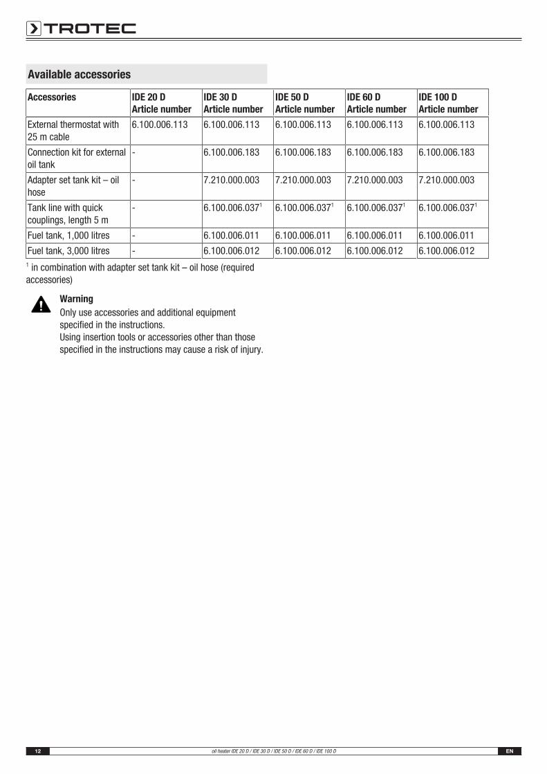
Available accessories
Accessories IDE 20 DArticle number
IDE 30 DArticle number
IDE 50 DArticle number
IDE 60 DArticle number
IDE 100 DArticle number
External thermostat with25 m cable
6.100.006.113 6.100.006.113 6.100.006.113 6.100.006.113 6.100.006.113
Connection kit for externaloil tank
- 6.100.006.183 6.100.006.183 6.100.006.183 6.100.006.183
Adapter set tank kit – oilhose
- 7.210.000.003 7.210.000.003 7.210.000.003 7.210.000.003
Tank line with quickcouplings, length 5 m
- 6.100.006.0371 6.100.006.0371 6.100.006.0371 6.100.006.0371
Fuel tank, 1,000 litres - 6.100.006.011 6.100.006.011 6.100.006.011 6.100.006.011
Fuel tank, 3,000 litres - 6.100.006.012 6.100.006.012 6.100.006.012 6.100.006.0121 in combination with adapter set tank kit – oil hose (requiredaccessories)
WarningOnly use accessories and additional equipmentspecified in the instructions.Using insertion tools or accessories other than thosespecified in the instructions may cause a risk of injury.
EN 13oil heater IDE 20 D / IDE 30 D / IDE 50 D / IDE 60 D / IDE 100 D
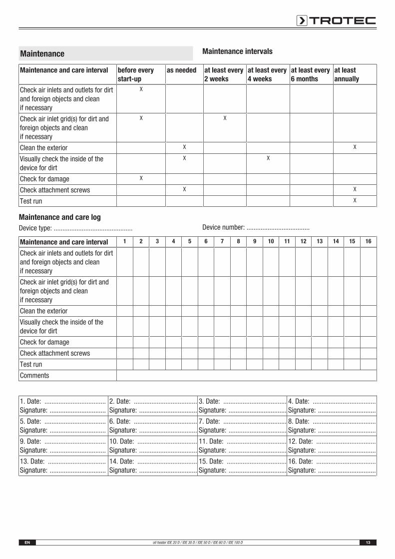
Maintenance Maintenance intervals
Maintenance and care interval before everystart-up
as needed at least every2 weeks
at least every4 weeks
at least every6 months
at leastannually
Check air inlets and outlets for dirtand foreign objects and cleanif necessary
X
Check air inlet grid(s) for dirt andforeign objects and cleanif necessary
X X
Clean the exterior X X
Visually check the inside of thedevice for dirt
X X
Check for damage X
Check attachment screws X X
Test run X
Maintenance and care logDevice type: ............................................. Device number: ....................................
Maintenance and care interval 1 2 3 4 5 6 7 8 9 10 11 12 13 14 15 16
Check air inlets and outlets for dirtand foreign objects and cleanif necessary
Check air inlet grid(s) for dirt andforeign objects and cleanif necessary
Clean the exterior
Visually check the inside of thedevice for dirt
Check for damage
Check attachment screws
Test run
Comments
1. Date: ...................................Signature: ................................
2. Date: ....................................Signature: .................................
3. Date: ....................................Signature: .................................
4. Date: ....................................Signature: .................................
5. Date: ...................................Signature: ................................
6. Date: ....................................Signature: .................................
7. Date: ....................................Signature: .................................
8. Date: ....................................Signature: .................................
9. Date: ...................................Signature: ................................
10. Date: ..................................Signature: .................................
11. Date: ..................................Signature: .................................
12. Date: ..................................Signature: .................................
13. Date: .................................Signature: ................................
14. Date: ..................................Signature: .................................
15. Date: ..................................Signature: .................................
16. Date: ..................................Signature: .................................
14 ENoil heater IDE 20 D / IDE 30 D / IDE 50 D / IDE 60 D / IDE 100 D
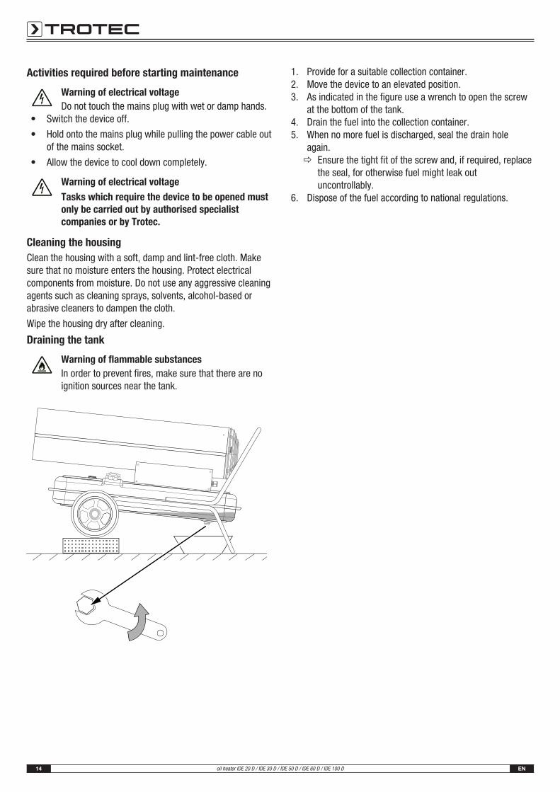
Activities required before starting maintenance
Warning of electrical voltageDo not touch the mains plug with wet or damp hands.
• Switch the device off.
• Hold onto the mains plug while pulling the power cable outof the mains socket.
• Allow the device to cool down completely.
Warning of electrical voltageTasks which require the device to be opened mustonly be carried out by authorised specialistcompanies or by Trotec.
Cleaning the housingClean the housing with a soft, damp and lint-free cloth. Makesure that no moisture enters the housing. Protect electricalcomponents from moisture. Do not use any aggressive cleaningagents such as cleaning sprays, solvents, alcohol-based orabrasive cleaners to dampen the cloth.
Wipe the housing dry after cleaning.
Draining the tank
Warning of flammable substancesIn order to prevent fires, make sure that there are noignition sources near the tank.
25 30
3540
45510
15
20
1. Provide for a suitable collection container.2. Move the device to an elevated position.3. As indicated in the figure use a wrench to open the screw
at the bottom of the tank.4. Drain the fuel into the collection container.5. When no more fuel is discharged, seal the drain hole
again.ð Ensure the tight fit of the screw and, if required, replace
the seal, for otherwise fuel might leak outuncontrollably.
6. Dispose of the fuel according to national regulations.
EN 15oil heater IDE 20 D / IDE 30 D / IDE 50 D / IDE 60 D / IDE 100 D
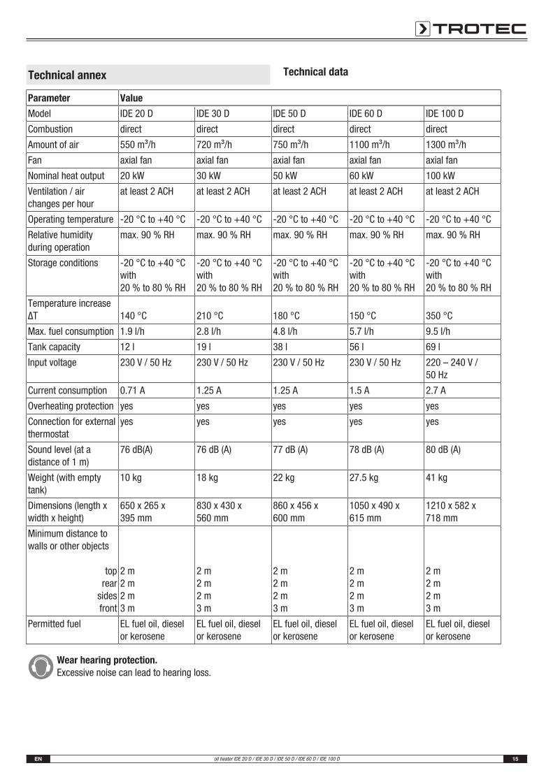
Technical annex Technical data
Parameter Value
Model IDE 20 D IDE 30 D IDE 50 D IDE 60 D IDE 100 D
Combustion direct direct direct direct direct
Amount of air 550 m³/h 720 m³/h 750 m³/h 1100 m³/h 1300 m³/h
Fan axial fan axial fan axial fan axial fan axial fan
Nominal heat output 20 kW 30 kW 50 kW 60 kW 100 kW
Ventilation / airchanges per hour
at least 2 ACH at least 2 ACH at least 2 ACH at least 2 ACH at least 2 ACH
Operating temperature -20 °C to +40 °C -20 °C to +40 °C -20 °C to +40 °C -20 °C to +40 °C -20 °C to +40 °C
Relative humidityduring operation
max. 90 % RH max. 90 % RH max. 90 % RH max. 90 % RH max. 90 % RH
Storage conditions -20 °C to +40 °Cwith 20 % to 80 % RH
-20 °C to +40 °Cwith 20 % to 80 % RH
-20 °C to +40 °Cwith 20 % to 80 % RH
-20 °C to +40 °Cwith 20 % to 80 % RH
-20 °C to +40 °Cwith 20 % to 80 % RH
Temperature increaseΔT 140 °C 210 °C 180 °C 150 °C 350 °C
Max. fuel consumption 1.9 l/h 2.8 l/h 4.8 l/h 5.7 l/h 9.5 l/h
Tank capacity 12 l 19 l 38 l 56 l 69 l
Input voltage 230 V / 50 Hz 230 V / 50 Hz 230 V / 50 Hz 230 V / 50 Hz 220 – 240 V /50 Hz
Current consumption 0.71 A 1.25 A 1.25 A 1.5 A 2.7 A
Overheating protection yes yes yes yes yes
Connection for externalthermostat
yes yes yes yes yes
Sound level (at adistance of 1 m)
76 dB(A) 76 dB (A) 77 dB (A) 78 dB (A) 80 dB (A)
Weight (with emptytank)
10 kg 18 kg 22 kg 27.5 kg 41 kg
Dimensions (length xwidth x height)
650 x 265 x 395 mm
830 x 430 x560 mm
860 x 456 x600 mm
1050 x 490 x 615 mm
1210 x 582 x718 mm
Minimum distance towalls or other objects
toprear
sidesfront
2 m2 m2 m3 m
2 m2 m2 m3 m
2 m2 m2 m3 m
2 m2 m2 m3 m
2 m2 m2 m3 m
Permitted fuel EL fuel oil, dieselor kerosene
EL fuel oil, dieselor kerosene
EL fuel oil, dieselor kerosene
EL fuel oil, dieselor kerosene
EL fuel oil, dieselor kerosene
Wear hearing protection.Excessive noise can lead to hearing loss.
16 ENoil heater IDE 20 D / IDE 30 D / IDE 50 D / IDE 60 D / IDE 100 D
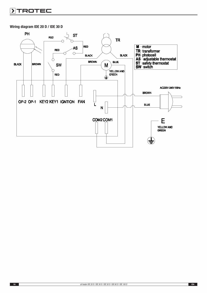
Wiring diagram IDE 20 D / IDE 30 D
EN 17oil heater IDE 20 D / IDE 30 D / IDE 50 D / IDE 60 D / IDE 100 D
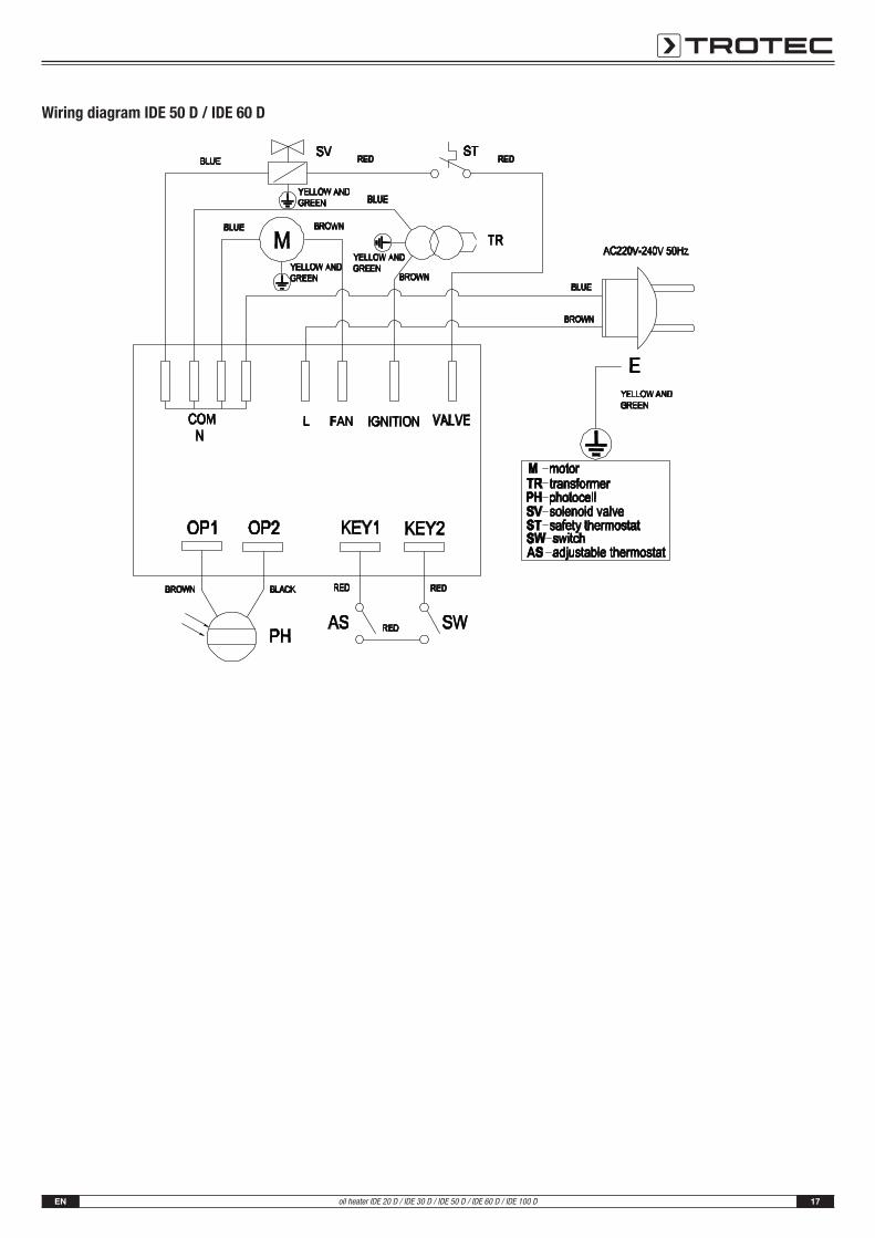
Wiring diagram IDE 50 D / IDE 60 D
18 ENoil heater IDE 20 D / IDE 30 D / IDE 50 D / IDE 60 D / IDE 100 D
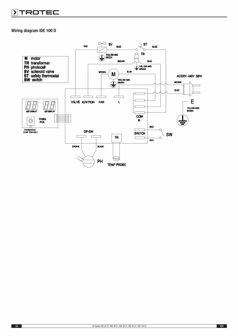
Wiring diagram IDE 100 D
EN 19oil heater IDE 20 D / IDE 30 D / IDE 50 D / IDE 60 D / IDE 100 D
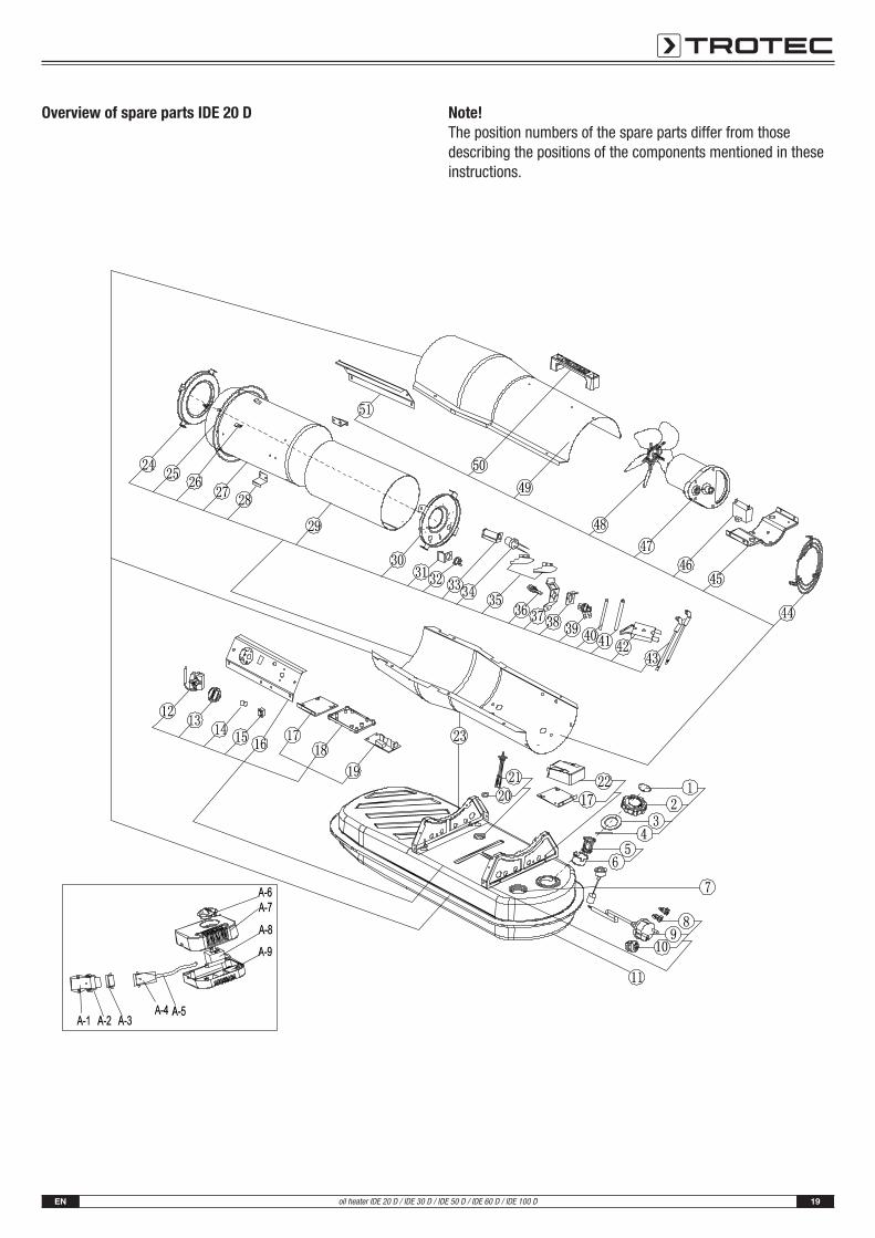
Overview of spare parts IDE 20 D Note!The position numbers of the spare parts differ from thosedescribing the positions of the components mentioned in theseinstructions.
20 ENoil heater IDE 20 D / IDE 30 D / IDE 50 D / IDE 60 D / IDE 100 D
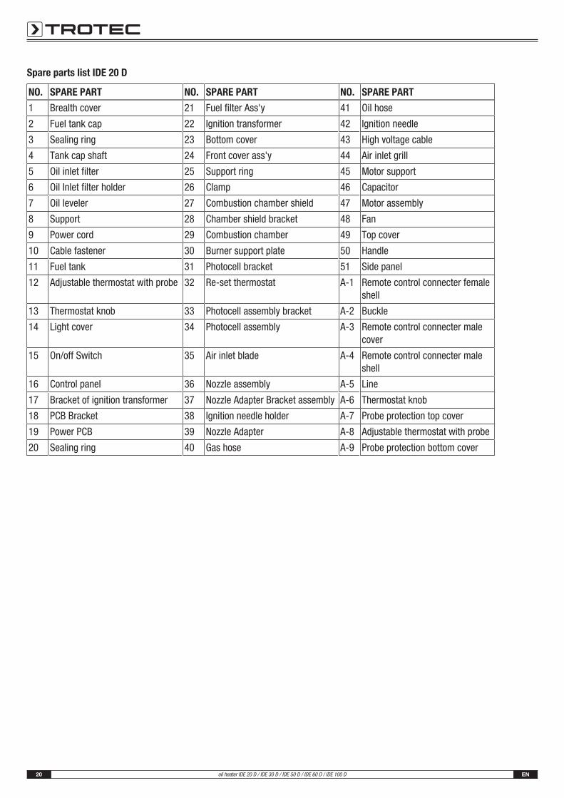
Spare parts list IDE 20 D
NO. SPARE PART NO. SPARE PART NO. SPARE PART
1 Brealth cover 21 Fuel filter Ass'y 41 Oil hose
2 Fuel tank cap 22 Ignition transformer 42 Ignition needle
3 Sealing ring 23 Bottom cover 43 High voltage cable
4 Tank cap shaft 24 Front cover ass'y 44 Air inlet grill
5 Oil inlet filter 25 Support ring 45 Motor support
6 Oil Inlet filter holder 26 Clamp 46 Capacitor
7 Oil leveler 27 Combustion chamber shield 47 Motor assembly
8 Support 28 Chamber shield bracket 48 Fan
9 Power cord 29 Combustion chamber 49 Top cover
10 Cable fastener 30 Burner support plate 50 Handle
11 Fuel tank 31 Photocell bracket 51 Side panel
12 Adjustable thermostat with probe 32 Re-set thermostat A-1 Remote control connecter femaleshell
13 Thermostat knob 33 Photocell assembly bracket A-2 Buckle
14 Light cover 34 Photocell assembly A-3 Remote control connecter malecover
15 On/off Switch 35 Air inlet blade A-4 Remote control connecter maleshell
16 Control panel 36 Nozzle assembly A-5 Line
17 Bracket of ignition transformer 37 Nozzle Adapter Bracket assembly A-6 Thermostat knob
18 PCB Bracket 38 Ignition needle holder A-7 Probe protection top cover
19 Power PCB 39 Nozzle Adapter A-8 Adjustable thermostat with probe
20 Sealing ring 40 Gas hose A-9 Probe protection bottom cover
EN 21oil heater IDE 20 D / IDE 30 D / IDE 50 D / IDE 60 D / IDE 100 D
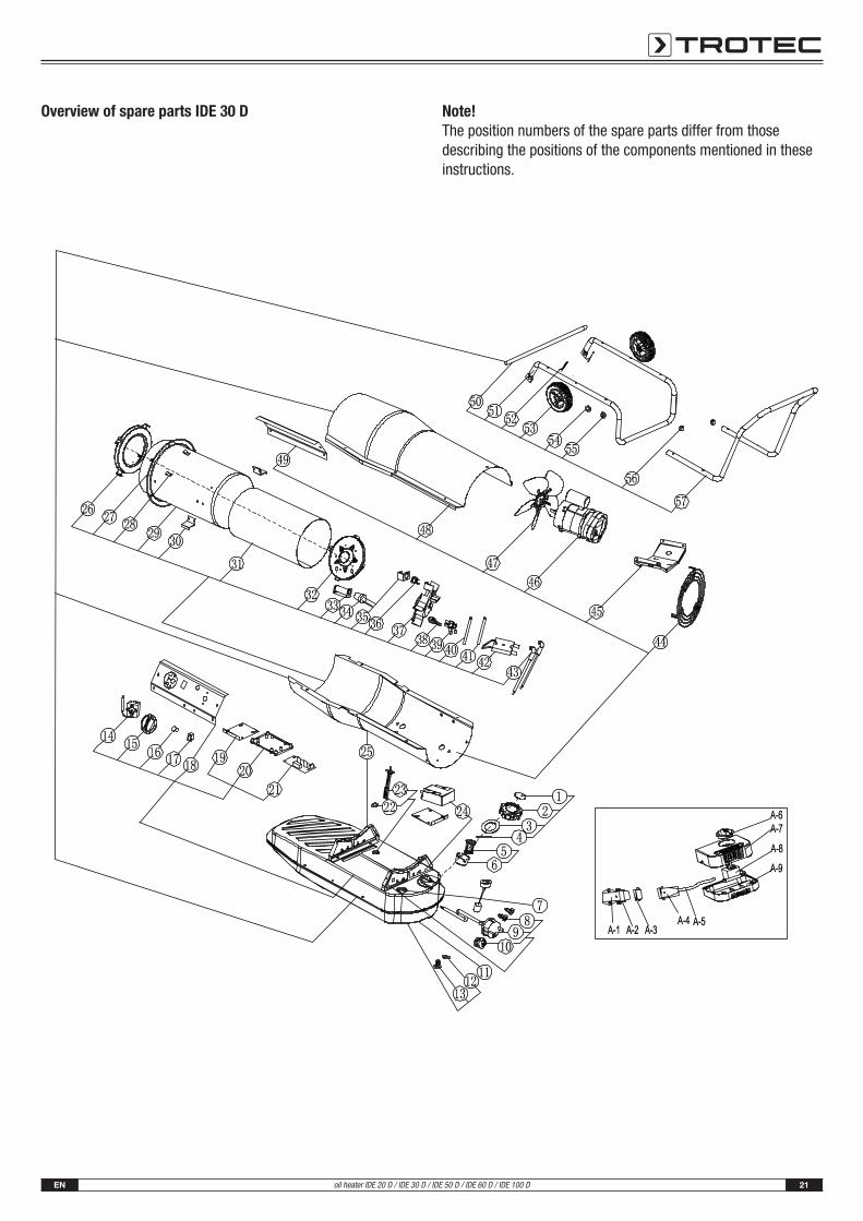
Overview of spare parts IDE 30 D Note!The position numbers of the spare parts differ from thosedescribing the positions of the components mentioned in theseinstructions.
22 ENoil heater IDE 20 D / IDE 30 D / IDE 50 D / IDE 60 D / IDE 100 D
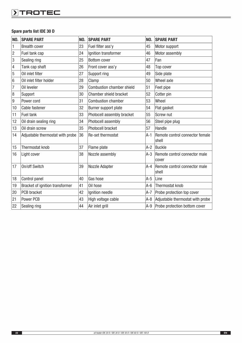
Spare parts list IDE 30 D
NO. SPARE PART NO. SPARE PART NO. SPARE PART
1 Brealth cover 23 Fuel filter ass'y 45 Motor support
2 Fuel tank cap 24 Ignition transformer 46 Motor assembly
3 Sealing ring 25 Bottom cover 47 Fan
4 Tank cap shaft 26 Front cover ass'y 48 Top cover
5 Oil inlet filter 27 Support ring 49 Side plate
6 Oil inlet filter holder 28 Clamp 50 Wheel axle
7 Oil leveler 29 Combustion chamber shield 51 Feet pipe
8 Support 30 Chamber shield bracket 52 Cotter pin
9 Power cord 31 Combustion chamber 53 Wheel
10 Cable fastener 32 Burner support plate 54 Flat gasket
11 Fuel tank 33 Photocell assembly bracket 55 Screw nut
12 Oil drain sealing ring 34 Photocell assembly 56 Steel pipe plug
13 Oil drain screw 35 Photocell bracket 57 Handle
14 Adjustable thermostat with probe 36 Re-set thermostat A-1 Remote control connector femaleshell
15 Thermostat knob 37 Flame plate A-2 Buckle
16 Light cover 38 Nozzle assembly A-3 Remote control connector malecover
17 On/off Switch 39 Nozzle Adapter A-4 Remote control connector maleshell
18 Control panel 40 Gas hose A-5 Line
19 Bracket of ignition transformer 41 Oil hose A-6 Thermostat knob
20 PCB bracket 42 Ignition needle A-7 Probe protection top cover
21 Power PCB 43 High voltage cable A-8 Adjustable thermostat with probe
22 Sealing ring 44 Air inlet grill A-9 Probe protection bottom cover
EN 23oil heater IDE 20 D / IDE 30 D / IDE 50 D / IDE 60 D / IDE 100 D
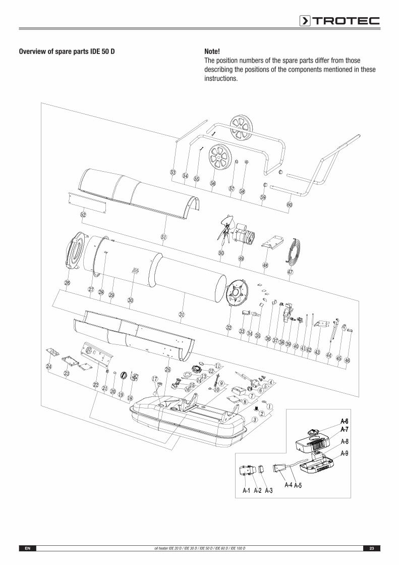
Overview of spare parts IDE 50 D Note!The position numbers of the spare parts differ from thosedescribing the positions of the components mentioned in theseinstructions.
24 ENoil heater IDE 20 D / IDE 30 D / IDE 50 D / IDE 60 D / IDE 100 D
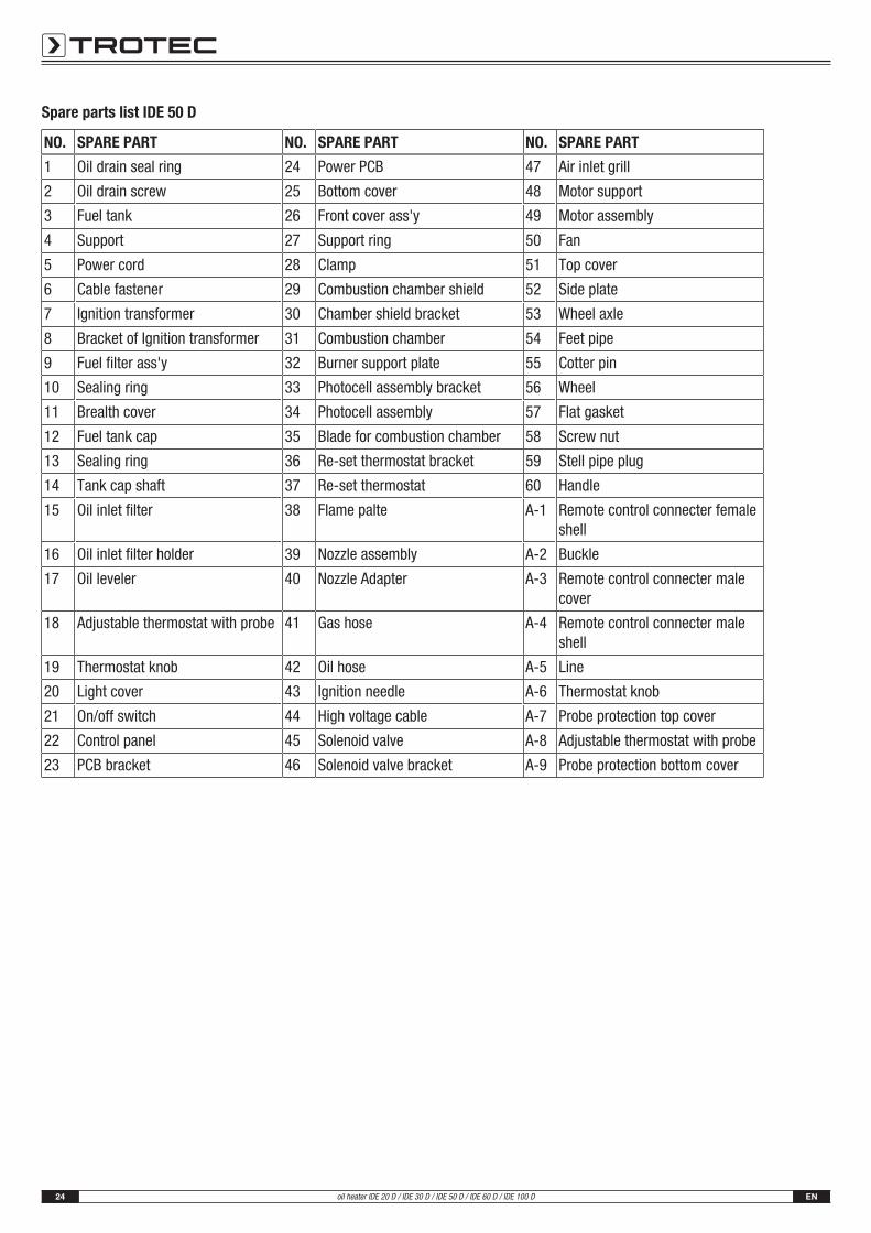
Spare parts list IDE 50 D
NO. SPARE PART NO. SPARE PART NO. SPARE PART
1 Oil drain seal ring 24 Power PCB 47 Air inlet grill
2 Oil drain screw 25 Bottom cover 48 Motor support
3 Fuel tank 26 Front cover ass'y 49 Motor assembly
4 Support 27 Support ring 50 Fan
5 Power cord 28 Clamp 51 Top cover
6 Cable fastener 29 Combustion chamber shield 52 Side plate
7 Ignition transformer 30 Chamber shield bracket 53 Wheel axle
8 Bracket of Ignition transformer 31 Combustion chamber 54 Feet pipe
9 Fuel filter ass'y 32 Burner support plate 55 Cotter pin
10 Sealing ring 33 Photocell assembly bracket 56 Wheel
11 Brealth cover 34 Photocell assembly 57 Flat gasket
12 Fuel tank cap 35 Blade for combustion chamber 58 Screw nut
13 Sealing ring 36 Re-set thermostat bracket 59 Stell pipe plug
14 Tank cap shaft 37 Re-set thermostat 60 Handle
15 Oil inlet filter 38 Flame palte A-1 Remote control connecter femaleshell
16 Oil inlet filter holder 39 Nozzle assembly A-2 Buckle
17 Oil leveler 40 Nozzle Adapter A-3 Remote control connecter malecover
18 Adjustable thermostat with probe 41 Gas hose A-4 Remote control connecter maleshell
19 Thermostat knob 42 Oil hose A-5 Line
20 Light cover 43 Ignition needle A-6 Thermostat knob
21 On/off switch 44 High voltage cable A-7 Probe protection top cover
22 Control panel 45 Solenoid valve A-8 Adjustable thermostat with probe
23 PCB bracket 46 Solenoid valve bracket A-9 Probe protection bottom cover
EN 25oil heater IDE 20 D / IDE 30 D / IDE 50 D / IDE 60 D / IDE 100 D
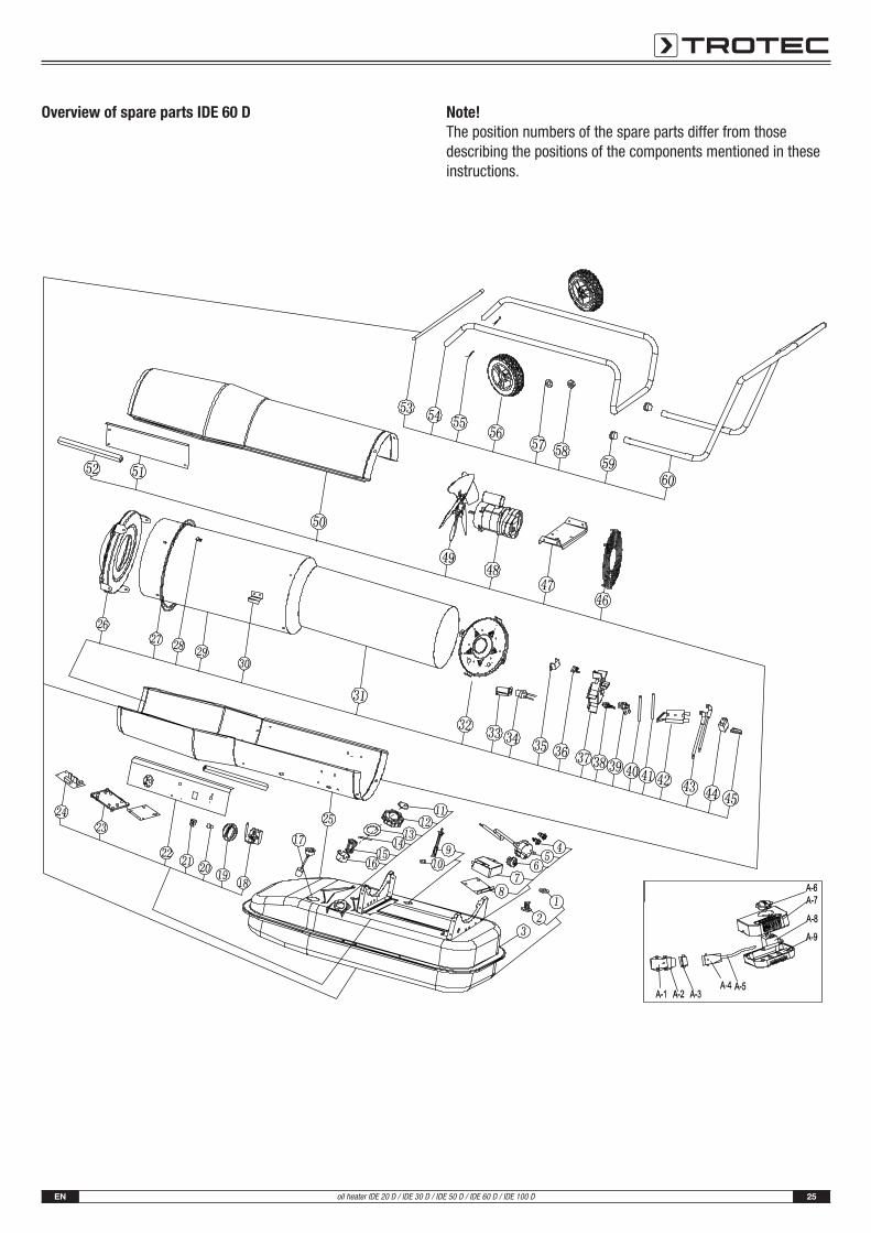
Overview of spare parts IDE 60 D Note!The position numbers of the spare parts differ from thosedescribing the positions of the components mentioned in theseinstructions.
26 ENoil heater IDE 20 D / IDE 30 D / IDE 50 D / IDE 60 D / IDE 100 D
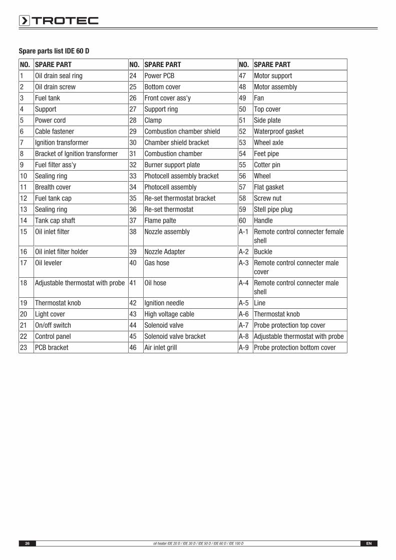
Spare parts list IDE 60 D
NO. SPARE PART NO. SPARE PART NO. SPARE PART
1 Oil drain seal ring 24 Power PCB 47 Motor support
2 Oil drain screw 25 Bottom cover 48 Motor assembly
3 Fuel tank 26 Front cover ass'y 49 Fan
4 Support 27 Support ring 50 Top cover
5 Power cord 28 Clamp 51 Side plate
6 Cable fastener 29 Combustion chamber shield 52 Waterproof gasket
7 Ignition transformer 30 Chamber shield bracket 53 Wheel axle
8 Bracket of Ignition transformer 31 Combustion chamber 54 Feet pipe
9 Fuel filter ass'y 32 Burner support plate 55 Cotter pin
10 Sealing ring 33 Photocell assembly bracket 56 Wheel
11 Brealth cover 34 Photocell assembly 57 Flat gasket
12 Fuel tank cap 35 Re-set thermostat bracket 58 Screw nut
13 Sealing ring 36 Re-set thermostat 59 Stell pipe plug
14 Tank cap shaft 37 Flame palte 60 Handle
15 Oil inlet filter 38 Nozzle assembly A-1 Remote control connecter femaleshell
16 Oil inlet filter holder 39 Nozzle Adapter A-2 Buckle
17 Oil leveler 40 Gas hose A-3 Remote control connecter malecover
18 Adjustable thermostat with probe 41 Oil hose A-4 Remote control connecter maleshell
19 Thermostat knob 42 Ignition needle A-5 Line
20 Light cover 43 High voltage cable A-6 Thermostat knob
21 On/off switch 44 Solenoid valve A-7 Probe protection top cover
22 Control panel 45 Solenoid valve bracket A-8 Adjustable thermostat with probe
23 PCB bracket 46 Air inlet grill A-9 Probe protection bottom cover
EN 27oil heater IDE 20 D / IDE 30 D / IDE 50 D / IDE 60 D / IDE 100 D
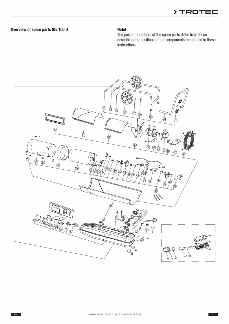
Overview of spare parts IDE 100 D Note!The position numbers of the spare parts differ from thosedescribing the positions of the components mentioned in theseinstructions.
28 ENoil heater IDE 20 D / IDE 30 D / IDE 50 D / IDE 60 D / IDE 100 D
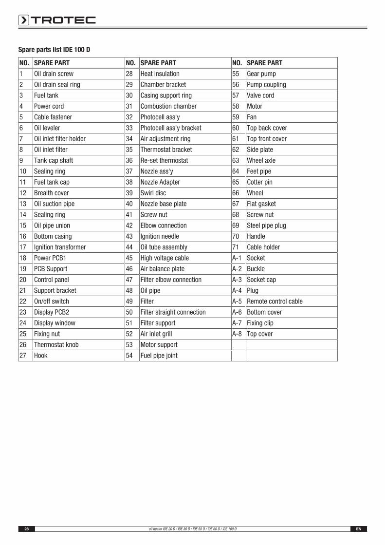
Spare parts list IDE 100 D
NO. SPARE PART NO. SPARE PART NO. SPARE PART
1 Oil drain screw 28 Heat insulation 55 Gear pump
2 Oil drain seal ring 29 Chamber bracket 56 Pump coupling
3 Fuel tank 30 Casing support ring 57 Valve cord
4 Power cord 31 Combustion chamber 58 Motor
5 Cable fastener 32 Photocell ass'y 59 Fan
6 Oil leveler 33 Photocell ass'y bracket 60 Top back cover
7 Oil inlet filter holder 34 Air adjustment ring 61 Top front cover
8 Oil inlet filter 35 Thermostat bracket 62 Side plate
9 Tank cap shaft 36 Re-set thermostat 63 Wheel axle
10 Sealing ring 37 Nozzle ass'y 64 Feet pipe
11 Fuel tank cap 38 Nozzle Adapter 65 Cotter pin
12 Brealth cover 39 Swirl disc 66 Wheel
13 Oil suction pipe 40 Nozzle base plate 67 Flat gasket
14 Sealing ring 41 Screw nut 68 Screw nut
15 Oil pipe union 42 Elbow connection 69 Steel pipe plug
16 Bottom casing 43 Ignition needle 70 Handle
17 Ignition transformer 44 Oil tube assembly 71 Cable holder
18 Power PCB1 45 High voltage cable A-1 Socket
19 PCB Support 46 Air balance plate A-2 Buckle
20 Control panel 47 Filter elbow connection A-3 Socket cap
21 Support bracket 48 Oil pipe A-4 Plug
22 On/off switch 49 Filter A-5 Remote control cable
23 Display PCB2 50 Filter straight connection A-6 Bottom cover
24 Display window 51 Filter support A-7 Fixing clip
25 Fixing nut 52 Air inlet grill A-8 Top cover
26 Thermostat knob 53 Motor support
27 Hook 54 Fuel pipe joint
EN 29oil heater IDE 20 D / IDE 30 D / IDE 50 D / IDE 60 D / IDE 100 D
Disposal
The icon with the crossed-out waste bin on wasteelectrical or electronic equipment stipulates that this equipmentmust not be disposed of with the household waste at the end ofits life. You will find collection points for free return of wasteelectrical and electronic equipment in your vicinity. Theaddresses can be obtained from your municipality or localadministration. You can also find out about other return optionsthat apply for many EU countries on the website https://hub.trotec.com/?id=45090. Otherwise, please contact anofficial recycling centre for electronic and electrical equipmentauthorised for your country.
The separate collection of waste electrical and electronicequipment aims to enable the re-use, recycling and other formsof recovery of waste equipment as well as to prevent negativeeffects for the environment and human health caused by thedisposal of hazardous substances potentially contained in theequipment.
Fuel oilThe fuel oil must be drained from the device and collected.
Fuels are to be disposed of according to the nationalregulations.
Declaration of conformity
Declaration of conformity in accordance with the EC MachineryDirective 2006/42/EC, Annex II, Part 1, Section A
We – Trotec GmbH – declare in sole responsibility that theproduct designated below was developed, constructed andproduced in compliance with the requirements of theEC Machinery Directive in the version 2006/42/EC.
Product model / product: IDE 20 D, IDE 30 D, IDE 50 D,IDE 60 D, IDE 100 D
Product type: oil heater
Year of manufacture as of: 2021
Relevant EU directives:• 2011/65/EU: 01/07/2011
• 2012/19/EU: 24/07/2012
• 2014/30/EU: 29/03/2014
• 2015/863/EU: 31/03/2015
Applied harmonised standards:• EN 55014-1:2017
• EN 61000-3-2:2014
• EN 61000-3-3:2013
• EN 60335-2-102:2016
Applied national standards and technical specifications:• EN 55014-2:2015
• EN 60335-1:2012/A1:2019
• EN 60335-1:2012/A2:2019
• EN 60335-1:2012/A14:2019
• EN 62233:2008
Manufacturer and name of the authorised representative ofthe technical documentation:Trotec GmbH
Grebbener Straße 7, D-52525 Heinsberg
Phone: +49 2452 962-400
E-mail: [email protected]
Place and date of issue:
Heinsberg, 01/06/2021
Detlef von der Lieck, Managing Director