icub3 avatar system - arxiv
TRANSCRIPT

1
iCub3 Avatar SystemStefano Dafarra1, Kourosh Darvish1, Riccardo Grieco1, Gianluca Milani1, Ugo Pattacini2, Lorenzo Rapetti1,4,Giulio Romualdi1,3, Mattia Salvi2, Alessandro Scalzo2, Ines Sorrentino1,4, Davide Tome2, Silvio Traversaro1,
Enrico Valli1, Paolo Maria Viceconte1,5, Giorgio Metta2, Marco Maggiali2, Daniele Pucci1,4
Abstract—We present an avatar system that enables a humanoperator to visit a remote location via iCub3, a new humanoidrobot developed at the Italian Institute of Technology (IIT) pavingthe way for the next generation of the iCub platforms. On theone hand, we present the humanoid iCub3 that plays the role ofthe robotic avatar. Particular attention is paid to the differencesbetween iCub3 and the classical iCub humanoid robot. On theother hand, we present the set of technologies of the avatar systemat the operator side. They are mainly composed of iFeel, namely,IIT lightweight non-invasive wearable devices for motion trackingand haptic feedback, and of non-IIT technologies designed forvirtual reality ecosystems. Finally, we show the effectiveness ofthe avatar system by describing a demonstration involving a real-time teleoperation of the iCub3. The robot is located in Venice,Biennale di Venezia, while the human operator is at more than290km distance and located in Genoa, IIT. Using a standardfiber optic internet connection, the avatar system transports theoperator locomotion, manipulation, voice, and face expressionsto the iCub3 with visual, auditory, haptic and touch feedback.
Index Terms—Avatars, Telexistence, humanoid robots, locomo-tion, haptic and touch feedback, emotions retargeting, iCub3.
I. INTRODUCTION
THE rise of biological disasters and digital virtual ecosys-tems calls for the development of avatar technologies
allowing humans to exist either in remote real locations or inimmersive virtual realities. The recent COVID-19 pandemic,for instance, revealed the immature status of avatar technolo-gies enabling humans to operate effectively in real remotelocations [1]. Analogously, the renewed interests of the En-gineering community on virtual reality systems is also drivenby the increasing applications of digital and virtual ecosystemsacross different segments [2]. This drive is also exemplifiedby the ANA Avatar XPRIZE, a 10M$ competition1 that aimsto create avatar systems transporting human presence to aremote real location in real time. Along this direction, anentire new field of applications and opportunities is emerg-ing when approaching what is nowadays called Metaverse,namely, ecosystems where digital avatars of humans interacteach for a large variety of reasons, ranging from simplevirtual reality chats to creating new digital businesses [3]. Thispaper contributes towards technologies and methods to createphysical avatars for humans to operate effectively in remotelocations via humanoid robots.
1 Artificial and Mechanical Intelligence, Italian Institute of Technology,Genoa, Italy, (e-mail: [email protected])
2 iCub Tech Facility, Italian Institute of Technology, Genoa, Italy,(e-mail: [email protected])
3 DIBRIS, University of Genoa, Genoa, Italy4 Machine Learning and Optimisation, University of Manchester, Manch-
ester, UK5 DIAG, Sapienza Universita di Roma, Rome, Italy1https://www.xprize.org/prizes/avatar
Fig. 1: iCub3 at in Biennale di Venezia, Venice.
When attempting at creating physical avatars, one is temptedto apply the state of the art on telexistence [4], a termoften interchanged with teleoperation when the latter involvesadvanced technologies for real time sensations from the remotesite. As a consequence, a telexistence system allows transfer-ring, and possibly augmenting, the skills of the human operatorto a robotic avatar. The intuitiveness is a key feature of thesystem, trading off the autonomy of the robotic avatar withthe capabilities of the human operator to cope with unforeseencircumstances. Through the system, the operator is physicallyconnected in the remote location while interacting with theenvironment or engaging with a person.
In light of the above, physical avatar technologies benefitfrom the state of the art in telexistence and teleoperation. Thus,a physical avatar system is mainly composed of three compo-nents that are often the constituents of telexistence systems:the physical avatar, often a robot with a degree of locomotion;the operator system, which is in charge of retargeting andtele-perception; the communication layer, which allows thecommunications between the avatar and the operator system.
Physical avatars are often implemented with robots havinga degree of locomotion. Typical solutions include multi-legged [5], or wheeled robots [6]. In some contexts, wherethe remote interaction with humans is crucial, avatar humanoidrobots show great potential. In fact, the human-likeness factorincreases the acceptability, the social closeness to the robot,and the legibility of its intentions [7]. At the same time, thelegged design allows performing complex movements in areduced space. Humanoid robots represent an optimal startingpoint for a platform able to emulate humans in terms of loco-motion, manipulation and verbal and non-verbal interaction.As an example, the operator can have direct control overthe whole-body posture of the robot [8], [9]. The humanoid
arX
iv:2
203.
0697
2v1
[cs
.RO
] 1
4 M
ar 2
022

2
design, on the other hand, poses additional challenges due tothe inherent instability of the robotic system. This complexitycan be faced by letting the robot to autonomously control itsstability while achieving the desired tasks [10]. Similarly, theoperator can provide only high-level walking commands [11],[12]. In this case, the robot autonomously follows the desiredwalking patterns. As a consequence, the lower-body motionof the robot is not synchronized to the operator movements.
The operator system often consists of a set of wearable tech-nologies in charge of retargeting and tele-perception. Thesedevices are often Virtual Reality commercial products [13], ormotion capture systems [8], [9]. In other cases, by employingspecial exoskeletons, it is possible to achieve bilateral feedbackteleoperation. In particular, both lower-body [14], and full-body [15] exoskeletons can be adopted to fully synchronizethe motion of the operator into the robotic avatar. On the otherhand, these devices can be very cumbersome and invasive,constraining the motion of the operator.
The communication layer connects the operator system tothe physical avatar. It allows the different components of theteleoperation system to communicate with each other, exploit-ing a potentially delayed network. In the robotics jargon, thesoftware suite that implements the communication layer isreferred as middleware. Common middlewares are the RobotOperating System (ROS) [16], and YARP [17].
A. Contribution
This paper introduces an avatar system exploiting a newlegged humanoid avatar: the iCub3. The robot is an evolutionof the classical iCub platform, being 25cm taller and 19kgheavier. The operator devices are lightweight and non-invasivefor better acceptability and immersion. Moreover, we exploitboth off-the-shelf and custom-made devices. We demonstratethe teleoperation system by allowing a human operator in IIT,Genoa, to remotely control the iCub 3 humanoid robot inthe Italian Pavilion within the Biennale dell’Architettura diVenezia, Venice, at about 290km distance. Using a standardfiber optic internet connection, the avatar system transportssimultaneously the operator locomotion, manipulation, voice,and face expressions to the robotic avatar with visual, auditory,haptic and touch feedback. To the best of the authors’ knowl-edge, it is the first time that such a complete avatar systemis validated on a legged humanoid robot allowing immersiveand remote verbal, non verbal and physical interaction.
II. THE AVATAR SYSTEM ARCHITECTURE
The avatar architecture presented in this paper is depicted inFig. 2. The figure describes both the physical and the logicalconnections between the operator and the avatar. The formeris achieved by a network of computers operating on both theoperator and robot side, connected via a standard fiber opticinternet connection.
The physical network allows achieving a set of logicalconnections between the operator and the robot. The operator’sactions, intentions and emotions are captured by a set of de-vices the operator is wearing. These are part of the retargetingcomponent and are transmitted in the form of references to
the avatar control. The retargeting and control compose theteleoperation interface.
The second interface is the teleperception. The measure-ments retrieved by the robot are transmitted to the operatoras a feedback, providing a first-person perspective of thesurroundings sensed by the robot.
The following presents the iCub3 avatar architecture. First,we present the avatar, iCub3, in Sec. III. Then, we introducethe communication layer in Sec. IV, connecting iCub3 to theoperator system, presented in Sec. V. In this last section, wepresent the set of devices used by the operator that allowteleoperation and teleperception.
III. THE AVATAR: ICUB3The longstanding iCub platform has been evolving along
several directions over the last fifteen years [18]. However, allits versions2, which range from v1.0 to v2.9, have concerneda humanoid robot having mostly the same morphology, size,joint topology, actuation and transmission mechanisms. Inother words, the evolution of iCub mechanics never concernedthe robot height – which kept being of about one meter –nor the robot actuation and transmission mechanisms – whichnever evolved for the robot to increase its dynamism substan-tially – nor its force sensing capabilities – which are derivedfrom Force/Torque sensors of 45 mm diameter installed inthe robot [19]. The iCub3 humanoid robot shown in Fig. 1is the outcome of a design effort that takes a step in allthese directions. The robot represents a concept of humanoidthat will be the starting point when conceptualising the nextgenerations of the iCub platform.
A. MechanicsThe iCub3 humanoid robot is 125cm tall, and weighs 52kg.
Its mechanical structure is mainly composed by an aluminumalloy. The robot also presents plastic covers that partially coverthe electronics. The weight is distributed as follows: about45% of the weight is on the legs, 20% on the arms, and 35%on the torso and head.
Each robot leg is approximately 63cm long, while the armsare 56cm long from the shoulder to the fingertips. With thearms along the body, the robot is 43cm wide. Each foot,showed in Fig. 3, is composed of two separate rectangularsections, with a total length of about 25cm and 10cm wide.
The iCub3 robot possesses in total 54 degrees of freedomincluding those in the hands and in the eyes, and they are allused in the avatar system. They are distributed as follows:
• 4 joints in the head, controlling the eyelids and the eyes,• 3 joints in the neck,• 7 joints in each arm,• 9 joints in each hand,• 3 joints in the torso,• 6 joints in each leg.The iCub3 hands are equipped with tendon driven joints,
moved by 9 motors, allowing to control separately the thumb,the index and the middle finger, while the ring and the pinkiefingers move jointly [20].
2See also https://icub-tech-iit.github.io/documentation/icub versions for theprecise details on the iCub versions.

3
Fig. 2: The avatar architecture, comprising the operator, the delayed network, and the avatar. The operator skills are retargetedto the robot through the control architecture, and receives feedback thanks to the robot measurements.
Fig. 3: The iCub3 foot housing of two different F/T sensors.
B. Actuation
The iCub3 is equipped with both DC and brushless three-phase motors.
The DC motors actuate the joints controlling the eyes, theeyelids, the neck, the wrists and the hands. They are equippedwith a Harmonic Drive gearbox with 1/100 reduction ratio.The reduced dimensions of these motors make them suitablefor controlling the joints that do not require high torques.
The torso, the arms and the legs are controlled by three-phase brushless motors, also coupled with 1/100 HarmonicDrive gearbox. The motor charachteristics are as follows. Therated power is 110W, with a rated torque of 0.18Nm, whilethe continuous stall torque is 0.22Nm.
The hip pitch, knee, and ankle pitch joints are driven byanother type of brushless motor, bigger and more powerful.For this set of joints, the rated power is 179W, with a ratedtorque of 0.43Nm and a continuous stall torque of 0.48Nm.
C. Electronics
The iCub3 robot is powered either by an external supplieror by a custom made battery. The connection to the robot canbe established through an Ethernet cable or wirelessly via astandard 5GHz Wi-Fi network.
The robot head is equipped with a 4th generation Intel®
Core [email protected] computer with 8GB of RAM and runningUbuntu. This central unit represents the interface between therobot and the other laptops in the robot network, Fig. 2.
The iCub3 central unit is communicating with a series ofboards distributed on the robot body and connected via anEthernet bus, as illustrated in Fig. 4. There are two main typesof boards connected to the bus:
• the Ethernet Motor Supervisor (EMS) boards, controllingthe three phase motors;
• the MC4Plus boards, controlling the DC motors.The EMS board is a 32-bit Arm Cortex micro-controller.
It runs at 1kHz and implements different control strategies,described in Sec. III-F. It communicates via CAN protocolwith the motor driver board (2FOC), which generates PWMsignals at 20 KHz to drive the motor.
Similar to the EMS board, the MC4Plus board is a 32-bit Arm Cortex micro-controller implementing different motor

4
Fig. 4: The iCub3 electronic architecture.
control strategies, running at 1kHz. Differently from the EMSthough, the MC4Plus board can control directly up to four DCmotors. They control the neck, wrists and hands joints.
D. SensorsA particular feature of iCub3 is the vast array of sen-
sors available. More in detail, iCub possesses 6 six-axesforce/torque (F/T) sensors [19]. Two of them are mountedat the shoulders, and two on each foot, connecting the twosections of the feet to the ankle assembly.
iCub3 also possesses tactile sensors as an artificial skin [21]on the upper arm and the hands, which provides informationabout both the location and the intensity of the contact forces.
The head sports several sensors. It possesses two camerascapturing images at 15 frames per second, with a resolution of1024x768. The cameras are placed within the eyes bulb andcan be controlled to a specified vergence, version and tilt angle.Both eyes are equipped with eyelids, controlled jointly by asingle DC motor. The robot head also includes a microphoneon both hears, and a speaker behind the face cover. Finally, aset of LEDs define the robot face expression.
At the joint level, the iCub3 robot uses a series of encoders.The motors controlled by the 2FOC board need of incrementaloptical encoder mounted on the motor axis. These allow toestimate the motor magnetic flux. At the same time, the EMSboards exploit an off-axis absolute magnetic encoder mountedon each joint, after the gearbox, to estimate each joint positionand velocity.
In the robot hands, the MC4Plus boards communicate witha series of MAIS boards. These are 32-channel miniature ADCboards used to acquire the measurements from the skin andfrom the hall sensors installed in the robot fingers, used toestimate the position of each phalanx.
Fig. 5: The iCub3 robot side to side to the classical iCub.
E. Comparison with the classical iCub platform
With respect to a classical iCub platform [18], the iCub3humanoid robot is bigger, being 25cm taller, and weighing19kg more. Figure 5 shows the different dimensions of thetwo platforms. The increased weight requires more powerfulmotors on the legs. As a result, the increased dimension of theactuators required a different approach for the knee and anklepitch joint. In particular, instead of having the motor and theactuator on the same axis, they are displaced and connected bybelts. Moreover, the torso and shoulder joints are serial directmechanisms, while classical iCub robots have coupled tendon-driven mechanisms. This allows higher range of motion andgreater mechanical robustness.
In addition, iCub3 has a higher capacity battery, 10050mAhversus 9300mAh, and this is part of the torso assembly insteadof being included in a rigidly attached backpack.
The head of iCub3 is identical to a classical iCub, althoughthe neck is longer for better proportions. Similarly, also thehands are in common between the two versions. The onlydifference is given by the location of the electronics boardthat control the finger. In the iCub 2.7, they are located in theupper arm, while on iCub3 they are housed in the forearms.
From the electronics point of view, both platforms share thesame 2FOC/EMS/MC4Plus architecture, although iCub3 hashigher resolution encoders. On the sensors side, the iCub3platform has also an additional Intel Realsense D435i depthcamera, while the eye cameras have better resolution comparedto the classical iCub.
F. Low Level Robot Control
Both the EMS and MC4Plus boards, described in Sec. III-C,can control the robot joints using position and velocity mode.Moreover, the EMS board also support controlling the jointsin torque. We briefly present here the different control modes:
• the position control mode implements a PID controllerthat aims to track a trajectory generated imposing a min-imum jerk profile. A variant of the position control modeis called position direct and differs from the previous oneas it does not impose any constraint on the acceleration.

5
Both these control modes close the loop on the measuredjoint position.
• The velocity control implementation includes an integra-tion of the velocity reference to compute the desired jointposition tracked then, using the position control mode.
• The torque control mode uses a PID controller closing theloop on the joint torque estimated using the F/T sensorreadings [22]. The PID controller output is combined witha feed-forward and a mechanical friction compensation.
The 2FOC board implements two different control modes:• The current control mode. It implements a PI controller
closing the loop on the measured current. The controlleroutput is transformed into a PWM used to drive the motor.
• The PWM control mode. This does not consider anyinternal loop and the motor is driven in open-loop.
G. High Level Robot controlThe robot motion is controlled adopting a layered control
architecture, described in [23].Each loop of the architecture receives inputs from the robot
and the environment, and provides references to the loopnext. We refer the reader to Fig.2 of [23] for a schematicrepresentation of the architecture. The inner the layer, theshorter the time horizon that is used to evaluate the outputs.Also, inner loops employ more complex robot models toevaluate their outputs. More precisely, from outer to inner, thehierarchical control architecture is composed of the followingloops: the trajectory optimization; the simplified model control;and the whole-body quadratic programming (QP) control loop.
The trajectory optimization loop is in charge of generat-ing foothold trajectories from high-level commands, like thedesired walking direction and speed. This layer mainly dealswith defining the contact locations of the locomotion pattern.
The output of the trajectory optimization layer is givento the simplified model control loop. Its aim is to generatedesired and feasible centroidal quantities [24] associated withstable walking instances. This loop exploits the contact forcefeedback, measured thanks to the force/torque sensors installedon the robot feet.
Finally, the whole-body QP control layer, which is incharge of stabilizing the planned trajectories exploiting the fullrobot model using a suitable Quadratic Programming (QP)formulation. This layer uses the dynamic model of the systemto ensure the tracking of the desired trajectories. The controlproblem is formulated using the stack of tasks approach. Thetasks are divided into high and low priority. The high prioritytasks are considered constraints of the QP problem and aredesigned to track the trajectories for the center of mass, feet,and root link height generated by the simplified model controllayer. The low priority tasks are designed to keep the torso in adesired orientation, while controlling the joint posture arounda specified reference. This joint level reference is obtainedby means of geometric retargeting [8]. In other words, theposture of the operator is directly used as a reference for thejoint regularization.
The output of the whole-body QP control layer is a jointposition reference. This is tracked by the PID controllersrunning on the iCub motor control boards.
IV. THE COMMUNICATION LAYER
Both the robot and the operator system require a clusterof different PCs connected in a local area network (LAN),running multiple applications at once on different operatingsystem. The communication between the different applicationsis done through YARP [17].
YARP supports building a robot control system as a collec-tion of programs communicating in a peer-to-peer way, withan extensible family of connection types, like TCP, UDP, orother carriers tailored for the streaming of images.
For real-time operation, network overhead has to be mini-mized, so YARP is designed to operate on an isolated networkor behind a firewall. On the other hand, the operator and therobot might be on two different far places. In order to have thetwo sub-networks connected to each other, we use OpenVPN3,so that YARP can still be used to have communication betweenapplications running on either side of the network.
A simplified diagram of the robot and operator network isdepicted in Fig. 2. Each network possess a simple Ethernetswitch that allows connecting multiple PCs, and the robot(either via wired or wireless connections). Each local sub-network is controlled by a router that is also connected toInternet. Both the two routers connect to the same OpenVPNserver, thus joining in a Virtual Private Network (VPN). Oncethe two routers are connected, all the devices connected toboth switches are visible to each other transparently.
V. THE OPERATOR SYSTEM
In the iCub3 avatar system, presented in Fig. 2, the operatoris exploiting a series of devices:
• the HTC Vive PRO eye4 headset,• the VIVE Facial Tracker5
• the iFeel sensorized and haptic suit6
• the SenseGlove DK17 haptic glove• the Cyberith Virtualizer Elite 28 omnidirectional tread-
mill.The operator devices define the retargeting and feedbackinterfaces defined in Fig. 2.
A. The retargeting interfaces
The retargeting interfaces contain the set of commands thatthe operator exploits (on the robot) to achieve a specified taskin the remote environment. In the iCub3 avatar system, wecan distinguish the following retargeting interfaces:
• manipulation,• locomotion,• voice,• face expressions.The manipulation interfaces exploit the headset, sensorized
suit and glove to control respectively the robot head, body,
3https://openvpn.net/4https://www.vive.com/eu/product/vive-pro-eye/overview/5https://www.vive.com/eu/accessory/facial-tracker/6https://ifeeltech.eu/7https://www.senseglove.com/8https://www.cyberith.com/virtualizer-elite/

6
Fig. 6: Thanks to the facial tracker, the operator can directlycontrol the emotions displayed by the robot.
and fingers. In particular, the 3D pose of the headset is trackedin real-time, defining a reference for the motion of the robothead. The operator gaze and eye openness are tracked too,allowing to retarget directly the robot eyelids and gaze. Therobot upper-body motion is controlled via the iFeel sensorizedsuit. The suit exploits an array of devices, called iFeel nodes.
The iFeel nodes contain an integrated inertial measurementunit (IMU) and instantiate a wireless connection with a basestation connected to a PC. Each iFeel node estimates the poseof the operator limb to which they are attached. The corestrengths of these devices are the reduced weight, they arenon-invasive, and the system is highly flexible. In particular,we exploit five nodes to estimate the orientation of the oper-ator arms with respect to his chest, exploiting the geometricretargeting approach presented in [8]. Through the geometricretargeting approach we compute a set of desired joint valuesto be fed to the robot controller presented in Sec. III-G.
The SenseGlove haptic glove completes the set of devicesof the manipulation interface. It is an exoskeleton-like hapticglove allowing to translate the motion of each of the operator’sfingers into a reference for the robot fingers.
The locomotion interface is supported via the CyberithVirtualizer Elite 2. It is an omni-directional treadmill wherethe operator walks by sliding. The motion is detected throughoptical sensors located on the device base plate, where theoperator is walking. The motion direction is estimated via amoving ring attached to the harness secured to the operatorwaist. The base plate can also be inclined of a fixed amountto ease the sliding motion, allowing the operator to walknaturally. The walking motion of the operator is not directly
commanded to the robot, but rather interpreted as a referencewalking direction and speed [11]. These references are fed tothe planning layer presented in Sec. III-G.
Finally, the voice and face expressions interface exploitthe HTC VIVE headset microphone and the attached VIVEfacial tracker. The former allows the operator to verballyinteract through the operator. The latter is fundamental forthe non-verbal interaction. One of the particular features of theheadset and the facial tracker is the capability of estimating theoperator’s face expressions. These are replayed by the robotLEDs installed on its face.
B. The feedback interfaces
The feedback interfaces report the robot sensors measure-ment to the operator. In the iCub3 teleoperation system wehave the following feebdack interfaces:
• visual,• auditory,• haptic,• touch.
The headset is fundamental for the visual and auditory feed-back. The images captured by the robot cameras are displayedinside the headset, allowing the operator to have a first personview of what the robot is seeing. At the same time, the audiocaptured by the robot microphones is directly played on theheadset’s headphones.
The robot sensorized skin and the iFeel haptic nodes arefundamental for the body haptic feedback. A touch on therobot arm is mimicked by a vibration on the robot arms, thusproviding a mean of physical interaction.
Finally, the SenseGlove provides touch feedback by meansof vibration motors in each fingertip and through a set ofbrakes able to produce up to 20N of passive force per finger.
VI. VALIDATION
The iCub3 avatar system is tested in a demonstrationinvolving the operator located in the IIT offices in Genova,Italy, and the iCub3 robot in the Italian Pavilion of theBiennale dell’Architettura located in Venice, Italy. Hence, theoperator and the robot are about 290km apart, “connected” viaa standard fiber optic internet connection. The test has beenperformed on November the 8th, 2021. The latency introducedby the communication channel has been constantly monitored,remaining stably below 25ms. This reduced latency did notaffect the operator experience. In addition, this delay does notaffect the robot stability since it is able to keep the balance in-dependently from the network configuration. The video of thedemonstration is available at https://youtu.be/r6bFwUPStOA.
The first part of the video, up to 0:55 is dedicated tothe preparation of the operator, who is wearing the devicesmentioned in Sec. V. The operator is then virtually transportedto the remote location.
At 1:25, and later at 1:51, the operator exploits the robotlocomotion capabilities. In particular, by walking inside theCyberith Virtualizer platform, the operator is able to walkaround the venue, as showed in Fig. 7. At 1:26, the operatorthen interacts through the avatar with a person in the remote
7
Fig. 7: The operator navigates the remote venue via iCub3.
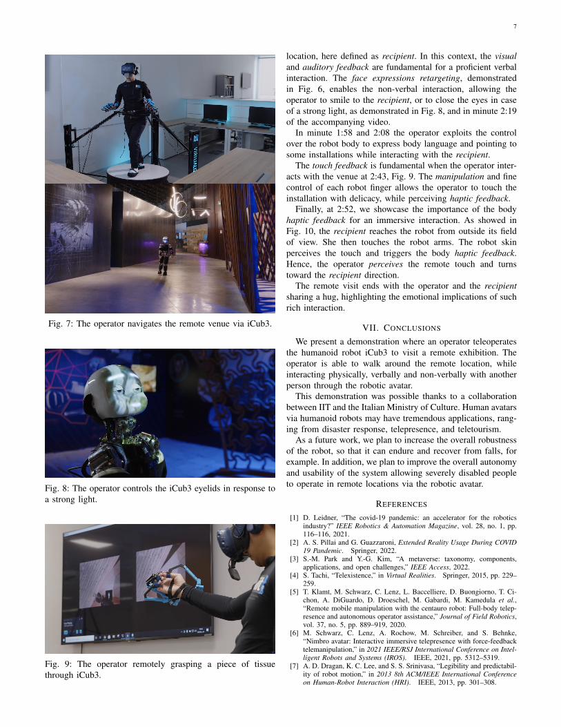
Fig. 8: The operator controls the iCub3 eyelids in response toa strong light.
Fig. 9: The operator remotely grasping a piece of tissuethrough iCub3.
location, here defined as recipient. In this context, the visualand auditory feedback are fundamental for a proficient verbalinteraction. The face expressions retargeting, demonstratedin Fig. 6, enables the non-verbal interaction, allowing theoperator to smile to the recipient, or to close the eyes in caseof a strong light, as demonstrated in Fig. 8, and in minute 2:19of the accompanying video.
In minute 1:58 and 2:08 the operator exploits the controlover the robot body to express body language and pointing tosome installations while interacting with the recipient.
The touch feedback is fundamental when the operator inter-acts with the venue at 2:43, Fig. 9. The manipulation and finecontrol of each robot finger allows the operator to touch theinstallation with delicacy, while perceiving haptic feedback.
Finally, at 2:52, we showcase the importance of the bodyhaptic feedback for an immersive interaction. As showed inFig. 10, the recipient reaches the robot from outside its fieldof view. She then touches the robot arms. The robot skinperceives the touch and triggers the body haptic feedback.Hence, the operator perceives the remote touch and turnstoward the recipient direction.
The remote visit ends with the operator and the recipientsharing a hug, highlighting the emotional implications of suchrich interaction.
VII. CONCLUSIONS
We present a demonstration where an operator teleoperatesthe humanoid robot iCub3 to visit a remote exhibition. Theoperator is able to walk around the remote location, whileinteracting physically, verbally and non-verbally with anotherperson through the robotic avatar.
This demonstration was possible thanks to a collaborationbetween IIT and the Italian Ministry of Culture. Human avatarsvia humanoid robots may have tremendous applications, rang-ing from disaster response, telepresence, and teletourism.
As a future work, we plan to increase the overall robustnessof the robot, so that it can endure and recover from falls, forexample. In addition, we plan to improve the overall autonomyand usability of the system allowing severely disabled peopleto operate in remote locations via the robotic avatar.
REFERENCES
[1] D. Leidner, “The covid-19 pandemic: an accelerator for the roboticsindustry?” IEEE Robotics & Automation Magazine, vol. 28, no. 1, pp.116–116, 2021.
[2] A. S. Pillai and G. Guazzaroni, Extended Reality Usage During COVID19 Pandemic. Springer, 2022.
[3] S.-M. Park and Y.-G. Kim, “A metaverse: taxonomy, components,applications, and open challenges,” IEEE Access, 2022.
[4] S. Tachi, “Telexistence,” in Virtual Realities. Springer, 2015, pp. 229–259.
[5] T. Klamt, M. Schwarz, C. Lenz, L. Baccelliere, D. Buongiorno, T. Ci-chon, A. DiGuardo, D. Droeschel, M. Gabardi, M. Kamedula et al.,“Remote mobile manipulation with the centauro robot: Full-body telep-resence and autonomous operator assistance,” Journal of Field Robotics,vol. 37, no. 5, pp. 889–919, 2020.
[6] M. Schwarz, C. Lenz, A. Rochow, M. Schreiber, and S. Behnke,“Nimbro avatar: Interactive immersive telepresence with force-feedbacktelemanipulation,” in 2021 IEEE/RSJ International Conference on Intel-ligent Robots and Systems (IROS). IEEE, 2021, pp. 5312–5319.
[7] A. D. Dragan, K. C. Lee, and S. S. Srinivasa, “Legibility and predictabil-ity of robot motion,” in 2013 8th ACM/IEEE International Conferenceon Human-Robot Interaction (HRI). IEEE, 2013, pp. 301–308.

8
Fig. 10: The robot is touched on the arm. The robot skin (whose activation is represented in the top right figure) triggers thebody haptic feedback on the operator, that turns.
[8] K. Darvish, Y. Tirupachuri, G. Romualdi, L. Rapetti, D. Ferigo, F. J. A.Chavez, and D. Pucci, “Whole-body geometric retargeting for humanoidrobots,” in 2019 IEEE-RAS 19th International Conference on HumanoidRobots (Humanoids). IEEE, 2019, pp. 679–686.
[9] L. Penco, N. Scianca, V. Modugno, L. Lanari, G. Oriolo, and S. Ivaldi,“A multimode teleoperation framework for humanoid loco-manipulation:An application for the icub robot,” IEEE Robotics & AutomationMagazine, vol. 26, no. 4, pp. 73–82, 2019.
[10] F. Abi-Farrajl, B. Henze, A. Werner, M. Panzirsch, C. Ott, and M. A.Roa, “Humanoid teleoperation using task-relevant haptic feedback,” in2018 IEEE/RSJ International Conference on Intelligent Robots andSystems (IROS). IEEE, 2018, pp. 5010–5017.
[11] M. Elobaid, Y. Hu, G. Romualdi, S. Dafarra, J. Babic, and D. Pucci,“Telexistence and teleoperation for walking humanoid robots,” in Pro-ceedings of SAI Intelligent Systems Conference. Springer, 2019, pp.1106–1121.
[12] D. Kim, B.-J. You, and S.-R. Oh, “Whole body motion control frame-work for arbitrarily and simultaneously assigned upper-body tasks andwalking motion,” in Modeling, Simulation and Optimization of BipedalWalking. Springer, 2013, pp. 87–98.
[13] U. Martinez-Hernandez, L. W. Boorman, and T. J. Prescott, “Telepres-ence: Immersion with the icub humanoid robot and the oculus rift,” inConference on Biomimetic and Biohybrid Systems. Springer, 2015, pp.461–464.
[14] J. Ramos and S. Kim, “Humanoid dynamic synchronization throughwhole-body bilateral feedback teleoperation,” IEEE Transactions onRobotics, vol. 34, no. 4, pp. 953–965, 2018.
[15] Y. Ishiguro, T. Makabe, Y. Nagamatsu, Y. Kojio, K. Kojima, F. Sugai,Y. Kakiuchi, K. Okada, and M. Inaba, “Bilateral humanoid teleoperationsystem using whole-body exoskeleton cockpit tablis,” IEEE Roboticsand Automation Letters, vol. 5, no. 4, pp. 6419–6426, 2020.
[16] M. Quigley, K. Conley, B. Gerkey, J. Faust, T. Foote, J. Leibs,R. Wheeler, A. Y. Ng et al., “Ros: an open-source robot operatingsystem,” in ICRA workshop on open source software, vol. 3, no. 3.2.Kobe, Japan, 2009, p. 5.
[17] P. Fitzpatrick, E. Ceseracciu, D. E. Domenichelli, A. Paikan, G. Metta,and L. Natale, “A middle way for robotics middleware,” J. Softw. Eng.Robot, vol. 5, no. 2, pp. 42–49, 2014.
[18] L. Natale, C. Bartolozzi, D. Pucci, A. Wykowska, and G. Metta, “icub:The not-yet-finished story of building a robot child,” Science Robotics,vol. 2, no. 13, 2017.
[19] M. Fumagalli, S. Ivaldi, M. Randazzo, L. Natale, G. Metta, G. Sandini,and F. Nori, “Force feedback exploiting tactile and proximal force/torquesensing,” Autonomous Robots, vol. 33, no. 4, pp. 381–398, 2012.[Online]. Available: http://dx.doi.org/10.1007/s10514-012-9291-2
[20] A. Schmitz, U. Pattacini, F. Nori, L. Natale, G. Metta, and G. Sandini,“Design, realization and sensorization of the dexterous icub hand,” in2010 10th IEEE-RAS International Conference on Humanoid Robots.IEEE, 2010, pp. 186–191.
[21] G. Cannata, M. Maggiali, G. Metta, and G. Sandini, “An embedded arti-ficial skin for humanoid robots,” in Multisensor Fusion and Integrationfor Intelligent Systems, 2008. MFI 2008. IEEE International Conferenceon, Aug 2008, pp. 434–438.
[22] F. Nori, S. Traversaro, J. Eljaik, F. Romano, A. Del Prete, and D. Pucci,“icub whole-body control through force regulation on rigid non-coplanarcontacts,” Frontiers in Robotics and AI, vol. 2, p. 6, 2015.
[23] G. Romualdi, S. Dafarra, Y. Hu, and D. Pucci, “A benchmarking ofdcm based architectures for position and velocity controlled walking ofhumanoid robots,” in 2018 IEEE-RAS 18th International Conference onHumanoid Robots (Humanoids). IEEE, 2018, pp. 1–9.
[24] D. E. Orin and A. Goswami, “Centroidal momentum matrix of a hu-manoid robot: Structure and properties,” Intelligent Robots and Systems,2008. IROS 2008. IEEE/RSJ International Conference on, pp. 653 – 659,2008.