ict 1 ct / vt test set - altanova group
TRANSCRIPT
DOCUMENT No. SIE10183, Rev. 09, January 2021
iCT 1
CT / VT Test Set

TABLE OF CONTENTS iCT 1 - C T / VT Test set | SPECIFICATIONS
Doc. No. SIE10183, Rev. 09, January 2021 Page 3
TABLE OF CONTENTS
1 GENERAL .............................................................................................................................................................. 6
2 APPLICABLE STANDARDS ....................................................................................................................................11
3 CHARACTERISTICS ...............................................................................................................................................12
3.1 FOREWORD ............................................................................................................................................................ 12
3.2 MAIN GENERATOR ................................................................................................................................................... 12
3.2.1 High AC voltage ........................................................................................................................................... 13
3.2.2 Low DC current ............................................................................................................................................ 14
3.2.3 Low AC current ............................................................................................................................................ 14
3.2.4 Low AC voltage ............................................................................................................................................ 15
3.2.5 Low voltage for excitation curve DC method .............................................................................................. 15
3.2.6 Output frequency ........................................................................................................................................ 16
3.2.7 Other features of main outputs ................................................................................................................... 16
3.3 INPUT / OUTPUTS MEASUREMENTS ............................................................................................................................. 17
3.4 OTHER MEASUREMENTS (RATIO, POLARITY, BURDEN, WINDING RESISTANCE) .................................................................... 18
3.5 PHASE ANGLE ......................................................................................................................................................... 19
3.6 DISPLAY ................................................................................................................................................................. 20
3.7 TEST CONTROL ........................................................................................................................................................ 20
3.8 MENU SELECTIONS .................................................................................................................................................. 21
3.9 STANDARD CONNECTION CABLES (LONG CABLES CODE PII18183) .................................................................................... 29
3.10 OTHER CHARACTERISTICS ....................................................................................................................................... 30
4 OPTIONS .............................................................................................................................................................31
4.1 TRANSIT CASES (CODE PII15183) .............................................................................................................................. 31
4.2 ICT1_SW LICENCE (CODE PII10183C) ....................................................................................................................... 32
5 PROTECTIONS .....................................................................................................................................................33
iCT 1 - C T / VT Test set | SPECIFICATIONS
Doc. No. SIE10183, Rev. 09, January 2021 Page 4
Disclaimer
Every effort has been made to make this material complete, accurate, and up-to-date. In addition, changes are
periodically added to the information herein; these changes will be incorporated into new editions of the publication.
ISA – ALTANOVA Group reserves the right to make improvements and/or changes in the product(s) and/or the
program(s), described in this document without notice, and shall not be responsible for any damages, including but not
limited to consequential damages, caused by reliance on the material presented, including but not limited to
typographical errors.
Copies, reprints or other reproductions of the content or of parts of this publication shall only be permitted with ISA
prior written consent.
All trademarks are the property of their respective holders.
Copyright 2021© I.S.A. – ALTANOVA Group S.r.l. Italy - All rights reserved

iCT 1 - C T / VT Test set | SPECIFICATIONS
Doc. No. SIE10183, Rev. 09, January 2021 Page 5
Page left intentionally blank.
1. INTRODUCTION iCT 1 - C T / VT Test set | SPECIFICATIONS
Doc. No. SIE10183, Rev. 09, January 2021 Page 6
1 GENERAL
The portable, high accuracy test set iCT 1 allows performing all tests foreseen by international Standards on CTs and
measurement VTs.
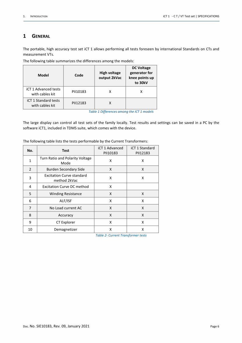
The following table summarizes the differences among the models:
Model Code High voltage
output 2kVac
DC Voltage
generator for
knee points up
to 30kV
iCT 1 Advanced tests
with cables kit PII10183 X X
iCT 1 Standard tests
with cables kit PII12183 X
Table 1 Differences among the ICT 1 models
The large display can control all test sets of the family locally. Test results and settings can be saved in a PC by the
software iCT1, included in TDMS suite, which comes with the device.
The following table lists the tests performable by the Current Transformers:
No. Test iCT 1 Advanced
PII10183
iCT 1 Standard
PII12183
1 Turn Ratio and Polarity Voltage
Mode X X
2 Burden Secondary Side X X
3 Excitation Curve standard
method 2kVac X X
4 Excitation Curve DC method X
5 Winding Resistance X X
6 ALF/ISF X X
7 No Load current AC X X
8 Accuracy X X
9 CT Explorer X X
10 Demagnetizer X X
Table 2- Current Transformer tests
1. INTRODUCTION iCT 1 - C T / VT Test set | SPECIFICATIONS
Doc. No. SIE10183, Rev. 09, January 2021 Page 7
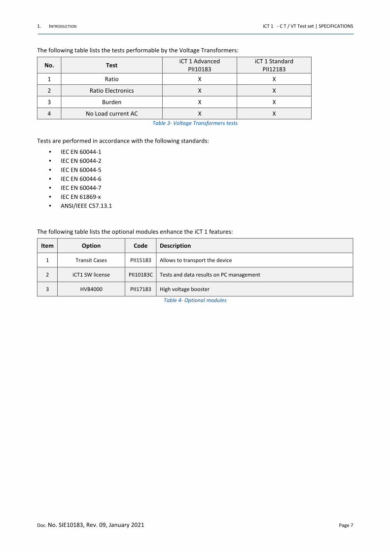
The following table lists the tests performable by the Voltage Transformers:
No. Test iCT 1 Advanced
PII10183
iCT 1 Standard
PII12183
1 Ratio X X
2 Ratio Electronics X X
3 Burden X X
4 No Load current AC X X
Table 3- Voltage Transformers tests
Tests are performed in accordance with the following standards:
• IEC EN 60044-1
• IEC EN 60044-2
• IEC EN 60044-5
• IEC EN 60044-6
• IEC EN 60044-7
• IEC EN 61869-x
• ANSI/IEEE C57.13.1
The following table lists the optional modules enhance the iCT 1 features:
Item Option Code Description
1 Transit Cases PII15183 Allows to transport the device
2 iCT1 SW license PII10183C Tests and data results on PC management
3 HVB4000 PII17183 High voltage booster
Table 4- Optional modules
1. INTRODUCTION iCT 1 - C T / VT Test set | SPECIFICATIONS
Doc. No. SIE10183, Rev. 09, January 2021 Page 8
The basic iCT 1 test set function is to generate current and voltages, as requested by the type of test to be performed;
only one test at a time. The test is selected on a color LCD touch screen.
Test results are kept in local memory or in a USB pen drive, and can be transferred to a PC later, along with settings.
iCT 1 contains a generator, with the following five outputs:
• High AC voltage
• Low AC current
• Low DC current
• Low AC voltage
• Low voltage for excitation curve DC method
In local control mode, the selected output is adjustable and metered on the large, graphic LCD display. Through the LCD
touch screen display it is possible to enter the MENU mode, which allows the functions setting.
This makes ICT 1 a very powerful testing device, with manual and automatic testing capabilities, and with the possibility
to transfer test results to a PC via ETHERNET (plug or wireless) or Pen Drive.
The iCT1 SW allows downloading, displaying and analyzing test results executed in local mode.
iCT1 SW operates with all WINDOWS versions (starting from Win7 64 bit).
The ease of operation has been the first goal of iCT 1: this is why the LCD is graphic, and so large. With it, the dialogue
in menu mode is made easy. Besides, all outputs relevant to the selected test are continuously measured, and output
values are displayed, with no extra effort to the operator.
For CT tests, the instrument can be connected directly up to 6 taps; in this way the connection to the device under test
it’s executed only one time without the need of any further manual operation.
All iCT 1 current and voltage outputs are measured at the same time; an insulated voltage measurement input allows
to perform ratio tests on CTs or VTs.
The instrument is housed in a transportable plastic box, which is provided with a cover and handles for ease of
transportation. An optional trolley is also available.
1. INTRODUCTION iCT 1 - C T / VT Test set | SPECIFICATIONS
Doc. No. SIE10183, Rev. 09, January 2021 Page 9
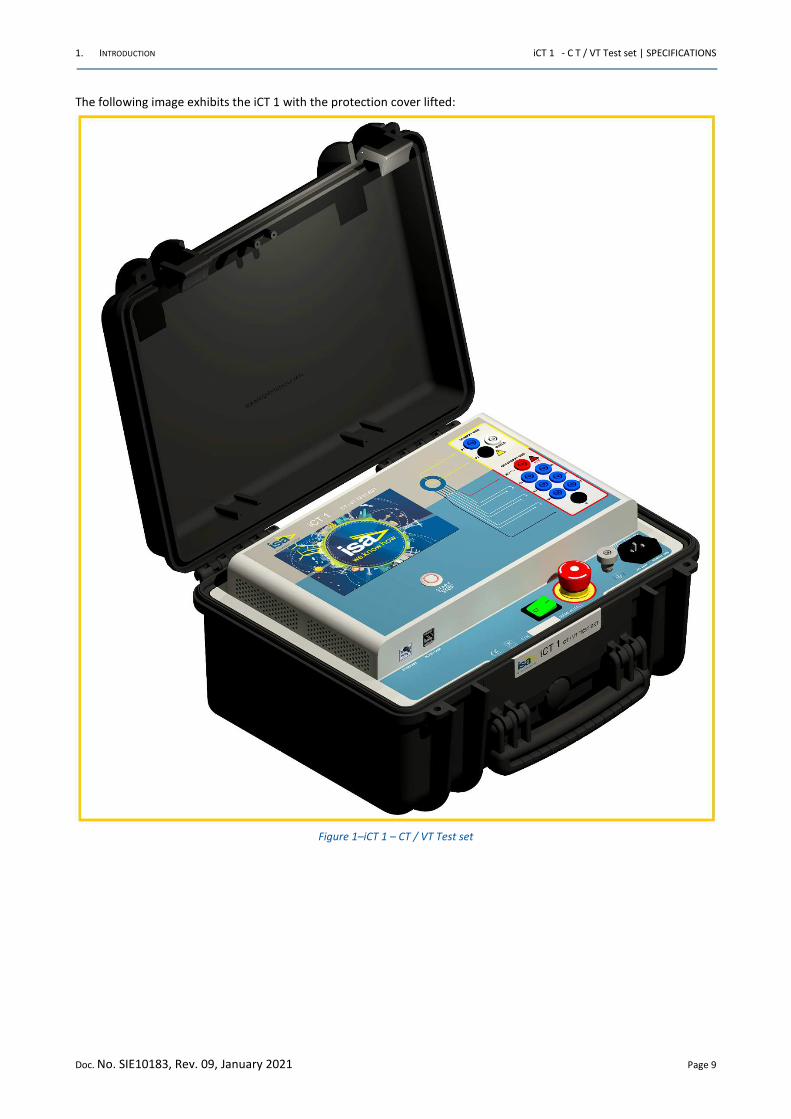
The following image exhibits the iCT 1 with the protection cover lifted:
Figure 1–iCT 1 – CT / VT Test set
1. INTRODUCTION iCT 1 - C T / VT Test set | SPECIFICATIONS
Doc. No. SIE10183, Rev. 09, January 2021 Page 10
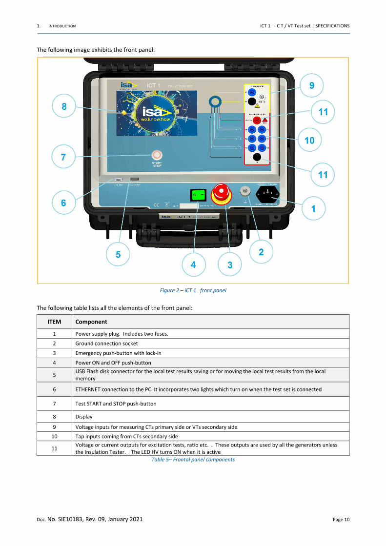
The following image exhibits the front panel:
Figure 2 – iCT 1 front panel
The following table lists all the elements of the front panel:
ITEM Component
1 Power supply plug. Includes two fuses.
2 Ground connection socket
3 Emergency push-button with lock-in
4 Power ON and OFF push-button
5 USB Flash disk connector for the local test results saving or for moving the local test results from the local
memory
6 ETHERNET connection to the PC. It incorporates two lights which turn on when the test set is connected
7 Test START and STOP push-button
8 Display
9 Voltage inputs for measuring CTs primary side or VTs secondary side
10 Tap inputs coming from CTs secondary side
11 Voltage or current outputs for excitation tests, ratio etc. . These outputs are used by all the generators unless
the Insulation Tester. The LED HV turns ON when it is active
Table 5– Frontal panel components
1. INTRODUCTION iCT 1 - C T / VT Test set | SPECIFICATIONS
Doc. No. SIE10183, Rev. 09, January 2021 Page 11
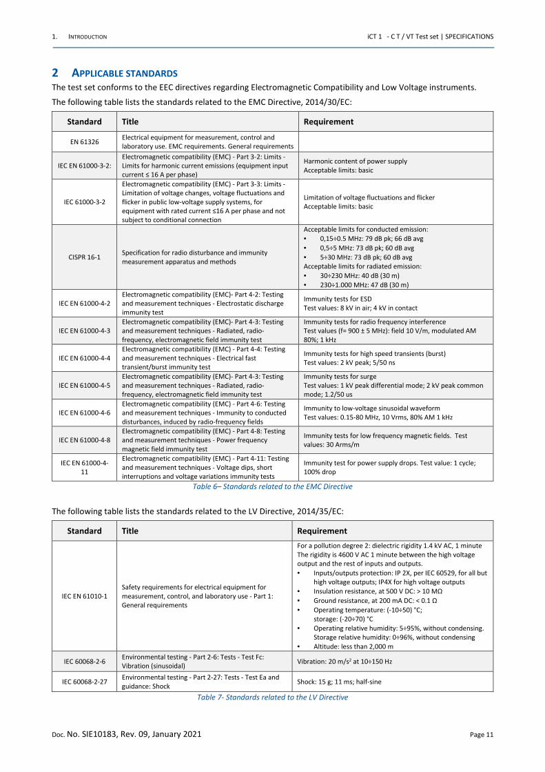
2 APPLICABLE STANDARDS The test set conforms to the EEC directives regarding Electromagnetic Compatibility and Low Voltage instruments.
The following table lists the standards related to the EMC Directive, 2014/30/EC:
Standard Title Requirement
EN 61326 Electrical equipment for measurement, control and
laboratory use. EMC requirements. General requirements
IEC EN 61000-3-2:
Electromagnetic compatibility (EMC) - Part 3-2: Limits -
Limits for harmonic current emissions (equipment input
current ≤ 16 A per phase)
Harmonic content of power supply
Acceptable limits: basic
IEC 61000-3-2
Electromagnetic compatibility (EMC) - Part 3-3: Limits -
Limitation of voltage changes, voltage fluctuations and
flicker in public low-voltage supply systems, for
equipment with rated current ≤16 A per phase and not
subject to conditional connection
Limitation of voltage fluctuations and flicker
Acceptable limits: basic
CISPR 16-1 Specification for radio disturbance and immunity
measurement apparatus and methods
Acceptable limits for conducted emission:
• 0,15÷0.5 MHz: 79 dB pk; 66 dB avg
• 0,5÷5 MHz: 73 dB pk; 60 dB avg
• 5÷30 MHz: 73 dB pk; 60 dB avg
Acceptable limits for radiated emission:
• 30÷230 MHz: 40 dB (30 m)
• 230÷1.000 MHz: 47 dB (30 m)
IEC EN 61000-4-2
Electromagnetic compatibility (EMC)- Part 4-2: Testing
and measurement techniques - Electrostatic discharge
immunity test
Immunity tests for ESD
Test values: 8 kV in air; 4 kV in contact
IEC EN 61000-4-3
Electromagnetic compatibility (EMC)- Part 4-3: Testing
and measurement techniques - Radiated, radio-
frequency, electromagnetic field immunity test
Immunity tests for radio frequency interference
Test values (f= 900 ± 5 MHz): field 10 V/m, modulated AM
80%; 1 kHz
IEC EN 61000-4-4
Electromagnetic compatibility (EMC) - Part 4-4: Testing
and measurement techniques - Electrical fast
transient/burst immunity test
Immunity tests for high speed transients (burst)
Test values: 2 kV peak; 5/50 ns
IEC EN 61000-4-5
Electromagnetic compatibility (EMC)- Part 4-3: Testing
and measurement techniques - Radiated, radio-
frequency, electromagnetic field immunity test
Immunity tests for surge
Test values: 1 kV peak differential mode; 2 kV peak common
mode; 1.2/50 us
IEC EN 61000-4-6
Electromagnetic compatibility (EMC) - Part 4-6: Testing
and measurement techniques - Immunity to conducted
disturbances, induced by radio-frequency fields
Immunity to low-voltage sinusoidal waveform
Test values: 0.15-80 MHz, 10 Vrms, 80% AM 1 kHz
IEC EN 61000-4-8
Electromagnetic compatibility (EMC) - Part 4-8: Testing
and measurement techniques - Power frequency
magnetic field immunity test
Immunity tests for low frequency magnetic fields. Test
values: 30 Arms/m
IEC EN 61000-4-
11
Electromagnetic compatibility (EMC) - Part 4-11: Testing
and measurement techniques - Voltage dips, short
interruptions and voltage variations immunity tests
Immunity test for power supply drops. Test value: 1 cycle;
100% drop
Table 6– Standards related to the EMC Directive
The following table lists the standards related to the LV Directive, 2014/35/EC:
Standard Title Requirement
IEC EN 61010-1
Safety requirements for electrical equipment for
measurement, control, and laboratory use - Part 1:
General requirements
For a pollution degree 2: dielectric rigidity 1.4 kV AC, 1 minute
The rigidity is 4600 V AC 1 minute between the high voltage
output and the rest of inputs and outputs.
• Inputs/outputs protection: IP 2X, per IEC 60529, for all but
high voltage outputs; IP4X for high voltage outputs
• Insulation resistance, at 500 V DC: > 10 MΩ
• Ground resistance, at 200 mA DC: < 0.1 Ω
• Operating temperature: (-10÷50) °C;
storage: (-20÷70) °C
• Operating relative humidity: 5÷95%, without condensing.
Storage relative humidity: 0÷96%, without condensing
• Altitude: less than 2,000 m
IEC 60068-2-6 Environmental testing - Part 2-6: Tests - Test Fc:
Vibration (sinusoidal) Vibration: 20 m/s2 at 10÷150 Hz
IEC 60068-2-27 Environmental testing - Part 2-27: Tests - Test Ea and
guidance: Shock Shock: 15 g; 11 ms; half-sine
Table 7- Standards related to the LV Directive
2. CHARACTERISTICS iCT 1 - C T / VT Test set | SPECIFICATIONS
Doc. No. SIE10183, Rev. 09, January 2021 Page 12
3 CHARACTERISTICS
3.1 Foreword
The iCT 1 instrument incorporates a generator with five outputs.
The generator is made of an electronic type D switching amplifier, followed by a power transformer or by electronic
devices for DC curve method and other tests, which adapts the suitable current or voltage output.
3.2 Main generator
The main generator has five outputs:
• High AC voltage
• Low AC current
• Low DC current
• Low AC voltage
• Low voltage for excitation curve DC method
Output adjustment is performed automatically, as a function of the selected test. The following specification applies to
the separate use of these outputs.
For all outputs, the following applies:
• Type of generator. Electronic type D switching amplifier, followed by a high power transformer, with a number
of secondary windings, for the following outputs: high AC current, high DC current, high AC voltage. Loop
control of the selected output. The transformer includes also the outputs: Low AC current, Low DC current,
Low AC voltage, but they are not loop controlled
• Output adjustable from zero to the maximum value
• The specified output power is available at 25°C maximum of external temperature, and with a power supply
error of 2% maximum. For higher temperatures, the maximum power decreases of 20 VA/°C
2. CHARACTERISTICS iCT 1 - C T / VT Test set | SPECIFICATIONS
Doc. No. SIE10183, Rev. 09, January 2021 Page 13
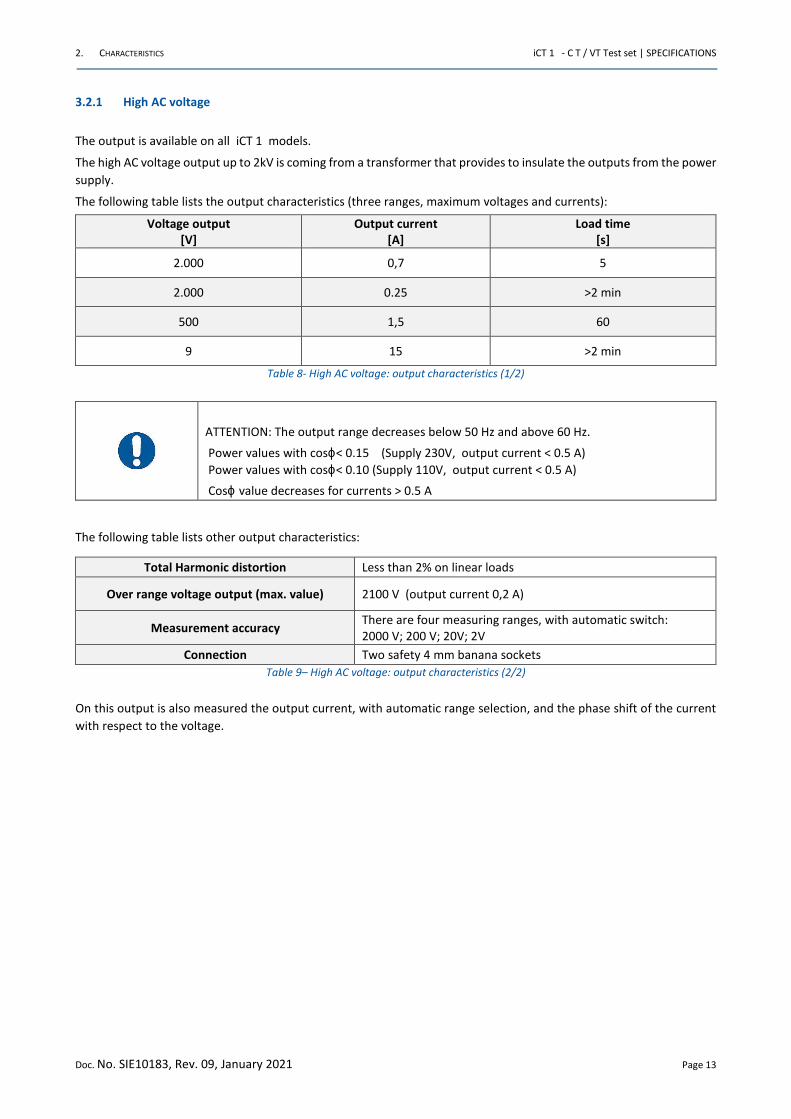
3.2.1 High AC voltage
The output is available on all iCT 1 models.
The high AC voltage output up to 2kV is coming from a transformer that provides to insulate the outputs from the power
supply.
The following table lists the output characteristics (three ranges, maximum voltages and currents):
Voltage output
[V]
Output current
[A]
Load time
[s]
2.000 0,7 5
2.000 0.25 >2 min
500 1,5 60
9 15 >2 min
Table 8- High AC voltage: output characteristics (1/2)
ATTENTION: The output range decreases below 50 Hz and above 60 Hz.
Power values with cosϕ< 0.15 (Supply 230V, output current < 0.5 A)
Power values with cosϕ< 0.10 (Supply 110V, output current < 0.5 A)
Cosϕ value decreases for currents > 0.5 A
The following table lists other output characteristics:
Total Harmonic distortion Less than 2% on linear loads
Over range voltage output (max. value) 2100 V (output current 0,2 A)
Measurement accuracy There are four measuring ranges, with automatic switch:
2000 V; 200 V; 20V; 2V
Connection Two safety 4 mm banana sockets
Table 9– High AC voltage: output characteristics (2/2)
On this output is also measured the output current, with automatic range selection, and the phase shift of the current
with respect to the voltage.
2. CHARACTERISTICS iCT 1 - C T / VT Test set | SPECIFICATIONS
Doc. No. SIE10183, Rev. 09, January 2021 Page 14
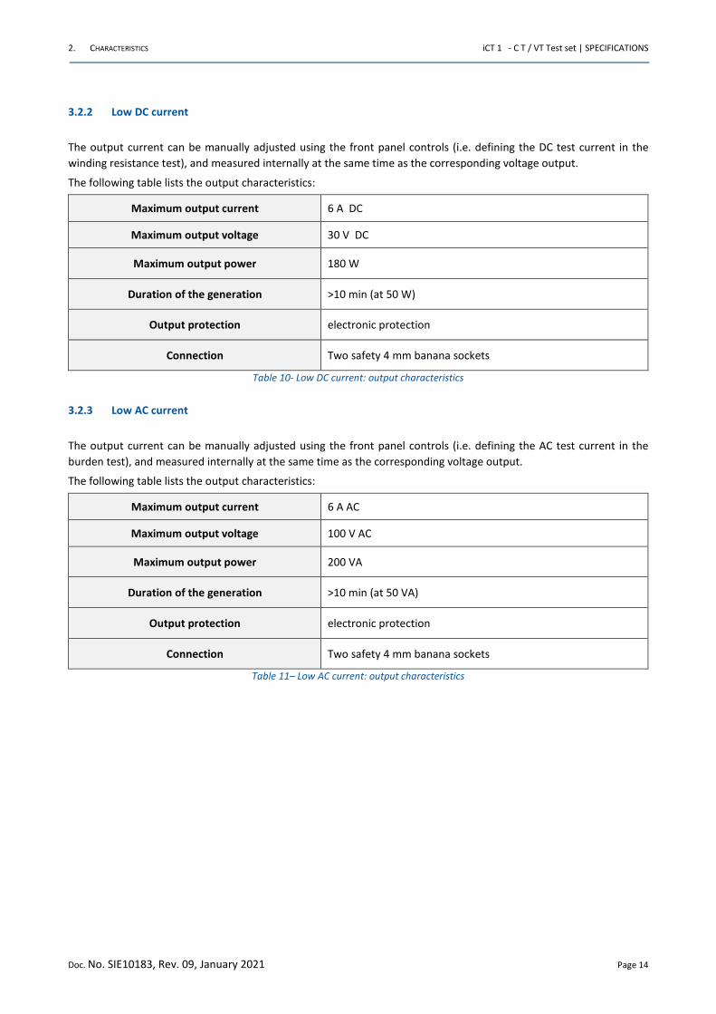
3.2.2 Low DC current
The output current can be manually adjusted using the front panel controls (i.e. defining the DC test current in the
winding resistance test), and measured internally at the same time as the corresponding voltage output.
The following table lists the output characteristics:
Maximum output current 6 A DC
Maximum output voltage 30 V DC
Maximum output power 180 W
Duration of the generation >10 min (at 50 W)
Output protection electronic protection
Connection Two safety 4 mm banana sockets
Table 10- Low DC current: output characteristics
3.2.3 Low AC current
The output current can be manually adjusted using the front panel controls (i.e. defining the AC test current in the
burden test), and measured internally at the same time as the corresponding voltage output.
The following table lists the output characteristics:
Maximum output current 6 A AC
Maximum output voltage 100 V AC
Maximum output power 200 VA
Duration of the generation >10 min (at 50 VA)
Output protection electronic protection
Connection Two safety 4 mm banana sockets
Table 11– Low AC current: output characteristics
2. CHARACTERISTICS iCT 1 - C T / VT Test set | SPECIFICATIONS
Doc. No. SIE10183, Rev. 09, January 2021 Page 15
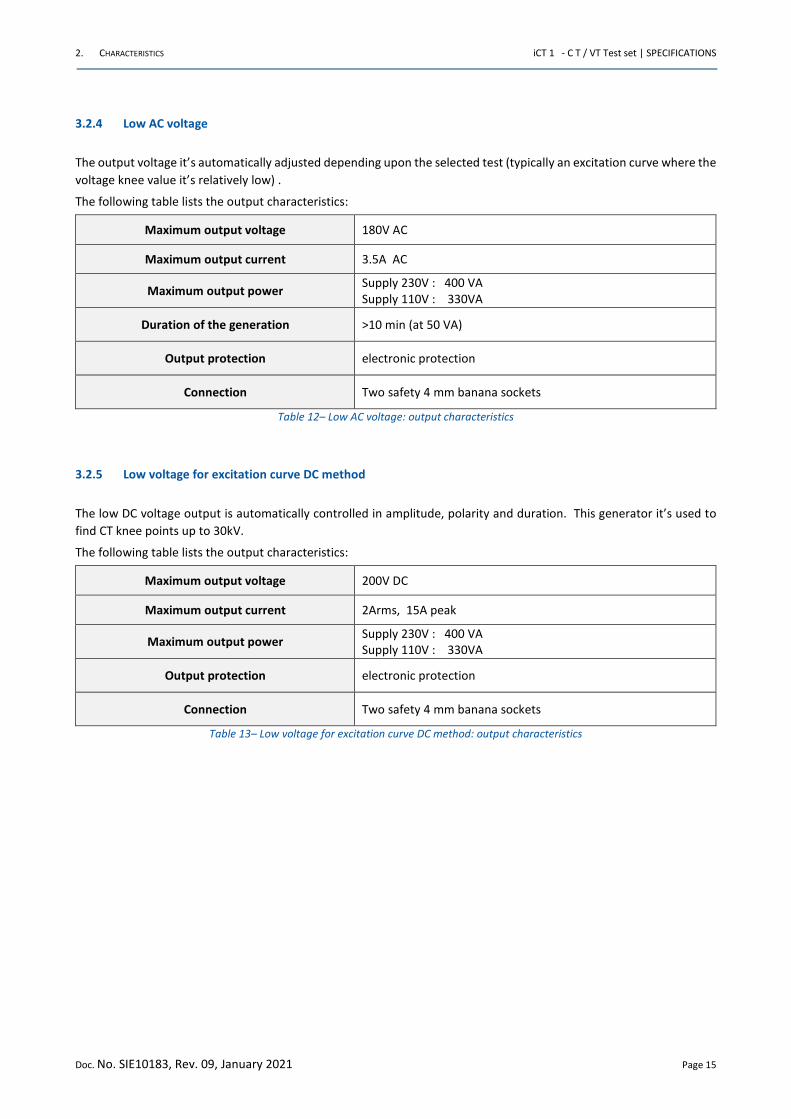
3.2.4 Low AC voltage
The output voltage it’s automatically adjusted depending upon the selected test (typically an excitation curve where the
voltage knee value it’s relatively low) .
The following table lists the output characteristics:
Maximum output voltage 180V AC
Maximum output current 3.5A AC
Maximum output power Supply 230V : 400 VA
Supply 110V : 330VA
Duration of the generation >10 min (at 50 VA)
Output protection electronic protection
Connection Two safety 4 mm banana sockets
Table 12– Low AC voltage: output characteristics
3.2.5 Low voltage for excitation curve DC method
The low DC voltage output is automatically controlled in amplitude, polarity and duration. This generator it’s used to
find CT knee points up to 30kV.
The following table lists the output characteristics:
Maximum output voltage 200V DC
Maximum output current 2Arms, 15A peak
Maximum output power Supply 230V : 400 VA
Supply 110V : 330VA
Output protection electronic protection
Connection Two safety 4 mm banana sockets
Table 13– Low voltage for excitation curve DC method: output characteristics
2. CHARACTERISTICS iCT 1 - C T / VT Test set | SPECIFICATIONS
Doc. No. SIE10183, Rev. 09, January 2021 Page 16
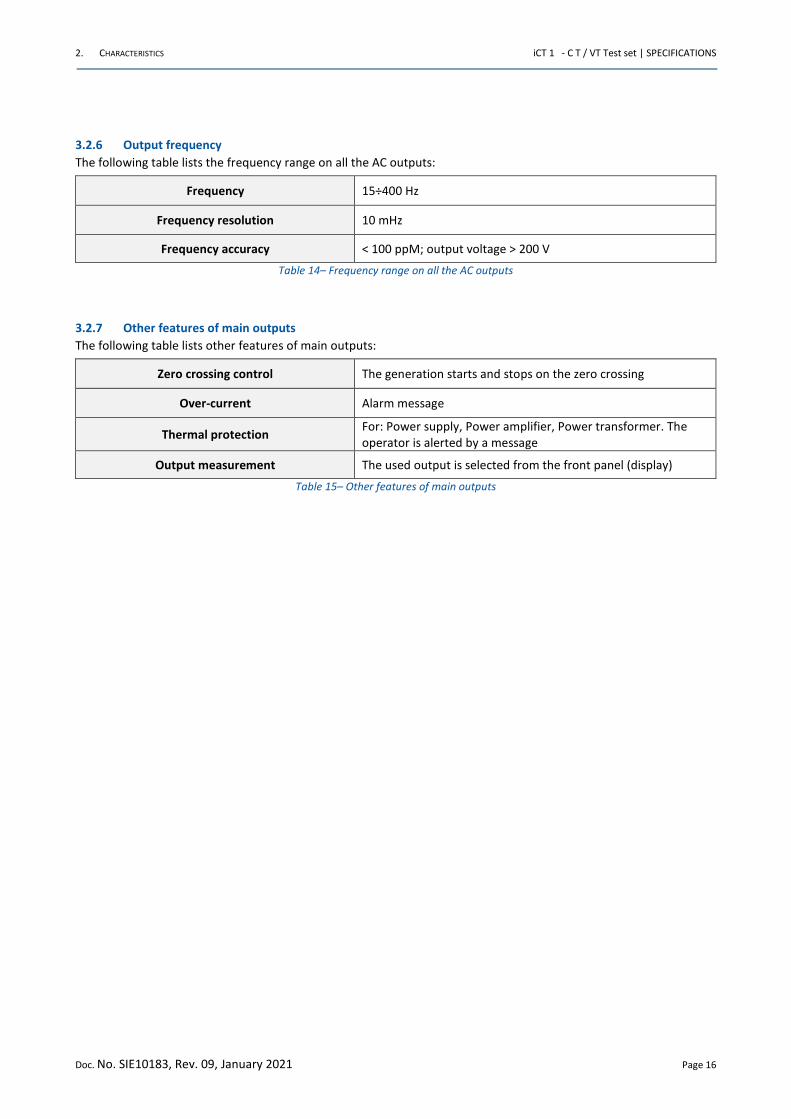
3.2.6 Output frequency
The following table lists the frequency range on all the AC outputs:
Frequency 15÷400 Hz
Frequency resolution 10 mHz
Frequency accuracy < 100 ppM; output voltage > 200 V
Table 14– Frequency range on all the AC outputs
3.2.7 Other features of main outputs
The following table lists other features of main outputs:
Zero crossing control The generation starts and stops on the zero crossing
Over-current Alarm message
Thermal protection For: Power supply, Power amplifier, Power transformer. The
operator is alerted by a message
Output measurement The used output is selected from the front panel (display)
Table 15– Other features of main outputs
2. CHARACTERISTICS iCT 1 - C T / VT Test set | SPECIFICATIONS
Doc. No. SIE10183, Rev. 09, January 2021 Page 17
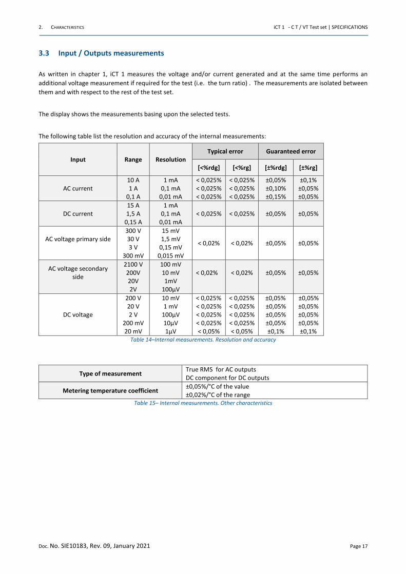
3.3 Input / Outputs measurements
As written in chapter 1, iCT 1 measures the voltage and/or current generated and at the same time performs an
additional voltage measurement if required for the test (i.e. the turn ratio) . The measurements are isolated between
them and with respect to the rest of the test set.
The display shows the measurements basing upon the selected tests.
The following table list the resolution and accuracy of the internal measurements:
Input Range Resolution
Typical error Guaranteed error
[<%rdg] [<%rg] [±%rdg] [±%rg]
AC current
10 A
1 A
0,1 A
1 mA
0,1 mA
0,01 mA
< 0,025%
< 0,025%
< 0,025%
< 0,025%
< 0,025%
< 0,025%
±0,05%
±0,10%
±0,15%
±0,1%
±0,05%
±0,05%
DC current
15 A
1,5 A
0,15 A
1 mA
0,1 mA
0,01 mA
< 0,025% < 0,025% ±0,05% ±0,05%
AC voltage primary side
300 V
30 V
3 V
300 mV
15 mV
1,5 mV
0,15 mV
0,015 mV
< 0,02% < 0,02% ±0,05% ±0,05%
AC voltage secondary
side
2100 V
200V
20V
2V
100 mV
10 mV
1mV
100μV
< 0,02%
< 0,02%
±0,05%
±0,05%
DC voltage
200 V
20 V
2 V
200 mV
20 mV
10 mV
1 mV
100μV
10μV
1μV
< 0,025%
< 0,025%
< 0,025%
< 0,025%
< 0,05%
< 0,025%
< 0,025%
< 0,025%
< 0,025%
< 0,05%
±0,05%
±0,05%
±0,05%
±0,05%
±0,1%
±0,05%
±0,05%
±0,05%
±0,05%
±0,1%
Table 14–Internal measurements. Resolution and accuracy
Type of measurement True RMS for AC outputs
DC component for DC outputs
Metering temperature coefficient ±0,05%/°C of the value
±0,02%/°C of the range
Table 15– Internal measurements. Other characteristics
2. CHARACTERISTICS iCT 1 - C T / VT Test set | SPECIFICATIONS
Doc. No. SIE10183, Rev. 09, January 2021 Page 18
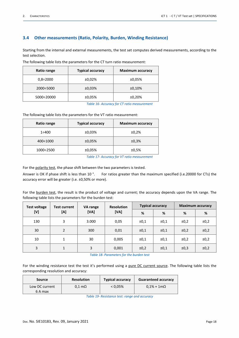
3.4 Other measurements (Ratio, Polarity, Burden, Winding Resistance)
Starting from the internal and external measurements, the test set computes derived measurements, according to the
test selection.
The following table lists the parameters for the CT turn ratio measurement:
Ratio range Typical accuracy Maximum accuracy
0,8÷2000 ±0,02% ±0,05%
2000÷5000 ±0,03% ±0,10%
5000÷20000 ±0,05% ±0,20%
Table 16- Accuracy for CT ratio measurement
The following table lists the parameters for the VT ratio measurement:
Ratio range Typical accuracy Maximum accuracy
1÷400 ±0,03% ±0,2%
400÷1000 ±0,05% ±0,3%
1000÷2500 ±0,05% ±0,5%
Table 17- Accuracy for VT ratio measurement
For the polarity test, the phase shift between the two parameters is tested.
Answer is OK if phase shift is less than 10 °. For ratios greater than the maximum specified (i.e.20000 for CTs) the
accuracy error will be greater (i.e. ±0,50% or more).
For the burden test, the result is the product of voltage and current; the accuracy depends upon the VA range. The
following table lists the parameters for the burden test:
Test voltage
[V]
Test current
[A]
VA range
[VA]
Resolution
[VA]
Typical accuracy Maximum accuracy
% % % %
130 3 3.000 0,05 ±0,1 ±0,1 ±0,2 ±0,2
30 2 300 0,01 ±0,1 ±0,1 ±0,2 ±0,2
10 1 30 0,005 ±0,1 ±0,1 ±0,2 ±0,2
3 1 3 0,001 ±0,2 ±0,1 ±0,3 ±0,2
Table 18- Parameters for the burden test
For the winding resistance test the test it’s performed using a pure DC current source. The following table lists the
corresponding resolution and accuracy:
Source Resolution Typical accuracy Guaranteed accuracy
Low DC current
6 A max
0,1 mΩ
< 0,05%
0,1% + 1mΩ
Table 19- Resistance test: range and accuracy
2. CHARACTERISTICS iCT 1 - C T / VT Test set | SPECIFICATIONS
Doc. No. SIE10183, Rev. 09, January 2021 Page 19
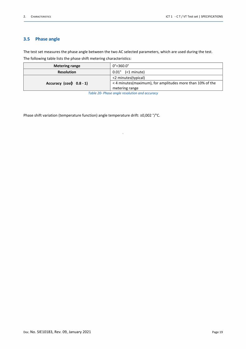
3.5 Phase angle
The test set measures the phase angle between the two AC selected parameters, which are used during the test.
The following table lists the phase shift metering characteristics:
Metering range 0°÷360.0°
Resolution 0.01° (<1 minute)
Accuracy (cosϕ 0.8 - 1)
<2 minutes(typical)
< 4 minutes(maximum), for amplitudes more than 10% of the
metering range
Table 20- Phase angle resolution and accuracy
Phase shift variation (temperature function) angle temperature drift: ±0,002 °/°C.
.
2. CHARACTERISTICS iCT 1 - C T / VT Test set | SPECIFICATIONS
Doc. No. SIE10183, Rev. 09, January 2021 Page 20
3.6 Display
The following image exhibits the iCT 1 display:
Figure 3 iCT 1 display
The following table lists the main features of the display touch:
Pixel Light LCD type View area
800 x 480 , colors (7”) Backlight TFT 152 x 90 mm
Table 21- Main features of the display
3.7 Test control
Test control: by the START / STOP pushbutton. Pressing it, the output is generated, after test selection, according to the
type of test.
Test saving:
• Automatic save
• After operator confirmation
2. CHARACTERISTICS iCT 1 - C T / VT Test set | SPECIFICATIONS
Doc. No. SIE10183, Rev. 09, January 2021 Page 21
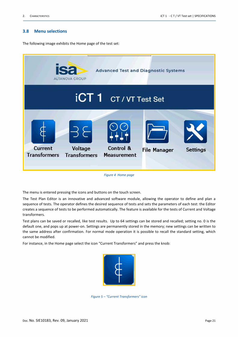
3.8 Menu selections
The following image exhibits the Home page of the test set:
Figure 4 Home page
The menu is entered pressing the icons and buttons on the touch screen.
The Test Plan Editor is an innovative and advanced software module, allowing the operator to define and plan a
sequence of tests. The operator defines the desired sequence of tests and sets the parameters of each test: the Editor
creates a sequence of tests to be performed automatically. The feature is available for the tests of Current and Voltage
transformers.
Test plans can be saved or recalled, like test results. Up to 64 settings can be stored and recalled; setting no. 0 is the
default one, and pops up at power-on. Settings are permanently stored in the memory; new settings can be written to
the same address after confirmation. For normal mode operation it is possible to recall the standard setting, which
cannot be modified.
For instance, in the Home page select the icon “Current Transformers” and press the knob:
Figure 5 – “Current Transformers" icon
2. CHARACTERISTICS iCT 1 - C T / VT Test set | SPECIFICATIONS
Doc. No. SIE10183, Rev. 09, January 2021 Page 22
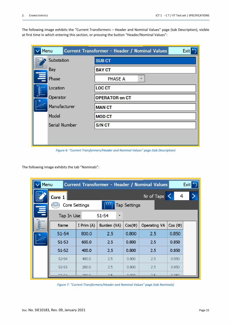
The following image exhibits the “Current Transformers – Header and Nominal Values” page (tab Description), visible
at first time in which entering this section, or pressing the button “Header/Nominal Values”:
Figure 6- "Current Transformers/Header and Nominal Values" page (tab Description)
The following image exhibits the tab “Nominals”:
Figure 7- "Current Transformers/Header and Nominal Values" page (tab Nominals)
2. CHARACTERISTICS iCT 1 - C T / VT Test set | SPECIFICATIONS
Doc. No. SIE10183, Rev. 09, January 2021 Page 23
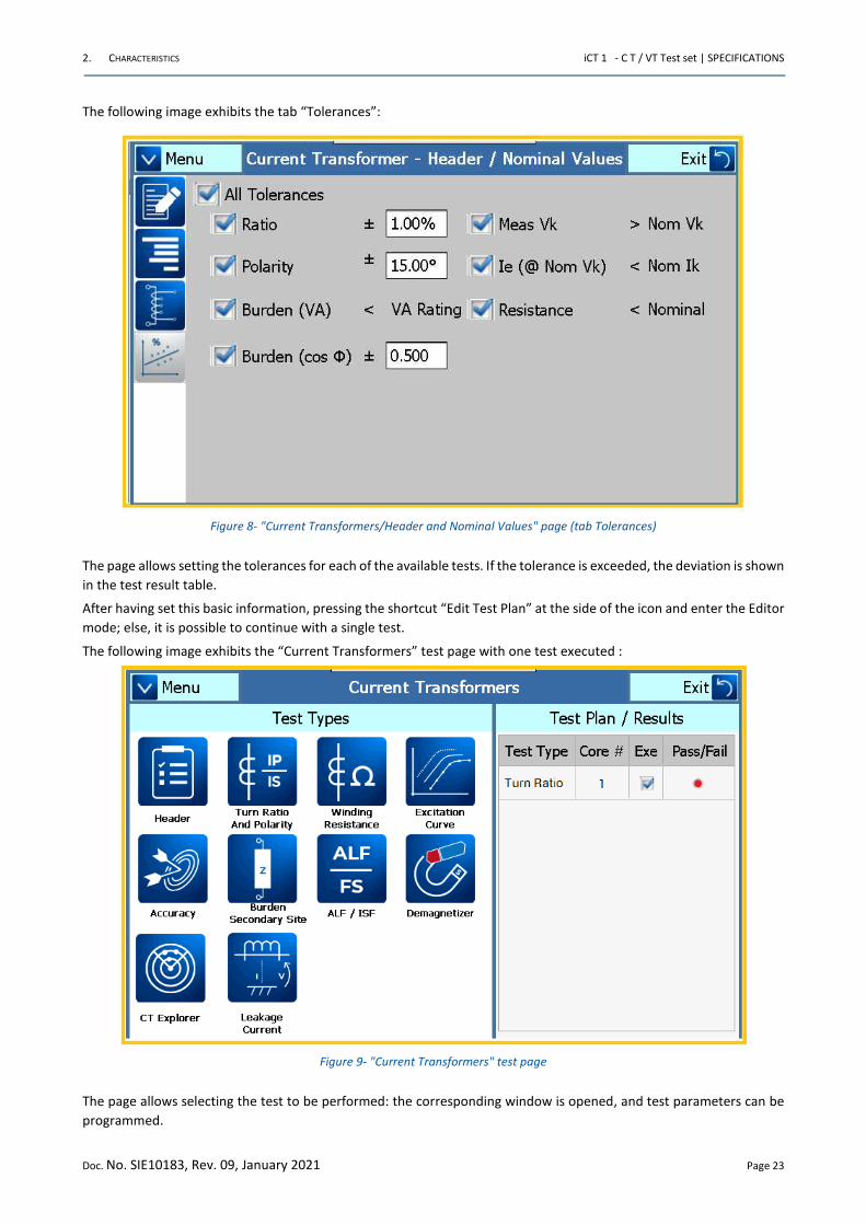
The following image exhibits the tab “Tolerances”:
Figure 8- "Current Transformers/Header and Nominal Values" page (tab Tolerances)
The page allows setting the tolerances for each of the available tests. If the tolerance is exceeded, the deviation is shown
in the test result table.
After having set this basic information, pressing the shortcut “Edit Test Plan” at the side of the icon and enter the Editor
mode; else, it is possible to continue with a single test.
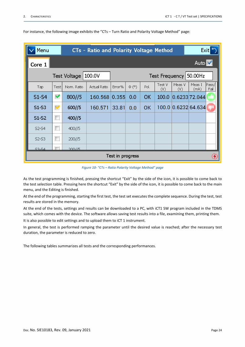
The following image exhibits the “Current Transformers” test page with one test executed :
Figure 9- "Current Transformers" test page
The page allows selecting the test to be performed: the corresponding window is opened, and test parameters can be
programmed.
2. CHARACTERISTICS iCT 1 - C T / VT Test set | SPECIFICATIONS
Doc. No. SIE10183, Rev. 09, January 2021 Page 24
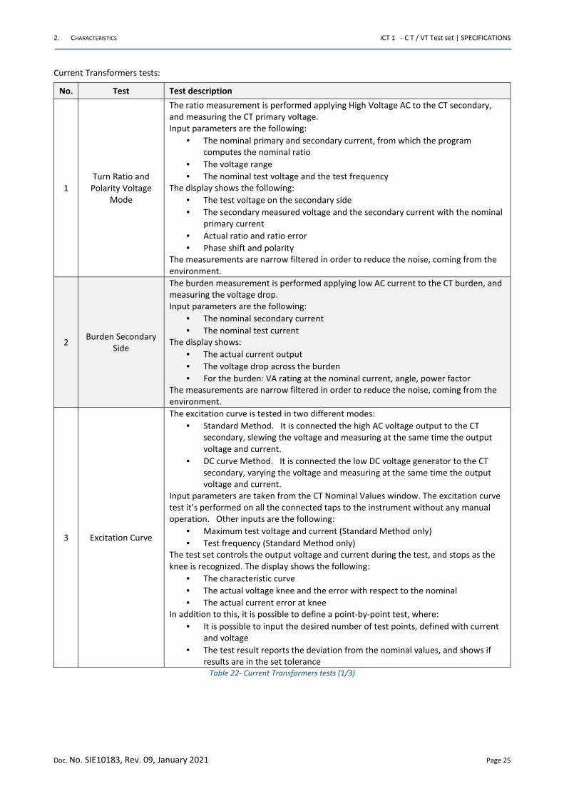
For instance, the following image exhibits the “CTs – Turn Ratio and Polarity Voltage Method” page:
Figure 10- "CTs – Ratio Polarity Voltage Method" page
As the test programming is finished, pressing the shortcut “Exit” by the side of the icon, it is possible to come back to
the test selection table. Pressing here the shortcut “Exit” by the side of the icon, it is possible to come back to the main
menu, and the Editing is finished.
At the end of the programming, starting the first test, the test set executes the complete sequence. During the test, test
results are stored in the memory.
At the end of the tests, settings and results can be downloaded to a PC, with iCT1 SW program included in the TDMS
suite, which comes with the device. The software allows saving test results into a file, examining them, printing them.
It is also possible to edit settings and to upload them to iCT 1 instrument.
In general, the test is performed ramping the parameter until the desired value is reached; after the necessary test
duration, the parameter is reduced to zero.
The following tables summarizes all tests and the corresponding performances.
2. CHARACTERISTICS iCT 1 - C T / VT Test set | SPECIFICATIONS
Doc. No. SIE10183, Rev. 09, January 2021 Page 25
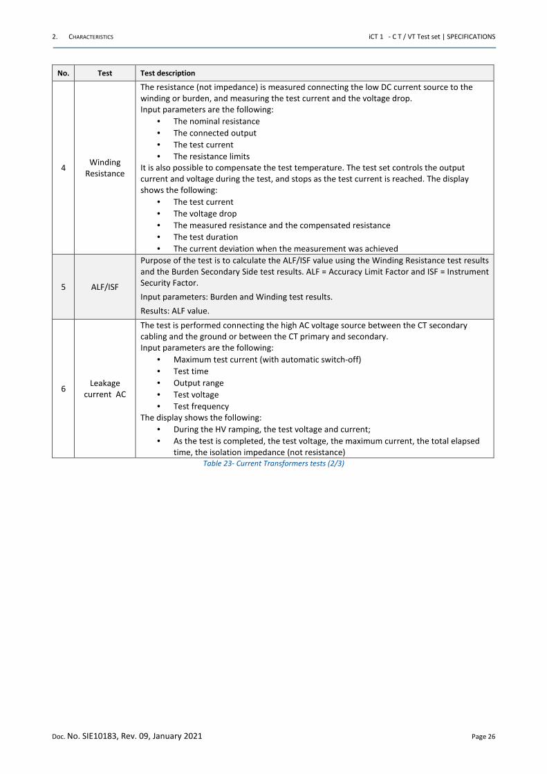
Current Transformers tests:
No. Test Test description
1
Turn Ratio and
Polarity Voltage
Mode
The ratio measurement is performed applying High Voltage AC to the CT secondary,
and measuring the CT primary voltage.
Input parameters are the following:
• The nominal primary and secondary current, from which the program
computes the nominal ratio
• The voltage range
• The nominal test voltage and the test frequency
The display shows the following:
• The test voltage on the secondary side
• The secondary measured voltage and the secondary current with the nominal
primary current
• Actual ratio and ratio error
• Phase shift and polarity
The measurements are narrow filtered in order to reduce the noise, coming from the
environment.
2 Burden Secondary
Side
The burden measurement is performed applying low AC current to the CT burden, and
measuring the voltage drop.
Input parameters are the following:
• The nominal secondary current
• The nominal test current
The display shows:
• The actual current output
• The voltage drop across the burden
• For the burden: VA rating at the nominal current, angle, power factor
The measurements are narrow filtered in order to reduce the noise, coming from the
environment.
3 Excitation Curve
The excitation curve is tested in two different modes:
• Standard Method. It is connected the high AC voltage output to the CT
secondary, slewing the voltage and measuring at the same time the output
voltage and current.
• DC curve Method. It is connected the low DC voltage generator to the CT
secondary, varying the voltage and measuring at the same time the output
voltage and current.
Input parameters are taken from the CT Nominal Values window. The excitation curve
test it’s performed on all the connected taps to the instrument without any manual
operation. Other inputs are the following:
• Maximum test voltage and current (Standard Method only)
• Test frequency (Standard Method only)
The test set controls the output voltage and current during the test, and stops as the
knee is recognized. The display shows the following:
• The characteristic curve
• The actual voltage knee and the error with respect to the nominal
• The actual current error at knee
In addition to this, it is possible to define a point-by-point test, where:
• It is possible to input the desired number of test points, defined with current
and voltage
• The test result reports the deviation from the nominal values, and shows if
results are in the set tolerance
Table 22- Current Transformers tests (1/3)
2. CHARACTERISTICS iCT 1 - C T / VT Test set | SPECIFICATIONS
Doc. No. SIE10183, Rev. 09, January 2021 Page 26
No. Test Test description
4 Winding
Resistance
The resistance (not impedance) is measured connecting the low DC current source to the
winding or burden, and measuring the test current and the voltage drop.
Input parameters are the following:
• The nominal resistance
• The connected output
• The test current
• The resistance limits
It is also possible to compensate the test temperature. The test set controls the output
current and voltage during the test, and stops as the test current is reached. The display
shows the following:
• The test current
• The voltage drop
• The measured resistance and the compensated resistance
• The test duration
• The current deviation when the measurement was achieved
5 ALF/ISF
Purpose of the test is to calculate the ALF/ISF value using the Winding Resistance test results
and the Burden Secondary Side test results. ALF = Accuracy Limit Factor and ISF = Instrument
Security Factor.
Input parameters: Burden and Winding test results.
Results: ALF value.
6 Leakage
current AC
The test is performed connecting the high AC voltage source between the CT secondary
cabling and the ground or between the CT primary and secondary.
Input parameters are the following:
• Maximum test current (with automatic switch-off)
• Test time
• Output range
• Test voltage
• Test frequency
The display shows the following:
• During the HV ramping, the test voltage and current;
• As the test is completed, the test voltage, the maximum current, the total elapsed
time, the isolation impedance (not resistance)
Table 23- Current Transformers tests (2/3)
2. CHARACTERISTICS iCT 1 - C T / VT Test set | SPECIFICATIONS
Doc. No. SIE10183, Rev. 09, January 2021 Page 27
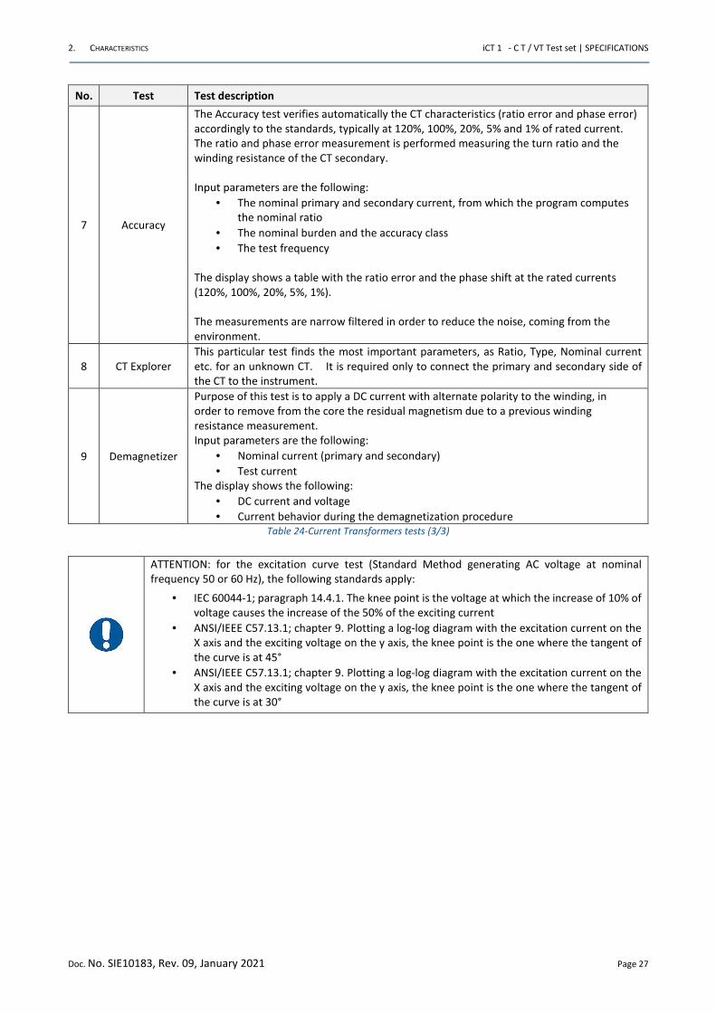
No. Test Test description
7 Accuracy
The Accuracy test verifies automatically the CT characteristics (ratio error and phase error)
accordingly to the standards, typically at 120%, 100%, 20%, 5% and 1% of rated current.
The ratio and phase error measurement is performed measuring the turn ratio and the
winding resistance of the CT secondary.
Input parameters are the following:
• The nominal primary and secondary current, from which the program computes
the nominal ratio
• The nominal burden and the accuracy class
• The test frequency
The display shows a table with the ratio error and the phase shift at the rated currents
(120%, 100%, 20%, 5%, 1%).
The measurements are narrow filtered in order to reduce the noise, coming from the
environment.
8 CT Explorer
This particular test finds the most important parameters, as Ratio, Type, Nominal current
etc. for an unknown CT. It is required only to connect the primary and secondary side of
the CT to the instrument.
9 Demagnetizer
Purpose of this test is to apply a DC current with alternate polarity to the winding, in
order to remove from the core the residual magnetism due to a previous winding
resistance measurement.
Input parameters are the following:
• Nominal current (primary and secondary)
• Test current
The display shows the following:
• DC current and voltage
• Current behavior during the demagnetization procedure
Table 24-Current Transformers tests (3/3)
ATTENTION: for the excitation curve test (Standard Method generating AC voltage at nominal
frequency 50 or 60 Hz), the following standards apply:
• IEC 60044-1; paragraph 14.4.1. The knee point is the voltage at which the increase of 10% of
voltage causes the increase of the 50% of the exciting current
• ANSI/IEEE C57.13.1; chapter 9. Plotting a log-log diagram with the excitation current on the
X axis and the exciting voltage on the y axis, the knee point is the one where the tangent of
the curve is at 45°
• ANSI/IEEE C57.13.1; chapter 9. Plotting a log-log diagram with the excitation current on the
X axis and the exciting voltage on the y axis, the knee point is the one where the tangent of
the curve is at 30°
2. CHARACTERISTICS iCT 1 - C T / VT Test set | SPECIFICATIONS
Doc. No. SIE10183, Rev. 09, January 2021 Page 28
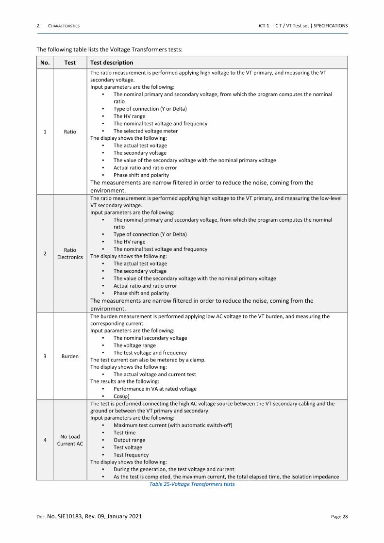
The following table lists the Voltage Transformers tests:
No. Test Test description
1 Ratio
The ratio measurement is performed applying high voltage to the VT primary, and measuring the VT
secondary voltage.
Input parameters are the following:
• The nominal primary and secondary voltage, from which the program computes the nominal
ratio
• Type of connection (Y or Delta)
• The HV range
• The nominal test voltage and frequency
• The selected voltage meter
The display shows the following:
• The actual test voltage
• The secondary voltage
• The value of the secondary voltage with the nominal primary voltage
• Actual ratio and ratio error
• Phase shift and polarity
The measurements are narrow filtered in order to reduce the noise, coming from the
environment.
2 Ratio
Electronics
The ratio measurement is performed applying high voltage to the VT primary, and measuring the low-level
VT secondary voltage.
Input parameters are the following:
• The nominal primary and secondary voltage, from which the program computes the nominal
ratio
• Type of connection (Y or Delta)
• The HV range
• The nominal test voltage and frequency
The display shows the following:
• The actual test voltage
• The secondary voltage
• The value of the secondary voltage with the nominal primary voltage
• Actual ratio and ratio error
• Phase shift and polarity
The measurements are narrow filtered in order to reduce the noise, coming from the
environment.
3 Burden
The burden measurement is performed applying low AC voltage to the VT burden, and measuring the
corresponding current.
Input parameters are the following:
• The nominal secondary voltage
• The voltage range
• The test voltage and frequency
The test current can also be metered by a clamp.
The display shows the following:
• The actual voltage and current test
The results are the following:
• Performance in VA at rated voltage
• Cos(ϕ)
4 No Load
Current AC
The test is performed connecting the high AC voltage source between the VT secondary cabling and the
ground or between the VT primary and secondary.
Input parameters are the following:
• Maximum test current (with automatic switch-off)
• Test time
• Output range
• Test voltage
• Test frequency
The display shows the following:
• During the generation, the test voltage and current
• As the test is completed, the maximum current, the total elapsed time, the isolation impedance
Table 25-Voltage Transformers tests
2. CHARACTERISTICS iCT 1 - C T / VT Test set | SPECIFICATIONS
Doc. No. SIE10183, Rev. 09, January 2021 Page 29
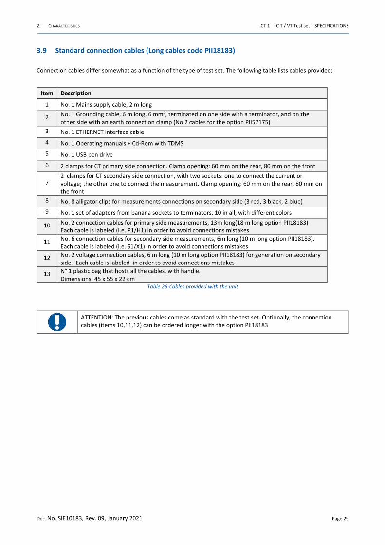
3.9 Standard connection cables (Long cables code PII18183)
Connection cables differ somewhat as a function of the type of test set. The following table lists cables provided:
Item Description
1 No. 1 Mains supply cable, 2 m long
2 No. 1 Grounding cable, 6 m long, 6 mm2, terminated on one side with a terminator, and on the
other side with an earth connection clamp (No 2 cables for the option PII57175)
3 No. 1 ETHERNET interface cable
4 No. 1 Operating manuals + Cd-Rom with TDMS
5 No. 1 USB pen drive
6 2 clamps for CT primary side connection. Clamp opening: 60 mm on the rear, 80 mm on the front
7 2 clamps for CT secondary side connection, with two sockets: one to connect the current or
voltage; the other one to connect the measurement. Clamp opening: 60 mm on the rear, 80 mm on
the front
8 No. 8 alligator clips for measurements connections on secondary side (3 red, 3 black, 2 blue)
9 No. 1 set of adaptors from banana sockets to terminators, 10 in all, with different colors
10 No. 2 connection cables for primary side measurements, 13m long(18 m long option PII18183)
Each cable is labeled (i.e. P1/H1) in order to avoid connections mistakes
11 No. 6 connection cables for secondary side measurements, 6m long (10 m long option PII18183).
Each cable is labeled (i.e. S1/X1) in order to avoid connections mistakes
12 No. 2 voltage connection cables, 6 m long (10 m long option PII18183) for generation on secondary
side. Each cable is labeled in order to avoid connections mistakes
13 N° 1 plastic bag that hosts all the cables, with handle.
Dimensions: 45 x 55 x 22 cm
Table 26-Cables provided with the unit
ATTENTION: The previous cables come as standard with the test set. Optionally, the connection
cables (items 10,11,12) can be ordered longer with the option PII18183
2. CHARACTERISTICS iCT 1 - C T / VT Test set | SPECIFICATIONS
Doc. No. SIE10183, Rev. 09, January 2021 Page 30
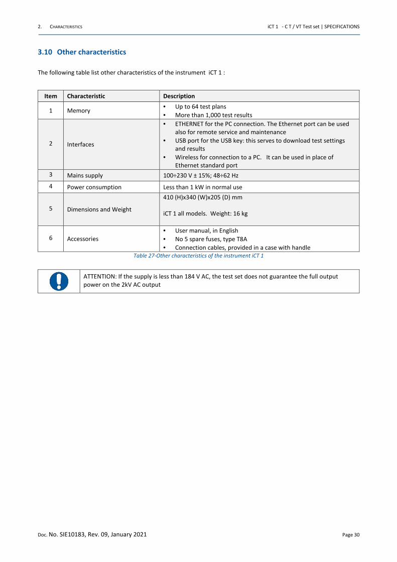
3.10 Other characteristics
The following table list other characteristics of the instrument iCT 1 :
Item Characteristic Description
1 Memory • Up to 64 test plans
• More than 1,000 test results
2 Interfaces
• ETHERNET for the PC connection. The Ethernet port can be used
also for remote service and maintenance
• USB port for the USB key: this serves to download test settings
and results
• Wireless for connection to a PC. It can be used in place of
Ethernet standard port
3 Mains supply 100÷230 V ± 15%; 48÷62 Hz
4 Power consumption Less than 1 kW in normal use
5 Dimensions and Weight
410 (H)x340 (W)x205 (D) mm
iCT 1 all models. Weight: 16 kg
6 Accessories
• User manual, in English
• No 5 spare fuses, type T8A
• Connection cables, provided in a case with handle
Table 27-Other characteristics of the instrument iCT 1
ATTENTION: If the supply is less than 184 V AC, the test set does not guarantee the full output
power on the 2kV AC output
3. OPTIONS iCT 1 - C T / VT Test set | SPECIFICATIONS
Doc. No. SIE10183, Rev. 09, January 2021 Page 31
4 OPTIONS
4.1 Transit cases (code PII15183)
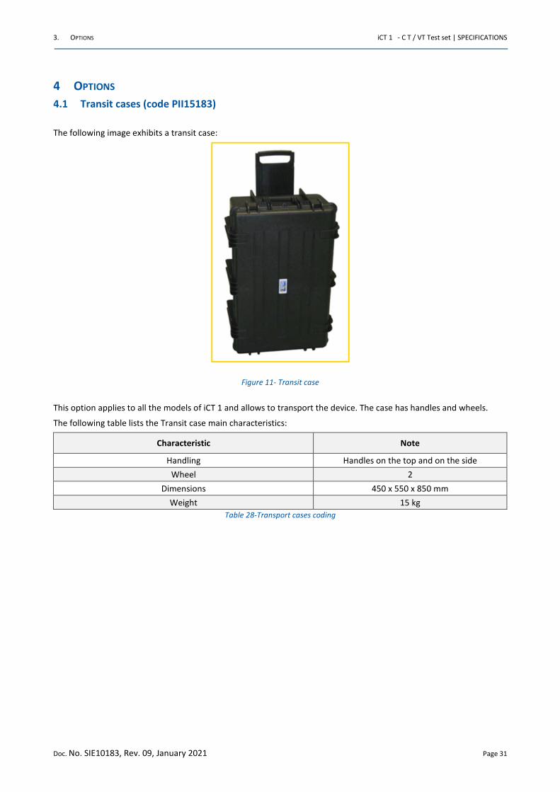
The following image exhibits a transit case:
Figure 11- Transit case
This option applies to all the models of iCT 1 and allows to transport the device. The case has handles and wheels.
The following table lists the Transit case main characteristics:
Characteristic Note
Handling Handles on the top and on the side
Wheel 2
Dimensions 450 x 550 x 850 mm
Weight 15 kg
Table 28-Transport cases coding
3. OPTIONS iCT 1 - C T / VT Test set | SPECIFICATIONS
Doc. No. SIE10183, Rev. 09, January 2021 Page 32
4.2 iCT1_SW licence (code PII10183C)
The software iCT1 SW allows connecting to the PC all models of the instrument iCT1.
Software features are the following:
• To download from the test set test results and settings, and to save them into a file
• To open and save test results, exporting them in EXCEL format
• To display in real time the measurements performed by the test set, with possibility to pause the test (when
applicable)
• To display, save and print test results diagrams
• To zoom different curves of more than one result
• To edit, display and print the test report, with the following information:
• Place, substation name, line, phase, model, serial number, operator, date and time
• Nominal values: type of device, power, primary and secondary voltage or current
• Test result table, with comments about the test results OK or NO
• Notes and comments
The program allows also to do the following:
• Upload or download test settings
• Upload or download test set calibration parameters
ATTENTION: The software runs with any WINDOWS© environment starting from Win 7 64 bit
Windows and EXCEL are trademarks of Microsoft Corporation
3. OPTIONS iCT 1 - C T / VT Test set | SPECIFICATIONS
Doc. No. SIE10183, Rev. 09, January 2021 Page 33
5 PROTECTIONS
The protections of the iCT 1 are the following:
• If the test set is not connected to the ground, the test set does not allow for power generation, and warns the
operator with a diagnostic message
• Fuse on the mains supply
• iCT 1 is protected against short circuit, overload and overvoltage
• At power-on, a diagnostic sequence controls
• Key microprocessor board components
• Auxiliary supply voltages.
If something is wrong, the operator is alerted by a message.
• Emergency pushbutton: if pressed, all main outputs are removed
• The high voltage output is generated only if selected
• Thermal sensor on the main transformer. In case of over-temperature, an alarm message is displayed
• Thermal sensor on the active electronic devices. In case of over-temperature, an alarm message is displayed
• If maximum current limits and time duration of power transformer generators are trespassed, the generation
is interrupted, and the operator is warned by an alarm message
REVISIONS iCT 1 - C T / VT Test set | SPECIFICATIONS
Doc. No. SIE10183, Rev. 09, January 2021 Page 34
REVISIONS
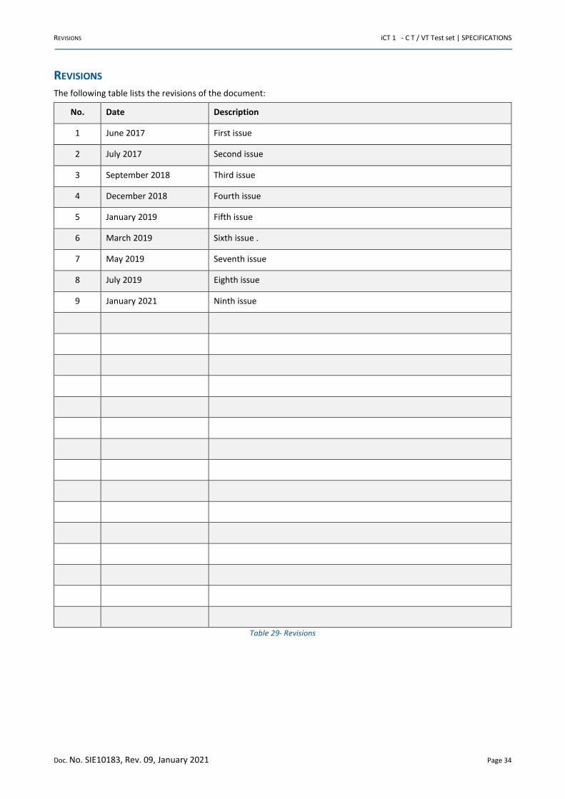
The following table lists the revisions of the document:
No. Date Description
1 June 2017 First issue
2 July 2017 Second issue
3 September 2018 Third issue
4 December 2018 Fourth issue
5 January 2019 Fifth issue
6 March 2019 Sixth issue .
7 May 2019 Seventh issue
8 July 2019 Eighth issue
9 January 2021 Ninth issue
Table 29- Revisions
LIST OF FIGURES iCT 1 - C T / VT Test set | SPECIFICATIONS
Doc. No. SIE10183, Rev. 09, January 2021 Page 35
LIST OF FIGURES
FIGURE 1–ICT 1 – CT / VT TEST SET ..................................................................................................................................... 9
FIGURE 2 – ICT 1 FRONT PANEL ...................................................................................................................................... 10
FIGURE 3 ICT 1 DISPLAY .................................................................................................................................................... 20
FIGURE 4 HOME PAGE ..................................................................................................................................................... 21
FIGURE 5 – “CURRENT TRANSFORMERS" ICON ................................................................................................................ 21
FIGURE 6- "CURRENT TRANSFORMERS/HEADER AND NOMINAL VALUES" PAGE (TAB DESCRIPTION) ............................ 22
FIGURE 7- "CURRENT TRANSFORMERS/HEADER AND NOMINAL VALUES" PAGE (TAB NOMINALS) ............................... 22
FIGURE 8- "CURRENT TRANSFORMERS/HEADER AND NOMINAL VALUES" PAGE (TAB TOLERANCES) ............................ 23
FIGURE 9- "CURRENT TRANSFORMERS" TEST PAGE ......................................................................................................... 23
FIGURE 10- "CTS – RATIO POLARITY VOLTAGE METHOD" PAGE ...................................................................................... 24
FIGURE 11- TRANSIT CASE ................................................................................................................................................ 31
LIST OF TABLES iCT 1 - C T / VT Test set | SPECIFICATIONS
Doc. No. SIE10183, Rev. 09, January 2021 Page 36
LIST OF TABLES
TABLE 1 DIFFERENCES AMONG THE ICT 1 MODELS............................................................................................................ 6
TABLE 2- CURRENT TRANSFORMER TESTS ......................................................................................................................... 6
TABLE 3- VOLTAGE TRANSFORMERS TESTS ........................................................................................................................ 7
TABLE 4- OPTIONAL MODULES ........................................................................................................................................... 7
TABLE 5– FRONTAL PANEL COMPONENTS ....................................................................................................................... 10
TABLE 6– STANDARDS RELATED TO THE EMC DIRECTIVE................................................................................................. 11
TABLE 7- STANDARDS RELATED TO THE LV DIRECTIVE ..................................................................................................... 11
TABLE 8- HIGH AC VOLTAGE: OUTPUT CHARACTERISTICS (1/2) ....................................................................................... 13
TABLE 9– HIGH AC VOLTAGE: OUTPUT CHARACTERISTICS (2/2) ...................................................................................... 13
TABLE 10- LOW DC CURRENT: OUTPUT CHARACTERISTICS .............................................................................................. 14
TABLE 11– LOW AC CURRENT: OUTPUT CHARACTERISTICS ............................................................................................. 14
TABLE 12– LOW AC VOLTAGE: OUTPUT CHARACTERISTICS ............................................................................................. 15
TABLE 13– LOW VOLTAGE FOR EXCITATION CURVE DC METHOD: OUTPUT CHARACTERISTICS ...................................... 15
TABLE 14–INTERNAL MEASUREMENTS. RESOLUTION AND ACCURACY ........................................................................... 17
TABLE 15– INTERNAL MEASUREMENTS. OTHER CHARACTERISTICS ................................................................................ 17
TABLE 16- ACCURACY FOR CT RATIO MEASUREMENT ..................................................................................................... 18
TABLE 17- ACCURACY FOR VT RATIO MEASUREMENT ..................................................................................................... 18
TABLE 18- PARAMETERS FOR THE BURDEN TEST ............................................................................................................. 18
TABLE 19- RESISTANCE TEST: RANGE AND ACCURACY ..................................................................................................... 18
TABLE 20- PHASE ANGLE RESOLUTION AND ACCURACY .................................................................................................. 19
TABLE 21- MAIN FEATURES OF THE DISPLAY .................................................................................................................... 20
TABLE 22- CURRENT TRANSFORMERS TESTS (1/3) ........................................................................................................... 25
TABLE 23- CURRENT TRANSFORMERS TESTS (2/3) ........................................................................................................... 26
TABLE 24-CURRENT TRANSFORMERS TESTS (3/3) ............................................................................................................ 27
TABLE 25-VOLTAGE TRANSFORMERS TESTS ..................................................................................................................... 28
TABLE 26-CABLES PROVIDED WITH THE UNIT .................................................................................................................. 29
TABLE 27-OTHER CHARACTERISTICS OF THE INSTRUMENT ICT 1..................................................................................... 30
TABLE 28-TRANSPORT CASES CODING ............................................................................................................................. 31
TABLE 30- REVISIONS ........................................................................................................................................................ 34
ISA HEADQUARTER
I.S.A. – Altanova Group S.r.l.
via Prati Bassi 22, 21020 Taino (Va) – ITALY
Phone +39 0331956081
Fax +39 0331957091
Email [email protected]
REGIONAL OFFICES
ISA ADVANCE INSTRUMENTS (I) Pvt. Ltd. C-33, Ground Floor, Sector-2, NOIDA-201
301, Uttar Pradesh, INDIA
Phone +91120 4543853 / 54 / 4222712
Fax +91120 4574772
Email: [email protected]
ISA PACIFIC PTE Ltd Blk 10, Kaki Bukit Ave 4, #08-68, Premier@kaki Bukit
Singapore, 415874
Phone +65 6278 3280
Fax +65 6278 2381
Email: [email protected]
ALTANOVA GROUP LATIN AMERICA São Paulo, BRASIL
T +5511 96335 - 3518
Email: [email protected]
ALTANOVA GROUP GCC Office no 713, Business Avenue Building Port Saeed Road, Dubai - United Arab Emirates
Phone: +971 55 5146998 / +971 55 5165793
Fax: +971 42956099
Email: [email protected]
TECHIMP GERMANY GMBH Feldstraße 23,31691 Helpsen
Germany
T: +49(0)1702364735
Email: [email protected]
ALTANOVA GROUP FRANCE & MAGHREB Paris, France
T: +33 6 73691137
Email: [email protected]

Manual edited by ISA Srl – Altanova Group