ibm spectrum scale erasure code edition: planning and
TRANSCRIPT

Redpaper
Front cover
IBM Spectrum ScaleErasure Code EditionPlanning and Implementation GuideBill Owen
Luis Bolinches
Wei Gong
Scott Guthridge
Nikhil Khandelwhal
Lin Feng Shen
Ravi Sure
Yu Bing Tang
Jon Terner
Rong Zeng
Rajan Mishra
Wu Xu


IBM Redbooks
IBM Spectrum Scale Erasure Code Edition: Planning and Implementation Guide
October 2019
REDP-5557-00

© Copyright International Business Machines Corporation 2019. All rights reserved.Note to U.S. Government Users Restricted Rights -- Use, duplication or disclosure restricted by GSA ADP ScheduleContract with IBM Corp.
First Edition (October 2019)
This edition applies to Version 5, Release 0, Modification 3 of IBM Spectrum Scale Erasure Code Ediition (product number 5737-J34).
This document was created or updated on October 15, 2019.
Note: Before using this information and the product it supports, read the information in “Notices” on page vii.

Contents
Notices . . . . . . . . . . . . . . . . . . . . . . . . . . . . . . . . . . . . . . . . . . . . . . . . . . . . . . . . . . . . . . . . . viiTrademarks . . . . . . . . . . . . . . . . . . . . . . . . . . . . . . . . . . . . . . . . . . . . . . . . . . . . . . . . . . . . . viii
Preface . . . . . . . . . . . . . . . . . . . . . . . . . . . . . . . . . . . . . . . . . . . . . . . . . . . . . . . . . . . . . . . . . ixAuthors. . . . . . . . . . . . . . . . . . . . . . . . . . . . . . . . . . . . . . . . . . . . . . . . . . . . . . . . . . . . . . . . . . ixNow you can become a published author, too! . . . . . . . . . . . . . . . . . . . . . . . . . . . . . . . . . . . xiComments welcome. . . . . . . . . . . . . . . . . . . . . . . . . . . . . . . . . . . . . . . . . . . . . . . . . . . . . . . . xiiStay connected to IBM Redbooks . . . . . . . . . . . . . . . . . . . . . . . . . . . . . . . . . . . . . . . . . . . . . xii
Chapter 1. Introduction to IBM Spectrum Scale Erasure Code Edition . . . . . . . . . . . . . 11.1 Overview . . . . . . . . . . . . . . . . . . . . . . . . . . . . . . . . . . . . . . . . . . . . . . . . . . . . . . . . . . . . . 21.2 Value proposition . . . . . . . . . . . . . . . . . . . . . . . . . . . . . . . . . . . . . . . . . . . . . . . . . . . . . . 31.3 Advantages and key features . . . . . . . . . . . . . . . . . . . . . . . . . . . . . . . . . . . . . . . . . . . . . 5
1.3.1 High-performance erasure coding. . . . . . . . . . . . . . . . . . . . . . . . . . . . . . . . . . . . . . 51.3.2 Declustered erasure coding . . . . . . . . . . . . . . . . . . . . . . . . . . . . . . . . . . . . . . . . . . 61.3.3 End-to-end checksum for comprehensive data integrity . . . . . . . . . . . . . . . . . . . . . 71.3.4 Extreme scalability . . . . . . . . . . . . . . . . . . . . . . . . . . . . . . . . . . . . . . . . . . . . . . . . . 71.3.5 Enterprise storage features and manageability. . . . . . . . . . . . . . . . . . . . . . . . . . . . 7
1.4 Configuration options . . . . . . . . . . . . . . . . . . . . . . . . . . . . . . . . . . . . . . . . . . . . . . . . . . . 81.5 Example ECE use cases. . . . . . . . . . . . . . . . . . . . . . . . . . . . . . . . . . . . . . . . . . . . . . . . . 9
1.5.1 High-performance file serving . . . . . . . . . . . . . . . . . . . . . . . . . . . . . . . . . . . . . . . . . 91.5.2 High-performance compute tier. . . . . . . . . . . . . . . . . . . . . . . . . . . . . . . . . . . . . . . 101.5.3 High capacity data storage . . . . . . . . . . . . . . . . . . . . . . . . . . . . . . . . . . . . . . . . . . 10
1.6 Example configuration. . . . . . . . . . . . . . . . . . . . . . . . . . . . . . . . . . . . . . . . . . . . . . . . . . 101.7 Summary. . . . . . . . . . . . . . . . . . . . . . . . . . . . . . . . . . . . . . . . . . . . . . . . . . . . . . . . . . . . 11
Chapter 2. IBM Spectrum Scale Erasure Code Edition use cases . . . . . . . . . . . . . . . . 132.1 High-performance tier for ML/DL and analytics. . . . . . . . . . . . . . . . . . . . . . . . . . . . . . . 142.2 High-performance file serving with CES protocol nodes. . . . . . . . . . . . . . . . . . . . . . . . 142.3 High-capacity data storage . . . . . . . . . . . . . . . . . . . . . . . . . . . . . . . . . . . . . . . . . . . . . . 16
Chapter 3. IBM Spectrum Scale RAID technical overview . . . . . . . . . . . . . . . . . . . . . . 193.1 Definitions of IBM Spectrum Scale RAID . . . . . . . . . . . . . . . . . . . . . . . . . . . . . . . . . . . 203.2 Software RAID . . . . . . . . . . . . . . . . . . . . . . . . . . . . . . . . . . . . . . . . . . . . . . . . . . . . . . . 21
3.2.1 RAID codes. . . . . . . . . . . . . . . . . . . . . . . . . . . . . . . . . . . . . . . . . . . . . . . . . . . . . . 213.2.2 Declustered RAID . . . . . . . . . . . . . . . . . . . . . . . . . . . . . . . . . . . . . . . . . . . . . . . . . 213.2.3 Fault-tolerance . . . . . . . . . . . . . . . . . . . . . . . . . . . . . . . . . . . . . . . . . . . . . . . . . . . 23
3.3 End-to-end checksum and data versions . . . . . . . . . . . . . . . . . . . . . . . . . . . . . . . . . . . 253.4 Integrity Manager . . . . . . . . . . . . . . . . . . . . . . . . . . . . . . . . . . . . . . . . . . . . . . . . . . . . . 263.5 Disk hospital . . . . . . . . . . . . . . . . . . . . . . . . . . . . . . . . . . . . . . . . . . . . . . . . . . . . . . . . . 263.6 Storage hardware software interface . . . . . . . . . . . . . . . . . . . . . . . . . . . . . . . . . . . . . . 273.7 IBM Spectrum Scale RAID software component layout . . . . . . . . . . . . . . . . . . . . . . . . 283.8 Start up sequence for recovery group and log groups . . . . . . . . . . . . . . . . . . . . . . . . . 283.9 Recovery of recovery group and log groups . . . . . . . . . . . . . . . . . . . . . . . . . . . . . . . . . 303.10 ECE read and write strategies . . . . . . . . . . . . . . . . . . . . . . . . . . . . . . . . . . . . . . . . . . 31
3.10.1 Reads . . . . . . . . . . . . . . . . . . . . . . . . . . . . . . . . . . . . . . . . . . . . . . . . . . . . . . . . . 313.10.2 Full track writes . . . . . . . . . . . . . . . . . . . . . . . . . . . . . . . . . . . . . . . . . . . . . . . . . . 323.10.3 Promoted full track writes . . . . . . . . . . . . . . . . . . . . . . . . . . . . . . . . . . . . . . . . . . 323.10.4 Medium writes . . . . . . . . . . . . . . . . . . . . . . . . . . . . . . . . . . . . . . . . . . . . . . . . . . . 32
© Copyright IBM Corp. 2019. All rights reserved. iii

3.10.5 Small writes. . . . . . . . . . . . . . . . . . . . . . . . . . . . . . . . . . . . . . . . . . . . . . . . . . . . . 323.10.6 Deferred writes and stale strips. . . . . . . . . . . . . . . . . . . . . . . . . . . . . . . . . . . . . . 33
Chapter 4. Planning an ECE installation . . . . . . . . . . . . . . . . . . . . . . . . . . . . . . . . . . . . . 354.1 Sizing considerations . . . . . . . . . . . . . . . . . . . . . . . . . . . . . . . . . . . . . . . . . . . . . . . . . . 364.2 Precheck tools. . . . . . . . . . . . . . . . . . . . . . . . . . . . . . . . . . . . . . . . . . . . . . . . . . . . . . . . 36
4.2.1 SpectrumScale_ECE_OS_READINESS helper tool. . . . . . . . . . . . . . . . . . . . . . . 364.2.2 SpectrumScale_ECE_OS_OVERVIEW helper tool . . . . . . . . . . . . . . . . . . . . . . . 374.2.3 SpectrumScale_NETWORK_READINESS tool . . . . . . . . . . . . . . . . . . . . . . . . . . 38
4.3 Erasure code selection . . . . . . . . . . . . . . . . . . . . . . . . . . . . . . . . . . . . . . . . . . . . . . . . . 394.4 Spare space allocation . . . . . . . . . . . . . . . . . . . . . . . . . . . . . . . . . . . . . . . . . . . . . . . . . 414.5 Network planning . . . . . . . . . . . . . . . . . . . . . . . . . . . . . . . . . . . . . . . . . . . . . . . . . . . . . 414.6 IBM Spectrum Scale node roles . . . . . . . . . . . . . . . . . . . . . . . . . . . . . . . . . . . . . . . . . . 424.7 Cluster Export Services. . . . . . . . . . . . . . . . . . . . . . . . . . . . . . . . . . . . . . . . . . . . . . . . . 444.8 System management and monitoring . . . . . . . . . . . . . . . . . . . . . . . . . . . . . . . . . . . . . . 444.9 Other IBM Spectrum Scale components. . . . . . . . . . . . . . . . . . . . . . . . . . . . . . . . . . . . 454.10 Running applications. . . . . . . . . . . . . . . . . . . . . . . . . . . . . . . . . . . . . . . . . . . . . . . . . . 454.11 File and Object Solution Design Studio tool . . . . . . . . . . . . . . . . . . . . . . . . . . . . . . . . 45
Chapter 5. ECE installation procedures . . . . . . . . . . . . . . . . . . . . . . . . . . . . . . . . . . . . . 475.1 Installation overview . . . . . . . . . . . . . . . . . . . . . . . . . . . . . . . . . . . . . . . . . . . . . . . . . . . 485.2 IBM Spectrum Scale ECE installation prerequisites . . . . . . . . . . . . . . . . . . . . . . . . . . . 48
5.2.1 Minimum requirements for ECE . . . . . . . . . . . . . . . . . . . . . . . . . . . . . . . . . . . . . . 485.2.2 SSH and network setup . . . . . . . . . . . . . . . . . . . . . . . . . . . . . . . . . . . . . . . . . . . . 485.2.3 Repository setup . . . . . . . . . . . . . . . . . . . . . . . . . . . . . . . . . . . . . . . . . . . . . . . . . . 48
5.3 IBM Spectrum Scale ECE installation background . . . . . . . . . . . . . . . . . . . . . . . . . . . . 495.4 IBM Spectrum Scale ECE installation and configuration . . . . . . . . . . . . . . . . . . . . . . . 49
Chapter 6. Daily management of ECE storage . . . . . . . . . . . . . . . . . . . . . . . . . . . . . . . . 696.1 Drive replacement . . . . . . . . . . . . . . . . . . . . . . . . . . . . . . . . . . . . . . . . . . . . . . . . . . . . . 70
6.1.1 Drive replacement cancellation. . . . . . . . . . . . . . . . . . . . . . . . . . . . . . . . . . . . . . . 716.2 Replacing nodes . . . . . . . . . . . . . . . . . . . . . . . . . . . . . . . . . . . . . . . . . . . . . . . . . . . . . . 71
6.2.1 Node replacement with new drives . . . . . . . . . . . . . . . . . . . . . . . . . . . . . . . . . . . . 716.2.2 Replacing nodes and preserving drives from the old node. . . . . . . . . . . . . . . . . . 73
6.3 Adding nodes . . . . . . . . . . . . . . . . . . . . . . . . . . . . . . . . . . . . . . . . . . . . . . . . . . . . . . . . 746.4 Upgrading to a new IBM Spectrum Scale release . . . . . . . . . . . . . . . . . . . . . . . . . . . . 796.5 Upgrading operating system, firmware, driver, and patch. . . . . . . . . . . . . . . . . . . . . . . 80
Chapter 7. Problem determination and debugging an ECE system. . . . . . . . . . . . . . . 837.1 Check whether the ECE nodes are active in the cluster . . . . . . . . . . . . . . . . . . . . . . . . 847.2 Check whether the recovery groups are active. . . . . . . . . . . . . . . . . . . . . . . . . . . . . . . 847.3 Check for pdisks that are ready for replacement . . . . . . . . . . . . . . . . . . . . . . . . . . . . . 857.4 Check for pdisks that are not in OK state . . . . . . . . . . . . . . . . . . . . . . . . . . . . . . . . . . . 857.5 Pdisk states. . . . . . . . . . . . . . . . . . . . . . . . . . . . . . . . . . . . . . . . . . . . . . . . . . . . . . . . . . 867.6 Check each recovery group’s event log for messages . . . . . . . . . . . . . . . . . . . . . . . . . 887.7 Using the mmhealth command with ECE . . . . . . . . . . . . . . . . . . . . . . . . . . . . . . . . . . . 887.8 System health monitoring use cases . . . . . . . . . . . . . . . . . . . . . . . . . . . . . . . . . . . . . . 897.9 Collecting data for problem determination . . . . . . . . . . . . . . . . . . . . . . . . . . . . . . . . . . 967.10 Network tools . . . . . . . . . . . . . . . . . . . . . . . . . . . . . . . . . . . . . . . . . . . . . . . . . . . . . . . 98
Chapter 8. Summary . . . . . . . . . . . . . . . . . . . . . . . . . . . . . . . . . . . . . . . . . . . . . . . . . . . . 1018.1 New Deployment Models . . . . . . . . . . . . . . . . . . . . . . . . . . . . . . . . . . . . . . . . . . . . . . 102
8.1.1 ECE on cloud . . . . . . . . . . . . . . . . . . . . . . . . . . . . . . . . . . . . . . . . . . . . . . . . . . . 1028.1.2 Building a containerized ECE solution . . . . . . . . . . . . . . . . . . . . . . . . . . . . . . . . 103
iv IBM Spectrum Scale Erasure Code Edition: Planning and Implementation Guide

8.1.3 New erasure codes . . . . . . . . . . . . . . . . . . . . . . . . . . . . . . . . . . . . . . . . . . . . . . . 1038.2 Conclusion . . . . . . . . . . . . . . . . . . . . . . . . . . . . . . . . . . . . . . . . . . . . . . . . . . . . . . . . . 104
Related publications . . . . . . . . . . . . . . . . . . . . . . . . . . . . . . . . . . . . . . . . . . . . . . . . . . . . 105IBM Redbooks . . . . . . . . . . . . . . . . . . . . . . . . . . . . . . . . . . . . . . . . . . . . . . . . . . . . . . . . . . 105Other publication . . . . . . . . . . . . . . . . . . . . . . . . . . . . . . . . . . . . . . . . . . . . . . . . . . . . . . . . 105Online resources . . . . . . . . . . . . . . . . . . . . . . . . . . . . . . . . . . . . . . . . . . . . . . . . . . . . . . . . 105Help from IBM . . . . . . . . . . . . . . . . . . . . . . . . . . . . . . . . . . . . . . . . . . . . . . . . . . . . . . . . . . 106
Contents v

vi IBM Spectrum Scale Erasure Code Edition: Planning and Implementation Guide

Notices
This information was developed for products and services offered in the US. This material might be available from IBM in other languages. However, you may be required to own a copy of the product or product version in that language in order to access it.
IBM may not offer the products, services, or features discussed in this document in other countries. Consult your local IBM representative for information on the products and services currently available in your area. Any reference to an IBM product, program, or service is not intended to state or imply that only that IBM product, program, or service may be used. Any functionally equivalent product, program, or service that does not infringe any IBM intellectual property right may be used instead. However, it is the user’s responsibility to evaluate and verify the operation of any non-IBM product, program, or service.
IBM may have patents or pending patent applications covering subject matter described in this document. The furnishing of this document does not grant you any license to these patents. You can send license inquiries, in writing, to:IBM Director of Licensing, IBM Corporation, North Castle Drive, MD-NC119, Armonk, NY 10504-1785, US
INTERNATIONAL BUSINESS MACHINES CORPORATION PROVIDES THIS PUBLICATION “AS IS” WITHOUT WARRANTY OF ANY KIND, EITHER EXPRESS OR IMPLIED, INCLUDING, BUT NOT LIMITED TO, THE IMPLIED WARRANTIES OF NON-INFRINGEMENT, MERCHANTABILITY OR FITNESS FOR A PARTICULAR PURPOSE. Some jurisdictions do not allow disclaimer of express or implied warranties in certain transactions, therefore, this statement may not apply to you.
This information could include technical inaccuracies or typographical errors. Changes are periodically made to the information herein; these changes will be incorporated in new editions of the publication. IBM may make improvements and/or changes in the product(s) and/or the program(s) described in this publication at any time without notice.
Any references in this information to non-IBM websites are provided for convenience only and do not in any manner serve as an endorsement of those websites. The materials at those websites are not part of the materials for this IBM product and use of those websites is at your own risk.
IBM may use or distribute any of the information you provide in any way it believes appropriate without incurring any obligation to you.
The performance data and client examples cited are presented for illustrative purposes only. Actual performance results may vary depending on specific configurations and operating conditions.
Information concerning non-IBM products was obtained from the suppliers of those products, their published announcements or other publicly available sources. IBM has not tested those products and cannot confirm the accuracy of performance, compatibility or any other claims related to non-IBM products. Questions on the capabilities of non-IBM products should be addressed to the suppliers of those products.
Statements regarding IBM’s future direction or intent are subject to change or withdrawal without notice, and represent goals and objectives only.
This information contains examples of data and reports used in daily business operations. To illustrate them as completely as possible, the examples include the names of individuals, companies, brands, and products. All of these names are fictitious and any similarity to actual people or business enterprises is entirely coincidental.
COPYRIGHT LICENSE:
This information contains sample application programs in source language, which illustrate programming techniques on various operating platforms. You may copy, modify, and distribute these sample programs in any form without payment to IBM, for the purposes of developing, using, marketing or distributing application programs conforming to the application programming interface for the operating platform for which the sample programs are written. These examples have not been thoroughly tested under all conditions. IBM, therefore, cannot guarantee or imply reliability, serviceability, or function of these programs. The sample programs are provided “AS IS”, without warranty of any kind. IBM shall not be liable for any damages arising out of your use of the sample programs.
© Copyright IBM Corp. 2019. All rights reserved. vii

Trademarks
IBM, the IBM logo, and ibm.com are trademarks or registered trademarks of International Business Machines Corporation, registered in many jurisdictions worldwide. Other product and service names might be trademarks of IBM or other companies. A current list of IBM trademarks is available on the web at “Copyright and trademark information” at http://www.ibm.com/legal/copytrade.shtml
The following terms are trademarks or registered trademarks of International Business Machines Corporation, and might also be trademarks or registered trademarks in other countries.
Redbooks (logo) ®AIX®IBM®
IBM Cloud™IBM Spectrum®Passport Advantage®
POWER®Redbooks®
The following terms are trademarks of other companies:
Intel, Intel logo, Intel Inside logo, and Intel Centrino logo are trademarks or registered trademarks of Intel Corporation or its subsidiaries in the United States and other countries.
The registered trademark Linux® is used pursuant to a sublicense from the Linux Foundation, the exclusive licensee of Linus Torvalds, owner of the mark on a worldwide basis.
Windows, and the Windows logo are trademarks of Microsoft Corporation in the United States, other countries, or both.
Java, and all Java-based trademarks and logos are trademarks or registered trademarks of Oracle and/or its affiliates.
OpenShift, Red Hat, are trademarks or registered trademarks of Red Hat, Inc. or its subsidiaries in the United States and other countries.
Other company, product, or service names may be trademarks or service marks of others.
viii IBM Spectrum Scale Erasure Code Edition: Planning and Implementation Guide

Preface
This IBM® Redpaper introduces the IBM Spectrum® Scale Erasure Code Edition (ECE) as a scalable, high-performance data and file management solution. ECE is designed to run on any commodity server that meets the ECE minimum hardware requirements. ECE provides all the functionality, reliability, scalability, and performance of IBM Spectrum Scale with the added benefit of network-dispersed IBM Spectrum Scale RAID, which provides data protection, storage efficiency, and the ability to manage storage in hyperscale environments that are composed from commodity hardware.
In this publication, we explain the benefits of ECE and the use cases where we believe it fits best. We also provide a technical introduction to IBM Spectrum Scale RAID. Next, we explain the key aspects of planning an installation, provide an example of an installation scenario, and describe the key aspects of day-to-day management and a process for problem determination. We conclude with an overview of possible enhancements that are being considered for future versions of IBM Spectrum Scale Erasure Code Edition.
Overall knowledge of IBM Spectrum Scale Erasure Code Edition is critical to planning a successful storage system deployment. This paper is targeted toward technical professionals (consultants, technical support staff, IT Architects, and IT Specialists) who are responsible for delivering cost effective storage solutions. The goal of this paper is to describe the benefits of using IBM Spectrum Scale Erasure Code Edition for the creation of high performing storage systems.
Authors
This paper was produced by a team of specialists from around the world working at IBM Redbooks, Poughkeepsie Center.
Bill Owen is a Senior Technical Staff Member with the IBM Spectrum Scale development team, leading the release of Erasure Code Edition. He has worked in various development roles within IBM for over 20 years, and has been a part of the IBM Spectrum Scale team for over 6 years. Before joining IBM, Bill developed and deployed grid management systems for electric utilities. Bill holds Bachelor of Science and Master of Science degrees in Electrical Engineering from New Mexico State University.
Luis Bolinches has been working with IBM Power Systems servers for over 15 years and has been with IBM Spectrum Scale (formerly known as IBM General Parallel File System (IBM GPFS) for over 10 years. He works 50 percent for IBM Lab Services in Nordic where he is the subject matter expert (SME) for HANA on IBM Power Systems, and the other 50 percent is on the IBM Spectrum Scale development team.
Wei Gong is a Senior Software Engineer in IBM responsible for IBM Spectrum Scale development and client adoption. He has over 9 years of development on IBM Spectrum Scale core functions. Wei takes significant time with clients on IBM Spectrum Scale solution design, deployment, and performance turning. Wei has 5 years storage development experience, including virtual machine storage system and storage HBA driver.
© Copyright IBM Corp. 2019. All rights reserved. ix

Scott Guthridge is a Senior Software Engineer in the IBM Almaden Research Center. He is an original member of the IBM Spectrum Scale RAID and IBM Spectrum Scale ECE development teams, and has been working on these projects for over 11 years. His main contributions are the Disk Hospital, NSPD, and internal mechanisms to ensure product quality. Scott’s active areas of research are methods of achieving high system reliability and adoption of emerging storage technologies.
Nikhil Khandelwhal is a senior engineer with the IBM Spectrum Scale development team. He has over 15 years of storage experience on NAS, disk, and tape storage systems. He has led development and worked in various architecture roles. Nikhil currently is a part of the IBM Spectrum Scale client adoption and cloud teams.
Lin Feng Shen is a Senior Architect for IBM Spectrum Scale RAID (also known as GPFS Native RAID or GNR) technology, supporting Erasure Code Edition (ECE) and Elastic Storage System (ESS). He is one of the original members of the IBM Spectrum Scale RAID and IBM Spectrum Scale ECE development teams, and has been working on these projects for over 10 years. He is responsible for IBM Spectrum Scale RAID roadmap development and the owner of GNR logging and buffer manager components. Lin Feng also has 4 years of Linux experience, working together with IBM Linux Technology Center.
Ravi Sure works for IBM India as a Senior System Software Engineer. He has worked on developing workload schedulers for High Performance Computers, Parallel File Systems, Computing Cluster Network Management, and Parallel Programming. He has strong engineering professional skills in distributed systems, parallel computing, C, C++, Python, shell scripting, MPI, and Linux.
Yu Bing Tang is a staff software engineer in IBM China. He has 11 years of experience for IBM Spectrum Scale RAID and more than 17 years for testing. He holds a Master of Science degree in computer science from Xi Dian University. His areas of expertise include Parallel File System, Software Development, and Software Test.
Jon Terner is a Software Engineer and a new member of IBM Spectrum Scale RAID team working in the United States. He has recently finished his bachelors in Computer Science and Mathematics from Binghamton University, where he focused on distributed systems and virtualization technology.
Rong Zeng is a Senior Software Engineer in the US. He has 20 years of experience in software development. His areas of expertise include distributed computing and software RAID development.
Rajan Mishra is a Software Engineer with the IBM Spectrum Scale Deployment development team. He is responsible for automating the installation of IBM Spectrum Scale component software in a IBM Spectrum Scale environment. He has worked within IBM for over 4 years. Rajan previously held roles within the IBM Platform Computing development teams. He has strong engineering professional skills in Software deployment, Python, Java, PHP, shell scripting, SQL, and Linux.
Wu Xu is a Software Engineer in China Lab for IBM Spectrum Scale RAID technology. He has 15 years of experience in software development, and has been part of IBM Spectrum Scale team for 9 years. He has worked on AFM, Clone, and GNR projects and his areas of expertise include testing distributed system and problem analysis. He has written extensively on ECE installation and system setup.
x IBM Spectrum Scale Erasure Code Edition: Planning and Implementation Guide

Thanks to the following people for their contributions to this project:
Larry CoyneIBM Redbooks®, Tucson Center
Indulis BernsteinsIBM Global Markets - Systems HW Sales
Everett BenallyWilliam BrownZhi CaiPuneet ChaudharyJohn DorfnerSteve DuerschShuo FengBrian HerrRezaul IslamWesley JonesMamdouh KhamisFelipe KnopJohn LewarsCarla LopezChristopher MaestasFrank MangioneMadhav PonamgiKumaran RajaramRoger StrommenStephen TeeJay VaddiCarl ZetieIBM Systems
Now you can become a published author, too!
Here’s an opportunity to spotlight your skills, grow your career, and become a published author—all at the same time! Join an IBM Redbooks residency project and help write a book in your area of expertise, while honing your experience using leading-edge technologies. Your efforts will help to increase product acceptance and customer satisfaction, as you expand your network of technical contacts and relationships. Residencies run from two to six weeks in length, and you can participate either in person or as a remote resident working from your home base.
Find out more about the residency program, browse the residency index, and apply online at:
ibm.com/redbooks/residencies.html
Preface xi

Comments welcome
Your comments are important to us!
We want our papers to be as helpful as possible. Send us your comments about this paper or other IBM Redbooks publications in one of the following ways:
� Use the online Contact us review Redbooks form found at:
ibm.com/redbooks
� Send your comments in an email to:
� Mail your comments to:
IBM Corporation, IBM RedbooksDept. HYTD Mail Station P0992455 South RoadPoughkeepsie, NY 12601-5400
Stay connected to IBM Redbooks
� Find us on Facebook:
http://www.facebook.com/IBMRedbooks
� Follow us on Twitter:
http://twitter.com/ibmredbooks
� Look for us on LinkedIn:
http://www.linkedin.com/groups?home=&gid=2130806
� Explore new Redbooks publications, residencies, and workshops with the IBM Redbooks weekly newsletter:
https://www.redbooks.ibm.com/Redbooks.nsf/subscribe?OpenForm
� Stay current on recent Redbooks publications with RSS Feeds:
http://www.redbooks.ibm.com/rss.html
xii IBM Spectrum Scale Erasure Code Edition: Planning and Implementation Guide

Chapter 1. Introduction to IBM Spectrum Scale Erasure Code Edition
This chapter introduces IBM Spectrum Scale Erasure Code Edition (ECE). It is a scalable, high-performance data and file management solution. ECE is designed to run on any industry standard server that meets the ECE minimum hardware requirements.
ECE also provides all the functionality, reliability, scalability, and performance of IBM Spectrum Scale with the added benefit of network-dispersed IBM Spectrum Scale RAID, which provides data protection, storage efficiency, and the ability to manage storage in hyperscale environments that are composed from standardized hardware.
This chapter includes the following topics:
� 1.1, “Overview” on page 2� 1.2, “Value proposition” on page 3� 1.3, “Advantages and key features” on page 5� 1.4, “Configuration options” on page 8� 1.5, “Example ECE use cases” on page 9� 1.6, “Example configuration” on page 10� 1.7, “Summary” on page 11
1
© Copyright IBM Corp. 2019. All rights reserved. 1

1.1 Overview
IBM Spectrum Scale Erasure Code Edition (ECE) is a high-performance, scale-out storage system for commodity servers. It is a new software edition of the IBM Spectrum Scale family, as shown in Figure 1-1. ECE provides all the functionality, reliability, scalability, and performance of IBM Spectrum Scale on the customer’s choice of commodity servers with the added benefit of network-dispersed IBM Spectrum Scale RAID, providing data protection, storage efficiency, and the ability to manage storage in hyperscale environments.
Figure 1-1 High-performance, scale-out storage with IBM Spectrum Scale Erasure Code Edition
Although ECE is a new IBM Spectrum Scale edition, the IBM Spectrum Scale RAID technology is field-proven in over 1000 deployed IBM Elastic Storage Server (ESS) systems. ESS is the storage power behind the fastest supercomputers on the planet. Summit and Sierra, supercomputers at Oak Ridge National Laboratory and Lawrence Livermore National Laboratory, are ranked the first and second fastest computers in the world at the time of this writing1.
With the innovative network-dispersed IBM Spectrum Scale RAID adapted for scale-out storage, ECE delivers the same capabilities on industry standard compute, storage, and network components. Customers can choose their preferred servers that meet ECE hardware requirements with the best flexibility and cost.
ECE can be integrated into existing Spectrum Scale clusters, or expanded with extra ECE servers or any other storage that is supported by Spectrum Scale, including IBM ESS, IBM block storage, or other vendor’s block storage.
Spectrum Scale ECE, ESS and other Scale Editions provide the freedom to choose and combine different storage hardware. This feature is a major advantage over storage that is purchased as an “appliance” where expansion is limited to other appliances from the same vendor.
Software and middleware, which is certified to operate with IBM Spectrum Scale software, continues to be certified with IBM Spectrum Scale ECE, or a cluster combining ECE and other Spectrum Scale storage pools.
A Spectrum Scale cluster that includes ECE also can include ECE servers, and industry-standard IBM POWER® servers that are running Linux or IBM AIX®, x86 servers that are running Linux or Windows, and IBM z servers that are running Linux.
IBM Cloud Tiering
IBM Elastic Storage Server
File Analytics Container
Swift S3
Object
Erasure Code Edition
1 https://www.energy.gov/articles/two-doe-supercomputers-top-list-world-s-fastest
2 IBM Spectrum Scale Erasure Code Edition: Planning and Implementation Guide

All of the servers in the same Spectrum Scale cluster use high-performance parallel access to access or serve data.
Users on servers that are outside the Spectrum Scale cluster can access the same data by using various industry standard protocols, such as NFS, SMB, HDFS, SWIFT, and S3. Other protocols can also be added by using “gateway” servers that are running open software, such as FTP, or vendor software, such as ownCloud.
1.2 Value proposition
The demand for storage systems that are based on commodity servers grew quickly in recent years. Many customers ask for enterprise storage software so they can adopt the most suitable server platform with the best flexibility and cost, without hardware vendor lock-in and the easiest management in their IT infrastructure. The following example user quotes explain why they need ECE:
� Supplier mandates:
– “We buy from Dell, HP, Lenovo, SuperMicro - whoever is cheapest at that moment.”– “Our designated configuration is HPE Apollo.”– “We assemble our own servers that are OCP-compliant.”
� Technical and architectural mandates:
– “This is for an analytical grid where the IT architecture team only allows x86.”
– “We need a strategic direction for scale-out storage.”
– “Only storage rich servers are acceptable, no appliances.”
– “We use storage arrays today and we are forced by upper management to go with storage rich servers.”
� Cost perception:
– “We want the economic benefits of commodity hardware.”– “We don't want to pay for high-end or even mid-range storage.”
As commodity servers with internal disk drives become more popular, they are widely adopted in various use cases, especially the emerging AI, big data analytics, and cloud environments. This architecture provides the best flexibility to choose the storage hardware platforms and it makes large-scale storage systems much more affordable for many customers, which becomes more important with the explosion of enterprise data. However, commodity storage servers also expose the following major challenges:
� Poor storage utilization
Many storage systems use traditional data replication to protect data from hardware or software failures, typically by using three replicas. This results in low storage efficiency (33 percent), which requires much more hardware in the storage system. With large volumes of data, customers must pay a large amount of money to acquire and operate the extra hardware.
Chapter 1. Introduction to IBM Spectrum Scale Erasure Code Edition 3

� High failure rates
Commodity hardware is less reliable than enterprise hardware, which introduces more hardware failures in different components, including node, HBA, and disk drive failures. High failure rates of commodity hardware results in poor durability and has a higher impact to performance during failure events, which makes these events more common instead of rare case. Because of these factors, achieving high data reliability and high storage performance during failure becomes a significant challenge to distributed storage systems.
� Data integrity concerns
With a large quantity of data in the storage system, the possibility of silent data corruption becomes much higher than traditional storage systems with a much smaller scale.
� Scalability challenges and data silos
It is a challenge to manage many servers and disk drives in the same system. Some distributed storage systems might not scale well when approaching exa-scale or even tens of petabytes. This issue introduces unnecessary data movement among storage systems or from storage systems to data processing systems.
� Missing enterprise storage features
The features include data lifecycle management (tiering, ILM policies), auditing, multi-site synchronization, snapshots, backup and restore, disaster recovery, and disk management. Without these features, it becomes difficult to manage large server farms with frequent maintenance requirements.
To address these issues, ECE provides the value of enterprise storage that is based on industry standard servers to our customers. A typical ECE hardware architecture is shown in Figure 1-2.
Figure 1-2 Hardware Architecture of IBM Spectrum Scale Erasure Code Edition
It is composed of a set of homogeneous storage servers with internal disk drives, typically NVMe or SAS SSD and spinning disks. They are connected to each other with a high-speed network infrastructure.
4 IBM Spectrum Scale Erasure Code Edition: Planning and Implementation Guide

ECE delivers all the capability of IBM Spectrum Scale Data Management Edition, including enormous scalability, high performance and enterprise manageability, and information lifecycle management tools. It also delivers the following durable, robust, and storage-efficient capabilities of IBM Spectrum Scale RAID:
� Data is distributed across nodes and drives for higher durability without the cost of replication
� End-to-end checksum identifies and corrects errors that are introduced by network or media
� Rapid recovery and rebuild after hardware failure while generally maintaining performance levels
� Disk hospital function manages drive health issues before they become disasters
� Continuous background scrub and error correction support deployment on many drives while maintaining data integrity
All of these features are delivered on your choice of ECE storage servers.
1.3 Advantages and key features
ECE delivers full features of valued IBM Spectrum Scale and IBM Spectrum Scale RAID with commodity server as a distributed storage system. It solves the challenges to manage large-scale, server-based distributed storage.
1.3.1 High-performance erasure coding
ECE supports several erasure codes and brings much better storage efficiency; for example, ~70 percent with 8+3p and ~80 percent with 8+2p Reed Solomon Code (see Figure 1-3).
Figure 1-3 8+2p / 8+3p Reed Solomon Code in ECE
Better storage efficiency means less hardware, improved network utilization, and lower operating costs. These benefits provide customers with significant savings without compromising system availability and data reliability.
Chapter 1. Introduction to IBM Spectrum Scale Erasure Code Edition 5

ECE erasure coding can better protect data when compared to traditional RAID5/6, with three nodes of fault tolerance with 8+3p in a configuration that features 11 or more nodes. ECE erasure coding also provides much faster rebuild and recovery performance compared to traditional RAID5/6.
This configuration can survive a concurrent failures of multiple servers and storage devices. Furthermore, ECE implements high-performance erasure coding, which can be used as tier one storage.
One of the typical use cases of ECE is to accelerate data processing by using enterprise NVMe drives, which can deliver high throughput and low latency. High performance is a key differentiation compared with other erasure coding implementations in distributed storage systems. These other schemes are typically used for cold data only.
1.3.2 Declustered erasure coding
ECE implements advanced declustered RAID with erasure coding. ECE declustered RAID can manage many disk drives across multiple servers in a single grouping that is known as a declustered array (also referred to as DA in this publication).
The left side of Figure 1-4 on page 9 shows a declustered RAID array that is composed of disk drives from multiple nodes in an ECE storage system. The ECE failure domain feature can detect and analyze hardware topology automatically and distribute data evenly among all the nodes and disk drives. The spare space is also distributed evenly across the drives in the declustered array. This even distribution results in a low probability of losing two or three strips in the same data block, which means much less data to rebuild during hardware failure.
With many disk drives in the same group and evenly distributed spare space, the data rebuild process can read from all surviving servers and disk drives in parallel and write to them in parallel as well, which results in shorter rebuild time and better mean time to data loss (MTTDL).
A key advantage of ECE’s Spectrum Scale RAID that distinguishes it from other declustered RAID approaches is its ability to maintain near-normal levels of performance to the user in many failure scenarios. This ability to maintain service levels at large scale was proven extensively with Spectrum Scale RAID that is running at some of the largest and most challenging computing sites in the world.
ECE achieves this by categorizing data rebuild into critical rebuild and normal rebuild. Critical rebuild occurs when data is in a high risk situation; for example, having lost two strips with 8+2p or three strips with 8+3p erasure code. In this situation, ECE rebuilds data urgently by using as much bandwidth as possible. Given much less data to rebuild, critical rebuild can complete in short time.
After critical rebuild, ECE enters normal rebuild and reserves most of the bandwidth for the applications if the data includes good enough fault tolerance so that the rebuild does not have to be completed as urgently.
With declustered RAID, even data and spare distribution and critical/normal rebuild, ECE can balance between high data reliability and low-performance impact to the applications.
6 IBM Spectrum Scale Erasure Code Edition: Planning and Implementation Guide

1.3.3 End-to-end checksum for comprehensive data integrity
ECE is highly reliable with extreme data integrity for any type of silent data corruption.
ECE calculates, transfers, and verifies checksum for each data block over the network. If corruption occurs during network transfer, the data is retransmitted until it succeeds.
ECE also calculates, stores, and verifies a checksum and other information, such as data versions, VDisk association, and data block and strip location. These metadata items are called buffer trailer in ECE, and are used to protect data from various data corruptions, especially silent data corruption, including hardware failures, offset write, drop write, write garbage, and media errors.
1.3.4 Extreme scalability
One of the major advantages of IBM Spectrum Scale and IBM Spectrum Scale RAID is its high scalability. This capability was proven in many large-scale systems. The latest and most impressive examples are the Coral systems.
The Summit system is in the US Department of Energy’s Oak Ridge National Laboratory (ORNL), and is 8 times more powerful than ORNL’s previous top-ranked system, Titan. The Summit system is the world’s fastest supercomputer with 200 PFLOPS of compute bandwidth and 300 PB storage capacity with 2.5 TBps I/O bandwidth that uses IBM ESS storage hardware.
IBM Spectrum Scale and IBM Spectrum Scale RAID are the same core storage software technologies powering ESS and ECE storage systems. A set of storage servers can be configured with ECE to provide a high-performance and reliable storage building block. Many of these building blocks can be aggregated together into the same large Spectrum Scale file system, which eliminates data silos and unnecessary data movement.
1.3.5 Enterprise storage features and manageability
IBM Spectrum Scale has been in production for over 20 years. It is well-known as an enterprise file system with a competitive list of features to meet data management requirements in various use cases.
ECE further extends Spectrum Scale to enable the use of industry standard storage servers.
ECE automatically configures storage layout by sensing the hardware topology and distributing data evenly among all nodes and drives to automatically achieve high data reliability and durability. ECE detects changes in the hardware topology, such as a node failure, and rearranges data to maintain an optimal distribution of data on the remaining hardware. It can also help system administrators manage their hardware in a simple and convenient way.
ECE implements a disk hospital to predict and detect disk failures, diagnose problems, and identify failing disks for replacement to the system administrator. It defines a standard procedure to help system administrators identify and replace bad disk drives.
It also informs the server in which slot a bad disk drive is located and can turn on an indicator LED for most types of drives, which makes disk replacement convenient. ECE provides this functionality on industry-standard, commodity server-based storage software by implementing hardware platform neutrality.
Chapter 1. Introduction to IBM Spectrum Scale Erasure Code Edition 7

1.4 Configuration options
IBM Spectrum Scale ECE is configured in one or more building blocks, also known as recovery groups, that are made up of storage rich servers. All of the servers in an ECE building block must have the same configurations in terms of CPU, memory, network, storage drive types, and operating system. The storage drives are used for storing data by striping the data across all the servers and drives in a building block.
A Spectrum Scale cluster can be constructed from multiple ECE building blocks. Each building block can have a unique server type and drive types. The storage topology must be the same for each building block. Multiple drive types can be installed into each server, but each server in a building block must have the same number of drives of each type, and the drives of each type must have the same capacity, and, for HDDs, the same rotational speed.
Different types of storage can be configured into separate file system storage pools, and these storage pools can be used for different types of workloads. For example, NVMe or SAS SSD devices are configured for metadata and small data fast I/Os, while HDD devices can be used to store cold or archived data.
The following storage options are supported by IBM Spectrum Scale Erasure Code Edition versions 5.0.3 and 5.0.4, please check the ECE Knowledge Center for the latest updates in hardware support:
� NVMe drives only
Storage rich servers that are populated with enterprise class NVMe drives with U.2 form factor can be configured with Erasure Code Edition to store data on the NVMe drives.
� Combination of HDD, NVMe, and SSD drives
Storage rich servers that are populated with a combination of SAS HDD, SAS SSD, and NVMe drives can be configured with ECE to have data stored on those drives. Normally, NVMe or SSD drives are configured for metadata and small data I/Os.
� ECE with multiple building blocks
Depending on your use case, you might want to create a storage system that is constructed from multiple building blocks. For a high capacity use case, several building blocks might be HDD with a few NVMe drives per node. For a high-performance file serving use case, one building block might be NVMe only, and a second that is a mix of NVMe and HDD drives, or several building blocks that include both NVMe and HDDs.
� ECE with ESS
At large-scale installations, the Erasure Code Edition servers (along with ESS storage systems) can be configured in a single IBM Spectrum Scale cluster environment. The different Recovery Groups must be configured on ESS storage systems and ECE storage servers. Figure 1-4 on page 9 shows a typical configuration of IBM Spectrum Scale cluster with ECE storage rich servers and ESS storage systems.
8 IBM Spectrum Scale Erasure Code Edition: Planning and Implementation Guide

Figure 1-4 IBM Spectrum Scale cluster made up of a combination of ECE and ESS servers
1.5 Example ECE use cases
IBM Spectrum Scale Erasure Code Edition can be used in many customer scenarios where industry standard scale-out storage systems are required. Examples can be, but are not limited to, AI and analytics, life sciences, manufacturing, media and entertainment, financial services, academia and government, and cloud storage; that is, the use cases where IBM Spectrum Scale demonstrated significant value.
This section describes several typical workloads or use cases that are used in ECE customer environments.
1.5.1 High-performance file serving
IBM Spectrum Scale Erasure Code Edition can provide backend storage with IBM Spectrum Scale Protocol services to allow clients to access data with NFS, SMB, and Object protocols in addition to high speed native access using the IBM Spectrum Scale client.
Chapter 1. Introduction to IBM Spectrum Scale Erasure Code Edition 9

Each ECE storage server is typically configured with several NVMe drives to store and accelerate IBM Spectrum Scale metadata and small data I/Os, and several HDD drives to store user data. ECE can deliver high-performance file serving for the user’s workloads and also achieve cost savings by tiering data from the NVMe storage pool to the HDD storage pool as the usage of data goes from hot to cold.
1.5.2 High-performance compute tier
IBM Spectrum Scale Erasure Code Edition implements high-performance erasure coding and provides the capability of storage tiering to different storage media (for example, flash drives, spinning disks, tape, and cloud storage) with different performance and cost characteristics.
Spectrum Scale’s policy-based Information Lifecycle Management (ILM) feature makes it convenient to automatically or manually manage data movement among different storage tiers.
A typical ECE high-performance compute tier is composed of servers with NVMe drives to store and accelerate IBM Spectrum Scale metadata and the set of hot data for high-performance computing and analytics.
1.5.3 High capacity data storage
IBM Spectrum Scale Erasure Code Edition can deliver the essential cost effective and data reliability features to large-scale storage system with space efficient erasure coding and extreme end-to-end data protection support.
A typical ECE storage system for high capacity storage can be composed of a NVMe storage pool to store and accelerate IBM Spectrum Scale metadata and small data I/Os, and a larger set of HDD drives to store the massive user data. It also can move cold data to much cheaper tape or Object Storage, if needed.
1.6 Example configuration
Consider an example configuration of 16 servers, with a mix of NVMe and SAS HDD drives, as listed in Table 1-1.
Table 1-1 Example ECE server configuration
ECE server configuration Description
Number of servers 16
CPUs per server 2 (Intel(R) Xeon(R) Silver 4110)
Cores per cpu 8
Memory per server 256 GB (16 GB x 16 DIMMs)
NVMe drives per server 2 x 1.8 TB (1.5 TiB)
SAS HDD drives 10 x 10.0 TB (9.1 TiB)
SAS HBA LSI MegaRAID SAS3516
HCA Mellanox MT27800 Family [ConnectX-5](100 Gbps)
10 IBM Spectrum Scale Erasure Code Edition: Planning and Implementation Guide

This type of server is shown in Figure 1-5.
Figure 1-5 Example ECE server
With this configuration, the approximate file system capacity is 1100 TB (1000 TiB) using an 8+3P erasure code. This usable space is delivered and accounts for erasure code overhead, reserved spare space, and IBM Spectrum Scale RAID metadata.
1.7 Summary
IBM Spectrum Scale Erasure Code Edition is a new member of the IBM Spectrum Scale family. It offers exciting potential to deploy systems that are highly tuned to your compute and storage needs.
In this IBM Redpaper publication, we describe ECE use cases in more detail, provide more information about the underlying technology, discuss planning considerations, and then describe an installation scenario, day-to-day management examples, and provide an overview of problem determination procedures.
Price per node Approximately 10,000 USD
ECE server configuration Description
Chapter 1. Introduction to IBM Spectrum Scale Erasure Code Edition 11

12 IBM Spectrum Scale Erasure Code Edition: Planning and Implementation Guide

Chapter 2. IBM Spectrum Scale Erasure Code Edition use cases
Many uses cases are well-suited for IBM Spectrum Scale Erasure Code Edition (ECE) storage. In this chapter, we focus on several specific examples that best take advantage of the unique features of ECE.
The uses cases that are presented in this chapter is not an exhaustive list of the applications of ECE. In general, any workload that is suited for IBM Spectrum Scale works well with ECE storage if the ECE servers are configured with the appropriate combination of storage, compute, and network resources.
Contact IBM Support for more information about how to configure ECE for your storage use cases.
This chapter includes the following topics:
� 2.1, “High-performance tier for ML/DL and analytics” on page 14� 2.2, “High-performance file serving with CES protocol nodes” on page 14� 2.3, “High-capacity data storage” on page 16
2
© Copyright IBM Corp. 2019. All rights reserved. 13

2.1 High-performance tier for ML/DL and analytics
Machine learning (ML), deep learning (DL), and analytics applications that are running across multiple processors and GPUs that demand high I/O performance. ECE’s ability to provide a reliable and efficient storage system from NVMe and SAS SSD devices in storage rich servers make it an excellent choice to meet these needs.
By combining fast storage with low-cost storage and by using IBM Spectrum Scale tiering or AFM, data can automatically be moved to this high-speed tier as required. This combination can provide cost-effective capacity with high-speed file access, all in the same global namespace.
To take advantage of low-latency storage, such as NVMe, a low-latency network is critical. InfiniBand and RDMA are best suited for a high-speed low-latency connection by eliminating overhead that is involved in TCP connections. If an InfiniBand network is not possible, Ethernet can be used. With Ethernet, a dedicated high-speed network with minimal switch hops and no competing traffic provides the best performance.
A typical high-performance solution consists of one or more ECE building blocks, each containing servers with multiple NVMe drives. A building block must have at least 12 devices and can contain up to 512 devices. Because of the parallel operation of IBM Spectrum Scale, multiple building blocks can be used to scale out capacity and performance because data is be striped across the building blocks.
High-capacity, low-cost HDD drives can be used to extend file system capacity with a tier for cold data, which can be provided by ECE, or by another subsystem, such as a high capacity model of ESS. When deploying a mixed-storage system, two options are available: HDD and NVMe/SSD storage can be mixed in the same ECE building block, or HDD and NVMe/SSD can be contained in separate ECE building blocks.
When configuring building blocks, it is important to remember that all the nodes within a single building block must contain identical hardware. Splitting HDD and NVMe devices into separate building blocks can include a greater up-front hardware cost. However, it provides more flexibility for future growth because the two storage tiers can be grown independently of each other.
2.2 High-performance file serving with CES protocol nodes
We typically recommend the use of the native IBM Spectrum Scale Network Shared Disk (NSD) protocol whenever possible, which means installing the IBM Spectrum Scale native client on your application nodes. However, certain scenarios exist in which this configuration is not practical. For these situations, IBM Spectrum Scale provides the Cluster Export Services (CES) functionality to support data access to users outside of the cluster by using industry standard protocols.
The CES nodes work as highly available gateways and provide multiple front end protocols. always using the NSD protocol on the backend. CES protocol nodes allow clients to access an IBM Spectrum Scale file system by using Network File System (NFS), Server Message Block (SMB), and OpenStack Swift as front end protocols.
For more information about the CES protocol nodes, see IBM Knowledge Center.
14 IBM Spectrum Scale Erasure Code Edition: Planning and Implementation Guide

Consider the following points as guidelines for your solution:
� Separate the front end protocol traffic from the back end NSD traffic by using different network interfaces.
� The backend network must provide at least as much bandwidth as the front end network.
� Although running CES within an ECE node is supported by using the RPQ process, we recommend dedicated CES protocol nodes for high-performance workloads.
� When CES nodes are separated from ECE, you can connect CES nodes to multiple ECE nodes that belong to different building blocks or Recovery Groups (RGs).
� ECE nodes within a recovery group must be configured alike. If you run CES on the ECE nodes, you must run it on all of them. Because SMB limits the number of protocol nodes to 16, the use of SMB on ECE nodes limits the size of the recovery group to 16 nodes.
� Clients that are using different protocols (NSD, NFS, SMB, SWIFT Object, HDFS) all can share access to the same data, which is subject to some limitations because of the differences between the protocols.
Figure 2-1 shows an example setup with 16 ECE nodes that form the backend cluster.
Figure 2-1 ECE nodes and separate CES nodes
The configuration that includes 16 ECE nodes and three CES nodes that is shown in Figure 2-1 is only an example. Up to 32 ECE nodes can be in each recovery group, and multiple recovery groups can be used. Up to 16 CES nodes can be used if SMB is used, or up to 32 if SMB is not used.
Note: Hadoop HDFS protocol also is supported natively in IBM Spectrum Scale, which allows clusters of Hadoop nodes to access data that is stored in an IBM Spectrum Scale filesystem. This configuration does not rely on the use of CES protocol nodes.
Frontend network (NFS, SMB, Swift, iSCSI, …)
Backend network (NSD)
ECE node 1 ECE node 2 ECE node 3 ECE node 4 ECE node 5 ECE node 6 … ECE node 16
client node 1 client node 2 client node 3 client node 4 client node 5 client node 6 … client node n
CES node 1 CES node 2 CES node 3
Chapter 2. IBM Spectrum Scale Erasure Code Edition use cases 15

The back-end network (green in Figure 2-1 on page 15) must provide at least as much bandwidth as the front-end network (orange in Figure 2-1 on page 15. On the CES nodes, the front-end and back-end networks must be on separate network ports.
Although we recommend separating CES and ECE functions onto different servers when possible, we also support running them on the same servers. Figure 2-2 shows an example of CES and ECE functions running on the same nodes.
Figure 2-2 ECE nodes and converged CES nodes
Because all nodes in an ECE recovery group must be configured alike, all of them must run the CES function in the converged configuration. When SMB protocol is used, the number of nodes is limited to 16.
For performance reasons, it is advantageous to separate the front-end and back-end networks, as shown in Figure 2-2.
For more information about protocol nodes, see IBM Knowledge Center.
2.3 High-capacity data storage
ECE can scale out to multiple petabytes of usable storage that is presented as a single unified namespace. This scale out is possible by using a large number of high-density storage nodes with high capacity hard drives that are configured in multiple building blocks.
When planning a high-capacity system, it might be necessary to divide the system into multiple ECE building blocks. Each building block consists of 4 - 32 nodes, and up to 512 drives. As of this writing, a limit of 24 internal drives per node is imposed.
client node 1 client node 2 client node 3 client node 4 client node 5 client node 6 … client node n
ECE/CES node 1 ECE/CES node 2 ECE/CES node 3 ECE/CES node 4 ECE/CES node 5 ECE/CES node 6 … ECE/CES node 16
Frontend network (NFS, SMB, Swift, iSCSI, …)
Backend network (NSD)
16 IBM Spectrum Scale Erasure Code Edition: Planning and Implementation Guide

VDisks and declustered arrays span the nodes of the building block and provide failure protection for the associated recovery group. For example, an 8+3P vdisk in a 16-node recovery group can tolerate failure of three of the 16 nodes. If the cluster consists of more than one of these recovery groups, each of them can independently tolerate failure of three of its 16 nodes.
By distributing the nodes of the recovery groups across racks or other high-level hardware failure domains, you can take advantage of this property to implement rack-level or higher fault tolerance. When planning such configurations, request assistance from IBM to ensure that the failure domains are understood and configured.
In a high-capacity deployment, it is recommended to include a smaller high-speed tier of storage for Spectrum Scale file system metadata. A metadata tier improves the performance of file system scans, file creates and deletes, directory listings, and other metadata intensive workloads. Lower cost storage can then be used for most of user data.
It is also possible to use tape or cloud storage as an even less expensive tier for archival data. The IBM Spectrum Scale Information Lifecycle Management (ILM) function automatically manages these tiers, moving data between them according to changeable policies.
High-capacity ECE systems can be easily expanded without interruption to user applications. Expansion can be done by adding nodes to recovery groups, or by adding recovery groups to the system. The nodes within each recovery group must have identical hardware configurations; however, no such restriction exists between recovery groups. Therefore, newly added recovery groups can take advantage of capacity and speed improvements as new technologies become available.
Spectrum Scale storage pools can be used to organize and move data seamlessly between different types of hardware and storage tiers, which gives users flexibility in managing the storage while keeping everything together in a single file system namespace.
Chapter 2. IBM Spectrum Scale Erasure Code Edition use cases 17

18 IBM Spectrum Scale Erasure Code Edition: Planning and Implementation Guide

Chapter 3. IBM Spectrum Scale RAID technical overview
In this chapter, we present an overview of IBM Spectrum Scale RAID, which is the core technology that is used in IBM Spectrum Scale Erasure Code Edition.
We start with a definition of terms, followed by a discussion of declustered RAID, and the key software concepts and components that differentiate ECE from other software defined storage technologies.
This chapter includes the following topics:
� 3.1, “Definitions of IBM Spectrum Scale RAID” on page 20� 3.2, “Software RAID” on page 21� 3.3, “End-to-end checksum and data versions” on page 25� 3.4, “Integrity Manager” on page 26� 3.5, “Disk hospital” on page 26� 3.6, “Storage hardware software interface” on page 27� 3.7, “IBM Spectrum Scale RAID software component layout” on page 28� 3.8, “Start up sequence for recovery group and log groups” on page 28� 3.9, “Recovery of recovery group and log groups” on page 30� 3.10, “ECE read and write strategies” on page 31
3
© Copyright IBM Corp. 2019. All rights reserved. 19

3.1 Definitions of IBM Spectrum Scale RAID
The following words and phrases are associated with IBM Spectrum Scale RAID:
� Disk: A block storage device, including NVMe drives, solid-state drives (SSDs), and hard disk drives (HDDs).
� Storage Server: An IBM Spectrum Scale cluster node that features several disks that are available to it, and serves abstractions that are based on those disks.
� Pdisk: An abstraction of a disk that encompasses all the physical paths and properties of the disk.
� Track: A RAID stripe, also a full GPFS file system block.
� Recovery group (RG): A recovery group is a collection of pdisks and servers. File system NSDs called VDisks might be created within a recovery group, and might be configured to include various levels of data protection, including tolerance and correction of disk errors, and tolerance and recovery of disk and server failures. A recovery group is also referred to as an ECE building block.
� Server set: All the servers within a recovery group, which is also known as an ECE node class.
� Declustered array (DA): A declustered array is a subset of the pdisks within a recovery group that all share similar characteristics, such as size and speed. A recovery group might contain multiple declustered arrays, which cannot overlap (that is, a pdisk must belong to exactly one declustered array).
� VDisk: An erasure code-protected virtual NSD that is partitioned among the pdisks of a declustered array of a recovery group, and served by one of the recovery group servers.
� Log home VDisk: A special VDisk that is used to store the recovery group internal transaction log, such as event log entries, updates to VDisk configuration data, and certain data write operations quickly. It is often created from a declustered array with fast devices, such as NVMes or SSDs.
� Log group (LG): A subset of the VDisks within a recovery group that all share a transaction log to only one log home VDisk. It is the smallest unit of failure recovery in a recovery group. All the VDisks in the same log group must failover and recovery together. A recovery group can contain multiple log groups, which cannot overlap (that is, a VDisk must belong to exactly one log group). All of the VDisks in a log group are served by one of the recovery group servers.
� Root log group: A special log group that allocates resources, hosts VDisk configuration data, and responds to commands for the entire recovery group. The root log group contains only a log home VDisk, which is used to ensure that the VDisk configuration data is updated atomically.
� mmvdisk: The command suite for simplified IBM Spectrum Scale RAID administration.
� VDisk set: A VDisk set is a collection of VDisks with identical sizes and attributes, one in each log group across one or more recovery groups. VDisk sets are externally managed according to the conventions of the mmvdisk command. With VDisk sets, the mmvdisk command creates IBM Spectrum Scale file systems that are striped uniformly across all log groups.
� NSD: The abstraction of a file system disk that is used by IBM Spectrum Scale. A VDisk NSD is an IBM Spectrum Scale NSD built from an IBM Spectrum Scale ECE recovery group.
� File system: An IBM Spectrum Scale file system is striped across a collection of NSDs.
20 IBM Spectrum Scale Erasure Code Edition: Planning and Implementation Guide

� Recovery group configuration manager (RGCM): RGCM assigns log groups to servers, manages recovery and failover, and directs Spectrum Scale clients to the node currently serving a specific VDisk NSD.
3.2 Software RAID
The IBM Spectrum Scale RAID software in ECE uses local serial-attached SCSI (SAS) or NVMe drives. Because RAID functions are handled by the software, ECE does not require an external RAID controller or acceleration hardware.
3.2.1 RAID codes
IBM Spectrum Scale RAID in ECE supports two and three fault tolerant RAID codes. The two-fault tolerant codes include 8 data plus 2 parity, 4 data plus 2 parity, and 3-way replication. The three-fault tolerant codes include 8 data plus 3 parity, 4 data plus 3 parity, and 4-way replication. Figure 3-1 shows example RAID tracks consisting of data and parity strips.
Figure 3-1 RAID tracks
3.2.2 Declustered RAID
IBM Spectrum Scale RAID distributes data and parity information across node failure domains to tolerate unavailability or failure of all pdisks in a node. It also distributes spare capacity across nodes to maximize parallelism in rebuild operations.
IBM Spectrum Scale RAID implements end-to-end checksums and data versions to detect and correct the data integrity problems of traditional RAID.
Figure 3-2 on page 22 shows a simple example of declustered RAID. The left side shows a traditional RAID layout that consists of three 2-way mirrored RAID volumes and a dedicated spare disk that uses seven drives is shown. The right side shows the equivalent declustered layout, which still uses seven drives. Here, the blocks of the three RAID volumes and the spare capacity are scattered over the seven disks.
Chapter 3. IBM Spectrum Scale RAID technical overview 21

Figure 3-2 Declustered array versus 1+1 array
Figure 3-3 shows a significant advantage of declustered RAID layout over traditional RAID layout after a drive failure. With the traditional RAID layout on the left side of Figure 3-3, the system must copy the surviving replica of the failed drive to the spare drive, reading only from one drive and writing only to one drive. However, with the declusterd layout that is shown on the right of Figure 3-3, the affected replicas and the spares are distributed across all six surviving disks. This configuration rebuilds reads from all surviving disks and writes to all surviving disks, which greatly increases rebuild parallelism.
Figure 3-3 Array rebuild operation
22 IBM Spectrum Scale Erasure Code Edition: Planning and Implementation Guide

A second advantage of the declustered RAID technology that is used by IBM Spectrum Scale ECE (and in IBM ESS) is that it minimizes the worst-case number of critical RAID tracks in the presence of multiple disk failures. ECE can then deal with restoring protection to critical RAID tracks as a high priority, while giving lower priority to RAID tracks that are not considered critical.
For example, consider an 8+3p RAID code on an array of 100 pdisks. In the traditional layout and declustered layout, the probability that a specific RAID track is critical is 11/100 * 10/99 * 9/98 (0.1%). However, when a track is critical in the traditional RAID array, all tracks in the volume are critical, whereas with declustered RAID, only 0.1%, of the tracks are critical. By prioritizing the rebuild of more critical tracks over less critical tracks, ECE quickly gets out of critical rebuild and then can tolerate another failure.
ECE adapts these priorities dynamically; if a “non-critical” RAID track is used and more drives fail, this RAID track’s rebuild priority can be escalated to “critical”.
A third advantage of declustered RAID is that it makes it possible to support any number of drives in the array and to dynamically add and remove drives from the array. Adding a drive in a traditional RAID layout (except in the case of adding a spare) requires significant data reorganization and restriping. However, only targeted data movement is needed to rebalance the array to include the added drive in a declustered array.
3.2.3 Fault-tolerance
When a VDisk set is created, the user selects one of the supported two or three fault tolerant Reed Solomon or replicated erasure codes. This choice determines the number of failures of each type the system can tolerate.
A simultaneous hard failure of individual disks that exceeds the VDisk fault tolerance can result in data loss. The failure of too many nodes results only in temporary data unavailability (assuming the contents of the disks in the failed node are not lost).
To ensure fault-tolerant data access, IBM Spectrum Scale Erasure Code Edition places the strips of RAID tracks across failure boundaries. The placement allows for survival from concurrent storage rich servers or disk failures.
The placement algorithm is aware of the hardware grouping of disks, which are present in individual storage servers and attempts to segregate the individual strips of RAID tracks across as many servers and disks as possible. For example, if a VDisk was created with four-way replication, each replica of the VDisk’s four-way track can be placed on a separate storage server. If a storage server fails, the surviving redundancy replicas on other servers ensure continuity of service.
Figure 3-4 on page 24 shows a sample track placement for a VDisk that is uses RAID redundancy code 4+3P (four data strips and three parity strips). Strips 1 - 4 are data strips and strips 5 - 7 are parity strips of the track. The system balances the strips across the servers such that each server is guaranteed to hold at least one strip, while only two servers hold two strips and no server holds more than two strips. ECE guarantees 1 node plus 1 disk drive fault tolerance in this configuration.
Chapter 3. IBM Spectrum Scale RAID technical overview 23

Figure 3-4 4+3P track strips across servers
By segregating each strip across as wide a set of disk groups as possible, ECE ensures that the loss of any set of disk groups up to the fault tolerance of the RAID redundancy code is survivable.
Figure 3-5 on page 25 shows an example of the same configuration after the loss of a server before a rebuild operation. In this example, the loss of server 2 makes strips 2 and 5 unavailable. These unavailable strips are rebuilt with help of other parity and data strips. The fault-tolerant placement of individual strips across multiple servers ensured that at least four strips survived.
Note: When mixing VDisk sets of different fault tolerances within the same ECE building block, the availability of all VDisks in the building block can be limited by the VDisk set with lowest fault tolerance. For example, suppose the building block consists of 12 nodes. One VDisk set uses a three fault tolerant code while another uses a two fault tolerant code. If three pdisks spread across nodes were to fail simultaneously, the VDisks with two fault tolerant code might report data loss while the three fault tolerant VDisks survive. However, if three nodes fail instead, the two-fault tolerant and three-fault tolerant VDisks become unavailable until at least one of the nodes comes up.
Server 3Server 1 Server 2
Server 4 Server 5
2 31 4 5 6 7
Sample 4+3p track
24 IBM Spectrum Scale Erasure Code Edition: Planning and Implementation Guide

Figure 3-5 4+3P track strips across servers after one server failure
3.3 End-to-end checksum and data versions
IBM Spectrum Scale Erasure Code Edition protects all data that is written to disk, and data that is passing over the network between Spectrum Scale client nodes and ECE storage nodes with strong (64-bit) checksums. If on-disk data becomes corrupted, ECE detects the corruption, uses the erasure code to compute the correct data, and repairs the corrupted on-disk data. If data is corrupted over the network between nodes, ECE detects the corruption and retransmits the data.
In addition to checksums, ECE records a version number with the modified on-disk data whenever on-disk data is modified. It also tracks that version number in the vdisk metadata.
If a disk write is silently dropped, ECE detects that the data version does not match the expected value when reading the data back from disk, and uses the erasure code to compute the correct data and repair the on-disk data.
Other RAID solutions use only T10 DIF with its weak 16-bit checksum and generally cannot detect dropped writes. In addition to ECE’s strong checksums and version numbers, ECE uses T10 DIF when available.
Server 3Server 1 Server 2
Server 4 Server 5
2 31 4 5 6 7
Sample 4+3p track
Chapter 3. IBM Spectrum Scale RAID technical overview 25

3.4 Integrity Manager
The Integrity Manager is a software component of IBM Spectrum Scale RAID that maintains data resiliency. It dynamically adjusts data layout to maintain fault tolerance and routinely verifies data correctness on disk drives. The layout adjustment operations are split into “Rebuild” and “Rebalance” phases, while data integrity is verified during the “Scrub” phase. These phases run sequentially.
Consider the following points:
� Rebuild is responsible for data migration when pdisks fail or become unavailable. It migrates data to spare space distributed over the other disks of the array to restore fault tolerance. When creating a declustered array, ECE specifies the minimum amount of space in the array to reserve as spare for rebuild. Unlike other RAID solutions that designate complete drives as spares, ECE distributes spare space equally among all disks in the array to maximum rebuild parallelism.
� Rebalance migrates data in a declustered array to balance data among the pdisks. When a failed pdisk in the array is replaced or when pdisks are added to the array, rebalance moves data into the newly added space. Similarly, if disks were unavailable for a long time, rebuild migrated the data to other disks, and the unavailable disks come back online, rebalance migrates data back to those disks.
� Scrub is a background task that slowly cycles through all VDisks in a declustered array and verifies the on-disk data and parity information. The purpose of scrub is to find and correct defects in cold data before enough of these defects accumulate to exceed the fault tolerance of the VDisks. Scrub runs at low priority relative to file system I/O so that it does not affect performance. When file system I/O is light, scrub paces itself so that by default it takes two weeks to complete a scrub cycle on each declustered array.
3.5 Disk hospital
The disk hospital monitors the health of physical disk drives. It analyzes errors that are reported by the operating system, repairs medium errors, measures disk error rates and performance, power-cycles drives to repair some connectivity problems, and decides when a disk must be replaced. A human is needed only to replace the drive after the hospital determines that the drive is defective.
The disk hospital features the following main responsibilities:
� Analyze errors that are reported by the operating system and determine whether they are connectivity problems, disk medium errors, or other disk problems.
� Facilitate correction of medium errors.
� Monitor SMART data and react to SMART trips.
� Measure long-term uncorrectable read error rate.
� Measure disk performance and identify slow disks.
� Determine when a drive is defective and prepare the drive for replacement.
Note: The user can increase the spare space beyond ECE default value to set aside extra space to withstand more drive failures while maintaining fault tolerance after rebuild completes.
26 IBM Spectrum Scale Erasure Code Edition: Planning and Implementation Guide

If the operating system reports an I/O error against a physical disk, the disk hospital puts the disk into a “diagnosing” state and begins a series of tests. While the disk is diagnosed, ECE reconstructs reads from parity and defers writes by marking strips “stale”. Stale strips are automatically readmitted if the disk is placed back into service.
If other drive failures prevent reconstruction, or more than one strip of a track were marked stale, ECE waits for the hospital to finish its diagnosis before issuing I/Os to the disk.
If the disk hospital finds disk medium errors, it repairs the errors by using the RAID layer to reconstruct the data and then overwrites the affected disk blocks with the reconstructed data.
Most modern drives include built-in, self-monitoring analysis and reporting technology (SMART). The disk hospital polls these drives for SMART predicted failures (also called smart trips) after any error, and at least every 24 hours. If the drive reports an impending failure, the disk hospital places the drive into “failing” state, drains all data from the disk to distributed spare space, and prepares the drive for replacement.
The disk hospital uses a patented algorithm to measure the uncorrectable read error rate of drives (also called the bit error rate). If the error rate exceeds the manufacturer’s specified rate, the hospital puts the pdisk into failing state and prepares it for replacement.
On every I/O operation, the disk hospital collects performance information. If a few drives exhibit poor performance compared to the average for the array over tens of thousands of I/O requests, the hospital puts the under-performing drives into “slow” state, and prepares them for replacement.
If the disk hospital finds that disk blocks can no longer be written, it puts the disk into “read-only” state. If the disk hospital finds that the disk suffered a complete internal failure, it puts the disk into “dead” state. In both cases, the disk hospital prepares the disk for replacement.
The disk hospital is careful not to mark drives bad in response to communication problems, such as a defective cable. Such problems can affect many drives, which easily exceeds the fault tolerance of the VDisks.
3.6 Storage hardware software interface
ECE interfaces with platform-specific disk bays to determine the physical locations of pdisks and control power and indicator lights. It provides this interface by using the following external commands:
� The tslsenclslot command is used to inventory and determine the status of disk slots.
� The tsctlenclslot command is used to control lights and power-on disk slots. Supported slot lights are power, identify, replace, and fail.
Both of these programs are accompanied by a corresponding platform dependent backend implementation, which allows ECE to integrate with various storage hardware and storage management interfaces.
Chapter 3. IBM Spectrum Scale RAID technical overview 27

3.7 IBM Spectrum Scale RAID software component layout
As shown in Figure 3-6, a recovery group is composed of a set of storage-rich servers with symmetrical configurations. All available disk drives in these servers (except system boot drives) belong to this recovery group.
Figure 3-6 IBM Spectrum Scale RAID software component layout
Multiple recovery groups can exist in the same IBM Spectrum Scale cluster and file system. The disk drives are grouped into different declustered arrays according to their characteristics, with each declustered array consisting of a set of matching drives. Usually, the disk space in a recovery group is evenly divided into different VDisk sets and the VDisks are evenly grouped into multiple user log groups.
A log home VDisk and one or more user VDisks (used as IBM Spectrum Scale NSDs) exist in each log group. Each server features two user log groups in the normal case. During server failure, the two log groups that are hosted by the failing server are automatically moved to two different available nodes.
The root log group is a special log group that allocates resources and hosts VDisk configuration data for the whole recovery group. From this perspective, when the term recovery group is used, it also refers to the root log group. The root log group is lightweight and typically does not use much system resources. The recovery group configuration manager (RGCM) is responsible for balancing the log groups across different nodes in the recovery group server set during cluster startup and failure recovery.
3.8 Start up sequence for recovery group and log groups
RGCM is a software component that tracks and assigns management responsibilities for all recovery groups and their associated log groups. RGCM is always on the cluster manager node. RGCM is responsible for the following startup operations for each recovery group in the cluster:
� During ECE cluster startup, designate a node within the ECE cluster and start a recovery group on this node.
� During ECE cluster startup, coordinate with each recovery group and assign an owner node to each of their log groups.
Server 2
Log Group
Log Group
Log Group
Log Group
Log Group
Log Group
…
Recovery Group
Server 1 Server 3 Server N
…
log home vdisks user vdisks used as GPFS NSD’s
Log Group
Log Group
Declustered array with HDDs
Declustered array with NVMes or SSDs
Root Log GroupRGCM
… …… …… …… …… …… …… ……
…… …… …… …… …… …… …… ……
28 IBM Spectrum Scale Erasure Code Edition: Planning and Implementation Guide

� Monitor and handle any failures of the recovery groups and log groups. If a failure occurs, reassign the owner nodes and reschedule the failed recovery for the recovery groups or log groups.
� Track ownership of the recovery group and the log groups among the nodes within the ECE cluster.
How RGCM starts the recovery group and associated log groups is shown in Figure 3-7.
Figure 3-7 RGCM roles during cluster startup
The nodes that host the recovery group and RGCM can also serve log groups. For simplicity, the example that is shown in Figure 3-7 does not display the log groups for these nodes.
As a recovery group starts, it scans and determines that log groups 1 and 2 must be started. The recovery group sends requests to the RGCM instance to designate nodes to serve the log groups.
As each log group starts, it activates its associated VDisks and brings the corresponding NSD disks online. The mmvdisk command can be used to list all log groups, list the log groups that are served by each node, and examine the VDisk status within each log group.
Node ACluster Manager
(Recovery group configuration manager)
Node BRecovery group
1. Designates a node andstarts recovery group
Node CLog group 1
Node DLog group 2
4. Starts the log group 1 on node C and log group 2 on node D.
2. Node B requests RGCM to chooses a node for each log groups
3. RGCM returns node C for log group 1,and node D for log group 2
Chapter 3. IBM Spectrum Scale RAID technical overview 29
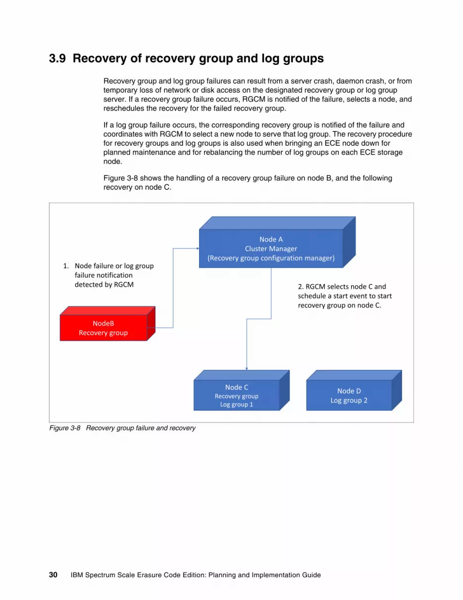
3.9 Recovery of recovery group and log groups
Recovery group and log group failures can result from a server crash, daemon crash, or from temporary loss of network or disk access on the designated recovery group or log group server. If a recovery group failure occurs, RGCM is notified of the failure, selects a node, and reschedules the recovery for the failed recovery group.
If a log group failure occurs, the corresponding recovery group is notified of the failure and coordinates with RGCM to select a new node to serve that log group. The recovery procedure for recovery groups and log groups is also used when bringing an ECE node down for planned maintenance and for rebalancing the number of log groups on each ECE storage node.
Figure 3-8 shows the handling of a recovery group failure on node B, and the following recovery on node C.
Figure 3-8 Recovery group failure and recovery
Node ACluster Manager
(Recovery group configuration manager)
NodeBRecovery group
1. Node failure or log group failure notification detected by RGCM
Node CRecovery group
Log group 1
Node DLog group 2
2. RGCM selects node C and schedule a start event to start recovery group on node C.
30 IBM Spectrum Scale Erasure Code Edition: Planning and Implementation Guide

Figure 3-9 shows the handling of the failure of log group 1 on node C, and the following recovery on node B.
Figure 3-9 log group failure and recovery
3.10 ECE read and write strategies
This section describes various strategies the ECE RAID layer uses to perform reads and writes that are received from the file system layer. Read operations in ECE are relatively straightforward. However, write operations use four different strategies, depending on the size of the operation and the amount of data that is cached in the RAID track.
By using different strategies for each case, ECE RAID minimizes latency or the total number of physical I/O operations that must be done to complete the operation.
3.10.1 Reads
When the ECE RAID layer receives a read request from the file system, it first checks if the requested blocks are cached. If the blocks are cached, ECE returns them. If they are not cached, ECE reads the data strips for the requested block from the appropriate pdisks and verifies the data checksums and version information. If no problems are found, ECE returns the aggregated data strips to the file system layer.
If checksum errors, failed pdisks or stale bits are detected, or some of the required data strips are not available, ECE reads other data and parity strips and reconstructs the data. If the number of unreadable strips exceeds the VDisk fault tolerance, the reconstruction cannot be done and ECE returns a read error back to the file system.
Node ACluster Manager
(Recovery group configuration manager)
Node BRecovery group
Log group 1
1. Node failure or log group failure notification detected by recovery group
Node CLog group 1
Node DLog group 2
2. Recovery group requests RGCM to select a node for failed log group 1.3. RGCM returns node B for log group 1 to be recovered.
4. Recovery group starts log group 1 on node B
Chapter 3. IBM Spectrum Scale RAID technical overview 31

3.10.2 Full track writes
Full track writes (also known as full block writes) are the most efficient case for ECE. In this strategy, ECE allocates a new free physical RAID track (ptrack), computes the parity strips from the data, and writes the data and parity strips to the new track. Then, it logs a record to the VDisk metadata log that changes the track location from the old ptrack track to the new ptrack and frees the old ptrack.
By writing to an unused ptrack on disk and changing the track location, updating data and parity strips remains atomic because no modifications were committed to the track until the VDisk metadata update is written to the log.
3.10.3 Promoted full track writes
If a write modifies most of a track, ECE reads the unmodified portion of the track and performs a full track write.
3.10.4 Medium writes
If the percentage of the track that is modified is greater than or equal to the fast write limit and less than nsdRAIDMediumWriteLimitPct parameter (default 50 percent), the write is performed as a medium write. This operation is also called an “in-place” write.
This case is tricky because the updates to data and parity must be made atomic, even though the in-place updates cannot be done atomically. The process includes the following steps:
1. Read the contents of the portions of the track that are to be modified; that is, the old data and parity.
2. Execute a parity update operation to calculate the new parity strips from the old data strips, old parity strips, and new data to be applied.
3. Write the intended changes to a redo log known as atomic update log (AU log).
4. Apply the changes to the track.
The medium write case adds several overheads in that it must read the old data, and write the new data to the atomic update log and to the track. It also must write to the VDisk metadata log. However, this method is used when these overheads are less than that of a promoted full track write.
3.10.5 Small writes
ECE uses the small write strategy if the size of the write in bytes is less than the small write limit. In the small write case, the data is written to the “fast write” log. After the data is successfully committed to the log, ECE returns success back to the file system. Because the log is placed on fast storage, this operation has low latency, which makes small writes fast.
The write is then flushed back to the RAID track in background by using the promoted full track write strategy or the medium write strategy, depending on what percentage of the affected track was modified at the time of the flush.
32 IBM Spectrum Scale Erasure Code Edition: Planning and Implementation Guide

3.10.6 Deferred writes and stale strips
In all four of the write cases, if an affected pdisk is in a transiently unavailable state (such as “diagnosing”), ECE can defer the write by marking the unavailable strip “stale”. If the pdisk later becomes available, a “readmit” process applies the deferred writes, which brings the pdisk up-to-date with the RAID track. This optimization allows ECE to achieve high performance with low latency, even when transient disk problems are occurring.
If more than one pdisk in the RAID track is transiently unavailable, ECE must mark multiple strips stale. In this case, it waits for the pdisks to stabilize before completing the write.
If the number of stably unavailable strips in the track exceed the VDisk fault tolerance such that parity strips cannot be computed, the write fails and returns an error back to the file system.
In addition, if some of these pdisks are in “missing” state (that is, unavailable but with expectation that they eventually become available), ECE resigns service of the log group and periodically attempts recovery waiting for the missing pdisks to become available.
Chapter 3. IBM Spectrum Scale RAID technical overview 33

34 IBM Spectrum Scale Erasure Code Edition: Planning and Implementation Guide

Chapter 4. Planning an ECE installation
In this chapter, guidelines for how to plan for an ECE installation are provided.
This chapter includes the following topics:
� 4.1, “Sizing considerations” on page 36� 4.2, “Precheck tools” on page 36� 4.3, “Erasure code selection” on page 39� 4.4, “Spare space allocation” on page 41� 4.5, “Network planning” on page 41� 4.6, “IBM Spectrum Scale node roles” on page 42� 4.7, “Cluster Export Services” on page 44� 4.8, “System management and monitoring” on page 44� 4.9, “Other IBM Spectrum Scale components” on page 45� 4.10, “Running applications” on page 45� 4.11, “File and Object Solution Design Studio tool” on page 45
4
© Copyright IBM Corp. 2019. All rights reserved. 35

4.1 Sizing considerations
The minimum hardware and network requirements for ECE storage servers are documented in the IBM Spectrum Scale Knowledge Center. However, to size an IBM Spectrum Scale ECE deployment for your workloads, the following factors must be considered:
� Required overall capacity, and requirements for expected capacity growth� Required I/O performance� Required redundancy and failure tolerance � Physical space and power� Cost
The following hardware choices influence how a system operates:
� Drive type (NVMe, SSD, or HDD)� Node hardware� Number of nodes� Network interconnect
As described in Chapter 1, “Introduction to IBM Spectrum Scale Erasure Code Edition” on page 1, ECE can be deployed in many ways to optimize capacity and performance. NVMe and HDDs can be paired in the same file system, or ECE can be combined with ESS to provide the optimal capacity and performance.
In this section, we explain other factors that must be considered when planning the installation of a system.
4.2 Precheck tools
The following open source precheck tools must be run and return passing results to ensure your ECE configuration features a supported hardware and network configuration:
� SpectrumScale_ECE_OS_READINESS� SpectrumScale_ECE_OS_OVERVIEW� SpectrumScale_NETWORK_READINESS
These tools can be found in the parent public GitHub repository.
4.2.1 SpectrumScale_ECE_OS_READINESS helper tool
The SpectrumScale_ECE_OS_READINESS helper tool checks the following attributes of your target hardware to confirm that the minimum hardware requirements are met for each server:
� CPU architecture, sockets, and cores
� Memory capacity and DIMMs
� Operating system levels
� Software that is installed on the system
� Network NIC and link speed to confirm that it is one of the supported models
� Storage adapter to confirm that it is one of the supported models
� HDDs, SSD capacity, and confirm that they are SAS drives and in JBOD mode
� NVMe CLI software is installed and NVMe drive capacities
36 IBM Spectrum Scale Erasure Code Edition: Planning and Implementation Guide

� Write cache settings on drives and adapters, to confirm that volatile write caching is disabled
� Operating system sysctl settings
For more information about and to download the SpectrumScale_ECE_OS_READINESS helper tool, see this GitHub web page.
After the tool is run, a JSON file is generated that includes information that was collected about this system. The file name is the IP address that is passed to the precheck tool.
If you find some issues with the tool, open a defect on the public repository. Also, notice that this open source helper tool does not include a warranty and it is not part of the ECE product from IBM.
Although this helper tool informs you about whether the server passes, the final authority of whether your hardware is suitable for an ECE cluster is the hardware requirements that are documented in IBM Knowledge Center.
4.2.2 SpectrumScale_ECE_OS_OVERVIEW helper tool
The SpectrumScale_ECE_OS_OVERVIEW helper tool is a standalone tool that reviews and consolidates the information in the JSON files that are generated by SpectrumScale_ECE_OS_READINESS tool. It looks for homogeneity of the systems with the assumption that all ECE nodes belong to the same recovery group.
Run this tool only if all of the nodes that you are testing pass the individual tests of SpectrumScale_ECE_OS_READINESS.
It is recommended that you always install ECE by using the IBM Spectrum Scale installation toolkit. When this toolkit is used, it runs the SpectrumScale_ECE_OS_READINESS and SpectrumScale_ECE_OS_OVERVIEW tools.
The following checks are run by SpectrumScale_ECE_OS_OVERVIEW:
� All nodes included in the overall test passed the individual test
� All nodes have the same:
– CPU architecture– Number of sockets– Number cores per socket– Number of DIMMs (a failure raises a warning only)– Amount of physical memory– Network interface– Network link speed– SAS card model
� If the nodes include NVMe drives, all have the same number of drives and capacity
� If the nodes include SAS SSD drives, all have the same number of drives and capacity
� If the nodes include HDD drives, all have the same number of drives and capacity
� At least one fast device (NVMe or SSD) is available per node
� At least 12 drives of matching size are evenly distributed across all nodes, and that at least six drives of each drive type are used
� No more than 512 drives total are used (a failure raises a warning only)
Chapter 4. Planning an ECE installation 37

For more information about how to run this tool and to download the tool, see this GitHub web page.
4.2.3 SpectrumScale_NETWORK_READINESS tool
Another standalone open source tool that was introduced with ECE helps ensure that your planned network meets the ECE network key performance indicators (KPIs). For more information about the required network KPIs that you must pass before installing a supported ECE configuration, see IBM Knowledge Center.
For more information about and to download this tool, see this GitHub web page.
This tool checks across all nodes that are to be part of the ECE cluster for certain metrics that are defined as KPIs and others that are not required, but can be beneficial to know. The tool uses IBM Spectrum Scale’s nsdperf tool to measure bandwidth between nodes, fping to measure ICMP latency, and other network metrics.
The current version of the tool includes the following checks of your ECE network:
� Average ICMP latency from each node to the rest of the nodes is less than 1.0 msec on a run test of at least 500 seconds (part of the KPI)
� Maximum ICMP latency from each node to the rest of the nodes is less than 2.0 msec on a run test of at least 500 seconds (part of the KPI)
� Standard deviation ICMP latency from each node to the rest of the nodes is less than 0.33 msec on a run test of at least 500 seconds (part of the KPI)
� Minimum ICMP latency from each node to the rest of the nodes is less than 1.0 msec on a run test of at least 500 seconds (not part of the KPI)
� Single node to the rest of the nodes bandwidth is more than 2000 MBps on a run test of at least 20 minutes (part of the KPI)
� Half of the nodes to the other half of the nodes bandwidth is more than 2000 MBps on a run test of at least 20 minutes (part of the KPI)
� The difference of the bandwidth between the better performing node and worst performing node is less than 20% (part of the KPI)
� Multiple packages stats per node (not part of the KPI)
For an ECE installation to be supported, it must be verified that the KPIs where fulfilled before the ECE software was installed.
Note: Passwordless SSH must be configured on all nodes for root user before this tool is run.
38 IBM Spectrum Scale Erasure Code Edition: Planning and Implementation Guide

4.3 Erasure code selection
IBM Spectrum Scale ECE supports four different Erasure codes: 4+2P, 4+3P, 8+2P, and 8+3P in addition to 3- and 4-way replication. Choosing an erasure code involves considering several factors, which are described next.
Data protection and storage utilizationMinimizing the risk of data loss because of multiple failures and minimizing disk rebuilds can be done by using 4+3P or 8+3P encoding at the expense of extra storage overhead. Table 4-1 lists the percentage of total capacity that is available after RAID protection for the various protection types.
Table 4-1 Total capacity (percent) available after ensure code protection of various protection types
Erasure code and file system block sizeRestrictions are imposed on what file system block sizes can be used with each erasure code, depending on the device media type. The allowed file system block sizes for each erasure code are listed in Table 4-2.
Table 4-2 Allowed file system block sizes for each Erasure Code
RAID RebuildIBM Spectrum Scale RAID runs intelligent rebuilds that are based on several failures on the set of strips that make up any data block in a VDisk. For example, with 8+2P protection, if 1 failure occurs, IBM Spectrum Scale RAID rebuilds the missing data strip. Because data is still protected, this rebuild process occurs in the background and has little effect on file system performance.
If a second failure occurs, IBM Spectrum Scale RAID recognizes that another failure results in data loss. It then begins a critical rebuild to restore data protection. This critical rebuild phase results in performance degradation until at least one level of protection can be restored.
Protection Type Usable capacity
4-Way Replication ~ 25%
3-Way Replication ~ 33%
4+3P ~ 57%
4+2P ~ 67%
8+3P ~ 73%
8+2P ~ 80%
Note: These storage efficiency numbers are calculated after allocating spare space and space for storing ECE configuration data and ECE transaction logs (log home VDisks).
Media type 4+2P 4+3P 8+2P 8+3P
HDD 1M, 2M, 4M, 8M 1M, 2M, 4M, 8M 1M, 2M, 4M, 8M, 16M
1M, 2M, 4M, 8M, 16M
SSD (NVMe or SAS)
1M, 2M 1M, 2M 1M, 2M, 4M 1M, 2M, 4M
Chapter 4. Planning an ECE installation 39

Critical rebuild is efficient and fast with less data movement required compared to traditional RAID systems, which minimizes any impacts on system performance.
Nodes in a recovery groupThe number of nodes in a recovery group can also affect erasure code selection. A recovery group can contain 4 - 32 nodes, and the level of fault tolerance that can be supported is affected by the number of nodes in the recovery group.
The level of fault tolerance that is provided for each erasure code and the number of recovery group nodes is listed in Table 4-3.
Table 4-3 Recommended Recovery Group Size for each Erasure Code
If we consider a 4-node recovery group with 4+2P protection for a specific data block, each node contains one strip of data.
In addition, for each stripe (the data strips plus parity strips for the data block), two nodes contain one strip of parity data. A failure of a node that contains parity and data results in a double-failure for that stripe of data, which causes that stripe to be critical and result in performance degradation during the critical rebuild phase. However, in a 6-node recovery group with the same 4+2P protection, a single node failure results in only one failure to the RAID array.
Although the number of failures that can be tolerated in a smaller recovery group is the same as the number of failures in a larger recovery group, the amount of data that is critical and must be rebuilt for each failure is less for a larger recovery group. For example, with an 8+3P array on an 11 node recovery group, three node failures affects all of the data in the file system.
On a 30-node recovery group, three node failures affect only approximately 10 percent of the data on the file system. Also, the critical rebuild completes more quickly because the rebuild work is distributed across a larger number of remaining nodes.
Number of Nodes
4+2P 4+3P 8+2P 8+3P
4 Not recommended1 Node
1 Node + 1 Device Not recommended2 Devices
Not recommended1 Node
5 Not recommended1 Node
1 Node + 1 Device Not recommended1 Node
Not recommended1 Node
6 - 8 2 Nodes 2 Nodes [1] Not recommended1 Node
1 Node + 1 Device
9 2 Nodes 3 Nodes Not recommended1 Node
1 Node + 1 Device
10 2 Nodes 3 Nodes 2 Nodes 2 Nodes
11+ 2 Nodes 3 Nodes 2 Nodes 3 Nodes
Note: For 7 or 8 nodes, 4+3P is limited to two nodes by recovery group descriptors rather than by the erasure code.
40 IBM Spectrum Scale Erasure Code Edition: Planning and Implementation Guide

When planning the erasure code type, also consider future expansion of the cluster and storage utilization. Erasure codes for a VDisks cannot be changed after the VDisk is created, and larger stripe widths feature better storage utilization.
A 4+3P code uses 57 percent of total capacity for usable data; an 8+3P code uses 73 percent of total capacity for usable data. Therefore, rather than creating a 9-node cluster with 4+3P and expanding it in the future, an 11 node cluster that uses 8+3P might be more cost-effective. In some cases, the use of a non-recommended erasure code might be tolerable if the cluster size is planned to be increased soon, and the risks are clearly understood.
4.4 Spare space allocation
When a recovery group and declustered arrays are created by using the mmvdisk command, a default amount of spare space is allocated in each array that is based on the number of drives in the array. Spare space is listed in terms of disk size, but no dedicated spare drives are in an array. The space is distributed across all of the disks in the declustered array.
When a drive in an array fails, the spare space is used to rebuild the data on the failed drive. After spare space is exhausted, no room exists to rebuild and an array cannot return to a fully fault tolerant state if more drive failures occur. Replacing a failed drive returns the spare space back into the array.
In certain cases, it might be useful to increase the spare space in a declustered array. For example, in some data centers, it might not be possible to replace failed hardware in a timely manner. Increasing spare space in these cases reduces the usable space on the system, but it can improve the manageability and increase availability of the system.
The spare space is the minimal disk space that is guaranteed for failed drive rebuild. However, if more free disk space is available that was not yet used by user VDisks, this space can also be used in rebuild because data reliability is the first priority at this time.
4.5 Network planning
The network is the backbone of any IBM Spectrum Scale deployment, which is especially true for ECE. Because ECE spreads data across multiple nodes, a significant amount of node-to-node traffic occurs between all of the nodes in a recovery group.
Consider the case of writing 8 MiB of data from a client to a VDisk in a recovery group with 11 storage nodes where 1 strip of data or parity is written to each node. In this case, the client writes 8 MiB of data to the node that serves the VDisk.
The node calculates parity on the 8 MiB of data; with 8+3P protection 3 MiB of parity is added, so 11 MiB of data must be written to disk. The 1 MiB of data is written to the local node, and the remaining 10 MiB of data is distributed to the 10 other nodes in the recovery group and is transferred over the network.
As a result, 8 MiB of data can generate 18 MiB of network traffic with 8+3P parity (8 MiB from the client to the VDisk server and 10 MiB to other nodes in the recovery group). In addition, before we can complete the write, we must complete two network transfers. Therefore, latency and bandwidth are key to the performance of the file system.
Chapter 4. Planning an ECE installation 41

Overall network bandwidth must run the client to ECE bandwidth and the storage bandwidth that is required for ECE. The latency must be as low as possible, especially for NVMe solutions, where network latency can interfere with storage performance.
If a node runs any services or applications other than ECE that have large network requirements (such as Cluster Export Services [CES]), it is highly recommended to use a separate network for these other services. Ensuring that application traffic does not interfere with the IBM Spectrum Scale and ECE communications gives the best performance and reliability.
The network should be designed to be tolerant of failures and outages. Various techniques can be used, including LACP bonding for Ethernet, and multi-interface for InfiniBand. A good starting point is a pair of network switches and dual network ports in each ECE server to provide redundancy.
4.6 IBM Spectrum Scale node roles
When configuring a IBM Spectrum Scale cluster, manager and quorum nodes must be defined. When choosing these nodes in a cluster with ECE, some other considerations must be addressed.
Quorum nodesIBM Spectrum Scale uses a cluster mechanism called quorum to maintain data consistency if a node failure occurs.
Quorum operates on a simple majority rule, meaning that a majority of quorum nodes in the cluster must be accessible before any node in the cluster can access a file system. This quorum logic keeps any nodes that are cut off from the cluster (for example, by a network failure) from writing data to the file system.
When nodes fail, quorum must be maintained for the cluster to remain online. If quorum is not maintained, IBM Spectrum Scale file systems unmount across the cluster until quorum is reestablished, at which point file system recovery occurs. For this reason, it is important that the set of quorum nodes be carefully considered.
IBM Spectrum Scale can use one of two methods for determining quorum:
� Node quorum
Node quorum is the default quorum algorithm for IBM Spectrum Scale. Quorum is defined as one plus half of the defined quorum nodes in the IBM Spectrum Scale cluster. No default quorum nodes exist; you must specify which nodes have this role.
� Node quorum with tiebreaker disks
Tiebreaker disks can be used in shared-storage configurations to preserve quorum.
Because clusters that are running ECE do not typically not use shared storage, we normally configure several quorum nodes. It is best to configure an odd number of nodes, with 3, 5, or 7 nodes being the typical numbers used.
If a cluster spans multiple failure domains, such as racks, power domains, or network domains, it is best to allocate quorum nodes from each failure domain to maintain availability. The number of quorum nodes (along with the erasure code selection) determines the maximum number of nodes that can simultaneously fail in the cluster.
42 IBM Spectrum Scale Erasure Code Edition: Planning and Implementation Guide

It is best to allocate quorum nodes as nodes that do not require frequent restarts or downtime. If possible, avoid nodes that run intensive compute or network loads because these nodes can affect the quorum messages. This issue becomes more important as clusters grow larger in size and the number of quorum messages increase.
Finally, quorum nodes are used to maintain critical configuration data that is stored on the operating system disk in the /var file system. To preserve access to this data, it is best to ensure that any workloads on the quorum node do not overly stress the disk that store the /var file system. The /var file system must be on persistent local storage for each quorum node.
Manager nodesWhen defining a IBM Spectrum Scale cluster, we define one or more manager nodes. Manager nodes are used for various internal tasks. For each file system, one manager node is designated as a file system manager. This node is responsible for providing certain tasks, such as file system configuration changes, quota management, and free space management.
In addition, manager nodes are responsible for token management throughout the cluster. Because of the extra load on manager nodes, it is recommended to not run tasks on a manager node that are time sensitive, require real-time response, or that might excessively use the system CPU or cluster network. Any tasks that might slow the IBM Spectrum Scale file system daemon affect the overall response of the file system throughout the cluster.
For large clusters of 100 or more nodes, or clusters where the maxFilesToCache parameter is modified from the default, it is necessary to consider the memory use on manager nodes for token management. Tokens are used to maintain locks and consistency when files are opened in the cluster. The number of tokens in use depends on the number of files that each node can open or cached and the number of nodes in the cluster. For large clusters (generally, 512 nodes or more), it might be beneficial to have dedicated nodes responsible for the manager role.
To determine the overall token memory that is used in a system, an approximation is to examine the maxFilesToCache (default 4000) and maxStatCache (default 1000) for all nodes. Each token uses approximately 512 bytes of memory on a token manager node. For example, a 20 node cluster that uses the default values use (4000 + 1000) tokens * 20 nodes * 512 bytes/token = approximately 49 MB of memory. This memory is distributed across all manager node because all manager nodes share the role of token management. If four manager nodes are used in our example, each manager node is responsible for just over 12 MB of tokens. For fault tolerance, it is best to leave room for a manager node to fail, so we can assume just over 16 MB of memory required.
On small or midsize clusters, the default token memory settings should be adequate. However, in some cases it can be beneficial to increase the maxFilesToCache on nodes to hundreds of thousands or even millions of files. In these cases, it is important to calculate the extra memory requirement and to ensure that any nodes have enough memory beyond the ECE requirements to perform token management tasks.
For optimal and balanced performance, we recommend that you have a uniform workload on each ECE storage node to the degree possible. For this reason, we recommend that all nodes in the recovery group be manager nodes, or none of the nodes be manager nodes.
In storage clusters that are composed of only ECE storage nodes, all nodes are manager nodes. In a large cluster, or a cluster with more than one ECE recovery group, the manager nodes can be on the nodes in one recovery group or on separate nodes altogether.
Chapter 4. Planning an ECE installation 43

4.7 Cluster Export Services
In Chapter 2, “IBM Spectrum Scale Erasure Code Edition use cases” on page 13, we describe high-speed file serving by combining ECE with CES. As discussed in that section, CES nodes can be deployed independently of ECE nodes or on the same nodes as ECE.
If CES and ECE are deployed on the same nodes, it is important to size the nodes appropriately. It is recommended to use separate networks for CES and ECE, with protocol traffic on one network, and IBM Spectrum Scale and ECE traffic on a separate network. The IBM Spectrum Scale network always must have at least as much or more available bandwidth than the protocol network.
Memory and CPU on nodes also are increased. The IBM Spectrum Scale FAQ contains the requirements for a CES node. At the time of this writing, it is recommended for a CES node to have at least 64 GB of RAM if serving a single protocol and 128 GB of RAM if serving multiple protocols. This memory is considered in addition to the memory that is required by ECE. For example, if the ECE planning guide recommends 128 GB of RAM, a node must have 256 GB of RAM to support ECE services in addition to running multiple CES protocols.
CES services also require more CPU resources to run on the nodes. More CPU cores are considered to run the CES services.
It is recommended to have uniform workload on each ECE storage node. If you choose to run CES protocols on ECE storage nodes, all nodes in the recovery group must be configured to be CES nodes. If you have multiple recovery groups, you might configure CES on only one set of recovery group nodes.
4.8 System management and monitoring
IBM Spectrum Scale provides the following components to assist with monitoring and managing a cluster:
� GUI and RESTful API for management and monitoring� Performance monitoring tools� IBM Call Home for problem data collection and transmittal
It is highly recommended to configure all three of these components to assist in the management and monitoring of a cluster. It is recommended to run these services on a node that is not a part of an ECE building block.
For clusters that contain 100 nodes or less, all three of these components typically can run on a single node that is configured to be a part of the cluster. The Installation Toolkit can be used to configure and deploy this node. For more information about sizing this node, see IBM Spectrum Scale Knowledge Center. For larger clusters, helper nodes can be deployed to assist with collecting and distributing messages.
Note: SMB protocol access is limited to 16 CES nodes. If enabling CES with SMB on ECE storage nodes, this configuration limits the recovery group size to 16.
44 IBM Spectrum Scale Erasure Code Edition: Planning and Implementation Guide
4.9 Other IBM Spectrum Scale components
IBM Spectrum Scale has various other components that provide configuration, monitoring, auditing, and access to the system. These components can be deployed on a system that is running IBM Spectrum Scale ECE. However, in most cases, they must be deployed on nodes that are not a part of an ECE building block. These limitations are in place to ensure that system performance is not affected by another component.
The IBM Spectrum Scale Knowledge Center contains the latest limitations on component interaction.
4.10 Running applications
It is important to consider where applications run in the cluster. Running applications on dedicated client nodes that are attached to ECE storage nodes allows compute capacity or storage capacity to be added independently of each other. Also, running on separate nodes provides the most consistent storage and application performance. The tradeoff is that more hardware is required.
An ECE server must be sized appropriately when running any applications. CPU and memory must be added, and where possible any shared resources (such as network adapters) are kept separate with one adapter dedicated to application use, and another adapter kept dedicated for IBM Spectrum Scale and ECE traffic.
When sizing CPU and memory, ensure that enough exists for IBM Spectrum Scale and the application. For example, if ECE requires 256 GB of RAM based on workload sizing and an application requires 256 GB of RAM, ensure that the node has at minimum 512 GB of RAM installed. CPU cores also must be increased as needed.
Applications are required to run in an environment that limits resource contention with IBM Spectrum Scale services. Linux cgroups or containers, such as Docker, can provide a way to limit CPU and memory use of applications that run on an ECE storage node.
For more information about running an application on an ECE building block, contact IBM Support.
4.11 File and Object Solution Design Studio tool
If you are unsure as to whether ECE storage is the best solution for your use case, tools are available to help you.
The File and Object Solution Design Studio (also known as FOSDE) assists you in choosing from various IBM storage solutions, such as Spectrum Scale, ESS, Cloud Object Storage (COS), and Spectrum Discover. It also helps to design the solution, including sizing and deployment suggestions that are based on your input.
Note: Running applications on nodes that are providing ECE storage must be done with care. Because an ECE node can provide storage services to an entire cluster, an application that is competing with ECE for resources on a node can affect operations for an entire cluster.
Chapter 4. Planning an ECE installation 45

After the solution is ready, the tool helps you to estimate the performance and provides tips and helpful materials.
For more information, see this web page (log in required).
46 IBM Spectrum Scale Erasure Code Edition: Planning and Implementation Guide

Chapter 5. ECE installation procedures
This chapter provides detailed instructions for the IBM Spectrum Scale ECE installation process by using the automated installation toolkit.
For more information, see spectrumscale command in IBM Spectrum Scale Command and Programming Reference page in IBM Knowledge Center.
This chapter includes the following topics:
� 5.1, “Installation overview” on page 48� 5.2, “IBM Spectrum Scale ECE installation prerequisites” on page 48� 5.3, “IBM Spectrum Scale ECE installation background” on page 49� 5.4, “IBM Spectrum Scale ECE installation and configuration” on page 49
5
© Copyright IBM Corp. 2019. All rights reserved. 47

5.1 Installation overview
The IBM Spectrum Scale installation toolkit can be used to automate the installation and configuration of IBM Spectrum Scale Erasure Code Edition, and other IBM Spectrum Scale components, such as GUI, Protocol software, and AFM.
You can use the installation toolkit to accomplish the following tasks:
� Verify that a valid hardware configuration is provided for ECE� Create an IBM Spectrum Scale cluster with ECE storage
You can use the IBM Spectrum Scale mmvdisk command to accomplish the following tasks:
� Specify and create collections of VDisk NSDs (VDisk sets) from matching physical disks (pdisks)
� Create file systems by using these VDisk sets
� List ECE components, such as recovery groups, servers, VDisk sets, and pdisks
The rest of this chapter outlines the installation process by using the installation toolkit and augmented by the use of the mmvdisk command.
5.2 IBM Spectrum Scale ECE installation prerequisites
This section describes the installation prerequisites that must be met to use the installation toolkit.
5.2.1 Minimum requirements for ECE
The following minimum requirements must be met for ECE:
� Four or more x86 servers with matching CPU, memory, and storage configurations, with RHEL 7.5 or later; six nodes are used in this demonstration.
� A total of 12 or more SCSI or NVMe drives evenly distributed across the servers.
� At least 64 GB memory per server for production deployment.
� At least 25 Gbps network connection between nodes for production deployment.
5.2.2 SSH and network setup
The following prerequisites must be met for the SSH and network setup:
� DNS is configured such that all host names (short or long) are resolvable.
� Passwordless SSH is configured from the admin node to all other nodes and to itself by way of IP, short name, and FQDN.
5.2.3 Repository setup
Red Hat Enterprise Linux yum repository must be set up on all nodes in the cluster.
For more information, see IBM Knowledge Center.
48 IBM Spectrum Scale Erasure Code Edition: Planning and Implementation Guide

5.3 IBM Spectrum Scale ECE installation background
Download the IBM Spectrum Scale Erasure Code Edition self-extracting package from the IBM Spectrum Scale page on IBM Passport Advantage or IBM Fix Central web sites.
Extracting the contents of the toolkit package places the relevant files in the following directory:
/usr/lpp/mmfs/5.0.3.x/installer/
The installation toolkit options are available by entering:
Type: /usr/lpp/mmfs/5.0.3.x/installer/spectrumscale -h
5.4 IBM Spectrum Scale ECE installation and configuration
Complete the following steps to install IBM Spectrum Scale Erasure Code Edition:
1. Download the IBM Spectrum Scale Erasure Code Edition self-extracting package from the IBM Spectrum Scale page on Passport Advantage® or Fix Central web sites.
2. Extract the installation package. The installation toolkit is extracted to the /usr/lpp/mmfs/5.0.x.x/installer/ directory (see Example 5-1).
Example 5-1 Extract the installation package
[root@ece1 ~]# ./Spectrum_Scale_Erasure_Code-5.0.3.1-x86_64-Linux-install --text-only
Extracting License Acceptance Process Tool to /usr/lpp/mmfs/5.0.3.1 ...tail -n +641 ./Spectrum_Scale_Erasure_Code-5.0.3.1-x86_64-Linux-install | tar -C /usr/lpp/mmfs/5.0.3.1 -xvz --exclude=installer --exclude=*_rpms --exclude=*_debs --exclude=*rpm --exclude=*tgz --exclude=*deb --exclude=*tools* 1> /dev/null
Installing JRE ...
If directory /usr/lpp/mmfs/5.0.3.1 has been created or was previously created during another extraction,.rpm, .deb, and repository related files in it (if there were) will be removed to avoid conflicts with the ones being extracted.
tail -n +641 ./Spectrum_Scale_Erasure_Code-5.0.3.1-x86_64-Linux-install | tar -C /usr/lpp/mmfs/5.0.3.1 --wildcards -xvz ibm-java*tgz 1> /dev/nulltar -C /usr/lpp/mmfs/5.0.3.1/ -xzf /usr/lpp/mmfs/5.0.3.1/ibm-java*tgz
Invoking License Acceptance Process Tool .../usr/lpp/mmfs/5.0.3.1/ibm-java-x86_64-80/jre/bin/java -cp /usr/lpp/mmfs/5.0.3.1/LAP_HOME/LAPApp.jar com.ibm.lex.lapapp.LAP -l /usr/lpp/mmfs/5.0.3.1/LA_HOME -m /usr/lpp/mmfs/5.0.3.1 -s /usr/lpp/mmfs/5.0.3.1 -text_only
LICENSE INFORMATION
Note: The license agreement must be accepted during the extraction process.
Chapter 5. ECE installation procedures 49

The Programs listed below are licensed under the following License Information terms and conditions in addition to the Program license terms previously agreed to by Client and IBM. If Client does not have previously agreed to license terms in effect for the Program, the International Program License Agreement (Z125-3301-14) applies.
Program Name (Program Number):IBM Spectrum Scale Erasure Code Edition V5.0.2.2 (5737-J34)
The following standard terms apply to Licensee's use of the Program.
Press Enter to continue viewing the license agreement, or enter "1" to accept the agreement, "2" to decline it, "3" to print it, "4" to read non-IBM terms, or "99" to go back to the previous screen.1
License Agreement Terms accepted.
Extracting Product RPMs to /usr/lpp/mmfs/5.0.3.1 ...tail -n +641 ./Spectrum_Scale_Erasure_Code-5.0.3.1-x86_64-Linux-install | tar -C /usr/lpp/mmfs/5.0.3.1 --wildcards -xvz installer gui hdfs_debs/ubuntu16/hdfs_3.1.0.x hdfs_rpms/rhel7/hdfs_2.7.3.x hdfs_rpms/rhel7/hdfs_3.0.0.x hdfs_rpms/rhel7/hdfs_3.1.0.x smb_debs/ubuntu/ubuntu16 smb_debs/ubuntu/ubuntu18 zimon_debs/ubuntu/ubuntu16 zimon_debs/ubuntu/ubuntu18 ganesha_debs/ubuntu16 ganesha_rpms/rhel7 ganesha_rpms/sles12 gpfs_debs/ubuntu16 gpfs_rpms/rhel7 gpfs_rpms/sles12 object_debs/ubuntu16 object_rpms/rhel7 smb_rpms/rhel7 smb_rpms/sles12 tools/repo zimon_debs/ubuntu16 zimon_rpms/rhel7 zimon_rpms/sles12 zimon_rpms/sles15 gpfs_debs gpfs_rpms manifest 1> /dev/null - installer - gui - hdfs_debs/ubuntu16/hdfs_3.1.0.x - hdfs_rpms/rhel7/hdfs_2.7.3.x - hdfs_rpms/rhel7/hdfs_3.0.0.x - hdfs_rpms/rhel7/hdfs_3.1.0.x - smb_debs/ubuntu/ubuntu16 - smb_debs/ubuntu/ubuntu18 - zimon_debs/ubuntu/ubuntu16 - zimon_debs/ubuntu/ubuntu18 - ganesha_debs/ubuntu16 - ganesha_rpms/rhel7 - ganesha_rpms/sles12 - gpfs_debs/ubuntu16 - gpfs_rpms/rhel7 - gpfs_rpms/sles12 - object_debs/ubuntu16 - object_rpms/rhel7 - smb_rpms/rhel7 - smb_rpms/sles12 - tools/repo - zimon_debs/ubuntu16 - zimon_rpms/rhel7 - zimon_rpms/sles12
50 IBM Spectrum Scale Erasure Code Edition: Planning and Implementation Guide

- zimon_rpms/sles15 - gpfs_debs - gpfs_rpms - manifest
Removing License Acceptance Process Tool from /usr/lpp/mmfs/5.0.3.1 ...rm -rf /usr/lpp/mmfs/5.0.3.1/LAP_HOME /usr/lpp/mmfs/5.0.3.1/LA_HOME
Removing JRE from /usr/lpp/mmfs/5.0.3.1 ...rm -rf /usr/lpp/mmfs/5.0.3.1/ibm-java*tgz
==================================================================Product packages successfully extracted to /usr/lpp/mmfs/5.0.3.1
Cluster installation and protocol deployment To install a cluster or deploy protocols with the Spectrum Scale Install Toolkit: /usr/lpp/mmfs/5.0.3.1/installer/spectrumscale -h To install a cluster manually: Use the gpfs packages located within /usr/lpp/mmfs/5.0.3.1/gpfs_<rpms/debs>
To upgrade an existing cluster using the Spectrum Scale Install Toolkit: 1) Copy your old clusterdefinition.txt file to the new /usr/lpp/mmfs/5.0.3.1/installer/configuration/ location 2) Review and update the config: /usr/lpp/mmfs/5.0.3.1/installer/spectrumscale config update 3) (Optional) Update the toolkit to reflect the current cluster config: /usr/lpp/mmfs/5.0.3.1/installer/spectrumscale config populate -N <node> 4) Run the upgrade: /usr/lpp/mmfs/5.0.3.1/installer/spectrumscale upgrade -h
To add nodes to an existing cluster using the Spectrum Scale Install Toolkit: 1) Add nodes to the clusterdefinition.txt file: /usr/lpp/mmfs/5.0.3.1/installer/spectrumscale node add -h 2) Install GPFS on the new nodes: /usr/lpp/mmfs/5.0.3.1/installer/spectrumscale install -h 3) Deploy protocols on the new nodes: /usr/lpp/mmfs/5.0.3.1/installer/spectrumscale deploy -h
To update the toolkit to reflect the current cluster config examples: /usr/lpp/mmfs/5.0.3.1/installer/spectrumscale config populate -N <node> 1) Manual updates outside of the install toolkit 2) Sync the current cluster state to the install toolkit prior to upgrade 3) Switching from a manually managed cluster to the install toolkit
==================================================================================To get up and running quickly, visit our wiki for an IBM Spectrum Scale Protocols Quick Overview:https://www.ibm.com/developerworks/community/wikis/home?lang=en#!/wiki/General%20Parallel%20File%20System%20%28GPFS%29/page/Protocols%20Quick%20Overview%20for%20IBM%20Spectrum%20Scale
3. Change the directory to where the installation toolkit is extracted:
[root@ece1 ~]# cd /usr/lpp/mmfs/5.0.3.1/installer/
Chapter 5. ECE installation procedures 51

4. Specify the installer node and the setup type in the cluster definition file. The setup type must be “ece” for IBM Spectrum Scale Erasure Code Edition:
./spectrumscale setup -s InstallerNodeIP -st ece
Check IP address of installer node:
[root@ece1 installer]# ping c72f4m5u13-ib0 -c 3PING c72f4m5u13-ib0 (10.168.2.13) 56(84) bytes of data.64 bytes from c72f4m5u13-ib0 (10.168.2.13): icmp_seq=1 ttl=64 time=0.025 ms64 bytes from c72f4m5u13-ib0 (10.168.2.13): icmp_seq=2 ttl=64 time=0.038 ms64 bytes from c72f4m5u13-ib0 (10.168.2.13): icmp_seq=3 ttl=64 time=0.040 ms--- c72f4m5u13-ib0 ping statistics ---3 packets transmitted, 3 received, 0% packet loss, time 1999msrtt min/avg/max/mdev = 0.025/0.034/0.040/0.008 ms
Specify the installer node and the setup type as Erasure Code Edition:
[root@ece1 installer]# ./spectrumscale setup -s 10.168.2.13 -st ece [ INFO ] Installing prerequisites for install node[ INFO ] Existing Chef installation detected. Ensure the PATH is configured so that chef-client and knife commands can be run.[ INFO ] Your control node has been configured to use the IP 10.168.2.13 to communicate with other nodes.[ INFO ] Port 8889 will be used for chef communication.[ INFO ] Port 10080 will be used for package distribution.[ INFO ] Install Toolkit setup type is set to ECE (Erasure Code Edition). [ INFO ] SUCCESS[ INFO ] Tip : Designate scale out, protocol and admin nodes in your environment to use during install:./spectrumscale node add <node> -p-a -so
5. Add scale-out nodes for IBM Spectrum Scale Erasure Code Edition in the cluster definition file:
./spectrumscale node add NodeName -so
In this example, six storage nodes make up the Erasure code building block (recovery group):
[root@ece1 installer]# cat ~/nodes ece1ece2ece3ece4ece5ece6
Adding node ece1 as a scale-out node:
[root@ece1 installer]# ./spectrumscale node add ece1 -so [ INFO ] Adding node ece1 as a GPFS node.[ INFO ] Setting ece1 as a scale-out node. [ INFO ] Configuration updated.
Adding node ece2 as a scale-out node:
[root@ece1 installer]# ./spectrumscale node add ece2 -so [ INFO ] Adding node ece2 as a GPFS node.[ INFO ] Setting ece2 as a scale-out node. [ INFO ] Configuration updated.
Adding node ece3 as a scale-out node:
[root@ece1 installer]# ./spectrumscale node add ece3 -so
52 IBM Spectrum Scale Erasure Code Edition: Planning and Implementation Guide

[ INFO ] Adding node ece3 as a GPFS node.[ INFO ] Setting ece3 as a scale-out node. [ INFO ] Configuration updated.
Adding node ece4 as a scale-out node:
[root@ece1 installer]# ./spectrumscale node add ece4 -so [ INFO ] Adding node ece4 as a GPFS node.[ INFO ] Setting ece4 as a scale-out node. [ INFO ] Configuration updated.
Adding node ece5 as a scale-out node:
[root@ece1 installer]# ./spectrumscale node add ece5 -so [ INFO ] Adding node ece5 as a GPFS node.[ INFO ] Setting ece5 as a scale-out node. [ INFO ] Configuration updated.
Adding node ece6 as a scale-out node:
[root@ece1 installer]# ./spectrumscale node add ece6 -so [ INFO ] Adding node ece6 as a GPFS node.[ INFO ] Setting ece6 as a scale-out node. [ INFO ] Configuration updated.
For example, if you attempt to specify ece1 as a GUI node, it fails:
[root@ece1 installer]# ./spectrumscale node add ece1 -g [ FATAL ] You cannot add a ece1 node as a gui node because node ece1 is marked as scale-out node.
6. You can use the following command to display the list of nodes that are specified in the cluster definition file and the respective node designations:
./spectrumscale node list[root@ece1 installer]# ./spectrumscale node list [ INFO ] List of nodes in current configuration: [ INFO ] [Installer Node][ INFO ] 10.168.2.13 [ INFO ][ INFO ] [Cluster Details][ INFO ] Name: scale_out.ece[ INFO ] Setup Type: Erasure Code Edition [ INFO ][ INFO ] [Extended Features][ INFO ] File Audit logging: Disabled [ INFO ] Watch folder: Disabled[ INFO ] Management GUI : Disabled [ INFO ] Performance Monitoring : Disabled [ INFO ] Callhome: Disabled [ INFO ][ INFO ] GPFSAdmin Quorum Manager Protocol Scaleout OS Arch [ INFO ] NodeNode NodeNodeNodeNode[ INFO ] ece1 XX rhel7 x86_64
Note: IBM Spectrum Scale GUI, Call Home, and other management functions, if required, must be installed on separate nodes. For environments with high-performance requirements, IBM Spectrum Scale Erasure Code Edition storage nodes must not be assigned file audit logging, Call Home, GUI, or protocol node roles.
Chapter 5. ECE installation procedures 53

[ INFO ] ece2 XX rhel7 x86_64[ INFO ] ece3 X XX rhel7 x86_64[ INFO ] ece4X rhel7 x86_64[ INFO ] ece5 X XX rhel7 x86_64[ INFO ] ece6XXrhel7x86_64 [ INFO ][ INFO ] [Export IP address][ INFO ] No export IP addresses configured
7. Define the recovery group for IBM Spectrum Scale Erasure Code Edition in the cluster definition file:
./spectrumscale recoverygroup define -N Node1,Node2,...,NodeN [root@ece1 installer]# ./spectrumscale recoverygroup define -N ece1,ece2,ece3,ece4,ece5,ece6[ INFO ] Defining nodeclass nc_1 with node ece1,ece2,ece3,ece4,ece5,ece6 into the cluster configuration.[ INFO ] Defining recovery group rg_1 of nodeclass nc_1 into the cluster configuration.[ INFO ] Configuration updated[ INFO ] Tip :If all recovery group definition are complete, define required vdiskset to your cluster definition:./spectrumscale vdiskset define -vs<vdiskset name> -rg <RgName> -code <RaidCode> -bs <blocksize> -ss <alloc size> [ INFO ] Tip : If all node designations and any required configurations are complete, proceed to check the installation configuration: ./spectrumscale install --precheck[ INFO ] Tip : if an advanced disk configuration is desired, complete the RG creation by running './spectrumscale install', then move to the CLI 'mmvdisk' command syntax to build advanced configuration.
8. Perform environment prechecks before starting the installation toolkit installation command:
./spectrumscale install -pre[root@ece1 installer]# ./spectrumscale install --pre [ INFO ] Logging to file:/usr/lpp/mmfs/5.0.3.3/installer/logs/INSTALL-PRECHECK-28-08-2019_07:59:41.log [ INFO ] Validating configuration[ INFO ] Performing Chef (deploy tool) checks.[ WARN ] NTP is not set to be configured with the install toolkit.See './spectrumscale config ntp -h' to setup.[ WARN ] Install toolkit will not reconfigure Performance Monitoring as it has been disabled. See the IBM Spectrum Scale Knowledge center for documentation on manual configuration.[ WARN ] No GUI servers specified. The GUI will not be configured on any nodes.[ INFO ] Install toolkit will not configure file audit logging as it has been disabled.[ INFO ] Install toolkit will not configure watch folder as it has been disabled.[ INFO ] Checking for knife bootstrap configuration...[ INFO ] Performing GPFS checks.[ INFO ] Running environment checks[ INFO ] Checking pre-requisites for portability layer.[ INFO ] GPFS precheck OK[ INFO ] Performing Erasure Code checks.[ INFO ] Running environment checks for Erasure Code Edition.[ INFO ] Erasure Code Edition precheck OK[ INFO ] Performing RGs checks.
54 IBM Spectrum Scale Erasure Code Edition: Planning and Implementation Guide

[ INFO ] Performing FILE AUDIT LOGGING checks.[ INFO ] Running environment checks for file Audit logging[ INFO ] Network check from admin node c72f4m5u13-ib0 to all other nodes in the cluster passed[ INFO ] ece1 IBM Spectrum Scale Erasure Code Edition OS readiness version 1.1 [ INFO ] ece1 JSON files versions:[ INFO ] ece1 supported OS:1.0 [ INFO ] ece1 sysctl: 0.5[ INFO ] ece1 packages: 1.0[ INFO ] ece1SAS adapters:1.1 [ INFO ] ece1NIC adapters:1.0[ INFO ] ece1HW requirements:1.0[ INFO ] ece1 checking processor compatibility[ INFO ] ece1 x86_64 processor is supported to run ECE[ WARN ] Ephemeral port range is not set. Please set valid ephemeral port range using the command ./spectrumscale config gpfs --ephemeral_port_range . You may set the default values as 60000-61000[ INFO ] The install toolkit will not configure call home as it is disabled. To enable call home, use the following CLI command: ./spectrumscale callhome enable[ INFO ] Pre-check successful for install. [ INFO ] Tip : ./spectrumscale install
9. Perform the installation toolkit installation procedure:
./spectrumscale install[root@ece1 installer]# ./spectrumscaleinstall [ INFO ] Logging to file:/usr/lpp/mmfs/5.0.3.3/installer/logs/INSTALL-28-08-2019_09:05:15.log [ INFO ] Validating configuration[ WARN ] NTP is not set to be configured with the install toolkit.See './spectrumscale config ntp -h' to setup.[ WARN ] Install toolkit will not reconfigure Performance Monitoring as it has been disabled. See the IBM Spectrum Scale Knowledge center for documentation on manual configuration.[ WARN ] No GUI servers specified. The GUI will not be configured on any nodes.[ INFO ] Install toolkit will not configure file audit logging as it has been disabled.[ INFO ] Install toolkit will not configure watch folder as it has been disabled.[ INFO ] Checking for knife bootstrap configuration... [ INFO ] Running pre-install checks[ INFO ] Running environment checks[ INFO ] No GPFS License RPM detected on node ece1 . Ensure the appropriate License RPM is installed to utilize all available functionality.[ INFO ] Checking pre-requisites for portability layer. [ INFO ] GPFS precheck OK[ INFO ] Running environment checks for Erasure Code Edition.[ WARN ] An odd number of quorum nodes is recommended. 4 quorum nodes are currently configured.[ WARN ] You have defined only 2 scale-out node as manager nodes, recommended to make all scale-out nodes into manager nodes.[ INFO ] Erasure Code Edition precheck OK[ INFO ] Running environment checks for file Audit logging[ INFO ] Network check from admin node ece1 to all other nodes in the cluster passed
Chapter 5. ECE installation procedures 55

[ WARN ] Ephemeral port range is not set. Please set valid ephemeral port range using the command ./spectrumscale config gpfs --ephemeral_port_range . You may set the default values as 60000-61000[ INFO ] The install toolkit will not configure call home as it is disabled. To enable call home, use the following CLI command: ./spectrumscale callhome enable[ INFO ] Preparing nodes for install[ INFO ] Installing Chef (deploy tool)[ INFO ] Installing Chef Client on nodes[ INFO ] Checking for chef-client and installing if required on ece1 [ INFO ] Chef Client 13.6.4 is on node ece1 [ INFO ] Checking for chef-client and installing if required on ece6[ INFO ] Chef Client 13.6.4 is on node ece6[ INFO ] Checking for chef-client and installing if required on ece3[ INFO ] Chef Client 13.6.4 is on node ece3[ INFO ] Checking for chef-client and installing if required on ece4[ INFO ] Chef Client 13.6.4 is on node ece4[ INFO ] Installing GPFS[ INFO ] GPFS Packages to be installed: gpfs.base, gpfs.gpl, gpfs.msg.en_US, gpfs.docs, and gpfs.gskit[ INFO ] [ece1 28-08-2019 09:06:16] IBM SPECTRUM SCALE: Generating node description file for cluster configuration (SS03)[ INFO ] [ece1 28-08-2019 09:06:16] IBM SPECTRUM SCALE: Creating GPFS cluster with default profile (SS04)[ INFO ] [ece1 28-08-2019 09:06:16] IBM SPECTRUM SCALE: [ INFO ] [ece1 28-08-2019 09:06:20] IBM SPECTRUM SCALE: Setting ephemeral ports for GPFS daemon communication (SS13)[ INFO ] [ece5 28-08-2019 09:07:32] IBM SPECTRUM SCALE: Tearing down core gpfs repository (SS06)[ INFO ] [ece5 28-08-2019 09:07:32] IBM SPECTRUM SCALE: Tearing down GPFS performance monitoring repository (SS35)[ INFO ] [ece1 28-08-2019 09:07:38] IBM SPECTRUM SCALE: Tearing down GPFS performance monitoring repository (SS35)[ INFO ] [ece1 28-08-2019 09:07:38] IBM SPECTRUM SCALE: Tearing down core gpfs repository (SS06)[ INFO ] Installing RGs[ INFO ] RG rg_1 already exists.[ INFO ] Installing FILE AUDIT LOGGING[ INFO ] [ece2 28-08-2019 09:08:15] IBM SPECTRUM SCALE: Removing Yum cache repository (SS229)[ INFO ] [ece2 28-08-2019 09:08:15] IBM SPECTRUM SCALE: Creating core gpfs repository (SS00)[ INFO ] [ece2 28-08-2019 09:08:16] IBM SPECTRUM SCALE: Creating core gpfs repository (SS00)[ INFO ] [ece2 28-08-2019 09:08:17] IBM SPECTRUM SCALE: Creating gpfs kafka repository (SS00)[ INFO ] [ece2 28-08-2019 09:08:18] IBM SPECTRUM SCALE: Configuring GPFS performance monitoring repository (SS31)[ INFO ] All services running[ INFO ] Installation successful. 6 GPFS node active in cluster scale_out.ece. Completed in 30 minutes 13 seconds.[ INFO ] Tip :If all node designations and any required protocol configurations are complete, proceed to check the deploy configuration:./spectrumscale deploy -precheck
Run the mmlslicense command to see ECE license:
56 IBM Spectrum Scale Erasure Code Edition: Planning and Implementation Guide

[root@ece1 installer]# mmlslicense
Summary information ---------------------Number of nodes defined in the cluster: 6Number of nodes with server license designation: 6Number of nodes with FPO license designation: 0Number of nodes with client license designation: 0Number of nodes still requiring server license designation: 0Number of nodes still requiring client license designation: 0
This node runs IBM Spectrum Scale Standard Edition.
Run the mmgetstate command to verify GPFS states:
[root@ece1 installer]# mmgetstate -a
Node number Node name GPFS state ------------------------------------------- 1 ece1 active 2 ece2 active 3 ece3 active 4 ece4 active 5 ece5 active 6 ece6 active
10.Define the VDisk sets and file system for IBM Spectrum Scale Erasure Code Edition in the cluster definition file.
Check whether the current configuration has single declustered array (DA) or multiple declustered arrays by running the mmvdisk command to check the DA information:
/usr/lpp/mmfs/bin/mmvdisk rg list --rg rg_1 --da[root@ece1 installer]# /usr/lpp/mmfs/bin/mmvdisk rg list --rg rg_1 --da declustered needs vdisks pdisks replace capacity scrubarray serviceuser logtotal sparethresholdtotal raw free raw durationbackground task---------------------- -------- ----------------------- -------------------------------DA1no 12 0 12 2 2 8869 GiB 7339 GiB14daysscrub (71%)mmvdisk: Total capacity is the raw space before any vdisk set definitions. mmvdisk: Free capacity is what remains for additional vdisk set definitions.Use the following command to get the recovery group name:./spectrumscale recoverygroup list
[root@ece1 installer]# ./spectrumscale recoverygroup list [ INFO ] Name nodeclass Server[ INFO ] rg_1nc_1ece1 ,ece2,ece3,ece4,ece5,ece6
a. Single declustered array:
./spectrumscale vdiskset define -rg RgName -code RaidCode -bs BlockSize -ss SetSize[root@ece1 installer]# ./spectrumscale vdiskset define -rg rg_1 -code 4+3P -bs 4M-ss 100[ INFO ] The vdiskset vs_1 will be configured with 4M blocksize.
Chapter 5. ECE installation procedures 57

[ INFO ] The vdiskset vs_1 will be configured with 100 setsize.[ INFO ] The vdiskset vs_1 will be configured with 4+3P erasure code. [ INFO ] Configuration updated[ INFO ] Tip : Now that vdisksset is defined, add a new filesystem with./spectrumscale filesystem define -fs <filesystem name> -vs <vdiskset name>. [ INFO ] Tip : If all the required configurations are complete, proceed to check the installation configuration: ./spectrumscale install --precheck
Use the following command to list VDisk set name:
./spectrumscale vdiskset list[root@ece1 installer]# ./spectrumscale vdiskset list[ INFO ] namerecoverygroup blocksize setsizeRaidCode [ INFO ] vs_1rg_14M1004+3P
Use the following command to create a file system with default attributes:
./spectrumscale filesystem define -fs FileSystem -vs VdiskSet[root@ece1 installer]# ./spectrumscale filesystem define -fs fs_1 -vs vs_1 [ INFO ] The installer will create the new file system fs_1 if it does not exist.[ INFO ] Configuration updated[ INFO ] Tip : If all recovery group and vdiskset creation is completed after./spectrumscale install, please run ./spectrumscale deploy to create filesystem.
If you need a protocol node, run step 11 first and then run the deploy command.
Perform environment prechecks before starting the installation toolkit deploy command:
./spectrumscale deploy -pre
Perform the installation toolkit deploy operation:
./spectrumscale deploy
b. Multiple declustered arrays:
If you have multiple declustered arrays, complete step 12 to create VDisk sets and a file system by using the mmvdisk command.
11.For protocol node configuration, use the following command. If you do not want protocol node now, you can complete this process later:
a. Assign cluster export service (CES) protocol service IP addresses:
These addresses are separate from the IP addresses that are used internally by the cluster:
./spectrumscale config protocols -e <list of CES IP>
b. Add nodes as a protocol node in the cluster definition file:
./spectrumscale node add NodeName -p
c. Enable required protocol (NFS, SMB or Object):
./spectrumscale enable nfs | smb | objectd. Configure protocol cesSharedRoot file system:
./spectrumscale config protocols -f cesSharedRoot -m /gpfs/cesSharedRoot
Where cesSharedRoot is the File system name that can be used for CES shared root that is needed for protocol configuration:
/gpfs/cesSharedRoot : CES shared root file system mount point.
58 IBM Spectrum Scale Erasure Code Edition: Planning and Implementation Guide

12.For multiple declustered arrays, create a VDisk and file systems by using the mmvdisk command.
List current RG state
# mmvdisk recoverygroup list needs userrecovery group active current or master server service vdisks remarks-------------- ------- -------------------------------- ------- ------ -------rg_1 yes c72f4m5u15-ib0 no 0
# mmvdisk recoverygroup list --recovery-group rg_1 --log-group
log group user vdisks log vdisks server--------- ----------- ---------- ------root 0 1 c72f4m5u15-ib0LG001 0 1 c72f4m5u15-ib0LG002 0 1 c72f4m5u21-ib0LG003 0 1 c72f4m5u19-ib0LG004 0 1 c72f4m5u17-ib0LG005 0 1 c72f4m5u11-ib0LG006 0 1 c72f4m5u13-ib0LG007 0 1 c72f4m5u15-ib0LG008 0 1 c72f4m5u21-ib0LG009 0 1 c72f4m5u19-ib0LG010 0 1 c72f4m5u17-ib0LG011 0 1 c72f4m5u11-ib0LG012 0 1 c72f4m5u13-ib0
In this example, the cluster has 3 DAs with different type of disks: NVMe, HDD, SSD
# mmvdisk recoverygroup list --recovery-group rg_1 --vdisk-set
declustered capacity all vdisk sets definedrecovery group array type total raw free raw free% in the declustered array-------------- ----------- ---- --------- -------- ----- ------------------------rg_1 DA1 NVMe 8869 GiB 8869 GiB 100% -rg_1 DA2 HDD 8829 GiB 8829 GiB 100% -rg_1 DA3 SSD 9173 GiB 9173 GiB 100% -
vdisk set map memory per servernode class available required required per vdisk set---------- --------- -------- ----------------------nc_1 7690 MiB 385 MiB -
Define vdisk sets for each DA.
Define the NVMe vdisk set
Chapter 5. ECE installation procedures 59

# mmvdisk vdiskset define --vdisk-set NV-Meta --recovery-group rg_1 --code 4way --block-size 1M --set-size 500G --declustered-array DA1 --nsd-usage metadataonly --storage-pool systemmmvdisk: Vdisk set 'NV-Meta' has been defined.mmvdisk: Recovery group 'rg_1' has been defined in vdisk set 'NV-Meta'.
member vdisksvdisk set count size raw size created file system and attributes-------------- ----- -------- -------- ------- --------------------------NV-Meta 12 41 GiB 170 GiB no -, DA1, 4WayReplication, 1 MiB, metadataOnly, system
declustered capacity all vdisk sets definedrecovery group array type total raw free raw free% in the declustered array-------------- ----------- ---- --------- -------- ----- ------------------------rg_1 DA1 NVMe 8869 GiB 6829 GiB 76% NV-Meta
vdisk set map memory per servernode class available required required per vdisk set---------- --------- -------- ----------------------nc_1 7690 MiB 391 MiB NV-Meta (6912 KiB)
Define the HDD vdisk set
# mmvdisk vdiskset define --vdisk-set HDD-Data --recovery-group rg_1 --code 8+3p --block-size 4M --set-size 100% --declustered-array DA2 --nsd-usage dataonly --storage-pool data01mmvdisk: Vdisk set 'HDD-Data' has been defined.mmvdisk: Recovery group 'rg_1' has been defined in vdisk set 'HDD-Data'.
member vdisksvdisk set count size raw size created file system and attributes-------------- ----- -------- -------- ------- --------------------------HDD-Data 12 527 GiB 731 GiB no -, DA2, 8+3p, 4 MiB, dataOnly, data01
declustered capacity all vdisk sets definedrecovery group array type total raw free raw free% in the declustered array-------------- ----------- ---- --------- -------- ----- ------------------------rg_1 DA2 HDD 8829 GiB 51 GiB 0% HDD-Data
vdisk set map memory per servernode class available required required per vdisk set---------- --------- -------- ----------------------nc_1 7690 MiB 416 MiB HDD-Data (24 MiB), NV-Meta (6912 KiB)
Define the SSD vdisk set
60 IBM Spectrum Scale Erasure Code Edition: Planning and Implementation Guide

# mmvdisk vdiskset define --vdisk-set SSD-Data --recovery-group rg_1 --code 8+3p --block-size 2M --set-size 100% --declustered-array DA3 --nsd-usage dataandmetadata --storage-pool systemmmvdisk: Vdisk set 'SSD-Data' has been defined.mmvdisk: Recovery group 'rg_1' has been defined in vdisk set 'SSD-Data'.
member vdisksvdisk set count size raw size created file system and attributes-------------- ----- -------- -------- ------- --------------------------SSD-Data 12 544 GiB 761 GiB no -, DA3, 8+3p, 2 MiB, dataAndMetadata, system
declustered capacity all vdisk sets definedrecovery group array type total raw free raw free% in the declustered array
-------------- ----------- ---- --------- -------- ----- ------------------------rg_1 DA3 SSD 9173 GiB 32 GiB 0% SSD-Data
vdisk set map memory per servernode class available required required per vdisk set---------- --------- -------- ----------------------nc_1 7690 MiB 502 MiB HDD-Data (24 MiB), NV-Meta (6912 KiB), SSD-Data (85 MiB)
Create all vdisks that belong to these vdisk sets
# mmvdisk vdiskset create --vdisk-set allmmvdisk: 12 vdisks and 12 NSDs will be created in vdisk set 'SSD-Data'.mmvdisk: 12 vdisks and 12 NSDs will be created in vdisk set 'NV-Meta'.mmvdisk: 12 vdisks and 12 NSDs will be created in vdisk set 'HDD-Data'.mmvdisk: (mmcrvdisk) [I] Processing vdisk RG001LG001VS003mmvdisk: (mmcrvdisk) [I] Processing vdisk RG001LG002VS003mmvdisk: (mmcrvdisk) [I] Processing vdisk RG001LG003VS003mmvdisk: (mmcrvdisk) [I] Processing vdisk RG001LG004VS003mmvdisk: (mmcrvdisk) [I] Processing vdisk RG001LG005VS003mmvdisk: (mmcrvdisk) [I] Processing vdisk RG001LG006VS003mmvdisk: (mmcrvdisk) [I] Processing vdisk RG001LG007VS003mmvdisk: (mmcrvdisk) [I] Processing vdisk RG001LG008VS003mmvdisk: (mmcrvdisk) [I] Processing vdisk RG001LG009VS003mmvdisk: (mmcrvdisk) [I] Processing vdisk RG001LG010VS003mmvdisk: (mmcrvdisk) [I] Processing vdisk RG001LG011VS003mmvdisk: (mmcrvdisk) [I] Processing vdisk RG001LG012VS003mmvdisk: (mmcrvdisk) [I] Processing vdisk RG001LG001VS001mmvdisk: (mmcrvdisk) [I] Processing vdisk RG001LG002VS001mmvdisk: (mmcrvdisk) [I] Processing vdisk RG001LG003VS001mmvdisk: (mmcrvdisk) [I] Processing vdisk RG001LG004VS001mmvdisk: (mmcrvdisk) [I] Processing vdisk RG001LG005VS001mmvdisk: (mmcrvdisk) [I] Processing vdisk RG001LG006VS001mmvdisk: (mmcrvdisk) [I] Processing vdisk RG001LG007VS001mmvdisk: (mmcrvdisk) [I] Processing vdisk RG001LG008VS001mmvdisk: (mmcrvdisk) [I] Processing vdisk RG001LG009VS001mmvdisk: (mmcrvdisk) [I] Processing vdisk RG001LG010VS001
Chapter 5. ECE installation procedures 61

mmvdisk: (mmcrvdisk) [I] Processing vdisk RG001LG011VS001mmvdisk: (mmcrvdisk) [I] Processing vdisk RG001LG012VS001mmvdisk: (mmcrvdisk) [I] Processing vdisk RG001LG001VS002mmvdisk: (mmcrvdisk) [I] Processing vdisk RG001LG002VS002mmvdisk: (mmcrvdisk) [I] Processing vdisk RG001LG003VS002mmvdisk: (mmcrvdisk) [I] Processing vdisk RG001LG004VS002mmvdisk: (mmcrvdisk) [I] Processing vdisk RG001LG005VS002mmvdisk: (mmcrvdisk) [I] Processing vdisk RG001LG006VS002mmvdisk: (mmcrvdisk) [I] Processing vdisk RG001LG007VS002mmvdisk: (mmcrvdisk) [I] Processing vdisk RG001LG008VS002mmvdisk: (mmcrvdisk) [I] Processing vdisk RG001LG009VS002mmvdisk: (mmcrvdisk) [I] Processing vdisk RG001LG010VS002mmvdisk: (mmcrvdisk) [I] Processing vdisk RG001LG011VS002mmvdisk: (mmcrvdisk) [I] Processing vdisk RG001LG012VS002mmvdisk: Created all vdisks in vdisk set 'SSD-Data'.mmvdisk: Created all vdisks in vdisk set 'NV-Meta'.mmvdisk: Created all vdisks in vdisk set 'HDD-Data'.mmvdisk: (mmcrnsd) Processing disk RG001LG001VS003mmvdisk: (mmcrnsd) Processing disk RG001LG002VS003mmvdisk: (mmcrnsd) Processing disk RG001LG003VS003mmvdisk: (mmcrnsd) Processing disk RG001LG004VS003mmvdisk: (mmcrnsd) Processing disk RG001LG005VS003mmvdisk: (mmcrnsd) Processing disk RG001LG006VS003mmvdisk: (mmcrnsd) Processing disk RG001LG007VS003mmvdisk: (mmcrnsd) Processing disk RG001LG008VS003mmvdisk: (mmcrnsd) Processing disk RG001LG009VS003mmvdisk: (mmcrnsd) Processing disk RG001LG010VS003mmvdisk: (mmcrnsd) Processing disk RG001LG011VS003mmvdisk: (mmcrnsd) Processing disk RG001LG012VS003mmvdisk: (mmcrnsd) Processing disk RG001LG001VS001mmvdisk: (mmcrnsd) Processing disk RG001LG002VS001mmvdisk: (mmcrnsd) Processing disk RG001LG003VS001mmvdisk: (mmcrnsd) Processing disk RG001LG004VS001mmvdisk: (mmcrnsd) Processing disk RG001LG005VS001mmvdisk: (mmcrnsd) Processing disk RG001LG006VS001mmvdisk: (mmcrnsd) Processing disk RG001LG007VS001mmvdisk: (mmcrnsd) Processing disk RG001LG008VS001mmvdisk: (mmcrnsd) Processing disk RG001LG009VS001mmvdisk: (mmcrnsd) Processing disk RG001LG010VS001mmvdisk: (mmcrnsd) Processing disk RG001LG011VS001mmvdisk: (mmcrnsd) Processing disk RG001LG012VS001mmvdisk: (mmcrnsd) Processing disk RG001LG001VS002mmvdisk: (mmcrnsd) Processing disk RG001LG002VS002mmvdisk: (mmcrnsd) Processing disk RG001LG003VS002mmvdisk: (mmcrnsd) Processing disk RG001LG004VS002mmvdisk: (mmcrnsd) Processing disk RG001LG005VS002mmvdisk: (mmcrnsd) Processing disk RG001LG006VS002mmvdisk: (mmcrnsd) Processing disk RG001LG007VS002mmvdisk: (mmcrnsd) Processing disk RG001LG008VS002mmvdisk: (mmcrnsd) Processing disk RG001LG009VS002mmvdisk: (mmcrnsd) Processing disk RG001LG010VS002mmvdisk: (mmcrnsd) Processing disk RG001LG011VS002mmvdisk: (mmcrnsd) Processing disk RG001LG012VS002mmvdisk: Created all NSDs in vdisk set 'SSD-Data'.mmvdisk: Created all NSDs in vdisk set 'NV-Meta'.
62 IBM Spectrum Scale Erasure Code Edition: Planning and Implementation Guide

mmvdisk: Created all NSDs in vdisk set 'HDD-Data'.
List the current vdisk set state
# mmvdisk recoverygroup list --recovery-group rg_1 --vdisk-set
declustered capacity all vdisk sets definedrecovery group array type total raw free raw free% in the declustered array-------------- ----------- ---- --------- -------- ----- ------------------------rg_1 DA1 NVMe 8869 GiB 6829 GiB 76% NV-Metarg_1 DA2 HDD 8829 GiB 51 GiB 0% HDD-Datarg_1 DA3 SSD 9173 GiB 32 GiB 0% SSD-Data
vdisk set map memory per servernode class available required required per vdisk set---------- --------- -------- ----------------------nc_1 7690 MiB 502 MiB HDD-Data (24 MiB), NV-Meta (6912 KiB), SSD-Data (85 MiB)
List the created vdisks
# mmvdisk recoverygroup list --recovery-group rg_1 --vdisk
declustered array block size andvdisk and log group activity capacity RAID code checksum granularity remarks------------------ ------- -------- -------- -------- --------------- --------- --------- -------RG001LG001LOGHOME DA3 LG001 normal 2048 MiB 4WayReplication 2 MiB 4096 log homeRG001LG002LOGHOME DA3 LG002 normal 2048 MiB 4WayReplication 2 MiB 4096 log homeRG001LG003LOGHOME DA3 LG003 normal 2048 MiB 4WayReplication 2 MiB 4096 log homeRG001LG004LOGHOME DA3 LG004 normal 2048 MiB 4WayReplication 2 MiB 4096 log homeRG001LG005LOGHOME DA3 LG005 normal 2048 MiB 4WayReplication 2 MiB 4096 log homeRG001LG006LOGHOME DA3 LG006 normal 2048 MiB 4WayReplication 2 MiB 4096 log homeRG001LG007LOGHOME DA3 LG007 normal 2048 MiB 4WayReplication 2 MiB 4096 log homeRG001LG008LOGHOME DA3 LG008 normal 2048 MiB 4WayReplication 2 MiB 4096 log homeRG001LG009LOGHOME DA3 LG009 normal 2048 MiB 4WayReplication 2 MiB 4096 log homeRG001LG010LOGHOME DA3 LG010 normal 2048 MiB 4WayReplication 2 MiB 4096 log homeRG001LG011LOGHOME DA3 LG011 normal 2048 MiB 4WayReplication 2 MiB 4096 log home
Chapter 5. ECE installation procedures 63

RG001LG012LOGHOME DA3 LG012 normal 2048 MiB 4WayReplication 2 MiB 4096 log homeRG001ROOTLOGHOME DA3 root normal 2048 MiB 4WayReplication 2 MiB 4096 log homeRG001LG001VS001 DA1 LG001 normal 41 GiB 4WayReplication 1 MiB 8192RG001LG001VS002 DA2 LG001 normal 527 GiB 8+3p 4 MiB 32 KiBRG001LG001VS003 DA3 LG001 normal 544 GiB 8+3p 2 MiB 8192RG001LG002VS001 DA1 LG002 normal 41 GiB 4WayReplication 1 MiB 8192RG001LG002VS002 DA2 LG002 normal 527 GiB 8+3p 4 MiB 32 KiBRG001LG002VS003 DA3 LG002 normal 544 GiB 8+3p 2 MiB 8192RG001LG003VS001 DA1 LG003 normal 41 GiB 4WayReplication 1 MiB 8192RG001LG003VS002 DA2 LG003 normal 527 GiB 8+3p 4 MiB 32 KiBRG001LG003VS003 DA3 LG003 normal 544 GiB 8+3p 2 MiB 8192RG001LG004VS001 DA1 LG004 normal 41 GiB 4WayReplication 1 MiB 8192RG001LG004VS002 DA2 LG004 normal 527 GiB 8+3p 4 MiB 32 KiBRG001LG004VS003 DA3 LG004 normal 544 GiB 8+3p 2 MiB 8192RG001LG005VS001 DA1 LG005 normal 41 GiB 4WayReplication 1 MiB 8192RG001LG005VS002 DA2 LG005 normal 527 GiB 8+3p 4 MiB 32 KiBRG001LG005VS003 DA3 LG005 normal 544 GiB 8+3p 2 MiB 8192RG001LG006VS001 DA1 LG006 normal 41 GiB 4WayReplication 1 MiB 8192RG001LG006VS002 DA2 LG006 normal 527 GiB 8+3p 4 MiB 32 KiBRG001LG006VS003 DA3 LG006 normal 544 GiB 8+3p 2 MiB 8192RG001LG007VS001 DA1 LG007 normal 41 GiB 4WayReplication 1 MiB 8192RG001LG007VS002 DA2 LG007 normal 527 GiB 8+3p 4 MiB 32 KiBRG001LG007VS003 DA3 LG007 normal 544 GiB 8+3p 2 MiB 8192RG001LG008VS001 DA1 LG008 normal 41 GiB 4WayReplication 1 MiB 8192RG001LG008VS002 DA2 LG008 normal 527 GiB 8+3p 4 MiB 32 KiBRG001LG008VS003 DA3 LG008 normal 544 GiB 8+3p 2 MiB 8192RG001LG009VS001 DA1 LG009 normal 41 GiB 4WayReplication 1 MiB 8192
64 IBM Spectrum Scale Erasure Code Edition: Planning and Implementation Guide

RG001LG009VS002 DA2 LG009 normal 527 GiB 8+3p 4 MiB 32 KiBRG001LG009VS003 DA3 LG009 normal 544 GiB 8+3p 2 MiB 8192RG001LG010VS001 DA1 LG010 normal 41 GiB 4WayReplication 1 MiB 8192RG001LG010VS002 DA2 LG010 normal 527 GiB 8+3p 4 MiB 32 KiBRG001LG010VS003 DA3 LG010 normal 544 GiB 8+3p 2 MiB 8192RG001LG011VS001 DA1 LG011 normal 41 GiB 4WayReplication 1 MiB 8192RG001LG011VS002 DA2 LG011 normal 527 GiB 8+3p 4 MiB 32 KiBRG001LG011VS003 DA3 LG011 normal 544 GiB 8+3p 2 MiB 8192RG001LG012VS001 DA1 LG012 normal 41 GiB 4WayReplication 1 MiB 8192RG001LG012VS002 DA2 LG012 normal 527 GiB 8+3p 4 MiB 32 KiBRG001LG012VS003 DA3 LG012 normal 544 GiB 8+3p 2 MiB 8192
Show the current vdisks fault tolerance
# mmvdisk recoverygroup list --recovery-group rg_1 --fault-tolerance
declustered VCD sparesconfiguration data array configured actual remarks------------------ ----------- ---------- ------ -------relocation space DA1 3 7 must contain VCDrelocation space DA2 9 13 must contain VCDrelocation space DA3 15 19 must contain VCD
configuration data disk group fault tolerance remarks------------------ --------------------------------- -------rg descriptor 2 node limiting fault tolerancesystem index 2 node limited by rg descriptor
vdisk RAID code disk group fault tolerance remarks------------------ --------------- --------------------------------- -------RG001LG001LOGHOME 4WayReplication 2 node limited by rg descriptorRG001LG002LOGHOME 4WayReplication 2 node limited by rg descriptorRG001LG003LOGHOME 4WayReplication 2 node limited by rg descriptorRG001LG004LOGHOME 4WayReplication 2 node limited by rg descriptorRG001LG005LOGHOME 4WayReplication 2 node limited by rg descriptorRG001LG006LOGHOME 4WayReplication 2 node limited by rg descriptor
Chapter 5. ECE installation procedures 65

RG001LG007LOGHOME 4WayReplication 2 node limited by rg descriptorRG001LG008LOGHOME 4WayReplication 2 node limited by rg descriptorRG001LG009LOGHOME 4WayReplication 2 node limited by rg descriptorRG001LG010LOGHOME 4WayReplication 2 node limited by rg descriptorRG001LG011LOGHOME 4WayReplication 2 node limited by rg descriptorRG001LG012LOGHOME 4WayReplication 2 node limited by rg descriptorRG001ROOTLOGHOME 4WayReplication 2 node limited by rg descriptorRG001LG001VS001 4WayReplication 2 node limited by rg descriptorRG001LG001VS002 8+3p 1 node + 1 pdiskRG001LG001VS003 8+3p 1 node + 1 pdiskRG001LG002VS001 4WayReplication 2 node limited by rg descriptorRG001LG002VS002 8+3p 1 node + 1 pdiskRG001LG002VS003 8+3p 1 node + 1 pdiskRG001LG003VS001 4WayReplication 2 node limited by rg descriptorRG001LG003VS002 8+3p 1 node + 1 pdiskRG001LG003VS003 8+3p 1 node + 1 pdiskRG001LG004VS001 4WayReplication 2 node limited by rg descriptorRG001LG004VS002 8+3p 1 node + 1 pdiskRG001LG004VS003 8+3p 1 node + 1 pdiskRG001LG005VS001 4WayReplication 2 node limited by rg descriptorRG001LG005VS002 8+3p 1 node + 1 pdiskRG001LG005VS003 8+3p 1 node + 1 pdiskRG001LG006VS001 4WayReplication 2 node limited by rg descriptorRG001LG006VS002 8+3p 1 node + 1 pdiskRG001LG006VS003 8+3p 1 node + 1 pdiskRG001LG007VS001 4WayReplication 2 node limited by rg descriptorRG001LG007VS002 8+3p 1 node + 1 pdiskRG001LG007VS003 8+3p 1 node + 1 pdiskRG001LG008VS001 4WayReplication 2 node limited by rg descriptorRG001LG008VS002 8+3p 1 node + 1 pdiskRG001LG008VS003 8+3p 1 node + 1 pdiskRG001LG009VS001 4WayReplication 2 node limited by rg descriptorRG001LG009VS002 8+3p 1 node + 1 pdiskRG001LG009VS003 8+3p 1 node + 1 pdiskRG001LG010VS001 4WayReplication 2 node limited by rg descriptorRG001LG010VS002 8+3p 1 node + 1 pdiskRG001LG010VS003 8+3p 1 node + 1 pdisk
66 IBM Spectrum Scale Erasure Code Edition: Planning and Implementation Guide

RG001LG011VS001 4WayReplication 2 node limited by rg descriptorRG001LG011VS002 8+3p 1 node + 1 pdiskRG001LG011VS003 8+3p 1 node + 1 pdiskRG001LG012VS001 4WayReplication 2 node limited by rg descriptorRG001LG012VS002 8+3p 1 node + 1 pdiskRG001LG012VS003 8+3p 1 node + 1 pdisk
Create a file system named gpfs_hd with vdisk set NV-Meta as metadata pool and vdisk set HDD-Data as data pool.
# mmvdisk filesystem create --file-system gpfs_hd --vdisk-set NV-Meta,HDD-Data --mmcrfs -T /gpfs_hdmmvdisk: Creating file system 'gpfs_hd'.mmvdisk: The following disks of gpfs_hd will be formatted on node c72f4m5u13-ib0:mmvdisk: RG001LG001VS001: size 42966 MBmmvdisk: RG001LG002VS001: size 42966 MBmmvdisk: RG001LG003VS001: size 42966 MBmmvdisk: RG001LG004VS001: size 42966 MBmmvdisk: RG001LG005VS001: size 42966 MBmmvdisk: RG001LG006VS001: size 42966 MBmmvdisk: RG001LG007VS001: size 42966 MBmmvdisk: RG001LG008VS001: size 42966 MBmmvdisk: RG001LG009VS001: size 42966 MBmmvdisk: RG001LG010VS001: size 42966 MBmmvdisk: RG001LG011VS001: size 42966 MBmmvdisk: RG001LG012VS001: size 42966 MBmmvdisk: RG001LG001VS002: size 539968 MBmmvdisk: RG001LG002VS002: size 539968 MBmmvdisk: RG001LG003VS002: size 539968 MBmmvdisk: RG001LG004VS002: size 539968 MBmmvdisk: RG001LG005VS002: size 539968 MBmmvdisk: RG001LG006VS002: size 539968 MBmmvdisk: RG001LG007VS002: size 539968 MBmmvdisk: RG001LG008VS002: size 539968 MBmmvdisk: RG001LG009VS002: size 539968 MBmmvdisk: RG001LG010VS002: size 539968 MBmmvdisk: RG001LG011VS002: size 539968 MBmmvdisk: RG001LG012VS002: size 539968 MBmmvdisk: Formatting file system ...mmvdisk: Disks up to size 594.17 GB can be added to storage pool system.mmvdisk: Disks up to size 8.11 TB can be added to storage pool data01.mmvdisk: Creating Inode Filemmvdisk: Creating Allocation Mapsmmvdisk: Creating Log Filesmmvdisk: Clearing Inode Allocation Mapmmvdisk: Clearing Block Allocation Mapmmvdisk: Formatting Allocation Map for storage pool systemmmvdisk: Formatting Allocation Map for storage pool data01mmvdisk: Completed creation of file system /dev/gpfs_hd.
Create a file system named gpfs_hs with vdisk set SSD-Data
# mmvdisk filesystem create --file-system gpfs_hs --vdisk-set SSD-Data --mmcrfs -T /gpfs_hs
Chapter 5. ECE installation procedures 67

mmvdisk: Creating file system 'gpfs_hs'.mmvdisk: The following disks of gpfs_hs will be formatted on node c72f4m5u15-ib0:mmvdisk: RG001LG001VS003: size 557872 MBmmvdisk: RG001LG002VS003: size 557872 MBmmvdisk: RG001LG003VS003: size 557872 MBmmvdisk: RG001LG004VS003: size 557872 MBmmvdisk: RG001LG005VS003: size 557872 MBmmvdisk: RG001LG006VS003: size 557872 MBmmvdisk: RG001LG007VS003: size 557872 MBmmvdisk: RG001LG008VS003: size 557872 MBmmvdisk: RG001LG009VS003: size 557872 MBmmvdisk: RG001LG010VS003: size 557872 MBmmvdisk: RG001LG011VS003: size 557872 MBmmvdisk: RG001LG012VS003: size 557872 MBmmvdisk: Formatting file system ...mmvdisk: Disks up to size 8.19 TB can be added to storage pool system.mmvdisk: Creating Inode Filemmvdisk: Creating Allocation Mapsmmvdisk: Creating Log Filesmmvdisk: Clearing Inode Allocation Mapmmvdisk: Clearing Block Allocation Mapmmvdisk: Formatting Allocation Map for storage pool systemmmvdisk: Completed creation of file system /dev/gpfs_hs.
Show the current vdisk sets
# mmvdisk vdiskset list
vdisk set created file system recovery groups---------------- ------- ----------- ---------------HDD-Data yes gpfs_hd rg_1NV-Meta yes gpfs_hd rg_1SSD-Data yes gpfs_hs rg_1
Show the file system information
# mmvdisk filesystem list
file system vdisk sets----------- ----------gpfs_hd HDD-Data, NV-Metagpfs_hs SSD-Data
68 IBM Spectrum Scale Erasure Code Edition: Planning and Implementation Guide

Chapter 6. Daily management of ECE storage
In this chapter, we introduce the typical management tasks of ECE storage. This process includes pdisk replacement, ECE node replacement, adding ECE nodes, and updating to new versions of IBM Spectrum Scale software.
We also briefly introduce the process of updating physical disks, SAS HBAs, network card firmware, and the operating system of the ECE storage nodes.
This chapter includes the following topics:
� 6.1, “Drive replacement” on page 70� 6.2, “Replacing nodes” on page 71� 6.3, “Adding nodes” on page 74� 6.4, “Upgrading to a new IBM Spectrum Scale release” on page 79� 6.5, “Upgrading operating system, firmware, driver, and patch” on page 80
6
© Copyright IBM Corp. 2019. All rights reserved. 69

6.1 Drive replacement
When a pdisk is ready for replacement, ECE writes a notification to mmfslog and starts the pdReplacePdisk user exit. Pdisks that are ready for replacement also appear in the IBM Spectrum Scale GUI and in the output of the mmvdisk pdisk list -rg all -replace command.
Complete the following steps to replace a drive:
1. Run the mmvdisk pdisk replace -prepare command. This command verifies that the pdisk is in a replaceable state and turns on the replace light on the disk enclosure (if available).
2. Remove the old drive and insert a new drive of the same type and capacity.
3. Run the mmvdisk pdisk replace command to complete the disk replacement. When you finish the replace operation, you can run the mmvdisk pdisk list command and verify that the pdisk is now in OK state. ECE automatically runs a rebalance operation that moves data from the other drives in the declustered array to the new drive to balance the space in the array.
The disk replacement process is shown in the following example:
1. Prepare for replacement:
[root@gpfstest10 ~]# mmvdisk pdisk replace --rg rg1 --pdisk n005p004 --preparemmvdisk: Suspending pdisk n005p004 of RG rg1 in location 06VHMG6-8.mmvdisk: Location 06VHMG6-8 is Enclosure 06VHMG6 Drive 8.mmvdisk: Carrier released.mmvdisk: mmvdisk: - Remove carrier.mmvdisk: - Replace disk in location 06VHMG6-8 with type '90Y8878'.mmvdisk: - Reinsert carrier.mmvdisk: - Issue the following command:mmvdisk: mmvdisk: mmvdisk pdisk replace --recovery-group rg1 --pdisk 'n005p004'
2. Remove the old drive and insert a new blank drive of the same size and type.
3. Complete the drive replacement:
[root@gpfstest10 ~]# mmvdisk pdisk replace --rg rg1 --pdisk n005p004 -v nommvdisk: mmvdisk: mmchcarrier : [I] Preparing a new pdisk for use may take many minutes.mmvdisk: mmvdisk: mmvdisk: The following pdisks will be formatted on node gpfstest6:mmvdisk: //gpfstest6/dev/sddmmvdisk: Pdisk n005p004 of RG rg1 successfully replaced.mmvdisk: Resuming pdisk n005p004#0003 of RG rg1.mmvdisk: Carrier resumed.
70 IBM Spectrum Scale Erasure Code Edition: Planning and Implementation Guide

6.1.1 Drive replacement cancellation
In some cases, it might be necessary to cancel a drive replacement operation that was started. You can cancel the drive replacement at any point before issuing the mmvdisk pdisk replace command to finalize the operation.
To cancel a disk replacement operation that was started, complete the following steps:
1. If you inserted a new drive into the system, remove the new drive and reinsert the original drive into the disk enclosure.
2. Run mmvdisk pdisk replace -cancel command to cancel the replacement operation.
6.2 Replacing nodes
A broken node or an active node in a recovery group can be replaced with a new node without stopping service. In this section, two scenarios are described: replacing nodes with new drives and replacing nodes with existing drives.
6.2.1 Node replacement with new drives
If a node must be replaced and the drives on the old node must be replaced with new drives, the following command sequence can be run to make this change. This process might be required if the old node is physically damaged so that old drives no longer work:
1. Prepare a new node with the same topology and operating system level as the node to be replaced. Server memory, the number of drives, drive types and size, and the network configurations of the new node must match the node that is replaced.
2. Configure the node for ssh/scp password-less access for root user to all IBM Spectrum Scale nodes and itself. Also, configure ssh/scp password-less access from all other nodes to this node.
3. Run mmaddnode to add this node into the IBM Spectrum Scale cluster. Configure the server license and open the IBM Spectrum Scale daemon. For more information about adding a node into gpfs cluster, see IBM Knowledge Center.
4. Define the node roles to be the same as the old server, such as quorum and fsmgr.
5. Run the mmvdisk server configure -N newnode command to configure the new node. Then, restart Spectrum Scale daemon on this node.
6. Run the mmvdisk rg replace command to replace the existing node with a new node. This process triggers several internal steps, including adding the new RG server to the current RG server list (node class), adding new pdisks into the current RG, deleting pdisks that are attached to the old node, and removing the old node from the RG server list. This process also triggers data rebalance to balance the space in the affected declustered arrays.
Tip: In this release, we support replacing one node at a time only.
Note: If the maximum quorum nodes exist before nodes are added to the IBM Spectrum Scale cluster, change the old node to be replaced as non-quorum. Then, change the new node as quorum.
Chapter 6. Daily management of ECE storage 71

7. Run the mmvdisk rg list command to ensure that the new node is in the node class, all related pdisks are in OK state, and the node that was replaced and its related pdisks are no longer in the recovery group. Check the RG again after some time to ensure all DAs are in scrub state.
8. Run the mmshutdown -N and mmdelnode -N command to delete the node to be replaced from the cluster.
The following example shows node replacement with new pdisks. In this example, node gpfstest10 is replaced with gpfstest11. For readability, only the commands that are specific for ECE are shown. The older IBM Spectrum Scale commands, such as mmaddnode, are not listed:
1. List the servers that are used by the RG before adding a new node:
[root@gpfstest2 mytools]# mmvdisk rg list --rg rg1 --server node number server active remarks------ -------------------------------- ------- ------- 5 gpfstest10 yes serving rg1: root, LG005, LG010 2 gpfstest2 yes serving rg1: LG004, LG009 7 gpfstest3 yes serving rg1: LG002, LG007 6 gpfstest4 yes serving rg1: LG001, LG006 8 gpfstest5 yes serving rg1: LG003, LG008
2. Configure the node as an ECE storage node:
[root@gpfstest2 mytools]# mmvdisk server configure -N gpfstest11mmvdisk: Checking resources for specified nodes.mmvdisk: Setting configuration for node 'gpfstest11'.mmvdisk: Node 'gpfstest11' has a scale-out recovery group disk topology.mmvdisk: Node 'gpfstest11' is now configured to be a recovery group server.mmvdisk: For configuration changes to take effect, GPFS should be restartedmmvdisk: on node 'gpfstest11'.
3. Restart the daemon for the new node.
4. Run node replacement:
[root@gpfstest2 mytools]# mmvdisk rg replace --rg rg1 -N gpfstest10 --new-node gpfstest11 mmvdisk: Checking daemon status on node 'gpfstest11'.mmvdisk: Analyzing disk topology for node 'gpfstest2'.mmvdisk: Analyzing disk topology for node 'gpfstest4'.mmvdisk: Analyzing disk topology for node 'gpfstest3'.mmvdisk: Analyzing disk topology for node 'gpfstest5'.mmvdisk: Analyzing disk topology for node 'gpfstest11'.mmvdisk: Adding 'gpfstest11' to node class 'r1'.mmvdisk: Checking resources for specified nodes.mmvdisk: Updating server list for recovery group 'rg1'.mmvdisk: Updating pdisk list for recovery group 'rg1'.mmvdisk: This could take a long time.mmvdisk: Adding node 'gpfstest11' pdisks to recovery group 'rg1'.mmvdisk: The following pdisks will be formatted on node gpfstest10:mmvdisk: //gpfstest11/dev/sddmmvdisk: //gpfstest11/dev/sdbmmvdisk: //gpfstest11/dev/sdcmmvdisk: //gpfstest11/dev/sda
72 IBM Spectrum Scale Erasure Code Edition: Planning and Implementation Guide

mmvdisk: //gpfstest11/dev/sdfmmvdisk: //gpfstest11/dev/sdemmvdisk: //gpfstest11/dev/sdgmmvdisk: Deleting node 'gpfstest10' pdisks from recovery group 'rg1'.mmvdisk: Removing node 'gpfstest10' from node class 'r1'.mmvdisk: Updating server list for recovery group 'rg1'.
5. After the replace command completes, rerun the list command. At this point, we see that gpfstest10 is out of the server list while gpfstest11 is in the list:
[root@gpfstest2 mytools]# mmvdisk rg list --rg rg1 --server
node number server active remarks------ -------------------------------- ------- ------- 4 gpfstest11 yes serving rg1: root, LG004, LG005 2 gpfstest2 yes serving rg1: LG009, LG010 7 gpfstest3 yes serving rg1: LG002, LG007 6 gpfstest4 yes serving rg1: LG001, LG006 8 gpfstest5 yes serving rg1: LG003, LG008
6.2.2 Replacing nodes and preserving drives from the old node
Circumstances exist in which a node must be replaced, but the drives for that node can still be used. For example, the node crashes and cannot return to service, but all of the pdisks that are attached to this node are working and contain some data strips.
Although this situation is not supported by the mmvdisk command at the time of this writing, this situation will be supported in the future. For now, the recommended approach is to “clone” a new node and reuse the pdisks from the old node.
Complete the following steps:
1. Ensure that the old node to be replaced is in “unknown” state. If this node is still active, it must be set to out of service. For example, shut down the node and disable the IBM Spectrum Scale daemon network interface on this node.
2. Prepare one new node, with the potential to have same topology and operating system level as the node to be replaced. (server memory, HBA cards, network configurations, and so on).
3. Install gpfs rpms with the same version as the old node, and build the GPL layer.
4. Remove all the disk drives that are used by ECE from the old node and insert them into the new node.
5. Set the hostname and IP addresses from the old node to the new node and configure the SSH/SCP. Check that password-less ssh/scp is configured correctly from this node to all the other nodes in the cluster and vice versa. This process can be done by using the mmnetverify connectivityc-N all command.
Important: Each disk drive must be placed into the slot in the new node that corresponds to the same slot in the old node. For example, if you removed the drive from slot 1 in the old node, it must be placed into slot 1 in the new node.
Chapter 6. Daily management of ECE storage 73

6. Check that all the physical disks that were moved from the old node can be seen on the new node.
7. Run the mmsdrrestore -p nodename command on the new node, where nodename is any node in the cluster that is in active state.
8. Run the mmstartup -N newnode command to start the daemon on this node.
9. Use the same mmvdisk rg list commands to verify that the new node and its pdisks are in the correct state.
6.3 Adding nodes
With IBM Spectrum Scale Erasure Code Edition, you can scale out storage capacity and storage bandwidth by adding nodes to a recovery group. The current limit is 32 nodes per recovery group, and 128 ECE storage nodes per cluster.
When a node is added to a recovery group, the new node must have the same configuration and operating system level as the existing nodes. Server memory, the number of drives, drive types and size, and network configurations of the new node must match the existing nodes in the recovery group.
Scaling out an ECE RG can be divided into the following steps:
1. Add nodes into IBM Spectrum Scale cluster.2. Add the nodes into an ECE RG.
To add nodes into IBM Spectrum Scale cluster, follow the procedure for adding nodes for general IBM Spectrum Scale. Here, only the process for how to add the node into RG is described.
Use the mmvdisk rg add command to support scaling out the recovery group. This function first adds the new node into the RG, which adds one server into the recovery group server list (mmvdisk node class) and adds pdisks into every DA. This process leads to all DAs going into rebalance state.
After the rebalance finishes for all DAs, two more user Log Groups are created in this recovery group, which creates VDisks or NSDs for all VDisk sets and adds the NSDS into file systems that are backed by the recovery group. The spare disk settings are also updated for every DA.
Complete the following steps to add one node:
1. Ensure that the new node is a member of the IBM Spectrum Scale cluster and is in active state. For more information about adding a node into a cluster, see IBM Knowledge Center. Also, ensure that the node accepted the IBM Spectrum Scale server license.
2. Run the mmvdisk server list -N newnode --disk-topology command to verify that this node includes the same disk topology as the recovery group.
Tip: After the node replacement process is completed the first scenario, a different node name and IP address exists for the pdisks. The old node name and IP address are removed from this recovery group.
For the second scenario, the same node and IP address is used. The pdisk names also are the same. In this scenario, it appears the old node was recovered instead of being replaced with a new node (although parameters, such as the system serial number, are different).
74 IBM Spectrum Scale Erasure Code Edition: Planning and Implementation Guide

3. Run the mmvdisk server configure -N newnode -recycle one command to configure it as an ECE server. This command checks that the new server topology matches the servers, and sets the initial tuning configuration values for this node. It also restarts the daemon on the new node to apply these configuration changes.
4. Run the mmvdisk rg add --rg rgname -N newnode command to add this node to a recovery group. This command returns without waiting for the rebalance to finish. All DAs should be in rebalance state. At this point, you must wait for all DAs to enter the scrub state before completing the node add procedure. While waiting, run the mmvdisk recoverygroup list --recovery-group rgname --declustered-array command to check the DA state.
5. After all DAs complete their rebalance work and are in scrub state, run the mmvdisk recoverygroup add --recovery-group rgname --complete-node-add command to finish adding the node. This process creates two log groups, creates VDisks for all vdisk sets, creates NSDs, and add the NSDs to file systems if the VDisk sets belong to some file system.
In the following example, node gpfstest12 is added into the recoverygroup rg1:
1. Before adding nodes to rg1, five nodes are in this recovery group. The file system gpfs1 also was created on it. File system gpfs1 features 10 NSDs:
[root@gpfstest2 mytools]# mmvdisk server list --nc r1
node number server active remarks------ -------------------------------- ------- ------- 4 gpfstest11 yes serving rg1: root, LG005, LG010 2 gpfstest2 yes serving rg1: LG004, LG009 7 gpfstest3 yes serving rg1: LG002, LG007 6 gpfstest4 yes serving rg1: LG001, LG006 8 gpfstest5 yes serving rg1: LG003, LG008
[root@gpfstest2 mytools]# mmlsdisk gpfs1disk driver sector failure holds holds storagename type size group metadata data status availability pool------------ -------- ------ ----------- -------- ----- ------------- ------------ ------------RG001LG001VS001 nsd 512 1 yes yes ready up system RG001LG002VS001 nsd 512 2 yes yes ready up system RG001LG003VS001 nsd 512 1 yes yes ready up system RG001LG004VS001 nsd 512 2 yes yes ready up system RG001LG005VS001 nsd 512 1 yes yes ready up system RG001LG006VS001 nsd 512 2 yes yes ready up system RG001LG007VS001 nsd 512 1 yes yes ready up system RG001LG008VS001 nsd 512 2 yes yes ready up system
Chapter 6. Daily management of ECE storage 75

RG001LG009VS001 nsd 512 1 yes yes ready up system RG001LG010VS001 nsd 512 2 yes yes ready up system [root@gpfstest2 mytools]# df -H /gpfs1Filesystem Size Used Avail Use% Mounted ongpfs1 609G 4.0G 605G 1% /gpfs1
2. Configure the node as an ECE storage node:
[root@gpfstest2 mytools]# mmvdisk server configure -N gpfstest12mmvdisk: Checking resources for specified nodes.mmvdisk: Setting configuration for node 'gpfstest12'.mmvdisk: Node 'gpfstest12' has a scale-out recovery group disk topology.mmvdisk: Node 'gpfstest12' is now configured to be a recovery group server.mmvdisk: For configuration changes to take effect, GPFS should be restartedmmvdisk: on node 'gpfstest12'.
3. Restart the daemon and check that the node is in active state. This restart can be skipped if the -recycle one parameter was passed in the previous step:
[root@gpfstest2 mytools]# mmshutdown -N gpfstest12 ;mmstartup -N gpfstest12Thu Aug 22 11:02:53 EDT 2019: mmshutdown: Starting force unmount of GPFS file systemsThu Aug 22 11:02:58 EDT 2019: mmshutdown: Shutting down GPFS daemonsThu Aug 22 11:03:06 EDT 2019: mmshutdown: FinishedThu Aug 22 11:03:06 EDT 2019: mmstartup: Starting GPFS ...
[root@gpfstest2 mytools]# mmgetstate -N gpfstest12 Node number Node name GPFS state ------------------------------------------- 3 gpfstest12 active
4. Run the mmvdisk rg add command:
[root@gpfstest2 mytools]# mmvdisk rg add --rg rg1 -N gpfstest12mmvdisk: Checking daemon status on node 'gpfstest12'.mmvdisk: Checking resources for specified nodes.mmvdisk: Adding 'gpfstest12' to node class 'r1'.mmvdisk: Analyzing disk topology for node 'gpfstest2'.mmvdisk: Analyzing disk topology for node 'gpfstest11'.mmvdisk: Analyzing disk topology for node 'gpfstest4'.mmvdisk: Analyzing disk topology for node 'gpfstest3'.mmvdisk: Analyzing disk topology for node 'gpfstest5'.mmvdisk: Analyzing disk topology for node 'gpfstest12'.mmvdisk: Updating server list for recovery group 'rg1'.mmvdisk: Updating pdisk list for recovery group 'rg1'.mmvdisk: The following pdisks will be formatted on node gpfstest11:mmvdisk: //gpfstest12/dev/sdfmmvdisk: //gpfstest12/dev/sdhmmvdisk: //gpfstest12/dev/sdgmmvdisk: //gpfstest12/dev/sdbmmvdisk: //gpfstest12/dev/sddmmvdisk: //gpfstest12/dev/sdemmvdisk: //gpfstest12/dev/sdcmmvdisk: Node 'gpfstest12' added to recovery group 'rg1'.
76 IBM Spectrum Scale Erasure Code Edition: Planning and Implementation Guide

mmvdisk: Log group and vdisk set operations for recovery group 'rg1'mmvdisk: must be deferred until rebalance completes in all declustered arrays.mmvdisk: To monitor the progress of rebalance, use the command:mmvdisk: mmvdisk recoverygroup list --recovery-group rg1 --declustered-arraymmvdisk: When rebalance is completed, issue the command:mmvdisk: mmvdisk recoverygroup add --recovery-group rg1 --complete-node-add
5. Run the mmvdisk command to monitor the rebalance progress. The rebalance state is highlighted in red:
[root@gpfstest2 mytools]# mmvdisk recoverygroup list --recovery-group rg1 --declustered-array
declustered needs vdisks pdisks replace capacity scrub array service user log total spare threshold total raw free raw duration background task----------- ------- ---- --- ----- ----- --------- --------- -------- -------- ---------------DA1 no 10 11 42 3 2 10 TiB 10 TiB 14 days rebalance (0%)
mmvdisk: Total capacity is the raw space before any vdisk set definitions.mmvdisk: Free capacity is what remains for additional vdisk set definitions.
mmvdisk: Attention: Recovery group 'rg1' has an incomplete node addition (gpfstest12).mmvdisk: Complete the node addition with the command:mmvdisk: mmvdisk recoverygroup add --recovery-group rg1 --complete-node-add
6. After a few minutes, the rebalance finishes. The DA is in scrub state, which is highlighted in green:
[root@gpfstest2 mytools]# mmvdisk recoverygroup list --recovery-group rg1 --declustered-array
declustered needs vdisks pdisks replace capacity scrub array service user log total spare threshold total raw free raw duration background task----------- ------- ---- --- ----- ----- --------- --------- -------- -------- ---------------DA1 no 10 11 42 3 2 10 TiB 10 TiB 14 days scrub (0%)
mmvdisk: Total capacity is the raw space before any vdisk set definitions.mmvdisk: Free capacity is what remains for additional vdisk set definitions.
mmvdisk: Attention: Recovery group 'rg1' has an incomplete node addition (gpfstest12).mmvdisk: Complete the node addition with the command:mmvdisk: mmvdisk recoverygroup add --recovery-group rg1 --complete-node-add
Chapter 6. Daily management of ECE storage 77

7. Run the mmvdisk rg add -complete-node-add command:
[root@gpfstest2 mytools]# mmvdisk recoverygroup add --recovery-group rg1 --complete-node-addmmvdisk: Verifying that the DAs in recovery group 'rg1' are idle.mmvdisk: Updating log vdisks for recovery group 'rg1'.mmvdisk: (mmcrvdisk) [I] Processing vdisk RG001LG011LOGHOMEmmvdisk: (mmcrvdisk) [I] Processing vdisk RG001LG012LOGHOMEmmvdisk: Updating vdisk sets for recovery group 'rg1.'mmvdisk: 2 vdisks and 2 NSDs will be created in vdisk set 'vs1'.mmvdisk: (mmcrvdisk) [I] Processing vdisk RG001LG011VS001mmvdisk: (mmcrvdisk) [I] Processing vdisk RG001LG012VS001mmvdisk: Created all vdisks in vdisk set 'vs1'.mmvdisk: (mmcrnsd) Processing disk RG001LG011VS001mmvdisk: (mmcrnsd) Processing disk RG001LG012VS001mmvdisk: Created all NSDs in vdisk set 'vs1'.mmvdisk: Extending file system 'gpfs1'.mmvdisk: The following disks of gpfs1 will be formatted on node gpfstest2:mmvdisk: RG001LG011VS001: size 4972 MBmmvdisk: RG001LG012VS001: size 4972 MBmmvdisk: Extending Allocation Mapmmvdisk: Checking Allocation Map for storage pool systemmmvdisk: Completed adding disks to file system gpfs1.
8. Check the server list to verify that one more server and two more LGs were added:
[root@gpfstest2 tangyub]# mmvdisk server list --nc r1
node number server active remarks------ -------------------------------- ------- ------- 4 gpfstest11 yes serving rg1: root, LG005, LG010 3 gpfstest12 yes serving rg1: LG004, LG011 2 gpfstest2 yes serving rg1: LG009, LG012 7 gpfstest3 yes serving rg1: LG002, LG007 6 gpfstest4 yes serving rg1: LG001, LG006 8 gpfstest5 yes serving rg1: LG003, LG008
[root@gpfstest2 tangyub]# mmlsdisk gpfs1disk driver sector failure holds holds storagename type size group metadata data status availability pool------------ -------- ------ ----------- -------- ----- ------------- ------------ ------------RG001LG001VS001 nsd 512 1 yes yes ready up system RG001LG002VS001 nsd 512 2 yes yes ready up system RG001LG003VS001 nsd 512 1 yes yes ready up system RG001LG004VS001 nsd 512 2 yes yes ready up system
78 IBM Spectrum Scale Erasure Code Edition: Planning and Implementation Guide

RG001LG005VS001 nsd 512 1 yes yes ready up system RG001LG006VS001 nsd 512 2 yes yes ready up system RG001LG007VS001 nsd 512 1 yes yes ready up system RG001LG008VS001 nsd 512 2 yes yes ready up system RG001LG009VS001 nsd 512 1 yes yes ready up system RG001LG010VS001 nsd 512 2 yes yes ready up system RG001LG011VS001 nsd 512 1 yes yes ready up system RG001LG012VS001 nsd 512 2 yes yes ready up system
[root@gpfstest2 tangyub]# df -H /gpfs1Filesystem Size Used Avail Use% Mounted ongpfs1 730G 4.2G 726G 1% /gpfs1
6.4 Upgrading to a new IBM Spectrum Scale release
Two upgrade modes are supported for IBM Spectrum Scale release upgrade: offline and online.
For offline upgrade, IBM Spectrum Scale daemon is shut down on all nodes and the IBM Spectrum Scale packages are updated. Next, IBM Spectrum Scale daemon is started on all nodes. For more information about the offline upgrade procedure, see this web page.
For the online upgrade, the IBM Spectrum Scale software must be upgraded sequentially for each of the servers in a recovery group. The Spectrum Scale services must be restarted on each node, and only one node is restarted at a time to minimize the disruption to active workloads.
To run the online upgrade manually, complete the following steps:
1. Check whether the quorum will be lost for IBM Spectrum Scale cluster after this node is shut down. If the quorum will be lost, stop the upgrade and troubleshoot the problem.
2. Use the mmvdisk recovery group list command to check the recovery group’s fault tolerance to ensure that the recovery group has at least one node and one pdisk fault tolerance. If failed nodes or drives exist, they must be repaired before continuing with the upgrade.
3. Use the mmchmgr command to transfer all manager roles on the node to be upgraded to another active node; for example, the file manager and cluster manager roles.
4. If CES protocols are running on the node to be upgraded, use the mmces command to transfer those addresses to another CES node in the same ECE building block.
5. Transfer the log groups that are served by the node to be upgrade to other active nodes by using the tsrecgroupserver command.
6. Unmount any Spectrum Scale file systems that are mounted by using the mmunmount command.
7. Run the mmshutdown command to shut down Spectrum Scale services on the node.
Chapter 6. Daily management of ECE storage 79

8. Install the new IBM Spectrum Scale packages and build the GPL. This process is the same as the general IBM Spectrum Scale upgrade process. For more information, see the Rolling Upgrade section in IBM Knowledge Center.
9. Run the mmstartup command to open the daemon on this node. Wait for approximately 3 minutes. Then, check that all of the pdisks in this node are in OK state and that all LGs are balanced in the node class.
10.Transfer back any of the all roles that were moved in Step 3 back to the newly upgraded node.
11.Repeat steps 1 - 10 on each of the other nodes in the ECE building block to complete the rolling upgrade.
6.5 Upgrading operating system, firmware, driver, and patch
With ECE (as with most software defined storage products), the management of each server’s operating system, firmware, driver, and patch updates are the responsibility of the customer. Planning is required to minimize any effect to any workloads that are served by the ECE systems because some operations can cause an ECE node to be out of service, which automatically triggers background integrity management operations, such as rebuild and rebalance.
Although other operations might affect an individual drive only, and all nodes stay in active state, performance might be affected in this case. We strongly encourage you to make a detailed plan before running any command, and if possible, verify that plan on a test cluster.
An operating system upgrade and a network adapter driver upgrade leads to a node out of service from an IBM Spectrum Scale perspective. The fault tolerance and performance are affected.
If disk drive firmware is updated online, I/O errors or I/O timeouts can occur during the upgrading process. Example 6-1 shows the IBM Spectrum Scale logs from the recovery group master node while the disk firmware is upgrading, which is listed here for reference. You can see pdisks go into “diagnosing” state for a short time, and then return to “OK” state. You might see write errors on the pdisk during the firmware upgrade steps.
Example 6-1 Log messages in mmfs.log during pdisk firmware updates
2019-08-22_13:16:51.559-0400: [D] Pdisk n003p004 of RG rg1 state changed from ok/0000.000 to diagnosing/0020.000.2019-08-22_13:16:56.570-0400: [D] Pdisk n003p004 of RG rg1 state changed from diagnosing/0020.000 to ok/0000.000.2019-08-22_13:19:34.652-0400: [D] Pdisk n003p005 of RG rg1 state changed from ok/0000.000 to diagnosing/0020.000.2019-08-22_13:19:38.333-0400: [D] Pdisk n003p005 of RG rg1 state changed from diagnosing/0020.000 to ok/0000.000.2019-08-22_13:20:56.591-0400: [D] Pdisk n003p006 of RG rg1 state changed from ok/0000.000 to diagnosing/0020.000.2019-08-22_13:21:00.182-0400: [D] Pdisk n003p006 of RG rg1 state changed from diagnosing/0020.000 to ok/0000.000.2019-08-22_13:22:18.553-0400: [D] Pdisk n003p001 of RG rg1 state changed from ok/0000.000 to diagnosing/0020.000.2019-08-22_13:22:22.724-0400: [D] Pdisk n003p001 of RG rg1 state changed from diagnosing/0020.000 to ok/0000.000.
80 IBM Spectrum Scale Erasure Code Edition: Planning and Implementation Guide

2019-08-22_13:23:40.484-0400: [D] Pdisk n003p003 of RG rg1 state changed from ok/0000.000 to diagnosing/0020.000.2019-08-22_13:23:41.599-0400: [E] Pdisk n003p003 of RG rg1 path //gpfstest12/dev/sdg: pdisk time-out on write: sector 302032880 length 8.2019-08-22_13:23:41.698-0400: [E] Pdisk n003p003 of RG rg1 path //gpfstest12/dev/sdg: pdisk time-out on write: sector 83750376 length 2056.2019-08-22_13:23:44.399-0400: [D] Pdisk n003p003 of RG rg1 state changed from diagnosing/0020.000 to ok/0000.000
Chapter 6. Daily management of ECE storage 81

82 IBM Spectrum Scale Erasure Code Edition: Planning and Implementation Guide

Chapter 7. Problem determination and debugging an ECE system
The first step in problem determination is to conduct a high-level analysis of the state of the system and isolate where problems might occur.
In this chapter, we provide an analysis checklist as a good starting point for that analysis process.
This chapter includes the following topics:
� 7.1, “Check whether the ECE nodes are active in the cluster” on page 84� 7.2, “Check whether the recovery groups are active” on page 84� 7.3, “Check for pdisks that are ready for replacement” on page 85� 7.4, “Check for pdisks that are not in OK state” on page 85� 7.5, “Pdisk states” on page 86� 7.6, “Check each recovery group’s event log for messages” on page 88� 7.7, “Using the mmhealth command with ECE” on page 88� 7.8, “System health monitoring use cases” on page 89� 7.9, “Collecting data for problem determination” on page 96� 7.10, “Network tools” on page 98
7
© Copyright IBM Corp. 2019. All rights reserved. 83

7.1 Check whether the ECE nodes are active in the cluster
Use the mmgetstate command to check the state of all cluster nodes:
mmgetstate -a
Node number Node name GPFS state ------------------------------------------- 1 node1 active 2 node2 active 3 node3 active 4 node4 active 5 node5 active 6 node6 active 7 node7 active 8 node8 active 9 node9 active 10 node10 active
If any nodes are not in active state, check that the nodes are up and check for network problems. Resolve any problems before moving forward.
7.2 Check whether the recovery groups are active
Use the mmvdisk rg list -not-ok command to list recovery groups that are not healthy:
mmvdisk rg list --not-ok
recovery group remarks-------------- -------rg1 down
If any recovery groups are not active, check the mmfs.log.* files on the ECE storage nodes for resign messages. Example 7-1 shows what we expect to see if too many nodes or pdisks are down.
Example 7-1 Example log output showing RG resign
2019-08-26_17:34:04.208-0700: [E]RG rg1 pdisk n009p011 slot both: disk state missing/0048.000; slot status disk unavailable.2019-08-26_17:34:04.208-0700: [E]RG rg1: Total of 36 unreadable pdisk slots.2019-08-26_17:34:32.897-0700: [E] Failed to recover RG rg1, error code 217.2019-08-26_17:34:32.898-0700: [E] Beginning to resign recovery group rg1 due to "recovery failure", caller err 217 when "recovering RG master"2019-08-26_17:34:32.916-0700: [I] Finished resigning recovery group rg1
In this situation, IBM Spectrum Scale ECE continually retries the recovery until enough pdisks are available.
You might encounter other resign messages when too many pdisks are down, including the following example:
2019-08-23_13:09:30.865-0700: [E] Beginning to resign recovery group rg1 due to "vdisk IO failure with unavailable pdisks", caller err 5 when "root log group resign"
84 IBM Spectrum Scale Erasure Code Edition: Planning and Implementation Guide

Other resign messages must be analyzed by IBM Support.
7.3 Check for pdisks that are ready for replacement
Use the mmvdisk pdisk list --replace command to find pdisks that are ready for replacement:
mmvdisk pdisk list -rg rg1 -replace
declusteredrecovery group pdisk array paths capacity free space FRU (type) state-------------- ------------ ----------- ----- -------- ---------- --------------- -----rg1 n001p001 DA1 0 931 GiB 928 GiB ST91000640NS failing/drained
If any pdisks are listed, use the mmvdisk pdisk replace command to replace the failed drives.
7.4 Check for pdisks that are not in OK state
Use the mmvdisk pdisk list -not-ok command to find pdisks that are in a state other than “ok”:
mmvdisk pdisk list -rg rg1 -not-ok
This command lists pdisks in states other than “OK”. It includes the pdisks that are ready for replacement with mmvdisk pdisk list -replace, but it also includes pdisks in various other states that are not called out for replacement. These include unavailable, draining, transient, and maintenance states, as shown in the following example:
declusteredrecovery group pdisk array paths capacity free space FRU (type) state-------------- ------------ ----------- ----- -------- ---------- --------------- -----rg1 n001p001 DA1 0 931 GiB 928 GiB ST91000640NS failing/replacerg1 n001p002 DA1 0 931 GiB 928 GiB ST91000640NS slow/drainingrg1 n001p003 DA1 0 931 GiB 52 GiB ST91000640NS missing/drainedrg1 n001p004 DA1 0 931 GiB 10 GiB ST91000640NS diagnosing
The pdisk state consists of several flags that combine to form the overall state. When the state is displayed, not all flags are always shown. For example, if a pdisk is in “failing” and “slow” states, only “failing” is displayed because it is the more important state.
The pdisk states are described next.
Chapter 7. Problem determination and debugging an ECE system 85

7.5 Pdisk states
Pdisk states include the following ranges:
� Normal state is OK, which indicates that the pdisk is operating normally.
� States indicating that the drive is defective:
– Dead
ECE can communicate with the drive, but the drive cannot read or write data.
– ReadOnly
Only some blocks of the drive can no longer be successfully written and ECE designated the entire drive as read-only.
– Failing
The uncorrectable error rate of the drive is too high. The drive reported a predicated failure through self-monitoring, analysis, and reporting technology (SMART), or the disk hospital determined that the medium error rate is too high.
– Slow
Performance of this drive is slow compared to other drives in the array.
� Transient states:
– Diagnosing
The disk hospital is checking the drive.
– PTOW
A write request is still pending on the drive after ECE timed out on the I/O. The state stands for pending timed-out write. Further writes are disallowed until the pending writes complete.
� Longer-term unavailable states:
– Missing
ECE has no I/O connectivity with the drive. The most common meaning of this state is that the server that is hosting the drive is down, but the state also can indicate any of the following issues:
• The drive was physically removed from the system.• The drive is not fully plugged into its socket.• The drive is not receiving power.• A cable is not connected.• An I/O expander or I/O HBA is not working.• The GPFS labels on the drive were overwritten.• The drive failed such that it does not respond to inquiry or identify commands (rare).
Other causes must be ruled out before missing drives are replaced.
– VWCE
The drive reports that it has volatile write caching enabled. The drive must be reconfigured to disable volatile write caching before ECE uses it.
� Test and maintenance states:
– SimulatedDead
The mmvdisk pdisk change -simulate-dead command was used to inject the equivalent of “dead” state. All data from the disk is rebuilt into the spare space of other drives. When the rebuild process completes, the pdisk is replaceable.
86 IBM Spectrum Scale Erasure Code Edition: Planning and Implementation Guide

– SimulatedFailing
The mmvdisk pdisk change -simulate-failing command was used to inject the equivalent of “failing” state. All data from the disk is rebuilt into the spare space of other drives. When the rebuild completes, the pdisk is replaceable. This test is safer than simulateDead because the system can still read and write the drive, if necessary.
– Suspended
The pdisk was suspended for all I/O activity for a maintenance action, such as upgrading the drive firmware. For more information, see mmvdisk pdisk change command, --suspend and -resume options in IBM Knowledge Center.
– ServiceDrain
All data from the pdisk is being temporarily drained in preparation for a maintenance operation. For more information, see mmvdisk pdisk change command, --begin-service-drain and -end-service-drain options in IBM Knowledge Center.
– PathMaintenance
An I/O path was temporarily taken offline in preparation for a maintenance operation such as upgrading HBA firmware.
� Deleting, draining, and replace states:
– deleting
The pdisk is in the process of being deleted from the recovery group.
– draining
Data from the pdisk is being rebuilt into the spare space of other drives.
– drained
All data was drained from the pdisk.
– Undrainable
The DA replacement threshold is set higher than the number of data spares and this pdisk was made replaceable without draining its data to meet the threshold. Replacing an undrainable pdisk effectively lowers the fault tolerance of all VDisks in the DA by one fault. Proceed with care.
– Replace
The pdisk is replaceable and the replacement threshold was met in the DA.
Except for the pdisks that are listed by using the mmvdisk pdisk list -replace command, most of the pdisk states that are listed here do not necessarily require any user action. For example, defective pdisks that are still in the process of being drained appear here, but these disks cannot be replaced until the drain completes. The reason is that although ECE attempts to avoid sending I/O to defective disks, it does so if the alternative is data loss.
For example, suppose that an 8+2p code is used for a VDisk, two pdisks in the array are in failing state, and a third is in slow state. These three defective disks exceed the fault tolerance of the VDisk, but ECE reads from these disks while re-replicating the data onto other disks.
If you see pdisks in unexpected states, some troubleshooting might be needed. For example, if you see pdisks in “missing” state when the hosting node is not down, service action is required to figure out why it is in “missing” state.
Note: This process is not a recommended test on a production system because too many disks in this state cause permanent data loss.
Chapter 7. Problem determination and debugging an ECE system 87

The following questions must be answered:
� Does Linux see the device� Does the device appear in the output of the tspreparedisk -s command?� Has the kernel logged errors from the device?� Is the drive present and seated in its socket?� Are there many missing drives with some hardware component in common?
7.6 Check each recovery group’s event log for messages
You can list the event log for each recovery group by using the mmvdisk recovery group list command:
mmvdisk recoverygroup list --recovery-group RgName -events
Not all messages indicate trouble. For example, drives are expected to have a certain frequency of errors (as many as 25 uncorrectable read errors in a year can be within the manufacture's specification). Although a message, such as “SCSI illegal request” appears similar to an error, it is a SCSI drive’s way of reporting that it does not support a particular feature. But in general, the logs should be quiet; seeing any message printing frequently suggests some kind of trouble.
An example is many “I/O error” or “pdisk timeout” messages, pdisks going into diagnosing state, hospital finding no problem, then pdisks returning to “OK” state. Although these issues can indicate bad drives, more often they indicate that something is wrong in the I/O layers between the drive and IBM Spectrum Scale.
Asking the following questions can be helpful:
� Are the errors isolated to only one drive? Are the errors common to a subset of drives sharing a common hardware failure domain, or are they spread across all drives?
� If the errors are isolated to one drive, do they always stay with that drive, or do they slowly move from drive to drive (for example, following the drive with current highest queue depth)?
� What errors is Linux reporting? Do they suggest connectivity problems, such as low-level SAS ACK/NAK timeouts?
7.7 Using the mmhealth command with ECE
The use of the mmhealth command helps to monitor the health of the node, network, and services that are hosted on the node in an ECE system. Every service that is hosted on an ECE node has its own health monitoring service.
All subcomponents, such as the file system, network, or disk interfaces, are monitored through the monitoring service of their main component. The us of the mmhealth command provides the health details from these monitoring services.
If the status of a service that is hosted on any node is failed, mmhealth allows the user to view the event log to analyze and determine the problem. On detailed analysis of these events, a set of troubleshooting steps can be followed to resume the failed service.
88 IBM Spectrum Scale Erasure Code Edition: Planning and Implementation Guide

Nodes or services feature the following possible statuses:
� UNKNOWN: The status of the component or the service that is hosted on the node is not known.
� HEALTHY: The component or the service that is hosted on the node is working as expected. No active error events exist.
� CHECKING: The monitoring of a service or a component that is hosted on the node is starting at the moment. This state is a transient state and is updated when the start is completed.
� TIPS: An issue might exist with the configuration and tuning of the components. This status is assigned to a tip event only.
� DEGRADED: The node or the service that is hosted on the node is not working as expected. That is, a problem occurred with the component, but it did not result in a complete failure.
� FAILED: The component or the service that is hosted on the node failed because of errors or no longer can be reached.
� DEPEND: The component or the services that are hosted on the node failed because of the failure of some of its components.
The statuses are graded as shown in the following example:
HEALTHY< TIPS< DEGRADED< FAILED.
For example, the status of the service that is hosted on a node becomes FAILED if at least one active event occurred in the FAILED status for that corresponding service. The FAILED status gets more priority than the DEGRADED, which is followed by TIPS and then HEALTHY while setting the status of the service. That is, if a service has an active event with a HEALTHY status and another active event with a FAILED status, the system sets the status of the service as FAILED.
7.8 System health monitoring use cases
In this section, the following use cases demonstrate the use of the mmhealth command to verify the health of ECE components. For more information about the components and services that are monitored by using the mmhealth command, see the “Monitoring system health by using mmhealth command” topic in IBM Spectrum Scale: Administration Guide:
� To view the status of current node, issue the mmhealth command:
mmhealth node show
The output of the command is similar to the following example:
Node name: client25-ib0.sonasad.almaden.ibm.comNode status: HEALTHYStatus Change: 2 days ago
Component Status Status Change Reasons--------------------------------------------------------------GPFS HEALTHY 2 days ago -NETWORK HEALTHY 3 days ago -FILESYSTEM HEALTHY 2 days ago -DISK HEALTHY 2 days ago -NATIVE_RAID HEALTHY 1 day ago -
Chapter 7. Problem determination and debugging an ECE system 89

� To view the status of components of NATIVE_RAID component on ECE server node, issue the command:
mmhealth node show NATIVE_RAID
The output of the command is like the following:
Node name: client25-ib0.sonasad.almaden.ibm.com
Component Status Status Change Reasons--------------------------------------------------------------------NATIVE_RAID HEALTHY 19 hours ago - ARRAY HEALTHY 19 hours ago - NVME HEALTHY 1 day ago - PHYSICALDISK HEALTHY 19 hours ago - RECOVERYGROUP HEALTHY 19 hours ago - VIRTUALDISK HEALTHY 19 hours ago -
There are no active error events for the component NATIVE_RAID on this node (client25-ib0.sonasad.almaden.ibm.com).
� In case the components of NATIVE_RAID has some errors or warning the output of the command, mmhealth node show NATIVE_RAID, presents the following information:
Node name: cv1
Component Status Status Change Reasons------------------------------------------------------------------------------------------NATIVE_RAID DEGRADED 3 min. ago gnr_pdisk_replaceable(rg1/n001p023), gnr_array_needsservice(rg1/DA1) ARRAY DEGRADED 27 min. ago gnr_array_needsservice(rg1/DA1) PHYSICALDISK DEGRADED 27 min. ago gnr_pdisk_replaceable(rg1/n001p023) RECOVERYGROUP HEALTHY 27 min. ago - VIRTUALDISK HEALTHY 3 min. ago -
Event Parameter Severity Active Since Event Message------------------------------------------------------------------------------------------gnr_pdisk_replaceable rg1/n001p023 ERROR 27 min. ago GNR pdisk rg1/n001p023 is replaceablegnr_array_needsservice rg1/DA1 WARNING 27 min. ago GNR declustered array rg1/DA1 needs service
Here, the pdisk rg1/n001p023 encountered errors that caused the drive to be replaceable. This issue marked components PHYSICALDISK, ARRAY as DEGRADED, which marked upper level component NATIVE_RAID also as degraded. The reasons column shows the events caused for degradation of the component.
� The status of low-level components of a node can be viewed by using the mmhealth node show command. For example, to view the status of physical disks of an ECE storage node, issue the following command:
mmhealth node show NATIVE_RAID PHYSICALDISK
90 IBM Spectrum Scale Erasure Code Edition: Planning and Implementation Guide

� The output of the command is like the following example:
Node name: client25-ib0.sonasad.almaden.ibm.com
Component Status Status Change Reasons----------------------------------------------------------------PHYSICALDISK HEALTHY 20 hours ago - rg_1/n005p001 HEALTHY 1 day ago - rg_1/n005p002 HEALTHY 1 day ago - rg_1/n005p003 HEALTHY 1 day ago - rg_1/n005p004 HEALTHY 1 day ago - rg_1/n005p005 HEALTHY 1 day ago - rg_1/n005p006 HEALTHY 1 day ago - rg_1/n005p007 HEALTHY 1 day ago - rg_1/n005p008 HEALTHY 1 day ago - rg_1/n005p009 HEALTHY 1 day ago - rg_1/n005p010 HEALTHY 1 day ago - rg_1/n005p011 HEALTHY 1 day ago - rg_1/n005p012 HEALTHY 1 day ago - rg_1/n005p013 HEALTHY 1 day ago - rg_1/n005p014 HEALTHY 1 day ago - rg_1/n005p015 HEALTHY 1 day ago - rg_1/n005p016 HEALTHY 1 day ago - rg_1/n005p017 HEALTHY 1 day ago -
There are no active error events for the component PHYSICALDISK on this node (client25-ib0.sonasad.almaden.ibm.com).
� To view the status of the subcomponents of a node, issue the mmhealth command:
mmhealth node show --verbose
The output of the command is similar to the following:Node name: client22-ib0.sonasad.almaden.ibm.comNode status: DEGRADEDStatus Change: 2019-09-04 23:24:36
Component Status Status Change Reasons-------------------------------------------------------------------------------------GPFS HEALTHY 2019-09-04 23:24:32 -NETWORK DEGRADED 2019-09-03 22:30:34 nic_firmware_not_available ib0 HEALTHY 2019-09-03 22:30:34 -FILESYSTEM HEALTHY 2019-09-04 23:25:31 - gpfs_hd HEALTHY 2019-09-04 23:25:31 - gpfs_hs HEALTHY 2019-09-04 23:25:31 -DISK HEALTHY 2019-09-04 23:24:32 - RG001LG001VS001 HEALTHY 2019-09-04 23:29:32 - RG001LG001VS002 HEALTHY 2019-09-04 23:24:33 - RG001LG001VS003 HEALTHY 2019-09-04 23:29:32 - RG001LG002VS001 HEALTHY 2019-09-04 23:29:33 - RG001LG002VS002 HEALTHY 2019-09-04 23:24:34 - RG001LG002VS003 HEALTHY 2019-09-04 23:29:33 - RG001LG003VS001 HEALTHY 2019-09-04 23:29:33 - RG001LG003VS002 HEALTHY 2019-09-04 23:24:35 - RG001LG003VS003 HEALTHY 2019-09-04 23:29:34 -
Chapter 7. Problem determination and debugging an ECE system 91

RG001LG004VS001 HEALTHY 2019-09-04 23:29:33 - RG001LG004VS002 HEALTHY 2019-09-04 23:24:34 - RG001LG004VS003 HEALTHY 2019-09-04 23:29:33 - RG001LG005VS001 HEALTHY 2019-09-04 23:29:32 - RG001LG005VS002 HEALTHY 2019-09-04 23:24:33 - RG001LG005VS003 HEALTHY 2019-09-04 23:29:32 - RG001LG006VS001 HEALTHY 2019-09-04 23:29:33 - RG001LG006VS002 HEALTHY 2019-09-04 23:24:35 - RG001LG006VS003 HEALTHY 2019-09-04 23:29:33 - RG001LG007VS001 HEALTHY 2019-09-04 23:29:33 - RG001LG007VS002 HEALTHY 2019-09-04 23:24:35 - RG001LG007VS003 HEALTHY 2019-09-04 23:29:33 - RG001LG008VS001 HEALTHY 2019-09-04 23:29:32 - RG001LG008VS002 HEALTHY 2019-09-04 23:24:33 - RG001LG008VS003 HEALTHY 2019-09-04 23:29:32 - RG001LG009VS001 HEALTHY 2019-09-04 23:29:33 - RG001LG009VS002 HEALTHY 2019-09-04 23:24:35 - RG001LG009VS003 HEALTHY 2019-09-04 23:29:33 - RG001LG010VS001 HEALTHY 2019-09-04 23:29:33 - RG001LG010VS002 HEALTHY 2019-09-04 23:24:34 - RG001LG010VS003 HEALTHY 2019-09-04 23:29:33 - RG001LG011VS001 HEALTHY 2019-09-04 23:24:32 - RG001LG011VS002 HEALTHY 2019-09-04 23:24:32 - RG001LG011VS003 HEALTHY 2019-09-04 23:29:32 - RG001LG012VS001 HEALTHY 2019-09-04 23:24:34 - RG001LG012VS002 HEALTHY 2019-09-04 23:24:34 - RG001LG012VS003 HEALTHY 2019-09-04 23:29:33 - RG001LG013VS001 HEALTHY 2019-09-04 23:24:32 - RG001LG013VS002 HEALTHY 2019-09-04 23:24:32 - RG001LG013VS003 HEALTHY 2019-09-04 23:29:32 - RG001LG014VS001 HEALTHY 2019-09-04 23:24:33 - RG001LG014VS002 HEALTHY 2019-09-04 23:24:33 - RG001LG014VS003 HEALTHY 2019-09-04 23:29:32 - RG001LG015VS001 HEALTHY 2019-09-04 23:24:35 - RG001LG015VS002 HEALTHY 2019-09-04 23:24:34 - RG001LG015VS003 HEALTHY 2019-09-04 23:29:33 - RG001LG016VS001 HEALTHY 2019-09-04 23:24:35 - RG001LG016VS002 HEALTHY 2019-09-04 23:24:34 - RG001LG016VS003 HEALTHY 2019-09-04 23:29:33 - RG001LG017VS001 HEALTHY 2019-09-04 23:24:32 - RG001LG017VS002 HEALTHY 2019-09-04 23:24:32 - RG001LG017VS003 HEALTHY 2019-09-04 23:29:32 - RG001LG018VS001 HEALTHY 2019-09-04 23:24:35 - RG001LG018VS002 HEALTHY 2019-09-04 23:24:35 - RG001LG018VS003 HEALTHY 2019-09-04 23:29:32 - RG001LG019VS001 HEALTHY 2019-09-04 23:24:33 - RG001LG019VS002 HEALTHY 2019-09-04 23:24:33 - RG001LG019VS003 HEALTHY 2019-09-04 23:29:32 - RG001LG020VS001 HEALTHY 2019-09-04 23:24:34 - RG001LG020VS002 HEALTHY 2019-09-04 23:24:34 - RG001LG020VS003 HEALTHY 2019-09-04 23:29:32 -NATIVE_RAID HEALTHY 2019-09-05 10:02:46 - ARRAY HEALTHY 2019-09-05 09:14:45 - rg_1/DA1 HEALTHY 2019-09-05 09:14:52 - rg_1/DA2 HEALTHY 2019-09-05 09:14:52 -
92 IBM Spectrum Scale Erasure Code Edition: Planning and Implementation Guide

rg_1/DA3 HEALTHY 2019-09-05 09:14:52 - NVME HEALTHY 2019-09-03 22:30:20 - /dev/nvme0 HEALTHY 2019-09-03 22:30:20 - PHYSICALDISK HEALTHY 2019-09-05 09:14:45 - rg_1/n002p001 HEALTHY 2019-09-04 23:26:53 - rg_1/n002p002 HEALTHY 2019-09-04 23:26:52 - rg_1/n002p003 HEALTHY 2019-09-04 23:26:52 - rg_1/n002p004 HEALTHY 2019-09-04 23:26:53 - rg_1/n002p005 HEALTHY 2019-09-04 23:26:52 - rg_1/n002p006 HEALTHY 2019-09-04 23:26:53 - rg_1/n002p007 HEALTHY 2019-09-04 23:26:53 - rg_1/n002p008 HEALTHY 2019-09-04 23:26:53 - rg_1/n002p009 HEALTHY 2019-09-04 23:26:53 - rg_1/n002p010 HEALTHY 2019-09-04 23:26:53 - rg_1/n002p011 HEALTHY 2019-09-04 23:26:53 - rg_1/n002p012 HEALTHY 2019-09-04 23:26:53 - rg_1/n002p013 HEALTHY 2019-09-05 01:08:44 - rg_1/n002p014 HEALTHY 2019-09-04 23:26:53 - rg_1/n002p015 HEALTHY 2019-09-04 23:26:53 - rg_1/n002p016 HEALTHY 2019-09-04 23:26:53 - rg_1/n002p017 HEALTHY 2019-09-04 23:26:53 - RECOVERYGROUP HEALTHY 2019-09-05 09:14:45 - rg_1 HEALTHY 2019-09-05 09:14:45 - VIRTUALDISK HEALTHY 2019-09-05 10:02:46 - RG001LG001LOGHOME HEALTHY 2019-09-05 09:14:51 - RG001LG001VS001 HEALTHY 2019-09-05 09:14:46 - RG001LG001VS002 HEALTHY 2019-09-05 10:02:46 - RG001LG001VS003 HEALTHY 2019-09-05 09:14:46 - RG001LG002LOGHOME HEALTHY 2019-09-05 09:14:49 - RG001LG002VS001 HEALTHY 2019-09-05 09:14:50 - RG001LG002VS002 HEALTHY 2019-09-05 10:02:47 - RG001LG002VS003 HEALTHY 2019-09-05 09:14:50 - RG001LG003LOGHOME HEALTHY 2019-09-05 09:14:47 - RG001LG003VS001 HEALTHY 2019-09-05 09:14:48 - RG001LG003VS002 HEALTHY 2019-09-05 10:02:46 - RG001LG003VS003 HEALTHY 2019-09-05 09:14:48 - RG001LG004LOGHOME HEALTHY 2019-09-05 09:14:46 - RG001LG004VS001 HEALTHY 2019-09-05 09:14:49 - RG001LG004VS002 HEALTHY 2019-09-05 10:02:47 - RG001LG004VS003 HEALTHY 2019-09-05 09:14:51 - RG001LG005LOGHOME HEALTHY 2019-09-05 09:14:51 - RG001LG005VS001 HEALTHY 2019-09-05 09:14:51 - RG001LG005VS002 HEALTHY 2019-09-05 10:02:46 - RG001LG005VS003 HEALTHY 2019-09-05 09:14:46 - RG001LG006LOGHOME HEALTHY 2019-09-05 09:14:49 - RG001LG006VS001 HEALTHY 2019-09-05 09:14:52 - RG001LG006VS002 HEALTHY 2019-09-05 10:02:47 - RG001LG006VS003 HEALTHY 2019-09-05 09:14:51 - RG001LG007LOGHOME HEALTHY 2019-09-05 09:14:46 - RG001LG007VS001 HEALTHY 2019-09-05 09:14:51 - RG001LG007VS002 HEALTHY 2019-09-05 10:02:47 - RG001LG007VS003 HEALTHY 2019-09-05 09:14:51 - RG001LG008LOGHOME HEALTHY 2019-09-05 09:14:48 - RG001LG008VS001 HEALTHY 2019-09-05 09:14:49 - RG001LG008VS002 HEALTHY 2019-09-05 10:02:46 -
Chapter 7. Problem determination and debugging an ECE system 93

RG001LG008VS003 HEALTHY 2019-09-05 09:14:49 - RG001LG009LOGHOME HEALTHY 2019-09-05 09:14:50 - RG001LG009VS001 HEALTHY 2019-09-05 09:14:48 - RG001LG009VS002 HEALTHY 2019-09-05 10:02:47 - RG001LG009VS003 HEALTHY 2019-09-05 09:14:51 - RG001LG010LOGHOME HEALTHY 2019-09-05 09:14:46 - RG001LG010VS001 HEALTHY 2019-09-05 09:14:50 - RG001LG010VS002 HEALTHY 2019-09-05 10:02:46 - RG001LG010VS003 HEALTHY 2019-09-05 09:14:50 - RG001LG011LOGHOME HEALTHY 2019-09-05 09:14:47 - RG001LG011VS001 HEALTHY 2019-09-05 09:14:46 - RG001LG011VS002 HEALTHY 2019-09-05 10:02:46 - RG001LG011VS003 HEALTHY 2019-09-05 09:14:45 - RG001LG012LOGHOME HEALTHY 2019-09-05 09:14:48 - RG001LG012VS001 HEALTHY 2019-09-05 09:14:47 - RG001LG012VS002 HEALTHY 2019-09-05 10:02:46 - RG001LG012VS003 HEALTHY 2019-09-05 09:14:47 - RG001LG013LOGHOME HEALTHY 2019-09-05 09:14:46 - RG001LG013VS001 HEALTHY 2019-09-05 09:14:48 - RG001LG013VS002 HEALTHY 2019-09-05 10:02:46 - RG001LG013VS003 HEALTHY 2019-09-05 09:14:48 - RG001LG014LOGHOME HEALTHY 2019-09-05 09:14:51 - RG001LG014VS001 HEALTHY 2019-09-05 09:14:47 - RG001LG014VS002 HEALTHY 2019-09-05 10:02:46 - RG001LG014VS003 HEALTHY 2019-09-05 09:14:47 - RG001LG015LOGHOME HEALTHY 2019-09-05 09:14:47 - RG001LG015VS001 HEALTHY 2019-09-05 09:14:47 - RG001LG015VS002 HEALTHY 2019-09-05 10:02:46 - RG001LG015VS003 HEALTHY 2019-09-05 09:14:47 - RG001LG016LOGHOME HEALTHY 2019-09-05 09:14:49 - RG001LG016VS001 HEALTHY 2019-09-05 09:14:47 - RG001LG016VS002 HEALTHY 2019-09-05 10:02:46 - RG001LG016VS003 HEALTHY 2019-09-05 09:14:47 - RG001LG017LOGHOME HEALTHY 2019-09-05 09:14:51 - RG001LG017VS001 HEALTHY 2019-09-05 09:14:46 - RG001LG017VS002 HEALTHY 2019-09-05 10:02:46 - RG001LG017VS003 HEALTHY 2019-09-05 09:14:46 - RG001LG018LOGHOME HEALTHY 2019-09-05 09:14:51 - RG001LG018VS001 HEALTHY 2019-09-05 09:14:51 - RG001LG018VS002 HEALTHY 2019-09-05 10:02:46 - RG001LG018VS003 HEALTHY 2019-09-05 09:14:48 - RG001LG019LOGHOME HEALTHY 2019-09-05 09:14:48 - RG001LG019VS001 HEALTHY 2019-09-05 09:14:46 - RG001LG019VS002 HEALTHY 2019-09-05 10:02:46 - RG001LG019VS003 HEALTHY 2019-09-05 09:14:46 - RG001LG020LOGHOME HEALTHY 2019-09-05 09:14:46 - RG001LG020VS001 HEALTHY 2019-09-05 09:14:50 - RG001LG020VS002 HEALTHY 2019-09-05 10:02:47 - RG001LG020VS003 HEALTHY 2019-09-05 09:14:49 - RG001ROOTLOGHOME HEALTHY 2019-09-05 09:14:51 -
� To view more information and user action of any event that caused a failure or degradation of any component, the mmhealth event show command can be used. For example, the mmhealth node show --verbose command shows that component NETWORK is degraded. The reason for the degradation shows the event nic_firmware_not_available.
94 IBM Spectrum Scale Erasure Code Edition: Planning and Implementation Guide

To view more detailed description of the event nic_firmware_not_available, issue the mmhealth command:
mmhealth event show nic_firmware_not_available
The output of the command is similar to the following example:
Event Name: nic_firmware_not_availableEvent ID: 998136Description: The expected firmware level is not available.Cause: /usr/lpp/mmfs/bin/tslshcafirmware -Y does not return any expected firmware level for this adapterUser Action: /usr/lpp/mmfs/bin/tslshcafirmware -Y does not return any firmware level for the expectedFirmware field. Check if it is working as expecting. This command uses /usr/lpp/mmfs/updates/latest/firmware/hca/FirmwareInfo.hca, which is provided with the ECE packages. Check if the file is available and accessible.Severity: WARNINGState: DEGRADED
� To view the eventlog history of the node, issue the following command:
mmhealth node eventlog
The output of the command is similar to the following example:
Node name: client22-ib0.sonasad.almaden.ibm.comTimestamp Event Name Severity Details2019-08-21 21:02:47.136304 PDT disk_vanished INFO The disk RG001LG001VS002 has vanished2019-08-21 21:02:47.188529 PDT disk_vanished INFO The disk RG001LG001VS003 has vanished2019-08-21 21:02:47.256690 PDT disk_vanished INFO The disk RG001LG001VS001 has vanished2019-08-21 21:02:47.308793 PDT disk_vanished INFO The disk RG001LG019VS003 has vanished2019-08-21 21:02:47.368934 PDT disk_vanished INFO The disk RG001LG019VS002 has vanished2019-08-21 21:02:47.429105 PDT disk_vanished INFO The disk RG001LG019VS001 has vanished2019-08-21 21:02:47.481211 PDT disk_vanished INFO The disk RG001LG006VS002 has vanished2019-08-21 21:02:47.549418 PDT disk_vanished INFO The disk RG001LG005VS002 has vanished2019-08-21 21:02:47.609433 PDT disk_vanished INFO The disk RG001LG005VS003 has vanished2019-08-21 21:02:47.664537 PDT disk_vanished INFO The disk RG001LG005VS001 has vanished2019-08-21 21:02:47.729973 PDT disk_vanished INFO The disk RG001LG008VS001 has vanished2019-08-21 21:02:47.784668 PDT disk_vanished INFO The disk RG001LG008VS003 has vanished2019-08-21 21:02:47.840647 PDT disk_vanished INFO The disk RG001LG008VS002 has vanished2019-08-21 21:02:47.908559 PDT disk_vanished INFO The disk RG001LG020VS001 has vanished2019-08-21 21:02:47.965598 PDT disk_vanished INFO The disk RG001LG004VS001 has vanished
Chapter 7. Problem determination and debugging an ECE system 95

2019-08-21 21:02:48.032636 PDT disk_vanished INFO The disk RG001LG015VS002 has vanished
12.To view the detailed description of the cluster, issue the command.
mmhealth cluster show
The output of the command is similar to the following example:
Component Total Failed Degraded Healthy Other------------------------------------------------------------------------------------------NODE 10 0 4 6 0GPFS 10 0 0 9 1NETWORK 10 0 4 6 0FILESYSTEM 2 0 0 2 0DISK 60 0 0 60 0GUI 1 0 1 0 0NATIVE_RAID 10 0 1 9 0PERFMON 1 0 0 1 0THRESHOLD 1 0 0 1 0
7.9 Collecting data for problem determination
Regardless of the problem that is encountered with ECE system, the following data must be collected when contacting the IBM Support Center:
� A description of the problem.
� A tar file that is generated by the gpfs.snap command that contains data from the nodes in the ECE cluster. In large clusters, the gpfs.snap command can collect data from selected nodes by using the -N option.
If the gpfs.snap command cannot be run, collect the following data manually:
– On a Linux node, create a tar file of all entries in the /var/log/messages file from all nodes in the cluster or the nodes that experienced the failure.
– A master GPFS log file that is merged and chronologically sorted for the date of the failure. For more information about creating a master GPFS log file, see IBM Spectrum Scale: Problem Determination Guide.
– If the cluster was configured to store dumps, collect any internal GPFS dumps that were written to that directory that relates to the time of the failure. The default directory is /tmp/mmfs.
– On a failing Linux node, gather the installed software packages and the versions of each package by issuing the rpm -qa command.
96 IBM Spectrum Scale Erasure Code Edition: Planning and Implementation Guide

– For file system attributes for all of the failing file systems, issue the mmlsfs Device command.
– For the current configuration and state of the disks for all of the failing file systems, issue the mmlsdisk Device command.
– A copy of file /var/mmfs/gen/mmsdrfs from the primary cluster configuration server.
In addition to these items, more trace information is needed to assist with problem diagnosis in certain situations. Complete the following steps:
1. Ensure that the /tmp/mmfs directory exists on all nodes. If this directory does not exist, the GPFS daemon does not generate internal dumps.
2. Set the traces on this ECE cluster:
mmtracectl --set --trace=def --trace-recycle=global
3. Start the trace facility by issuing the following command:
mmtracectl --start
4. Recreate the problem, if possible.
5. After the problem is encountered on the node, turn off the trace facility by issuing the following command:
mmtracectl --off
6. Collect gpfs.snap output by using the following command:
gpfs.snap
For performance issues, the following procedures must be performed to collect the data during the time of the performance problem. In the following example, the parameter -N all is used. However, in some cases, for large clusters you want to substitute a subset of nodes; for example, the mmvdisk node class that is used by a recovery group that is being analyzed:
1. Reset the internal counters and start the gpfs trace facility to collect trace in “overwrite” mode for reasonable amount of time during which performance problem is observed. Stop the trace, gather the internal counters, and collect gpfs.snap output. The following high-level procedure is used:
a. Specify the directory where trace data will be collected by using the DUMP_DIR environment variable. This directory must exist on each node and be part of a file system with adequate space for collecting trace data.
We recommend creating a directory under the directory that is specified by the dataStructureDump Spectrum Scale configuration value; for example, /tmp/mmfs/perf_issue. This way, the data is collected and packaged into a single file by using the gpfs.snap command. For more information about the gpfs.snap command and its use of dataStructureDump, see IBM Knowledge Center.
DUMP_DIR=/tmp/mmfs/perf_issue
b. Set the Trace configuration:
mmtracectl --set --trace=def --tracedev-write-mode=overwrite --tracedev-overwrite-buffer-size=2G -N all
c. Reset the I/O counters and I/O history on all of the nodes by using the following commands:
i. mmdsh -N all “/usr/lpp/mmfs/bin/mmfsadm resetstats”ii.mmdsh -N all “/usr/lpp/mmfs/bin/mmfsadm dump iohist > /dev/null”
Chapter 7. Problem determination and debugging an ECE system 97

d. Start the trace:
mmtracectl --start -N all
e. Trigger the performance issue.
f. Stop the trace:
mmtracectl --stop -N all
g. Gather the I/O counters and I/O history on all of the nodes by using the following commands:
i. mmdsh -N all “/usr/lpp/mmfs/bin/mmfsadm dump iocounters >$DUMP_DIR/\$(cat /etc/hostname).iocounters.txt”
ii.mmdsh -N all “/usr/lpp/mmfs/bin/mmfsadm dump iohist >$DUMP_DIR/\$(cat /etc/hostname).iohist.txt”
h. Disable Trace config after Trace Capture:
mmtracectl --off -N all
i. Capture GPFS Snap:
gpfs.snap
2. In parallel, collect viostat output on each node. For example, to take viostat output every 5 seconds for 10 minutes on each node:
mmdsh -N all "/usr/lpp/mmfs/samples/vdisk/viostat --timestamp 5 1000 | tee -a$DUMP_DIR/\$(cat /etc/hostname).viostat"
3. Capture GPFS Snap:
gpfs.snap
7.10 Network tools
IBM Spectrum Scale is a distributed parallel file system. Like any other network distributed file system, it is highly dependent on the network stability, throughput, and latency.
Many network synthetic benchmarking tools are available to assess different types of networks on which IBM Spectrum Scale can run. Because we cannot cover every network tool in this publication, consider the following points as you decide on whichever tool you use to assess your network that runs IBM Spectrum Scale:
� IBM Spectrum Scale is not a one-to-one flow or one-to-many flow; it is many-to-many.
� If only an Ethernet network is used, IBM Spectrum Scale uses TCP single socket per node for data transfer. This does not apply to RDMA or RoCE networks.
� Always start by creating a baseline data set that can be used to compare with measurements that are taken later. Because it is your first measurement, it is not considered slow or fast, only your starting baseline.
� Because of the nature of many-to-many flows of IBM Spectrum Scale, the inter-switch links (ISL) are important. If starvation exists on any layer by way of ISL, performance degradation can occur.
� Ethernet link aggregation, in particular LACP (also referred as 802.3ad or 802.1AX) does not make one single flow as the sum of all the individual links. One single flow still uses only one port at any time.
98 IBM Spectrum Scale Erasure Code Edition: Planning and Implementation Guide

� Networks evolve, the number of hosts change, workloads change, and so on. Measure when a network change occurs on your new baseline. Also, always keep time stamps of those changes.
� Network tuning is a journey, not a one-time event. As with any tuning, you measure, change, measure again and compare, and act based on the data.
� Performance is not a feeling. It must be based on hard evidence and data.
Although you can use any tool you feel comfortable with, several tools were developed for IBM Spectrum Scale to assess and measure networks. Those tools are generic to any IBM Spectrum Scale installation and not only to ECE, including: nsdperf, gpfsperf, and mmnetverify.
One specific tool was introduced with ECE, called SpectrumScale_NETWORK_READINESS. On any supported ECE installation, you need a baseline by using this tool that gives you permission to install the product. Then, you can always refer to that data as your baseline for future comparisons.
Furthermore, this tool can be used to measure the network performance metrics for any IBM Spectrum Scale network. The tool stresses the Spectrum Scale network and is run with care on a production cluster.
Chapter 7. Problem determination and debugging an ECE system 99

100 IBM Spectrum Scale Erasure Code Edition: Planning and Implementation Guide

Chapter 8. Summary
This paper describes the capabilities of IBM Spectrum Scale Erasure Code Edition. IBM is also researching future extensions and advances to IBM Spectrum Scale Erasure Code Edition. In this chapter, we also describe some possible new deployment models.
This chapter includes the following topics:
� 8.1, “New Deployment Models” on page 102� 8.2, “Conclusion” on page 104
8
Note: Any references to future investigation are for planning purposes only. IBM reserves the right to change those plans at its discretion. Any reliance on such a disclosure is solely at your own risk. IBM makes no commitment to provide additional information in the future.
© Copyright IBM Corp. 2019. All rights reserved. 101

8.1 New Deployment Models
In this section, we discuss environments and technologies that might be supported in the future to allow ECE to support high-performance, scale-out storage in public and private clouds. We also discuss changes to our erasure coding technology for improved storage efficiency for high capacity workloads.
8.1.1 ECE on cloud
Running IBM Spectrum Scale on cloud resources can provide a high-performance and highly reliable file service for various workloads, such as AI, IoT, analytics, and general file storage. Some IBM Spectrum Scale advanced features, such as Active File Management (AFM) and Transparent Cloud Tiering (TCT), help customers to build hybrid cloud data solutions.
In general, cloud service providers provide volume storage services with high availability, such as AWS EBS volumes or Oracle Cloud block volumes. They also typically provide storage that is not replicated for durability.
ECE can be deployed on this infrastructure to build a high-performance, durable storage system that uses virtual block devices that are provided by public cloud service providers. Some cloud service providers, such as IBM Cloud™ or Oracle Cloud, can provide bare metal servers with disks that are attached locally. IBM Spectrum Scale ECE can run on these bare metal servers to build high-performance, reliable storage systems that are based on local attached disk within these servers.
Some IBM Spectrum Scale advanced features help customers to build a hybrid cloud storage system. For example, customers can use IBM Spectrum Scale Active File Management (AFM) to create an asynchronous data cache between traditional NFS or on-premises IBM Spectrum Scale cluster and an IBM Spectrum Scale cluster running in cloud.
IBM Spectrum Scale Transparent Cloud Tiering (TCT) can archive IBM Spectrum Scale data into Object Storage systems, such as AWS S3 or IBM COS. All of these advanced features work with ECE storage, regardless of whether the ECE cluster is deployed in your data center or in a public cloud.
IBM continues to advance ECE so that it is deployed and managed easily in various cloud provider environments. Today, ECE’s specific hardware requirements might not always match what is available in public cloud offerings. For example, different cloud service providers have different ways to export disk volumes to instances. Not all of these disk volumes can be recognized by ECE, particularly if the disk volumes do not show up as traditional SCSI or NVMe devices.
On public cloud, the mapping between virtual instances and physicals server is generally not exposed. Several instances in a Virtual Private Cloud (VPC) can be hosted by the same physical server. This ability means that a single node failure in a public cloud can cause several instances to fail at the same time, which can cause the ECE cluster I/O service to become unavailable.
Interfaces that allow cloud deployment infrastructure to control and monitor what physical resources are used for ECE virtual resources are needed to ensure that fault tolerance is provided as expected, or, at a minimum, is reported accurately.
102 IBM Spectrum Scale Erasure Code Edition: Planning and Implementation Guide

8.1.2 Building a containerized ECE solution
In a deployment model that uses a Kubernetes-based container orchestration system to manage containerized applications and system resources (including storage), IBM Spectrum Scale ECE is one of the best considerations for software defined storage systems. ECE can provide storage services for persistent volumes running in OpenShift.
Recent OpenShift 4.x and related Kubernetes distributions recommend running all components in containers instead of deploying them in the host operating system. In this case, ECE also must be run in a container.
In the future, IBM Spectrum Scale ECE is planned to be generally available in a fully containerized mode.
At that time, significant benefits can be delivered in terms of deployment and management efficiency. Upgrades can be as simple as starting a new container image, cloud deployment, and bare metal deployment can become identical, and support for converged workloads becomes simpler because resources can be specified and managed on a container basis.
8.1.3 New erasure codes
Today, ECE supports 4+2P, 4+3P, 8+2P, and 8+3P erasure code protection types. ECE’s Reed-Solomon erasure code implementation can be extended to wider erasure codes; for example, 16+2P, 16+3P, 16+4P.
Wider erasure codes provide better storage capacity efficiency and tolerance for more concurrent faults. For example, 8+2P provides 80% usable storage capacity while 4+3P can provide only approximately 57% usable capacity. In the future, a 16+2P erasure code providers approximately 88% usable capacity. with a 16+4P erasure code, a system can withstand four concurrent failures and still maintain access to data.
In ECE systems, network bandwidth is used by the client workload and backend storage traffic between nodes. For read I/O, every 1.0 Gbps of usable bandwidth requires 2.0 Gbps of total bandwidth.
For write I/O, the overhead depends on the selected erasure code. When writing with 8+2P, each 1.0 Gbps of usable bandwidth requires 2.25 Gbps of total bandwidth. With 16+2P, the write bandwidth overhead factor is reduced to 2.125. Therefore, wider erasure codes with the same protection level also reduce the network bandwidth that is required for erasure code traffic.
However, tradeoffs exist. To use wider erasure codes, the recommended number of nodes in a recovery group is also increased. For example, at least 10 nodes are recommended in a recovery group to use 8+2P erasure code. If you plan to use 16+2P, at least 18 nodes are used in the recovery group.
Taking all of these factors into consideration, wider erasure codes are useful for workloads dealing large volumes of cool data that do not have extreme performance requirements.
Chapter 8. Summary 103

8.2 Conclusion
In this IBM Redpaper publication, we introduced IBM Spectrum Scale Erasure Code Edition (ECE). ECE is a scalable, high-performance data and file management solution that is designed to run on any commodity server that meets the ECE minimum hardware requirements.
ECE provides all the functionality, reliability, scalability, and performance of IBM Spectrum Scale with the added benefit of network-dispersed IBM Spectrum Scale RAID. It provides data protection, storage efficiency, and the ability to manage storage in hyperscale environments that are composed of commodity hardware.
This technology provides all of the capabilities of enterprise storage controllers, running on hardware of your choice. With this capability, you can create high-performing storage systems for your most challenging workloads.
104 IBM Spectrum Scale Erasure Code Edition: Planning and Implementation Guide

Related publications
The publications listed in this section are considered particularly suitable for a more detailed discussion of the topics covered in this paper.
IBM Redbooks
The following IBM Redbooks publications provide additional information about the topic in this document. Note that some publications referenced in this list might be available in softcopy only.
� IBM Elastic Storage Server Implementation Guide for Version 5.3, REDP-5487� IBM Hybrid Solution for Scalable Data Solutions using IBM Spectrum Scale, REDP-5549� IBM Private, Public, and Hybrid Cloud Storage Solutions, REDP-4873
You can search for, view, download or order these documents and other Redbooks, Redpapers, Web Docs, draft and additional materials, at the following website:
ibm.com/redbooks
Other publication
The publication IBM Spectrum Scale Version 5.0.3: Erasure Code Edition Guide, SC27-9578, also is relevant as further information sources.
Online resources
These websites are also relevant as further information sources:
� IBM Knowledge Center: IBM Spectrum Scale Erasure Code Edition 5.0.3:
https://www.ibm.com/support/knowledgecenter/en/STXKQY_ECE_5.0.3/ibmspectrumscaleece503_welcome.html
� IBM Knowledge Center: Elastic Storage Server (ESS):
https://www.ibm.com/support/knowledgecenter/en/SSYSP8/sts_welcome.html
� IBM Spectrum Scale Erasure Code Edition (ECE): Installation Demonstration (video):
https://www.youtube.com/watch?v=6If50EvgP-U
� IBM Spectrum Scale Erasure Code Edition Fault Tolerance:
https://developer.ibm.com/storage/2019/05/30/ibm-spectrum-scale-erasure-code-edition-fault-tolerance
� IBM Spectrum Scale FAQ with ECE included:
https://www.ibm.com/support/knowledgecenter/STXKQY/gpfsclustersfaq.html
© Copyright IBM Corp. 2019. All rights reserved. 105

Help from IBM
IBM Support and downloads
ibm.com/support
IBM Global Services
ibm.com/services
106 IBM Spectrum Scale Erasure Code Edition: Planning and Implementation Guide


ibm.com/redbooks
Printed in U.S.A.
Back cover
ISBN 0738458074
REDP-5557-00
®