hydrodynamic processes research of the positive ... - doi
TRANSCRIPT
30TH DAAAM INTERNATIONAL SYMPOSIUM ON INTELLIGENT MANUFACTURING AND AUTOMATION
DOI: 10.2507/30th.daaam.proceedings.078
HYDRODYNAMIC PROCESSES RESEARCH OF THE POSITIVE
DISPLACEMENT HYDRAULIC MACHINES PISTON INTERFACE
Sergei Stazhkov, Iraida Korobova, Vladimir Korolev & Anton Kuzmin
This Publication has to be referred as: Stazhkov, S[ergey]; Korobova, I[raida]; Korolev, V[ladimir] & Kuzmin, A[nton]
(2019). Hydrodynamic Processes Research of the Positive Displacement Hydraulic Machines Piston Interface,
Proceedings of the 30th DAAAM International Symposium, pp.0580-0585, B. Katalinic (Ed.), Published by DAAAM
International, ISBN 978-3-902734-22-8, ISSN 1726-9679, Vienna, Austria
DOI: 10.2507/30th.daaam.proceedings.078
Abstract
In mechatronic hydraulic drives axial piston swash plate hydraulic machines are commonly applied in case of high external load. For modern servo hydraulic drives, problems of sensitivity of the drive and its control range increase are among the most relevant ones. To solve this problems, it is important to reduce hydraulic machines deadband. This can be accomplished by decrease of friction forces in the piston mechanism. To provide friction forces reduction, an improved piston was developed. The improved piston design promotes lubrication friction mode to occur at lower speed range due to hydrodynamic pressure. In this work the hydrodynamic force in the piston mechanism is examined. The pressure field was calculated for both improved and regular piston interfaces. It was shown, that the hydrodynamic force in the improved piston mechanism significantly exceed the hydrodynamic force in regular piston mechanism, which leads to friction forces reduction. The improved piston mechanism allows to decrease the hydraulic machine deadband and to widen its control range.
Keywords: Machinery; Hydraulics; Axial Piston Machine; Swash plate pump; Hydrodynamics; Hydraulic Drive.
1. The piston interface problem
Axial piston swash plate hydraulic machines are widely developed in modern precision power hydraulic drives[1],[2].
The advantage of this type of hydraulic machines is an ease of manufacture and an ease of assembling and fitting. For
mechatronic hydraulic drives that work under conditions of high external load, such features as high sensitivity and wide
control range are very important. The deadband of the axial piston swash plate machine is the problem that reduces theses
parameters. The deadband of the swash plate machine is caused primarily by the friction forces in the piston – bore
interface. The objective of this work is to reduce friction forces in the the axial piston swash plate machine in order to
improve its features, that are sufficient for mechatronic drives.
One of the methods to solve the problem of friction forces in the piston mechanism is to provide the liquid friction mode
at lower speed range. This aim can be obtained by creating conditions for a hydrodynamic force in a cylindrical bore,
caused by piston motion, to take higher values.
In the work by Jeong & Kim [3] a complex model of forces, applied to the piston, was examined in order to obtain
equation systems for friction forces and torques. However, this work can be applied mostly to liquid friction mode, when
- 0580 -
30TH DAAAM INTERNATIONAL SYMPOSIUM ON INTELLIGENT MANUFACTURING AND AUTOMATION
friction forces do not have such an impact of the machine performance. Therefore, for the present work another
mathematical model was used [4]. The most complex model of the piston interface was developed by Pelosi [5]. A
proposed way to increase hydrodynamic forces is to make the piston surface barrel shaped instead of cylindrical. This
improvement has shown its efficiency at high speed, though it requires more complex research for low speed.
To calculate the hydrodynamic pressure in piston – bushing a numerical method application was presented in the work
[6] by Li, Wang etc. This method allows to get required result, however, the calculations can be improved by using
Yanenko method for pressure computation.
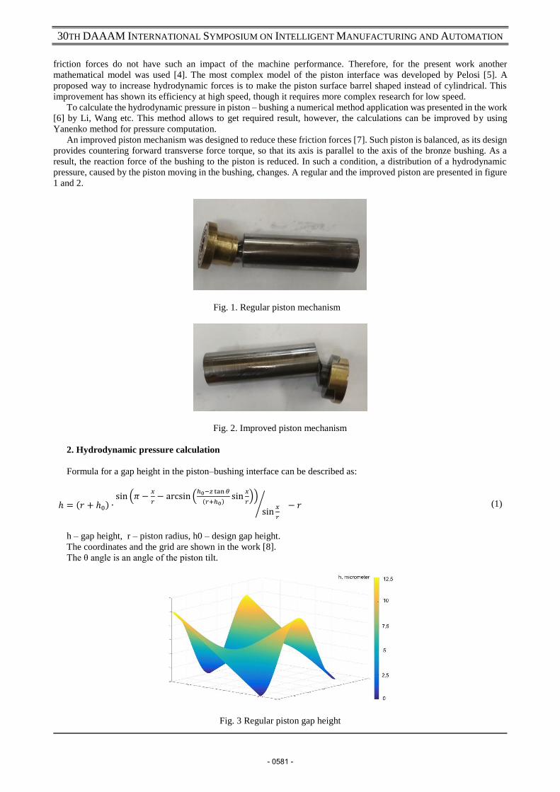
An improved piston mechanism was designed to reduce these friction forces [7]. Such piston is balanced, as its design
provides countering forward transverse force torque, so that its axis is parallel to the axis of the bronze bushing. As a
result, the reaction force of the bushing to the piston is reduced. In such a condition, a distribution of a hydrodynamic
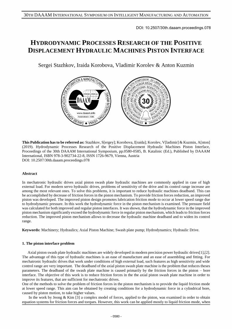
pressure, caused by the piston moving in the bushing, changes. A regular and the improved piston are presented in figure
1 and 2.
Fig. 1. Regular piston mechanism
Fig. 2. Improved piston mechanism
2. Hydrodynamic pressure calculation
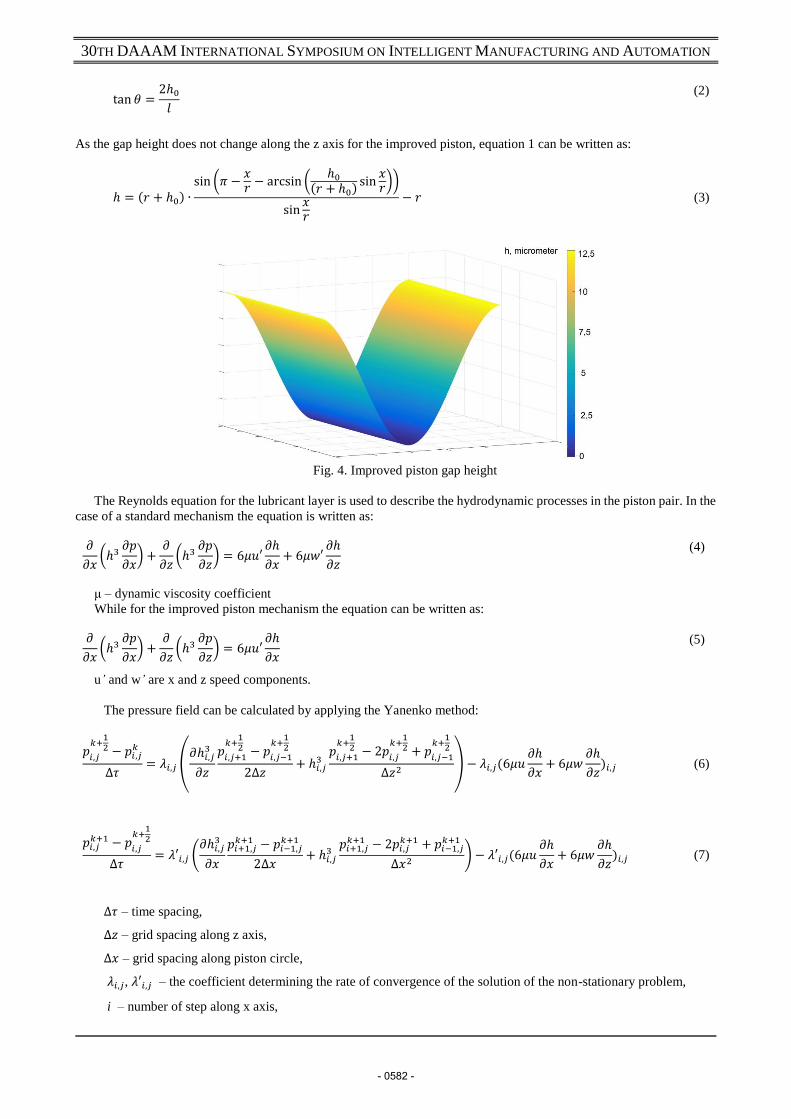
Formula for a gap height in the piston–bushing interface can be described as:
ℎ = (𝑟 + ℎ0) ∙sin (𝜋 −
𝑥
𝑟− arcsin (
ℎ0−𝑧 tan 𝜃
(𝑟+ℎ0)sin
𝑥
𝑟))
sin𝑥
𝑟
⁄ − 𝑟 (1)
h – gap height, r – piston radius, h0 – design gap height.
The coordinates and the grid are shown in the work [8].
The θ angle is an angle of the piston tilt.
Fig. 3 Regular piston gap height
- 0581 -
30TH DAAAM INTERNATIONAL SYMPOSIUM ON INTELLIGENT MANUFACTURING AND AUTOMATION
tan 𝜃 =2ℎ0
𝑙
(2)
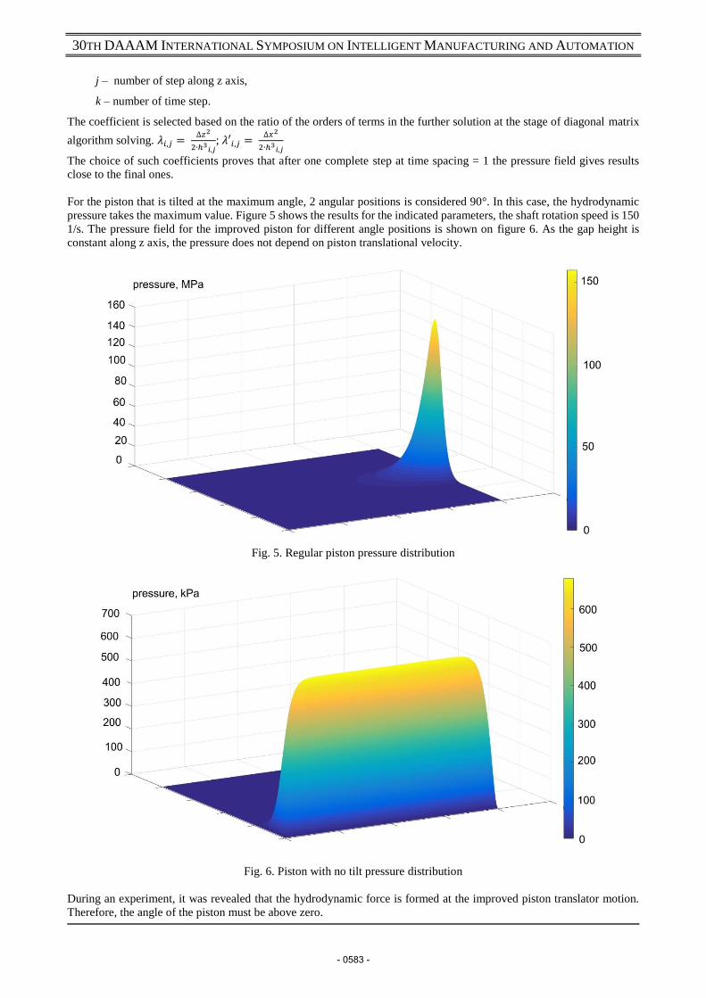
As the gap height does not change along the z axis for the improved piston, equation 1 can be written as:
ℎ = (𝑟 + ℎ0) ∙sin (𝜋 −
𝑥𝑟
− arcsin (ℎ0
(𝑟 + ℎ0)sin
𝑥𝑟
))
sin𝑥𝑟
− 𝑟
(3)
Fig. 4. Improved piston gap height
The Reynolds equation for the lubricant layer is used to describe the hydrodynamic processes in the piston pair. In the
case of a standard mechanism the equation is written as:
𝜕
𝜕𝑥(ℎ3
𝜕𝑝
𝜕𝑥) +
𝜕
𝜕𝑧(ℎ3
𝜕𝑝
𝜕𝑧) = 6𝜇𝑢′
𝜕ℎ
𝜕𝑥+ 6𝜇𝑤′
𝜕ℎ
𝜕𝑧
(4)
μ – dynamic viscosity coefficient
While for the improved piston mechanism the equation can be written as:
𝜕
𝜕𝑥(ℎ3
𝜕𝑝
𝜕𝑥) +
𝜕
𝜕𝑧(ℎ3
𝜕𝑝
𝜕𝑧) = 6𝜇𝑢′
𝜕ℎ
𝜕𝑥
(5)
u’ and w’ are x and z speed components.
The pressure field can be calculated by applying the Yanenko method:
𝑝𝑖,𝑗
𝑘+12 − 𝑝𝑖,𝑗
𝑘
∆𝜏= 𝜆𝑖,𝑗 (
𝜕ℎ𝑖,𝑗3
𝜕𝑧
𝑝𝑖,𝑗+1
𝑘+12 − 𝑝
𝑖,𝑗−1
𝑘+12
2∆𝑧+ ℎ𝑖,𝑗
3𝑝
𝑖,𝑗+1
𝑘+12 − 2𝑝
𝑖,𝑗
𝑘+12 + 𝑝
𝑖,𝑗−1
𝑘+12
∆𝑧2) − 𝜆𝑖,𝑗(6𝜇𝑢
𝜕ℎ
𝜕𝑥+ 6𝜇𝑤
𝜕ℎ
𝜕𝑧)𝑖,𝑗
(6)
𝑝𝑖,𝑗𝑘+1 − 𝑝
𝑖,𝑗
𝑘+12
∆𝜏= 𝜆′𝑖,𝑗 (
𝜕ℎ𝑖,𝑗3
𝜕𝑥
𝑝𝑖+1,𝑗𝑘+1 − 𝑝𝑖−1,𝑗
𝑘+1
2∆𝑥+ ℎ𝑖,𝑗
3𝑝𝑖+1,𝑗
𝑘+1 − 2𝑝𝑖,𝑗𝑘+1 + 𝑝𝑖−1,𝑗
𝑘+1
∆𝑥2) − 𝜆′𝑖,𝑗(6𝜇𝑢
𝜕ℎ
𝜕𝑥+ 6𝜇𝑤
𝜕ℎ
𝜕𝑧)𝑖,𝑗
(7)
∆𝜏 – time spacing,
∆𝑧 – grid spacing along z axis,
∆𝑥 – grid spacing along piston circle,
𝜆𝑖,𝑗, 𝜆′𝑖,𝑗 – the coefficient determining the rate of convergence of the solution of the non-stationary problem,
i – number of step along x axis,
- 0582 -
30TH DAAAM INTERNATIONAL SYMPOSIUM ON INTELLIGENT MANUFACTURING AND AUTOMATION
j – number of step along z axis,
k – number of time step.
The coefficient is selected based on the ratio of the orders of terms in the further solution at the stage of diagonal matrix
algorithm solving. 𝜆𝑖,𝑗 = ∆𝑧2
2∙ℎ3𝑖,𝑗
; 𝜆′𝑖,𝑗 = ∆𝑥2
2∙ℎ3𝑖,𝑗
The choice of such coefficients proves that after one complete step at time spacing = 1 the pressure field gives results
close to the final ones.
For the piston that is tilted at the maximum angle, 2 angular positions is considered 90°. In this case, the hydrodynamic
pressure takes the maximum value. Figure 5 shows the results for the indicated parameters, the shaft rotation speed is 150
1/s. The pressure field for the improved piston for different angle positions is shown on figure 6. As the gap height is
constant along z axis, the pressure does not depend on piston translational velocity.
Fig. 5. Regular piston pressure distribution
Fig. 6. Piston with no tilt pressure distribution
During an experiment, it was revealed that the hydrodynamic force is formed at the improved piston translator motion.
Therefore, the angle of the piston must be above zero.
- 0583 -
30TH DAAAM INTERNATIONAL SYMPOSIUM ON INTELLIGENT MANUFACTURING AND AUTOMATION
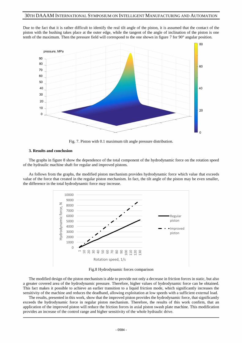
Due to the fact that it is rather difficult to identify the real tilt angle of the piston, it is assumed that the contact of the
piston with the bushing takes place at the outer edge, while the tangent of the angle of inclination of the piston is one
tenth of the maximum. Then the pressure field will correspond to the one shown in figure 7 for 90° angular position.
Fig. 7. Piston with 0.1 maximum tilt angle pressure distribution.
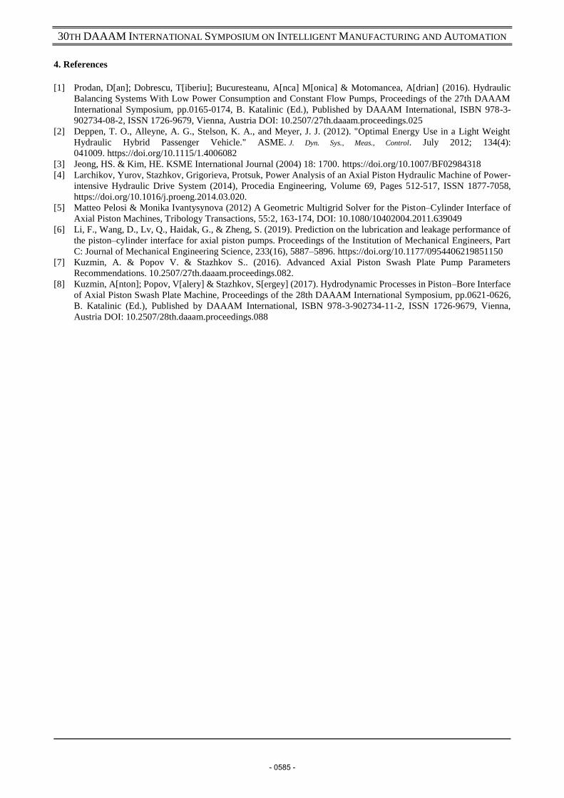
3. Results and conclusion
The graphs in figure 8 show the dependence of the total component of the hydrodynamic force on the rotation speed
of the hydraulic machine shaft for regular and improved pistons.
As follows from the graphs, the modified piston mechanism provides hydrodynamic force which value that exceeds
value of the force that created in the regular piston mechanism. In fact, the tilt angle of the piston may be even smaller,
the difference in the total hydrodynamic force may increase.
Fig.8 Hydrodynamic forces comparison
The modified design of the piston mechanism is able to provide not only a decrease in friction forces in static, but also
a greater covered area of the hydrodynamic pressure. Therefore, higher values of hydrodynamic force can be obtained.
This fact makes it possible to achieve an earlier transition to a liquid friction mode, which significantly increases the
sensitivity of the machine and reduces the deadband, allowing exploitation at low speeds with a sufficient external load.
The results, presented in this work, show that the improved piston provides the hydrodynamic force, that significantly
exceeds the hydrodynamic force in regular piston mechanism. Therefore, the results of this work confirm, that an
application of the improved piston will reduce the friction forces in axial piston swash plate machine. This modification
provides an increase of the control range and higher sensitivity of the whole hydraulic drive.
0
1000
2000
3000
4000
5000
6000
7000
8000
9000
10000
1
10
20
30
40
50
60
70
80
90
10
0
11
0
12
0
13
0
Hyd
rod
ynam
ic f
orc
e, N
Rotation speed, 1/s
Regularpiston
Improvedpiston
- 0584 -
30TH DAAAM INTERNATIONAL SYMPOSIUM ON INTELLIGENT MANUFACTURING AND AUTOMATION
4. References
[1] Prodan, D[an]; Dobrescu, T[iberiu]; Bucuresteanu, A[nca] M[onica] & Motomancea, A[drian] (2016). Hydraulic
Balancing Systems With Low Power Consumption and Constant Flow Pumps, Proceedings of the 27th DAAAM
International Symposium, pp.0165-0174, B. Katalinic (Ed.), Published by DAAAM International, ISBN 978-3-
902734-08-2, ISSN 1726-9679, Vienna, Austria DOI: 10.2507/27th.daaam.proceedings.025
[2] Deppen, T. O., Alleyne, A. G., Stelson, K. A., and Meyer, J. J. (2012). "Optimal Energy Use in a Light Weight
Hydraulic Hybrid Passenger Vehicle." ASME. J. Dyn. Sys., Meas., Control. July 2012; 134(4):
041009. https://doi.org/10.1115/1.4006082
[3] Jeong, HS. & Kim, HE. KSME International Journal (2004) 18: 1700. https://doi.org/10.1007/BF02984318
[4] Larchikov, Yurov, Stazhkov, Grigorieva, Protsuk, Power Analysis of an Axial Piston Hydraulic Machine of Power-
intensive Hydraulic Drive System (2014), Procedia Engineering, Volume 69, Pages 512-517, ISSN 1877-7058,
https://doi.org/10.1016/j.proeng.2014.03.020.
[5] Matteo Pelosi & Monika Ivantysynova (2012) A Geometric Multigrid Solver for the Piston–Cylinder Interface of
Axial Piston Machines, Tribology Transactions, 55:2, 163-174, DOI: 10.1080/10402004.2011.639049
[6] Li, F., Wang, D., Lv, Q., Haidak, G., & Zheng, S. (2019). Prediction on the lubrication and leakage performance of
the piston–cylinder interface for axial piston pumps. Proceedings of the Institution of Mechanical Engineers, Part
C: Journal of Mechanical Engineering Science, 233(16), 5887–5896. https://doi.org/10.1177/0954406219851150
[7] Kuzmin, A. & Popov V. & Stazhkov S.. (2016). Advanced Axial Piston Swash Plate Pump Parameters
Recommendations. 10.2507/27th.daaam.proceedings.082.
[8] Kuzmin, A[nton]; Popov, V[alery] & Stazhkov, S[ergey] (2017). Hydrodynamic Processes in Piston–Bore Interface
of Axial Piston Swash Plate Machine, Proceedings of the 28th DAAAM International Symposium, pp.0621-0626,
B. Katalinic (Ed.), Published by DAAAM International, ISBN 978-3-902734-11-2, ISSN 1726-9679, Vienna,
Austria DOI: 10.2507/28th.daaam.proceedings.088
- 0585 -