husqvarna automower® 105 - gardena
TRANSCRIPT
EN, English
Operator's manualHusqvarna Automower® 105
Read the operator's manual carefully and make sure that youunderstand the instructions before you use the product.
Contents
1 Introduction1.1 Support.......................................................31.2 Product description.....................................3
2 Safety2.1 Safety definitions........................................ 92.2 General safety instructions.........................92.3 Safety instructions for operation...............11
3 Installation3.1 Introduction - Installation.......................... 143.2 Before the installation of the wires........... 143.3 Before the installation of the product........143.4 Installation of the product......................... 183.5 To put the wire into position with stakes...193.6 To bury the boundary wire or theguide wire....................................................... 193.7 To extend the boundary wire or theguide wire....................................................... 203.8 After the installation of the product...........203.9 To do the product settings........................20
4 Operation4.1 Main switch...............................................254.2 To start the product.................................. 254.3 Operating modes......................................254.4 To stop the product.................................. 264.5 To switch off the product.......................... 264.6 Timer and Standby................................... 264.7 To charge the battery............................... 274.8 Adjust the cutting height........................... 27
5 Maintenance5.1 Introduction - maintenance.......................285.2 Clean the product..................................... 285.3 Replace the blades...................................295.4 Battery...................................................... 295.5 Winter service...........................................30
6 Troubleshooting6.1 Introduction - troubleshooting...................316.2 Fault messages........................................ 316.3 Information messages.............................. 356.4 Indicator lamp in the charging station.......366.5 Symptoms................................................ 376.6 Find breaks in the loop wire..................... 38
7 Transportation, storage and disposal7.1 Transportation.......................................... 41
7.2 Storage.....................................................417.3 Disposal....................................................41
8 Technical data8.1 Technical data.......................................... 42
9 Warranty9.1 Warranty terms.........................................44
10 EC Declaration of Conformity10.1 EC Declaration of Conformity.................45
2 1285 - 002 - 20.08.2019
1 Introduction
Serial number:
PIN code:
The serial number is on the product rating plate and on the product carton.• Use the serial number to register your product on www.husqvarna.com.
1.1 SupportFor support about the Husqvarna® product,speak to your servicing dealer.
1.2 Product descriptionNote: Husqvarna® regularly updates theappearance and function of the products. Referto Support on page 3.
The product is a robotic lawn mower. The producthas a battery power source and cuts the grass
automatically. Collection of grass is notnecessary.
The operator selects the operation settings withthe keys on the keypad. The display shows theselected and possible operation settings, and theoperating mode of the product.
The boundary wire and the guide wire controlsthe movement of the product within the workarea.
1285 - 002 - 20.08.2019 Introduction - 3
1.2.1 Product overview
1
32
1726
6
54
13
14
12
2125
19
24
2023
18
8
10
11
7
22
28
15
29
16
9
27
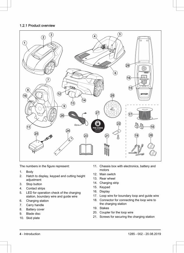
The numbers in the figure represent:
1. Body2. Hatch to display, keypad and cutting height
adjustment3. Stop button4. Contact strips5. LED for operation check of the charging
station, boundary wire and guide wire6. Charging station7. Carry handle8. Battery cover9. Blade disc10. Skid plate
11. Chassis box with electronics, battery andmotors
12. Main switch13. Rear wheel14. Charging strip15. Keypad16. Display17. Loop wire for boundary loop and guide wire18. Connector for connecting the loop wire to
the charging station19. Stakes20. Coupler for the loop wire21. Screws for securing the charging station
4 - Introduction 1285 - 002 - 20.08.2019
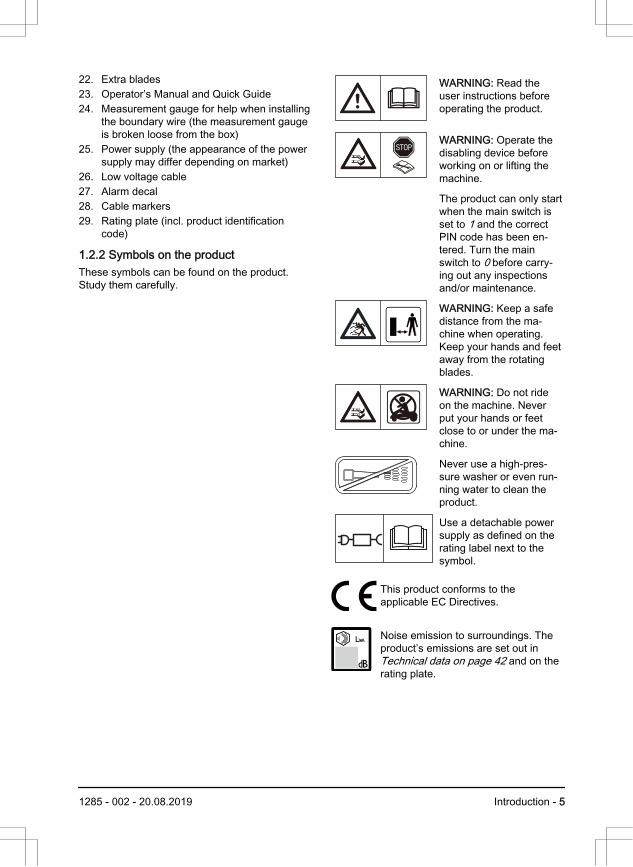
22. Extra blades23. Operator’s Manual and Quick Guide24. Measurement gauge for help when installing
the boundary wire (the measurement gaugeis broken loose from the box)
25. Power supply (the appearance of the powersupply may differ depending on market)
26. Low voltage cable27. Alarm decal28. Cable markers29. Rating plate (incl. product identification
code)
1.2.2 Symbols on the productThese symbols can be found on the product.Study them carefully.
WARNING: Read theuser instructions beforeoperating the product.
WARNING: Operate thedisabling device beforeworking on or lifting themachine.
The product can only startwhen the main switch isset to 1 and the correctPIN code has been en-tered. Turn the mainswitch to 0 before carry-ing out any inspectionsand/or maintenance.
WARNING: Keep a safedistance from the ma-chine when operating.Keep your hands and feetaway from the rotatingblades.
WARNING: Do not rideon the machine. Neverput your hands or feetclose to or under the ma-chine.
Never use a high-pres-sure washer or even run-ning water to clean theproduct.
Use a detachable powersupply as defined on therating label next to thesymbol.
This product conforms to theapplicable EC Directives.
Noise emission to surroundings. Theproduct’s emissions are set out in Technical data on page 42 and on therating plate.
1285 - 002 - 20.08.2019 Introduction - 5
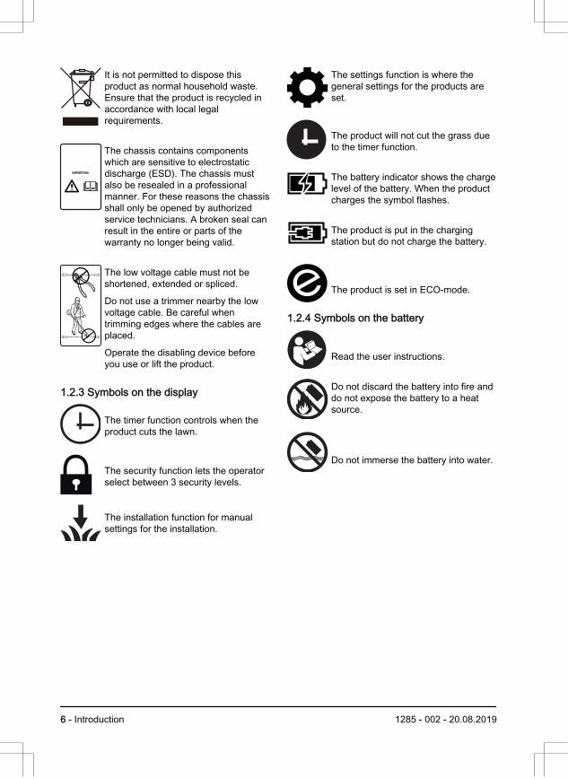
It is not permitted to dispose thisproduct as normal household waste.Ensure that the product is recycled inaccordance with local legalrequirements.
The chassis contains componentswhich are sensitive to electrostaticdischarge (ESD). The chassis mustalso be resealed in a professionalmanner. For these reasons the chassisshall only be opened by authorizedservice technicians. A broken seal canresult in the entire or parts of thewarranty no longer being valid.
The low voltage cable must not beshortened, extended or spliced.
Do not use a trimmer nearby the lowvoltage cable. Be careful whentrimming edges where the cables areplaced.
Operate the disabling device beforeyou use or lift the product.
1.2.3 Symbols on the display
The timer function controls when theproduct cuts the lawn.
The security function lets the operatorselect between 3 security levels.
The installation function for manualsettings for the installation.
The settings function is where thegeneral settings for the products areset.
The product will not cut the grass dueto the timer function.
The battery indicator shows the chargelevel of the battery. When the productcharges the symbol flashes.
The product is put in the chargingstation but do not charge the battery.
The product is set in ECO-mode.
1.2.4 Symbols on the battery
Read the user instructions.
Do not discard the battery into fire anddo not expose the battery to a heatsource.
Do not immerse the battery into water.
6 - Introduction 1285 - 002 - 20.08.2019
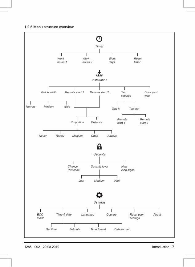
1.2.5 Menu structure overview
Installation
Guide width Remote start 1
Narrow
Never Rarely Medium Often Always
Medium WideTest outTest in
DistanceRemote
start 1
Remote
start 2 Proportion
Remote start 2 Test
settings
Drive past
wire
Settings
ECO
mode
Time & date
Set time Set date Time format
Language Country Reset user
settings
About
Date format
Security
Change
PIN code
Low HighMedium
Security level New
loop signal
Timer
Work
hours 1
Work
hours 2
Work
days
Reset
timer
1285 - 002 - 20.08.2019 Introduction - 7
1.2.6 DisplayThe display on the product shows informationand settings of the product.
To access the display, push the STOP button.
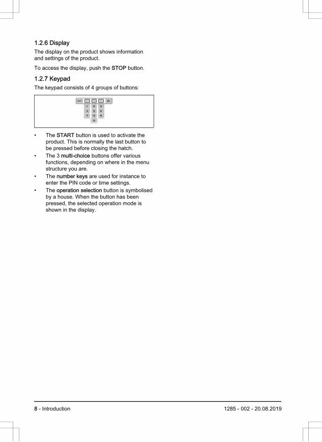
1.2.7 Keypad The keypad consists of 4 groups of buttons:
• The START button is used to activate theproduct. This is normally the last button tobe pressed before closing the hatch.
• The 3 multi-choice buttons offer variousfunctions, depending on where in the menustructure you are.
• The number keys are used for instance toenter the PIN code or time settings.
• The operation selection button is symbolisedby a house. When the button has beenpressed, the selected operation mode isshown in the display.
8 - Introduction 1285 - 002 - 20.08.2019
2 Safety2.1 Safety definitionsWarnings, cautions and notes are used to pointout specially important parts of the manual.
WARNING: Used if there is a risk ofinjury or death for the operator orbystanders if the instructions in themanual are not obeyed.
CAUTION: Used if there is a risk ofdamage to the product, other materialsor the adjacent area if the instructionsin the manual are not obeyed.
Note: Used to give more information that isnecessary in a given situation.
2.2 General safety instructionsThe following system is used in the Operator’sManual to make it easier to use:
• Text written in italics is a text that is shownon the display of the product or is areference to another section in theOperator’s Manual.
• Text written in bold is one of the buttons onthe keypad of the product.
• Text written in UPPERCASE and italics referto the different operating modes available inthe product.
1285 - 002 - 20.08.2019 Safety - 9
2.2.1 IMPORTANT. READ CAREFULLYBEFORE USE. KEEP FOR FUTUREREFERENCEThe operator is responsible for accidents or hazards occurring toother people or property.This appliance is not intended for use by persons (including chil-dren) with reduced physical, sensory or mental capabilities (thatcould affect a safe handling of the product), or lack of experienceand knowledge, unless they have been given supervision or in-struction concerning use of the appliance by a person responsiblefor their safety.This appliance can be used by children aged from 8 years andabove and persons with reduced physical, sensory or mental ca-pabilities or lack of experience and knowledge if they have beengiven supervision or instruction concerning use of the appliance ina safe way and understand the hazards involved. Local regula-tions may restrict the age of the operator. Cleaning and mainte-nance shall not be made by children without supervision.Never connect the power supply to an outlet if the plug or cord isdamaged. Worn or damaged cord increase the risk of electricshock.Only charge the battery in the included charging station. Incorrectuse may result in electric shock, overheating or leaking of corro-sive liquid from the battery. In the event of leakage of electrolyte,flush with water/neutralizing agent. Seek medical help if it comesin contact with the eyes.Use only original batteries recommended by the manufacturer.Product safety cannot be guaranteed with other than original bat-teries. Do not use non-rechargeable batteries.The appliance must be disconnected from the supply mains whenremoving the battery.
10 - Safety 1285 - 002 - 20.08.2019
WARNING: The productcan be dangerous if usedincorrectly.
WARNING: Do not usethe product whenpersons, especiallychildren, or animals, arein the work area.
WARNING: Keep yourhands and feet awayfrom the rotating blades.Never put your hands orfeet close to or under theproduct when the motoris running.
2.3 Safety instructions for operation2.3.1 Use• The product may only be used with the
equipment recommended by themanufacturer. All other types of use areincorrect. The manufacturer’s instructionswith regard to operation/maintenance mustbe followed precisely.
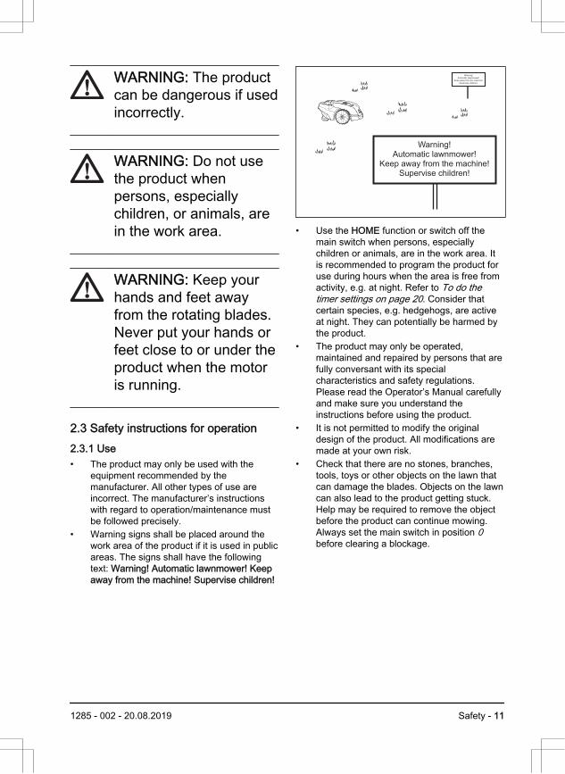
• Warning signs shall be placed around thework area of the product if it is used in publicareas. The signs shall have the followingtext: Warning! Automatic lawnmower! Keepaway from the machine! Supervise children!
Warning!Automatic lawnmower!
Keep away from the machine!Supervise children!
Warning!
Automatic lawnmower!
Keep away from the machine!
Supervise children!
• Use the HOME function or switch off themain switch when persons, especiallychildren or animals, are in the work area. Itis recommended to program the product foruse during hours when the area is free fromactivity, e.g. at night. Refer to To do thetimer settings on page 20. Consider thatcertain species, e.g. hedgehogs, are activeat night. They can potentially be harmed bythe product.
• The product may only be operated,maintained and repaired by persons that arefully conversant with its specialcharacteristics and safety regulations.Please read the Operator’s Manual carefullyand make sure you understand theinstructions before using the product.
• It is not permitted to modify the originaldesign of the product. All modifications aremade at your own risk.
• Check that there are no stones, branches,tools, toys or other objects on the lawn thatcan damage the blades. Objects on the lawncan also lead to the product getting stuck.Help may be required to remove the objectbefore the product can continue mowing.Always set the main switch in position 0before clearing a blockage.
1285 - 002 - 20.08.2019 Safety - 11
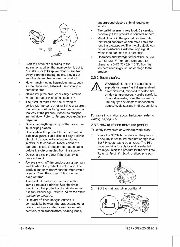
• Start the product according to theinstructions. When the main switch is set to1, make sure to keep your hands and feetaway from the rotating blades. Never putyour hands and feet under the product.
• Never touch moving hazardous parts, suchas the blade disc, before it has come to acomplete stop.
• Never lift up the product or carry it aroundwhen the main switch is in position 1.
• The product must never be allowed tocollide with persons or other living creatures.If a person or other living creature comes inthe way of the product, it shall be stoppedimmediately. Refer to To stop the product onpage 26.
• Do not put anything on top of the product orits charging station.
• Do not allow the product to be used with adefective guard, blade disc or body. Neithershould it be used with defective blades,screws, nuts or cables. Never connect adamaged cable, or touch a damaged cablebefore it is disconnected from the supply.
• Do not use the product if the main switchdoes not work.
• Always switch off the product using the mainswitch when the product is not in use. Theproduct can only start when the main switchis set to 1 and the correct PIN code hasbeen entered.
• The product must never be used at thesame time as a sprinkler. Use the timerfunction so the product and sprinkler neverrun simultaneously. Refer to To do the timersettings on page 20.
• Husqvarna® does not guarantee fullcompatibility between the product and othertypes of wireless systems such as remotecontrols, radio transmitters, hearing loops,
underground electric animal fencing orsimilar.
• The built-in alarm is very loud. Be careful,especially if the product is handled indoors.
• Metal objects in the ground (for examplereinforced concrete or anti-mole nets) canresult in a stoppage. The metal objects cancause interference with the loop signalwhich then can lead to a stoppage.
• Operation and storage temperature is 0-50°C / 32-122 °F. Temperature range forcharging is 0-45 °C / 32-113 °F. Too hightemperatures might cause damage to theproduct.
2.3.2 Battery safety
WARNING: Lithium-ion batteries canexplode or cause fire if disassembled,short-circuited, exposed to water, fire,or high temperatures. Handle carefully,do not dismantle, open the battery oruse any type of electrical/mechanicalabuse. Avoid storage in direct sunlight.
For more information about the battery, refer to Battery on page 29
2.3.3 How to lift and move the productTo safely move from or within the work area:
1. Press the STOP button to stop the product.If security is set to the medium or high levelthe PIN code has to be entered. The PINcode contains four digits and is selectedwhen you start the product for the first time.Refer to To do the basic settings on page20.
2. Set the main switch in position 0.
12 - Safety 1285 - 002 - 20.08.2019
3. Carry the product by the handle under theproduct with the blade disc away from thebody.
CAUTION: Do not lift the product whenit is parked in the charging station. Itcan damage the charging stationand/or the product. Press the STOPbutton and pull the product out of thecharging station before lifting it.
2.3.4 Maintenance
WARNING: When the product isturned upside down the main switchmust always be in the 0 position.
The main switch should be set in the 0position before all work on the chassisof the product, such as cleaning orreplacing the blades.
CAUTION: Never use a high-pressurewasher or even running water to cleanthe product. Never use solvents forcleaning.
CAUTION: Use the plug to disconnectthe charging station before anycleaning or maintenance of thecharging station or the loop wire.
Inspect the product each week and replace anydamaged or worn parts. Refer to Maintenance onpage 28.
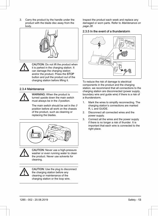
2.3.5 In the event of a thunderstorm
To reduce the risk of damage to electricalcomponents in the product and the chargingstation, we recommend that all connections to thecharging station are disconnected (power supply,boundary wire and guide wire) if there is a risk ofa thunderstorm.
1. Mark the wires to simplify reconnecting. Thecharging station’s connections are markedR, L and GUIDE.
2. Disconnect all connected wires and thepower supply.
3. Connect all the wires and the power supplyif there is no longer a risk of thunder. It isimportant that each wire is connected to theright place.
1285 - 002 - 20.08.2019 Safety - 13
3 Installation3.1 Introduction - Installation
WARNING: Read and understand thesafety chapter before you install theproduct.
CAUTION: Use original spare partsand installation material.
Note: Refer to www.husqvarna.com for moreinformation about installation.
3.2 Before the installation of the wiresYou can select to attach the wires with stakes orbury them. You can use the 2 procedures for thesame work area.
• Bury the boundary wire or the guide wire ifyou are going to use a dethatcher on thework area. If not, attach the boundary wireor guide wire with stakes.
• Cut the grass before you install the product.Make sure that the grass is maximum 4 cm /1.6 in.
Note: The first weeks after installation theperceived sound level when cutting the grassmay be higher than expected. When the producthas cut the grass for some time, the perceivedsound level is much lower.
3.3 Before the installation of theproduct• Make a blueprint of the work area and
include all obstacles.• Make a mark on the blueprint where to put
the charging station, the boundary wire andthe guide wire.
• Make an eyelet on the blueprint where theguide wire connects to the boundary wire.Refer to To examine where to put theboundary wire on page 15.
• Fill in holes in the lawn.
Note: Holes with water in the lawn cancause damage to the product.
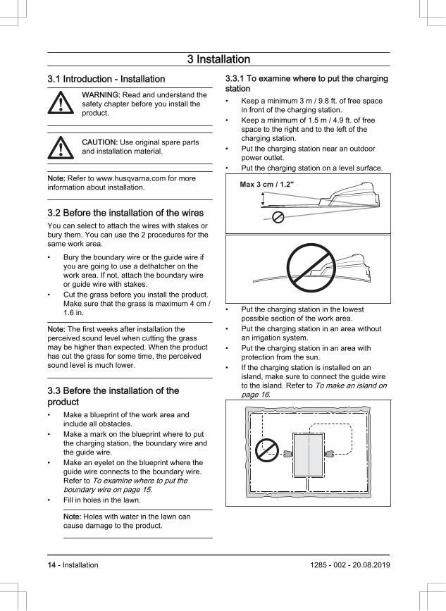
3.3.1 To examine where to put the chargingstation• Keep a minimum 3 m / 9.8 ft. of free space
in front of the charging station.• Keep a minimum of 1.5 m / 4.9 ft. of free
space to the right and to the left of thecharging station.
• Put the charging station near an outdoorpower outlet.
• Put the charging station on a level surface.
Max 3 cm / 1.2"
• Put the charging station in the lowestpossible section of the work area.
• Put the charging station in an area withoutan irrigation system.
• Put the charging station in an area withprotection from the sun.
• If the charging station is installed on anisland, make sure to connect the guide wireto the island. Refer to To make an island onpage 16.
14 - Installation 1285 - 002 - 20.08.2019
3.3.2 To examine where to put the powersupply• Put the power supply in an area with a roof
and protection from the sun and rain.• Put the power supply in an area with good
airflow.• Use a residual-current device (RCD) when
you connect the power supply to the poweroutlet.
WARNING: Do not change the powersupply. Do not cut or extend the low-voltage cable. There is a risk ofelectrical shock.
Low-voltage cables of different lengths areavailable as accessories.
CAUTION: Make sure that the bladeson the product do not cut the low-voltage cable.
CAUTION: Do not put the low-voltagecable in a coil or below the chargingstation plate. The coil causesinterference with the signal from thecharging station.
3.3.3 To examine where to put theboundary wireThe boundary wire should be put as a looparound the work area. Sensors in the productsenses when the product approaches theboundary wire, and the product selects anotherdirection.
CAUTION: If the work area is adjacentto water bodies, slopes, precipices or apublic road, the boundary wire musthave a protective wall. The wall mustbe minimum 15 cm / 6 in. in height.
To make the connection easier between theguide wire and the boundary wire, it is
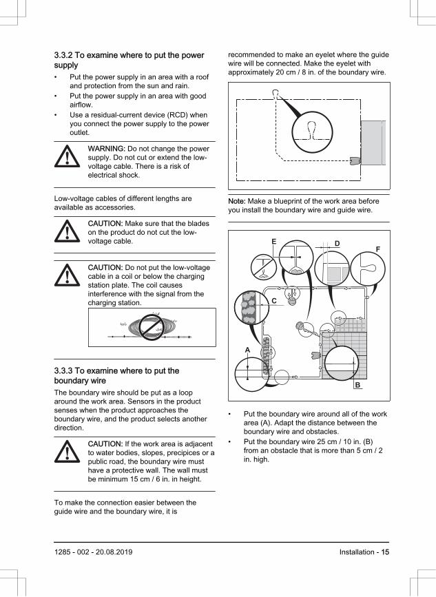
recommended to make an eyelet where the guidewire will be connected. Make the eyelet withapproximately 20 cm / 8 in. of the boundary wire.
Note: Make a blueprint of the work area beforeyou install the boundary wire and guide wire.
DE
B
C
F
A
• Put the boundary wire around all of the workarea (A). Adapt the distance between theboundary wire and obstacles.
• Put the boundary wire 25 cm / 10 in. (B)from an obstacle that is more than 5 cm / 2in. high.
1285 - 002 - 20.08.2019 Installation - 15
25 cm / 10"
> 5 cm/>2"
• Put the boundary wire 20 cm / 8 in. (C) froman obstacle that is 1-5 cm / 0.4-2 in. high.
• Put the boundary wire 5 cm / 2 in. (D) froman obstacle that is less than 1 cm / 0.4 in.
• If you have a paving stone path that is inlevel with the lawn, put the boundary wirebelow the paving stone.
Note: If the paving stone is minimum 30 cm /12 in. wide, use the factory setting for theDrive Past Wire function to cut all the grassadjacent to the paving stone.
CAUTION: Do not let the productoperate on gravel.
• If you make an island, put the boundary wirethat runs to and from the island neartogether (E). Put the wires in the samestake.
• Make an eyelet (F) where the guide wire isto be connected to the boundary wire.
CAUTION: Do not make sharpbends when you install theboundary wire.
CAUTION: For careful operationwithout noise, isolate all obstaclessuch as trees, roots and stones.
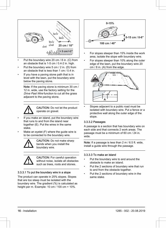
3.3.3.1 To put the boundary wire in a slopeThe product can operate in 25% slopes. Slopesthat are too steep must be isolated with theboundary wire. The gradient (%) is calculated asheight per m. Example: 10 cm / 100 cm = 10%.
0-15%
0-15 cm / 0-6"
100 cm / 40"
• For slopes steeper than 15% inside the workarea, isolate the slope with boundary wire.
• For slopes steeper than 10% along the outeredge of the lawn, put the boundary wire 20cm / 8 in. (A) from the edge.
A
>15%
• Slopes adjacent to a public road must beisolated with boundary wire. Put a fence or aprotective wall along the outer edge of theslope.
3.3.3.2 PassagesA passage is a section that has boundary wire oneach side and that connects 2 work areas. Thepassage must be a minimum of 60 cm / 24 in.wide.
Note: If a passage is less than 2 m / 6.5 ft. wide,install a guide wire through the passage.
3.3.3.3 To make an island• Put the boundary wire to and around the
obstacle to make an island.• Put the 2 sections of boundary wire that run
to and from the obstacle together.• Put the 2 sections of boundary wire in the
same stake.
16 - Installation 1285 - 002 - 20.08.2019
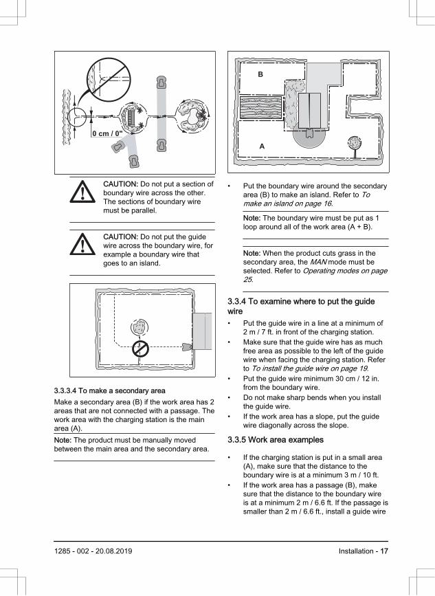
0 cm / 0"
CAUTION: Do not put a section ofboundary wire across the other.The sections of boundary wiremust be parallel.
CAUTION: Do not put the guidewire across the boundary wire, forexample a boundary wire thatgoes to an island.
3.3.3.4 To make a secondary areaMake a secondary area (B) if the work area has 2areas that are not connected with a passage. Thework area with the charging station is the mainarea (A).Note: The product must be manually movedbetween the main area and the secondary area.
B
A
• Put the boundary wire around the secondaryarea (B) to make an island. Refer to Tomake an island on page 16.
Note: The boundary wire must be put as 1loop around all of the work area (A + B).
Note: When the product cuts grass in thesecondary area, the MAN mode must beselected. Refer to Operating modes on page25.
3.3.4 To examine where to put the guidewire• Put the guide wire in a line at a minimum of
2 m / 7 ft. in front of the charging station.• Make sure that the guide wire has as much
free area as possible to the left of the guidewire when facing the charging station. Referto To install the guide wire on page 19.
• Put the guide wire minimum 30 cm / 12 in.from the boundary wire.
• Do not make sharp bends when you installthe guide wire.
• If the work area has a slope, put the guidewire diagonally across the slope.
3.3.5 Work area examples
• If the charging station is put in a small area(A), make sure that the distance to theboundary wire is at a minimum 3 m / 10 ft.
• If the work area has a passage (B), makesure that the distance to the boundary wireis at a minimum 2 m / 6.6 ft. If the passage issmaller than 2 m / 6.6 ft., install a guide wire
1285 - 002 - 20.08.2019 Installation - 17
through the passage. Minimum passagebetween the boundary wire is 60 cm / 24 in.
• If the work area has areas which areconnected by a narrow passage (B), youcan set the product to leave the guide wireafter a certain distance (C). The settings canbe changed in Remote start 1 on page 21.
• If the work area includes a secondary area(D), refer to To make a secondary area onpage 17. Put the product in the secondaryarea and select Proportion.
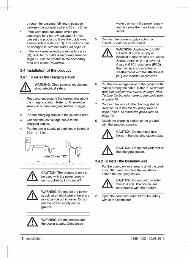
3.4 Installation of the product3.4.1 To install the charging station
WARNING: Obey national regulationsabout electrical safety.
1. Read and understand the instructions aboutthe charging station. Refer to To examinewhere to put the charging station on page14.
2. Put the charging station in the selected area.3. Connect the low-voltage cable to the
charging station.4. Put the power supply at a minimum height of
30 cm / 12 in.
min 30 cm / 12”
CAUTION: The product is only tobe used with the power supplyunit supplied by Husqvarna®.
WARNING: Do not put the powersupply at a height where there is arisk it can be put in water. Do notput the power supply on theground.
WARNING: Do not encapsulatethe power supply. Condensed
water can harm the power supplyand increase the risk of electricalshock.
5. Connect the power supply cable to a100-240V outdoor power outlet.
WARNING: Applicable to USA/Canada. If power supply isinstalled outdoors: Risk of ElectricShock. Install only to a coveredClass A GFCI receptacle (RCD)that has an enclosure that isweatherproof with the attachmentplug cap inserted or removed.
6. Put the low-voltage cable in the ground withstakes or bury the cable. Refer to To put thewire into position with stakes on page 19 or To bury the boundary wire or the guide wireon page 19.
7. Connect the wires to the charging station.Refer to To install the boundary wire onpage 18 and To install the guide wire onpage 19.
8. Attach the charging station to the groundwith the supplied screws.
CAUTION: Do not make newholes in the charging station plate.
CAUTION: Do not put your feet onthe charging station.
3.4.2 To install the boundary wire1. Put the boundary wire around all of the work
area. Start and complete the installationbehind the charging station.
CAUTION: Do not put unwantedwire in a coil. The coil causesinterference with the product.
2. Open the connector and put the boundarywire in the connector.
18 - Installation 1285 - 002 - 20.08.2019
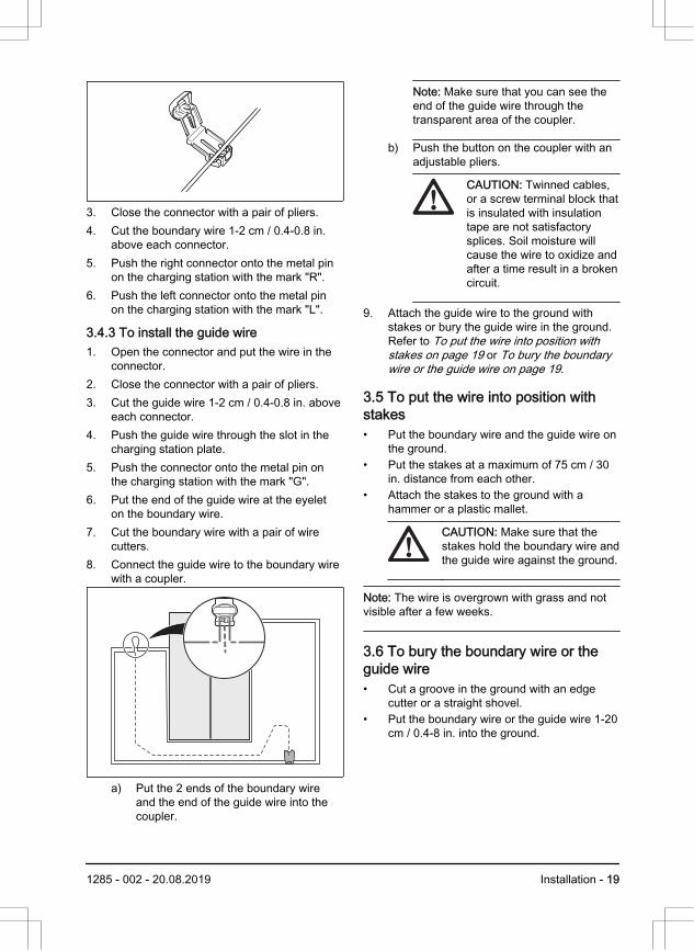
3. Close the connector with a pair of pliers.4. Cut the boundary wire 1-2 cm / 0.4-0.8 in.
above each connector.5. Push the right connector onto the metal pin
on the charging station with the mark "R".6. Push the left connector onto the metal pin
on the charging station with the mark "L".
3.4.3 To install the guide wire1. Open the connector and put the wire in the
connector.2. Close the connector with a pair of pliers.3. Cut the guide wire 1-2 cm / 0.4-0.8 in. above
each connector.4. Push the guide wire through the slot in the
charging station plate.5. Push the connector onto the metal pin on
the charging station with the mark "G".6. Put the end of the guide wire at the eyelet
on the boundary wire.7. Cut the boundary wire with a pair of wire
cutters.8. Connect the guide wire to the boundary wire
with a coupler.
a) Put the 2 ends of the boundary wireand the end of the guide wire into thecoupler.
Note: Make sure that you can see theend of the guide wire through thetransparent area of the coupler.
b) Push the button on the coupler with anadjustable pliers.
CAUTION: Twinned cables,or a screw terminal block thatis insulated with insulationtape are not satisfactorysplices. Soil moisture willcause the wire to oxidize andafter a time result in a brokencircuit.
9. Attach the guide wire to the ground withstakes or bury the guide wire in the ground.Refer to To put the wire into position withstakes on page 19 or To bury the boundarywire or the guide wire on page 19.
3.5 To put the wire into position withstakes• Put the boundary wire and the guide wire on
the ground.• Put the stakes at a maximum of 75 cm / 30
in. distance from each other.• Attach the stakes to the ground with a
hammer or a plastic mallet.
CAUTION: Make sure that thestakes hold the boundary wire andthe guide wire against the ground.
Note: The wire is overgrown with grass and notvisible after a few weeks.
3.6 To bury the boundary wire or theguide wire• Cut a groove in the ground with an edge
cutter or a straight shovel.• Put the boundary wire or the guide wire 1-20
cm / 0.4-8 in. into the ground.
1285 - 002 - 20.08.2019 Installation - 19
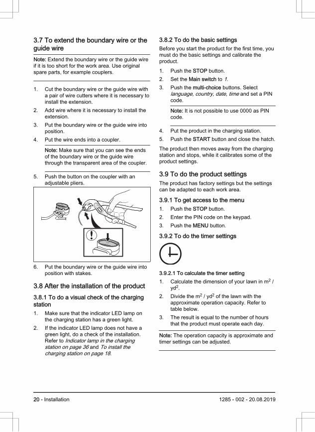
3.7 To extend the boundary wire or theguide wireNote: Extend the boundary wire or the guide wireif it is too short for the work area. Use originalspare parts, for example couplers.
1. Cut the boundary wire or the guide wire witha pair of wire cutters where it is necessary toinstall the extension.
2. Add wire where it is necessary to install theextension.
3. Put the boundary wire or the guide wire intoposition.
4. Put the wire ends into a coupler.
Note: Make sure that you can see the endsof the boundary wire or the guide wirethrough the transparent area of the coupler.
5. Push the button on the coupler with anadjustable pliers.
6. Put the boundary wire or the guide wire intoposition with stakes.
3.8 After the installation of the product3.8.1 To do a visual check of the chargingstation1. Make sure that the indicator LED lamp on
the charging station has a green light.2. If the indicator LED lamp does not have a
green light, do a check of the installation.Refer to Indicator lamp in the chargingstation on page 36 and To install thecharging station on page 18.
3.8.2 To do the basic settingsBefore you start the product for the first time, youmust do the basic settings and calibrate theproduct.
1. Push the STOP button.2. Set the Main switch to 1.3. Push the multi-choice buttons. Select
language, country, date, time and set a PINcode.
Note: It is not possible to use 0000 as PINcode.
4. Put the product in the charging station.5. Push the START button and close the hatch.
The product then moves away from the chargingstation and stops, while it calibrates some of theproduct settings.
3.9 To do the product settingsThe product has factory settings but the settingscan be adapted to each work area.
3.9.1 To get access to the menu1. Push the STOP button.2. Enter the PIN code on the keypad.3. Push the MENU button.
3.9.2 To do the timer settings
3.9.2.1 To calculate the timer setting1. Calculate the dimension of your lawn in m2 /
yd2.2. Divide the m2 / yd2 of the lawn with the
approximate operation capacity. Refer totable below.
3. The result is equal to the number of hoursthat the product must operate each day.
Note: The operation capacity is approximate andtimer settings can be adjusted.
20 - Installation 1285 - 002 - 20.08.2019
Model Approximate operation ca-pacity, m2/h / yd2/h
Automower® 105 43 / 50
Example: A lawn of 500 m2 / 600 yd2, cut with anAutomower® 105.
500 m2 / 43 ≈ 12 h.
600 yd2 / 50 ≈ 12 h.
Days /week
h / day Timer settings
7 12 07:00-19:00 / 7:00am-7:00 pm
3.9.2.2 To set the timer1. Do steps 1–3 in To get access to the menu
on page 20.2. Use the multi-choice buttons to move
through the menu structure to select Timer.3. Use the multi-choice buttons to select Work
hours 1 or Work hours 2.4. Enter the time with the number buttons.5. Push OK.6. Use the multi-choice buttons to select Work
days.7. Use the multi-choice buttons to select the
days that the product will operate.8. Push OK.
3.9.2.3 To reset the timer settingYou can remove all timer settings and use thefactory setting. The factory timer setting lets theproduct operate all hours each day of the week.Refer to Timer and Standby on page 26.
1. Do steps 1–3 in To get access to the menuon page 20.
2. Use the multi-choice buttons to movethrough the menu structure Timer > Resettimer.
3. Push OK.
3.9.3 Installation In the Installation menu it is possible toadapt the settings of the product forbest mowing result.
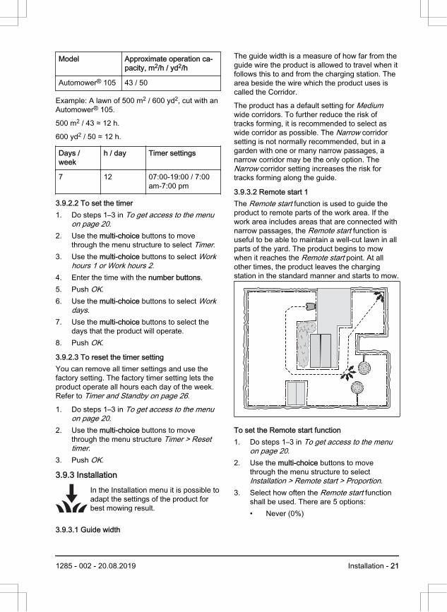
3.9.3.1 Guide width
The guide width is a measure of how far from theguide wire the product is allowed to travel when itfollows this to and from the charging station. Thearea beside the wire which the product uses iscalled the Corridor.
The product has a default setting for Mediumwide corridors. To further reduce the risk oftracks forming, it is recommended to select aswide corridor as possible. The Narrow corridorsetting is not normally recommended, but in agarden with one or many narrow passages, anarrow corridor may be the only option. TheNarrow corridor setting increases the risk fortracks forming along the guide.
3.9.3.2 Remote start 1The Remote start function is used to guide theproduct to remote parts of the work area. If thework area includes areas that are connected withnarrow passages, the Remote start function isuseful to be able to maintain a well-cut lawn in allparts of the yard. The product begins to mowwhen it reaches the Remote start point. At allother times, the product leaves the chargingstation in the standard manner and starts to mow.
To set the Remote start function 1. Do steps 1–3 in To get access to the menu
on page 20.2. Use the multi-choice buttons to move
through the menu structure to selectInstallation > Remote start > Proportion.
3. Select how often the Remote start functionshall be used. There are 5 options:• Never (0%)
1285 - 002 - 20.08.2019 Installation - 21
• Rarely (approx. 20%)• Medium (approx. 50%)• Often (approx. 80%)• Always (100%)
4. Select the distance from the charging stationto the Remote start.
5. Push OK.
3.9.3.3 Remote start 2If the work area contains 2 remote areas, theguide wire should be installed so that it reachesboth areas. Remote start 1 and Remote start 2can then be combined to steer the product toeach area.
The settings for Proportion and Distance arecarried out in the same way as for Remote start1. The factory setting is Never.
Note: The sum of Proportion for Remote start 1and Remote start 2 cannot exceed 100%.
If you have for instance selected Often forRemote start 1, then you can only select Never orRarely for Remote start 2.
To measure the distance from the chargingstation1. Put the product in the charging station.2. Do steps 1–3 in To get access to the menu
on page 20.3. Use the multi-choice buttons to move
through the menu structure Installation >Remote start 1 or Remote start 2 >Distance.
4. Use the number buttons to set 100 m as adistance.
5. Push OK.6. Use the multi-choice buttons to move
through the menu structure Installation >Test settings > Test OUT.
7. Push OK.8. Push the STOP button when the product is
at the distance you select to measure. Thedistance shows in the display.
3.9.3.4 Test settingsIn the Test settings menu, it is possible to testhow the settings for Remote start 1 and Remotestart 2 work in the work area in question.
To do a test of the Remote start function1. Put the product in the charging station.2. Do steps 1-3 in To get access to the menu
on page 20.3. Use the multi-choice buttons to move
through the menu structure Installation >Test settings > Test OUT > Remote start 1or Remote start 2.
4. Push OK.5. Push the START button.6. Close the hatch.7. Make sure the product can find the area.
3.9.3.5 To set the Drive Past Wire functionThe front of the product always moves past theboundary wire by a specified distance before theproduct moves back into the work area. Thefactory setting is 25 cm. You can select adistance of 20-30 cm.
1. Do steps 1–3 in To get access to the menuon page 20.
2. Use the multi-choice buttons to movethrough the menu structure Installation >Drive Past Wire.
3. Use the number buttons to set the distancein cm.
4. Push the BACK button.
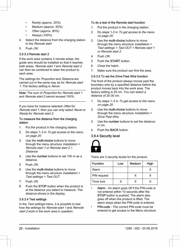
3.9.4 Security level
There are 3 security levels for the product.
Function Low Medium High
Alarm X
PIN request X X
Time lock X X X
• Alarm - An alarm goes off if the PIN-code isnot entered within 10 seconds after theSTOP button is pushed. The alarm alsogoes off when the product is lifted. Thealarm stops when the PIN-code is entered.
• PIN-code - The correct PIN-code must beentered to get access to the Menu structure
22 - Installation 1285 - 002 - 20.08.2019

of the product. If the incorrect PIN-code isentered 5 times, the product is locked forsome time. The lock is extended for eachnew incorrect try.
• Time lock - The product is locked if the PIN-code has not been entered in 30 days. Enterthe PIN-code to get access to the product.
3.9.4.1 To change the PIN code1. Do steps 1–3 in To get access to the menu
on page 20.2. Use the multi-choice buttons to move
through the menu structure Security >Change PIN code.
3. Enter the new PIN code.4. Push OK.5. Enter the new PIN code.6. Push OK.7. Make a note of the new PIN code. Refer to
Introduction on page 3.
3.9.4.2 To set the security levelSelect 1 of 3 security levels for your product.
1. Do steps 1–3 in To get access to the menuon page 20.
2. Use the multi-choice buttons to movethrough the menu structure Security >Security level.
3. Use the multi-choice buttons to select thelevel of security.
4. Push OK.
3.9.4.3 To create a New loop signalThe loop signal is randomly selected to create aunique link between the product and the chargingstation. In rare cases, there may be a need togenerate a new signal, for instance if twoadjacent installations have a very similar signal.
1. Place the product in the charging station.2. Do steps 1–3 in To get access to the menu
on page 20.3. Use the multi-choice buttons to move
through the menu structure Security > Newloop signal.
4. Push OK and await confirmation that theloop signal has been generated. Thisnormally takes about 10 seconds.
3.9.5 Settings
In settings you can change the general settingsto your product.
3.9.5.1 ECO modeECO mode stops the signal in the boundary loop,the guide wire and the charging station, when theproduct is parked or is charging.
Note: Use ECO mode to save energy and avoidinterference with other equipment, for examplehearing loops or garage doors.
Note: Push the STOP button before you removethe product from the charging station. If not, theproduct can not be started in the work area.
To set the ECO mode1. Do steps 1–3 in To get access to the menu
on page 20.2. Use the multi-choice buttons to move
through the menu structure Settings > ECOmode.
3. Push OK.
3.9.5.2 To set the Time & Date1. Do steps 1–3 in To get access to the menu
on page 20.2. Use the multi-choice buttons to move
through the menu structure Settings > Time& Date.
3. Use the number buttons to set the time andthen push OK.
4. Use the number buttons to set the date andthen push OK.
5. Use the multi-choice buttons to set the timeformat and then push OK.
6. Use the multi-choice buttons to set the dateformat and then push OK.
3.9.5.3 To set the language1. Do steps 1–3 in To get access to the menu
on page 20.
1285 - 002 - 20.08.2019 Installation - 23
2. Use the multi-choice buttons to movethrough the menu structure Settings >Language.
3. Use the multi-choice buttons to selectlanguage and then push OK.
3.9.5.4 To set the country1. Do steps 1–3 in To get access to the menu
on page 20.2. Use the multi-choice buttons to move
through the menu structure Settings >Country.
3. Use the multi-choice buttons to selectcountry and then push OK.
3.9.5.5 To reset all user settings1. Do steps 1–3 in To get access to the menu
on page 20.2. Use the multi-choice buttons to move
through the menu structure Settings > Resetuser settings.
3. Use the multi-choice buttons to selectcountry and then push OK.
4. Enter the PIN code.5. Push OK to reset all the user settings.
Note: Security level, PIN code, Loop signal,Messages, Date & Time, Language and Countrysettings are not reset.
3.9.5.6 The About menuThe About menu displays information about theproduct, for example serial number and firmwareversions.
24 - Installation 1285 - 002 - 20.08.2019
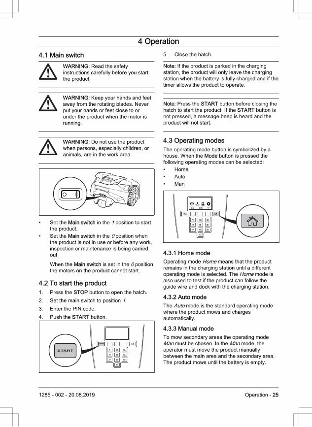
4 Operation4.1 Main switch
WARNING: Read the safetyinstructions carefully before you startthe product.
WARNING: Keep your hands and feetaway from the rotating blades. Neverput your hands or feet close to orunder the product when the motor isrunning.
WARNING: Do not use the productwhen persons, especially children, oranimals, are in the work area.
• Set the Main switch in the 1 position to startthe product.
• Set the Main switch in the 0 position whenthe product is not in use or before any work,inspection or maintenance is being carriedout.
When the Main switch is set in the 0 positionthe motors on the product cannot start.
4.2 To start the product1. Press the STOP button to open the hatch.2. Set the main switch to position 1.3. Enter the PIN code.4. Push the START button.
5. Close the hatch.
Note: If the product is parked in the chargingstation, the product will only leave the chargingstation when the battery is fully charged and if thetimer allows the product to operate.
Note: Press the START button before closing thehatch to start the product. If the START button isnot pressed, a message beep is heard and theproduct will not start.
4.3 Operating modesThe operating mode button is symbolized by ahouse. When the Mode button is pressed thefollowing operating modes can be selected:• Home• Auto• Man
4.3.1 Home modeOperating mode Home means that the productremains in the charging station until a differentoperating mode is selected. The Home mode isalso used to test if the product can follow theguide wire and dock with the charging station.
4.3.2 Auto modeThe Auto mode is the standard operating modewhere the product mows and chargesautomatically.
4.3.3 Manual modeTo mow secondary areas the operating modeMan must be chosen. In the Man mode, theoperator must move the product manuallybetween the main area and the secondary area.The product mows until the battery is empty.
1285 - 002 - 20.08.2019 Operation - 25
When the battery is empty, the product stops andthe message Needs manual charging shows inthe product display. Put the product in thecharging station to charge the battery. When thebattery is charged, the product moves out of thecharging station and stops. The product is nowprepared to start operation, but needsconfirmation from the operator first.Note: If you want to cut the main area after thebattery is charged, set the product to Auto modebefore placing it in the charging station.
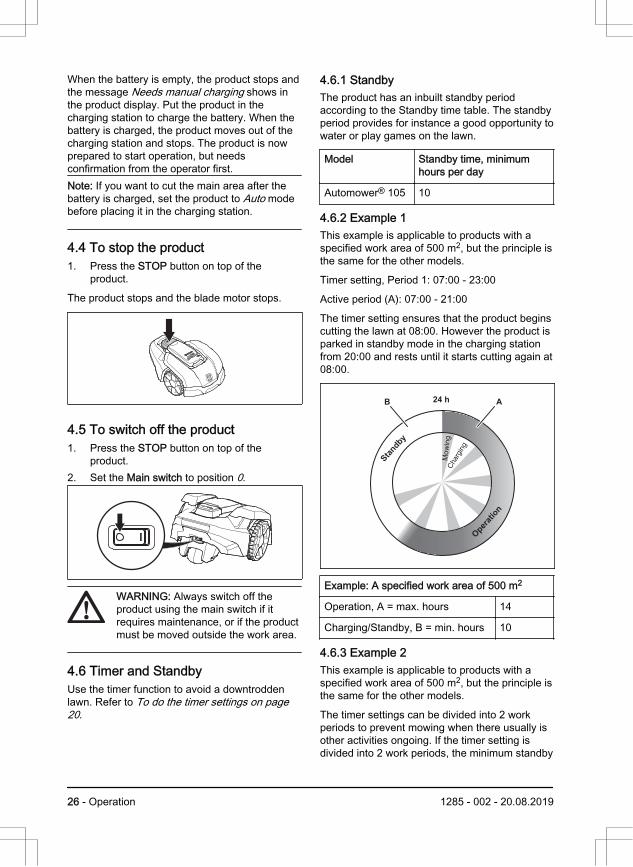
4.4 To stop the product1. Press the STOP button on top of the
product.
The product stops and the blade motor stops.
4.5 To switch off the product1. Press the STOP button on top of the
product.2. Set the Main switch to position 0.
WARNING: Always switch off theproduct using the main switch if itrequires maintenance, or if the productmust be moved outside the work area.
4.6 Timer and StandbyUse the timer function to avoid a downtroddenlawn. Refer to To do the timer settings on page20.
4.6.1 StandbyThe product has an inbuilt standby periodaccording to the Standby time table. The standbyperiod provides for instance a good opportunity towater or play games on the lawn.
Model Standby time, minimumhours per day
Automower® 105 10
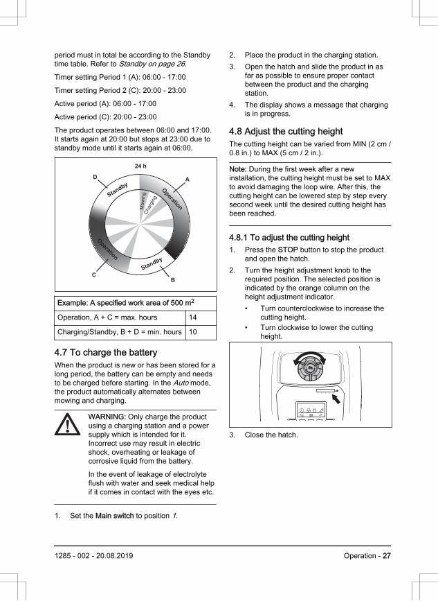
4.6.2 Example 1This example is applicable to products with aspecified work area of 500 m2, but the principle isthe same for the other models.
Timer setting, Period 1: 07:00 - 23:00
Active period (A): 07:00 - 21:00
The timer setting ensures that the product beginscutting the lawn at 08:00. However the product isparked in standby mode in the charging stationfrom 20:00 and rests until it starts cutting again at08:00.
24 h AB
Sta
ndby
Mowing
Charging
Ope
ratio
n
Example: A specified work area of 500 m2
Operation, A = max. hours 14
Charging/Standby, B = min. hours 10
4.6.3 Example 2This example is applicable to products with aspecified work area of 500 m2, but the principle isthe same for the other models.
The timer settings can be divided into 2 workperiods to prevent mowing when there usually isother activities ongoing. If the timer setting isdivided into 2 work periods, the minimum standby
26 - Operation 1285 - 002 - 20.08.2019
period must in total be according to the Standbytime table. Refer to Standby on page 26.
Timer setting Period 1 (A): 06:00 - 17:00
Timer setting Period 2 (C): 20:00 - 23:00
Active period (A): 06:00 - 17:00
Active period (C): 20:00 - 23:00
The product operates between 06:00 and 17:00.It starts again at 20:00 but stops at 23:00 due tostandby mode until it starts again at 06:00.
Mowing
ChargingStandby
Standby
Operation
Operation
24 h
AD
CB
Example: A specified work area of 500 m2
Operation, A + C = max. hours 14
Charging/Standby, B + D = min. hours 10
4.7 To charge the batteryWhen the product is new or has been stored for along period, the battery can be empty and needsto be charged before starting. In the Auto mode,the product automatically alternates betweenmowing and charging.
WARNING: Only charge the productusing a charging station and a powersupply which is intended for it.Incorrect use may result in electricshock, overheating or leakage ofcorrosive liquid from the battery.
In the event of leakage of electrolyteflush with water and seek medical helpif it comes in contact with the eyes etc.
1. Set the Main switch to position 1.
2. Place the product in the charging station.3. Open the hatch and slide the product in as
far as possible to ensure proper contactbetween the product and the chargingstation.
4. The display shows a message that chargingis in progress.
4.8 Adjust the cutting heightThe cutting height can be varied from MIN (2 cm /0.8 in.) to MAX (5 cm / 2 in.).
Note: During the first week after a newinstallation, the cutting height must be set to MAXto avoid damaging the loop wire. After this, thecutting height can be lowered step by step everysecond week until the desired cutting height hasbeen reached.
4.8.1 To adjust the cutting height1. Press the STOP button to stop the product
and open the hatch.2. Turn the height adjustment knob to the
required position. The selected position isindicated by the orange column on theheight adjustment indicator.• Turn counterclockwise to increase the
cutting height.• Turn clockwise to lower the cutting
height.
1 2 3 4 5
3. Close the hatch.
1285 - 002 - 20.08.2019 Operation - 27
5 Maintenance5.1 Introduction - maintenanceFor better operating reliability and longer servicelife: check and clean the product regularly andreplace worn parts if necessary. All maintenanceand servicing must be done according toinstructions from Husqvarna®. Refer to Warrantyterms on page 44.
When the product is first used, the blade disc andblades should be inspected once a week. If theamount of wear during this period has been low,the inspection interval can be increased.
It is important that the blade disc rotates easily.The edges of the blades should not be damaged.The lifetime of the blades varies immensely anddepends for instance on:
• Operating time and size of the work area.• Type of grass and seasonal growth.• Soil, sand and use of fertilizers.• The presence of objects such as cones,
windfalls, toys, tools, stones, roots and thelike.
The normal life is 4 to 7 weeks when used underfavorable conditions. Refer to To replace theblades on page 29 on how to replace theblades.
Note: Working with blunt blades gives a poorermowing result. The grass is not cut cleanly andmore energy is needed resulting in the productnot mowing such a large area.
WARNING: The product must beswitched off before any maintenance isdone.
WARNING: Wear protective gloves.
5.2 Clean the productIt is important to keep the product clean. Aproduct with large amounts of grass stuck to itwill not cope as well with slopes. It isrecommended to clean using a brush.
Husqvarna® offers a special cleaning andmaintenance kit as an accessory. Contact yourHusqvarna® central service.
CAUTION: Never use a high-pressurewasher or even running water to cleanthe product. Never use solvents forcleaning.
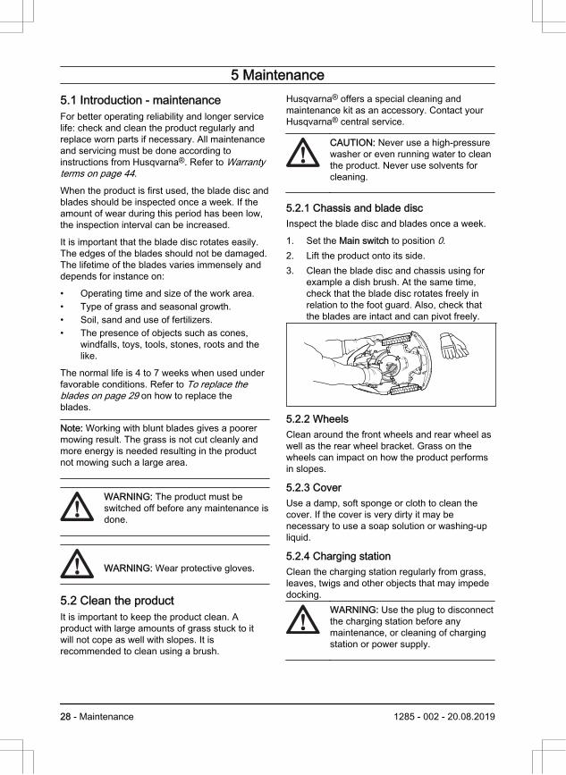
5.2.1 Chassis and blade discInspect the blade disc and blades once a week.
1. Set the Main switch to position 0.2. Lift the product onto its side.3. Clean the blade disc and chassis using for
example a dish brush. At the same time,check that the blade disc rotates freely inrelation to the foot guard. Also, check thatthe blades are intact and can pivot freely.
5.2.2 WheelsClean around the front wheels and rear wheel aswell as the rear wheel bracket. Grass on thewheels can impact on how the product performsin slopes.
5.2.3 CoverUse a damp, soft sponge or cloth to clean thecover. If the cover is very dirty it may benecessary to use a soap solution or washing-upliquid.
5.2.4 Charging stationClean the charging station regularly from grass,leaves, twigs and other objects that may impededocking.
WARNING: Use the plug to disconnectthe charging station before anymaintenance, or cleaning of chargingstation or power supply.
28 - Maintenance 1285 - 002 - 20.08.2019
5.3 Replace the bladesWARNING: Use blades and screws ofthe right type. Husqvarna® can onlyguarantee safety when using originalblades. Only replacing the blades andreusing the screw can result in a screwwearing during mowing. The bladescan then be propelled from under thebody and cause serious injury.
Replace worn or damaged parts for safetyreasons. Even if the blades are intact, theyshould be replaced on a regular basis for the bestmowing result and low energy usage. All 3 bladesand screws must be replaced at the same time toobtain a balanced cutting system. UseHusqvarna® original blades embossed with thecrowned H-mark logotype, refer to Warrantyterms on page 44.
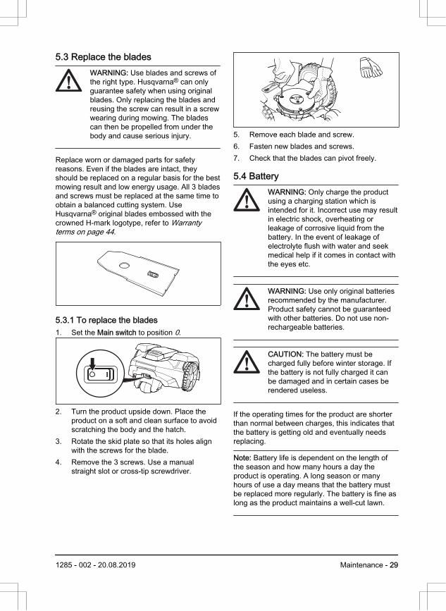
5.3.1 To replace the blades1. Set the Main switch to position 0.
2. Turn the product upside down. Place theproduct on a soft and clean surface to avoidscratching the body and the hatch.
3. Rotate the skid plate so that its holes alignwith the screws for the blade.
4. Remove the 3 screws. Use a manualstraight slot or cross-tip screwdriver.
5. Remove each blade and screw.6. Fasten new blades and screws.7. Check that the blades can pivot freely.
5.4 BatteryWARNING: Only charge the productusing a charging station which isintended for it. Incorrect use may resultin electric shock, overheating orleakage of corrosive liquid from thebattery. In the event of leakage ofelectrolyte flush with water and seekmedical help if it comes in contact withthe eyes etc.
WARNING: Use only original batteriesrecommended by the manufacturer.Product safety cannot be guaranteedwith other batteries. Do not use non-rechargeable batteries.
CAUTION: The battery must becharged fully before winter storage. Ifthe battery is not fully charged it canbe damaged and in certain cases berendered useless.
If the operating times for the product are shorterthan normal between charges, this indicates thatthe battery is getting old and eventually needsreplacing.
Note: Battery life is dependent on the length ofthe season and how many hours a day theproduct is operating. A long season or manyhours of use a day means that the battery mustbe replaced more regularly. The battery is fine aslong as the product maintains a well-cut lawn.
1285 - 002 - 20.08.2019 Maintenance - 29
5.5 Winter serviceTake your product to your local Husqvarna®representative for service prior to winter storage.Regular winter service will maintain the product ingood condition and create the best conditions fora new season without any disruptions.
Service usually includes the following:
• Thorough cleaning of the body, the chassis,the blade disc and all other moving parts.
• Testing of the products’s function andcomponents.
• Checking and, if required, replacing wearitems such as blades and bearings.
• Testing the products’s battery capacity aswell as a recommendation to replace batteryif necessary.
• If new firmware is available, the product isupdated.
30 - Maintenance 1285 - 002 - 20.08.2019
6 Troubleshooting
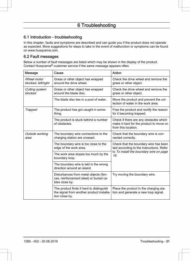
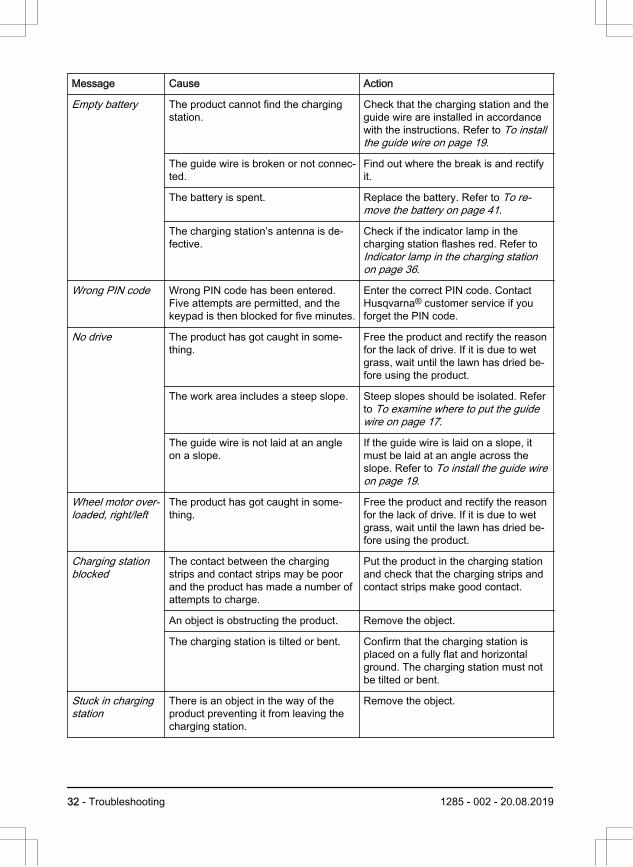
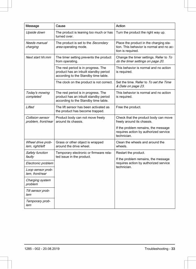
6.1 Introduction - troubleshootingIn this chapter, faults and symptoms are described and can guide you if the product does not operateas expected. More suggestions for steps to take in the event of malfunction or symptoms can be foundon www.husqvarna.com.
6.2 Fault messagesBelow a number of fault messages are listed which may be shown in the display of the product.Contact Husqvarna® customer service if the same message appears often.
Message Cause Action
Wheel motorblocked, left/right
Grass or other object has wrappedaround the drive wheel.
Check the drive wheel and remove thegrass or other object.
Cutting systemblocked
Grass or other object has wrappedaround the blade disc.
Check the drive wheel and remove thegrass or other object.
The blade disc lies in a pool of water. Move the product and prevent the col-lection of water in the work area.
Trapped The product has got caught in some-thing.
Free the product and rectify the reasonfor it becoming trapped.
The product is stuck behind a numberof obstacles.
Check if there are any obstacles whichmake it hard for the product to move onfrom this location.
Outside workingarea
The boundary wire connections to thecharging station are crossed.
Check that the boundary wire is con-nected correctly.
The boundary wire is too close to theedge of the work area.
Check that the boundary wire has beenlaid according to the instructions. Referto To install the boundary wire on page18.The work area slopes too much by the
boundary loop.
The boundary wire is laid in the wrongdirection around an island.
Disturbances from metal objects (fen-ces, reinforcement steel) or buried ca-bles close by.
Try moving the boundary wire.
The product finds it hard to distinguishthe signal from another product installa-tion close by.
Place the product in the charging sta-tion and generate a new loop signal.
1285 - 002 - 20.08.2019 Troubleshooting - 31
Message Cause Action
Empty battery The product cannot find the chargingstation.
Check that the charging station and theguide wire are installed in accordancewith the instructions. Refer to To installthe guide wire on page 19.
The guide wire is broken or not connec-ted.
Find out where the break is and rectifyit.
The battery is spent. Replace the battery. Refer to To re-move the battery on page 41.
The charging station’s antenna is de-fective.
Check if the indicator lamp in thecharging station flashes red. Refer to Indicator lamp in the charging stationon page 36.
Wrong PIN code Wrong PIN code has been entered.Five attempts are permitted, and thekeypad is then blocked for five minutes.
Enter the correct PIN code. ContactHusqvarna® customer service if youforget the PIN code.
No drive The product has got caught in some-thing.
Free the product and rectify the reasonfor the lack of drive. If it is due to wetgrass, wait until the lawn has dried be-fore using the product.
The work area includes a steep slope. Steep slopes should be isolated. Referto To examine where to put the guidewire on page 17.
The guide wire is not laid at an angleon a slope.
If the guide wire is laid on a slope, itmust be laid at an angle across theslope. Refer to To install the guide wireon page 19.
Wheel motor over-loaded, right/left
The product has got caught in some-thing.
Free the product and rectify the reasonfor the lack of drive. If it is due to wetgrass, wait until the lawn has dried be-fore using the product.
Charging stationblocked
The contact between the chargingstrips and contact strips may be poorand the product has made a number ofattempts to charge.
Put the product in the charging stationand check that the charging strips andcontact strips make good contact.
An object is obstructing the product. Remove the object.
The charging station is tilted or bent. Confirm that the charging station isplaced on a fully flat and horizontalground. The charging station must notbe tilted or bent.
Stuck in chargingstation
There is an object in the way of theproduct preventing it from leaving thecharging station.
Remove the object.
32 - Troubleshooting 1285 - 002 - 20.08.2019
Message Cause Action
Upside down The product is leaning too much or hasturned over.
Turn the product the right way up.
Needs manualcharging
The product is set to the Secondaryarea operating mode.
Place the product in the charging sta-tion. This behavior is normal and no ac-tion is required.
Next start hh:mm The timer setting prevents the productfrom operating.
Change the timer settings. Refer to Todo the timer settings on page 20.
The rest period is in progress. Theproduct has an inbuilt standby periodaccording to the Standby time table.
This behavior is normal and no actionis required.
The clock on the product is not correct. Set the time. Refer to To set the Time& Date on page 23.
Today's mowingcompleted
The rest period is in progress. Theproduct has an inbuilt standby periodaccording to the Standby time table.
This behavior is normal and no actionis required.
Lifted The lift sensor has been activated asthe product has become trapped.
Free the product.
Collision sensorproblem, front/rear
Product body can not move freelyaround its chassis.
Check that the product body can movefreely around its chassis.
If the problem remains, the messagerequires action by authorized servicetechnician.
Wheel drive prob-lem, right/left
Grass or other object is wrappedaround the drive wheel.
Clean the wheels and around thewheels.
Safety functionfaulty
Temporary electronic or firmware rela-ted issue in the product.
Restart the product.
If the problem remains, the messagerequires action by authorized servicetechnician.
Electronic problem
Loop sensor prob-lem, front/rear
Charging systemproblem
Tilt sensor prob-lem
Temporary prob-lem
1285 - 002 - 20.08.2019 Troubleshooting - 33

Message Cause Action
Temporary batteryproblem
Temporary battery or firmware relatedissue in the product.
Restart the product.
Disconnect and reconnect the battery.
If the problem remains, the messagerequires action by authorized servicetechnician.
Battery problem
Charging currenttoo high
Wrong or faulty power supply unit. Restart the product.
If the problem remains, the messagerequires action by authorized servicetechnician.
Message Cause Action
No loop signal The power supply is not connected. Check the wall socket connection andwhether an earth-fault breaker has trip-ped or not.
The low voltage cable is damaged ornot connected.
Check that the low voltage cable is notdamaged. Check that it is also properlyconnected to the charging station andto the power supply.
The boundary wire is not connected tothe charging station.
Check that the boundary wire connec-tors are fitted properly to the chargingstation. Replace connectors if dam-aged. Refer to To install the boundarywire on page 18.
Boundary wire broken. Find out where the break is. Replacethe damaged section of the loop with anew loop wire and splice using an origi-nal coupler. Refer to Find breaks in theloop wire on page 38.
ECO mode is activated and the producthas attempted to start outside thecharging station.
Place the product in the charging sta-tion and press the STOP button. Referto ECO mode on page 23.
The boundary wire is crossed on itsway to and from an island.
Check that the boundary wire is laid ac-cording to instructions, e.g. in the rightdirection around the island. Refer to Toinstall the boundary wire on page 18.
The connection between the productand the charging station has been bro-ken.
Place the product in the charging sta-tion and generate a new loop signal.
Disturbances from metal objects (fen-ces, reinforcement steel) or buried ca-bles close by.
Try moving the boundary wire.
34 - Troubleshooting 1285 - 002 - 20.08.2019
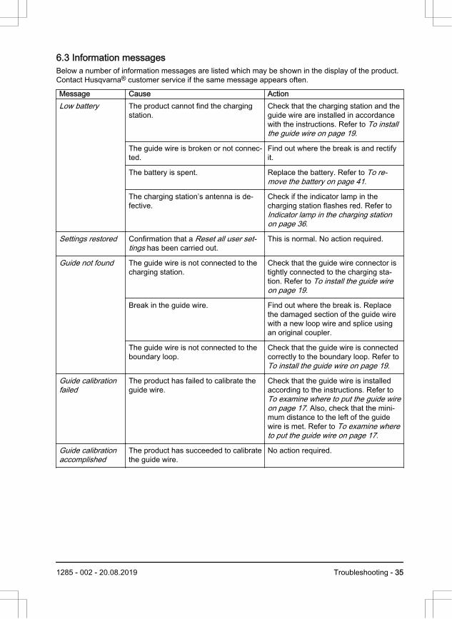
6.3 Information messagesBelow a number of information messages are listed which may be shown in the display of the product.Contact Husqvarna® customer service if the same message appears often.
Message Cause ActionLow battery The product cannot find the charging
station.Check that the charging station and theguide wire are installed in accordancewith the instructions. Refer to To installthe guide wire on page 19.
The guide wire is broken or not connec-ted.
Find out where the break is and rectifyit.
The battery is spent. Replace the battery. Refer to To re-move the battery on page 41.
The charging station’s antenna is de-fective.
Check if the indicator lamp in thecharging station flashes red. Refer to Indicator lamp in the charging stationon page 36.
Settings restored Confirmation that a Reset all user set-tings has been carried out.
This is normal. No action required.
Guide not found The guide wire is not connected to thecharging station.
Check that the guide wire connector istightly connected to the charging sta-tion. Refer to To install the guide wireon page 19.
Break in the guide wire. Find out where the break is. Replacethe damaged section of the guide wirewith a new loop wire and splice usingan original coupler.
The guide wire is not connected to theboundary loop.
Check that the guide wire is connectedcorrectly to the boundary loop. Refer to To install the guide wire on page 19.
Guide calibrationfailed
The product has failed to calibrate theguide wire.
Check that the guide wire is installedaccording to the instructions. Refer to To examine where to put the guide wireon page 17. Also, check that the mini-mum distance to the left of the guidewire is met. Refer to To examine whereto put the guide wire on page 17.
Guide calibrationaccomplished
The product has succeeded to calibratethe guide wire.
No action required.
1285 - 002 - 20.08.2019 Troubleshooting - 35
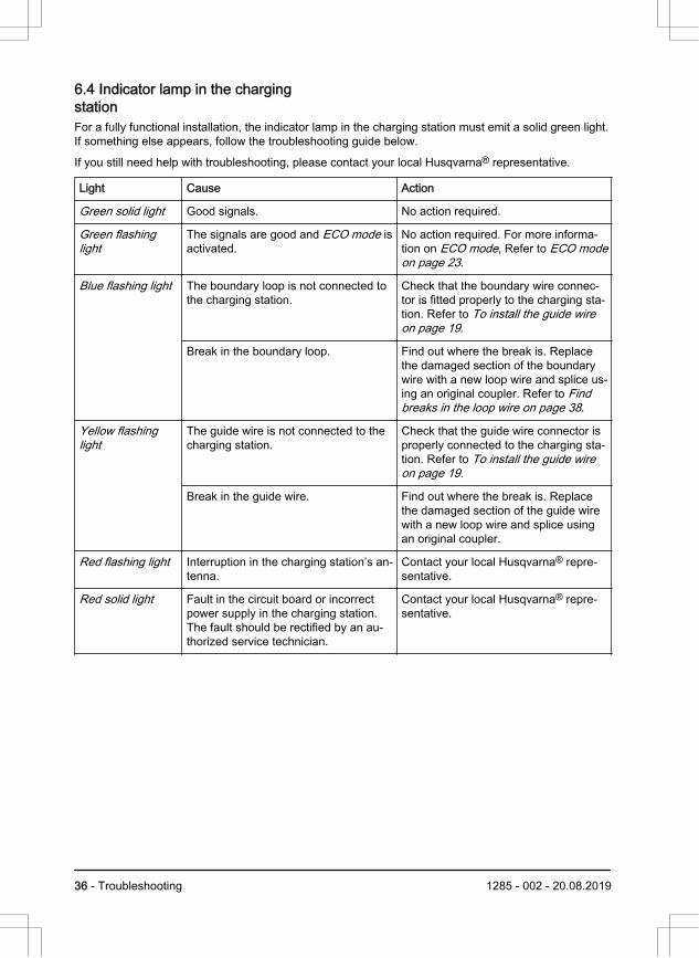
6.4 Indicator lamp in the chargingstationFor a fully functional installation, the indicator lamp in the charging station must emit a solid green light.If something else appears, follow the troubleshooting guide below.
If you still need help with troubleshooting, please contact your local Husqvarna® representative.
Light Cause Action
Green solid light Good signals. No action required.
Green flashinglight
The signals are good and ECO mode isactivated.
No action required. For more informa-tion on ECO mode, Refer to ECO modeon page 23.
Blue flashing light The boundary loop is not connected tothe charging station.
Check that the boundary wire connec-tor is fitted properly to the charging sta-tion. Refer to To install the guide wireon page 19.
Break in the boundary loop. Find out where the break is. Replacethe damaged section of the boundarywire with a new loop wire and splice us-ing an original coupler. Refer to Findbreaks in the loop wire on page 38.
Yellow flashinglight
The guide wire is not connected to thecharging station.
Check that the guide wire connector isproperly connected to the charging sta-tion. Refer to To install the guide wireon page 19.
Break in the guide wire. Find out where the break is. Replacethe damaged section of the guide wirewith a new loop wire and splice usingan original coupler.
Red flashing light Interruption in the charging station’s an-tenna.
Contact your local Husqvarna® repre-sentative.
Red solid light Fault in the circuit board or incorrectpower supply in the charging station.The fault should be rectified by an au-thorized service technician.
Contact your local Husqvarna® repre-sentative.
36 - Troubleshooting 1285 - 002 - 20.08.2019
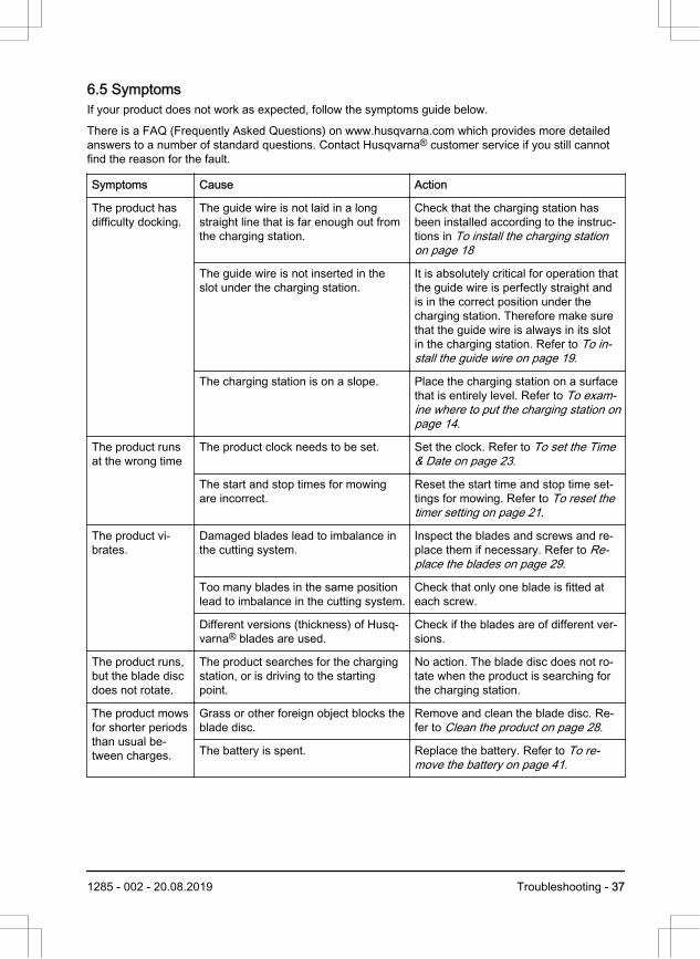
6.5 SymptomsIf your product does not work as expected, follow the symptoms guide below.
There is a FAQ (Frequently Asked Questions) on www.husqvarna.com which provides more detailedanswers to a number of standard questions. Contact Husqvarna® customer service if you still cannotfind the reason for the fault.
Symptoms Cause Action
The product hasdifficulty docking.
The guide wire is not laid in a longstraight line that is far enough out fromthe charging station.
Check that the charging station hasbeen installed according to the instruc-tions in To install the charging stationon page 18
The guide wire is not inserted in theslot under the charging station.
It is absolutely critical for operation thatthe guide wire is perfectly straight andis in the correct position under thecharging station. Therefore make surethat the guide wire is always in its slotin the charging station. Refer to To in-stall the guide wire on page 19.
The charging station is on a slope. Place the charging station on a surfacethat is entirely level. Refer to To exam-ine where to put the charging station onpage 14.
The product runsat the wrong time
The product clock needs to be set. Set the clock. Refer to To set the Time& Date on page 23.
The start and stop times for mowingare incorrect.
Reset the start time and stop time set-tings for mowing. Refer to To reset thetimer setting on page 21.
The product vi-brates.
Damaged blades lead to imbalance inthe cutting system.
Inspect the blades and screws and re-place them if necessary. Refer to Re-place the blades on page 29.
Too many blades in the same positionlead to imbalance in the cutting system.
Check that only one blade is fitted ateach screw.
Different versions (thickness) of Husq-varna® blades are used.
Check if the blades are of different ver-sions.
The product runs,but the blade discdoes not rotate.
The product searches for the chargingstation, or is driving to the startingpoint.
No action. The blade disc does not ro-tate when the product is searching forthe charging station.
The product mowsfor shorter periodsthan usual be-tween charges.
Grass or other foreign object blocks theblade disc.
Remove and clean the blade disc. Re-fer to Clean the product on page 28.
The battery is spent. Replace the battery. Refer to To re-move the battery on page 41.
1285 - 002 - 20.08.2019 Troubleshooting - 37
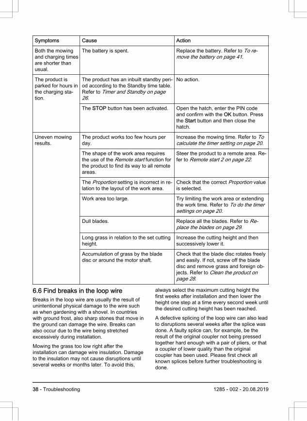
Symptoms Cause Action
Both the mowingand charging timesare shorter thanusual.
The battery is spent. Replace the battery. Refer to To re-move the battery on page 41.
The product isparked for hours inthe charging sta-tion.
The product has an inbuilt standby peri-od according to the Standby time table.Refer to Timer and Standby on page26.
No action.
The STOP button has been activated. Open the hatch, enter the PIN codeand confirm with the OK button. Pressthe Start button and then close thehatch.
Uneven mowingresults.
The product works too few hours perday.
Increase the mowing time. Refer to Tocalculate the timer setting on page 20.
The shape of the work area requiresthe use of the Remote start function forthe product to find its way to all remoteareas.
Steer the product to a remote area. Re-fer to Remote start 2 on page 22.
The Proportion setting is incorrect in re-lation to the layout of the work area.
Check that the correct Proportion valueis selected.
Work area too large. Try limiting the work area or extendingthe work time. Refer to To do the timersettings on page 20.
Dull blades. Replace all the blades. Refer to Re-place the blades on page 29.
Long grass in relation to the set cuttingheight.
Increase the cutting height and thensuccessively lower it.
Accumulation of grass by the bladedisc or around the motor shaft.
Check that the blade disc rotates freelyand easily. If not, screw off the bladedisc and remove grass and foreign ob-jects. Refer to Clean the product onpage 28.
6.6 Find breaks in the loop wireBreaks in the loop wire are usually the result ofunintentional physical damage to the wire suchas when gardening with a shovel. In countrieswith ground frost, also sharp stones that move inthe ground can damage the wire. Breaks canalso occur due to the wire being stretchedexcessively during installation.
Mowing the grass too low right after theinstallation can damage wire insulation. Damageto the insulation may not cause disruptions untilseveral weeks or months later. To avoid this,
always select the maximum cutting height thefirst weeks after installation and then lower theheight one step at a time every second week untilthe desired cutting height has been reached.
A defective splicing of the loop wire can also leadto disruptions several weeks after the splice wasdone. A faulty splice can, for example, be theresult of the original coupler not being pressedtogether hard enough with a pair of pliers, or thata coupler of lower quality than the originalcoupler has been used. Please first check allknown splices before further troubleshooting isdone.
38 - Troubleshooting 1285 - 002 - 20.08.2019
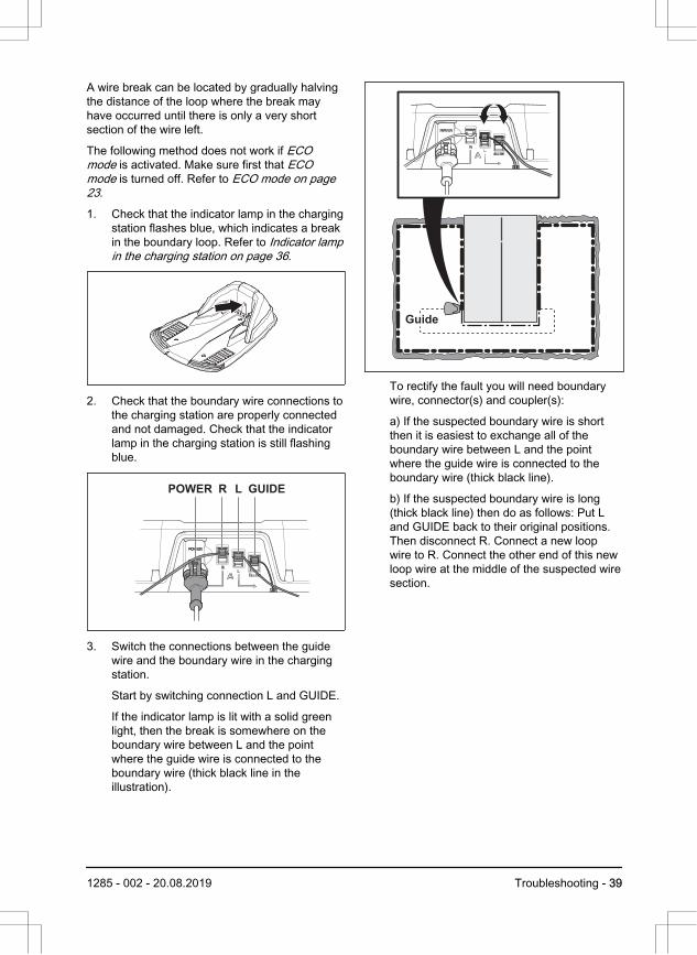
A wire break can be located by gradually halvingthe distance of the loop where the break mayhave occurred until there is only a very shortsection of the wire left.
The following method does not work if ECOmode is activated. Make sure first that ECOmode is turned off. Refer to ECO mode on page23.
1. Check that the indicator lamp in the chargingstation flashes blue, which indicates a breakin the boundary loop. Refer to Indicator lampin the charging station on page 36.
2. Check that the boundary wire connections tothe charging station are properly connectedand not damaged. Check that the indicatorlamp in the charging station is still flashingblue.
POWER R L GUIDE
3. Switch the connections between the guidewire and the boundary wire in the chargingstation.
Start by switching connection L and GUIDE.
If the indicator lamp is lit with a solid greenlight, then the break is somewhere on theboundary wire between L and the pointwhere the guide wire is connected to theboundary wire (thick black line in theillustration).
Guide
To rectify the fault you will need boundarywire, connector(s) and coupler(s):
a) If the suspected boundary wire is shortthen it is easiest to exchange all of theboundary wire between L and the pointwhere the guide wire is connected to theboundary wire (thick black line).
b) If the suspected boundary wire is long(thick black line) then do as follows: Put Land GUIDE back to their original positions.Then disconnect R. Connect a new loopwire to R. Connect the other end of this newloop wire at the middle of the suspected wiresection.
1285 - 002 - 20.08.2019 Troubleshooting - 39
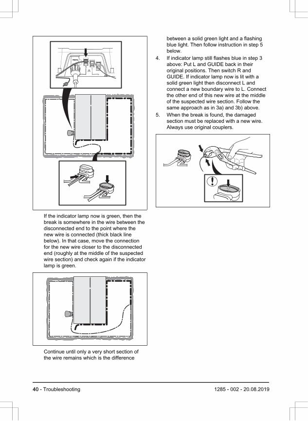
If the indicator lamp now is green, then thebreak is somewhere in the wire between thedisconnected end to the point where thenew wire is connected (thick black linebelow). In that case, move the connectionfor the new wire closer to the disconnectedend (roughly at the middle of the suspectedwire section) and check again if the indicatorlamp is green.
Continue until only a very short section ofthe wire remains which is the difference
between a solid green light and a flashingblue light. Then follow instruction in step 5below.
4. If indicator lamp still flashes blue in step 3above: Put L and GUIDE back in theiroriginal positions. Then switch R andGUIDE. If indicator lamp now is lit with asolid green light then disconnect L andconnect a new boundary wire to L. Connectthe other end of this new wire at the middleof the suspected wire section. Follow thesame approach as in 3a) and 3b) above.
5. When the break is found, the damagedsection must be replaced with a new wire.Always use original couplers.
40 - Troubleshooting 1285 - 002 - 20.08.2019
7 Transportation, storage and disposal7.1 TransportationThe supplied Li-ion batteries obey the DangerousGoods Legislation requirements.
• Obey all applicable national regulations.• Obey the special requirement on package
and labels for commercial transportations,including by third parties and forwardingagents.
7.2 Storage• Fully charge the product. Refer to To charge
the battery on page 27.• Switch off the product. Refer to To switch off
the product on page 26.• Clean the product. Refer to Clean the
product on page 28.• Keep the product in a dry, frost free space.• Keep the product with all wheels on level
ground during storage, or use an originalwall hanger if available.
• If you keep the charging station indoors,disconnect and remove the power supplyand all the connectors from the chargingstation. Put the end of each connector wirein a container with grease.
Note: If you keep the charging station outdoors,do not disconnect the power supply and theconnectors.
7.3 Disposal• Obey the local recycling requirements and
applicable regulations.• For questions about how to remove the
battery, refer to To remove the battery onpage 41.
7.3.1 To remove the batteryFollow these steps for removal of the battery fromthe product.
1. Set the Main switch in position 0.2. Set the cutting height to its lowest position.3. Turn the product upside down.4. Clean around the battery cover.
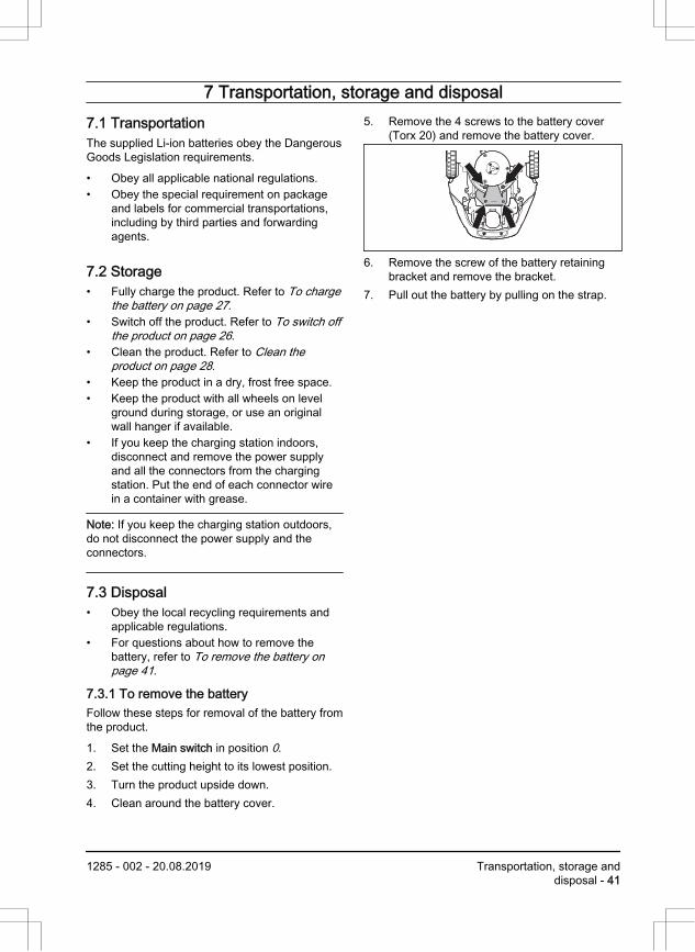
5. Remove the 4 screws to the battery cover(Torx 20) and remove the battery cover.
6. Remove the screw of the battery retainingbracket and remove the bracket.
7. Pull out the battery by pulling on the strap.
1285 - 002 - 20.08.2019 Transportation, storage anddisposal - 41
8 Technical data8.1 Technical dataDimensions Automower® 105
Length, cm / in 55 / 21.7
Width, cm / in 39 / 15.4
Height, cm / in 25 / 9.8
Weight, kg / lbs 6.9 / 15
Electrical system Automower® 105
Battery, Lithium-Ion 18 V/2.1 Ah Art.No 586 57 62-01, 586 57 62-02, 586 5762-04
Power supply, V/28 V DC 100-240
Low voltage cable length, m / ft 5 / 16.4
Mean energy consumption at maximum use 5 kWh/month in a 600 m2 / 0.15 yd2
work area
Charge current, A DC 1.3
Average mowing time, min 65
Average charging time, min 50
Boundary wire antenna Automower® 105
Operating Frequency Band, Hz 300-80000
Maximum Radio-frequency power, mW @60m 1 <25
Noise emissions measured in the environment as soundpower2
Automower® 105
Measured sound power noise level, dB (A) 58
Guaranteed sound power noise level, dB (A) 61
Sound pressure noise level at the operator’s ear, dB (A) 3 47
1 Maximum active output power to antennas in the frequency band in which the radio equipmentoperates.
2 Noise emissions in the environment measured as sound power (Lwa) in conformity with EC di-rective 2000/14/EC and New South Wales legislation (Protection of the Environment OperationsRegulation 2017, Noise Control). The guaranteed sound power level includes variation in pro-duction as well as variation from the test code with 1-3 dB(A). Noise emission data can be foundon the rating label and in the Technical data chapter.
3 Sound pressure noise uncertainties KpA, 2-4 dB (A)
42 - Technical data 1285 - 002 - 20.08.2019
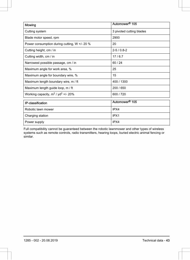
Mowing Automower® 105
Cutting system 3 pivoted cutting blades
Blade motor speed, rpm 2900
Power consumption during cutting, W +/- 20 % 20
Cutting height, cm / in 2-5 / 0.8-2
Cutting width, cm / in 17 / 6.7
Narrowest possible passage, cm / in 60 / 24
Maximum angle for work area, % 25
Maximum angle for boundary wire, % 15
Maximum length boundary wire, m / ft 400 / 1300
Maximum length guide loop, m / ft 200 / 650
Working capacity, m2 / yd2 +/- 20% 600 / 720
IP-classification Automower® 105
Robotic lawn mower IPX4
Charging station IPX1
Power supply IPX4
Full compatibility cannot be guaranteed between the robotic lawnmower and other types of wirelesssystems such as remote controls, radio transmitters, hearing loops, buried electric animal fencing orsimilar.
1285 - 002 - 20.08.2019 Technical data - 43
9 Warranty9.1 Warranty termsHusqvarna® warranty covers this product'sfunctionality for a period of 2 years from date ofpurchase. The warranty covers serious faultsrelating to materials or manufacturing faults.Within the warranty period, we will replace theproduct or repair it at no charge if the followingterms are met:
• The product and the charging station mayonly be used in compliance with theinstructions in this Operator’s Manual. Thismanufacturer's warranty does not affectwarranty entitlements against the dealer/retailer.
• End-users or non-authorized third partiesmust not attempt to repair the product.
Examples of faults which are not included in thewarranty:
• Damage caused by water seepage fromusing a high-pressure washer, or from beingsubmerged under water, for example whenheavy rain forms pools of water.
• Damage caused by lightning.• Damage caused by improper battery storage
or battery handling.• Damage caused by using a battery that is
not a Husqvarna® original battery.• Damage caused by not using Husqvarna®
original spare parts and accessories, suchas blades and installation material.
• Damage to the loop wire.• Damage caused by non-authorized
changing or tampering with the product or itspower supply.
The blades and wheels are seen as disposableand are not covered by the warranty.
If an error occurs with your Husqvarna® product,please contact Husqvarna® customer service forfurther instructions. Please have the receipt andthe product’s serial number at hand whencontacting Husqvarna® customer service.
44 - Warranty 1285 - 002 - 20.08.2019
10 EC Declaration of Conformity10.1 EC Declaration of ConformityHusqvarna AB, SE-561 82 Huskvarna, Sweden,tel: +46-36-146500, declares that the roboticlawn mowers Husqvarna Automower® 105 withserial numbers dating 2018 week 44 andonwards (the year and week is clearly stated onthe rating plate, followed by the serial number),comply with the requirements of the COUNCIL’SDIRECTIVE:
• Directive “relating to machinery”2006/42/EC.• Particular requirements for robotic
battery powered electrical lawnmowersEN 50636-2-107: 2015
• Electromagnetic fields EN 62233: 2008.• Directive on ”restriction of use of certain
hazardous substances” 2011/65/EU.• The following standard is applied: EN
50581:2012• Directive “relating to noise emissions from
outdoor equipment” 2000/14/EC. See also Technical data on page 42 for informationregarding noise emissions and the cuttingwidth.
The notified body 0404, SMP SvenskMaskinprovning AB, Fyrisborgsgatan 3,SE-754 50 Uppsala, Sweden, has issued areport regarding the assessment ofconformity according to annex VI to theCouncil’s Directive of May 8, 2000 “relatingto noise emissions into the environment”2000/14/EC. The certificate is numbered:01/901/163 for Husqvarna Automower® 105. for .
• Directive “relating to radio equipment”2014/53/EU. Type examination certificate isissued for examination to Directive2014/53/EU. Type examination certificatenumber for Husqvarna Automower® 105 isSC1110-17. The following standards havebeen applied:• ETSI EN 303 447 V1.1.1
Electromagnetic compatibility: • ETSI EN 301 489-1 v 2.2.0
Huskvarna, 2019-01-01
Lars Roos
Global R&D Director, Robotic category
(Authorized representative for Husqvarna AB andresponsible for technical documentation.)
1285 - 002 - 20.08.2019 EC Declaration of Conformity- 45

46 - EC Declaration of Conformity 1285 - 002 - 20.08.2019

1285 - 002 - 20.08.2019 EC Declaration of Conformity- 47
www.husqvarna.com
AUTOMOWER® is a trademark owned by Husqvarna AB.
Copyright© 2019 HUSQVARNA. All rights reserved.
Original instructions
1141861-26
2019-09-05