human head-neck system: the effect of viscoelastic neck on the eigenfrequency spectrum
TRANSCRIPT

Human Head-Neck system: The effect of viscoelastic neckon the eigenfrequency spectrum
A. Charalambopoulos, D. I. Fotiadis, C. V. Massalas
Summary The present study is concerned with determining the dynamic characteristics of thehuman head-neck system which is described as a ¯uid-®lled spherical cavity supported by aviscoelastic neck reacting in three dimensions. The material of the skull is assumed to be ahomogeneous, isotropic, elastic material, and that of the brain-cerebrospinal ¯uid as an in-viscid irrotational ¯uid. The neck is approximated by a three-element viscoelastic model, theconstants of which are computed by using experimental data. The obtained results show thatthe viscoelastic properties of the neck affect only the ®rst two eigenfrequencies and the cor-responding damping coef®cients, while the remaining spectrum remains unchanged.
Key words Human head-neck system, dynamic characteristics, viscoelasticity
1IntroductionIn a previous communication [1] we presented a model of the human head-neck system inwhich the neck was approximated by elastic strings acting in three dimensions. It was un-derstood that the neck support plays an important role in the eigenfrequency spectrum of thesystem: it introduces a shift of the spectrum and censes two new eigenfrequencies which are thelowest ones in the system. A comprehensive investigation of the resonance frequencies ofthe human skull in vivo, including measurements of the system frequencies as well as dampingcoef®cients was presented in [2]. Recently developed models take into account the viscoelasticbehavior of the human skull and brain [3±4], using properties reported previously by otherresearchers [5±6]. We obtained good agreement with the experimentally reported eigenfre-quencies, but observed discrepancies between our results and those reported for dampingcoef®cients in [2]. One of the reasons might be ignoring viscoelastic behavior of the neck.
An analytical and experimental study involving non-destructive, axisymmetric impact on a¯uid-®lled skull constrained by a viscoelastic, arti®cial neck is presented in [7]. The constantsof the proposed viscoelastic model were determined by least squares ®tting of data. A study ofthe head-neck system with a viscoelastic neck support is found in [8]. The authors consideredan elastic, homogeneous and isotropic skull, while the brain was regarded as an inviscid andcompressible ¯uid with irrotational motion. The arti®cial neck was represented analytically bya linear viscoelastic cantilever beam rigidly connected to the skull.
Archive of Applied Mechanics 70 (2000) 307±322 Ó Springer-Verlag 2000
307
Received 18 December 1997; accepted for publication 23 April 1998
A. CharalambopoulosPolytechnic School, Mathematics Division, Aristotle University ofThessaloniki, GR-540 06 Thessaloniki, Greece
D. I. FotiadisDept. of Computer Science, Univ. of Ioannina,GR-45110 Ioannina, Greece
C. V. MassalasDept. of Mathematics, Univ. of Ioannina,GR-45110 Ioannina, Greece
The present work forms a part of the project ``New Systems forEarly Medical Diagnosis and Biotechnological Applications'',which is supported by the Greek General Secretariat for Researchand Technology through the EU-funded R & D Program EPET II.

Because of the importance of the system motion at head injury there were other modelsproposed for the same system. Finite element techniques were used in [9] to investigate theresponses of spherical and plane strain head models, giving particular emphasis on thedetermination of ¯uid pressure distribution and skull de¯ections. The dynamic response of a¯uid - ®lled spherical shell was analysed using ®nite differences [10]. The human headresponse to impact loading was showed in [11] on three axisymmetric head model con®g-urations using ®nite elements. A mathematical model using three-dimensional equations oflinear viscoelasticity for the brain and the skull to predict the response of a human head toaxisymmetric impact was developed in [12]. In [13], a two-dimensional model was developedto predict the motion and upper torso accelerations under impact loading. Later, the modelwas in [14] extended to a three-dimensional one. However, to our knowledge, no otherattempt has been reported on the predictions of the frequency characteristics of the humanhead-neck system. These dynamic characteristics are useful in determining brain diseasesthrough a semi-interference method, which is based on the shifting of the eigenfrequencyspectrum. The process is related to the intracranial pressure±volume relationship attributedto Lang®tt et al. [5]. Such a method can be proved operative if, according to experimentalobservations, sudden changes in intracranial pressure have a measurable relative effect on thefrequencies spectrum with or without the use of a protective helmet, the latter being dis-cussed in [16].
In this work, we perform an analysis of the frequency spectrum of the human head-necksystem. The human skull is simulated by a linear, isotropic, homogeneous, elastic material. Thebrain is assumed to be an inviscid irrotational incompressible ¯uid undergoing small oscilla-tions, since we have observed that the effect of viscoelasticity is small for resonance frequencies[4]. The cerebrospinal ¯uid is treated in the same way. Finally, the neck support is approxi-mated by a three element model which reacts in three dimensions. The mathematical model isbased on the three-dimensional theory of elasticity and the representation of the displacement®elds in terms of the Navier eigenvectors [17]. The coef®cients involved in the three-elementelastic model for the neck support are determined by the existing experimental data.
These coef®cients are used for the computations of the eigenfrequency spectrum. In addi-tion, a model for the neck is described and the spectrum is computed for several parametersinvolved in the model. The results obtained show a good agreement with experimental databoth for the eigenfrequency and damping coef®cients. However, it is not possible to predict the®rst eigenfrequency. Further study including characteristics not described by our model mightgive a better insight of the ®rst eigenfrequency behavior.
2Problem formulationThe system under consideration is presented in Fig. 1. It consists of an elastic sphere (region 1±skull) containing an inviscid and irrotational ¯uid material (region 0 ± brain/cerebrospinal¯uid) and supported by the viscoelastic neck, whose simulation in the model is realisedthrough a particular type of boundary conditions imposed on S1 re¯ecting the geometric as wellas the physical characteristics of the neck support mechanism.
r1
r0
θ0θ0
1
0
S1
S0
V0
0
εu
(1)=
(1)= (1)
Tu
TuS’1
Fig. 1. Problem geometry
308

The aim of this work is the determination of the dynamic characteristics of the above system,that is its natural frequencies and the corresponding attenuation coef®cients due to the vis-coelastic character of the neck.
The material of region 1 is characterised by LameÁ's constants k and l and the mass densityq1. Its motion is described by the displacement ®eld u�1��r; t�, which satis®es the elasticityequation
lr2u�1��r; t� � �k� l�r�r � u�1��r; t�� � q1
o2u�1��r; t�ot2
; �1�
where r is the gradient operator
r � roor� h
1
r
ooh� u
1
r sin hoou
;
r; h; u denote the unit vectors in r, h, u direction, respectively, and t is the time. The sphericalcoordinate system is shown in Fig. 2.
The motion of region 0 is studied under the assumption that the inviscid and irrotational¯uid occupying this region undergoes small oscillations. Then its motion is governed by thewave equation
r2U�r; t� � 1
c2f
o2U�r; t�ot2
; �2�
where U�r; t� is the velocity potential de®ned by
u�1��r; t� � ÿrU�r; t� ;and cf is the speed of sound in the ¯uid.
The pressure P of the ¯uid can be determined from the velocity potential through therelation
P � ÿqf
oUot
� �; �3�
where qf stands for the mass density of the ¯uid.The neck support mechanism creates attenuation due to its viscous properties. Conse-
quently, we assume harmonic motion of the whole system with angular frequency x1 andattenuation x2.
We apply the Fourier transform analysis to the problem, de®ning
x
y
z
r
θ
θ
ϕ
ˆ
ˆ
r
ϕ
Fig. 2. Spherical polar coordinate system
309

u�1��r;x� �Z �1ÿ1
u�1��r; t�e�ixt dt ; �4�
U0�r;x� �Z �1ÿ1
U�r; t�e�ixt dt ; �5�
P�r;x� �Z �1ÿ1
P�r; t�e�ixt dt ; �6�
with x � x1 � ix2 �i �������ÿ1p �.
For simplicity, we suppress the dependence of previously transformed functions on theirargument x.
Taking advantage of the Fourier transform properties, Eqs. (1), (2), (3) lead to the following
equations concerning functions u�1��r�; U�r�; P�r�:lr2u�1��r� � �k� l�r�r � u�1��r�� � q1x
2u�1��r� � 0 ; �7�
r2U�r� � k2f U�r� � 0 ; �8�
P�r� � ixqf U�r� ; �9�where kf � x=cf is the wave number, U � U0=``1'' is a nondimensionalized quantity and ``1''
has the dimension of U0 and measure unity.In order to study the dynamic properties of the system we introduce dimensionless vari-
ables.Evoking the velocities cp �
�������������������������k� 2l�=q1
p, cs �
����������l=q1
p, which describe the elastic medium 1
alternatively to the LameÁ's constants, we de®ne the following dimensionless quantities:
r0 � r
a; X � xa
cp�a � r1� ;
r0 � ar; c0s �cs
cp; c0p � 1; c0f �
cf
cp; k0f �
Xcf; q0f �
qf
q1
:
The differential equations (1) and (2) in dimensionless form are written as
c02s r0u�1��r0� � �c02p ÿ c02s �r0�r0 � u�1��r0�� � X2u�1��r0� � 0 ; �10�
r02U�r0� � k02f U�r0� � 0 : �11�
The pressure P in dimensionless form is given by
P�r0� � iXq0f1
c02sU�r0� : �12�
The velocity potential U�r0� is the fundamental quantity in terms of which all quantitiescharacterising the motion of the ¯uid occupying region 0 can be expressed. We introduce herethe ¯uid velocity v�r0� and the displacement ®eld u�0��r0� in dimensionless form as follows:
v�r0� � r0U�r0� ; �13�u�0��r0� � i
Xv�r0� : �14�
The displacement ®elds u�0�, u�1� and the pressure P, in addition to Eqs. (10), (11), (12), (14),satisfy the boundary conditions expressing the interaction of the partial components of thesystem.
As far as the surface S0 is concerned, we have the continuity of the displacement ®elds, whilethe stress ®eld due to the elastic medium must be compensated by the pressure of the ¯uid, thatis
310

u�1��r0� � u�0��r0�; r0 2 S0 ; �15�T0 u�0��r0� � ÿP�r0�r; r0 2 S0 ; �16�
where
T0 � 2l0r � r0 � k0 r� �r0 � � � l0r� �r0�� ; �17�stands for the dimensionless surface stress operator on S0, r is the unit outward normal vectoron S0 and
�k0; l0� � kl; 1
� �:
The boundary conditions satis®ed by the elastic ®eld on the exterior surface S1 are of mixedtype. The surface section shown in Fig. 1 in the region 0 � # < pÿ h0 is stress free, while thesurface section pÿ h0 � # � p represents the neck support. The boundary condition satis®edthere must incorporate the physical character of the interaction between human head and neck.We assume that a Robin type boundary condition is satis®ed, which simulates appropriatelythe dynamic character of the motion of the contact region.
The boundary condition on surface S1 is described thus by
T0u�1��r0� � 0; 0 � # < pÿ h0; r0 2 �S1nS01�eu�1��r0�; pÿ h0 � # � p; r0 2 S01 ;
��18�
where e � e1 � ie2 is the complex stiffness incorporating the physical characteristics of thehuman neck. In contrast to our previous work [1], the parameter e has a non-zero imaginarypart due to the viscous properties of the neck. This term is responsible for the damping of thesystem. Although only this term carries on the viscoelastic behavior of the system, the treat-ment of the problem is affected drastically because of the assumption of complex eigenfre-quencies, fact leading, as it will be explained in what follow, to a much more dif®cult approach.
We note that the problem described by Eqs. (10), (11), (12) and boundary conditions (15),(16) and (18) constitutes a well ± posed boundary value problem.
3Problem solution: frequency equationAdopting the method applied in [1], we expand the elastic displacement ®eld u�1��r0� in termsof the Navier eigenvectors [17], the velocity potential U�r0� in terms of the Helmholtz equation
basis solutions, and ®nd expansions for u�0��r0� and P�r0� via their de®nition relations. Theprocedure leads to
u�1��r0� �X�1n�0
Xn
m�ÿn
X2
l�1
fam;ln Lm;l
n �r0� � bm;ln Mm;l
n �r0� � cm;ln Nm;l
n �r0�g ; �19�
U�r0� �X1n�0
Xn
m�ÿn
fcmn g1
n�k0f r0�Pmn �cos#�eimug ; �20�
u�0��r0� � iX�1n�0
Xn
m�ÿn
cmn Lm;l
n �r0� ; �21�
P�r0� � iXq0f1
c02s
X�1n�0
Xn
m�ÿn
fcmn g1
n�k0f r0�Pmn �cos#�eimug ; �22�
where g1n�z� and g2
n�z� represent the spherical Bessel functions of the ®rst, jn�z�, and secondkind, yn�z�, respectively. Functions Pm
n �cos#� are the Legendre functions and the productPm
n �cos #�eimu constitutes the spherical harmonic Ymn �r0�.
The Navier eigenvectors are given as
Lm;ln �r0� � _gl
n�k0pr0�Pmn �r� �
������������������n�n� 1�
p gln�k0pr0�k0pr0
Bmn �r� ; �23�
311
Mm;ln �r0� �
������������������n�n� 1�
pgl
n�k0sr0�Cmn �r0� ; �24�
Nm;ln �r0� � n�n� 1� gl
n�k0sr0�k0sr0
Pmn �r� �
������������������n�n� 1�
p_gl
n�k0sr0� �gl
n�k0sr0�k0sr0
� �Bm
n �r� ; �25�
where _gln�z� stands for the derivative of gl
n�z� with respect to its argument, and the functionsPm
n �r�, Bmn �r�, Cm
n �r� constitute the vector spherical harmonics given by
Pmn �r� � rYm
n �r� ; �26�
Bmn �r� �
1������������������n�n� 1�p 0
oo#� u
1
sin#
oou
� �Ym
n �r� ; �27�
Cmn �r� �
1������������������n�n� 1�p 0
1
sin uo
ouÿ u
oo#
� �Ym
n �r� ; �28�
where r, 0, u are the unit vectors in r, #, u directions, respectively,
k0p � Xc0p
and k0s � Xc0s
.
Forcing expansions (19), (21), (22) to satisfy boundary conditions (15), (16) and (18), andfollowing the procedure presented in [1], we ®nd that the involved coef®cients must satisfy thefollowing relations:X2
l�1
am0;ln0 Al
n0 �r00� � cm0;ln0 Dl
n0 �r00�h i
� ÿiXq0f1
c02scm0
n0 gln0 �k0f r00� ; �29�
X2
l�1
am0;ln0 Bl
n0 �r00� � cm0;ln0 El
n0 �r00�h i
� 0 ; �30�
X2
l�1
bm0;ln0 Cl
n0 �r00�h i
� 0 ; �31�
X2
l�1
am0;ln0 _gl
n0 �Xr00� � cm0;ln0 n0�n0 � 1� gl
n0 �k0sr00�k0sr00
� �� icm0
n0 _gln0 �k0f r00� ; �32�
X2
l�1
am0;ln0 Al
n0 �r01� � cm0;ln0 Dl
n0 �r01�h i
�X�1
n�jm0j
X2
l�1
am0;ln Al
n�r01� � cm0;ln D1
n�r01�h i
N�n0; n; h0;m0� ;
�33�X2
l�1
am0;ln0 Bl
n0 �r01� � cm0;ln0 El
n0 �r01�h i
�X�1
n�jm0j
X2
l�1
am0;ln Bl
n�r0l� � cm0;ln E1
n�r01�h i
N1�n0; n; h0;m0� ;
�34�X2
l�1
bm0;ln0 Cl
n0 �r01� �X�1
n�jm0j
X2
l�1
bm0;ln Cl
n�r01�N1�n0; n; h0;m0� ; �35�
where n0 � 0; 1; 2; . . . ; jm0j � n0 and
N�n0; n; h0;m0�
� e���pp Xn�n0
i � jn0 ÿ njiÿ n0 � n � even
�������2i�1p
2i
P�i=2�
k�0
�ÿ1�iÿk�1�2iÿ2k�!k!�iÿk�!�iÿ2k�1�!
��cos h0�iÿ2k�1 ÿ 1
���ÿ1�nÿi�m0 ���������������2n0 � 1
p n i n0
m0 0 ÿm0
� �8>>><>>>:
9>>>=>>>; �36�
312

N1�n0;n;h0;m0� � e
���pp Xn�n0
i� jn0 ÿnjiÿn0 �n� even
�������2i�1p
2i
P�i=2�
k�0
�ÿ1�iÿk�1�2iÿ2k�!k!�iÿk�!�iÿ2k�1�!
��cosh0�iÿ2k�1ÿ 1
�� 1
2
�������������n�n�1�
n0�n0�1�q
��������������n0�n0�1�n�n�1�
qÿ i�iÿ1������������������������
n�n�1�n0�n0�1�p
� ��ÿ1�nÿi�m0
� ��������������2n0 � 1p n i n0
m0 0 ÿm0
� �
8>>>>>>>><>>>>>>>>:
9>>>>>>>>=>>>>>>>>;�37�
with
n i n0
m0 0 ÿm0
� ��"�n� iÿ n0�!�nÿ i� n0�!�ÿn� i� n0�!
�n� i� n0 � 1�!
#1=2
� ��n�m0�!�nÿm�!�i!�2�n0 ÿm0�!�n0 �m0��1=2
�Xz2L
�ÿ1�z�n�i�m0
z!�n� i� n0 ÿ z�!�nÿm0 ÿ z�!�iÿ z�!�n0 ÿ i�m0 � z�!�n0 ÿ n� z�!
All the quantities A;B;C; . . . are given in Appendix A.The algebraic equations (29)±(35) consist of a linear system of the following form:
Dx � 0 ; �38�where
D �
Djm0j;jm0j Djm0j;jm0j�1 Djm0 j;jm0j�2 � � � � � �Djm0j�1;jm0j Djm0j�1;jm0 j�1 Djm0j�1;jm0j�2 � � � � � �Djm0j�2;jm0j Djm0j�2;jm0 j�1 Djm0j�2;jm0j�2 � � � � � �� � � � � � � � � � � � � � �� � � � � � � � � � � � � � �
266664377775 ; �39�
is a 7�n0 � 1� matrix, where n0 ensures convergence of the solution as it is described in Sec. 5below, and
x � am0;1jm0j ; a
m0;2jm0j ; . . . ; cm0;2
jm0j ;ÿicm0jm0j; . . . ;ÿicm0
jm0j�1; . . .h iT
:
Details about the matrix D are given in Appendix B.In order for the system (38) to have non trivial solutions, the frequency equation must be
satis®ed, that is
det D � 0 : �40�The solution of (40) provides the complex eigenfrequencies X � X1 � iX2 of the system underdiscussion. At this point, we note that the complex matrix D has elements constituted bycombinations of Bessel functions with the complex eigenfrequency X as an argument as well asthe complicated complex quantities N and N1. The numerical treatment of the matrix, as will bepresented in Sec. 5, requires the determination of the real and imaginary parts of the matrix. Toful®ll this requirement we introduce the real quantities N and N1, which are de®ned by theequations
N�n0; n; h0;m0� � e1N�n0; n; h0;m
0� � ie2N�n0; n; h0;m0�; �41�
N1�n0; n; h0;m0� � e1N1�n0; n; h0;m
0� � ie2N1�n0; n; h0;m0�: �42�
where quantities e1 and e2 will be sought for. The determination of the real and imaginary partsof the matrix is realised as follows: let us consider, for example, the (3, 1) element of matrixDk;k, which has the form
d3;1 � A1k�r01� ÿ A1
k�r01�N�k; k; h0;m0�:
313
By using the de®nition (41) we get
d3;1 � Re A1k�r01� ÿ e1Re A1
k�r01� ÿ e2Im A1k�r01�
� �N�k; k; h0;m
0�� � i Im A1k�r01�
�ÿ e1Im A1
k�r01� � e2Re A1k�r01�
� �N�k; k; h0;m
0�: �43�
However, we have separated the real from the imaginary part just formally. The determinationof ReA1
k�r01� and ImA1k�r01� requires some analytical manipulations as well as use of suitable
numerical schemes for the computation of the real and imaginary part of spherical Besselfunctions with complex argument. This procedure is repeated for every element of the trun-cated matrix D.
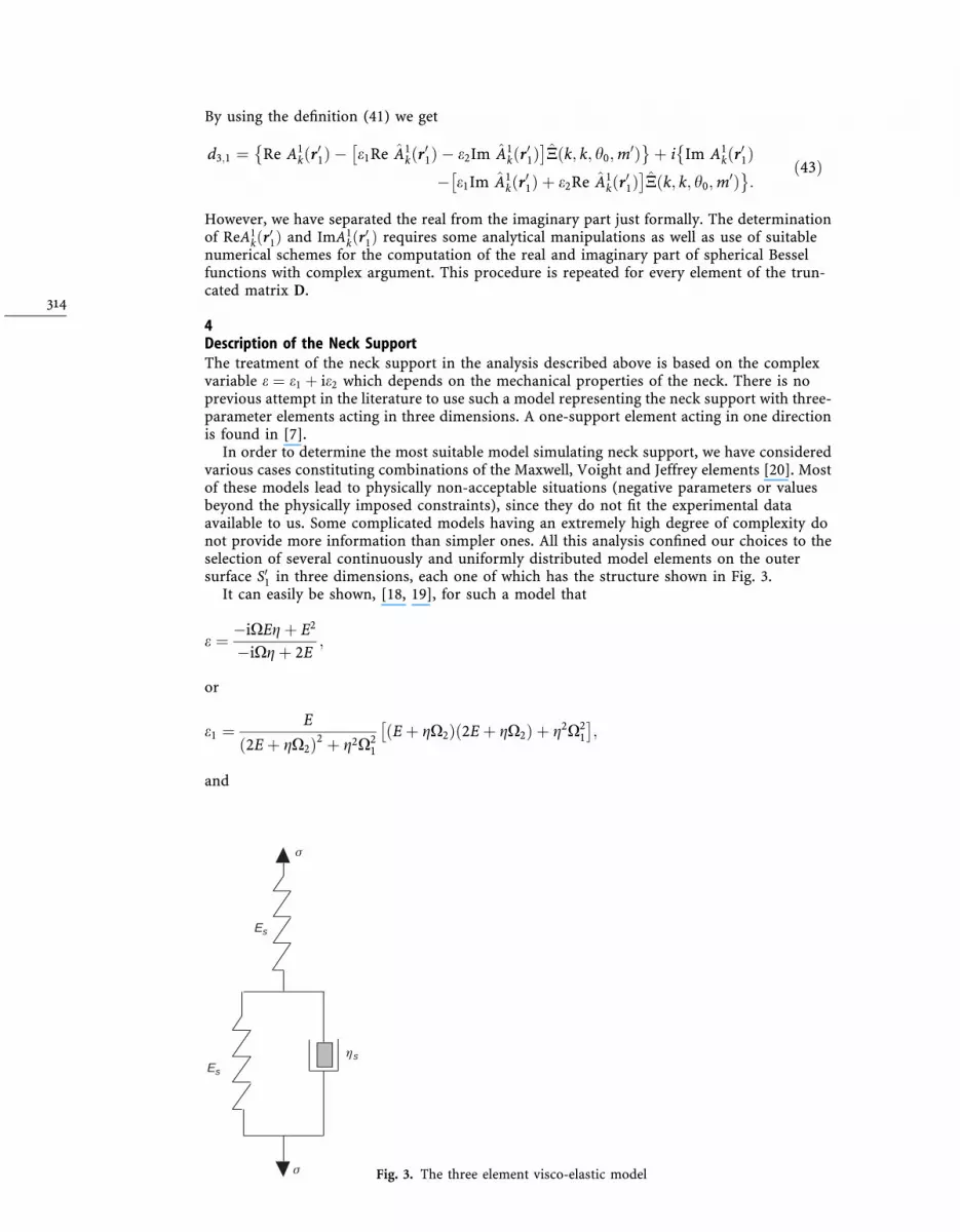
4Description of the Neck SupportThe treatment of the neck support in the analysis described above is based on the complexvariable e � e1 � ie2 which depends on the mechanical properties of the neck. There is noprevious attempt in the literature to use such a model representing the neck support with three-parameter elements acting in three dimensions. A one-support element acting in one directionis found in [7].
In order to determine the most suitable model simulating neck support, we have consideredvarious cases constituting combinations of the Maxwell, Voight and Jeffrey elements [20]. Mostof these models lead to physically non-acceptable situations (negative parameters or valuesbeyond the physically imposed constraints), since they do not ®t the experimental dataavailable to us. Some complicated models having an extremely high degree of complexity donot provide more information than simpler ones. All this analysis con®ned our choices to theselection of several continuously and uniformly distributed model elements on the outersurface S01 in three dimensions, each one of which has the structure shown in Fig. 3.
It can easily be shown, [18, 19], for such a model that
e � ÿiXEg� E2
ÿiXg� 2E;
or
e1 � E
�2E� gX2�2 � g2X21
�E� gX2��2E� gX2� � g2X21
� �;
and
Es
Es
ηs
σ
σ Fig. 3. The three element visco-elastic model
314

e2 � ÿ E
�2E� gX2�2 � g2X21
gX1E;
where E; g represent dimensionless parameters E � Es=l; g � gscp=la, and Es; gs the constantsof the model of Fig. 3.
The determination of the parameters E; g is based on the agreement between the values�X1; X2� obtained by using our model and those of the experimental measurements ofeigenfrequencies and damping coef®cients. One particular set of data is of interest, whoseparameters are given in Table 1 and concern the second fundamental eigenfrequency of thehuman head - neck system. The results obtained are shown graphically in Fig. 4. It is noticeablethat the estimated parameters E; g of our model adapting the experimental data concerning thesecond basic eigenfrequency lead to a model reconstructing higher eigenfrequencies in goodagreement with experiment. This is the ®rst necessary test for the acceptance of the speci®cparameter estimation.
5Numerical resultsThe properties used for skull, brain and cerebrospinal ¯uid are given in Ref. [1]. The geometryof the system is described by the following parameters:
Table 1. Parameters for the three-element visco elastic model obtained from the second eigenfrequencyexperimental data [2]
experiment [2] constants ®tted to data
x�2�1 (Hz) x�2�2 (Hz) E n
1082 49.2 0.071 2.761378 49.2 0.077 0.951378 127.9 0.116 4.551082 127.9 0.121 1.66average 0.100 2.48
Fig. 4. Model constants e1; e2 as a functionof X1;X2 for average pairs E, n shown inTable 1
315
Tab
le2.
Mo
del
con
verg
ence
ofX�k�
1,
k=
1,2,
¼,1
9
No
.n
¢=0
n¢=
1n
¢=2
n=
3n
=4
n=
5n
=6
n=
7n
=8
n=
9
10.
1417
40.
1473
00.
1455
10.
1462
60.
1459
20.
1460
80.
1460
10.
1460
40.
1460
22
0.34
332
0.36
101
0.35
504
0.35
756
0.35
648
0.35
691
0.35
677
0.35
680
0.35
680
30.
4156
80.
4201
30.
4183
40.
4189
90.
4188
10.
4188
40.
4188
40.
4180
44
0.51
837
0.51
896
0.51
837
0.51
885
0.51
852
0.51
871
0.51
861
50.
6257
00.
6272
20.
6267
70.
6269
40.
6268
80.
6269
06
0.73
425
0.73
611
0.73
525
0.73
568
0.73
548
70.
8650
10.
8653
20.
8651
50.
8652
68
1.04
509
1.04
579
1.04
548
91.
1828
11.
1828
11.
1827
81.
1828
31.
1827
81.
1828
31.
1827
91.
1828
110
1.19
711
1.19
823
1.19
780
1.19
802
1.19
791
1.19
795
1.19
795
1.19
797
1.19
797
111.
2523
31.
2526
712
1.50
691
131.
9080
81.
9086
71.
9083
91.
9084
61.
9084
31.
9084
41.
9084
414
2.23
668
2.23
668
2.23
667
2.23
668
2.23
667
2.23
669
2.23
668
2.23
668
152.
3338
62.
3338
92.
3338
92.
3338
72.
3339
02.
3338
82.
3338
92.
3338
82.
3338
92.
3338
916
2.54
067
2.54
081
2.54
071
2.54
078
2.54
074
2.54
076
173.
1668
93.
1669
43.
1669
13.
1669
33.
1669
218
3.24
163
3.24
162
3.24
131
3.24
131
3.24
131
3.24
131
3.24
131
3.24
131
3.24
131
193.
2593
63.
2594
63.
2594
23.
2594
43.
2594
33.
2594
33.
2594
3
316
Tab
le3.
Mo
del
con
verg
ence
ofX�k�
2,
k=
1,2,
¼,1
9
No
.n
¢=0
n¢=
1n
¢=2
n¢=
3n
¢=4
n¢=
5n
¢=6
n¢=
7n
¢=8
n¢=
9
10.
0172
40.
0187
40.
0183
80.
0185
10.
0184
60.
0184
80.
0184
70.
0184
70.
0184
72
0.01
987
0.02
205
0.02
142
0.02
167
0.02
157
0.02
161
0.02
160
0.02
160
0.02
160
30.
0014
50.
0023
10.
0020
40.
0021
00.
0021
00.
0020
90.
0020
90.
0021
04
0.00
021
0.00
017
0.00
023
0.00
017
0.00
021
0.00
019
0.00
020
50.
0007
50.
0009
50.
0009
10.
0009
20.
0009
20.
0009
26
0.00
050
0.00
069
0.00
061
0.00
065
0.00
063
70.
0001
00.
0001
20.
0001
10.
0001
28
0.00
041
0.00
047
0.00
044
90.
0006
30.
0006
30.
0006
40.
0006
30.
0006
40.
0006
30.
0006
40.
0006
310
0.00
133
0.00
141
0.00
138
0.00
139
0.00
139
0.00
139
0.00
139
0.00
139
0.00
139
110.
0015
00.
0001
712
0.00
014
130.
0004
00.
0004
20.
0004
10.
0004
20.
0004
20.
0004
20.
0004
214
0.00
009
0.00
009
0.00
009
0.00
009
0.00
009
0.00
009
0.00
009
0.00
009
150.
0000
70.
0000
70.
0000
70.
0000
70.
0000
70.
0000
70.
0000
70.
0000
70.
0000
70.
0000
716
0.00
007
0.00
007
0.00
007
0.00
007
0.00
007
0.00
007
170.
0000
50.
0000
60.
0000
60.
0000
60.
0000
518
0.00
000
0.00
000
0.00
001
0.00
001
0.00
001
0.00
001
0.00
001
0.00
001
0.00
001
190.
0001
20.
0001
20.
0001
20.
0001
20.
0001
20.
0001
20.
0001
2
317
r1 � 0:0854 m; r0 � 0:0794 m; h0 � p=8, that re¯ect average geometrical characteristics of theexperiments in Ref. [2].
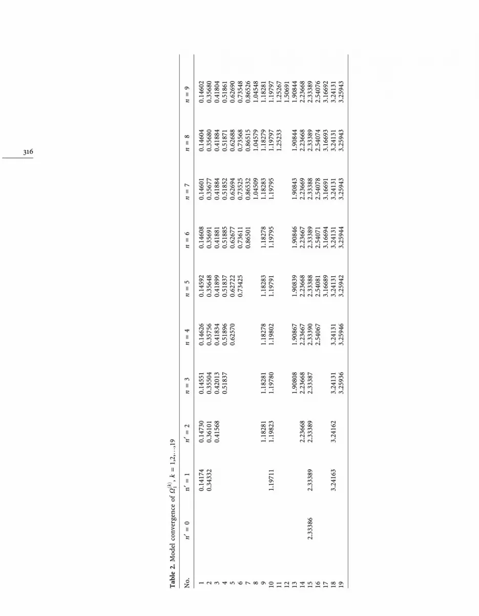
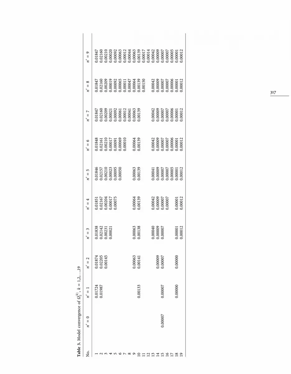
The numerical method used is similar to the one described in Ref. [4]. The dimension of thetruncated matrix depends on the appropriate selection of the value of n0 which ensures con-vergence of X�k� � X�k�1 � iX�k�2 ; k � 1; 2; 3; . . . ; 20. The computational results of X�k�1 and X�k�2are listed in Tables 2 and 3, respectively. The results obtained are shown as a function of n0 and,in what follows, we repeat the procedure until kX�k��e; h0; n
0� ÿ X�k��e; h0; n0 � 1�k � O�10ÿ4�;
k � 1; 2; . . . ; 20. As it is shown, we obtain convergence of the ®rst 11 eigenfrequencies forn0 � 1. Using higher values of n0 does not contribute to better predictions, although moreeigenfrequencies can be computed. It makes also the computations very extensive, since higherdimension matrices must be computed.
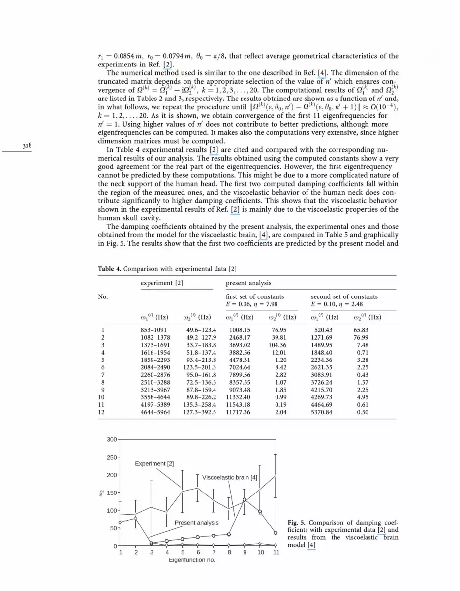
In Table 4 experimental results [2] are cited and compared with the corresponding nu-merical results of our analysis. The results obtained using the computed constants show a verygood agreement for the real part of the eigenfrequencies. However, the ®rst eigenfrequencycannot be predicted by these computations. This might be due to a more complicated nature ofthe neck support of the human head. The ®rst two computed damping coef®cients fall withinthe region of the measured ones, and the viscoelastic behavior of the human neck does con-tribute signi®cantly to higher damping coef®cients. This shows that the viscoelastic behaviorshown in the experimental results of Ref. [2] is mainly due to the viscoelastic properties of thehuman skull cavity.
The damping coef®cients obtained by the present analysis, the experimental ones and thoseobtained from the model for the viscoelastic brain, [4], are compared in Table 5 and graphicallyin Fig. 5. The results show that the ®rst two coef®cients are predicted by the present model and
Table 4. Comparison with experimental data [2]
experiment [2] present analysis
No. ®rst set of constantsE = 0.36, g = 7.98
second set of constantsE = 0.10, g = 2.48
x1(i) (Hz) x2
(i) (Hz) x1(i) (Hz) x2
(i) (Hz) x1(i) (Hz) x2
(i) (Hz)
1 853±1091 49.6±123.4 1008.15 76.95 520.43 65.832 1082±1378 49.2±127.9 2468.17 39.81 1271.69 76.993 1373±1691 33.7±183.8 3693.02 104.36 1489.95 7.484 1616±1954 51.8±137.4 3882.56 12.01 1848.40 0.715 1859±2293 93.4±213.8 4478.31 1.20 2234.36 3.286 2084±2490 123.5±201.3 7024.64 8.42 2621.35 2.257 2260±2876 95.0±161.8 7899.56 2.82 3083.91 0.438 2510±3288 72.5±136.3 8357.55 1.07 3726.24 1.579 3213±3967 87.8±159.4 9073.48 1.85 4215.70 2.25
10 3558±4644 89.8±226.2 11332.40 0.99 4269.73 4.9511 4197±5389 135.3±258.4 11543.18 0.19 4464.69 0.6112 4644±5964 127.3±392.5 11717.36 2.04 5370.84 0.50
0
50
100
150
200
250
300
1 2 3 4 5 6 7 8 9 10 11Eigenfunction no.
ω2
Experiment [2]
Present analysis
Viscoelastic brain [4]
Fig. 5. Comparison of damping coef-®cients with experimental data [2] andresults from the viscoelastic brainmodel [4]
318
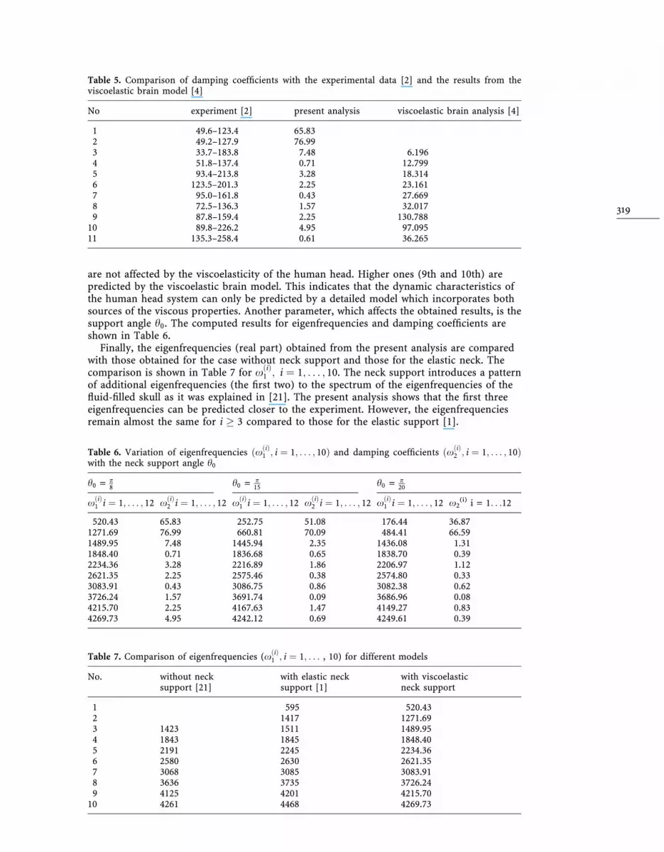
are not affected by the viscoelasticity of the human head. Higher ones (9th and 10th) arepredicted by the viscoelastic brain model. This indicates that the dynamic characteristics ofthe human head system can only be predicted by a detailed model which incorporates bothsources of the viscous properties. Another parameter, which affects the obtained results, is thesupport angle h0. The computed results for eigenfrequencies and damping coef®cients areshown in Table 6.
Finally, the eigenfrequencies (real part) obtained from the present analysis are comparedwith those obtained for the case without neck support and those for the elastic neck. Thecomparison is shown in Table 7 for x�i�1 ; i � 1; . . . ; 10. The neck support introduces a patternof additional eigenfrequencies (the ®rst two) to the spectrum of the eigenfrequencies of the¯uid-®lled skull as it was explained in [21]. The present analysis shows that the ®rst threeeigenfrequencies can be predicted closer to the experiment. However, the eigenfrequenciesremain almost the same for i � 3 compared to those for the elastic support [1].
Table 5. Comparison of damping coef®cients with the experimental data [2] and the results from theviscoelastic brain model [4]
No experiment [2] present analysis viscoelastic brain analysis [4]
1 49.6±123.4 65.832 49.2±127.9 76.993 33.7±183.8 7.48 6.1964 51.8±137.4 0.71 12.7995 93.4±213.8 3.28 18.3146 123.5±201.3 2.25 23.1617 95.0±161.8 0.43 27.6698 72.5±136.3 1.57 32.0179 87.8±159.4 2.25 130.788
10 89.8±226.2 4.95 97.09511 135.3±258.4 0.61 36.265
Table 6. Variation of eigenfrequencies �x�i�1 ; i � 1; . . . ; 10� and damping coef®cients �x�i�2 ; i � 1; . . . ; 10�with the neck support angle h0
h0 = p8 h0 = p
15 h0 = p20
x�i�1 i � 1; . . . ; 12 x�i�2 i � 1; . . . ; 12 x�i�1 i � 1; . . . ; 12 x�i�2 i � 1; . . . ; 12 x�i�1 i � 1; . . . ; 12 x2(i) i = 1. . .12
520.43 65.83 252.75 51.08 176.44 36.871271.69 76.99 660.81 70.09 484.41 66.591489.95 7.48 1445.94 2.35 1436.08 1.311848.40 0.71 1836.68 0.65 1838.70 0.392234.36 3.28 2216.89 1.86 2206.97 1.122621.35 2.25 2575.46 0.38 2574.80 0.333083.91 0.43 3086.75 0.86 3082.38 0.623726.24 1.57 3691.74 0.09 3686.96 0.084215.70 2.25 4167.63 1.47 4149.27 0.834269.73 4.95 4242.12 0.69 4249.61 0.39
Table 7. Comparison of eigenfrequencies (x�i�1 ; i � 1; . . . , 10) for different models
No. without necksupport [21]
with elastic necksupport [1]
with viscoelasticneck support
1 595 520.432 1417 1271.693 1423 1511 1489.954 1843 1845 1848.405 2191 2245 2234.366 2580 2630 2621.357 3068 3085 3083.918 3636 3735 3726.249 4125 4201 4215.70
10 4261 4468 4269.73
319

6ConclusionsWe have introduced a model for the simulation of the human head- neck support whichdescribes its viscoelastic properties. The parameters involved in the model have been computedusing ®tting to experimental dynamic characteristics. We assumed also that we can describe thehuman head using a simpli®ed spherical cavity. Our results show that we can predict the realpart of the eigenfrequencies and the damping coef®cients of the ®rst two eigenfrequencies,these being the only ones which are affected by the neck viscoelastic properties. However, thereal part of the ®rst eigenfrequency, which is important in certain clinical methods for the earlydiagnosis of brain diseases, cannot be predicted by the proposed model, and further investi-gation is needed.
References1. Charalambopoulos, A.; Dassios, G.; Fotiadis, D. I.; Massalas, C. V.: Frequency spectrum of the human
head-neck system, Int. J. Eng. Sci. 35(8) (1997) 753±7682. HaÊkansson, B.; Brandt, A.; Carlsson, P.: Resonance frequencies of the human skull in vivo, J. Acoust.
Soc. Am. 95(3) (1994) 14743. Charalambopoulos, A.; Fotiadis D. I.; Massalas, C. V.: Free vibrations of the viscoelastic human skull.
Int. J. Eng. Sci. 36 (5/6) (1998) 565±5764. Charalambopoulos, A.; Fotiadis, D. I.; Massalas, C. V.: The effect of viscoelastic brain on the dynamic
characteristics of the human skull-brain system. Acta Mech. accepted (1997)5. McElhaney, J. H.; Fogle, J. L.; Melvin, J. W.; Haynes, R. R.; Roberts, V. L.; Alem, N. M.: Mechanical
properties of the cranial bone, J. Biomech. 3 (1970) 495±5116. Schuck, L. Z.; Advani, S. H.: Rheological response of human brain tissue in shear. Trans. ASME Sec D J.
Basic Engineering. (1972) 905±9117. Landkof B.; Goldsmith, W.; Sackman, J. L.: Impact on a head-neck structure. J. Biomech. 9 (1976) 141±
1518. Misra, J. C.; Chakravarty, S.: Dynamic response of a head-neck system to an impulsive load. Math.
Modelling 6 (1985) 83±969. Shugar, T. A.; Katona, M. G.: Development of Finite Element head injury model. ASCE J. Eng. Mech.
Div. EM3 (1975) 223±23910. Akkas, N.: Dynamic analysis of a ¯uid-®lled spherical sandwich shell ± a model of the human head.
J. Biomech. 8 (1975) 275±28411. Khalil, T. B.; Hubbard, R. P.: Parametric study of head response by Finite Element Modelling.
J. Biomech. 10 (1977) 119±13212. Hickling, R.; Wenner, M. L.: Mathematical model of a head subjected to an axisymmetric impact.
J. Biomech. 6 (1973) 115±13213. Reber, J. G.; Goldsmith, W.: Analysis of large head-neck motions. J. Biomech. 12 (1979) 211±22214. Merrill T.; Goldsmith, W.; Deng, Y. C.: Three-dimensional response of a lumped parameter head-neck
model due to impact and impulsive loading. J. Biomech. 17 (1984) 81±9515. Lang®tt, T. W.; Weinstein, J. D.; Kassell, N. F.: Vascular factors in head injury: Contribution to brain
swelling and intracranial hypertension. In: Caveness W. F., and Walker J. B. (ed.) Head Injury. pp. 172±194 Conference Preceedings, Chicago: Philadelphia: Lippencott and Co. 1996
16. Huston, R. L.; Seras, J.: Effect of protective helmet mass on head/neck dynamics. Trans. ASME 103(1981) 18±23
17. Hansen, W. W.: A new type of expansion in radiation problems. Phys. Rev. 47 (1935) 139±14318. Bland, D. R.: The theory of linear viscoelasticity. Oxford: Pergamon Press 196019. Christensen, R. M.: Theory of viscoelasticity: An Introduction. New York: Academic Press 197120. Joseph, D. D.: Fluid dynamics of viscoelastic ¯uids. New York: Springer 199021. Charalambopoulos, A.; Dassios, G.; Fotiadis, D. I.; Massalas, C. V.: Dynamic characteristics of the
human skull-brain system. Comput. and Math. Modelling 27(2) (1998) 81±101
Appendix AFunctions Al
n0;i;Bln0;i;C
ln0;i;D
ln0;i;E
ln0;i and Al
n0 ; Bln0 ; C
ln0 ; D
ln0 ; E
ln0 are given as follows:
Aln;i�r0� � ÿ
4l0ir0
gln�k0pi
r0� � 2l0ik0pi
1ÿ n�n� 1�k02pi
r02
!gl
n�k0pir0� � k0ik
0pi
gln�k0pi
r0�" #
;
Bln;i�r0� � 2l0i
������������������n�n� 1�
p 1
r0_gln�k0pi
r0� ÿ gln�k0pi
r0�k0pi
r02
" #;
Cln;i�r0� � l0i
������������������n�n� 1�
pk0si
_gln�k0si
r0� ÿ 1
r0gl
n�k0sir0�
� �;
320

Dln;i�r0� � 2l0in�n� 1� _gl
n�k0sir0�
r0ÿ gl
n�k0sir0�
k0sir02
" #;
Eln;i�r0� � l0i
������������������n�n� 1�
pÿ2
_gln�k0si
r0�r0
ÿ k0sigl
n�k0sir0� � 2
n�n� 1� ÿ 1
k0sir02
gln�k0si
r0�" #
;
Aln0 � gl
n0 �k0pr0�;
Bln0 �
��������������������n0�n0 � 1�
p gln0 �k0pr0�
k0pr0;
Cln0 �
��������������������n0�n0 � 1�
pgl
n0 �k0pr0�;
Dln0 � n0�n0 � 1� gl
n0 �k0sr0�k0sr0
;
Eln0 �
��������������������n0�n0 � 1�
p_gln0 �k0sr0� �
gln0 �k0sr0�
k0sr0
� �:
Appendix BMatrix D can be described by submatrices having dimension 7� 7, i.e.
D �D1;1 D1;2 � � � D1;n0�1
D2;1 � � � � � � � � �� � � � � � � � � � � �
Dn0�1;1 � � � � � � Dn0�1;n0�1
26643775:
The diagonal Dkik submatrix are given as
D �
d1;1 d1;2 � � � � � � � � � � � � d1;7
d2;1 � � � � � � � � � � � � � � � � � �� � � � � � � � � � � � � � � � � � � � �� � � � � � � � � � � � � � � � � � � � �� � � � � � � � � � � � � � � � � � � � �� � � � � � � � � � � � � � � � � � � � �d7;1 � � � � � � � � � � � � � � � d7;7
2666666664
3777777775;
where the nonvanishing elements are
d1;1 � A1k�r00�; d1;2 � A2
k�r00�; d1;5 � D1k�r00�; d1;6 � D2
k�r00�;
d1;7 � ÿXq0fc02s
g1k�k0f r00�;
d2;1 � B1k�r00�; d2;2 � B2
k�r00�; d2;5 � E1k�r00�; d2;6 � E2
k�r00�;d3;1 � A1
k�r01� ÿ A1k�r01�N�k; k; h0;m
0�; d3;2 � A2k�r01� ÿ A2
k�r01�N�k; k; h0;m0�;
d3;5 � D1k�r01� ÿ D1
k�r01�N�k; k; h0;m0�; d3;6 � D2
k�r01� ÿ D2k�r01�N�k; k; h0;m
0�;d4;1 � B1
k�r01� ÿ B1k�r01�N�k; k; h0;m
0�; d4;2 � B2k�r01� ÿ B2
k�r01�N�k; k; h0;m0�;
d4;5 � E1k�r01� ÿ E1
k�r01�N�k; k; h0;m0�; d4;6 � E2
k�r01� ÿ E2k�r01�N�k; k; h0;m
0�;d5;3 � C1
k�r00�; d5;4 � C2k�r00�;
d6;3 � C1k�r01� ÿ C1
k�r01�N1�k; k; h0;m0�; d6;4 � C2
k�r01� ÿ C2k�r01�N1�k; k; h0;m
0�;
d7;1 � _g1k�Xr00�; d7;2 � _g2
k�Xr00�; d7;4 � k�k� 1� g1k�k0sr00�k0sr00
;
321

d7;5 � k�k� 1� g2k�k0sr00�k0sr00
; d7;7 �_g1k�k0f r00�
c0f;
and the corresponding nonvanishing elements of the non diagonal submatrices Dk;j are
d3;1 � ÿA1j �r01�N�k; j; h0;m
0�; d3;2 � ÿA2j �r01�N�k; j; h0;m
0�;d3;5 � ÿD1
j �r01�N�k; j; h0;m0�; d3;6 � ÿD2
j �r01�N�k; j; h0;m0�;
d4;1 � ÿB1j �r01�N1�k; j; h0;m
0�; d4;2 � ÿB2j �r01�N1�k; j; h0;m
0�;d4;5 � ÿE1
j �r01�N1�k; j; h0;m0�; d4;6 � ÿE2
j �r01�N1�k; j; h0;m0�;
d6;3 � ÿC1j �r01�N1�k; j; h0;m
0�; d6;4 � ÿC2j �r01�N1�k; j; h0;m
0� :322