hp525 efi bravo sterndrive models
TRANSCRIPT
eng i
Thank Youfor your purchase of one of the finest marine powerpackages available. It incorporates numerous designfeatures to ensure operating ease and durability.With proper care and maintenance, you will thoroughly enjoyusing this product for many boating seasons. To ensuremaximum performance and carefree use, we ask that youthoroughly read this manual.The Operation, Maintenance & Warranty Manual containsspecific instructions for using and maintaining your product.We suggest that this manual remain with the product forready reference whenever you are on the water.Again, thank you for purchasing one of our Mercury Marineproducts. We sincerely hope your boating will be pleasant!
Mercury Racing, N7480 County Road "UU" Fond du Lac, WI 54935-9585
7406
Warranty Message
! WARNINGThe operator (driver) is responsible for the correct andsafe operation of the boat, the equipment aboard and thesafety of all occupants aboard. We strongly recommendthat the operator read this Operation, Maintenance andWarranty Manual and thoroughly understand theoperational instructions for the power package and allrelated accessories before the boat is used.
© 2
013
Mer
cury
Mar
ine
HP5
25 E
FI B
ravo
Ste
rndr
ive
Mod
els
90-8
M00
7939
7 51
3

ii eng
The product you have purchased comes with a limited warrantyfrom Mercury Marine; the terms of the warranty are set forth inthe Warranty Information section of this manual. The warrantystatement contains a description of what is covered, what is notcovered, the duration of coverage, how to best obtain warrantycoverage, important disclaimers and limitations of damages, andother related information. Please review this importantinformation.
Safety Alerts and NoticesThroughout this publication, dangers, warnings, cautions, and
notices, accompanied by the international HAZARD symbol ! ,are used to alert the boat operator and technician to specialinstructions concerning a particular service or operation that maybe hazardous if performed incorrectly or carelessly. Observethese safety alerts carefully.These safety alerts alone can not eliminate the hazards theysignal. Strict compliance to these special instructions whenperforming the service, and common sense operation are majoraccident prevention measures.
! DANGERIndicates a hazardous situation which, if not avoided, will resultin death or serious injury.
! WARNINGIndicates a hazardous situation which, if not avoided, couldresult in death or serious injury.
! CAUTIONIndicates a hazardous situation which, if not avoided, couldresult in minor or moderate injury.
NOTICEIndicates a situation which, if not avoided, could result inengine or major component failure.
eng iii
IMPORTANT: Identifies information essential to the successfulcompletion of the task.NOTE: Indicates information that helps in the understanding of aparticular step or action.
Copyright and Trademark Information© 2013 Mercury Marine, Fond du Lac, Wisconsin, USA. Printedin USA.Mercury, Mercury Marine, MerCruiser, Mercury MerCruiser,Mercury Racing, Mercury Precision Parts, Mercury Propellers,Mariner, Quicksilver, #1 On The Water, Alpha, Bravo One, BravoTwo, Bravo Three, OptiMax, Sport‑Jet, K‑Planes, MerCathode,SmartCraft, Zero Effort, VesselView, Zeus, Axius, Circle M withWaves logo, Mercury with Waves logo, and SmartCraft logo areall trademarks or registered trademarks of BrunswickCorporation. Mercury Product Protection logo is a registeredservice mark of Brunswick Corporation.
! WARNINGThe engine exhaust from this product contains chemicalsknown to the state of California to cause cancer, birth defectsor other reproductive harm.

iv eng
eng v
Warranty Information
Warranty Registration United States and Canada....................... 1Transfer of Warranty.................................................................... 2Mercury Racing Division One‑Year Limited Warranty................. 3Products Sold to Government Agencies...................................... 6Three‑Year Limited Warranty Against Corrosion......................... 7Warranty Coverage and Exclusions for Mercury RacingSterndrive Products................................................................... 10E.P.A. Emission Controls...........................................................11
General Information
Before Operating Your Boat...................................................... 14Boat Horsepower Capacity........................................................ 14High‑Speed and High‑Performance Boat Operation................. 15Paddle Wheel and Water Temperature Sensors....................... 15Lanyard Stop Switch.................................................................. 16Trailering the Boat..................................................................... 17Protecting People in the Water.................................................. 17Exhaust Emissions.................................................................... 18Wave and Wake Jumping.......................................................... 20Impact With Underwater Hazards.............................................. 21Operating in Shallow Water....................................................... 22Safe Boating Suggestions......................................................... 24Stolen Power Package.............................................................. 27
vi eng
Specifications
Engine Identification.................................................................. 28Fuel Requirements.................................................................... 29Low Permeation Fuel Hose Requirement ................................. 31Crankcase Oil............................................................................ 31Capacities.................................................................................. 33General Engine Specifications...................................................33Engine Operating Limitations.....................................................34Engine Break‑in......................................................................... 35After Break‑In Period................................................................. 35
Operation
Instrumentation.......................................................................... 36Warning System........................................................................ 36Electrical System Overload Protection...................................... 39Remote Controls........................................................................ 43Remote Controls (Console Mounted Zero Effort)...................... 46Power Trim................................................................................ 47Starting, Shifting and Stopping.................................................. 52Operation Chart......................................................................... 54Freezing Temperature Operation.............................................. 55Drain Plug and Bilge Pump........................................................56Launching And Boat Operation Care......................................... 56
Conditions Affecting Operation
Weight Distribution.....................................................................57Bottom Of Boat.......................................................................... 57Cavitation................................................................................... 57Ventilation.................................................................................. 58Propeller Selection.....................................................................58Conditions That Lower Engine Performance............................. 59
eng vii
Maintenance
Service Responsibilities............................................................. 60Replacement Service Parts....................................................... 61Do‑It‑Yourself Maintenance Suggestions.................................. 61Servicing High‑Horsepower Engines......................................... 63Engine Maintenance Charts...................................................... 63Bravo Drive Maintenance Charts............................................... 65Checking Fluid Levels................................................................67Changing Fluids......................................................................... 74Lubrication................................................................................. 85Propellers...................................................................................88Flushing the Power Package..................................................... 96Seawater Pump Impeller Inspection........................................ 100Cleaning Seawater (Raw Water) Section of Oil Cooler........... 101Changing Positive Crankcase Ventilation Valve...................... 102Serpentine Drive Belt............................................................... 103Changing Fuel Filters...............................................................105Corrosion and Corrosion Protection........................................ 108Battery..................................................................................... 115Bottom of Boat......................................................................... 116Inspection and Maintenance.................................................... 116Attention Required After Submersion...................................... 116
Cold Weather or Extended Storage
Power Package Lay‑up............................................................117Draining Instructions................................................................ 119Battery Winter Storage............................................................ 122Power Package Recommissioning.......................................... 122

viii eng
Troubleshooting
Engine Will Not Crank..............................................................126Engine Cranks But Will Not Start............................................. 126Engine Hard to Start, Runs Rough, Misses, and/or Backfires. 127Low Engine Coolant (Closed Cooling) Temperature............... 127Poor Performance....................................................................128Insufficient Engine Temperature.............................................. 128High Engine Temperature........................................................129Low Engine Oil Pressure......................................................... 129Battery Will Not Come Up On Charge..................................... 130Power Trim Does Not Operate (Motor Doesn't Run)............... 130Power Trim Does Not Operate (Motor Runs But Drive Unit DoesNot Move)................................................................................ 130Electrical Analog Trim Gauge Malfunction...............................131Remote Control Operates Hard, Binds, Has Excessive Free‑Playor Makes Unusual Sounds.......................................................131Steering Wheel Turns Hard or Jerky....................................... 131Seawater Pressure Is Below Specification.............................. 132Seawater Pressure Is Above Specification.............................. 132
Owner Service Assistance
Local Repair Service................................................................133Service Away from Home........................................................ 133Parts and Accessories Inquiries.............................................. 133Service Assistance.................................................................. 133Mercury Mercruiser Service Offices.........................................134
Ordering Literature
United States and Canada.......................................................136Outside The United States and Canada.................................. 136

eng ix
Maintenance Log
Maintenance Log..................................................................... 137

x eng

WARRANTY INFORMATION
eng 1
Warranty Registration United States and CanadaOutside United States and Canada–Check with your localdistributor.1. You may change your registered address at any time,
including at time of warranty claim, by calling MercuryMarine or sending a letter or fax with your name, oldaddress, new address, and engine serial number to MercuryMarine’s warranty registration department. Your dealer canalso process this change of information.Mercury MarineAttn.: Warranty Registration DepartmentW6250 W. Pioneer RoadP.O. Box 1939Fond du Lac, WI 54936-1939920-929-5054Fax 920-907-6663
NOTE: Registration lists must be maintained by Mercury Marineand any dealer on marine products sold in the United States,should a safety recall notification under the Federal Safety Actbe required.2. At the time of sale, the dealer should complete the warranty
registration and immediately submit it to Mercury Marine viaMercNET, E‑mail, or mail. Upon receipt of this warrantyregistration, Mercury Marine will record the registration.
IMPORTANT: Your warranty coverage begins at the time ofsale, but warranty claims cannot be processed until the productis registered with Mercury Marine.3. Upon processing the warranty registration, Mercury Marine
will send the purchaser a Mercury Owner Resource Guide.The back page of this guide contains your warrantyregistration information and should be saved. If thisregistration verification is not received within 30 days,please contact your selling dealer immediately.
WARRANTY INFORMATION
2 eng
Transfer of WarrantyThe limited warranty is transferable to a subsequent purchaser,but only for the remainder of the unused portion of the limitedwarranty. This will not apply to products used for commercialapplications.To transfer the warranty to the subsequent owner, send or fax acopy of the bill of sale or purchase agreement, new owner’sname, address and engine serial number to Mercury Marine’sWarranty Registration Department. In the United States andCanada, mail to:Mercury MarineAttn: Warranty Registration DepartmentW6250 W. Pioneer RoadP.O. Box 1939Fond du Lac, WI 54936-1939920-929-5054Fax +1 920 907 6663Upon processing the transfer of warranty, Mercury Marine willsend registration verification to the new owner of the product bymail.There is no charge for this service.For products purchased outside the United States and Canada,contact the distributor in your country, or the Marine PowerService Center closest to you.
WARRANTY INFORMATION
eng 3
Mercury Racing Division One‑Year LimitedWarrantyWHAT IS COVEREDMercury Marine warrants its new products (and remanufacturedproducts sold under the trade name "Pacemaker") to be free ofdefects in material and workmanship during the period describedbelow.
DURATION OF COVERAGEThis Limited Warranty provides coverage for one (1) year fromeither the date the product is first sold to a recreational use retailpurchaser, or the date on which the product is first put intoservice, whichever occurs first. The repair or replacement ofparts, or the performance of service under this warranty, doesnot extend the life of this warranty beyond its original expirationdate. Unexpired warranty coverage can be transferred to asubsequent purchaser upon proper re‑registration of the product.
CONDITIONS THAT MUST BE MET IN ORDER TO OBTAINWARRANTY COVERAGEWarranty coverage is available only to retail customers thatpurchase from a dealer authorized by Mercury Marine todistribute the product in the country in which the sale occurred,and then only after the Mercury Marine‑specified pre‑deliveryinspection process is completed and documented. Warrantycoverage becomes available upon proper registration of theproduct by the authorized dealer. Inaccurate warrantyregistration information regarding recreational use, orsubsequent change of use from recreational to commercial mayvoid the warranty at the sole discretion of Mercury Marine.Routine maintenance outlined in the Operation and MaintenanceManual must be timely performed in order to maintain warrantycoverage. Mercury Marine reserves the right to make warrantycoverage contingent upon proof of proper maintenance.
WARRANTY INFORMATION
4 eng
WHAT MERCURY WILL DOMercury’s sole and exclusive obligation under this warranty islimited to, at our option, repairing a defective part, replacing suchpart or parts with new or Mercury Marine‑certifiedre‑manufactured parts, or refunding the purchase price of theMercury product. Mercury reserves the right to improve or modifyproducts from time to time without assuming an obligation tomodify products previously manufactured.
HOW TO OBTAIN WARRANTY COVERAGEThe customer must provide Mercury with a reasonableopportunity to repair and reasonable access to the product forwarranty service. Warranty claims shall be made by deliveringthe product for inspection to a Mercury dealer authorized toservice the product. If purchaser cannot deliver the product tosuch a dealer, written notice must be given to Mercury. We willthen arrange for the inspection and any covered repair.Purchaser in that case shall pay for all related transportationcharges and/or travel time. If the service provided is not coveredby this warranty, purchaser shall pay for all related labor andmaterial, and any other expenses associated with that service.Purchaser shall not, unless requested by Mercury, ship theproduct or parts of the product directly to Mercury. Proof ofregistered ownership must be presented to the dealer at the timewarranty service is requested in order to obtain coverage.
WARRANTY INFORMATION
eng 5
WHAT IS NOT COVEREDThis limited warranty does not cover routine maintenance items,tune ups, adjustments, normal wear and tear, damage caused byabuse, abnormal use, use of a propeller or gear ratio that doesnot allow the engine to run in its recommendedwide‑open‑throttle RPM range, operation of the product in amanner inconsistent with the recommended operation/duty cyclesection of the Warranty, Operation, and Maintenance Manual,neglect, accident, submersion, improper installation (properinstallation specifications and techniques are set forth in theinstallation instructions for the product), improper service, use ofan accessory or part not manufactured or sold by us, operationwith fuels, oils or lubricants which are not suitable for use withthe product, alteration or removal of parts, water entering theengine through the fuel intake, air intake or exhaust system, ordamage to the product from insufficient cooling water caused byblockage of the cooling system by a foreign body, running theengine out of water, mounting the engine too high on thetransom, or running the boat with the engine trimmed out too far.The commercial use of the product, defined as any work oremployment related use of the product, or any incomegenerating use of the product, even if such use is onlyoccasional, will void the warranty. Use of the product for racingor other competitive activity, at any point, even by a prior ownerof the product, voids the warranty. Expenses related to haul‑out,launch, towing, storage, telephone, rental, inconvenience, slipfees, insurance coverage, loan payments, loss of time, loss ofincome, tournament fees, club fees, prize money or any othertype of incidental or consequential damages are not covered bythis warranty. Also, expenses associated with the removal and/orreplacement of boat partitions or material caused by boat designfor access to the product are not covered by this warranty.
WARRANTY INFORMATION
6 eng
No individual or entity, including Mercury Marine‑authorizeddealers, has been given authority by Mercury Marine to makeany affirmation, representation or warranty regarding theproduct, other than those contained in this limited warranty, andif made, shall not be enforceable against Mercury Marine. Foradditional information regarding events and circumstancescovered by this warranty, and those that are not, see theWarranty Coverage section of this manual, incorporated byreference into this warranty.Disclaimers and limitations the implied warranties ofmerchantability and fitness for a particular pupose are expresslydisclaimed. to the extent that they cannot be disclaimed, theimplied warranties are limited in duration to the life of the expresswarranty. Incidental and consequential damages are excludedfrom coverage under this warranty. Some states and countriesdo not allow for the disclaimers, limitations, and exclusionsidentifies above, as a result, they may not apply to you. Thiswarranty gives you specific legal rights, and you may also haveother legal rights which vary from state‑to‑state andcountry‑to‑country.
Products Sold to Government AgenciesContact the Mercury Racing Sales Department for a copy of theGovernment Agencies Warranty Packet Kit which explains theconditions required for government agencies to receive warrantywhen purchasing Mercury Racing Outboard or Sterndriveproduct.Mercury Racing Sales DepartmentN7840 County Road UUFond du Lac, WI 54935920-921-5330Fax 920-921-6533
WARRANTY INFORMATION
eng 7
Three‑Year Limited Warranty Against CorrosionWHAT IS COVERED: Mercury Marine warrants that each newMercury, Mariner, Mercury Racing Outboard, Sport Jet, M2 JetDrive, Tracker by Mercury Marine Outboard, Mercury MerCruiserinboard or sterndrive engine, Mercury Racing Bravo‑stylesterndrive engine (Product) will not be rendered inoperative as adirect result of corrosion for the period of time described below.DURATION OF COVERAGE: This limited corrosion warrantyprovides coverage for three (3) years from either the date theproduct is first sold, or the date on which the product is first putinto service, whichever occurs first. The repair or replacement ofparts, or the performance of service under this warranty does notextend the life of this warranty beyond its original expiration date.Unexpired warranty coverage can be transferred to subsequent(non‑commercial use) purchaser upon proper re‑registration ofthe product.CONDITIONS THAT MUST BE MET IN ORDER TO OBTAINWARRANTY COVERAGE: Warranty coverage is available onlyto retail customers that purchase from a dealer authorized byMercury Marine to distribute the product in the country in whichthe sale occurred, and then only after the Mercury Marinespecified pre‑delivery inspection process is completed anddocumented. Warranty coverage becomes available upon properregistration of the product by the authorized dealer. Corrosionprevention devices specified in the Operation and MaintenanceManual must be in use on the boat, and routine maintenanceoutlined in the Operation and Maintenance Manual must betimely performed (including without limitation the replacement ofsacrificial anodes, use of specified lubricants, and touch‑up ofnicks and scratches) in order to maintain warranty coverage.Mercury Marine reserves the right to make warranty coveragecontingent upon proof of proper maintenance.
WARRANTY INFORMATION
8 eng
WHAT MERCURY WILL DO: Mercury's sole and exclusiveobligation under this warranty is limited to, at our option,repairing a corroded part, replacing such part or parts with newor Mercury Marine‑certified re‑manufactured parts, or refundingthe purchase price of the Mercury product. Mercury reserves theright to improve or modify products from time to time withoutassuming an obligation to modify products previouslymanufactured.HOW TO OBTAIN WARRANTY COVERAGE: The customermust provide Mercury with a reasonable opportunity to repair,and reasonable access to the product for warranty service.Warranty claims shall be made by delivering the product forinspection to a Mercury dealer authorized to service the product.If purchaser cannot deliver the product to such a dealer, writtennotice must be given to Mercury. We will then arrange for theinspection and any covered repair. Purchaser in that case shallpay for all related transportation charges and/or travel time. If theservice provided is not covered by this warranty, purchaser shallpay for all related labor and material, and any other expensesassociated with that service. Purchaser shall not, unlessrequested by Mercury, ship the product or parts of the productdirectly to Mercury. Proof of registered ownership must bepresented to the dealer at the time warranty service is requestedin order to obtain coverage.WHAT IS NOT COVERED: This limited warranty does not coverelectrical system corrosion; corrosion resulting from damage,corrosion which causes purely cosmetic damage, abuse orimproper service; corrosion to accessories, instruments, steeringsystems; corrosion to factory installed jet drive unit; damage dueto marine growth; replacement parts (parts purchased bycustomer); products used in a commercial application.Commercial use is defined as any work or employment relateduse of the product, or any use of the product which generatesincome, for any part of the warranty period, even if the product isonly occasionally used for such purposes.
WARRANTY INFORMATION
eng 9
Corrosion damage caused by stray electrical currents (on‑shorepower connections, nearby boats, submerged metal) is notcovered by this corrosion warranty and should be protectedagainst by the use of a corrosion protection system, such as theMercury Precision Parts or Quicksilver MerCathode systemand/or galvanic Isolator. Corrosion damage caused by improperapplication of copper base anti‑fouling paints is also not coveredby this limited warranty. If anti‑fouling protection is required,tri‑butyl‑tin‑adipate (TBTA) base anti‑fouling paints arerecommended on outboard and MerCruiser boating applications.In areas where TBTA base paints are prohibited by law, copperbase paints can be used on the hull and transom. Do not applypaint to the outboard or MerCruiser product. In addition, caremust be taken to avoid an electrical interconnection between thewarranted product and the paint. For MerCruiser product, anunpainted gap of at least 38 mm (1.5 in.) should be left aroundthe transom assembly. Refer to the Operation andMaintenance Manual for additional details.For additional information regarding events and circumstancescovered by this warranty, and those that are not, see theWarranty Coverage section of the Operation and MaintenanceManual, incorporated by reference into this warranty.
DISCLAIMERS AND LIMITATIONS:
THE IMPLIED WARRANTIES OF MERCHANTABILITY AND FITNESS FORA PARTICULAR PURPOSE ARE EXPRESSLY DISCLAIMED. TO THEEXTENT THAT THEY CANNOT BE DISCLAIMED, THE IMPLIEDWARRANTIES ARE LIMITED IN DURATION TO THE LIFE OF THEEXPRESS WARRANTY. INCIDENTAL AND CONSEQUENTIAL DAMAGESARE EXCLUDED FROM COVERAGE UNDER THIS WARRANTY. SOMESTATES/COUNTRIES DO NOT ALLOW FOR THE DISCLAIMERS,LIMITATIONS AND EXCLUSIONS IDENTIFIED ABOVE, AS A RESULT,THEY MAY NOT APPLY TO YOU. THIS WARRANTY GIVES YOUSPECIFIC LEGAL RIGHTS, AND YOU MAY ALSO HAVE OTHER LEGALRIGHTS WHICH VARY FROM STATE TO STATE AND COUNTRY TOCOUNTRY.
WARRANTY INFORMATION
10 eng
Warranty Coverage and Exclusions for MercuryRacing Sterndrive ProductsThe purpose of this section is to help eliminate some of the morecommon misunderstandings regarding warranty coverage. Thefollowing information explains some of the types of services thatare not covered by warranty. The provisions set forth followinghave been incorporated by reference into the Mercury RacingDivision Three‑Year Limited Warranty Against Corrosion Failure,the Mercury Racing Division 90‑Day, Six‑Month and One‑YearLimited Warranties.Keep in mind that warranty covers repairs that are needed withinthe warranty period because of defects in material andworkmanship. Installation errors, accidents, normal wear, and avariety of other causes that affect the product are not covered.Warranty is limited to defects in material or workmanship, butonly to retail customers that purchase from a dealer authorizedby Mercury Marine to distribute the product in the country inwhich the sale occurred, and then only after the Mercury Marinespecified pre‑delivery inspection process is completed anddocumented.Should you have any questions concerning warranty coverage,contact your authorized dealer. They will be pleased to answerany questions that you may have.
GENERAL EXCLUSIONS FROM WARRANTY1. Minor adjustments and tune‑ups, including checking,
cleaning or adjusting spark plugs, ignition components,carburetor or EFI settings, filters, belts, controls, andchecking lubrication made in connection with normalservices.
2. Damage caused by lack of maintenance.3. Haul‑out, launch, towing charges, and all related
transportation charges and/or travel time, etc.4. Additional service work requested by customer other than
that necessary to satisfy the warranty obligation.
WARRANTY INFORMATION
eng 11
5. Labor performed by other than an authorized dealer may becovered only under following circumstances: Whenperformed on an emergency basis providing there are noauthorized dealers in the area who can perform the workrequired or have no facilities to haul out, etc., and priorfactory approval has been given to have the work performedat this facility.
6. Use of other than Mercury Precision or Quicksilver partswhen making warranty repairs.
7. Engine noise does not necessarily indicate a serious engineproblem. If diagnosis indicates a serious internal enginecondition, which could result in a failure, conditionresponsible for noise should be corrected under thewarranty.
8. Lower unit and/or propeller damage caused by striking asubmerged object is considered a marine hazard.
9. Water in the starter motor.10.Starter motors and/or armatures or field coil assembly,
which are burned, or where lead is thrown out ofcommutator because of excess cranking.
11.Valve or valve seat grinding required because of wear.
E.P.A. Emission ControlsINTRODUCTIONConsistent with the obligations created by 40 CFR Part 1045,Subpart B, Mercury Marine provides an emission warranty ofthree years or 480 hours of engine use, whichever occurs first, tothe retail purchaser for electrical components of the emissioncontrol system, and one year or 150 hours of engine use,whichever occurs first, to the retail purchaser for mechanicalcomponents of the emission control system. The engine isdesigned, built, and equipped to conform at the time of sale withapplicable regulations under section 213 of the Clean Air Act,and the engine is free from defects in materials andworkmanship that cause the engine to fail to conform withapplicable regulations.
WARRANTY INFORMATION
12 eng
EMISSION CONTROL SYSTEM COMPONENTSThe emission‑related warranty covers all components whosefailure would increase an engine's emission of any regulatedcomponent including the following list of components:1. Fuel metering system
a. Carburetor and internal parts (or fuel pressure regulatoror fuel injection system)
b. Air/fuel ratio feedback and control systemc. Cold start enrichment systemd. Intake valves
2. Air induction systema. Controlled hot air intake systemb. Intake manifoldc. Air filterd. Turbocharger systemse. Heat riser valve and assembly
3. Ignition systema. Spark plugsb. Magneto or electronic ignition systemc. Spark control systemd. Ignition coil or control modulee. Ignition wires
4. Lubrication systema. Oil pump and internal partsb. Oil injectorsc. Oil meter
5. Positive crankcase ventilation (PCV) systema. PCV valveb. Oil filler cap
6. Exhaust systema. Exhaust manifoldb. Exhaust elbowc. Intermediate exhaust elbow
WARRANTY INFORMATION
eng 13
d. Lower exhaust pipee. Tailpipe
7. Catalysts or thermal reactor systema. Catalytic converterb. Thermal reactorc. Exhaust manifoldd. Exhaust valves
8. Evaporative Systema. Carbon Canister(s)b. Fuel tanksc. Purge valve(s)
9. Miscellaneous items used in above systemsa. Hoses, clamps, fittings, tubing, sealing gaskets or
devices, and mounting hardwareb. Pulleys, belts, and idlersc. Vacuum, temperature, check and time sensitive valves
and switchesd. Electronic controls
NOTE: The EPA emission‑related warranty does not covercomponents whose failure would not increase an engine'semissions on any regulated pollutant.
GENERAL INFORMATION
14 eng
Before Operating Your BoatRead this manual carefully. Safety and operating information thatis practiced along with using good common sense can helpprevent personal injury and product damage. If you have anyquestions, contact your dealer.This manual as well as safety labels posted on the enginepackage use safety alerts to draw your attention to special safetyinstructions that must be followed.
! WARNINGIndicates a hazardous situation which, if not avoided, couldresult in death or serious injury.
! CAUTIONIndicates a hazardous situation which, if not avoided, couldresult in minor or moderate injury.
IMPORTANT: Indicates information or instructions that arenecessary for proper operation and/or maintenance.NOTE: Indicates information that helps in the understanding of astep or action.
Boat Horsepower Capacity
! WARNINGExceeding the boat's maximum horsepower rating can causeserious injury or death. Overpowering the boat can affect boatcontrol and flotation characteristics or break the transom. Donot install an engine that exceeds the boat's maximum powerrating.

GENERAL INFORMATION
eng 15
Do not overpower or overload your boat. Most boats will carry arequired capacity plate indicating the maximum acceptablepower and load as determined by the manufacturer followingcertain federal guidelines. If in doubt, contact your dealer or theboat manufacturer.
U.S. COAST GUARD CAPACITYMAXIMUM HORSEPOWER XXXMAXIMUM PERSON CAPACITY (POUNDS) XXXMAXIMUM WEIGHT CAPACITY XXX
26777
High‑Speed and High‑Performance Boat OperationIf your power package is to be used on a high‑speed orhigh‑performance boat with which you are unfamiliar, werecommend that you never operate it at its high‑speed capabilitywithout first requesting an initial orientation and familiarizationdemonstration ride with your dealer or an operator experiencedwith your boat/power package combination. For additionalinformation, obtain a copy of our High‑Performance BoatOperation booklet from your dealer, distributor, or MercuryMarine.
Paddle Wheel and Water Temperature SensorsPaddle wheels cannot be utilized on vessels that are capable ofspeeds in excess of 50 mph. Water temperature sensors cannotbe connected to Race sterndrive engines that are equipped witha propulsion control module (PCM). The water temperatuesensor connection is utilized by the PCM for monitoring engineoil temperature.

GENERAL INFORMATION
16 eng
Lanyard Stop SwitchThe purpose of a lanyard stop switch is to turn off the enginewhen the operator moves far enough away from the operator'sposition (as in accidental ejection from the operator's position) toactivate the switch. A lanyard stop switch can be installed as anaccessory ‑ generally on the dashboard or side adjacent to theoperator's position.While activation of the lanyard stop switch will stop the engineimmediately, a boat will continue to coast for some distancedepending upon the velocity and degree of any turn at shutdown. However, the boat will not complete a full circle. While theboat is coasting, it can cause injury to anyone in the boat's pathas seriously as the boat would when under power.
a - Lanyard cordb - Lanyard stop switch
We strongly recommend that other occupants be instructed onproper starting and operating procedures should they berequired to operate the engine in an emergency (e.g. if theoperator is accidentally ejected).
! WARNINGIf the operator falls out of the boat, stop the engine immediatelyto reduce the possibility of serious injury or death from beingstruck by the boat. Always properly connect the operator to thestop switch using a lanyard.
21629
a b
GENERAL INFORMATION
eng 17
! WARNINGAvoid serious injury or death from deceleration forces resultingfrom accidental or unintended stop switch activation. The boatoperator should never leave the operator's station without firstdisconnecting the stop switch lanyard from the operator.
Accidental or unintended activation of the switch during normaloperation is also a possibility. This could cause any, or all, of thefollowing potentially hazardous situations:• Occupants could be thrown forward due to unexpected loss
of forward motion ‑ a particular concern for passengers inthe front of the boat who could be ejected over the bow andpossibly struck by the gear case or propeller.
• Loss of power and directional control in heavy seas, strongcurrent or high winds.
• Loss of control when docking.
Trailering the BoatThe boat can be trailered with the drive unit in up or downposition. Adequate road clearance is required between road andgear housing skeg when trailering with the drive unit in downposition.If adequate road clearance is a problem, place drive unit in fullup position.
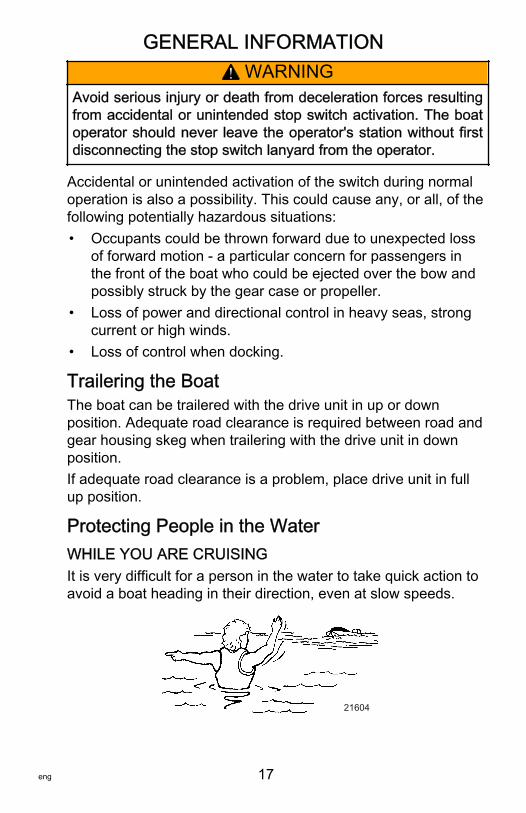
Protecting People in the WaterWHILE YOU ARE CRUISINGIt is very difficult for a person in the water to take quick action toavoid a boat heading in their direction, even at slow speeds.
21604
GENERAL INFORMATION
18 eng
Always slow down and exercise extreme caution any time youare boating in an area where there might be people in the water.Whenever a boat is moving (even coasting) and the gear shift isin neutral, there is sufficient force by the water on the propeller tocause the propeller to rotate. This neutral propeller rotation cancause serious injury.
WHILE BOAT IS STATIONARY
! WARNINGA spinning propeller, a moving boat, or any solid deviceattached to the boat can cause serious injury or death toswimmers. Stop the engine immediately whenever anyone inthe water is near your boat.
Shift into neutral and shut off the engine before allowing peopleto swim or be in the water near your boat.
Exhaust EmissionsBE ALERT TO CARBON MONOXIDE POISONINGCarbon monoxide is present in the exhaust fumes of all internalcombustion engines. This includes the outboards, sterndrivesand inboard engines that propel boats, as well as the generatorsthat power various boat accessories. Carbon monoxide is adeadly gas that is odorless, colorless and tasteless.Early symptoms of carbon monoxide poisoning which should notbe confused with seasickness or intoxication, include headache,dizziness, drowsiness, and nausea.
! WARNINGCarbon monoxide poisoning can lead to unconsciousness,brain damage, or death. Keep the boat well ventilated while atrest or underway and avoid prolonged exposure to carbonmonoxide.
GENERAL INFORMATION
eng 19
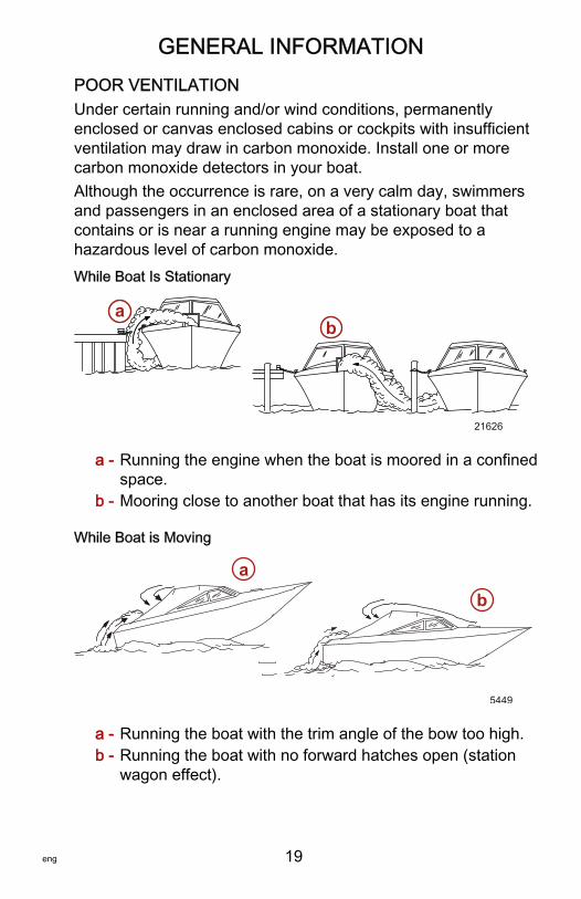
POOR VENTILATIONUnder certain running and/or wind conditions, permanentlyenclosed or canvas enclosed cabins or cockpits with insufficientventilation may draw in carbon monoxide. Install one or morecarbon monoxide detectors in your boat.Although the occurrence is rare, on a very calm day, swimmersand passengers in an enclosed area of a stationary boat thatcontains or is near a running engine may be exposed to ahazardous level of carbon monoxide.While Boat Is Stationary
a - Running the engine when the boat is moored in a confinedspace.
b - Mooring close to another boat that has its engine running.
While Boat is Moving
a - Running the boat with the trim angle of the bow too high.b - Running the boat with no forward hatches open (station
wagon effect).
21626
ab
5449
ab

GENERAL INFORMATION
20 eng
GOOD VENTILATIONVentilate passenger area, open side curtains, or forward hatchesto remove fumes.
5448
Wave and Wake JumpingOperating recreational boats over waves and wake is a naturalpart of boating. However, when this activity is done with sufficientspeed to force the boat hull partially or completely out of thewater, certain hazards arise, particularly when the boat entersthe water.
5450
The primary concern is the boat changing direction while in themidst of the jump. In such case, the landing may cause the boatto veer violently in a new direction. Such a sharp change indirection can cause occupants to be thrown out of their seats, orout of the boat.
! WARNINGWave or wake jumping can cause serious injury or death fromoccupants being thrown within or out of the boat. Avoid waveor wake jumping whenever possible.
GENERAL INFORMATION
eng 21
There is another less common hazardous result from allowingyour boat to launch off a wave or wake. If the bow of your boatpitches down far enough while airborne, upon water contact itmay penetrate under the water surface and submarine for aninstant. This will bring the boat to a nearly instantaneous stopand can send the occupants flying forward. The boat may alsosteer sharply to one side.
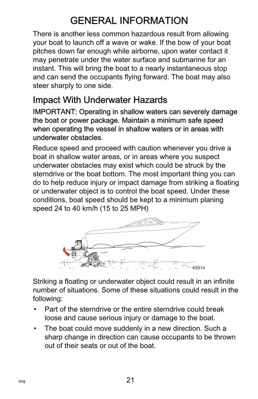
Impact With Underwater HazardsIMPORTANT: Operating in shallow waters can severely damagethe boat or power package. Maintain a minimum safe speedwhen operating the vessel in shallow waters or in areas withunderwater obstacles.Reduce speed and proceed with caution whenever you drive aboat in shallow water areas, or in areas where you suspectunderwater obstacles may exist which could be struck by thesterndrive or the boat bottom. The most important thing you cando to help reduce injury or impact damage from striking a floatingor underwater object is to control the boat speed. Under theseconditions, boat speed should be kept to a minimum planingspeed 24 to 40 km/h (15 to 25 MPH)
45914
Striking a floating or underwater object could result in an infinitenumber of situations. Some of these situations could result in thefollowing:• Part of the sterndrive or the entire sterndrive could break
loose and cause serious injury or damage to the boat.• The boat could move suddenly in a new direction. Such a
sharp change in direction can cause occupants to be thrownout of their seats or out of the boat.
GENERAL INFORMATION
22 eng
• A rapid reduction in speed. This will cause occupants to bethrown forward, or even out of the boat.
• Impact damage to the sterndrive and/or boat.
Keep in mind, the most important thing you can do to helpreduce injury or impact damage during an impact is control theboat speed. Boat speed should be kept to a minimum planingspeed when driving in waters known to have underwaterobstacles.
! WARNINGOperating a boat or engine with impact damage can result inproduct damage, serious injury, or death. If the vesselexperiences any form of impact, have an authorized MercuryMarine dealer inspect and repair the vessel or power package.
After striking a submerged object, stop the engine as soon aspossible and inspect it for any broken or loose parts. If damageis present or suspected, the sterndrive should be taken to anauthorized dealer for a thorough inspection and necessaryrepair.The boat should also be checked for any hull fractures, transomfractures, or water leaks.Operating a damaged sterndrive could cause additional damageto other parts of the sterndrive, or could affect control of the boat.If continued running is necessary, do so at greatly reducedspeeds.
Operating in Shallow Water
NOTICEOperating in shallow water can cause severe engine damagedue to clogged water inlets. Ensure that the water inlets on thegearcase do not ingest sand, silt, or other debris, which canrestrict or stop cooling water supply to the engine.
GENERAL INFORMATION
eng 23
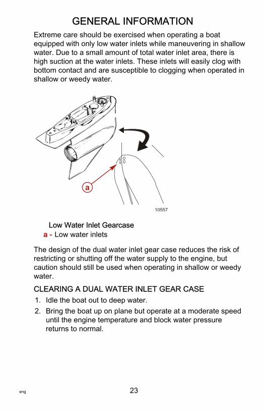
Extreme care should be exercised when operating a boatequipped with only low water inlets while maneuvering in shallowwater. Due to a small amount of total water inlet area, there ishigh suction at the water inlets. These inlets will easily clog withbottom contact and are susceptible to clogging when operated inshallow or weedy water.
Low Water Inlet Gearcasea - Low water inlets
The design of the dual water inlet gear case reduces the risk ofrestricting or shutting off the water supply to the engine, butcaution should still be used when operating in shallow or weedywater.
CLEARING A DUAL WATER INLET GEAR CASE1. Idle the boat out to deep water.2. Bring the boat up on plane but operate at a moderate speed
until the engine temperature and block water pressurereturns to normal.
10557
a
GENERAL INFORMATION
24 eng
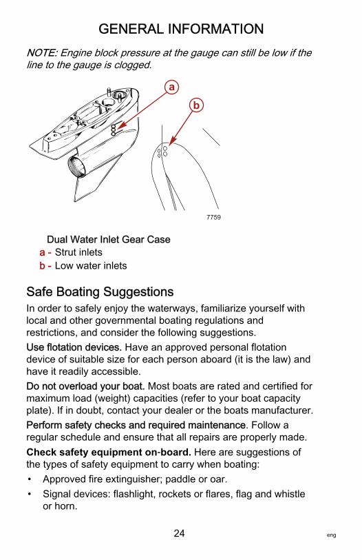
NOTE: Engine block pressure at the gauge can still be low if theline to the gauge is clogged.
Dual Water Inlet Gear Casea - Strut inletsb - Low water inlets
Safe Boating SuggestionsIn order to safely enjoy the waterways, familiarize yourself withlocal and other governmental boating regulations andrestrictions, and consider the following suggestions.Use flotation devices. Have an approved personal flotationdevice of suitable size for each person aboard (it is the law) andhave it readily accessible.Do not overload your boat. Most boats are rated and certified formaximum load (weight) capacities (refer to your boat capacityplate). If in doubt, contact your dealer or the boats manufacturer.Perform safety checks and required maintenance. Follow aregular schedule and ensure that all repairs are properly made.Check safety equipment on‑board. Here are suggestions ofthe types of safety equipment to carry when boating:• Approved fire extinguisher; paddle or oar.• Signal devices: flashlight, rockets or flares, flag and whistle
or horn.
7759
ab
GENERAL INFORMATION
eng 25
• Spare propeller, thrust hubs and an appropriate wrench.• Tools for necessary minor repairs; first aid kit and book.• Anchor, extra anchor line; water‑proof storage containers.• Manual bilge pump and extra drain plugs; compass and map
or chart of area.• Spare operating equipment; batteries, bulbs, fuses, etc.• Transistor radio and drinking water.
Know signs of weather change and avoid foul weather andrough‑sea boating.Tell someone where you are going and when you expect toreturn.Know and obey all nautical rules and laws of the waterways.Boat operators should complete a boating safety course.Courses are offered in the U.S.A. by:1. The U.S. Coast Guard Auxiliary2. The Power Squadron3. The Red Cross4. Your state boating law enforcement agencyDirect all inquiries to the Boat U.S. Foundation informationnumber 1‑800‑336‑BOAT (2626).We strongly recommend that all powerboat operators attend oneof these courses.You should also review the NMMA Sources of WaterwayInformation booklet. It lists regional sources of safety, cruisingand local navigation and is available at no charge by writing to:
Sources of Waterway InformationNational Marine Manufacturers Association410 N. Michigan AvenueChicago, IL 60611 U.S.A.

GENERAL INFORMATION
26 eng
Make sure everyone in the boat is properly seated. Do not allowanyone to sit or ride on any part of the boat that was notintended for such use. This includes the back of seats,gunwales, transom, bow, decks, raised fishing seats, anyrotating fishing seat; or anywhere that an unexpectedacceleration, sudden stopping, unexpected loss of boat control,or sudden boat movement could cause a person to be thrownoverboard or into the boat.Never be under the influence of alcohol or drugs while boating (itis the law). Alcohol or drug use impairs your judgment andgreatly reduces your ability to react quickly.Know your boating area and avoid hazardous locations.Prepare other boat operators. Instruct at least one other personon board in the basics of starting and operating the powerpackage, and boat handling, in case the driver becomes disabledor falls overboard.Passenger boarding. Stop the engine whenever passengers areboarding, unloading, or are near the back (stern) of the boat.Just shifting the power package into neutral is not sufficient.Be alert. The operator of the boat is responsible by law tomaintain a proper lookout by sight and hearing. The operatormust have an unobstructed view particularly to the front. Nopassengers, load, or fishing seats should block the operatorsview when operating the boat above idle speed.Never drive your boat directly behind a water skier in case theskier falls. As an example, your boat traveling at 40 km/h(25 MPH) will overtake a fallen skier 61 m (200 ft.) in front of youin five seconds.Watch fallen skiers. When using your boat for water skiing orsimilar activities, always keep a fallen or down skier on theoperator's side of the boat while returning to assist the skier. Theoperator should always have the down skier in sight and neverback up to the skier or anyone in the water.Report accidents. Boat operators are required by law to file aboating accident report with their state boating law enforcementagency when their boat is involved in certain boating accidents.A boating accident must be reported if:
GENERAL INFORMATION
eng 27
1. There is loss of life or probable loss of life2. There is personal injury requiring medical treatment beyond
first aid3. There is damage to boats or other property where the
damage value exceeds $500.004. There is complete loss of the boatIMPORTANT: Seek further assistance from local lawenforcement for a complete list of rules and regulations.
Stolen Power PackageIf your power package is stolen, immediately advise the localauthorities and Mercury Marine of the model and serialnumber(s) and to whom the recovery is to be reported. ThisStolen Power Package information is placed into a file atMercury Marine to aid authorities and dealers in recovery ofstolen engines.
SPECIFICATIONS
28 eng
Engine Identification
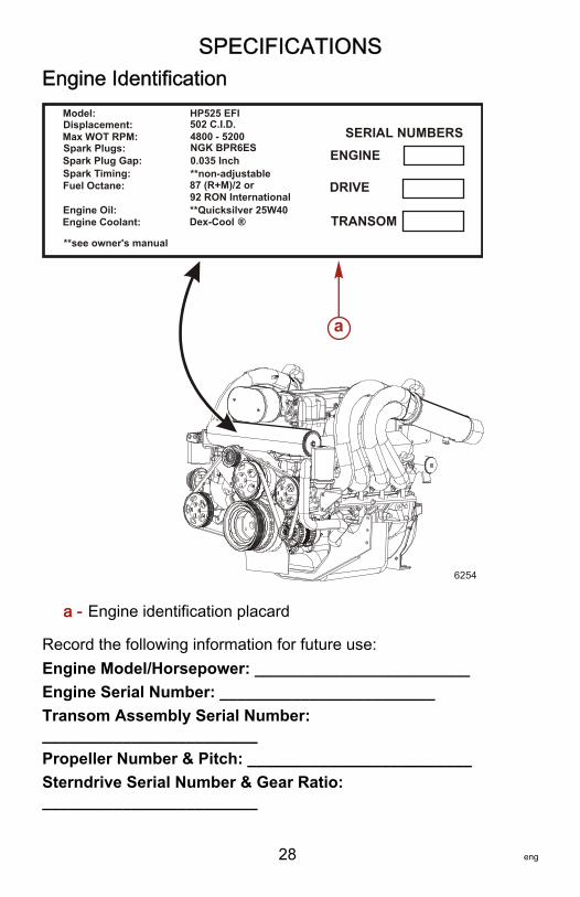
a - Engine identification placard
Record the following information for future use:Engine Model/Horsepower: ________________________Engine Serial Number: ________________________Transom Assembly Serial Number:________________________Propeller Number & Pitch: _________________________Sterndrive Serial Number & Gear Ratio:________________________
Model:Displacement:Max WOT RPM:Spark Plugs:Spark Plug Gap:Spark Timing:Fuel Octane:
Engine Oil:Engine Coolant:
**see owner's manual
HP525 EFI502 C.I.D.4800 - 5200NGK BPR6ES0.035 Inch**non-adjustable87 (R+M)/2 or92 RON International**Quicksilver 25W40Dex-Cool ®
SERIAL NUMBERSENGINE
DRIVE
TRANSOM
a
6254
SPECIFICATIONS
eng 29
Running Rotation: _________________________Hull Identification Number: _________________________Boat Model & Length: _________________________MODEL (HALF) YEAR IDENTIFICATION• Changed the engine harness from 10 pin to 14 pin.• Relocated the ignition coils and fuel filter for clearance of the
tailpipe in staggered engine installations.• Relocated the engine fuses and circuit breaker to the front of
the engine for improved serviceability.
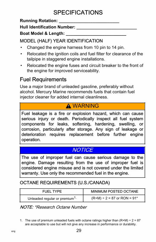
Fuel RequirementsUse a major brand of unleaded gasoline, preferably withoutalcohol. Mercury Marine recommends fuels that contain fuelinjector cleaner for added internal cleanliness.
! WARNINGFuel leakage is a fire or explosion hazard, which can causeserious injury or death. Periodically inspect all fuel systemcomponents for leaks, softening, hardening, swelling, orcorrosion, particularly after storage. Any sign of leakage ordeterioration requires replacement before further engineoperation.
NOTICEThe use of improper fuel can cause serious damage to theengine. Damage resulting from the use of improper fuel isconsidered engine misuse and is not covered under the limitedwarranty. Use only the recommended fuel in the engine.
OCTANE REQUIREMENTS (U.S./CANADA)
FUEL TYPE MINIMUM POSTED OCTANE
Unleaded regular or premium1. (R+M) ÷ 2 = 87 or RON = 91*
NOTE: *Research Octane Number
1. The use of premium unleaded fuels with octane ratings higher than (R+M) ÷ 2 = 87are acceptable to use but will not give any increase in performance or durability.
SPECIFICATIONS
30 eng
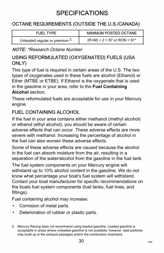
OCTANE REQUIREMENTS (OUTSIDE THE U.S./CANADA)
FUEL TYPE MINIMUM POSTED OCTANE
Unleaded regular or premium 2. (R+M) ÷ 2 = 87 or RON = 91*
NOTE: *Research Octane NumberUSING REFORMULATED (OXYGENATED) FUELS (USAONLY)This type of fuel is required in certain areas of the U.S. The twotypes of oxygenates used in these fuels are alcohol (Ethanol) orEther (MTBE or ETBE). If Ethanol is the oxygenate that is usedin the gasoline in your area, refer to the Fuel ContainingAlcohol section.These reformulated fuels are acceptable for use in your Mercuryengine.
FUEL CONTAINING ALCOHOLIf the fuel in your area contains either methanol (methyl alcohol)or ethanol (ethyl alcohol), you should be aware of certainadverse effects that can occur. These adverse effects are moresevere with methanol. Increasing the percentage of alcohol inthe fuel can also worsen these adverse effects.Some of these adverse effects are caused because the alcoholin the fuel can absorb moisture from the air, resulting in aseparation of the water/alcohol from the gasoline in the fuel tank.The fuel system components on your Mercury engine willwithstand up to 10% alcohol content in the gasoline. We do notknow what percentage your boat’s fuel system will withstand.Contact your boat manufacturer for specific recommendations onthe boats fuel system components (fuel tanks, fuel lines, andfittings).Fuel containing alcohol may increase:• Corrosion of metal parts.• Deterioration of rubber or plastic parts.
2. Mercury Racing does not recommend using leaded gasoline. Leaded gasoline isacceptable in areas where unleaded gasoline is not available; however, lead particlesmay build up in the exhaust passages and/or the combustion chambers.
SPECIFICATIONS
eng 31
• Fuel permeation through rubber fuel lines.• Starting and operating difficulties.
IMPORTANT: Operating a Mercury Marine engine with gasolinecontaining alcohol creates unique problems as a result of longstorage periods common to a boat. Cars normally consumealcohol‑blend fuels before they absorb enough moisture to causeproblems; however, boats often sit idle long enough for phaseseparation to occur. In addition, alcohol can wash protective oilfilms from internal components causing corrosion.IMPORTANT: Because of possible adverse effects of alcohol ingasoline, it is recommended that only alcohol‑free fuel be usedwhere possible.If only fuel containing alcohol is available, or if the presence ofalcohol is unknown, increased inspection frequency for leaks andabnormalities is required.
Low Permeation Fuel Hose RequirementLow permeation fuel hose must be installed on all sterndriveengine packages that are manufactured for sale, sold, or offeredfor sale in the United States.• The Environmental Protection Agency (EPA) requires that
any sterndrive engine package manufactured after January1, 2009, must use low permeation fuel hose for the primaryfuel hose connecting the fuel tank to the engine.
• Low permeation hose is USCG Type B1‑15 or Type A1‑15,defined as not exceeding 15/gm²/24 h with CE 10 fuel at23 °C as specified in SAE J 1527 ‑ marine fuel hose.
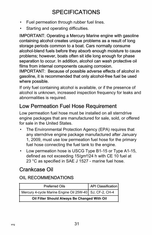
Crankcase OilOIL RECOMMENDATIONS
Preferred Oils API Classification
Mercury 4‑cycle Marine Engine Oil 25W‑40 SJ, CF‑2, CH‑4
Oil Filter Should Always Be Changed With Oil
SPECIFICATIONS
32 eng
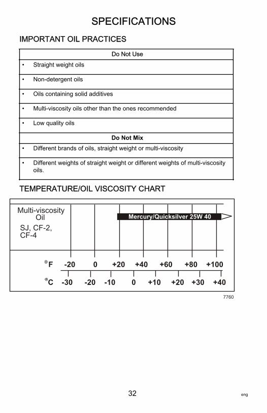
IMPORTANT OIL PRACTICES
Do Not Use
• Straight weight oils
• Non‑detergent oils
• Oils containing solid additives
• Multi‑viscosity oils other than the ones recommended
• Low quality oils
Do Not Mix• Different brands of oils, straight weight or multi‑viscosity
• Different weights of straight weight or different weights of multi‑viscosityoils.
TEMPERATURE/OIL VISCOSITY CHART
Multi-viscosity Oil
-20 0 +20 +40 +60 +80 +100 F
C
SJ, CF-2, CF-4
-20 -30 -10 +20 0 +30 +40 +10
Mercury/Quicksilver 25W 40
7760
SPECIFICATIONS
eng 33
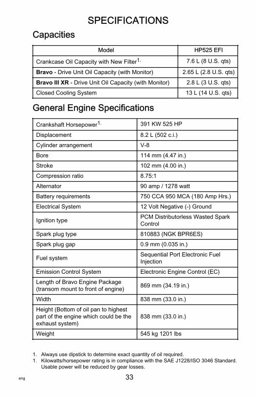
CapacitiesModel HP525 EFI
Crankcase Oil Capacity with New Filter1. 7.6 L (8 U.S. qts)
Bravo ‑ Drive Unit Oil Capacity (with Monitor) 2.65 L (2.8 U.S. qts)
Bravo III XR ‑ Drive Unit Oil Capacity (with Monitor) 2.8 L (3 U.S. qts)
Closed Cooling System 13 L (14 U.S. qts)
General Engine Specifications
Crankshaft Horsepower1. 391 KW 525 HP
Displacement 8.2 L (502 c.i.)
Cylinder arrangement V‑8
Bore 114 mm (4.47 in.)
Stroke 102 mm (4.00 in.)
Compression ratio 8.75:1
Alternator 90 amp / 1278 watt
Battery requirements 750 CCA 950 MCA (180 Amp Hrs.)
Electrical System 12 Volt Negative (‑) Ground
Ignition type PCM Distributorless Wasted SparkControl
Spark plug type 810883 (NGK BPR6ES)
Spark plug gap 0.9 mm (0.035 in.)
Fuel system Sequential Port Electronic FuelInjection
Emission Control System Electronic Engine Control (EC)
Length of Bravo Engine Package(transom mount to front of engine) 869 mm (34.19 in.)
Width 838 mm (33.0 in.)
Height (Bottom of oil pan to highestpart of the engine which could be theexhaust system)
838 mm (33.0 in.)
Weight 545 kg 1201 lbs
1. Always use dipstick to determine exact quantity of oil required.1. Kilowatts/horsepower rating is in compliance with the SAE J1228/ISO 3046 Standard.
Usable power will be reduced by gear losses.

SPECIFICATIONS
34 eng
Engine Operating LimitationsMaximum wide open throttle (W.O.T.) RPM 4800 ‑ 5300 RPM
Rev limit 1. 5400 RPM
Idle RPM in gear 700 RPM
Idle RPM out of gear 750 RPM
Maximum fuel system flow rate 163 L/hr (43 gals/hr) at 5200RPM
Fuel pressure at Sea Level 262‑296 kPa (38‑43 psi)
Coolant thermostat initially opens attemperature 62° C (143° F)
Coolant thermostat is at maximum open attemperature 71° C (160° F)
Minimum water pressure supplied to theengine at WOT 207 kPa (30 psi)
Maximum water pressure supplied to theengine at WOT 296 kPa (43 psi)
Minimum oil pressure at idle (Hot) 138 kPa (20 psi)
Minimum oil pressure at WOT (Hot) 331 kPa (48 psi)
Maximum oil temperature 121° C (250° F)
a - Front of engine and boatb - Firing order 1‑8‑4‑3‑6‑5‑7‑2
1
2
3
4
5
6
7
86985
a
b
b
1. Engines are equipped with an ignition system that has a built‑in 5400 RPM rev limiter.Engine is performing normally if it will not exceed this RPM.
SPECIFICATIONS
eng 35
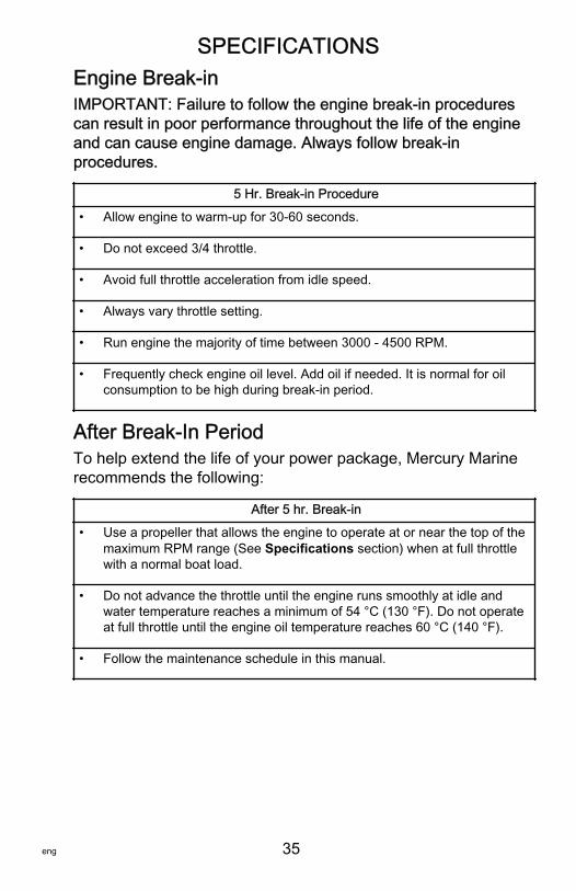
Engine Break‑inIMPORTANT: Failure to follow the engine break‑in procedurescan result in poor performance throughout the life of the engineand can cause engine damage. Always follow break‑inprocedures.
5 Hr. Break‑in Procedure
• Allow engine to warm‑up for 30‑60 seconds.
• Do not exceed 3/4 throttle.
• Avoid full throttle acceleration from idle speed.
• Always vary throttle setting.
• Run engine the majority of time between 3000 ‑ 4500 RPM.
• Frequently check engine oil level. Add oil if needed. It is normal for oilconsumption to be high during break‑in period.
After Break‑In PeriodTo help extend the life of your power package, Mercury Marinerecommends the following:
After 5 hr. Break‑in
• Use a propeller that allows the engine to operate at or near the top of themaximum RPM range (See Specifications section) when at full throttlewith a normal boat load.
• Do not advance the throttle until the engine runs smoothly at idle andwater temperature reaches a minimum of 54 °C (130 °F). Do not operateat full throttle until the engine oil temperature reaches 60 °C (140 °F).
• Follow the maintenance schedule in this manual.

OPERATION
36 eng
InstrumentationMercury Racing requires that the following critical enginefunctions be monitored:• Oil pressure• Engine RPM• Oil temperature• Water temperature• System voltage• Guardian fault messages
The use of SmartCraft instrumentation will display all of theabove critical engine functions as well as others not listed.SmartCraft instrumentation will also display informationabout power train sensor faults and Guardian activation.
Warning SystemThe engine's warning system includes an audible alert consistingof a horn located in the helm harness, and the Engine Guardiansystem. Do not attempt to alter or disable the warning system inany way.
NOTICEA continuous horn indicates a critical fault. Operating theengine during a critical fault can damage components. If thewarning horn emits a continuous beep, do not operate theengine unless avoiding a hazardous situation.
ENGINE GUARDIAN SYSTEMThe Engine Guardian system monitors sensors on the engine forany early indications of problems. If a sensor indicates a fault,the system responds to the problem by emitting a continuous orintermittent horn and, depending on the type of fault, may reduceengine power to provide engine protection. If the boat isequipped with System View, a message will be given on thedisplay screen in conjunction with the horn. Refer to the SystemView manual for details. When the key switch is turned "ON", thewarning system's horn beeps once to verify horn operation.
OPERATION
eng 37
Fault Type and Related Warning Signal• Critical ‑ Steady horn• Severe ‑ 5 beeps, each 3 seconds long• Warning ‑ 3 beeps, each 1.5 seconds long• Caution ‑ 2 beeps, each 1 second long• To stop an activated horn warning, turn off the engine. If the
horn continues to sound on restart, the system detected afault again. See your Mercury Marine dealer to correct theproblem as soon as possible.
• If on restart the beeping stops, the problem does not needimmediate attention but will require you to see yourauthorized Mercury Marine dealer to diagnose and clear thefault.
If the Propulsion Control Module (PCM) detects a fault signalfrom an engine sensor, it records a fault code. A DigitalDiagnostic Terminal (DDT) or Computer Diagnostic System(CDS) is required to extract specific problem codes from thePCM.
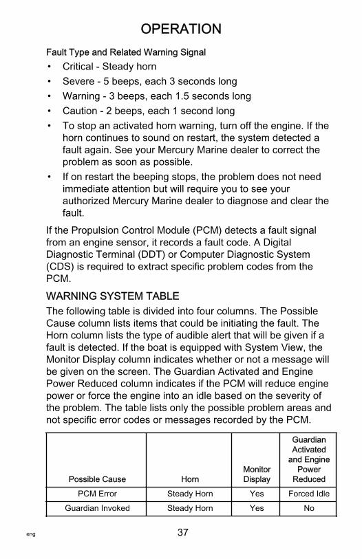
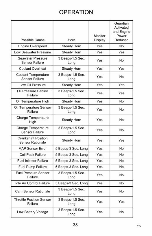
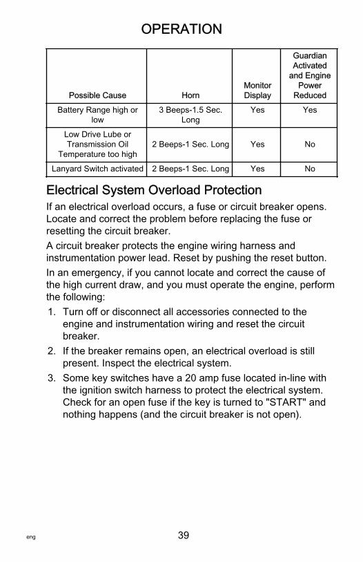
WARNING SYSTEM TABLEThe following table is divided into four columns. The PossibleCause column lists items that could be initiating the fault. TheHorn column lists the type of audible alert that will be given if afault is detected. If the boat is equipped with System View, theMonitor Display column indicates whether or not a message willbe given on the screen. The Guardian Activated and EnginePower Reduced column indicates if the PCM will reduce enginepower or force the engine into an idle based on the severity ofthe problem. The table lists only the possible problem areas andnot specific error codes or messages recorded by the PCM.
Possible Cause HornMonitorDisplay
GuardianActivated
and EnginePower
Reduced
PCM Error Steady Horn Yes Forced Idle
Guardian Invoked Steady Horn Yes No
OPERATION
38 eng
Possible Cause HornMonitorDisplay
GuardianActivated
and EnginePower
Reduced
Engine Overspeed Steady Horn Yes No
Low Seawater Pressure Steady Horn Yes Yes
Seawater PressureSensor Failure
3 Beeps‑1.5 Sec.Long Yes No
Coolant Overheat Steady Horn Yes Yes
Coolant TemperatureSensor Failure
3 Beeps‑1.5 Sec.Long Yes No
Low Oil Pressure Steady Horn Yes Yes
Oil Pressure SensorFailure
3 Beeps‑1.5 Sec.Long Yes Yes
Oil Temperature High Steady Horn Yes No
Oil Temperature SensorFailure
3 Beeps‑1.5 Sec.Long Yes No
Charge TemperatureHigh Steady Horn Yes No
Charge TemperatureSensor Failure
3 Beeps‑1.5 Sec.Long Yes No
Crankshaft PositionSensor Rationale Steady Horn Yes Yes
MAP Sensor Error 5 Beeps‑3 Sec. Long Yes No
Coil Pack Failure 5 Beeps‑3 Sec. Long Yes No
Fuel Injector Failure 5 Beeps‑3 Sec. Long Yes No
Fuel Pump Failure 5 Beeps‑3 Sec. Long Yes No
Fuel Pressure SensorFailure
3 Beeps‑1.5 Sec.Long Yes No
Idle Air Control Failure 5 Beeps‑3 Sec. Long Yes No
Cam Sensor Rationale 3 Beeps‑1.5 Sec.Long Yes No
Throttle Position SensorFailure
3 Beeps‑1.5 Sec.Long Yes Yes
Low Battery Voltage 3 Beeps‑1.5 Sec.Long Yes No
OPERATION
eng 39
Possible Cause HornMonitorDisplay
GuardianActivated
and EnginePower
Reduced
Battery Range high orlow
3 Beeps‑1.5 Sec.Long
Yes Yes
Low Drive Lube orTransmission Oil
Temperature too high2 Beeps‑1 Sec. Long Yes No
Lanyard Switch activated 2 Beeps‑1 Sec. Long Yes No
Electrical System Overload ProtectionIf an electrical overload occurs, a fuse or circuit breaker opens.Locate and correct the problem before replacing the fuse orresetting the circuit breaker.A circuit breaker protects the engine wiring harness andinstrumentation power lead. Reset by pushing the reset button.In an emergency, if you cannot locate and correct the cause ofthe high current draw, and you must operate the engine, performthe following:1. Turn off or disconnect all accessories connected to the
engine and instrumentation wiring and reset the circuitbreaker.
2. If the breaker remains open, an electrical overload is stillpresent. Inspect the electrical system.
3. Some key switches have a 20 amp fuse located in‑line withthe ignition switch harness to protect the electrical system.Check for an open fuse if the key is turned to "START" andnothing happens (and the circuit breaker is not open).
OPERATION
40 eng
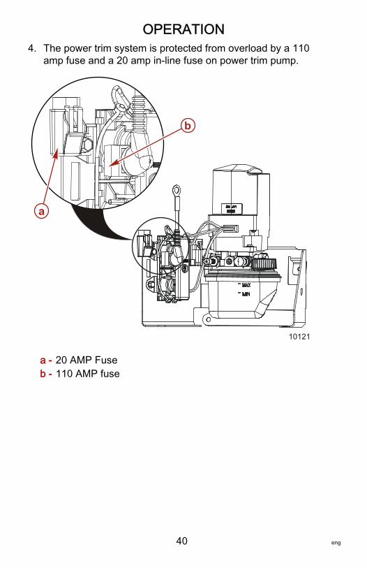
4. The power trim system is protected from overload by a 110amp fuse and a 20 amp in‑line fuse on power trim pump.
a - 20 AMP Fuseb - 110 AMP fuse
10121
a
b
OPERATION
eng 41
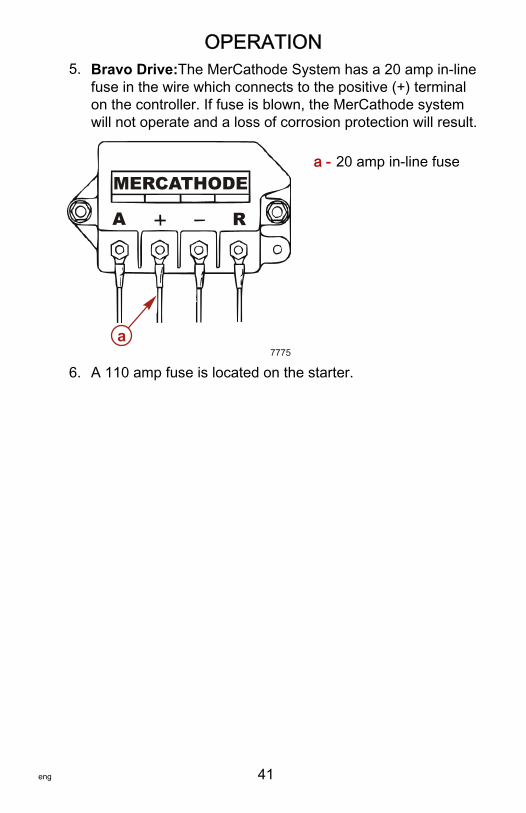
5. Bravo Drive:The MerCathode System has a 20 amp in‑linefuse in the wire which connects to the positive (+) terminalon the controller. If fuse is blown, the MerCathode systemwill not operate and a loss of corrosion protection will result.
a - 20 amp in‑line fuse
6. A 110 amp fuse is located on the starter.
MERCATHODE
A R
7775a
OPERATION
42 eng
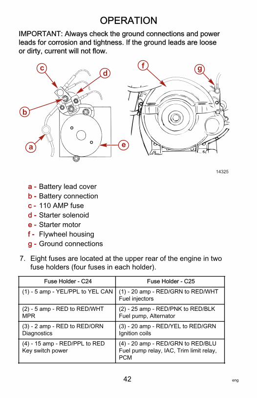
IMPORTANT: Always check the ground connections and powerleads for corrosion and tightness. If the ground leads are looseor dirty, current will not flow.
a - Battery lead coverb - Battery connectionc - 110 AMP fused - Starter solenoide - Starter motorf - Flywheel housingg - Ground connections
7. Eight fuses are located at the upper rear of the engine in twofuse holders (four fuses in each holder).
Fuse Holder ‑ C24 Fuse Holder ‑ C25
(1) ‑ 5 amp ‑ YEL/PPL to YEL CAN (1) ‑ 20 amp ‑ RED/GRN to RED/WHTFuel injectors
(2) ‑ 5 amp ‑ RED to RED/WHTMPR
(2) ‑ 25 amp ‑ RED/PNK to RED/BLKFuel pump, Alternator
(3) ‑ 2 amp ‑ RED to RED/ORNDiagnostics
(3) ‑ 20 amp ‑ RED/YEL to RED/GRNIgnition coils
(4) ‑ 15 amp ‑ RED/PPL to REDKey switch power
(4) ‑ 20 amp ‑ RED/GRN to RED/BLUFuel pump relay, IAC, Trim limit relay,PCM
14325
c
a
b
e
d gf
OPERATION
eng 43
Remote ControlsAll controls feature an integral safety switch that allows startingthe engine in neutral only. If the boat is equipped with a remotecontrol other than that shown, consult your dealer for adescription and/or demonstration of the control.
OPERATION
44 eng
1
73
5
46
2
1
4
2
3
6
4
2
8
6
7820
3
7
OPERATION
eng 45
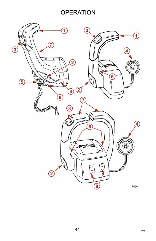
1 - Neutral Lock Bar ‑ Prevents accidental shift and throttleengagement. The neutral lock bar must be pulled up tomove the control handle out of neutral.
2 - Throttle Only Button ‑ Allows throttle advancementwithout shifting the engine by disengaging the shiftmechanism from the control handle. The throttle onlybutton can be depressed only when the remote controlhandle is in the neutral position, and should only be usedto assist in starting the engine.
3 - Power Trim Switch ‑ See the Power Trim section fordetailed power trim operating procedures.
4 - Trailer Switch (May not apply to all Bravo XR Drives) ‑See the Power Trim section for detailed trailer switchoperation.
5 - Lanyard Stop Switch ‑ Turns the ignition off. See theLanyard Stop Switch section at the front of this manualfor operation and safety warning on the use of this switch.
6 - Control Handle Tension Adjustment Screw ‑ Thisscrew can be adjusted to increase or decrease thetension on the control handle. This will help preventCreep of the remote control handle. Turn the screwclockwise to increase tension and Counter‑clockwise todecrease tension. Adjust to the tension desired.
7 - Control Handle ‑ Operation of the shift and throttle arecontrolled by the movement of the control handle. Pushthe control handle forward from neutral with a quick, firmmotion to the first detent for forward gear. Continuepushing forward to increase speed. Pull the controlhandle back from neutral with a quick, firm motion to thefirst detent for reverse gear. Continue pulling back toincrease speed.
8 - Power Trim Adjustment Switches ‑ (Used on ThreeButton Trim Control Only) ‑ See the Power Trim sectionfor detailed power trim operating procedures.
OPERATION
46 eng
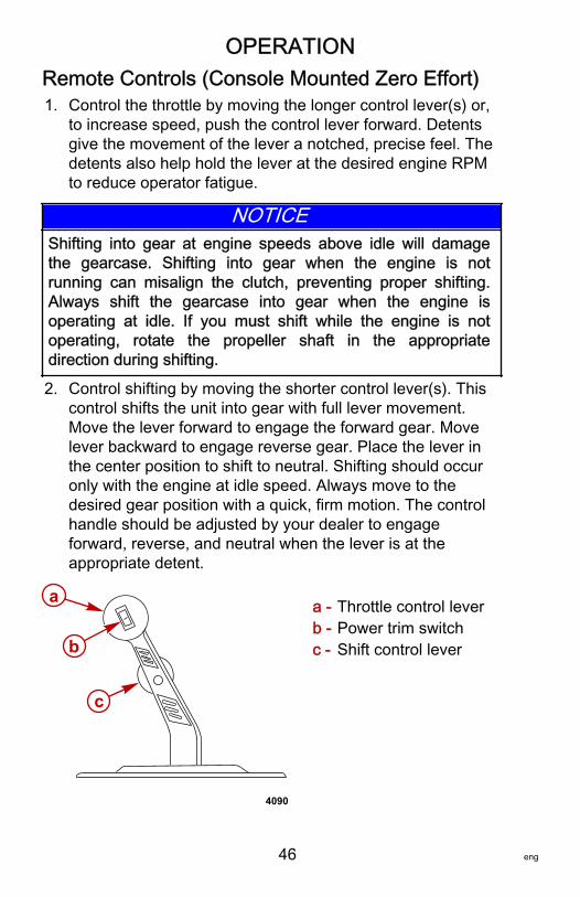
Remote Controls (Console Mounted Zero Effort)1. Control the throttle by moving the longer control lever(s) or,
to increase speed, push the control lever forward. Detentsgive the movement of the lever a notched, precise feel. Thedetents also help hold the lever at the desired engine RPMto reduce operator fatigue.
NOTICEShifting into gear at engine speeds above idle will damagethe gearcase. Shifting into gear when the engine is notrunning can misalign the clutch, preventing proper shifting.Always shift the gearcase into gear when the engine isoperating at idle. If you must shift while the engine is notoperating, rotate the propeller shaft in the appropriatedirection during shifting.
2. Control shifting by moving the shorter control lever(s). Thiscontrol shifts the unit into gear with full lever movement.Move the lever forward to engage the forward gear. Movelever backward to engage reverse gear. Place the lever inthe center position to shift to neutral. Shifting should occuronly with the engine at idle speed. Always move to thedesired gear position with a quick, firm motion. The controlhandle should be adjusted by your dealer to engageforward, reverse, and neutral when the lever is at theappropriate detent.
a - Throttle control leverb - Power trim switchc - Shift control lever
a
b
c
4090
OPERATION
eng 47
3. See Power Trim section for detailed power trim operatingprocedures.
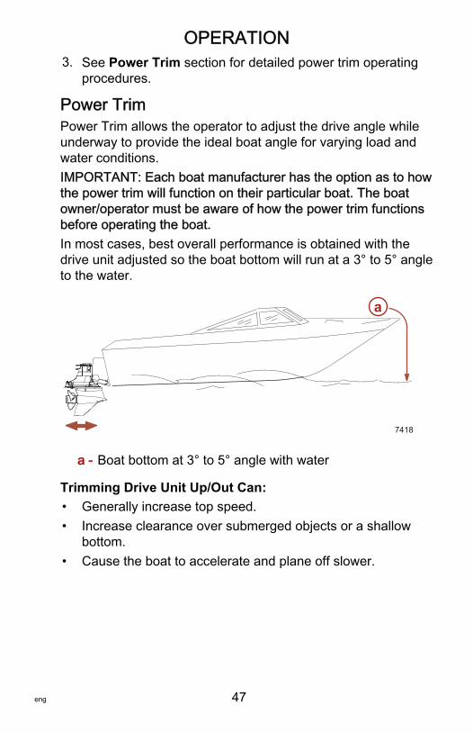
Power TrimPower Trim allows the operator to adjust the drive angle whileunderway to provide the ideal boat angle for varying load andwater conditions.IMPORTANT: Each boat manufacturer has the option as to howthe power trim will function on their particular boat. The boatowner/operator must be aware of how the power trim functionsbefore operating the boat.In most cases, best overall performance is obtained with thedrive unit adjusted so the boat bottom will run at a 3° to 5° angleto the water.
a - Boat bottom at 3° to 5° angle with water
Trimming Drive Unit Up/Out Can:• Generally increase top speed.• Increase clearance over submerged objects or a shallow
bottom.• Cause the boat to accelerate and plane off slower.
7418
a
OPERATION
48 eng
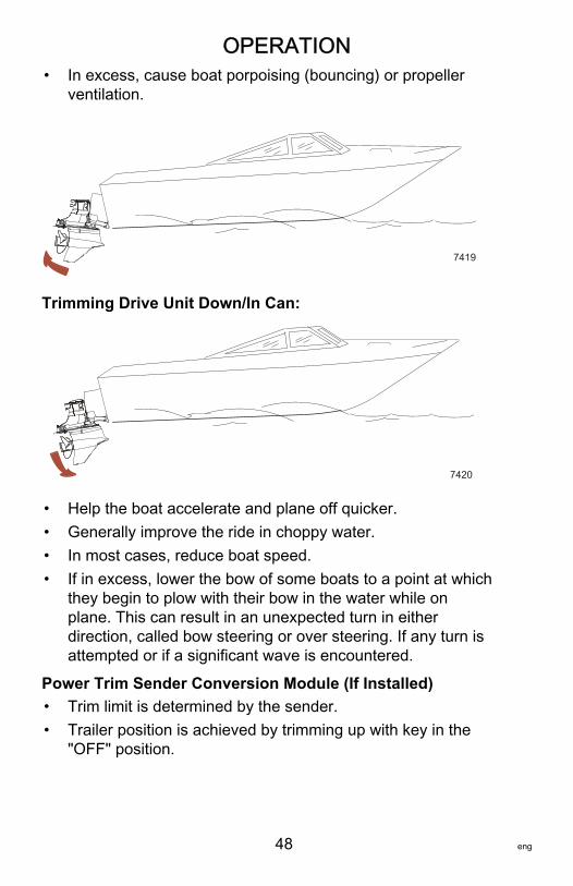
• In excess, cause boat porpoising (bouncing) or propellerventilation.
7419
Trimming Drive Unit Down/In Can:
7420
• Help the boat accelerate and plane off quicker.• Generally improve the ride in choppy water.• In most cases, reduce boat speed.• If in excess, lower the bow of some boats to a point at which
they begin to plow with their bow in the water while onplane. This can result in an unexpected turn in eitherdirection, called bow steering or over steering. If any turn isattempted or if a significant wave is encountered.
Power Trim Sender Conversion Module (If Installed)• Trim limit is determined by the sender.• Trailer position is achieved by trimming up with key in the
"OFF" position.
OPERATION
eng 49
POWER TRIM OPERATIONDual Engine Console Mount Remote Control (Two Button Version)
! WARNINGExcessive trim can cause serious injury or death at highspeeds, and single‑ram trim systems do not provide a trim‑outlimiting device or trim indicator. Use caution when trimmingwith a single‑ram trim system and never trim out beyond theunit's side support flanges while the boat is underway or atengine speeds above 1200 RPM.
NOTICEIf using external tie bars, raising or lowering the drivesindependently of each other can damage the drive and steeringsystems. If using an external tie bar, raise and lower all drivestogether as a unit.
IMPORTANT: Holding the trailer button depressed after the driveunit reaches the end of its travel will cause an internal circuitbreaker to open. Release the button and allow the pump to coolfor one minute. The circuit breaker will reset and power trimoperation can be resumed.
OPERATION
50 eng
1
2
2
1
2
3 7867
1

OPERATION
eng 51
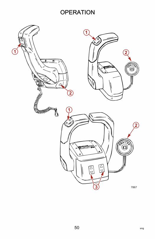
1 - Control ‑ Used to control both drive units from thehandle. Press up on the button(s) to trim drive unit up orout. Press down on button(s) to trim drive unit down or in.
2 - Trailer Button ‑ Press button until drive unit reachesdesired height for trailering drive units.
3 - Three Button Trim Control (Trim AdjustmentSwitches) ‑ With a single integral trim button in thehandle to control two drive units simultaneously, thesetwo switches control the fine tune adjustment of eachdrive unit. Using these fine tune switches, set each driveunit to the desired trim angle. Then use the single trimswitch in the handle to control the trim of both drive unitssimultaneously.
Zero Effort Control with Integral Trim SwitchSome bravo heavy duty transom assemblies do not have anelectrical trim limit switch or trim position sender. Therefore thefollowing precautions must be observed.
! WARNINGExcessive trim can cause serious injury or death at highspeeds, and single‑ram trim systems do not provide a trim‑outlimiting device or trim indicator. Use caution when trimmingwith a single‑ram trim system and never trim out beyond theunit's side support flanges while the boat is underway or atengine speeds above 1200 RPM.
NOTICEIf using external tie bars, raising or lowering the drivesindependently of each other can damage the drive and steeringsystems. If using an external tie bar, raise and lower all drivestogether as a unit.

OPERATION
52 eng
NOTE: The word trim is usually considered the first 20° up/outmovement from vertical position.
1 - Trailering and trimming up/out position ‑ Press (top)up/out portion of switch until drive unit reaches desiredtrim/trailering position.
2 - Trim drive unit in/down position ‑ Press (bottom) in/down portion of switch until drive unit reaches desiredtrim position.
Starting, Shifting and Stopping
! WARNINGExplosive fumes contained in the engine compartment cancause serious injury or death from fire or explosion. Beforestarting the engine, operate the bilge blower or vent the enginecompartment for at least five minutes.
NEW ENGINES OR ENGINES COMING OUT OF STORAGESee Power Package Recommissioning.
1
2
7868
OPERATION
eng 53
IMPORTANT: Observe the following:• Do not start the engine without supplying water to the
seawater pickup pump (to prevent pump or engine damage).• Do not operate the starter motor continuously for more than
30 seconds.• Never shift the drive unit unless the engine is at idle RPM.
Perform the following as appropriate:Check all items listed in Operation Chart.Perform any other necessary checks, as indicated by yourdealer, or specified in your boat owner's manual.Place the drive unit in full the down/in position.Place the control handle in neutral.
COLD OR WARM ENGINEEFI engines require no throttle advance to start. The boat can beoperated after the engine has started and is idling smoothly.IMPORTANT: If the engine has not been operated for more than24 hours, Mercury Marine recommends priming the engine oilsystem.NOTE: Engines that have not been started for extended periodsor have had fuel filter changes may not stay running on the firstfew initial attempts to start. Do not advance the throttle to keepthe engine running. Continue to restart the engine until it idlessmoothly which means the fuel system is primed. Allow theengine to warm up to 54 °C (130 °F) before advancing thethrottle. Do not operate at full throttle until the engine reaches anoil temperature of 60 °C (140 °F).FLOODED ENGINEMove control/throttle lever to half throttle. Be prepared todecrease engine speed to 1000 ‑ 1500 RPM as soon as enginestarts.
STARTING• Turn key switch to "START." Release key when engine
starts and allow switch to return to "RUN" position.
OPERATION
54 eng
• Check the oil pressure gauge immediately after the enginestarts. If oil pressure is not within the specified range, seeSpecifications, stop the engine immediately, and determinecause.
• If engine is cold, make sure engine is idling smoothly beforeoperating boat.
• After the engine has warmed up, check the watertemperature gauge to ensure that the engine temperature isnot abnormally high. If it is, stop the engine immediately anddetermine cause.
• Ensure that the charging system is functioning correctly.• Observe the power package for fuel, oil, water, and exhaust
leaks.
SHIFTING• To shift the drive unit into gear, move the control/shift lever
with a firm, quick motion forward to shift to forward gear, orbackward to shift to reverse. After shifting the drive unit,advance the throttle to the desired setting.
STOPPING• To shift the drive unit out of gear, move the control/shift
lever to neutral and allow the engine to drop to idle speed. Ifthe engine has been operating at high speed for a longperiod of time, allow the engine to cool by running at idlespeed for three to five minutes.
• Turn key switch to "OFF."
IMPORTANT: Starting procedure if engine is shut off or stopswith drive unit in gear.1. Pull/push remote control handle to neutral‑lock position (it
will be necessary to exert force to move handle).2. Turn key to "START" position, momentarily, to release clutch
from gear.3. Resume normal starting procedure.
Operation Chart1. Before Starting
OPERATION
eng 55
Open the engine hatch.Turn battery switch "ON," if equipped.Operate bilge blowers, if equipped.Open fuel shut off valve.Open seacock, if equipped.Perform all other checks specified by your dealer and/orboat builder.
2. After StartingObserve all gauges to check condition of engine. If notnormal, stop engine.Check for fuel, oil, water, fluid and exhaust leaks, etc.Check shift and throttle control operation.Check steering operation.
3. While UnderwayObserve all gauges to monitor engine condition.
4. After StoppingShift to neutral. Turn ignition key "OFF."Turn battery switch "OFF," if equipped.Close fuel valve.Close seacock.Flush cooling system if in saltwater area.
Freezing Temperature OperationIMPORTANT: If boat is operated in freezing temperatures,ensure that closed coolant is rated for the temperature range inwhich it is to be used. The seawater section of the engine mustbe drained after use to prevent freezing. Damage caused byfreezing is not covered by Mercury Racing's Limited Warranty.
OPERATION
56 eng
Drain Plug and Bilge PumpThe engine compartment in your boat is a natural place for waterto collect. For this reason, boats are normally equipped with adrain plug and/or a bilge pump. It is very important to checkthese items on a regular basis to ensure that the water leveldoes not rise to come in contact with your power package.Engine components will be damaged if submerged. Damagecaused by submersion is not covered by the Mercury RacingLimited Warranty.
Launching And Boat Operation Care
NOTICESome boating maneuvers can introduce water into the enginethrough the exhaust system, causing severe engine damage.Be careful when unloading a boat from its trailer, slowing downrapidly, backing up rapidly, and stopping suddenly.
In any of the situations described in the preceding caution, waterentering the engine could cause severe damage to internal parts.Refer to Attention Required After Submersion in the GeneralInformation section of this manual.

CONDITIONS AFFECTING OPERATION
eng 57
Weight DistributionPositioning of weight (passengers and gear) inside the boat hasthe following effects:Shifting weight to rear (stern) may:• Increase speed and engine RPM.• Cause the boat to porpoise.• Cause the bow to bounce in choppy water.• Increase the danger of a following wave splashing into the
boat when coming off plane.
Shifting weight to front (bow) may:• Improve ease of planing.• Improve rough water ride.• Cause the boat to veer back and forth (bow steer).
Bottom Of BoatTo maintain maximum speed, ensure that the bottom of the boatis:• Clean and free of barnacles and marine growth.• Free of distortion and nearly flat where it contacts the water.• Straight and smooth both fore and aft.
Marine vegetation may accumulate when the boat is docked,clogging water inlets and causing the engine to overheat. Thisgrowth must be removed before operation.
CavitationCavitation occurs when water flow cannot follow the contour of afast‑moving, underwater object, such as a gear housing orpropeller. Cavitation permits the propeller to speed up, but theboat speed to reduce. Cavitation can seriously erode the surfaceof the gear housing or propeller. Common causes of cavitationare:• Weeds or other debris snagged on propeller or gear
housing.• Bent propeller blade or damaged gear housing skeg.• Raised burrs or sharp edges on propeller or gear housing.
CONDITIONS AFFECTING OPERATION
58 eng
VentilationVentilation occurs when surface air or exhaust gases surroundthe propeller, causing propeller speed‑up (slippage) and adecrease in boat speed. Excessive ventilation is annoying andusually caused by:• A drive unit trimmed out too far.• A damaged propeller or gear housing, allowing exhaust
gases to escape between propeller and gear housing.• A drive unit installed too high on the transom.
Propeller SelectionIMPORTANT: Choosing the correct propeller allows the engineto run at its specified maximum wide‑open‑throttle RPM. Use anaccurate service tachometer to verify engine operating RPM.It is the boat manufacturer and/or the selling dealer'sresponsibility to equip the power package with the correctpropeller(s). Specified engine wide‑open‑throttle (WOT) andoperating RPM range are listed in Specifications.IMPORTANT: All Mercury Racing engines have an RPMrev‑limiter that is set to an upper (or limited) RPM. This limit isslightly above the normal operating range of the engine and isdesigned to help prevent damage from excessive engine RPM.Once the RPM drops into the recommended operating RPMrange, normal engine operation resumes.Select a propeller that allows the engine to operate in the upperhalf of the recommended full throttle RPM range with the boatnormally loaded (refer to Specifications).If full throttle operation is below the recommended range, changethe propeller to prevent loss of performance and possible enginedamage. On the other hand, operating an engine above therecommended operating RPM range causes higher than normalwear or damage. "Propeller lines normally are designed so thatthe next size pitch will change engine RPM by 300 to 500. Forevery 1" of pitch change, the effect will be approximately 200RPM."RPM loss may require changing to a lower pitch propellerdue to the following conditions:
CONDITIONS AFFECTING OPERATION
eng 59
• Operating in warmer weather and greater humidity.• Operating in a higher elevation.• Operating with a damaged propeller or dirty boat bottom.• Operating with increased load (additional passengers,
pulling skiers, etc.).
Conditions That Lower Engine PerformanceThe following conditions lower engine performance and cannotbe compensated by the engine fuel or electronic managementsystems.• Above sea level elevations• High temperature.• Low barometric pressure.• High humidity.
The conditions listed above reduce air density to the enginewhich in turn reduces the following:• Boost pressure on supercharged engines• Horsepower and torque throughout the RPM range• Peak RPM• Cranking compression
EXAMPLE: An engine running at an elevation of 2,438 m (8,000ft) will have over a 30% power loss while engine power on a hotand humid day can be reduced by as much as 14%. Theselosses apply to both normally aspirated and superchargedengines.Compensating for power robbing conditions:• Switch to a lower pitch propeller.• Change the gear ratio.
Some boat performance can be regained by dropping to a lowerpitch propeller, but engine performance will remain lower. Insome cases, a gear ratio reduction may be more beneficial. Tooptimize engine performance, prop the engine to allow operationat or near the top end of the recommended maximum RPMrange at wide open throttle with a normal boat load.
MAINTENANCE
60 eng
Service ResponsibilitiesOWNER/OPERATOR RESPONSIBILITIESIt is the owner/operator's responsibility to perform the following:• Perform all safety checks.• Return the unit to an authorized Mercury Marine dealer for a
periodic checkup.
Proper maintenance and care of your power package will ensureoptimum performance and dependability, and will keep youroverall operating expenses at a minimum. See your authorizedMercury Marine dealer for service aids.
DEALER RESPONSIBILITIESIn general, a dealer's responsibilities to the customer includepredelivery inspection and preparation. These include:• Completing a Warranty Registration Card and mailing it to
the factory immediately upon sale of the new product.• Properly equipping the boat.• Making certain that the Mercury Marine power package and
other equipment are in proper operating condition prior todelivery.
• Making all necessary adjustments for maximum efficiency.• Familiarizing the customer with the on‑board equipment.• Explaining and demonstrating the operation of the power
package and boat.• Providing you with a copy of a Predelivery Inspection
Checklist prior to delivery.
MAINTENANCE
eng 61
Replacement Service Parts
! WARNINGAvoid fire or explosion hazard. Electrical, ignition, and fuelsystem components on Mercury Marine products comply withfederal and international standards to minimize risk of fire orexplosion. Do not use replacement electrical or fuel systemcomponents that do not comply with these standards. Whenservicing the electrical and fuel systems, properly install andtighten all components.
Marine engines are expected to operate at or near full throttle formost of their life. They are also expected to operate in fresh andsaltwater environments. These conditions require numerousspecial parts. Care should be exercised when replacing marineengine parts, as specifications are quite different from those ofthe standard automotive engine.For example, one of the most important, and probably the leastsuspected special replacement part, is the cylinder head gasket.Since saltwater is highly corrosive, the steel‑type automotivehead gasket cannot be used. A marine engine head gasket usesspecial materials to resist corrosive action.Since marine engines must be capable of running at or nearmaximum RPM much of the time, special valve springs, valvelifters, pistons, bearings, camshafts and other heavy‑duty movingparts are required for long life and peak performance.These are but a few of the many special modifications that arerequired in Mercury Marine engines to provide long life anddependable performance.
Do‑It‑Yourself Maintenance SuggestionsIf you are one of those persons who likes to do‑it‑yourself, hereare some suggestions for you.
MAINTENANCE
62 eng
• Present‑day marine equipment, such as your MercuryMarine power package, are highly technical pieces ofmachinery. Electronic ignition and special fuel deliverysystems provide greater fuel economies, but increasedcomplexity for the untrained mechanic.
• Do not attempt any repairs that are not covered in thismanual unless you are aware of the precautions andprocedures required. Your safety is our concern.
• If you attempt to service the product yourself, we suggestyou order the service manual for that model. This manualoutlines the correct procedures to follow. It is written for thetrained mechanic, so there may be procedures you don'tunderstand. Do not attempt repairs if you do not understandthe procedures.
• Special tools and equipment may be required to performsome repairs. Do not attempt these repairs unless you havethese special tools and/or equipment. You can causedamage to the product in excess of the cost a dealer wouldcharge you for the repair.
• If you partially disassemble an engine or drive assembly andare unable to repair it, the dealer's mechanic mustre‑assemble the components and test to determine theproblem. This will cost you more than taking it to the dealerimmediately upon having a problem. It may be a very simpleadjustment to correct the problem.
• Do not telephone the dealer, service office or the factory andattempt to diagnose a problem or request the repairprocedure. It is difficult for them to diagnose a problem overthe telephone.
• Your authorized Mercury Marine dealer is there to serviceyour power package. They have qualified factory‑trainedmechanics.
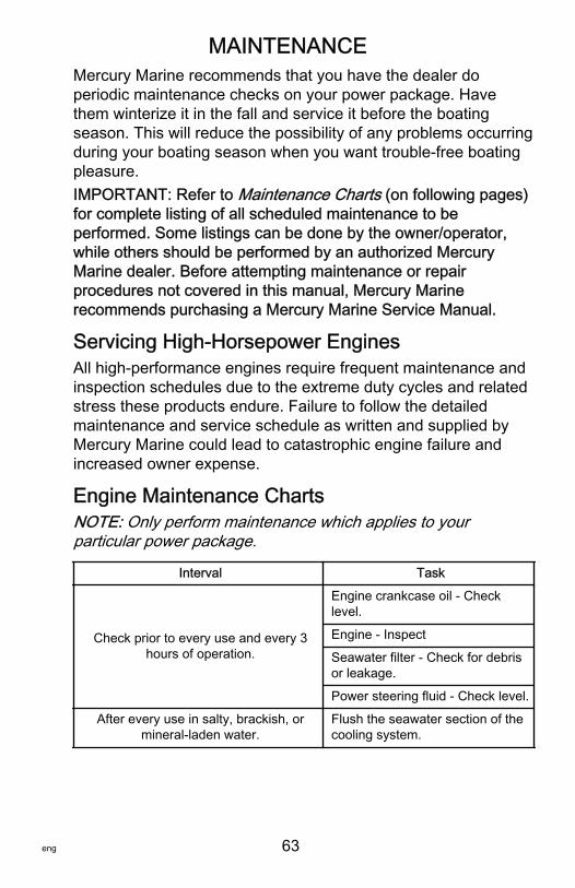
MAINTENANCE
eng 63
Mercury Marine recommends that you have the dealer doperiodic maintenance checks on your power package. Havethem winterize it in the fall and service it before the boatingseason. This will reduce the possibility of any problems occurringduring your boating season when you want trouble‑free boatingpleasure.IMPORTANT: Refer to Maintenance Charts (on following pages)for complete listing of all scheduled maintenance to beperformed. Some listings can be done by the owner/operator,while others should be performed by an authorized MercuryMarine dealer. Before attempting maintenance or repairprocedures not covered in this manual, Mercury Marinerecommends purchasing a Mercury Marine Service Manual.
Servicing High‑Horsepower EnginesAll high‑performance engines require frequent maintenance andinspection schedules due to the extreme duty cycles and relatedstress these products endure. Failure to follow the detailedmaintenance and service schedule as written and supplied byMercury Marine could lead to catastrophic engine failure andincreased owner expense.
Engine Maintenance ChartsNOTE: Only perform maintenance which applies to yourparticular power package.
Interval Task
Check prior to every use and every 3hours of operation.
Engine crankcase oil ‑ Checklevel.
Engine ‑ Inspect
Seawater filter ‑ Check for debrisor leakage.
Power steering fluid ‑ Check level.
After every use in salty, brackish, ormineral‑laden water.
Flush the seawater section of thecooling system.
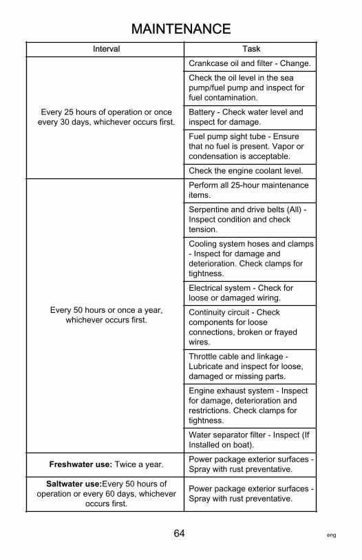
MAINTENANCE
64 eng
Interval Task
Every 25 hours of operation or onceevery 30 days, whichever occurs first.
Crankcase oil and filter ‑ Change.
Check the oil level in the seapump/fuel pump and inspect forfuel contamination.
Battery ‑ Check water level andinspect for damage.
Fuel pump sight tube ‑ Ensurethat no fuel is present. Vapor orcondensation is acceptable.
Check the engine coolant level.
Every 50 hours or once a year,whichever occurs first.
Perform all 25‑hour maintenanceitems.
Serpentine and drive belts (All) ‑Inspect condition and checktension.
Cooling system hoses and clamps‑ Inspect for damage anddeterioration. Check clamps fortightness.
Electrical system ‑ Check forloose or damaged wiring.
Continuity circuit ‑ Checkcomponents for looseconnections, broken or frayedwires.
Throttle cable and linkage ‑Lubricate and inspect for loose,damaged or missing parts.
Engine exhaust system ‑ Inspectfor damage, deterioration andrestrictions. Check clamps fortightness.
Water separator filter ‑ Inspect (IfInstalled on boat).
Freshwater use: Twice a year. Power package exterior surfaces ‑Spray with rust preventative.
Saltwater use:Every 50 hours ofoperation or every 60 days, whichever
occurs first.
Power package exterior surfaces ‑Spray with rust preventative.
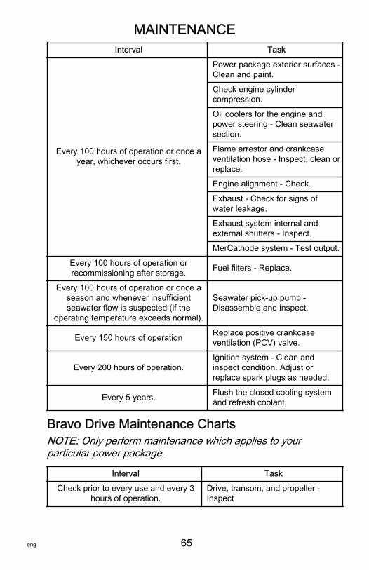
MAINTENANCE
eng 65
Interval Task
Every 100 hours of operation or once ayear, whichever occurs first.
Power package exterior surfaces ‑Clean and paint.
Check engine cylindercompression.
Oil coolers for the engine andpower steering ‑ Clean seawatersection.
Flame arrestor and crankcaseventilation hose ‑ Inspect, clean orreplace.
Engine alignment ‑ Check.
Exhaust ‑ Check for signs ofwater leakage.
Exhaust system internal andexternal shutters ‑ Inspect.
MerCathode system ‑ Test output.
Every 100 hours of operation orrecommissioning after storage. Fuel filters ‑ Replace.
Every 100 hours of operation or once aseason and whenever insufficientseawater flow is suspected (if the
operating temperature exceeds normal).
Seawater pick‑up pump ‑Disassemble and inspect.
Every 150 hours of operation Replace positive crankcaseventilation (PCV) valve.
Every 200 hours of operation.Ignition system ‑ Clean andinspect condition. Adjust orreplace spark plugs as needed.
Every 5 years. Flush the closed cooling systemand refresh coolant.
Bravo Drive Maintenance ChartsNOTE: Only perform maintenance which applies to yourparticular power package.
Interval Task
Check prior to every use and every 3hours of operation.
Drive, transom, and propeller ‑Inspect

MAINTENANCE
66 eng
Interval Task
Every 25 hours of operation or onceevery 30 days, whichever occurs first.
Gear housing water pickups ‑Check for marine growth or debris.
Anodes ‑ Inspect for erosion.
Sterndrive unit oil ‑ Check level.
Trim pump ‑ Check oil level
Saltwater use: Every 50 hours ofoperation or 60 days, whichever occurs
first.Propeller shaft ‑ Lubricate.
Every 50 hours or once a year,whichever occurs first.
Perform all 25 hour maintenanceitems.
Shift cable and linkage ‑ Lubricateand inspect for loose, damaged ormissing parts.
Engine coupler and universal jointshaft splines and O‑rings ‑Lubricate.
Sterndrive unit ‑ Oil change.
Sterndrive unit universal joint crossbearings ‑ Inspect and lubricate.
Gimbal ring clamping screws ‑Re‑torque to 67‑74 Nm(50‑55 lb. ft.).
Gimbal bearing ‑ Lubricate.
Transom gimbal housing assemblyswivel shaft and gimbal bearing ‑Lubricate.
Engine driveshaft ‑ Lubricate (driveline models).
Engine output shaft bearings ‑Lubricate (drive line models).
Input shaft/rear bearing supportblock bearing ‑ Lubricate (drive linemodels).
Steering system ‑ Lubricate andinspect for loose, damaged ormissing parts.
Propeller shaft ‑ Inspect forbending.
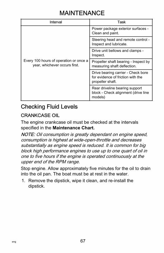
MAINTENANCE
eng 67
Interval Task
Every 100 hours of operation or once ayear, whichever occurs first.
Power package exterior surfaces ‑Clean and paint.
Steering head and remote control ‑Inspect and lubricate.
Drive unit bellows and clamps ‑Inspect.
Propeller shaft bearing ‑ Inspect bymeasuring shaft deflection.
Drive bearing carrier ‑ Check borefor evidence of friction with thepropeller shaft.
Rear driveline bearing supportblock ‑ Check alignment (drive linemodels)
Checking Fluid LevelsCRANKCASE OILThe engine crankcase oil must be checked at the intervalsspecified in the Maintenance Chart.NOTE: Oil consumption is greatly dependant on engine speed,consumption is highest at wide‑open‑throttle and decreasessubstantially as engine speed is reduced. It is common for bigblock high performance engines to use up to one quart of oil inone to five hours if the engine is operated continuously at theupper end of the RPM range.Stop engine. Allow approximately five minutes for the oil to draininto the oil pan. The boat must be at rest in the water.1. Remove the dipstick, wipe it clean, and re‑install the
dipstick.
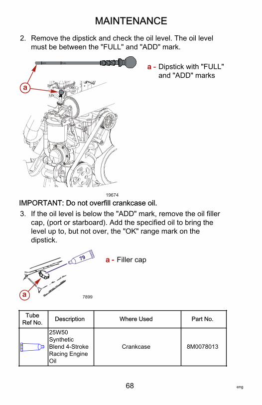
MAINTENANCE
68 eng
2. Remove the dipstick and check the oil level. The oil levelmust be between the "FULL" and "ADD" mark.
a - Dipstick with "FULL"and "ADD" marks
IMPORTANT: Do not overfill crankcase oil.3. If the oil level is below the "ADD" mark, remove the oil filler
cap, (port or starboard). Add the specified oil to bring thelevel up to, but not over, the "OK" range mark on thedipstick.
a - Filler cap
TubeRef No. Description Where Used Part No.
25W50SyntheticBlend 4-StrokeRacing EngineOil
Crankcase 8M0078013
ADD FULL
aa
19674
a 7899
79
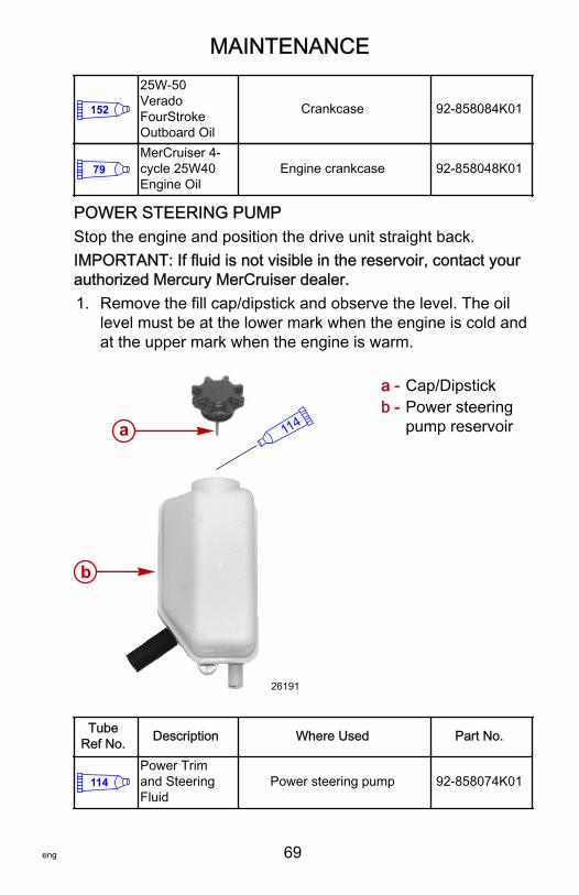
MAINTENANCE
eng 69
152
25W-50VeradoFourStrokeOutboard Oil
Crankcase 92-858084K01
79MerCruiser 4-cycle 25W40Engine Oil
Engine crankcase 92-858048K01
POWER STEERING PUMPStop the engine and position the drive unit straight back.IMPORTANT: If fluid is not visible in the reservoir, contact yourauthorized Mercury MerCruiser dealer.1. Remove the fill cap/dipstick and observe the level. The oil
level must be at the lower mark when the engine is cold andat the upper mark when the engine is warm.
a - Cap/Dipstickb - Power steering
pump reservoir
TubeRef No. Description Where Used Part No.
114Power Trimand SteeringFluid
Power steering pump 92-858074K01
114
26191
a
b
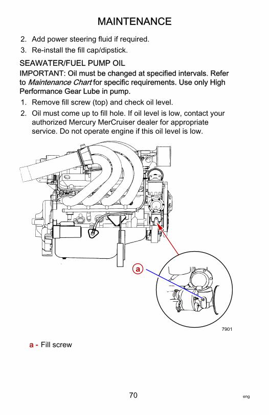
MAINTENANCE
70 eng
2. Add power steering fluid if required.3. Re‑install the fill cap/dipstick.
SEAWATER/FUEL PUMP OILIMPORTANT: Oil must be changed at specified intervals. Referto Maintenance Chart for specific requirements. Use only HighPerformance Gear Lube in pump.1. Remove fill screw (top) and check oil level.2. Oil must come up to fill hole. If oil level is low, contact your
authorized Mercury MerCruiser dealer for appropriateservice. Do not operate engine if this oil level is low.
a - Fill screw
a
7901

MAINTENANCE
eng 71
TubeRef No. Description Where Used Part No.
87HighPerformanceGear Lubricant
Seawater/fuel pump 92-858064K01
ENGINE COOLANT
! CAUTIONA sudden loss of pressure can cause hot coolant to boil anddischarge violently resulting in serious injury from burns. Allowthe engine to cool down before removing the coolant pressurecap.
IMPORTANT: Check engine coolant before starting engine.1. Check coolant level in coolant reservoir. Coolant should be
at the full line marked on the reservoir with the engine cold.Add specified coolant as required.
a - Reservoir
2. If coolant is low, inspect coolant recovery system for leaks.
a
19621
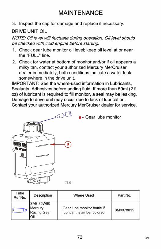
MAINTENANCE
72 eng
3. Inspect the cap for damage and replace if necessary.
DRIVE UNIT OILNOTE: Oil level will fluctuate during operation. Oil level shouldbe checked with cold engine before starting.1. Check gear lube monitor oil level; keep oil level at or near
the "FULL" line.2. Check for water at bottom of monitor and/or if oil appears a
milky tan, contact your authorized Mercury MerCruiserdealer immediately; both conditions indicate a water leaksomewhere in the drive unit.
IMPORTANT: See the where‑used information in Lubricants,Sealants, Adhesives before adding fluid. If more than 59ml (2 floz) of lubricant is required to fill monitor, a seal may be leaking.Damage to drive unit may occur due to lack of lubrication.Contact your authorized Mercury MerCruiser dealer for service.
a - Gear lube monitor
TubeRef No. Description Where Used Part No.
SAE 85W90MercuryRacing GearOil
Gear lube monitor bottle iflubricant is amber colored 8M0078015
87
7333
a
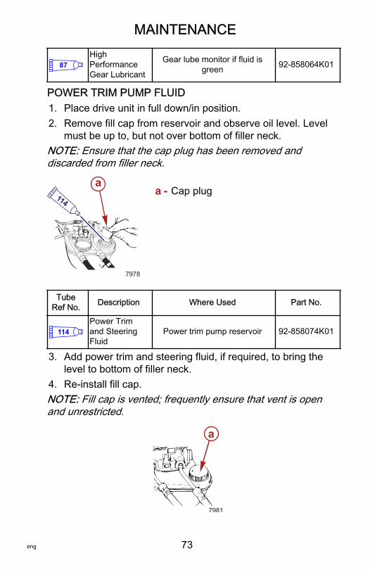
MAINTENANCE
eng 73
87HighPerformanceGear Lubricant
Gear lube monitor if fluid isgreen 92-858064K01
POWER TRIM PUMP FLUID1. Place drive unit in full down/in position.2. Remove fill cap from reservoir and observe oil level. Level
must be up to, but not over bottom of filler neck.NOTE: Ensure that the cap plug has been removed anddiscarded from filler neck.
a - Cap plug
TubeRef No. Description Where Used Part No.
114Power Trimand SteeringFluid
Power trim pump reservoir 92-858074K01
3. Add power trim and steering fluid, if required, to bring thelevel to bottom of filler neck.
4. Re‑install fill cap.NOTE: Fill cap is vented; frequently ensure that vent is openand unrestricted.
a
7981
a114
7978

MAINTENANCE
74 eng
Changing FluidsSee the Maintenance Chart for lubricant change frequency.Lubricant should be changed before placing the boat in storage.Power trim or power steering fluids do not require changing.
CRANKCASE OIL AND FILTER (BOAT IN THE WATER)IMPORTANT: Change oil when engine is warm from operation.Warm oil flows more freely, carrying away more impurities. Useonly recommended motor oil (see Specifications).1. With the engine at normal operating temperature, remove
the dipstick.2. Install the crankcase oil pump onto the dipstick tube.3. Insert the hose end of crankcase oil pump into an
appropriate container and, using the pump handle, pumpuntil the crankcase is empty.
a - Crankcase oil pumpb - Crankcase oil pump hose
4. Remove the crankcase oil pump.5. Place a container below the oil filter.NOTE: To allow the oil to drain from the filter, loosen the filterjust enough to break the internal vacuum. Let the oil drain backinto the system for 15 minutes prior to complete removal of thefilter.
a - Crankcase oil filter
6. Remove the oil filter from the adaptor and discard the old oilfilter and old sealing ring.
ba
7983
a
7984
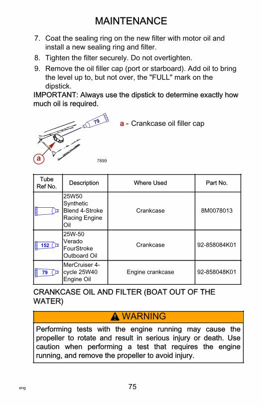
MAINTENANCE
eng 75
7. Coat the sealing ring on the new filter with motor oil andinstall a new sealing ring and filter.
8. Tighten the filter securely. Do not overtighten.9. Remove the oil filler cap (port or starboard). Add oil to bring
the level up to, but not over, the "FULL" mark on thedipstick.
IMPORTANT: Always use the dipstick to determine exactly howmuch oil is required.
a - Crankcase oil filler cap
TubeRef No. Description Where Used Part No.
25W50SyntheticBlend 4-StrokeRacing EngineOil
Crankcase 8M0078013
152
25W-50VeradoFourStrokeOutboard Oil
Crankcase 92-858084K01
79MerCruiser 4-cycle 25W40Engine Oil
Engine crankcase 92-858048K01
CRANKCASE OIL AND FILTER (BOAT OUT OF THEWATER)
! WARNINGPerforming tests with the engine running may cause thepropeller to rotate and result in serious injury or death. Usecaution when performing a test that requires the enginerunning, and remove the propeller to avoid injury.
a 7899
79
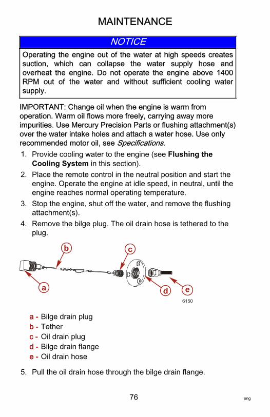
MAINTENANCE
76 eng
NOTICEOperating the engine out of the water at high speeds createssuction, which can collapse the water supply hose andoverheat the engine. Do not operate the engine above 1400RPM out of the water and without sufficient cooling watersupply.
IMPORTANT: Change oil when the engine is warm fromoperation. Warm oil flows more freely, carrying away moreimpurities. Use Mercury Precision Parts or flushing attachment(s)over the water intake holes and attach a water hose. Use onlyrecommended motor oil, see Specifications.1. Provide cooling water to the engine (see Flushing the
Cooling System in this section).2. Place the remote control in the neutral position and start the
engine. Operate the engine at idle speed, in neutral, until theengine reaches normal operating temperature.
3. Stop the engine, shut off the water, and remove the flushingattachment(s).
4. Remove the bilge plug. The oil drain hose is tethered to theplug.
a - Bilge drain plugb - Tetherc - Oil drain plugd - Bilge drain flangee - Oil drain hose
5. Pull the oil drain hose through the bilge drain flange.
6150
ed
cb
a
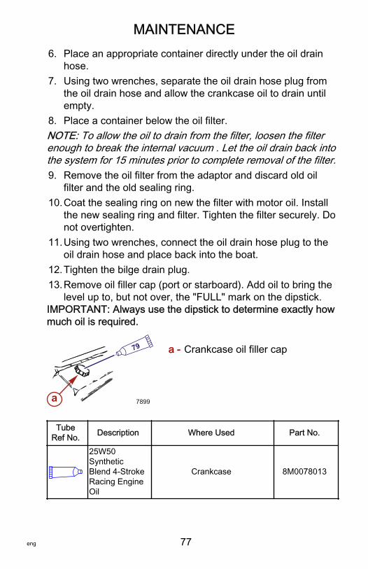
MAINTENANCE
eng 77
6. Place an appropriate container directly under the oil drainhose.
7. Using two wrenches, separate the oil drain hose plug fromthe oil drain hose and allow the crankcase oil to drain untilempty.
8. Place a container below the oil filter.NOTE: To allow the oil to drain from the filter, loosen the filterenough to break the internal vacuum . Let the oil drain back intothe system for 15 minutes prior to complete removal of the filter.9. Remove the oil filter from the adaptor and discard old oil
filter and the old sealing ring.10.Coat the sealing ring on new the filter with motor oil. Install
the new sealing ring and filter. Tighten the filter securely. Donot overtighten.
11.Using two wrenches, connect the oil drain hose plug to theoil drain hose and place back into the boat.
12.Tighten the bilge drain plug.13.Remove oil filler cap (port or starboard). Add oil to bring the
level up to, but not over, the "FULL" mark on the dipstick.IMPORTANT: Always use the dipstick to determine exactly howmuch oil is required.
a - Crankcase oil filler cap
TubeRef No. Description Where Used Part No.
25W50SyntheticBlend 4-StrokeRacing EngineOil
Crankcase 8M0078013
a 7899
79
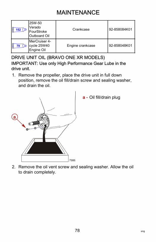
MAINTENANCE
78 eng
152
25W-50VeradoFourStrokeOutboard Oil
Crankcase 92-858084K01
79MerCruiser 4-cycle 25W40Engine Oil
Engine crankcase 92-858048K01
DRIVE UNIT OIL (BRAVO ONE XR MODELS)IMPORTANT: Use only High Performance Gear Lube in thedrive unit.1. Remove the propeller, place the drive unit in full down
position, remove the oil fill/drain screw and sealing washer,and drain the oil.
a - Oil fill/drain plug
2. Remove the oil vent screw and sealing washer. Allow the oilto drain completely.
a
7986
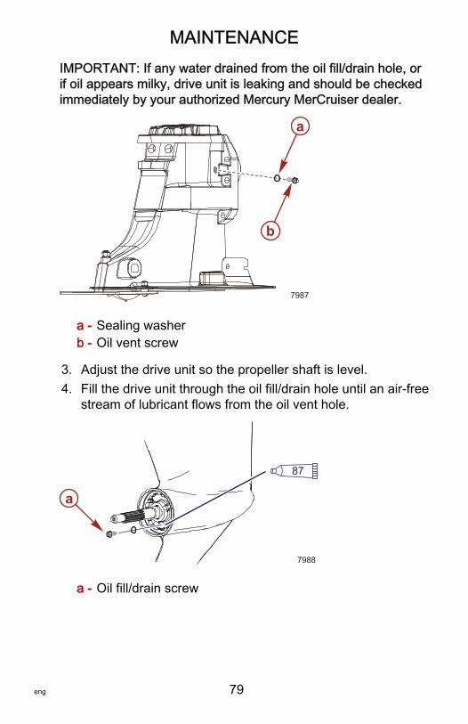
MAINTENANCE
eng 79
IMPORTANT: If any water drained from the oil fill/drain hole, orif oil appears milky, drive unit is leaking and should be checkedimmediately by your authorized Mercury MerCruiser dealer.
a - Sealing washerb - Oil vent screw
3. Adjust the drive unit so the propeller shaft is level.4. Fill the drive unit through the oil fill/drain hole until an air‑free
stream of lubricant flows from the oil vent hole.
a - Oil fill/drain screw
a
b
7987
a
87
7988
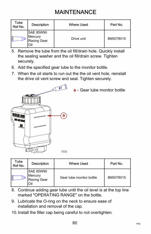
MAINTENANCE
80 eng
TubeRef No. Description Where Used Part No.
SAE 85W90MercuryRacing GearOil
Drive unit 8M0078015
5. Remove the tube from the oil fill/drain hole. Quickly installthe sealing washer and the oil fill/drain screw. Tightensecurely.
6. Add the specified gear lube to the monitor bottle.7. When the oil starts to run out the the oil vent hole, reinstall
the drive oil vent screw and seal. Tighten securely.
a - Gear lube monitor bottle
TubeRef No. Description Where Used Part No.
SAE 85W90MercuryRacing GearOil
Gear lube monitor bottle 8M0078015
8. Continue adding gear lube until the oil level is at the top linemarked "OPERATING RANGE" on the bottle.
9. Lubricate the O‑ring on the neck to ensure ease ofinstallation and removal of the cap.
10. Install the filler cap being careful to not overtighten.
87
7333
a
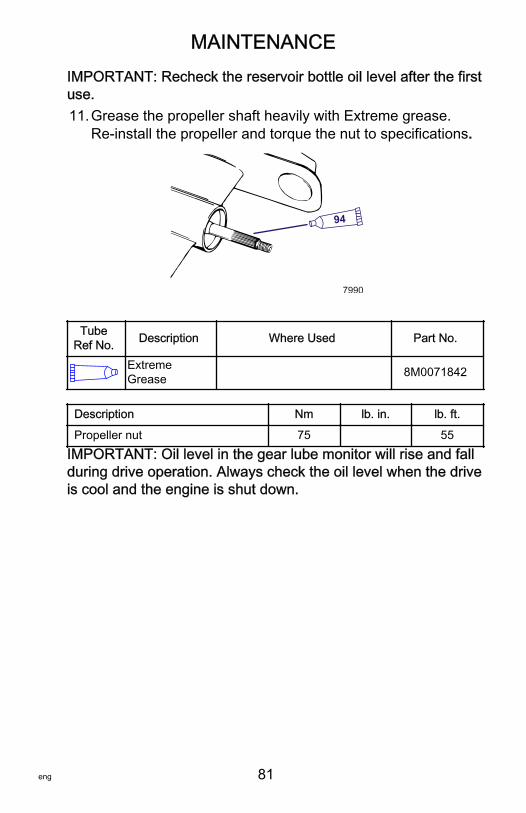
MAINTENANCE
eng 81
IMPORTANT: Recheck the reservoir bottle oil level after the firstuse.11.Grease the propeller shaft heavily with Extreme grease.
Re‑install the propeller and torque the nut to specifications.
94
7990
TubeRef No. Description Where Used Part No.
ExtremeGrease 8M0071842
Description Nm lb. in. lb. ft.
Propeller nut 75 55IMPORTANT: Oil level in the gear lube monitor will rise and fallduring drive operation. Always check the oil level when the driveis cool and the engine is shut down.
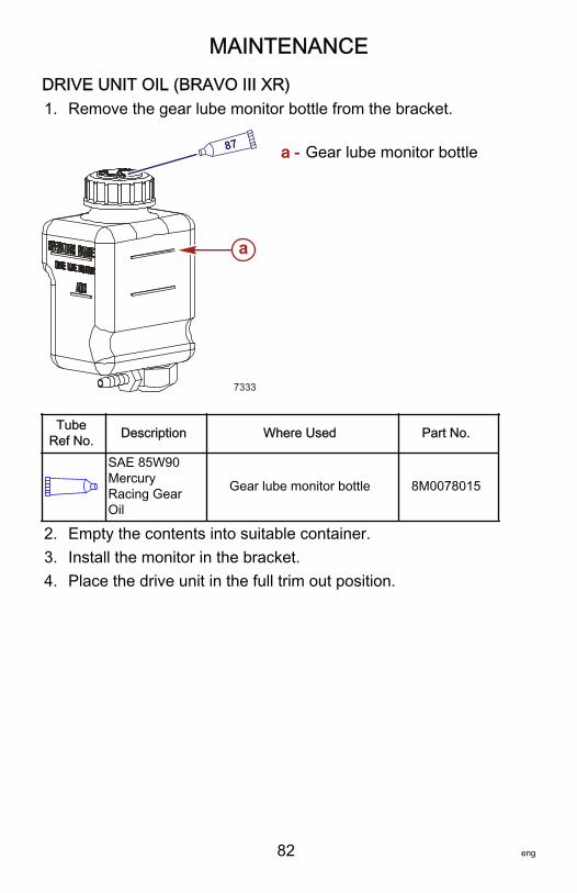
MAINTENANCE
82 eng
DRIVE UNIT OIL (BRAVO III XR)1. Remove the gear lube monitor bottle from the bracket.
a - Gear lube monitor bottle
TubeRef No. Description Where Used Part No.
SAE 85W90MercuryRacing GearOil
Gear lube monitor bottle 8M0078015
2. Empty the contents into suitable container.3. Install the monitor in the bracket.4. Place the drive unit in the full trim out position.
87
7333
a
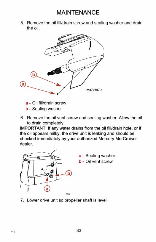
MAINTENANCE
eng 83
5. Remove the oil fill/drain screw and sealing washer and drainthe oil.
a - Oil fill/drain screwb - Sealing washer
6. Remove the oil vent screw and sealing washer. Allow the oilto drain completely.
IMPORTANT: If any water drains from the oil fill/drain hole, or ifthe oil appears milky, the drive unit is leaking and should bechecked immediately by your authorized Mercury MerCruiserdealer.
a - Sealing washerb - Oil vent screw
7. Lower drive unit so propeller shaft is level.
b
amc79507-1
a
b
7991
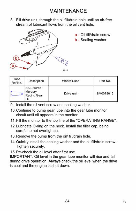
MAINTENANCE
84 eng
8. Fill drive unit, through the oil fill/drain hole until an air‑freestream of lubricant flows from the oil vent hole.
a - Oil fill/drain screwb - Sealing washer
TubeRef No. Description Where Used Part No.
SAE 85W90MercuryRacing GearOil
Drive unit 8M0078015
9. Install the oil vent screw and sealing washer.10.Continue to pump gear lube into the gear lube monitor
circuit until oil appears in the monitor.11.Fill the monitor to the top line of the "OPERATING RANGE".12.Lubricate O‑ring on the neck. Install the filler cap, being
careful to not overtighten.13.Remove the pump from the oil/ fill/drain hole.14.Quickly install the sealing washer and the oil fill/drain screw.
Tighten securely.15.Re‑check the oil level after first use.IMPORTANT: Oil level in the gear lube monitor will rise and fallduring drive operation. Always check the oil level when the driveis cool and the engine is shut down.
18912
87a
b
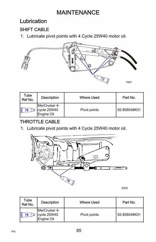
MAINTENANCE
eng 85
LubricationSHIFT CABLE1. Lubricate pivot points with 4 Cycle 25W40 motor oil.
797997
TubeRef No. Description Where Used Part No.
79MerCruiser 4-cycle 25W40Engine Oil
Pivot points 92-858048K01
THROTTLE CABLE1. Lubricate pivot points with 4 Cycle 25W40 motor oil.
79
8008
TubeRef No. Description Where Used Part No.
79MerCruiser 4-cycle 25W40Engine Oil
Pivot points 92-858048K01
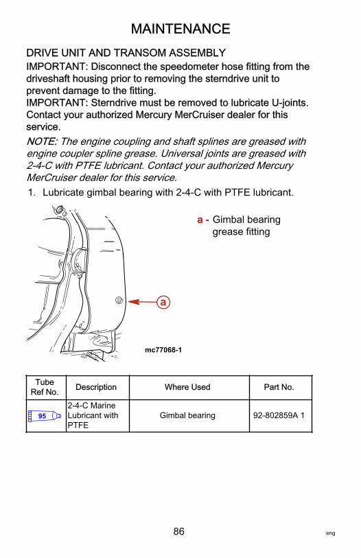
MAINTENANCE
86 eng
DRIVE UNIT AND TRANSOM ASSEMBLYIMPORTANT: Disconnect the speedometer hose fitting from thedriveshaft housing prior to removing the sterndrive unit toprevent damage to the fitting.IMPORTANT: Sterndrive must be removed to lubricate U‑joints.Contact your authorized Mercury MerCruiser dealer for thisservice.NOTE: The engine coupling and shaft splines are greased withengine coupler spline grease. Universal joints are greased with2‑4‑C with PTFE lubricant. Contact your authorized MercuryMerCruiser dealer for this service.1. Lubricate gimbal bearing with 2‑4‑C with PTFE lubricant.
a - Gimbal bearinggrease fitting
TubeRef No. Description Where Used Part No.
952-4-C MarineLubricant withPTFE
Gimbal bearing 92-802859A 1
mc77068-1
a
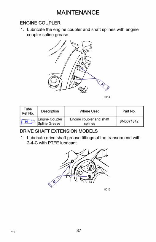
MAINTENANCE
eng 87
ENGINE COUPLER1. Lubricate the engine coupler and shaft splines with engine
coupler spline grease.
91
8014
TubeRef No. Description Where Used Part No.
91Engine CouplerSpline Grease
Engine coupler and shaftsplines 8M0071842
DRIVE SHAFT EXTENSION MODELS1. Lubricate drive shaft grease fittings at the transom end with
2‑4‑C with PTFE lubricant.
95
8015
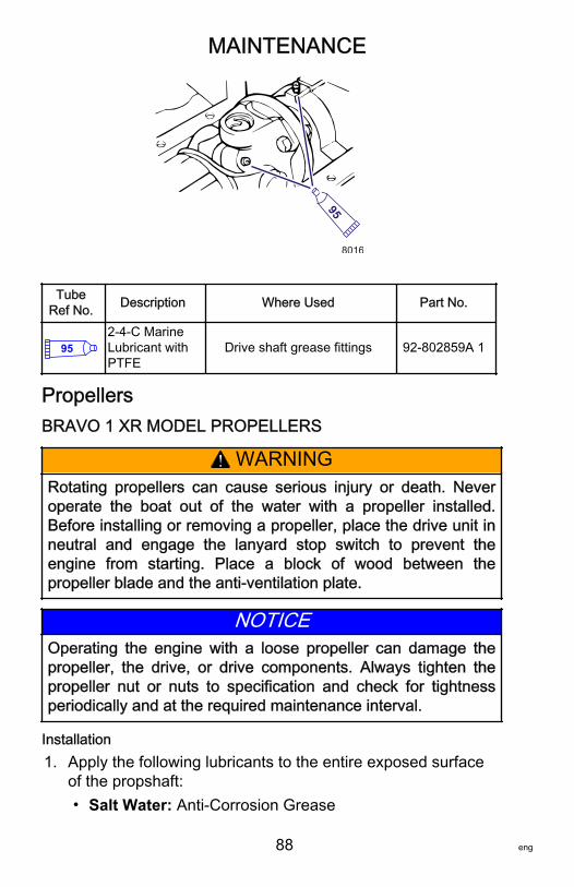
MAINTENANCE
88 eng
958016
TubeRef No. Description Where Used Part No.
952-4-C MarineLubricant withPTFE
Drive shaft grease fittings 92-802859A 1
PropellersBRAVO 1 XR MODEL PROPELLERS
! WARNINGRotating propellers can cause serious injury or death. Neveroperate the boat out of the water with a propeller installed.Before installing or removing a propeller, place the drive unit inneutral and engage the lanyard stop switch to prevent theengine from starting. Place a block of wood between thepropeller blade and the anti‑ventilation plate.
NOTICEOperating the engine with a loose propeller can damage thepropeller, the drive, or drive components. Always tighten thepropeller nut or nuts to specification and check for tightnessperiodically and at the required maintenance interval.
Installation1. Apply the following lubricants to the entire exposed surface
of the propshaft:• Salt Water: Anti‑Corrosion Grease
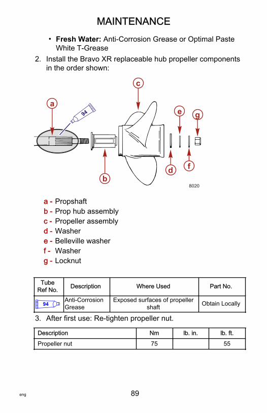
MAINTENANCE
eng 89
• Fresh Water: Anti‑Corrosion Grease or Optimal PasteWhite T‑Grease
2. Install the Bravo XR replaceable hub propeller componentsin the order shown:
a - Propshaftb - Prop hub assemblyc - Propeller assemblyd - Washere - Belleville washerf - Washerg - Locknut
TubeRef No. Description Where Used Part No.
94Anti-CorrosionGrease
Exposed surfaces of propellershaft Obtain Locally
3. After first use: Re‑tighten propeller nut.
Description Nm lb. in. lb. ft.
Propeller nut 75 55
b
c
d
e
f
ga
8020
94
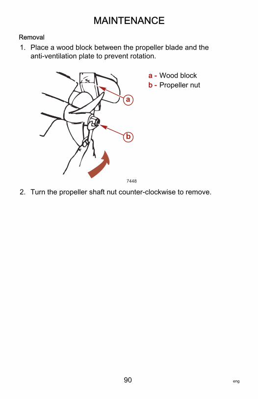
MAINTENANCE
90 eng
Removal1. Place a wood block between the propeller blade and the
anti‑ventilation plate to prevent rotation.
a - Wood blockb - Propeller nut
2. Turn the propeller shaft nut counter‑clockwise to remove.
a
b
7448
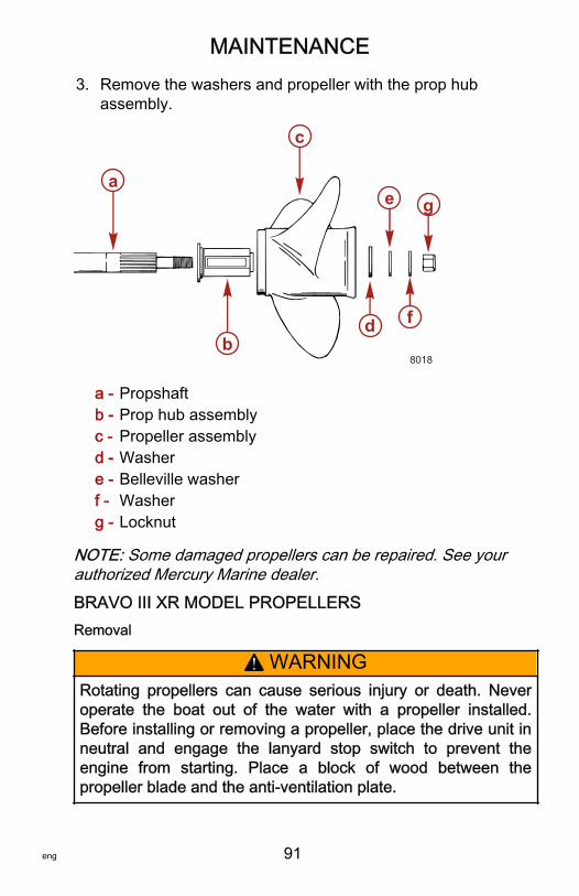
MAINTENANCE
eng 91
3. Remove the washers and propeller with the prop hubassembly.
a - Propshaftb - Prop hub assemblyc - Propeller assemblyd - Washere - Belleville washerf - Washerg - Locknut
NOTE: Some damaged propellers can be repaired. See yourauthorized Mercury Marine dealer.BRAVO III XR MODEL PROPELLERSRemoval
! WARNINGRotating propellers can cause serious injury or death. Neveroperate the boat out of the water with a propeller installed.Before installing or removing a propeller, place the drive unit inneutral and engage the lanyard stop switch to prevent theengine from starting. Place a block of wood between thepropeller blade and the anti‑ventilation plate.
a
b
c
d
e
f
g
8018
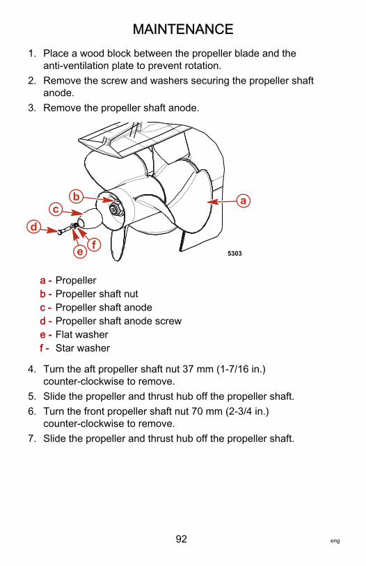
MAINTENANCE
92 eng
1. Place a wood block between the propeller blade and theanti‑ventilation plate to prevent rotation.
2. Remove the screw and washers securing the propeller shaftanode.
3. Remove the propeller shaft anode.
a - Propellerb - Propeller shaft nutc - Propeller shaft anoded - Propeller shaft anode screwe - Flat washerf - Star washer
4. Turn the aft propeller shaft nut 37 mm (1‑7/16 in.)counter‑clockwise to remove.
5. Slide the propeller and thrust hub off the propeller shaft.6. Turn the front propeller shaft nut 70 mm (2‑3/4 in.)
counter‑clockwise to remove.7. Slide the propeller and thrust hub off the propeller shaft.
ab
dc
fe 5303
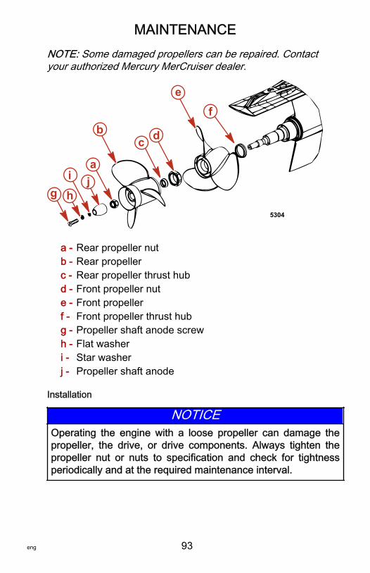
MAINTENANCE
eng 93
NOTE: Some damaged propellers can be repaired. Contactyour authorized Mercury MerCruiser dealer.
a - Rear propeller nutb - Rear propellerc - Rear propeller thrust hubd - Front propeller nute - Front propellerf - Front propeller thrust hubg - Propeller shaft anode screwh - Flat washeri - Star washerj - Propeller shaft anode
Installation
NOTICEOperating the engine with a loose propeller can damage thepropeller, the drive, or drive components. Always tighten thepropeller nut or nuts to specification and check for tightnessperiodically and at the required maintenance interval.
ef
a
bc d
5304
g h
i j
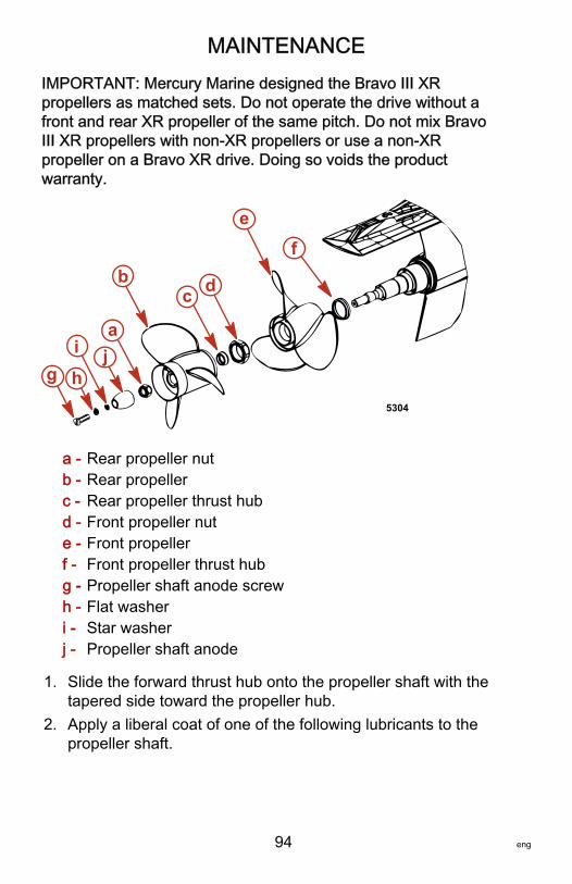
MAINTENANCE
94 eng
IMPORTANT: Mercury Marine designed the Bravo III XRpropellers as matched sets. Do not operate the drive without afront and rear XR propeller of the same pitch. Do not mix BravoIII XR propellers with non‑XR propellers or use a non‑XRpropeller on a Bravo XR drive. Doing so voids the productwarranty.
a - Rear propeller nutb - Rear propellerc - Rear propeller thrust hubd - Front propeller nute - Front propellerf - Front propeller thrust hubg - Propeller shaft anode screwh - Flat washeri - Star washerj - Propeller shaft anode
1. Slide the forward thrust hub onto the propeller shaft with thetapered side toward the propeller hub.
2. Apply a liberal coat of one of the following lubricants to thepropeller shaft.
ef
a
bc d
5304
g h
i j
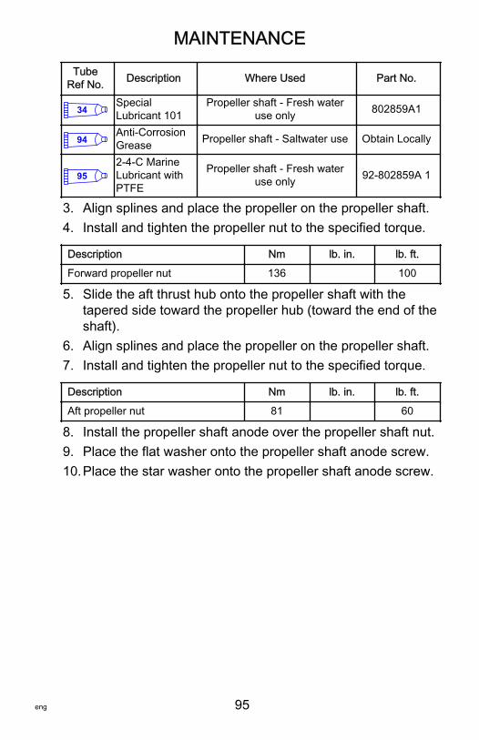
MAINTENANCE
eng 95
TubeRef No. Description Where Used Part No.
34SpecialLubricant 101
Propeller shaft - Fresh wateruse only 802859A1
94Anti-CorrosionGrease Propeller shaft - Saltwater use Obtain Locally
952-4-C MarineLubricant withPTFE
Propeller shaft - Fresh wateruse only 92-802859A 1
3. Align splines and place the propeller on the propeller shaft.4. Install and tighten the propeller nut to the specified torque.
Description Nm lb. in. lb. ft.
Forward propeller nut 136 100
5. Slide the aft thrust hub onto the propeller shaft with thetapered side toward the propeller hub (toward the end of theshaft).
6. Align splines and place the propeller on the propeller shaft.7. Install and tighten the propeller nut to the specified torque.
Description Nm lb. in. lb. ft.
Aft propeller nut 81 60
8. Install the propeller shaft anode over the propeller shaft nut.9. Place the flat washer onto the propeller shaft anode screw.10.Place the star washer onto the propeller shaft anode screw.
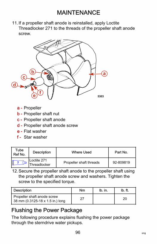
MAINTENANCE
96 eng
11. If a propeller shaft anode is reinstalled, apply LoctiteThreadlocker 271 to the threads of the propeller shaft anodescrew.
a - Propellerb - Propeller shaft nutc - Propeller shaft anoded - Propeller shaft anode screwe - Flat washerf - Star washer
TubeRef No. Description Where Used Part No.
7Loctite 271Threadlocker Propeller shaft threads 92-809819
12.Secure the propeller shaft anode to the propeller shaft usingthe propeller shaft anode screw and washers. Tighten thescrew to the specified torque.
Description Nm lb. in. lb. ft.
Propeller shaft anode screw38 mm (0.3125‑18 x 1.5 in.) long 27 20
Flushing the Power PackageThe following procedure explains flushing the power packagethrough the sterndrive water pickups.
ab
dc
fe 5303

MAINTENANCE
eng 97
FLUSHING ATTACHMENTS
Flushing Device 91‑44357Q 2
9192
Attaches to the water intakes;provides a fresh waterconnection when flushing thecooling system or operating theengine.
Dual Water Pick‑up Flush Gearcase SealKit 91‑881150K 1
9194
Blocks off the front water inletholes on the dual water inletgearcases.
Flushing Kit 91‑849996T 1
9195
Use for flushing gearcases withlow water inlets.
Flushing Attachment 91‑843122A01
14565
Attaches to the water intakes;provides a fresh waterconnection when flushing thecooling system or operating theengine.
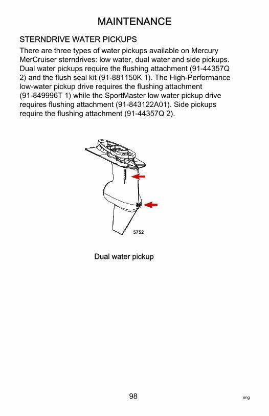
MAINTENANCE
98 eng
STERNDRIVE WATER PICKUPSThere are three types of water pickups available on MercuryMerCruiser sterndrives: low water, dual water and side pickups.Dual water pickups require the flushing attachment (91‑44357Q2) and the flush seal kit (91‑881150K 1). The High‑Performancelow‑water pickup drive requires the flushing attachment(91‑849996T 1) while the SportMaster low water pickup driverequires flushing attachment (91‑843122A01). Side pickupsrequire the flushing attachment (91‑44357Q 2).
5752
Dual water pickup
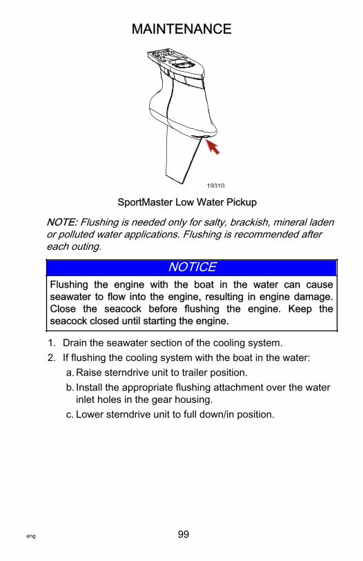
MAINTENANCE
eng 99
19310
SportMaster Low Water Pickup
NOTE: Flushing is needed only for salty, brackish, mineral ladenor polluted water applications. Flushing is recommended aftereach outing.
NOTICEFlushing the engine with the boat in the water can causeseawater to flow into the engine, resulting in engine damage.Close the seacock before flushing the engine. Keep theseacock closed until starting the engine.
1. Drain the seawater section of the cooling system.2. If flushing the cooling system with the boat in the water:
a. Raise sterndrive unit to trailer position.b. Install the appropriate flushing attachment over the water
inlet holes in the gear housing.c. Lower sterndrive unit to full down/in position.
MAINTENANCE
100 eng
3. ! WARNINGRotating propellers can cause serious injury or death. Neveroperate the boat out of the water with a propeller installed.Before installing or removing a propeller, place the drive unitin neutral and engage the lanyard stop switch to prevent theengine from starting. Place a block of wood between thepropeller blade and the anti‑ventilation plate.
If flushing the cooling system with the boat out of the water:a. Lower sterndrive unit to full down/in position.b. Remove propeller.c. Install the appropriate flushing attachment over the water
inlet holes in the gear housing.4. Connect a hose between the flushing attachment and the
water source.5. With the sterndrive unit in normal operating position, partially
open the water source (about 1/2 maximum).6. Place the remote control in the neutral idle speed position
and start the engine.
NOTICEOperating the engine out of the water at high speeds createssuction, which can collapse the water supply hose andoverheat the engine. Do not operate the engine above 1400RPM out of the water and without sufficient cooling watersupply.
7. Operate the engine at idle speed, in neutral, for about 10minutes or until the discharge is clear.
8. Observe the water temperature gauge to ensure that theengine is operating in the normal range.
9. Stop the engine.10.Shut off the water and remove the flushing attachment.
Seawater Pump Impeller InspectionService should be performed by an authorized MercuryMerCruiser dealer.
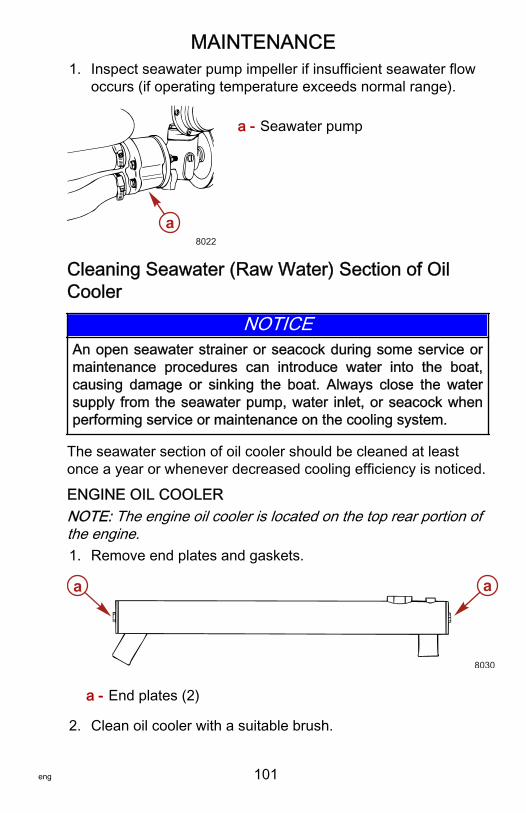
MAINTENANCE
eng 101
1. Inspect seawater pump impeller if insufficient seawater flowoccurs (if operating temperature exceeds normal range).
a - Seawater pump
Cleaning Seawater (Raw Water) Section of OilCooler
NOTICEAn open seawater strainer or seacock during some service ormaintenance procedures can introduce water into the boat,causing damage or sinking the boat. Always close the watersupply from the seawater pump, water inlet, or seacock whenperforming service or maintenance on the cooling system.
The seawater section of oil cooler should be cleaned at leastonce a year or whenever decreased cooling efficiency is noticed.
ENGINE OIL COOLERNOTE: The engine oil cooler is located on the top rear portion ofthe engine.1. Remove end plates and gaskets.
a - End plates (2)
2. Clean oil cooler with a suitable brush.
a8022
aa
8030
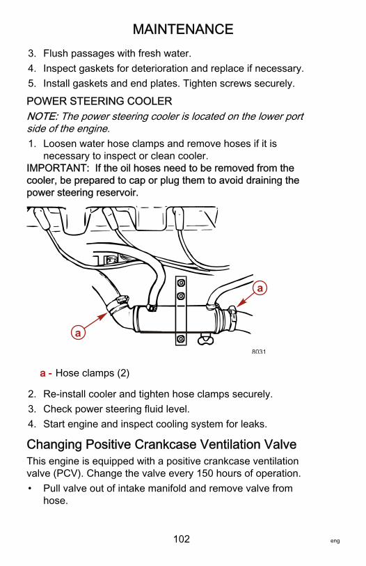
MAINTENANCE
102 eng
3. Flush passages with fresh water.4. Inspect gaskets for deterioration and replace if necessary.5. Install gaskets and end plates. Tighten screws securely.
POWER STEERING COOLERNOTE: The power steering cooler is located on the lower portside of the engine.1. Loosen water hose clamps and remove hoses if it is
necessary to inspect or clean cooler.IMPORTANT: If the oil hoses need to be removed from thecooler, be prepared to cap or plug them to avoid draining thepower steering reservoir.
a - Hose clamps (2)
2. Re‑install cooler and tighten hose clamps securely.3. Check power steering fluid level.4. Start engine and inspect cooling system for leaks.
Changing Positive Crankcase Ventilation ValveThis engine is equipped with a positive crankcase ventilationvalve (PCV). Change the valve every 150 hours of operation.• Pull valve out of intake manifold and remove valve from
hose.
a
a
8031
MAINTENANCE
eng 103
• Install new PCV valve into hose, and install into intakemanifold.
• Ensure that the valve is tightly seated in manifold.
Use only Mercury MerCruiser replacement parts.
Serpentine Drive BeltDRIVE BELT ROUTING AND TENSION
! WARNINGInspecting the belts with the engine running may cause seriousinjury or death. Turn off the engine and remove the ignition keybefore adjusting tension or inspecting belts.
IMPORTANT: Drive belt must be routed as shown or damagemay result.1. Loosen the 5/8 in locking nut on adjustment stud. Leave the
wrench on the adjustment nut.2. Install the belt tension gauge onto the belt.3. Use a 5/16 in socket and tighten adjusting stud until the belt
tension conforms to the correct setting on the gauge.4. Hold the adjustment stud and tighten the 5/8 in locking nut.5. Remove the belt tension gauge from the belt.
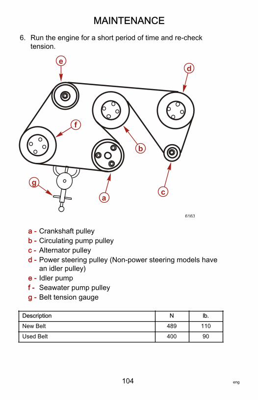
MAINTENANCE
104 eng
6. Run the engine for a short period of time and re‑checktension.
a - Crankshaft pulleyb - Circulating pump pulleyc - Alternator pulleyd - Power steering pulley (Non‑power steering models have
an idler pulley)e - Idler pumpf - Seawater pump pulleyg - Belt tension gauge
Description N lb.
New Belt 489 110
Used Belt 400 90
c
b
a
g
f
ed
6163

MAINTENANCE
eng 105
INSPECTING BELTNOTE: Minor, transverse cracks (across the belt width) may beacceptable. Longitudinal cracks (in the direction of belt length)that join transverse cracks are not acceptable.The belt will have to be replaced for the following conditions:• Excessive wear• Cracks or fraying• Glazed surfaces
a - Frayingb - Transverse cracksc - Longitudinal cracks
Changing Fuel FiltersWATER SEPARATING FUEL FILTER
! WARNINGFuel is flammable and explosive. Ensure that the key switch isoff and the lanyard is positioned so that the engine cannotstart. Do not smoke or allow sources of spark or open flame inthe area while servicing. Keep the work area well ventilatedand avoid prolonged exposure to vapors. Always check forleaks before attempting to start the engine, and wipe up anyspilled fuel immediately.
a
c
b
6164
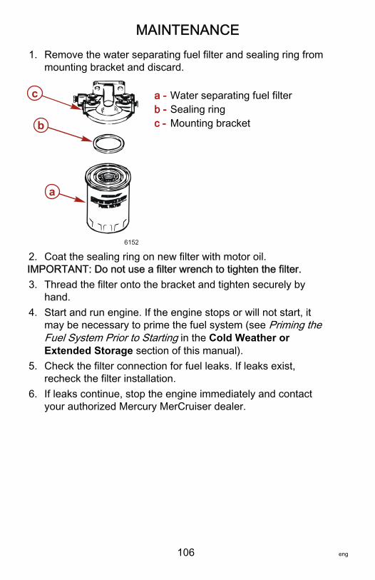
MAINTENANCE
106 eng
1. Remove the water separating fuel filter and sealing ring frommounting bracket and discard.
a - Water separating fuel filterb - Sealing ringc - Mounting bracket
2. Coat the sealing ring on new filter with motor oil.IMPORTANT: Do not use a filter wrench to tighten the filter.3. Thread the filter onto the bracket and tighten securely by
hand.4. Start and run engine. If the engine stops or will not start, it
may be necessary to prime the fuel system (see Priming theFuel System Prior to Starting in the Cold Weather orExtended Storage section of this manual).
5. Check the filter connection for fuel leaks. If leaks exist,recheck the filter installation.
6. If leaks continue, stop the engine immediately and contactyour authorized Mercury MerCruiser dealer.
b
c
a
6152

MAINTENANCE
eng 107
FUEL FILTER ELEMENT1. Remove the fuel line from the filter head.
a - Fuel filter headb - Fuel linec - Fuel filter element
2. Turn the filter head and remove.3. Remove the internal filter element.4. Insert the new filter element.5. Install the filter head.6. Install the fuel line.7. Start the engine and check for leaks.
18962
a
b
c
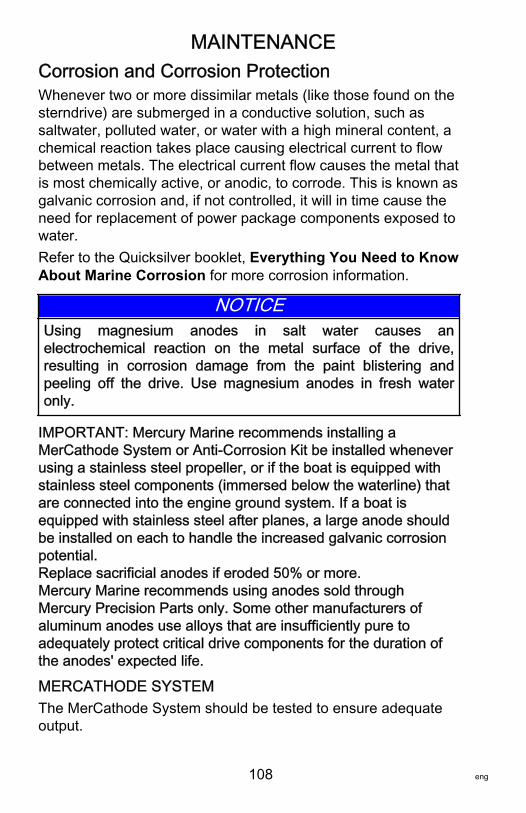
MAINTENANCE
108 eng
Corrosion and Corrosion ProtectionWhenever two or more dissimilar metals (like those found on thesterndrive) are submerged in a conductive solution, such assaltwater, polluted water, or water with a high mineral content, achemical reaction takes place causing electrical current to flowbetween metals. The electrical current flow causes the metal thatis most chemically active, or anodic, to corrode. This is known asgalvanic corrosion and, if not controlled, it will in time cause theneed for replacement of power package components exposed towater.Refer to the Quicksilver booklet, Everything You Need to KnowAbout Marine Corrosion for more corrosion information.
NOTICEUsing magnesium anodes in salt water causes anelectrochemical reaction on the metal surface of the drive,resulting in corrosion damage from the paint blistering andpeeling off the drive. Use magnesium anodes in fresh wateronly.
IMPORTANT: Mercury Marine recommends installing aMerCathode System or Anti‑Corrosion Kit be installed wheneverusing a stainless steel propeller, or if the boat is equipped withstainless steel components (immersed below the waterline) thatare connected into the engine ground system. If a boat isequipped with stainless steel after planes, a large anode shouldbe installed on each to handle the increased galvanic corrosionpotential.Replace sacrificial anodes if eroded 50% or more.Mercury Marine recommends using anodes sold throughMercury Precision Parts only. Some other manufacturers ofaluminum anodes use alloys that are insufficiently pure toadequately protect critical drive components for the duration ofthe anodes' expected life.
MERCATHODE SYSTEMThe MerCathode System should be tested to ensure adequateoutput.
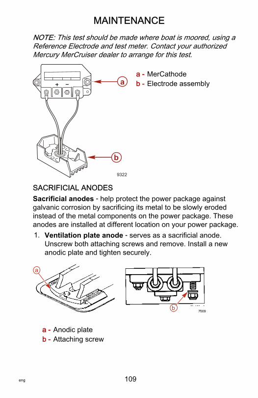
MAINTENANCE
eng 109
NOTE: This test should be made where boat is moored, using aReference Electrode and test meter. Contact your authorizedMercury MerCruiser dealer to arrange for this test.
a - MerCathodeb - Electrode assembly
SACRIFICIAL ANODESSacrificial anodes ‑ help protect the power package againstgalvanic corrosion by sacrificing its metal to be slowly erodedinstead of the metal components on the power package. Theseanodes are installed at different location on your power package.1. Ventilation plate anode ‑ serves as a sacrificial anode.
Unscrew both attaching screws and remove. Install a newanodic plate and tighten securely.
a - Anodic plateb - Attaching screw
9322
a
b
a
b7009
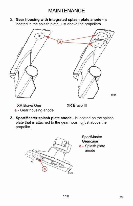
MAINTENANCE
110 eng
2. Gear housing with integrated splash plate anode ‑ islocated in the splash plate, just above the propellers.
XR Bravo One XR Bravo IIIa - Gear housing anode
3. SportMaster splash plate anode ‑ is located on the splashplate that is attached to the gear housing just above thepropeller.
SportMasterGearcase
a - Splash plateanode
a
6205
9329a
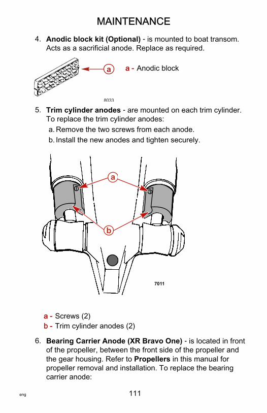
MAINTENANCE
eng 111
4. Anodic block kit (Optional) ‑ is mounted to boat transom.Acts as a sacrificial anode. Replace as required.
a - Anodic block
5. Trim cylinder anodes ‑ are mounted on each trim cylinder.To replace the trim cylinder anodes:a. Remove the two screws from each anode.b. Install the new anodes and tighten securely.
a - Screws (2)b - Trim cylinder anodes (2)
6. Bearing Carrier Anode (XR Bravo One) ‑ is located in frontof the propeller, between the front side of the propeller andthe gear housing. Refer to Propellers in this manual forpropeller removal and installation. To replace the bearingcarrier anode:
a
8033
7011
a
b

MAINTENANCE
112 eng
a. Remove the propeller.b. Remove the two screws from the anode.c. Install a new anode and tighten securely.d. Reinstall the propeller. See Propeller Installation for
proper torque.
a - Bearing carrier anode
7. Propshaft Anode (XR Bravo III) ‑ is located behind the aftpropeller. To replace the propshaft anode:a. Place a block of wood between the propeller blades and
the anti‑ventilation plate to prevent propeller rotation.b. Remove the bolt and washers securing the propshaft
anode and remove the anode.c. Install the new propshaft anode over the propeller nut.d. Place the flat washer then the star washer onto the
propshaft anode screw
a
5644

MAINTENANCE
eng 113
e. Apply threadlocker to the threads of the screw and installthe screw to secure the anode. Tighten to the torquespecification.
a - Propellerb - Propshaft nutc - Propshaft anoded - Propshaft anode screwe - Flat washerf - Star washer
Tube RefNo. Description Where Used Part No.
7Loctite 271Threadlocker Bravo III propshaft anode screw 92-809819
Description Nm lb. in. lb. ft.
Propshaft anode screw 27 20
PAINTING THE BOAT HULL OR TRANSOM1. If anti‑fouling protection is required for boat hull or boat
transom, copper or tin base paints can be used unlessotherwise prohibited by law.
ab
dc
fe 5303
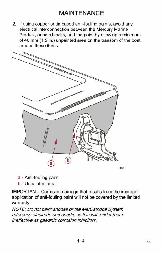
MAINTENANCE
114 eng
2. If using copper or tin based anti‑fouling paints, avoid anyelectrical interconnection between the Mercury MarineProduct, anodic blocks, and the paint by allowing a minimumof 40 mm (1.5 in.) unpainted area on the transom of the boataround these items.
a - Anti‑fouling paintb - Unpainted area
IMPORTANT: Corrosion damage that results from the improperapplication of anti‑fouling paint will not be covered by the limitedwarranty.NOTE: Do not paint anodes or the MerCathode Systemreference electrode and anode, as this will render themineffective as galvanic corrosion inhibitors.
a b6118

MAINTENANCE
eng 115
PAINTING THE DRIVE UNIT OR TRANSOM ASSEMBLYPaint the drive unit and transom assembly with a good qualitymarine paint or an anti‑fouling paint that does not containcopper, tin, or any other material that could conduct electricalcurrent. Do not paint drain holes, anodes, or items specified bythe boat manufacturer.
ADDITIONAL CORROSION PREVENTION TIPS1. Spray the power package components on the inside of the
boat every two to three weeks with Corrosion Guard toprotect the finish from dulling and corrosion. External powerpackage components may also be sprayed.
TubeRef No. Description Where Used Part No.
120CorrosionGuard Power package 92-802878 55
2. All lubrication points, especially the steering system andshift and throttle linkages, should be kept well lubricated.
3. Flush the seawater system after each use in salty, brackish,or mineral‑laden water.
BatteryAll lead acid batteries discharge when not in use. Rechargeevery 30 to 45 days, or when specific gravity drops below batterymanufacturer's specifications.Refer to specific instructions and warnings accompanying yourbattery. If this information is not available, observe the following:
! WARNINGAn operating or charging battery produces gas that can igniteand explode, spraying out sulfuric acid, which can causesevere burns. Ventilate the area around the battery and wearprotective equipment when handling or servicing batteries.
MAINTENANCE
116 eng
! WARNINGRecharging a weak battery in the boat, or using jumper cablesand a booster battery to start the engine, can cause seriousinjury or product damage from fire or explosion. Remove thebattery from the boat and recharge in a ventilated area awayfrom sparks or flames.
Bottom of BoatTo maintain maximum speed, ensure that the boat bottom is:• Clean, free of barnacles and marine growth.• Free of distortion, nearly flat where it contacts water.• Straight and smooth, fore and aft.
Marine vegetation may accumulate when the boat is docked.This growth must be removed before operation; it may clog waterinlets and cause the engine to overheat.
Inspection and MaintenanceInspect the power package often and at regular intervals to helpmaintain its top operating performance, and correct potentialproblems before they occur. The entire power package shouldbe checked carefully, including all accessible engine parts.1. Check for loose, damaged or missing parts, hoses and
clamps; tighten or replace as required.2. Check plug leads and electrical leads for damage.3. Remove and inspect the propeller. If nicked, bent or
cracked, see your authorized Mercury Marine dealer.4. Repair nicks and corrosion damage on the power package's
exterior finish.
Attention Required After Submersion• Before recovery, contact an authorized Mercury Marine
dealer.• After recovery, immediate service by an authorized Mercury
Marine dealer is required to prevent serious damage topower package.
COLD WEATHER OR EXTENDED STORAGE
eng 117
Power Package Lay‑upIMPORTANT: This service should be performed by anauthorized Mercury MerCruiser dealer.
NOTICEWithout sufficient cooling water, the engine, the water pump,and other components will overheat and suffer damage.Provide a sufficient supply of water to the water inlets duringoperation.
IMPORTANT: Before starting the engine, attach a water sourceto the seawater pickup pump. Follow all warnings and flushingattachment procedures stated in the Flushing Cooling Systemsection of this manual.1. Run engine sufficiently to bring it up to normal operating
temperature. Shut off engine and change oil and oil filter.2. Flush cooling system. Refer to Flushing Cooling System
shown earlier in this manual.
! WARNINGFuel vapors trapped in the engine compartment may be anirritant, cause difficulty breathing, or may ignite resulting in afire or explosion. Always ventilate the engine compartmentbefore servicing the power package.
3. Close the fuel shut off valve if equipped.4. Prepare fuel system for extended storage by mixing the
following in a 23 liter (6 U.S. gal) remote outboard fuel tank:• 19 liter (5 U.S. gal) regular unleaded 87 octane (R+M)/2
(92 RON) gasoline.• 1.89 liter (64 fl oz) Premium Plus 2‑cycle TC‑W3
outboard oil.• 150 ml (5 fl oz) Fuel System Treatment and Stabilizer or
30 ml (1 fl oz) Fuel System Treatment and StabilizerConcentrate.
5. Disconnect and plug the boat's fuel line from the waterseparating fuel filter inlet.
COLD WEATHER OR EXTENDED STORAGE
118 eng
6. Connect the remote outboard fuel tank to the inlet of thewater separating fuel filter.
IMPORTANT: If the boat is out of the water, follow instructionsfor running the engine on a flush device as found in the servicemanual.7. Start and run the engine at 1300 RPM for five minutes.8. After the specified running time is complete, slowly return
the throttle to idle RPM and shut off the engine.IMPORTANT: Operating a Mercury Marine engine with gasolinecontaining alcohol creates unique problems as a result of longstorage periods common to a boat. Cars normally consumealcohol‑blend fuels before they absorb enough moisture tocause problems; however, boats often sit idle long enough forphase separation to occur. In addition, alcohol can washprotective oil films from internal components causing corrosion.IMPORTANT: Do not run the engine's fuel system dry of thisfogging mixture in the 23 liter (6 U.S. gal) remote outboard fueltank.NOTE: Refer to Fuel Requirements for additional information.9. Close fuel shut off valve, if equipped.10.Place drive unit in the full down position.
NOTICEThe universal joint bellows may develop a set when stored ina raised or up position, causing the bellows to fail whenreturned to service and allowing water to enter the boat. Storethe sterndrive in the full down position.
COLD WEATHER OR EXTENDED STORAGE
eng 119
Draining Instructions
NOTICEWater trapped in the seawater section of the cooling systemcan cause corrosion or freeze damage. Drain the seawatersection of the cooling system immediately after operation orbefore any length of storage in freezing temperatures. If theboat is in the water, keep the seacock closed until restartingthe engine to prevent water from flowing back into the coolingsystem. If the boat is not fitted with a seacock, leave the waterinlet hose disconnected and plugged.
NOTE: As a precautionary measure, attach a tag to the keyswitch or steering wheel of the boat reminding the operator toopen the seacock or unplug and reconnect the water inlet hosebefore starting the engine.IMPORTANT: The boat must be as level as possible to ensurecomplete draining of cooling system.1. Remove the following drain plugs:
• End of exhaust manifold balance rail (plastic wingnutplugs, port and starboard)
• Fuel cooler (plastic wingnut plug, below engine front)
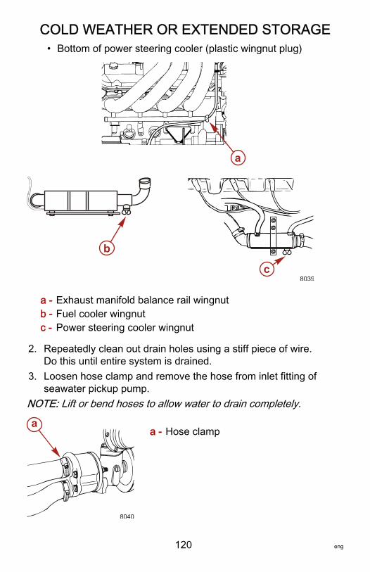
COLD WEATHER OR EXTENDED STORAGE
120 eng
• Bottom of power steering cooler (plastic wingnut plug)
a - Exhaust manifold balance rail wingnutb - Fuel cooler wingnutc - Power steering cooler wingnut
2. Repeatedly clean out drain holes using a stiff piece of wire.Do this until entire system is drained.
3. Loosen hose clamp and remove the hose from inlet fitting ofseawater pickup pump.
NOTE: Lift or bend hoses to allow water to drain completely.
a - Hose clamp
a
b
c8039
a
8040

COLD WEATHER OR EXTENDED STORAGE
eng 121
4. After draining seawater cooling system, install drain plugs(Perfect Seal is not required on wing nut type plugs),reconnect hoses and tighten all hose clamps securely.
5. Make sure the following passages are open andunobstructed:
a - Speedometer pitot tubeb - Trim tab cavity vent holec - Trim tab cavity drain passage
6. For additional assurance against freezing and rust in theengine seawater cooling system when storing for winter orlong periods of non use, perform the following steps:
IMPORTANT: A nontoxic and environmentally safe ethyleneglycol antifreeze containing a rust inhibitor must be used whenpreparing the seawater section of the cooling system for coldweather or extended storage. Be certain to follow themanufacturer's recommendations.NOTE: If the boat is in the water during the following procedure,the seawater shut off valve must be closed and the hoseremoved from the engine side of the valve to avoid waterentering the boat.
a
b
c
8042
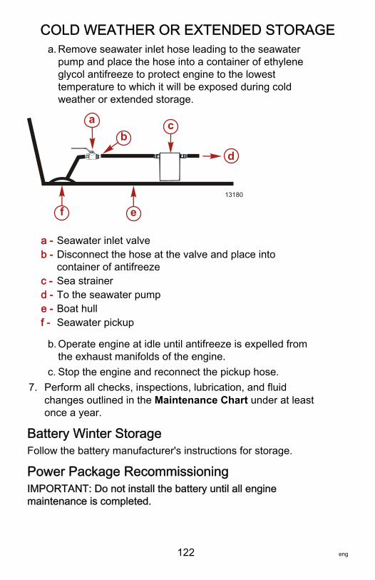
COLD WEATHER OR EXTENDED STORAGE
122 eng
a. Remove seawater inlet hose leading to the seawaterpump and place the hose into a container of ethyleneglycol antifreeze to protect engine to the lowesttemperature to which it will be exposed during coldweather or extended storage.
a - Seawater inlet valveb - Disconnect the hose at the valve and place into
container of antifreezec - Sea strainerd - To the seawater pumpe - Boat hullf - Seawater pickup
b. Operate engine at idle until antifreeze is expelled fromthe exhaust manifolds of the engine.
c. Stop the engine and reconnect the pickup hose.7. Perform all checks, inspections, lubrication, and fluid
changes outlined in the Maintenance Chart under at leastonce a year.
Battery Winter StorageFollow the battery manufacturer's instructions for storage.
Power Package RecommissioningIMPORTANT: Do not install the battery until all enginemaintenance is completed.
ab
c
d
13180
ef
COLD WEATHER OR EXTENDED STORAGE
eng 123
1. Ensure that all cooling system hoses are connected properlyand hose clamps are tight, all removed drain plugs havebeen installed and are tight.
! CAUTIONDisconnecting or connecting the battery cables in theincorrect order can cause injury from electrical shock or candamage the electrical system. Always disconnect thenegative (‑) battery cable first and connect it last.
2. Install fully‑charged battery. Clean battery cable clamps andterminals and reconnect cables. Tighten each cable clampsecurely when connecting.
3. Coat battery terminal connections with a anti‑corrosionagent.
4. Perform all checks in Operation Chart in the BeforeStarting column.
5. Refer to Flushing Cooling System before starting engine.6. Supply water to engine cooling system.
STARTING WITHOUT PRIMING THE FUEL SYSTEMIMPORTANT: The throttle must not be advanced until the engineidles and runs smoothly and the water temperature reaches aminimum of 54 °C (130 °F). Advancing the throttle prematurelywhile the PCM is in its rich running mode will result in poorengine starting and performance.1. Connect the main permanent fuel line to the engine.2. Do not advance the throttle until the engine idles and runs
smoothly and the water temperature reaches a minimum of54 °C (130 °F).
3. Crank the engine over for 10 seconds at a time and stop.4. Repeat cranking procedure until the engine starts and runs
smoothly. Observe instrumentation to ensure all systemsare functioning.
5. Inspect engine for fuel, oil, fluid, water and exhaust leaks.6. Check steering system, shift and throttle control for proper
operation.
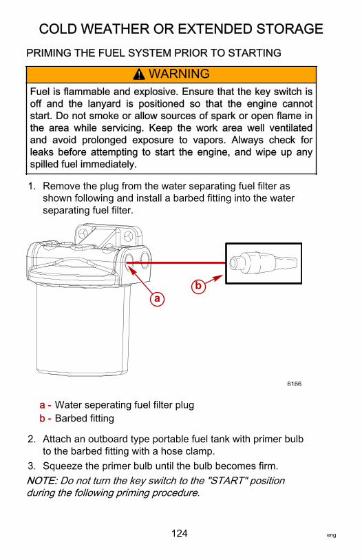
COLD WEATHER OR EXTENDED STORAGE
124 eng
PRIMING THE FUEL SYSTEM PRIOR TO STARTING
! WARNINGFuel is flammable and explosive. Ensure that the key switch isoff and the lanyard is positioned so that the engine cannotstart. Do not smoke or allow sources of spark or open flame inthe area while servicing. Keep the work area well ventilatedand avoid prolonged exposure to vapors. Always check forleaks before attempting to start the engine, and wipe up anyspilled fuel immediately.
1. Remove the plug from the water separating fuel filter asshown following and install a barbed fitting into the waterseparating fuel filter.
a - Water seperating fuel filter plugb - Barbed fitting
2. Attach an outboard type portable fuel tank with primer bulbto the barbed fitting with a hose clamp.
3. Squeeze the primer bulb until the bulb becomes firm.NOTE: Do not turn the key switch to the "START" positionduring the following priming procedure.
ab
6166
COLD WEATHER OR EXTENDED STORAGE
eng 125
4. Cycle the ignition key switch to the "RUN" position for threeseconds and then "OFF."
5. Repeat steps three and four, one to two more times. Theobject of this procedure is to prime the fuel system but not tothe point of having the system completely full and the primerbulb hard and under pressure.
6. With the primer bulb soft, remove the remote fuel line andfitting from the water separating fuel filter.
! WARNINGIf the primer bulb is hard when removing the remote fuel tank,pressurized fuel will be sprayed in the engine compartmentcreating an explosive condition that could result in seriousinjury or death. When removing the remote fuel tank line fromthe engine connection, ensure that the primer bulb is soft.
7. Re‑install the plug in the water separating fuel filter usingLoctite Pipe Sealant with PTFE on the threads.
8. Attempt to start the engine by turning the key switch to the"START" position for a maximum of 15 seconds or until theengine starts and runs smoothly. Do not advance the throttleuntil the water temperature has reached a minimum of 54 °C(130 °F).
IMPORTANT: The throttle must not be advanced until theengine idles and runs smoothly and the water temperature hasreached a minimum of 54 °C (130 °F). Advancing the throttleprematurely while the ECM is in its rich running mode will resultin poor engine starting and performance.9. Inspect engine for fuel, oil, fluid, water and exhaust leaks.10.Check steering system, shift and throttle control for proper
operation.

TROUBLESHOOTING
126 eng
Engine Will Not CrankPossible Causes Remedy
Battery switch turned "OFF." Turn switch "ON."
Gearshift not in neutralposition. Position control lever to neutral.
Open circuit breaker or blownfuse.
Check and reset circuit breaker or replacefuse.
Loose or dirty electricalconnections or damagedwiring.
Check all electrical connections and wires(especially battery cables). Clean and tightenfaulty connection.
Defective battery. Test and replace if defective.
Defective starter. Test and replace if defective.
Flywheel ring gear isdamaged. Confirm diagnostic and replace flywheel.
Engine is seized.Check to see if engine can be rotated byhand with the spark plugs removed. If not,then determine cause.
Faulty ignition switch. Test wire with a remote starter switch at thestarter motor.
Engine Cranks But Will Not StartPossible Cause Remedy
Improper starting procedure. Read starting procedure.
Low battery voltage. Charge the battery.
Empty fuel tank or fuel shut off valveclosed. Fill tank or open valve.
Faulty fuel pump, wiring, fuel pumpfuse, 50 amp circuit breaker or a fuelpump relay.
Replace faulty component.
Faulty ignition system component. Service ignition system.
Lanyard Stop Activated. Reset.
Obstructed fuel filter. Replace filters.
Stale or contaminated fuel. If contaminated, drain tank and fill withfresh fuel.
TROUBLESHOOTING
eng 127
Possible Cause Remedy
Fuel line or tank vent line kinked orrestricted.
Replace kinked lines or blow out lineswith compressed air to removeobstruction.
Crankshaft position sensor faulty. Test and replace if faulty.
Faulty fuel pressure regulatordiaphragm.
Test and replace if faulty. Do notattempt to start the engine if the fuelpressure regulator diaphragm isruptured.
Engine Hard to Start, Runs Rough, Misses, and/orBackfires
Possible Cause Remedy
Faulty ignition system component. Service ignition system.
Clogged fuel filter. Replace filters.
Stale or contaminated fuel. If contaminated, drain tank. Fill withfresh fuel.
Kinked or clogged fuel line or fueltank vent line.
Replace kinked lines or blow out lineswith compressed air to removeobstruction.
Flame arrestor plugged. Clean or replace the flame arrestor.
Rev limiter engaging atwide‑open‑throttle. Change to propeller with more pitch.
Low Engine Coolant (Closed Cooling)Temperature
Possible Cause Remedy
Faulty thermostat. Replace.
TROUBLESHOOTING
128 eng
Poor PerformancePossible Cause Remedy
Throttle not fully open. Inspect throttle cable and linkages forproper operation.
Damaged or wrong propeller. Replace propeller.
Excessive bilge water. Drain and check for cause of entry.
Boat overloaded or loadimproperly distributed.
Reduce load or redistribute load moreevenly.
Boat bottom fouled or damaged. Clean or repair as necessary.
Flame arrestor dirty. Change or clean flame arrestor.
Insufficient Engine TemperaturePossible Cause Remedy
Faulty water thermostat. Replace water thermostat.
Faulty gauge or sender. Test with shop gauge; test sender.
Faulty oil thermostat. Replace.
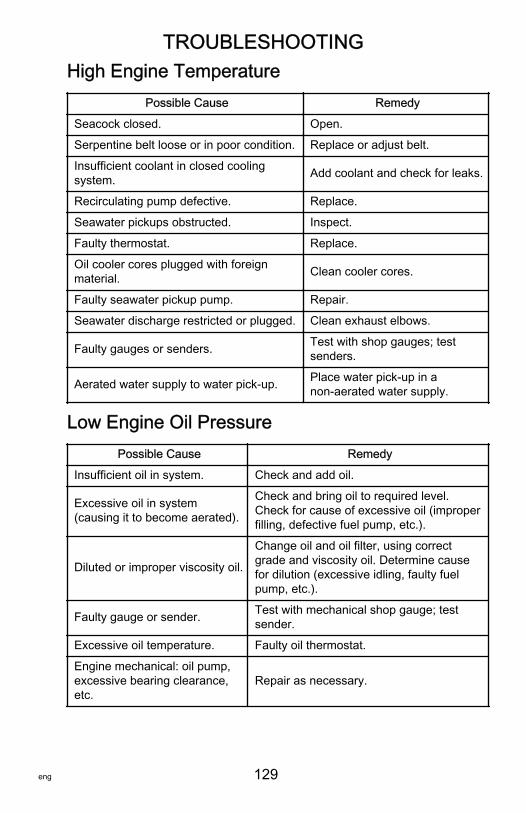
TROUBLESHOOTING
eng 129
High Engine TemperaturePossible Cause Remedy
Seacock closed. Open.
Serpentine belt loose or in poor condition. Replace or adjust belt.
Insufficient coolant in closed coolingsystem. Add coolant and check for leaks.
Recirculating pump defective. Replace.
Seawater pickups obstructed. Inspect.
Faulty thermostat. Replace.
Oil cooler cores plugged with foreignmaterial. Clean cooler cores.
Faulty seawater pickup pump. Repair.
Seawater discharge restricted or plugged. Clean exhaust elbows.
Faulty gauges or senders. Test with shop gauges; testsenders.
Aerated water supply to water pick‑up. Place water pick‑up in anon‑aerated water supply.
Low Engine Oil PressurePossible Cause Remedy
Insufficient oil in system. Check and add oil.
Excessive oil in system(causing it to become aerated).
Check and bring oil to required level.Check for cause of excessive oil (improperfilling, defective fuel pump, etc.).
Diluted or improper viscosity oil.
Change oil and oil filter, using correctgrade and viscosity oil. Determine causefor dilution (excessive idling, faulty fuelpump, etc.).
Faulty gauge or sender. Test with mechanical shop gauge; testsender.
Excessive oil temperature. Faulty oil thermostat.
Engine mechanical: oil pump,excessive bearing clearance,etc.
Repair as necessary.
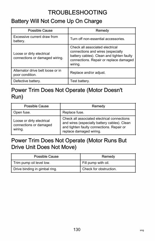
TROUBLESHOOTING
130 eng
Battery Will Not Come Up On ChargePossible Cause Remedy
Excessive current draw frombattery. Turn off non‑essential accessories.
Loose or dirty electricalconnections or damaged wiring.
Check all associated electricalconnections and wires (especiallybattery cables). Clean and tighten faultyconnections. Repair or replace damagedwiring.
Alternator drive belt loose or inpoor condition. Replace and/or adjust.
Defective battery. Test battery.
Power Trim Does Not Operate (Motor Doesn'tRun)
Possible Cause Remedy
Open fuse. Replace fuse.
Loose or dirty electricalconnections or damagedwiring.
Check all associated electrical connectionsand wires (especially battery cables). Cleanand tighten faulty connections. Repair orreplace damaged wiring.
Power Trim Does Not Operate (Motor Runs ButDrive Unit Does Not Move)
Possible Cause Remedy
Trim pump oil level low. Fill pump with oil.
Drive binding in gimbal ring. Check for obstruction.
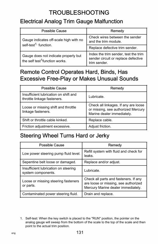
TROUBLESHOOTING
eng 131
Electrical Analog Trim Gauge MalfunctionPossible Cause Remedy
Gauge indicates off‑scale high with noself‑test1. function.
Check wires between the senderand the trim module.
Replace defective trim sender.
Gauge does not indicate properly butthe self test1function works.
Index the trim sender, test the trimsender circuit or replace defectivetrim sender.
Remote Control Operates Hard, Binds, HasExcessive Free‑Play or Makes Unusual Sounds
Possible Cause Remedy
Insufficient lubrication on shift andthrottle linkage fasteners. Lubricate.
Loose or missing shift and throttlelinkage fasteners.
Check all linkages. If any are looseor missing, see authorized MercuryMarine dealer immediately.
Shift or throttle cable kinked. Replace cable.
Friction adjustment excessive. Adjust friction.
Steering Wheel Turns Hard or JerkyPossible Cause Remedy
Low power steering pump fluid level. Refill system with fluid and check forleaks.
Sepentine belt loose or damaged. Replace and/or adjust.
Insufficient lubrication on steeringsystem components. Lubricate.
Loose or missing steering fastenersor parts.
Check all parts and fasteners. If anyare loose or missing, see authorizedMercury Marine dealer immediately.
Contaminated power steering fluid. Drain and replace.
1. Self‑test: When the key switch is placed to the "RUN" position, the pointer on theanalog gauge will sweep from the bottom of the scale to the top of the scale and thenpoint to the actual trim position.
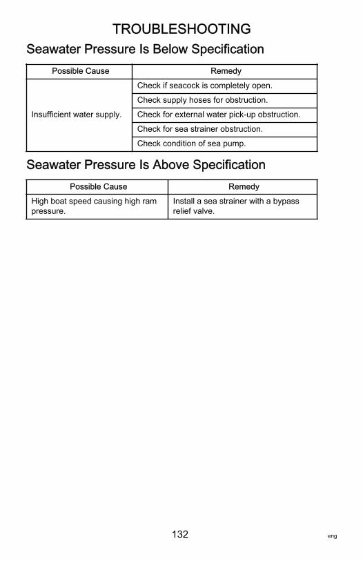
TROUBLESHOOTING
132 eng
Seawater Pressure Is Below SpecificationPossible Cause Remedy
Insufficient water supply.
Check if seacock is completely open.
Check supply hoses for obstruction.
Check for external water pick‑up obstruction.
Check for sea strainer obstruction.
Check condition of sea pump.
Seawater Pressure Is Above SpecificationPossible Cause Remedy
High boat speed causing high rampressure.
Install a sea strainer with a bypassrelief valve.
OWNER SERVICE ASSISTANCE
eng 133
Local Repair ServiceAlways return your outboard to your local authorized dealershould the need for service arise. Only he has the factory trainedmechanics, knowledge, special tools, equipment, and genuineparts and accessories to properly service your engine should theneed occur. He knows your engine best.
Service Away from HomeIf you are away from your local dealer and the need arises forservice, contact the nearest authorized dealer. Refer to theYellow Pages of the telephone directory. If, for any reason, youcannot obtain service, contact the nearest Mercury MarineService Office.
Parts and Accessories InquiriesAll inquiries concerning genuine replacement parts andaccessories should be directed to your local authorized dealer.The dealer has the necessary information to order parts andaccessories for you. When inquiring about parts andaccessories, the dealer requires the model and serial number toorder the correct parts.
Service AssistanceSatisfaction with your Sterndrive or Inboard product is veryimportant to your dealer and to us. If you ever have a problem,question or concern about your Sterndrive or Inboard product,contact your dealer or any authorized Mercury Marine dealer. Ifadditional assistance is required, take these steps.1. Talk with the dealership's sales manager or service
manager. If this has already been done, then contact theowner of the dealership.
2. Should you have a question, concern, or problem thatcannot be resolved by your dealership, please contactMercury Marine Service Office for assistance. MercuryMarine will work with you and your dealership to resolve allproblems.
The following information will be needed by the service office:
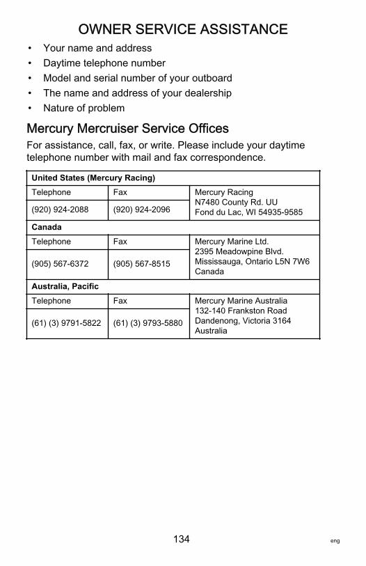
OWNER SERVICE ASSISTANCE
134 eng
• Your name and address• Daytime telephone number• Model and serial number of your outboard• The name and address of your dealership• Nature of problem
Mercury Mercruiser Service OfficesFor assistance, call, fax, or write. Please include your daytimetelephone number with mail and fax correspondence.
United States (Mercury Racing)Telephone Fax Mercury Racing
N7480 County Rd. UUFond du Lac, WI 54935-9585(920) 924‑2088 (920) 924‑2096
CanadaTelephone Fax Mercury Marine Ltd.
2395 Meadowpine Blvd.Mississauga, Ontario L5N 7W6Canada
(905) 567‑6372 (905) 567‑8515
Australia, PacificTelephone Fax Mercury Marine Australia
132-140 Frankston RoadDandenong, Victoria 3164Australia
(61) (3) 9791‑5822 (61) (3) 9793‑5880
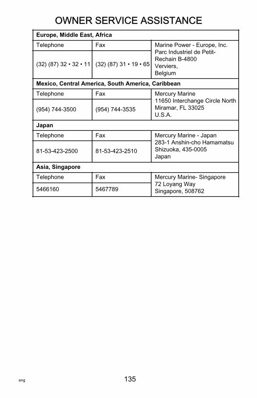
OWNER SERVICE ASSISTANCE
eng 135
Europe, Middle East, AfricaTelephone Fax Marine Power - Europe, Inc.
Parc Industriel de Petit-Rechain B-4800Verviers,Belgium
(32) (87) 32 • 32 • 11 (32) (87) 31 • 19 • 65
Mexico, Central America, South America, CaribbeanTelephone Fax Mercury Marine
11650 Interchange Circle NorthMiramar, FL 33025U.S.A.
(954) 744‑3500 (954) 744‑3535
JapanTelephone Fax Mercury Marine - Japan
283-1 Anshin-cho HamamatsuShizuoka, 435-0005Japan
81‑53‑423‑2500 81‑53‑423‑2510
Asia, SingaporeTelephone Fax Mercury Marine- Singapore
72 Loyang WaySingapore, 5087625466160 5467789

ORDERING LITERATURE
136 eng
United States and CanadaBefore ordering literature, please have the following informationabout your power package available:
EngineModel: Horsepower:
SerialNumber: Model year:
For information on additional literature that is available for yourparticular Mercury/MerCruiser power package and how to orderthat literature contact your nearest dealer or contact:
MERCURY MARINE
Telephone Fax Mail
(920) 929‑5110 (920) 929‑4894
Mercury MarineAttn: Publications Department
P.O. Box 1939Fond du Lac, WI 54936-1939
Outside The United States and CanadaBefore ordering literature, please have the following informationabout your power package available:
EngineModel: Horsepower:
SerialNumber: Model year:
Contact your nearest dealer or Marine Power Service Center forinformation on additional literature that is available for yourparticular Mercury/MerCruiser power package and how to orderthat literature.
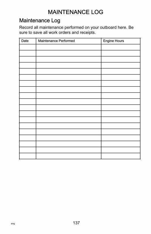
MAINTENANCE LOG
eng 137
Maintenance LogRecord all maintenance performed on your outboard here. Besure to save all work orders and receipts.
Date Maintenance Performed Engine Hours