hospital pager systems may cause interference with pacemaker telemetry
TRANSCRIPT
Hospital Pager Systems May Cause Interferencewith Pacemaker Telemetry
FIRAT DURU, PETER LAUBER.* GEORG KLAUS,* and RETO CANDINAS
From the Division of Cardiology, University Hospital of Zurich; and * Amstein and Walthert AG,Zurich, Switzerland
DURU, F., ET AL.: Hospital Pager Systems May Cause Interference with Pacemaker Telemetry. Electro-magnetic interference (EMI) is a well-known cause of pacemaker dysfunction. The communication be-tween pacemakers and programmers, enabled by telemetry, is also susceptible to EMI. We have observedthat hospital pager systems have the potential to interfere with pacemaker telemetry. Measurements in ourpacemaker clinic and in a technical laboratory have shown that inductive pager systems may disturbtelemetry in the form of inaccurate battery voltage, current and impedance measurements, disturbancesIn intracardiac electrogram tracings, or total interruption of telemetric communications. The reason forEMI was an overlap of carrier frequencies of some pacemaker programmers (32-37 kHz) with those of ourinductive pager system (36.11 kHz). Radiofrequency pager systems using higher frequencies (in MHZrange) are unlikely to cause such interference. Awareness of this interference potential may have practi-cal implications in choosing the carrier frequencies of inductive hospital pager systems, as well as pace-maker programmers, and in planning the location of pacemaker clinics. (PACE 1998; 21[Pt. II] :2353-2359)
electromagnetic interference, pacemaker, telemetry, pager
Introduction
It is well-known that electromagnetic sourcesmay interfere with pacemaker function. ̂ '̂ Electro-magnetic interference (EMI) may cause pacemakerinhibition, reprogramming, or reversion to othermodes (e.g., electrical reset) and may result in per-manent damage to the pulse generator. Electro-magnetic noise is rapidly increasing in our envi-ronment, and sources of EMI can be foundanywhere, including our houses, workplace, andhospitals. Therefore, despite significant techno-logical improvements in modern pacemakers, EMIremains an important cause of pacemaker dys-function.
Noninvasive transfer of data and commandsback and forth hetween a pacemaker and its pro-grammer, enabled by telemetry, may also be sus-ceptible to EMI.̂ We have recently identified thatpager systems widely used for communication inhospitals are also potential sources of EMI thatmay disturb pacemaker telemetry.
Address for reprints: Firat Duru. M-D,. Division ofCardiology. University Hospital Zurich, Ramlstr, 100,8091 Zurich, Switzerland. Fax: 41-1-255-44-01; e-mail:[email protected]
Telemetry Interference by Pager Systems:Observations
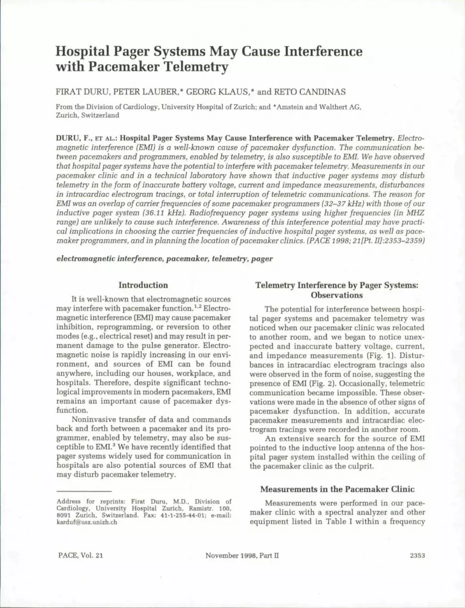
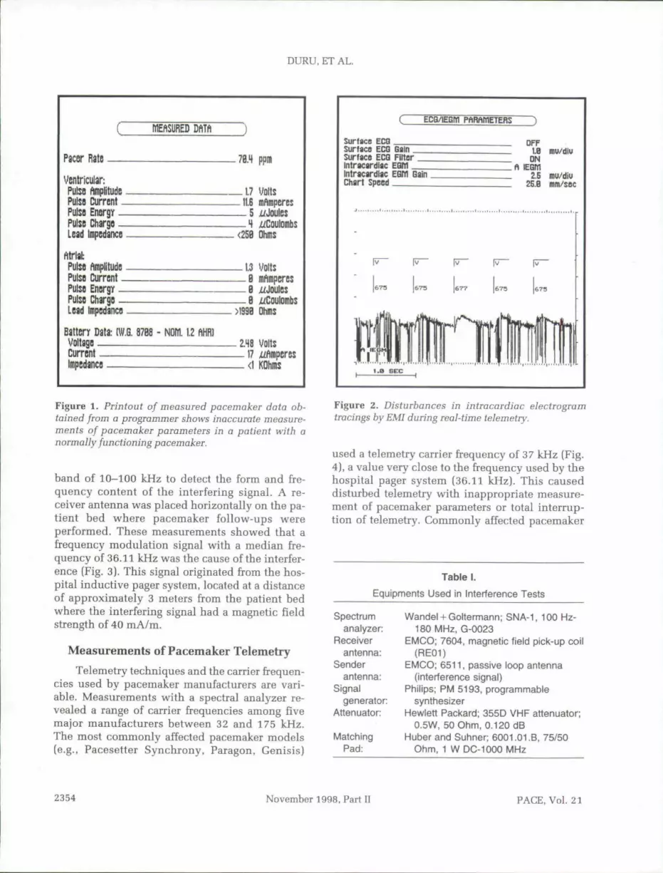
The potential for interference between hospi-tal pager systems and pacemaker telemetry wasnoticed when our pacemaker clinic was relocatedto another room, and we began to notice unex-pected and inaccurate battery voltage, current,and impedance measurements (Fig. 1). Distur-bances in intracardiac electrogram tracings alsowere observed in the form of noise, suggesting thepresence of EMI (Fig. 2). Occasionally, telemetriccommunication became impossible. Tbese obser-vations were made in the absence of other signs ofpacemaker dysfunction. In addition, accuratepacemaker measurements and intracardiac elec-trogram tracings were recorded in another room.
An extensive search for the source of EMIpointed to the inductive loop antenna of the hos-pital pager system installed within the ceiling ofthe pacemaker clinic as the culprit.
Measurements in the Pacemaker Clinic
Measurements were performed in our pace-maker clinic with a spectral analyzer and otherequipment listed in Table I within a frequency
PACE, Vol. 21 November 1998, Part 2353
DURU, ET AL.
MEfiSDRED DftTft
Pacer Rate 7B.4 ppm
Ventricular:PulsQ ftmplitudGPulsfl Current _PulsB Energy _Pulso Chargo _Lead Impcdanco
- 1 7 volts-11.6 mAmperes— 5 ^Joules— 4<25B Dhms
Pulso pPulSD CurrcnlPulsD Enorgy -Pulso Charge -L d Impcdancs
_ 1.3 Volt:— B mAmpcres— B i f Joules— B x/Coulomb:>I393 Ohms
Battery Data: (W.G. 8768 -VoltageCurrentImpedance
1.1.2 fm2.48 Volts
- 1 7 p_ <l KOhms
Figure 1. Printout of measured pacemaker data ob-tained from a programmer shows inaccurate measure-ments of pacemaker parameters in a patient with anormally functioning pacemaker.
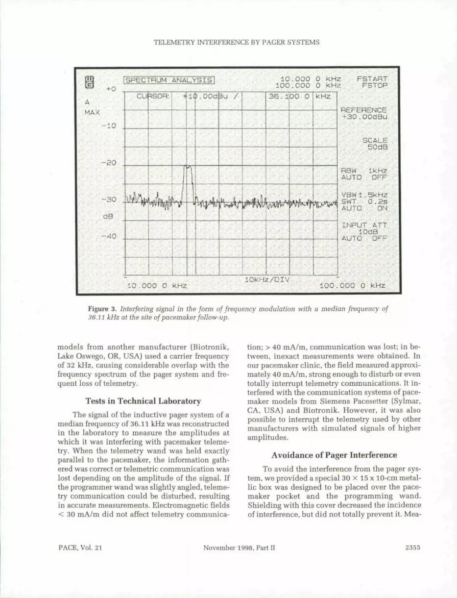
band of 10-100 kHz to detect the form and fre-quency content of the interfering signal. A re-ceiver antenna was placed horizontally on the pa-tient bed w^here pacemaker follow-ups wereperformed. These measurements showed that afrequency modulation signal with a median fre-quency of 36.11 kHz was the cause of the interfer-ence (Fig. 3). This signal originated from the hos-pital inductive pager system, located at a distanceof approximately 3 meters from the patient bedwhere the interfering signal had a magnetic fieldstrength of 40 mA/m.
Measurements of Pacemaker Telemetry
Telemetry techniques and the carrier frequen-cies used by pacemaker manufacturers are vari-able. Measurements with a spectral analyzer re-vealed a range of carrier frequencies among fivemajor manufacturers hetween 32 and 175 kHz.The most commonly affected pacemaker models(e.g., Pacesetter Synchrony, Paragon, Genisis)
ECQ/IEGBl PhRAIflETERS
Surface ECGSurfacB ECQ Gainsurface ECG FilterIntracardiac EGWIntracardiac EGM GainChart Speed
QFF1.B inu/diu
ON
2.S mu/diu2E.B mm/sec
Figure 2. Disturbances in intracardiac electrogramtracings by EMI during real-time telemetry.
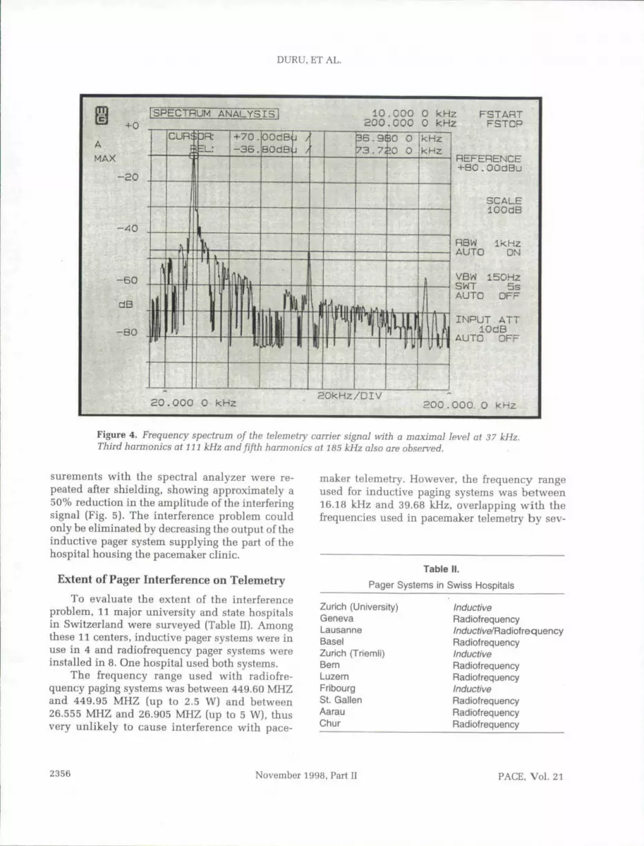
used a telemetry carrier frequency of 37 kHz [Fig.4), a value very close to the frequency used by thehospital pager system (36.11 kHz). This causeddisturbed telemetry with inappropriate measure-ment of pacemaker parameters or total interrup-tion of telemetry. Commonly affected pacemaker
Table 1.
Equipments Used in Interference Tests
Spectrumanalyzer:
Receiverantenna:
Senderantenna:
Signalgenerator:
Attenuator:
MatchingPad:
Wandel + Goitormann; SNA-1, 100 Hz-180 MHz, G-0023
EMCO; 7604, magnetic field pick-up coil(RE01)
EMCO; 6511, passive loop antenna(interference signal)
Phiiips; PM 5193, programmablesynthesizer
Hewiett Packard; 355D VHF attenuator;0.5W, 50 Ohm, 0.120 dB
Huber and Subner; 6001.01.B, 75/50Ohm, 1 W DC-1000 MHz
2354 November 1998, Part U PACE, Vol. 21
TELEMETRY INTERFERENCE BY PAGER SYSTEMS
10.000 0 kHzlOkHz/OlV
FSTARTFSTCP
REFERENCEH-30.00dBu
SCALE50dB
RBWfUTO OFF
VBWl.SkHzSWT 0 .2SAUTO ON
INPUT ATTlOdB
AUTO OFF
100.000 0 kHz
Figure 3. Interfering signal in the form of frequency modulation with a median frequency of36.lt kHz at the site of pacemaker foUow-up.
models from another manufacturer (Biotronik,Lake Oswego, OR, USA) used a carrier frequencyof 32 kHz, causing considerable overlap with thefrequency spectrum of the pager system and fre-quent loss of telemetry.
Tests in Technical Laboratory
The signal of the inductive pager system of amedian frequency of 36.11 kHz was reconstructedin the lahoratory to measure the amplitudes atwhich it was interfering with pacemaker teleme-try. When the telemetry wand was held exactlyparallel to the pacemaker, the information gath-ered was correct or telemetric communication waslost depending on the amplitude of the signal. Ifthe programmer wand was slightly angled, teleme-try communication could be disturbed, resultingin accurate measurements. Electromagnetic fields< 30 mA/m did not affect telemetry communica-
tion; > 40 mA/m, communication was lost; in be-tween, inexact measurements were obtained. Inour pacemaker clinic, the field measured approxi-mately 40 mA/m, strong enough to disturb or eventotally interrupt telemetry communications. It in-terfered with the communication systems of pace-maker models from Siemens Pacesetter (Sylmar,CA, USA) and Biotronik. However, it was alsopossible to interrupt the telemetry used by othermanufacturers with simulated signals of bigberamplitudes.
Avoidance of Pager Interference
To avoid the interference from the pager sys-tem, we provided a special 30 x 15 x 10-cm metal-lic box was designed to be placed over the pace-maker pocket and tbe programming wand.Shielding witb this cover decreased the incidenceof interference, but did not totally prevent it. Mea-
FACE.Vol. 21 November 1998, Part II 2355
DURU, ET AL.
jSPECTRUM ANALYS,IS 10.COO 0 kHz200.000 0 kHz
3R: +70.-36.
OOdSfiBOdB
5.9SO 0173.730 O
kHzkHz
FSTARTFSTOP
REFERENCE+B0.OOdBu
SCALElOOdB
RSW Ik HzAUTO ON
VBW 150H2SWT 5sAUTO OFF
INPUT ATTlOdB
AUTO OFF
aO.OOO 0 kHz HOkHz/DIV200.000. O kHz
Figure 4. Frequency spectrum of the telemetry carrier signal with a maximal level at 37 kHz.Third harmonics at 111 kHz and fifth harmonics at 7 85 kHz also are observed.
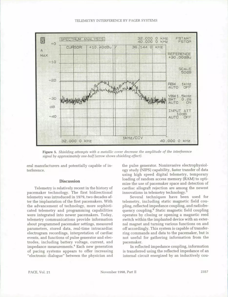
surements with the spectral analyzer were re-peated after shielding, showing approximately a50% reduction in the amplitude of the interferingsignal (Fig. 5). The interference problem couldonly be eliminated by decreasing the output of tbeinductive pager system supplying the part of thehospital housing the pacemaker clinic.
Extent of Pager Interference on Telemetry
To evaluate the extent of the interferenceproblem, 11 major university and state hospitalsin Switzerland were surveyed (Table II). Amongthese 11 centers, inductive pager systems were inuse in 4 and radiofrequency pager systems wereinstalled in 8. One hospital used hoth systems.
The frequency range used with radiofre-quency paging systems was between 449.60 MHZand 449.95 MHZ (up to 2.5 W) and between26.555 MHZ and 26.905 MHZ (up to 5 W), thusvery unlikely to cause interference with pace-
maker telemetry. However, the frequency rangeused for inductive paging systems was hetween16.18 kHz and 39.68 kHz, overlapping with thefrequencies used in pacemaker telemetry by sev-
Table rr.
Pager Systems in Swiss Hospitals
Zurich (University)GenevaLausanneBaselZurich (Triemli)BernLuzernFribourgSt. GallenAarauChur
InductiveRadiofrequency/nduc^/Ve/Rad iof req u encyRadiofrequencyInductiveRadiofrequencyRadiofrequencyInductiveRadiofrequencyRadiofrequencyRadiofrequency
2356 November 1998, Fart II PACE, Vol. 21
TELEMETRY INTERFERENCE BY PAGER SYSTEMS
fSPECTRUM ANALYSIS
AMAX
•+-0
10
32.000 0 KHz^0-000 0 kHz
FSTABTFSTOP
- 3 0
dB
- 4 0
CUP SOR 4-10. ^OdBu
1
3 6 .
^ /
144 0 kHz
IjMiLjy
REFERENCE+30.OOdBu
SCALE50dB
RBW Ik HzAUTO OFF
VBW1.5kHzSWT O.2SAUTO ON
INPUT ATTlOdB
AUTO OFF
3a.000 0 kHzikHz/DIV
40.000 O kHz
Figure 5. Shielding attempts with a metallic cover decrease the amplitude of the interferencesignal by approximately one-half (arrow shows shielding effect).
eral manufacturers and potentially capable of in-terference.
DiscussionTelemetry is relatively recent in the history of
pacemaker technology. The first bidirectionaltelemetry was introduced in 1979, two decades af-ter tbe implantation ofthe first pacemakers. Withthe advancement of technology, more sophisti-cated telemetry and programming capabilitieswere integrated into newer pacemakers. Today,telemetry communications provide informationabout programmed pacemaker settings, measuredparameters, stored data, real-time intracardiaceiectrogram recordings, interpretation of cardiacevents, and functions of pulse generator and elec-trodes, including battery voltage, current, andimpedance measurements.^ Each new generationof pacing systems appears to offer increasing"electronic dialogue" between tbe physician and
the pulse generator. Noninvasive electrophysiol-ogy study (NIPS) capability, faster transfer of datausing high speed digital telemetry, temporaryloading of random access memory (RAM) to opti-mize the use of pacemaker space and detection ofcardiac allograft rejection are among the newestinnovations in telemetry technology.^
Several techniques have been used fortelemetry, including static magnetic field cou-pling, reflected impedance coupling, and radiofre-quency coupling.^ Static magnetic field couplingoperates by closing or opening a magnetic reedswitch within the implanted device with an exter-nal magnet and turning various functions on andoff accordingly. This system is capable of transfer-ring commands and data to the pacemaker, but isnot useful for gathering information from thepacemaker.
In reflected impedance coupling, informationis transferred using the reflected impedance of aninternal circuit energized by an inductively cou-
PACE, Vol. 21 November 1998, Part II 2357

DURU, ET AL.
pled external circuit.^ In radiofrequency coupling,data transfer is from a transmitting coil to a re-ceiving coil by way of a carrier signal. The modu-lated carrier induces a voltage at the receivingcoil, and the received signal then is demodulatedto recover the transmitted data. The carrier fre-quency of these systems is limited by the metal en-closure of the implanted device that acts as a lowpass filter. Therefore, these systems generallyhave not been able to transfer data at very fastrates. Faster data transmission is possible with awide bandwidthj which increases the susceptibil-ity to EMI.
Modern pacemakers are equipped with a num-ber of features to minimize the risk of EMI.̂ The ti-tanium case provides electrical shielding, suchthat interference through the case is very unlikelyto occur. Interference occurs usually via the headeror via the leads that function as antennas, receivingexternal signals and transferring them through theconnector and a feedthrough assembly into the in-ner circuitry. Most pacemaker manufacturers useEMI capacitors, which function as filters, to pro-vide some degree of protection. These features aredesigned to avoid or minimize EMI-related pace-maker dysfunction. In contrast, the problem oftelemetry interference is much less appreciated,despite its existence in clinical practice.
If a radiofrequency electromagnetic field at asimilar or greater power is being generated hy anearby EMI source, telemetry transmission can heaffected/ Possible effects include a slowed rate ofdata transmission, alterations of measured pace-maker data and diagnostics, incorrect program-ming, or cessation of telemetric communication.^Most manufacturers have added various forms ofidentification checks to secure correct transmis-sion. This provides additional security, such thateven when the interference is powerful enough toactivate telemetry, the received signals are not ac-cepted. However, with the increasing number andcomplexity of environmental electromagneticsources, it may be impossible to guarantee a
References
1. Irnich W. de Bakker JMT, Bisping HJ. Electromag-netic interference in implantable pacemakers.PACE 1978; 1:52-61.
2. Irnich W. Interference in pacemakers. PACE 1984;7:1021-1048.
telemetry data transfer with complete immunityagainst MI.
The identification of interference by our hos-pital pager systems was an accidental finding. Suchproblems had not been noticed prior to the changeof location of our pacemaker clinic. The conse-quences were serious, because it was impossible toperform pacemaker follow-ups until the cause ofEMI could be identified. Since relocation of thepacemaker clinic was undesirable, other solutionswere sought. Shielding attempts did not solve theproblem. A definitive solution was achieved onlyby decreasing the output of the pager system at therisk of disturbing pager communications.
Physicians and other medical personnelshould be aware of the interference potential ofhospital equipment, such as pager systems andother sources yet to be identified, on telemetrycommunication, and perform pacemaker follow-ups with a high index of suspicion. As the amountof data to be transferred increases with each newgeneration of pacemakers, the "electronic dia-logue" will probahly remain susceptible to newpotential sources of EMI.
Conclusions
EMI may cause pacemaker dysfunction anddisturb telemetric transfer of data between pace-makers and programmers. Certain hospital pagersystems have the potential of interfering withtelemetry, resulting in inappropriate measure-ments of pacemaker parameters, disturbances inintracardiac electrogram tracings, and even totalinterruption of telemetry communication. Thereason for interference is an overlap of carrier fre-quencies of some pacemaker programmers withthose of inductive pager systems. Radiofrequencysystems using higher fi-equencies are unlikely tocause such interference. Awareness of this inter-ference potential may have practical implicationswhen choosing the carrier frequencies of induc-tive pager systems and pacemaker programmers,and in planning the location of pacemaker clinics.
3. Moherg BL, Strandberg HG. Effects of interferenceon pacemakers. Eur JCPE 1995; 5:146-157.
4. Levine PA, Long RJ. Pacemaker diagnostics: An aidto patient follow-up. In KK Sethi KK (ed.): Proceed-ings of VI Asian-Pacific Symposium on Cardiac
2358 November 1998, Part II PACE, Vol. 21

TELEMETRY INTERFERENCE BY PAGER SYSTEMS
Pacing and Electrophysiology. Bologna, Italy, Mon- device. United States patent report. Inventor: Sergiuduzzi Editore, 1997, pp. 37-42. Silvian, La Crescenta, CA. U.S, Patent number;Candinas R, Duru F, Bauersfeld U. Advances in pro- 4999299.gramming and telemetry. In KK Sethi (ed.): Pro- 7. Bassen HJ. RF interference (RFI) of medical devicesceedings of VI Asian-Pacific Symposium on Cardiac by mobile communications transmitters. In NPacing and Electrophysiology. Bologna, Italy, Mon- Kuster, Q Balzano, JC Lin (eds.J: Mobile Communi-duzzi Editore, 1997, pp. 17-23. cations Safety. New York, Cbapman & Hall, 1997,High speed digital telemetry system for implantable pp. 65-94.
PACE, Vol. 21 November 1998, Part II 2359