hindustan aeronautics limited overhual division, bangalore
TRANSCRIPT
Project Report
on
“DESIGN OPTIMIZATION OF TOOL REQUIREMENT FOR
FATIGUE STRENGTH IN HAWK-MK132 AIRCRAFT”
Submitted by
J.B RAVI KIRAN 1NH14ME408
MOLAKA KALYAN 1NH14ME412
DINU KRISHNAN 1NH11ME013
In partial fulfillment of
BACHELOR OF ENGINEERING
IN
MECHANICAL ENGINEERING INTERNAL GUIDE: EXTERNAL GUIDE:
Mrs.RESMY.J.DEVAN Mr.RAJA NAIK
Asst. Professor Quality Manager, Department of Mechanical Engineering, Hawk Quality Dept,
N.H.C.E, Bangalore. Overhaul division, H.A.L,
Bangalore.
Project work carried out at
Hindustan Aeronautics Limited Overhual Division, Bangalore-560017
DEPARTMENT OF MECHANICAL ENGINEERING
NEW HORIZON COLLEGE OF ENGINEERING BANGALORE-560 103
2016-17
NEW HORIZON COLLEGE OF ENGINEERING
DEPARTMENT OF MECHANICAL ENGINEERING
CERTIFICATE
It is certified that the project entitled "Design Optimization of Tool
Requirement for Fatigue Strength in Hawk-Mk132 Aircraft” is a
bonafide work carried out by J.B.RAVI KIRAN (1NH14ME408), MOLAKA
KALYAN (1NH14ME412) and DINU KRISHNAN (1NH11ME013) for the partial
fulfillment for award of degree of Bachelor of Engineering in Mechanical
Engineering of New Horizon College of Engineering, Bangalore during the year
2016-2017. It is further certified that all corrections/suggestions indicated for internal
assessment has been incorporated in the report deposited in the department library.
The Project has been approved as it satisfies the academic requirements in respect of
Project Work prescribed for the Bachelor of Engineering degree.
Signature of the guide
Signature of the HOD
Signature of the Principal Mrs RESMY.J.DEVAN Dr. M S GANESHA PRASAD Dr MANJUNATHA
Asst. Professor, Dean-Students Affairs & HOD-ME, Principal,
Dept. of Mechanical Engineering. Dept. of Mechanical Engineering. NHCE.
External Examiner(s) Signature with Date
1.
2.
DECLARATION
I hereby declare that the entire work embodied in this dissertation has been carried
out by our group and no part of it has been submitted for any degree of any institution
previously.
Date: Signature of the student
Place: Bangalore
CERTIFICATE
This is to certify that the above declaration made by the candidate is correct to the
best of my knowledge and belief.
Place: Bangalore RESMY J DEVAN
Date: Asst Professor
Department of Mechanical Engg,
N.H.C.E, Bangalore.
J.B.RAVI KIRAN 1NH14ME408
MOLAKA KALYAN 1NH14ME412
DINU KRISHNAN 1NH11ME013
ACKNOWLEDGEMENTS
I thank the Lord Almighty for showering His blessings on me.
It is indeed a great pleasure to recall the people who have helped me in carrying
out this project. Naming all the people who have helped me in achieving this goal would
be impossible, yet I attempt to thank a selected few who have helped me in diverse ways.
I wish to express my sincere gratitude to Dr. Manjunatha, Principal, NHCE,
Bangalore, for providing me with facilities to carry out this project.
I wish to express my sincere gratitude to Dr. M S Ganesha Prasad, NHCE,
Dean-Students Affairs & Head of Department, Mechanical Engg., for his constant
encouragement and cooperation.
I wish to express my sincere gratitude to my teacher and guide RESMY J
DEVAN, Professor in the Department of Mechanical Engg., NHCE, for his valuable
suggestions, guidance, care & attention shown during the planning, conduction stages of
this project work.
I express my sincere thanks to project coordinators, all the staff members and non-
teaching staff of Department of Mechanical Engg., for the kind cooperation extended by
them.
I thank my parents for their support and encouragement throughout the course of
my studies.

Design Optimization of Tool Requirement of Fatigue Strength in HAWK MK 132 Aircraft
Dept. of Mechanical Engg., NHCE, Bangalore 2016-17
Abstract
In major industrial countries, manufacturing is considered as the most important driving
towards nation’s richness and success. But globalization and consolidation of companies
has resulted in increased competition for manufacturing plants, therefore it is essential for
the claims to their productivity to survive in the competitive market. When it comes to
improving productivity, optimum utilization of machinery and reducing rejections are the
key factors.In Hindustan Aeronautics limited, overhaul division the management
authorities have identified many thrust areas for reducing the lead time of manufacturing
of components. This has resulted in selecting the components. “Alignment pin & landing
gear pintle pin bolts remover” for the project work.Basically, Alignment pins are
manufactured for the standard sizes and the problem facing is unavailability of size
required. Where, the required size of diameter Φ4.67mm. Therefore, we are designing
alignment pin for required dimensions. Landing Gear Pintle Pin Bolts Remover is the
tool, which is designed for easy removal of landing gear & unmounting the pintle pin
located in the wing structure. The main purpose is to reduce manufacturing lead-time and
reduce man-hour rate. It also helps to reduce additional costs due to rework & it is
convenient to use.Analysis based on tools requirement for fatigue modification is carried
out. Therefore, we design & fabricate the suitable tool for respective modification as per
the requirements of the organization where the general tools are not easily accessible.
CONTENTS
CERTIFICATE
ACKNOWLEDGEMENT
DECLARATION
ABSTRACT
CONTENTS
LIST OF FIGURES
LIST OF TABLES
1. INTRODUCTION 1
1.1 HISTORY 2
1.2 FLOW CHART OF ORGANIZATION 3
1.3 BANGALORE COMPLEX 3
1.4 MIG COMPLEX 5
1.5 ACCESSORIES COMPLEX 5
1.6 DESIGN COMPLEX 6
1.7 EVOLUTION AND GROWTH OF COMPANY 7
1.8 ABOUT HAWK AIRCRAFT 8
1.9 SPECIFICATIONS 9
1.9.1 AIRCRAFT FACTS 10
2. MISSION AND VISION 13
2.1 MSSION OF THE ORGANIZATION 13
2.2 VISION 13
2.3 QUALITY POLICY 13
2.4 QUALITY OBJECTIVES 13
2.5 PRINCIPLES AND CONCEPTS OF FIXTURING FOR CNC
CONTROL
14
2.6 DEFINITION OF PROBLEM AND OBJECTIVES 15
2.6.1 DEFINITION OF PROBLEM 15
3. DETAILS OF FIXTURE 17
3.1 ALIGNMENT PIN 17
3.2 LANDING GEAR PINTLE PIN BOLTS REMOVER 18
3.2.1 LIST OF COMPONENTS 18
3.3 ENGINEERING DRAWING 20
3.3.1 ALIGNMENT PIN 20
3.3.2 LANDING GEAR PINTLE PIN BOLTS REMOVER 21
3.4 FINAL ASSEMBLY 23
4. MATERIAL SELECTION 25
4.1 MATERIAL SELECTION 25
4.1.1 ABSTRACT 25
4.1.2 GENERAL PRODUCT INFORMATION 25
4.1.3 SCOPE 25
4.1.4 CLASSIFICATION 26
4.2 REQUIREMENTS 26
4.3 MATERIAL PROPERTIES 27
4.3.1 MECHNAICAL PROPERTIES 27
4.3.2 CHEMICAL PROPERTIES 28
4.3.3 PHYSICAL PROPERTIES 28
5 DESIGN OF FIXTURES 29
5.1.1 CUTTING FORCE CALCULATIONS 29
5.1.2 DESIGN OF EXTERNAL SLEEVE 30
5.1.3 DESIGN OF INTERNAL SLEEVE 31
5.1.4 DESIGN OF SCREW ROD 32
5.2 STRESSES INDUCED IN FINAL ASSEMBLED PART 33
6 JUSTIFICATIONS AND DIMENSIONS 34
6.1.1 JUSTIFICATION OF ALIGNMENT PIN 34
6.1.2 JUSTIFICATION OF BOLTS EXTRACTOR 34

Table
No.
LIST OF TABLES
Particulars
Page
No.
Table1
Material Selection
15
Table2
Mechnaical Properties
18
Table3
Chemical Properties
28
Table4 Dimensions with tolerances 30
DESIGN OPTIMIZATION OF TOOL REQUIREMENT FOR FATIGUE STRENGTH IN HAWK MK 132 AIRCRAFT
Dept. of Mechanical Engg., NHCE, Bangalore 2016-17 Page 1
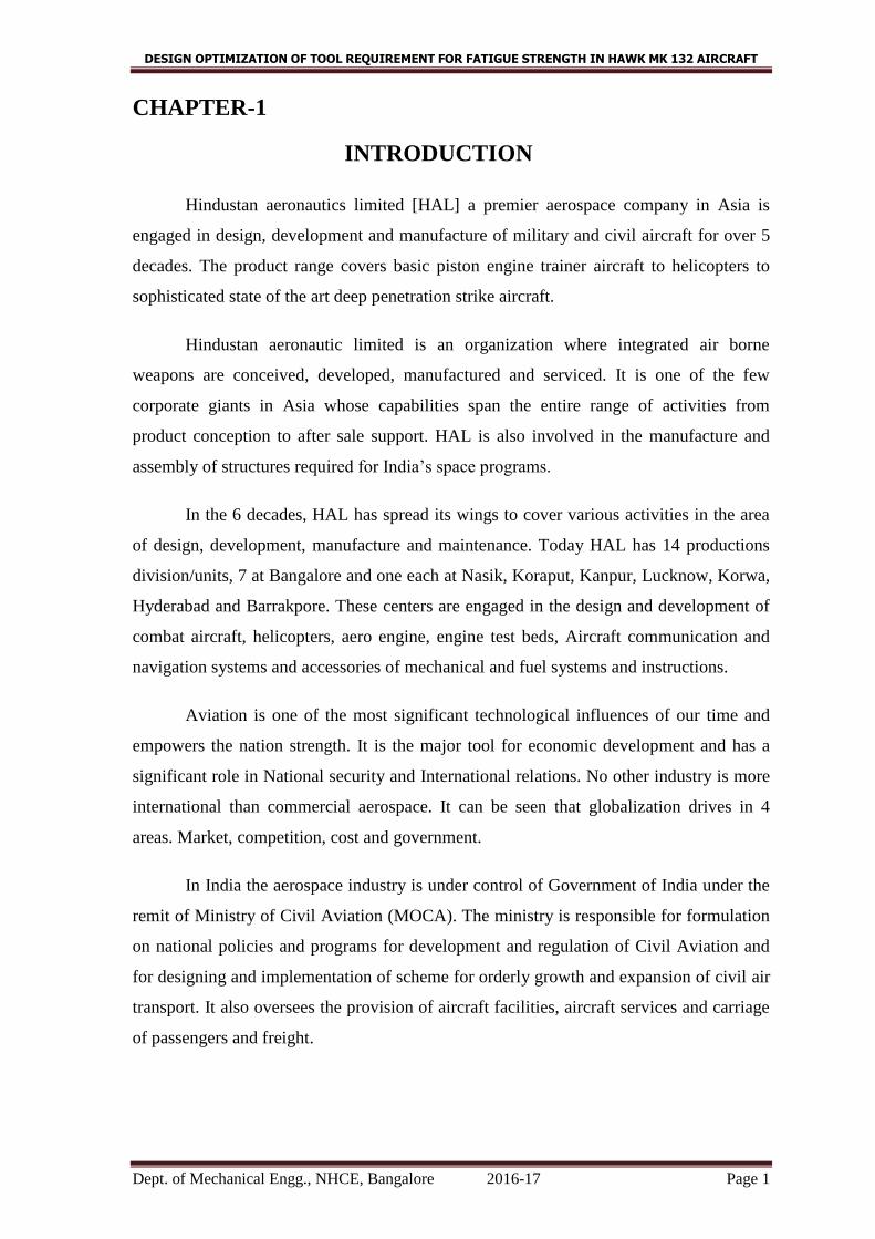
CHAPTER-1
INTRODUCTION
Hindustan aeronautics limited [HAL] a premier aerospace company in Asia is
engaged in design, development and manufacture of military and civil aircraft for over 5
decades. The product range covers basic piston engine trainer aircraft to helicopters to
sophisticated state of the art deep penetration strike aircraft.
Hindustan aeronautic limited is an organization where integrated air borne
weapons are conceived, developed, manufactured and serviced. It is one of the few
corporate giants in Asia whose capabilities span the entire range of activities from
product conception to after sale support. HAL is also involved in the manufacture and
assembly of structures required for India’s space programs.
In the 6 decades, HAL has spread its wings to cover various activities in the area
of design, development, manufacture and maintenance. Today HAL has 14 productions
division/units, 7 at Bangalore and one each at Nasik, Koraput, Kanpur, Lucknow, Korwa,
Hyderabad and Barrakpore. These centers are engaged in the design and development of
combat aircraft, helicopters, aero engine, engine test beds, Aircraft communication and
navigation systems and accessories of mechanical and fuel systems and instructions.
Aviation is one of the most significant technological influences of our time and
empowers the nation strength. It is the major tool for economic development and has a
significant role in National security and International relations. No other industry is more
international than commercial aerospace. It can be seen that globalization drives in 4
areas. Market, competition, cost and government.
In India the aerospace industry is under control of Government of India under the
remit of Ministry of Civil Aviation (MOCA). The ministry is responsible for formulation
on national policies and programs for development and regulation of Civil Aviation and
for designing and implementation of scheme for orderly growth and expansion of civil air
transport. It also oversees the provision of aircraft facilities, aircraft services and carriage
of passengers and freight.

DESIGN OPTIMIZATION OF TOOL REQUIREMENT FOR FATIGUE STRENGTH IN HAWK MK 132 AIRCRAFT
Dept. of Mechanical Engg., NHCE, Bangalore 2016-17 Page 2
India has been fortunate to start aeronautics related activities an 1940, with the
establishment of HAL. The largest Indian aircraft manufacture in HAL (PSU) owned
aerospace related companies in South India, centered on the group of companies in
Bangalore. While HAL is mainly defence related, other local companies serve the civil
sector and are involved in the production of light aircraft structure designs, engines,
electronics and other equipment avionics/radar precision parts and materials. Many
companies are collaborating a Joint Ventures or Technology Transfers to manufacture
under license for foreign partners.
DESIGN OPTIMIZATION OF TOOL REQUIREMENT FOR FATIGUE STRENGTH IN HAWK MK 132 AIRCRAFT
Dept. of Mechanical Engg., NHCE, Bangalore 2016-17 Page 3
CHAPTER-2
HISTORY
Fig2.1 History
Hindustan Aeronautic Limited was founded in Dec 1940 by Shri Seth Walchand
Hirachand as Hindustan Aircraft Ltd. A private limited company and since then the
company has produced over 3300 aircrafts, 3400 aero engines, overhauled over 7700
aircrafts and 26000 engines and produced over 3700 engines.
In 1962, Aeronautic India Ltd was formed to undertake the manufacture MiG-21 aircrafts
as an agreement between Govt of India and Soviet Union (USSR). IN 1964 Hindustan
Aircraft did and Aeronautics India Ltd. After Independence, the company rededicated
itself to the design, development, manufacture and maintenance of aircrafts. During the
50 years of post-independence era, the company has contributed significantly through
vigorous R&D efforts of indigenously designing trainers, fighters, helicopters,
sophisticated airborne and ground equipment, avionics and systems.
DESIGN OPTIMIZATION OF TOOL REQUIREMENT FOR FATIGUE STRENGTH IN HAWK MK 132 AIRCRAFT
Dept. of Mechanical Engg., NHCE, Bangalore 2016-17 Page 4
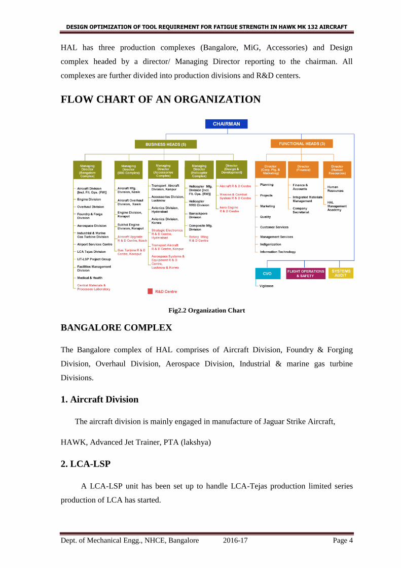
HAL has three production complexes (Bangalore, MiG, Accessories) and Design
complex headed by a director/ Managing Director reporting to the chairman. All
complexes are further divided into production divisions and R&D centers.
FLOW CHART OF AN ORGANIZATION
Fig2.2 Organization Chart
BANGALORE COMPLEX
The Bangalore complex of HAL comprises of Aircraft Division, Foundry & Forging
Division, Overhaul Division, Aerospace Division, Industrial & marine gas turbine
Divisions.
1. Aircraft Division
The aircraft division is mainly engaged in manufacture of Jaguar Strike Aircraft,
HAWK, Advanced Jet Trainer, PTA (lakshya)
2. LCA-LSP
A LCA-LSP unit has been set up to handle LCA-Tejas production limited series
production of LCA has started.

DESIGN OPTIMIZATION OF TOOL REQUIREMENT FOR FATIGUE STRENGTH IN HAWK MK 132 AIRCRAFT
Dept. of Mechanical Engg., NHCE, Bangalore 2016-17 Page 5
3. Aerospace Division
The division manufactures space worthy structures like Satellite Launch Vehicle
(SLV) interstages , propellant tanks and separator mechanism for ASLV, PSLV, GSLV,
IRS and INSAT series of technologies.
4. Aero engine division
The division is involved in state of art manufacture, overhaul and maintenance of Aero
engines for Helicopters and Aircrafts.
5. Industrial Marine and Gas Turbine Division
As a part of diversification plan, industrial and marine gas turbine division has been
formed on 1st April 1998 as a part of Bangalore complex. This division manufactures,
repairs, and overhauls 501K series 3 MW aero derivative gas turbine under license from
M/S, Allison gas turbine, USA, HAL supports over 40 such engines in India used by
GAIL, OGNC and RSEB. In addition, IMGT division carries out onsite maintenance of
RB-211 engines and overhaul of 17MW Industrial Avon Engines of ONGC under
arrangement with M/S, Rolls Royce.
6. Overhaul Division
This division is involved in major servicing and overhaul of associated rotables in respect
of Kiran MK-1/MK-1A/MK-11, Jaguar and Mirage 2000 aircrafts.
7. Foundry and Forge Division
The division capabilities include precision casting, sand casting and ring forgings. The
division is also involved in the development of material and alloys for aerospace and
defense applications.
MIG COMPLEX
Nasik Division
This division was established as a manufacturing base for MiG series of aircrafts.
The division involved in repair and overhaul of Mig 21, MiG21 BIS &MiG 27.
DESIGN OPTIMIZATION OF TOOL REQUIREMENT FOR FATIGUE STRENGTH IN HAWK MK 132 AIRCRAFT
Dept. of Mechanical Engg., NHCE, Bangalore 2016-17 Page 6
Koraput Division
The division undertakes manufacture and overhaul of R11 and R25 series
engines and R 29B engines. The division also has excellent hot forging and precision die
casting facilities.
ACCESSORIES COMPLEX
Hyderabad Division
These divisions undertake production and servicing of avionics, Air Route Surveillance
Radar (ARSR), Precision Approach Radar (PSR), and assembly of components and sub
systems for IAF/ ARMY/ NAVY/ COAST GUARD/ SPACE and other civil applications.
Transport Aircraft Division-Kanpur
The division manufactures HPT-32 and DORNIER 228 aircrafts. The division is
supported by R&D center.
Luck now Division
The division is involved in manufacturing of mechanical and hydro-mechanical
accessories, fuel system and instrument accessories for the complete range of aircrafts
produced in HAL.
Korwa Division
The capabilities of this division covers the manufacture, repair and maintenance of
Advanced Avionics Systems for military aircraft of Eastern Origin covering inertial
navigational systems, head up displays, weapon aiming computers, combined map
electronic display, laser ranger and marked target seeker, integrated navigation and
sighting complex.
DESIGN COMPLEX
1. Helicopter Division
The division currently undertakes manufacture, repair and maintenance of Chetak
(Aloutte 111) and Cheetah (Lama SA 3158) helicopters. The division is also engaged in
DESIGN OPTIMIZATION OF TOOL REQUIREMENT FOR FATIGUE STRENGTH IN HAWK MK 132 AIRCRAFT
Dept. of Mechanical Engg., NHCE, Bangalore 2016-17 Page 7
series production of Multi role, Multi mission, and Medium weight Class helicopter
named Advanced Light Helicopter (ALH) (DHRUV).
2. Maintenance repair and overhaul division
Hindustan Aeronautics Limited (HAL) is looking at setting up a maintainance, repair and
overhaul (MRO) facility to leverage its Bangalore airport asset which is now closed to
commercial aircraft. The division will facilitate overhauling of air craft, manufacturing of
spare parts and engine assemblies.
3. Barrackpore Division
The present factory of Hindustan Aeronautics Limited (HAL), Barrackpore is engaged
with overhauling and repairing of small aircrafts. The factory is also a agency for civil
customer aircrafts. The factory is well supported with ground support/handling
equipment, test rig etc.,
4. Aircraft Research &Development Center
It mainly involves in development of Aircraft Design, Prototype Manufacturing, and
Extensive Testing Facilities and Design & development of Intermediate Jet Trainer&
Light combat aircrafts.
5. Rotary Wing Research and Development Center
It mainly involves in development of Design task for civil and military
Helicopters, Design Development & testing analysis of structure/transmission system&
integration of engine/avionics, Design development of DHRUV, ALH, LCH.
6. Composite Manufacturing Division
Composite shop is equipped with bonding fixtures and balancing aids. Composite shop is
equipped with facilities for lay-up composites and autoclave for curing fabricated
components. For manufacturing the various gears and component gear shapers, gear
hobbers.
DESIGN OPTIMIZATION OF TOOL REQUIREMENT FOR FATIGUE STRENGTH IN HAWK MK 132 AIRCRAFT
Dept. of Mechanical Engg., NHCE, Bangalore 2016-17 Page 8
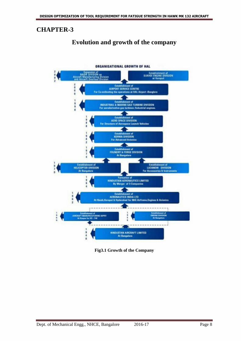
CHAPTER-3
Evolution and growth of the company
Fig3.1 Growth of the Company
DESIGN OPTIMIZATION OF TOOL REQUIREMENT FOR FATIGUE STRENGTH IN HAWK MK 132 AIRCRAFT
Dept. of Mechanical Engg., NHCE, Bangalore 2016-17 Page 9
CHAPTER-4
ABOUT HAWK AIRCRAFT
PROJECTS
Over the last six decades, HAL has grown progressively into an integrated
aerospace organization with the indigenous design and development of Advanced Light
Helicopter, IJT and LCA (Tejas).
The ongoing major projects and programmes include ALH, IJT, LCA and Pilot less target
aircraft, SU-30MK1, and HAWK Advanced Jet trainer.
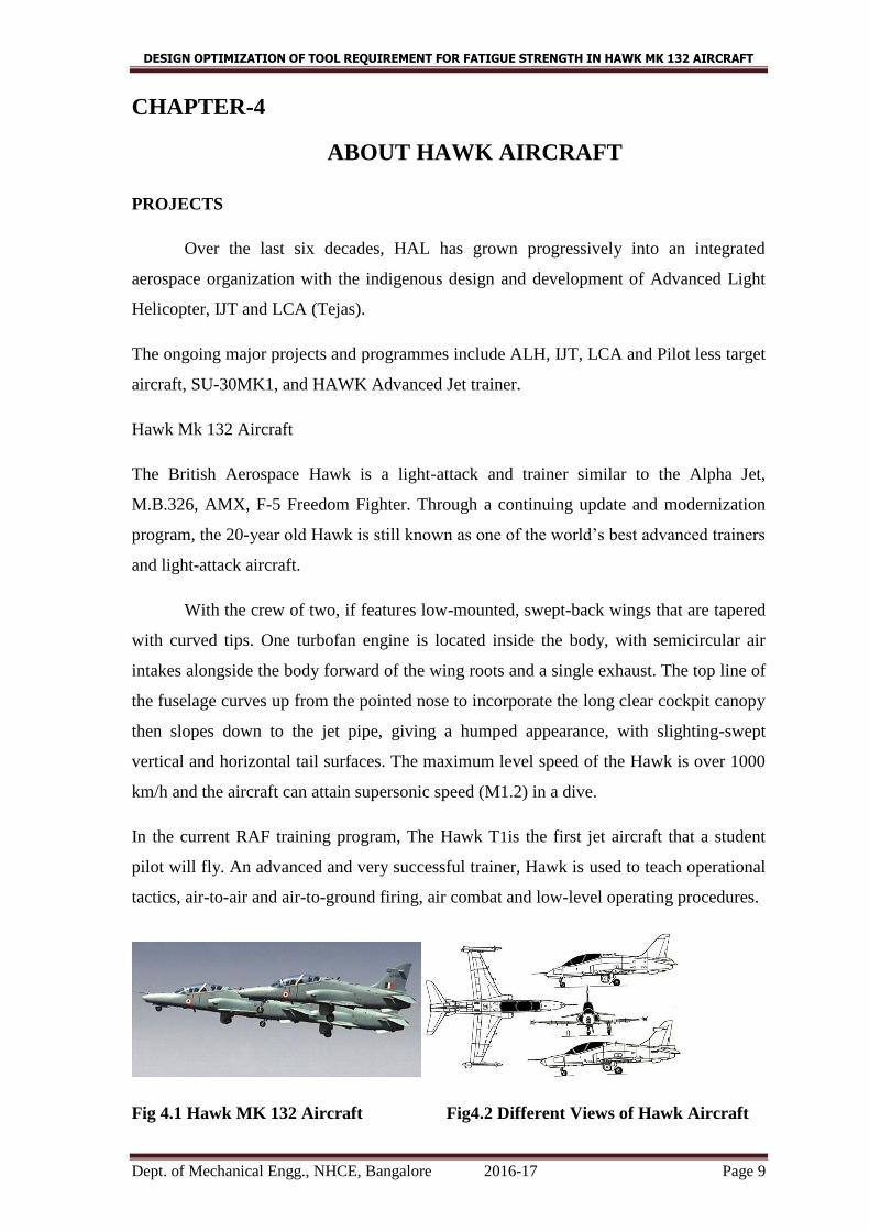
Hawk Mk 132 Aircraft
The British Aerospace Hawk is a light-attack and trainer similar to the Alpha Jet,
M.B.326, AMX, F-5 Freedom Fighter. Through a continuing update and modernization
program, the 20-year old Hawk is still known as one of the world’s best advanced trainers
and light-attack aircraft.
With the crew of two, if features low-mounted, swept-back wings that are tapered
with curved tips. One turbofan engine is located inside the body, with semicircular air
intakes alongside the body forward of the wing roots and a single exhaust. The top line of
the fuselage curves up from the pointed nose to incorporate the long clear cockpit canopy
then slopes down to the jet pipe, giving a humped appearance, with slighting-swept
vertical and horizontal tail surfaces. The maximum level speed of the Hawk is over 1000
km/h and the aircraft can attain supersonic speed (M1.2) in a dive.
In the current RAF training program, The Hawk T1is the first jet aircraft that a student
pilot will fly. An advanced and very successful trainer, Hawk is used to teach operational
tactics, air-to-air and air-to-ground firing, air combat and low-level operating procedures.
Fig 4.1 Hawk MK 132 Aircraft Fig4.2 Different Views of Hawk Aircraft
DESIGN OPTIMIZATION OF TOOL REQUIREMENT FOR FATIGUE STRENGTH IN HAWK MK 132 AIRCRAFT
Dept. of Mechanical Engg., NHCE, Bangalore 2016-17 Page 10
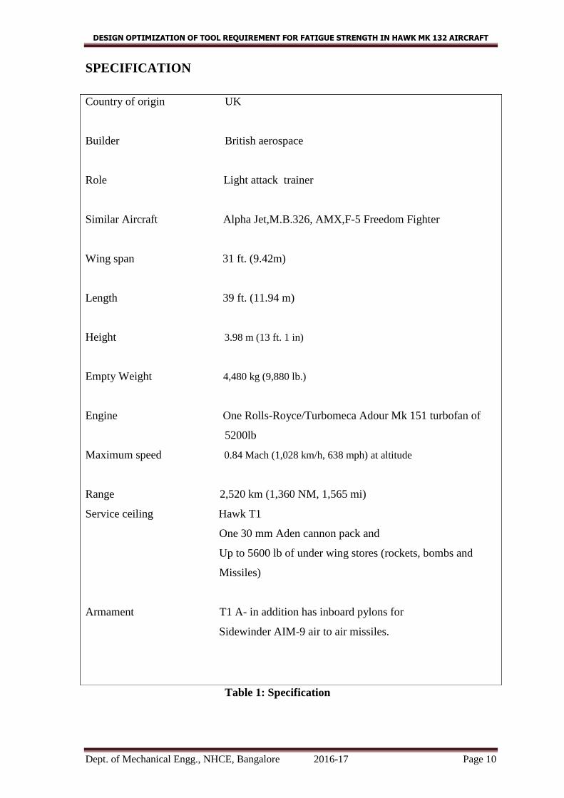
SPECIFICATION
Table 1: Specification
Country of origin UK
Builder British aerospace
Role Light attack trainer
Similar Aircraft Alpha Jet,M.B.326, AMX,F-5 Freedom Fighter
Wing span 31 ft. (9.42m)
Length 39 ft. (11.94 m)
Height 3.98 m (13 ft. 1 in)
Empty Weight 4,480 kg (9,880 lb.)
Engine One Rolls-Royce/Turbomeca Adour Mk 151 turbofan of
5200lb
Maximum speed 0.84 Mach (1,028 km/h, 638 mph) at altitude
Range 2,520 km (1,360 NM, 1,565 mi)
Service ceiling Hawk T1
One 30 mm Aden cannon pack and
Up to 5600 lb of under wing stores (rockets, bombs and
Missiles)
Armament T1 A- in addition has inboard pylons for
Sidewinder AIM-9 air to air missiles.
DESIGN OPTIMIZATION OF TOOL REQUIREMENT FOR FATIGUE STRENGTH IN HAWK MK 132 AIRCRAFT
Dept. of Mechanical Engg., NHCE, Bangalore 2016-17 Page 11
AIRCRAFT FACTS
The Hawk Advanced Jet trainer is a new aircraft, which has encapsulated 30 years
of experience with new systems to provide state-of-the-art training for the 21st century.
Principal features
Three, full color, Active matrix Liquid Crystal Displays, each controlled by soft
keys, and each able to display the full range of navigation, sensor, weapons and
systems data
Cockpit lighting fully compatible with the use of Night Vision Goggles, for
enhanced situational awareness during night operations
Head-up Display featuring symbology compatible with front line combat aircraft
types.
Hands-On-Throttle-And–Stick (HOTAS) controls with moding and switching
fully representative of front line combat aircraft types.
Inertial Navigation /Global positioning system for enhanced navigation weapon
aiming accuracy.
Health and usage monitoring system guaranteeing 10000 hours fatigue Life.
Rolls Royce/Turbomeca Adour Mk.951 turbofan engine (6500lb) with Full
Authority Digital Engine Control, with an impressive 4000 hours TBO (time
between overhaul).
Enhanced systems on the aircraft also include: -
An upgraded Electrical system, with power provided by a 25kVA generator
An Auxiliary Power Unit to provide electrical power and avionic cooling air
whilst the aircraft is on the ground. The APU also provides engine start and
engine re-light capability in flight.
An On –Board Oxygen generation system
DESIGN OPTIMIZATION OF TOOL REQUIREMENT FOR FATIGUE STRENGTH IN HAWK MK 132 AIRCRAFT
Dept. of Mechanical Engg., NHCE, Bangalore 2016-17 Page 12
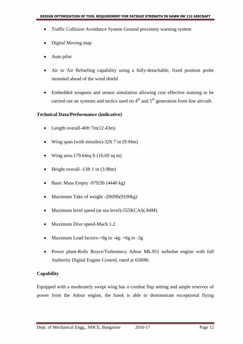
Traffic Collision Avoidance System Ground proximity warning system
Digital Moving map
Auto pilot
Air to Air Refueling capability using a fully-detachable, fixed position probe
mounted ahead of the wind shield
Embedded weapons and sensor simulation allowing cost effective training to be
carried out on systems and tactics used on 4th
and 5th
generation front line aircraft.
Technical Data/Performance (indicative)
Length overall-40ft 7in(12.43m)
Wing span (with missiles)-32ft 7 in (9.94m)
Wing area-179.64sq ft (16.69 sq m)
Height overall -13ft 1 in (3.98m)
Basic Mass Empty -9792lb (4440 kg)
Maximum Take of weight -2069lb(9100kg)
Maximum level speed (at sea level)-555KCAS(.84M)
Maximum Dive speed-Mach 1.2
Maximum Load factors-+8g to -4g: +6g to -3g
Power plant-Rolls Royce/Turbomeca Adour Mk.951 turbofan engine with full
Authority Digital Engine Control, rated at 6500lb
Capability
Equipped with a moderately swept wing has a combat flap setting and ample reserves of
power from the Adour engine, the hawk is able to demonstrate exceptional flying

DESIGN OPTIMIZATION OF TOOL REQUIREMENT FOR FATIGUE STRENGTH IN HAWK MK 132 AIRCRAFT
Dept. of Mechanical Engg., NHCE, Bangalore 2016-17 Page 13
characteristics. The aircraft has an excellent turn rate in both clean and loaded
configurations and an impressive climb rate.
Throughout its flight envelope the Hawk demonstrates stable, carefree handling
characteristics with no control difficulties and therefore provides an exceptionally safe
training environments for pilots. The aircraft is equipped with the latest cockpit displays
and sensors and is able to demonstrate air to air and air to ground combat and tactical
formation flying and perform extended missions through the use of an air to air refueling
probe. Consequently, the Hawk is an ideal platform for the introduction of student pilots
in the Advanced Fast Jet phase of conversion.
The Hawk has tandem seats, with full controls available in the front cockpit. Duplication
of essentials controls with appropriate override facilities is provided in the rear cockpit,
for example store jettison, landing gear and flaps. Internal lighting is provided for
instruments displays, and general cockpit illumination. Cockpit lighting, instruments, and
displays are compatible with the use of night vision goggles (NVG).
DESIGN OPTIMIZATION OF TOOL REQUIREMENT FOR FATIGUE STRENGTH IN HAWK MK 132 AIRCRAFT
Dept. of Mechanical Engg., NHCE, Bangalore 2016-17 Page 14
CHAPTER-5
MISSION AND VISION
MISSION OF THE ORGANISATION
“To become a globally competitive aerospace industry, while working as an instrument
for achieving self-reliance in design, manufacture and maintenance of aerospace
equipment, civil transport aircraft helicopter and missiles and diversifying to related
areas, managing the business on commercial lines in a climate of growing professional
competence.”
VISION
“To make HAL a dynamic, vibrant value based learning organization with human
resources exceptionally skilled, highly motivated and committed to meet the current and
future challenges. This will be driven by core values of the company fully embedded in
the culture of the organization.”
QUALITY POLICY
To provide quality product and service to international standard resulting in total
customer satisfaction and to strive for continual improvement.
QUALITY OBJECTIVES
Conformance to approve specification/systems
Product review and improvement
To remain competitive in international market
To provide leadership to effect attitudinal changes in human resource
Customer training
Systematic selection of supplies.
DESIGN OPTIMIZATION OF TOOL REQUIREMENT FOR FATIGUE STRENGTH IN HAWK MK 132 AIRCRAFT
Dept. of Mechanical Engg., NHCE, Bangalore 2016-17 Page 15
CHAPTER-6
Principles and concepts of fixturing for CNC
machining centers
1. N.C. MACHINING CENTERS
An N.C. Machining centre has the ability to encompass many machine tools into one.
With this fact in mind the obvious extension of this newfound capability is to design and
build fixtures that will allow as many of these different operations to be performed in the
least number of setups. How N.C. affects the design of fixtures may be derived from the
principle of operation of these machines.
Briefly, an N.C. machine is positioned by accurate ball screws coupled to servo motors.
Feedback systems attached to these ball screws can measure the exact position to within
one tenth of one thousand of an inch (.0001). Therefore, the accuracy of machined part is
not reliant upon the operator but in the machine tool, the cutters and the fixture.
In N.C machining, the part remains fixed while positioning and motion is carried out
by the tool. The only purpose of fixture in N.C machining is to locate accurately and hold
the part rigid while the cutting tool is engaged in the work piece.
There are two types of machining centers which need to be categorized, one having a
horizontal spindle and a rotating work table, the other a vertical spindle. Both types of
machines incorporate automatic tool changing.
DESIGN OPTIMIZATION OF TOOL REQUIREMENT FOR FATIGUE STRENGTH IN HAWK MK 132 AIRCRAFT
Dept. of Mechanical Engg., NHCE, Bangalore 2016-17 Page 16
2. FIXTURE DESIGNING FOR NC
Programming NC machines in many cases is accomplished using the computer but it has
not yet become a reality in fixture design although successful implementation of
CAD/CAM systems have produced automated drafting, process planning, scheduling and
part design. Fixture designing for conventional machine relies on a thorough knowledge
of basic machining practice, previous hands-on experience and familiarity with machine
tools. Tooling up an NC machine with regard to fixtures requires the tool designer’s
normal requirements together with teamwork on the part of the process planner,
programmer and tool designer. Each must know what the other has in mind and before
final plans are made a sequence of events should be formulated as outlined in the
following procedure.
1. The process planner decides the basic method of manufacture and writes his process
sheets accordingly.
2. The NC parts programmer reviews these plans and indicates the size of material
required, pre-machined surfaces, stock allowances and his tooling requirements.
3. A basic layout of the proposed fixture is given to the tool designer by the programmer
which may show the locating surfaces, part clamping regions, clearance areas required,
and location of the fixture with respect to the machine tool. The tool designer should have
reference material showing the physical elements of the machine such as slide travels and
limits
DESIGN OPTIMIZATION OF TOOL REQUIREMENT FOR FATIGUE STRENGTH IN HAWK MK 132 AIRCRAFT
Dept. of Mechanical Engg., NHCE, Bangalore 2016-17 Page 17
CHAPTER-7
DEFINITION OF PROBLEM AND OBJECTIVES
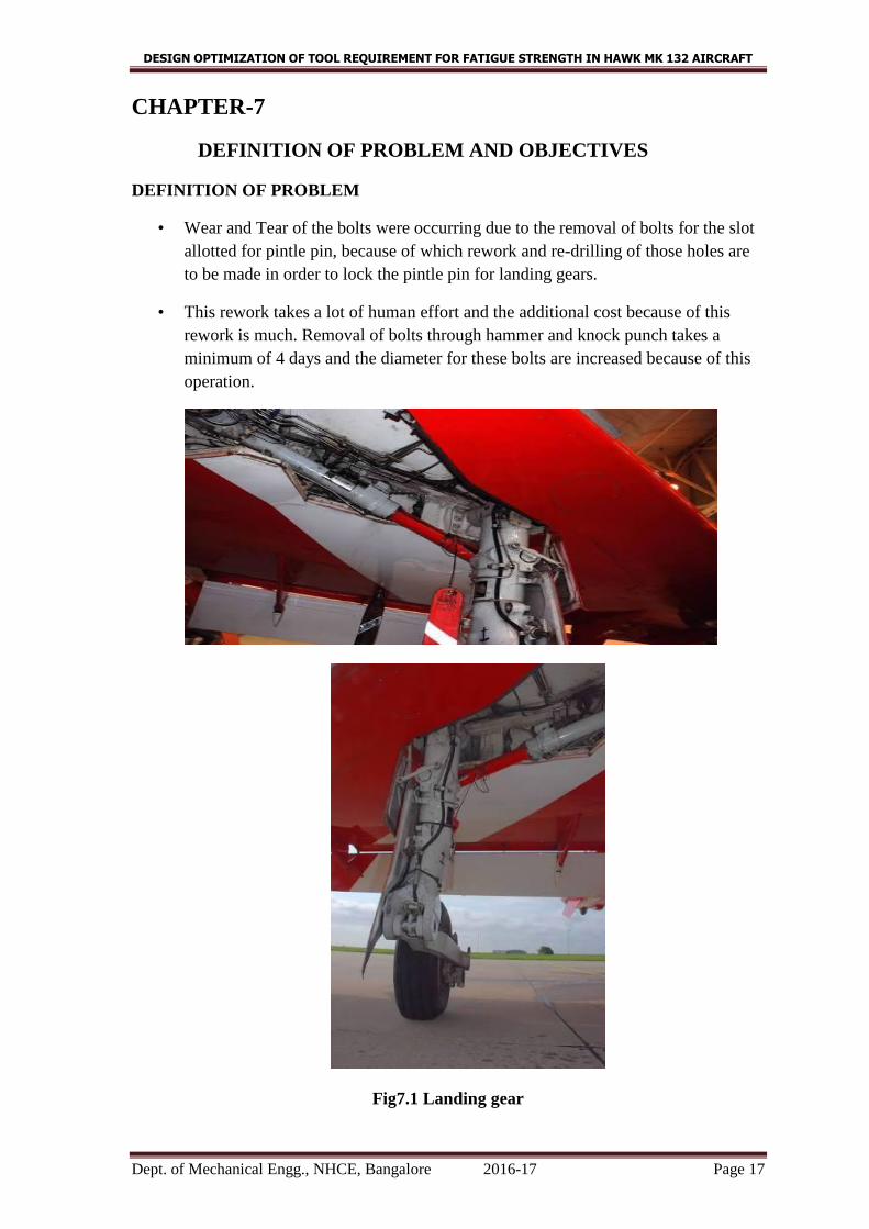
DEFINITION OF PROBLEM
• Wear and Tear of the bolts were occurring due to the removal of bolts for the slot
allotted for pintle pin, because of which rework and re-drilling of those holes are
to be made in order to lock the pintle pin for landing gears.
• This rework takes a lot of human effort and the additional cost because of this
rework is much. Removal of bolts through hammer and knock punch takes a
minimum of 4 days and the diameter for these bolts are increased because of this
operation.
Fig7.1 Landing gear

DESIGN OPTIMIZATION OF TOOL REQUIREMENT FOR FATIGUE STRENGTH IN HAWK MK 132 AIRCRAFT
Dept. of Mechanical Engg., NHCE, Bangalore 2016-17 Page 18
Objectives
• We analyzed the problems faced during the removal of the bolts in the landing
gear pintle pin and we are designing and fabricating a small hand tool (Tool
extractor) through which these bolts are removed with ease without causing
damage.
• Because of which there would not be any rework has to be carried out further and
thereby reducing human effort and additional cost required for reworking thus
increasing efficiency and reducing manufacturing lead time.
• Apart from MOD 2459, Longeron requires Alignment pin for the size 4.67mm is
required for alignment of axis for drill jig on an inclined surface.
DESIGN OPTIMIZATION OF TOOL REQUIREMENT FOR FATIGUE STRENGTH IN HAWK MK 132 AIRCRAFT
Dept. of Mechanical Engg., NHCE, Bangalore 2016-17 Page 19
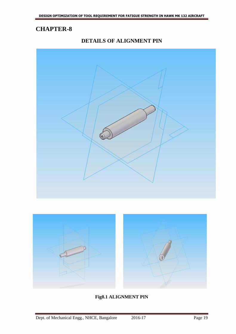
CHAPTER-8
DETAILS OF ALIGNMENT PIN
Fig8.1 ALIGNMENT PIN
DESIGN OPTIMIZATION OF TOOL REQUIREMENT FOR FATIGUE STRENGTH IN HAWK MK 132 AIRCRAFT
Dept. of Mechanical Engg., NHCE, Bangalore 2016-17 Page 20
CHAPTER-9
DETAILS OF LANDING GEAR PINTLE BOLTS REMOVER
LIST OF COMPONENTS
1. EXTERNAL SLEEVE
2. INTERNAL SLEEVE
3. SCREW ROD
4. FLANGE
5. SPACER
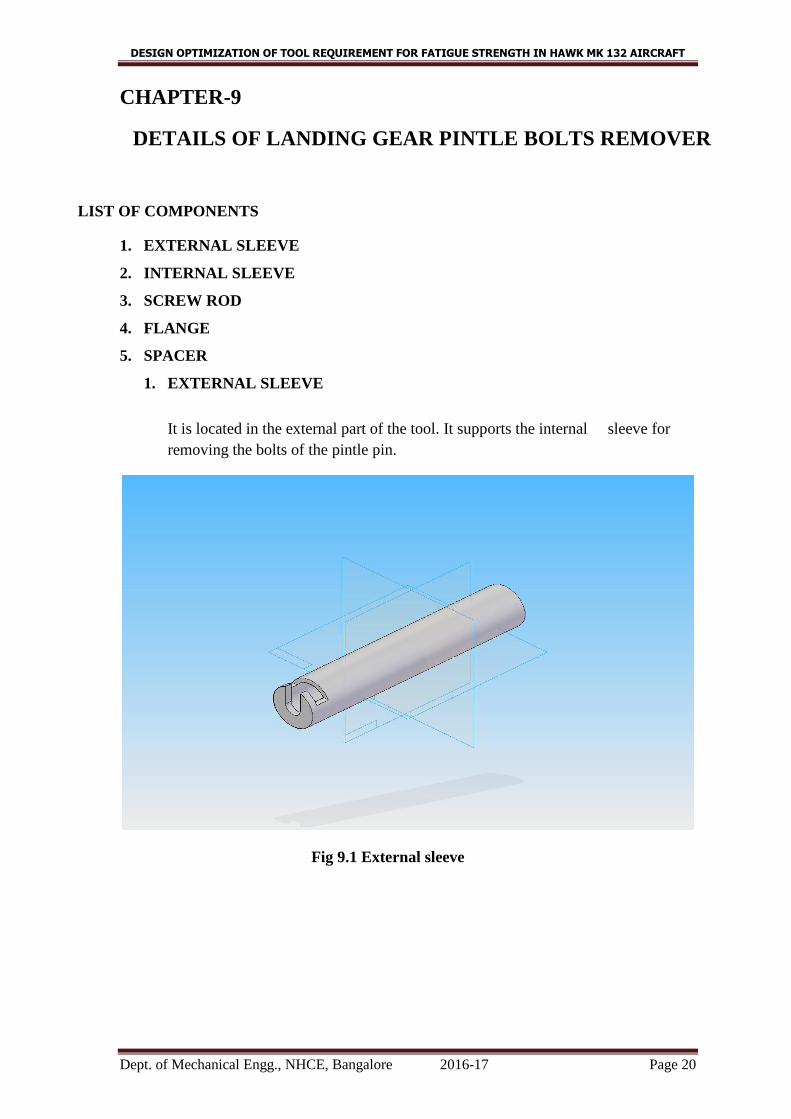
1. EXTERNAL SLEEVE
It is located in the external part of the tool. It supports the internal sleeve for
removing the bolts of the pintle pin.
Fig 9.1 External sleeve
DESIGN OPTIMIZATION OF TOOL REQUIREMENT FOR FATIGUE STRENGTH IN HAWK MK 132 AIRCRAFT
Dept. of Mechanical Engg., NHCE, Bangalore 2016-17 Page 21
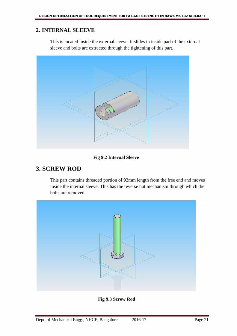
2. INTERNAL SLEEVE
This is located inside the external sleeve. It slides in inside part of the external
sleeve and bolts are extracted through the tightening of this part.
Fig 9.2 Internal Sleeve
3. SCREW ROD
This part contains threaded portion of 92mm length from the free end and moves
inside the internal sleeve. This has the reverse nut mechanism through which the
bolts are removed.
Fig 9.3 Screw Rod
DESIGN OPTIMIZATION OF TOOL REQUIREMENT FOR FATIGUE STRENGTH IN HAWK MK 132 AIRCRAFT
Dept. of Mechanical Engg., NHCE, Bangalore 2016-17 Page 22
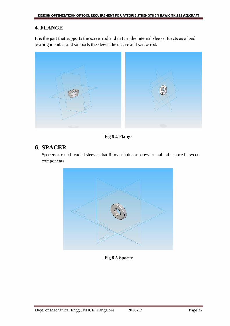
4. FLANGE
It is the part that supports the screw rod and in turn the internal sleeve. It acts as a load
bearing member and supports the sleeve the sleeve and screw rod.
Fig 9.4 Flange
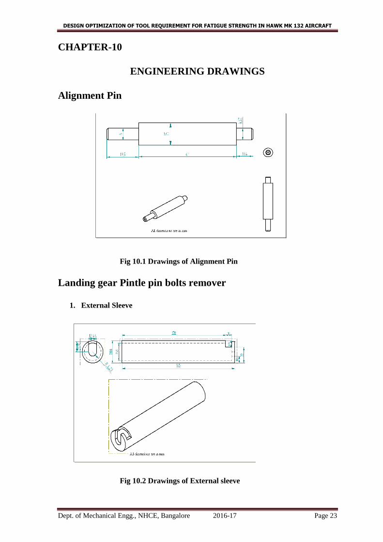
6. SPACER Spacers are unthreaded sleeves that fit over bolts or screw to maintain space between
components.
Fig 9.5 Spacer
DESIGN OPTIMIZATION OF TOOL REQUIREMENT FOR FATIGUE STRENGTH IN HAWK MK 132 AIRCRAFT
Dept. of Mechanical Engg., NHCE, Bangalore 2016-17 Page 23
CHAPTER-10
ENGINEERING DRAWINGS
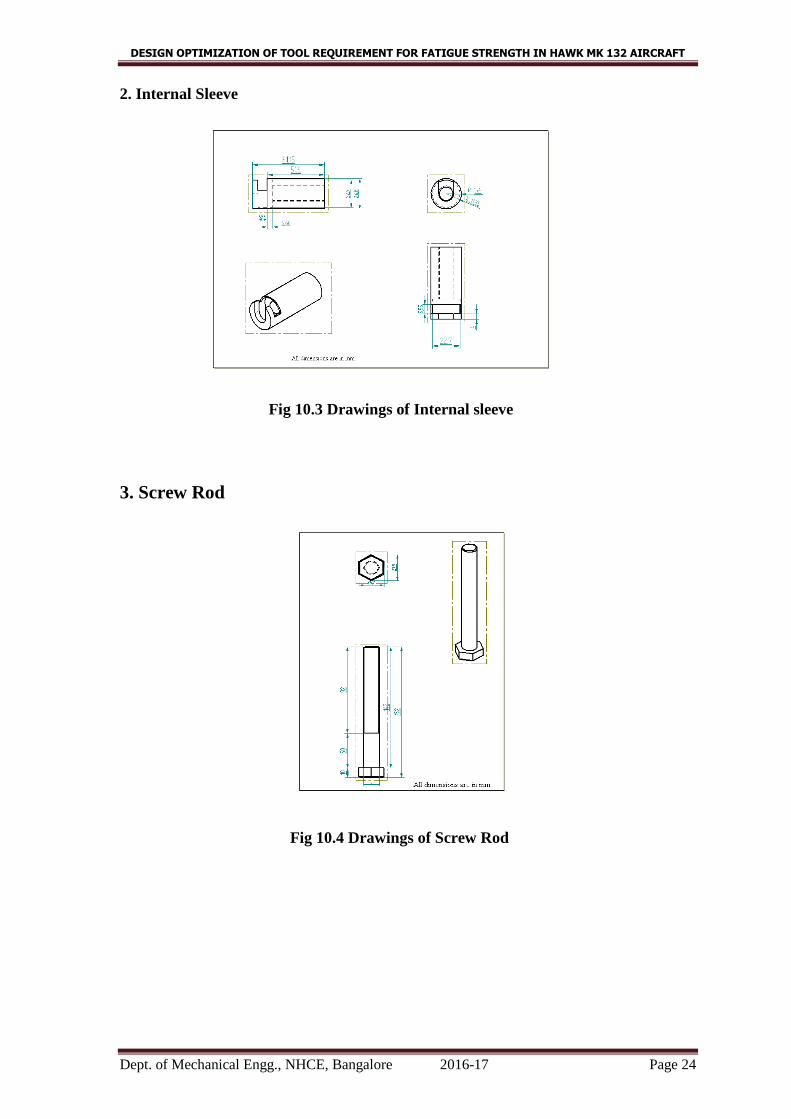
Alignment Pin
Fig 10.1 Drawings of Alignment Pin
Landing gear Pintle pin bolts remover
1. External Sleeve
Fig 10.2 Drawings of External sleeve
DESIGN OPTIMIZATION OF TOOL REQUIREMENT FOR FATIGUE STRENGTH IN HAWK MK 132 AIRCRAFT
Dept. of Mechanical Engg., NHCE, Bangalore 2016-17 Page 24
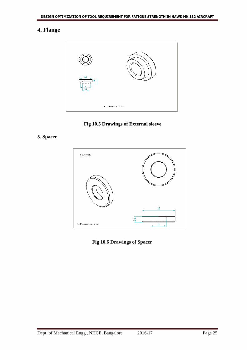
2. Internal Sleeve
Fig 10.3 Drawings of Internal sleeve
3. Screw Rod
Fig 10.4 Drawings of Screw Rod
DESIGN OPTIMIZATION OF TOOL REQUIREMENT FOR FATIGUE STRENGTH IN HAWK MK 132 AIRCRAFT
Dept. of Mechanical Engg., NHCE, Bangalore 2016-17 Page 25
4. Flange
Fig 10.5 Drawings of External sleeve
5. Spacer
Fig 10.6 Drawings of Spacer
DESIGN OPTIMIZATION OF TOOL REQUIREMENT FOR FATIGUE STRENGTH IN HAWK MK 132 AIRCRAFT
Dept. of Mechanical Engg., NHCE, Bangalore 2016-17 Page 26
CHAPTER-11
MATERIAL SELECTION AND ITS PROPERTIES
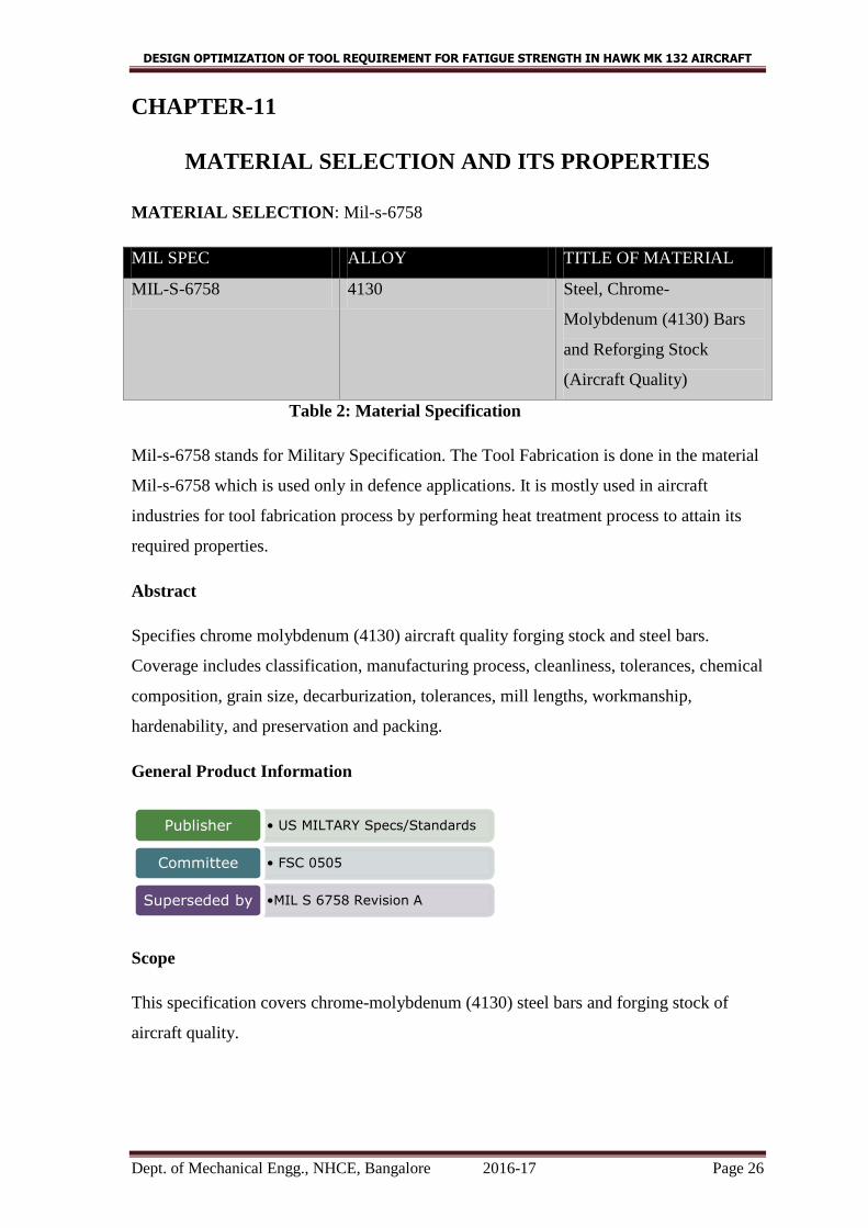
MATERIAL SELECTION: Mil-s-6758
MIL SPEC ALLOY TITLE OF MATERIAL
MIL-S-6758 4130 Steel, Chrome-
Molybdenum (4130) Bars
and Reforging Stock
(Aircraft Quality)
Table 2: Material Specification
Mil-s-6758 stands for Military Specification. The Tool Fabrication is done in the material
Mil-s-6758 which is used only in defence applications. It is mostly used in aircraft
industries for tool fabrication process by performing heat treatment process to attain its
required properties.
Abstract
Specifies chrome molybdenum (4130) aircraft quality forging stock and steel bars.
Coverage includes classification, manufacturing process, cleanliness, tolerances, chemical
composition, grain size, decarburization, tolerances, mill lengths, workmanship,
hardenability, and preservation and packing.
General Product Information
Scope
This specification covers chrome-molybdenum (4130) steel bars and forging stock of
aircraft quality.
• US MILTARY Specs/Standards Publisher
• FSC 0505 Committee
•MIL S 6758 Revision A Superseded by
DESIGN OPTIMIZATION OF TOOL REQUIREMENT FOR FATIGUE STRENGTH IN HAWK MK 132 AIRCRAFT
Dept. of Mechanical Engg., NHCE, Bangalore 2016-17 Page 27
Classification
The Steel bars and reforging stock shall be follows:
Physical Condition: Materials shall be furnished in one of the following physical
conditions, as specified
A. As forged
B. As rolled
C. Annealed
D. Normalized
E. Normalized and tempered
F. Hardened and tempered
Surface conditions: Materials shall be furnished in one of the following surface
conditions, as specified
1. Black, as forged or rolled
2. Pickled or blast cleaned
3. Rough turned
4. Cold finished (drawn)
5. Turned ground and polished.
REQUIREMENTS
1. Material
2. Quality: The steel shall be of aircraft quality.
3. Cleanliness: When inspected magnetically in accordance with the procedures,
material shall not exceed the size and frequency rating limits specified.
4. Manufacturing Process: The steel may be melted by one of the commercially
acceptable types of melting including open hearth, basic oxygen or electric arc
furnace. The steel may be ingot cast or continuous cast into billets. When
ingot casting, sufficient discard shall be made to secure freedom from piping
and undue segregation.
5. Physical/Surface Conditions: Unless otherwise specified in the acquisition
documents, bars 1.5 inches or less in diameter or thickness shall be furnished
in conditions and bars over 1.5inches in diameter or thickness shall be
furnished in conditions.
6. Tolerances: The permissible variation in dimension of bars, produced in
conformance with this specification, shall be as specified vin AMS 2251.

DESIGN OPTIMIZATION OF TOOL REQUIREMENT FOR FATIGUE STRENGTH IN HAWK MK 132 AIRCRAFT
Dept. of Mechanical Engg., NHCE, Bangalore 2016-17 Page 28
7. Workmanship: Material shall be sound, of uniform quality and condition,
free from pipes, and shall not contain laps, cracks, twists, seams, or other
defects detrimental to the fabrication or performance of parts.
Material Properties
• Mechanical properties
Strength, Ductility, toughness, hardness, strength to weight ratio etc.
• Physical properties
Density, specific heat, thermal expansion, conductivity, melting point.
• Chemical properties
Oxidation, corrosion, flammability
• Manufacturing properties
Formed, casting, machined, welding
Mechanical Properties
Yield strength at 0.2% offset
Tensile strength Psi(min) Extension
under load
inches per
inch
Elongation in 2
inches
Reduction of
area percent
125000 100000 .0107 17 55
Table 3: Mechanical Properties
DESIGN OPTIMIZATION OF TOOL REQUIREMENT FOR FATIGUE STRENGTH IN HAWK MK 132 AIRCRAFT
Dept. of Mechanical Engg., NHCE, Bangalore 2016-17 Page 29
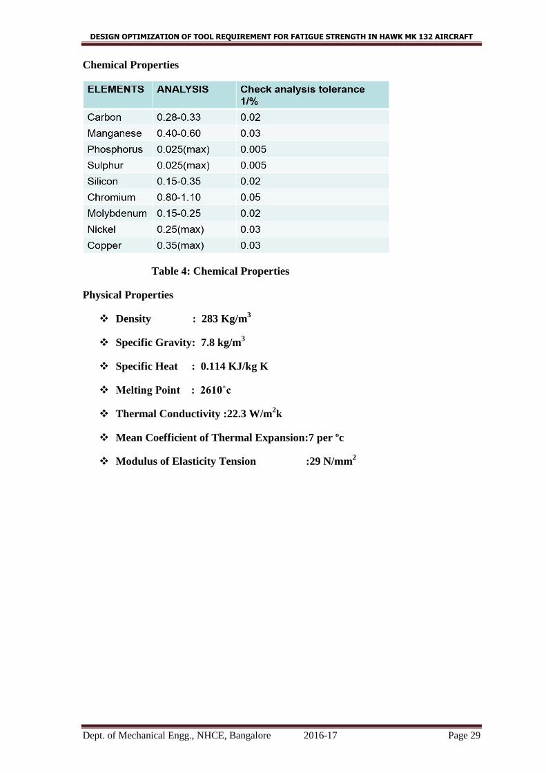
Chemical Properties
Table 4: Chemical Properties
Physical Properties
Density : 283 Kg/m3
Specific Gravity: 7.8 kg/m3
Specific Heat : 0.114 KJ/kg K
Melting Point : 2610˚c
Thermal Conductivity :22.3 W/m2k
Mean Coefficient of Thermal Expansion:7 per ºc
Modulus of Elasticity Tension :29 N/mm2
DESIGN OPTIMIZATION OF TOOL REQUIREMENT FOR FATIGUE STRENGTH IN HAWK MK 132 AIRCRAFT
Dept. of Mechanical Engg., NHCE, Bangalore 2016-17 Page 30
CHAPTER-12
DESIGN OF FIXTURE
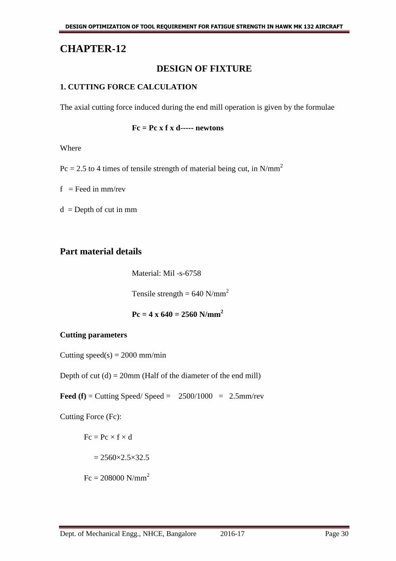
1. CUTTING FORCE CALCULATION
The axial cutting force induced during the end mill operation is given by the formulae
Fc = Pc x f x d----- newtons
Where
Pc = 2.5 to 4 times of tensile strength of material being cut, in N/mm2
f = Feed in mm/rev
d = Depth of cut in mm
Part material details
Material: Mil -s-6758
Tensile strength = 640 N/mm2
Pc = 4 x 640 = 2560 N/mm2
Cutting parameters
Cutting speed(s) = 2000 mm/min
Depth of cut (d) = 20mm (Half of the diameter of the end mill)
Feed (f) = Cutting Speed/ Speed = 2500/1000 = 2.5mm/rev
Cutting Force (Fc):
Fc = Pc × f × d
= 2560×2.5×32.5
Fc = 208000 N/mm2
DESIGN OPTIMIZATION OF TOOL REQUIREMENT FOR FATIGUE STRENGTH IN HAWK MK 132 AIRCRAFT
Dept. of Mechanical Engg., NHCE, Bangalore 2016-17 Page 31
2. Design of External sleeve
1. Fixture Material details
Material: Mil-s- 6758
Density: 7.85 g/cm3
Tensile strength = 640 N/mm2
Factor of safety = n = 2.5
Allowable bending stress (σb) = Tensile strength/ Factor of Safety
= 640/2.5 = 256 N/mm2
Bending moment Mb = Force × Distance
= 208000*40
= 8.32×10⁶ N-mm
2. Bending Equation
=
=
Where
Mb= Bending moment
I = Moment of Inertia
σb = Bending stress
y = Distance of extreme fiber from neutral axis
E = Young’s Modulus of material
R = Radius of curvature
The thickness of external sleeve
Mathematically,
=√
= √
= 3.122mm
The thickness of external sleeve is designed to 5mm.
DESIGN OPTIMIZATION OF TOOL REQUIREMENT FOR FATIGUE STRENGTH IN HAWK MK 132 AIRCRAFT
Dept. of Mechanical Engg., NHCE, Bangalore 2016-17 Page 32
3. Design of internal sleeve
The internal sleeve is subjected to more compression load of 2, 08,000 N-mm
The design is based on direct compression load.
Allowable compressive stress of material = 256 N/mm2
Area of tapped hole
A1 = (π×d2×n)/4
= (π×272×4 )/4
A1= 2290.2mm2
Area of drilled hole for screw rod
A2 = (π×d2×n)/4
= (π×272×2)/4
A2 = 1145.1mm2
Bearing area required to sustain the compression load
A3 = Force / Stress
=2, 08,000/256
A3 =812.5 mm2
Total area as per the design
Area = A1 + A2+ A3
= 2290.2+1145.1+812.5
= 4247.8 mm2
The actual cross section area of internal sleeve is
Aactual= 1145.1*25
= 28,627.5mm2
Hence the design is safe.
The height of internal sleeve is designed to 65mm based on the accessibility of screw
rod.

DESIGN OPTIMIZATION OF TOOL REQUIREMENT FOR FATIGUE STRENGTH IN HAWK MK 132 AIRCRAFT
Dept. of Mechanical Engg., NHCE, Bangalore 2016-17 Page 33
4. DESIGN OF SCREW ROD
The design of screw rod is based on the compression strength of material, since it is
subjected to compressive load due to cutting force.
1. Compressive force acting on plate Fc = 208000
2. Allowable sleeve in plate (σ) =256/mm2
3. Area required to withstand stress (A1) = Force / Allowable stress
= 208000 / 256
=812.5mm2
4. Area required to accommodate bolt head (A2)
A2= ((π×d2×n)/4
= (π×182×6)/4
= 1526.81
5. Total area required (A)
A=A1 + A2
=1526.81+812.5
=2339.3mm2 = 2340mm
2
6. The width of the plate = 300mm and design is based on configuration of the part.
To find design thickness
Load bearing area A = width x thickness
2340= 300 x t
t =2340/300
t=7.8mm
By considering the stress for accommodating the bolt
Actual thickness = 10mm
Hence the design is safe.
DESIGN OPTIMIZATION OF TOOL REQUIREMENT FOR FATIGUE STRENGTH IN HAWK MK 132 AIRCRAFT
Dept. of Mechanical Engg., NHCE, Bangalore 2016-17 Page 34
CHAPTER-13
STRESSES INDUCED IN FINAL ASSEMBLY PART
Twisting moment
Mt= Bolt head radius× Force applied by operator
= 28×2
Mt =56 N-mm.
Polar moment of inertia
J=
=
J =79020.38mm4
Radius of external sleeve
r =
=
= 17mm.
Shear stress induced
τ induced =
τ induced = 0.118 N/mm2
σy = 435 mpa (yield stress of material)
τ allowable =
=
τ allowable= 217.5mpa.
τ induced < τ allowable
Hence the design is safe.
DESIGN OPTIMIZATION OF TOOL REQUIREMENT FOR FATIGUE STRENGTH IN HAWK MK 132 AIRCRAFT
Dept. of Mechanical Engg., NHCE, Bangalore 2016-17 Page 35
CHAPTER-14
JUSTIFICATION AND DIMENSIONS
Justifications for Alignment Pin
Mod-2459 kit is suitable only for pre-cold work.
Post cold work required size & dimension has not supplied.
Hence with new size and dimensions new pin is designed and fabricated.
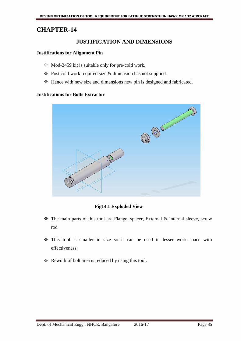
Justifications for Bolts Extractor
Fig14.1 Exploded View
The main parts of this tool are Flange, spacer, External & internal sleeve, screw
rod
This tool is smaller in size so it can be used in lesser work space with
effectiveness.
Rework of bolt area is reduced by using this tool.
DESIGN OPTIMIZATION OF TOOL REQUIREMENT FOR FATIGUE STRENGTH IN HAWK MK 132 AIRCRAFT
Dept. of Mechanical Engg., NHCE, Bangalore 2016-17 Page 36
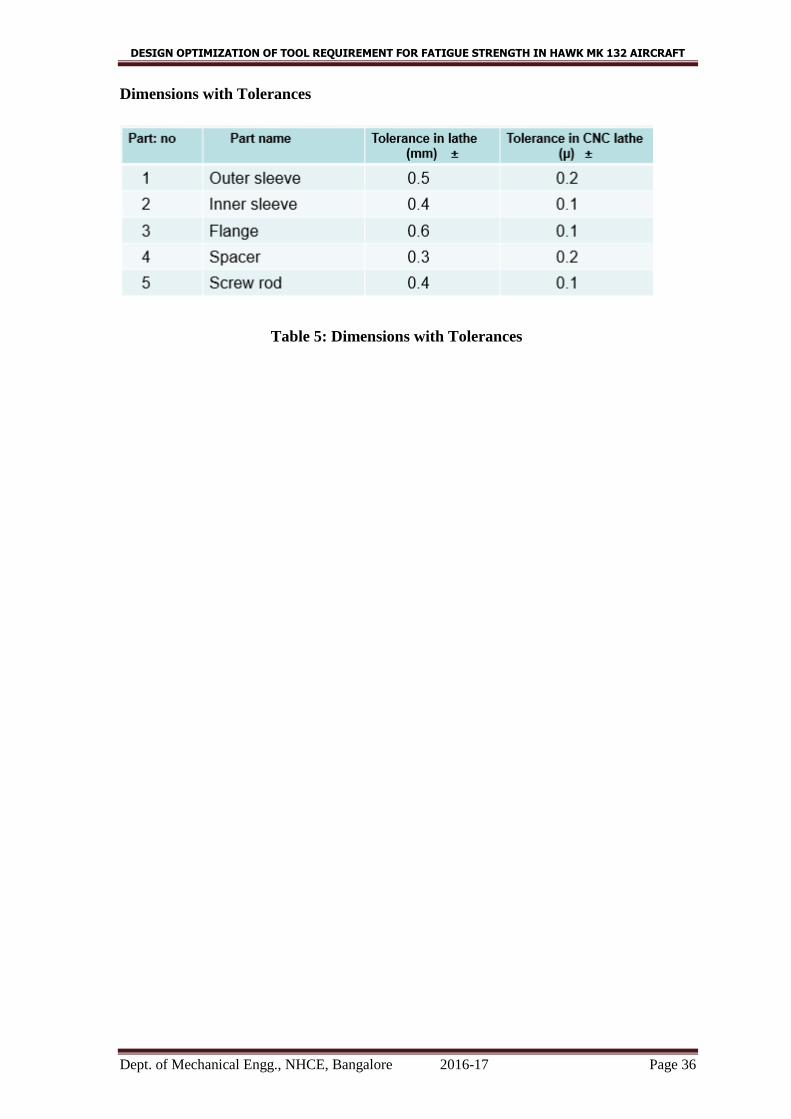
Dimensions with Tolerances
Table 5: Dimensions with Tolerances
DESIGN OPTIMIZATION OF TOOL REQUIREMENT FOR FATIGUE STRENGTH IN HAWK MK 132 AIRCRAFT
Dept. of Mechanical Engg., NHCE, Bangalore 2016-17 Page 37
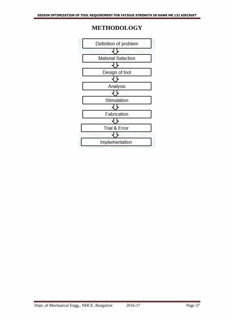
METHODOLOGY

DESIGN OPTIMIZATION OF TOOL REQUIREMENT FOR FATIGUE STRENGTH IN HAWK MK 132 AIRCRAFT
Dept. of Mechanical Engg., NHCE, Bangalore 2016-17 Page 38
GANTT CHART
DESIGN OPTIMIZATION OF TOOL REQUIREMENT FOR FATIGUE STRENGTH IN HAWK MK 132 AIRCRAFT
Dept. of Mechanical Engg., NHCE, Bangalore 2016-17 Page 39
CONCLUSION
Hindustan Aeronautics Limited has world class infrastructure. They deal with
manufacturing of sophisticated products with ease. Although, they don’t have competitors
in the market, they maintain quality of the product.
They follow autocratic management with certain set of rules and principles. They deal
with current ear of globalization without harming the environment.
In this project work fixture has been designed and developed for “Alignment Pin and
Landing Gear pintle pin remover” used in HAWK aircrafts. Conclusion is to overcome
this problem we are designing alignment pin of the required dimensions necessary for
modifying the aircraft. This results in reducing the manufacturing lead time & the
addition cost required for rework.
In addition to above tangible benefits, the company stands to gain many intangible
benefits which includes, reduction in waiting time of tool component, reduction in rework
and defect, employee satisfaction and enhancing the reputation of the organization.