high-precision parallel graphic equalizer - aaltodoc
TRANSCRIPT
This is an electronic reprint of the original article.This reprint may differ from the original in pagination and typographic detail.
Author(s): Rämö, J.; Välimäki, V.; Bank, B.
Title: High-Precision Parallel Graphic Equalizer
Year: 2014
Version: Post print
Please cite the original version:J. Rämö, V. Välimäki, and B. Bank. High-Precision Parallel Graphic Equalizer.IEEE/ACM Transactions on Audio, Speech and Language Processing, Vol. 22, No. 12,pp. 1894-1904, December 2014. DOI: 10.1109/TASLP.2014.2354241
Note: © IEEE
In reference to IEEE copyrighted material which is used with permission in this thesis, the IEEE does notendorse any of Aalto Universitys products of services. Internal or personal use of this material is permitted. Ifinterested in reprinting/republishing IEEE copyrighted material for advertising or promotional purposes or forcreating new collective works for resale or distribution, please go tohttp://www.ieee.org/publications_standards/publications/rights/rights_link.html to learn how to obtain aLicense from RightsLink.
This publication is included in the electronic version of the article dissertation:Rämö, Jussi. Equalization Techniques for Headphone Listening.Aalto University publication series DOCTORAL DISSERTATIONS, 147/2014.
All material supplied via Aaltodoc is protected by copyright and other intellectual property rights, andduplication or sale of all or part of any of the repository collections is not permitted, except that material maybe duplicated by you for your research use or educational purposes in electronic or print form. You mustobtain permission for any other use. Electronic or print copies may not be offered, whether for sale orotherwise to anyone who is not an authorised user.
Powered by TCPDF (www.tcpdf.org)
IEEE/ACM TRANSACTIONS ON AUDIO, SPEECH AND LANGUAGE PROCESSING, VOL. 22, NO. 12, DECEMBER 2014 1
High-Precision Parallel Graphic EqualizerJussi Ramo*, Vesa Valimaki, Senior Member, IEEE, and Balazs Bank, Member, IEEE,
Abstract—This paper proposes a high-precision graphic equal-izer based on second-order parallel filters. Previous graphicequalizers suffer from interaction between adjacent band filters,especially at high gain values, which can lead to substantialerrors in the magnitude response. The fixed-pole design of theproposed parallel graphic equalizer avoids this problem, sincethe parallel second-order filters are optimized jointly. When thenumber of pole frequencies is twice the number of commandpoints of the graphic equalizer, the proposed non-iterative designmatches the target curve with high precision. In the three examplecases presented in this paper, the proposed parallel equalizerclearly outperforms other non-iterative graphic equalizer designs,and its maximum global error is as low as 0.00–0.75 dB whencompared to the target curve. While the proposed design hassuperior accuracy, the number of operations in the filter structureis increased only by 23% when compared to the second-orderRegalia-Mitra structure. The parallel structure also enables theutilization of parallel computing hardware, which can nowadayseasily outperform the traditional serial processing. The proposedgraphic equalizer can be widely used in audio signal processingapplications.
Index Terms—Acoustic signal processing, audio systems, digitalsignal processing, equalizers, infinite impulse response (IIR)filters.
I. INTRODUCTION
EQUALIZERS are a common part of modern audio sys-tems. They were originally used to flatten, i.e., to equal-
ize, telephone and audio systems. With telephones using fixedequalizers to enhance the intelligibility of the speech signalwas adequate, but the need for an adjustable equalizer emergedin the 1930s when a recorded soundtrack was included inmotion pictures [1].
Nowadays the goal of equalizing is not necessarily to flattenout the response of an audio system but rather to correct orenhance the performance of the system [2]. This includes,e.g., the correction of a loudspeaker response [3]–[5] and theloudspeaker-room interaction [6]–[10], equalization of activeas well as passive headphones to assure natural music listening[11]–[14] and hear-through [15]–[17] experiences when usingheadphones, and enhancement of recorded music [18], [19].
A basic common equalizer is called a tone control. Tonecontrols can be found in many commercial audio products,and, at its simplest, it allows the user to adjust the level of
Copyright (c) 2014 IEEE. Personal use of this material is permitted.However, permission to use this material for any other purposes must beobtained from the IEEE by sending a request to [email protected].
J. Ramo and V. Valimaki are with the Department of Signal Processingand Acoustics, School of Electrical Engineering, Aalto University, FI-00076AALTO, Espoo, Finland (e-mail: [email protected]; [email protected])
B. Bank is with the Department of Measurement and Information Systems,Budapest University of Technology and Economics, H-1521 Budapest, Hun-gary (e-mail: [email protected]).
Manuscript received December 19, 2013; revised May 09, 2014; acceptedAugust 27, 2014.
bass and treble with two shelving filters [20]. When morethan two filters are combined in a tone control system, whichis common, e.g., in musical instrument amplifiers [21], [22],the user’s possibilities to modify the sound are increased.
There are two main types of equalizers. When the usercan control the gain, center frequency, and bandwidth of theequalizer filters separately, the equalizer is called a parametricequalizer [23]–[27]. A parametric equalizer is flexible and theuser has good control of it, but it is quite cumbersome to userequiring an expert user, such as an audio engineer or a musicproducer, and it usually has a limited number of filters thatthe user can adjust.
A graphic equalizer, on the other hand, is much simplerto use than a parametric equalizer, since the only user-controllable parameters are the gains. The center frequenciesand bandwidths of the equalizer filters, or band filters, arefixed, and the command gains are usually adjusted using slid-ers [28]–[30]. The sliders then plot the approximate magnitudefrequency response of the equalizer, hence the name ‘graphicequalizer’. Typically, a graphic equalizer has more bands, i.e.,equalizer filters, than a parametric equalizer. Although theflexibility of a graphic equalizer is not as good as that ofa parametric equalizer, it is often a preferred choice in soundenhancement.
A graphic equalizer can be implemented using a cascade[23], [29], [31] or a parallel [28], [30], [32] filter structure.In a cascade implementation, each band filter adjusts itsmagnitude response around its center frequency accordingto the command gain, but the magnitude response of theband filter remains close to unity, i.e., 0 dB, elsewhere. In aparallel implementation, each band filter produces a resonanceat its center frequency and has a low gain at other centerfrequencies. Both types of equalizers suffer from interactionbetween adjacent band filters, which can cause substantialerrors in the magnitude response [31]–[33].
This paper presents a novel idea to utilize an optimizedparallel filter as a graphic equalizer. The fixed-pole designof second-order parallel filters was first presented in [34]as a means of providing efficient filtering with logarithmicfrequency resolution, which is often required in audio appli-cations [35], [36]. The use of parallel filters in our contextis motivated by the fact that it provides better efficiencycompared to alternative methods, including warped [37] andKautz filters [38], as demonstrated in [39], [40].
An additional benefit of the parallel structure is the pos-sibility to implement the equalization filters using a graphicprocessing unit (GPU) instead of a central processing unit(CPU) [41]. GPUs have a large number of parallel computingcores, and they have been recently used to perform audiosignal processing as well, since they can outperform a CPUin many parallelizable tasks [42].
IEEE/ACM TRANSACTIONS ON AUDIO, SPEECH AND LANGUAGE PROCESSING, VOL. 22, NO. 12, DECEMBER 2014 2
In H1(z)
H2(z)
HK(z)
d0
Out
(a)
bk,0
z-‐1
z-‐1
bk,1
-ak,2
-ak,1
In Out
(b)
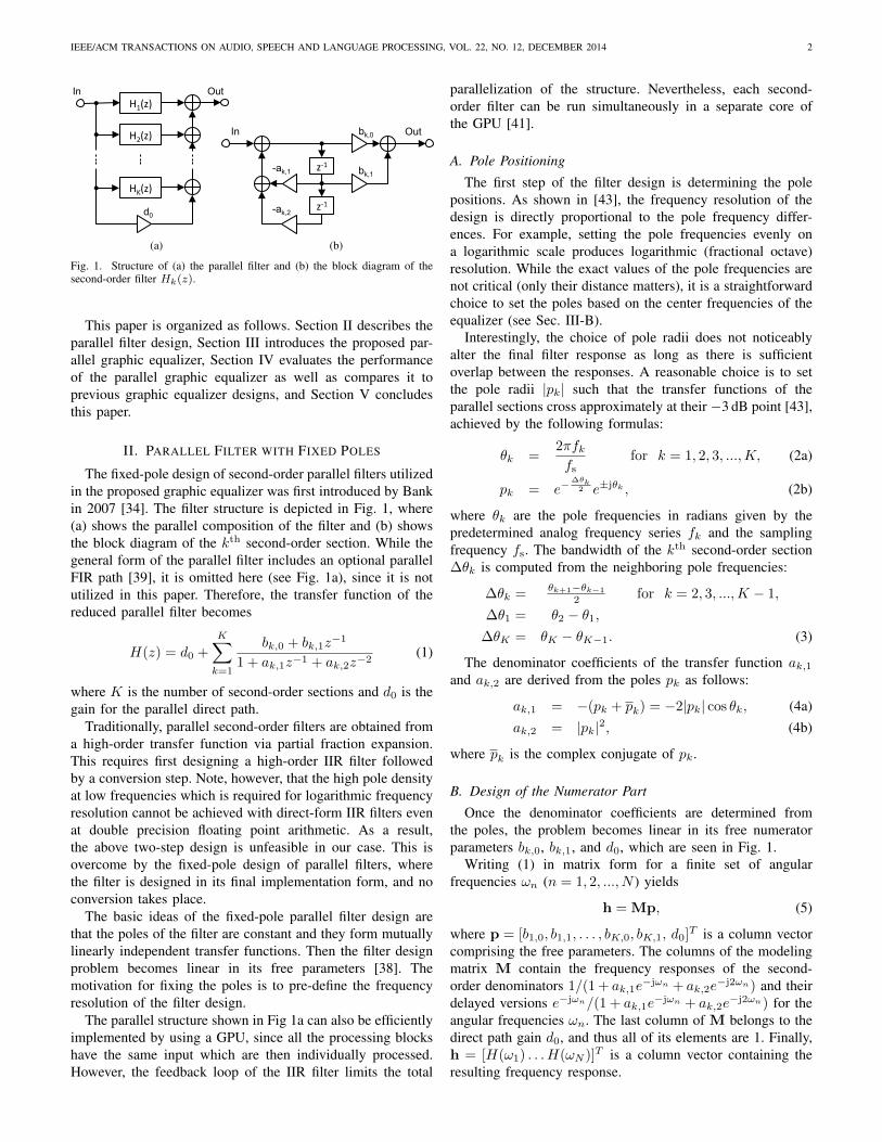
Fig. 1. Structure of (a) the parallel filter and (b) the block diagram of thesecond-order filter Hk(z).
This paper is organized as follows. Section II describes theparallel filter design, Section III introduces the proposed par-allel graphic equalizer, Section IV evaluates the performanceof the parallel graphic equalizer as well as compares it toprevious graphic equalizer designs, and Section V concludesthis paper.
II. PARALLEL FILTER WITH FIXED POLES
The fixed-pole design of second-order parallel filters utilizedin the proposed graphic equalizer was first introduced by Bankin 2007 [34]. The filter structure is depicted in Fig. 1, where(a) shows the parallel composition of the filter and (b) showsthe block diagram of the kth second-order section. While thegeneral form of the parallel filter includes an optional parallelFIR path [39], it is omitted here (see Fig. 1a), since it is notutilized in this paper. Therefore, the transfer function of thereduced parallel filter becomes
H(z) = d0 +
K∑k=1
bk,0 + bk,1z−1
1 + ak,1z−1 + ak,2z−2(1)
where K is the number of second-order sections and d0 is thegain for the parallel direct path.
Traditionally, parallel second-order filters are obtained froma high-order transfer function via partial fraction expansion.This requires first designing a high-order IIR filter followedby a conversion step. Note, however, that the high pole densityat low frequencies which is required for logarithmic frequencyresolution cannot be achieved with direct-form IIR filters evenat double precision floating point arithmetic. As a result,the above two-step design is unfeasible in our case. This isovercome by the fixed-pole design of parallel filters, wherethe filter is designed in its final implementation form, and noconversion takes place.
The basic ideas of the fixed-pole parallel filter design arethat the poles of the filter are constant and they form mutuallylinearly independent transfer functions. Then the filter designproblem becomes linear in its free parameters [38]. Themotivation for fixing the poles is to pre-define the frequencyresolution of the filter design.
The parallel structure shown in Fig 1a can also be efficientlyimplemented by using a GPU, since all the processing blockshave the same input which are then individually processed.However, the feedback loop of the IIR filter limits the total
parallelization of the structure. Nevertheless, each second-order filter can be run simultaneously in a separate core ofthe GPU [41].
A. Pole Positioning
The first step of the filter design is determining the polepositions. As shown in [43], the frequency resolution of thedesign is directly proportional to the pole frequency differ-ences. For example, setting the pole frequencies evenly ona logarithmic scale produces logarithmic (fractional octave)resolution. While the exact values of the pole frequencies arenot critical (only their distance matters), it is a straightforwardchoice to set the poles based on the center frequencies of theequalizer (see Sec. III-B).
Interestingly, the choice of pole radii does not noticeablyalter the final filter response as long as there is sufficientoverlap between the responses. A reasonable choice is to setthe pole radii |pk| such that the transfer functions of theparallel sections cross approximately at their −3 dB point [43],achieved by the following formulas:
θk =2πfkfs
for k = 1, 2, 3, ...,K, (2a)
pk = e−∆θk
2 e±jθk , (2b)
where θk are the pole frequencies in radians given by thepredetermined analog frequency series fk and the samplingfrequency fs. The bandwidth of the kth second-order section∆θk is computed from the neighboring pole frequencies:
∆θk = θk+1−θk−1
2 for k = 2, 3, ...,K − 1,
∆θ1 = θ2 − θ1,∆θK = θK − θK−1. (3)
The denominator coefficients of the transfer function ak,1and ak,2 are derived from the poles pk as follows:
ak,1 = −(pk + pk) = −2|pk| cos θk, (4a)ak,2 = |pk|2, (4b)
where pk is the complex conjugate of pk.
B. Design of the Numerator Part
Once the denominator coefficients are determined fromthe poles, the problem becomes linear in its free numeratorparameters bk,0, bk,1, and d0, which are seen in Fig. 1.
Writing (1) in matrix form for a finite set of angularfrequencies ωn (n = 1, 2, ..., N ) yields
h = Mp, (5)
where p = [b1,0, b1,1, . . . , bK,0, bK,1, d0]T is a column vectorcomprising the free parameters. The columns of the modelingmatrix M contain the frequency responses of the second-order denominators 1/(1 + ak,1e
−jωn + ak,2e−j2ωn) and their
delayed versions e−jωn/(1 + ak,1e−jωn + ak,2e
−j2ωn) for theangular frequencies ωn. The last column of M belongs to thedirect path gain d0, and thus all of its elements are 1. Finally,h = [H(ω1) . . . H(ωN )]T is a column vector containing theresulting frequency response.
IEEE/ACM TRANSACTIONS ON AUDIO, SPEECH AND LANGUAGE PROCESSING, VOL. 22, NO. 12, DECEMBER 2014 3
Now the task is to find the optimal parameters popt suchthat h = Mpopt is closest to the target frequency responseht = [Ht(ω1) . . . Ht(ωN )]T . If the error is evaluated in themean squares sense, the minimum is found by the well knownleast-squares (LS) solution
popt = M+ht, (6a)M+ = (MHM)−1MH , (6b)
where M+ is the Moore-Penrose pseudo-inverse and MH isthe conjugate transpose of M. Note that this method is verysimilar to the LS FIR filter except that the modeling matrixM now contains the frequency responses of the second-orderdenominators instead of, for example, cosine terms, which areused in linear-phase FIR filter design [44]. When the frequencyresolution—the set of poles and the modeling matrix M—isfixed, which is the case for a graphic equalizer, the pseudo-inverse M+ can be precomputed and stored. As a result, theparameter estimation reduces to the matrix multiplication in(6a), reducing design time [43].
Note that (6) assumes a filter specification Ht(ωn) givenfor the full frequency range ωn ∈ [−π, π] and thus allowsdesigning filters with complex coefficients. However, in ourcase, we are interested in filters with a real impulse response,that is, having a conjugate-symmetric frequency response,which allows the reduction of computational complexity in (6).In this case, a real modeling matrix Mr is formed by placingthe real and imaginary parts of the the complex matrix M intandem for frequencies ωn ∈ [0, π], as also for the real targetvector ht,r:
Mr =
[ReMImM
], (7a)
ht,r =
[RehtImht
]. (7b)
The optimal set of numerator parameters is thus obtained from
popt = M+r ht,r, (8a)
M+r = (MT
r Mr)−1MT
r , (8b)
which now only involves real multiplications.
C. Frequency-Dependent Weighting
The frequency points can also be assigned different weightsduring LS error minimization [36], [44], in which case theerror is
eWLS =
N∑n=1
W (ωn)|H(ejωn)−Ht(ωn)|2, (9)
where W (ωn) is a non-negative weight for frequency ωn. Thecomputationally most efficient implementation of weightingin parameter estimation is to multiply all the elements of themodeling matrix Mr and target vector ht,r, which correspondto frequency ωn, by
√W (ωn) before computing (8). Note
that if the weights depend on the target response Ht(ωn), thepseudo-inverse M+
r cannot be precomputed, but it must beevaluated when the target response is changed.
III. PARALLEL GRAPHIC EQUALIZER
This section demonstrates the effectiveness of the parallelfilters from Sec. II for designing a highly accurate graphicequalizer.
A. Target Computation
The graphic equalizer design starts with computing a targetfrequency response based on the command gains Gm of thegraphic equalizer at frequencies fc,m for m = 1, 2, ..., P ,where P is the number of command points. To this end,the magnitude response is first computed using a suitableinterpolation from the command points so that a smooth curveis produced between the command points with no overshoots.Hermite and spline interpolation are two potential methods forobtaining a smooth target magnitude response [45]. They bothproduce an interpolating function, which not only matches thegiven data points but also some of the derivatives of the data.
The cubic Hermite and spline interpolation methods fit theinterpolating function to the data and its slope at the knownpoints. In our examples, the target magnitude response wascomputed on a logarithmic frequency grid (10P frequencypoints) on a decibel scale by using the piecewise Hermitecubic interpolation readily available in MATLAB (the pchipfunction). The pchip function is preferred over splinein MATLAB, because spline can produce significant over-shoots between command points when the input data are non-smooth.
Next, a suitable phase response has to be generated, sincea complex target Ht(ωn) is required by the LS design ofSec. II-B. Minimum phase is a natural choice, since analoggraphic equalizers also have minimum phase [46]. In addition,the energy of a minimum-phase system is concentrated nearthe beginning of the impulse response [47], which makes iteasy to model with parallel filters, since the impulse responseof parallel filters is a linear combination of decaying sinusoidalfunctions. Notice that, for example, a linear-phase responsewould be particularly difficult to model with parallel filters.
Therefore, a phase response is computed corresponding toa minimum-phase transfer function. For this, the magnituderesponse is first resampled to a linear frequency scale (215
frequency points) and its logarithm is computed. Next, theHilbert transform of the log magnitude is computed with thehelp of an FFT and IFFT operation, and this gives the phaseresponse [48]. Finally, the linear-frequency-scale phase data issampled at the original logarithmic frequency points.
B. Parallel Graphic Equalizer Design
The first step of the filter design is setting up the polefrequencies. A straightforward choice for the pole frequenciesis setting them equal to the center frequencies of the commandpoints. However, doing so results in a large approximationerror if the command points alternate between +12 dB and−12 dB, because this would require a higher Q value thanis possible with such a small number of poles. This can beseen in Fig. 2a around 500 Hz for a third-octave equalizerexample. The maximum magnitude of the error in Fig. 2a is
IEEE/ACM TRANSACTIONS ON AUDIO, SPEECH AND LANGUAGE PROCESSING, VOL. 22, NO. 12, DECEMBER 2014 4
100 1k 10k−20
−10
0
10
Frequency (Hz)
Mag
nitu
de (
dB)
(a)
100 1k 10k−20
−10
0
10
Frequency (Hz)
Mag
nitu
de (
dB)
(b)
100 1k 10k−20
−10
0
10
Frequency (Hz)
Mag
nitu
de (
dB)
(c)
100 1k 10k−20
−10
0
10
Frequency (Hz)M
agni
tude
(dB
)
(d)
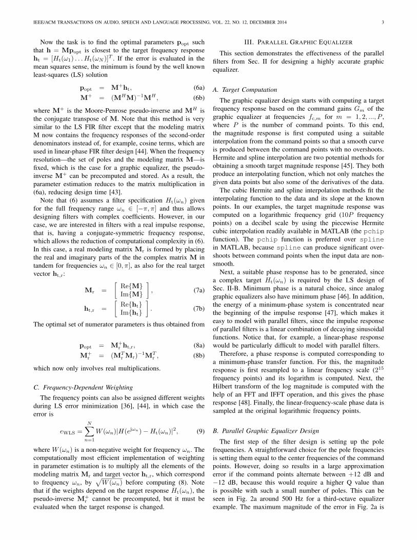
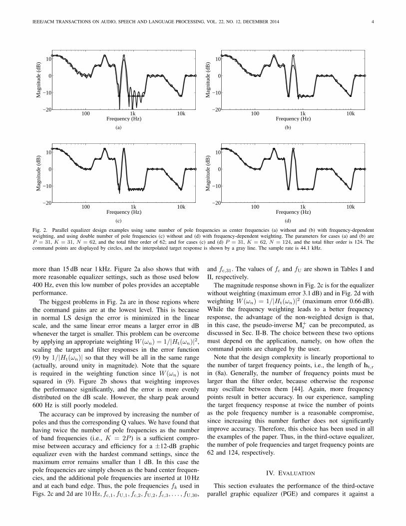
Fig. 2. Parallel equalizer design examples using same number of pole frequencies as center frequencies (a) without and (b) with frequency-dependentweighting, and using double number of pole frequencies (c) without and (d) with frequency-dependent weighting. The parameters for cases (a) and (b) areP = 31, K = 31, N = 62, and the total filter order of 62; and for cases (c) and (d) P = 31, K = 62, N = 124, and the total filter order is 124. Thecommand points are displayed by circles, and the interpolated target response is shown by a gray line. The sample rate is 44.1 kHz.
more than 15 dB near 1 kHz. Figure 2a also shows that withmore reasonable equalizer settings, such as those used below400 Hz, even this low number of poles provides an acceptableperformance.
The biggest problems in Fig. 2a are in those regions wherethe command gains are at the lowest level. This is becausein normal LS design the error is minimized in the linearscale, and the same linear error means a larger error in dBwhenever the target is smaller. This problem can be overcomeby applying an appropriate weighting W (ωn) = 1/|Ht(ωn)|2,scaling the target and filter responses in the error function(9) by 1/|Ht(ωn)| so that they will be all in the same range(actually, around unity in magnitude). Note that the squareis required in the weighting function since W (ωn) is notsquared in (9). Figure 2b shows that weighting improvesthe performance significantly, and the error is more evenlydistributed on the dB scale. However, the sharp peak around600 Hz is still poorly modeled.
The accuracy can be improved by increasing the number ofpoles and thus the corresponding Q values. We have found thathaving twice the number of pole frequencies as the numberof band frequencies (i.e., K = 2P ) is a sufficient compro-mise between accuracy and efficiency for a ±12-dB graphicequalizer even with the hardest command settings, since themaximum error remains smaller than 1 dB. In this case thepole frequencies are simply chosen as the band center frequen-cies, and the additional pole frequencies are inserted at 10 Hzand at each band edge. Thus, the pole frequencies fk used inFigs. 2c and 2d are 10 Hz, fc,1, fU,1, fc,2, fU,2, fc,3, . . . , fU,30,
and fc,31. The values of fc and fU are shown in Tables I andII, respectively.
The magnitude response shown in Fig. 2c is for the equalizerwithout weighting (maximum error 3.1 dB) and in Fig. 2d withweighting W (ωn) = 1/|Ht(ωn)|2 (maximum error 0.66 dB).While the frequency weighting leads to a better frequencyresponse, the advantage of the non-weighted design is that,in this case, the pseudo-inverse M+
r can be precomputed, asdiscussed in Sec. II-B. The choice between these two optionsmust depend on the application, namely, on how often thecommand points are changed by the user.
Note that the design complexity is linearly proportional tothe number of target frequency points, i.e., the length of ht,r
in (8a). Generally, the number of frequency points must belarger than the filter order, because otherwise the responsemay oscillate between them [44]. Again, more frequencypoints result in better accuracy. In our experience, samplingthe target frequency response at twice the number of pointsas the pole frequency number is a reasonable compromise,since increasing this number further does not significantlyimprove accuracy. Therefore, this choice has been used in allthe examples of the paper. Thus, in the third-octave equalizer,the number of pole frequencies and target frequency points are62 and 124, respectively.
IV. EVALUATION
This section evaluates the performance of the third-octaveparallel graphic equalizer (PGE) and compares it against a
IEEE/ACM TRANSACTIONS ON AUDIO, SPEECH AND LANGUAGE PROCESSING, VOL. 22, NO. 12, DECEMBER 2014 5
a In Out
KRM/2 -
1/2
z-‐1
z-‐1
b(1+a)
-a
-b(1+a)
Allpass section ARM(z)
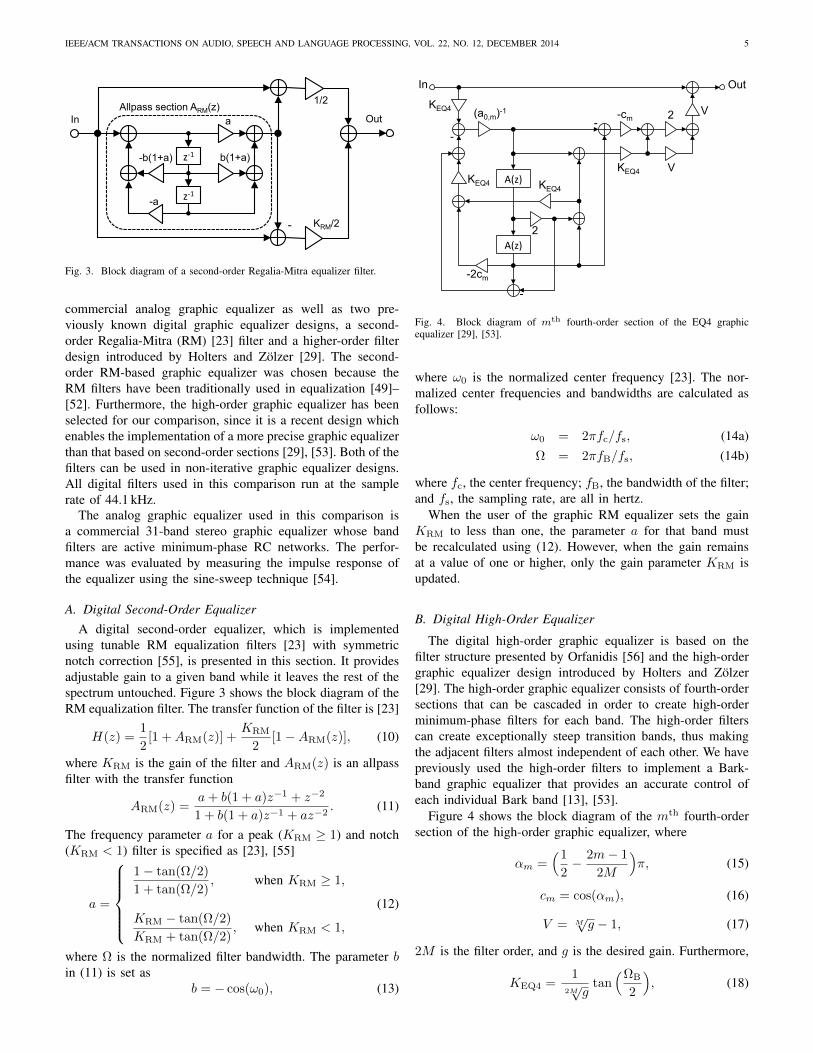
Fig. 3. Block diagram of a second-order Regalia-Mitra equalizer filter.
commercial analog graphic equalizer as well as two pre-viously known digital graphic equalizer designs, a second-order Regalia-Mitra (RM) [23] filter and a higher-order filterdesign introduced by Holters and Zolzer [29]. The second-order RM-based graphic equalizer was chosen because theRM filters have been traditionally used in equalization [49]–[52]. Furthermore, the high-order graphic equalizer has beenselected for our comparison, since it is a recent design whichenables the implementation of a more precise graphic equalizerthan that based on second-order sections [29], [53]. Both of thefilters can be used in non-iterative graphic equalizer designs.All digital filters used in this comparison run at the samplerate of 44.1 kHz.
The analog graphic equalizer used in this comparison isa commercial 31-band stereo graphic equalizer whose bandfilters are active minimum-phase RC networks. The perfor-mance was evaluated by measuring the impulse response ofthe equalizer using the sine-sweep technique [54].
A. Digital Second-Order EqualizerA digital second-order equalizer, which is implemented
using tunable RM equalization filters [23] with symmetricnotch correction [55], is presented in this section. It providesadjustable gain to a given band while it leaves the rest of thespectrum untouched. Figure 3 shows the block diagram of theRM equalization filter. The transfer function of the filter is [23]
H(z) =1
2[1 +ARM(z)] +
KRM
2[1−ARM(z)], (10)
where KRM is the gain of the filter and ARM(z) is an allpassfilter with the transfer function
ARM(z) =a+ b(1 + a)z−1 + z−2
1 + b(1 + a)z−1 + az−2. (11)
The frequency parameter a for a peak (KRM ≥ 1) and notch(KRM < 1) filter is specified as [23], [55]
a =
1− tan(Ω/2)
1 + tan(Ω/2), when KRM ≥ 1,
KRM − tan(Ω/2)
KRM + tan(Ω/2), when KRM < 1,
(12)
where Ω is the normalized filter bandwidth. The parameter bin (11) is set as
b = − cos(ω0), (13)
A(z)
A(z)
KEQ4
KEQ4
-
-2cm
-
- -cm 2
KEQ4 V
V
2
KEQ4
(a0,m)-1
In Out
Fig. 4. Block diagram of mth fourth-order section of the EQ4 graphicequalizer [29], [53].
where ω0 is the normalized center frequency [23]. The nor-malized center frequencies and bandwidths are calculated asfollows:
ω0 = 2πfc/fs, (14a)Ω = 2πfB/fs, (14b)
where fc, the center frequency; fB, the bandwidth of the filter;and fs, the sampling rate, are all in hertz.
When the user of the graphic RM equalizer sets the gainKRM to less than one, the parameter a for that band mustbe recalculated using (12). However, when the gain remainsat a value of one or higher, only the gain parameter KRM isupdated.
B. Digital High-Order Equalizer
The digital high-order graphic equalizer is based on thefilter structure presented by Orfanidis [56] and the high-ordergraphic equalizer design introduced by Holters and Zolzer[29]. The high-order graphic equalizer consists of fourth-ordersections that can be cascaded in order to create high-orderminimum-phase filters for each band. The high-order filterscan create exceptionally steep transition bands, thus makingthe adjacent filters almost independent of each other. We havepreviously used the high-order filters to implement a Bark-band graphic equalizer that provides an accurate control ofeach individual Bark band [13], [53].
Figure 4 shows the block diagram of the mth fourth-ordersection of the high-order graphic equalizer, where
αm =(1
2− 2m− 1
2M
)π, (15)
cm = cos(αm), (16)
V = M√g − 1, (17)
2M is the filter order, and g is the desired gain. Furthermore,
KEQ4 =1
2M√g
tan(ΩB
2
), (18)
IEEE/ACM TRANSACTIONS ON AUDIO, SPEECH AND LANGUAGE PROCESSING, VOL. 22, NO. 12, DECEMBER 2014 6
where ΩB is the normalized filter bandwidth and
a−10,m =
1
1 + 2KEQ4cm +K2EQ4
. (19)
A(z) is a second-order allpass filter having the transfer func-tion
A(z) =cos(ΩM)z−1 + z−2
1 + cos(ΩM)z−1, (20)
where ΩM is the optimized and normalized center frequency
ΩM = 2 arctan
√tan(
ΩU
2) tan(
ΩL
2), (21)
and ΩL and ΩU are the normalized lower and upper cut-offfrequency of the filter, respectively. The normalized cut-offfrequencies are obtained as follows:
ΩL = 2πfL/fs, (22a)ΩU = 2πfU/fs. (22b)
When the gain g of the high-order graphic equalizer isaltered in some band, parameters V , KEQ4, and a−1
0,m mustbe recalculated for each fourth-order section used in that bandusing (17), (18), and (19), respectively.
C. Equalizer Parameters
Digital Second-Order RM Equalizer: The used third-octavecenter frequencies fc and bandwidths fB of the RM filters inhertz are shown in Table I. The used bandwidths are half ofthe typical third-octave filter bandwidths. The bandwidth of thefilters was manually chosen such that the results are the bestcompromise in all example cases. Increasing the bandwidthsincreases the interaction between the adjacent filters, whichresults in larger errors at the center frequencies, and decreasingthe bandwidths decreases the interaction between the filters,which may decrease the maximum errors at the center frequen-cies but increases the global error. The center frequencies andbandwidths of the RM equalizer were normalized using (14a)and (14b).
Digital fourth-order EQ4 Equalizer: Table II shows thelower and upper cut-off frequencies of the fourth-order fil-ters in hertz. The lower and upper cut-off frequencies werenormalized using (22a) and (22b) whereas the optimized andnormalized center frequencies were calculated using (21). Inthis comparison we use only one fourth-order section per band(see Fig. 4) so that the total filter order compared to theproposed parallel implementation is approximately the same.
D. Accuracy
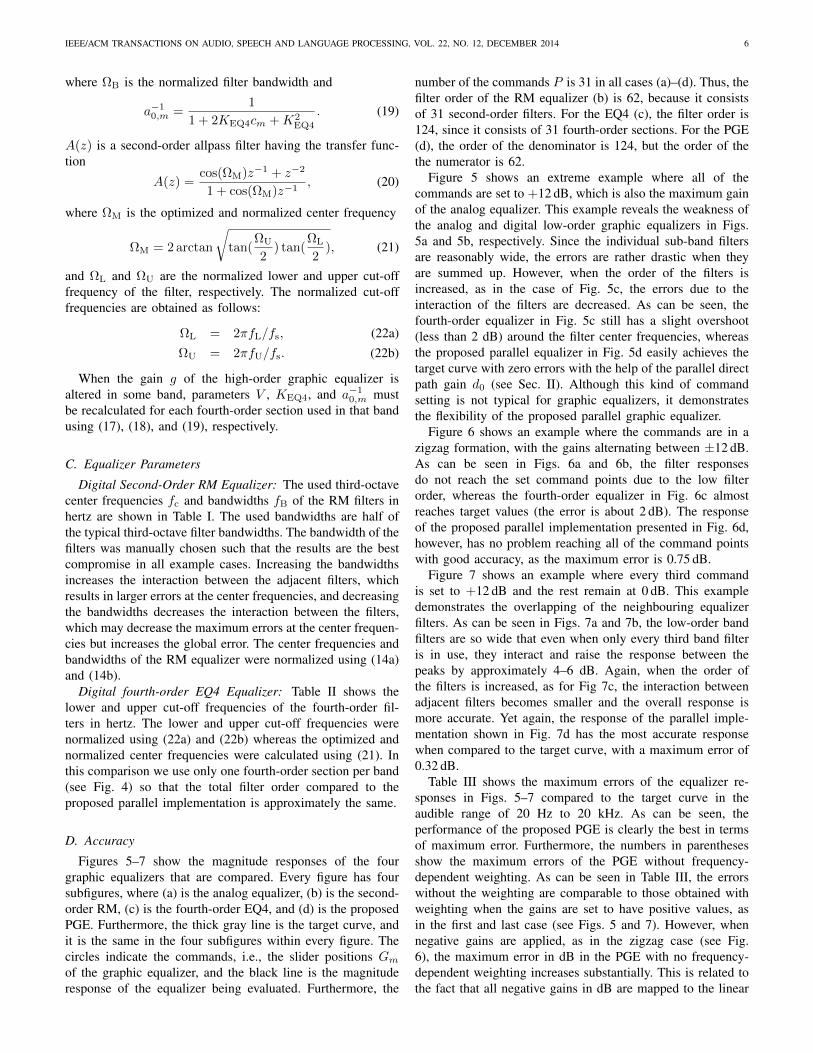
Figures 5–7 show the magnitude responses of the fourgraphic equalizers that are compared. Every figure has foursubfigures, where (a) is the analog equalizer, (b) is the second-order RM, (c) is the fourth-order EQ4, and (d) is the proposedPGE. Furthermore, the thick gray line is the target curve, andit is the same in the four subfigures within every figure. Thecircles indicate the commands, i.e., the slider positions Gmof the graphic equalizer, and the black line is the magnituderesponse of the equalizer being evaluated. Furthermore, the
number of the commands P is 31 in all cases (a)–(d). Thus, thefilter order of the RM equalizer (b) is 62, because it consistsof 31 second-order filters. For the EQ4 (c), the filter order is124, since it consists of 31 fourth-order sections. For the PGE(d), the order of the denominator is 124, but the order of thethe numerator is 62.
Figure 5 shows an extreme example where all of thecommands are set to +12 dB, which is also the maximum gainof the analog equalizer. This example reveals the weakness ofthe analog and digital low-order graphic equalizers in Figs.5a and 5b, respectively. Since the individual sub-band filtersare reasonably wide, the errors are rather drastic when theyare summed up. However, when the order of the filters isincreased, as in the case of Fig. 5c, the errors due to theinteraction of the filters are decreased. As can be seen, thefourth-order equalizer in Fig. 5c still has a slight overshoot(less than 2 dB) around the filter center frequencies, whereasthe proposed parallel equalizer in Fig. 5d easily achieves thetarget curve with zero errors with the help of the parallel directpath gain d0 (see Sec. II). Although this kind of commandsetting is not typical for graphic equalizers, it demonstratesthe flexibility of the proposed parallel graphic equalizer.
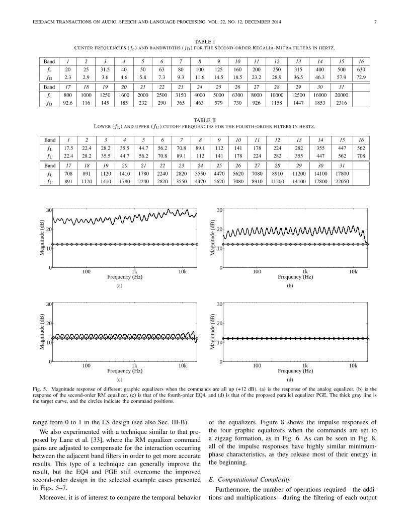
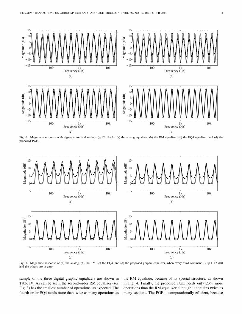
Figure 6 shows an example where the commands are in azigzag formation, with the gains alternating between ±12 dB.As can be seen in Figs. 6a and 6b, the filter responsesdo not reach the set command points due to the low filterorder, whereas the fourth-order equalizer in Fig. 6c almostreaches target values (the error is about 2 dB). The responseof the proposed parallel implementation presented in Fig. 6d,however, has no problem reaching all of the command pointswith good accuracy, as the maximum error is 0.75 dB.
Figure 7 shows an example where every third commandis set to +12 dB and the rest remain at 0 dB. This exampledemonstrates the overlapping of the neighbouring equalizerfilters. As can be seen in Figs. 7a and 7b, the low-order bandfilters are so wide that even when only every third band filteris in use, they interact and raise the response between thepeaks by approximately 4–6 dB. Again, when the order ofthe filters is increased, as for Fig 7c, the interaction betweenadjacent filters becomes smaller and the overall response ismore accurate. Yet again, the response of the parallel imple-mentation shown in Fig. 7d has the most accurate responsewhen compared to the target curve, with a maximum error of0.32 dB.
Table III shows the maximum errors of the equalizer re-sponses in Figs. 5–7 compared to the target curve in theaudible range of 20 Hz to 20 kHz. As can be seen, theperformance of the proposed PGE is clearly the best in termsof maximum error. Furthermore, the numbers in parenthesesshow the maximum errors of the PGE without frequency-dependent weighting. As can be seen in Table III, the errorswithout the weighting are comparable to those obtained withweighting when the gains are set to have positive values, asin the first and last case (see Figs. 5 and 7). However, whennegative gains are applied, as in the zigzag case (see Fig.6), the maximum error in dB in the PGE with no frequency-dependent weighting increases substantially. This is related tothe fact that all negative gains in dB are mapped to the linear
IEEE/ACM TRANSACTIONS ON AUDIO, SPEECH AND LANGUAGE PROCESSING, VOL. 22, NO. 12, DECEMBER 2014 7
TABLE ICENTER FREQUENCIES (fc) AND BANDWIDTHS (fB) FOR THE SECOND-ORDER REGALIA-MITRA FILTERS IN HERTZ.
Band 1 2 3 4 5 6 7 8 9 10 11 12 13 14 15 16
fc 20 25 31.5 40 50 63 80 100 125 160 200 250 315 400 500 630fB 2.3 2.9 3.6 4.6 5.8 7.3 9.3 11.6 14.5 18.5 23.2 28.9 36.5 46.3 57.9 72.9
Band 17 18 19 20 21 22 23 24 25 26 27 28 29 30 31
fc 800 1000 1250 1600 2000 2500 3150 4000 5000 6300 8000 10000 12500 16000 20000fB 92.6 116 145 185 232 290 365 463 579 730 926 1158 1447 1853 2316
TABLE IILOWER (fL) AND UPPER (fU) CUTOFF FREQUENCIES FOR THE FOURTH-ORDER FILTERS IN HERTZ.
Band 1 2 3 4 5 6 7 8 9 10 11 12 13 14 15 16
fL 17.5 22.4 28.2 35.5 44.7 56.2 70.8 89.1 112 141 178 224 282 355 447 562fU 22.4 28.2 35.5 44.7 56.2 70.8 89.1 112 141 178 224 282 355 447 562 708
Band 17 18 19 20 21 22 23 24 25 26 27 28 29 30 31
fL 708 891 1120 1410 1780 2240 2820 3550 4470 5620 7080 8910 11200 14100 17800fU 891 1120 1410 1780 2240 2820 3550 4470 5620 7080 8910 11200 14100 17800 22050
100 1k 10k0
10
20
30
Frequency (Hz)
Mag
nitu
de (
dB)
(a)
100 1k 10k0
10
20
30
Frequency (Hz)
Mag
nitu
de (
dB)
(b)
100 1k 10k0
10
20
30
Frequency (Hz)
Mag
nitu
de (
dB)
(c)
100 1k 10k0
10
20
30
Frequency (Hz)
Mag
nitu
de (
dB)
(d)
Fig. 5. Magnitude response of different graphic equalizers when the commands are all up (+12 dB). (a) is the response of the analog equalizer, (b) is theresponse of the second-order RM equalizer, (c) is that of the fourth-order EQ4, and (d) is that of the proposed parallel equalizer PGE. The thick gray line isthe target curve, and the circles indicate the command positions.
range from 0 to 1 in the LS design (see also Sec. III-B).We also experimented with a technique similar to that pro-
posed by Lane et al. [33], where the RM equalizer commandgains are adjusted to compensate for the interaction occurringbetween the adjacent band filters in order to get more accurateresults. This type of a technique can generally improve theresult, but the EQ4 and PGE still overcome the improvedsecond-order design in the selected example cases presentedin Figs. 5–7.
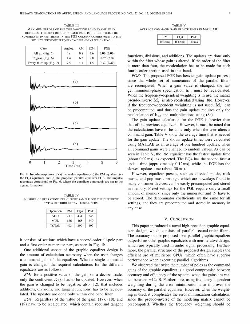
Moreover, it is of interest to compare the temporal behavior
of the equalizers. Figure 8 shows the impulse responses ofthe four graphic equalizers when the commands are set toa zigzag formation, as in Fig. 6. As can be seen in Fig. 8,all of the impulse responses have highly similar minimum-phase characteristics, as they release most of their energy inthe beginning.
E. Computational Complexity
Furthermore, the number of operations required—the addi-tions and multiplications—during the filtering of each output
IEEE/ACM TRANSACTIONS ON AUDIO, SPEECH AND LANGUAGE PROCESSING, VOL. 22, NO. 12, DECEMBER 2014 8
100 1k 10k−15
−10
−5
0
5
10
15
Frequency (Hz)
Mag
nitu
de (
dB)
(a)
100 1k 10k−15
−10
−5
0
5
10
15
Frequency (Hz)
Mag
nitu
de (
dB)
(b)
100 1k 10k−15
−10
−5
0
5
10
15
Frequency (Hz)
Mag
nitu
de (
dB)
(c)
100 1k 10k−15
−10
−5
0
5
10
15
Frequency (Hz)M
agni
tude
(dB
)
(d)
Fig. 6. Magnitude response with zigzag command settings (±12 dB) for (a) the analog equalizer, (b) the RM equalizer, (c) the EQ4 equalizer, and (d) theproposed PGE.
100 1k 10k−5
0
5
10
15
Frequency (Hz)
Mag
nitu
de (
dB)
(a)
100 1k 10k−5
0
5
10
15
Frequency (Hz)
Mag
nitu
de (
dB)
(b)
100 1k 10k−5
0
5
10
15
Frequency (Hz)
Mag
nitu
de (
dB)
(c)
100 1k 10k−5
0
5
10
15
Frequency (Hz)
Mag
nitu
de (
dB)
(d)
Fig. 7. Magnitude response of (a) the analog, (b) the RM, (c) the EQ4, and (d) the proposed graphic equalizer, when every third command is up (+12 dB)and the others are at zero.
sample of the three digital graphic equalizers are shown inTable IV. As can be seen, the second-order RM equalizer (seeFig. 3) has the smallest number of operations, as expected. Thefourth-order EQ4 needs more than twice as many operations as
the RM equalizer, because of its special structure, as shownin Fig. 4. Finally, the proposed PGE needs only 23% moreoperations than the RM equalizer although it contains twice asmany sections. The PGE is computationally efficient, because
IEEE/ACM TRANSACTIONS ON AUDIO, SPEECH AND LANGUAGE PROCESSING, VOL. 22, NO. 12, DECEMBER 2014 9
TABLE IIIMAXIMUM ERRORS OF THE THIRD-OCTAVE BAND EXAMPLES IN
DECIBELS. THE BEST RESULT IN EACH CASE IS HIGHLIGHTED. THENUMBERS IN PARENTHESES IN THE PGE COLUMN CORRESPOND TO THE
RESULTS WITHOUT FREQUENCY-DEPENDENT WEIGHTING.
Case Analog RM EQ4 PGE
All up (Fig. 5) 18 9.8 3.6 0.00 (0.00)Zigzag (Fig. 6) 4.4 6.3 2.8 0.75 (2.0)
Every third up (Fig. 7) 7.5 4.1 1.5 0.32 (0.29)
0 1 2 3 4 5 6Time (ms)
(a)
(b)
(c)
(d)
Fig. 8. Impulse responses of (a) the analog equalizer, (b) the RM equalizer, (c)the EQ4 equalizer, and (d) the proposed parallel equalizer PGE. The impulseresponses correspond to Fig. 6, where the equalizer commands are set to thezigzag formation.
TABLE IVNUMBER OF OPERATIONS PER OUTPUT SAMPLE FOR THE DIFFERENT
TYPES OF THIRD-OCTAVE EQUALIZERS.
Operation RM EQ4 PGE
ADD 217 434 248MUL 186 465 249
TOTAL 403 899 497
it consists of sections which have a second-order all-pole partand a first-order numerator part, as seen in Fig. 1b.
One additional aspect of the graphic equalizer design isthe amount of calculation necessary when the user changesa command gain of the equalizer. When a single commandgain is changed, the required calculations for the differentequalizers are as follows:
RM: for a positive value of the gain on a decibel scale,only the coefficient KRM has to be updated. However, whenthe gain is changed to be negative, also (12), that includesadditions, divisions, and tangent functions, has to be recalcu-lated. The updates are done only within one band filter.
EQ4: Regardless of the value of the gain, (17), (18), and(19) have to be recalculated, which contain root and tangent
TABLE VAVERAGE COMMAND GAIN UPDATE TIMES IN MATLAB.
RM EQ4 PGE
0.02 ms 0.12 ms 30 ms
functions, divisions, and additions. The updates are done onlywithin the filter whose gain is altered. If the order of the filteris more than four, the recalculation has to be made for eachfourth-order section used in that band.
PGE: The proposed PGE has heavier gain update process,since the whole set of numerators of the parallel filtersare recomputed. When a gain value is changed, the tar-get minimum-phase specification ht,r must be recalculated.When the frequency-dependent weighting is in use, the matrixpseudo-inverse M+
r is also recalculated using (8b). However,if the frequency-dependent weighting is not used, M+
r canbe precomputed, and thus the gain update requires only therecalculation of ht,r and multiplications using (8a).
The gain update calculation for the PGE is heavier thanthat of the previous equalizers. However, it must be noted thatthe calculations have to be done only when the user alters acommand gain. Table V show the average time that is neededfor the gain update. The shown update times were calculatedusing MATLAB as an average of one hundred updates, whenall command gains were changed to random values. As can beseen in Table V, the RM equalizer has the fastest update time(about 0.02 ms), as expected. The EQ4 has the second fastestupdate time (approximately 0.12 ms), while the PGE has theslowest update time (about 30 ms).
However, equalizer presets, such as classical music, rockmusic, and pop music settings, which are nowadays found inmany consumer devices, can be easily precomputed and storedin memory. Preset settings for the PGE require only a smallamount of memory, since only the numerator and d0 have tobe stored. The denominator coefficients are the same for allsettings, and they are precomputed and stored in memory inany case.
V. CONCLUSION
This paper introduced a novel high-precision graphic equal-izer design, which consists of parallel second-order filters.The accuracy of the proposed new parallel graphic equalizeroutperforms other graphic equalizers with non-iterative design,which are typically used in audio signal processing. Further-more, the parallel structure of the proposed design enables theefficient use of multicore GPUs, which often have superiorperformance when executing parallel algorithms.
We observed that twice the number of poles as the commandgains of the graphic equalizer is a good compromise betweenaccuracy and efficiency of the system, when the gains are var-ied between ±12 dB. Furthermore, using frequency-dependentweighting during the error minimization also improves theaccuracy of the parallel equalizer. However, when the weight-ing is used, it complicates the error minimization calculation,since the pseudo-inverse of the modeling matrix cannot beprecomputed. Whether the frequency weighting should be
IEEE/ACM TRANSACTIONS ON AUDIO, SPEECH AND LANGUAGE PROCESSING, VOL. 22, NO. 12, DECEMBER 2014 10
included in the design or not should be decided based on theapplication the proposed parallel equalizer will be used for.
The results show that with weighting the parallel equalizeroperates highly accurately with the given design, maintainingerrors of less than 1 dB even during the hardest example cases.Although the proposed filtering can be implemented with a40% smaller number of operations than a graphic equalizerbased on fourth-order filters, the achieved accuracy is better.
A MATLAB implementation of the design method withexamples is available at http://www.acoustics.hut.fi/go/ieee-taslp-pge.
ACKNOWLEDGMENT
The work of Balazs Bank was supported by the BolyaiScholarship of the Hungarian Academy of Sciences.
REFERENCES
[1] D. A. Bohn, “Operator adjustable equalizers: An overview,” in Proc.AES 6th Int. Conf., May 1988, pp. 369–381.
[2] R. Berkovitz, “Digital equalization of audio signals,” in Proc. AES 1stInt. Conf.: Digital Audio, Jun. 1982, pp. 226–238.
[3] M. Karjalainen, E. Piirila, A. Jarvinen, and J. Huopaniemi, “Comparisonof loudspeaker equalization methods based on DSP techniques,” J. AudioEng. Soc., vol. 47, no. 1-2, pp. 15–31, Jan./Feb. 1999.
[4] A. Marques and D. Freitas, “Infinite impulse response (IIR) inverse filterdesign for the equalization of non-minimum phase loudspeaker systems,”in Proc. IEEE Workshop on Applications of Signal Processing to Audioand Acoustics, New Paltz, NY, Oct. 2005, pp. 170–173.
[5] G. Ramos and J. J. Lopez, “Filter design method for loudspeakerequalization based on IIR parametric filters,” J. Audio Eng. Soc., vol. 54,no. 12, pp. 1162–1178, Dec. 2006.
[6] J. N. Mourjopoulos, “Digital equalization of room acoustics,” J. AudioEng. Soc., vol. 42, no. 11, pp. 884–900, Nov. 1994.
[7] M. Karjalainen, P. A. A. Esquef, P. Antsalo, A. Makivirta, andV. Valimaki, “Frequency-zooming ARMA modeling of resonant andreverberant systems,” J. Audio Eng. Soc., vol. 50, no. 12, pp. 1012–1029, Dec. 2002.
[8] A. Makivirta, P. Antsalo, M. Karjalainen, and V. Valimaki, “Modalequalization of loudspeaker-room responses at low frequencies,” J. AudioEng. Soc., vol. 51, no. 5, pp. 324–343, May 2003.
[9] A. Carini, S. Cecchi, F. Piazza, I. Omiciuolo, and G. L. Sicuranza,“Multiple position room response equalization in frequency domain,”IEEE Trans. Audio, Speech, and Language Processing, vol. 20, no. 1,pp. 122–135, Jan. 2012.
[10] B. Bank, “Loudspeaker and room equalization using parallel filters:Comparison of pole positioning strategies,” in Proc. AES 51st Int. Conf.,Helsinki, Finland, Aug. 2013.
[11] G. Lorho, “Subjective evaluation of headphone target frequency re-sponses,” in Proc. AES 126th Convention, Munich, Germany, May 2009.
[12] A. Lindau and F. Brinkmann, “Perceptual evaluation of headphonecompensation in binaural synthesis based on non-individual recordings,”J. Audio Eng. Soc., vol. 60, no. 1/2, pp. 54–62, Jan./Feb. 2012.
[13] J. Ramo, V. Valimaki, and M. Tikander, “Perceptual headphone equaliza-tion for mitigation of ambient noise,” in Proc. IEEE Int. Conf. Acoustics,Speech, and Signal Processing (ICASSP), Vancouver, Canada, May2013, pp. 724–728.
[14] S. E. Olive, T. Welti, and E. McMullin, “Listener preferences for in-room loudspeaker and headphone target responses,” in Proc. AES 135thConvention, New York, NY, October 2013.
[15] M. Tikander, “Usability issues in listening to natural sounds with anaugmented reality audio headset,” J. Audio Eng. Soc., vol. 57, no. 6, pp.430–441, Jun. 2009.
[16] J. Ramo and V. Valimaki, “Digital augmented reality headset,” J.Electrical and Computer Engineering, vol. 2012, 2012.
[17] J. Ramo, V. Valimaki, and M. Tikander, “Live sound equalization andattenuation with a headset,” in Proc. AES 51st Int. Conf., Helsinki,Finland, Aug. 2013.
[18] E. Perez Gonzales and J. Reiss, “Automatic equalization of multi-channel audio using cross-adaptive methods,” in Proc. AES 127thConvention, New York, NY, Oct. 2009.
[19] Z. Ma, J. D. Reiss, and D. A. A. Black, “Implementation of an intelligentequalization tool using Yule-Walker for music mixing and mastering,”in Proc. AES 134th Convention, Rome, Italy, May 2013.
[20] P. Dutilleux, M. Holters, S. Disch, and U. Zolzer, “Filters and delays,”in DAFX: Digital Audio Effects, 2nd ed., U. Zolzer, Ed. John Wiley& Sons Ltd, 2011, ch. 2, pp. 47–81.
[21] D. T. Yeh and J. O. Smith, “Discretization of the ’59 Fender Bassmantone stack,” in Proc. Int. Conf. Digital Audio Effects (DAFx-06), Mon-treal, Canada, Sep. 2006.
[22] L. Gabrielli, V. Valimaki, H. Penttinen, S. Squartini, and S. Bilbao, “Adigital waveguide based approach for Clavinet modeling and synthesis,”EURASIP J. Applied Signal Processing, vol. 2013, no. 1, May 2013.
[23] P. Regalia and S. Mitra, “Tunable digital frequency response equalizationfilters,” IEEE Trans. Acoustics, Speech, and Signal Processing, vol. 35,no. 1, pp. 118–120, Jan. 1987.
[24] T. van Waterschoot and M. Moonen, “A pole-zero placement techniquefor designing second-order IIR parametric equalizer filters,” IEEE Trans.Audio, Speech, and Language Processing, vol. 15, no. 8, pp. 2561–2565,Nov. 2007.
[25] H. Behrends, A. von dem Knesebeck, W. Bradinal, P. Neumann, andU. Zolzer, “Automatic equalization using parametric IIR filters,” J. AudioEng. Soc., vol. 59, pp. 102–109, Mar. 2011.
[26] J. D. Reiss, “Design of audio parametric equalizer filters directly in thedigital domain,” IEEE Trans. Audio Speech and Language Processing,vol. 19, no. 6, pp. 1843–1848, Aug. 2011.
[27] S. Sarkka and A. Huovilainen, “Accurate discretization of analog audiofilters with application to parametric equalizer design,” IEEE Trans.Audio, Speech, and Language Processing, vol. 19, no. 8, pp. 2486–2493,Nov. 2011.
[28] Motorola Inc., “Digital stereo 10-band graphic equalizer using theDSP56001,” Application note, 1988.
[29] M. Holters and U. Zolzer, “Graphic equalizer design using higher-orderrecursive filters,” in Proc. Int. Conf. Digital Audio Effects (DAFx-06),Sep. 2006, pp. 37–40.
[30] S. Tassart, “Graphical equalization using interpolated filter banks,” J.Audio Eng. Soc., vol. 61, no. 5, pp. 263–279, May 2013.
[31] J. Ramo and V. Valimaki, “Optimizing a high-order graphic equalizerfor audio processing,” IEEE Signal Processing Lett., vol. 21, no. 3, pp.301–305, Mar. 2014.
[32] Z. Chen, G. S. Geng, F. L. Yin, and J. Hao, “A pre-distortion baseddesign method for digital audio graphic equalizer,” Digital SignalProcessing, vol. 25, pp. 296–302, 2014.
[33] J. E. Lane, D. Hoory, and J. P. K. Brewer, “Method and apparatusfor generating decoupled filter parameters and implementing a banddecoupled filter,” U.S. Patent 5,687,104, Nov. 1997.
[34] B. Bank, “Direct design of parallel second-order filters forinstrument body modeling,” in Proc. Int. Computer MusicConf., Copenhagen, Denmark, Aug. 2007, pp. 458–465, URL:http://www.acoustics.hut.fi/go/icmc07-parfilt.
[35] A. Harma and T. Paatero, “Discrete representation of signals on a log-arithmic frequency scale,” in Proc. IEEE Workshop on the Applicationsof Signal Processing to Audio and Acoustics, New Paltz, NY, Oct. 2001,pp. 39–42.
[36] B. Bank, “Logarithmic frequency scale parallel filter design with com-plex and magnitude-only specifications,” IEEE Signal Process. Lett.,vol. 18, no. 2, pp. 138–141, Feb. 2011.
[37] A. Harma, M. Karjalainen, L. Savioja, V. Valimaki, U. K. Laine,and J. Huopaniemi, “Frequency-warped signal processing for audioapplications,” J. Audio Eng. Soc., vol. 48, no. 11, pp. 1011–1031, Nov.2000.
[38] T. Paatero and M. Karjalainen, “Kautz filters and generalized frequencyresolution: Theory and audio applications,” J. Audio Eng. Soc., vol. 51,no. 1–2, pp. 27–44, Jan./Feb. 2003.
[39] B. Bank, “Perceptually motivated audio equalization using fixed-poleparallel second-order filters,” IEEE Signal Process. Lett., vol. 15,pp. 477–480, 2008, URL: http://www.acoustics.hut.fi/go/spl08-parfilt.
[40] B. Bank and G. Ramos, “Improved pole positioning for parallel filtersbased on spectral smoothing and multi-band warping,” IEEE SignalProcess. Lett., vol. 18, no. 5, pp. 299–302, Mar. 2011.
[41] J. A. Belloch, B. Bank, L. Savioja, A. Gonzalez, and V. Valimaki,“Multi-channel IIR filtering of audio signals using a GPU,” in Proc.IEEE Int. Conf. Acoust. Speech Signal Process., Florence, Italy, May2014, pp. 6692–6696.
[42] L. Savioja, V. Valimaki, and J. O. Smith, “Audio signal processing usinggraphics processing units,” J. Audio Eng. Soc., vol. 59, no. 1/2, pp. 3–19,Jan./Feb. 2011.
IEEE/ACM TRANSACTIONS ON AUDIO, SPEECH AND LANGUAGE PROCESSING, VOL. 22, NO. 12, DECEMBER 2014 11
[43] B. Bank, “Audio equalization with fixed-pole parallel filters: An efficientalternative to complex smoothing,” J. Audio Eng. Soc., vol. 61, no. 1/2,pp. 39–49, Jan. 2013.
[44] T. W. Parks and C. S. Burrus, Digital Filter Design. New York: JohnWiley & Sons, Inc., 1987.
[45] F. B. Hildebrand, Introduction to Numerical Analysis, 2nd ed. NewYork: Dover Publications, Inc, 1987.
[46] R. A. Geiner and M. Schoessow, “Design aspects of graphic equalizers,”J. Audio Eng. Soc., vol. 31, no. 6, pp. 394–407, Jun. 1983.
[47] J. O. Smith, Introduction to Digital Filters with Audio Applications.W3K Publishing, 2007.
[48] A. V. Oppenheim and R. W. Schafer, Digital Signal Processing. En-glewood Cliffs, NJ: Prentice-Hall, 1975.
[49] J. Dattorro, “Effect design,” J. Audio Eng. Soc., vol. 45, no. 9, pp. 660–684, Sep. 1997.
[50] J. Rauhala, “The beating equalizer and its applications to the synthesisand modification of piano tones,” in Proc. 10th Int. Conf. Digital AudioEffects (DAFx-07), Bordeaux, France, Sep. 2007, pp. 181–188.
[51] V. Valimaki, J. S. Abel, and J. O. Smith, “Spectral delay filters,” J.Audio Eng. Soc., vol. 57, no. 7/8, pp. 521–531, Jul./Aug. 2009.
[52] A. Pandey and V. J. Mathews, “Adaptive gain processing with offendingfrequency suppression for digital hearing aids,” IEEE Trans. Audio,Speech, and Language Processing, vol. 20, no. 3, pp. 1043–1055, Mar.2012.
[53] J. Ramo, V. Valimaki, M. Alanko, and M. Tikander, “Perceptualfrequency response simulator for music in noisy environments,” in Proc.AES 45th Int. Conf., Helsinki, Finland, Mar. 2012.
[54] A. Farina, “Simultaneous measurement of impulse response and distor-tion with a swept-sine technique,” in Proc. AES 108th Convention, Paris,France, Feb. 2000.
[55] U. Zolzer and T. Boltze, “Parametric digital filter structures,” in AES99th Convention, New York, NY, Oct. 1995.
[56] S. J. Orfanidis, “High-order digital parametric equalizer design,” J. AudioEng. Soc., vol. 53, no. 11, pp. 1026–1046, Nov. 2005.
Jussi Ramo received his M.Sc. degree in commu-nication engineering from the Helsinki Universityof Technology, in 2009. His major subject wasacoustics and audio signal processing.
Since 2009 he has worked as a researcher in theDepartment of Signal Processing and Acoustics atAalto University, Espoo, Finland. Currently he isfinalizing his Ph.D. degree in the field of headphoneaudio and digital signal processing. His researchinterests include sound reproduction and digital fil-tering.
Mr. Ramo is a member of the Audio Engineering Society. He was amember of the organizing committee of the Audio Engineering Society 51stInternational Conference on Loudspeakers and Headphones, Helsinki, Finland,August 2013.
Vesa Valimaki (S’90–M’92–SM’99) received theM.Sc. (Tech.), the Licentiate of Science in Technol-ogy, and the Doctor of Science in Technology de-grees, all in electrical engineering, from the HelsinkiUniversity of Technology (TKK), Espoo, Finland,in 1992, 1994, and 1995, respectively. His doctoraldissertation dealt with fractional delay filters andphysical modeling of musical instruments.
He was a Postdoctoral Research Fellow at theUniversity of Westminster, London, UK, in 1996. In1997–2001, he was a Senior Assistant at the TKK
Laboratory of Acoustics and Audio Signal Processing, Espoo, Finland. From1998 to 2001, he was on leave as a Postdoctoral Researcher under a grant fromthe Academy of Finland. In 2001–2002, he was Professor of signal processingat the Pori unit of the Tampere University of Technology, Pori, Finland. Hewas appointed Docent in signal processing at the Pori unit of the TampereUniversity of Technology in 2003. In 2006–2007, he was the Head of theTKK Laboratory of Acoustics and Audio Signal Processing. He is currentlyProfessor of audio signal processing in the Department of Signal Processingand Acoustics, Aalto University, Espoo, Finland. In 2008–2009, he was onsabbatical leave as a Visiting Scholar at the Center for Computer Research inMusic and Acoustics (CCRMA), Stanford University, Stanford, CA.
Prof. Valimaki is a Fellow of the Audio Engineering Society, a LifeMember of the Acoustical Society of Finland, and a Member of the FinnishMusicological Society. In 2000–2001, he was Secretary of the IEEE FinlandSection. In 2008, he was the Chairman of DAFx-08, the 11th InternationalConference on Digital Audio Effects (Espoo, Finland). He was a Guest Editorfor the EURASIP Journal on Applied Signal Processing and for the EURASIPJournal on Advances in Signal Processing, and was in the Editorial Board ofthe Research Letters in Signal Processing and of the Journal of Electricaland Computer Engineering. He is currently an Editorial Board Member ofThe Scientific World Journal. From 2005 to 2009 he was an Associate Editorof the IEEE SIGNAL PROCESSING LETTERS, and from 2007 to 2011 hewas an Associate Editor of the IEEE TRANSACTIONS ON AUDIO, SPEECHAND LANGUAGE PROCESSING. He was the Lead Guest Editor of a specialissue of the IEEE SIGNAL PROCESSING MAGAZINE in 2007 and of a specialissue of the IEEE TRANSACTIONS ON AUDIO, SPEECH AND LANGUAGEPROCESSING in 2010. He is currently a Guest Editor of the special issue of theIEEE SIGNAL PROCESSING MAGAZINE on signal processing techniques forassisted listening. In 2007–2013 he was a Member of the Audio and AcousticSignal Processing Technical Committee of the IEEE Signal Processing Societyand is currently an Associate Member.
Balazs Bank (M’12) received his M.Sc. and Ph.D.degrees in Electrical Engineering from the BudapestUniversity of Technology and Economics, Hungary,in 2000 and 2006, respectively. His doctoral disser-tation was about physics-based synthesis of stringinstrument sounds with an emphasis on the piano.
In the academic year 1999/2000, he was withthe Laboratory of Acoustics and Audio Signal Pro-cessing, Helsinki University of Technology, Finland.From 2000 to 2006 he was a Ph.D. student andresearch assistant at the Department of Measurement
and Information Systems, Budapest University of Technology and Economics.In 2001 he visited the Department of Information Engineering, Universityof Padova. In 2007 he returned to the Acoustics Laboratory of HelsinkiUniversity of Technology for a year, with the support of an FP6 Marie CurieEIF individual fellowship. In 2008 he was with the Department of ComputerScience, Verona University, Italy. In 2009–2010 he was a postdoctoral re-searcher at the Budapest University of Technology and Economics, supportedby the Norway and EEA Grants and the Zoltan Magyary Higher EducationFoundation. Currently he is an associate professor at the Department ofMeasurement and Information Systems, Budapest University of Technologyand Economics, Budapest, Hungary. His research interests include physics-based sound synthesis and filter design for audio applications.
Prof. Bank is a member of the Audio Engineering Society. Since 2013 heis an Associate Editor of the IEEE SIGNAL PROCESSING LETTERS.