harrington - fire alarm - potter electric signal company
TRANSCRIPT
HS3DL Dual Line Dialer and
HS-3030DACT
Installation Manual
Revision 2 March 2012Document # LT-2021HAR
HARRINGTON
FIRE ALARM SIGNAL INC.

Table of Contents
Harrington Signal, Inc. iii
Table of Contents
1 Introduction
1.1 General Dialer Features of the HS3DL ........................................................................... 7
1.2 Codes, Standards and Installation Requirements .......................................................... 7
1.2.1 Relevant Codes and Standards ...................................................................................... 7
1.2.2 General Installation Requirements ................................................................................. 7
1.3 Technical Support and General Information ................................................................... 8
1.4 System Verification ......................................................................................................... 8
1.5 Standby Power ............................................................................................................... 8
2 Installing and Wiring
2.1 Unpacking the Dialers ................................................................................................... 9
2.1.1 HS3DL ............................................................................................................................ 9
2.1.2 HS-3030-DACT .............................................................................................................. 9
2.2 Mounting & Wiring the Dialer .......................................................................................... 10
2.2.1 Mounting & Wiring the HS3DL ........................................................................................ 10
3 Dialer Operation
3.1 LED Indicators ................................................................................................................ 12
3.2 Communication with the Fire Alarm Control Panel ......................................................... 12
3.3 Phone Line Communication ........................................................................................... 12
4 Programming the Dialer
4.1 Programming the HS3DL ............................................................................................... 13
4.1.1 Accessing the Dialer Settings ......................................................................................... 13
4.2 Programming the HS-3030-DACT .................................................................................. 14
4.2.1 Accessing the Dialer Settings ......................................................................................... 14
4.3 Dialer Settings ................................................................................................................ 16
4.3.2 Dialer Configuration 2 ..................................................................................................... 20
5 Appendices
Contact ID ....................................................................................................................... 24
SIA Format – Level 2 (Hardcoded) ................................................................................. 24
Automatic Contact ID/SIA Reporting Codes ................................................................... 25
Contact ID Zone Alarm/Restoral Event Codes ............................................................... 25
Table of Contents
Harrington Signal, Inc. iv
SIA Format Automatic Zone Alarm/Restoral Codes ....................................................... 26
6 Warranty Procedure
6.1 Conditions to Void Warranty .......................................................................................... 27
6.2 Limitation of Liability ....................................................................................................... 27
6.3 Disclaimer of Warranties ................................................................................................ 28
6.4 Out of Warranty Repairs ................................................................................................ 28
7 FCC Compliance Statement
List of Figure and Tables
Harrington Signal, Inc. iii
List of Figure and Tables
Figure 1 HS3DL Installation Location ........................................................................................... 10
Figure 2 HS-3030-DACT Installation Location .............................................................................. 11
Figure 3 Initial Programmer Screen - HS3DL ............................................................................... 13
Figure 4 Panels Screen - HS3DL ................................................................................................. 13
Figure 5 Dialer Settings Button - HS3DL ...................................................................................... 14
Figure 6 Initial Programmer Screen .............................................................................................. 14
Figure 7 Panels Screen - HS-3030-DACT .................................................................................... 15
Figure 8 Dialer Settings Button - HS-3030-DACT ........................................................................ 15
Figure 9 Initial Dialer Screen ........................................................................................................ 17
Figure 10 Dialer Configuration 1 ..................................................................................................... 17
Figure 11 Dialer Configuration 2 ..................................................................................................... 20
Figure 12 Call Directions ................................................................................................................ 21
Figure 13 Zone Data ....................................................................................................................... 22
Figure 14 Dialer Maintenance and Common Reporting Codes ...................................................... 23
Table 1 Dialer LED Indicators ...................................................................................................... 12
List of Figure and Tables
Harrington Signal, Inc. iv
Harrington Signal, Inc. 7
Introduction
1 IntroductionThis manual is to describe the proper installation and operation of the HS3DL and HS-3030-DACT Dialers.
The HS3DL is a dual line dialer that will communicate all alarms, supervisory and troubleconditions to a Central Station using Contact ID or SIA communication formats. The HS3DLwill support the HS3100 and HS3200 Fire Panels.The HS-3030-DACT provides a digital alarmcommunicating transmitter (DACT) that will communicate alarm, supervisory, and troubleconditions to a Central Station using Contact ID, SIA, or 10/20 BPS communications formats.The HS-3030-DACT supports the HS-3030 Series Fire Panels.
The NP_V21 or greater programmer must be used to program the HS3DL or HS-3030-DACTDialer.
1.1 General Dialer Features of the HS3DL
• Supports all zone alarm, supervisory, and trouble conditions
• Supports all panel troubles
• Programmable through NP_V21 or greater programmer
• Supports SIA, Contact ID, and Pager Formats
• Three telephone numbers
• Fully programmable test transmission
• Automatic reporting codes for SIA and Contact ID formats
• 128 Event buffer with date and time stamp
• Communicator call directions by group
• Swinger shutdown options available for all events
• Module current rating: 40mA standby / 65mA when dialing
• Module voltage rating: 19 VDC to 27.5 VDC
1.2 Codes, Standards and Installation Requirements
1.2.1 Relevant Codes and Standards
The HS3DL Dual-Line Digital Dialer and HS-3030-DACT are designed to meet the DACTrequirements of NFPA 72, UL 864 Rev.9, Control Units for fire Protective Systems.
1.2.2 General Installation Requirements
Manufacturer’s Documents
When installing the HS3DL or HS-3030-DACT, refer to this manual and the manual for thecontrol panel into which this module is being installed. Programming requires NP_V21 orgreater.
Harrington Signal, Inc. 8
Introduction
Field Wiring
Field wiring recommendations in these documents are intended as guidelines. All field wiringmust be installed in accordance with NFPA 70 National Electrical Code and with all relevantlocal codes and standards and the Authority Having Jurisdiction.
1.3 Technical Support and General Information
For technical support call toll free at 1-800-577-5758.
For general product information visit our web site: www.harringtonfire.com.
1.4 System Verification
The complete fire alarm system must be verified for proper installation and operation when:
• the initial installation is ready for inspection by the Local Authority Having Jurisdiction;
• any system component is added, changed or deleted;
• any programming changes are made;
• system wiring has been altered or repaired;
• system failure due to external influences such as lightning, water damage or extended power outages has occurred.
1.5 Standby Power
The HS3100/HS3200 and HS-3030 Fire Panels provide standby battery support for lead-acidrechargeable batteries. The required capacity of the standby batteries must be calculatedusing the charts and tables within the HS3100/HS3200Installation Manual (LT-2000HAR) forthe period as required by national or local codes and standards. Even though the calculationtable within the HS3100/HS3200 Installation Manual (LT-2000HAR) includes a safety margin,lead-acid batteries commonly used for standby can have variable capacity as a result of ageand ambient conditions. Periodic inspection for damage and the batteries’ ability to support theattached equipment is highly recommended.
Installing and Wiring
Harrington Signal, Inc. 9
2 Installing and Wiring2.1 Unpacking the Dialers
2.1.1 HS3DL
The basic HS3DL package includes the following components:
• Dialer
• 4-pin polarized locking cable assembly
• Four #4 mounting screws
• Installation manual
2.1.2 HS-3030-DACT
The basic HS-3030-DACT package includes the following components:
• Dialer
• Isolator
• 4-pin polarized locking cable assembly
• Isolator Wires
• Eight #4 mounting screws
• Eight standoffs
• Installation manual
Installing and Wiring
Harrington Signal, Inc. 10
2.2 Mounting & Wiring the Dialer
2.2.1 Mounting & Wiring the HS3DL
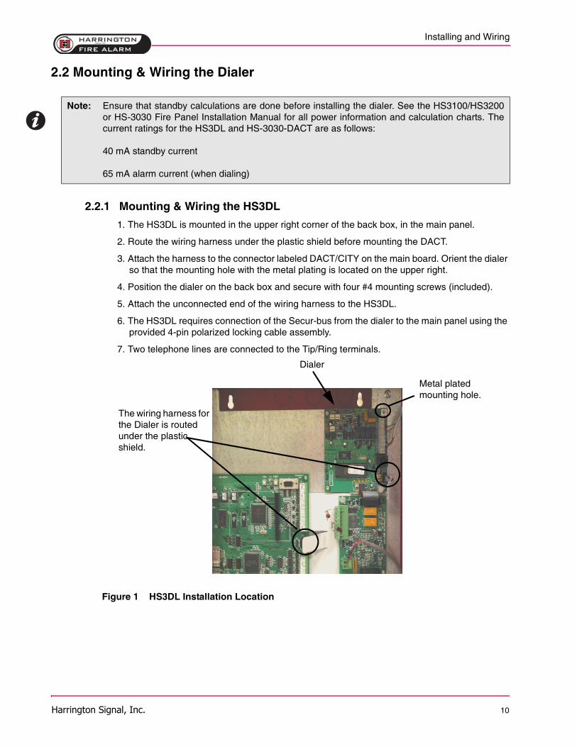
1. The HS3DL is mounted in the upper right corner of the back box, in the main panel.
2. Route the wiring harness under the plastic shield before mounting the DACT.
3. Attach the harness to the connector labeled DACT/CITY on the main board. Orient the dialer so that the mounting hole with the metal plating is located on the upper right.
4. Position the dialer on the back box and secure with four #4 mounting screws (included).
5. Attach the unconnected end of the wiring harness to the HS3DL.
6. The HS3DL requires connection of the Secur-bus from the dialer to the main panel using the provided 4-pin polarized locking cable assembly.
7. Two telephone lines are connected to the Tip/Ring terminals.
Figure 1 HS3DL Installation Location
Note: Ensure that standby calculations are done before installing the dialer. See the HS3100/HS3200or HS-3030 Fire Panel Installation Manual for all power information and calculation charts. Thecurrent ratings for the HS3DL and HS-3030-DACT are as follows:
40 mA standby current
65 mA alarm current (when dialing)
The wiring harness for the Dialer is routed under the plastic shield.
Metal plated mounting hole.
Dialer
Installing and Wiring
Harrington Signal, Inc. 11
2.2.2 Mounting & Wiring the HS-3030-DACT
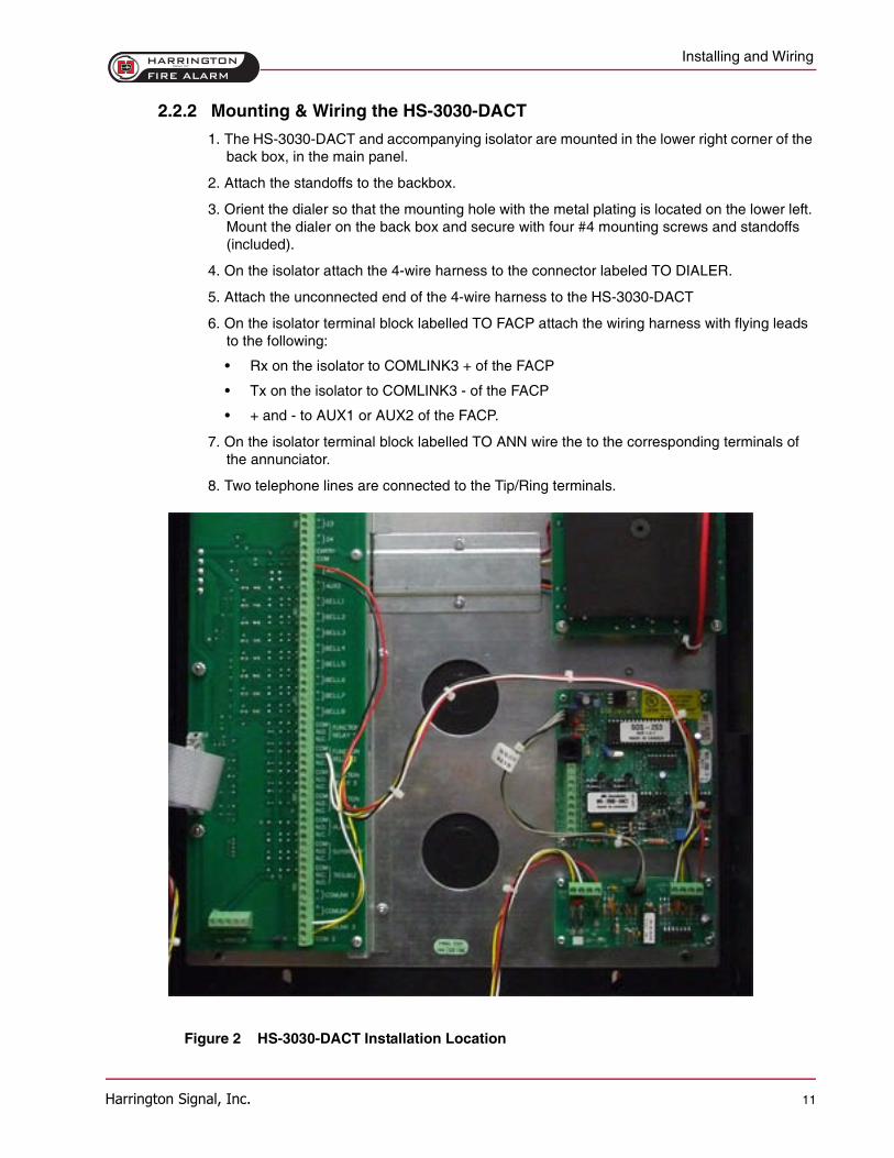
1. The HS-3030-DACT and accompanying isolator are mounted in the lower right corner of the back box, in the main panel.
2. Attach the standoffs to the backbox.
3. Orient the dialer so that the mounting hole with the metal plating is located on the lower left. Mount the dialer on the back box and secure with four #4 mounting screws and standoffs (included).
4. On the isolator attach the 4-wire harness to the connector labeled TO DIALER.
5. Attach the unconnected end of the 4-wire harness to the HS-3030-DACT
6. On the isolator terminal block labelled TO FACP attach the wiring harness with flying leads to the following:
• Rx on the isolator to COMLINK3 + of the FACP
• Tx on the isolator to COMLINK3 - of the FACP
• + and - to AUX1 or AUX2 of the FACP.
7. On the isolator terminal block labelled TO ANN wire the to the corresponding terminals of the annunciator.
8. Two telephone lines are connected to the Tip/Ring terminals.
Figure 2 HS-3030-DACT Installation Location
Dialer Operation
Harrington Signal, Inc. 12
3 Dialer Operation3.1 LED Indicators
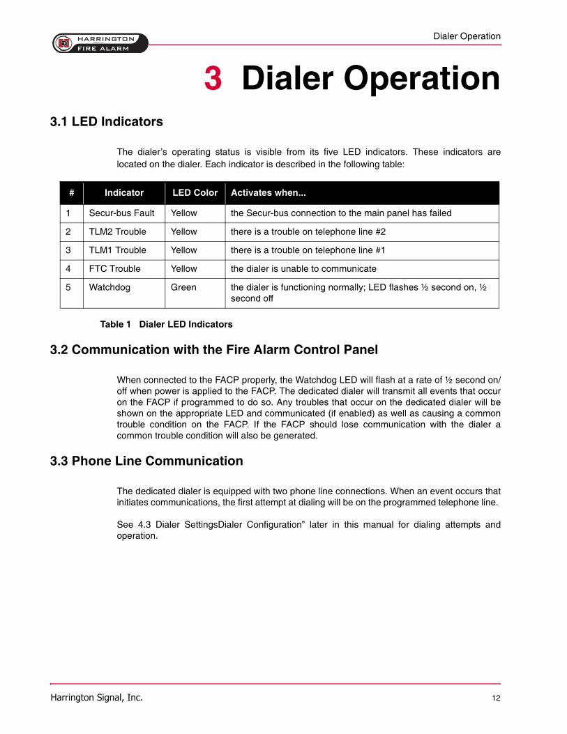
The dialer’s operating status is visible from its five LED indicators. These indicators arelocated on the dialer. Each indicator is described in the following table:
Table 1 Dialer LED Indicators
3.2 Communication with the Fire Alarm Control Panel
When connected to the FACP properly, the Watchdog LED will flash at a rate of ½ second on/off when power is applied to the FACP. The dedicated dialer will transmit all events that occuron the FACP if programmed to do so. Any troubles that occur on the dedicated dialer will beshown on the appropriate LED and communicated (if enabled) as well as causing a commontrouble condition on the FACP. If the FACP should lose communication with the dialer acommon trouble condition will also be generated.
3.3 Phone Line Communication
The dedicated dialer is equipped with two phone line connections. When an event occurs thatinitiates communications, the first attempt at dialing will be on the programmed telephone line.
See 4.3 Dialer SettingsDialer Configuration” later in this manual for dialing attempts andoperation.
# Indicator LED Color Activates when...
1 Secur-bus Fault Yellow the Secur-bus connection to the main panel has failed
2 TLM2 Trouble Yellow there is a trouble on telephone line #2
3 TLM1 Trouble Yellow there is a trouble on telephone line #1
4 FTC Trouble Yellow the dialer is unable to communicate
5 Watchdog Green the dialer is functioning normally; LED flashes ½ second on, ½ second off
Programming the Dialer
Harrington Signal, Inc. 13
4 Programming the Dialer4.1 Programming the HS3DL
4.1.1 Accessing the Dialer Settings
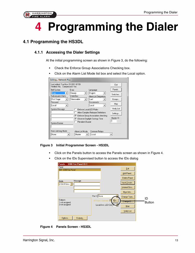
At the initial programming screen as shown in Figure 3, do the following:
• Check the Enforce Group Associations Checking box.
• Click on the Alarm List Mode list box and select the Local option.
Figure 3 Initial Programmer Screen - HS3DL
• Click on the Panels button to access the Panels screen as shown in Figure 4.
• Click on the IDs Supervised button to access the IDs dialog
Figure 4 Panels Screen - HS3DL
IDButton
Programming the Dialer
Harrington Signal, Inc. 14
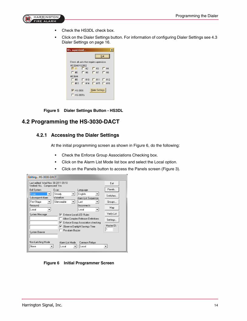
• Check the HS3DL check box.
• Click on the Dialer Settings button. For information of configuring Dialer Settings see 4.3 Dialer Settings on page 16.
Figure 5 Dialer Settings Button - HS3DL
4.2 Programming the HS-3030-DACT
4.2.1 Accessing the Dialer Settings
At the initial programming screen as shown in Figure 6, do the following:
• Check the Enforce Group Associations Checking box.
• Click on the Alarm List Mode list box and select the Local option.
• Click on the Panels button to access the Panels screen (Figure 3).
Figure 6 Initial Programmer Screen
Programming the Dialer
Harrington Signal, Inc. 15
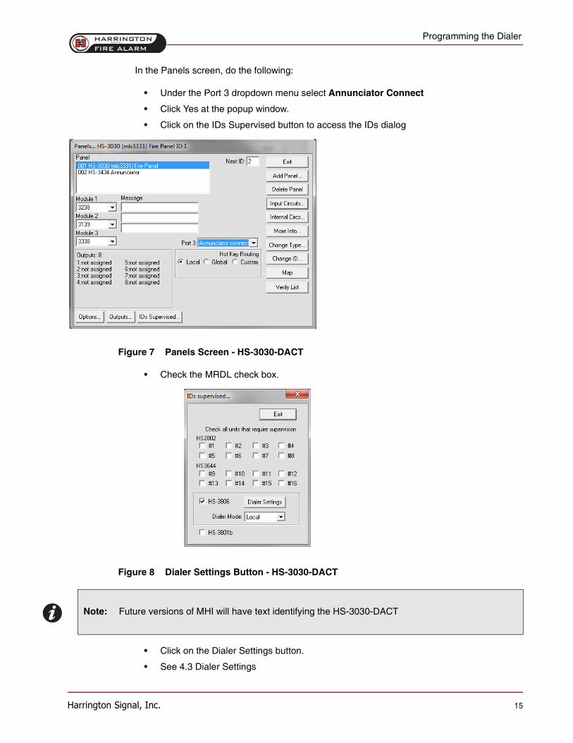
In the Panels screen, do the following:
• Under the Port 3 dropdown menu select Annunciator Connect
• Click Yes at the popup window.
• Click on the IDs Supervised button to access the IDs dialog
Figure 7 Panels Screen - HS-3030-DACT
• Check the MRDL check box.
Figure 8 Dialer Settings Button - HS-3030-DACT
• Click on the Dialer Settings button.
• See 4.3 Dialer Settings
Note: Future versions of MHI will have text identifying the HS-3030-DACT
Programming the Dialer
Harrington Signal, Inc. 16
4.3 Dialer Settings
The Dialer Settings dialog allows for the programming of various communications options.
The 1st, 2nd and 3rd Telephone Numbers can be up to 32 digits. Special digits may be used toperform the following functions:
• HEX (B)-simulates the [*] key
• HEX (C)-simulates the [#] key
• HEX (D)-forces the panel to search for dial tone
• HEX (E)-forces the panel to pause for 2 seconds
• HEX (F)-end of telephone number marker
1st and 2nd Account Codes
Identifies the system to the central station when a communication is sent. The code can beprogrammed for up to four digits. The first and third telephone number transmit the firstaccount code. The second telephone number transmits the second account code.
1st and 2nd Format setting
Sets the type of communication that the dialer sends to the central station. The formatsavailable include Contact ID, SIA and a pager format.
The Dialer Settings window has the following push buttons along the right side:
• Exit: Close the Dialer Settings window and return to the IDs window.
• Set Defaults: Sets all Dialer Settings to the Default Values.
• Configuration 1: Display the Dialer Configuration 1 screen.
• Configuration 2: Display the Dialer Configuration 2 screen.
• Zone Data: Display the Zone Data screen.
Note: A Hex D is required before the number, example: D9054704070
Programming the Dialer
Harrington Signal, Inc. 17
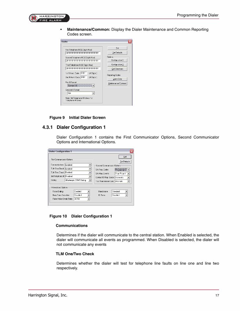
• Maintenance/Common: Display the Dialer Maintenance and Common Reporting Codes screen.
Figure 9 Initial Dialer Screen
4.3.1 Dialer Configuration 1
Dialer Configuration 1 contains the First Communicator Options, Second CommunicatorOptions and International Options.
Figure 10 Dialer Configuration 1
Communications
Determines if the dialer will communicate to the central station. When Enabled is selected, thedialer will communicate all events as programmed. When Disabled is selected, the dialer willnot communicate any events
TLM One/Two Check
Determines whether the dialer will test for telephone line faults on line one and line tworespectively.
Programming the Dialer
Harrington Signal, Inc. 18
Third Phone #
Can be programmed for two different modes of operation.
• Selecting Alternate Dialing Enabled switches the dialer between the first and third numbers after each dialing attempt, until the maximum number of dialing attempts have been made to each number.
• Enabling Third Number Backup enables the dialer to use the third number if all attempts to communicate to the first number fail. If all attempts to communicate to the third number also fail, a failure to communicate trouble will be generated.
Dialing
Has three different options for pulse or DTMF dialing. If All attempts Pulse is selected, thedialer will always use pulse (rotary) dialing. If All attempts DTMF Dialing is selected, the dialerwill always use DTMF dialing. If 4 attempts DTMF then Pulse is selected, the dialer will useDTMF dialing for the first four attempts. If unsuccessful, the dialer will switch to pulse dialingfor the remaining attempts.
SIA Rep. Codes
Determines whether the dialer will send automatic reporting codes, or use the reporting codesthat are programmed in the Zone Data and Maintenance/Common reporting codes sections.See Appendix A Reporting Codes Table on page 24 for a list of the automatic SIA ReportingCodes.
SIA Max Events
SETS the maximum number of events the dialer will send for one SIA transmission. When 20per Round is selected, SIA sends a maximum of 20 events per round. When 8 per Round isselected, SIA sends maximum of 8 events per round.
Contact ID Rep. Codes
Determines whether the dialer will send automatic reporting codes, or use the values that areprogrammed in the Zone Data and Maintenance/Common reporting codes sections. SeeAppendix A Reporting Codes Table on page 24 for a list of the automatic Contact ID ReportingCodes.
Pager Format
Events will be communicated to a pager when using this format. When programming a pagertelephone number, extra digits must be used in order for the feature to function properly.Program two hexadecimal digits 'E' at the end of the number (4 second pause). The panel willattempt to call the pager one time. After dialing the digits in the telephone number the panelwill send the account number and reporting code followed by the [#] key (Hex [C]). There is noringback when using Pager format. The panel has no way of confirming if the paging attemptwas successful. Do not use hexadecimal C in a reporting code when using pager format. Inmost cases the digit C will be interpreted as a [*], which will terminate the page before it hasfinished. Example: D19787319876EE
Programming the Dialer
Harrington Signal, Inc. 19
Test Transmission Line
Determines how the dialer chooses a telephone line to send the automatic test transmission. IfAlternate is selected, the dialer will alternate between using lines 1 and 2 for transmissions,regardless of telephone line troubles. If Available is selected, the dialer will use Line 1 for testtransmissions. If a trouble exists on Line 1, the dialer will switch to Line 2.
Force Dialing
When set to Enabled, if the first attempt by the panel to call the monitoring station fails, onevery subsequent attempt the panel will dial regardless of the presence of dial tone. WhenDisabled is selected, the panel will not dial the programmed telephone number if dial tone isnot present.
Busy Tone Detection
When Enabled and a busy tone is detected, the dialer will disengage the phone line and try toplace the call again following the delay between dialing attempts. When Disabled is selected,the dialer will use the standard dialing procedure for every attempt.
Pulse Make/Break Ratio
For panels used in international applications. When 40/60 is selected, the pulse dialing make/break ratio is the 40/60, and when 33/67 is selected it is 33/67.
ID Tone
Can be set to 1300Hz or 2100 Hz. The panel will emit a tone at the selected frequency for 500ms every 2 seconds when it places a call to indicate that it is a digital equipment call, not voice.When Disabled is selected, this feature will not be used.
Programming the Dialer
Harrington Signal, Inc. 20
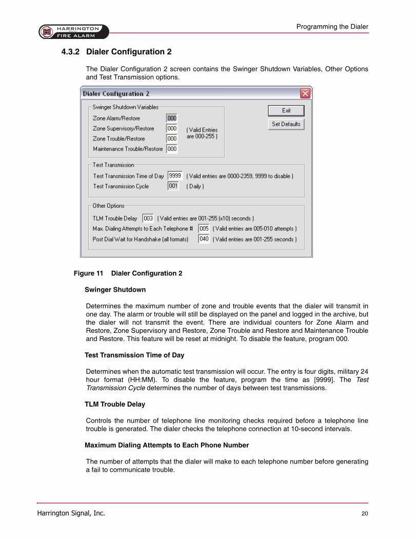
4.3.2 Dialer Configuration 2
The Dialer Configuration 2 screen contains the Swinger Shutdown Variables, Other Optionsand Test Transmission options.
Figure 11 Dialer Configuration 2
Swinger Shutdown
Determines the maximum number of zone and trouble events that the dialer will transmit inone day. The alarm or trouble will still be displayed on the panel and logged in the archive, butthe dialer will not transmit the event. There are individual counters for Zone Alarm andRestore, Zone Supervisory and Restore, Zone Trouble and Restore and Maintenance Troubleand Restore. This feature will be reset at midnight. To disable the feature, program 000.
Test Transmission Time of Day
Determines when the automatic test transmission will occur. The entry is four digits, military 24hour format (HH:MM). To disable the feature, program the time as [9999]. The TestTransmission Cycle determines the number of days between test transmissions.
TLM Trouble Delay
Controls the number of telephone line monitoring checks required before a telephone linetrouble is generated. The dialer checks the telephone connection at 10-second intervals.
Maximum Dialing Attempts to Each Phone Number
The number of attempts that the dialer will make to each telephone number before generatinga fail to communicate trouble.
Programming the Dialer
Harrington Signal, Inc. 21
Post Dial Wait for Handshake
The amount of time the dialer will wait for a valid initial handshake from the receiver afterdialing the programmed telephone number.
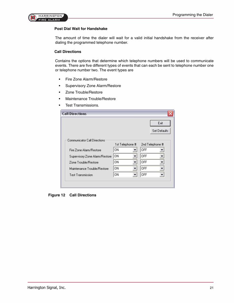
Call Directions
Contains the options that determine which telephone numbers will be used to communicateevents. There are five different types of events that can each be sent to telephone number oneor telephone number two. The event types are
• Fire Zone Alarm/Restore
• Supervisory Zone Alarm/Restore
• Zone Trouble/Restore
• Maintenance Trouble/Restore
• Test Transmissions.
Figure 12 Call Directions
Programming the Dialer
Harrington Signal, Inc. 22
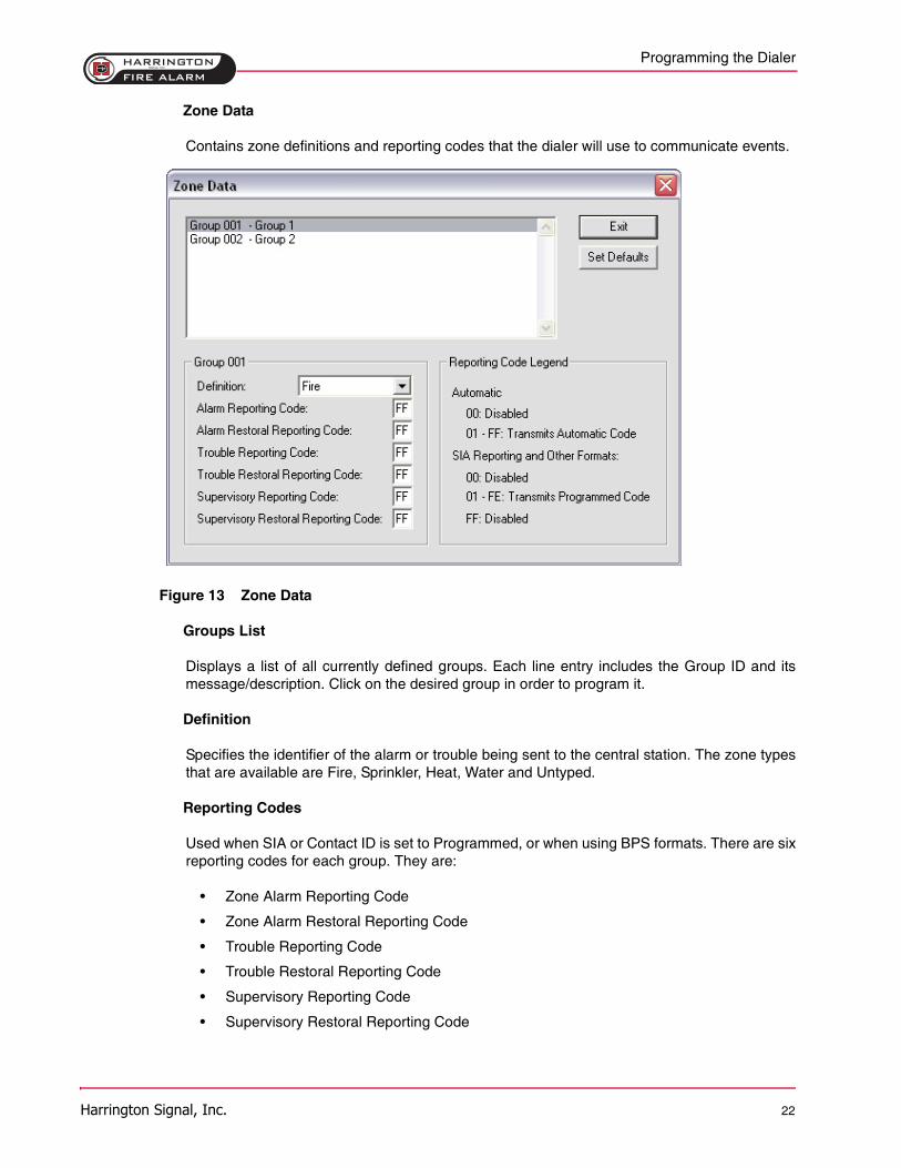
Zone Data
Contains zone definitions and reporting codes that the dialer will use to communicate events.
Figure 13 Zone Data
Groups List
Displays a list of all currently defined groups. Each line entry includes the Group ID and itsmessage/description. Click on the desired group in order to program it.
Definition
Specifies the identifier of the alarm or trouble being sent to the central station. The zone typesthat are available are Fire, Sprinkler, Heat, Water and Untyped.
Reporting Codes
Used when SIA or Contact ID is set to Programmed, or when using BPS formats. There are sixreporting codes for each group. They are:
• Zone Alarm Reporting Code
• Zone Alarm Restoral Reporting Code
• Trouble Reporting Code
• Trouble Restoral Reporting Code
• Supervisory Reporting Code
• Supervisory Restoral Reporting Code
Programming the Dialer
Harrington Signal, Inc. 23
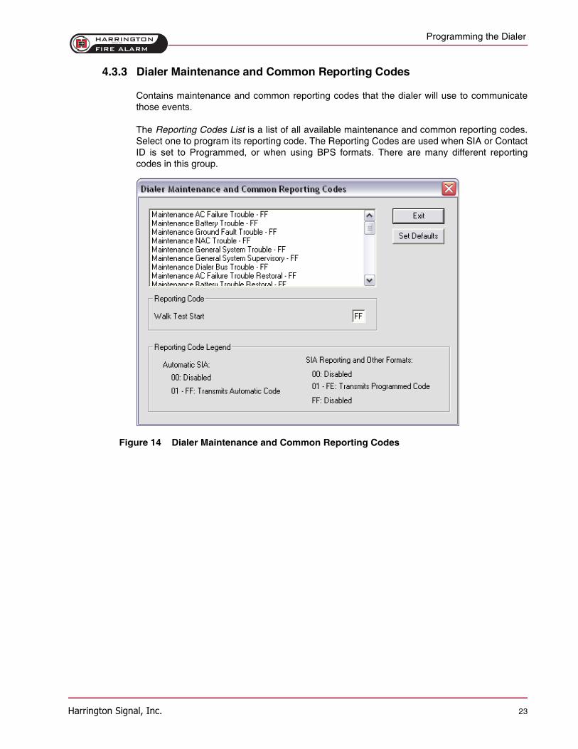
4.3.3 Dialer Maintenance and Common Reporting Codes
Contains maintenance and common reporting codes that the dialer will use to communicatethose events.
The Reporting Codes List is a list of all available maintenance and common reporting codes.Select one to program its reporting code. The Reporting Codes are used when SIA or ContactID is set to Programmed, or when using BPS formats. There are many different reportingcodes in this group.
Figure 14 Dialer Maintenance and Common Reporting Codes
Appendices
Harrington Signal, Inc. 24
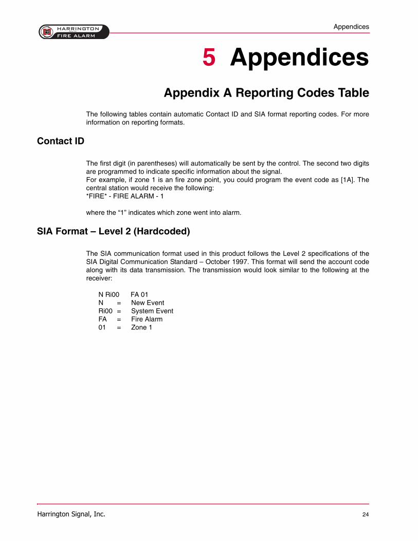
5 AppendicesAppendix A Reporting Codes Table
The following tables contain automatic Contact ID and SIA format reporting codes. For moreinformation on reporting formats.
Contact ID
The first digit (in parentheses) will automatically be sent by the control. The second two digitsare programmed to indicate specific information about the signal.For example, if zone 1 is an fire zone point, you could program the event code as [1A]. Thecentral station would receive the following:*FIRE* - FIRE ALARM - 1
where the “1” indicates which zone went into alarm.
SIA Format – Level 2 (Hardcoded)
The SIA communication format used in this product follows the Level 2 specifications of theSIA Digital Communication Standard – October 1997. This format will send the account codealong with its data transmission. The transmission would look similar to the following at thereceiver:
N Ri00 FA 01N = New EventRi00 = System EventFA = Fire Alarm01 = Zone 1
Appendices
Harrington Signal, Inc. 25
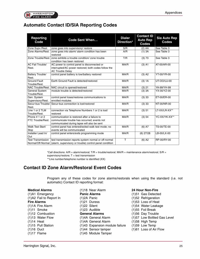
Automatic Contact ID/SIA Reporting Codes
*Call directions: A/R = alarm/restoral; T/R = trouble/restoral; MA/R = maintenance alarm/restoral; S/R = supervisory/restore; T = test transmission**Line number/telephone number is identified (XX)
Contact ID Zone Alarm/Restoral Event Codes
Program any of these codes for zone alarms/restorals when using the standard (i.e. notautomatic) Contact ID reporting format:
Reporting Code
Code Sent When…Dialer
Direction*
Contact ID Auto Rep
Codes
Sia Auto Rep Codes
Zone Supv./Rest. zone goes into supervisory/ restore S/R (2) AA See Table 3Zone Alarms/Rest. zone goes into alarm/ alarm condition has been
restoredA/R (1) 3A See Table 3
Zone Trouble/Rest. zone exhibits a trouble condition/ zone trouble condition has been restored
T/R (3) 73 See Table 3
AC Fail Trouble/Rest.
AC power to control panel is disconnected or interrupted/AC power restored; both codes follow the AC Trouble Delay
MA/R (3) A1 AT-00/AR-00
Battery Trouble/Rest.
control panel battery is low/battery restored MA/R (3) A2 YT-00/YR-00
Ground Fault Trouble/Rest.
Earth Ground Fault is detected/restored MA/R (3) 1A UT-OO/UJ-00
NAC Trouble/Rest. NAC circuit is opened/restored MA/R (3) 21 YA-99/YH-99General System Trouble/Rest.
module trouble is detected/restored MA/R (3) 3A YX-00/YZ-00
Gen. System Supervisory/Rest.
control panel loses/restores communications to enrolled modules
MA/R (3) 33 ET-00/ER-00
Secur-bus Trouble/Rest.
Secur-bus connection is lost/restored MA/R (3) 33 NT-00/NR-00
Line 1 or 2 TLM Trouble/Rest.
connection via Telephone Numbers 1 or 2 is lost/restored
MA/R (3) 51 LT-XX/LR-XX**
Phone # 1 or 2 FTC Trouble/Rest.
communication is restored after a failure to communicate trouble has occurred; events not communicated during lapse will also be sent
MA/R (3) 54 YC-XX/YK-XX**
Walk Test Start/Stop
control panel has entered/exited walk test mode; no events will be communicated
MA/R (6) A7 TS-00/TE-00
Installer Lead In/Out
control panel enters/exits programming mode MA/R (6) 27/28 LB-00/LX-00
Test Transmission Normal/Off-Normal
test transmission reports system normal or off-normal (alarm, supervisory or trouble) control panel condition
T (6) A2 RP-00/RY-00
Medical Alarms (1)18 Near Alarm 24 Hour Non-Fire(1)A1 Emergency Panic Alarms (1)51 Gas Detected(1)A2 Fail to Report In (1)2A Panic (1)52 RefrigerationFire Alarms (1)21 Duress (1)53 Loss of Heat(1)1A Fire Alarm (1)22 Silent (1)54 Water Leakage(1)11 Smoke (1)23 Audible (1)55 Foil Break(1)12 Combustion General Alarms (1)56 Day Trouble(1)13 Water Flow (1)4A General Alarm (1)57 Low Bottled Gas Level(1)14 Heat (1)4A General Alarm (1)58 High Temp(1)15 Pull Station (1)43 Expansion module failure (1)59 Low Temp(1)16 Duct (1)44 Sensor tamper (1)61 Loss of Air Flow(1)17 Flame (1)45 Module Tamper
Appendices
Harrington Signal, Inc. 26
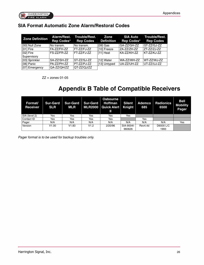
SIA Format Automatic Zone Alarm/Restoral Codes
ZZ = zones 01-05
Appendix B Table of Compatible Receivers
Pager format is to be used for backup troubles only.
Zone DefinitionAlarm/Rest. Rep Codes*
Trouble/Rest.Rep Codes
Zone Definition
SIA Auto Rep Codes*
Trouble/Rest. Rep Codes
[00] Null Zone No transm. No transm. [09] Gas GA-ZZ/GH-ZZ GT-ZZ/GJ-ZZ[01] Fire FA-ZZ/FH-ZZ FT-ZZ/FJ-ZZ [10] Freeze ZA-ZZ/ZH-ZZ ZT-ZZ/ZJ-ZZ[02] Fire Supervisory
FS-ZZ/FR-ZZ FT-ZZ/FJ-ZZ [11] Heat KA-ZZ/KH-ZZ KT-ZZ/KJ-ZZ
[03] Sprinkler SA-ZZ/SH-ZZ ST-ZZ/SJ-ZZ [12] Water WA-ZZ/WH-ZZ WT-ZZ/WJ-ZZ[06] Panic PA-ZZ/PH-ZZ PT-ZZ/PJ-ZZ [13] Untyped UA-ZZ/UH-ZZ UT-ZZ/UJ-ZZ[07] Emergency QA-ZZ/QH/ZZ QT-ZZ/QJ/ZZ
Format/Receiver
Sur-GardSLR
Sur-GardMLR
Sur-GardMLR2000
Osbourne Hoffman
Quick Alert II
Silent Knight
Ademco 685
Radionics 6500
Bell Mobility Pager
SIA (level 2) Yes Yes Yes Yes YesContact ID Yes Yes Yes Yes YesPager N/A N/A N/A N/A N/A N/A N/A YesVersion V1.00 V1.83 V1.2 2/20/96 SIA-9004I-
960626Rev4.4d D6500 L/C
1993
Warranty Procedure
Harrington Signal, Inc. 27
6 Warranty ProcedureTo obtain service under this warranty, please return the item(s) in question to the point ofpurchase. All authorized distributors and dealers have a warranty program. Anyone returninggoods to Harrington Signal must first obtain an authorization number. Harrington Signal will notaccept any shipment whatsoever for which prior authorization has not been obtained.
6.1 Conditions to Void Warranty
This warranty applies only to defects in parts and workmanship relating to normal use. It doesnot cover:
• Damage incurred in shipping or handling;
• Damage caused by disaster such as fire, flood, wind, earthquake or lightning;
• Damage due to causes beyond the control of Harrington Signal such as excessive voltage,mechanical shock or water damage;
• Damage caused by unauthorized attachment, alterations, modifications, repair or foreignobjects;
• Damage caused by peripherals (unless such peripherals were supplied by HarringtonSignal);
• Defects caused by failure to provide a suitable installation environment for the products;
• Damage caused by use of the products for purposes other than those for which it wasdesigned;
• Damage from improper maintenance;
• Damage arising out of any other abuse, mishandling or improper application of the products.
Harrington Signals’ liability for failure to repair the product under this warranty after a reasonable numberof attempts will be limited to a replacement of the product, as the exclusive remedy for breach ofwarranty.
6.2 Limitation of Liability
Under no circumstances shall Harrington Signal be liable for any special, incidental, orconsequential damages based upon breach of warranty, breach of contract, negligence, strictliability, or any other legal theory. Such damages include, but are not limited to, loss of profits,loss of the product or any associated equipment, cost of capital, cost of substitute orreplacement equipment, facilities or services, down time, purchaser's time, the claims of thirdparties, including customers, and injury to property.
Warranty Procedure
Harrington Signal, Inc. 28
6.3 Disclaimer of Warranties
All other obligations or liabilities on the part of Harrington Signal neither assumes norauthorizes any other person purporting to act on its behalf to modify or to change thiswarranty, nor to assume for it any other warranty or liability concerning this product.
WARNING: Harrington Signal recommends that the entire system be completely tested on aregular basis. However, despite frequent testing, and due to, but not limited to, criminaltampering or electrical disruption, it is possible for this product to fail to perform as expected.
6.4 Out of Warranty Repairs
Harrington Signal will at its option repair or replace out-of-warranty products which arereturned to its factory according to the following conditions. Anyone returning goods toHarrington Signal must first obtain an authorization number. Harrington Signal will not acceptany shipment whatsoever for which prior authorization has not been obtained. Products whichHarrington Signal determines to be repairable will be repaired and returned. A set fee whichHarrington Signal has predetermined and which may be revised from time to time, will becharged for each unit repaired. Products which Harrington Signal determines not to berepairable will be replaced by the nearest equivalent product available
FCC Compliance Statement
Harrington Signal, Inc. 29
7 FCC ComplianceStatement
CAUTION: Changes or modifications not expressly approved by the manufacturer could voidyour authority to use this equipment.
This equipment has been tested and found to comply with the limits for a Class B digitaldevice, pursuant to Part 15 of the FCC Rules. These limits are designed to provide reasonableprotection against harmful interference in a residential installation. This equipment generates,uses and can radiate radio frequency energy and, if not installed and used in accordance withthe instructions, may cause harmful interference to radio communications. However, there isno guarantee that interference will not occur in a particular installation. If this equipment doescause harmful interference to radio or television reception, which can be determined byturning the equipment off and on, the user is encouraged to try to correct the interference byone or more of the following measures:
• Re-orient the receiving antenna.
• Increase the separation between the equipment and receiver.
• Connect the equipment into an outlet on a circuit different from that to which the receiver is connected.
• Consult the dealer or an experienced radio/television technician for help.
The user may find the following booklet prepared by the FCC useful: “How to Identify andResolve Radio/Television Interference Problems”. This booklet is available from the U.S.Government Printing Office, Washington D.C. 20402, Stock # 004-000-00345-4.
The user may find the following booklet prepared by the FCC useful: “How to Identify andResolve Radio/Television Interference Problems”. This booklet is available from the U.S.Government Printing Office, Washington D.C. 20402, Stock # 004-000-00345-4.
IMPORTANT INFORMATION
This equipment complies with Part 68 of the FCC Rules. On the side of this equipment is alabel that contains, among other information, the FCC registration number of this equipment.
NOTIFICATION TO TELEPHONE COMPANY The customer shall notify the telephonecompany of the particular line to which the connection will be made, and provide the FCCregistration number and the ringer equivalence of the protective circuit.
FCC Registration Number: F53CAN-XXXXX-AL-E Ringer Equivalence Number: 0.1BUSOCJack: RJ-31X
TELEPHONE CONNECTION REQUIREMENTS Except for the telephone company providedringers, all connections to the telephone network shall be made through standard plugs andtelephone company provided jacks, or equivalent, in such a manner as to allow for easy,immediate disconnection of the terminal equipment. Standard jacks shall be so arranged that,if the plug connected thereto is withdrawn, no interference to the operation of the equipment at
FCC Compliance Statement
Harrington Signal, Inc. 30
the customer’s premises which remains connected to the telephone network shall occur byreason of such withdrawal.
INCIDENCE OF HARM Should terminal equipment or protective circuitry cause harm to thetelephone network, the telephone company shall, where practicable, notify the customer thattemporary disconnection of service may be required; however, where prior notice is notpracticable, the telephone company may temporarily discontinue service if such action isdeemed reasonable in the circumstances. In the case of such temporary discontinuance, thetelephone company shall promptly notify the customer and will be given the opportunity tocorrect the situation.
ADDITIONAL TELEPHONE COMPANY INFORMATION The security control panel must beproperly connected to the telephone line with a USOC RJ-31X telephone jack.
The FCC prohibits customer-provided terminal equipment be connected to party lines or to beused in conjunction with coin telephone service. Interconnect rules may vary from state tostate.
CHANGES IN TELEPHONE COMPANY EQUIPMENT OR FACILITIES The telephonecompany may make changes in its communications facilities, equipment, operations orprocedures, where such actions are reasonably required and proper in its business. Shouldany such changes render the customer’s terminal equipment incompatible with the telephonecompany facilities the customer shall be given adequate notice to the effect modifications tomaintain uninterrupted service.
RINGER EQUIVALENCE NUMBER (REN) The REN is useful to determine the quantity ofdevices that you may connect to your telephone line and still have all of those devices ringwhen your telephone number is called. In most, but not all areas, the sum of the RENs of alldevices connected to one line should not exceed five (5.0). To be certain of the number ofdevices that you may connect to your line, you may want to contact your local telephonecompany.
EQUIPMENT MAINTENANCE FACILITY If you experience trouble with this telephoneequipment, please contact the facility indicated below for information on obtaining service orrepairs. The telephone company may ask that you disconnect this equipment from the networkuntil the problem has been corrected or until you are sure that the equipment is notmalfunctioning.


Harrington Signal Inc. 2519 4th AvenueMoline, IL 61265
HARRINGTON
FIRE ALARMSIGNAL INC.