gtx - kitformwork › formwork and scaffolding
TRANSCRIPT
The information contained within these data sheets remain the property of RMD Kwikform and is not to be altered or reproduced without permission. RMD Kwikform reserves the right to change any specification without giving prior notice. It is the customers responsibility to incorporate this generic information into a document specific to the site conditions.
GTX
MIDDLE EAST DATA ME-TD-GT-001 DATE OF ISSUE: 07.04.2013 ISSUE: B SHEET 2
CONTENTS
COMPONENTS REFERENCE GUIDE
GTX BEAM TECHNICAL DATA
INTRODUCTION
BEAM PROPERTIES
ACCESSORIES
ACCESSORIES
GTX TO SOLDIER CLAMP – EYE BOLT
GTX CLAMP SPANNER
GTX CLAMP HOLDER
GTX TO ALBEAM CONNECTION
GTX CLEAT
GTX RESTRAINT STRAP
GTX RESTRAINT UNIT
ALFORM CORNER STRAP
GTX CORNER SOLDIER CLAMP
GTX OUTSIDE CORNER 1200
GTX LIFTING UNIT
ALFORM BEAM HANDRAIL POST
GTX BEAM GUARDRAIL POST
FIXING DETAILS
1: STOP END DETAIL
2: METHOD OF HOLDING TWO SHUTTERS TOGETHER
3: LIGHT DUTY EXTERNAL CORNER
4: GTX OUTSIDE CORNER
5: INTERNAL STRIPPING CORNER
6: CORNER SOLDIERS
ALLOWABLE END REACTIONS
SHEET DESCRIPTION
3
4
4
4
4
4
4
4
5
5
5
6
6
6
7
7
7
7
8
9
10
11
12
13
14
The information contained within these data sheets remain the property of RMD Kwikform and is not to be altered or reproduced without permission. RMD Kwikform reserves the right to change any specification without giving prior notice. It is the customers responsibility to incorporate this generic information into a document specific to the site conditions.
GTX
MIDDLE EAST DATA ME-TD-GT-001 DATE OF ISSUE: 07.04.2013 ISSUE: B SHEET 3
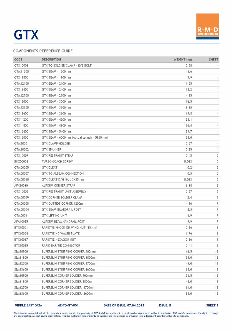
COMPONENTS REFERENCE GUIDE
CODE DESCRIPTION WEIGHT (kg) SHEET
GTX10001 GTX TO SOLDIER CLAMP – EYE BOLT 0.58 4
GTM11200 GTX BEAM – 1200mm 6.6 4
GTX11800 GTX BEAM – 1800mm 9.9 4
GTM12100 GTX BEAM – 2100mm 11.55 4
GTX12400 GTX BEAM – 2400mm 13.2 4
GTM12700 GTX BEAM – 2700mm 14.85 4
GTX13000 GTX BEAM – 3000mm 16.5 4
GTM13300 GTX BEAM – 3300mm 18.15 4
GTX13600 GTX BEAM – 3600mm 19.8 4
GTX14200 GTX BEAM – 4200mm 23.1 4
GTX14800 GTX BEAM – 4800mm 26.4 4
GTX15400 GTX BEAM – 5400mm 29.7 4
GTX16000 GTX BEAM – 6000mm (Actual length = 5950mm) 33.0 4
GTM20001 GTX CLAMP HOLDER 0.57 4
GTM20002 GTX SPANNER 0.35 4
GTX10007 GTX RESTRAINT STRAP 0.45 5
BNX00008 TURBO COACH SCREW 0.013 5
GTM00005 GTX CLEAT 0.2 5
GTM00007 GTX TO ALBEAM CONNECTION 0.5 5
GTM00010 GTX CLEAT D/H NAIL 3x35mm 0.013 5
AFX20010 ALFORM CORNER STRAP 6.18 6
GTX10006 GTX RESTRAINT UNIT ASSEMBLY 0.67 6
GTM00009 GTX CORNER SOLDIER CLAMP 2.4 6
GTM00008 GTX OUTSIDE CORNER 1200mm 14.26 7
GTM00004 GTX BEAM GUARDRAIL POST 8.5 7
GTM00011 GTX LIFTING UNIT 1.9 7
AFA10025 ALFORM BEAM HANDRAIL POST 9.9 7
BTX10001 RAPIDTIE KNOCK ON WING NUT (15mm) 0.36 8
BTX10004 RAPIDTIE HD WALER PLATE 1.76 8
BTX10017 RAPIDTIE HEXAGON NUT 0.16 9
BTX10015 RAPID BAR TIE CONNECTOR 0.41 9
SSM20900 SUPERSLIM STRIPPING CORNER 900mm 16.5 12
SSM21800 SUPERSLIM STRIPPING CORNER 1800mm 33.0 12
SSM22700 SUPERSLIM STRIPPING CORNER 2700mm 49.0 12
SSM23600 SUPERSLIM STRIPPING CORNER 3600mm 65.0 12
SSM10900 SUPERSLIM CORNER SOLDIER 900mm 21.5 13
SSM11800 SUPERSLIM CORNER SOLDIER 1800mm 43.0 13
SSM12700 SUPERSLIM CORNER SOLDIER 2700mm 64.0 13
SSM13600 SUPERSLIM CORNER SOLDIER 3600mm 85.0 13
The information contained within these data sheets remain the property of RMD Kwikform and is not to be altered or reproduced without permission. RMD Kwikform reserves the right to change any specification without giving prior notice. It is the customers responsibility to incorporate this generic information into a document specific to the site conditions.
GTX
MIDDLE EAST DATA ME-TD-GT-001 DATE OF ISSUE: 07.04.2013 ISSUE: B SHEET 4
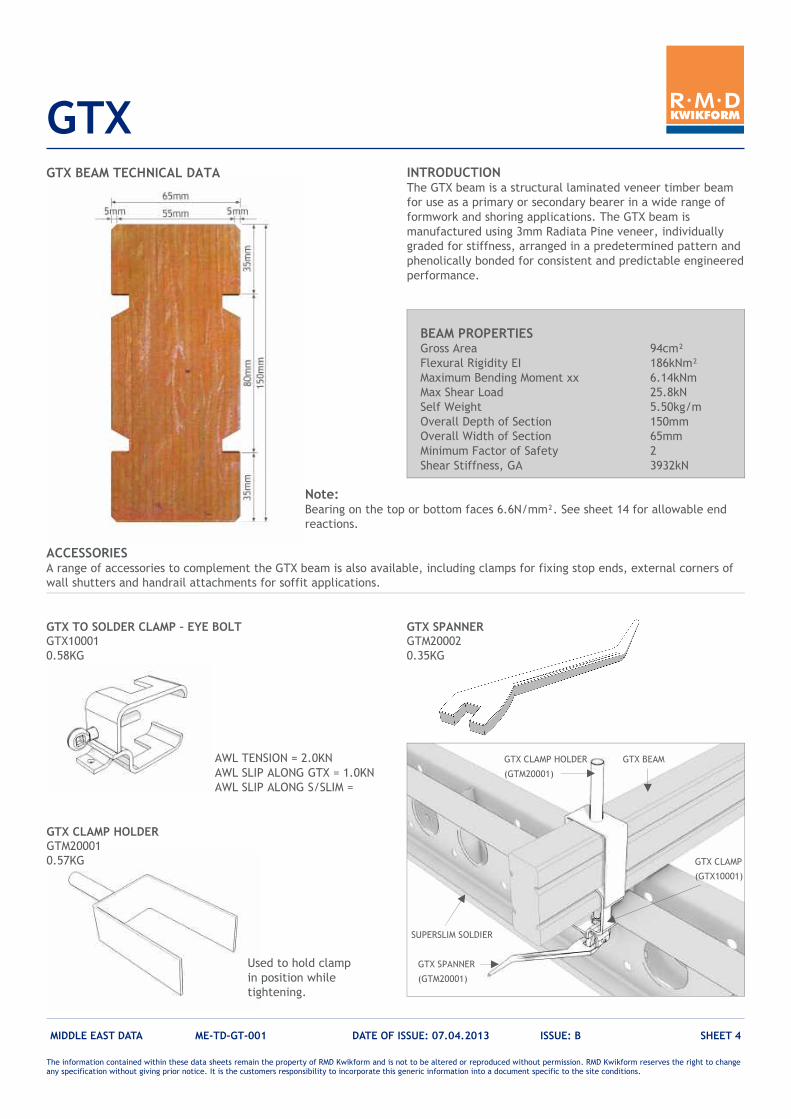
GTX BEAM TECHNICAL DATA
BEAM PROPERTIES Gross Area 94cm²
Flexural Rigidity EI 186kNm²
Maximum Bending Moment xx 6.14kNm
Max Shear Load 25.8kN
Self Weight 5.50kg/m
Overall Depth of Section 150mm
Overall Width of Section 65mm
Minimum Factor of Safety 2
Shear Stiffness, GA 3932kN
INTRODUCTION The GTX beam is a structural laminated veneer timber beam
for use as a primary or secondary bearer in a wide range of
formwork and shoring applications. The GTX beam is
manufactured using 3mm Radiata Pine veneer, individually
graded for stiffness, arranged in a predetermined pattern and
phenolically bonded for consistent and predictable engineered
performance.
ACCESSORIES A range of accessories to complement the GTX beam is also available, including clamps for fixing stop ends, external corners of
wall shutters and handrail attachments for soffit applications.
GTX TO SOLDER CLAMP – EYE BOLT GTX10001
0.58KG
GTX SPANNER GTM20002
0.35KG
AWL TENSION = 2.0KN
AWL SLIP ALONG GTX = 1.0KN
AWL SLIP ALONG S/SLIM =
GTX CLAMP HOLDER GTM20001
0.57KG
GTX CLAMP HOLDER
(GTM20001)
GTX CLAMP
(GTX10001)
GTX SPANNER
(GTM20001)
SUPERSLIM SOLDIER
GTX BEAM
Used to hold clamp
in position while
tightening.
Note: Bearing on the top or bottom faces 6.6N/mm². See sheet 14 for allowable end
reactions.
The information contained within these data sheets remain the property of RMD Kwikform and is not to be altered or reproduced without permission. RMD Kwikform reserves the right to change any specification without giving prior notice. It is the customers responsibility to incorporate this generic information into a document specific to the site conditions.
GTX
MIDDLE EAST DATA ME-TD-GT-001 DATE OF ISSUE: 07.04.2013 ISSUE: B SHEET 5
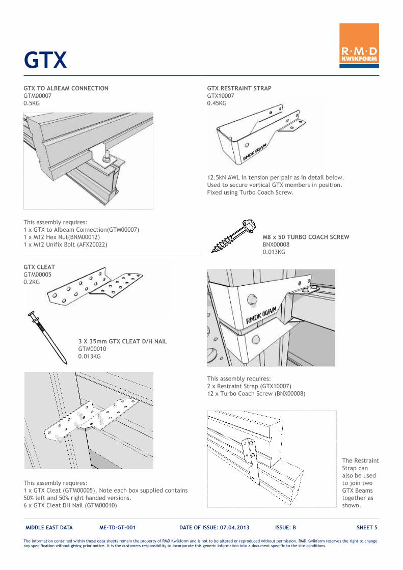
GTX RESTRAINT STRAP
GTX10007
0.45KG
This assembly requires:
1 x GTX Cleat (GTM00005), Note each box supplied contains
50% left and 50% right handed versions.
6 x GTX Cleat DH Nail (GTM00010)
This assembly requires:
2 x Restraint Strap (GTX10007)
12 x Turbo Coach Screw (BNX00008)
12.5kN AWL in tension per pair as in detail below.
Used to secure vertical GTX members in position.
Fixed using Turbo Coach Screw.
3 X 35mm GTX CLEAT D/H NAIL GTM00010
0.013KG
M8 x 50 TURBO COACH SCREW
BNX00008
0.013KG
GTX TO ALBEAM CONNECTION
GTM00007
0.5KG
The Restraint
Strap can
also be used
to join two
GTX Beams
together as
shown.
This assembly requires:
1 x GTX to Albeam Connection(GTM00007)
1 x M12 Hex Nut(BNM00012)
1 x M12 Unifix Bolt (AFX20022)
GTX CLEAT
GTM00005
0.2KG
The information contained within these data sheets remain the property of RMD Kwikform and is not to be altered or reproduced without permission. RMD Kwikform reserves the right to change any specification without giving prior notice. It is the customers responsibility to incorporate this generic information into a document specific to the site conditions.
GTX
MIDDLE EAST DATA ME-TD-GT-001 DATE OF ISSUE: 07.04.2013 ISSUE: B SHEET 6
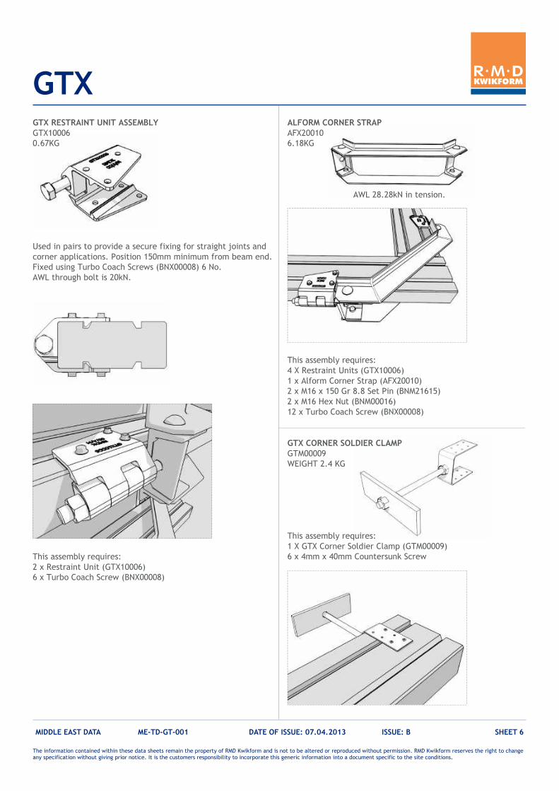
GTX RESTRAINT UNIT ASSEMBLY
GTX10006
0.67KG
ALFORM CORNER STRAP
AFX20010
6.18KG
Used in pairs to provide a secure fixing for straight joints and
corner applications. Position 150mm minimum from beam end.
Fixed using Turbo Coach Screws (BNX00008) 6 No.
AWL through bolt is 20kN.
AWL 28.28kN in tension.
This assembly requires:
2 x Restraint Unit (GTX10006)
6 x Turbo Coach Screw (BNX00008)
This assembly requires:
4 X Restraint Units (GTX10006)
1 x Alform Corner Strap (AFX20010)
2 x M16 x 150 Gr 8.8 Set Pin (BNM21615)
2 x M16 Hex Nut (BNM00016)
12 x Turbo Coach Screw (BNX00008)
GTX CORNER SOLDIER CLAMP
GTM00009
WEIGHT 2.4 KG
This assembly requires:
1 X GTX Corner Soldier Clamp (GTM00009)
6 x 4mm x 40mm Countersunk Screw
The information contained within these data sheets remain the property of RMD Kwikform and is not to be altered or reproduced without permission. RMD Kwikform reserves the right to change any specification without giving prior notice. It is the customers responsibility to incorporate this generic information into a document specific to the site conditions.
GTX
MIDDLE EAST DATA ME-TD-GT-001 DATE OF ISSUE: 07.04.2013 ISSUE: B SHEET 7
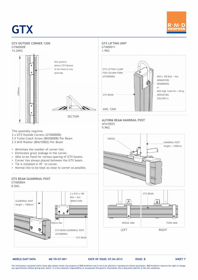
GTX OUTSIDE CORNER 1200
GTM00008
14.26KG
This assembly requires:
2 x GTX Outside Corners (GTM00008)
2 X Turbo Coach Screw (BNX00008) Per Beam
2 X M10 Washer (BNU10002) Per Beam
Slot pattern
allows GTX Beams
to be fixed at any
spacings
> Minimises the number of corner ties. > Eliminates grout leakage in the corner. > Able to be fixed for various spacing of GTX beams. > Corner ties always placed between the GTX beam. > Tie is installed @ 45° to corner. > Normal ties to be kept as close to corner as possible.
SECTION
50mm Min
GTX BEAM GUARDRAIL POST
(GTM00004)
GTX BEAM GUARDRAIL POST
GTM00004 8.5KG
GTX LIFTING UNIT
GTM00011
1.9KG
GTX LIFTING CLAMP
FOR COLUMN FORM
(GTM00006)
GTX BEAM
ALFORM BEAM HANDRAIL POST
AFA10025
9.9KG
WEDGE
FIXED ARM WEDGE ARM
GTX BEAM
HANDRAIL POST
Height = 1200mm
GTX BEAM
GUARDRAIL POST
Height = 1500mm
AWL 12kN
M20 x 100 Bolt + Nut
(BNM20100)
(BNM00020)
or
M20 High Yeild Pin + RClip
(BNX20100)
(SSU10011)
2 x M12 x 100
Bolt + Nut
(BNM12100)
1200mm
LEFT RIGHT
The information contained within these data sheets remain the property of RMD Kwikform and is not to be altered or reproduced without permission. RMD Kwikform reserves the right to change any specification without giving prior notice. It is the customers responsibility to incorporate this generic information into a document specific to the site conditions.
GTX
MIDDLE EAST DATA ME-TD-GT-001 DATE OF ISSUE: 07.04.2013 ISSUE: B SHEET 8
FIXING DETAILS 1: STOP END DETAILS
GTX TWIN
HORIZONTAL BEAM
SUPERSLIM
HORIZONTAL BEAM
AWL CLAMP = 20KN
RAPIDTIE KNOCK ON WING NUT
(BTX10001)
SUPERSLIM SOLDIER OR TWIN GTX/ALFORM
RAPIDTIE HEAVY DUTY
WALER PLATE
(BTX10004)
RAPIDTIE ROD
OR
ALL THREAD
ROD
RESTRAINT UNIT
(GTX10006)
GTX BEAM
WALER
GTX STOPEND
BEAM
The information contained within these data sheets remain the property of RMD Kwikform and is not to be altered or reproduced without permission. RMD Kwikform reserves the right to change any specification without giving prior notice. It is the customers responsibility to incorporate this generic information into a document specific to the site conditions.
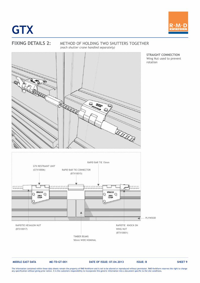
GTX
MIDDLE EAST DATA ME-TD-GT-001 DATE OF ISSUE: 07.04.2013 ISSUE: B SHEET 9
FIXING DETAILS 2: METHOD OF HOLDING TWO SHUTTERS TOGETHER (each shutter crane handled separately)
GTX RESTRAINT UNIT
(GTX10006)
RAPID BAR TIE 15mm
RAPIDTIE KNOCK ON
WING NUT
(BTX10001)
RAPIDTIE HEXAGON NUT
(BTX10017)
TIMBER BEAMS
50mm WIDE NOMINAL
STRAIGHT CONNECTION
Wing Nut used to prevent
rotation
PLYWOOD
RAPID BAR TIE CONNECTOR
(BTX10015)
The information contained within these data sheets remain the property of RMD Kwikform and is not to be altered or reproduced without permission. RMD Kwikform reserves the right to change any specification without giving prior notice. It is the customers responsibility to incorporate this generic information into a document specific to the site conditions.
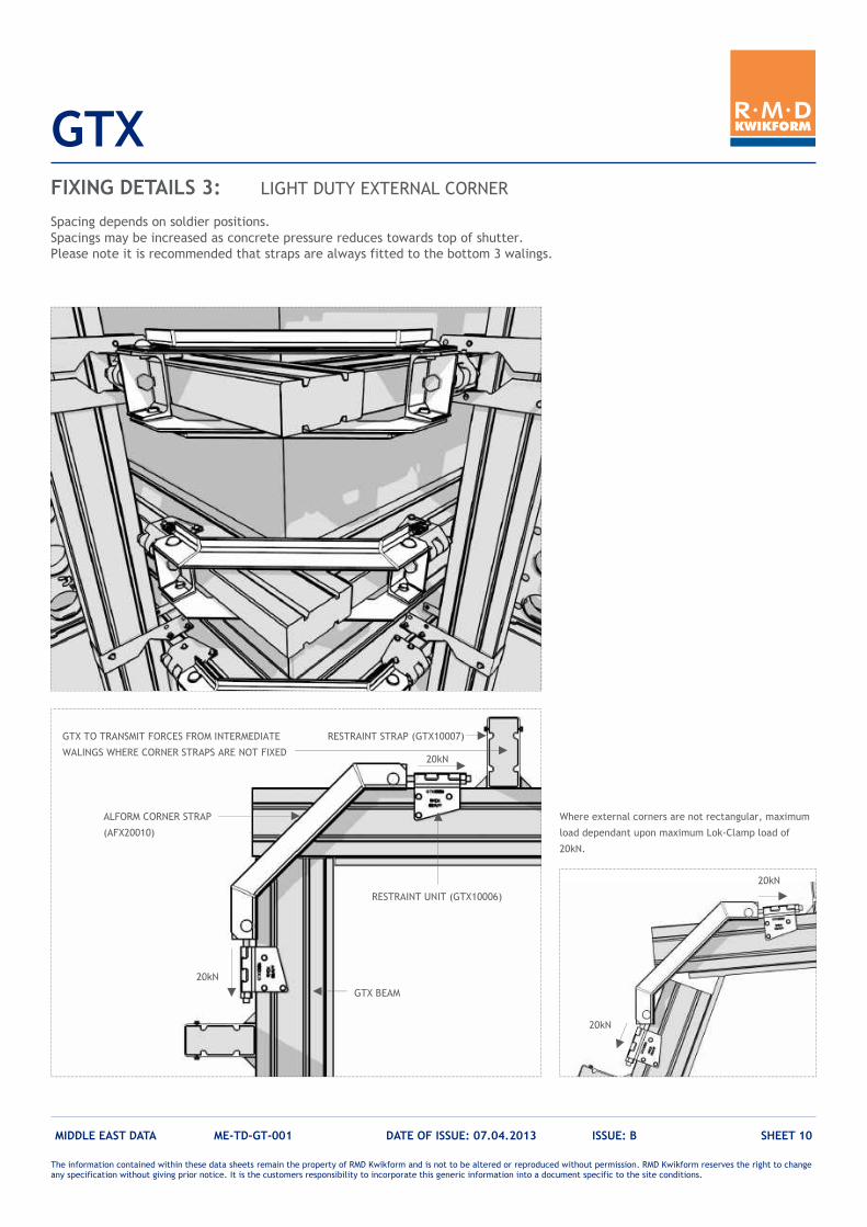
GTX
MIDDLE EAST DATA ME-TD-GT-001 DATE OF ISSUE: 07.04.2013 ISSUE: B SHEET 10
FIXING DETAILS 3: LIGHT DUTY EXTERNAL CORNER
Spacing depends on soldier positions.
Spacings may be increased as concrete pressure reduces towards top of shutter.
Please note it is recommended that straps are always fitted to the bottom 3 walings.
ALFORM CORNER STRAP
(AFX20010)
GTX BEAM
RESTRAINT UNIT (GTX10006)
RESTRAINT STRAP (GTX10007) GTX TO TRANSMIT FORCES FROM INTERMEDIATE
WALINGS WHERE CORNER STRAPS ARE NOT FIXED
Where external corners are not rectangular, maximum
load dependant upon maximum Lok-Clamp load of
20kN.
20kN
20kN
20kN
20kN
The information contained within these data sheets remain the property of RMD Kwikform and is not to be altered or reproduced without permission. RMD Kwikform reserves the right to change any specification without giving prior notice. It is the customers responsibility to incorporate this generic information into a document specific to the site conditions.
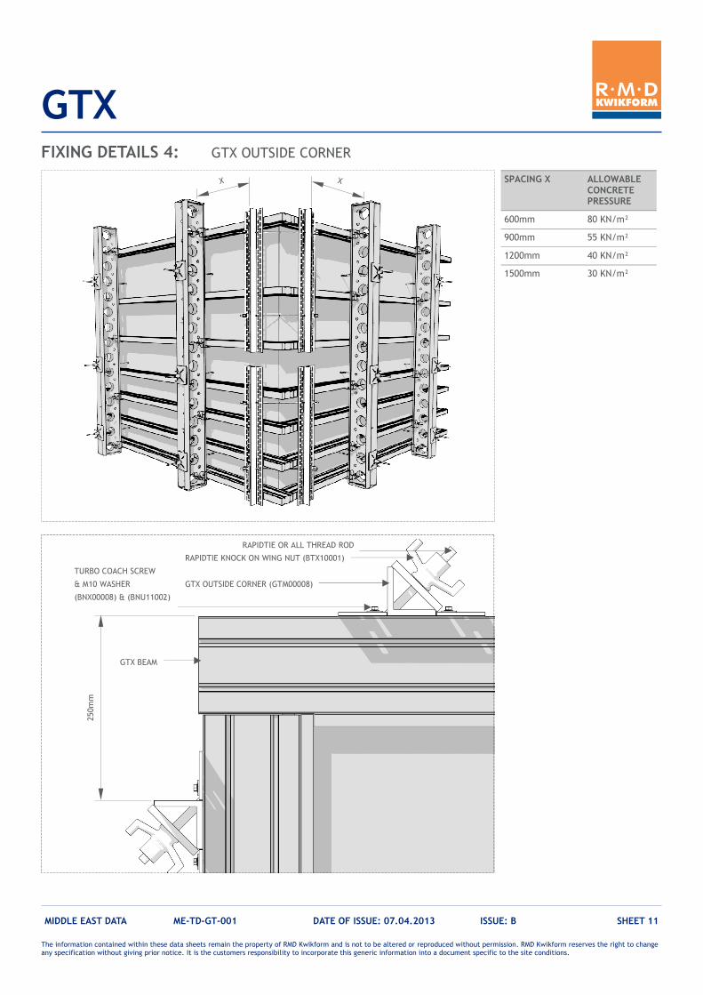
GTX
MIDDLE EAST DATA ME-TD-GT-001 DATE OF ISSUE: 07.04.2013 ISSUE: B SHEET 11
FIXING DETAILS 4: GTX OUTSIDE CORNER
GTX OUTSIDE CORNER (GTM00008)
GTX BEAM
RAPIDTIE OR ALL THREAD ROD
RAPIDTIE KNOCK ON WING NUT (BTX10001)
TURBO COACH SCREW
& M10 WASHER
(BNX00008) & (BNU11002)
250mm
SPACING X ALLOWABLE CONCRETE PRESSURE
600mm 80 KN/m²
900mm 55 KN/m²
1200mm 40 KN/m²
1500mm 30 KN/m²
X X
The information contained within these data sheets remain the property of RMD Kwikform and is not to be altered or reproduced without permission. RMD Kwikform reserves the right to change any specification without giving prior notice. It is the customers responsibility to incorporate this generic information into a document specific to the site conditions.
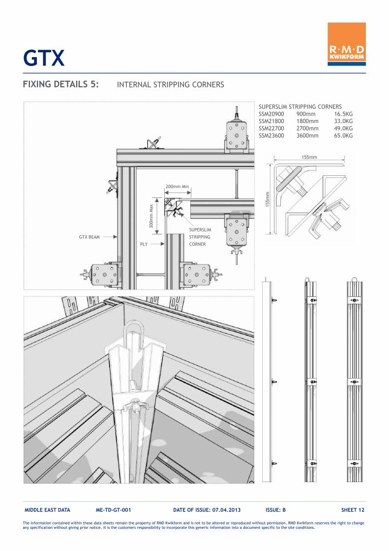
GTX
MIDDLE EAST DATA ME-TD-GT-001 DATE OF ISSUE: 07.04.2013 ISSUE: B SHEET 12
FIXING DETAILS 5: INTERNAL STRIPPING CORNERS
SUPERSLIM
STRIPPING
CORNER
GTX BEAM
PLY
200mm Min
300mm Max
SUPERSLIM STRIPPING CORNERS
SSM20900 900mm 16.5KG
SSM21800 1800mm 33.0KG
SSM22700 2700mm 49.0KG
SSM23600 3600mm 65.0KG
The information contained within these data sheets remain the property of RMD Kwikform and is not to be altered or reproduced without permission. RMD Kwikform reserves the right to change any specification without giving prior notice. It is the customers responsibility to incorporate this generic information into a document specific to the site conditions.
GTX
MIDDLE EAST DATA ME-TD-GT-001 DATE OF ISSUE: 07.04.2013 ISSUE: B SHEET 13
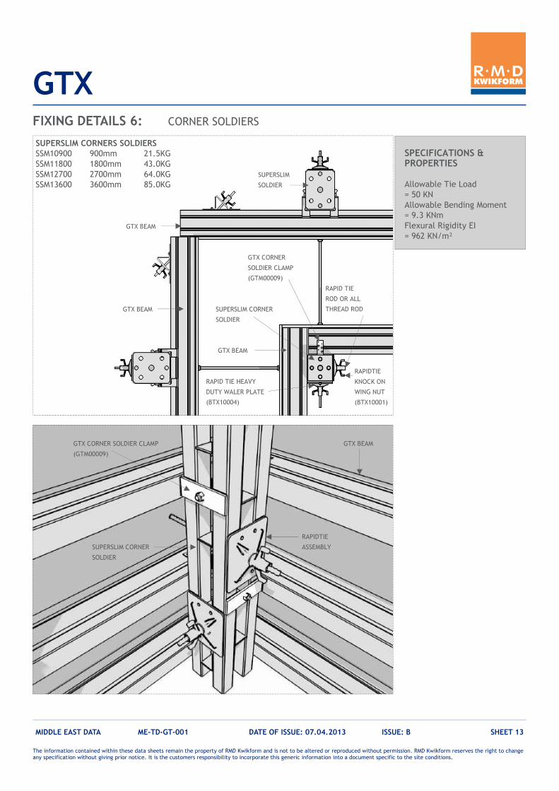
FIXING DETAILS 6: CORNER SOLDIERS
GTX BEAM
RAPIDTIE
ASSEMBLY
GTX CORNER SOLDIER CLAMP
(GTM00009)
SUPERSLIM CORNER
SOLDIER
GTX BEAM
RAPID TIE
ROD OR ALL
THREAD ROD
SUPERSLIM
SOLDIER
GTX BEAM
GTX CORNER
SOLDIER CLAMP
(GTM00009)
RAPIDTIE
KNOCK ON
WING NUT
(BTX10001)
SUPERSLIM CORNER
SOLDIER
RAPID TIE HEAVY
DUTY WALER PLATE
(BTX10004)
GTX BEAM
SUPERSLIM CORNERS SOLDIERS
SSM10900 900mm 21.5KG
SSM11800 1800mm 43.0KG
SSM12700 2700mm 64.0KG
SSM13600 3600mm 85.0KG
SPECIFICATIONS & PROPERTIES Allowable Tie Load
= 50 KN
Allowable Bending Moment
= 9.3 KNm
Flexural Rigidity EI
= 962 KN/m²
The information contained within these data sheets remain the property of RMD Kwikform and is not to be altered or reproduced without permission. RMD Kwikform reserves the right to change any specification without giving prior notice. It is the customers responsibility to incorporate this generic information into a document specific to the site conditions.
GTX
MIDDLE EAST DATA ME-TD-GT-001 DATE OF ISSUE: 07.04.2013 ISSUE: B SHEET 14
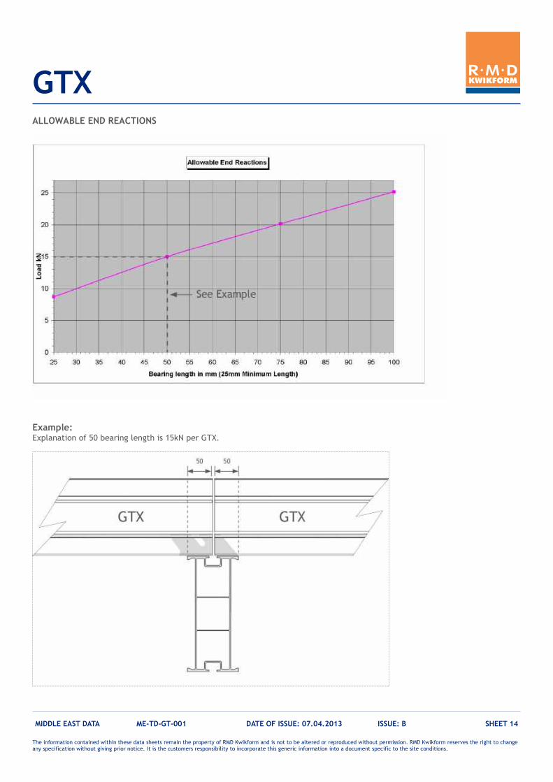
ALLOWABLE END REACTIONS
Example: Explanation of 50 bearing length is 15kN per GTX.