giant stroke 2009 som
TRANSCRIPT

www.sciencemag.org/cgi/content/full/323/5921/1575/DC1
Supporting Online Material for
Giant-Stroke, Superelastic Carbon Nanotube Aerogel Muscles
Ali E. Aliev, Jiyoung Oh, Mikhail E. Kozlov, Alexander A. Kuznetsov, Shaoli Fang,
Alexandre F. Fonseca, Raquel Ovalle, Márcio D. Lima, Mohammad H. Haque, Yuri N. Gartstein, Mei Zhang, Anvar A. Zakhidov, Ray H. Baughman*
*To whom correspondence should be addressed: E-mail: [email protected]
Published 20 March 2009, Science 323, 1575 (2009)
This PDF file includes:
Materials and Methods SOM Text Figs. S1 to S11 References
Other Supporting Online Material for this manuscript includes the following: (available at www.sciencemag.org/cgi/content/full/323/5921/1575/DC1)
Movie S1

Supporting Online Material for
Giant Stroke, Superelastic Carbon Nanotube Aerogel Muscles
Ali E. Aliev, Jiyoung Oh, Mikhail E. Kozlov, Alexander A. Kuznetsov, Shaoli Fang, Alexandre F. Fonseca, Raquel Ovalle, Márcio D. Lima, Mohammad H. Haque, Yuri N. Gartstein, Mei Zhang,* Anvar A. Zakhidov, Ray H. Baughman†
The Alan G. MacDiarmid NanoTech Institute, University of Texas at Dallas, Richardson, TX 75083, USA. *Present address: Department of Industrial Engineering, Florida State University, Tallahassee, FL 32306, USA. †To whom correspondence should be addressed: E-mail: [email protected]
This PDF file includes: Materials and Methods SOM Text Figures S1-S11 Movie S1 References

I. Material Preparation
Transparent carbon nanotube aerogel sheets were drawn from straight sidewalls of multiwalled nanotube (MWNT) forests that were synthesized by catalytic chemical vapor deposition, using acetylene gas as the carbon source (S1). Deployed nanotube forests had heights between 180 and 400 µm and the drawn sheets contained less than 1 wt % catalyst. From transmission electron microscopy and scanning electron microscopy, the nanotubes had an outer diameter of ~12 nm and contained ~9 walls. The nanotubes in the sheets were highly bundled, with an average of roughly 25 nanotubes in each bundle and wide dispersity in degree of bundling (from one to 60 nanotubes per bundle). The degree of alignment of the nanotubes in the sheets depends in a complicated way upon the structural nature of the precursor nanotube forest (S2). Despite areal densities typically ranging between ~1 and ~3 μg/cm2, aerogel sheets could be easily manipulated, such as by suspension between meter-distant end supports and stacking to produce sheet arrays.
Figure S1 shows this assembly by wrapping sheets on a rotating mandrel as they are fabricated by draw from a nanotube forest. Sheet stacks used in the present studies were hand fabricated using a U-shaped metal frame to lift a sheet segment that is supported by a nanotube forest on one end and a wire support on the other end, during a process that both captures this sheet segment and reconnects the sheet to the original wire support (for repeat of this process during following layer depositions). The nanotube sheets strongly adhere to contacting substrates and end supports, which facilitates transfer to end supports for actuation and mechanical properties measurements. Sheets were densified by imbibing and subsequent evaporation of ethanol while supported on a substrate, such a glass microscope slide.
To decrease the effects of length-direction end supports on giant actuation, which produces “ballooning” in sample width (W) and thickness (H), investigated samples generally had a length (L, corresponding to the sheet draw direction) that was much longer than the sample width. Initial sample length, width, and thickness are designated Lo, Wo, and Ho, respectively. Sample width and thickness during actuation and during Poisson’s ratio measurements were measured midway between length-direction end supports.
II. Mechanical Properties Characterization
There are large errors in measuring the thicknesses of the individual nanotube sheets, which are typically about 20 µm and 50 nm before and after densification, respectively. To avoid these errors, reported stresses (and related Young’s moduli and work capacities) are normalized with respect to volumetric densities. Since density-normalized stress (i.e., specific stress) equals applied force divided by sample weight-per-length in the stress direction, stress, volumetric density, or sheet thickness measurements are not needed for determination of specific stress, specific Young’s modulus, or specific work capacity. For example, the specific Young’s modulus in the length direction (YL) equals (ΔFL/ΔεL)/(ρAWo), where ΔFL is the change in applied force needed to elastically produce a strain change ΔεL, ρA is the areal density of the sheet, and ρAWo is the weight per sample length.

Reliable determination of density-normalized actuator performance from measured forces requires areal sheet density, ρA. Because of the extremely low areal densities, large sheet areas (~500 cm2) are needed for evaluation of ρA from direct measurement of sheet weight and area. Hence, optical transmission was used as a secondary method for determining sheet areal density. Using Beer-Lambert’s Law, ρA = - ln(I/Io)/αa, where Io and I are the initial and transmitted light intensity, respectively, and the sheet absorption coefficient αa at 550 nm (0.0887 cm2/µg) was determined from gravimetric measurement of ρA and optical measurement of I/Io. Using this coefficient, obtained for unpolarized light, ρA and changes in ρA for actuated sheets were determined from measurements of I/Io at 550 nm. This approach correctly predicts gravimetrically determined ρA for MWNT sheets and the absorption of know MWNT concentrations dispersed in transparent liquids. The reliability of these measurements of single sheet areal density was also confirmed by observation that optically determined areal density was the same for two identical sheets stacked with either parallel or orthogonal draw directions, and twice that determined optically for a single sheet.
Specific mechanical properties were determined from measurements of force versus strain at 1%/minute engineering strain rate for a three-layer sheet stack using a tensile test apparatus (Instron 5848 MicroTester, Instron Corp., Canton, MA). For a sheet stack in which the single sheet areal density from direct weight and area measurements is 2.23 ± 0.13 µg/cm2, the maximum specific stress before failure is 129.0 ± 1.6 MPa cm3/g, the specific modulus from the linear region of the force-strain curve is 7.4 ± 1.0 GPa cm3/g, and the strain to maximum stress is 6.3 ± 0.3 %. Densification of such three-sheet stacks using surface tension effects associated with imbibing and subsequent evaporation of ethanol increased maximum specific stress before failure to 564 ± 6 MPa cm3/g, increased the specific modulus to 21.0 ± 1.3 GPa cm3/g, and slightly decreased the strain to maximum specific stress to 5.44 ± 0.05 %. These gravimetric parameters use the initial sample weight per length, so they are the density-normalized equivalent of engineering modulus and engineering stress at failure. Including the change in sample weight per length with strain will increase these parameters by small factors, which is 1.063 for the above failure stress.
Poisson’s ratios were derived from width and thickness changes measured from digital pictures of a sheet or sheet stack (taken perpendicular to either the length-width plane or the length-thickness plane) as the length direction strain was increased from 0 to 2% in ~0.1% increments. The length-direction strain was applied by mounting the sheets or sheet stacks between 2 mm diameter wooden rods held in the above Instron 5848 MicroTester. This mounting was accomplished by essentially simultaneous contact of a nanotube sheet (supported by a U-shaped wire frame) to the two wooden rods, which resulted in strong adhesion at these end supports. The same measurement apparatus and method were used in some experiments for characterizing actuation, by coating the wooden rods with conducting silver paste to provide wire contact. In order to minimize the effects of length direction end supports, these Poisson’s ratio measurements (and later actuation measurements in width and length direction) were made midway between the supports.

III. Characterization of Actuation and Related Parameters
Actuation was characterized in width, length, and thickness directions, using the measurement jig described above for Poisson’s ratio and the jigs shown in Figs. S2 and S3. The sample jig in Fig. S2 was used for measurement of actuation in width and thickness directions (Figs. 2A, B, and D) at temperatures between 80 and 1900 K for nanotube sheets and sheet stacks having fixed length. In a typical experiment, a 1 mm wide, 25 mm long nanotube sheet was attached to the two rigid gold-coated copper electrodes of this sample jig. Using 3 cm insulating pillars to reduce electric field distortions, this jig was attached to a stage that enabled the translational and rotational positioning needed for width and thickness measurements. Sheet width and thickness were optically determined by using the response of a photodetector to indicate the start and end of sheet intersection with a laser beam. To increase measurement accuracy for these measurements (and related measurements of electrically driven sheet oscillation and actuation rate), the laser beam was focused (using a cylindrical lens) to a high-aspect-ratio ellipse (20 µm full width at half intensity) that was parallel to the sheet edge. These optical measurements used 633 nm light from a He-Ne laser, which was polarized parallel to the sheet length direction (the predominant nanotube alignment direction) in order to enhance sensitivity by maximizing sheet absorption. Fig. S4 shows the voltage dependence of width-direction actuation strain for sheet strips having different Lo/Wo ratios, which was obtained from electronic pictures taken of single nanotube sheets as a function of applied potential. Rigid length supports were used (parallel 1 mm diameter steel wires glued to the face of a glass slide, and projecting from a length direction edge of the slide to support the nanotube sheet strip about 25 mm from this edge).
While actuation resulting from charge injection in nanotube sheets would normally be expected to be independent of the sign of injected charge, we have used hole injection for all of the above investigations at high voltages, so the nanotube sheet is a positive electrodes. The reason is that carbon nanotube sheets are very effective electron emitters, and at high applied potentials this energy loss process decreases electrical to mechanical energy conversion efficiencies, creates instability in actuation, and reduces actuator stroke by depolarizing electrostatic fields.
Actuation in the sheet length direction (including load-dependent actuation strain, specific stress generation, and work capacity) was characterized using the jig in Fig. S3, providing the results in Fig. 2C. This jig supports a nanotube sheet strip between a rigid post and a cantilever that acts as a spring, whose effective force constant was independently measured. Using this cantilever force constant, specific stress versus length-direction strain at constant applied voltage and for increasing voltage for a given tensile stress applied before actuation were obtained, which provide the above mentioned actuation parameters for the sheet length direction.
Adding an ac voltage (16 volts peak-peak at the resonance frequency) on a static dc bias potential (both with respect to a distant ground electrode) generated oscillations of the sheet edge that increased the accuracy of optical measurement of width-direction actuation for low applied dc bias potentials (using a photodiode that detected laser beam radiation transmitted close to sheet edge). The results of these measurements (Fig. S5 for Lo/Wo = 14.1) indicate that width-direction actuation for a low applied dc voltage deviates noticeably from proportionality with V2 and that ΔW/Wo is about 14% at 260 V dc. This

deviation might be a result of increasing modulus for width-direction elongation with increasing width-direction strain.
Measurements of actuation at extreme temperatures (from 80 K to 1900 K) were made in vacuum (10-6 Torr) in a grounded 10 cm diameter cryostat in which the sample was centrally located using the jig shown in Fig. S2. High temperatures were achieved by passing current through the sample, and measured optically (Photo Research PR-650 Spectracolorimeter) using emitted radiation.
The average stroke rate for width-direction actuation was determined by measuring the time delay between an antennae-detected trigger pulse (generated by closing the switch that applies voltage to the nanotube sheet) and subsequent movement of the sheet edge to intersect a laser beam, using the apparatus illustrated in Fig. S6. Intersection of the laser beam and the sheet edge, as a result of completion of width-direction stroke, provided light scattering that was detected by a silicon photodiode. The laser beam, elliptically shaped and polarized along the sheet draw direction, is the same as described above for other experiments. The nanotube sheet length was kept constant during actuation by using rigid end supports and the sheet length and width were 71.4 mm and 2 mm, respectively. Complete width direction actuation (ΔW/Wo = 183%) occurred in 5 ms for actuation at ambient, providing an average width-direction action stroke rate of 3.66 x 10⁴ %/s for switching between 0 and 5 kV.
Resonant vibration in the sheet width direction was obtained by applying an ac voltage (1 VRMS, Root Mean Square voltage) to the sheet, with respect to either (a) symmetric counter-electrodes orthogonal to the width direction (Fig. S7) or (b) a distant ground (the walls of a 10 cm diameter cryostat in which the sheet was centrally located). Relative oscillation amplitude as a function of driving frequency was optically measured using a photodiode to detect oscillation in the intensity of light (633 nm wavelength, polarized parallel to the sheet length direction). Essentially identical resonant frequencies (fR) and quality factors (Q) for width-direction oscillation (fR = 1089 Hz and Q = 455 for a 25.0 mm by 1.8 mm single MWNT sheet) were obtained for ac voltages applied to the sheet with respect to symmetric counter electrodes (Fig. S7) or with respect to a distant ground. These measurements were made in vacuum. Fig. S8 shows that the introduction of air dramatically decreases resonant vibration amplitude.
The ac voltage needed for high stroke resonant actuation can be dramatically decreased by using a combination of electronic and mechanical resonances. Since the nanotube sheet is largely a capacitive load, resonant electronic actuation can be achieved by placing a small inductor in series between the ac power supply and the nanotube sheet. This inductance was chosen so that the resonant electronic frequency nearly equals the mechanical resonant frequency. For such double resonant actuation in vacuum at about 1100 Hz, shown in Fig. S9, an applied voltage of 10 VRMS from a power supply was increased to a measured 150 VRMS sheet voltage by introducing this small 2.4 H inductor. The actuation achieved using the 10 VRMS power source and this simple circuit was ±30% strain, where the sign ± indicates approximately symmetrical expansion and contraction of sheet in opposite extremes of the cycle.
The expected uniformity in width-direction strain for charge-injection-based actuation was determined (using the jig used for Poisson’s ratio measurements) by measuring actuation-produced displacement of TiO2 particles that had been dusted on the surface of a carbon nanotube aerogel sheet. Pictures of end-supported nanotube sheet

were taken before and after application of 3 kV, to obtain the change in width-direction particle position (Δy) as a function of particle position y in the width direction. The observed linear dependence of Δy on y, with the same slope on both sides of an arbitrarily chosen origin, indicates that there are no significant deviations from uniform strain across the length midpoint of the investigated 59.6 mm long, 3.94 mm wide sheet strip. However, width strain distribution becomes nonuniform because of end constraints (especially for large actuator strains), when aspect ratio is decreased or width-direction actuation is measured close to the length direction supports.
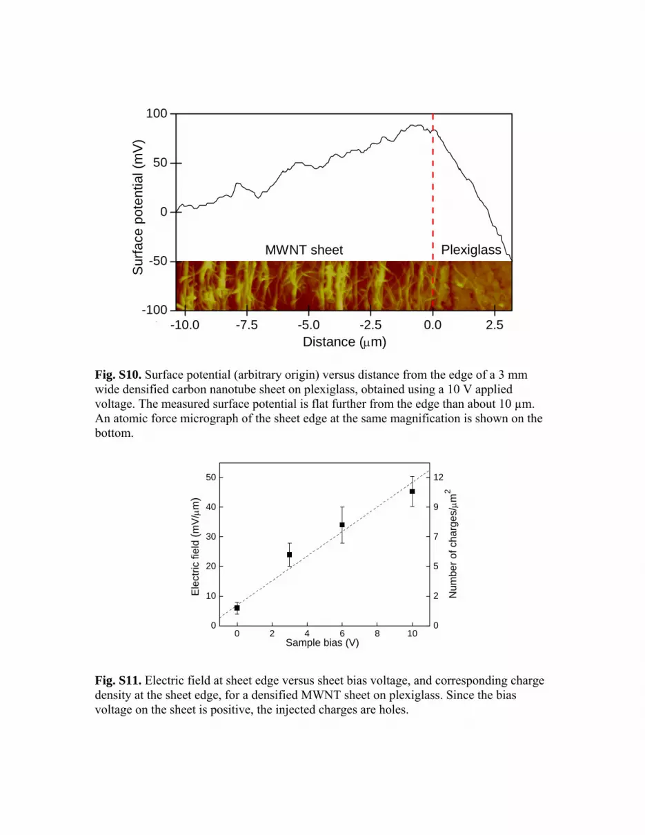
This uniformity in the electromechanically generated strain at length midpoint for samples having high Lo/Wo ratios results from distribution of charge so that electrostatically generated stresses are applied exclusively at sheet surfaces. This distribution produces enhancement of charge concentration near sheet surfaces, which is indicated by potential measurements using a Kelvin probe (Pt-coated tip) operating as an atomic force microscope tip (Veeco NanoScope IV). A carbon nanotube aerogel sheet was placed on a plexiglass substrate and densified using ethanol infiltration and evaporation. A positive constant voltage (10 V) was then applied to the sheet. Kelvin probe measurements across the sheet width (Fig. S10) show that there is increased potential and therefore increased charge concentration within about 10 µm of the nanotube sheet edge. Further distant from this edge, the Kelvin probe measurements indicate uniform charge distribution. Because these measurements determine the variation of surface potential rather than charge distribution itself, it was not possible to directly obtain charge density. As shown in Fig. S11, the electric field induced by the nanotube sheet charge is constant in the plexiglass. This enabled calculation of the surface charge density at the edge of nanotube sheet as a function of the voltage applied to the sheet (Fig. S11).
A carbon nanotube sheets acts as a disordered grating to diffract light. Changes in the resulting diffraction pattern with applied voltage were used in preliminary experiments as another method for observing actuation. Measurements were for 633 nm light from a He-Ne laser directed orthogonal to the sheet direction and polarized parallel to the nanotube orientation direction. This polarization provided the highest intensity for the observed irregular array of diffuse diffraction spots, which were recorded using a digital movie camera. This diffraction results from slit-shaped void spaces in single nanotube sheets. Movie S1 shows simultaneously recorded width-direction actuation and corresponding changes in the diffraction pattern. IV. Theoretical Analysis
Understanding the electrostatically generated stresses at the sheet surfaces is important for both interpreting experimental results and making predictions. While accurate calculation of these stresses requires calculation of actual surface charge densities as determined by the shape of the sheet (and the positions of other electrodes), qualitative estimate of the average stresses in simple geometries is possible by using the principle of virtual work. According to this principle, the electrostatic force in “direction x” is given by the corresponding derivative of the electrostatic potential energy at fixed charge Q:

where Q = CV and the capacitance C depends on the parameter x. When a voltage V is applied between the conductor and the ground, the counter-electrode of the capacitor is at effectively infinity. Representing the aerogel sheet by a highly anisotropic conducting plate, whose length L, width W, and thickness H, satisfy L >> W >> H, the corresponding inverse capacitance as a function of those dimensions is qualitatively evaluated as
1/C ≅ [α + β ln(L/W) - γ(H/W)]/[εoL],
where α, β, and γ are numerical factors. The average stress in direction W is then estimated in this anisotropic limit as
σW = FW/LH ≅ [(C2V2)/(2εoL2)][β/HW].
Likewise, stresses in L and H directions are estimated as
σL = FL/LW ≅ [(C2V2)/(2εoL2)][(α + β ln(L/eW))/(HW)]
and
σH = FH/LW ≅ [(C2V2)/(2εoL2)][γ/W2].
The magnitudes of these stresses in this case (of the counter-electrode at infinity) follow the shape anisotropy: σL > σW >> σH. Note, however, that by judiciously using counter-electrodes positioned in the vicinity of the aerogel sheet, electrostatic stresses and corresponding actuation strain can be substantially increased in a desired direction. For instance, symmetrically positioning two planar counter electrodes parallel to the sheet plane would result in electrostatic stresses only in the sheet thickness direction. Needless to say that much larger stresses and corresponding actuation strains can be achieved with counter electrodes for the same applied voltage V when the separation between these counter electrodes and the actuating electrode is small, as compared with the case of the counter electrode at infinity. The following calculation shows that the bending modulus of MWNT bundles is so large that entropic contributions to sheet elasticity will be negligible at all temperatures. Yakobson and Couchman (S3) found that the bending stiffness KB of a single wall nanotube of radius R is KB = 1.08 x 10⁻¹⁵ (R/nm)3 J nm. Assuming that inner and outer walls in a MWNT and the MWNTs in a bundle can slip with respect to each other during bending provides a lower limit estimate of bundle bending stiffness KB, and therefore a lower limit estimate for the persistence length. This bending stiffness is the sum of bending stiffnesses of the single walled nanotubes in a MWNT (with nine walls and an outer diameter of 12 nm) multiplied by the average number of MWNTs in a bundle (25). Since the persistence length at temperature T in Kelvin is KB/kBT, where kB is the Boltzmann constant, the persistence length at 1900 K is about one meter. Hence, entropic contributions to rubber elasticity are negligible. Making the usual approximation that the entropic contribution to elastic constant is proportional to temperature and realizing than the electrostatically generated stress should be independent of temperature, the data in Fig. 2D for the change in width-direction actuation strain between 300 and 1365 K shows that the entropic contribution to modulus at 300 K is less than 3.6 % of the enthalpic component. This evaluation is obtained most conservatively by using the upper error bar limit for the data at 300 K and the lower error bar limit for the data at 1365 K.

Supplemental Movie Movie S1. Real time movie showing width direction actuation of a single nanotube sheet (by 125%) on going from 0 to 5 kV and the reverse, and corresponding changes in diffraction pattern for 532 nm light polarized along the nanotube orientation direction. Over the pictured 9 cycles, the sheet was charged and later discharged to ground by manually turning a high voltage switch. References S1. M. Zhang et al., Science 309, 1215 (2005). S2. A. Kuznetsov, PhD Thesis, University of Texas at Dallas, August 22, 2008. S3. B. I. Yakobson, L. S. Couchman, Journal of Nanoparticle Research 8, 105 (2006).

Fig. S1. Fabrication of thick sheet stacks (100 layers in the above case) by winding a MWNT sheet on a 7.2 cm diameter mandrel (a plastic bottle) as it is drawn from a carbon nanotube forest.
Fig. S2. Photographs showing two views of a measurement jig used for characterization of actuation in width and thickness directions at temperatures between 80 and 1900 K. The pictured single MWNT sheet is supported by two rigid gold-coated copper electrode supports, which redundantly enable application of electrode voltage.
Nanotube forest
Motor

Fig. S3. Illustration of the measurement jig used to determine specific stress generation and work capacity of carbon nanotube sheets for length direction actuation at room temperature.
Fig. S4. Width direction actuation strain (ΔW/Wo) as a function of applied voltage for single MWNT sheets having different Lo/Wo ratios. The sheets were held by rigid length-direction supports, which maintain constant sheet length and constant sheet width and thickness at the supports. Actuation strain as a function of voltage increases with increasing Lo/Wo, as does the voltage range where transition occurs between ~V2
and ~V2/3 dependencies for ΔW/Wo.
Stationary Moveable
Cantilever
MWNT sheet
0 1 2 3 4 50.0
0.5
1.0
1.5
2.0
2.5Lo / Wo
ΔW/W
o
~V 2
regi
on
17
41
46
Voltage (kV)
~V 2/3 region

Fig. S5. Width direction actuator stroke (ΔW/Wo) versus applied dc voltage for a 25 mm by 1.77 mm single nanotube sheet.
Fig. S6. Apparatus for determining width-direction actuation rate by measuring the delay time (τ) between an antennae-detected pulse from closing a switch that connects the nanotube sheet to the power supply, and subsequent movement of the sheet edge to intersect a laser beam. The image on the two channel oscilloscope illustrates the time delay τ between trigger signal and subsequent electrical signal from the photodetector.
0 100 200 3000.00
0.05
0.10
0.15Δ
W/W
o
Voltage (V)
High V source
MWNT sheet
Silicon photodetector
Antenna
Two channel oscilloscope
Cylindrical lens τ
Laser

1060 1070 1080 1090 1100 1110 11200.0
0.2
0.4
0.6
0.8
1.0
Nor
mal
ized
am
plitu
de
Frequency (Hz)
Fig. S7. Electrically driven width-direction resonant actuation in vacuum for a 25 mm by 1.8 mm single MWNT sheet. Actuation resulted (figure insert) from the application of an alternating voltage (1 VRMS) to the nanotube sheet with respect to two symmetrically placed orthogonal counter electrode plates, 3 mm from sheet edges (viewed orthogonal to the sheet plane and parallel to the plate planes in the insert). The resonance frequency is fR = 1089 Hz. A Q factor of 455 results from dividing fR by the width of the resonance peak at √2/2 of maximum amplitude.
10-6 10-5 10-4 10-3 10-20.0
0.2
0.4
0.6
0.8
1.0
Nor
mal
ized
vib
ratio
n am
plitu
de
Pressure (Torr)
1455
1459
1463
1467
1471R
eson
ance
freq
uenc
y (H
z)
Fig. S8. The dependence of width-direction resonance frequency and normalized resonant vibration amplitude on air pressure for a 22.7 mm by 1.3 mm single nanotube sheet.
~
2/2

Fig. S9. Picture of segment from a single nanotube sheet strip before (A) and during width-direction (B) resonant actuation driven at 1100 Hz in vacuum. The ac drive voltage was Vo = 10 VRMS, which was amplified 15 fold by placing a 2.4 H inductor in series between the power supply and nanotube sheet to provide a LC circuit that resonated at the mechanical resonance frequency of the sheet. Sheet overlap close to sheet edges was retained for the 25 mm by 2.2 mm sheet strip, so that the locations of these edges become visible at opposite extremes of sheet width actuation. Part (C) shows the equivalent LC circuit where L is the inductance and C is the capacitance, including cable capacitance, with respect to distant ground.
Power supply
Vo = 10 VRMS V = QVoL
C
A
B
C
0 2 4 6 8 100
10
20
30
40
50
0
2
5
7
9
12
Num
ber o
f cha
rges
/μm
2
Ele
ctric
fiel
d (m
V/μ
m)
Sample bias (V)
-10.0 -7.5 -5.0 -2.5 0.0 2.5-100
-50
0
50
100
PlexiglassMWNT sheet
Sur
face
pot
entia
l (m
V)
Distance (μm)
Fig. S10. Surface potential (arbitrary origin) versus distance from the edge of a 3 mm wide densified carbon nanotube sheet on plexiglass, obtained using a 10 V applied voltage. The measured surface potential is flat further from the edge than about 10 µm. An atomic force micrograph of the sheet edge at the same magnification is shown on the bottom.
Fig. S11. Electric field at sheet edge versus sheet bias voltage, and corresponding charge density at the sheet edge, for a densified MWNT sheet on plexiglass. Since the bias voltage on the sheet is positive, the injected charges are holes.