gestra - energy technology, thailand
TRANSCRIPT
GESTRAEquipment for Energy Supply Centres
SPECTORbus
Energy Technology Co., Ltd.
Tel : (66) 0-2721-3860 Fax : (66) 0-2721-3869 E-mail : [email protected]: www.energytechnology.co.th
436 Soi On-Nuch 39, Sukhumvit Rd., Suanluang, Bangkok 10250
For further information, please contact
Distributor :
2
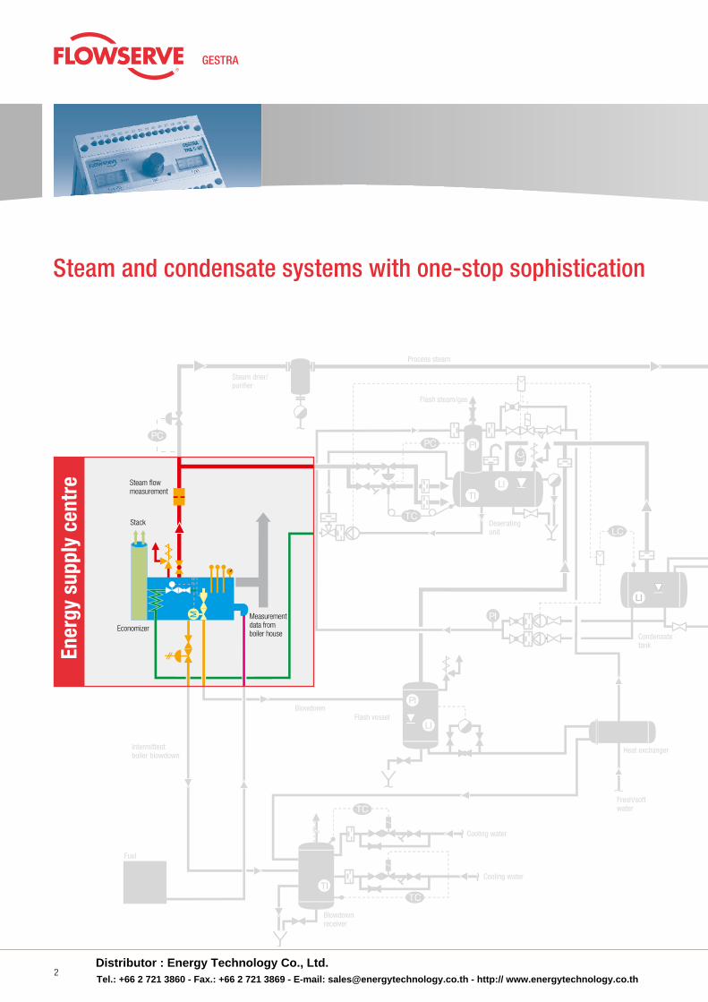
Steam and condensate systems with one-stop sophistication
Ener
gy s
uppl
y ce
ntre
Process steam
Flash steam/gas
Fuel
Intermittentboiler blowdown
Blowdownreceiver
Cooling water
Electrical pressure control
Cooling water
Blowdown
Deaeratingunit
Heat exchanger
Fresh/softwater
Monitoring ofconductivity
Heatexchanger
Controlled fromthe condensate side
Mechanicaltemperaturecontrol
Electricaltemperaturecontrol
Monitoringof turbidity
Condensatetank
Steam drier/purifier
Economizer
Flashvessel
Flash vessel
Stack
Measurementdata fromboiler house
Steam flow measurement
Steam flowmeasurement
Sightglass
Steam trap
Non-return valve
Distributor : Energy Technology Co., Ltd.Tel.: +66 2 721 3860 - Fax.: +66 2 721 3869 - E-mail: [email protected] - http:// www.energytechnology.co.th
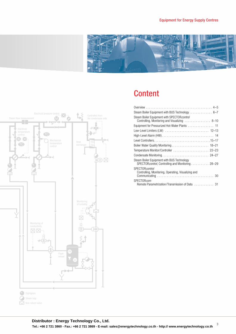
Equipment for Energy Supply Centres
3
Overview . . . . . . . . . . . . . . . . . . . . . . . . . . . . . . . . . . . . . . . . . 4–5
Steam Boiler Equipment with BUS Technology . . . . . . . . . . . . . . 6–7
Steam Boiler Equipment with SPECTORcontrol Controlling, Monitoring and Visualizing . . . . . . . . . . . . . . . . 8–10
Equipment for Pressurized Hot-Water Plants . . . . . . . . . . . . . . . . 11
Low-Level Limiters (LW) . . . . . . . . . . . . . . . . . . . . . . . . . . . 12–13
High-Level Alarm (HW) . . . . . . . . . . . . . . . . . . . . . . . . . . . . . . . . 14
Level Controllers . . . . . . . . . . . . . . . . . . . . . . . . . . . . . . . . . . .15–17
Boiler Water Quality Monitoring . . . . . . . . . . . . . . . . . . . . . . . 18–21
Temperature Monitor/Controller . . . . . . . . . . . . . . . . . . . . . . 22–23
Condensate Monitoring . . . . . . . . . . . . . . . . . . . . . . . . . . . . . 24–27
Steam Boiler Equipment with BUS Technology SPECTORcontrol, Controlling and Monitoring . . . . . . . . . . . 28–29
SPECTORcontrol Controlling, Monitoring, Operating, Visualizing and Communicating . . . . . . . . . . . . . . . . . . . . . . . . . . . . . . . . . . . 30
SPECTORcom Remote Parametrization/Transmission of Data . . . . . . . . . . . . 31
Content
Process steam
Flash steam/gas
Fuel
Intermittentboiler blowdown
Blowdownreceiver
Cooling water
Electrical pressure control
Cooling water
Blowdown
Deaeratingunit
Heat exchanger
Fresh/softwater
Monitoring ofconductivity
Heatexchanger
Controlled fromthe condensate side
Mechanicaltemperaturecontrol
Electricaltemperaturecontrol
Monitoringof turbidity
Condensatetank
Steam drier/purifier
Economizer
Flashvessel
Flash vessel
Stack
Measurementdata fromboiler house
Steam flow measurement
Steam flowmeasurement
Sightglass
Steam trap
Non-return valve
Distributor : Energy Technology Co., Ltd.Tel.: +66 2 721 3860 - Fax.: +66 2 721 3869 - E-mail: [email protected] - http:// www.energytechnology.co.th
4
Safety, reliability, availability and economy have always enjoyed top priority in boiler operation . To an increasing extent, another aspect is being added for the plant operators: process automation and visualization .
To meet these stringent requirements, GESTRA AG has – for more than fi ve decades now – been working exclusively with electrode systems that are low in maintenance and wear; in contrast to other systems, they function entirely without moving parts, which leads to high service lifetimes and very low failure rates .
By now, these GESTRA electrode systems are being applied in many different areas of the energy supply centre . In addition to the boiler equipment itself, these units are also used in condensate tanks, pump-driven return installations, steam regenerators etc . With a low response sensitivity of > 0 .5 µS/cm, even operation with demineralization equipment does not pose a problem . In general, the entire energy supply centre is only as effective as its weakest element . Many plant operators, designers and manufacturers are therefore no longer prepared to enter into any compromises in this area .
Nothing is as cost-intensive as a production outage.
Over and above these aspects, the requirements for the equipment of an energy supply centre tend to differ greatly . The requirements can no longer be met with one and the same system, as was perhaps the case only 10 to 15 years ago . The wishes expressed by the customers have always been the driving force behind GESTRA’s innovative developments, and this is still the case today .
There is no longer a “one size fi ts all” system for customer requirements!
Another step forward was taken for the GESTRA equipment components through the introduction of the SPECTOR family, which focuses on meeting the customer’s specifi c needs . The family now consists of SPECTORcompact, SPECTORbus and SPECTORmodule .
SPECTORcompact
SPECTORcompact comprises systems that facili-tate the easy replacement of existing self-acting systems . Measurement values are transferred as standard 4–20 mA signals or can be incorporated into existing controllers via integrated volt-free relay contacts without any need for additional electronic control units . If necessary, controllers are of course also available for implementing the entire controlled systems .
SPECTORbus
SPECTORbus offers easy integration into automa-tion concepts by means of remote data transmis-sion and parameter setting . Thanks to many technical innovations, the design, erection and commissioning of plants is simplifi ed considerably . This is a system that has been tried and tested over more than 10 years and has set new stand-ards in boiler equipment . Now, with SPECTORbus, a large amount of process-relevant data can be transmitted for the fi rst time . Further information is given in the separate brochure “Equipment for Energy Supply Centres – SPECTORbus” .
SPECTORmodule
The SPECTORmodule line represents a systematic advancement of the proven GESTRA technology . Using the most modern electronic components and constituting the state of the art, these systems were designed with a focus on ease of handling, reducing the installation expense, and providing cost-effective solutions .
New units were developed as demand-oriented solutions for boiler automation . The scope of the parameterization was limited to the most essential functions to ensure intuitive operating of the controllers .
Depending on the task at hand, the customer can choose between the system variants SPECTORmodule and SPECTORmodule Touch .
SPECTORmodule concentrates on the key functions, and the parameters are set by means of a rotary pushbutton .
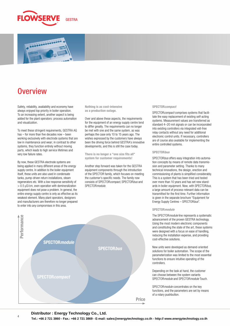
Overview
SPECTORcompact
Perf
orm
ance
Price
SPECTORmoduleSPECTORbus
Distributor : Energy Technology Co., Ltd.Tel.: +66 2 721 3860 - Fax.: +66 2 721 3869 - E-mail: [email protected] - http:// www.energytechnology.co.th
www.gestra.de
5
SPECTORmodule Touch
The SPECTORmodule Touch version focuses on the essentials: the main functions and a clear, intuitive user interface .
With this series, the controller was separated from the operating unit, which means that the laborious wiring for sensors, feedback, limits, valve actuation etc . in the control cabinet door is no longer required .
Universal controllers generally entail a large number of parameter settings, making the operat-ing workflow and the setting of parameters more difficult .
In the development of the SPECTORmodule Touch series, clear and easily understandable operating was a top priority .
Thanks to the intuitive user inter-face, the operator can enter the parameters rapidly and reliably . The colour touch display leads directly to the parameterization level . A virtual numerical keypad is shown, so that values can be changed or functions selected . Care was taken to ensure that the various controllers always have the same clear, uniform operating structure .
To give customers and plant operators greater convenience, we design our systems with a focus on■ optimized system interfaces■ minimized maintenance (See separate brochure) GESTRA – always the right solution!
The Benefits
GESTRA SPECTORbus
1. No risk of overheating:
■ Patented thermal barrier in cylindrical body above electrode flange■ Electronic temperature protection in the
terminal box■ Patented connection arrangement■ Minimization of thermal effects
2. Easy installation and maintenance:
■ Freely accessible connecting terminals at the control units■ Large terminal box makes for easy installation .
3. Reduced cost:
■ Minimized inventory and spares levels ■ Only a single cable needed between boiler
and control cabinet■ Low installation and material costs■ Reduced cost for control cabinets■ Cabling connection male/female, ready-made cables■ Only five input terminals■ Only one cable in the control cabinet for all sensing units■ Optimum system integration without additional cable installations
4. Increased safety:
■ Active cable monitoring with more than twice the previous maximum cable length■ Easy to integrate into visual display and auto mation systems
Less is more!
From little acorns big oaks grow . With the BUS technology by GESTRA, a new era has begun in the measurement and control of boiler systems:
■ Less cabling (preconfigured cable connection) ■ More control■ Less installation work ■ Better process overview■ Less space needed in control cabinets ■ Higher availability■ Fewer control units ■ Enhanced reliability■ Less wear and tear ■ Greater plant efficiency■ Less maintenance ■ Better utilization of energy■ Fewer production outages ■ Longer plant operation times■ Lower costs
Distributor : Energy Technology Co., Ltd.Tel.: +66 2 721 3860 - Fax.: +66 2 721 3869 - E-mail: [email protected] - http:// www.energytechnology.co.th
302010
-10-20-30-40
0
100
°F°C
8060
2032
0-20-40
40
1
15
4
5
5
69
7 8
9
12
2
3
3 3
12 1311
26
2425
20
20
22
23
14
18
19
19 1910
19
19
18
19
16
17
13
15
6
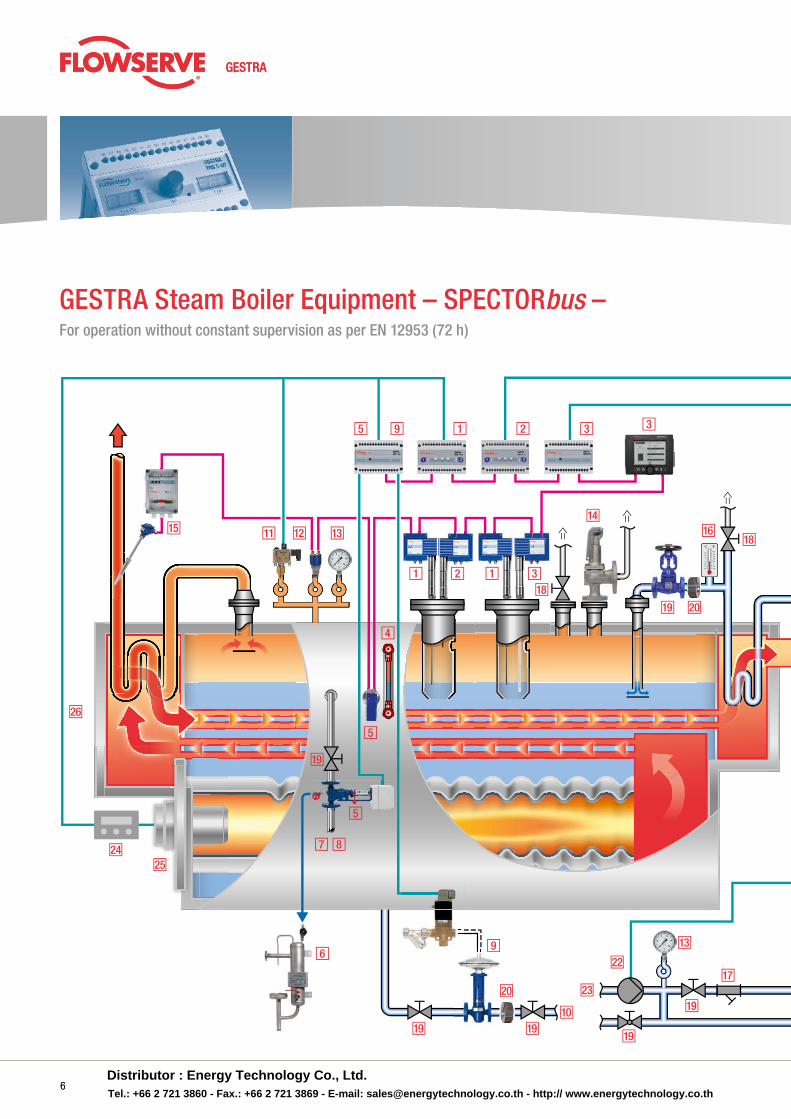
GESTRA Steam Boiler Equipment – SPECTORbus –For operation without constant supervision as per EN 12953 (72 h)
6Distributor : Energy Technology Co., Ltd.Tel.: +66 2 721 3860 - Fax.: +66 2 721 3869 - E-mail: [email protected] - http:// www.energytechnology.co.th
302010
-10-20-30-40
0
100
°F°C
8060
2032
0-20-40
40
21
27
14
19
13
19
Equipment for Energy Supply Centres
7
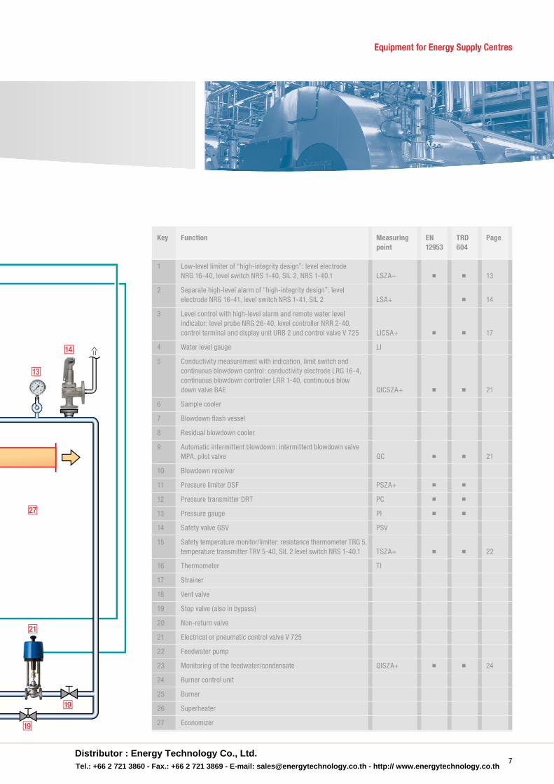
Key Function Measuring EN TRD Page point 12953 604
1 Low-level limiter of “high-integrity design”: level electrode NRG 16-40, level switch NRS 1-40, SIL 2, NRS 1-40.1 LSZA– ■ ■ 13
2 Separate high-level alarm of “high-integrity design”: level electrode NRG 16-41, level switch NRS 1-41, SIL 2 LSA+ ■ 14
3 Level control with high-level alarm and remote water level indicator: level probe NRG 26-40, level controller NRR 2-40, control terminal and display unit URB 2 und control valve V 725 LICSA+ ■ ■ 17
4 Water level gauge LI
5 Conductivity measurement with indication, limit switch and continuous blowdown control: conductivity electrode LRG 16-4, continuous blowdown controller LRR 1-40, continuous blow down valve BAE QICSZA+ ■ ■ 21
6 Sample cooler
7 Blowdown flash vessel
8 Residual blowdown cooler
9 Automatic intermittent blowdown: intermittent blowdown valve MPA, pilot valve QC ■ ■ 21
10 Blowdown receiver
11 Pressure limiter DSF PSZA+ ■ ■
12 Pressure transmitter DRT PC ■ ■
13 Pressure gauge PI ■ ■
14 Safety valve GSV PSV
15 Safety temperature monitor/limiter: resistance thermometer TRG 5, temperature transmitter TRV 5-40, SIL 2 level switch NRS 1-40.1 TSZA+ ■ ■ 22
16 Thermometer TI
17 Strainer
18 Vent valve
19 Stop valve (also in bypass)
20 Non-return valve
21 Electrical or pneumatic control valve V 725
22 Feedwater pump
23 Monitoring of the feedwater/condensate QISZA+ ■ ■ 24
24 Burner control unit
25 Burner
26 Superheater
27 Economizer
Equipment for Energy Supply Centres
7Distributor : Energy Technology Co., Ltd.Tel.: +66 2 721 3860 - Fax.: +66 2 721 3869 - E-mail: [email protected] - http:// www.energytechnology.co.th
302010
-10-20-30-40
0
100
°F°C
8060
2032
0-20-40
40
1
15
4
5
5
69
7 8
12 3
12 1311
26
2425
20
20
28
22
23
14
18
19
19 1910
19
19
18
19
16
17
13
15
Control room
Control
Service partner
8
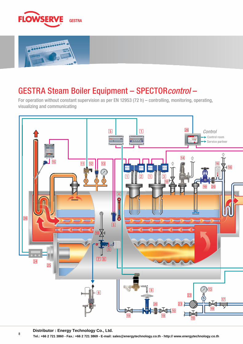
GESTRA Steam Boiler Equipment – SPECTORcontrol –For operation without constant supervision as per EN 12953 (72 h) – controlling, monitoring, operating, visualizing and communicating
8Distributor : Energy Technology Co., Ltd.Tel.: +66 2 721 3860 - Fax.: +66 2 721 3869 - E-mail: [email protected] - http:// www.energytechnology.co.th
302010
-10-20-30-40
0
100
°F°C
8060
2032
0-20-40
40
21
27
14
19
13
19
29
www.gestra.de
9
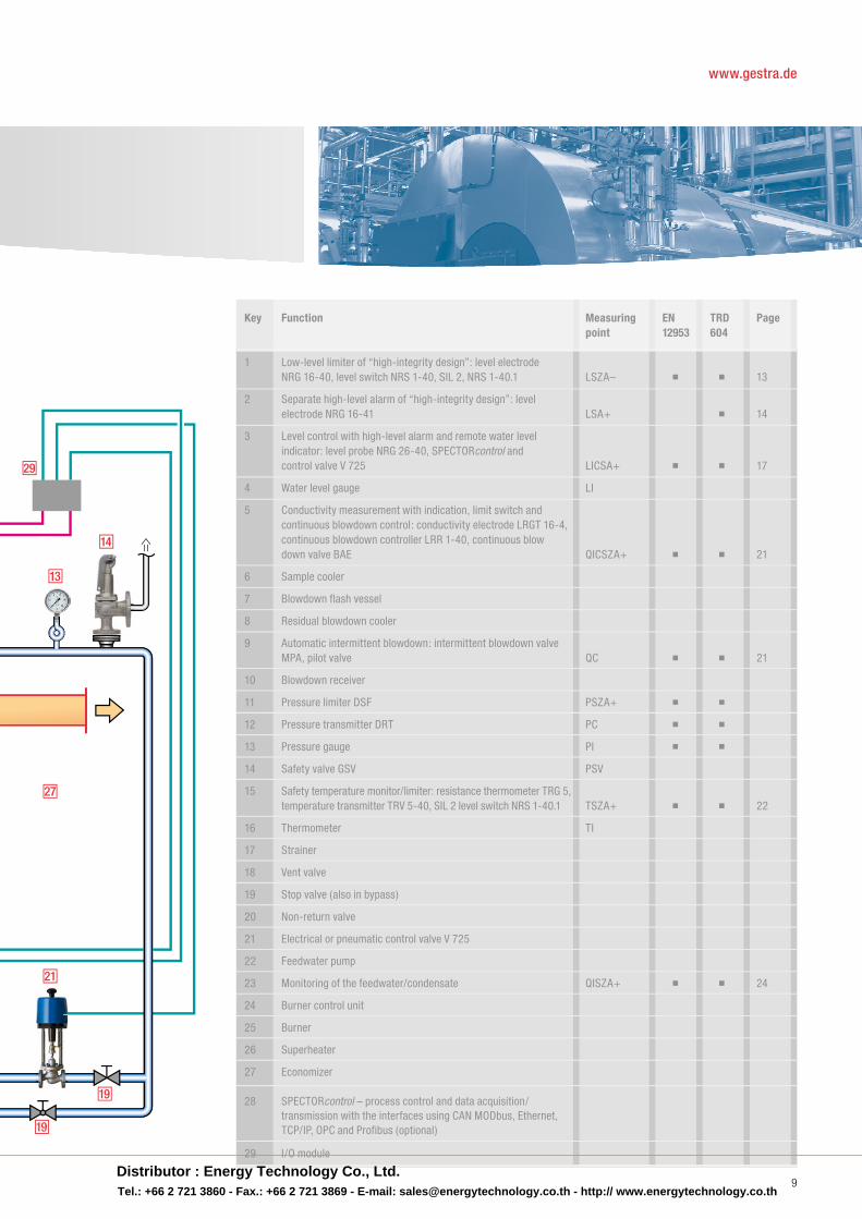
Key Function Measuring EN TRD Page point 12953 604
1 Low-level limiter of “high-integrity design”: level electrode NRG 16-40, level switch NRS 1-40, SIL 2, NRS 1-40.1 LSZA– ■ ■ 13
2 Separate high-level alarm of “high-integrity design”: level electrode NRG 16-41 LSA+ ■ 14
3 Level control with high-level alarm and remote water level indicator: level probe NRG 26-40, SPECTORcontrol and control valve V 725 LICSA+ ■ ■ 17
4 Water level gauge LI
5 Conductivity measurement with indication, limit switch and continuous blowdown control: conductivity electrode LRGT 16-4, continuous blowdown controller LRR 1-40, continuous blow down valve BAE QICSZA+ ■ ■ 21
6 Sample cooler
7 Blowdown flash vessel
8 Residual blowdown cooler
9 Automatic intermittent blowdown: intermittent blowdown valve MPA, pilot valve QC ■ ■ 21
10 Blowdown receiver
11 Pressure limiter DSF PSZA+ ■ ■
12 Pressure transmitter DRT PC ■ ■
13 Pressure gauge PI ■ ■
14 Safety valve GSV PSV
15 Safety temperature monitor/limiter: resistance thermometer TRG 5, temperature transmitter TRV 5-40, SIL 2 level switch NRS 1-40.1 TSZA+ ■ ■ 22
16 Thermometer TI
17 Strainer
18 Vent valve
19 Stop valve (also in bypass)
20 Non-return valve
21 Electrical or pneumatic control valve V 725
22 Feedwater pump
23 Monitoring of the feedwater/condensate QISZA+ ■ ■ 24
24 Burner control unit
25 Burner
26 Superheater
27 Economizer 28 SPECTORcontrol – process control and data acquisition/ transmission with the interfaces using CAN MODbus, Ethernet, TCP/IP, OPC and Profibus (optional)
29 I/O module
Distributor : Energy Technology Co., Ltd.Tel.: +66 2 721 3860 - Fax.: +66 2 721 3869 - E-mail: [email protected] - http:// www.energytechnology.co.th
a
2
3
3
1
4
10
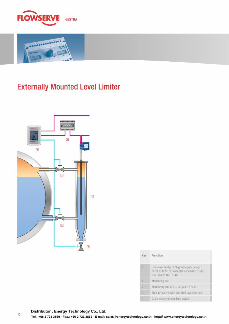
Externally Mounted Level Limiter
Key Function
A Low-level limiter of “high-integrity design”, certified to SIL 2: level electrode NRG 16-40, level switch NRS 1-40
1 Measuring pot
2 Monitoring unit SRL 6-40 (24 h / 72 h)
3 Shut-off valves with two limit switches each
4 Drain valve with one limit switch
Distributor : Energy Technology Co., Ltd.Tel.: +66 2 721 3860 - Fax.: +66 2 721 3869 - E-mail: [email protected] - http:// www.energytechnology.co.th
bcbc a
b
a
p p p p
klk
a
l tka
l
n
m n
e
c*
p
xbc
a
Steam boiler 1
Steam boiler 2
v
y
y
*) 72 h operation only
Equipment for Energy Supply Centres
11
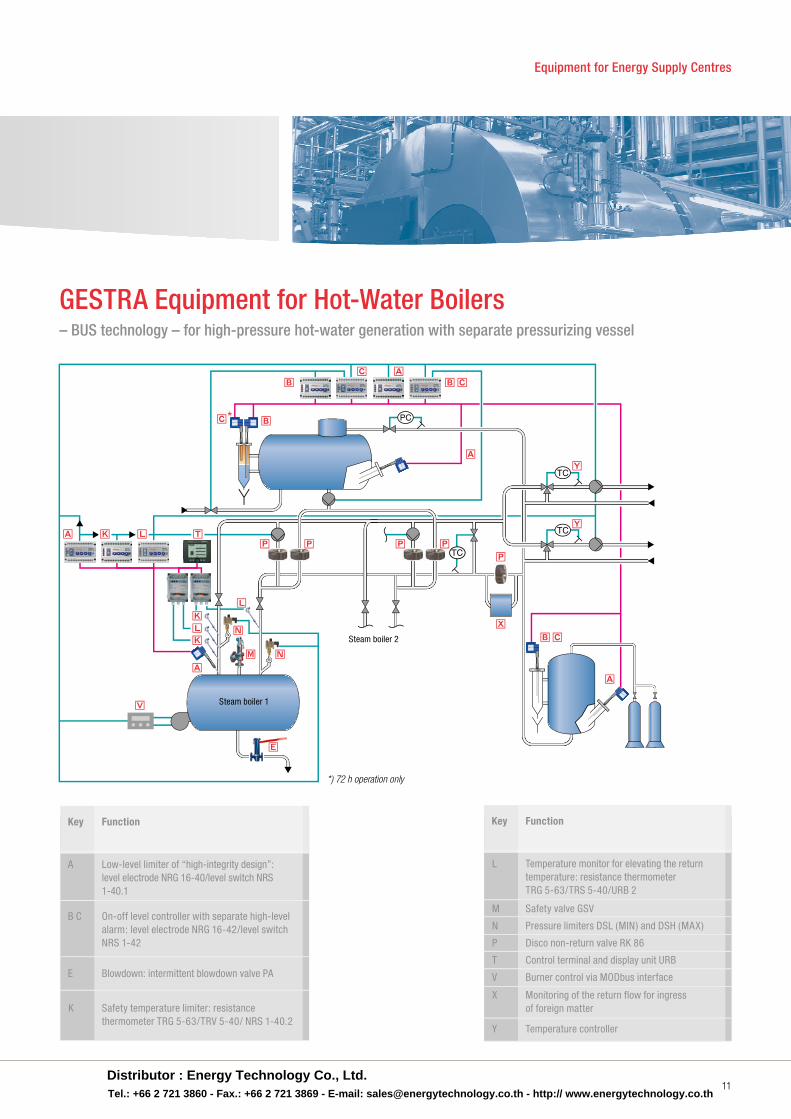
GESTRA Equipment for Hot-Water Boilers– BUS technology – for high-pressure hot-water generation with separate pressurizing vessel
Key Function
A Low-level limiter of “high-integrity design”: level electrode NRG 16-40/level switch NRS 1-40.1
B C On-off level controller with separate high-level alarm: level electrode NRG 16-42/level switch NRS 1-42
E Blowdown: intermittent blowdown valve PA
K Safety temperature limiter: resistance thermometer TRG 5-63/TRV 5-40/ NRS 1-40.2
Key Function
L Temperature monitor for elevating the return temperature: resistance thermometer TRG 5-63/TRS 5-40/URB 2
M Safety valve GSV
N Pressure limiters DSL (MIN) and DSH (MAX)
P Disco non-return valve RK 86
T Control terminal and display unit URB
V Burner control via MODbus interface
X Monitoring of the return flow for ingress of foreign matter
Y Temperature controller
Distributor : Energy Technology Co., Ltd.Tel.: +66 2 721 3860 - Fax.: +66 2 721 3869 - E-mail: [email protected] - http:// www.energytechnology.co.th
12
Technical Informationa Low-Level Limiter (LW) up to PN 320
technician and boiler inspector . A distinction must be made between bus-capable (SPECTORbus ) and non-bus-capable (SPECTORmodule ) systems .
SPECTORbus – SIL 2 certifiedNRS 1-40/NRS 1-40.1
■ One level switch for two electrodes■ Response sensitivity always from 0.5 µS/cm■ Separate undelayed signal output for
emerging of the electrode■ Autonomous functional test, including the
relay output contacts■ Definite detection of the signal state within
the system ■ Flashing indicator = electrode emerged■ Steady light = electrode emerged and time
delay elapsed■ Active test of the cable connection between
electrode and switch
Of course, the limiters of “high-integrity design” comply with the PED (Pressure Equipment
Directive) and have TÜV and EU type approval . In addition, the limiters of the SPECTORbus system are SIL 2 certified in accordance with IEC 61508 .
If particularly high demands are made on the availability of boiler plants, the “2-out-of-3” circuit is often used .
With this arrangement, the safety chain is only interrupted when at least two limiters give the signal for low-water or fault . If the self-monitoring triggers for one of these units, the plant remains available and the malfunctioning unit can be che-cked during planned downtime . With the SPECTORbus technology in particular, certain situations must be given special attention, e .g . interrupted bus lines . As in the past, GESTRA is again offering with the systems NRG 16-, 17-, 19- and 111- . . the entire palette up to the pressure rating PN 320 (183 bar / 357 °C) .
GESTRA electrodes are not expendable parts .
The limiters consist of a combination of level electrode and level switch . In general, a distinction must be made between units of “conventional design” and those of “high-integrity design” (i .e . with self-monitoring) . The corresponding applications for the units are defined in the techni-cal rules and depend mainly on the hazard poten-tial of the plant . A basis for these considerations can be the maximum allowable operating pressure (TRD 701: 1 bar; PED: 0 .5 bar) or the boiler water content (TRD 802) .
For areas covered by these rules and the com-parable regulations of non-EU states, such as limited supervision (2 h, 4 h or 8 h operation), the compact units NRGS 11-2 (PN 6) and NRGS 16-2 (PN 40) were developed . With this design, the level electrode and level switch form a single unit . In addition, the test and reset buttons were integrated into the terminal box . As a special feature, the redundancy (2-channel design) was extended right up to the electrode tip, which leads to a clear increase in safety .
With the self-monitoring limiters of “high-integrity design”, the concept proven over decades for the systems MR/2VR8, ER 86/NRS 1-4/VR 18 and NRG 16-, 17-, 19-, 111-11/NRS 1-7 was advanced further and now offers the current state of safety technology with the system SPECTORbus NRG 16-, 17-, 19-, 111-40 or NRS 1-40 .1 . On the basis of the applicable EN standards, the units were developed and manufactured according to IEC 61508 “Functional safety” and certified to SIL 2 . Building on the experience of the last decades, fur-ther optimization was introduced for the benefit of the design engineer, plant operator, commissioning
The following systems are available:
SPECTORbus■ NRG 1 .-40/NRS 1-40■ NRG 1 .-40/NRS 1-40 .1
12Distributor : Energy Technology Co., Ltd.Tel.: +66 2 721 3860 - Fax.: +66 2 721 3869 - E-mail: [email protected] - http:// www.energytechnology.co.th
Zertifiziert nach SIL 2
13
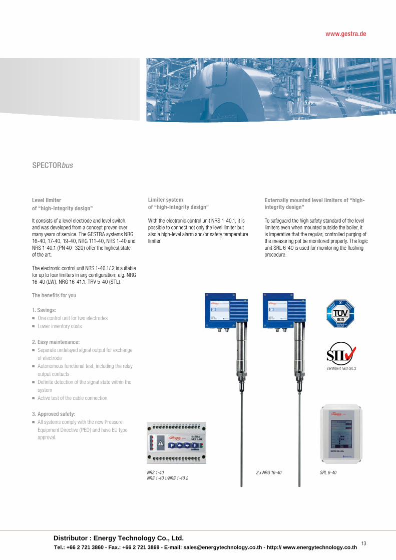
Externally mounted level limiters of “high-integrity design”
To safeguard the high safety standard of the level limiters even when mounted outside the boiler, it is imperative that the regular, controlled purging of the measuring pot be monitored properly . The logic unit SRL 6-40 is used for monitoring the flushing procedure .
Level limiter of “high-integrity design”
It consists of a level electrode and level switch, and was developed from a concept proven over many years of service . The GESTRA systems NRG 16-40, 17-40, 19-40, NRG 111-40, NRS 1-40 and NRS 1-40 .1 (PN 40–320) offer the highest state of the art .
The electronic control unit NRS 1-40 .1/ .2 is suitable for up to four limiters in any configuration; e .g . NRG 16-40 (LW), NRG 16-41 .1, TRV 5-40 (STL) .
The benefits for you
1. Savings:■ One control unit for two electrodes■ Lower inventory costs
2. Easy maintenance: ■ Separate undelayed signal output for exchange of electrode■ Autonomous functional test, including the relay
output contacts■ Definite detection of the signal state within the system■ Active test of the cable connection
3. Approved safety:■ All systems comply with the new Pressure Equipment Directive (PED) and have EU type approval .
Limiter system of “high-integrity design”
With the electronic control unit NRS 1-40 .1, it is possible to connect not only the level limiter but also a high-level alarm and/or safety temperature limiter .
NRS 1-40NRS 1-40.1/NRS 1-40.2
2 x NRG 16-40 SRL 6-40
SPECTORbus
www.gestra.de
Distributor : Energy Technology Co., Ltd.Tel.: +66 2 721 3860 - Fax.: +66 2 721 3869 - E-mail: [email protected] - http:// www.energytechnology.co.th
14
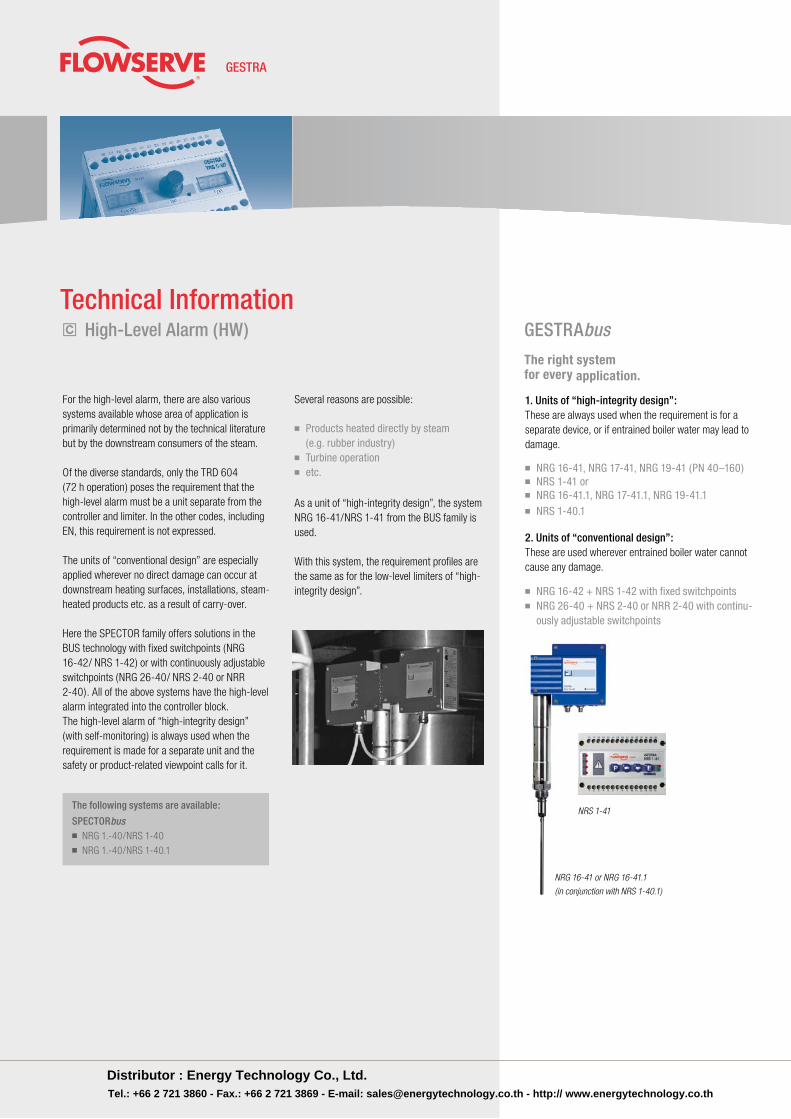
For the high-level alarm, there are also various systems available whose area of application is primarily determined not by the technical literature but by the downstream consumers of the steam .
Of the diverse standards, only the TRD 604 (72 h operation) poses the re quirement that the high-level alarm must be a unit separate from the controller and limiter . In the other codes, including EN, this requirement is not expressed .
The units of “conventional design” are especially applied wherever no direct damage can occur at downstream heating surfaces, installations, steam- heated products etc . as a result of carry-over .
Here the SPECTOR family offers solutions in the BUS technology with fixed switchpoints (NRG 16-42/ NRS 1-42) or with continuously adjustable switchpoints (NRG 26-40/ NRS 2-40 or NRR 2-40) . All of the above systems have the high-level alarm integrated into the controller block .The high-level alarm of “high-integrity design” (with self-monitoring) is always used when the requirement is made for a separate unit and the safety or product-related viewpoint calls for it .
Several reasons are possible:
■ Products heated directly by steam (e.g. rubber industry)■ Turbine operation■ etc.
As a unit of “high-integrity design”, the system NRG 16-41/NRS 1-41 from the BUS family is used .
With this system, the requirement profiles are the same as for the low-level limiters of “high-integrity design” .
GESTRAbus
The right system for every application.
1. Units of “high-integrity design”:These are always used when the requirement is for a separate device, or if entrained boiler water may lead to damage .
■ NRG 16-41, NRG 17-41, NRG 19-41 (PN 40–160) ■ NRS 1-41 or ■ NRG 16-41.1, NRG 17-41.1, NRG 19-41.1 ■ NRS 1-40.1
2. Units of “conventional design”:These are used wherever entrained boiler water cannot cause any damage .
■ NRG 16-42 + NRS 1-42 with fixed switchpoints■ NRG 26-40 + NRS 2-40 or NRR 2-40 with continu-
ously adjustable switchpoints
The following systems are available:
SPECTORbus■ NRG 1 .-40/NRS 1-40■ NRG 1 .-40/NRS 1-40 .1
Technical Informationc High-Level Alarm (HW)
NRS 1-41
NRG 16-41 or NRG 16-41.1
(in conjunction with NRS 1-40.1)
Distributor : Energy Technology Co., Ltd.Tel.: +66 2 721 3860 - Fax.: +66 2 721 3869 - E-mail: [email protected] - http:// www.energytechnology.co.th
Equipment for Energy Supply Centres
15
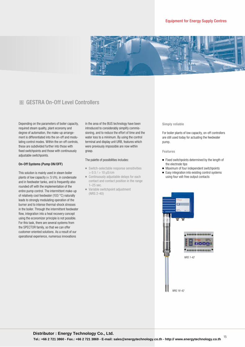
Depending on the parameters of boiler capacity, required steam quality, plant economy and degree of automation, the make-up arrange-ment is differentiated into the on-off and modu-lating control modes . Within the on-off controls, these are subdivided further into those with fixed switchpoints and those with continuously adjustable switchpoints .
On-Off Systems (Pump ON/OFF)
This solution is mainly used in steam boiler plants of low capacity (< 5 t/h), in condensate and in feedwater tanks, and is frequently also rounded off with the implementation of the entire pump control . The intermittent make-up of relatively cool feedwater (103 °C) naturally leads to strongly modulating operation of the burner and to intense thermal-shock stresses in the boiler . Through the intermittent feedwater flow, integration into a heat recovery concept using the economizer principle is not possible . For this task, there are several systems from the SPECTOR family, so that we can offer customer-oriented solutions . As a result of our operational experience, numerous innovations
in the area of the BUS technology have been introduced to considerably simplify commis-sioning, and to reduce the effort of time and the water loss to a minimum . By using the control terminal and display unit URB, features which were previously impossible are now within grasp .
The palette of possibilities includes:
■ Switch-selectable response sensitivities > 0.5 / > 10 µS/cm■ Continuously adjustable delays for each
contact and contact position in the range 1–25 sec.
■ Variable switchpoint adjustment (NRS 2-40)
Simply reliable
For boiler plants of low capacity, on-off controllers are still used today for actuating the feedwater pump .
Features
■ Fixed switchpoints determined by the length of the electrode tips■ Maximum of four independent switchpoints■ Easy integration into existing control systems using four volt-free output contacts
NRG 16-42
NRS 1-42
b GESTRA On-Off Level Controllers
Distributor : Energy Technology Co., Ltd.Tel.: +66 2 721 3860 - Fax.: +66 2 721 3869 - E-mail: [email protected] - http:// www.energytechnology.co.th
16
Technical Informationb GESTRA Modulating Level Controller
Modulating Systems (control valves, frequency-controlled pumps)
With modulating control, one thinks first of the economical operation, higher steam quality and the capability of adapting to difficult situations regard- ing the controlled systems, e .g . those caused by strong fluctuations or sudden changes in steam consumption, as is the case for process-related reasons in the rubber, foodstuff and building-mate-rials industries . The greater operational economy of the boiler and the higher steam quality are naturally an aspect of the controlled, demand-oriented make-up of the boiler water . On the one hand, this mode ensures continuous burner operation and, on the other, the boiler water level is not elevated as high as with the two-position control, which then reduces the danger of carry-over appreciably .
In practice, the following units have established themselves:
■ NRG 26-40 / NRR 2-40/URB
In the BUS technology, the experience of the last three decades was evaluated and integrated here to optimize the established systems . The level controller NRR 2-40 also offers, as an option to the 3-position stepping output, the possibility of using 4–20 mA modules for the manipulated variable and/or the actual value . As already described with the on-off controllers, delays can also be program-med here . Furthermore, by using the control ter-minal and display unit URB, considerable savings are possible in commissioning, since, thanks to the modern technology, the calibration of the 100 % measuring range of the probe can already be per-formed at the 50 % level . The pleasing result: less time lost, lower water losses and lower resource requirements .
What is more, in coordination with the boiler inspector, the control terminal can also be used as a second water level indicator, which does away with the need for a water gauge glass, in accor-dance with TRD 401 section 8 .1; prEN 12952-7 section 5 .4 .1; and prEN 12953-6 section . 5 .1 .1 . Another advantage of this technology is the fact that the entire “output stage” of the controller remains on the mounting panel, i .e . elaborate cable harnesses in the control cabinet door can be omit-ted and at the same time the control terminal can be used for setting the parameters of the continu-ous/intermittent blowdown control . As mentioned already, with modulating control there is also the possibility of catering for difficult controlled sys-tems through the use of steam and feedwater flow measurement . In such cases, the so-called two- or three-element controls are implemented .
For pressures > PN 40, GESTRA uses the intelligent buoyancy transmitter 244 LD or the radar probe 7MS with the level transmitter 705 to cover the range up to PN 250 . Like the compact system NRGT 26-1, this system has a level-proportional 4–20 mA current output .
Three-element controls can be realized in conjunction with the SPECTORcontrol system .
Distributor : Energy Technology Co., Ltd.Tel.: +66 2 721 3860 - Fax.: +66 2 721 3869 - E-mail: [email protected] - http:// www.energytechnology.co.th
17
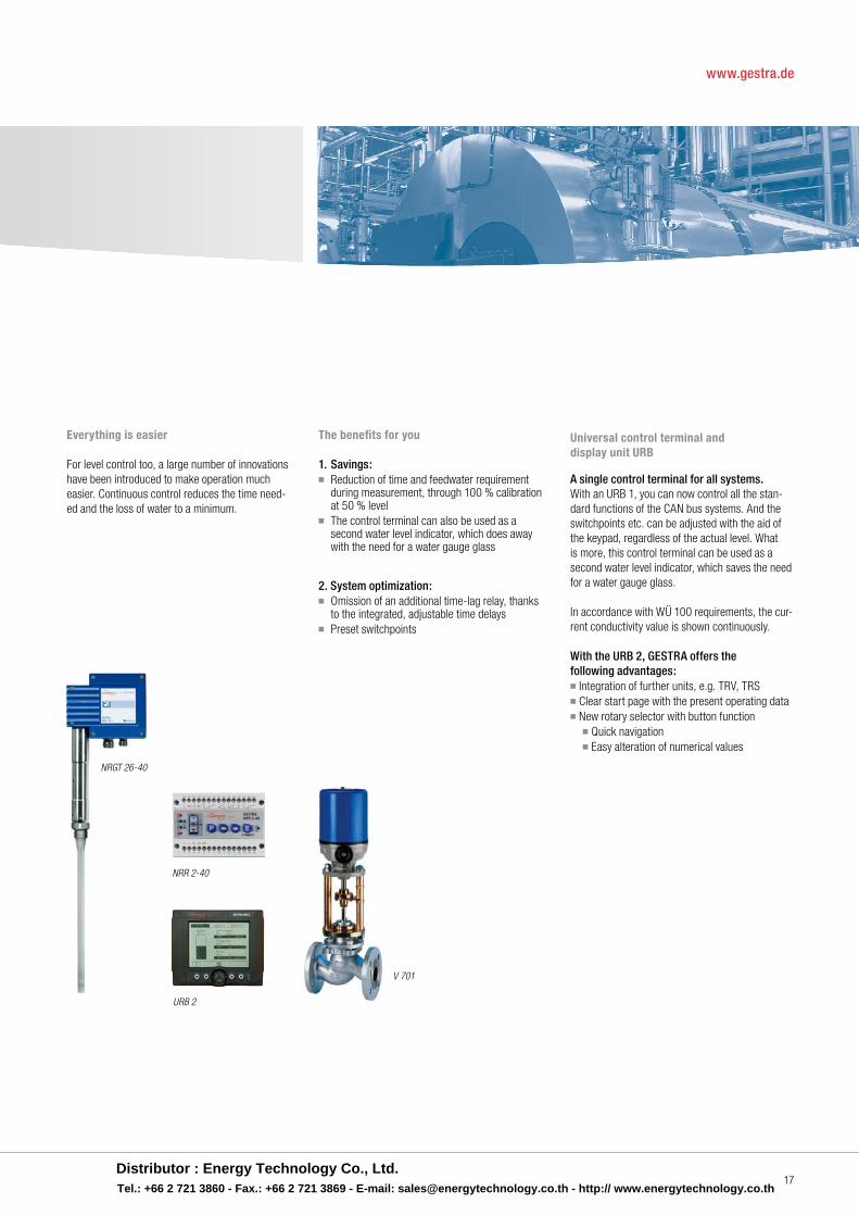
Universal control terminal and display unit URB
A single control terminal for all systems. With an URB 1, you can now control all the stan-dard functions of the CAN bus systems . And the switchpoints etc . can be adjusted with the aid of the keypad, regardless of the actual level . What is more, this control terminal can be used as a second water level indicator, which saves the need for a water gauge glass .
In accordance with WÜ 100 requirements, the cur-rent conductivity value is shown continuously .
With the URB 2, GESTRA offers the following advantages:■ Integration of further units, e .g . TRV, TRS ■ Clear start page with the present operating data■ New rotary selector with button function ■ Quick navigation ■ Easy alteration of numerical values
Everything is easier
For level control too, a large number of innovations have been introduced to make operation much easier . Continuous control reduces the time need-ed and the loss of water to a minimum .
The benefits for you
1. Savings:■ Reduction of time and feedwater requirement
during measurement, through 100 % calibration at 50 % level
■ The control terminal can also be used as a second water level indicator, which does away with the need for a water gauge glass
2. System optimization:■ Omission of an additional time-lag relay, thanks
to the integrated, adjustable time delays■ Preset switchpoints
NRGT 26-40
NRR 2-40
URB 2
V 701
www.gestra.de
Distributor : Energy Technology Co., Ltd.Tel.: +66 2 721 3860 - Fax.: +66 2 721 3869 - E-mail: [email protected] - http:// www.energytechnology.co.th
18
Technical Informationd e GESTRA Boiler Water Monitoring
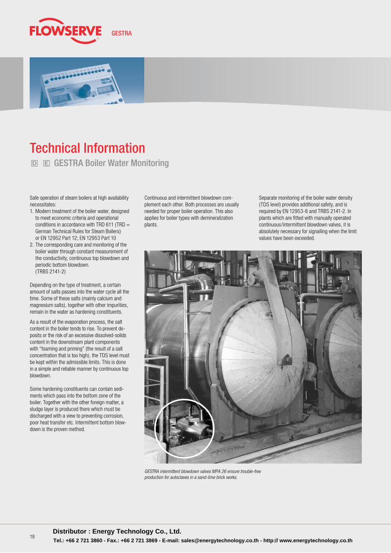
Continuous and intermittent blowdown com-plement each other . Both processes are usually needed for proper boiler opera tion . This also applies for boiler types with de minera lization plants .
Separate monitoring of the boiler water density (TDS level) provides additional safe ty, and is re quired by EN 12953-6 and TRBS 2141-2 . In plants which are fitted with manually operated continuous/intermittent blowdown valves, it is absolute ly necessary for signalling when the limit values have been exceeded .
Safe operation of steam boilers at high availability necessitates:1 . Modern treatment of the boiler water, designed
to meet economic criteria and operational conditions in accordance with TRD 611 (TRD = German Technical Rules for Steam Boilers) or EN 12952 Part 12; EN 12953 Part 10
2 . The corresponding care and monitoring of the boiler water through constant measurement of the conductivity, con tinuous top blowdown and periodic bottom blowdown .
(TRBS 2141-2)
Depending on the type of treatment, a certain amount of salts passes into the water cycle all the time . Some of these salts (mainly calcium and magnesium salts), together with other impurities, re main in the water as hardening con sti tuents .
GESTRA intermittent blowdown valves MPA 26 ensure trouble-free production for autoclaves in a sand-lime brick works.
As a result of the evaporation process, the salt content in the boiler tends to rise . To prevent de -posits or the risk of an excessive dissolved-solids content in the down stream plant components with “foaming and priming” (the result of a salt con centration that is too high), the TDS level must be kept within the admissible limits . This is done in a simple and reliable manner by continuous top blowdown .
Some hardening constituents can contain sedi-ments which pass into the bottom zone of the boiler . Together with the other foreign matter, a sludge layer is produced there which must be discharged with a view to preventing corrosion, poor heat transfer etc . Intermittent bottom blow-down is the proven method .
Distributor : Energy Technology Co., Ltd.Tel.: +66 2 721 3860 - Fax.: +66 2 721 3869 - E-mail: [email protected] - http:// www.energytechnology.co.th
Equipment for Energy Supply Centres
d
d
d
r
gh
rj
e
e
f
19
Equipment for Energy Supply Centres
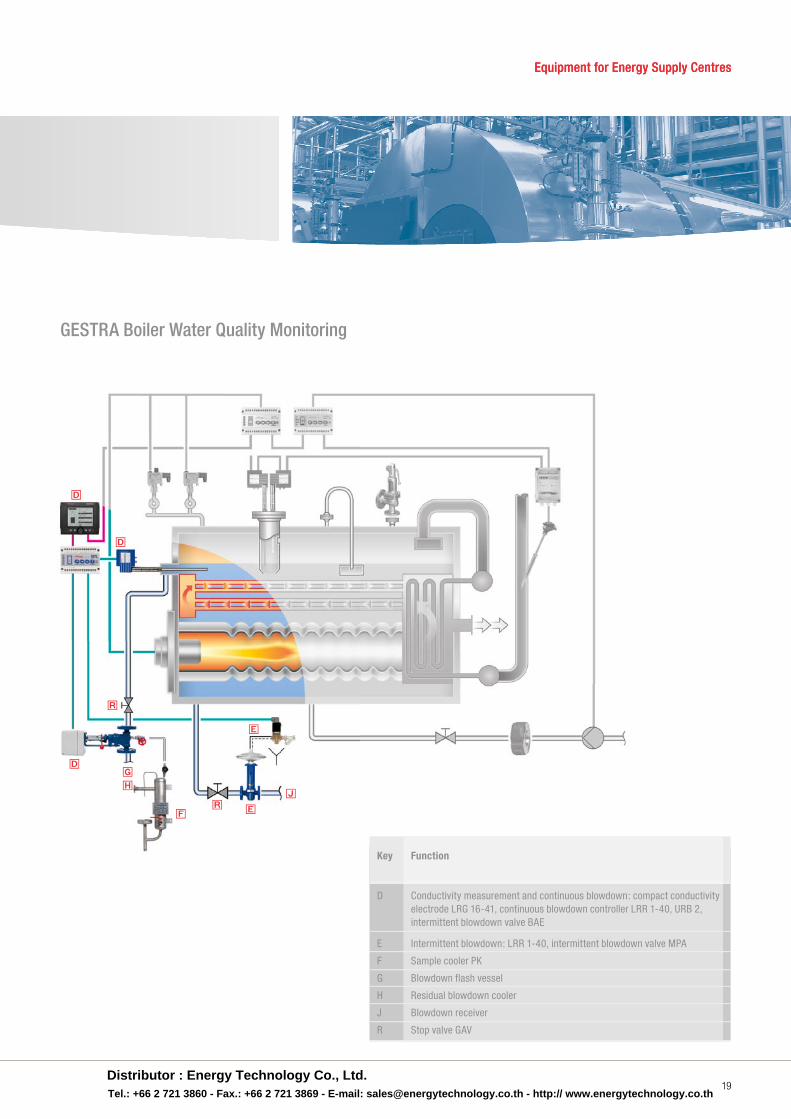
GESTRA Boiler Water Quality Monitoring
Key Function
D Conductivity measurement and continuous blowdown: compact conductivity electrode LRG 16-41, continuous blowdown controller LRR 1-40, URB 2, intermittent blowdown valve BAE E Intermittent blowdown: LRR 1-40, intermittent blowdown valve MPA
F Sample cooler PK
G Blowdown flash vessel
H Residual blowdown cooler
J Blowdown receiver
R Stop valve GAV
Distributor : Energy Technology Co., Ltd.Tel.: +66 2 721 3860 - Fax.: +66 2 721 3869 - E-mail: [email protected] - http:// www.energytechnology.co.th
20
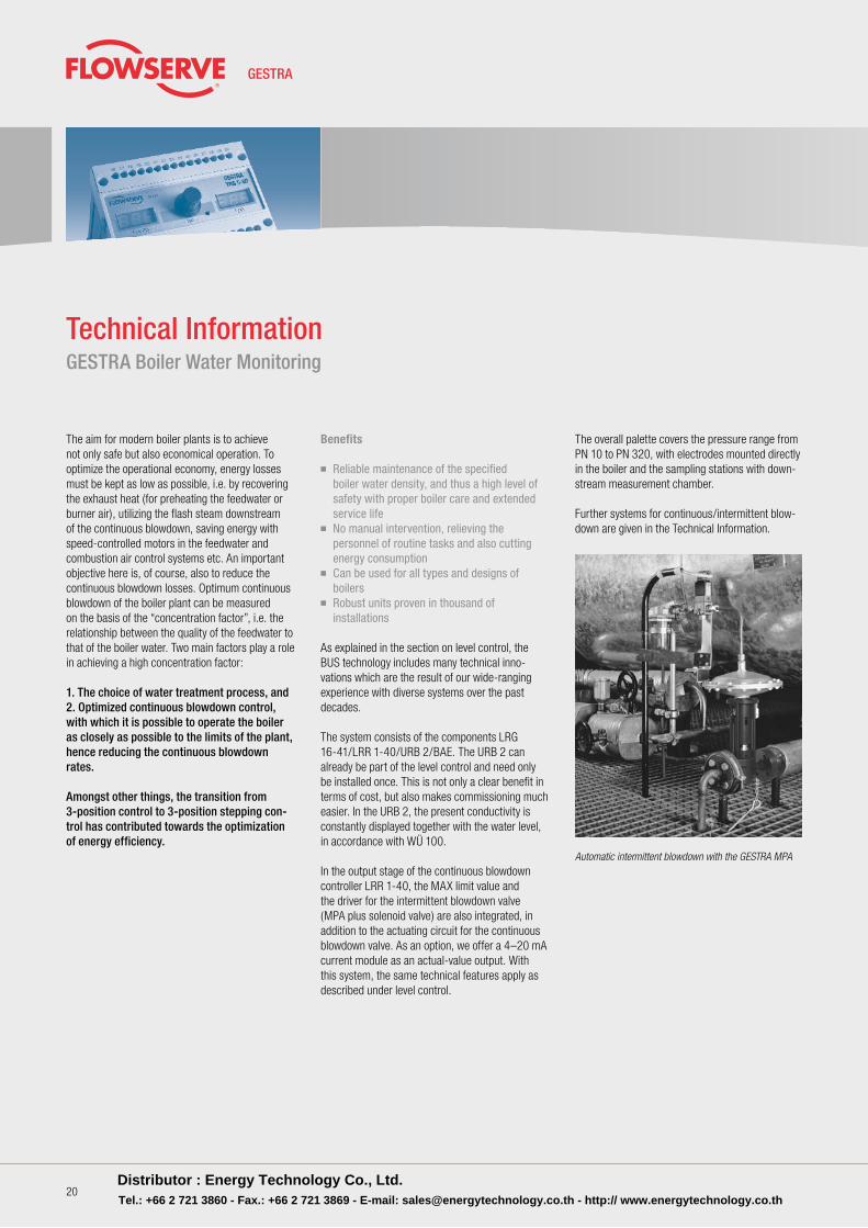
The overall palette covers the pressure range from PN 10 to PN 320, with electrodes mounted directly in the boiler and the sampling stations with down-stream measurement chamber .
Further systems for continuous/intermittent blow-down are given in the Technical Information .
Benefits
■ Reliable maintenance of the specified boiler water density, and thus a high level of safety with proper boiler care and extended service life■ No manual intervention, relieving the personnel of routine tasks and also cutting energy consumption■ Can be used for all types and designs of
boilers■ Robust units proven in thousand of installations
As explained in the section on level control, the BUS technology includes many technical inno-vations which are the result of our wide-ranging experience with diverse systems over the past decades .
The system consists of the components LRG 16-41/LRR 1-40/URB 2/BAE . The URB 2 can already be part of the level control and need only be installed once . This is not only a clear benefit in terms of cost, but also makes commissioning much easier . In the URB 2, the present conductivity is constantly displayed together with the water level, in accordance with WÜ 100 .
In the output stage of the continuous blowdown controller LRR 1-40, the MAX limit value and the driver for the intermittent blowdown valve (MPA plus solenoid valve) are also integrated, in addition to the actuating circuit for the continuous blowdown valve . As an option, we offer a 4–20 mA current module as an actual-value output . With this system, the same technical features apply as described under level control .
Automatic intermittent blowdown with the GESTRA MPA
The aim for modern boiler plants is to achieve not only safe but also economical operation . To optimize the operational economy, energy losses must be kept as low as possible, i .e . by recovering the exhaust heat (for preheating the feedwater or burner air), utilizing the flash steam downstream of the continuous blowdown, saving energy with speed-controlled motors in the feedwater and combustion air control systems etc . An important objective here is, of course, also to reduce the continuous blowdown losses . Optimum continuous blowdown of the boiler plant can be measured on the basis of the “concentration factor”, i .e . the relationship between the quality of the feedwater to that of the boiler water . Two main factors play a role in achieving a high concentration factor:
1. The choice of water treatment process, and2. Optimized continuous blowdown control, with which it is possible to operate the boiler as closely as possible to the limits of the plant, hence reducing the continuous blowdown rates.
Amongst other things, the transition from 3-position control to 3-position stepping con-trol has contributed towards the optimization of energy efficiency.
Technical InformationGESTRA Boiler Water Monitoring
Distributor : Energy Technology Co., Ltd.Tel.: +66 2 721 3860 - Fax.: +66 2 721 3869 - E-mail: [email protected] - http:// www.energytechnology.co.th
21
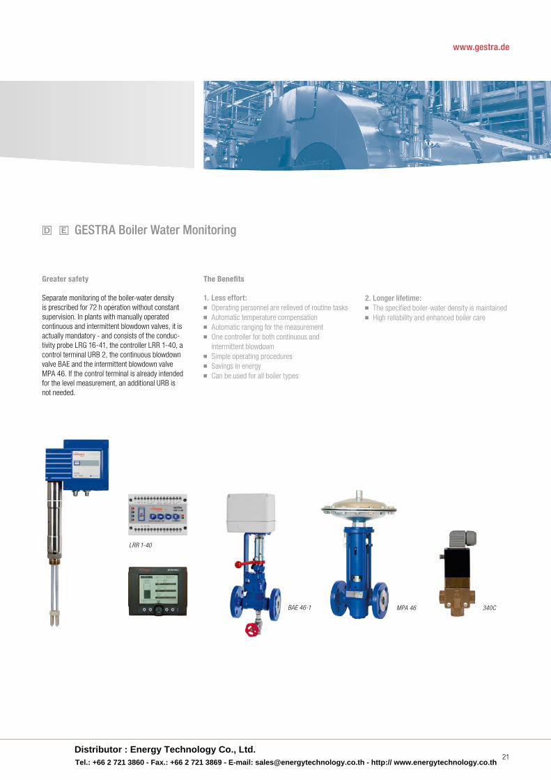
Greater safety
Separate monitoring of the boiler-water density is prescribed for 72 h operation without constant supervision . In plants with manually operated continuous and intermittent blowdown valves, it is actually mandatory - and consists of the conduc-tivity probe LRG 16-41, the controller LRR 1-40, a control terminal URB 2, the continuous blowdown valve BAE and the intermittent blowdown valve MPA 46 . If the control terminal is already intended for the level measurement, an additional URB is not needed .
The Benefi ts
1. Less effort: ■ Operating personnel are relieved of routine tasks■ Automatic temperature compensation■ Automatic ranging for the measurement■ One controller for both continuous and
intermittent blowdown■ Simple operating procedures■ Savings in energy■ Can be used for all boiler types
2. Longer lifetime:■ The specified boiler-water density is maintained■ High reliability and enhanced boiler care
d e GESTRA Boiler Water Monitoring
MPA 46
LRR 1-40
BAE 46-1 340C
www.gestra.de
Distributor : Energy Technology Co., Ltd.Tel.: +66 2 721 3860 - Fax.: +66 2 721 3869 - E-mail: [email protected] - http:// www.energytechnology.co.th
22
Technical Informationk GESTRA Safety Temperature Limiter/Temperature Monitor
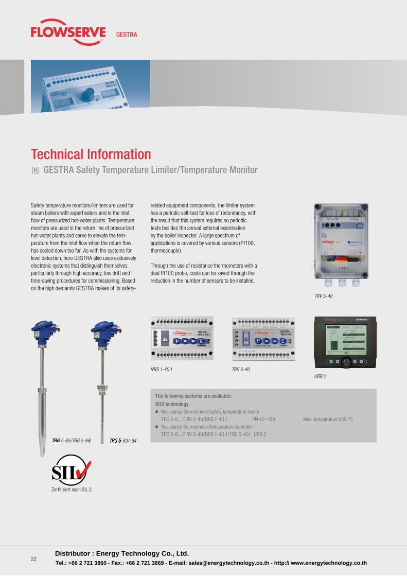
Safety temperature monitors/limiters are used for steam boilers with superheaters and in the inlet flow of pressurized hot-water plants . Temperature monitors are used in the return line of pressurized hot-water plants and serve to elevate the tem-perature from the inlet flow when the return flow has cooled down too far . As with the systems for level detection, here GESTRA also uses exclusively electronic systems that distinguish themselves particularly through high accuracy, low drift and time-saving procedures for commissioning . Basedon the high demands GESTRA makes of its safety-
The following systems are available:
BUS technology■ Resistance thermometer/safety temperature limiter TRG 5-6 . . ./TRV 5-40/NRS 1-40 .1 PN 40–160 Max . temperature 650 °C■ Resistance thermometer/temperature controller TRG 5-6 . . ./TRV 5-40/NRS 1-40 .1/TRS 5-40/ URB 2
TRV 5-40
NRS 1-40.1URB 2
TRS 5-40
TRG 5-63/-64TRG 5-65/TRG 5-66 TRG 5-63/-64TRG 5-63/-64TRG 5-65/TRG 5-66TRG 5-65/TRG 5-66TRG 5-65/TRG 5-66TRG 5-65/TRG 5-66
Zertifiziert nach SIL 2
related equipment components, the limiter system has a periodic self-test for loss of redundancy, with the result that this system requires no periodic tests besides the annual external examination by the boiler inspector . A large spectrum of applications is covered by various sensors (Pt100, thermocouple) .
Through the use of resistance thermometers with a dual Pt100 probe, costs can be saved through the reduction in the number of sensors to be installed .
Distributor : Energy Technology Co., Ltd.Tel.: +66 2 721 3860 - Fax.: +66 2 721 3869 - E-mail: [email protected] - http:// www.energytechnology.co.th
Equipment for Energy Supply Centres
23
Equipment for Energy Supply Centres
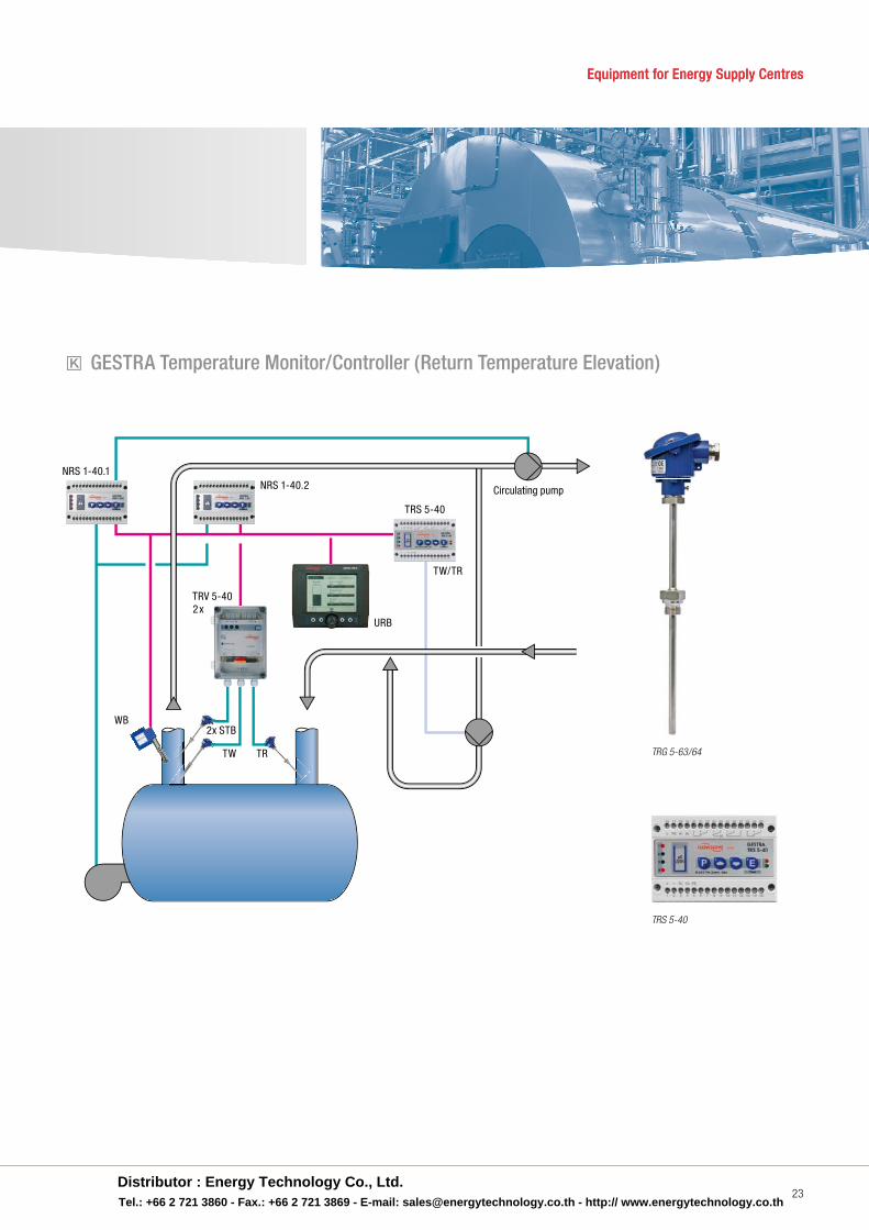
k GESTRA Temperature Monitor/Controller (Return Temperature Elevation)
TRG 5-63/64
TRS 5-40
NRS 1-40.1
Circulating pump
TRV 5-40
URB
2x STB
TW TR
TW/TR
WB
TRS 5-40
NRS 1-40.2
2x
Distributor : Energy Technology Co., Ltd.Tel.: +66 2 721 3860 - Fax.: +66 2 721 3869 - E-mail: [email protected] - http:// www.energytechnology.co.th
24
Technical Information3 4 GESTRA Condensate Monitoring
In any heat exchanger that is operated with steam, condensate is produced . Since the condensate contains an appreciable quantity of heat, it would economically unwise to discharge this condensate unused from the boiler water cycle . Nonetheless, the condensate is often dumped because of fears that it might be contaminated by product ingress . Indeed, the possibility that hydrocarbons, acids, alkalis, dyebaths or other sub stances may pass through leaky heat-exchanger surfaces into the condensate, thus en dangering the boiler opera-tion, cannot be excluded . As a rule, however, the condensate will not be contaminated constantly, i .e . it is generally feasible to include the returning condensate in the boiler water cycle . If the plants are operated according to prEN 12952/12953 or TRD 604, the standard requires constant monitoring of the condensate quality if there is any risk of ingress by the products mentioned above . For this monitoring, a distinction is made between substances which affect the electrical conductivity of the condensate and those which cause turbidity or refraction . The former is sensed by means of conductivity electrodes and evaluated by the asso-ciated control units . For the detection of oil, grease and similar substances, oil and turbidity detectors are used .
According to TRD 604, the boiler plant must be shut down on detection of foreign matter ingress, if the contaminated condensate can pass into the boiler water cycle . Since the availability of the boiler plant has the highest priority, measures must be taken to prevent such an ingress into the boiler water cycle .
In practice, fitting a three-way control valve down-stream has proven to be ef fec tive, i .e . the impure condensate is dis charged and then disposed of . This dis posal takes place via oil separation sys tems, for instance, since the contamin ated conden sate is not allowed to pass into the sewage system .
When planning boiler plants according to TRD 604 – 72 hour operation – it is additionally necessary to observe that in this case the oil and turbidity detector is required twofold .
Experience shows that in these cases it is ad vi s-able to install the second monitoring unit down-stream of the three-way control valve, because only in this way is the function of the valve moni tored properly .
Distributor : Energy Technology Co., Ltd.Tel.: +66 2 721 3860 - Fax.: +66 2 721 3869 - E-mail: [email protected] - http:// www.energytechnology.co.th
25
www.gestra.de
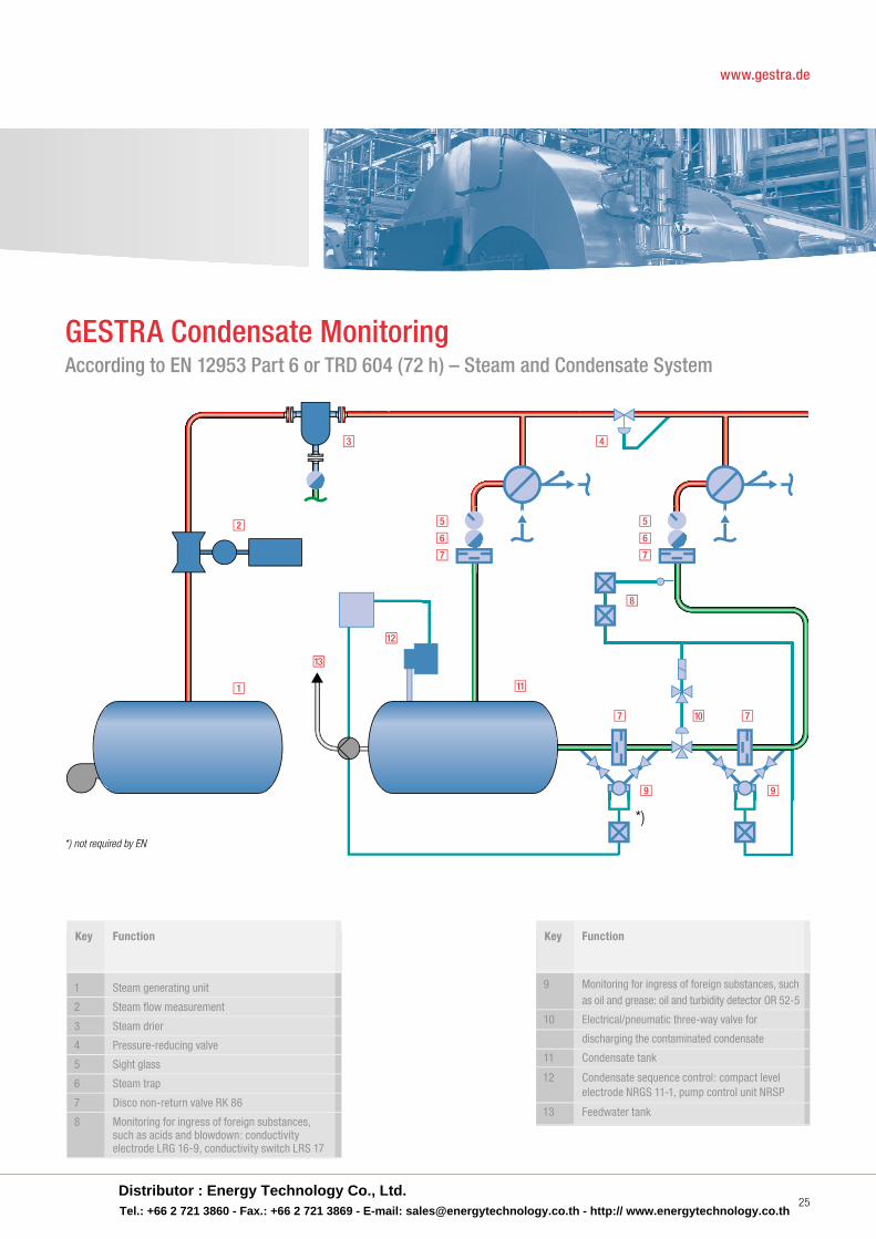
GESTRA Condensate MonitoringAccording to EN 12953 Part 6 or TRD 604 (72 h) – Steam and Condensate System
*) not required by EN
*)
1
2
3 4
5
6
7
9
5
6
7
77
8
9
10
11
12
13
Key Function
1 Steam generating unit
2 Steam fl ow measurement
3 Steam drier
4 Pressure-reducing valve
5 Sight glass
6 Steam trap
7 Disco non-return valve RK 86
8 Monitoring for ingress of foreign substances, such as acids and blowdown: conductivity electrode LRG 16-9, conductivity switch LRS 17
Key Function
9 Monitoring for ingress of foreign substances, such as oil and grease: oil and turbidity detector OR 52-5
10 Electrical/pneumatic three-way valve for
discharging the contaminated condensate
11 Condensate tank
12 Condensate sequence control: compact level electrode NRGS 11-1, pump control unit NRSP
13 Feedwater tank
Distributor : Energy Technology Co., Ltd.Tel.: +66 2 721 3860 - Fax.: +66 2 721 3869 - E-mail: [email protected] - http:// www.energytechnology.co.th
26
If the downstream oil and turbidity detector senses an impurity, there is the possibility of shutting down the condensate pumps in order to ensure the plant’s availability . This step prevents the passage of impure condensate into the boiler water cycle .
In this case, the shutdown should be coupled to an alarm annunciation, so that the operating personnel can intervene appropriately .
Regarding the question as to when monitoring of the return condensate is necessary, a clear rule is given in EN 12952/12953 and TRD 604:
Whenever there is a risk of ingress by foreign substances, but only then!
In the majority of the boiler plants already installed, the condensate is collected in condensate tanks . This is frequently done decentrally in the various production zones, and the condensate is then conveyed to the main condensate tank in the energy supply centre by means of recirculation units working with or without pumps .
For such extended systems, the most suitable location for the condensate monitoring equipment must of course be considered carefully .
Owing to the increasing pressure of costs with the planning and construction of the plant, the principle frequently applied is to cut the costs as far as possible by reducing the number of units, which often means that the monitoring devices are
installed downstream of the condensate tanks . Unfortunately, this approach also signifies that, if there is any ingress of foreign substances, the entire condensate system is contaminated and therefore the entire condensate must be dumped, not to mention the cleaning and disposal costs .The following rule should be applied:
Mount the monitoring unit as close as possible to the potential source of trouble.
If there are several potential trouble-spots in a facility, it may be necessary to group several condensate lines together before the monitoring point .
But even for this solution, the scope of the grouped lines should be kept within clear limits, so that the source of a fault can be localized quickly .
3 Conductivity Monitoring
The ingress of conductive substances – such as blowdown, acids, untreated water, dyebaths etc . – is rapidly detected and signalled by the systems LRG 16-9 / LRS 1-7 or the compact system LRGT / URS 2, and the necessary measures are initiated automatically . As explained for boiler water monitoring, these systems function with automatic temperature compensation, i .e . fluctuations in temperature do not lead to a fault indication or initiation of automatic discharge .
4 Oil and Turbidity Detection
As described above, this monitoring system is used to cover the risk of ingress by hydrocarbons, whey products etc . Because of the various condensates, a system is needed to differentiate, after calibration of the zero point, between soiling and impurities resulting from the condensate system itself and contamination by hydrocarbons, for instance . With the oil and turbidity detector OR, GESTRA has developed a system which can make this distinction through a combination of transmitted and scattered light . False alarms are reduced to a minimum, and system malfunctions are detected automatically .
The requirements described for the condensate system must be applied to the same extent for the return flow of pressurized hot-water plants . An essential difference lies in the signal processing, since discharge is not possible or not permissible for hot-water systems .
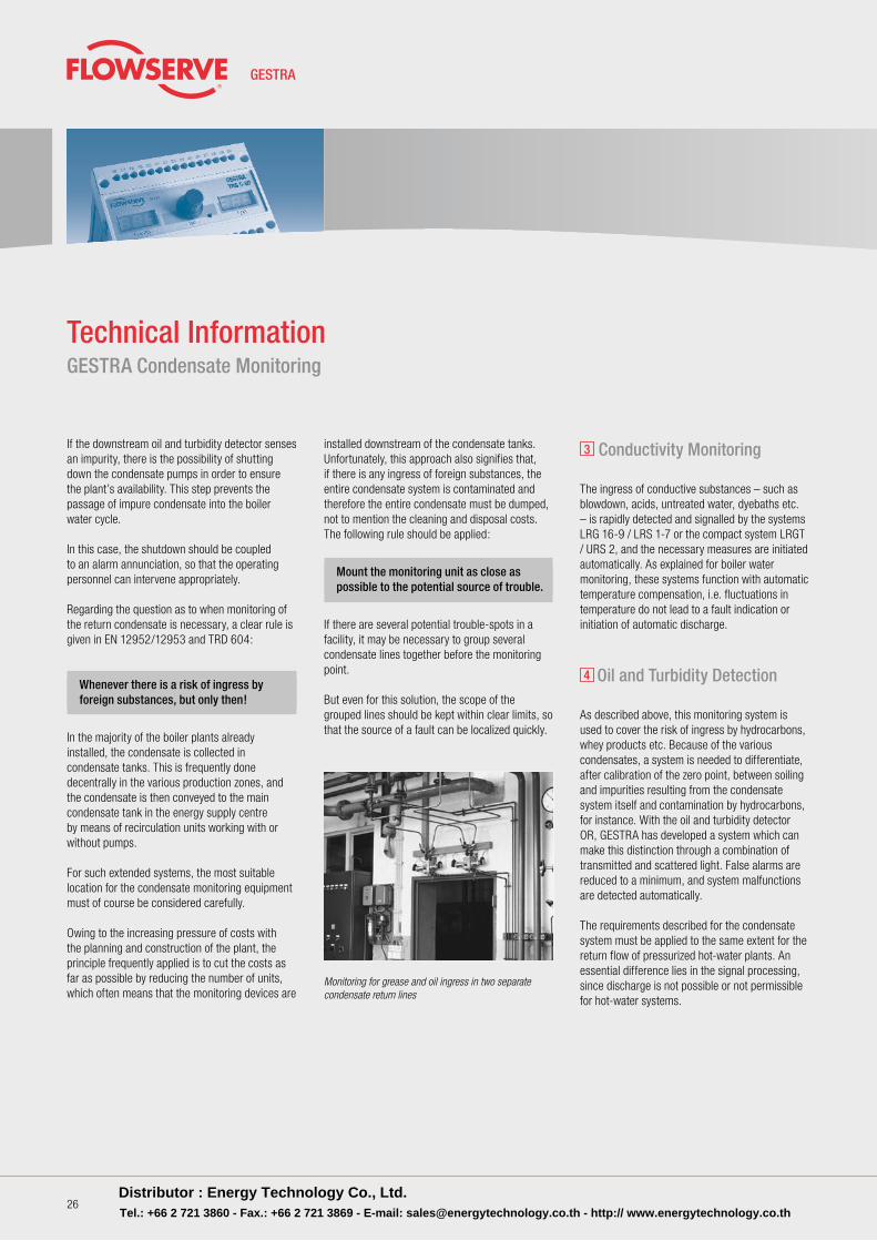
Technical Information GESTRA Condensate Monitoring
Monitoring for grease and oil ingress in two separate condensate return lines
Distributor : Energy Technology Co., Ltd.Tel.: +66 2 721 3860 - Fax.: +66 2 721 3869 - E-mail: [email protected] - http:// www.energytechnology.co.th
Equipment for Energy Supply Centres
27
Equipment for Energy Supply Centres
Please do not disturb!
Since the availability of your boiler plant enjoys highest priority, nothing must be allowed to penetrate the boiler water cycle .
With GESTRA oil and turbidity detectors, you obtain automatic compensation of disturbances such as:
■ Discolouration■ Lamp ageing■ Soiling of the glasses
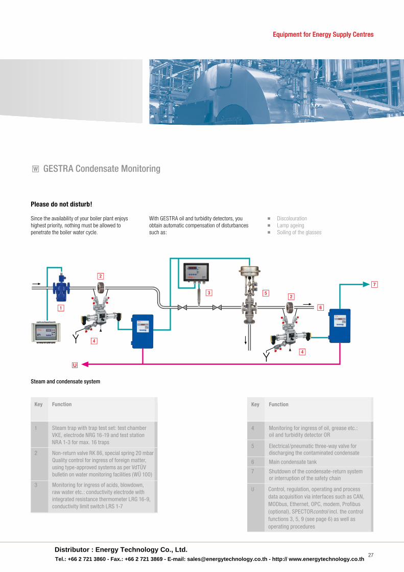
w GESTRA Condensate Monitoring
1
2
3
4
5
6
2
4
7
u
Steam and condensate system
Key Function
1 Steam trap with trap test set: test chamber VKE, electrode NRG 16-19 and test station NRA 1-3 for max. 16 traps
2 Non-return valve RK 86, special spring 20 mbar Quality control for ingress of foreign matter, using type-approved systems as per VdTÜV bulletin on water monitoring facilities (WÜ 100)
3 Monitoring for ingress of acids, blowdown, raw water etc.: conductivity electrode with integrated resistance thermometer LRG 16-9, conductivity limit switch LRS 1-7
Key Function
4 Monitoring for ingress of oil, grease etc.: oil and turbidity detector OR
5 Electrical/pneumatic three-way valve for discharging the contaminated condensate
6 Main condensate tank
7 Shutdown of the condensate-return system or interruption of the safety chain
U Control, regulation, operating and process data acquisition via interfaces such as CAN, MODbus, Ethernet, OPC, modem, Profibus (optional), SPECTORcontrol incl. the control functions 3, 5, 9 (see page 6) as well as operating procedures
Distributor : Energy Technology Co., Ltd.Tel.: +66 2 721 3860 - Fax.: +66 2 721 3869 - E-mail: [email protected] - http:// www.energytechnology.co.th
28
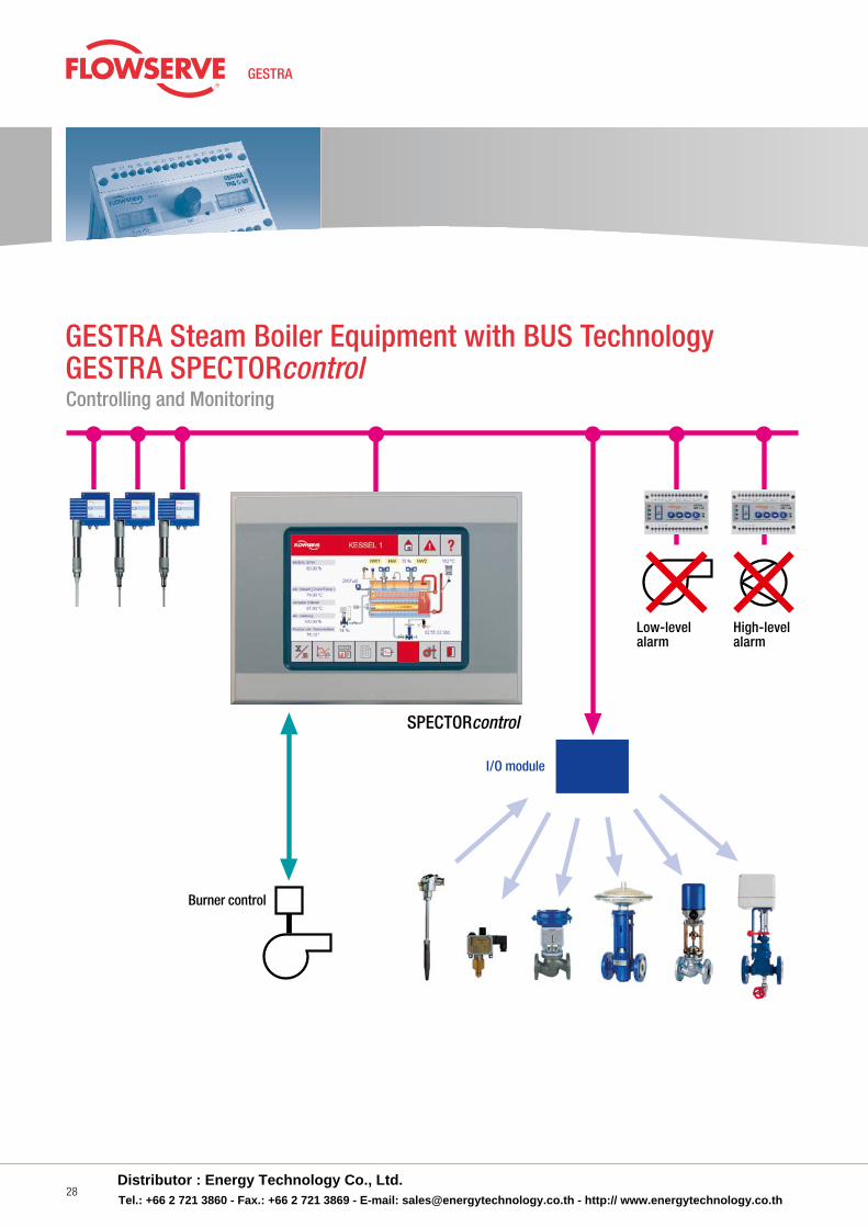
GESTRA SPECTORcontrol GESTRA Steam Boiler Equipment with BUS Technology
Controlling and Monitoring
Low-levelalarm
Burner control
SPECTORcontrol
High-levelalarm
I/O module
Distributor : Energy Technology Co., Ltd.Tel.: +66 2 721 3860 - Fax.: +66 2 721 3869 - E-mail: [email protected] - http:// www.energytechnology.co.th
29
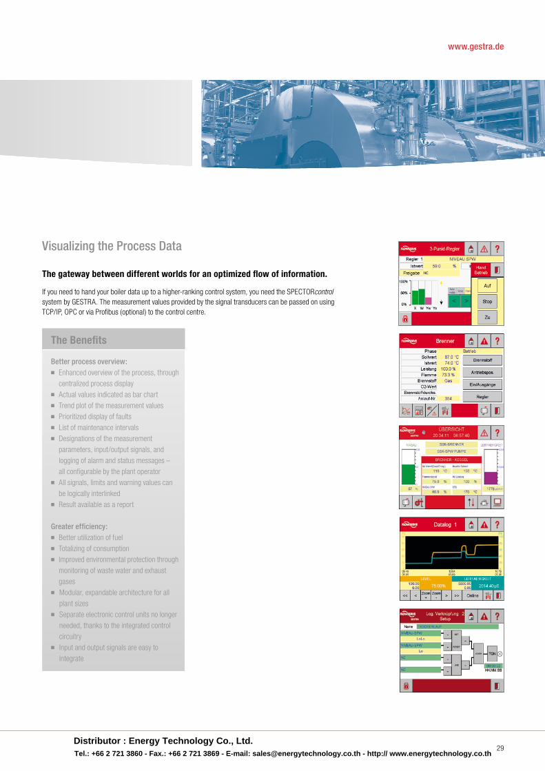
The gateway between different worlds for an optimized flow of information.
If you need to hand your boiler data up to a higher-ranking control system, you need the SPECTORcontrol system by GESTRA . The measurement values provided by the signal transducers can be passed on using TCP/IP, OPC or via Profibus (optional) to the control centre .
Visualizing the Process Data
www.gestra.de
The Benefits
Better process overview:■ Enhanced overview of the process, through
centralized process display■ Actual values indicated as bar chart■ Trend plot of the measurement values■ Prioritized display of faults■ List of maintenance intervals■ Designations of the measurement parameters, input/output signals, and logging of alarm and status messages – all configurable by the plant operator■ All signals, limits and warning values can be logically interlinked■ Result available as a report
Greater efficiency:■ Better utilization of fuel■ Totalizing of consumption■ Improved environmental protection through monitoring of waste water and exhaust gases■ Modular, expandable architecture for all plant sizes■ Separate electronic control units no longer needed, thanks to the integrated control circuitry■ Input and output signals are easy to integrate
Distributor : Energy Technology Co., Ltd.Tel.: +66 2 721 3860 - Fax.: +66 2 721 3869 - E-mail: [email protected] - http:// www.energytechnology.co.th
30
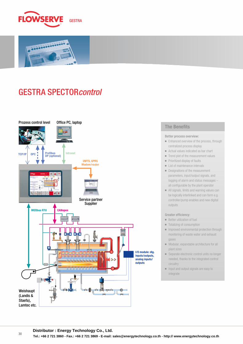
Prozess control level
OPCTCP/IP ProfibusDP (optional)
Intranet
UMTS, GPRSModem/router
I/O module: dig. inputs/outputs, analog inputs/outputs
Weishaupt(Landis & Staefa),Lamtec etc.
CANopenMODbus RTU
Service partnerSupplier
Office PC, laptop
GESTRA SPECTORcontrol
The Benefi ts
Better process overview:■ Enhanced overview of the process, through
centralized process display■ Actual values indicated as bar chart■ Trend plot of the measurement values■ Prioritized display of faults■ List of maintenance intervals■ Designations of the measurement parameters, input/output signals, and logging of alarm and status messages – all configurable by the plant operator■ All signals, limits and warning values can be logically interlinked and can form e .g . controller/pump enables and new digital outputs
Greater efficiency:■ Better utilization of fuel■ Totalizing of consumption■ Improved environmental protection through monitoring of waste water and exhaust gases■ Modular, expandable architecture for all plant sizes■ Separate electronic control units no longer needed, thanks to the integrated control circuitry■ Input and output signals are easy to integrate
Distributor : Energy Technology Co., Ltd.Tel.: +66 2 721 3860 - Fax.: +66 2 721 3869 - E-mail: [email protected] - http:// www.energytechnology.co.th
Equipment for Energy Supply Centres
31
Equipment for Energy Supply Centres
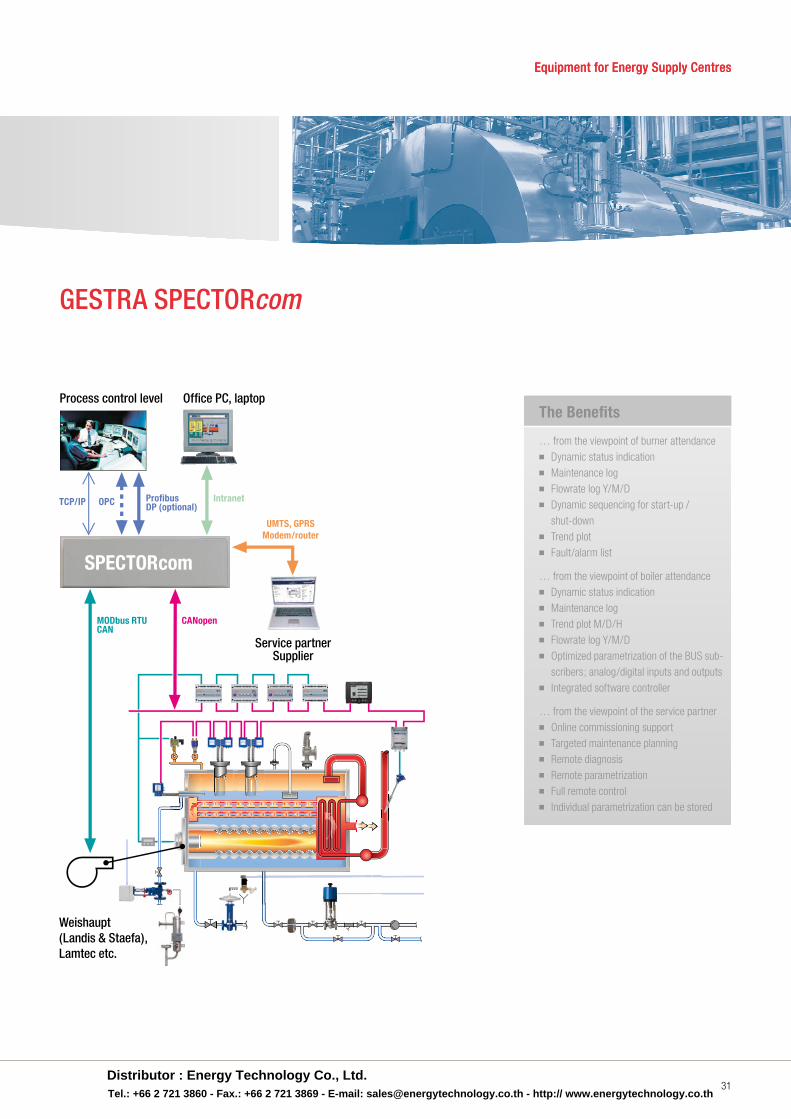
SPECTORcom
Process control level
OPCTCP/IP ProfibusDP (optional)
Intranet
UMTS, GPRSModem/router
Weishaupt(Landis & Staefa),Lamtec etc.
CANopenMODbus RTUCAN
Service partnerSupplier
Office PC, laptop
GESTRA SPECTORcom
The Benefi ts
… from the viewpoint of burner attendance■ Dynamic status indication■ Maintenance log■ Flowrate log Y/M/D■ Dynamic sequencing for start-up / shut-down■ Trend plot■ Fault/alarm list
… from the viewpoint of boiler attendance■ Dynamic status indication■ Maintenance log■ Trend plot M/D/H■ Flowrate log Y/M/D■ Optimized parametrization of the BUS sub- scribers; analog/digital inputs and outputs■ Integrated software controller
… from the viewpoint of the service partner■ Online commissioning support■ Targeted maintenance planning■ Remote diagnosis■ Remote parametrization■ Full remote control■ Individual parametrization can be stored
Distributor : Energy Technology Co., Ltd.Tel.: +66 2 721 3860 - Fax.: +66 2 721 3869 - E-mail: [email protected] - http:// www.energytechnology.co.th
GESTRA AGMünchener Strasse 77, D-28215 BremenP .O . Box 10 54 60, D-28054 BremenTelephone +49 (0) 421-35 03-0Telefax +49 (0) 421-35 03-393E-mail gestra .ag@flowserve .comInternet www .gestra .de
810689-09/1114 © 2014 · GESTRA AG · Bremen · Printed in Germany With Energy into the Future
Energy Technology Co., Ltd.
Tel : (66) 0-2721-3860 Fax : (66) 0-2721-3869 E-mail : [email protected]: www.energytechnology.co.th
436 Soi On-Nuch 39, Sukhumvit Rd., Suanluang, Bangkok 10250
For further information, please contact
Distributor :