gebrauchsanweisung gebruiksaanwijzing notice d'utilisation
TRANSCRIPT
Gebrauchsanweisung
Gebruiksaanwijzing
Notice d‘utilisation
Instruction manual
Istruzioni d‘uso
Manual de Instrucciones
DEU
TSC
HEN
GLI
SH
FRA
NÇ
AIS
NED
ERLA
ND
SIT
ALI
AN
OES
PAÑ
OL
Seite 2
DEU
TSC
H
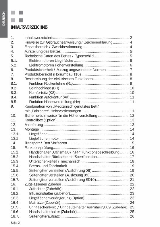
INHALTSVERZEICHNIS
1. Inhaltsverzeichnis ............................................................................... 22. Hinweise zur Gebrauchsanweisung / Zeichenerklärung ................. 43. Einsatzbereich / Zweckbestimmung ................................................. 44. Aufstellung des Bettes ........................................................................ 55. Technische Daten des Bettes / Typenschild ..................................... 5
.......................................................... 65.2. Elektromotoren Höhenverstellung ................................................ 66. Produktsicherheit / Auszug angewendeter Normen ........................ 77. Produktübersicht (Holzumbau T10) .................................................. 88. Beschreibung der elektrischen Funktionen ...................................... 88.1. Funktion Rückenlehne (RL) ........................................................... 98.2. Beinhochlage (BH) ......................................................................... 108.3. Komfortsitz (KS) ............................................................................. 108.4. Funktion Autokontur (AK) .............................................................. 118.5. Funktion Höhenverstellung (HV) ................................................... 119. Kombination von „Medizinisch genutztes Bett“ mit „Fahrbarer“ Hebevorrichtungen .................................................. 1110. Sicherheitshinweise für die Höhenverstellung ................................. 1211. Kontrollbox (Option) ............................................................................ 1312. Anlieferung .......................................................................................... 1313. Montage .............................................................................................. 14
..................................................................................... 14 ......................................................................... 14
14. Transport / Bett Verfahren ................................................................. 1515. Funktionsprüfung................................................................................ 1615.1. Handschalter „Carisma 07 NPF“ Funktionsbeschreibung .......... 1615.2. Handschalter Rückseite mit Sperrfunktion .................................. 1715.3. Unterschenkelteil / mechanisch ................................................... 1815.4. Brems- und Fahrbarkeit ................................................................. 1915.5. Seitengitter verstellen (Ausführung 06) ....................................... 1915.6. Seitengitter verstellen (Auslösung 09) ......................................... 2015.7. Seitengitter verstellen (Ausführung SD10) ................................... 2116. Zugelassenes Zubehör ...................................................................... 2216.1. Aufrichter (Zubehör) ....................................................................... 2216.2. Infusionshalter (Zubehör) .............................................................. 23
............................................... 2316.4. Matratze (Zubehör) ........................................................................ 24
.. 2516.6. Handschalterhalter (Zubehör) ....................................................... 2516.7. Seitengitteraufsatz ......................................................................... 26
DEU
TSC
H
Seite 3
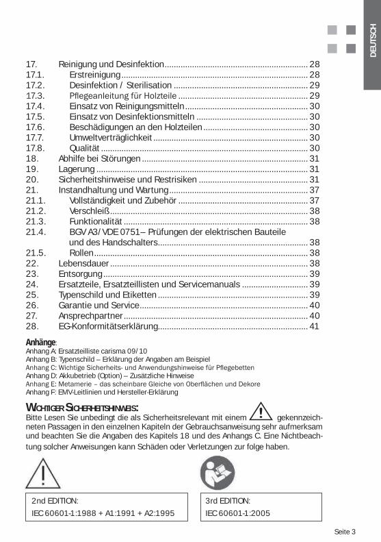
17. Reinigung und Desinfektion ............................................................... 2817.1. Erstreinigung .................................................................................. 2817.2. Desinfektion / Sterilisation ........................................................... 29
......................................................... 2917.4. Einsatz von Reinigungsmitteln ...................................................... 3017.5. Einsatz von Desinfektionsmitteln ................................................. 3017.6. Beschädigungen an den Holzteilen .............................................. 3017.7. Umweltverträglichkeit .................................................................... 3017.8. Qualität ........................................................................................... 3018. Abhilfe bei Störungen ......................................................................... 3119. Lagerung ............................................................................................. 3120. Sicherheitshinweise und Restrisiken ................................................ 3121. Instandhaltung und Wartung ............................................................. 3721.1. Vollständigkeit und Zubehör ......................................................... 3721.2. Verschleiß ....................................................................................... 3821.3. Funktionalität ................................................................................. 3821.4. BGV A3/VDE 0751– Prüfungen der elektrischen Bauteile und des Handschalters .................................................................. 3821.5. Rollen .............................................................................................. 3822. Lebensdauer ....................................................................................... 3823. Entsorgung .......................................................................................... 3924. Ersatzteile, Ersatzteillisten und Servicemanuals ............................. 3925. Typenschild und Etiketten .................................................................. 3926. Garantie und Service .......................................................................... 4027. Ansprechpartner ................................................................................. 4028. EG-Konformitätserklärung .................................................................. 41
Anhänge:Anhang A: Ersatzteilliste carisma 09/10Anhang B: Typenschild – Erklärung der Angaben am Beispiel
Anhang D: Akkubetrieb (Option) – Zusätzliche Hinweise
Anhang F: EMV-Leitlinien und Hersteller-Erklärung
WICHTIGER SICHERHEITSHINWEIS:Bitte Lesen Sie unbedingt die als Sicherheitsrelevant mit einem gekennzeich-neten Passagen in den einzelnen Kapiteln der Gebrauchsanweisung sehr aufmerksam und beachten Sie die Angaben des Kapitels 18 und des Anhangs C. Eine Nichtbeach-tung solcher Anweisungen kann Schäden oder Verletzungen zur folge haben.
2nd EDITION:
IEC 60601-1:1988 + A1:1991 + A2:1995
3 EDITION:
IEC 60601-1:2005
rd
Seite 4
DEU
TSC
H
Sehr geehrte Kunden,wir danken Ihnen für das Vertrauen, dass Sie uns mit dem Erwerb unseres Produktes entge-
-alltags voll gewachsen ist. Die sorgfältige Auswahl von Materialien, der Einsatz modernster Technologien und nicht zuletzt die Gründlichkeit und der Teamgeist unserer Mitarbeiter ma-chen unsere Produkte zu Produkten mit hohem Nutzwert und einer soliden Qualität. Wir sind
2. HINWEISE ZUR GEBRAUCHSANWEISUNG / ZEICHENERKLÄRUNG
Dieses Zeichen weist auf sicherheitsrelevante Anweisungen hin, deren Nichtbeachtung schwerwiegende Folgen (z.B. Schäden, Verletzungen) haben kann. Derartige Anweisungen bzw. Hinweise sind deshalb dringend zu beachten. Diese Gebrauchsanweisung richtet sich
dienung dieses Produktes beauftragt ist. Bitte dringend um Beachtung der Anweisungen.
Achtung! Jede Handhabung dieses Produktes setzt die genaue Kenntnis und Beachtung dieser Gebrauchsanweisung voraus. Daher ist sie sorgfältig bis zur Entsorgung aufzubewahren. Um Bedienungsfehler zu vermeiden und einen stö-rungsfreien Betrieb zu gewährleisten, muss die Gebrauchsanweisung dem Be-
im Nachttisch aufzubewahren.
Die Texte und zeichnerischen Darstellungen dieser Gebrauchsanweisung entsprechen nicht un-bedingt dem Lieferumfang, da sie für alle Varianten der Modellreihen ausgelegt ist. Die Zeich-nungen und Graphiken sind nicht maßstäblich.
3. EINSATZBEREICH / ZWECKBESTIMMUNG
(201.3.203 ) * ANWENDUNGSUMGEBUNG 3
und für eine Überwachung erforderlichenfalls gesorgt wird. Ein bei medizinischen Verfahren verwendetes ME GERÄT kann bereitgestellt werden, um das Aufrechterhalten oder Verbessern des Zustandes vom PATIENTEN zu unterstützen
(201.3.205 ) * ANWENDUNGSUMGEBUNG 5 -
richtung unter medizinischer Aufsicht geboten wird. Es wird ein ME-GERÄT für das Bedürfnis von Personen mit Krankheit, Verletzung oder Behinderung zur Behandlung, Diagnose oder Überwa-chung bereitgestellt Andere Anwendungen sind mit der Firma wissner-bosserhoff GmbH zuvor
den Vorschriften der zuständigen Bereichsgenossenschaften. -
ter Normen“ benannten Vorschriften und Normen ein Medizinprodukt. Demnach darf dieses Produkt nur unter medizinischer Aufsicht angewendet werden. Ausschlaggebend dafür, ob
medizinisch beaufsichtigt unter Anweisung von medizinischem Personal erfolgt.
DEU
TSC
H
Seite 5
4. AUFSTELLUNG DES BETTES
Eignung des Bodenbelages sicher, damit keine Schäden am Boden entste-hen. Ungeeignet sind z.B. zu weiche, unversiegelte oder mängelbehaftete Böden. Vielfach ungeeignet sind: weiche Holzböden, offenporige und weiche Steinböden, Teppichböden mit Schaumrücken, weiches Linoleum oder ähnliche Bodenbeläge. Im Zweifel wenden Sie sich
GmbH.rings um das Bett ein aus-
reichender Sicherheitsabstand in allen Verstellpositionen (Auch Schwenkungsfunktion) zusätzlicher Sicherheitsab-
stand von 2,5 cm zu Gegenständen, Wänden und Installationen als Klemmschutz zu berück-sichtigen.
Der Sicherheitsabstand vom Kopfteil zu Gegenständen, Wänden und Installationen beträgt min. 20 cm.
bauseitiger mechanischer und elektrotechnischer Schutzmaßnahmen z. B. Wandstoßleisten, Stoßwinkel, FI-Schalter etc..
sinnvolle Steckdosenpositionen für den Netzanschluss des Bettes. Unge-eignet sind Positionen die beim Verstellen des Bettes zu Kollisionen oder Dehnungen führen könnte oder bei denen das Netzkabel zu lang über den Boden oder sogar unter dem Bett her geführt werden muss.
vermeiden ist die Verwendung von Verlängerungsleitungen oder Mehrfach-steckdosen, die ungesichert auf dem Boden eines Raumes liegen.
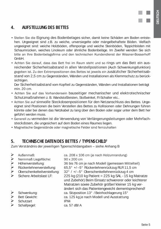
5. TECHNISCHE DATEN DES BETTES / TYPENSCHILD1
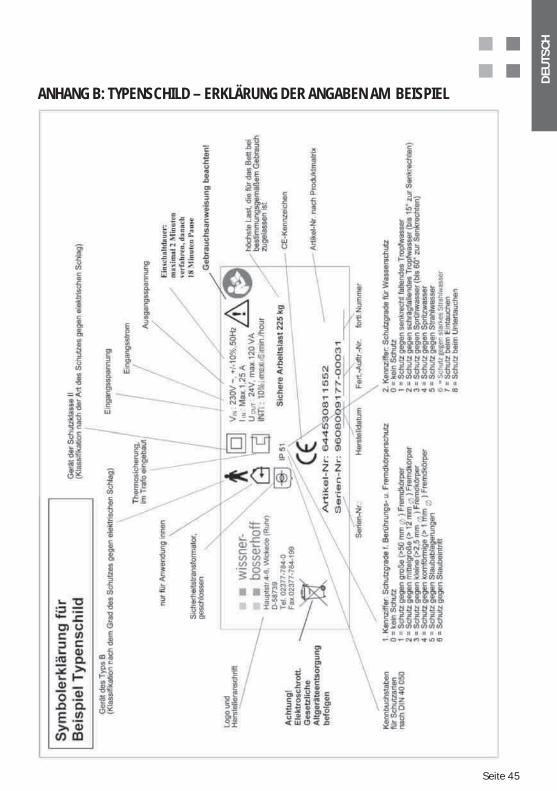
Zum Verständnis der jeweiligen Typenschildangaben – siehe Anhang B
Höhenverstellung: 36 bis 76 cm je nach Modell (gemessen Mittelteil) Rückenlehnenverstellung: 65,5° +/–5° Rückenlehnenrückzug RLR 11,5 cm Oberschenkelteilverstellung: 32° / +/–5° Oberschenkellehnenrückzug 4 cm Sichere Arbeitslast LF: 225 kg (210 kg Patient = 225 kg SAL - 15 kg Matratze
und Zubehör) Beim Einsatz schwererer oder leichterer Matratzen sowie Zubehör größer/kleiner 15 kg ver- ändert sich das Patientengewicht dementsprechend!
Schwenkung: ca. Sitzposition 13° /Beinhochlagerung 15° Bett Gewicht: ca. 125 kg je nach Modell und Ausstattung Schutzart IPX4 Schallpegel: ca. 57 dB/A
Seite 6
DEU
TSC
H
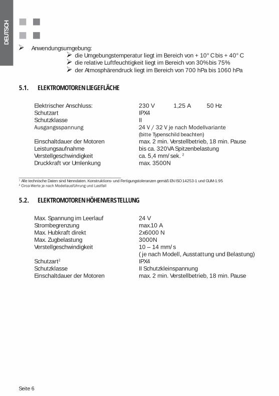
Anwendungsumgebung: die Umgebungstemperatur liegt im Bereich von + 10°C bis + 40°C die relative Luftfeuchtigkeit liegt im Bereich von 30% bis 75% der Atmosphärendruck liegt im Bereich von 700 hPa bis 1060 hPa
5.1. ELEKTROMOTOREN LIEGEFLÄCHE
Elektrischer Anschluss: 230 V 1,25 A 50 Hz Schutzart IPX4 Schutzklasse II (bitte Typenschild beachten) Einschaltdauer der Motoren max. 2 min. Verstellbetrieb, 18 min. Pause Leistungsaufnahme bis ca. 320VA Spitzenbelastung Verstellgeschwindigkeit ca. 5,4 mm/sek. 2
Druckkraft vor Umlenkung max. 3500N
___________________________________________________1 Alle technische Daten sind Nenndaten. Konstruktions- und Fertigungstoleranzen gemäß EN ISO 14253-1 und GUM-1:952
5.2. ELEKTROMOTOREN HÖHENVERSTELLUNG
Max. Spannung im Leerlauf 24 V Strombegrenzung max.10 A Max. Hubkraft direkt 2x6000 N Max. Zugbelastung 3000N Verstellgeschwindigkeit 10 – 14 mm/s ( je nach Modell, Ausstattung und Belastung) Schutzart2 IPX4 Schutzklasse II Schutzkleinspannung Einschaltdauer der Motoren max. 2 min. Verstellbetrieb, 18 min. Pause
DEU
TSC
H
Seite 7
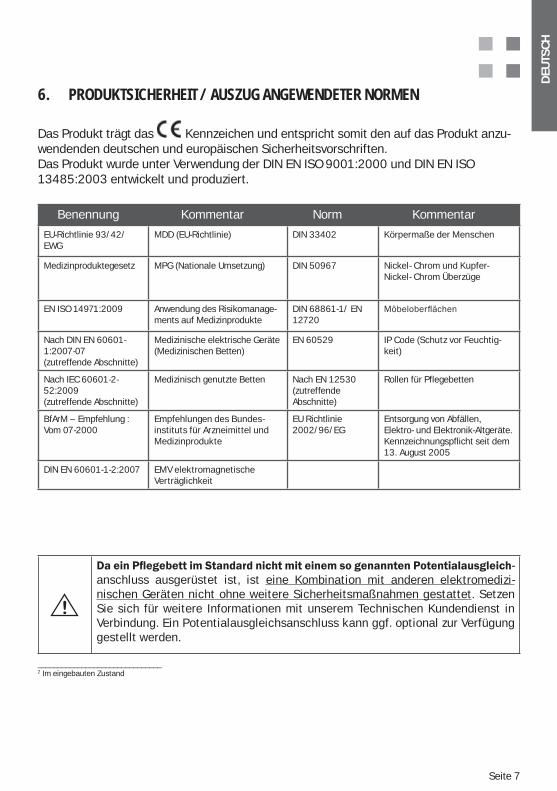
6. PRODUKTSICHERHEIT / AUSZUG ANGEWENDETER NORMEN
Das Produkt trägt das Kennzeichen und entspricht somit den auf das Produkt anzu-wendenden deutschen und europäischen Sicherheitsvorschriften. Das Produkt wurde unter Verwendung der DIN EN ISO 9001:2000 und DIN EN ISO 13485:2003 entwickelt und produziert.
Benennung Kommentar Norm Kommentar
EU-Richtlinie 93/42/EWG
MDD (EU-Richtlinie) DIN 33402 Körpermaße der Menschen
Medizinproduktegesetz MPG (Nationale Umsetzung) DIN 50967 Nickel- Chrom und Kupfer-Nickel- Chrom Überzüge
EN ISO 14971:2009 Anwendung des Risikomanage-ments auf Medizinprodukte
DIN 68861-1/ EN 12720
Nach DIN EN 60601-1:2007-07(zutreffende Abschnitte)
Medizinische elektrische Geräte (Medizinischen Betten)
EN 60529 IP Code (Schutz vor Feuchtig-keit)
Nach IEC 60601-2-52:2009(zutreffende Abschnitte)
Medizinisch genutzte Betten Nach EN 12530(zutreffende Abschnitte)
Rollen für Pflegebetten
BfArM – Empfehlung : Vom 07-2000
Empfehlungen des Bundes-instituts für Arzneimittel und Medizinprodukte
EU Richtlinie 2002/96/EG
Entsorgung von Abfällen, Elektro- und Elektronik-Altgeräte. Kennzeichnungspflicht seit dem 13. August 2005
DIN EN 60601-1-2:2007 EMV elektromagnetische Verträglichkeit
_______________________________2 Im eingebauten Zustand
-anschluss ausgerüstet ist, ist eine Kombination mit anderen elektromedizi-nischen Geräten nicht ohne weitere Sicherheitsmaßnahmen gestattet. Setzen Sie sich für weitere Informationen mit unserem Technischen Kundendienst in Verbindung. Ein Potentialausgleichsanschluss kann ggf. optional zur Verfügung gestellt werden.
Seite 8
DEU
TSC
H
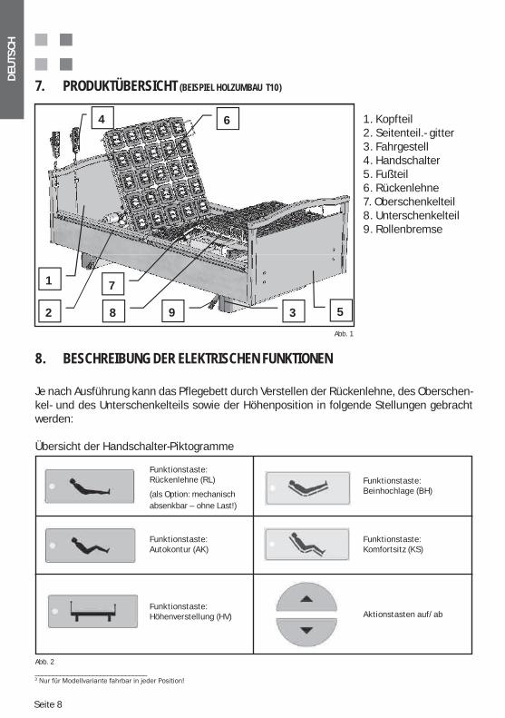
1. Kopfteil2. Seitenteil.- gitter3. Fahrgestell4. Handschalter5. Fußteil6. Rückenlehne7. Oberschenkelteil8. Unterschenkelteil9. Rollenbremse
7. PRODUKTÜBERSICHT (BEISPIEL HOLZUMBAU T10)
Abb. 1
8. BESCHREIBUNG DER ELEKTRISCHEN FUNKTIONEN
Je nach Ausführung kann das Pflegebett durch Verstellen der Rückenlehne, des Oberschen-kel- und des Unterschenkelteils sowie der Höhenposition in folgende Stellungen gebracht werden:
Übersicht der Handschalter-Piktogramme
1
2 3
4
5
6
7
8 9
Abb. 2
Funktionstaste:Rückenlehne (RL)
(als Option: mechanisch absenkbar – ohne Last!)
Funktionstaste:Autokontur (AK)
Funktionstaste:Höhenverstellung (HV)
Funktionstaste:Beinhochlage (BH)
Funktionstaste:Komfortsitz (KS)
Aktionstasten auf/ab
_______________________________3
DEU
TSC
H
Seite 9
Achtung! Beim Verfahren des Bettes in die verschiedenen Positionen ist da-rauf zu achten, dass sich z.B. keine Personen, Körperteile oder Gegenstän-
Achtung! Da das System über einen Akkubetrieb gespeist werden kann (Option), reicht es nicht aus, bei Fehlfunktionen der Motoren den Netz-stecker zu ziehen. Tritt eine Fehlfunktion auf, bitte über die Sperrbox die Funktionen abschalten und Kontakt mit unserem Kundendienst aufneh-men (Option Akkubetrieb).
Achtung! Nicht unter Last bedienen. Bei Betätigung der mechanischen Notabsenkung der Rückenlehne, (Option) muss diese immer am Matrat-zenbegrenzungsbügel oder Halterohr festgehalten werden, um ein plötz-liches Absenken zu verhindern.
Achtung! Alle elektrischen Funktionen können Fehler behaftet sein. Es sei denn, sie sperren sie und geben sie für die Funktionsdauer frei.
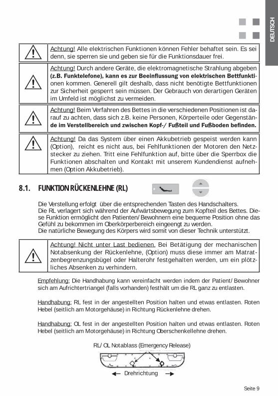
8.1. FUNKTION RÜCKENLEHNE (RL)
Die Verstellung erfolgt über die entsprechenden Tasten des Handschalters.Die RL verlagert sich während der Aufwärtsbewegung zum Kopfteil des Bettes. Die-se Funktion ermöglicht den Patienten/Bewohnern eine bequeme Position ohne das Gefühl zu bekommen im Oberkörperbereich eingeengt zu werden.Die natürliche Bewegung des Körpers wird somit von dieser Technik unterstützt.
Empfehlung: Die Handhabung kann vereinfacht werden indem der Patient/Bewohner sich am Aufrichtertriangel (falls vorhanden) festhält um die RL ganz zu entlasten.
Handhabung: RL fest in der angestellten Position halten und etwas entlasten. Roten Hebel (seitlich am Motorgehäuse) in Richtung Rückenlehne drehen.
Handhabung: OL fest in der angestellten Position halten und etwas entlasten. Roten Hebel (seitlich am Motorgehäuse) in Richtung Oberschenkellehne drehen.
Achtung! Durch andere Geräte, die elektromagnetische Strahlung abgeben -
onen kommen. Generell gilt deshalb, dass nicht benötigte Bettfunktionen zur Sicherheit gesperrt sein müssen. Der Gebrauch von derartigen Geräten im Umfeld ist möglichst zu vermeiden.
RL/OL Notablass (Emergency Release)
Drehrichtung
Seite 10
DEU
TSC
H
8.2. BEINHOCHLAGE (BH)
Die Verstellung erfolgt über die entsprechenden Tasten des Handschalters. Achtung! Diese Position darf aus Sicherheitsgründen nur vom medizinischen Perso-nal bzw. nur „unter medizinischer Aufsicht“ freigegeben werden! Die Handschaltertas- ten werden über den Sicherheitsschlüssel frei geschaltet!Aufgrund der Zweckbestimmung ist eine Trendelenburgposition nicht erforderlich!
Achtung! Die Beinhochlagerung dient bei Altenpflegebetten nicht zur Akutversorgung im Notfall/Schocklagerung. Primär dient diese Funktion nur der mühelosen Einstel-lung einer Beinhochlagerung aus therapeutischen Gründen! Um nicht in Gefahr einer ungewollten Trendelenburg zu geraten, wird dringend empfohlen, gleichzeitig zur Beinhochlagerung die (RL) ca. eine Handbreite anzu-heben. Wichtig dabei ist, dass sich der Kopf des Patienten höher befindet als der orthostatische Punkt des Körpers.
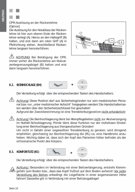
CPR-Auslösung an der Rückenlehne (Option)Die Auslösung für den Notablass der Rücken-lehne ist hier zum oberen Ende der Rücken-lehne verlegt (A). Hierzu an den Haltegriff (B) halten, und erst dann am roten Griff (A) in Pfeilrichtung ziehen. Anschließend Rücken-lehne langsam herunterführen.
ACHTUNG! Bei Betätigung der CPR, immer vorher die Rückenlehne am Matrat-zenbegrenzungsbügel (B) halten und erst dann langsam herunterführen.
BA
A
8.3. KOMFORTSITZ (KS)
Die Verstellung erfolgt über die entsprechenden Tasten des Handschalters.
Achtung ! Besonders im Verbindung mit einer Bettverlängerung, entsteht Klemm-gefahr zum Boden bzw., dass das Kopf/Fußteil auf dem Boden aufsetzt! Vor jeder Verstellung des Bettes unbedingt die Liegefläche in einer angemessenen Höhe fahren! Dasselbe gilt in Verbindung mit einer Bettzeugablage!
DEU
TSC
H
Seite 11
Achtung! Da bei dem Modell „carisma“ zwei voneinander unabhängige An-triebe für die Höhenverstellung zum Einsatz kommen, ist es notwendig, die
-tion (Höchst- oder Tiefstposition) zu verfahren. Damit werden die potentiellen
anzupassen, um eine Gefährdung durch Sturz zu vermeiden.
Achtung! Diese Position darf aus Sicherheitsgründen nur vom medizinischen Perso-nal bzw. nur „unter medizinischer Aufsicht“ freigegeben werden! Die Handschalter- tasten werden über den Sicherheitsschlüssel frei geschaltet! (Kapitel „Handschalter-rückseite mit Sperrfunktion)
8.4. FUNKTION AUTOKONTUR (AK)
Die Verstellung erfolgt über die entsprechenden Tasten des Handschalters.
8.5. FUNKTION HÖHENVERSTELLUNG (HV)
Die Verstellung erfolgt über die entsprechenden Tasten des Handschalters.
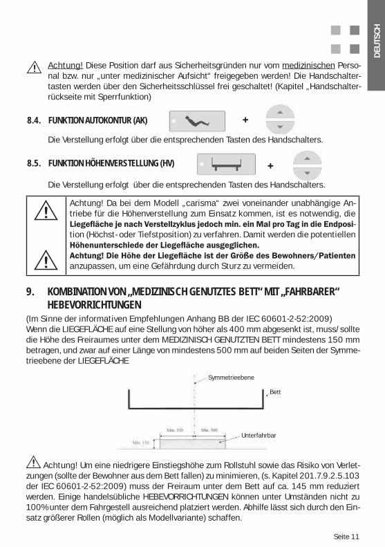
Achtung! Um eine niedrigere Einstiegshöhe zum Rollstuhl sowie das Risiko von Verlet-zungen (sollte der Bewohner aus dem Bett fallen) zu minimieren, (s. Kapitel 201.7.9.2.5.103 der IEC 60601-2-52:2009) muss der Freiraum unter dem Bett auf ca. 145 mm reduziert werden. Einige handelsübliche HEBEVORRICHTUNGEN können unter Umständen nicht zu 100% unter dem Fahrgestell ausreichend platziert werden. Abhilfe lässt sich durch den Ein-satz größerer Rollen (möglich als Modellvariante) schaffen.
9. KOMBINATION VON „MEDIZINISCH GENUTZTES BETT“ MIT „FAHRBARER“ HEBEVORRICHTUNGEN (Im Sinne der informativen Empfehlungen Anhang BB der IEC 60601-2-52:2009)Wenn die LIEGEFLÄCHE auf eine Stellung von höher als 400 mm abgesenkt ist, muss/sollte die Höhe des Freiraumes unter dem MEDIZINISCH GENUTZTEN BETT mindestens 150 mm betragen, und zwar auf einer Länge von mindestens 500 mm auf beiden Seiten der Symme-trieebene der LIEGEFLÄCHE
Symmetrieebene
Bett
Unterfahrbar
Symmetrieebene
Bett
Unterfahrbar
Seite 12
DEU
TSC
H
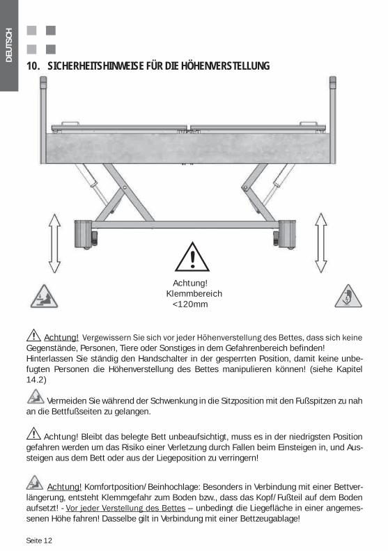
10. SICHERHEITSHINWEISE FÜR DIE HÖHENVERSTELLUNG
Achtung! Gegenstände, Personen, Tiere oder Sonstiges in dem Gefahrenbereich befinden!Hinterlassen Sie ständig den Handschalter in der gesperrten Position, damit keine unbe-fugten Personen die Höhenverstellung des Bettes manipulieren können! (siehe Kapitel 14.2)
Vermeiden Sie während der Schwenkung in die Sitzposition mit den Fußspitzen zu nah an die Bettfußseiten zu gelangen.
Achtung! Bleibt das belegte Bett unbeaufsichtigt, muss es in der niedrigsten Position gefahren werden um das Risiko einer Verletzung durch Fallen beim Einsteigen in, und Aus-steigen aus dem Bett oder aus der Liegeposition zu verringern!
Achtung! Komfortposition/Beinhochlage: Besonders in Verbindung mit einer Bettver-längerung, entsteht Klemmgefahr zum Boden bzw., dass das Kopf/Fußteil auf dem Boden aufsetzt! - – unbedingt die Liegefläche in einer angemes-senen Höhe fahren! Dasselbe gilt in Verbindung mit einer Bettzeugablage!
Achtung!Klemmbereich
<120mm
DEU
TSC
H
Seite 13
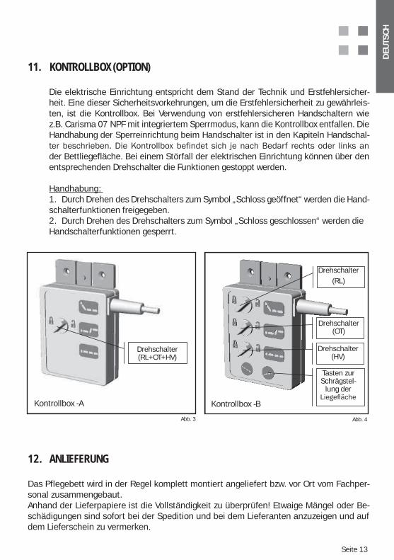
11. KONTROLLBOX (OPTION)
Die elektrische Einrichtung entspricht dem Stand der Technik und Erstfehlersicher-heit. Eine dieser Sicherheitsvorkehrungen, um die Erstfehlersicherheit zu gewährleis- ten, ist die Kontrollbox. Bei Verwendung von erstfehlersicheren Handschaltern wie z.B. Carisma 07 NPF mit integriertem Sperrmodus, kann die Kontrollbox entfallen. Die Handhabung der Sperreinrichtung beim Handschalter ist in den Kapiteln Handschal-
der Bettliegefläche. Bei einem Störfall der elektrischen Einrichtung können über den entsprechenden Drehschalter die Funktionen gestoppt werden.
Handhabung: 1. Durch Drehen des Drehschalters zum Symbol „Schloss geöffnet“ werden die Hand- schalterfunktionen freigegeben.2. Durch Drehen des Drehschalters zum Symbol „Schloss geschlossen“ werden die Handschalterfunktionen gesperrt.
12. ANLIEFERUNG
Das Pflegebett wird in der Regel komplett montiert angeliefert bzw. vor Ort vom Fachper-sonal zusammengebaut. Anhand der Lieferpapiere ist die Vollständigkeit zu überprüfen! Etwaige Mängel oder Be-schädigungen sind sofort bei der Spedition und bei dem Lieferanten anzuzeigen und auf dem Lieferschein zu vermerken.
Abb. 3 Abb. 4
Kontrollbox -A
rehs halter
Kontrollbox -B
Drehschalter(RL+OT+HV)
Drehschalter(RL)
Drehschalter (OT)
Drehschalter (HV)
Tasten zur Schrägstel-
lung der
Kontrollbox -BKontrollbox -A
Seite 14
DEU
TSC
H
13. MONTAGE
Im Bedarfsfall, z. B. zum Zweck des Austausches, können einfache Montagevorgänge auch von fachlich autorisierten Personen durchgeführt werden.
13.1. LIEGEFLÄCHE
1. Fahrgestell positionieren. 2. Liegefläche mit Hilfe einer zweiten Person so auf die Hubelemente legen, dass die Schrauben in Rahmenhöhe liegen. 3. Restliche Schrauben in die vorgesehenen Bohrungen eindrehen und fest mit dem Rahmen verschrauben.
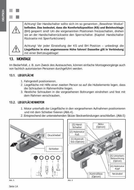
13.2. LIEGEFLÄCHENMOTOR
1. Motor unterhalb der Liegefläche in den vorgesehenen Aufnahmen positionieren und mit dem Schieber fixieren (Abb.4). 2. Entsprechend der untenstehenden Skizze Steckverbindungen anschließen. (Abb.5)
Abb. 5 Abb. 6
Achtung! Der Handschalter sollte sich im so genannten „Bewohner Modus“
(BH) gesperrt sind! Um die vorgenannten Positionen freizuschalten, drehen sie an der Handschalterrückseite den Sperrschalter. (Kapitel: Handschalter Rückseite mit Sperrfunktionen)
Achtung! Vor jeder Einstellung der KS und BH Position – unbedingt die
mit einer Bettzeugablage!
Schieber
Druckhebel
(1) Kontroll-box (Option)
Kontrollbox (Option)
(2) Hubmotor Fuß
(3) Hand-schalter
(5) Unterbett- Beleuchtung
(Option)
Akku (Option)
(4) Hubmotor Kopf
Netzkabel
Druckhebel
Schieber
(3) Hand- Schalter
(2) Hubmotor Fuß
(1) Kontroll- box (Option)
Akku (Option)
Kontrollbox (Option)
(5) Unterbett- Beleuchtung
(Option)
(4) Hubmotor Kopf
Netzkabel
Abb. 5 Abb. 6
DEU
TSC
H
Seite 15
14. TRANSPORT / BETT VERFAHRENBett in fahrbare Position bringen und Bett verfahren (s. Kapitel Brems- und Fahrbarkeit). Zum Verfahren des Bettes nur an den Kopf- und Fußteilen (s. Abb.2) festhalten. Auf keinen Fall darf das Bett an den Seitengittern gezogen/geschoben werden!
Achtung! Beim Transport nicht über das Kabel des Handschalters oder über das Netzanschlusskabel fahren. Nutzen Sie den am Kabel ange-brachten Kabelhaltehaken!
Achten sie beim Verfahren darauf, mit dem Fuß nicht unter die laufenden Rollen bzw. die Fahrgestellverkleidung zu gelangen.
Seite 16
DEU
TSC
H
15. FUNKTIONSPRÜFUNG
Einsatz des Pflegebettes sind einige Funktionsprüfungen durchzuführen und zu kontrollieren, ob die dem Modell entsprechenden Verstellungen erreicht werden und ohne Unterbrechung erfolgen. Diese werden im folgenden näher erläutert.
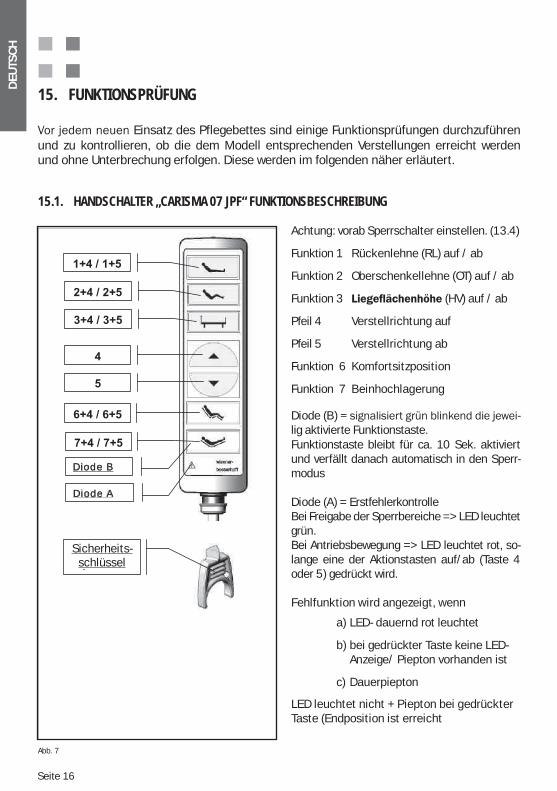
15.1. HANDSCHALTER „CARISMA 07 JPF“ FUNKTIONSBESCHREIBUNG
Achtung: vorab Sperrschalter einstellen. (13.4)
Funktion 1 Rückenlehne (RL) auf / ab
Funktion 2 Oberschenkellehne (OT) auf / ab
Funktion 3 (HV) auf / ab
Pfeil 4 Verstellrichtung auf
Pfeil 5 Verstellrichtung ab
Funktion 6 Komfortsitzposition
Funktion 7 Beinhochlagerung
Diode (B) -lig aktivierte Funktionstaste.Funktionstaste bleibt für ca. 10 Sek. aktiviert und verfällt danach automatisch in den Sperr-modus
Diode (A) = ErstfehlerkontrolleBei Freigabe der Sperrbereiche => LED leuchtet grün.Bei Antriebsbewegung => LED leuchtet rot, so-lange eine der Aktionstasten auf/ab (Taste 4 oder 5) gedrückt wird.
Fehlfunktion wird angezeigt, wenn
a) LED- dauernd rot leuchtet
b) bei gedrückter Taste keine LED- Anzeige/ Piepton vorhanden ist
c) Dauerpiepton
LED leuchtet nicht + Piepton bei gedrückter Taste (Endposition ist erreicht
Abb. 7
Diode A
Diode B
Sicher-heitsschlüs
l
Sicherheits- schlüssel
DEU
TSC
H
Seite 17
1
2
3
A B
4
Achtung! Si -cherheitsschlüssel - nur in dem dafür vor-gesehenen S lt i l i
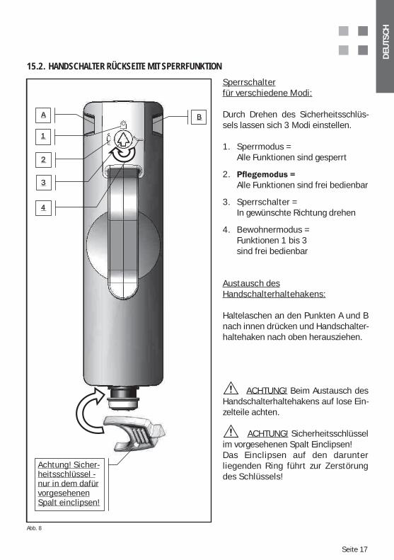
Sperrschalter für verschiedene Modi:
Durch Drehen des Sicherheitsschlüs-sels lassen sich 3 Modi einstellen.
1. Sperrmodus = Alle Funktionen sind gesperrt
2. Alle Funktionen sind frei bedienbar
3. Sperrschalter = In gewünschte Richtung drehen
4. Bewohnermodus = Funktionen 1 bis 3 sind frei bedienbar
Austausch desHandschalterhaltehakens:
Haltelaschen an den Punkten A und B nach innen drücken und Handschalter-haltehaken nach oben herausziehen.
ACHTUNG! Beim Austausch des Handschalterhaltehakens auf lose Ein-zelteile achten.
ACHTUNG! Sicherheitsschlüssel im vorgesehenen Spalt Einclipsen!Das Einclipsen auf den darunter liegenden Ring führt zur Zerstörung des Schlüssels!
15.2. HANDSCHALTER RÜCKSEITE MIT SPERRFUNKTION
Achtung! Sicher- heitsschlüssel - nur in dem dafür vorgesehenen Spalt einclipsen!
Abb. 8
Seite 18
DEU
TSC
H
Erstfehlersicherheit des Handschalters: Beim Betätigen der Tasten erklingt ein kurzer Signalton. Das bedeutet, dass die Handschal-terfunktion korrekt ausgeführt wird. Im Falle eines Dauertons bei nicht gedrückter Taste ist entweder die Handschalterfunktion über die Kontrollbox (Option) gesperrt, oder es liegt ein Fehler vor.
Liegt ein Fehlerfall vor bitte das Bett vom Netz trennen (Stecker ziehen) und unseren Kundendienst benachrichtigen (s. Kapitel Ansprechpartner auf S.38)
Handschalter:
Achtung! Ohne die Freigabe über den Sicherheitsschlüssel sind aus Si-cherheitsgründen keine Einzelfunktionen für die Komfortsitzverstellung (6+4 , 6+5) sowie für die Beinhochlagerung (7+4 , 7+5) möglich!Da diese Positionen nur von der „medizinischen Aufsicht“ (z. B. Kranken-
-zubewahren, um den Schlüssel im Bedarfsfall griffbereit zu haben.
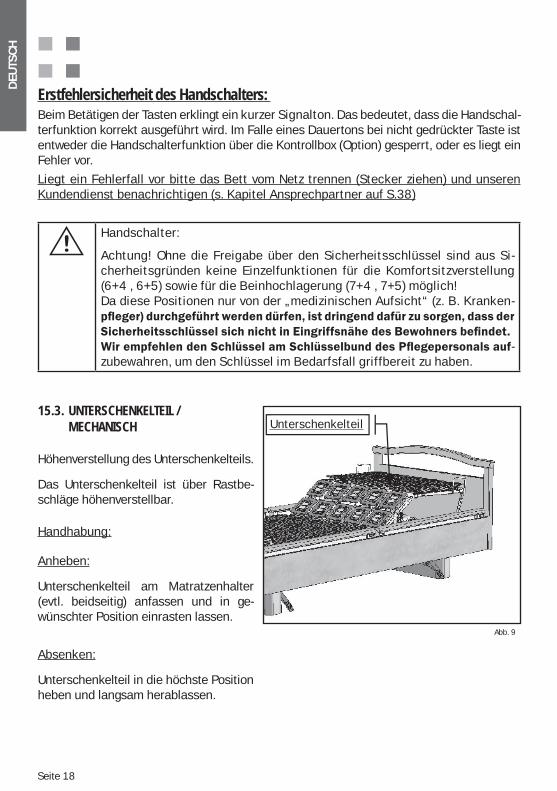
15.3. UNTERSCHENKELTEIL / MECHANISCH
Höhenverstellung des Unterschenkelteils.
Das Unterschenkelteil ist über Rastbe-schläge höhenverstellbar.
Handhabung:
Anheben:
Unterschenkelteil am Matratzenhalter (evtl. beidseitig) anfassen und in ge-wünschter Position einrasten lassen.
Absenken:
Unterschenkelteil in die höchste Position heben und langsam herablassen.
Abb. 9
Unterschenkelteil
DEU
TSC
H
Seite 19
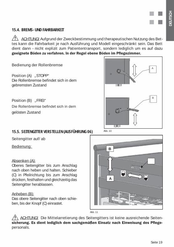
15.4. BREMS- UND FAHRBARKEIT
ACHTUNG! Aufgrund der Zweckbestimmung und therapeutischen Nutzung des Bet-tes kann die Fahrbarkeit je nach Ausführung und Modell eingeschränkt sein. Das Bett dient dann - nicht explizit zum Patiententransport, sondern lediglich um es auf dazu
Bedienung der Rollenbremse
Position (A) „STOPP“Die Rollenbremse befindet sich in dem gebremsten Zustand
Position (B) „FREI“
gelösten Zustand
Abb. 10
A
B
Seitengitter auf/ab
Bedienung:
Absenken (A):Oberes Seitengitter bis zum Anschlag nach oben heben und halten. Schieber (C) in Pfeilrichtung bis zum Anschlag drücken, festhalten und gleichzeitig das Seitengitter herablassen.
Anheben (B):Das obere Seitengitter nach oben schie-ben, bis der Knopf (C) einrastet.
15.5. SEITENGITTER VERSTELLEN (AUSFÜHRUNG 06)
Abb. 11
B
A
ACHTUNG! Die Mittelarretierung des Seitengitters ist keine ausreichende Seiten-
personals.
Seite 20
DEU
TSC
H
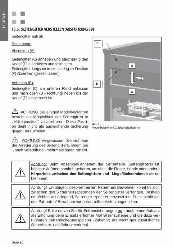
Seitengitter auf/ab
Bedienung:
Absenken (A):
Seitengitter (C) anheben und gleichzeitig den Knopf (D) eindrücken und festhalten.Seitengitter langsam in die niedrigste Position (A) Absenken (gleiten lassen).
Anheben (B):Seitengitter (C) am unteren Rand anfassen und nach oben (B - Richtung) heben bis der Knopf (D) eingerastet ist.
ACHTUNG! Bei einigen Modellvarianten besteht die Möglichkeit das Seitengitter in „Mittelposition“ zu arretieren. Diese Positi-on dient nicht als ausreichende Sicherung gegen Herausfallen.
ACHTUNG! Vergewissern Sie sich von der Arretierung des Seitengitters, indem Sie - nach Verstellung - mehrmals daran rütteln.
15.6. SEITENGITTER VERSTELLEN (AUSFÜHRUNG 09)
Abb. 12Modellbeispiel mit 2 Seitengitterholmen
B
A
D
C
Achtung! Beim Absenken/Anheben der Seitenteile (Seitengitters) ist höchste Aufmerksamkeit geboten, um nicht die Finger, Hände oder andere
-klemmen.
Achtung! Unruhigen, desorientierten Patienten/Bewohner könnten sich zwischen den Sicherheitsabständen der Seitengitter verfangen. Deshalb empfehlen wir dringend, Seitengitterpolster einzusetzen. Diese schützen den Patienten/Bewohner vor potentiellen Verletzungsrisiken.
Achtung! Bitte nutzen Sie für Seitensicherungen ggf. auch einen Aufsatz als Erhöhung beim Einsatz erhöhter Matratzensysteme und die dazu ver-fügbaren Seitensicherungspolster (Zubehör) als wichtiges zusätzliches Sicherheits- und Schutzmerkmal.
DEU
TSC
H
Seite 21
Seitenteile auf /ab
Handhabung:
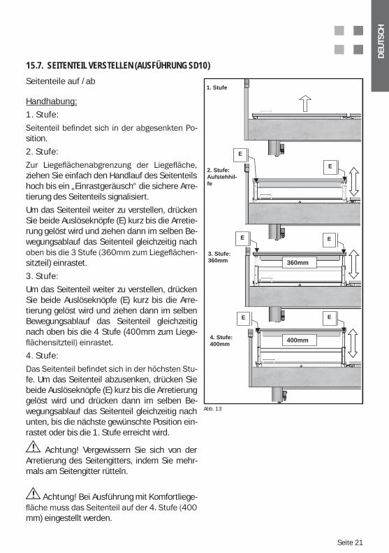
1. Stufe:
-sition.
2. Stufe:
ziehen Sie einfach den Handlauf des Seitenteils hoch bis ein „Einrastgeräusch“ die sichere Arre-tierung des Seitenteils signalisiert.
Um das Seitenteil weiter zu verstellen, drücken Sie beide Auslöseknöpfe (E) kurz bis die Arretie-rung gelöst wird und ziehen dann im selben Be-wegungsablauf das Seitenteil gleichzeitig nach
-sitzteil) einrastet.
3. Stufe:
Um das Seitenteil weiter zu verstellen, drücken Sie beide Auslöseknöpfe (E) kurz bis die Arre-tierung gelöst wird und ziehen dann im selben Bewegungsablauf das Seitenteil gleichzeitig nach oben bis die 4 Stufe (400mm zum Liege-
4. Stufe:
-fe. Um das Seitenteil abzusenken, drücken Sie beide Auslöseknöpfe (E) kurz bis die Arretierung gelöst wird und drücken dann im selben Be-wegungsablauf das Seitenteil gleichzeitig nach unten, bis die nächste gewünschte Position ein-rastet oder bis die 1. Stufe erreicht wird.
Achtung! Vergewissern Sie sich von der Arretierung des Seitengitters, indem Sie mehr-mals am Seitengitter rütteln.
Achtung! Bei Ausführung mit Komfortliege-
mm) eingestellt werden.
15.7. SEITENTEIL VERSTELLEN (AUSFÜHRUNG SD10)
Abb. 16
360mm
400mm
1. Stufe
2. Stufe:
Aufstehhil-
fe
3. Stufe:
360mm
4. Stufe:
400mm
E
E E
E
E
E
Abb. 13
Seite 22
DEU
TSC
H
Achtung! Beim Absenken/Anheben der Seitenteile (Seitengitters) ist höchste Aufmerksamkeit geboten, um nicht die Finger, Hände oder ande-
-klemmen.
Achtung! Unruhigen, desorientierten Patienten/Bewohner könnten sich zwischen den Sicherheitsabständen der Seitengitter verfangen. Deshalb empfehlen wir dringend, Seitengitterpolster einzusetzen. Diese schützen den Patienten/Bewohner vor potentiellen Verletzungsrisiken.
16. ZUGELASSENES3 ZUBEHÖR4
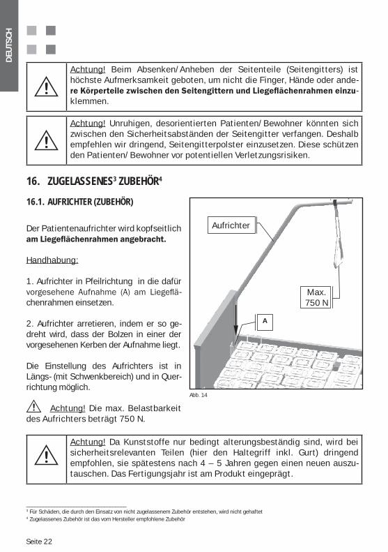
16.1. AUFRICHTER (ZUBEHÖR)
Der Patientenaufrichter wird kopfseitlich
Handhabung:
1. Aufrichter in Pfeilrichtung in die dafür -
chenrahmen einsetzen.
2. Aufrichter arretieren, indem er so ge-dreht wird, dass der Bolzen in einer der vorgesehenen Kerben der Aufnahme liegt.
Die Einstellung des Aufrichters ist in Längs- (mit Schwenkbereich) und in Quer-richtung möglich.
Achtung! Die max. Belastbarkeit des Aufrichters beträgt 750 N.
Achtung! Da Kunststoffe nur bedingt alterungsbeständig sind, wird bei sicherheitsrelevanten Teilen (hier den Haltegriff inkl. Gurt) dringend empfohlen, sie spätestens nach 4 – 5 Jahren gegen einen neuen auszu- tauschen. Das Fertigungsjahr ist am Produkt eingeprägt.
____________________________________3 Für Schäden, die durch den Einsatz von nicht zugelassenem Zubehör entstehen, wird nicht gehaftet4 Zugelassenes Zubehör ist das vom Hersteller empfohlene Zubehör
Abb. 14
Aufrichter
A
Max.
750N
Aufrichter
Max.750 N
DEU
TSC
H
Seite 23
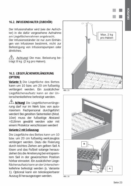
Der Infusionshalter wird (wie der Aufrich-ter) in die dafür vorgesehene Aufnahme
Der Infusionsständer ist nur zum Einhän-gen von Infusionen bestimmt, nicht zur Befestigung von Infusionspumpen oder ähnliches.
Achtung! Die max. Belastung be-trägt 8 kg (2 kg pro Haken).
16.2. INFUSIONSHALTER (ZUBEHÖR)
16.3. LIEGEFLÄCHENVERLÄNGERUNG (OPTION)Variante 1: kann um 10 bzw. um 20 cm fußseitig verlängert werden. Ein zusätzlicher
-terschenkellehne befestigt werden.
Achtung! -rung darf nur im Werk bzw. von auto-risiertem Fachpersonal durchgeführt werden! Bei geteilten Seitenteilen (Mod. 10er) muss der fußseitige Abstand >318mm gewählt werden oder mit einem Protektor verschlossen werden!
Variante 2 mit Seilauszug:
bzw. um 20 cm fußseitig werkzeuglos verlängert werden. Dazu die Fixierung durch leichtes Ziehen am gelben Seil A lösen und das Fußteil solange heraus-ziehen bis die Arretierung bei entspann- tem Seil in der gewünschten Position hörbar einrastet. Ein zusätzlicher Liege-
-kellehne befestigt werden (s. Variante 1). Optional kann ein teleskopierbarer Auszug B herausgezogen werden.
Abb. 15
Abb. 16
dierah-
In-usi-
8 kg
Max. 2 kgpro Haken
f
B
A
Seite 24
DEU
TSC
H
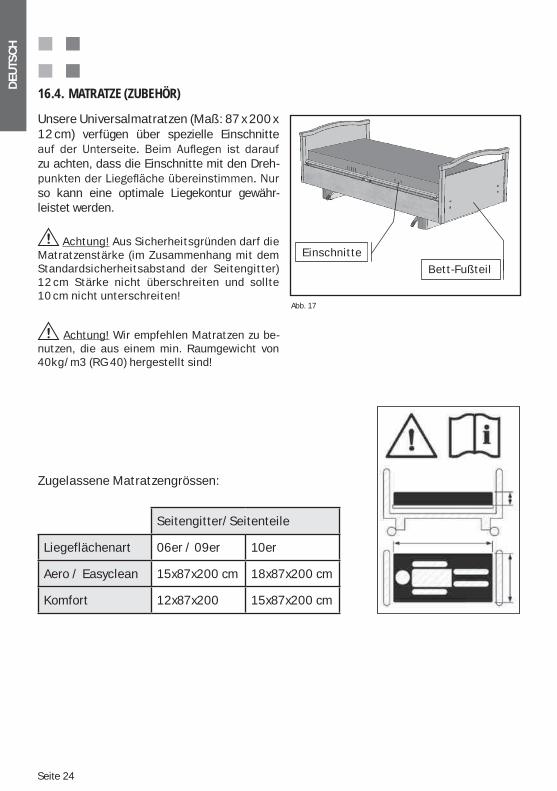
Unsere Universalmatratzen (Maß: 87 x 200 x 12 cm) verfügen über spezielle Einschnitte
zu achten, dass die Einschnitte mit den Dreh-
so kann eine optimale Liegekontur gewähr- leistet werden.
Achtung! Aus Sicherheitsgründen darf die Matratzenstärke (im Zusammenhang mit dem Standardsicherheitsabstand der Seitengitter) 12 cm Stärke nicht überschreiten und sollte 10 cm nicht unterschreiten!
Achtung! Wir empfehlen Matratzen zu be-nutzen, die aus einem min. Raumgewicht von 40kg/m3 (RG 40) hergestellt sind!
16.4. MATRATZE (ZUBEHÖR)
Abb. 17
Bett-Fußteil
EinschnitteEinschnitte
Bett-Fußteil
Zugelassene Matratzengrössen:
Seitengitter/Seitenteile
Liegeflächenart 06er / 09er 10er
Aero / Easyclean 15x87x200 cm 18x87x200 cm
Komfort 12x87x200 15x87x200 cm
DEU
TSC
H
Seite 25
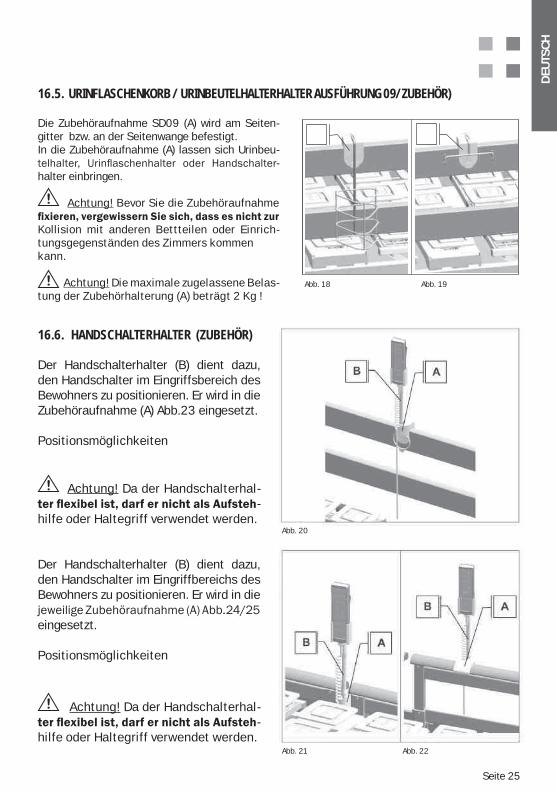
Der Handschalterhalter (B) dient dazu, den Handschalter im Eingriffsbereich des Bewohners zu positionieren. Er wird in die Zubehöraufnahme (A) Abb.23 eingesetzt.
Positionsmöglichkeiten
Achtung! Da der Handschalterhal--
hilfe oder Haltegriff verwendet werden.
Der Handschalterhalter (B) dient dazu, den Handschalter im Eingriffbereichs des Bewohners zu positionieren. Er wird in die
eingesetzt.
Positionsmöglichkeiten
Achtung! Da der Handschalterhal--
hilfe oder Haltegriff verwendet werden.
16.6. HANDSCHALTERHALTER (ZUBEHÖR)
Abb. 20
Abb. 21 Abb. 22
Die Zubehöraufnahme SD09 (A) wird am Seiten-gitter bzw. an der Seitenwange befestigt. In die Zubehöraufnahme (A) lassen sich Urinbeu-
-halter einbringen.
Achtung! Bevor Sie die Zubehöraufnahme
Kollision mit anderen Bettteilen oder Einrich-tungsgegenständen des Zimmers kommen kann.
Achtung! Die maximale zugelassene Belas- tung der Zubehörhalterung (A) beträgt 2 Kg !
16.5. URINFLASCHENKORB / URINBEUTELHALTERHALTER AUSFÜHRUNG 09/ZUBEHÖR)
Abb. 18 Abb. 19
Seite 26
DEU
TSC
H
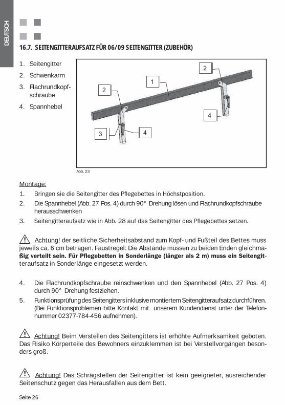
1. Seitengitter
2. Schwenkarm
3. Flachrundkopf- schraube
4. Spannhebel
16.7. SEITENGITTERAUFSATZ FÜR 06/09 SEITENGITTER (ZUBEHÖR)
Abb. 23
Montage:
2. Die Spannhebel (Abb. 27 Pos. 4) durch 90° Drehung lösen und Flachrundkopfschraube herausschwenken
Achtung! der seitliche Sicherheitsabstand zum Kopf- und Fußteil des Bettes muss jeweils ca. 6 cm betragen. Faustregel: Die Abstände müssen zu beiden Enden gleichmä-
-teraufsatz in Sonderlänge eingesetzt werden.
4. Die Flachrundkopfschraube reinschwenken und den Spannhebel (Abb. 27 Pos. 4) durch 90° Drehung festziehen.
5. Funktionsprüfung des Seitengitters inklusive montiertem Seitengitteraufsatz durchführen. (Bei Funktionsproblemen bitte Kontakt mit unserem Kundendienst unter der Telefon- nummer 02377-784-456 aufnehmen).
Achtung! Beim Verstellen des Seitengitters ist erhöhte Aufmerksamkeit geboten. Das Risiko Körperteile des Bewohners einzuklemmen ist bei Verstellvorgängen beson-ders groß.
Achtung! Das Schrägstellen der Seitengitter ist kein geeigneter, ausreichender Seitenschutz gegen das Herausfallen aus dem Bett.
DEU
TSC
H
Seite 27
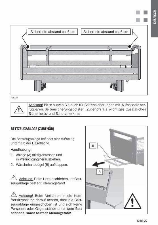
Sicherheitsabstand ca. 6 cm Sicherheitsabstand ca. 6 cm
Achtung! Bitte nutzen Sie auch für Seitensicherungen mit Aufsatz die ver-fügbaren Seitensicherungspolster (Zubehör) als wichtiges zusätzliches Sicherheits- und Schutzmerkmal.
Abb. 24
BETTZEUGABLAGE (ZUBEHÖR)
Handhabung:
1. Ablage (A) mittig anfassen und in Pfeilrichtung herausziehen.
2. Wäschehaltebügel (B) aufklappen.
Achtung! Beim Hereinschieben der Bett-zeugablage besteht Klemmgefahr!
Achtung! Beim Verfahren in die Kom-fortsitzposition darauf achten, dass die Bett-zeugablage eingeschoben ist und sich keine Personen oder Gegenstände unter dem Bett
Seite 28
DEU
TSC
H
17. REINIGUNG UND DESINFEKTION
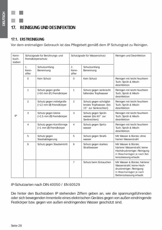
17.1. ERSTREINIGUNG
IP-Schutzarten nach DIN 40050 / EN 60529
Die hinter den Buchstaben IP stehenden Ziffern geben an, wie die spannungsführenden oder sich bewegenden Innenteile eines elektrischen Gerätes gegen von außen eindringende Festkörper bzw. gegen von außen eindringendes Wasser geschützt sind.
Kenn-buch-staben
Schutzgrade für Berührungs- und Fremdkörperschutz
Schutzgrade für Wasserschutz Reinigen und Desinfektion
IP
1. Kenn-ziffer
SchutzumfangBenennung
2. Kenn-ziffer
Schutzumfang Benennung
0 Kein Schutz 0 Kein Schutz Reinigen mit leicht feuchtem Tuch; Sprüh & Wisch- desinfektion
1 Schutz gegen große (>50 mm Ø ) Fremdkörper
1 Schutz gegen senkrecht fallendes Tropfwasser
Reinigen mit leicht feuchtem Tuch; Sprüh & Wisch- desinfektion
2 Schutz gegen mittelgroße (>12 mm Ø) Fremdkörper
2 Schutz gegen schrägfal-lendes Tropfwasser. (bis 15° zur Senkrechten)
Reinigen mit leicht feuchtem Tuch; Sprüh & Wisch- desinfektion
3 Schutz gegen kleine (>2,5 mm Ø) Fremdkörper
3 Schutz gegen Sprüh-wasser (bis 60° zur Senkrechten)
Reinigen mit leicht feuchtem Tuch; Sprüh & Wisch- desinfektion
4 Schutz gegen Kornförmige (>1 mm Ø) Fremdkörper
4 Schutz gegen Spritz-wasser
Reinigen mit leicht feuchtem Tuch; Sprüh & Wisch- desinfektion
5 Schutz gegenStaubablagerung
5 Schutz gegen Strahl-wasser
Mit Wasser & Bürste; ohne harten Wasserstrahl
6 Schutz gegen Staubeintritt 6 Schutz gegen starkesStrahlwasser
Mit Wasser & Bürste; härterer Wasserstrahl; keine Hochdruckreiniger; Reinigung
tenzulassung erlaubt.
7 Schutz beim Eintauchen Mit Wasser & Bürste; härterer Wasserstrahl; keine Hoch-druckreiniger; Reinigung
Bettenzulassung erlaubt.
DEU
TSC
H
Seite 29
Achtung! Aus Sicherheitsgründen muss dringend das Eindringen oder Aufbringen von anderen Flüssigkeiten als Wasser (z.B. Lösungsmittel, Öle, Laugen, Reiniger etc.) in oder auf Teile des Pflegebettes vermieden werden.
Achtung! Gehäuse die Schutz gegen das Eindringen von Wasser haben, verfügen nicht zwangsläufig auch über den gleichen Schutz gegen andere Flüssigkeiten!
Achtung! Das Pflegebett ist deshalb generell vor jeglicher Feuchtigkeit möglichst zu schützen! Die Reinigung sollte nur mit einem leicht feuchten Tuch erfolgen.
17.2. DESINFEKTION / STERILISATION-
fizieren. Das Pflegebett darf nicht in Waschstraßen oder mit Spritzwasser desinfiziert wer-den. Für die Desinfektion des Pflegebettes werden folgende Mittel empfohlen, die nur durch gleichwertige Mittel ersetzt werden dürfen:Terralin, Perform und Sagrotan Med (Schülke & Mayr GmbH, Norderstedt).Diese Mittel sind nur gemäß Herstellervorschrift zu verwenden! Dies betrifft vor allem die Dosierung der Mittel und die eventuelle Gefährdung bei der Kombination mit anderen Mit-teln.Die Holzumrandung darf mit diesen Mitteln nicht in Berührung kommen.
17.3. PFLEGEANLEITUNG FÜR HOLZTEILE Wir haben Materialien höchster Qualität eingesetzt, um für Sie ein Produkt mit hohem Ge-brauchsnutzen und wohnlichen Echtholzcharakter zu schaffen.Damit die Freude an Ihrem Wissner-Bosserhoff-Produkt möglichst lange von Bestand ist, empfehlen wir die Reinigung mit einem leicht feuchten und weichen Tuch.
Jedes Echtholzmaterial (Furnier, Massivholz) unterliegt auch im lackierten Zustand einem natürlichen Alterungsprozess. Im Laufe der Zeit führen Umwelteinflüsse wie UV-Strahlung, Luftfeuchtigkeit oder Wärme zu Veränderungen der Farbgebung der Echtholzoberflächen. Hinzu kommt, dass Holz als natürliches Material einer naturgegebenen Vielfalt und Nuan-cierung unterliegt. Die Texturen von Furnieren sind grundsätzlich nur allgemein festlegbar,
-unterschiede innerhalb von Wissner-Bosserhoff Lieferungen sind natur bedingt und tech-nisch unvermeidbar. Dies gilt insbesondere bei Nach- oder Ergänzungslieferungen. Aus den genannten Gründen stellen relative Helligkeits-, Kontrast- und Farbdifferenzen zwischen Furnierflächen, Massivholzteilen oder Dekoroberflächen (Melamin, HPL) sowie wuchsbedingte Einschlüsse in den Echtholzmaterialien keinen Mangel dar und die Wissner-Bosserhoff GmbH kann hierfür keinerlei Haftung oder Gewährleistung übernehmen.Durch die sorgfältige Auswahl, die Sortierung und die farbliche Abstimmung von Furnie-ren und Lacken garantiert Wissner-Bosserhoff eine hohe Qualität der Farbgebung der Pro-dukte.
Seite 30
DEU
TSC
H
17.4. EINSATZ VON REINIGUNGSMITTELNBei besonders hartnäckigen Flecken können selbstverständlich handelsübliche, umweltscho-nende Allzweck Haushaltsreiniger verwendet werden. Die Möbeloberflächen der Wissner-Bos-serhoff-Produkte entsprechen den Anforderungen der Norm DIN 68861 - 1A für Möbelober-flächen bei chemischer Beanspruchung und haben damit eine ausgezeichnete Beständigkeit gegenüber üblichen, normalen Belastungen.
abtragende Bestandteile enthalten und als Scheuermittel wirken.Es ist darauf zu achten, dass bei Nutzung und Reinigung keine Nässe oder Flüssigkeitsflecken auf dem Echtholz und Furnierflächen verbleiben. Holz ist ein Naturprodukt mit der Eigenschaft, Feuchtigkeit aufzunehmen und sich dabei auszudehnen. Dies kann zu Beschädigungen der Oberflächenversiegelung führen. Deshalb ist die Nutzung und die Lagerung von Holzprodukten unter Einfluss von hoher Feuch-tigkeit zu vermeiden. Nach einer Reinigung wird empfohlen, die Echtholz- und Furnierflächen mit einem trockenen Tuch abzuwischen, um eine Schädigung des Produktes durch Feuchtig-keit möglichst auszuschließen.
17.5. EINSATZ VON DESINFEKTIONSMITTELNEs dürfen nur Desinfektionsmittel benutzt werden, die den im Anhang 1 der DIN 68861 Teil1 beschriebenen Desinfektionsmitteln entsprechen: a) Phenolderivate, 0,5-%ige wässrige Lösung: Chlorierte Alkyl-,Cycloalkyl- Aryl-Phenol b) Chloramin T, 2,5-%ige wässrige Lösung: p-Toluolsulfonchloramid-Natrium
16.6. BESCHÄDIGUNGEN AN DEN HOLZTEILENWird das Furnier oder die Oberflächenversiegelung durch Stöße, Kratzer oder Schnitte beschädigt, so muß die Oberfläche anschließend umgehend wieder durch geeignete Repa-raturmaterialien gegen das Eindringen von Feuchtigkeit geschützt werden. Wenden Sie sich bitte an den Wissner-Bosserhoff-Kundendienst oder einen Fachbetrieb.
17.7. UMWELTVERTRÄGLICHKEITAlle verwendeten Holzmaterialien erfüllen die strengen deutschen Gesetze und Vorschriften und sind gesundheitlich unbedenklich. Der Mensch und seine Umwelt stehen im Mittelpunkt unseres Handelns.
17.8. QUALITÄTUnsere Produkte unterliegen einer strengen Kontrolle durch unser Qualitätssicherungssystem nach der internationalen Norm DIN EN ISO 9001:2000 und DIN EN ISO 13485:2003 für die Herstellung und den Vertrieb von Medizinprodukten.Auf alle Ihnen zugesicherten Eigenschaften übernimmt Wissner-Bosserhoff ein Jahr Herstel-lergarantie. Ausgenommen sind Ansprüche, die ihre Ursache im unsachgemäßen, unüblichen Gebrauch oder Pflege haben. Bitte wenden Sie sich bei Anlass zu Beanstandungen oder Kritik an unseren Kundendienst.
DEU
TSC
H
Seite 31
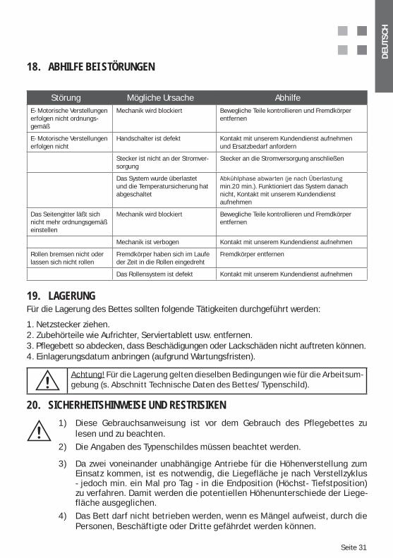
18. ABHILFE BEI STÖRUNGEN
Störung Mögliche Ursache AbhilfeE- Motorische Verstellungen erfolgen nicht ordnungs-gemäß
Mechanik wird blockiert Bewegliche Teile kontrollieren und Fremdkörper entfernen
E- Motorische Verstellungen erfolgen nicht
Handschalter ist defekt Kontakt mit unserem Kundendienst aufnehmen und Ersatzbedarf anfordern
Stecker ist nicht an der Stromver-sorgung
Stecker an die Stromversorgung anschließen
Das System wurde überlastet und die Temperatursicherung hat abgeschaltet
min.20 min.). Funktioniert das System danach nicht, Kontakt mit unserem Kundendienst aufnehmen
Das Seitengitter läßt sich nicht mehr ordnungsgemäß einstellen
Mechanik wird blockiert Bewegliche Teile kontrollieren und Fremdkörper entfernen
Mechanik ist verbogen Kontakt mit unserem Kundendienst aufnehmen
Rollen bremsen nicht oder lassen sich nicht rollen
Fremdkörper haben sich im Laufe der Zeit in die Rollen eingedreht
Fremdkörper entfernen
Das Rollensystem ist defekt Kontakt mit unserem Kundendienst aufnehmen
19. LAGERUNGFür die Lagerung des Bettes sollten folgende Tätigkeiten durchgeführt werden:
1. Netzstecker ziehen.2. Zubehörteile wie Aufrichter, Serviertablett usw. entfernen.3. Pflegebett so abdecken, dass Beschädigungen oder Lackschäden nicht auftreten können.4. Einlagerungsdatum anbringen (aufgrund Wartungsfristen).
Achtung! Für die Lagerung gelten dieselben Bedingungen wie für die Arbeitsum-gebung (s. Abschnitt Technische Daten des Bettes/Typenschild).
20. SICHERHEITSHINWEISE UND RESTRISIKEN
1) Diese Gebrauchsanweisung ist vor dem Gebrauch des Pflegebettes zu lesen und zu beachten.2) Die Angaben des Typenschildes müssen beachtet werden.
3) Da zwei voneinander unabhängige Antriebe für die Höhenverstellung zum Einsatz kommen, ist es notwendig, die Liegefläche je nach Verstellzyklus - jedoch min. ein Mal pro Tag - in die Endposition (Höchst- Tiefstposition) zu verfahren. Damit werden die potentiellen Höhenunterschiede der Liege- fläche ausgeglichen.4) Das Bett darf nicht betrieben werden, wenn es Mängel aufweist, durch die Personen, Beschäftigte oder Dritte gefährdet werden können.
Seite 32
DEU
TSC
H
5) Das Bett darf nur von Personen angewendet werden, die aufgrund ihrer Ausbildung oder ihrer Kenntnisse und praktischen Erfahrungen die Gewähr für eine sachgerechte Handhabung bieten.
6) Der Anwender muss sich vor der Anwendung des Bettes von der Funkti- onssicherheit und dem ordnungsgemäßen Zustand des Bettes überzeu- gen.
7) Das Bett muss u. U. täglich oder bei jedem Schichtwechsel einer Funkti- onsprüfung unterzogen werden, damit gewährleistet ist, dass das Bett ohne Gefahren für den Patienten und den Anwender bestimmungsgemäß verwendet werden kann.
8) Verformte Aufrichter nicht richten und wieder einsetzen, sondern austau- schen.
9) Das Bett darf nur auf ebenen und festen Bodenbelägen verfahren werden.
10) Ist das Bett belegt, müssen sich die Rollen stets in gebremster Position befinden - ansonsten besteht Sturzgefahr für den Patienten beim Ein- und Aussteigen, da er sich u. U. am Bett abstützt-.
11) Die Höhe der Liegefläche ist der Größe des Patienten anzupassen, um eine Gefährdung durch Sturz zu vermeiden.
12) Bei Betätigung der mechanischen Notabsenkung der Rückenlehne (Option) muss diese immer am Matratzenbegrenzungsbügel oder Halterohr festgehalten werden, um ein plötzliches Absenken zu verhindern.
13) Beim Verfahren des Bettes in die verschiedenen Positionen ist darauf zu achten, dass sich keine Kinder, Körperteile oder sonstige Gegenstände im Verstellbereich befinden.
14) Die Verstellungen der Seitenteile (Seitengitter) sind nur durch das Pflege- personal vorzunehmen. Das Pflegepersonal muss sich bei der Verstellung der Liegeflächenpositionen davon überzeugen, dass der Patient nicht mit den Seitengittern in Berührung kommt, damit Quetschungen von Hand, Bein oder sonstigen Körperteilen vermieden werden.
15) Extremes seitliches Hinauslehnen des Oberkörpers ist zu vermeiden.
16) Seitengitter nicht über 75 kg in senkrechter und über 50 kg in waage- rechter Richtung belasten.
DEU
TSC
H
Seite 33
17) Je nach körperlicher und geistiger Verfassung des Patienten sind die Funktionen am Handschalter über eine Kontrollbox zu sperren bzw. freizu-geben. Die Wirksamkeit der Sperrfunktionen muss am Handschalter über-prüft werden.
18) Da das System über Akkubetrieb gespeist werden kann, reicht es nicht aus, bei Fehlfunktionen der Motoren den Netzstecker zu ziehen. Tritt eine Fehlfunktion auf, bitte über die Kontrollbox die Funktionen abschalten und Kontakt mit unserem Kundendienst aufnehmen (Option Akkubetrieb).
19) Bei Verstellungen über den Handschalter wird empfohlen, in der Nähe der Kontrollbox zu bleiben um etwaige Fehlfunktionen sofort abzustellen.
20) Achtung! Alle elektrischen Funktionen können fehlerbehaftet sein. Es sei denn, sie sperren sie über die Kontrollbox.
21) Als Stromquelle ist eine nach VDE Bestimmungen eingerichtete Netzsteck-dose 220 / 230 Volt, 50 Hz zu benutzen.
22) Den Stecker nicht mit nassen Händen berühren. Netzanschlussleitung nur am Stecker anfassen und aus der Netzsteckdose ziehen.
23) Netzanschlussleitung ohne Schlingen verlegen, nicht knicken oder um scharfe Kanten biegen.
24) Anschluss- und Zuleitung generell vor mechanischer Beanspruchung schüt-zen.
25) Netzanschlussleitung und Zuleitung zum Handschalter quetschsicher verle-gen und keine Gegenstände auf Anschluss- und Zuleitung stellen.
26) Bei Aufstellung des Bettes im dafür vorgesehenen Raum sind Sicherheits-abstände zur Wand, Fensterbänken oder anderen Einrichtungsgegenstän-den einzuhalten. Die Sicherheitsabstände ergeben sich je nach Ausführung und Modell des Bettes, in dem die extremen Höhenverstell- und Schwenk-bewegungen durchführt werden und min. 25 mm Fingerfreiheit eingehalten werden.
27) Werden die Lagerungs- und Höhenverstellfunktionen durchgeführt ist darauf zu achten, das der Sicherheitsschlüssel nicht steckt oder sich in Handschalternähe (Eingriffsbereich der Patienten / Bewohner) befindet.
Seite 34
DEU
TSC
H
Durch die nicht sachgemäße Freigabe über den Sicherheitsschlüssel kön-nen für den Patienten / Bewohner risikobehaftete Positionen erreicht wer-den, wie beispielsweise eine falsch angewendete Trendelenburg- Position.
28) Den Handschalter in die dafür vorgesehene Halterung (Option) oder am Bett so einhängen, das die Tasten nicht zwischen zwei Gegenständen versehent-lich betätigt werden können, z.B. zwischen Seitengitter und Nachttisch.
29) Die Reinigung des Bettes darf nur mit einem feuchten Tuch erfolgen.
30) Bei unsachgemäßer Benutzung des Bettes können Gefahren entstehen durch:
Unbefugte Betätigung der elektrischen Funktionen beim unkontrollierten Positionieren des Bettes,
Benutzung des Bettes für Kinder unter zwölf Jahren, Betätigung der Funktionen des Bettes durch den Patienten ohne vorherige
Einweisung, Gleichzeitiger Betätigung der elektrischen Funktionen durch mehrere Per-
sonen, Anschluss nicht vorgesehener elektrischer Geräte an das Bett, Bewegung des Bettes durch Ziehen am Netzkabel, oder Seitenteile, Ziehen am Netzkabel, um den Netzstecker von der Stromversorgung zu tren-
nen, Mangelnden Schutz der Anschluss- und Zuleitungen vor scharfen Kanten oder
sonstiger mechanischer Beanspruchung (z.B. Überfahren des Netzkabels), Bewegung des Bettes auf unbefestigtem Untergrund, Benutzung des Bettes auf abschüssigem Untergrund mit einem Neigungs-
winkel von 10° und mehr, Geräte, die starke elektromagnetische Felder erzeugen und u.U. Einfluß auf
die Steuerung des Bettes haben, sind in unmittelbarer Nähe des Bettes nicht gestattet (z.B. Mobilfunktelefone),
Vor der Reinigung oder Wartung des Bettes muß der Netzstecker immer von der Stromversorgung getrennt werden,
Aus Sicherheitsgründen ist der Aufrichtergriff (Triangel) samt Gurtband spätestens nach 5 Jahren komplett auszutauschen,
Die zu benutzende Matratze muss den geltenden Sicherheitsnormen entspre- chen und darf nicht stärker als 120 mm sein.
Stetig tropfende Flüssigkeit im Motorenbereich (z. B. bei Inkontinenz) Unsachgemäße Reparaturarbeiten an der elektrischen Einrichtung
DEU
TSC
H
Seite 35
31) Sicherheitshinweise - Maßnahmen für einen sicheren Betrieb von Kranken- und Pflegebetten:
Elektrische Komponenten an Kranken- und Pflegebetten dürfen nur vom Her-steller oder von Fachpersonal, das vom Hersteller speziell geschult wurde, repariert und instand gesetzt werden. Ansonsten besteht die Gefahr, dass spe-zielle Vorgehensweisen durch Unkenntnis der Produktfunktionalitäten nicht sachgerecht ausgeführt werden und ein erhöhtes Risiko eines elektrischen Schlages oder eines Brandes entsteht.
Elektrische Komponenten an Kranken- und Pflegebetten dürfen ausschließlich durch Originalersatzteile des Herstellers ersetzt werden, da bei einem Ersatz durch nicht sachgerechte Komponenten ein stark erhöhtes Risiko eines elek-trischen Schlages oder eines Brandes besteht.
Ein sicherer Ort für die Handbedienung am Bett muß vorgegeben werden, damit ein Spielen an den Handbedienungen unterbunden werden kann.
Eine Reinigung des Bettes darf nur nach den Vorgaben im Abschnitt „Reinigung und Desinfektion“ dieser Gebrauchsanweisung erfolgen, da es sonst zu erhöhten Risiken kommen kann, die nicht vom Hersteller vertreten werden.
Inkontinenzschutz für die Matratze verwendet werden.
Bei dauerhafter Lagerung immobiler Patienten/Bewohner kann es ohne weitere Lagerungshilfen (z.B. Dekubitusmatratzen) und ohne besondere pflegerische Maßnahmen zur Dekubitusprophylaxe zu Druckgeschwüren kommen. In keinem Fall hat dies der Hersteller des Bettes zu vertreten.
Das Produkt ist ausdrücklich nicht für einen Dauerbetrieb geeignet. Wird die vorgegebene Einschaltdauer überschritten, kann es zu einer Erwärmung des Antriebes und einer automatischen Abschaltung des Antriebes kommen. Der Antrieb muß dann erst mindestens zwei Stunden lang abkühlen und kann erst nach Ablauf dieser Zeit wieder in Betrieb genommen werden.
Eine Blockade des Bettes oder von Teilen der Bettenmechanik ist unbedingt zu vermeiden, da es zu Schäden und dem Totalausfall des Antriebes durch Über- hitzung kommen kann.
Eine Überschreitung der sicheren Arbeitslast ist unbedingt zu vermeiden, da es zu Schäden und dem Totalausfall des Antriebes durch Überhitzung kommen kann.
32) Wartungshinweise - Sicherheitstechnische Kontrolle - Hinweise zur Fehlerbehebung
Elektrisch betriebene Kranken- und Pflegebetten sind Medizinprodukte und unterliegen gemäß Medizinproduktegesetz (MPG) und Medizinprodukte Betrei- berverordnung § 6 (MedProdBetrV) den so genannten Sicherheitstechnischen
durchgeführt werden. Hierbei muß die funktionelle und elektrische Sicherheit gemäß VDE0751 inklusive einer Sicht- und Funktionsprüfung (Prüfung des Betriebsmittels im Betrieb) sowie eine Überprüfung etwaiger Meßfunktionen durchgeführt werden.
Seite 36
DEU
TSC
H
Generell sind auch das Zubehör und weitere Geräte, die mit dem Produkt kombiniert werden, sicherheitstechnisch zu überprüfen. Hierbei ist sicher- zustellen, dass nur vom Hersteller zugelassenes Zubehör und erlaubte Gerätekombinationen eingesetzt werden. Diese STK dürfen nur von Elektro- fachkräften oder einer elektrotechnisch unterwiesenen Person mit einem speziellen Meß- und Prüfgerät vorgenommen werden, die speziell durch den Hersteller auf das Produkt, das zugelassene Zubehör und zulässige Geräte- kombinationen geschult wurden. Die Person, die die Prüfungen durchführt,
spezielle Prüfprotokolle anzufertigen. Das Produkt selbst sollte mit einer Prüf- plakette gekennzeichnet werden, die den nächsten Prüftermin anzeigt.
Des Weiteren handelt es sich bei elektrisch betriebenen Kranken- und Pflegebetten um elektrische Betriebsmittel, für deren Sicherheit der Arbeit- geber verantwortlich ist. Die Überwachungsfunktion dieser Pflicht obliegt der Berufsgenossenschaft für Gesundheitsdienst und Wohlfahrtspflege (BGW) und den Gewerbeaufsichtsämtern. Es gelten die Vorschriften der Berufsgenossenschaften für Sicherheit und Gesundheit bei der Arbeit (abgekürzt BGV, ehemals VBG). Insbesondere gilt die BGV A3 (ehemals VBG „Elektrische Anlagen und Betriebsmittel“ (BGV A2), die Wiederholungs- prüfungen ortsveränderlicher elektrischer Betriebsmittel mit einem Richtwert
Diese Prüfungen dürfen nur von einer Elektrofachkraft oder einer elektronisch unterwiesenen Person mit einem speziellen Meß- und Prüfgerät vorgenommen werden. Die Prüfungen gemäß BGV A3 können im Rahmen der Sicherheitstech-nischen Kontrollen für Medizinprodukte durch vom Hersteller geschultes Fachper-sonal mit durchgeführt werden, da diese BGV-Prüfungen in den Sicherheitstech-nischen Kontrollen enthalten sind.
Elektrisch betriebene Kranken- und Pflegebetten sind aktive Medizinprodukte und müssen gemäß Medizinprodukte Betreiberverordnung (MedProdBetrV) in
in diesem Bestandsverzeichnis auch die ordnungsgemäße Durchführung der vorgeschriebenen STK zu dokumentieren und den nächsten Prüftermin vor- zugeben. Die erforderlichen Protokolle zu den bereits durchgeführten sicher- heitstechnischen Kontrollen sollten dem Bestandsverzeichnis anliegen.
Die ordnungsgemäße Durchführung und nachvollziehbare Dokumentation der vom Hersteller vorgegeben technischen Kontrollen, Wartungs- und Instand- haltungsarbeiten sowie der sicherheitstechnischen Überprüfungen ist not- wendige Voraussetzung zur Erhaltung der Gewährleistungsrechte des Käufers. Kommt der Betreiber eines Medizinproduktes seinen Pflichten nicht nach, so können sich hieraus Schadens- und Unfallrisiken ergeben, die vom Hersteller ausdrücklich nicht vertreten werden.
Instandsetzungsarbeiten sind nach EN62353:2008 durchzuführen und mit einer sicherheitstechnischen Kontrolle dokumentiert abzuschließen.
DEU
TSC
H
Seite 37
21. INSTANDHALTUNG UND WARTUNGDie Pflegebetten der Wissner-Bosserhoff GmbH sind generell auf eine Nutzungsdauer von 10-15 Jahren ausgerichtet. Hierbei sind die Betten extrem wartungsarm. Denn bei der Entwicklung der Produkte wurde bereits darauf geachtet einen möglichst geringen Wartungsaufwand mit geringen Betriebskosten zu gewährleisten.
mit Produkten und durch rauen Betrieb auch zu schnellerer Alterung und Verschleiß be-stimmter Bauteile ohne das ein Hersteller direkten Einfluss darauf haben kann.
Deshalb sollten auch routinemäßige Instandhaltungsdurchsichten beim Betreiber durchgeführt werden – auch um im eigenen Interesse die Verfügbarkeit der Betten zu gewährleisten.
Der Wissner-Bosserhoff technische Kundendienst bietet Wartungen und die not-wendigen Schulungen rund ums Produkt an. Überhaupt liegt Wissner-Bosserhoff die Schulung der Kunden sehr am Herzen, denn nur geschulte Anwender und Instandhal-ter können einen ordnungsgemäßen Umgang und Einsatz der Betten sicherstellen.
Die Instandhaltung sollte ausschließlich durch kompetentes Fachpersonal ausgeführt werden, dass auf das Produkt durch Wissner-Bosserhoff geschult wurde.
Der Hersteller haftet nur dann für die Sicherheit und Zuverlässigkeit des Produktes, wenn es regelmäßig gewartet und gemäß den Betriebs-, Gebrauchs- und Sicherheits-hinweisen in dieser Gebrauchsanweisung benutzt wird.
Ergibt eine Funktionskontrolle, eine Inspektion, Messung oder die Wartung gravierende Mängel, die nicht behoben werden können, ist das Produkt für den weiteren Gebrauch zu sperren.
Die Wissner-Bosserhoff GmbH empfiehlt eine einfache mechanische Wartung im jährlichen Rhythmus. -weils aktuell geltenden Regeln der Technik voraus, da es sich bei Pflegebetten um ein Arbeitsmittel, dass den Unfallverhütungsvorschriften (UVV) der Berufsgenossenschaften unterliegt, handelt. Für Sicherheitsprüfungen gilt deshalb die BGV A3 in Verbindung mit der VDE 0751 – Norm.Unser Kundendienst steht Ihnen bei Rückfragen und für die Bereitstellung von Schu-lungen und Prüflisten einzelner Produkte gerne zur Verfügung.
21.1. VOLLSTÄNDIGKEIT UND ZUBEHÖRAnhand des Lieferscheines, der Gebrauchsanweisung und einer optischen Prüfung ist festzustellen, ob Teile fehlen und daher nachbestellt oder ersetzt werden müssen. Ge-nerell sind auch das Zubehör und weitere Geräte, die mit dem Produkt kombiniert wer-den, zu überprüfen. Hierbei ist sicherzustellen, dass nur vom Hersteller zugelassenes Zubehör und erlaubte Gerätekombinationen eingesetzt werden.
Seite 38
DEU
TSC
H
21.2. VERSCHLEIßDas Pflegebett ist in seinen Einzelteilen auf Scheuer-, Kratz- oder anderweitige Ver-schleißspuren im Rahmen einer Besichtigung und Funktionskontrolle zu untersuchen, die Ursache ist festzustellen und durch Austausch der Einzelteile zu beheben. Alle Arre-tierungen und Verstellungen müssen ordnungsgemäß vorgenommen werden können. Achten Sie besonderes auf sicherheitsrelevante Teile der Pflegebetten.
21.3. FUNKTIONALITÄTPrüfung, ob alle Verstellungen bis in ihre maximalen Positionen vorzunehmen sind. Füh-ren Sie eine Funktionskontrolle anhand der Abschnitte „Funktionskontrolle” und „Be-schreibung der Pflegebetten-Funktionen” dieser Gebrauchsanweisung durch.
21.4. BGV A3/VDE 0751 – 1:2008 – 8 / DIN EN 62353 : 2008 – PRÜFUNGEN DER ELEKTRISCHEN BAUTEILE UND DES HANDSCHALTERS
Prüfung, ob die Antriebe ordnungsgemäß ein- und ausfahren und ob sich die Anlage und der Handschalter noch in einwandfreiem Zustand befindet bezüglich:
Überprüfung der Mechanik (Festsitz von Schrauben, Bolzen etc., Unversehrtheit der Teile, Aufschriften etc.)
Zustand der Verkabelung, Gehäuse etc. (Scherstellen, Quetschungen etc.)
Funktionsprüfung
Sichtprüfung
Ausreichende Zugentlastung und Knickschutz
Ableitstromprüfung
Schutzleiterprüfung bei Ausführung in Schutzklasse I
Ggf. IsolationsmessungUnser Kundendienst steht Ihnen bei Rückfragen und für die Bereitstellung von Schulungen und Prüflisten einzelner Produkte gerne zur Verfügung. (Kontakt siehe Abschnitt 22 und 25).
21.5. ROLLENPrüfung der Funktionalität der Rollen (Fahren – Bremsen) und Entfernung von ggf. an-gesammeltem Staub, eingefahrenen Fäden, Haaren o. ä.. Ggf. müssen die Rollenbrem-sen nachgestellt werden. Bitte Fragen Sie den Wissner-Bosserhoff Kundendienst.
22. LEBENSDAUERBei sachgemäßer Benutzung, Reinigung, Wartung und Reparatur kann mit einer Lebensdauer unserer Produkte von bis 10-15 Jahren gerechnet werden. Ausgenom-men davon sind Verschleißteile, wie Rollen, Gasfedern und Elektrokomponenten usw.
DEU
TSC
H
Seite 39
23. ENTSORGUNGDas Bett kann Blei/Gel-Akkus (Option) Elektroteile, Metall-, Holz- und Kunststoff-teile aus ABS, PA, PUR, PE enthalten. (Vergleich Lieferumfang und Ausführung).
Die bei der Wartung und Reparatur anfallenden Metall- und Kunststoffteile müssen den Gesetzen und Vorschriften entsprechend sach- und fachgerecht entsorgt werden. Spe-ziell die Elektromotoren und die elektrische Steuerung sind nur über hierfür zugelas-sene Fachfirmen zu entsorgen.
Achtung! Elektroschrott!
Gesetzliche Altgeräteentsorgung befolgen.
24. ERSATZTEILE, ERSATZTEILLISTEN UND SERVICEMANUALSEs dürfen nur Wissner-Bosserhoff Originalteile eingesetzt werden.
Der Kundendienst, der Verkauf oder die technische Beratungsstelle erteilt Informa- tionen bzgl. Ersatzteillieferungen, etc. (Anschrift s. Ansprechpartner).
Ersatzteillisten, aktuelle Preislisten sowie Serviceanweisungen mit Explosionsdarstel-lungen fordern Sie bitte bei Bedarf unter Angabe der Typenschilddaten des Bettes oder der zutreffenden Artikelnummer, Auftragsnummer und Lieferdatum bei Wissner- Bosserhoff, Abteilung Technischer Kundendienst an.
Kundendienst Tel.: 02377 / 784-456 Fax: 02377 / 784-150
25. TYPENSCHILD UND ETIKETTENZur schnelleren Behandlung von Anfragen oder Ersatzteilbestellungen, sind die An- gaben vom Typenschild erforderlich.
Eine beispielhafte Erklärung der Angaben auf dem Typenschild entnehmen Sie bitte Anhang B dieser Gebrauchsanweisung.
Sehr hilfreich sind auch die Typenschilder und Etiketten der einzelnen Komponenten (z.B. Motor, Gasdruckfeder, Hydraulik, Handschalter).
Seite 40
DEU
TSC
H
26. GARANTIE UND SERVICEMit dem „carisma“ haben Sie ein Wissner-Bosserhoff-Qualitätsprodukt gekauft. Dieses Bett wurde mit Sorgfalt unter Verwendung hochwertiger Materialien und moderner Produk-tionstechniken hergestellt.
Auf das „Pflegebett ‚carisma‘“ bestehen 36 Monate Garantie
gerechnet ab Kaufdatum. Diese Garantie umfasst alle durch Material und Fabrikation be-dingten Störungen und Fehler. Ausgeschlossen sind Störungen und Fehler, die durch un-sachgemäße Handhabung und äußere Einwirkung entstehen. Sollte es dennoch innerhalb der Garantiezeit Anlass zu berechtigten Beanstandungen geben, werden diese kosten-los behoben. Mit dem Kaufbeleg, der das Kaufdatum trägt, kann diese Garantieleistung geltend gemacht werden. Es gelten unsere Geschäfts- und Lieferungsbedingungen.
27. ANSPRECHPARTNER
Hersteller: Wissner - Bosserhoff GmbH Hauptstr. 4-658739 Wickede (Ruhr)
Bei Rückfragen sind wir unter folgenden Nummern zu erreichen:
Kundenberater Tel.: 02377 / 784-0 Kundendienst Tel.: 02377 / 784-456Fax: 02377 / 784-163 Fax: 02377 / 784-150
Internet http://www.wi-bo.de E-Mail [email protected]
Wir möchten Sie bitten, sich bei Rücksprachen auf ein Telefongespräch vorzubereiten, indem Sie die Angaben auf den Lieferpapieren und den Typenschildern (siehe Anhang B dieser Gebrauchs-anweisung) der an Sie gelieferten Produkte notieren und dann dem/der Wissner-Bosserhoff Kundenberater/in im Gespräch mitteilen können. Liegen diese Daten nicht vor, können insbe- sondere Gewährleistungsleistungen nicht von vornherein kostenlos behandelt werden.
Servicepartner:
(Bitte hier Hinweisaufkleber einkleben.)
DEU
TSC
H
Seite 41
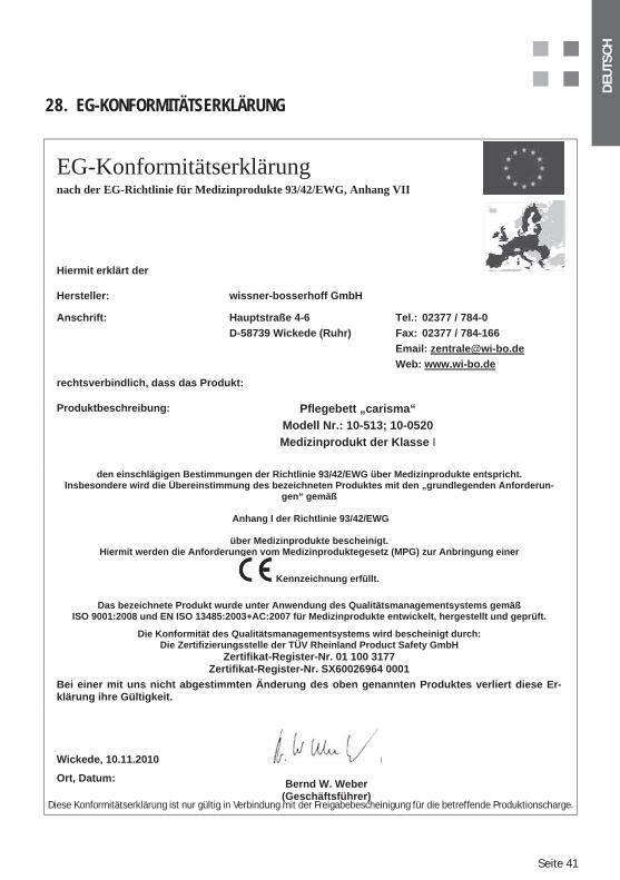
28. EG-KONFORMITÄTSERKLÄRUNG
EG-Konformitätserklärungnach der EG-Richtlinie für Medizinprodukte 93/42/EWG, Anhang VII
Hiermit erklärt der
Hersteller: wissner-bosserhoff GmbH
Anschrift: Hauptstraße 4-6 D-58739 Wickede (Ruhr)
Tel.: 02377 / 784-0 Fax: 02377 / 784-166 Email: [email protected]: www.wi-bo.de
rechtsverbindlich, dass das Produkt:
Produktbeschreibung: Pflegebett „carisma“ Modell Nr.: 10-513; 10-0520 Medizinprodukt der Klasse I
den einschlägigen Bestimmungen der Richtlinie 93/42/EWG über Medizinprodukte entspricht. Insbesondere wird die Übereinstimmung des bezeichneten Produktes mit den „grundlegenden Anforderun-
gen“ gemäß
Anhang I der Richtlinie 93/42/EWG
über Medizinprodukte bescheinigt. Hiermit werden die Anforderungen vom Medizinproduktegesetz (MPG) zur Anbringung einer
Kennzeichnung erfüllt.
Das bezeichnete Produkt wurde unter Anwendung des Qualitätsmanagementsystems gemäß ISO 9001:2008 und EN ISO 13485:2003+AC:2007 für Medizinprodukte entwickelt, hergestellt und geprüft.
Die Konformität des Qualitätsmanagementsystems wird bescheinigt durch: Die Zertifizierungsstelle der TÜV Rheinland Product Safety GmbH
Zertifikat-Register-Nr. 01 100 3177 Zertifikat-Register-Nr. SX60026964 0001
Bei einer mit uns nicht abgestimmten Änderung des oben genannten Produktes verliert diese Er-klärung ihre Gültigkeit.
Wickede, 10.11.2010
Ort, Datum: Bernd W. Weber (Geschäftsführer)
Diese Konformitätserklärung ist nur gültig in Verbindung mit der Freigabebescheinigung für die betreffende Produktionscharge.
Seite 42
DEU
TSC
H
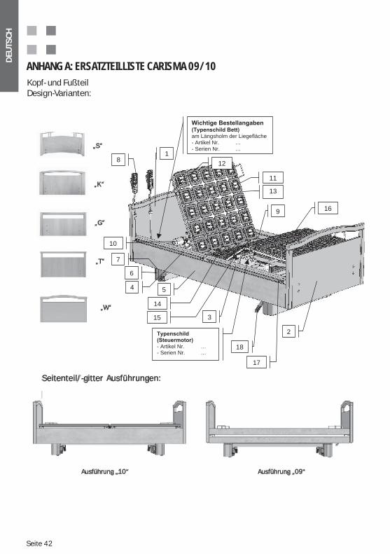
ANHANG A: ERSATZTEILLISTE CARISMA 09/10
Kopf- und FußteilDesign-Varianten:
„S“
„K“
„G“
„T“
„W“
Seitenteil/-gitter Ausführungen:
Ausführung „10“ Ausführung „09“
- Artikel Nr. …- Serien Nr. …
18
3
5
17
4
18
2
11
10
12
13
15
16
14
9
am Längsholm der Liegefläche- Artikel Nr. …- Serien Nr. …
6
7
Kopf- und FußteilDesign-Varianten:
DEU
TSC
H
Seite 43
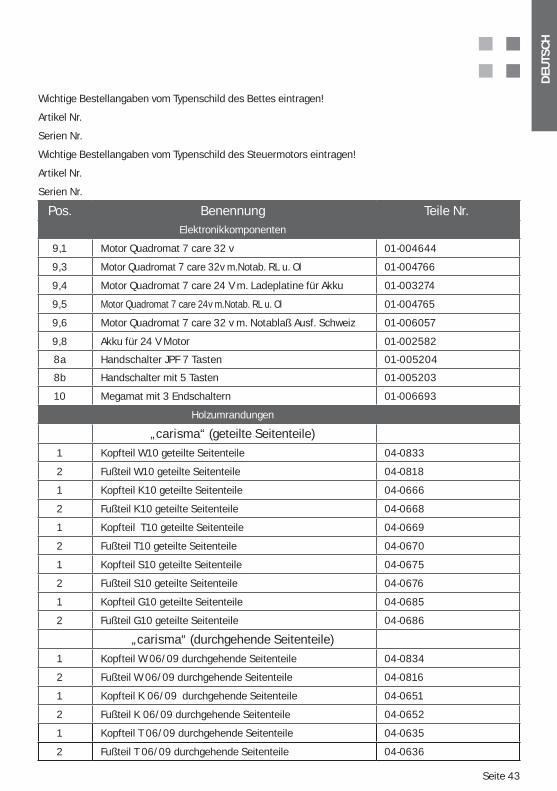
Wichtige Bestellangaben vom Typenschild des Bettes eintragen!
Artikel Nr.
Serien Nr.
Wichtige Bestellangaben vom Typenschild des Steuermotors eintragen!
Artikel Nr.
Serien Nr.
Pos. Benennung Teile Nr. Elektronikkomponenten
9,1 Motor Quadromat 7 care 32 v 01-004644
9,3 Motor Quadromat 7 care 32v m.Notab. RL u. Ol 01-004766
9,4 Motor Quadromat 7 care 24 V m. Ladeplatine für Akku 01-003274
9,5 Motor Quadromat 7 care 24v m.Notab. RL u. Ol 01-004765
9,6 Motor Quadromat 7 care 32 v m. Notablaß Ausf. Schweiz 01-006057
9,8 Akku für 24 V Motor 01-002582
8a Handschalter JPF 7 Tasten 01-005204
8b Handschalter mit 5 Tasten 01-005203
10 Megamat mit 3 Endschaltern 01-006693
Holzumrandungen
„carisma“ (geteilte Seitenteile)
1 Kopfteil W10 geteilte Seitenteile 04-0833
2 Fußteil W10 geteilte Seitenteile 04-0818
1 Kopfteil K10 geteilte Seitenteile 04-0666
2 Fußteil K10 geteilte Seitenteile 04-0668
1 Kopfteil T10 geteilte Seitenteile 04-0669
2 Fußteil T10 geteilte Seitenteile 04-0670
1 Kopfteil S10 geteilte Seitenteile 04-0675
2 Fußteil S10 geteilte Seitenteile 04-0676
1 Kopfteil G10 geteilte Seitenteile 04-0685
2 Fußteil G10 geteilte Seitenteile 04-0686
„carisma“ (durchgehende Seitenteile)
1 Kopfteil W 06/09 durchgehende Seitenteile 04-0834
2 Fußteil W 06/09 durchgehende Seitenteile 04-0816
1 Kopfteil K 06/09 durchgehende Seitenteile 04-0651
2 Fußteil K 06/09 durchgehende Seitenteile 04-0652
1 Kopfteil T 06/09 durchgehende Seitenteile 04-0635
2 Fußteil T 06/09 durchgehende Seitenteile 04-0636
Seite 44
DEU
TSC
H
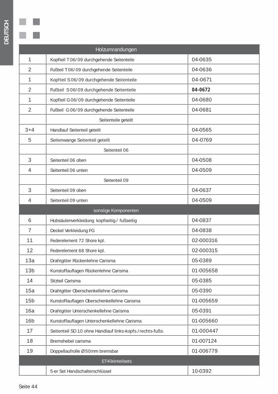
Holzumrandungen
1 Kopfteil T 06/09 durchgehende Seitenteile 04-0635
2 Fußteil T 06/09 durchgehende Seitenteile 04-0636
1 Kopfteil S 06/09 durchgehende Seitenteile 04-0671
2 Fußteil S 06/09 durchgehende Seitenteile 04-0672
1 Kopfteil G 06/09 durchgehende Seitenteile 04-0680
2 Fußteil G 06/09 durchgehende Seitenteile 04-0681
Seitenteile geteilt
3+4 Handlauf Seitenteil geteilt 04-0565
5 Seitenwange Seitenteil geteilt 04-0769
Seitenteil 06
3 Seitenteil 06 oben 04-0508
4 Seitenteil 06 unten 04-0509
Seitenteil 09
3 Seitenteil 09 oben 04-0637
4 Seitenteil 09 unten 04-0509
sonstige Komponenten
6 Hubsäulenverkleidung kopfseitig / fußseitig 04-0837
7 Deckel Verkleidung FG 04-0838
11 Federelement 72 Shore kpl. 02-000316
12 Federelement 68 Shore kpl. 02-000315
13a Drahtgitter Rückenlehne Carisma 05-0389
13b Kunstoffauflagen Rückenlehne Carisma 01-005658
14 Sitzteil Carisma 05-0385
15a Drahtgitter Oberschenkellehne Carisma 05-0390
15b Kunstoffauflagen Oberschenkellehne Carisma 01-005659
16a Drahtgitter Unterschenkellehne Carisma 05-0391
16b Kunstoffauflagen Unterschenkellehne Carisma 01-005660
17 Seitenteil SD 10 ohne Handlauf links-kopfs./rechts-fußs. 01-000447
18 Bremshebel carisma 01-007124
19 Doppellaufrolle Ø 50mm bremsbar 01-006779
ET-Kleinteilsets
5-er Set Handschalterschlüssel 10-0392
DEU
TSC
H
Seite 45
ANHANG B: TYPENSCHILD – ERKLÄRUNG DER ANGABEN AM BEISPIEL
Seite 46
DEU
TSC
H
ANHANG C: WICHTIGE SICHERHEITS- UND ANWENDUNGSHINWEISE FÜR PFLEGEBETTEN
BESTIMMUNGSGEMÄßER GEBRAUCH UND ZWECKBESTIMMUNG VON PFLEGEBETTEN Ein Pflegebett darf nur seiner Zweckbestimmung entsprechend, nach den Vor-
schriften des Medizinproduktegesetztes (MPG), den zugehörigen Verordnungen, den allgemein anerkannten Regeln der Technik sowie den Arbeitsschutz- und Unfallverhütungsvorschriften in Betrieb genommen, betrieben und angewendet werden. In fehlerhaftem Zustand, in dem das Bett Patienten, Pflegepersonal oder Dritte gefährden könnte, darf ein Pflegebett nicht betrieben werden.
Folgende Punkte müssen beachtet werden:
Lagerung von Personen ab einem Alter von 12 Jahren bestimmt. Dies muß si-chergestellt werden, da Personen mit vom üblichen Durchschnitt abweichenden Körpermaßen oder Gewicht u. U. einem erhöhten Risiko ausgesetzt sind. Als empfohlener Gebrauchsbereich sind Personen in einem Bereich von einer 146 cm großen Frau bis zu einem 185 cm großen Mann (körperlich und mental nicht kritischer Gesundheitszustand und zumindest in Grenzen eigenständig hand-lungsfähig) im Bett ohne zusätzliche Risiken oder Leistungseinschränkungen zu lagern (gemäß der Norm IEC 60601-2-52). Außerhalb dieses Bereiches ist ggf. weiteres Zubehör zu nutzen oder ein Gebrauch unmöglich. So sollten z.B. für größere Personen Bettverlängerungen benutzt werden (Zubehör) oder bei abgemagerten Personen unbedingt zusätzliche Schutzmaßnahmen wie z.B. Sei-tengitterschutzhüllen (Zubehör) benutzt werden. Individuell, abweichende An-wendungsfälle müssen mit der Wissner - Bosserhoff GmbH abgestimmt werden.
-
gewährleisten. Es sind die körperlichen, psychologischen und medizinischen Be-dürfnisse und Zustände der Patienten zu beachten. Dementsprechend müssen
werden. Dies gilt insbesondere für Produkte mit speziellen Schwenkungsmög-
Höhere Belastungen
-nehmen! Das Bett darf nicht für Patienten mit einem Körpergewicht von mehr als 155 kg verwendet werden. In der sicheren Arbeitslast von 225 kg ist das
Bettzeug etc.) enthalten!
DEU
TSC
H
Seite 47
-tenden Vorschriften ebenfalls regelmäßig auf ordnungsgemäße Funktion der Sicherheitseinrichtungen (FI-Schutz, FU-Schutz, Isolationsfehlerdetektoren, Leis- tungssicherung etc.) überprüft werden.
räumen benutzt werden, in denen brennbare Anästhetika, brennbare Reinigungs- oder Lösungsmittel oder möglicherweise entzündlichen Stoff-Luft-Gemische an-zutreffen sind. Diesbezüglich sind die Vorschriften der Berufsgenossenschaften zu beachten.
Ein möglicher von dieser Zweckbestimmung abweichender Gebrauch stellt einen -
sprüchen ausgeschlossen.
GRUNDFUNKTIONEN UND NUTZEN VON PFLEGEBETTEN
-ligen Produkt-Gebrauchsanweisungen detailliert beschrieben werden. Der volle Nutzen
-lungen möglichst regelmäßig und achten Sie dabei insbesondere auch auf die not-wendigen Sicherheitsregeln, die es zu beachten gilt.
Generell besteht auch immer die Gefahr der unbeabsichtigten oder falschen Verstellung des Bettes. So können versehentliche Schalterbetätigungen oder unbeabsichtigte Funktionsfreigaben bestimmte Patienten/Bewohner gefähr-den! Um einen hohen Schutz der Patienten/Bewohner sicherzustellen, ist es unabdingbar notwendig Sperreinrichtungen und/oder Freigabeschlüssel ge-zielt zu benutzen. In keinem Fall dürfen Freigabeschlüssel am Handschalter oder am Bett verbleiben! Freigabeschlüssel sind ausschließlich zur Nutzung
Die Nutzung der Sperreinrichtungen und ggf. die bewusste Trennung des Bet-tes vom Netz – als eine absolute Sperrmaßnahme zum maximalen Schutz eines evtl. gefährdeten Patienten/ Bewohners – liegt ausschließlich im Ermessen und in der Verantwortung der zuständigen medizinischen Aufsicht und des
-merkt werden, um eine ordnungsgemäße Schichtübergabe zu gewährleisten.
Seite 48
DEU
TSC
H
Die Nutzung der speziellen Lagerungsmöglichkeiten z.B. Trendelenburg-Anti-
ist ausdrücklich nur durch medizinisches Aufsichtspersonal erlaubt. Für Pati-enten und Bewohner müssen diese Funktionen gesperrt sein, da es sonst zu Gefährdungen kommen kann.
Die Sicherheitshinweise in den speziellen Produkt-Gebrauchsanweisungen sind zu beachten, da sonst Gefahren entstehen.
Beim Einsatz von Seitensicherungen ist besondere Sorgfalt und Vorsicht ge-boten:
Seitensicherungen dienen in erster Linie als Patienten-Schutz im Sinne eines -
rung genutzt werden.
Zum Einsatz der Seitensicherungen sind richterliche Verfügungen notwendig, sobald die Mobilität des Patienten/Bewohners eingeschränkt wird. Lediglich geteilte Seitensicherungen oder individuell absenkbare Seitensicherungen, bei denen nur die Kopfteilsektion aufgestellt wird und die als Ein- und Aufstiegshilfe benutzt werden können, bilden hier nur eine zulässige Ausnahme für mobile Be-wohner/Patienten.
DEU
TSC
H
Seite 49
Eine Überlastung durch Setzen, Abstützen oder Ziehen auf oder am Seiten-gitter hat schwere Schäden der Seitengitter zur Folge und löst Gefährdungen aus. Derartige Belastungen müssen unbedingt vermieden werden.
Beim Einsatz von Seitensicherungen ist die Eignung unter Berücksichtigung der Besonderheiten des jeweiligen Patienten/Bewohners zu prüfen. Insbeson-dere sind die Abstände zwischen den Holmen und Stegen im Verhältnis zum Körperbau des Patienten/Bewohners zu beachten, so dass ein Einklemmen oder Hindurchrutschen auszuschließen sind. Ggf. sind zusätzliche Seitensi-cherungspolster einzusetzen, die das Spaltmaß verringern bzw. die Spalte ver-schließen. Diese Entscheidung liegt ausschließlich in der Verantwortung der zuständigen medizinischen Aufsicht. Als Orientierung dienen die Angaben zur Eingrenzung des bestimmungsgemäßen Gebrauchs dieser Anweisung und der speziellen Produkt-Gebrauchsanweisung des Bettes und des Seitengitters.
Es dürfen ausschließlich Seitensicherungen an den Betten benutzt werden, die auch für den jeweiligen Bettentyp zugelassen sind, da ansonsten erhöhte Unfallrisiken bestehen.
Die Seitengitter/Seitensicherungen sind vor jeder Benutzung auf etwaige Beschädigungen, auf eine sichere Befestigung am Bett und auf die einwand-freie Funktion der Sicherheitsverriegelung hin zu überprüfen! Angaben zur
-duktgebrauchsanweisungen.
Die Nutzung der Handfernbedienung durch den Bewohner-Patienten selbst liegt ausschließlich im Ermessen und in der Verantwortung der zuständigen
um eine ordnungsgemäße Schichtübergabe und Nachverfolgbarkeit von Nut-zungsrechten zu gewährleisten.
Soll die Handfernbedienung nicht durch den Bewohner-Patienten selbst be-nutzt werden muß diese sicher vor dessen Zugriff und vor Einklemmung ge-schützt z.B. am Fußteil des Bettes eingehängt werden.
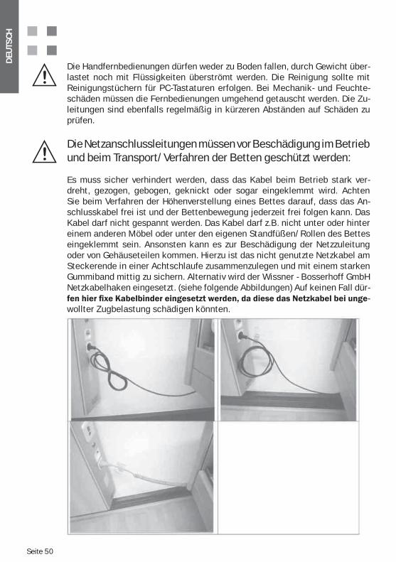
Seite 50
DEU
TSC
H
Die Handfernbedienungen dürfen weder zu Boden fallen, durch Gewicht über-lastet noch mit Flüssigkeiten überströmt werden. Die Reinigung sollte mit Reinigungstüchern für PC-Tastaturen erfolgen. Bei Mechanik- und Feuchte-schäden müssen die Fernbedienungen umgehend getauscht werden. Die Zu-leitungen sind ebenfalls regelmäßig in kürzeren Abständen auf Schäden zu prüfen.
Die Netzanschlussleitungen müssen vor Beschädigung im Betrieb und beim Transport/Verfahren der Betten geschützt werden:
Es muss sicher verhindert werden, dass das Kabel beim Betrieb stark ver-dreht, gezogen, gebogen, geknickt oder sogar eingeklemmt wird. Achten Sie beim Verfahren der Höhenverstellung eines Bettes darauf, dass das An-schlusskabel frei ist und der Bettenbewegung jederzeit frei folgen kann. Das Kabel darf nicht gespannt werden. Das Kabel darf z.B. nicht unter oder hinter einem anderen Möbel oder unter den eigenen Standfüßen/Rollen des Bettes eingeklemmt sein. Ansonsten kann es zur Beschädigung der Netzzuleitung oder von Gehäuseteilen kommen. Hierzu ist das nicht genutzte Netzkabel am Steckerende in einer Achtschlaufe zusammenzulegen und mit einem starken Gummiband mittig zu sichern. Alternativ wird der Wissner - Bosserhoff GmbH Netzkabelhaken eingesetzt. (siehe folgende Abbildungen) Auf keinen Fall dür-
-wollter Zugbelastung schädigen könnten.
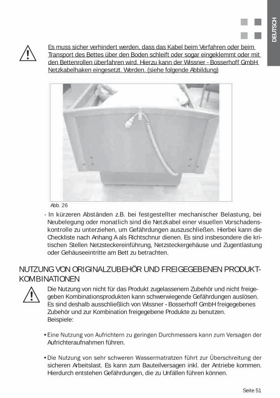
DEU
TSC
H
Seite 51
Es muss sicher verhindert werden, dass das Kabel beim Verfahren oder beim Transport des Bettes über den Boden schleift oder sogar eingeklemmt oder mit den Bettenrollen überfahren wird. Hierzu kann der Wissner - Bosserhoff GmbH Netzkabelhaken eingesetzt. Werden. (siehe folgende Abbildung)
- In kürzeren Abständen z.B. bei festgestellter mechanischer Belastung, bei Neubelegung oder monatlich sind die Netzkabel einer visuellen Vorschadens-kontrolle zu unterziehen, um Gefährdungen auszuschließen. Hierbei kann die Checkliste nach Anhang A als Richtschnur dienen. Es sind insbesondere die kri-tischen Stellen Netzsteckereinführung, Netzsteckergehäuse und Zugentlastung oder Gehäuseeintritte am Bett zu betrachten.
NUTZUNG VON ORIGINALZUBEHÖR UND FREIGEGEBENEN PRODUKT-KOMBINATIONEN
Die Nutzung von nicht für das Produkt zugelassenem Zubehör und nicht freige-geben Kombinationsprodukten kann schwerwiegende Gefährdungen auslösen. Es sind deshalb ausschließlich von Wissner - Bosserhoff GmbH freigegebenes Zubehör und zur Kombination freigegebene Produkte zu benutzen.Beispiele:
Aufrichteraufnahmen führen.
sicheren Arbeitslast. Es kann zum Bauteilversagen inkl. der Antriebe kommen. Hierdurch entstehen Gefährdungen, die zu Unfällen führen können.
Abb. 26
Seite 52
DEU
TSC
H
AUFSTELLUNG DES PFLEGEBETTES (SICHERHEITSABSTÄNDE)
Das Bett muss so aufgestellt werden, dass bei Durchführung aller Verstellfunk-tionen des Bettes eine Kollision von Bettteilen mit anderen Gegenständen im Raum oder mit Teilen des Raumes unmöglich ist (z.B. Netzkabel, Fensterbänke, Dachschrägen, Rohre, Aufputzinstallationen, Wandboards etc.). Hierbei sollte auch ein Sicherheitsabstand zu Wänden und anderen Gegenständen von min. 2,5 cm in allen möglichen Bettpositionen eingehalten werden. Achtung: Auch bei Schwenkung und Höhenverstellung darf keine Kollision auftreten! Das Bett ist so aufzustellen, dass das Trennen vom Versorgungsnetz (Netzstecker zie-hen) einfach bewerkstellig werden kann!
REINIGUNG UND DESINFEKTION DES BETTES
regelmäßig, -sel nicht in Waschstra-ßen, nicht mit Schwall-, Strahl- und nicht -ziert werden. Es ist ausschließlich eine Sprüh- und Wischdesinfektion zulässig.
Mittel empfohlen, die nur durch gleichwertige Mittel ersetzt werden dürfen:Terralin, Perform und Sagrotan Med (Schülke & Mayr GmbH, Norderstedt).Diese Mittel sind nur gemäß Herstellervorschrift zu verwenden! Dies betrifft vor allem die Dosierung der Mittel und die eventuelle Gefährdung bei der Kombina-tion mit anderen Mitteln.
Die Holzumrandung darf mit diesen Mitteln nicht in Berührung kommen.Bei besonders hartnäckigen Flecken können selbstverständlich handelsübliche, umweltschonende Allzweck-Haushaltsreiniger verwendet werden.
keine Reiniger oder Reinigungsmittelmechanisch abtragende Bestandteile enthalten und als Scheuermittel wirken.
Es ist darauf zu achten, dass bei Nutzung und Reinigung keine Nässe oder Flüs- verbleiben. Holz ist ein Na-
turprodukt mit der Eigenschaft, Feuchtigkeit aufzunehmen und sich dabei aus-
Reparaturlacken beseitigt werden. Fragen Sie den Wissner - Bosserhoff GmbH Service.
Handfernbedienungen dürfen nur mit Reinigungstüchern für PC-Tastaturen gereinigt werden. Bei eingedrungener Feuchtigkeit, zu starker Verschmutzung oder verklemmten Tasten durch Schmutzpartikel muß die Handbedienung ggf. getauscht werden.
DEU
TSC
H
Seite 53
ANHANG D: AKKUBETRIEB (OPTION) - ZUSÄTZLICHE HINWEISE
Als Sonderausstattung kann der Bettantrieb mit einer zusätzlichen Akkufunktion ausge rüstet werden, die es ermöglicht das Bett unabhängig vom Versorgungsnetz in den elek-trischen Funktionen mehrfach zu verstellen.
Die mögliche Häufigkeit der Verstellung ist dabei abhängig vom Ladezustand des Akkus. Um eine Tiefentladung zu vermeiden sollte das Bett möglichst am Netz angeschlossen bleiben.
Die Akkuladung findet dann vollautomatisch über eine spezielle integrierte Ladeschaltung statt.
In der Regel wird der Akku fertig geladen und montiert am Hauptantrieb mitgeliefert, eine Montage durch den ungeschulten Anwender ist nicht vorgesehen.
Wichtige Merkmale:
Die Akkubox darf aus Sicherheitsgründen nicht geöffnet werden.
Sollten Sie den Akku nachträglich beziehen wollen, so setzen Sie sich bitte dringlich mit
mit dem Akku geeignet ist. Ein Tausch der Akkubox sollte nur durch geschultes Personal erfolgen, um etwaige Schäden durch falsche Handhabung zu vermeiden.
Die Lebensdauer des Akkus ist stark abhängig von der Nutzung und der Tatsache, dass evtl. schädliche Tiefentladungen stattgefunden haben.
Es besteht die Möglichkeit auch eine vierfache, externe Ladestation (Zubehör zur parallelen Ladung von vier Akku-Boxen) einzusetzen, die separat erhältlich ist.Bitte beachten Sie in so einem Fall dringlich die separate Gebrauchsanweisung zur Akkula-destation.
Seite 54
DEU
TSC
H
ANHANG E: METAMERIE – DAS SCHEINBARE GLEICHE VON OBERFLÄCHEN UND DEKORE
„Metamerie“
Zwei Farben erscheinen nur unter einer bestimmten Lichtart gleich. Bei wechselnder Be-leuchtung unterscheiden Sie sich, durch die spektralen Eigenschaften der verwendeten Pigmente, Farbstoffe und Materialien. Ein im Laden gekaufter grüner Mantel, wird auf der Straße plötzlich braun doch die grüne Hose ist grün geblieben. Zum Betrachten kritischer Farben bei Kleidungsstücken geht man häufig an das Tageslicht, da das zum Abstimmen von Druck- und Materialfarben problematischer ist, verwendet man Tageslicht/ tageslichtähn- liches Licht D65.
Es handelt sich also um ein Phänomen der bedingten Gleichheit von Farben. Zwei oder mehr Farben erscheinen nur unter einer bestimmten Lichtart (z.B. Neonlampe) gleich und unterscheiden sich ansonsten aufgrund ihrer spektralen Eigenschaften (z.B. die verwen-
Metamerie entsteht nie an einer Farbe allein. Z.B. wirkt ein weißes Hemd in rotem Sonnen-licht anders als in gelben Sonnenlicht. Metamerie ist der mit dem Licht veränderliche Farb-unterschied zwischen zwei und mehreren Farben von Materialien.
Insbesondere bei unterschiedlichen Werkstoffen/Materialien, unterschiedlichen Farbge-bungs- bzw. Druckverfahren mit unterschiedlichen Farbsubstanzen ergeben fast zwangs-läufig leichte Farbunterschiede bei unterschiedlichen Lichtverhältnissen (Neoneffekt, La-denlichteffekt oder Ausstellungslichteffekt bezeichnen solche typischen Phänomene)
Für Unifarbvergleiche von Unidekoren bietet sich eine Farbmessung als gutes Instrument an. Hierbei wird ein so genannter Metamerieindex als Vergleichswert zwischen zwei Proben
zwei Lichtarten – meist von der Tageslicht- (C, D50, D60) zur Kunstlichtart (A). Es werden dazu kombinierte Farb- und Glanzgradmessgeräte eingesetzt.
Eine Bewertung muss hingegen bei Holzdekor-, Strukturdekor- und Musterdrucken visuell an einem Rapport erfolgen, denn eine rein messtechnische Farbvergleichsmessung ist nicht sinnvoll umzusetzen. Hierbei ist es wichtig eine interdisziplinäre Mehrheitsentschei-dung in einem Entscheidungsgremium herbeizuführen, da bekanntlich visuelle Eindrücke höchst individuell sind.
Dabei ist der so genannte Rapport die kleinste abgeschlossene Einheit eines Musters. Wenn ein Muster (z.B. bei Druckfolien oder Stoffen) also aus mehreren kleinen Teilen zu-sammengesetzt ist, nennt man ein einzelnes solcher Teile Rapport (z.B. ein Druckabschnitt von 1,5 m Länge nach der sich das Grundmuster wiederholt).
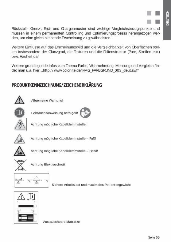
DEU
TSC
H
Seite 55
Rückstell-, Grenz-, Erst- und Chargenmuster sind wichtige Vergleichsbezugspunkte und müssen in einem permanenten Controlling und Optimierungsprozess herangezogen wer-den, um eine gleich bleibende Erscheinung zu gewährleisten.
Weitere Einflüsse auf das Erscheinungsbild und die Vergleichbarkeit von Oberflächen stel-len insbesondere der Glanzgrad, die Texturen und die Folienstruktur (Pore, Streifen etc.) bzw. Rauheit dar.
Weitere grundlegende Infos zum Thema Farbe, Wahrnehmung, Messung und Vergleich fin-det man u.a. hier: „http://www.colorlite.de/FMG_FARBGRUND_003_deut.swf“
PRODUKTKENNZEICHNUNG/ZEICHENERKLÄRUNG
Sichere Arbeitslast und maximales Patientengewicht
Allgemeine Warnung!
Gebrauchsanweisung befolgen!
Achtung mögliche Kabelklemmstelle!
Achtung mögliche Kabelklemmstelle – Fuß!
Achtung mögliche Kabelklemmstelle – Hand!
Achtung Elektroschrott!
Austauschbare Matratze
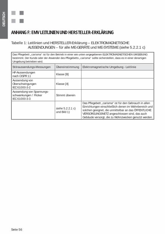
Seite 56
DEU
TSC
H
ANHANG F: EMV LEITLINIEN UND HERSTELLER-ERKLÄRUNG
Tabelle 1: Leitlinien und HERSTELLER-Erklärung – ELEKTROMAGNETISCHE AUSSENDUNGEN – für alle ME-GERÄTE und ME-SYSTEME (siehe 5.2.2.1 c)
Das Pflegebett „carisma“ ist für den Betrieb in einer wie unten angegebenen ELEKTROMAGNETISCHEN UMGEBUNG bestimmt. Der Kunde oder der Anwender des Pflegebetts „carisma“ sollte sicherstellen, dass es in einer derartigen Umgebung betrieben wird.
Störaussendungs-Messungen Übereinstimmung Elektromagnetische Umgebung - Leitlinie
HF-Aussendungen nach CISPR 11
Klasse [B]
Aussendung von OberschwingungenIEC 61000-3-2
Klasse [A]
Aussendung von Spannungs-schwankungen / FlickerIEC 61000-3-3
Stimmt überein
siehe 5.2.2.1 c) und Bild 1)
Das Pflegebett „carisma“ ist für den Gebrauch in allen Einrichtungen einschließlich denen im Wohnbereich und solchen geeignet, die unmittelbar an das ÖFFENTLICHE VERSORGUNGSNETZ angeschlossen sind, das auch Gebäude versorgt, die zu Wohnzwecken genutzt werden.
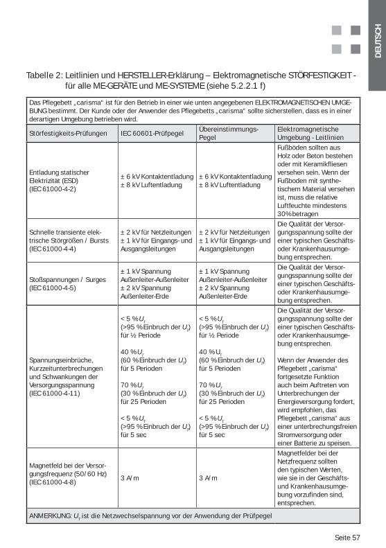
DEU
TSC
H
Seite 57
Tabelle 2: Leitlinien und HERSTELLER-Erklärung – Elektromagnetische STÖRFESTIGKEIT - für alle ME-GERÄTE und ME-SYSTEME (siehe 5.2.2.1 f)
Das Pflegebett „carisma“ ist für den Betrieb in einer wie unten angegebenen ELEKTROMAGNETISCHEN UMGE-BUNG bestimmt. Der Kunde oder der Anwender des Pflegebetts „carisma“ sollte sicherstellen, dass es in einer derartigen Umgebung betrieben wird.
Störfestigkeits-Prüfungen IEC 60601-PrüfpegelÜbereinstimmungs-Pegel
Elektromagnetische Umgebung - Leitlinien
Entladung statischer Elektrizität (ESD)(IEC 61000-4-2)
± 6 kV Kontaktentladung± 8 kV Luftentladung
± 6 kV Kontaktentladung± 8 kV Luftentladung
Fußböden sollten aus Holz oder Beton bestehen oder mit Keramikfliesen versehen sein. Wenn der Fußboden mit synthe-tischem Material versehen ist, muss die relative Luftfeuchte mindestens 30% betragen
Schnelle transiente elek-trische Störgrößen / Bursts(IEC 61000-4-4)
± 2 kV für Netzleitungen± 1 kV für Eingangs- und Ausgangsleitungen
± 2 kV für Netzleitungen± 1 kV für Eingangs- und Ausgangsleitungen
Die Qualität der Versor-gungsspannung sollte der einer typischen Geschäfts- oder Krankenhausumge-bung entsprechen.
Stoßspannungen / Surges(IEC 61000-4-5)
± 1 kV Spannung Außenleiter-Außenleiter± 2 kV Spannung Außenleiter-Erde
± 1 kV Spannung Außenleiter-Außenleiter± 2 kV Spannung Außenleiter-Erde
Die Qualität der Versor-gungsspannung sollte der einer typischen Geschäfts- oder Krankenhausumge-bung entsprechen.
Spannungseinbrüche, Kurzzeitunterbrechungen und Schwankungen der Versorgungsspannung(IEC 61000-4-11)
< 5 % UT(>95 % Einbruch der UT)für ½ Periode
40 % UT (60 % Einbruch der UT)für 5 Perioden
70 % UT (30 % Einbruch der UT)für 25 Perioden
< 5 % UT (>95 % Einbruch der UT)für 5 sec
< 5 % UT(>95 % Einbruch der UT)für ½ Periode
40 % UT (60 % Einbruch der UT)für 5 Perioden
70 % UT (30 % Einbruch der UT)für 25 Perioden
< 5 % UT (>95 % Einbruch der UT)für 5 sec
Die Qualität der Versor-gungsspannung sollte der einer typischen Geschäfts- oder Krankenhausumge-bung entsprechen.
Wenn der Anwender des Pflegebett „carisma“ fortgesetzte Funktion auch beim Auftreten von Unterbrechungen der Energieversorgung fordert, wird empfohlen, das Pflegebett „carisma“ aus einer unterbrechungsfreien Stromversorgung oder einer Batterie zu speisen.
Magnetfeld bei der Versor-gungsfrequenz (50/60 Hz)(IEC 61000-4-8)
3 A/m 3 A/m
Magnetfelder bei der Netzfrequenz sollten den typischen Werten, wie sie in der Geschäfts- und Krankenhausumge-bung vorzufinden sind, entsprechen.
ANMERKUNG: UT ist die Netzwechselspannung vor der Anwendung der Prüfpegel
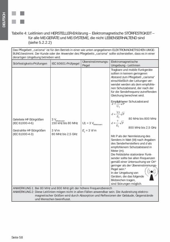
Seite 58
DEU
TSC
H
Tabelle 4: Leitlinien und HERSTELLER-Erklärung – Elektromagnetische STÖRFESTIGKEIT – für alle ME-GERÄTE und ME-SYSTEME, die nicht LEBENSERHALTEND sind (siehe 5.2.2.2)
Das Pflegebett „carisma“ ist für den Betrieb in einer wie unten angegebenen ELEKTROMAGNETISCHEN UMGE-BUNG bestimmt. Der Kunde oder der Anwender des Pflegebetts „carisma“ sollte sicherstellen, dass es in einer derartigen Umgebung betrieben wird.
Störfestigkeits-Prüfungen IEC 60601-PrüfpegelÜbereinstimmungs-Pegel
Elektromagnetische Umgebung - Leitlinien
Geleitete HF-Störgrößen(IEC 61000-4-6)
Gestrahlte HF-Störgrößen(IEC 61000-4-3)
3 VEffektivwert
150 kHz bis 80 MHz
3 V/m80 MHz bis 2,5 GHz
U1 = 3 VEffektivwert
E1 = 3 V/m
Tragbare und mobile Funkgeräte sollten in keinem geringeren Abstand zum Pflegebett „carisma“ einschließlich der Leitungen ver-wendet werden als dem empfohle-nen Schutzabstand, der nach der für die Sendefrequenz zutreffenden Gleichung berechnet wird.
Empfohlener Schutzabstand
80 MHz bis 800 MHz
800 MHz bis 2,5 GHz
Mit P als der Nennleistung des Senders in Watt (W) nach Angaben des Senderherstellers und d als empfohlenem Schutzabstand in Meter (m).Die Feldstärke stationärer Funk-sender sollte bei allen Frequenzen gemäß einer Untersuchung vor Orta geringer als der Übereinstimmungs-Pegel sein.b
In der Umgebung von Geräten, die das folgende Bildzeichen tragen, sind Störungen möglich.
ANMERKUNG 1: Bei 80 MHz und 800 MHz gilt der höhere FrequenzbereichANMERKUNG 2: Diese Leitlinien mögen nicht in allen Fällen anwendbar sein. Die Ausbreitung elektro-
magnetischer Größen wird durch Absorption und Reflexionen der Gebäude, Gegenstände und Menschen beeinflusst.
PE
d1
5,3=
PU
d1
5,3=
PE
d1
7=
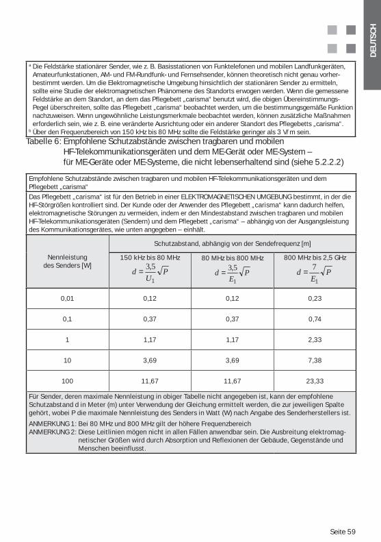
DEU
TSC
H
Seite 59
a Die Feldstärke stationärer Sender, wie z. B. Basisstationen von Funktelefonen und mobilen Landfunkgeräten, Amateurfunkstationen, AM- und FM-Rundfunk- und Fernsehsender, können theoretisch nicht genau vorher-bestimmt werden. Um die Elektromagnetische Umgebung hinsichtlich der stationären Sender zu ermitteln, sollte eine Studie der elektromagnetischen Phänomene des Standorts erwogen werden. Wenn die gemessene Feldstärke an dem Standort, an dem das Pflegebett „carisma“ benutzt wird, die obigen Übereinstimmungs-Pegel überschreiten, sollte das Pflegebett „carisma“ beobachtet werden, um die bestimmungsgemäße Funktion nachzuweisen. Wenn ungewöhnliche Leistungsmerkmale beobachtet werden, können zusätzliche Maßnahmen erforderlich sein, wie z. B. eine veränderte Ausrichtung oder ein anderer Standort des Pflegebetts „carisma“.
b Über den Frequenzbereich von 150 kHz bis 80 MHz sollte die Feldstärke geringer als 3 V/m sein.Tabelle 6: Empfohlene Schutzabstände zwischen tragbaren und mobilen
HF-Telekommunikationsgeräten und dem ME-Gerät oder ME-System – für ME-Geräte oder ME-Systeme, die nicht lebenserhaltend sind (siehe 5.2.2.2)
Empfohlene Schutzabstände zwischen tragbaren und mobilen HF-Telekommunikationsgeräten und dem Pflegebett „carisma“
Das Pflegebett „carisma“ ist für den Betrieb in einer ELEKTROMAGNETISCHEN UMGEBUNG bestimmt, in der die HF-Störgrößen kontrolliert sind. Der Kunde oder der Anwender des Pflegebett „carisma“ kann dadurch helfen, elektromagnetische Störungen zu vermeiden, indem er den Mindestabstand zwischen tragbaren und mobilen HF-Telekommunikationsgeräten (Sendern) und dem Pflegebett „carisma“ – abhängig von der Ausgangsleistung des Kommunikationsgerätes, wie unten angegeben – einhält.
Nennleistung des Senders [W]
Schutzabstand, abhängig von der Sendefrequenz [m]
150 kHz bis 80 MHz
PU
d1
5,3=80 MHz bis 800 MHz
PE
d1
5,3=
800 MHz bis 2,5 GHz
PE
d1
7=
0,01 0,12 0,12 0,23
0,1 0,37 0,37 0,74
1 1,17 1,17 2,33
10 3,69 3,69 7,38
100 11,67 11,67 23,33
Für Sender, deren maximale Nennleistung in obiger Tabelle nicht angegeben ist, kann der empfohlene Schutzabstand d in Meter (m) unter Verwendung der Gleichung ermittelt werden, die zur jeweiligen Spalte gehört, wobei P die maximale Nennleistung des Senders in Watt (W) nach Angabe des Senderherstellers ist.
ANMERKUNG 1: Bei 80 MHz und 800 MHz gilt der höhere FrequenzbereichANMERKUNG 2: Diese Leitlinien mögen nicht in allen Fällen anwendbar sein. Die Ausbreitung elektromag-
netischer Größen wird durch Absorption und Reflexionen der Gebäude, Gegenstände und Menschen beeinflusst.
Seite 60
DEU
TSC
H
Notizen

DEU
TSC
H
Seite 61
Notizen

Seite 62
DEU
TSC
H
Notizen
DEU
TSC
H
Seite 63
Notizen
ENG
LIS
H
Page 64
TABLE OF CONTENTS
1. Table of Contents ....................................................................................... 64 Important Safety Note: .............................................................................. 652. Notes on Instructions for use / Explanation of Symbols ......................... 663. Area of Use / Intended Use ....................................................................... 664. Setting up the Bed ..................................................................................... 675. Technical Data for the Bed / Nameplate ................................................. 675.1. Electromotor Patient Surface .............................................................. 68
........................................................ 686. Product Safety / Extract from applied Standards .................................... 697. Product Overview (Example Wood Décor T10) ........................................ 708. Description of electrical Functions ........................................................... 708.1. Backrest Function (BR) ........................................................................ 718.2. Legs up position (LU) ............................................................................ 728.3. Comfortable sitting position (CS) ........................................................ 728.4. Auto contour Function (AC) .................................................................. 73
........................................................ 739. Combination of ”medical bed“ and ”movable“ lifting devices ............... 73
......................................................... 7411. Control box (Optional) ................................................................................ 7412. Delivery ....................................................................................................... 7513. Assembly .................................................................................................... 7613.1. Patient Surface ..................................................................................... 7613.2. Patient Surface Motor .......................................................................... 7614. Transport / Moving Bed............................................................................. 7615. Function Test .............................................................................................. 7715.1. Handset “Carisma 07 JPF“ Function Description ............................... 7715.2. Handset – Rear Side with Locking Function....................................... 7815.3. Calf rest / Mechanical ......................................................................... 7915.4. Braking / Moving .................................................................................. 80
........................................................... 80 ............................................. 81
........................................................... 8216. Permitted Accessories ............................................................................... 8316.1. Lifting Pole (Accessories) ..................................................................... 8316.2. Infusion Holder (Accessories) .............................................................. 8416.3. Patient Surface Extension (Option) ..................................................... 8416.4. Mattress (Accessories) ......................................................................... 8516.5. Urine Bottle Basket / Urine Bag Container Model 09 (Accessory) ... 8516.6. Handset holder (Accessory) ................................................................. 8616.7. Side rail exntension for 06/09 Side rail (Accessories) ...................... 8717. Cleaning and Disinfection ......................................................................... 8917.1. Initial Cleaning ...................................................................................... 8917.2. Disinfection / Sterilisation ................................................................... 90
ENG
LIS
H
Page 65
17.3. Care Instructions for Wooden Parts .................................................... 9017.4. Use of Cleaning Agents ........................................................................ 9117.5. Use of Disinfection Agents ................................................................... 9117.6. Damage to Wooden Parts .................................................................... 9117.7. Environmental Compatibility ................................................................ 9117.8. Quality ................................................................................................... 9118. Help in case of Malfunctions .................................................................... 9219. Storage ....................................................................................................... 9220. Safety Notes and Residual Risks .............................................................. 9221. Maintenance and servicing ....................................................................... 9821.1. Completeness and Accessories........................................................... 9821.2. Wear and Tear ...................................................................................... 9921.3. Functionality ......................................................................................... 9921.4. BGV A3/VDE 0751– Inspections of the Electrical Components of he Handset ....................................................................................... 99 21.5. Castors .................................................................................................. 9922. Useful Life .................................................................................................. 9923. Disposal ...................................................................................................... 10024. Spare parts, Spare part lists and Service manuals ................................ 10025. Nameplate and Labels .............................................................................. 10026. Guarantee and Service ............................................................................. 10127. Contact Partner.......................................................................................... 10128. EC Declaration of Conformity .................................................................... 102Appendix C: Important safety and usage notes for nursing home beds ......... 107Intended Use and Purpose of Nursing Home Beds .......................................... 107Basic Functions and Uses of Nursing Home Beds ............................................ 108Use of Original Accessories and Released Product Combinations .................. 109Setting up the Nursing Home Bed (Safety Clearances) .................................... 112Cleaning and Disinfection of the Bed ................................................................ 112
Appendixes:Appendix A: Replacement parts list carisma 09/10Appendix B: Nameplate – explanation of details using an exampleAppendix C: Important safety and usage notes for nursing home beds Appendix D: Battery operation (option) - additional notesAppendix E: Metamerism – the apparent sameness of surfaces and décorsAppendix F: EMC guidelines and manufacturer’s declaration
IMPORTANT SAFETY NOTE:Please make sure that you read the safety-relevant passages marked with a in the individual chapters of the instructions for use very carefully, and observe the details of Chapter 18 and of Appendix C. Non-observance of such instructions
ENG
LIS
H
Page 66
Dear customers,
we thank you for the trust that you have shown in purchasing one of our products. We are convinced that our product is fully able to cope with the requirements of everyday hospital life. The careful choice of materials, the use of highly modern technologies and not least, the
and a solid quality. We are sure that this will mean care is made easier for you.
2. NOTES ON INSTRUCTIONS FOR USE / EXPLANATION OF SYMBOLS
This symbol indicates safety-relevant instructions, the non-observance of which could have serious consequences (e.g. damage, injuries). For this reason it is essential that such instructions and notes are observed.
These instructions for use are intended for trained nursing staff or for those persons who are in charge of the commissioning and operation of this product.
Caution! A precise knowledge and observation of these instructions for use is a prerequisite for handling this product. They should therefore be kept carefully until the product is disposed of. To avoid operating errors and to guarantee ope-ration without malfunction, the instructions for use must be available to opera-ting personnel at all times. It is recommended that they are stored in the bed or in the bedside cabinet.
The texts and graphic representations in these instructions for use do not necessarily match the exact scope of delivery, as they are designed for all variations of the model series. The drawings and graphics are not to scale.
3. AREA OF USE / INTENDED USE
(201.3.203 ) * APPLICATION ENVIRONMENT 3Long term care in a medical environment, with necessity for medical supervision and with possi-bility of special monitoring, if applicable. A ME DEVICE used for medical purposes can be made available to maintain or improve the condition of the PATIENT
(201.3.205 ) * APPLICATION ENVIRONMENT 5Ambulant care area in a hospital or another medical institution, with medical supervision at
-ment, diagnosis or supervision. Any other application must be agreed beforehand in writing with the company wissner-bosserhoff GmbH. The product must be used as a utility for nursing, and
This nursing bed is a medical product in the sense of the regulations and standards named in the following chapter, „Product safety / excerpt of applied standards“. Accordingly, this product may only be used under medical supervision. The decisive factor in whether nursing is medi-cally supervised or not depends on whether this nursing takes place on the instructions of medical personnel or not.
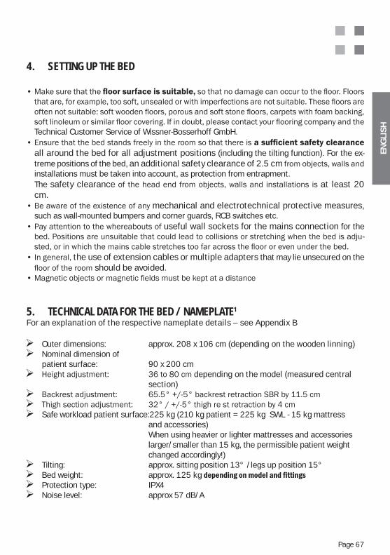
ENG
LIS
H
Page 67
4. SETTING UP THE BED
Technical Customer Service of Wissner-Bosserhoff GmbH.
all around the bed for all adjustment positions (including the tilting function). For the ex-treme positions of the bed, an additional safety clearance of 2.5 cminstallations must be taken into account, as protection from entrapment.
The safety clearance at least 20 cm.
mechanical and electrotechnical protective measures, such as wall-mounted bumpers and corner guards, RCB switches etc.
useful wall sockets for the mains connection for the -
the use of extension cables or multiple adapters that may lie unsecured on the should be avoided.
5. TECHNICAL DATA FOR THE BED / NAMEPLATE1
For an explanation of the respective nameplate details – see Appendix B
Outer dimensions: approx. 208 x 106 cm (depending on the wooden linning) Nominal dimension of
patient surface: 90 x 200 cmdepending on the model (measured central
section)
Safe workload patient surface:225 kg (210 kg patient = 225 kg SWL - 15 kg mattress and accessories) When using heavier or lighter mattresses and accessories larger/smaller than 15 kg, the permissible patient weight changed accordingly!)
Tilting: approx. sitting position 13° /legs up position 15° Bed weight: approx. 125 kg Protection type: IPX4 Noise level: approx 57 dB/A
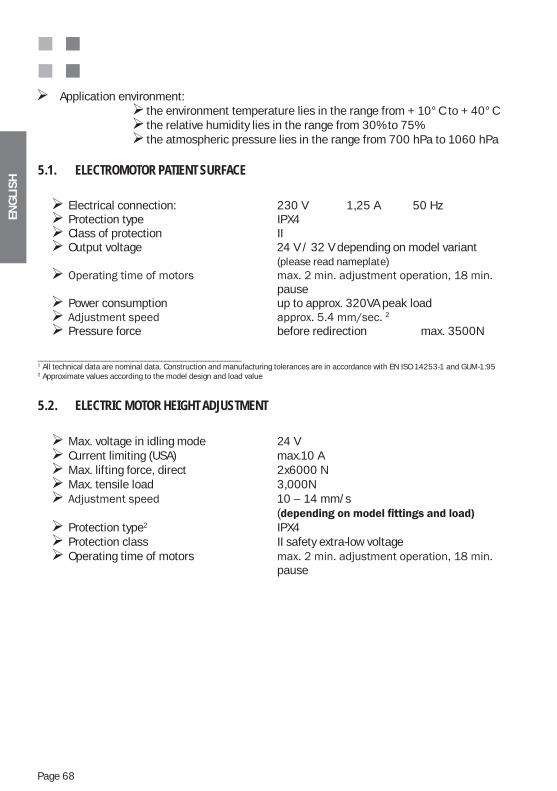
ENG
LIS
H
Page 68
Application environment: the environment temperature lies in the range from + 10°C to + 40°C the relative humidity lies in the range from 30% to 75% the atmospheric pressure lies in the range from 700 hPa to 1060 hPa
5.1. ELECTROMOTOR PATIENT SURFACE
Electrical connection: 230 V 1,25 A 50 Hz Protection type IPX4 Class of protection II Output voltage 24 V / 32 V depending on model variant
(please read nameplate)
pause Power consumption up to approx. 320VA peak load
2
Pressure force before redirection max. 3500N
___________________________________________________1 All technical data are nominal data. Construction and manufacturing tolerances are in accordance with EN ISO 14253-1 and GUM-1:952 Approximate values according to the model design and load value
5.2. ELECTRIC MOTOR HEIGHT ADJUSTMENT
Max. voltage in idling mode 24 V Current limiting (USA) max.10 A Max. lifting force, direct 2x6000 N Max. tensile load 3,000N 10 – 14 mm/s
( Protection type2 IPX4 Protection class II safety extra-low voltage Operating time of motors
pause
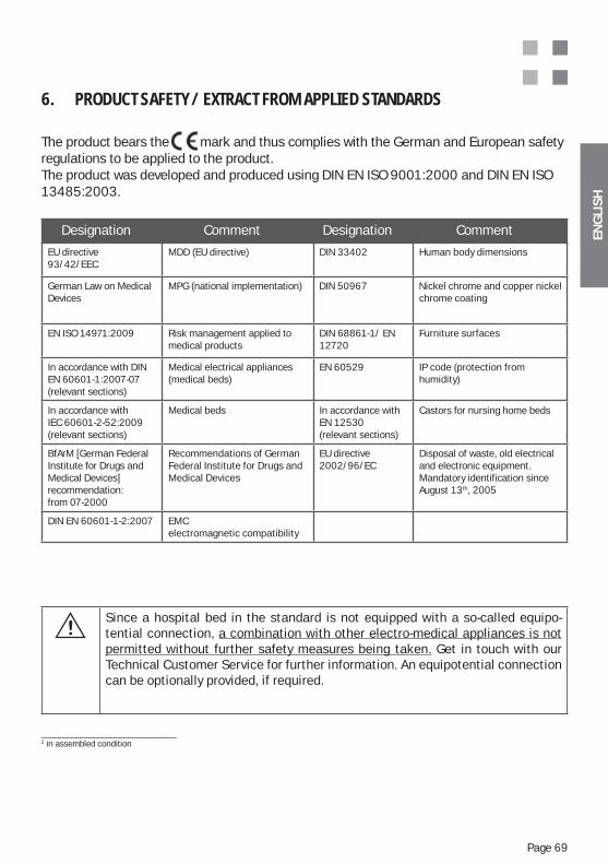
ENG
LIS
H
Page 69
6. PRODUCT SAFETY / EXTRACT FROM APPLIED STANDARDS
The product bears the mark and thus complies with the German and European safety regulations to be applied to the product.The product was developed and produced using DIN EN ISO 9001:2000 and DIN EN ISO 13485:2003.
Designation Comment Designation Comment
EU directive 93/42/EEC
MDD (EU directive) DIN 33402 Human body dimensions
German Law on Medical Devices
MPG (national implementation) DIN 50967 Nickel chrome and copper nickel chrome coating
EN ISO 14971:2009 Risk management applied to medical products
DIN 68861-1/ EN 12720
Furniture surfaces
In accordance with DIN EN 60601-1:2007-07(relevant sections)
Medical electrical appliances (medical beds)
EN 60529 IP code (protection from humidity)
In accordance withIEC 60601-2-52:2009(relevant sections)
Medical beds In accordance with EN 12530(relevant sections)
Castors for nursing home beds
BfArM [German Federal Institute for Drugs and Medical Devices]recommendation: from 07-2000
Recommendations of German Federal Institute for Drugs and Medical Devices
EU directive 2002/96/EC
Disposal of waste, old electrical and electronic equipment. Mandatory identification since August 13th, 2005
DIN EN 60601-1-2:2007 EMC electromagnetic compatibility
_______________________________2 in assembled condition
Since a hospital bed in the standard is not equipped with a so-called equipo-tential connection, a combination with other electro-medical appliances is not permitted without further safety measures being taken. Get in touch with our Technical Customer Service for further information. An equipotential connection can be optionally provided, if required.
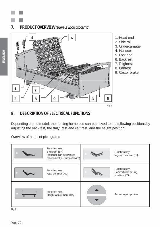
ENG
LIS
H
Page 70
1. Head end2. Side rail3. Undercarriage4. Handset5. Foot end6. Backrest7. Thighrest8. Calfrest9. Castor brake
7. PRODUCT OVERVIEW (EXAMPLE WOOD DÉCOR T10)
Fig. 1
8. DESCRIPTION OF ELECTRICAL FUNCTIONS
Depending on the model, the nursing home bed can be moved to the following positions by
Overview of handset pictograms
1
2 3
4
5
6
7
8 9
Fig. 2
Function key:Backrest (BR)(optional: can be lowered mechanically – without load!)
Function key:Auto contour (AC)
Function key:Height adjustment (HA)
Function key:legs up position (LU)
Function key:Comfortable sitting position (CS)
Action keys up/down
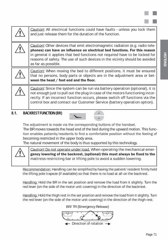
ENG
LIS
H
Page 71
Caution! Do not operate under load. When operating the mechanical emer-
mattress restricting bar or lifting pole to avoid a sudden lowering.
8.1. BACKREST FUNCTION (BR)
The BR moves towards the head end of the bed during the upward motion. This func-
becoming restricted in the upper body area.The natural movement of the body is thus supported by this technology.
Recommendation: Handling can be simplified by having the patient/resident firmly hold the lifting pole trapeze (if available) so that there is no load at all on the backrest.
Handling: Hold the BR in the set position and remove the load from it slightly. Turn the red lever (on the side of the motor unit covering) in the direction of the backrest.
Handling: Hold the thigh rest in the set position and remove the load from it slightly. Turn the red lever (on the side of the motor unit covering) in the direction of the thigh rest.
BR/TR (Emergency Release)
Direction of rotation
Caution! When moving the bed to different positions, it must be ensured that no persons, body parts or objects are in the adjustment area or bet-
Caution! Since the system can be run via battery operation (optional), it is not enough just to pull out the plug in case of the motors functioning incor-rectly. If an incorrect function occurs, please switch off functions via the control box and contact our Customer Service (battery operation option).
Caution! All electrical functions could have faults - unless you lock them and just release them for the duration of the function.
Caution! Other devices that emit electromagnetic radiation (e.g. radio tele-
in general it applies that bed functions not required have to be locked for reasons of safety. The use of such devices in the vicinity should be avoided as far as possible.
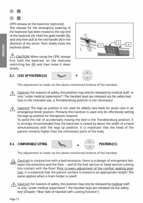
ENG
LIS
H
Page 72
8.2. LEGS UP POSITION (LU)
Caution! For reasons of safety, this position may only be released by medical staff, or only “under medical supervision“! The handset keys are released via the safety key!Due to the intended use, a Trendelenburg position is not necessary!
Caution! The legs up position is not used for elderly care beds for acute care in an emergency/shock position. Primarily this function is used only for effortlessly setting the legs up position for therapeutic reasons!To avoid the risk of accidentally moving the bed to the Trendelenburg position, it is strongly recommended that the backrest is raised by about the width of a hand simultaneously with the legs up position. It is important that the head of the patient remains higher than the orthostatic point of the body.
8.3. COMFORTABLE SITTING POSITION (CS)
Caution! In conjunction with a bed extension, there is a danger of entrapment bet-ween the extension and the floor – and of the foot section or head section coming into contact with the floor! Prior to every adjustment of the comfort seating posi-tion, it is essential that the patient surface is moved to an appropriate height! The same applies when a linen holder is used!
Caution! For reasons of safety, this position may only be released by medical staff, or only “under medical supervision“! The handset keys are released via the safety key! (Chapter “Rear Side of Handset with Locking Function“)
CPR release at the backrest (optional)The release for the emergency lowering of the backrest has been moved to the top end of the backrest (A). Hold the grab handle (B), and only then pull at the red handle (A) in the direction of the arrow. Then slowly move the backrest down.
CAUTION! When using the CPR, always first hold the backrest on the mattress restricting bar (B) and then move it down slowly.
BA
A
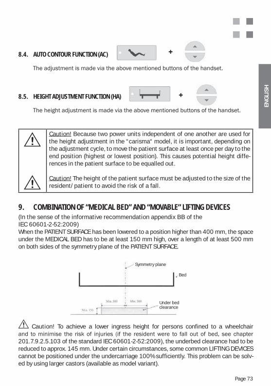
ENG
LIS
H
Page 73
Caution! Because two power units independent of one another are used for the height adjustment in the “carisma“ model, it is important, depending on the adjustment cycle, to move the patient surface at least once per day to the end position (highest or lowest position). This causes potential height diffe-rences in the patient surface to be equalled out.
Caution! The height of the patient surface must be adjusted to the size of the resident/patient to avoid the risk of a fall.
Caution! To achieve a lower ingress height for persons confined to a wheelchair
201.7.9.2.5.103 of the standard IEC 60601-2-52:2009), the underbed clearance had to be reduced to approx. 145 mm. Under certain circumstances, some common LIFTING DEVICES cannot be positioned under the undercarriage 100% sufficiently. This problem can be solv- ed by using larger castors (available as model variant).
9. COMBINATION OF “MEDICAL BED” AND “MOVABLE” LIFTING DEVICES(In the sense of the informative recommendation appendix BB of the IEC 60601-2-52:2009)When the PATIENT SURFACE has been lowered to a position higher than 400 mm, the space under the MEDICAL BED has to be at least 150 mm high, over a length of at least 500 mm on both sides of the symmetry plane of the PATIENT SURFACE.
8.4. AUTO CONTOUR FUNCTION (AC)
8.5. HEIGHT ADJUSTMENT FUNCTION (HA)
Symmetrieebene
Bett
Unterfahrbar
Symmetry plane
Under bed clearance
Bed
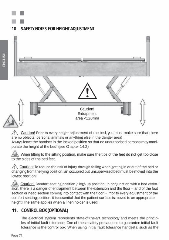
ENG
LIS
H
Page 74
11. CONTROL BOX (OPTIONAL)
The electrical system represents state-of-the-art technology and meets the princip-les of initial fault tolerance. One of these safety precautions to guarantee initial fault tolerance is the control box. When using initial fault tolerance handsets, such as the
Caution!Entrapment
area <120mm
10. SAFETY NOTES FOR HEIGHT ADJUSTMENT
Caution! ment of the bed, you must make sure that there
Always leave the handset in the locked position so that no unauthorised persons may mani-pulate the height of the bed! (see Chapter 14.2)
When tilting to the sitting position, make sure the tips of the feet do not get too close to the sides of the bed feet.
Caution! changing from the lying position, an occupied but unsupervised bed must be moved into the lowest position!
Caution! -sion, there is a danger of entrapment between the extension and the floor – and of the foot
comfort seating position, it is essential that the patient surface is moved to an appropriateheight! The same applies when a linen holder is used!
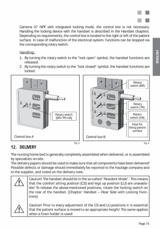
ENG
LIS
H
Page 75
Caution! The handset should be in the so-called “Resident Mode“. This means that the comfort sitting position (CS) and legs up position (LU) are unavaila-ble! To release the above-mentioned positions, rotate the locking switch on the rear of the handset. (Chapter: Handset – Rear Side with Locking Func-tions)
Caution! Prior to every adjustment of the CS and LU positions it is essential that the patient surface is moved to an appropriate height! The same applies when a linen holder is used!
Fig. 3 Fig. 4
Kontrollbox -A
rehs halter
Kontrollbox -B
Rotary switch(BR+TR+HA)
Rotary switch (BR)
Rotary switch (TR)
Rotary switch (HA)
Keys for tilting patient
surface
Control box BControl box A
12. DELIVERY
The nursing home bed is generally completely assembled when delivered, or is assembled by specialists on-site. The delivery papers should be used to make sure that all components have been delivered! Possible defects or damage should immediately be reported to the haulage company and to the supplier, and noted on the delivery note.
Handling:
1. By turning the rotary switch to the “lock open“ symbol, the handset functions are released.2. By turning the rotary switch to the “lock closed“ symbol, the handset functions are locked.
Carisma 07 NPF with integrated locking mode, the control box is not necessary. Handling the locking device with the handset is described in the Handset chapters. Depending on requirements, the control box is located to the right or left of the patient surface. In case of malfunction of the electrical system, functions can be stopped via the corresponding rotary switch.
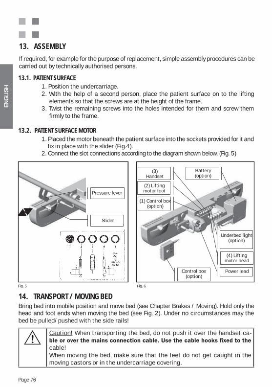
ENG
LIS
H
Page 76
14. TRANSPORT / MOVING BED Bring bed into mobile position and move bed (see Chapter Brakes / Moving). Hold only the head and foot ends when moving the bed (see Fig. 2). Under no circumstances may the bed be pulled/pushed with the side rails!
Caution! When transporting the bed, do not push it over the handset ca-
cable!When moving the bed, make sure that the feet do not get caught in the moving castors or in the undercarriage covering.
13.1. PATIENT SURFACE 1. Position the undercarriage. 2. With the help of a second person, place the patient surface on to the lifting elements so that the screws are at the height of the frame. 3. Twist the remaining screws into the holes intended for them and screw them firmly to the frame.
13.2. PATIENT SURFACE MOTOR 1. Placed the motor beneath the patient surface into the sockets provided for it and fix in place with the slider (Fig.4). 2. Connect the slot connections according to the diagram shown below. (Fig. 5)
Abb. 5 Abb. 6
Schieber
Druckhebel
(1) Kontroll-box (Option)
Kontrollbox (Option)
(2) Hubmotor Fuß
(3) Hand-schalter
(5) Unterbett- Beleuchtung
(Option)
Akku (Option)
(4) Hubmotor Kopf
Netzkabel
Pressure lever
Slider
(3) Handset
(2) Lifting motor foot
(1) Control box (option)
Battery (option)
Control box (option)
Underbed light (option)
(4) Lifting motor-head
Power lead
Fig. 5 Fig. 6
13. ASSEMBLY
If required, for example for the purpose of replacement, simple assembly procedures can be carried out by technically authorised persons.
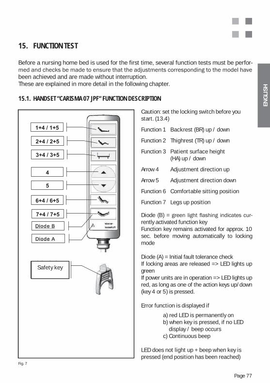
ENG
LIS
H
Page 77
15. FUNCTION TEST
Before a nursing home bed is used for the first time, several function tests must be perfor-
been achieved and are made without interruption.These are explained in more detail in the following chapter.
15.1. HANDSET “CARISMA 07 JPF“ FUNCTION DESCRIPTION
Caution: set the locking switch before you start. (13.4)
Function 1 Backrest (BR) up / down
Function 2 Thighrest (TR) up / down
Function 3 Patient surface height (HA) up / down
Arrow 4 Adjustment direction up
Arrow 5 Adjustment direction down
Function 6 Comfortable sitting position
Function 7 Legs up position
Diode (B) = -rently activated function keyFunction key remains activated for approx. 10 sec. before moving automatically to locking mode Diode (A) = Initial fault tolerance checkIf locking areas are released => LED lights up greenIf power units are in operation => LED lights up red, as long as one of the action keys up/down (key 4 or 5) is pressed.
Error function is displayed if
a) red LED is permanently on b) when key is pressed, if no LED display / beep occurs c) Continuous beep
LED does not light up + beep when key is pressed (end position has been reached)
Fig. 7
Diode A
Diode B
Sicher-heitsschlüs
l
Sicherheits- schlüsselSafety key
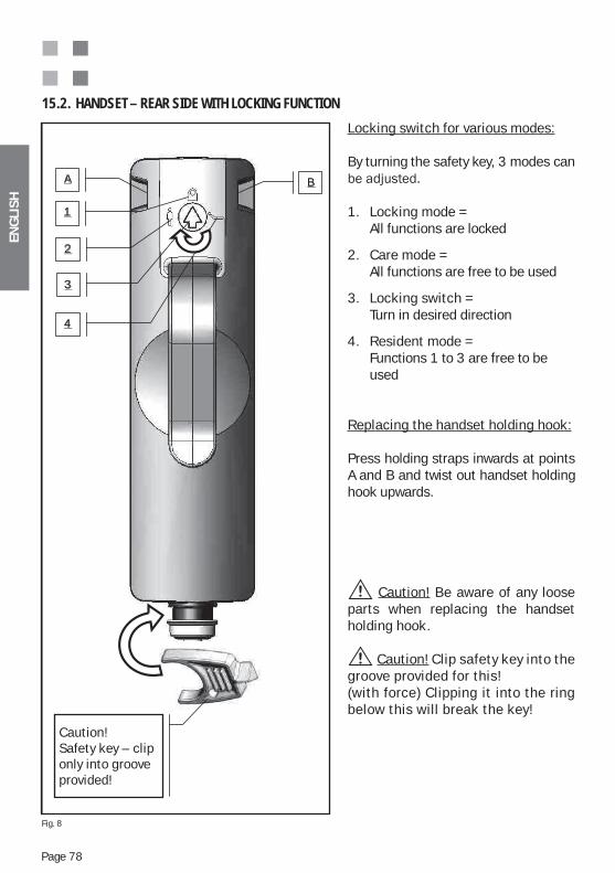
ENG
LIS
H
Page 78
1
2
3
A B
4
Achtung! Si -cherheitsschlüssel - nur in dem dafür vor-gesehenen S lt i l i
Locking switch for various modes:
By turning the safety key, 3 modes can
1. Locking mode = All functions are locked
2. Care mode = All functions are free to be used
3. Locking switch = Turn in desired direction
4. Resident mode = Functions 1 to 3 are free to be used
Replacing the handset holding hook:
Press holding straps inwards at points A and B and twist out handset holding hook upwards.
Caution! Be aware of any loose parts when replacing the handset holding hook.
Caution! Clip safety key into the groove provided for this!(with force) Clipping it into the ring below this will break the key!
15.2. HANDSET – REAR SIDE WITH LOCKING FUNCTION
Achtung! Sicher- heitsschlüssel - nur in dem dafür vorgesehenen Spalt einclipsen!
Fig. 8
Caution! Safety key – clip only into grooveprovided!
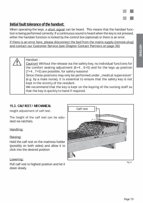
ENG
LIS
H
Page 79
Initial fault tolerance of the handset: When operating the keys, a short signal can be heard. This means that the handset func-tion is being performed correctly. If a continuous sound is heard when the key is not pressed, either the handset function is locked by the control box (optional) or there is an error.
If there is an error here, please disconnect the bed from the mains supply (remove plug) and contact our Customer Service (see Chapter Contact Partners on page 38)
Handset :Caution! Without the release via the safety key, no individual functions for the comfort seating adjustment (6+4 , 6+5) and for the legs up position (7+4 , 7+5) are possible, for safety reasons!Since these positions may only be performed under „medical supervision“ (e.g. by a male nurse), it is essential to ensure that the safety key is not kept in the vicinity of the resident. We recommend that the key is kept on the keyring of the nursing staff so that the key is quickly to hand if required.
15.3. CALF REST / MECHANICAL
-sted via ratchets.
Handling:
Raising:
Hold the calf rest on the mattress holder (possibly on both sides) and allow it to click into the desired position
Lowering:
Pull calf rest to highest position and let it down slowly.
Fig. 9
Calf rest
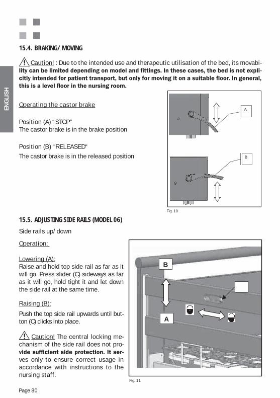
ENG
LIS
H
Page 80
15.4. BRAKING/ MOVING
Caution! : Due to the intended use and therapeutic utilisation of the bed, its movabi--
Operating the castor brake
Position (A) “STOP“The castor brake is in the brake position
Position (B) “RELEASED“
The castor brake is in the released position
Fig. 10
n
-
A
B
Side rails up/down
Operation:
Lowering (A):Raise and hold top side rail as far as it will go. Press slider (C) sideways as far as it will go, hold tight it and let down the side rail at the same time.
Raising (B):
Push the top side rail upwards until but-ton (C) clicks into place.
Caution! The central locking me-chanism of the side rail does not pro-
-ves only to ensure correct usage in accordance with instructions to the nursing staff.
15.5. ADJUSTING SIDE RAILS (MODEL 06)
Fig. 11
B
A
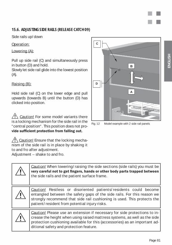
ENG
LIS
H
Page 81
Side rails up/down
Operation:
Lowering (A):
Pull up side rail (C) and simultaneously press in button (D) and hold.Slowly let side rail glide into the lowest position (A).
Raising (B):
Hold side rail (C) on the lower edge and pull upwards (towards B) until the button (D) has clicked into position.
Caution! For some model variants there is a locking mechanism for the side rail in the “central position“. This position does not pro-
Caution! Ensure that the locking mecha-nism of the side rail is in place by shaking it to and fro after adjustment.Adjustment – shake to and fro.
15.6. ADJUSTING SIDE RAILS (RELEASE CATCH 09)
Fig. 12 Model example with 2 side rail panels
Caution! When lowering/raising the side sections (side rails) you must be
the side rails and the patient surface frame.
Caution! Restless or disoriented patients/residents could become entangled between the safety gaps of the side rails. For this reason we strongly recommend that side rail cushioning is used. This protects the patient/resident from potential injury risks.
Caution! Please use an extension if necessary for side protections to in-crease the height when using raised mattress systems, as well as the side protection cushioning available for this (accessories) as an important ad-ditional safety and protection feature.
B
A
D
C
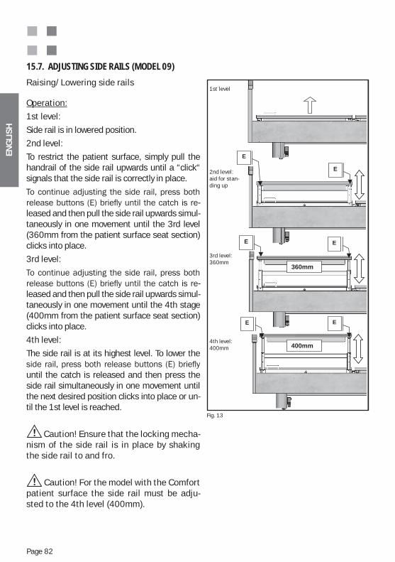
ENG
LIS
H
Page 82
Raising/Lowering side rails
Operation:
1st level:
Side rail is in lowered position.
2nd level:
To restrict the patient surface, simply pull the handrail of the side rail upwards until a “click“ signals that the side rail is correctly in place.
-leased and then pull the side rail upwards simul-taneously in one movement until the 3rd level (360mm from the patient surface seat section) clicks into place.
3rd level:
-leased and then pull the side rail upwards simul-taneously in one movement until the 4th stage (400mm from the patient surface seat section) clicks into place.
4th level:
The side rail is at its highest level. To lower the
until the catch is released and then press the side rail simultaneously in one movement until the next desired position clicks into place or un-til the 1st level is reached.
Caution! Ensure that the locking mecha-nism of the side rail is in place by shaking the side rail to and fro.
Caution! For the model with the Comfort patient surface the side rail must be adju-sted to the 4th level (400mm).
15.7. ADJUSTING SIDE RAILS (MODEL 09)
Abb. 16
360mm
400mm
1. Stufe
2. Stufe:
Aufstehhil-
fe
3. Stufe:
360mm
4. Stufe:
400mm
E
E E
E
E
E
Fig. 13
1st level
2nd level: aid for stan-ding up
3rd level: 360mm
4th level: 400mm
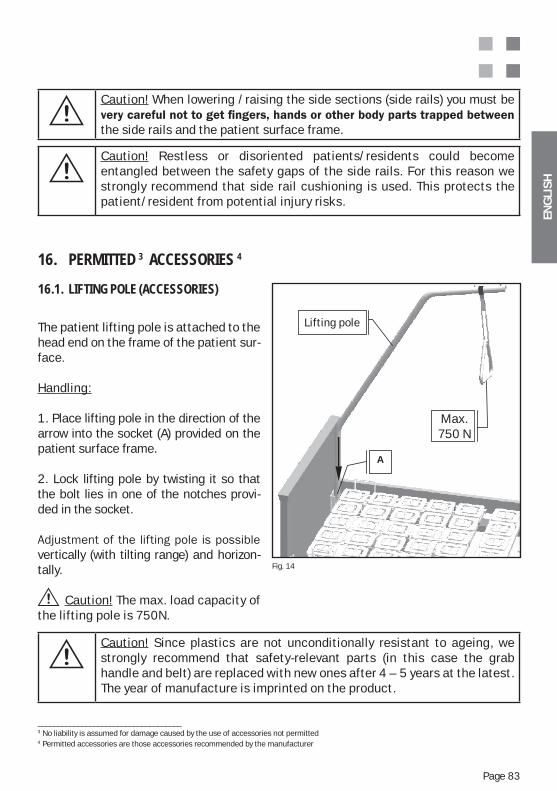
ENG
LIS
H
Page 83
Caution! Restless or disoriented patients/residents could become entangled between the safety gaps of the side rails. For this reason we strongly recommend that side rail cushioning is used. This protects the patient/resident from potential injury risks.
Caution! When lowering /raising the side sections (side rails) you must be
the side rails and the patient surface frame.
16. PERMITTED 3 ACCESSORIES 4
16.1. LIFTING POLE (ACCESSORIES)
The patient lifting pole is attached to the head end on the frame of the patient sur-face.
Handling:
1. Place lifting pole in the direction of the arrow into the socket (A) provided on the patient surface frame.
2. Lock lifting pole by twisting it so that the bolt lies in one of the notches provi-ded in the socket.
vertically (with tilting range) and horizon-tally.
Caution! The max. load capacity of the lifting pole is 750N.
Caution! Since plastics are not unconditionally resistant to ageing, we strongly recommend that safety-relevant parts (in this case the grab handle and belt) are replaced with new ones after 4 – 5 years at the latest. The year of manufacture is imprinted on the product.
____________________________________3 No liability is assumed for damage caused by the use of accessories not permitted4 Permitted accessories are those accessories recommended by the manufacturer
Fig. 14
Aufrichter
A
Max.
750N
Lifting pole
Max.750 N
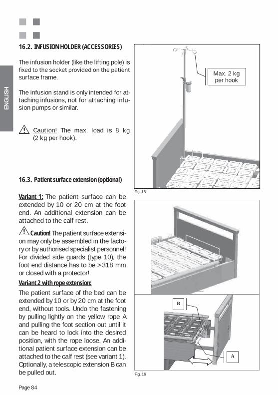
ENG
LIS
H
Page 84
The infusion holder (like the lifting pole) is
surface frame. The infusion stand is only intended for at-taching infusions, not for attaching infu-sion pumps or similar.
Caution! The max. load is 8 kg (2 kg per hook).
16.2. INFUSION HOLDER (ACCESSORIES)
Fig. 15
Fig. 16
dieah-
In-usi-
kg
Max. 2 kg per hook
f
bb
B
A
16.3. Patient surface extension (optional)
Variant 1: The patient surface can be extended by 10 or 20 cm at the foot end. An additional extension can be attached to the calf rest.
Caution! The patient surface extensi-on may only be assembled in the facto-ry or by authorised specialist personnel! For divided side guards (type 10), the foot end distance has to be > 318 mm or closed with a protector!
Variant 2 with rope extension:The patient surface of the bed can be extended by 10 or by 20 cm at the foot end, without tools. Undo the fastening by pulling lightly on the yellow rope A and pulling the foot section out until it can be heard to lock into the desired position, with the rope loose. An addi-tional patient surface extension can be attached to the calf rest (see variant 1). Optionally, a telescopic extension B can be pulled out.
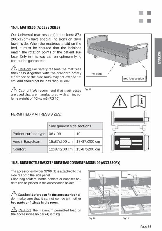
ENG
LIS
H
Page 85
Our Universal mattresses (dimensions: 87x 200x12cm) have special incisions on their lower side. When the mattress is laid on the bed, it must be ensured that the incisions match the rotation points of the patient sur-face. Only in this way can an optimum lying contour be guaranteed.
Caution! For safety reasons the mattress thickness (together with the standard safety clearance of the side rails) may not exceed 12 cm, and should not be less than 10 cm!
Caution! We recommend that mattresses are used that are manufactured with a min. vo-lume weight of 40kg/m3 (RG 40)!
16.4. MATTRESS (ACCESSORIES)
Fig. 17
Bett-Fußteil
EinschnitteIncisions
Bed foot section
The accessories holder SD09 (A) is attached to the side rail or to the side panel. Urine bag holders, bottle holders or handset hol-ders can be placed in the accessories holder.
Caution! -der, make sure that it cannot collide with other
Caution! The maximum permitted load on the accessories holder (A) is 2 kg !
16.5. URINE BOTTLE BASKET / URINE BAG CONTAINER MODEL 09 (ACCESSORY)
Fig. 18 Fig 19
PERMITTED MATTRESS SIZES:
Side guards/side sections
Patient surface type 06 / 09 10
Aero / Easyclean 15x87x200 cm 18x87x200 cm
Comfort 12x87x200 cm 15x87x200 cm
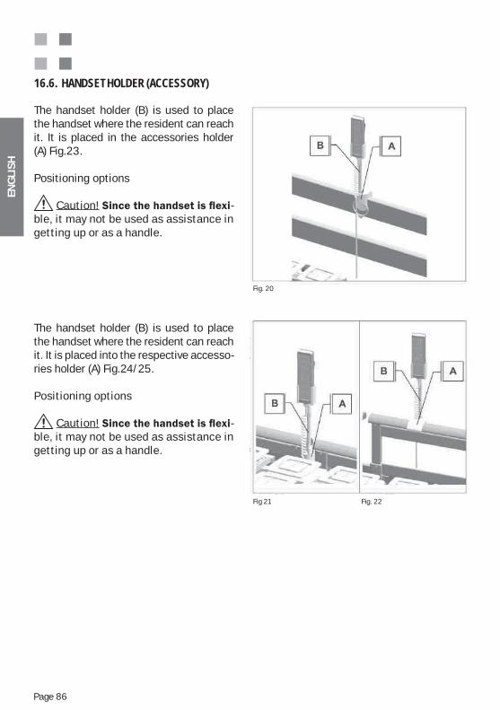
ENG
LIS
H
Page 86
The handset holder (B) is used to place the handset where the resident can reach it. It is placed in the accessories holder (A) Fig.23.
Positioning options
Caution! -ble, it may not be used as assistance in getting up or as a handle.
The handset holder (B) is used to place the handset where the resident can reach it. It is placed into the respective accesso-ries holder (A) Fig.24/25.
Positioning options
Caution! -ble, it may not be used as assistance in getting up or as a handle.
16.6. HANDSET HOLDER (ACCESSORY)
Fig. 20
Fig 21 Fig. 22
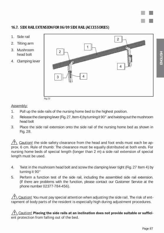
ENG
LIS
H
Page 87
1. Side rail
2. Tilting arm
3. Mushroom head bolt
4. Clamping lever
16.7. SIDE RAIL EXTENSION FOR 06/09 SIDE RAIL (ACCESSORIES)
Fig 23
Assembly:
1. Pull up the side rails of the nursing home bed to the highest position.
2. Release the clamping lever (Fig. 27, Item 4) by turning it 90° and twisting out the mushroom head bolt
3. Place the side rail extension onto the side rail of the nursing home bed as shown in Fig. 28.
Caution! the side safety clearance from the head and foot ends must each be ap-prox. 6 cm. Rule of thumb: The clearance must be equally distributed at both ends. For nursing home beds of special length (longer than 2 m) a side rail extension of special length must be used.
4. Twist in the mushroom head bolt and screw the clamping lever tight (Fig. 27 Item 4) by turning it 90°
5. Perform a function test of the side rail, including the assembled side rail extension. (If there are problems with the function, please contact our Customer Service at the phone number 02377-784-456).
Caution! You must pay special attention when adjusting the side rail. The risk of ent-rapment of body parts of the resident is especially high during adjustment procedures.
Caution! -ent protection from falling out of the bed.
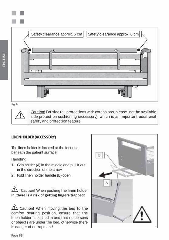
ENG
LIS
H
Page 88
Safety clearance approx. 6 cm Safety clearance approx. 6 cm
Caution! For side rail protections with extensions, please use the available side protection cushioning (accessory), which is an important additional safety and protection feature.
Fig. 24
LINEN HOLDER (ACCESSORY)
The linen holder is located at the foot end beneath the patient surface
Handling:
1. Grip holder (A) in the middle and pull it out in the direction of the arrow.
2. Fold linen holder handle (B) open.
Caution! When pushing the linen holder
Caution! When moving the bed to the comfort seating position, ensure that the linen holder is pushed in and that no persons or objects are under the bed, otherwise there is danger of entrapment!
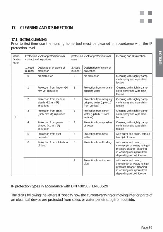
ENG
LIS
H
Page 89
17. CLEANING AND DISINFECTION
17.1. INITIAL CLEANING
protection level.
IP protection types in accordance with DIN 40050 / EN 60529
The digits following the letters IP specify how the current-carrying or moving interior parts of an electrical device are protected from solids or water penetrating from outside.
Identi-fication letter
Protection level for protection from contact and impurities
protection level for protection from water
Cleaning and Disinfection
IP
1. code number
Designation of extent of protection
2. code number
Designation of extent of protection
0 No protection 0 No protection Cleaning with slightly damp cloth, spray and wipe disin-fection
1 Protection from large (>50 mm Ø ) impurities
1 Protection from vertically dripping water
Cleaning with slightly damp cloth, spray and wipe disin-fection
2 Protection from medium-sized (>12 mm Ø ) impurities
2 Protection from obliquely dripping water (up to 15° from vertical)
Cleaning with slightly damp cloth, spray and wipe disin-fection
3 Protection from small (>2.5 mm Ø ) impurities
3 Protection from spray water (up to 60° from vertical)
Cleaning with slightly damp cloth, spray and wipe disin-fection
4 Protection from grain-shaped (>1 mm Ø ) impurities
4 Protection from splashes of water
Cleaning with slightly damp cloth, spray and wipe disin-fection
5 Protection from dust deposits
5 Protection from hose water
with water and brush, without
6 Protection from infiltration of dust
6 Protection from flooding with water and brush;
pressure cleaner; cleaning in washing units permitted, depending on bed licence.
7 Protection from immer-sion
with water and brush;
pressure cleaner; cleaning in washing units permitted, depending on bed licence.
ENG
LIS
H
Page 90
Caution! For safety reasons it is essential that the penetration or appliance of fluids (e.g. water, solvents, oils, lyes, cleaning agents, etc.) into or on parts of the nursing home bed are avoided.
Caution! Housing that provides protection from the penetration of water does not necessarily provide the same protection from other fluids!
Caution! For this reason the nursing home bed must generally be protected as much as possible from any kind of dampness! Cleaning should only be carried out with a slightly damp cloth.
17.2. DISINFECTION / STERILISATIONThe nursing home bed must be disinfected regularly, and at least before every change of resident. The bed may not be disinfected in automatic washing units or with spray water.The following agents are recommended for the disinfection of the nursing home bed, and may only be replaced by equivalent agents:Terralin, Perform and Sagrotan Med (Schülke & Mayr GmbH, Norderstedt).These agents may only be used in accordance with the manufacturer‘s regulations! These refer particularly to the dosage of the agents and possible hazards in combination with other agents.The wooden lining must not come into contact with these agents.
17.3. CARE INSTRUCTIONS FOR WOODEN PARTS We have used materials of the highest quality to create a product for you with a high level of benefits and homely real wood character.In order that you can gain pleasure for as long as possible from your Wissner-Bosserhoff product, we recommend that you clean with a slightly damp, soft cloth.
when varnished. Over the course of time, environmental influences such as UV radiation, humidity or warmth cause changes to the colouring of the real wood surfaces. In addition, wood as a natural material has, by its nature, a wide variety of shadings. The textures of veneers can basically only be generally specified, since each trunk of a particular species of tree has its own characteristics. Slight variations in colour and contrast in deliveries from Wissner-Bosserhoff are natural, and technically unavoidable. This is particularly the case for refurnishing or replenishment deliveries. For the reasons mentioned, relative differences in tone, contrast and colour between veneer surfaces, solid wood parts or patterned surfaces (melamin, HPL), as well as growth-depen-dent inclusions in real wood materials, do not represent defects, and Wissner-Bosserhoff GmbH cannot assume any liability or guarantees for this.Through careful selection, consulting and colour coordination of veneers and varnish, Wiss-ner-Bosserhoff guarantees a high-quality in the coloration of products.
ENG
LIS
H
Page 91
17.4. USE OF CLEANING AGENTSFor particularly stubborn stains, commercially available, environmentally friendly all-round household cleaners can of course be used. The furniture surfaces of Wissner-Bosserhoff pro-
chemicals, and thus have an excellent resistance to normal pollution.No cleaners or cleaning agents may be used, however, that contain mechanically abrasive components and that have the effect of scouring agents.
It must be ensured that no wetness or fluid stains remain on the real wood and veneer sur-faces when in use and when being cleaned. Wood is a natural product which has the property of absorbing moisture, and which expands in doing so. This can cause damage to the surface sealing. For this reason the use and storage of wooden products under the influence of high levels of humidity must be avoided.After cleaning, it is recommended that the real wood and veneer surfaces are wiped down with a dry cloth to avoid damage to the product through moisture as far as possible.
17.5. USE OF DISINFECTION AGENTSOnly disinfection agents may be used that correspond to the disinfection agents described in Appendix 1 of DIN 68861 Part 1: a) Phenolderivates, 0.5-% aqueous solution: Chlorinated alkyl aryl-phenol, cycloalkyl- - aryl-phenol b) Chloramin T, 2.5-% aqueous solution: p-Toluolsulfonchloramide-sodium
17.6. DAMAGE TO WOODEN PARTSIf the veneer or surface sealing is damaged by bumps, scratches or incisions, the surface must immediately be protected from the penetration of humidity by suitable repair materials. Please contact the Wissner-Bosserhoff Customer Service or a specialist company.
17.7. ENVIRONMENTAL COMPATIBILITYAll wooden materials used comply with strict German laws and regulations and are harmless in terms of health. The focus of our operation is on people and their environment.
17.8. QUALITY
with international standards DIN EN ISO 9001:2000 and DIN EN ISO 13485:2003 for the manufacture and distribution of medical products.For all properties guaranteed, Wissner-Bosserhoff assumes a one-year manufacturing war-ranty. Claims that originate from improper or non-standard use or care are excluded from this. If you have grounds for complaint, please contact our Customer Service.
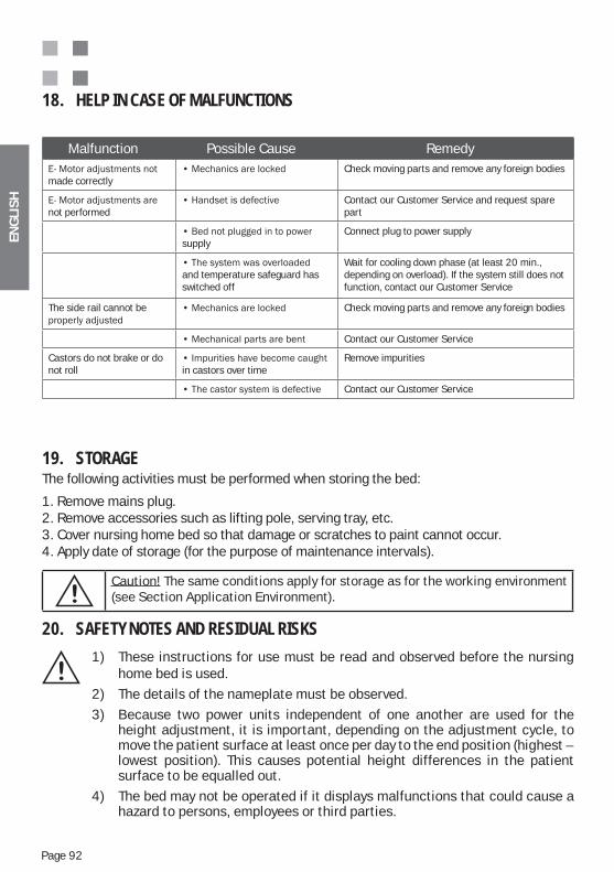
ENG
LIS
H
Page 92
18. HELP IN CASE OF MALFUNCTIONS
Malfunction Possible Cause Remedy
made correctlyCheck moving parts and remove any foreign bodies
not performedContact our Customer Service and request spare part
supplyConnect plug to power supply
and temperature safeguard has switched off
Wait for cooling down phase (at least 20 min., depending on overload). If the system still does not function, contact our Customer Service
The side rail cannot be Check moving parts and remove any foreign bodies
Contact our Customer Service
Castors do not brake or do not roll in castors over time
Remove impurities
Contact our Customer Service
19. STORAGEThe following activities must be performed when storing the bed:
1. Remove mains plug.2. Remove accessories such as lifting pole, serving tray, etc.3. Cover nursing home bed so that damage or scratches to paint cannot occur.4. Apply date of storage (for the purpose of maintenance intervals).
Caution! The same conditions apply for storage as for the working environment (see Section Application Environment).
20. SAFETY NOTES AND RESIDUAL RISKS
1) These instructions for use must be read and observed before the nursing home bed is used.2) The details of the nameplate must be observed.3) Because two power units independent of one another are used for the height adjustment, it is important, depending on the adjustment cycle, to move the patient surface at least once per day to the end position (highest – lowest position). This causes potential height differences in the patient surface to be equalled out.4) The bed may not be operated if it displays malfunctions that could cause a hazard to persons, employees or third parties.
ENG
LIS
H
Page 93
5) The bed may only be operated by persons who can guarantee correct hand- ling because of their training or knowledge and practical experience.
6) Before operating the bed, the person doing this must be satisfied with the functional safety and the proper condition of the bed.
7) The bed must be subject to a function test, possibly daily or with each change of shift, so that it is guaranteed that the bed can be used as intended without danger for the patient or the operator.
8) Do not repair and reuse lifting poles that have become distorted, but replace them.
9) The bed may only be moved on level and firm floor covering.
10) If the bed is occupied the castors must always be in braked position – otherwise there is a risk of the patient falling when getting in or out, since he may support himself on the bed-.
11) The height of the patient surface must be adjusted to the size of the patient to avoid the risk of a fall.
12) When operating the mechanical emergency lowering of the backrest, (optional) this must always be fixed to the mattress restricting bar or lifting pole to avoid a sudden lowering.
13) When moving the bed to different positions, it must be ensured that no children, body parts or other objects are in the adjustment area.
14) Adjustments to the side sections (side rails) may only be made by nursing staff. When adjusting the patient surface positions, nursing staff must be satisfied that the patient will not come into contact with the side rails, to avoid entrapment of hands, legs or other body parts.
15) Extreme leaning out sideways of the upper body must be avoided.
16) Do not alone the side rails more than 75 kg in a vertical direction and more than 50 kg in a horizontal direction.
17) Depending on the physical and mental state of the patient, functions on the handset must be locked or released via a control box. The effective- ness of the locking functions must be tested with the handset.

ENG
LIS
H
Page 94
18) Since the system can be run via battery operation, it is not enough just to pull out the plug in case of the motors functioning incorrectly. If an incorrect function occurs, please switch off functions via the control box and contact our Customer Service (battery operation option).
19) For adjustments via the handset, it is recommended that the operator remains in the vicinity of the control box so that possible incorrect functions can be immediately switched off.
20) Caution! All electrical functions can be faulty – unless they are locked through the control box.
21) For the power source, a 220 / 230 volt, 50 Hz mains plug in accordance with VDE stipulations must be used.
22) Do not touch the plug with wet hands. Only hold the mains connection cable on the plug and pull out from the mains socket.
23) Lay the mains connection cable without loops, do not bend or pull around sharp edges.
24) Generally protect connection cable and supply cable from mechanical stress.
25) Position the mains connection cable and supply cable to the handset so that they are safe from being squashed and do not place any objects on the connection or extension cable.
26) When setting up the bed in the room provided for it, safety clearances from the wall, windowsills and other objects must be maintained. Safety clearances depend on the design and model of the bed, for which extreme height adjustment and tilting movements are performed and at least 25 mm space for fingers must be maintained.
27) If the bedding and height adjustment functions are performed, it must be ensured that the safety key is not in the lock or in the vicinity of the hand- set (in the range of the patient/resident). Through improper release via the safety key, positions can be achieved that may represent a risk to the patient/resident, such as a wrongly applied Trendelenburg position.
28) Place the handset in the holder provided for this (option) or on the bed so that the keys can not be pressed through being caught between two objects, e.g. between side rail and bedside cabinet.
ENG
LIS
H
Page 95
29) Cleaning of the bed may only be carried out with a damp cloth.
30) If the bed is not used properly, dangers can occur through:
Unauthorised operation of electrical functions during the uncontrolled positio- ning of the bed,
Using the bed for children under the age of 12, operating functions of the bed by the patient without previous instruction, Simultaneous operation of electrical functions by different people, connecting electrical devices to the bed that are not intended, Moving the bed by pulling the mains cable or side rails, Pulling the mains cable to remove the mains plug from the power supply, Lack of protection for the connection and supplied cables from sharp edges or
other mechanical strains (e.g. running over the mains cable), moving the bed on an unstable surface, Using the bed on a sloping surface with an angle of 10° or more, Devices that create strong electromagnetic fields and that may possibly
influence the control of the bed are not permitted in the direct vicinity of the bed (e.g. mobile phones).
Before cleaning or servicing the bed the mains plug must always be removed from the power supply.
For safety reasons the lifting handle (trapeze) together with the strap must be completely replaced after 5 years at the latest.
The mattress to be used must meet valid safety standards and may not be thicker than 120 mm.
Continuously dripping fluid in the motor unit area (e.g. in case of inconti- nence)
Improper repair work on electrical installations
31) Safety notes – measures for the safe operation of hospital and nursing home beds:
Electrical components on hospital and nursing home beds may only be re-paired and serviced by the manufacturer or by specialist personnel trained speci-fically by the manufacturer. Otherwise there is a danger that specific procedures will not be performed directly through lack of knowledge of product functionalities, leading to an increased risk of electrical shock or fire.
Electrical components on hospital and nursing home beds may be replaced only with the original spare parts from the manufacturer, since replacement with in-correct components can lead to a highly increased risk of electrical shock or fire.
A safe location on the bed must be specified for the hand controls, so that playing with the hand controls can be prevented.
ENG
LIS
H
Page 96
Cleaning the bed may only be carried out in accordance with the specifications in Section “Cleaning and Disinfection“ of these instructions for use, since in- creased risks could otherwise occur for which the manufacturer can take no responsibility.
If incontinent patients occupy the bed, an incontinence protection for the mattress must always be used.
If immobile patients/residents lie in the bed permanently, bed sores can occur if additional lying aids (e.g. pressure sore mattresses) and other special nursing measures for pressure sore prevention are not employed. Under no circumstances is this the responsibility of the manufacturer of the bed.
The product is explicitly not suitable for permanent use. If the specified opera- ting time is exceeded, the power unit can heat up, causing it to switch off auto- matically. The power unit must then cool down for at least two hours, and can only be put into operation again after this time has expired.
It is absolutely essential that a blockage of the bed or of parts of the bed mechanics is avoided, since this can lead to damage and to the total failure of the power unit through overheating.
It is absolutely essential that the safe working load is not exceeded, since this can lead to damage and to the total failure of the power unit through overhea- ting. 32) Servicing notes – Technical Safety Inspections – Notes on Rectifying Errors:
Electrically-operated hospital and nursing home beds are medical products
dance with the Law on Medical Products (MPG) and the Medical Products Operator Decree § 6 (MedProdBetrV). This regular TSI should be carried out at least once a year. When this is done the functional and electrical safety in accordance with VDE0751, including a visual and function inspection (in- spection of the resource in operation) must be performed, as well as an in- spection of possible measuring functions
In general the accessories and other devices that are combined with the product must also be inspected for technical safety. It must be ensured when doing this that only accessories authorised by the manufacturer and permit- ted combinations of appliances are used. These TSIs may only be undertaken by specialised electricians or persons instructed in electrotechnical matters using a special measuring and test device, who have been trained specifically by the manufacturer for the product and the permitted accessories and combi- nations of appliances. The person performing the inspections may not accept any instructions from the operator. Special test records must be written for each of the TSIs. The product itself should be marked with a test sticker displa- ying the next test date.
ENG
LIS
H
Page 97
Furthermore, electrically-operated hospital and nursing home beds are electrical resources, for the safety of which the employer is responsible. The monitoring function for this obligation is the responsibility of the German profes- sional association for health service and welfare care (BGW) and the German industrial inspectorate. The regulations of the professional associations for Health and Safety at the Workplace (abbreviated BGV, formerly VBG) apply. In particular, BGV A3 (formerly VBG “Electrical Facilities and Resources“ (BGV A2)) applies to repeat inspections of movable electrical resources with a guideline of six months, but at least once per year. These inspections may only be performed by a qualified electrician or a person in- structed in electrotechnical matters, using a special measuring and testing device. The inspections in accordance with BGV A3 may also be performed by specialist staff trained by the manufacturer, in the context of the Technical Safety Inspections for Medical Devices, since these BGV inspections form a part of the Technical Safety Inspections.
Electrically-operated hospital and nursing home beds are active medical products and must be maintained, in accordance with the German Medical Products Operator Directive (MedProdBetrV) in an inventory sheet for each pre- mises. It is recommended that the correct implementation of the stipulated TSIs are also documented in this inventory sheet and that the next test date is specified. The required records for the technical safety inspections already per- formed should be attached to the inventory sheet.
The proper implementation and traceable documentation of the technical inspec- tions, maintenance and service work specified by the manufacturer, as well as the technical safety inspections, is a necessary prerequisite on the part of the purchaser that he may acquire rights of guarantee. If the operator of a medical product does not meet his obligations, risk of damage and accident may arise from this that are explicitly not the responsibility of the manufacturer.
Servicing work must be performed in accordance with EN62353:2008 and be concluded with a documented technical safety inspection
ENG
LIS
H
Page 98
21. MAINTENANCE AND SERVICING
The nursing home beds of Wissner-Bosserhoff GmbH are generally designed for a use-ful life of 10-15 years. The beds here are extremely low in maintenance. This is because attention was paid during the development of the products to ensure that maintenance work was reduced to a minimum, with low operating costs.In daily use, however, experience shows that there is also careless handling of products, and rough handling can also contribute to them ageing quicker and to the wear of cer-tain components, on which the manufacturer can have no direct influence. For this reason, routine servicing examinations should be performed by the operator – also to guarantee the availability of beds, which is in his own interest.The Technical Customer Service of Wissner-Bosserhoff offers servicing and necessary training covering all aspects of the product. Wissner-Bosserhoff certainly places gre-at emphasis on training for customers, since only trained operators and maintenance technicians can ensure proper handling and use of the beds.Maintenance should be performed exclusively by competent specialists who have been trained for the product by Wissner-Bosserhoff.The manufacturer assumes liability for the safety and reliability of the product only if it is regularly maintained and used in accordance with the operating, usage and safety notes in these instructions for use.
If a function control, an inspection, measurement or maintenance reveals serious de-fects that cannot be rectified, the product must be suspended from further use.
Wissner-Bosserhoff GmbH recommends a simple mechanical servicing at yearly inter-vals. In general the manufacturer assumes a servicing in accordance with the currently valid
-dent prevention regulations (UVV) of the professional association. For this reason, BGV
Our Customer Service is available to you for any enquiries and to provide training and test lists for individual products. (To make contact, see Sections 22 and 25)
21.1. COMPLETENESS AND ACCESSORIES
It must be determined, by means of the delivery note, the instructions for use and a visu-al inspection, whether parts are missing, and therefore need to be ordered or replaced. In general the accessories and other devices that are combined with the product must also be checked. It must be ensured when doing this that only accessories authorised by the manufacturer and permitted combinations of appliances are used.
ENG
LIS
H
Page 99
21.2. WEAR AND TEAR
The individual components of the nursing home bed must be examined for scouring, scratches or other types of wear in the context of an inspection and function control, and the cause must be determined and rectified by the replacement of the individual
in the correct manner. Pay particular attention to safety-relevant parts of the nursing home beds.
21.3. FUNCTIONALITY
a function control using the Sections “Function Control“ and “Description of Nursing Home Beds – Functions“ in these instructions for use.
21.4. BGV A3/VDE 0751 – 1:2008 – 8 / DIN EN 62353 : 2008 – INSPECTIONS OF THE ELECTRICAL COMPONENTS OF THE HANDSET
Test of whether the power units move in and out correctly, and whether the unit and handset remain in flawless condition with respect to:
Checking of mechanics (screws, bolts etc. are tight, parts, labels undamaged, etc.)
Condition of cables, housing, etc. (cables crossed, squashed, etc.)
Function Test
Visual inspection
Sufficient cable relief and protection from buckling
Discharge current test
PE conductor test for models in class of protection I
Insulation test if necessaryOur Customer Service is available to you for any enquiries and to provide training and test lists for individual products. (To make contact, see Sections 22 and 25).
21.5. CASTORS
Test of functionality of castors (moving – braking) and the removal of possibly accumulated dust, threads, hair or similar that may have been caught in the castors. If necessary the castor
22. USEFUL LIFE
If used, cleaned, serviced and repaired correctly, a useful life for our products of 10 to 15 years can be expected. Excluded from this are wearing parts such as castors, pneumatic springs, electrical components, etc.
ENG
LIS
H
Page 100
23. DISPOSAL
The bed may optionally contain lead batteries, metal, wood and plastic parts made of ABS, PA, PUR, PE. (cf. scope of delivery and model).
The metal and plastic parts that accumulate during servicing and repairs must be disposed of properly and professionally in accordance with valid laws and regulations. Specifically the electric motors and electrical controls may only be disposed of through specialist firms autho-rised to do this.
24. SPARE PARTS, SPARE PART LISTS AND SERVICE MANUALS
Only Wissner-Bosserhoff original parts may be used.
Customer Service, Sales and the technical consultation department provide information con-cerning spare part deliveries, etc. (for the address, see Contact Partners).
Spare part lists, current price lists and servicing instructions with exploded diagrams can be requested if required from Wissner-Bosserhoff, Technical Customer Service, by specifying the nameplate data of the bed or the relevant article number, order number and delivery date.
Customer Service Tel.: +49(0)2377 / 784-456 Fax: +49(0)2377 / 784-150
25. NAMEPLATE AND LABELS
In order to handle enquiries or spare part orders, details of the nameplate are required.
An example explanation of the details on the nameplate can be found in Appendix B of these instructions for use.
The nameplates and labels of individual components (e.g. motor, pneumatic spring, hydrau-lics, handset) are also very useful.
ENG
LIS
H
Page 101
26. GUARANTEE AND SERVICE
With the “charisma“ nursing home bed you have bought a Wissner-Bosserhoff quality product. This bed was manufactured with great care using high-quality materials and modern production techniques.
The “carisma“ nursing home bed“ has a 36-month guarantee
from the date of purchase. This guarantee covers all malfunctions and defects in materials and manufacture. Malfunctions and defects arising from incorrect handling and external influences are
however, these will be rectified free of charge. This guarantee can be claimed with the purchase slip, which bears the date of purchase. Our general terms and conditions of delivery apply.
27. CONTACT PARTNER
Manufacturer: Wissner-Bosserhoff GmbH Hauptstr. 4-658739 Wickede (Ruhr)
For enquiries we can be reached at the following numbers:
Customer consultants Tel.: +49(0)2377 / 784-0 Fax: +49(0)2377 / 784-163
Customer Servivce Tel.: +49(0)2377 / 784-456 Fax: +49(0)2377 / 784-150
Internet http://www.wi-bo.de Email [email protected]
If you make enquiries, we would like to ask you to prepare for a phone conversation by noting the details on the delivery notes and the nameplates (see Appendix B of these instructions for use) so that the Wissner-Bosserhoff customer consultant can be notified of these. If these data are not available, guarantee services in particular cannot be treated free of charge.
Service partners:
(Please stick reminder stickers here.)
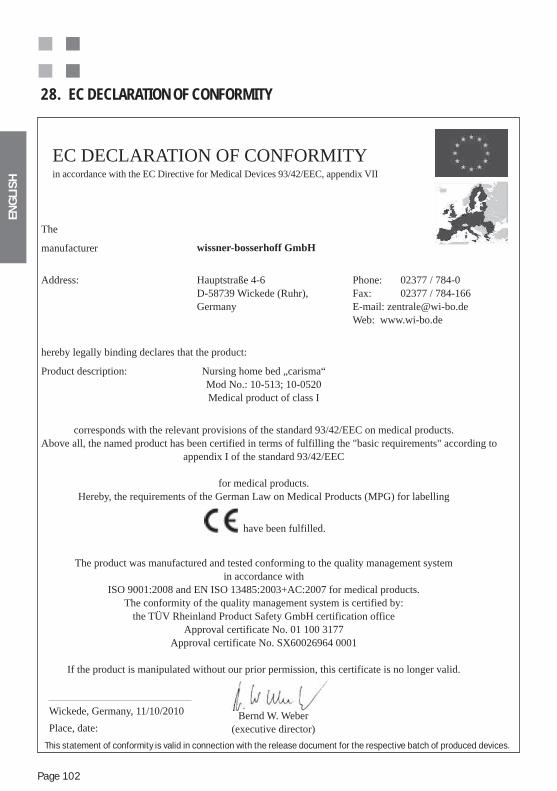
ENG
LIS
H
Page 102
28. EC DECLARATION OF CONFORMITY
EC DECLARATION OF CONFORMITYin accordance with the EC Directive for Medical Devices 93/42/EEC, appendix VII
Bernd W. Weber(executive director)
The
manufacturer wissner-bosserhoff GmbH
Address: Hauptstraße 4-6D-58739 Wickede (Ruhr), Germany
Phone: 02377 / 784-0Fax: 02377 / 784-166E-mail: [email protected] Web: www.wi-bo.de
hereby legally binding declares that the product:
Product description: Nursing home bed „carisma“Mod No.: 10-513; 10-0520Medical product of class I
corresponds with the relevant provisions of the standard 93/42/EEC on medical products.Above all, the named product has been certified in terms of fulfilling the "basic requirements" according to
appendix I of the standard 93/42/EEC
for medical products.Hereby, the requirements of the German Law on Medical Products (MPG) for labelling
have been fulfilled.
The product was manufactured and tested conforming to the quality management system in accordance with
ISO 9001:2008 and EN ISO 13485:2003+AC:2007 for medical products.The conformity of the quality management system is certified by:
the TÜV Rheinland Product Safety GmbH certification officeApproval certificate No. 01 100 3177
Approval certificate No. SX60026964 0001
If the product is manipulated without our prior permission, this certificate is no longer valid.
Wickede, Germany, 11/10/2010
Place, date:
This statement of conformity is valid in connection with the release document for the respective batch of produced devices.
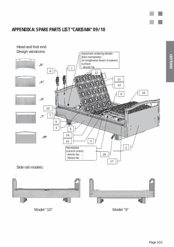
ENG
LIS
H
Page 103
APPENDIX A: SPARE PARTS LIST “CARISMA“ 09/10
Kopf- und FußteilDesign-Varianten:
„S“
„K“
„G“
„T“
„W“
Seitenteil/-gitter Ausführungen:
Ausführung „10“ Ausführung „09“
- Artikel Nr. …- Serien Nr. …
18
3
5
17
4
18
2
11
10
12
13
15
16
14
9
am Längsholm der Liegefläche- Artikel Nr. …- Serien Nr. …
6
7
Head and foot end Design variations:
Important ordering details(bed nameplate)on lengthwise beam of patient surface- Article No. …
Nameplate(control motor)- Article No. …- Series No. …
Side rail models:
Model “10“ Model “9“
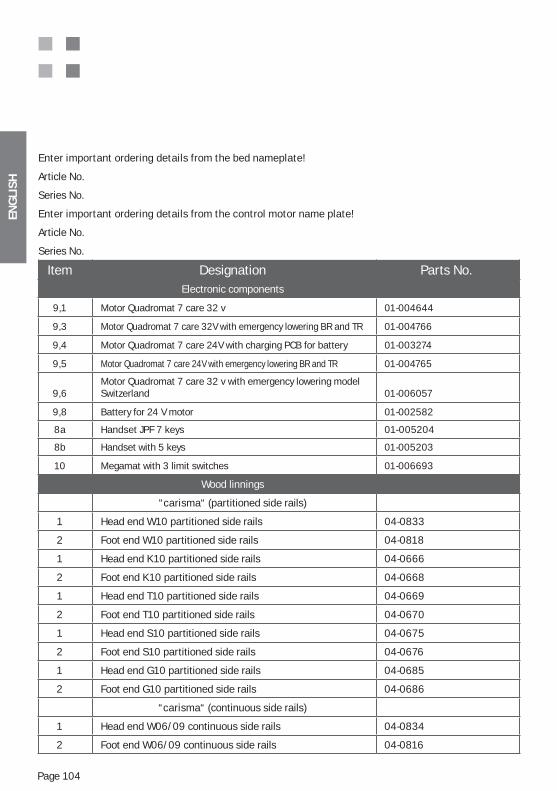
ENG
LIS
H
Page 104
Enter important ordering details from the bed nameplate!
Article No.
Series No.
Enter important ordering details from the control motor name plate!
Article No.
Series No.
Item Designation Parts No. Electronic components
9,1 Motor Quadromat 7 care 32 v 01-004644
9,3 Motor Quadromat 7 care 32V with emergency lowering BR and TR 01-004766
9,4 Motor Quadromat 7 care 24V with charging PCB for battery 01-003274
9,5 Motor Quadromat 7 care 24V with emergency lowering BR and TR 01-004765
9,6Motor Quadromat 7 care 32 v with emergency lowering model Switzerland 01-006057
9,8 Battery for 24 V motor 01-002582
8a Handset JPF 7 keys 01-005204
8b Handset with 5 keys 01-005203
10 Megamat with 3 limit switches 01-006693
Wood linnings
“carisma“ (partitioned side rails)
1 Head end W10 partitioned side rails 04-0833
2 Foot end W10 partitioned side rails 04-0818
1 Head end K10 partitioned side rails 04-0666
2 Foot end K10 partitioned side rails 04-0668
1 Head end T10 partitioned side rails 04-0669
2 Foot end T10 partitioned side rails 04-0670
1 Head end S10 partitioned side rails 04-0675
2 Foot end S10 partitioned side rails 04-0676
1 Head end G10 partitioned side rails 04-0685
2 Foot end G10 partitioned side rails 04-0686
“carisma“ (continuous side rails)
1 Head end W06/09 continuous side rails 04-0834
2 Foot end W06/09 continuous side rails 04-0816
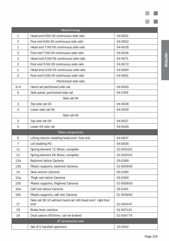
ENG
LIS
H
Page 105
Wood linnings
1 Head end K06/09 continuous side rails 04-0651
2 Foot end K06/09 continuous side rails 04-0652
1 Head end T 06/09 continuous side rails 04-0635
2 Foot end T 06/09 continuous side rails 04-0636
1 Head end S 06/09 continuous side rails 04-0671
2 Foot end S 06/09 continuous side rails 04-0672
1 Head end G 06/09 continuous side rails 04-0680
2 Foot end G 06/09 continuous side rails 04-0681
Partitioned side rails
3+4 Hand rail partitioned side rail 04-0565
5 Side panel, partitioned side rail 04-0769
Side rail 06
3 Top side rail 06 04-0508
4 Lower side rail 06 04-0509
Side rail 09
3 Top side rail 09 04-0637
4 Lower 09 side rail 04-0509
Other components
6 Lifting column cladding head end / foot end 04-0837
7 Lid cladding FG 04-0838
11 Spring element 72 Shore, complete 02-000316
12 Spring element 68 Shore, complete 02-000315
13a Backrest lattice Carisma 05-0389
13b Plastic supports, backrest Carisma 01-005658
14 Seat section Carisma 05-0385
15a Thigh rest lattice Carisma 05-0390
15b Plastic supports, thighrest Carisma 01-005659
16a Calf rest lattice Carisma 05-0391
16b Plastic supports, calf rest Carisma 01-005660
17Side rail SD 10 without hand rail, left-head end / right-foot end 01-000447
18 Brake lever carisma 01-007124
19 Dual castors Ø 50mm, can be braked 01-006779
ET accessories sets
Set of 5 handset spanners 10-0392
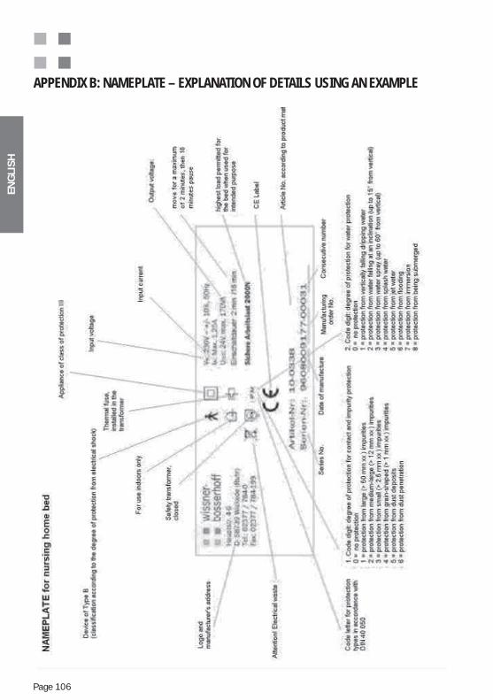
ENG
LIS
H
Page 106
APPENDIX B: NAMEPLATE – EXPLANATION OF DETAILS USING AN EXAMPLE
ENG
LIS
H
Page 107
APPENDIX C: IMPORTANT SAFETY AND USAGE NOTES FOR NURSING HOME BEDS
INTENDED USE AND PURPOSE OF NURSING HOME BEDS
A nursing home bed may only be operated and used in accordance with its inten-ded purpose, in compliance with the regulations of the Law on Medical Products (MPG), the accompanying orders, the generally recognised rules of technology and the regulations on work safety and accident prevention. A nursing home bed may not be operated in a defective condition in which the bed could be a hazard to patients, nursing staff or third parties.
The conditions of the respective instructions for use of the product shall apply:
The following points must be observed:
the occupancy of persons from the age of 12 and above. This must be ensured, since persons with a body size or weight deviating from the normal average are exposed to an increased risk under certain circumstances. As the recommended standard range, persons in a range from a woman of 146 cm in height to a man of 185 cm in height (with a non-critical state of health and capable of acting independently at least to a certain extent) can occupy the bed without additional risks or restrictions in performance (in accordance with Standard IEC 60601-2-52). Beyond this range, additional accessories must be used if necessary, or use is not possible. Bed extensions (accessories) should be used for larger persons, and it is essential that additional protective measures such as side rail protec-tion covers (accessories) are used for emaciated persons. Individual application cases that deviate from this must be co-ordinated with Wissner-Bosserhoff GmbH.
supervision) is necessary to guarantee safe use of the nursing home beds. The physical, psychological and medical needs and conditions of patients must be observed. Accordingly the bed functions must be individually released or locked for each patient/resident. This applies particularly to products with special tilting options for the patient surface, and when using side guards.
The maximum working load of the nursing home bed is 225 kg. Higher loads are possible and must be taken from the instructions for use for the respective product! The bed may not be used for patients with a weight of more than 155 kg. The safe working load of 225 kg includes the patient weight, the mattress and the accessories located on the bed (lifting pole, linen etc.)!
ENG
LIS
H
Page 108
installed in the building that are up-to-date and that are inspected regularly for the correct function of safety installations (RCD protection, insulation error detec-tors, power fuse, etc.) in accordance with valid regulations.
or possible ignitable substances mixed with air and can be found. The regulations of the professional associations must be observed in this respect.
Possible use deviating from this intended purpose represents a non-intended use and is excluded from all claims of liability.
BASIC FUNCTIONS AND USES OF NURSING HOME BEDS
Modern nursing home beds have numerous bedding functions, which are described in
home bed can only be achieved through careful training of the users and inhabitants of a nursing home. Please repeat these training sessions as regularly as possible and pay particular attention to the necessary safety regulations that must be observed.
In general there is always a risk of unintended or wrong adjustment of the bed. For example, pressing switches accidentally or unintended release of func-tions can be a hazard to certain patients/residents! To ensure a high degree of protection, it is absolutely essential to use locking facilities and/or the release keys selectively. Under no circumstances may release keys remain on the handset or on the bed! Release keys are intended exclusively for use by nursing staff.
The use of the locking facilities and if required, the intentional separation of the bed from the power supply – as an absolute locking measure for the ma-ximum protection of a possibly jeopardised patient/resident– lies exclusively at the discretion of and in the responsibility of the medical supervision and nursing staff in charge. Corresponding measures should be noted in the shift report to guarantee a correct shift handover.
The use of special positions, such as Trendelenburg anti-Trendelenburg, la-yered bedding or relative lowered head position as a shock position is expli-citly allowed only by medical supervision staff. These functions must be lo-cked for patients and residents, since this could otherwise result in hazards.
ENG
LIS
H
Page 109
since hazards could otherwise occur.
When using the side guards, particular care and caution should be taken:
- As soon as the mobility of the patient/resident is restricted, a court order is required to use the side guards. Only divided side guards or side guards that can be individually lowered, in which only the head and section is assembled, and which can be used as a help in getting in and out, are just one permissible exception for mobile residents/patients here.
Overloading caused by sitting, leaning or pulling on the side rail can result in serious damage to this and cause hazards. It is essential that such overloa-ding is avoided.
When using side guards, their suitability should be checked, taking into ac-count the peculiarities of the respective patient/resident. In particular the clearances between the panels and supports in relation to the body shape of the patient/resident must be taken into account, so that entrapment or slipping through is ruled out. If necessary, additional side guard cushioning must be used which reduces the size of the gap or closes it. This decision is exclusively the responsibility of the medical supervision in charge. The details on the restriction of the intended use in these instructions for use are referred
bed and for the side rail.
Only side guards may be used on the beds which are also permitted for that particular bed type, since increased risk of accident could otherwise occur.
The side rails/side guards must be checked each time before they are used for possible damage, and checked that they are securely attached to the bed and that the safety lock functions correctly! Details on the correct handling of the side guard can be found in the respective product instructions for use.
The use of the manual remote control by the resident/patient himself lies ex-clusively at the discretion of and in the responsibility of the medical supervi-sion and nursing staff in charge. Corresponding measures should be noted in the shift report or in the nursing documentation to guarantee a correct shift handover and traceability of usage rights.
If the manual remote control is not to be used by the resident/patient himself, then it must be protected from being accessed by this person and from beco-ming trapped, for example by attaching it to the foot end of the bed.
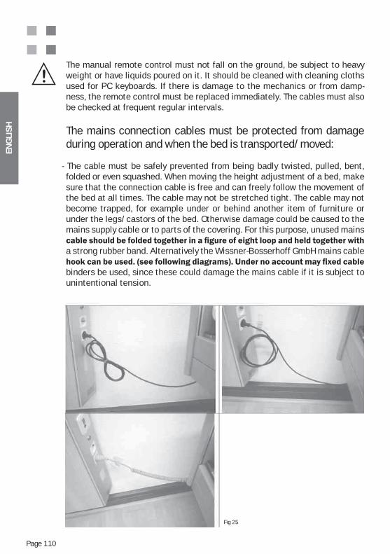
ENG
LIS
H
Page 110
The manual remote control must not fall on the ground, be subject to heavy weight or have liquids poured on it. It should be cleaned with cleaning cloths used for PC keyboards. If there is damage to the mechanics or from damp-ness, the remote control must be replaced immediately. The cables must also be checked at frequent regular intervals.
The mains connection cables must be protected from damage during operation and when the bed is transported/moved:
- The cable must be safely prevented from being badly twisted, pulled, bent, folded or even squashed. When moving the height adjustment of a bed, make sure that the connection cable is free and can freely follow the movement of the bed at all times. The cable may not be stretched tight. The cable may not become trapped, for example under or behind another item of furniture or under the legs/castors of the bed. Otherwise damage could be caused to the mains supply cable or to parts of the covering. For this purpose, unused mains
a strong rubber band. Alternatively the Wissner-Bosserhoff GmbH mains cable
binders be used, since these could damage the mains cable if it is subject to unintentional tension.
Fig 25
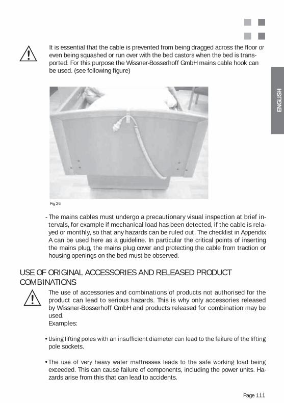
ENG
LIS
H
Page 111
It is essential that the cable is prevented from being dragged across the floor or even being squashed or run over with the bed castors when the bed is trans-ported. For this purpose the Wissner-Bosserhoff GmbH mains cable hook can be used. (see following figure)
- The mains cables must undergo a precautionary visual inspection at brief in-tervals, for example if mechanical load has been detected, if the cable is rela-yed or monthly, so that any hazards can be ruled out. The checklist in Appendix A can be used here as a guideline. In particular the critical points of inserting the mains plug, the mains plug cover and protecting the cable from traction or housing openings on the bed must be observed.
USE OF ORIGINAL ACCESSORIES AND RELEASED PRODUCT COMBINATIONS
The use of accessories and combinations of products not authorised for the product can lead to serious hazards. This is why only accessories released by Wissner-Bosserhoff GmbH and products released for combination may be used.Examples:
pole sockets.
exceeded. This can cause failure of components, including the power units. Ha-zards arise from this that can lead to accidents.
Fig 26
ENG
LIS
H
Page 112
SETTING UP THE NURSING HOME BED (SAFETY CLEARANCES)
The bed must be set up in such a way that when implementing all adjustment functions of the bed, collision of bed parts with other objects in the room or with parts of the room is not possible (e.g. mains cable, windowsills, slanting ceilings, pipes, surface-mounted installations, wall boards etc.). A safety clea-rance from walls and other objects of at least 2.5 cm should be maintained in all possible bed positions when doing this. Caution: Equally no collision may occur for tilting and height adjustments! The bed must be set up in a way it can be easily disconnected from the mains supply (by unplugging the mains plug).
CLEANING AND DISINFECTION OF THE BED
The nursing home bed must be cleaned and disinfected regularly, and at least before every change of resident. The nursing home bed may not be cleaned or disinfected in automatic washing units, nor with splash water, jet water or water spray. Only spray and wiping disinfection is permitted.
The following agents are recommended for the disinfection of the nursing home bed, and may only be replaced by equivalent agents:Terralin, Perform and Sagrotan Med (Schülke & Mayr GmbH, Norderstedt).These agents may only be used in accordance with the manufacturer‘s regula-tions! These refer particularly to the dosage of the agents and possible hazards in combination with other agents.
The wooden linning must not come into contact with these agents.For particularly stubborn stains, commercially available, environmentally friendly all-round household cleaners can of course be used.
No cleaners or cleaning agents may be used, however, that contain mechani-cally abrasive components and that have the effect of scouring agents.
and veneer surfaces when in use and when being cleaned. Wood is a natural product which has the property of absorbing moisture, and which expands in doing so. This can cause damage to the surface sealing. Damage to varnished
ask Wissner-Bosserhoff Customer Service.
Manual remote controls may only be cleaned with cleaning cloths for PC key-boards. If dampness has penetrated, if the unit is heavily soiled or if the keys stick due to dirt particles, the hand controls must be replaced if necessary.
ENG
LIS
H
Page 113
APPENDIX D: BATTERY OPERATION (OPTION) – ADDITIONAL NOTES
As a special fitting, the bed power unit can be equipped with an additional battery function allowing the bed to be moved multiple times with its electrical functions independently of the mains supply.
prevent the batteries from excessive discharge, the bed should remain connected to the mains if possible.
Battery charging will then take place fully automatically via a specially integrated PCB.
Normally the battery is delivered fully loaded and mounted on the main power unit; assem-bly by an untrained operator is not intended.
Important features
For safety reasons the battery box must not be opened.
If you want to acquire the battery later on, we urge you to contact Technical Customer Service, since not every power unit is suitable for combination with the battery. Replace-ment of the battery box should only be performed by trained personnel to avoid possible damage through incorrect handling.
The lifetime of the battery is strongly dependent on usage and on the fact that possible harmful excessive discharge may have occurred.
It is also possible to use a fourfold external charging unit (accessory for parallel charging of four battery boxes), which can be obtained separately:We strongly urge you to observe the separate instructions for use for the battery charging unit in such a case.

ENG
LIS
H
Page 114
APPENDIX E: METAMERISM – THE APPARENT SAMENESS OF SURFACES AND DÉCORS
“Metamerism”
Two colours appear to be identical only under a specific type of light. If the light changes, differentiations occur, due to the spectral properties of the pigments, colours and materials used. A green coat bought in a shop may suddenly turn brown out on the street, but the green trousers have remained green. To look closely at critical colours in clothes, people often go into daylight, but since this is rather problematic formatching print and material colours, daylight/ daylight-similar light D65 is used.
This is therefore a phenomenon involving the conditional similarity of colours. Two colours or more appear to be identical only under a specific type of light (e.g. a neon light) and otherwise display differences due to their spectral properties (e.g. the pigments and paint materials used) under any other lighting.
sunlight has a different effect than in yellow sunlight. Metamerism is the colour difference between two or more colours in materials changeable by light.
Particularly when different materials, different colouring and printing techniques are used, slight differences in colour are almost bound to occur under different lighting conditions (neon effect, shop lighting effect or exhibition effect are terms referring to such typical phe-nomena).
For colour comparisons of unidécors, colorimetry is a useful instrument. A so-called meta-merism index is used as a comparative value between two samples. The metamerism index is the Delta E value in the CIE L*a*b system under two light sources in each case – usually from a daylight source (C, D50, D60) to an artificial light source (A). Combined colour and gloss-measuring instruments are used for this purpose.
For wood décor, structural décor and pattern prints, on the other hand, a visual assessment must be made, on a pattern repeat, since a purely metrological colour comparison mea-surement cannot be practically implemented. It is important to reach an interdisciplinary
highly individual.
The so-called pattern repeat is the smallest separate unit of a pattern. If a pattern (e.g. for print foils or materials) is therefore composed of several small parts, a single part is called a pattern repeat (e.g. a print section of 1.5 m in length, after which the basic pattern is repeated).
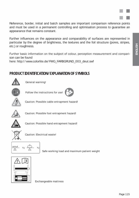
ENG
LIS
H
Page 115
Reference, border, initial and batch samples are important comparison reference points and must be used in a permanent controlling and optimisation process to guarantee an appearance that remains constant.
Further influences on the appearance and comparability of surfaces are represented in particular by the degree of brightness, the textures and the foil structure (pores, stripes, etc.) or roughness.
-son can be foundhere: http://www.colorlite.de/FMG_FARBGRUND_003_deut.swf
PRODUCT IDENTIFICATION/EXPLANATION OF SYMBOLS
Safe working load and maximum patient weight
General warning!
Follow the instructions for use!
Caution: Possible cable entrapment hazard!
Caution: Possible foot entrapment hazard!
Caution: Possible hand entrapment hazard!
Caution: Electrical waste!
Exchangeable mattress
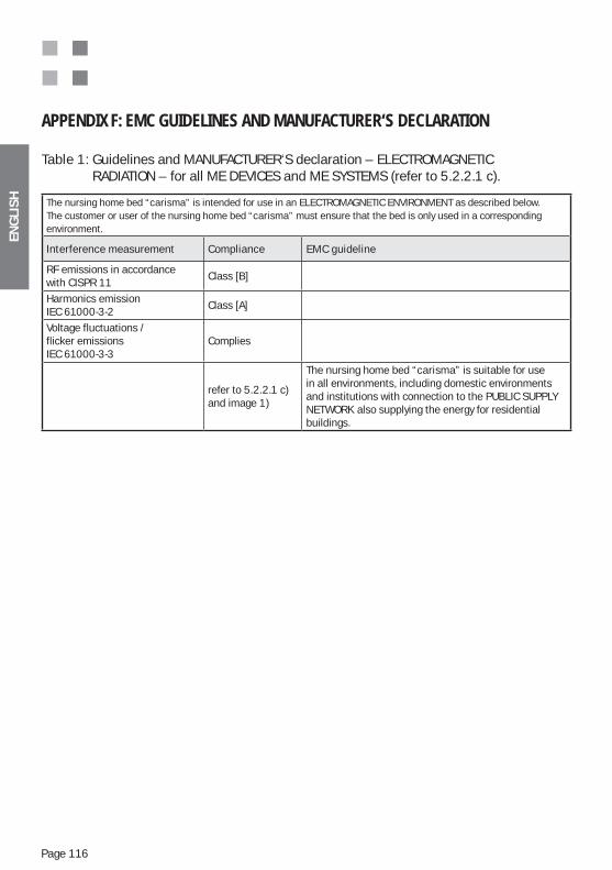
ENG
LIS
H
Page 116
APPENDIX F: EMC GUIDELINES AND MANUFACTURER‘S DECLARATION
Table 1: Guidelines and MANUFACTURER‘S declaration – ELECTROMAGNETIC RADIATION – for all ME DEVICES and ME SYSTEMS (refer to 5.2.2.1 c).
The nursing home bed “carisma” is intended for use in an ELECTROMAGNETIC ENVIRONMENT as described below. The customer or user of the nursing home bed “carisma” must ensure that the bed is only used in a corresponding environment.
Interference measurement Compliance EMC guideline
RF emissions in accordance with CISPR 11
Class [B]
Harmonics emissionIEC 61000-3-2
Class [A]
Voltage fluctuations /flicker emissionsIEC 61000-3-3
Complies
refer to 5.2.2.1 c)and image 1)
The nursing home bed “carisma” is suitable for use in all environments, including domestic environments and institutions with connection to the PUBLIC SUPPLY NETWORK also supplying the energy for residential buildings.
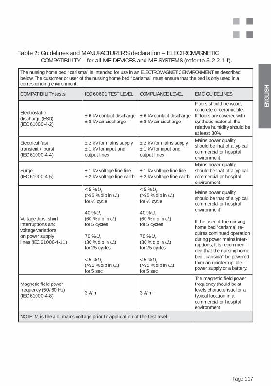
ENG
LIS
H
Page 117
Table 2: Guidelines and MANUFACTURER‘S declaration – ELECTROMAGNETIC COMPATIBILITY – for all ME DEVICES and ME SYSTEMS (refer to 5.2.2.1 f).
The nursing home bed “carisma” is intended for use in an ELECTROMAGNETIC ENVIRONMENT as described below. The customer or user of the nursing home bed “carisma” must ensure that the bed is only used in a corresponding environment.
COMPATIBILITY tests IEC 60601 TEST LEVEL COMPLIANCE LEVEL EMC GUIDELINES
Electrostaticdischarge (ESD)(IEC 61000-4-2)
± 6 kV contact discharge± 8 kV air discharge
± 6 kV contact discharge± 8 kV air discharge
Floors should be wood, concrete or ceramic tile. If floors are covered with synthetic material, the relative humidity should be at least 30%.
Electrical fasttransient / burst(IEC 61000-4-4)
± 2 kV for mains supply± 1 kV for input and output lines
± 2 kV for mains supply± 1 kV for input and output lines
Mains power quality should be that of a typical commercial or hospital environment.
Surge(IEC 61000-4-5)
± 1 kV voltage line-line± 2 kV voltage line-earth
± 1 kV voltage line-line± 2 kV voltage line-earth
Mains power quality should be that of a typical commercial or hospital environment.
Voltage dips, shortinterruptions andvoltage variationson power supplylines (IEC 61000-4-11)
< 5 % UT(>95 % dip in UT)for ½ cycle
40 % UT (60 % dip in UT)for 5 cycles
70 % UT (30 % dip in UT)for 25 cycles
< 5 % UT (>95 % dip in UT)for 5 sec
< 5 % UT(>95 % dip in UT)for ½ cycle
40 % UT (60 % dip in UT)for 5 cycles
70 % UT (30 % dip in UT)for 25 cycles
< 5 % UT (>95 % dip in UT)for 5 sec
Mains power quality should be that of a typical commercial or hospital environment.
If the user of the nursing home bed “carisma” re-quires continued operationduring power mains inter-ruptions, it is recommen-ded that the nursing homebed „carisma“ be powered from an uninterruptible power supply or a battery.
Magnetic field power frequency (50/60 Hz)(IEC 61000-4-8)
3 A/m 3 A/m
The magnetic field power frequency should be at levels characteristic for atypical location in a commercial or hospital environment.
NOTE: UT is the a.c. mains voltage prior to application of the test level.
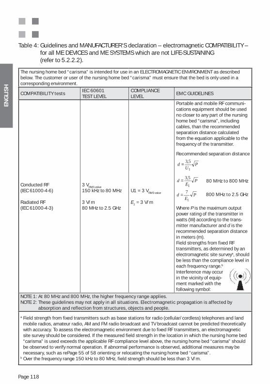
ENG
LIS
H
Page 118
Table 4: Guidelines and MANUFACTURER‘S declaration – electromagnetic COMPATIBILITY – for all ME DEVICES and ME SYSTEMS which are not LIFE-SUSTAINING (refer to 5.2.2.2).
The nursing home bed “carisma” is intended for use in an ELECTROMAGNETIC ENVIRONMENT as described below. The customer or user of the nursing home bed “carisma” must ensure that the bed is only used in a corresponding environment.
COMPATIBILITY testsIEC 60601 TEST LEVEL
COMPLIANCE LEVEL
EMC GUIDELINES
Conducted RF(IEC 61000-4-6)
Radiated RF(IEC 61000-4-3)
3 VRMS value
150 kHz to 80 MHz
3 V/m80 MHz to 2.5 GHz
U1 = 3 VRMS value
E1 = 3 V/m
Portable and mobile RF communi-cations equipment should be used no closer to any part of the nursing home bed “carisma”, including cables, than the recommended separation distance calculated from the equation applicable to the frequency of the transmitter.
Recommended separation distance
80 MHz to 800 MHz
800 MHz to 2.5 GHz
Where P is the maximum output power rating of the transmitter in watts (W) according to the trans-mitter manufacturer and d is the recommended separation distance in meters (m).Field strengths from fixed RF transmitters, as determined by an electromagnetic site surveya, should be less than the compliance level in each frequency range.b
Interference may occur in the vicinity of equip- ment marked with the following symbol:
NOTE 1: At 80 MHz and 800 MHz, the higher frequency range applies.NOTE 2: These guidelines may not apply in all situations. Electromagnetic propagation is affected by
absorption and reflection from structures, objects and people.
a Field strength from fixed transmitters such as base stations for radio (cellular/cordless) telephones and land mobile radios, amateur radio, AM and FM radio broadcast and TV broadcast cannot be predicted theoretically with accuracy. To assess the electromagnetic environment due to fixed RF transmitters, an electromagnetic site survey should be considered. If the measured field strength in the location in which the nursing home bed “carisma” is used exceeds the applicable RF compliance level above, the nursing home bed “carisma” should be observed to verify normal operation. If abnormal performance is observed, additional measures may be necessary, such as rePage 55 of 58 orienting or relocating the nursing home bed “carisma”.
b Over the frequency range 150 kHz to 80 MHz, field strength should be less than 3 V/m.
PE
d1
5,3=
PU
d1
5,3=
PE
d1
7=
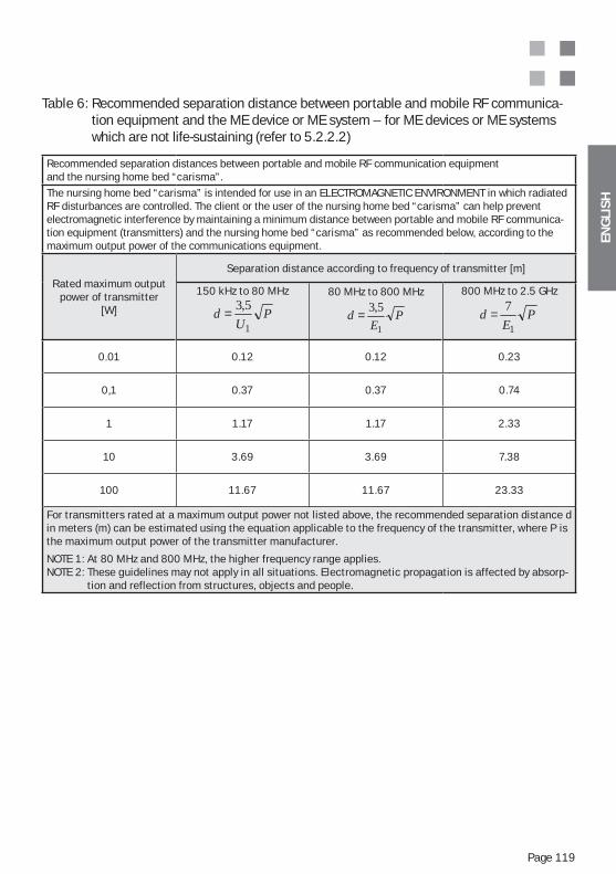
ENG
LIS
H
Page 119
Table 6: Recommended separation distance between portable and mobile RF communica-tion equipment and the ME device or ME system – for ME devices or ME systems which are not life-sustaining (refer to 5.2.2.2)
Recommended separation distances between portable and mobile RF communication equipmentand the nursing home bed “carisma”.
The nursing home bed “carisma” is intended for use in an ELECTROMAGNETIC ENVIRONMENT in which radiated RF disturbances are controlled. The client or the user of the nursing home bed “carisma” can help prevent electromagnetic interference by maintaining a minimum distance between portable and mobile RF communica-tion equipment (transmitters) and the nursing home bed “carisma” as recommended below, according to the maximum output power of the communications equipment.
Rated maximum outputpower of transmitter
[W]
Separation distance according to frequency of transmitter [m]
150 kHz to 80 MHz
PU
d1
5,3=80 MHz to 800 MHz
PE
d1
5,3=
800 MHz to 2.5 GHz
PE
d1
7=
0.01 0.12 0.12 0.23
0,1 0.37 0.37 0.74
1 1.17 1.17 2.33
10 3.69 3.69 7.38
100 11.67 11.67 23.33
For transmitters rated at a maximum output power not listed above, the recommended separation distance d in meters (m) can be estimated using the equation applicable to the frequency of the transmitter, where P is the maximum output power of the transmitter manufacturer.
NOTE 1: At 80 MHz and 800 MHz, the higher frequency range applies.NOTE 2: These guidelines may not apply in all situations. Electromagnetic propagation is affected by absorp-
tion and reflection from structures, objects and people.
ENG
LIS
H
Page 120
Notices
ENG
LIS
H
Page 121
Notices
FRA
NÇ
AIS
Page 122
TABLE DES MATIÈRES
2. Indication pour le mode d‘emploi / explication des symboles ...................................................................... 1223. Domaine d‘utilisation / appliications ................................................... 1224. Montage du lit ....................................................................................... 125
.......................... 1255.1. Sommiers electriques ...................................................................... 1265.2. Réglage en hauteur des moteurs électriques ................................ 1266. Sécurité du produit / extrait des normes appliiquées ........................ 1277. Aperçu des produits (exemple du modèle bois T10) ........................... 1288. Description des fonctions éléctriques ................................................ 1288.1. Fonction releve buste (RB) ............................................................... 129
........................................................................... 1308.3. Siege confort (SC) .............................................................................. 1308.4. Fonction autocontour (AC) ............................................................... 1318.5. Fonction pour le reglage de la hauteur (RH) .................................. 1319. Combinaison du lit a usage medical avec des dispositifs de levage mobiles .................................................................................. 13110. Regles de sécurite pour le reglage de la hauteur ............................... 13211. Boîtier de controle en option ............................................................... 13212. Livraison ................................................................................................ 13313. Montage .................................................................................................. 13413.1. Sommier ............................................................................................. 13413.2. Moteur du sommier ........................................................................... 13414. Transport / déplacement du lit ............................................................. 13415. Test de fonctions .................................................................................... 13515.1. Boitier de commande „carisma 07 JPF“ Description des fonctions ................................................................. 13515.2. Boitier verso avec fonction de verrouillage ..................................... 136
............................................................ 13715.4. Déplacement / Freinage ................................................................... 13815.5. Réglage des treillis latéraux (Modèle 06) ........................................ 13815.6. Réglage des treillis latéraux (Déclenchement 09) .......................... 13915.7. Réglage des treillis latéraux (Modèle 10) ........................................ 14016. Accessoires3 autorises4 ........................................................................ 14116.1. Potence (accessoire) ......................................................................... 14116.2. Flacon de perfusion (accessoire) ..................................................... 14216.3. Prolongation de sommier (option) .................................................... 14216.4. Matelas ( accessoire) ........................................................................ 14316.5. Panier pour urinal/support pour poche a urine, modele 09 (accessoire) .................................................................... 14316.6. Support pour boîtier (accessoire) .................................................... 14416.7. Rehausse de treillis latéraux pour treillis Latéraux 06/09 (accessoires) ................................................................... 14517. Nettoyage et desinfection ..................................................................... 14717.1. Premier nettoyage ............................................................................. 14717.2. Desinfection / Sterilisation ............................................................... 148
FRA
NÇ
AIS
Page 123
17.3. Soin des parties en bois .................................................................. 14817.4. Utilisation de produits nettoyants .................................................... 14917.5. Utilisation de produits desinfectants .............................................. 14917.6. Dommages sur les parties en bois .................................................. 14917.7. Respect de l’environnement ............................................................. 14917.8. Qualite ................................................................................................ 14918. Aide lors de derangements ................................................................... 15019. Stockage ................................................................................................. 15020. Indications de securite et autres risques ............................................ 15021. Maintenance et entretien ...................................................................... 15621.1. Integralite et accessoires .................................................................. 15621.2. Usure .................................................................................................. 15721.3. Fonctionnalite .................................................................................... 157
et du boitier ........................................................................................ 15721.5. Roues .................................................................................................. 15722. Duree de vie ........................................................................................... 15723. Elimination .............................................................................................. 15824. Pieces de rechange, listes de pieces de rechange et manuels de service ............................................................................................. 158
............................................ 15826. Garantie et service ................................................................................ 15927. Contact ................................................................................................... 15928. CE-Déclaration de conformité ............................................................... 160
Annexe A : Liste des pièces détachées carisma 09/10Annexe B : Plaque signalétique – Explication des données de l‘exempleAnnexe C : Règles essentielles de sécurité et d‘utilisation pour les lits de soinAnnexe D : Mode batterie (en option) - indications supplémentairesAnnexe E : Métamérie – la similitude de l‘aspect des surfaces et décorsAnnexe F : Directives CEM et déclaration du fabricant
CONSIGNES DE SÉCURITÉ IMPORTANTES :Veuillez lire attentivement les passages importants pour la sécurité, marqués par le symbole
dans les chapitres du mode d‘emploi, et respecter les indications du chapitre 18 et de l‘annexe C.
Le non-respect de ces consignes peut provoquer des dommages ou des blessures.
FRA
NÇ
AIS
Page 124
Chers clients,
notre produit convient parfaitement aux exigences des soins quotidiens. Le bon choix des matériaux, l‘emploi de technologies les plus modernes et surtout le travail minutieux et l‘esprit d‘équipe de nos collaborateurs, rendent nos produits extrêmement utiles et quali-tativement très solides. Nous sommes sûrs de vous faciliter le travail des soins avec nos produits.
2. INDICATION POUR LE MODE D‘EMPLOI / EXPLICATION DES SYMBOLES
Ce symbole rend attentif à des indications de sécurité dont le non respect peut avoir des conséquences graves (p.e. dommages, blessures). Il est donc indispensable de bien respecter ces instructions et indications.
Ce mode d‘emploi s‘adresse au personnel soignant formé, c‘est-à-dire à toute personne chargée de la mise en service de ce produit.
Attention! Le boîtier de commande devant se trouver en « mode résident ». Cha-que maniement de ce produit exige que la personne connaisse et respecte avec précision ce mode d‘emploi. Pour cette raison il doit être gardé précieusement
un service sans dérangements, le mode d‘emploi doit être accessible à tout mo-ment au personnel soignant. Il est conseillé de le garder près du lit ou dans la table de nuit.
Les textes et dessins de ce mode d‘emploi ne correspondent pas nécessairement au volume de livraison, puisqu‘il est fait pour toutes les variantes de modèles. Les dessins et graphiques ne sont pas à l‘échelle.
3. DOMAINE D‘UTILISATION / APPLICATIONS
(201.3.203 ) * ENVIRONNEMENT D‘UTILISATION 3Soins de longue durée dans un service médical requérant un contrôle médical et assurant une surveillance en cas de besoin. Un appareil électromédical utilisé dans le cadre d‘une procéduremédicale peut être mis à disposition pour encourager le maintien droit ou l‘amélioration de l‘état du PATIENT.(201.3.205 ) * ENVIRONNEMENT D‘UTILISATION 5Service de soins ambulatoires fonctionnant dans un hôpital ou un autre établissement de soins sous contrôle médical. Un APPAREIL électromédical est mis à la disposition des personnes at-
de surveillance. Les autres applications sont à convenir préalablement par écrit avec la société wissner-bosserhoff GmbH. Ce produit est utilisé comme équipement de travail pour les soins et est soumis aux prescriptions des associations professionnelles compétentes de ce domaine.Ce lit de soin est un dispositif à but médical à utiliser selon les prescriptions et normes dé-crites dans le chapitre suivant «Sécurité du dispositif/extrait des normes appliquées». Ce produ-it doit donc uniquement être utilisé sous surveillance médicale. Le soin est sous surveillance médicale s‘il est effectué sous la direction du personnel médical.
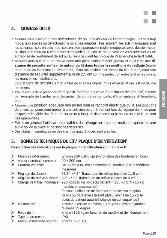
FRA
NÇ
AIS
Page 125
4. MONTAGE DU LIT
le bon revêtement de solmous, non scellés ou défectueux ne sont pas adaptés. Très souvent, les sols inadéquats sont les suivants : sols en bois mou, sols en pierre poreuse et molle, moquettes avec dossier mous-se, linoleum mou ou revêtements semblables. En cas de doute veuillez vous adresser à une entreprise de revêtement de sol ou au service client technique de Wissner-Bosserhoff SARL.
di- (égale-
distance de sécurité supplémentaire de 2,5 cmles murs et les installations.
La distance de sécuritéminimum.
de dispositifs mécaniques et électriques de sécurité, comme
etc..position adéquate des prises pour le raccord électrique du lit. Les positions
de prises qui pourraient mener à une collision ou un étirement lors du réglage du lit, ou pour lesquelles le câble doit être tiré sur de trop longues distances sur le sol ou sous le lit ne sont pas appropriées.Evitez en général l‘utilisation de câbles de rallonge ou de prises multiples qui se trouvent sur le sol de la pièce et ne sont pas sécurisés.
5. DONNEES TECHNIQUES DU LIT / PLAQUE D’IDENTIFICATION1
Mesures extérieures: Environ 208 x 106 cm (en fonction des bordures en bois) Valeur nominale sommier: 90 x 200 cm Hauteur variable: De 36 cm à 80 cm en fonction du modèle (partie médiane
mesurée) Réglage du dossier: 65,5° +/-5° Translation du relève-buste de 11,5 cm Réglage du relève-cuisses: 32° +/-5° Translation du relève-cuisses de 4 cm Charge de travail nominale: 225 kg (210 kg poids du patient = 225 kg CTN - 15 kg
matelas et accessoires) En cas d’utilisation de matelas et d’accessoires plus lourds ou plus légers faisant plus / moins de 15 kg, le poids du patient autorisé change en conséquence !
relevées 15 degrés Poids du lit : environ 125 kg en fonction du modèle et de l’équipement Type de protection IPX4 Niveau d’intensité sonore : approx. 57 dB/A
FRA
NÇ
AIS
Page 126
5.1. SOMMIERS ELECTRIQUES
Raccord électrique : 230 V 1,25 A 50 Hz Type de protection PX4 Catégorie de protection II Tension de sortie 24 V / 32 V en fonction du modèle
Durée d’utilisation des moteurs Max. 2 minutes. Mode de réglage, 18 min. pause Consommation Jusqu’à 320VA en charge de pointe Vitesse de réglage Environ 5,4 mm/seconde2
Pression avant inclinaison max. 3500N
5.2. RÉGLAGE EN HAUTEUR DES MOTEURS ÉLECTRIQUES
Tension maximale à vide 24 V Limitation de courant (USA) max.10 A Force de levage directe maximale 2x6000 N Etirement maximal 3,000N Vitesse de réglage 10 – 14 mm/s ( en fonction de l’équipement du modèle et de la charge) Type de protection IPX4 Classe de protection Tension protectrice II Durée d’utilisation des moteurs Max. 2 minutes. Mode de réglage, 18 min. pause
___________________________________________________2 Valeurs approximatives selon les différents modèles et charges
Environnement d’utilisation : la température ambiante doit être comprise entre +10°C et +40°C l’humidité relative de l’air doit être comprise entre 30% et 75% la pression atmosphérique doit être comprise entre 700 hPa et 1060 hPa.
___________________________________________________1 EN ISO 14253-1 et GUM-1:95
FRA
NÇ
AIS
Page 127
6. SÉCURITÉ DU PRODUIT / EXTRAIT DES NORMES APPLIQUÉES
Le produit porte le symbole et correspond donc aux prescriptions de sécurité allemandes et européennes. Le produit a été développé et fabriqué selon les normes DIN EN ISO 9001:2000 et DIN EN ISO 13485:2003.
Désignation Commentaire Désignation Commentaire
Directive 93/42/CEE
MDD (Directive UE) DIN 33402 Mensurations des êtres humains
Loi sur les dispositifs médicaux allemande(Medizinproduktegesetz, MPG)
MPG (Transposition nationale) DIN 50967 Revêtements en nickel – chrome et cuivre – nickel – chrome
EN ISO 14971:2009 Application de la gestion des risques sur les dispositifs médicaux.
DIN 68861-1/ EN 12720
Surfaces des meubles
Selon DIN EN 60601-1:2007-07(paragraphes correspondants)
Appareils médicaux électriques (lits médicaux)
EN 60529 Code IP (protection contre l‘humidité)
Selon norme CEI 60601-2-52:2009(paragraphes correspondants)
Lits à usage médical Selon EN 12530(paragraphes correspondants)
Roues pour lit de soin
Recommandation du BfArM (Institut fédéral pour les produits pharmaceutiques et médicaux): à partir de
Recommandations du Bundesinstitut für Arzneimittel und Medizinprodukte (Institut Fédéral pour les produits pharmaceutiques et médicaux
Directive UE 2002/96/CE
Traitement des déchets, des anciens appareils électriques et électroniques. Obligation de marquage depuis le 13 août 2005
DIN EN 60601-1-2:2007 Compatibilité électro- magnétique
_______________________________2 intégré
Puisqu‘un lit de soin standard n‘est pas équipé d‘un raccord de compensation de potentiel, son utilisation en combinaison avec d‘autres appareils électromédi-caux n‘est pas permise sans autres mesures de sécurité. Pour plus d‘informations, veuillez contacter le service client technique. En option, un raccord de compen-sation de potentiel peut, le cas échéant, être mis à disposition.
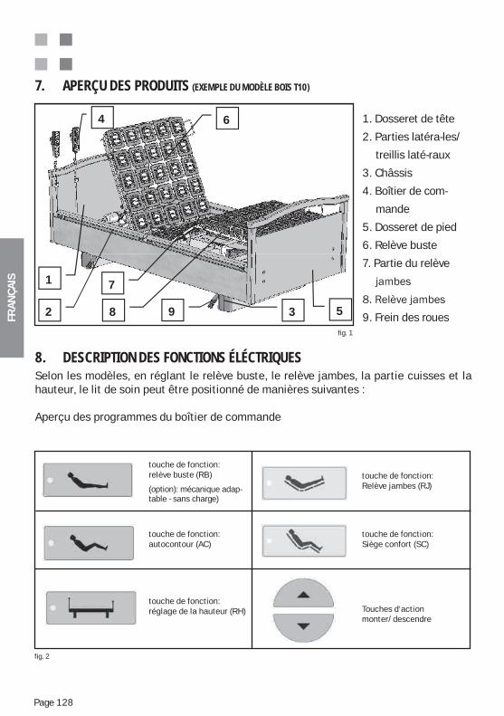
FRA
NÇ
AIS
Page 128
1. Dosseret de tête
2. Parties latéra-les/
treillis laté-raux
3. Châssis
4. Boîtier de com-
mande
5. Dosseret de pied
6. Relève buste
7. Partie du relève
9. Frein des roues
7. APERÇU DES PRODUITS (EXEMPLE DU MODÈLE BOIS T10)
fig. 1
8. DESCRIPTION DES FONCTIONS ÉLÉCTRIQUESSelon les modèles, en réglant le relève buste, le relève jambes, la partie cuisses et la hauteur, le lit de soin peut être positionné de manières suivantes :
Aperçu des programmes du boîtier de commande
1
2 3
4
5
6
7
8 9
fig. 2
touche de fonction:relève buste (RB)
(option): mécanique adap- table - sans charge)
touche de fonction:autocontour (AC)
touche de fonction:réglage de la hauteur (RH)
touche de fonction:Relève jambes (RJ)
touche de fonction:Siège confort (SC)
Touches d‘action monter/descendre
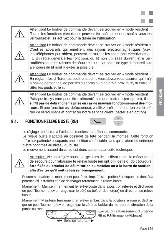
FRA
NÇ
AIS
Page 129
Attention! Le boîtier de commande devant se trouver en « mode résident ». En réglant les différentes positions du lit vous devez vous assurer qu‘il n‘y a pas de personnes, de parties du corps ou d‘objets à proximité, ni entre la tête/les pieds et le sol.
Attention! Le boîtier de commande devant se trouver en « mode résident ». Puisque le système peut être alimenté par une batterie (en option), il ne
-teurs. Si une fonction est défectueuse, veuillez arrêter la fonction par le boî-tier de verrouillage et contacter notre service client (batterie en option).
Attention! Ne pas régler sous charge. Lors de l‘utilisation de la mécanique de secours pour rabaisser le relève buste (en option), celle-ci doit toujours
Attention! Le boîtier de commande devant se trouver en « mode résident ». Toutes les fonctions électriques peuvent être défectueuses, sauf si vous les verrouillez et les activez pour la durée de l‘utilisation.
8.1. FONCTION RELEVE BUSTE (RB)
Le réglage s‘effectue à l‘aide des touches du boîtier de commande.Le relève buste s‘adapte au dosseret de tête pendant la montée. Cette fonction offre aux patients/occupants une position confortable sans qu‘ils aient le sentiment d‘être opprimés au niveau du buste.Le mouvement naturel du corps est donc soutenu par cette technique.
Recommandation: Le maniement peut être simplifié si le patient/occupant se tient à la potence (si installée) afin de décharger totalement le relève buste.
Maniement : Maintenir fermement le relève buste dans la position relevée et décharger un peu. Tourner le levier rouge (sur le côté du boîtier du moteur) en direction du relève buste.
Maniement :Maintenir fermement le relève-jambes dans la position relevée et déchar-ger un peu. Tourner le levier rouge (sur le côté du boîtier du moteur) en direction de la partie cuisses.
Évacuation/rabaissement d‘urgence RB et RJ (Emergency Release)
Sens de la rotation
Attention! Le boîtier de commande devant se trouver en « mode résident ». D‘autres appareils qui émettent des rayons électromagnétiques (p.ex. les téléphones portables), peuvent perturber les fonctions électriques du lit. En règle générale les fonctions du lit non utilisées doivent être ver-rouillées pour des raisons de sécurité. L‘utilisation de ce type d‘appareil aux alentours du lit sont à éviter si possible.
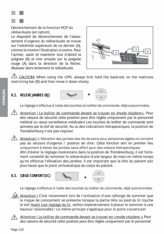
FRA
NÇ
AIS
Page 130
8.2. RELEVE JAMBES (RJ)
Attention ! Le boîtier de commande devant se trouver en «mode résident». Pour des raisons de sécurité cette position peut être réglée uniquement par le personnel médical ou «sous surveillance médicale»! Les touches du boîtier de commande sont activées par la clef de sécurité. Au vu des indications thérapeutiques, la position de Trendelenburg n‘est pas requise!
Attention ! pas au secours d‘urgence / position de choc. Cette fonction sert en premier lieu
Afin d‘éviter le réglage involontaire dans la position de Trendelenburg, il est forte-ment conseillé de remonter le relève-buste d‘une largeur de main en même temps qu‘on effectue l‘élévation des jambes. Il est important que la tête du patient soit plus haute que le point orthostatique du corps du patient.
8.3. SIEGE CONFORT (SC)
Attention ! C’est notamment lors de l‘utilisation d‘une rallonge de sommier que le risque de coincement se présente lorsque la partie tête ou pied du lit touche le sol! Avant tout réglage du lit, veillez impérativement à placer le sommier à une hauteur raisonnable ! Le même principe s‘applique pour le porte-couverture!
Attention ! Le boîtier de commande devant se trouver en « mode résident ». Pour des raisons de sécurité cette position peut être réglée uniquement par le personnel
Déclenchement de la fonction RCP durelève-buste (en option)Le dispositif de déclenchement de l‘abais-sement d‘urgence du relève-buste se trouve sur l‘extrémité supérieure de ce dernier (A), comme le montre l‘illustration ci-contre. Pour l‘activer, saisir et maintenir tout d‘abord la poignée (B) et tirer ensuite sur la poignée rouge (A) dans la direction de la flèche. Abaisser alors lentement le relèvebuste.
BA
A
CAUTION! When using the CPR, always first hold the backrest on the mattress restricting bar (B) and then move it down slowly.
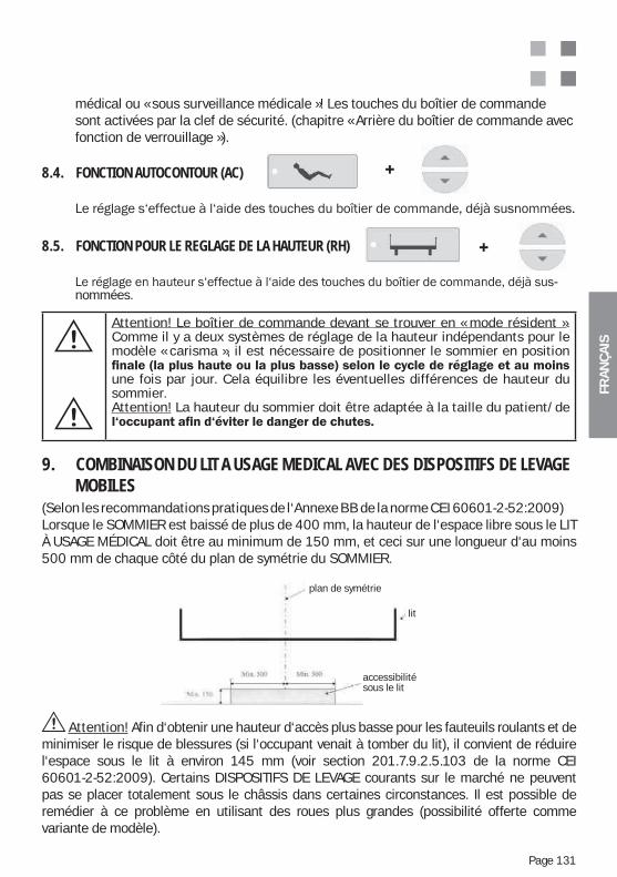
FRA
NÇ
AIS
Page 131
Attention! Le boîtier de commande devant se trouver en « mode résident ». Comme il y a deux systèmes de réglage de la hauteur indépendants pour le modèle « carisma », il est nécessaire de positionner le sommier en position
une fois par jour. Cela équilibre les éventuelles différences de hauteur du sommier. Attention! La hauteur du sommier doit être adaptée à la taille du patient/de
Attention! Afin d‘obtenir une hauteur d‘accès plus basse pour les fauteuils roulants et de minimiser le risque de blessures (si l‘occupant venait à tomber du lit), il convient de réduire l‘espace sous le lit à environ 145 mm (voir section 201.7.9.2.5.103 de la norme CEI 60601-2-52:2009). Certains DISPOSITIFS DE LEVAGE courants sur le marché ne peuvent pas se placer totalement sous le châssis dans certaines circonstances. Il est possible de remédier à ce problème en utilisant des roues plus grandes (possibilité offerte comme variante de modèle).
9. COMBINAISON DU LIT A USAGE MEDICAL AVEC DES DISPOSITIFS DE LEVAGE MOBILES(Selon les recommandations pratiques de l‘Annexe BB de la norme CEI 60601-2-52:2009)Lorsque le SOMMIER est baissé de plus de 400 mm, la hauteur de l‘espace libre sous le LIT À USAGE MÉDICAL doit être au minimum de 150 mm, et ceci sur une longueur d‘au moins 500 mm de chaque côté du plan de symétrie du SOMMIER.
Symmetrieebene
Bett
Unterfahrbar
plan de symétrie
lit
accessibilité sous le lit
8.4. FONCTION AUTOCONTOUR (AC)
8.5. FONCTION POUR LE REGLAGE DE LA HAUTEUR (RH)
-nommées.
médical ou « sous surveillance médicale »! Les touches du boîtier de commande sont activées par la clef de sécurité. (chapitre « Arrière du boîtier de commande avec fonction de verrouillage »).
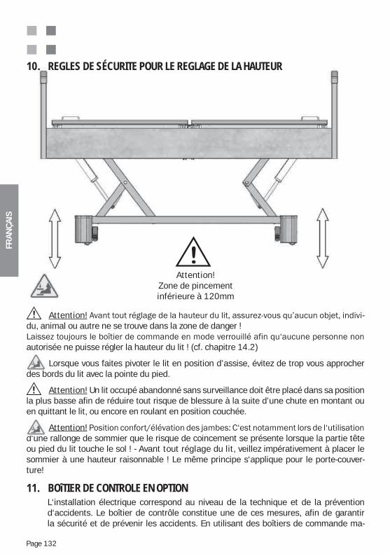
FRA
NÇ
AIS
Page 132
11. BOîTIER DE CONTROLE EN OPTIONL‘installation électrique correspond au niveau de la technique et de la prévention d‘accidents. Le boîtier de contrôle constitue une de ces mesures, afin de garantir la sécurité et de prévenir les accidents. En utilisant des boîtiers de commande ma-
Attention!Zone de pincement inférieure à 120mm
10. REGLES DE SÉCURITE POUR LE REGLAGE DE LA HAUTEUR
Attention! -du, animal ou autre ne se trouve dans la zone de danger !
autorisée ne puisse régler la hauteur du lit ! (cf. chapitre 14.2)
Lorsque vous faites pivoter le lit en position d’assise, évitez de trop vous approcher des bords du lit avec la pointe du pied.
Attention! Un lit occupé abandonné sans surveillance doit être placé dans sa position la plus basse afin de réduire tout risque de blessure à la suite d’une chute en montant ou en quittant le lit, ou encore en roulant en position couchée.
Attention! d‘une rallonge de sommier que le risque de coincement se présente lorsque la partie tête ou pied du lit touche le sol ! - Avant tout réglage du lit, veillez impérativement à placer le sommier à une hauteur raisonnable ! Le même principe s‘applique pour le porte-couver-ture!
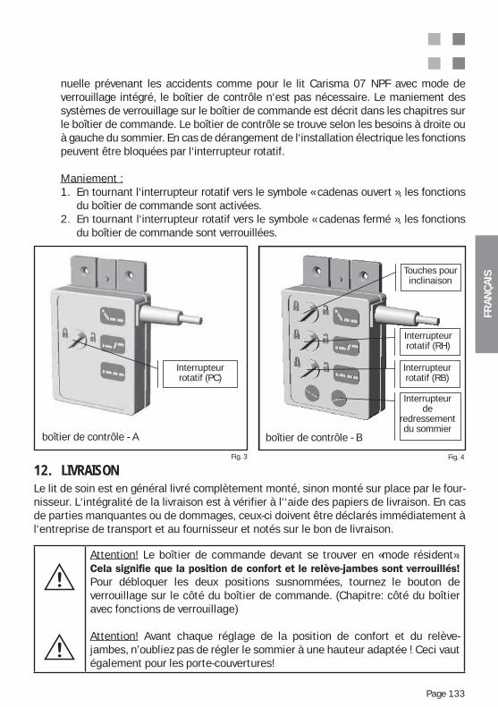
FRA
NÇ
AIS
Page 133
Attention! Le boîtier de commande devant se trouver en «mode résident».
Pour débloquer les deux positions susnommées, tournez le bouton de verrouillage sur le côté du boîtier de commande. (Chapitre: côté du boîtier avec fonctions de verrouillage)
Attention! Avant chaque réglage de la position de confort et du relève-jambes, n’oubliez pas de régler le sommier à une hauteur adaptée ! Ceci vaut également pour les porte-couvertures!
Fig. 3 Fig. 4
Kontrollbox -A
rehs halter
Kontrollbox -B
Touches pour inclinaison
Interrupteur rotatif (RH)
Interrupteur rotatif (RB)
Interrupteur de
redressement du sommier
boîtier de contrôle - Bboîtier de contrôle - A
Interrupteur rotatif (PC)
12. LIVRAISON Le lit de soin est en général livré complètement monté, sinon monté sur place par le four-nisseur. L‘intégralité de la livraison est à vérifier à l‘‘aide des papiers de livraison. En cas de parties manquantes ou de dommages, ceux-ci doivent être déclarés immédiatement à l‘entreprise de transport et au fournisseur et notés sur le bon de livraison.
nuelle prévenant les accidents comme pour le lit Carisma 07 NPF avec mode de verrouillage intégré, le boîtier de contrôle n‘est pas nécessaire. Le maniement des systèmes de verrouillage sur le boîtier de commande est décrit dans les chapitres sur le boîtier de commande. Le boîtier de contrôle se trouve selon les besoins à droite ou à gauche du sommier. En cas de dérangement de l‘installation électrique les fonctions peuvent être bloquées par l‘interrupteur rotatif.
Maniement :1. En tournant l‘interrupteur rotatif vers le symbole « cadenas ouvert », les fonctions du boîtier de commande sont activées.2. En tournant l‘interrupteur rotatif vers le symbole « cadenas fermé », les fonctions du boîtier de commande sont verrouillées.
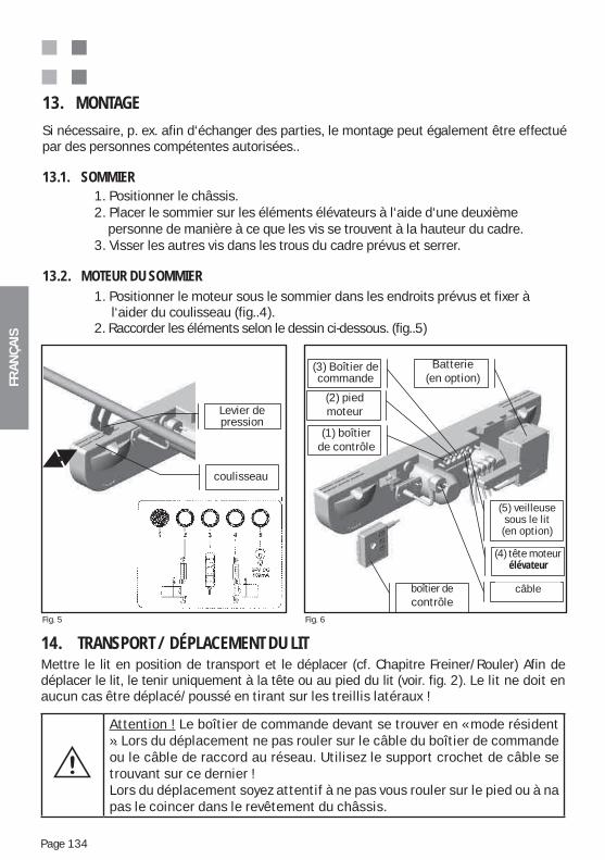
FRA
NÇ
AIS
Page 134
14. TRANSPORT / DÉPLACEMENT DU LITMettre le lit en position de transport et le déplacer (cf. Chapitre Freiner/Rouler) Afin de déplacer le lit, le tenir uniquement à la tête ou au pied du lit (voir. fig. 2). Le lit ne doit en aucun cas être déplacé/poussé en tirant sur les treillis latéraux !
Attention ! Le boîtier de commande devant se trouver en « mode résident ». Lors du déplacement ne pas rouler sur le câble du boîtier de commande ou le câble de raccord au réseau. Utilisez le support crochet de câble se trouvant sur ce dernier !Lors du déplacement soyez attentif à ne pas vous rouler sur le pied ou à na pas le coincer dans le revêtement du châssis.
13. MONTAGE
Si nécessaire, p. ex. afin d‘échanger des parties, le montage peut également être effectué par des personnes compétentes autorisées..
13.1. SOMMIER 1. Positionner le châssis. 2. Placer le sommier sur les éléments élévateurs à l‘aide d‘une deuxième personne de manière à ce que les vis se trouvent à la hauteur du cadre. 3. Visser les autres vis dans les trous du cadre prévus et serrer.
13.2. MOTEUR DU SOMMIER 1. Positionner le moteur sous le sommier dans les endroits prévus et fixer à l‘aider du coulisseau (fig..4). 2. Raccorder les éléments selon le dessin ci-dessous. (fig..5)
Schieber
Druckhebel
(1) Kontroll-box (Option)
Kontrollbox (Option)
(2) Hubmotor Fuß
(3) Hand-schalter
(5) Unterbett- Beleuchtung
(Option)
Akku (Option)
(4) Hubmotor Kopf
Netzkabel
coulisseau
(3) Boîtier de commande
(2) pied moteur
(1) boîtier de contrôle
Batterie (en option)
(5) veilleuse sous le lit (en option)
(4) tête moteur élévateur
câble
Levier de pression
boîtier de contrôle
Fig. 5 Fig. 6
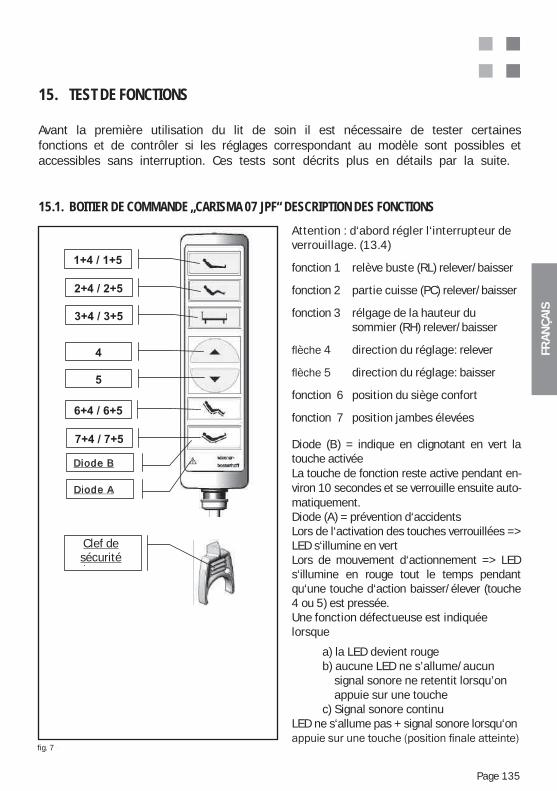
FRA
NÇ
AIS
Page 135
Abb. 7
15. TEST DE FONCTIONS
Avant la première utilisation du lit de soin il est nécessaire de tester certaines fonctions et de contrôler si les réglages correspondant au modèle sont possibles et accessibles sans interruption. Ces tests sont décrits plus en détails par la suite.
15.1. BOITIER DE COMMANDE „CARISMA 07 JPF“ DESCRIPTION DES FONCTIONS
Attention : d‘abord régler l‘interrupteur de verrouillage. (13.4)
fonction 1 relève buste (RL) relever/baisser
fonction 2 partie cuisse (PC) relever/baisser
fonction 3 rélgage de la hauteur du sommier (RH) relever/baisser
direction du réglage: relever
direction du réglage: baisser
fonction 6 position du siège confort
fonction 7 position jambes élevées
Diode (B) = indique en clignotant en vert la touche activéeLa touche de fonction reste active pendant en-viron 10 secondes et se verrouille ensuite auto-matiquement.Diode (A) = prévention d‘accidentsLors de l‘activation des touches verrouillées => LED s‘illumine en vertLors de mouvement d‘actionnement => LED s‘illumine en rouge tout le temps pendant qu‘une touche d‘action baisser/élever (touche 4 ou 5) est pressée.Une fonction défectueuse est indiquée lorsque
a) la LED devient rouge b) aucune LED ne s’allume/aucun signal sonore ne retentit lorsqu’on appuie sur une touche c) Signal sonore continuLED ne s‘allume pas + signal sonore lorsqu‘on
Diode A
Diode B
Sicher-heitsschlüs
l
Clef de sécurité
fig. 7
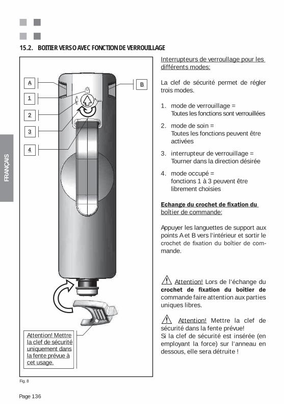
FRA
NÇ
AIS
Page 136
1
2
3
A B
4
Achtung! Si -cherheitsschlüssel - nur in dem dafür vor-gesehenen S lt i l i
Interrupteurs de verroullage pour les différents modes:
La clef de sécurité permet de régler trois modes.
1. mode de verrouillage = Toutes les fonctions sont verrouillées
2. mode de soin = Toutes les fonctions peuvent être activées
3. interrupteur de verrouillage = Tourner dans la direction désirée
4. mode occupé = fonctions 1 à 3 peuvent être librement choisies
boîtier de commande:
Appuyer les languettes de support aux points A et B vers l‘intérieur et sortir le
-mande.
Attention! Lors de l‘échange du
commande faire attention aux parties uniques libres.
Attention! Mettre la clef de sécurité dans la fente prévue!Si la clef de sécurité est insérée (en employant la force) sur l‘anneau en dessous, elle sera détruite !
15.2. BOITIER VERSO AVEC FONCTION DE VERROUILLAGE
Attention! Mettrela clef de sécuritéuniquement dansla fente prévue àcet usage.
Fig. 8
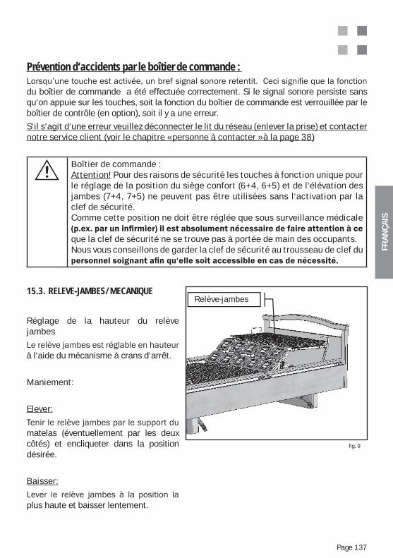
FRA
NÇ
AIS
Page 137
Prévention d‘accidents par le boîtier de commande :
du boîtier de commande a été effectuée correctement. Si le signal sonore persiste sans qu‘on appuie sur les touches, soit la fonction du boîtier de commande est verrouillée par le boîtier de contrôle (en option), soit il y a une erreur.
S‘il s‘agit d‘une erreur veuillez déconnecter le lit du réseau (enlever la prise) et contacter notre service client (voir le chapitre « personne à contacter » à la page 38)
Boîtier de commande :Attention! Pour des raisons de sécurité les touches à fonction unique pour le réglage de la position du siège confort (6+4, 6+5) et de l‘élévation des jambes (7+4, 7+5) ne peuvent pas être utilisées sans l‘activation par la clef de sécurité.Comme cette position ne doit être réglée que sous surveillance médicale
que la clef de sécurité ne se trouve pas à portée de main des occupants. Nous vous conseillons de garder la clef de sécurité au trousseau de clef du
15.3. RELEVE-JAMBES/MECANIQUE
Réglage de la hauteur du relève jambes
à l‘aide du mécanisme à crans d‘arrêt.
Maniement:
Elever:
matelas (éventuellement par les deux côtés) et encliqueter dans la position désirée.
Baisser:
plus haute et baisser lentement.
fig. 9
Relève-jambes
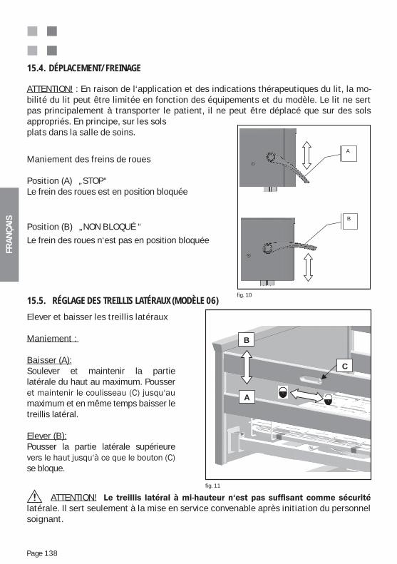
FRA
NÇ
AIS
Page 138
15.4. DÉPLACEMENT/FREINAGE
ATTENTION! : En raison de l‘application et des indications thérapeutiques du lit, la mo-bilité du lit peut être limitée en fonction des équipements et du modèle. Le lit ne sert pas principalement à transporter le patient, il ne peut être déplacé que sur des sols appropriés. En principe, sur les sols plats dans la salle de soins.
Maniement des freins de roues
Position (A) „STOP“Le frein des roues est en position bloquée
Position (B) „NON BLOQUÉ “
Le frein des roues n‘est pas en position bloquée
fig. 10
n
-
A
B
Elever et baisser les treillis latéraux
Maniement :
Baisser (A):Soulever et maintenir la partie latérale du haut au maximum. Pousser
maximum et en même temps baisser le treillis latéral.
Elever (B):Pousser la partie latérale supérieure
se bloque.
15.5. RÉGLAGE DES TREILLIS LATÉRAUX (MODÈLE 06)
fig. 11
B
A
C
ATTENTION! latérale. Il sert seulement à la mise en service convenable après initiation du personnel soignant.
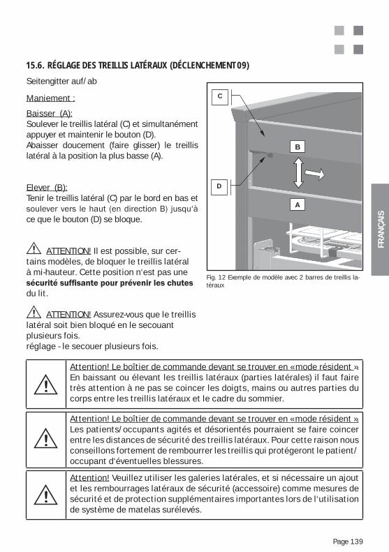
FRA
NÇ
AIS
Page 139
Seitengitter auf/ab
Maniement :
Baisser (A):Soulever le treillis latéral (C) et simultanément appuyer et maintenir le bouton (D).Abaisser doucement (faire glisser) le treillis latéral à la position la plus basse (A).
Elever (B):Tenir le treillis latéral (C) par le bord en bas et
ce que le bouton (D) se bloque.
ATTENTION! Il est possible, sur cer-tains modèles, de bloquer le treillis latéral à mi-hauteur. Cette position n‘est pas une
du lit.
ATTENTION! Assurez-vous que le treillis latéral soit bien bloqué en le secouant plusieurs fois. réglage - le secouer plusieurs fois.
15.6. RÉGLAGE DES TREILLIS LATÉRAUX (DÉCLENCHEMENT 09)
Fig. 12 Exemple de modèle avec 2 barres de treillis la-téraux
B
A
D
C
Attention! Le boîtier de commande devant se trouver en « mode résident ». En baissant ou élevant les treillis latéraux (parties latérales) il faut faire très attention à ne pas se coincer les doigts, mains ou autres parties du corps entre les treillis latéraux et le cadre du sommier.
Attention! Le boîtier de commande devant se trouver en « mode résident ». Les patients/occupants agités et désorientés pourraient se faire coincer entre les distances de sécurité des treillis latéraux. Pour cette raison nous conseillons fortement de rembourrer les treillis qui protégeront le patient/occupant d‘éventuelles blessures.
Attention! Veuillez utiliser les galeries latérales, et si nécessaire un ajout et les rembourrages latéraux de sécurité (accessoire) comme mesures de sécurité et de protection supplémentaires importantes lors de l‘utilisation de système de matelas surélevés.

FRA
NÇ
AIS
Page 140
Élever / abaisser les parties latérales
Maniement:
1. niveau :La partie latérale se trouve en position abais-sée.
2. niveau :Si vous voulez faire passer le sommier dans une po-sition différente, tirez simplement la main courante de la partie latérale vers le haut
Si vous voulez procéder à un autre réglage de la par-tie latérale, appuyez brièvement sur les
déblocage complet, tout en tirant alors dans le même mouvement continu la partie latérale
mm par rapport à la partie assise du sommier) se bloque.
3. niveau :
partie laté-rale, appuyez brièvement sur les
déblocage complet, tout en tirant alors dans le même mouvement continu la partie latérale
mm par rapport à la partie assise du sommier) se bloque.
4. niveau :La partie latérale se trouve dans sa plus hau-te posi-tion. Si vous voulez abaisser la partie latérale, ap-puyez brièvement sur les deux
déblocage complet, tout en appuyant alors dans le même mouvement continu la partie
que le 1e niveau soit atteint.
15.7. RÉGLAGE DES TREILLIS LATÉRAUX (MODÈLE 10)
Abb. 16
360 mm
400 mm
1e
niveau
2e niveau :
Assistance de
redressement
3e
niveau :
4e
niveau :
E
E E
E
E
E
fig. 13
Attention ! Assurez-vous que le treillis latéral soit bien bloqué en le secouant plusieurs fois.
Attention ! La partie latérale des modèles avec sommiers de confort doit être réglée au 4e niveau (400 mm).
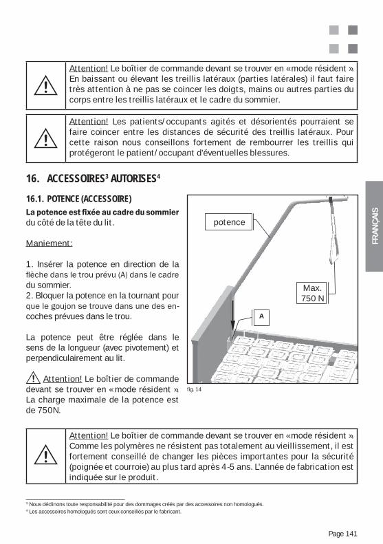
FRA
NÇ
AIS
Page 141
Attention! Le boîtier de commande devant se trouver en « mode résident ». En baissant ou élevant les treillis latéraux (parties latérales) il faut faire très attention à ne pas se coincer les doigts, mains ou autres parties du corps entre les treillis latéraux et le cadre du sommier.
Attention! Les patients/occupants agités et désorientés pourraient se faire coincer entre les distances de sécurité des treillis latéraux. Pour cette raison nous conseillons fortement de rembourrer les treillis qui protégeront le patient/occupant d'éventuelles blessures.
16. ACCESSOIRES3 AUTORISES4
16.1. POTENCE (ACCESSOIRE)
du côté de la tête du lit.
Maniement:
1. Insérer la potence en direction de la
du sommier.2. Bloquer la potence en la tournant pour
-coches prévues dans le trou.
La potence peut être réglée dans le sens de la longueur (avec pivotement) et perpendiculairement au lit.
Attention! Le boîtier de commande devant se trouver en « mode résident ». La charge maximale de la potence est de 750N.
Attention! Le boîtier de commande devant se trouver en « mode résident ». Comme les polymères ne résistent pas totalement au vieillissement, il est fortement conseillé de changer les pièces importantes pour la sécurité (poignée et courroie) au plus tard après 4-5 ans. L'année de fabrication est indiquée sur le produit.
____________________________________3 Nous déclinons toute responsabilité pour des dommages créés par des accessoires non homologués.4 Les accessoires homologués sont ceux conseillés par le fabricant.
fig. 14
Aufrichter
A
Max.
750N
potence
Max.750 N
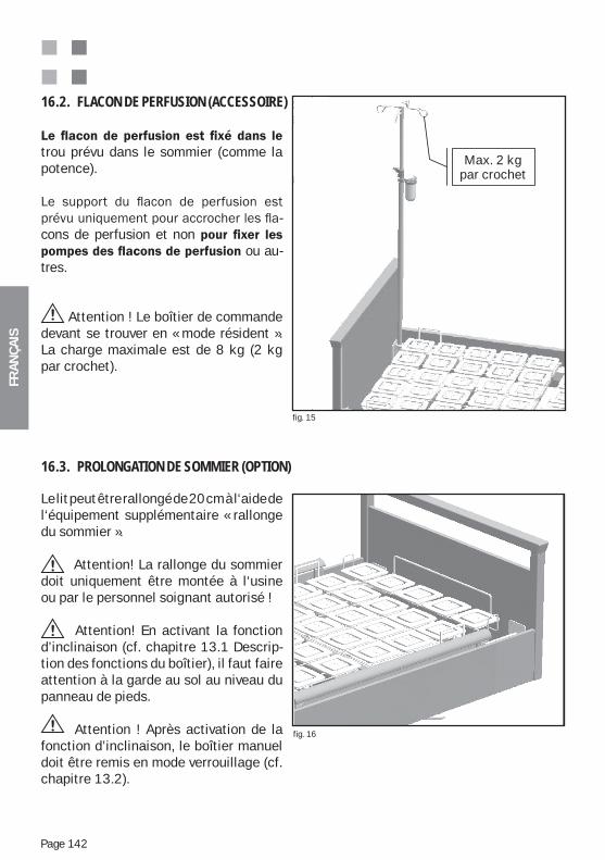
FRA
NÇ
AIS
Page 142
trou prévu dans le sommier (comme la potence).
-
cons de perfusion et non ou au-
tres.
Attention ! Le boîtier de commande devant se trouver en « mode résident ». La charge maximale est de 8 kg (2 kg par crochet).
16.2. FLACON DE PERFUSION (ACCESSOIRE)
Le lit peut être rallongé de 20 cm à l‘aide de l‘équipement supplémentaire « rallonge du sommier ».
Attention! La rallonge du sommier doit uniquement être montée à l‘usine ou par le personnel soignant autorisé !
Attention! En activant la fonction d’inclinaison (cf. chapitre 13.1 Descrip-tion des fonctions du boîtier), il faut faire attention à la garde au sol au niveau du panneau de pieds.
Attention ! Après activation de la fonction d’inclinaison, le boîtier manuel doit être remis en mode verrouillage (cf. chapitre 13.2).
16.3. PROLONGATION DE SOMMIER (OPTION)
fig. 15
fig. 16
dieah-
In-usi-
kg
Max. 2 kgpar crochet
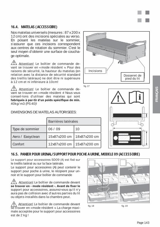
FRA
NÇ
AIS
Page 143
Nos matelas universels (mesures : 87 x 200 x 12 cm) ont des incisions spéciales au verso. En posant les matelas sur le sommier, s‘assurer que ces incisions correspondent aux centres de rotation du sommier. C‘est le seul moyen d‘obtenir une surface de coucha-ge optimale.
Attention! Le boîtier de commande de-vant se trouver en « mode résident ». Pour des raisons de sécurité, la hauteur du matelas (en relation avec la distance de sécurité standard des treillis latéraux) ne doit être ni supérieure à 12 cm et ni inférieure à 10cm!
Attention! Le boîtier de commande de-vant se trouver en « mode résident »! Nous vous conseil-lons d‘utiliser des matelas qui sont
40kg/m3 (PS 40)!
16.4. MATELAS ( ACCESSOIRE)
fig. 17
Bett-Fußteil
EinschnitteIncisions Dosseret de pied du lit
le treillis latéral ou sur la face latérale. Le support pour accessoires (A) peut contenir le support pour poche à urine, le récipient pour uri-noir et le support pour boîtier de commande
Attention! Le boîtier de commande devant
support pour accessoires, assurez-vous qu‘il n‘y aura pas de collision avec d‘autres parties du lit ou objets installés dans la chambre.peut. Attention! Le boîtier de commande devant se trouver en « mode résident ». La charge maxi-male acceptée pour le support pour accessoires est de 2 kg !
16.5. PANIER POUR URINAL/SUPPORT POUR POCHE A URINE, MODELE 09 (ACCESSOIRE)
fig. 18 fig. 19
DIMENSIONS DE MATELAS AUTORISEES:
Barrières latérales
Type de sommier 06 / 09 10
Aero / Easyclean 15x87x200 cm 18x87x200 cm
Confort 12x87x200 cm 15x87x200 cm
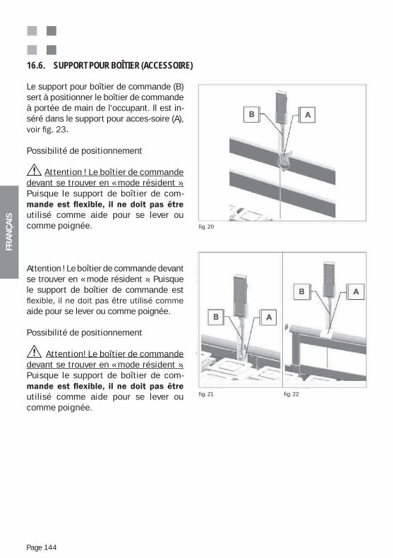
FRA
NÇ
AIS
Page 144
Le support pour boîtier de commande (B) sert à positionner le boîtier de commande à portée de main de l‘occupant. Il est in-séré dans le support pour acces-soire (A),
Possibilité de positionnement
Attention ! Le boîtier de commande devant se trouver en « mode résident ». Puisque le support de boîtier de com-
utilisé comme aide pour se lever ou comme poignée.
Attention ! Le boîtier de commande devant se trouver en « mode résident ». Puisque le support de boîtier de commande est
aide pour se lever ou comme poignée.
Possibilité de positionnement
Attention! Le boîtier de commande devant se trouver en « mode résident ». Puisque le support de boîtier de com-
utilisé comme aide pour se lever ou comme poignée.
16.6. SUPPORT POUR BOÎTIER (ACCESSOIRE)
fig. 20
fig. 21 fig. 22
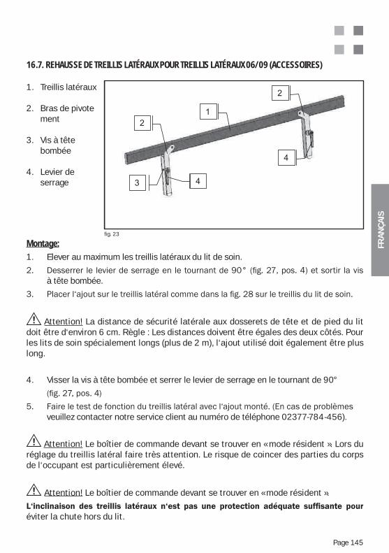
FRA
NÇ
AIS
Page 145
1. Treillis latéraux
2. Bras de pivote ment
3. Vis à tête bombée
4. Levier de serrage
16.7. REHAUSSE DE TREILLIS LATÉRAUX POUR TREILLIS LATÉRAUX 06/09 (ACCESSOIRES)
fig. 23
Montage:1. Elever au maximum les treillis latéraux du lit de soin.
à tête bombée.
Attention! La distance de sécurité latérale aux dosserets de tête et de pied du lit doit être d‘environ 6 cm. Règle : Les distances doivent être égales des deux côtés. Pour les lits de soin spécialement longs (plus de 2 m), l‘ajout utilisé doit également être plus long.
4. Visser la vis à tête bombée et serrer le levier de serrage en le tournant de 90°
veuillez contacter notre service client au numéro de téléphone 02377-784-456).
Attention! Le boîtier de commande devant se trouver en « mode résident ». Lors du réglage du treillis latéral faire très attention. Le risque de coincer des parties du corps de l‘occupant est particulièrement élevé.
Attention! Le boîtier de commande devant se trouver en « mode résident ».
éviter la chute hors du lit.
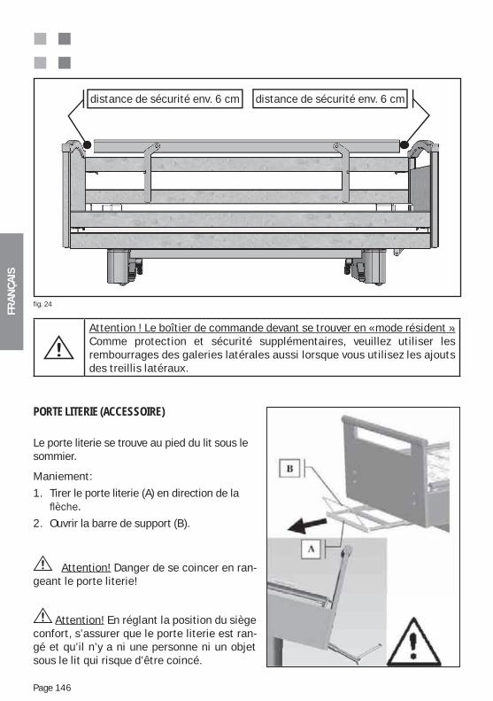
FRA
NÇ
AIS
Page 146
distance de sécurité env. 6 cm distance de sécurité env. 6 cm
Attention ! Le boîtier de commande devant se trouver en « mode résident ».Comme protection et sécurité supplémentaires, veuillez utiliser les rembourrages des galeries latérales aussi lorsque vous utilisez les ajouts des treillis latéraux.
fig. 24
PORTE LITERIE (ACCESSOIRE)
Le porte literie se trouve au pied du lit sous le sommier.
Maniement:
1. Tirer le porte literie (A) en direction de la
2. Ouvrir la barre de support (B).
Attention! Danger de se coincer en ran-geant le porte literie!
Attention! En réglant la position du siège confort, s’assurer que le porte literie est ran-gé et qu’il n’y a ni une personne ni un objet sous le lit qui risque d’être coincé.
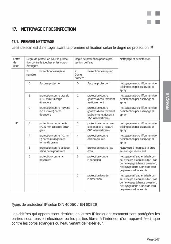
FRA
NÇ
AIS
Page 147
17. NETTOYAGE ET DESINFECTION
17.1. PREMIER NETTOYAGELe lit de soin est à nettoyer avant la première utilisation selon le degré de protection IP.
Types de protection IP selon DIN 40050 / EN 60529
Les chiffres qui apparaissent derrière les lettres IP indiquent comment sont protégées les parties sous tension électrique ou les parties libres à l‘intérieur d‘un appareil électrique contre les corps étrangers ou l‘eau venant de l‘extérieur.
Lettredecode
Degré de protection pour la protec-tion contre le toucher et les corps étrangers
Degré de protection pour la pro-tection de l‘eau
Nettoyage et désinfection
IP
1. numéro
Protectiondescription 2. 2ème numéro
Protectiondescription
0 Aucune protection 0 Aucune protection nettoyage avec chiffon humide; désinfection par essuyage et spray
1 protection contre grands (>50 mm Ø ) corps étrangers
1 protection contre gouttes d‘eau tombant verticalement
nettoyage avec chiffon humide; désinfection par essuyage et spray
2 protection contre moyens (>12 mm Ø) corps étrangers
2 protection contre gouttes d‘eau tombant
15° à la verticale)
nettoyage avec chiffon humide; désinfection par essuyage et spray
3 protection contre petits (>2,5 mm Ø) corps étran-gers
3 protection contre pro-
60° à la verticale)
nettoyage avec chiffon humide; désinfection par essuyage et spray
4 protection contre (>1 mm Ø) corps étrangers en forme de grains
4 protection contre éclaboussures
nettoyage avec chiffon humide; désinfection par essuyage et spray
5 protection contre la dépo-sition de la poussière
5d‘eau
Nettoyage à l‘eau et à la bros-
6 protection contre la poussière
6 protection contre l‘inondaion
nettoyage à l‘eau et à la bros-
de nettoyage à haute pression; nettoyage dans tunnel de lava-ge permis selon les lits
7 protection lors de l‘immersion
nettoyage à l‘eau et à la bros-
de nettoyage à haute pression; nettoyage dans tunnel de lava-ge permis selon les lits
FRA
NÇ
AIS
Page 148
Attention ! Pour des raisons de sécurité il faut absolument éviter le contact des parties du lit de soin avec des liquides (p.e. eau, solvants, huiles, bases, produits de nettoyage, etc.).
Attention ! Les boîtiers protégés contre l‘eau ne le sont pas nécessairement aussi bien contre d‘autres liquides.
Attention! Le boîtier de commande devant se trouver en « mode résident ». Le lit de soin doit donc être protégé un maximum contre l‘humidité! Le nettoyage doit s‘effectuer uniquement à l‘aide d‘un chiffon légèrement humide.
17.2. DESINFECTION/STERILISATION
Les produits suivants sont conseillés pour la désinfection du lit de soin et ils peuvent uniquement être substitués par des produits équivalents :Terralin, Perform et Sagrotan Med (Schülke & Mayr GmbH, Norderstedt).Ces produits sont à utiliser uniquement selon les indications du fabricant! Ceci concerne avant tout le dosage du produit et le danger potentiel lors de la combinaison avec d‘autres produits.Le cadre en bois ne doit pas être mis en contact avec ces produits.
17.3. SOIN DES PARTIES EN BOIS Nous avons utilisé des matériaux d‘excellente qualité afin de fabriquer pour vous un produit très utile et de créer une ambiance confortable avec caractère de bois authentique.Afin de faire durer le plus longtemps le plaisir d‘utiliser votre produit Wissner-Bosserhoff, nous vous recommandons de le nettoyer avec un chiffon mou et humide.Tout bois authentique (feuille de placage, bois massif) subit un processus de vieillissement naturel même s‘il a été laqué. Avec le temps les influences de l‘environnement comme les rayons UV, l‘humidité ou la chaleur provoquent des modifications des couleurs des surfaces en bois authentique. De plus le bois, en tant que matériel naturel, est très varié et nuancé. Fondamentalement, les textures des feuilles de placage ne sont définissables que de façon générale, car chaque tronc d‘arbre a ses caractéristiques propres. De légères différences de couleur et de contour pour les livraisons de Wissner-Bosserhoff sont naturelles et ne peuvent pas être évitées techniquement. Ceci est vrai surtout pour les livraisons tardives ou supplémentaires. Pour les raisons indiquées ci-dessus, les différences de clarté, de contraste et de couleur entre les surfaces des feuilles de placage, des parties en bois massif ou des décors (Mé-lamine, HPL) ne sont pas des défauts pas plus que les différentes inclusions lors de la croissance dans les bois authentiques. Wissner-Bosserhoff SARL décline toute responsabi-lité et ne donne aucune garantie.Par un choix minutieux, un tri et une adéquation de couleurs des feuilles de placage et des laques, Wissner-Bosserhoff garantit une bonne qualité de couleur des produits.
FRA
NÇ
AIS
Page 149
17.4. UTILISATION DE PRODUITS NETTOYANTSPour des taches particulièrement tenaces, on peut évidemment utiliser des produits de nettoyage standards respectueux de l‘environnement. Les surfaces des meubles des produits Wissner-Bosserhoff satisfont aux exigences de la norme DIN 68861 - 1A pour la surface des meubles soumis à des stress chimiques, et ont par conséquent une résistance excellente aux autres stress habituelsL‘utilisation de produits de nettoyages contenant des particules abrasives n‘est pas permise.
Veillez à ne pas faire de taches permanentes d‘eau ou de liquide sur le bois authentique et les feuilles de placage lors de l‘utilisation et du nettoyage. Le bois est un produit naturel qui absorbe l‘eau et se dilate. Cela peut provoquer des dommages sur la surface vitrifiée Pour cette raison il faut éviter l‘utilisation et le stockage de produits en bois dans des condi-tions humides.Après le nettoyage il est recommandé d‘essuyer les surface en bois authentique et les feuilles de placage avec un torchon sec, afin d‘éviter au maximum les dégâts dus à l‘humidité.
17.5. UTILISATION DE PRODUITS DESINFECTANTSSeuls les désinfectants décrits dans l‘annexe 1 de la norme DIN 68861 partie 1 ou des désinfectants correspondants peuvent être utilisés : a) des dérivés du phénol, des solutions aqueuses à 0,5-% : des phénols chlorés alkylés, cycloalkylés ou arylés b) des amines chlorés T, des solutions aqueuses à 2,5-% : p-Toluènesulfonechlora- mide de sodium
17.6. DOMMAGES SUR LES PARTIES EN BOISSi les feuilles de placage ou la surface vitrifiée sont endommagées par des coups, rayures ou coupures, elles doivent immédiatement être réparées afin de les protéger contre l‘humidité. Veuillez vous adresser au service client de Wissner-Bosserhoff ou à une entreprise spécialisée.
17.7. RESPECT DE L’ENVIRONNEMENTTous les matériaux en bois utilisés correspondent strictement aux lois et aux prescriptions allemandes et ne présentent aucun inconvénient du point de vue santé. L‘homme et son environnement sont au centre de nos activités.
17.8. QUALITENos produits sont soumis à un contrôle strict par notre système d‘assurance de la qualité selon les normes internationales DIN EN ISO 9001:2000 et DIN EN ISO 13485:2003 Pour la production et la vente de dispositifs médicaux.Wissner-Bosserhoff prend en charge une année de garantie sur toutes les caractéristiques spécifiées, à l‘exception de revendications dont les causes proviennent d‘une utilisation ou d‘un entretien incorrects ou inhabituels. Veuillez vous adresser à notre service client en cas de réclamations ou de critiques.
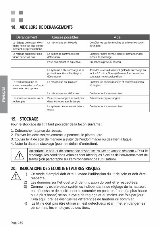
FRA
NÇ
AIS
Page 150
18. AIDE LORS DE DERANGEMENTS
Dérangement Causes possibles AideLe réglage du moteur élec-trique ne se fait pas confor-mément aux prescriptions
La mécanique est bloquée Contôler les parties mobiles et enlever les corps étrangers.
Le réglage du moteur élec-trique ne se fait pas
Le boîtier de commande est défectueux
Contacter notre service client et demander des pièces de rechange
Prise non branchée au réseau Brancher la prise au réseau
Le système a été surchargé et la protection anti surchauffage a déconnecté
Attendre le refroidissement (selon la surcharge au moins.20 min.). Si le système ne fonctionne pas, contacter notre service client
Le treillis latéral ne se -
ment aux prescriptions
La mécanique est bloquée Contôler les parties mobiles et enlever les corps étrangers
La mécanique est déformée Contacter notre service client
Les roues ne freinent ou ne roulent pas
Des corps étrangers se sont pris dans les roues avec le temps.
Enlever les corps étrangers.
Le système des roues est défec-tueux.
Contacter notre service client
19. STOCKAGEPour le stockage du lit il faut procéder de la façon suivante :
1. Débrancher la prise du réseau.2. Enlever les accessoires comme la potence, le plateau etc.3. Couvrir le lit de soin de manière à éviter de l‘endommager ou de rayer la laque.4. Noter la date de stockage (pour les délais d‘entretien).
Attention! Le boîtier de commande devant se trouver en « mode résident ». Pour le stockage, les conditions valables sont identiques à celles de l‘environnement de travail (voir paragraphe sur l‘environnement de l‘utilisation).
20. INDICATIONS DE SECURITE ET AUTRES RISQUES1) Ce mode d‘emploi doit être lu avant l‘utilisation du lit de soin et doit être respecté.2) Les données sur l‘étiquette d‘identification doivent être respectées.3) Comme il y existe deux systèmes indépendants de réglage de la hauteur, il est nécessaire de positionner le sommier en position finale (la plus haute ou la plus basse) selon le cycle de réglage et au moins une fois par jour. Cela équilibre les éventuelles différences de hauteur du sommier.4) Le lit ne doit pas être utilisé s‘il est défectueux et s‘il met en danger les personnes, les employés ou des tiers.
FRA
NÇ
AIS
Page 151
5) Le lit doit uniquement être utilisé par des personnes qui peuvent assurer un maniement adéquat grâce à leur formation ou leurs connaissances et expériences pratiques.
6) Avant d‘utiliser le lit, l‘utilisateur doit s‘assurer qu‘il fonctionne de manière sûre et qu‘il est en bon état.
7) Selon les circonstances, le lit doit être soumis à un test de fonctionnement tous les jours ou à chaque relève, afin de garantir qu‘il peut être utilisé selon les règles et sans danger ni pour le patient ni pour l‘opérateur.
8) Les potences déformées ne doivent pas être redressées et réutilisées, mais échangées.
9) Le lit doit être déplacé uniquement sur des revêtements de sol durs et plats.
10) Si le lit est occupé, les roues doivent toujours être bloquées, sinon le patient risque de tomber en se levant ou en se couchant, puisqu‘il peut, le cas échéant se tenir au lit.
11) La hauteur du sommier doit être adaptée à la taille du patient afin d‘éviter le danger de chute.
12) Lors de l‘utilisation de la mécanique de secours pour rabaisser le relève buste (en option), celle-ci doit toujours être fixée au crochet de délimitation du matelas ou à la barre de soutien, afin d‘éviter qu‘il soit rabaissé brus- quement.
13) En réglant les différentes positions du lit vous devez vous assurer qu‘il n‘y a pas d‘enfants, de parties du corps ou d‘objets à proximité.
14) Les réglages des treillis latéraux doivent être effectués uniquement par le personnel soignant. Lors du réglage du sommier, le personnel soignant doit s‘assurer que le patient ne touche pas le treillis latéral, afin d‘éviter des contusions des mains, des jambes ou d‘autres parties du corps.
15) Eviter de se pencher fortement en dehors du lit.
16) Ne pas surcharger les treillis latéraux de plus de 75 kg verticalement et 50 kg horizontalement.
17) Selon l‘état physique et mental du patient, les fonctions du boîtier de comma de sont à verrouiller ou à activer par le boîtier de contrôle. L‘efficacité des fonctions de verrouillage est à vérifier sur le boîtier de commande.
18) Comme le système peut être alimenté par le mode batterie, il ne suffit pas de débrancher la prise lors d‘un mauvais fonctionnement des moteurs. S‘il y a une fonction défectueuse, veuillez arrêter les fonctions par le boîtier de contrôle et contacter notre service client (mode batterie en option).
FRA
NÇ
AIS
Page 152
19) Lors de réglage par le boîtier de commande, il est recommandé de rester près du boîtier de contrôle afin de pouvoir interrompre immédiatement les fonctions défectueuses. 20) Attention ! Toutes les fonctions électriques peuvent être défectueuses, à moins qu‘elles ne soient verrouillées par le boîtier de contrôle. 21) Utiliser la prise de réseau à 220 / 230 volts, 50 Hz comme source de courant, selon les spécifications VDE.22) Ne pas toucher la prise avec les mains mouillées. Toucher le câble du réseau uniquement à la prise mâle et le débrancher de la prise femelle.23) Poser le câble du réseau sans boucles, ne pas le plier ou tordre fortement dans les coins.24) Protéger en toutes circonstances les câbles de stress mécaniques.
25) Poser le câble de branchement au réseau et les câbles reliés au boîtier de manière à ne pas les écraser et ne pas poser d‘objets sur les connexions26) Lors du montage du lit dans la pièce prévue, respecter les distances de sécurité entre le lit et le mur, les rebords de fenêtre et autres installations. Les distances de sécurité dépendent du modèle du lit en respectant les réglages de hauteur et de pivotement les plus extrêmes et en ajoutant 25 mm de place pour les doigts.27) Pendant l’exécution des fonctions de stockage et de réglage de la hauteur, veillez à ce que la clé de sécurité ne soit pas coincée ou ne se trouve pas à proximité du boîtier (portée de main du patien/de l’occupant). En activant les fonctions de manière inappropriée à l‘aide de la clef de sécurité, le patient/occupant peut atteindre des positions dangereuses, comme par exemple une fausse position déclive.28) Placer le boîtier dans le support (option) prévu à cet effet ou sur le lit, de façon à ce que les touches ne puissent pas être actionnées car coincées entre deux objets, comme le treillis latéral et la table de nuit.29) Le nettoyage du lit doit être effectué uniquement avec un linge humide.
30) Lors d‘utilisation inappropriée du lit, attention aux dangers potentiels suivants:
Utilisation non autorisée des fonctions électriques lors du positionnement incontrôlé du lit.
Utilisation du lit par des enfants de moins de douze ans, Utilisation des fonctions du lit par le patient sans instructions préalables. Utilisation simultanée des fonctions électriques par plusieurs personnes, Raccord au lit d‘appareils électriques non prévus, Déplacement du lit en tirant sur le câble, ou les parties latérales, Tirer sur le câble pour débrancher la prise du réseau, Protection insuffisante afin d‘éviter de plier les câbles dans les coins ou de
provoquer d‘autres stress mécaniques (p.ex. rouler sur le câble), Déplacement du lit sur un sol non stable, Utilisation du lit sur un sol non plat avec un angle de 10° ou plus,
FRA
NÇ
AIS
Page 153
Les appareils, qui provoquent de forts champs magnétiques et qui peuvent influencer la commande du lit, ne sont pas autorisés à proximité du lit (p.ex. téléphones portables).
Pour des raisons de sécurité la poignée de la potence (triangle) et la courroie
doivent être changées intégralement tous les 5 ans. Le matelas à utiliser doit correspondre aux normes de sécurité en vigueur et
ne doit pas dépasser 120 mm Un liquide dégoulinant constamment au niveau du moteur (par ex. in-
continence) Réparations des installations électriques ne respectant pas les prescrip-
tions.
31) Consignes de sécurité : mesures pour un fonctionnement sûr des lits d‘hôpitaux et de soin:
Les composantes électriques des lits d‘hôpitaux et de soin doivent être répa rées ou remises en marche uniquement par le fabricant ou le personnel soignant, qui a été spécifiquement formé par le fabricant. Autrement il y a le danger que des procédures spéciales ne soient pas effectuées comme il faut à cause du manque de connaissance de la fonctionnalité du produit, ce qui peut augmenter le risque d‘un choc électrique ou d‘un incendie..
Les composantes électriques des lits d‘hôpitaux et de soin doivent être unique-ment remplacées par des pièces de rechange d‘origine venant du fabricant, puisque lors d‘un échange par une composante non appropriée le risque de choc électrique ou d‘incendie est fortement augmenté..
Un endroit sûr pour la commande manuelle du lit doit être prévue afin d‘éviter
Le nettoyage du lit doit être effectué strictement selon les indications dans le paragraphe « Nettoyage et désinfection » de ce mode d‘emploi. Sinon l‘augmentation des risques n‘est pas de la responsabilité du fabricant..
Si des patients incontinents utilisent le lit, une protection du matelas contre l‘incontinence doit absolument être utilisée.
Si un patient/occupant immobile doit rester longtemps couché, et si on n‘utilise pas des me-sures de prévention spéciales (matelas antidecubitus ou autres), il y a risque d‘escarres. Le fabricant du lit n‘est en aucun cas responsable de cela.
FRA
NÇ
AIS
Page 154
Le produit n‘est clairement pas adapté à une utilisation en continu. Si la durée d‘utilisation prévue est dépassée, ceci peut provoquer un réchauffement du système (de commande) et un arrêt automatique. Il faut alors le laisser refroidir pendant au moins deux heures et il ne peut être relancé qu‘après ce délai
Un blocage du lit ou d‘une partie de la mécanique du lit doit absolument être évité, puisque cela peut provoquer des dommages et un arrêt total du système dû à une surchauffe.
Il faut absolument éviter de dépasser la charge de fonctionnement en sécurité, puisque cela peut provoquer des dommages et un arrêt total du système dû à une surchauffe.
32) Recommandations d’entretien – Contrôles de sécurité – Instructions de dépannage:
Les lits d‘hôpitaux et de soin électriques sont des dispositifs médicaux et sont donc soumis à la loi allemande sur les dispositifs médicaux (Medizinprodukte- gesetz MPG), au décret allemand sur les dispositifs médicaux (Medizin produkte Betreiberverordnung § 6 (MedProdBetrV)) et aux contrôles techniques de sécurité. Ces contrôles techniques de sécurité réguliers doivent être effectués au moins une fois par an. Il est nécessaire de tester la sécurité fonctionnelle et électrique selon la spécification VDE0751 et d‘effectuer aussi un test visuel et de fonction (test du matériel en fonction- nement dans l‘entreprise) de même que de vérifier d‘éventuelles fonctions demesure.
En général il faut également vérifier les accessoires et les autres appareils qui peuvent être combinés avec le produit. Il faut s‘assurer que seuls les accessoires homologués et les combinaisons d‘appareils agréés par le fabricant sont utilisés. Ces contrôles techniques de sécurité peuvent uniquement être effectués à l‘aide d‘appareils de mesure et de test spéciaux par des spécialistes en électrotechnique ou par une personne formée en électronique par le fabricant pour ce produit, pour ces accessoires homo- logués et pour ces combinaisons d‘appareil autorisées. La personne qui effe tue le test ne doit pas être soumise à des directives de l‘utilisateur. Des protocoles de tests spéciaux sont à rédiger suite aux contrôles techniques de sécurité. Le produit lui-même doit être marqué par une étiquette de test qui fixe la prochaine date de test.
De plus, pour les lits d‘hôpitaux et de soin électriques il s‘agit de matériel électrique et l‘employeur est responsable de la sécurité. La fonction de surveillance de ces obligations appartient à l‘association préventive des accidents du travail Les prescriptions de l‘association préventive des accidents du travail (Berufsgenossenschaften für Sicherheit und Gesundheit bei der Arbeit (abrégé BGV, anciennement VBG) sont applicables. En particulier les prescriptions BGV A3 (anciennement VBG « nstallations électriques et matériaux de production » „(BGV A2)), qui prévoient des tests répétés des matériaux
FRA
NÇ
AIS
Page 155
électriques mobiles environ tous les 6 mois, mais au minimum une fois par an. „Ces tests peuvent être effectués uniquement par des spécialistes en électro-technique ou par une personne formée en électronique, et à l‘aide d‘appareils de mesure et de test spéciaux. Ces tests, selon les prescriptions BGV A3, peu-vent être effectués dans le cadre des contrôles techniques de sécurité pour les dispositifs médicaux par le personnel soignant formé par le fabricant, puisque ces tests BGV sont contenus dans les contrôles techniques de sécurité.
Les lits d‘hôpitaux et de soin électriques sont des dispositifs médicaux actifs et doivent être listés dans un inventaire selon le décret allemand sur les dispositifs médicaux (Medizinprodukte Betreiberverordnung (MedProdBetrV)). Il est conseil-lé de documenter dans cet inventaire également l‘exécution réglementaire des contrôles techniques de sécurité prescrits, de même que d‘indiquer la prochaine date de test. Les protocoles nécessaires des contrôles techniques de sécurité
L‘exécution réglementaire et une documentation compréhensible, exigée par le fabricant, des contrôles techniques, des travaux de maintenance et d‘entretien, de même que des contrôles techniques de sécurité sont une condition nécessaire pour le maintien des droits de garantie de l‘acheteur. Si l‘opérateur des dispositifs médicaux ne remplit pas ses obligations, il peut provoquer des dommages et des risques d‘accidents dont le fabricant ne prend explicitement pas la responsabili-té.
Les travaux de maintenance sont à effectuer selon la norme EN62353:2008 et doivent être conclus par un contrôle technique de sécurité.
FRA
NÇ
AIS
Page 156
21. MAINTENANCE ET ENTRETIEN
Les lits de soin de Wissner-Bosserhoff SARL sont en général prévus pour une durée d‘utilisation de 10 à 15 ans. Pour cette durée, les lits ont besoin de très peu d‘entretien,
et des frais d‘exploitation minimes.
incidents dus à une manipulation sans précautions ou rude, ce qui mène à un vieillisse-ment accéléré et à l‘usure de certaines parties sans que le fabricant puisse le prévoir. Pour cette raison des examens de maintenance de routine devraient être effectués chez l‘utilisateur -pour qu‘il puisse aussi garantir la disponibilité des lits.Le service client technique de Wissner-Bosserhoff offre un entretien et les formations nécessaires pour le produit. Wissner-Bosserhoff est en général intéressé à bien former ses clients, car seuls les utilisateurs et techniciens de maintenance bien formés peuvent assurer une utilisation réglementaire des lits.La maintenance doit être effectuée uniquement par le personnel soignant compétent et qui a été formé pour ce produit par Wissner-Bosserhoff.Le fabricant est uniquement responsable de la sécurité et de la fiabilité du produit s‘il est entretenu régulièrement et selon les indications d‘utilisation et de sécurité décrites dans le mode d‘emploi de l‘entreprise,
Si un contrôle de fonction, une inspection, une mesure ou un entretien montre des dé-fauts graves, qui ne peuvent pas être réparés, le produit doit être mis hors service.
Wissner-Bosserhoff SARL conseille un entretien mécanique simple une fois par an. En général le fabricant exige une maintenance selon les règles techniques valables et actuelles, puisque les lits constituent un moyen de travail qui est soumis aux prescrip-tions de la prévention d‘accidents (Unfallverhütungsvorschriften (UVV)) de l‘association préventive des accidents au travail. Pour des examens de sécurité, les normes BGV A3 et VDE 0751 sont applicables.Notre service client est à votre disposition pour des questions et des formations, de même que pour des listes de tests des différents produits. (Contact voir le para-graphe 22 et 25).
21.1. INTEGRALITE ET ACCESSOIRESA l‘aide des bons de livraison, du mode d‘emploi et d‘une vérification visuelle, on peut contrôler si des parties manquent et doivent être commandées ou remplacées. En général il faut également vérifier les accessoires et les autres appareils qui peuvent être combinés avec le produit. Il faut s‘assurer que seuls les accessoires homologués et les combinaisons d‘appareils agréés par le fabricant sont utilisés.
FRA
NÇ
AIS
Page 157
21.2. USUREDans le cadre d‘un examen et d‘un contrôle de fonction, vérifier si les parties du lit de soin n‘ont pas souffert de traces de frottement, de rayures ou d‘autres usures. La cause doit être définie et les parties défectueuses remplacées. Tous les blocages et réglages doivent être faits de manière réglementaire. Faire surtout attention aux parties impor-tantes pour la sécurité des lits de soin.
21.3. FONCTIONNALITEVérifier si tous les réglages peuvent être mis dans leurs positions extrêmes. Faites un contrôle de fonctionnement à l‘aide des paragraphes « Contrôle de fonction » et « Description des lits de soin – fonctions » de ce mode d‘emploi.
21.4. BGV A3/VDE 0751 – 1:2008 – 8 / DIN EN 62353 : 2008 – VERIFICATION DES ELEMENTS ELECTRIQUES ET DU BOITIER
Vérifier si les moteurs électriques s‘ils sortent et entrent comme il faut, et vérifier si
Vérifier la mécanique (vis et boulons bien serrés, bon état des pièces, des inscriptions, etc.)
Etat des câbles, des boîtiers etc. (coupures, pincements, etc)
test de fonctions
Vérification de la visibilité
Délestage de traction et protection contre les plis suffisante
Détection de courant de fuite
Vérification du conducteur de protection pour modèle en catégorie de protection I
Mesure d’isolation si nécessaireNotre service client est à votre disposition pour des questions et des formations, de même que pour des listes de tests des différents produits. (Contact voir le para-graphe 22 et 25).
21.5. ROUESTests de fonctionnalité des roues (rouler - freiner) et élimination de poussière accumulée, de fils ou che-veux enroulés etc. Les freins des roues doivent éventuellement être réglés à nou-veau. Veuillez vous adresser au service client Wissner-Bosserhoff.
22. DUREE DE VIEDans le cas d‘une utilisation, d‘un nettoyage, d‘un entretien et de réparations réglementaires la durée de vie de notre produit peut atteindre 10 à 15 ans. Les pièces d‘usure comme les roues, les ressorts pneumatiques et les composants électriques etc. font exception.
FRA
NÇ
AIS
Page 158
23. ELIMINATIONEn option, le lit peut contenir des batteries (accumulateurs au plomb), des parties en métal, en bois et des polymères tels que l‘ABS, le PA, le PUR, le PE. (Comparer le volume de livraison et le modèle).Les pièces de métal ou de polymère résultant de l‘entretien ou des réparations doivent être éliminées de manière réglementaire. Surtout les moteurs électriques et les commandes électriques doivent être éliminés par des entreprises spécialisées agréées.
24. PIECES DE RECHANGE, LISTES DE PIECES DE RECHANGE ET MANUELS DE SERVICESeules des pièces originales de Wissner-Bosserhoff peuvent être utilisées.
Le service client, la vente ou le poste de consultation technique donne des informations concernant les livraisons des pièces de rechange, etc. (Adresse voir personne de contact).
Veuillez demander chez Wissner- Bosserhoff au service client technique les listes des pièces de rechange, les listes des prix actuels et les indications de service avec description en vue éclatée selon vos besoins en indiquant les données de la plaquette d‘identification du lit ou le numéro d‘article correspondant, le numéro de commande et la date de livraison.
Service clients Tel.: +49 02377 / 784-456 Fax: +49 02377 / 784-150
25. PLAQUETTES D‘IDENTIFICATION ET ETIQUETTESAfin de pouvoir répondre rapidement à votre demande ou commande de pièces de rechange, nous avons besoin des données de la plaquette d‘identification. .
Vous trouverez l‘explication des données de la plaquette d‘identification dans l’annexe B de ce mode d‘emploi.
Les plaquettes d‘identification et les étiquettes des différentes composantes sont aussi très utiles. (p.ex. moteur, ressort pneumatique, l‘hydraulique, boîtier de commande...)
FRA
NÇ
AIS
Page 159
26. GARANTIE ET SERVICEEn achetant le „lit de soin carisma“ vous avez acheté un produit de qualité de Wissner- Bosserhoff. Ce lit a été fabriqué grâce à un travail minutieux, l‘utilisation d‘excellents matériaux et l‘emploi de technologies modernes.
Il y a 36 mois de garantie sur le « lit de soins « carisma ».
à partir de la date d‘achat. Cette garantie couvre tous les défauts et dérangments dus aux ma-tériaux, ou à la fabrication. Les dérangements et défauts dus à un maniement non approprié ou à des interventions externes ne sont pas couverts. Si pendant le temps de la garantie il y a des
-tie à l‘aide du bon d‘achat contenant la date d‘achat. Les conditions générales et les conditions de livraison du fabricant sont applicables.
27. CONTACTFabricant:
Wissner - Bosserhoff GmbH Hauptstr. 4-658739 Wickede (Ruhr)
Pour d‘éventuelles questions vous pouvez nous contacter aux numéros suivants:
Conseiller Tel.: +49 02377 / 784-0 Service clients Tel.: +49 02377 / 784-456 clientèle Fax: +49 02377 / 784-163 Fax: +49 02377 / 784-150
Internet http://www.wi-bo.de E-Mail [email protected]
Nous vous prions de bien vouloir vous préparer pour une consultation par téléphone en notant les données sur les papiers de livraison et les plaquettes d‘identification (voir annexe B de ce mode d‘emploi) de vos produits afin de pouvoir les communiquer au conseiller clientèle de Wissner-Bosserhoff lors de l‘appel téléphonique. Si vous n‘avez pas ces données, les services garantis ne peuvent être traités gratuitement.
Partnaire de service :
(Veuillez coller ici l‘étiquette avec les indications)
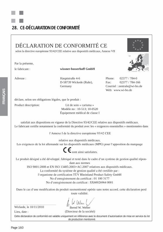
FRA
NÇ
AIS
Page 160
28. CE-DÉCLARATION DE CONFORMITÉ
DÉCLARATION DE CONFORMITÉ CEselon la directive européenne 93/42/CEE relative aux dispositifs médicaux, Annexe VII
Bernd W. Weber(Directeur de la société)
Par la présente,
le fabricant : wissner-bosserhoff GmbH
Adresse : Hauptstraße 4-6D-58739 Wickede (Ruhr), Germany
Phone: 02377 / 784-0Fax: 02377 / 784-166Courriel : [email protected] Web: www.wi-bo.de
déclare, selon ses obligations légales, que le produit :
Product description: Lit de soin « carisma »Modèle no : 10-513; 10-0520
Équipement médical de classe I
satisfait aux dispositions en vigueur de la Directive 93/42/CEE relative aux dispositifs médicaux.Le fabricant certifie notamment la conformité du produit avec les « exigences essentielles » mentionnées dans
relative aux dispositifs médicaux.
sont ainsi satisfaites.
-dant aux normes
ISO 9001:2008 et EN ISO 13485:2003+AC:2007 relatives aux dispositifs médicaux.La conformité du système de gestion qualité a été certifiée par :
toute validité.
Wickede, le 10/11/2010
Lieu, date :
Cette déclaration de conformité est valable uniquement en référence avec le document d‘autorisation de mise en service du lot de production mentionné.
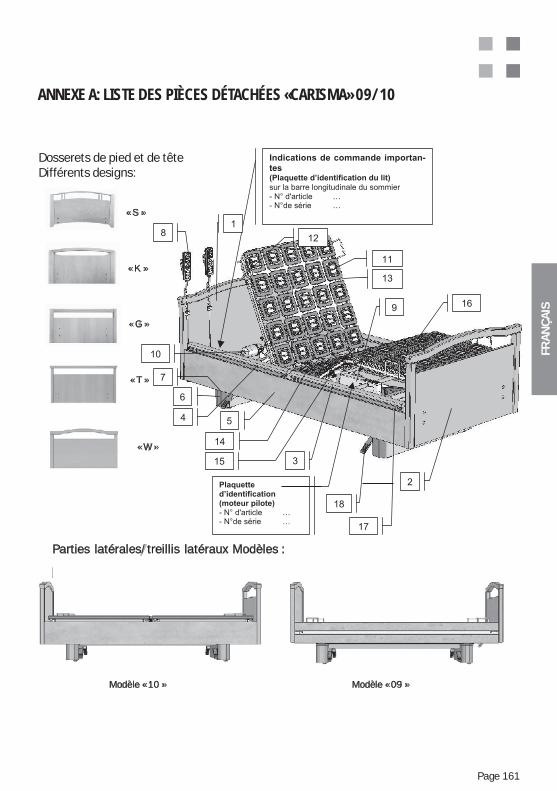
FRA
NÇ
AIS
Page 161
ANNEXE A: LISTE DES PIÈCES DÉTACHÉES «CARISMA» 09/10
Dosserets de pied et de têteDifférents designs:
« S »
« K »
« G »
« T »
« W »
Parties latérales/treillis latéraux Modèles :
Modèle « 10 » Modèle « 09 »
Dosserets de pied et de têteDifférents designs:
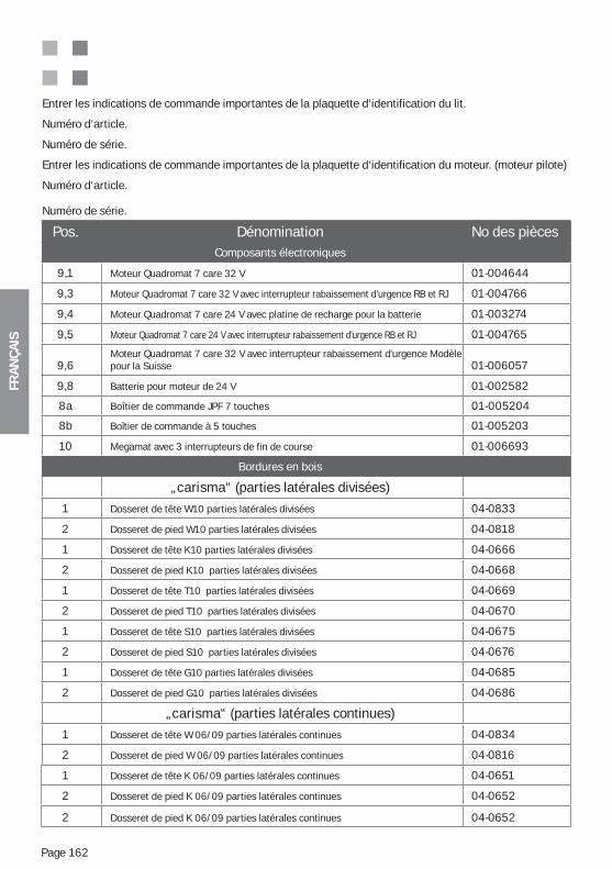
FRA
NÇ
AIS
Page 162
Entrer les indications de commande importantes de la plaquette d‘identification du lit.
Numéro d‘article.
Numéro de série.
Entrer les indications de commande importantes de la plaquette d‘identification du moteur. (moteur pilote)
Numéro d‘article.
Numéro de série.
Pos. Dénomination No des pièces Composants électroniques
9,1 Moteur Quadromat 7 care 32 V 01-004644
9,3 Moteur Quadromat 7 care 32 V avec interrupteur rabaissement d'urgence RB et RJ 01-004766
9,4 Moteur Quadromat 7 care 24 V avec platine de recharge pour la batterie 01-003274
9,5 Moteur Quadromat 7 care 24 V avec interrupteur rabaissement d'urgence RB et RJ 01-004765
9,6Moteur Quadromat 7 care 32 V avec interrupteur rabaissement d'urgence Modèle pour la Suisse 01-006057
9,8 Batterie pour moteur de 24 V 01-002582
8a Boîtier de commande JPF 7 touches 01-005204
8b Boîtier de commande à 5 touches 01-005203
10 Megamat avec 3 interrupteurs de fin de course 01-006693
Bordures en bois
„carisma“ (parties latérales divisées)
1 Dosseret de tête W10 parties latérales divisées 04-0833
2 Dosseret de pied W10 parties latérales divisées 04-0818
1 Dosseret de tête K10 parties latérales divisées 04-0666
2 Dosseret de pied K10 parties latérales divisées 04-0668
1 Dosseret de tête T10 parties latérales divisées 04-0669
2 Dosseret de pied T10 parties latérales divisées 04-0670
1 Dosseret de tête S10 parties latérales divisées 04-0675
2 Dosseret de pied S10 parties latérales divisées 04-0676
1 Dosseret de tête G10 parties latérales divisées 04-0685
2 Dosseret de pied G10 parties latérales divisées 04-0686
„carisma“ (parties latérales continues)
1 Dosseret de tête W 06/09 parties latérales continues 04-0834
2 Dosseret de pied W 06/09 parties latérales continues 04-0816
1 Dosseret de tête K 06/09 parties latérales continues 04-0651
2 Dosseret de pied K 06/09 parties latérales continues 04-0652
2 Dosseret de pied K 06/09 parties latérales continues 04-0652
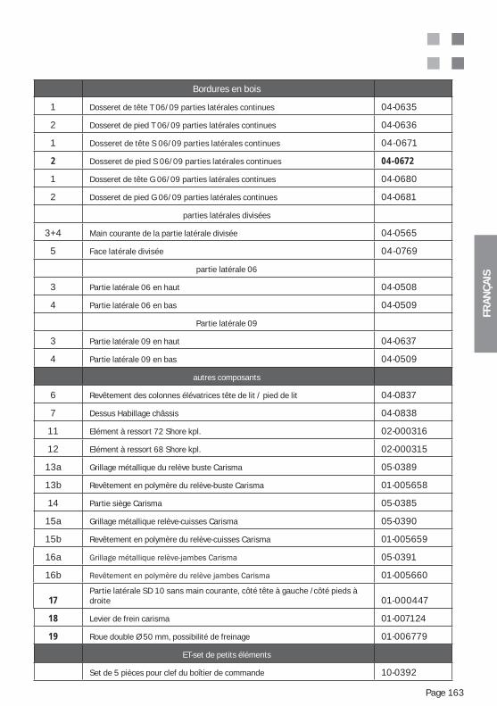
FRA
NÇ
AIS
Page 163
Bordures en bois
1 Dosseret de tête T 06/09 parties latérales continues 04-0635
2 Dosseret de pied T 06/09 parties latérales continues 04-0636
1 Dosseret de tête S 06/09 parties latérales continues 04-0671
2 Dosseret de pied S 06/09 parties latérales continues 04-0672
1 Dosseret de tête G 06/09 parties latérales continues 04-0680
2 Dosseret de pied G 06/09 parties latérales continues 04-0681
parties latérales divisées
3+4 Main courante de la partie latérale divisée 04-0565
5 Face latérale divisée 04-0769
partie latérale 06
3 Partie latérale 06 en haut 04-0508
4 Partie latérale 06 en bas 04-0509
Partie latérale 09
3 Partie latérale 09 en haut 04-0637
4 Partie latérale 09 en bas 04-0509
autres composants
6 Revêtement des colonnes élévatrices tête de lit / pied de lit 04-0837
7 Dessus Habillage châssis 04-0838
11 Elément à ressort 72 Shore kpl. 02-000316
12 Elément à ressort 68 Shore kpl. 02-000315
13a Grillage métallique du relève buste Carisma 05-0389
13b Revêtement en polymère du relève-buste Carisma 01-005658
14 Partie siège Carisma 05-0385
15a Grillage métallique relève-cuisses Carisma 05-0390
15b Revêtement en polymère du relève-cuisses Carisma 01-005659
16a 05-0391
16b 01-005660
17Partie latérale SD 10 sans main courante, côté tête à gauche /côté pieds à droite 01-000447
18 Levier de frein carisma 01-007124
19 Roue double Ø 50 mm, possibilité de freinage 01-006779
ET-set de petits éléments
Set de 5 pièces pour clef du boîtier de commande 10-0392
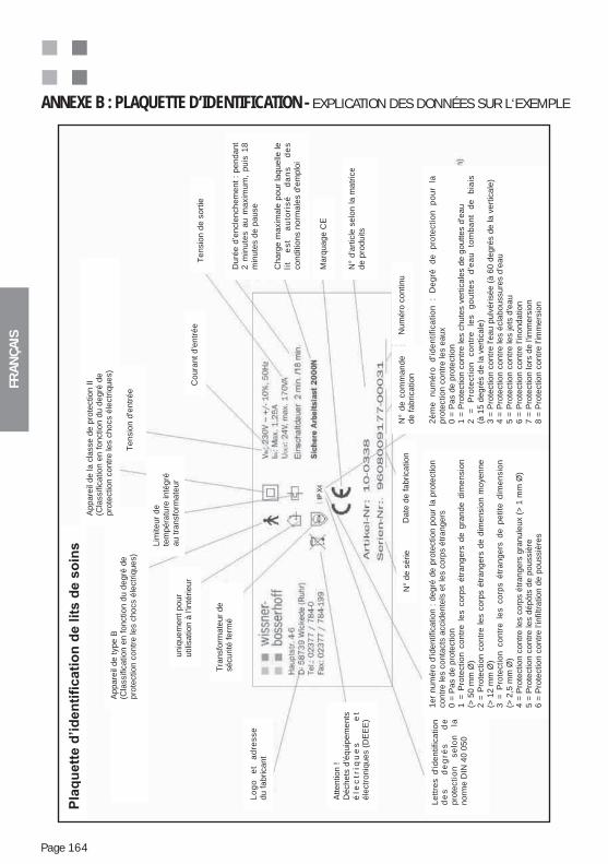
FRA
NÇ
AIS
Page 164
ANNEXE B : PLAQUETTE D‘IDENTIFICATION - EXPLICATION DES DONNÉES SUR L‘EXEMPLEA
ppare
il de t
ype B
(Cla
ssific
ation e
n f
onction d
u d
egré
de
pro
tection c
ontr
e les c
hocs é
lectr
iques)
Appare
il de la c
lasse d
e p
rote
ction I
I(C
lassific
ation e
n f
onction d
u d
egré
de
pro
tection c
ontr
e les c
hocs é
lectr
iques)
Lim
iteur
de
tem
péra
ture
inté
gré
au t
ransfo
rmate
ur
Tra
nsfo
rmate
ur
de
sé
cu
rité
fe
rmé
uniq
uem
ent
pour
utilis
ation à
l'in
térieur
Lo
go
e
t a
dre
sse
du f
abricant
Attention !
Dé
ch
ets
d'é
qu
ipe
me
nts
éle
ctr
iqu
es
e
téle
ctr
oniq
ues (
DE
EE
)
Marq
uage C
E
Coura
nt
d'e
ntr
ée
Tensio
n d
'entr
ée
Le
ttre
s d
'ide
ntifica
tio
nd
es
d
eg
rés
d
epro
tecti
on
s
elo
n
lanorm
e D
IN 4
0 0
50
Du
rée
d’e
ncle
nch
em
en
t :
pe
nd
an
t2
min
ute
s a
u m
axim
um
, p
uis
18
min
ute
s d
e p
ause
Tensio
n d
e s
ort
ie
Date
de f
abrication
Ch
arg
e m
axim
ale
po
ur
laq
ue
lle le
lit
es
t a
uto
ris
é
da
ns
d
es
conditio
ns n
orm
ale
s d
'em
plo
i
N°
de
co
mm
an
de
de f
abrication
Num
éro
continu
N°
de
sé
rie
N°
d'a
rtic
le s
elo
n la
ma
tric
ede p
roduits
1e
r n
um
éro
d'id
en
tifica
tio
n :
de
gré
de
pro
tectio
n p
ou
r la
pro
tectio
nco
ntr
e le
s c
on
tacts
accid
en
tels
et
les c
orp
s é
tra
ng
ers
0 =
Pas d
e p
rote
ction
1 =
Pro
tectio
n c
on
tre
le
s c
orp
s é
tra
ng
ers
de
gra
nd
e d
ime
nsio
n(>
50
mm
Ø)
2 =
Pro
tectio
n c
on
tre
le
s c
orp
s é
tra
ng
ers
de
dim
en
sio
n m
oye
nn
e(>
12
mm
Ø)
3 =
Pro
tectio
n c
on
tre
le
s c
orp
s é
tra
ng
ers
de
pe
tite
dim
en
sio
n(>
2,5
mm
Ø)
4 =
Pro
tection c
ontr
e les c
orp
s é
trangers
gra
nule
ux (
> 1
mm
Ø)
5 =
Pro
tection c
ontr
e les d
épôts
de p
oussiè
re6 =
Pro
tection c
ontr
e l’in
filtra
tion d
e p
oussiè
res
2è
me
n
um
éro
d
'ide
ntifica
tio
n
: D
eg
ré
de
p
rote
ctio
n
po
ur
lapro
tection c
ontr
e les e
aux
0 =
Pas d
e p
rote
ction
1 =
Pro
tection c
ontr
e les c
hute
s v
ert
icale
s d
e g
outtes d
'eau
2
=
Pro
tecti
on
co
ntr
e
les
go
utt
es
d'e
au
to
mb
an
t d
e
bia
is(à
15 d
egré
s d
e la v
ert
icale
)3 =
Pro
tection c
ontr
e l'e
au p
ulv
érisée (
à 6
0 d
egré
s d
e la v
ert
icale
)4 =
Pro
tection c
ontr
e les é
cla
boussure
s d
’eau
5 =
Pro
tection c
ontr
e les jets
d'e
au
6 =
Pro
tection c
ontr
e l’in
ondation
7 =
Pro
tection lors
de l'im
mers
ion
8 =
Pro
tection c
ontr
e l'im
mers
ion
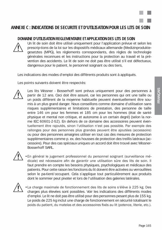
FRA
NÇ
AIS
Page 165
ANNEXE C : INDICATIONS DE SECURITE ET D‘UTILISATION POUR LES LITS DE SOIN
DOMAINE D‘UTILISATION REGLEMENTAIRE ET APPLICATION DES LITS DE SOINUn lit de soin doit être utilisé uniquement pour l‘application prévue et selon les prescrip-tions de la loi sur les dispositifs médicaux allemande (Medizinprodukte-gesetztes (MPG), les règlements correspondants, des règles de technologie générales reconnues et les instructions pour la protection au travail et la pré-vention des accidents. Le lit de soin ne doit pas être utilisé s‘il est défectueux, dangereux pour le patient, le personnel soignant ou des tiers,
Les indications des modes d‘emploi des différents produits sont à appliqués.
Les points suivants doivent être respectés:
Les lits Wissner - Bosserhoff sont prévus uniquement pour des personnes à partir de 12 ans. Ceci doit être assuré, car les personnes qui ont une taille ou un poids différent de la moyenne habituelle peuvent éventuellement être sou-mis à un plus grand danger. Nous conseillons comme domaine d‘utilisation sans risques supplémentaires et limitations de prestation, des personne de taille entre 146 cm pour les femmes et 185 cm pour les hommes (état de santé physique et mental non critique, et autonome à un certain degré) (selon la nor-me IEC 60601-2-52). En dehors de ce domaine des accessoires peuvent éven-
ou pour des personnes amaigries utiliser en tout cas des mesures de protection supplémentaires comme p. ex. des housses de protection des treillis latéraux (ac-cessoire). Pour des cas spéciaux uniques un accord doit être trouvé avec Wissner- Bosserhoff SARL.
-
faut prendre en compte les besoins physiques, psychologiques et médicaux des patients. Pour cette raison les fonctions du lit doivent être activées ou verrouillées selon le pa-tient/occupant. Cela s’applique tout particulièrement aux produits dont le sommier peut pivoter et lors de l‘utilisation des galeries latérales.
charges plus élevées sont possibles. Voir les indications des différents modes d‘emploi. Le lit ne doit pas être utilisé pour des personnes pesant plus de 155 kg. Le poids de 225 kg inclut une charge de fonctionnement en sécurité totalisant le
FRA
NÇ
AIS
Page 166
aux prises de courant domestiques qui correspondent au niveau de la technologie et dont le fonctionnement réglementaire des installations de sécurité (protection FI, protection FU, détecteurs d‘isolement défectueux, fusibles, etc.) est testé ré-gulièrement selon les prescriptions en vigueur.
où se trouvent des produits anesthésiques ou des produits de nettoyage ou des
respecter.
Une éventuelle utilisation en dehors de cette application constitue une utilisation non ré-glementaire et nous en déclinons toute responsabilité.
FONCTIONS DE BASES ET UTILISATION DES LITS DE SOIN
Les lits de soin modernes disposent de fonctions de positionnement nombreuses qui sont détaillées dans les différents modes d‘emploi des produits. On ne peut utiliser un lit de soin de façon optimale que par une formation minutieuse de l‘utilisateur et de l‘occupant de l‘installation de soin. Il faut répéter cette formation le plus souvent possible et surtout respecter les règles de sécurité nécessaires.
En général il y a toujours le danger d‘un mauvais réglage ou d‘un réglage involontaire du lit. L‘actionnement ou l‘activation de fonctions par mégarde
-tion adéquate du patient/occupant, il est indispensable d‘utiliser de manière précise des dispositifs de verrouillage ou des clefs de sécurité. En aucun cas la
sécurité est prévue uniquement pour l‘utilisation par le personnel soignant.
L‘utilisation de dispositifs de verrouillage ou le débranchement volontaire du lit du réseau, est une mesure absolue de verrouillage pour une protec-tion maximale d‘un patient/occupant en danger, qui dépend uniquement du jugement et de la responsabilité de la surveillance médicale compétente et du personnel soignant. Des mesures correspondantes doivent être notées dans
FRA
NÇ
AIS
Page 167
L‘utilisation des positions spéciales comme p.ex. la position déclive et anti-déclive, la positionnement par paliers ou une position basse pour la tête comme position choc est réservée uniquement au personnel soignant médical. Pour les patients et les occupants, ces fonctions doivent être verrouillées puisqu‘elles peuvent être dangereuses.
Les indications de sécurité dans les différents modes d‘emploi des produits sont absolument à respecter pour éviter les dangers.
Lors de l‘utilisation de galeries latérales il faut faire spécialement attention:
Les galeries latérales servent surtout de protection pour le patient, en l’empêchant de tomber de son lit. Les treillis latéraux doivent en aucun cas
Pour utiliser les galeries latérales, des dispositions judiciaires sont néces-saires dès que la mobilité du patient/de l’occupant se trouve limitée. Seules les galeries latérales divisées ou abaissables individuellement, dont on peut monter uniquement la partie au niveau de la tête et qui servent d‘aide au pati-ent pour se lever ou se coucher dans le lit, sont une exception acceptable pour les patients/occupants mobiles.
-
-
FRA
NÇ
AIS
Page 168
Une surcharge créée en s‘asseyant, s‘appuyant ou en tirant sur le treillis latéral provoque de graves dommages du treillis latéral et est dangereuse. Il faut donc absolument éviter ce genre de dommage..
Lors de l‘utilisation de galeries latérales il faut d‘abord s‘assurer qu‘elles sont appropriées aux patients/occupants selon les cas. Il faut surtout faire atten-tion que les distances entre les barreaux et les marches soient adaptées par
à travers. Le cas échéant, des rembourrages des galeries latérales doivent être utilisés qui diminuent ou ferment les espaces. Cette décision est de la responsabilité de la surveillance médicale compétente. Elle peut se baser sur les données sur la limitation de l‘utilisation réglementaire des modes d‘emploi des lits et des treillis latéraux.
Seules les galeries latérales prévues pour le type de lit correspondant peuvent être utilisées, sinon les risques d‘accidents sont augmentés.
-
au lit et que leur verrouillage de sécurité est impeccable. Des indications pour le maniement correct des galeries latérales se trouvent dans les différents modes d‘emploi des produits.
L‘utilisation de la télécommande manuelle par le patient/occupant lui-même dépend du jugement et de la responsabilité de la surveillance médicale compétente et du personnel soignant. Ces mesures doivent être notées dans le
un relève réglementaire et un suivi clair du droit d‘utilisation.
Si la télécommande manuelle ne doit pas être utilisée par le patient/ occupant, elle doit être sécurisée hors de sa portée d en s‘assurant qu‘elle ne
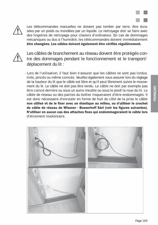
FRA
NÇ
AIS
Page 169
Les télécommandes manuelles ne doivent pas tomber par terre, être écra-sées par un poids ou inondées par un liquide. Le nettoyage doit se faire avec des lingettes de nettoyage pour claviers d‘ordinateur. En cas de dommages mécaniques ou dus à l‘humidité, les télécommandes doivent immédiatement
Les câbles de branchement au réseau doivent être protégés con-tre des dommages pendant le fonctionnement et le transport/déplacement du lit :
- Lors de l‘utilisation, il faut bien s‘assurer que les câbles ne sont pas tordus, tirés, pincés ou même coincés. Veuillez également vous assurer lors du réglage de la hauteur du lit que le câble est libre et qu‘il peut librement suivre le mouve-ment du lit. Le câble ne doit pas être tendu. Le câble ne doit par exemple pas être coincé derrière ou sous un autre meuble ou sous le pied/la roue du lit. Le câble de réseau ou des parties du boîtier risqueraient d‘être endommagés. Il est donc nécessaire d‘enrouler en forme de huit du côté de la prise le câble
d‘étirement involontaire.
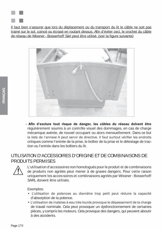
FRA
NÇ
AIS
Page 170
Il faut bien s‘assurer que lors du déplacement ou du transport du lit le câble ne soit pas trainé sur le sol, coincé ou écrasé en roulant dessus. Afin d‘éviter ceci, le crochet du câble de réseau de Wissner - Bosserhoff Sàrl peut être utilisé. (voir la figure suivante)
régulièrement soumis à un contrôle visuel des dommages, en cas de charge mécanique avérée, de nouvel occupant ou alors mensuellement. Dans ce but
critiques comme l‘entrée de la prise, le boîtier de la prise et le délestage de trac-tion ou l‘entrée dans les boîtiers du lit.
UTILISATION D‘ACCESSOIRES D‘ORIGINE ET DE COMBINAISONS DE PRODUITS PERMISES
L‘utilisation d‘accessoires non homologués pour le produit et de combinaisons de produits non agréés peut mener à de graves dangers. Pour cette raison uniquement les acces-soires et combinaisons agréés par Wissner - Bosserhoff SARL doivent être utilisés.
Exemples:
d’absorption de la potence.
de travail nominale. Cela peut provoquer un dysfonctionnement de certaines pièces, y compris les moteurs. Cela provoque des dangers, qui peuvent aboutir à des accidents.
FRA
NÇ
AIS
Page 171
MONTAGE DU LIT DE SOIN (DISTANCES DE SECURITE)
Le lit doit être monté de manière à pouvoir régler toutes les fonctions du lit sans provoquer de collisions des parties du lit avec d‘autres objets ou des parties de la chambre. (p.ex. câbles, rebords de fenêtre, plafond en pente, tuyauterie, installations en sailli, étagères etc.). Ici aussi il faut garder une distance de sécurité minimum de 2,5 cm à tous les murs et autres objets et dans toutes les positions du lit. Attention : Il faut également éviter toute col-lision lors de pivotement et du réglage en hauteur! Il convient de placer le lit de manière à pouvoir couper facilement l‘alimentation électrique (en retirant
NETTOYAGE ET DESINFECTION DU LIT
Le lit de soin doit être nettoyé et désinfecté régulièrement, au moins avant chaque nouveau patient. Le lit de soin ne doit pas être nettoyé ou désinfecté
Il peut uniquement être désinfecté par essuyage ou spray.
Les produits suivants sont conseillés pour la désinfection du lit de soin et ils peuvent unique-ment être substitués par des produits équivalents :Terralin, Perform et Sagrotan Med (Schülke & Mayr GmbH, Norderstedt).Ces produits sont à utiliser uniquement selon les indications du fabricant! Ceci concerne avant tout le dosage du produit et le danger potentiel lors de la combinaison avec d‘autres produits.
Le cadre en bois ne doit pas être mis en contact avec ces produits.Pour des taches particulièrement tenaces, on peut évidemment utiliser des produits de nettoyage standards respectueux de l‘environnement.
L‘utilisation de produits de nettoyages contenant des particules abrasives n‘est pas permise.
Veillez à ne pas faire de taches permanentes d‘eau ou de liquide sur le bois véritable et les feuilles de placage lors de l‘utilisation et du nettoyage. Le bois est un produit naturel qui absorbe l‘eau et se dilate. Cela peut provoquer des
être éliminés après le nettoyage à l‘aide d‘une laque réparatrice. Veuillez vous adresser au service client de Wissner - Bosserhoff SARL.
Le nettoyage des télécommandes manuelles doit se faire uniquement avec des lingettes de nettoyage pour clavier d‘ordinateur.la commande manuelle, ou si elle est trop sale ou des touches sont bloquées par des grains de poussières, la commande doit éventuellement être remplacée.
FRA
NÇ
AIS
Page 172
ANNEXE D : MODE BATTERIE (=ACCUMULATEUR) (EN OPTION) - INDICATIONS SUPPLEMENTAIRES
Le moteur du lit peut être équipé spécialement par une fonction supplémentaire, le mode batterie. qui permet de régler les fonctions électriques plusieurs fois sans qu‘il soit raccordé au réseau.
Le nombre de réglages possibles est indépendant de l‘état de charge de la batterie. Pour éviter une décharge complète, le lit doit rester raccordé au réseau le plus souvent possi-ble.
La batterie se recharge alors automatiquement par un système de charge spécial intégré.
En général la batterie est livrée chargée et montée, solidaire du moteur principal. L‘utilisateur non formé ne peut pas la monter.
Caractéristiques importantes:
Pour des raisons de sécurité le boîtier de la batterie ne doit pas être ouvert.
Si vous désirez acheter la batterie ultérieurement, veuillez vous adresser inconditi-onnellement à notre serv-ice client technique, car tous les moteurs ne sont pas adaptés à l‘utilisation avec batterie. L‘échange d‘un boîtier de batterie doit être effectué uniquement par le personnel formé afin d‘éviter des dommages dus à un mauvais maniement.
La durée de vie de la batterie dépend fortement de son utilisation et est raccourci, si elle a été complète-ment déchargée.
Il est possible d‘utiliser un chargeur de batterie quadruple externe (accessoire pour la recharge de quatre batteries en parallèle), disponible séparément:Veuillez dans ces cas respecter inconditionnellement le mode d‘emploi spéciale pour le chargeur de batterie.
FRA
NÇ
AIS
Page 173
ANNEXE E: METAMERIE – LA SIMILITUDE DE L‘ASPECT DES SURFACES ET DECORS
La métamérie
Deux couleurs semblent identiques uniquement sous un type d’éclairage particulier. Elles diffèrent lorsque l’éclairage change, à cause des propriétés spectrales des pigments utili-sés, des couleurs et des matériaux. Un manteau acheté vert dans le magasin apparaîtra tout d’un coup marron dans la rue, mais le pantalon vert restera vert. Pour observer des
poser problème pour accorder les matériaux imprimés et les couleurs imprimées, si l’on uti-
ausbildung/mediengestalter/tutorials/Dictionary.php?Action=ByTitle&Title=LichtD65.
Il s’agit donc d’un phénomène d’égalité conditionnelle des couleurs. Deux ou plusieurs cou-leurs ne semblent identiques que sous un type précis de lumière (par exemple, une lampe néon) et ne diffèrent autrement que par leurs propriétés spectrales (par exemple, les pig-ments et colorants utilisés) sous tout autre type d’éclairage.
est la différence de couleurs changeante en fonction de la lumière entre deux ou plusieurs couleurs de matériaux.
C’est surtout en présence de matières/matériaux différents, de processus d’impression ou de coloration avec différentes substances colorantes qu’apparaissent presque inévitable-ment de légères différences de couleurs lorsque la lumière varie (les effets de néons, de lumière des magasins ou de lumière d’exposition renvoient à ces phénomènes typiques).
Une colorimétrie s’avère être un bon instrument pour la comparaison des couleurs unies sur des décors unis. On calcule alors un indice de métamérie comme valeur de comparai-son entre deux échantillons. L’indice de métamérie est la valeur delta E -dans le système
D60) à la lumière artificielle (A). On utilise ici des appareils de mesures combinées de la couleur et du degré de brillance.
Il faut néanmoins effectuer une évaluation visuelle sur un rapport pour les impressions sur décors en bois, décors de structures et d’échantillons, car une comparaison des couleurs
-
visuelles sont très personnelles.
Le fameux rapport est alors la plus petite unité isolée d’un échantillon. Lorsqu’un échan-tillon (par exemple, un film d’impression ou un matériau) est composé de plusieurs parties, une de ces parties est appelée rapport (par exemple, un échantillon d’impression de 1,5 m de long sur lequel l’échantillon de base se répète).
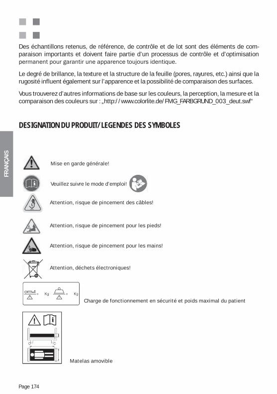
FRA
NÇ
AIS
Page 174
Des échantillons retenus, de référence, de contrôle et de lot sont des éléments de com-paraison importants et doivent faire partie d’un processus de contrôle et d’optimisation
Le degré de brillance, la texture et la structure de la feuille (pores, rayures, etc.) ainsi que la rugosité influent également sur l’apparence et la possibilité de comparaison des surfaces.
Vous trouverez d’autres informations de base sur les couleurs, la perception, la mesure et la comparaison des couleurs sur : „http://www.colorlite.de/FMG_FARBGRUND_003_deut.swf“
DESIGNATION DU PRODUIT/LEGENDES DES SYMBOLES
Charge de fonctionnement en sécurité et poids maximal du patient
Mise en garde générale!
Veuillez suivre le mode d’emploi!
Attention, risque de pincement des câbles!
Attention, risque de pincement pour les pieds!
Attention, risque de pincement pour les mains!
Attention, déchets électroniques!
Matelas amovible
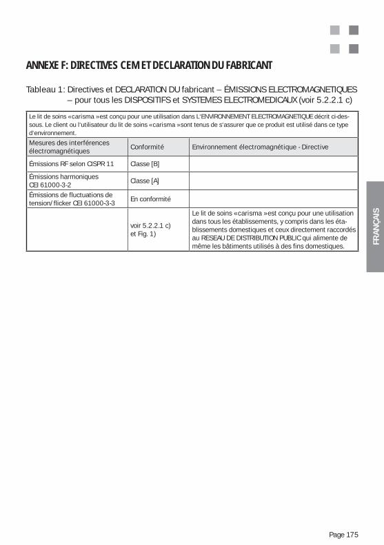
FRA
NÇ
AIS
Page 175
ANNEXE F: DIRECTIVES CEM ET DECLARATION DU FABRICANT
Tableau 1: Directives et DECLARATION DU fabricant – ÉMISSIONS ELECTROMAGNETIQUES – pour tous les DISPOSITIFS et SYSTEMES ELECTROMEDICAUX (voir 5.2.2.1 c)
Le lit de soins « carisma » est conçu pour une utilisation dans L‘ENVIRONNEMENT ELECTROMAGNETIQUE décrit ci-des-sous. Le client ou l‘utilisateur du lit de soins « carisma » sont tenus de s‘assurer que ce produit est utilisé dans ce typed‘environnement.
Mesures des interférencesélectromagnétiques
Conformité Environnement électromagnétique - Directive
Émissions RF selon CISPR 11 Classe [B]
Émissions harmoniquesCEI 61000-3-2
Classe [A]
Émissions de fluctuations detension/flicker CEI 61000-3-3
En conformité
voir 5.2.2.1 c)et Fig. 1)
Le lit de soins « carisma » est conçu pour une utilisation dans tous les établissements, y compris dans les éta-blissements domestiques et ceux directement raccordés au RESEAU DE DISTRIBUTION PUBLIC qui alimente de même les bâtiments utilisés à des fins domestiques.
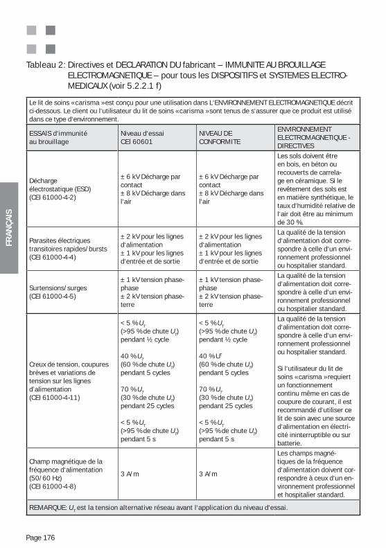
FRA
NÇ
AIS
Page 176
Tableau 2: Directives et DECLARATION DU fabricant – IMMUNITE AU BROUILLAGE ELECTROMAGNETIQUE – pour tous les DISPOSITIFS et SYSTEMES ELECTRO- MEDICAUX (voir 5.2.2.1 f)
Le lit de soins « carisma » est conçu pour une utilisation dans L‘ENVIRONNEMENT ELECTROMAGNETIQUE décrit ci-dessous. Le client ou l‘utilisateur du lit de soins « carisma » sont tenus de s‘assurer que ce produit est utilisé dans ce type d‘environnement.
ESSAIS d‘immunitéau brouillage
Niveau d‘essai CEI 60601
NIVEAU DE CONFORMITE
ENVIRONNEMENT ELECTROMAGNETIQUE -DIRECTIVES
Déchargeélectrostatique (ESD)(CEI 61000-4-2)
± 6 kV Décharge par contact± 8 kV Décharge dans l‘air
± 6 kV Décharge parcontact± 8 kV Décharge dans l‘air
Les sols doivent être en bois, en béton ou recouverts de carrela-ge en céramique. Si le revêtement des sols est en matière synthétique, le taux d‘humidité relative de l‘air doit être au minimum de 30 %.
Parasites électriquestransitoires rapides/bursts(CEI 61000-4-4)
± 2 kV pour les lignesd‘alimentation± 1 kV pour les lignesd‘entrée et de sortie
± 2 kV pour les lignesd‘alimentation± 1 kV pour les lignesd‘entrée et de sortie
La qualité de la tension d‘alimentation doit corre-spondre à celle d‘un envi-ronnement professionnel ou hospitalier standard.
Surtensions/surges(CEI 61000-4-5)
± 1 kV tension phase-phase± 2 kV tension phase-terre
± 1 kV tension phase-phase± 2 kV tension phase-terre
La qualité de la tension d‘alimentation doit corre-spondre à celle d‘un envi-ronnement professionnel ou hospitalier standard.
Creux de tension, coupures brèves et variations detension sur les lignesd’alimentation(CEI 61000-4-11)
< 5 % UT(>95 % de chute UT)pendant ½ cycle
40 % UT (60 % de chute UT)pendant 5 cycles
70 % UT (30 % de chute UT)pendant 25 cycles
< 5 % UT (>95 % de chute UT)pendant 5 s
< 5 % UT(>95 % de chute UT)pendant ½ cycle
40 % UT (60 % de chute UT)pendant 5 cycles
70 % UT (30 % de chute UT)pendant 25 cycles
< 5 % UT (>95 % de chute UT)pendant 5 s
La qualité de la tension d‘alimentation doit corre-spondre à celle d‘un envi-ronnement professionnel ou hospitalier standard.
Si l‘utilisateur du lit de soins « carisma » requiert un fonctionnement continu même en cas de coupure de courant, il est recommandé d‘utiliser ce lit de soin avec une source d‘alimentation en électri-cité ininterruptible ou sur batterie.
Champ magnétique de la fréquence d‘alimentation(50/60 Hz) (CEI 61000-4-8)
3 A/m 3 A/m
Les champs magné-tiques de la fréquence d‘alimentation doivent cor-respondre à ceux d‘un en-vironnement professionnel et hospitalier standard.
REMARQUE: UT est la tension alternative réseau avant l‘application du niveau d‘essai.
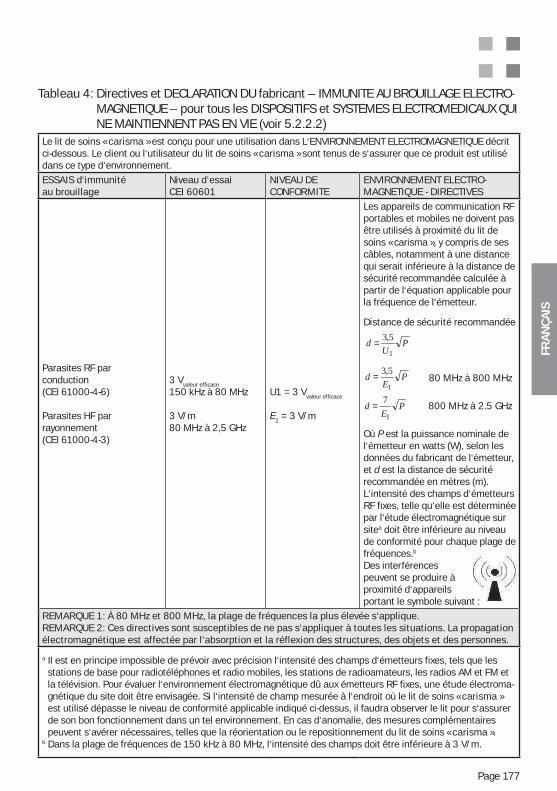
FRA
NÇ
AIS
Page 177
Tableau 4: Directives et DECLARATION DU fabricant – IMMUNITE AU BROUILLAGE ELECTRO-MAGNETIQUE – pour tous les DISPOSITIFS et SYSTEMES ELECTROMEDICAUX QUI NE MAINTIENNENT PAS EN VIE (voir 5.2.2.2)
Le lit de soins « carisma » est conçu pour une utilisation dans L‘ENVIRONNEMENT ELECTROMAGNETIQUE décrit ci-dessous. Le client ou l‘utilisateur du lit de soins « carisma » sont tenus de s‘assurer que ce produit est utilisé dans ce type d‘environnement.
ESSAIS d‘immunitéau brouillage
Niveau d‘essai CEI 60601
NIVEAU DE CONFORMITE
ENVIRONNEMENT ELECTRO- MAGNETIQUE - DIRECTIVES
Parasites RF parconduction(CEI 61000-4-6)
Parasites HF parrayonnement(CEI 61000-4-3)
3 Vvaleur efficace
150 kHz à 80 MHz
3 V/m80 MHz à 2,5 GHz
U1 = 3 Vvaleur efficace
E1 = 3 V/m
Les appareils de communication RFportables et mobiles ne doivent pas être utilisés à proximité du lit de soins « carisma », y compris de ses câbles, notamment à une distance qui serait inférieure à la distance de sécurité recommandée calculée à partir de l‘équation applicable pour la fréquence de l‘émetteur.
Distance de sécurité recommandée
80 MHz à 800 MHz
800 MHz à 2.5 GHz
Où P est la puissance nominale del‘émetteur en watts (W), selon lesdonnées du fabricant de l‘émetteur, et d est la distance de sécurité recommandée en mètres (m).L‘intensité des champs d‘émetteurs RF fixes, telle qu‘elle est déterminée par l‘étude électromagnétique sur sitea doit être inférieure au niveau de conformité pour chaque plage de fréquences.b
Des interférences peuvent se produire àproximité d‘appareils portant le symbole suivant :
REMARQUE 1: À 80 MHz et 800 MHz, la plage de fréquences la plus élevée s‘applique.REMARQUE 2: Ces directives sont susceptibles de ne pas s‘appliquer à toutes les situations. La propagationélectromagnétique est affectée par l‘absorption et la réflexion des structures, des objets et des personnes.
a Il est en principe impossible de prévoir avec précision l‘intensité des champs d‘émetteurs fixes, tels que les stations de base pour radiotéléphones et radio mobiles, les stations de radioamateurs, les radios AM et FM et la télévision. Pour évaluer l‘environnement électromagnétique dû aux émetteurs RF fixes, une étude électroma-gnétique du site doit être envisagée. Si l‘intensité de champ mesurée à l‘endroit où le lit de soins « carisma » est utilisé dépasse le niveau de conformité applicable indiqué ci-dessus, il faudra observer le lit pour s‘assurer de son bon fonctionnement dans un tel environnement. En cas d‘anomalie, des mesures complémentaires peuvent s‘avérer nécessaires, telles que la réorientation ou le repositionnement du lit de soins « carisma ».
b Dans la plage de fréquences de 150 kHz à 80 MHz, l‘intensité des champs doit être inférieure à 3 V/m.
PE
d1
5,3=
PU
d1
5,3=
PE
d1
7=
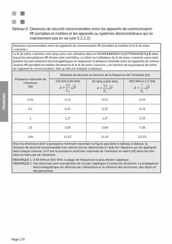
FRA
NÇ
AIS
Page 178
Tableau 6: Distances de sécurité recommandées entre les appareils de communication RF portables et mobiles et les appareils ou systèmes électromédicaux qui ne maintiennent pas en vie (voir 5.2.2.2)
Distances recommandées entre les appareils de communication RF portables et mobiles et le lit de soins « carisma »Le lit de soins « carisma » est conçu pour une utilisation dans un ENVIRONNEMENT ELECTROMAGNETIQUE dans lequel les perturbations RF émises sont contrôlées. Le client ou l‘utilisateur du lit de soins « carisma » peut ainsi prévenir les perturbations électromagnétiques en respectant la distance minimale entre les appareils de commu-nication RF portables et mobiles (émetteurs) et le lit de soins « carisma », en fonction de la puissance de sortie de l‘appareil de communication, telle qu‘elle est indiquée ci-dessous.
Puissance nominale del‘émetteur
[W]
Distance de sécurité en fonction de la fréquence de l‘émetteur [m]
150 kHz à 80 MHz
PU
d1
5,3=80 MHz à 800 MHz
PE
d1
5,3=
800 MHz à 2.5 GHz
PE
d1
7=
0,01 0,12 0,12 0,23
0,1 0,37 0,37 0,74
1 1,17 1,17 2,33
10 3,69 3,69 7,38
100 11,67 11,67 23,33
Pour les émetteurs dont la puissance nominale maximale ne figure pas dans le tableau ci-dessus, la distance de sécurité recommandée d en mètres (m) est déterminée à l‘aide de l‘équation qui est appliquée dans chaque colonne, où P est la puissance nominale maximale de l‘émetteur en watts (W) selon les don-nées du fabricant de l‘émetteur.
REMARQUE 1: À 80 MHz et 800 MHz, la plage de fréquences la plus élevée s‘applique.REMARQUE 2: Ces directives sont susceptibles de ne pas s‘appliquer à toutes les situations. La propagation
électromagnétique est affectée par l‘absorption et la réflexion des structures, des objets et des personnes.
FRA
NÇ
AIS
Page 179
NOTES
FRA
NÇ
AIS
Page 180
NOTES

FRA
NÇ
AIS
Page 181
NOTES
NED
ERLA
ND
S
Pagina 182
1. INHOUDSOPGAVE
1. Inhoudsopgave..................................................................................182 ........................................................183
.........184 ...........................................184
4. Opstelling van het bed ......................................................................185 ............................185
5.1. Elektromotoren ligvlak .................................................................1865.2. Elektromotoren voor Hoogteverstelling ......................................1866. Productveiligheid / uittreksel van de toegepaste normen .............1877. Productoverzicht (VOORBEELD houten ombouw t10) ....................188
........................................1888.1. Functie Rugleuning (RL) ..............................................................1898.2. Beenlift (BL) .................................................................................1908.3. Comfortzit (CZ) .............................................................................1908.4. Functie Autocontour (AC) .............................................................1918.5. Functie hoogteverstelling (HV) ....................................................1919. 19110. Veiligheidsinstructies voor de hoogteverstelling ............................19211. Blokkeerconsole (Optie) ...................................................................192 12. Levering .............................................................................................19313. Montage ............................................................................................19413.1. Ligvlak ...........................................................................................19413.2. Ligvlakmotor .................................................................................19414. Transport / Verplaatsen van het bed ..............................................19415. Functietests .......................................................................................195
...........195 .....................196
15.3. Onderbeengedeelte / mechanisch .............................................197 ..........................................................................198
15.5. Onrusthekken verstellen (Uitvoering 06) ...................................19815.6. Onrusthekken verstellen (Losmaken 09) ...................................19915.7. Onrusthekken verstellen (Uitvoering 10) ....................................20016. Toelaatbare accessoires ..................................................................20116.1. Patiëntenoprichter (accessoire) ..................................................20116.2. Serumstaaf (accessoire) .............................................................20216.3. Ligvlakverlenging (Optie) .............................................................20216.4. Matras (accessoire) .....................................................................20316.5. Urinaalhouder / Urinezakhouder uitvoering 09 (accessoire) ...20316.6. Houder voor handschakelaar (accessoire) ................................20416.7. Opzetstuk voor onrusthekken voor serie 06/09 onrusthekken (accessoire) ..................................................................................20517. Reiniging en desinfectie ...................................................................207
NED
ERLA
ND
S
Pagina 183
17.1. Reiniging vooraf ...........................................................................20717.2. Desinfecteren / Steriliseren ........................................................20817.3. Onderhoudsinstructies voor houten onderdelen .......................20817.4. Gebruik van reinigingsmiddelen .................................................20917.5. Gebruik van desinfecteermiddelen ............................................20917.6. Beschadigingen aan houten onderdelen ...................................20917.7. Milieuzorg .....................................................................................20917.8. Kwaliteit ........................................................................................209
..............................................................................21019. Opslag ................................................................................................21020. Veiligheidskennisgeving en restrisico‘s ...........................................21021. Onderhoud en reparatie ...................................................................21621.1. Volledigheid en accessoires ........................................................216
..........................................................................................21721.3. Functionaliteit...............................................................................21721.4. BGV A3/VDE 0751– Tests voor elektrische onderdelen en de kandschakelaar ...........................................................................217 21.5. Wielen ...........................................................................................21722. Levensduur........................................................................................217
.......................................................................................218........................218
...................................................................21826. Garantie en service ..........................................................................21927. Contactpersoon ................................................................................21928. EG-conformiteitsverklaring ...............................................................220
verpleegbedden ..............................................................................................225Gebruik volgens voorschrift en doelbepaling van verpleegbedden.............225Basisfuncties en inzet van verpleegbedden .................................................226Gebruik van originele accesoires en goedgekeurde productcombinaties ..230Opstelling van het verpleegbed (veiligheidsafstanden) ................................231Reiniging en desinfectie van het bed ............................................................231
Appendices:
BELANGRIJK VEILIGHEIDSINSTRUCTIE:Lees steeds de als veiligheidsrelevant de met een aangeduide passages in elk hoofdstuk
NED
ERLA
ND
S
Pagina 184
Zeer geachte klant,wij bedanken u voor het vertrouwen dat u ons met de aankoop van ons product bewijst. Wij zijn ervan overtuigd, dat ons product aan de eisen van de dagelijkse zorg voldoet. Zorgvuldige keuze van materialen, het gebruik van de modernste technologieën en, niet in de laatste plaats, de grondighed en teamgeest van onze medewerkers zorgen voor de hoge gebruiks-waarde en solide kwaliteit van onze producten. Wij zijn ervan overtuigd dat de zorg hiermee gemakkelijker wordt gemaakt.
2. TIPS OMTRENT DE GEBRUIKSAANWIJZING / VERKLARING DER TEKENS
Dit teken wijst op veiligheidsrelevante informatie, waarvan het negeren ernstige ge-volgen (bijvoorbeeld schade of letsel) kan hebben. Het is daarom belangrijk deze aanwijzin-gen en tips op te volgen.
-on die is aangewezen dit product in gebruik te nemen en te bedienen.
Attentie! Ieder gebruik van dit product vereist exacte kennis en opvolging van deze gebruiksaanwijzing. Daarom dient deze tot aan de verwijdering zorgvuldig bewaard te worden. Om bedieningsfouten te vermijden en een storingsvrije wer-king te garanderen moet de gebruiksaanwijzing voor het personeel steeds toe-gankelijk zijn. Het is aan te bevelen deze aan het bed of in het nachtkastje te bewaren.
op schaal.
3. GEBRUIKSMOGELIJKHEDEN / BESTEMMING
(201.3.203) * GEBRUIKSOMGEVING 3Langdurige verpleging in een medische omgeving, waarin medisch toezicht is vereist en zo nodig
-steld worden, om het handhaven of verbeteren van de toestand van de PATIËNT te ondersteunen.(201.3.205) * GEBRUIKSOMGEVING 5Ambulante verpleging, die in een ziekenhuis of in een andere medische instelling onder medischtoezicht wordt geboden. Er wordt een ME-APPARAAT voor de behoefte van personen met ziekte,letsel of met een handicap ten behoeve van de behandeling, diagnose of bewaking klaar gezet
overeengekomen te worden. Het product dient als arbeidsmiddel in de verpleging en is gebon-
Dit verpleegbed geldt volgens de in het volgende hoofdstuk „Productveiligheid / uittreksel van de toegepaste normen“ genoemde voorschriften en normen als medisch product. Derhalve mag dit product uitsluitend onder medisch toezicht worden ingezet. Doorslaggevend voor de vraag of de verpleging onder medisch toezicht staat of niet, is de vraag of deze verpleging op aanwijzing van medisch personeel plaatsvindt.
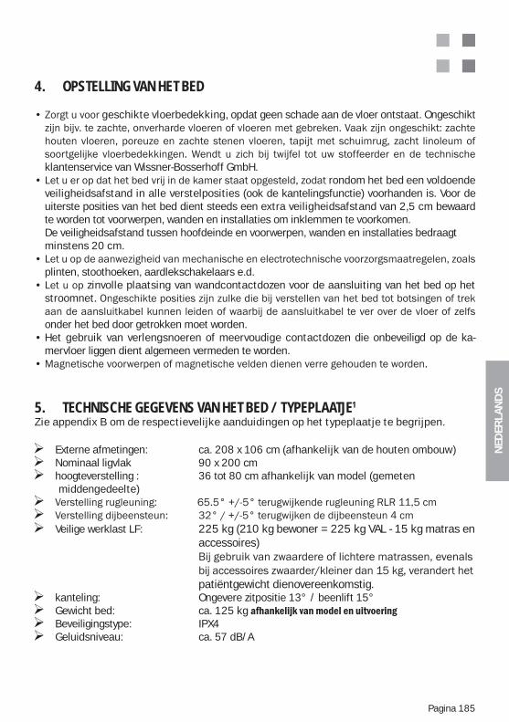
NED
ERLA
ND
S
Pagina 185
4. OPSTELLING VAN HET BED
geschikte vloerbedekking, opdat geen schade aan de vloer ontstaat. Ongeschikt
klantenservice van Wissner-Bosserhoff GmbH.rondom het bed een voldoende
veiligheidsafstand in alle verstelposities (ook de kantelingsfunctie) voorhanden is. Voor de uiterste posities van het bed dient steeds een extra veiligheidsafstand van 2,5 cm bewaard te worden tot voorwerpen, wanden en installaties om inklemmen te voorkomen.
De veiligheidsafstand tussen hoofdeinde en voorwerpen, wanden en installaties bedraagt minstens 20 cm.
plinten, stoothoeken, aardlekschakelaars e.d.zinvolle plaatsing van wandcontactdozen voor de aansluiting van het bed op het
stroomnet
onder het bed door getrokken moet worden.Het gebruik van verlengsnoeren of meervoudige contactdozen die onbeveiligd op de ka-mervloer liggen dient algemeen vermeden te worden.
5. TECHNISCHE GEGEVENS VAN HET BED / TYPEPLAATJE1
Zie appendix B om de respectievelijke aanduidingen op het typeplaatje te begrijpen.
Externe afmetingen: ca. 208 x 106 cm (afhankelijk van de houten ombouw) Nominaal ligvlak 90 x 200 cm hoogteverstelling : 36 tot 80 cm afhankelijk van model (gemeten
middengedeelte)
Veilige werklast LF: 225 kg (210 kg bewoner = 225 kg VAL - 15 kg matras en accessoires)
patiëntgewicht dienovereenkomstig. kanteling: Ongevere zitpositie 13° / beenlift 15° Gewicht bed: ca. 125 kg Beveiligingstype: IPX4 Geluidsniveau: ca. 57 dB/A
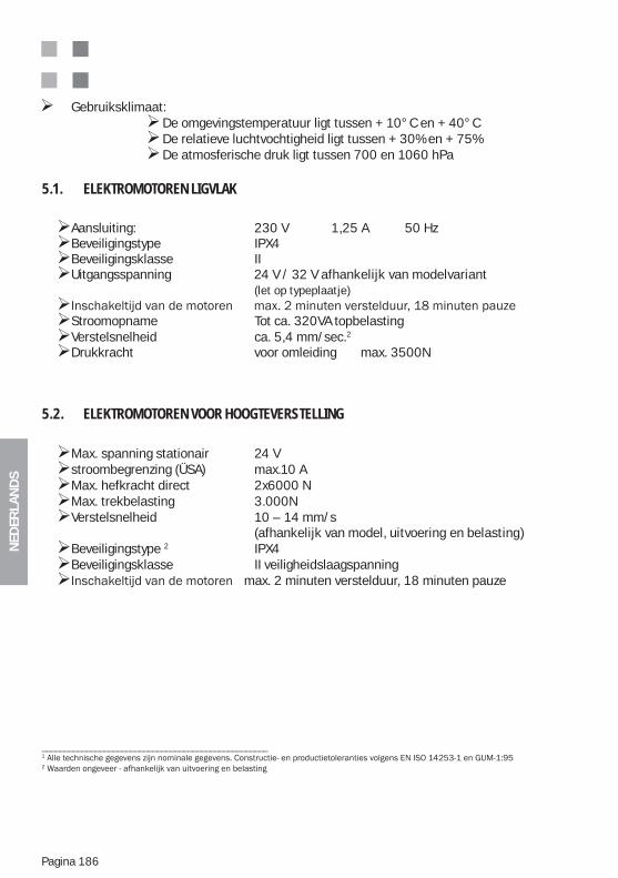
NED
ERLA
ND
S
Pagina 186
Gebruiksklimaat: De omgevingstemperatuur ligt tussen + 10°C en + 40°C De relatieve luchtvochtigheid ligt tussen + 30% en + 75% De atmosferische druk ligt tussen 700 en 1060 hPa
5.1. ELEKTROMOTOREN LIGVLAK
Aansluiting: 230 V 1,25 A 50 Hz Beveiligingstype IPX4 Beveiligingsklasse II Uitgangsspanning 24 V / 32 V afhankelijk van modelvariant
(let op typeplaatje)
Stroomopname Tot ca. 320VA topbelasting Verstelsnelheid ca. 5,4 mm/sec.2
Drukkracht voor omleiding max. 3500N
5.2. ELEKTROMOTOREN VOOR HOOGTEVERSTELLING
Max. spanning stationair 24 V stroombegrenzing (ÜSA) max.10 A Max. hefkracht direct 2x6000 N Max. trekbelasting 3.000N Verstelsnelheid 10 – 14 mm/s
(afhankelijk van model, uitvoering en belasting) Beveiligingstype 2 IPX4 Beveiligingsklasse II veiligheidslaagspanning max. 2 minuten verstelduur, 18 minuten pauze
___________________________________________________1
2
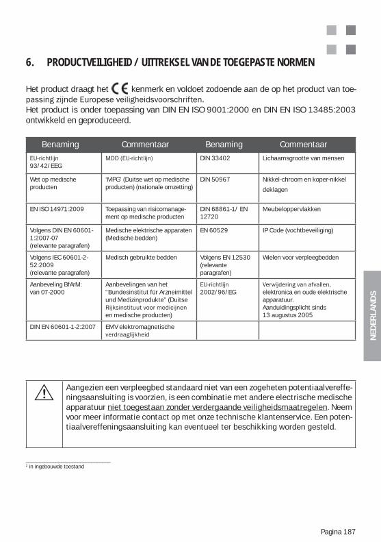
NED
ERLA
ND
S
Pagina 187
6. PRODUCTVEILIGHEID / UITTREKSEL VAN DE TOEGEPASTE NORMEN
Het product draagt het kenmerk en voldoet zodoende aan de op het product van toe-
Het product is onder toepassing van DIN EN ISO 9001:2000 en DIN EN ISO 13485:2003 ontwikkeld en geproduceerd.
Benaming Commentaar Benaming Commentaar
93/42/EEG
DIN 33402 Lichaamsgrootte van mensen
Wet op medische producten
‘MPG’ (Duitse wet op medischeproducten) (nationale omzetting)
DIN 50967 Nikkel-chroom en koper-nikkel
deklagen
EN ISO 14971:2009 Toepassing van risicomanage-ment op medische producten
DIN 68861-1/ EN 12720
Meubeloppervlakken
Volgens DIN EN 60601-1:2007-07(relevante paragrafen)
Medische elektrische apparaten (Medische bedden)
EN 60529 IP Code (vochtbeveiliging)
Volgens IEC 60601-2-52:2009(relevante paragrafen)
Medisch gebruikte bedden Volgens EN 12530(relevante paragrafen)
Wielen voor verpleegbedden
Aanbeveling BfArM: van 07-2000
Aanbevelingen van het “Bundesinstitut für Arzneimittel und Medizinprodukte” (Duitse
en medische producten)
2002/96/EG elektronica en oude elektrische apparatuur. Aanduidingsplicht sinds 13 augustus 2005
DIN EN 60601-1-2:2007 EMV elektromagnetische
_______________________________2 in ingebouwde toestand
Aangezien een verpleegbed standaard niet van een zogeheten potentiaalvereffe-ningsaansluiting is voorzien, is een combinatie met andere electrische medische apparatuur niet toegestaan zonder verdergaande veiligheidsmaatregelen. Neem voor meer informatie contact op met onze technische klantenservice. Een poten-tiaalvereffeningsaansluiting kan eventueel ter beschikking worden gesteld.
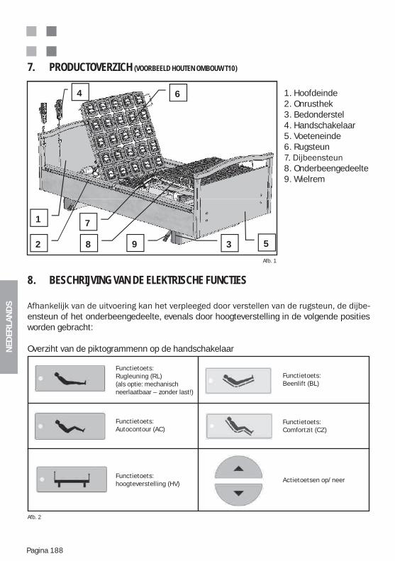
NED
ERLA
ND
S
Pagina 188
1. Hoofdeinde2. Onrusthek3. Bedonderstel4. Handschakelaar5. Voeteneinde6. Rugsteun
8. Onderbeengedeelte9. Wielrem
7. PRODUCTOVERZICH (VOORBEELD HOUTEN OMBOUW T10)
Afb. 1
8. BESCHRIJVING VAN DE ELEKTRISCHE FUNCTIES
-ensteun of het onderbeengedeelte, evenals door hoogteverstelling in de volgende posities worden gebracht:
Overziht van de piktogrammenn op de handschakelaar
1
2 3
4
5
6
7
8 9
Afb. 2
Functietoets:Rugleuning (RL)(als optie: mechanisch neerlaatbaar – zonder last!)
Functietoets:Autocontour (AC)
Functietoets:hoogteverstelling (HV)
Functietoets:Beenlift (BL)
Functietoets:Comfortzit (CZ)
Actietoetsen op/neer
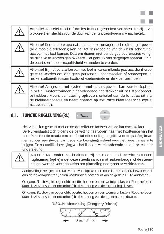
NED
ERLA
ND
S
Pagina 189
8.1. FUNCTIE RUGLEUNING (RL)
Het verstellen gebeurt met de desbetreffende toetsen van de handschakelaar.
-
ondersteund.
Aanbeveling: Het gebruik kan vereenvoudigd worden doordat de patiënt/bewoner zich aan de ziekenoprichter (indien voorhanden) vasthoudt om de gehele RL te ontlasten.
Omgang: RL stevig in opgerichte positie houden en een weinig onlasten. Rode hefboom (aan de zijkant van het motorhuis) in de richting van de rugleuning duwen.
Omgang: BL stevig in opgerichte positie houden en een weinig onlasten. Rode hefboom (aan de zijkant van het motorhuis) in de richting van de dijbeensteun duwen.
RL/OL Noodneerlating (Emergency Release)
Draairichting
Attentie! Bij het verstellen van het bed in verschillende posities dient erop gelet te worden dat zich geen personen, lichaamsdelen of voorwerpen in het verstelbereik tussen hoofd- of voeteneinde en de vloer bevinden.
Attentie! Aangezien het systeem met accu‘s gevoed kan worden (optie), is het bij motorstoringen niet voldoende het stekker uit het stopcontact te trekken. Mocht een storing optreden, schakel dan de functies uit via de blokkeerconsole en neem contact op met onze klantenservice (optie accuvoeding).
Attentie! Alle elektrische functies kunnen gebreken vertonen, tenzij u ze blokkeert en slechts voor de duur van de functieuitvoering vrijschakelt.
Attentie! Door andere apparatuur, die elektromagnetische straling afgeven (bijv. mobiele telefoons) kan het tot beïnvloeding van de elektrische func-ties van het bed komen. Daarom dienen niet-benodigde bedfuncties veilig-heidshalve te worden geblokkeerd. Het gebruik van dergelijke apparatuur in de buurt dient naar mogelijkheid vermeden te worden.
Attentie! Niet onder last bedienen. Bij het mechanisch neerlaten van de rugleuning, (optie) moet deze steeds aan de matraskeerbeugel of de steun-beugel worden vastgehouden om plotseling neergaan te verhinderen.
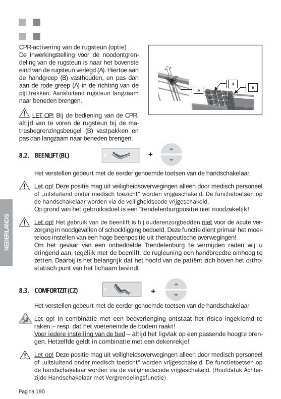
NED
ERLA
ND
S
Pagina 190
8.2. BEENLIFT (BL)
Het verstellen gebeurt met de eerder genoemde toetsen van de handschakelaar. Let op! Deze positie mag uit veiligheidsoverwegingen alleen door medisch personeel
Op grond van het gebruiksdoel is een Trendelenburgpositie niet noodzakelijk!
Let op! niet voor de acute ver-zorging in noodgevallen of schockligging bedoeld. Deze functie dient primair het moei-teloos instellen van een hoge beenpositie uit therapeutische overwegingen! Om het gevaar van een onbedoelde Trendelenburg te vermijden raden wij u dringend aan, tegelijk met de beenlift, de rugleuning een handbreedte omhoog te zetten. Daarbij is het belangrijk dat het hoofd van de patiënt zich boven het ortho-statisch punt van het lichaam bevindt.
8.3. COMFORTZIT (CZ)
Het verstellen gebeurt met de eerder genoemde toetsen van de handschakelaar.
Let op! In combinatie met een bedverlenging ontstaat het risico ingeklemd te raken – resp. dat het voeteneinde de bodem raakt!Voor iedere instelling van de bed – altijd het ligvlak op een passende hoogte bren-gen. Hetzelfde geldt in combinatie met een dekenrekje!
Let op! Deze positie mag uit veiligheidsoverwegingen alleen door medisch personeel
-
CPR-activering van de rugsteun (optie)De inwerkingstelling voor de noodontgren-deling van de rugsteun is naar het bovenste eind van de rugsteun verlegd (A). Hiertoe aan de handgreep (B) vasthouden, en pas dan aan de rode greep (A) in de richting van de
naar beneden brengen.
LET OP! Bij de bediening van de CPR, altijd van te voren de rugsteun bij de ma-trasbegrenzingsbeugel (B) vastpakken en pas dan langzaam naar beneden brengen.
BA
A
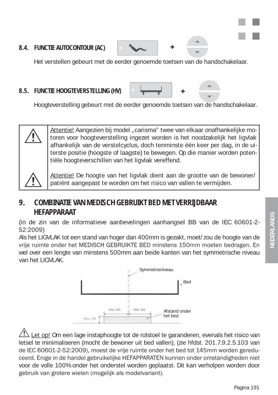
NED
ERLA
ND
S
Pagina 191
Attentie! Aangezien bij model „carisma” twee van elkaar onafhankelijke mo-toren voor hoogteverstelling ingezet worden is het noodzakelijk het ligvlak afhankelijk van de verstelcyclus, doch tenminste één keer per dag, in de ui-terste positie (hoogste of laagste) te bewegen. Op die manier worden poten-tiële hoogteverschillen van het ligvlak vereffend.
Attentie! De hoogte van het ligvlak dient aan de grootte van de bewoner/patiënt aangepast te worden om het risico van vallen te vermijden.
Let op! Om een lage instaphoogte tot de rolstoel te garanderen, evenals het risico van letsel te minimaliseren (mocht de bewoner uit bed vallen), (zie hfdst. 201.7.9.2.5.103 van
-
voor de volle 100% onder het onderstel worden geplaatst. Dit kan verholpen worden door
9. COMBINATIE VAN MEDISCH GEBRUIKT BED MET VERRIJDBAAR HEFAPPARAAT(in de zin van de informatieve aanbevelingen aanhangsel BB van de IEC 60601-2-52:2009)Als het LIGVLAK tot een stand van hoger dan 400mm is gezakt, moet/zou de hoogte van de
wel over een lengte van minstens 500mm aan beide kanten van het symmetrische niveau van het LIGVLAK.
Symmetrieebene
Bett
Unterfahrbar
Symmetrieniveau
Bed
Afstand onder het bed
8.4. FUNCTIE AUTOCONTOUR (AC)
Het verstellen gebeurt met de eerder genoemde toetsen van de handschakelaar.
8.5. FUNCTIE HOOGTEVERSTELLING (HV)
Hoogteverstelling gebeurt met de eerder genoemde toetsen van de handschakelaar.
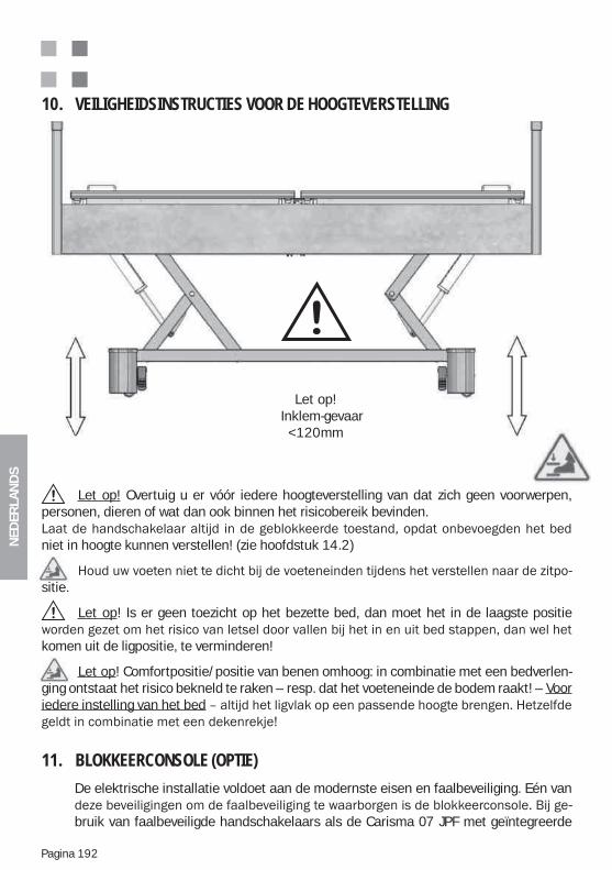
NED
ERLA
ND
S
Pagina 192
11. BLOKKEERCONSOLE (OPTIE)
De elektrische installatie voldoet aan de modernste eisen en faalbeveiliging. Eén van -
bruik van faalbeveiligde handschakelaars als de Carisma 07 JPF met geïntegreerde
10. VEILIGHEIDSINSTRUCTIES VOOR DE HOOGTEVERSTELLING
Let op! Overtuig u er vóór iedere hoogteverstelling van dat zich geen voorwerpen, personen, dieren of wat dan ook binnen het risicobereik bevinden.
niet in hoogte kunnen verstellen! (zie hoofdstuk 14.2)
-sitie.
Let op! Is er geen toezicht op het bezette bed, dan moet het in de laagste positie
komen uit de ligpositie, te verminderen!
Let op! Comfortpositie/positie van benen omhoog: in combinatie met een bedverlen-ging ontstaat het risico bekneld te raken – resp. dat het voeteneinde de bodem raakt! – Voor iedere instelling van het bed
Let op!Inklem-gevaar
<120mm
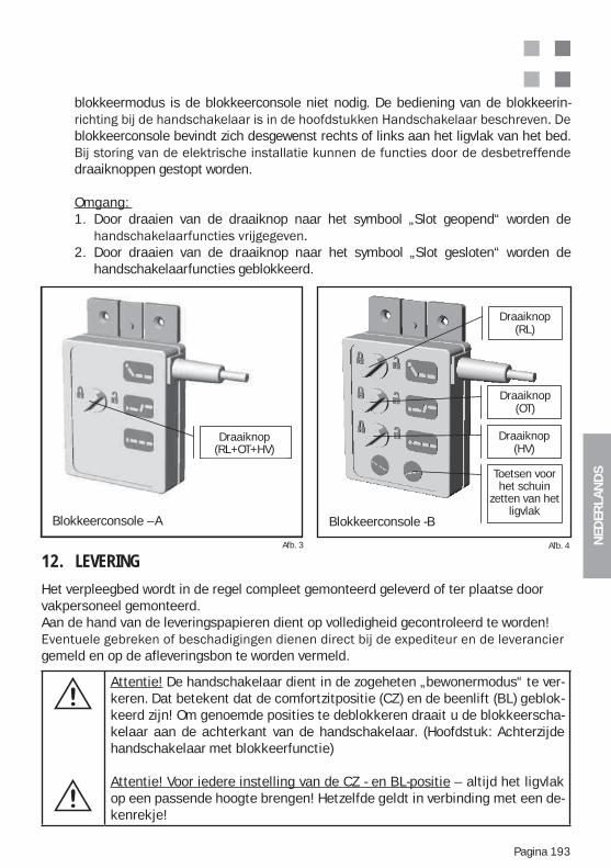
NED
ERLA
ND
S
Pagina 193
Attentie! De handschakelaar dient in de zogeheten „bewonermodus“ te ver-keren. Dat betekent dat de comfortzitpositie (CZ) en de beenlift (BL) geblok-keerd zijn! Om genoemde posities te deblokkeren draait u de blokkeerscha-kelaar aan de achterkant van de handschakelaar. (Hoofdstuk: Achterzijde handschakelaar met blokkeerfunctie)
Attentie! Voor iedere instelling van de CZ - en BL-positie – altijd het ligvlak op een passende hoogte brengen! Hetzelfde geldt in verbinding met een de-kenrekje!
Afb. 3 Afb. 4
Kontrollbox -A
rehs halter
Kontrollbox -B
Draaiknop(RL+OT+HV)
Draaiknop (RL)
Draaiknop(OT)
Draaiknop(HV)
Toetsen voor het schuin
zetten van het ligvlak
Blokkeerconsole -BBlokkeerconsole –A
12. LEVERING
Het verpleegbed wordt in de regel compleet gemonteerd geleverd of ter plaatse door vakpersoneel gemonteerd. Aan de hand van de leveringspapieren dient op volledigheid gecontroleerd te worden!
gemeld en op de afleveringsbon te worden vermeld.
blokkeermodus is de blokkeerconsole niet nodig. De bediening van de blokkeerin-
blokkeerconsole bevindt zich desgewenst rechts of links aan het ligvlak van het bed.
draaiknoppen gestopt worden.
Omgang: 1. Door draaien van de draaiknop naar het symbool „Slot geopend“ worden de
2. Door draaien van de draaiknop naar het symbool „Slot gesloten“ worden de handschakelaarfuncties geblokkeerd.
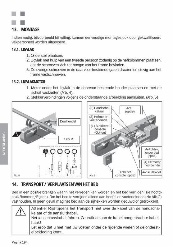
NED
ERLA
ND
S
Pagina 194
14. TRANSPORT / VERPLAATSEN VAN HET BED -
vasthouden. In geen geval mag het bed aan de zijhekken worden geduwd of getrokken!
Attentie! Rijd tijdens het transport niet over de kabel van de handscha-kelaar of de aansluitkabel.Netzanschlusskabel fahren. Gebruik de aan de kabel aangebrachte kabel-haak!Let erop dat u niet met uw voeten onder de rijdende wielen of de onderst-elbekleding komt.
13. MONTAGE
vakpersoneel worden uitgevoerd.
13.1. LIGVLAK 1. Onderstel plaatsen. 2. Ligvlak met hulp van een tweede persoon zodanig op de hefkolommen plaatsen, dat de schroeven zich ter hoogte van het frame bevinden. 3. De overige schroeven in de daarvoor bestemde gaten draaien en stevig aan het frame vastschroeven.
13.2. LIGVLAKMOTOR 1. Motor onder het ligvlak in de daarvoor bestemde houder plaatsen en met de schuif vastzetten (Afb. 4). 2. Stekkerverbindingen volgens de onderstaande afbeelding aansluiten. (Afb. 5)
Abb. 5
Schieber
Druckhebel
(1) Kontroll-box (Option)
Kontrollbox (Option)
(2) Hubmotor Fuß
(3) Hand-schalter
(5) Unterbett- Beleuchtung
(Option)
Akku (Option)
(4) Hubmotor Kopf
Netzkabel
Duwhendel
Schuif
(3) Handscha-kelaar
(2) Hefmotor voeteneinde
Accu (optie)
Blokkeer- console (optie)
Verlichting onder bed
(optie)
(4) Hefmotor hoofdeinde
AansluitkabelAfb. 5 Afb. 6
(1) Blokkeer-console (Option)
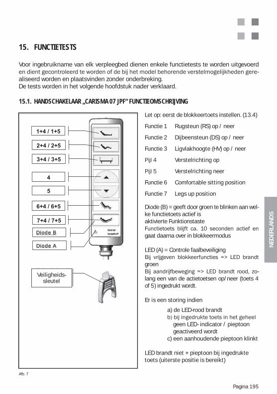
NED
ERLA
ND
S
Pagina 195
15. FUNCTIETESTS
Voor ingebruikname van elk verpleegbed dienen enkele functietests te worden uitgevoerd -
aliseerd worden en plaatsvinden zonder onderbreking.De tests worden in het volgende hoofdstuk nader verklaard.
15.1. HANDSCHAKELAAR „CARISMA 07 JPF“ FUNCTIEOMSCHRIJVING
Let op: eerst de blokkeertoets instellen. (13.4)
Functie 1 Rugsteun (RS) op / neer
Functie 2 Dijbeensteun (DS) op / neer
Functie 3 Ligvlakhoogte (HV) op / neer
Verstelrichting op
Verstelrichting neer
Functie 6 Comfortable sitting position
Functie 7 Legs up position
Diode (B) = geeft door groen te blinken aan wel-ke functietoets actief isaktivierte Funktionstaste
gaat daarna over in blokkeermodus LED (A) = Controle faalbeveiliging
groen-
lang een van de actietoetsen op/neer (toets 4 of 5) ingedrukt wordt.
Er is een storing indien
a) de LED-rood brandt
geen LED- indicator / pieptoon geactiveerd wordt c) een aanhoudende pieptoon klinkt
LED brandt niet + pieptoon bij ingedrukte toets (uiterste positie is bereikt)
Afb. 7
Diode A
Diode B
Sicher-heitsschlüs
l
Sicherheits- schlüsselVeiligheids-
sleutel
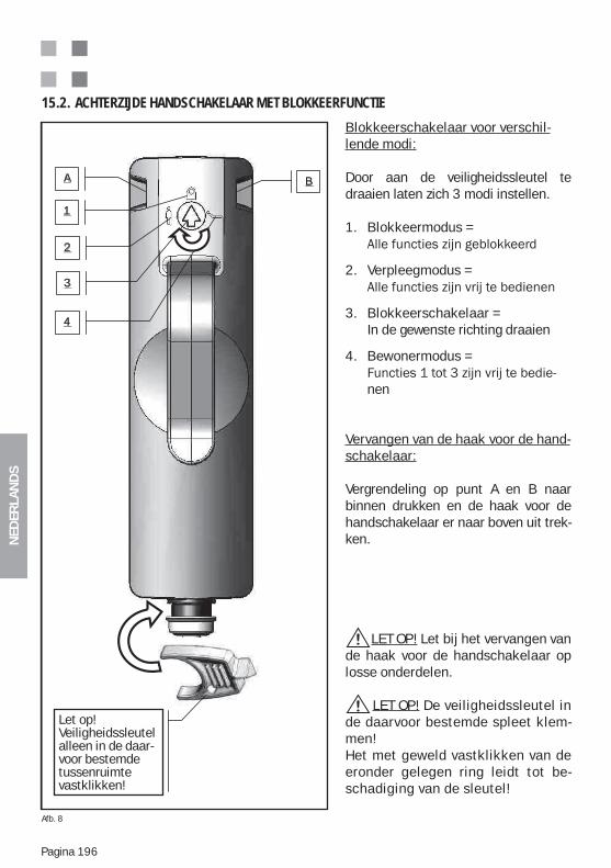
NED
ERLA
ND
S
Pagina 196
1
2
3
A B
4
Achtung! Si -cherheitsschlüssel - nur in dem dafür vor-gesehenen S lt i l i
Blokkeerschakelaar voor verschil-lende modi:
Door aan de veiligheidssleutel te draaien laten zich 3 modi instellen.
1. Blokkeermodus =
2. Verpleegmodus =
3. Blokkeerschakelaar = In de gewenste richting draaien
4. Bewonermodus =
nen
Vervangen van de haak voor de hand- schakelaar:
Vergrendeling op punt A en B naar binnen drukken en de haak voor de handschakelaar er naar boven uit trek-ken.
LET OP! Let bij het vervangen van de haak voor de handschakelaar op losse onderdelen.
LET OP! De veiligheidssleutel in de daarvoor bestemde spleet klem-men!Het met geweld vastklikken van de eronder gelegen ring leidt tot be-schadiging van de sleutel!
15.2. ACHTERZIJDE HANDSCHAKELAAR MET BLOKKEERFUNCTIE
Achtung! Sicher- heitsschlüssel - nur in dem dafür vorgesehenen Spalt einclipsen!
Afb. 8
Let op! Veiligheidssleutelalleen in de daar- voor bestemdetussenruimtevastklikken!
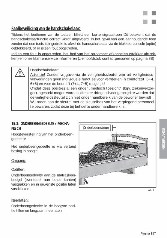
NED
ERLA
ND
S
Pagina 197
Faalbeveiliging van de handschakelaar: korte signaaltoon Dit betekent dat de
handschakelaarfunctie correct wordt uitgevoerd. In het geval van een aanhoudende toon zonder dat een toets is ingedrukt is ofwel de handschakelaar via de blokkeerconsole (optie) geblokkeerd, of er is een fout opgetreden.
Indien een fout is opgetreden, het bed van het stroomnet afkoppelen (stekker uittrek-ken) en onze klantenservice informeren (zie hoofdstuk contactpersonen op pagina 38)
Handschakelaar:Attentie! Zonder vrijgave via de veiligheidssleutel zijn uit veiligheidso-verwegingen geen individuele functies voor verstellen in comfortzit (6+4, 6+5) en voor de beenlift (7+4, 7+5) mogelijk!Omdat deze posities alleen onder „medisch toezicht“ (bijv. ziekenverzor-ger) ingesteld mogen worden, dient er dringend voor gezorgd te worden dat de veiligheidssleutel zich niet onder handbereik van de bewoner bevindt. Wij raden aan de sleutel met de sleutelbos van het verplegend personeel te bewaren, zodat deze bij behoefte onder handbereik is.
15.3. ONDERBEENGEDEELTE / MECHA-NISCHHoogteverstelling van het onderbeen-gedeelte
Het onderbeengedeelte is via vertand beslag in hoogte.
Omgang:
Optillen:
Onderbeengedeelte aan de matraskeer-beugel (eventueel aan beide kanten) vastpakken en in gewenste positie laten vastklikken.
Neerlaten:
Onderbeengedeelte in de hoogste posi-tie tillen en langzaam neerlaten.
Afb. 9
Onderbeensteun
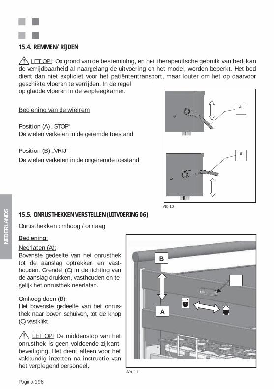
NED
ERLA
ND
S
Pagina 198
15.4. REMMEN/ RIJDEN
LET OP!: Op grond van de bestemming, en het therapeutische gebruik van bed, kan de verrijdbaarheid al naargelang de uitvoering en het model, worden beperkt. Het bed dient dan niet expliciet voor het patiëntentransport, maar louter om het op daarvoor geschikte vloeren te verrijden. In de regel op gladde vloeren in de verpleegkamer.
Bediening van de wielrem
Position (A) „STOP“De wielen verkeren in de geremde toestand
Position (B) „VRIJ“
De wielen verkeren in de ongeremde toestand
Afb 10
n
-
A
B
Onrusthekken omhoog /omlaag
Bediening:
Neerlaten (A):Bovenste gedeelte van het onrusthek tot de aanslag optrekken en vast-houden. Grendel (C) in de richting van de aanslag drukken, vasthouden en te-
Omhoog doen (B):Het bovenste gedeelte van het onrus-thek naar boven schuiven, tot de knop (C) vastklikt.
LET OP! De middenstop van het onrusthek is geen voldoende zijkant-beveiliging. Het dient alleen voor het vakkundig inzetten na instructie van het verplegend personeel.
15.5. ONRUSTHEKKEN VERSTELLEN (UITVOERING 06)
Afb. 11
B
A
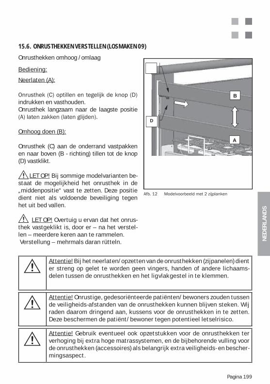
NED
ERLA
ND
S
Pagina 199
Onrusthekken omhoog /omlaag
Bediening:
Neerlaten (A):
indrukken en vasthouden.Onrusthek langzaam naar de laagste positie
Omhoog doen (B):
Onrusthek (C) aan de onderrand vastpakken en naar boven (B - richting) tillen tot de knop (D) vastklikt.
LET OP! Bij sommige modelvarianten be-staat de mogelijkheid het onrusthek in de „middenpositie“ vast te zetten. Deze positie dient niet als voldoende beveiliging tegen het uit bed vallen.
LET OP! Overtuig u ervan dat het onrus-thek vastgeklikt is, door er – na het verstel-len – meerdere keren aan te rammelen. Verstellung – mehrmals daran rütteln.
15.6. ONRUSTHEKKEN VERSTELLEN (LOSMAKEN 09)
B
A
D
Attentie! Bij het neerlaten/opzetten van de onrusthekken (zijpanelen) dient er streng op gelet te worden geen vingers, handen of andere lichaams-delen tussen de onrusthekken en het ligvlakgestel in te klemmen.
Attentie! Onrustige, gedesoriënteerde patiënten/bewoners zouden tussen de veiligheids-afstanden van de onrusthekken kunnen blijven steken. Wij raden daarom dringend aan, kussens voor de onrusthekken in te zetten. Deze beschermen de patiënt/bewoner tegen potentieel letselrisico.
Attentie! Gebruik eventueel ook opzetstukken voor de onrusthekken ter verhoging bij extra hoge matrassystemen, en de bijbehorende vulling voor de onrusthekken (accessoires) als belangrijk extra veiligheids- en bescher-mingsaspect.
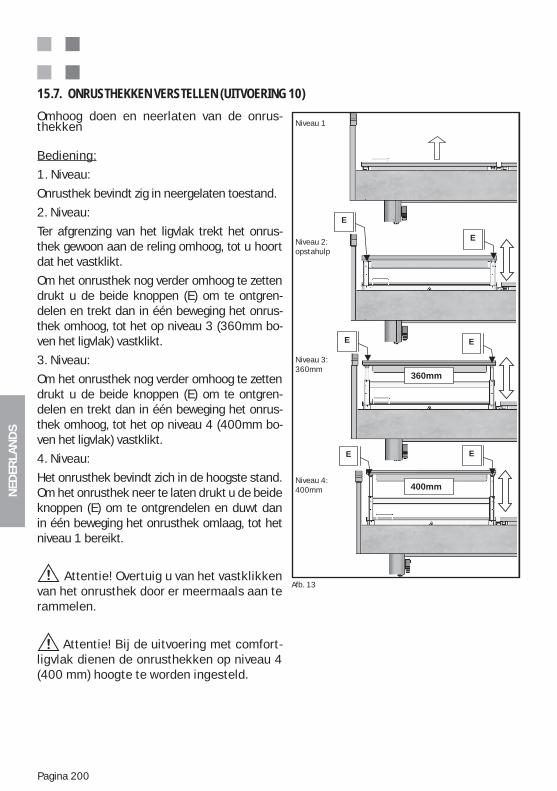
NED
ERLA
ND
S
Pagina 200
Omhoog doen en neerlaten van de onrus-thekken
Bediening:
1. Niveau:
Onrusthek bevindt zig in neergelaten toestand.
2. Niveau:
Ter afgrenzing van het ligvlak trekt het onrus-thek gewoon aan de reling omhoog, tot u hoort dat het vastklikt.
Om het onrusthek nog verder omhoog te zetten drukt u de beide knoppen (E) om te ontgren-delen en trekt dan in één beweging het onrus-thek omhoog, tot het op niveau 3 (360mm bo-ven het ligvlak) vastklikt.
3. Niveau:
Om het onrusthek nog verder omhoog te zetten drukt u de beide knoppen (E) om te ontgren-delen en trekt dan in één beweging het onrus-thek omhoog, tot het op niveau 4 (400mm bo-ven het ligvlak) vastklikt.
4. Niveau:
Het onrusthek bevindt zich in de hoogste stand. Om het onrusthek neer te laten drukt u de beide knoppen (E) om te ontgrendelen en duwt dan in één beweging het onrusthek omlaag, tot het niveau 1 bereikt.
Attentie! Overtuig u van het vastklikken van het onrusthek door er meermaals aan te rammelen.
Attentie! Bij de uitvoering met comfort-ligvlak dienen de onrusthekken op niveau 4 (400 mm) hoogte te worden ingesteld.
15.7. ONRUSTHEKKEN VERSTELLEN (UITVOERING 10)
Abb. 16
360mm
400mm
1. Stufe
2. Stufe:
Aufstehhil-
fe
3. Stufe:
360mm
4. Stufe:
400mm
E
E E
E
E
E
Afb. 13
Niveau 1
Niveau 2: opstahulp
Niveau 3: 360mm
Niveau 4: 400mm
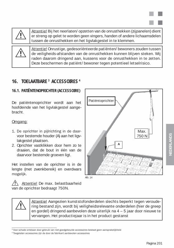
NED
ERLA
ND
S
Pagina 201
Attentie! Onrustige, gedesoriënteerde patiënten/bewoners zouden tussen de veiligheids-afstanden van de onrusthekken kunnen blijven steken. Wij raden daarom dringend aan, kussens voor de onrusthekken in te zetten. Deze beschermen de patiënt/bewoner tegen potentieel letselrisico.
Attentie! Bij het neerlaten/opzetten van de onrusthekken (zijpanelen) dient er streng op gelet te worden geen vingers, handen of andere lichaamsdelen tussen de onrusthekken en het ligvlakgestel in te klemmen.
16. TOELAATBARE 3 ACCESSOIRES 4
16.1. PATIËNTENOPRICHTER (ACCESSOIRE)
De patiëntenoprichter wordt aan het hoofdeinde van het ligvlakgestel aange-bracht.
Omgang:
voor bestemde houder (A) aan het ligv- lakgestel plaatsen.2. Oprichter vastklikken door hem zo te draaien, dat de bout in één van de daarvoor bestemde groeven ligt.
Het instellen van de oprichter is in de lengte (met zwenkbereik) en overdwars
Attentie! De max. belastbaarheid van de oprichter bedraagt 750N.
Attentie! Aangezien kunststofonderdelen slechts beperkt tegen veroude-ring bestand zijn, wordt bij veiligheidsrelevante onderdelen (hier de greep en gordel) dringend aanbevolen deze uiterlijk na 4 – 5 jaar door nieuwe te vervangen. Het productiejaar is in het product gestanst
____________________________________3
4
Afb. 14
Aufrichter
A
Max.
750N
Max.750 N
Patiëntoprichter
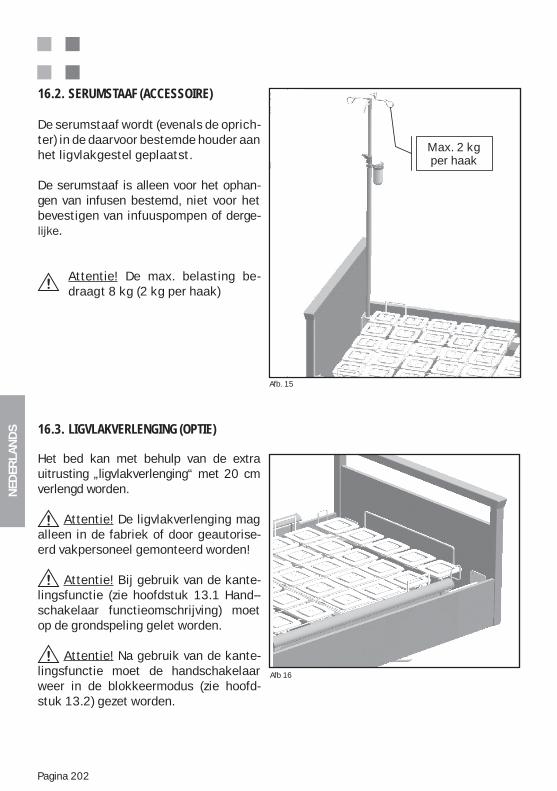
NED
ERLA
ND
S
Pagina 202
De serumstaaf wordt (evenals de oprich-ter) in de daarvoor bestemde houder aan het ligvlakgestel geplaatst. De serumstaaf is alleen voor het ophan-gen van infusen bestemd, niet voor het bevestigen van infuuspompen of derge-
Attentie! De max. belasting be- draagt 8 kg (2 kg per haak)
16.2. SERUMSTAAF (ACCESSOIRE)
Het bed kan met behulp van de extra uitrusting „ligvlakverlenging“ met 20 cm verlengd worden.
Attentie! De ligvlakverlenging mag alleen in de fabriek of door geautorise-erd vakpersoneel gemonteerd worden!
Attentie! Bij gebruik van de kante-lingsfunctie (zie hoofdstuk 13.1 Hand-- schakelaar functieomschrijving) moet op de grondspeling gelet worden.
Attentie! Na gebruik van de kante-lingsfunctie moet de handschakelaar weer in de blokkeermodus (zie hoofd-stuk 13.2) gezet worden.
16.3. LIGVLAKVERLENGING (OPTIE)
Afb. 15
Afb 16
dieah-
In-usi-
kg
Max. 2 kg per haak
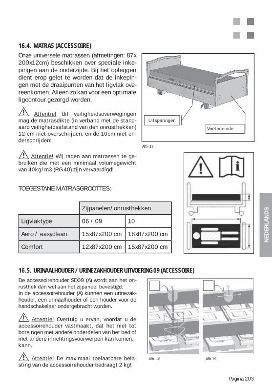
NED
ERLA
ND
S
Pagina 203
Onze universele matrassen (afmetingen: 87x 200x12cm) beschikken over speciale inke-pingen aan de onderzijde. Bij het opleggen dient erop gelet te worden dat de inkepin-gen met de draaipunten van het ligvlak ove-reenkomen. Alleen zo kan voor een optimale ligcontour gezorgd worden.
Attentie! Uit veiligheidsoverwegingen mag de matrasdikte (in verband met de stand-aard veiligheidsafstand van den onrusthekken) 12 cm niet overschrijden, en de 10cm niet on-derschrijden!
Attentie! Wij raden aan matrassen te ge-bruiken die met een minimaal volumegewicht van 40kg/m3 (RG 40) zijn vervaardigd!
16.4. MATRAS (ACCESSOIRE)
Afb. 17
Bett-Fußteil
EinschnitteUitsparingen
Voeteneinde
De accessoirehouder SD09 (A) wordt aan het on-
In de accessoirehouder (A) kunnen een urinezak-houder, een urinaalhouder of een houder voor de handschakelaar ondergebracht worden.
Attentie! Overtuig u ervan, voordat u de accessoirehouder vastmaakt, dat het niet tot botsingen met andere onderdelen van het bed of met andere inrichtingsvoorwerpen kan komen. kann.
Attentie! De maximaal toelaatbare bela-sting van de accessoirehouder bedraagt 2 kg!
16.5. URINAALHOUDER / URINEZAKHOUDER UITVOERING 09 (ACCESSOIRE)
Afb. 18 Afb 19
TOEGESTANE MATRASGROOTTES:
Zijpanelen/onrusthekken
Ligvlaktype 06 / 09 10
Aero / easyclean 15x87x200 cm 18x87x200 cm
Comfort 12x87x200 cm 15x87x200 cm
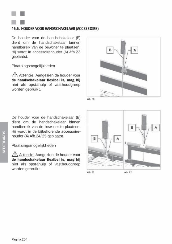
NED
ERLA
ND
S
Pagina 204
De houder voor de handschakelaar (B) dient om de handschakelaar binnen handbereik van de bewoner te plaatsen.
geplaatst.
Plaatsingsmogelijkheden
Attentie! Aangezien de houder voor
niet als opstahulp of vasthoudgreep worden gebruikt.
De houder voor de handschakelaar (B) dient om de handschakelaar binnen handbereik van de bewoner te plaatsen.
-houder (A) Afb.24/25 geplaatst.
Plaatsingsmogelijkheden
Attentie! Aangezien de houder voor
niet als opstahulp of vasthoudgreep worden gebruikt.
16.6. HOUDER VOOR HANDSCHAKELAAR (ACCESSOIRE)
Afb. 20
Afb. 21 Afb. 22
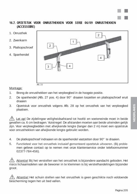
NED
ERLA
ND
S
Pagina 205
1. Onrusthek
2. Zwenkarm
3. Platkopschroef
4. Spanhendel
16.7. OPZETSTUK VOOR ONRUSTHEKKEN VOOR SERIE 06/09 ONRUSTHEKKEN (ACCESSOIRE)
Afb. 23
Montage:
1. Breng de onrusthekken van het verpleegbed in de hoogste positie.
2. De spanhendel (Afb. 27 pos. 4) door 90° draaien loszetten en platkopschroef eruit draaien
3. Opzetstuk voor onrusthek volgens Afb. 28 op het onrusthek van het verpleegbed plaatsen.
Let op! De zijdelingse veiligheidsafstand tot hoofd- en voeteneinde moet in beide gevallen ca. 6 cm bedragen. Vuistregel: De afstanden moeten aan beide uiteinden gelijk zijn. Voor verpleegbedden met afwijkende lengte (langer dan 2 m) moet een opzetstuk voor onrusthekken van afwijkende lengte gebruikt worden.
4. De platkopschroef indraaien en de spanhendel vastzetten door 90° te draaien.
men gelieve contact op te nemen met onze klantenservice onder telefoonnummer 02377-784-456).
Attentie! Bij het verstellen van het onrusthek is bijzondere aandacht geboden. Het risico lichaamsdelen van de bewoner in te klemmen is bij verstelhandelingen bijzonder groot.
Attentie! Het schuin stellen van het onrusthek is geen geschikte noch voldoende bescherming tegen het uit bed vallen.
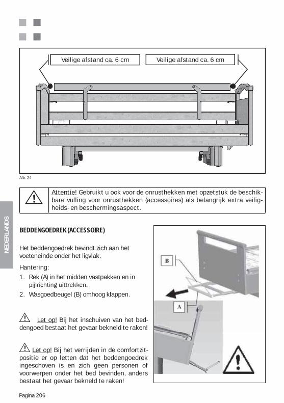
NED
ERLA
ND
S
Pagina 206
Veilige afstand ca. 6 cm Veilige afstand ca. 6 cm
Attentie! Gebruikt u ook voor de onrusthekken met opzetstuk de beschik-bare vulling voor onrusthekken (accessoires) als belangrijk extra veilig-heids- en beschermingsaspect.
Afb. 24
BEDDENGOEDREK (ACCESSOIRE)
Het beddengoedrek bevindt zich aan het voeteneinde onder het ligvlak.
Hantering:
1. Rek (A) in het midden vastpakken en in
2. Wasgoedbeugel (B) omhoog klappen.
Let op! Bij het inschuiven van het bed-dengoed bestaat het gevaar bekneld te raken!
Let op! Bij het verrijden in de comfortzit-positie er op letten dat het beddengoedrek ingeschoven is en zich geen personen of voorwerpen onder het bed bevinden, anders bestaat het gevaar bekneld te raken!
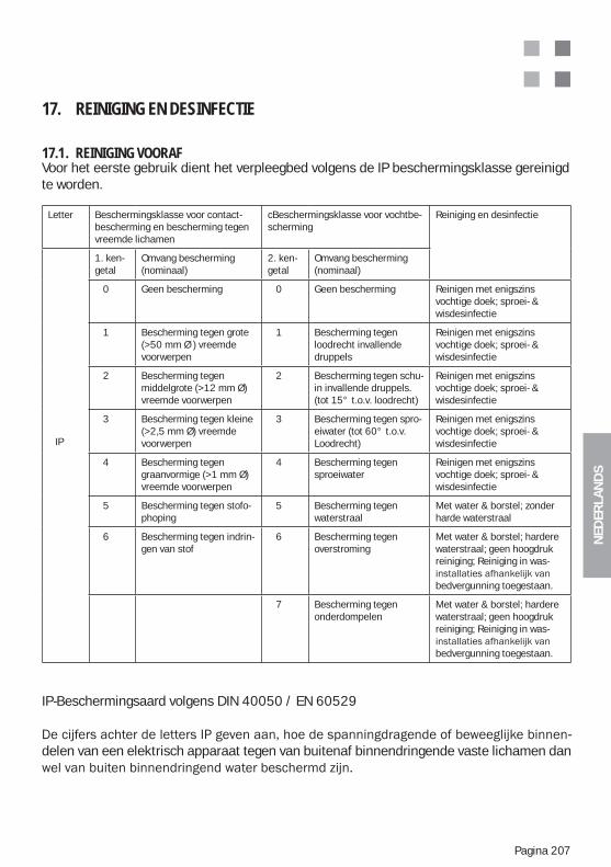
NED
ERLA
ND
S
Pagina 207
17. REINIGING EN DESINFECTIE
17.1. REINIGING VOORAFVoor het eerste gebruik dient het verpleegbed volgens de IP beschermingsklasse gereinigd te worden.
IP-Beschermingsaard volgens DIN 40050 / EN 60529
-delen van een elektrisch apparaat tegen van buitenaf binnendringende vaste lichamen dan
Letter Beschermingsklasse voor contact-bescherming en bescherming tegen vreemde lichamen
cBeschermingsklasse voor vochtbe-scherming
Reiniging en desinfectie
IP
1. ken-getal
Omvang bescherming (nominaal)
2. ken-getal
Omvang bescherming (nominaal)
0 Geen bescherming 0 Geen bescherming Reinigen met enigszins vochtige doek; sproei- & wisdesinfectie
1 Bescherming tegen grote (>50 mm Ø ) vreemde voorwerpen
1 Bescherming tegen loodrecht invallende druppels
Reinigen met enigszins vochtige doek; sproei- & wisdesinfectie
2 Bescherming tegen middelgrote (>12 mm Ø) vreemde voorwerpen
2 Bescherming tegen schu-in invallende druppels. (tot 15° t.o.v. loodrecht)
Reinigen met enigszins vochtige doek; sproei- & wisdesinfectie
3 Bescherming tegen kleine (>2,5 mm Ø) vreemde voorwerpen
3 Bescherming tegen spro-eiwater (tot 60° t.o.v. Loodrecht)
Reinigen met enigszins vochtige doek; sproei- & wisdesinfectie
4 Bescherming tegen graanvormige (>1 mm Ø) vreemde voorwerpen
4 Bescherming tegen sproeiwater
Reinigen met enigszins vochtige doek; sproei- & wisdesinfectie
5 Bescherming tegen stofo-phoping
5 Bescherming tegen waterstraal
Met water & borstel; zonder harde waterstraal
6 Bescherming tegen indrin-gen van stof
6 Bescherming tegen overstroming
Met water & borstel; hardere waterstraal; geen hoogdruk reiniging; Reiniging in was-
bedvergunning toegestaan.
7 Bescherming tegen onderdompelen
Met water & borstel; hardere waterstraal; geen hoogdruk reiniging; Reiniging in was-
bedvergunning toegestaan.
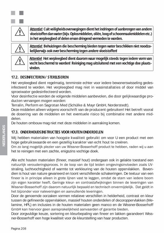
NED
ERLA
ND
S
Pagina 208
Attentie! Cuit veiligheidsoverwegingen dient het indringen of aanbrengen van andere vloeistoffen dan water (bijv. Oplosmiddelen, oliën, loog of schoonmaakmiddelen etc.) in het verpleegbed of delen ervan dringend vermeden te worden.
Attentie! Behuizingen die bescherming bieden tegen water beschikken niet noodza-kelijkerwijs ook over bescherming tegen andere vloeistoffen!
Attentie! Het verpleegbed dient daarom waar mogelijk steeds tegen iedere vorm van vocht beschermd te worden! Reiniging mag uitsluitend met een vochtige doe plaats-vinden.
17.2. DESINFECTEREN / STERILISERENHet verpleegbed dient regelmatig, tenminste echter voor iedere bewonerswisseling gedes-infecteerd te worden. Het verpleegbed mag niet in wasinstallaties of door middel van sproeiwater gedesinfecteerd worden.Voor desinfectie worden de volgende middelen aanbevolen, die door gelijkwaardige pro-ducten vervangen mogen worden:Terralin, Perform en Sagrotan Med (Schülke & Mayr GmbH, Norderstedt).Deze middelen alleen volgens voorschrift van de producent gebruiken! Het betreft vooral de dosering van de middelen en het eventuele risico bij combinatie met andere mid-delen.De houten ombouw mag niet met deze middelen in aanraking komen.
17.3. ONDERHOUDSINSTRUCTIES VOOR HOUTEN ONDERDELEN Wij hebben materialen van hoogste kwaliteit gebruikt om voor U een product met een hoge gebruikswaarde en een gezellig karakter van echt hout te creëren.
het te reinigen met een zachte, enigszins vochtige doek.
Alle echt houten materialen (fineer, massief hout) ondergaan ook in gelakte toestand een
straling, luchtvochtigheid of warmte tot verkleuring van de houten oppervlakken. Boven-dien is hout van nature gevarieerd en toont verschillende schakeringen. De textuur van een
Door de genoemde oorzaken vormen relatieve verschillen in helderheid, contrast en kleur tussen de gefineerde oppervlakken, massief houten onderdelen of decoroppervlakken (Me-lamine, HPL) en inclusies in de houten materialen geen manco en de Wissner-Bosserhoff
Door zorgvuldige keuze, sortering en kleurbepaling van fineer en lakken garandeert Wiss-ner-Bosserhoff een hoge kwaliteit voor de kleurstelling van haar producten.
NED
ERLA
ND
S
Pagina 209
17.4. GEBRUIK VAN REINIGINGSMIDDELEN-
Bosserhoff producten voldoen aan de eisen van de DIN 68861 – 1A norm voor meubelop-
Er mogen echter geen schoonmaak- of reinigingsmiddelen worden gebruikt die mechanisch abrasieve bestanddelen hebben en als schuurmiddel werken.
-
leiden.
vermeden worden.Na reiniging wordt aangeraden de houten en fineeroppervlakken met een droge doek af te
17.5. GEBRUIK VAN DESINFECTEERMIDDELENAlleen desinfecteermiddelen die overeenkomen met de in appendix 1 van DIN 68861 deel 1 beschreven desinfecteermiddelen: a) Fenolderivaten, 0,5-% waterige oplossing: gechloreerde Alkyl-,Cycloalkyl- Aryl-Fenol b) Chloramine T, 2,5-% waterige oplossing: p-Toluolsulfonchloramide-Natrium
17.6. BESCHADIGINGEN AAN HOUTEN ONDERDELEN-
worden om het tegen indringen van vocht te beschermen. Neem contact op met de Wissner-Bosserhoff –
17.7. MILIEUZORGAlle gebruikte houten materialen voldoen aan de strenge Duitse wetgeving en voorschriften
van ons handelen.
17.8. KWALITEITOnze producten worden aan een streng systeem van kwaliteitszorg onderworpen volgens de internationale normen DIN EN ISO 9001:2000 en DIN EN ISO 13485:2003 voor de productie en verkoop van medische producten.
-
Mocht u redenen hebben tot reclamatie of kritiek, wendt u zich dan tot onze klantenservice.
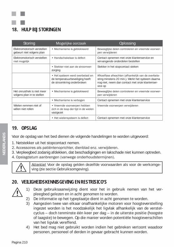
NED
ERLA
ND
S
Pagina 210
18. HULP BIJ STORINGEN
Storing OplossingElektromotorisch verstellen gebeurt niet volgens plan
-
Elektromotorisch verstellen Contact opnemen met onze klantenservice en vervangende onderdelen bestellen
-zorging
Stekker in het stopcontact steken
de temperatuurbeveiliging heeft de stroomkring onderbroken
-sting minstens 20 min.). Werkt het systeem daarna nog niet, neem dan contact met onze klantenser-vice op
Het onrusthek is niet meer volgens plan in te stellen
-
Contact opnemen met onze klantenservice
Wielen remmen niet of willen niet rollen
vastgezet
Contact opnemen met onze klantenservice
Attentie! Voor de opslag gelden dezelfde voorwaarden als voor de werkomge-ving (zie sectie Gebruiksomgeving).
20. VEILIGHEIDSKENNISGEVING EN RESTRISICO‘S1) Deze gebruiksaanwijzing dient voor het in gebruik nemen van het ver- pleegbed gelezen en in acht genomen te worden.2) De informatie op het typeplaatje dient in acht genomen te worden.3) Aangezien twee van elkaar onafhankelijke motoren voor hoogteverstelling ingezet worden is het noodzakelijk het ligvlak afhankelijk van de verstel- cyclus – doch tenminste één keer per dag – in de uiterste positie (hoogste of laagste) te bewegen. Op die manier worden potentiële hoogteverschillen van het ligvlak vereffend.4) Het bed mag niet gebruikt worden indien het gebreken vertoont waadoor personen, personeel of derden in gevaar gebracht kunnen worden.
19. OPSLAG
Voor de opslag van het bed dienen de volgende handelingen te worden uitgevoerd:
1. Netstekker uit het stopcontact nemen.
3. Verpleegbed zodanig afdekken, dat beschadigingen en lakschade niet kunnen optreden.
NED
ERLA
ND
S
Pagina 211
5) Het bed mag uitsluitend door personen gebruikt worden, die op grond van opleiding of kennis en praktische ervaring voor vakkundige bediening borg staan.6) De gebruiker dient zich voor gebruik van het bed van de betrouwbaarheid en ordelijke toestand van het bed te overtuigen.7) Het bed moet eventueel dagelijks of bij iedere ploegenwisseling opnieuw aan een functietest worden onderworpen mot ervoor te zorgen dat het bed zonder gevaar voor de patiënt en gebruiker volgens voorschrift gebruikt kan worden.8) Vervormde patiëntenoprichters niet rechtbuigen en weer gebruiken, maar vervangen.9) Het bed mag uitsluitend op vlakke bodem en op vaste vloerbedekking verre- den worden.10) Zolang het bed bezet is dienen de wielen zich in geremde toestand te be- vinden – anders bestaat het gevaar dat de patiënt valt bij het in- of uitstap- pen, omdat hij eventueel op het bed leunt–.11) De hoogte van het ligvlak dient aan de grootte van de patiënt aangepast te worden om het risico van vallen te vermijden. 12) Bij bediening van het mechanische neerlaat-mechanisme van de rugsteun (optie) moet deze steeds aan de matraskeerbeugel of de steunbeugel wor- den vastgehouden om plotseling neerklappen te verhinderen. 13) Tijdens het verstellen van het bed in de verschillende posities dient erop gelet te worden dat zich geen kleine kinderen, lichaamsdelen of andere voorwerpen in het verstelbereik bevinden.14) Het verstellen van de onrusthekken (zijpanelen) mag uitsluitend door het verplegend personeel worden uitgevoerd. Het verplegend personeel dient zich bij het verstellen van de ligvlakposities ervan te overtuigen dat de pa- tiënt niet met de onrusthekken in aanraking komt, om het bekneld raken van hand, been of andere lichaamsdelen te vermijden.15) Extreem naar buiten leunen van het bovenlichaam dient vermeden te wor- den.16) Onrusthekken in verticale richting met niet meer dan 75 kg, in horizontale richting met niet meer dan 50 kg belasten.17) Afhankelijk van lichamelijke en geestelijke toestand van de patiënt dienen de functies van de handschakelaar door middel van de blokkeerconsole geblokkeerd dan wel vrijgegeven te zijn. Het functioneren van de blokkeer- functie dient aan de handschakelaar getest te worden. 18) Omdat het systeem ook met accu’s gevoed kan worden is het niet voldo- ende bij storing van de motoren het netstekker uit het stopcontact te trek- ken. Mocht een storing optreden, blokkeer de functie dan via de blokkeer- console en neem contact op met onze klantenservice (optie Accuvoeding).19) Bij het verstellen via de handschakelaar wordt aangeraden in de buurt van de blokkeerconsole te blijven om bij eventuele storingen direct uit te kun- nen schakelen.
NED
ERLA
ND
S
Pagina 212
20) Attentie! Alle elektrische functies kunnen gebreken vertonen. tenzij u ze via de blokkeerconsole blokkeert. 21) Als stroomvoorziening dient een volgens VDE richtlijnen ingerichte netstroomcontactdoos 220 / 230 Volt, 50 Hz gebruikt te worden.22) De stekker niet met natte handen aanraken. Netaansluitkabel alleen aan de stekker aanraken en uit de contactdoos trekken.23) Netaansluitkabel zonder lussen uitleggen, niet knikken of om scherpe ho- eken buigen.24) Aansluit- en voedingskabel steeds tegen mechanische belasting bescher- men.25) Netaansluitkabel en voeding voor de handschakelaar zodanig uitleggen dat deze niet kunnen worden ingeklemd en geen voorwerpen op aansluit- kabel of voedingskabel plaatsen.26) Bij het opstellen van het bed in de daarvoor bestemde ruimte dienen veilig heidsafstanden tot wanden, vensterbanken of andere inrichtingsvoorwer- pen aangehouden te worden. De veiligheidsafstanden kunnen uit de uit- voering en het model van het bed afgeleid worden door bij uiterste hoogte- verstellingen en kantelbewegingen tenminste 25 mm speelruimte voor vingers te bewaren.27) Indien lighoudings- en hoogteverstelfuncties uitgevoerd worden dient erop gelet te worden dat de veiligheidssleutel niet ingestoken is of zich in de buurt van de handschakelaar (handbereik van de patiënt/bewoner) bevindt. Door onvakkundig vrijgeven via de veiligheidssleutel kunnen voor de patiënt/bewoner riskante posities worden ingenomen, zoals een ver- keerd gebruikte Trendelenburg-positie.28) De handschakelaar in de daarvoor bestemde houder (optie’ of aan het bed zodanig ophangen, dat de toetsen niet per ongeluk tussen twee voorwer- pen ingedrukt kunnen worden, bijv. Tussen onrusthek en nachtkastje.29) Het bed uitsluitend met een vochtige doek reinigen.
NED
ERLA
ND
S
Pagina 213
30) Bij ondeskundig gebruik van het bed kunnen risico’s ontstaan door:
oneren van het bed,
Gebruik van het bed door kinderen jonger dan twaalf jaar
geïnstrueerd,
Aansluiten van niet daarvoor bestemde elektrische apparaten aan het bed, Bewegen van het bed door trekken aan de netaansluitkabel of aan de onrus-
thekken, Trekken aan de netaansluitkabel om de netstekker uit het stopcontact te trek-
ken, Gebrekkige bescherming van de aansluit- en voedingskabels tegen scherpe
kabel),
Bewegen van het bed op onverharde ondergrond, Gebruik van het bed op hellende ondergrond met een hellingshoek van 10° of
meer, Apparaten die een sterk elektromagnetisch veld veroorzaken en eventueel inv-
contact getrokken worden.
Uit veiligheidsoverwegingen dient de greep van de patiëntenoprichter (triangel) samen met de band geheel uitgewisseld te worden.
De te gebruiken matras moet aan de geldende veiligheidsvoorschriften voldo-
Ondeskundig uitgevoerde reparaties aan de elektrische installatie
31) Veiligheidskennisgeving – maatregelen voor een veilig gebruik van zie-ken- en verpleegbedden:
Elektrische componenten van zieken- en verpleegbedden mogen uitsluitend door de fabrikant of door de fabrikant geschoold vakpersoneel gerepareerd en hersteld worden. Anders bestaat het gevaar dat speciale handelingen, door gebrek aan kennis van de productfunctionaliteit, niet doelmatig worden uitge- voerd en tot een verhoogd risico van een elektrische schok of brand leiden.
Elektrische componenten zieken- en verpleegbedden mogen uitsluitend door
doelmatige componenten het risico van een elektrische schok of brand sterk verhoogd wordt.
NED
ERLA
ND
S
Pagina 214
Een veilige plek voor het bedienen van het bed met de hand moet aangegeven worden, opdat spelen met de handbediening voorkomen kan worden.
Reiniging van het bed mag uitsluitend plaatsvinden volgens de instructies in
Indien incontinente patiënten in het bed ondergebracht worden, dient in ieder geval een incontinentiebescherming voor het matras gebruikt te worden.
wonden komen. De fabrikant van het bed is hiervoor onder geen omstandighe-
tisch uitschakelen van de motoren komen. De motoren dienen dan eerst ten- minste twee uur lang af te koelen en kunnen eerst na afloop daarvan weer in gebruik genomen worden.
meden te worden, aangezien het tot beschadiging en het geheel uitvallen van de motoren door oververhitting kan leiden.
den, daar het tot beschadiging en het geheel uitvallen van de motoren door oververhitting kan leiden. 32) Onderhoudsinstructies – veiligheidstechnische controles – instructies voor het verhelpen van storingen:
en dienen volgens de wet op medische producten (MPG – Medizinproduktege- setz) en de verordening gebruikers van medische producten § 6 (MedProdBe- trV) aan zogeheten veiligheidstechnische controles (VTC) te worden onder-
VDE0751 worden uitgevoerd, inclusief een visuele inspectie en functietest (test
ties.
NED
ERLA
ND
S
Pagina 215
Ook accessoires en overige apparaten die met het product gecombineerd wor-
controleerd te worden dat uitsluitend door de fabrikant goedgekeurde acces- soires en toegestane combinaties van apparaten gebruikt worden. Deze VTC’s mogen slechts door elektrotechnisch vakpersoneel of elektrotechnisch opge- leid personeel met speciale meetapparatuur worden uitgevoerd, die speciaal door de fabrikant voor het product, de goedgekeurde accessoires en de toege-
VTC dienen productspecifieke testprotocollen aangelegd te worden. Het pro- duct zelf dient te worden voorzien van een controle-etiket dat de volgende in-
niging voor Gesundheitsdienst und Wohlfahrtspflege (BGW) en de arbeidsin-
de BGV A3 (voorheen VBG „Elektrische Anlagen und Betriebsmittel“ (BGV
door elektrotechnische vaklieden of een elektrotechnisch geschoold persoon met speciale meet- en testapparatuur worden uitgevoerd. De inspecties vol- gens BGV A3 kunnen binnen het kader van de VTC’s voor medische producten worden uitgevoerd door de fabrikant geschoold vakpersoneel, aangezien de
producten en dienen volgens de verordening gebruikers van medische pro-
aangegeven technische controles, onderhouds- en reparatiewerkzaamheden
het behoud van het recht op garantie van de koper. Indien de gebruiker van
risico‘s aanvaarden. Reparatiewerkzaamheden dienen volgens EN62353:2008 uitgevoerd te wor-
den, en met een veiligheidstechnische controle gedocumenteerd, te worden afgesloten.
NED
ERLA
ND
S
Pagina 216
21. ONDERHOUD EN REPARATIE-
-
met producten kan voorkomen en door ruw gebruik ook een versnelde veroudering en -
rect invloed op kan uitoefenen. -
voerd – ook uit eigen interesse om de beschikbaarheid van de bedden te waarborgen.De Wissner-Bosserhoff Technische Klantenservice biedt onderhoud en de nodige trai-ning rondom ons product aan. De scholing van onze klanten ligt Wissner-Bosserhoff toch al na aan het hart, want alleen geschoolde gebruikers en geschoold onderhouds-personeel kunnen omgang en gebruik volgens voorschrift waarborgen.Het onderhoud dient uitsluitend te worden uitgevoerd door competente vaklieden die
De fabrikant staat alleen dan voor de veiligheid en betrouwbaarheid van het product -
Mochten uit een functiecontrole, inspectie of meting of onderhoudswerkzaamheden zwaarwegende gebreken naar voren komen die niet gerepareerd kunnen worden, dient het product van verder gebruik te worden uitgesloten.
Wissner-Bosserhoff GmbH raadt eenvoudig mechanisch onderhoud met een jaarlijkse cyclus aan. De fabrikant gaat uit van onderhoud volgens de actueel geldende regels der techniek,
veiligheidstests geldt daarom de BGV A3 samen met de VDE 0751 – norm.
(voor contact, zie paragraaf 22 en 25).
21.1. VOLLEDIGHEID EN ACCESSOIRES
vastgesteld te worden of onderdelen ontbreken en daarom nabesteld of vervangen die-nen te worden. Ook de accessoires en overige apparaten die met het product gecom-
uitsluitend door de fabrikant goedgekeurde accessoires en toegestane combinaties van apparaten worden gebruikt.
NED
ERLA
ND
S
Pagina 217
21.2. SLIJTAGE-
dient te worden vastgesteld en door vervanging van onderdelen dient te worden verhol-
21.3. FUNCTIONALITEIT--
21.4. BGV A3/VDE 0751 – 1:2008 – 8 / DIN EN 62353 : 2008 – TESTS VOOR ELEKTRISCHE ONDERDELEN EN DE KANDSCHAKELAAR
zich nog in feilloze toestand bevinden wat betreft:
Mechanische aspecten (vastzitten van schroeven, bouten etc., onderdelen onbescha- digd, opschriften etc.)
Toestand van de verkabeling, behuizing etc. (knikken, knellen etc.) Functietests visuele inspectie voldoende trekontlasting en bescherming tegen knikken Lekstroomtest
Eventueel. isolatiemetingOnze klantenservice staat u bij vragen en voor het beschikbaar stellen van scholing en checklisten voor individuele producten graag ter zijde (contact zie sectie 22 en 25). (voor contact, zie paragraaf 22 en 25)
21.5. WIELEN
opgehoopt stof, ingedraaide draden, haren e.d. Eventueel dienen de wielremmen opnieuw ingesteld worden. Vraag de Wissner-Bosserhoff klantenservice.
22. LEVENSDUUR--
delen zoals wielen, gasdrukveren, elektrische componenten enz.
NED
ERLA
ND
S
Pagina 218
23. VERWIJDERINGHet bed kan als optie loodaccu’s, metaal-, hout- en kunststofonderdelen van ABS, PA, PUR, PE. (zie leveringsomvang en uitvoering).
--
24. ONDERDELEN, ONDERDELENLIJSTEN EN SERVICEMANUALSAlleen originele Wissner-Bosserhoff onderdelen mogen worden gebruikt.
De klantenservice, verkoop of technische adviesdienst biedt informatie over levering van on-derdelen etc. (adres: zie contactpersoon).
afdeling technische klantenservice.
Klantenservice Tel.: +49(0)2377 / 784-456 Fax: +49(0)2377 / 784-150
25. TYPEPLAATJE EN ETIKETTENVoor een snelle afhandeling van aanvragen of bestellingen van onderdelen is de informatie op
appendix B van deze gebruiksaanwijzing.
-
NED
ERLA
ND
S
Pagina 219
26. GARANTIE EN SERVICEMet verpleegbed „carisma“ heeft u een Wissner-Bosserhoff kwaliteitsproduct gekocht. Dit bed werd met zorg en onder gebruikmaking van hoogwaardige materialen en moderne productietech-nieken vervaardigd.
Op het verpleegbed „carisma“ wordt 36 maanden garantie geboden
gerekend vanaf aankoopdatum. Deze garantie omvat alle door materiaal en productie veroor-
inwerking van buitenaf ontstaan. Mochten niettemin binnen de garantieperiode gerechtvaardigde redenen tot klachten bestaan, dan worden deze gratis verholpen. Op vertoon van de kwitantie met aankoopdatum kan deze garantie in aanspraak genomen worden. Voorts gelden onze handels- en leveringsvoorwaarden.
27. CONTACTPERSOON
Fabrikant: Wissner-Bosserhoff GmbH Hauptstr. 4-658739 Wickede (Ruhr)
Klantenadvies Tel.: +49(0)2377 / 784-0 Fax: +49(0)2377 / 784-163
Klantenservice Tel.: +49(0)2377 / 784-456 Fax: +49(0)2377 / 784-150
Internet http://www.wi-bo.de Email [email protected]
leveringspapieren en het typeplaatje op de aan u geleverde producten te noteren (zie appendix B --
Servicepartner:
(hier a.u.b. informatiesticker inplakken.)
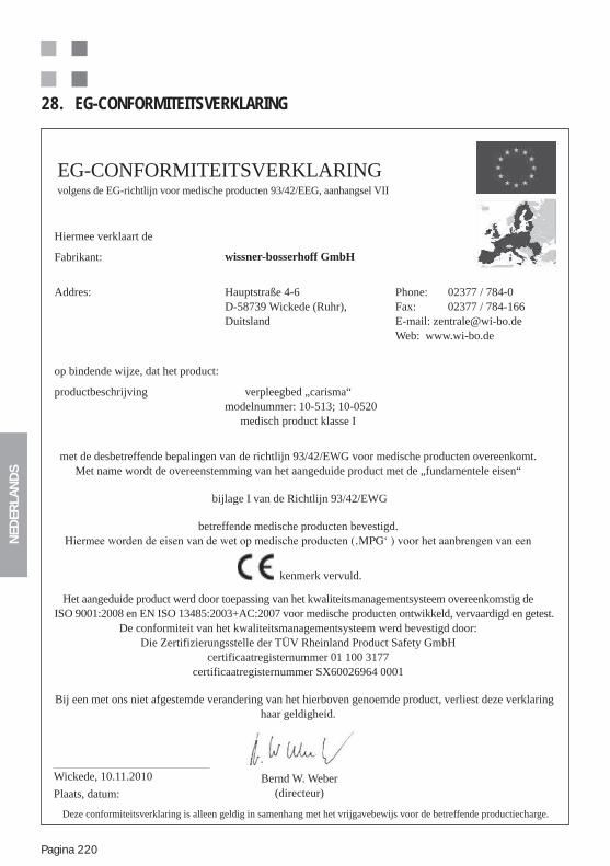
NED
ERLA
ND
S
Pagina 220
28. EG-CONFORMITEITSVERKLARING
EG-CONFORMITEITSVERKLARINGvolgens de EG-richtlijn voor medische producten 93/42/EEG, aanhangsel VII
Bernd W. Weber(directeur)
Hiermee verklaart de
Fabrikant: wissner-bosserhoff GmbH
Addres: Hauptstraße 4-6D-58739 Wickede (Ruhr), Duitsland
Phone: 02377 / 784-0Fax: 02377 / 784-166E-mail: [email protected] Web: www.wi-bo.de
op bindende wijze, dat het product:
productbeschrijving verpleegbed „carisma“modelnummer: 10-513; 10-0520
medisch product klasse I
met de desbetreffende bepalingen van de richtlijn 93/42/EWG voor medische producten overeenkomt.Met name wordt de overeenstemming van het aangeduide product met de „fundamentele eisen“
bijlage I van de Richtlijn 93/42/EWG
betreffende medische producten bevestigd.
kenmerk vervuld.
Het aangeduide product werd door toepassing van het kwaliteitsmanagementsysteem overeenkomstig deISO 9001:2008 en EN ISO 13485:2003+AC:2007 voor medische producten ontwikkeld, vervaardigd en getest.
De conformiteit van het kwaliteitsmanagementsysteem werd bevestigd door:Die Zertifizierungsstelle der TÜV Rheinland Product Safety GmbH
certificaatregisternummer 01 100 3177certificaatregisternummer SX60026964 0001
Bij een met ons niet afgestemde verandering van het hierboven genoemde product, verliest deze verklaring haar geldigheid.
Wickede, 10.11.2010
Plaats, datum:
Deze conformiteitsverklaring is alleen geldig in samenhang met het vrijgavebewijs voor de betreffende productiecharge.
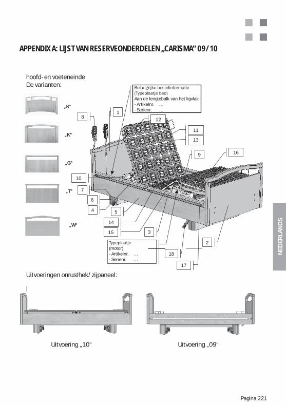
NED
ERLA
ND
S
Pagina 221
APPENDIX A: LIJST VAN RESERVEONDERDELEN „CARISMA” 09/10
Kopf- und FußteilDesign-Varianten:
„S“
„K“
„G“
„T“
„W“
Seitenteil/-gitter Ausführungen:
Ausführung „10“ Ausführung „09“
- Artikel Nr. …- Serien Nr. …
18
3
5
17
4
18
2
11
10
12
13
15
16
14
9
am Längsholm der Liegefläche- Artikel Nr. …- Serien Nr. …
6
7
hoofd- en voeteneinde De varianten:
(motor)- Artikelnr. …- Serienr. …
Uitvoeringen onrusthek/zijpaneel:
Uitvoering „10“ Uitvoering „09“
Aan de lengtebalk van het ligvlak- Artikelnr. …- Serienr. …
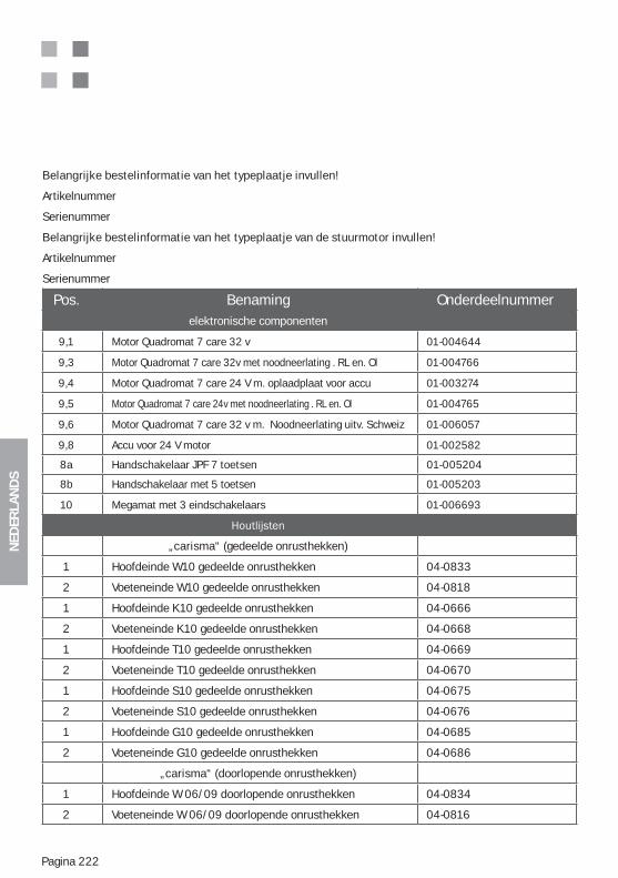
NED
ERLA
ND
S
Pagina 222
Belangrijke bestelinformatie van het typeplaatje invullen!
Artikelnummer
Serienummer
Belangrijke bestelinformatie van het typeplaatje van de stuurmotor invullen!
Artikelnummer
Serienummer
Pos. Benaming Onderdeelnummer elektronische componenten
9,1 Motor Quadromat 7 care 32 v 01-004644
9,3 Motor Quadromat 7 care 32v met noodneerlating . RL en. Ol 01-004766
9,4 Motor Quadromat 7 care 24 V m. oplaadplaat voor accu 01-003274
9,5 Motor Quadromat 7 care 24v met noodneerlating . RL en. Ol 01-004765
9,6 Motor Quadromat 7 care 32 v m. Noodneerlating uitv. Schweiz 01-006057
9,8 Accu voor 24 V motor 01-002582
8a Handschakelaar JPF 7 toetsen 01-005204
8b Handschakelaar met 5 toetsen 01-005203
10 Megamat met 3 eindschakelaars 01-006693
„carisma“ (gedeelde onrusthekken)
1 Hoofdeinde W10 gedeelde onrusthekken 04-0833
2 Voeteneinde W10 gedeelde onrusthekken 04-0818
1 Hoofdeinde K10 gedeelde onrusthekken 04-0666
2 Voeteneinde K10 gedeelde onrusthekken 04-0668
1 Hoofdeinde T10 gedeelde onrusthekken 04-0669
2 Voeteneinde T10 gedeelde onrusthekken 04-0670
1 Hoofdeinde S10 gedeelde onrusthekken 04-0675
2 Voeteneinde S10 gedeelde onrusthekken 04-0676
1 Hoofdeinde G10 gedeelde onrusthekken 04-0685
2 Voeteneinde G10 gedeelde onrusthekken 04-0686
„carisma“ (doorlopende onrusthekken)
1 Hoofdeinde W 06/09 doorlopende onrusthekken 04-0834
2 Voeteneinde W 06/09 doorlopende onrusthekken 04-0816
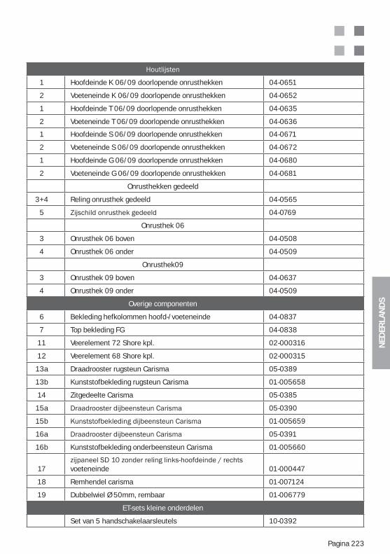
NED
ERLA
ND
S
Pagina 223
1 Hoofdeinde K 06/09 doorlopende onrusthekken 04-0651
2 Voeteneinde K 06/09 doorlopende onrusthekken 04-0652
1 Hoofdeinde T 06/09 doorlopende onrusthekken 04-0635
2 Voeteneinde T 06/09 doorlopende onrusthekken 04-0636
1 Hoofdeinde S 06/09 doorlopende onrusthekken 04-0671
2 Voeteneinde S 06/09 doorlopende onrusthekken 04-0672
1 Hoofdeinde G 06/09 doorlopende onrusthekken 04-0680
2 Voeteneinde G 06/09 doorlopende onrusthekken 04-0681
Onrusthekken gedeeld
3+4 Reling onrusthek gedeeld 04-0565
5 04-0769
Onrusthek 06
3 Onrusthek 06 boven 04-0508
4 Onrusthek 06 onder 04-0509
Onrusthek09
3 Onrusthek 09 boven 04-0637
4 Onrusthek 09 onder 04-0509
Overige componenten
6 Bekleding hefkolommen hoofd-/voeteneinde 04-0837
7 Top bekleding FG 04-0838
11 Veerelement 72 Shore kpl. 02-000316
12 Veerelement 68 Shore kpl. 02-000315
13a Draadrooster rugsteun Carisma 05-0389
13b Kunststofbekleding rugsteun Carisma 01-005658
14 Zitgedeelte Carisma 05-0385
15a 05-0390
15b 01-005659
16a 05-0391
16b Kunststofbekleding onderbeensteun Carisma 01-005660
17 voeteneinde 01-000447
18 Remhendel carisma 01-007124
19 Dubbelwiel Ø 50mm, rembaar 01-006779
ET-sets kleine onderdelen
Set van 5 handschakelaarsleutels 10-0392
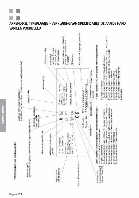
NED
ERLA
ND
S
Pagina 224
APPENDIX B: TYPEPLAATJE – VERKLARING VAN SPECIFICATIES DE AAN DE HAND VAN EEN VOORBEELD
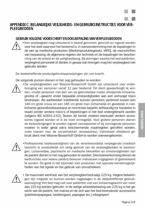
NED
ERLA
ND
S
Pagina 225
APPENDIX C: BELANGRIJKE VEILIGHEIDS- EN GEBRUIKSINSTRUCTIES VOOR VER-PLEEGBEDDEN
GEBRUIK VOLGENS VOORSCHRIFT EN DOELBEPALING VAN VERPLEEGBEDDEN
voor het doel waarvoor het bestemd is, in overeenstemming met de bepalingen in de wet op medische producten (Medizinproduktegesetz, MPG), de voorschriften van toepassing, de algemene regelen der techniek en de bepalingen ter bescher-
verplegend personeel of derden in gevaar kan brengen mag het verpleegbed niet gebruikt worden
De volgende punten dienen in het oog gehouden te worden:---
grootte of –gewicht onder bepaalde omstandigheden aan een verhoogd risico blootstaan. Als aanbevolen inzetbereik kunnen personen variërend tussen een
kritische gezondheidstoestand en tenminste beperkt zelfstandig tot handelen in staat) zonder verdere risico’s of beperkingen in het bed ondergebracht worden (volgens IEC 60601-2-52). Buiten dit bereik moeten eventueel verdere acces-
moeten in ieder geval extra beschermende maatregelen getroffen worden, -
bruik dient met Wissner-Bosserhoff GmbH te worden overeengekomen.
-
de patiënt dienen in het oog gehouden te worden. Dienovereenkomstig dienen de
-heden van het ligvlak en het gebruik van onrusthekken.
De maximale werklast van het verpleegbed bedraagt 225 kg. Hogere belastin-
-
dan 155 kg worden gebruikt. In de veilige arbeidsbelasting van 225 kg is het ge-wicht van de patiënt, het matras en de zich aan het bed bevindende accessoires (patiëntenpapegaai, beddengoed, papegaai etc.) inbegrepen!
NED
ERLA
ND
S
Pagina 226
-dozen toegestaan, die volgens de huidige techniek en geldende voorschriften eveneens getest dienen te worden naar functie en veiligheid (FI-bescherming, FU-bescherming, isolatiefoutdetectoren, zekeringen etc.).
-bruikt worden in ruimtes waar brandbare anesthetica, brandbare reinigings- of oplosmiddelen of eventueel ontplofbare stof-lucht mengsels aangetroffen kun-
-gen aangehouden te worden.
-
BASISFUNCTIES EN INZET VAN VERPLEEGBEDDEN
-
van een verpleegbed is alleen te bereiken door zorgvuldige scholing van de gebruiker
-houden moeten worden.
Er bestaat altijd een gevaar dat het bed onbedoeld versteld wordt. Zo kan het per ongeluk drukken van toetsen of onbedoelde functievrijgave bepaal-de patiënten/bewoners in gevaar brengen! Om een hoge mate van bescher-ming van de patiënt/bewoner te waarborgen is het beslist noodzakelijk om de blokkeerinrichting en/of de vrijgavesleutel doelgericht in te zetten. In geen geval mogen vrijgavesleutels aan de handschakelaar of het bed verblijven! Vrijgavesleutels zijn uitsluitend bedoeld voor gebruik door het verplegend per-soneel.
Het gebruik van de blokkeerinrichtingen en eventueel de bewuste ontkoppe-ling van het bed van de netstroomvoorziening – als absolute blokkeermaat-regel voor maximale bescherming van de patiënt/bewoner – is uitsluitend afhankelijk van het oordeel en de verantwoordelijkheid van het verantwoor-delijk medisch toezicht en het verplegend personeel. Dergelijke maatregelen
-sing te waarborgen.
Het gebruik van speciale lighoudingen, bijv. Trendelenburg-Anti-Trendelenburg,
door medisch personeel toegestaan. Voor patiënten en bewoners dienen deze functies geblokkeerd te zijn, omdat het anders tot risico’s kan leiden.
NED
ERLA
ND
S
Pagina 227
De veiligheidsinstructies in de speciale productgebruiksaanwijzingen dienen opgevolgd te worden, omdat anders gevaren ontstaan.
Bij het gebruik van onrusthekken is bijzondere zorgvuldigheid en voorzichtig-heid geboden:- Onrusthekken dienen er in de eerste plaats voor om de patiënt te bescher-men tegen het uit bed vallen. In geen geval mogen de onrusthekken als mid-
- Om de onrusthekken te gebruiken zijn rechterlijke besluiten noodzakelijk, zodra deze de mobiliteit van de patiënt/bewoner beperkt. Alleen gedeelde onrusthekken of afzonderlijk neerlaatbare onrusthekken, waarbij alleen de delen aan het hoofdeinde opgezet worden en die als instaphulp gebruikt kun-nen worden, vormen hierop een toelaatbare uitzondering voor mobiele bewo-ners/patiënten.
Overbelasting door erop te gaan zitten, erop te leunen of te trekken aan de onrusthekken leidt tot ernstige beschadiging en levert gevaar op. Dergelijke belastingen dienen te allen tijde vermeden te worden.
Bij het gebruik van onrusthekken dient de rekening gehouden te worden met de geschiktheid ervan, afhankelijk van de bijzonderheden van de patiënt/be-woner. In het bijzonder dienen de afstanden tussen de planken van de onrus-thekken in relatie tot de lichaamsbouw van de patiënt/bewoner in de gaten gehouden te worden, zodat erin bekneld raken of ertussendoor glijden uit-gesloten kan worden. Eventueel dienen extra vullingen voor de onrusthekken te worden ingezet, die de grootte van de tussenruimtes verkleinen of geheel afsluiten. Het besluit hiertoe ligt uitsluitend in de verantwoordelijkheid van het verantwoordelijk medisch toezicht. Ter oriëntatie dienen de gegevens ter bepaling van doelmatig gebruik in deze gebruiksaanwijzing en de productspe-
Uitsluitende onrusthekken die ook voor het desbetreffende type bed zijn to-egelaten mogen worden ingezet, omdat anders de kans op ongelukken ver-groot wordt.
De onrusthekken/zijpanelen dienen voor gebruik steeds op beschadigingen en veilige bevestiging aan het bed gecontroleerd te worden, evenals op het probleemloos functioneren van de veiligheidsvergrendeling! Hoe de onrus-thekken correct worden bediend vindt u in de desbetreffende productgebru-iksaanwijzing.
NED
ERLA
ND
S
Pagina 228
Beslissingen over het gebruik van de handschakelaar door de patiënt/bewo-ner zelf worden uitsluitend onder verantwoordelijkheid van het medisch en verplegend personeel genomen. Dergelijke maatregelen dienen goed zicht-baar aangegeven te worden in de verplegingsdocumentatie, om een goed ge-
Indien de handschakelaar niet door de bewoner/patiënt zelf gebruikt wordt, moet hij buiten diens reikwijdte en beschermd tegen inklemmen aan het voe-teneinde van het bed worden opgehangen.
De handschakelaar mag niet op de grond vallen, door gewicht overbelast wor-den noch door vloeistoffen overstroomd worden. Reiniging dient te geschie-den met reinigingsdoekjes voor PC-toetsenborden. Bij mechanische schade of schade door vocht moet de handschakelaar direct vervangen worden. De voedingskabels dienen eveneens regelmatig op beschadigingen gecontro-leerd te worden.
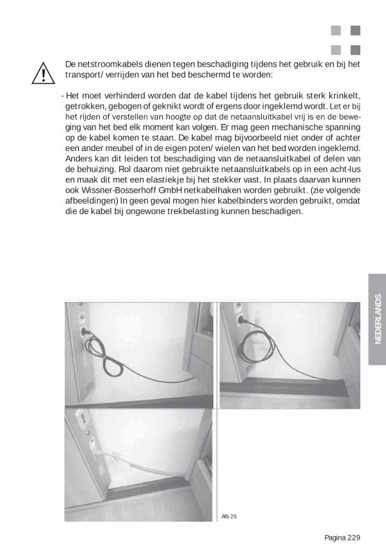
NED
ERLA
ND
S
Pagina 229
De netstroomkabels dienen tegen beschadiging tijdens het gebruik en bij het transport/verrijden van het bed beschermd te worden:
- Het moet verhinderd worden dat de kabel tijdens het gebruik sterk krinkelt, getrokken, gebogen of geknikt wordt of ergens door ingeklemd wordt.
-ging van het bed elk moment kan volgen. Er mag geen mechanische spanning op de kabel komen te staan. De kabel mag bijvoorbeeld niet onder of achter een ander meubel of in de eigen poten/wielen van het bed worden ingeklemd. Anders kan dit leiden tot beschadiging van de netaansluitkabel of delen van de behuizing. Rol daarom niet gebruikte netaansluitkabels op in een acht-lus en maak dit met een elastiekje bij het stekker vast. In plaats daarvan kunnen ook Wissner-Bosserhoff GmbH netkabelhaken worden gebruikt. (zie volgende afbeeldingen) In geen geval mogen hier kabelbinders worden gebruikt, omdat die de kabel bij ongewone trekbelasting kunnen beschadigen.
Afb 25
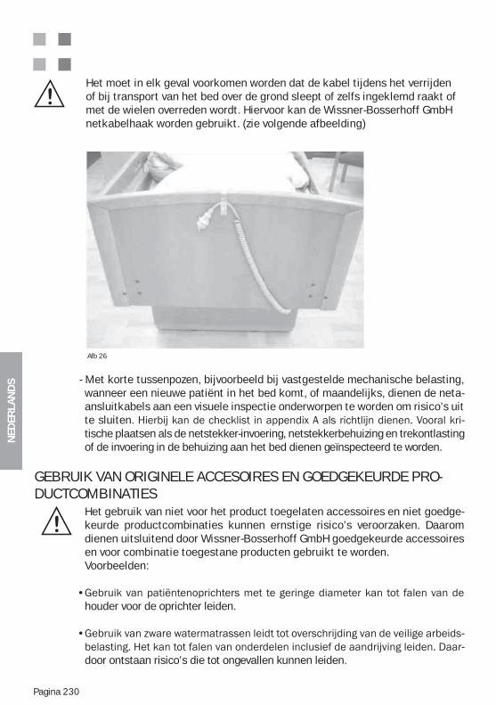
NED
ERLA
ND
S
Pagina 230
Het moet in elk geval voorkomen worden dat de kabel tijdens het verrijden of bij transport van het bed over de grond sleept of zelfs ingeklemd raakt of met de wielen overreden wordt. Hiervoor kan de Wissner-Bosserhoff GmbH netkabelhaak worden gebruikt. (zie volgende afbeelding)
- Met korte tussenpozen, bijvoorbeeld bij vastgestelde mechanische belasting, wanneer een nieuwe patiënt in het bed komt, of maandelijks, dienen de neta-ansluitkabels aan een visuele inspectie onderworpen te worden om risico’s uit te sluiten. -tische plaatsen als de netstekker-invoering, netstekkerbehuizing en trekontlasting of de invoering in de behuizing aan het bed dienen geïnspecteerd te worden.
GEBRUIK VAN ORIGINELE ACCESOIRES EN GOEDGEKEURDE PRO-DUCTCOMBINATIES
Het gebruik van niet voor het product toegelaten accessoires en niet goedge-keurde productcombinaties kunnen ernstige risico’s veroorzaken. Daarom dienen uitsluitend door Wissner-Bosserhoff GmbH goedgekeurde accessoires en voor combinatie toegestane producten gebruikt te worden.Voorbeelden:
houder voor de oprichter leiden.
--
door ontstaan risico’s die tot ongevallen kunnen leiden.
Afb 26
NED
ERLA
ND
S
Pagina 231
OPSTELLING VAN HET VERPLEEGBED (VEILIGHEIDSAFSTANDEN)
Het bed dient zodanig te worden opgesteld, dat bij het uitvoeren van alle ver-stelfuncties van het bed botsingen van onderdelen van het bed met andere voor-werpen in de kamer, of met delen van de kamer, uitgesloten zijn (bijvoorbeeld aansluitkabel, vensterbanken, schuine daken, buizen, opliggende leidingen, wandborden etc.). Een veiligheidsafstand van tenminste 2,5 cm tot wanden en andere voorwerpen dient hierbij in alle mogelijke bedposities aangehouden te worden. Let op: Ook bij het kantelen en bij hoogteverstelling mag geen botsing optreden! Het bed moet zo opgesteld worden, dat het scheiden van het stroom-net (aan de netstekker trekken) eenvoudig bewerkstelligd kan worden!
REINIGING EN DESINFECTIE VAN HET BED
Het verpleegbed dient regelmatig, tenminste echter voor iedere wisseling van bewoner gereinigd en gedesinfecteerd te worden. Het verpleegbed mag niet in wasinstallaties, niet met stromend water, niet met waterstralen en niet met wa-terspuiten gereinigd of gedesinfecteerd worden. Alleen sproei- en wisdesinfectie
-dige producten vervangen mogen worden:Terralin, Perform en Sagrotan Med (Schülke & Mayr GmbH, Norderstedt).Deze middelen alleen volgens voorschrift van de producent gebruiken! Het be-treft vooral de dosering van de middelen en het eventuele risico bij combinatie met andere middelen.
De houten ombouw mag niet met deze middelen in aanraking komen.
Er mogen echter geen schoonmaak- of reinigingsmiddelen worden gebruikt die mechanisch abrasieve bestanddelen hebben en als schuurmiddel werken.
-Hout is een natu-
urproduct met de eigenschap vocht op te nemen en daarbij uit te zetten. Dit kan tot beschadiging van de laklaag leiden. Schade aan gelakte oppervlakken dienen na reiniging met voor reparatie geschikte lak gerepareerd te worden. Vraag de Wissner-Bosserhoff GmbH klantenservice.
of klemmende toetsen moet de handschakelaar eventueel vervangen worden.
NED
ERLA
ND
S
Pagina 232
APPENDIX D: ACCUAANDRIJVING (OPTIE) – OVERIGE INSTRUCTIES
meerdere malen elektrisch te verstellen.
Het laden van de accu geschiedt dan volautomatisch door middel van een speciaal geïnte-greerde ladingsschakeling plaats.
-bonden anfgeleverd, in montage door een ongeschoold gebruiker is niet voorzien.
Belangrijke kenmerken:
De accubox mag uit veiligheidspverwegingen niet geopend worden.
Mocht u later een accu willen aanschaffen, neem dan dringend contact op met de tech-
de accu. Vervangen van de accubox dient alleen door geschoold personeel gedaan te
totale ontladingen hebben plaatsgevonden.
te zetten (accessoire voor het parallel opladen van vier accuboxen:
laadstation.
NED
ERLA
ND
S
Pagina 233
APPENDIX E: METAMERIE – SCHIJNBAAR HETZELFDE ZIJN VAN OPPERVLAKKEN EN DECORS
„Metamerie“
te onderscheiden vanwege de spectrale eigenschappen van de gebruikte pigmenten, kleur-
--
tussen twee en meer materiaalkleuren.
-schillende lichtomstandigheden (neoneffect, winkelverlichting of tentoonstellings-lichteffect
De metamerie-index is de Delta-E-waarde in het CIE- L*a*b – systeem onder telkens twee lichtsoorten – meestal van een daglicht- (C, D50, D60) naar een kunstlichtsoort (A). Daar-voor worden kleur- en glansgraadmeetapparaten in combinatie gebruikt.
de hand van een basispatroon plaats te vinden, daar een puur meettechnische kleurverge--
besluit in een besluitvormingscommissie te bereiken, daar visuele indrukken, zoals bekend,
-
basispatroon herhaalt).
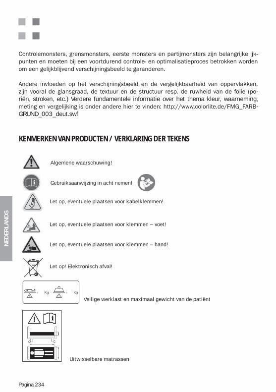
NED
ERLA
ND
S
Pagina 234
-
-riën, stroken, etc.) Verdere fundamentele informatie over het thema kleur, waarneming,
-GRUND_003_deut.swf
KENMERKEN VAN PRODUCTEN / VERKLARING DER TEKENS
Veilige werklast en maximaal gewicht van de patiënt
Algemene waarschuwing!
Gebruiksaanwijzing in acht nemen!
Let op, eventuele plaatsen voor kabelklemmen!
Let op, eventuele plaatsen voor klemmen – voet!
Let op, eventuele plaatsen voor klemmen – hand!
Let op! Elektronisch afval!
Uitwisselbare matrassen
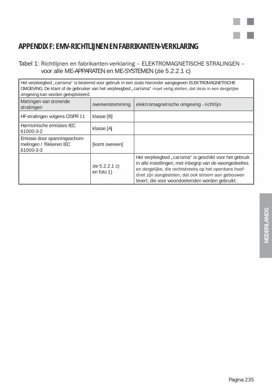
NED
ERLA
ND
S
Pagina 235
APPENDIX F: EMV-RICHTLIJNEN EN FABRIKANTEN-VERKLARING
Tabel 1: voor alle ME-APPARATEN en ME-SYSTEMEN (zie 5.2.2.1 c)
Het verpleegbed „carisma“ is bestemd voor gebruik in een zoals hieronder aangegeven ELEKTROMAGNETISCHEOMGEVING. De klant of de gebruiker van het verpleegbed „carisma“omgeving kan worden geëxploiteerd.
Metingen van storende stralingen
overeenstemming elektromagnetische omgeving - richtlijn
HF-stralingen volgens CISPR 11 klasse [B]
Harmonische emissies IEC 61000-3-2
klasse [A]
Emissie door spanningsschom-melingen / flikkeren IEC61000-3-3
[komt overeen]
zie 5.2.2.1 c)en foto 1)
Het verpleegbed „carisma“ is geschikt voor het gebruik in alle instellingen, met inbegrip van de woongedeeltes
-
levert, die voor woondoeleinden worden gebruikt.
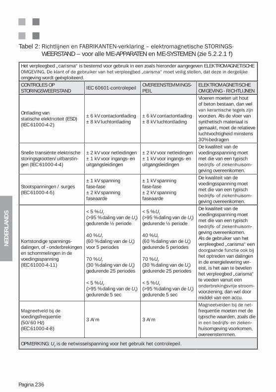
NED
ERLA
ND
S
Pagina 236
Tabel 2: WEERSTAND – voor alle ME-APPARATEN en ME-SYSTEMEN (zie 5.2.2.1 f)
Het verpleegbed „carisma“ is bestemd voor gebruik in een zoals hieronder aangegeven ELEKTROMAGNETISCHE
omgeving wordt geëxploiteerd.
CONTROLES OPSTORINGSWEERSTAND
IEC 60601-controlepeilOVEREENSTEMMINGS-PEIL
ELEKTROMAGNETISCHE OMGEVING - RICHTLIJNEN
Ontlading vanstatische elektriciteit (ESD)(IEC 61000-4-2)
± 6 kV contactontlading± 8 kV luchtontlading
± 6 kV contactontlading± 8 kV luchtontlading
Vloeren moeten uit hout of beton bestaan, dan wel
voorzien. Als de vloer vansynthetisch materiaal is gemaakt, moet de relatieve luchtvochtigheid minstens 30% bedragen
Snelle transiënte elektrische storingsgrootten/uitbarstin-gen (IEC 61000-4-4)
± 2 kV voor netleidingen± 1 kV voor ingangs- enuitgangsleidingen
± 2 kV voor netleidingen± 1 kV voor ingangs- enuitgangsleidingen
De kwaliteit van de voedingsspanning moet met die van een typisch
-geving overeenkomen.
Stootspanningen / surges(IEC 61000-4-5)
± 1 kV spanning fase-fase± 2 kV spanning faseaarde
± 1 kV spanning fase-fase± 2 kV spanning faseaarde
De kwaliteit van de voedingsspanning moet met die van een typisch
-geving overeenkomen.
Kortstondige spannings- dalingen, of - onderbrekingenen schommelingen in devoedingsspanning(IEC 61000-4-11)
< 5 % UT(>95 % daling van de UT)gedurende ½ periode
40 % UT (60 % daling van de UT)voor 5 periodes
70 % UT (30 % daling van de UT)gedurende 25 periodes
< 5 % UT (>95 % daling van de UT)gedurende 5 sec
< 5 % UT(>95 % daling van de UT)gedurende ½ periode
40 % UT (60 % daling van de UT)gedurende 5 periodes
70 % UT (30 % daling van de UT)gedurende 25 periodes
< 5 % UT (>95 % daling van de UT)gedurende 5 sec
De kwaliteit van de voedingsspanning moet met die van een typisch
-geving overeenkomen. Als de gebruiker van het verpleegbed „carisma“ een
het optreden van dalingen in de energielevering ver-eist, is het aan te bevelen het verpleegbed „carisma“ te voeden vanuit een
-voorziening, dan wel door middel van een accu.
voedingsfrequentie (50/60 Hz)(IEC 61000-4-8)
3 A/m 3 A/m
-frequentie moeten met de typische waarden, zoals die
-huisomgeving voorkomen,overeenstemmen.
OPMERKING: UT is de netwisselspanning voor het gebruik het controlepeil.
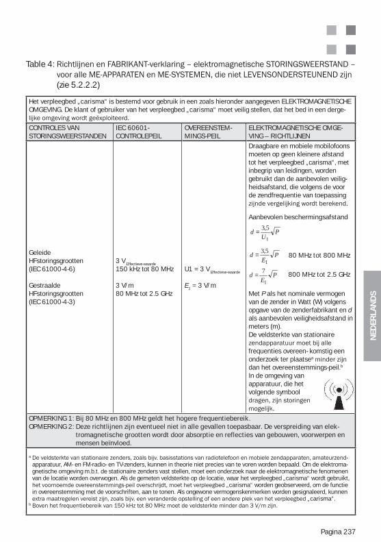
NED
ERLA
ND
S
Pagina 237
Table 4:
(zie 5.2.2.2)
Het verpleegbed „carisma“ is bestemd voor gebruik in een zoals hieronder aangegeven ELEKTROMAGNETISCHEOMGEVING. De klant of gebruiker van het verpleegbed „carisma“ moet veilig stellen, dat het bed in een derge-
CONTROLES VANSTORINGSWEERSTANDEN
IEC 60601- CONTROLEPEIL
OVEREENSTEM-MINGS-PEIL
ELEKTROMAGNETISCHE OMGE-VING – RICHTLIJNEN
Geleide HFstoringsgrootten(IEC 61000-4-6)
Gestraalde HFstoringsgrootten(IEC 61000-4-3)
3 V Effectieve-waarde
150 kHz tot 80 MHz
3 V/m80 MHz tot 2.5 GHz
U1 = 3 V Effectieve-waarde
E1 = 3 V/m
Draagbare en mobiele mobilofoonsmoeten op geen kleinere afstand tot het verpleegbed „carisma“, met inbegrip van leidingen, worden gebruikt dan de aanbevolen veilig-heidsafstand, die volgens de voor de zendfrequentie van toepassing
Aanbevolen beschermingsafstand
80 MHz tot 800 MHz
800 MHz tot 2.5 GHz
Met P als het nominale vermogen van de zender in Watt (W) volgens opgave van de zenderfabrikant en d als aanbevolen veiligheidsafstand in meters (m).De veldsterkte van stationaire
frequenties overeen- komstig een onderzoek ter plaatsea
dan het overeenstemmings-peil.b
In de omgeving van apparatuur, die het volgende symbool
OPMERKING 1: Bij 80 MHz en 800 MHz geldt het hogere frequentiebereik.OPMERKING 2: Deze richtlijnen zijn eventueel niet in alle gevallen toepasbaar. De verspreiding van elek-
tromagnetische grootten wordt door absorptie en reflecties van gebouwen, voorwerpen en mensen beïnvloed.
a -apparatuur, AM- en FM-radio- en TV-zenders, kunnen in theorie niet precies van te voren worden bepaald. Om de elektroma-gnetische omgeving m.b.t. de stationaire zenders vast stellen, moet een onderzoek naar de elektromagnetische fenomenen van de locatie worden overwogen. Als de gemeten veldsterkte op de locatie, waar het verpleegbed „carisma“ wordt gebruikt,
„carisma“ worden geobserveerd, om de functie in overeenstemming met de voorschriften, aan te tonen. Als ongewone vermogenskenmerken worden gesignaleerd, kunnen
„carisma“.b
PE
d1
5,3=
PU
d1
5,3=
PE
d1
7=
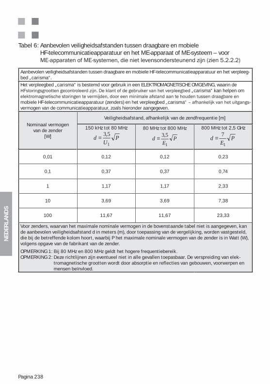
NED
ERLA
ND
S
Pagina 238
Tabel 6: Aanbevolen veiligheidsafstanden tussen draagbare en mobiele HF-telecommunicatieapparatuur en het ME-apparaat of ME-systeem – voor
Aanbevolen veiligheidsafstanden tussen draagbare en mobiele HF-telecommunicatieapparatuur en het verpleeg-bed „carisma“.
Het verpleegbed „carisma“ is bestemd voor gebruik in een ELEKTROMAGNETISCHE OMGEVING, waarin de „carisma“ kan helpen om
mobiele HF-telecommunicatieapparatuur (zenders) en het verpleegbed „carisma“ -vermogen van de communicatieapparatuur, zoals hieronder aangegeven.
Nominaal vermogen van de zender
[W]
Veiligheidsafstand, afhankelijk van de zendfrequentie [m]
150 kHz tot 80 MHz
PU
d1
5,3=80 MHz tot 800 MHz
PE
d1
5,3=
800 MHz tot 2,5 GHz
PE
d1
7=
0,01 0,12 0,12 0,23
0,1 0,37 0,37 0,74
1 1,17 1,17 2,33
10 3,69 3,69 7,38
100 11,67 11,67 23,33
Voor zenders, waarvan het maximale nominale vermogen in de bovenstaande tabel niet is aangegeven, kan de aanbevolen veiligheidsafstand d in meters (m), door toepassing van de vergelijking, worden vastgesteld, die bij de betreffende kolom hoort, waarbij P het maximale nominale vermogen van de zender is in Watt (W), volgens opgave van de fabrikant van de zender.
OPMERKING 1: Bij 80 MHz en 800 MHz geldt het hogere frequentiebereik.OPMERKING 2: Deze richtlijnen zijn eventueel niet in alle gevallen toepasbaar. De verspreiding van elek-
tromagnetische grootten wordt door absorptie en reflecties van gebouwen, voorwerpen en mensen beïnvloed.
NED
ERLA
ND
S
Pagina 239
NOTITIES
NED
ERLA
ND
S
Pagina 240
NOTITIES
NED
ERLA
ND
S
Pagina 241
NOTITIES
ITA
LIA
NO
Pagina 242
SOMMARIO
1. Sommario ................................................................................................2422. Indicazioni sulle Istruzioni d‘uso / Spiegazione dei simboli ................2443. Ambito d‘applicazione / Uso conforme alla destinazione ....................2444. Sistemazione del letto ............................................................................2455. Dati tecnici del letto / Targhetta dei dati tecnici ...................................2455.1. Elettromotori del piano letto ..............................................................2465.2. Regolazione dell’altezza elettromotori .............................................2466. Sicurezza del prodotto / Estratto delle norme utilizzate ......................2477. Descrizione generale del prodotto (Esempio sponde in legno T10) ....2488. Descrizione delle funzioni elettriche .....................................................2488.1. Funzione Spalliera (RL) ......................................................................2498.2. Gambe sollevate (BH) ........................................................................2508.3. Seduta comfort (KS) ..........................................................................250
......................................................2518.5. Funzione Regolazione dell‘altezza (HV) ............................................2519. Combinazione di „letto di degenza“ e dispositivi di sollevamento „mibili“ ...25110. Istruzioni di sicurezza per la regolazione dell‘altezza ..........................25211. Scatola di controllo (optional) ................................................................25212. Fornitura ..................................................................................................25313. Montaggio ................................................................................................25413.1. Piano letto ...............................................................................................25413.2. Motore del piano letto ............................................................................25414. Trasporto / movimentazione del letto ...................................................25415. Controllo del funzionamento ..................................................................25515.1. Interruttore manuale „Carisma 07 JPF“ Descrizione del funzionamento ...................................................................................25515.2. Interruttore manuale, lato posteriore con funzione di blocco ........25615.3. Parte inferiore di supporto gambe / meccanica ..............................25715.4. Frenare/ muovere ..............................................................................25815.5. Regolazione delle sponde laterali (Modello 06) ..............................25815.6. Regolare le sponde laterali (Versione 09) ........................................25915.7. Regolazione delle sponde laterali (Modello 10) ..............................26016. Accessori approvati ...............................................................................26116.1. Dispositivo di sollevamento con trapezio (accessorio) ...................261
......................................................................26216.3. Prolunga del piano letto (optional) ...................................................26216.4. Materasso (Accessorio) .....................................................................26316.5. Cestello per il contenitore delle urine / supporto per la sacca delle urine Modello 09 (Accessorio) .................................................26316.6. Supporto per l’interruttore manuale (Accessorio) ...........................26416.7. Prolunga per sponda 06/09 (accessorio) ........................................26517. Pulizia e disinfezione ..............................................................................267
ITA
LIA
NO
Pagina 243
17.1. Prima pulizia .......................................................................................26717.2. Desinfezione / Sterilizzazione ...........................................................26817.3. Istruzioni di pulizia delle parti in legno .............................................26817.4. Impiego di detergenti .........................................................................26917.5. Impiego di disinfettanti ......................................................................26917.6. Danneggiamenti alle parti in legno ..................................................26917.7. Compatibilità ambientale ..................................................................26917.8. Qualità ................................................................................................26918. Soluzioni in caso di anomalie ................................................................27019. Deposito ..................................................................................................27020. Istruzioni di sicurezza e rischi ................................................................27021. Riparazione e manutenzione .................................................................27621.1. Completezza e Accessori ...................................................................27621.2. Usura ..................................................................................................27721.3. Funzonalità .........................................................................................27721.4. BGV A3/VDE 0751– Controlli dei componenti elettrici dell’interruttore manuale ..................................................................27721.5. Ruote ..................................................................................................27722. Durata ......................................................................................................27823. smaltimento ............................................................................................27824. Pezzi di ricambio, elenchi dei pezzi di ricambio e manuali di servizio ... 27825. Targhetta dei dati tecnici ed etichette ...................................................27826. Garanzia e assistenza tecnica ...............................................................27927. Persona di riferimento ............................................................................27928. Dichiarazione di conformità cee ...........................................................280Allegato C: Importanti istruzioni di sicurezza e di utilizzo dei letti per lungodegenti . 285Uso Conforme alla Destinazione e Destinazione dei Letti per lungodegenti .....285Funzioni di base ed utilizzo dei letti per lungodegenti ........................................286Utilizzo di accessori originali e combinazioni di prodotti approvati ...................290Sistemazione del letto per lungodegenti (distanze di sicurezza) ........................291Pulizia e disinfezione del letto ...............................................................................291
Allegati:Allegato A: Elenco dei pezzi di ricambio carisma 09/10Allegato B: Targhetta – Spiegazione dei dati per mezzo di un esempioAllegato C: Informazioni importanti per la sicurezza e l‘utilizzo dei letti di degenzaAllegato D: Funzionamento a batteria (optional) - Istruzioni aggiuntive
Allegato F: Direttive EMV e dichiarazione del produttore
IMPORTANTI ISTRUZIONI DI SICUREZZA:I passaggi di testo contenuti nei singoli capitoli e contrassegnati dal simbolo
zione ed osservare le indicazioni riportate nel capitolo 18 e nell‘allegato C. La non osservanza di tali istruzioni può causare danni agli oggetti o lesioni alle persone.
ITA
LIA
NO
Pagina 244
Cari clienti,
-guate risposte alle esigenze quotidiane della lungodegenza. La scelta accurata dei materiali,
nostri responsabili, fanno dei nostri letti un prodotto veramente valido dal punto di vista
2. INDICAZIONI SULLE ISTRUZIONI D‘USO / SPIEGAZIONE DEI SIMBOLI
Il presente simbolo indica istruzioni importanti per la sicurezza, la mancata osservanza delle quali può avere gravi conseguenze (come per es. danni agli oggetti e lesioni alle perso-ne). Queste istruzioni o indicazioni sono pertanto assolutamente da osservare.
Le presenti istruzioni per l‘uso sono destinate a personale di assistenza specializzato ovvero a ogni persona incaricata della messa in funzione e dell‘impiego del presente prodotto.
Attenzione! Per l’utilizzo del presente prodotto sono necessarie precise cono-scenze e l'osservanza delle istruzioni d'uso. Pertanto è necessario conservarle
e garantire un funzionamento senza anomalie, le istruzioni d'uso devono essere sempre a portata di mano del personale addetto all'uso del prodotto. Si consiglia di conservarle nelle vicinanze del letto o nel comodino.
letto acquistato, in quanto sono state realizzate per tutte le varianti della serie di modelli. I
3. AMBITO D‘APPLICAZIONE / USO CONFORME ALLA DESTINAZIONE
(201.3.203) * CONDIZIONI D‘USO 3Lungodegenza in un ambiente ospedaliero nel quale è possibile controllo medico e all‘occorrenza viene fornita sorveglianza. Può essere messo a disposizione un DISPOSITIVO ME utilizzato in
(201.3.205) * CONDIZIONI D‘USO 5Lungodegenza ambulante offerta in un ospedale o presso un ente medico sotto controllo me-dico. Viene messo a disposizione un DISPOSITIVO ME per le esigenze di persone con malattie, ferite o invalidità per il trattamento, la diagnosi o la sorveglianza. Ogni altro tipo di impiego deve essere previamente accordato per iscritto con la ditta Wissner-Bosserhoff GmbH. Il prodotto va impiegato come mezzo operativo per l‘assistenza ed è sottoposto alle norme previste dalle relative associazioni di settore.Secondo le misure e norme contenute nel seguente capitolo „Sicurezza del prodotto / Estratto delle norme applicate“, questo letto è un prodotto medico. Pertanto può essere utilizzato solo sotto il controllo di personale medico. L‘aspetto determinante del fatto che la cura sia sotto-posta al controllo medico oppure no, è quello che essa avvenga su istruzione del personale medico.
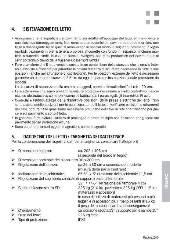
ITA
LIA
NO
Pagina 245
4. SISTEMAZIONE DEL LETTO
morbidi, pavimenti in pietra tenera o porosa, moquette con fondo in espanso, linoleum mor-
servizio tecnico clienti della Wissner-Bosserhoff GmbH.-
posizioni (anche nella funzione di oscillazione). Per le posizioni estreme del letto è necessario garantire un‘ulteriore distanza di 2,5 cm da oggetti, pareti e installazioni, quale protezione da blocchi.
La distanza di sicurezza dalla testata ad oggetti, pareti ed installazioni è di min. 20 cm.-
nico ed elettrotecnico come per esempio i battiscopa, i paraspigoli, gli interruttori FI ecc.l’adeguatezza delle rispettive posizioni delle prese elettriche del letto . Non
-cere sul pavimento o sotto il letto.
pavimento senza protezione alcuna.
5. DATI TECNICI DEL LETTO / TARGHETTA DEI DATI TECNICI1
Per la comprensione dei rispettivi dati della targhetta, consultare l‘allegato B
Dimensione esterna: ca. 208 x 106 cm (a seconda del bordo in legno) Dimensione nominale del piano letto 90 x 200 cm Regolazione dell'altezza: da 36 a 80 cm a seconda del modello
(misura della parte centrale) Inclinazione dello schienale: 65,5°+/-5°ritraz ione dello schienale 11,5 cm Regolazione del segmento centrale di supporto bacino/femorale:
32° / +/-5° retrazione del femorale 4 cm Carico di lavoro sicuro SD: 225 kg (210 kg paziente = 225 kg CSPL - 15 kg
materasso e accessori) In caso di utilizzo di materassi più pesanti o più leggeri e di accessori più / meno pesanti di 15 kg, il peso del paziente cambia di conseguenza! Orientamento: ca. posizione seduta 13° /supporto per le gambe 15° Peso del letto: 125 kg circa Tipo di protezione IPX4
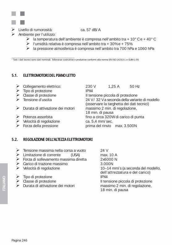
ITA
LIA
NO
Pagina 246
5.1. ELETTROMOTORI DEL PIANO LETTO
Collegamento elettrico: 230 V 1,25 A 50 Hz Tipo di protezione IPX4 Classe di protezione II tensione piccola di protezione Tensione d’uscita 24 V / 32 V a seconda della variante di modello
(osservare la targhetta dei dati tecnici) Durata di attivazione dei motori massimo 2 min. di regolazione,
18 min. di pausa Potenza assorbita fino a circa 320W di carico di punta Velocità di regolazione ca. 5,4 mm/sec. Forza della pressione prima del rinvio max. 3.500N
5.2. REGOLAZIONE DELL’ALTEZZA ELETTROMOTORI
Tensione massima nella corsa a vuoto 24 V Limitazione di corrente (USA) max. 10 A Forza di sollevamento massima diretta 2x6000 N Carico di trazione massimo 3.000N Velocità di regolazione 10–14 mm/s (a seconda del modello,
dell’attrezzatura e del carico) Tipo di protezione IPX4 Classe di protezione II tensione piccola di protezione Durata di attivazione dei motori massimo 2 min. di regolazione,
18 min. di pausa
Livello di rumorosità: ca. 57 dB/A Ambiente per l‘utilizzo: la temperatura dell‘ambiente è compresa nell‘ambito tra + 10°C e + 40°C l‘umidità relativa è compresa nell‘ambito tra + 30% e + 75% la pressione atmosferica è compresa nell‘ambito tra 700 hPa e 1060 hPa
___________________________________________________1 Tutti i dati tecnici sono dati nominali. Tolleranze costruttive e produttive conformi alla norma EN ISO 14253-1 e GUM-1:95
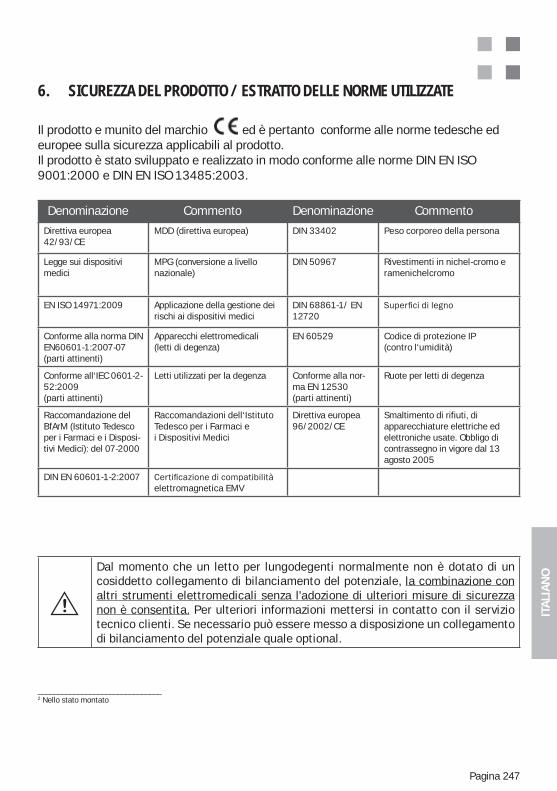
ITA
LIA
NO
Pagina 247
6. SICUREZZA DEL PRODOTTO / ESTRATTO DELLE NORME UTILIZZATE
Il prodotto e munito del marchio ed è pertanto conforme alle norme tedesche ed europee sulla sicurezza applicabili al prodotto. Il prodotto è stato sviluppato e realizzato in modo conforme alle norme DIN EN ISO 9001:2000 e DIN EN ISO 13485:2003.
Denominazione Commento Denominazione Commento
Direttiva europea 42/93/CE
MDD (direttiva europea) DIN 33402 Peso corporeo della persona
Legge sui dispositivi medici
MPG (conversione a livellonazionale)
DIN 50967 Rivestimenti in nichel-cromo e ramenichelcromo
EN ISO 14971:2009 Applicazione della gestione dei rischi ai dispositivi medici
DIN 68861-1/ EN 12720
Conforme alla norma DIN EN60601-1:2007-07(parti attinenti)
Apparecchi elettromedicali (letti di degenza)
EN 60529 Codice di protezione IP (contro l‘umidità)
Conforme all‘IEC 0601-2-52:2009(parti attinenti)
Letti utilizzati per la degenza Conforme alla nor-ma EN 12530(parti attinenti)
Ruote per letti di degenza
Raccomandazione del BfArM (Istituto Tedesco per i Farmaci e i Disposi-tivi Medici): del 07-2000
Raccomandazioni dell‘Istituto Tedesco per i Farmaci e i Dispositivi Medici
Direttiva europea96/2002/CE
Smaltimento di rifiuti, diapparecchiature elettriche edelettroniche usate. Obbligo dicontrassegno in vigore dal 13 agosto 2005
DIN EN 60601-1-2:2007 elettromagnetica EMV
_______________________________2 Nello stato montato
Dal momento che un letto per lungodegenti normalmente non è dotato di un cosiddetto collegamento di bilanciamento del potenziale, la combinazione con altri strumenti elettromedicali senza l'adozione di ulteriori misure di sicurezza non è consentita. Per ulteriori informazioni mettersi in contatto con il servizio tecnico clienti. Se necessario può essere messo a disposizione un collegamento di bilanciamento del potenziale quale optional.
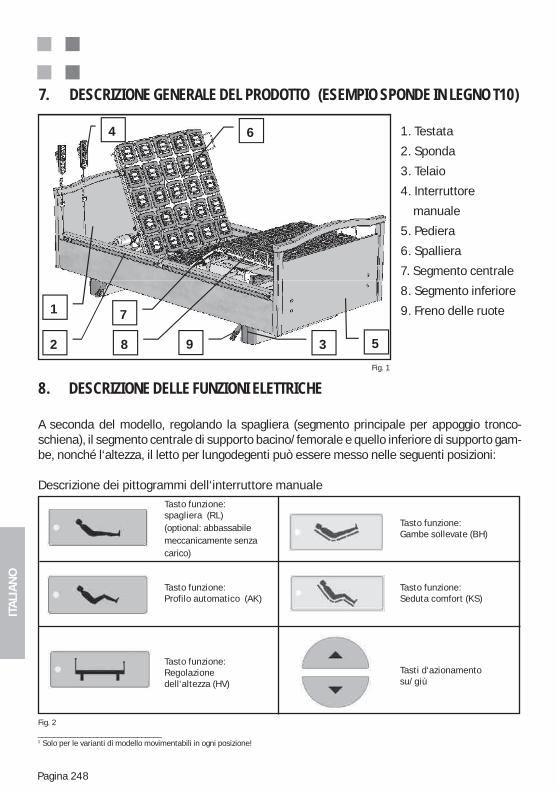
ITA
LIA
NO
Pagina 248
1. Testata
2. Sponda
3. Telaio
4. Interruttore
manuale
5. Pediera
6. Spalliera
7. Segmento centrale
8. Segmento inferiore
9. Freno delle ruote
7. DESCRIZIONE GENERALE DEL PRODOTTO (ESEMPIO SPONDE IN LEGNO T10)
Fig. 1
1
2 3
4
5
6
7
8 9
8. DESCRIZIONE DELLE FUNZIONI ELETTRICHE
A seconda del modello, regolando la spagliera (segmento principale per appoggio tronco-schiena), il segmento centrale di supporto bacino/femorale e quello inferiore di supporto gam-be, nonché l‘altezza, il letto per lungodegenti può essere messo nelle seguenti posizioni:
Descrizione dei pittogrammi dell‘interruttore manuale
Fig. 2
Tasto funzione:spagliera (RL)(optional: abbassabile meccanicamente senza carico)
Tasto funzione:Profilo automatico (AK)
Tasto funzione:Regolazione dell‘altezza (HV)
Tasto funzione:Gambe sollevate (BH)
Tasto funzione:Seduta comfort (KS)
Tasti d‘azionamento su/giù
_______________________________1 Solo per le varianti di modello movimentabili in ogni posizione!
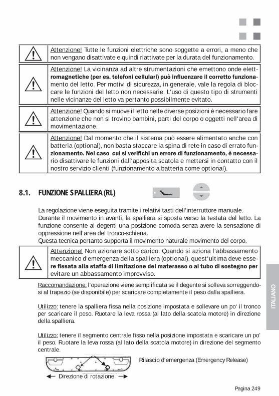
ITA
LIA
NO
Pagina 249
Attenzione! Quando si muove il letto nelle diverse posizioni è necessario fare attenzione che non si trovino bambini, parti del corpo o oggetti nell‘area di movimentazione.
Attenzione! Dal momento che il sistema può essere alimentato anche con batteria (optional), non basta staccare la spina di rete in caso di errato fun-
-rio disattivare le funzioni dall‘apposita scatola e mettersi in contatto con il nostro servizio clienti (funzionamento a batteria come optional).
Attenzione! Non azionare sotto carico. Quando si aziona l‘abbassamento meccanico d‘emergenza della spalliera (optional), quest‘ultima deve esse-
evitare un abbassamento improvviso.
Attenzione! Tutte le funzioni elettriche sono soggette a errori, a meno che non vengano disattivate e quindi riattivate per la durata del funzionamento.
8.1. FUNZIONE SPALLIERA (RL)
La regolazione viene eseguita tramite i relativi tasti dell‘interruttore manuale.Durante il movimento in avanti, la spalliera si sposta verso la testata del letto. La funzione consente ai degenti una posizione comoda senza avere la sensazione di oppressione nell‘area del tronco-schiena.Questa tecnica pertanto supporta il movimento naturale movimento del corpo.
Raccomandazione: l‘operazione viene semplificata se il degente si solleva sorreggendo-si al trapezio (se disponibile) per scaricare completamente il peso dalla spalliera.
Utilizzo: tenere la spalliera fissa nella posizione impostata e sollevare un po‘ il tronco per scaricare il peso. Ruotare la leva rossa (al lato della scatola motore) in direzione della spalliera.
Utilizzo: tenere il segmento centrale fisso nella posizione impostata e scaricare un po’ il peso. Ruotare la leva rossa (al lato della scatola motore) in direzione del segmento centrale.
Rilascio d‘emergenza (Emergency Release)
Direzione di rotazione
Attenzione! La vicinanza ad altre strumentazioni che emettono onde elett--
mento del letto. Per motivi di sicurezza, in generale, vale la regola di bloc-care le funzioni del letto non necessarie. L‘uso di questo tipo di strumenti nelle vicinanze del letto va pertanto possibilmente evitato.
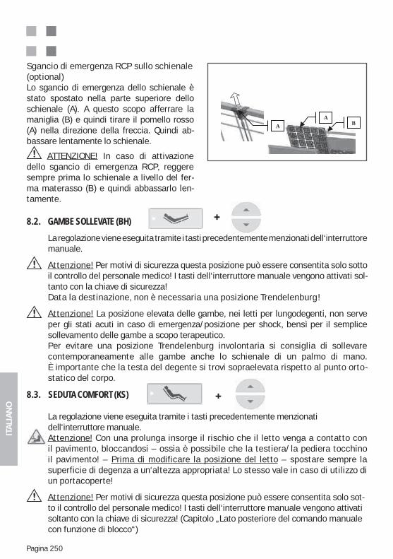
ITA
LIA
NO
Pagina 250
8.2. GAMBE SOLLEVATE (BH)
La regolazione viene eseguita tramite i tasti precedentemente menzionati dell‘interruttore manuale.
Attenzione! Per motivi di sicurezza questa posizione può essere consentita solo sotto il controllo del personale medico! I tasti dell‘interruttore manuale vengono attivati sol-tanto con la chiave di sicurezza!Data la destinazione, non è necessaria una posizione Trendelenburg!
Attenzione! La posizione elevata delle gambe, nei letti per lungodegenti, non serve per gli stati acuti in caso di emergenza/posizione per shock, bensì per il semplice sollevamento delle gambe a scopo terapeutico. Per evitare una posizione Trendelenburg involontaria si consiglia di sollevare contemporaneamente alle gambe anche lo schienale di un palmo di mano. È importante che la testa del degente si trovi sopraelevata rispetto al punto orto-statico del corpo.
8.3. SEDUTA COMFORT (KS)
La regolazione viene eseguita tramite i tasti precedentemente menzionati dell‘interruttore manuale. Attenzione! Con una prolunga insorge il rischio che il letto venga a contatto con il pavimento, bloccandosi – ossia è possibile che la testiera/la pediera tocchino il pavimento! – Prima di modificare la posizione del letto – spostare sempre la superficie di degenza a un‘altezza appropriata! Lo stesso vale in caso di utilizzo di un portacoperte!
Attenzione! Per motivi di sicurezza questa posizione può essere consentita solo sot-to il controllo del personale medico! I tasti dell‘interruttore manuale vengono attivati soltanto con la chiave di sicurezza! (Capitolo „Lato posteriore del comando manuale con funzione di blocco“)
Sgancio di emergenza RCP sullo schienale(optional)Lo sgancio di emergenza dello schienale è stato spostato nella parte superiore dello schienale (A). A questo scopo afferrare la maniglia (B) e quindi tirare il pomello rosso (A) nella direzione della freccia. Quindi ab-bassare lentamente lo schienale.
ATTENZIONE! In caso di attivazione dello sgancio di emergenza RCP, reggere sempre prima lo schienale a livello del fer-ma materasso (B) e quindi abbassarlo len-tamente.
BA
A
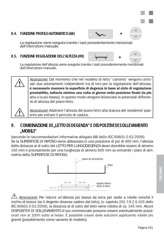
ITA
LIA
NO
Pagina 251
Attenzione! Dal momento che nel modello di letto “carisma” vengono utiliz-zati due azionamenti indipendenti tra di loro per la regolazione dell‘altezza,
alta o la più bassa). In questo modo vengono bilanciate le potenziali differen-ze di altezza del piano letto.
Attenzione! Adattare l‘altezza del piano letto alla statura del residente/pazi-ente per evitare il pericolo di caduta.
Attenzione! Per ridurre un‘altezza più bassa da terra per sedie a rotelle nonché il rischio di lesioni (se il degente dovesse cadere dal letto), (v. capitolo 201.7.9.2.5.103 dello IEC 60601-2-52:2009), la distanza al di sotto del letto viene ridotta di ca. 145 mm. Alcuni DISPOSITIVI DI SOLLEVAMENTO d‘uso commerciale possono essere eventualmente posizi-
grandi (possibilmente come variante di modello).
9. COMBINAZIONE DI „LETTO DI DEGENZA“ E DISPOSITIVI DI SOLLEVAMENTO „MOBILI“(secondo le raccomandazioni informative allegato BB dello IEC 60601-2-52:2009)Se la SUPERFICIE DI RIPOSO viene abbassata in una posizione di più di 400 mm, l‘altezza della distanza al di sotto del LETTO PER LUNGODEGENZA deve/dovrebbe essere di almeno 150 mm e precisamente per una lunghezza di almeno 500 mm su entrambi i piani di sim-metria della SUPERFICIE DI RIPOSO.
8.4. FUNZIONE PROFILO AUTOMATICO (AK)
La regolazione viene eseguita tramite i tasti precedentemente menzionati dell‘interruttore manuale.
8.5. FUNZIONE REGOLAZIONE DELL‘ALTEZZA (HV)
La regolazione dell’altezza viene eseguita tramite i tasti precedentemente menzionati dell‘interruttore manuale.
Symmetrieebene
Bett
Unterfahrbar
piani di simmetria
letto
spazio libero sotto il letto
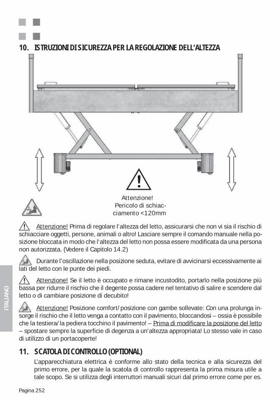
ITA
LIA
NO
Pagina 252
11. SCATOLA DI CONTROLLO (OPTIONAL)L’apparecchiatura elettrica è conforme allo stato della tecnica e alla sicurezza del primo errore, per la quale la scatola di controllo rappresenta la prima misura utile a tale scopo. Se si utilizza degli interruttori manuali sicuri dal primo errore come per es.
10. ISTRUZIONI DI SICUREZZA PER LA REGOLAZIONE DELL‘ALTEZZA
Attenzione! Prima di regolare l‘altezza del letto, assicurarsi che non vi sia il rischio di schiacciare oggetti, persone, animali o altro! Lasciare sempre il comando manuale nella po-sizione bloccata in modo che l‘altezza del letto non possa essere modificata da una persona non autorizzata. (Vedere il Capitolo 14.2)
Durante l’oscillazione nella posizione seduta, evitare di avvicinarsi eccessivamente ai lati del letto con le punte dei piedi.
Attenzione! Se il letto è occupato e rimane incustodito, portarlo nella posizione più bassa per ridurre il rischio che il degente possa cadere nel tentativo di salire e scendere dal letto o di cambiare posizione di decubito!
Attenzione! Posizione comfort/posizione con gambe sollevate: Con una prolunga in-sorge il rischio che il letto venga a contatto con il pavimento, bloccandosi – ossia è possibile che la testiera/la pediera tocchino il pavimento! – Prima di modificare la posizione del letto – spostare sempre la superficie di degenza a un‘altezza appropriata! Lo stesso vale in caso di utilizzo di un portacoperte!
Attenzione!Pericolo di schiac-
ciamento <120mm
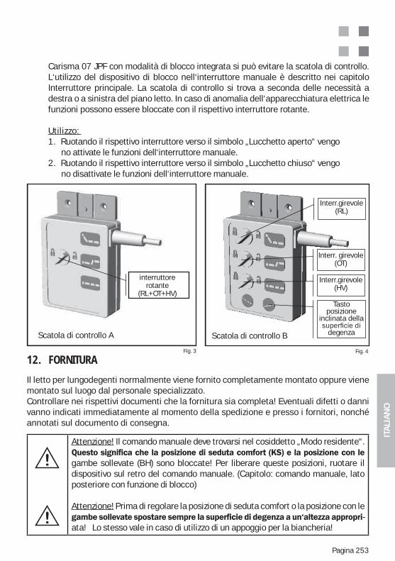
ITA
LIA
NO
Pagina 253
Attenzione! Il comando manuale deve trovarsi nel cosiddetto „Modo residente“.
gambe sollevate (BH) sono bloccate! Per liberare queste posizioni, ruotare il dispositivo sul retro del comando manuale. (Capitolo: comando manuale, lato posteriore con funzione di blocco)
Attenzione! Prima di regolare la posizione di seduta comfort o la posizione con le -
ata! Lo stesso vale in caso di utilizzo di un appoggio per la biancheria!
Fig. 3 Fig. 4
Kontrollbox -A
rehs halter
Kontrollbox -B
interruttorerotante
(RL+OT+HV)
Interr.girevole (RL)
Interr. girevole (OT)
Interr.girevole (HV)
Tasto posizione
inclinata della
degenzaScatola di controllo BScatola di controllo A
12. FORNITURA
Il letto per lungodegenti normalmente viene fornito completamente montato oppure viene montato sul luogo dal personale specializzato. Controllare nei rispettivi documenti che la fornitura sia completa! Eventuali difetti o danni vanno indicati immediatamente al momento della spedizione e presso i fornitori, nonché annotati sul documento di consegna.
Carisma 07 JPF con modalità di blocco integrata si può evitare la scatola di controllo. L‘utilizzo del dispositivo di blocco nell‘interruttore manuale è descritto nei capitolo Interruttore principale. La scatola di controllo si trova a seconda delle necessità a destra o a sinistra del piano letto. In caso di anomalia dell‘apparecchiatura elettrica le funzioni possono essere bloccate con il rispettivo interruttore rotante.
Utilizzo: 1. Ruotando il rispettivo interruttore verso il simbolo „Lucchetto aperto“ vengo no attivate le funzioni dell‘interruttore manuale.2. Ruotando il rispettivo interruttore verso il simbolo „Lucchetto chiuso“ vengo no disattivate le funzioni dell‘interruttore manuale.
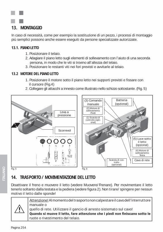
ITA
LIA
NO
Pagina 254
14. TRASPORTO / MOVIMENTAZIONE DEL LETTO
Disattivare il freno e muovere il letto (vedere Muovere/Frenare). Per movimentare il letto tenerlo soltanto dalla testata e la pediera (vedere figura 2). Non tirare/spingere per nessun motivo il letto dalle sponde!
Attenzione! Al momento del trasporto non calpestare il cavo dell’interruttore manuale oquello di rete. Utilizzare il gancio di arresto sistemato sul cavo!
ruote o rivestimento del telaio.
13. MONTAGGIO
In caso di necessità, come per esempio la sostituzione di un pezzo, i processi di montaggio più semplici possono anche essere eseguiti da persone specializzate autorizzate.
13.1. PIANO LETTO 1. Posizionare il telaio. 2. Adagiare il piano letto sugli elementi di sollevamento con l’aiuto di una seconda persona, in modo che le viti si trovino all’altezza del telaio. 3. Posizionare le restanti viti nei fori previsti e avvitarle al telaio.
13.2 MOTORE DEL PIANO LETTO
1. Posizionare il motore sotto il piano letto nei supporti previsti e fissare con il cursore (Fig.4) 2. Collegare gli attacchi a innesto come illustrato nello schizzo sottostante. (Fig. 5)
Fig. 5 Fig. 6
Caja de con-trol (opción)
Cable de alimentación
Schieber
Druckhebel
(1) Kontroll-box (Option)
Kontrollbox (Option)
(2) Hubmotor Fuß
(3) Hand-schalter
(5) Unterbett- Beleuchtung
(Option)
Akku (Option)
(4) Hubmotor Kopf
Netzkabel
Leva apressione
(3) Comando manuale
(2) Motore di sollevamento
Piedi
Batteria (opzional)
(5) Luce sotto il letto
(opzional)
Cavo di rete
(1) Scatola di controllo (opti-
onal)
Scatola di con-trollo
(optional)
(4) Motore di sollevamento
Testa
Scorrevol
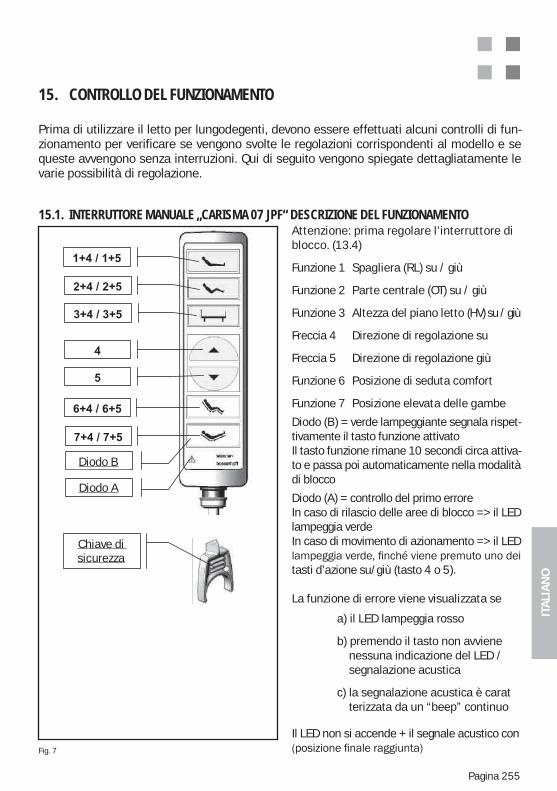
ITA
LIA
NO
Pagina 255
15. CONTROLLO DEL FUNZIONAMENTO
Prima di utilizzare il letto per lungodegenti, devono essere effettuati alcuni controlli di fun-zionamento per verificare se vengono svolte le regolazioni corrispondenti al modello e se queste avvengono senza interruzioni. Qui di seguito vengono spiegate dettagliatamente le varie possibilità di regolazione.
15.1. INTERRUTTORE MANUALE „CARISMA 07 JPF“ DESCRIZIONE DEL FUNZIONAMENTO
Attenzione: prima regolare l’interruttore di blocco. (13.4)
Funzione 1 Spagliera (RL) su / giù
Funzione 2 Parte centrale (OT) su / giù
Funzione 3 Altezza del piano letto (HV) su / giù
Freccia 4 Direzione di regolazione su
Freccia 5 Direzione di regolazione giù
Funzione 6 Posizione di seduta comfort
Funzione 7 Posizione elevata delle gambe
Diodo (B) = verde lampeggiante segnala rispet-tivamente il tasto funzione attivatoIl tasto funzione rimane 10 secondi circa attiva-to e passa poi automaticamente nella modalità di blocco
Diodo (A) = controllo del primo erroreIn caso di rilascio delle aree di blocco => il LED lampeggia verdeIn caso di movimento di azionamento => il LED
tasti d’azione su/giù (tasto 4 o 5).
La funzione di errore viene visualizzata se
a) il LED lampeggia rosso
b) premendo il tasto non avviene nessuna indicazione del LED / segnalazione acustica
c) la segnalazione acustica è carat terizzata da un “beep” continuo
Il LED non si accende + il segnale acustico con Fig. 7
Diode A
Diode B
Sicher-heitsschlüs
l
Chiave di sicurezza
Diodo B
Diodo A
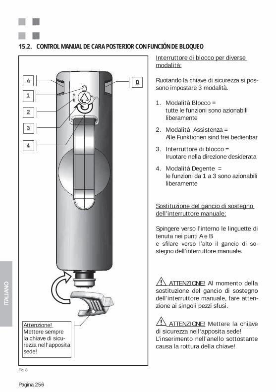
ITA
LIA
NO
Pagina 256
15.2. CONTROL MANUAL DE CARA POSTERIOR CON FUNCIÓN DE BLOQUEO
1
2
3
A B
4
Achtung! Si -cherheitsschlüssel - nur in dem dafür vor-gesehenen S lt i l i
Interruttore di blocco per diverse modalità:
Ruotando la chiave di sicurezza si pos-sono impostare 3 modalità.
1. Modalità Blocco = tutte le funzioni sono azionabili liberamente
2. Modalità Assistenza = Alle Funktionen sind frei bedienbar
3. Interruttore di blocco = Iruotare nella direzione desiderata
4. Modalità Degente = le funzioni da 1 a 3 sono azionabili liberamente
Sostituzione del gancio di sostegno dell’interruttore manuale:
Spingere verso l’interno le linguette di tenuta nei punti A e B
-stegno dell’interruttore manuale.
ATTENZIONE! Al momento della sostituzione del gancio di sostegno dell’interruttore manuale, fare atten-zione ai singoli pezzi sfusi.
ATTENZIONE! Mettere la chiave di sicurezza nell‘apposita sede!L’inserimento nell’anello sottostante causa la rottura della chiave!
Attenzione! Mettere sempre la chiave di sicu-rezza nell‘apposita sede!
Fig. 8
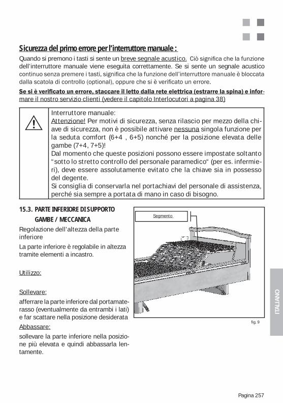
ITA
LIA
NO
Pagina 257
fig. 9
Sicurezza del primo errore per l’interruttore manuale : Quando si premono i tasti si sente un breve segnale acustico.dell’interruttore manuale viene eseguita correttamente. Se si sente un segnale acustico
-mare il nostro servizio clienti (vedere il capitolo Interlocutori a pagina 38)
Interruttore manuale:Attenzione! Per motivi di sicurezza, senza rilascio per mezzo della chi-ave di sicurezza, non è possibile attivare nessuna singola funzione per la seduta comfort (6+4 , 6+5) nonché per la posizione elevata delle gambe (7+4, 7+5)!Dal momento che queste posizioni possono essere impostate soltanto “sotto lo stretto controllo del personale paramedico“ (per es. infermie-ri), deve essere assolutamente evitato che la chiave sia in possesso del degente. Si consiglia di conservarla nel portachiavi del personale di assistenza, perché sia sempre a portata di mano in caso di bisogno.
15.3. PARTE INFERIORE DI SUPPORTO
GAMBE / MECCANICARegolazione dell’altezza della parte inferiore
La parte inferiore è regolabile in altezza tramite elementi a incastro.
Utilizzo:
Sollevare:
afferrare la parte inferiore dal portamate-rasso (eventualmente da entrambi i lati) e far scattare nella posizione desiderata
Abbassare:
sollevare la parte inferiore nella posizio-ne più elevata e quindi abbassarla len-tamente.
Segmento
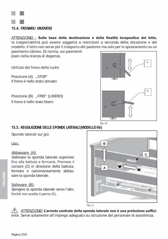
ITA
LIA
NO
Pagina 258
15.4. FRENARE/ MUOVERE
ATTENZIONE! :la trasportabilità può essere soggetta a restrizioni a seconda della dotazione e del modello. Il letto non serve per il trasporto del paziente ma solo per lo spostamento su un pavimento idoneo. Di norma, sui pavimenti piani nella stanza di degenza.
Utilizzo del freno delle ruote
Posizione (A) „STOP“Il freno è nello stato attivato
Posizione (B) „FREI“ (LIBERO)
Il freno è nello stato libero
Fig. 10
n
-
A
B
Sponde laterali su/giù
Uso:
Abbassare (A):Sollevare la sponda laterale superiore
cursore (C) in direzione della battuta, fermare e carismaneamente abbas-sare la sponda laterale.
Sollevare (B):Spingere la sponda laterale verso l’alto,
15.5. REGOLAZIONE DELLE SPONDE LATERALI (MODELLO 06)
Fig. 11
B
A
C
ATTENZIONE! -ente. Serve solamente all’impiego adeguato su istruzione del personale di assistenza.
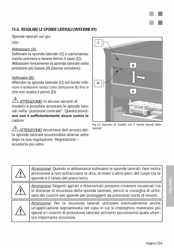
ITA
LIA
NO
Pagina 259
Sponde laterali su/giùUso :
Abbassare (A):Sollevare la sponda laterale (C) e carismanea-mente premere e tenere fermo il tasto (D).Abbassare lentamente la sponda laterale nella posizione più bassa (A) (lasciar scivolare).
Sollevare (B):Afferrare la sponda laterale (C) sul bordo infe-
che non scatta il perno (D).
ATTENZIONE! In alcune varianti di modello è possibile arrestare le sponde late-rali nella “posizione centrale“. Questa posizi-
cadute.
ATTENZIONE! Accertarsi dell’arresto del-la sponda laterale scuotendola diverse volte dopo la sua regolazione. Regolazione – scuoterla più volte.
15.6. REGOLARE LE SPONDE LATERALI (VERSIONE 09)
Fig..12 Esempio di modello con 2 bande laterali della sponda
B
A
D
C
Attenzione! Quando si abbassano/sollevano le sponde laterali, fare molta attenzione a non schiacciarsi le dita, le mani o altre parti del corpo tra le sponde e il telaio del piano letto.
Attenzione! Degenti agitati e disorientati possono rimanere incastrati tra le distanze di sicurezza della sponda laterale, perciò si consiglia di utiliz-zare dei cuscini per sponde per proteggerli da potenziali rischi di lesioni.
Attenzione! Per le sicurezze laterali utilizzare eventualmente anche un’applicazione sopraelevata nel caso in cui si impieghino materassi più spessi e i cuscini di protezione laterale attinenti (accessorio) quale ulteri-ore importante sicurezza.
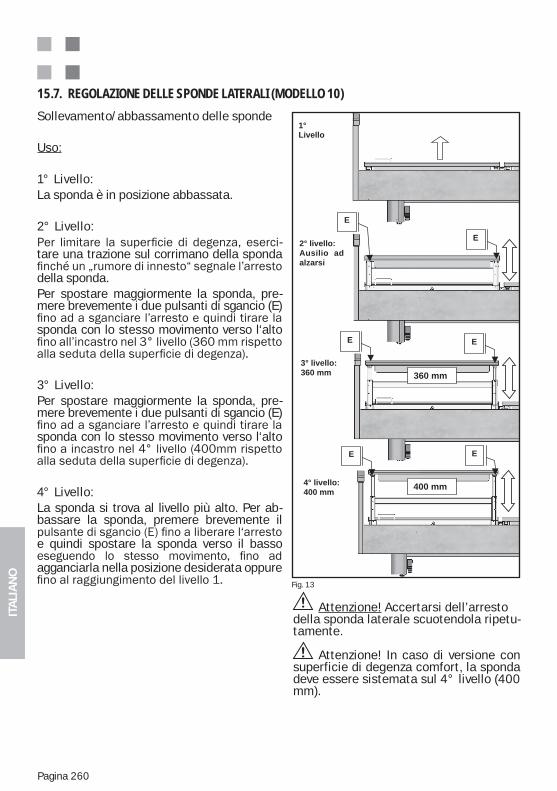
ITA
LIA
NO
Pagina 260
Sollevamento/abbassamento delle sponde
Uso:
1° Livello:La sponda è in posizione abbassata.
2° Livello:-
tare una trazione sul corrimano della sponda
della sponda.Per spostare maggiormente la sponda, pre-mere brevemente i due pulsanti di sgancio (E)
sponda con lo stesso movimento verso l‘alto
3° Livello:Per spostare maggiormente la sponda, pre-mere brevemente i due pulsanti di sgancio (E)
sponda con lo stesso movimento verso l‘alto
4° Livello:La sponda si trova al livello più alto. Per ab-bassare la sponda, premere brevemente il
e quindi spostare la sponda verso il basso
agganciarla nella posizione desiderata oppure
15.7. REGOLAZIONE DELLE SPONDE LATERALI (MODELLO 10)
Abb. 16
360 mm
400 mm
1°
Livello
2° livello:
Ausilio ad
alzarsi
3° livello:
360 mm
4° livello:
400 mm
E
E E
E
E
E
Fig. 13
Attenzione! Accertarsi dell’arresto della sponda laterale scuotendola ripetu-tamente.
Attenzione! In caso di versione con superficie di degenza comfort, la sponda deve essere sistemata sul 4° livello (400 mm).
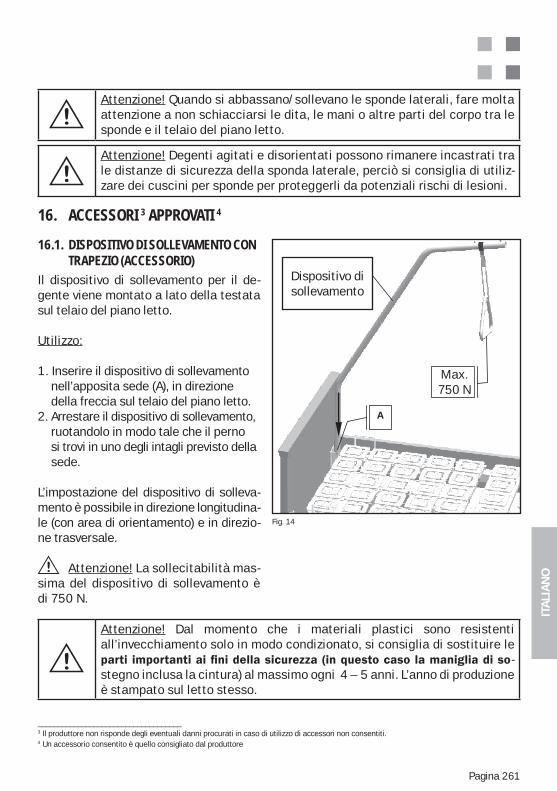
ITA
LIA
NO
Pagina 261
Attenzione! Quando si abbassano/sollevano le sponde laterali, fare molta attenzione a non schiacciarsi le dita, le mani o altre parti del corpo tra le sponde e il telaio del piano letto.
Attenzione! Degenti agitati e disorientati possono rimanere incastrati tra le distanze di sicurezza della sponda laterale, perciò si consiglia di utiliz-zare dei cuscini per sponde per proteggerli da potenziali rischi di lesioni.
16. ACCESSORI 3 APPROVATI 4
16.1. DISPOSITIVO DI SOLLEVAMENTO CON TRAPEZIO (ACCESSORIO)Il dispositivo di sollevamento per il de-gente viene montato a lato della testata sul telaio del piano letto.
Utilizzo:
1. Inserire il dispositivo di sollevamento nell’apposita sede (A), in direzione della freccia sul telaio del piano letto.2. Arrestare il dispositivo di sollevamento, ruotandolo in modo tale che il perno si trovi in uno degli intagli previsto della sede.
L’impostazione del dispositivo di solleva-mento è possibile in direzione longitudina-le (con area di orientamento) e in direzio-ne trasversale.
Attenzione! La sollecitabilità mas-sima del dispositivo di sollevamento è di 750 N.
Attenzione! Dal momento che i materiali plastici sono resistenti all’invecchiamento solo in modo condizionato, si consiglia di sostituire le
-stegno inclusa la cintura) al massimo ogni 4 – 5 anni. L’anno di produzione è stampato sul letto stesso.
____________________________________3 Il produttore non risponde degli eventuali danni procurati in caso di utilizzo di accessori non consentiti.4 Un accessorio consentito è quello consigliato dal produttore
Fig. 14
Aufrichter
A
Max.
750N
Dispositivo di sollevamento
Max.750 N
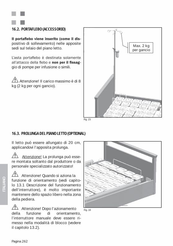
ITA
LIA
NO
Pagina 262
-positivo di sollevamento) nelle apposite sedi sul telaio del piano letto.
-gio di pompe per infusione o simili.
Attenzione! Il carico massimo è di 8 kg (2 kg per ogni gancio).
16.2. PORTAFLEBO (ACCESSORIO)
Il letto può essere allungato di 20 cm, applicandovi l’apposita prolunga.
Attenzione! La prolunga può esse-re montata soltanto dal produttore o da personale specializzato autorizzato!
Attenzione! Quando si aziona la funzione di orientamento (vedi capito-lo 13.1 Descrizione del funzionamento dell’interruttore), è molto importante mantenere dello spazio libero nella zona della pediera.
Attenzione! Dopo l’azionamento della funzione di orientamento, l’interruttore manuale deve essere ri-messo nella modalità di blocco (vedere il capitolo 13.2).
16.3. PROLUNGA DEL PIANO LETTO (OPTIONAL)
Fig. 15
Fig. 16
dieah-
In-usi-
kg
Max. 2 kg per gancio
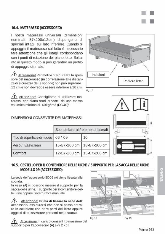
ITA
LIA
NO
Pagina 263
I nostri materassi universali (dimensioni nominali: 87x200x12cm) dispongono di speciali intagli sul lato inferiore. Quando si appoggia il materasso sul letto è necessario fare attenzione che gli intagli corrispondano con i punti di rotazione del piano letto. Solta-
di appoggio ottimale.
Attenzione! Per motivi di sicurezza lo spes-sore del materasso (in correlazione alle distan-ze di sicurezza delle sponde) non può superare i 12 cm e non dovrebbe essere inferiore a 10 cm!
Attenzione! Consigliamo di utilizzare ma-terassi che siano stati prodotti da una massa volumica minima di 40kg/m3 (RG 40)!
16.4. MATERASSO (ACCESSORIO)
Fig. 17
Bett-Fußteil
EinschnitteIncisioni
Pediera letto
sponda. In essa (A) si possono inserire il supporto per la sacca delle urine, il supporto per il contenitore del-le urine oppure l’interruttore manuale Attenzione! accessorio, assicurarsi che non si possa entra-re in collisione con altre parti del letto oppure oggetti di attrezzature presenti nella stanza.
16.5. CESTELLO PER IL CONTENITORE DELLE URINE / SUPPORTO PER LA SACCA DELLE URINE MODELLO 09 (ACCESSORIO)
Fig. 18 Fig. 19
Attenzione! Il carico consentito massimo delsupporto per l’accessorio (A) è di 2 kg !
DIMENSIONI CONSENTITE DEI MATERASSI:
Sponde laterali/elementi laterali
Tipo di superficie di riposo 06 / 09 10
Aero / Easyclean 15x87x200 cm 18x87x200 cm
Comfort 12x87x200 cm 15x87x200 cm
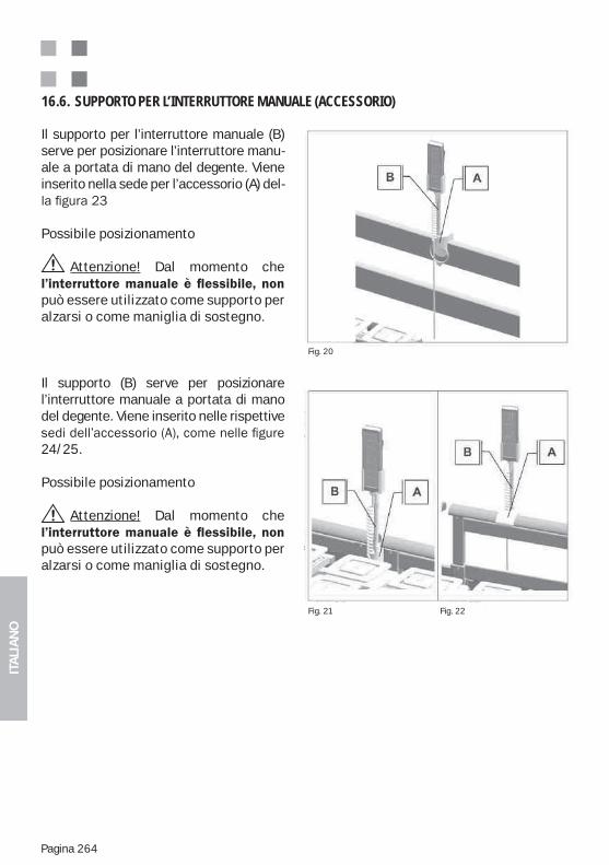
ITA
LIA
NO
Pagina 264
Il supporto per l’interruttore manuale (B) serve per posizionare l’interruttore manu-ale a portata di mano del degente. Viene inserito nella sede per l’accessorio (A) del-
Possibile posizionamento
Attenzione! Dal momento che
può essere utilizzato come supporto per alzarsi o come maniglia di sostegno.
Il supporto (B) serve per posizionare l’interruttore manuale a portata di mano del degente. Viene inserito nelle rispettive
24/25.
Possibile posizionamento
Attenzione! Dal momento che
può essere utilizzato come supporto per alzarsi o come maniglia di sostegno.
16.6. SUPPORTO PER L’INTERRUTTORE MANUALE (ACCESSORIO)
Fig. 20
Fig. 21 Fig. 22
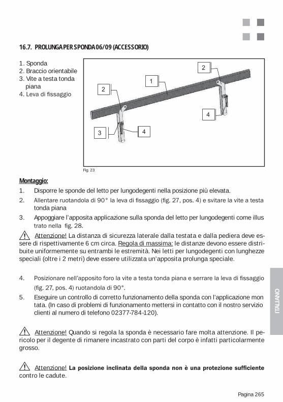
ITA
LIA
NO
Pagina 265
1. Sponda2. Braccio orientabile3. Vite a testa tonda piana
16.7. PROLUNGA PER SPONDA 06/09 (ACCESSORIO)
Fig. 23
Montaggio:1. Disporre le sponde del letto per lungodegenti nella posizione più elevata.
tonda piana
3. Appoggiare l’apposita applicazione sulla sponda del letto per lungodegenti come illus
Attenzione! La distanza di sicurezza laterale dalla testata e dalla pediera deve es-sere di rispettivamente 6 cm circa. Regola di massima: le distanze devono essere distri-buite uniformemente su entrambi le estremità. Nei letti per lungodegenti con lunghezze speciali (oltre i 2 metri) deve essere utilizzata un’apposita prolunga speciale.
5. Eseguire un controllo di corretto funzionamento della sponda con l’applicazione mon tata. (In caso di problemi di funzionamento mettersi in contatto con il nostro servizio clienti al numero di telefono 02377-784-120).
Attenzione! Quando si regola la sponda è necessario fare molta attenzione. Il pe-ricolo per il degente di rimanere incastrato con parti del corpo è infatti particolarmente grosso.
Attenzione!contro le cadute.
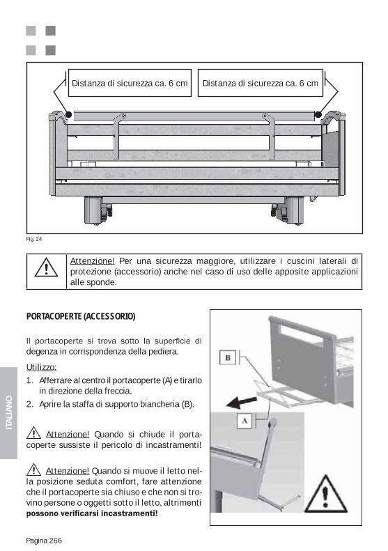
ITA
LIA
NO
Pagina 266
Distanza di sicurezza ca. 6 cm Distanza di sicurezza ca. 6 cm
Attenzione! Per una sicurezza maggiore, utilizzare i cuscini laterali di protezione (accessorio) anche nel caso di uso delle apposite applicazioni alle sponde.
Fig. 24
PORTACOPERTE (ACCESSORIO)
degenza in corrispondenza della pediera.
Utilizzo:
1. Afferrare al centro il portacoperte (A) e tirarloin direzione della freccia.
2. Aprire la staffa di supporto biancheria (B).
Attenzione! Quando si chiude il porta-coperte sussiste il pericolo di incastramenti!
Attenzione! Quando si muove il letto nel-la posizione seduta comfort, fare attenzione che il portacoperte sia chiuso e che non si tro-vino persone o oggetti sotto il letto, altrimenti
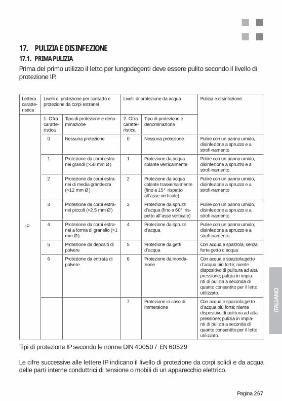
ITA
LIA
NO
Pagina 267
17. PULIZIA E DISINFEZIONE17.1. PRIMA PULIZIAPrima del primo utilizzo il letto per lungodegenti deve essere pulito secondo il livello di protezione IP.
Tipi di protezione IP secondo le norme DIN 40050 / EN 60529
Le cifre successive alle lettere IP indicano il livello di protezione da corpi solidi e da acqua delle parti interne conduttrici di tensione o mobili di un apparecchio elettrico.
Lettera caratte-ristica
Livelli di protezione per contatto e protezione da corpi estranei
Livelli di protezione da acqua Pulizia e disinfezione
IP
1. Cifra caratte-ristica
Tipo di protezione e deno-minazione
2. Cifra caratte-ristica
Tipo di protezione e denominazione
0 Nessuna protezione 0 Nessuna protezione Pulire con un panno umido, disinfezione a spruzzo e a strofi-namento
1 Protezione da corpi estra-nei grandi (>50 mm Ø )
1 Protezione da acqua colante verticalmente
Pulire con un panno umido, disinfezione a spruzzo e a strofi-namento
2 Protezione da corpi estra-nei di media grandezza (>12 mm Ø )
2 Protezione da acqua colante trasversalmente (fino a 15° rispetto all‘asse verticale)
Pulire con un panno umido, disinfezione a spruzzo e a strofi-namento
3 Protezione da corpi estra-nei piccoli (>2,5 mm Ø )
3 Protezione da spruzzi d’acqua (fino a 60° ris-petto all’asse verticale)
Pulire con un panno umido, disinfezione a spruzzo e a strofi-namento
4 Protezione da corpi estra-nei a forma di granello (>1 mm Ø )
4 Protezione da spruzzi d’acqua
Pulire con un panno umido, disinfezione a spruzzo e a strofi-namento
5 Protezione da depositi di polvere
5 Protezione da getti d’acqua
Con acqua e spazzola; senza forte getto d’acqua
6 Protezione da entrata di polvere
6 Protezione da inonda-zione
Con acqua e spazzola;getto d’acqua più forte; niente dispositivo di pulitura ad alta pressione; pulizia in impia-nti di pulizia a seconda di quanto consentito per il letto utilizzato.
7 Protezione in caso di immersione
Con acqua e spazzola;getto d’acqua più forte; niente dispositivo di pulitura ad alta pressione; pulizia in impia-nti di pulizia a seconda di quanto consentito per il letto utilizzato.
ITA
LIA
NO
Pagina 268
Attenzione! Per motivi di sicurezza deve essere evitata l’introduzione o il contatto con liquidi (p.es. acqua, solventi, oli, liscive, detergenti e così via) nel letto per lungode-genti o parti di esso.
Attenzione! Le scatole che presentano la protezione dall’entrata dell’acqua , non dis-pongono necessariamente della stessa protezione anche per altre sostanze!
Attenzione! Il letto per lungodegenti generalmente va pertanto protetto da ogni tipo di sostanza liquida! La pulizia dovrebbe essere eseguita soltanto con un panno um-ido.
17.2. DESINFEZIONE / STERILIZZAZIONEIl letto per lungodegenti va disinfettato regolarmente o almeno prima di ogni cambio del degente. Non deve essere disinfettato in percorsi ad acqua o con acqua a spruzzo.Per la disinfezione del letto per lungodegenti si consiglia di utilizzare i seguenti prodotti che possono essere sostituiti da prodotti con le stesse e identiche caratteristiche:Terralin, Perform e Sagrotan Med (Schülke & Mayr GmbH, Norderstedt).Questi prodotti vanno utilizzati seguendo assolutamente le istruzioni del produttore! Ciò riguarda soprattutto il dosaggio e l’eventuale rischio che si corre nel mescolarli con altri prodotti. Il bordo in legno non deve venire a contatto con questi prodotti.
17.3. ISTRUZIONI DI PULIZIA DELLE PARTI IN LEGNOSono stati utilizzati materiali di ottima qualità per conferire al letto un’ampia possibilità di utilizzo e quel carattere di accoglienza proprio del legno autentico.Perché si possa usufruire a lungo e con gioia del letto Wissner-Bosserhoff, consigliamo di pulirlo con un panno morbido leggermente umido.
Ogni materiale di legno autentico (impiallacciatura, legno massiccio) è soggetto a un natu-rale processo di invecchiamento. Nel corso della sua durata, fattori ambientali come i raggi UV, l’umidità o il calore, influiscono molto sul cambiamento di colore delle superfici in vero legno. Inoltre il legno, essendo un materiale naturale, è soggetto a diversità e sfumature del suo aspetto. Le strutture delle impiallacciature sono definibili solo grossolanamente, in quanto ogni albero dei vari tipi di legno utilizzati ha le sue proprie caratteristiche. Leggere differenze di contrasto e colore delle forniture di Wissner-Bosserhoff sono legate alla natura stessa del prodotto e sono inevitabili dal punto di vista tecnico. Ciò va considerato soprat-tutto in caso di forniture successive e completamenti. Per i motivi citati, le differenze di contrasto, luminosità e colore tra le varie superfici di im-piallacciatura, le parti di legno massiccio o le superficie decorative (melammina, HPL), non-ché inclusione dovuti alla crescita dei materiali in vero legno, non rappresentano un difetto e Wissner-Bosserhoff GmbH non se ne assume pertanto la responsabilità.Con l’accurata scelta, la selezione e la determinazione cromatica di impiallacciature e verni-ciature, Wissner-Bosserhoff garantisce l’elevata qualità della colorazione dei prodotti.
ITA
LIA
NO
Pagina 269
17.4. IMPIEGO DI DETERGENTIIn caso di macchie particolarmente dure, si può utilizzare anche un detergente universale ed ecologico per uso domestico. Le superfici dei mobili dei prodotti Wissner-Bosserhoff sono conformi alla norma DIN 68861 - 1A per superfici di mobili in caso di sollecitazione chimica e presentano pertanto un’ottima resistenza alle normali sollecitazioni.Tuttavia non devono essere utilizzati dei detergenti contenenti componenti con azione abra-siva.
autentico e di impiallacciatura non vengano a contatto con l’umidità e le macchie di sostanze liquide. Il legno è un prodotto naturale con la caratteristica di assorbire l’umidità e quindi di dilatarsi. Questo aspetto può causare danni alla sigillatura della superficie.
luoghi soggetti ad un’umidità elevata.Dopo la pulizia si consiglia di asciugare le superfici di legno vero e di impiallacciatura con un panno asciutto per evitare possibili danni dovuti all’umidità.
17.5. IMPIEGO DI DISINFETTANTI
nell’allegato 1 della norma DIN 68861, parte 1: a) derivati del fenolo, 0,5-% di soluzione acquosa: alchil-, cicloalchil- arilfenolo clorato b) cloramina T, 2,5-% di soluzione acquosa: Toluen-p-sulfoncloramide sodica
17.6. DANNEGGIAMENTI ALLE PARTI IN LEGNOSe l’impiallacciatura o la sigillatura delle superfici viene danneggiata da urti, graffi o tagli, deve essere riparata con appositi materiali che le riconferiscano la protezione dall’umidità. Rivolgersi al servizio clienti di Wissner-Bosserhoff oppure ad un rivenditore specializzato in materia.
17.7. COMPATIBILITÀ AMBIENTALETutti i materiali in legno utilizzati sono conformi alle severi leggi e direttive tedesche in materia e non sono nocivi per la salute. L’uomo e il suo ambiente costituiscono il fulcro della nostra attività.
17.8. QUALITÀI prodotti vengono sottoposti a severi controlli da parte del nostro sistema di sicurezza della qualità conforme alle norme internazionali DIN EN ISO 9001:2000 e DIN EN ISO 13485:2003 riguardanti la produzione e commercializzazione di prodotti medici.Wissner-Bosserhoff conferisce un anno di garanzia del produttore per tutte le caratteristiche assicurate ai clienti. Sono esclusi dalla garanzia i risarcimenti di danni dovuti ad utilizzi o ma-nutenzioni inusuali e non conformi alla destinazione. In caso di reclami o critiche, si prega di rivolgersi al nostro servizio clienti.
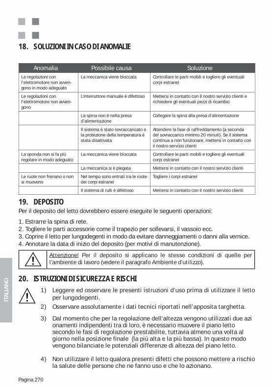
ITA
LIA
NO
Pagina 270
18. SOLUZIONI IN CASO DI ANOMALIE
Anomalia Possibile causa SoluzioneLe regolazioni con l‘elettromotore non avven-gono in modo adeguato
La meccanica viene bloccata Controllare le parti mobili e togliere gli eventuali corpi estranei
Le regolazioni con l‘elettromotore non avven-gono
L’interruttore manuale è difettoso Mettersi in contatto con il nostro servizio clienti e richiedere gli eventuali pezzi di ricambio
La spina non è nella presa d’alimentazione
Collegare la spina alla presa d’alimentazione
Il sistema è stato sovraccaricato e la protezione della temperatura è stata disattivata
Attendere la fase di raffreddamento (a seconda del sovraccarico minimo 20 minuti). Se il sistema continua a non funzionare, mettersi in contatto con il nostro servizio clienti
La sponda non si fa più regolare in modo adeguato
La meccanica viene bloccata Controllare le parti mobili e togliere gli eventuali corpi estranei
La meccanica si è piegata Mettersi in contatto con il nostro servizio clienti
Le ruote non frenano o non si muovono
Nel tempo sono entrati tra le ruote dei corpi estranei
Togliere i corpi estranei
Il sistema di rulli è difettoso Mettersi in contatto con il nostro servizio clienti
19. DEPOSITOPer il deposito del letto dovrebbero essere eseguite le seguenti operazioni:
1. Estrarre la spina di rete.2. Togliere le parti accessorie come il trapezio per sollevarsi, il vassoio ecc.3. Coprire il letto per lungodegenti in modo da evitare danneggiamenti o danni alla vernice.4. Annotare la data di inizio del deposito (per motivi di manutenzione).
Attenzione! Per il deposito si applicano le stesse condizioni di quelle per l’ambiente di lavoro (vedere il paragrafo Ambiente d’utilizzo).
20. ISTRUZIONI DI SICUREZZA E RISCHI1) Leggere ed osservare le presenti istruzioni d’uso prima di utilizzare il letto per lungodegenti.2) Osservare assolutamente i dati tecnici riportati nell’apposita targhetta.
3) Dal momento che per la regolazione dell‘altezza vengono utilizzati due azi onamenti indipendenti tra di loro, è necessario muovere il piano letto secondo le fasi di regolazione prestabilite, tuttavia almeno una volta al giorno nella posizione finale (la più alta e la più bassa). In questo modo vengono bilanciate le potenziali differenze di altezza del piano letto.
4) Non utilizzare il letto qualora presenti difetti che possono mettere a rischio la salute delle persone che ne fanno uso e che lo azionano.
ITA
LIA
NO
Pagina 271
5) Il letto deve essere utilizzato da persone che possono garantirne l’uso ap- propriato in quanto dispongono della formazione professionale, le conos- cenze e l‘esperienza pratica adeguate.
6) Prima di usare il letto, l’utente deve assicurarsi che sia in perfetto stato e che funzioni in modo adeguato.
7) Controllare giornalmente o almeno ad ogni cambio del turno che il letto fun- zioni regolarmente, in modo da garantirne l’uso conforme alla destinazione senza rischi per il degente e l’utente.
8) Non riparare il trapezio per sollevarsi dal letto e poi riutilizzarlo, ma sostituirlo.
9) Il letto può essere movimentato su superfici piane e fisse.
10) Se il letto è occupato, le ruote devono essere frenate. In caso contrario sus- siste il pericolo che il paziente cada quando sale o scende dal letto (appog- giandosi ad esso).
11) Adattare l‘altezza del piano letto alla statura del paziente per evitare il peri- colo di caduta.
12) Quando si aziona l‘abbassamento meccanico d‘emergenza della spagliera (optional), quest‘ultima deve essere fissata alla staffa di limitazione del ma- terasso o al tubo di sostegno per evitare un abbassamento improvviso.
13) Quando si muove il letto nelle diverse posizioni fare attenzione che non si trovino bambini, parti del corpo o oggetti nell‘area di movimentazione.
14) I movimenti delle sponde devono essere eseguiti soltanto dal personale di assistenza. Quando vengono movimentate le posizioni del piano letto, il per- sonale di assistenza deve assicurarsi che il degente non venga a contatto con le sponde, al fine di evitare schiacciamenti delle mani, gambe o altre parti del corpo.
15) Evitare di sporgersi in modo estremo su un lato con il tronco.
16) Non sollecitare le sponde oltre i 75 kg. in direzione verticale e oltre i 50 kg in direzione orizzontale.
17) A seconda delle condizioni fisiche e psichiche del degente, le funzioni dell’interruttore manuale devono essere disattivate o attivate tramite una scatola di controllo. Controllare dall’interruttore manuale che le funzioni sia- no state realmente bloccate.
ITA
LIA
NO
Pagina 272
18) Dal momento che il sistema può essere alimentato anche a batteria , la disconnessione della spina dalla presa elettrica non garantisce l’arresto dei motori in caso di un loro errato funzionamento. Se si verifica un errore nel funzionamento, è necessario disattivare le funzioni dall‘apposita scato- la di controllo e mettersi in contatto con il nostro servizio clienti (funzion- amento a batteria come optional).
19) In caso di movimentazioni tramite l’interruttore manuale si consiglia di ri- manere nelle vicinanze della scatola di controllo per fermare immediata- mente eventuali funzioni errate.
20) Attenzione! Tutte le funzioni elettriche sono soggette ad errori, A meno che non le si blocchi tramite la scatola di controllo
21) Come sorgente elettrica deve essere utilizzata una presa di rete da 220 / 230 Volt, 50 Hz, come previsto dalle norme della VDE (associazione tedesca degli elettrotecnici)
22) Non toccare la spina con le mani bagnate. Disconnettere il cavo di collega- mento alla presa elettrica solo dalla spina e non tirarlo mai dalla presa stes- sa.
23) Posare il cavo di rete evitando nodi, flessioni e piegature.
24) Proteggere l‘attacco e l’alimentazione da sollecitazioni meccaniche.
25) Posare il cavo di rete e quello d’alimentazione verso l’interruttore manuale evitando il rischio di schiacciarli con oggetti.
26) Al momento della sistemazione del letto fare attenzione che vengano mantenute le distanze di sicurezza rispetto le pareti, i davanzali o altri og- getti d’arredamento. Le distanze di sicurezza sono diverse a seconda del modello del letto e si stabiliscono effettuando i movimenti più estremi di orientamento e regolazione in altezza e mantenendo da essi 25 mm di spa- zio libero.
27) Quando si effettuano le funzioni di supporto e regolazione in altezza è neces- sario fare attenzione che la chiave di sicurezza (magnete) non sia inserita o che non si trovi nelle vicinanze dell’interruttore manuale (c’é il rischio che il degente arrivi ad afferrarla). Attivando in modo scorretto la chiave di si- curezza (magnete) possono essere prese delle posizioni rischiose per i de- genti, come per esempio la posizione di Trendeleburg applicata scorretta- mente..
28) Appendere l’interruttore manuale nell’apposito supporto (optional) o al letto in modo tale da non azionare accidentalmente i tasti perchè disposti tra due oggetti, come per esempio tra la sponda e il comodino.

ITA
LIA
NO
Pagina 273
29) La pulizia del letto deve essere eseguita soltanto con un panno umido.
30) In caso di utilizzo non corretto del letto possono verificarsi le seguenti situazio- ni di pericolo:
Azionamento accidentale delle funzioni elettriche in caso di posizionamento incontrollato del letto,
Utilizzo del letto per bambini di età inferiore ai dodici anni, Azionamento delle funzioni del letto da parte del paziente senza previa istruzi-
one, Azionamento carismaneo delle funzioni elettriche da parte di più persone, Collegamento di strumenti elettrici non previsti al letto, Spostamenti del letto tirando il cavo di rete o le sponde, Staccare la spina dalla presa tirando il cavo, Protezione mancante dei cavi di collegamento e alimentazione da piegature a
spigolo vivo o altre sollecitazioni meccaniche (per es. calpestamento del cavo),
Spostamento del letto su superfici instabili, Utilizzo del letto su superfici in discesa con un angolo di inclinazione di 10° ed
oltre, gli strumenti che generano forti campi elettromagnetici e possono pertanto
disturbare il controllo del letto, non sono consentiti nelle immediate vicinanze del letto (ad esempio telefoni cellulari).
Prima di eseguire lavori di pulizia e manutenzione del letto, staccare sempre la spina dalla presa elettrica.
Per motivi di sicurezza il trapezio per sollevarsi dal letto deve essere sostituito insieme alla cinghia dopo 5 anni.
Il materasso da utilizzare deve essere conforme alle norme di sicurezza e non può superare i 120 mm di spessore.
Continua presenza di sostanze liquide nell’area motore (ad es. in caso di in- continenza)
Lavori di riparazione errata degli strumenti elettrici
31) Istruzioni di sicurezza – Misure per un funzionamento sicuro di letti per lungo- degenti:
i componenti elettrici presenti nei letti per lungodegenti possono essere ripa-rati e manutenuti soltanto dal produttore o da personale specializzato appo-sitamente addestrato dal produttore stesso. In caso contrario, si rischia che modalità speciali di esecuzione non avvengano correttamente per mancata conoscenza delle funzionalità del prodotto con conseguente pericolo di sca-riche elettriche o incendi.
I componenti elettrici presenti nei letti per lungodegenti possono essere sosti-tuiti soltanto con pezzi di ricambio originali del produttore, dal momento che se si impiegano dei componenti non adeguati sussiste il rischio di scarica elet-trica o di incendio.
ITA
LIA
NO
Pagina 274
-do manuale al fine di evitare un uso di tipo ludico dello stesso.
La pulizia del letto deve essere eseguita soltanto seguendo quanto descritto nel paragrafo „Pulizia e disinfenzione“ delle presenti istruzioni d’uso. Il produttore non risponde per rischi derivanti dalla mancata osservanza delle istruzioni.
Se i pazienti che occupano il letto soffrono di incontinenza, è necessario utiliz-zare un’apposita protezione per il materasso.
In caso di lungodegenza, di mancati ausili preventivi (come i materassi antide-cubito), e di assenza di un’adeguata profilassi antidecubito, i degenti possono sviluppare piaghe nei punti di pressione. Il produttore declina ogni responsabi-lità al riguardo.
Il prodotto non è espressamente adeguato per un utilizzo continuato. Se la du-rata di attivazione predefinita viene superata, si può verificare un riscaldamento dell’azionamento ed una disattivazione automatica dello stesso. L’azionamento deve quindi raffreddarsi almeno due ore e può essere rimesso in funzione solo dopo che è trascorso tale periodo di tempo.
Deve essere assolutamente evitato un blocco del letto o di parti della sua mecca-nica, perchè verrebbero causati danni e l’azionamento potrebbe bloccarsi total-mente per surriscaldamento.
Il superamento del carico di lavoro sicuro deve essere assolutamente evitato, perchè verrebbero causati danni e l’azionamento potrebbe bloccarsi totalmente per surriscaldamento.
32) Istruzioni di manutenzione – Controlli tecnici di sicurezza – Istruzioni per l’eliminazione degli errori:
I letti per lungodegenti azionati elettricamente sono prodotti medici e sono soggetti a cosiddetti controlli tecnici di sicurezza (STK) ai sensi della legge sui prodotti medicali (MPG) e alle disposizioni di legge per gli utenti dei prodotti medicali § 6 (MedProdBetrV). Questi controlli dovrebbero essere ripetuti ad in-tervalli regolari di una volta all’anno. In essi deve essere controllata la sicurez-za funzionale ed elettrica ai sensi della norma VDE0751, incluso un controllo della funzione a vista (controllo del mezzo operativo durante il funzionamento), nonché una verifica di eventuali funzioni di misura.
In generale dovrebbero essere controllati dal punto di vista tecnico della si-curezza anche gli accessori e gli ulteriori apparecchi che vengono combinati con il prodotto. A tale scopo si deve garantire che vengano utilizzati soltanto accessori omologati dal produttore e combinazioni di apparecchi consentite. Questi controlli tecnici di sicurezza devono essere effettuati soltanto da elett-ricisti specializzati oppure da una persona con uno speciale strumento di mi-surazione e verifica istruita dal punto di vista elettrotecnico e appositamente addestrata dal produttore per questo tipo di prodotto, i suoi accessori e le com-binazioni di apparecchi consentite. La persona che esegue i controlli non deve ricevere nessun tipo di istruzione dall’utente. Per questi controlli devono
ITA
LIA
NO
Pagina 275
essere redatti degli appositi verbali. Sul letto stesso deve essere apposta una targhetta di controllo atta ad indicare la data del controllo successivo.
I letti per lungodegenti sono inoltre di mezzi operativi elettrici per la cui sicurez-za è responsabile il datore di lavoro. La funzione di controllo di questo obbligo viene svolta dalla mutua assicuratrice di categoria professionale contro gli in-fortuni sul lavoro per il servizio sanitario e l’assistenza sociale (BGW) e dagli uf-fici dell’ispettorato del lavoro. Si applicano le direttive delle mutue assicuratrici di categoria professionale per la sicurezza e la salute sul posto di lavoro (BGV). In particolare vige la direttiva BGV A3 - „Impianti elettrici e mezzi operativi” (BGV A2) – che prescrive controlli ripetuti di mezzi operativi elettrici mobili con una frequenza di ogni 6 mesi o almeno una volta all’anno. Questi controlli pos-sono essere eseguiti soltanto da personale elettrotecnico specializzato o da una persona appositamente istruita dal punto di vista elettrotecnico con uno speciale strumento di misurazione e controllo. Le verifiche conformi alla BGV A3 possono essere eseguite nell’ambito dei controlli tecnici di sicurezza per i prodotti medici dal personale appositamente istruito dal produttore, dal mo-mento che queste verifiche BGV fanno parte dei controlli tecnici di cui sopra.
I letti per lungodegenti azionati elettricamente sono prodotti medici attivi e devo-no essere riportati in un apposito elenco d’inventario per ogni azienda, secondo le disposizioni di legge per gli utenti di prodotti medici (MedProdBetrV). Si consiglia di documentare in tale elenco anche l’esecuzione regolare dei controlli tecnici di sicurezza e di indicare la scadenza del controllo successivo. I verbali necessari per i controlli già effettuati devono essere allegati all’elenco d’inventario.
L’esecuzione regolare e la documentazione eseguibile dei controlli tecnici, i lavori di manutenzione e riparazione previsti dal produttore, nonché le verifiche tec-niche di sicurezza sono la premessa necessaria per il mantenimento dei diritti di garanzia dell‘acquirente. Il mancato adempimento degli obblighi previsti da parte dell’utente, può comportare dei rischi per i quali il produttore declina ogni respon-sabilità.
I lavori di riparazione devono essere eseguiti secondo la norma EN62353:2008 e da concludere con la documentazione di controlli tecnici di sicurezza.
ITA
LIA
NO
Pagina 276
21. RIPARAZIONE E MANUTENZIONEI letti per lungodegenti di Wissner-Bosserhoff GmbH sono generalmente indicati per una durata di 10-15 anni e richiedono interventi manutentivi ridotti. Già al momento del loro sviluppo è stata posta particolare attenzione al minimo dispendio manutentivo e costi aziendali minimi.Nell’utilizzo quotidiano tuttavia i prodotti non sempre vengono trattati con attenzione, accelerandone pertanto l’invecchiamento e l’usura di determinati componenti per i quali il produttore non è chiamato a rispondere A tale scopo dovrebbero essere eseguite delle verifiche di riparazione anche presso l’utente, al fine di garantire, nel proprio interesse, la disponibilità dei letti.Il servizio tecnico clienti di Wissner-Bosserhoff offre manutenzioni e addestramenti vari riguardanti il prodotto. A Wissner-Bosserhoff sta molto a cuore l’addestramento dei cli-enti, perché soltanto un utente ben istruito può garantire un utilizzo adeguato dei letti.La riparazione dovrebbe essere eseguita soltanto da personale specializzato compe-tente appositamente addestrato sul prodotto da Wissner-Bosserhoff.Il produttore risponde per la sicurezza e l‘affidabilità del prodotto soltanto se esso viene sottoposto regolarmente a manutenzione e utilizzato in modo conforme alle istruzioni di comando, uso e sicurezza contenute nelle presenti istruzioni d’uso.
Qualora a seguito di un controllo, di un’ispezione, di una misurazione o un intervento manutentivo, si evidenzino difetti gravi non risolvibili, occorre sospendere l’uso del letto fino ad avvenuta risoluzione del problema.
Wissner-Bosserhoff GmbH consiglia una semplice manutenzione meccanica ad intervalli annuali. Generalmente il produttore prevede una manutenzione conforme alle regole tecniche in vigore, dal momento che i letti per lungodegenti sono mezzi operativi regolati dalle direttive sulla prevenzione dagli infortuni sul lavoro delle rispettive mutue assicuratrici di categoria professionale. Per controlli della sicurezza vale pertanto la BGV A 3 in cor-relazione alla norma VDE 0751.Il nostro servizio clienti è a vostra completa disposizione in caso di domande e per la preparazione di corsi di addestramento ed elenchi di controlli dei singoli prodotti. (per un contatto diretto, vedere i paragrafi 22 e 25)
21.1. COMPLETEZZA E ACCESSORISulla base del documento di consegna, delle istruzioni d’uso e il controllo a vista, ve-rificare la completezza della fornitura e ordinare o richiedere la sostituzione di pezzi mancanti o difettosi. In generale dovrebbero essere controllati anche gli accessori e gli ulteriori apparecchi abbinati al prodotto. A tale scopo si deve garantire che vengano utilizzati soltanto accessori approvati dal produttore e combinazioni di apparecchi con-sentite.
ITA
LIA
NO
Pagina 277
21.2. USURAControllare che i singoli componenti del letto per lungodegenti non riportino abrasioni, graffi o tracce d’usura di altro tipo nel contesto dell’ispezione e del controllo del suo funzionamento. Determinare la causa ed eliminarla con la sostituzione dei singoli pezzi. Tutti gli arresti e regolazioni devono poter essere eseguiti in modo adeguato. Fare parti-colare attenzione ai pezzi importanti ai fine della scurezza dei letti per lungodegenti.
21.3. FUNZIONALITÀControllare che tutte le regolazioni siano eseguibili fino alle loro rispettive posizio-ni massime. Eseguire un controllo funzionale secondo quanto descritto nei paragrafi “Controllo funzionale“ e “Descrizione dei letti per lungodegenti - Funzioni“ delle presenti istruzioni d’uso.
21.4. BGV A3/VDE 0751 – 1:2008 – 8 / DIN EN 62353 : 2008 – VERIFICACIÓN DE LOS COMPONENTES ELÉCTRICOS Y DEL CONTROL MANUAL
Controllare se gli azionamenti si muovono in modo regolare e se l’impianto e
l’interruttore manuale si trovano in uno stato ancora perfetto in riferimento a
quanto segue.
Controllo della meccanica (sede fissa delle viti, bulloni ecc, perfezione dei pezzi,
delle etichette ecc)
Stato dei cablaggi, delle scatole ecc. (punti di taglio, schiacciamenti ecc.)
Controllo del funzionamento
Controllo a vista
Sufficiente scarico della trazione e protezione da piegature
Controllo della corrente di derivazione
Controllo dei conduttori di protezione per modello nella classe di protezione I
Eventuale misurazione dell’isolamento
Il nostro servizio clienti è a vostra completa disposizione in caso di domande e per la prepa-razione di corsi di addestramento ed elenchi di controlli dei singoli prodotti. (Per un contatto diretto, vedere i paragrafi 22 e 25)
21.5. RUOTEControle la funcionalidad de las ruedas (transporte y freno) y, si es necesario, retire el polvo, los pelos u otros elementos similares acumulados en ellas. En determinados casos puede
Wissner-Bosserhoff.
ITA
LIA
NO
Pagina 278
22. DURATASe utilizzati, puliti, manutenuti e riparati in modo adeguato, i nostri prodotti hanno una durata di 10-15 anni, ad esclusione delle parti soggette ad usura, come le ruote, le molle a gas, i componenti elettronici ecc.
23. SMALTIMENTO
Il letto comprende la possibilità di batterie al piombo parti in materiale plastico, legnoso e metallico di ABS, PA, PUR, PE. (cfr. il volume di fornitura e il modello).Le parti plastiche e metalliche sostituite devono essere smaltite in modo adeguato secondo le disposizioni di legge vigenti. In special modo gli elettromotori e i controlli elettrici devono essere smaltiti dalle aziende specializzate.
24. PEZZI DI RICAMBIO, ELENCHI DEI PEZZI DI RICAMBIO E MANUALI DI SERVIZIOPossono essere utilizzati soltanto pezzi originali Wissner-Bosserhoff.
Il servizio clienti, il reparto vendite o il centro di assistenza tecnica informano sulle forniture di pezzi di ricambio ecc (per i relativi indirizzi, vedere il paragrafo Interlocutori).
Elenchi dei pezzi di ricambio, listini prezzi attuali, nonché istruzioni di servizio con rappresent-azioni esplose, possono essere richieste a Wissner-Bosserhoff, reparto Servizio tecnico clienti, indicando i dati contenuti nell’apposita targhetta del letto oppure il relativo numero di articolo e la data di consegna.
Assistenza clienti Tel.: +49 02377 / 784-456 Fax: +49 02377 / 784-150
25. TARGHETTA DEI DATI TECNICI ED ETICHETTEPer poter sbrigare più rapidamente le richieste o le ordinazioni di pezzi di ricambio, sono ne-cessarie le indicazioni riportate sulla targhetta dei dati tecnici.
Per una spiegazione d’esempio dei dati di questa targhetta, consultare l’allegato B delle pre-senti istruzioni d’uso.
Sono molto utili anche le targhette dei dati tecnici dei singoli componenti ( ad es. del motore, delle molle a gas, del gruppo idraulico, dell’interruttore manuale).
ITA
LIA
NO
Pagina 279
26. GARANZIA E ASSISTENZA TECNICACon il letto per lungodegenti “carisma“ si è acquistato un prodotto Wissner-Bosserhoff di qualità. Esso è stato prodotto utilizzando materiali preziosi e tecniche di produzione moderne.
Il letto per lungodegenti „carisma“ ha una garanzia di 36 mesi
a partire dalla data di acquisto. Questa garanzia comprende tutte le anomalie e guasti riguardanti il materiale e la fabbricazione. Sono escluse le anomalie e gli errori causati da un utilizzo inappro-priato e da influssi esterni. Se tuttavia si verificano casi di reclamo entro il periodo della garanzia, questi verranno eliminati gratuitamente. Il diritto di garanzia può esser fatto valere se si è in pos-sesso della ricevuta di acquisto con la relativa data. Si applicano le nostre condizioni contrattuali e di fornitura.
27. PERSONA DI RIFERIMENTO
Costruttore: Wissner - Bosserhoff GmbH Hauptstr. 4-658739 Wickede (Ruhr)
In caso di domande rivolgersi ai seguenti numeri di telefono:
Consulente Tel.: +49 02377 / 784-0 Assistenza Tel.: +49 02377 / 784-456 clienti Fax: +49 02377 / 784-163 clienti Fax: +49 02377 / 784-150
Internet http://www.wi-bo.de E-Mail [email protected]
Nel caso in cui vogliate interpellarci telefonicamente vi preghiamo di annotarvi i dati riportati nei documenti di consegna e delle targhette dei dati tecnici (vedere l’allegato B delle presenti istruzioni d’uso) dei prodotti a voi forniti per poterli comunicare al consulente clienti di Wissner-Bosserhoff durante il colloquio. Se i dati sopradescritti non sono a disposizione, non si potranno ricevere pre-stazioni gratuite relative alla garanzia.
Partner per l’assistenza tecnica:
(Attaccare qui l’adesivo informativo.)
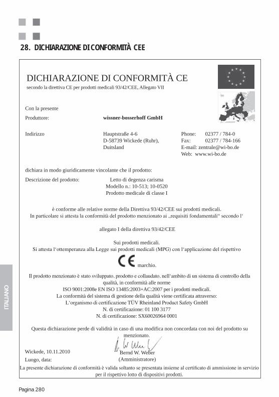
ITA
LIA
NO
Pagina 280
28. DICHIARAZIONE DI CONFORMITÀ CEE
DICHIARAZIONE DI CONFORMITÀ CEsecondo la direttiva CE per prodotti medicali 93/42/CEE, Allegato VII
Bernd W. Weber(Amministratore)
Con la presente
Produttore: wissner-bosserhoff GmbH
Indirizzo Hauptstraße 4-6D-58739 Wickede (Ruhr), Duitsland
Phone: 02377 / 784-0Fax: 02377 / 784-166E-mail: [email protected] Web: www.wi-bo.de
dichiara in modo giuridicamente vincolante che il prodotto:
Descrizione del prodotto: Letto di degenza carismaModello n.: 10-513; 10-0520Prodotto medicale di classe I
è conforme alle relative norme della Direttiva 93/42/CEE sui prodotti medicali.
allegato I della direttiva 93/42/CEE
Sui prodotti medicali.
marchio.
qualità, in conformità alle normeISO 9001:2008e EN ISO 13485:2003+AC:2007 per i prodotti medicali.
La conformità del sistema di gestione della qualità viene certificata attraverso:
N. di certificazione: 01 100 3177N. di certificazione: SX60026964 0001
Questa dichiarazione perde di validità in caso di una modifica non concordata con noi del prodotto su menzionato.
Wickede, 10.11.2010
Luogo, data:
per il rispettivo lotto di dispositivi prodotti.
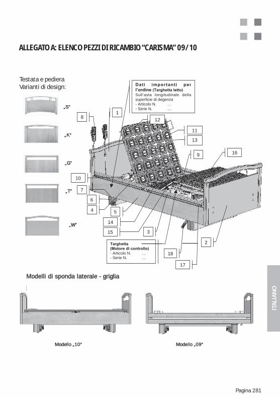
ITA
LIA
NO
Pagina 281
ALLEGATO A: ELENCO PEZZI DI RICAMBIO “CARISMA” 09/10
Testata e pedieraVarianti di design:
„S“
„K“
„G“
„T“
„W“
Modelli di sponda laterale - griglia
Modello „10“ Modello „09“
- Articolo N. …- Serie N. …
18
3
5
17
4
18
2
11
10
12
13
15
16
14
9
Sull’asta longitudinale dellasuperficie di degenza- Articolo N. …- Serie N. …
6
7
Testata e pedieraVarianti di design:
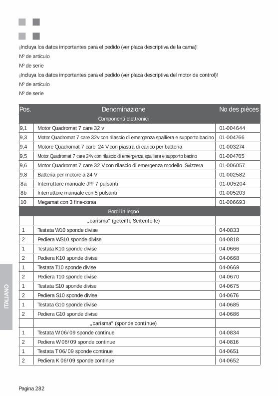
ITA
LIA
NO
Pagina 282
¡Incluya los datos importantes para el pedido (ver placa descriptiva de la cama)!
Nº de artículo
Nº de serie
¡Incluya los datos importantes para el pedido (ver placa descriptiva del motor de control)!
Nº de artículo
Nº de serie
Pos. Denominazione No des pièces Componenti elettronici
9,1 Motor Quadromat 7 care 32 v 01-004644
9,3 Motor Quadromat 7 care 32v con rilascio di emergenza spalliera e supporto bacino 01-004766
9,4 Motore Quadromat 7 care 24 V con piastra di carico per batteria 01-003274
9,5 Motor Quadromat 7 care 24v con rilascio di emergenza spalliera e supporto bacino 01-004765
9,6 Motor Quadromat 7 care 32 V con rilascio di emergenza modello Svizzera 01-006057
9,8 Batteria per motore a 24 V 01-002582
8a Interruttore manuale JPF 7 pulsanti 01-005204
8b Interruttore manuale con 5 pulsanti 01-005203
10 Megamat con 3 fine-corsa 01-006693
Bordi in legno
„carisma“ (geteilte Seitenteile)
1 Testata W10 sponde divise 04-0833
2 Pediera WS10 sponde divise 04-0818
1 Testata K10 sponde divise 04-0666
2 Pediera K10 sponde divise 04-0668
1 Testata T10 sponde divise 04-0669
2 Pediera T10 sponde divise 04-0670
1 Testata S10 sponde divise 04-0675
2 Pediera S10 sponde divise 04-0676
1 Testata G10 sponde divise 04-0685
2 Pediera G10 sponde divise 04-0686
„carisma“ (sponde continue)
1 Testata W 06/09 sponde continue 04-0834
2 Pediera W 06/09 sponde continue 04-0816
1 Testata T 06/09 sponde continue 04-0651
2 Pediera K 06/09 sponde continue 04-0652
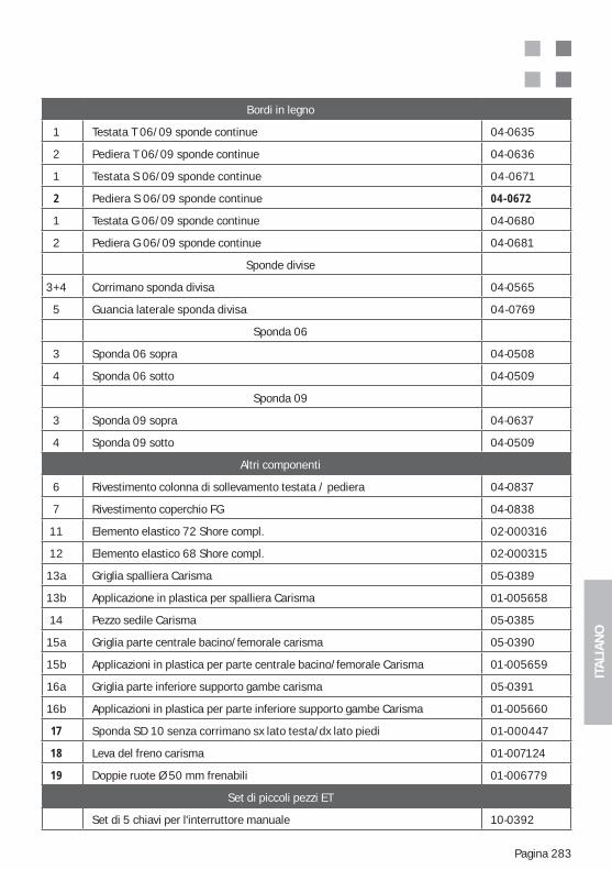
ITA
LIA
NO
Pagina 283
Bordi in legno
1 Testata T 06/09 sponde continue 04-0635
2 Pediera T 06/09 sponde continue 04-0636
1 Testata S 06/09 sponde continue 04-0671
2 Pediera S 06/09 sponde continue 04-0672
1 Testata G 06/09 sponde continue 04-0680
2 Pediera G 06/09 sponde continue 04-0681
Sponde divise
3+4 Corrimano sponda divisa 04-0565
5 Guancia laterale sponda divisa 04-0769
Sponda 06
3 Sponda 06 sopra 04-0508
4 Sponda 06 sotto 04-0509
Sponda 09
3 Sponda 09 sopra 04-0637
4 Sponda 09 sotto 04-0509
Altri componenti
6 Rivestimento colonna di sollevamento testata / pediera 04-0837
7 Rivestimento coperchio FG 04-0838
11 Elemento elastico 72 Shore compl. 02-000316
12 Elemento elastico 68 Shore compl. 02-000315
13a Griglia spalliera Carisma 05-0389
13b Applicazione in plastica per spalliera Carisma 01-005658
14 Pezzo sedile Carisma 05-0385
15a Griglia parte centrale bacino/femorale carisma 05-0390
15b Applicazioni in plastica per parte centrale bacino/femorale Carisma 01-005659
16a Griglia parte inferiore supporto gambe carisma 05-0391
16b Applicazioni in plastica per parte inferiore supporto gambe Carisma 01-005660
17 Sponda SD 10 senza corrimano sx lato testa/dx lato piedi 01-000447
18 Leva del freno carisma 01-007124
19 Doppie ruote Ø 50 mm frenabili 01-006779
Set di piccoli pezzi ET
Set di 5 chiavi per l'interruttore manuale 10-0392
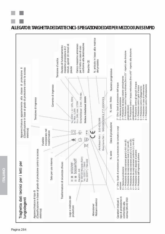
ITA
LIA
NO
Pagina 284
ALLEGATO B: TARGHETTA DEI DATI TECNICI–SPIEGAZIONI DEI DATI PER MEZZO DI UN ESEMPIO
Trag
hett
a da
ti te
cnic
i pe
r i
lett
i pe
rlu
ngod
egen
ti
Appa
recc
hiat
ura
di ti
po B
(Cla
ssifi
cazi
one
in b
ase
al g
rado
di p
rote
zion
e co
ntro
la s
coss
ael
ettr
ica)
Appa
recc
hiat
ura
appa
rten
ente
alla
cla
sse
di p
rote
zion
e II
(Cla
ssifi
cazi
one
in b
ase
al g
rado
di p
rote
zion
e co
ntro
la s
coss
ael
ettr
ica)
Tens
ione
di i
ngre
sso
Corr
ente
di i
ngre
sso
Tens
ione
d’u
scita
Dur
ata
di fu
nzio
nam
ento
:m
assi
mo
proc
edur
a di
2m
inut
i, qu
indi
18
min
uti d
ipa
usa
Caric
o m
assi
mo
amm
esso
per i
l let
to in
cas
o di
uso
conf
orm
e al
la d
estin
azio
ne
Mar
chio
CE
N. a
rtic
olo
in b
ase
alla
mat
rice
del p
rodo
tto
Fusi
bile
inco
rpor
ato
nel
tras
form
ator
eSo
lo p
er u
so in
tern
o
Tras
form
ator
e di
sic
urez
za c
hius
o
Logo
e in
diriz
zo d
elpr
odut
tore
Atte
nzio
ne!
Rot
tam
i ele
ttric
i
Cara
tter
i ind
icat
i il
tipo
di p
rote
zion
e in
conf
orm
ità a
llano
rma
DIN
40
05
0
N. s
erie
Dat
a di
pro
duzi
one
N. c
ontr
. fin
itoN
umer
o pr
ogre
ssiv
o
1°
Cifr
a: G
rado
di p
rote
zion
e pe
r la
prot
ezio
ne d
al c
onta
tto
e co
rpi
estr
anei
0 =
Nes
suna
pro
tezi
one
1 =
Pro
tezi
one
da c
orpi
est
rane
i gra
ndi (
>5
0 m
m Ø
)2
= P
rote
zion
e da
cor
pi e
stra
nei m
edi (
>1
2 m
m Ø
)3
= P
rote
zion
e da
cor
pi e
stra
nei p
icco
li (>
2,5
mm
Ø )
4 =
Pro
tezi
one
da c
orpi
est
rane
i con
form
i (>
1 m
m Ø
)5
= P
rote
zion
e co
ntro
i de
posi
ti di
pol
vere
6 =
Pro
tezi
one
dall’
ingr
esso
di p
olve
re
2°
Cifr
a: G
radi
di p
rote
zion
e da
ll’ac
qua
0 =
Nes
suna
pro
tezi
one
1=
Pro
tezi
one
da a
cqua
col
ante
ver
tical
men
te2
= P
rote
zion
e co
ntro
l’ac
qua
incl
inat
a (f
ino
a 1
5°
ris
pett
o al
la d
irezi
one
perp
endi
cola
re)
3=
Pro
tezi
one
cont
ro l’
acqu
a ne
buliz
zata
(fin
o a
60
° r
ispe
tto
alla
dire
zion
epe
rpen
dico
lare
)4
= P
rote
zion
e co
ntro
gli
spru
zzi d
’acq
ua5
= P
rote
zion
e co
ntro
i ge
tti d
’acq
ua6
= P
rote
zion
e co
ntro
l’al
laga
men
to7
= P
rote
zion
e in
cas
o di
imm
ersi
one
8 =
Pro
tezi
one
cont
ro l’
affo
ndam
ento
ITA
LIA
NO
Pagina 285
ALLEGATO C: IMPORTANTI ISTRUZIONI DI SICUREZZA E DI UTILIZZO DEI LETTI PER LUNGODEGENTIUSO CONFORME ALLA DESTINAZIONE E DESTINAZIONE DEI LETTI PER LUNGODEGENTI
Il letto per lungodegenti deve essere messo in funzione ed utilizzato soltanto in modo conforme alla sua destinazione, ai sensi della legge sui prodotti medici (MPG), alle disposizioni attinenti, alle regole generali della tecnica, nonché alle normative generali sulla prevenzione dagli infortuni e la sicurezza sul lavoro Se il letto si trova in un stato difettoso che potrebbe procurare danni al personale di assistenza o a terzi, non deve assolutamente essere utilizzato.
Sono da applicare le indicazioni contenute nelle istruzioni d’uso del rispettivo prodotto.
Osservare assolutamente i seguenti punti:
-mente alla degenza di persone di età superiore ai 12 anni, in quanto le perso-ne che non hanno una massa e un peso corporeo sotto la media prevista sono sottoposti a un rischio maggiore. Le persone indicate per la degenza su questo letto senza ulteriori rischi o limitazioni della prestazione (conforme alla norma IEC 60601-2-52), devono avere una statura di 146 cm, per le donne e max. 185
limitata capacità di agire). Al di fuori di questa fascia è eventualmente necessario utilizzare degli appositi accessori oppure rinunciare all’utilizzo del letto. Per le persone più alte per esempio dovrebbero essere utilizzate delle prolunghe per il letto (accessorio) o in caso di persone molto magre sono assolutamente neces-sarie le protezioni come i cuscini delle sponde (accessorio). Altri utilizzi devono essere accordati con Wissner – Bosserhoff GmbH.
medico) per garantire un utilizzo sicuro dei letti per lungodegenti. Devono essere osservate le esigenze mediche e psicologiche nonché lo stato dei degenti. Allo stesso modo le funzioni del letto devono essere attivate o disattivate a seconda del degente. Quanto detto vale soprattutto per i letti con possibilità di orienta-mento speciali del piano letto e se si impiega delle protezioni laterali.
. Per infor-
mazioni sulla possibilità di sollecitazioni maggiori, consultare le istruzioni d‘uso del rispettivo prodotto! Il letto non può essere utilizzato per degenti con un peso corporeo maggiore di 155 kg. Nel carico di lavoro sicuro di 225 kg è compreso il peso del paziente, del materasso e degli accessori presenti sul letto (lenzuola, dispositivo di sollevamento e così via)!
ITA
LIA
NO
Pagina 286
-se dell’installazione domestica conformi al relativo stato della tecnica e rego-larmente controllate, secondo le disposizioni vigenti, per quanto riguarda il fun-zionamento dei dispositivi di sicurezza (protezione FI, protezione FU, rilevatori di errori di isolamento, dispositivi di sicurezza di potenza ecc).
-
detergenti e solventi, nonché composti di aria-materiali incendiabili. Osservare le relative disposizioni delle mutue assicuratrici di categoria professionale contro gli infortuni sul lavoro.
Un utilizzo diverso da quello descritto conforme alla destinazione è considerato non adeguato per cui si declina ogni responsabilità.
FUNZIONI DI BASE ED UTILIZZO DEI LETTI PER LUNGODEGENTI
I letti per lungodegenti di moderna concezione dispongono di diverse funzioni di suppor-to descritte dettagliatamente nelle relative istruzioni d’uso. L’utilizzo adeguato del letto per lungodegenti si può ottenere soltanto grazie ad accurati addestramenti dell’utente e del degente di un istituto di cura da ripetere a intervalli regolari, nonché osservando anche le rispettive regole di sicurezza.
Generalmente sussiste sempre il rischio che il letto venga movimentato in-avvertitamente in modo errato, azionando l’interruttore o attivando determi-nate funzioni che possono risultare rischiose per il degente! Per garantire un’elevata protezione del degente è assolutamente necessario utilizzare i dispositivi di blocco e/o la chiave d’attivazione in modo opportuno. La chiave di attivazione non deve rimanere per nessun motivo attaccata all’interruttore manuale o al letto. Le chiavi di attivazione devono essere utilizzate solo dal personale di assistenza.
L’utilizzo dei dispositivi di blocco ed eventualmente il distacco intenzionale
protezione di eventuali degenti a rischio – è di esclusiva valutazione e compe-tenza del rispettivo organo di controllo medico incaricato e del personale di assistenza. Le misure rispettivamente adottate dovrebbero essere annotate nel rapporto del turno per garantire un adeguato passaggio delle consegne.
ITA
LIA
NO
Pagina 287
L’utilizzo delle speciali possibilità di supporto, come per es. la posizione Tren-delenburg-Antitrendelenburg, supporto a livelli del letto o la relativa posizione abbassata della testa in caso di shock) è riservato esclusivamente al persona-le di controllo medico. Per i degenti queste funzioni devono essere bloccate al
Le istruzioni sulla sicurezza contenute nelle relative istruzioni d’uso del pro-
-schi.
In caso di impiego di dispositivi di sicurezza laterali è necessario fare molta attenzione a quanto segue:
-i dispositivi di protezione laterali servono in prima linea a proteggere il pa-
paziente.
-Per l’impiego dei dispositivi di protezione sono necessarie disposizioni giudizi-
laterali divise o quelle abbassabili singolarmente, nelle quali viene sollevata soltanto la parte di supporto testa e che possono essere utilizzate come ausi-lio per scendere e salire sul letto, rappresentano in questa sede un‘eccezione consentita per i degenti mobili.
ITA
LIA
NO
Pagina 288
Una sollecitazione eccessiva dovuta a usi impropri quali ad esempio mettersi a sedere, appoggiarsi o tirare la sponda può comportare gravi conseguenze e dare luogo a pericoli. Sollecitazioni di questo tipo devono essere assoluta-mente evitate.
In caso di impiego di protezioni laterali deve essere considerata la loro ade-
osservate le distanze tra i corrimano e le bande in relazione alla struttura corporea del degente, in modo da evitare incastri o scivolamenti attraverso di esse. Se necessario devono essere utilizzati dei cuscini per sponde, che riducono la dimensione della fessura o chiudono la fessura stessa. Per que-sta decisione è responsabile soltanto il personale medico incaricato del con-trollo. Come orientamento valgono le indicazioni per la limitazione dell’uso conforme alla destinazione di esse e delle istruzioni d‘uso speciali del letto e della sponda.
-lizzato, onde evitare l’aumento di rischi di infortunio.
Le sponde/protezioni laterali devono essere controllate prima di ogni impie-
letto e che il blocco di sicurezza funzioni in modo adeguato! Indicazioni per il corretto uso delle protezioni laterali si trovano nelle rispettive istruzioni d’uso del prodotto.
L’uso del telecomando da parte del degente è di esclusiva valutazione e com-petenza del rispettivo organo di controllo medico incaricato e del personale di assistenza. Le misure rispettivamente adottate dovrebbero essere annotate nel rapporto del turno o nella documentazione dell‘assistenza per garantire un adeguato passaggio delle consegne.
Se il telecomando non deve essere usato dal degente, esso deve essere posi-zionato in un punto sicuro e non accessibile, come per esempio sulla pediera del letto.
Evitare che il telecomando subisca urti, sovraccarichi e che venga a contatto con sostanze liquide. La pulizia dovrebbe essere eseguita con panni per tastiere del PC. In caso di danni al gruppo meccanico e dovuti all’umidità i telecoman-di devono essere sostituiti immediatamente. Anche i cavi d’alimentazione de-vono essere controllati a intervalli regolari per escludere danneggiamenti.
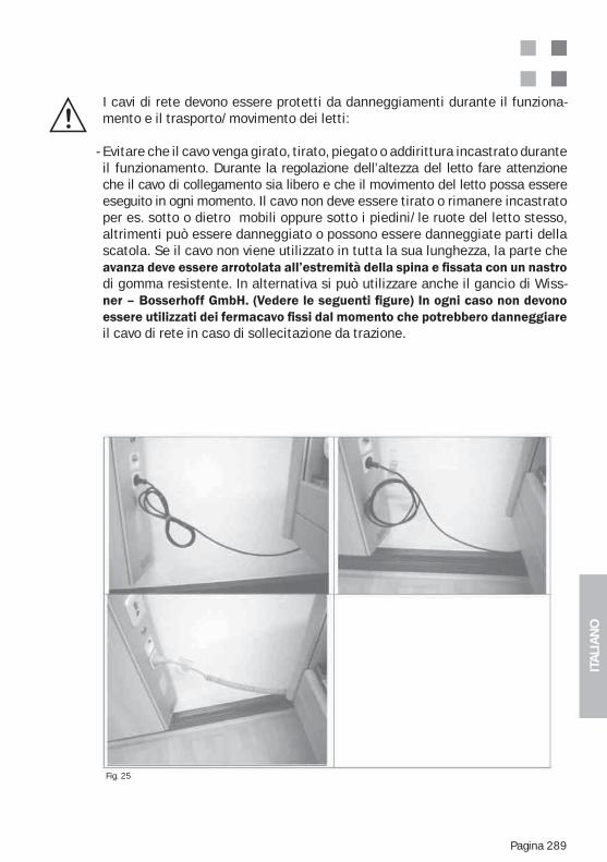
ITA
LIA
NO
Pagina 289
I cavi di rete devono essere protetti da danneggiamenti durante il funziona-mento e il trasporto/movimento dei letti:
- Evitare che il cavo venga girato, tirato, piegato o addirittura incastrato durante il funzionamento. Durante la regolazione dell’altezza del letto fare attenzione che il cavo di collegamento sia libero e che il movimento del letto possa essere eseguito in ogni momento. Il cavo non deve essere tirato o rimanere incastrato per es. sotto o dietro mobili oppure sotto i piedini/le ruote del letto stesso, altrimenti può essere danneggiato o possono essere danneggiate parti della scatola. Se il cavo non viene utilizzato in tutta la sua lunghezza, la parte che
di gomma resistente. In alternativa si può utilizzare anche il gancio di Wiss-
il cavo di rete in caso di sollecitazione da trazione.
Fig. 25
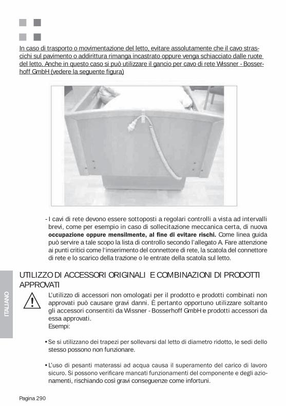
ITA
LIA
NO
Pagina 290
In caso di trasporto o movimentazione del letto, evitare assolutamente che il cavo stras-cichi sul pavimento o addirittura rimanga incastrato oppure venga schiacciato dalle ruote del letto. Anche in questo caso si può utilizzare il gancio per cavo di rete Wissner - Bosser-hoff GmbH (vedere la seguente figura)
- I cavi di rete devono essere sottoposti a regolari controlli a vista ad intervalli brevi, come per esempio in caso di sollecitazione meccanica certa, di nuova
Come linea guida può servire a tale scopo la lista di controllo secondo l’allegato A. Fare attenzione ai punti critici come l‘inserimento del connettore di rete, la scatola del connettore di rete e lo scarico della trazione o le entrate della scatola sul letto.
UTILIZZO DI ACCESSORI ORIGINALI E COMBINAZIONI DI PRODOTTI APPROVATI
L’utilizzo di accessori non omologati per il prodotto e prodotti combinati non approvati può causare gravi danni. È pertanto opportuno utilizzare soltanto gli accessori consentiti da Wissner - Bosserhoff GmbH e prodotti accessori da essa approvati.Esempi:
stesso possono non funzionare.
-namenti, rischiando così gravi conseguenze come infortuni.
ITA
LIA
NO
Pagina 291
SISTEMAZIONE DEL LETTO PER LUNGODEGENTI (DISTANZE DI SICUREZZA)
Il letto deve essere sistemato in modo tale che al momento dell‘esecuzione delle funzioni di regolazione risulti impossibile una collisione di parti del letto con altri oggetti presenti nella stanza oppure con parti della stanza stessa (ad
-vole alla parete ecc.). A tale scopo deve essere mantenuta anche una distanza di sicurezza dalle pareti ed altri oggetti di minimo 2,5 cm in tutte le possibili posizioni del letto. Attenzione: Anche in caso di orientamento e regolazione
modo tale che sia possibile scollegarlo facilmente dalla rete elettrica (estrar-re la spina)!!
PULIZIA E DISINFEZIONE DEL LETTO
Il letto per lungodegenti deve essere pulito e disinfettato regolarmente o al-meno prima di ogni cambio del degente. Il letto per lungodegenti non può essere pulito e disinfettato né in percorsi di lavaggio, né con acqua a getto e nemmeno a spruzzo. È consentita solamente una disinfezione a spruzzo e a
Per la disinfezione del letto per lungodegenti si consiglia di utilizzare i seguen-ti prodotti che possono essere sostituiti da prodotti con le stesse e identiche caratteristiche:Terralin, Perform e Sagrotan Med (Schülke & Mayr GmbH, Norderstedt).Questi prodotti vanno utilizzati seguendo assolutamente le istruzioni del pro-duttore! Ciò riguarda soprattutto il dosaggio e l’eventuale rischio che si corre nel mescolarli con altri prodotti.
Il bordo in legno non deve venire a contatto con questi prodotti.In caso di macchie particolarmente dure, si può utilizzare anche un detergente universale ed ecologico per uso domestico.
Tuttavia non devono essere utilizzati dei detergenti contenenti componenti con azione abrasiva.
È necessario fare attenzione che al momento dell’utilizzo e della pulizia le super-
e sostanze liquide. Il legno è un prodotto naturale con la caratteristica di assorbire l’umidità e quindi di dilatarsi. Questo aspetto può causare danni alla sigillatura del-
vernici di riparazione. Rivolgersi al servizio di Wissner – Bosserhoff GmbH.
I telecomandi possono essere puliti soltanto con appositi panni per tastiere del PC. In caso di contatto con l’umidità, un forte imbrattamento o tasti incastra-ti a causa di particelle di imbrattamento, il telecomando deve essere eventual-mente sostituito.
ITA
LIA
NO
Pagina 292
ALLEGATO D: FUNZIONAMENTO A BATTERIA (OPTIONAL) - ISTRUZIONI AGGIUNTIVE
L’azionamento del letto può essere dotato di un’attrezzatura speciale con funzione a batte-ria aggiuntiva che consente di continuare ad utilizzare le funzioni elettriche indipendente-mente dalla rete di alimentazione.
La frequenza delle regolazioni è indipendente dallo stato della carica della batteria. Per evitare una scarica profonda il letto dovrebbe rimanere possibilmente attaccato alla rete.
La carica della batteria ha pertanto luogo in modo completamente automatico tramite un‘attivazione di carica integrata speciale.
Normalmente la batteria viene caricata e fornita montata sull’azionamento principale, modo da non dover essere montata dell’utente.
Caratteristiche importanti
Per motivi di sicurezza la scatola della batteria non può essere aperta.
Per un successivo acquisto della batteria, rivolgersi alla nostro servizio tecnico clienti, in quanto non tutti gli azionamento sono adatti all’abbinamento della batteria. Una sostituzi-one della scatola della batteria dovrebbe essere eseguita da personale specializzato per evitare eventuali danni dovuti ad un trattamento errato.
La durata della batteria è fortemente dipendente dall’utilizzo e dagli eventuali scaricamen-ti profondi avvenuti.
Sussiste al possibilità di inserire anche una stazione di carica esterna a quattro (accesso-rio per la carica parallela di quattro scatole della batteria) disponibile a parte.Osservare, in tal caso, assolutamente le istruzioni d’uso separate della stazione di carica delle batterie
ITA
LIA
NO
Pagina 293
ALLEGATO E: METAMERIA: L’APPARENTE UGUAGLIANZA DELLE SUPERFICI E DECORAZIONI
„Metameria“
Due colori appaiono uguali solo se illuminati da un determinato tipo di luce. In caso di illu-minazione che varia, si distinguono per le caratteristiche spettrali dei pigmenti, dei colori e dei materiali utilizzati. Un cappotto che nel negozio dove viene acquistato appare di colore verde, una volta usciti alla luce del sole diventa marrone, mentre i pantaloni rimangono verdi. Per osservare i colori di un capo di abbigliamento si esce spesso alla luce del giorno. Per l‘armonizzazione dei colori stampati con i materiali si utilizza la luce D65 http://www.zfamedien.de/ausbildung/mediengestalter/tutorials/Dictionary.php?Action=ByTitle&Title=Tageslicht simile alla luce del giorno http://www.zfamedien.de/ausbildung/mediengestal-ter/tutorials/Dictionary.php?Action=ByTitle&Title=Licht.
Si tratta del fenomeno della uguaglianza condizionata dei colori. Due o più colori appaiono uguali solo se illuminati da un certo tipo di luce (ad es. lampada al neon) e si distinguono altrimenti per le loro caratteristiche spettrali (ad es. i pigmenti e i coloranti utilizzati) con ogni altro tipo di illuminazione.La metameria non si riscontra in presenza di un colore solo. Ad es. una camicia bianca appare diversa se illuminata dalla luce rossa del sole rispetto alla luce gialla solare. La me-tameria è la differenza tra due o più colori di un materiale a seconda della luce.
In particolare, in caso di materiali diversi, di colorazioni ovvero procedimenti di stampa dif-ferenti con coloranti diversi, risultano quasi obbligatoriamente delle leggere differenze di colore a condizioni di luce diverse (questi fenomeni tipici vengono descritti come effetto neon, effetto luce del negozio o effetto luce esposizione).
La misurazione cromatica è un utile strumento per confrontare le decorazioni realizzate in tinta unita. A tale scopo viene rilevato un cosiddetto indice di metameria come valore di confronto tra due provini. L‘indice di metameria è il valore EDelta nel sistema CIE- L*a*b considerando due diversi tipi di luce – solitamente la luce diurna- (C, D50, D60) e la luce artificiale (A). Vengono impiegati dei dispositivi di misurazione del grado cromatico e di lu-centezza combinati.
Al contrario una valutazione delle stampe decorative effettuate su legno, delle decorazioni strutturate e delle stampe con motivi decorativi deve essere eseguita mediante un rapporto di tipo visivo; infatti non è opportuno effettuare una misurazione cromatica comparativa esclusivamente dal punto di vista metrologico. A tale scopo è importante effettuare una decisione interdisciplinare a carattere maggioritario all‘interno di un gruppo con facoltà di decisione, dal momento che le impressioni visive sono notoriamente molto personali.
Il cosiddetto rapporto risulta pertanto essere l‘unità conclusa più piccola di un motivo. Se un motivo (ad es. in caso di pellicola di stampa o di stoffe) è composto da più piccole parti,
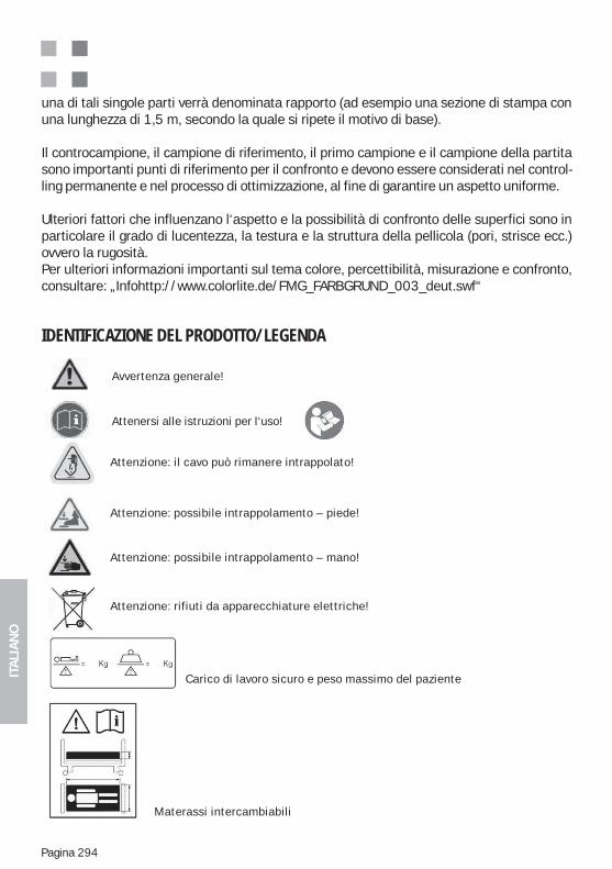
ITA
LIA
NO
Pagina 294
una di tali singole parti verrà denominata rapporto (ad esempio una sezione di stampa con una lunghezza di 1,5 m, secondo la quale si ripete il motivo di base).
Il controcampione, il campione di riferimento, il primo campione e il campione della partita sono importanti punti di riferimento per il confronto e devono essere considerati nel control-ling permanente e nel processo di ottimizzazione, al fine di garantire un aspetto uniforme.
Ulteriori fattori che influenzano l‘aspetto e la possibilità di confronto delle superfici sono in particolare il grado di lucentezza, la testura e la struttura della pellicola (pori, strisce ecc.) ovvero la rugosità. Per ulteriori informazioni importanti sul tema colore, percettibilità, misurazione e confronto, consultare: „Infohttp://www.colorlite.de/FMG_FARBGRUND_003_deut.swf“
IDENTIFICAZIONE DEL PRODOTTO/LEGENDA
Carico di lavoro sicuro e peso massimo del paziente
Avvertenza generale!
Attenzione: il cavo può rimanere intrappolato!
Attenzione: possibile intrappolamento – piede!
Attenzione: possibile intrappolamento – mano!
Attenzione: rifiuti da apparecchiature elettriche!
Materassi intercambiabili
Attenersi alle istruzioni per l‘uso!
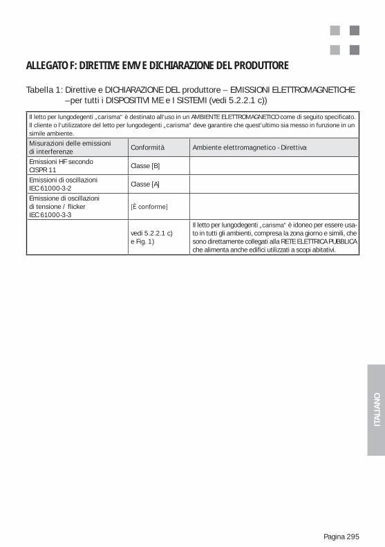
ITA
LIA
NO
Pagina 295
ALLEGATO F: DIRETTIVE EMV E DICHIARAZIONE DEL PRODUTTORE
Tabella 1: Direttive e DICHIARAZIONE DEL produttore – EMISSIONI ELETTROMAGNETICHE –per tutti i DISPOSITIVI ME e I SISTEMI (vedi 5.2.2.1 c))
Il letto per lungodegenti „carisma“ è destinato all‘uso in un AMBIENTE ELETTROMAGNETICO come di seguito specificato. Il cliente o l‘utilizzatore del letto per lungodegenti „carisma“ deve garantire che quest‘ultimo sia messo in funzione in unsimile ambiente.
Misurazioni delle emissioni di interferenze
Conformità Ambiente elettromagnetico - Direttiva
Emissioni HF secondoCISPR 11
Classe [B]
Emissioni di oscillazioniIEC 61000-3-2
Classe [A]
Emissione di oscillazioni di tensione / flicker IEC 61000-3-3
vedi 5.2.2.1 c)e Fig. 1)
Il letto per lungodegenti „carisma“ è idoneo per essere usa-to in tutti gli ambienti, compresa la zona giorno e simili, che sono direttamente collegati alla RETE ELETTRICA PUBBLICA che alimenta anche edifici utilizzati a scopi abitativi.
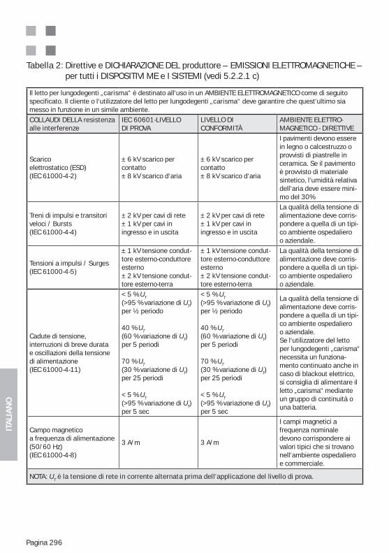
ITA
LIA
NO
Pagina 296
Tabella 2: Direttive e DICHIARAZIONE DEL produttore – EMISSIONI ELETTROMAGNETICHE – per tutti i DISPOSITIVI ME e I SISTEMI (vedi 5.2.2.1 c)
Il letto per lungodegenti „carisma“ è destinato all‘uso in un AMBIENTE ELETTROMAGNETICO come di seguito specificato. Il cliente o l‘utilizzatore del letto per lungodegenti „carisma“ deve garantire che quest‘ultimo sia messo in funzione in un simile ambiente.
COLLAUDI DELLA resistenza alle interferenze
IEC 60601-LIVELLO DI PROVA
LIVELLO DI CONFORMITÀ
AMBIENTE ELETTRO- MAGNETICO - DIRETTIVE
Scaricoelettrostatico (ESD)(IEC 61000-4-2)
± 6 kV scarico per contatto± 8 kV scarico d‘aria
± 6 kV scarico per contatto± 8 kV scarico d‘aria
I pavimenti devono essere in legno o calcestruzzo o provvisti di piastrelle in ceramica. Se il pavimento è provvisto di materiale sintetico, l‘umidità relativa dell‘aria deve essere mini-mo del 30%
Treni di impulsi e transitori veloci / Bursts(IEC 61000-4-4)
± 2 kV per cavi di rete± 1 kV per cavi in ingresso e in uscita
± 2 kV per cavi di rete± 1 kV per cavi in ingresso e in uscita
La qualità della tensione dialimentazione deve corris-pondere a quella di un tipi-co ambiente ospedaliero o aziendale.
Tensioni a impulsi / Surges(IEC 61000-4-5)
± 1 kV tensione condut-tore esterno-conduttoreesterno± 2 kV tensione condut-tore esterno-terra
± 1 kV tensione condut-tore esterno-conduttoreesterno± 2 kV tensione condut-tore esterno-terra
La qualità della tensione dialimentazione deve corris-pondere a quella di un tipi-co ambiente ospedalieroo aziendale.
Cadute di tensione, interruzioni di breve durata e oscillazioni della tensione di alimentazione(IEC 61000-4-11)
< 5 % UT(>95 % variazione di UT)per ½ periodo
40 % UT (60 % variazione di UT)per 5 periodi
70 % UT (30 % variazione di UT)per 25 periodi
< 5 % UT (>95 % variazione di UT)per 5 sec
< 5 % UT(>95 % variazione di UT)per ½ periodo
40 % UT (60 % variazione di UT)per 5 periodi
70 % UT (30 % variazione di UT)per 25 periodi
< 5 % UT (>95 % variazione di UT)per 5 sec
La qualità della tensione dialimentazione deve corris-pondere a quella di un tipi-co ambiente ospedalieroo aziendale.Se l‘utilizzatore del letto per lungodegenti „carisma“ necessita un funziona-mento continuato anche in caso di blackout elettrico, si consiglia di alimentare il letto „carisma“ mediante un gruppo di continuità o una batteria.
Campo magneticoa frequenza di alimentazione(50/60 Hz)(IEC 61000-4-8)
3 A/m 3 A/m
I campi magnetici a frequenza nominale devono corrispondere ai valori tipici che si trovano nell‘ambiente ospedaliero e commerciale.
NOTA: UT è la tensione di rete in corrente alternata prima dell‘applicazione del livello di prova.
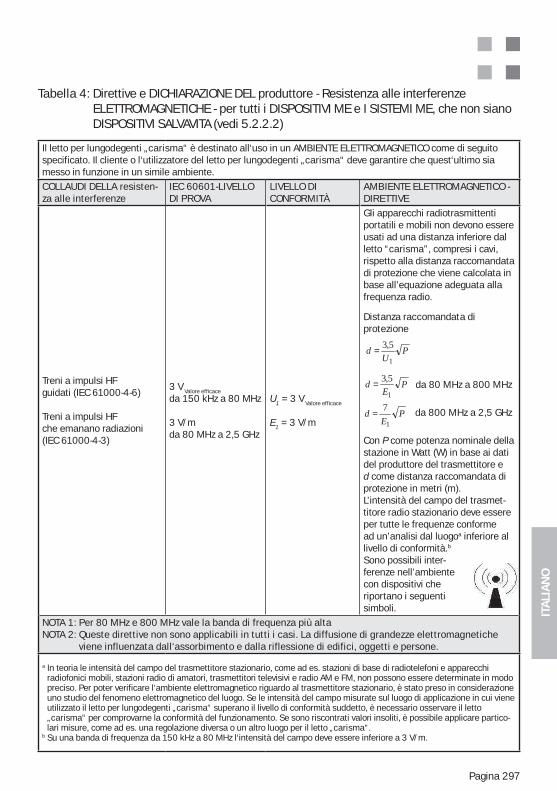
ITA
LIA
NO
Pagina 297
Tabella 4: Direttive e DICHIARAZIONE DEL produttore - Resistenza alle interferenze ELETTROMAGNETICHE - per tutti i DISPOSITIVI ME e I SISTEMI ME, che non siano DISPOSITIVI SALVAVITA (vedi 5.2.2.2)
Il letto per lungodegenti „carisma“ è destinato all‘uso in un AMBIENTE ELETTROMAGNETICO come di seguito specificato. Il cliente o l‘utilizzatore del letto per lungodegenti „carisma“ deve garantire che quest‘ultimo sia messo in funzione in un simile ambiente.
COLLAUDI DELLA resisten-za alle interferenze
IEC 60601-LIVELLO DI PROVA
LIVELLO DI CONFORMITÀ
AMBIENTE ELETTROMAGNETICO - DIRETTIVE
Treni a impulsi HFguidati (IEC 61000-4-6)
Treni a impulsi HFche emanano radiazioni(IEC 61000-4-3)
3 V Valore efficace
da 150 kHz a 80 MHz
3 V/mda 80 MHz a 2,5 GHz
U1 = 3 V Valore efficace
E1 = 3 V/m
Gli apparecchi radiotrasmittenti portatili e mobili non devono essere usati ad una distanza inferiore dal letto “carisma”, compresi i cavi, rispetto alla distanza raccomandata di protezione che viene calcolata in base all’equazione adeguata alla frequenza radio.
Distanza raccomandata di protezione
da 80 MHz a 800 MHz
da 800 MHz a 2,5 GHz
Con P come potenza nominale dellastazione in Watt (W) in base ai dati del produttore del trasmettitore e d come distanza raccomandata di protezione in metri (m).L’intensità del campo del trasmet-titore radio stazionario deve essere per tutte le frequenze conforme ad un’analisi dal luogoa inferiore al livello di conformità.b
Sono possibili inter- ferenze nell’ambientecon dispositivi che riportano i seguentisimboli.
NOTA 1: Per 80 MHz e 800 MHz vale la banda di frequenza più altaNOTA 2: Queste direttive non sono applicabili in tutti i casi. La diffusione di grandezze elettromagnetiche
viene influenzata dall‘assorbimento e dalla riflessione di edifici, oggetti e persone.
a In teoria le intensità del campo del trasmettitore stazionario, come ad es. stazioni di base di radiotelefoni e apparecchi radiofonici mobili, stazioni radio di amatori, trasmettitori televisivi e radio AM e FM, non possono essere determinate in modo preciso. Per poter verificare l‘ambiente elettromagnetico riguardo al trasmettitore stazionario, è stato preso in considerazione uno studio del fenomeno elettromagnetico del luogo. Se le intensità del campo misurate sul luogo di applicazione in cui viene utilizzato il letto per lungodegenti „carisma“ superano il livello di conformità suddetto, è necessario osservare il letto „carisma“ per comprovarne la conformità del funzionamento. Se sono riscontrati valori insoliti, è possibile applicare partico-lari misure, come ad es. una regolazione diversa o un altro luogo per il letto „carisma“.
b Su una banda di frequenza da 150 kHz a 80 MHz l‘intensità del campo deve essere inferiore a 3 V/m.
PE
d1
5,3=
PU
d1
5,3=
PE
d1
7=
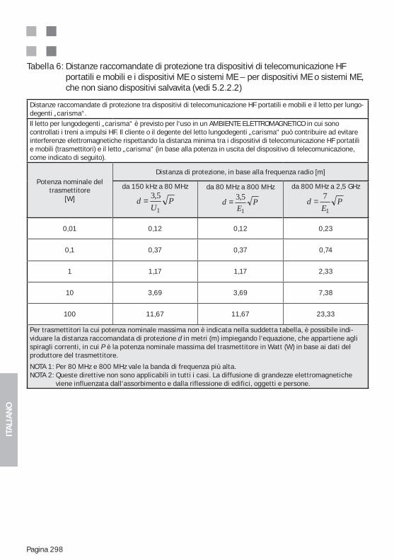
ITA
LIA
NO
Pagina 298
Tabella 6: Distanze raccomandate di protezione tra dispositivi di telecomunicazione HF portatili e mobili e i dispositivi ME o sistemi ME – per dispositivi ME o sistemi ME, che non siano dispositivi salvavita (vedi 5.2.2.2)
Distanze raccomandate di protezione tra dispositivi di telecomunicazione HF portatili e mobili e il letto per lungo-degenti „carisma“.
Il letto per lungodegenti „carisma“ è previsto per l‘uso in un AMBIENTE ELETTROMAGNETICO in cui sono controllati i treni a impulsi HF. Il cliente o il degente del letto lungodegenti „carisma“ può contribuire ad evitare interferenze elettromagnetiche rispettando la distanza minima tra i dispositivi di telecomunicazione HF portatili e mobili (trasmettitori) e il letto „carisma“ (in base alla potenza in uscita del dispositivo di telecomunicazione, come indicato di seguito).
Potenza nominale deltrasmettitore
[W]
Distanza di protezione, in base alla frequenza radio [m]
da 150 kHz a 80 MHz
PU
d1
5,3=da 80 MHz a 800 MHz
PE
d1
5,3=
da 800 MHz a 2,5 GHz
PE
d1
7=
0,01 0,12 0,12 0,23
0,1 0,37 0,37 0,74
1 1,17 1,17 2,33
10 3,69 3,69 7,38
100 11,67 11,67 23,33
Per trasmettitori la cui potenza nominale massima non è indicata nella suddetta tabella, è possibile indi-viduare la distanza raccomandata di protezione d in metri (m) impiegando l‘equazione, che appartiene agli spiragli correnti, in cui P è la potenza nominale massima del trasmettitore in Watt (W) in base ai dati del produttore del trasmettitore.
NOTA 1: Per 80 MHz e 800 MHz vale la banda di frequenza più alta.NOTA 2: Queste direttive non sono applicabili in tutti i casi. La diffusione di grandezze elettromagnetiche
viene influenzata dall‘assorbimento e dalla riflessione di edifici, oggetti e persone.

ITA
LIA
NO
Pagina 299
APPUNTI
ITA
LIA
NO
Pagina 300
APPUNTI
ITA
LIA
NO
Pagina 301
APPUNTI
ESPA
ÑO
L
Pagina 302
ÍNDICE
1. Índice ....................................................................................................... 3022. Notas sobre las instrucciones de uso / Explicación de los símbolos .... 3043. Campo de aplicación / Uso previsto ...................................................... 3044. Colocación de la cama ........................................................................... 3055. Datos técnicos de la cama / Placa descriptiva .................................... 305
..................................... 3065.2. Electromotores de regulación en altura ........................................... 3066. Seguridad del producto / Resumen de normas aplicadas .................. 307
.............. 3088. Descripción de las funciones eléctricas ................................................ 3088.1. Función de respaldo (RL) .................................................................. 3098.2. Elevación de piernas (BH) ................................................................. 3108.3. Asiento confortable (KS).................................................................... 3108.4. Función de contorno automático (AK) .............................................. 3118.5. Función de regulación en altura (HV) ............................................... 3119. Combinación de «camas de uso médico» con dispositivos de elevación «transportables» ................................................................ 31110. Normas de seguridad para la Regulación en altura ............................. 312
.......................................................................... 31212. Envió ........................................................................................................ 313
.................................................................................................... 314 .......................................................................... 314
...................................................... 31414. Transporte / Traslado de la cama .......................................................... 31415. Controle las distintas funciones. ........................................................... 31515.1. Control manual „Carisma 07 JPF“: Descripción del funcionamiento .................................................................................. 31515.2. Control manual de cara posterior con función de bloqueo ............ 31615.3. Parte inferior de la pierna: Dispositivo mecánico ............................ 31715.4. Transporte / Freno ............................................................................. 318
.......................................... 318 ................................... 319
.......................................... 32016. Accesorios previstos ............................................................................. 32116.1. Elevador (accesorio) .......................................................................... 32116.2. Soporte de infusión (accesorio) ........................................................ 322
..................................... 32216.4. Colchón (accesorio) ........................................................................... 32316.5. Soportes para botella de orina y para bolsa de orina modelo 09 (accesorio) .................................................................................... 32316.6. Soporte para control manual (accesorio)......................................... 32416.7. Suplemento de barandilla para 06/09 Barandilla lateral (Accesorios) ..32517. Limpieza y desinfección ......................................................................... 327
ESPA
ÑO
L
Pagina 303
17.1. Primera limpieza ................................................................................ 32717.2. Desinfección / Esterilización ............................................................. 32817.3. Cuidado de las partes de madera .................................................... 32817.4. Uso de limpiadores ............................................................................ 32917.5. Uso de desinfectantes ....................................................................... 32917.6. Daños en las partes de madera ....................................................... 32917.7. Impacto ambiental ............................................................................. 32917.8. Calidad ................................................................................................ 32918. Problemas y soluciones .......................................................................... 33019. Almacenamiento ..................................................................................... 33020. Normas de seguridad y riesgos residuales ........................................... 33021. Reparación y mantenimiento ................................................................. 33621.1. Suministro completo y accesorios .................................................... 33621.2. Desgaste ............................................................................................. 33721.3. Funcionalidad ..................................................................................... 337
del control manual ............................................................................. 33721.5. Ruedas ..................................................................................................... 33722. Vida útil .................................................................................................... 33723. Eliminación del producto ........................................................................ 33824. Piezas de repuesto, listas de piezas de repuesto y servicio técnico... 33825. Placa descriptiva y etiquetas ................................................................. 33826. Garantía ................................................................................................... 33927. Contacto .................................................................................................. 33928. Declaración de conformidad CE ............................................................ 340Anexo C: Normas importantes de seguridad y uso para las camas de cuidados 345Uso adecuado y previsto de las camas de cuidados ........................................... 345Funciones básicas y aprovechamiento de las camas de cuidados .................... 346Uso de accesorios originales y combinaciones de productos admitidas ........... 350Colocación de la cama de cuidados (distancias de seguridad) ......................... 351Limpieza y desinfección de la cama ..................................................................... 351
Anexos :Anexo A: Lista de piezas de repuesto de «carisma» 09/10
Anexo C: Normas importantes de seguridad y uso para las camas geriátricas
Anexo D: Funcionamiento con batería (opcional) - Notas adicionales
Anexo F: Directivas y declaración del fabricante (CEM)
NOTA IMPORTANTE DE SEGURIDAD :
en los distintos capítulos del manual, así como la información del Capítulo 18 y del Anexo C. El incumpli-
miento de las instrucciones puede causar daños materiales o lesiones.
ESPA
ÑO
L
Pagina 304
Estimados clientes:-
ducto. Estamos convencidos de que nuestro producto satisface plenamente las exigencias
más moderna tecnología, junto a la idoneidad y el espíritu de equipo de nuestro personal,
a usted los cuidados del paciente.
2. NOTAS SOBRE LAS INSTRUCCIONES DE USO / EXPLICACIÓN DE LOS SÍMBOLOS
Este símbolo indica la presencia de instrucciones importantes para la seguridad, cuyo incumplimiento puede tener graves consecuencias (por ejemplo: daños materiales o le-siones). Dichas instrucciones y advertencias siempre deben tenerse en cuenta.
Este Manual de Instrucciones está dirigido al personal de enfermería capacitado y a las
¡Atención! Cualquier manipulación de este producto presupone el conocimiento preciso y el cumplimiento de lo establecido en el Manual de Instrucciones. Por lo tanto, éste debe conservarse cuidadosamente hasta el momento de la elimi-
funcionamiento, el Manual de Instrucciones debe estar siempre disponible para el personal responsable. Se recomienda guardarlo en la cama o en la mesa de noche.
alcance del suministro, dado que se presentan para todas las variantes de modelos correspon-
3. CAMPO DE APLICACIÓN / USO PREVISTO(201.3.203 ) * ENTORNO DE UTILIZACIÓN 3Cuidados de larga duración en el campo médico para casos en los que sea necesaria una super-visión médica y para los que se ofrece la posibilidad de control de ser necesario. Un aparato EM utilizado para procesos médicos se puede disponer para ayudar a los PACIENTES a mantenerse
(201.3.205 ) * ENTORNO DE UTILIZACIÓN 5
supervisión médica. Se dispone un aparato EM para atender las necesidades de personas con enfermedades, lesiones u otro tipo de limitaciones para la realización del tratamiento, diagnó-stico o control pertinente. La posibilidad de otras aplicaciones debe acordarse previamente por
asociaciones profesionales.Esta cama geriátrica constituye un producto médico conforme a las normas y disposiciones mencionadas en el capítulo “Seguridad del producto / Resumen de normas aplicadas”. Por lo
, resulta decisivo establecer si existen instrucciones de personal médico.
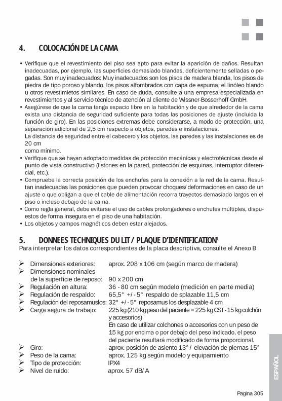
ESPA
ÑO
L
Pagina 305
4. COLOCACIÓN DE LA CAMA
-gadas. Son muy inadecuados: Muy inadecuados son los pisos de madera blanda, los pisos de piedra de tipo poroso y blando, los pisos alfombrados con capa de espuma, el linóleo blando u otros revestimietos similares. En caso de duda, consulte a una empresa especializada en revestimientos y al servicio técnico de atención al cliente de Wissner-Bosserhoff GmbH.
función de giro). En las posiciones extremas debe considerarse, a modo de protección, una
20 cm como mínimo.
punto de vista constructivo (listones en la pared, protección de esquinas, interruptor diferen-cial, etc.).
-tan inadecuadas las posiciones que pueden provocar choques/deformaciones en caso de un
-estos de forma insegura en el piso de una habitación.
5. DONNEES TECHNIQUES DU LIT / PLAQUE D’IDENTIFICATION1
Para interpretar los datos correspondientes de la placa descriptiva, consulte el Anexo B
Dimensiones exteriores: aprox. 208 x 106 cm (según marco de madera) Dimensiones nominales
de la superficie de reposo: 90 x 200 cm Regulación en altura: 36 - 80 cm según modelo (medición en parte media) Regulación de respaldo: 65,5° +/- 5° respaldo de splazable 11,5 cm Regulación del reposamuslos: 32° +/- 5° reposamus los desplazable 4 cm 225 kg (210 kg peso del paciente = 225 kg CST - 15 kg colchón
y accesorios) En caso de utilizar colchones o accesorios con un peso de
Giro: aprox. posición de asiento 13°/ elevación de piernas 15° Peso de la cama: aprox. 125 kg según modelo y equipamiento Tipo de protección: IPX4 Nivel de ruido: aprox. 57 dB/A
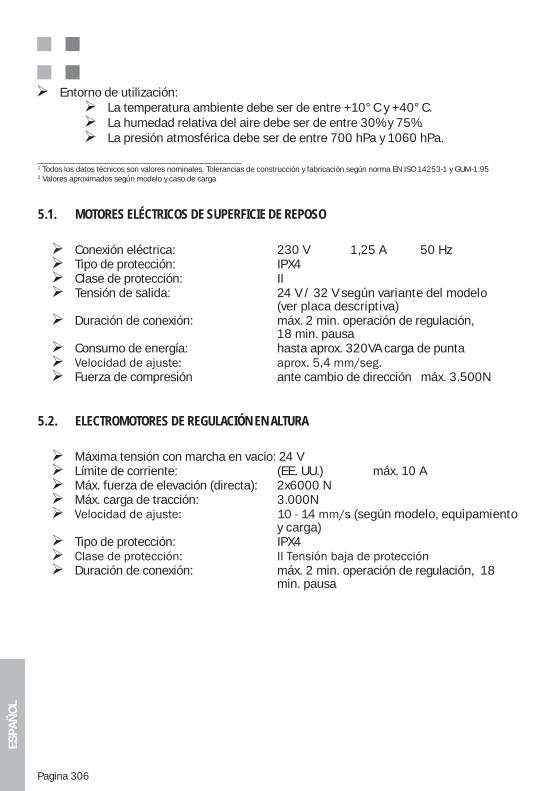
ESPA
ÑO
L
Pagina 306
5.1. MOTORES ELÉCTRICOS DE SUPERFICIE DE REPOSO
Conexión eléctrica: 230 V 1,25 A 50 Hz Tipo de protección: IPX4 Clase de protección: II Tensión de salida: 24 V / 32 V según variante del modelo
(ver placa descriptiva) Duración de conexión: máx. 2 min. operación de regulación,
18 min. pausa Consumo de energía: hasta aprox. 320VA carga de punta Fuerza de compresión ante cambio de dirección máx. 3.500N
5.2. ELECTROMOTORES DE REGULACIÓN EN ALTURA
Máxima tensión con marcha en vacío: 24 V Límite de corriente: (EE. UU.) máx. 10 A Máx. fuerza de elevación (directa): 2x6000 N Máx. carga de tracción: 3.000N (según modelo, equipamiento
y carga) Tipo de protección: IPX4 Duración de conexión: máx. 2 min. operación de regulación, 18
min. pausa
Entorno de utilización: La temperatura ambiente debe ser de entre +10°C y +40°C. La humedad relativa del aire debe ser de entre 30% y 75%. La presión atmosférica debe ser de entre 700 hPa y 1060 hPa.
___________________________________________________1 Todos los datos técnicos son valores nominales. Tolerancias de construcción y fabricación según norma EN ISO 14253-1 y GUM-1:952 Valores aproximados según modelo y caso de carga
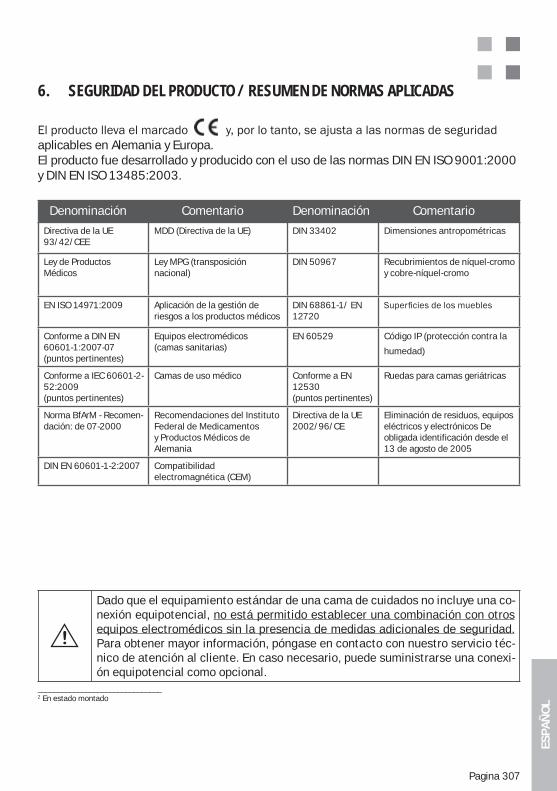
ESPA
ÑO
L
Pagina 307
6. SEGURIDAD DEL PRODUCTO / RESUMEN DE NORMAS APLICADAS
aplicables en Alemania y Europa. El producto fue desarrollado y producido con el uso de las normas DIN EN ISO 9001:2000 y DIN EN ISO 13485:2003.
Denominación Comentario Denominación Comentario
Directiva de la UE 93/42/CEE
MDD (Directiva de la UE) DIN 33402 Dimensiones antropométricas
Ley de Productos Médicos
Ley MPG (transposiciónnacional)
DIN 50967 Recubrimientos de níquel-cromo y cobre-níquel-cromo
EN ISO 14971:2009 Aplicación de la gestión de riesgos a los productos médicos
DIN 68861-1/ EN 12720
Conforme a DIN EN 60601-1:2007-07 (puntos pertinentes)
Equipos electromédicos (camas sanitarias)
EN 60529 Código IP (protección contra la
humedad)
Conforme a IEC 60601-2-52:2009(puntos pertinentes)
Camas de uso médico Conforme a EN 12530(puntos pertinentes)
Ruedas para camas geriátricas
Norma BfArM - Recomen-dación: de 07-2000
Recomendaciones del Instituto Federal de Medicamentos y Productos Médicos de Alemania
Directiva de la UE2002/96/CE
Eliminación de residuos, equiposeléctricos y electrónicos De obligada identificación desde el 13 de agosto de 2005
DIN EN 60601-1-2:2007 Compatibilidad electromagnética (CEM)
_______________________________2 En estado montado
Dado que el equipamiento estándar de una cama de cuidados no incluye una co-nexión equipotencial, no está permitido establecer una combinación con otros equipos electromédicos sin la presencia de medidas adicionales de seguridad. Para obtener mayor información, póngase en contacto con nuestro servicio téc-nico de atención al cliente. En caso necesario, puede suministrarse una conexi-ón equipotencial como opcional.
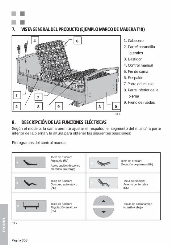
ESPA
ÑO
L
Pagina 308
1. Cabecero
2. Parte/barandilla
laterales
3. Bastidor
4. Control manual
5. Pie de cama
6. Respaldo
7. Parte del muslo
8. Parte inferior de la
pierna
9. Freno de ruedas
7. VISTA GENERAL DEL PRODUCTO (EJEMPLO MARCO DE MADERA T10)
Fig. 1
8. DESCRIPCIÓN DE LAS FUNCIONES ELÉCTRICASSegún el modelo, la cama permite ajustar el respaldo, el segmento del muslo/la parte inferior de la pierna y la altura para obtener las siguientes posiciones:
Pictogramas del control manual
1
2 3
4
5
6
7
8 9
Fig. 2
Tecla de función:Respaldo (RL)
(como opción: descenso mecánco, sin carga)
Tecla de función:Contorno automático (AK)
Tecla de función:Regulación en altura (HV)
Tecla de función:Elevación de piernas (BH)
Tecla de función:Asiento confortable (KS)
Teclas de accionamien-to arriba/abajo
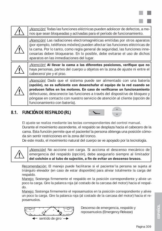
ESPA
ÑO
L
Pagina 309
¡Atención!haya personas, partes del cuerpo u objetos en la zona de ajuste ni entre el cabecero/pie y el piso.
¡Atención! Dado que el sistema puede ser alimentado con una batería
defectuoso, desconecte las funciones a través del dispositivo de bloqueo y póngase en contacto con nuestro servicio de atención al cliente (opción de funcionamiento con batería).
¡Atención! No accione con carga. Si acciona el descenso mecánico de emergencia del respaldo (opción), debe asegurarlo siempre al limitador
¡Atención! Todas las funciones eléctricas pueden adolecer de defectos, a me-nos que sean bloqueadas y activadas para el período de funcionamiento.
8.1. FUNCIÓN DE RESPALDO (RL)
Durante el movimiento ascendente, el respaldo se desplaza hacia el cabecero de la cama. Esta función permite que el paciente/la persona obtenga una posición cómo-da sin sentir restricciones en la zona del tronco.De este modo, el movimiento natural del cuerpo se ve apoyado por la tecnología.
Recomendación: El manejo puede facilitarse si el paciente/la persona se sujeta al triángulo elevador (en caso de estar disponible) para aliviar totalmente la carga del respaldo.Manejo: Sostenga firmemente el respaldo en la posición correspondiente y alivie un poco la carga. Gire la palanca roja (al costado de la carcasa del motor) hacia el respal-do.Manejo: Sostenga firmemente el reposamuslos en la posición correspondiente y alivie un poco la carga. Gire la palanca roja (al costado de la carcasa del motor) hacia el re-posamuslos.
Descenso de emergencia, respaldo y reposamuslos (Emergency Release)
sentido de giro
¡Atención! Las radiaciones electromagnéticas emitidas por otros aparatos (por ejemplo, teléfonos móviles) pueden afectar las funciones eléctricas de la cama. Por lo tanto, como regla general de seguridad, las funciones inne-cesarias deben bloquearse. En lo posible, debe evitarse el uso de dichos aparatos en las inmediaciones del lugar.
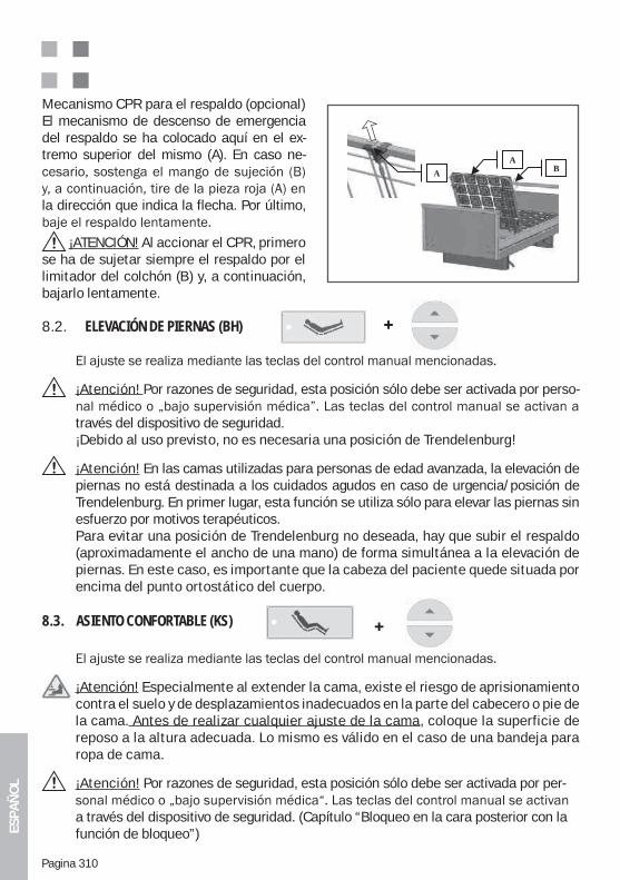
ESPA
ÑO
L
Pagina 310
8.2. ELEVACIÓN DE PIERNAS (BH)
¡Atención! Por razones de seguridad, esta posición sólo debe ser activada por perso-
través del dispositivo de seguridad.¡Debido al uso previsto, no es necesaria una posición de Trendelenburg!
¡Atención! En las camas utilizadas para personas de edad avanzada, la elevación de piernas no está destinada a los cuidados agudos en caso de urgencia/posición de Trendelenburg. En primer lugar, esta función se utiliza sólo para elevar las piernas sin esfuerzo por motivos terapéuticos. Para evitar una posición de Trendelenburg no deseada, hay que subir el respaldo (aproximadamente el ancho de una mano) de forma simultánea a la elevación de piernas. En este caso, es importante que la cabeza del paciente quede situada por encima del punto ortostático del cuerpo.
8.3. ASIENTO CONFORTABLE (KS)
¡Atención! Especialmente al extender la cama, existe el riesgo de aprisionamiento contra el suelo y de desplazamientos inadecuados en la parte del cabecero o pie de la cama. Antes de realizar cualquier ajuste de la cama, coloque la superficie de reposo a la altura adecuada. Lo mismo es válido en el caso de una bandeja para ropa de cama.
¡Atención! Por razones de seguridad, esta posición sólo debe ser activada por per-
a través del dispositivo de seguridad. (Capítulo “Bloqueo en la cara posterior con la función de bloqueo”)
Mecanismo CPR para el respaldo (opcional)El mecanismo de descenso de emergencia del respaldo se ha colocado aquí en el ex-tremo superior del mismo (A). En caso ne-
la dirección que indica la flecha. Por último,
¡ATENCIÓN! Al accionar el CPR, primero se ha de sujetar siempre el respaldo por el limitador del colchón (B) y, a continuación, bajarlo lentamente.
BA
A
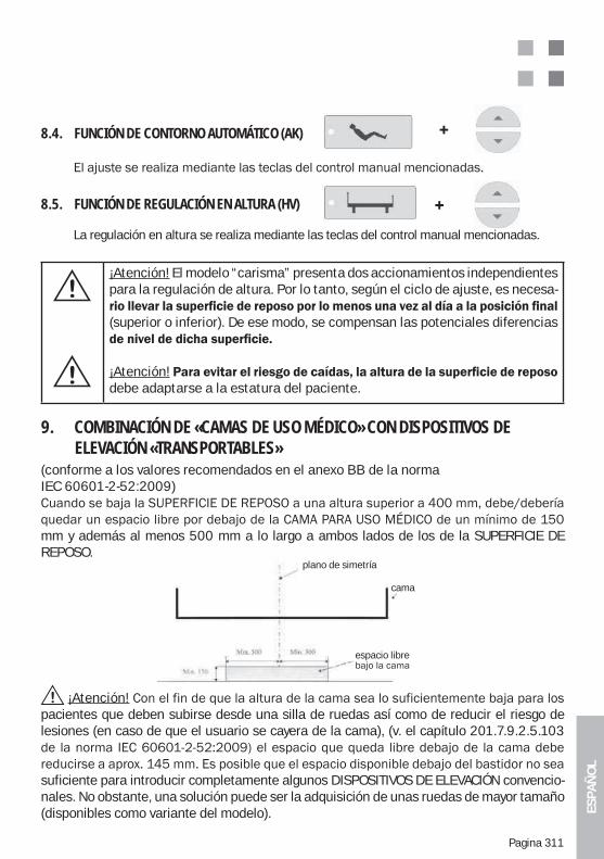
ESPA
ÑO
L
Pagina 311
¡Atención! El modelo “carisma” presenta dos accionamientos independientes para la regulación de altura. Por lo tanto, según el ciclo de ajuste, es necesa-
(superior o inferior). De ese modo, se compensan las potenciales diferencias
¡Atención!debe adaptarse a la estatura del paciente.
¡Atención!pacientes que deben subirse desde una silla de ruedas así como de reducir el riesgo de lesiones (en caso de que el usuario se cayera de la cama), (v. el capítulo 201.7.9.2.5.103
suficiente para introducir completamente algunos DISPOSITIVOS DE ELEVACIÓN convencio-nales. No obstante, una solución puede ser la adquisición de unas ruedas de mayor tamaño (disponibles como variante del modelo).
9. COMBINACIÓN DE «CAMAS DE USO MÉDICO» CON DISPOSITIVOS DE ELEVACIÓN «TRANSPORTABLES»(conforme a los valores recomendados en el anexo BB de la norma IEC 60601-2-52:2009)
mm y además al menos 500 mm a lo largo a ambos lados de los de la SUPERFICIE DE REPOSO.
Symmetrieebene
Bett
Unterfahrbar
plano de simetría
cama
espacio libre
8.4. FUNCIÓN DE CONTORNO AUTOMÁTICO (AK)
8.5. FUNCIÓN DE REGULACIÓN EN ALTURA (HV)
La regulación en altura se realiza mediante las teclas del control manual mencionadas.
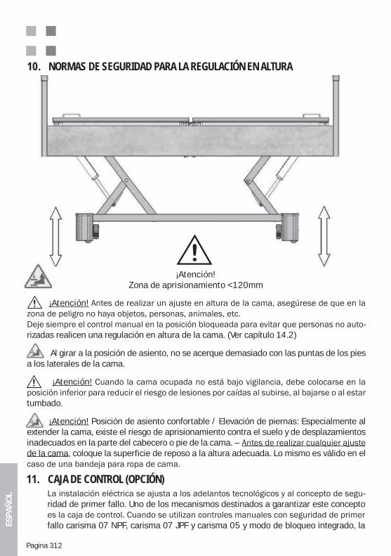
ESPA
ÑO
L
Pagina 312
11. CAJA DE CONTROL (OPCIÓN)-
ridad de primer fallo. Uno de los mecanismos destinados a garantizar este concepto
fallo carisma 07 NPF, carisma 07 JPF y carisma 05 y modo de bloqueo integrado, la
10. NORMAS DE SEGURIDAD PARA LA REGULACIÓN EN ALTURA
¡Atención!
-rizadas realicen una regulación en altura de la cama. (Ver capítulo 14.2)
Al girar a la posición de asiento, no se acerque demasiado con las puntas de los pies a los laterales de la cama.
¡Atención!
tumbado.
¡Atención! Posición de asiento confortable / Elevación de piernas: Especialmente al extender la cama, existe el riesgo de aprisionamiento contra el suelo y de desplazamientos inadecuados en la parte del cabecero o pie de la cama. – de la cama, coloque la superficie de reposo a la altura adecuada. Lo mismo es válido en el
¡Atención!Zona de aprisionamiento <120mm
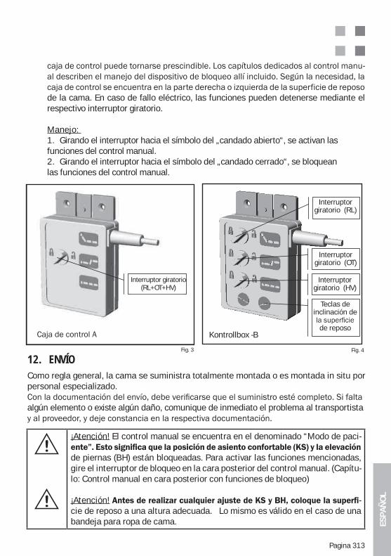
ESPA
ÑO
L
Pagina 313
¡Atención! El control manual se encuentra en el denominado “Modo de paci-
de piernas (BH) están bloqueadas. Para activar las funciones mencionadas, gire el interruptor de bloqueo en la cara posterior del control manual. (Capítu-lo: Control manual en cara posterior con funciones de bloqueo)
¡Atención! -cie de reposo a una altura adecuada. Lo mismo es válido en el caso de una bandeja para ropa de cama.
Fig. 3 Fig. 4
Kontrollbox -A
rehs halter
Kontrollbox -B
Interruptor giratorio(RL+OT+HV)
Interruptor giratorio (RL)
Interruptor giratorio (OT)
Interruptor giratorio (HV)
Teclas de inclinación de
de reposoKontrollbox -B
12. ENVÍO Como regla general, la cama se suministra totalmente montada o es montada in situ por personal especializado.
algún elemento o existe algún daño, comunique de inmediato el problema al transportista
-
de la cama. En caso de fallo eléctrico, las funciones pueden detenerse mediante el respectivo interruptor giratorio.
Manejo: 1. Girando el interruptor hacia el símbolo del „candado abierto“, se activan las funciones del control manual.2. Girando el interruptor hacia el símbolo del „candado cerrado“, se bloquean las funciones del control manual.
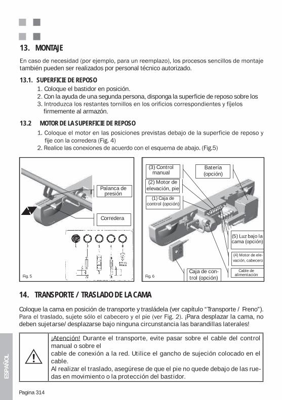
ESPA
ÑO
L
Pagina 314
14. TRANSPORTE / TRASLADO DE LA CAMA
Coloque la cama en posición de transporte y trasládela (ver capítulo “Transporte / Freno”). ¡Para desplazar la cama, no
deben sujetarse/desplazarse bajo ninguna circunstancia las barandillas laterales!
¡Atención! Durante el transporte, evite pasar sobre el cable del control manual o sobre elcable de conexión a la red. Utilice el gancho de sujeción colocado en el cable.Al realizar el traslado, asegúrese de que el pie no quede debajo de las rue-das en movimiento o la protección del bastidor.
13. MONTAJE
también pueden ser realizados por personal técnico autorizado.
13.1. SUPERFICIE DE REPOSO 1. Coloque el bastidor en posición. 2. Con la ayuda de una segunda persona, disponga la superficie de reposo sobre los
firmemente al armazón.
13.2 MOTOR DE LA SUPERFICIE DE REPOSO
Fig. 5 Fig. 6
Schieber
Druckhebel
(1) Kontroll-box (Option)
Kontrollbox (Option)
(2) Hubmotor Fuß
(3) Hand-schalter
(5) Unterbett- Beleuchtung
(Option)
Akku (Option)
(4) Hubmotor Kopf
Netzkabel
Palanca depresión
Corredera
(3) Control manual
(2) Motor de elevación, pie
(1) Caja de control (opción)
Batería (opción)
Caja de con-trol (opción)
(5) Luz bajo la cama (opción)
(4) Motor de ele-vación, cabecero
Cable de alimentación
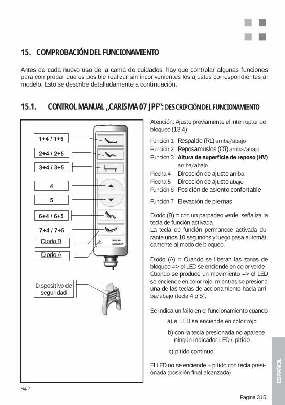
ESPA
ÑO
L
Pagina 315
15. COMPROBACIÓN DEL FUNCIONAMIENTO
Antes de cada nuevo uso de la cama de cuidados, hay que controlar algunas funciones
modelo. Esto se describe detalladamente a continuación.
15.1. CONTROL MANUAL „CARISMA 07 JPF“: DESCRIPCIÓN DEL FUNCIONAMIENTO
Atención: Ajuste previamente el interruptor de bloqueo (13.4)
Función 1 Respaldo (RL)Función 2 Reposamuslos (OT)Función 3
Flecha 4 Dirección de ajuste arribaFlecha 5 Dirección de ajusteFunción 6 Posición de asiento confortable
Función 7 Elevación de piernas
Diodo (B) = con un parpadeo verde, señaliza la tecla de función activadaLa tecla de función permanece activada du-rante unos 10 segundos y luego pasa automáticamente al modo de bloqueo.
Diodo (A) = Cuando se liberan las zonas de bloqueo => el LED se enciende en color verdeCuando se produce un movimiento => el LED
una de las teclas de accionamiento hacia arri-
Se indica un fallo en el funcionamiento cuando
b) con la tecla presionada no aparece ningún indicador LED / pitido
c) pitido continuo
El LED no se enciende + pitido con tecla presi-
Fig. 7
Diode A
Diode B
Sicher-heitsschlüs
l
Diodo B
Diodo A
Dispositivo de seguridad
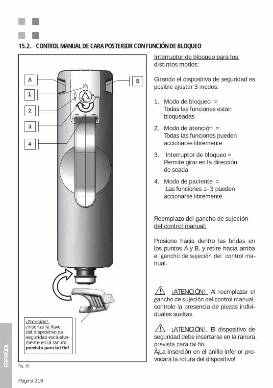
ESPA
ÑO
L
Pagina 316
1
2
3
A B
4
Achtung! Si -cherheitsschlüssel - nur in dem dafür vor-gesehenen S lt i l i
Interruptor de bloqueo para los distintos modos:
Girando el dispositivo de seguridad es
1. Modo de bloqueo = Todas las funciones están bloqueadas
2. Modo de atención = Todas las funciones pueden accionarse libremente
3. Interruptor de bloqueo = Permite girar en la dirección de-seada
4. Modo de paciente = Las funciones 1- 3 pueden accionarse libremente
Reemplazo del gancho de sujeción del control manual:
Presione hacia dentro las bridas en los puntos A y B, y retire hacia arriba
-nual.
¡ATENCIÓN! Al reemplazar el
controle la presencia de piezas indivi-duales sueltas.
¡ATENCIÓN! El dispositivo de seguridad debe insertarse en la ranura
¡La inserción en el anillo inferior pro-vocará la rotura del dispositivo!
15.2. CONTROL MANUAL DE CARA POSTERIOR CON FUNCIÓN DE BLOQUEO
¡Atención! ¡Insertar la llave del dispositivo de seguridad exclusiva-mente en la ranura
Fig. 10
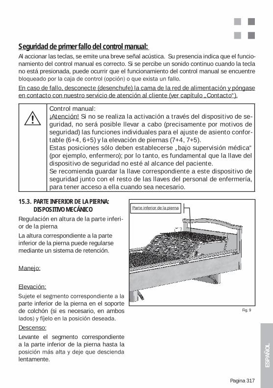
ESPA
ÑO
L
Pagina 317
Fig. 9
Seguridad de primer fallo del control manual: Al accionar las teclas, se emite una breve señal acústica. Su presencia indica que el funcio-namiento del control manual es correcto. Si se percibe un sonido continuo cuando la tecla no está presionada, puede ocurrir que el funcionamiento del control manual se encuentre
En caso de fallo, desconecte (desenchufe) la cama de la red de alimentación y póngase en contacto con nuestro servicio de atención al cliente (ver capítulo „Contacto“).
Control manual:¡Atención! Si no se realiza la activación a través del dispositivo de se-guridad, no será posible llevar a cabo (precisamente por motivos de seguridad) las funciones individuales para el ajuste de asiento confor-table (6+4, 6+5) y la elevación de piernas (7+4, 7+5).Estas posiciones sólo deben establecerse „bajo supervisión médica“ (por ejemplo, enfermero); por lo tanto, es fundamental que la llave del dispositivo de seguridad no esté al alcance del paciente. Se recomienda guardar la llave correspondiente a este dispositivo de seguridad junto con el resto de las llaves del personal de enfermería, para tener acceso a ella cuando sea necesario.
15.3. PARTE INFERIOR DE LA PIERNA: DISPOSITIVO MECÁNICORegulación en altura de la parte inferi-or de la pierna
La altura correspondiente a la parte inferior de la pierna puede regularse mediante un sistema de retención.
Manejo:
Elevación:
parte inferior de la pierna en el soporte de colchón (si es necesario, en ambos
Descenso:
Levante el segmento correspondiente a la parte inferior de la pierna hasta la
lentamente.
Parte inferior de la pierna
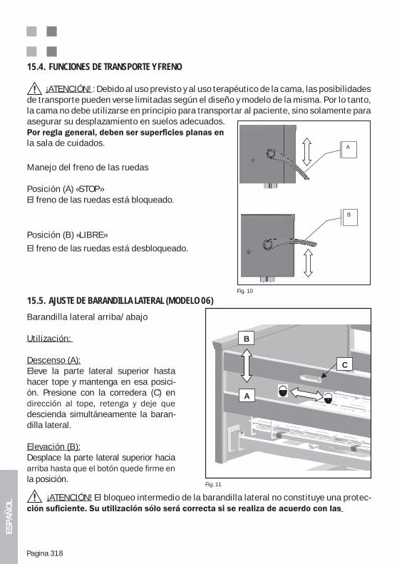
ESPA
ÑO
L
Pagina 318
15.4. FUNCIONES DE TRANSPORTE Y FRENO
¡ATENCIÓN! : Debido al uso previsto y al uso terapéutico de la cama, las posibilidades de transporte pueden verse limitadas según el diseño y modelo de la misma. Por lo tanto, la cama no debe utilizarse en principio para transportar al paciente, sino solamente para asegurar su desplazamiento en suelos adecuados.
la sala de cuidados.
Manejo del freno de las ruedas
Posición (A) «STOP»El freno de las ruedas está bloqueado.
Posición (B) «LIBRE»
El freno de las ruedas está desbloqueado.
Fig. 10
n
-
A
B
Barandilla lateral arriba/abajo
Utilización:
Descenso (A):Eleve la parte lateral superior hasta hacer tope y mantenga en esa posici-ón. Presione con la corredera (C) en
descienda simultáneamente la baran-dilla lateral.
Elevación (B):Desplace la parte lateral superior hacia
la posición.
15.5. AJUSTE DE BARANDILLA LATERAL (MODELO 06)
Fig. 11
B
A
C
¡ATENCIÓN! El bloqueo intermedio de la barandilla lateral no constituye una protec-
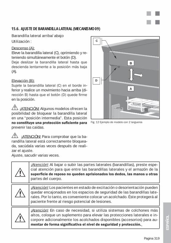
ESPA
ÑO
L
Pagina 319
Barandilla lateral arriba/abajoUtilización :
Descenso (A):Eleve la barandilla lateral (C), oprimiendo y re-teniendo simultáneamente el botón (D).
(A).
Elevación (B):-
ferior y realice un movimiento hacia arriba (di-
en la posición.
¡ATENCIÓN! Algunos modelos ofrecen la posibilidad de bloquear la barandilla lateral en una “posición intermedia”. Esta posición
prevenir las caídas.
¡ATENCIÓN! Para comprobar que la ba-randilla lateral está correctamente bloquea-da, sacúdala varias veces después de reali-zar el ajuste.Ajuste, sacudir varias veces.
15.6. AJUSTE DE BARANDILLA LATERAL (MECANISMO 09)
B
A
D
C
¡Atención! Al bajar o subir las partes laterales (barandillas), preste espe-cial atención para que entre las barandillas laterales y el armazón de la
partes del cuerpo.
¡Atención! Los pacientes en estado de excitación o desorientación pueden quedar encajonados en los espacios de seguridad de las barandillas late-rales. Por lo tanto, es conveniente colocar un acolchado. Éste protegerá al paciente frente al riesgo potencial de lesiones.
¡Atención! En caso de necesidad, si utiliza sistemas de colchones más altos, coloque un suplemento para elevar las protecciones laterales e in-corpore adicionalmente los acolchados disponibles (accesorios) para au-
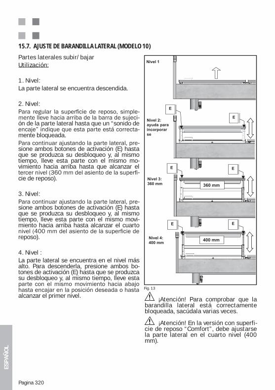
ESPA
ÑO
L
Pagina 320
Partes laterales subir/bajarUtilización:
1. Nivel:La parte lateral se encuentra descendida.
2. Nivel:--
ón de la parte lateral hasta que un “sonido de -
mente bloqueada.-
sione ambos botones de activación (E) hasta que se produzca su desbloqueo y, al mismo tiempo, lleve esta parte con el mismo mo-vimiento hacia arriba hasta que alcanzar el
-cie de reposo).
3. Nivel:-
sione ambos botones de activación (E) hasta que se produzca su desbloqueo y, al mismo tiempo, lleve esta parte con el mismo movi-miento hacia arriba hasta alcanzar el cuarto
reposo).
4. Nivel :La parte lateral se encuentra en el nivel más alto. Para descenderla, presione ambos bo-tones de activación (E) hasta que se produzca su desbloqueo y, al mismo tiempo, lleve esta
alcanzar el primer nivel.
15.7. AJUSTE DE BARANDILLA LATERAL (MODELO 10)
Abb. 16
Fig. 13
¡Atención! Para comprobar que la barandilla lateral está correctamente bloqueada, sacúdala varias veces.
¡Atención! En la versión con superfi-cie de reposo “Comfort”, debe ajustarse la parte lateral en el cuarto nivel (400 mm).
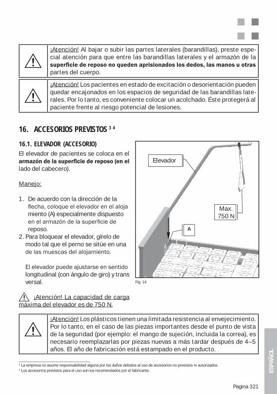
ESPA
ÑO
L
Pagina 321
¡Atención! Al bajar o subir las partes laterales (barandillas), preste espe-cial atención para que entre las barandillas laterales y el armazón de la
partes del cuerpo.
¡Atención! Los pacientes en estado de excitación o desorientación pueden quedar encajonados en los espacios de seguridad de las barandillas late-rales. Por lo tanto, es conveniente colocar un acolchado. Éste protegerá al paciente frente al riesgo potencial de lesiones.
16. ACCESORIOS PREVISTOS 3 4
16.1. ELEVADOR (ACCESORIO)El elevador de pacientes se coloca en el
lado del cabecero).
Manejo:
1. De acuerdo con la dirección de la
miento (A) especialmente dispuesto
reposo.2. Para bloquear el elevador, gírelo de modo tal que el perno se sitúe en una
longitudinal (con ángulo de giro) y trans versal.
¡Atención! La capacidad de carga máxima del elevador es de 750 N.
¡Atención! Los plásticos tienen una limitada resistencia al envejecimiento. Por lo tanto, en el caso de las piezas importantes desde el punto de vista de la seguridad (por ejemplo: el mango de sujeción, incluida la correa), es necesario reemplazarlas por piezas nuevas a más tardar después de 4–5 años. El año de fabricación está estampado en el producto.
____________________________________3 La empresa no asume responsabilidad alguna por los daños debidos al uso de accesorios no previstos ni autorizados.4 Los accesorios previstos para el uso son los recomendados por el fabricante.
Fig. 14
Aufrichter
A
Max.
750N
Elevador
Max.750 N
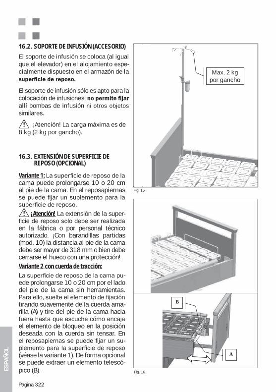
ESPA
ÑO
L
Pagina 322
El soporte de infusión se coloca (al igual que el elevador) en el alojamiento espe-cialmente dispuesto en el armazón de la
El soporte de infusión sólo es apto para la colocación de infusiones; allí bombas de infusiónsimilares.
¡Atención! La carga máxima es de 8 kg (2 kg por gancho).
16.2. SOPORTE DE INFUSIÓN (ACCESORIO)
Fig. 15
dieah-
In-usi-
kg
Max. 2 kgpor gancho
Fig. 16
f
bb
B
A
16.3. EXTENSIÓN DE SUPERFICIE DE REPOSO (OPCIONAL)
Variante 1: cama puede prolongarse 10 o 20 cm al pie de la cama. En el reposapiernas
¡Atención! La extensión de la super-
en la fábrica o por personal técnico autorizado. ¡Con barandillas partidas (mod. 10) la distancia al pie de la cama debe ser mayor de 318 mm o bien debe cerrarse el hueco con una protección!Variante 2 con cuerda de tracción:
-ede prolongarse 10 o 20 cm por el lado del pie de la cama sin herramientas.
tirando suavemente de la cuerda ama-rilla (A) y tire del pie de la cama hacia
el elemento de bloqueo en la posición deseada con la cuerda sin tensar. En
-
(véase la variante 1). De forma opcional se puede extraer un elemento telescó-pico (B).
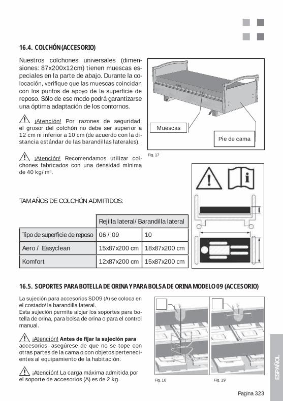
ESPA
ÑO
L
Pagina 323
Nuestros colchones universales (dimen-siones: 87x200x12cm) tienen muescas es-peciales en la parte de abajo. Durante la co-
reposo. Sólo de ese modo podrá garantizarse una óptima adaptación de los contornos.
¡Atención! Por razones de seguridad, el grosor del colchón no debe ser superior a 12 cm ni inferior a 10 cm (de acuerdo con la di-stancia estándar de las barandillas laterales).
¡Atención! Recomendamos utilizar col-chones fabricados con una densidad mínima de 40 kg/m3.
16.4. COLCHÓN (ACCESORIO)
Fig. 17
Bett-Fußteil
EinschnitteMuescas
Pie de cama
el costado/la barandilla lateral. -
tella de orina, para bolsa de orina o para el control manual.
¡Atención!accesorios, asegúrese de que no se tope con otras partes de la cama o con objetos perteneci-entes al equipamiento de la habitación. ¡Atención! La carga máxima admitida por el soporte de accesorios (A) es de 2 kg.
16.5. SOPORTES PARA BOTELLA DE ORINA Y PARA BOLSA DE ORINA MODELO 09 (ACCESORIO)
Fig. 18 Fig. 19
TAMAÑOS DE COLCHÓN ADMITIDOS:
Rejilla lateral/Barandilla lateral
Tipo de superficie de reposo 06 / 09 10
Aero / Easyclean 15x87x200 cm 18x87x200 cm
Komfort 12x87x200 cm 15x87x200 cm
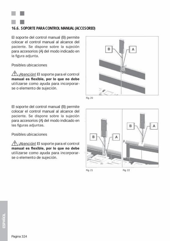
ESPA
ÑO
L
Pagina 324
El soporte del control manual (B) permite colocar el control manual al alcance del
para accesorios (A) del modo indicado en
Posibles ubicaciones
¡Atención! El soporte para el control
utilizarse como ayuda para incorporar-se o elemento de sujeción.
El soporte del control manual (B) permite colocar el control manual al alcance del
para accesorios (A) del modo indicado en
Posibles ubicaciones
¡Atención! El soporte para el control
utilizarse como ayuda para incorporar-se o elemento de sujeción.
16.6. SOPORTE PARA CONTROL MANUAL (ACCESORIO)
Fig. 20
Fig. 21 Fig. 22
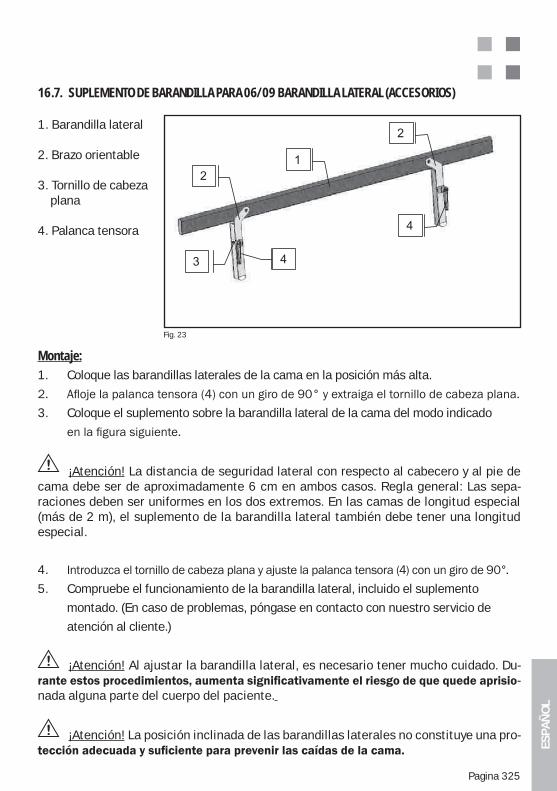
ESPA
ÑO
L
Pagina 325
1. Barandilla lateral
2. Brazo orientable
3. Tornillo de cabeza plana
4. Palanca tensora
16.7. SUPLEMENTO DE BARANDILLA PARA 06/09 BARANDILLA LATERAL (ACCESORIOS)
Fig. 23
Montaje:1. Coloque las barandillas laterales de la cama en la posición más alta.
3. Coloque el suplemento sobre la barandilla lateral de la cama del modo indicado
¡Atención! La distancia de seguridad lateral con respecto al cabecero y al pie de cama debe ser de aproximadamente 6 cm en ambos casos. Regla general: Las sepa-raciones deben ser uniformes en los dos extremos. En las camas de longitud especial (más de 2 m), el suplemento de la barandilla lateral también debe tener una longitud especial.
4.
5. Compruebe el funcionamiento de la barandilla lateral, incluido el suplemento
montado. (En caso de problemas, póngase en contacto con nuestro servicio de
atención al cliente.)
¡Atención! Al ajustar la barandilla lateral, es necesario tener mucho cuidado. Du--
nada alguna parte del cuerpo del paciente.
¡Atención! La posición inclinada de las barandillas laterales no constituye una pro-
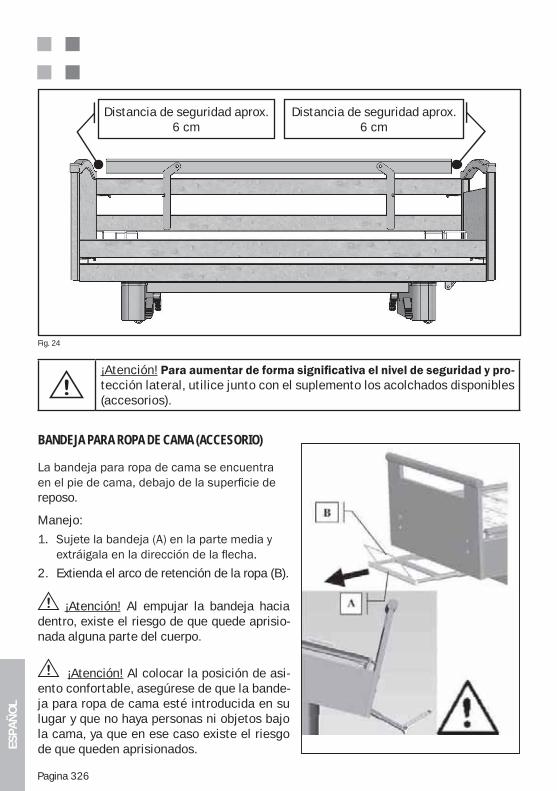
ESPA
ÑO
L
Pagina 326
Distancia de seguridad aprox. 6 cm
Distancia de seguridad aprox. 6 cm
¡Atención!tección lateral, utilice junto con el suplemento los acolchados disponibles (accesorios).
Fig. 24
BANDEJA PARA ROPA DE CAMA (ACCESORIO)
reposo.
Manejo:
2. Extienda el arco de retención de la ropa (B).
¡Atención! Al empujar la bandeja hacia dentro, existe el riesgo de que quede aprisio-nada alguna parte del cuerpo.
¡Atención! Al colocar la posición de asi-ento confortable, asegúrese de que la bande-ja para ropa de cama esté introducida en su lugar y que no haya personas ni objetos bajo la cama, ya que en ese caso existe el riesgo de que queden aprisionados.
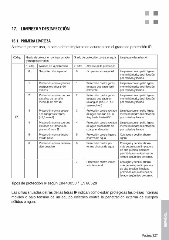
ESPA
ÑO
L
Pagina 327
17. LIMPIEZA Y DESINFECCIÓN
16.1. PRIMERA LIMPIEZAAntes del primer uso, la cama debe limpiarse de acuerdo con el grado de protección IP.
Tipos de protección IP según DIN 40050 / EN 60529 Las cifras situadas detrás de las letras IP indican cómo están protegidas las piezas internas
sólidos o agua.
Código Grado de protección contra contacto y cuerpos extraños
Grado de protección contra el agua Limpieza y desinfección
IP
1. cifra Alcance de la protección 2. cifra Alcance de la protección
0 Sin protección especial 0 Sin protección especial Limpieza con un paño ligera-mente húmedo; desinfección por rociado y lavado
1 Protección contra grandes cuerpos extraños (>50 mm Ø )
1 Protección contra gotas de agua que caen verti-calmente
Limpieza con un paño ligera-mente húmedo; desinfección por rociado y lavado
2 Protección contra cuerpos extraños de tamaño medio (>12 mm Ø)
2 Protección contra gotas de agua que caen en un ángulo (bis 15° zur senkrechten)
Limpieza con un paño ligera-mente húmedo; desinfección por rociado y lavado
3 Protección contra peque-ños cuerpos extraños (>2,5 mm Ø)
3 Protección contra rociado de agua que cae en un ángulo de hasta 60°
Limpieza con un paño ligera-mente húmedo; desinfección por rociado y lavado
4 Protección contra cuerpos extraños de tamaño de grano (>1 mm Ø)
4 Protección contra rociado de agua procedente de cualquier dirección
Limpieza con un paño ligera-mente húmedo; desinfección por rociado y lavado
5 Protección contra depósi-tos de polvo
5 Protección contra ligeros chorros de agua
Con agua y cepillo; chorro ligero
6 Protección contra penetra-ción de polvo
6 Protección contra po-tentes chorros de agua
Con agua y cepillo; chorro más potente; sin limpiadora de alta presión; limpieza permitida con máquinas de lavado según tipo de cama.
7 Protección contra inmer-sión temporal
Con agua y cepillo; chorro más potente; sin limpiadora de alta presión; limpieza permitida con máquinas de lavado según tipo de cama.
ESPA
ÑO
L
Pagina 328
¡Atención! Por razones de seguridad, es fundamental evitar la penetración o aplica-ción de líquidos (agua, disolventes, aceites, lejías, limpiadores, etc.) en el interior de la cama o sobre alguna parte de ella.
¡Atención! Las carcasas protegidas contra la penetración del agua no siempre tienen esa misma protección frente a otros líquidos.
¡Atención! Como regla general, la cama de cuidados debe estar siempre protegida al máximo para no ser afectada por la humedad. La limpieza debe realizarse única-mente con un paño ligeramente húmedo.
17.2. DESINFECCIÓN / ESTERILIZACIÓNLa cama debe desinfectarse periódicamente, por lo menos antes de cada cambio de paciente. No debe desinfectarse en túneles de lavado ni con chorros de agua.
Para la desinfección de la cama se recomiendan los siguientes productos, que podrán ser reemplazados únicamente por otros de iguales características:Terralin, Perform y Sagrotan Med (Schülke & Mayr GmbH, Norderstedt, Alemania).Los productos deben utilizarse de acuerdo con las indicaciones del fabricante. Esto es par-ticularmente válido en lo que se refiere a la dosificación y al potencial riesgo derivado de la combinación con otros agentes.El marco de madera no debe entrar en contacto con estos productos.
17.3. CUIDADO DE LAS PARTES DE MADERA Hemos utilizado materiales de excelente calidad para ofrecerle a usted un producto que combine la gran utilidad con el confort de la madera natural.Para que aproveche al máximo su producto Wissner-Bosserhoff, recomendamos realizar la limpieza con un paño suave y ligeramente húmedo.
incluso cuando ha sido barnizada. Con el paso del tiempo, la radiación UV, la humedad, el calor y otros agentes atmosféricos modifican la coloración de las superficies. Además,
texturas de los enchapados sólo pueden determinarse de un modo general, ya que cada rama de un árbol tiene sus propias características. Las pequeñas diferencias de color y contraste que existen en los suministros de Wissner-Bosserhoff tienen causas naturales y son técnicamente inevitables. Esto debe tenerse en cuenta, sobre todo, en el caso de los suministros posteriores o complementarios. Por los motivos expuestos, no constituyen un defecto las diferencias relativas de brillo, con-traste y color entre los enchapados, las piezas de madera maciza o las superficies deco-rativas (melamina, HPL), ni las formaciones inherentes al crecimiento que aparecen en los elementos de madera natural. En consecuencia, Wissner-Bosserhoff GmbH no puede asumir responsabilidades ni ofrecer garantías al respecto.
Bosserhoff garantiza una alta calidad en el color de los productos.
ESPA
ÑO
L
Pagina 329
17.4. USO DE LIMPIADORESPara las manchas muy rebeldes, desde luego, pueden aplicarse limpiadores domésticos multiuso de tipo ecológico. Las superficies de los muebles correspondientes a los produc-tos Wissner-Bosserhoff satisfacen los requisitos de la Norma DIN 68861 - 1A en materia de exigencia química y, por lo tanto, ofrecen una excelente resistencia frente a los esfuerzos normales y habituales.Sin embargo, no deben utilizarse limpiadores con componentes abrasivos.
Verifique que durante el uso y la limpieza no queden manchas de líquido o humedad en la madera natural y las superficies enchapadas. La madera es un producto natural que absorbe humedad y, al hacerlo, se expande. Debido a este proceso, puede verse afectado el sellado de la superficie. Por lo tanto, es importante evitar la presencia de altos niveles de humedad durante el uso y el almacenamiento de los productos de madera.Después de realizar la limpieza, se recomienda aplicar un paño seco sobre las superficies de madera natural o enchapada para minimizar el riesgo de daños ocasionados por la hu-medad.
17.5. USO DE DESINFECTANTES
Anexo 1 de la norma DIN 68861, Parte 1: a) Derivados fenólicos, solución acuosa al 0,5 %: alquil-cicloalquil-aril-fenol clorado b) Cloramina T, solución acuosa al 2,5 %: p-toluensulfocloramida sódica
17.6. DAÑOS EN LAS PARTES DE MADERASi el enchapado o el sellado se deterioran como consecuencia de golpes, arañazos o cortes, habrá que reacondicionar de inmediato la superficie y protegerla con materiales adecuados para evitar que penetre la humedad. Consulte al servicio de atención al cliente de Wissner-Bosserhoff o a una empresa especializada.
17.7. IMPACTO AMBIENTALTodos los materiales de madera utilizados cumplen las estrictas leyes y disposiciones alema-nas, y no representan ningún peligro para la salud. El hombre y el medio ambiente constitu-yen prioridades para nuestra acción.
17.8. CALIDADLos productos están sometidos a un estricto control realizado por nuestro sistema de asegu-ramiento de calidad y satisfacen las normas internacionales DIN EN ISO 9001:2000 y DIN EN ISO 13485:2003 para la fabricación y comercialización de productos sanitarios.Wissner-Bosserhoff otorga un año de garantía para todas las características prometidas. Sin embargo, no se admitirán reclamaciones derivadas de un uso o un cuidado inadecuado o
-ción al cliente.
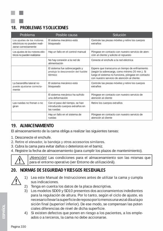
ESPA
ÑO
L
Pagina 330
18. PROBLEMAS Y SOLUCIONES Problema Posible causa Solución
eléctricos no pueden reali-zarse correctamente
El sistema mecánico está bloqueado
Controle las piezas móviles y retire los cuerpos extraños
-tricos no pueden realizarse
Hay un fallo en el control manual Póngase en contacto con nuestro servicio de aten-ción al cliente y solicite el repuesto
No hay conexión a la red de alimentación
Conecte el enchufe a la red eléctrica
El sistema fue sobrecargado y
térmico
Espere que transcurra un tiempo de enfriamiento (según la sobrecarga, como mínimo 20 min.). Si luego el sistema no funciona, póngase en contacto con nuestro servicio de atención al cliente.
La barandilla lateral no -
mente
El sistema mecánico está bloqueado
Controle las piezas móviles y retire los cuerpos extraños
El sistema mecánico ha sufrido una deformación
Póngase en contacto con nuestro servicio de atención al cliente
Las ruedas no frenan o no giran
Con el paso del tiempo, se han introducido cuerpos extraños en las ruedas
Retire los cuerpos extraños
Hay un fallo en el sistema de ruedas
Póngase en contacto con nuestro servicio de atención al cliente
19. ALMACENAMIENTOEl almacenamiento de la cama obliga a realizar las siguientes tareas:
1. Desconecte el enchufe.
3. Cubra la cama para evitar daños o deterioros en el barniz.4. Registre la fecha de almacenamiento (para cumplir los plazos de mantenimiento).
¡Atención! Las condiciones para el almacenamiento son las mismas que para el entorno operativo (ver Entorno de utilizaciónâ).
20. NORMAS DE SEGURIDAD Y RIESGOS RESIDUALES
1) Lea este Manual de Instrucciones antes de utilizar la cama y cumpla sus indicaciones.2) Tenga en cuenta los datos de la placa descriptiva.3) Los modelos SD09 y SD10 presentes dos accionamientos indedientes para la regulación de altura. Por lo tanto, según el ciclo de ajuste, es necesario llevar la superficie de reposo por lo menos una vez al día a la po sición final (superior/inferior). De ese modo, se compensan las poten ciales diferencias de nivel de dicha superficie.4) Si existen defectos que ponen en riesgo a los pacientes, a los emple- ados o a terceros, la cama no debe accionarse.
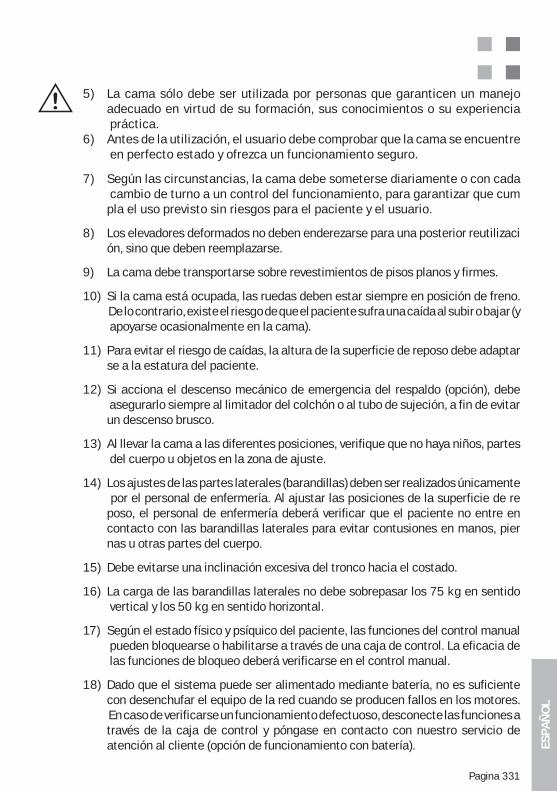
ESPA
ÑO
L
Pagina 331
5) La cama sólo debe ser utilizada por personas que garanticen un manejo adecuado en virtud de su formación, sus conocimientos o su experiencia práctica.6) Antes de la utilización, el usuario debe comprobar que la cama se encuentre en perfecto estado y ofrezca un funcionamiento seguro.
7) Según las circunstancias, la cama debe someterse diariamente o con cada cambio de turno a un control del funcionamiento, para garantizar que cum pla el uso previsto sin riesgos para el paciente y el usuario.
8) Los elevadores deformados no deben enderezarse para una posterior reutilizaci ón, sino que deben reemplazarse.
9) La cama debe transportarse sobre revestimientos de pisos planos y firmes.
10) Si la cama está ocupada, las ruedas deben estar siempre en posición de freno. De lo contrario, existe el riesgo de que el paciente sufra una caída al subir o bajar (y apoyarse ocasionalmente en la cama).
11) Para evitar el riesgo de caídas, la altura de la superficie de reposo debe adaptar se a la estatura del paciente.
12) Si acciona el descenso mecánico de emergencia del respaldo (opción), debe asegurarlo siempre al limitador del colchón o al tubo de sujeción, a fin de evitar un descenso brusco.
13) Al llevar la cama a las diferentes posiciones, verifique que no haya niños, partes del cuerpo u objetos en la zona de ajuste.
14) Los ajustes de las partes laterales (barandillas) deben ser realizados únicamente por el personal de enfermería. Al ajustar las posiciones de la superficie de re poso, el personal de enfermería deberá verificar que el paciente no entre en contacto con las barandillas laterales para evitar contusiones en manos, pier nas u otras partes del cuerpo.
15) Debe evitarse una inclinación excesiva del tronco hacia el costado.
16) La carga de las barandillas laterales no debe sobrepasar los 75 kg en sentido vertical y los 50 kg en sentido horizontal.
17) Según el estado físico y psíquico del paciente, las funciones del control manual pueden bloquearse o habilitarse a través de una caja de control. La eficacia de las funciones de bloqueo deberá verificarse en el control manual.
18) Dado que el sistema puede ser alimentado mediante batería, no es suficiente con desenchufar el equipo de la red cuando se producen fallos en los motores. En caso de verificarse un funcionamiento defectuoso, desconecte las funciones a través de la caja de control y póngase en contacto con nuestro servicio de atención al cliente (opción de funcionamiento con batería).
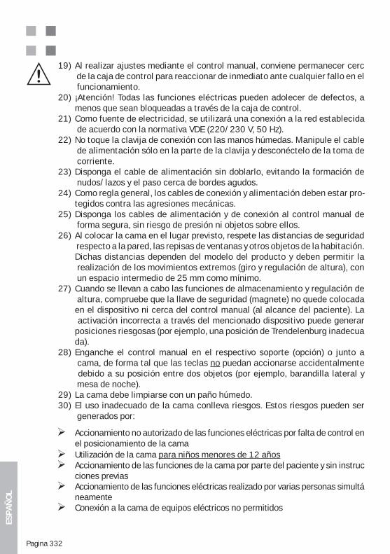
ESPA
ÑO
L
Pagina 332
19) Al realizar ajustes mediante el control manual, conviene permanecer cerc de la caja de control para reaccionar de inmediato ante cualquier fallo en el funcionamiento. 20) ¡Atención! Todas las funciones eléctricas pueden adolecer de defectos, a menos que sean bloqueadas a través de la caja de control. 21) Como fuente de electricidad, se utilizará una conexión a la red establecida de acuerdo con la normativa VDE (220/230 V, 50 Hz).22) No toque la clavija de conexión con las manos húmedas. Manipule el cable de alimentación sólo en la parte de la clavija y desconéctelo de la toma de corriente.23) Disponga el cable de alimentación sin doblarlo, evitando la formación de nudos/lazos y el paso cerca de bordes agudos.24) Como regla general, los cables de conexión y alimentación deben estar pro- tegidos contra las agresiones mecánicas.25) Disponga los cables de alimentación y de conexión al control manual de forma segura, sin riesgo de presión ni objetos sobre ellos.26) Al colocar la cama en el lugar previsto, respete las distancias de seguridad respecto a la pared, las repisas de ventanas y otros objetos de la habitación. Dichas distancias dependen del modelo del producto y deben permitir la realización de los movimientos extremos (giro y regulación de altura), con un espacio intermedio de 25 mm como mínimo.27) Cuando se llevan a cabo las funciones de almacenamiento y regulación de altura, compruebe que la llave de seguridad (magnete) no quede colocada en el dispositivo ni cerca del control manual (al alcance del paciente). La activación incorrecta a través del mencionado dispositivo puede generar posiciones riesgosas (por ejemplo, una posición de Trendelenburg inadecua da).28) Enganche el control manual en el respectivo soporte (opción) o junto a cama, de forma tal que las teclas no puedan accionarse accidentalmente debido a su posición entre dos objetos (por ejemplo, barandilla lateral y mesa de noche).29) La cama debe limpiarse con un paño húmedo.30) El uso inadecuado de la cama conlleva riesgos. Estos riesgos pueden ser generados por:
Accionamiento no autorizado de las funciones eléctricas por falta de control en el posicionamiento de la cama
Utilización de la cama para niños menores de 12 años Accionamiento de las funciones de la cama por parte del paciente y sin instruc
ciones previas Accionamiento de las funciones eléctricas realizado por varias personas simultá
neamente Conexión a la cama de equipos eléctricos no permitidos
ESPA
ÑO
L
Pagina 333
Movimiento de la cama por tirar del cable de alimentación o las partes laterales Tirón del cable de alimentación para realizar la desconexión de la red eléctri
ca Deficiente protección de los cables de conexión y alimentación frente a los
del cable) Movimiento de la cama sobre una superficie inestable Utilización de la cama sobre una superficie inclinada (pendiente de 10° o
más) Cercanía de equipos que generan fuertes campos electromagnéticos y pueden
Antes de realizar cualquier tarea de limpieza o mantenimiento, hay que desco nectar el equipo
Por razones de seguridad, a más tardar después de 5 años es necesario reemplazar de forma completa el triángulo elevador (con la correa)
a 120 mm
31) Normas de seguridad: Medidas para un manejo seguro de las camas de cuidados:
Los componentes eléctricos de las camas de cuidados sólo deben ser manteni dos y reparados por el fabricante o por personal técnico capacitado especial mente para este fin. De lo contrario, el desconocimiento de la funcionalidad del
pro cedimientos específicos, con lo que aumentaría el riesgo de choque eléc- trico o incendio.
Los componentes eléctricos de las camas de cuidados sólo deben ser reem-plazados por repuestos originales del fabricante. Si se colocan componentes inadecuados, aumenta significativamente el riesgo de que se produzca un choque eléctrico o incendio
Debe predeterminarse un lugar seguro en la cama para el accionamiento ma- nual, a fin de evitar un uso inadecuado.
La limpieza de la cama debe realizarse de acuerdo con las especificaciones in-cluidas en la sección „Limpieza y desinfección“ del presente manual. En caso contrario, pueden aumentar los riesgos no contemplados por el fabricante.
Si la cama está ocupada por un paciente incontinente, debe utilizarse una protección para la incontinencia en el colchón.
-chones antiescaras) y no se adoptan cuidados especiales para la prevención, la permanencia prolongada de personas/pacientes inmóviles puede conducir a la formación de escaras. Esto no será responsabilidad del fabricante de la
ESPA
ÑO
L
Pagina 334
El producto no es apto para el uso continuo. Si se excede el tiempo de conexión especificado, puede producirse un sobrecalentamiento del accionamiento y una desconexión automática. En tal caso, el accionamiento debe enfriarse durante dos horas como mínimo para luego, una vez trascurrido este período, volver al funcionamiento.
su sistema mecánico, ya que ello podría causar daños y destruir totalmente el accionamiento por el sobrecalentamiento.
ya que ello podría causar daños y destruir totalmente el accionamiento por el sobrecalentamiento.
32) Indicaciones para el mantenimiento, controles de seguridad, solución de problemas:
Las camas de cuidados accionadas eléctricamente son productos médicos y
Ley de Productos Médicos (MPG) y por el punto 6 del reglamento para el uso de productos médicos (MedProdBetrV) de Alemania. Los controles técnicos mencionados deben realizarse periódicamente, por lo menos una vez al año. Allí se verifica la seguridad eléctrica y funcional según VDE 0751, se efectúa una inspección visual y funcional (comprobación del material durante la oper-ación) y se controlan las posibles funciones de medición.
Como regla general, también se realiza una verificación técnica de seguridad en los accesorios y en otros equipos que se combinan con el producto. En este caso, sólo deben utilizarse las combinaciones de equipos permitidas y los accesorios autorizados por el fabricante. Los controles STK, realizados con un aparato especial de medición y prueba, deben ser llevados a cabo por perso-nal especializado en el campo electrotécnico, capacitado especialmente por
a ninguna instrucción del operador. Además, en el marco de los controles STK, deben elaborarse protocolos especiales de los respectivos ensayos. Luego se coloca en el propio producto una identificación, que indica la fecha de la próxi-ma prueba.
Además, las camas de cuidados accionadas eléctricamente constituyen mate--
ador. El control del cumplimiento de esta obligación corresponde a la mutua laboral de sanidad y servicios sociales (BGW) y a los organismos de inspec-
-
se aplica el punto BGV A3 (antes VBG „Material y equipos eléctricos“, BGV A2), que prevé la repetición de ensayos en el material eléctrico móvil y sugiere que se realicen con un plazo orientativo de 6 meses, pero por lo menos una vez al
ESPA
ÑO
L
Pagina 335
año. Estas pruebas, realizadas con un aparato especial de medición y prueba, de-ben ser llevadas a cabo por personal especializado o por una persona capacitada en el campo electrotécnico. Los ensayos establecidos según BGV A3 pueden ser realizados en el marco de los controles técnicos de seguridad para productos mé-dicos, ya que están incluidos allí. La tarea será responsabilidad de personal espe-cializado, capacitado por el fabricante.
Las camas de cuidados accionadas eléctricamente son productos médicos activos y deben registrarse en un inventario del lugar de acuerdo con lo dis-puesto por el reglamento para el uso de productos médicos (MedProdBetrV). También se recomienda documentar allí la realización de los controles STK prescritos e indicar la fecha de la próxima prueba. Los protocolos de los con-
La correcta realización y la documentación ordenada de los controles téc--
miento y reparación y las verificaciones de seguridad, son condición necesaria para que el comprador conserve sus derechos de garantía. Si el usuario de un producto médico no cumple sus obligaciones, puede aumentar el riesgo de daños y accidentes, cuya responsabilidad es rechazada expresamente por el fabricante.
EN62353:2008 y documentarse con un control técnico final de seguridad.
ESPA
ÑO
L
Pagina 336
21. REPARACIÓN Y MANTENIMIENTO
Las camas fabricadas por Wissner-Bosserhoff GmbH han sido diseñadas, de modo ge-neral, para una vida útil de 10-15 años. Dentro de todo este período, requieren un mínimo mantenimiento. Ya durante el desarrollo del producto, una de las prioridades
costes operativos.Sin embargo, de acuerdo con la experiencia, durante el uso cotidiano se presentan
-
directa del fabricante. Por lo tanto, el usuario debe realizar controles de rutina para garantizar, también por interés propio, el buen estado de la cama.El servicio técnico de atención al cliente de Wissner-Bosserhoff ofrece todo el manteni-miento y la capacitación necesaria en torno al producto. Para Wissner-Bosserhoff la capacitación de los clientes es fundamental, ya que sólo el conocimiento puede garan-
Las reparaciones deben ser llevadas a cabo únicamente por personal técnico compe-
El fabricante sólo se responsabilizará por la seguridad y fiabilidad del producto cuando éste sea sometido a un mantenimiento periódico y se utilice de acuerdo con las normas de seguridad, operación y uso indicadas en el presente manual.
Si las tareas de control funcional, inspección, medición o mantenimiento detectan gra-
Wissner-Bosserhoff GmbH recomienda realizar un sencillo mantenimiento mecánico con un ritmo anual. Como regla general, el fabricante presupone que las tareas de mantenimiento y repa-ración se llevarán a cabo de acuerdo con la tecnología actual. Las camas de cuidados
de accidentes (UVV) establecidas por las asociaciones profesionales de Alemania. Por
la norma VDE 0751.Nuestro servicio de atención al cliente estará a su disposición para responder a cualquier consulta, ofrecer capacitación y suministrar listas de verificación corre-spondientes a los distintos productos. (“Contacto”, ver secciones 22 y 25).
21.1. SUMINISTRO COMPLETO Y ACCESORIOSCon la documentación de entrega, el manual de instrucciones y una inspección visual, se determinará si faltan piezas y si es necesario realizar un pedido complementario o un reem-plazo. Como regla general, también debe realizarse una verificación de los accesorios y otros equipos que se combinan con el producto. En este caso, sólo deben utilizarse las combinaciones de equipos permitidas y los accesorios autorizados por el fabricante.
ESPA
ÑO
L
Pagina 337
21.2. DESGASTELas distintas partes de la cama deberán ser sometidas a una inspección y un control para verificar la presencia de marcas, arañazos u otro tipo de desgaste, determinar las causas y solucionar ocasionalmente el problema mediante un reemplazo. Todos
piezas que resultan importantes en materia de seguridad.
21.3. FUNCIONALIDAD
a cabo un control de acuerdo con lo indicado en las secciones 8,13 y 14 del presente manual.
21.4. BGV A3/VDE 0751 – 1:2008 – 8 / DIN EN 62353 : 2008 – VERIFICACIÓN DE LOS COMPONENTES ELÉCTRICOS Y DEL CONTROL MANUAL
Compruebe que los accionamientos funcionen correctamente en todos los casos y que el equipo y el control manual se encuentren en perfecto estado
Controle el sistema mecánico (posición firme de tornillos y pernos, perfecto estado de piezas, rótulos, inscripciones, etc.).
Verifique el estado del cableado, de la carcasa, etc. (posición respecto a bordes, presión sobre alguna zona, etc.)
Comprobación del funcionamiento
Realice una inspección visual.
Asegure una suficiente descarga de tracción y una buena protección en la disposi-ción de los cables.
Controle la corriente de fuga.
Verifique los conductores de protección en versiones con clase de protección I.
En caso necesario, mida el aislamiento.
Nuestro servicio de atención al cliente estará a su disposición para responder a cualquier consulta, ofrecer capacitación y suministrar listas de verificación correspondientes a los distintos productos. (Contacto, ver secciones 22 y 25)
21.5. RUEDASControle la funcionalidad de las ruedas (transporte y freno) y, si es necesario, retire el polvo, los pelos u otros elementos similares acumulados en ellas. En determinados casos puede
Wissner-Bosserhoff.
22. VIDA ÚTILSi el uso, la limpieza, el mantenimiento y la reparación se realizan de forma correcta, nuestros productos pueden ofrecer una vida útil de 10-15 años. Esto no incluye las piezas sometidas al desgaste como ruedas, muelles de gas, componentes eléctricos, etc. .
ESPA
ÑO
L
Pagina 338
23. ELIMINACIÓN DEL PRODUCTOLa cama contiene opcionalmente baterías de plomo y piezas de metal, madera y plástico en ABS, PA, PUR y PE (comparar alcance del suministro y modelo).Las piezas metálicas y plásticas desechadas durante las tareas de mantenimiento y repara-ción deben eliminarse de forma adecuada según las leyes y normas vigentes. Los motores y los componentes eléctricos exigen un tratamiento especial y deben ser eliminados por las empresas u organismos autorizados.
¡Atención! ¡Chatarra eléctrica!
Cumpla la directiva para la eliminación de aparatos de este tipo.
24. PIEZAS DE REPUESTO, LISTAS DE PIEZAS DE REPUESTO Y SERVICIO TÉCNICOSólo deben utilizarse piezas originales de Wissner-Bosserhoff.
Los departamentos de atención al cliente, ventas y asesoramiento técnico proporcionan infor-mación relacionada con el suministro de piezas de repuesto, etc. (ver “Contacto”).
En caso de necesidad, usted puede solicitar listas de piezas de repuesto, listas de precios ac-tuales o instrucciones técnicas con vistas detalladas de todos los componentes. Para hacerlo,
descriptiva de la cama o los datos correspondientes a número de artículo, número de orden y fecha de entrega.
Atención al cliente Tel.: +49 02377 / 784-456 Fax: +49 02377 / 784-150
25. PLACA DESCRIPTIVA Y ETIQUETASPara obtener una respuesta más rápida a las consultas o pedidos de piezas de repuesto, es necesario que usted indique los datos de la placa descriptiva.
En el Anexo B de este manual,de la placa descriptiva.
También son de gran utilidad las placas descriptivas y etiquetas de los distintos componentes
ESPA
ÑO
L
Pagina 339
26. GARANTÍACon su cama de cuidados “carisma”, usted ha adquirido un producto de calidad de Wissner-Bosserhoff. Esta cama ha sido fabricada con gran precisión, con excelentes materiales y moder-nas técnicas de producción
La cama baja de cuidados “carisma” ofrece 36 meses de garantía
desde la fecha de compra. Esta garantía incluye todos los fallos y defectos de material y fabri-
externas. Si existen derechos y se realizan reclamaciones dentro del período de garantía, los pro-blemas serán subsanados de forma gratuita. Para solicitar el cumplimiento de la garantía, deberá presentarse el documento que indique la fecha de compra. En todos los casos se aplicarán nue-stras condiciones de venta y suministro.
27. CONTACTO
Fabricante: Wissner - Bosserhoff GmbH Hauptstr. 4-658739 Wickede/Ruhr (Alemania)
Para cualquier consulta, póngase en contacto con nosotros:
Asesoramiento Tel.: +49 02377 / 784-0 Atención al Tel.: +49 02377 / 784-456 al cliente Fax: +49 02377 / 784-163 cliente Fax: +49 02377 / 784-150
Internet http://www.wi-bo.de E-Mail [email protected]
Antes de realizar cualquier consulta, verifique los datos del producto en la documentación de entrega y en las placas descriptivas (ver Anexo B de este manual) para poder informar luego al personal de Wissner-Bosserhoff. Si estos datos no están disponibles, no podrá ofrecerse de an-temano un servicio gratuito en materia de garantía.
Contacto:
(Coloque aquí la etiqueta indicadora.)
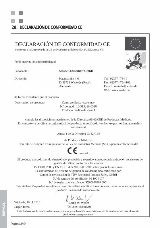
ESPA
ÑO
L
Pagina 340
28. DECLARACIÓN DE CONFORMIDAD CE
DECLARACIÓN DE CONFORMIDAD CEconforme a la Directiva de la UE de Productos Médicos 93/42/CEE, anexo VII
Bernd W. Weber(Director ejecutivo)
Por el presente documento declara el
Fabricante: wissner-bosserhoff GmbH
Dirección Hauptstraße 4-6D-58739 Wickede (Ruhr),Alemania
Tel.: 02377 / 784-0Fax: 02377 / 784-166E-mail: [email protected] Web: www.wi-bo.de
de forma vinculante que el producto:
Descripción de producto: Cama geriátrica «carisma»N.º de mod.: 10-513; 10-0520
Producto médico de clase I
cumple las disposiciones pertinentes de la Directiva 93/42/CEE de Productos Médicos.En concreto se certifica la conformidad del producto especificado con los «requisitos fundamentales»
conforme al
Anexo I de la Directiva 93/42/CEE
de Productos Médicos.Con esto se cumplen los requisitos de la Ley de Productos Médicos (MPG) para la colocación del
marcado.
El producto marcado ha sido desarrollado, producido y sometido a prueba con la aplicación del sistema de gestión de calidad conforme a las normas
ISO 9001:2008 y EN ISO 13485:2003+AC:2007 sobre productos médicos.La conformidad del sistema de gestión de calidad ha sido certificado por:
Centro de certificación de TÜV Rheinland Product Safety GmbHN.º de registro del certificado: 01 100 3177
N.º de registro del certificado: SX60026964 0001Esta declaración perderá su validez en caso de realizar modificaciones no autorizadas por nuestra parte en el
producto mencionado anteriormente.
Wickede, 10.11.2010
Lugar, fecha:
producción correspondiente.
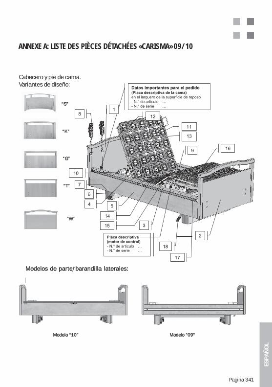
ESPA
ÑO
L
Pagina 341
ANNEXE A: LISTE DES PIÈCES DÉTACHÉES «CARISMA» 09/10
Cabecero y pie de cama.Variantes de diseño:
“S”
“K”
“G”
“T”
“W”
Modelos de parte/barandilla laterales:
Modelo “10” Modelo “09”
Cabecero y pie de cama.Variantes de diseño:
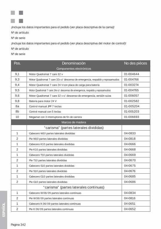
ESPA
ÑO
L
Pagina 342
¡Incluya los datos importantes para el pedido (ver placa descriptiva de la cama)!
Nº de artículo
Nº de serie
¡Incluya los datos importantes para el pedido (ver placa descriptiva del motor de control)!
Nº de artículo
Nº de serie
Pos. Denominación No des pièces Componentes electrónicos
9,1 Motor Quadromat 7 care 32 v 01-004644
9,3 Motor Quadromat 7 care 32v c/ descenso de emergencia, respaldo y reposamuslos 01-004766
9,4 Motor Quadromat 7 care 24 V con placa de carga para batería 01-003274
9,5 Motor Quadromat 7 care 24v c/ descenso de emergencia, respaldo y reposamuslos 01-004765
9,6 Motor Quadromat 7 care 32 v c/ descenso de emergencia, versión suiza 01-006057
9,8 Batería para motor 24 V 01-002582
8a Control manual JPF 7 teclas 01-005204
8b Control manual con 5 teclas 01-005203
10 Megamat con 3 interruptores de fin de carrera 01-006693
Marcos de madera
“carisma” (partes laterales divididas)
1 Cabecero W10 partes laterales divididas 04-0833
2 Pie W10 partes laterales divididas 04-0818
1 Cabecero K10 partes laterales divididas 04-0666
2 Pie K10 partes laterales divididas 04-0668
1 Cabecero T10 partes laterales divididas 04-0669
2 Pie T10 partes laterales divididas 04-0670
1 Cabecero S10 partes laterales divididas 04-0675
2 Pie S10 partes laterales divididas 04-0676
1 Cabecero G10 partes laterales divididas 04-0685
2 Pie G10 partes laterales divididas 04-0686
“carisma” (partes laterales continuas)
1 Cabecero W 06/09 partes laterales continuas 04-0834
2 Pie W 06/09 partes laterales continuas 04-0816
1 Cabecero K 06/09 partes laterales continuas 04-0651
2 Pie K 06/09 partes laterales continuas 04-0652
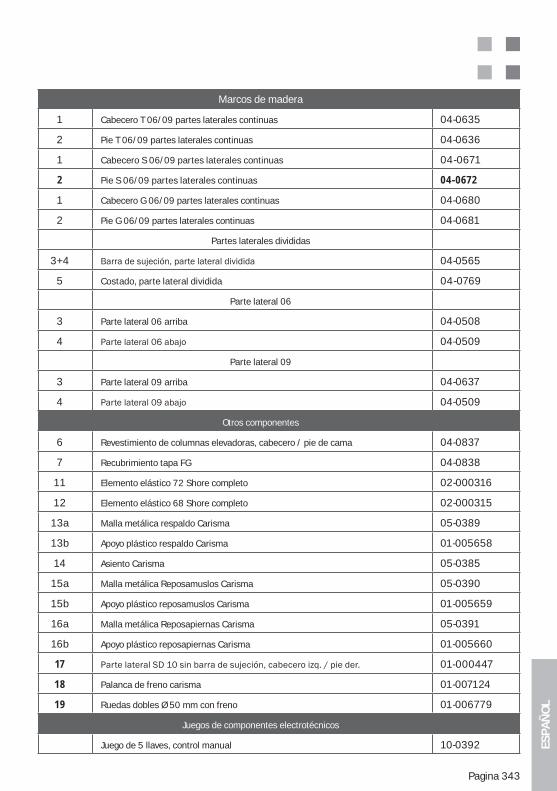
ESPA
ÑO
L
Pagina 343
Marcos de madera
1 Cabecero T 06/09 partes laterales continuas 04-0635
2 Pie T 06/09 partes laterales continuas 04-0636
1 Cabecero S 06/09 partes laterales continuas 04-0671
2 Pie S 06/09 partes laterales continuas 04-0672
1 Cabecero G 06/09 partes laterales continuas 04-0680
2 Pie G 06/09 partes laterales continuas 04-0681
Partes laterales divididas
3+4 04-0565
5 Costado, parte lateral dividida 04-0769
Parte lateral 06
3 Parte lateral 06 arriba 04-0508
4 04-0509
Parte lateral 09
3 Parte lateral 09 arriba 04-0637
4 04-0509
Otros componentes
6 Revestimiento de columnas elevadoras, cabecero / pie de cama 04-0837
7 Recubrimiento tapa FG 04-0838
11 Elemento elástico 72 Shore completo 02-000316
12 Elemento elástico 68 Shore completo 02-000315
13a Malla metálica respaldo Carisma 05-0389
13b Apoyo plástico respaldo Carisma 01-005658
14 Asiento Carisma 05-0385
15a Malla metálica Reposamuslos Carisma 05-0390
15b Apoyo plástico reposamuslos Carisma 01-005659
16a Malla metálica Reposapiernas Carisma 05-0391
16b Apoyo plástico reposapiernas Carisma 01-005660
17 01-000447
18 Palanca de freno carisma 01-007124
19 Ruedas dobles Ø 50 mm con freno 01-006779
Juegos de componentes electrotécnicos
Juego de 5 llaves, control manual 10-0392
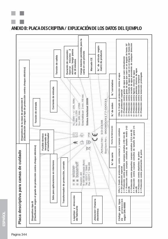
ESPA
ÑO
L
Pagina 344
ANEXO B: PLACA DESCRIPTIVA / EXPLICACIÓN DE LOS DATOS DEL EJEMPLO
Pla
ca d
escri
pti
va p
ara
cam
as d
e c
uid
ad
o
Lo
go
tip
o
y
dir
ec
ció
nd
el
fab
ric
an
te
¡Ate
nc
ión
! C
ha
tarr
ae
lec
tró
nic
a
Có
dig
o
pa
ra
tip
os
de
p
ro
tec
ció
nseg
ún
DIN
40050
Só
lo p
ara
ap
lic
ac
ion
es
en
in
teri
ore
sC
orr
ien
te d
e e
ntr
ad
a
Te
ns
ión
de
en
tra
da
Fu
sib
le t
érm
ico
inc
orp
ora
do
en
el
tra
ns
form
ad
or
Te
ns
ión
de
sa
lid
a
Dis
po
sit
ivo
tip
o B
(Cla
sif
ica
ció
n s
eg
ún
el
gra
do
de
pro
tec
ció
n c
on
tra
ch
oq
ue
elé
ctr
ico
)
Dis
po
sit
ivo
de
la
cla
se
de
pro
tec
ció
n I
I(C
las
ific
ac
ión
se
gú
n e
l ti
po
de
pro
tec
ció
n c
on
tra
ch
oq
ue
elé
ctr
ico
)
Tra
ns
form
ad
or
de
pro
tec
ció
n,
ce
rra
do
N.°
de
se
rie
Fech
a d
e f
ab
ricació
nN
.° d
e o
rde
nN
.° c
orr
ela
tiv
o
Cif
ra 1
: G
rad
o d
e p
rote
cció
n c
on
tra c
on
tacto
y c
uerp
os e
xtr
añ
os
0 =
Sin
pro
tecció
n e
sp
ecia
l1 =
Pro
tecció
n c
on
tra g
ran
des c
uerp
os e
xtr
añ
os (
>50 m
m Ø
)
2 =
P
rote
cc
ión
c
on
tra
c
ue
rpo
s
ex
tra
ño
s d
e
tam
añ
o
me
dio
(>
12
mm
Ø)
3 =
Pro
tecció
n c
on
tra p
eq
ueñ
os cu
erp
os e
xtr
añ
os (
>2,5
mm
Ø)
4 =
Pro
tec
ció
n
co
ntr
a c
ue
rpo
s
ex
tra
ño
s d
e ta
ma
ño
d
e g
ran
o (>
1m
m Ø
)5 =
Pro
tecció
n c
on
tra d
ep
ósit
os d
e p
olv
o6 =
Pro
tecció
n c
on
tra p
en
etr
ació
n d
e p
olv
o
Cif
ra 2
: G
rad
o d
e p
rote
cció
n c
on
tra e
l ag
ua
0 =
Sin
pro
tecció
n e
sp
ecia
l1 =
Pro
tecció
n c
on
tra g
ota
s d
e a
gu
a q
ue c
aen
vert
icalm
en
te
2 =
Pro
tecció
n c
on
tra g
ota
s d
e a
gu
a q
ue c
aen
en
un
án
gu
lo d
e h
asta
15°
3 =
Pro
tecció
n c
on
tra r
ocia
do
de a
gu
a q
ue c
ae e
n u
n á
ng
ulo
de h
asta
60°
4 =
Pro
tecció
n c
on
tra r
ocia
do
de a
gu
a p
roced
en
te d
e c
ualq
uie
r d
irecció
n
5 =
Pro
tecció
n c
on
tra l
igero
s c
ho
rro
s d
e a
gu
a6 =
Pro
tecció
n c
on
tra p
ote
nte
s c
ho
rro
s d
e a
gu
a7 =
Pro
tecció
n c
on
tra i
nm
ers
ión
te
mp
ora
l8 =
Pro
tecció
n c
on
tra i
nm
ers
ión
p
rolo
ng
ad
aDu
rac
ión
de
co
ne
xió
n:
Op
era
r m
áx
imo
2
min
uto
s;
lue
go
pa
us
ad
e 1
8 m
inu
tos
Ca
rga
má
xim
a p
erm
itid
a p
ara
la
ca
ma
en
us
o p
rev
isto
Marc
ad
o C
E
N.°
d
e a
rtíc
ulo
s
eg
ún
ma
triz
de
pro
du
cto
ESPA
ÑO
L
Pagina 345
ANEXO C: NORMAS IMPORTANTES DE SEGURIDAD Y USO PARA LAS CAMAS DE CUIDADOS
USO ADECUADO Y PREVISTO DE LAS CAMAS DE CUIDADOSUna cama de cuidados sólo debe utilizarse para las funciones previstas, de acu-erdo con lo dispuesto por la Ley de Productos Médicos (MPG) de Alemania, las disposiciones conexas, las normas técnicas reconocidas y las normas de pro-tección laboral y prevención de accidentes. Si su estado es defectuoso y puede poner en riesgo al paciente, al personal de enfermería o a terceros, la cama no debe utilizarse.
En todos los casos son aplicables las especificaciones incluidas en las instrucciones de uso de los respectivos productos.
Deben tenerse en cuenta los siguientes puntos:
-sivamente para el uso por parte de personas a partir de los 12 años de edad. Esto debe controlarse en cada caso, ya que las personas con una contextura física o peso muy diferente al promedio podrían estar expuestas a un riesgo ma-yor. Para colocar en la cama a una persona sin que existan riesgos o limitaci-ones adicionales (conforme a la norma IEC 60601-2-52), el rango recomendado
con al menos alguna capacidad de acción independiente y un estado de salud aceptable desde el punto de vista físico y mental. Fuera de este rango el uso no es posible o, en determinadas circunstancias, es necesario utilizar accesori-
(accesorio) y las personas demasiado delgadas obligan a incorporar elementos adicionales, como una protección en las barandillas laterales (accesorio). Los di-stintos casos individuales que presentan alguna anomalía deberán consultarse con Wissner-Bosserhoff GmbH.
responsable (supervisión médica) para garantizar un uso seguro de la cama. Deben tenerse en cuenta las necesidades y el estado de los pacientes desde el punto de vista físico, psíquico y médico. Por lo tanto, las distintas funciones de la cama deben habilitarse o bloquearse según el tipo de paciente/persona, con un criterio individual. Esto es particularmente válido para los productos cuya
protecciones laterales.
ESPA
ÑO
L
Pagina 346
La carga máxima de trabajo para la cama geriátrica es de 225 kg. Es posi-ble aplicar cargas superiores (para ello deberán consultarse las instrucciones del respectivo producto). La cama no debe utilizarse con pacientes de más de 155 kg 225 kg incluye el peso del paciente, el colchón y los respectivos accesorios (ropa de cama, in-corporador, etc.).
correcto funcionamiento de los dispositivos de seguridad (interruptor diferencial, interruptor de tensión de defecto, detección de fallos de aislamiento, fusible de potencia, etc.).
-
ben utilizarse en habitaciones con presencia de anestésicos, limpiadores, disol-
respetarse la normativa de las asociaciones profesionales de Alemania.
no previsto e implicará la pérdida de la garantía.
FUNCIONES BÁSICAS Y APROVECHAMIENTO DE LAS CAMAS DE CUIDADOS Las modernas camas de cuidados poseen numerosas funciones, que se describen de-talladamente en el manual de instrucciones del respectivo producto. Para lograr un aprovechamiento total de estas camas, es imprescindible que se capaciten los usua-rios y las personas pertenecientes a las instituciones sanitarias. En la medida de lo po-sible, repita esta capacitación periódicamente, teniendo siempre en cuenta las normas de seguridad necesarias.
Como regla general, siempre existe el riesgo de que se produzca un ajuste accidental o incorrecto de la cama. Los accionamientos imprevistos y la habi-litación accidental de las funciones pueden poner en riesgo a determinados pacientes. Para incrementar la seguridad de los pacientes, es fundamental utilizar de forma adecuada los dispositivos de bloqueo y/o las llaves de habili-tación, que no deben dejarse en el control manual ni en la cama bajo ninguna circunstancia. Los dispositivos de habilitación de funciones deben ser utiliza-dos únicamente por el personal de enfermería.
ESPA
ÑO
L
Pagina 347
El uso de los dispositivos de bloqueo y, dado el caso, la desconexión de la cama de la red de suministro (como medida extrema para lograr la máxima protección de un paciente en riesgo) se encuentran bajo la exclusiva respon-sabilidad de la supervisión médica y del personal de enfermería. Para ase-gurar un cambio de turnos ordenado, las medidas adoptadas deben constar en el respectivo informe.
El uso de las posibilidades especiales (Trendelenburg-Antitrendelenburg, posiciones graduadas o con la cabeza relativamente hacia abajo, etc.) con-stituye expresamente una responsabilidad exclusiva del personal médico de supervisión. Para los pacientes deben bloquearse estas funciones, ya que de lo contrario existirían riesgos. Para evitar riesgos, tenga en cuenta las normas de seguridad incluidas en las instrucciones especiales de cada producto.
El uso de las protecciones laterales exige especial cuidado y atención:
- Las protecciones laterales sirven principalmente para proteger al paciente y evi-tar su caída. En ningún caso deben utilizarse las barandillas como elemento de
- Cuando la movilidad del paciente se ve limitada, puede ser necesaria una dis-
sección del cabecero y que pueden utilizarse como ayuda para subir a la cama e incorporarse) constituyen en este caso una excepción permitida para los pa-cientes con movilidad.
ESPA
ÑO
L
Pagina 348
La sobrecarga de las barandillas laterales (al sentarse, apoyarse o hacer pre-sión sobre ellas) puede tener graves consecuencias y ocasionar riesgos. Por lo tanto, es imprescindible evitar dichas sobrecargas.
función de las particularidades de cada paciente. Deben tenerse en cuenta especialmente las distancias entre los largueros y los elementos de unión
encajone o se deslice a través de las aberturas. Dado el caso, deberán colo-carse acolchados laterales adicionales para reducir la separación o cerrar la brecha. Estas decisiones constituyen una responsabilidad exclusiva de la
-al sobre la limitación de los usos previstos, así como las instrucciones espe-ciales relativas a la cama y a las barandillas laterales.Deben utilizarse protecciones laterales adecuadas para el tipo de cama en cuestión. De lo contrario, aumenta el riesgo de que se produzcan accidentes.
Antes de cada uso, es necesario controlar las barandillas/protecciones late-
perfecto funcionamiento de los mecanismos de bloqueo. Las instrucciones
manejo correcto de las protecciones laterales.
El uso del accionamiento manual a distancia por parte del propio paciente se encuentra bajo la exclusiva responsabilidad de la supervisión médica y del personal de enfermería. Para asegurar un cambio de turnos ordenado y garan-tizar el seguimiento del proceso, las medidas adoptadas deben constar en el respectivo informe o en la documentación referida al tratamiento.
Si no está permitido el uso del accionamiento manual a distancia por parte del paciente, el dispositivo deberá colocarse en un lugar seguro y lejos de su alcance (por ejemplo, en el pie de la cama).
Para proteger el accionamiento manual a distancia, es necesario evitar las caídas, la sobrecarga de peso y la penetración de líquidos. La limpieza debe realizarse con los paños que se utilizan para el teclado del ordenador. En caso de fallos mecánicos o daños producidos por la humedad, el dispositivo debe reemplazarse de inmediato. También es necesario realizar un control periódi-co frecuente de los cables para comprobar que no existan daños.
Durante el funcionamiento y el traslado de la cama, es necesario asegurar una buena protección para evitar daños en los cables de conexión a la red eléctrica:
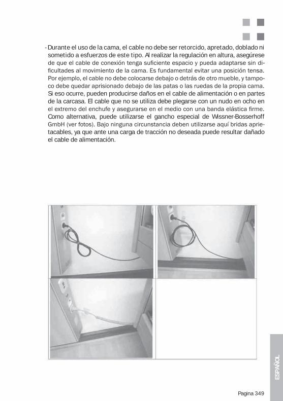
ESPA
ÑO
L
Pagina 349
- Durante el uso de la cama, el cable no debe ser retorcido, apretado, doblado ni sometido a esfuerzos de este tipo. Al realizar la regulación en altura, asegúrese
-
-
Si eso ocurre, pueden producirse daños en el cable de alimentación o en partes de la carcasa. El cable que no se utiliza debe plegarse con un nudo en ocho en
Como alternativa, puede utilizarse el gancho especial de Wissner-Bosserhoff -
tacables, ya que ante una carga de tracción no deseada puede resultar dañado el cable de alimentación.
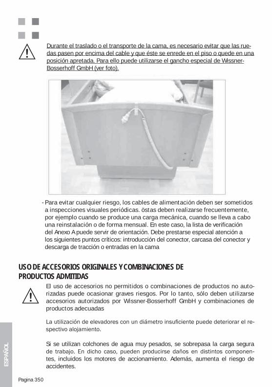
ESPA
ÑO
L
Pagina 350
Durante el traslado o el transporte de la cama, es necesario evitar que las rue-das pasen por encima del cable y que éste se enrede en el piso o quede en una posición apretada. Para ello puede utilizarse el gancho especial de Wissner-Bosserhoff GmbH (ver foto).
- Para evitar cualquier riesgo, los cables de alimentación deben ser sometidos a inspecciones visuales periódicas. östas deben realizarse frecuentemente, por ejemplo cuando se produce una carga mecánica, cuando se lleva a cabo una reinstalación o de forma mensual. En este caso, la lista de verificación del Anexo A puede servir de orientación. Debe prestarse especial atención a los siguientes puntos críticos: introducción del conector, carcasa del conector y descarga de tracción o entradas en la cama
USO DE ACCESORIOS ORIGINALES Y COMBINACIONES DE PRODUCTOS ADMITIDAS
El uso de accesorios no permitidos o combinaciones de productos no auto-rizadas puede ocasionar graves riesgos. Por lo tanto, sólo deben utilizarse accesorios autorizados por Wissner-Bosserhoff GmbH y combinaciones de productos adecuadas
-
Si se utilizan colchones de agua muy pesados, se sobrepasa la carga segura -
tes, incluidos los motores de accionamiento. Además, aumenta el riesgo de accidentes.
ESPA
ÑO
L
Pagina 351
COLOCACIÓN DE LA CAMA DE CUIDADOS (DISTANCIAS DE SEGURIDAD)
La cama debe colocarse en una posición adecuada, de forma tal que durante todas sus funciones de ajuste no exista la posibilidad de choque entre partes de la cama y otros objetos o partes de la habitación -xión, repisas de ventanas, vertientes del techo, tubos, instalaciones salientes, estantes, etc.). Aquí también, en todas las posiciones posibles de la cama, debe respetarse una distancia de seguridad mínima de 2,5 cm con respecto a las
los movimientos de giro y de regulación en altura. ¡La cama debe colocarse de tal forma que la desconexión de la red de alimentación (extracción del enchufe) pueda realizarse con facilidad!
LIMPIEZA Y DESINFECCIÓN DE LA CAMA
La cama debe limpiarse y desinfectarse periódicamente, por lo menos antes de cada cambio de paciente. No debe limpiarse o desinfectarse en túneles de lava-do ni con chorros de agua. Sólo se permite una desinfección por rociado y lavado.
Para la desinfección de la cama se recomiendan los siguientes productos, que podrán ser reemplazados únicamente por otros de iguales características:Terralin, Perform y Sagrotan Med (Schülke & Mayr GmbH, Norderstedt, Alemania).Los productos deben utilizarse de acuerdo con las indicaciones del fabricante.
riesgo derivado de la combinación con otros agentes.
El marco de madera no debe entrar en contacto con estos productos.Para las manchas muy rebeldes, desde luego, pueden aplicarse limpiadores do-mésticos multiuso de tipo ecológico.
Sin embargo, no deben utilizarse limpiadores con componentes abrasivos.
La madera es un producto natural que absorbe humedad y, al hacerlo, se expande. Debido a este
pinturas reparadoras adecuadas. Consulte al servicio técnico de Wissner-Bos-serhoff GmbH.
La limpieza del accionamiento manual a distancia debe realizarse con los paños que se utilizan para el teclado del ordenador. Si penetran líquidos, se acumula demasiada suciedad o se atascan las teclas debido a la presencia de partículas extrañas, puede ser necesario reemplazar el dispositivo.
ESPA
ÑO
L
Pagina 352
ANEXO D: FUNCIONAMIENTO CON BATERÍA (OPCIÓN) / NOTAS ADICIONALES
Como opción especial, el accionamiento puede incorporar un funcionamiento adicional
sin conexión a la red de suministro eléctrico.
descarga excesiva, la cama debe permanecer conectada en la medida de lo posible a la red de suministro.
En este caso, la batería se carga automáticamente mediante una conexión especial inte-grada al equipo.
Por regla general, la batería se suministra cargada e instalada en el motor principal; no es conveniente que realice la instalación un usuario que no ha sido capacitado.
Características principales:
-ón
-duos
Por razones de seguridad, la caja de la batería no debe abrirse.
Si desea incorporar posteriormente la batería, póngase en contacto con el servicio técnico de atención al cliente, ya que no todos los sistemas de accionamiento son aptos para esta combinación. Para evitar daños como consecuencia de una manipulación incorrecta, el
-do.
La vida útil de la batería depende, en buena medida, del uso y de las eventuales descar-gas excesivas.
También existe la posibilidad de utilizar una estación de carga externa cuádruple (acce-
separada.En este caso, tenga siempre en cuenta las instrucciones de uso destinadas especialmente a la estación de carga de baterías.
ESPA
ÑO
L
Pagina 353
ANEXO E: METAMERISMO – LA APARENTE IGUALDAD DE LAS SUPERFICIES Y OTROS ELEMENTOS DECORATIVOS
«Metamerismo»
iluminación, estas muestras difieren por las características espectrales de los pigmentos, colorantes y materiales empleados. Un abrigo verde comprado en una tienda parece de pronto marrón al salir a la calle mientras que los pantalones siguen siendo verdes. Para observar los colores más difíciles en las prendas de vestir, solemos buscar la luz diurna, ya que para resolver dicho problema y ponerse de acuerdo con respecto a los colores de im-presión y de los materiales se suele utilizar la luz dirunao una fuente de luz similar (D65).
Se trata del fenómeno de igualdad condicionada de los colores. Dos o más muestras de
neón) y, en otros casos, se diferencian entre sí por sus características espectrales (por -
diferencia de color que se produce por el cambio de la fuente de luz entre dos o más mues-tras de color de un material.
Especialmente con distintos materiales, distintos tipos de coloración o procedimientos de impresión con distintos tintes se aprecian con casi total seguridad diferencias cromáticas
o la iluminación de una exposición dan lugar a este fenómeno).
Para comparar el color liso de un elemento decorativo sencillo, resulta adecuado realizar una cromatometría. En este proceso se utiliza como valor de comparación entre las dos muestras el denominado índice de metamerismo. El índice de metamerismo es el valor E Delta en el sistema CIE (L*a*b) cuando se somete una muestra a distintos iluminantes, para lo que se suele utilizar la luz diurna (C, D50, D60) y el iluminante artificial (A). Para ello se emplean cromatómetros y dispositivos de medición de brillo de forma combinada.
Sin embargo, en el caso de elementos decorativos de madera, de muebles o de estampa-dos debe realizarse una valoración visual sobre un patrón de repetición, ya que realizar una cromatometría con herramientas de medición exclusivamente técnicas no resultaría muy práctico. En estos casos es más importante tomar una decisión por mayoría en el seno de
El denominado patrón de repetición se trata en este caso de la unidad cerrada de menor
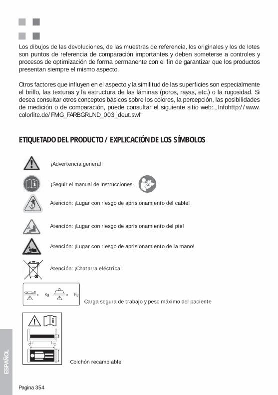
ESPA
ÑO
L
Pagina 354
son puntos de referencia de comparación importantes y deben someterse a controles y procesos de optimización de forma permanente con el fin de garantizar que los productos presentan siempre el mismo aspecto.
Otros factores que influyen en el aspecto y la similitud de las superficies son especialmente el brillo, las texturas y la estructura de las láminas (poros, rayas, etc.) o la rugosidad. Si desea consultar otros conceptos básicos sobre los colores, la percepción, las posibilidades de medición o de comparación, puede consultar el siguiente sitio web: „Infohttp://www.colorlite.de/FMG_FARBGRUND_003_deut.swf“
ETIQUETADO DEL PRODUCTO / EXPLICACIÓN DE LOS SÍMBOLOS
Carga segura de trabajo y peso máximo del paciente
¡Advertencia general!
¡Seguir el manual de instrucciones!
Atención: ¡Lugar con riesgo de aprisionamiento del cable!
Atención: ¡Lugar con riesgo de aprisionamiento del pie!
Atención: ¡Lugar con riesgo de aprisionamiento de la mano!
Atención: ¡Chatarra eléctrica!
Colchón recambiable
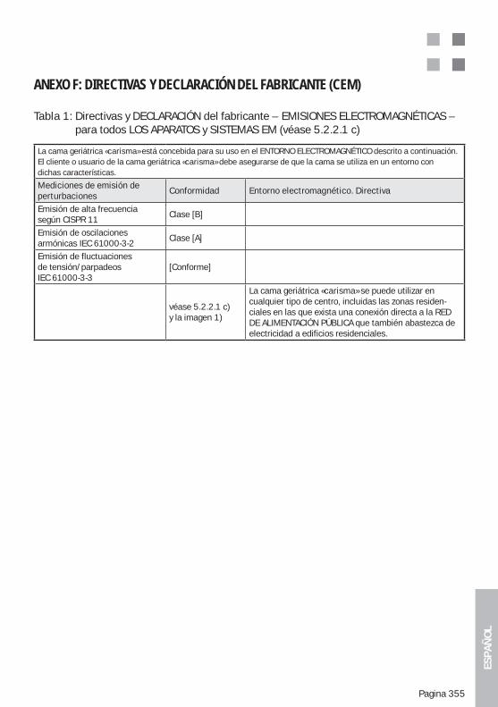
ESPA
ÑO
L
Pagina 355
ANEXO F: DIRECTIVAS Y DECLARACIÓN DEL FABRICANTE (CEM)
Tabla 1: Directivas y DECLARACIÓN del fabricante – EMISIONES ELECTROMAGNÉTICAS – para todos LOS APARATOS y SISTEMAS EM (véase 5.2.2.1 c)
La cama geriátrica «carisma» está concebida para su uso en el ENTORNO ELECTROMAGNÉTICO descrito a continuación.El cliente o usuario de la cama geriátrica «carisma» debe asegurarse de que la cama se utiliza en un entorno condichas características.
Mediciones de emisión deperturbaciones
Conformidad Entorno electromagnético. Directiva
Emisión de alta frecuenciasegún CISPR 11
Clase [B]
Emisión de oscilacionesarmónicas IEC 61000-3-2
Clase [A]
Emisión de fluctuacionesde tensión/parpadeosIEC 61000-3-3
[Conforme]
véase 5.2.2.1 c)y la imagen 1)
La cama geriátrica «carisma» se puede utilizar en cualquier tipo de centro, incluidas las zonas residen-ciales en las que exista una conexión directa a la RED DE ALIMENTACIÓN PÚBLICA que también abastezca de electricidad a edificios residenciales.
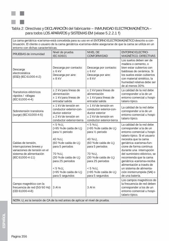
ESPA
ÑO
L
Pagina 356
Tabla 2: Directivas y DECLARACIÓN del fabricante – INMUNIDAD ELECTROMAGNÉTICA – para todos LOS APARATOS y SISTEMAS EM (véase 5.2.2.1 f)
La cama geriátrica «carisma» está concebida para su uso en el ENTORNO ELECTROMAGNÉTICO descrito a con-tinuación. El cliente o usuario de la cama geriátrica «carisma» debe asegurarse de que la cama se utiliza en un entorno con dichas características.
PRUEBAS de inmunidadNivel de pruebaIEC 60601
NIVEL DE CONFORMIDAD
ENTORNO ELECTRO- MAGNÉTICO. DIRECTIVAS
Descargaelectrostática(ESD) (IEC 61000-4-2)
Descarga por contacto:± 6 kVDescarga por aire: ± 8 kV
Descarga por contacto:± 6 kVDescarga por aire: ± 8 kV
Los suelos deben ser de madera o cemento, o bien estar cubiertos con baldosas de cerámica. Si los suelos están cubiertos con material sintético, la humedad relativa debe ser de al menos 30%.
Transitorios eléctricos rápidos / ráfagas(IEC 61000-4-4)
± 2 kV para líneas dealimentación± 1 kV para líneas deentrada/salida
± 2 kV para líneas dealimentación± 1 kV para líneas deentrada/salida
La calidad de la red debe corresponder a la de un entorno comercial u hospi-talario típico.
Sobretensión transitoria (surge) (IEC 61000-4-5)
± 1 kV de tensión enconductor exterior-con-ductor exterior± 2 kV de tensión enconductor exterior-tierra
± 1 kV de tensión enconductor exterior-con-ductor exterior± 2 kV de tensión enconductor exterior-tierra
La calidad de la red debe corresponder a la de un entorno comercial u hospi-talario típico.
Caídas de tensión, interrupciones breves y variaciones de tensión en el sistema de alimentación (IEC 61000-4-11)
< 5 % UT(>95 % de caída de UT)para ½ periodo
40 % UT (60 % de caída de UT)para 5 periodos
70 % UT (30 % de caída de UT)para 25 periodos
< 5 % UT (>95 % de caída de UT)para 5 segundos
< 5 % UT(>95 % de caída de UT)para ½ periodo
40 % UT (60 % de caída de UT)para 5 periodos
70 % UT (30 % de caída de UT)para 25 periodos
< 5 % UT (>95 % de caída de UT)para 5 segundos
La calidad de la red debe corresponder a la de un entorno comercial u hospi-talario típico. Si el usuario necesita que la cama geriátrica «carisma» fun-cione de forma continua durante una interrupción del suministro eléctrico, se recomienda que la cama geriátrica «carisma» reciba alimentación a través de un sistema de alimenta- ción ininterrumpida (SAI) o de una batería.
Campo magnético con la frecuencia de red (50/60 Hz)(CEI 61000-4-8)
3 A/m 3 A/m
Los campos magnéticos de la frecuencia de red deben corresponder a los de unentorno comercial u hospi-talario típico.
NOTA: UT es la tensión de CA de la red antes de aplicar el nivel de prueba.
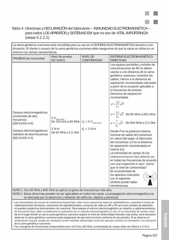
ESPA
ÑO
L
Pagina 357
Tabla 4: Directivas y DECLARACIÓN del fabricante – INMUNIDAD ELECTROMAGNÉTICA – para todos LOS APARATOS y SISTEMAS EM que no son de VITAL IMPORTANCIA (véase 5.2.2.2)
La cama geriátrica «carisma» está concebida para su uso en el ENTORNO ELECTROMAGNÉTICO descrito a con-tinuación. El cliente o usuario de la cama geriátrica «carisma» debe asegurarse de que la cama se utiliza en un entorno con dichas características.
PRUEBAS de inmunidadNivel de pruebaIEC 60601
NIVEL DE CONFORMIDAD
ENTORNO ELECTROMAGNÉTICO. DIRECTIVAS
Campos electromagnéticosconducidos de alta frecuencia(CEI 61000-4-6)
Campos electromagnéticosradiados de alta frecuencia(IEC 61000-4-3)
3 V valor eficaz
De 150 kHz a 80 MHz
3 V/mDe 80 MHz a 2,5 GHz
U1 = 3 V valor eficaz
E1 = 3 V/m
Los equipos portátiles y móviles decomunicaciones de RF no deben usarse a una distancia de la cama geriátrica «carisma», incluidos los cables, inferior a la distancia de separación recomendada calculada a partir de la ecuación aplicable a la frecuencia de emisión.Distancia de separación recomendada
De 80 MHz a 800 MHz
De 800 MHz a 2,5 GHz
Donde P es la potencia máxima nominal de salida del transmisor en vatios (W) según el fabricante del transmisor y d es la distancia de separación recomendada en metros (m).La intensidad de campo de los
en todas las frecuencias de acuerdo con una inspección in situa, menor que el nivel de conformidad.b
En la proximidad de los aparatos marcados con el siguiente símbolo puede haber interferencias.
NOTA 1: Con 80 MHz y 800 MHz se aplica la gama de frecuencias más alta.NOTA 2: Estas directivas pueden no ser aplicables en todos los casos. La propagación electromagnética se
ve afectada por la absorción y reflexión de edificios, objetos y personas.a
radiotransmisión terrestres, estaciones de radioaficionados, emisoras de radio en AM y FM así como canales de televisión, no pueden predecirse teóricamente con exactitud. Para evaluar el entorno electromagnético en relación a radiotransmisores
-da en el lugar donde se usa la cama geriátrica «carisma» supera el nivel de conformidad indicado más arriba, será necesario observar la cama geriátrica «carisma» para asegurarse de que esta funciona conforme al uso previsto. Si se observa un
de la cama geriátrica «carisma».b Con una gama de frecuencias comprendida entre 150 kHz y 80 MHz, la intensidad de campo debe ser inferior a 3 V/m.
PE
d1
5,3=
PU
d1
5,3=
PE
d1
7=
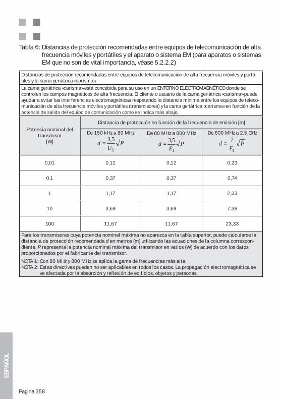
ESPA
ÑO
L
Pagina 358
Tabla 6: Distancias de protección recomendadas entre equipos de telecomunicación de alta frecuencia móviles y portátiles y el aparato o sistema EM (para aparatos o sistemas EM que no son de vital importancia, véase 5.2.2.2)
Distancias de protección recomendadas entre equipos de telecomunicación de alta frecuencia móviles y portá-tiles y la cama geriátrica «carisma».La cama geriátrica «carisma» está concebida para su uso en un ENTORNO ELECTROMAGNÉTICO donde se controlen los campos magnéticos de alta frecuencia. El cliente o usuario de la cama geriátrica «carisma» puede ayudar a evitar las interferencias electromagnéticas respetando la distancia mínima entre los equipos de teleco-municación de alta frecuencia móviles y portátiles (transmisores) y la cama geriátrica «carisma» en función de la
Potencia nominal deltransmisor
[W]
Distancia de protección en función de la frecuencia de emisión [m]
De 150 kHz a 80 MHz
PU
d1
5,3=De 80 MHz a 800 MHz
PE
d1
5,3=
De 800 MHz a 2,5 GHz
PE
d1
7=
0,01 0,12 0,12 0,23
0,1 0,37 0,37 0,74
1 1,17 1,17 2,33
10 3,69 3,69 7,38
100 11,67 11,67 23,33
Para los transmisores cuya potencia nominal máxima no aparezca en la tabla superior, puede calcularse la distancia de protección recomendada d en metros (m) utilizando las ecuaciones de la columna correspon-diente. P representa la potencia nominal máxima del transmisor en vatios (W) de acuerdo con los datos proporcionados por el fabricante del transmisor.
NOTA 1: Con 80 MHz y 800 MHz se aplica la gama de frecuencias más alta.NOTA 2: Estas directivas pueden no ser aplicables en todos los casos. La propagación electromagnética se
ve afectada por la absorción y reflexión de edificios, objetos y personas.
ESPA
ÑO
L
Pagina 359
NOTAS
ESPA
ÑO
L
Pagina 360
NOTAS