gbs an prc 8 sg v10... - noodlez.org
TRANSCRIPT
Table of Contents
Chapter 1 - Global Broadcast Service (GBS) Overview 1 Introduction to the Receive Suite AN/TSR-8 19
AN/TSR-8 Electronic Technical Manual (ETM) Overview 29 Pre-Mission Planning 34 GBS Information Security 40
Chapter 2 - AN/TSR-8 Assembly and Preparation for Use 45
Receive Broadcast Manager (RBM) Assembly and Preparation for Use 59 System Power Up 74
Chapter 3 - AN/TSR-8 Tear Down and Pack Up 83 Receive Broadcast Manager (RBM) Tear Down 95
Chapter 4 - AN/TSR-8 Operations 105
Antenna Initialization 107 Integrated Receiver Decoder (IRD) Configuration 127 KG 250 Crypto Installation and Configuration 153 Media Stream Operations and Set Top Box (STB) Configuration 191 KenCast Client Administration 198 KenCast Client Operations 210
Chapter 5 - Transmit Suite Client
Unit Editor for Administrators 221 Chapter 6 - Maintenance and Troubleshooting 239 Chapter 7 - Network Integration and Operations 253
Immediate File Delivery (IFD) with National Geospatial- Intelligence Agency (NGA) 258 IFD with National Ground Intelligence Center (NGIC) 265 IFD with Topographic Engineer Center (TEC) 271 GBS Network Integration 278

Program of Instruction (POI) Global Broadcast Service (GBS) Receive Suite (AN/TSR-8) Operator’s Course
40 Hours This course is designed to provide students with extensive hands-on practice to build the fundamental skills and abilities to successfully operate the Global Broadcast Service (GBS) Receive Suite. Students will learn theory, application, and principles of operating and maintaining the Global Broadcast Service (GBS) Receive Suite. DAY 1 Chapter 1 - Introduction to GBS
• Global Broadcast Service (GBS) Overview • Introduction to the Receive Suite AN/TSR-8 • AN/TSR-8 Electronic Technical Manual (ETM) Overview • Pre-Mission Planning • GBS Information Security
Chapter 2 - AN/TSR-8 Assembly and Preparation for Use
• Next Generation Receive Terminal (NGRT) Assembly and Preparation for Use
• Receive Broadcast Manager (RBM) Assembly and Preparation for Use • System Power Up
Chapter 3 - AN/TSR-8 Tear Down and Pack Up
• System Power Down • Next Generation Receive Terminal (NGRT) Tear Down and Pack Up • Receive Broadcast Manager (RBM) Tear Down
DAY 2 Chapter 4 - AN/TSR-8 Operations
• Antenna Initialization • Integrated Receiver Decoder (IRD) Configuration • KG 250 Crypto Installation and Configuration
DAY 3 • Media Stream Operations and Set Top Box (STB) Configuration • KenCast Client Administration • KenCast Client Operations
DAY 4 Chapter 5 - Transmit Suite Client
• Unit Editor for Administrators Chapter 6 - Maintenance and Troubleshooting
• Maintenance and Troubleshooting
DAY 5 Chapter 7 - Network Integration and Operations
• Immediate File Delivery (IFD) with National Geospatial-Intelligence Agency (NGA)
• IFD with National Geospatial Imagery Center (NGIC) • IFD with Topographic Engineer Center (TEC) • GBS Network Integration


TAB
Insert Tab # 1 Here
1-1
Global Broadcast Service (GBS) Overview

2
3
GBS Overview - Objectives
• Upon successful completion of this lesson, the student will be able to: State the purpose of the GBS
Identify the components of the GBS
Describe the operational characteristics of the GBS
4
Purpose of GBS
GBS is a Department of Defense (DoD) directed program to provide the warfighter with a near
worldwide, high-throughput broadcast information system for one-way, high-speed information flow.
23.5 (up to 45.0) Megabits per second (Mbps)
Larger Throughput = Faster Dissemination = Better Service to Warfighter
Information can be disseminated using either smart push or user pull. Smart push is when some information is deemed necessary for mission accomplishment, possibly by an outside agency, and that information is automatically “pushed” to the user. User pull is when the user finds some information that he needs that can be sent over GBS and requests that information. Users request information via GBS using the GBS Mission Request (GMR) form, which will be discussed later in this course.
5
GBS Data Rate
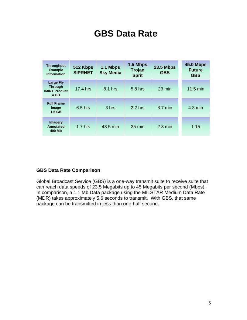
ThroughputExample
Information
512 KbpsSIPRNET
1.1 MbpsSky Media
1.5 MbpsTrojan Sprit
23.5 MbpsGBS
Large Fly Through
IMINT Product4 GB
17.4 hrs 8.1 hrs 5.8 hrs 23 min
Full Frame Image 1.5 GB
6.5 hrs 3 hrs 2.2 hrs 8.7 min
ImageryAnnotated
400 Mb1.7 hrs 48.5 min 35 min 2.3 min
45.0 MbpsFuture GBS
11.5 min
4.3 min
1.15
GBS Data Rate Comparison Global Broadcast Service (GBS) is a one-way transmit suite to receive suite that can reach data speeds of 23.5 Megabits up to 45 Megabits per second (Mbps). In comparison, a 1.1 Mb Data package using the MILSTAR Medium Data Rate (MDR) takes approximately 5.6 seconds to transmit. With GBS, that same package can be transmitted in less than one-half second.

6
GBS UFO KA Architecture
GBS Ka ARCHITECTURE GBS uses transponders from two Ka-band Ultra High Frequency (UHF) Follow-On (UFO) satellites (UFO8 and UFO10), TWO Ka-band Wideband Global Satellite Communications (WGS) satellites, and various Ku and Ka-band commercial satellites. Each satellite is served by a primary uplink site (Transmit Suite). The Transmit Suite assembles and transmits information to the satellite, which relays it to multiple GBS Receive Suites within a large geographical area. The satellites downlink the information via wide beam to a large area or by narrow beam to specific localized spots. GBS also provides the capability to transmit pre-assembled information directly from information sources through the SBM. Information may also be transmitted directly from the theater served by GBS through a transportable Theater Injection Point (TIP) system. Receive Suites receive and decode the information, then distribute it to end users over Local Area Networks (LANs). There are various types of Receive Suites, including transportable ground, shipboard, and sub-surface. All Receive Suites are equipped with a Crypto Unit that decrypts Classified broadcasts. A Receive Suite (RS) consists of a Receive Terminal (RT) and either one or two RBMs.]

7
GBS WGS KA Architecture
WGS Satellites WGS satellites are geosynchronous. Their exact location however varies slightly throughout the year in a figure-eight pattern. The NGRT has ephemeris data for commonly used satellites stored in memory, eliminating the need to contact the SBM. Each WGS satellite comes equipped with six Narrow Coverage Area (NCA) antennas, or spot beams, that provide up to 500 nautical miles of coverage. Each of the six transponders transmits data at a specific frequency. Transponders have a nominal bandwidth of 23.5 Mbps, but can operate up to a maximum of 45 Mbps per transponder on demand. Beam movement is planned at the SBM, based on RBM locations and mission priorities. The plan is then forwarded to the Wideband Satellite Communications (SATCOM) Operations Center (WSOC), which controls antenna movement on the WGS satellites. Using high power transponders and focused spot beams and/or area coverage beams, users in different areas can be provided targeted, high bandwidth video/data. Using a fanned network configuration, the SBM can transmit up to six NCA spot beams over a standard four beam broadcast
8
Components/Segments of GBS (1)
ENCRYPTIONUNCLASSENCLAVE
SECRETENCLAVE
ROKUSENCLAVE
CAS
CRYPTO
CRYPTO
BROADCASTENCLAVE
To the Transmit Segment
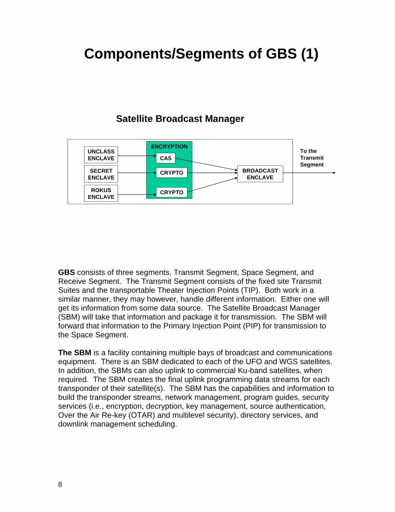
Satellite Broadcast Manager
GBS consists of three segments, Transmit Segment, Space Segment, and Receive Segment. The Transmit Segment consists of the fixed site Transmit Suites and the transportable Theater Injection Points (TIP). Both work in a similar manner, they may however, handle different information. Either one will get its information from some data source. The Satellite Broadcast Manager (SBM) will take that information and package it for transmission. The SBM will forward that information to the Primary Injection Point (PIP) for transmission to the Space Segment. The SBM is a facility containing multiple bays of broadcast and communications equipment. There is an SBM dedicated to each of the UFO and WGS satellites. In addition, the SBMs can also uplink to commercial Ku-band satellites, when required. The SBM creates the final uplink programming data streams for each transponder of their satellite(s). The SBM has the capabilities and information to build the transponder streams, network management, program guides, security services (i.e., encryption, decryption, key management, source authentication, Over the Air Re-key (OTAR) and multilevel security), directory services, and downlink management scheduling.
9
Components/Segments of GBS (2)
TRANSMIT SEGMENT
THEATER INJECTION POINTTransportable
TheaterInjection Terminal
TransportableSatellite
BroadcastManager
TRANSMIT SUITE
SatelliteBroadcastManager
PrimaryInjectionTerminal
DataSources
andMgmt
SPACE SEGMENTCommercial
Ku-BandSatellite
UFO/GBSKa-BandSatellite
RECEIVE SUITE
End UserReceive
BroadcastManager
RECEIVE SEGMENT
TheaterData
Sourcesand
Mgmt
NGRT
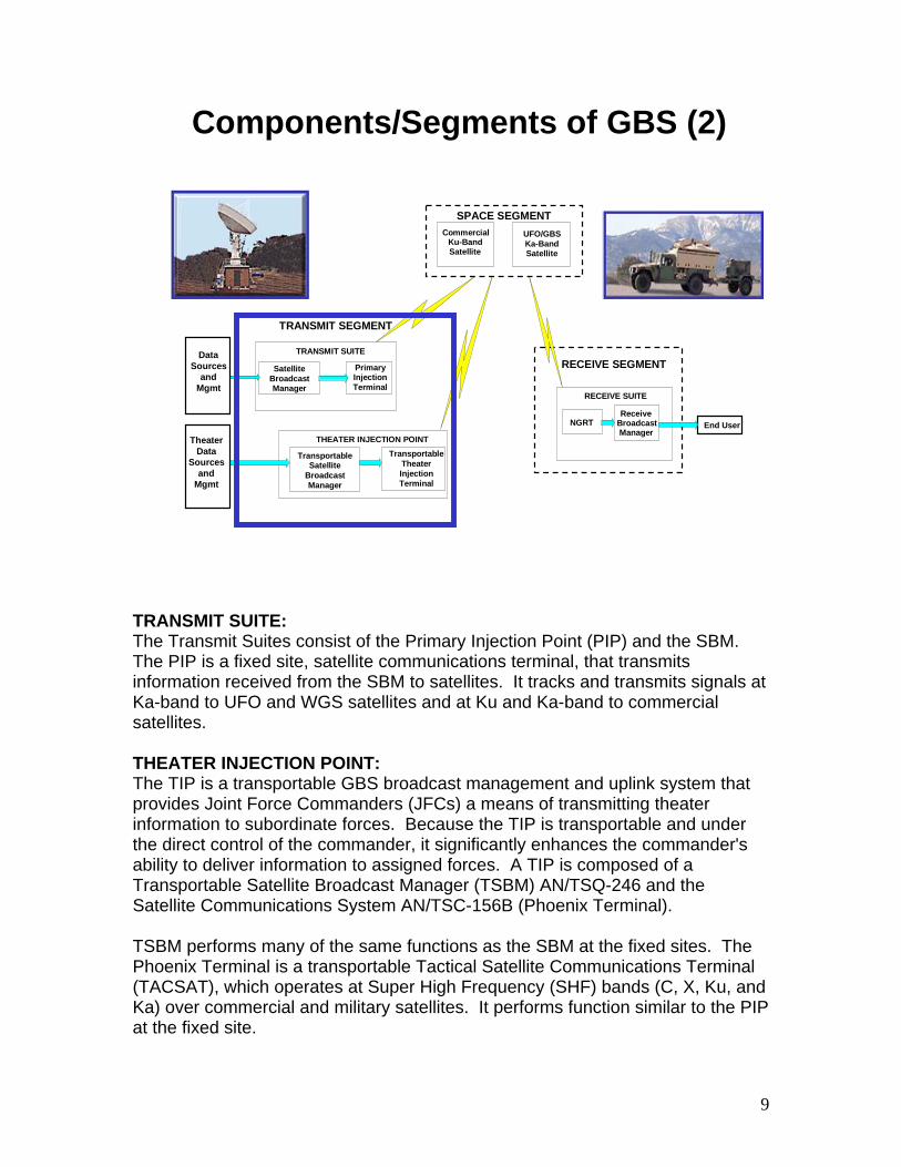
TRANSMIT SUITE: The Transmit Suites consist of the Primary Injection Point (PIP) and the SBM. The PIP is a fixed site, satellite communications terminal, that transmits information received from the SBM to satellites. It tracks and transmits signals at Ka-band to UFO and WGS satellites and at Ku and Ka-band to commercial satellites. THEATER INJECTION POINT: The TIP is a transportable GBS broadcast management and uplink system that provides Joint Force Commanders (JFCs) a means of transmitting theater information to subordinate forces. Because the TIP is transportable and under the direct control of the commander, it significantly enhances the commander's ability to deliver information to assigned forces. A TIP is composed of a Transportable Satellite Broadcast Manager (TSBM) AN/TSQ-246 and the Satellite Communications System AN/TSC-156B (Phoenix Terminal). TSBM performs many of the same functions as the SBM at the fixed sites. The Phoenix Terminal is a transportable Tactical Satellite Communications Terminal (TACSAT), which operates at Super High Frequency (SHF) bands (C, X, Ku, and Ka) over commercial and military satellites. It performs function similar to the PIP at the fixed site.
10
TRANSMIT SEGMENT
THEATER INJECTION POINT
TransportableTheaterInjection Terminal
TransportableSatellite
BroadcastManager
TRANSMIT SUITE
SatelliteBroadcastManager
PrimaryInjectionTerminal
DataSources
andMgmt
SPACE SEGMENTCommercial
Ku-BandSatellite
UFO/GBSKa-BandSatellite
RECEIVE SUITE
End UserReceive
BroadcastManager
RECEIVE SEGMENT
TheaterData
Sourcesand
Mgmt
Components/Segments of GBS (3)
NGRT
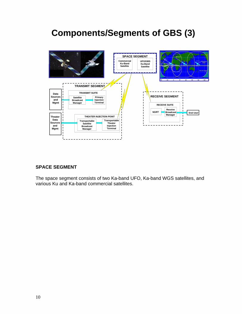
SPACE SEGMENT The space segment consists of two Ka-band UFO, Ka-band WGS satellites, and various Ku and Ka-band commercial satellites.
11
TRANSMIT SEGMENT
THEATER INJECTION POINT
TransportableTheaterInjection Terminal
TransportableSatellite
BroadcastManager
TRANSMIT SUITE
SatelliteBroadcastManager
PrimaryInjectionTerminal
DataSources
andMgmt
SPACE SEGMENTCommercial
Ku-BandSatellite
UFO/GBSKa-BandSatellite
RECEIVE SUITE
End UserReceive
BroadcastManager
RECEIVE SEGMENT
TheaterData
Sourcesand
Mgmt
Next Generation Receive Terminal
(NGRT)Receive Only Satellite
Communications Terminal
Receive Broadcast Manager (RBM)Extracts data from the IF signal and
supports the dissemination of information to the end user
Components/Segments of GBS (4)
NGRT
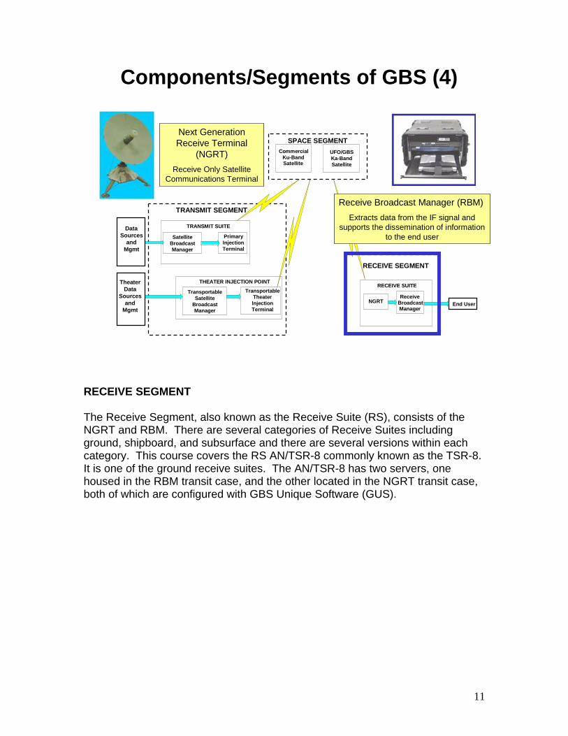
RECEIVE SEGMENT The Receive Segment, also known as the Receive Suite (RS), consists of the NGRT and RBM. There are several categories of Receive Suites including ground, shipboard, and subsurface and there are several versions within each category. This course covers the RS AN/TSR-8 commonly known as the TSR-8. It is one of the ground receive suites. The AN/TSR-8 has two servers, one housed in the RBM transit case, and the other located in the NGRT transit case, both of which are configured with GBS Unique Software (GUS).

12
GBS UFO Ka Satellite Coverage
UFO Coverage Currently, there are two UFO satellites (UFO 8 and UFO 10) with GBS payloads. They provide four transponders each with Ka-band downlink frequencies of 20.295, 20.425, 20.475, and 20.595 GHz respectively.
13
WGS Ka Coverage
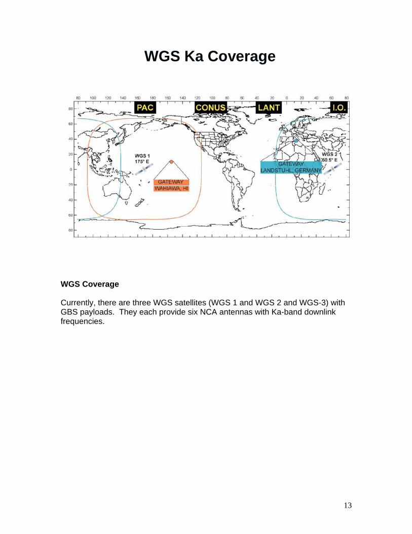
WGS Coverage Currently, there are three WGS satellites (WGS 1 and WGS 2 and WGS-3) with GBS payloads. They each provide six NCA antennas with Ka-band downlink frequencies.

14
Commercial Ku and Ka Satellites
COMMERCIAL Ku and Ka SATELLITES Commercial satellites are used to broadcast to locations not covered by the UFO satellites (such as North America, Atlantic Ocean, Spain, and parts of western Africa) and to areas requiring additional capacity such as Europe. Commercial satellites typically use Ku-band frequencies and can be either circularly or linearly polarized. Because the leasing of GBS supported commercial satellites will change from year to year, specific satellite names are not mentioned here.
15
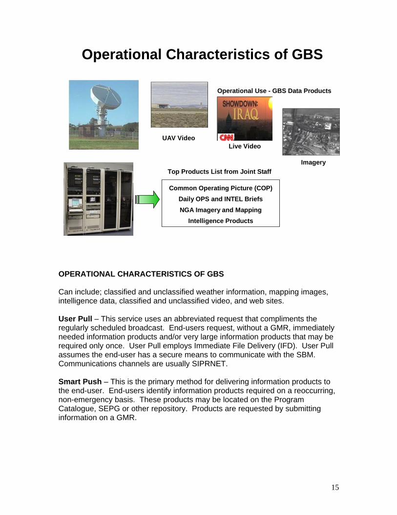
Common Operating Picture (COP)Daily OPS and INTEL BriefsNGA Imagery and Mapping
Intelligence Products
Top Products List from Joint Staff
UAV Video
Imagery
Live Video
Operational Use - GBS Data Products
Operational Characteristics of GBS
OPERATIONAL CHARACTERISTICS OF GBS Can include; classified and unclassified weather information, mapping images, intelligence data, classified and unclassified video, and web sites. User Pull – This service uses an abbreviated request that compliments the regularly scheduled broadcast. End-users request, without a GMR, immediately needed information products and/or very large information products that may be required only once. User Pull employs Immediate File Delivery (IFD). User Pull assumes the end-user has a secure means to communicate with the SBM. Communications channels are usually SIPRNET. Smart Push – This is the primary method for delivering information products to the end-user. End-users identify information products required on a reoccurring, non-emergency basis. These products may be located on the Program Catalogue, SEPG or other repository. Products are requested by submitting information on a GMR.
16
File Based Services (queued) based on PriorityImmediate File Delivery (IFD) -The IFD Service allows an
authorized source to create an IFD hot folder at the SBM then File Transfer Protocol (FTP) files into this folder. The files will be immediately prepared for broadcast.
Web Service - Allows web crawl to pull information of interest from Web Sources by the SBM.
GBS Delivery Services (Data)
GBS DELIVERY SERVICES: The Planning and Management software used by the SBM provides a suite of editors on the SIPRNET designed for Theater Information Managers, Sources and Units to view, add, edit, and delete the data in the GBS database. This interface is used to model the system and control the broadcast from the Unclassified and Classified SBM enclaves using two types of services; File Based and Streaming. FILE BASED SERVICES: Immediate File Delivery (IFD) Service: Files in the hot folder are immediately sent out over the broadcast or queued for later delivery. If the freshness period of the file expires before transmission, the file is not sent. WEB SERVICE: The Mirrored Web Service mirrors selected contents of a source website over the satellite to the Receive Suite. The SBM Collection Manager crawls the web site and creates an internally linked web package. The web data is collected according to the crawl configuration parameters set up when the program is registered. The crawls are repeated based on the refresh parameters, and are made available to the end user through a web browser interface.
17
Streaming Services (scheduled):
• Video – Video products arriving at the SBM from sources are encoded and delivered to the RBM as IP over MPEG with or without FEC added.
• UAV/Predator – To receive UAV/Predator video products, requestor must submit request via Chain of Command. (Contact CENTCOM TIM)
• Streaming Packet –Any multicast or UDP product that is tunneled through the SBM for which GBS does not have visibility into the content. This could be a source encrypted IP data.
GBS Delivery Services (Video)
STREAMING SERVICES: Internet Protocol (IP) to IP Video and Streaming Packet Services can be encoded with Forward Error Correction (FEC). FEC increases video stream reliability and adds latency proportionate to the amount of FEC applied. IP to IP Video Service (Predator/UAV feeds) The IP to IP Video Service allows a source to define and send an IP video to the SBM for broadcast. The Receive Suite provides an IP video stream to the end user. Users must submit request to CENTCOM TIM via appropriate Chain of Command. Form is located on CENTCOM TIM Website. Streaming Packet Service: The Streaming Packet Service allows a source to define and send an IP multicast or unicast stream to the SBM for broadcast. The Receive Suite provides an identical IP stream for end user consumption.
18
GBS Overview - Summary
• Review:State the purpose of GBS
Identify the components of GBS
Describe the operational characteristics of GBS
19
1- 2
Introduction to the Receive Suite AN/TSR-8
20
Introduction to AN/TSR-8 Objectives
• Upon successful completion of this lesson, the student will be able to: Identify AN/TSR-8 assemblies
Identify the Next Generation Receive Terminal (NGRT) Components
Identify the Receive Broadcast Manager (RBM) Components
21
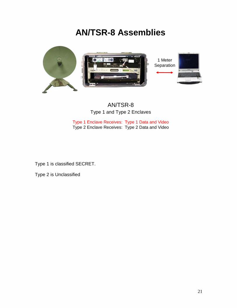
AN/TSR-8 Assemblies
AN/TSR-8Type 1 and Type 2 Enclaves
Type 1 Enclave Receives: Type 1 Data and VideoType 2 Enclave Receives: Type 2 Data and Video
1 Meter Separation
Type 1 is classified SECRET. Type 2 is Unclassified
22
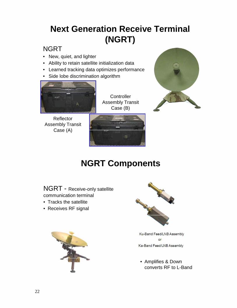
Next Generation Receive Terminal(NGRT)
NGRT• New, quiet, and lighter• Ability to retain satellite initialization data• Learned tracking data optimizes performance• Side lobe discrimination algorithm
Controller Assembly Transit
Case (B)
Reflector Assembly Transit
Case (A)
NGRT - Receive-only satellite communication terminal• Tracks the satellite • Receives RF signal
NGRT Components
• Amplifies & Down converts RF to L-Band
23
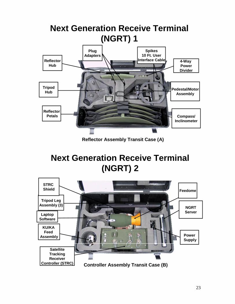
Reflector Assembly Transit Case (A)
ReflectorPetals
TripodHub
ReflectorHub
Pedestal/MotorAssembly
4-Way PowerDivider
Compass/Inclinometer
Spikes10 Ft. User
Interface Cable
PlugAdapters
Next Generation Receive Terminal(NGRT) 1
Controller Assembly Transit Case (B)
Tripod LegAssembly (3)
Feedome
SatelliteTrackingReceiver
Controller (STRC)
NGRTServer
PowerSupply
STRC Shield
KU/KA Feed
Assembly
LaptopSoftware
Next Generation Receive Terminal(NGRT) 2
24
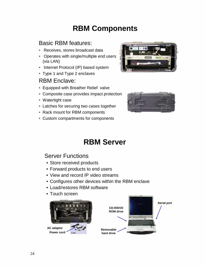
RBM Components
Basic RBM features:• Receives, stores broadcast data • Operates with single/multiple end users
(via LAN)• Internet Protocol (IP) based system• Type 1 and Type 2 enclaves
RBM Enclave:• Equipped with Breather Relief valve • Composite case provides impact protection• Watertight case• Latches for securing two cases together• Rack mount for RBM components• Custom compartments for components
RBM Server
Removablehard drive
CD-R/DVD ROM drive
AC adaptorPower cord
Server Functions• Store received products• Forward products to end users• View and record IP video streams• Configures other devices within the RBM enclave• Load/restores RBM software• Touch screen
Serial port
25
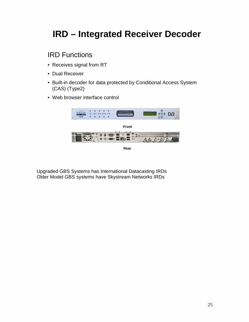
IRD – Integrated Receiver Decoder
IRD Functions• Receives signal from RT
• Dual Receiver
• Built-in decoder for data protected by Conditional Access System (CAS) (Type2)
• Web browser interface control
Front
Rear
Upgraded GBS Systems has International Datacasting IRDs Older Model GBS systems have Skystream Networks IRDs
26
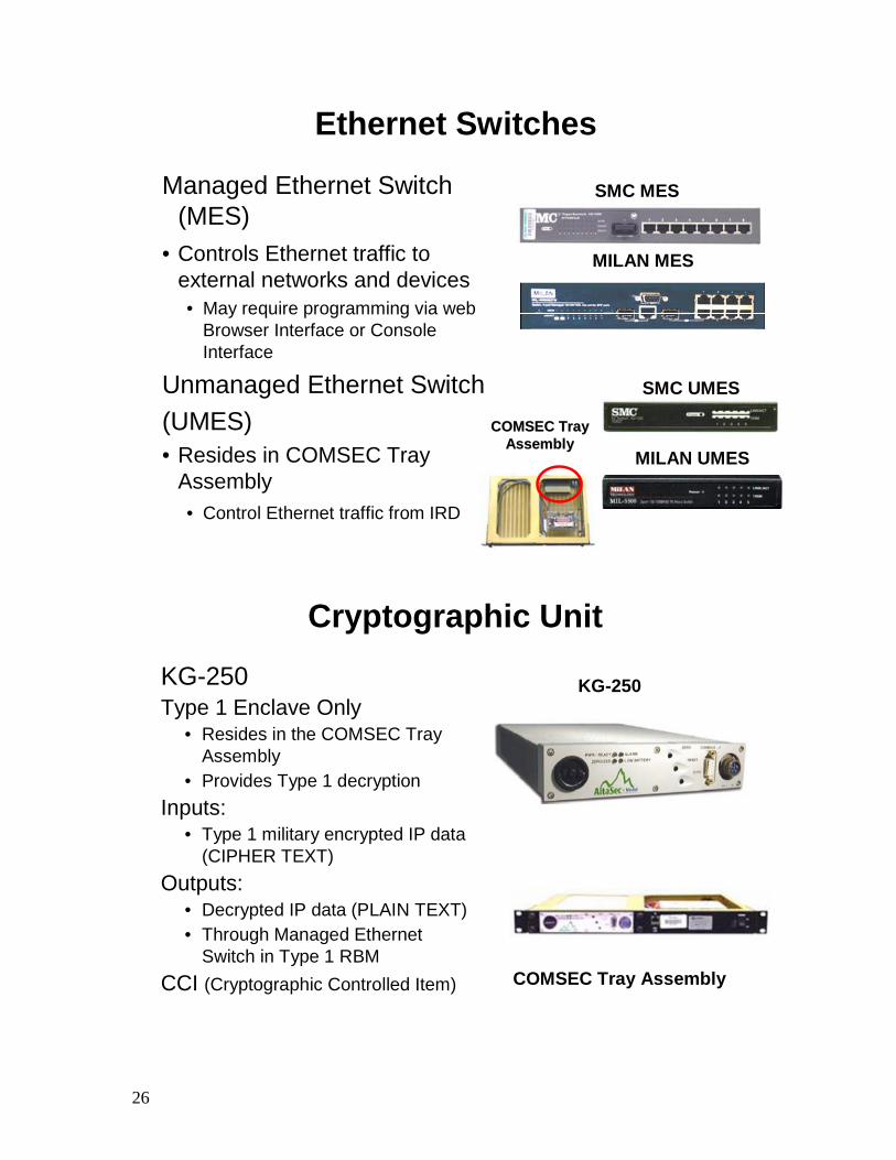
Ethernet Switches
Managed Ethernet Switch (MES)
• Controls Ethernet traffic to external networks and devices• May require programming via web
Browser Interface or Console Interface
Unmanaged Ethernet Switch(UMES)• Resides in COMSEC Tray
Assembly• Control Ethernet traffic from IRD
COMSEC Tray COMSEC Tray AssemblyAssembly
SMC MES
MILAN MES
SMC UMES
MILAN UMES
Cryptographic Unit
COMSEC Tray Assembly
KG-250KG-250Type 1 Enclave Only
• Resides in the COMSEC Tray Assembly
• Provides Type 1 decryptionInputs:
• Type 1 military encrypted IP data (CIPHER TEXT)
Outputs:• Decrypted IP data (PLAIN TEXT)• Through Managed Ethernet
Switch in Type 1 RBMCCI (Cryptographic Controlled Item)
27
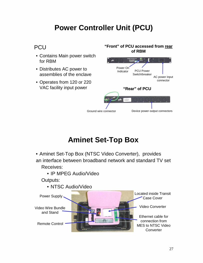
Power Controller Unit (PCU)
Device power output connectorsGround wire connector
““RearRear”” of PCUof PCU
““FrontFront”” of PCU accessed from of PCU accessed from rearrearof RBM of RBM
AC power input connector
Power On Indicator PCU Power
Switch/breaker
PCU• Contains Main power switch
for RBM
• Distributes AC power to assemblies of the enclave
• Operates from 120 or 220 VAC facility input power
Aminet Set-Top Box
• Aminet Set-Top Box (NTSC Video Converter), providesan interface between broadband network and standard TV set
Receives:• IP MPEG Audio/Video
Outputs:• NTSC Audio/Video
Ethernet cable for connection from
MES to NTSC Video Converter
Video ConverterVideo Wire Bundle and Stand
Remote Control
Power SupplyLocated inside Transit
Case Cover
28
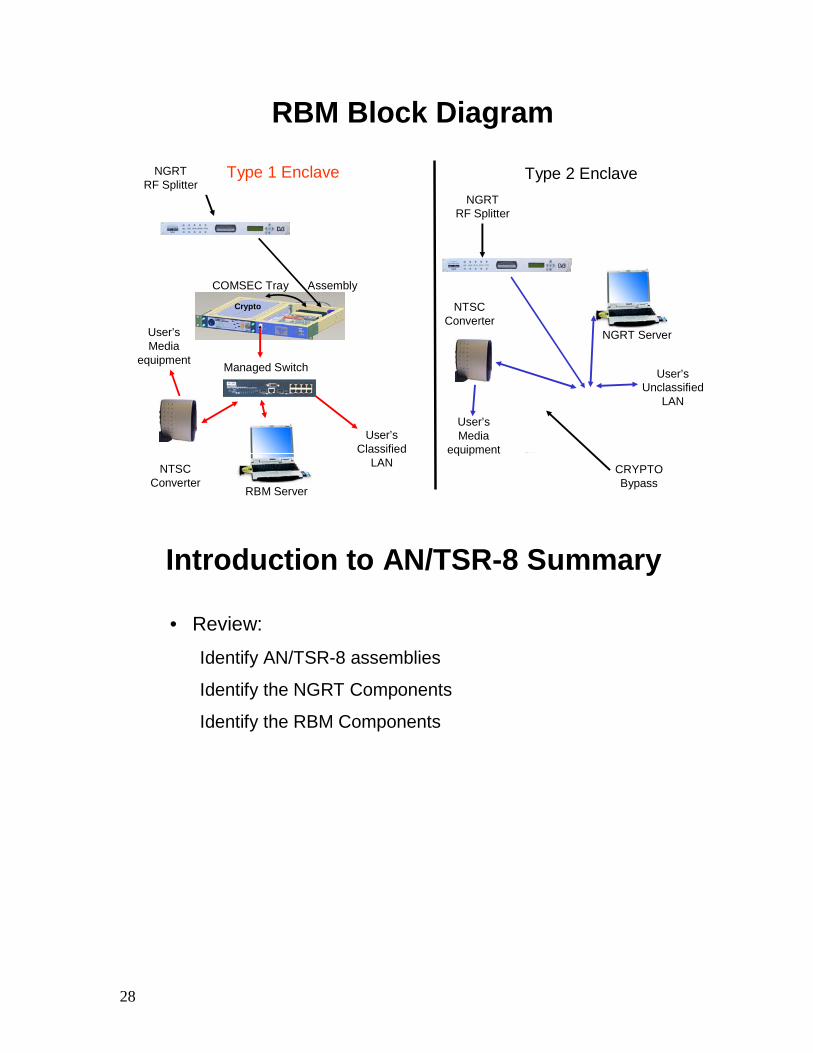
RBM Block Diagram
Type 1 Enclave Type 2 EnclaveNGRTRF Splitter
NGRTRF Splitter
User’s Unclassified
LAN
User’sMedia
equipment
NTSC Converter
User’s Classified
LAN
User’sMedia
equipment
NTSC Converter
Crypto
COMSEC Tray Assembly
RBM Server
NGRT Server
CRYPTO Bypass
Managed Switch
Introduction to AN/TSR-8 Summary
• Review:
Identify AN/TSR-8 assemblies
Identify the NGRT Components
Identify the RBM Components
29
1- 3 AN/TSR-8 Electronic
Technical Manual (ETM) Overview
30
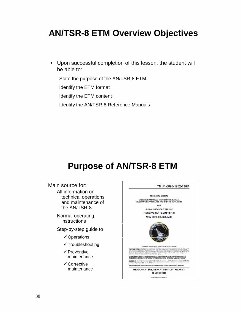
AN/TSR-8 ETM Overview Objectives
• Upon successful completion of this lesson, the student will be able to:State the purpose of the AN/TSR-8 ETM
Identify the ETM format
Identify the ETM content
Identify the AN/TSR-8 Reference Manuals
Purpose of AN/TSR-8 ETM
Main source for:All information on
technical operations and maintenance of the AN/TSR-8
Normal operating instructions
Step-by-step guide toOperations
Troubleshooting
Preventive maintenance
Corrective maintenance
31
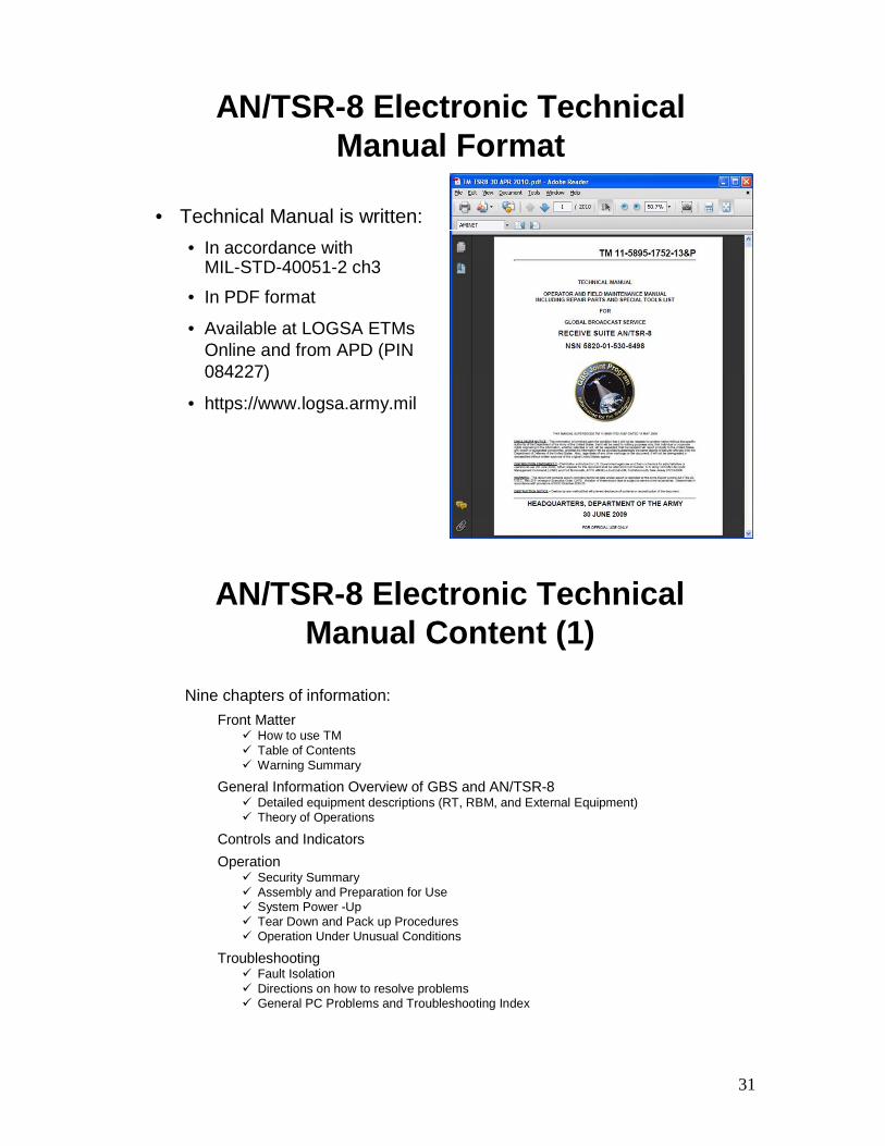
AN/TSR-8 Electronic Technical Manual Format
• Technical Manual is written:• In accordance with
MIL-STD-40051-2 ch3
• In PDF format
• Available at LOGSA ETMsOnline and from APD (PIN 084227)
• https://www.logsa.army.mil
AN/TSR-8 Electronic Technical Manual Content (1)
Nine chapters of information:Front Matter
How to use TMTable of ContentsWarning Summary
General Information Overview of GBS and AN/TSR-8Detailed equipment descriptions (RT, RBM, and External Equipment)Theory of Operations
Controls and IndicatorsOperation
Security SummaryAssembly and Preparation for UseSystem Power -UpTear Down and Pack up ProceduresOperation Under Unusual Conditions
TroubleshootingFault IsolationDirections on how to resolve problemsGeneral PC Problems and Troubleshooting Index
32
AN/TSR-8 Electronic Technical Manual Content (2)
Nine chapters of information (cont.):Preventive Maintenance
Actions needed to maintain regular AN/TSR-8 operations
Corrective MaintenanceRemove and Replace Procedures
LRU ConfigurationNGRT ConfigurationIRD Configuration
Repair Parts and Special Tools ListRepair Parts listPart Number Index
Support InformationReference materialMaintenance allocation chartsTool Lists, COEI, BII, Consumables List
Rear MatterGlossaryAppendices
AN/TSR-8 Reference Material
• Reference Manuals are provided with the AN/TSR-8 TM to provide• Commercial Off The Shelf (COTS) manuals for main
AN/TSR-8 LRUs
• Detailed operating information outside the scope of the AN/TSR-8 system
Examples:AmiNET User GuideSMC TigerSwitch User Guide
33
AN/TSR-8 ETM Overview Summary
• Review:State the purpose of the AN/TSR-8 ETM
Identify the ETM format
Identify the ETM content
Identify the AN/TSR-8 Reference Manuals

34
1- 4 Pre-Mission Planning
35
Pre-Mission Planning Objectives
• Upon successful completion of this lesson, the student will be able to:State the purpose of GBS Mission Request (GMR)
State the purpose of Mission Data Sheet (MDS)
State Site Selection Requirements
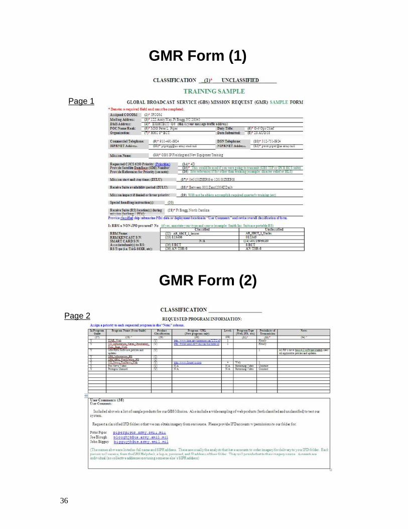
Purpose of GBS Mission Request(GMR)
• GMR is used when initiating, adding, dropping or changing GBS services.
• An initial GMR needs to be submitted no later than 14 days prior to required delivery date through the proper chain of commands.
* A Theater Information Manager (TIM) needs to approve all GMR’s.
URL for Norfolk SBM: https://207.85.158.99/
URL for Wahiawa SBM: https://info.gbs-pacom.navy.smil.mil/
36
GMR Form (1)
Page 1
GMR Form (2)
Page 2
37
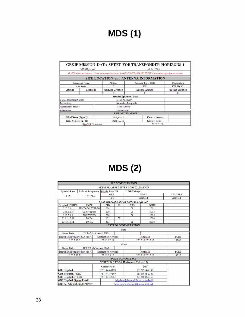
Purpose of the Mission Data Sheet (MDS)
• A Mission Data Sheet provides necessary information for configuring LRU’s of the GBS Receive Suite.
• Most information provided by the SBM• Site information • Antenna information• IRD configuration information• Crypto Unit configuration information• KenCast configuration information• Point of Contact (POC) information
38
MDS (1)
MDS (2)
39
Site Selection Requirements1. Antenna must be setup within 150 ft of RBM equipment
2. Clear Line of Sight (LOS) to anticipated target satellite and free of obstacles
3. Ground should be firm, level and free of obstructions
4. Ground should accept stabilization spikes and stakes for grounding kit
5. Sandbags may be used to help stabilize tripod
6. Do not operate in sustained winds greater than 30 MPH
7. No more than a 30º slope to support antenna tripod
8. Due to moving parts, Antenna should be placed in restricted access area
If restricted access is not available, obtain locally available warning tags that instruct to “Keep away during operation”
Pre-Mission Planning Summary
• Review:State the purpose of GBS Mission Request (GMR)
State the purpose of Mission Data Sheet (MDS)
State Site Selection Requirements
40
1-5 GBS Information
Security
41
GBS Information Security Objective
• Upon successful completion of this lesson, the student will be able to:
Explain GBS Information Security
GBS Information Security
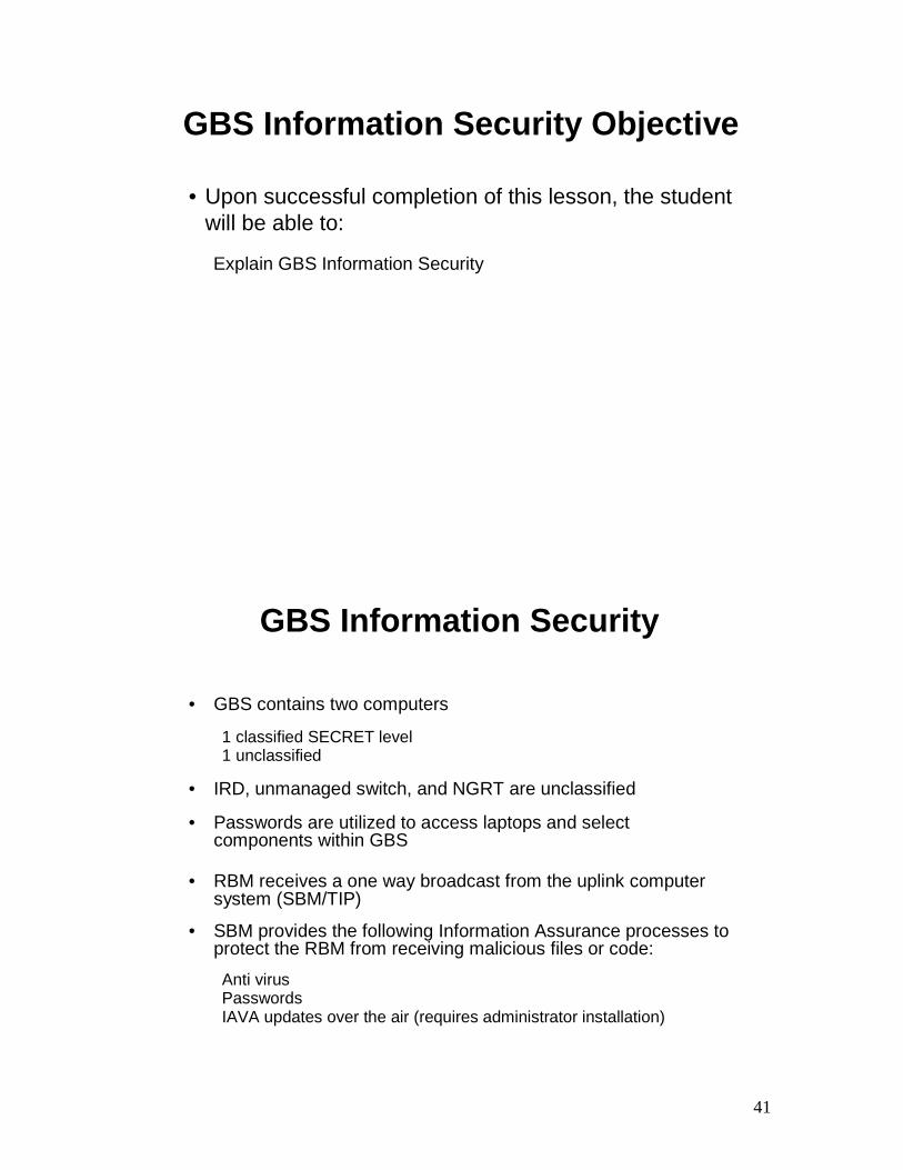
• GBS contains two computers
1 classified SECRET level 1 unclassified
• IRD, unmanaged switch, and NGRT are unclassified
• Passwords are utilized to access laptops and select components within GBS
• RBM receives a one way broadcast from the uplink computer system (SBM/TIP)
• SBM provides the following Information Assurance processes to protect the RBM from receiving malicious files or code:
Anti virus PasswordsIAVA updates over the air (requires administrator installation)
42
GBS Passwords
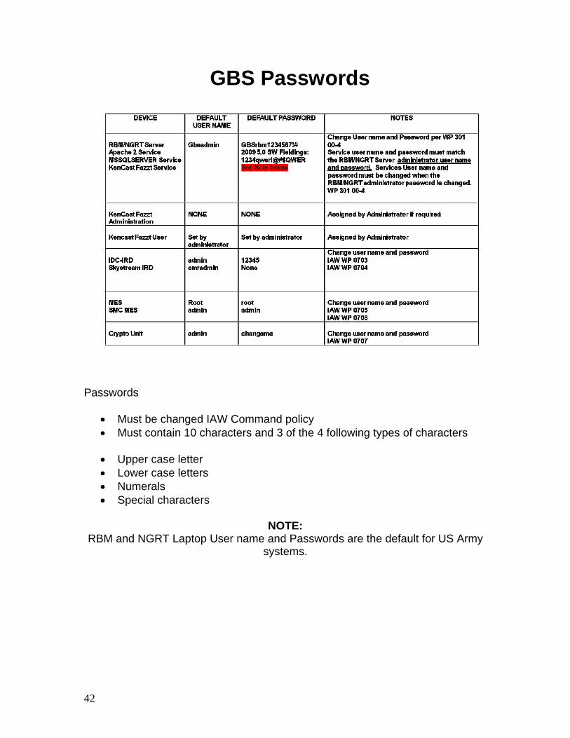
Passwords
• Must be changed IAW Command policy • Must contain 10 characters and 3 of the 4 following types of characters
• Upper case letter • Lower case letters • Numerals • Special characters
NOTE:
RBM and NGRT Laptop User name and Passwords are the default for US Army systems.
43
GBS General Security
• Audit logs are recorded on the NGRT/RBM Servers and the KG-250
• Do not download any software on your GBS laptops
Only the System Administrator may add software to your GBS laptops
GBS Security Updates
• The Anti virus updates are sent over the satellite
• Periodically, Microsoft will publish an Information Assurance Vulnerability Alert (IAVA)-commonly called “hot fixes”
• The administrator must install all updates that are received via broadcast (you will be prompted by a Security Update Alert on the KenCast homepage)
• Send an email to [email protected] when the hot fixes have been installed
The PM must inform DA that these were done

44
GBS Information Security Summary
• Review:State the GBS Information Security

TAB
Insert Tab # 2 Here
45
2-1
Next Generation Receive Terminal (NGRT)
Assembly and Preparation for Use

46
47
NGRT Assembly and Preparation for Use Objectives
• Upon successful completion of this lesson, the student will be able to:Explain NGRT Transit Case
Explain NGRT Assembly and Preparation for Use

48
Open NGRT Cases
NGRT Assembly and Preparation for Use The NGRT is transported in two Transit Cases: Reflector and Controller. The NGRT also uses a Grounding Kit, which is in a separately bundled bag. Open NGRT Transit Cases:
1. Press RELIEF VALVE. 2. Open latches. 3. Open covers.

49
Tripod Assembly – Legs to Hub
Set up the Tripod 1. Remove the Tripod legs and Tripod Hub from Transit Cases. 2. Rotate the three Tripod Leg collars clockwise onto Tripod Hub. 3. Stand Tripod upright. 4. Orient Tripod such that draw latch attachment notch points towards
satellite heading on Mission Data Sheet (MDS). Ensure white alignment mark on Tripod Hub is pointing opposite the draw latch attachment notch.
1. Loosen Tripod locking nut. 2. Rotate Tripod Hub white alignment mark so that it is pointing opposite the
draw latch attachment notch. 3. While holding Tripod Hub in place, tighten Tripod locking nut.

50
Tripod Assembly –Pedestal/Motor Assembly
Install Pedestal/Motor Assembly onto Tripod 1. Remove Pedestal/Motor Assembly from Reflector Transit Case. 2. Loosen Pedestal/Motor Assembly T-bolt band clamp. 3. Line up Pedestal/Motor Assembly and Tripod Hub white alignment marks
on clamping block. 4. Lower Pedestal/Motor Assembly onto clamping block. 5. Tighten the T-bolt band clamp.

51
STRC Installation
Install STRC Have one person hold STRC from the front with both hands, fully supporting its weight, while another secures the draw latch from the back. Failure to do so may result in damage to equipment or injury to personnel.
1. Remove STRC from Controller Transit Case. 2. Support STRC underside and slide STRC mounting slot onto STRC
Tripod attachment bracket. 3. Pull STRC draw latch up and secure in attachment notch. STRC
automatically positions against Tripod Hub saddle points. 4. Ensure that STRC ON/OFF circuit breaker is set to OFF.

52
Reflector Assembly –Hub to Pedestal
Assemble the Reflector Assembly The Reflector Hub mounts onto the Pedestal/Motor Assembly at four mounting points. The two mounting points at the bottom of the Pedestal/Motor Assembly have raised bosses, which mate with the two counter sunk holes at the bottom of the Reflector Hub.
1. Remove Reflector Hub from Reflector Transit Case. 2. Align the Reflector Hub onto the Pedestal/Motor Assembly ensuring
mounting points mate with their counterparts (boss to counter bore), and tighten four thumbscrews.
3. Remove the Reflector Petals from Reflector Transit Case. 4. Starting at bottom of Reflector Hub, insert a Petal onto the Hub guide pins. 5. Latch the Hub and Petal together and support Petal until next Petal is
attached. 6. Insert another Petal next to the first. 7. Latch the Hub and Petal together. 8. Latch the Petals together. 9. Repeat for the remaining Petals. 10. Check to ensure that all latches are secure.
53
Feedome Installation (1)
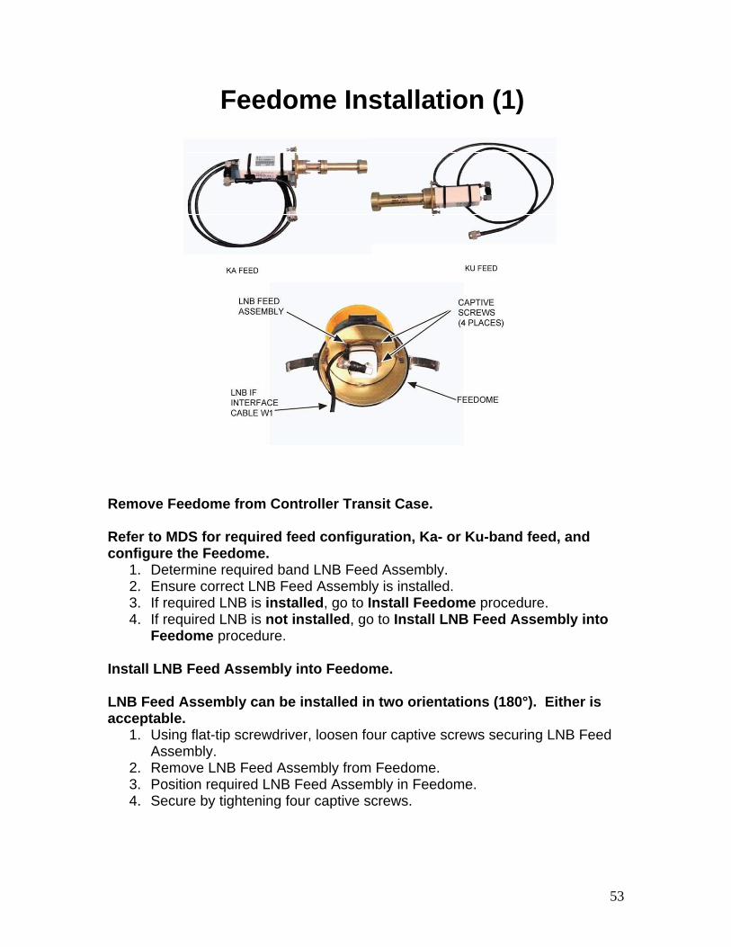
Remove Feedome from Controller Transit Case. Refer to MDS for required feed configuration, Ka- or Ku-band feed, and configure the Feedome.
1. Determine required band LNB Feed Assembly. 2. Ensure correct LNB Feed Assembly is installed. 3. If required LNB is installed, go to Install Feedome procedure. 4. If required LNB is not installed, go to Install LNB Feed Assembly into
Feedome procedure. Install LNB Feed Assembly into Feedome. LNB Feed Assembly can be installed in two orientations (180°). Either is acceptable.
1. Using flat-tip screwdriver, loosen four captive screws securing LNB Feed Assembly.
2. Remove LNB Feed Assembly from Feedome. 3. Position required LNB Feed Assembly in Feedome. 4. Secure by tightening four captive screws.

54
Feedome Installation (2)
All cabling between Pedestal/Motor Assembly and center of Multi-Piece Reflector must pass through side opening opposite the AZ motor. Failure to comply may result in damage to equipment. This task requires two persons: one to support the item and another to remove/replace attaching hardware. Failure to comply may result in damage to equipment. Hold Feedome while attaching it to Reflector Hub to avoid dropping Feedome and its components. Install Feedome.
1. Insert LNB IF Interface Cable W1 through opening in Reflector Hub. 2. Route cable through Pedestal/Motor Assembly side opening opposite
Azimuth Motor. 3. Engage and tighten two Feedome draw latches to support ring.
Polarity orientation of the Feedome is arbitrary when first installed. The orientation will be adjusted later.
55
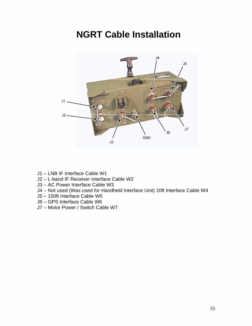
NGRT Cable Installation
J1 – LNB IF Interface Cable W1 J2 – L-band IF Receiver Interface Cable W2 J3 – AC Power Interface Cable W3 J4 – Not used (Was used for Handheld Interface Unit) 10ft Interface Cable W4 J5 – 150ft Interface Cable W5 J6 – GPS Interface Cable W6 J7 – Motor Power / Switch Cable W7
56
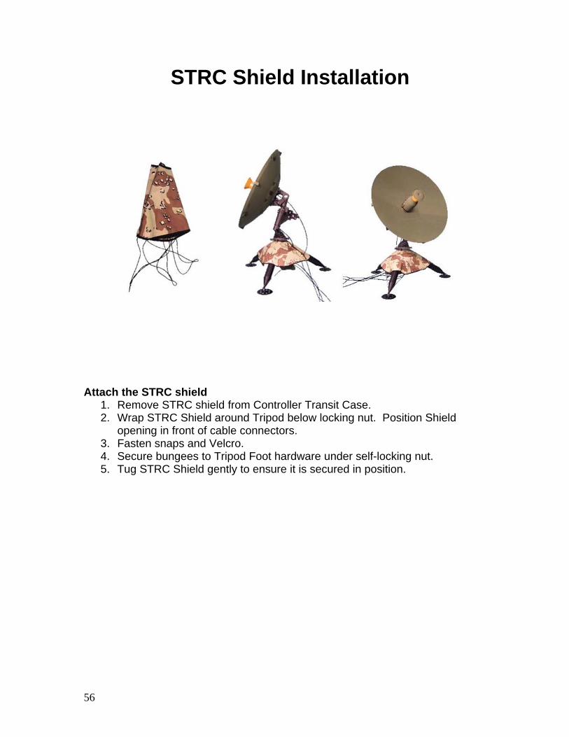
STRC Shield Installation
Attach the STRC shield 1. Remove STRC shield from Controller Transit Case. 2. Wrap STRC Shield around Tripod below locking nut. Position Shield
opening in front of cable connectors. 3. Fasten snaps and Velcro. 4. Secure bungees to Tripod Foot hardware under self-locking nut. 5. Tug STRC Shield gently to ensure it is secured in position.

57
Grounding Kit Installation
• A spike is driven through each Tripod Foot for stabilization. Sandbags or other anchoring methods may also be used to ensure proper stability.
• A Grounding Kit provides proper grounding of NGRT
• Install Grounding Kit according to GFE instructions provided

58
NGRT Assembly and Preparation for Use - Summary
• Review:Explain NGRT Transit Case
Explain NGRT Assembly and Preparation for Use
59
2-2 Receive Broadcast
Manager (RBM) Assembly and
Preparation for Use

60
RBM Assembly and Preparationfor Use - Objectives
• Upon successful completion of this lesson, the student will be able to:Explain Removal of RBM Transit Case Covers
Explain RBM Setup
61
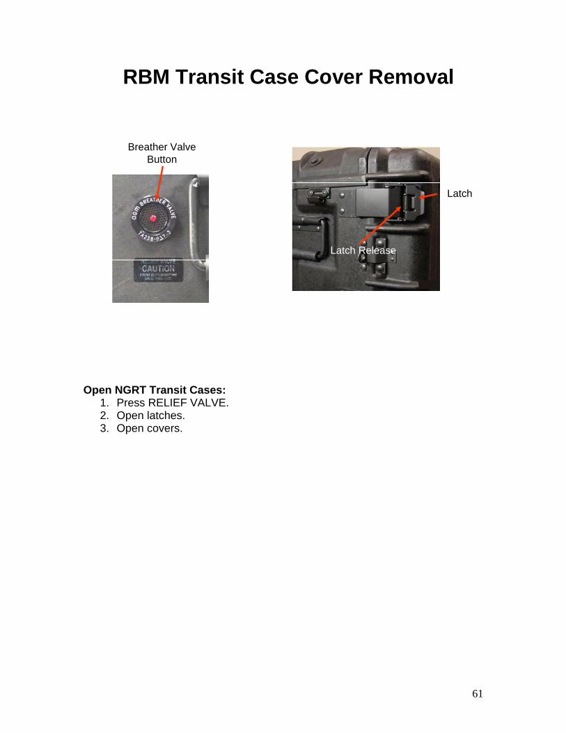
RBM Transit Case Cover Removal
Latch Release
Latch
Breather ValveButton
Open NGRT Transit Cases: 1. Press RELIEF VALVE. 2. Open latches. 3. Open covers.
62
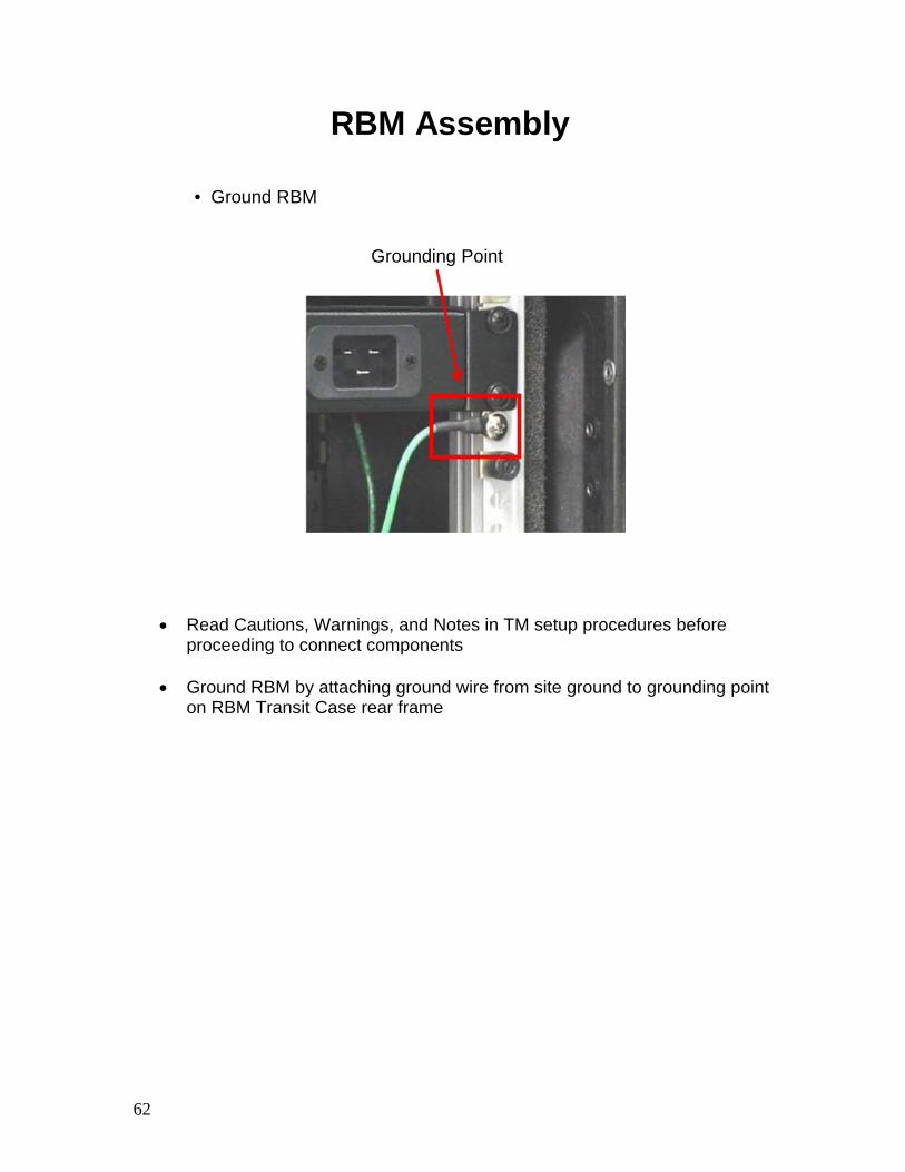
RBM Assembly
• Ground RBM
Grounding Point
• Read Cautions, Warnings, and Notes in TM setup procedures before proceeding to connect components
• Ground RBM by attaching ground wire from site ground to grounding point
on RBM Transit Case rear frame
63
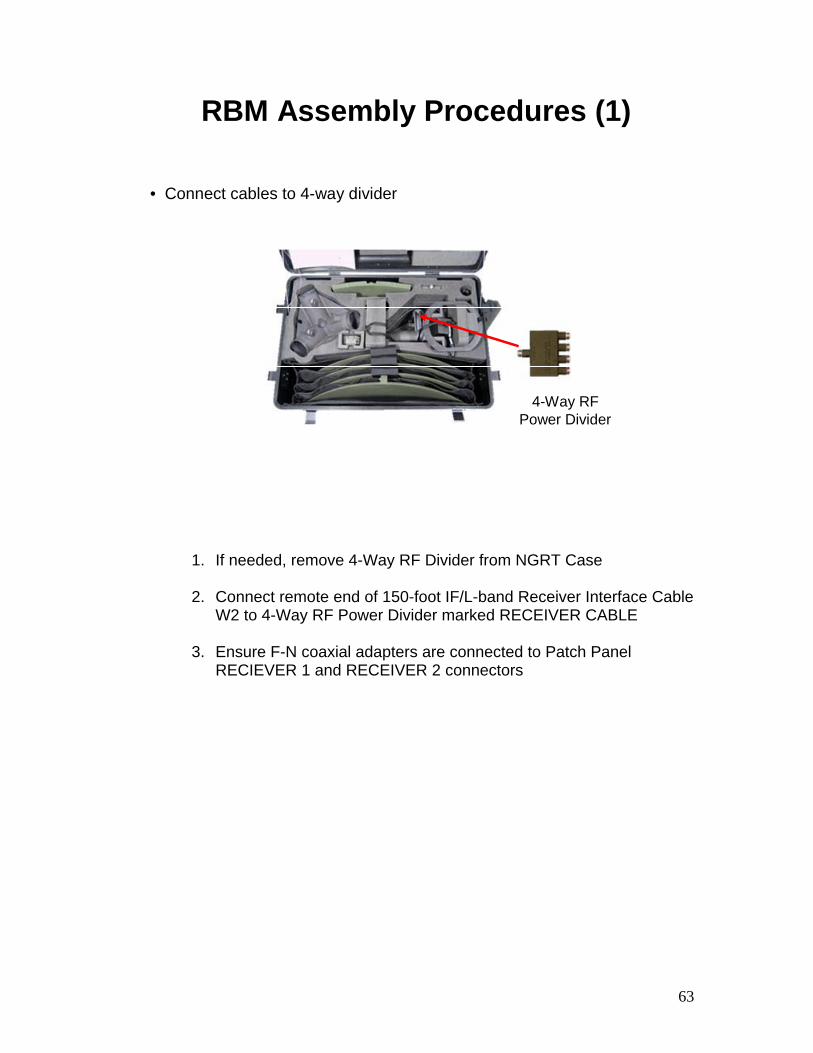
RBM Assembly Procedures (1)
• Connect cables to 4-way divider
4-Way RF Power Divider
1. If needed, remove 4-Way RF Divider from NGRT Case
2. Connect remote end of 150-foot IF/L-band Receiver Interface Cable W2 to 4-Way RF Power Divider marked RECEIVER CABLE
3. Ensure F-N coaxial adapters are connected to Patch Panel
RECIEVER 1 and RECEIVER 2 connectors
64
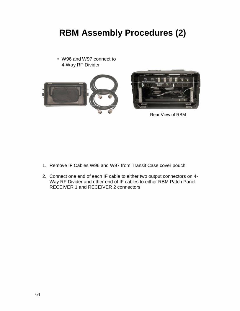
RBM Assembly Procedures (2)
• W96 and W97 connect to 4-Way RF Divider
Rear View of RBM
1. Remove IF Cables W96 and W97 from Transit Case cover pouch.
2. Connect one end of each IF cable to either two output connectors on 4-Way RF Divider and other end of IF cables to either RBM Patch Panel RECEIVER 1 and RECEIVER 2 connectors
65
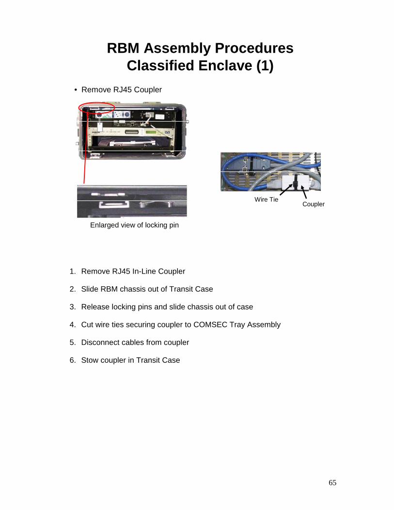
RBM Assembly ProceduresClassified Enclave (1)
• Remove RJ45 Coupler
Enlarged view of locking pin
Wire TieCoupler
1. Remove RJ45 In-Line Coupler
2. Slide RBM chassis out of Transit Case
3. Release locking pins and slide chassis out of case
4. Cut wire ties securing coupler to COMSEC Tray Assembly
5. Disconnect cables from coupler
6. Stow coupler in Transit Case
66
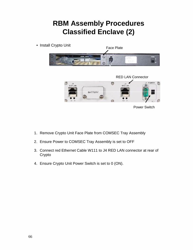
RBM Assembly ProceduresClassified Enclave (2)
• Install Crypto UnitFace Plate
RED LAN Connector
Power Switch
1. Remove Crypto Unit Face Plate from COMSEC Tray Assembly
2. Ensure Power to COMSEC Tray Assembly is set to OFF
3. Connect red Ethernet Cable W111 to J4 RED LAN connector at rear of Crypto
4. Ensure Crypto Unit Power Switch is set to 0 (ON).
67
RBM Assembly ProceduresClassified Enclave (3)
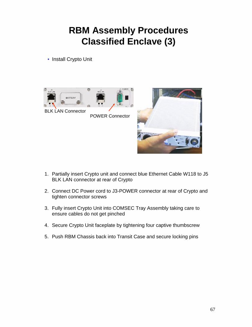
BLK LAN ConnectorPOWER Connector
• Install Crypto Unit
1. Partially insert Crypto unit and connect blue Ethernet Cable W118 to J5 BLK LAN connector at rear of Crypto
2. Connect DC Power cord to J3-POWER connector at rear of Crypto and
tighten connector screws
3. Fully insert Crypto Unit into COMSEC Tray Assembly taking care to ensure cables do not get pinched
4. Secure Crypto Unit faceplate by tightening four captive thumbscrew
5. Push RBM Chassis back into Transit Case and secure locking pins
68
RBM Assembly ProceduresClassified Enclave (4)
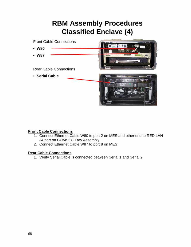
Front Cable Connections
• W80
• W87
Rear Cable Connections
• Serial Cable
Front Cable Connections 1. Connect Ethernet Cable W80 to port 2 on MES and other end to RED LAN
J4 port on COMSEC Tray Assembly 2. Connect Ethernet Cable W87 to port 8 on MES
Rear Cable Connections
1. Verify Serial Cable is connected between Serial 1 and Serial 2
69
RBM Assembly ProceduresClassified Enclave (5)
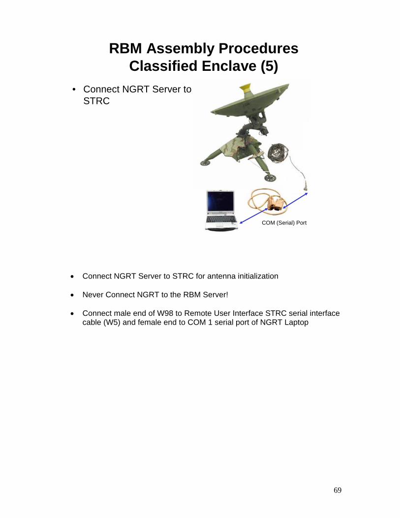
• Connect NGRT Server to STRC
COM (Serial) Port
• Connect NGRT Server to STRC for antenna initialization
• Never Connect NGRT to the RBM Server!
• Connect male end of W98 to Remote User Interface STRC serial interface cable (W5) and female end to COM 1 serial port of NGRT Laptop
70
RBM Assembly ProceduresClassified Enclave (6)
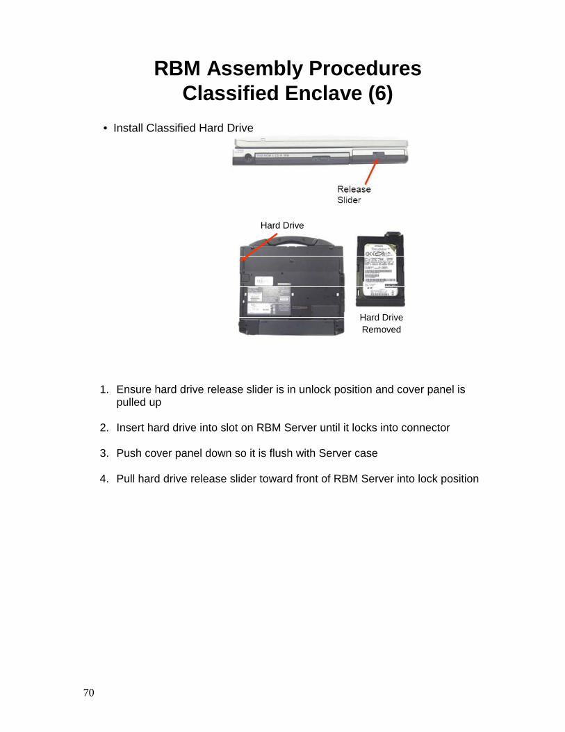
• Install Classified Hard Drive
Hard DriveRemoved
Hard Drive
1. Ensure hard drive release slider is in unlock position and cover panel is pulled up
2. Insert hard drive into slot on RBM Server until it locks into connector
3. Push cover panel down so it is flush with Server case
4. Pull hard drive release slider toward front of RBM Server into lock position
71
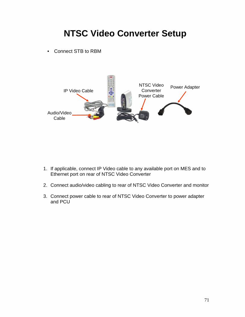
NTSC Video Converter Setup
• Connect STB to RBM
IP Video Cable
Audio/Video Cable
Power AdapterNTSC Video Converter
Power Cable
1. If applicable, connect IP Video cable to any available port on MES and to Ethernet port on rear of NTSC Video Converter
2. Connect audio/video cabling to rear of NTSC Video Converter and monitor
3. Connect power cable to rear of NTSC Video Converter to power adapter
and PCU
72
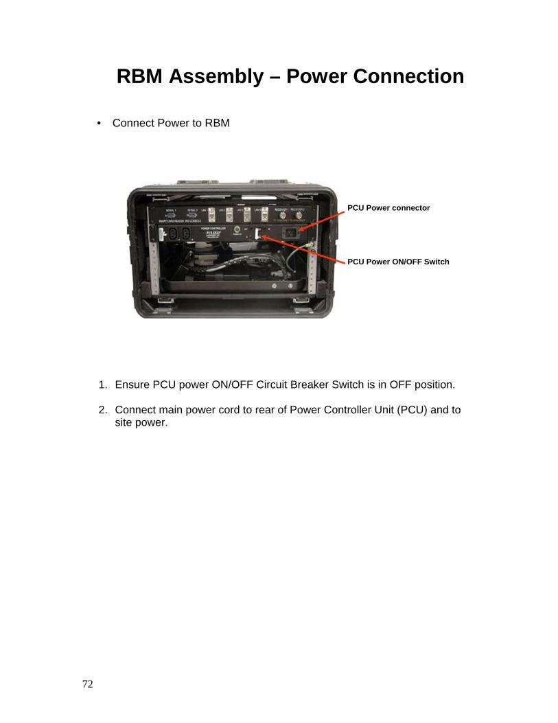
RBM Assembly – Power Connection
• Connect Power to RBM
PCU Power connector
PCU Power ON/OFF Switch
1. Ensure PCU power ON/OFF Circuit Breaker Switch is in OFF position.
2. Connect main power cord to rear of Power Controller Unit (PCU) and to site power.
73
RBM Assembly and Preparation for Use – Summary
• Review:Explain Removal of RBM Transit Case Covers
Explain RBM Setup

74
2-3 System Power Up
75
System Power Up Objectives
• Upon successful completion of this lesson, the student will be able to:Explain how to Power Up the NGRT
Explain how to Power Up the RBM
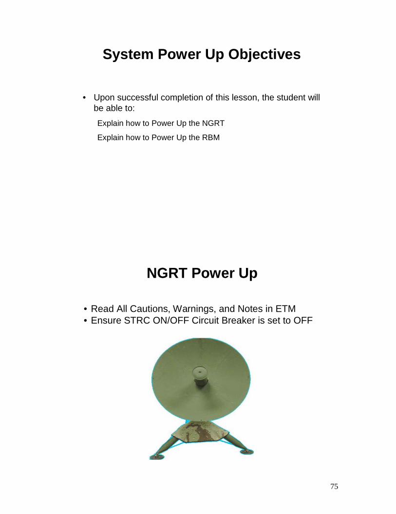
NGRT Power Up
• Read All Cautions, Warnings, and Notes in ETM • Ensure STRC ON/OFF Circuit Breaker is set to OFF
76
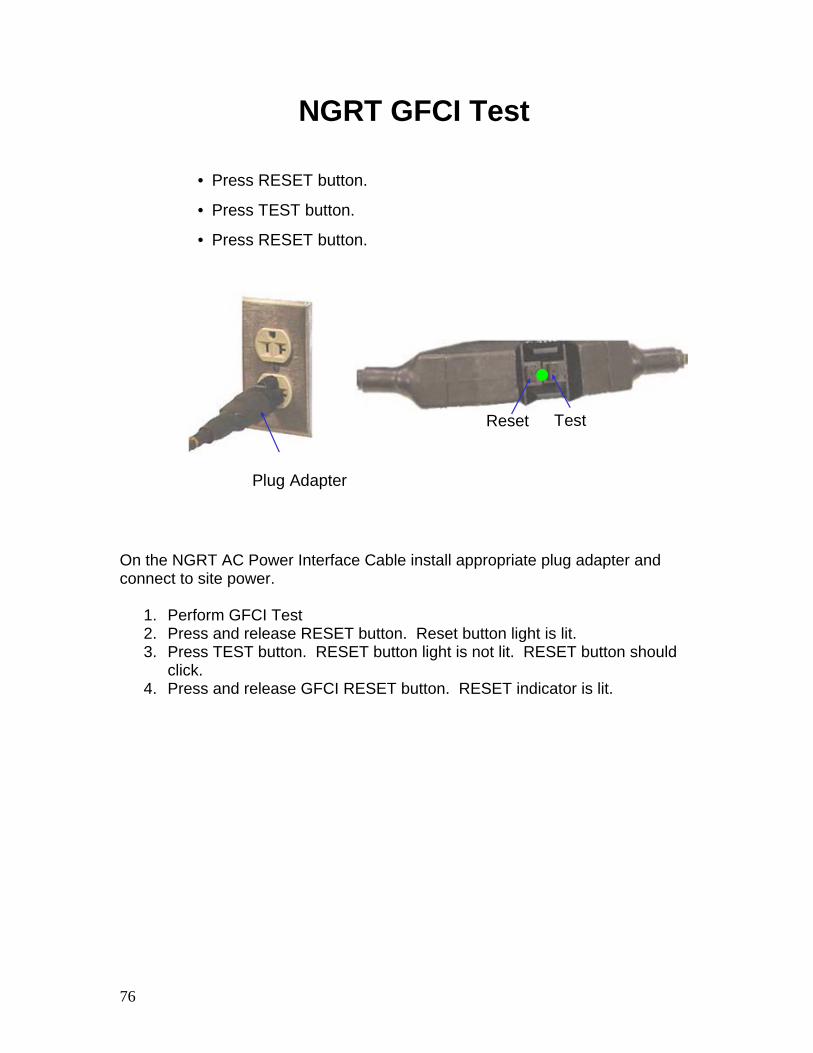
NGRT GFCI Test
Plug Adapter
• Press RESET button.
• Press TEST button.
• Press RESET button.
TestReset
On the NGRT AC Power Interface Cable install appropriate plug adapter and connect to site power.
1. Perform GFCI Test 2. Press and release RESET button. Reset button light is lit. 3. Press TEST button. RESET button light is not lit. RESET button should
click. 4. Press and release GFCI RESET button. RESET indicator is lit.
77
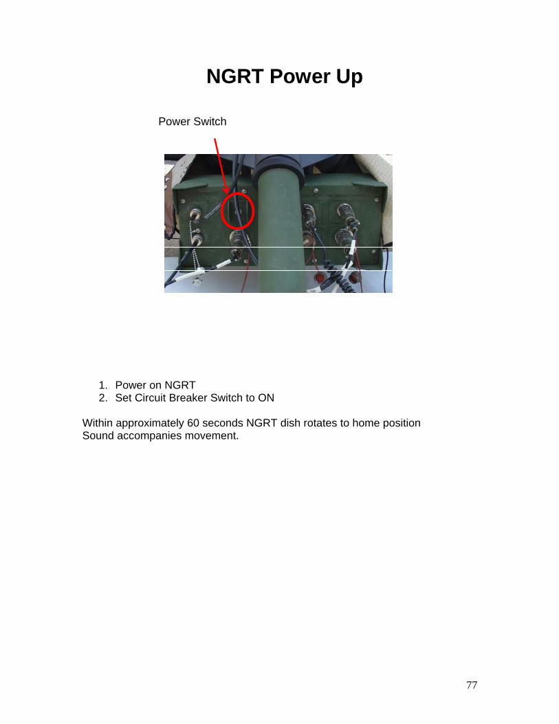
NGRT Power Up
Power Switch
1. Power on NGRT 2. Set Circuit Breaker Switch to ON
Within approximately 60 seconds NGRT dish rotates to home position Sound accompanies movement.
78
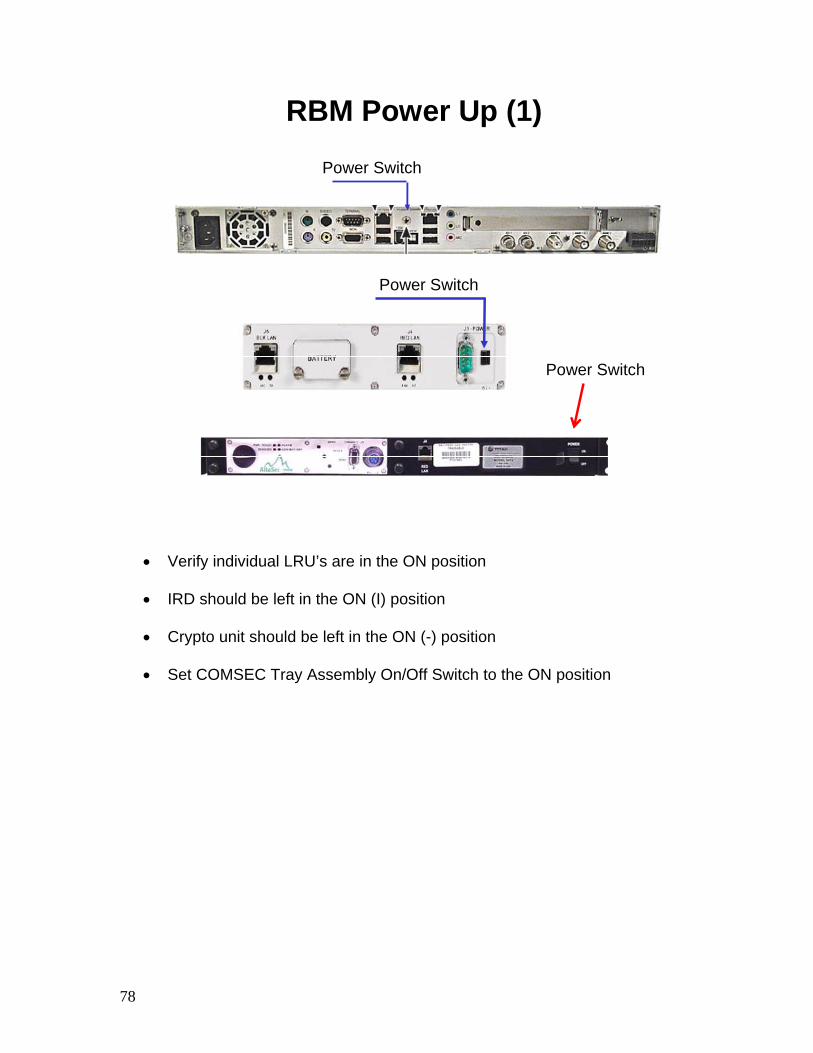
RBM Power Up (1)
Power Switch
Power Switch
Power Switch
• Verify individual LRU’s are in the ON position
• IRD should be left in the ON (I) position
• Crypto unit should be left in the ON (-) position
• Set COMSEC Tray Assembly On/Off Switch to the ON position
79
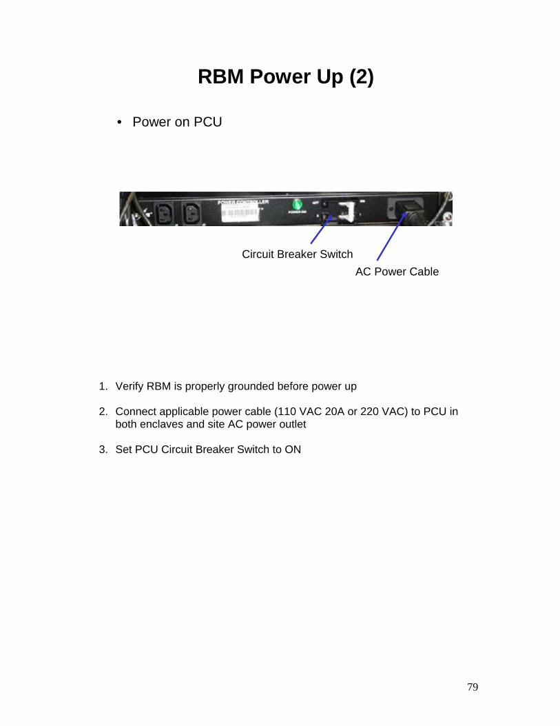
RBM Power Up (2)
• Power on PCU
Circuit Breaker SwitchAC Power Cable
1. Verify RBM is properly grounded before power up
2. Connect applicable power cable (110 VAC 20A or 220 VAC) to PCU in both enclaves and site AC power outlet
3. Set PCU Circuit Breaker Switch to ON

80
RBM Power Up (3)
• Verify system powers on
MES Power Indicator
PCU Power Indicator
• PCU POWER ON indicator is lit green
• MES Power indicator is green
81
Power on RBM Server
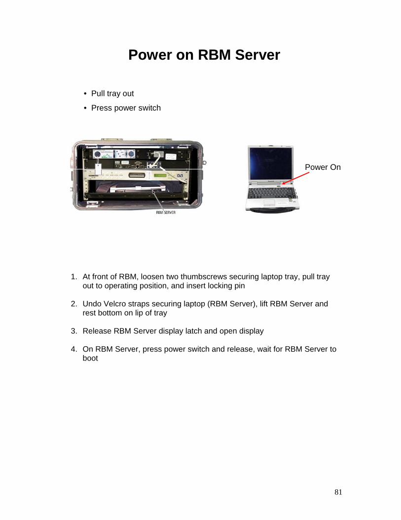
• Pull tray out
• Press power switch
Power On
1. At front of RBM, loosen two thumbscrews securing laptop tray, pull tray out to operating position, and insert locking pin
2. Undo Velcro straps securing laptop (RBM Server), lift RBM Server and
rest bottom on lip of tray
3. Release RBM Server display latch and open display
4. On RBM Server, press power switch and release, wait for RBM Server to boot
82
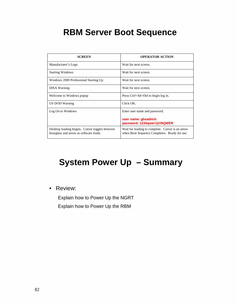
RBM Server Boot Sequence
SCREEN OPERATOR ACTION
Manufacturer’s Logo Wait for next screen.
Starting Windows Wait for next screen.
Windows 2000 Professional Starting Up Wait for next screen.
DISA Warning Wait for next screen.
Welcome to Windows popup Press Ctrl+Alt+Del to begin log in.
US DOD Warning Click OK.
Log On to Windows Enter user name and password.
user name: gbsadminpassword: 1234qwer!@#$QWER
Desktop loading begins. Cursor toggles between hourglass and arrow as software loads.
Wait for loading to complete. Cursor is an arrow when Boot Sequence Completes. Ready for use.
System Power Up – Summary
• Review:Explain how to Power Up the NGRT
Explain how to Power Up the RBM

TAB
Insert Tab # 3 Here
Next Generation Receive Terminal
(NGRT) Tear Down and Pack Up

84

85
NGRT Tear Down and Pack Up Objectives
• Upon successful completion of this lesson, the student will be able to:
Explain how to Tear Down the NGRT
Explain how to Pack Up the NGRT

86
Grounding/Stabilization and Shield Removal
• NGRT is in Home position
• Sandbags and Spikes
• STRC CB OFF
• Remove Grounding Kit
• Remove STRC Shield
1. Ensure NGRT is in Home position and properly powered down
2. Remove any sandbags and pull out anchoring spikes driven through each Foot Pad
3. Ensure STRC ON/OFF circuit breaker is set to OFF position
4. Remove Grounding Kit
5. Release bungees from Foot Pad hardware, unsnap STRC Shield, and
remove from Tripod
87
NGRT Cable and STRC Removal
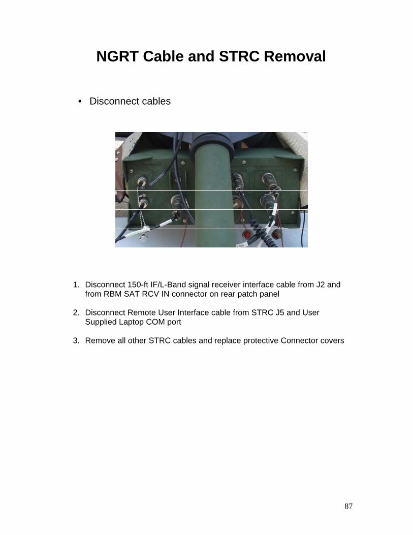
• Disconnect cables
1. Disconnect 150-ft IF/L-Band signal receiver interface cable from J2 and from RBM SAT RCV IN connector on rear patch panel
2. Disconnect Remote User Interface cable from STRC J5 and User
Supplied Laptop COM port
3. Remove all other STRC cables and replace protective Connector covers
88
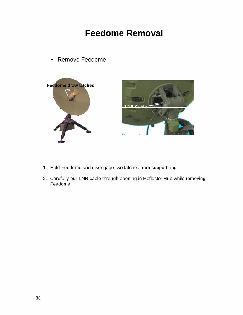
Feedome Removal
• Remove Feedome
Feedome draw latches
LNB Cable
1. Hold Feedome and disengage two latches from support ring
2. Carefully pull LNB cable through opening in Reflector Hub while removing Feedome

89
Reflector Assembly Removal
• Remove Reflector Petals
1. Release Reflector Petal latch from Hub and Petal
2. Unlatch Petal from adjacent Petals
3. Repeat for remaining petals
90
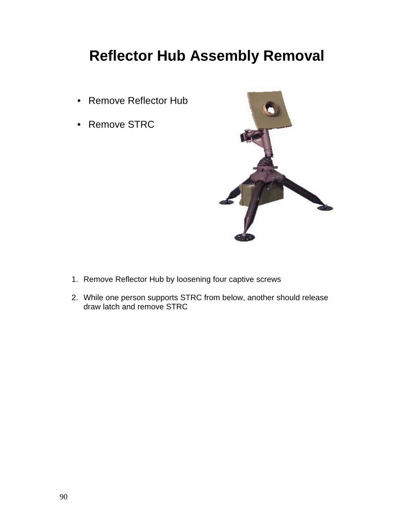
Reflector Hub Assembly Removal
• Remove Reflector Hub
• Remove STRC
1. Remove Reflector Hub by loosening four captive screws
2. While one person supports STRC from below, another should release draw latch and remove STRC

91
Pedestal/Motor Assembly Removal
• Remove Pedestal/Motor Assembly• Remove Legs from Tripod Hub
T-Bolt Band Clamp
1. Release T-bolt band clamp
2. Raise Pedestal/Motor Assembly from Tripod Hub
3. Tear down Tripod by rotating Leg retaining nuts counterclockwise and removing from Tripod Hub
92
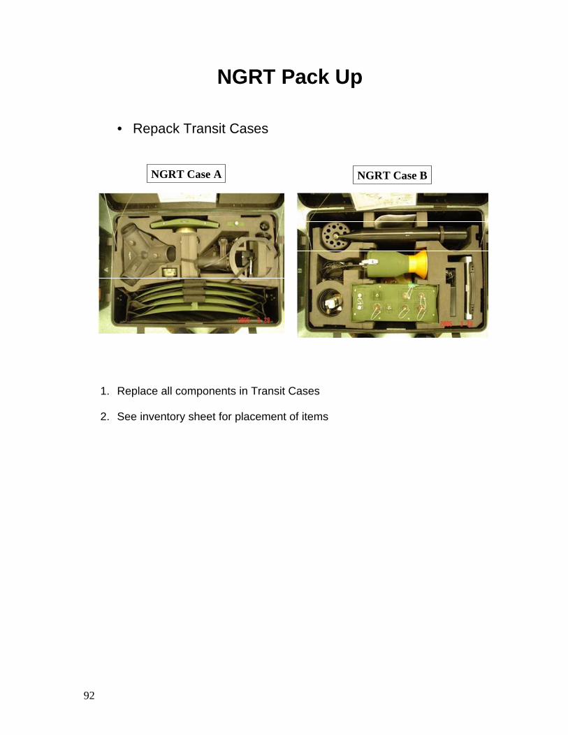
NGRT Pack Up
• Repack Transit Cases
NGRT Case A NGRT Case B
1. Replace all components in Transit Cases
2. See inventory sheet for placement of items
93
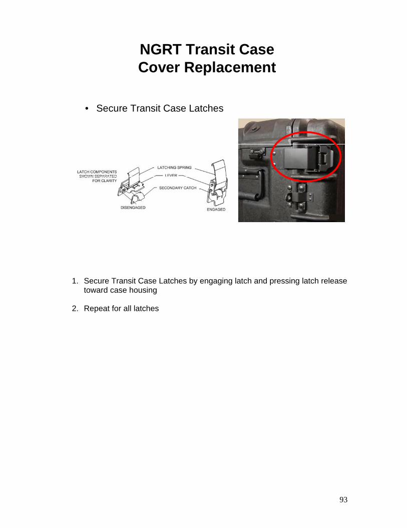
NGRT Transit Case Cover Replacement
• Secure Transit Case Latches
1. Secure Transit Case Latches by engaging latch and pressing latch release toward case housing
2. Repeat for all latches

94
NGRT Tear Down and Pack Up – Summary
• Review:
Explain how to Tear Down the NGRT
Explain how to Pack Up the NGRT

95
Receive Broadcast
Manager (RBM) Tear Down and Pack Up

96
RBM Tear Down Pack Up Objectives
• Upon successful completion of this lesson, the student will be able to:Explain how to tear down an RBM
Explain how to pack up an RBM
97
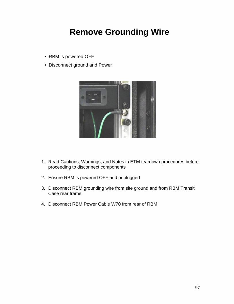
Remove Grounding Wire
• RBM is powered OFF
• Disconnect ground and Power
1. Read Cautions, Warnings, and Notes in ETM teardown procedures before proceeding to disconnect components
2. Ensure RBM is powered OFF and unplugged
3. Disconnect RBM grounding wire from site ground and from RBM Transit
Case rear frame
4. Disconnect RBM Power Cable W70 from rear of RBM
98
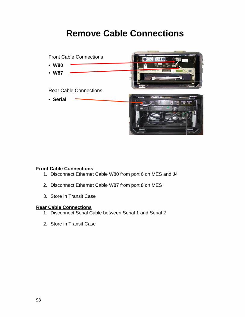
Remove Cable Connections
Front Cable Connections
• W80• W87
Rear Cable Connections
• Serial
Front Cable Connections 1. Disconnect Ethernet Cable W80 from port 6 on MES and J4
2. Disconnect Ethernet Cable W87 from port 8 on MES
3. Store in Transit Case
Rear Cable Connections
1. Disconnect Serial Cable between Serial 1 and Serial 2
2. Store in Transit Case
99
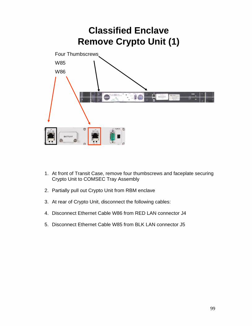
Classified EnclaveRemove Crypto Unit (1)
Four Thumbscrews
W85
W86
1. At front of Transit Case, remove four thumbscrews and faceplate securing Crypto Unit to COMSEC Tray Assembly
2. Partially pull out Crypto Unit from RBM enclave
3. At rear of Crypto Unit, disconnect the following cables:
4. Disconnect Ethernet Cable W86 from RED LAN connector J4
5. Disconnect Ethernet Cable W85 from BLK LAN connector J5
100
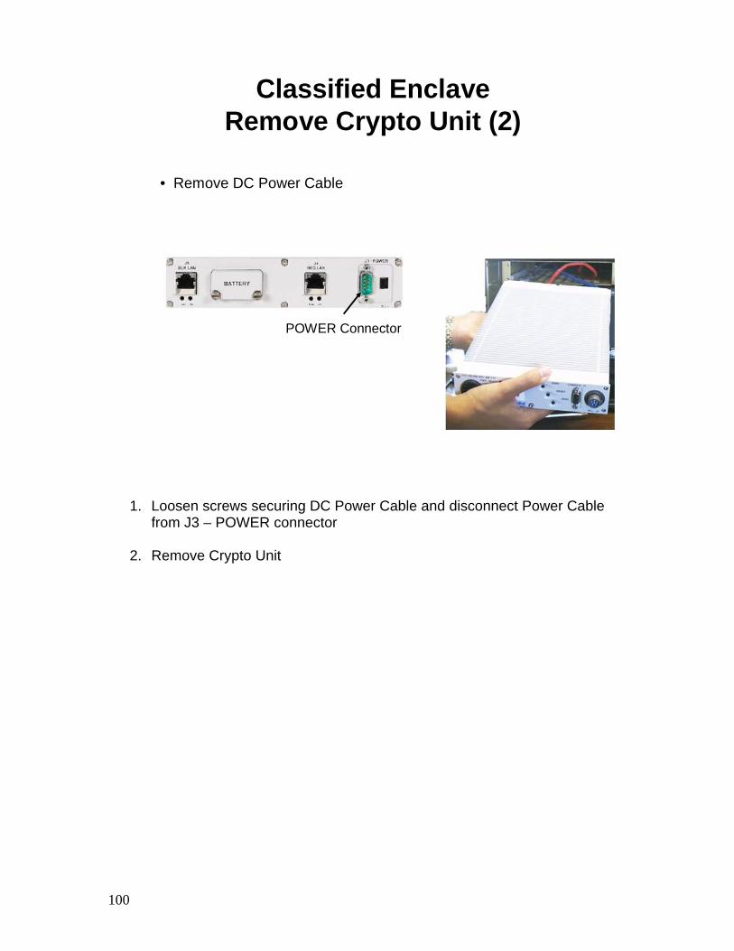
Classified EnclaveRemove Crypto Unit (2)
• Remove DC Power Cable
POWER Connector
1. Loosen screws securing DC Power Cable and disconnect Power Cable from J3 – POWER connector
2. Remove Crypto Unit
101
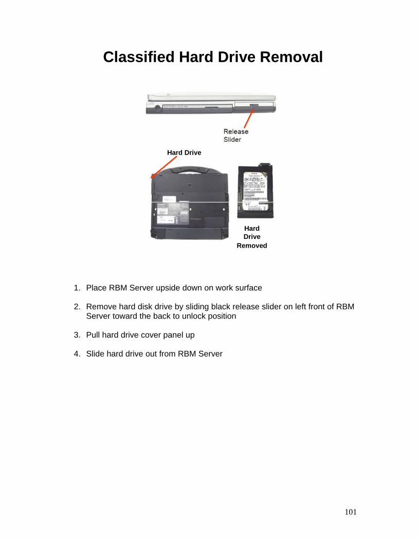
Classified Hard Drive Removal
Hard Drive
Removed
Hard Drive
1. Place RBM Server upside down on work surface
2. Remove hard disk drive by sliding black release slider on left front of RBM Server toward the back to unlock position
3. Pull hard drive cover panel up
4. Slide hard drive out from RBM Server
102
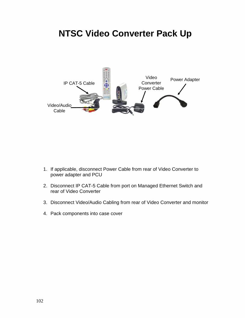
NTSC Video Converter Pack Up
IP CAT-5 Cable
Video/Audio Cable
Power AdapterVideo Converter
Power Cable
1. If applicable, disconnect Power Cable from rear of Video Converter to power adapter and PCU
2. Disconnect IP CAT-5 Cable from port on Managed Ethernet Switch and
rear of Video Converter
3. Disconnect Video/Audio Cabling from rear of Video Converter and monitor
4. Pack components into case cover
103
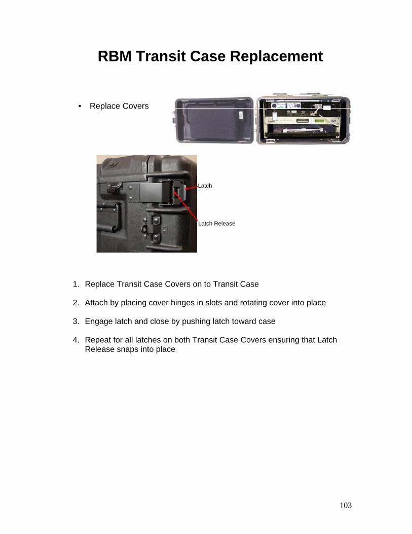
RBM Transit Case Replacement
• Replace Covers
Latch Release
Latch
1. Replace Transit Case Covers on to Transit Case
2. Attach by placing cover hinges in slots and rotating cover into place
3. Engage latch and close by pushing latch toward case
4. Repeat for all latches on both Transit Case Covers ensuring that Latch Release snaps into place

104
RBM Tear Down and Pack Up - Summary
• Review:Explain how to tear down an RBM
Explain how to pack up an RBM

TAB
Insert Tab # 4 Here
AN/TSR-8 Operations

106

107
4-1
Antenna Initialization
108
Antenna Initialization – Objectives
• Upon successful completion of this lesson, the student will be able to:
Explain how to initialize the NGRT Antenna using the NGRT Server
109
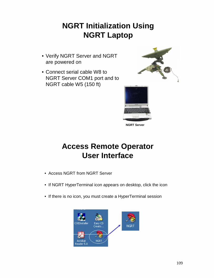
NGRT Initialization Using NGRT Laptop
• Verify NGRT Server and NGRT are powered on
• Connect serial cable W8 to NGRT Server COM1 port and to NGRT cable W5 (150 ft)
NGRT Server
Access Remote Operator User Interface
• Access NGRT from NGRT Server
• If NGRT HyperTerminal icon appears on desktop, click the icon
• If there is no icon, you must create a HyperTerminal session
110
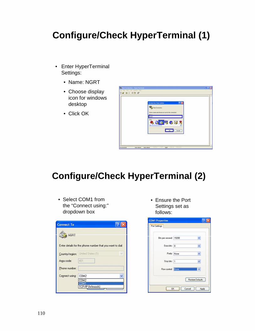
Configure/Check HyperTerminal (1)
• Enter HyperTerminal Settings:
• Name: NGRT
• Choose display icon for windows desktop
• Click OK
Configure/Check HyperTerminal (2)
Pedestal Assembly
• Select COM1 from the “Connect using:”dropdown box
• Ensure the Port Settings set as follows:
111
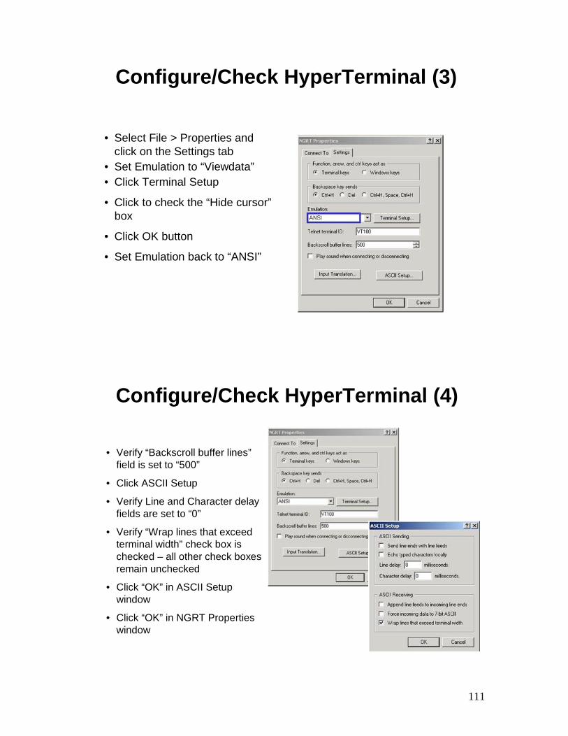
Configure/Check HyperTerminal (3)
• Select File > Properties and click on the Settings tab
• Set Emulation to “Viewdata”• Click Terminal Setup
• Click to check the “Hide cursor”box
• Click OK button
• Set Emulation back to “ANSI”
Configure/Check HyperTerminal (4)
• Verify “Backscroll buffer lines”field is set to “500”
• Click ASCII Setup
• Verify Line and Character delay fields are set to “0”
• Verify “Wrap lines that exceed terminal width” check box is checked – all other check boxes remain unchecked
• Click “OK” in ASCII Setup window
• Click “OK” in NGRT Properties window
112
Configure/Check HyperTerminal (5)
At the HyperTerminal main screen, click File and then:
• Save As, if this is a new NGRT HyperTerminal setup, then select Desktop as the directory and enter NGRT for file name. Finally, click Save
• Save if this is a modification of an existing NGRT HyperTerminalsetup
• The new settings will be saved and an icon will be available on the Windows desktop
113
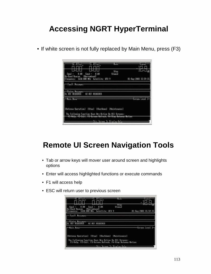
Accessing NGRT HyperTerminal
• If white screen is not fully replaced by Main Menu, press (F3)
Remote UI Screen Navigation Tools
• Tab or arrow keys will mover user around screen and highlights options
• Enter will access highlighted functions or execute commands
• F1 will access help
• ESC will return user to previous screen
114
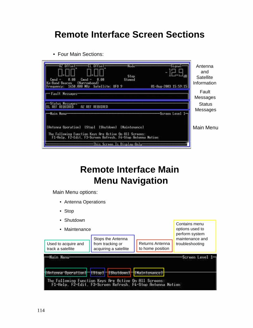
Remote Interface Screen Sections
• Four Main Sections:
Antenna and
Satellite Information
Fault Messages
Status Messages
Main Menu
Remote Interface MainMenu Navigation
Main Menu options:
• Antenna Operations
• Stop
• Shutdown
• Maintenance
Used to acquire and track a satellite
Stops the Antenna from tracking or acquiring a satellite
Returns Antenna to home position
Contains menu options used to perform system maintenance and troubleshooting
115
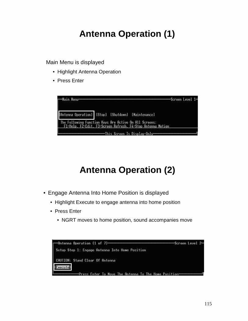
Antenna Operation (1)
Main Menu is displayed
• Highlight Antenna Operation
• Press Enter
Antenna Operation (2)
• Engage Antenna Into Home Position is displayed
• Highlight Execute to engage antenna into home position
• Press Enter
• NGRT moves to home position, sound accompanies move
116
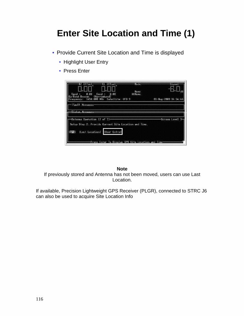
Enter Site Location and Time (1)
• Provide Current Site Location and Time is displayed
• Highlight User Entry
• Press Enter
Note If previously stored and Antenna has not been moved, users can use Last
Location. If available, Precision Lightweight GPS Receiver (PLGR), connected to STRC J6 can also be used to acquire Site Location Info
117
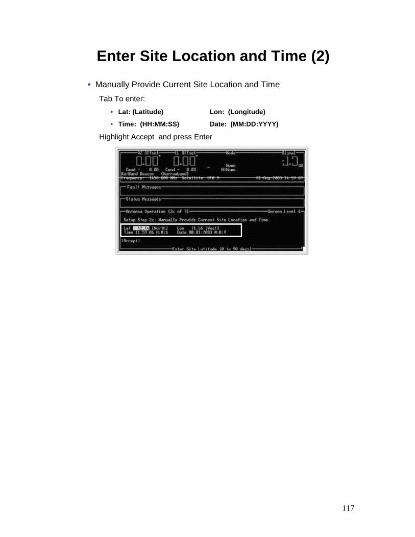
Enter Site Location and Time (2)• Manually Provide Current Site Location and Time
Tab To enter:
• Lat: (Latitude) Lon: (Longitude)
• Time: (HH:MM:SS) Date: (MM:DD:YYYY)
Highlight Accept and press Enter
118
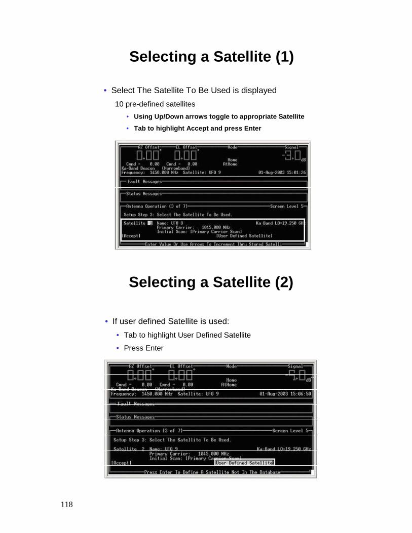
Selecting a Satellite (1)
• Select The Satellite To Be Used is displayed10 pre-defined satellites
• Using Up/Down arrows toggle to appropriate Satellite
• Tab to highlight Accept and press Enter
Selecting a Satellite (2)
• If user defined Satellite is used:• Tab to highlight User Defined Satellite
• Press Enter
119
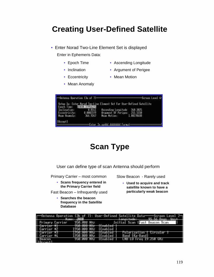
Creating User-Defined Satellite
• Enter Norad Two-Line Element Set is displayedEnter in Ephemeris Data:
• Epoch Time
• Inclination
• Eccentricity
• Mean Anomaly
• Ascending Longitude
• Argument of Perigee
• Mean Motion
Scan Type
Primary Carrier – most common• Scans frequency entered in
the Primary Carrier fieldFast Beacon – Infrequently used
• Searches the beacon frequency in the Satellite Database
Slow Beacon - Rarely used• Used to acquire and track
satellite known to have a particularly weak beacon
User can define type of scan Antenna should perform
120
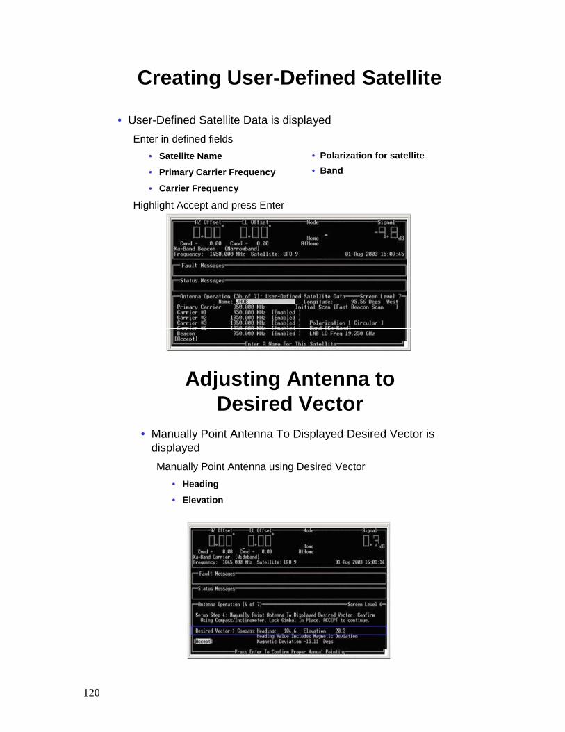
Creating User-Defined Satellite
• User-Defined Satellite Data is displayedEnter in defined fields
• Satellite Name
• Primary Carrier Frequency
• Carrier Frequency
Highlight Accept and press Enter
• Polarization for satellite• Band
Adjusting Antenna to Desired Vector
• Manually Point Antenna To Displayed Desired Vector is displayedManually Point Antenna using Desired Vector
• Heading
• Elevation
121
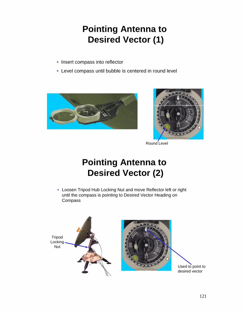
Pointing Antenna toDesired Vector (1)
• Insert compass into reflector
• Level compass until bubble is centered in round level
Round Level
Pointing Antenna toDesired Vector (2)
• Loosen Tripod Hub Locking Nut and move Reflector left or right until the compass is pointing to Desired Vector Heading on Compass
Tripod Locking
Nut
Used to point to desired vector
122
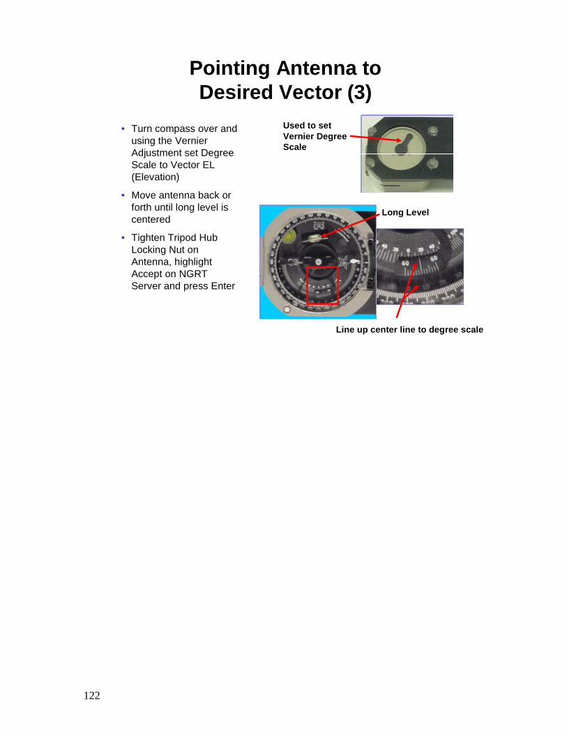
Pointing Antenna to Desired Vector (3)
• Turn compass over and using the VernierAdjustment set Degree Scale to Vector EL (Elevation)
• Move antenna back or forth until long level is centered
• Tighten Tripod Hub Locking Nut on Antenna, highlight Accept on NGRT Server and press Enter
Used to set Vernier Degree Scale
Line up center line to degree scale
Long Level
123
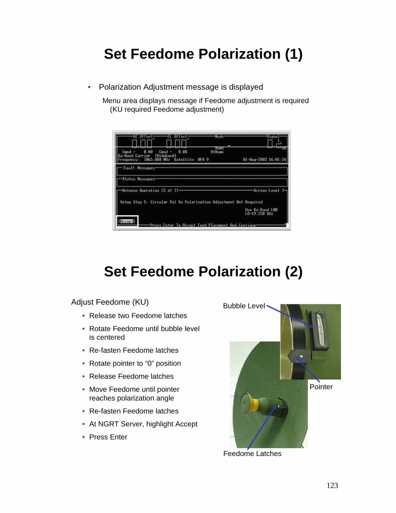
Set Feedome Polarization (1)
• Polarization Adjustment message is displayed
Menu area displays message if Feedome adjustment is required (KU required Feedome adjustment)
Set Feedome Polarization (2)
Adjust Feedome (KU)• Release two Feedome latches
• Rotate Feedome until bubble level is centered
• Re-fasten Feedome latches
• Rotate pointer to “0” position
• Release Feedome latches
• Move Feedome until pointer reaches polarization angle
• Re-fasten Feedome latches
• At NGRT Server, highlight Accept
• Press Enter
Feedome Latches
Bubble Level
Pointer
124
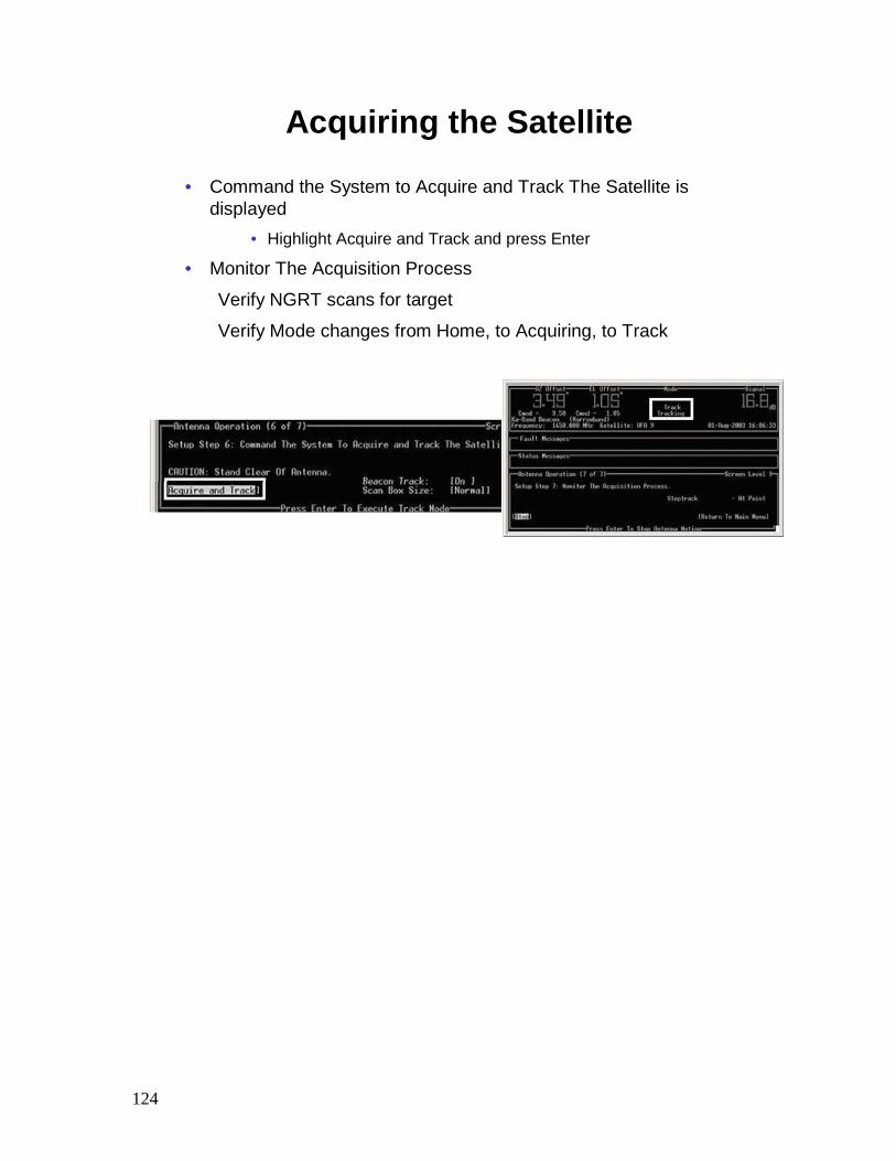
Acquiring the Satellite
• Command the System to Acquire and Track The Satellite is displayed
• Highlight Acquire and Track and press Enter
• Monitor The Acquisition Process
Verify NGRT scans for target
Verify Mode changes from Home, to Acquiring, to Track
125
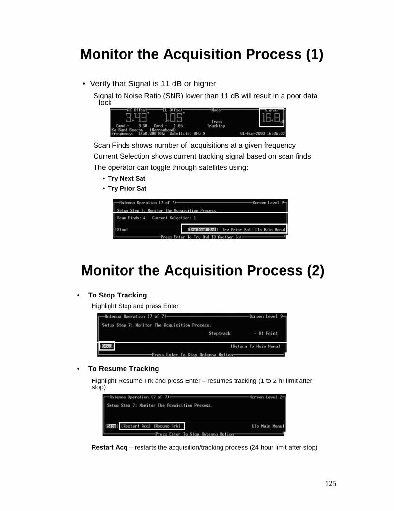
Monitor the Acquisition Process (1)
• Verify that Signal is 11 dB or higherSignal to Noise Ratio (SNR) lower than 11 dB will result in a poor data
lock
Scan Finds shows number of acquisitions at a given frequencyCurrent Selection shows current tracking signal based on scan finds The operator can toggle through satellites using:
• Try Next Sat• Try Prior Sat
• To Stop TrackingHighlight Stop and press Enter
• To Resume TrackingHighlight Resume Trk and press Enter – resumes tracking (1 to 2 hr limit after stop)
Restart Acq – restarts the acquisition/tracking process (24 hour limit after stop)
Monitor the Acquisition Process (2)
126
Antenna Initialization – Summary
• Review:
• Explain how to initialize the NGRT Antenna using the NGRT Server
127
Integrated Receiver Decoder
(IRD) Configuration
128
Configure IRD/Enable Smart Card Objectives
• Upon successful completion of this lesson, the student will be able to:
– Explain the IRD functions and characteristics
– Explain accessing IRD software
– Explain the IRD menu options
– Explain how to manually configure the IRD
– Explain the functions of the IRD Metrics menu
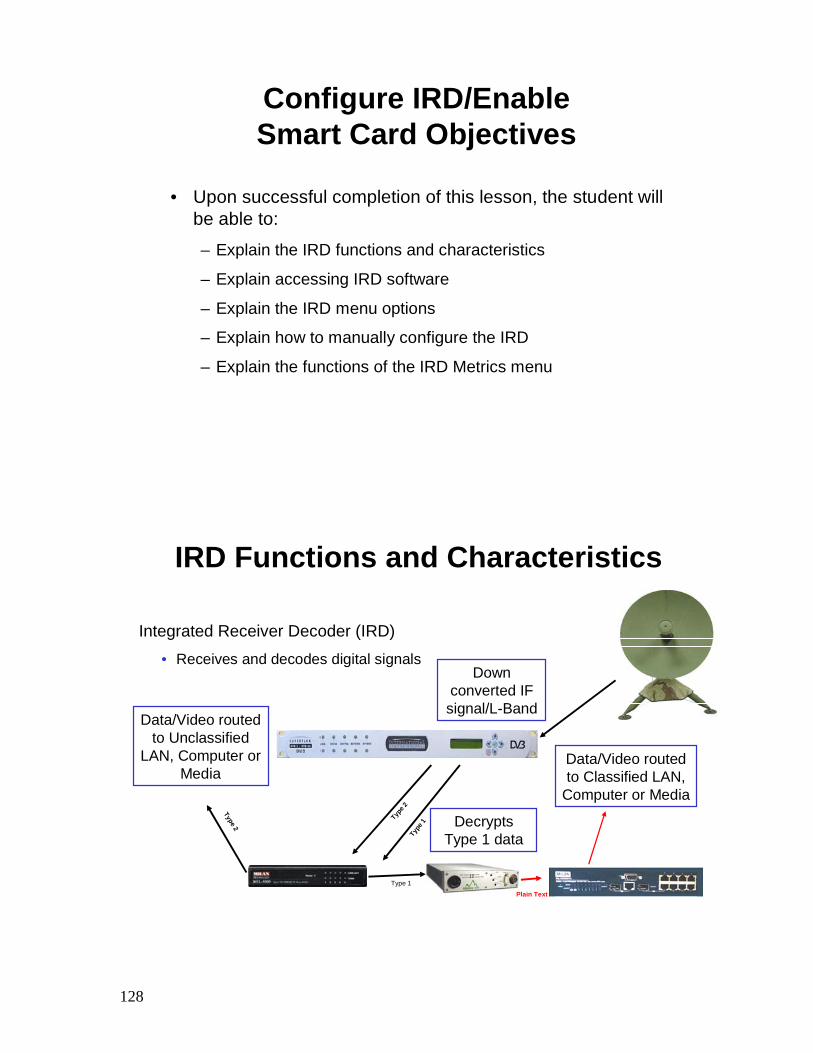
IRD Functions and Characteristics
Integrated Receiver Decoder (IRD)
• Receives and decodes digital signals
Type 2
Data/Video routed to Unclassified
LAN, Computer or Media
Down converted IF signal/L-Band
Type 1
Type
1 Decrypts Type 1 data
Plain Text
Data/Video routed to Classified LAN,
Computer or Media
Type 2
129
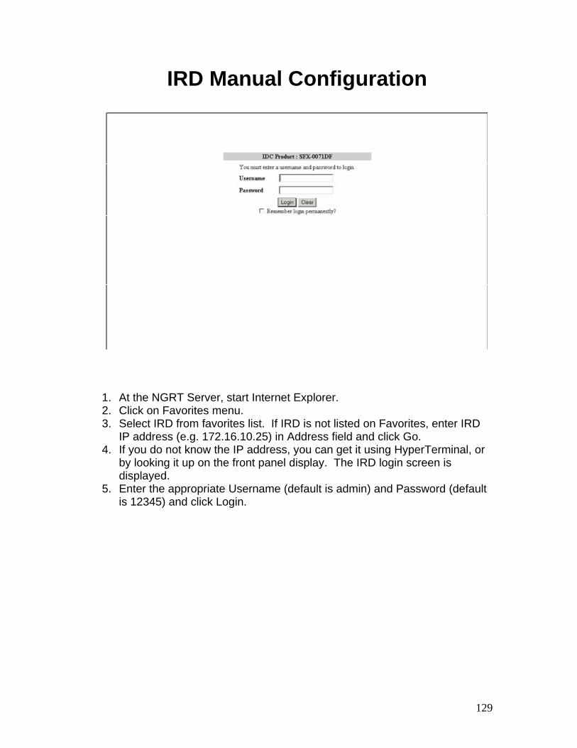
IRD Manual Configuration
1. At the NGRT Server, start Internet Explorer. 2. Click on Favorites menu. 3. Select IRD from favorites list. If IRD is not listed on Favorites, enter IRD
IP address (e.g. 172.16.10.25) in Address field and click Go. 4. If you do not know the IP address, you can get it using HyperTerminal, or
by looking it up on the front panel display. The IRD login screen is displayed.
5. Enter the appropriate Username (default is admin) and Password (default is 12345) and click Login.
130
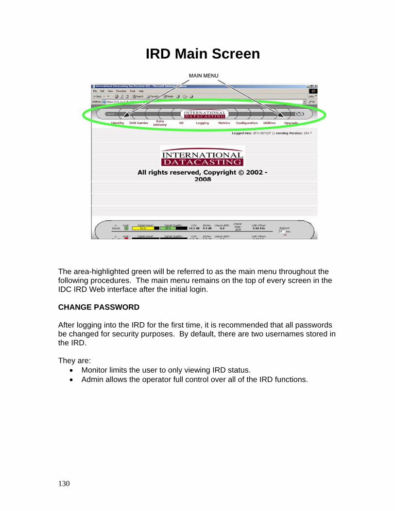
IRD Main Screen
The area-highlighted green will be referred to as the main menu throughout the following procedures. The main menu remains on the top of every screen in the IDC IRD Web interface after the initial login. CHANGE PASSWORD After logging into the IRD for the first time, it is recommended that all passwords be changed for security purposes. By default, there are two usernames stored in the IRD. They are:
• Monitor limits the user to only viewing IRD status. • Admin allows the operator full control over all of the IRD functions.
131
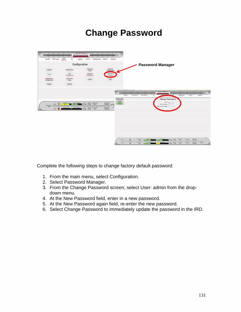
Change Password
Password Manager
Complete the following steps to change factory default password:
1. From the main menu, select Configuration. 2. Select Password Manager. 3. From the Change Password screen, select User: admin from the drop-
down menu. 4. At the New Password field, enter in a new password. 5. At the New Password again field, re-enter the new password. 6. Select Change Password to immediately update the password in the IRD.
132
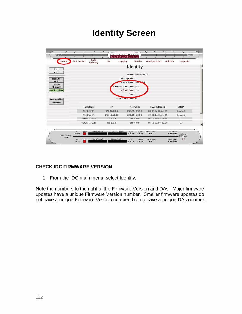
Identity Screen
CHECK IDC FIRMWARE VERSION
1. From the IDC main menu, select Identity. Note the numbers to the right of the Firmware Version and DAs. Major firmware updates have a unique Firmware Version number. Smaller firmware updates do not have a unique Firmware Version number, but do have a unique DAs number.
133
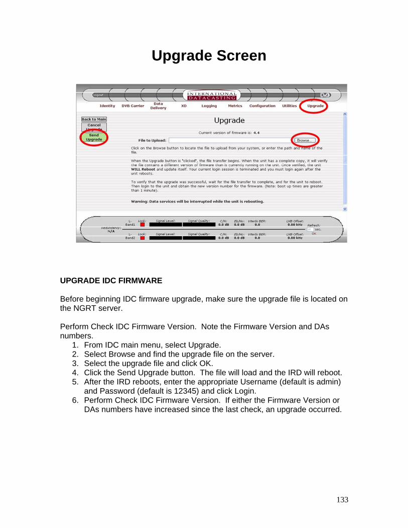
Upgrade Screen
UPGRADE IDC FIRMWARE Before beginning IDC firmware upgrade, make sure the upgrade file is located on the NGRT server. Perform Check IDC Firmware Version. Note the Firmware Version and DAs numbers.
1. From IDC main menu, select Upgrade. 2. Select Browse and find the upgrade file on the server. 3. Select the upgrade file and click OK. 4. Click the Send Upgrade button. The file will load and the IRD will reboot. 5. After the IRD reboots, enter the appropriate Username (default is admin)
and Password (default is 12345) and click Login. 6. Perform Check IDC Firmware Version. If either the Firmware Version or
DAs numbers have increased since the last check, an upgrade occurred.
134
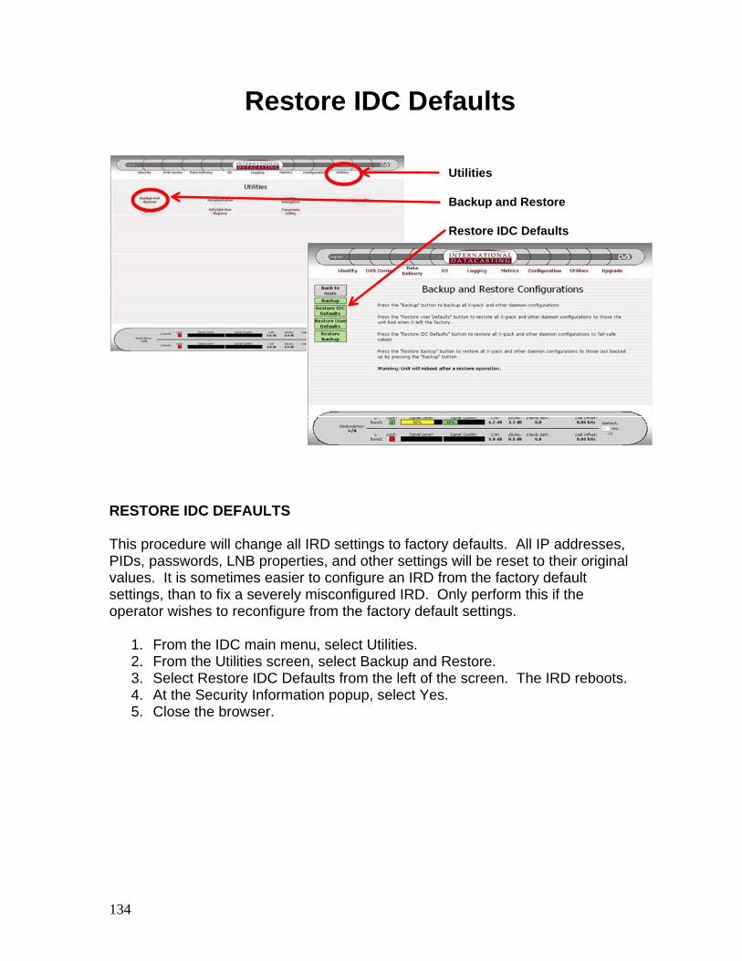
Restore IDC Defaults
Utilities
Backup and Restore
Restore IDC Defaults
RESTORE IDC DEFAULTS This procedure will change all IRD settings to factory defaults. All IP addresses, PIDs, passwords, LNB properties, and other settings will be reset to their original values. It is sometimes easier to configure an IRD from the factory default settings, than to fix a severely misconfigured IRD. Only perform this if the operator wishes to reconfigure from the factory default settings.
1. From the IDC main menu, select Utilities. 2. From the Utilities screen, select Backup and Restore. 3. Select Restore IDC Defaults from the left of the screen. The IRD reboots. 4. At the Security Information popup, select Yes. 5. Close the browser.
135
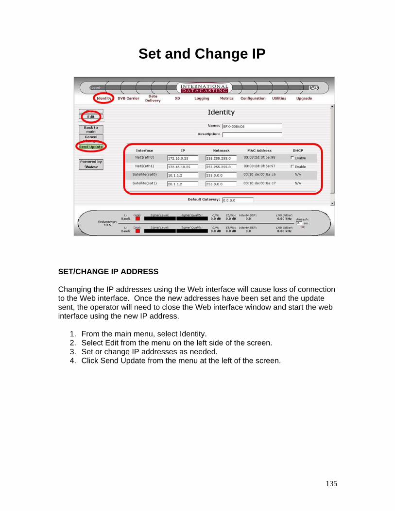
Set and Change IP
SET/CHANGE IP ADDRESS Changing the IP addresses using the Web interface will cause loss of connection to the Web interface. Once the new addresses have been set and the update sent, the operator will need to close the Web interface window and start the web interface using the new IP address.
1. From the main menu, select Identity. 2. Select Edit from the menu on the left side of the screen. 3. Set or change IP addresses as needed. 4. Click Send Update from the menu at the left of the screen.
136
Configure IRD (1)
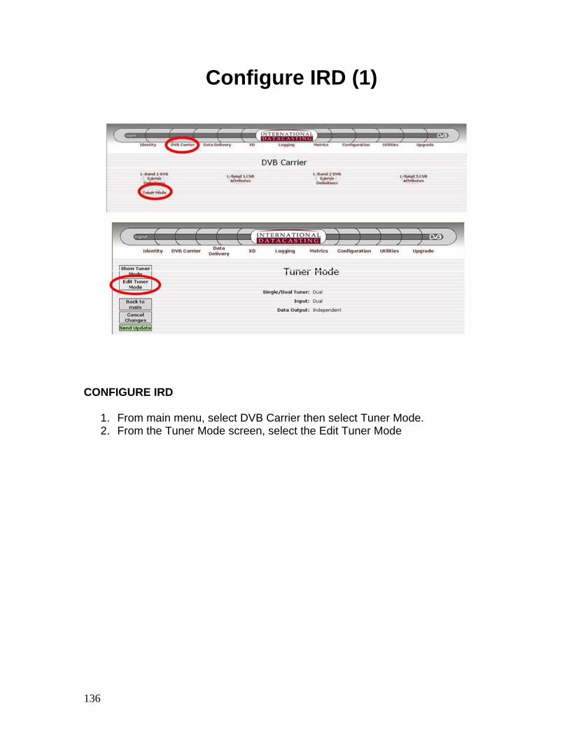
CONFIGURE IRD
1. From main menu, select DVB Carrier then select Tuner Mode. 2. From the Tuner Mode screen, select the Edit Tuner Mode
137
Configure IRD (2)
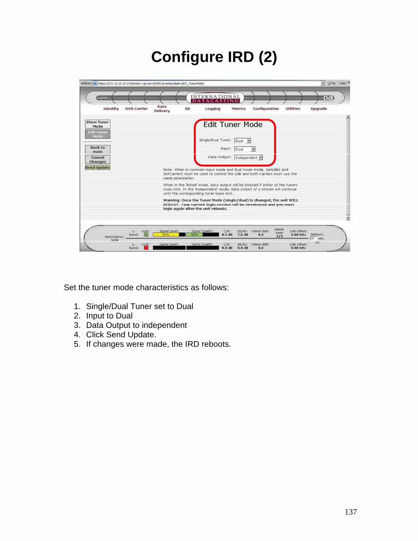
Set the tuner mode characteristics as follows:
1. Single/Dual Tuner set to Dual 2. Input to Dual 3. Data Output to independent 4. Click Send Update. 5. If changes were made, the IRD reboots.
138
Configure IRD (3)
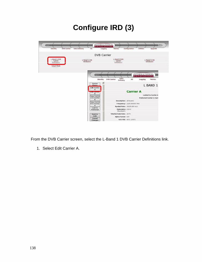
From the DVB Carrier screen, select the L-Band 1 DVB Carrier Definitions link.
1. Select Edit Carrier A.
139
Configure IRD (4)
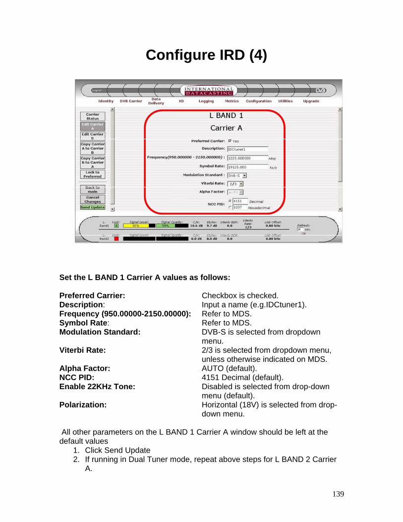
Set the L BAND 1 Carrier A values as follows: Preferred Carrier: Checkbox is checked. Description: Input a name (e.g.IDCtuner1). Frequency (950.00000-2150.00000): Refer to MDS. Symbol Rate: Refer to MDS. Modulation Standard: DVB-S is selected from dropdown menu. Viterbi Rate: 2/3 is selected from dropdown menu, unless otherwise indicated on MDS. Alpha Factor: AUTO (default). NCC PID: 4151 Decimal (default). Enable 22KHz Tone: Disabled is selected from drop-down menu (default). Polarization: Horizontal (18V) is selected from drop- down menu. All other parameters on the L BAND 1 Carrier A window should be left at the default values
1. Click Send Update 2. If running in Dual Tuner mode, repeat above steps for L BAND 2 Carrier
A.
140
Configure IRD (5)
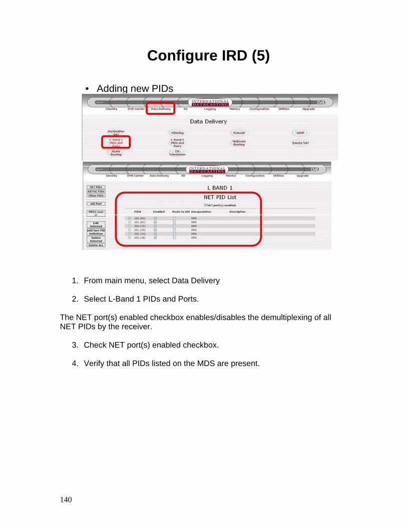
• Adding new PIDs
1. From main menu, select Data Delivery
2. Select L-Band 1 PIDs and Ports. The NET port(s) enabled checkbox enables/disables the demultiplexing of all NET PIDs by the receiver.
3. Check NET port(s) enabled checkbox.
4. Verify that all PIDs listed on the MDS are present.
141
Configure IRD (6)
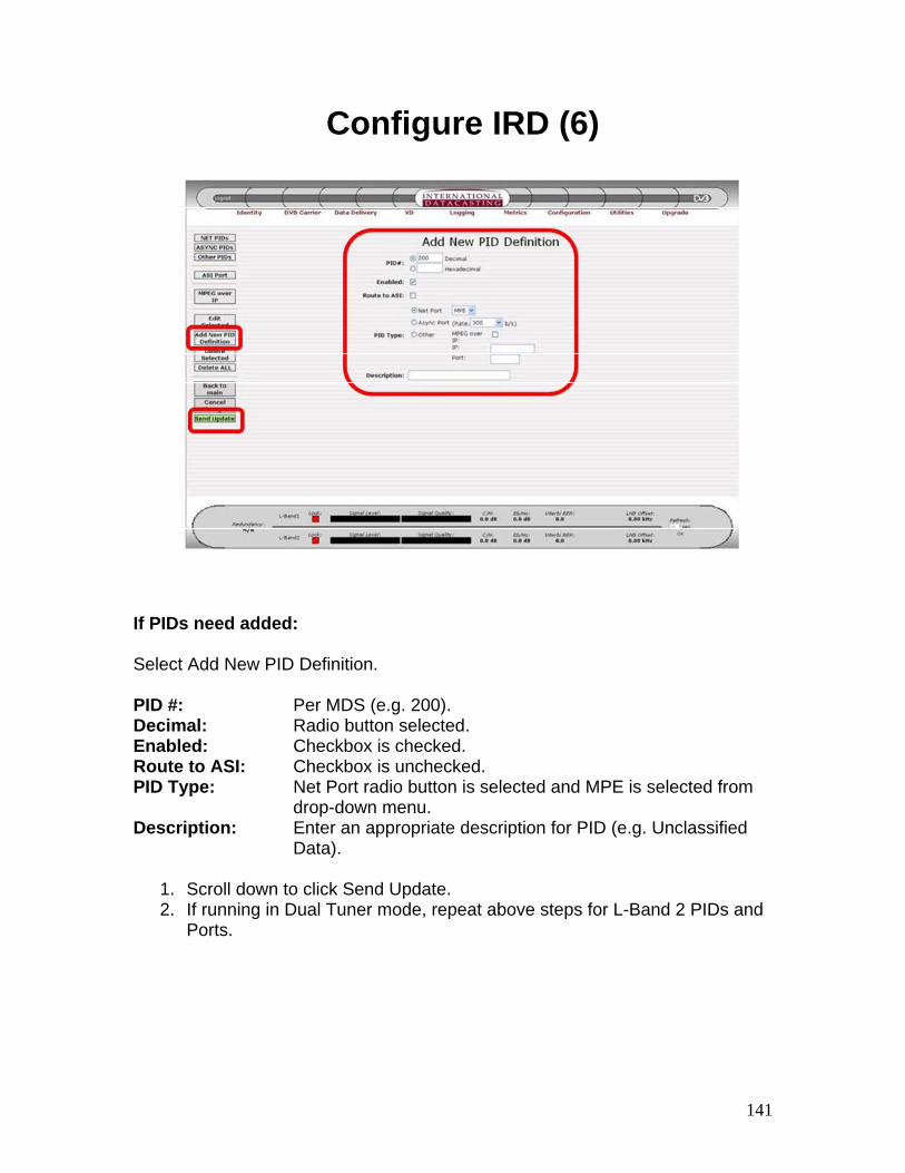
If PIDs need added: Select Add New PID Definition. PID #: Per MDS (e.g. 200). Decimal: Radio button selected. Enabled: Checkbox is checked. Route to ASI: Checkbox is unchecked. PID Type: Net Port radio button is selected and MPE is selected from drop-down menu. Description: Enter an appropriate description for PID (e.g. Unclassified Data).
1. Scroll down to click Send Update. 2. If running in Dual Tuner mode, repeat above steps for L-Band 2 PIDs and
Ports.
142
Configure IRD (7)
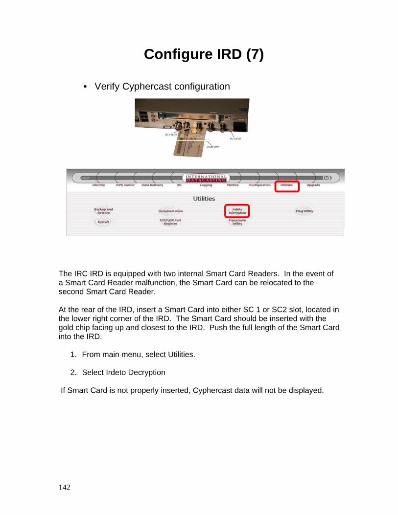
• Verify Cyphercast configuration
The IRC IRD is equipped with two internal Smart Card Readers. In the event of a Smart Card Reader malfunction, the Smart Card can be relocated to the second Smart Card Reader. At the rear of the IRD, insert a Smart Card into either SC 1 or SC2 slot, located in the lower right corner of the IRD. The Smart Card should be inserted with the gold chip facing up and closest to the IRD. Push the full length of the Smart Card into the IRD.
1. From main menu, select Utilities.
2. Select Irdeto Decryption If Smart Card is not properly inserted, Cyphercast data will not be displayed.
143
Configure IRD (8)
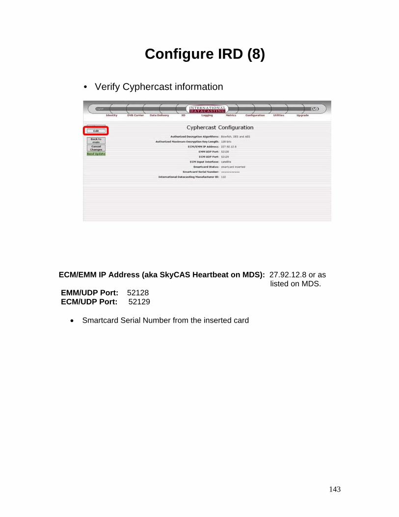
• Verify Cyphercast information
ECM/EMM IP Address (aka SkyCAS Heartbeat on MDS): 27.92.12.8 or as listed on MDS. EMM/UDP Port: 52128 ECM/UDP Port: 52129
• Smartcard Serial Number from the inserted card
144
Configure IRD (9)
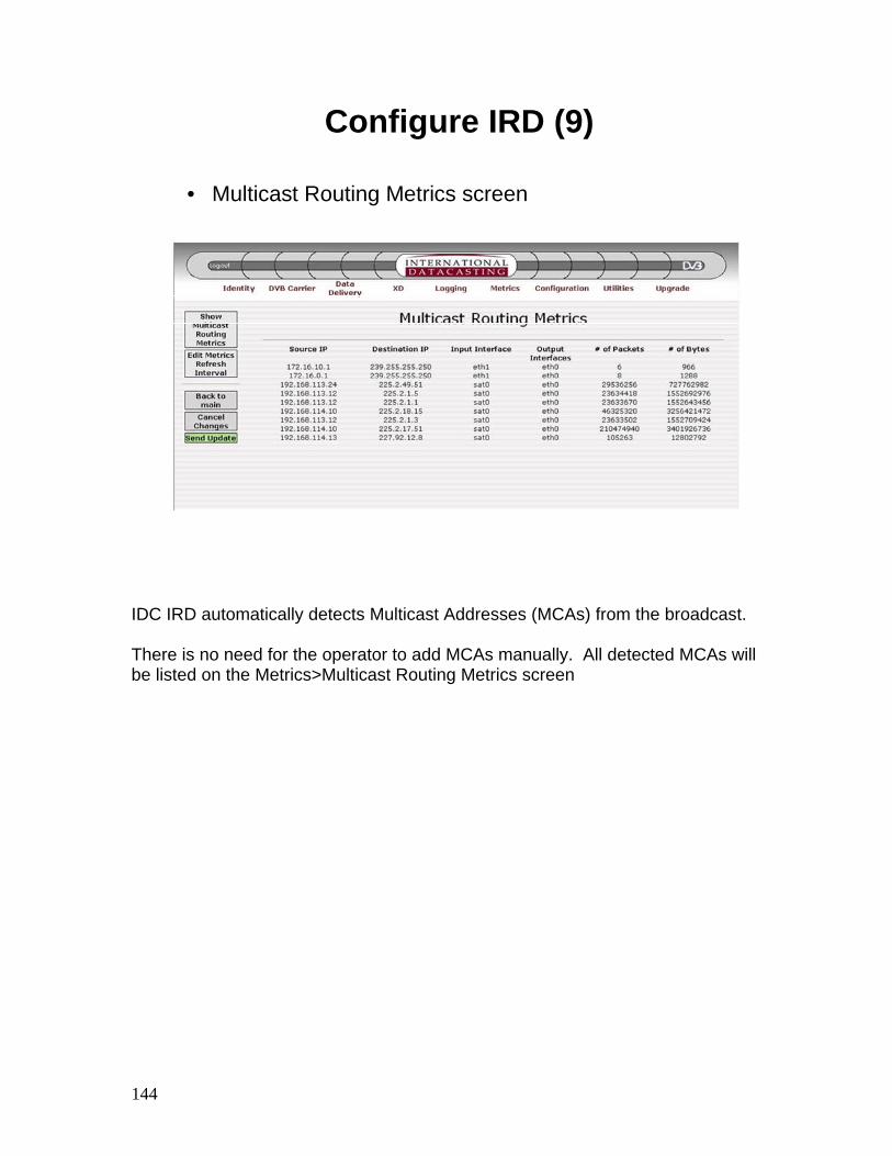
• Multicast Routing Metrics screen
IDC IRD automatically detects Multicast Addresses (MCAs) from the broadcast. There is no need for the operator to add MCAs manually. All detected MCAs will be listed on the Metrics>Multicast Routing Metrics screen
145
Configure IRD (10)
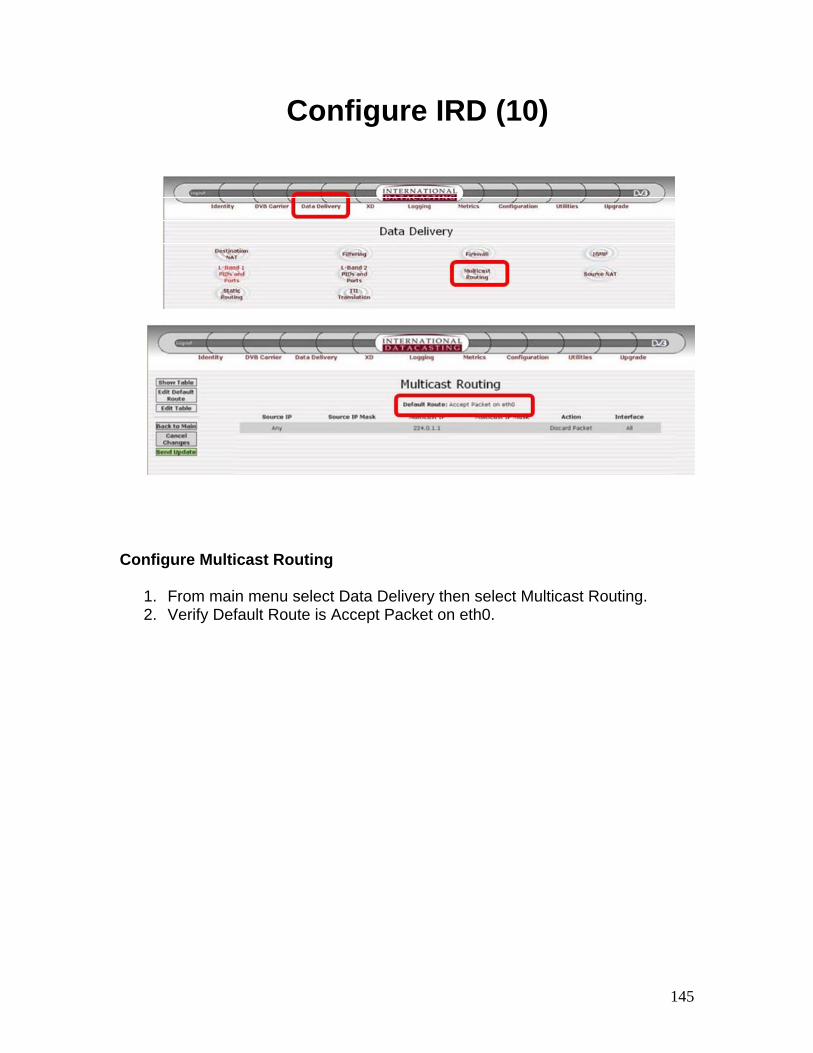
Configure Multicast Routing
1. From main menu select Data Delivery then select Multicast Routing. 2. Verify Default Route is Accept Packet on eth0.
146
Configure IRD (11)
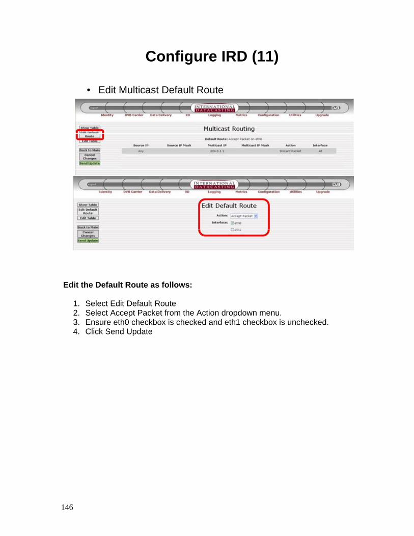
• Edit Multicast Default Route
Edit the Default Route as follows:
1. Select Edit Default Route 2. Select Accept Packet from the Action dropdown menu. 3. Ensure eth0 checkbox is checked and eth1 checkbox is unchecked. 4. Click Send Update
147
Configure IRD (12)
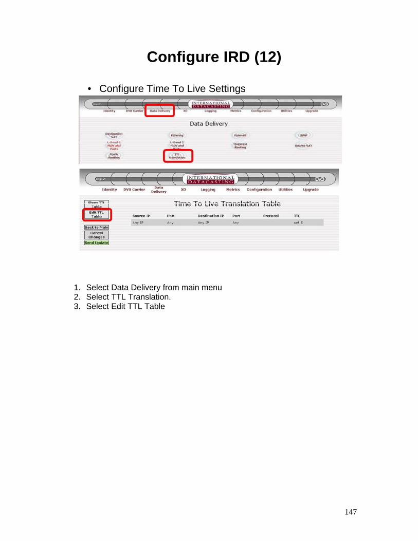
• Configure Time To Live Settings
1. Select Data Delivery from main menu 2. Select TTL Translation. 3. Select Edit TTL Table
148
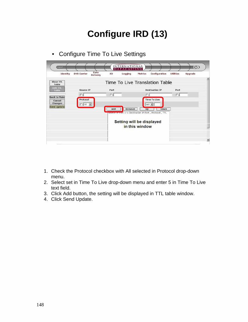
Configure IRD (13)
• Configure Time To Live Settings
1. Check the Protocol checkbox with All selected in Protocol drop-down menu.
2. Select set in Time To Live drop-down menu and enter 5 in Time To Live text field.
3. Click Add button, the setting will be displayed in TTL table window. 4. Click Send Update.
149
Preparation for Auto Tuning (1)
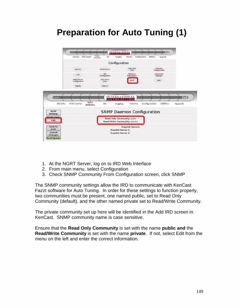
1. At the NGRT Server, log on to IRD Web Interface 2. From main menu, select Configuration 3. Check SNMP Community From Configuration screen, click SNMP
The SNMP community settings allow the IRD to communicate with KenCast Fazzt software for Auto Tuning. In order for these settings to function properly, two communities must be present, one named public, set to Read Only Community (default), and the other named private set to Read/Write Community. The private community set up here will be identified in the Add IRD screen in KenCast. SNMP community name is case sensitive. Ensure that the Read Only Community is set with the name public and the Read/Write Community is set with the name private. If not, select Edit from the menu on the left and enter the correct information.
150
Preparation for Auto Tuning (2)
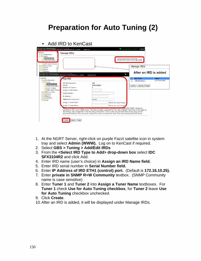
• Add IRD to KenCast
1. At the NGRT Server, right-click on purple Fazzt satellite icon in system tray and select Admin (WWW). Log on to KenCast if required.
2. Select GBS > Tuning > Add/Edit IRDs 3. From the <Select IRD Type to Add> drop-down box select IDC
SFX3104R2 and click Add. 4. Enter IRD name (user’s choice) in Assign an IRD Name field. 5. Enter IRD serial number in Serial Number field. 6. Enter IP Address of IRD ETH1 (control) port. (Default is 172.16.10.25). 7. Enter private in SNMP R+W Community textbox. (SNMP Community
name is case sensitive) 8. Enter Tuner 1 and Tuner 2 into Assign a Tuner Name textboxes. For
Tuner 1 check Use for Auto Tuning checkbox, for Tuner 2 leave Use for Auto Tuning checkbox unchecked.
9. Click Create. 10. After an IRD is added, it will be displayed under Manage IRDs.
151
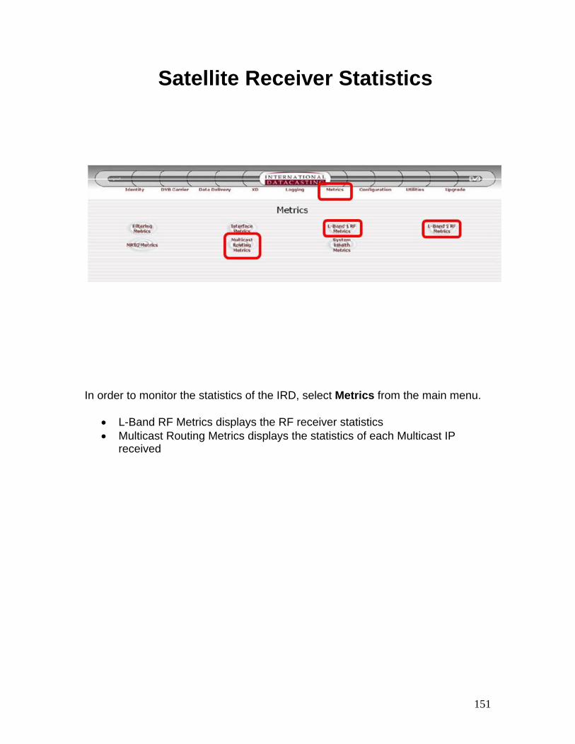
Satellite Receiver Statistics
In order to monitor the statistics of the IRD, select Metrics from the main menu.
• L-Band RF Metrics displays the RF receiver statistics • Multicast Routing Metrics displays the statistics of each Multicast IP
received
152
IRD Configuration – Summary
• Review:
– Explain the IRD functions and characteristics
– Explain accessing IRD software
– Explain the IRD menu options
– Explain how to configure the IRD
– Explain the functions of the IRD Metrics menu
153
Crypto Configuration
154
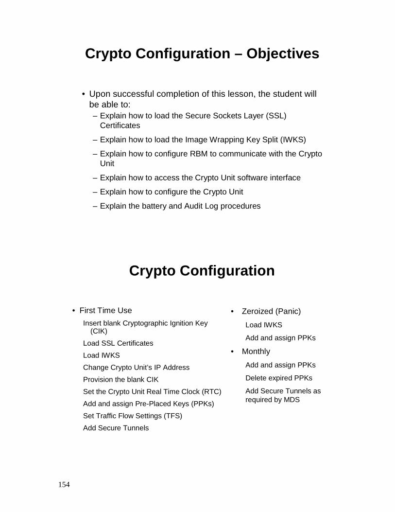
Crypto Configuration – Objectives
• Upon successful completion of this lesson, the student will be able to:– Explain how to load the Secure Sockets Layer (SSL)
Certificates
– Explain how to load the Image Wrapping Key Split (IWKS)
– Explain how to configure RBM to communicate with the Crypto Unit
– Explain how to access the Crypto Unit software interface
– Explain how to configure the Crypto Unit
– Explain the battery and Audit Log procedures
Crypto Configuration
• First Time UseInsert blank Cryptographic Ignition Key
(CIK)
Load SSL Certificates
Load IWKS
Change Crypto Unit’s IP Address
Provision the blank CIK
Set the Crypto Unit Real Time Clock (RTC)
Add and assign Pre-Placed Keys (PPKs)
Set Traffic Flow Settings (TFS)
Add Secure Tunnels
• Zeroized (Panic)
Load IWKS
Add and assign PPKs
• MonthlyAdd and assign PPKs
Delete expired PPKs
Add Secure Tunnels as required by MDS
155
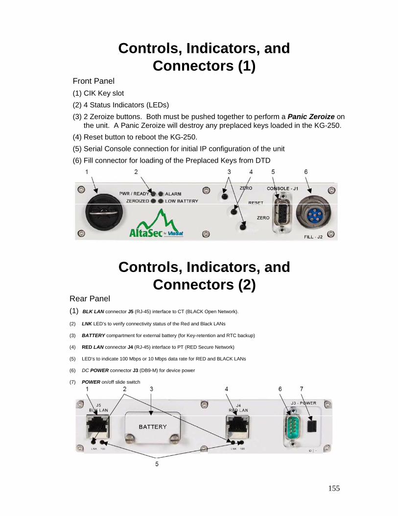
Controls, Indicators, and Connectors (1)
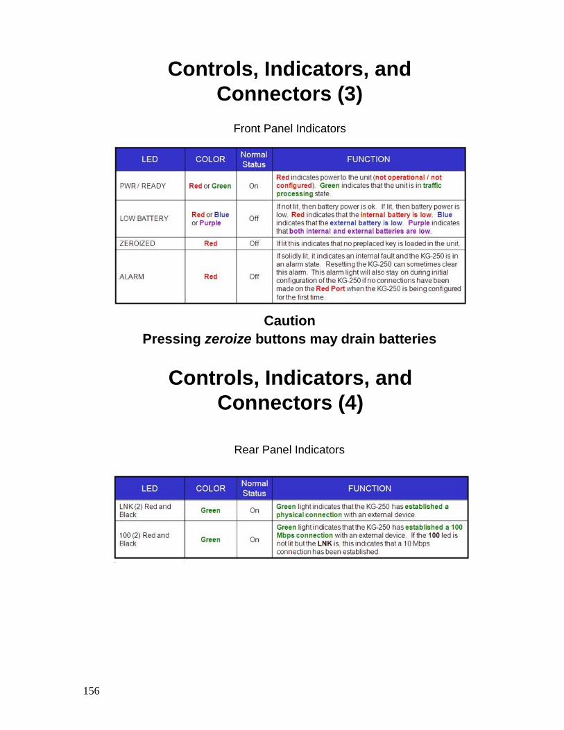
Front Panel(1) CIK Key slot(2) 4 Status Indicators (LEDs)(3) 2 Zeroize buttons. Both must be pushed together to perform a Panic Zeroize on
the unit. A Panic Zeroize will destroy any preplaced keys loaded in the KG-250.(4) Reset button to reboot the KG-250.(5) Serial Console connection for initial IP configuration of the unit(6) Fill connector for loading of the Preplaced Keys from DTD
Rear Panel(1) BLK LAN connector J5 (RJ-45) interface to CT (BLACK Open Network).
(2) LNK LED’s to verify connectivity status of the Red and Black LANs
(3) BATTERY compartment for external battery (for Key-retention and RTC backup)
(4) RED LAN connector J4 (RJ-45) interface to PT (RED Secure Network)
(5) LED’s to indicate 100 Mbps or 10 Mbps data rate for RED and BLACK LANs
(6) DC POWER connector J3 (DB9-M) for device power
(7) POWER on/off slide switch
Controls, Indicators, and Connectors (2)
156
Controls, Indicators, and Connectors (3)
Front Panel Indicators
CautionPressing zeroize buttons may drain batteries
Controls, Indicators, and Connectors (4)
Rear Panel Indicators
157
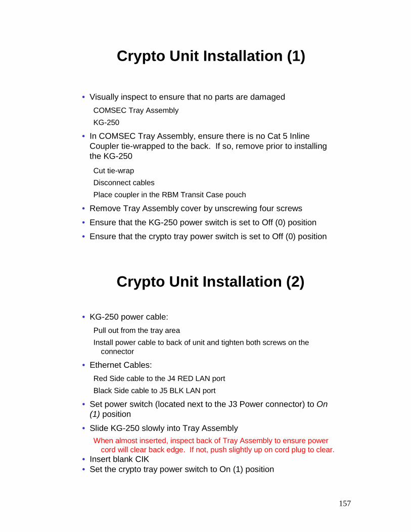
Crypto Unit Installation (1)
• Visually inspect to ensure that no parts are damagedCOMSEC Tray AssemblyKG-250
• In COMSEC Tray Assembly, ensure there is no Cat 5 Inline Coupler tie-wrapped to the back. If so, remove prior to installing the KG-250
Cut tie-wrapDisconnect cablesPlace coupler in the RBM Transit Case pouch
• Remove Tray Assembly cover by unscrewing four screws
• Ensure that the KG-250 power switch is set to Off (0) position
• Ensure that the crypto tray power switch is set to Off (0) position
• KG-250 power cable:Pull out from the tray areaInstall power cable to back of unit and tighten both screws on the
connector
• Ethernet Cables:Red Side cable to the J4 RED LAN portBlack Side cable to J5 BLK LAN port
• Set power switch (located next to the J3 Power connector) to On (1) position
• Slide KG-250 slowly into Tray AssemblyWhen almost inserted, inspect back of Tray Assembly to ensure power
cord will clear back edge. If not, push slightly up on cord plug to clear.• Insert blank CIK• Set the crypto tray power switch to On (1) position
Crypto Unit Installation (2)
158
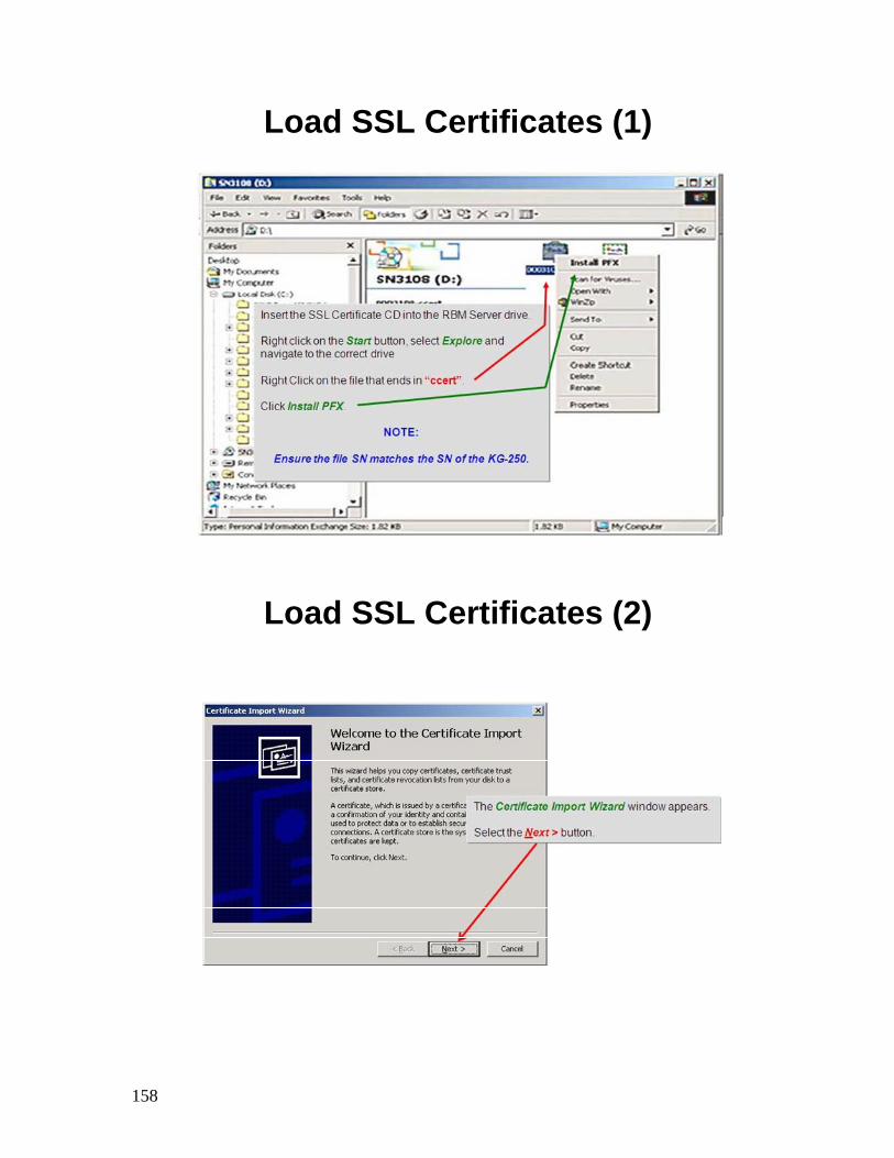
Load SSL Certificates (1)
Load SSL Certificates (2)
159
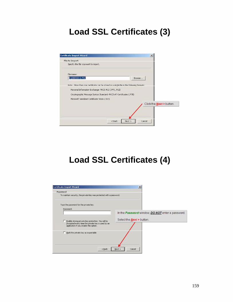
Load SSL Certificates (3)
Load SSL Certificates (4)
160
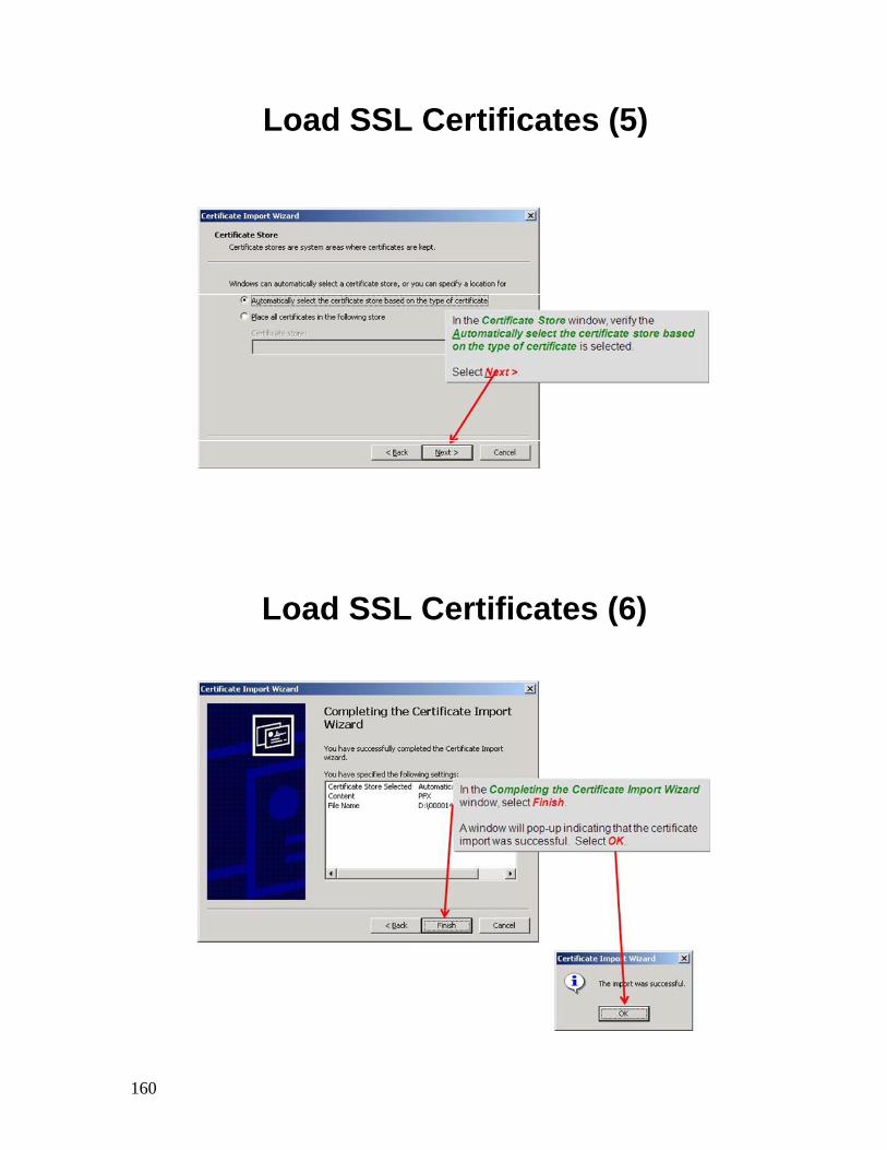
Load SSL Certificates (5)
Load SSL Certificates (6)
161
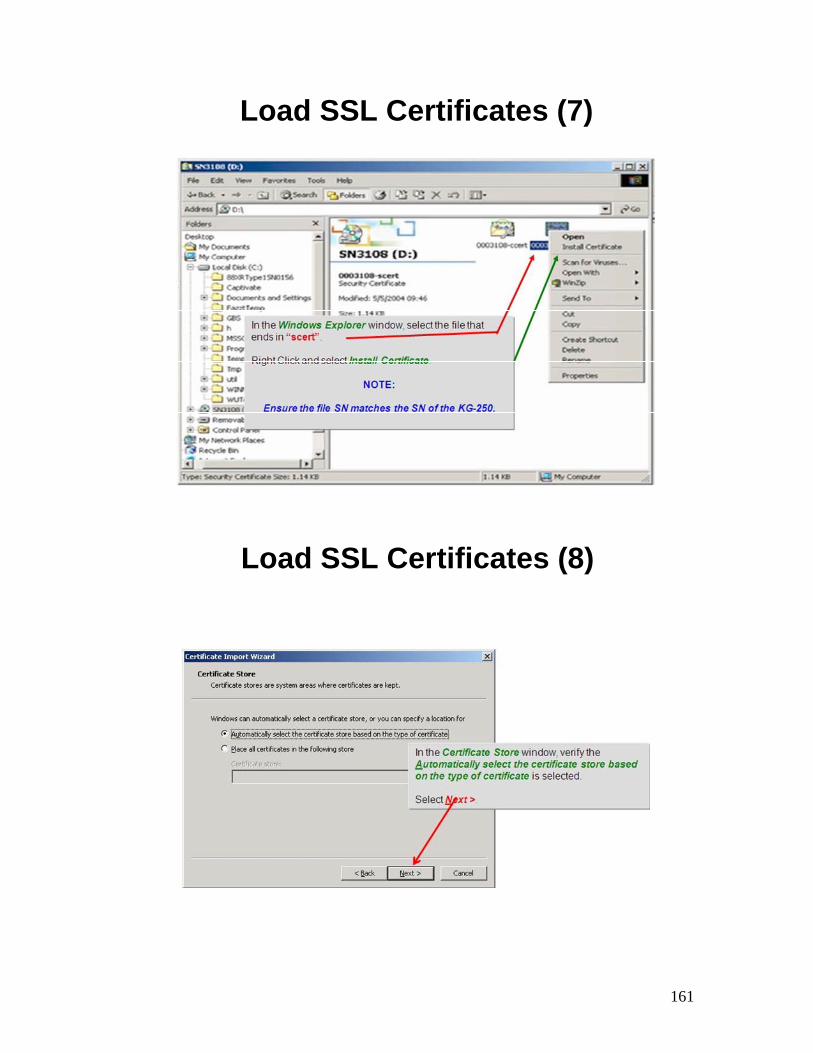
Load SSL Certificates (7)
Load SSL Certificates (8)
162
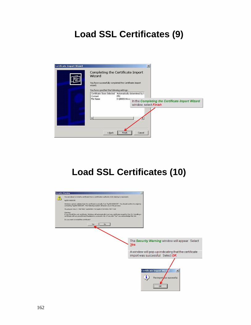
Load SSL Certificates (9)
Load SSL Certificates (10)
163
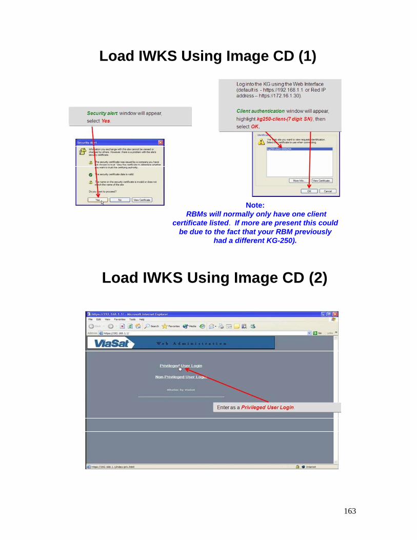
Load IWKS Using Image CD (1)
Note:RBMs will normally only have one client
certificate listed. If more are present this could be due to the fact that your RBM previously
had a different KG-250).
Load IWKS Using Image CD (2)
164
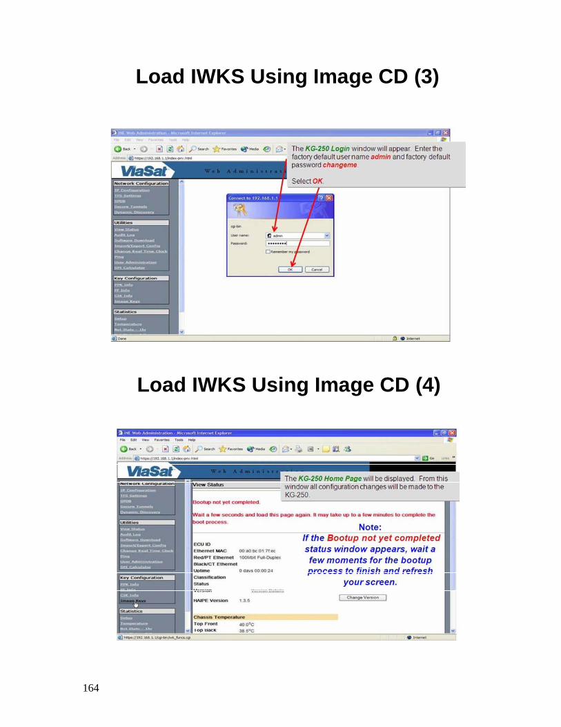
Load IWKS Using Image CD (3)
Load IWKS Using Image CD (4)
165
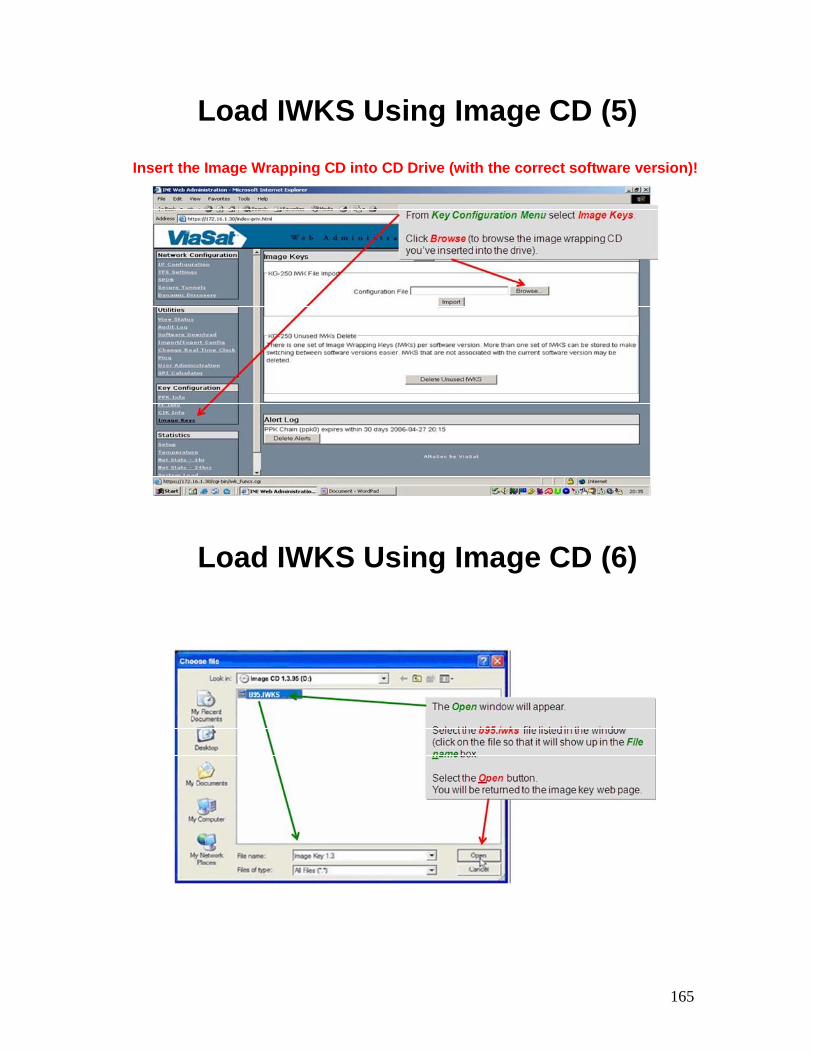
Load IWKS Using Image CD (5)
Insert the Image Wrapping CD into CD Drive (with the correct software version)!
Load IWKS Using Image CD (6)
166
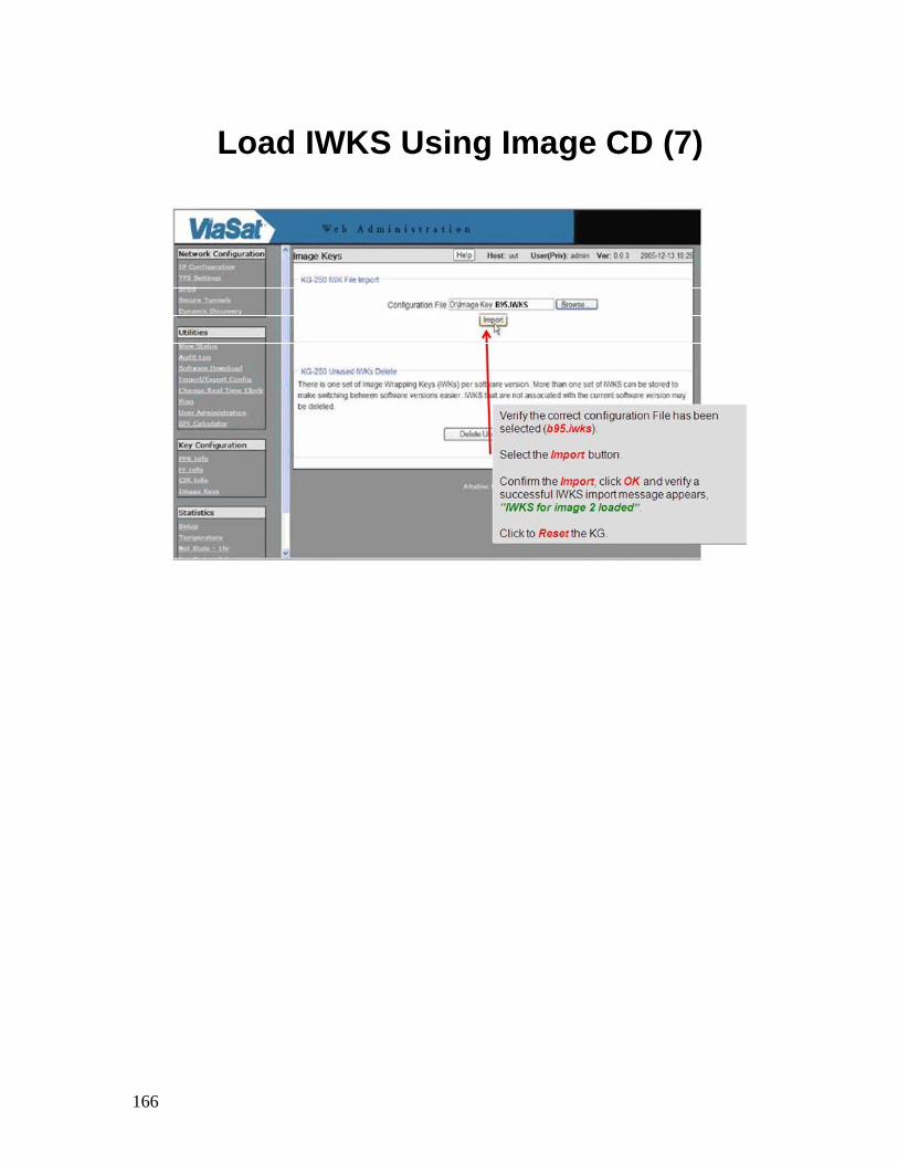
Load IWKS Using Image CD (7)
167
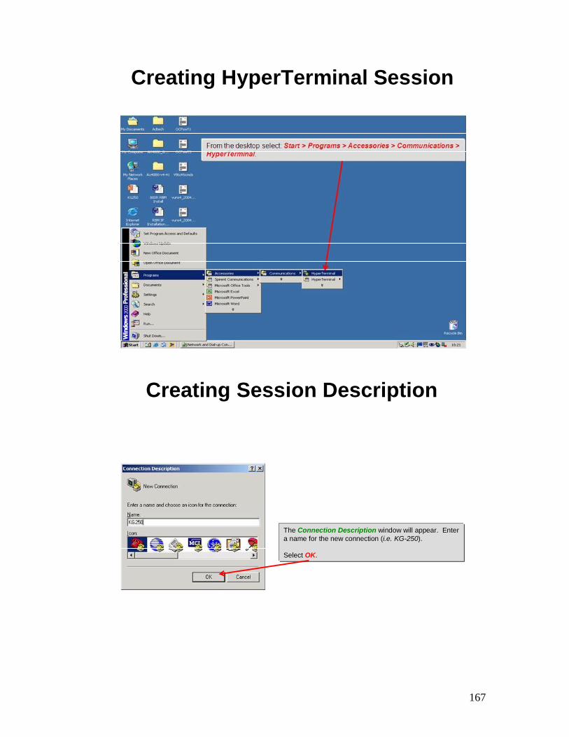
Creating HyperTerminal Session
Creating Session Description
The Connection Description window will appear. Enter a name for the new connection (i.e. KG-250).
Select OK.
168
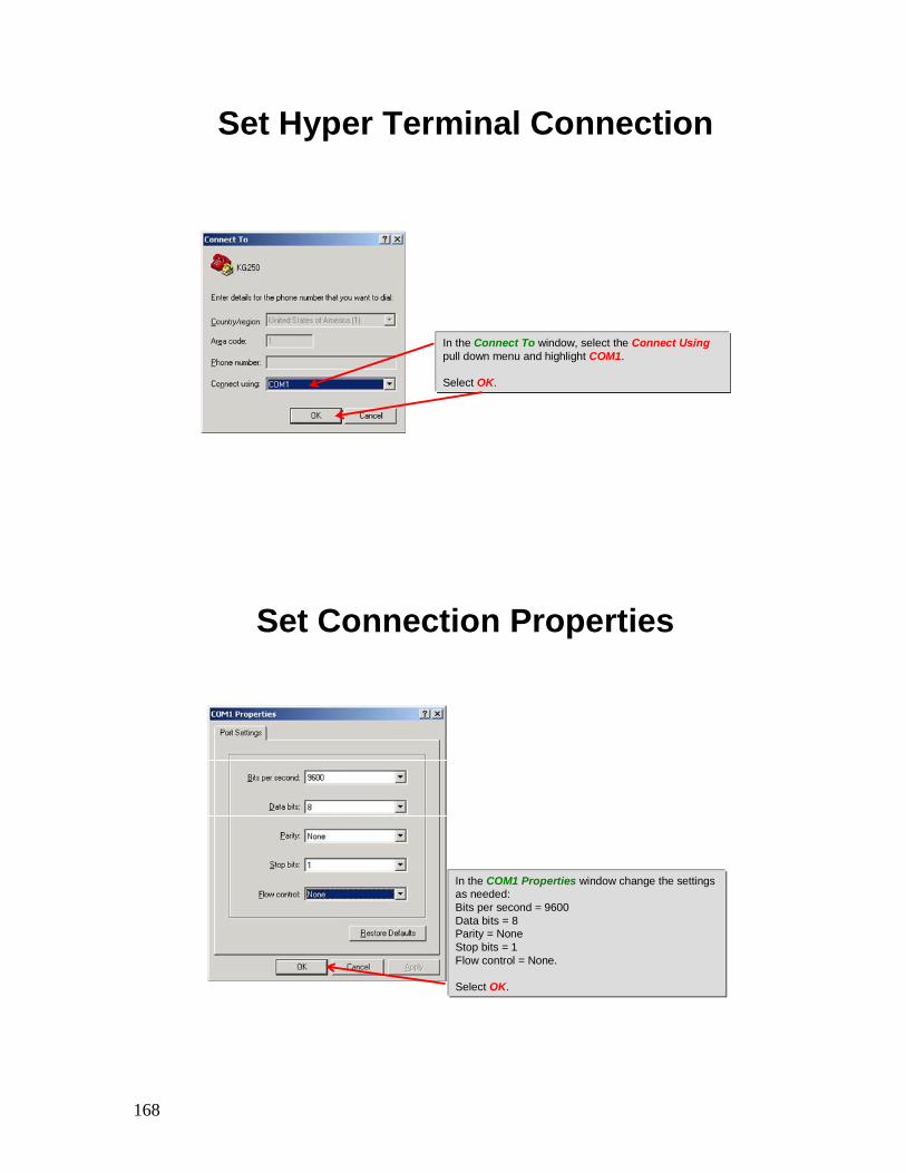
Set Hyper Terminal Connection
In the Connect To window, select the Connect Usingpull down menu and highlight COM1.
Select OK.
Set Connection Properties
In the COM1 Properties window change the settingsas needed:Bits per second = 9600Data bits = 8Parity = NoneStop bits = 1Flow control = None.
Select OK.
169
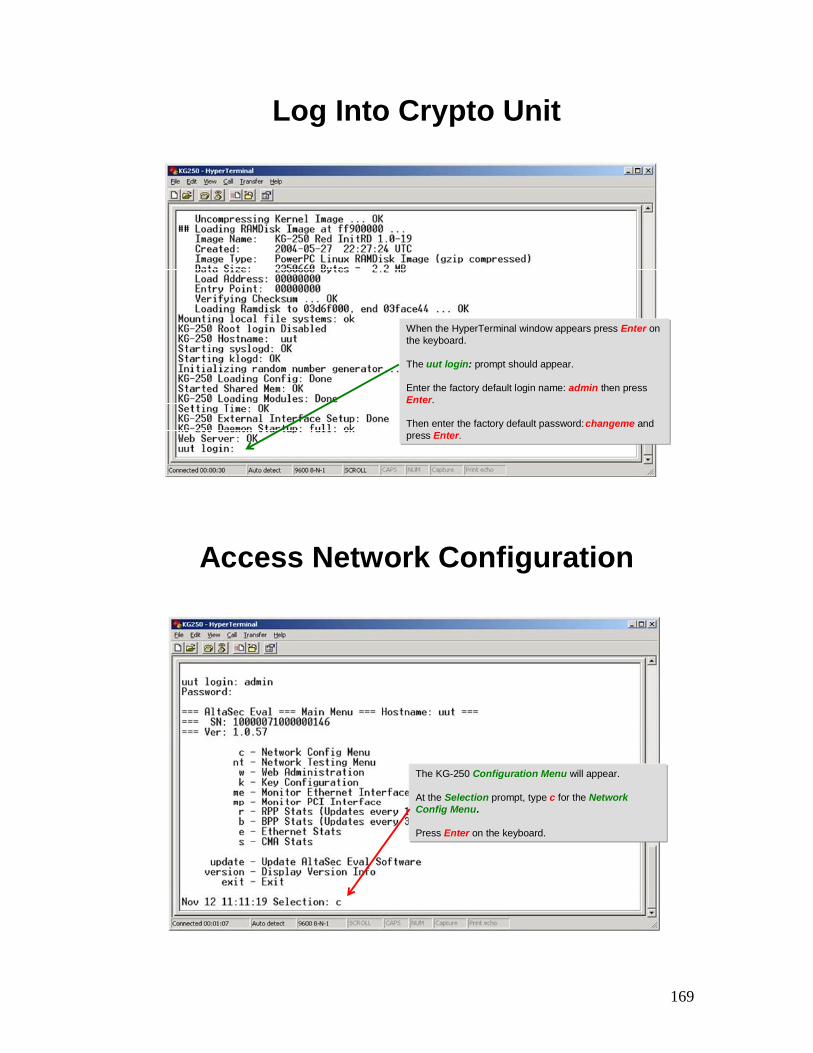
Log Into Crypto Unit
When the HyperTerminal window appears press Enter on the keyboard.
The uut login: prompt should appear.
Enter the factory default login name: admin then pressEnter.
Then enter the factory default password:changeme and press Enter.
Access Network Configuration
The KG-250 Configuration Menu will appear.
At the Selection prompt, type c for the Network Config Menu.
Press Enter on the keyboard.
170
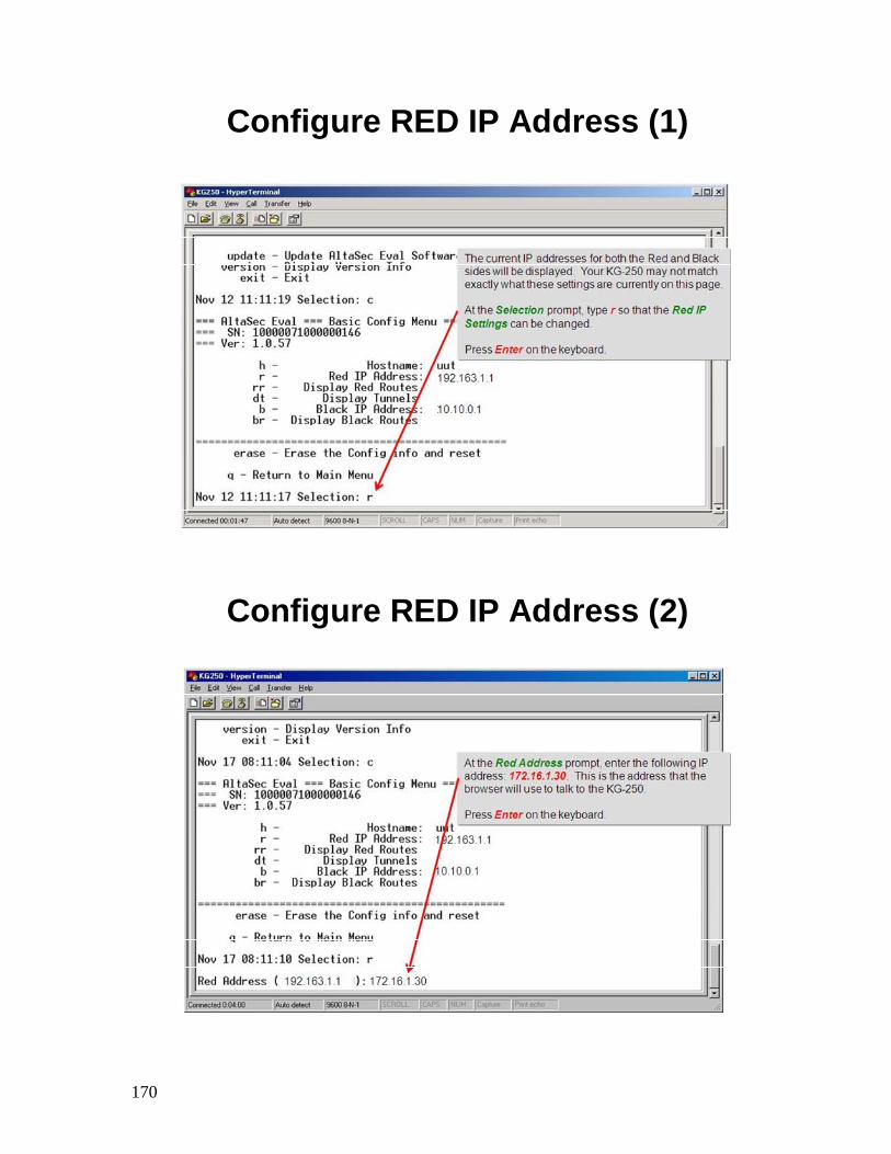
Configure RED IP Address (1)
Configure RED IP Address (2)
171
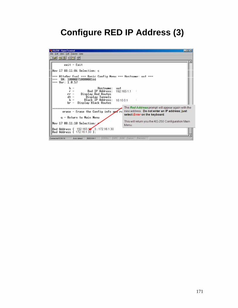
Configure RED IP Address (3)
172
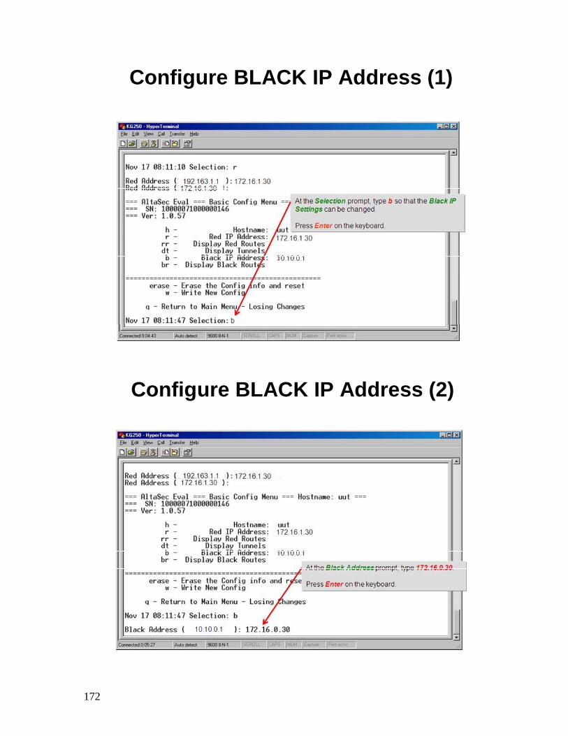
Configure BLACK IP Address (1)
Configure BLACK IP Address (2)
173
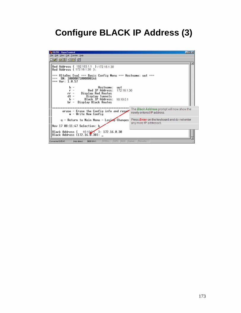
Configure BLACK IP Address (3)
174
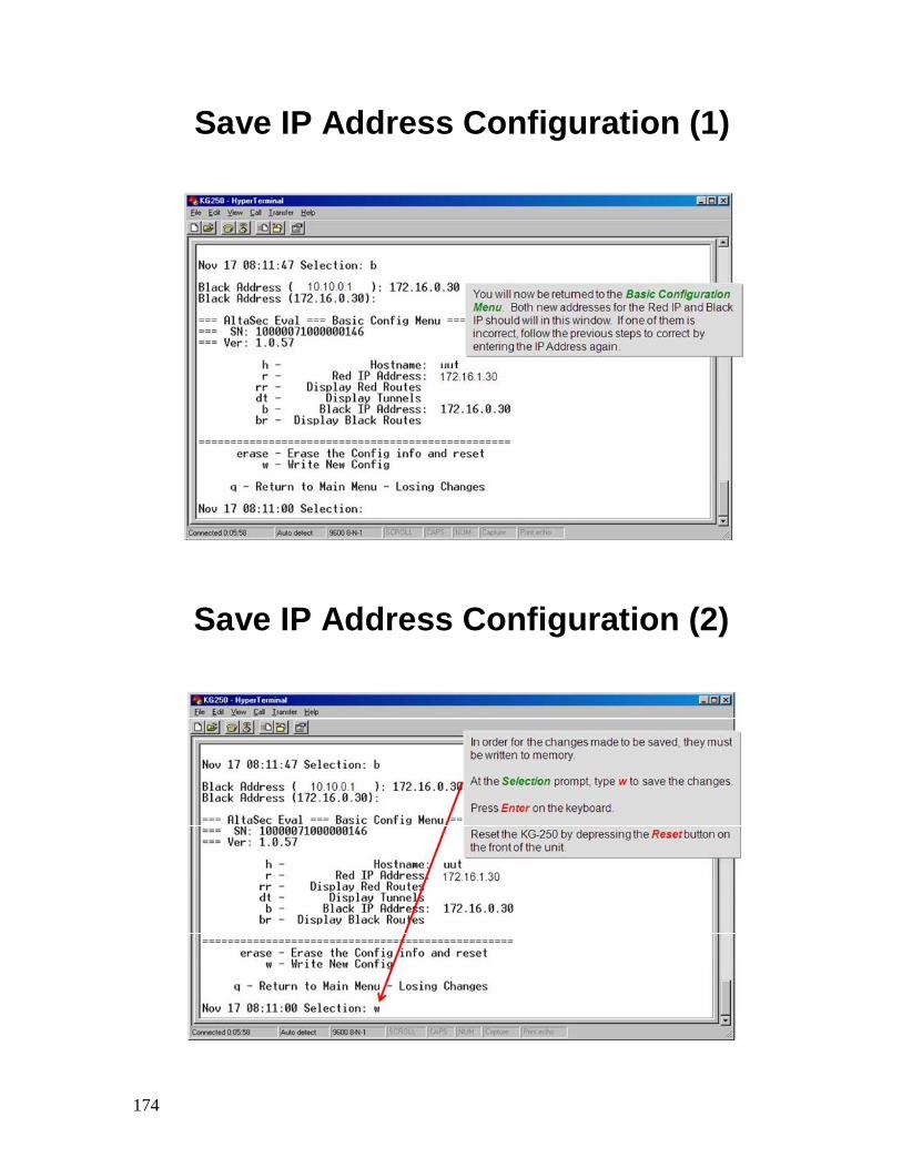
Save IP Address Configuration (1)
Save IP Address Configuration (2)
175
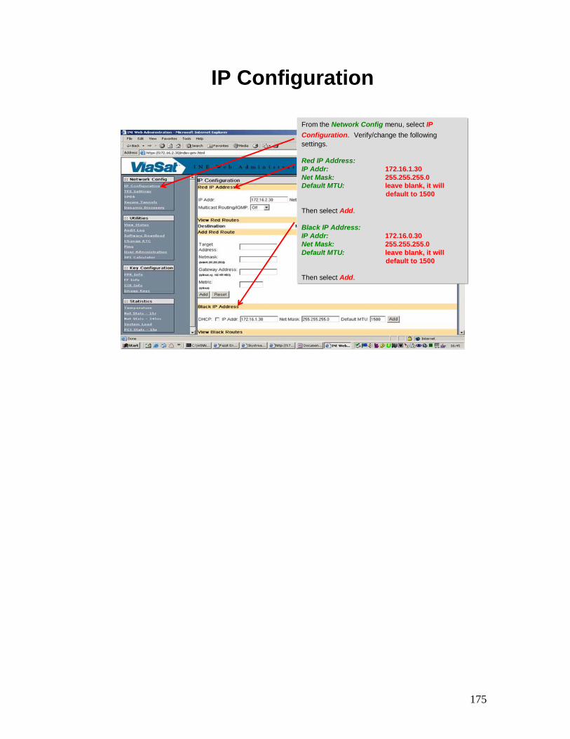
IP Configuration
From the Network Config menu, select IPConfiguration. Verify/change the following settings.
Red IP Address:IP Addr: 172.16.1.30Net Mask: 255.255.255.0Default MTU: leave blank, it will
default to 1500
Then select Add.
Black IP Address:IP Addr: 172.16.0.30Net Mask: 255.255.255.0Default MTU: leave blank, it will
default to 1500
Then select Add.
176
Provision Blank CIK (1)
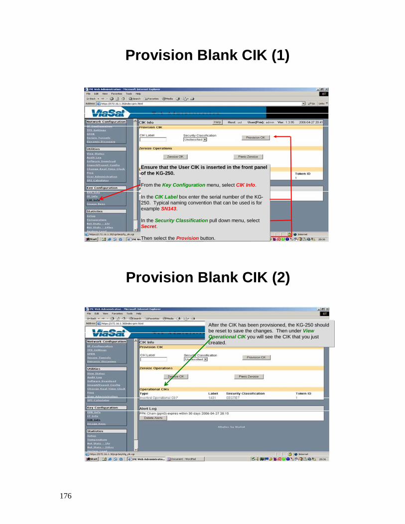
Ensure that the User CIK is inserted in the front panel of the KG-250.
From the Key Configuration menu, select CIK Info.
In the CIK Label box enter the serial number of the KG-250. Typical naming convention that can be used is for example SN143.
In the Security Classification pull down menu, select Secret.
Then select the Provision button.
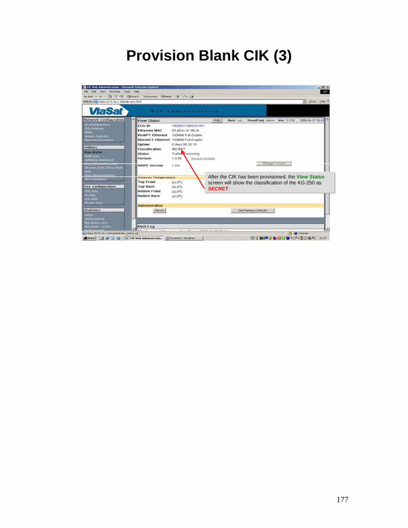
Provision Blank CIK (2)
After the CIK has been provisioned, the KG-250 should be reset to save the changes. Then under View Operational CIK you will see the CIK that you just created.
177
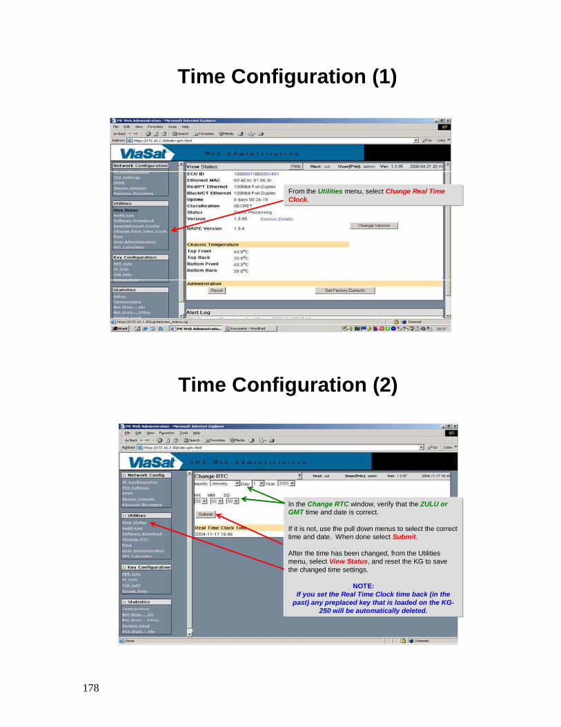
Provision Blank CIK (3)
After the CIK has been provisioned, the View Statusscreen will show the classification of the KG-250 as SECRET.
178
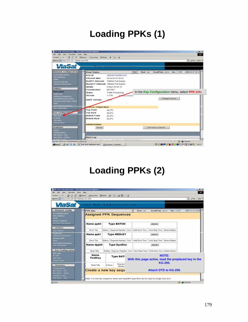
Time Configuration (1)
From the Utilities menu, select Change Real Time Clock.
Time Configuration (2)
In the Change RTC window, verify that the ZULU or GMT time and date is correct.
If it is not, use the pull down menus to select the correct time and date. When done select Submit.
After the time has been changed, from the Utilities menu, select View Status, and reset the KG to save the changed time settings.
NOTE:If you set the Real Time Clock time back (in the
past) any preplaced key that is loaded on the KG-250 will be automatically deleted.
179
Loading PPKs (1)
In the Key Configuration menu, select PPK Info.
Loading PPKs (2)
NOTE:With this page active, load the preplaced key in the
KG-250.
Attach DTD to KG-250.
180
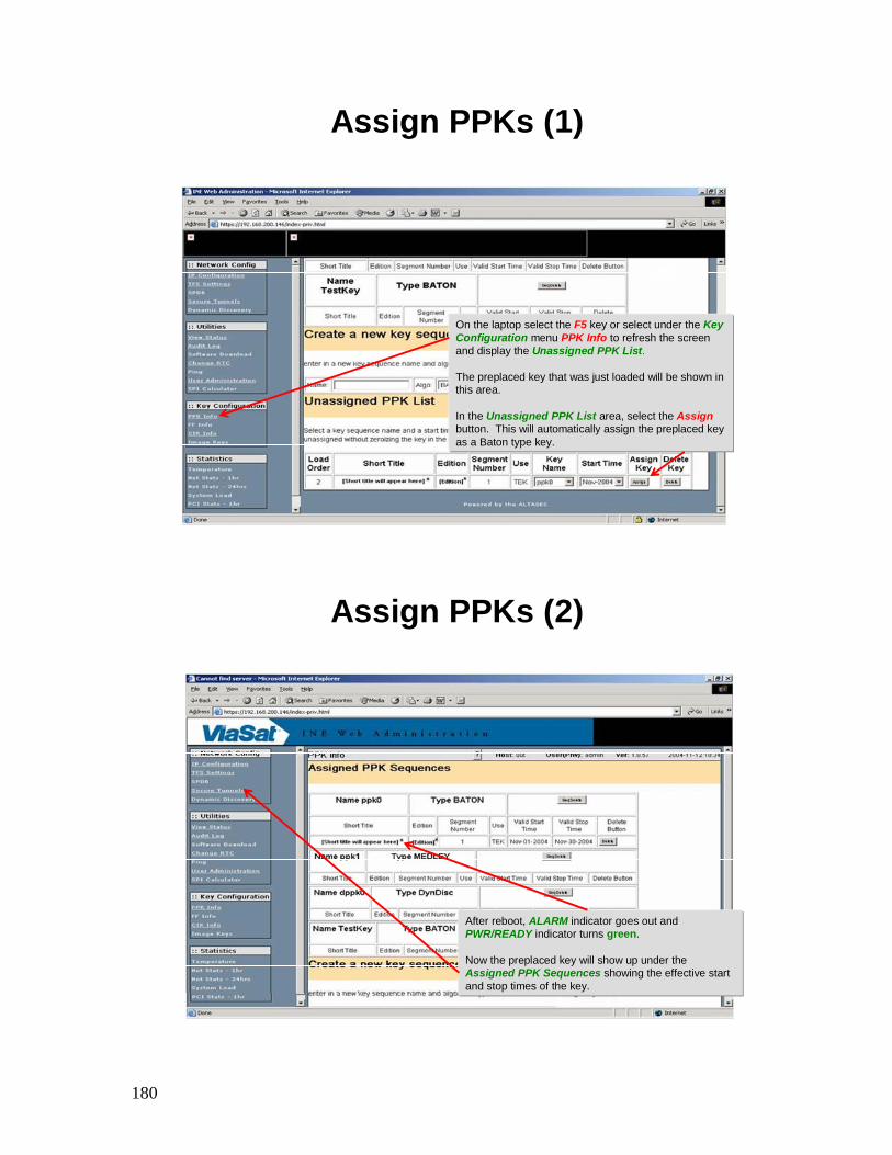
Assign PPKs (1)
On the laptop select the F5 key or select under the Key Configuration menu PPK Info to refresh the screen and display the Unassigned PPK List.
The preplaced key that was just loaded will be shown in this area.
In the Unassigned PPK List area, select the Assignbutton. This will automatically assign the preplaced key as a Baton type key.
Assign PPKs (2)
After reboot, ALARM indicator goes out and PWR/READY indicator turns green.
Now the preplaced key will show up under the Assigned PPK Sequences showing the effective start and stop times of the key.
181
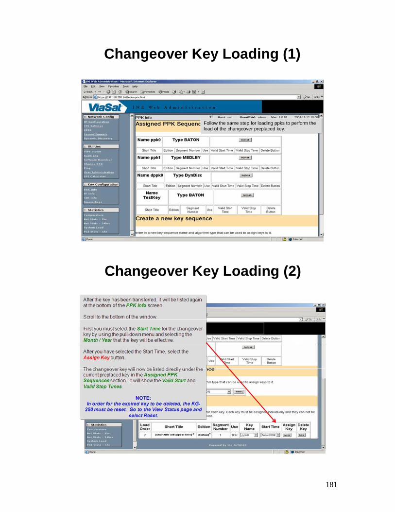
Changeover Key Loading (1)
Follow the same step for loading ppks to perform the load of the changeover preplaced key.
Changeover Key Loading (2)
182
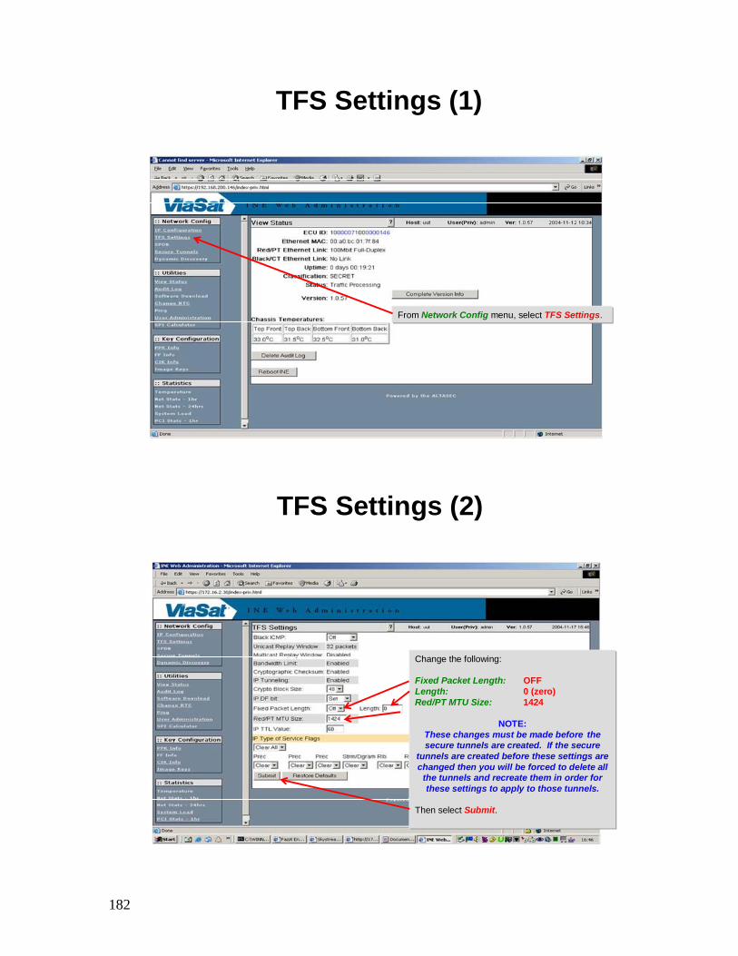
TFS Settings (1)
From Network Config menu, select TFS Settings.
TFS Settings (2)
Change the following:
Fixed Packet Length: OFFLength: 0 (zero)Red/PT MTU Size: 1424
NOTE:These changes must be made before the secure tunnels are created. If the secure
tunnels are created before these settings are changed then you will be forced to delete all
the tunnels and recreate them in order for these settings to apply to those tunnels.
Then select Submit.
183
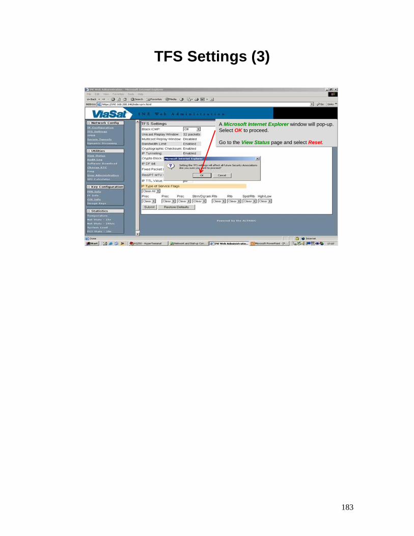
TFS Settings (3)
A Microsoft Internet Explorer window will pop-up. Select OK to proceed.
Go to the View Status page and select Reset.
184
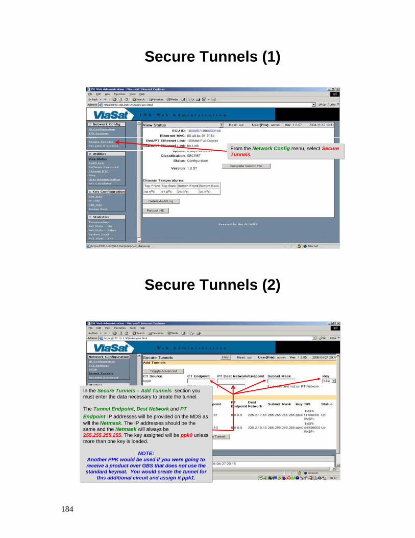
Secure Tunnels (1)
From the Network Config menu, select Secure Tunnels.
Secure Tunnels (2)
In the Secure Tunnels – Add Tunnels section you must enter the data necessary to create the tunnel.
The Tunnel Endpoint, Dest Network and PT Endpoint IP addresses will be provided on the MDS as will the Netmask. The IP addresses should be the same and the Netmask will always be 255.255.255.255. The key assigned will be ppk0 unless more than one key is loaded.
NOTE:Another PPK would be used if you were going to receive a product over GBS that does not use the standard keymat. You would create the tunnel for
this additional circuit and assign it ppk1.
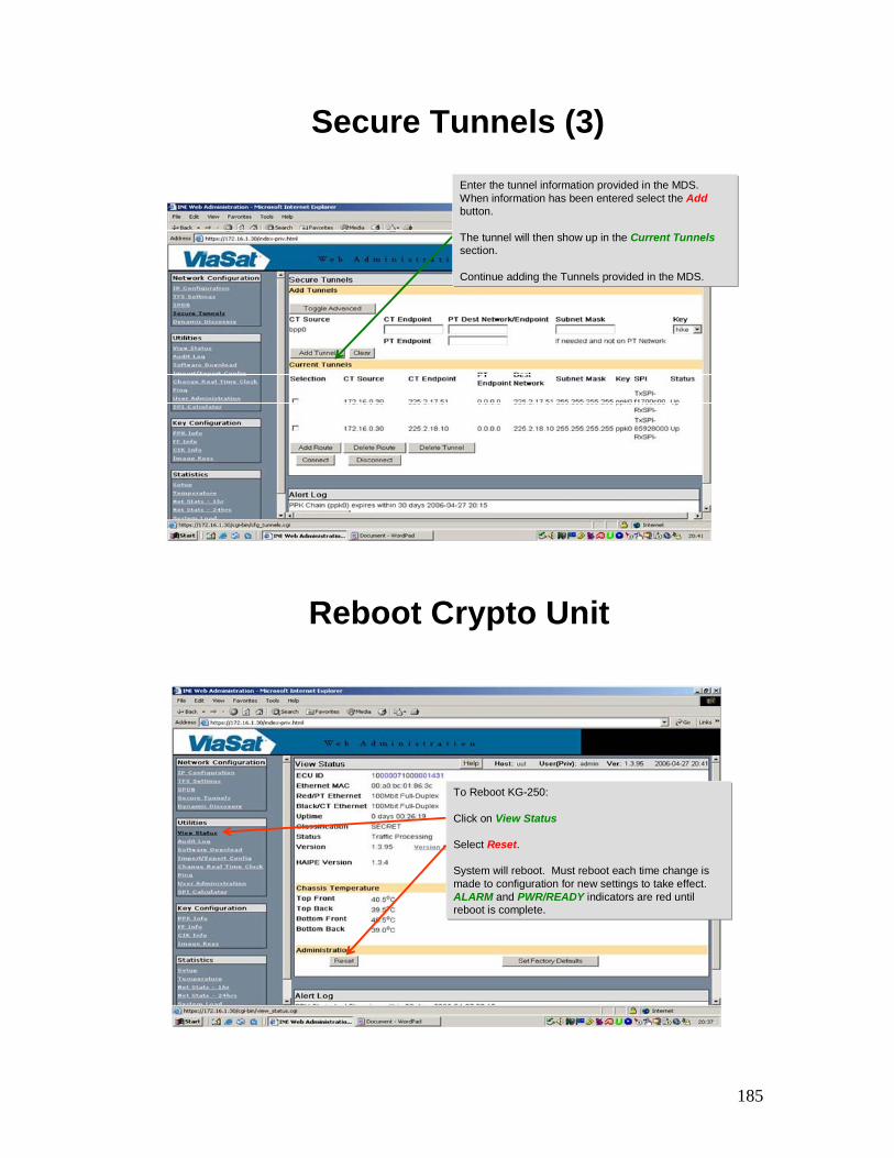
185
Secure Tunnels (3)Enter the tunnel information provided in the MDS. When information has been entered select the Addbutton.
The tunnel will then show up in the Current Tunnelssection.
Continue adding the Tunnels provided in the MDS.
Reboot Crypto Unit
To Reboot KG-250:
Click on View Status
Select Reset.
System will reboot. Must reboot each time change is made to configuration for new settings to take effect. ALARM and PWR/READY indicators are red until reboot is complete.
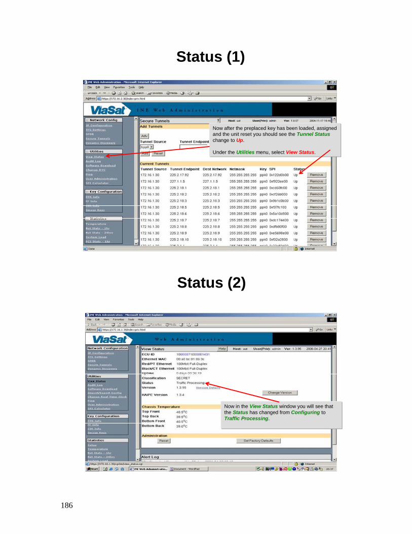
186
Status (1)
Now after the preplaced key has been loaded, assigned and the unit reset you should see the Tunnel Statuschange to Up.
Under the Utilities menu, select View Status.
Status (2)
Now in the View Status window you will see that the Status has changed from Configuring to Traffic Processing.

187
Crypto Unit Battery Management (1)
NOTE:
The KG-250 contains a lithium battery located on the rear panel of the device. To minimize power drain on the battery, prime DC power should always be applied and the Power slide switch always kept in the ON position.
WARNING:
Do not expose this battery to extreme high temperatures or incinerate because of the risk of explosion.
Crypto Unit Battery Management (2)
The KG-250 requires some voltage at all times to maintain its functionality.
Three electrical sources• Prime DC Power – always applied during operation and should remain
on whenever possible.
• External battery – backup to retain keys and RTC (field replaceable)
• Internal battery – will retain keys if external battery drained (non-rechargeable, but may retain key splits up to six months)
IF ALL THREE FAIL, KG-250 must be sent to ViaSat for Depot repair.

188
Crypto Unit Battery Management (3)
The KG-250 is shipped with an external “C-size” battery in a special holder that is only for use during storage and shipment.
The “1/2AA-size” external battery is standard for operations and can be used during shipment and limited storage periods.
Should “LOW BATTERY” LED light, emergency operating procedures will be required to continue KG-250 use. This LED indicates drained internal battery
• KEEP PRIME DC POWER ON
• Change external battery with Prime DC power on
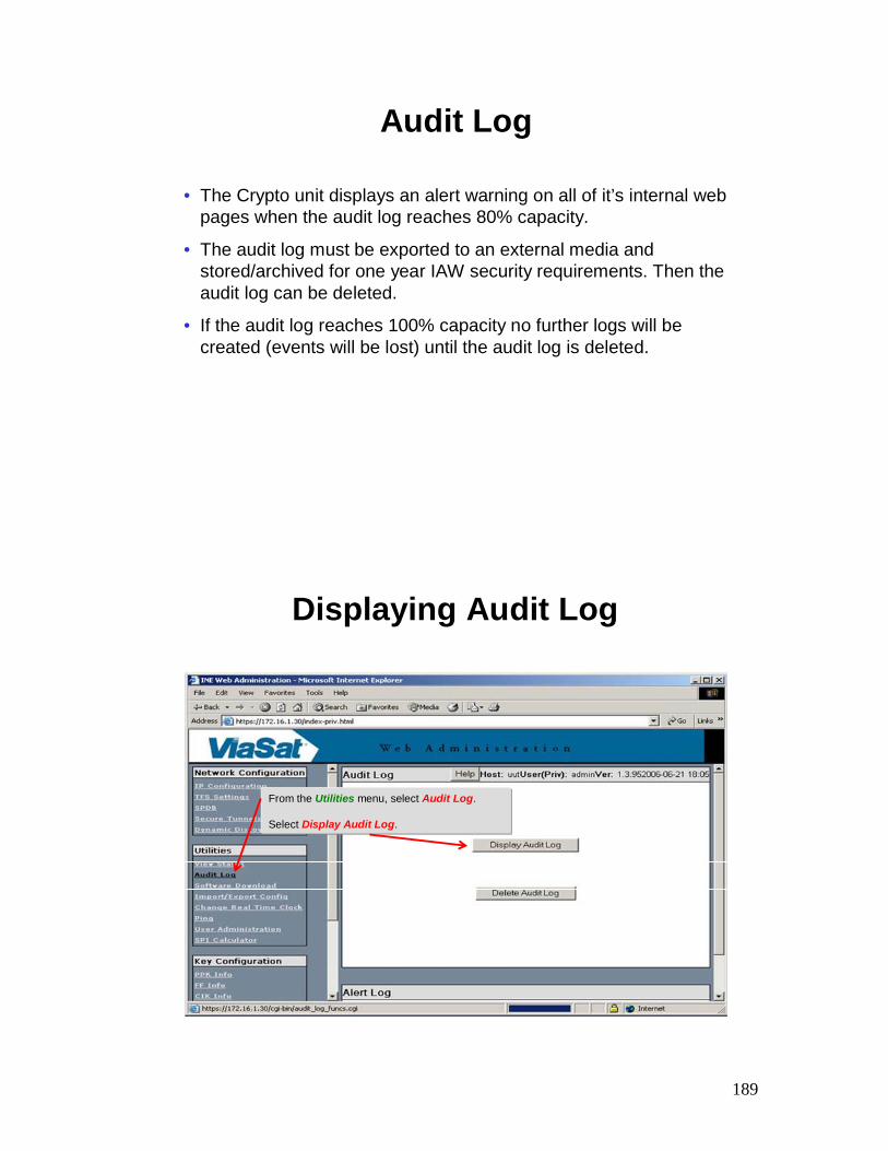
189
Audit Log
• The Crypto unit displays an alert warning on all of it’s internal web pages when the audit log reaches 80% capacity.
• The audit log must be exported to an external media and stored/archived for one year IAW security requirements. Then theaudit log can be deleted.
• If the audit log reaches 100% capacity no further logs will be created (events will be lost) until the audit log is deleted.
Displaying Audit Log
From the Utilities menu, select Audit Log.
Select Display Audit Log.
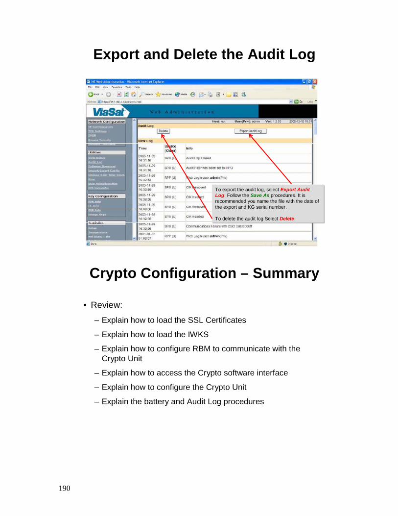
190
Export and Delete the Audit Log
To export the audit log, select Export Audit Log. Follow the Save As procedures. It is recommended you name the file with the date of the export and KG serial number.
To delete the audit log Select Delete.
Crypto Configuration – Summary
• Review:
– Explain how to load the SSL Certificates
– Explain how to load the IWKS
– Explain how to configure RBM to communicate with the Crypto Unit
– Explain how to access the Crypto software interface
– Explain how to configure the Crypto Unit
– Explain the battery and Audit Log procedures
191
MediaStream Operations & Set Top
Box (STB) Configuration

192
MediaStream Operations – Objectives
• Upon successful completion of this lesson, the student will be able to:
– Explain how to configure the MediaStream software
– Explain how to operate the MediaStream software
– Explain how to configure the Set Top Box
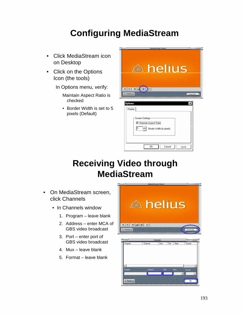
193
Configuring MediaStream
• Click MediaStream icon on Desktop
• Click on the Options Icon (the tools)In Options menu, verify:
Maintain Aspect Ratio is checked
• Border Width is set to 5 pixels (Default)
Receiving Video through MediaStream
• On MediaStream screen, click Channels• In Channels window
1. Program – leave blank
2. Address – enter MCA of GBS video broadcast
3. Port – enter port of GBS video broadcast
4. Mux – leave blank
5. Format – leave blank
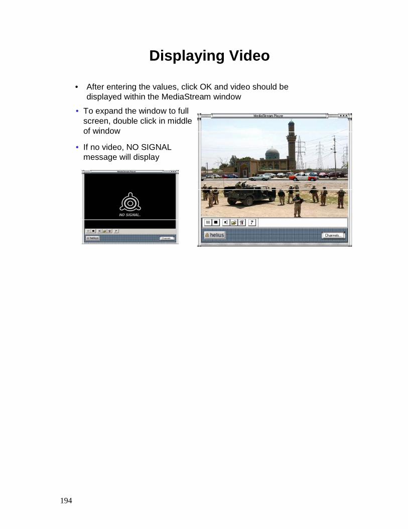
194
Displaying Video
• After entering the values, click OK and video should be displayed within the MediaStream window
• To expand the window to full screen, double click in middle of window
• If no video, NO SIGNAL message will display
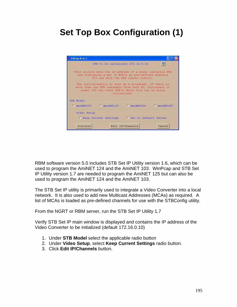
195
Set Top Box Configuration (1)
RBM software version 5.0 includes STB Set IP Utility version 1.6, which can be used to program the AmiNET 124 and the AmiNET 103. WinPcap and STB Set IP Utility version 1.7 are needed to program the AmiNET 125 but can also be used to program the AmiNET 124 and the AmiNET 103. The STB Set IP utility is primarily used to integrate a Video Converter into a local network. It is also used to add new Multicast Addresses (MCAs) as required. A list of MCAs is loaded as pre-defined channels for use with the STBConfig utility. From the NGRT or RBM server, run the STB Set IP Utility 1.7 Verify STB Set IP main window is displayed and contains the IP address of the Video Converter to be initialized (default 172.16.0.10)
1. Under STB Model select the applicable radio button 2. Under Video Setup, select Keep Current Settings radio button. 3. Click Edit IP/Channels button.
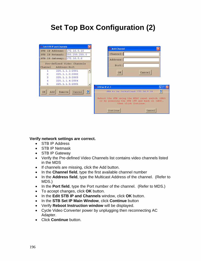
196
Set Top Box Configuration (2)
Verify network settings are correct. • STB IP Address • STB IP Netmask • STB IP Gateway • Verify the Pre-defined Video Channels list contains video channels listed
in the MDS • If channels are missing, click the Add button. • In the Channel field, type the first available channel number • In the Address field, type the Multicast Address of the channel. (Refer to
MDS.) • In the Port field, type the Port number of the channel. (Refer to MDS.) • To accept changes, click OK button. • In the Edit STB IP and Channels window, click OK button. • In the STB Set IP Main Window, click Continue button • Verify Reboot Instruction window will be displayed. • Cycle Video Converter power by unplugging then reconnecting AC
Adapter. • Click Continue button.
197
MediaStream Operations – Summary
• Review:
– Explain how to configure the MediaStream software
– Explain how to operate the MediaStream software
– Explain how to configure the Set Top Box

198
KenCast Client Administration

199
KenCast Administration - Objectives
• Upon successful completion of this lesson, the student will be able to:
– State the purpose of KenCast Fazzt Software
– Explain how to access KenCast Client Administration
– Explain Configuration Menu Setup
– Explain Tuning Menu Setup
– Explain Sites & Users Menu Setup
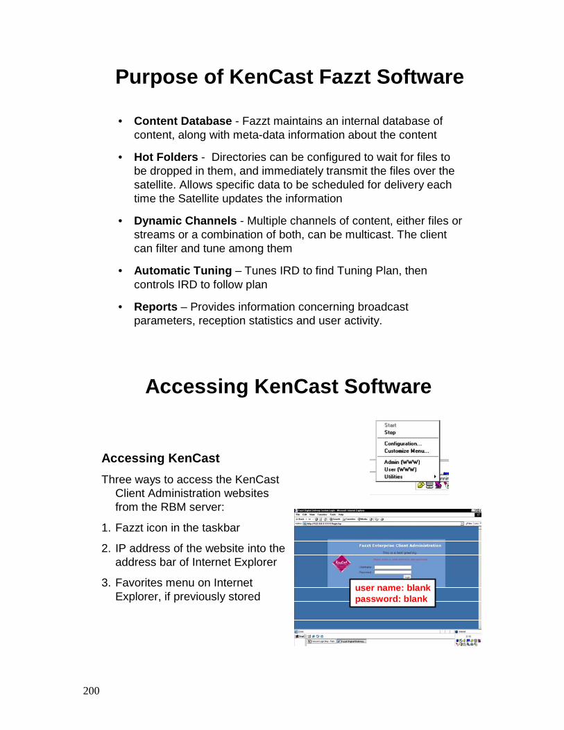
200
Purpose of KenCast Fazzt Software
• Content Database - Fazzt maintains an internal database of content, along with meta-data information about the content
• Hot Folders - Directories can be configured to wait for files to be dropped in them, and immediately transmit the files over the satellite. Allows specific data to be scheduled for delivery each time the Satellite updates the information
• Dynamic Channels - Multiple channels of content, either files or streams or a combination of both, can be multicast. The client can filter and tune among them
• Automatic Tuning – Tunes IRD to find Tuning Plan, then controls IRD to follow plan
• Reports – Provides information concerning broadcast parameters, reception statistics and user activity.
Accessing KenCast Software
Accessing KenCastThree ways to access the KenCast
Client Administration websites from the RBM server:
1. Fazzt icon in the taskbar
2. IP address of the website into the address bar of Internet Explorer
3. Favorites menu on Internet Explorer, if previously stored
user name: blankpassword: blank
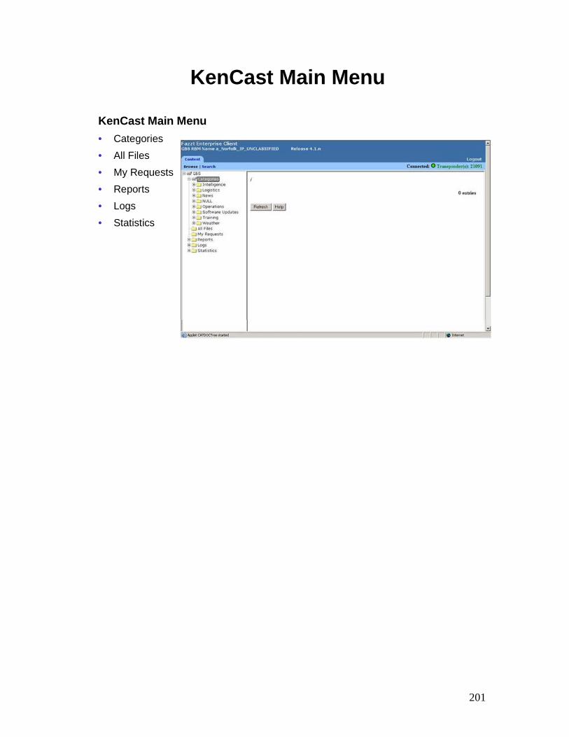
201
KenCast Main Menu
KenCast Main Menu• Categories• All Files• My Requests• Reports• Logs• Statistics
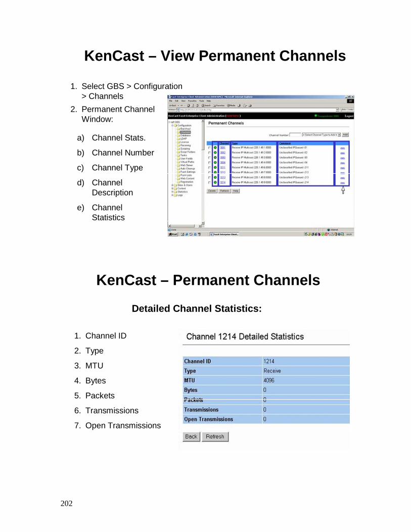
202
KenCast – View Permanent Channels
1. Select GBS > Configuration > Channels
2. Permanent Channel Window:
a) Channel Stats.
b) Channel Number
c) Channel Type
d) Channel Description
e) Channel Statistics
KenCast – Permanent Channels
Detailed Channel Statistics:
1. Channel ID
2. Type
3. MTU
4. Bytes
5. Packets
6. Transmissions
7. Open Transmissions
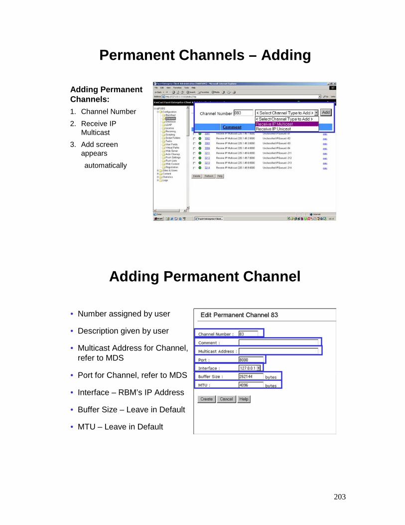
203
Permanent Channels – Adding
Adding Permanent Channels:1. Channel Number2. Receive IP
Multicast3. Add screen
appearsautomatically
Adding Permanent Channel
• Number assigned by user
• Description given by user
• Multicast Address for Channel, refer to MDS
• Port for Channel, refer to MDS
• Interface – RBM’s IP Address
• Buffer Size – Leave in Default
• MTU – Leave in Default
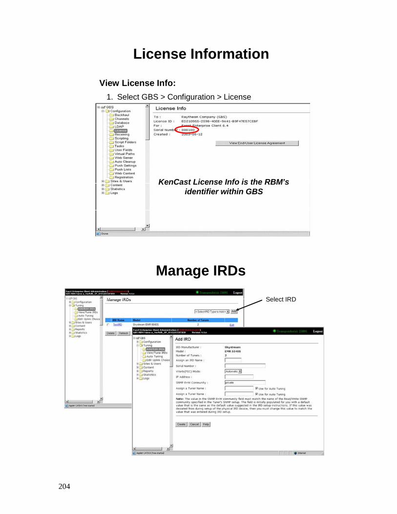
204
License Information
KenCast License Info is the RBM’sidentifier within GBS
View License Info:1. Select GBS > Configuration > License
Manage IRDs
Select IRD
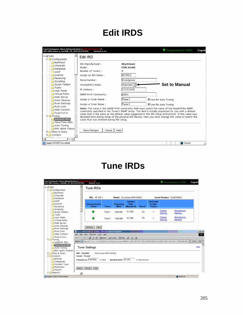
205
Edit IRDS
Set to Manual
Tune IRDs
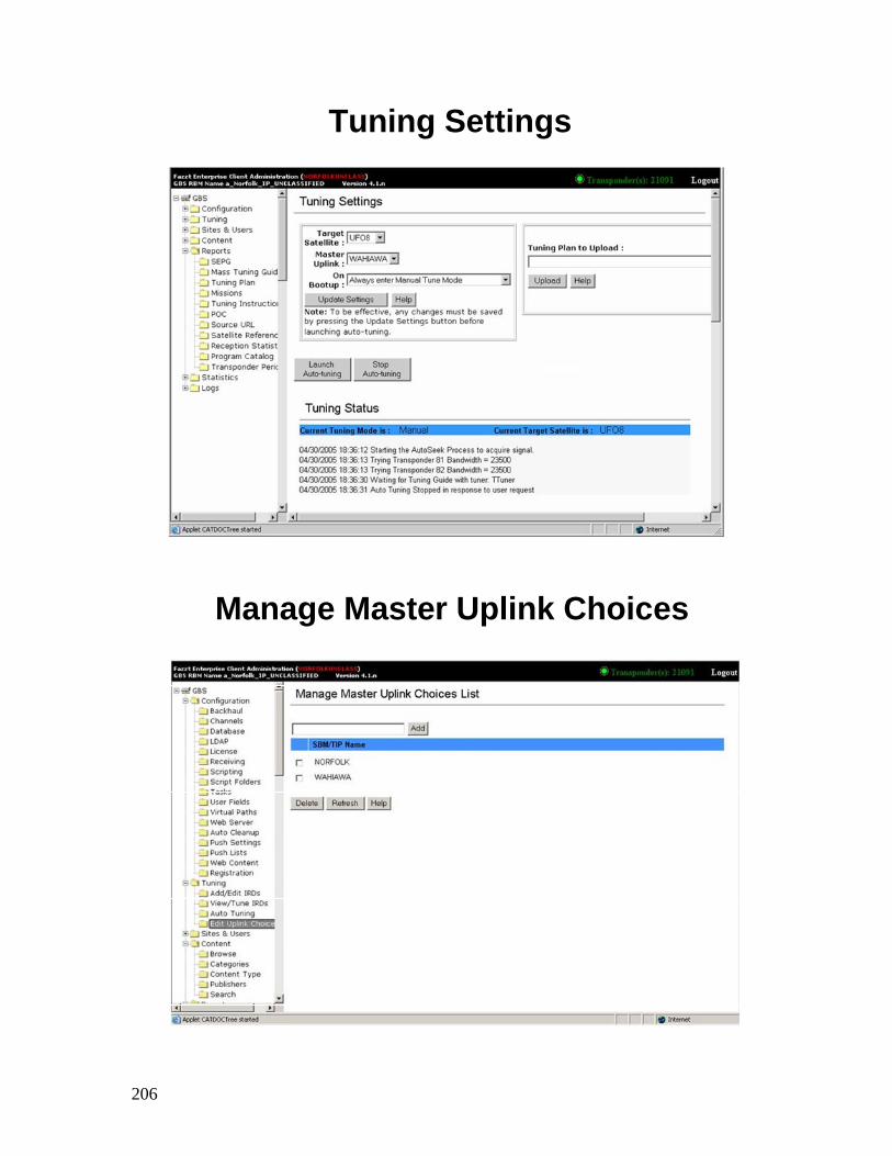
206
Tuning Settings
Manage Master Uplink Choices
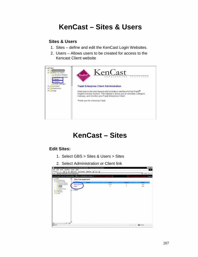
207
KenCast – Sites & Users
Sites & Users1. Sites – define and edit the KenCast Login Websites. 2. Users – Allows users to be created for access to the
Kencast Client website
KenCast – Sites
Edit Sites:1. Select GBS > Sites & Users > Sites
2. Select Administration or Client link
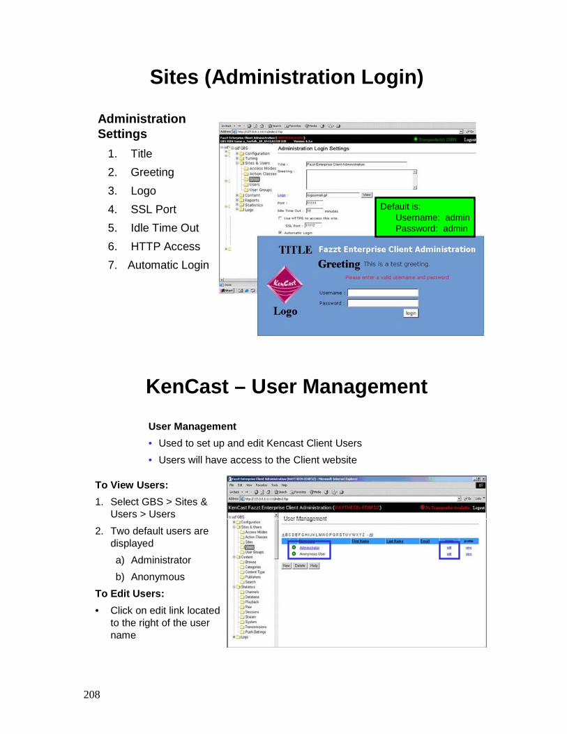
208
Sites (Administration Login)
Administration Settings
1. Title2. Greeting3. Logo4. SSL Port5. Idle Time Out6. HTTP Access7. Automatic Login
Default is:Username: adminPassword: admin
KenCast – User Management
To View Users:1. Select GBS > Sites &
Users > Users2. Two default users are
displayeda) Administratorb) Anonymous
To Edit Users:• Click on edit link located
to the right of the user name
User Management• Used to set up and edit Kencast Client Users• Users will have access to the Client website
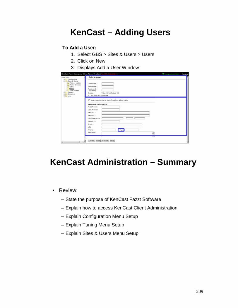
209
KenCast – Adding UsersTo Add a User:
1. Select GBS > Sites & Users > Users2. Click on New3. Displays Add a User Window
KenCast Administration – Summary
• Review:
– State the purpose of KenCast Fazzt Software
– Explain how to access KenCast Client Administration
– Explain Configuration Menu Setup
– Explain Tuning Menu Setup
– Explain Sites & Users Menu Setup

210
KenCast Client Operations
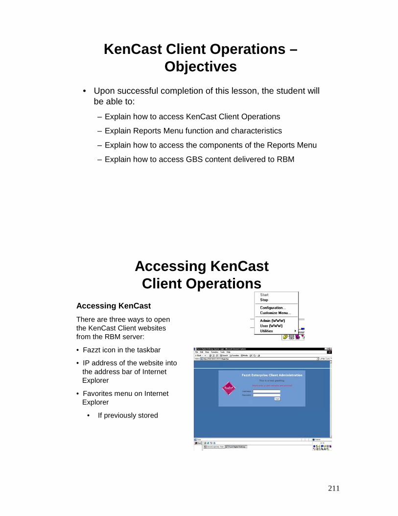
211
KenCast Client Operations –Objectives
• Upon successful completion of this lesson, the student will be able to:
– Explain how to access KenCast Client Operations
– Explain Reports Menu function and characteristics
– Explain how to access the components of the Reports Menu
– Explain how to access GBS content delivered to RBM
Accessing KenCast Client Operations
Accessing KenCastThere are three ways to open the KenCast Client websites from the RBM server:
• Fazzt icon in the taskbar
• IP address of the website into the address bar of Internet Explorer
• Favorites menu on Internet Explorer
• If previously stored
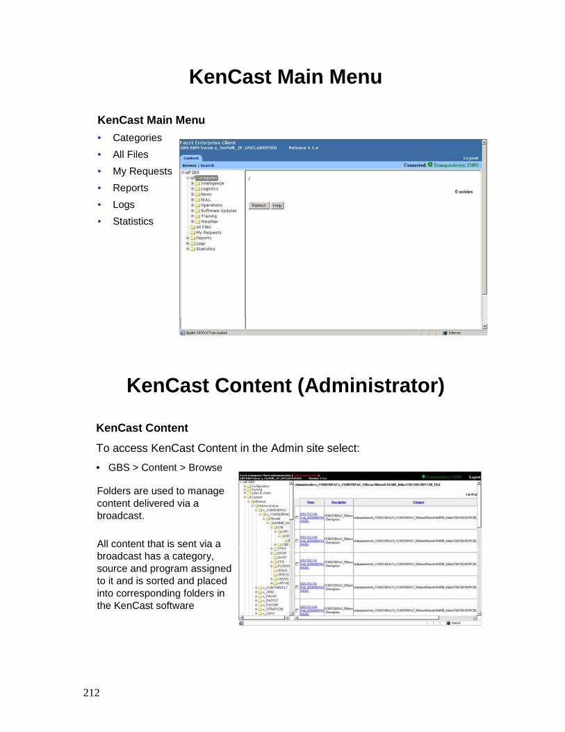
212
KenCast Main Menu
KenCast Main Menu• Categories• All Files• My Requests• Reports• Logs• Statistics
KenCast Content (Administrator)
KenCast Content
To access KenCast Content in the Admin site select:• GBS > Content > Browse
Folders are used to manage content delivered via a broadcast.
All content that is sent via a broadcast has a category, source and program assigned to it and is sorted and placed into corresponding folders in the KenCast software
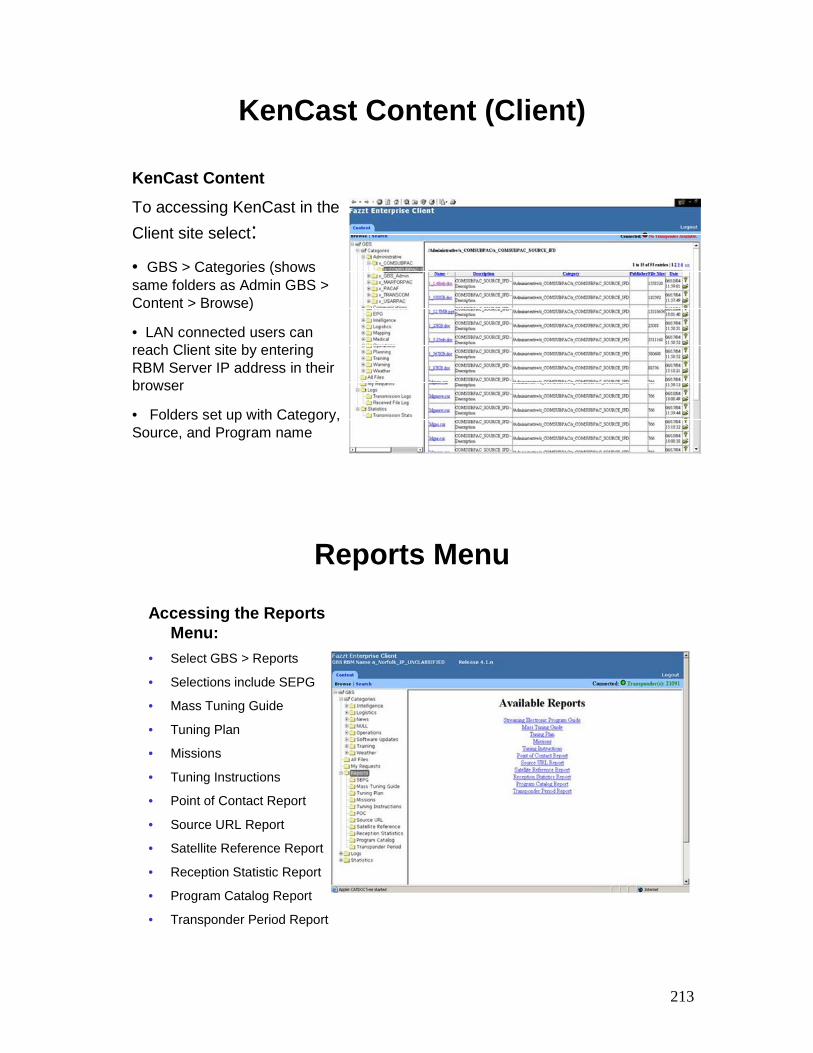
213
KenCast Content (Client)
KenCast Content
To accessing KenCast in the Client site select:• GBS > Categories (shows same folders as Admin GBS > Content > Browse)
• LAN connected users can reach Client site by entering RBM Server IP address in their browser
• Folders set up with Category, Source, and Program name
Reports Menu
Accessing the Reports Menu:
• Select GBS > Reports
• Selections include SEPG
• Mass Tuning Guide
• Tuning Plan
• Missions
• Tuning Instructions
• Point of Contact Report
• Source URL Report
• Satellite Reference Report
• Reception Statistic Report
• Program Catalog Report
• Transponder Period Report
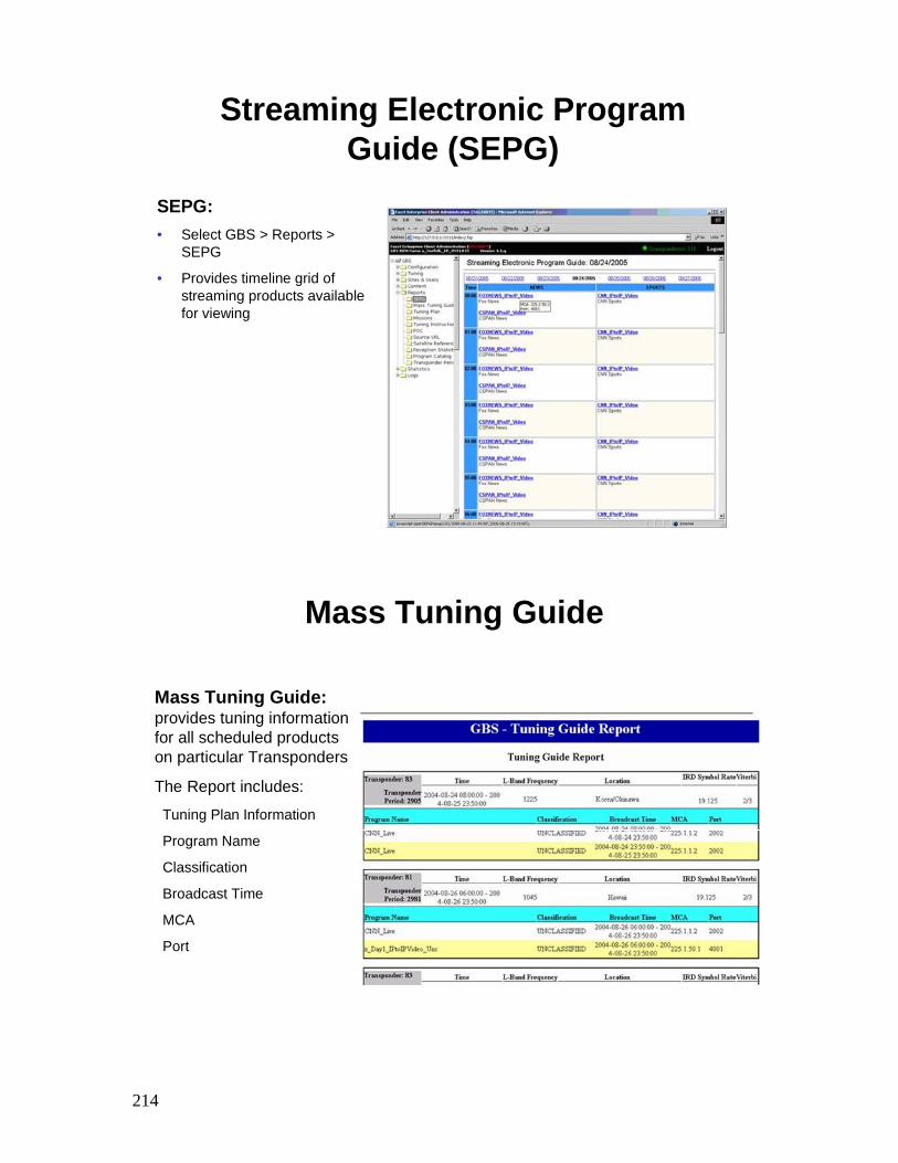
214
Streaming Electronic Program Guide (SEPG)
SEPG:• Select GBS > Reports >
SEPG
• Provides timeline grid of streaming products available for viewing
Mass Tuning Guide
Mass Tuning Guide: provides tuning information for all scheduled products on particular Transponders
The Report includes:
Tuning Plan Information
Program Name
Classification
Broadcast Time
MCA
Port
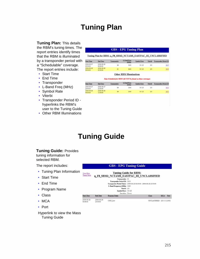
215
Tuning Plan
Tuning Plan: This details the RBM’s tuning times. The report entries identify times that the RBM is illuminated by a transponder period with a “Schedulable” coverage. The report entries include:• Start Time• End Time• Transponder• L-Band Freq (MHz)• Symbol Rate• Viterbi• Transponder Period ID -
hyperlinks the RBM’suser to the Tuning Guide
• Other RBM Illuminations
Tuning Guide
Tuning Guide: Provides tuning information for selected RBM.The report includes:• Tuning Plan Information• Start Time• End Time• Program Name• Class• MCA• PortHyperlink to view the Mass
Tuning Guide
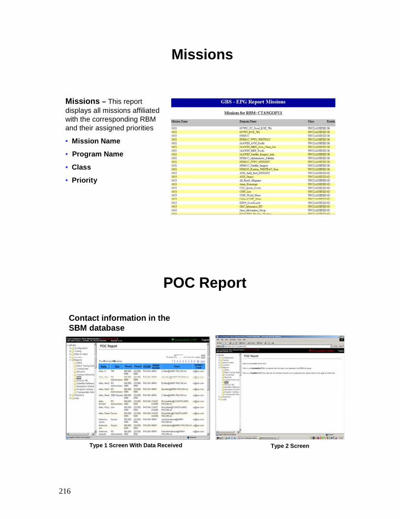
216
Missions
Missions – This report displays all missions affiliated with the corresponding RBM and their assigned priorities
• Mission Name
• Program Name
• Class
• Priority
POC Report
Contact information in the SBM database
Type 1 Screen With Data Received Type 2 Screen
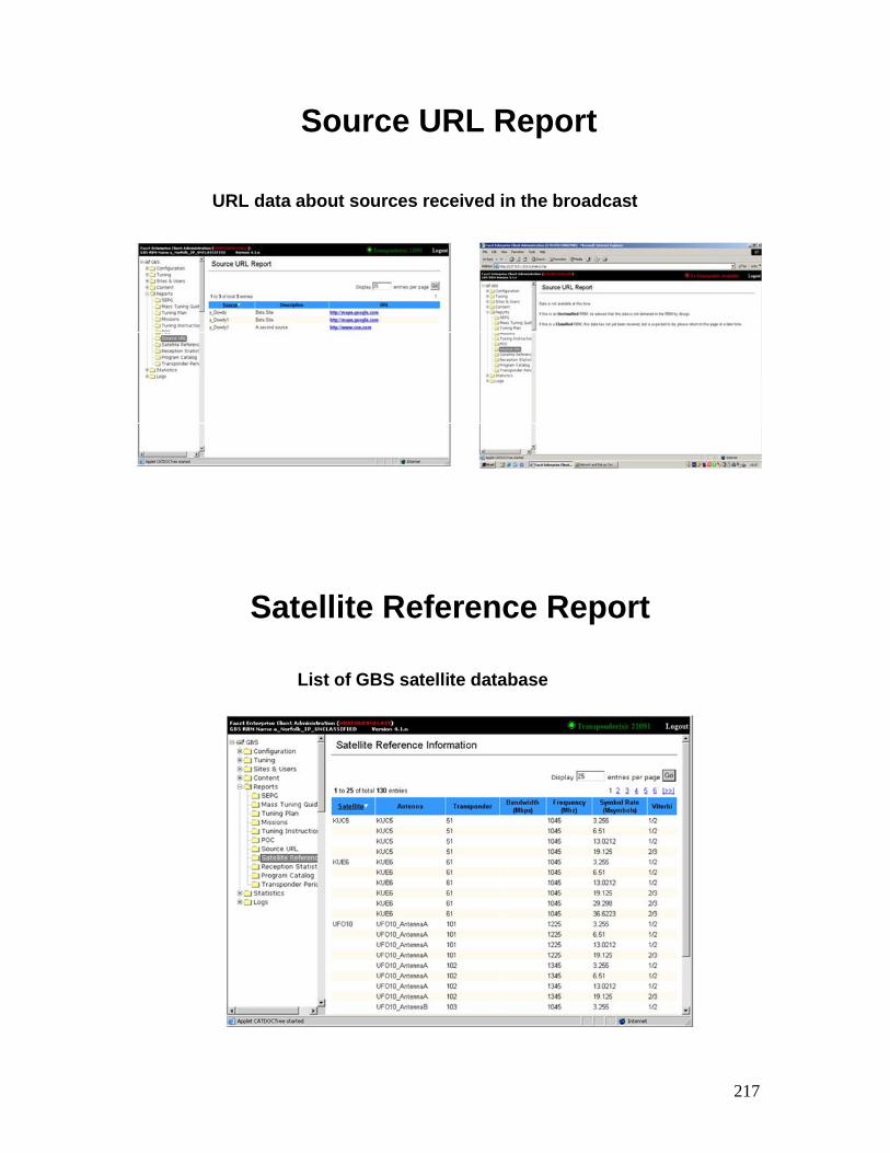
217
Source URL Report
URL data about sources received in the broadcast
Type 1 Screen With Data Received Type 2 Screen
Satellite Reference Report
List of GBS satellite database
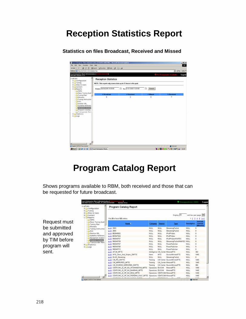
218
Reception Statistics Report
Statistics on files Broadcast, Received and Missed
Program Catalog Report
Shows programs available to RBM, both received and those that can be requested for future broadcast.
Request must be submitted and approved by TIM before program will sent.
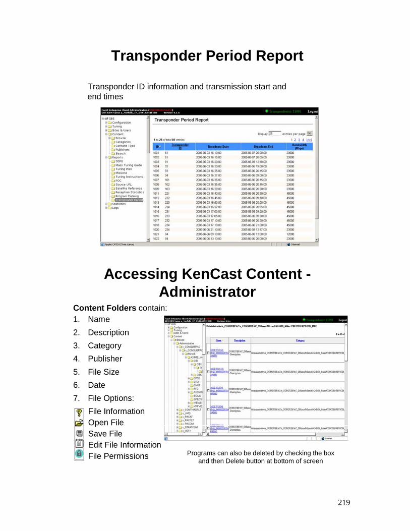
219
Transponder Period Report
Transponder ID information and transmission start and end times
Accessing KenCast Content -Administrator
Content Folders contain:1. Name2. Description3. Category4. Publisher5. File Size6. Date7. File Options:
File InformationOpen FileSave FileEdit File InformationFile Permissions Programs can also be deleted by checking the box
and then Delete button at bottom of screen
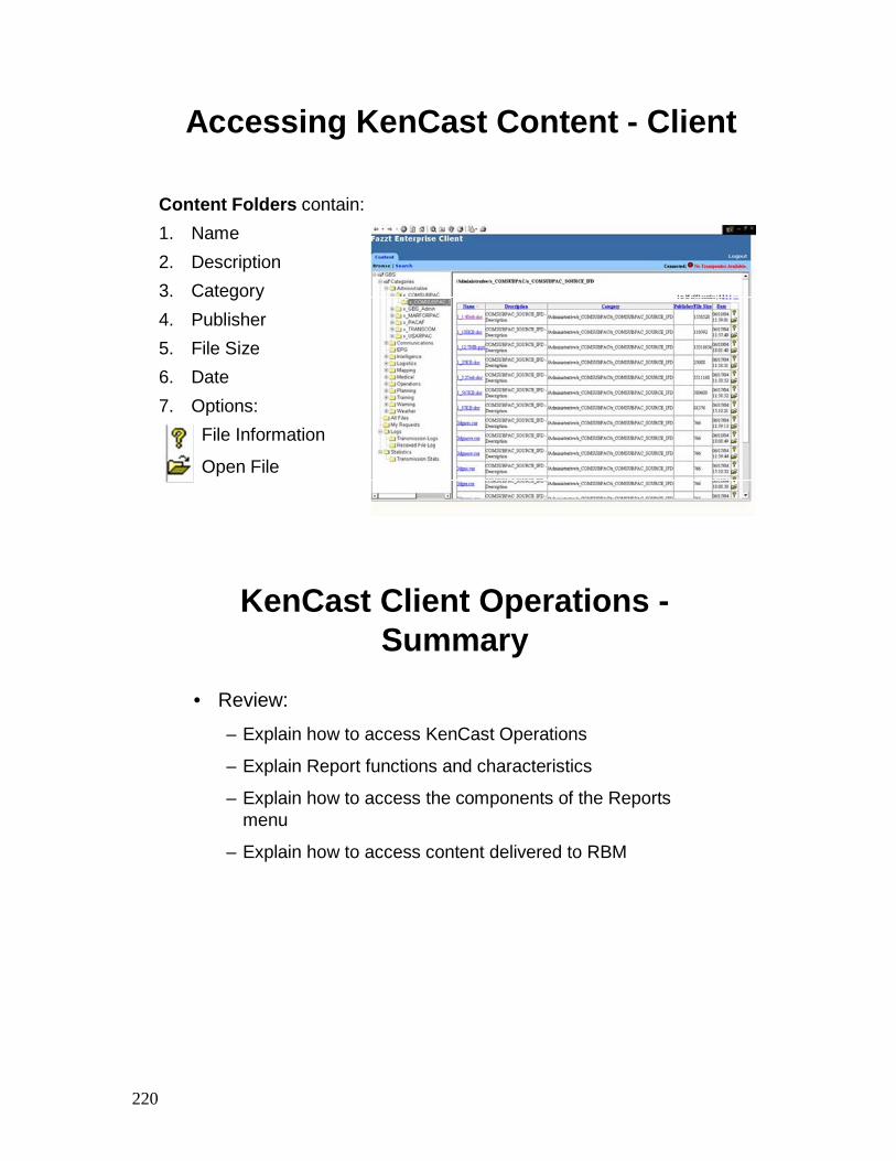
220
Accessing KenCast Content - Client
Content Folders contain:1. Name2. Description3. Category4. Publisher5. File Size6. Date7. Options:
File Information
Open File
KenCast Client Operations -Summary
• Review:
– Explain how to access KenCast Operations
– Explain Report functions and characteristics
– Explain how to access the components of the Reports menu
– Explain how to access content delivered to RBM

TAB
Insert Tab # 5 Here
Transmit Suite Client -
Unit Editor for AN/TSR-8 Administrators

222
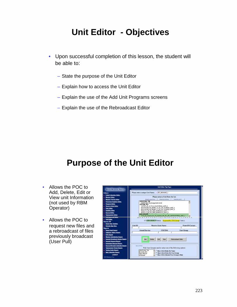
223
Unit Editor - Objectives
• Upon successful completion of this lesson, the student will be able to:
– State the purpose of the Unit Editor
– Explain how to access the Unit Editor
– Explain the use of the Add Unit Programs screens
– Explain the use of the Rebroadcast Editor
Purpose of the Unit Editor
• Allows the POC to Add, Delete, Edit or View unit Information (not used by RBM Operator)
• Allows the POC to request new files and a rebroadcast of files previously broadcast (User Pull)
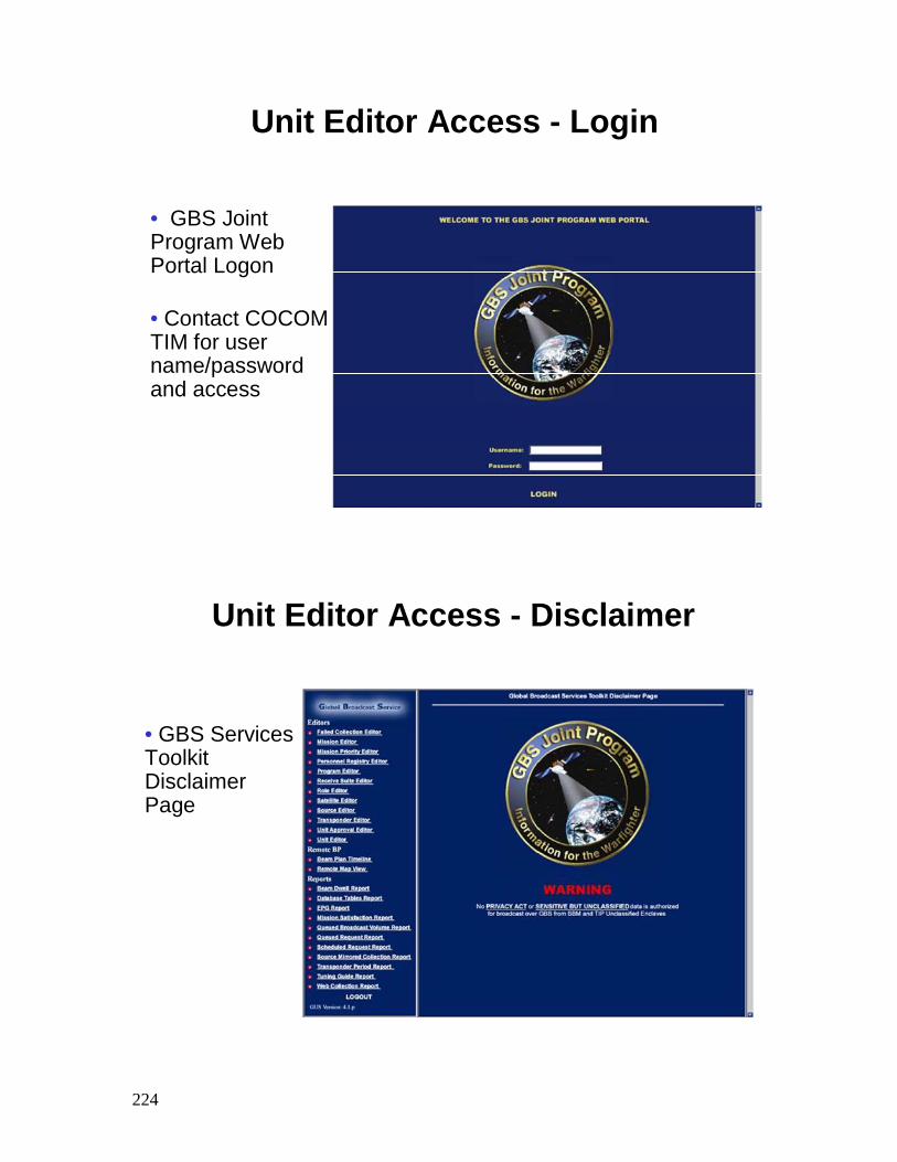
224
Unit Editor Access - Login
• GBS Joint Program Web Portal Logon
• Contact COCOM TIM for user name/password and access
Unit Editor Access - Disclaimer
• GBS Services Toolkit Disclaimer Page
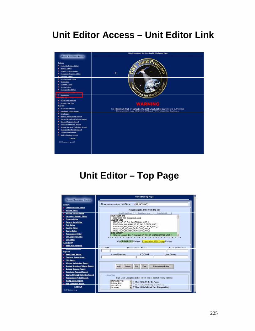
225
Unit Editor Access – Unit Editor Link
Unit Editor – Top Page
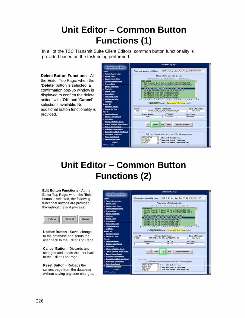
226
Unit Editor – Common Button Functions (1)
Delete Button Functions - At the Editor Top Page, when the 'Delete' button is selected, a confirmation pop-up window is displayed to confirm the delete action, with 'OK' and 'Cancel'selections available. No additional button functionality is provided.
In all of the TSC Transmit Suite Client Editors, common button functionality is provided based on the task being performed:
Unit Editor – Common Button Functions (2)
Edit Button Functions - At the Editor Top Page, when the 'Edit' button is selected, the following functional buttons are provided throughout the edit process:
Update Button - Saves changes to the database and sends the user back to the Editor Top Page.
Cancel Button - Discards any changes and sends the user back to the Editor Top Page.
Reset Button - Reloads the current page from the database without saving any user changes.
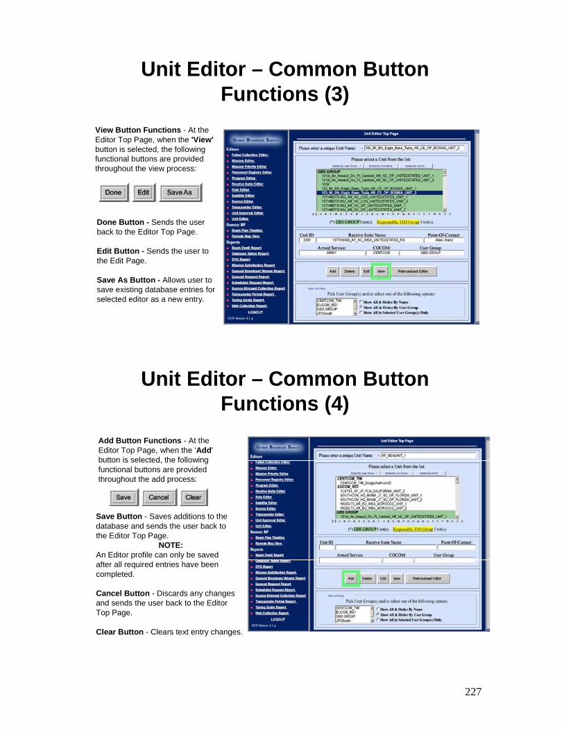
227
Unit Editor – Common Button Functions (3)
View Button Functions - At the Editor Top Page, when the 'View'button is selected, the following functional buttons are provided throughout the view process:
Done Button - Sends the user back to the Editor Top Page.
Edit Button - Sends the user to the Edit Page.
Save As Button - Allows user to save existing database entries for selected editor as a new entry.
Unit Editor – Common Button Functions (4)
Add Button Functions - At the Editor Top Page, when the 'Add' button is selected, the following functional buttons are provided throughout the add process:
Save Button - Saves additions to the database and sends the user back to the Editor Top Page.
NOTE:An Editor profile can only be saved after all required entries have been completed.
Cancel Button - Discards any changes and sends the user back to the Editor Top Page.
Clear Button - Clears text entry changes.
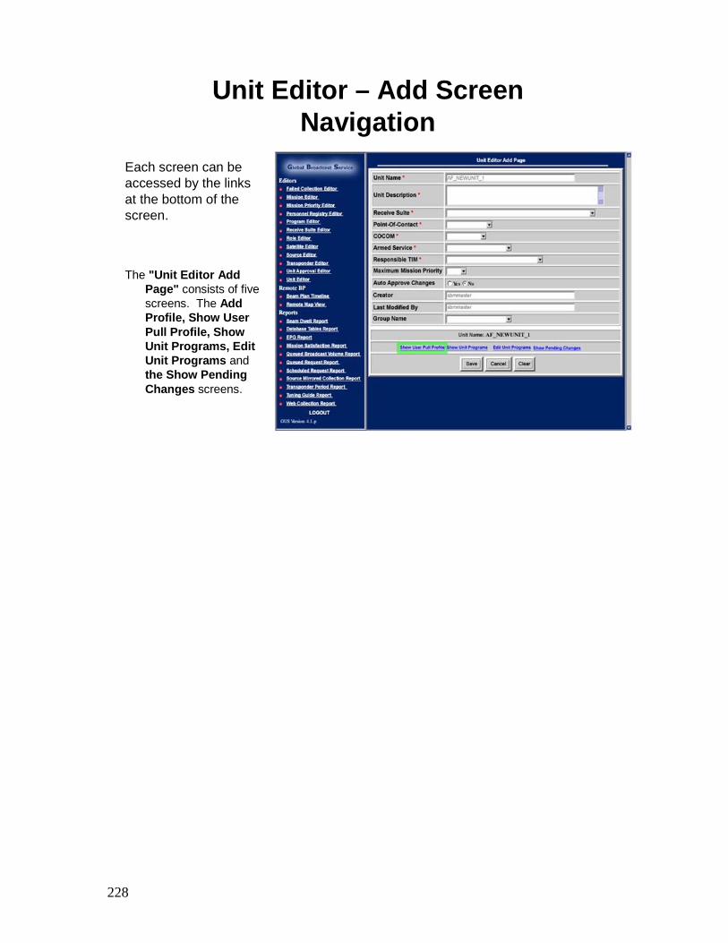
228
Unit Editor – Add Screen Navigation
The "Unit Editor Add Page" consists of five screens. The Add Profile, Show User Pull Profile, Show Unit Programs, Edit Unit Programs and the Show Pending Changes screens.
Each screen can beaccessed by the links at the bottom of the screen.
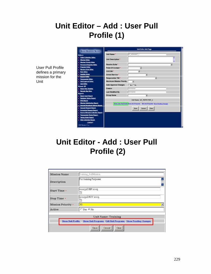
229
Unit Editor – Add : User Pull Profile (1)
User Pull Profile defines a primary mission for the Unit
Unit Editor - Add : User PullProfile (2)
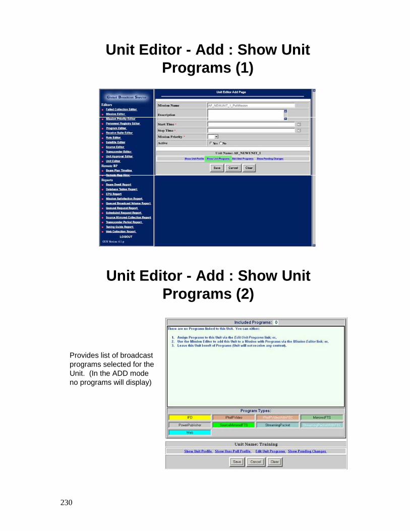
230
Unit Editor - Add : Show Unit Programs (1)
Unit Editor - Add : Show Unit Programs (2)
Provides list of broadcast programs selected for the Unit. (In the ADD mode no programs will display)
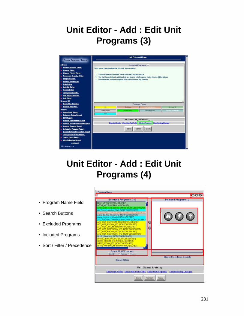
231
Unit Editor - Add : Edit Unit Programs (3)
Unit Editor - Add : Edit Unit Programs (4)
• Program Name Field
• Search Buttons
• Excluded Programs
• Included Programs
• Sort / Filter / Precedence
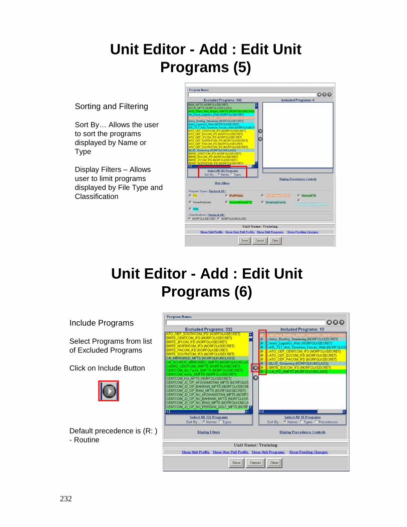
232
Unit Editor - Add : Edit Unit Programs (5)
Sorting and Filtering
Sort By… Allows the user to sort the programs displayed by Name or Type
Display Filters – Allows user to limit programs displayed by File Type and Classification
Include Programs
Select Programs from list of Excluded Programs
Click on Include Button
Default precedence is (R: ) - Routine
Unit Editor - Add : Edit Unit Programs (6)
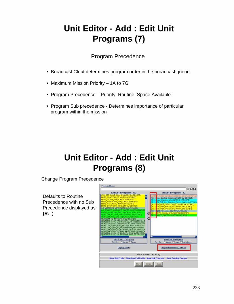
233
Unit Editor - Add : Edit Unit Programs (7)
• Broadcast Clout determines program order in the broadcast queue
• Maximum Mission Priority – 1A to 7G
• Program Precedence – Priority, Routine, Space Available
• Program Sub precedence - Determines importance of particular program within the mission
Program Precedence
Unit Editor - Add : Edit Unit Programs (8)
Defaults to Routine Precedence with no Sub Precedence displayed as(R: )
Change Program Precedence
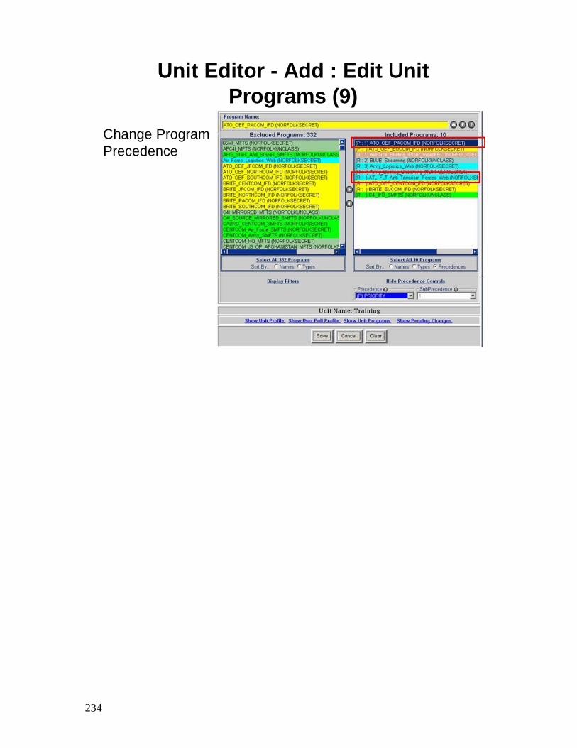
234
Unit Editor - Add : Edit Unit Programs (9)
Change ProgramPrecedence
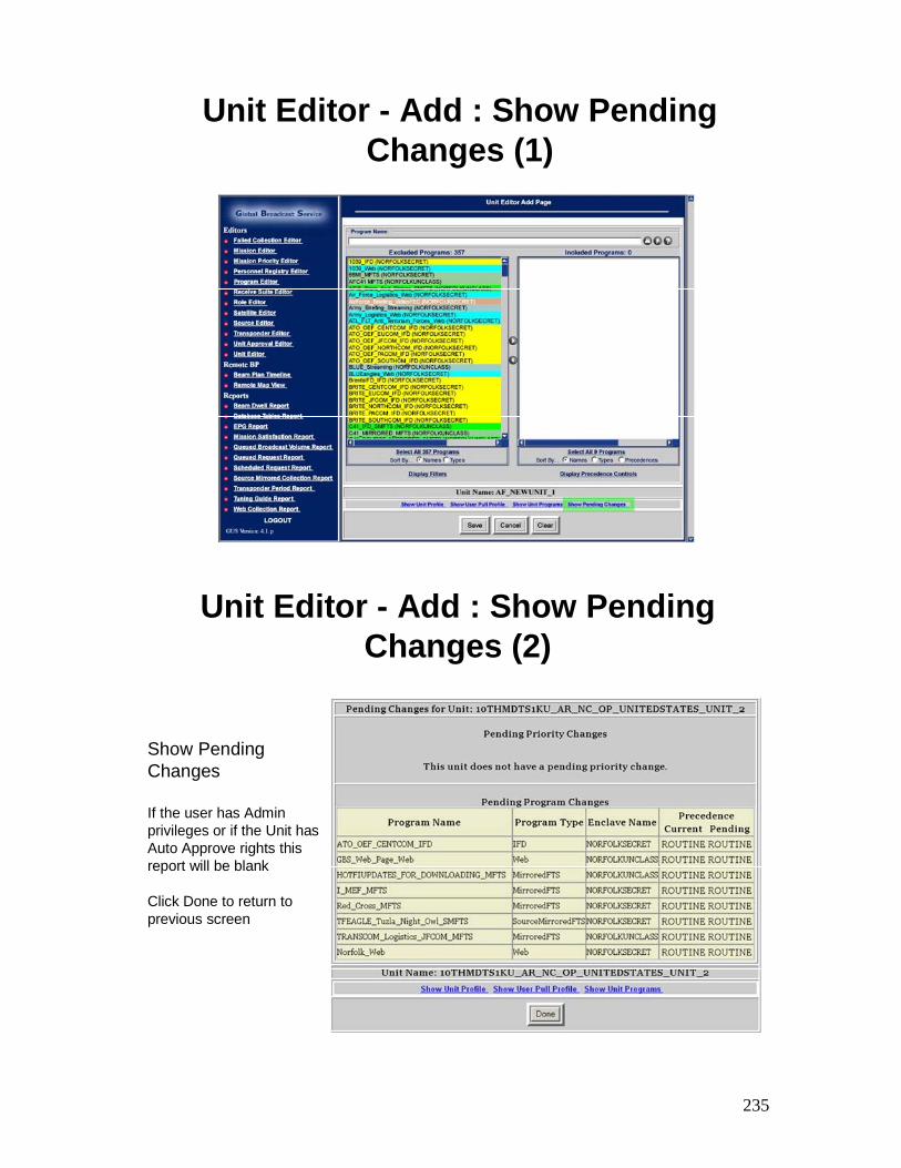
235
Unit Editor - Add : Show PendingChanges (1)
Unit Editor - Add : Show PendingChanges (2)
Show Pending Changes
If the user has Admin privileges or if the Unit has Auto Approve rights this report will be blank
Click Done to return to previous screen
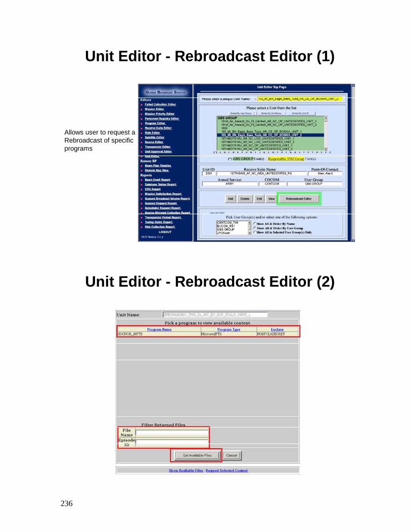
236
Unit Editor - Rebroadcast Editor (1)
Allows user to request a Rebroadcast of specific programs
Unit Editor - Rebroadcast Editor (2)
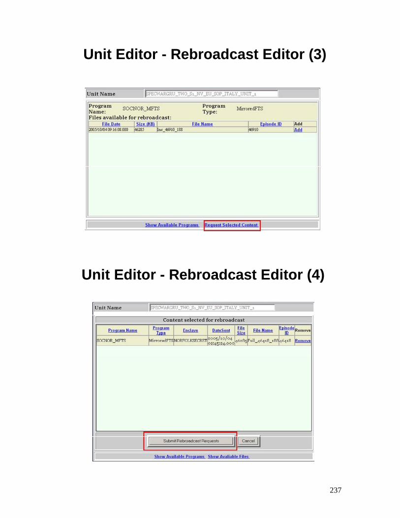
237
Unit Editor - Rebroadcast Editor (3)
Unit Editor - Rebroadcast Editor (4)
238
Unit Editor - Summary
Review:
State the purpose of the Unit Editor
Explain how to access the Unit Editor
Explain the use of the Add Unit Programs screens
Explain the use of the Rebroadcast Editor

TAB
Insert Tab # 6 Here
AN/TSR-8 Maintenance and Troubleshooting

240
241
Maintenance and TroubleshootingObjectives
• Upon successful completion of this lesson, the student will be able to: – Explain the troubleshooting steps
– Explain the periodic maintenance
242
Troubleshooting (1)
• The troubleshooting method used to diagnose and repair faults within the RBM consists of three steps:
1. Fault Identification
2. Fault Isolation
3. LRU Removal and Replacement
Troubleshooting (2)
• Preliminary System Checks: Before conducting fault isolation procedures, perform the following:
Perform the System Power Down ProcedureEnsure all cables are secure and connected correctlyEnsure power is supplied to the NGRT and RBMPerform the System Power Up ProcedureEnsure GFCI on antenna power cable is not trippedEnsure Power Controller Unit circuit breaker is not trippedEnsure power is applied to all LRUsEnsure system is configured per Mission Data Sheet
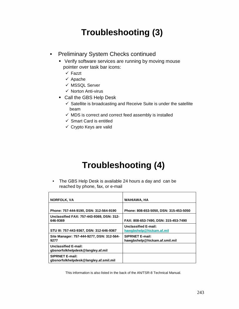
243
Troubleshooting (3)
• Preliminary System Checks continuedVerify software services are running by moving mouse
pointer over task bar icons: FazztApacheMSSQL ServerNorton Anti-virus
Call the GBS Help DeskSatellite is broadcasting and Receive Suite is under the satellite
beamMDS is correct and correct feed assembly is installedSmart Card is entitledCrypto Keys are valid
Troubleshooting (4)• The GBS Help Desk is available 24 hours a day and can be
reached by phone, fax, or e-mail
NORFOLK, VA WAHIAWA, HA
Phone: 757-444-9190, DSN: 312-564-9190 Phone: 808-653-5050, DSN: 315-453-5050Unclassified FAX: 757-443-9369, DSN: 312-646-9369 FAX: 808-653-7490, DSN: 315-453-7490
STU III: 757-443-9367, DSN: 312-646-9367Unclassified E-mail: [email protected]
Site Manager: 757-444-9277, DSN: 312-564-9277
SIPRNET E-mail: [email protected]
Unclassified E-mail: [email protected] E-mail: [email protected]
This information is also listed in the back of the AN/TSR-8 Technical Manual.
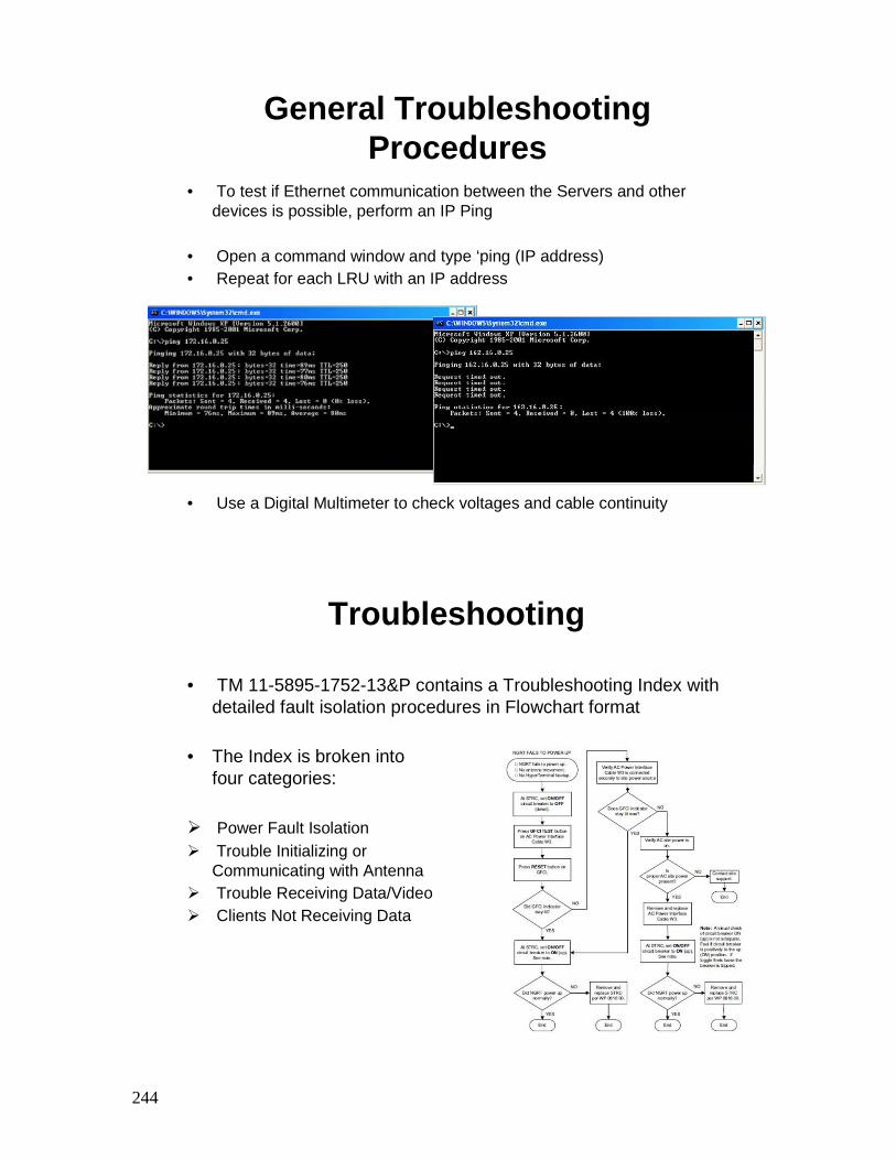
244
• To test if Ethernet communication between the Servers and otherdevices is possible, perform an IP Ping
• Open a command window and type ‘ping (IP address)• Repeat for each LRU with an IP address
• Use a Digital Multimeter to check voltages and cable continuity
General Troubleshooting Procedures
Troubleshooting
• TM 11-5895-1752-13&P contains a Troubleshooting Index with detailed fault isolation procedures in Flowchart format
• The Index is broken into four categories:
Power Fault IsolationTrouble Initializing or Communicating with Antenna Trouble Receiving Data/VideoClients Not Receiving Data
245
Power Fault Isolation (1)
• NGRT fails to power up:
GFCI on NGRT power cable W3 needs resetSite power is offSTRC circuit breaker tripped
• COMSEC Tray Assembly, Unmanaged Ethernet Switch (UMES) and/or Crypto Unit fails to power up:
COMSEC Tray power switch is OFFCrypto Unit power switch is OFFPower cable to Crypto Unit / MES not connected
Here are some basic items to check before breaking out the TM.
Power Fault Isolation (2)
• Managed Ethernet Switch (MES) fails to power up
Power cable not connected
• IRD fails to power up
IRD Power switch is OFFPower cable not connected
246
Power Fault Isolation (3)
• RBM Server or NGRT Server fails to power up
Power cable not connectedBad AC adapterServer laptop hard drive crashed
• Power Controller Unit (PCU) fails to power up
Not plugged inSite power is OFF
247
Trouble Initializing or Communicating with Antenna (1)
• NGRT Server fails to communicate with the NGRT
Serial Cable not properly connected STRC is not poweredHyperTerminal not configured properly
• NGRT Server displays NGRT Fault Messages
The LNB or a motor may have gone bad or there is a loose cable
• NGRT fails to track a satellite
Not a clear line of site to the satellite Possible magnetic interference from other equipmentIncorrect tracking dataIncorrect LNB
• MES or Crypto Unit Web Interface Problems
Bad Ethernet cableIP conflictMES ports turned off
Trouble Initializing or Communicating with Antenna (2)
248
Trouble Initializing or Communicating with Antenna (3)
• NGRT Server Web interface problems with IRD
Bad Ethernet cableIncorrect Ethernet cabling (ETH0 / ETH1)UMES not powered
• IRD no signal lock
Incorrect satellite setting in IRDSBM outage
Go to the GBS SIPRNET Website and check the news. There may be a scheduled outage in progress. It there was an unplanned outage, a message will be posted.
249
Trouble Initializing or Communicating with Antenna (4)
• Smart Card Reader fails to enable
Smart card needs re-entitled, call GBS Help DeskSmart card bad or expired
If the SMART Card has not been used in more then 270 days, it will need to be re-entitled.
250
Trouble Receiving Data/Video
• Trouble Receiving Data/Video
KenCast Transponder Lock is redSecure Tunnels not “UP”Incorrect or expired COMSEC
Clients Not Receiving Video/Data
• LAN Users Not Receiving Video/Data
Bad Ethernet cablingUser FTP software issuePush setting incorrect or changed
251
Periodic Maintenance (1)
• Weekly PMCS
• KG-250 Crypto Unit: Export Audit log, maintain for 1 year.
• RBM and NGRT Servers: Export the Apache and Fazzt logs; Application, System, and Security logs; maintain for 1 year.
Periodic Maintenance (2)
• Monthly PMCS
• RBM Server and NGRT Server Hard Drives: Perform DiskeeperPaging File and Master File Table Defragmentation procedure
• RBM Server and NGRT Server Hard Drives: Delete FPK files that are older than 37 days if disk space is an issue
• Smart Card: Maintain entitlement of Smart Card by obtaining data lock on broadcast signal. Can take up to 30 minutes to fully entitle card. After 255 days of inactivity, the Smart Card will expire.
252
Maintenance and Troubleshooting–Summary
• Review:– Explain the troubleshooting steps
– Explain the periodic maintenance

TAB
Insert Tab # 7 Here
Network Integration And
Operations

254
255
Immediate File Delivery (IFD)
• Upon successful completion of this lesson, the student will be able to: – Explain how to request IFD access
IFD Accounts
IFD Accounts requested via GMR to SBMUser must provide:
•Name, Rank, SIPR Account,•IP Address•CAC Certificate •Computer name
IFD Address, User name and Password will be sent via SIPR by SBM
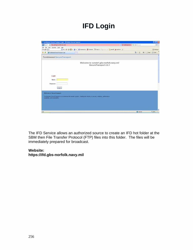
256
IFD Login
The IFD Service allows an authorized source to create an IFD hot folder at the SBM then File Transfer Protocol (FTP) files into this folder. The files will be immediately prepared for broadcast. Website: https://ifd.gbs-norfolk.navy.mil
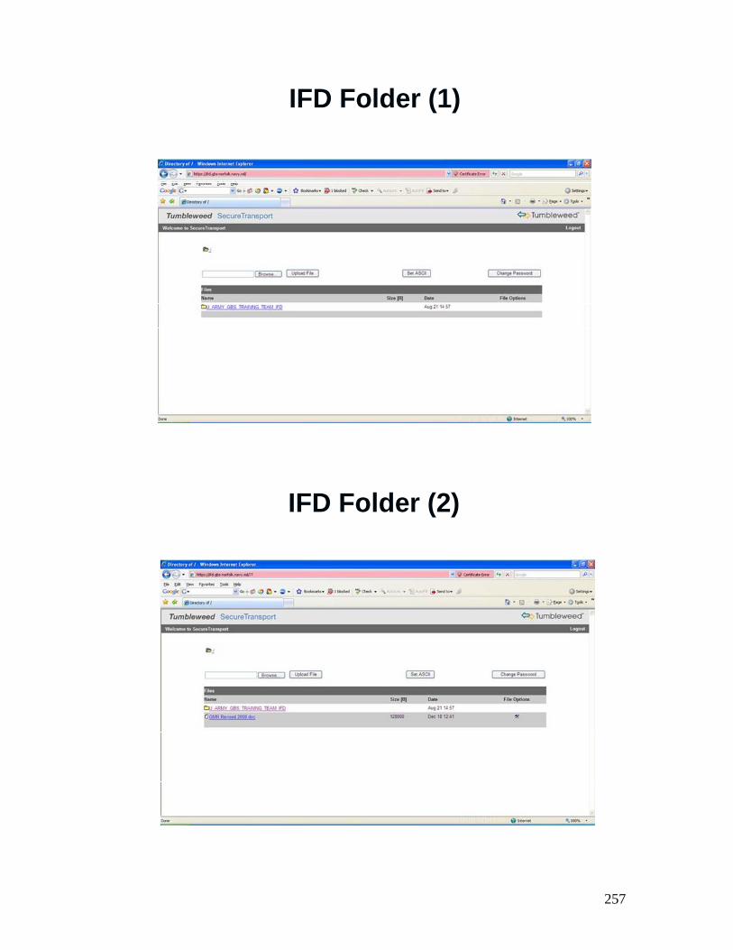
257
IFD Folder (1)
IFD Folder (2)

258
IFD Operations with National Geospatial-
Intelligence Agency (NGA)

259
IFD Operations with NGA - Objectives
• Upon successful completion of this lesson, the student will be able to: – Explain how to Perform IFD Interface
– Explain how to Perform IFD Interface with the National National GeospatialGeospatial--Intelligence Agency (NGA)Intelligence Agency (NGA)
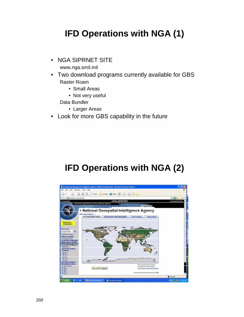
260
IFD Operations with NGA (1)
• NGA SIPRNET SITE www.nga.smil.mil
• Two download programs currently available for GBSRaster Roam
• Small Areas• Not very useful
Data Bundler • Larger Areas
• Look for more GBS capability in the future
IFD Operations with NGA (2)
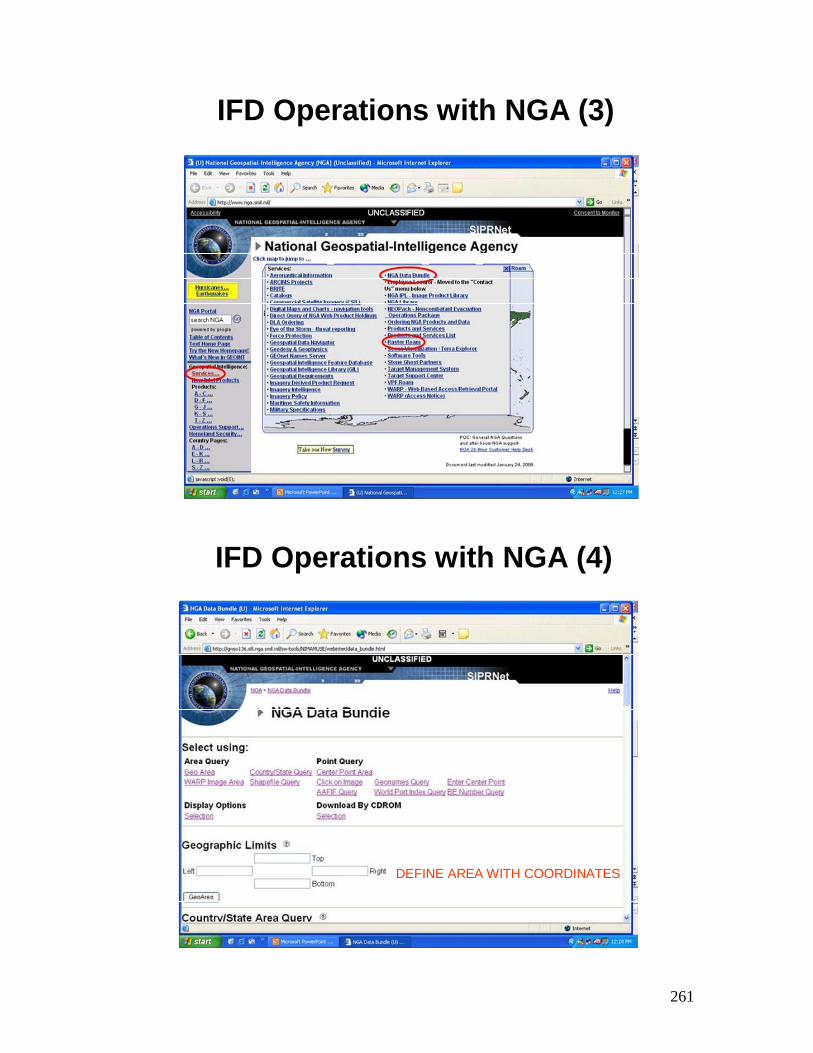
261
IFD Operations with NGA (3)
IFD Operations with NGA (4)
DEFINE AREA WITH COORDINATES
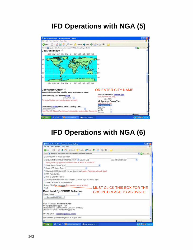
262
IFD Operations with NGA (5)
OR ENTER CITY NAME
IFD Operations with NGA (6)
MUST CLICK THIS BOX FOR THE GBS INTERFACE TO ACTIVATE
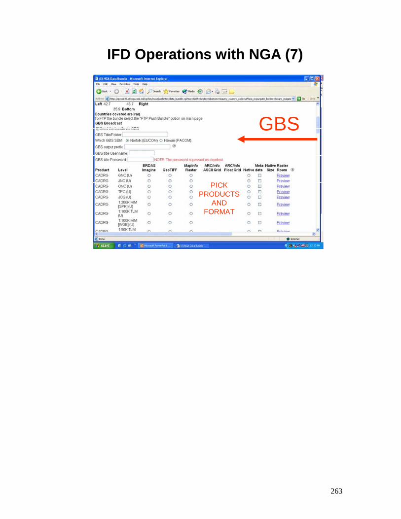
263
IFD Operations with NGA (7)
GBS
PICK PRODUCTS
AND FORMAT

264
IFD Operations with NGA - Summary
• Review:– Explain how to Perform IFD Interface
– Explain how to Perform IFD Interface with the National National GeospatialGeospatial--Intelligence Center (NGA)Intelligence Center (NGA)

265
IFD Operations with National Ground
Intelligence Center (NGIC)

266
IFD Operations withNGIC - Objectives
• Upon successful completion of this lesson, the student will be able to:– Explain how to Perform IFD Interface
– Explain how to Perform IFD Interface with the National National Ground Intelligence Center (NGIC)Ground Intelligence Center (NGIC)
267
IFD Operations with NGIC (1)
• GBS Web Ordering - Geospatial Data & Imagery
• National Ground Intelligence Center http://e45001.ngic.army.smil.mil
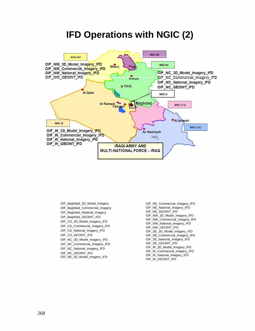
268
20
IFD Operations with NGIC (2)
OIF_Baghdad_3D_Model_ImageryOIF_Baghdad_Commercial_ImageryOIF_Baghdad_National_ImageryOIF_Baghdad_GEOINT_IFDOIF_CS_3D_Model_Imagery_IFDOIF_CS_Commercial_Imagery_IFDOIF_CS_National_Imagery_IFDOIF_CS_GEOINT_IFDOIF_NC_3D_Model_Imagery_IFDOIF_NC_Commercial_Imagery_IFDOIF_NC_National_Imagery_IFDOIF_NC_GEOINT_IFDOIF_NE_3D_Model_Imagery_IFD
OIF_NE_Commercial_Imagery_IFDOIF_NE_National_Imagery_IFDOIF_NE_GEOINT_IFDOIF_NW_3D_Model_Imagery_IFDOIF_NW_Commercial_Imagery_IFDOIF_NW_National_Imagery_IFDOIF_NW_GEOINT_IFDOIF_SE_3D_Model_Imagery_IFDOIF_SE_Commercial_Imagery_IFDOIF_SE_National_Imagery_IFDOIF_SE_GEOINT_IFDOIF_W_3D_Model_Imagery_IFDOIF_W_Commercial_Imagery_IFDOIF_W_National_Imagery_IFDOIF_W_GEOINT_IFD
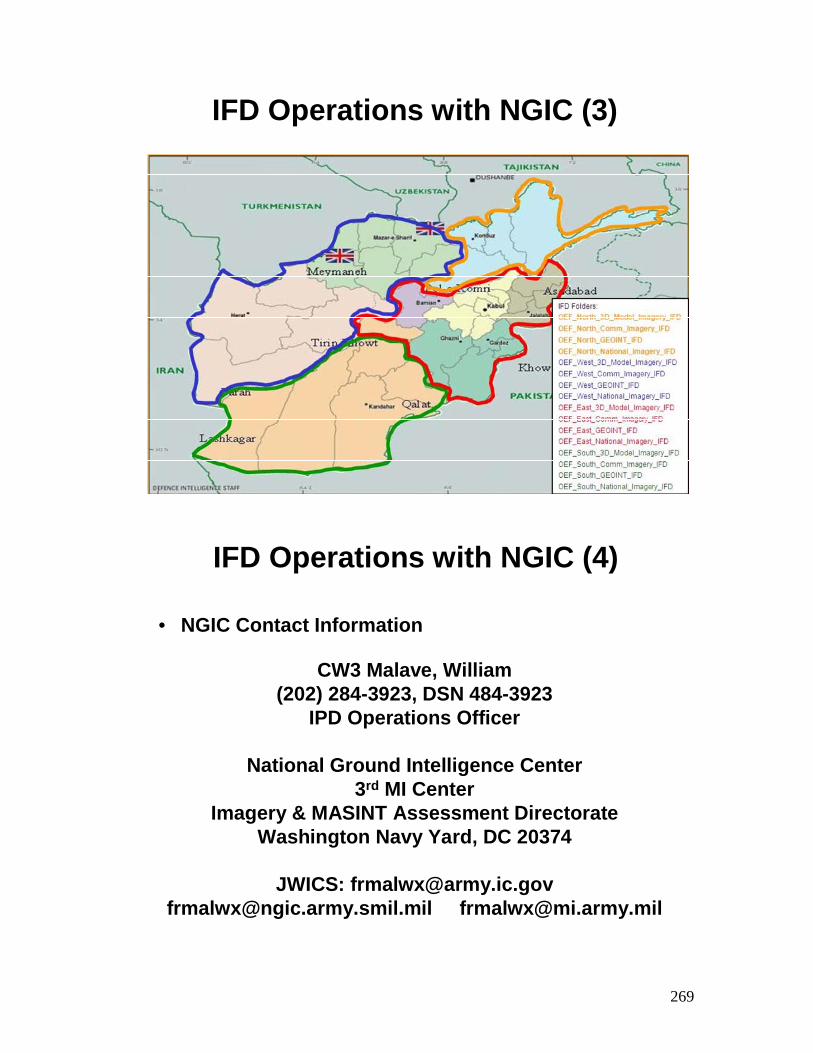
269
IFD Operations with NGIC (3)
IFD Operations with NGIC (4)
CW3 Malave, William(202) 284-3923, DSN 484-3923
IPD Operations Officer
National Ground Intelligence Center3rd MI Center
Imagery & MASINT Assessment DirectorateWashington Navy Yard, DC 20374
JWICS: [email protected]@ngic.army.smil.mil [email protected]
• NGIC Contact Information
270
IFD Operations with NGIC - Summary
• Review:– Explain how to Perform IFD Interface
– Explain how to Perform IFD Interface with the National National Ground Intelligence Center (NGIC)Ground Intelligence Center (NGIC)

271
IFD Operations with
Topographic Engineer Center (TEC)

272
IFD Operations with TEC - Objectives
• Upon successful completion of this lesson, the student will be able to:– Explain how to Perform IFD
– Explain how to Perform IFD with the TEC
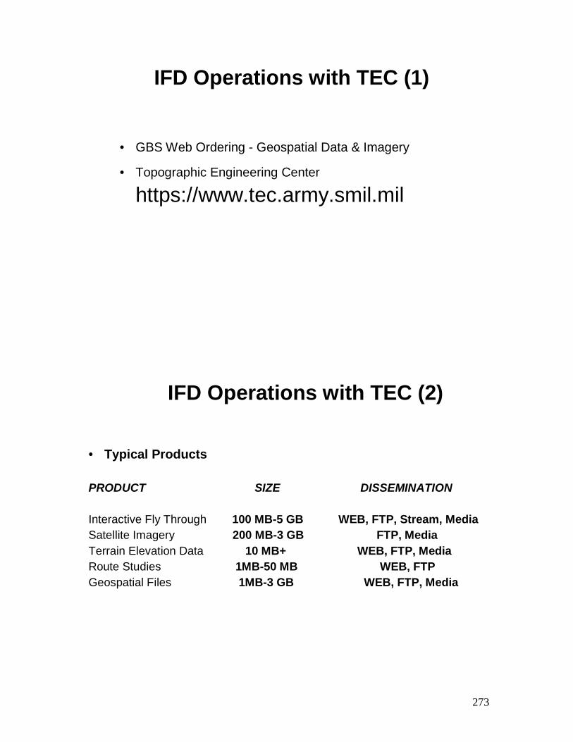
273
IFD Operations with TEC (1)
• GBS Web Ordering - Geospatial Data & Imagery
• Topographic Engineering Center
https://www.tec.army.smil.mil
IFD Operations with TEC (2)
• Typical Products
PRODUCT SIZE DISSEMINATION
Interactive Fly Through 100 MB-5 GB WEB, FTP, Stream, MediaSatellite Imagery 200 MB-3 GB FTP, MediaTerrain Elevation Data 10 MB+ WEB, FTP, MediaRoute Studies 1MB-50 MB WEB, FTPGeospatial Files 1MB-3 GB WEB, FTP, Media
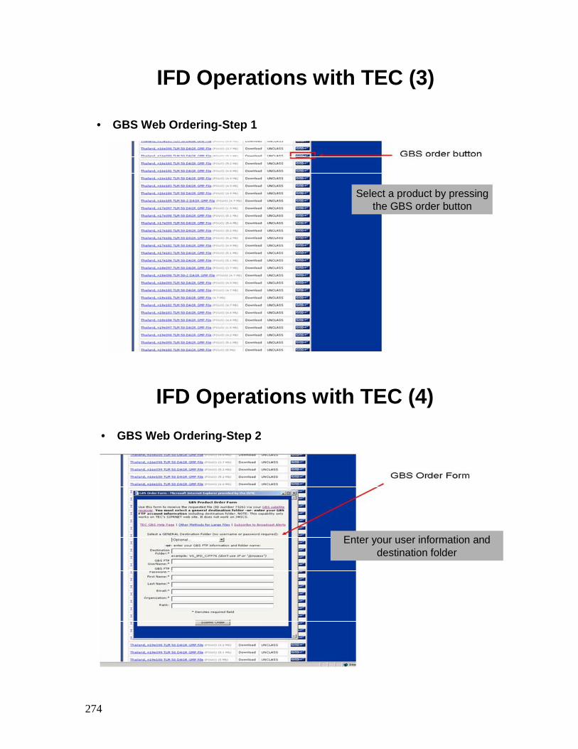
274
IFD Operations with TEC (3)
• GBS Web Ordering-Step 1
Select a product by pressingthe GBS order button
IFD Operations with TEC (4)• GBS Web Ordering-Step 2
Enter your user information and destination folder
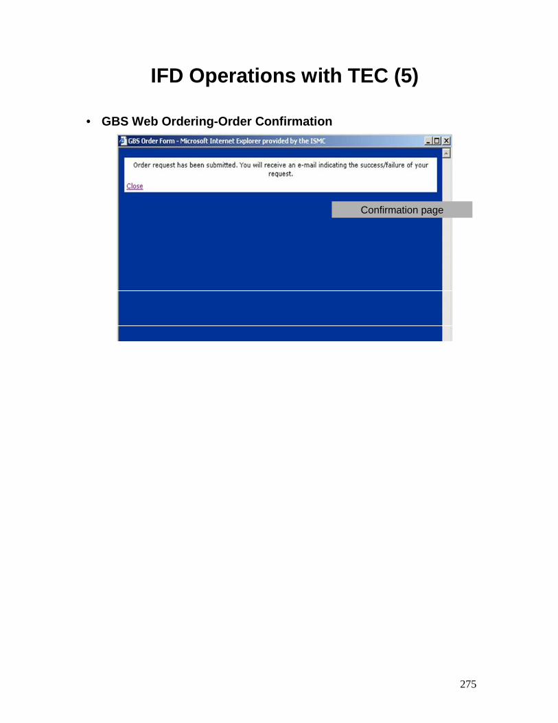
275
IFD Operations with TEC (5)
• GBS Web Ordering-Order Confirmation
Confirmation page

276
TEC POC Information
• TEC Contact Information
Steve Benzek(703) 428-6732, DSN 364-6732
Topographic Engineering CenterUS Army Corps of Engineers
Engineer Research and Development Center7701 Telegraph Rd., Alexandria, Virginia 22315
www.tec.army.milwww.tec.army.smil.mil www.tec.ic.gov

277
IFD Operations with TEC - Summary
• Review:– Explain how to Perform IFD
– Explain how to Perform IFD with the TEC
278
GBS Network Integration
279
GBS NetworkIntegration - Objectives
• Upon successful completion of this lesson, the student will be able to:– Explain Bandwidth and Video Distribution methods
– Explain how to configure the servers to connect to a site LAN maintaining GBS IP addresses
– Explain how to configure the servers to connect to a site LAN using site LAN IP addresses for all GBS equipment
– Explain how to connect a router for network integration
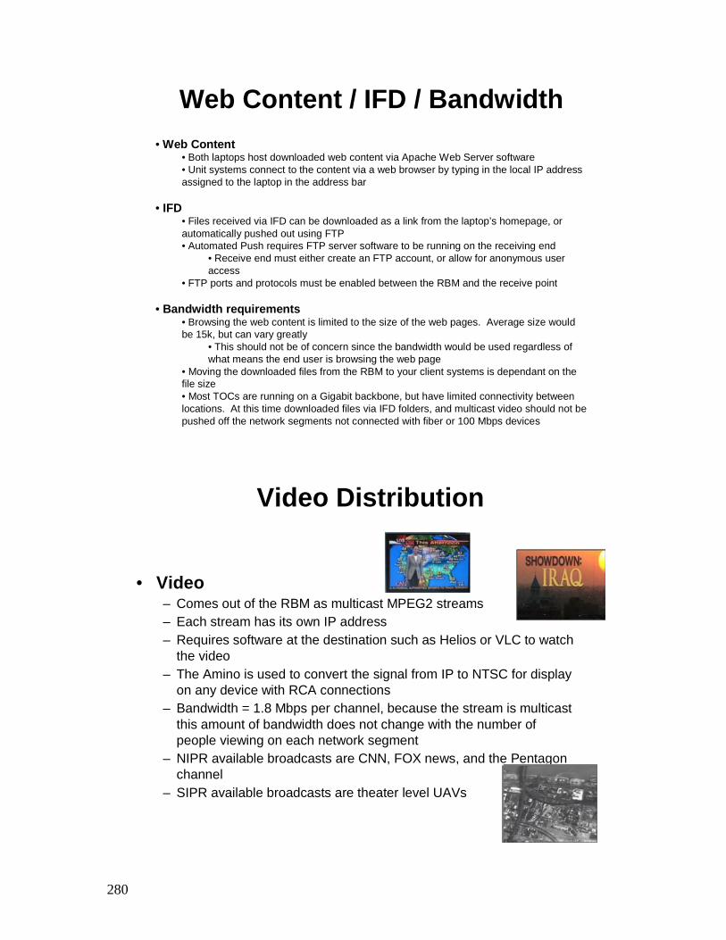
280
Web Content / IFD / Bandwidth• Web Content
• Both laptops host downloaded web content via Apache Web Server software• Unit systems connect to the content via a web browser by typing in the local IP address assigned to the laptop in the address bar
• IFD• Files received via IFD can be downloaded as a link from the laptop’s homepage, or automatically pushed out using FTP• Automated Push requires FTP server software to be running on the receiving end
• Receive end must either create an FTP account, or allow for anonymous user access
• FTP ports and protocols must be enabled between the RBM and the receive point
• Bandwidth requirements• Browsing the web content is limited to the size of the web pages. Average size would be 15k, but can vary greatly
• This should not be of concern since the bandwidth would be used regardless of what means the end user is browsing the web page
• Moving the downloaded files from the RBM to your client systems is dependant on the file size• Most TOCs are running on a Gigabit backbone, but have limited connectivity between locations. At this time downloaded files via IFD folders, and multicast video should not be pushed off the network segments not connected with fiber or 100 Mbps devices
Video Distribution
• Video– Comes out of the RBM as multicast MPEG2 streams– Each stream has its own IP address– Requires software at the destination such as Helios or VLC to watch
the video– The Amino is used to convert the signal from IP to NTSC for display
on any device with RCA connections– Bandwidth = 1.8 Mbps per channel, because the stream is multicast
this amount of bandwidth does not change with the number of people viewing on each network segment
– NIPR available broadcasts are CNN, FOX news, and the Pentagon channel
– SIPR available broadcasts are theater level UAVs
281
Configure GBS Servers MaintainingDefault ARS IP Addresses (1)
• Obtain IP addresses from LAN Manager for the NGRT Server and the RBM Server
One IP for each Server
One subnet mask for each Server
Default Gateway IP for each Server
Preferred DNS IP for Each Server
Alternate DNS IP for each Server
Configure GBS Servers MaintainingDefault ARS IP Addresses (2)
• Configure NGRT Server and RBM Server
In My Network Places>Properties>Local Area Connections>TCP/IP>Properties
1. Enter default Gateway
2. Enter preferred DNS IP
3. Enter Alternate DNS IP
4. Click OK
5. Enter IP (Provided by LAN Manager)
6. Enter Subnet Mask (Provided by LAN Manager)
7. Click OK, and close
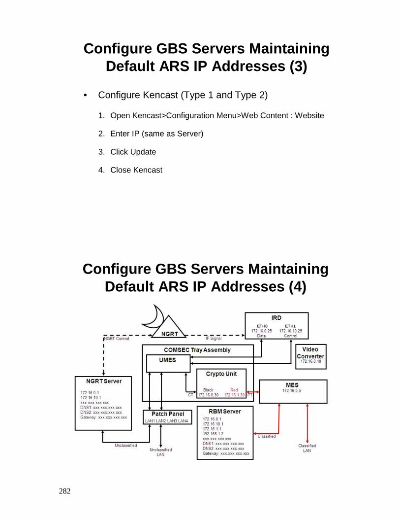
282
Configure GBS Servers MaintainingDefault ARS IP Addresses (3)
• Configure Kencast (Type 1 and Type 2)
1. Open Kencast>Configuration Menu>Web Content : Website
2. Enter IP (same as Server)
3. Click Update
4. Close Kencast
Configure GBS Servers MaintainingDefault ARS IP Addresses (4)
ETH0 ETH1
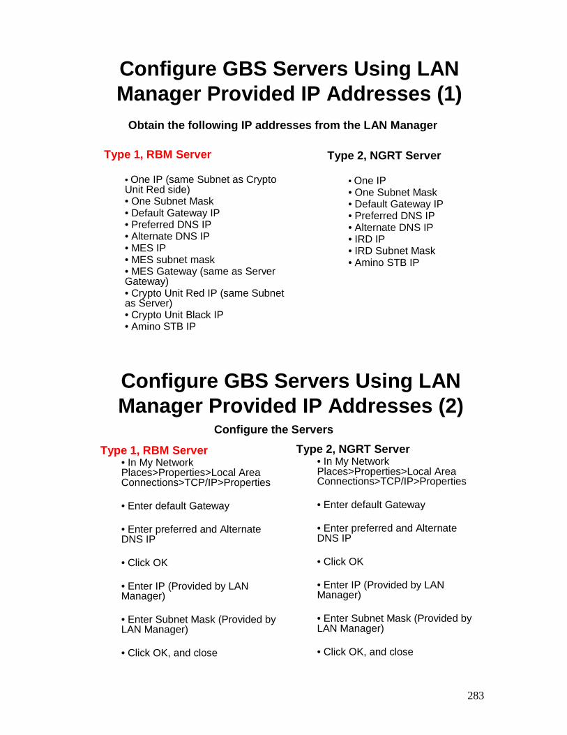
283
Configure GBS Servers Using LANManager Provided IP Addresses (1)
Type 1, RBM Server
• One IP (same Subnet as Crypto Unit Red side)• One Subnet Mask• Default Gateway IP• Preferred DNS IP• Alternate DNS IP• MES IP• MES subnet mask• MES Gateway (same as Server Gateway)• Crypto Unit Red IP (same Subnet as Server)• Crypto Unit Black IP• Amino STB IP
Type 2, NGRT Server
• One IP• One Subnet Mask• Default Gateway IP• Preferred DNS IP• Alternate DNS IP• IRD IP• IRD Subnet Mask• Amino STB IP
Obtain the following IP addresses from the LAN Manager
Configure GBS Servers Using LANManager Provided IP Addresses (2)
Type 1, RBM Server• In My Network Places>Properties>Local Area Connections>TCP/IP>Properties
• Enter default Gateway
• Enter preferred and Alternate DNS IP
• Click OK
• Enter IP (Provided by LAN Manager)
• Enter Subnet Mask (Provided by LAN Manager)
• Click OK, and close
Configure the ServersType 2, NGRT Server
• In My Network Places>Properties>Local Area Connections>TCP/IP>Properties
• Enter default Gateway
• Enter preferred and Alternate DNS IP
• Click OK
• Enter IP (Provided by LAN Manager)
• Enter Subnet Mask (Provided by LAN Manager)
• Click OK, and close
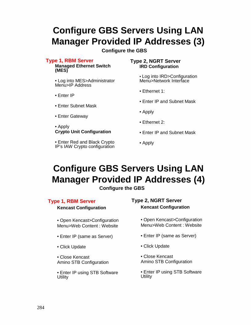
284
Configure GBS Servers Using LANManager Provided IP Addresses (3)
Type 1, RBM ServerManaged Ethernet Switch (MES)
• Log into MES>Administrator Menu>IP Address
• Enter IP
• Enter Subnet Mask
• Enter Gateway
• ApplyCrypto Unit Configuration
• Enter Red and Black Crypto IP’s IAW Crypto configuration
Configure the GBS
Type 2, NGRT ServerIRD Configuration
• Log into IRD>Configuration Menu>Network Interface
• Ethernet 1:
• Enter IP and Subnet Mask
• Apply
• Ethernet 2:
• Enter IP and Subnet Mask
• Apply
Configure GBS Servers Using LANManager Provided IP Addresses (4)
Type 1, RBM ServerKencast Configuration
• Open Kencast>Configuration Menu>Web Content : Website
• Enter IP (same as Server)
• Click Update
• Close KencastAmino STB Configuration
• Enter IP using STB Software Utility
Configure the GBS
Type 2, NGRT ServerKencast Configuration
• Open Kencast>Configuration Menu>Web Content : Website
• Enter IP (same as Server)
• Click Update
• Close KencastAmino STB Configuration
• Enter IP using STB Software Utility
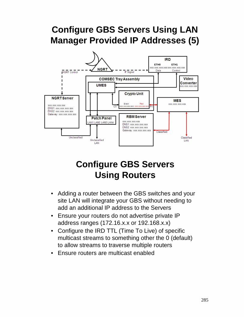
285
Configure GBS Servers Using LANManager Provided IP Addresses (5)
ETH0 ETH1
Configure GBS Servers Using Routers
• Adding a router between the GBS switches and your site LAN will integrate your GBS without needing to add an additional IP address to the Servers
• Ensure your routers do not advertise private IP address ranges (172.16.x.x or 192.168.x.x)
• Configure the IRD TTL (Time To Live) of specific multicast streams to something other the 0 (default) to allow streams to traverse multiple routers
• Ensure routers are multicast enabled
286
GBS Network Integration - Summary
• Review:– Explain Bandwidth and Video Distribution methods
– Explain how to configure the servers to connect to a site LAN maintaining GBS IP addresses
– Explain how to configure the servers to connect to a site LAN using site LAN IP addresses for all GBS equipment
– Explain how to connect a router for network integration