gas–liquid mass transfer in unbaffled dual-impeller mixers
TRANSCRIPT
Chemical Engineering Science 63 (2008) 1636–1647www.elsevier.com/locate/ces
Gas–liquid mass transfer in unbaffled dual-impeller mixers
F. Cabaret, L. Fradette, P.A. Tanguy∗
URPEI, Department of Chemical Engineering, Ecole Polytechnique, P.O. Box 6079 Station Centre-Ville, Montreal, Que., Canada H3C 3A7
Received 6 July 2007; received in revised form 6 November 2007; accepted 11 November 2007Available online 22 November 2007
Abstract
The gas–liquid mass transfer performance of different unbaffled dual-impeller mixers was investigated experimentally using low- and high-viscosity Newtonian and non-Newtonian liquids. The tested configurations were composed of two Rushton turbines located at two different heightlevels in the vessel in centered or off-centered positions. Various mixers were compared based on their respective mass transfer performancemeasured by means of two dissolved oxygen probes located at different levels in the vessel. kla correlations and an axial homogeneity criterionwere established for the different configurations and liquids used. It was concluded that the dual shaft mixer consisting of two off-centeredshafts appears to be a very interesting and flexible configuration to deal with Newtonian liquids in a large range of viscosities. However,concerning the gas–liquid dispersion in non-Newtonian liquids, it is shown that off-centered shaft configurations have to be avoided.� 2007 Elsevier Ltd. All rights reserved.
Keywords: Multiphase reactors; Mixing; Dispersion; Absorption; Unbaffled; Shaft off-centering
1. Introduction
Stirred tank reactors under gassed conditions are often usedwith single impeller or multiple impellers stacked on a com-mon shaft to intensify the contact between gas and liquid. Thesereactors have numerous industrial applications such as chem-ical synthesis, aerobic fermentation and wastewater treatment.Compared to single-impeller reactors, the multiple-impellerconfigurations exhibit numerous advantages such as a betterdistribution of energy dissipation, improved liquid circulationin the vessel, a better gas distribution and longer gas residencetime in the vessel, yielding a higher efficiency of gas utilization.
When low-viscosity liquids are handled, baffled vessels withrelatively small-sized turbine impellers generating a high shear-ing action are generally adopted. This “standard” configurationcan be used with radial turbine impellers along the shaft onlyor, to improve the axial homogenization, a combination of ra-dial and axial type impellers can be considered. In this case,a radial turbine impeller is often located at the bottom end ofthe shaft for gas dispersion and axial type impellers are placedalong the shaft for homogenization. To improve furthermore the
∗ Corresponding author. Tel.: +1 514 340 4040; fax: +1 514 340 4105.E-mail address: [email protected] (P.A. Tanguy).
0009-2509/$ - see front matter � 2007 Elsevier Ltd. All rights reserved.doi:10.1016/j.ces.2007.11.028
flexibility of multiple-impeller reactors, Solomons and LeGrys(1981) proposed to use a baffled dual shaft system. In thisreactor, a shaft was introduced at the bottom of the vessel torotate a radial turbine impeller and another shaft was introducedat the top of the tank to drive an axial impeller. It has beenshown that the flexibility of this reactor, resulting from thefact that the two impellers can rotate at different speeds, helpsto mix slightly viscous and non-Newtonian liquids (Andersonet al., 1982; John et al., 1995, 1997, 1998). However, the majordrawback of this configuration is the use of baffles. Usually,baffles must be avoided with viscous and/or non-Newtonianfluids due to an insufficient mixing behind them often resultingin intensive cleaning requirements.
For gas–liquid contacting operations dealing with liquids ofhigh viscosity and often exhibiting non-Newtonian rheology,unbaffled vessels with relatively large-sized impellers of lowshearing action, such as helical ribbon or Maxblend impellerscan be used. However, problems encountered in these viscousreactors are multiple and include (Yoshida et al., 2001):
• the presence of large gas-filled cavities behind the impellerblades,
• the need to use a small gas sparging rate to avoid floodingof the impeller.
F. Cabaret et al. / Chemical Engineering Science 63 (2008) 1636–1647 1637
• and the insufficient generation of small bubbles due to thelow shearing action of the impeller.
All these problems lead to poor mass transfer between the twophases although a good spatial distribution is reached in thetank.
In some industrial applications such as fermentation pro-cesses, media evolves during the process from low-viscosityNewtonian fluids into a rheologically complex viscous andnon-Newtonian media. This leads to a major problem becauselow-viscosity multiple impeller gas–liquid reactors operate ef-ficiently at the beginning of the process but their performancedecreases drastically when the fluid rheology evolves. Thus,the need to develop new gas–liquid reactors able to deal with alarge range of liquid viscosities becomes evident. Some solu-tions have already been proposed by different authors to circum-vent this problem. Tanguy et al. (1997) and Espinosa-Solareset al. (1997, 2001, 2002a, b) designed a coaxial mixer com-posed of a Rushton turbine and a close-clearance helical ribbonimpeller for biotechnology applications. The authors justifiedtheir choice based on the well-documented capabilities of theRushton turbine for gas dispersion and of the helical ribbonimpeller for bulk homogenization. Another solution was pro-posed by Yoshida et al. (2001) which consists in using anunbaffled multiple-impeller agitated vessel having alternatingforward–reverse rotating impellers. These authors have shownthat the change of the rotating mode (forward–reverse) leads toan even gas dispersion without creating the typical bulk flowgenerated with a centered shaft used without baffles. Althoughboth of the proposed reactors have shown good mixing charac-teristics, their main drawback arises from the construction andmaintenance costs associated with co-axial shafts or alternatingforward–reverse operating mode.
Literature review shows that shaft eccentricity appears to bea good solution to prevent the use of baffles both in turbulentand laminar flow. In single phase turbulent mixing, differentauthors have shown that shaft eccentricity is equivalent to baf-fling (Joosten et al., 1977; Nishikawa et al., 1979; Novak et al.,1982; King and Muskett, 1985; Hall et al., 2004, 2005a; Karczand Szoplik, 2004; Karcz et al., 2005; Montante et al., 2006).Nishikawa et al. (1979), Karcz and Szoplik (2004) and Karczet al. (2005) have shown that for axial and radial type impellersthe mixing time decreases with the increase of the shaft ec-centricity. Many studies also report an increase in the impellerpower consumption with the shaft eccentricity when both axialand radial impellers are used (Nishikawa et al., 1979; Novaket al., 1982; Karcz et al., 2005). It was even concluded by Hallet al. (2005a) that eccentrically agitated vessels provide slightlylower mixing times than baffled configurations at the same scaleat equal power consumption per unit volume. Concerning theturbulent gas–liquid mixing, Hall et al. (2005b, c) have shownthat an off-centered impeller produces smaller bubbles thanthose reported in previous studies conducted at a much largerscale in fully baffled vessels. Therefore, shaft off-centeringappears also as an interesting solution in gas–liquid mixing.
Moreover, in single phase laminar mixing recent studies onopen impellers without baffles conclude that, in the laminar
regime, the dynamic perturbations generated by using an ec-centric shaft help to break the segregated regions, and increasethe axial circulation in a tank even if the agitator is of theradial type (Alvarez, 2000; Ascanio et al., 2002a, b; Alvarezet al., 2002; Hall et al., 2005b; Sanchez Cervantes et al., 2006;Cabaret et al., 2007). For dual-impeller systems operating inlaminar flow without baffles, Cabaret et al. (2007) have shownthat the dual shaft mixer with two off-centered shafts (see Fig.1(d)) operating in counter-rotating mode appears as a good al-ternative to prevent the flow compartmentalization and reducethe mixing time.
Since gas absorption is often a rate-limiting step in processesinvolving low solubility gases, the volumetric mass transfercoefficient is a crucial design parameter in gas–liquid reactors.Thus, we will focus our attention on this parameter. As un-baffled gas–liquid stirred vessels have received little attentionby researchers so far and as no data exist in gas–liquid masstransfer with off-centered shaft(s), the objective of this paperis to test the ability of off-centered shaft(s) mixers to generateeffective gas–liquid mass transfer when handling low- andhigh-viscosity Newtonian and non-Newtonian liquids. Threedifferent unbaffled configurations of gas–liquid reactor are pro-posed and their performances are compared to the “standard”dual-impeller configuration with a centered shaft and baffles.
2. Materials and methods
2.1. Apparatus
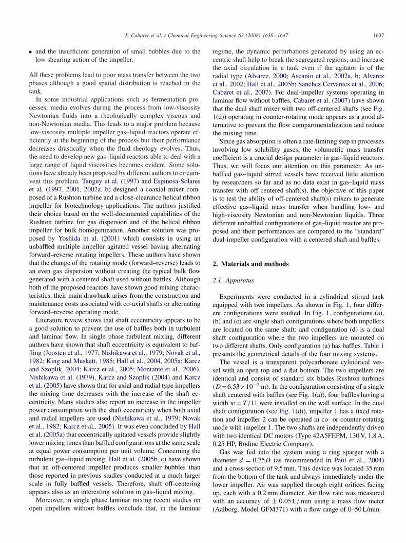
Experiments were conducted in a cylindrical stirred tankequipped with two impellers. As shown in Fig. 1, four differ-ent configurations were studied. In Fig. 1, configurations (a),(b) and (c) are single shaft configurations where both impellersare located on the same shaft; and configuration (d) is a dualshaft configuration where the two impellers are mounted ontwo different shafts. Only configuration (a) has baffles. Table 1presents the geometrical details of the four mixing systems.
The vessel is a transparent polycarbonate cylindrical ves-sel with an open top and a flat bottom. The two impellers areidentical and consist of standard six blades Rushton turbines(D=6.53×10⁻² m). In the configuration consisting of a singleshaft centered with baffles (see Fig. 1(a)), four baffles having awidth w = T/11 were installed on the wall surface. In the dualshaft configuration (see Fig. 1(d)), impeller 1 has a fixed rota-tion and impeller 2 can be operated in co- or counter-rotatingmode with impeller 1. The two shafts are independently drivenwith two identical DC motors (Type 42A5FEPM, 130 V, 1.8 A,0.25 HP, Bodine Electric Company).
Gas was fed into the system using a ring sparger with adiameter d = 0.75D (as recommended in Paul et al., 2004)and a cross-section of 9.5 mm. This device was located 35 mmfrom the bottom of the tank and always immediately under thelower impeller. Air was supplied through eight orifices facingup, each with a 0.2 mm diameter. Air flow rate was measuredwith an accuracy of ± 0.05 L/ min using a mass flow meter(Aalborg, Model GFM371) with a flow range of 0–50 L/min.
1638 F. Cabaret et al. / Chemical Engineering Science 63 (2008) 1636–1647
Fig. 1. Dual-impeller mixing systems: (a) single shaft centered with baffles, (b) single shaft centered without baffles, (c) single shaft off-centered, (d) dual shaft.
Table 1Experimental setup dimensions
Tank size T = 0, 21 mH1 = H2 = T
V = 14.5 × 10⁻³ m3
Baffles Four baffles, w = T/11Sparger d = 0.75D
Impellers Rushton turbine, D = 6.53 × 10⁻² mImpellers position C1 = C2 = T/3
E = E1 = E2 = T/4.4
Table 2Physical properties of Newtonian liquids at 21 ◦C
Solution Viscosity (mPa s) Density (kg/m3)
Water 0.954 998
Glucose solutions 15.0 117749.0 1204
102.0 1245
2.2. Fluids and rheology
Water and aqueous solutions of glucose (Glucose Enzose62DE, Univar) were chosen as the Newtonian fluids and aque-ous solutions of Sodium Carboxymethyl Cellulose (CMC solu-tion) (Cekol, Noviant) which showed shear-thinning behaviorwere used as the non-Newtonian liquids.
Glucose and CMC solutions rheology was characterized witha Couette rheometer (AR2000, TA Instruments) at room tem-perature (21 ◦C). It was verified that the CMC solutions did notpresent viscoelastic behavior and thus the apparent viscositywas described by the power law model:
�a = m · �̇n−1. (1)
Physical properties of the Newtonian and non-Newtonianliquids are listed, respectively, in Tables 2 and 3.
The shear rate in an agitated medium was related toimpeller speed by Metzner and Otto (1957). In this study thecommon value obtained by Metzner and Otto (1957) for sixblades Rushton turbine was used:
�̇av = KS · N = 11.5N . (2)
Table 3Physical properties of non-Newtonian liquids at 21 ◦C (for �̇ ∈ [50.300 s−1])
CMC solution (wt%) m (Pa sn) n Density (kg/m3)
0.1 0.071 0.68 9980.5 0.860 0.54 10021.0 4.318 0.44 1007
In this study all the experiments were carried out at roomtemperature (21 ◦C) and agitation speed was used in therange 5.25 s−1 (300–1500 RPM) which corresponds to �̇av ∈57.5.287.5 s−1.
2.3. Gas–liquid mass transfer
The experimental setup used to determine the volumet-ric gas–liquid mass transfer coefficient (kla) by the standarddynamic gassing out method is described in Fig. 2. At thebeginning of an experiment, oxygen present in the liquid wasstripped out using nitrogen until CO2 ≈ 0.5 mg/L. When theliquid was completely free of gas bubbles, agitation was startedand then air was sparged. The time-dependent oxygen con-centration was followed after the air injection using two highprecision Dissolved Oxygen (DO) probes (YSI, Model 58) anda LabVIEW software (National Instruments) was used for dataacquisition. Due to the strong dependence of the oxygen con-centration at the equilibrium (C∗
O2) with respect to temperature,
thermometers were used to correct C∗O2
at the beginning of eachexperiment.
The positions of the two DO probes are presented in Fig. 2.Each DO probe is located 2 cm above the impeller level in orderto follow the axial homogenization in the vessel. Moreover, theprobes were positioned at the wall surface not to perturb theflow. After checking for each of the two halves of the vessel (topand bottom parts) that the mass transfer time is high comparedto the mixing time, we assume an ideal mixing of the twophases and thus the oxygen balance in each part gives:
dCO2
dt= kla(C∗
O2− CO2). (3)

F. Cabaret et al. / Chemical Engineering Science 63 (2008) 1636–1647 1639
Fig. 2. Gas–liquid mass transfer experimental setup.
Upon integration of Eq. (3), one obtains:
ln(C∗O2
− CO2) = −kla.t . (4)
Thus, kla can be evaluated from the slope of ln(C∗O2
− CO2)
vs. time plot for each run. The mean value of kla in the tankis simply evaluated by
klamean = klaTop + klaBottom
2. (5)
3. Results and discussion
3.1. Water
Several relationships correlating the Froude number (Fr), theflow number (Fl) and dispersion regimes for a single RT inwater in tanks with straight baffles have been reported in liter-ature. Nienow et al. (1977) defined the maximum gas-holdingfor full recirculation as Eq. (6). Warmoeskerken et al. (1981)reported that the minimum Fr for gas dispersion is given byEq. (7). And, Nienow et al. (1985) proposed Eq. (8) to deter-mine the maximum gas flow rate before flooding the impeller.
Fl = 13Fr2(
D
T
)5
, (6)
Fr = 0.045, (7)
Fl = 30Fr
(D
T
)3.5
. (8)
The mass transfer experiments performed on each configurationwith water are presented on the flow map shown in Fig. 3 (seeblack dot). Agitation speed was used in the range 5.16.7 s−1
0.01
0.1
1
10
0.001 0.01 0.1 1 10
Fl
Fr
Eq.6
Eq.7
Eq.8
Fig. 3. Presentation of mass transfer experiments on the flow map(D/T = 0.31).
0
0.01
0.02
0.03
0.04
0.05
0.06
0.07
0 0.5 1 1.5 2 2.5 3
Q (vvm)
Bubble column (0 RPM)
Centered shaft without baffles
Off-centered shaft
Centered shaft with baffles
Dual shaft Co-rotating
Dual shaft Counter-rotating
kla
me
an (
s-1
)
Fig. 4. Mass transfer coefficient in water against gas flow rate for the differentconfigurations: N = 750 RPM, Fr = 1.04.
(300–1000 RPM), which corresponds to Fr ∈ [0.17; 1.85]. Gasflow rate was used in the range 1.55–40.4 L/min, which corre-sponds to 0.11–2.78 vvm. Flow numbers are in the range [0.011;0.217]. As presented in Fig. 3, all the 31 experiments are in theloaded regime.
Using water as the liquid, a comparison of the four mixingconfigurations is presented in Fig. 4. This figure representsklamean in the tank against gas flow rate at Fr = 1.04 (whichcorresponds to an impeller speed of 12.5 s−1).
It can be seen in Fig. 4 that the dual shaft configurationoperating in counter-rotating mode appears to be as effective asthe single shaft configuration with baffles. Concerning the dualshaft configuration operating in co-rotating mode, its efficacyis lower than the counter-rotating one due to the formation ofa bulk flow generating a vortex between the two impellers aspresented in Figs. 5 and 6. Moreover, it can be seen that the off-centered shaft configuration yields comparable klamean with thedual shaft configuration used in co-rotating mode. Even if an

1640 F. Cabaret et al. / Chemical Engineering Science 63 (2008) 1636–1647
Fig. 5. Dual shaft configuration operating in co-rotating mode (on the left) and counter-rotating mode (on the right) (Fr = 0.17 (N = 5 s−1) andFl = 0.018 (Q = 0.11 vvm)).
Fig. 6. Comparison of the flow patterns in the dual shaft configurations:A—co-rotating, B—counter-rotating.
off-centered shaft was employed as a means of breaking solidbody rotation within the vessel, some bulk flow remains as itwas noticed by Hall et al. (2005a) in single phase mixing. Thus,the lower performance of the off-centered shaft configuration isalso explained by a vortex formation between the two impellersas presented in Fig. 7.
Concerning the centered shaft configuration without baffles,a huge surface vortex is generated at the central part of the liquidsurface. The free surface is isobaric, and many other isobaricsurfaces exist parallel to the free surface. Gas bubbles injectedat the tank bottom are subjected to buoyancy perpendicular tothese isobaric faces and gather around the agitator axis as seen
in Fig. 8. Therefore the contacting efficiency of gas and liquidis very poor with an unbaffled centered shaft. Moreover, un-der certain conditions of impellers speed and gas flow rate, kla
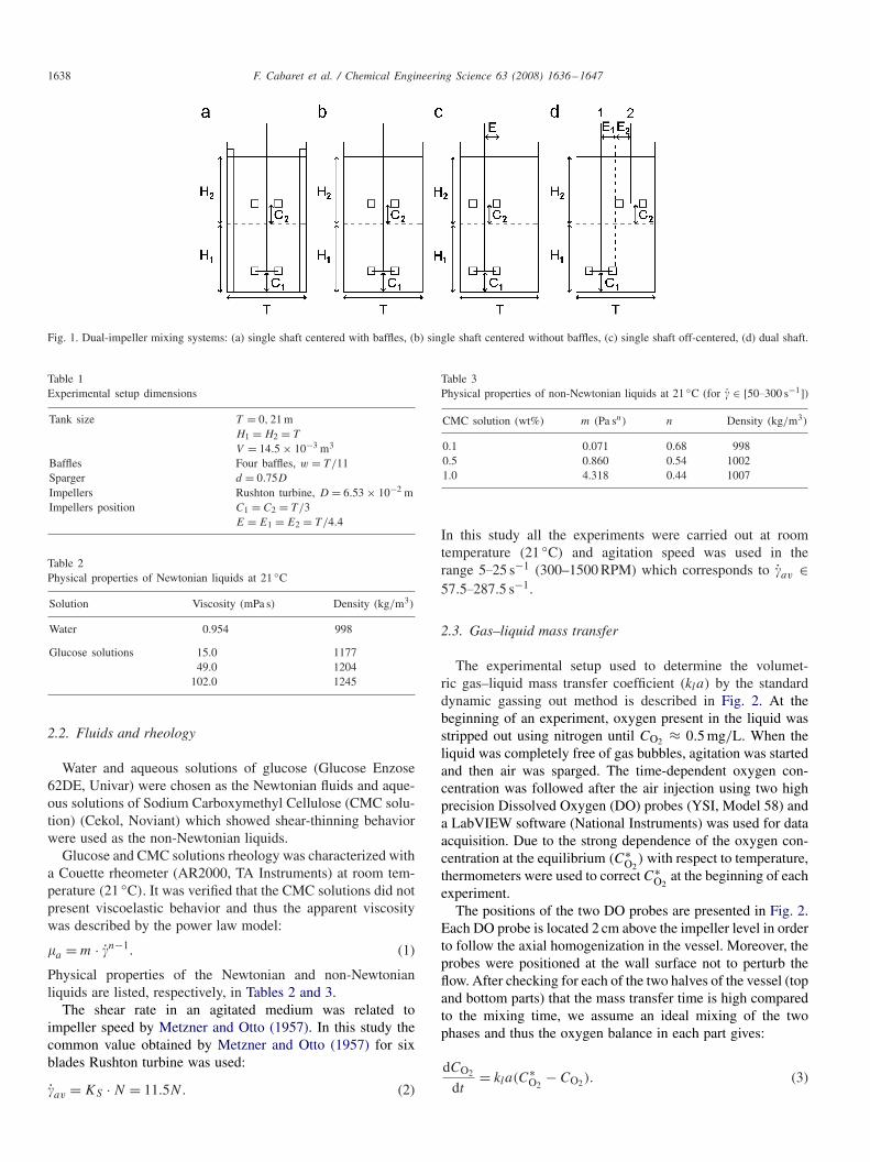
can be lower in unbaffled agitated tanks with a centered shaftcompared to unagitated ones (bubble column). Some experi-ments presented in Fig. 9 have been carried out to determinethese conditions, which are summarized in Table 4. Firstly, itappears in Fig. 9a that when Re and the gas flow rate are high,the impeller is flooded and thus it is better to do not mix (seethe intersection between the bubble column curve and the othercurves). This indicates that the flooding regime appears soonerif we do not use baffles. The expression of Flc given in Table 4gives the separation between the loaded and flooding regimes.Moreover, it can be seen in Fig. 9b that when Re < 14 800 thecurves for the agitated case do not intersect the bubble columncurve. This indicates that at low Re (below 14 800) the vortexformation is small and some gas bubbles can be dispersed.
In many of the early studies, the volumetric oxygen transfercoefficient, kla, was correlated to gassed power input per unitmass, Pg/�V , since mechanical agitation plays an importantrole in gas absorption (Paul et al., 2004). A second parameterthat also has a strong effect on kla is the superficial gas velocity,vs . Many previous investigators combined these two effectsand proposed correlations of the following form (Paul et al.,2004):
kla = A
(Pg
�V
)�
v�S . (9)

F. Cabaret et al. / Chemical Engineering Science 63 (2008) 1636–1647 1641
Fig. 7. Vortex formation observed in the off-centered shaft configuration: (a) Fr=0.46 (N=8.33 s−1) and Fl=0.011 (Q=0.11 vvm), (b) Fr=1.04 (N=12.5 s−1)
and Fl = 0.015 (Q = 0.21 vvm).
In this work, in order to compare the different configurationsthe following equation was proposed:
kla = C.NaQb. (10)
This correlation was already used successfully byWarmoeskerken (1986) and Ogut and Hatch (1988) and isequivalent to Eq. (9) since (Pg/V ) is proportional to N3D2
in turbulent flow (Tatterson, 1991). In dimensionless termsEq. (10) can be rewritten as
kla
N= K.FreFlf . (11)
With all the configurations tested in this work, Eqs. (10) and(11) have shown very good agreement with experimental dataas it can be seen in Fig. 10. Eqs. (10) and (11) model parametersare presented for the different configurations in Table 5. It canbe seen from Table 5 that the main difference between all theconfigurations comes from C and b values of Eq. (10) or K andf values of Eq. (11). Indeed, it is quite normal to have the samea (Eq. (10)) and e (Eq. (11)) values for the different configura-tions when the impeller is properly loaded. As it was mentioned,the centered shaft configuration without baffles is not wellloaded, and it explains that we have different a and e parametersfor this configuration. From Table 5 it can clearly be concludedthat the dual shaft configuration operating in counter-rotatingmode is at least as good as the centered shaft configuration
with baffles. The ranking of the others configurations are (fromthe best to the worst):
• dual shaft co-rotating;• off-centered shaft without baffles;• centered shaft without baffles.
Even if the volumetric mass transfer coefficient is a key param-eter in process design, oxygen homogenization in the vesselmust also be taken into account. In order to test the homogene-ity generated within the different configurations, a criterion (h)
has been defined as follows:
h =∑
n
|klaTop−klaBottom |klamean
n. (12)
In this equation n represents the number of experiments, inour study n = 31 (see the flow map in Fig. 3). It is clear that hrepresents the mean deviation between the kla at the top andthe kla at the bottom of the tank. A high h value means that thekla at the top and the bottom are different and therefore oxy-gen concentration is not homogeneous in the vessel. Table 6presents the h values in water for the different configura-tions. Surprisingly, the smallest h values have been obtainedfor the configurations where a vortex was seen. Moreover, itseems that the larger the solid body motion is, the lower is the

1642 F. Cabaret et al. / Chemical Engineering Science 63 (2008) 1636–1647
Fig. 8. Surface vortex formation in centered shaft without baffles configuration(Fr = 1.04 (N = 12.5 s−1) and Fl = 0.072 (Q = 1.03 vvm)).
homogenization criterion. However, it is also reasonable tohave klaBottom higher than klaTop if the bottom impeller isproperly loaded, that is why we have the highest h values forthe most efficient configurations, that is for the centered shaftwith baffles configuration and for the dual shaft configurationoperating in counter-rotating mode.
The interest of the dual shaft configuration in terms of flex-ibility to control homogenization can be highlighted. Indeed,the counter-rotating mode can be used with a higher rotationalspeed for the upper impeller to increase furthermore the masstransfer at the top. Fig. 11 presents an example where the up-per impeller is rotated at a different rotational speed from thebottom one. We clearly see that an optimum rotational speedexists for the upper impeller in order to have an homogeneousmass transfer in the tank. This flexibility is not possible witha single shaft configuration. Thus by using an impeller speed20% higher for the upper impeller than the lower one in thedual shaft configuration in counter-rotating mode it was possi-ble to reduce the h value to 1.57%.
3.2. Viscous Newtonian fluids
The evolution of the characteristics of the different config-urations has been followed with a viscosity increase. Fig. 12presents klamean against gas flow rate at Fr = 1.04 (impellerspeed: 12.5 s−1) when a glucose solution of 15 mPa s is used.In comparison with Fig. 4, we observe that when the vis-cosity increases the two dual shaft configurations show better
0
0.005
0.01
0.015
0.02
0.025
0.03
0.035
0 1 2 3 4 5
Q (vvm)
kla
me
an (
s-1
)k
lam
ea
n (
s-1
)
0 RPM (Bubble column)
300 RPM (Re=22294)
500 RPM (Re=37157)
750 RPM (Re=55735)
1000 RPM (Re=74313)
0
0.002
0.004
0.006
0.008
0.01
0.012
0.014
0.016
0 0.5 1 1.5 2
Q (vvm)
0 RPM (Bubble column)
100 RPM (Re=7431)
150 RPM (Re=11147)
200 RPM (Re=14863)
300 RPM (Re=22294)
Fig. 9. Agitation effect on mass transfer coefficients in water with the centeredshaft configuration without baffles.
performance. Indeed, the counter-rotating mode of the dualshaft configuration appears to have better mass transfer than thebaffled centered shaft configuration and the co-rotating modeof the dual shaft configuration appears to perform better thanthe off-centered configuration.
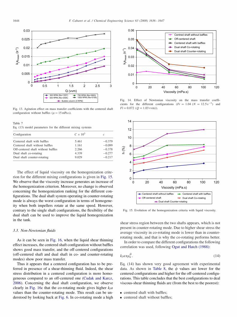
Concerning the centered shaft configuration without baffles,we observe by comparing Figs. 4 and 12 that its efficiencyincreases with liquid viscosity. This is due to the fact that thevortex size reduces with liquid density and viscosity. Moreover,as it can be seen in Fig. 13, when a viscous liquid is usedthe agitated mode of the centered shaft configuration is alwaysbetter than the unagitated one. This is due to the fact that theReynolds number is lower than 14 800 (see Table 3).
In order to compare the different configurations the followingequation was proposed:
kla = C.NaQb�c. (13)
This correlation was already employed successfully by Ogutand Hatch (1988) for viscous non-Newtonian liquid using theapparent viscosity. Moreover, let us note that this correlationis to compare the different mixing configurations proposedand cannot be used to predict mass transfer coefficient in vis-cous liquids. Indeed, Eq. (13) does not depend on liquid phase
F. Cabaret et al. / Chemical Engineering Science 63 (2008) 1636–1647 1643
Table 4Agitation—no agitation comparison for the single shaft configuration withoutbaffles
Agitation preferred if: Re < 14 800
No agitation preferred if: Re�14 800andFl > Flc = 1.407 × 10⁻⁶ Re + 7.654 × 10⁻²
0
0.02
0.04
0.06
0.08
0.1
0 0.10.080.060.040.02
Predicted kla (s-1)
Exp
erim
en
tal k
la (
s-1
)
Centered shaft without baffles
Off-centered shaft
Dual shaft Co-rotating
Dual shaft Counter-rotating
Centered shaft with baffles
Fig. 10. Experimental kla in water compared with predicted values by Eq.(10).
Table 5Eqs. (10) and (11) model parameters for the different mixing systems
Configuration Eq. (10) Eq. (11)
C × 103 a b K × 103 E f
Centered shaftwith baffles
11.927 1.598 0.320 8.692 0.459 0.320
Centered shaftwithout baffles
0.981 1.484 0.140 1.481 0.305 0.140
Off-centered shaftwithout baffles
3.564 1.654 0.214 5.418 0.435 0.214
Dual shaft co-rotating 5.761 1.637 0.270 6.143 0.453 0.270Dual shaftcounter-rotating
15.167 1.548 0.333 9.018 0.433 0.333
Table 6Homogenization criteria values in water
Configuration h (%)
Centered shaft with baffles 5.16Centered shaft without baffles 1.45Off-centered shaft 4.53Dual shaft co-rotating 3.52Dual shaft counter-rotating 7.17
diffusivity and surface tension which differ with the liquidrheology.
Eq. (13) has shown very good agreement with experimentaldata for a Newtonian viscosity in the range 0.954–102 mPa s. Itwas observed that the a and b values were unchanged comparedto Table 5. Therefore, just the C and c values were determined
0.9
0.92
0.94
0.96
0.98
1
1.02
1.04
1.06
0 200 400 600 800 1000 1200
NTop (RPM)
kla
To
p / k
laB
ott
om
Fig. 11. Mass transfer homogenization when the upper impeller rotationalspeed was varied in the dual shaft configuration operating in counter-rotatingmode (Q = 4.45 L/ min (0.3 vvm) and NBottom = 450 RPM).
Bubble column (0 RPM)
Centered shaft without baffles
Off-centered shaft
Centered shaft with baffles
Dual shaft Co-rotating
Dual shaft Counter-rotating
0
0.01
0.02
0.03
0.04
0.05
0.06
0 0.5 1 1.5 2 2.5 3
Q (vvm)
kla
me
an (
s-1
)
Fig. 12. Mass transfer coefficient in glucose solution (� = 15 mPa s) againstgas flow rate for the different configurations at Fr = 1.04.
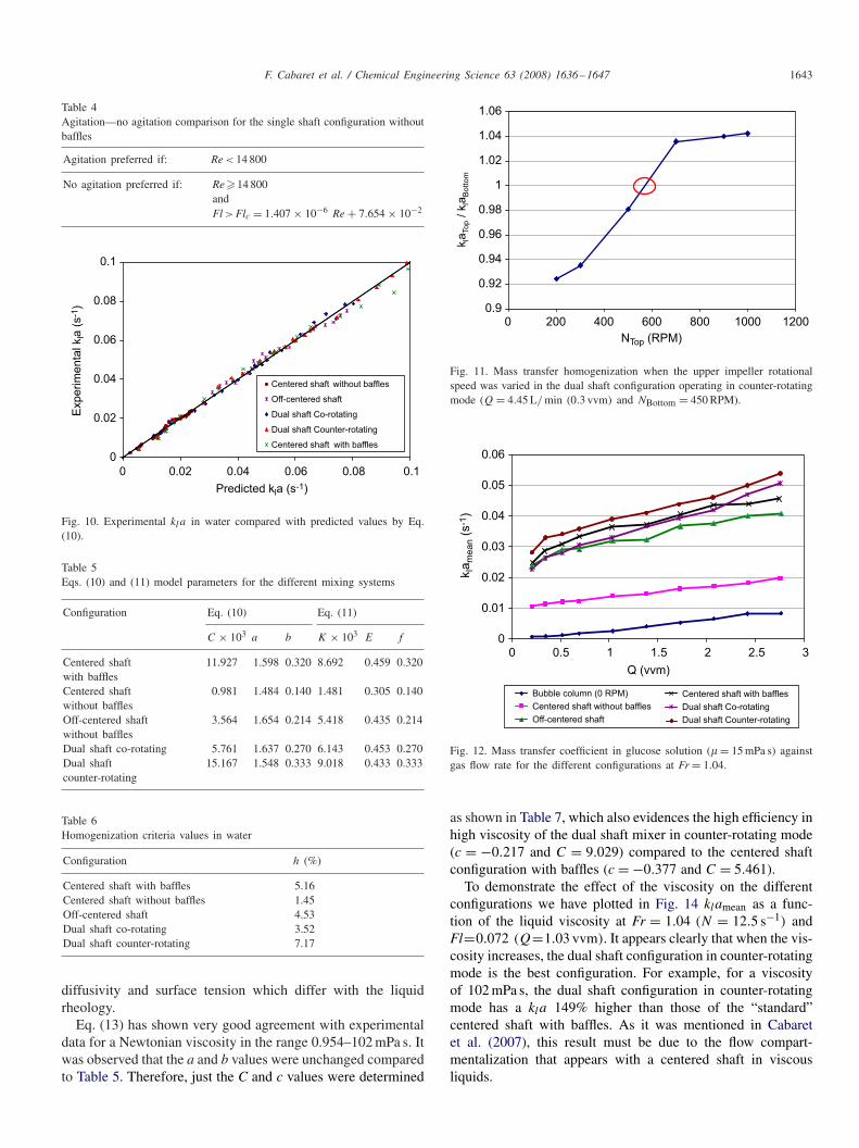
as shown in Table 7, which also evidences the high efficiency inhigh viscosity of the dual shaft mixer in counter-rotating mode(c = −0.217 and C = 9.029) compared to the centered shaftconfiguration with baffles (c = −0.377 and C = 5.461).
To demonstrate the effect of the viscosity on the differentconfigurations we have plotted in Fig. 14 klamean as a func-tion of the liquid viscosity at Fr = 1.04 (N = 12.5 s−1) andFl=0.072 (Q=1.03 vvm). It appears clearly that when the vis-cosity increases, the dual shaft configuration in counter-rotatingmode is the best configuration. For example, for a viscosityof 102 mPa s, the dual shaft configuration in counter-rotatingmode has a kla 149% higher than those of the “standard”centered shaft with baffles. As it was mentioned in Cabaretet al. (2007), this result must be due to the flow compart-mentalization that appears with a centered shaft in viscousliquids.
1644 F. Cabaret et al. / Chemical Engineering Science 63 (2008) 1636–1647
0
0.005
0.01
0.015
0.02
0.025
0.03
0 0.5 1 1.5 2 2.5 3
Q (vvm)
kla
me
an (
s-1
)
300 RPM (Re=1557)
500 RPM (Re=2595)
750 RPM (Re=3893)1000 RPM (Re=5190)
Bubble column (0 RPM)
Fig. 13. Agitation effect on mass transfer coefficients with the centered shaftconfiguration without baffles (� = 15 mPa s).
Table 7Eq. (13) model parameters for the different mixing systems
Configuration C × 103 c
Centered shaft with baffles 5.461 −0.379Centered shaft without baffles 1.161 −0.099Off-centered shaft without baffles 2.266 −0.378Dual shaft co-rotating 4.339 −0.277Dual shaft counter-rotating 9.029 −0.217
The effect of liquid viscosity on the homogenization crite-rion for the different mixing configurations is given in Fig. 15.We observe that the viscosity increase generates an increase ofthe homogenization criterion. Moreover, no change is observedconcerning the homogenization ranking for the different con-figurations. The dual shaft system operating in counter-rotatingmode is always the worst configuration in terms of homogene-ity when both impellers rotate at the same speed. However,contrary to the single shaft configurations, the flexibility of thedual shaft can be used to improve the liquid homogenizationin the tank.
3.3. Non-Newtonian fluids
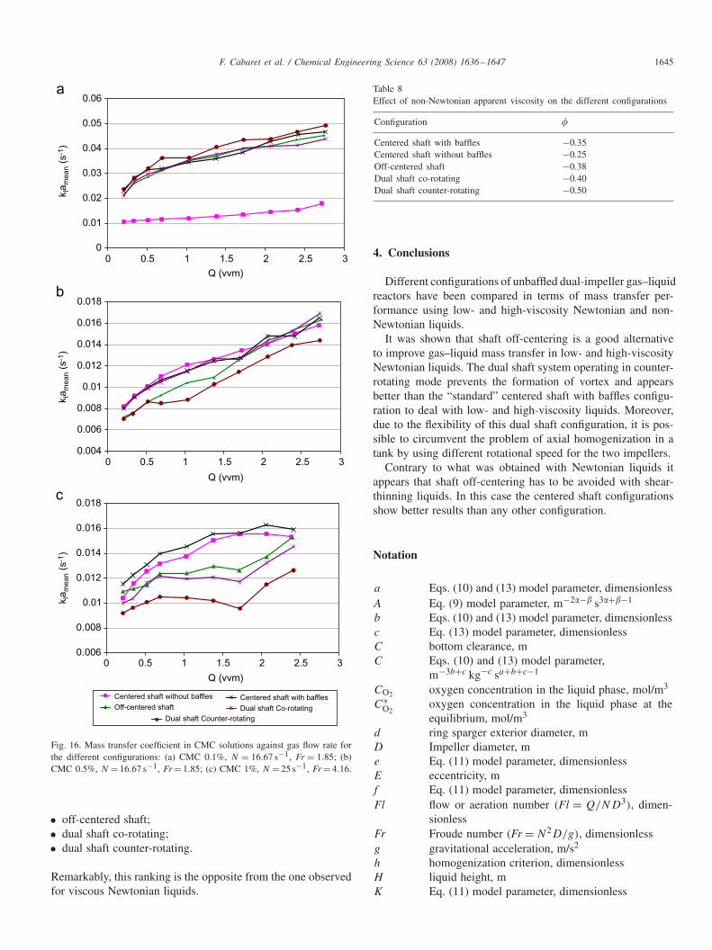
As it can be seen in Fig. 16, when the liquid shear thinningeffect increases, the centered shaft configuration without bafflesshows good mass transfer, and the off-centered configurations(off-centered shaft and dual shaft in co- and counter-rotatingmodes) show poor mass transfer.
Thus it appears that a centered configuration has to be pre-ferred in presence of a shear-thinning fluid. Indeed, the shearstress distribution in a centered configuration is more homo-geneous compared to an off-centered one (Cudak and Karcz,2006). Concerning the dual shaft configuration, we observeclearly in Fig. 16c that the co-rotating mode gives higher kla
values than the counter-rotating mode. This result can be un-derstood by looking back at Fig. 6. In co-rotating mode a high
0
0.01
0.02
0.03
0.04
0.05
0.06
0 20 40 60 80 100 120
Viscosity (mPa.s)
kla
mean (
s-1
)
Centred shaft without baffles
Off-centered shaft
Centered shaft with baffles
Dual shaft Co-rotating
Dual shaft Counter-rotating
Fig. 14. Effect of Newtonian viscosity on the mass transfer coeffi-cients for the different configurations (Fr = 1.04 (N = 12.5 s−1) andFl = 0.072 (Q = 1.03 vvm)).
0
2
4
6
8
10
12
14
0 20 40 60 80 100 120
Viscosity (mPa.s)
h (
%)
Centered shaft without baffles
Off-centered shaft
Centered shaft with baffles
Dual shaft Co-rotating
Dual shaft Counter-rotating
Fig. 15. Evolution of the homogenization criteria with liquid viscosity.
shear stress region between the two shafts appears, which is notpresent in counter-rotating mode. Due to higher shear stress theaverage viscosity in co-rotating mode is lower than in counter-rotating mode, and that is why the co-rotating performs better.
In order to compare the different configurations the followingcorrelation was used, following Ogut and Hatch (1988):
kla���a . (14)
Eq. (14) has shown very good agreement with experimentaldata. As shown in Table 8, the � values are lower for thecentered configurations and higher for the off-centered configu-rations. This table concludes that the best configurations to dealviscous-shear thinning fluids are (from the best to the poorest):
• centered shaft with baffles;• centered shaft without baffles;
F. Cabaret et al. / Chemical Engineering Science 63 (2008) 1636–1647 1645
0
0.01
0.02
0.03
0.04
0.05
0.06
0 0.5 1 1.5 2 2.5 3
Q (vvm)
0 0.5 1 1.5 2 2.5 3
Q (vvm)
0 0.5 1 1.5 2 2.5 3
Q (vvm)
kla
me
an (
s-1
)k
lam
ea
n (
s-1
)k
lam
ea
n (
s-1
)
0.004
0.006
0.008
0.01
0.012
0.014
0.016
0.018
0.006
0.008
0.01
0.012
0.014
0.016
0.018
Centered shaft without baffles
Off-centered shaft
Centered shaft with baffles
Dual shaft Co-rotating
Dual shaft Counter-rotating
Fig. 16. Mass transfer coefficient in CMC solutions against gas flow rate forthe different configurations: (a) CMC 0.1%, N = 16.67 s−1, Fr = 1.85; (b)CMC 0.5%, N = 16.67 s−1, Fr = 1.85; (c) CMC 1%, N = 25 s−1, Fr = 4.16.
• off-centered shaft;• dual shaft co-rotating;• dual shaft counter-rotating.
Remarkably, this ranking is the opposite from the one observedfor viscous Newtonian liquids.
Table 8Effect of non-Newtonian apparent viscosity on the different configurations
Configuration �
Centered shaft with baffles −0.35Centered shaft without baffles −0.25Off-centered shaft −0.38Dual shaft co-rotating −0.40Dual shaft counter-rotating −0.50
4. Conclusions
Different configurations of unbaffled dual-impeller gas–liquidreactors have been compared in terms of mass transfer per-formance using low- and high-viscosity Newtonian and non-Newtonian liquids.
It was shown that shaft off-centering is a good alternativeto improve gas–liquid mass transfer in low- and high-viscosityNewtonian liquids. The dual shaft system operating in counter-rotating mode prevents the formation of vortex and appearsbetter than the “standard” centered shaft with baffles configu-ration to deal with low- and high-viscosity liquids. Moreover,due to the flexibility of this dual shaft configuration, it is pos-sible to circumvent the problem of axial homogenization in atank by using different rotational speed for the two impellers.
Contrary to what was obtained with Newtonian liquids itappears that shaft off-centering has to be avoided with shear-thinning liquids. In this case the centered shaft configurationsshow better results than any other configuration.
Notation
a Eqs. (10) and (13) model parameter, dimensionlessA Eq. (9) model parameter, m−2�−� s3�+�−1
b Eqs. (10) and (13) model parameter, dimensionlessc Eq. (13) model parameter, dimensionlessC bottom clearance, mC Eqs. (10) and (13) model parameter,
m−3b+c kg−c sa+b+c−1
CO2 oxygen concentration in the liquid phase, mol/m3
C∗O2
oxygen concentration in the liquid phase at theequilibrium, mol/m3
d ring sparger exterior diameter, mD Impeller diameter, me Eq. (11) model parameter, dimensionlessE eccentricity, mf Eq. (11) model parameter, dimensionlessFl flow or aeration number (Fl = Q/ND3), dimen-
sionlessFr Froude number (Fr = N2D/g), dimensionlessg gravitational acceleration, m/s2
h homogenization criterion, dimensionlessH liquid height, mK Eq. (11) model parameter, dimensionless
1646 F. Cabaret et al. / Chemical Engineering Science 63 (2008) 1636–1647
kla volumetric gas–liquid mass transfer coefficient, s−1
N impeller rotational speed, s−1
Pg impeller power consumption under gassedcondition, W
Q gas flow rate, m3/s1 orvvmRe Reynolds number (Re = �ND2/�), dimensionlesst time, sT tank diameter, mV tank volume, m3
vS gas superficial velocity, m/sw baffle width, m
Greek letters
� Eq. (9) model parameter, dimensionless� Eq. (9) model parameter, dimensionless� viscosity, Pa s�a apparent viscosity, Pa s� liquid density, kg/m3
� Eq. (14) model parameter, dimensionless
Subscripts
1 refer to impeller 12 refer to impeller 2c critical
References
Alvarez, M.M., 2000. Using spatio-temporal asymmetry to enhance mixing inchaotic flows: from maps to stirred tanks. Ph.D. Thesis, Rutgers University,Piscataway, NJ, USA.
Alvarez, M.M., Arratia, P.E., Muzzio, F.J., 2002. Laminar mixing in eccentricstirred tank systems. Canadian Journal of Chemical Engineering 80,546–557.
Anderson, C., LeGrys, G.A., Solomons, G.L., 1982. Concepts in the designof large-scale fermenters for viscous culture broths. Chemical Engineer377, 43–49.
Ascanio, G., Brito-Bazan, M., Brito-De La Fuente, E., Carreau, P.J.,Tanguy, P.A., 2002a. Mixing enhancement of non-Newtonian fluidsusing unconventional configurations. In: Proceedings of ASME FluidsEngineering Division Summer Meeting, Montreal, Canada, July 14–18,2002.
Ascanio, G., Brito-Bazan, M., Brito-De La Fuente, E., Carreau, P.J., Tanguy,P.A., 2002b. Unconventional configuration studies to improve mixing timesin stirred tanks. Canadian Journal of Chemical Engineering 80, 558–565.
Cabaret, F., Rivera, C., Fradette, L., Heniche, M., Tanguy, P.A., 2007.Hydrodynamics performance of a dual shaft mixer with viscous Newtonianliquids. Chemical Engineering Research and Design 85 (A5), 583–590.
Cudak, M., Karcz, J., 2006. Momentum transfer in an agitated vessel withoff-centered impellers. Chemical Papers 60 (5), 375–380.
Espinosa-Solares, T., Brito-De La Fuente, E., Tecante, A., Tanguy, P.A., 1997.Power consumption of a dual turbine-helical ribbon impeller mixer inungassed conditions. Chemical Engineering Journal 67 (3), 215–219.
Espinosa-Solares, T., Brito-De La Fuente, E., Tecante, A., Tanguy, P.A.,2001. Flow patterns in rheologically evolving model fluids produced byhybrid dual mixing systems. Chemical Engineering and Technology 24 (9),913–918.
Espinosa-Solares, T., Brito-De La Fuente, E., Tecante, A., Tanguy, P.A.,2002a. Gas dispersion in rheologically-evolving model fluids by hybriddual mixing systems. Chemical Engineering and Technology 25 (7),723–727.
Espinosa-Solares, T., Brito-De La Fuente, E., Tecante, A., Medina-Torres,L., Tanguy, P.A., 2002b. Mixing time in rheologically evolving model
fluids by hybrid dual mixing systems. Chemical Engineering Research andDesign 80 (8), 817–823.
Hall, J.F., Barigou, M., Simmons, M.J.H., Stitt, E.H., 2004. Mixingin unbaffled high-throughput experimentation reactors. Industrial andEngineering Chemistry Research 43, 4149–4158.
Hall, J.F., Barigou, M., Simmons, M.J.H., Stitt, E.H., 2005a. Comparativestudy of different mixing strategies in small high throughputexperimentation reactors. Chemical Engineering Science 60, 2355–2368.
Hall, J.F., Barigou, M., Simmons, M.J.H., Stitt, E.H., 2005b. Just because it’ssmall doesn’t mean it’s well mixed: ensuring good mixing in mesoscalereactors. Industrial and Engineering Chemistry Research 44, 9695–9704.
Hall, J.F., Barigou, M., Simmons, M.J.H., Stitt, E.H., 2005c. A PIV studyof hydrodynamics in gas–liquid high throughput experimentation (HTE)reactors with eccentric impeller configurations. Chemical EngineeringScience 60, 6403–6413.
John, A.H., Bujalski, W., Nienow, A.W., Sánchez, A., Torres, L., Galindo,E., 1995. Studies of an independently-driven, dual impeller protofermenterwith and without a draft tube: power and hold-up. Chemical EngineeringResearch & Design 73 (A5), 535–541.
John, A.H., Bujalski, W., Nienow, A.W., 1997. A novel reactor withindependently-driven dual impellers for gas–liquid processing. In:Proceedings of the 9th European Conference on Mixing, Paris-Marne laVallée, France, March 18–21, 1997, pp. 169–176.
John, A.H., Bujalski, W., Nienow, A.W., 1998. Performance of a proto-fermenter containing independently-driven dual impellers in a draft tube(IDDIDT): mixing times. Food and Bioproducts Processing 76 (4),199–207.
Joosten, G.E.H., Schilder, J.G.M., Broere, A.M., 1977. The suspension offloating solids in stirred vessels. Chemical Engineering Research andDesign 55, 220–222.
Karcz, J., Szoplik, J., 2004. An effect of the eccentric position of the propelleragitator on the mixing time. Chemical Papers 58, 9–14.
Karcz, J., Cudak, M., Szoplik, J., 2005. Stirring of a liquid in a stirred tankwith an eccentrically located impeller. Chemical Engineering Science 60,2369–2380.
King, R., Muskett, M.J., 1985. Fluid loading and power measurements on aneccentrically mounted pitched blade impeller. In: Proceedings of the 5thEuropean Conference on Mixing, Wurzburg, West Germany, June 10–12,1985, pp. 285–301.
Metzner, A.B., Otto, R.E., 1957. Agitation of non-Newtonian fluids. ChemicalEngineering Progress 3 (1), 3–10.
Montante, G., Bakker, A., Paglianti, A., Magelli, F., 2006. Effect of the shafteccentricity on the hydrodynamics of unbaffled stirred tanks. ChemicalEngineering Science 61, 2807–2814.
Nienow, A.W., Wisdom, D.J., Middleton, J.C., 1977. The effect of scale andgeometry on flooding, recirculation and power in gassed stirred vessels.In: Proceedings of the 2nd European Conference on Mixing, Cambridge,1977, pp. 17–34.
Nienow, A.W., Warmoeskerken, M.M.C.G., Smith, J.M., Konno, M., 1985.On the flooding/loading transition and the complete dispersal condition inaerated vessels agitated by a Rushton-turbine. In: Proceedings of the 5thEuropean Conference on Mixing, Wurzburg, West Germany, June 10–121985, pp. 143–154.
Nishikawa, M., Ashiwake, K., Hashimoto, N., Nagata, S., 1979. Agitationpower and mixing time in off-centering mixing. International ChemicalEngineering 19 (1), 153–159.
Novak, V., Ditl, P., Rieger, F., 1982. Mixing in unbaffled vessels the influenceof an eccentric impeller position on power consumption and surfaceaeration. In: Proceedings of the 4th European Conference on Mixing,Noordwijkerhout, The Netherlands, April 27–29, 1982, pp. 57–70.
Ogut, A., Hatch, R.T., 1988. Oxygen transfer into Newtonian and non-Newtonian fluids in mechanically agitated vessels. The Canadian Journalof Chemical Engineering 66, 79–85.
Paul, E.L., Atiemo-Obeng, V.A., Kresta, S.M., 2004. Handbook of IndustrialMixing. Wiley, New Jersey.
Sanchez Cervantes, M.I., Lacombe, J., Muzzio, F.J., Avarez, M.M., 2006.Novel bioreactor design for the culture of suspended mammalian cells. PartI: mixing characterization. Chemical Engineering Science 61, 8075–8084.
F. Cabaret et al. / Chemical Engineering Science 63 (2008) 1636–1647 1647
Solomons, G.L., LeGrys, G.A., 1981. Method and apparatus for promotingfermentation. British Patent 1 584 103.
Tanguy, P.A., Thibault, F., Brito-De La Fuente, E., Espinosa-Solares, T.,Tecante, A., 1997. Mixing performance induced by coaxial flat blade-helical ribbon impellers rotating at different speeds. Chemical EngineeringScience 52 (11), 1733–1741.
Tatterson, G.B., 1991. Fluid Mixing and Gas Dispersion in Agitated Tanks.McGraw-Hill, New York.
Warmoeskerken, M.M.C.G., 1986. Gas–liquid dispersing characteristics ofturbine agitators, Ph.D. Thesis, Delf University.
Warmoeskerken, M.M.C.G., Feijen, J., Smith, J.M., 1981. Institution ofChemical Engineers Symposium Series 64, J1–J14.
Yoshida, M., Yamagiwa, K., Ito, A., Ohkawa, A., Abe, M., Tezura, S.,Shimazaki, M., 2001. Flow and mass transfer in aerated viscous Newtonianliquids in an unbaffled agitated vessel having alternating forward–reverserotating impellers. Journal of Chemical Technology and Biotechnology76, 1185–1193.