fuller's geodesics: a pedagogy of design-build
TRANSCRIPT
Research 620Fuller’s Geodesics
Fuller’s Geodesics: A Pedagogy of Design-Build Experimentation
DESIGN-BUILD EXPERIMENTATION:R. Buckminster Fuller (1895-1983) was a pioneer in the pedagogy of Design-Build experimentation. Travelling tirelessly across many schools of architecture and working alongside students, he built large-scale geodesic constructions whose form and complex geometry tested the limits of numerous materials. Scholars have remarked how “no single construction system has been built in so many sizes and of such diverse materials – wood, pipes, sheets of plastic and metal, foam panels, cardboard, plywood, bamboo, fiberglass, concrete and even bicycle wheels and the tops of junked cars.” 1 In parallel, and forfeiting architectural drawing conventions, Fuller also developed an original culture of representation informed by his prolific production of patents. His drawings, in the form of
“Fuller came with his aluminum mobile home trailer, packed full with his math-ematical models. His laboratory was now mobile, his research nomadic. According to reports from participants, including Elaine de Kooning, Kenneth Snelson, Richard Lippold, and Merce Cunningham, Fuller’s first three-hour-long lecture must have had an electrifying effect on the audience. “Bucky,” Elaine de Kooning recalled, “whirled off into his talk, using bobby pins, clothes pins, all sorts of units from the five-and-ten-cent store to make geometric, mobile constructions, collapsing an ingeniously fashioned icosahedron by twisting it and doubling and tripling the module down to a tetrahedron; talking about the obsolescence of the square, the cube, the numbers two and ten (throwing in a short history of ciphering and why it was punishable by death in the Dark Ages); extolling the numbers nine and three, the circle, the triangle, the tetrahedron, and the sphere; dazzling us with his complex theories of ecology, engineering, and technology. Then he began mak-ing diagrams on a blackboard. He drew a square, connecting two corners with a diagonal line. ‘Ah’, he said affectionately, ‘here’s’ our old friend, the hypotenuse.” Elaine de Kooning quoted in Mary Emma Harris, The Arts at Black Mountain College (Cambridge , Mass., 1987), p.151.” Joachim Krausse and Claude Lichtenstein, Ed. “Architecture out of the Laboratory”, Your Private Sky, R. Buckminster Fuller, the Art of Design Science (Zurich: Lars Muller, 1999), p. 316.
DANIEL LOPEZ-PEREZUniversity of San Diego
621 WORKING OUT | thinking while building
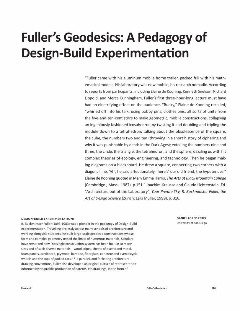
assembly “manuals”, focused more on describing order, or how the overall form is broken down into constituent parts and their “part-to-whole” relationships, than the forms themselves. By challenging architectural conventions, both with respect to materials and representation, Fuller’s geodesic constructions can be understood as original Design-Build experiments. In these, complex geometry tested the limits of materials and conversely, different materials assemblages those of design and representation. Amongst the many photographs of Fuller working alongside students, perhaps one of the earliest and most indicative of this pedagogy of Design-Build experimentation is at Black Mountain College in the summer of 1949. In the image Fuller can be seen holding what appears to be an assembly manual surrounded by students. Their puzzled gazes trying to decipher why a sturdy geodesic model three feet in diameter and made of venetian blinds is unable to gain any curvature when scaled up to thirty-feet in diameter. A firsthand account of this incident tells of how they had “worked like the devil all summer and waited for the dome to rise like the second coming of Moses, but it laid there like a bowl of wet spaghetti.” 2 In the space between the drawing and the models lies Fuller’s lesson to the students. Materials alone could not adequately test the limits of design; as much as drawings alone could the limits of building. Devising a pedagogical approach of Design-Build experimentation would form the basis of Fuller’s methodology of collaborative research with the students, and their only way out of this paradox! This paper is divided into a number of sections that examine Fuller’s original prototypes and concepts, and their legacy in contemporary architectural design education. Historically, it traces a trajectory starting with a number of Fuller’s original “artifacts”3 and “inventions”4 and how these were translated into Design-Build manuals, including “Geodesics”5 and “Domebooks”6 , intended for pedagogical and practical innovation. The paper also reflects upon the legacy of these models, prototypes and pedagogical approaches of Design-Build experimentation to deepen and inform design research today, and into the future.ARTIFACTS AND INVENTIONSCharacteristic of his Design-Build pedagogy, Fuller pursued two distinct forms of exploration in the development of geodesic models with his students. The first was physical, one that sought to build specific geodesic “artifacts” using the widest range of materials possible. The second was more conceptual, one that transcended mate-rial specificity and rather sought to explore a series of universal “inventions” in the form of concepts and drawings that would become the basis for a number of patents. Rather than seeing these two forms of exploration as autonomous (mate-rial and universal), Fuller sought to find a transversal logic across these as a way to challenge the limits of each. In a similar manner in which Fuller defied his students in Black Mountain College to decipher the disparity that emerged between designing and building; he pursued both of these forms of exploration simultaneously as a way to arrive at new forms of knowledge.
A scan of Fuller’s Geodesic Design-Build research starting in the 1940s reveals three distinct formal and structural systems. The first system is linear and composed of struts (rigid members) that are acting primarily in compression and follow a logic of structural continuity. This system is the most prolific and ubiquitous amongst Fuller’s geodesic prototypes and the basis for his “Geodesic” patent (1954).7 The second predominant system is tensile in nature and composed of a combination of struts and cables that together result in an assembly where the predominant structural behavior is based on “discontinuous-compression” and divided between compression (struts) and tension (cables). This system was the basis of a number of patents including “Tensegrity” (1962) (or “tensile integrity”) where rigid members
Figure 1: “Workshop at Black Mountain College,
summer school 1948: constructing a geodesic dome
out of the metal stripping used for Venetian blinds,”
“Architecture out of the Laboratory,” Joachim
Krausse and Claude Lichtenstein Ed., Your Private
Sky, R. Buckminster Fuller, the Art of Design Science
(Zurich: Lars Muller, 1999), p. 318.
1
Research 622Fuller’s Geodesics
are separated and made discontinuous by a web of cables. While the rigid members are discontinuous, the cables are continuous and “subjugate” the struts to “small islands” of compression within a “sea” of continuous tension.8 Exploring the space between compression and tension, structural continuity and discontinuity, a num-ber of additional prototypes emerged that would mix cables, rigid struts and tenting (plastic or fabric covering) to form hybrid configurations such as the University of Minnesota Dome (1953) or the Catenary Geodesic Tent Patent (1967).9 The third predominant system is one based on surfaces where the form of the prototype is subdivided and articulated into panels of varying size. A number of patents were issued from this surface-based system spanning from planar and folded surfaces, such as the Paper Dome (1959) and Laminar Dome (1965), all the way to doubly curved surfaces such as the Plydome (1959). 10
Materially, Fuller’s Design-Build exploration into hybrid configurations of strut, cable and surface based prototypes can be understood as searching for increas-ingly lighter forms of construction; one that he would describe as akin to bringing “the slenderness, lightness and strength of the suspension bridge cable into the realm previously dominated by the compression column concept of building.”11 Discursively, the fact that each of these prototypical systems gives rise to a number of concepts that together would give rise to the Synergetics dictionary12 and appear in the writing of numerous patents, also point to the conceptualization of these forms well beyond the terms of structure.
In addition to material experimentation Fuller also followed a parallel discursive line of exploration that sought to define a number of concepts. The logic of the term “geodesic” is inherent in its mathematical definition as the shortest distance between two distinct points on the surface of a sphere. It could simultaneously mean quite literally the shortest and most efficient line of structure from which to create a spherical form, and at the same time the most efficient and shortest route from which to ship the world’s resources on the surface of the earth as a spherical body. Experimenting with the expansive nature of language, Fuller points to light-ness in construction as a primary virtue of his “geodesic” patent. Structurally light-ness translated into doing-more-with-less by finding the shortest and most efficient vectorial routes from which to distribute structure. The concept of “tensegrity”, as
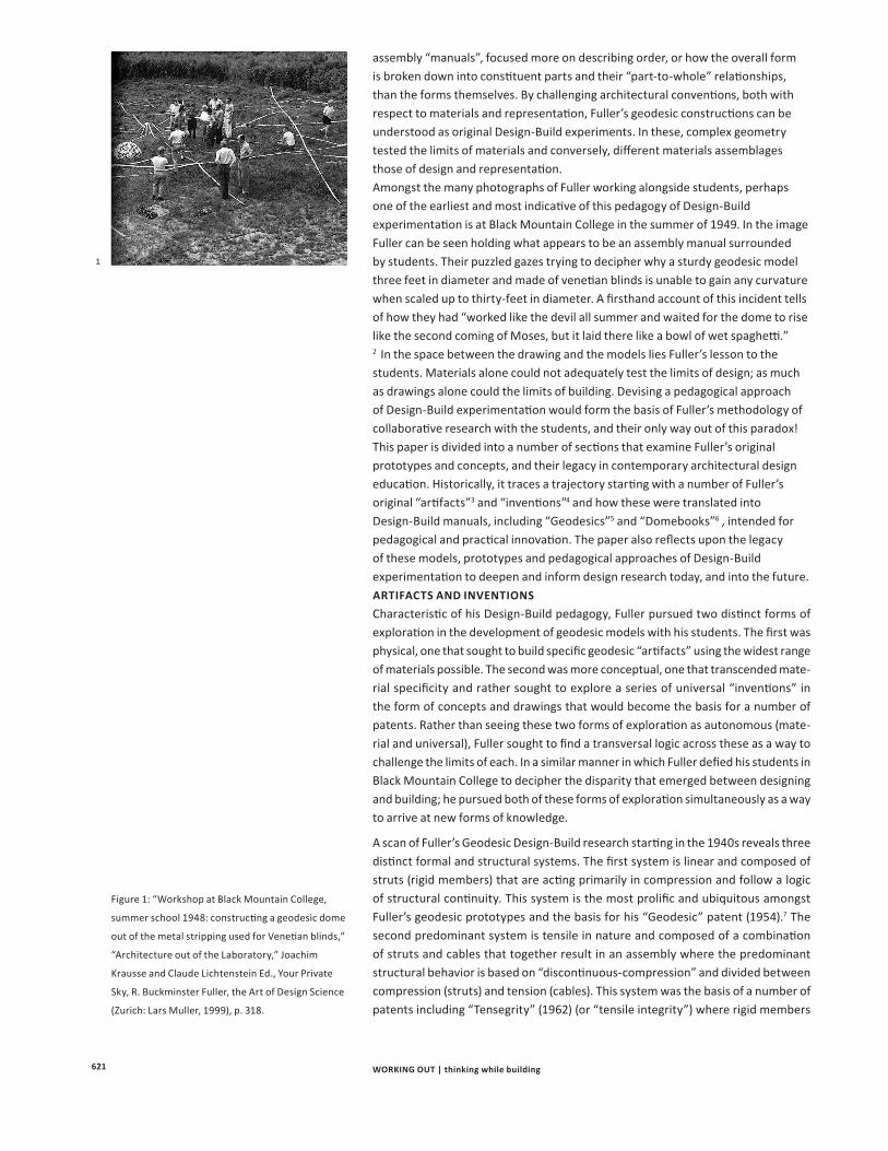
Figure 2: Fuller’s Geodesic Prototypes
indexed across time, Daniel López-Pérez, “The
Spherical Atlas”, Advanced Geodesic Research Unit,
Department of Art, Architecture and Art History,
University of San Diego (www.sphericalatlas.com).
32
16. US Marine Corps Preliminary Dome (1955) E. Icosahedron; II. Class II
17. Dome Units for Geodesics Inc. (1950’s) E. Icosahedron; I. Class I
18. Paperboard Dome (1959) F. Rhombic Triacontahedron; II. Class II
19. Geodesic Tent (1950)E. Icosahedron; I. Class I
20. Typical Raft System (1957)B. Octahedron; I. Class I
21. Plydome Patent (1959) E. Icosahedron; II. Class II
22. Tensegrity Patent (1962)E. Icosahedron; I. Class I
23. Geodesic Structures E. Icosahedron; II. Class II
24. Laminar Geodesic Dome (1965)E. Icosahedron; I. Class I
25. Laminar Geodesic Dome (1965) E. Icosahedron; I. Class I
26. Laminar Geodesic Dome (1965) E. Icosahedron; I. Class I
27. Laminar Geodesic Dome Patent (1965) E. Icosahedron; I. Class I
28. Non-Symmetrical Tensegrity Patent (1975)
29. Pine-Cone Dome (1977)E. Icosahedron; I. Class I
30. 4V - Parallel Sheet Metal Dome (1980)E. Icosahedron; I. Class I
05915491 1955 1960 198019751965
10
11
18
21
24
II
15
0491
I
1619
22
25
26
27
23a
23b
29
30
28
20
17
8
14
12
13
106
9
7
3
4
5
2IV
III
V 1
E
A
B
D
C
F
1. “Dymaxion” Map (1944):D. Cuboctahedron; II. Class II
2. Preparatory Studies,Geodesic Dome (1947):C. Icosadodecahedron; V. 31 Great Circles
3. Geodesic Dome, Pan Type (1947): C. Icosadodecahedron; V. 31 Great Circles
4. Egg Crate Basic Assembly Unit (1950): F. Rhombic Triacontahedron; II. Class II
5. Eight, Sixteen Frequency Geodesphere (1951) E. Icosahedron; II. Class II)
6. University of Minnesota, Dome Project (1953)F. Rhombic Triacontahedron; II. Class II
7. Discontinuous Compression Sphere (1953)E. Icosahedron; I. Class I
8. Geodesic Patent (1954) E. Icosahedron; II. Class II
9. University of Oregon, Geodesic Dome (1954) F. Rhombic Triacontahedron; II. Class II
10. Geodesic Hangar (1954) E. Icosahedron; II. Class II
11. Tenting for the Geodesic Hangar (1954) E. Icosahedron; II. Class II
12. Radome (1954)C. Icosadodecahedron; V. 31 Great Circle
13. Thirty-one Foot Base Radome (1954)E. Icosahedron; II. Class II
14. Fifty Foot Base Radome (1954)E. Icosahedron; II. Class II
15. Fifty Foot Base Diameter Radome (1955) E. Icosahedron; I. Class I
General Timeline: R. Buckminster FullerGeodesic Prototypes (1944-1980)
2
623 WORKING OUT | thinking while building
the basis of Fuller’s patent under that same name, is equally a call for lightness in finding alternative building solutions that are based on tensile forces rather than compression and structural mass. The discovery of finding structural stability in “tensegrity” (or “tensile-integrity”)13 from “discontinuous-compression” in the complementarity of rigid and cable members becomes the basis from where a new structural paradigm can occur in the realm of buildings rather than just bridges.
If Fuller’s claim was true that “nothing in the universe touches” the potential of building structures based on tension became an analogue for seeing their lines of structure function more like magnetic force fields rather than physical ones, bring-ing their logic closer to that of the forces that control the universe rather than those devised by man.14 As for the surface-based prototypes and patents, the discovery of corrugated cardboard (in the Paperboard-dome), plywood (Plydome), and lam-inar sheets of steel, aluminum, plastics, and fiberglass (Laminar dome) as viable expanded the material palette available for his geodesic prototypes. By using these ready-made materials Fuller found an opportunity in the intersection between off-the-shelf industrialized processes of manufacture and geodesic forms. New tech-niques of folding, curving and shingling emerge from the sphere’s material challenge to planarity in the production of doubly-curved surfaces out of planar faces. In the intersection between serially produced planar members and curved surfaces, light-ness would also play a crucial role in the surface based prototypes.15
Using geodesic geometry to test the limits of materials was the basis for Fuller’s Design-Build experimentation. Fuller’s inexhaustible energy and constant travel resulted in him teaching across many universities and building different prototypes along the way (pioneering the faculty – research models of practice that are so prevalent today). In each stop, he would work side by side with the students to build large scale structures and document their process in the form of assembly manuals drawn by the students. The immersive and intensive culture instilled by Fuller was infectious and created a high intensity charrette culture that challenged his students to decipher complex geometry, draw a kit of parts and describe their assembly. As Joachim Krausse and Claude Lichtenstein have observed, by taking “architec-ture out of the laboratory” and on the road across many programs of architecture and design, Fuller created a special culture of collaboration with his students as colleagues: “without the innovative contributions of numerous students and col-leagues [...] Fuller’s success of the fifties would have been all but unthinkable.”16
76
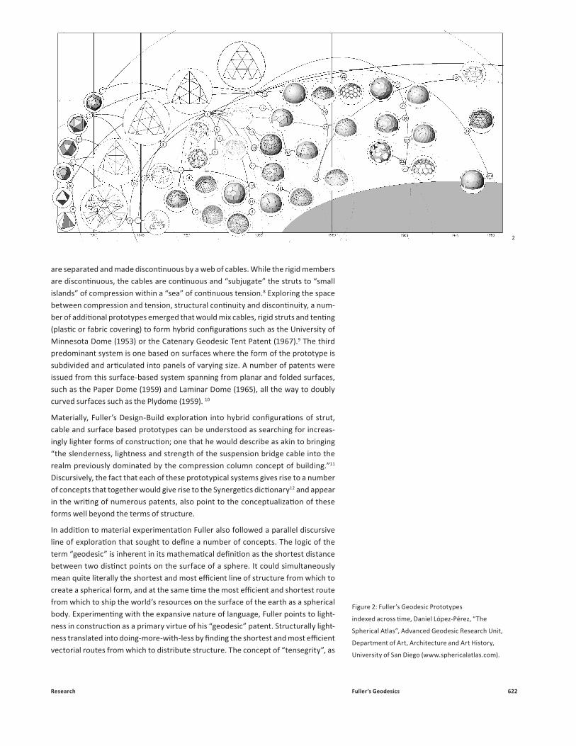
General Index:From R. Buckminster FullerPrototypes to Transformations
TOP DOWN
BOTTOM UP
Rhombic triacontahedron
Truncated Octahedron
Rhombicosidodecahedron
Truncated Dodecahedron
Tetrahedron
Dodecahedron
Rhombitruncated Icosidodecahedron
Icosahedron
Snub Cube
SOLID
Cuboctahedron
Truncated Tetrahedron
Truncated Cube
Octahedron
Snub Dodecahedron
Icosidodecahedron
Cube
Truncated Dodecahedron
Rhombitruncated Cubeoctahedron
RhombicubeoctahedronArchimedean
Catalan (Dual)
Platonic
Triacon
Base Layer Cut
Grid Density
Irregular
Modularization
Optimal
Regular
Grid Typology
Shallow
HorizontalVertical
Global Geometrical Distortion
Elongated
Porosity
Triangular
Form Adaptation
CurvedStraight
Planar
Radius of strut
Depth of Plate
Depth (part)
Profile (part)
Tubular
Square
Tensegrity
Plate
Strut
System (whole)
Fabric
Paper
Fiber Glass
Wood
Concrete
Aluminum
Steel
FREQUENCY
GRID
Alternate
Regular
ParallelTruncatable
31 Great Circles
Regular
Geodesic Dome, 31 Circles
12v
16v
10v
8v
6v
4v
3v
DEFORMATION
MATERIAL
STRUCTURAL
GEOMETRY
ORDER
PROTOTYPE
Thirty-One Foot Base Radome
Tenting for the 50 ft. Geodesic Hangar
Laminar Geodesic Dome
4v Parallel Sheet Metal Dome
Radome
Geodesic Dome, Pan Type
Laminar Geodesic DomeLaminar Geodesic Dome
Laminar Geodesic Dome
Pine-Cone Dome
Dome Units for Geodesics, Inc.
Geodesic Structures (A)
Non-Symmetrical Tensegrity Patent
Geodesic Structures (B)
Egg Crate Basic Assembly Unit
Geodesic Tent
Geodesic Structures (B)
Fifty-Foot Base Radome
Discontinuous Compression Sphere
Laminar Geodesic Dome
U.S. Marine Corps Preliminary Dome
Geodesic Tent
Fifty-foot Magnesium Geodesic Hangar
Laminar Geodesic Dome
Geodesic Patent
Fifty-foot Magnesium Geodesic Hangar
University of Minnesota, Dome Project
U.S. Marine Corps Preliminary Dome
Radome
4v Parallel Sheet Metal DomePine-Cone Dome
Plydome Patent
Dymaxion Map
Tensegrity Patent
Tenting for the 50 ft. Geodesic Hangar
Fifty Foot Base Diameter Radome
Laminar Geodesic Dome
Fifty-Foot Base Radome
Eight, Sixteen Frequency Geodesphere
Thirty-One Foot Base Radome
Plydome Patent
Dome Units for Geodesics, Inc.
Geodesic Structures (A)
Laminar Geodesic Dome
University of Minnesota, Dome Project
Dymaxion Map
Egg Crate Basic Assembly Unit
Fifty Foot Base Diameter Radome
University of Oregon, Geodesic Dome
Paperboard Dome
Typical Raft System
Discontinuous Compression SphereGeodesic Patent
Eight, Sixteen Frequency Geodesphere
Paperboard Dome
Typical Raft System
Non-Symmetrical Tensegrity Patent
University of Oregon, Geodesic Dome
Tensegrity Patent
Geodesic Deformation A.
Radome Deformation A.
University of Oregon Deformation
Tenting Deformation
Plydome DeformationTensegrity Deformation
Geodesic Tent Deformation
Hangar Deformation
Laminar Deformation A.
Preliminary Deformation
Laminar Deformation D.
Laminar Deformation B.
Typical Raft System Deformation
Egg Crate Deformation
Paperboard Deformation
Pan Type Deformation
Radome Deformation B.
Laminar Deformation C.
Pine-Cone Deformation
Dymaxion Deformation
4v Parallel Deformation
Geodesic Patent Deformation
Eight, Sixteen Freq. Deformation
31 Great Cirlces Deformation
University of Minnesota Deformation
Radome Deformation
Dome Units Deformation
Geodesic Deformation B.
Non-Symmetrical Tens. Deformation
Sphere
Radome Deformation
Discontinuous Compr. Deformation
Potential Deformations:
Bottom-up:A. Surface subdivision- gen-eral density of grid, form of grid
- Looking to identify the opti-mised ratio between member and model size to achieve the lowest use of materials to generate a form and seeing how this varies for different grid typologies and why.
B. Variation within form- variation of density within form- either as an abstract or to respond to performance requirements
- Identifying if this ratio vari-ous across the structure
- Base cut off level relative to equator
- Studying the modi cation of structure to see how the stiff-ness variation introduced by the objects contact with the ground varies with different interface conditions.
Top down:A. Alteration of sphericalform- global geometrical distortion - Application of elongation effects etc. to identify how dependant on the purity of form the performance of the structure is.
B. Introduction of form constraints- de ned openings through the form- Adaptations to re ect real constraints such as access to the structure. Study to identify variation in stress paths due to inconsistencies around the form.
C. Multiple forms- interac-tion of, say two, three, four, spheres- Looking at balancing forms against each other to allow modularisation and develop-ment of structures scaled over plan areas.
D. Performance require-ments- effect of location on form- Study of the effects of high vertical or lateral loads, seismic effects and thermal in uences on the design requirements.
Structural:A. Materiality- Abstract comparison of ma-terial properties to develop to a comparative study of the performance of different common and uncommon building materials.
B. Structural form- reciprocal frame, tensegrity structures etc.- Hierarchy of members- de- ning the member based on its performance require-ments, non uniform member sizes, alteration of member form (rectangular, circular etc.)
3
Figure 3: Fuller’s Geodesic Prototypes indexed in
accordance to their potential material deformation,
Daniel López-Pérez, “The Spherical Atlas” Research
Project, Advanced Geodesic Research Unit,
Department of Art, Architecture and Art History,
University of San Diego (www.sphericalatlas.com).
Research 624Fuller’s Geodesics
GEODESICS AND DOMEBOOKS This highly collaborative culture of Design-Build experimentation, disseminated widely by Fuller himself and many of his students and collaborators, resulted in the writing of numerous fabrication manuals across many departments of architec-ture and design nationally. In a do-it-yourself spirit, these manuals aimed to both decipher the geometry needed to construct these geodesic prototypes as well as illustrating their assembly in a wide range of material variations. They aimed to introduce the public to the geometrical complexities of geodesics, while at the same time expand the possibilities of its material translation into new forms of shelter. By making the geometry and material possibilities legible, these manuals bridged the gap between “designing” and “building”. By merging a do-it-yourself spirit with making legible the space of Design-Build exploration, these manuals were a tool for Design-Build exploration encouraging students and the general public alike to build new and unprecedented combinations of formal and material assemblages whose starting point would be geodesic form.
As an example of this kind of manual, Edward Popko’s Geodesics was used as an “industrialization and technology course supplement” in the School of Architecture at the University of Detroit in 1968. The division between “designing” and “build-ing” was translated into two sections across its pages. The first section is devoted to understanding the geometrical protocols of geodesics. With crystalline clarity, Popko offers an introduction to geodesic geometry in just 7 pages broken down into subsections that include “polyhedra”, “orientation”, “breakdown”, “frequency”, “base truncations”, and “chord factors.” These subsections outline a very clear path from which to understand the use of this geometry: starting with the inscription of a polyhedral solid into a sphere, projecting and orienting its faces upon the spheres’ surface, and finally applying a frequency of subdivision upon the newly created sur-face that would give raise to the distribution of struts or panels. Finding a footprint for the spherical body was also a recurring challenge, covered by Popko’s “base truncation” section. The second section of Popko’s Geodesics focuses on the trans-formation of this geometry into material structures in the form of an extraordinarily broad set of experiments – not only in an academic setting but also in practice. Varying dramatically in scale and material definition, Popko illustrates a number of examples, embodying Design-Build logic. By including drawings, details and physical models which at times follow Fuller’s protocols, but at others dramatically depart into devising new transformations from them, Popko’s manual embodies Design-Build exploration as expansive in nature. Linear (strut), Tensegrity (strut and cable) and Surface based models explore many different material combinations includ-ing wood and Mylar, tubular metal struts and fabric, polyester fiberglass panels, plywood, corrugated metal sheets, bicycle wheels, laminate wood with cables and acrylic sheeting, sheet metal, and aluminum panels. If the first section of geodesics was analytical and focused on understanding geometry and form, the extraordinary breadth and variety of cases in the second is proof of the transformational nature of geodesics as a highly potent source from where to imagine an endless number of material assemblages.
The proliferation of Fuller’s Design-Build experimentation in academic programs throughout the 1960s spilled out into the general public in the form of a counter culture of do-it-yourself dome-builders launched by Stuart Brand’s Whole Earth Catalog and Lloyd Khan’s Domebooks towards the end of the decade.17 As it has been argued by Felicity D. Scott, if the Domebooks were inspired by Fuller and in Khan’s own words tested “the physical projection of our fantasies”, they proved “infectious.”18 The transformation of Fuller’s geodesic geometry into a “pod, pillow
4
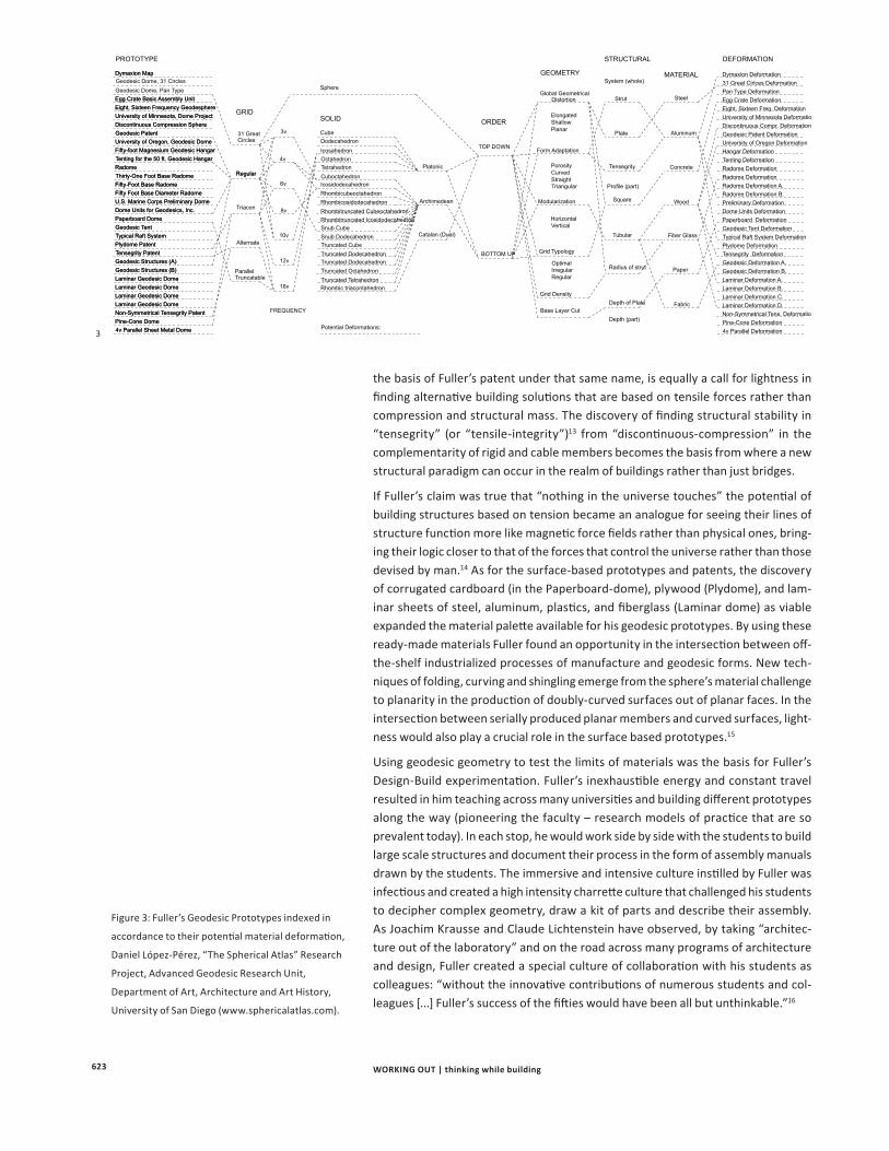
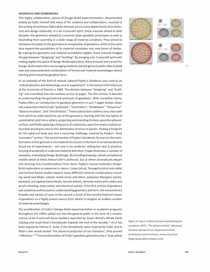
Figure 4: Class II. Grid:Formal and Load-Bearing As-
sumptions, AKTII, “The Spherical Atlas”, Advanced
Geodesic Research Unit, Department of Art,
Architecture and Art History, University of San
Diego (www.sphericalatlas.com).
625 WORKING OUT | thinking while building
and shingle dome” in the first issue of Domebook will now been expanded to include many other variation in Domebook 2 including: Elliptical domes, muslin-foam domes, plastic foam domes, Ferro-cement domes, tube-framed domes, tent domes, aluminum triacon domes, bamboo domes, and even metal “zomes” (based on a convex polyhedron whose faces are regular polygons). In each of these instances, the logic would be to expand upon a basic understanding of geodesic geometry into a growing number of material possibilities – to see geometry as the basis from which to explore endless variations of material assemblages. The page spreads in the Domebooks functioned like assembly manuals (or cookbooks) outlining a kit of parts and the basic steps of assembly in order to arrive at a form of shelter, outlined in sections that included: “Vital Statistics, Dome Ingredients, Builder’s Instructions, Cutting, Drilling, Edges, Pre-Fabrication” and many others. In the second issue of Domebook, a postscript expanded the possibilities for transformation beyond building materials by including Joseph D. Clinton’s “Geodesic Math” but also how through “Chord Factors and Angles” one can arrive at formal transformations such as “Elliptical Domes.”19 In this sense the expansive possibilities for transformation had now reached the broadest public and including material but also formal, geo-metrical and spatial possibilities.
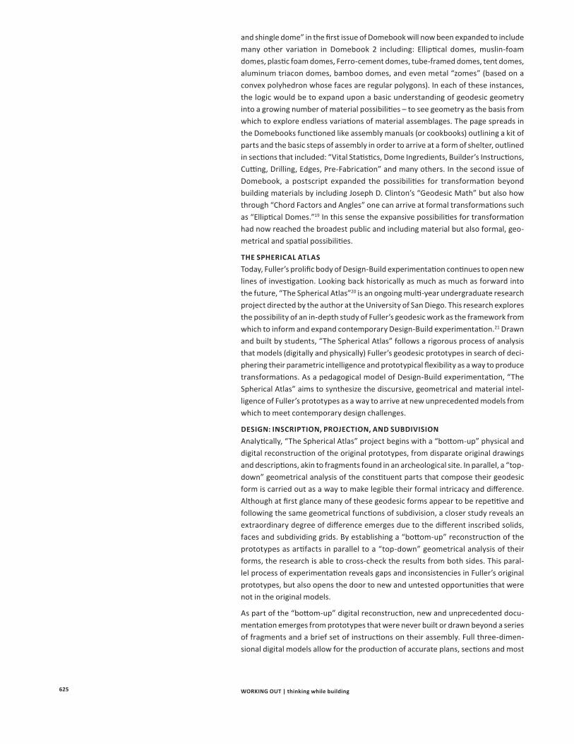
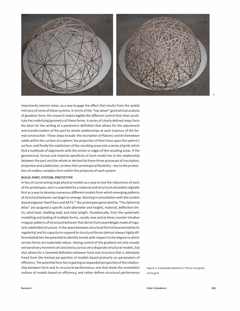
THE SPHERICAL ATLASToday, Fuller’s prolific body of Design-Build experimentation continues to open new lines of investigation. Looking back historically as much as much as forward into the future, “The Spherical Atlas”20 is an ongoing multi-year undergraduate research project directed by the author at the University of San Diego. This research explores the possibility of an in-depth study of Fuller’s geodesic work as the framework from which to inform and expand contemporary Design-Build experimentation.21 Drawn and built by students, “The Spherical Atlas” follows a rigorous process of analysis that models (digitally and physically) Fuller’s geodesic prototypes in search of deci-phering their parametric intelligence and prototypical flexibility as a way to produce transformations. As a pedagogical model of Design-Build experimentation, “The Spherical Atlas” aims to synthesize the discursive, geometrical and material intel-ligence of Fuller’s prototypes as a way to arrive at new unprecedented models from which to meet contemporary design challenges.
DESIGN: INSCRIPTION, PROJECTION, AND SUBDIVISION Analytically, “The Spherical Atlas” project begins with a “bottom-up” physical and digital reconstruction of the original prototypes, from disparate original drawings and descriptions, akin to fragments found in an archeological site. In parallel, a “top-down” geometrical analysis of the constituent parts that compose their geodesic form is carried out as a way to make legible their formal intricacy and difference. Although at first glance many of these geodesic forms appear to be repetitive and following the same geometrical functions of subdivision, a closer study reveals an extraordinary degree of difference emerges due to the different inscribed solids, faces and subdividing grids. By establishing a “bottom-up” reconstruction of the prototypes as artifacts in parallel to a “top-down” geometrical analysis of their forms, the research is able to cross-check the results from both sides. This paral-lel process of experimentation reveals gaps and inconsistencies in Fuller’s original prototypes, but also opens the door to new and untested opportunities that were not in the original models.
As part of the “bottom-up” digital reconstruction, new and unprecedented docu-mentation emerges from prototypes that were never built or drawn beyond a series of fragments and a brief set of instructions on their assembly. Full three-dimen-sional digital models allow for the production of accurate plans, sections and most
Research 626Fuller’s Geodesics
importantly interior views, as a way to gage the affect that results from the spatial intricacy of some of these systems. In terms of the “top-down” geometrical analysis of geodesic form, the research makes legible the different control lines that consti-tute the underlying geometry of these forms. A series of clearly defined steps form the basis for the writing of a parametric definition that allows for the adjustment and transformation of the part-to-whole relationships at each instance of the for-mal construction. These steps include: the inscription of Platonic and Archimedean solids within the surface of a sphere; the projection of their faces upon the sphere’s surface; and finally the subdivision of the resulting areas into a series of grids which find a multitude of alignments with the center or edges of the resulting areas. If the geometrical, formal and material specificity of each model lies in the relationship between the part and the whole as derived by these three processes of inscription, projection and subdivision, so does their prototypical flexibility – key to the produc-tion of endless variation form within the protocols of each system.
BUILD: PART, SYSTEM, PROTOTYPE In lieu of constructing large physical models as a way to test the robustness of each of the prototypes, each is submitted to a material and structural simulation digitally first as a way to develop numerous different models from which emerging patterns of structural behavior can begin to emerge. Working in consultation with the London based engineer Hanif Kara and AKTII,22 the prototypes generated by “The Spherical Atlas” are assigned a specific scale (diameter and height), material, deflection lim-its, wind load, cladding load, and total weight. Paradoxically, from the systematic modelling and testing of multiple forms, results new and at times counter intuitive irregular patterns of structural behavior that derive from assemblages made of regu-larly subdivided structure. In the space between structural form (characterized by its regularity) and its capacity to respond to structural forces (almost always highly dif-ferentiated) lies the potential to identify trends with respect to the degree to which certain forms are materially robust. Having control of this gradient not only reveals extraordinary moments of consistency across very disparate structural models, but also allows for a renewed definition between form and structure that is ultimately freed from the limited perspective of models based primarily on parameters of efficiency. The potential here lies in gaining an expanded perspective of the relation-ship between form and its structural performance, one that sheds the essentialist notions of models based on efficiency, and rather defines structural performance
5
Figure 5: icosadodecahedron’s Thirty-one great
circle grid
627 WORKING OUT | thinking while building
as gradients of efficiency and inefficiency providing yet another lever from which to find specificity and at the same time flexibility in these formal systems.
If Fuller’s models of Design-Build experimentation challenged his students to find relationships across multiple geometrical, discursive, and material registers; their legacy today remains alive in the promise of finding a transversal logic that can cut across these resulting in novel forms. The potential of this transversal logic points to a deeper and more complex understanding of the relationship between the meta-physical-and-physical, conceptual-and-material, design-and-build, challenging the limits of each of these dimensions, while exploring the fertile grounds of their sepa-rate yet irreducible potential. This transversal logic and more synthetic understand-ing of the relationship between the formal and material dimension of architectural form in Design-Build experimentation is ultimately Fuller’s legacy, and potential for contemporary practice to innovate as it moves into the future.
ENDNOTES
1. Edward S. Popko, “Bucky’s Dome,” Divided Spheres, Geodesics and the Orderly Subdivision of the Sphere (New York: CRC Press, Taylor & Francis Group, 2012), p.14.
2. Popko, “Bucky’s Dome,” p.25
3. The Artifacts of R. Buckminster Fuller: A Comprehensive Collection of His Designs and Drawings in Four Volumes (New York: Garland Publishing, Inc., 1985).
4. R. Buckminster Fuller, Inventions: The Patented Works of R. Buckminster Fuller (New York: St. Martin’s Press, 1983).
5. Edward S. Popko, Geodesics, Industrialization and Technology Course Supplement No. 1 (Detroit: University of Detroit, Michigan, 1968).
6. Lloyd Khan Ed., Domebook 1 (Los Gatos, CA: Pacific Domes, 1970); Lloyd Khan Ed., Domebook 2 (Bolinas, CA: Pacific Domes, 1971).
7. Fuller, “Geodesic Dome (1954)”, Inventions, Ibid., p.127-129.
8. Fuller, “Tensile-Integrity Structures”, Inventions, Ibid., 179-193.
9. Fuller, “Geodesic Tent (1959)”, Inventions, Ibid., p.162-165.
10. Fuller, “Paper Dome (1959)”, “Laminar Dome (1965)”, “Plydome (1959)”, Inventions, Ibid., p. 145-157, p.227-241, p.157-162.
11. Fuller, Ibid., 179-193.
12. R. Buckminster Fuller, Applewhite, E.J., Ed., Synergetics Dictionary: The Mind of Buckminster Fuller. Vol. 1-4 (New York: Garland, 1986).
13. Fuller, “World Design Initiative”, The Design Initiative, Vol. 2, World Design Science Decade, 1965-1975 (Carbondale, Ill: Southern Illinois University Press, 1963), p.28.
14. Fuller, “Tensegrity (1962),” Inventions, Ibid., p. 179.
15. Fuller, “Geodesic Dome”, Ibid. 16.
16. Joachim Krausse and Claude Lichtenstein Ed., “Architecture out of the Laboratory,” Your Private Sky, R. Buckminster Fuller, the Art of Design Science (Zurich: Lars Muller, 1999), p. 314.
17. Stuart Brand, Ed. Whole Earth Catalog, No. 1 (Menlo Park, CA, Fall, 1969).
18. Felicity D. Scott, “Ch. 6, Revolutionaries or Dropouts,” Architecture or Utopia, Politics after Modernism (Cambridge, Mass: MIT Press, 2007), p. 167.
19. Domebook 1, Ibid., p. 106-113.
20. Under the direction of Daniel López-Pérez, The Spherical Atlas is an ongoing collaborative faculty student undergraduate research project in the Department of Art, Architecture and Art History at the University of San Diego. www.sphericalatlas.com The project has received funding from the University’s Office of Undergraduate Research under the Keck, McNair, and SURE Faculty and Student undergraduate research programs.
21. For a generative understanding of historical form, refer to Farshid Moussavi, The Function of Form (Barcelona: Actar and Harvard University Graduate School of Design, 2009), p.32-33.
22. The London based engineer Hanif Kara, of AKTII (www.akt-uk.com ) is generously supporting and consulting the “The Spherical Atlas” research project.