frequency hopping spread spectrum transceiver implementation using floating-point dsp
TRANSCRIPT
1
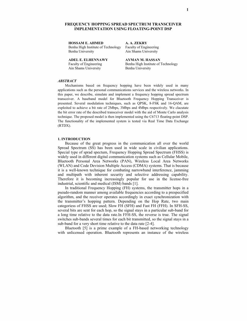
FREQUENCY HOPPING SPREAD SPECTRUM TRANSCEIVERIMPLEMENTATION USING FLOATING-POINT DSP
ABSTRACTMechanisms based on frequency hopping have been widely used in many
applications such as the personal communications services and the wireless networks. Inthis paper, we describe, simulate and implement a frequency hopping spread spectrumtransceiver. A baseband model for Bluetooth Frequency Hopping Transceiver ispresented. Several modulation techniques, such as QPSK, 8-FSK and 16-QAM, areexploited to achieve a bit rate of 2Mbps, 3Mbps and 4Mbps respectively. We clacutatethe bit error rate of the described transceiver model with the aid of Monte Carlo analysistechnique. The proposed model is then implemented using the C6713 floating-point DSP.The functionality of the implemented system is tested via Real Time Data Exchange(RTDX).
1. INTRODUCTIONBecause of the great progress in the communication all over the world
Spread Spectrum (SS) has been used in wide scale in civilian applications.Special type of sprad spectum, Frequency Hopping Spread Spectrum (FHSS) iswidely used in different digital communication systems such as Cellular Mobile,Bluetooth Personal Area Networks (PAN), Wireless Local Area Networks(WLAN) and Code Devision Multiple Access (CDMA) systems. That is becauseit is a well-known technique for combating narrowband interference, jammingand multipath with inherent security and selective addressing capability.Therefore it is becoming increasingly popular for use in the license-freeindustrial, scientific and medical (ISM) bands [1].
In traditional Frequency Hopping (FH) systems, the transmitter hops in apseudo-random manner among available frequencies according to a prespecifiedalgorithm, and the receiver operates accordingly in exact synchronization withthe transmitter’s hopping pattern. Depending on the Hop Rate, two maincategoriess of FHSS are used; Slow FH (SFH) and Fast FH (FFH). In SFH-SS,several bits are sent for each hop, so the signal stays in a particular sub-band fora long time relative to the data rate.In FFH-SS, the reverse is true. The signalswitches sub-bands several times for each bit transmitted, so the signal stays in asub-band for a very short time relative to the data rate [2-4].
Bluetooth [5] is a prime example of a FH-based networking technologywith unlicensed operation. Bluetooth represents an instance of the wireless
HOSSAM E. AHMEDBenha High Institute of TechnologyBenha University
A. A. ZEKRYFaculty of EngineeringAin Shams University
ADEL E. ELHENNAWYFaculty of EngineeringAin Shams University
AYMAN M. HASSANBenha High Institute of TechnologyBenha University
2
personal area network (WPAN), which has been further standardized within theIEEE 802.15 Working Group for WPAN [6].
Recently the FHSS has become a hot research topic. In multiple accesssystems, a collision may happen when more than one FH users transmit in thesame frequency band simultaneously. To solve this problem a new conceptcalled, “Collision-Free Frequency Hopping”, (CFFH) can achieve highinformation capacity and can successfully resolve the strict synchronizationlimitation [7].
A new Adaptive Frequency Hopping (AFH) technique has been proposed inan attempt to mitigate the interference between Bluetooth (IEEE 802.15) andwireless local area networks (WLANs) (IEEE 802.11b). The new AFHtechnique optimizes the carrier spacing according to the network load and noiselevel [8].
Personal Communications Services (PCS) require low-power radiotechnologies. Min and Samueli Presented one such transceiver architectureemploying frequency-hopped spread-spectrum techniques with the analysis anddesign of that transceiver [9].
High complexity of FHSS sequence is of a great importance to high-security multiple-access communication systems, for it makes FHSS sequencedifficult to be analyzed. With the growing development in the design of FHSSsequence, in much wider fields, the well-known complexity measures, the linearcomplexity (LC), the linear complexity profile (LCP) and the k-error linearcomplexity (k-error LC) are widely used but not sufficient to evaluate thecomplexities of the sequences available. In [10], a new complexity metric toevaluate the unpredictability of FHSS sequence based on the approximateentropy (AE) is proposed in the view of the maximal randomness of thesequences with arbitrary length. The proposed AE works effectively to discernthe changing complexities of the FHSS sequences with small number ofsamples, which provide superior performance over its candidates.
Finally optimization of the transmission range in terms of maximizinginformation efficiency is studied in [11] for mobile ad hoc networks (MANETs)with frequency-hopped (FH) CDMA and multiple antennas.
In this work we describe, simulate and implement a FHSS transceiver.First, a generic slow rate FHSS passband system is simulated using matlabsimulink. The bit error rate of the system is calculated, analysed and comparedwith ideal BFSK. Second, a baseband model for Bluetooth frequency hoppingsystem is presented. Several modulation techniques, such as QPSK, 8-FSK and16-QAM, are exploited to achieve a bit rate of 2Mbps, 3Mbps and 4Mbps.
Finally, we propose an implementation of the baseband model using theC6713 floating point DSP. The C6713 DSP Starter Kit (DSK) is used as anexperimental platform. The functionality of the implemented base band FHSStranceiver is tested via the Real Time Data Exchange (RTDX) techniquesupported by the TMS320C6713 DSK Kit.
The rest of this paper is organized as follow; Section 2 presents an overviewof the experimental setup. The system description, simulation and bit errorcalculations are represented in Section 3. The DSP implementation of theproposed FHSS transceiver is shown in Section 4. Finally, the conclusions aredrawn in Section 5.
3
2. EXPERIMENTAL SETUPIn simulating the FHSS transceiver the Matlab Simulink from “Mathworks
Inc” is used. The required libraries to build the transceiver are the simulinklibrary, communication library, DSP library and Embedded Target for TI C6000DSP library. The proposed transceiver is implemented using the C6713 floating-point DSP.The C6713 DSP Starter Kit (DSK) is used as an experimentalplatform. The C6713DSK is one of the most resourceful kits avaliable today forDigital Signal Processing [12]. It is a complete DSP system with the necessaryhardware and software support tools for real-time signal processing. The DSKboard includes the C6713 floating-point DSP and a 32-bit stereo codecTLV320AIC23 (AIC23) for input and output. The onboard codec AIC23 uses asigma–delta technology that provides ADC and DAC. It connects to a 12-MHzsystem clock. Variable sampling rates from 8 to 96 kHz can be set readily.TheDSK board includes 16MB of Synchronous Dynamic Random Access Memory(SDRAM) and 256kB of flash memory. Four connectors on the board provideinput and output: MIC IN for microphone input, LINE IN for line input, LINEOUT for line output, and HEADPHONE for a headphone output.The status ofthe four user dip switches on the DSK board can be read from a program andprovides the user with a feedback control interface.The DSK operates at225MHz [13][14].
Code Composer Studio (CCS3.1) from Texas Instruments includes tools forcode generation, such as a C compiler, an assembler, and a linker.It provides aneasy-to-use software tool to build and debug programs. The C compilercompiles a C source program with extension .c to produce an assembly sourcefile with extension .asm. The assembler assembles an .asm source file toproduce a machine language object file with extension .obj. The linker combinesobject files and object libraries as input to produce an executable file withextension .out. This executable file represents a linked Common Object FileFormat (COFF),This executable file can be loaded and run directly on theC6713 processor [15].
Finally the functionality of the implemented system is tested via Real TimeData Exchange (RTDX) supported by C6713 DSK and CCS.
3. TRANSCEIVER SIMULATIONTypically, we have two types of simulation models, namely “passband
model” and “baseband model”. In passband model, all modulation anddemodulation blocks are manually built and all required carrier generators usedin these blocks and in the frequency synthesizer block are in real form and realfrequency. On the other hand the baseband model is actually supported simulinkmodel where all modulation and demodulation blocks are ready made andavailable in the communication toolbox [16] ,furthermore any carrier generatoris not a real one instead each carrier is represented in complex form as amplitudeand phase1- Passband model
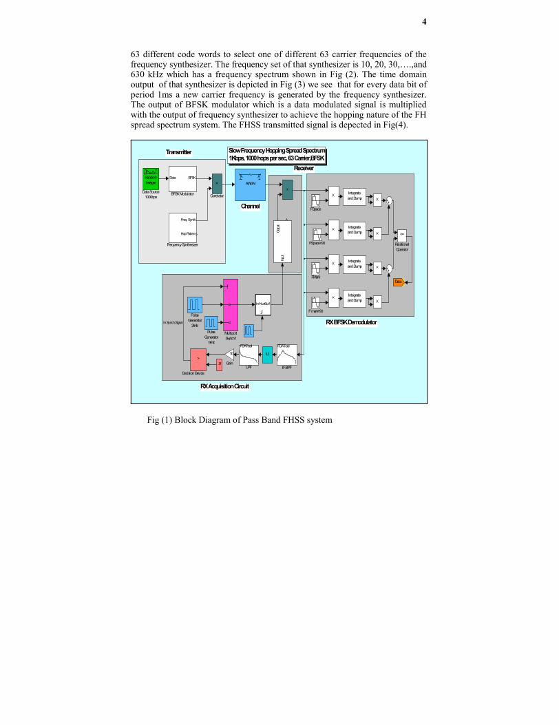
The complete simulink model is shown in Fig (1). In this model a binaryrandom integer generator with data rate of 1kbps is used as data source. Thisdata source feed a BFSK modulator of space and mark frequencies of 1 kHzand 8 kHz respectively. A PN sequence with maximum length type of [6,1] tapswith the same rate (1kHz) is used as code generator. The code generator provide
4
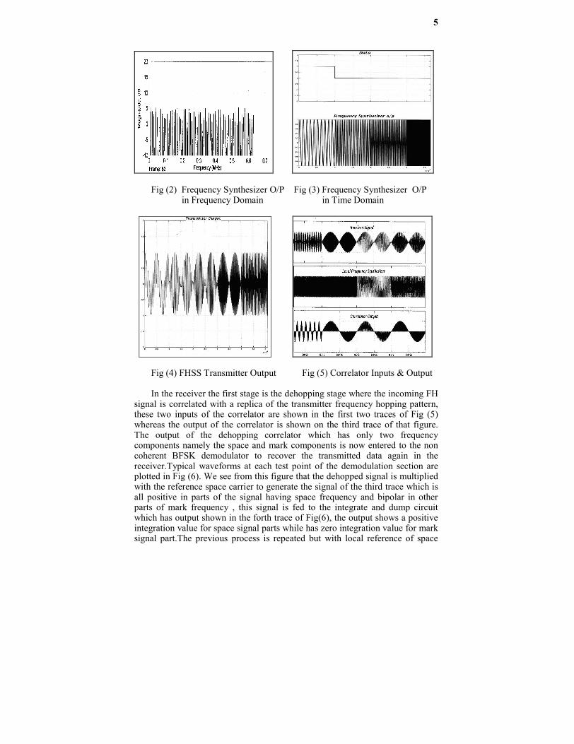
63 different code words to select one of different 63 carrier frequencies of thefrequency synthesizer. The frequency set of that synthesizer is 10, 20, 30,….,and630 kHz which has a frequency spectrum shown in Fig (2). The time domainoutput of that synthesizer is depicted in Fig (3) we see that for every data bit ofperiod 1ms a new carrier frequency is generated by the frequency synthesizer.The output of BFSK modulator which is a data modulated signal is multipliedwith the output of frequency synthesizer to achieve the hopping nature of the FHspread spectrum system. The FHSS transmitted signal is depected in Fig(4).
Slow Frequency Hopping Spread Spectrum1Kbps, 1000 hops per sec, 63 Carrier,BFSK
Transmitter
Receiver
TX Frequency Synthesizer
ChannelBFSK Modulator
RX BFSK Demodulator
Correlator
RX Acquisition Circuit
In1<Lo>Out1
Input
Outpu
t
<=
RelationalOperator
PulseGenerator
2kHzPulse
Generator1kHz
MultiportSwitch1
FDATool
LPF
Integrateand Dump
Integrateand Dump
Integrateand Dump
Integrateand Dump
FDATool
IF-BPF
Data
10
Gain
Freq. Synth
Hop Pattern
Frequency Synthesizer FSpace+90
FSpace
FMark
F mark+90
>
Decision Device
RandomInteger
Data Source1000bps Correlator
.9
Data BFSK
BFSK Modulator
|u|
AWGN
In Synch Signal
Fig (1) Block Diagram of Pass Band FHSS system
5
Fig (2) Frequency Synthesizer O/P Fig (3) Frequency Synthesizer O/Pin Frequency Domain in Time Domain
Fig (4) FHSS Transmitter Output Fig (5) Correlator Inputs & Output
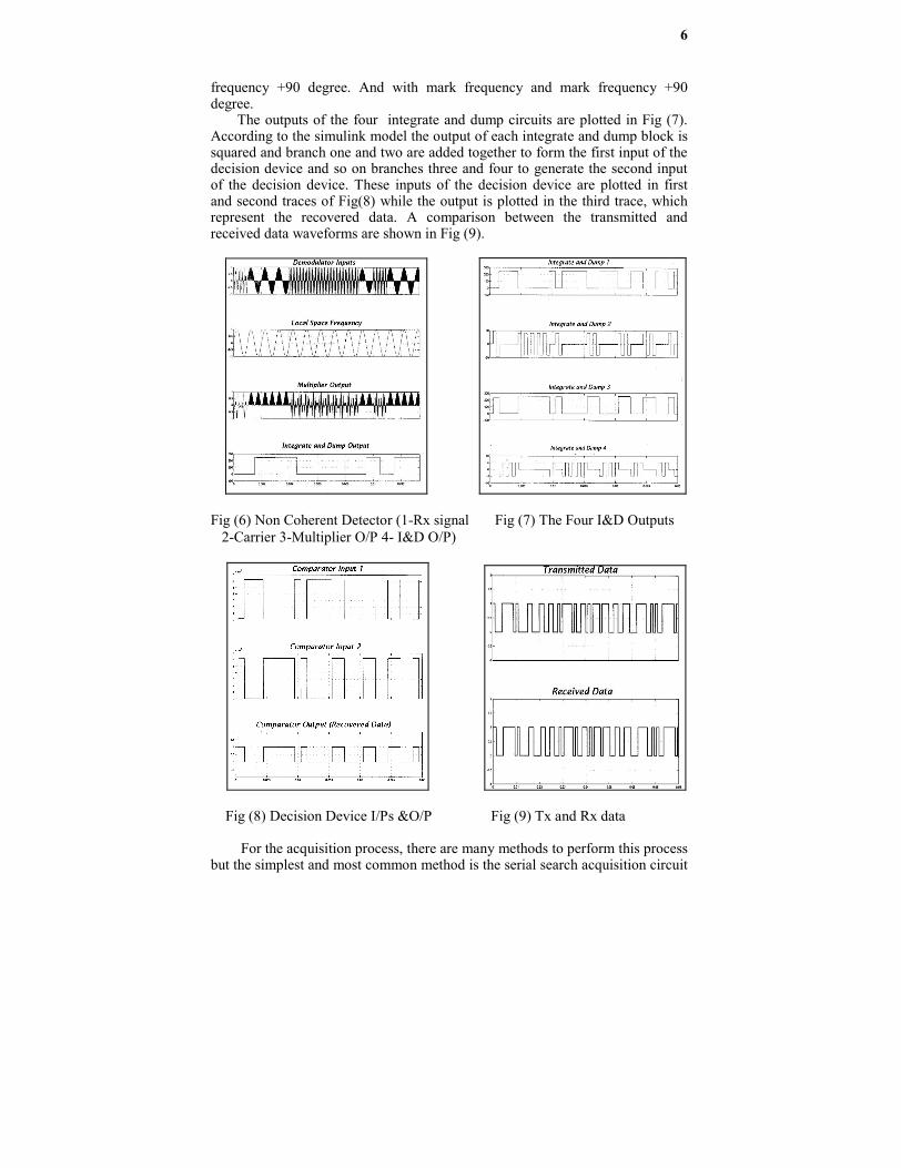
In the receiver the first stage is the dehopping stage where the incoming FHsignal is correlated with a replica of the transmitter frequency hopping pattern,these two inputs of the correlator are shown in the first two traces of Fig (5)whereas the output of the correlator is shown on the third trace of that figure.The output of the dehopping correlator which has only two frequencycomponents namely the space and mark components is now entered to the noncoherent BFSK demodulator to recover the transmitted data again in thereceiver.Typical waveforms at each test point of the demodulation section areplotted in Fig (6). We see from this figure that the dehopped signal is multipliedwith the reference space carrier to generate the signal of the third trace which isall positive in parts of the signal having space frequency and bipolar in otherparts of mark frequency , this signal is fed to the integrate and dump circuitwhich has output shown in the forth trace of Fig(6), the output shows a positiveintegration value for space signal parts while has zero integration value for marksignal part.The previous process is repeated but with local reference of space
6
frequency +90 degree. And with mark frequency and mark frequency +90degree.
The outputs of the four integrate and dump circuits are plotted in Fig (7).According to the simulink model the output of each integrate and dump block issquared and branch one and two are added together to form the first input of thedecision device and so on branches three and four to generate the second inputof the decision device. These inputs of the decision device are plotted in firstand second traces of Fig(8) while the output is plotted in the third trace, whichrepresent the recovered data. A comparison between the transmitted andreceived data waveforms are shown in Fig (9).
Fig (6) Non Coherent Detector (1-Rx signal Fig (7) The Four I&D Outputs 2-Carrier 3-Multiplier O/P 4- I&D O/P)
Fig (8) Decision Device I/Ps &O/P Fig (9) Tx and Rx data
For the acquisition process, there are many methods to perform this processbut the simplest and most common method is the serial search acquisition circuit
7
[17]. In this method the received FH signal plus noise is correlated in a wideband mixer with the local hop sequence produced by a FH synthesizer driven bya PN generator whose epoch is controlled in accordance with the decision tocontinue the search. The result of this correlator is passed through an IF filterfollowed by an energy detector. Post detection integration of the energy detectoroutput produces a signal whose mean value is nominally zero when the two hopsequences are misaligned and non zero when they are either partially or fullyaligned. Thus comparing this signal with a preset threshold allows a decision tobe made as whether or not FH acquisition has been achieved, or equivalentlywhether or not to step the PN code epoch and continue search.
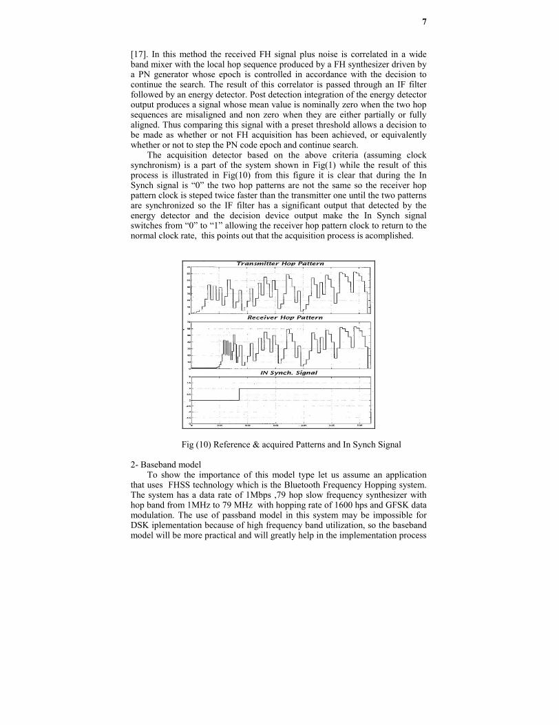
The acquisition detector based on the above criteria (assuming clocksynchronism) is a part of the system shown in Fig(1) while the result of thisprocess is illustrated in Fig(10) from this figure it is clear that during the InSynch signal is “0” the two hop patterns are not the same so the receiver hoppattern clock is steped twice faster than the transmitter one until the two patternsare synchronized so the IF filter has a significant output that detected by theenergy detector and the decision device output make the In Synch signalswitches from “0” to “1” allowing the receiver hop pattern clock to return to thenormal clock rate, this points out that the acquisition process is acomplished.
Fig (10) Reference & acquired Patterns and In Synch Signal
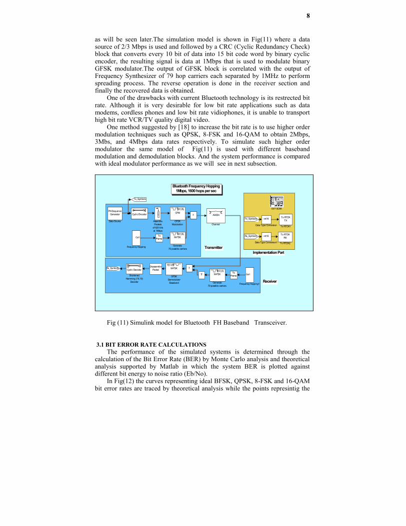
2- Baseband modelTo show the importance of this model type let us assume an application
that uses FHSS technology which is the Bluetooth Frequency Hopping system.The system has a data rate of 1Mbps ,79 hop slow frequency synthesizer withhop band from 1MHz to 79 MHz with hopping rate of 1600 hps and GFSK datamodulation. The use of passband model in this system may be impossible forDSK iplementation because of high frequency band utilization, so the basebandmodel will be more practical and will greatly help in the implementation process
8
as will be seen later.The simulation model is shown in Fig(11) where a datasource of 2/3 Mbps is used and followed by a CRC (Cyclic Redundancy Check)block that converts every 10 bit of data into 15 bit code word by binary cyclicencoder, the resulting signal is data at 1Mbps that is used to modulate binaryGFSK modulator.The output of GFSK block is correlated with the output ofFrequency Synthesizer of 79 hop carriers each separated by 1MHz to performspreading process. The reverse operation is done in the receiver section andfinally the recovered data is obtained.
One of the drawbacks with current Bluetooth technology is its restrected bitrate. Although it is very desirable for low bit rate applications such as datamodems, cordless phones and low bit rate vidiophones, it is unable to transporthigh bit rate VCR/TV quality digital video.
One method suggested by [18] to increase the bit rate is to use higher ordermodulation techniques such as QPSK, 8-FSK and 16-QAM to obtain 2Mbps,3Mbs, and 4Mbps data rates respectively. To simulate such higher ordermodulator the same model of Fig(11) is used with different basebandmodulation and demodulation blocks. And the system performance is comparedwith ideal modulator performance as we will see in next subsection.
Transmitter
Receiver
Bluetooth Frequency Hopping1Mbps, 1600 hops per sec
Implementation Part
To RTDXRX
To RTDX2
To RTDXTX
To RTDX1
Cyclic Encoder
Cyclic Decoder
ShortenedHamming (15,10)
Decoder
u
Rx_Symbols
Tx_Symbols
M-FSK
Generate79 possible carriers.
M-FSK
Generate79 possible carriers
CPM
GFSKModulation
M-FSK
GFSKDemodulator
Baseband
Rx_Symbols
Tx_Symbols
Out1
Frequency Hopping1
Out1
Frequency Hopping
ToFrame
ToFrame
DisassemblePacket
int16
Data Type Conversion1
int16
Data Type Conversion
PN SequenceGenerator
Data Source
AWGN
Channel
C6713DSK
AssemblePackets
of 625 bitsat 1Mbps
Fig (11) Simulink model for Bluetooth FH Baseband Transceiver.
3.1 BIT ERROR RATE CALCULATIONSThe performance of the simulated systems is determined through the
calculation of the Bit Error Rate (BER) by Monte Carlo analysis and theoreticalanalysis supported by Matlab in which the system BER is plotted againstdifferent bit energy to noise ratio (Eb/No).
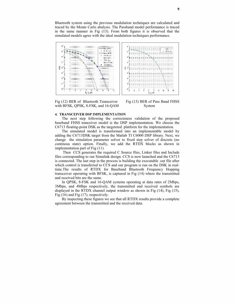
In Fig(12) the curves representing ideal BFSK, QPSK, 8-FSK and 16-QAMbit error rates are traced by theoretical analysis while the points represintig the
9
Bluetooth system using the previous modulation techniques are calculated andtraced by the Monte Carlo abalysis. The Passband model performance is tracedin the same manner in Fig (13). From both figures it is observed that thesimulated models agree with the ideal modulation techniques performance.
Fig (12) BER of Bluetooth Transceiver Fig (13) BER of Pass Band FHSSwith BFSK, QPSK, 8-FSK, and 16-QAM System
4. TRANSCEIVER DSP IMPLEMENTATIONThe next step following the correcteness validation of the proposed
baseband FHSS tranceiver model is the DSP implementation. We choose theC6713 floating-point DSK as the targeteted platform for the implementation.
The simulated model is transformed into an implementable model byadding the C6713DSK target from the Matlab TI C6000 DSP library. Next, wechange the simulation parameter solver to fixed step solver of discrete (nocontinous state) option. Finally, we add the RTDX blocks as shown inimplementation part of Fig (11).
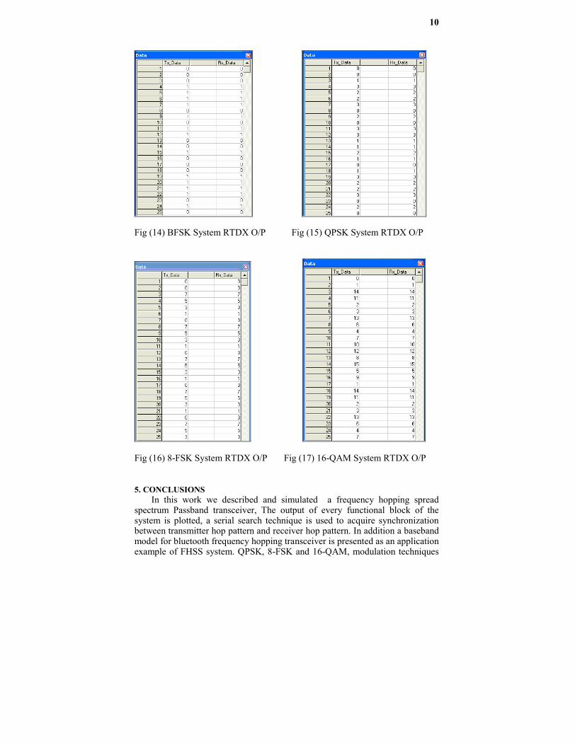
Then CCS generates the required C Source files, Linker files and Includefiles corresponding to our Simulink design. CCS is now launched and the C6713is connected. The last step in the process is building the executable .out file afterwhich control is transferred to CCS and our program is run on the DSK in real-time.The results of RTDX for Baseband Bluetooth Frequency Hoppingtransceiver operating with BFSK, is captured in Fig (14) where the transmittedand received bits are the same.
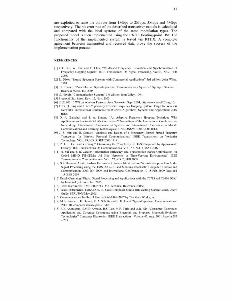
In QPSK, 8-FSK and 16-QAM systems operating at data rates of 2Mbps,3Mbps, and 4Mbps respectively, the transmitted and received symbols aredisplayed in the RTDX channel output window as shown in Fig (14), Fig (15),Fig (16) and Fig (17), respectively.
By inspecting these figures we see that all RTDX results provide a completeagreement between the transmitted and the received data.
10
Fig (14) BFSK System RTDX O/P Fig (15) QPSK System RTDX O/P
Fig (16) 8-FSK System RTDX O/P Fig (17) 16-QAM System RTDX O/P
5. CONCLUSIONSIn this work we described and simulated a frequency hopping spread
spectrum Passband transceiver, The output of every functional block of thesystem is plotted, a serial search technique is used to acquire synchronizationbetween transmitter hop pattern and receiver hop pattern. In addition a basebandmodel for bluetooth frequency hopping transceiver is presented as an applicationexample of FHSS system. QPSK, 8-FSK and 16-QAM, modulation techniques
11
are exploited to raise the bit rate from 1Mbps to 2Mbps, 3Mbps and 4Mbpsrespectively. The bit error rate of the described transceiver models is calculatedand compared with the ideal systems of the same modulation types. Theproposed model is then implemented using the C6713 floating-point DSP.Thefunctionality of the implemented system is tested via RTDX. A completeagreement between transmitted and received data prove the sucsess of theimplementation process.
REFERENCES
[1] C.C. Ko, W. Zhi, and F. Chin, “ML-Based Frequency Estimation and Synchronization ofFrequency Hopping Signals” IEEE Transactions On Signal Processing, Vol.53, No.2, FEB2005.
[2] R. Dixon “Spread Spectrum Systems with Commercial Applications” 3rd edition: John Wiley,1994
[3] D. Torrieri “Principles of Spread-Spectrum Communications Systems” Springer Science +Business Media, Inc. 2005
[4] S. Haykin “Communication Systems” 3rd edition: John Wiley, 1994.[5] Bluetooth Std. Spec., Rev. 1.2, Nov. 2003.[6] IEEE 802.15 WG on Wireless Personal Area Networks, Sept. 2004; http://www.ieee802.org/15/[7] T. Li, Q. Ling and J. Ren “Spectrally Efficient Frequency Hopping System Design for Wireless
Networks” International Conference on Wireless Algorithms, Systems and Applications 2007IEEE
[8] O. A. Bamahdi and S. A. Zummo “An Adaptive Frequency Hopping Technique WithApplication to Bluetooth-WLAN Coexistence” Proceedings of the International Conference onNetworking, International Conference on Systems and International Conference on MobileCommunications and Learning Technologies (ICNICONSMCL’06) 2006 IEEE
[9] J. S. Min and H. Samueli “Analysis and Design of a Frequency-Hopped Spread SpectrumTransceiver for Wireless Personal Communications” IEEE Transactions on VehicularTechnology, VOL. 49, NO. 5, SEP 2000 1719
[10] Z. Li, J. Cai, and Y.Chang “Determining the Complexity of FH/SS Sequence by ApproximateEntropy” IEEE Transactions On Communications, VOL. 57, NO. 3, MAR 2009
[11] H. Sui and J. R. Zeidler ”Information Efficiency and Transmission Range Optimization forCoded MIMO FH-CDMA Ad Hoc Networks in Time-Varying Environments” IEEETransactions On Communications, VOL. 57, NO. 2, FEB 2009
[12] S K Hasnain ,Aresh Dinshaw Daruwalla & Ameer Ishrat Saleem “A unified approach in AudioSignal Processing using the TMS320C6713 and Simulink Blocksets” Computer, Control andCommunication, 2009. IC4 2009. 2nd International Conference on 17-18 Feb. 2009 Page(s):1– 5 IEEE 2009
[13] Rulph Chassaing “Digital Signal Processing and Applications with the C6713 and C6416 DSK”by John Wiley & Sons, Inc. 2005
[14] Texas Instruments. TMS320C6713 DSK Technical Reference 2003al[15] Texas Instruments. TMS320C6713, Code Composer Studio IDE Getting Started Guide, User's
Guide, SPRU509f-May 2005.[16] Communications Toolbox 3 User’s Guide1996–2007 by The Math Works, Inc.[17] M. k. Simon, J. K. Omura, R. A. Scholtz and B. K. Levitt “Spread Spectrum Communications”
:VOL III, computer science press, 1985[18] A.K Arumugam, S.M.D Armour, B.S. Lee, M.F. Tariq and A.R. Nix “Consumer Electronics
Application and Coverage Constraints using Bluetooth and Proposed Bluetooth EvolutionTechnologies” Consumer Electronics, IEEE Transactions Volume 47, Aug. 2001 Page(s):283– 293.