frequency-domain receiver design for fast varying channels
TRANSCRIPT
Frequency-Domain Receiver Design for FastVarying Channels
Fabio Silva(1,2), Rui Dinis(1,2) and Paulo Montezuma(2,3)(1) Instituto de Telecomunicacoes, Lisboa, Portugal
(2) DEE, FCT-UNL, Portugal(3) UNINOVA, Caparica, Portugal
Abstract - Conventional frequency-domain receiversrequire a fixed channel within the block duration beingthe performance severely affected in presence of strongDoppler effects. In this paper we propose an itera-tive receiver for SC-FDE schemes (Single Carrier withFrequency-Domain Equalization) that is able to mitigatestrong Doppler effects. This receiver can be regarded as amodified turbo equalizer, implemented in the frequency-domain, able to compensate the Doppler effects associ-ated to different groups of multipath components whileperforming the equalization procedure. Our performanceresults show significant improvements over the turbo-FDE, even when different multipath components havesubstantially different Doppler effects.
I. INTRODUCTION
The growing demand for high speed wireless services andapplications (especially those based on multimedia) has incitedthe rapid development of broadband wireless systems. Broad-band wireless systems deployed in outdoor non-line of sightenvironments may encounter strong selective channels whichcan cause intersymbol interference. For these reasons, a majorchallenge on the design of broadband mobile communicationssystems is to overcome the effects of the mobile radio channel,assuring at same time high power and spectral efficiencies.Therefore, to meet the high data rate requirements while deal-ing with severely time-dispersive channels effects, powerfulequalization techniques become necessary to compensate thesignal distortion.
The conventional receiver for SC-FDE schemes is a linearFDE. However, it is known that nonlinear equalizers outper-form linear equalizers [1]. IB-DFE (Iterative Block DecisionFeedback Equalizer) [2] is a promising iterative FDE techniquefor SC-FDE that was first proposed in [3] and extended todiversity scenarios [4] and layered space-time schemes [5].These receivers can be regarded as low-complexity turbo FDEschemes [6], [7], where the channel decoder is not involved inthe feedback. True turbo FDE schemes can also be designedbased on the IB-DFE concept [8], [9].
Both linear FDE and IB-DFE schemes assume that thechannel remains constant during the duration of a given block,and there might be significant performance degradation when
we have fast-varying channels, namely due to strong Dopplereffects or high residual CFO (Carrier Frequency Offset).
Channel variations due to phase noise or residual CFOlead to simple phase variations that are relatively easy tocompensate at the receiver [10], [11]. The situation is muchmore complex when the channel variations are due to Dopplereffects that are different for different multipath components(e.g., when we have different departure/arrival directions rel-atively to the terminal movement).
In this paper we consider the use of SC-FDE schemes inchannels with strong Doppler effects. We model the short termchannel variations as pure Doppler shifts that are differentfor each multipath component and use this model to designfrequency-domain receivers that are able to cope with strongDoppler effects.
This paper is organized as follows: The system considered inthis chapter is characterized in Section II. Section III describesa mathematical model to represent the short term channelvariations. Section IV describes our SC-FDE receiver withjoint equalization and frequency drift correction and a set ofperformance results is presented in Section V. Finally, SectionVI presents the conclusions of this paper.
II. SYSTEM DESCRIPTION
We consider an SC-FDE modulation where data is trans-mitted in blocks of N useful modulation symbols {sn;n =0, ..., N − 1}, resulting from a direct mapping of the originaldata into a selected signal constellation (e.g., a QPSK con-stellation). Subsequently, a cyclic prefix with length longerthan the channel impulse response is appended, resulting thetransmitted signal {sn;n = −NG, ..., N − 1}, where NGdenotes the number of guard samples. The signal is transmittedover a time-dispersive channel. The received signal is sampledat the receiver and the CP samples are removed, leading inthe time-domain the samples {yn;n = 0, ..., N − 1}. Thecorresponding frequency-domain block, obtained after an ap-propriate size-N DFT (Discrete Fourier Transform) operation,is {Yk; k = 0, 1, . . . , N − 1}, where Yk can be written as
Yk = SkHk +Nk, (1)
with Hk denoting the overall channel frequency response forthe kth frequency of a given block, and Nk representingchannel noise term in the frequency-domain.

A linear FDE is employed in conventional SC-FDE schemesto deal with channel effects. However, the performance can besubstantially improved if the linear FDE scheme is replacedby an IB-DFE [3]. This is an iterative receiver where thefrequency-domain block at the equalizer output for the ithiteration is {S(i)
k ; k = 0, 1, . . . , N − 1}, with
S(i)k = F
(i)k Yk −B(i)
k S(i−1)
k (2)
where {F (i)k ; k = 0, 1, . . . , N − 1} are the feedforward coeffi-
cients and {B(i)k ; k = 0, 1, . . . , N − 1} are the feedback coef-
ficients. {S(i−1)
k ; k = 0, 1, . . . , N−1} denotes the DFT of theblock of time-domain conditional symbol expectations associ-ated with the previous iteration {s(i−1)
n ;n = 0, 1, . . . , N −1}.For a normalized IB-DFE, the optimum feedback coefficientsare
B(i)k = F
(i)k Hk − 1 (3)
and the feedforward coefficients are given by
F(i)k =
F(i)k
γ(i), (4)
with
F(i)k =
H∗kα+ (1− (ρ(i−1))2)|Hk|2
, (5)
where α = E[|N (l)k |2]/E[|Sk|2] (common to all data blocks),
γ(i) =1
N
N−1∑k=0
F(i)k Hk (6)
and the correlation factor ρ(i−1) is defined as
ρ(i−1) =E[s
(i−1)n s∗n]
E[|sn|2]=E[S
(i−1)k S∗k ]
E[|Sk|2], (7)
where the block {s(i−1)n ;n = 0, 1, . . . , N − 1} denotes the
data estimates associated to the previous iteration, i.e., thehard decisions associated to the time-domain block at theoutput of the FDE, {s(i)
n ;n = 0, 1, . . . , N − 1} = IDFT{S(i)
k ; k = 0, 1, . . . , N − 1}. For QPSK constellations, thecorrelation coefficient is given by [12]
ρ(i) =1
2N
N−1∑n=0
(ρI(i)n + ρQ(i)n ), (8)
where
ρI(i)n =
∣∣∣∣∣tanh
(LI(i)n
2
)∣∣∣∣∣ , (9)
and
ρQ(i)n =
∣∣∣∣∣tanh
(LQ(i)n
2
)∣∣∣∣∣ , (10)
with the LLRs (LogLikelihood Ratios) of the “in-phase bit”and the “quadrature bit”, associated to sIn and sQn , respectively,given by
LI(i)n =2
σ2i
sI(i)n (11)
and
LQ(i)n =
2
σ2i
sQ(i)n , (12)
respectively, with
σ2i =
1
2E[|sn − s(i)
n |2] ≈ 1
2N
N−1∑n=0
|s(i)n − s(i)
n |2. (13)
The conditional expectations associated with the data sym-bols are given by
s(i)n = tanh
(LI(i)n
2
)+ j tanh
(LQ(i)n
2
). (14)
With a conventional IB-DFE receiver the log-likelihoodvalues are computed on a symbol-by-symbol basis (i.e., wedo not need to perform the channel decoding in the feedbackloop). As an alternative, we can define a turbo IB-DFE thatemploys the channel decoder outputs instead of the uncoded“soft decisions” in the feedback loop. The main differencebetween conventional IB-DFE and turbo IB-DFE is in thedecision device: in the first case the decision device is asymbol-by-symbol soft-decision (for QPSK constellation thiscorresponds to the hyperbolic tangent, as in (14)); for theturbo IB-DFE a SISO channel decoder (Soft-In, Soft-Out)is employed in the feedback loop. The SISO block can beimplemented as defined in [13] and provides the LLRs of boththe “information bits” and the “coded bits”. The input of theSISO block are LLRs of the “coded bits” at the FDE output,given by (11) and (12).
III. MODELING SHORT-TERM CHANNEL VARIATIONS
In this section we present a channel characterization able tomodel short term channel variations.
We consider a channel with multipath propagation and thechannel’s impulsive response associated to an impulse at timet0 is
h(t, t0) =∑l∈Ψ
αell (t0)δ(t− τell
), (15)
where Ψ is the set of multipath components, αell (t0) is thecomplex amplitude of the lth multipath component and τl itsdelay (without loss of generality, we assume that τl is constantfor the short-term variations that we are considering).
If the channel variations are due to Doppler effects then
αell (t0) = αl(0)ej(2πf(l)D t0) (16)
(we will assume the specific case were the receiver and allreflecting surfaces are fixed, and the transmitter is moving).
The Doppler shift associated to the lth multipath componentis
f(l)D =
v
cfc cos(θl) = fD cos(θl), (17)
with fc denoting the carrier frequency, c the speed of light andv the speed of the transmitter. The maximum Doppler shift isfD = vfc/c and θl is the angle between the velocity vector ~vand the directions of propagation.

Although this model is general, the number of multipathcomponents can be very high, especially when the reflectingsurfaces have high rugosity and/or we have scattering effects.To overcome this problem it is common to group the multipathcomponents in sets following a similar path, i.e.,
h(t, t0) 'NR∑r=1
αr(t0)δ (t− τr) , (18)
whereαr(t0) =
∑l∈Ψr
αell (t0), (19)
with Ψr denoting the set of elements contributions grouped inthe rth multipath group. Naturally, this means that τell ≈ τr,∀l∈Ψr
, i.e., the contributions associated to the rth multipathgroup have the same delay (at least at the symbol scale).
If we assume that θl is uniformly distributed in [0, 2π] andthe number of components in Ψr is ]Ψr � 1 (with ]Ψr
representing the number of elements in the set Ψr), thenαr(t0) can be regarded as a zero-mean complex Gaussianprocess with power spectral density
Gαr(f) ∝
{1√
1−(f/fD)2, |f | < fD
0, |f | > fD(20)
which corresponds to the so-called Jakes’ Doppler spectrum.Therefore, we can model αr(t0) as a white Gaussian noisew(t0), filtered by a filter with frequency response HD(f) ∝√Gαr
(f), as in Fig. 1 (usually denoted “Doppler filter”) [14].Therefore, we can use the model of Fig. 1 to generate αr(t0)
( )DH f0( )t 0( )r t
Fig. 1: Doppler filter.
However, this means that each multipath component thatfollows a given “macro path” is decomposed in several com-ponents that are scattered at the vicinity of the transmitter (seeFig. 2).
l
vTx
Rx
Txv
1r
2r
Rx
v
1r
2r Rx
1 1
1
2 2
2
,
,
el
l l
el
l
el
l l
el
l
Tx
Fig. 2: Various objects in the environment scatter the radiosignal before it arrives at the receiver.
Although this is acceptable for narrow band systems wherethe symbol duration is very high, for broadband systems multi-path components that depart/arrive with substantially different
directions will have delays that are very different and thereforeshould not be regarded as elementary components of the sameray. This means that all elementary components at a given rayshould have almost the same direction of arrival (see Fig. 3).Therefore, in the model of Fig. 1 the Doppler filter will havea very narrow band centered in f (r)
D = fD cos(θr).
l
vTx
Rx
Txv
1r
2r
Rx
v
1r
2r Rx
1 1
1
2 2
2
,
,
el
l l
el
l
el
l l
el
l
Tx
Fig. 3: Model where the elementary components at a givenray have almost the same direction of arrival.
As a result, the short term channel variations can be modeledas pure Doppler shifts that are different for each multipathgroup, i.e.,
αr(t0) ' αr(0)ej(2πfD cos(θr)t0), (21)
(αr(0) can still be modeled as a sample of a zero-meancomplex Gaussian process).
The time-varying channel impulsive response can also bewritten as
h(t, t0) '∑m
h(m)(t, t0) =∑m
h(m)(t, 0)ej(2πfD cos(θ(m))t0),
(22)where h(m)(t, t0) is the set of multipath components that havesimilar direction of arrival (although can have substantiallydifferent delays). Equation (22) can be written as
h(t, t0) ≈∑r
αr(0)ej(2πfD cos(θr)t0)δ (t− τr)
=∑r
αr(0)ej2πf(m)D t0δ (t− τr)
=∑m
∑l∈Φm
αl(0)ej(2πf(l)D t0)δ (t− τl)
=∑m
ej(2πf(m)D t0)
∑l∈Φm
αl(0)ej(2π(f(l)D −f
(m)D )t0)δ (t− τl)
(23)
with, Φm denoting the set of all multipath components.In practical scenarios it might be necessary to perform a
kind of quantization of the Doppler shifts.
IV. RECEIVER DESIGN
Let us now consider a SC-FDE based transmission, in thepresence of fast-varying channels. We assume that each setof rays is associated with a different frequency drift dueto Doppler effects, and we present a method to compensatethese effects at the receiver side. Under these conditions, each
sample is affected by a different frequency drift. For SC-FDEthe frequency drift induces a rotation in the constellation thatgrows linearly along the block. Without loss of generality, weadmit that the phase rotation is 0 for the initial sample n = 0.
In [11], a estimation and compensation technique of thephase rotation associated to the frequency drift is proposed fora conventional cellular system in a slowly varying scenario.However, the multipath propagation causes time dispersion,and multiple sets of rays received with different delays areadded in the receiver. Moreover, for fast varying channels thereceived signal will fluctuate within each block. Therefore,regarding these conditions, we will admit that the receivedsignals arrive with possible different delays, and are exposedto different frequency drifts.
The received equivalent time-domain block, yDopplern , con-sists in the addition of the time-domain blocks associated tothe NR sets of rays, and is given by
yDopplern =
NR∑r=1
y(r)n ej2πf
(r)D n/N (24)
where f (r)D denotes the frequency drift associated to the rth
set of rays. By defining
θ(r)n = 2πf
(r)D
n
N, (25)
then (24) can be rewritten as
yDopplern =
NR∑r=1
y(r)n ejθ
(r)n . (26)
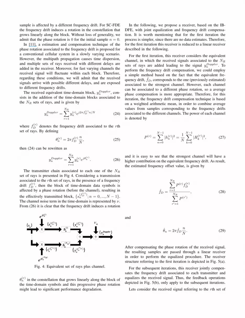
The transmitter chain associated to each one of the NRset of rays is presented in Fig 4. Considering a transmissionassociated to the rth set of rays, in the presence of a frequencydrift f (r)
D , then the block of time-domain data symbols isaffected by a phase rotation (before the channel), resulting in
the effectively transmitted block, {s(f(r)D )
n ;n = 0, ..., N − 1}.The channel noise term in the time-domain is represented by ν.From (26) it is clear that the frequency drift induces a rotation
Transmitter Channel.Eq
n
(1)nje
X
X
}{n
s(1)( )}{ D
f
ny
( )( )}{
NR
Df
ny
( )
NRnj
e
(1)
nh
( )R
N
nh
(1)( )}{ Df
ns
( )( )}{
N R
Df
ns
}{ Dopplern
y
Fig. 4: Equivalent set of rays plus channel.
θ(r)n in the constellation that grows linearly along the block of
the time-domain symbols and this progressive phase rotationmight lead to significant performance degradation.
In the following, we propose a receiver, based on the IB-DFE, with joint equalization and frequency drift compensa-tion. It is worth mentioning that for the first iteration theprocess is simpler, since there are no data estimates. Therefore,for the first iteration this receiver is reduced to a linear receiverdescribed in the following.
For the first iteration, this receiver considers the equivalentchannel, in which the received signals associated to the NRsets of rays are added leading to the signal yDopplern . Toperform the frequency drift compensation, we could employa simple method based on the fact that the equivalent fre-quency drift, fD, corresponds to the one (previously estimated)associated to the strongest channel. However, each channelcan be associated to a different phase rotation, so a averagephase compensation is more appropriate. Therefore, for thisiteration, the frequency drift compensation technique is basedon a weighted arithmetic mean, in order to combine averagevalues from samples corresponding to the frequency driftsassociated to the different channels. The power of each channelis denoted by
P (r) =
N−1∑n=0
|h(r)n |2 =
1
N
N−1∑k=0
|H(r)k |2, (27)
and it is easy to see that the strongest channel will have ahigher contribution on the equivalent frequency drift. As result,the estimated frequency offset value, is given by
fD =
NR∑r=1
P (r)f(r)D
NR∑r′=1
P (r′)
, (28)
and
θn = 2πfDn
N. (29)
After compensating the phase rotation of the received signal,the resulting samples are passed through a linear receiverin order to perform the equalized procedure. The receiverstructure referring to the first iteration is depicted in Fig. 5(a).
For the subsequent iterations, this receiver jointly compen-sates the frequency drift associated to each transmitter andequalizes the received signal. Thus, the feedback operationsdepicted in Fig. 5(b), only apply to the subsequent iterations.
Lets consider the received signal referring to the rth set of

XDFT X
nje
}{k
Y
(1)}{k
F
(1)ˆ }{n
s(1)}{n
s(1)}{k
S}{ Dopplern
y
A IDFTHard
Decisions
(a)
X
(1)}{n
sIDFT
IDFT
(1, )}{ ik
F
( , ){ }RN i
kF
X
X
DFT
DFT
( )( )
1
ˆ
r
njr
nr
y e
}{ Dopplern
y(1)( )}{ D
f
kS
( )( )}{
N R
Df
kS
( ){ }RN
ns
(1)( )}{ Df
ny
( )( )}{
N R
Df
ny
(1)( )}{ Df
kY
( )( )}{
N R
Df
kY
(1)( )}{ Df
ns
( )( )}{
NR
Df
ns
( )( )ˆ
R
rn
jrn
r N
y e
( ) RN
nj
e
(1)n
je
( )ˆ }{ in
s
X
DFT IDFT
( )}{ in
s
Delay
( 1)ˆ }{ in
s
( )}{ ik
B
DFT X
( 1)}{ in
s( 1)}{ ik
S
Soft
Dec.
∑
( )}{ ik
SHard
Dec.
(b)
Fig. 5: Receiver structure for the first iteration (a); Receiver structure for the subsequent iterations (b).
rays, given by
y(f
(r)D )
n = yDopplern −NR∑r′ 6=r
y(r′)n ejθ
(r′)n
= yDopplern −NR∑r′ 6=r
(s(i−1)n ⊗ h(r′)
n
)ejθ
(r′)n
= yDopplern −NR∑r′ 6=r
IDFT(S
(i−1)k H
(r′)k
)ejθ
(r′)n
≈ yDopplern −NR∑r′ 6=r
y(r′)n ejθ
(r′)n .
(30)
The set of operations described next are performed for allNR signals within each iteration. In the receiver of Fig. 5(b)the first operation consists in a filtering procedure required
to isolate the group of rays signal y(f(r)D )
n , from the totalreceived signal yDopplern which is accomplished by removingthe contributions of the interfering signals as described in(30). The computation of these undesired signal componentsis based on the equalized samples at the FDE’s output fromthe previous iteration, {S(i−1)
k ; k = 0, 1, . . . , N − 1}.The samples corresponding to the resulting signal
{y(f(r)D )
n ;n = 0, ..., N − 1} are then passed to the frequency-domain by an N -point DFT, leading to the correspondingfrequency-domain samples which are then equalized by afrequency-domain feedforward filter. The equalized samplesare converted back to the time-domain by an IDFT operation
leading to the block of time-domain equalized samples s(f(r)D )
n .Next, the resulting signal is compensated by the respectivefrequency drift θ(r)
n , which for simplicity it is assumed to havebeen previously estimated. This process is performed for eachone of the NR signals, and the signals are added in a singlesignal which is then equalized with resort to the IB-DFE.The equalized samples at the FDE’s output, will be given by{S(i)
k ; k = 0, 1, . . . , N−1}. For each iteration we perform thefrequency drift compensation before the detection procedure.The receiver jointly compensates the phase error and equalizesthe received signal. As will be seen in the section V, despitebeing more complex, this receiver presents higher gains whencompared to the traditional IB-DFE.
V. PERFORMANCE RESULTS
Here we present a set of performance results regarding theuse of the proposed receiver in time-varying channels.
We consider an SC-FDE modulation with blocks of N =1024 symbols and a cyclic prefix of 256 symbols acquiredfrom each block, although similar results were observed forother values of N , provided that N >> 1. The modulationsymbols belong to a QPSK constellation and are selected fromthe transmitted data according to a Gray mapping rule.
We considered a coded transmission employing a channelencoder based on a 64-state, 1/2-rate convolutional code withthe polynomials generators 1+D2+D3+D5+D6 and 1+D+D2 + D3 + D6. The coded bits are interleaved before beingmapped into the constellation points and distributed by thesymbols of the block. Our performance results are expressed as

function of Eb/N0, where N0 is the one-sided power spectraldensity of the noise and Eb is the energy of the transmittedbits.
It is also assumed that, for each multipath group, theDoppler drift and the respective channel impulse response areknown. This information can be obtained with the help ofappropriate training sequences, although the details are beyondthe scope of this paper.
We consider a scenario where the receiver and all reflectingsurfaces are fixed, and the transmitter (i.e., mobile terminal) ismoving with speed v. We also assume a channel with uncor-related Rayleigh fading, with multipath propagation, and withshort-term variations due to Doppler effects. The maximumnormalized Doppler drift is given by fd = fDTB = vfc/cTB ,with fc denoting the carrier frequency, c the speed of lightand TB the block duration. Under this scenario we considertwo different cases regarding the number of multipath groups.
Let us consider the case illustrated in Fig. 6(a), where themultipath components are divided in two multipath groups.The first group has the direction of movement and thereforeis associated to a Doppler drift of ∆f1 = fd, while thesecond group has the opposite direction and a Doppler driftof ∆f2 = −fd. Without loss of generality we will assumethat 64 multipath components are arriving from each direction.Figs 7 and 8 present the BER performance for the proposedreceiver, regarding a transmission with two different valuesof maximum normalized Doppler drifts, fd = 0.15 andfd = 0.2, respectively. For comparison purposes we alsopresent the results employing the IB-DFE (with no frequencydrift compensation), as well as the results obtained with a staticchannel. For a more practical comparison, the performanceresults regarding the Doppler drifts fd = 0.15 and fd = 0.2are represented together in Fig. 9.
Let us consider now the case illustrated in Fig. 6(b), wherewe have multipath groups with maximum normalized Dopplerdrifts 0,±0.7fd and ±fd (this can be regarded as a scenariowhere the angle between the direction of movement and thedirection of the multipath components is 0, ±π/4, ±π/2and π). As well as in the previous scenario, we admit that64 multipath components are arriving from each direction.Multipath groups with similar θl (i.e., angle between thedirection of movement and the direction of the multipathgroup), are grouped together (e.g., multipath groups r2 andr8 are joined in a larger set with 128 rays, with a Dopplerdrift of ∆f2 = 0.7fd).
Figs. 10 and 11 present the BER performance for theproposed receiver, regarding a transmission with two differentvalues of maximum normalized Doppler drifts, fd = 0.15 andfd = 0.2, respectively. Once again, for comparison purposeswe also present the results employing the IB-DFE (with nofrequency drift compensation), as well as the results obtainedwith a static channel.
For both scenarios, it can be observed that when thecompensation method is not employed (i.e., when it is usedthe IB-DFE), the BER performance highly deteriorates withincreasing values of the Doppler drifts. Although more com-
180°
2r
1r
ν →
Case I(1)
1
(2)
2
D d
D d
f f f
f f f
(a)
2
2
ν →
2r
1r
4r
3r
5r
6r
8r
7r
45°
ν →
df
2
2 df
C ase II
(1)
1
(2) (8)
2
(3) (7)
3
(4) (6)
4
(5)
5
0
D d
D D
D D
D D
D d
f f f
f f f
f f f
f f f
f f f
(b)
Fig. 6: Transmission with two multipath groups (a);Transmission with five multipath groups (b).
−1 1 3 5 7 9 1110
−4
10−3
10−2
10−1
100
Eb/N
0(dB)
BE
R
− − − − :− ⋅ − ⋅ −:_______ :
Iter. 1 (SC-FDE)Iter. 2Iter. 4
fd = 0.15
◦ : No Correction+ : CorrectionΔ : Static Channel
Fig. 7: Coded BER performance for case I with normalizedDoppler drifts fd and −fd for fd = 0.15.
plex, this receiver presents better results when compared tothe IB-DFE.
VI. CONCLUSIONS
In this paper we considered the use of SC-FDE schemesin channels with strong Doppler effects, which can be dif-ferent for different multipath components. We proposed aniterative frequency-domain receiver that is able to compensatethese Doppler effects. From our performance results we mayconclude that the proposed compensation method can achievehigh gains, even for several groups of rays with substantiallydifferent Doppler drifts. Therefore, the proposed receiver is

−1 1 3 5 7 9 1110
−4
10−3
10−2
10−1
100
Eb/N
0(dB)
BE
R
Iter. 1 (SC-FDE)Iter. 2Iter. 4
− − − − :− ⋅ − ⋅ −:_______ :
fd = 0.2
◦ : No Correction+ : CorrectionΔ : Static Channel
Fig. 8: Coded BER performance for case I with normalizedDoppler drifts fd and −fd for fd = 0.2.
−1 1 3 5 7 9 1110
−4
10−3
10−2
10−1
100
Eb/N
0(dB)
BE
R
− − − − :− ⋅ − ⋅ −:_______ :
Iter. 1 (SC-FDE)Iter. 2Iter. 4
Scenario I∗ : fd = 0.15◦ : fd = 0.2
Fig. 9: Coded BER performance for case I with normalizedDoppler drifts fd and −fd for fd = 0.15 and fd = 0.2.
−1 1 3 5 7 9 1110
−4
10−3
10−2
10−1
100
Eb/N
0(dB)
BE
R
Iter. 1 (SC-FDE)Iter. 2Iter. 4
− − − − :− ⋅ − ⋅ −:_______ :
fd = 0.15
◦ : No Correction+ : CorrectionΔ : Static Channel
Fig. 10: Coded BER performance for case II withnormalized Doppler drifts 0,±0.7fd and ±fd for fd = 0.15.
−1 1 3 5 7 9 1110
−4
10−3
10−2
10−1
100
Eb/N
0(dB)
BE
R
− − − − :− ⋅ − ⋅ −:_______ :
Iter. 1 (SC-FDE)Iter. 2Iter. 4
◦ : No Correction+ : CorrectionΔ : Static Channelfd = 0.2
Fig. 11: Coded BER performance for case II withnormalized Doppler drifts 0,±0.7fd and ±fd for fd = 0.2.
suitable for SC-FDE transmission, and can have excellentperformance in the presence of fast-varying channels.
ACKNOWLEDGMENTS
This work was partially supported by Fundacao para aCiencia e Tecnologia under the projects ADCOD, MPSATPTDC/EEA-TEL/099074/2008 and pluriannual projects PEst-OE/EEI/LA0008/2011 and PEst-OE/EEI/UI0066/2011.
REFERENCES
[1] J. Proakis, Digital Communications, McGraw-Hill, 1995.[2] N. Benvenuto, R. Dinis, D. Falconer and S. Tomasin, “Single Carrier
Modulation with Non Linear Frequency Domain Equalization: An IdeaWhose Time Has Come - Again”, Proceedings of IEEE, vol. 98, no. 1,page 69-96, Jan. 2010.
[3] N. Benvenuto and S. Tomasin, ”Block Iterative DFE for Single CarrierModulation”, IEE Electronic Letters, vol. 39, no. 19, Sep. 2002.
[4] R. Dinis, A. Gusmao and N. Esteves, ”On Broadband Block Trans-mission over Strongly Frequency-Selective Fading Channels”, Wireless2003, Calgary, Canada, July 2003.
[5] R. Dinis, R. Kalbasi, D. Falconer and A. Banihashemi, “IterativeLayered Space-Time Receivers for Single-Carrier Transmission overSevere Time-Dispersive Channels”, IEEE Comm. Letters, vol. 8, no.9, pp. 579–581, Sep. 2004.
[6] M. Tuchler and J. Hagenauer, “Turbo Equalization Using FrequencyDomain Equalizers,”, Allerton Conf., Oct. 2000.
[7] M. Tuchler and J. Hagenauer, “Linear Time and Frequency DomainTurbo Equalization”, IEEE VTC’01 (Fall), Oct. 2001.
[8] N. Benvenuto and S. Tomasin, “Iterative Design and Detection of aDFE in the Frequency Domain”, IEEE Trans. on Comm., vol. 53, no.11, pp. 1867–1875, Nov. 2005.
[9] A. Gusmao, P. Torres, R. Dinis and N. Esteves, “A Turbo FDE Techniquefor Reduced-CP SC-Based Block Transmission Systems”, IEEE Trans.on Comm., vol. 55, no. 1, pp. 16-20, Jan. 2007.
[10] M. Sabbaghian and D. Falconer, ”Joint Turbo Frequency DomainEqualization and Carrier Synchronization ”, IEEE Trans. on Comm.,vol. 7, no. 11, pp. 204–212, Jan. 2008 .
[11] R. Dinis, T. Araujo, P. Pedrosa and F. Nunes, “Joint turbo equalisationand carrier synchronisation for SC-FDE schemes”, IEEE EuropeanTrans. on Telecom., vol. 21, no. 2, pp. 131–141, 2010.
[12] D. Falconer, S. Ariyavisitakul, A. Benyamin-Seeyar and B. Eidson,“Frequency Domain Equalization for Single-Carrier Broadband WirelessSystems”, IEEE Comm. Mag., vol. 4, no. 4, pp. 58–66, April 2002.
[13] B. Vucetic and J. Yuan, Turbo Codes: Principles and Applications,Kluwer Academic Publ., 2002.
[14] P. Dent, G. Bottomley and T. Croft, “Jakes fading model revisited”,Electronics Letters, vol. 29, pp. 1162–1163, June 1993