fr-family - electrobit
TRANSCRIPT
FACTORY AUTOMATION
FR-FAMILYFrequency inverters
Cost-effective
Reliable
Safe
User-friendly
Network-capable
Flexible

2
Global player
Global impact of Mitsubishi Electric
Through Mitsubishi Electric’s vision, “Changes for the Better“ are possible for a brighter future.
We bring together the best minds to create the best technologies. At Mitsubishi Electric, we understand that technology is the driving force of change in our lives. By bringing greater comfort to daily life, maximizing the efficiency of businesses and keeping things running across society, we integrate technology and innovation to bring changes for the better.
Mitsubishi Electric is involved in many areas including the following
Energy and electric systemsA wide range of power and electrical products from generators to large-scale displays.
Electronic devicesA wide portfolio of cutting-edge semiconductor devices for systems and products.
Home applianceDependable consumer products like air conditioners and home entertainment systems.
Information and communication systemsCommercial and consumer-centric equipment, products and systems.
Industrial automation systemsMaximising productivity and efficiency with cutting-edge automation technology.
3
The six ingredients for success 5
The right solution everytime 6
FR-A800 – Leading drive performance 7–8
FR-F800 – Power saving inverters 9
FR-E700 SC – Compact inverters 10
FR-D700 SC – Standard inverters 11
TMdrive®-MVe2/MVG2 series – Energy saving medium voltage inverter 12
Peripherals and software 13
Increased productivity 14
Optimum speed 15
Extreme cost efficiency 16
Potential savings 17
Technical information section
Contents
Contents
4
Mitsubishi Electric frequency inverters
Always one step ahead of technology
Innovative technologies applied by Mitsubishi Electric in developing their frequency inverters result in highly dynamic drive systems and genuine power misers. Examples of this innovative power are the new functions RSV control (Real Sensorless Vector Control) and AOEC control (Advanced Optimum Excitation Control).
Meeting global norms and standards
Mitsubishi Electr ic ’s frequency inverters meet all the standards and specifications laid down in the EU Low Voltage Directive 73/23/EEC and the Machinery Directive 98/37/EC. Needless to say, all the units carry the CE mark and are certified as conforming to UL, cUL and EAC.
Frequency inverters made by Mitsubishi Electric
carry all the major national and international marks
of conformity.
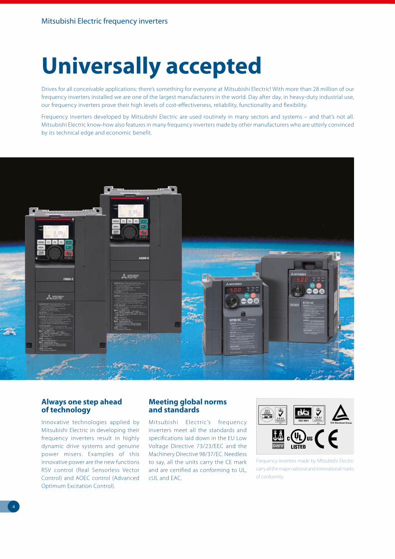
Universally acceptedDrives for all conceivable applications: there’s something for everyone at Mitsubishi Electric! With more than 28 million of our frequency inverters installed we are one of the largest manufacturers in the world. Day after day, in heavy-duty industrial use, our frequency inverters prove their high levels of cost-effectiveness, reliability, functionality and flexibility.
Frequency inverters developed by Mitsubishi Electric are used routinely in many sectors and systems – and that’s not all. Mitsubishi Electric know-how also features in many frequency inverters made by other manufacturers who are utterly convinced by its technical edge and economic benefit.
5
The success factors
Cost effectiveness
Energy savings of up to 60 % can be made by using Mitsubishi Electric frequency inverters, thereby also reducing CO
2 emissions and protecting
the environment.
Reliability
Safe and fault-free operation is guaranteed by various protective mechanisms and overload functions, top-quality temperature-resistant capacitors, permanently lubricated fans and dual-coated power and control PCBs.
The Six Sigma certified production ensures a high-quality level at Mitsubishi Electric.
Standards
In addition to complying with well-known international norms and standards, the frequency inverters are also certified by DNV, ABS, BV, LR and NK.
An increased level of safety is ensured in some frequency inverter ranges by the integrated emergency stop function (Safety Stop).
Convenience
The integral multifunction user panel, complete with digital dial, facilitates rapid and efficient input of all necessary drive parameters. It can also provide display of various performance data and error messages.
Flexibility
Compatible with all major field bus systems such as CC-Link, CC-Link IE Field, Profibus DP/V1, Profinet, DeviceNet®, EtherNet IP, EtherCat, CanOpen, SSCNET III/H, LonWorks, BACnet (the international communication standard in building services automation).
Functionality
Functionality, compatibility and perfect mecha nical design are the main features of the frequency inverters supplied by Mitsubishi Electric.
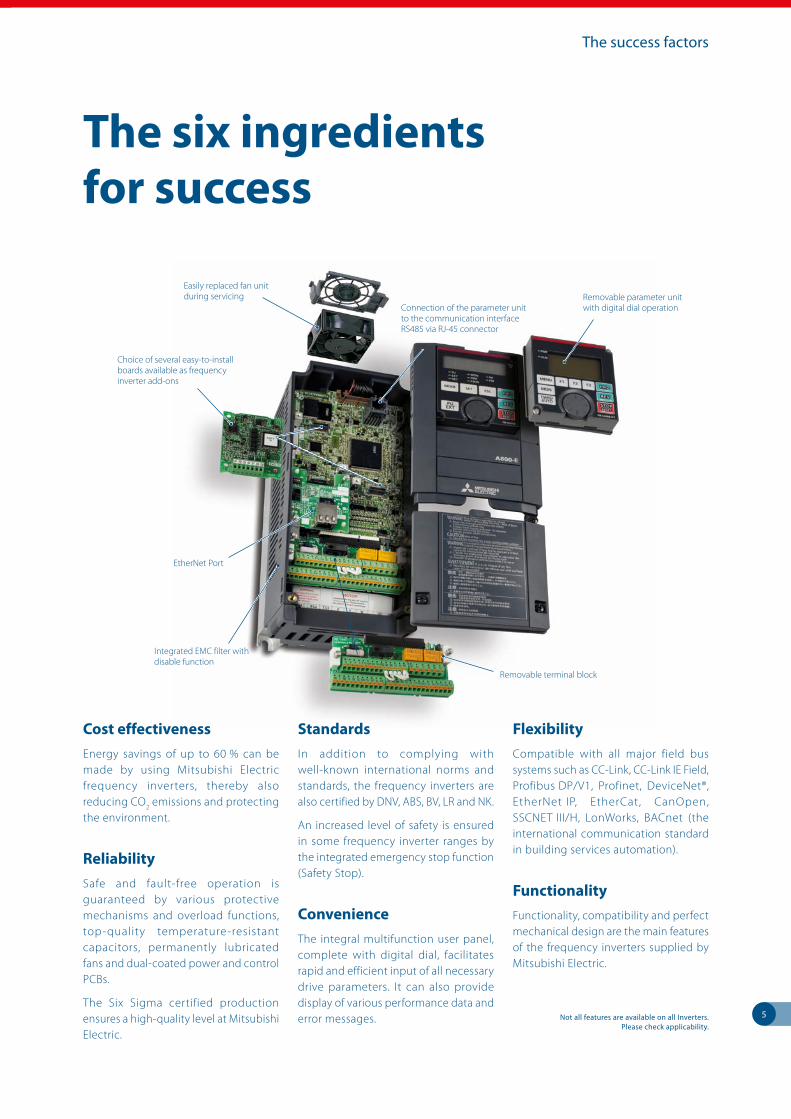
The six ingredients for success
EtherNet Port
Choice of several easy-to-install boards available as frequency inverter add-ons
Removable parameter unit with digital dial operation
Easily replaced fan unit during servicing
Connection of the parameter unit to the communication interface RS485 via RJ-45 connector
Integrated EMC filter with disable function
Removable terminal block
Not all features are available on all Inverters. Please check applicability.
6
Extensive product range
The right solution every time
Well set
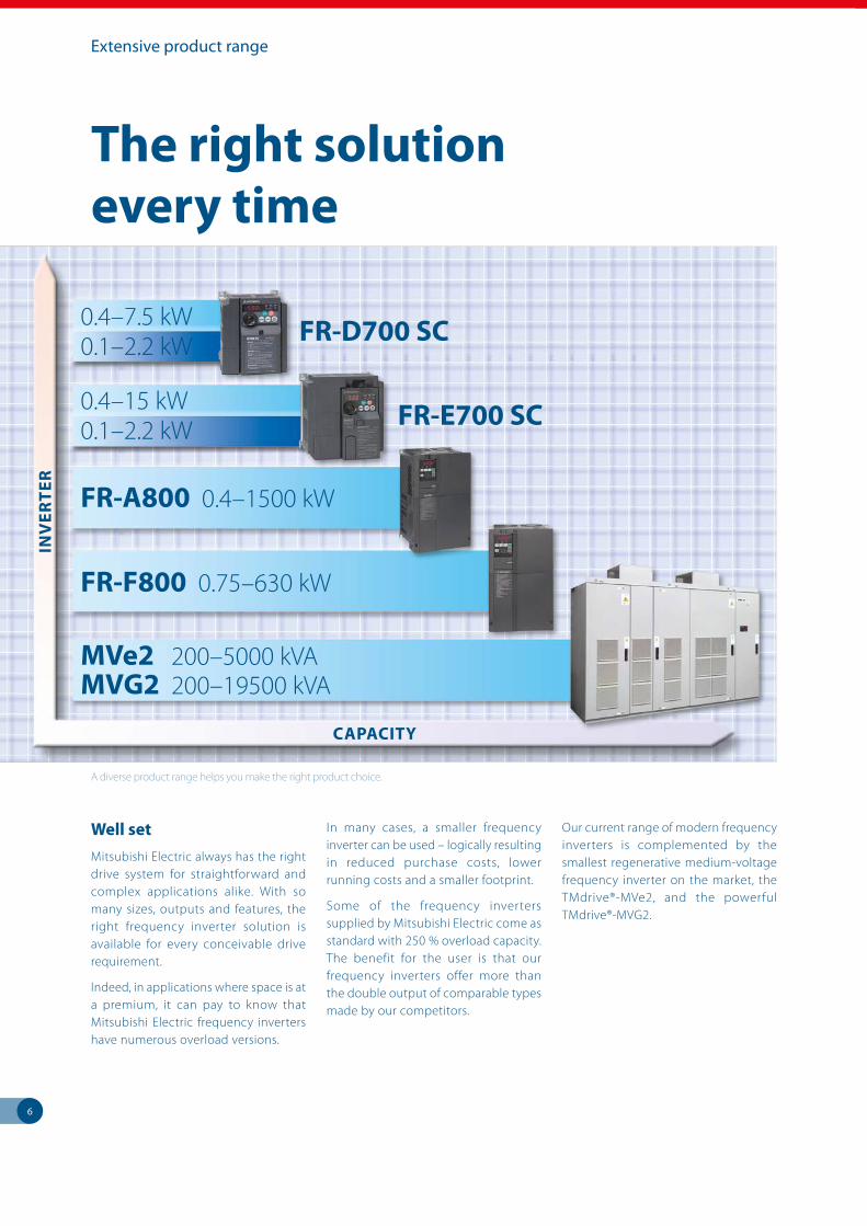
Mitsubishi Electric always has the right drive system for straightforward and complex applications alike. With so many sizes, outputs and features, the right frequency inverter solution is available for every conceivable drive requirement.
Indeed, in applications where space is at a premium, it can pay to know that Mitsubishi Electric frequency inverters have numerous overload versions.
In many cases, a smaller frequency inverter can be used – logically resulting in reduced purchase costs, lower running costs and a smaller footprint.
Some of the frequency inverters supplied by Mitsubishi Electric come as standard with 250 % overload capacity. The benefit for the user is that our frequency inverters offer more than the double output of comparable types made by our competitors.
Our current range of modern frequency inverters is complemented by the smallest regenerative medium-voltage frequency inverter on the market, the TMdrive®-MVe2, and the powerful TMdrive®-MVG2.
A diverse product range helps you make the right product choice.
FR-A800 0.4–1500 kW
FR-F800 0.75–630 kW
FR-E700 SC
FR-D700 SC
0.4–15 kW0.1–2.2 kW
0.4–7.5 kW0.1–2.2 kW
INV
ER
TE
R
CAPACITY
MVe2 200–5000 kVA MVG2 200–19500 kVA
7
FR-A800 / Leading drive performance
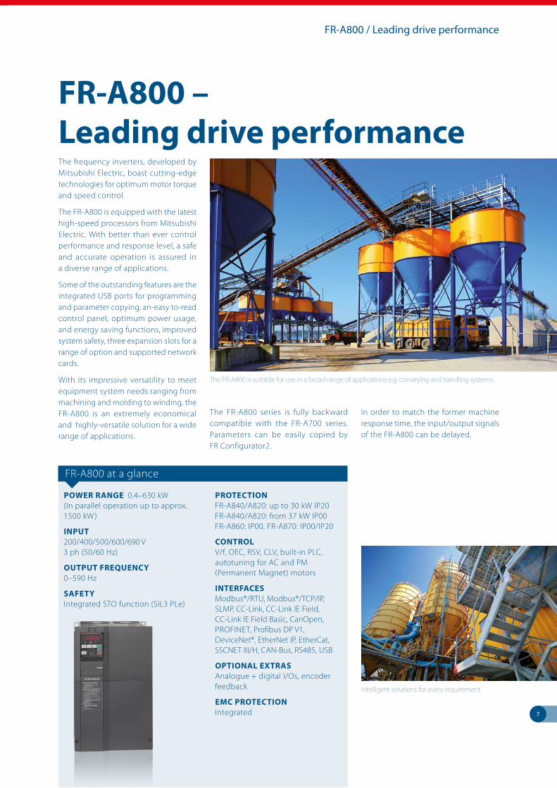
The FR-A800 is suitable for use in a broad range of applications e.g. conveying and handling systems.
The frequency inverters, developed by Mitsubishi Electric, boast cutting-edge technologies for optimum motor torque and speed control.
The FR-A800 is equipped with the latest high-speed processors from Mitsubishi Electric. With better than ever control performance and response level, a safe and accurate operation is assured in a diverse range of applications.
Some of the outstanding features are the integrated USB ports for programming and parameter copying, an-easy to-read control panel, optimum power usage, and energy saving functions, improved system safety, three expansion slots for a range of option and supported network cards.
With its impressive versatility to meet equipment system needs ranging from machining and molding to winding, the FR-A800 is an extremely economical and highly-versatile solution for a wide range of applications.
The FR-A800 series is fully backward compatible with the FR-A700 series. Parameters can be easily copied by FR Configurator2.
In order to match the former machine response time, the input/output signals of the FR-A800 can be delayed.
FR-A800 – Leading drive performance
FR-A800 at a glance
POWER RANGE 0.4–630 kW (In parallel operation up to approx. 1500 kW)
INPUT200/400/500/600/690 V 3 ph (50/60 Hz)
OUTPUT FREQUENCY0–590 Hz
SAFETYIntegrated STO function (SIL3 PLe)
PROTECTIONFR-A840/A820: up to 30 kW IP20 FR-A840/A820: from 37 kW IP00 FR-A860: IP00, FR-A870: IP00/IP20
CONTROLV/f, OEC, RSV, CLV, built-in PLC, autotuning for AC and PM (Permanent Magnet) motors
INTERFACESModbus®/RTU, Modbus®/TCP/IP, SLMP, CC-Link, CC-Link IE Field, CC-Link IE Field Basic, CanOpen, PROFINET, Profibus DP V1, DeviceNet®, EtherNet IP, EtherCat, SSCNET III/H, CAN-Bus, RS485, USB
OPTIONAL EXTRASAnalogue + digital I/Os, encoder feedback
EMC PROTECTIONIntegrated
Intelligent solutions for every requirement.
8
FR-A800 / Leading drive performance
The drive behind your success
Intelligent functions for any application
Sensorless vector control (RSV)
Equipped with their innovative RSV function (Real Sensorless Vector Control), Mitsubishi Electric frequency inverters have the ability to control the speed and torque of an AC motor without an encoder. The result is maximum performance across the full speed range in terms of dynamic response, precision and control. The motor thus sustains optimum dynamic speed characteristics, smooth rotation, and high starting torque. As such, the FR-A800 is capable of achievements which used to be the reserve of high-end DC or servo systems.
Simple positioning
The FR-A800 can also be used for positioning in conjunction with the “Closed Loop Vector Control”. Full point to point positioning including different homing functions is available.
Optimum excitation control
Optimum control of the excitation current maximizes motor efficiency for additional energy savings. As an example, an approximately 15 % increase in efficiency is obtained at a motor load torque of 10 % compared to conventional V/F control.
Boost productivity while saving energy
Energy-saving functions well suited to the system and purpose application An energy monitor lets you confirm energy-saving at a glance. Measured values for power output can also be output as pulse signals. An external 24 V DC power source can be used to operate control circuits other than the drive unit.
PLC functions
The PLC functions integrated in the FR-A800 and FR-F800 mean optimum tailoring to the requirements of the user. The PLC offers direct access to all the drive parameters and will, on request, undertake plant management as a stand-alone control and monitoring unit. Password protection prevents unauthorized access to the PLC code.
FR Configurator2 supports all PLC programming functionality eliminating the need for additional programming software.
Integrated positioning
All FR-A800 series drives can be used within a motion system. Connection is simple and can be used with all our standard SSCNETIII/H motion modules, if you do not have a PLC then you can use the drives integral positioning table giving you ultimate flexibility. The FR-A800 can even work as a leading axis drive. As such, there is no reason why the drives cannot be integrated further in existing control concepts.
Fourfold overload capacity
Many manufacturers of frequency inverters have specified various overload rating classes for their products – but rarely more than two. The FR-A800 is designed for no less than four overload ranges! This makes it easier to select the best frequency inverter for any application.
Simple visualization of the plant status
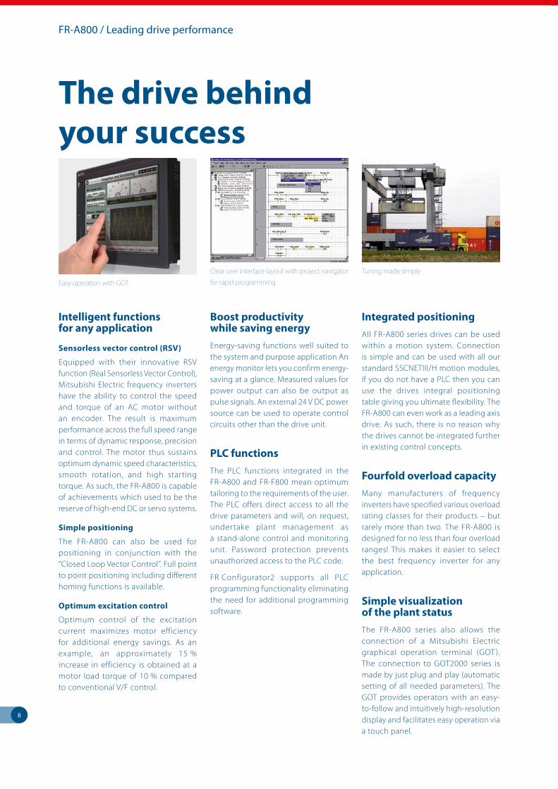
The FR-A800 series also allows the connection of a Mitsubishi Electric graphical operation terminal (GOT ). The connection to GOT2000 series is made by just plug and play (automatic setting of all needed parameters). The GOT provides operators with an easy-to-follow and intuitively high-resolution display and facilitates easy operation via a touch panel.
Tuning made simple
Easy operation with GOT
Clear user interface layout with project navigator
for rapid programming
9
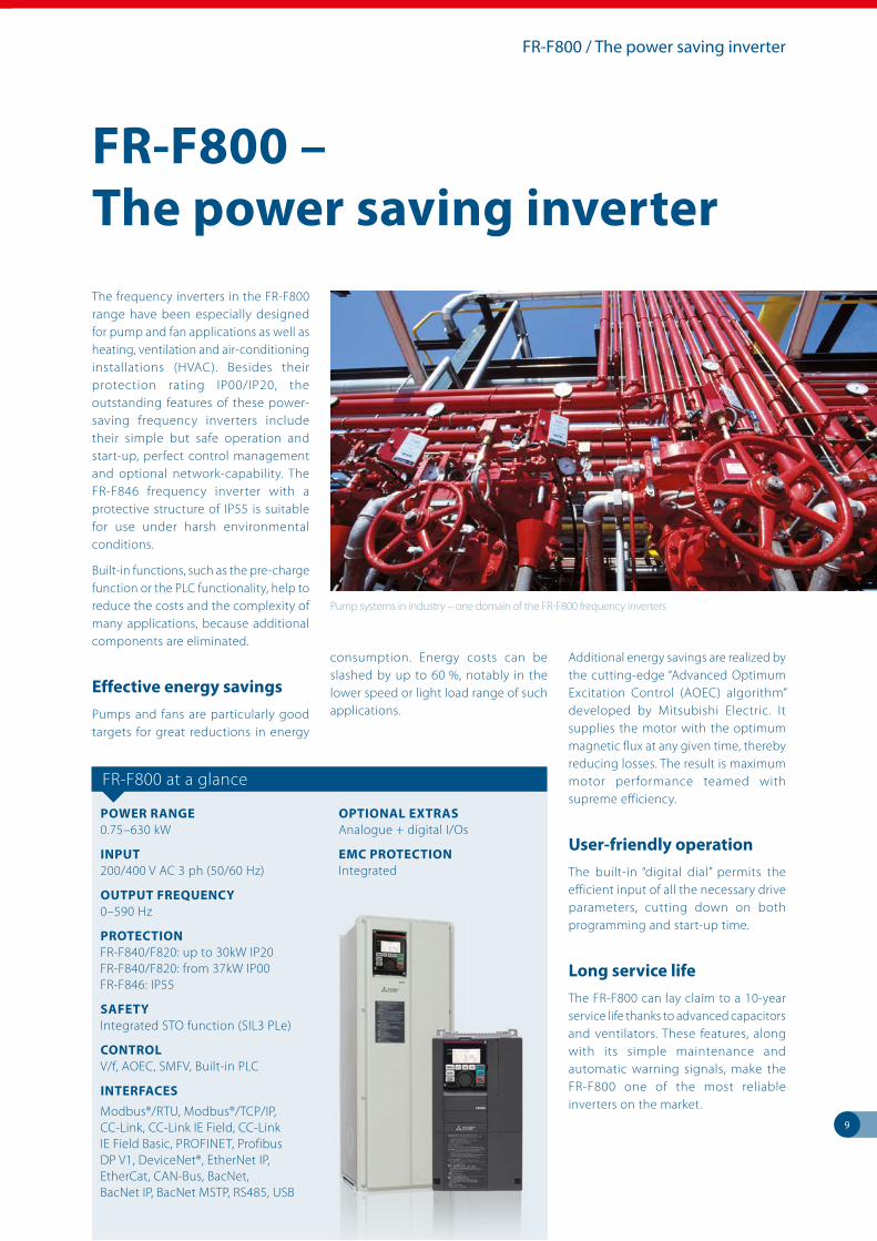
The frequency inverters in the FR-F800 range have been especially designed for pump and fan applications as well as heating, ventilation and air-conditioning installations (HVAC). Besides their protection rating IP00/IP20, the outstanding features of these power-saving frequency inverters include their simple but safe operation and start-up, perfect control management and optional network-capability. The FR-F846 frequency inverter with a protective structure of IP55 is suitable for use under harsh environmental conditions.
Built-in functions, such as the pre-charge function or the PLC functionality, help to reduce the costs and the complexity of many applications, because additional components are eliminated.
Effective energy savings
Pumps and fans are particularly good targets for great reductions in energy
consumption. Energy costs can be slashed by up to 60 %, notably in the lower speed or light load range of such applications.
Additional energy savings are realized by the cutting-edge “Advanced Optimum Excitation Control (AOEC) algorithm” developed by Mitsubishi Electric. It supplies the motor with the optimum magnetic flux at any given time, thereby reducing losses. The result is maximum motor performance teamed with supreme efficiency.
User-friendly operation
The built-in “digital dial” permits the efficient input of all the necessary drive parameters, cutting down on both programming and start-up time.
Long service life
The FR-F800 can lay claim to a 10-year service life thanks to advanced capacitors and ventilators. These features, along with its simple maintenance and automatic warning signals, make the FR-F800 one of the most reliable inverters on the market.
FR-F800 / The power saving inverter
Pump systems in industry – one domain of the FR-F800 frequency inverters
FR-F800 – The power saving inverter
FR-F800 at a glance
POWER RANGE0.75–630 kW
INPUT200/400 V AC 3 ph (50/60 Hz)
OUTPUT FREQUENCY0–590 Hz
PROTECTIONFR-F840/F820: up to 30kW IP20 FR-F840/F820: from 37kW IP00 FR-F846: IP55
SAFETYIntegrated STO function (SIL3 PLe)
CONTROLV/f, AOEC, SMFV, Built-in PLC
INTERFACES
Modbus®/RTU, Modbus®/TCP/IP, CC-Link, CC-Link IE Field, CC-Link IE Field Basic, PROFINET, Profibus DP V1, DeviceNet®, EtherNet IP, EtherCat, CAN-Bus, BacNet, BacNet IP, BacNet MSTP, RS485, USB
OPTIONAL EXTRASAnalogue + digital I/Os
EMC PROTECTIONIntegrated
10
FR-E700 SC / The compact inverter
FR-E700 SC – The compact inverter
The inverters in the FR-E700 SC series are all-rounders and miniature masterpieces given their compact size.
Improved functions like an integrated USB port, an integrated one-touch Digital Dial control with a display as well as improved power usage at low speeds make the FR-E700 SC an economical and highly-versatile solution for a wide range of applications
Small and powerful
The FR-E700 SC is a popular choice in a wide range of diverse applications, from textiles machines to conveyor systems, from door and gate drives to fans and pumps. Featuring Mitsubishi Electric’s extended vector control system they are able to achieve torques of 150 % from a frequency of just one Hertz.
The autotuning function makes this mode possible even with high fluctuations in motor characteristics. For the user, this means ample power under all circumstances, even at very low speeds.
Emergency stop function
The FR-E700 SC series has a two-channel emergency stop for safe shutdown. This ensures safe operation in compliance with the European Machinery Directive without installation of another contactor.
The FR-E700 SC conforms to ISO 13849-1, PLd and IEC 60204-1 cat. 0 standards.
Intelligent control
Thanks to the integrated PID control these inverters can control flow or temperature without the need of additional controllers.
Network support
A selection of plug-in option cards are available for the FR-E700 SC that enables it to connect to open fieldbus systems like Profibus DP, DeviceNet™ and even CC-Link.
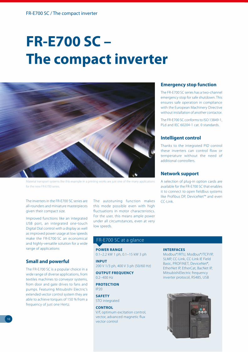
Material transport systems like this example in a printing works are just one of the many applications
for the new FR-E700 series.
FR-E700 SC at a glance
POWER RANGE0.1–2.2 kW 1 ph, 0.1–15 kW 3 ph
INPUT200 V 1/3 ph, 400 V 3 ph (50/60 Hz)
OUTPUT FREQUENCY0.2–400 Hz
PROTECTION IP20
SAFETYSTO integrated
CONTROLV/f, optimum excitation control, vector, advanced magnetic flux vector control
INTERFACESModbus®/RTU, Modbus®/TCP/IP, SLMP, CC-Link, CC-Link IE Field Basic, PROFINET, DeviceNet®, EtherNet IP, EtherCat, BacNet IP, Mitsubishi Electric frequency inverter protocol, RS485, USB
11
FR-D700 SC / The standard inverter
Enter the new drive universe
The inverters of the FR-D700 SC series set standards for small-format drives and provide an easy entry to the world of modern variable-speed drive technology. Despite their ultra-compact dimensions, they feature a wealth of advanced functions. The FR-D700 SC series is ideal for simple drive applications in environments where space is limited.
Improved functions and device properties such as simplified cabling thanks to spring clamps, the integrated Digital Dial with LED display, improved performance yield in the low-speed range make the FR-D700 the new standard in the ultra-compact class.
Built-in emergency stop function (STO)
The FR-D700 SC series features a dual-channel emergency stop function for a safe torque off. With that, the FR-D700 SC conforms to ISO 13849-1, PLd and IEC 60204-1 Cat 0.
Simple operation
The user-friendliness of the FR-D700 SC series makes these units a particularly good choice for standard applications. Entering drive parameters and settings is quick and easy with the one-touch Digital Dial on the integrated control panel, saving time and cutting costs.
These features make the FR-D700 SC an excellent performer for both simple and more demanding tasks. Typical applications include feed and conveyor drives, machine tools and door and gate drives.
Space-saving installation
The ultra-compact FR-D700 SC can be mounted directly side by side. This saves valuable space in the cabinet.
FR-D700 SC at a glance
POWER RANGE0.1–2.2 kW 1 ph, 0.4–7.5 kW 3 ph
INPUT 100 V 1 ph/200 V 1/3 ph/400 V 3 ph (50/60 Hz)
OUTPUT FREQUENCY 0.2–400 Hz
PROTECTION IP20
SAFETYSTO integrated
CONTROL V/f, optimum excitation control, general-purpose magnetic flux vector control
INTERFACESModbus®/RTU, Mitsubishi Electric frequency inverter protocol, RS485
FR-D700 SC – The standard inverter
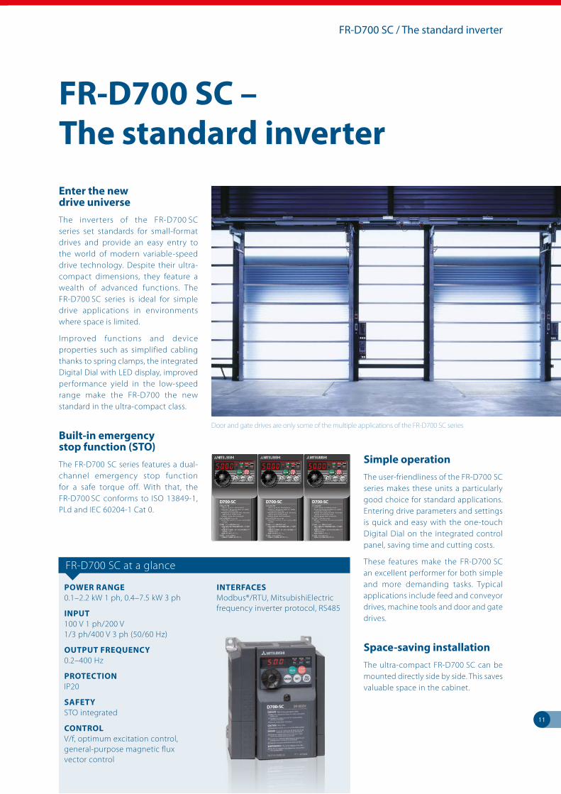
Door and gate drives are only some of the multiple applications of the FR-D700 SC series
friendly
100
[%]
80
60
40
20
0
MVe2
12
TMdrive®-MVe2/MVG2 series
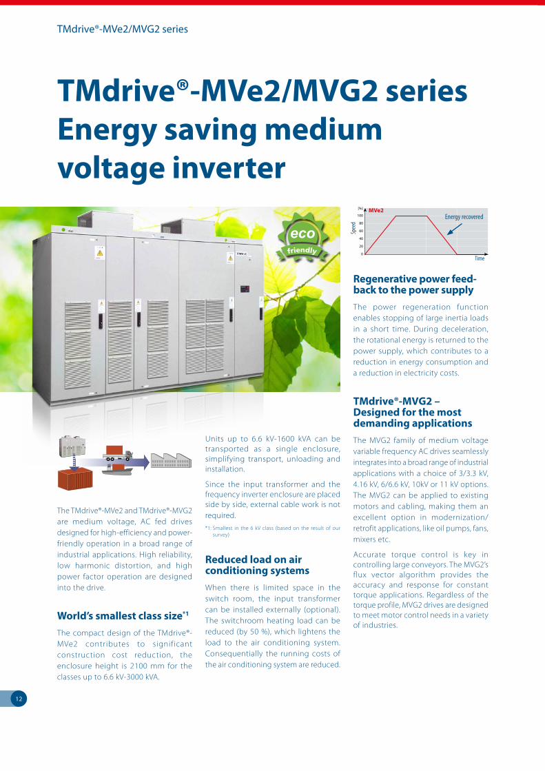
The TMdrive®-MVe2 and TMdrive®-MVG2 are medium voltage, AC fed drives designed for high-efficiency and power-friendly operation in a broad range of industrial applications. High reliability, low harmonic distortion, and high power factor operation are designed into the drive.
World’s smallest class size*1
The compact design of the TMdrive®-MVe2 contributes to significant construction cost reduction, the enclosure height is 2100 mm for the classes up to 6.6 kV-3000 kVA.
Units up to 6.6 kV-1600 kVA can be transported as a single enclosure, simplifying transport, unloading and installation.
Since the input transformer and the frequency inverter enclosure are placed side by side, external cable work is not required.
*1: Smallest in the 6 kV class (based on the result of our survey)
Reduced load on air conditioning systems
When there is limited space in the switch room, the input transformer can be installed externally (optional). The switchroom heating load can be reduced (by 50 %), which lightens the load to the air conditioning system. Consequentially the running costs of the air conditioning system are reduced.
Regenerative power feed-back to the power supply
The power regeneration function enables stopping of large inertia loads in a short time. During deceleration, the rotational energy is returned to the power supply, which contributes to a reduction in energy consumption and a reduction in electricity costs.
TMdrive®-MVG2 – Designed for the most demanding applications
The MVG2 family of medium voltage variable frequency AC drives seamlessly integrates into a broad range of industrial applications with a choice of 3/3.3 kV, 4.16 kV, 6/6.6 kV, 10kV or 11 kV options. The MVG2 can be applied to existing motors and cabling, making them an excellent option in modernization/retrofit applications, like oil pumps, fans, mixers etc.
Accurate torque control is key in controlling large conveyors. The MVG2’s flux vector algorithm provides the accuracy and response for constant torque applications. Regardless of the torque profile, MVG2 drives are designed to meet motor control needs in a variety of industries.
TMdrive®-MVe2/MVG2 series Energy saving medium voltage inverter
Spee
d
Time
Energy recovered
friendly
100
[%]
80
60
40
20
0
MVe2
13
Peripherals and software
Wide range of expansion options
Optional extras are available to optimize and expand system capability. Additional brake components, reactors and filters guarantee operation even in difficult conditions.
The range of functions can be expanded by optional boards, such as additional analog/digital inputs/outputs.
Strong and smart
The separate Floor Standing Unit (FSU) for FR-F840 Inverters is a simple way of accommodating a free-standing frequency inverter system complying with protection class IP20 for installation in an electrical operating area.
The robust base units come pre-assembled and permit optional integration of a link reactor, a circuit breaker or – if required – an additional EMC filter.
Effective Harmonic Converters
In most cases, the energy given off by a motor in the regenerative mode is converted to heat by braking resistors and thereby is lost. The Harmonic Converter FR-HC2 returns this energy back to the power source or supplies it to other inverters. The Harmonic Converters is equipped with high-quality filters to effectively suppress harmonics.
Handy parameter units
For added ease and convenience users may opt for integrated parameter units (FR-E/FR-D700 only) or clip-on parameter units (for all other inverters). A numeric keypad is available for direct input of numerical values. A four-line LCD display provides plain text information about performance data, parameter names, status signals and error messages – in eight languages.
User-friendly set-up Software
The user-friendly set-up software FR-Configurator runs on Windows®, i.e. the inverters can be configured using standard PCs. Several inverters can be set up, operated and monitored in parallel in one network. A connection is possible either via an RS485 interface, USB port (except FR-D700) or the optional SC-FR PC adapter cable.
Peripherals and software
Power regeneration combined with effctive
harmonic suppression, the FR-HC2.
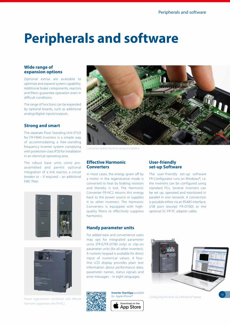
Connector system for time-saving installation
Configuring the drive via a Windows® laptopInverter StartApp available for Apple iPhone®
14
Paper production
Increased productivity
Synchronization – the ultimate priority
Precise synchronism of the drives is synonymous with maximum productivity and top quality in the printing and paper production industry. The drives need to retain control of the sheets throughout the entire printing and production process. The intelligent motor control function in Mitsubishi Electric frequency inverters processes the actual values and matches the speed and torque to the specified setpoint. This prevents the sheets from tearing or bunching.
Another feature which helps in this regard is the power-down braking function which controls the deceleration of all the drives after a power failure or an emergency machine shutdown. All this translates into maximum productivity and quality.
An advanced version of this control has the ability to operate up to four motors consecutively in alternate and/or changeover mode via one single frequency inverter.
Prepared for the toughest applications
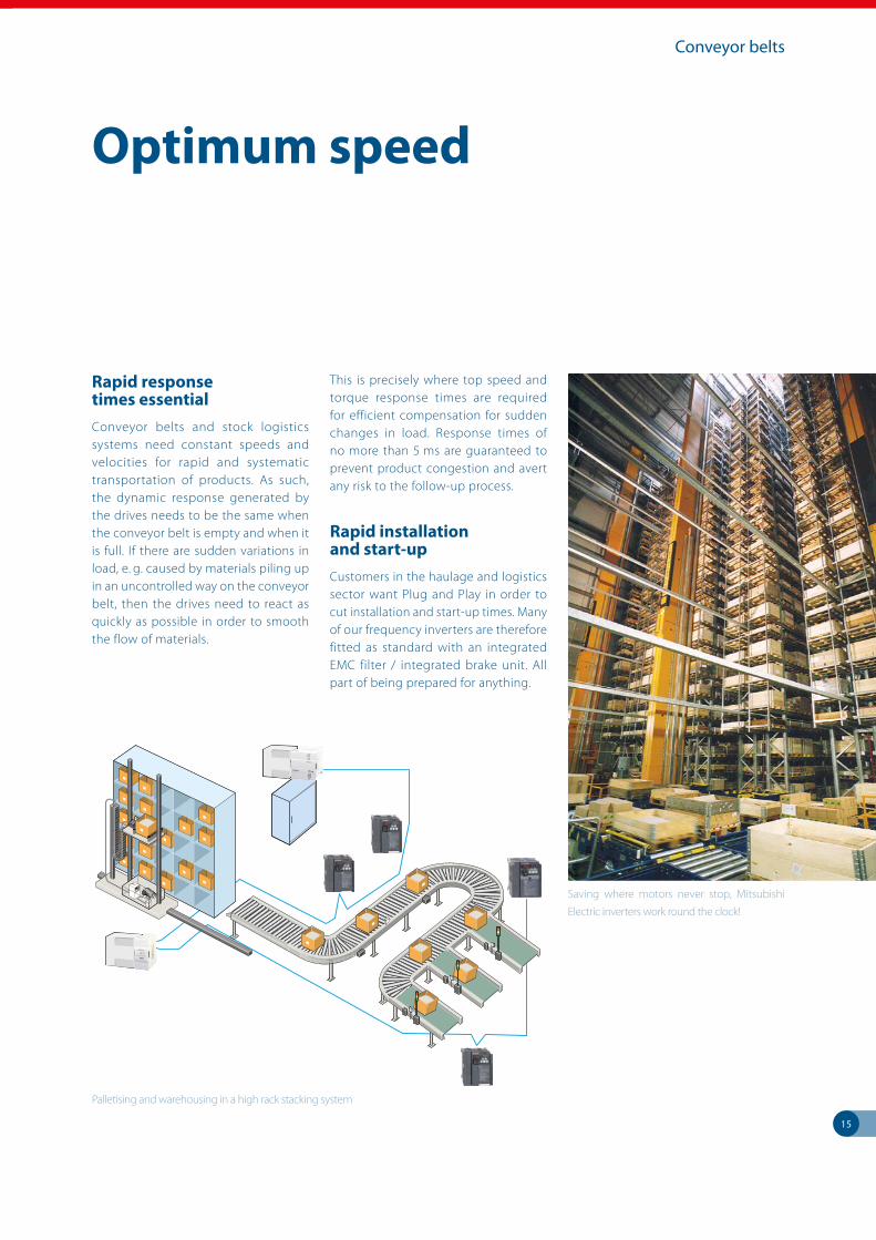
High temperatures and high air humidity are routine conditions in the printing and paper industry. The capacitors in the top-of-the-range models, the FR-F800 and FR-A800, are therefore designed to withstand internal temperatures of 105 °C. The power and control PCBs support IC60721-3-3 level 3C2 compliant coating, the cooling fans are housed in sealed, specially lubricated industrial bearings. There is no better way to prepare frequency inverters to meet human and mechanical requirements.Simplified schematic of paper production
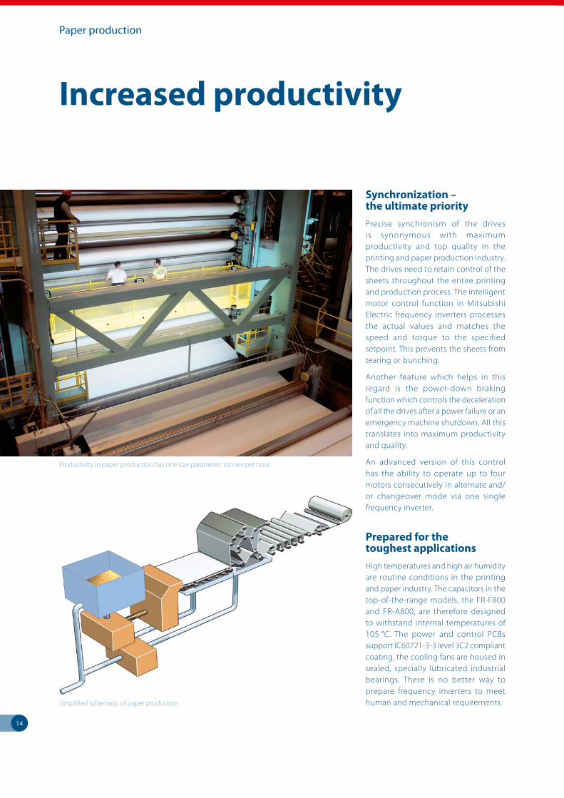
Productivity in paper production has one size parameter: tonnes per hour
15
Conveyor belts
Rapid response times essential
Conveyor belts and stock logistics systems need constant speeds and velocities for rapid and systematic transportation of products. As such, the dynamic response generated by the drives needs to be the same when the conveyor belt is empty and when it is full. If there are sudden variations in load, e. g. caused by materials piling up in an uncontrolled way on the conveyor belt, then the drives need to react as quickly as possible in order to smooth the flow of materials.
This is precisely where top speed and torque response times are required for efficient compensation for sudden changes in load. Response times of no more than 5 ms are guaranteed to prevent product congestion and avert any risk to the follow-up process.
Rapid installation and start-up
Customers in the haulage and logistics sector want Plug and Play in order to cut installation and start-up times. Many of our frequency inverters are therefore fitted as standard with an integrated EMC filter / integrated brake unit. All part of being prepared for anything.
Optimum speed
Saving where motors never stop, Mitsubishi
Electric inverters work round the clock!
Palletising and warehousing in a high rack stacking system
16
Stirring machine
Extreme cost efficiency
Variable speed and efficiency
Maximum efficiency is required from each individual drive in pump and fan applications as well as in mixers and stirrers.
In comparison with mechanical solutions, frequency inverters developed by Mitsubishi Electric are always able to tap the full potential when it comes to savings in energy consumption.
Replacing conventional DC drives with modern AC variable seed drive removes one less maintenance procedure, by utilizing the drives inbuilt predictive maintenance function costly plant failures can all but be eliminated.
Saving energy when starting and braking
The AOEC technology (Advanced Optimum Excitation Control) developed by Mitsubishi Electric combines maximum drive efficiency with minimum power consumption. The only thing supplied to the connected motor is the magnetic flux which brings about the optimum degree of efficiency at all times. This leads to inordinate improvement in energy efficiency is achieved, particularly in the acceleration and braking phases.
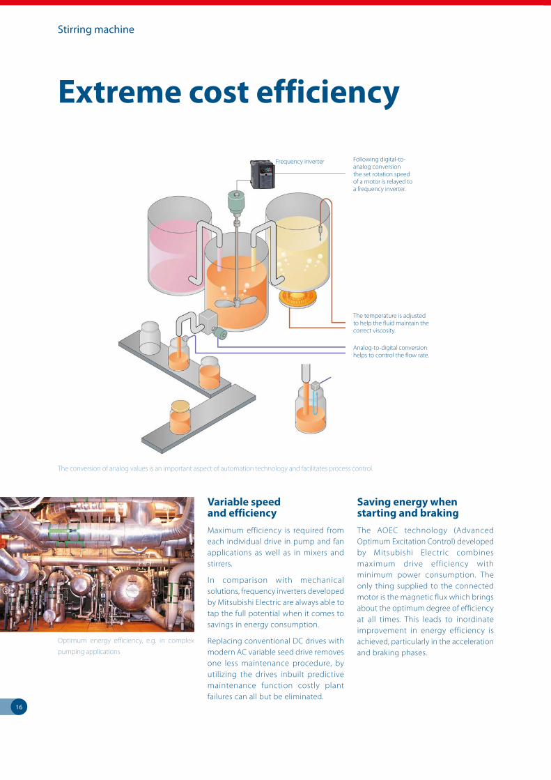
The conversion of analog values is an important aspect of automation technology and facilitates process control.
Optimum energy efficiency, e.g. in complex
pumping applications
Following digital-to- analog conversion the set rotation speed of a motor is relayed to a frequency inverter.
The temperature is adjusted to help the fluid maintain the correct viscosity.
Analog-to-digital conversion helps to control the flow rate.
Frequency inverter
10090
7060
50
40
3020
10
00 40 80 10060
80
AIR QUANTITY (%)AIR QUANTITY (%)AIR QUANTITY (%)
PO
WE
R C
ON
SU
MP
TIO
N (
%)
PO
WE
R C
ON
SU
MP
TIO
N (
%)
PO
WE
R C
ON
SU
MP
TIO
N (
%)
17
Potential savings
Potential savings
Too powerful and too expensive!
Energy costs are rising all the time. Over half of the power consumed in the industry is accounted for by electric motors. Up to 96 % of the life cycle costs of a motor are accounted for by energy costs. Unfortunately, when analyzing costs, it is precisely this point which is paid precious little attention or is ignored altogether. The biggest potential source of savings is frequently disregarded.
For example, in order to guarantee that an air handling plant will run smoothly even at full load, which is seldom the case, and to have spare capacity for expansion the systems fans are often over-specified. In some cases, fans in these applications can be operating at an average efficiency of 65 % or less.
In addition, in conventional systems, the equipment is usually controlled by mechanical ventilation flaps which
slashes efficiency levels, especially with medium loads. The flap control function can very easily be replaced by the use of frequency inverters and the power consumption reduced by 20 to 60 %.
Result: wasted energy
Oversized fan, pump and motor systems combined with continuous operation at maximum capacity means many systems are operated at levels far below ideal in terms of efficiency. This leads to excess power consumption which can only really be explained by ignorance or poor practice.
Countermeasures
The power consumption of slow running motors can be reduced if the speed is controlled by changing the frequency. The frequency inverter allows the motor to be adjusted to the load. Frequency inverters which generate variable frequencies and voltage levels save energy, reduce wear on the motor and minimize wear and tear on the motor drive train.
They also allow greater flexibility in operating procedures.
Save on energy costs by investing in the Mitsubishi
Electric family of inverters
A Mitsubishi Electric frequency inverter is a safe investment
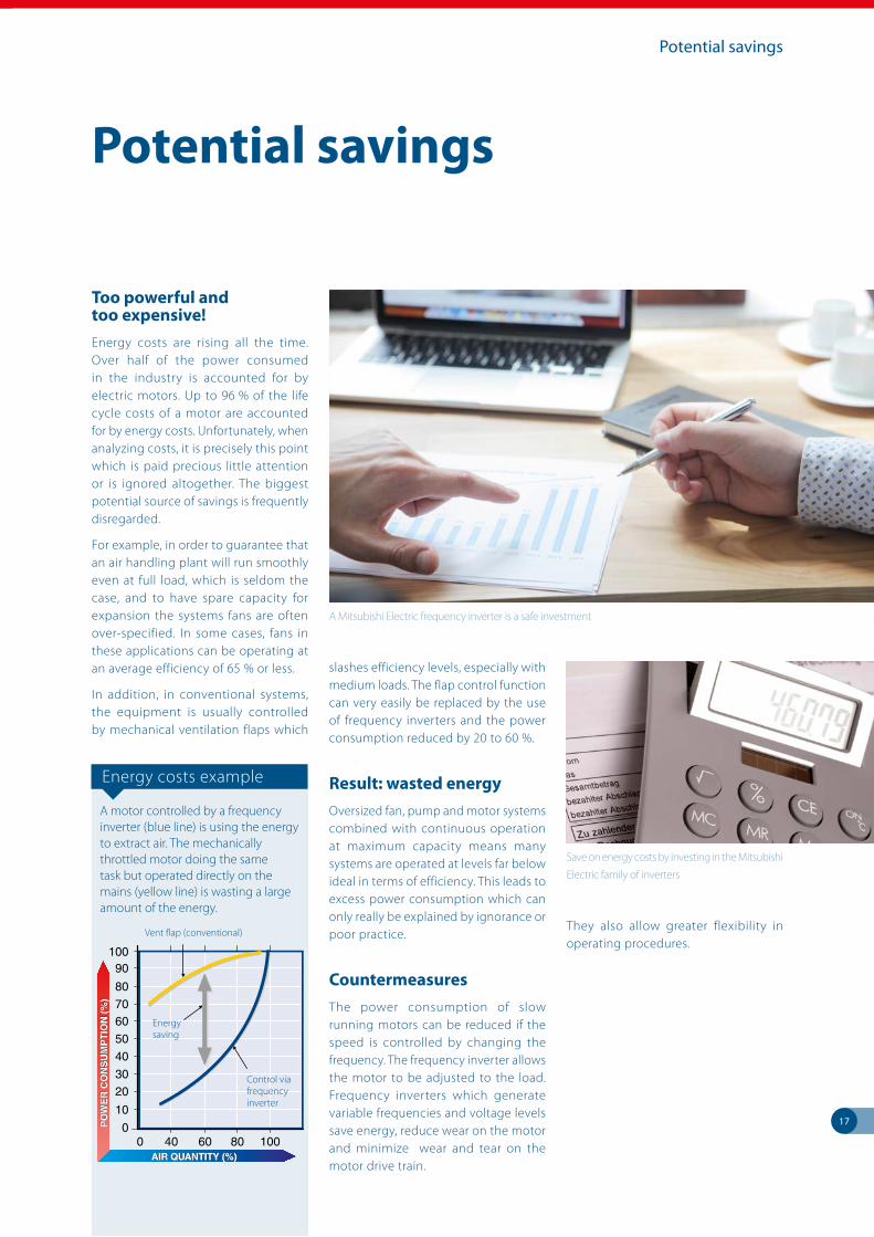
Energy costs example
A motor controlled by a frequency inverter (blue line) is using the energy to extract air. The mechanically throttled motor doing the same task but operated directly on the mains (yellow line) is wasting a large amount of the energy.
10090
7060
50
40
3020
10
00 40 80 10060
80
AIR QUANTITY (%)AIR QUANTITY (%)AIR QUANTITY (%)
PO
WE
R C
ON
SU
MP
TIO
N (
%)
PO
WE
R C
ON
SU
MP
TIO
N (
%)
PO
WE
R C
ON
SU
MP
TIO
N (
%)
Vent flap (conventional)
Energy saving
Control via frequency inverter
18
Application solutions
A world of applications
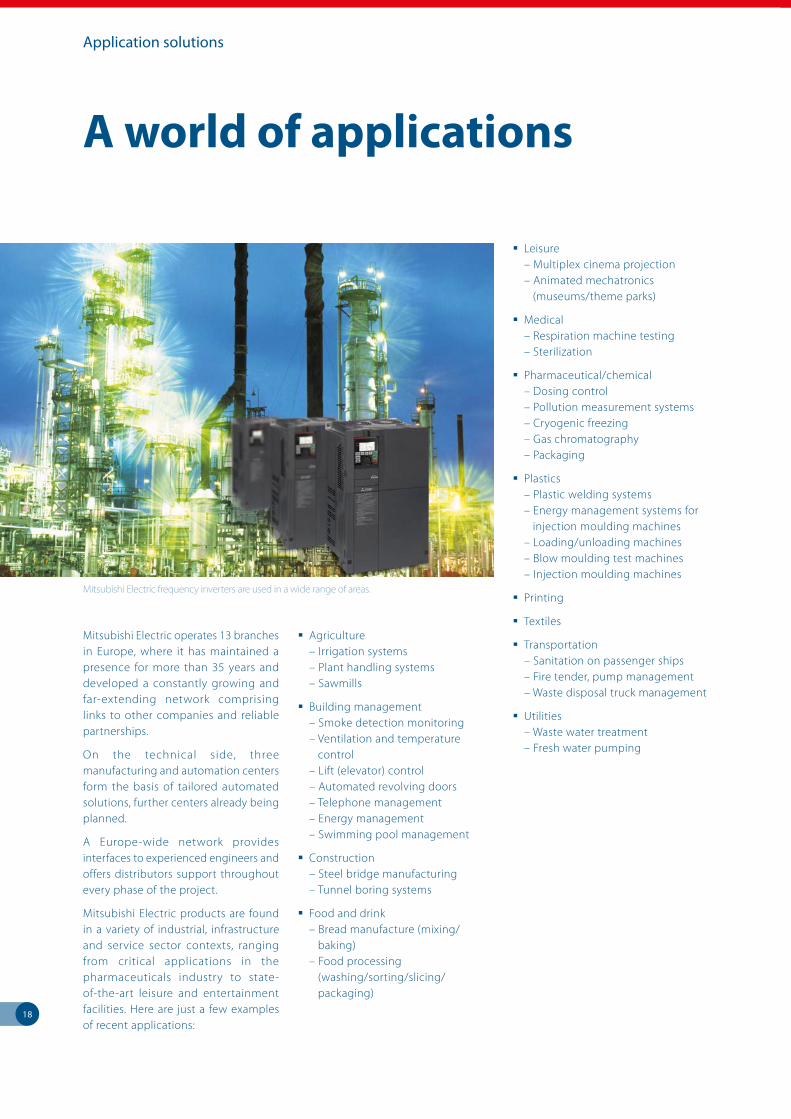
Mitsubishi Electric operates 13 branches in Europe, where it has maintained a presence for more than 35 years and developed a constantly growing and far-extending network comprising links to other companies and reliable partnerships.
On the technical side, three manufacturing and automation centers form the basis of tailored automated solutions, further centers already being planned.
A Europe-wide network provides interfaces to experienced engineers and offers distributors support throughout every phase of the project.
Mitsubishi Electric products are found in a variety of industrial, infrastructure and service sector contexts, ranging from critical applications in the pharmaceuticals industry to state-of-the-art leisure and entertainment facilities. Here are just a few examples of recent applications:
Agriculture – Irrigation systems – Plant handling systems – Sawmills
Building management – Smoke detection monitoring – Ventilation and temperature control – Lift (elevator) control – Automated revolving doors – Telephone management – Energy management – Swimming pool management
Construction – Steel bridge manufacturing – Tunnel boring systems
Food and drink – Bread manufacture (mixing/ baking) – Food processing (washing/sorting/slicing/ packaging)
Leisure – Multiplex cinema projection – Animated mechatronics (museums/theme parks)
Medical – Respiration machine testing – Sterilization
Pharmaceutical/chemical – Dosing control – Pollution measurement systems – Cryogenic freezing – Gas chromatography – Packaging
Plastics – Plastic welding systems – Energy management systems for injection moulding machines – Loading/unloading machines – Blow moulding test machines – Injection moulding machines
Printing
Textiles
Transportation – Sanitation on passenger ships – Fire tender, pump management – Waste disposal truck management
Utilities – Waste water treatment – Fresh water pumping
Mitsubishi Electric frequency inverters are used in a wide range of areas.
FR-D700 SC / FR-E700 SC / FR-F800 / FR-A741 / FR-A800 / MVe2/MVG2
Technical Information Section
2
Further publications within the Mitsubishi Electric family
Brochures
Q/L family
Product catalogues for modular programmable logic controllers and accessories for the MELSEC System Q and MELSEC L series
FX family
Product catalogue for compact programmable logic controllers and accessories for the MELSEC FX family
HMI family
Product catalogue for operator terminals, supervision software and accessories
MR family
Product catalogue for servo amplifiers and servo motors as well as motion controller and accessories
Robots family
Product catalogue for industrial robots and accessories
LVS family
Product catalogue for low voltage switchgears, magnetic contactors and circuit breakers
Automation book
Overview on all Mitsubishi Electric automation products, like frequency inverters, servo/motion, robots etc.
Further service supplies
This product catalogue is designed to give an overview of the extensive range of the Mitsubishi Electric frequency inverters. If you cannot find the information you require in this catalogue, there are a number of ways you can get further details on configuration and technical issues, pricing and availability.
For technical issues visit the https://eu3a.mitsubishielectric.com website. Our website provides a simple and fast way of accessing further technical data and up to the minute details on our products and services. Manuals and catalogues are available in several different languages and can be downloaded for free.
For technical, configuration, pricing and availability issues contact our distributors and partners. Mitsubishi Electric partners and distributors are only too happy to help answer your technical questions or help with configuration building. For a list of Mitsubishi Electric partners please see the back of this catalogue or alternatively take a look at the “contact us” section of our website.
About this product catalogue
This product catalogue is a guide to the range of products available. For detailed configuration rules, system building, installation and configuration the associated product manuals must be read. You must satisfy yourself that any system you design with the products in this catalogue is fit for purpose, meets your requires and conforms to the product configuration rules as defined in the product manuals.
Specifications are subject to change without notice. All trademarks acknowledged. © Mitsubishi Electric Europe B.V., Factory Automation - European Business Group
The products of Mitsubishi Electric Europe B.V., that are listed and described in this document, are neither subject to approval for export nor subject to the Dual-Use List.
Scan or click QR code for Inverter Selection Tool
3
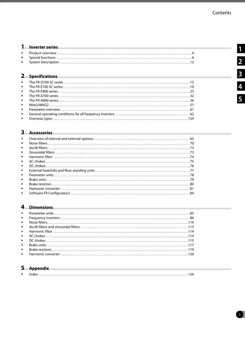
Contents
1 Inverter series Product overview . . . . . . . . . . . . . . . . . . . . . . . . . . . . . . . . . . . . . . . . . . . . . . . . . . . . . . . . . . . . . . . . . . . . . . . . . . . . . . . . . . . . . . . 4 Special functions . . . . . . . . . . . . . . . . . . . . . . . . . . . . . . . . . . . . . . . . . . . . . . . . . . . . . . . . . . . . . . . . . . . . . . . . . . . . . . . . . . . . . . . 6 System Description . . . . . . . . . . . . . . . . . . . . . . . . . . . . . . . . . . . . . . . . . . . . . . . . . . . . . . . . . . . . . . . . . . . . . . . . . . . . . . . . . . . . 12
2 Specifications The FR-D700 SC series . . . . . . . . . . . . . . . . . . . . . . . . . . . . . . . . . . . . . . . . . . . . . . . . . . . . . . . . . . . . . . . . . . . . . . . . . . . . . . . . . 15 The FR-E700 SC series . . . . . . . . . . . . . . . . . . . . . . . . . . . . . . . . . . . . . . . . . . . . . . . . . . . . . . . . . . . . . . . . . . . . . . . . . . . . . . . . . . 19 The FR-F800 series . . . . . . . . . . . . . . . . . . . . . . . . . . . . . . . . . . . . . . . . . . . . . . . . . . . . . . . . . . . . . . . . . . . . . . . . . . . . . . . . . . . . . 23 The FR-A700 series . . . . . . . . . . . . . . . . . . . . . . . . . . . . . . . . . . . . . . . . . . . . . . . . . . . . . . . . . . . . . . . . . . . . . . . . . . . . . . . . . . . . . 32 The FR-A800 series . . . . . . . . . . . . . . . . . . . . . . . . . . . . . . . . . . . . . . . . . . . . . . . . . . . . . . . . . . . . . . . . . . . . . . . . . . . . . . . . . . . . . 36 MVe2/MVG2 . . . . . . . . . . . . . . . . . . . . . . . . . . . . . . . . . . . . . . . . . . . . . . . . . . . . . . . . . . . . . . . . . . . . . . . . . . . . . . . . . . . . . . . . . . . 57 Parameter overview . . . . . . . . . . . . . . . . . . . . . . . . . . . . . . . . . . . . . . . . . . . . . . . . . . . . . . . . . . . . . . . . . . . . . . . . . . . . . . . . . . . 61 General operating conditions for all frequency inverters . . . . . . . . . . . . . . . . . . . . . . . . . . . . . . . . . . . . . . . . . . . . . . . . 62 Overseas types . . . . . . . . . . . . . . . . . . . . . . . . . . . . . . . . . . . . . . . . . . . . . . . . . . . . . . . . . . . . . . . . . . . . . . . . . . . . . . . . . . . . . . .124
3 Accessories Overview of internal and external options . . . . . . . . . . . . . . . . . . . . . . . . . . . . . . . . . . . . . . . . . . . . . . . . . . . . . . . . . . . . . . 65 Noise filters . . . . . . . . . . . . . . . . . . . . . . . . . . . . . . . . . . . . . . . . . . . . . . . . . . . . . . . . . . . . . . . . . . . . . . . . . . . . . . . . . . . . . . . . . . . . 70 du/dt filters . . . . . . . . . . . . . . . . . . . . . . . . . . . . . . . . . . . . . . . . . . . . . . . . . . . . . . . . . . . . . . . . . . . . . . . . . . . . . . . . . . . . . . . . . . . . 73 Sinusoidal filters . . . . . . . . . . . . . . . . . . . . . . . . . . . . . . . . . . . . . . . . . . . . . . . . . . . . . . . . . . . . . . . . . . . . . . . . . . . . . . . . . . . . . . . 73 Harmonic filter . . . . . . . . . . . . . . . . . . . . . . . . . . . . . . . . . . . . . . . . . . . . . . . . . . . . . . . . . . . . . . . . . . . . . . . . . . . . . . . . . . . . . . . . 74 AC chokes . . . . . . . . . . . . . . . . . . . . . . . . . . . . . . . . . . . . . . . . . . . . . . . . . . . . . . . . . . . . . . . . . . . . . . . . . . . . . . . . . . . . . . . . . . . . . 75 DC chokes . . . . . . . . . . . . . . . . . . . . . . . . . . . . . . . . . . . . . . . . . . . . . . . . . . . . . . . . . . . . . . . . . . . . . . . . . . . . . . . . . . . . . . . . . . . . . 76 External heatsinks and floor standing units . . . . . . . . . . . . . . . . . . . . . . . . . . . . . . . . . . . . . . . . . . . . . . . . . . . . . . . . . . . . . 77 Parameter units . . . . . . . . . . . . . . . . . . . . . . . . . . . . . . . . . . . . . . . . . . . . . . . . . . . . . . . . . . . . . . . . . . . . . . . . . . . . . . . . . . . . . . . . 78 Brake units . . . . . . . . . . . . . . . . . . . . . . . . . . . . . . . . . . . . . . . . . . . . . . . . . . . . . . . . . . . . . . . . . . . . . . . . . . . . . . . . . . . . . . . . . . . . 79 Brake resistors . . . . . . . . . . . . . . . . . . . . . . . . . . . . . . . . . . . . . . . . . . . . . . . . . . . . . . . . . . . . . . . . . . . . . . . . . . . . . . . . . . . . . . . . . 80 Harmonic converter . . . . . . . . . . . . . . . . . . . . . . . . . . . . . . . . . . . . . . . . . . . . . . . . . . . . . . . . . . . . . . . . . . . . . . . . . . . . . . . . . . . 81 Software FR Configurator2 . . . . . . . . . . . . . . . . . . . . . . . . . . . . . . . . . . . . . . . . . . . . . . . . . . . . . . . . . . . . . . . . . . . . . . . . . . . . . 84
4 Dimensions Parameter units . . . . . . . . . . . . . . . . . . . . . . . . . . . . . . . . . . . . . . . . . . . . . . . . . . . . . . . . . . . . . . . . . . . . . . . . . . . . . . . . . . . . . . . . 85 Frequency inverters . . . . . . . . . . . . . . . . . . . . . . . . . . . . . . . . . . . . . . . . . . . . . . . . . . . . . . . . . . . . . . . . . . . . . . . . . . . . . . . . . . . . 86 Noise filters . . . . . . . . . . . . . . . . . . . . . . . . . . . . . . . . . . . . . . . . . . . . . . . . . . . . . . . . . . . . . . . . . . . . . . . . . . . . . . . . . . . . . . . . . . .110 du/dt filters and sinusoidal filters . . . . . . . . . . . . . . . . . . . . . . . . . . . . . . . . . . . . . . . . . . . . . . . . . . . . . . . . . . . . . . . . . . . . . .113 Harmonic filter . . . . . . . . . . . . . . . . . . . . . . . . . . . . . . . . . . . . . . . . . . . . . . . . . . . . . . . . . . . . . . . . . . . . . . . . . . . . . . . . . . . . . . .114 AC chokes . . . . . . . . . . . . . . . . . . . . . . . . . . . . . . . . . . . . . . . . . . . . . . . . . . . . . . . . . . . . . . . . . . . . . . . . . . . . . . . . . . . . . . . . . . . .114 DC chokes . . . . . . . . . . . . . . . . . . . . . . . . . . . . . . . . . . . . . . . . . . . . . . . . . . . . . . . . . . . . . . . . . . . . . . . . . . . . . . . . . . . . . . . . . . . .115 Brake units . . . . . . . . . . . . . . . . . . . . . . . . . . . . . . . . . . . . . . . . . . . . . . . . . . . . . . . . . . . . . . . . . . . . . . . . . . . . . . . . . . . . . . . . . . .117 Brake resistors . . . . . . . . . . . . . . . . . . . . . . . . . . . . . . . . . . . . . . . . . . . . . . . . . . . . . . . . . . . . . . . . . . . . . . . . . . . . . . . . . . . . . . . .119 Harmonic converter . . . . . . . . . . . . . . . . . . . . . . . . . . . . . . . . . . . . . . . . . . . . . . . . . . . . . . . . . . . . . . . . . . . . . . . . . . . . . . . . . .120
5 Appendix Index . . . . . . . . . . . . . . . . . . . . . . . . . . . . . . . . . . . . . . . . . . . . . . . . . . . . . . . . . . . . . . . . . . . . . . . . . . . . . . . . . . . . . . . . . . . . . . . . .126
1
2
3
4
5
4
1
Inverter series
Product overview
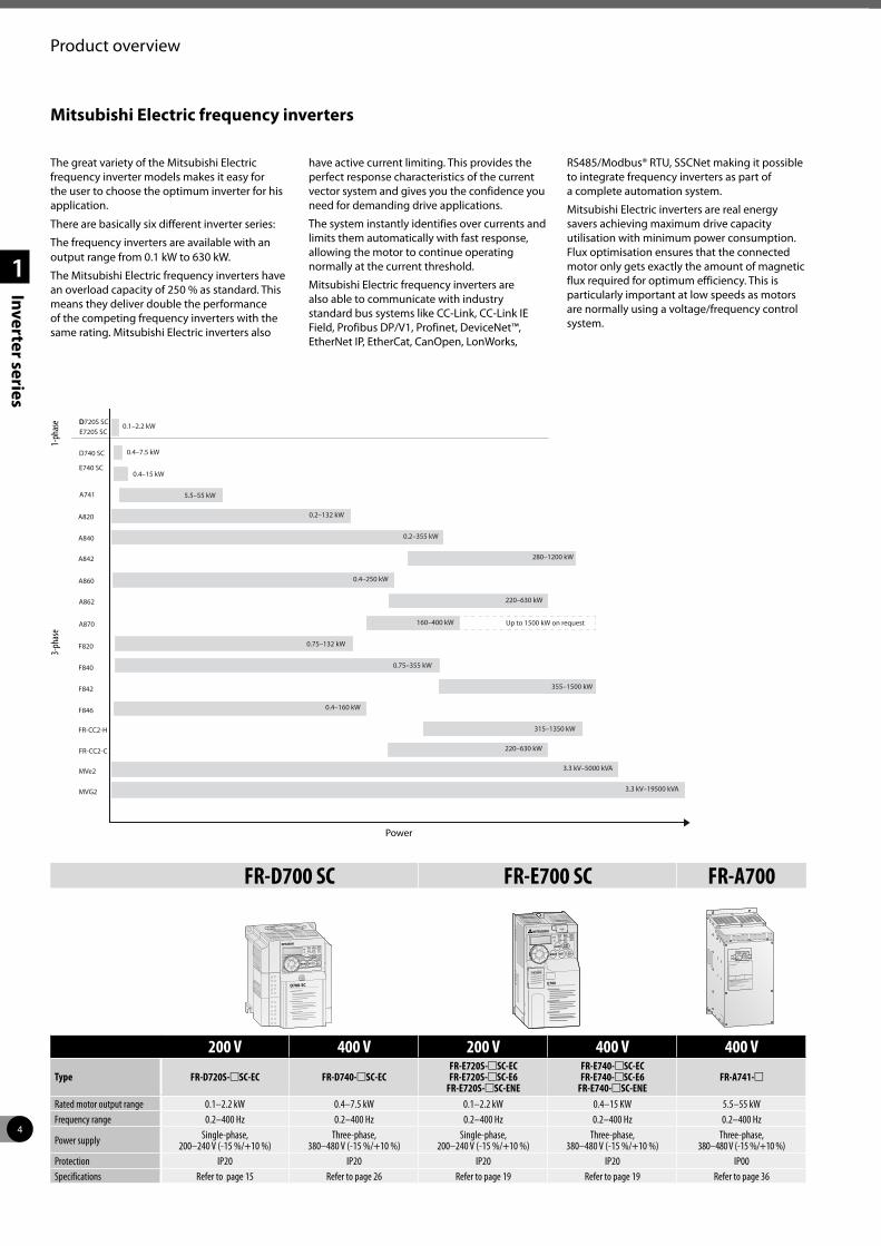
The great variety of the Mitsubishi Electric frequency inverter models makes it easy for the user to choose the optimum inverter for his application.
There are basically six different inverter series:
The frequency inverters are available with an output range from 0.1 kW to 630 kW.
The Mitsubishi Electric frequency inverters have an overload capacity of 250 % as standard. This means they deliver double the performance of the competing frequency inverters with the same rating. Mitsubishi Electric inverters also
have active current limiting. This provides the perfect response characteristics of the current vector system and gives you the confidence you need for demanding drive applications.
The system instantly identifies over currents and limits them automatically with fast response, allowing the motor to continue operating normally at the current threshold.
Mitsubishi Electric frequency inverters are also able to communicate with industry standard bus systems like CC-Link, CC-Link IE Field, Profibus DP/V1, Profinet, DeviceNet™, EtherNet IP, EtherCat, CanOpen, LonWorks,
RS485/Modbus® RTU, SSCNet making it possible to integrate frequency inverters as part of a complete automation system.
Mitsubishi Electric inverters are real energy savers achieving maximum drive capacity utilisation with minimum power consumption. Flux optimisation ensures that the connected motor only gets exactly the amount of magnetic flux required for optimum efficiency. This is particularly important at low speeds as motors are normally using a voltage/frequency control system.
Mitsubishi Electric frequency inverters
A820 0.2–132 kW
A840 0.2–355 kW
A842 280–1200 kW
A860 0.4–250 kW
F820 0.75–132 kW
F840 0.75–355 kW
F842 355–1500 kW
220–630 kWA862
A870 160–400 kW
F846 0.4–160 kW
FR-CC2-H
FR-CC2-C
315–1350 kW
220–630 kW
MVe2
MVG2
3.3 kV–5000 kVA
3.3 kV–19500 kVA
Up to 1500 kW on request
D740 SC 0.4–7.5 kW
0.1–2.2 kWD720S SCD
E740 SC0.4–15 kW
A741 5.5–55 kW
E720S SC
1-ph
ase
3-ph
ase
Power
FR-D700 SC FR-E700 SC FR-A700
D700-SC
200 V 400 V 200 V 400 V 400 V
Type FR-D720S-mSC-EC FR-D740-mSC-ECFR-E720S-mSC-ECFR-E720S-mSC-E6
FR-E720S-mSC-ENE
FR-E740-mSC-ECFR-E740-mSC-E6
FR-E740-mSC-ENEFR-A741-m
Rated motor output range 0.1–2.2 kW 0.4–7.5 kW 0.1–2.2 kW 0.4–15 KW 5.5–55 kWFrequency range 0.2–400 Hz 0.2–400 Hz 0.2–400 Hz 0.2–400 Hz 0.2–400 Hz
Power supply Single-phase, 200–240 V (-15 %/+10 %)
Three-phase, 380–480 V (-15 %/+10 %)
Single-phase, 200–240 V (-15 %/+10 %)
Three-phase, 380–480 V (-15 %/+10 %)
Three-phase, 380–480 V (-15 %/+10 %)
Protection IP20 IP20 IP20 IP20 IP00Specifications Refer to page 15 Refer to page 26 Refer to page 19 Refer to page 19 Refer to page 36
5
1
Inverter series
Product overview
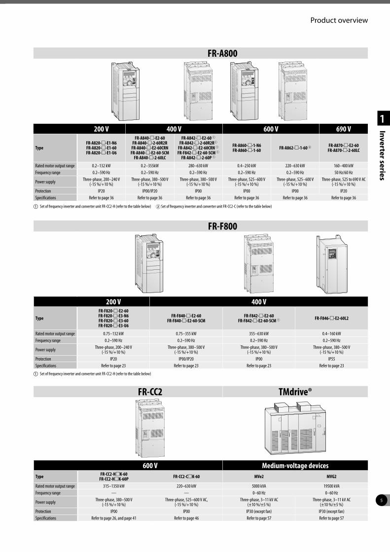
FR-A800
200 V 400 V 600 V 690 V
TypeFR-A820-m-E1-N6FR-A820-m-E1-60FR-A820-m-E1-U6
FR-A840-m-E2-60FR-A840-m-2-60R2R
FR-A840-m-E2-60CRN FR-A840-m-E2-60-SCM
FR-A840-m-2-60LC
FR-A842-m-E2-60 1FR-A842-m-2-60R2R1
FR-A842-m-E2-60CRN 1FR-F842-m-E2-60-SCM 1
FR-A842-m-2-60P 1
FR-A860-m-1-N6FR-A860-m-1-60 FR-A862-m-1-60 2 FR-A870-m-E2-60
FR-A870-m-2-60LC
Rated motor output range 0.2–132 kW 0.2–355kW 280–630 kW 0.4–250 kW 220–630 kW 160–400 kWFrequency range 0.2–590 Hz 0.2–590 Hz 0.2–590 Hz 0.2–590 Hz 0.2–590 Hz 50 Hz/60 Hz
Power supply Three-phase, 200–240 V (-15 %/+10 %)
Three-phase, 380–500 V (-15 %/+10 %)
Three-phase, 380–500 V (-15 %/+10 %)
Three-phase, 525–600 V (-15 %/+10 %)
Three-phase, 525–600 V (-15 %/+10 %)
Three-phase, 525 to 690 V AC (-15 %/+10 %)
Protection IP20 IP00/IP20 IP00 IP00 IP00 IP20Specifications Refer to page 36 Refer to page 36 Refer to page 36 Refer to page 36 Refer to page 36 Refer to page 36
a Set of frequency inverter and converter unit FR-CC2-H (refer to the table below) 2 Set of frequency inverter and converter unit FR-CC2-C (refer to the table below)
FR-CC2 TMdrive®
600 V Medium-voltage devicesType FR-CC2-HmK-60
FR-CC2-HmK-60P FR-CC2-CmK-60 MVe2 MVG2
Rated motor output range 315–1350 kW 220–630 kW 5000 kVA 19500 kVAFrequency range — — 0–60 Hz 0–60 Hz
Power supply Three-phase, 380–500 V (-15 %/+10 %)
Three-phase, 525–600 V AC, (-15 %/+10 %)
Three-phase, 3–11 kV AC (±10 %/±5 %)
Three-phase, 3–11 kV AC (±10 %/±5 %)
Protection IP00 IP00 IP30 (except fan) IP30 (except fan)Specifications Refer to page 26, and page 41 Refer to page 46 Refer to page 57 Refer to page 57
FR-F800
200 V 400 V
TypeFR-F820-m-E2-60FR-F820-m-E3-N6FR-F820-m-E3-60FR-F820-m-E3-U6
FR-F840-m-E2-60FR-F840-m-E2-60-SCM
FR-F842-m-E2-60FR-F842-m-E2-60-SCM 1 FR-F846-m-E2-60L2
Rated motor output range 0.75–132 kW 0.75–355 kW 355–630 kW 0.4–160 kWFrequency range 0.2–590 Hz 0.2–590 Hz 0.2–590 Hz 0.2–590 Hz
Power supply Three-phase, 200–240 V (-15 %/+10 %)
Three-phase, 380–500 V (-15 %/+10 %)
Three-phase, 380–500 V (-15 %/+10 %)
Three-phase, 380–500 V (-15 %/+10 %)
Protection IP20 IP00/IP20 IP00 IP55Specifications Refer to page 23 Refer to page 23 Refer to page 23 Refer to page 23
a Set of frequency inverter and converter unit FR-CC2-H (refer to the table below)
6
1
Inverter series
Special functions
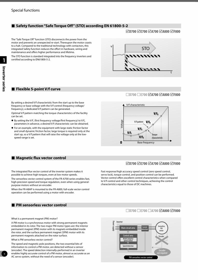
The “Safe Torque Off” function (STO) disconnects the power from the motor and prevents an unexpected re-start. Thereupon the motor coasts to a halt. Compared to the traditional technology with contactors, this integrated Safety function reduces the effort in hardware, wiring and maintenance and offers higher performance and lifetime.
The STO function is standard integrated into the frequency inverters and certified according to EN61800-5-2.
Safety function “Safe Torque Off” (STO) according EN 61800-5-2 þD700 þE700 þA700 þA800 þF800
Flexible 5-point V/f curve ¨D700 ¨E700 þA700 þA800 þF800
By setting a desired V/f characteristic from the start up to the base frequency or base voltage with the V/f control (frequency voltage/frequency), a dedicated V/f pattern can be generated.
Optimal V/f pattern matching the torque characteristics of the facility can be set.
z By setting the V/f1 (first frequency voltage/first frequency) to V/f5 parameters in advance, a desired V/f characteristic can be obtained.
z For an example, with the equipment with large static friction factor and small dynamic friction factor, large torque is required only at the start up, so a V/f pattern that will raise the voltage only at the low-speed range is set.
PM sensorless vector control ¨D700 ¨E700 ¨A700 þA800 þF800
What is a permanent magnet (PM) motor?
A PM motor is a synchronous motor with strong permanent magnets embedded in its rotor. The two major PM motor types are: the interior permanent magnet (IPM) motor with its magnets embedded inside the rotor, and the surface permanent magnet (SPM) motor with its permanent magnets attached on the rotor surface.
What is PM sensorless vector control?
The speed and magnetic pole positions, the two essential bits of information to control a PM motor, are detected without a sensor (encoder). The speed detection internally-performed in an inverter enables highly accurate control of a PM motor, almost as accurate as an AC servo system, without the need of a sensor (encoder).
Inverter
Power supply
Sensorless PM
motor
Encoder
Encoder not required
Current detectionMain circuit area
Control areaModel adaptive
speed control
Speed detection
PM sensorless vector control
V/f characteristic
Base frequency
Volta
ge V/f pattern
Torque characteristic
Magnetic flux vector control þD700 þE700 þA700 þA800 þF800
The integrated flux vector control of the inverter system makes it possible to achieve high torques, even at low motor speeds.
The sensorless vector control system of the FR-A700 series enables fast, high-precision speed and torque regulation, even when using general-purpose motors without an encoder.
When the FR-A8AP is mounted to the FR-A800, full-scale vector control operation can be performed using a motor with encoder.
Fast response/high accuracy speed control (zero speed control, servo lock), torque control, and position control can be performed. Vector control offers excellent control characteristics when compared to V/f control and other control techniques, achieving the control characteristics equal to those of DC machines.
7
Special functions
1
Inverter series
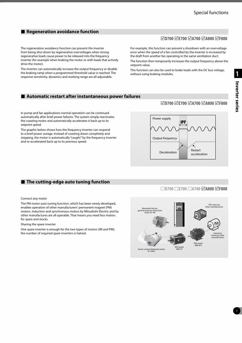
The cutting-edge auto tuning function ¨D700 ¨E700 ¨A700 þA800 þF800
Connect any motor
The PM motor auto tuning function, which has been newly developed, enables operation of other manufacturers' permanent magnet (PM) motors. Induction and synchronous motors by Mitsubishi Electric and by other manufactures are all operable. That means you need less motors for spare and stocks.
Sharing the spare inverter
One spare inverter is enough for the two types of motors (IM and PM); the number of required spare inverters is halved.
Mitsubishi Electric general-purpose (induction)
motor SF-HR
PM motor by other manufacturers
Induction motor by other manufacturers
IPM motor MM-EFS
IPM motor MM-CFVector control dedicated motor
SF-V5RU
Automatic restart after instantaneous power failures þD700 þE700 þA700 þA800 þF800
In pump and fan applications normal operation can be continued automatically after brief power failures. The system simply reactivates the coasting motor and automatically accelerates it back up to its setpoint speed.
The graphic below shows how the frequency inverter can respond to a brief power outage. Instead of coasting down completely and stopping, the motor is automatically “caught” by the frequency inverter and re-accelerated back up to its previous speed.
Regeneration avoidance function þD700 þE700 þA700 þA800 þF800
The regeneration avoidance function can prevent the inverter from being shut down by regenerative overvoltages when strong regenerative loads cause power to be released into the frequency inverter (for example when braking the motor or with loads that actively drive the motor).
The inverter can automatically increase the output frequency or disable the braking ramp when a programmed threshold value is reached. The response sensitivity, dynamics and working range are all adjustable.
For example, this function can prevent a shutdown with an overvoltage error when the speed of a fan controlled by the inverter is increased by the draft from another fan operating in the same ventilation duct.
The function then temporarily increases the output frequency above the setpoint value.
This function can also be used to brake loads with the DC bus voltage, without using braking modules.
Power supply
Restart acceleration
Output frequency
Deceleration
8
Special functions
1
Inverter series Standard 24 V DC power supply for the control circuit ¨D700 ¨E700¨A700 þA800 þF800
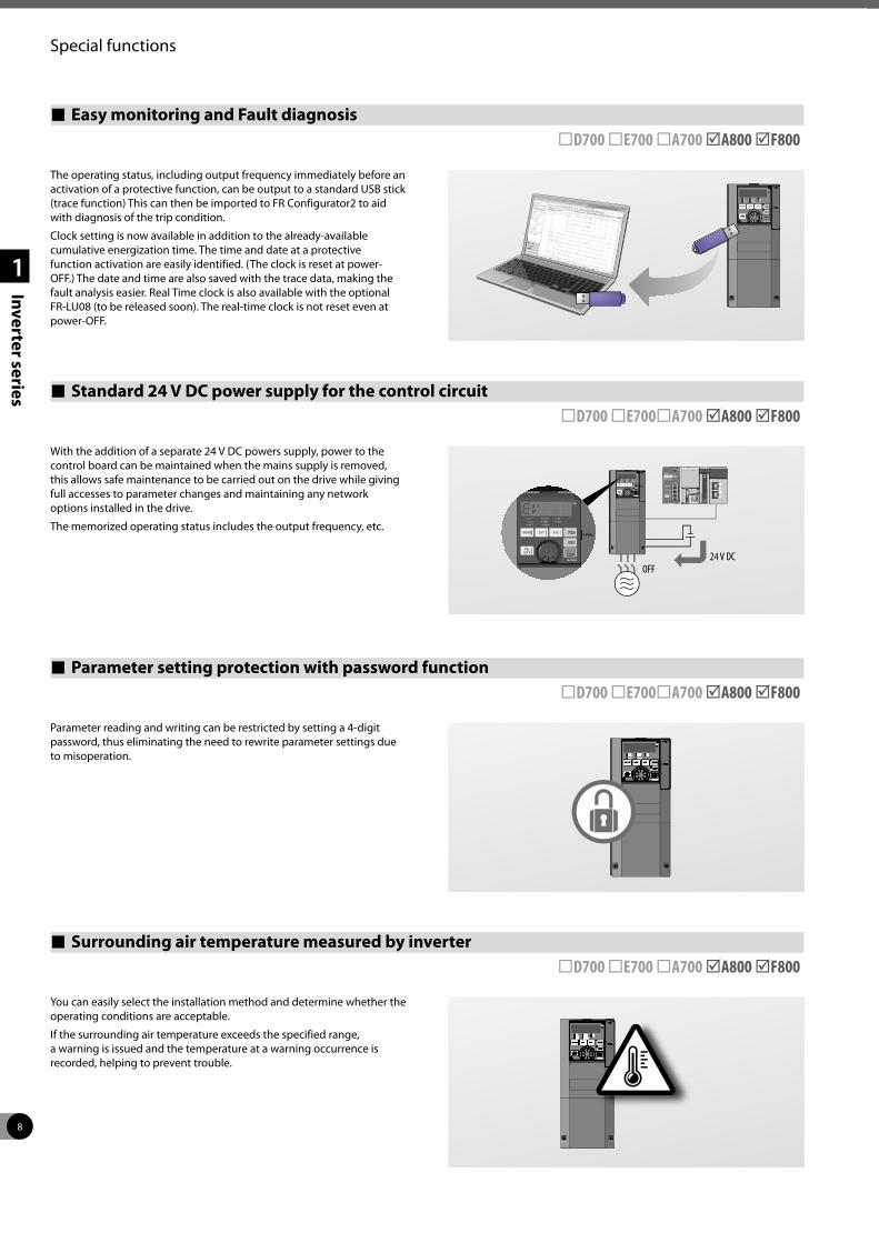
With the addition of a separate 24 V DC powers supply, power to the control board can be maintained when the mains supply is removed, this allows safe maintenance to be carried out on the drive while giving full accesses to parameter changes and maintaining any network options installed in the drive.
The memorized operating status includes the output frequency, etc.
Surrounding air temperature measured by inverter ¨D700 ¨E700 ¨A700 þA800 þF800
Parameter reading and writing can be restricted by setting a 4-digit password, thus eliminating the need to rewrite parameter settings due to misoperation.
You can easily select the installation method and determine whether the operating conditions are acceptable.
If the surrounding air temperature exceeds the specified range, a warning is issued and the temperature at a warning occurrence is recorded, helping to prevent trouble.
FWD
RE V
STOPRES ET
R E V
FWD
STOPRES ET
P.RUN
PUEXTNET
MONPRM
IMPM
OFF24 V DC
Parameter setting protection with password function ¨D700 ¨E700¨A700 þA800 þF800
Easy monitoring and Fault diagnosis ¨D700 ¨E700 ¨A700 þA800 þF800
The operating status, including output frequency immediately before an activation of a protective function, can be output to a standard USB stick (trace function) This can then be imported to FR Configurator2 to aid with diagnosis of the trip condition.
Clock setting is now available in addition to the already-available cumulative energization time. The time and date at a protective function activation are easily identified. (The clock is reset at power-OFF.) The date and time are also saved with the trace data, making the fault analysis easier. Real Time clock is also available with the optional FR-LU08 (to be released soon). The real-time clock is not reset even at power-OFF.
9
Special functions
1
Inverter series
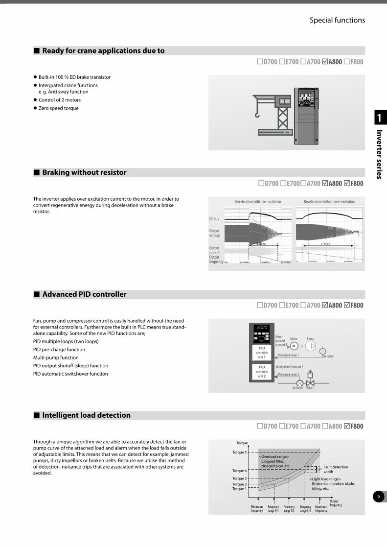
Ready for crane applications due to ¨D700 ¨E700 ¨A700 þA800 ¨F800
z Built-in 100 % ED brake transistor
z Intergrated crane functions e. g. Anti sway function
z Control of 2 motors
z Zero speed torque
Braking without resistor ¨D700 ¨E700¨A700 þA800 þF800
The inverter applies over excitation current to the motor, in order to convert regenerative energy during deceleration without a brake resistor.
Advanced PID controller ¨D700 ¨E700 ¨A700 þA800 þF800
Fan, pump and compressor control is easily handled without the need for external controllers. Furthermore the built in PLC means true stand-alone capability. Some of the new PID functions are;
PID multiple loops (two loops)
PID pre-charge function
Multi-pump function
PID output shutoff (sleep) function
PID automatic switchover function
Intelligent load detection ¨D700 ¨E700 ¨A700 ¨A800 þF800
Through a unique algorithm we are able to accurately detect the fan or pump curve of the attached load and alarm when the load falls outside of adjustable limits. This means that we can detect for example, jammed pumps, dirty impellors or broken belts. Because we utilise this method of detection, nuisance trips that are associated with other systems are avoided.
M
Mani-pulated amount 1
PID operation
unit 1
PID operation
unit 2
Manipulated amount 2
Motor Pump
Detector
Detector Valve
Measured value 1
Measured value 2
Deceleration without over excitationDeceleration with over excitation
DC bus
Output voltage
Output currentOutput frequency
Seit 4
Torque
Torque 5
Torque 4
Torque 3Torque 2Torque 1
< Overload range> Clogged filter, clogged pipe, etc. Fault detection
width
< Light load range> Broken belt, broken blade, idling, etc.
Minimum frequency
Frequency range 1/4
Frequency range 1/2
Frequency range 3/4
Maximum frequency
Output frequency
10
Special functions
1
Inverter series
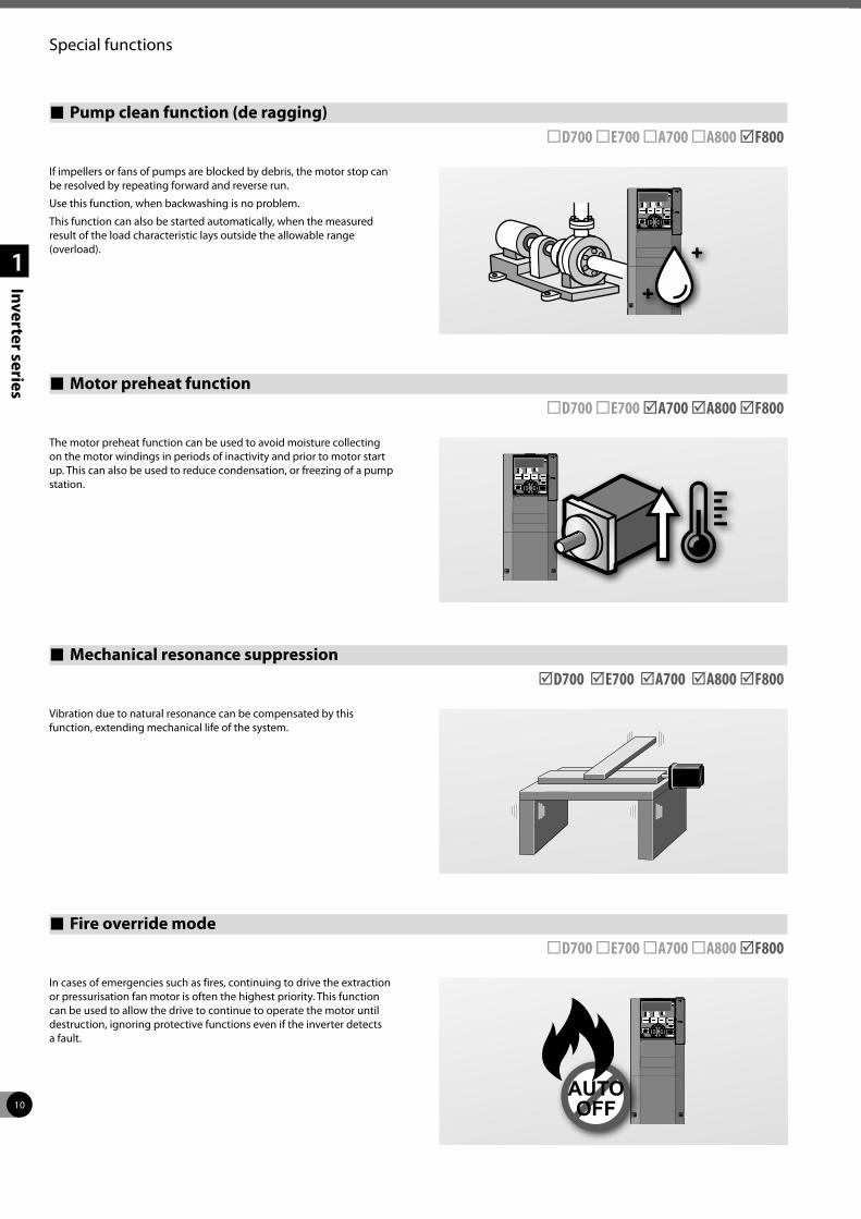
Pump clean function (de ragging) ¨D700 ¨E700 ¨A700 ¨A800 þF800
If impellers or fans of pumps are blocked by debris, the motor stop can be resolved by repeating forward and reverse run.
Use this function, when backwashing is no problem.
This function can also be started automatically, when the measured result of the load characteristic lays outside the allowable range (overload).
Motor preheat function ¨D700 ¨E700 þA700 þA800 þF800
The motor preheat function can be used to avoid moisture collecting on the motor windings in periods of inactivity and prior to motor start up. This can also be used to reduce condensation, or freezing of a pump station.
Mechanical resonance suppression þD700 þE700 þA700 þA800 þF800
Vibration due to natural resonance can be compensated by this function, extending mechanical life of the system.
Seit 4
Fire override mode ¨D700 ¨E700 ¨A700 ¨A800 þF800
In cases of emergencies such as fires, continuing to drive the extraction or pressurisation fan motor is often the highest priority. This function can be used to allow the drive to continue to operate the motor until destruction, ignoring protective functions even if the inverter detects a fault.
11
Special functions
1
Inverter series
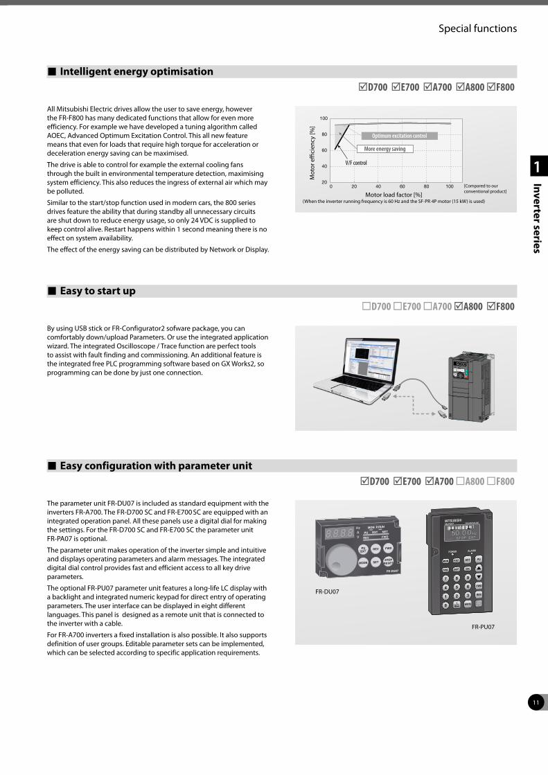
Intelligent energy optimisation þD700 þE700 þA700 þA800 þF800
All Mitsubishi Electric drives allow the user to save energy, however the FR-F800 has many dedicated functions that allow for even more efficiency. For example we have developed a tuning algorithm called AOEC, Advanced Optimum Excitation Control. This all new feature means that even for loads that require high torque for acceleration or deceleration energy saving can be maximised.
The drive is able to control for example the external cooling fans through the built in environmental temperature detection, maximising system efficiency. This also reduces the ingress of external air which may be polluted.
Similar to the start/stop function used in modern cars, the 800 series drives feature the ability that during standby all unnecessary circuits are shut down to reduce energy usage, so only 24 VDC is supplied to keep control alive. Restart happens within 1 second meaning there is no effect on system availability.
The effect of the energy saving can be distributed by Network or Display.
Easy to start up ¨D700 ¨E700 ¨A700 þA800 þF800
By using USB stick or FR-Configurator2 sofware package, you can comfortably down/upload Parameters. Or use the integrated application wizard. The integrated Oscilloscope / Trace function are perfect tools to assist with fault finding and commissioning. An additional feature is the integrated free PLC programming software based on GX Works2, so programming can be done by just one connection.
Easy configuration with parameter unit þD700 þE700 þA700 ¨A800 ¨F800
FR-PU07
FR-DU07
The parameter unit FR-DU07 is included as standard equipment with the inverters FR-A700. The FR-D700 SC and FR-E700 SC are equipped with an integrated operation panel. All these panels use a digital dial for making the settings. For the FR-D700 SC and FR-E700 SC the parameter unit FR-PA07 is optional.
The parameter unit makes operation of the inverter simple and intuitive and displays operating parameters and alarm messages. The integrated digital dial control provides fast and efficient access to all key drive parameters.
The optional FR-PU07 parameter unit features a long-life LC display with a backlight and integrated numeric keypad for direct entry of operating parameters. The user interface can be displayed in eight different languages. This panel is designed as a remote unit that is connected to the inverter with a cable.
For FR-A700 inverters a fixed installation is also possible. It also supports definition of user groups. Editable parameter sets can be implemented, which can be selected according to specific application requirements.
20
40
60
80
100
0 20 40 60 80 100
Optimum excitation control
Mot
or e
ffici
ency
[%]
V/F control
More energy saving
Motor load factor [%](When the inverter running frequency is 60 Hz and the SF-PR 4P motor (15 kW) is used)
[Compared to our conventional product]
12
1
Inverter series
System description
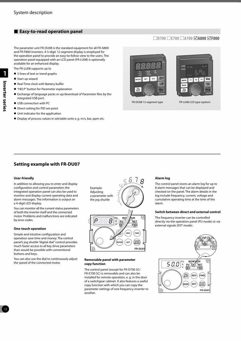
Easy-to-read operation panel ¨D700 ¨E700 ¨A700 þA800 þF800
The parameter unit FR-DU08 is the standard equipment for all FR-A800 and FR-F800 inverters. A 5-digit 12-segment display is employed for the operation panel to provide an easy-to-follow view to the users. The operation panel equipped with an LCD panel (FR-LU08) is optionally available for an enhanced display.
The FR-LU08 supports up to
z 5 lines of text or trend graphs
z Start up wizard
z Real Time clock with Battery buffer
z “HELP” button for Parameter explanation
z Exchange of language packs or up/download of Parameter files by the integrated USB port.
z USB connection with PC
z Direct setting for PID set-point
z Unit indicator for the application
z Display of process values in selctable units e. g. m/s, bar, ppm etc.
PWR
ALM
FR-LU08 LCD type (option)FR-DU08 12-segment type
User-friendly
In addition to allowing you to enter and display configuration and control parameters the integrated operation panel can also be used to monitor and display current operating data and alarm messages. The information is output on a 4-digit LED display.
You can monitor all the current status parameters of both the inverter itself and the connected motor. Problems and malfunctions are indicated by error codes.
One-touch operation
Simple and intuitive configuration and operation save time and money. The control panel’s jog shuttle “digital dial” control provides much faster access to all key drive parameters than would be possible with conventional buttons and keys.
You can also use the dial to continuously adjust the speed of the connected motor.
Removable panel with parameter copy function
The control panel (except for FR-D700 SC/ FR-E700 SC) is removable and can also be installed for remote operation, e. g. in the door of a switchgear cabinet. It also features a useful copy function with which you can copy the parameter settings of one frequency inverter to another.
Alarm log
The control panel stores an alarm log for up to 8 alarm messages that can be displayed and checked on the panel. The alarm details in the log include frequency, current, voltage and cumulative operating time at the time of the alarm.
Switch between direct and external control
The frequency inverter can be controlled directly via the operation panel (PU mode) or via external signals (EXT mode).
Hz MONPU
REV
REV
SET
EXT
PUEXT
STOPRESET
NETFWD
FWD
MODE
P.RUN
FR-DU07
AV
MONPU
REV
REV
EXT
U
NETFWD
FW
P.RUN
Hz MONPU
REV
REV
SET
EXT
PUEXT
STOPRESET
NETFWD
FWD
MODE
P.RUN
FR-DU07
AV
87654
321
Example: Adjusting a parameter with the jog shuttle
Setting example with FR-DU07
13
System description
1
Inverter series
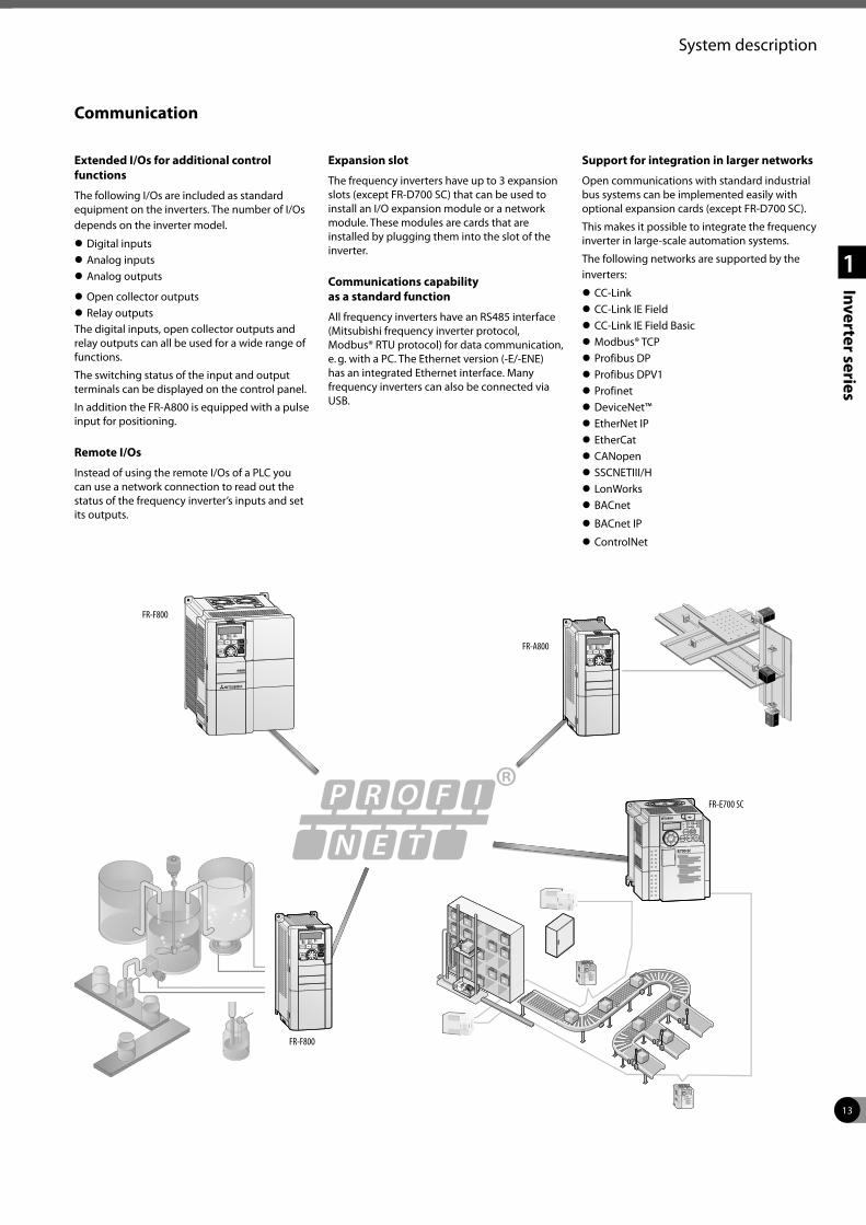
Communication
Extended I/Os for additional control functions
The following I/Os are included as standard equipment on the inverters. The number of I/Os depends on the inverter model.
z Digital inputs z Analog inputs z Analog outputs
z Open collector outputs z Relay outputs
The digital inputs, open collector outputs and relay outputs can all be used for a wide range of functions.
The switching status of the input and output terminals can be displayed on the control panel.
In addition the FR-A800 is equipped with a pulse input for positioning.
Remote I/Os
Instead of using the remote I/Os of a PLC you can use a network connection to read out the status of the frequency inverter’s inputs and set its outputs.
Expansion slot
The frequency inverters have up to 3 expansion slots (except FR-D700 SC) that can be used to install an I/O expansion module or a network module. These modules are cards that are installed by plugging them into the slot of the inverter.
Communications capability as a standard function
All frequency inverters have an RS485 interface (Mitsubishi frequency inverter protocol, Modbus® RTU protocol) for data communication, e. g. with a PC. The Ethernet version (-E/-ENE) has an integrated Ethernet interface. Many frequency inverters can also be connected via USB.
Support for integration in larger networks
Open communications with standard industrial bus systems can be implemented easily with optional expansion cards (except FR-D700 SC).
This makes it possible to integrate the frequency inverter in large-scale automation systems.
The following networks are supported by the inverters:
z CC-Link z CC-Link IE Field z CC-Link IE Field Basic z Modbus® TCP z Profibus DP z Profibus DPV1 z Profinet z DeviceNet™ z EtherNet IP z EtherCat z CANopen z SSCNETIII/H z LonWorks z BACnet
z BACnet IP
z ControlNet
FR-F800
FR-E700 SC
FR-F800
FR-A800

14
System description
1
Inverter series
Maintenance and standards
Simplified maintenance
Easy installation and maintenance
Since the control and power terminal block is easy to access, the installation and maintenance of the inverter is also very easy.
All connection points are designed as screw terminals or spring clamps. The housing includes a cable routing facility which can be removed for installing.
Easy access to cooling fans
The easily accessible cooling fans can be replaced quickly and easily if required.
The integrated cooling fan can be switched OFF automatically in stand-by operation to increase its lifetime significantly.
Even the cabinet fan can be activated based on environment temp measurement of the Inverter.
Service timer
The frequency inverters offer up to 3 integrated service timers that automatically triggers a diagnostic alarm after a set number of operating hours. This feature can be used for monitoring the frequency inverter itself or a peripheral component. The values of the average output current and the service timer can also be output as analog signals.
Modern diagnostics functions further extend service life
The ageing of the main circuit capacitors, the control circuit power capacitor, the internal cooling fans, and the inrush current limiter circuit can be checked with the monitoring functions.
If the inrush resistor overheats an alarm is displayed.
The alarms for the main circuit capacitors, control circuit capacitor, inrush current limiter and internal fans can all be output to a network or via the optional FR-A8AY module.
This makes it possible to prevent malfunctions by configuring diagnostics alarms to be triggered when the end of the service life is reached.
The inverter also has an internal program that can evaluate the ageing of the main circuit capacitors. This feature is only available when a motor is connected to the inverter.
Due to built-in environment temperature sensor the real cooling situation can be judged more precisely and e. g. IGBT overtemperature alarms can be avoided.
Environment-friendly and international compliance
Electromagnetic compatibility
Latest technologies have been used to significantly reduce the interference levels generated by this frequency inverter.
Regarding its electromagnetic compatibility, the frequency inverters comply with the European EMC directives.
To meet these standards noise filters have been developed for each performance range.
The FR-A800 have a built-in EMC filter and comply to the strict electromagnetic compatibility regulations of the European Union (EMC Directive, Environment 2, EN 61800-3).
In order to meet these standards, the inverters are fitted with a new, Integrated EMC filter, which can easily be deactivated with a jumper if necessary.
You can also further limit the make current and reduce network interference by fitting the input of the inverter with an optional AC choke and a DC choke, which is connected to special terminals on the inverter unit.
Circuit boards with two coats of protective varnish
The twin coating on the internal PCBs provides even better protection against environmental influences. This is particularly important in sewage plant applications where the switchgear cabinets are exposed to aggressive fermentation gases that can reduce the service life of the equipment.
The FR-A800 and FR-F800 series complies to the Environmental requirements of IEC60721-3-3 level 3C2 as standard.
International standards
The inverters are designed so that they can be used worldwide without any additional modifications or certifications.
z The units conform to the international standards CE, UL, cUL, EAC, CCC, ISO 9001, ISO 14001 and C-Tick (FR-A741: CE/UL/cUL/GOST). In addition, the series FR-A800 conform to DNV/GL, ABS/BV/LR/NK marine approvals.
z User-selectable positive or negative switching logic. Users can select positive or negative switching logic for input and output signals, enabling flexible and simple adaptation of the units for varying world market requirements.
z Multilingual programming/control unit (optional)
z Support for a variety of international industrial bus systems
z Internationally standardised, frequency inverter configuration software package for MS Windows®, with multilingual user interface.
These features make the inverters a truly international product that meets all relevant standards and can be easily adjusted for national requirements.
15
2
Specifications
Specifications FR-D700 SC
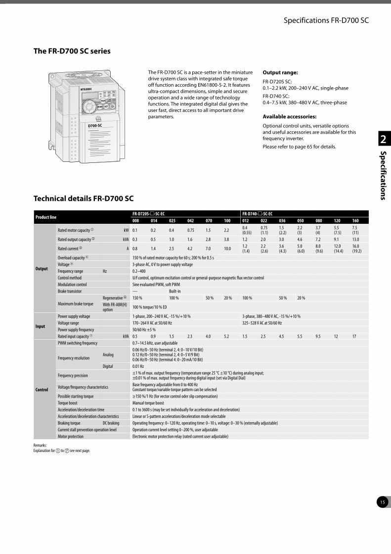
The FR-D700 SC series
D700-SC
The FR-D700 SC is a pace-setter in the miniature drive system class with integrated safe torque off function according EN61800-5-2. It features ultra-compact dimensions, simple and secure operation and a wide range of technology functions. The integrated digital dial gives the user fast, direct access to all important drive parameters.
Output range:
FR-D720S SC: 0.1–2.2 kW, 200–240 V AC, single-phase
FR-D740 SC: 0.4–7.5 kW, 380–480 V AC, three-phase
Available accessories:
Optional control units, versatile options and useful accessories are available for this frequency inverter.
Please refer to page 65 for details.
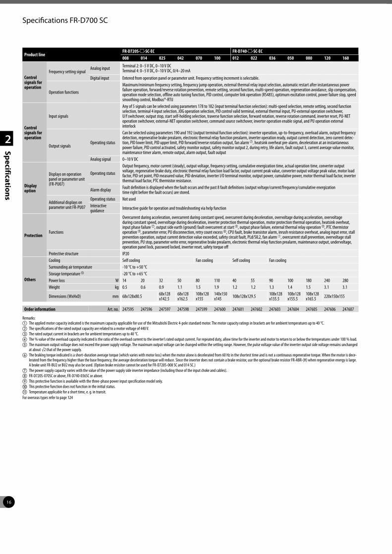
Technical details FR-D700 SC
Product lineFR-D720S-m-SC-EC FR-D740-m-SC-EC008 014 025 042 070 100 012 022 036 050 080 120 160
Output
Rated motor capacity a kW 0.1 0.2 0.4 0.75 1.5 2.2 0.4 (0.55)
0.75 (1.1)
1.5 (2.2)
2.2 (3)
3.7 (4)
5.5 (7.5)
7.5 (11)
Rated output capacity b kVA 0.3 0.5 1.0 1.6 2.8 3.8 1.2 2.0 3.0 4.6 7.2 9.1 13.0
Rated current c A 0.8 1.4 2.5 4.2 7.0 10.0 1.2 (1.4)
2.2 (2.6)
3.6 (4.3)
5.0 (6.0)
8.0 (9.6)
12.0 (14.4)
16.0 (19.2)
Overload capacity 4 150 % of rated motor capacity for 60 s; 200 % for 0.5 sVoltage 5 3-phase AC, 0 V to power supply voltageFrequency range Hz 0.2–400Control method U/f control, optimum excitation control or general-purpose magnetic flux vector controlModulation control Sine evaluated PWM, soft PWMBrake transistor — Built-in
Maximum brake torqueRegenerative f 150 % 100 % 50 % 20 % 100 % 50 % 20 %With FR-ABR(H) option 100 % torque/10 % ED
Input
Power supply voltage 1-phase, 200–240 V AC, -15 %/+10 % 3-phase, 380–480 V AC, -15 %/+10 %Voltage range 170–264 V AC at 50/60 Hz 325–528 V AC at 50/60 HzPower supply frequency 50/60 Hz ±5 %Rated input capacity 7 kVA 0.5 0.9 1.5 2.3 4.0 5.2 1.5 2.5 4.5 5.5 9.5 12 17
Control
PWM switching frequency 0.7–14.5 kHz, user adjustable
Frequency resolutionAnalog
0.06 Hz/0–50 Hz (terminal 2, 4: 0–10 V/10 Bit) 0.12 Hz/0–50 Hz (terminal 2, 4: 0–5 V/9 Bit) 0.06 Hz/0–50 Hz (terminal 4: 0–20 mA/10 Bit)
Digital 0.01 Hz
Frequency precision ±1 % of max. output frequency (temperature range 25 °C ±10 °C) during analog input; ±0.01 % of max. output frequency during digital input (set via Digital Dial)
Voltage/frequency characteristics Base frequency adjustable from 0 to 400 Hz Constant torque/variable torque pattern can be selected
Possible starting torque ≥150 %/1 Hz (for vector control oder slip compensation)Torque boost Manual torque boostAcceleration/deceleration time 0.1 to 3600 s (may be set individually for acceleration and deceleration)Acceleration/deceleration characteristics Linear or S-pattern acceleration/deceleration mode selectableBraking torque DC braking Operating frequency: 0–120 Hz, operating time: 0–10 s, voltage: 0–30 % (externally adjustable)Current stall prevention operation level Operation current level setting 0–200 %, user adjustableMotor protection Electronic motor protection relay (rated current user adjustable)
Remarks:Explanation for a to g see next page.
16
2
Specifications
Specifications FR-D700 SC
Product lineFR-D720S-m-SC-EC FR-D740-m-SC-EC008 014 025 042 070 100 012 022 036 050 080 120 160
Control signals for operation
Frequency setting signalAnalog input Terminal 2: 0–5 V DC, 0–10 V DC
Terminal 4: 0–5 V DC, 0–10 V DC, 0/4–20 mA
Digital input Entered from operation panel or parameter unit. Frequency setting increment is selectable.
Operation functions
Maximum/minimum frequency setting, frequency jump operation, external thermal relay input selection, automatic restart after instantaneous power failure operation, forward/reverse rotation prevention, remote setting, second function, multi-speed operation, regeneration avoidance, slip compensation, operation mode selection, offline auto tuning function, PID control, computer link operation (RS485), optimum excitation control, power failure stop, speed smoothing control, Modbus®-RTU
Control signals for operation
Input signals
Any of 5 signals can be selected using parameters 178 to 182 (input terminal function selection): multi-speed selection, remote setting, second function selection, terminal 4 input selection, JOG operation selection, PID control valid terminal, external thermal input, PU-external operation switchover, U/f switchover, output stop, start self-holding selection, traverse function selection, forward rotation, reverse rotation command, inverter reset, PU-NET operation switchover, external-NET operation switchover, command source switchover, inverter operation enable signal, and PU operation external interlock
Output signalsOperating status
Can be selected using parameters 190 and 192 (output terminal function selection): inverter operation, up-to-frequency, overload alarm, output frequency detection, regenerative brake prealarm, electronic thermal relay function prealarm, inverter operation ready, output current detection, zero current detec-tion, PID lower limit, PID upper limit, PID forward/reverse rotation output, fan alarm g, heatsink overheat pre-alarm, deceleration at an instantaneous power failure, PID control activated, safety monitor output, safety monitor output 2, during retry, life alarm, fault output 3, current average value monitor, maintenance timer alarm, remote output, alarm output, fault output
Analog signal 0–10 V DC
Display option
Displays on operation panel or parameter unit (FR-PU07)
Operating status
Output frequency, motor current (steady), output voltage, frequency setting, cumulative energization time, actual operation time, converter output voltage, regenerative brake duty, electronic thermal relay function load factor, output current peak value, converter output voltage peak value, motor load factor, PID set point, PID measured value, PID deviation, inverter I/O terminal monitor, output power, cumulative power, motor thermal load factor, inverter thermal load factor, PTC thermistor resistance.
Alarm display Fault definition is displayed when the fault occurs and the past 8 fault definitions (output voltage/current/frequency/cumulative energization time right before the fault occurs) are stored.
Additional displays on parameter unit FR-PU07
Operating status Not usedInteractive guidance Interactive guide for operation and troubleshooting via help function
ProtectionFunctions
Overcurrent during acceleration, overcurrent during constant speed, overcurrent during deceleration, overvoltage during acceleration, overvoltage during constant speed, overvoltage during deceleration, inverter protection thermal operation, motor protection thermal operation, heatsink overheat, input phase failure g, output side earth (ground) fault overcurrent at start i, output phase failure, external thermal relay operation i, PTC thermistor operation i, parameter error, PU disconnection, retry count excess h, CPU fault, brake transistor alarm, inrush resistance overheat, analog input error, stall prevention operation, output current detection value exceeded, safety circuit fault, PLd/SIL2, fan alarm 7, overcurrent stall prevention, overvoltage stall prevention, PU stop, parameter write error, regenerative brake prealarm, electronic thermal relay function prealarm, maintenance output, undervoltage, operation panel lock, password locked, inverter reset, safety torque off
Protective structure IP20
Others
Cooling Self cooling Fan cooling Self cooling Fan coolingSurrounding air temperature -10 °C to +50 °CStorage temperature k -20 °C to +65 °CPower loss W 14 20 32 50 80 110 40 55 90 100 180 240 280Weight kg 0.5 0.6 0.9 1.1 1.5 1.9 1.2 1.2 1.3 1.4 1.5 3.1 3.1
Dimensions (WxHxD) mm 68x128x80.5 68x128 x142.5
68x128 x162.5
108x128 x155
140x150 x145 108x128x129.5 108x128
x135.5108x128 x155.5
108x128 x165.5 220x150x155
Order information Art. no. 247595 247596 247597 247598 247599 247600 247601 247602 247603 247604 247605 247606 247607
Remarks:a The applied motor capacity indicated is the maximum capacity applicable for use of the Mitsubishi Electric 4-pole standard motor. The motor capacity ratings in brackets are for ambient temperatures up to 40 °C.b The specifications of the rated output capacity are related to a motor voltage of 440 V.c The rated output current in brackets are for ambient temperatures up to 40 °C. d The % value of the overload capacity indicated is the ratio of the overload current to the inverter’s rated output current. For repeated duty, allow time for the inverter and motor to return to or below the temperatures under 100 % load.e The maximum output voltage does not exceed the power supply voltage. The maximum output voltage can be changed within the setting range. However, the pulse voltage value of the inverter output side voltage remains unchanged
at about √2 that of the power supply.f The braking torque indicated is a short-duration average torque (which varies with motor loss) when the motor alone is decelerated from 60 Hz in the shortest time and is not a continuous regenerative torque. When the motor is dece-
lerated from the frequency higher than the base frequency, the average deceleration torque will reduce. Since the inverter does not contain a brake resistor, use the optional brake resistor FR-ABR-(H) when regenerative energy is large. A brake unit FR-BU2 or BU2 may also be used. (Option brake resisitor cannot be used for FR-D720S-008 SC and 014 SC.)
g The power supply capacity varies with the value of the power supply side inverter impedance (including those of the input choke and cables).h FR-D720S-070SC or above, FR-D740-036SC or above.i This protective function is available with the three-phase power input specification model only. j This protective function does not function in the initial status.k Temperature applicable for a short time, e. g. in transit.For overseas types refer to page 124
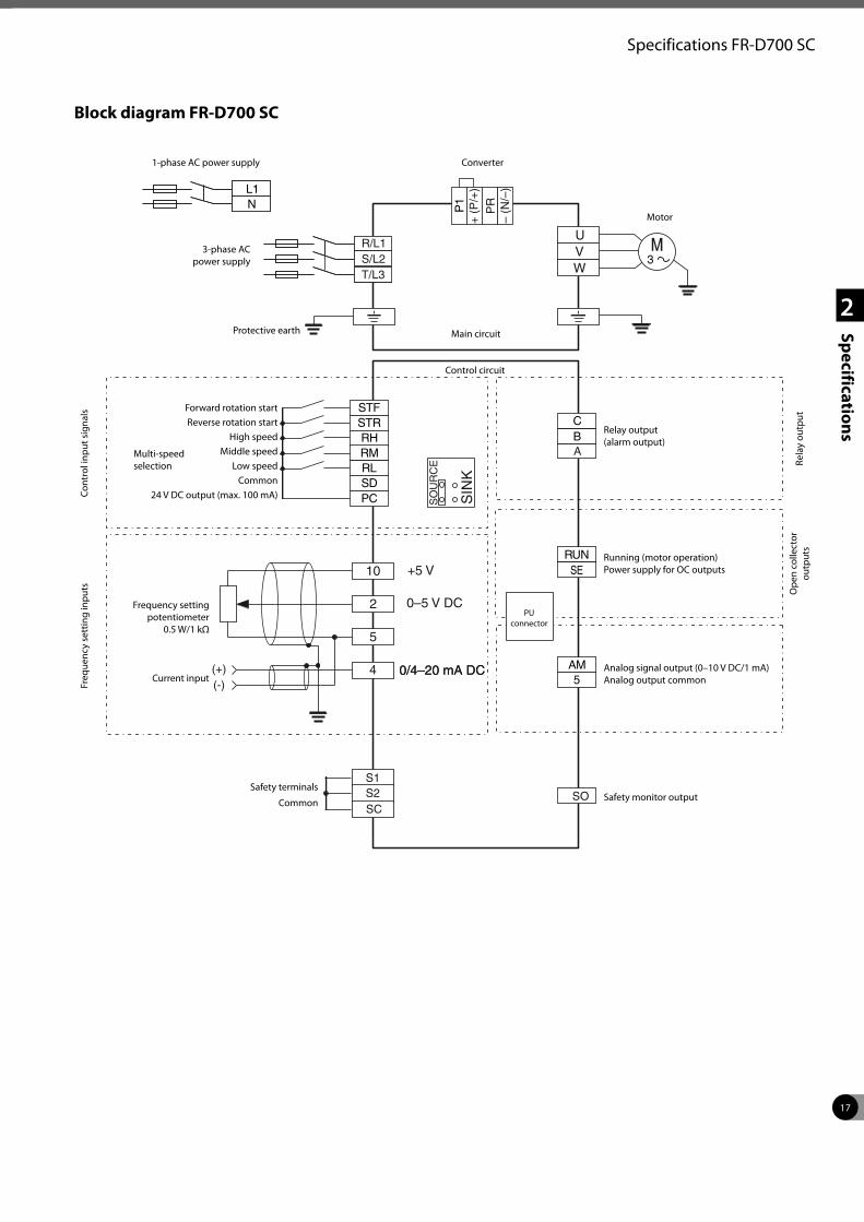
17
2
Specifications
Specifications FR-D700 SC
10
2
5
4(+)(-)
UVW
0/4–20 mA DC0/4–20 mA DC
A
S/L2T/L3
R/L1
PR
SCS2S1
SO
– (N
/–)
+ (
P/+
)
SO
UR
CE
SIN
K
Block diagram FR-D700 SC
1-phase AC power supply
3-phase AC power supply
Protective earth
Cont
rol i
nput
sig
nals
Freq
uenc
y se
ttin
g in
puts
Forward rotation startReverse rotation start
High speedMiddle speed
Low speedCommon
24 V DC output (max. 100 mA)
Multi-speed selection
Frequency setting potentiometer
0.5 W/1 kΩ
Current input
Main circuit
Control circuit
Motor
Relay output(alarm output)
Rela
y ou
tput
Ope
n co
llect
or
outp
uts
Running (motor operation)Power supply for OC outputs
Analog signal output (0–10 V DC/1 mA)Analog output common
Safety terminals
Common Safety monitor output
Converter
PU connector
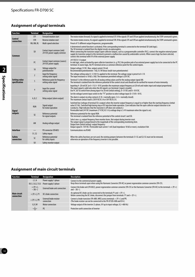
18
2
Specifications
Specifications FR-D700 SC
Function Terminal Designation Description
Control connection
STF Forward rotation start The motor rotates forward, if a signal is applied to terminal STF. If the signals STF and STR are applied simultaneously, the STOP command is given.STR Reverse rotation start The motor rotates reverse, if a signal is applied to terminal STR. If the signals STF and STR are applied simultaneously, the STOP command is given.
RH, RM, RL Multi-speed selection Preset of 15 different output frequencies; programmable.
Common
SD Contact input common (sink) 24 V DC power supply common
A determined control function is activated, if the corresponding terminal is connected to the terminal SD (sink logic). The SD terminal is isolated from the digital circuits via optocouplers. When connecting the transistor output (open collector output), such as a programmable controller (PLC), connect the negative external power supply for transistor output to this terminal to prevent a malfunction caused by undesirable currents. When source logic has been selected, connect this terminal with 0 V of the external power supply.
PC Contact input common (source) 24 V DC power supply
24 V DC/0.1 A output In sink logic, when activated by open collector transistors (e. g. PLC) the positive pole of an external power supply has to be connected to the PC terminal. In source logic, the PC terminal serves as common reference point for the control inputs.
Setting value specification
10 Voltage output for potentiometer
Output voltage 5 V DC. Max. output current 10 mA Recommended potentiometer: 1 kΩ, 0.5 W linear (multi-turn potentiometer)
2 Input for frequency setting value signal
The voltage setting value 0–5 (10) V is applied to this terminal. The voltage range is preset to 0–5 V. The input resistance is 10 kΩ ±1kΩ. The maximum permitted voltage is 20 V DC.
5 Reference point for fre quency setting value signal
Terminal 5 is the reference point for all analog setting values and for the analog output signal AM. The terminal is isolated from the reference potential of the control circuit and should not be earthed for reasons of noise immunity.
4 Input for current setting value signal
Inputting 4–20 mA DC (or 0–5 V, 0–10 V) provides the maximum output frequency at 20 mA and makes input and output proportional. This input signal is valid only when the AU signal is on (terminal 2 input is invalid). Use Pr. 267 to switch from among input 4 to 20 mA (initial setting), 0–5 V DC and 0–10 V DC. Set the voltage/current input switch in the “V” position to select voltage input (0–5 V/0–10 V).
Signal outputs
A, B, C Relay output (alarm output) The alarm is output via relay contacts (C-B = normally open, C-A = normally closed). The maximum contact load is 230 V AC/0.3 A or 30 V DC/0.3 A.
RUN Signal output for motor operation
Switched low (voltage of terminal SE is output) when the inverter output frequency is equal to or higher than the starting frequency (initial value 0.5 Hz). Switched high during stop or DC injection brake operation. (Low indicates that the open collector output transistor is on (conducts). High indicates that the transistor is off (does not conduct).)Permissible load 24 V DC (maximum 27 V DC)/0.1 A (a voltage drop is 3.4 V maximum when the signal is on).
SE Reference potential for signal outputs
Reference potential for the signal RUN. This terminal is isolated from the reference potential of the control circuit 5 and SD.
AM Analog voltage output
Select one e. g. output frequency from monitor items. Not output during inverter reset. The output signal is proportional to the magnitude of the corresponding monitoring item. Output item (initial setting): output frequency Output signal 0–10 V DC. Permissible load current 1 mA (load impedance 10 kΩ or more), resolution 8 bit
Interface — PU connector (RS485) Communications via RS485
Safety connection
S1, S2 Safety inputsWhen the safety functions are not used, the existing jumpers between the terminals S1-SC and S2-SC must not be removed, otherwise an operation of the frequency inverter is not possible.SC Reference potential
for safety inputsSO Safety monitor output
Assignment of signal terminals
Assignment of main circuit terminals
Function Terminal Designation Description
Main circuit connection
L1, N Power supply 1-phase Connect to the commercial power supply.Keep these terminals open when using the Harmonic Converter (FR-HC) or power regeneration common converter (FR-CV). R/L1, S/L2, T/L3 Power supply 3-phase
+ (P/+), – (N/–) External brake unit connection Connect the brake unit (FR-BU2), power regeneration common converter (FR-CV) or the Harmonic Converter (FR-HC) to the terminals + (P/+)
and – (N/–).
+ (P/+), P1 DC choke connection An optional DC choke can be connected to the terminals P1 and + (P/+). Before connecting the DC choke, disconnect the jumper from terminals P1 and + (P/+).
+ (P/+), PR External brake resistor connection
Connect a brake transistor (FR-ABR, MRS) across terminals + (P/+) and PR. (The brake resistor can not be connected to the FR-D720S-008 and 014.)
U, V, W Motor connection Voltage output of the inverter (3-phase, 0 V up to input voltage, 0.2–400 Hz)
PE Protective earth connection of inverter
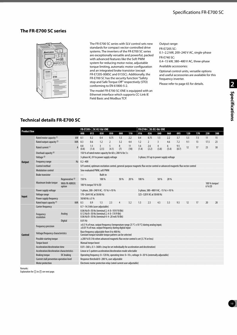
19
2
Specifications
Specifications FR-E700 SC
The FR-E700 SC series with SLV control sets new standards for compact vector-controlled drive systems. The inverters of the FR-E700 SC series are exceptionally versatile and powerful, packed with advanced features like the Soft PWM system for reducing motor noise, adjustable torque limiting, automatic motor configuration and an integrated brake transistor (except FR-E720S-008SC and 015SC). Additionally, the FR-E700 SC has the security function “Safety stop and Safe Torque Off” respectively (STO) conforming to EN 61800-5-2.
The model FR-E700 SC-ENE is equipped with an Ethernet interface which supports CC-Link IE Field Basic and Modbus TCP.
Output range:
FR-E720S SC: 0.1–2.2 kW, 200–240 V AC, single-phase
FR-E740 SC: 0.4–15 kW, 380–480 V AC, three-phase
Available accessories:
Optional control units, versatile options and useful accessories are available for this frequency inverter.
Please refer to page 65 for details.
The FR-E700 SC series
Product lineFR-E720S-mSC-EC/-E6/-ENE FR-E740-mSC-EC/-E6/-ENE008 015 030 050 080 110 016 026 040 060 095 120 170 230 300
Output
Rated motor capacity a kW 0.1 0.2 0.4 0.75 1.5 2.2 0.4 0.75 1.5 2.2 3.7 5.5 7.5 11 15Rated output capacity b kVA 0.3 0.6 1.2 2 3.2 4.4 1.2 2 3 4.6 7.2 9.1 13 17.5 23
Rated current 3 A 0.8 (0.8)
1.5 (1.4)
3(2.5)
5 (4.1)
8(7)
11 (10)
1.6 (1.4)
2.6 (2.2)
4 (3.8)
6 (5.4)
9.5 (8.7) 12 17 23 30
Overload capacity d 150 % of rated motor capacity for 60 s; 200 % for 3 sVoltage e 3-phase AC, 0 V to power supply voltage 3-phase, 0 V up to power supply voltageFrequency range Hz 0.2–400Control method U/f control, optimum excitation control, general-purpose magnetic flux vector control or advanced magnetic flux vector controlModulation control Sine evaluated PWM, soft PWMBrake transistor — Built-in
Maximum brake torqueRegenerative f 150 % 100 % 50 % 20 % 100 % 50 % 20 %With FR-ABR(H) option 100 % torque/10 % ED 100 % torque/
6 % ED
Input
Power supply voltage 1-phase, 200–240 V AC, -15 %/+10 % 3-phase, 380–480 V AC, -15 %/+10 %Voltage range 170–264 V AC at 50/60 Hz 325–528 V AC at 50/60 HzPower supply frequency 50/60 Hz ±5 %Rated input capacity g kVA 0.5 0.9 1.5 2.5 4 5.2 1.5 2.5 4.5 5.5 9.5 12 17 20 28
Control
Carrier frequency 0.7–14.5 kHz (user adjustable)
Frequency resolution
Analog0.06 Hz/0–50 Hz (terminal 2, 4: 0–10 V/10 Bit) 0.12 Hz/0–50 Hz (terminal 2, 4: 0–5 V/9 Bit)0.06 Hz/0–50 Hz (terminal 4: 4–20 mA/10 Bit)
Digital 0.01 Hz
Frequency precision ±0.5 % of max. output frequency (temperature range 25 °C ±10 °C) during analog input;±0.01 % of max. output frequency during digital input
Voltage/frequency characteristics Base frequency adjustable from 0 to 400 Hz;Constant torque/variable torque pattern can be selected
Possible starting torque ≥200 %/0.5 Hz when advanced magnetic flux vector control is set (3.7 K or less)Torque boost Manual torque boostAcceleration/deceleration time 0.01–360 s, 0.1–3600 s (may be set individually for acceleration and deceleration)Acceleration/deceleration characteristics Linear or S-pattern acceleration/deceleration mode selectableBraking torque DC braking Operating frequency: 0–120 Hz, operating time: 0–10 s, voltage: 0–30 % (externally adjustable)Current stall prevention operation level Response threshold 0–200 %, user adjustableMotor protection Electronic motor protection relay (rated current user adjustable)
Remarks:Explanation for a to g see next page.
Technical details FR-E700 SC
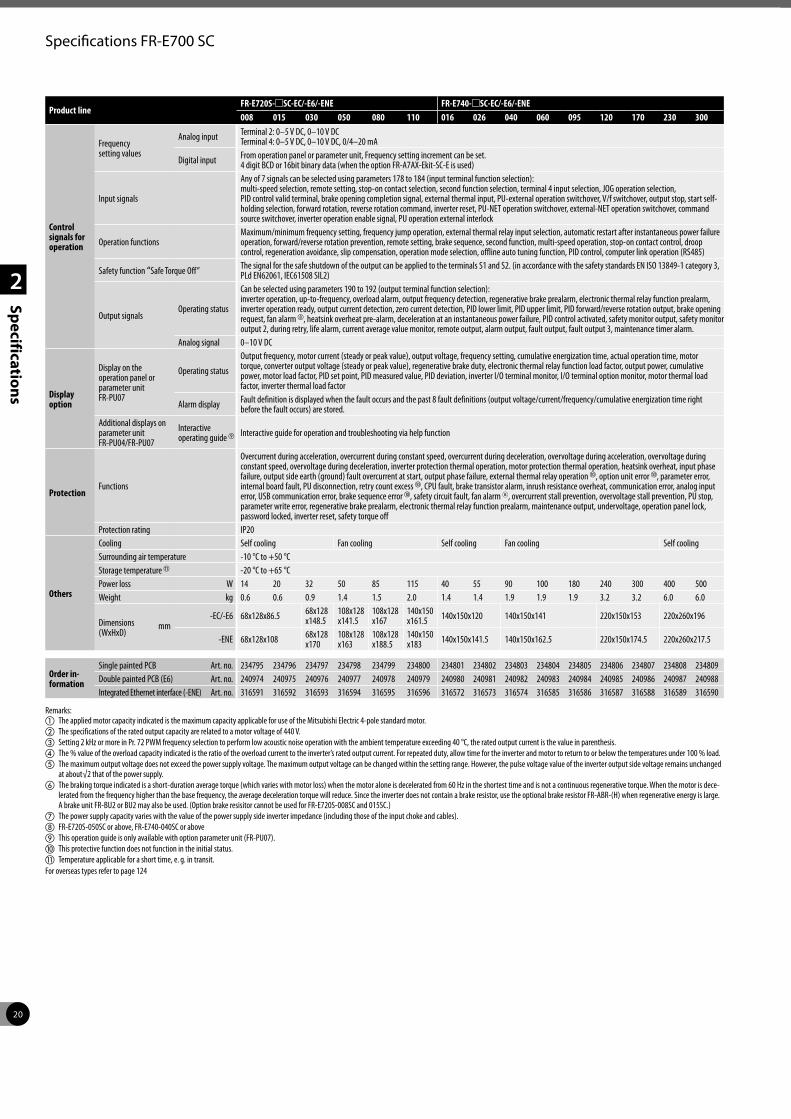
20
2
Specifications
Specifications FR-E700 SC
Product lineFR-E720S-mSC-EC/-E6/-ENE FR-E740-mSC-EC/-E6/-ENE008 015 030 050 080 110 016 026 040 060 095 120 170 230 300
Control signals for operation
Frequency setting values
Analog input Terminal 2: 0–5 V DC, 0–10 V DCTerminal 4: 0–5 V DC, 0–10 V DC, 0/4–20 mA
Digital input From operation panel or parameter unit, Frequency setting increment can be set. 4 digit BCD or 16bit binary data (when the option FR-A7AX-Ekit-SC-E is used)
Input signals
Any of 7 signals can be selected using parameters 178 to 184 (input terminal function selection): multi-speed selection, remote setting, stop-on contact selection, second function selection, terminal 4 input selection, JOG operation selection, PID control valid terminal, brake opening completion signal, external thermal input, PU-external operation switchover, V/f switchover, output stop, start self-holding selection, forward rotation, reverse rotation command, inverter reset, PU-NET operation switchover, external-NET operation switchover, command source switchover, inverter operation enable signal, PU operation external interlock
Operation functionsMaximum/minimum frequency setting, frequency jump operation, external thermal relay input selection, automatic restart after instantaneous power failure operation, forward/reverse rotation prevention, remote setting, brake sequence, second function, multi-speed operation, stop-on contact control, droop control, regeneration avoidance, slip compensation, operation mode selection, offline auto tuning function, PID control, computer link operation (RS485)
Safety function “Safe Torque Off” The signal for the safe shutdown of the output can be applied to the terminals S1 and S2. (in accordance with the safety standards EN ISO 13849-1 category 3, PLd EN62061, IEC61508 SIL2)
Output signalsOperating status
Can be selected using parameters 190 to 192 (output terminal function selection):inverter operation, up-to-frequency, overload alarm, output frequency detection, regenerative brake prealarm, electronic thermal relay function prealarm, inverter operation ready, output current detection, zero current detection, PID lower limit, PID upper limit, PID forward/reverse rotation output, brake opening request, fan alarm h, heatsink overheat pre-alarm, deceleration at an instantaneous power failure, PID control activated, safety monitor output, safety monitor output 2, during retry, life alarm, current average value monitor, remote output, alarm output, fault output, fault output 3, maintenance timer alarm.
Analog signal 0–10 V DC
Displayoption
Display on the operation panel or parameter unit FR-PU07
Operating status
Output frequency, motor current (steady or peak value), output voltage, frequency setting, cumulative energization time, actual operation time, motor torque, converter output voltage (steady or peak value), regenerative brake duty, electronic thermal relay function load factor, output power, cumulative power, motor load factor, PID set point, PID measured value, PID deviation, inverter I/O terminal monitor, I/O terminal option monitor, motor thermal load factor, inverter thermal load factor
Alarm display Fault definition is displayed when the fault occurs and the past 8 fault definitions (output voltage/current/frequency/cumulative energization time right before the fault occurs) are stored.
Additional displays on parameter unit FR-PU04/FR-PU07
Interactive operating guide i Interactive guide for operation and troubleshooting via help function
ProtectionFunctions
Overcurrent during acceleration, overcurrent during constant speed, overcurrent during deceleration, overvoltage during acceleration, overvoltage during constant speed, overvoltage during deceleration, inverter protection thermal operation, motor protection thermal operation, heatsink overheat, input phase failure, output side earth (ground) fault overcurrent at start, output phase failure, external thermal relay operation j, option unit error j, parameter error, internal board fault, PU disconnection, retry count excess j, CPU fault, brake transistor alarm, inrush resistance overheat, communication error, analog input error, USB communication error, brake sequence error j, safety circuit fault, fan alarm 8, overcurrent stall prevention, overvoltage stall prevention, PU stop, parameter write error, regenerative brake prealarm, electronic thermal relay function prealarm, maintenance output, undervoltage, operation panel lock, password locked, inverter reset, safety torque off
Protection rating IP20
Others
Cooling Self cooling Fan cooling Self cooling Fan cooling Self coolingSurrounding air temperature -10 °C to +50 °CStorage temperature k -20 °C to +65 °CPower loss W 14 20 32 50 85 115 40 55 90 100 180 240 300 400 500Weight kg 0.6 0.6 0.9 1.4 1.5 2.0 1.4 1.4 1.9 1.9 1.9 3.2 3.2 6.0 6.0
Dimensions (WxHxD)
mm-EC/-E6 68x128x86.5 68x128
x148.5108x128 x141.5
108x128 x167
140x150 x161.5 140x150x120 140x150x141 220x150x153 220x260x196
-ENE 68x128x108 68x128 x170
108x128 x163
108x128 x188.5
140x150 x183 140x150x141.5 140x150x162.5 220x150x174.5 220x260x217.5
Order in- formation
Single painted PCB Art. no. 234795 234796 234797 234798 234799 234800 234801 234802 234803 234804 234805 234806 234807 234808 234809Double painted PCB (E6) Art. no. 240974 240975 240976 240977 240978 240979 240980 240981 240982 240983 240984 240985 240986 240987 240988Integrated Ethernet interface (-ENE) Art. no. 316591 316592 316593 316594 316595 316596 316572 316573 316574 316585 316586 316587 316588 316589 316590
Remarks:a The applied motor capacity indicated is the maximum capacity applicable for use of the Mitsubishi Electric 4-pole standard motor.b The specifications of the rated output capacity are related to a motor voltage of 440 V.c Setting 2 kHz or more in Pr. 72 PWM frequency selection to perform low acoustic noise operation with the ambient temperature exceeding 40 °C, the rated output current is the value in parenthesis.d The % value of the overload capacity indicated is the ratio of the overload current to the inverter’s rated output current. For repeated duty, allow time for the inverter and motor to return to or below the temperatures under 100 % load.e The maximum output voltage does not exceed the power supply voltage. The maximum output voltage can be changed within the setting range. However, the pulse voltage value of the inverter output side voltage remains unchanged
at about√2 that of the power supply.f The braking torque indicated is a short-duration average torque (which varies with motor loss) when the motor alone is decelerated from 60 Hz in the shortest time and is not a continuous regenerative torque. When the motor is dece-
lerated from the frequency higher than the base frequency, the average deceleration torque will reduce. Since the inverter does not contain a brake resistor, use the optional brake resistor FR-ABR-(H) when regenerative energy is large. A brake unit FR-BU2 or BU2 may also be used. (Option brake resisitor cannot be used for FR-E720S-008SC and 015SC.)
g The power supply capacity varies with the value of the power supply side inverter impedance (including those of the input choke and cables).h FR-E720S-050SC or above, FR-E740-040SC or abovei This operation guide is only available with option parameter unit (FR-PU07).j This protective function does not function in the initial status.k Temperature applicable for a short time, e. g. in transit.For overseas types refer to page 124
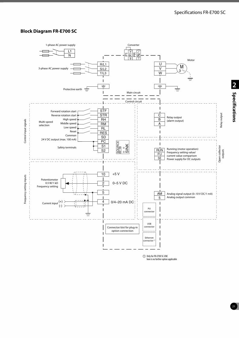
21
2
Specifications
Specifications FR-E700 SC
Block Diagram FR-E700 SC
10
2
5
4(+)(-)
UVW
RUNFUSE
P1
PR
PC
STFSTRRHRMRL
RESSD
0/4–20 mA DC
0–5 V DC
+5 V
R/L1S/L2T/L3
S1S2
–(N/–
)
+(P/+
)
SO
UR
CE
SIN
K
Cont
rol i
nput
sig
nals
Freq
uenc
y se
ttin
g in
puts
1-phase AC power supply
3-phase AC power supply
Protective earth
Forward rotation startReverse rotation start
High speedMiddle speed
Low speedReset
Common24 V DC output (max. 100 mA)
Safety terminals
Multi-speed selection
Converter
Main circuit
Control circuit
Motor
Relay output (alarm output)
Potentiometer0.5 W/1 kΩ
Frequency setting
Current input
Running (motor operation) Frequency setting value/ current value comparison Power supply for OC outputs
Analog signal output (0–10 V DC/1 mA) Analog output common
Connector/slot for plug-in option connection
Rela
y ou
tput
Ope
n co
llect
or
outp
uts
PU connector
USB connector
Ethernet connector 1
a Only for FR-E700 SC-ENE here is no further option applicable
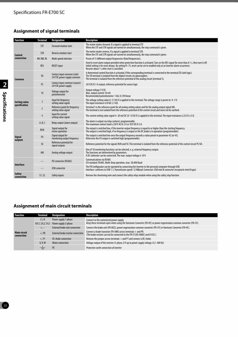
22
2
Specifications
Specifications FR-E700 SC
Assignment of signal terminals
Assignment of main circuit terminals
Function Terminal Designation Description
Main circuit connection
L1, N Power supply 1-phase Connect to the commercial power supply.Keep these terminals open when using the Harmonic Converter (FR-HC) or power regeneration common converter (FR-CV). R/L1, S/L2, T/L3 Power supply 3-phase
+, − External brake unit connection Connect the brake unit (FR-BU2), power regeneration common converter (FR-CV) or Harmonic Converter (FR-HC).
+, PR External brake resistor connection Connect a brake transistor (FR-ABR) across terminals + and PR. (The brake resistor can not be connected to the FR-E720S-008SC and 015SC.)
+, P1 DC choke connection Remove the jumper across terminals + and P1 and connect a DC choke.U, V, W Motor connection Voltage output of the inverter (3-phase, 0 V up to power supply voltage, 0.2–400 Hz)
PE Protective earth connection of inverter
Function Terminal Designation Description
Control connection
STF Forward rotation start The motor rotates forward, if a signal is applied to terminal STF. When the STF and STR signals are turned on simultaneously, the stop command is given.
STR Reverse rotation start The motor rotates reverse, if a signal is applied to terminal STR. When the STF and STR signals are turned on simultaneously, the stop command is given.
RH, RM, RL Multi-speed selection Preset of 15 different output frequencies (fixed frequencies).
RES RESET inputUsed to reset alarm output provided when protective function is activated. Turn on the RES signal for more than 0.1 s, then turn it off. Initial setting is for reset always. By setting Pr. 75, reset can be set to enabled only at an inverter alarm occurrence. Recover about 1 s after reset is cancelled.
CommonSD Contact input common (sink)
24 V DC power supply common
A determined control function is activated, if the corresponding terminal is connected to the terminal SD (sink logic). The SD terminal is isolated from the digital circuits via optocouplers. The terminal is isolated from the reference potential of the analog circuit (terminal 5).
PC Contact input common (source) 24 V DC power supply 24 V DC/0.1 A output; reference potential for source logic
Setting value specification
10 Voltage output for potentiometer
Output voltage 5 V DC Max. output current 10 mA Recommended potentiometer: 1 kΩ, 0.5 W linear
2 Input for frequency setting value signal
The voltage setting value 0–5 (10) V is applied to this terminal. The voltage range is preset to 0–5 V. The input resistance is10 kΩ ±1 kΩ.
5 Reference point for frequency setting value signal
Terminal 5 is the reference point for all analog setting values and for the analog output signal AM. The terminal is not isolated from the reference potential of the control circuit and must not be earthed.
4 Input for current setting value signal The current setting value signal 4–20 mA DC (0–5(10) V) is applied to this terminal. The input resistance is 233 Ω ±5 Ω.
Signal outputs
A, B, C Relay output (alarm output) The alarm is output via relay contacts; programmable. The maximum contact load is 230 V AC/0.3 A or 30 V DC/0.3 A.
RUN Signal output for motor operation
The output is switched low, if the inverter output frequency is equal to or higher than the starting frequency. The output is switched high, if no frequency is output or the DC brake is in operation (programmable).
FU Signal output for monitoring output frequency
The output is switched low once the output frequency exceeds a value preset in parameter 42 (or 43). Otherwise the FU output is switched high (programmable).
SE Reference potential for signal outputs Reference potential for the signals RUN and FU. This terminal is isolated from the reference potential of the control circuit PC/SD.
AM Analog voltage outputOne of 18 monitoring functions can be selected, e. g. external frequency output. The functions are determined by parameters. A DC voltmeter can be connected. The max. output voltage is 10 V.
Interface— PU connector (RS485) Communications via RS485
I/O standard: RS485, Multi-Drop operation, max. 38,400 Baud
— USB connector The FR Configurator can be operated by connecting the inverter to the personal computer through USB.Interface: conforms to USB 1.1; Transmission speed: 12 MBaud; Connector: USB mini B connector (receptacle mini B type)
Safety connection S1, S2 Safety inputs Remove the shortening wire and connect the safety relay module when using the safety stop function.
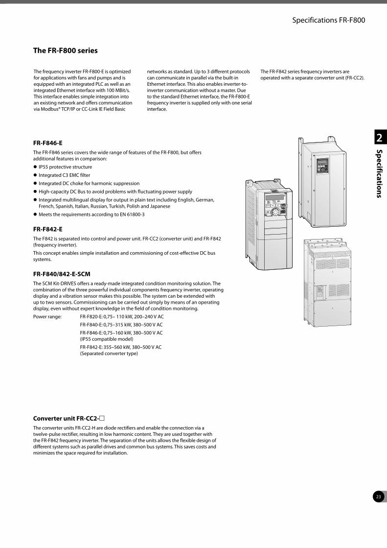
23
2
Specifications
Specifications FR-F800
The FR-F800 series
FR-F846-EThe FR-F846 series covers the wide range of features of the FR-F800, but offers additional features in comparison:
z IP55 protective structure
z Integrated C3 EMC filter
z Integrated DC choke for harmonic suppression
z High-capacity DC Bus to avoid problems with fluctuating power supply
z Integrated multilingual display for output in plain text including English, German, French, Spanish, Italian, Russian, Turkish, Polish and Japanese
z Meets the requirements according to EN 61800-3
FR-F842-EThe F842 is separated into control and power unit. FR-CC2 (converter unit) and FR-F842 (frequency inverter).
This concept enables simple installation and commissioning of cost-effective DC bus systems.
FR-F840/842-E-SCMThe SCM Kit-DRIVES offers a ready-made integrated condition monitoring solution. The combination of the three powerful individual components frequency inverter, operating display and a vibration sensor makes this possible. The system can be extended with up to two sensors. Commissioning can be carried out simply by means of an operating display, even without expert knowledge in the field of condition monitoring.
Power range: FR-F820-E: 0,75– 110 kW, 200–240 V AC
FR-F840-E: 0,75–315 kW, 380–500 V AC
FR-F846-E: 0,75–160 kW, 380–500 V AC (IP55 compatible model)
FR-F842-E: 355–560 kW, 380–500 V AC (Separated converter type)
The frequency inverter FR-F800-E is optimized for applications with fans and pumps and is equipped with an integrated PLC as well as an integrated Ethernet interface with 100 MBit/s. This interface enables simple integration into an existing network and offers communication via Modbus® TCP/IP or CC-Link IE Field Basic
networks as standard. Up to 3 different protocols can communicate in parallel via the built-in Ethernet interface. This also enables inverter-to-inverter communication without a master. Due to the standard Ethernet interface, the FR-F800-E frequency inverter is supplied only with one serial interface.
The FR-F842 series frequency inverters are operated with a separate converter unit (FR-CC2).
Converter unit FR-CC2-mThe converter units FR-CC2-H are diode rectifiers and enable the connection via a twelve-pulse rectifier, resulting in low harmonic content. They are used together with the FR-F842 frequency inverter. The separation of the units allows the flexible design of different systems such as parallel drives and common bus systems. This saves costs and minimizes the space required for installation.
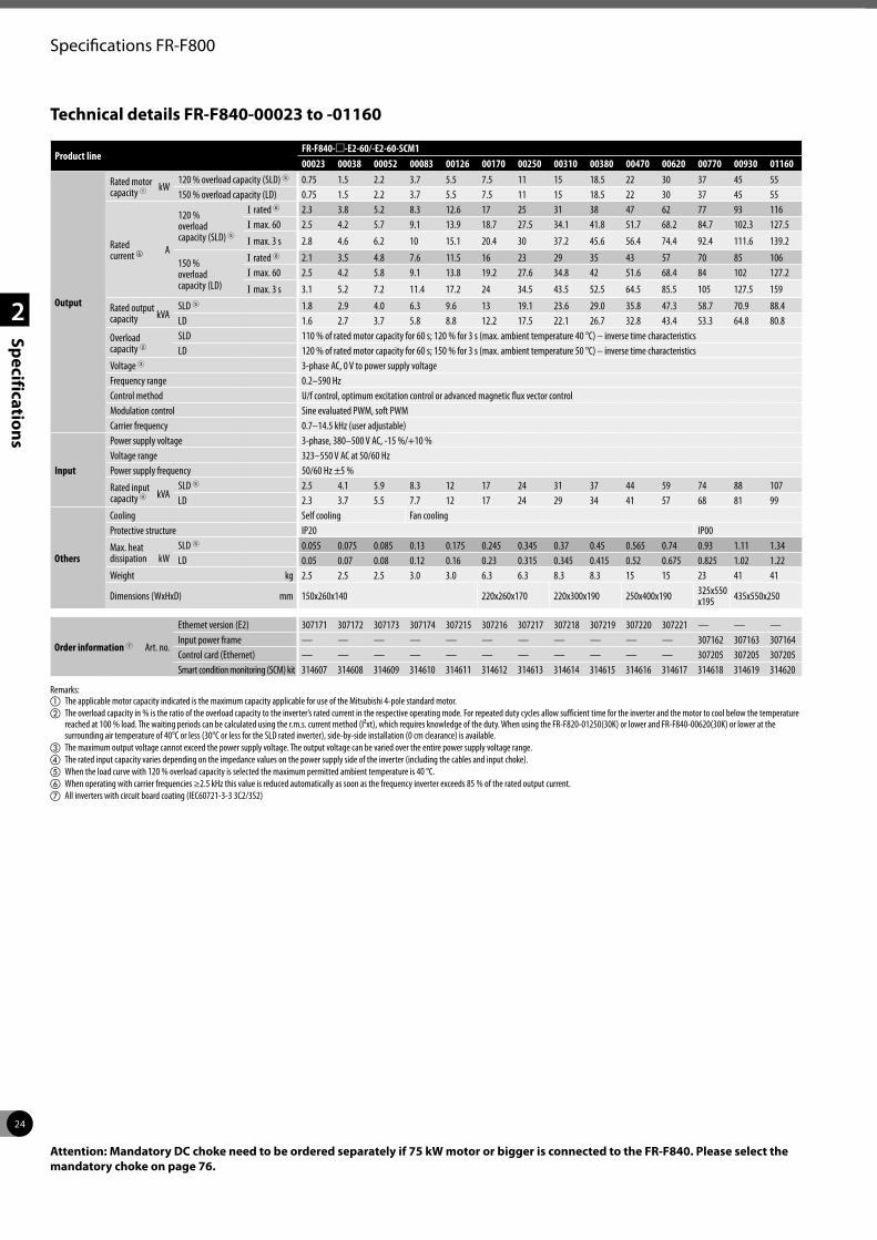
24
2
Specifications
Specifications FR-F800
Technical details FR-F840-00023 to -01160
Product lineFR-F840-m-E2-60/-E2-60-SCM100023 00038 00052 00083 00126 00170 00250 00310 00380 00470 00620 00770 00930 01160
Output
Rated motor capacity 1 kW
120 % overload capacity (SLD) 5 0.75 1.5 2.2 3.7 5.5 7.5 11 15 18.5 22 30 37 45 55150 % overload capacity (LD) 0.75 1.5 2.2 3.7 5.5 7.5 11 15 18.5 22 30 37 45 55
Rated current f A
120 % overload capacity (SLD) 5
I rated 6 2.3 3.8 5.2 8.3 12.6 17 25 31 38 47 62 77 93 116I max. 60 2.5 4.2 5.7 9.1 13.9 18.7 27.5 34.1 41.8 51.7 68.2 84.7 102.3 127.5
I max. 3 s 2.8 4.6 6.2 10 15.1 20.4 30 37.2 45.6 56.4 74.4 92.4 111.6 139.2
150 % overload capacity (LD)
I rated 6 2.1 3.5 4.8 7.6 11.5 16 23 29 35 43 57 70 85 106I max. 60 2.5 4.2 5.8 9.1 13.8 19.2 27.6 34.8 42 51.6 68.4 84 102 127.2
I max. 3 s 3.1 5.2 7.2 11.4 17.2 24 34.5 43.5 52.5 64.5 85.5 105 127.5 159
Rated output capacity kVA
SLD 5 1.8 2.9 4.0 6.3 9.6 13 19.1 23.6 29.0 35.8 47.3 58.7 70.9 88.4LD 1.6 2.7 3.7 5.8 8.8 12.2 17.5 22.1 26.7 32.8 43.4 53.3 64.8 80.8
Overload capacity 2
SLD 110 % of rated motor capacity for 60 s; 120 % for 3 s (max. ambient temperature 40 °C) – inverse time characteristicsLD 120 % of rated motor capacity for 60 s; 150 % for 3 s (max. ambient temperature 50 °C) – inverse time characteristics
Voltage 3 3-phase AC, 0 V to power supply voltageFrequency range 0.2–590 HzControl method U/f control, optimum excitation control or advanced magnetic flux vector controlModulation control Sine evaluated PWM, soft PWMCarrier frequency 0.7–14.5 kHz (user adjustable)
Input
Power supply voltage 3-phase, 380–500 V AC, -15 %/+10 %Voltage range 323–550 V AC at 50/60 HzPower supply frequency 50/60 Hz ±5 %
Rated input capacity 4 kVA
SLD 5 2.5 4.1 5.9 8.3 12 17 24 31 37 44 59 74 88 107LD 2.3 3.7 5.5 7.7 12 17 24 29 34 41 57 68 81 99
Others
Cooling Self cooling Fan coolingProtective structure IP20 IP00
Max. heat dissipation kW
SLD 5 0.055 0.075 0.085 0.13 0.175 0.245 0.345 0.37 0.45 0.565 0.74 0.93 1.11 1.34LD 0.05 0.07 0.08 0.12 0.16 0.23 0.315 0.345 0.415 0.52 0.675 0.825 1.02 1.22
Weight kg 2.5 2.5 2.5 3.0 3.0 6.3 6.3 8.3 8.3 15 15 23 41 41
Dimensions (WxHxD) mm 150x260x140 220x260x170 220x300x190 250x400x190 325x550 x195 435x550x250
Order information 7 Art. no.
Ethernet version (E2) 307171 307172 307173 307174 307215 307216 307217 307218 307219 307220 307221 — — —Input power frame — — — — — — — — — — — 307162 307163 307164Control card (Ethernet) — — — — — — — — — — — 307205 307205 307205Smart condition monitoring (SCM) kit 314607 314608 314609 314610 314611 314612 314613 314614 314615 314616 314617 314618 314619 314620
Remarks:a The applicable motor capacity indicated is the maximum capacity applicable for use of the Mitsubishi 4-pole standard motor.b The overload capacity in % is the ratio of the overload capacity to the inverter’s rated current in the respective operating mode. For repeated duty cycles allow sufficient time for the inverter and the motor to cool below the temperature
reached at 100 % load. The waiting periods can be calculated using the r.m.s. current method (I²xt), which requires knowledge of the duty. When using the FR-F820-01250(30K) or lower and FR-F840-00620(30K) or lower at the surrounding air temperature of 40°C or less (30°C or less for the SLD rated inverter), side-by-side installation (0 cm clearance) is available.
c The maximum output voltage cannot exceed the power supply voltage. The output voltage can be varied over the entire power supply voltage range. d The rated input capacity varies depending on the impedance values on the power supply side of the inverter (including the cables and input choke).e When the load curve with 120 % overload capacity is selected the maximum permitted ambient temperature is 40 °C.f When operating with carrier frequencies ≥2.5 kHz this value is reduced automatically as soon as the frequency inverter exceeds 85 % of the rated output current.g All inverters with circuit board coating (IEC60721-3-3 3C2/3S2)
Attention: Mandatory DC choke need to be ordered separately if 75 kW motor or bigger is connected to the FR-F840. Please select the mandatory choke on page 76.
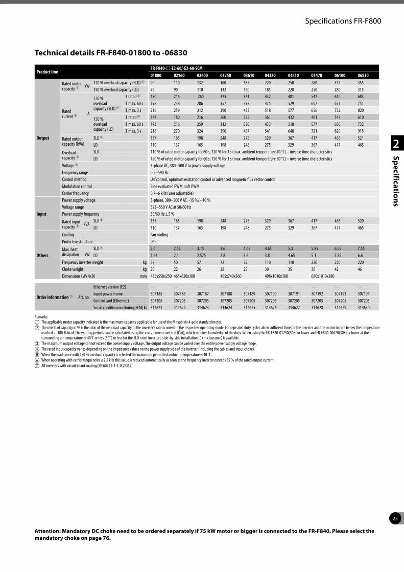
25
2
Specifications
Specifications FR-F800
Product lineFR-F840-m-E2-60/-E2-60-SCM01800 02160 02600 03250 03610 04320 04810 05470 06100 06830
Output
Rated motor capacity 1 kW
120 % overload capacity (SLD) 5 90 110 132 160 185 220 250 280 315 355150 % overload capacity (LD) 75 90 110 132 160 185 220 250 280 315
Rated current 6 A
120 % overload capacity (SLD) 5
I rated 6 180 216 260 325 361 432 481 547 610 683I max. 60 s 198 238 286 357 397 475 529 602 671 751I max. 3 s 216 259 312 390 433 518 577 656 732 820
150 % overload capacity (LD)
I rated 6 144 180 216 260 325 361 432 481 547 610I max. 60 s 173 216 259 312 390 433 518 577 656 732I max. 3 s 216 270 324 390 487 541 648 721 820 915
Rated output capacity [kVA]
SLD 5 137 165 198 248 275 329 367 417 465 521LD 110 137 165 198 248 275 329 367 417 465
Overload capacity 2
SLD 110 % of rated motor capacity for 60 s; 120 % for 3 s (max. ambient temperature 40 °C) – inverse time characteristicsLD 120 % of rated motor capacity for 60 s; 150 % for 3 s (max. ambient temperature 50 °C) – inverse time characteristics
Voltage 3 3-phase AC, 380–500 V to power supply voltageFrequency range 0.2–590 HzControl method U/f control, optimum excitation control or advanced magnetic flux vector controlModulation control Sine evaluated PWM, soft PWMCarrier frequency 0.7–6 kHz (user adjustable)
Input
Power supply voltage 3-phase, 380–500 V AC, -15 %/+10 %Voltage range 323–550 V AC at 50/60 HzPower supply frequency 50/60 Hz ±5 %
Rated input capacity 4 kVA
SLD 5 137 165 198 248 275 329 367 417 465 520LD 110 137 165 198 248 275 329 367 417 465
Others
Cooling Fan coolingProtective structure IP00
Max. heat dissipation kW
SLD 5 2.0 2.52 3.15 3.6 4.05 4.65 5.3 5.85 6.65 7.55LD 1.64 2.1 2.575 2.8 3.6 3.8 4.65 5.1 5.85 6.6
Frequency inverter weight kg 37 50 57 72 72 110 110 220 220 220Choke weight kg 20 22 26 28 29 30 35 38 42 46Dimensions (WxHxD) mm 435x550x250 465x620x300 465x740x360 498x1010x380 680x1010x380
Order information 7 Art. no.
Ethernet version (E2) — — — — — — — — — —Input power frame 307185 307186 307187 307188 307189 307190 307191 307192 307193 307194Control card (Ethernet) 307205 307205 307205 307205 307205 307205 307205 307205 307205 307205Smart condition monitoring (SCM) kit 314621 314622 314623 314624 314625 314626 314627 314628 314629 314630
Remarks:a The applicable motor capacity indicated is the maximum capacity applicable for use of the Mitsubishi 4-pole standard motor.b The overload capacity in % is the ratio of the overload capacity to the inverter’s rated current in the respective operating mode. For repeated duty cycles allow sufficient time for the inverter and the motor to cool below the temperature
reached at 100 % load. The waiting periods can be calculated using the r.m.s. current method (I²xt), which requires knowledge of the duty. When using the FR-F820-01250(30K) or lower and FR-F840-00620(30K) or lower at the surrounding air temperature of 40°C or less (30°C or less for the SLD rated inverter), side-by-side installation (0 cm clearance) is available.
c The maximum output voltage cannot exceed the power supply voltage. The output voltage can be varied over the entire power supply voltage range. d The rated input capacity varies depending on the impedance values on the power supply side of the inverter (including the cables and input choke).e When the load curve with 120 % overload capacity is selected the maximum permitted ambient temperature is 40 °C.f When operating with carrier frequencies ≥2.5 kHz this value is reduced automatically as soon as the frequency inverter exceeds 85 % of the rated output current.g All inverters with circuit board coating (IEC60721-3-3 3C2/3S2)
Technical details FR-F840-01800 to -06830
Attention: Mandatory DC choke need to be ordered separately if 75 kW motor or bigger is connected to the FR-F840. Please select the mandatory choke on page 76.
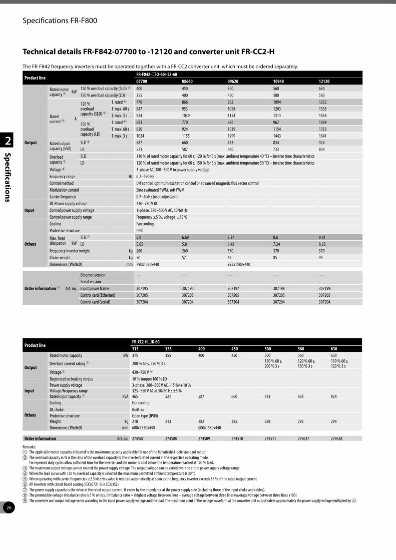
26
2
Specifications
Specifications FR-F800
Product lineFR-F842-m-2-60/-E2-6007700 08660 09620 10940 12120
Output
Rated motor capacity 1 kW
120 % overload capacity (SLD) 5 400 450 500 560 630150 % overload capacity (LD) 355 400 450 500 560
Rated current 6 A
120 % overload capacity (SLD) 5
I rated 6 770 866 962 1094 1212I max. 60 s 847 953 1058 1203 1333I max. 3 s 924 1039 1154 1313 1454
150 % overload capacity (LD)
I rated 6 683 770 866 962 1094I max. 60 s 820 924 1039 1154 1313I max. 3 s 1024 1155 1299 1443 1641
Rated output capacity [kVA]
SLD 5 587 660 733 834 924LD 521 587 660 733 834
Overload capacity 2
SLD 110 % of rated motor capacity for 60 s; 120 % for 3 s (max. ambient temperature 40 °C) – inverse time characteristicsLD 120 % of rated motor capacity for 60 s; 150 % for 3 s (max. ambient temperature 50 °C) – inverse time characteristics
Voltage 3 3-phase AC, 380–500 V to power supply voltageFrequency range Hz 0.2–590 HzControl method U/f control, optimum excitation control or advanced magnetic flux vector controlModulation control Sine evaluated PWM, soft PWMCarrier frequency 0.7–6 kHz (user adjustable)
InputDC Power supply voltage 430–780 V DCControl power supply voltage 1-phase, 380–500 V AC, 50/60 Hz Control power supply range Frequency ±5 %, voltage ±10 %
Others
Cooling Fan coolingProtective structure IP00
Max. heat dissipation kW
SLD 5 5.8 6.69 7.37 8.6 9.81LD 5.05 5.8 6.48 7.34 8.63
Frequency inverter weight kg 260 260 370 370 370Choke weight kg 50 57 67 85 95Dimensions (WxHxD) mm 790x1330x440 995x1580x440
Order information 7 Art. no.
Ethernet version — — — — —Serial version — — — — —Input power frame 307195 307196 307197 307198 307199Control card (Ethernet) 307205 307205 307205 307205 307205Control card (serial) 307204 307204 307204 307204 307204
Technical details FR-F842-07700 to -12120 and converter unit FR-CC2-H
The FR-F842 frequency inverters must be operated together with a FR-CC2 converter unit, which must be ordered separately.
Product lineFR-CC2-HmK-60315 355 400 450 500 560 630
Output
Rated motor capacity kW 315 355 400 450 500 560 630
Overload current rating 1 200 % 60 s, 250 % 3 s 150 % 60 s,200 % 3 s
120 % 60 s,150 % 3 s
110 % 60 s,120 % 3 s
Voltage 2 430–780 V 8
Regenerative braking torque 10 % torque/100 % ED
InputPower supply voltage 3-phase, 380–500 V AC, -15 %/+10 %Voltage/frequency range 323–550 V AC at 50/60 Hz ±5 %Rated input capacity 7 kVA 465 521 587 660 733 833 924
Others
Cooling Fan coolingDC choke Built-inProtective structure Open type (IP00)Weight kg 210 213 282 285 288 293 294Dimensions (WxHxD) mm 600x1330x440 600x1580x440
Order information Art. no. 274507 274508 274509 274510 274511 279637 279638
Remarks:a The applicable motor capacity indicated is the maximum capacity applicable for use of the Mitsubishi 4-pole standard motor.b The overload capacity in % is the ratio of the overload capacity to the inverter’s rated current in the respective operating mode.
For repeated duty cycles allow sufficient time for the inverter and the motor to cool below the temperature reached at 100 % load. c The maximum output voltage cannot exceed the power supply voltage. The output voltage can be varied over the entire power supply voltage range. d When the load curve with 120 % overload capacity is selected the maximum permitted ambient temperature is 30 °C.e When operating with carrier frequencies ≥2.5 kHz this value is reduced automatically as soon as the frequency inverter exceeds 85 % of the rated output current.f All inverters with circuit board coating (IEC60721-3-3 3C2/3S2)g The power supply capacity is the value at the rated output current. It varies by the impedance at the power supply side (including those of the input choke and cables).h The permissible voltage imbalance ratio is 3 % or less. (Imbalance ratio = (highest voltage between lines – average voltage between three lines)/average voltage between three lines x100)i The converter unit output voltage varies according to the input power supply voltage and the load. The maximum point of the voltage waveform at the converter unit output side is approximately the power supply voltage multiplied by √2.
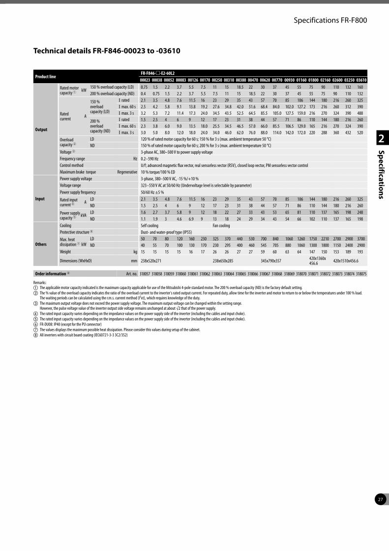
27
2
Specifications
Specifications FR-F800
Product lineFR-F846-m-E2-60L2
00023 00038 00052 00083 00126 00170 00250 00310 00380 00470 00620 00770 00930 01160 01800 02160 02600 03250 03610
Output
Rated motor capacity 1 kW
150 % overload capacity (LD) 0.75 1.5 2.2 3.7 5.5 7.5 11 15 18.5 22 30 37 45 55 75 90 110 132 160200 % overload capacity (ND) 0.4 0.75 1.5 2.2 3.7 5.5 7.5 11 15 18.5 22 30 37 45 55 75 90 110 132
Rated current A
150 % overload capacity (LD)
I rated 2.1 3.5 4.8 7.6 11.5 16 23 29 35 43 57 70 85 106 144 180 216 260 325I max. 60 s 2.5 4.2 5.8 9.1 13.8 19.2 27.6 34.8 42.0 51.6 68.4 84.0 102.0 127.2 173 216 260 312 390I max. 3 s 3.2 5.3 7.2 11.4 17.3 24.0 34.5 43.5 52.5 64.5 85.5 105.0 127.5 159.0 216 270 324 390 488
200 % overload capacity (ND)
I rated 1.5 2.5 4 6 9 12 17 23 31 38 44 57 71 86 110 144 180 216 260I max. 60 s 2.3 3.8 6.0 9.0 13.5 18.0 25.5 34.5 46.5 57.0 66.0 85.5 106.5 129.0 165 216 270 324 390I max. 3 s 3.0 5.0 8.0 12.0 18.0 24.0 34.0 46.0 62.0 76.0 88.0 114.0 142.0 172.0 220 288 360 432 520
Overload capacity 2
LD 120 % of rated motor capacity for 60 s; 150 % for 3 s (max. ambient temperature 50 °C)ND 150 % of rated motor capacity for 60 s; 200 % for 3 s (max. ambient temperature 50 °C)
Voltage 3 3-phase AC, 380–500 V to power supply voltageFrequency range Hz 0.2–590 HzControl method U/f; advanced magnetic flux vector, real sensorless vector (RSV), closed loop vector, PM sensorless vector controlMaximum brake torque Regenerative 10 % torque/100 % ED
Input
Power supply voltage 3-phase, 380–500 V AC, -15 %/+10 %Voltage range 323–550 V AC at 50/60 Hz (Undervoltage level is selectable by parameter)Power supply frequency 50/60 Hz ±5 %
Rated input current 4 A
LD 2.1 3.5 4.8 7.6 11.5 16 23 29 35 43 57 70 85 106 144 180 216 260 325ND 1.5 2.5 4 6 9 12 17 23 31 38 44 57 71 86 110 144 180 216 260
Power supply capacity 5 kVA
LD 1.6 2.7 3.7 5.8 9 12 18 22 27 33 43 53 65 81 110 137 165 198 248ND 1.1 1.9 3 4.6 6.9 9 13 18 24 29 34 43 54 66 102 110 137 165 198
Others
Cooling Self cooling Fan coolingProtective structure 6 Dust- and water-proof type (IP55)Max. heat dissipation 7 kW
LD 50 70 80 120 160 230 325 370 440 530 700 840 1060 1260 1750 2210 2700 2900 3700ND 40 55 70 100 130 170 230 295 400 460 545 705 880 1060 1300 1800 1150 2400 2900
Weight kg 15 15 15 15 16 17 26 26 27 27 59 60 63 64 147 150 153 189 193
Dimensions (WxHxD) mm 238x520x271 238x650x285 345x790x357 420x1360x 456.6 420x1510x456.6
Order information 8 Art. no. 318057 318058 318059 318060 318061 318062 318063 318064 318065 318066 318067 318068 318069 318070 318071 318072 318073 318074 318075
Remarks:a The applicable motor capacity indicated is the maximum capacity applicable for use of the Mitsubishi 4-pole standard motor. The 200 % overload capacity (ND) is the factory default setting. b The % value of the overload capacity indicates the ratio of the overload current to the inverter's rated output current. For repeated duty, allow time for the inverter and motor to return to or below the temperatures under 100 % load.
The waiting periods can be calculated using the r.m.s. current method (I²xt), which requires knowledge of the duty.c The maximum output voltage does not exceed the power supply voltage. The maximum output voltage can be changed within the setting range.
However, the pulse voltage value of the inverter output side voltage remains unchanged at about √2 that of the power supply.d The rated input capacity varies depending on the impedance values on the power supply side of the inverter (including the cables and input choke).e The rated input capacity varies depending on the impedance values on the power supply side of the inverter (including the cables and input choke).f FR-DU08: IP40 (except for the PU connector)g The values displays the maximum possible heat dissipation. Please consider this values during setup of the cabinet.h All inverters with circuit board coating (IEC60721-3-3 3C2/3S2)
Technical details FR-F846-00023 to -03610
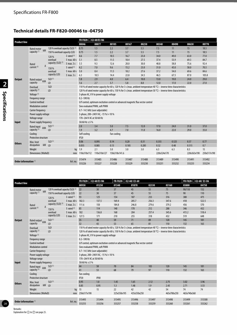
28
2
Specifications
Specifications FR-F800
Technical details FR-F820-00046 to -04750
Product lineFR-F820-m-E2-60/E3-N6 00046 00077 00105 00167 00250 00340 00490 00630 00770
Output
Rated motor capacity 1 kW
120 % overload capacity (SLD) 5 0.75 1.5 2.2 3.7 5.5 7.5 11 15 18.5 150 % overload capacity (LD) 0.75 1.5 2.2 3.7 5.5 7.5 11 15 18.5
Rated current 6 A
120 % overload capacity (SLD) 5
I rated 6 4.6 7.7 10.5 16.7 25.0 34.0 49.0 63.0 77.0I max. 60 s 5.1 8.5 11.5 18.4 27.5 37.4 53.9 69.3 84.7I max. 3 s 5.5 9.3 12.6 20.0 30.0 40.8 58.8 75.6 92.4
150 % overload capacity (LD)
I rated 6 4.2 7.0 9.6 15.2 23.0 31.0 45.0 58.0 70.5I max. 60 s 5.0 8.4 11.5 18.2 27.6 37.2 54.0 69.6 84.6I max. 3 s 6.3 10.5 14.4 22.8 34.5 46.5 67.5 87.0 105.8
Rated output capacity kVA
SLD 5 1.8 2.9 4.0 6.4 10.0 13.0 19.0 24.0 29.0LD 1.6 2.7 3.7 5.8 8.8 12.0 17.0 22.0 27.0
Overload capacity 2
SLD 110 % of rated motor capacity for 60 s; 120 % for 3 s (max. ambient temperature 40 °C) – inverse time characteristicsLD 120 % of rated motor capacity for 60 s; 150 % for 3 s (max. ambient temperature 50 °C) – inverse time characteristics
Voltage 3 3-phase AC, 0 V to power supply voltageFrequency range 0.2–590 HzControl method U/f control, optimum excitation control or advanced magnetic flux vector controlModulation control Sine evaluated PWM, soft PWMCarrier frequency 0.7–14.5 kHz (user adjustable)
Input
Power supply voltage 3-phase, 200–240 V AC, -15 %/+10 %Voltage range 170–264 V AC at 50/60 Hz Power supply frequency 50/60 Hz ±5 %
Rated input capacity 4 kVA
SLD 5 2.0 3.4 5.0 7.5 12.0 17.0 24.0 31.0 37.0LD 1.9 3.2 4.7 7.0 11.0 16.0 22.0 29.0 35.0
Others
Cooling Self cooling Fan coolingProtective structure IP20Max. heat dissipation kW
SLD 5 0.06 0.095 0.14 0.20 0.31 0.355 0.525 0.57 0.77LD 0.055 0.085 0.13 0.185 0.285 0.32 0.48 0.515 0.7
Weight kg 1.9 2.1 3.0 3.0 3.0 6.3 6.3 8.3 15Dimensions (WxHxD) mm 110x310x112 110x310x127 150x318x141.6 220x324x170 220x363x190 250x517x190
Order information 7 Art. no.315474 315485 315486 315487 315488 315489 315490 315491 315492333226 333227 333228 333229 333230 333231 333232 333233 333234
Product lineFR-F820-m-E2-60/E3-N6 FR-F820-m-E2-60/-E3-60 FR-F820-m-E2-60/-E3-U600930 01250 01540 01870 02330 03160 03800 04750
Output
Rated motor capacity 1 kW
120 % overload capacity (SLD) 5 22 30 37 45 55 75 90/110 132150 % overload capacity (LD) 22 30 37 45 55 75 90 110
Rated current 6 A
120 % overload capacity (SLD) 5
I rated 6 93 125 154 187 233 316 380 475I max. 60 s 102.3 137.5 169.4 205.7 256.3 347.6 418 522.5I max. 3 s 111.6 150 184.8 246.8 279.6 379.2 456 570
150 % overload capacity (LD)
I rated 6 85 114 140 170 212 288 346 432I max. 60 s 102 136.8 168 204 257.4 345.6 415.2 518.4I max. 3 s 127.5 171 210 255 318 432 519 648
Rated output capacity kVA
SLD 5 35 48 59 71 89 120 145 181LD 32 43 53 65 81 110 132 165
Overload capacity 2
SLD 110 % of rated motor capacity for 60 s; 120 % for 3 s (max. ambient temperature 40 °C) – inverse time characteristicsLD 120 % of rated motor capacity for 60 s; 150 % for 3 s (max. ambient temperature 50 °C) – inverse time characteristics
Voltage 3 3-phase AC, 0 V to power supply voltageFrequency range 0.2–590 HzControl method U/f control, optimum excitation control or advanced magnetic flux vector controlModulation control Sine evaluated PWM, soft PWMCarrier frequency 0.7–14.5 kHz (user adjustable)
Input
Power supply voltage 3-phase, 200–240 V AC, -15 %/+10 %Voltage range 170–264 V AC at 50/60 Hz Power supply frequency 50/60 Hz ±5 %Rated input capacity 4 kVA
SLD 5 44 58 70 84 103 120 145 181LD 41 53 68 79 97 110 132 165
Others
Cooling Fan coolingProtective structure IP20 IP00Max. heat dissipation kW
SLD 5 0.95 1.0 1.45 1.65 2.12 2.75 3.02 3.96LD 0.85 0.95 1.3 1.48 1.9 2.45 2.71 3.53
Weight kg 15 15 22 42 42 54 74 74Dimensions (WxHxD) mm 250x517x190 325x550x195 435x550x250 465x700x250 465x740x360
Order information 7 Art. no.315493 315494 315495 315496 315497 315498 315499 315500333255 333256 333257 333258 333259 333260 333261 333262
Remarks:Explanation for a to g see page 25.
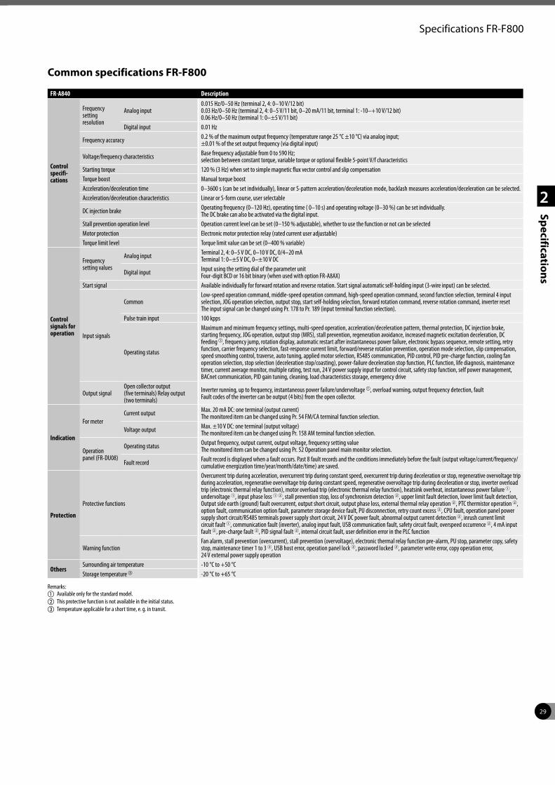
29
2
Specifications
Specifications FR-F800
Common specifications FR-F800
FR-A840 Description
Control specifi- cations
Frequency setting resolution
Analog input0.015 Hz/0–50 Hz (terminal 2, 4: 0–10 V/12 bit)0.03 Hz/0–50 Hz (terminal 2, 4: 0–5 V/11 bit, 0–20 mA/11 bit, terminal 1: -10–+10 V/12 bit)0.06 Hz/0–50 Hz (terminal 1: 0–±5 V/11 bit)
Digital input 0.01 Hz
Frequency accuracy 0.2 % of the maximum output frequency (temperature range 25 °C ±10 °C) via analog input; ±0.01 % of the set output frequency (via digital input)
Voltage/frequency characteristics Base frequency adjustable from 0 to 590 Hz; selection between constant torque, variable torque or optional flexible 5-point V/f characteristics
Starting torque 120 % (3 Hz) when set to simple magnetic flux vector control and slip compensationTorque boost Manual torque boostAcceleration/deceleration time 0–3600 s (can be set individually), linear or S-pattern acceleration/deceleration mode, backlash measures acceleration/deceleration can be selected.Acceleration/deceleration characteristics Linear or S-form course, user selectable
DC injection brake Operating frequency (0–120 Hz), operating time ( 0–10 s) and operating voltage (0–30 %) can be set individually. The DC brake can also be activated via the digital input.
Stall prevention operation level Operation current level can be set (0–150 % adjustable), whether to use the function or not can be selectedMotor protection Electronic motor protection relay (rated current user adjustable)Torque limit level Torque limit value can be set (0–400 % variable)
Control signals for operation
Frequency setting values
Analog input Terminal 2, 4: 0–5 V DC, 0–10 V DC, 0/4–20 mA Terminal 1: 0–±5 V DC, 0–±10 V DC
Digital input Input using the setting dial of the parameter unit Four-digit BCD or 16 bit binary (when used with option FR-A8AX)
Start signal Available individually for forward rotation and reverse rotation. Start signal automatic self-holding input (3-wire input) can be selected.
Input signals
CommonLow-speed operation command, middle-speed operation command, high-speed operation command, second function selection, terminal 4 input selection, JOG operation selection, output stop, start self-holding selection, forward rotation command, reverse rotation command, inverter reset The input signal can be changed using Pr. 178 to Pr. 189 (input terminal function selection).
Pulse train input 100 kpps
Operating status
Maximum and minimum frequency settings, multi-speed operation, acceleration/deceleration pattern, thermal protection, DC injection brake, starting frequency, JOG operation, output stop (MRS), stall prevention, regeneration avoidance, increased magnetic excitation deceleration, DC feeding a, frequency jump, rotation display, automatic restart after instantaneous power failure, electronic bypass sequence, remote setting, retry function, carrier frequency selection, fast-response current limit, forward/reverse rotation prevention, operation mode selection, slip compensation, speed smoothing control, traverse, auto tuning, applied motor selection, RS485 communication, PID control, PID pre-charge function, cooling fan operation selection, stop selection (deceleration stop/coasting), power-failure deceleration stop function, PLC function, life diagnosis, maintenance timer, current average monitor, multiple rating, test run, 24 V power supply input for control circuit, safety stop function, self power management, BACnet communication, PID gain tuning, cleaning, load characteristics storage, emergency drive
Output signalOpen collector output (five terminals) Relay output (two terminals)
Inverter running, up to frequency, instantaneous power failure/undervoltage a, overload warning, output frequency detection, fault Fault codes of the inverter can be output (4 bits) from the open collector.
Indication
For meterCurrent output Max. 20 mA DC: one terminal (output current)
The monitored item can be changed using Pr. 54 FM/CA terminal function selection.
Voltage output Max. ±10 V DC: one terminal (output voltage)The monitored item can be changed using Pr. 158 AM terminal function selection.
Operation panel (FR-DU08)
Operating status Output frequency, output current, output voltage, frequency setting valueThe monitored item can be changed using Pr. 52 Operation panel main monitor selection.
Fault record Fault record is displayed when a fault occurs. Past 8 fault records and the conditions immediately before the fault (output voltage/current/frequency/cumulative energization time/year/month/date/time) are saved.
Protection
Protective functions
Overcurrent trip during acceleration, overcurrent trip during constant speed, overcurrent trip during deceleration or stop, regenerative overvoltage trip during acceleration, regenerative overvoltage trip during constant speed, regenerative overvoltage trip during deceleration or stop, inverter overload trip (electronic thermal relay function), motor overload trip (electronic thermal relay function), heatsink overheat, instantaneous power failure 1, undervoltage 1, input phase loss 1 2, stall prevention stop, loss of synchronism detection 2, upper limit fault detection, lower limit fault detection, Output side earth (ground) fault overcurrent, output short circuit, output phase loss, external thermal relay operation 2, PTC thermistor operation 2, option fault, communication option fault, parameter storage device fault, PU disconnection, retry count excess 2, CPU fault, operation panel power supply short circuit/RS485 terminals power supply short circuit, 24 V DC power fault, abnormal output current detection 2, inrush current limit circuit fault 1, communication fault (inverter), analog input fault, USB communication fault, safety circuit fault, overspeed occurrence 2, 4 mA input fault 2, pre-charge fault 2, PID signal fault 2, internal circuit fault, user definition error in the PLC function
Warning functionFan alarm, stall prevention (overcurrent), stall prevention (overvoltage), electronic thermal relay function pre-alarm, PU stop, parameter copy, safety stop, maintenance timer 1 to 3 2, USB host error, operation panel lock 2, password locked 2, parameter write error, copy operation error, 24 V external power supply operation
OthersSurrounding air temperature -10 °C to +50 °CStorage temperature c -20 °C to +65 °C
Remarks:a Available only for the standard model.b This protective function is not available in the initial status.c Temperature applicable for a short time, e. g. in transit.
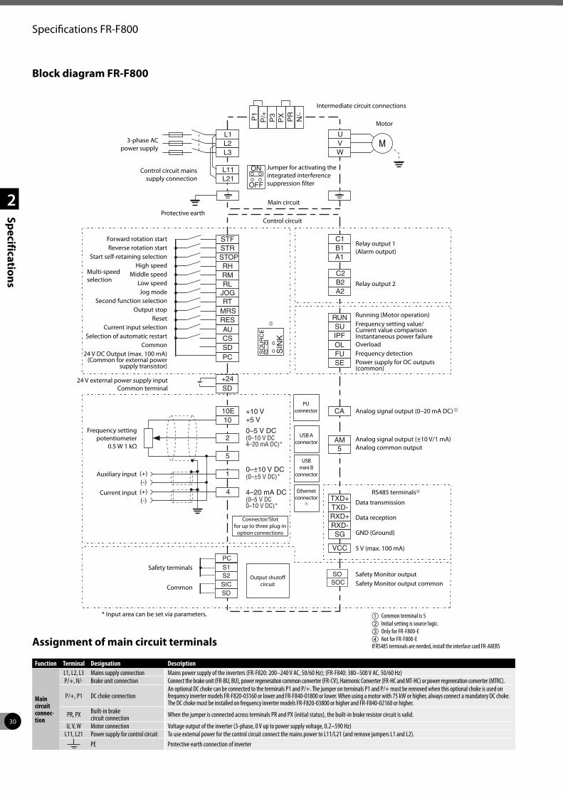
30
2
Specifications
Specifications FR-F800
Block diagram FR-F800
Assignment of main circuit terminals
PC
STOP
STFSTR
RHRMRL
RT
CS
RES RUN
TXD+
SU
TXD-
OLIPF
RXD+
FU
RXD-
SE
SG
VCC
CA
AM5
1010E
2
5
1
4
SD
L1
C2
C1
B2
B1
A2
A1
L11
L2
L21
L3
UVW
PR
N/-
(+)
(+)
(-)
(-)
OFF
ON
JOG
MRS
AU
SO
UR
CE
SIN
KP
X
SICS2S1
SO
PC
SD
SOC
P/+P1
P3
SD+24
Main circuit
3-phase AC power supply
Control circuit mains supply connection
Protective earth
Multi-speed selection
Control circuit
Jumper for activating the integrated interference suppression filter
Intermediate circuit connections
Motor
Relay output 1 (Alarm output)
Relay output 2
Running (Motor operation)
Analog signal output (0–20 mA DC)a
Data transmission Data reception GND (Ground)
5 V (max. 100 mA)
Connector/Slot for up to three plug-in
option connections
PU connector
Frequency setting potentiometer
0.5 W 1 kΩ
Auxiliary input
Current input
Frequency setting value/ Current value comparisonInstantaneous power failureOverload
Power supply for OC outputs (common)
Frequency detection
Analog signal output (±10 V/1 mA) Analog common output
USB A connector
USB mini B
connector
Output shutoff circuit
Forward rotation startReverse rotation start
Start self-retaining selectionHigh speed
Middle speedLow speedJog mode
Second function selectionOutput stop
ResetCurrent input selection
Selection of automatic restartCommon
24 V DC Output (max. 100 mA) (Common for external power
supply transistor)
Safety terminals
Common
Safety Monitor outputSafety Monitor output common
24 V external power supply input Common terminal
b
a Common terminal is 5b Initial setting is source logic.c Only for FR-F800-Ed Not for FR-F800-E If RS485 terminals are needed, install the interface card FR-A8ERS
* Input area can be set via parameters.
Function Terminal Designation Description
Main circuit connec-tion
L1, L2, L3 Mains supply connection Mains power supply of the inverters (FR-F820: 200–240 V AC, 50/60 Hz); (FR-F840: 380–500 V AC, 50/60 Hz)P/+, N/- Brake unit connection Connect the brake unit (FR-BU, BU), power regeneration common converter (FR-CV), Harmonic Converter (FR-HC and MT-HC) or power regeneration converter (MTRC).
P/+, P1 DC choke connectionAn optional DC choke can be connected to the terminals P1 and P/+. The jumper on terminals P1 and P/+ must be removed when this optional choke is used on frequency inverter models FR-F820-03160 or lower and FR-F840-01800 or lower. When using a motor with 75 kW or higher, always connect a mandatory DC choke. The DC choke must be installed on frequency inverter models FR-F820-03800 or higher and FR-F840-02160 or higher.
PR, PX Built-in brake circuit connection When the jumper is connected across terminals PR and PX (initial status), the built-in brake resistor circuit is valid.
U, V, W Motor connection Voltage output of the inverter (3-phase, 0 V up to power supply voltage, 0.2–590 Hz)L11, L21 Power supply for control circuit To use external power for the control circuit connect the mains power to L11/L21 (and remove jumpers L1 and L2).
PE Protective earth connection of inverter
Ethernet connector
3
RS485 terminals4
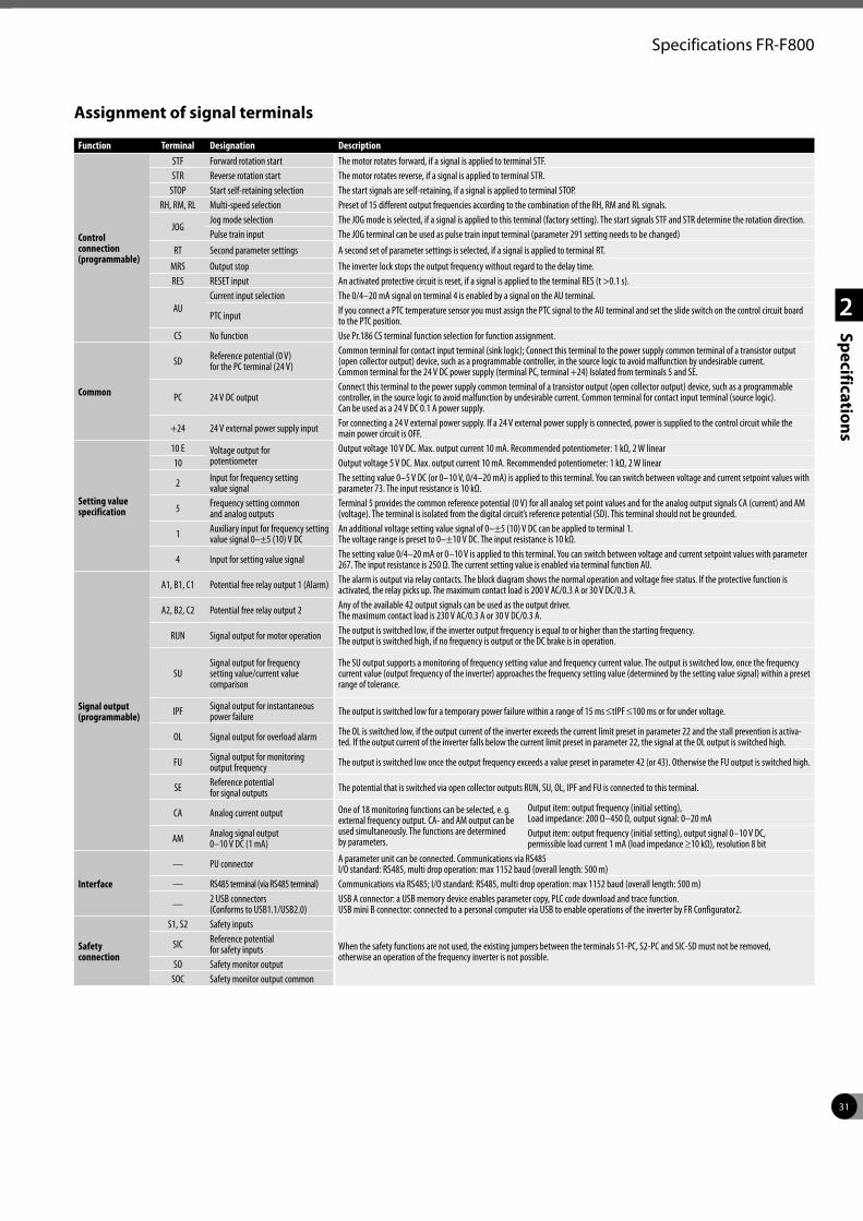
31
2
Specifications
Specifications FR-F800
Assignment of signal terminals
Function Terminal Designation Description
Control connection (programmable)
STF Forward rotation start The motor rotates forward, if a signal is applied to terminal STF.STR Reverse rotation start The motor rotates reverse, if a signal is applied to terminal STR.
STOP Start self-retaining selection The start signals are self-retaining, if a signal is applied to terminal STOP.RH, RM, RL Multi-speed selection Preset of 15 different output frequencies according to the combination of the RH, RM and RL signals.
JOGJog mode selection The JOG mode is selected, if a signal is applied to this terminal (factory setting). The start signals STF and STR determine the rotation direction.Pulse train input The JOG terminal can be used as pulse train input terminal (parameter 291 setting needs to be changed)
RT Second parameter settings A second set of parameter settings is selected, if a signal is applied to terminal RT.
MRS Output stop The inverter lock stops the output frequency without regard to the delay time. RES RESET input An activated protective circuit is reset, if a signal is applied to the terminal RES (t >0.1 s).
AUCurrent input selection The 0/4–20 mA signal on terminal 4 is enabled by a signal on the AU terminal.
PTC input If you connect a PTC temperature sensor you must assign the PTC signal to the AU terminal and set the slide switch on the control circuit board to the PTC position.
CS No function Use Pr.186 CS terminal function selection for function assignment.
Common
SD Reference potential (0 V) for the PC terminal (24 V)
Common terminal for contact input terminal (sink logic); Connect this terminal to the power supply common terminal of a transistor output (open collector output) device, such as a programmable controller, in the source logic to avoid malfunction by undesirable current.Common terminal for the 24 V DC power supply (terminal PC, terminal +24) Isolated from terminals 5 and SE.
PC 24 V DC outputConnect this terminal to the power supply common terminal of a transistor output (open collector output) device, such as a programmable controller, in the source logic to avoid malfunction by undesirable current. Common terminal for contact input terminal (source logic).Can be used as a 24 V DC 0.1 A power supply.
+24 24 V external power supply input For connecting a 24 V external power supply. If a 24 V external power supply is connected, power is supplied to the control circuit while the main power circuit is OFF.
Setting value specification
10 E Voltage output for potentiometer
Output voltage 10 V DC. Max. output current 10 mA. Recommended potentiometer: 1 kΩ, 2 W linear10 Output voltage 5 V DC. Max. output current 10 mA. Recommended potentiometer: 1 kΩ, 2 W linear
2 Input for frequency setting value signal
The setting value 0–5 V DC (or 0–10 V, 0/4–20 mA) is applied to this terminal. You can switch between voltage and current setpoint values with parameter 73. The input resistance is 10 kΩ.
5 Frequency setting common and analog outputs
Terminal 5 provides the common reference potential (0 V) for all analog set point values and for the analog output signals CA (current) and AM (voltage). The terminal is isolated from the digital circuit’s reference potential (SD). This terminal should not be grounded.
1 Auxiliary input for frequency setting value signal 0–±5 (10) V DC
An additional voltage setting value signal of 0–±5 (10) V DC can be applied to terminal 1.The voltage range is preset to 0–±10 V DC. The input resistance is 10 kΩ.
4 Input for setting value signal The setting value 0/4–20 mA or 0–10 V is applied to this terminal. You can switch between voltage and current setpoint values with parameter 267. The input resistance is 250 Ω. The current setting value is enabled via terminal function AU.
Signal output (programmable)
A1, B1, C1 Potential free relay output 1 (Alarm) The alarm is output via relay contacts. The block diagram shows the normal operation and voltage free status. If the protective function is activated, the relay picks up. The maximum contact load is 200 V AC/0.3 A or 30 V DC/0.3 A.
A2, B2, C2 Potential free relay output 2 Any of the available 42 output signals can be used as the output driver.The maximum contact load is 230 V AC/0.3 A or 30 V DC/0.3 A.
RUN Signal output for motor operation The output is switched low, if the inverter output frequency is equal to or higher than the starting frequency.The output is switched high, if no frequency is output or the DC brake is in operation.
SUSignal output for frequency setting value/current value comparison
The SU output supports a monitoring of frequency setting value and frequency current value. The output is switched low, once the frequency current value (output frequency of the inverter) approaches the frequency setting value (determined by the setting value signal) within a preset range of tolerance.
IPF Signal output for instantaneous power failure The output is switched low for a temporary power failure within a range of 15 ms ≤tIPF ≤100 ms or for under voltage.
OL Signal output for overload alarm The OL is switched low, if the output current of the inverter exceeds the current limit preset in parameter 22 and the stall prevention is activa-ted. If the output current of the inverter falls below the current limit preset in parameter 22, the signal at the OL output is switched high.
FU Signal output for monitoring output frequency The output is switched low once the output frequency exceeds a value preset in parameter 42 (or 43). Otherwise the FU output is switched high.
SE Reference potential for signal outputs The potential that is switched via open collector outputs RUN, SU, OL, IPF and FU is connected to this terminal.
CA Analog current output One of 18 monitoring functions can be selected, e. g. external frequency output. CA- and AM output can be used simultaneously. The functions are determined by parameters.
Output item: output frequency (initial setting),Load impedance: 200 Ω–450 Ω, output signal: 0–20 mA
AM Analog signal output 0–10 V DC (1 mA)
Output item: output frequency (initial setting), output signal 0–10 V DC, permissible load current 1 mA (load impedance ≥10 kΩ), resolution 8 bit
Interface
— PU connector A parameter unit can be connected. Communications via RS485 I/O standard: RS485, multi drop operation: max 1152 baud (overall length: 500 m)
— RS485 terminal (via RS485 terminal) Communications via RS485; I/O standard: RS485, multi drop operation: max 1152 baud (overall length: 500 m)
— 2 USB connectors (Conforms to USB1.1/USB2.0)
USB A connector: a USB memory device enables parameter copy, PLC code download and trace function. USB mini B connector: connected to a personal computer via USB to enable operations of the inverter by FR Configurator2.
Safety connection
S1, S2 Safety inputs
When the safety functions are not used, the existing jumpers between the terminals S1-PC, S2-PC and SIC-SD must not be removed, otherwise an operation of the frequency inverter is not possible.
SIC Reference potential for safety inputs
SO Safety monitor outputSOC Safety monitor output common
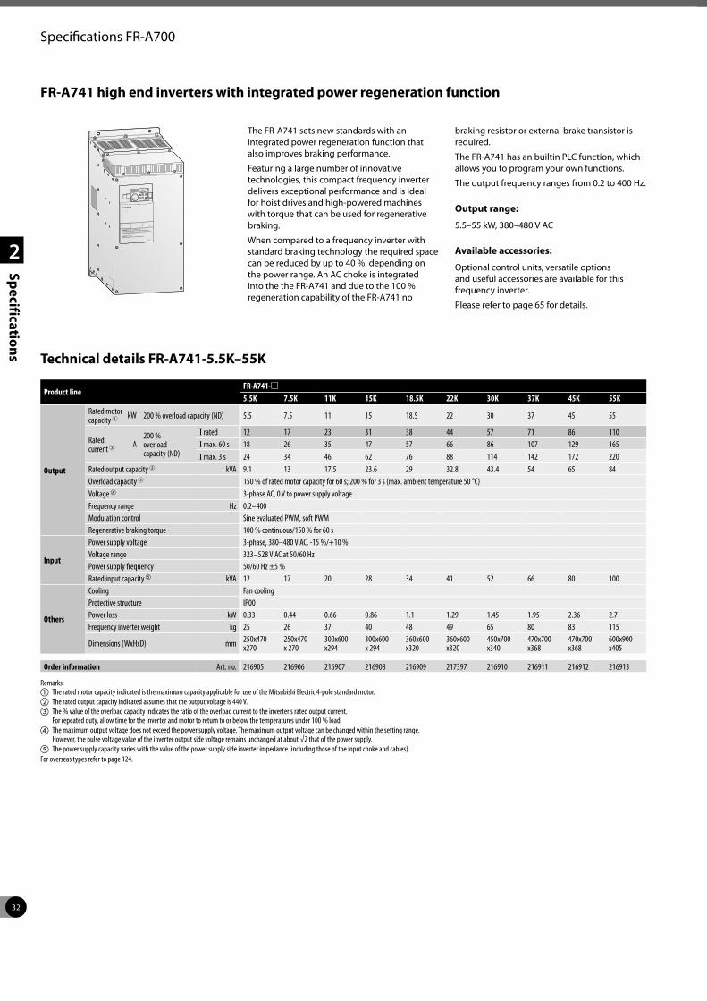
32
2
Specifications
FR-A741 high end inverters with integrated power regeneration function
The FR-A741 sets new standards with an integrated power regeneration function that also improves braking performance.
Featuring a large number of innovative technologies, this compact frequency inverter delivers exceptional performance and is ideal for hoist drives and high-powered machines with torque that can be used for regenerative braking.
When compared to a frequency inverter with standard braking technology the required space can be reduced by up to 40 %, depending on the power range. An AC choke is integrated into the the FR-A741 and due to the 100 % regeneration capability of the FR-A741 no
braking resistor or external brake transistor is required.
The FR-A741 has an builtin PLC function, which allows you to program your own functions.
The output frequency ranges from 0.2 to 400 Hz.
Output range:
5.5–55 kW, 380–480 V AC
Available accessories:
Optional control units, versatile options and useful accessories are available for this frequency inverter.
Please refer to page 65 for details.
Technical details FR-A741-5.5K–55K
Product lineFR-A741-m5.5K 7.5K 11K 15K 18.5K 22K 30K 37K 45K 55K
Output
Rated motor capacity 1 kW 200 % overload capacity (ND) 5.5 7.5 11 15 18.5 22 30 37 45 55
Rated current 3 A
200 % overload capacity (ND)
I rated 12 17 23 31 38 44 57 71 86 110I max. 60 s 18 26 35 47 57 66 86 107 129 165I max. 3 s 24 34 46 62 76 88 114 142 172 220
Rated output capacity 2 kVA 9.1 13 17.5 23.6 29 32.8 43.4 54 65 84Overload capacity 3 150 % of rated motor capacity for 60 s; 200 % for 3 s (max. ambient temperature 50 °C)Voltage d 3-phase AC, 0 V to power supply voltageFrequency range Hz 0.2–400Modulation control Sine evaluated PWM, soft PWMRegenerative braking torque 100 % continuous/150 % for 60 s
Input
Power supply voltage 3-phase, 380–480 V AC, -15 %/+10 %Voltage range 323–528 V AC at 50/60 HzPower supply frequency 50/60 Hz ±5 %Rated input capacity e kVA 12 17 20 28 34 41 52 66 80 100
Others
Cooling Fan coolingProtective structure IP00Power loss kW 0.33 0.44 0.66 0.86 1.1 1.29 1.45 1.95 2.36 2.7Frequency inverter weight kg 25 26 37 40 48 49 65 80 83 115
Dimensions (WxHxD) mm 250x470 x270
250x470 x 270
300x600 x294
300x600 x 294
360x600 x320
360x600 x320
450x700 x340
470x700 x368
470x700 x368
600x900 x405
Order information Art. no. 216905 216906 216907 216908 216909 217397 216910 216911 216912 216913
Remarks:a The rated motor capacity indicated is the maximum capacity applicable for use of the Mitsubishi Electric 4-pole standard motor.b The rated output capacity indicated assumes that the output voltage is 440 V.c The % value of the overload capacity indicates the ratio of the overload current to the inverter's rated output current.
For repeated duty, allow time for the inverter and motor to return to or below the temperatures under 100 % load.d The maximum output voltage does not exceed the power supply voltage. The maximum output voltage can be changed within the setting range.
However, the pulse voltage value of the inverter output side voltage remains unchanged at about √2 that of the power supply.e The power supply capacity varies with the value of the power supply side inverter impedance (including those of the input choke and cables).For overseas types refer to page 124.
Specifications FR-A700
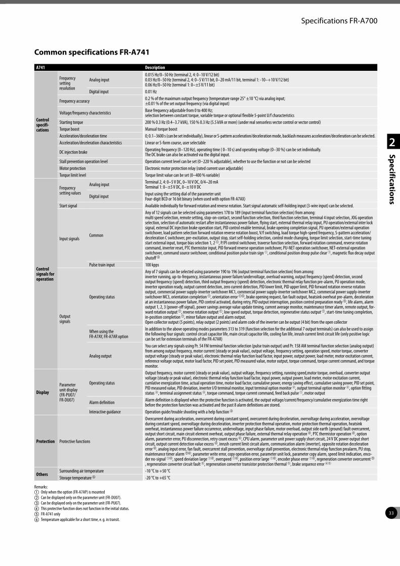
33
2
Specifications
Specifications FR-A700
Common specifications FR-A741
A741 Description
Control specifi- cations
Frequency setting resolution
Analog input0.015 Hz/0–50 Hz (terminal 2, 4: 0–10 V/12 bit)0.03 Hz/0–50 Hz (terminal 2, 4: 0–5 V/11 bit, 0–20 mA/11 bit, terminal 1: -10–+10 V/12 bit)0.06 Hz/0–50 Hz (terminal 1: 0–±5 V/11 bit)
Digital input 0.01 Hz
Frequency accuracy 0.2 % of the maximum output frequency (temperature range 25° ±10 °C) via analog input; ±0.01 % of the set output frequency (via digital input)
Voltage/frequency characteristics Base frequency adjustable from 0 to 400 Hz; selection between constant torque, variable torque or optional flexible 5-point U/f characteristics
Starting torque 200 % 0.3 Hz (0.4–3.7 kVA), 150 % 0.3 Hz (5.5 kVA or more) (under real sensorless vector control or vector control)Torque boost Manual torque boostAcceleration/deceleration time 0; 0.1–3600 s (can be set individually), linear or S-pattern acceleration/deceleration mode, backlash measures acceleration/deceleration can be selected.Acceleration/deceleration characteristics Linear or S-form course, user selectable
DC injection brake Operating frequency (0–120 Hz), operating time ( 0–10 s) and operating voltage (0–30 %) can be set individually. The DC brake can also be activated via the digital input.
Stall prevention operation level Operation current level can be set (0–220 % adjustable), whether to use the function or not can be selectedMotor protection Electronic motor protection relay (rated current user adjustable)Torque limit level Torque limit value can be set (0–400 % variable)
Control signals for operation
Frequency setting values
Analog input Terminal 2, 4: 0–5 V DC, 0–10 V DC, 0/4–20 mA Terminal 1: 0–±5 V DC, 0–±10 V DC
Digital input Input using the setting dial of the parameter unit Four-digit BCD or 16 bit binary (when used with option FR-A7AX)
Start signal Available individually for forward rotation and reverse rotation. Start signal automatic self-holding input (3-wire input) can be selected.
Input signalsCommon
Any of 12 signals can be selected using parameters 178 to 189 (input terminal function selection) from among:multi speed selection, remote setting, stop-on-contact, second function selection, third function selection, terminal 4 input selection, JOG operation selection, selection of automatic restart after instantaneous power failure, flying start, external thermal relay input, PU operation/external inter lock signal, external DC injection brake operation start, PID control enable terminal, brake opening completion signal, PU operation/external operation switchover, load pattern selection forward rotation reverse rotation boost, V/f switching, load torque high-speed frequency, S-pattern acceleration/deceleration C switchover, pre-excitation, output stop, start self-holding selection, control mode changing, torque limit selection, start-time tuning start external input, torque bias selection 1, 2 a, P/PI control switchover, traverse function selection, forward rotation command, reverse rotation command, inverter reset, PTC thermistor input, PID forward reverse operation switchover, PU-NET operation switchover, NET-external operation switchover, command source switchover, conditional position pulse train sign 1, conditional position droop pulse clear 1, magnetic flux decay output shutoff e
Pulse train input 100 kpps
Output signals
Operating status
Any of 7 signals can be selected using parameter 190 to 196 (output terminal function selection) from among:inverter running, up-to-frequency, instantaneous power failure/undervoltage, overload warning, output frequency (speed) detection, second output frequency (speed) detection, third output frequency (speed) detection, electronic thermal relay function pre-alarm, PU operation mode, inverter operation ready, output current detection, zero current detection, PID lower limit, PID upper limit, PID forward rotation reverse rotation output, commercial power supply-inverter switchover MC1, commercial power supply-inverter switchover MC2, commercial power supply-inverter switchover MC3, orientation completion a, orientation error ae, brake opening request, fan fault output, heatsink overheat pre-alarm, deceleration at an instantaneous power failure, PID control activated, during retry, PID output interruption, position control preparation ready e, life alarm, alarm output 1, 2, 3 (power-off signal), power savings average value update timing, current average monitor, maintenance timer alarm, remote output, for-ward rotation output a, reverse rotation output a, low speed output, torque detection, regenerative status output a, start-time tuning completion, in-position completion a, minor failure output and alarm output. Open collector output (5 points), relay output (2 points) and alarm code of the inverter can be output (4 bit) from the open collector
When using the FR-A7AY, FR-A7AR option
In addition to the above operating modes parameters 313 to 319 (function selection for the additional 7 output terminals) can also be used to assign the following four signals: control circuit capacitor life, main circuit capacitor life, cooling fan life, inrush current limit circuit life (only positive logic can be set for extension terminals of the FR-A7AR)
Analog output
You can select any signals using Pr. 54 FM terminal function selection (pulse train output) and Pr. 158 AM terminal function selection (analog output) from among output frequency, motor current (steady or peak value), output voltage, frequency setting, operation speed, motor torque, converter output voltage (steady or peak value), electronic thermal relay function load factor, input power, output power, load meter, motor excitation current, reference voltage output, motor load factor, PID set point, PID measured value, motor output, torque command, torque current command, and torque monitor.
DisplayParameter unit display (FR-PU07/ FR-DU07)
Operating status
Output frequency, motor current (steady or peak value), output voltage, frequency setting, running speed,motor torque, overload, converter output voltage (steady or peak value), electronic thermal relay function load factor, input power, output power, load meter, motor excitation current, cumlative energization time, actual operation time, motor load factor, cumulative power, energy saving effect, cumulative saving power, PID set point, PID measured value, PID deviation, inverter I/O terminal monitor, input terminal option monitor 2, output terminal option monitor 2, option fitting status 3, terminal assignment status 3, torque command, torque current command, feed back pulse 1, motor output
Alarm definition Alarm definition is displayed when the protective function is activated, the output voltage/current/frequency/cumulative energization time right before the protection function was activated and the past 8 alarm definitions are stored.
Interactive guidance Operation guide/trouble shooting with a help function c
Protection Protective functions
Overcurrent during acceleration, overcurrent during constant speed, overcurrent during deceleration, overvoltage during acceleration, overvoltage during constant speed, overvoltage during deceleration, inverter protection thermal operation, motor protection thermal operation, heatsink overheat, instantaneous power failure occurrence, undervoltage, input phase failure, motor overload, output side earth (ground) fault overcurrent, output short circuit, main circuit element overheat, output phase failure, external thermal relay operation d, PTC thermistor operation d, option alarm, parameter error, PU disconnection, retry count excess d, CPU alarm, parameter unit power supply short circuit, 24 V DC power output short circuit, output current detection value excess d, inrush current limit circuit alarm, communication alarm (inverter), opposite rotation deceleration error d, analog input error, fan fault, overcurrent stall prevention, overvoltage stall prevention, electronic thermal relay function prealarm, PU stop, maintenance timer alarm bd, parameter write error, copy operation error, parameter unit lock, parameter copy alarm, speed limit indication, enco-der no-signal 1d, speed deviation large 1d, overspeed 1d, position error large 1d, encoder phase error 1d, regeneration converter overcurrent e , regeneration converter circuit fault 5, regeneration converter transistor protection thermal 5, brake sequence error 45
OthersSurrounding air temperature -10 °C to +50 °CStorage temperature f -20 °C to +65 °C
Remarks:a Only when the option (FR-A7AP) is mountedb Can be displayed only on the parameter unit (FR-DU07).c Can be displayed only on the parameter unit (FR-PU07).d This protective function does not function in the initial status.e FR-A741 onlyf Temperature applicable for a short time, e. g. in transit.

34
2
Specifications
Specifications FR-A700
PC
STOP
STFSTR
RHRMRLRT
PCTCS
RES
RUN
TXD+
SU
TXD-
OLIPF
RXD+
FU
RXD-
SE
SG
VCC
AM5
1010E
2
5
1
4
SD
L1
C2
C1
B2
B1
A2
A1
L11
L2
L21
L3
UVW
N/-
P/+
(+)
(+)
(-)
(-)
JOGMRSAU
AU
SO
UR
CE
SIN
KPTC
SPFM
Main circuit
3-phase AC power supply
Control circuit mains supply connection
Protective earth
24 V DC output (max. 100 mA)
Forward rotation start
Reverse rotation start
Start self-retaining selection
High speed
Middle speed
Low speed
Second function selection
JOG mode
Output stop
Current input selection/PTC
Selection of automatic restart
Common
Reset
Multi-speed selection
Control circuit
Motor
Relay output 1 (alarm output)
Relay output 2
Rela
y ou
tput
sO
pen
colle
ctor
ou
tput
s
Running (motor operation)Frequency setting value/ current value comparisonInstantaneous power failureOverloadFrequency detectionPower supply for OC outputs
Pulse output
FM output common
Analog signal output (0–10 V DC/1 mA)
Analog output common
Data transmission Data reception GND (Ground)
5 V (max. 100 mA) RS
485
term
inal
Connector/slot for up to three plug-in
option connections
PU connector
* Input area can be set via parameters.
Frequency setting potentiometer
0.5 W 1 kΩ
Auxiliary input
Current input
Function Terminal Designation Description
Main circuit connection
L1, L2, L3 Mains supply connection Mains power supply of the inverters (380–480 V AC, 50/60 Hz)
P/+, N/- Brake unit connection Connect the brake unit (FR-BU, BU), power regeneration common converter (FR-CV), Harmonic Converter (FR-HC and MT-HC) or power regeneration converter (MTRC).
U, V, W Motor connection Voltage output of the inverter (3-phase, 0 V up to power supply voltage, 0.2–400 Hz)L11, L21 Power supply for control circuit To use external power for the control circuit connect the mains power to L11/L21 (and remove jumpers L1 and L2).
PE Protective earth connection of inverter
Assignment of main circuit terminals
Cont
rol i
nput
sig
nals
Freq
uenc
y se
ttin
g in
puts USB
connector
Block diagram FR-A741
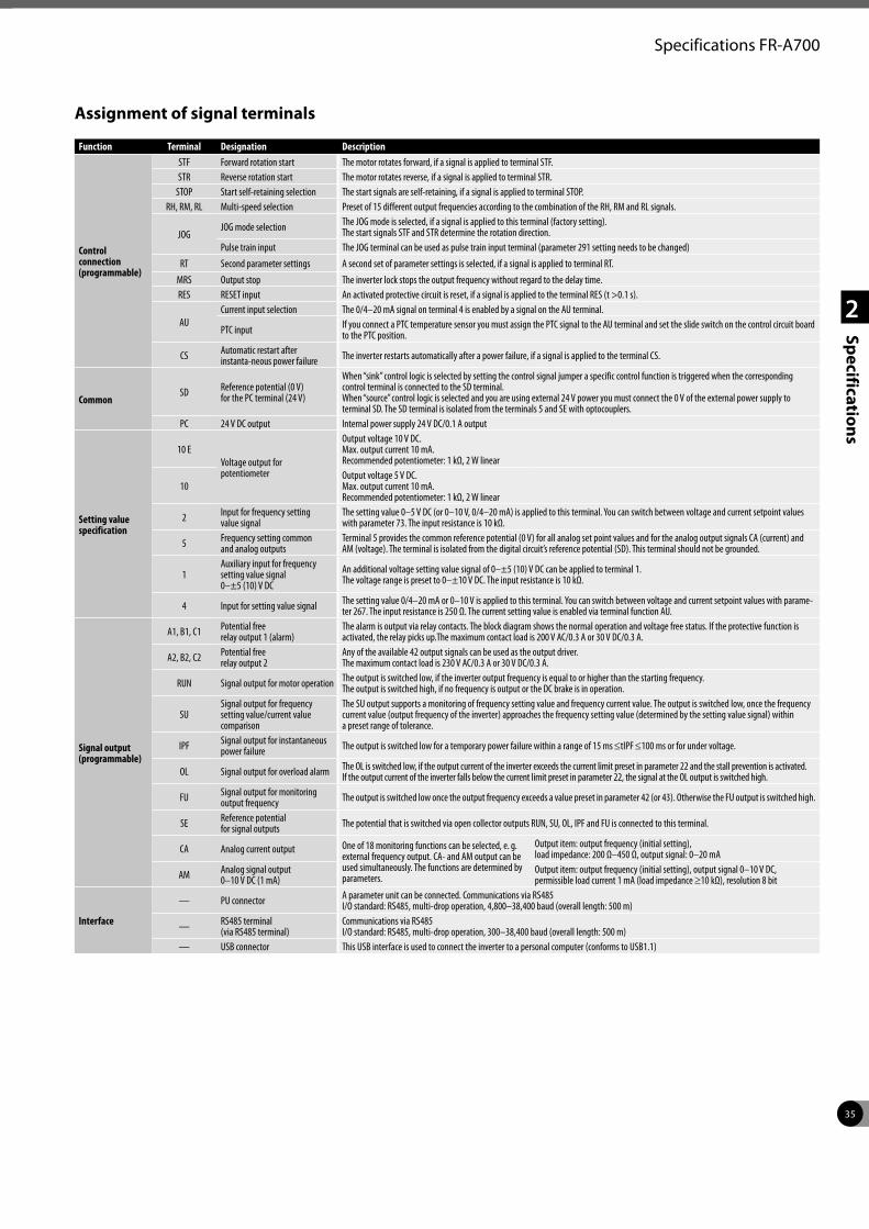
35
2
Specifications
Specifications FR-A700
Assignment of signal terminals
Function Terminal Designation Description
Control connection (programmable)
STF Forward rotation start The motor rotates forward, if a signal is applied to terminal STF.STR Reverse rotation start The motor rotates reverse, if a signal is applied to terminal STR.
STOP Start self-retaining selection The start signals are self-retaining, if a signal is applied to terminal STOP.RH, RM, RL Multi-speed selection Preset of 15 different output frequencies according to the combination of the RH, RM and RL signals.
JOGJOG mode selection The JOG mode is selected, if a signal is applied to this terminal (factory setting).
The start signals STF and STR determine the rotation direction.Pulse train input The JOG terminal can be used as pulse train input terminal (parameter 291 setting needs to be changed)
RT Second parameter settings A second set of parameter settings is selected, if a signal is applied to terminal RT.MRS Output stop The inverter lock stops the output frequency without regard to the delay time. RES RESET input An activated protective circuit is reset, if a signal is applied to the terminal RES (t >0.1 s).
AUCurrent input selection The 0/4–20 mA signal on terminal 4 is enabled by a signal on the AU terminal.
PTC input If you connect a PTC temperature sensor you must assign the PTC signal to the AU terminal and set the slide switch on the control circuit board to the PTC position.
CS Automatic restart after instanta-neous power failure The inverter restarts automatically after a power failure, if a signal is applied to the terminal CS.
CommonSD Reference potential (0 V)
for the PC terminal (24 V)
When “sink” control logic is selected by setting the control signal jumper a specific control function is triggered when the corresponding control terminal is connected to the SD terminal.When “source” control logic is selected and you are using external 24 V power you must connect the 0 V of the external power supply to terminal SD. The SD terminal is isolated from the terminals 5 and SE with optocouplers.
PC 24 V DC output Internal power supply 24 V DC/0.1 A output
Setting value specification
10 EVoltage output for potentiometer
Output voltage 10 V DC. Max. output current 10 mA. Recommended potentiometer: 1 kΩ, 2 W linear
10Output voltage 5 V DC. Max. output current 10 mA. Recommended potentiometer: 1 kΩ, 2 W linear
2 Input for frequency setting value signal
The setting value 0–5 V DC (or 0–10 V, 0/4–20 mA) is applied to this terminal. You can switch between voltage and current setpoint values with parameter 73. The input resistance is 10 kΩ.
5 Frequency setting common and analog outputs
Terminal 5 provides the common reference potential (0 V) for all analog set point values and for the analog output signals CA (current) and AM (voltage). The terminal is isolated from the digital circuit’s reference potential (SD). This terminal should not be grounded.
1Auxiliary input for frequency setting value signal 0–±5 (10) V DC
An additional voltage setting value signal of 0–±5 (10) V DC can be applied to terminal 1.The voltage range is preset to 0–±10 V DC. The input resistance is 10 kΩ.
4 Input for setting value signal The setting value 0/4–20 mA or 0–10 V is applied to this terminal. You can switch between voltage and current setpoint values with parame-ter 267. The input resistance is 250 Ω. The current setting value is enabled via terminal function AU.
Signal output (programmable)
A1, B1, C1 Potential free relay output 1 (alarm)
The alarm is output via relay contacts. The block diagram shows the normal operation and voltage free status. If the protective function is activated, the relay picks up.The maximum contact load is 200 V AC/0.3 A or 30 V DC/0.3 A.
A2, B2, C2 Potential free relay output 2
Any of the available 42 output signals can be used as the output driver.The maximum contact load is 230 V AC/0.3 A or 30 V DC/0.3 A.
RUN Signal output for motor operation The output is switched low, if the inverter output frequency is equal to or higher than the starting frequency.The output is switched high, if no frequency is output or the DC brake is in operation.
SUSignal output for frequency setting value/current value comparison
The SU output supports a monitoring of frequency setting value and frequency current value. The output is switched low, once the frequency current value (output frequency of the inverter) approaches the frequency setting value (determined by the setting value signal) within a preset range of tolerance.
IPF Signal output for instantaneous power failure The output is switched low for a temporary power failure within a range of 15 ms ≤tIPF ≤100 ms or for under voltage.
OL Signal output for overload alarm The OL is switched low, if the output current of the inverter exceeds the current limit preset in parameter 22 and the stall prevention is activated. If the output current of the inverter falls below the current limit preset in parameter 22, the signal at the OL output is switched high.
FU Signal output for monitoring output frequency The output is switched low once the output frequency exceeds a value preset in parameter 42 (or 43). Otherwise the FU output is switched high.
SE Reference potential for signal outputs The potential that is switched via open collector outputs RUN, SU, OL, IPF and FU is connected to this terminal.
CA Analog current output One of 18 monitoring functions can be selected, e. g. external frequency output. CA- and AM output can be used simultaneously. The functions are determined by parameters.
Output item: output frequency (initial setting), load impedance: 200 Ω–450 Ω, output signal: 0–20 mA
AM Analog signal output 0–10 V DC (1 mA)
Output item: output frequency (initial setting), output signal 0–10 V DC, permissible load current 1 mA (load impedance ≥10 kΩ), resolution 8 bit
Interface
— PU connector A parameter unit can be connected. Communications via RS485 I/O standard: RS485, multi-drop operation, 4,800–38,400 baud (overall length: 500 m)
— RS485 terminal (via RS485 terminal)
Communications via RS485 I/O standard: RS485, multi-drop operation, 300–38,400 baud (overall length: 500 m)
— USB connector This USB interface is used to connect the inverter to a personal computer (conforms to USB1.1)
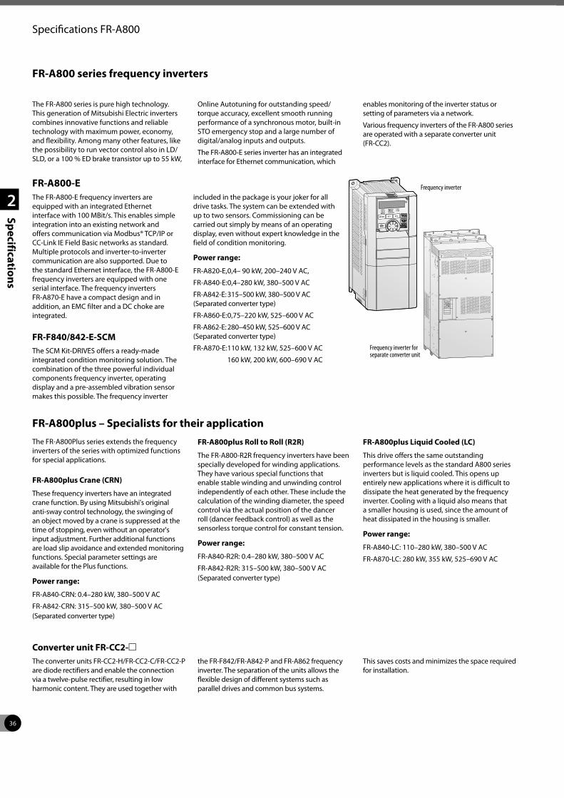
36
2
Specifications
Specifications FR-A800
FR-A800-EThe FR-A800-E frequency inverters are equipped with an integrated Ethernet interface with 100 MBit/s. This enables simple integration into an existing network and offers communication via Modbus® TCP/IP or CC-Link IE Field Basic networks as standard. Multiple protocols and inverter-to-inverter communication are also supported. Due to the standard Ethernet interface, the FR-A800-E frequency inverters are equipped with one serial interface. The frequency inverters FR-A870-E have a compact design and in addition, an EMC filter and a DC choke are integrated.
FR-F840/842-E-SCMThe SCM Kit-DRIVES offers a ready-made integrated condition monitoring solution. The combination of the three powerful individual components frequency inverter, operating display and a pre-assembled vibration sensor makes this possible. The frequency inverter
included in the package is your joker for all drive tasks. The system can be extended with up to two sensors. Commissioning can be carried out simply by means of an operating display, even without expert knowledge in the field of condition monitoring.
Power range:
FR-A820-E, 0,4– 90 kW, 200–240 V AC,
FR-A840-E: 0,4–280 kW, 380–500 V AC
FR-A842-E: 315–500 kW, 380–500 V AC (Separated converter type)
FR-A860-E: 0,75–220 kW, 525–600 V AC
FR-A862-E: 280–450 kW, 525–600 V AC (Separated converter type)
FR-A870-E: 110 kW, 132 kW, 525–600 V AC
160 kW, 200 kW, 600–690 V AC
FR-A800 series frequency inverters
The FR-A800 series is pure high technology. This generation of Mitsubishi Electric inverters combines innovative functions and reliable technology with maximum power, economy, and flexibility. Among many other features, like the possibility to run vector control also in LD/SLD, or a 100 % ED brake transistor up to 55 kW,
Online Autotuning for outstanding speed/torque accuracy, excellent smooth running performance of a synchronous motor, built-in STO emergency stop and a large number of digital/analog inputs and outputs.
The FR-A800-E series inverter has an integrated interface for Ethernet communication, which
enables monitoring of the inverter status or setting of parameters via a network.
Various frequency inverters of the FR-A800 series are operated with a separate converter unit (FR-CC2).
Frequency inverter
FR-A800plus – Specialists for their applicationThe FR-A800Plus series extends the frequency inverters of the series with optimized functions for special applications.
FR-A800plus Crane (CRN)
These frequency inverters have an integrated crane function. By using Mitsubishi's original anti-sway control technology, the swinging of an object moved by a crane is suppressed at the time of stopping, even without an operator's input adjustment. Further additional functions are load slip avoidance and extended monitoring functions. Special parameter settings are available for the Plus functions.
Power range:
FR-A840-CRN: 0.4–280 kW, 380–500 V AC
FR-A842-CRN: 315–500 kW, 380–500 V AC (Separated converter type)
FR-A800plus Roll to Roll (R2R)
The FR-A800-R2R frequency inverters have been specially developed for winding applications. They have various special functions that enable stable winding and unwinding control independently of each other. These include the calculation of the winding diameter, the speed control via the actual position of the dancer roll (dancer feedback control) as well as the sensorless torque control for constant tension.
Power range:
FR-A840-R2R: 0.4–280 kW, 380–500 V AC
FR-A842-R2R: 315–500 kW, 380–500 V AC (Separated converter type)
FR-A800plus Liquid Cooled (LC)
This drive offers the same outstanding performance levels as the standard A800 series inverters but is liquid cooled. This opens up entirely new applications where it is difficult to dissipate the heat generated by the frequency inverter. Cooling with a liquid also means that a smaller housing is used, since the amount of heat dissipated in the housing is smaller.
Power range:
FR-A840-LC: 110–280 kW, 380–500 V AC
FR-A870-LC: 280 kW, 355 kW, 525–690 V AC
Frequency inverter for separate converter unit
Converter unit FR-CC2-mThe converter units FR-CC2-H/FR-CC2-C/FR-CC2-P are diode rectifiers and enable the connection via a twelve-pulse rectifier, resulting in low harmonic content. They are used together with
the FR-F842/FR-A842-P and FR-A862 frequency inverter. The separation of the units allows the flexible design of different systems such as parallel drives and common bus systems.
This saves costs and minimizes the space required for installation.
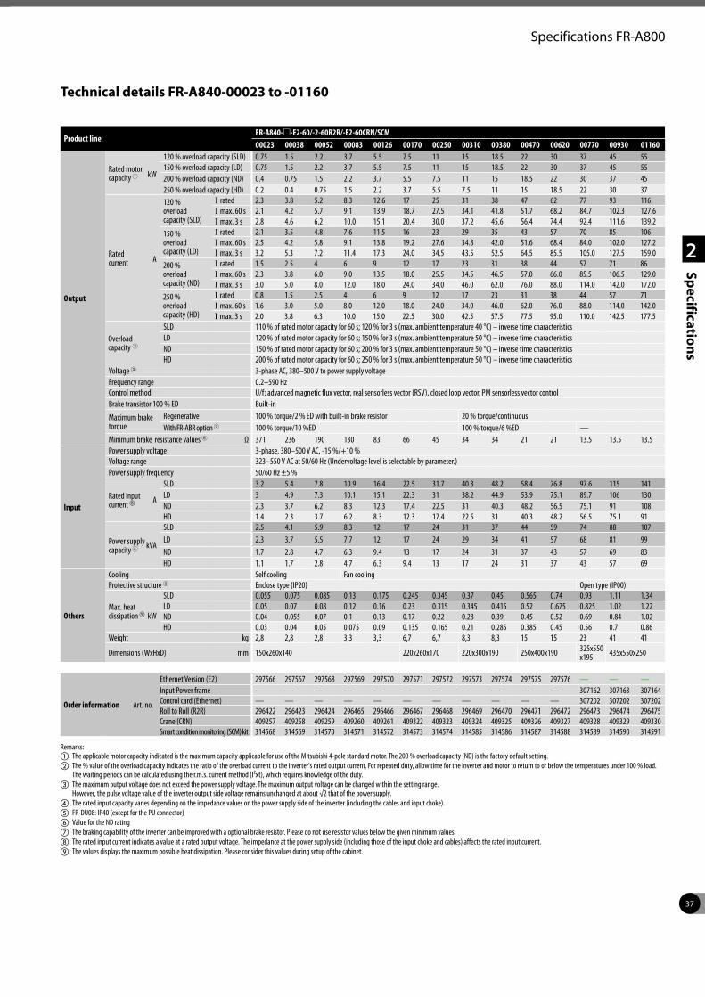
37
2
Specifications
Specifications FR-A800
Technical details FR-A840-00023 to -01160
Product lineFR-A840-m-E2-60/-2-60R2R/-E2-60CRN/SCM00023 00038 00052 00083 00126 00170 00250 00310 00380 00470 00620 00770 00930 01160
Output
Rated motor capacity 1 kW
120 % overload capacity (SLD) 0.75 1.5 2.2 3.7 5.5 7.5 11 15 18.5 22 30 37 45 55150 % overload capacity (LD) 0.75 1.5 2.2 3.7 5.5 7.5 11 15 18.5 22 30 37 45 55200 % overload capacity (ND) 0.4 0.75 1.5 2.2 3.7 5.5 7.5 11 15 18.5 22 30 37 45250 % overload capacity (HD) 0.2 0.4 0.75 1.5 2.2 3.7 5.5 7.5 11 15 18.5 22 30 37
Rated current A
120 % overload capacity (SLD)
I rated 2.3 3.8 5.2 8.3 12.6 17 25 31 38 47 62 77 93 116I max. 60 s 2.1 4.2 5.7 9.1 13.9 18.7 27.5 34.1 41.8 51.7 68.2 84.7 102.3 127.6I max. 3 s 2.8 4.6 6.2 10.0 15.1 20.4 30.0 37.2 45.6 56.4 74.4 92.4 111.6 139.2
150 % overload capacity (LD)
I rated 2.1 3.5 4.8 7.6 11.5 16 23 29 35 43 57 70 85 106I max. 60 s 2.5 4.2 5.8 9.1 13.8 19.2 27.6 34.8 42.0 51.6 68.4 84.0 102.0 127.2I max. 3 s 3.2 5.3 7.2 11.4 17.3 24.0 34.5 43.5 52.5 64.5 85.5 105.0 127.5 159.0
200 % overload capacity (ND)
I rated 1.5 2.5 4 6 9 12 17 23 31 38 44 57 71 86I max. 60 s 2.3 3.8 6.0 9.0 13.5 18.0 25.5 34.5 46.5 57.0 66.0 85.5 106.5 129.0I max. 3 s 3.0 5.0 8.0 12.0 18.0 24.0 34.0 46.0 62.0 76.0 88.0 114.0 142.0 172.0
250 % overload capacity (HD)
I rated 0.8 1.5 2.5 4 6 9 12 17 23 31 38 44 57 71I max. 60 s 1.6 3.0 5.0 8.0 12.0 18.0 24.0 34.0 46.0 62.0 76.0 88.0 114.0 142.0I max. 3 s 2.0 3.8 6.3 10.0 15.0 22.5 30.0 42.5 57.5 77.5 95.0 110.0 142.5 177.5
Overload capacity 2
SLD 110 % of rated motor capacity for 60 s; 120 % for 3 s (max. ambient temperature 40 °C) – inverse time characteristicsLD 120 % of rated motor capacity for 60 s; 150 % for 3 s (max. ambient temperature 50 °C) – inverse time characteristicsND 150 % of rated motor capacity for 60 s; 200 % for 3 s (max. ambient temperature 50 °C) – inverse time characteristicsHD 200 % of rated motor capacity for 60 s; 250 % for 3 s (max. ambient temperature 50 °C) – inverse time characteristics
Voltage 3 3-phase AC, 380–500 V to power supply voltageFrequency range 0.2–590 HzControl method U/f; advanced magnetic flux vector, real sensorless vector (RSV), closed loop vector, PM sensorless vector controlBrake transistor 100 % ED Built-in
Maximum brake torque
Regenerative 100 % torque/2 % ED with built-in brake resistor 20 % torque/continuous With FR-ABR option 7 100 % torque/10 %ED 100 % torque/6 %ED —
Minimum brake resistance values 6 Ω 371 236 190 130 83 66 45 34 34 21 21 13.5 13.5 13.5
Input
Power supply voltage 3-phase, 380–500 V AC, -15 %/+10 %Voltage range 323–550 V AC at 50/60 Hz (Undervoltage level is selectable by parameter.)Power supply frequency 50/60 Hz ±5 %
Rated input current h A
SLD 3.2 5.4 7.8 10.9 16.4 22.5 31.7 40.3 48.2 58.4 76.8 97.6 115 141LD 3 4.9 7.3 10.1 15.1 22.3 31 38.2 44.9 53.9 75.1 89.7 106 130ND 2.3 3.7 6.2 8.3 12.3 17.4 22.5 31 40.3 48.2 56.5 75.1 91 108HD 1.4 2.3 3.7 6.2 8.3 12.3 17.4 22.5 31 40.3 48.2 56.5 75.1 91
Power supply capacity 4 kVA
SLD 2.5 4.1 5.9 8.3 12 17 24 31 37 44 59 74 88 107LD 2.3 3.7 5.5 7.7 12 17 24 29 34 41 57 68 81 99ND 1.7 2.8 4.7 6.3 9.4 13 17 24 31 37 43 57 69 83HD 1.1 1.7 2.8 4.7 6.3 9.4 13 17 24 31 37 43 57 69
Others
Cooling Self cooling Fan coolingProtective structure 5 Enclose type (IP20) Open type (IP00)
Max. heat dissipationi kW
SLD 0.055 0.075 0.085 0.13 0.175 0.245 0.345 0.37 0.45 0.565 0.74 0.93 1.11 1.34LD 0.05 0.07 0.08 0.12 0.16 0.23 0.315 0.345 0.415 0.52 0.675 0.825 1.02 1.22ND 0.04 0.055 0.07 0.1 0.13 0.17 0.22 0.28 0.39 0.45 0.52 0.69 0.84 1.02HD 0.03 0.04 0.05 0.075 0.09 0.135 0.165 0.21 0.285 0.385 0.45 0.56 0.7 0.86
Weight kg 2,8 2,8 2,8 3,3 3,3 6,7 6,7 8,3 8,3 15 15 23 41 41
Dimensions (WxHxD) mm 150x260x140 220x260x170 220x300x190 250x400x190 325x550 x195 435x550x250
Order information Art. no.
Ethernet Version (E2) 297566 297567 297568 297569 297570 297571 297572 297573 297574 297575 297576 — — —Input Power frame — — — — — — — — — — — 307162 307163 307164Control card (Ethernet) — — — — — — — — — — — 307202 307202 307202Roll to Roll (R2R) 296422 296423 296424 296465 296466 296467 296468 296469 296470 296471 296472 296473 296474 296475Crane (CRN) 409257 409258 409259 409260 409261 409322 409323 409324 409325 409326 409327 409328 409329 409330 Smart condition monitoring (SCM) kit 314568 314569 314570 314571 314572 314573 314574 314585 314586 314587 314588 314589 314590 314591
Remarks:a The applicable motor capacity indicated is the maximum capacity applicable for use of the Mitsubishi 4-pole standard motor. The 200 % overload capacity (ND) is the factory default setting. b The % value of the overload capacity indicates the ratio of the overload current to the inverter's rated output current. For repeated duty, allow time for the inverter and motor to return to or below the temperatures under 100 % load.
The waiting periods can be calculated using the r.m.s. current method (I²xt), which requires knowledge of the duty.c The maximum output voltage does not exceed the power supply voltage. The maximum output voltage can be changed within the setting range.
However, the pulse voltage value of the inverter output side voltage remains unchanged at about √2 that of the power supply.d The rated input capacity varies depending on the impedance values on the power supply side of the inverter (including the cables and input choke).e FR-DU08: IP40 (except for the PU connector)f Value for the ND ratingg The braking capability of the inverter can be improved with a optional brake resistor. Please do not use resistor values below the given minimum values.h The rated input current indicates a value at a rated output voltage. The impedance at the power supply side (including those of the input choke and cables) affects the rated input current.i The values displays the maximum possible heat dissipation. Please consider this values during setup of the cabinet.
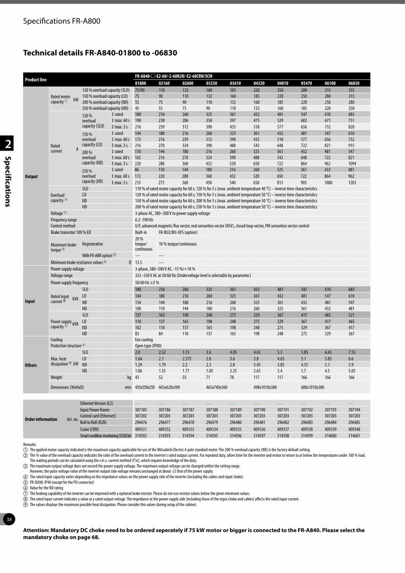
38
2
Specifications
Specifications FR-A800
Technical details FR-A840-01800 to -06830
Product lineFR-A840-m-E2-60/-2-60R2R/-E2-60CRN/SCM01800 02160 02600 03250 03610 04320 04810 05470 06100 06830
Output
Rated motor capacity 1 kW
120 % overload capacity (SLD) 75/90 110 132 160 185 220 250 280 315 355150 % overload capacity (LD) 75 90 110 132 160 185 220 250 280 315200 % overload capacity (ND) 55 75 90 110 132 160 185 220 250 280250 % overload capacity (HD) 45 55 75 90 110 132 160 185 220 250
Rated current A
120 % overload capacity (SLD)
I rated 180 216 260 325 361 432 481 547 610 683I max. 60 s 198 238 286 358 397 475 529 602 671 751I max. 3 s 216 259 312 390 433 518 577 656 732 820
150 % overload capacity (LD)
I rated 144 180 216 260 325 361 432 481 547 610I max. 60 s 173 216 259 312 390 433 518 577 656 732I max. 3 s 216 270 324 390 488 542 648 722 821 915
200 % overload capacity (ND)
I rated 110 144 180 216 260 325 361 432 481 547I max. 60 s 165 216 270 324 390 488 542 648 722 821I max. 3 s 220 288 360 432 520 650 722 864 962 1094
250 % overload capacity (HD)
I rated 86 110 144 180 216 260 325 361 432 481I max. 60 s 172 220 288 360 432 520 650 722 864 962I max. 3 s 215 275 360 450 540 650 813 903 1080 1203
Overload capacity 2
SLD 110 % of rated motor capacity for 60 s; 120 % for 3 s (max. ambient temperature 40 °C) – inverse time characteristicsLD 120 % of rated motor capacity for 60 s; 150 % for 3 s (max. ambient temperature 50 °C) – inverse time characteristicsND 150 % of rated motor capacity for 60 s; 200 % for 3 s (max. ambient temperature 50 °C) – inverse time characteristicsHD 200 % of rated motor capacity for 60 s; 250 % for 3 s (max. ambient temperature 50 °C) – inverse time characteristics
Voltage 3 3-phase AC, 380–500 V to power supply voltageFrequency range 0.2–590 HzControl method U/f; advanced magnetic flux vector, real sensorless vector (RSV), closed loop vector, PM sensorless vector controlBrake transistor 100 % ED Built-in FR-BU2/BU-UFS (option)
Maximum brake torque 6
Regenerative20 % torque/ continuous
10 % torque/continuous
With FR-ABR option g — —Minimum brake resistance values 6 Ω 13.5 —
Input
Power supply voltage 3-phase, 380–500 V AC, -15 %/+10 %Voltage range 323–550 V AC at 50/60 Hz (Undervoltage level is selectable by parameter.)Power supply frequency 50/60 Hz ±5 %
Rated input current h kVA
SLD 180 216 260 325 361 432 481 547 610 683LD 144 180 216 260 325 361 432 481 547 610ND 134 144 180 216 260 325 361 432 481 547HD 108 110 144 180 216 260 325 361 432 481
Power supply capacity 4 kVA
SLD 137 165 198 248 275 329 367 417 465 521LD 110 137 165 198 248 275 329 367 417 465ND 102 110 137 165 198 248 275 329 367 417HD 83 84 110 137 165 198 248 275 329 367
Others
Cooling Fan coolingProtective structure 5 Open type (IP00)
Max. heat dissipationi kW
SLD 2.0 2.52 3.15 3.6 4.05 4.65 5.3 5.85 6.65 7.55LD 1.64 2.1 2.575 2.8 3.6 3.8 4.65 5.1 5.85 6.6ND 1.29 1.79 2.2 2.3 2.8 3.45 3.85 4.55 5.1 5.9HD 1.06 1.35 1.77 1.85 2.25 2.65 3.4 3.7 4.5 5.05
Weight kg 43 52 55 71 78 117 117 166 166 166
Dimensions (WxHxD) mm 435x550x250 465x620x300 465x740x360 498x1010x380 680x1010x380
Order information Art. no.
Ethernet Version (E2) — — — — — — — — — —Input Power frame 307185 307186 307187 307188 307189 307190 307191 307192 307193 307194Control card (Ethernet) 307202 307203 307203 307203 307203 307203 307203 307203 307203 307203Roll to Roll (R2R) 296476 296477 296478 296479 296480 296481 296482 296483 296484 296485Crane (CRN) 409331 409332 409333 409334 409335 409336 409337 409338 409339 409340 Smart condition monitoring (SCM) kit 314592 314593 314594 314595 314596 314597 314598 314599 314600 314601
Remarks:a The applied motor capacity indicated is the maximum capacity applicable for use of the Mitsubishi Electric 4-pole standard motor. The 200 % overload capacity (ND) is the factory default setting. b The % value of the overload capacity indicates the ratio of the overload current to the inverter's rated output current. For repeated duty, allow time for the inverter and motor to return to or below the temperatures under 100 % load.
The waiting periods can be calculated using the r.m.s. current method (I²xt), which requires knowledge of the duty.c The maximum output voltage does not exceed the power supply voltage. The maximum output voltage can be changed within the setting range.
However, the pulse voltage value of the inverter output side voltage remains unchanged at about √2 that of the power supply.d The rated input capacity varies depending on the impedance values on the power supply side of the inverter (including the cables and input choke).e FR-DU08: IP40 (except for the PU connector)f Value for the ND ratingg The braking capability of the inverter can be improved with a optional brake resistor. Please do not use resistor values below the given minimum values.h The rated input current indicates a value at a rated output voltage. The impedance at the power supply side (including those of the input choke and cables) affects the rated input current.i The values displays the maximum possible heat dissipation. Please consider this values during setup of the cabinet.
Attention: Mandatory DC choke need to be ordered seperately if 75 kW motor or bigger is connected to the FR-A840. Please select the mandatory choke on page 68.
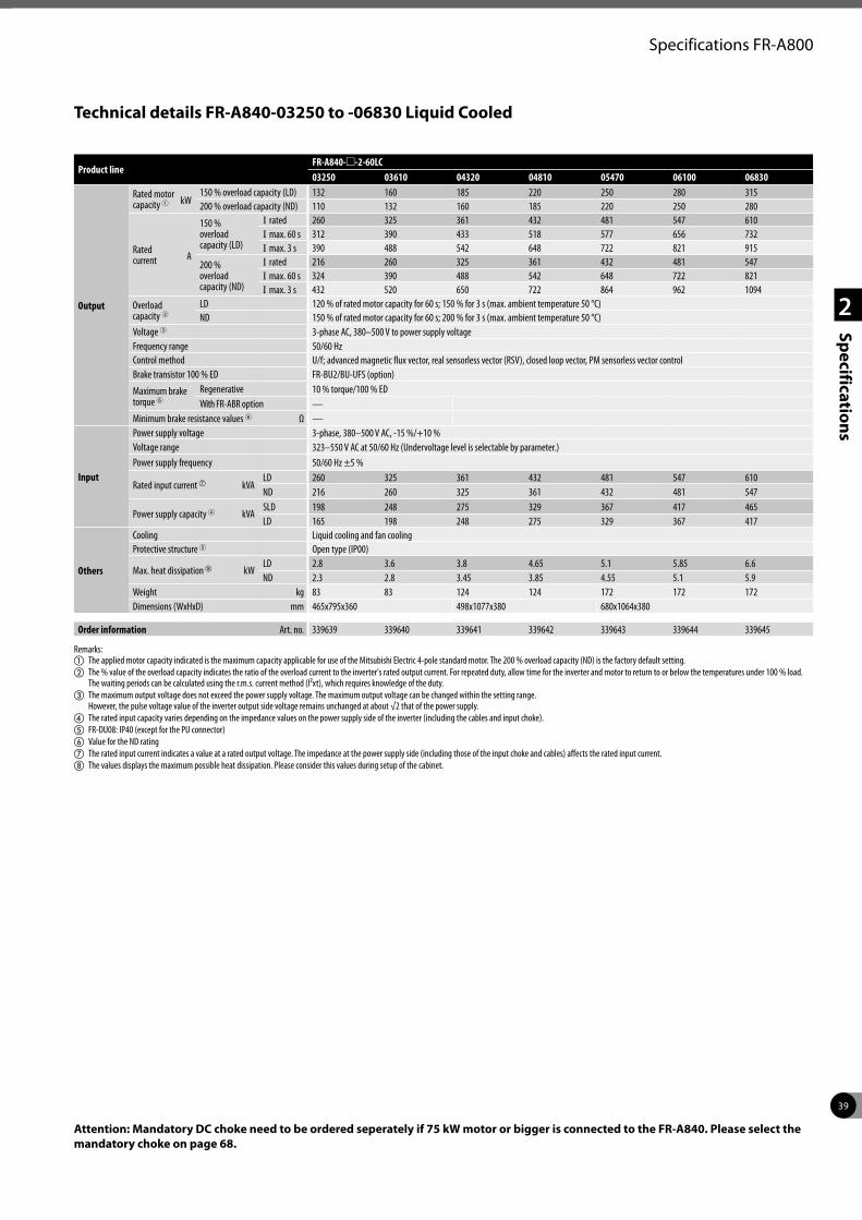
39
2
Specifications
Specifications FR-A800
Attention: Mandatory DC choke need to be ordered seperately if 75 kW motor or bigger is connected to the FR-A840. Please select the mandatory choke on page 68.
Product lineFR-A840-m-2-60LC03250 03610 04320 04810 05470 06100 06830
Output
Rated motor capacity 1 kW
150 % overload capacity (LD) 132 160 185 220 250 280 315200 % overload capacity (ND) 110 132 160 185 220 250 280
Rated current A
150 % overload capacity (LD)
I rated 260 325 361 432 481 547 610I max. 60 s 312 390 433 518 577 656 732I max. 3 s 390 488 542 648 722 821 915
200 % overload capacity (ND)
I rated 216 260 325 361 432 481 547I max. 60 s 324 390 488 542 648 722 821I max. 3 s 432 520 650 722 864 962 1094
Overload capacity 2
LD 120 % of rated motor capacity for 60 s; 150 % for 3 s (max. ambient temperature 50 °C)ND 150 % of rated motor capacity for 60 s; 200 % for 3 s (max. ambient temperature 50 °C)
Voltage 3 3-phase AC, 380–500 V to power supply voltageFrequency range 50/60 HzControl method U/f; advanced magnetic flux vector, real sensorless vector (RSV), closed loop vector, PM sensorless vector controlBrake transistor 100 % ED FR-BU2/BU-UFS (option)
Maximum brake torque 6
Regenerative 10 % torque/100 % EDWith FR-ABR option —
Minimum brake resistance values 6 Ω —
Input
Power supply voltage 3-phase, 380–500 V AC, -15 %/+10 %Voltage range 323–550 V AC at 50/60 Hz (Undervoltage level is selectable by parameter.)Power supply frequency 50/60 Hz ±5 %
Rated input current g kVALD 260 325 361 432 481 547 610ND 216 260 325 361 432 481 547
Power supply capacity 4 kVASLD 198 248 275 329 367 417 465LD 165 198 248 275 329 367 417
Others
Cooling Liquid cooling and fan coolingProtective structure 5 Open type (IP00)
Max. heat dissipationh kWLD 2.8 3.6 3.8 4.65 5.1 5.85 6.6ND 2.3 2.8 3.45 3.85 4.55 5.1 5.9
Weight kg 83 83 124 124 172 172 172Dimensions (WxHxD) mm 465x795x360 498x1077x380 680x1064x380
Order information Art. no. 339639 339640 339641 339642 339643 339644 339645
Remarks:a The applied motor capacity indicated is the maximum capacity applicable for use of the Mitsubishi Electric 4-pole standard motor. The 200 % overload capacity (ND) is the factory default setting. b The % value of the overload capacity indicates the ratio of the overload current to the inverter's rated output current. For repeated duty, allow time for the inverter and motor to return to or below the temperatures under 100 % load.
The waiting periods can be calculated using the r.m.s. current method (I²xt), which requires knowledge of the duty.c The maximum output voltage does not exceed the power supply voltage. The maximum output voltage can be changed within the setting range.
However, the pulse voltage value of the inverter output side voltage remains unchanged at about √2 that of the power supply.d The rated input capacity varies depending on the impedance values on the power supply side of the inverter (including the cables and input choke).e FR-DU08: IP40 (except for the PU connector)f Value for the ND ratingg The rated input current indicates a value at a rated output voltage. The impedance at the power supply side (including those of the input choke and cables) affects the rated input current.h The values displays the maximum possible heat dissipation. Please consider this values during setup of the cabinet.
Technical details FR-A840-03250 to -06830 Liquid Cooled
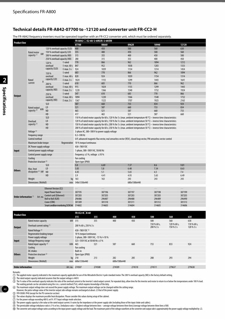
40
2
Specifications
Specifications FR-A800
Technical details FR-A842-07700 to -12120 and converter unit FR-CC2-H
Product lineFR-A842-m-E2-60/-2-60R2R/-2-60CRN07700 08660 09620 10940 12120
Output
Rated motor capacity 1 kW
120 % overload capacity (SLD) 400 450 500 560 630150 % overload capacity (LD) 355 400 450 500 560200 % overload capacity (ND) 315 355 400 450 500250 % overload capacity (HD) 280 315 355 400 450
Rated current A
120 % overload capacity (SLD)
I rated 770 866 962 1094 1212I max. 60 s 847 952 1058 1203 1333I max. 3 s 924 1039 1154 1314 1454
150 % overload capacity (LD)
I rated 683 770 866 962 1094I max. 60 s 820 924 1039 1154 1314I max. 3 s 1024 1155 1299 1443 1641
200 % overload capacity (ND)
I rated 610 683 770 866 962I max. 60 s 915 1024 1155 1299 1443I max. 3 s 1220 1366 1540 1732 1924
250 % overload capacity (HD)
I rated 547 610 683 770 866I max. 60 s 1094 1220 1366 1540 1732I max. 3 s 1367 1525 1707 1925 2165
Rated output capacity 2 kVA
SLD 587 660 733 834 924LD 521 587 660 733 834ND 465 521 587 660 733HD 417 465 521 587 660
Overload capacity 3
SLD 110 % of rated motor capacity for 60 s; 120 % for 3 s (max. ambient temperature 40 °C) – inverse time characteristicsLD 120 % of rated motor capacity for 60 s; 150 % for 3 s (max. ambient temperature 50 °C) – inverse time characteristicsND 150 % of rated motor capacity for 60 s; 200 % for 3 s (max. ambient temperature 50 °C) – inverse time characteristicsHD 200 % of rated motor capacity for 60 s; 250 % for 3 s (max. ambient temperature 50 °C) – inverse time characteristics
Voltage 4 3-phase AC, 380–500 V to power supply voltageFrequency range 0.2–590 HzControl method U/f; advanced magnetic flux vector, real sensorless vector (RSV), closed loop vector, PM sensorless vector controlMaximum brake torque Regenerative 10 % torque/continuous
InputDC Power supply voltage 430–780 V DCControl power supply voltage 1-phase, 380–500 V AC, 50/60 Hz Control power supply range Frequency ±5 %, voltage ±10 %
Others
Cooling Fan coolingProtective structure 5 Open type (IP00)
Max. heat dissipation 6 kW
SLD 5.8 6.69 7.37 8.6 9.81LD 5.05 5.8 6.48 7.34 8.63ND 4.45 5.1 5.65 6.5 7.4HD 3.9 4.41 4.93 5.65 6.49
Weight kg 163 163 243 243 243Dimensions (WxHxD) mm 540x1330x440 680x1580x440
Order information 7 Art. no.
Ethernet Version (E2) — — — — —Input Power frame 307195 307196 307197 307198 307199Control card (Ethernet) 307203 307203 307203 307203 307203Roll to Roll (R2R) 296486 296487 296488 296489 296490Crane (CRN) 301309 301310 301311 301312 301313Smart condition monitoring (SCM) kit 314602 314603 314604 314605 314606
The FR-A842 frequency inverters must be operated together with an FR-CC2 converter unit, which must be ordered separately.
Product lineFR-CC2-HmK-60315 355 400 450 500 560 630
Output
Rated motor capacity kW 315 355 400 450 500 560 630
Overload current rating 1 200 % 60 s, 250 % 3 s 150 % 60 s,200 % 3 s
120 % 60 s,150 % 3 s
110 % 60 s,120 % 3 s
Rated Voltage 2 430–780 V DC 5
Regenerative braking torque 10 % torque/continuous
InputPower supply voltage 3-phase, 380–500 V AC, -15 %/+10 %Voltage/frequency range 323–550 V AC at 50/60 Hz ±5 %Rated input capacity 3 kVA 465 521 587 660 733 833 924
Others
Cooling Fan coolingDC chokes Built-inProtective structure 4 Open type (IP00)Weight kg 210 213 282 285 288 293 294Dimensions (WxHxD) mm 600x1330x440 600x1580x440
Order information Art. no. 274507 274508 274509 274510 274511 279637 279638
Remarks:a The applied motor capacity indicated is the maximum capacity applicable for use of the Mitsubishi Electric 4-pole standard motor. The 200 % overload capacity (ND) is the factory default setting. b The rated output capacity indicated assumes that the output voltage is 440 V.c The % value of the overload capacity indicates the ratio of the overload current to the inverter's rated output current. For repeated duty, allow time for the inverter and motor to return to or below the temperatures under 100 % load.
The waiting periods can be calculated using the r.m.s. current method (I²xt), which requires knowledge of the duty.d The maximum output voltage does not exceed the power supply voltage. The maximum output voltage can be changed within the setting range.
However, the pulse voltage value of the inverter output side voltage remains unchanged at about √2 that of the power supply.e FFR-DU08: IP40 (except for the PU connector section)f The values displays the maximum possible heat dissipation. Please consider this values during setup of the cabinet.g For the power voltage exceeding 480 V, set Pr. 977 Input voltage mode selection.h The power supply capacity is the value at the rated output current. It varies by the impedance at the power supply side (including those of the input choke and cables).i The permissible voltage imbalance ratio is 3 % or less. (Imbalance ratio = (highest voltage between lines – average voltage between three lines)/average voltage between three lines x100)j The converter unit output voltage varies according to the input power supply voltage and the load. The maximum point of the voltage waveform at the converter unit output side is approximately the power supply voltage multiplied by √2.
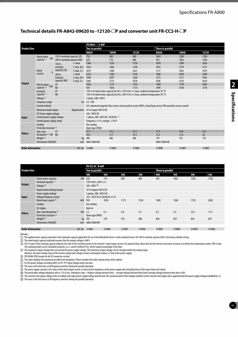
41
2
Specifications
Specifications FR-A800
Product lineFR-CC2-HmK-60PTwo in parallel Three in parallel400 450 500 560 400 450 500 560
Output
Rated motor capacity kW 630 710 800 900 945 1065 1200 1350Overload capacity 3 150 % 60 s, 200 % 3 sVoltage k 430–780 V j
Regenerative braking torque 10 % torque/100 % ED
InputPower supply voltage 3-phase, 380–500 V ACVoltage/frequency range 323–550 V AC at 50/60 Hz ±5 %Rated input capacit 9 kVA 939 1056 1173 1334 1409 1584 1759 2002
Others
Cooling Fan coolingDC chokes Built-inMax. heat dissipation 6 kW 5.5 6.1 6.8 7.9 8.2 9.2 10.3 11.9Protective structure 5 Open type (IP00)Weightl kg 564 570 576 586 846 855 864 879Dimensions (WxHxD) mm 600x1580x440
Order information Art. no. 314883 314884 314905 314906 314883 314884 314905 314906
Remarks:a The applied motor capacity indicated is the maximum capacity applicable for use of the Mitsubishi Electric 4-pole standard motor. The 200 % overload capacity (ND) is the factory default setting. b The rated output capacity indicated assumes that the output voltage is 440 V.c The % value of the overload capacity indicates the ratio of the overload current to the inverter's rated output current. For repeated duty, allow time for the inverter and motor to return to or below the temperatures under 100 % load.
The waiting periods can be calculated using the r.m.s. current method (I²xt), which requires knowledge of the duty.d The maximum output voltage does not exceed the power supply voltage. The maximum output voltage can be changed within the setting range.
However, the pulse voltage value of the inverter output side voltage remains unchanged at about √2 that of the power supply.e FFR-DU08: IP40 (except for the PU connector section)f The values displays the maximum possible heat dissipation. Please consider this values during setup of the cabinet.g For the power voltage exceeding 480 V, set Pr. 977 Input voltage mode selection.h The mass is the total mass of all frequency inverters during the parallel operation.i The power supply capacity is the value at the rated output current. It varies by the impedance at the power supply side (including those of the input choke and cables).j The permissible voltage imbalance ratio is 3 % or less. (Imbalance ratio = (highest voltage between lines – average voltage between three lines)/average voltage between three lines x100)k The converter unit output voltage varies according to the input power supply voltage and the load. The maximum point of the voltage waveform at the converter unit output side is approximately the power supply voltage multiplied by √2.l The mass is the total mass of all frequency inverters during the parallel operation.
Technical details FR-A842-09620 to -12120-mP and converter unit FR-CC2-H-mP
Product lineFR-A842-m-2-60PTwo in parallel Three in parallel09620 10940 12120 09620 10940 12120
Output
Rated motor capacity 1 kW
150 % overload capacity (LD) 710 800 900 1065 1200 1350200 % overload capacity (ND) 630 710 800 945 1065 1200
Rated current A
150 % overload capacity (LD)
I rated 1386 1539 1750 2078 2309 2626I max. 60 s 1663 1846 2100 2493 2770 3151I max. 3 s 2079 2308 2625 3117 2463 2939
200 % overload capacity (ND)
I rated 1232 1386 1539 1848 2078 2309I max. 60 s 1848 2079 2308 2772 3117 3463I max. 3 s 2464 2772 3078 3696 4156 4618
Rated output capacity 2 kVA
LD 1056 1173 1334 1584 1759 2002ND 939 1056 1173 1409 1584 1759
Overload capacity 3
LD 120 % of rated motor capacity for 60 s; 150 % for 3 s (max. ambient temperature 50 °C)ND 150 % of rated motor capacity for 60 s; 200 % for 3 s (max. ambient temperature 50 °C)
Voltage 4 3-phase, 380–500 VFrequency range Hz 0.2–590Control method U/f; advanced magnetic flux vector, real sensorless vector (RSV), closed loop vector, PM sensorless vector controlMaximum brake torque Regenerative 10 % torque/100 % ED
InputDC Power supply voltage 430–780 V DCControl power supply voltage 1-phase, 380–500 V AC, 50/60 Hz 7
Control power supply range Frequency ±5 %, voltage ±10 %
Others
Cooling Fan coolingProtective structure 5 Open type (IP00)Max. heat dissipation 6 kW
LD 11.7 13.2 15.5 17.5 19.8 23.3ND 10.2 11.7 13.3 15.3 17.6 20
Weight 8 kg 486 486 486 729 729 729Dimensions (WxHxD) mm 680x1580x440 680x1580x440
Order information Art. no. 314880 314881 314882 314880 314881 314882
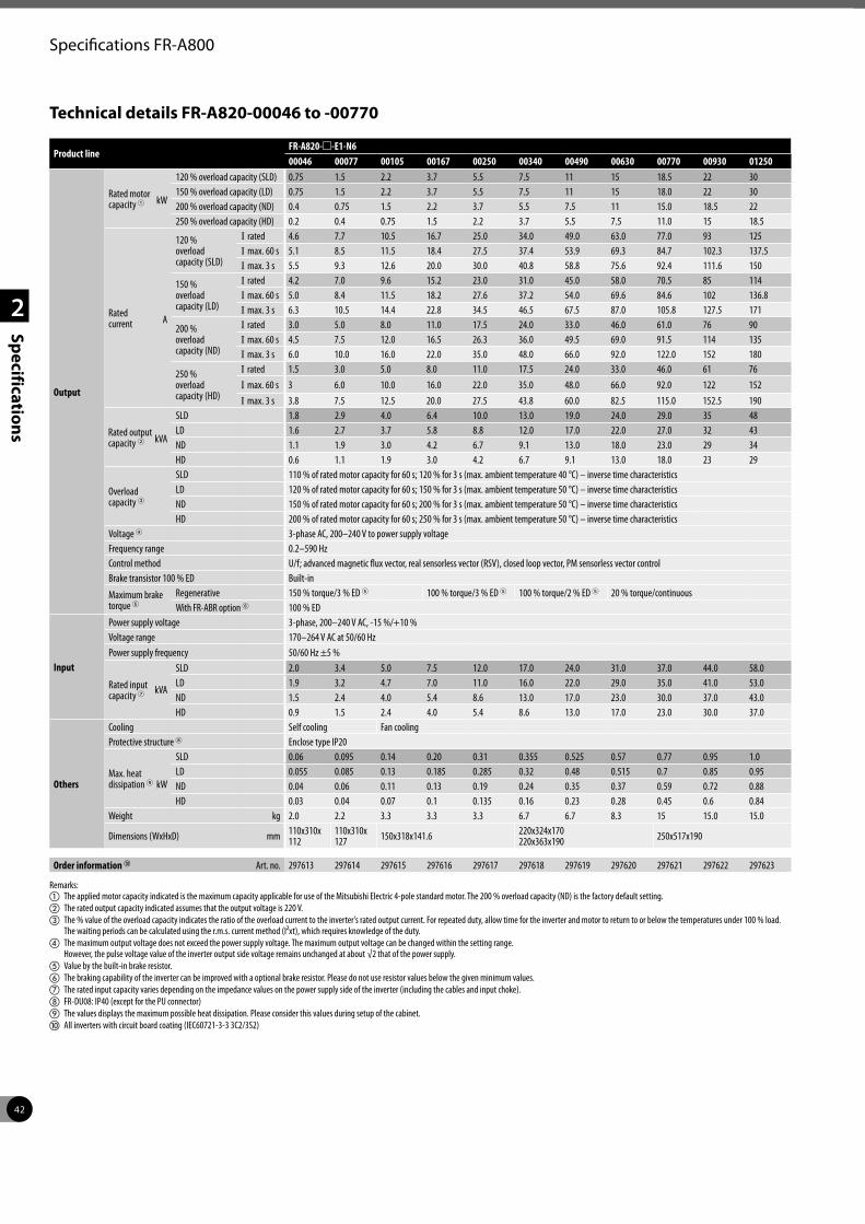
42
2
Specifications
Specifications FR-A800
Technical details FR-A820-00046 to -00770
Product lineFR-A820-m-E1-N600046 00077 00105 00167 00250 00340 00490 00630 00770 00930 01250
Output
Rated motor capacity 1 kW
120 % overload capacity (SLD) 0.75 1.5 2.2 3.7 5.5 7.5 11 15 18.5 22 30150 % overload capacity (LD) 0.75 1.5 2.2 3.7 5.5 7.5 11 15 18.0 22 30200 % overload capacity (ND) 0.4 0.75 1.5 2.2 3.7 5.5 7.5 11 15.0 18.5 22250 % overload capacity (HD) 0.2 0.4 0.75 1.5 2.2 3.7 5.5 7.5 11.0 15 18.5
Rated current A
120 % overload capacity (SLD)
I rated 4.6 7.7 10.5 16.7 25.0 34.0 49.0 63.0 77.0 93 125I max. 60 s 5.1 8.5 11.5 18.4 27.5 37.4 53.9 69.3 84.7 102.3 137.5I max. 3 s 5.5 9.3 12.6 20.0 30.0 40.8 58.8 75.6 92.4 111.6 150
150 % overload capacity (LD)
I rated 4.2 7.0 9.6 15.2 23.0 31.0 45.0 58.0 70.5 85 114I max. 60 s 5.0 8.4 11.5 18.2 27.6 37.2 54.0 69.6 84.6 102 136.8I max. 3 s 6.3 10.5 14.4 22.8 34.5 46.5 67.5 87.0 105.8 127.5 171
200 % overload capacity (ND)
I rated 3.0 5.0 8.0 11.0 17.5 24.0 33.0 46.0 61.0 76 90I max. 60 s 4.5 7.5 12.0 16.5 26.3 36.0 49.5 69.0 91.5 114 135I max. 3 s 6.0 10.0 16.0 22.0 35.0 48.0 66.0 92.0 122.0 152 180
250 % overload capacity (HD)
I rated 1.5 3.0 5.0 8.0 11.0 17.5 24.0 33.0 46.0 61 76I max. 60 s 3 6.0 10.0 16.0 22.0 35.0 48.0 66.0 92.0 122 152I max. 3 s 3.8 7.5 12.5 20.0 27.5 43.8 60.0 82.5 115.0 152.5 190
Rated output capacity 2 kVA
SLD 1.8 2.9 4.0 6.4 10.0 13.0 19.0 24.0 29.0 35 48LD 1.6 2.7 3.7 5.8 8.8 12.0 17.0 22.0 27.0 32 43ND 1.1 1.9 3.0 4.2 6.7 9.1 13.0 18.0 23.0 29 34HD 0.6 1.1 1.9 3.0 4.2 6.7 9.1 13.0 18.0 23 29
Overload capacity 3
SLD 110 % of rated motor capacity for 60 s; 120 % for 3 s (max. ambient temperature 40 °C) – inverse time characteristicsLD 120 % of rated motor capacity for 60 s; 150 % for 3 s (max. ambient temperature 50 °C) – inverse time characteristicsND 150 % of rated motor capacity for 60 s; 200 % for 3 s (max. ambient temperature 50 °C) – inverse time characteristicsHD 200 % of rated motor capacity for 60 s; 250 % for 3 s (max. ambient temperature 50 °C) – inverse time characteristics
Voltage 4 3-phase AC, 200–240 V to power supply voltageFrequency range 0.2–590 HzControl method U/f; advanced magnetic flux vector, real sensorless vector (RSV), closed loop vector, PM sensorless vector controlBrake transistor 100 % ED Built-in
Maximum brake torque 5
Regenerative 150 % torque/3 % ED 5 100 % torque/3 % ED 5 100 % torque/2 % ED 5 20 % torque/continuousWith FR-ABR option 6 100 % ED
Input
Power supply voltage 3-phase, 200–240 V AC, -15 %/+10 %Voltage range 170–264 V AC at 50/60 Hz Power supply frequency 50/60 Hz ±5 %
Rated input capacity 7 kVA
SLD 2.0 3.4 5.0 7.5 12.0 17.0 24.0 31.0 37.0 44.0 58.0LD 1.9 3.2 4.7 7.0 11.0 16.0 22.0 29.0 35.0 41.0 53.0ND 1.5 2.4 4.0 5.4 8.6 13.0 17.0 23.0 30.0 37.0 43.0HD 0.9 1.5 2.4 4.0 5.4 8.6 13.0 17.0 23.0 30.0 37.0
Others
Cooling Self cooling Fan coolingProtective structure 8 Enclose type IP20
Max. heat dissipation 9 kW
SLD 0.06 0.095 0.14 0.20 0.31 0.355 0.525 0.57 0.77 0.95 1.0LD 0.055 0.085 0.13 0.185 0.285 0.32 0.48 0.515 0.7 0.85 0.95ND 0.04 0.06 0.11 0.13 0.19 0.24 0.35 0.37 0.59 0.72 0.88HD 0.03 0.04 0.07 0.1 0.135 0.16 0.23 0.28 0.45 0.6 0.84
Weight kg 2.0 2.2 3.3 3.3 3.3 6.7 6.7 8.3 15 15.0 15.0
Dimensions (WxHxD) mm 110x310x 112
110x310x 127 150x318x141.6 220x324x170
220x363x190 250x517x190
Order information j Art. no. 297613 297614 297615 297616 297617 297618 297619 297620 297621 297622 297623
Remarks:a The applied motor capacity indicated is the maximum capacity applicable for use of the Mitsubishi Electric 4-pole standard motor. The 200 % overload capacity (ND) is the factory default setting. b The rated output capacity indicated assumes that the output voltage is 220 V.c The % value of the overload capacity indicates the ratio of the overload current to the inverter's rated output current. For repeated duty, allow time for the inverter and motor to return to or below the temperatures under 100 % load.
The waiting periods can be calculated using the r.m.s. current method (I²xt), which requires knowledge of the duty.d The maximum output voltage does not exceed the power supply voltage. The maximum output voltage can be changed within the setting range.
However, the pulse voltage value of the inverter output side voltage remains unchanged at about √2 that of the power supply.e Value by the built-in brake resistor.f The braking capability of the inverter can be improved with a optional brake resistor. Please do not use resistor values below the given minimum values.g The rated input capacity varies depending on the impedance values on the power supply side of the inverter (including the cables and input choke).h FR-DU08: IP40 (except for the PU connector)i The values displays the maximum possible heat dissipation. Please consider this values during setup of the cabinet.j All inverters with circuit board coating (IEC60721-3-3 3C2/3S2)
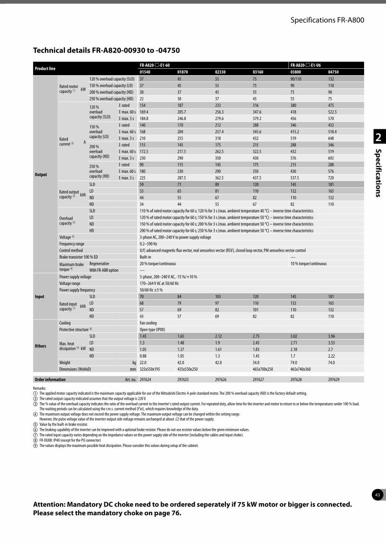
43
2
Specifications
Specifications FR-A800
Technical details FR-A820-00930 to -04750
Product lineFR-A820-m-E1-60 FR-A820-m-E1-U601540 01870 02330 03160 03800 04750
Output
Rated motor capacity 1 kW
120 % overload capacity (SLD) 37 45 55 75 90/110 132150 % overload capacity (LD) 37 45 55 75 90 110200 % overload capacity (ND) 30 37 45 55 75 90250 % overload capacity (HD) 22 30 37 45 55 75
Rated current 3 A
120 % overload capacity (SLD)
I rated 154 187 233 316 380 475I max. 60 s 169.4 205.7 256.3 347.6 418 522.5I max. 3 s 184.8 246.8 279.6 379.2 456 570
150 % overload capacity (LD)
I rated 140 170 212 288 346 432I max. 60 s 168 204 257.4 345.6 415.2 518.4I max. 3 s 210 255 318 432 519 648
200 % overload capacity (ND)
I rated 115 145 175 215 288 346I max. 60 s 172.5 217.5 262.5 322.5 432 519I max. 3 s 230 290 350 430 576 692
250 % overload capacity (HD)
I rated 90 115 145 175 215 288I max. 60 s 180 230 290 350 430 576I max. 3 s 225 287.5 362.5 437.5 537.5 720
Rated output capacity 2 kVA
SLD 59 71 89 120 145 181LD 53 65 81 110 132 165ND 44 55 67 82 110 132HD 34 44 55 67 82 110
Overload capacity 4
SLD 110 % of rated motor capacity for 60 s; 120 % for 3 s (max. ambient temperature 40 °C) – inverse time characteristicsLD 120 % of rated motor capacity for 60 s; 150 % for 3 s (max. ambient temperature 50 °C) – inverse time characteristicsND 150 % of rated motor capacity for 60 s; 200 % for 3 s (max. ambient temperature 50 °C) – inverse time characteristicsHD 200 % of rated motor capacity for 60 s; 250 % for 3 s (max. ambient temperature 50 °C) – inverse time characteristics
Voltage 5 3-phase AC, 200–240 V to power supply voltageFrequency range 0.2–590 HzControl method U/f; advanced magnetic flux vector, real sensorless vector (RSV), closed loop vector, PM sensorless vector controlBrake transistor 100 % ED Built-in —
Maximum brake torque 6
Regenerative 20 % torque/continuous 10 % torque/continuous With FR-ABR option —
Input
Power supply voltage 3-phase, 200–240 V AC, -15 %/+10 %Voltage range 170–264 V AC at 50/60 Hz Power supply frequency 50/60 Hz ±5 %
Rated input capacity 7 kVA
SLD 70 84 103 120 145 181LD 68 79 97 110 132 165ND 57 69 82 101 110 132HD 43 57 69 82 82 110
Others
Cooling Fan coolingProtective structure 8 Open type (IP00)
Max. heat dissipation9 kW
SLD 1.45 1.65 2.12 2.75 3.02 3.96LD 1.3 1.48 1.9 2.45 2.71 3.53ND 1.05 1.27 1.61 1.83 2.18 2.7HD 0.88 1.05 1.3 1.45 1.7 2.22
Weight kg 22.0 42.0 42.0 54.0 74.0 74.0Dimensions (WxHxD) mm 325x550x195 435x550x250 465x700x250 465x740x360
Order information Art. no. 297624 297625 297626 297627 297628 297629
Remarks:a The applied motor capacity indicated is the maximum capacity applicable for use of the Mitsubishi Electric 4-pole standard motor. The 200 % overload capacity (ND) is the factory default setting. b The rated output capacity indicated assumes that the output voltage is 220 V.c The % value of the overload capacity indicates the ratio of the overload current to the inverter's rated output current. For repeated duty, allow time for the inverter and motor to return to or below the temperatures under 100 % load.
The waiting periods can be calculated using the r.m.s. current method (I²xt), which requires knowledge of the duty.d The maximum output voltage does not exceed the power supply voltage. The maximum output voltage can be changed within the setting range.
However, the pulse voltage value of the inverter output side voltage remains unchanged at about √2 that of the power supply.e Value by the built-in brake resistor.f The braking capability of the inverter can be improved with a optional brake resistor. Please do not use resistor values below the given minimum values.g The rated input capacity varies depending on the impedance values on the power supply side of the inverter (including the cables and input choke).h FR-DU08: IP40 (except for the PU connector)i The values displays the maximum possible heat dissipation. Please consider this values during setup of the cabinet.
Attention: Mandatory DC choke need to be ordered seperately if 75 kW motor or bigger is connected. Please select the mandatory choke on page 76.
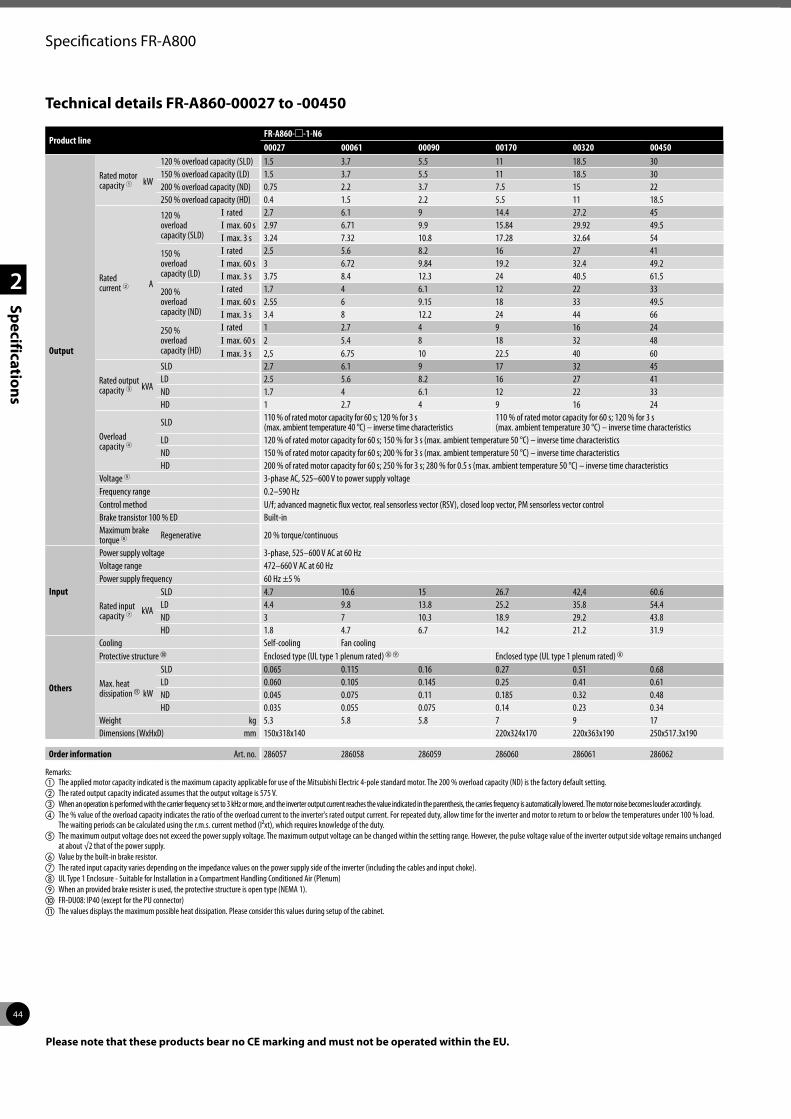
44
2
Specifications
Specifications FR-A800
Technical details FR-A860-00027 to -00450
Product lineFR-A860-m-1-N600027 00061 00090 00170 00320 00450
Output
Rated motor capacity 1 kW
120 % overload capacity (SLD) 1.5 3.7 5.5 11 18.5 30150 % overload capacity (LD) 1.5 3.7 5.5 11 18.5 30200 % overload capacity (ND) 0.75 2.2 3.7 7.5 15 22250 % overload capacity (HD) 0.4 1.5 2.2 5.5 11 18.5
Rated current 2 A
120 % overload capacity (SLD)
I rated 2.7 6.1 9 14.4 27.2 45I max. 60 s 2.97 6.71 9.9 15.84 29.92 49.5I max. 3 s 3.24 7.32 10.8 17.28 32.64 54
150 % overload capacity (LD)
I rated 2.5 5.6 8.2 16 27 41I max. 60 s 3 6.72 9.84 19.2 32.4 49.2I max. 3 s 3.75 8.4 12.3 24 40.5 61.5
200 % overload capacity (ND)
I rated 1.7 4 6.1 12 22 33I max. 60 s 2.55 6 9.15 18 33 49.5I max. 3 s 3.4 8 12.2 24 44 66
250 % overload capacity (HD)
I rated 1 2.7 4 9 16 24I max. 60 s 2 5.4 8 18 32 48I max. 3 s 2,5 6.75 10 22.5 40 60
Rated output capacity 3 kVA
SLD 2.7 6.1 9 17 32 45LD 2.5 5.6 8.2 16 27 41ND 1.7 4 6.1 12 22 33HD 1 2.7 4 9 16 24
Overload capacity 4
SLD 110 % of rated motor capacity for 60 s; 120 % for 3 s (max. ambient temperature 40 °C) – inverse time characteristics
110 % of rated motor capacity for 60 s; 120 % for 3 s (max. ambient temperature 30 °C) – inverse time characteristics
LD 120 % of rated motor capacity for 60 s; 150 % for 3 s (max. ambient temperature 50 °C) – inverse time characteristicsND 150 % of rated motor capacity for 60 s; 200 % for 3 s (max. ambient temperature 50 °C) – inverse time characteristicsHD 200 % of rated motor capacity for 60 s; 250 % for 3 s; 280 % for 0.5 s (max. ambient temperature 50 °C) – inverse time characteristics
Voltage 5 3-phase AC, 525–600 V to power supply voltageFrequency range 0.2–590 HzControl method U/f; advanced magnetic flux vector, real sensorless vector (RSV), closed loop vector, PM sensorless vector controlBrake transistor 100 % ED Built-inMaximum brake torque 6 Regenerative 20 % torque/continuous
Input
Power supply voltage 3-phase, 525–600 V AC at 60 HzVoltage range 472–660 V AC at 60 Hz Power supply frequency 60 Hz ±5 %
Rated input capacity 7 kVA
SLD 4.7 10.6 15 26.7 42,4 60.6LD 4.4 9.8 13.8 25.2 35.8 54.4ND 3 7 10.3 18.9 29.2 43.8HD 1.8 4.7 6.7 14.2 21.2 31.9
Others
Cooling Self-cooling Fan coolingProtective structure j Enclosed type (UL type 1 plenum rated)hi Enclosed type (UL type 1 plenum rated)h
Max. heat dissipationk kW
SLD 0.065 0.115 0.16 0.27 0.51 0.68LD 0.060 0.105 0.145 0.25 0.41 0.61ND 0.045 0.075 0.11 0.185 0.32 0.48HD 0.035 0.055 0.075 0.14 0.23 0.34
Weight kg 5.3 5.8 5.8 7 9 17Dimensions (WxHxD) mm 150x318x140 220x324x170 220x363x190 250x517.3x190
Order information Art. no. 286057 286058 286059 286060 286061 286062
Remarks:a The applied motor capacity indicated is the maximum capacity applicable for use of the Mitsubishi Electric 4-pole standard motor. The 200 % overload capacity (ND) is the factory default setting. b The rated output capacity indicated assumes that the output voltage is 575 V.c When an operation is performed with the carrier frequency set to 3 kHz or more, and the inverter output current reaches the value indicated in the parenthesis, the carries frequency is automatically lowered. The motor noise becomes louder accordingly.d The % value of the overload capacity indicates the ratio of the overload current to the inverter's rated output current. For repeated duty, allow time for the inverter and motor to return to or below the temperatures under 100 % load.
The waiting periods can be calculated using the r.m.s. current method (I²xt), which requires knowledge of the duty.e The maximum output voltage does not exceed the power supply voltage. The maximum output voltage can be changed within the setting range. However, the pulse voltage value of the inverter output side voltage remains unchanged
at about √2 that of the power supply.f Value by the built-in brake resistor.g The rated input capacity varies depending on the impedance values on the power supply side of the inverter (including the cables and input choke).h UL Type 1 Enclosure - Suitable for Installation in a Compartment Handling Conditioned Air (Plenum)i When an provided brake resister is used, the protective structure is open type (NEMA 1).j FR-DU08: IP40 (except for the PU connector)k The values displays the maximum possible heat dissipation. Please consider this values during setup of the cabinet.
Please note that these products bear no CE marking and must not be operated within the EU.
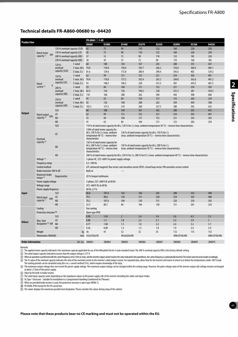
45
2
Specifications
Specifications FR-A800
Product lineFR-A860-m-1-6000680 01080 01440 01670 02430 02890 03360 04420
Output
Rated motor capacity 1 kW
120 % overload capacity (SLD) 45 75 90 110 132 160 220 250150 % overload capacity (LD) 45 75 90 110 132 160 220 250200 % overload capacity (ND) 37 55 75 90 110 132 185 220250 % overload capacity (HD) 30 45 55 75 90 110 160 185
Rated current 2 A
120 % overload capacity (SLD)
I rated 68 108 144 167 242 288 335 441I max. 60 s 74.8 118.8 158.4 183.7 266.2 316.8 368.5 485.1I max. 3 s 81.6 129.6 172.8 200.4 290.4 345.6 402 529.2
150 % overload capacity (LD)
I rated 62 99 131 152 221 254 303 401I max. 60 s 74.4 118.8 157.2 182.4 265.2 304.8 363.6 481.2I max. 3 s 93 148.5 196.5 228 331.5 381 454.5 601.5
200 % overload capacity (ND)
I rated 55 84 104 131 152 221 254 303I max. 60 s 82.5 126 156 196.5 228 331.5 381 454.5I max. 3 s 110 168 208 262 304 442 508 606
250 % overload capacity (HD)
I rated 41 63 84 104 131 152 202 254I max. 60 s 82 126 168 208 262 304 404 508I max. 3 s 102.5 157.5 210 260 327.5 380 505 635
Rated output capacity 3 kVA
SLD 68 108 144 167 242 288 335 441LD 62 99 131 152 221 254 303 401ND 55 84 104 131 152 221 254 303HD 41 63 84 104 131 152 202 254
Overload capacity 4
SLD 110 % of rated motor capacity for 60 s; 120 % for 3 s (max. ambient temperature 50 °C) – inverse time characteristics
LD
120% of rated motor capacity for 60 s; 150 % for 3 s (max. ambient temperature 40 °C) – inverse time characteristics
120 % of rated motor capacity for 60 s; 150 % for 3 s (max. ambient temperature 50 °C) – inverse time characteristics
ND
150 % of rated motor capacity for 60 s; 200 % for 3 s (max. ambient temperature 40 °C) – inverse time characteristics
150 % of rated motor capacity for 60 s; 200 % for 3 s (max. ambient temperature 50 °C) – inverse time characteristics
HD 200 % of rated motor capacity for 60 s; 250 % for 3 s; 280 % for 0.5 s (max. ambient temperature 40 °C) – inverse time characteristicsVoltage 5 3-phase AC, 525–600 V to power supply voltageFrequency range 0.2–590 HzControl method U/f; advanced magnetic flux vector, real sensorless vector (RSV), closed loop vector, PM sensorless vector controlBrake transistor 100 % ED Built-in —Maximum brake torque 6 Regenerative 20 % torque/continuous
Input
Power supply voltage 3-phase, 525–600 V AC at 60 HzVoltage range 472–660 V AC at 60 Hz Power supply frequency 60 Hz ±5 %
Rated input capacity 7 kVA
SLD 86.8 107.6 143 166 245 288 335 440LD 79.1 98.6 130 151 220 254 303 400ND 70.2 107.6 104 130 151 220 254 303HD 52.3 80.7 84 104 130 151 201 254
Others
Cooling Fan coolingProtective structure j Open type IP00
Max. heat dissipationk kW
SLD 0.98 1.45 2 2.4 3.4 3.6 4.3 5.5LD 0.88 1.3 1.8 2.2 3.1 3.2 3.9 5ND 0.77 1.08 1.5 1.8 2.2 2.6 3.2 3.7HD 0.56 0.80 1.2 1.5 1.8 1.9 2.4 2.9.
Weight kg 36 41 52 52 55 112 115 153Dimensions (WxHxD) mm 432x550x250 465x620x300 498x1010x380 680x1010x380
Order information Art. no. 286063 286064 286065 286066 286067 286068 286069 286070
Remarks:a The applied motor capacity indicated is the maximum capacity applicable for use of the Mitsubishi Electric 4-pole standard motor. The 200 % overload capacity (ND) is the factory default setting. b The rated output capacity indicated assumes that the output voltage is 575 V.c When an operation is performed with the carrier frequency set to 3 kHz or more, and the inverter output current reaches the value indicated in the parenthesis, the carries frequency is automatically lowered. The motor noise becomes louder accordingly.d The % value of the overload capacity indicates the ratio of the overload current to the inverter's rated output current. For repeated duty, allow time for the inverter and motor to return to or below the temperatures under 100 % load.
The waiting periods can be calculated using the r.m.s. current method (I²xt), which requires knowledge of the duty.e The maximum output voltage does not exceed the power supply voltage. The maximum output voltage can be changed within the setting range. However, the pulse voltage value of the inverter output side voltage remains unchanged
at about √2 that of the power supply.f Value by the built-in brake resistor.g The rated input capacity varies depending on the impedance values on the power supply side of the inverter (including the cables and input choke).h UL Type 1 Enclosure - Suitable for Installation in a Compartment Handling Conditioned Air (Plenum)i When an provided brake resister is used, the protective structure is open type (NEMA 1).j FR-DU08: IP40 (except for the PU connector)k The values displays the maximum possible heat dissipation. Please consider this values during setup of the cabinet.
Technical details FR-A860-00680 to -04420
Please note that these products bear no CE marking and must not be operated within the EU.
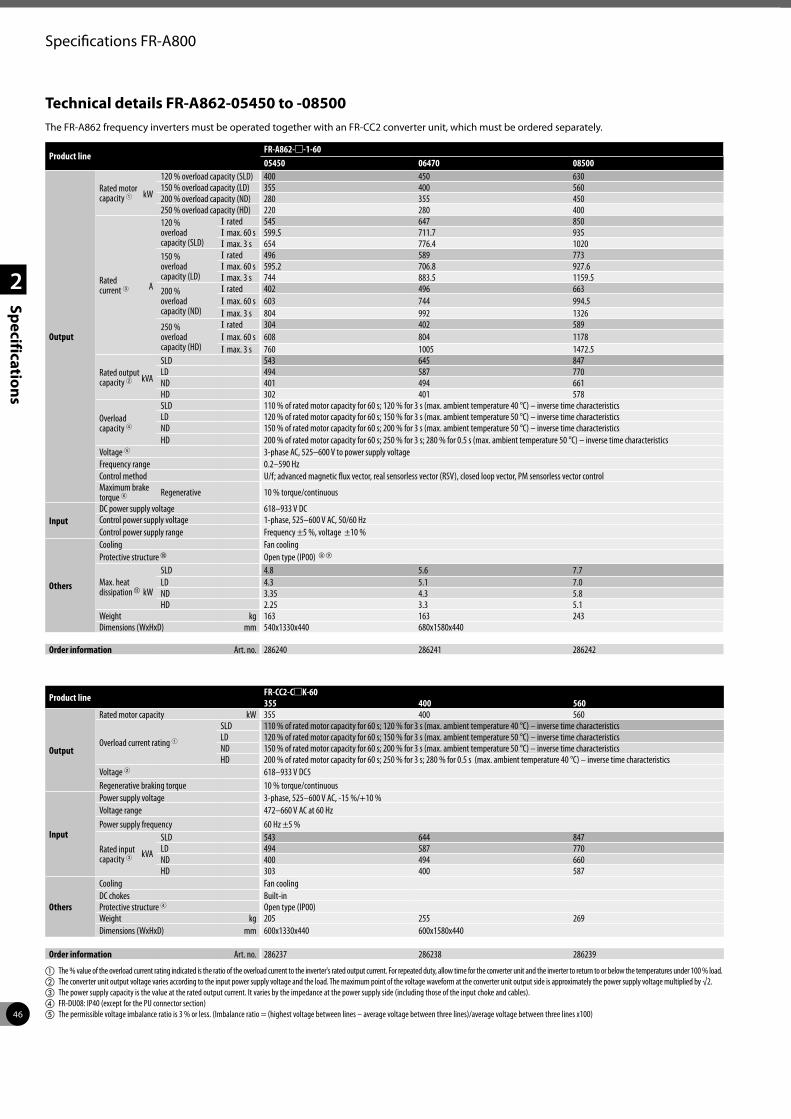
46
2
Specifications
Specifications FR-A800
Technical details FR-A862-05450 to -08500
Product lineFR-A862-m-1-6005450 06470 08500
Output
Rated motor capacity 1 kW
120 % overload capacity (SLD) 400 450 630150 % overload capacity (LD) 355 400 560200 % overload capacity (ND) 280 355 450250 % overload capacity (HD) 220 280 400
Rated current 3 A
120 % overload capacity (SLD)
I rated 545 647 850I max. 60 s 599.5 711.7 935I max. 3 s 654 776.4 1020
150 % overload capacity (LD)
I rated 496 589 773I max. 60 s 595.2 706.8 927.6I max. 3 s 744 883.5 1159.5
200 % overload capacity (ND)
I rated 402 496 663I max. 60 s 603 744 994.5I max. 3 s 804 992 1326
250 % overload capacity (HD)
I rated 304 402 589I max. 60 s 608 804 1178I max. 3 s 760 1005 1472.5
Rated output capacity 2 kVA
SLD 543 645 847LD 494 587 770ND 401 494 661HD 302 401 578
Overload capacity 4
SLD 110 % of rated motor capacity for 60 s; 120 % for 3 s (max. ambient temperature 40 °C) – inverse time characteristicsLD 120 % of rated motor capacity for 60 s; 150 % for 3 s (max. ambient temperature 50 °C) – inverse time characteristicsND 150 % of rated motor capacity for 60 s; 200 % for 3 s (max. ambient temperature 50 °C) – inverse time characteristicsHD 200 % of rated motor capacity for 60 s; 250 % for 3 s; 280 % for 0.5 s (max. ambient temperature 50 °C) – inverse time characteristics
Voltage 5 3-phase AC, 525–600 V to power supply voltageFrequency range 0.2–590 HzControl method U/f; advanced magnetic flux vector, real sensorless vector (RSV), closed loop vector, PM sensorless vector controlMaximum brake torque 6 Regenerative 10 % torque/continuous
InputDC power supply voltage 618–933 V DCControl power supply voltage 1-phase, 525–600 V AC, 50/60 Hz Control power supply range Frequency ±5 %, voltage ±10 %
Others
Cooling Fan coolingProtective structure j Open type (IP00) hi
Max. heat dissipationk kW
SLD 4.8 5.6 7.7LD 4.3 5.1 7.0ND 3.35 4.3 5.8HD 2.25 3.3 5.1
Weight kg 163 163 243Dimensions (WxHxD) mm 540x1330x440 680x1580x440
Order information Art. no. 286240 286241 286242
Product line FR-CC2-CmK-60355 400 560
Output
Rated motor capacity kW 355 400 560
Overload current rating 1SLD 110 % of rated motor capacity for 60 s; 120 % for 3 s (max. ambient temperature 40 °C) – inverse time characteristicsLD 120 % of rated motor capacity for 60 s; 150 % for 3 s (max. ambient temperature 50 °C) – inverse time characteristicsND 150 % of rated motor capacity for 60 s; 200 % for 3 s (max. ambient temperature 50 °C) – inverse time characteristicsHD 200 % of rated motor capacity for 60 s; 250 % for 3 s; 280 % for 0.5 s (max. ambient temperature 40 °C) – inverse time characteristics
Voltage 2 618–933 V DC5Regenerative braking torque 10 % torque/continuous
Input
Power supply voltage 3-phase, 525–600 V AC, -15 %/+10 %Voltage range 472–660 V AC at 60 HzPower supply frequency 60 Hz ±5 %
Rated input capacity 3 kVA
SLD 543 644 847LD 494 587 770ND 400 494 660HD 303 400 587
Others
Cooling Fan coolingDC chokes Built-inProtective structure 4 Open type (IP00)Weight kg 205 255 269Dimensions (WxHxD) mm 600x1330x440 600x1580x440
Order information Art. no. 286237 286238 286239
a The % value of the overload current rating indicated is the ratio of the overload current to the inverter's rated output current. For repeated duty, allow time for the converter unit and the inverter to return to or below the temperatures under 100 % load.b The converter unit output voltage varies according to the input power supply voltage and the load. The maximum point of the voltage waveform at the converter unit output side is approximately the power supply voltage multiplied by √2.c The power supply capacity is the value at the rated output current. It varies by the impedance at the power supply side (including those of the input choke and cables).d FR-DU08: IP40 (except for the PU connector section)e The permissible voltage imbalance ratio is 3 % or less. (Imbalance ratio = (highest voltage between lines – average voltage between three lines)/average voltage between three lines x100)
The FR-A862 frequency inverters must be operated together with an FR-CC2 converter unit, which must be ordered separately.
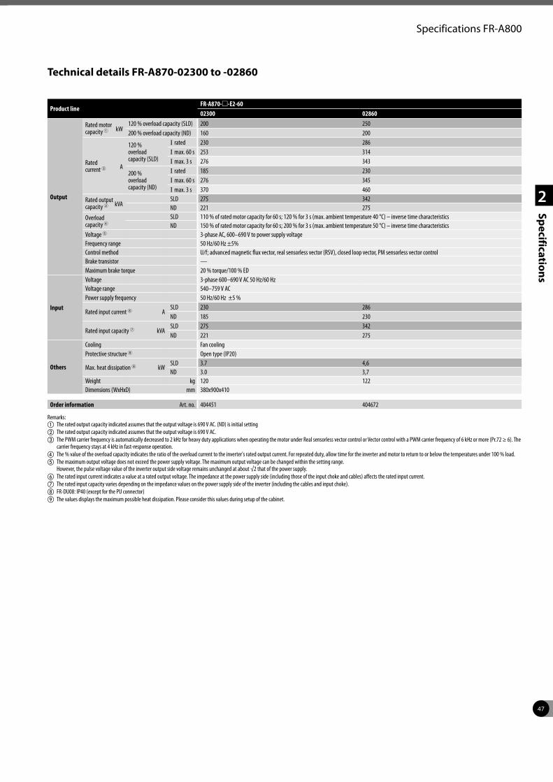
47
2
Specifications
Specifications FR-A800
Technical details FR-A870-02300 to -02860
Product lineFR-A870-m-E2-6002300 02860
Output
Rated motor capacity 1 kW
120 % overload capacity (SLD) 200 250200 % overload capacity (ND) 160 200
Rated current 3 A
120 % overload capacity (SLD)
I rated 230 286I max. 60 s 253 314I max. 3 s 276 343
200 % overload capacity (ND)
I rated 185 230I max. 60 s 276 345I max. 3 s 370 460
Rated output capacity 2 kVA
SLD 275 342ND 221 275
Overload capacity 4
SLD 110 % of rated motor capacity for 60 s; 120 % for 3 s (max. ambient temperature 40 °C) – inverse time characteristicsND 150 % of rated motor capacity for 60 s; 200 % for 3 s (max. ambient temperature 50 °C) – inverse time characteristics
Voltage 5 3-phase AC, 600–690 V to power supply voltageFrequency range 50 Hz/60 Hz ±5%Control method U/f; advanced magnetic flux vector, real sensorless vector (RSV), closed loop vector, PM sensorless vector controlBrake transistor —Maximum brake torque 20 % torque/100 % ED
Input
Voltage 3-phase 600–690 V AC 50 Hz/60 HzVoltage range 540–759 V ACPower supply frequency 50 Hz/60 Hz ±5 %
Rated input current 6 ASLD 230 286ND 185 230
Rated input capacity 7 kVASLD 275 342ND 221 275
Others
Cooling Fan coolingProtective structure 8 Open type (IP20)
Max. heat dissipation 9 kWSLD 3.7 4,6ND 3.0 3,7
Weight kg 120 122Dimensions (WxHxD) mm 380x900x410
Order information Art. no. 404451 404672
Remarks:a The rated output capacity indicated assumes that the output voltage is 690 V AC. (ND) is initial settingb The rated output capacity indicated assumes that the output voltage is 690 V AC.c The PWM carrier frequency is automatically decreased to 2 kHz for heavy duty applications when operating the motor under Real sensorless vector control or Vector control with a PWM carrier frequency of 6 kHz or more (Pr.72 ≥ 6). The
carrier frequency stays at 4 kHz in fast-response operation.d The % value of the overload capacity indicates the ratio of the overload current to the inverter's rated output current. For repeated duty, allow time for the inverter and motor to return to or below the temperatures under 100 % load. e The maximum output voltage does not exceed the power supply voltage. The maximum output voltage can be changed within the setting range.
However, the pulse voltage value of the inverter output side voltage remains unchanged at about √2 that of the power supply.f The rated input current indicates a value at a rated output voltage. The impedance at the power supply side (including those of the input choke and cables) affects the rated input current.g The rated input capacity varies depending on the impedance values on the power supply side of the inverter (including the cables and input choke).h FR-DU08: IP40 (except for the PU connector)i The values displays the maximum possible heat dissipation. Please consider this values during setup of the cabinet.
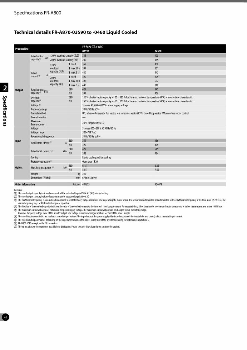
48
2
Specifications
Specifications FR-A800
Technical details FR-A870-03590 to -0460 Liquid Cooled
Product lineFR-A870-m-2-60LC03590 04560
Output
Rated motor capacity 1 kW
120 % overload capacity (SLD) 315 400200 % overload capacity (ND) 280 355
Rated current 3 A
120 % overload capacity (SLD)
I rated 359 456I max. 60 s 394 501I max. 3 s 430 547
200 % overload capacity (ND)
I rated 320 405I max. 60 s 480 607I max. 3 s 640 810
Rated output capacity 2 kVA
SLD 429 545ND 359 456
Overload capacity 4
SLD 110 % of rated motor capacity for 60 s; 120 % for 3 s (max. ambient temperature 40 °C) – inverse time characteristicsND 150 % of rated motor capacity for 60 s; 200 % for 3 s (max. ambient temperature 50 °C) – inverse time characteristics
Voltage 5 3-phase AC, 600–690 V to power supply voltageFrequency range 50 Hz/60 Hz ±5%Control method U/f; advanced magnetic flux vector, real sensorless vector (RSV), closed loop vector, PM sensorless vector controlBremstransistor —Maximales Bremsmoment 20 % torque/100 % ED
Input
Voltage 3-phase 600–690 V AC 50 Hz/60 HzVoltage range 525–759 V ACPower supply frequency 50 Hz/60 Hz ±5 %
Rated input current 6 ASLD 359 456ND 320 405
Rated input capacity 7 kVASLD 429 545ND 382 484
Others
Cooling Liquid cooling and fan coolingProtective structure 8 Open type (IP20)
Max. heat dissipation 9 kWSLD 6.15 6.85ND 5.55 7.65
Weight kg 212Dimensions (WxHxD) mm 675x1551x440
Order information Art. no. 404673 404674
Remarks:a The rated output capacity indicated assumes that the output voltage is 690 V AC. (ND) is initial settingb The rated output capacity indicated assumes that the output voltage is 690 V AC.c The PWM carrier frequency is automatically decreased to 2 kHz for heavy duty applications when operating the motor under Real sensorless vector control or Vector control with a PWM carrier frequency of 6 kHz or more (Pr.72 ≥ 6). The
carrier frequency stays at 4 kHz in fast-response operation.d The % value of the overload capacity indicates the ratio of the overload current to the inverter's rated output current. For repeated duty, allow time for the inverter and motor to return to or below the temperatures under 100 % load. e The maximum output voltage does not exceed the power supply voltage. The maximum output voltage can be changed within the setting range.
However, the pulse voltage value of the inverter output side voltage remains unchanged at about √2 that of the power supply.f The rated input current indicates a value at a rated output voltage. The impedance at the power supply side (including those of the input choke and cables) affects the rated input current.g The rated input capacity varies depending on the impedance values on the power supply side of the inverter (including the cables and input choke).h FR-DU08: IP40 (except for the PU connector)i The values displays the maximum possible heat dissipation. Please consider this values during setup of the cabinet.
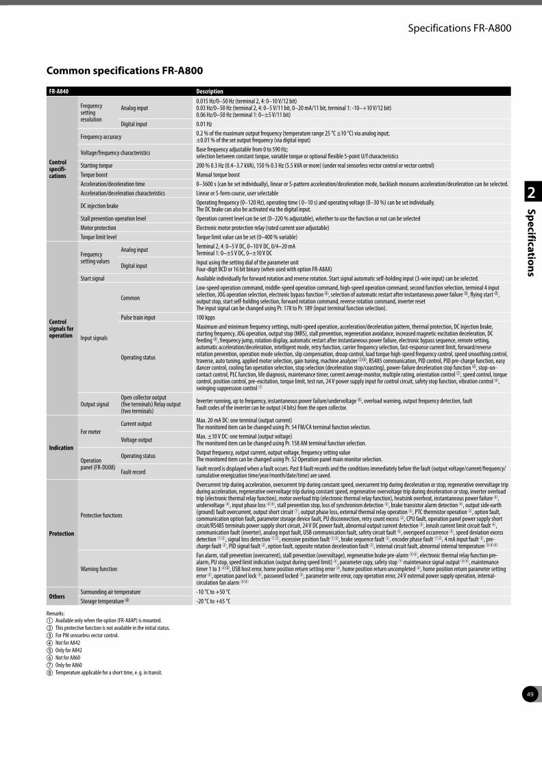
49
2
Specifications
Specifications FR-A800
Common specifications FR-A800
FR-A840 Description
Control specifi- cations
Frequency setting resolution
Analog input0.015 Hz/0–50 Hz (terminal 2, 4: 0–10 V/12 bit)0.03 Hz/0–50 Hz (terminal 2, 4: 0–5 V/11 bit, 0–20 mA/11 bit, terminal 1: -10–+10 V/12 bit)0.06 Hz/0–50 Hz (terminal 1: 0–±5 V/11 bit)
Digital input 0.01 Hz
Frequency accuracy 0.2 % of the maximum output frequency (temperature range 25 °C ±10 °C) via analog input; ±0.01 % of the set output frequency (via digital input)
Voltage/frequency characteristics Base frequency adjustable from 0 to 590 Hz; selection between constant torque, variable torque or optional flexible 5-point U/f characteristics
Starting torque 200 % 0.3 Hz (0.4–3.7 kVA), 150 % 0.3 Hz (5.5 kVA or more) (under real sensorless vector control or vector control)Torque boost Manual torque boostAcceleration/deceleration time 0–3600 s (can be set individually), linear or S-pattern acceleration/deceleration mode, backlash measures acceleration/deceleration can be selected.Acceleration/deceleration characteristics Linear or S-form course, user selectable
DC injection brake Operating frequency (0–120 Hz), operating time ( 0–10 s) and operating voltage (0–30 %) can be set individually. The DC brake can also be activated via the digital input.
Stall prevention operation level Operation current level can be set (0–220 % adjustable), whether to use the function or not can be selectedMotor protection Electronic motor protection relay (rated current user adjustable)Torque limit level Torque limit value can be set (0–400 % variable)
Control signals for operation
Frequency setting values
Analog input Terminal 2, 4: 0–5 V DC, 0–10 V DC, 0/4–20 mA Terminal 1: 0–±5 V DC, 0–±10 V DC
Digital input Input using the setting dial of the parameter unit Four-digit BCD or 16 bit binary (when used with option FR-A8AX)
Start signal Available individually for forward rotation and reverse rotation. Start signal automatic self-holding input (3-wire input) can be selected.
Input signals
Common
Low-speed operation command, middle-speed operation command, high-speed operation command, second function selection, terminal 4 input selection, JOG operation selection, electronic bypass function d, selection of automatic restart after instantaneous power failure e, flying start e, output stop, start self-holding selection, forward rotation command, reverse rotation command, inverter reset The input signal can be changed using Pr. 178 to Pr. 189 (input terminal function selection).
Pulse train input 100 kpps
Operating status
Maximum and minimum frequency settings, multi-speed operation, acceleration/deceleration pattern, thermal protection, DC injection brake, starting frequency, JOG operation, output stop (MRS), stall prevention, regeneration avoidance, increased magnetic excitation deceleration, DC feeding d, frequency jump, rotation display, automatic restart after instantaneous power failure, electronic bypass sequence, remote setting, automatic acceleration/deceleration, intelligent mode, retry function, carrier frequency selection, fast-response current limit, forward/reverse rotation prevention, operation mode selection, slip compensation, droop control, load torque high-speed frequency control, speed smoothing control, traverse, auto tuning, applied motor selection, gain tuning, machine analyzer ad, RS485 communication, PID control, PID pre-charge function, easy dancer control, cooling fan operation selection, stop selection (deceleration stop/coasting), power-failure deceleration stop function d, stop-on-contact control, PLC function, life diagnosis, maintenance timer, current average monitor, multiple rating, orientation control a, speed control, torque control, position control, pre-excitation, torque limit, test run, 24 V power supply input for control circuit, safety stop function, vibration control 6, swinging suppression control 7
Output signalOpen collector output (five terminals) Relay output (two terminals)
Inverter running, up to frequency, instantaneous power failure/undervoltage d, overload warning, output frequency detection, fault Fault codes of the inverter can be output (4 bits) from the open collector.
Indication
For meterCurrent output Max. 20 mA DC: one terminal (output current)
The monitored item can be changed using Pr. 54 FM/CA terminal function selection.
Voltage output Max. ±10 V DC: one terminal (output voltage)The monitored item can be changed using Pr. 158 AM terminal function selection.
Operation panel (FR-DU08)
Operating status Output frequency, output current, output voltage, frequency setting valueThe monitored item can be changed using Pr. 52 Operation panel main monitor selection.
Fault record Fault record is displayed when a fault occurs. Past 8 fault records and the conditions immediately before the fault (output voltage/current/frequency/cumulative energization time/year/month/date/time) are saved.
Protection
Protective functions
Overcurrent trip during acceleration, overcurrent trip during constant speed, overcurrent trip during deceleration or stop, regenerative overvoltage trip during acceleration, regenerative overvoltage trip during constant speed, regenerative overvoltage trip during deceleration or stop, inverter overload trip (electronic thermal relay function), motor overload trip (electronic thermal relay function), heatsink overheat, instantaneous power failure 4, undervoltage 4, input phase loss 24, stall prevention stop, loss of synchronism detection 2, brake transistor alarm detection 4, output side earth (ground) fault overcurrent, output short circuit 7, output phase loss, external thermal relay operation 2, PTC thermistor operation 2, option fault, communication option fault, parameter storage device fault, PU disconnection, retry count excess 2, CPU fault, operation panel power supply short circuit/RS485 terminals power supply short circuit, 24 V DC power fault, abnormal output current detection 2, inrush current limit circuit fault 4, communication fault (inverter), analog input fault, USB communication fault, safety circuit fault 6, overspeed occurrence 2, speed deviation excess detection 12, signal loss detection 12, excessive position fault 12, brake sequence fault 2, encoder phase fault 12, 4 mA input fault 2, pre-charge fault 2, PID signal fault 2, option fault, opposite rotation deceleration fault 2, internal circuit fault, abnormal internal temperature 346
Warning function
Fan alarm, stall prevention (overcurrent), stall prevention (overvoltage), regenerative brake pre-alarm 24, electronic thermal relay function pre-alarm, PU stop, speed limit indication (output during speed limit) 2, parameter copy, safety stop 7 maintenance signal output 24, maintenance timer 1 to 3 2e, USB host error, home position return setting error 2, home position return uncompleted 2, home position return parameter setting error 2, operation panel lock 2, password locked 2, parameter write error, copy operation error, 24 V external power supply operation, internal-circulation fan alarm 34
OthersSurrounding air temperature -10 °C to +50 °CStorage temperature h -20 °C to +65 °C
Remarks:a Available only when the option (FR-A8AP) is mounted.b This protective function is not available in the initial status.c For PM sensorless vector control.d Not for A842e Only for A842f Not for A860g Only for A860h Temperature applicable for a short time, e. g. in transit.
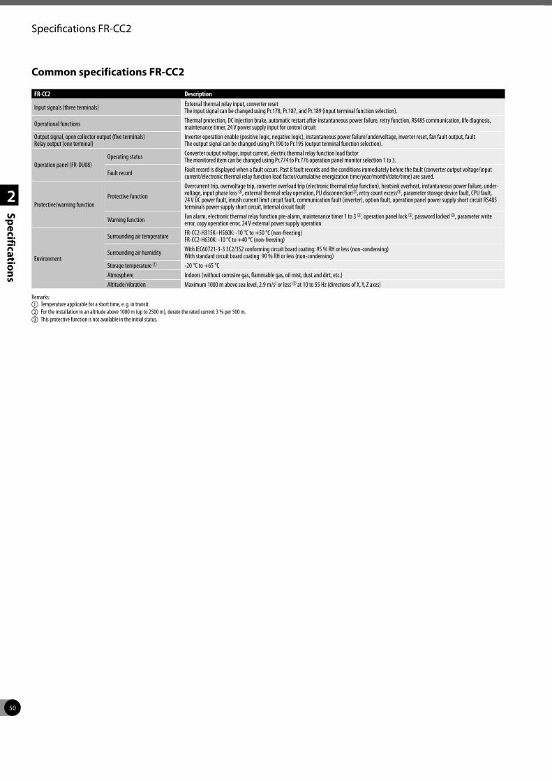
50
2
Specifications
Specifications FR-CC2
Common specifications FR-CC2
FR-CC2 Description
Input signals (three terminals) External thermal relay input, converter resetThe input signal can be changed using Pr.178, Pr.187, and Pr.189 (input terminal function selection).
Operational functions Thermal protection, DC injection brake, automatic restart after instantaneous power failure, retry function, RS485 communication, life diagnosis, maintenance timer, 24 V power supply input for control circuit
Output signal, open collector output (five terminals)Relay output (one terminal)
Inverter operation enable (positive logic, negative logic), instantaneous power failure/undervoltage, inverter reset, fan fault output, faultThe output signal can be changed using Pr.190 to Pr.195 (output terminal function selection).
Operation panel (FR-DU08)Operating status Converter output voltage, input current, electric thermal relay function load factor
The monitored item can be changed using Pr.774 to Pr.776 operation panel monitor selection 1 to 3.
Fault record Fault record is displayed when a fault occurs. Past 8 fault records and the conditions immediately before the fault (converter output voltage/input current/electronic thermal relay function load factor/cumulative energization time/year/month/date/time) are saved.
Protective/warning functionProtective function
Overcurrent trip, overvoltage trip, converter overload trip (electronic thermal relay function), heatsink overheat, instantaneous power failure, under-voltage, input phase lossc, external thermal relay operation, PU disconnectionc, retry count excessc, parameter storage device fault, CPU fault, 24 V DC power fault, inrush current limit circuit fault, communication fault (inverter), option fault, operation panel power supply short circuit RS485 terminals power supply short circuit, Internal circuit fault
Warning function Fan alarm, electronic thermal relay function pre-alarm, maintenance timer 1 to 3 c, operation panel lock c, password locked c, parameter write error, copy operation error, 24 V external power supply operation
Environment
Surrounding air temperature FR-CC2-H315K–H560K: -10 °C to +50 °C (non-freezing)FR-CC2-H630K: -10 °C to +40 °C (non-freezing)
Surrounding air humidity With IEC60721-3-3 3C2/3S2 conforming circuit board coating: 95 % RH or less (non-condensing) With standard circuit board coating: 90 % RH or less (non-condensing)
Storage temperature a -20 °C to +65 °CAtmosphere Indoors (without corrosive gas, flammable gas, oil mist, dust and dirt, etc.)Altitude/vibration Maximum 1000 m above sea level, 2.9 m/s2 or less b at 10 to 55 Hz (directions of X, Y, Z axes)
Remarks:a Temperature applicable for a short time, e. g. in transit.b For the installation in an altitude above 1000 m (up to 2500 m), derate the rated current 3 % per 500 m.c This protective function is not available in the initial status.
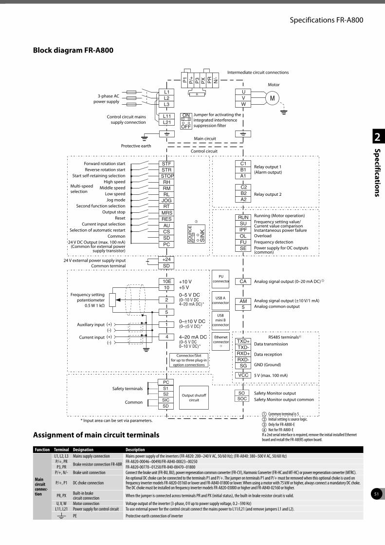
51
2
Specifications
Specifications FR-A800
Block diagram FR-A800
Assignment of main circuit terminals
PC
STOP
STFSTR
RHRMRL
RT
CS
RES RUN
TXD+
SU
TXD-
OLIPF
RXD+
FU
RXD-
SE
SG
VCC
CA
AM5
1010E
2
5
1
4
SD
L1
C2
C1
B2
B1
A2
A1
L11
L2
L21
L3
UVW
PR
N/-
(+)
(+)
(-)
(-)
OFF
ON
JOG
MRS
AU
SO
UR
CE
SIN
KP
X
R
SICS2S1
SO
PC
SD
SOC
P/+P1
P3
SD+24
Main circuit
3-phase AC power supply
Control circuit mains supply connection
Protective earth
Multi-speed selection
Control circuit
Jumper for activating the integrated interference suppression filter
Intermediate circuit connections
Motor
Relay output 1 (Alarm output)
Relay output 2
Running (Motor operation)
Analog signal output (0–20 mA DC)a
Data transmission Data reception GND (Ground)
5 V (max. 100 mA)
Connector/Slot for up to three plug-in
option connections
PU connector
Frequency setting potentiometer
0.5 W 1 kΩ
Auxiliary input
Current input
Frequency setting value/ Current value comparisonInstantaneous power failureOverload
Power supply for OC outputs (common)
Frequency detection
Analog signal output (±10 V/1 mA) Analog common output
USB A connector
USB mini B
connector
Output shutoff circuit
Forward rotation startReverse rotation start
Start self-retaining selectionHigh speed
Middle speedLow speedJog mode
Second function selectionOutput stop
ResetCurrent input selection
Selection of automatic restartCommon
24 V DC Output (max. 100 mA) (Common for external power
supply transistor)
Safety terminals
Common
Safety Monitor outputSafety Monitor output common
24 V external power supply input Common terminal
Function Terminal Designation Description
Main circuit connec-tion
L1, L2, L3 Mains supply connection Mains power supply of the inverters (FR-A820: 200–240 V AC, 50/60 Hz); (FR-A840: 380–500 V AC, 50/60 Hz)P/+, PR Brake resistor connection FR-ABR FR-A820-00046–00490/FR-A840-00023–00250P3, PR FR-A820-00770–01250/FR-840-00470–01800
P/+, N/- Brake unit connection Connect the brake unit (FR-BU, BU), power regeneration common converter (FR-CV), Harmonic Converter (FR-HC and MT-HC) or power regeneration converter (MTRC).
P/+, P1 DC choke connectionAn optional DC choke can be connected to the terminals P1 and P/+. The jumper on terminals P1 and P/+ must be removed when this optional choke is used on frequency inverter models FR-A820-03160 or lower and FR-A840-01800 or lower. When using a motor with 75 kW or higher, always connect a mandatory DC choke. The DC choke must be installed on frequency inverter models FR-A820-03800 or higher and FR-A840-02160 or higher.
PR, PX Built-in brake circuit connection When the jumper is connected across terminals PR and PX (initial status), the built-in brake resistor circuit is valid.
U, V, W Motor connection Voltage output of the inverter (3-phase, 0 V up to power supply voltage, 0.2–590 Hz)L11, L21 Power supply for control circuit To use external power for the control circuit connect the mains power to L11/L21 (and remove jumpers L1 and L2).
PE Protective earth connection of inverter
b
* Input area can be set via parameters.
Ethernet connector
3
a Common terminal is 5b Initial setting is source logic.c Only for FR-A800-Ed Not for FR-A800-E If a 2nd serial interface is required, remove the initial installed Ethernet board and install the FR-A8ERS option board.
RS485 terminals4
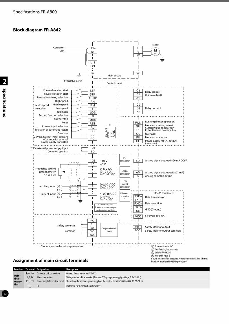
52
2
Specifications
Specifications FR-A800
Block diagram FR-A842
Assignment of main circuit terminals
PC
STOP
STFSTR
RHRMRL
RT
CS
RES RUN
TXD+
SU
TXD-
OLIPF
RXD+
FU
RXD-
SE
SG
VCC
CA
AM5
1010E
2
5
1
4
SD
P/+
C2
C1
B2
B1
A2
A1
L11
N/-
L21
UVW
(+)
(+)
(-)
(-)
JOG
MRS
AU
SO
UR
CE
SIN
K
SICS2S1
SO
PC
SD
SOC
SD+24
Main circuit
Converter unit
Protective earth
Multi-speed selection
Control circuit
Motor
Relay output 1 (Alarm output)
Relay output 2
Running (Motor operation)
Analog signal output (0–20 mA DC) a
Data transmission Data reception GND (Ground)
5 V (max. 100 mA)
Connector/Slot for up to three plug-in
option connections
PU connector
Frequency setting potentiometer
0.5 W 1 kΩ
Auxiliary input
Current input
Frequency setting value/ Current value comparisonInstantaneous power failureOverload
Power supply for OC outputs (common)
Frequency detection
Analog signal output (±10 V/1 mA) Analog common output
USB A connector
USB mini B
connector
Output shutoff circuit
Forward rotation startReverse rotation start
Start self-retaining selectionHigh speed
Middle speedLow speedJog mode
Second function selectionOutput stop
ResetCurrent input selection
Selection of automatic restartCommon
24 V DC Output (max. 100 mA) (Common for external
power supply transistor)
Safety terminals
CommonSafety Monitor outputSafety Monitor output common
24 V external power supply input Common terminal
Function Terminal Designation Description
Main circuit connec-tion
P/+, N/- Converter unit connection Connect the converter unit FR-CC2.U, V, W Motor connection Voltage output of the inverter (3-phase, 0 V up to power supply voltage, 0.2–590 Hz)
L11, L21 Power supply for control circuit The voltage for separate power supply of the control circuit is 380 to 480 V AC, 50/60 Hz.
PE Protective earth connection of inverter
b
* Input area can be set via parameters.
Ethernet connector
3
a Common terminal is 5b Initial setting is source logic.c Only for FR-A800-Ed Not for FR-A800-E If a 2nd serial interface is required, remove the initial installed Ethernet board and install the FR-A8ERS option board.
RS485 terminals4
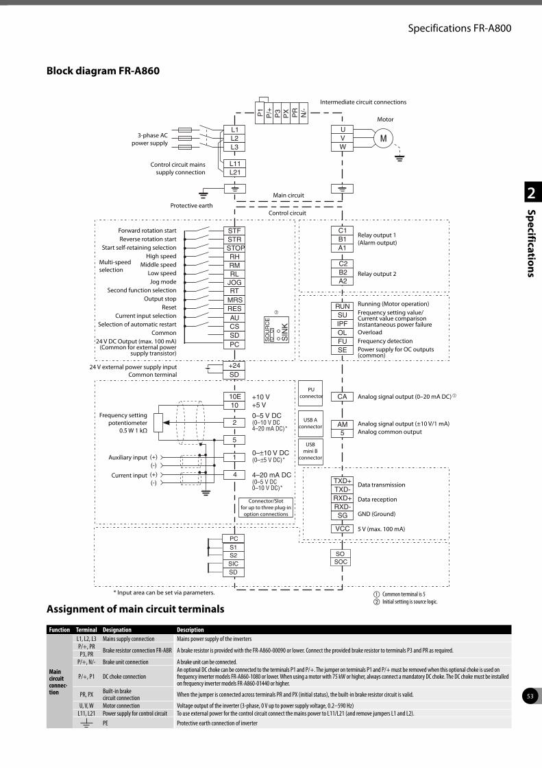
53
2
Specifications
Specifications FR-A800
Block diagram FR-A860
Assignment of main circuit terminals
PC
STOP
STFSTR
RHRMRL
RT
CS
RES RUN
TXD+
SU
TXD-
OLIPF
RXD+
FU
RXD-
SE
SG
VCC
CA
AM5
1010E
2
5
1
4
SD
L1
C2
C1
B2
B1
A2
A1
L11
L2
L21
L3
UVW
PR
N/-
(+)
(+)
(-)
(-)
JOG
MRS
AU
SO
UR
CE
SIN
KP
X
SICS2S1
SO
PC
SD
SOC
P/+P1
P3
SD+24
Main circuit
3-phase AC power supply
Control circuit mains supply connection
Protective earth
Multi-speed selection
Control circuit
Intermediate circuit connections
Motor
Relay output 1 (Alarm output)
Relay output 2
Running (Motor operation)
Analog signal output (0–20 mA DC)a
Data transmission Data reception GND (Ground)
5 V (max. 100 mA)
Connector/Slot for up to three plug-in
option connections
PU connector
Frequency setting potentiometer
0.5 W 1 kΩ
Auxiliary input
Current input
Frequency setting value/ Current value comparisonInstantaneous power failureOverload
Power supply for OC outputs (common)
Frequency detection
Analog signal output (±10 V/1 mA) Analog common output
USB A connector
USB mini B
connector
Forward rotation startReverse rotation start
Start self-retaining selectionHigh speed
Middle speedLow speedJog mode
Second function selectionOutput stop
ResetCurrent input selection
Selection of automatic restartCommon
24 V DC Output (max. 100 mA) (Common for external power
supply transistor)
24 V external power supply input Common terminal
Function Terminal Designation Description
Main circuit connec-tion
L1, L2, L3 Mains supply connection Mains power supply of the invertersP/+, PR Brake resistor connection FR-ABR A brake resistor is provided with the FR-A860-00090 or lower. Connect the provided brake resistor to terminals P3 and PR as required.P3, PRP/+, N/- Brake unit connection A brake unit can be connected.
P/+, P1 DC choke connectionAn optional DC choke can be connected to the terminals P1 and P/+. The jumper on terminals P1 and P/+ must be removed when this optional choke is used on frequency inverter models FR-A860-1080 or lower. When using a motor with 75 kW or higher, always connect a mandatory DC choke. The DC choke must be installed on frequency inverter models FR-A860-01440 or higher.
PR, PX Built-in brake circuit connection When the jumper is connected across terminals PR and PX (initial status), the built-in brake resistor circuit is valid.
U, V, W Motor connection Voltage output of the inverter (3-phase, 0 V up to power supply voltage, 0.2–590 Hz)L11, L21 Power supply for control circuit To use external power for the control circuit connect the mains power to L11/L21 (and remove jumpers L1 and L2).
PE Protective earth connection of inverter
b
a Common terminal is 5b Initial setting is source logic.
* Input area can be set via parameters.
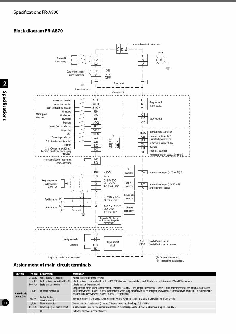
54
2
Specifications
Specifications FR-A800
Block diagram FR-A870
Assignment of main circuit terminals
PC
STOP
STFSTR
RHRMRL
RT
CS
RES RUNSU
OLIPF
FUSE
CA
AM5
1010E
2
5
1
4
SD
L1
C2
C1
B2
B1
A2
A1
L11
L2
L21
L3
UVW
PR
N/-
(+)
(+)
(-)
(-)
OFF
ON
JOG
MRS
AU
SO
UR
CE
SIN
KP
/+
SICS2S1
SO
PC
SD
SOC
SD+24
Main circuit
3-phase AC power supply
Control circuit mains supply connection
Protective earth
Multi-speed selection
Control circuit
Intermediate circuit connections
Motor
Relay output 1 (Alarm output)
Relay output 2
Analog signal output (0–20 mA DC) a
Connector/Slot for up to three plug-in option
connections
PU connector
Frequency setting potentiometer
0,5 W 1 kΩ
Auxiliary input
Current input
Analog signal output (±10 V/1 mA) Analog common output
USB-A-connector
USB-Mini-B-connector
Ethernet connectorc
Output shutoff circuit
Forward rotation startReverse rotation start
Start self-retaining selectionHigh speed
Middle speedLow speedJog mode
Second function selectionOutput stop
ResetCurrent input selection
Selection of automatic restartCommon
24 V DC Output (max. 100 mA) (Common for external power supply
transistor)
Safety terminals
CommonSafety Monitor outputSafety Monitor output common
24 V external power supply input Common terminal
Function Terminal Designation Description
Main circuit connection
L1, L2, L3 Mains supply connection Mains power supply of the inverterP/+, PR Brake resistor connection FR-ABR A brake resistor is provided with the FR-A860-00090 or lower. Connect the provided brake resistor to terminals P3 and PR as required.P/+, N/- Brake unit connection A brake unit can be connected.
P/+, P1 DC choke connectionAn optional DC choke can be connected to the terminals P1 and P/+. The jumper on terminals P1 and P/+ must be removed when this optional choke is used on frequency inverter models FR-A860-1080 or lower. When using a motor with 75 kW or higher, always connect a mandatory DC choke. The DC choke must be installed on frequency inverter models FR-A860-01440 or higher.
PR, PX Built-in brake circuit connection When the jumper is connected across terminals PR and PX (initial status), the built-in brake resistor circuit is valid.
U, V, W Motor connection Voltage output of the inverter (3-phase, 0 V up to power supply voltage, 0.2–590 Hz)L11, L21 Power supply for control circuit To use external power for the control circuit connect the mains power to L11/L21 (and remove jumpers L1 and L2).
PE Protective earth connection of inverter
b
a Common terminal is 5b Initial setting is source logic.
Running (Motor operation)
Frequency setting value/ Current value comparisonInstantaneous power failureOverloadFrequency detectionPower supply for OC outputs (common)
* Input area can be set via parameters.
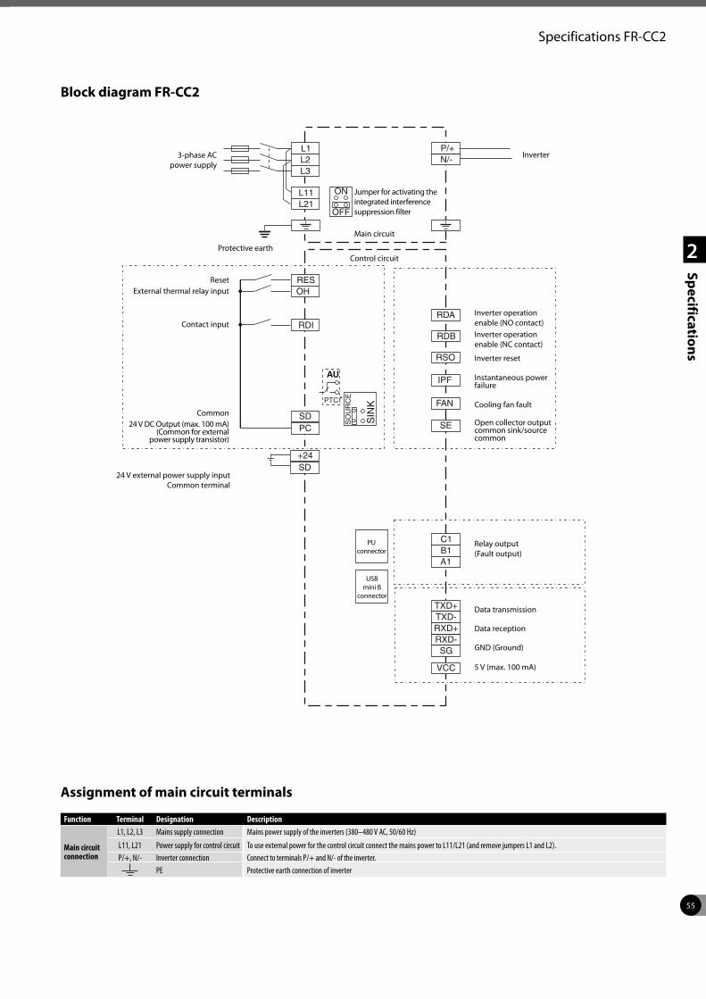
55
2
Specifications
Specifications FR-CC2
Block diagram FR-CC2
Assignment of main circuit terminals
PC
RESOH
RDI
PCT
RDA
TXD+
RDB
TXD-
IPF
RSO
RXD+
FAN
RXD-
SE
SG
VCC
SD
L1
C1B1A1
L11
L2
L21
L3
P/+N/-
OFF
ON
AU
SO
UR
CE
SIN
KPTC
SD+24
Main circuit
Protective earthControl circuit
Inverter
Relay output (Fault output)
Inverter operation enable (NO contact)Inverter operation enable (NC contact)
Data transmission Data reception GND (Ground)
5 V (max. 100 mA)
PU connector
Inverter reset
Instantaneous power failure
Cooling fan fault
Open collector output common sink/source common
USB mini B
connector
ResetExternal thermal relay input
Contact input
Common24 V DC Output (max. 100 mA)
(Common for external power supply transistor)
24 V external power supply input Common terminal
Function Terminal Designation Description
Main circuit connection
L1, L2, L3 Mains supply connection Mains power supply of the inverters (380–480 V AC, 50/60 Hz)
L11, L21 Power supply for control circuit To use external power for the control circuit connect the mains power to L11/L21 (and remove jumpers L1 and L2).P/+, N/- Inverter connection Connect to terminals P/+ and N/- of the inverter.
PE Protective earth connection of inverter
Jumper for activating the integrated interference suppression filter
3-phase AC power supply
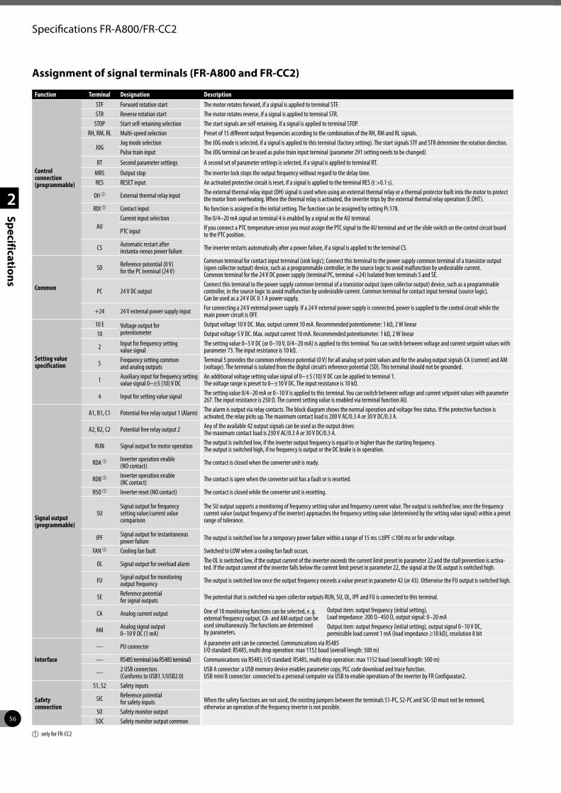
56
2
Specifications
Specifications FR-A800/FR-CC2
Assignment of signal terminals (FR-A800 and FR-CC2)
Function Terminal Designation Description
Control connection (programmable)
STF Forward rotation start The motor rotates forward, if a signal is applied to terminal STF.STR Reverse rotation start The motor rotates reverse, if a signal is applied to terminal STR.
STOP Start self-retaining selection The start signals are self-retaining, if a signal is applied to terminal STOP.RH, RM, RL Multi-speed selection Preset of 15 different output frequencies according to the combination of the RH, RM and RL signals.
JOGJog mode selection The JOG mode is selected, if a signal is applied to this terminal (factory setting). The start signals STF and STR determine the rotation direction.Pulse train input The JOG terminal can be used as pulse train input terminal (parameter 291 setting needs to be changed)
RT Second parameter settings A second set of parameter settings is selected, if a signal is applied to terminal RT.
MRS Output stop The inverter lock stops the output frequency without regard to the delay time. RES RESET input An activated protective circuit is reset, if a signal is applied to the terminal RES (t >0.1 s).
OH a External thermal relay input The external thermal relay input (OH) signal is used when using an external thermal relay or a thermal protector built into the motor to protect the motor from overheating. When the thermal relay is activated, the inverter trips by the external thermal relay operation (E.OHT).
RDI a Contact input No function is assigned in the initial setting. The function can be assigned by setting Pr.178.
AUCurrent input selection The 0/4–20 mA signal on terminal 4 is enabled by a signal on the AU terminal.
PTC input If you connect a PTC temperature sensor you must assign the PTC signal to the AU terminal and set the slide switch on the control circuit board to the PTC position.
CS Automatic restart after instanta-neous power failure The inverter restarts automatically after a power failure, if a signal is applied to the terminal CS.
Common
SD Reference potential (0 V) for the PC terminal (24 V)
Common terminal for contact input terminal (sink logic); Connect this terminal to the power supply common terminal of a transistor output (open collector output) device, such as a programmable controller, in the source logic to avoid malfunction by undesirable current.Common terminal for the 24 V DC power supply (terminal PC, terminal +24) Isolated from terminals 5 and SE.
PC 24 V DC outputConnect this terminal to the power supply common terminal of a transistor output (open collector output) device, such as a programmable controller, in the source logic to avoid malfunction by undesirable current. Common terminal for contact input terminal (source logic).Can be used as a 24 V DC 0.1 A power supply.
+24 24 V external power supply input For connecting a 24 V external power supply. If a 24 V external power supply is connected, power is supplied to the control circuit while the main power circuit is OFF.
Setting value specification
10 E Voltage output for potentiometer
Output voltage 10 V DC. Max. output current 10 mA. Recommended potentiometer: 1 kΩ, 2 W linear10 Output voltage 5 V DC. Max. output current 10 mA. Recommended potentiometer: 1 kΩ, 2 W linear
2 Input for frequency setting value signal
The setting value 0–5 V DC (or 0–10 V, 0/4–20 mA) is applied to this terminal. You can switch between voltage and current setpoint values with parameter 73. The input resistance is 10 kΩ.
5 Frequency setting common and analog outputs
Terminal 5 provides the common reference potential (0 V) for all analog set point values and for the analog output signals CA (current) and AM (voltage). The terminal is isolated from the digital circuit’s reference potential (SD). This terminal should not be grounded.
1 Auxiliary input for frequency setting value signal 0–±5 (10) V DC
An additional voltage setting value signal of 0–±5 (10) V DC can be applied to terminal 1.The voltage range is preset to 0–±10 V DC. The input resistance is 10 kΩ.
4 Input for setting value signal The setting value 0/4–20 mA or 0–10 V is applied to this terminal. You can switch between voltage and current setpoint values with parameter 267. The input resistance is 250 Ω. The current setting value is enabled via terminal function AU.
Signal output (programmable)
A1, B1, C1 Potential free relay output 1 (Alarm) The alarm is output via relay contacts. The block diagram shows the normal operation and voltage free status. If the protective function is activated, the relay picks up. The maximum contact load is 200 V AC/0.3 A or 30 V DC/0.3 A.
A2, B2, C2 Potential free relay output 2 Any of the available 42 output signals can be used as the output driver.The maximum contact load is 230 V AC/0.3 A or 30 V DC/0.3 A.
RUN Signal output for motor operation The output is switched low, if the inverter output frequency is equal to or higher than the starting frequency.The output is switched high, if no frequency is output or the DC brake is in operation.
RDA a Inverter operation enable (NO contact) The contact is closed when the converter unit is ready.
RDB a Inverter operation enable (NC contact) The contact is open when the converter unit has a fault or is resetted.
RSO a Inverter reset (NO contact) The contact is closed while the converter unit is resetting.
SUSignal output for frequency setting value/current value comparison
The SU output supports a monitoring of frequency setting value and frequency current value. The output is switched low, once the frequency current value (output frequency of the inverter) approaches the frequency setting value (determined by the setting value signal) within a preset range of tolerance.
IPF Signal output for instantaneous power failure The output is switched low for a temporary power failure within a range of 15 ms ≤tIPF ≤100 ms or for under voltage.
FAN a Cooling fan fault Switched to LOW when a cooling fan fault occurs.
OL Signal output for overload alarm The OL is switched low, if the output current of the inverter exceeds the current limit preset in parameter 22 and the stall prevention is activa-ted. If the output current of the inverter falls below the current limit preset in parameter 22, the signal at the OL output is switched high.
FU Signal output for monitoring output frequency The output is switched low once the output frequency exceeds a value preset in parameter 42 (or 43). Otherwise the FU output is switched high.
SE Reference potential for signal outputs The potential that is switched via open collector outputs RUN, SU, OL, IPF and FU is connected to this terminal.
CA Analog current output One of 18 monitoring functions can be selected, e. g. external frequency output. CA- and AM output can be used simultaneously. The functions are determined by parameters.
Output item: output frequency (initial setting),Load impedance: 200 Ω–450 Ω, output signal: 0–20 mA
AM Analog signal output 0–10 V DC (1 mA)
Output item: output frequency (initial setting), output signal 0–10 V DC, permissible load current 1 mA (load impedance ≥10 kΩ), resolution 8 bit
Interface
— PU connector A parameter unit can be connected. Communications via RS485 I/O standard: RS485, multi drop operation: max 1152 baud (overall length: 500 m)
— RS485 terminal (via RS485 terminal) Communications via RS485; I/O standard: RS485, multi drop operation: max 1152 baud (overall length: 500 m)
— 2 USB connectors (Conforms to USB1.1/USB2.0)
USB A connector: a USB memory device enables parameter copy, PLC code download and trace function. USB mini B connector: connected to a personal computer via USB to enable operations of the inverter by FR Configurator2.
Safety connection
S1, S2 Safety inputs
When the safety functions are not used, the existing jumpers between the terminals S1-PC, S2-PC and SIC-SD must not be removed, otherwise an operation of the frequency inverter is not possible.
SIC Reference potential for safety inputs
SO Safety monitor outputSOC Safety monitor output common
a only for FR-CC2
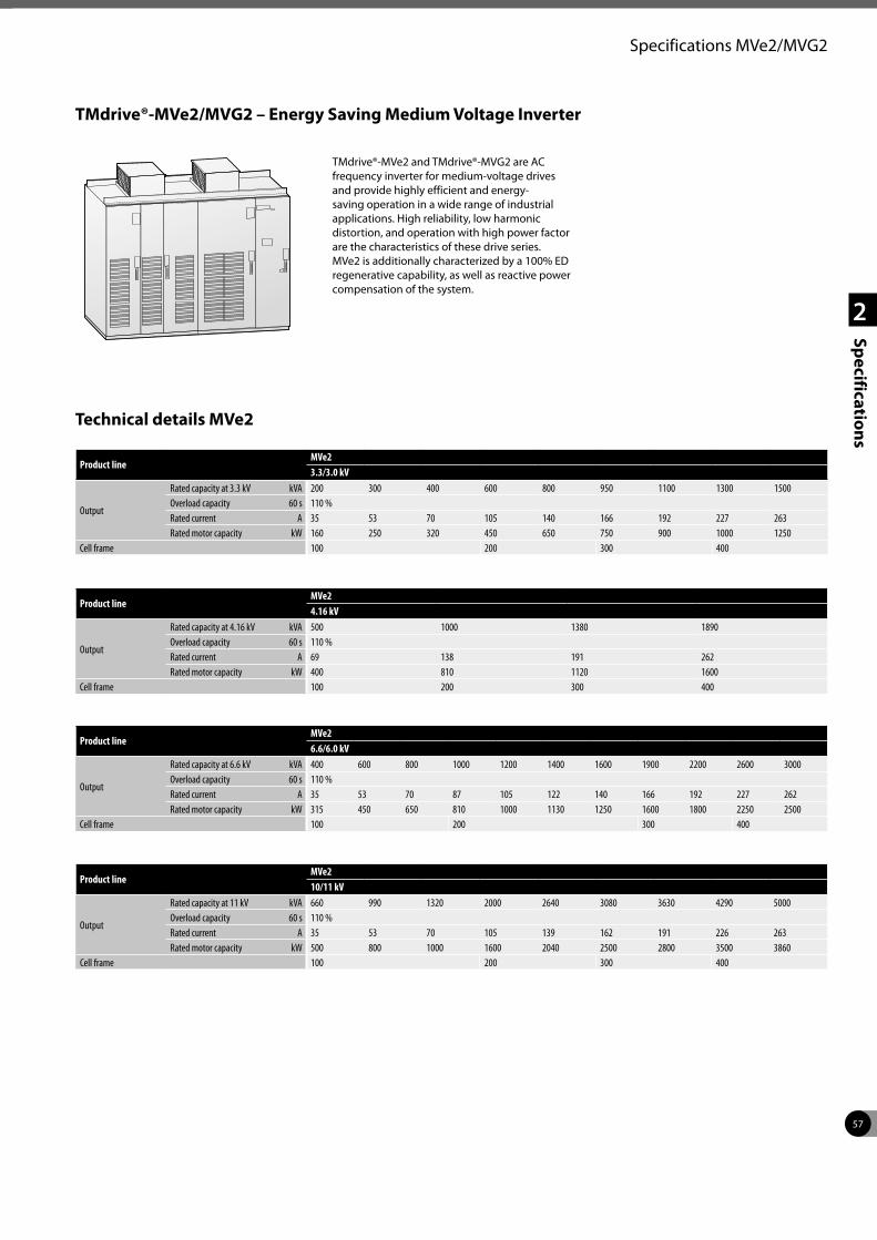
57
2
Specifications
Specifications MVe2/MVG2
Product lineMVe23.3/3.0 kV
Output
Rated capacity at 3.3 kV kVA 200 300 400 600 800 950 1100 1300 1500Overload capacity 60 s 110 %Rated current A 35 53 70 105 140 166 192 227 263Rated motor capacity kW 160 250 320 450 650 750 900 1000 1250
Cell frame 100 200 300 400
Product lineMVe24.16 kV
Output
Rated capacity at 4.16 kV kVA 500 1000 1380 1890Overload capacity 60 s 110 %Rated current A 69 138 191 262Rated motor capacity kW 400 810 1120 1600
Cell frame 100 200 300 400
Product lineMVe26.6/6.0 kV
Output
Rated capacity at 6.6 kV kVA 400 600 800 1000 1200 1400 1600 1900 2200 2600 3000Overload capacity 60 s 110 %Rated current A 35 53 70 87 105 122 140 166 192 227 262Rated motor capacity kW 315 450 650 810 1000 1130 1250 1600 1800 2250 2500
Cell frame 100 200 300 400
Product lineMVe210/11 kV
Output
Rated capacity at 11 kV kVA 660 990 1320 2000 2640 3080 3630 4290 5000Overload capacity 60 s 110 %Rated current A 35 53 70 105 139 162 191 226 263Rated motor capacity kW 500 800 1000 1600 2040 2500 2800 3500 3860
Cell frame 100 200 300 400
Technical details MVe2
TMdrive®-MVe2/MVG2 – Energy Saving Medium Voltage Inverter
TMdrive®-MVe2 and TMdrive®-MVG2 are AC frequency inverter for medium-voltage drives and provide highly efficient and energy-saving operation in a wide range of industrial applications. High reliability, low harmonic distortion, and operation with high power factor are the characteristics of these drive series. MVe2 is additionally characterized by a 100% ED regenerative capability, as well as reactive power compensation of the system.
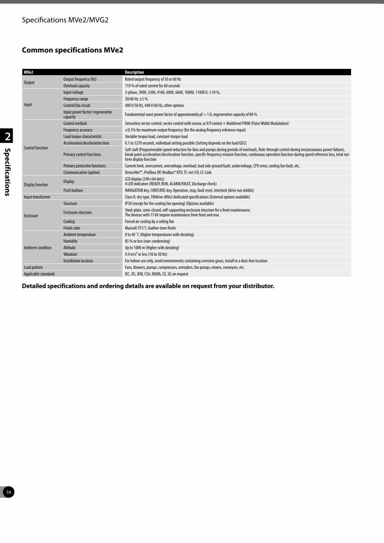
58
2
Specifications
Specifications MVe2/MVG2
MVe2 Description
OutputOutput frequency (Hz) Rated output frequency of 50 or 60 HzOverload capacity 110 % of rated current for 60 seconds
Input
Input voltage 3-phase, 3000, 3300, 4160, 6000, 6600, 10000, 11000 V, ±10 %,Frequency range 50/60 Hz ±5 %Control/fan circuit 400 V/50 Hz, 440 V/60 Hz, other optionsInput power factor/ regenerative capacity Fundamental wave power factor of approximately pf = 1.0, regenerative capacity of 80 %
Control function
Control method Sensorless vector control, vector control with sensor, or V/f control + Multilevel PWM (Pulse Width Modulation)Frequency accuracy ±0.5% for maximum output frequency (for the analog frequency reference input)Load torque characteristic Variable torque load, constant-torque loadAcceleration/deceleration time 0.1 to 3270 seconds, individual setting possible (Setting depends on the load GD2)
Primary control functionsSoft stall (Programmable speed reduction for fans and pumps during periods of overload), Ride-through control during instantaneous power failures, break point acceleration/deceleration function, specific frequency evasion function, continuous operation function during speed reference loss, total run time display function
Primary protective functions Current limit, overcurrent, overvoltage, overload, load side ground fault, undervoltage, CPU error, cooling fan fault, etc.Communication (option) DeviceNet™, Profibus DP, Modbus® RTU, TC-net I/O, CC-Link
Display functionDisplay LCD display (240×64 dots)
4 LED indicators (READY, RUN, ALARM/FAULT, Discharge check)Push buttons NAVIGATION key, CONTLROL key, Operation, stop, fault reset, interlock (drive run inhibit)
Input transformer Class H, dry type, TMdrive-MVe2 dedicated specifications (External options available)
Enclosure
Structure IP30 (except for the cooling fan opening) (Options available)
Enclosure structure Steel-plate, semi-closed, self-supporting enclosure structure for a front maintenance. The devices with 11 kV require maintenance from front and rear.
Cooling Forced air cooling by a ceiling fanFinish color Munsell 5Y7/1, leather-tone finish
Ambient condition
Ambient temperature 0 to 40 ˚C (Higher temperatures with derating)Humidity 85 % or less (non-condensing)Altitude Up to 1000 m (Higher with derating)Vibration 4.9 m/s² or less (10 to 50 Hz)Installation location For indoor use only, avoid environments containing corrosive gases, install in a dust-free location
Load pattern Fans, blowers, pumps, compressors, extruders, fan pumps, mixers, conveyors, etc.Applicable standards IEC, JIS, JEM, CSA, NEMA, CE, UL on request
Common specifications MVe2
Detailed specifications and ordering details are available on request from your distributor.
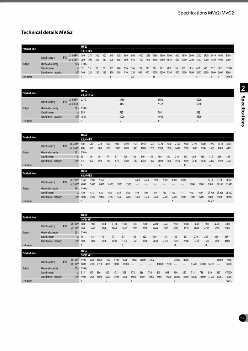
59
2
Specifications
Specifications MVe2/MVG2
Product lineMVG23.0/3.3 kV
Output
Rated capacity kVAat 3.0 kV 180 270 360 400 540 720 800 860 1000 1080 1180 1360 1500 1630 1810 2000 2200 2720 3410 4090 5180at 3.3 kV 200 300 400 440 600 800 880 950 1100 1200 1300 1500 1650 1800 2000 2200 2400 3000 3750 4500 5700
Overload capacity 60 s 110%Rated current A 35 53 70 77 105 140 154 166 192 210 227 263 289 315 350 385 420 525 657 787 CF 997Rated motor capacity kW 160 250 320 355 450 650 710 750 900 970 1000 1250 1340 1400 1600 1800 2000 2500 3060 3600 4560
Cell frame 1 2 3A 3B 4 5 6 7 Twin 5
Product lineMVG24.0/4.16 kV
Output
Rated capacity kVAat 4.0 kV 2770 3780 5050 6000at 4.16 kV — 4147 5537 6580
Overload capacity 60 s 110%Rated current A 384 525 701 833Rated motor capacity kW 1640 3026 4040 4800
Cell frame 4 5 6 7
Product lineMVG26.0/6.6 kV
Output
Rated capacity kVAat 6.0 kV 360 540 720 800 900 1090 1260 1450 1600 1720 2000 2160 2360 2720 3000 3270 3630 4000at 6.6 kV 400 600 800 880 1000 1200 1400 1600 1760 1900 2200 2400 2600 3000 3300 3600 4000 4400
Overload capacity 60 s 110%Rated current A 35 53 70 77 87 105 122 140 154 166 192 210 227 262 289 315 350 385Rated motor capacity kW 315 450 650 710 810 1000 1130 1250 1420 1600 1800 1940 2250 2500 2670 2800 3150 3550
Cell frame 1 2 3A 3B 4
Product lineMVG26.0/6.6 kV
Output
Rated capacity kVAat 6.0 kV 4360 4900 5450 — — — 6000 6500 7000 7500 8200 9000 — — 8270 9320 10360at 6.6 kV 4800 5400 6000 6500 7000 7500 — — — — — — 8200 9000 9100 10260 11400
Overload capacity 60 s 110%Rated current A 420 473 525 569 612 656 578 626 674 730 790 — 718 790 CF 796 CF 898 CF 997Rated motor capacity kW 4000 4500 5000 5200 5600 6000 5000 5600 6000 6500 6500 7360 6300 7200 8000 8500 10000
Cell frame 5 6 7 Twin 5
Product lineMVG210/11 kV
Output
Rated capacity kVAat 10 kV 600 900 1200 1330 1500 1800 2100 2400 2660 2800 3300 3630 3900 4500 5000at 11 kV 660 660 1320 1460 1650 2000 2310 2640 2930 3080 3630 4000 4290 5000 5500
Overload capacity 60 s 110%Rated current A 35 53 70 77 87 105 122 139 154 162 191 210 226 263 289Rated motor capacity kW 500 800 1000 1040 1350 1600 1800 2040 2375 2500 2800 3250 3500 3860 4400
Cell frame 1 2 3A 3B
Product lineMVG210/11 kV
Output
Rated capacity kVAat 10 kV 5400 6000 6680 7200 8100 9000 10000 11000 12600 — — 13600 14700 — — — 15000 17500at 11 kV 6000 6600 7350 8000 9000 10000 — — — 11000 12600 — — 13600 15000 16100 — 19500
Overload capacity 60 s 110%Rated current A 315 347 386 420 473 525 578 636 730 578 662 790 850 718 788 850 867 CF 1024Rated motor capacity kW 4900 5400 5800 6500 7300 8000 8000 8800 10000 8800 10000 10800 11500 10800 11500 13500 12265 16000
Cell frame 4 5 6 7 Twin 5
Technical details MVG2
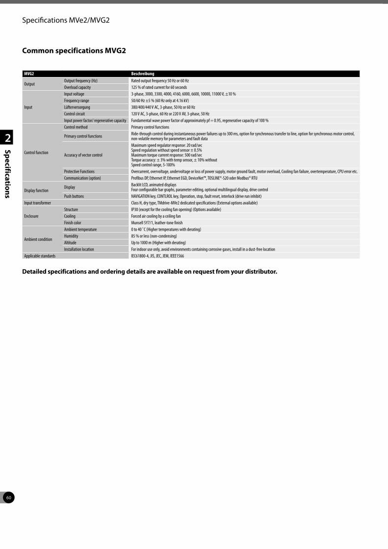
60
2
Specifications
Specifications MVe2/MVG2
Common specifications MVG2
MVG2 Beschreibung
OutputOutput frequency (Hz) Rated output frequency 50 Hz or 60 HzOverload capacity 125 % of rated current for 60 seconds
Input
Input voltage 3-phase, 3000, 3300, 4000, 4160, 6000, 6600, 10000, 11000 V, ±10 %Frequency range 50/60 Hz ±5 % (60 Hz only at 4.16 kV)Lüfterversorgung 380/400/440 V AC, 3-phase, 50 Hz or 60 HzControl circuit 120 V AC, 3-phase, 60 Hz or 220 V AV, 3-phase, 50 HzInput power factor/ regenerative capacity Fundamental wave power factor of approximately pf = 0.95, regenerative capacity of 100 %
Control function
Control method Primary control functions
Primary control functions Ride-through control during instantaneous power failures up to 300 ms, option for synchronous transfer to line, option for synchronous motor control, non-volatile memory for parameters and fault data
Accuracy of vector control
Maximum speed regulator response: 20 rad/secSpeed regulation without speed sensor ± 0.5%Maximum torque current response: 500 rad/secTorque accuracy: ± 3% with temp sensor, ± 10% withoutSpeed control range, 5-100%
Protective Functions Overcurrent, overvoltage, undervoltage or loss of power supply, motor ground fault, motor overload, Cooling fan failure, overtemperature, CPU error etc.Communication (option) Profibus DP, Ethernet IP, Ethernet EGD, DeviceNet™, TOSLINE®-S20 oder Modbus® RTU
Display functionDisplay Backlit LCD, animated displays
Four configurable bar graphs, parameter editing, optional multilingual display, drive controlPush buttons NAVIGATION key, CONTLROL key, Operation, stop, fault reset, interlock (drive run inhibit)
Input transformer Class H, dry type, TMdrive-MVe2 dedicated specifications (External options available)
EnclosureStructure IP30 (except for the cooling fan opening) (Options available)Cooling Forced air cooling by a ceiling fanFinish color Munsell 5Y7/1, leather-tone finish
Ambient condition
Ambient temperature 0 to 40 ˚C (Higher temperatures with derating)Humidity 85 % or less (non-condensing)Altitude Up to 1000 m (Higher with derating)Installation location For indoor use only, avoid environments containing corrosive gases, install in a dust-free location
Applicable standards IEC61800-4, JIS, JEC, JEM, IEEE1566
Detailed specifications and ordering details are available on request from your distributor.
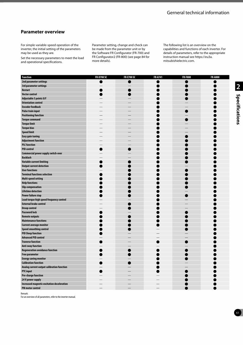
61
2
Specifications
Gerneral technical information
Function FR-D700 SC FR-E700 SC FR-A741 FR-F800 FR-A8002nd parameter settings U U U U U
3rd parameter settings — — U U U
Restart U U U U U
Vector control U U U U U
Adjustable 5 points U/f — — U U U
Orientation control — — U — U
Encoder feedback — — U — U
Pulse train input — — U U U
Positioning function — — U — U
Torque command — — U U U
Torque limit — — U — U
Torque bias — — U — U
Speed limit — — U — U
Easy gain tuning — — U U U
Adjustment function — — U U U
PLC function — — U U U
PID control U U U U U
Commercial power supply switch-over — — U U U
Backlash — — U U U
Variable current limiting U U U U U
Output current detection U U U — U
User functions — U U U U
Terminal functions selection U U U U U
Multi-speed setting U U U U U
Help functions U U U U U
Slip compensation U U U U U
Lifetime detection U U U — U
Power failure stop U U U U U
Load torque high speed frequency control — — U — U
External brake control — U U — U
Droop control — U U — U
Password lock U — U U U
Remote outputs U U U U U
Maintenance functions U U U U U
Current average monitor U U U U U
Speed smoothing control U U — U U
PID Sleep function U — — — U
Advanced PID control — — — — U
Traverse function U — U U U
Anti sway function — — — — U
Regeneration avoidance function U U U U U
Free parameter U U U U U
Energy saving monitor — — U U U
Calibration function U U U — U
Analog current output calibration function — — U — U
PTC input U — U U U
Pre-charge function — — — U U
24 V power supply — — — U U
Increased magnetic excitation deceleration — — — U U
PM motor control — — — U U
Remark:For an overview of all parameters, refer to the inverter manual.
Parameter overview
For simple variable-speed operation of the inverter, the initial setting of the parameters may be used as they are.
Set the necessary parameters to meet the load and operational specifications.
Parameter setting, change and check can be made from the parameter unit or by the Software FR Configurator (FR-700) and FR Configurator2 (FR-800) (see page 84 for more details).
The following list is an overview on the capabilities and functions of each inverter. For details of parameters, refer to the appropriate instruction manual see https://eu3a.mitsubishielectric.com.
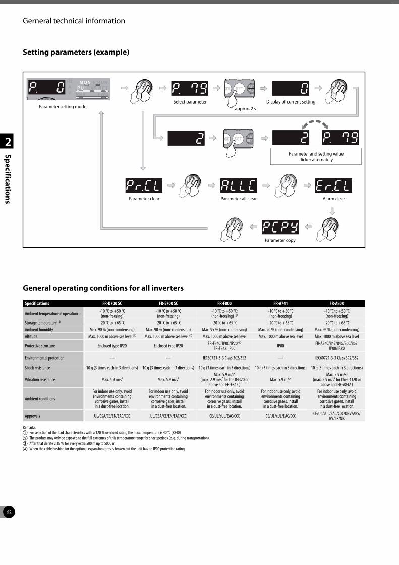
62
2
Specifications
Gerneral technical information
Setting parameters (example)
General operating conditions for all inverters
Specifications FR-D700 SC FR-E700 SC FR-F800 FR-A741 FR-A800
Ambient temperature in operation -10 °C to +50 °C (non-freezing)
-10 °C to +50 °C (non-freezing)
-10 °C to +50 °C; (non-freezing) a
-10 °C to +50 °C (non-freezing)
-10 °C to +50 °C (non-freezing)
Storage temperature b -20 °C to +65 °C -20 °C to +65 °C -20 °C to +65 °C -20 °C to +65 °C -20 °C to +65 °CAmbient humidity Max. 90 % (non-condensing) Max. 90 % (non-condensing) Max. 95 % (non-condensing) Max. 90 % (non-condensing) Max. 95 % (non-condensing)Altitude Max. 1000 m above sea levelc Max. 1000 m above sea level c Max. 1000 m above sea level Max. 1000 m above sea level Max. 1000 m above sea level
Protective structure Enclosed type IP20 Enclosed type IP20 FR-F840: IP00/IP20 d
FR-F842: IP00 IP00 FR-A840/842/846/860/862: IP00/IP20
Environmental protection — — IEC60721-3-3 Class 3C2/3S2 — IEC60721-3-3 Class 3C2/3S2
Shock resistance 10 g (3 times each in 3 directions) 10 g (3 times each in 3 directions) 10 g (3 times each in 3 directions) 10 g (3 times each in 3 directions) 10 g (3 times each in 3 directions)
Vibration resistance Max. 5.9 m/s2 Max. 5.9 m/s2Max. 5.9 m/s2
(max. 2.9 m/s² for the 04320 or above and FR-F842 )
Max. 5.9 m/s2Max. 5.9 m/s2
(max. 2.9 m/s² for the 04320 or above and FR-A842 )
Ambient conditions
For indoor use only, avoid environments containing
corrosive gases, install in a dust-free location.
For indoor use only, avoid environments containing
corrosive gases, install in a dust-free location.
For indoor use only, avoid environments containing
corrosive gases, install in a dust-free location.
For indoor use only, avoid environments containing
corrosive gases, install in a dust-free location.
For indoor use only, avoid environments containing
corrosive gases, install in a dust-free location.
Approvals UL/CSA/CE/EN/EAC/CCC UL/CSA/CE/EN/EAC/CCC CE/UL/cUL/EAC/CCC CE/UL/cUL/EAC/CCC CE/UL/cUL/EAC/CCC/DNV/ABS/BV/LR/NK
Remarks:a For selection of the load characteristics with a 120 % overload rating the max. temperature is 40 °C (F840) b The product may only be exposed to the full extremes of this temperature range for short periods (e. g. during transportation).c After that derate 2.87 % for every extra 500 m up to 5000 m.d When the cable bushing for the optional expansion cards is broken out the unit has an IP00 protection rating.
Parameter setting mode
Parameter clear Parameter all clear
Parameter copy
Select parameterapprox. 2 s
Display of current setting
Parameter and setting value flicker alternately
Alarm clear
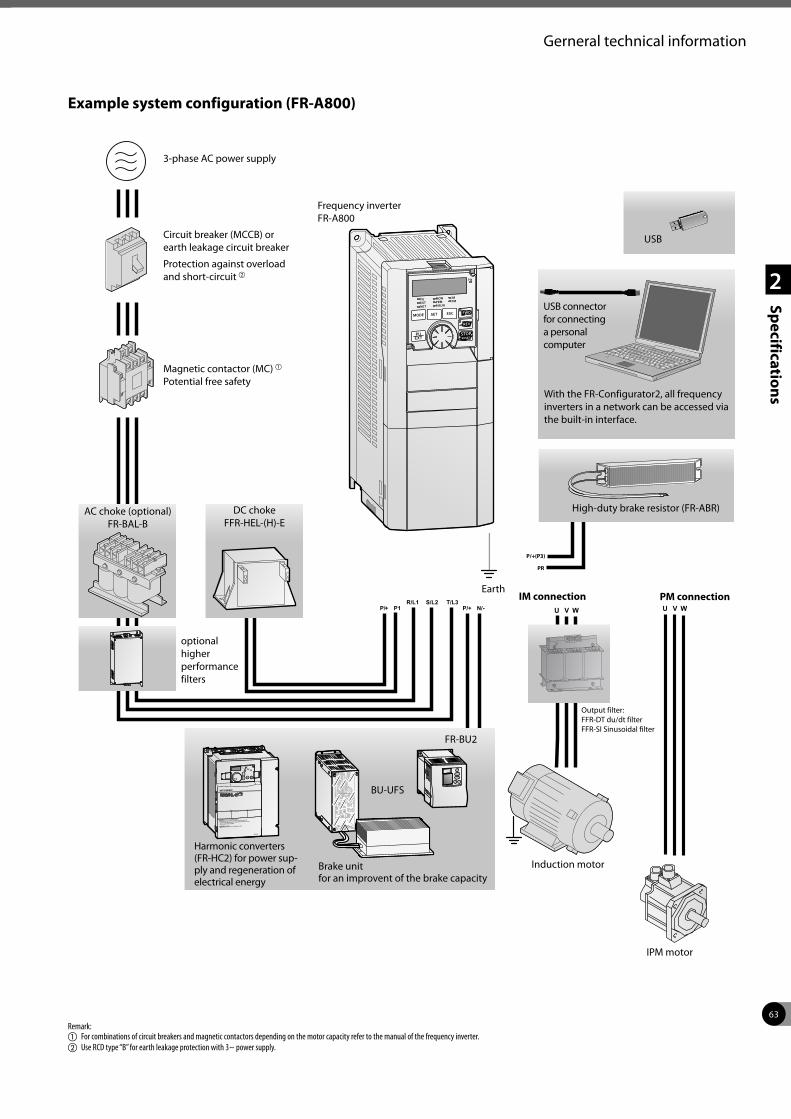
63
2
Specifications
Gerneral technical information
DANGER: Risk of injury and electric shockRead the manual and follow the safety instructions before use.
Isolate from supply and wait 10 minutes before removing this cover.
Ensure proper earth connection
Mount the inverter on a non-combustible surface.
200V
P/+(P3)
PR
L2 L3L1 E
L2’ L3’L1’ E
Example system configuration (FR-A800)
Remark:a For combinations of circuit breakers and magnetic contactors depending on the motor capacity refer to the manual of the frequency inverter.b Use RCD type “B” for earth leakage protection with 3~ power supply.
USB connector for connecting a personal computer
Frequency inverter FR-A800
Earth
Induction motor
FR-BU2
Harmonic converters (FR-HC2) for power sup-ply and regeneration of electrical energy
BU-UFS
optional higher performance filters
Magnetic contactor (MC) a Potential free safety
Circuit breaker (MCCB) or earth leakage circuit breaker
Protection against overload and short-circuit b
3-phase AC power supply
DC choke FFR-HEL-(H)-E
AC choke (optional) FR-BAL-B
Brake unit for an improvent of the brake capacity
Output filter:FFR-DT du/dt filterFFR-SI Sinusoidal filter
IPM motor
High-duty brake resistor (FR-ABR)
IM connection PM connection
USB
With the FR-Configurator2, all frequency inverters in a network can be accessed via the built-in interface.
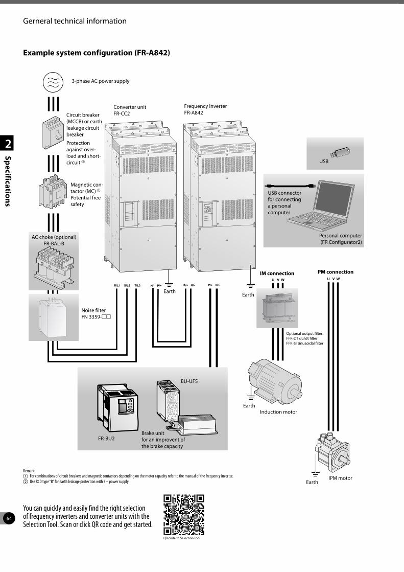
64
2
Specifications
Example system configuration (FR-A842)
Remark:a For combinations of circuit breakers and magnetic contactors depending on the motor capacity refer to the manual of the frequency inverter.b Use RCD type “B” for earth leakage protection with 3~ power supply.
USB connector for connecting a personal computer
Frequency inverter FR-A842
Earth
Induction motor
FR-BU2
BU-UFS
Noise filter FN 3359-mm
Magnetic con-tactor (MC) a Potential free safety
Circuit breaker (MCCB) or earth leakage circuit breaker
Protection against over-load and short-circuit b
3-phase AC power supply
AC choke (optional) FR-BAL-B
Brake unit for an improvent of the brake capacity
IPM motor
IM connection PM connection
Personal computer (FR Configurator2)
Earth
Earth
Earth
Converter unit FR-CC2
USB
Optional output filter:FFR-DT du/dt filterFFR-SI sinusoidal filter
Gerneral technical information
You can quickly and easily find the right selection of frequency inverters and converter units with the Selection Tool. Scan or click QR code and get started.
QR code to Selection Tool
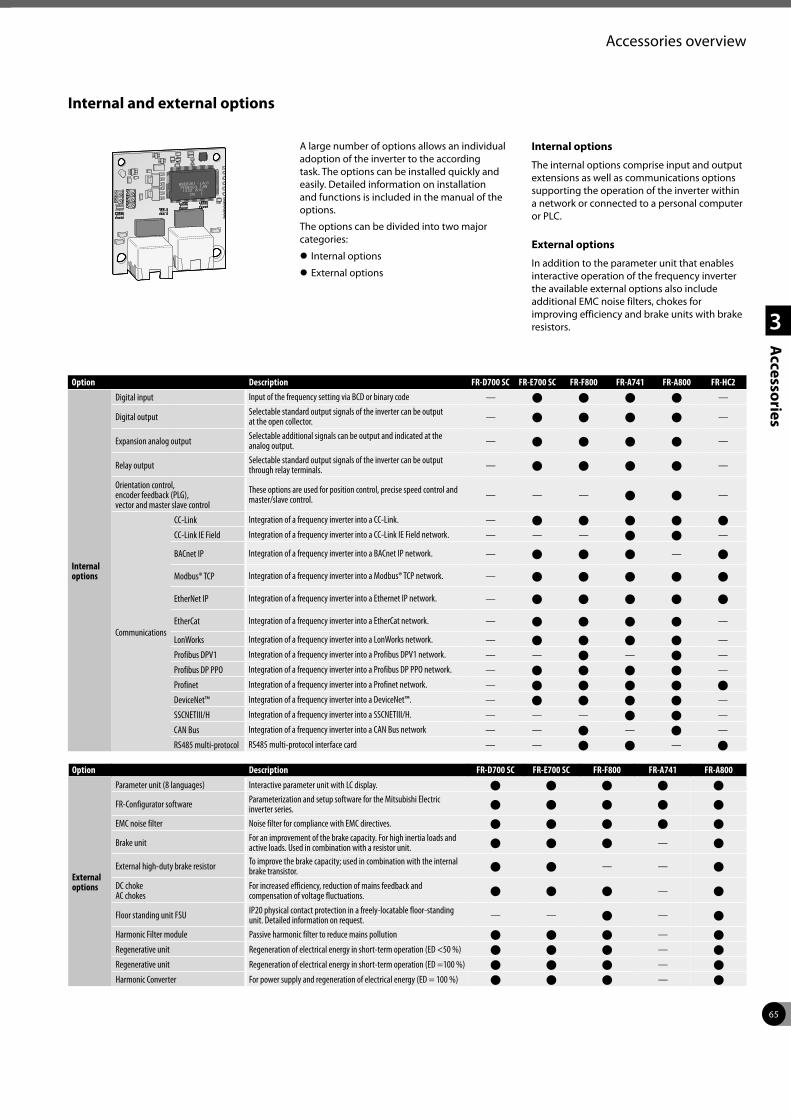
65
1
2
3
Accessories
Accessories overview
Internal and external options
A large number of options allows an individual adoption of the inverter to the according task. The options can be installed quickly and easily. Detailed information on installation and functions is included in the manual of the options.
The options can be divided into two major categories:
z Internal options
z External options
Internal options
The internal options comprise input and output extensions as well as communications options supporting the operation of the inverter within a network or connected to a personal computer or PLC.
External options
In addition to the parameter unit that enables interactive operation of the frequency inverter the available external options also include additional EMC noise filters, chokes for improving efficiency and brake units with brake resistors.
Option Description FR-D700 SC FR-E700 SC FR-F800 FR-A741 FR-A800 FR-HC2
Internal options
Digital input Input of the frequency setting via BCD or binary code — U U U U —
Digital output Selectable standard output signals of the inverter can be output at the open collector. — U U U U —
Expansion analog output Selectable additional signals can be output and indicated at the analog output. — U U U U —
Relay output Selectable standard output signals of the inverter can be output through relay terminals. — U U U U —
Orientation control, encoder feedback (PLG), vector and master slave control
These options are used for position control, precise speed control and master/slave control. — — — U U —
Communications
CC-Link Integration of a frequency inverter into a CC-Link. — U U U U U
CC-Link IE Field Integration of a frequency inverter into a CC-Link IE Field network. — — — U U —
BACnet IP Integration of a frequency inverter into a BACnet IP network. — U U U — U
Modbus® TCP Integration of a frequency inverter into a Modbus® TCP network. — U U U U U
EtherNet IP Integration of a frequency inverter into a Ethernet IP network. — U U U U U
EtherCat Integration of a frequency inverter into a EtherCat network. — U U U U —
LonWorks Integration of a frequency inverter into a LonWorks network. — U U U U —
Profibus DPV1 Integration of a frequency inverter into a Profibus DPV1 network. — — U — U —
Profibus DP PPO Integration of a frequency inverter into a Profibus DP PPO network. — U U U U —
Profinet Integration of a frequency inverter into a Profinet network. — U U U U U
DeviceNet™ Integration of a frequency inverter into a DeviceNet™. — U U U U —
SSCNETIII/H Integration of a frequency inverter into a SSCNETIII/H. — — — U U —
CAN Bus Integration of a frequency inverter into a CAN Bus network — — U — U —
RS485 multi-protocol RS485 multi-protocol interface card — — U U — U
Option Description FR-D700 SC FR-E700 SC FR-F800 FR-A741 FR-A800
External options
Parameter unit (8 languages) Interactive parameter unit with LC display. U U U U U
FR-Configurator software Parameterization and setup software for the Mitsubishi Electric inverter series. U U U U U
EMC noise filter Noise filter for compliance with EMC directives. U U U U U
Brake unit For an improvement of the brake capacity. For high inertia loads and active loads. Used in combination with a resistor unit. U U U — U
External high-duty brake resistor To improve the brake capacity; used in combination with the internal brake transistor. U U — — U
DC chokeAC chokes
For increased efficiency, reduction of mains feedback and compensation of voltage fluctuations. U U U — U
Floor standing unit FSU IP20 physical contact protection in a freely-locatable floor-standing unit. Detailed information on request. — — U — U
Harmonic Filter module Passive harmonic filter to reduce mains pollution U U U — U
Regenerative unit Regeneration of electrical energy in short-term operation (ED <50 %) U U U — U
Regenerative unit Regeneration of electrical energy in short-term operation (ED =100 %) U U U — U
Harmonic Converter For power supply and regeneration of electrical energy (ED = 100 %) U U U — U
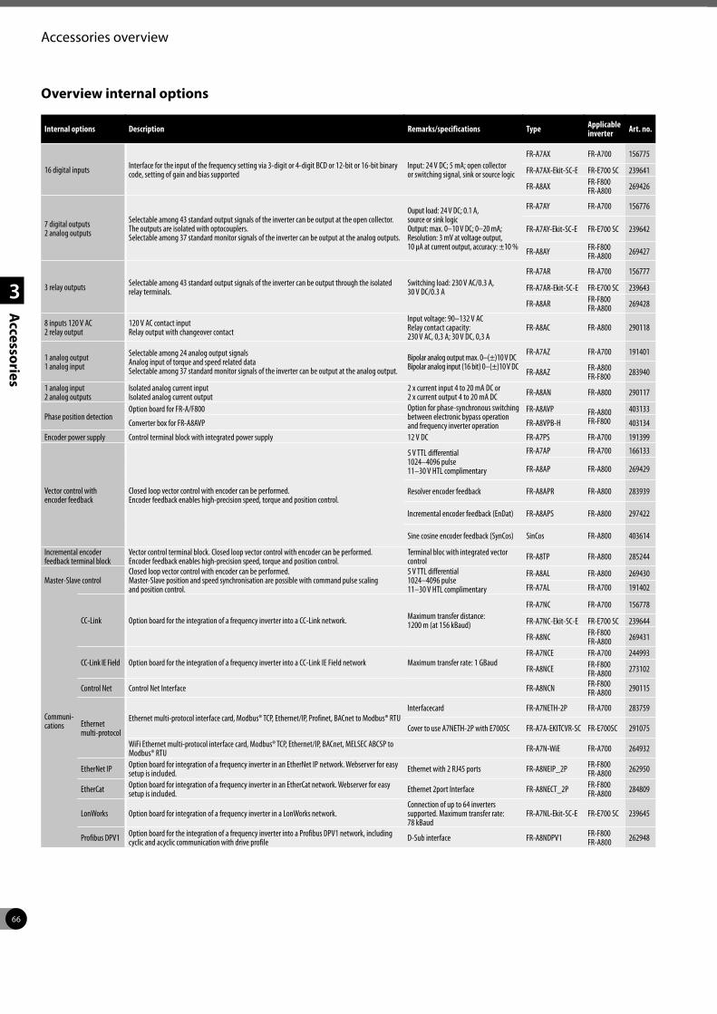
66
1
2
3
Accessories
Accessories overview
Overview internal options
Internal options Description Remarks/specifications Type Applicable inverter Art. no.
16 digital inputs Interface for the input of the frequency setting via 3-digit or 4-digit BCD or 12-bit or 16-bit binary code, setting of gain and bias supported
Input: 24 V DC; 5 mA; open collector or switching signal, sink or source logic
FR-A7AX FR-A700 156775
FR-A7AX-Ekit-SC-E FR-E700 SC 239641
FR-A8AX FR-F800FR-A800 269426
7 digital outputs 2 analog outputs
Selectable among 43 standard output signals of the inverter can be output at the open collector. The outputs are isolated with optocouplers. Selectable among 37 standard monitor signals of the inverter can be output at the analog outputs.
Ouput load: 24 V DC; 0.1 A, source or sink logic Output: max. 0–10 V DC; 0–20 mA; Resolution: 3 mV at voltage output, 10 µA at current output, accuracy: ±10 %
FR-A7AY FR-A700 156776
FR-A7AY-Ekit-SC-E FR-E700 SC 239642
FR-A8AY FR-F800FR-A800 269427
3 relay outputs Selectable among 43 standard output signals of the inverter can be output through the isolated relay terminals.
Switching load: 230 V AC/0.3 A, 30 V DC/0.3 A
FR-A7AR FR-A700 156777
FR-A7AR-Ekit-SC-E FR-E700 SC 239643
FR-A8AR FR-F800FR-A800 269428
8 inputs 120 V AC2 relay output
120 V AC contact inputRelay output with changeover contact
Input voltage: 90–132 V ACRelay contact capacity:230 V AC, 0,3 A; 30 V DC, 0,3 A
FR-A8AC FR-A800 290118
1 analog output 1 analog input
Selectable among 24 analog output signals Analog input of torque and speed related data Selectable among 37 standard monitor signals of the inverter can be output at the analog output.
Bipolar analog output max. 0–(±)10 V DC Bipolar analog input (16 bit) 0–(±)10 V DC
FR-A7AZ FR-A700 191401
FR-A8AZ FR-A800 FR-F800 283940
1 analog input2 analog outputs
Isolated analog current inputIsolated analog current output
2 x current input 4 to 20 mA DC or 2 x current output 4 to 20 mA DC FR-A8AN FR-A800 290117
Phase position detectionOption board for FR-A/F800 Option for phase-synchronous switching
between electronic bypass operation and frequency inverter operation
FR-A8AVP FR-A800 FR-F800
403133
Converter box for FR-A8AVP FR-A8VPB-H 403134
Encoder power supply Control terminal block with integrated power supply 12 V DC FR-A7PS FR-A700 191399
Vector control with encoder feedback
Closed loop vector control with encoder can be performed. Encoder feedback enables high-precision speed, torque and position control.
5 V TTL differential 1024–4096 pulse 11–30 V HTL complimentary
FR-A7AP FR-A700 166133
FR-A8AP FR-A800 269429
Resolver encoder feedback FR-A8APR FR-A800 283939
Incremental encoder feedback (EnDat) FR-A8APS FR-A800 297422
Sine cosine encoder feedback (SynCos) SinCos FR-A800 403614
Incremental encoder feedback terminal block
Vector control terminal block. Closed loop vector control with encoder can be performed.Encoder feedback enables high-precision speed, torque and position control.
Terminal bloc with integrated vector control FR-A8TP FR-A800 285244
Master-Slave controlClosed loop vector control with encoder can be performed. Master-Slave position and speed synchronisation are possible with command pulse scaling and position control.
5 V TTL differential1024–4096 pulse11–30 V HTL complimentary
FR-A8AL FR-A800 269430
FR-A7AL FR-A700 191402
Communi-cations
CC-Link Option board for the integration of a frequency inverter into a CC-Link network. Maximum transfer distance: 1200 m (at 156 kBaud)
FR-A7NC FR-A700 156778
FR-A7NC-Ekit-SC-E FR-E700 SC 239644
FR-A8NC FR-F800FR-A800 269431
CC-Link IE Field Option board for the integration of a frequency inverter into a CC-Link IE Field network Maximum transfer rate: 1 GBaudFR-A7NCE FR-A700 244993
FR-A8NCE FR-F800FR-A800 273102
Control Net Control Net Interface FR-A8NCN FR-F800FR-A800 290115
Ethernet multi-protocol
Ethernet multi-protocol interface card, Modbus® TCP, Ethernet/IP, Profinet, BACnet to Modbus® RTUInterfacecard FR-A7NETH-2P FR-A700 283759
Cover to use A7NETH-2P with E700SC FR-A7A-EKITCVR-SC FR-E700SC 291075
WiFi Ethernet multi-protocol interface card, Modbus® TCP, Ethernet/IP, BACnet, MELSEC ABCSP to Modbus® RTU FR-A7N-WiE FR-A700 264932
EtherNet IP Option board for integration of a frequency inverter in an EtherNet IP network. Webserver for easy setup is included. Ethernet with 2 RJ45 ports FR-A8NEIP_2P FR-F800
FR-A800 262950
EtherCat Option board for integration of a frequency inverter in an EtherCat network. Webserver for easy setup is included. Ethernet 2port Interface FR-A8NECT_2P FR-F800
FR-A800 284809
LonWorks Option board for integration of a frequency inverter in a LonWorks network. Connection of up to 64 inverters supported. Maximum transfer rate: 78 kBaud
FR-A7NL-Ekit-SC-E FR-E700 SC 239645
Profibus DPV1 Option board for the integration of a frequency inverter into a Profibus DPV1 network, including cyclic and acyclic communication with drive profile D-Sub interface FR-A8NDPV1 FR-F800
FR-A800 262948
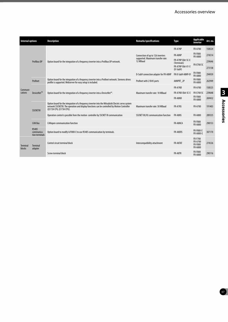
67
1
2
3
Accessories
Accessories overview
Internal options Description Remarks/specifications Type Applicable inverter Art. no.
Communi-cations
Profibus DP Option board for the integration of a frequency inverter into a Profibus DP network.
Connection of up to 126 inverters supported. Maximum transfer rate: 12 MBaud
FR-A7NP FR-A700 158524
FR-A8NP FR-F800FR-A800 274514
FR-A7NP-Ekit-SC-E (Terminals)
FR-E700 SC239646
FR-A7NP-Ekit-01-E (D-Sub9) 273138
D-Sub9 connection adapter for FR-A8NP FR-D-Sub9-A8NP-01 FR-F800FR-A800 294939
Profinet Option board for the integration of a frequency inverter into a Profinet network. Siemens drives profile is supported. Webserver for easy setup is included. Profinet with 2 RJ45 ports A8NPRT_2P FR-F800
FR-A800 262949
DeviceNetTM Option board for the integration of a frequency inverter into a DeviceNet™. Maximum transfer rate: 10 MBaud
FR-A7ND FR-A700 158525
FR-A7ND-Ekit-SC-E FR-E700 SC 239648
FR-A8ND FR-F800FR-A800 269432
SSCNETIII
Option board for the integration of a frequency inverter into the Mitsubishi Electric servo system network SSCNETIII. The operation and display functions can be controlled by Motion Controller (Q172H CPU, Q173H CPU).
Maximum transfer rate: 50 MBaud FR-A7NS FR-A700 191403
Operation control is possible from the motion controller by SSCNET III communication SSCNET III(/H) communication function FR-A8NS FR-A800 289335
CAN Bus CANopen communication function FR-A8NCA FR-F800FR-A800 298153
RS485 communica-tion terminals
Option board to modify A/F800-E to use RS485 communication by terminals. FR-A8ERS FR-F800-EFR-A800-E 307170
Terminal blocks
Terminal adapter
Control circuit terminal block Intercompatibility attachment FR-A8TAT
FR-F700FR-A700FR-F800FR-A800
274526
Screw terminal block FR-A8TR FR-F800FR-A800 290116
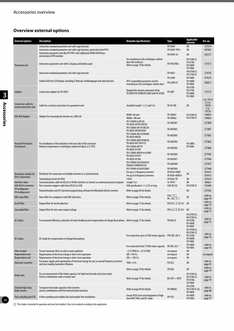
68
1
2
3
Accessories
Accessories overview
Overview external options
External options Description Remarks/specifications Type Applicable inverter Art. no.
Parameter unit
Interactive standard parameter unit with copy function
For mounting on the switchgear cabinet door (for instance) Refer to page 78 for details.
FR-DU07 All 157514Interactive standard parameter unit with copy function, protection level IP54 FR-DU07-IP54 All 207067Interactive parameter unit like FR-PU07 with additional HAND/AUTO keys and advanced PID monitor FR-PU07-01 All 242151
Interactive parameter unit with LC display and battery pack FR-PU07BB-L
FR-E700 SC FR-A700 FR-A800FR-F800
157515
Interactive standard parameter unit with copy function FR-PA07 FR-D700 SC FR-E700 SC 214795
Grafical full text LCD display, including E-Manual, multilanguage and copy function.FR-LU08 FR-A800 274525
IP55 compatible parameter unit for mounting on the switchgear cabinet door FR-LU08-01 FR-A800
FR-F800 296613
Adapter Connection adapter for FR-DU07 Required for remote connection of the FR-DU07/FR-DU08/FR-LU08 with FR-A5CBL FR-ADP
FR-A700 FR-F700 FR-A800 FR-F800
157515
Connection cable for remote parameter unit Cable for a remote connection of a parameter unit Available length: 1; 2.5 and 5 m FR-A5 CBL All
1 m: 70727 2.5 m: 70728 5 m:
70729
DIN-Rail Adapter Adapter for mounting the inverter on a DIN rail Width: 68 mm FR-UDA01 FR-D700 SCFR-E700 SC
130833Width: 108 mm FR-UDA02 130832
Heatsink Protrusion Attachment
For installation of the heatsink on the rear side of the enclosure Reduces temperature in switchgear cabinet of about 2/3, IP20
FR-F/A840 to 00126FR-A820-00105/00250 FR-A8CN01
FR-A800 FR-F800
277880
FR-F/A840-00170/00250FR-A820-00340/0049 FR-A8CN02 277881
FR-F/A840-00310/00380FR-A820-00630 FR-A8CN03 277882
FR-F/A840-00470/00620FR-A820-00770/0125 FR-A8CN04 277883
FR-F/A840-00770FR-A820-01540 FR-A8CN05 277884
FR-F/A840-00930 to 01800FR-A820-01870 FR-A8CN06 277945
FR-A820-03160 FR-A8CN07 277946FR-F/A840-03250/03610FRA820-03800/04750 FR-A8CN08 277947
FR-F/A840-02160/02600 FR-A8CN09 277948
Distributor module for RJ45 connections
Distributor for connection of multiple inverters in a serial networkFor up to 2 frequency inverters FR-RJ45-HUB4
All167612
For up to 8 frequency inverters FR-RJ45-HUB10 167613Terminating resistor for RJ45 120 Ω FR-RJ45-TR All 167614
Interface cable Communications cable for RS232 or RS485 interface to connect an external personal computer Length 3 m SC-FR PC All 88426USB-RS232 converter Port converter adapter cable from RS232 to USB USB specification 1.1, 0.35 m long USB-RS232 FR-D700 SC 155606FR Configurator Parametrisation and PLC function programming software for Mitsubishi Electric inverter. Refer to page 84 for details. — All 275503FR Configurator2
EMC noise filter Noise filter for compliance with EMC directives. Refer to page 70 for details. FFR-mm, FR-, FN-mm All refer to
page 70
du/dt filter Output filter for du/dt reduction Refer to page 73 for details. FFR-DT-mmA-SS1 All refer to page 73
Sinusoidal filter Output filter for sine wave output voltage Refer to page 73 for details. FFR-SI-mmA-SS1 All refer to page 73
AC chokes For increased efficiency, reduction of mains feedback and compensation of voltage fluctuations. Refer to page 75 for details. FR-BAL-B
FR-D700 SC, FR-E700 SC, FR-A700, FR-A800, FR-F800
refer to page 75
DC chokes DC choke for compensation of voltage fluctuations.For connection up to 55 kW motor capacity FFR-HEL-(H)-E
FR-D700 SC, FR-E700 SC, FR-A700,FR-A800, FR-F800
refer to page 76
For connection from 75 kW motor capacity FR-HEL-(H) 1 FR-A800 FR-F800
refer to page 76
Filter module Passive harmonic filter to reduce mains pollution <5 % THDi to <16 % THDi on request Allon requestRegenerative unit Regeneration of electrical energy in short-term operation (ED <50 %) on request All
Regenerative unit Regeneration of electrical energy in short-term operation (ED = 100 %) on request All
Harmonic converter For power supply and regeneration of electrical energy for one or several frequency inverters and class leading harmonics filtration. THDi <4 % FR-HC2 All refer to
page 81
Brake units For an improvement of the brake capacity. For high inertia loads and active loads.Used in combination with a resistor unit.
Refer to page 79 for details. FR-BU2 All refer to page 79
Refer to page 79 for details. BU-UFS + RUFC
FR-D700 SC, FR-E700 SC, FR-A700, FR-F800
refer to page 79
External high-duty brake resistor
To improve the brake capacity of the inverter; used in combination with the internal brake transistor Refer to page 80 for details. FR-ABR(H)
FR-D700 FR-E700 SC-EC, FR-A800
refer to page 80
Floor standing unit FSU A floor standing unit enables fast and trouble-free installation Ensure IP20 Level and integration of high level EMC Filter and DC choke FR-FSU FR-A800
FR-F800,refer to page 77
a This choke is essential for operation and must be installed. It has to be ordered according to the application.

69
1
2
3
Accessories
Noise filters
1st and 2nd environment
Different interference levels are permissible depending on the place of use. Differentiation is made between 1st and 2nd environment. The first environment includes residential and business areas which are connected directly to the low-voltage network, i.e. which are not supplied via dedicated high-voltage or medium-voltage transformers. In contrast, the second environment is not connected directly to the public low-voltage network. The second environment is also referred to as the industrial environment.
Norms and directives
The limits for the respective environments are specified in norms. The environmental norm EN 55011 defines the limits of the basic environments in the industrial area with Classes A1 and A2 and in the residential area with Class B. In addition, the product norm EN 61800-3 for electrical drive systems, which defines the categories C1 to C4, has been in force since June 2007.
These days, the operator or user of the system is responsible for complying with the statutory directives and norms. With the help of solutions provided by the manufacturer, he must ensure that any interference which occurs is eliminated. Mitsubishi Electric offers a wide range of EMC filters, chokes, harmonic filters and much more, which are optimized for use with the appropriate inverter. To ensure that all units are capable of fulfilling their function without interference, the user of the system must also take into account the connection requirements of the local power supply company.
Product norm EN 61800-3 (2005-07) for electrical drive systems
Assignment by category C1 C2 C3 C4
Environment 1st environment 1st or 2nd environment (user’s decision) 2nd environment
Voltage/Current <1000 V <1000 V; In >400 A , connection to IT network
EMC expertise No requirements Installation and commissioning by an EMC specialist EMC plan required
Limit according to EN 55011 Class B Class A1 (+ warning notice)
Class A2 (+ warning notice) Values exceed Class A2
Unrestricted distribution Category C1
Prop
agat
ion
of c
ondu
cted
in
terf
eren
ce
Med
ium
-vol
tage
pow
er s
uppl
y
2nd environment: Industrial low-voltage power supply (TT, TN and IT networks)
1st environment: Public low-voltage mains power supply (TT and TN networks)
2nd environment: C3 rated current <100 A 2nd environment: C4 rated current >100 A
Restricted distribution Category C2
EMC
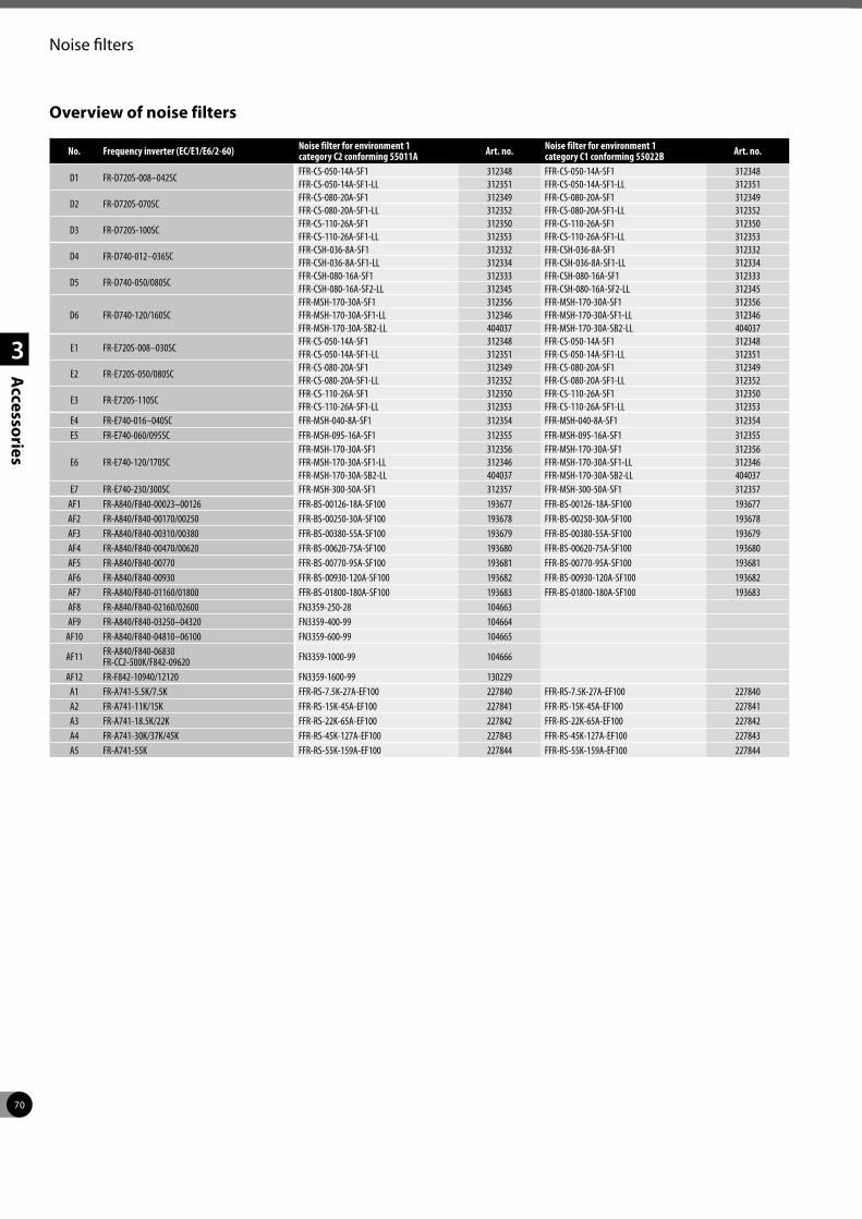
70
1
2
3
Accessories
Noise filters
Overview of noise filters
No. Frequency inverter (EC/E1/E6/2-60) Noise filter for environment 1 category C2 conforming 55011A Art. no. Noise filter for environment 1
category C1 conforming 55022B Art. no.
D1 FR-D720S-008–042SCFFR-CS-050-14A-SF1 312348 FFR-CS-050-14A-SF1 312348FFR-CS-050-14A-SF1-LL 312351 FFR-CS-050-14A-SF1-LL 312351
D2 FR-D720S-070SCFFR-CS-080-20A-SF1 312349 FFR-CS-080-20A-SF1 312349FFR-CS-080-20A-SF1-LL 312352 FFR-CS-080-20A-SF1-LL 312352
D3 FR-D720S-100SCFFR-CS-110-26A-SF1 312350 FFR-CS-110-26A-SF1 312350FFR-CS-110-26A-SF1-LL 312353 FFR-CS-110-26A-SF1-LL 312353
D4 FR-D740-012–036SCFFR-CSH-036-8A-SF1 312332 FFR-CSH-036-8A-SF1 312332FFR-CSH-036-8A-SF1-LL 312334 FFR-CSH-036-8A-SF1-LL 312334
D5 FR-D740-050/080SCFFR-CSH-080-16A-SF1 312333 FFR-CSH-080-16A-SF1 312333FFR-CSH-080-16A-SF2-LL 312345 FFR-CSH-080-16A-SF2-LL 312345
D6 FR-D740-120/160SCFFR-MSH-170-30A-SF1 312356 FFR-MSH-170-30A-SF1 312356FFR-MSH-170-30A-SF1-LL 312346 FFR-MSH-170-30A-SF1-LL 312346FFR-MSH-170-30A-SB2-LL 404037 FFR-MSH-170-30A-SB2-LL 404037
E1 FR-E720S-008–030SCFFR-CS-050-14A-SF1 312348 FFR-CS-050-14A-SF1 312348FFR-CS-050-14A-SF1-LL 312351 FFR-CS-050-14A-SF1-LL 312351
E2 FR-E720S-050/080SCFFR-CS-080-20A-SF1 312349 FFR-CS-080-20A-SF1 312349FFR-CS-080-20A-SF1-LL 312352 FFR-CS-080-20A-SF1-LL 312352
E3 FR-E720S-110SCFFR-CS-110-26A-SF1 312350 FFR-CS-110-26A-SF1 312350FFR-CS-110-26A-SF1-LL 312353 FFR-CS-110-26A-SF1-LL 312353
E4 FR-E740-016–040SC FFR-MSH-040-8A-SF1 312354 FFR-MSH-040-8A-SF1 312354E5 FR-E740-060/095SC FFR-MSH-095-16A-SF1 312355 FFR-MSH-095-16A-SF1 312355
E6 FR-E740-120/170SCFFR-MSH-170-30A-SF1 312356 FFR-MSH-170-30A-SF1 312356FFR-MSH-170-30A-SF1-LL 312346 FFR-MSH-170-30A-SF1-LL 312346FFR-MSH-170-30A-SB2-LL 404037 FFR-MSH-170-30A-SB2-LL 404037
E7 FR-E740-230/300SC FFR-MSH-300-50A-SF1 312357 FFR-MSH-300-50A-SF1 312357AF1 FR-A840/F840-00023–00126 FFR-BS-00126-18A-SF100 193677 FFR-BS-00126-18A-SF100 193677AF2 FR-A840/F840-00170/00250 FFR-BS-00250-30A-SF100 193678 FFR-BS-00250-30A-SF100 193678AF3 FR-A840/F840-00310/00380 FFR-BS-00380-55A-SF100 193679 FFR-BS-00380-55A-SF100 193679AF4 FR-A840/F840-00470/00620 FFR-BS-00620-75A-SF100 193680 FFR-BS-00620-75A-SF100 193680AF5 FR-A840/F840-00770 FFR-BS-00770-95A-SF100 193681 FFR-BS-00770-95A-SF100 193681AF6 FR-A840/F840-00930 FFR-BS-00930-120A-SF100 193682 FFR-BS-00930-120A-SF100 193682AF7 FR-A840/F840-01160/01800 FFR-BS-01800-180A-SF100 193683 FFR-BS-01800-180A-SF100 193683AF8 FR-A840/F840-02160/02600 FN3359-250-28 104663AF9 FR-A840/F840-03250–04320 FN3359-400-99 104664
AF10 FR-A840/F840-04810–06100 FN3359-600-99 104665
AF11 FR-A840/F840-06830FR-CC2-500K/F842-09620 FN3359-1000-99 104666
AF12 FR-F842-10940/12120 FN3359-1600-99 130229A1 FR-A741-5.5K/7.5K FFR-RS-7.5K-27A-EF100 227840 FFR-RS-7.5K-27A-EF100 227840A2 FR-A741-11K/15K FFR-RS-15K-45A-EF100 227841 FFR-RS-15K-45A-EF100 227841A3 FR-A741-18.5K/22K FFR-RS-22K-65A-EF100 227842 FFR-RS-22K-65A-EF100 227842A4 FR-A741-30K/37K/45K FFR-RS-45K-127A-EF100 227843 FFR-RS-45K-127A-EF100 227843A5 FR-A741-55K FFR-RS-55K-159A-EF100 227844 FFR-RS-55K-159A-EF100 227844
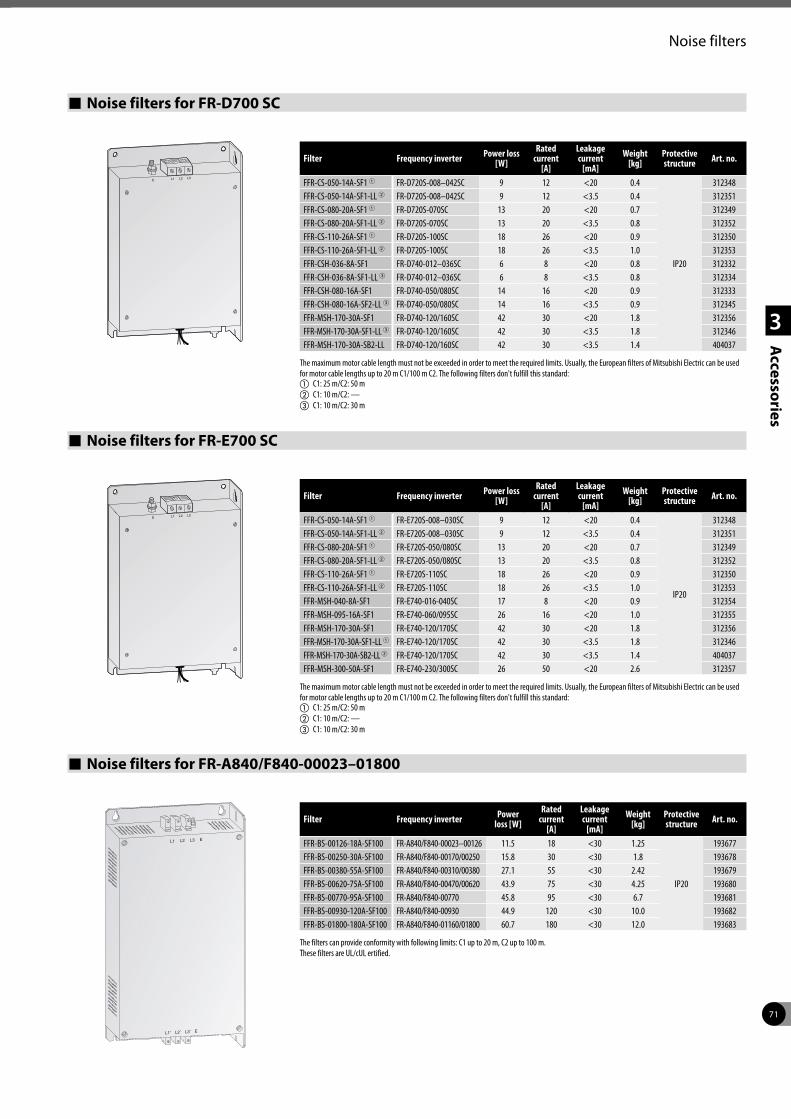
71
1
2
3
Accessories
Noise filters
Noise filters for FR-D700 SC
Filter Frequency inverter Power loss [W]
Rated current
[A]
Leakage current
[mA]Weight
[kg]Protectivestructure Art. no.
FFR-CS-050-14A-SF1 1 FR-D720S-008–042SC 9 12 <20 0.4
IP20
312348FFR-CS-050-14A-SF1-LL 2 FR-D720S-008–042SC 9 12 <3.5 0.4 312351FFR-CS-080-20A-SF1 1 FR-D720S-070SC 13 20 <20 0.7 312349FFR-CS-080-20A-SF1-LL 2 FR-D720S-070SC 13 20 <3.5 0.8 312352FFR-CS-110-26A-SF1 1 FR-D720S-100SC 18 26 <20 0.9 312350FFR-CS-110-26A-SF1-LL 2 FR-D720S-100SC 18 26 <3.5 1.0 312353FFR-CSH-036-8A-SF1 FR-D740-012–036SC 6 8 <20 0.8 312332FFR-CSH-036-8A-SF1-LL 3 FR-D740-012–036SC 6 8 <3.5 0.8 312334FFR-CSH-080-16A-SF1 FR-D740-050/080SC 14 16 <20 0.9 312333FFR-CSH-080-16A-SF2-LL 3 FR-D740-050/080SC 14 16 <3.5 0.9 312345FFR-MSH-170-30A-SF1 FR-D740-120/160SC 42 30 <20 1.8 312356FFR-MSH-170-30A-SF1-LL 3 FR-D740-120/160SC 42 30 <3.5 1.8 312346FFR-MSH-170-30A-SB2-LL FR-D740-120/160SC 42 30 <3.5 1.4 404037
The maximum motor cable length must not be exceeded in order to meet the required limits. Usually, the European filters of Mitsubishi Electric can be used for motor cable lengths up to 20 m C1/100 m C2. The following filters don't fulfill this standard:a C1: 25 m/C2: 50 mb C1: 10 m/C2: —c C1: 10 m/C2: 30 m
Noise filters for FR-E700 SC
Filter Frequency inverter Power loss [W]
Rated current
[A]
Leakage current
[mA]Weight
[kg]Protectivestructure Art. no.
FFR-CS-050-14A-SF1 1 FR-E720S-008–030SC 9 12 <20 0.4
IP20
312348FFR-CS-050-14A-SF1-LL 2 FR-E720S-008–030SC 9 12 <3.5 0.4 312351FFR-CS-080-20A-SF1 1 FR-E720S-050/080SC 13 20 <20 0.7 312349FFR-CS-080-20A-SF1-LL 2 FR-E720S-050/080SC 13 20 <3.5 0.8 312352FFR-CS-110-26A-SF1 1 FR-E720S-110SC 18 26 <20 0.9 312350FFR-CS-110-26A-SF1-LL 2 FR-E720S-110SC 18 26 <3.5 1.0 312353FFR-MSH-040-8A-SF1 FR-E740-016-040SC 17 8 <20 0.9 312354FFR-MSH-095-16A-SF1 FR-E740-060/095SC 26 16 <20 1.0 312355FFR-MSH-170-30A-SF1 FR-E740-120/170SC 42 30 <20 1.8 312356FFR-MSH-170-30A-SF1-LL 1 FR-E740-120/170SC 42 30 <3.5 1.8 312346FFR-MSH-170-30A-SB2-LL 2 FR-E740-120/170SC 42 30 <3.5 1.4 404037FFR-MSH-300-50A-SF1 FR-E740-230/300SC 26 50 <20 2.6 312357
The maximum motor cable length must not be exceeded in order to meet the required limits. Usually, the European filters of Mitsubishi Electric can be used for motor cable lengths up to 20 m C1/100 m C2. The following filters don't fulfill this standard:a C1: 25 m/C2: 50 mb C1: 10 m/C2: —c C1: 10 m/C2: 30 m
Noise filters for FR-A840/F840-00023–01800
L2 L3L1 E
L2’ L3’L1’ E
Filter Frequency inverter Power loss [W]
Rated current
[A]
Leakage current
[mA]Weight
[kg]Protectivestructure Art. no.
FFR-BS-00126-18A-SF100 FR-A840/F840-00023–00126 11.5 18 <30 1.25
IP20
193677FFR-BS-00250-30A-SF100 FR-A840/F840-00170/00250 15.8 30 <30 1.8 193678FFR-BS-00380-55A-SF100 FR-A840/F840-00310/00380 27.1 55 <30 2.42 193679FFR-BS-00620-75A-SF100 FR-A840/F840-00470/00620 43.9 75 <30 4.25 193680FFR-BS-00770-95A-SF100 FR-A840/F840-00770 45.8 95 <30 6.7 193681FFR-BS-00930-120A-SF100 FR-A840/F840-00930 44.9 120 <30 10.0 193682FFR-BS-01800-180A-SF100 FR-A840/F840-01160/01800 60.7 180 <30 12.0 193683
The filters can provide conformity with following limits: C1 up to 20 m, C2 up to 100 m. These filters are UL/cUL ertified.
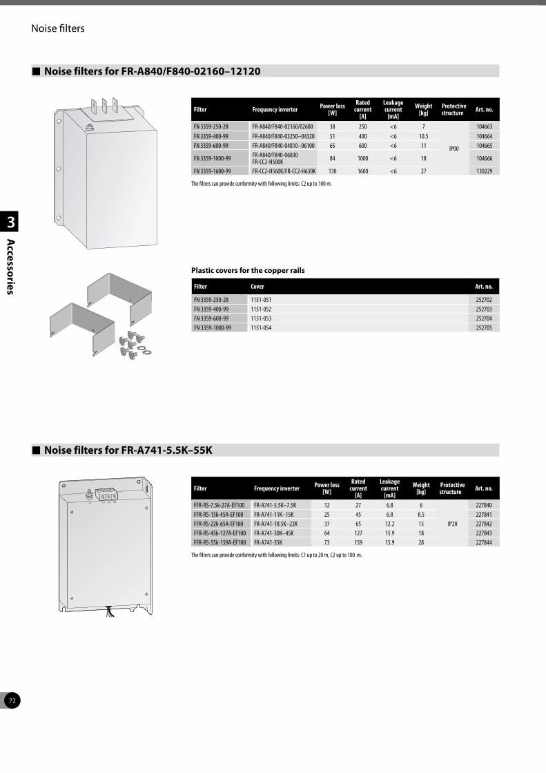
72
1
2
3
Accessories
Noise filters
Noise filters for FR-A840/F840-02160–12120
Filter Frequency inverter Power loss [W]
Rated current
[A]
Leakage current
[mA]Weight
[kg]Protectivestructure Art. no.
FN 3359-250-28 FR-A840/F840-02160/02600 38 250 <6 7
IP00
104663FN 3359-400-99 FR-A840/F840-03250–04320 51 400 <6 10.5 104664FN 3359-600-99 FR-A840/F840-04810–06100 65 600 <6 11 104665
FN 3359-1000-99 FR-A840/F840-06830 FR-CC2-H500K 84 1000 <6 18 104666
FN 3359-1600-99 FR-CC2-H560K/FR-CC2-H630K 130 1600 <6 27 130229
The filters can provide conformity with following limits: C2 up to 100 m.
Noise filters for FR-A741-5.5K–55K
Filter Frequency inverter Power loss [W]
Rated current
[A]
Leakage current
[mA]Weight
[kg]Protectivestructure Art. no.
FFR-RS-7.5k-27A-EF100 FR-A741-5.5K–7.5K 12 27 6.8 6
IP20
227840FFR-RS-15k-45A-EF100 FR-A741-11K–15K 25 45 6.8 8.5 227841FFR-RS-22k-65A-EF100 FR-A741-18.5K–22K 37 65 12.2 13 227842FFR-RS-45k-127A-EF100 FR-A741-30K–45K 64 127 15.9 18 227843FFR-RS-55k-159A-EF100 FR-A741-55K 73 159 15.9 28 227844
The filters can provide conformity with following limits: C1 up to 20 m, C2 up to 100 m.
Filter Cover Art. no.
FN 3359-250-28 1151-051 252702 FN 3359-400-99 1151-052 252703 FN 3359-600-99 1151-053 252704 FN 3359-1000-99 1151-054 252705
Plastic covers for the copper rails
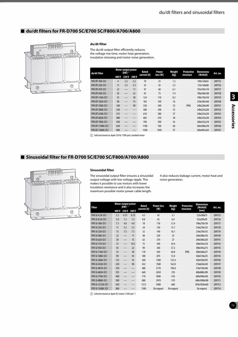
73
1
2
3
Accessories
du/dt filters and sinusoidal filters
du/dt filters for FR-D700 SC/E700 SC/F800/A700/A800
du/dt filter
The du/dt output filter efficiently reduces the voltage rise time, motor heat generation, insulation stressing and motor noise generation.
du/dt FilterMotor output power
[kW] 1 Rated current [A]
Power loss [W]
Weight [kg]
Protectivestructure
Dimensions (WxHxD) Art. no.
400 V 230 V 200 VFFR-DT-10A-SS1 4 2.2 2.2 10 25 1.2
IP00
100x120x65 209755FFR-DT-25A-SS1 11 5.5 5.5 25 45 2.5 125x140x80 209756FFR-DT-47A-SS1 22 — 11 47 60 6.1 155x195x110 209757FFR-DT-93A-SS1 45 — 22 93 75 7.4 190x240x100 209758FFR-DT-124A-SS1 55 — 30 124 110 8.2 190x170x150 209759FFR-DT-182A-SS1 90 — 75 182 140 16 210x185x160 209760FFR-DT-330A-SS1 160 — 90 330 240 32 240x220x240 209761FFR-DT-500A-SS1 250 — — 500 340 35 240x325x220 209762FFR-DT-610A-SS1 315 — — 610 380 37 240x325x230 209763FFR-DT-683A-SS1 400 — — 683 410 38 240x325x230 209764FFR-DT-790A-SS1 450 — — 790 590 43 300x355x218 209765FFR-DT-1100A-SS1 630 — — 1100 760 66 360x380x250 209766FFR-DT-1500A-SS1 800 — — 1500 1045 97 360x485x265 209767
a Selection based on 4pole (50 Hz 1500 rpm) standard motor
Sinusoidal filter for FR-D700 SC/E700 SC/F800/A700/A800
Sinusoidal filter
The sinusoidal output filter ensures a sinusoidal output voltage with low voltage ripple. This makes it possible to use motors with lower insulation resistance and it also increases the maximum possible motor power cable length.
It also reduces leakage current, motor heat and noise generation.
FilterMotor output power
[kW] 1 Rated current [A]
Power loss [W]
Weight [kg]
Protectivestructure
Dimensions (WxHxD)
[mm]Art. no.
400 V 230 V 200 VFFR-SI-4.5A-SS1 1.5 0.75 0.75 4.5 45 3.1
IP00
125x180x75 209735FFR-SI-8.3A-SS1 3.0 1.5 1.5 8.0 65 6.9 155x205x95 209736FFR-SI-18A-SS1 7.5 4.0 4.0 18 118 12.4 190x210x130 209737FFR-SI-25A-SS1 11 5.5 5.5 24 130 15.7 210x270x125 209738FFR-SI-32A-SS1 15 7.5 7.5 32 140 16.1 210x270x135 209739FFR-SI-48A-SS1 22 — 11 48 230 25 240x300x210 209740FFR-SI-62A-SS1 30 — 15 62 270 27 240x300x220 209741FFR-SI-77A-SS1 37 — 18.5 75 290 34.4 300x345x210 209742FFR-SI-93A-SS1 45 — 22 90 360 37.2 300x345x215 209743FFR-SI-116A-SS1 55 — 30 110 430 46.8 300x360x237 209744FFR-SI-180A-SS1 90 — 45 180 870 72.4 420x510x235 209745FFR-SI-260A-SS1 132 — 55 260 1300 123.4 420x550x295 209746FFR-SI-432A-SS1 220 — 90 432 1580 162.8 510x650x320 209747FFR-SI-481A-SS1 250 — — 480 2170 196.8 510x750x340 209748FFR-SI-683A-SS1 355 — — 660 2650 218 600x880x390 209749FFR-SI-770A-SS1 400 — — 770 3900 410 600x990x430 209750FFR-SI-880A-SS1 500 — — 880 3970 570 600x1000x500 209751FFR-SI-1212A-SS1 630 — — 1212 5900 660 870x1050x420 209752FFR-SI-1500A-SS1 800 — — 1500 On request On request On request 209754
a Selection based on 4pole IE2 motor (1500 rpm-1)
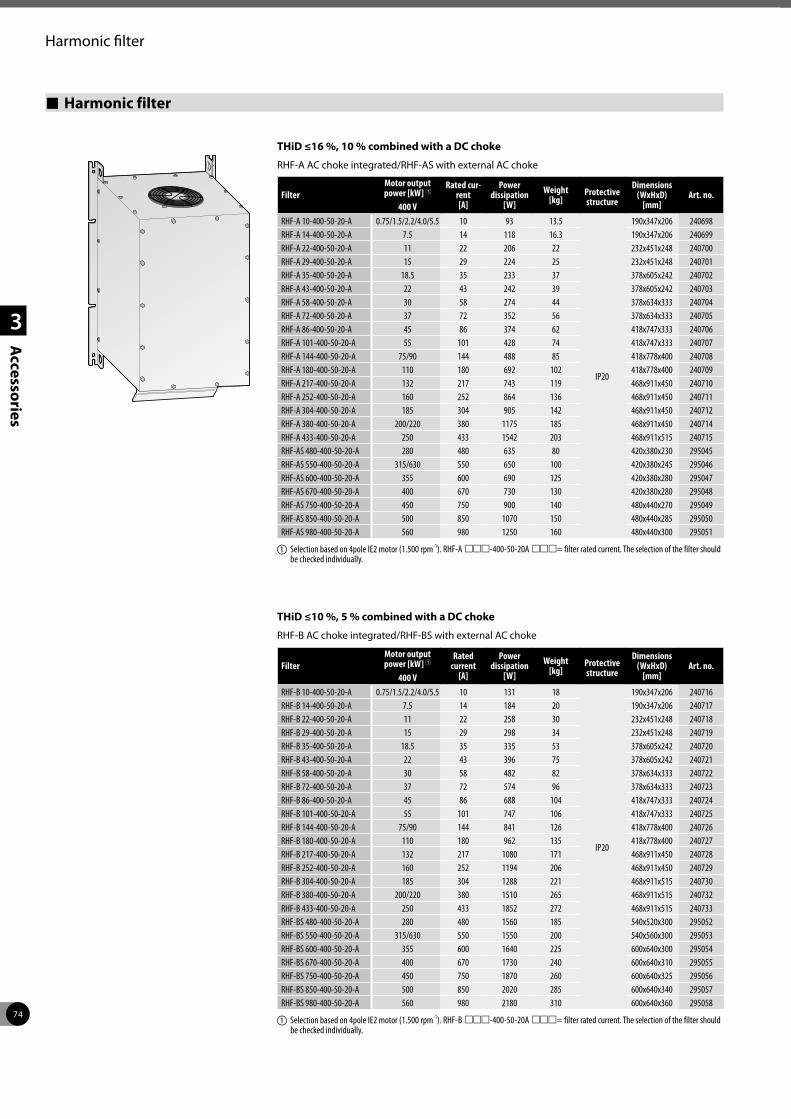
74
1
2
3
Accessories
Harmonic filter
Harmonic filter
THiD ≤16 %, 10 % combined with a DC choke
RHF-A AC choke integrated/RHF-AS with external AC choke
FilterMotor output power [kW] 1
Rated cur-rent [A]
Power dissipation
[W]Weight
[kg]Protective structure
Dimensions (WxHxD)
[mm]Art. no.
400 VRHF-A 10-400-50-20-A 0.75/1.5/2.2/4.0/5.5 10 93 13.5
IP20
190x347x206 240698RHF-A 14-400-50-20-A 7.5 14 118 16.3 190x347x206 240699RHF-A 22-400-50-20-A 11 22 206 22 232x451x248 240700RHF-A 29-400-50-20-A 15 29 224 25 232x451x248 240701RHF-A 35-400-50-20-A 18.5 35 233 37 378x605x242 240702RHF-A 43-400-50-20-A 22 43 242 39 378x605x242 240703RHF-A 58-400-50-20-A 30 58 274 44 378x634x333 240704RHF-A 72-400-50-20-A 37 72 352 56 378x634x333 240705RHF-A 86-400-50-20-A 45 86 374 62 418x747x333 240706RHF-A 101-400-50-20-A 55 101 428 74 418x747x333 240707RHF-A 144-400-50-20-A 75/90 144 488 85 418x778x400 240708RHF-A 180-400-50-20-A 110 180 692 102 418x778x400 240709RHF-A 217-400-50-20-A 132 217 743 119 468x911x450 240710RHF-A 252-400-50-20-A 160 252 864 136 468x911x450 240711RHF-A 304-400-50-20-A 185 304 905 142 468x911x450 240712RHF-A 380-400-50-20-A 200/220 380 1175 185 468x911x450 240714RHF-A 433-400-50-20-A 250 433 1542 203 468x911x515 240715RHF-AS 480-400-50-20-A 280 480 635 80 420x380x230 295045RHF-AS 550-400-50-20-A 315/630 550 650 100 420x380x245 295046RHF-AS 600-400-50-20-A 355 600 690 125 420x380x280 295047RHF-AS 670-400-50-20-A 400 670 730 130 420x380x280 295048RHF-AS 750-400-50-20-A 450 750 900 140 480x440x270 295049RHF-AS 850-400-50-20-A 500 850 1070 150 480x440x285 295050RHF-AS 980-400-50-20-A 560 980 1250 160 480x440x300 295051
a Selection based on 4pole IE2 motor (1.500 rpm-1). RHF-A mmm-400-50-20A mmm= filter rated current. The selection of the filter should be checked individually.
FilterMotor output power [kW] 1
Rated current
[A]
Power dissipation
[W]Weight
[kg]Protective structure
Dimensions (WxHxD)
[mm]Art. no.
400 VRHF-B 10-400-50-20-A 0.75/1.5/2.2/4.0/5.5 10 131 18
IP20
190x347x206 240716RHF-B 14-400-50-20-A 7.5 14 184 20 190x347x206 240717RHF-B 22-400-50-20-A 11 22 258 30 232x451x248 240718RHF-B 29-400-50-20-A 15 29 298 34 232x451x248 240719RHF-B 35-400-50-20-A 18.5 35 335 53 378x605x242 240720RHF-B 43-400-50-20-A 22 43 396 75 378x605x242 240721RHF-B 58-400-50-20-A 30 58 482 82 378x634x333 240722RHF-B 72-400-50-20-A 37 72 574 96 378x634x333 240723RHF-B 86-400-50-20-A 45 86 688 104 418x747x333 240724RHF-B 101-400-50-20-A 55 101 747 106 418x747x333 240725RHF-B 144-400-50-20-A 75/90 144 841 126 418x778x400 240726RHF-B 180-400-50-20-A 110 180 962 135 418x778x400 240727RHF-B 217-400-50-20-A 132 217 1080 171 468x911x450 240728RHF-B 252-400-50-20-A 160 252 1194 206 468x911x450 240729RHF-B 304-400-50-20-A 185 304 1288 221 468x911x515 240730RHF-B 380-400-50-20-A 200/220 380 1510 265 468x911x515 240732RHF-B 433-400-50-20-A 250 433 1852 272 468x911x515 240733RHF-BS 480-400-50-20-A 280 480 1560 185 540x520x300 295052RHF-BS 550-400-50-20-A 315/630 550 1550 200 540x560x300 295053RHF-BS 600-400-50-20-A 355 600 1640 225 600x640x300 295054RHF-BS 670-400-50-20-A 400 670 1730 240 600x640x310 295055RHF-BS 750-400-50-20-A 450 750 1870 260 600x640x325 295056RHF-BS 850-400-50-20-A 500 850 2020 285 600x640x340 295057RHF-BS 980-400-50-20-A 560 980 2180 310 600x640x360 295058
a Selection based on 4pole IE2 motor (1.500 rpm-1). RHF-B mmm-400-50-20A mmm= filter rated current. The selection of the filter should be checked individually.
THiD ≤10 %, 5 % combined with a DC choke
RHF-B AC choke integrated/RHF-BS with external AC choke
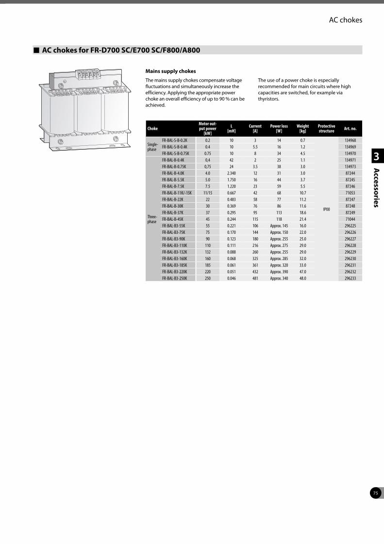
75
1
2
3
Accessories
AC chokes
AC chokes for FR-D700 SC/E700 SC/F800/A800
Mains supply chokes
The mains supply chokes compensate voltage fluctuations and simultaneously increase the efficiency. Applying the appropriate power choke an overall efficiency of up to 90 % can be achieved.
The use of a power choke is especially recommended for main circuits where high capacities are switched, for example via thyristors.
ChokeMotor out-put power
[kW] L
[mH]Current
[A]Power loss
[W]Weight
[kg]Protectivestructure Art. no.
Single- phase
FR-BAL-S-B-0.2K 0.2 10 3 14 0.7
IP00
134968FR-BAL-S-B-0.4K 0.4 10 5.5 16 1.2 134969FR-BAL-S-B-0.75K 0.75 10 8 34 4.5 134970
Three- phase
FR-BAL-B-0.4K 0,4 42 2 25 1.1 134971FR-BAL-B-0.75K 0,75 24 3.5 38 3.0 134973FR-BAL-B-4.0K 4.0 2.340 12 31 3.0 87244FR-BAL-B-5.5K 5.0 1.750 16 44 3.7 87245FR-BAL-B-7.5K 7.5 1.220 23 59 5.5 87246FR-BAL-B-11K/-15K 11/15 0.667 42 68 10.7 71053FR-BAL-B-22K 22 0.483 58 77 11.2 87247FR-BAL-B-30K 30 0.369 76 86 11.6 87248FR-BAL-B-37K 37 0.295 95 113 18.6 87249FR-BAL-B-45K 45 0.244 115 118 21.4 71044FR-BAL-B3-55K 55 0.221 106 Approx. 145 16.0 296225FR-BAL-B3-75K 75 0.170 144 Approx. 150 22.0 296226FR-BAL-B3-90K 90 0.123 180 Approx. 255 25.0 296227FR-BAL-B3-110K 110 0.111 216 Approx. 275 29.0 296228FR-BAL-B3-132K 132 0.088 260 Approx. 255 29.0 296229FR-BAL-B3-160K 160 0.068 325 Approx. 285 32.0 296230FR-BAL-B3-185K 185 0.061 361 Approx. 320 33.0 296231FR-BAL-B3-220K 220 0.051 432 Approx. 390 47.0 296232FR-BAL-B3-250K 250 0.046 481 Approx. 340 48.0 296233
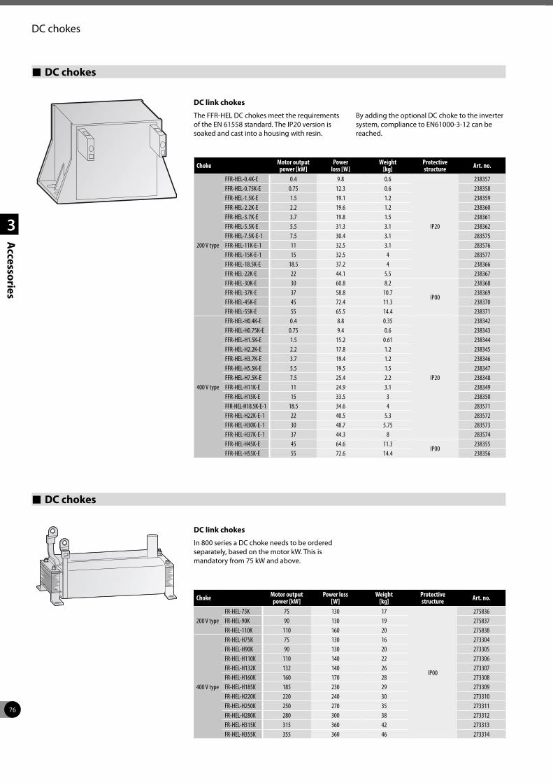
76
1
2
3
Accessories
DC chokes
DC chokes
DC link chokes
The FFR-HEL DC chokes meet the requirements of the EN 61558 standard. The IP20 version is soaked and cast into a housing with resin.
By adding the optional DC choke to the inverter system, compliance to EN61000-3-12 can be reached.
Choke Motor output power [kW]
Power loss [W]
Weight [kg]
Protectivestructure Art. no.
200 V type
FFR-HEL-0.4K-E 0.4 9.8 0.6
IP20
238357FFR-HEL-0.75K-E 0.75 12.3 0.6 238358FFR-HEL-1.5K-E 1.5 19.1 1.2 238359FFR-HEL-2.2K-E 2.2 19.6 1.2 238360FFR-HEL-3.7K-E 3.7 19.8 1.5 238361FFR-HEL-5.5K-E 5.5 31.3 3.1 238362FFR-HEL-7.5K-E-1 7.5 30.4 3.1 283575FFR-HEL-11K-E-1 11 32.5 3.1 283576FFR-HEL-15K-E-1 15 32.5 4 283577FFR-HEL-18.5K-E 18.5 37.2 4 238366FFR-HEL-22K-E 22 44.1 5.5 238367FFR-HEL-30K-E 30 60.8 8.2
IP00
238368FFR-HEL-37K-E 37 58.8 10.7 238369FFR-HEL-45K-E 45 72.4 11.3 238370FFR-HEL-55K-E 55 65.5 14.4 238371
400 V type
FFR-HEL-H0.4K-E 0.4 8.8 0.35
IP20
238342FFR-HEL-H0.75K-E 0.75 9.4 0.6 238343FFR-HEL-H1.5K-E 1.5 15.2 0.61 238344FFR-HEL-H2.2K-E 2.2 17.8 1.2 238345FFR-HEL-H3.7K-E 3.7 19.4 1.2 238346FFR-HEL-H5.5K-E 5.5 19.5 1.5 238347FFR-HEL-H7.5K-E 7.5 25.4 2.2 238348FFR-HEL-H11K-E 11 24.9 3.1 238349FFR-HEL-H15K-E 15 33.5 3 238350FFR-HEL-H18.5K-E-1 18.5 34.6 4 283571FFR-HEL-H22K-E-1 22 40.5 5.3 283572FFR-HEL-H30K-E-1 30 48.7 5.75 283573FFR-HEL-H37K-E-1 37 44.3 8 283574FFR-HEL-H45K-E 45 64.6 11.3
IP00238355
FFR-HEL-H55K-E 55 72.6 14.4 238356
DC chokes
DC link chokes
In 800 series a DC choke needs to be ordered separately, based on the motor kW. This is mandatory from 75 kW and above.
Choke Motor output power [kW]
Power loss [W]
Weight [kg]
Protectivestructure Art. no.
200 V typeFR-HEL-75K 75 130 17
IP00
275836FR-HEL-90K 90 130 19 275837FR-HEL-110K 110 160 20 275838
400 V type
FR-HEL-H75K 75 130 16 273304FR-HEL-H90K 90 130 20 273305FR-HEL-H110K 110 140 22 273306FR-HEL-H132K 132 140 26 273307FR-HEL-H160K 160 170 28 273308FR-HEL-H185K 185 230 29 273309FR-HEL-H220K 220 240 30 273310FR-HEL-H250K 250 270 35 273311FR-HEL-H280K 280 300 38 273312FR-HEL-H315K 315 360 42 273313FR-HEL-H355K 355 360 46 273314
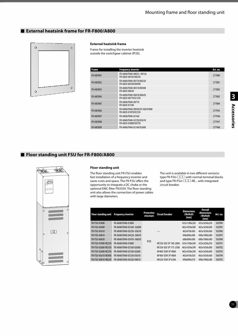
77
1
2
3
Accessories
Mounting frame and floor standing unit
External heatsink frame for FR-F800/A800
External heatsink frame
Frame for installing the inverter heatsink outside the switchgear cabinet (IP20).
Frame Frequency inverter Art. no.
FR-A8CN01 FR-A840/F840-00023–00126 FR-A820-00105/00250 277880
FR-A8CN02 FR-A840/F840-00170/00250 FR-A820-00340/00490 277881
FR-A8CN03 FR-A840/F840-00310/00380 FR-A820-00630 277882
FR-A8CN04 FR-A840/F840-00470/00620 FR-A820-00770/01250 277883
FR-A8CN05 FR-A840/F840-00770 FR-A820-01540 277884
FR-A8CN06 FR-A840/F840-00930/01160/01800 FR-A820-01870/02330 277945
FR-A8CN07 FR-A840/F840-02160 277946
FR-A8CN08 FR-A840/F840-03250/03610 FR-A820-03800/04750 277947
FR-A8CN09 FR-A840/F840-02160/02600 277948
Floor standing unit FSU for FR-F800/A800
Floor standing unit
The floor standing unit FR-FSU enables fast installation of a frequency inverter and saves costs and space. The FR-FSU offers the opportunity to integrate a DC choke or the optional EMC filter FN3359. The floor standing unit also allows the connection of power cables with large diameters.
The unit is available in two different versions: type FR-FSU-mmm with normal terminal blocks and type FR-FSU-mmm-RE... with integrated circuit breaker.
Floor standing unit Frequency inverter Protectivestructure Circuit breaker
Dimensions(WxHxD)
[mm]
Overall dimensions
(WxHxD) [mm]
Art. no.
FR-FSU-01800 FR-A840/F840-01800
IP20
—
435x1100x250 435x1650x250 163994FR-FSU-02600 FR-A840/F840-02160–02600 465x1030x300 465x1650x300 163995FR-FSU-03610 FR-A840/F840-03250–03610 465x910x360 465x1650x360 163996FR-FSU-04810 FR-A840/F840-04320–04810 498x890x380 498x1900x380 163997FR-FSU-06830 FR-A840/F840-05470–06830 680x890x380 680x1900x380 163998FR-FSU-01800-RE250 FR-A840/F840-01800 NF250-SGV 3P 140-200A 435x1100x240 435x1650x250 164791FR-FSU-02600-RE250 FR-A840/F840-02160-02600 NF250-SGV 3P 175-250A 465x1030x290 465x1650x300 164792FR-FSU-02600-RE250 FR-A840/F840-02160-02600 NF400-SEW 3P 400A 465x1030x290 465x1650x300 164793FR-FSU-03610-RE400 FR-A840/F840-03250-03610 NF400-SEW 3P 400A 465x910x350 465x1650x360 164794FR-FSU-04810-RE630 FR-A840/F840-04320-04810 NF630-SEW 3P 630A 498x890x370 498x1900x380 164795
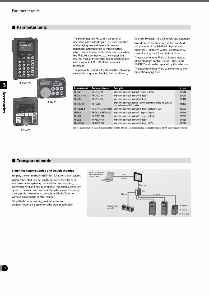
78
1
2
3
Accessories
Parameter units
The parameter unit FR-LU08 is an optional operation panel adopting an LCD panel capable of displaying text and menus. It can save parameter settings for up to three inverters, which can be transferred to other inverters. When the FR-LU08 is connected to the inverter, the internal clock of the inverter can be synchronized with the clock of FRLU08. (Real time clock function).
The parameter unit displays text in the following selectable languages: English, German, French,
Spanish, Swedish, Italian, Finnish, and Japanese.
In addition to the functions of the standard parameter unit the FR-PU07 displays and monitors 21 different values (like frequency, current, voltage, etc.) and states in total.
The parameter unit FR-PU07 is used instead of the standard control units FR-DU04 and FR-DU07 and can be replaced by this after use.
The parameter unit FR-PU07 conforms to the protection rating IP40.
Parameter units
Parameter unit Frequency inverter Description Art. no.FR-DU07 FR-D/E/A700 Interactive parameter unit with 7 Segment display 157514FR-DU07-IP54 FR-D/E/A700 Interactive parameter unit with LC display 207067FR-PU07 FR-D/E/A700 Interactive parameter unit with LC display 166134
FR-PU07-01 1 FR-F/A800 Interactive parameter unit like FR-PU07 but with additional AUTO/HAND keys and advanced PID monitor 242151
FR-PU07BB-L FR-D/E700 SC/FR-F/A800 Interactive parameter unit with LC display and battery pack 209052FR-PA07 FR-D700 SC/FR-E700 SC Interactive parameter unit with 7 Segment display 214795FR-DU08 FR-A800/F800 Interactive parameter unit with 12 Segment display 286226FR-LU08 FR-A800/F800 Interactive parameter unit with LC display 274525FR-LU08-01 FR-A800/F800 Interactive parameter unit with LC display (IP55) 296613
a The parameter unit FR-PU07-01 can be used for FR-A800/F800 series per connection cable. It cannot be mounted directly on the frequency inverter.
FR-DU07
FR-PU07-01
PWR
ALM
FR-LU08
Transparent mode
Simplified commissioning and troubleshooting
Simplify the commissioning if industrial automation systems.
When connected to a personal computer, the GOT acts as a transparent gateway that enables programming, commissioning and fine-tuning of an industrial automation system. The user can communicate with several frequency inverters via the network connection (RS485/Ethernet) without opening the control cabinet.
Simplified commissioning, maintenance, and troubleshooting is possible via the plain text display.
PC with software for programming and configuration
Programmable controller
Ethernet
Ethernet
Ethernet
FR-A800-E
FR-F800-E
FR-E700-ENE
Ethernet
Hub
USB
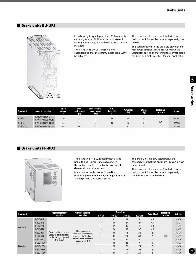
79
1
2
3
Accessories
Brake units
For a braking torque higher than 20 % or a duty cycle higher than 30 % an external brake unit including the adequate brake resistors has to be installed.
The brake units BU-UFS listed below are cascadable so that the optimum size can always be achieved.
The brake units here are not fitted with brake resistors, which must be ordered separately (see below).
The configurations in the table are only general recommendations. Please consult Mitsubishi Electric for advice on matching the correct brake modules and brake resistors for your application.
Brake units BU-UFS
Brake unit Applicable motor capacity
Multiple (parallel) operation
PowerlossWeight [kg] Protective
structure Art. no.0 % ED 10 % ED 50 % ED 100 % ED
200 V class
FR-BU2-1.5K
Capacity of the motor to be used with differs according to the braking torque and
duty (% ED)
10 units maximum (Note that torque generated is not more than the toler-able overcurrent amount of
connected inverter)
5 8 18 31 0.9
IP00
202420FR-BU2-3.7K 5 10 27 49 0.9 202421FR-BU2-7.5K 5 12 36 67 0.9 202422FR-BU2-15K 5 23 86 165 0.9 202423FR-BU2-30K 5 38 149 288 5 202424FR-BU2-55K 5 91 318 601 5 202425
400 V class
FR-BU2-H7.5K 5 10 27 47 5 202426FR-BU2-H15K 5 13 40 74 5 202427FR-BU2-H30K 5 20 72 137 5 202428FR-BU2-H55K 5 37 140 268 5 202429FR-BU2-H75K 5 49 174 331 5 202430
Brake units FR-BU2
Brake unit Frequency inverterRated
voltage [V]
Max. peak current
[A]
Max. instanta-neous power
[kW]
Max. duty cycle
[%]Power loss
[W]Weight
[kg]Protective structure Art. no.
BU-UFS22 FR-D740/FR-E740 SCFR-A/F840-00023–00250 400 34 25 10 37 2.5
IP20127947
BU-UFS40 FR-A/F840-00250–00470 400 55 41 10 42 2.5 127948BU-UFS110 FR-A/F840-00470–01160 400 140 105 5 48 3.9 127950
The brake unit FR-BU2 is used when a large brake torque is necessary such as when the motor is made to run by the load, quick deceleration is required, etc.
It is equipped with a control panel for monitoring different values, setting parameters and displaying the alarm history.
The brake units FR-BU2 listed below are cascadable so that the optimum size can always be achieved.
The brake units here are not fitted with brake resistors, which must be ordered separately (brake resistors available soon).
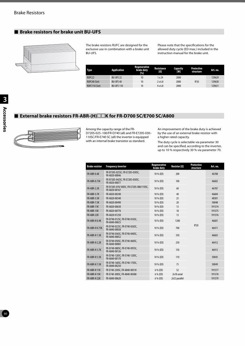
80
1
2
3
Accessories
Brake Resistors
Brake resistors for brake unit BU-UFS
The brake resistors RUFC are designed for the exclusive use in combination with a brake unit BU-UFS.
Please note that the specifications for the allowed duty cycle (ED max.) included in the instruction manual for the brake unit.
Type ApplicationRegenerative
brake duty [%]
Resistance [Ω]
Capacity [W]
Protective structure Art. no.
RUFC22 BU-UFS 22 10 1 x 24 2000IP20
129629RUFC40 (Set) BU-UFS 40 10 2 x 6.8 2000 129630RUFC110 (Set) BU-UFS 110 10 4 x 6.8 2000 129631
External brake resistors FR-ABR-(H)mmK for FR-D700 SC/E700 SC/A800
Among the capacity range of the FR-D720S-025–100/FR-D740 (all) and FR-E720S-030–110SC/FR-E740 SC (all) the inverter is equipped with an internal brake transistor as standard.
An improvement of the brake duty is achieved by the use of an external brake resistor with a higher rated capacity.
The duty cycle is selectable via parameter 30 and can be specified, according to the inverter, up to 10 % respectively 30 % via parameter 70.
Brake resistor Frequency inverter Regenerative brake duty Resistor [Ω] Protective
structure Art. no.
FR-ABR-0.4K FR-D720S-025SC, FR-E720S-030SC, FR-A820-00046 10 % (ED) 200
IP20
46788
FR-ABR-0.75K FR-D720S-042SC, FR-E720S-050SC, FR-A820-00077 10 % (ED) 100 46602
FR-ABR-2.2K FR-D720S-070/100SC, FR-E720S-080/110SC, FR-A820-00167 10 % (ED) 60 46787
FR-ABR-3.7K FR-A820-00240 10 % (ED) 40 46604FR-ABR-5.5K FR-A820-00340 10 % (ED) 25 48301FR-ABR-7.5K FR-A820-00490 10 % (ED) 20 50048FR-ABR-11K FR-A820-00630 10 % (ED) 13 191574FR-ABR-15K FR-A820-00770 10 % (ED) 18 191575FR-ABR-22K FR-A820-01250 10 % (ED) 13 191576
FR-ABR-H 0.4K FR-D740-012SC, FR-E740-016SC, FR-A840-00023 10 % (ED) 1200 46601
FR-ABR-H 0.75K FR-D740-022SC, FR-E740-026SC, FR-A840-00038 10 % (ED) 700 46411
FR-ABR-H 1.5K FR-D740-036SC, FR-E740-040SC, FR-A840-00052 10 % (ED) 350 46603
FR-ABR-H 2.2K FR-D740-050SC, FR-E740-060SC, FR-A840-00083 10 % (ED) 250 46412
FR-ABR-H 3.7K FR-D740-080SC, FR-E740-095SC, FR-A840-00126 10 % (ED) 150 46413
FR-ABR-H 5.5K FR-D740-120SC, FR-E740-120SC, FR-A840-00170 10 % (ED) 110 50045
FR-ABR-H 7.5K FR-D740-160SC, FR-E740-170SC, FR-A840-00250 10 % (ED) 75 50049
FR-ABR-H 11K FR-E740-230SC, FR-A840-00310 6 % (ED) 52 191577FR-ABR-H 15K FR-E740-300SC, FR-A840-00380 6 % (ED) 2x18 serial 191578FR-ABR-H 22K FR-A840-00620 6 % (ED) 2x52 parallel 191579
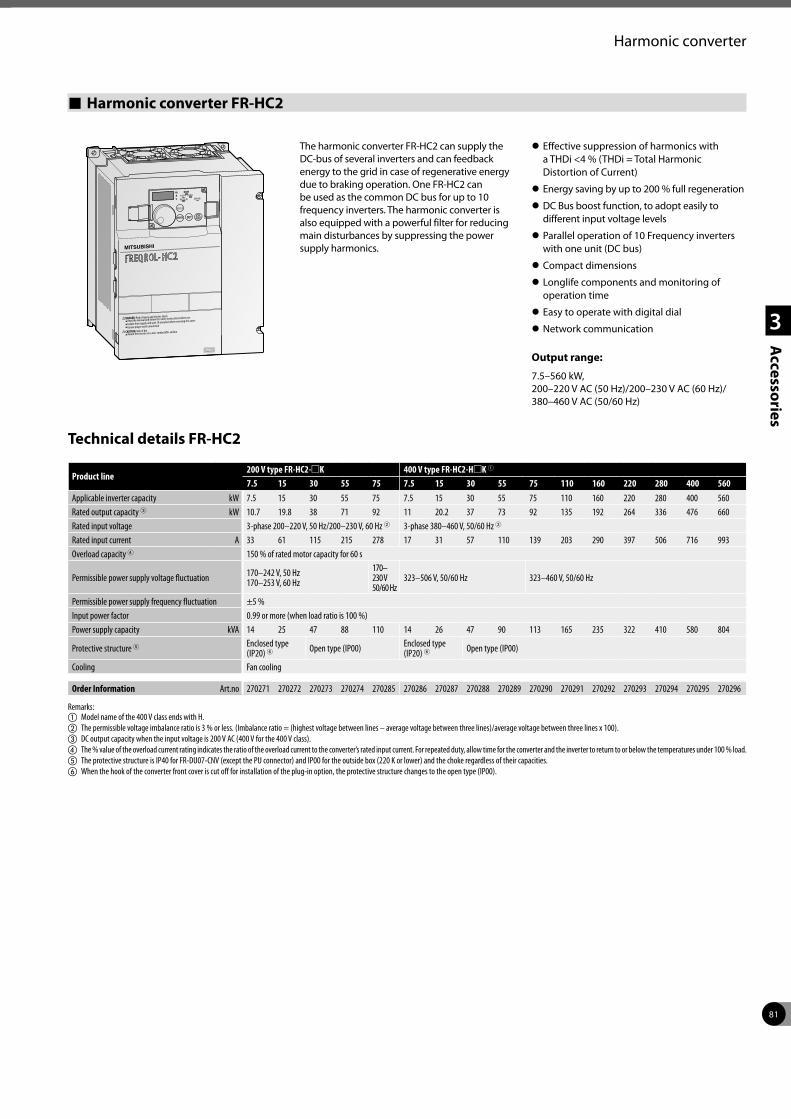
81
1
2
3
Accessories
Harmonic converter
Harmonic converter FR-HC2
The harmonic converter FR-HC2 can supply the DC-bus of several inverters and can feedback energy to the grid in case of regenerative energy due to braking operation. One FR-HC2 can be used as the common DC bus for up to 10 frequency inverters. The harmonic converter is also equipped with a powerful filter for reducing main disturbances by suppressing the power supply harmonics.
z Effective suppression of harmonics with a THDi <4 % (THDi = Total Harmonic Distortion of Current)
z Energy saving by up to 200 % full regeneration
z DC Bus boost function, to adopt easily to different input voltage levels
z Parallel operation of 10 Frequency inverters with one unit (DC bus)
z Compact dimensions
z Longlife components and monitoring of operation time
z Easy to operate with digital dial
z Network communication
Output range:
7.5–560 kW, 200–220 V AC (50 Hz)/200–230 V AC (60 Hz)/ 380–460 V AC (50/60 Hz)
Technical details FR-HC2
DANGER: Risk of injury and electric shockRead the manual and follow the safety instructions before use.
Isolate from supply and wait 10 minutes before removing this cover.
Ensure proper earth connection
Mount the inverter on a non-combustible surface.
200V
Product line200 V type FR-HC2-mK 400 V type FR-HC2-HmK 1
7.5 15 30 55 75 7.5 15 30 55 75 110 160 220 280 400 560Applicable inverter capacity kW 7.5 15 30 55 75 7.5 15 30 55 75 110 160 220 280 400 560Rated output capacity 3 kW 10.7 19.8 38 71 92 11 20.2 37 73 92 135 192 264 336 476 660Rated input voltage 3-phase 200–220 V, 50 Hz/200–230 V, 60 Hz 2 3-phase 380–460 V, 50/60 Hz 2
Rated input current A 33 61 115 215 278 17 31 57 110 139 203 290 397 506 716 993Overload capacity 4 150 % of rated motor capacity for 60 s
Permissible power supply voltage fluctuation 170–242 V, 50 Hz 170–253 V, 60 Hz
170– 230 V 50/60 Hz
323–506 V, 50/60 Hz 323–460 V, 50/60 Hz
Permissible power supply frequency fluctuation ±5 %Input power factor 0.99 or more (when load ratio is 100 %)Power supply capacity kVA 14 25 47 88 110 14 26 47 90 113 165 235 322 410 580 804
Protective structure 5 Enclosed type (IP20) 6 Open type (IP00) Enclosed type
(IP20) 6 Open type (IP00)
Cooling Fan cooling
Order Information Art.no 270271 270272 270273 270274 270285 270286 270287 270288 270289 270290 270291 270292 270293 270294 270295 270296
Remarks:a Model name of the 400 V class ends with H.b The permissible voltage imbalance ratio is 3 % or less. (Imbalance ratio = (highest voltage between lines – average voltage between three lines)/average voltage between three lines x 100).c DC output capacity when the input voltage is 200 V AC (400 V for the 400 V class).d The % value of the overload current rating indicates the ratio of the overload current to the converter’s rated input current. For repeated duty, allow time for the converter and the inverter to return to or below the temperatures under 100 % load.e The protective structure is IP40 for FR-DU07-CNV (except the PU connector) and IP00 for the outside box (220 K or lower) and the choke regardless of their capacities.f When the hook of the converter front cover is cut off for installation of the plug-in option, the protective structure changes to the open type (IP00).
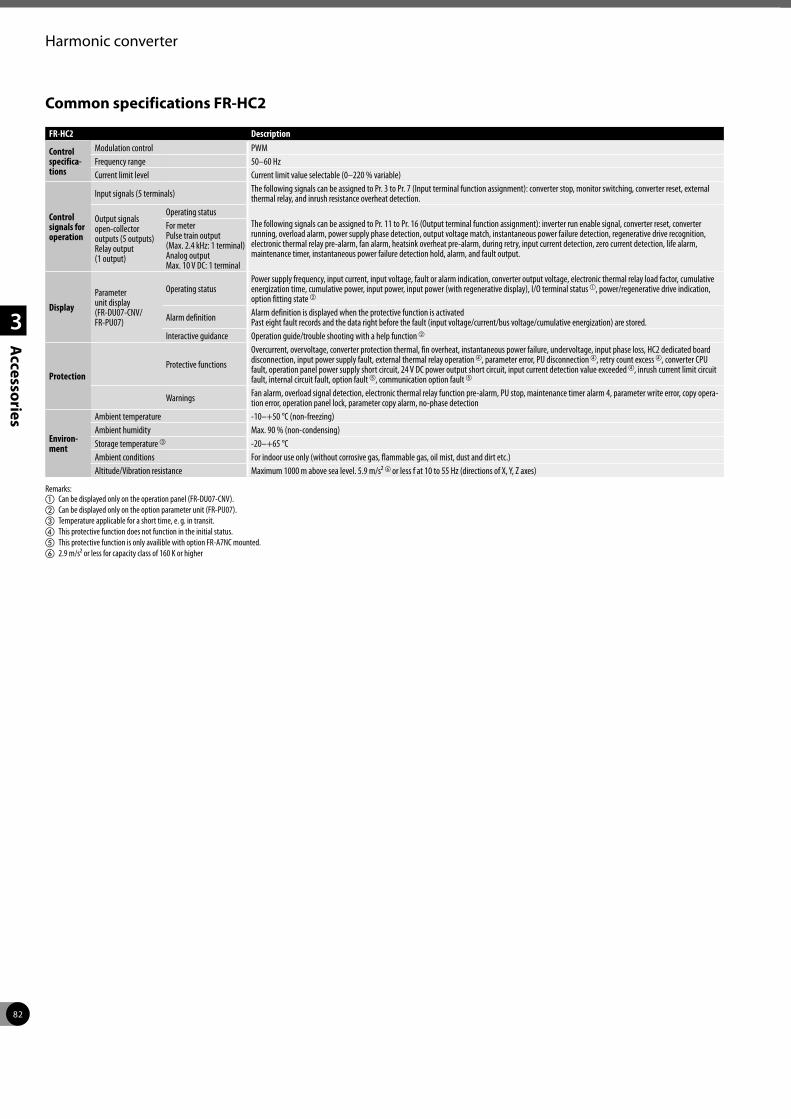
82
1
2
3
Accessories
Harmonic converter
Common specifications FR-HC2
FR-HC2 Description
Control specifica- tions
Modulation control PWMFrequency range 50–60 HzCurrent limit level Current limit value selectable (0–220 % variable)
Control signals for operation
Input signals (5 terminals) The following signals can be assigned to Pr. 3 to Pr. 7 (Input terminal function assignment): converter stop, monitor switching, converter reset, external thermal relay, and inrush resistance overheat detection.
Output signals open-collector outputs (5 outputs) Relay output (1 output)
Operating statusThe following signals can be assigned to Pr. 11 to Pr. 16 (Output terminal function assignment): inverter run enable signal, converter reset, converter running, overload alarm, power supply phase detection, output voltage match, instantaneous power failure detection, regenerative drive recognition, electronic thermal relay pre-alarm, fan alarm, heatsink overheat pre-alarm, during retry, input current detection, zero current detection, life alarm, maintenance timer, instantaneous power failure detection hold, alarm, and fault output.
For meter Pulse train output (Max. 2.4 kHz: 1 terminal) Analog output Max. 10 V DC: 1 terminal
DisplayParameter unit display (FR-DU07-CNV/ FR-PU07)
Operating statusPower supply frequency, input current, input voltage, fault or alarm indication, converter output voltage, electronic thermal relay load factor, cumulative energization time, cumulative power, input power, input power (with regenerative display), I/O terminal status a, power/regenerative drive indication, option fitting state b
Alarm definition Alarm definition is displayed when the protective function is activated Past eight fault records and the data right before the fault (input voltage/current/bus voltage/cumulative energization) are stored.
Interactive guidance Operation guide/trouble shooting with a help function b
ProtectionProtective functions
Overcurrent, overvoltage, converter protection thermal, fin overheat, instantaneous power failure, undervoltage, input phase loss, HC2 dedicated board disconnection, input power supply fault, external thermal relay operation d, parameter error, PU disconnection d, retry count excess d, converter CPU fault, operation panel power supply short circuit, 24 V DC power output short circuit, input current detection value exceeded d, inrush current limit circuit fault, internal circuit fault, option fault e, communication option fault e
Warnings Fan alarm, overload signal detection, electronic thermal relay function pre-alarm, PU stop, maintenance timer alarm 4, parameter write error, copy opera-tion error, operation panel lock, parameter copy alarm, no-phase detection
Environ-ment
Ambient temperature -10–+50 °C (non-freezing)Ambient humidity Max. 90 % (non-condensing)Storage temperature c -20–+65 °CAmbient conditions For indoor use only (without corrosive gas, flammable gas, oil mist, dust and dirt etc.)Altitude/Vibration resistance Maximum 1000 m above sea level. 5.9 m/s² for less f at 10 to 55 Hz (directions of X, Y, Z axes)
Remarks:a Can be displayed only on the operation panel (FR-DU07-CNV).b Can be displayed only on the option parameter unit (FR-PU07).c Temperature applicable for a short time, e. g. in transit.d This protective function does not function in the initial status.e This protective function is only availible with option FR-A7NC mounted.f 2.9 m/s² or less for capacity class of 160 K or higher
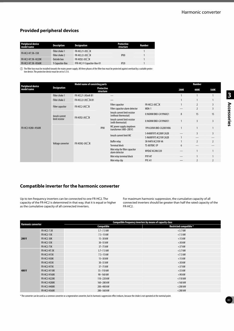
83
1
2
3
Accessories
Harmonic converter
Provided peripheral devices
Peripheral device model name Description Designation Protective
structure Number
FR-HC2-H7.5K–55KFilter choke 1 FR-HCL21-(H)mK
IP001
Filter choke 2 FR-HCL22-(H)mK 1FR-HC2-H7.5K–H220K Outside box FR-HCB2-(H)mK 1FR-HC2-H7.5K–H560K Y-Capacitor-Box FFR-HC2-Y-Capacitor-Box-01 IP20 1
a The filter box must be installed towards the mains power supply. All three phases of the filter box must be protected against overload by a suitable protec-tive device. The protective device must be set to 5.5 A.
Peripheral device model name Designation
Model name of consisting parts NumberProtective structure 280K 400K 560K
FR-HC2-H280–H560K
Filter choke 1 FR-HCL21-(H)mK-B1
IP00
— 1 1 1
Filter choke 2 FR-HCL22-(H)mK-B1 — 1 1 1
Filter capacitor FR-HCC2-(H)mKFilter capacitor FR-HCC2-(H)mK 1 2 3Filter capacitor alarm detector MDA-1 — 2 3
Inrush current limit resistor FR-HCR2-(H)mK
Inrush current limit resistor (without thermostat) 0.96OHM BKO-CA1996H21 8 15 15
Inrush current limit resistor (with thermostat) 0.96OHM BKO-CA1996H31 1 3 3
Voltage converter FR-HCM2-(H)mK
MC power supply stepdown transformer (400–200 V) 1PH 630VA BKO-CA2001H06 1 1 1
Inrush current limit MCS-N400FXYS AC200V 2A2B — 3 3S-N600FXYS AC210V 2A2B 1 — —
Buffer relay SR-N4FX AC210V 4A 1 2 2Terminal block TS-807BXC-5P 6 — —Mini relay for filter capacitor alarm detector MYQ4Z AC200/220 — 1 1
Mini relay terminal block PYF14T — 1 1Mini relay clip PYC-A1 — 2 2
Compatible inverter for the harmonic converter
Up to ten frequency inverters can be connected to one FR-HC2. The capacity of the FR-HC2 is determined in that way, that it is equal or higher as the cumulative capacity of all connected inverters.
For maximum harmonic suppression, the cumulative capacity of all connected inverters should be greater than half the rated capacity of the FR-HC2.
Harmonic converterCompatible frequency inverters by means of capacity class
Compatible Restricted compatible *
200 V
FR-HC2-7.5K 3.7–7.5 kW <3.7 kWFR-HC2-15K 7.5–15 kW <7.5 kW FR-HC2-30K 15–30 kW <15 kWFR-HC2-55K 30–55 kW <30 kWFR-HC2-75K 37–75 kW <37 kW
400 V
FR-HC2-H7.5K 3.7–7.5 kW <3.7 kWFR-HC2-H15K 7.5–15 kW <7.5 kW FR-HC2-H30K 15–30 kW <15 kWFR-HC2-H55K 30–55 kW <30 kWFR-HC2-H75K 37–75 kW <37 kWFR-HC2-H110K 55–110 kW <55 kWFR-HC2-H160K 90–160 kW <90 kWFR-HC2-H220K 110–220 kW <110 kWFR-HC2-H280K 160–280 kW <160 kWFR-HC2-H400K 200–400 kW <200 kWFR-HC2-H560K 280–560 kW <280 kW
* The converter can be used as a common converter or a regenerative converter, but its harmonic suppression effect reduces, because the choke is not operated at the nominal point.
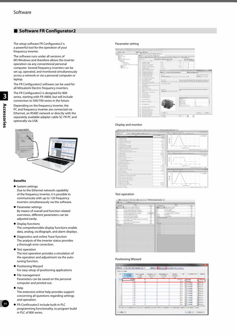
84
1
2
3
Accessories
Software
Software FR Configurator2
The setup software FR Configurator2 is a powerful tool for the operation of your frequency inverter.
The software runs under all versions of MS Windows and therefore allows the inverter operation via any conventional personal computer. Several frequency inverters can be set up, operated, and monitored simultaneously across a network or via a personal computer or laptop.
The FR Configurator2 software can be used for all Mitsubishi Electric frequency inverters.
The FR Configurator2 is designed for 800 series, starting with FR-A800, but will include connection to 500/700 series in the future.
Depending on the frequency inverter, the PC and frequency inverter are connected via Ethernet, an RS485 network or directly with the separately available adapter cable SC-FR PC and optionally via USB.
MITSUBISHI
FR–F740–2.2K
DANGER: Risk of injury and electric shock
CAUTION: Risk of fire
Read the manual and follow the safety instructions before use.
Isolate from supply and wait 10 minutes before removing this cover.
Ensure proper earth connection
Mount the inverter on a non-combustible surface.
FREQROL-F 700
400V
!
!
r.
400V
Benefits
z System settings Due to the Ethernet network capability of the frequency inverter, it is possible to communicate with up to 120 frequency inverters simultaneously via the software.
z Parameter settings By means of overall and function related overviews, different parameters can be adjusted easily.
z Display functions The comprehensible display functions enable data, analog, oscillograph, and alarm displays.
z Diagnostics and online Trace function The analysis of the inverter status provides a thorough error correction.
z Test operation The test operation provides a simulation of the operation and adjustment via the auto-tuning function.
z Positioning Wizzard For easy setup of positioning applications
z File management Parameters can be saved on the personal computer and printed out.
z Help The extensive online help provides support concerning all questions regarding settings and operation.
z FR-Confirurator2 include built-in PLC programming functionality, to program build in PLC of 800 series.
Parameter setting
Display and monitor
Test operation
Positioning Wizzard
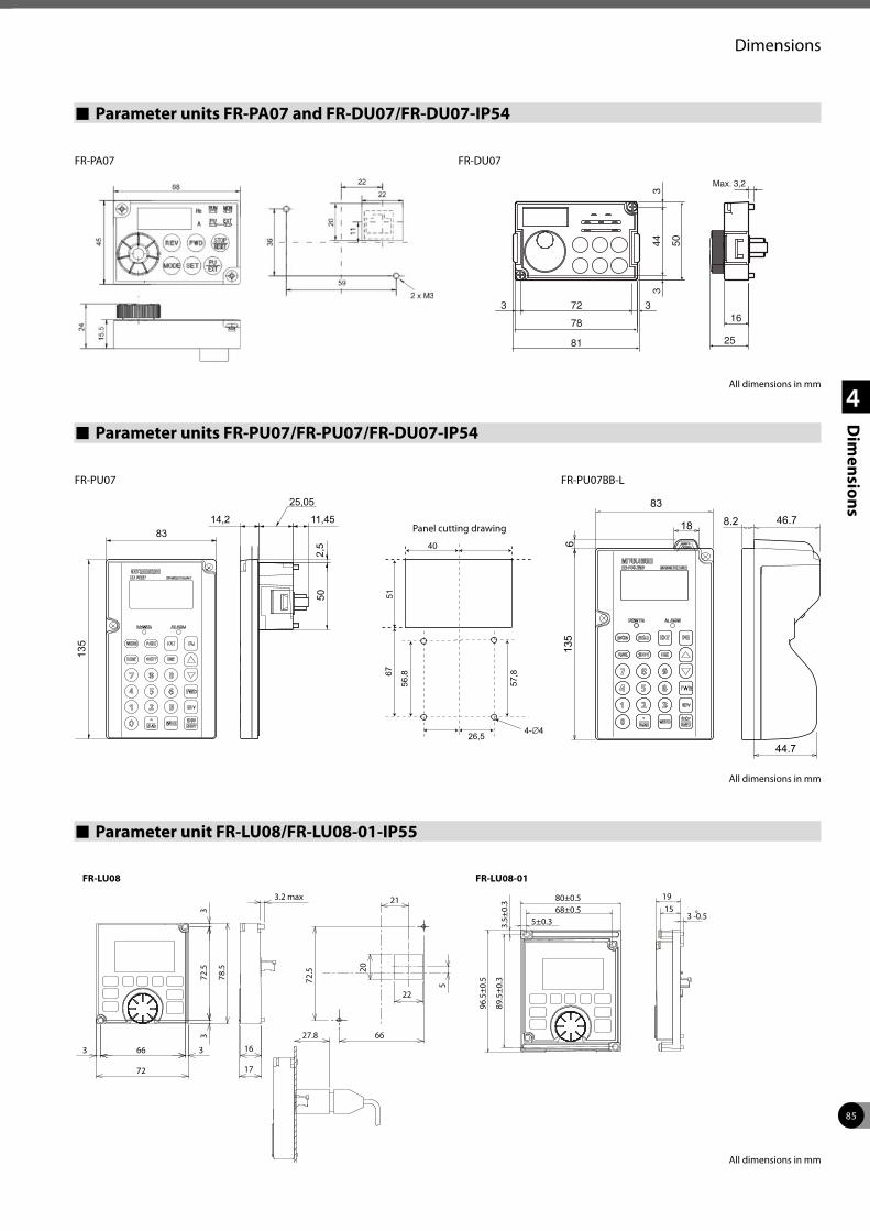
85
1
2
3
4
Dim
ensions
Dimensions
Parameter units FR-PA07 and FR-DU07/FR-DU07-IP54
Parameter units FR-PU07/FR-PU07/FR-DU07-IP54
Parameter unit FR-LU08/FR-LU08-01-IP55
FR-PA07 FR-DU07
72
44 50
33
316
Max. 3,2
25
3
78
81
All dimensions in mm
25,05
11,4514,2
2,5
83
50
All dimensions in mm
135
83
18
6
8.2 46.7
44.7
All dimensions in mm
FR-PU07 FR-PU07BB-L
Panel cutting drawing
27.8
66
72.5
78.5
33
33
72
16
17
66
72.5
21
5
22
20
3.2 max
FR-LU08
1980±0.5
3.5±
0.3
96.5
±0.5
89.5
±0.3
68±0.55±0.3
153
0-0.5
FR-LU08-01
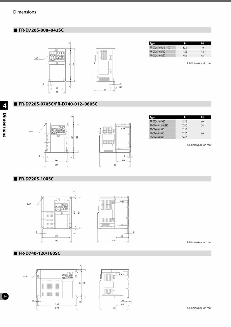
86
Dimensions
1
2
3
4
Dim
ensions
Type D D1FR-D720S-008–014SC 80.5 10FR-D720S-025SC 142.5 42FR-D720S-042SC 162.5 62
FR-D720S-008–042SC
All dimensions in mm
FR-D720S-070SC/FR-D740-012–080SC
Type D D1FR-D720S-070SC 155.5 60FR-D740-012/022SC 129.5 54FR-D740-036SC 135.5
60FR-D740-050SC 155.5FR-D740-080SC 165.5
All dimensions in mm
FR-D720S-100SC
All dimensions in mm
FR-D740-120/160SC
All dimensions in mm
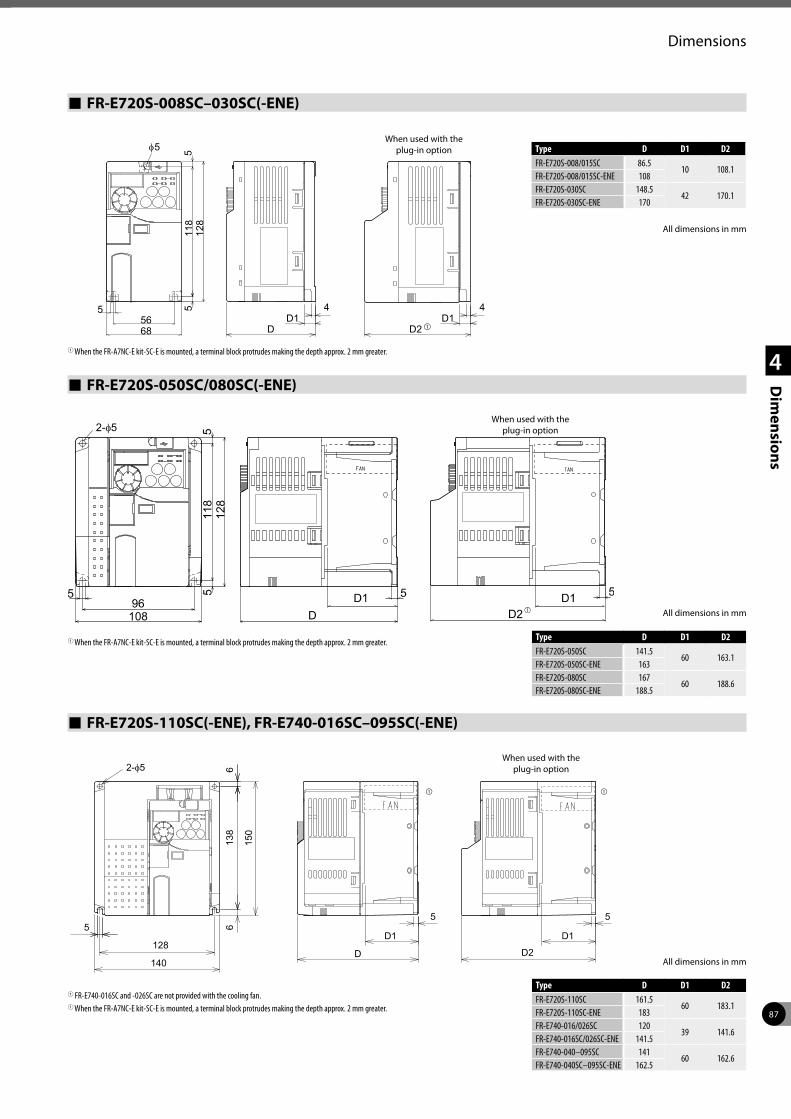
87
Dimensions
1
2
3
4
Dim
ensions
Type D D1 D2FR-E720S-110SC 161.5
60 183.1FR-E720S-110SC-ENE 183FR-E740-016/026SC 120
39 141.6FR-E740-016SC/026SC-ENE 141.5FR-E740-040–095SC 141
60 162.6FR-E740-040SC–095SC-ENE 162.5
FR-E720S-008SC–030SC(-ENE)
FR-E720S-050SC/080SC(-ENE)
FR-E720S-110SC(-ENE), FR-E740-016SC–095SC(-ENE)
Type D D1 D2FR-E720S-008/015SC 86.5
10 108.1FR-E720S-008/015SC-ENE 108FR-E720S-030SC 148.5
42 170.1FR-E720S-030SC-ENE 170
All dimensions in mm
4
DD1
4
D2 D1
5
6856
511
85
128
φ5When used with the
plug-in option
1 When the FR-A7NC-E kit-SC-E is mounted, a terminal block protrudes making the depth approx. 2 mm greater.
Type D D1 D2FR-E720S-050SC 141.5
60 163.1FR-E720S-050SC-ENE 163FR-E720S-080SC 167
60 188.6FR-E720S-080SC-ENE 188.5
When used with the plug-in option
All dimensions in mm
1 When the FR-A7NC-E kit-SC-E is mounted, a terminal block protrudes making the depth approx. 2 mm greater.
1 FR-E740-016SC and -026SC are not provided with the cooling fan.1 When the FR-A7NC-E kit-SC-E is mounted, a terminal block protrudes making the depth approx. 2 mm greater.
All dimensions in mm
When used with the plug-in option
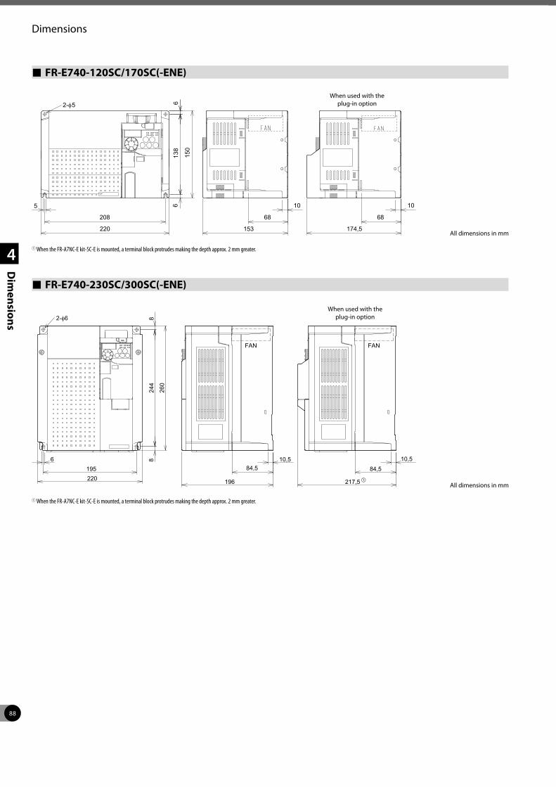
88
Dimensions
1
2
3
4
Dim
ensions
FR-E740-120SC/170SC(-ENE)
FR-E740-230SC/300SC(-ENE)
2-φ
138
66
150
5
208
220
10
153
68
10
174,5
68
5
All dimensions in mm
1 When the FR-A7NC-E kit-SC-E is mounted, a terminal block protrudes making the depth approx. 2 mm greater.
195
8
260
244
FAN
10,5 10,5 84,5 84,5
196
2-φ6
FAN
217,5220
8
6
All dimensions in mm
1 When the FR-A7NC-E kit-SC-E is mounted, a terminal block protrudes making the depth approx. 2 mm greater.
When used with the plug-in option
When used with the plug-in option
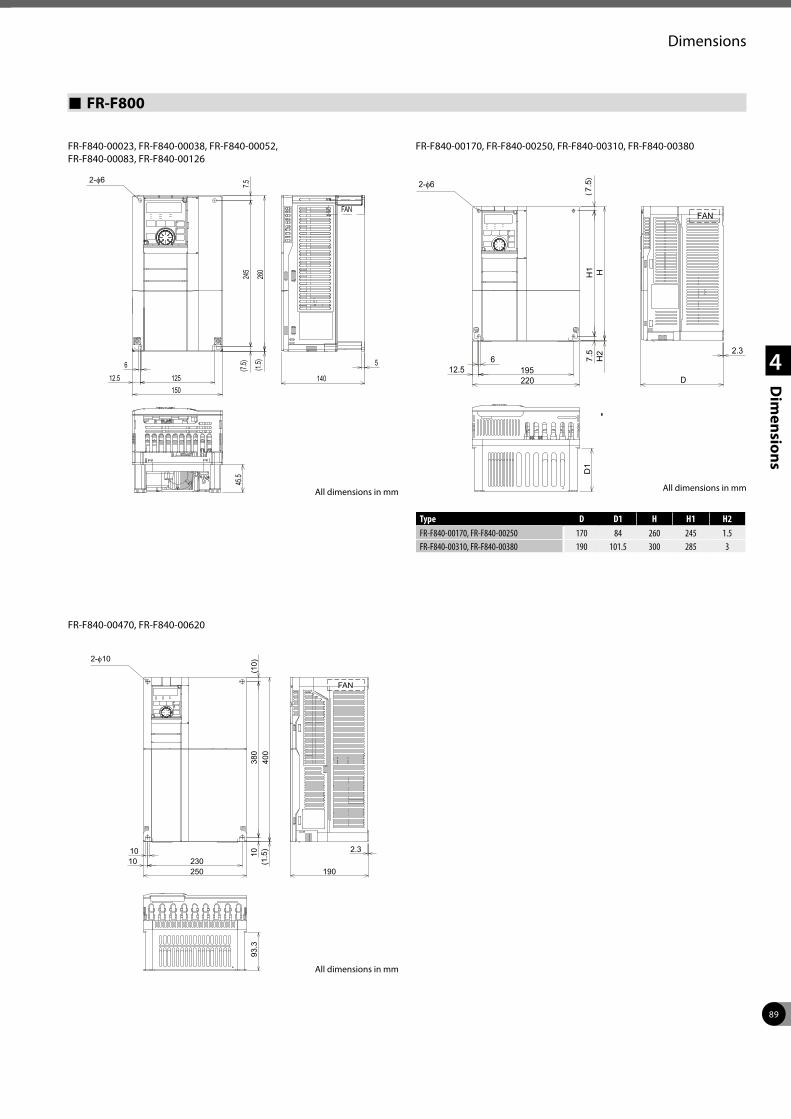
89
Dimensions
1
2
3
4
Dim
ensions
FR-F800
FR-F840-00023, FR-F840-00038, FR-F840-00052, FR-F840-00083, FR-F840-00126
150
5
140
(1.5)
245
7.5
260
45.5
(7.5)6
12.5 125
FAN
2-φ
6195220
7.5
H1
(7.5)
H2
H
2.3
D1
12.5D
FAN
2-φ
250230
10 10(1
.5)
380
(10)
400
2.3
190
93.3
10
FAN
2-φ
FR-F840-00170, FR-F840-00250, FR-F840-00310, FR-F840-00380
FR-F840-00470, FR-F840-00620
All dimensions in mm
Type D D1 H H1 H2FR-F840-00170, FR-F840-00250 170 84 260 245 1.5FR-F840-00310, FR-F840-00380 190 101.5 300 285 3
All dimensions in mmAll dimensions in mm
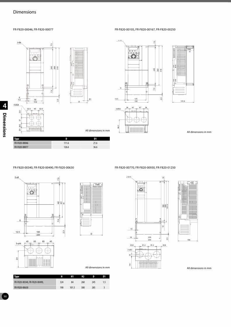
90
Dimensions
1
2
3
4
Dim
ensions
FR-F820-00046, FR-F820-00077
245
260
6
12.5 150125
7.5
7.5
86.1
28 47 47 283-Ø35
318
2.3
141.6
FAN
2-Ø6
D1
6
195 220
7.5
H2
7.5
H1
12.5D
45 65 65 45
H2.
3
FAN
2-φ6
3-φ44
250 230
10
10
380
1040
0
43.8 81.2
19010
81.2
1911
9
43.8
517.
3 2.
3
FAN
2-φ10
3-φ63
FR-F820-00105, FR-F820-00167, FR-F820-00250
FR-F820-00340, FR-F820-00490, FR-F820-00630 FR-F820-00770, FR-F820-00930, FR-F820-01250
All dimensions in mm
Type D D1FR-F820-00046 111.6 21.6FR-F820-00077 126.6 36.6
Type H H1 H2 D D1
FR-F820-00340, FR-F820-00490, 324 84 260 245 1.5
FR-F820-00630 190 101.5 300 285 3
All dimensions in mm
All dimensions in mm All dimensions in mm
2-Ø6
6 95
110
7.5
245
7.5
260
7.5 D1D
32.5 45
28.5
3723
.1
32.5
310
2.3
D1
4-Ø28
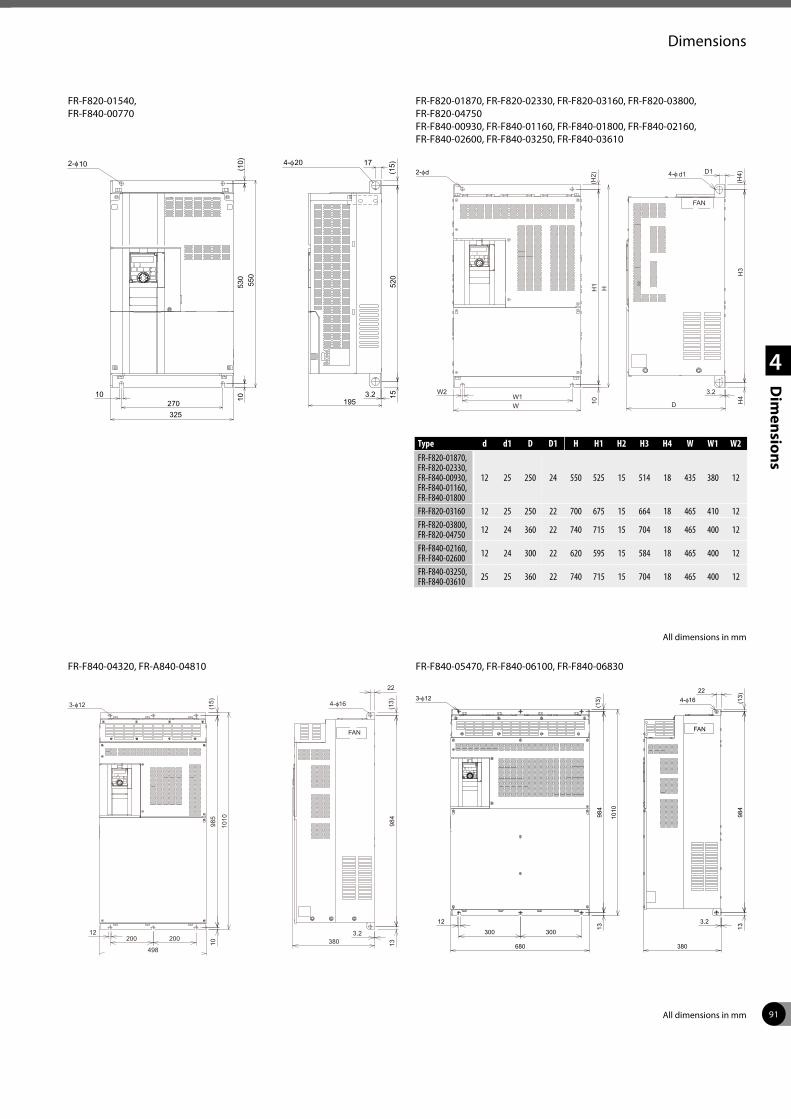
91
Dimensions
1
2
3
4
Dim
ensions
FR-F820-01540, FR-F840-00770
10
325270 10
550
(10)
530
3.2(1
5)52
015
195
4-φ 172-φ 2010
W
W2W1
10H
1(H
2)H
3.2
D H4
H3
(H4)
FAN
2-φ D14-φ d1d
3-φ
12200
498
1098
5(1
5)
1010
3.2380 13
984
(13)
22
FAN
4-φ
200300
680
12
300
1398
4(1
3)
1010
3.2
380
1398
4(1
3)FAN
224-φ3-φ
FR-F820-01870, FR-F820-02330, FR-F820-03160, FR-F820-03800, FR-F820-04750 FR-F840-00930, FR-F840-01160, FR-F840-01800, FR-F840-02160, FR-F840-02600, FR-F840-03250, FR-F840-03610
FR-F840-04320, FR-A840-04810 FR-F840-05470, FR-F840-06100, FR-F840-06830
Type d d1 D D1 H H1 H2 H3 H4 W W1 W2FR-F820-01870, FR-F820-02330, FR-F840-00930, FR-F840-01160, FR-F840-01800
12 25 250 24 550 525 15 514 18 435 380 12
FR-F820-03160 12 25 250 22 700 675 15 664 18 465 410 12FR-F820-03800, FR-F820-04750 12 24 360 22 740 715 15 704 18 465 400 12
FR-F840-02160, FR-F840-02600 12 24 300 22 620 595 15 584 18 465 400 12
FR-F840-03250, FR-F840-03610 25 25 360 22 740 715 15 704 18 465 400 12
All dimensions in mm
All dimensions in mm
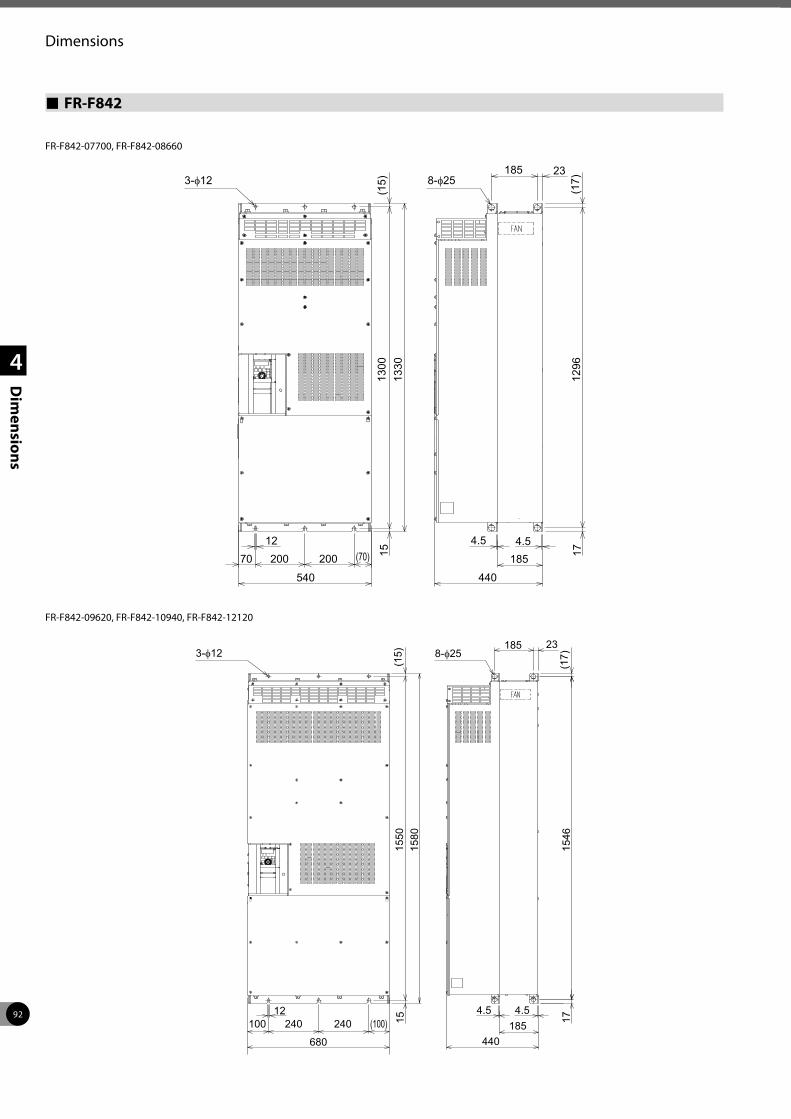
92
Dimensions
1
2
3
4
Dim
ensions
FR-F842
185
185
23
1270 200
540 440
4.5 4.5200 (70)
(15)
1300
(17)
1712
96
1513
30
3-φ 8-φ
FR-F842-07700, FR-F842-08660
185
185
23
12100 240
680 440
4.5 4.5240 (100)
(15)
1550
(17)
1715
46
1515
80
3-φ 8-φ
FR-F842-09620, FR-F842-10940, FR-F842-12120
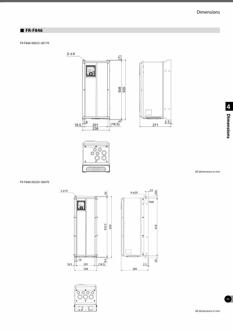
93
Dimensions
1
2
3
4
Dim
ensions
FR-F846
520
238271
2.350
85
20118.58
(7)
(18.5)
2- Ø 8
650
238 285
23
610
20
2.3
632.
58.
5
20118.5
10
(20)
(9)
(18.5)
2-φ10 4-φ20
FAN
All dimensions in mm
All dimensions in mm
FR-F846-00023–00170
FR-F846-00250–00470
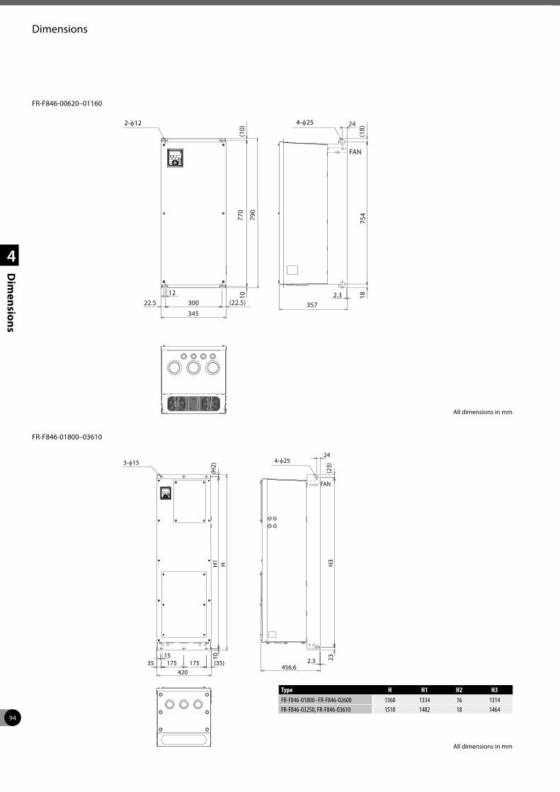
94
Dimensions
1
2
3
4
Dim
ensions
345
10
30022.512
(22.5)
(10)
790
770
357
24
754
182.3
(18)
FAN
2-φ12 4-φ25
42035 175 175 (35)
15 10H
1(H
2)H
2.3456.6
23H
3(2
3)
243-φ15 4-φ25
FAN
All dimensions in mm
All dimensions in mm
FR-F846-00620–01160
FR-F846-01800–03610
Type H H1 H2 H3FR-F846-01800–FR-F846-02600 1360 1334 16 1314FR-F846-03250, FR-F846-03610 1510 1482 18 1464
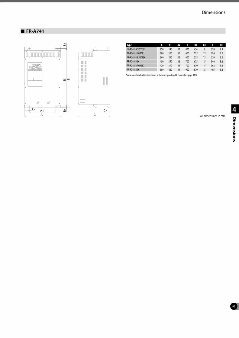
95
Dimensions
1
2
3
4
Dim
ensions
Type A A1 Ax B B1 Bx C CxFR-A741-5.5K/7.5K 250 190 10 470 454 8 270 2.3FR-A741-11K/15K 300 220 10 600 575 15 294 3.2FR-A741-18.5K/22K 360 260 12 600 575 15 320 3.2FR-A741-30K 450 350 12 700 675 15 340 3.2FR-A741-37K/45K 470 370 14 700 670 15 368 3.2FR-A741-55K 600 480 14 900 870 15 405 3.2
Please consider also the dimensions of the corresponding DC chokes (see page 115)
FR-A741
A1A
B1 B
C
Bx
Bx
Ax Cx
All dimensions in mm
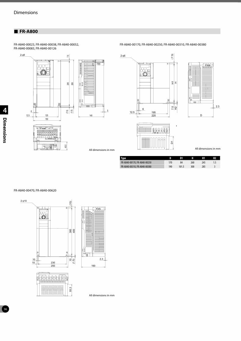
96
Dimensions
1
2
3
4
Dim
ensions
FR-A800
FR-A840-00023, FR-A840-00038, FR-A840-00052, FR-A840-00083, FR-A840-00126
150
5
140
(1.5)
245
7.5
260
45.5
(7.5)6
12.5 125
FAN
2-φ
6195220
7.5
H1
(7.5)
H2
H
2.3
D1
12.5D
FAN
2-φ
250230
10 10(1
.5)
380
(10)
400
2.3
190
93.3
10
FAN
2-φ
FR-A840-00170, FR-A840-00250, FR-A840-00310, FR-A840-00380
FR-A840-00470, FR-A840-00620
All dimensions in mm
Type D D1 H H1 H2FR-A840-00170, FR-A840-00250 170 84 260 245 1.5FR-A840-00310, FR-A840-00380 190 101.5 300 285 3
All dimensions in mmAll dimensions in mm
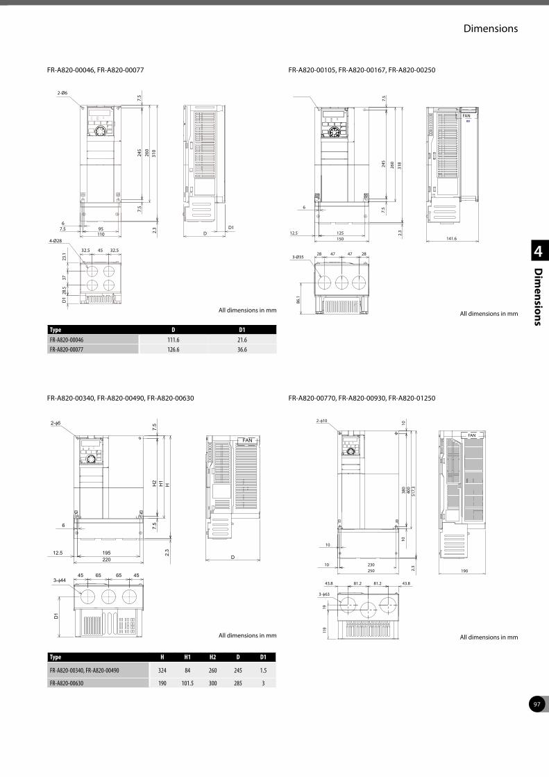
97
Dimensions
1
2
3
4
Dim
ensions
FR-A820-00046, FR-A820-00077
245
260
6
12.5 150125
7.5
7.5
86.1
28 47 47 283-Ø35
318
2.3
141.6
FAN
2-Ø6
D1
6
195 220
7.5
H2
7.5
H1
12.5D
45 65 65 45
H2.
3
FAN
2-φ6
3-φ44
250 230
10
10
380
1040
0
43.8 81.2
19010
81.2
1911
9
43.8
517.
3 2.
3
FAN
2-φ10
3-φ63
FR-A820-00105, FR-A820-00167, FR-A820-00250
FR-A820-00340, FR-A820-00490, FR-A820-00630 FR-A820-00770, FR-A820-00930, FR-A820-01250
All dimensions in mm
Type D D1FR-A820-00046 111.6 21.6FR-A820-00077 126.6 36.6
Type H H1 H2 D D1
FR-A820-00340, FR-A820-00490 324 84 260 245 1.5
FR-A820-00630 190 101.5 300 285 3
All dimensions in mm
All dimensions in mm All dimensions in mm
2-Ø6
6 95
110
7.5
245
7.5
260
7.5 D1D
32.5 45
28.5
3723
.1
32.5
310
2.3
D1
4-Ø28
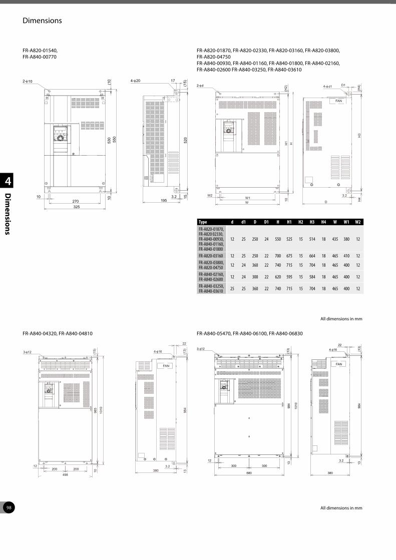
98
Dimensions
1
2
3
4
Dim
ensions
FR-A820-01540, FR-A840-00770
10
325270 10
550
(10)
530
3.2
(15)
520
15
195
4-φ 172-φ 2010
W
W2W1
10H
1(H
2)H
3.2
D H4
H3
(H4)
FAN
2-φ D14-φ d1d
3-φ
12200
498
1098
5(1
5)
1010
3.2380 13
984
(13)
22
FAN
4-φ
200300
680
12
300
1398
4(1
3)
1010
3.2
380
1398
4(1
3)
FAN
224-φ3-φ
FR-A820-01870, FR-A820-02330, FR-A820-03160, FR-A820-03800, FR-A820-04750 FR-A840-00930, FR-A840-01160, FR-A840-01800, FR-A840-02160, FR-A840-02600 FR-A840-03250, FR-A840-03610
FR-A840-04320, FR-A840-04810 FR-A840-05470, FR-A840-06100, FR-A840-06830
Type d d1 D D1 H H1 H2 H3 H4 W W1 W2FR-A820-01870, FR-A820 02330, FR-A840-00930, FR-A840-01160, FR-A840-01800
12 25 250 24 550 525 15 514 18 435 380 12
FR-A820-03160 12 25 250 22 700 675 15 664 18 465 410 12FR-A820-03800, FR-A820-04750 12 24 360 22 740 715 15 704 18 465 400 12
FR-A840-02160, FR-A840-02600 12 24 300 22 620 595 15 584 18 465 400 12
FR-A840-03250, FR-A840-03610 25 25 360 22 740 715 15 704 18 465 400 12
All dimensions in mm
All dimensions in mm
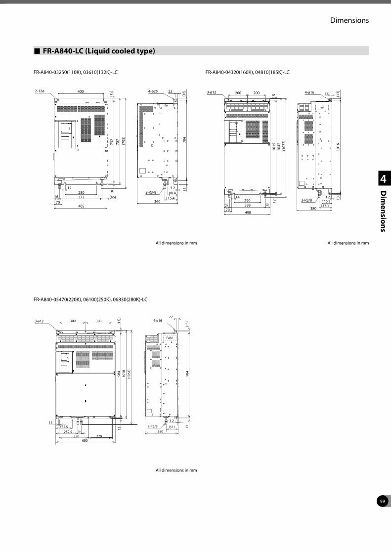
99
Dimensions
1
2
3
4
Dim
ensions
FR-A840-LC (Liquid cooled type)
FR-A840-03250(110K), 03610(132K)-LC FR-A840-04320(160K), 04810(185K)-LC
FR-A840-05470(220K), 06100(250K), 06830(280K)-LC
All dimensions in mm
All dimensions in mmAll dimensions in mm
3-ø12
14
4-ø16
7955 (55)
200 200
380
2-R3/8137.1
110.13.2
22
1016
(13)
1510
1510
42(1
077)
12
498
388
13290
22300 300
330 270
1398
4(1
3)10
10(1
064)
3-ø12
187.5
680
12
380
3.2
13(1
3)
4-ø16
252.5
FAN
39137.12-R3/8
984
400
(15)
465
757
2-12ø
(795
)
4-ø25
732 70
4(1
8)3512
10
373280
4670
(46)
22
360115.4
88.43.2
2-R3/8
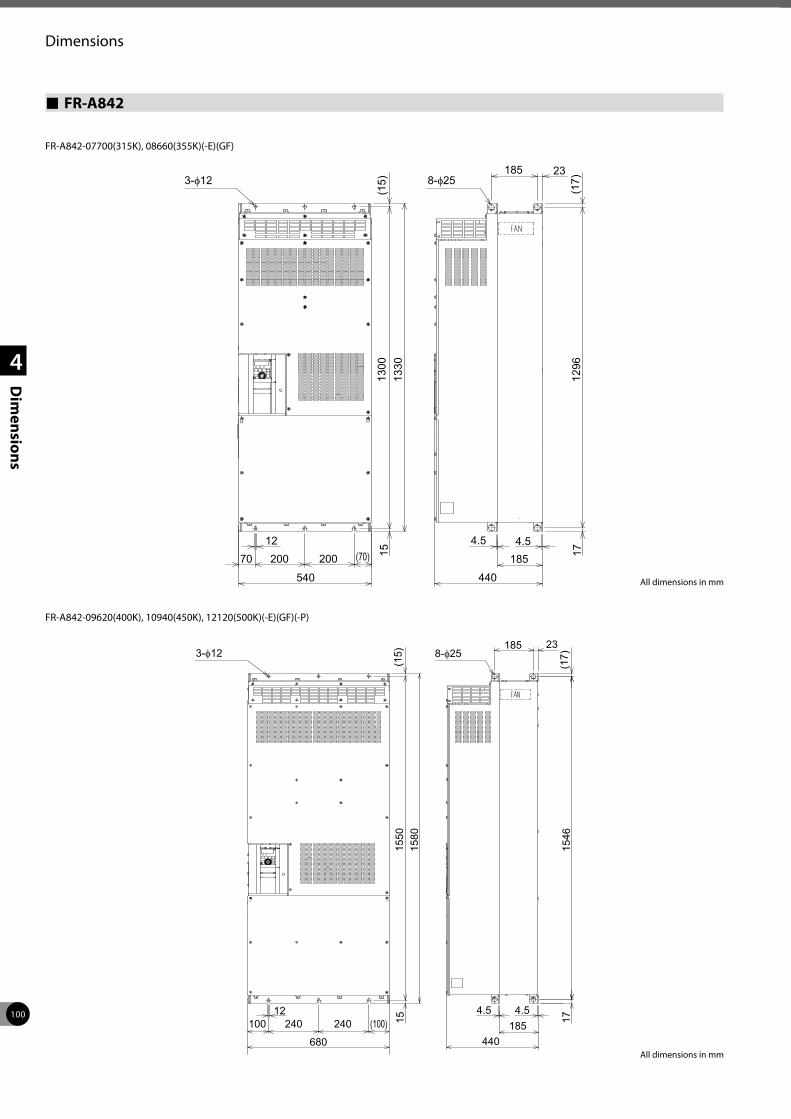
100
Dimensions
1
2
3
4
Dim
ensions
FR-A842
185
185
23
1270 200
540 440
4.5 4.5200 (70)
(15)
1300
(17)
1712
96
1513
30
3-φ 8-φ
FR-A842-07700(315K), 08660(355K)(-E)(GF)
185
185
23
12100 240
680 440
4.5 4.5240 (100)
(15)
1550
(17)
1715
46
1515
80
3-φ 8-φ
FR-A842-09620(400K), 10940(450K), 12120(500K)(-E)(GF)(-P)
All dimensions in mm
All dimensions in mm
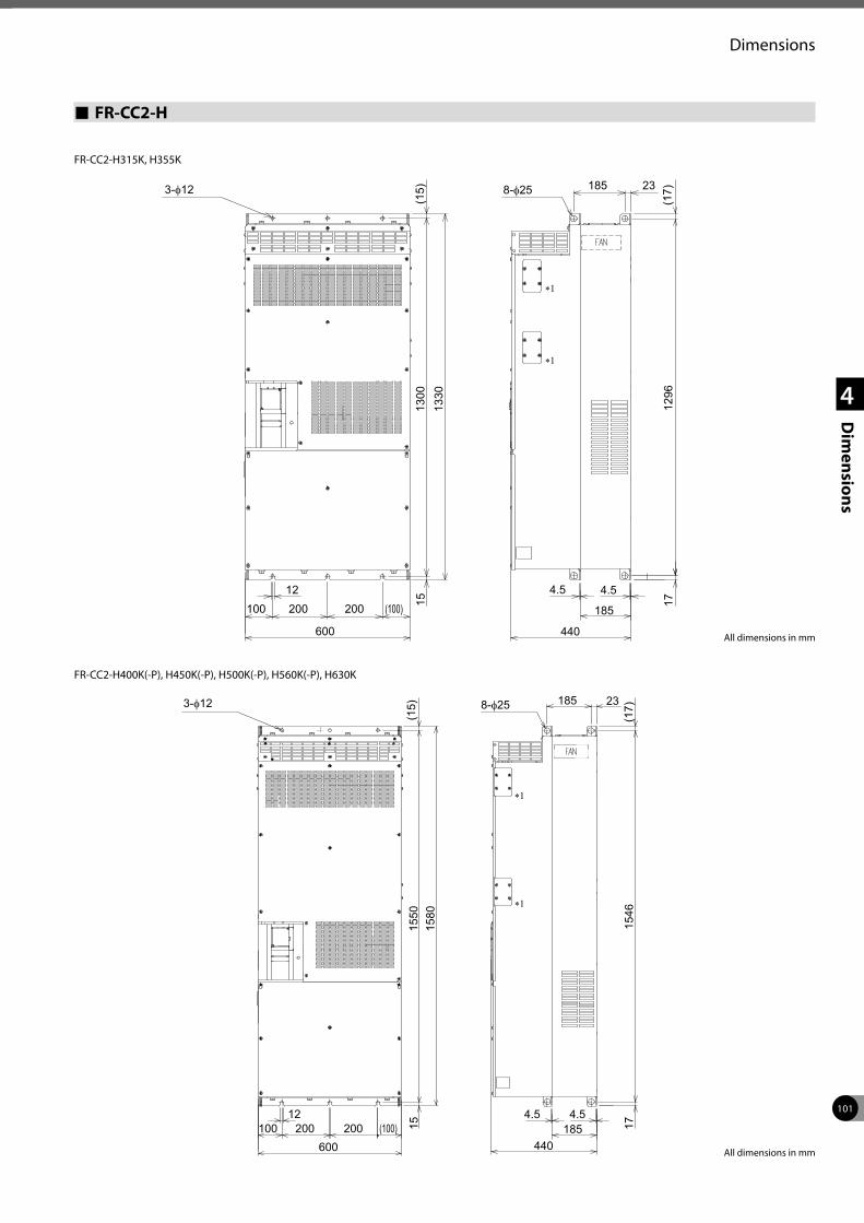
101
Dimensions
1
2
3
4
Dim
ensions
FR-CC2-H
3-φ 8-φ 185
185
23
12100 200
600 440
4.5 4.5200 (100)
(15)
1300
(17)
1712
96
1513
30
∗1
∗1
FR-CC2-H315K, H355K
3-φ 8-φ 185
185
23
12100 200
600 440
4.5 4.5200 (100)
(15)
1550
(17)
1715
46
1515
80
∗1
∗1
FR-CC2-H400K(-P), H450K(-P), H500K(-P), H560K(-P), H630K
All dimensions in mm
All dimensions in mm
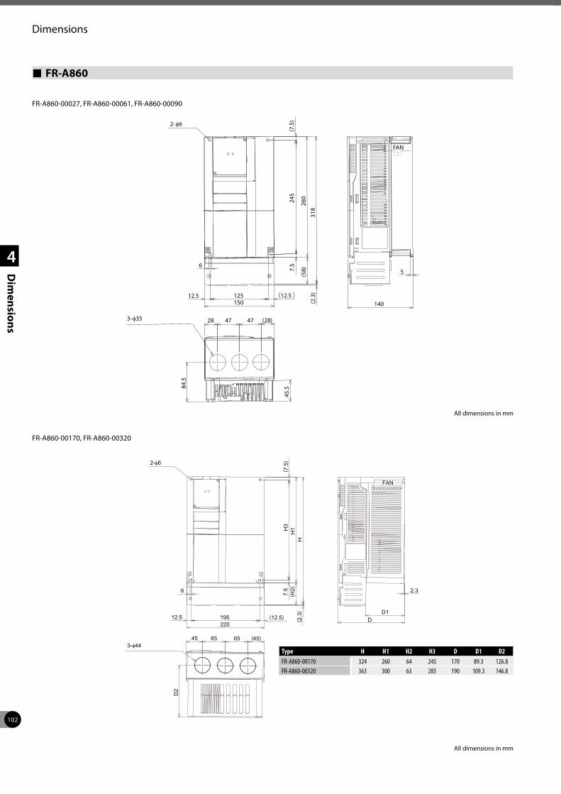
102
Dimensions
1
2
3
4
Dim
ensions
FR-A860
2-φ6
45.5
5
140
245
(7.5
)
260
6
12.5150125
7.5
(12.5)(5
8)
84.5
28 47 47 (28)3-φ35 31
8(2
.3)
FAN
FR-A860-00027, FR-A860-00061, FR-A860-00090
FR-A860-00170, FR-A860-00320
3-φ44
2-φ6
65
D2
D1
6
195220
7.5
H3
(7.5)
H1
(45)45 65
2.3
D12.5 (12.5)
(H2)
H(2
.3)
FAN
All dimensions in mm
All dimensions in mm
Type H H1 H2 H3 D D1 D2FR-A860-00170 324 260 64 245 170 89.3 126.8FR-A860-00320 363 300 63 285 190 109.3 146.8
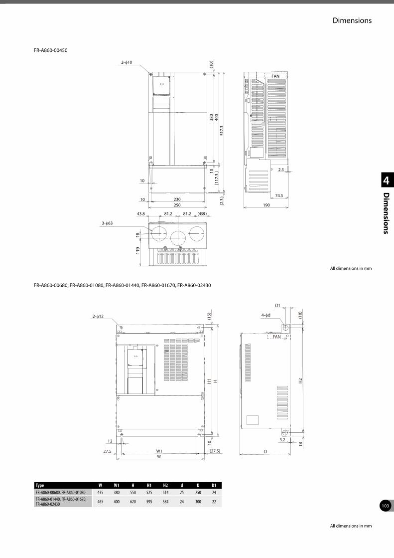
103
Dimensions
1
2
3
4
Dim
ensions
250230
10
1038
0(1
0)40
043.8 81.2
2.3
10
81.2
1911
9
(43.8 )
74.5
(117
.3)
517.
3(2
.3)
190
FAN
3-φ63
2-φ10
FR-A860-00450
H1
W1W
H
D
3.2
10(1
5)
27.5
12
(18)
H2
18
(27.5)
FAN
D1
2-φ12 4-φd
FR-A860-00680, FR-A860-01080, FR-A860-01440, FR-A860-01670, FR-A860-02430
All dimensions in mm
All dimensions in mm
Type W W1 H H1 H2 d D D1FR-A860-00680, FR-A860-01080 435 380 550 525 514 25 250 24FR-A860-01440, FR-A860-01670, FR-A860-02430 465 400 620 595 584 24 300 22
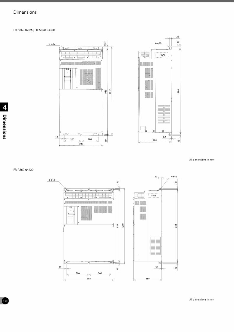
104
Dimensions
1
2
3
4
Dim
ensions
3-φ12
12200
498
1098
5(1
5)
1010
3.2380 13
984
(13)
22
FAN
4-φ16
200
FR-A860-02890, FR-A860-03360
300
FAN
680
12
300
1398
4(1
3)
1010
3.2
380
1398
4(1
3)22
3-φ12 4-φ16
FR-A860-04420
All dimensions in mm
All dimensions in mm
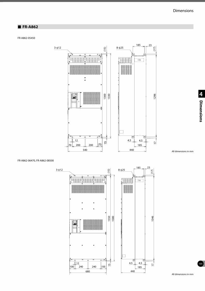
105
Dimensions
1
2
3
4
Dim
ensions
FR-A862
185
185
23
12
70 200
540 440
4.5 4.5
200 (70)
(15)
1300
(17)
1712
96
1513
30
3-φ12 8-φ25
185
185
23
12100 240
680 440
4.5 4.5240 (100)
(15)
1550
(17)
1715
46
1515
80
3-φ12 8-φ25
All dimensions in mm
All dimensions in mm
FR-A862-05450
FR-A862-06470, FR-A862-08500
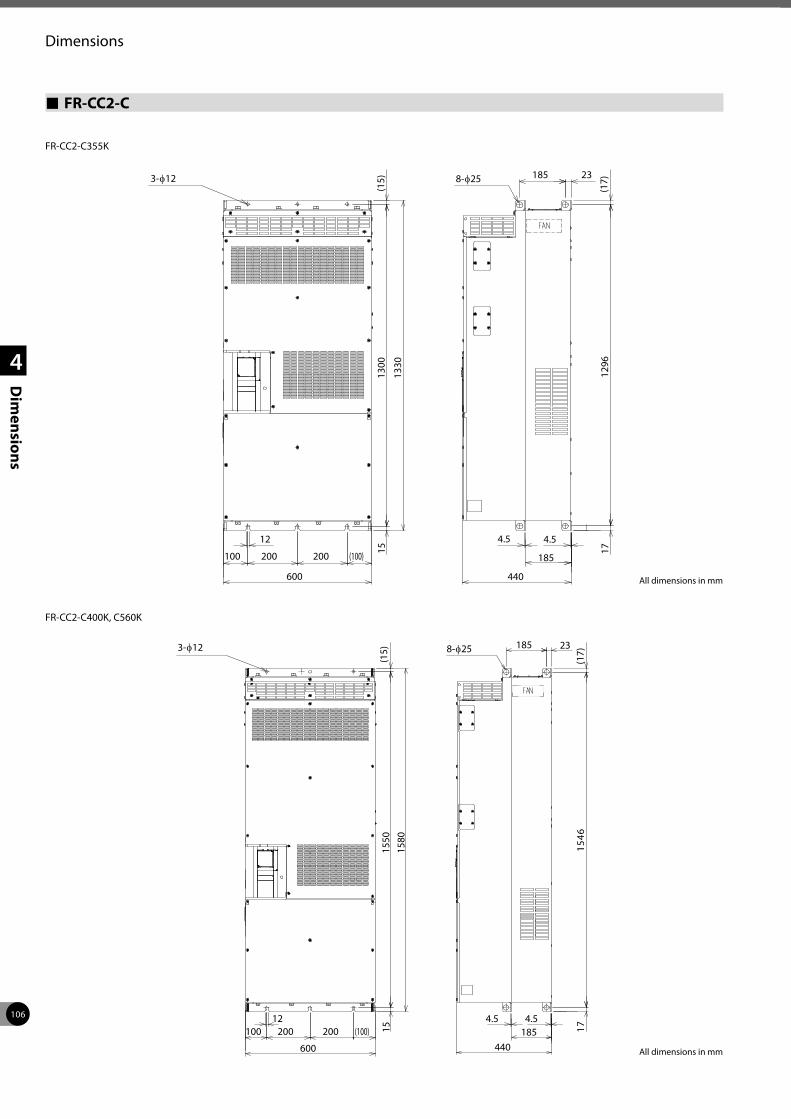
106
Dimensions
1
2
3
4
Dim
ensions
FR-CC2-C
3-φ12 8-φ25 185
185
23
12
100 200
600 440
4.5 4.5
200 (100)
(15)
1300
(17)
1712
96
15
1330
FR-CC2-C355K
3-φ12 8-φ25 185
185
23
12100 200
600 440
4.5 4.5200 (100)
(15)
1550
(17)
64517115
1580
FR-CC2-C400K, C560K
All dimensions in mm
All dimensions in mm
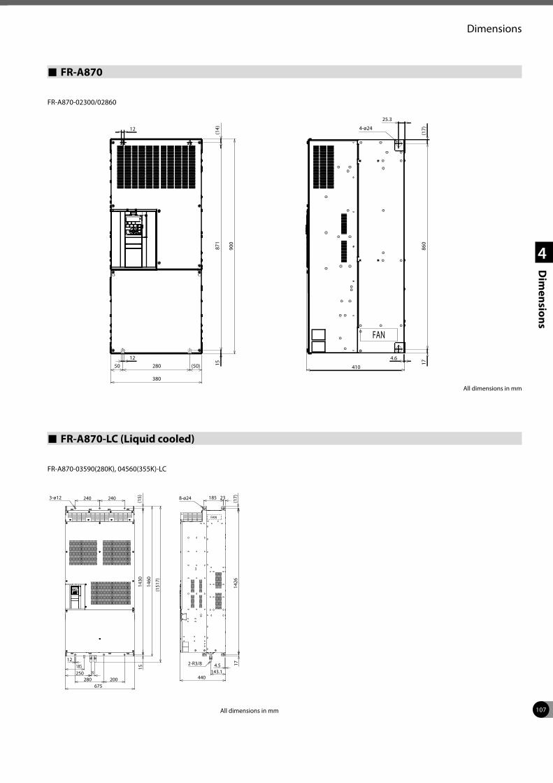
107
Dimensions
1
2
3
4
Dim
ensions
FR-A870
280
380
1587
1(1
4)
900
12
12
410
4.6
1786
0(1
7)
25.3
50 (50)
4-ø24
FAN
All dimensions in mm
FR-A870-02300/02860
FR-A870-LC (Liquid cooled)
12185250 39
280 200675
240 2403-ø12
1514
30(1
5)
1460
(151
7)
4.5143.1
440
1714
26(1
7)185 23
2-R3/8
8-ø24
FAN
FR-A870-03590(280K), 04560(355K)-LC
All dimensions in mm
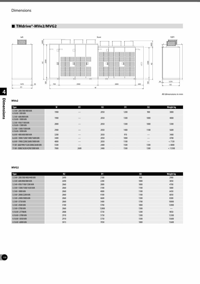
108
Dimensions
1
2
3
4
Dim
ensions
TMdrive®-MVe2/MVG2
Type W H1 H2 D1 D2 Weight kg3.3 kV–200/300/400 kVA 4.16 kV–500 kVA 1900 — 2050 1200 900 3800
3.3 kV–600/800 kVA 4.16 kV–1000 kVA 1900 — 2050 1300 1000 4000
3.3 kV–950/1100 kVA 4.16 kV–1380 kVA 2800 — 2050 1300 1000 5300
3.3 kV–1300/1500 kVA 4.16 kV–1890 kVA 2900 — 2050 1400 1100 5600
6.6 kV–400/600/800 kVA 3200 — 2050 970 — 34006.6 kV–1000/1200/1400/1600 kVA 3400 — 2050 1000 — 47006.6 kV–1900/2200/2600/3000 kVA 4800 — 2050 1100 — < 715011 kV–660/990/1320/2000/2640 kVA 5500 — 2400 1500 1300 < 800011 kV–3080/3630/4290/5000 kVA 7000 2600 2400 1500 1300 < 13500
rightleft front
1470 30
D1
700 2900 2800 600
W
100
2300
H2
(490
)
100
2500
H1
(400
)
127030
D2
All dimensions in mm
Type H2 D1 D2 Weight kg3.3 kV–200/300/400/440 kVA 2690 2100 900 29003.3 kV–600/800/880 kVA 2690 2200 1000 38503.3 kV–950/1100/1200 kVA 2860 2800 1000 47003.3 kV–1300/1500/1650 kVA 2860 3100 1100 58003.3 kV–1800 kVA 2860 4000 1100 64503.3 kV–2000/2200 kVA 2860 4100 1100 68503.3 kV–2400/3000 kVA 2860 4600 1300 83003.3 kV–3750 kVA 2860 5400 1700 100003.3 kV–4500 kVA 3100 5700 1800 120003.3 kV–5700 kVA 2860 12800 1300 —4.16 kV–2770kVA 2808 5730 1200 98504.16 kV–3780 kVA 2910 5750 1300 123004.16 kV–5050 kVA 2910 5750 1500 136004.16 kV–6000 kVA 3013 7050 1800 15600
MVe2
MVG2
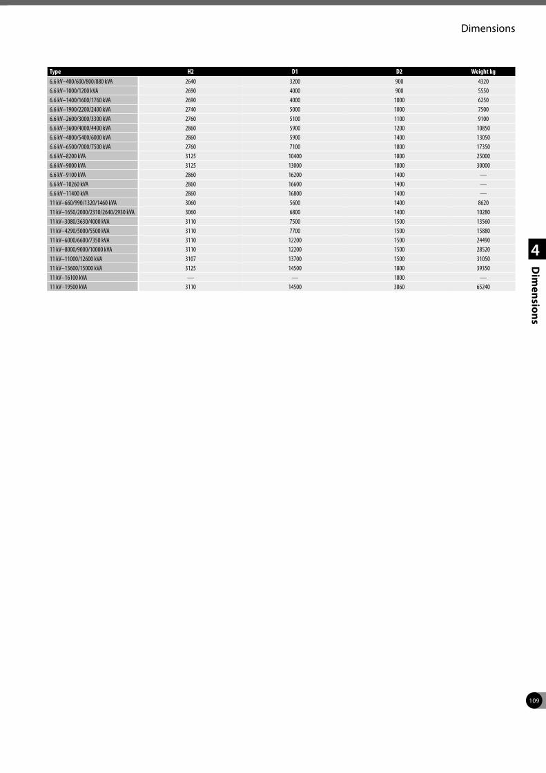
109
Dimensions
1
2
3
4
Dim
ensions
Type H2 D1 D2 Weight kg6.6 kV–400/600/800/880 kVA 2640 3200 900 43206.6 kV–1000/1200 kVA 2690 4000 900 55506.6 kV–1400/1600/1760 kVA 2690 4000 1000 62506.6 kV–1900/2200/2400 kVA 2740 5000 1000 75006.6 kV–2600/3000/3300 kVA 2760 5100 1100 91006.6 kV–3600/4000/4400 kVA 2860 5900 1200 108506.6 kV–4800/5400/6000 kVA 2860 5900 1400 130506.6 kV–6500/7000/7500 kVA 2760 7100 1800 173506.6 kV–8200 kVA 3125 10400 1800 250006.6 kV–9000 kVA 3125 13000 1800 300006.6 kV–9100 kVA 2860 16200 1400 —6.6 kV–10260 kVA 2860 16600 1400 —6.6 kV–11400 kVA 2860 16800 1400 —11 kV–660/990/1320/1460 kVA 3060 5600 1400 862011 kV–1650/2000/2310/2640/2930 kVA 3060 6800 1400 1028011 kV–3080/3630/4000 kVA 3110 7500 1500 1356011 kV–4290/5000/5500 kVA 3110 7700 1500 1588011 kV–6000/6600/7350 kVA 3110 12200 1500 2449011 kV–8000/9000/10000 kVA 3110 12200 1500 2852011 kV–11000/12600 kVA 3107 13700 1500 3105011 kV–13600/15000 kVA 3125 14500 1800 3935011 kV–16100 kVA — — 1800 —11 kV–19500 kVA 3110 14500 3860 65240
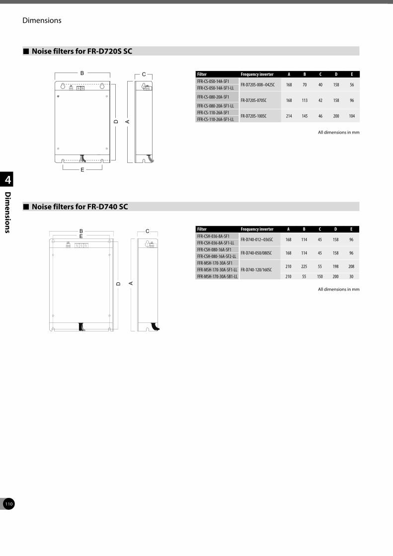
110
Dimensions
1
2
3
4
Dim
ensions
Noise filters for FR-D720S SC
Filter Frequency inverter A B C D EFFR-CS-050-14A-SF1
FR-D720S-008–042SC 168 70 40 158 56FFR-CS-050-14A-SF1-LL
FFR-CS-080-20A-SF1FR-D720S-070SC 168 113 42 158 96
FFR-CS-080-20A-SF1-LLFFR-CS-110-26A-SF1
FR-D720S-100SC 214 145 46 200 104FFR-CS-110-26A-SF1-LL
Noise filters for FR-D740 SC
Filter Frequency inverter A B C D EFFR-CSH-036-8A-SF1
FR-D740-012–036SC 168 114 45 158 96FFR-CSH-036-8A-SF1-LLFFR-CSH-080-16A-SF1
FR-D740-050/080SC 168 114 45 158 96FFR-CSH-080-16A-SF2-LLFFR-MSH-170-30A-SF1
FR-D740-120/160SC210 225 55 198 208
FFR-MSH-170-30A-SF1-LLFFR-MSH-170-30A-SB1-LL 210 55 150 200 30
All dimensions in mm
All dimensions in mm
Ab hier Reihenfolge geändert
B
D
E
C
A
B
D
EC
A
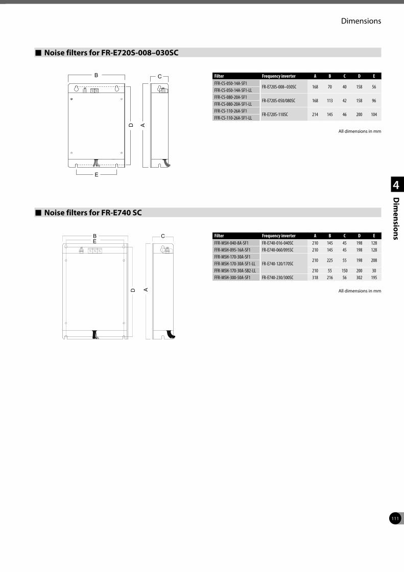
111
Dimensions
1
2
3
4
Dim
ensions
Noise filters for FR-E720S-008–030SC
Filter Frequency inverter A B C D EFFR-CS-050-14A-SF1
FR-E720S-008–030SC 168 70 40 158 56FFR-CS-050-14A-SF1-LLFFR-CS-080-20A-SF1
FR-E720S-050/080SC 168 113 42 158 96FFR-CS-080-20A-SF1-LLFFR-CS-110-26A-SF1
FR-E720S-110SC 214 145 46 200 104FFR-CS-110-26A-SF1-LL
Noise filters for FR-E740 SC
Filter Frequency inverter A B C D EFFR-MSH-040-8A-SF1 FR-E740-016-040SC 210 145 45 198 128FFR-MSH-095-16A-SF1 FR-E740-060/095SC 210 145 45 198 128FFR-MSH-170-30A-SF1
FR-E740-120/170SC210 225 55 198 208
FFR-MSH-170-30A-SF1-LLFFR-MSH-170-30A-SB2-LL 210 55 150 200 30FFR-MSH-300-50A-SF1 FR-E740-230/300SC 318 216 56 302 195
All dimensions in mm
All dimensions in mm
B
D
E
C
A
B
D
EC
A
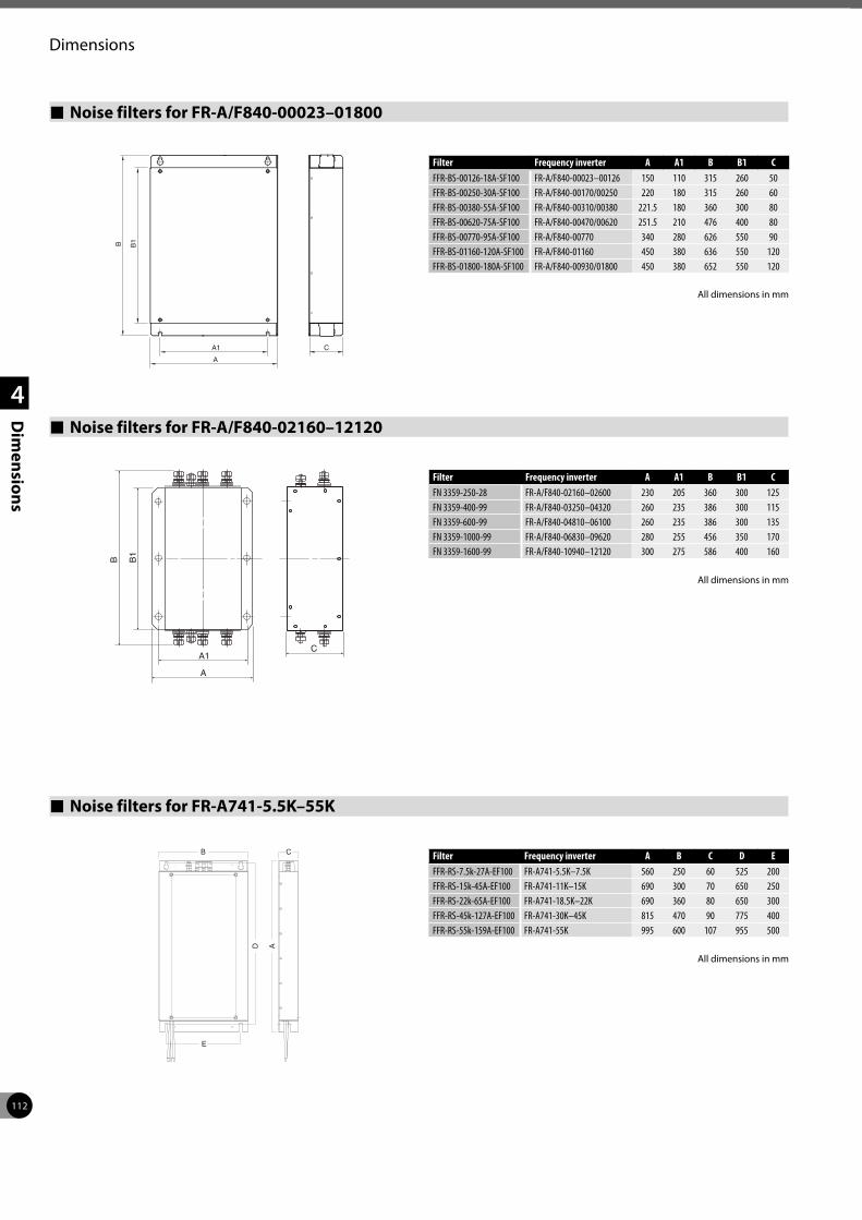
112
Dimensions
1
2
3
4
Dim
ensions
Noise filters for FR-A/F840-00023–01800
Filter Frequency inverter A A1 B B1 CFFR-BS-00126-18A-SF100 FR-A/F840-00023–00126 150 110 315 260 50FFR-BS-00250-30A-SF100 FR-A/F840-00170/00250 220 180 315 260 60FFR-BS-00380-55A-SF100 FR-A/F840-00310/00380 221.5 180 360 300 80FFR-BS-00620-75A-SF100 FR-A/F840-00470/00620 251.5 210 476 400 80FFR-BS-00770-95A-SF100 FR-A/F840-00770 340 280 626 550 90FFR-BS-01160-120A-SF100 FR-A/F840-01160 450 380 636 550 120FFR-BS-01800-180A-SF100 FR-A/F840-00930/01800 450 380 652 550 120
All dimensions in mm
Noise filters for FR-A/F840-02160–12120
Filter Frequency inverter A A1 B B1 CFN 3359-250-28 FR-A/F840-02160–02600 230 205 360 300 125FN 3359-400-99 FR-A/F840-03250–04320 260 235 386 300 115FN 3359-600-99 FR-A/F840-04810–06100 260 235 386 300 135FN 3359-1000-99 FR-A/F840-06830–09620 280 255 456 350 170FN 3359-1600-99 FR-A/F840-10940–12120 300 275 586 400 160
Noise filters for FR-A741-5.5K–55K
Filter Frequency inverter A B C D EFFR-RS-7.5k-27A-EF100 FR-A741-5.5K–7.5K 560 250 60 525 200FFR-RS-15k-45A-EF100 FR-A741-11K–15K 690 300 70 650 250FFR-RS-22k-65A-EF100 FR-A741-18.5K–22K 690 360 80 650 300FFR-RS-45k-127A-EF100 FR-A741-30K–45K 815 470 90 775 400FFR-RS-55k-159A-EF100 FR-A741-55K 995 600 107 955 500
A
CA1
B B1
D
E
B C
A
All dimensions in mm
All dimensions in mm
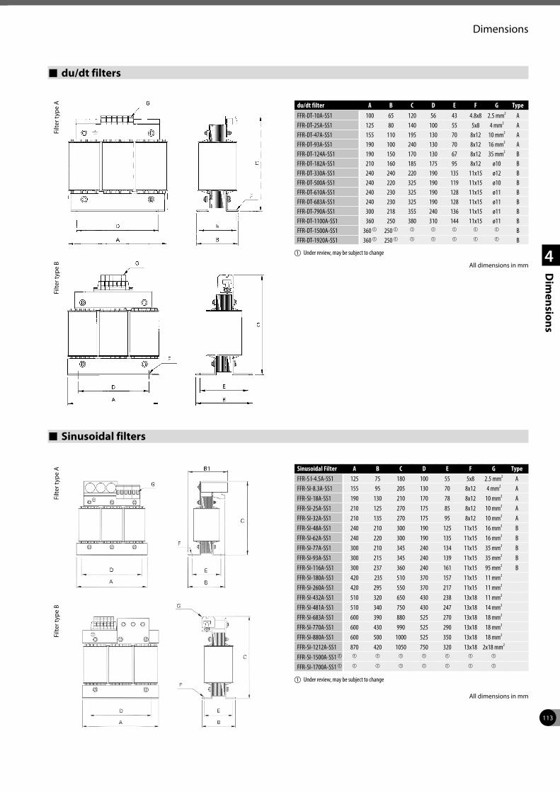
113
Dimensions
1
2
3
4
Dim
ensions
du/dt filters
du/dt filter A B C D E F G TypeFFR-DT-10A-SS1 100 65 120 56 43 4.8x8 2.5 mm2 AFFR-DT-25A-SS1 125 80 140 100 55 5x8 4 mm2 AFFR-DT-47A-SS1 155 110 195 130 70 8x12 10 mm2 AFFR-DT-93A-SS1 190 100 240 130 70 8x12 16 mm2 AFFR-DT-124A-SS1 190 150 170 130 67 8x12 35 mm2 BFFR-DT-182A-SS1 210 160 185 175 95 8x12 ø10 BFFR-DT-330A-SS1 240 240 220 190 135 11x15 ø12 BFFR-DT-500A-SS1 240 220 325 190 119 11x15 ø10 BFFR-DT-610A-SS1 240 230 325 190 128 11x15 ø11 BFFR-DT-683A-SS1 240 230 325 190 128 11x15 ø11 BFFR-DT-790A-SS1 300 218 355 240 136 11x15 ø11 BFFR-DT-1100A-SS1 360 250 380 310 144 11x15 ø11 BFFR-DT-1500A-SS1 360 a 250 a a a a a a BFFR-DT-1920A-SS1 360 a 250 a a a a a a B
a Under review, may be subject to change
Filte
r typ
e A
Filte
r typ
e B All dimensions in mm
Sinusoidal filters
Sinusoidal Filter A B C D E F G TypeFFR-S I-4.5A-SS1 125 75 180 100 55 5x8 2.5 mm2 AFFR-SI-8.3A-SS1 155 95 205 130 70 8x12 4 mm2 AFFR-SI-18A-SS1 190 130 210 170 78 8x12 10 mm2 AFFR-SI-25A-SS1 210 125 270 175 85 8x12 10 mm2 AFFR-SI-32A-SS1 210 135 270 175 95 8x12 10 mm2 AFFR-SI-48A-SS1 240 210 300 190 125 11x15 16 mm2 BFFR-SI-62A-SS1 240 220 300 190 135 11x15 16 mm2 BFFR-SI-77A-SS1 300 210 345 240 134 11x15 35 mm2 BFFR-SI-93A-SS1 300 215 345 240 139 11x15 35 mm2 BFFR-SI-116A-SS1 300 237 360 240 161 11x15 95 mm2 BFFR-SI-180A-SS1 420 235 510 370 157 11x15 11 mm2
FFR-SI-260A-SS1 420 295 550 370 217 11x15 11 mm2
FFR-SI-432A-SS1 510 320 650 430 238 13x18 11 mm2
FFR-SI-481A-SS1 510 340 750 430 247 13x18 14 mm2
FFR-SI-683A-SS1 600 390 880 525 270 13x18 18 mm2
FFR-SI-770A-SS1 600 430 990 525 290 13x18 18 mm2
FFR-SI-880A-SS1 600 500 1000 525 350 13x18 18 mm2
FFR-SI-1212A-SS1 870 420 1050 750 320 13x18 2x18 mm2
FFR-SI-1500A-SS1 a a a a a a a a
FFR-SI-1700A-SS1 a a a a a a a a
a Under review, may be subject to change
Filte
r typ
e A
Filte
r typ
e B
All dimensions in mm
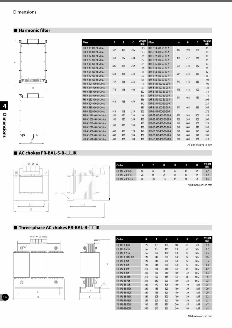
114
Dimensions
1
2
3
4
Dim
ensions Three-phase AC chokes FR-BAL-B-mmK
L3L1
U1 V1W1U2 V2 W2
TB
H
d1
Choke B T H L1 L3 d1 Weight [kg]
FR-BAL-B-4.0K 125 82 130 100 56 5x8 3.0FR-BAL-B-5.5K 155 85 145 130 55 8x12 3.7FR-BAL-B-7.5K 155 100 150 130 70 8x12 5.5FR-BAL-B-11K/-15K 190 115 210 170 79 8x12 10.7FR-BAL-B-22K 190 115 210 170 79 8x12 11.2FR-BAL-B-30K 190 118 230 170 79 8x12 3.0FR-BAL-B-37K 210 128 265 175 97 8x12 3.7FR-BAL-B-45K 230 165 280 180 122 8x12 5.5FR-BAL-B3-55K 210 190 185 175 95 8x12 16FR-BAL-B3-75K 230 210 200 180 122 8x12 22FR-BAL-B3-90K 240 170 325 190 110 11x15 25FR-BAL-B3-110K 240 185 325 190 120 11x15 29FR-BAL-B3-132K 240 185 325 190 120 11x15 29FR-BAL-B3-160K 240 205 325 190 130 11x15 32FR-BAL-B3-185K 285 205 325 190 130 11x15 33FR-BAL-B3-220K 300 220 330 240 155 11x15 47FR-BAL-B3-250K 300 240 330 240 160 11x15 48
All dimensions in mm
Harmonic filter
All dimensions in mm
Filter A B C Weight [kg] Filter A B C Weight
[kg]RHF-A 10-400-50-20-A
347 190 20613.5 RHF-B 10-400-50-20-A
347 190 20618
RHF-A 14-400-50-20-A 16.3 RHF-B 14-400-50-20-A 20RHF-A 22-400-50-20-A
451 232 24822 RHF-B 22-400-50-20-A
451 232 24830
RHF-A 29-400-50-20-A 25 RHF-B 29-400-50-20-A 34RHF-A 35-400-50-20-A
605 378 24237 RHF-B 35-400-50-20-A
605 378 24253
RHF-A 43-400-50-20-A 39 RHF-B 43-400-50-20-A 75RHF-A 58-400-50-20-A
634 378 33344 RHF-B 58-400-50-20-A
634 378 33382
RHF-A 72-400-50-20-A 56 RHF-B 72-400-50-20-A 96RHF-A 86-400-50-20-A
747 418 33362 RHF-B 86-400-50-20-A
747 418 333104
RHF-A 101-400-50-20-A 74 RHF-B 101-400-50-20-A 106RHF-A 144-400-50-20-A
778 418 40085 RHF-B 144-400-50-20-A
778 418 400126
RHF-A 180-400-50-20-A 102 RHF-B 180-400-50-20-A 135RHF-A 217-400-50-20-A
911 468 450
119 RHF-B 217-400-50-20-A911 468 450
171RHF-A 252-400-50-20-A 136 RHF-B 252-400-50-20-A 206RHF-A 304-400-50-20-A 142 RHF-B 304-400-50-20-A
911 468 515221
RHF-A 380-400-50-20-A 185 RHF-B 380-400-50-20-A 265RHF-A 433-400-50-20-A 911 468 515 203 RHF-B 433-400-50-20-A 272RHF-AS 480-400-50-20-A 380 420 230 80 RHF-BS 480-400-50-20-A 520 540 300 185RHF-AS 550-400-50-20-A 380 420 245 100 RHF-BS 550-400-50-20-A 560 540 300 200RHF-AS 600-400-50-20-A
380 420 280125 RHF-BS 600-400-50-20-A 640 600 300 225
RHF-AS 670-400-50-20-A 130 RHF-BS 670-400-50-20-A 640 600 310 240RHF-AS 750-400-50-20-A 440 480 270 140 RHF-BS 750-400-50-20-A 640 600 325 260RHF-AS 850-400-50-20-A 440 480 285 150 RHF-BS 850-400-50-20-A 640 600 340 285RHF-AS 980-400-50-20-A 440 480 300 160 RHF-BS 980-400-50-20-A 640 600 360 310
CB
A
CB
A
AC chokes FR-BAL-S-B-mmK
Choke B T H L1 L3 d1 Weight [kg]
FR-BAL-S-B-0.2K 66 70 86 50 41 4.5 0.7FR-BAL-S-B-0.4K 78 88 95 56 47 4.5 1.2FR-BAL-S-B-0.75K 96 120 115 84 86 5.5 4.5
All dimensions in mm
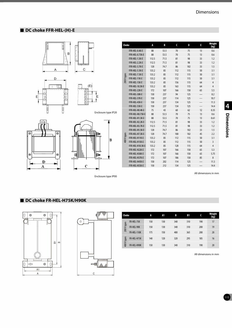
115
Dimensions
1
2
3
4
Dim
ensions
DC choke FFR-HEL-(H)-E
Choke A B C D E Weight [kg]
200 V
type
s
FFR-HEL-0.4K-E 88 53.5 70 75 13 0.6FFR-HEL-0.75K-E 88 53.5 70 75 13 0.6FFR-HEL-1.5K-E 112.5 71.5 81 98 33 1.2FFR-HEL-2.2K-E 112.5 71.5 81 98 33 1.2FFR-HEL-3.7K-E 120 74.7 86 102 33 1.5FFR-HEL-5.5K-E 133.2 85 112 115 50 3.1FFR-HEL-7.5K-E 133.2 85 112 115 50 3.1FFR-HEL-11K-E 133.2 85 112 115 50 3.1FFR-HEL-15K-E 133.2 85 156 115 64 4FFR-HEL-18.5K-E 133.2 85 163 115 64 4FFR-HEL-22K-E 172 107 166 150 65 5.5FFR-HEL-30K-E 150 237 94 125 — 8.2FFR-HEL-37K-E 150 237 114 125 — 10.7FFR-HEL-45K-E 150 237 134 125 — 11.3FFR-HEL-55K-E 150 237 134 125 — 14.4
400 V
type
s
FFR-HEL-H0.4K-E 75 43 60 62 12 0.35FFR-HEL-H0.75K-E 88 53.5 70 75 13 0.6FFR-HEL-H1.5K-E 88 53.5 70 75 13 0.61FFR-HEL-H2.2K-E 112.5 71.5 81 98 33 1.2FFR-HEL-H3.7K-E 112.5 71.5 81 98 33 1.2FFR-HEL-H5.5K-E 120 74.7 86 102 33 1.5FFR-HEL-H7.5K-E 120 74.7 100 102 45 2.2FFR-HEL-H11K-E 133.2 85 112 115 50 3.1FFR-HEL-H15K-E 133.2 85 112 115 50 3FFR-HEL-H18.5K-E 133.2 85 128 115 64 4FFR-HEL-H22K-E 172 107 166 150 65 5.3FFR-HEL-H30K-E 172 107 166 150 65 5.75FFR-HEL-H37K-E 172 107 186 150 85 8FFR-HEL-H45K-E 150 202 114 125 — 11.3FFR-HEL-H55K-E 150 212 134 125 — 14.4
All dimensions in mmEnclosure type IP00
DC choke FR-HEL-H75K/H90K
Choke A A1 B B1 C Weight [kg]
200 V
type
s FR-HEL-75K 150 130 340 310 190 17
FR-HEL-90K 150 130 340 310 200 19
FR-HEL-110K 175 150 400 365 200 20
400 V
type
s
FR-HEL-H75K 140 120 320 295 185 16
FR-HEL-H90K 150 130 340 310 190 20
All dimensions in mm
Enclosure type IP20
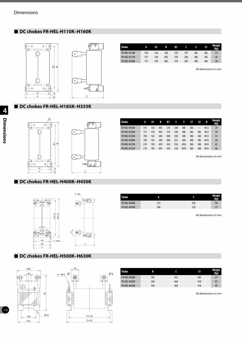
116
Dimensions
1
2
3
4
Dim
ensions
DC chokes FR-HEL-H110K–H160K
Choke A A1 B B1 C S S1 Weight [kg]
FR-HEL-H110K 150 130 340 310 195 M6 M6 22FR-HEL-H132K 175 150 405 370 200 M8 M6 26FR-HEL-H160K 175 150 405 370 205 M8 M6 28
All dimensions in mm
DC chokes FR-HEL-H185K–H355K
Choke A A1 B B1 C S S1 S2 Ø Weight [kg]
FR-HEL-H185K 175 150 405 370 240 M8 M6 — M12 29FR-HEL-H220K 175 150 405 370 240 M8 M6 M6 M12 30FR-HEL-H250K 190 165 440 400 250 M8 M8 M8 M12 35FR-HEL-H280K 190 165 440 400 255 M8 M8 M8 M16 38FR-HEL-H315K 210 185 495 450 250 M10 M8 M8 M16 42FR-HEL-H355K 210 185 495 450 250 M10 M8 M8 M16 46
DC chokes FR-HEL-H400K–H450K
Choke A C Weight [kg]
FR-HEL-H400K 235 250 50FR-HEL-H450K 240 270 57
DC chokes FR-HEL-H500K–H630K
Choke B C C1 Weight [kg]
FR-HEL-H500K 345 455 405 67FR-HEL-H560K 360 460 410 85FR-HEL-H630K 360 460 410 95
All dimensions in mm
All dimensions in mm
All dimensions in mm
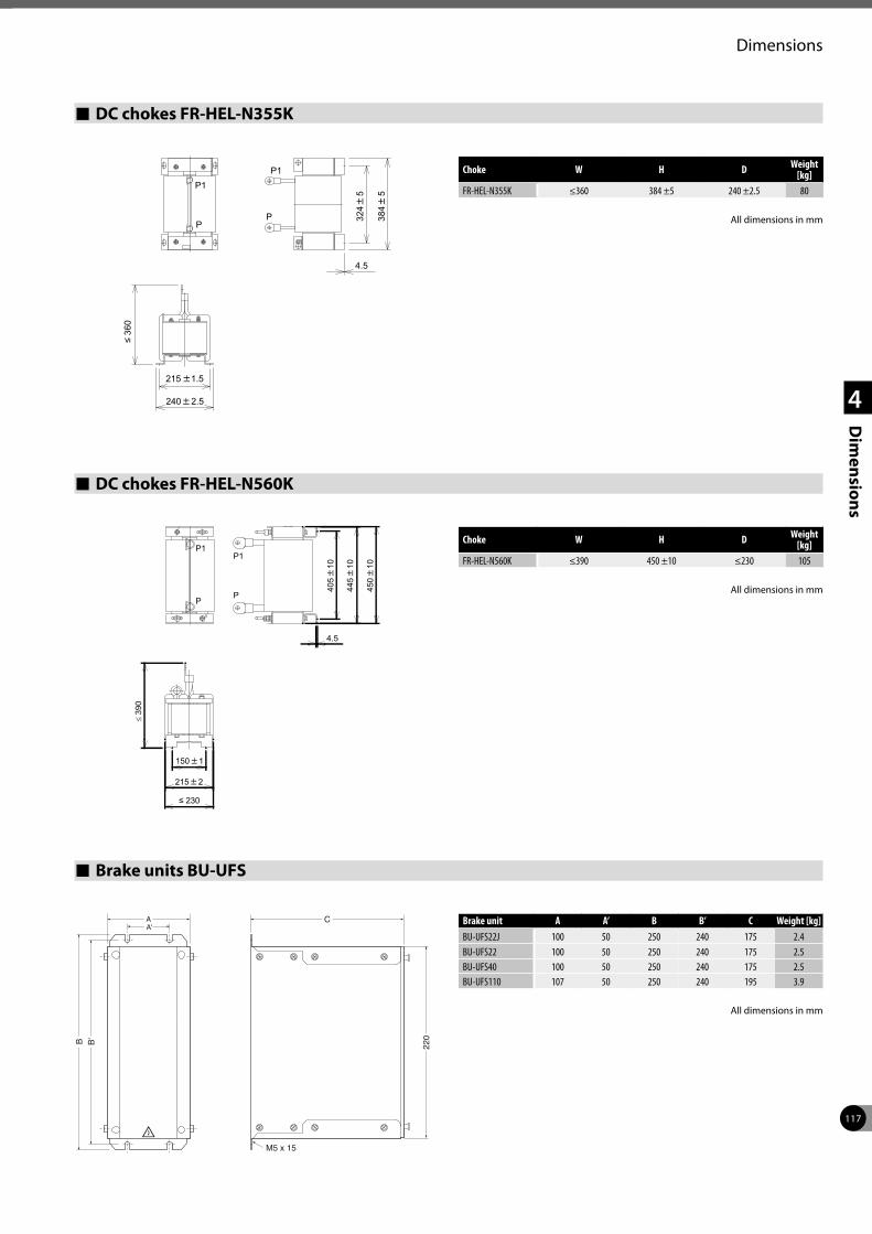
117
Dimensions
1
2
3
4
Dim
ensions
DC chokes FR-HEL-N355K
Choke W H D Weight [kg]
FR-HEL-N355K ≤360 384 ±5 240 ±2.5 80
All dimensions in mm
DC chokes FR-HEL-N560K
Choke W H D Weight [kg]
FR-HEL-N560K ≤390 450 ±10 ≤230 105
PP
P1P1
4.5
324
5
384
5
≤ 36
0
215 1.5
240 2.5
P1P1
4.5
405
10
445
10
450
10
≤ 39
0
215 2
150 1
≤ 230
PP All dimensions in mm
Brake units BU-UFS
Brake unit A A’ B B’ C Weight [kg]BU-UFS22J 100 50 250 240 175 2.4BU-UFS22 100 50 250 240 175 2.5BU-UFS40 100 50 250 240 175 2.5BU-UFS110 107 50 250 240 195 3.9
M5 x 15
A'A C
B'B
220
All dimensions in mm
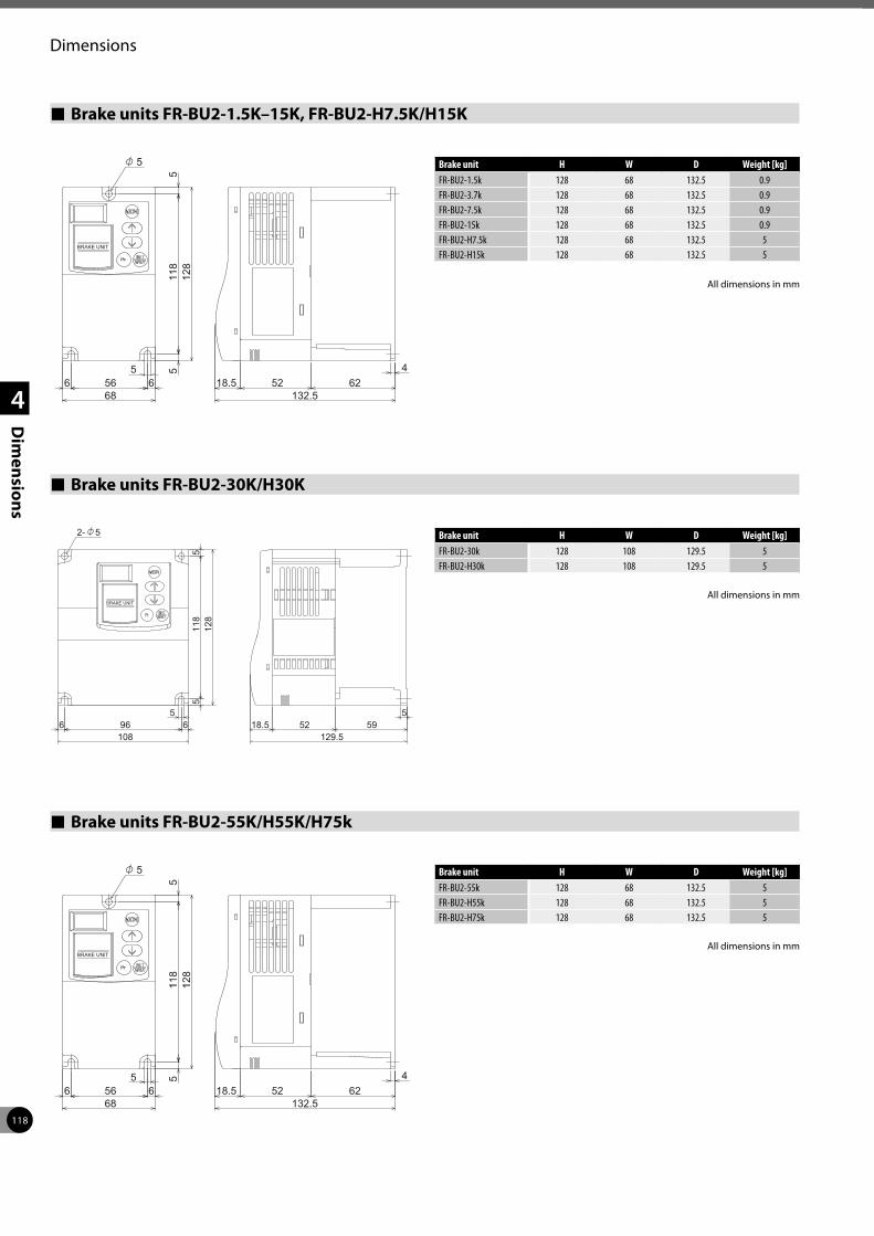
118
Dimensions
1
2
3
4
Dim
ensions
Brake units FR-BU2-1.5K–15K, FR-BU2-H7.5K/H15K
Brake unit H W D Weight [kg]FR-BU2-1.5k 128 68 132.5 0.9FR-BU2-3.7k 128 68 132.5 0.9FR-BU2-7.5k 128 68 132.5 0.9FR-BU2-15k 128 68 132.5 0.9FR-BU2-H7.5k 128 68 132.5 5FR-BU2-H15k 128 68 132.5 5
Brake units FR-BU2-30K/H30K
Brake units FR-BU2-55K/H55K/H75k
Brake unit H W D Weight [kg]FR-BU2-30k 128 108 129.5 5FR-BU2-H30k 128 108 129.5 5
Brake unit H W D Weight [kg]FR-BU2-55k 128 68 132.5 5FR-BU2-H55k 128 68 132.5 5FR-BU2-H75k 128 68 132.5 5
All dimensions in mm
All dimensions in mm
All dimensions in mm
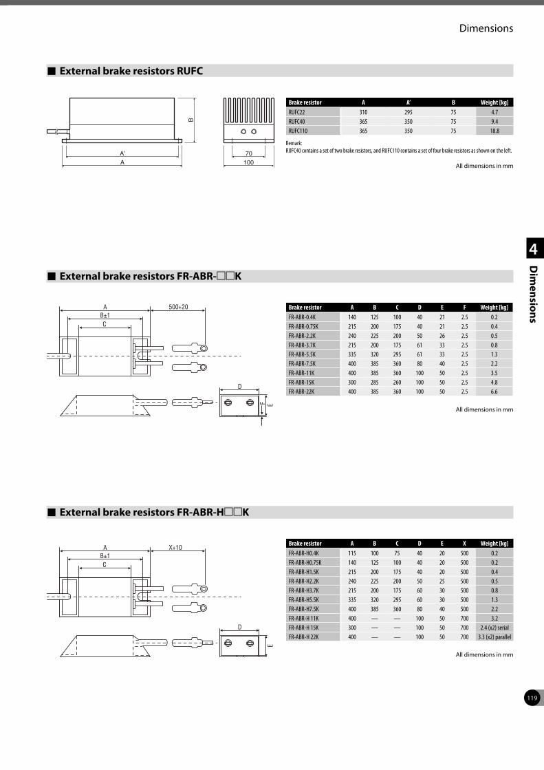
119
Dimensions
1
2
3
4
Dim
ensions
External brake resistors RUFC
Brake resistor A A’ B Weight [kg]RUFC22 310 295 75 4.7RUFC40 365 350 75 9.4RUFC110 365 350 75 18.8
Remark: RUFC40 contains a set of two brake resistors, and RUFC110 contains a set of four brake resistors as shown on the left.
External brake resistors FR-ABR-mmK
External brake resistors FR-ABR-HmmK
Brake resistor A B C D E F Weight [kg]FR-ABR-0.4K 140 125 100 40 21 2.5 0.2FR-ABR-0.75K 215 200 175 40 21 2.5 0.4FR-ABR-2.2K 240 225 200 50 26 2.5 0.5FR-ABR-3.7K 215 200 175 61 33 2.5 0.8FR-ABR-5.5K 335 320 295 61 33 2.5 1.3FR-ABR-7.5K 400 385 360 80 40 2.5 2.2FR-ABR-11K 400 385 360 100 50 2.5 3.5FR-ABR-15K 300 285 260 100 50 2.5 4.8FR-ABR-22K 400 385 360 100 50 2.5 6.6
Brake resistor A B C D E X Weight [kg]FR-ABR-H0.4K 115 100 75 40 20 500 0.2FR-ABR-H0.75K 140 125 100 40 20 500 0.2FR-ABR-H1.5K 215 200 175 40 20 500 0.4FR-ABR-H2.2K 240 225 200 50 25 500 0.5FR-ABR-H3.7K 215 200 175 60 30 500 0.8FR-ABR-H5.5K 335 320 295 60 30 500 1.3FR-ABR-H7.5K 400 385 360 80 40 500 2.2FR-ABR-H 11K 400 — — 100 50 700 3.2FR-ABR-H 15K 300 — — 100 50 700 2.4 (x2) serialFR-ABR-H 22K 400 — — 100 50 700 3.3 (x2) parallel
A’ 70
B
A 100
EF
D
CB±1
A 500+20
E
D
CB±1
A X+10
All dimensions in mm
All dimensions in mm
All dimensions in mm
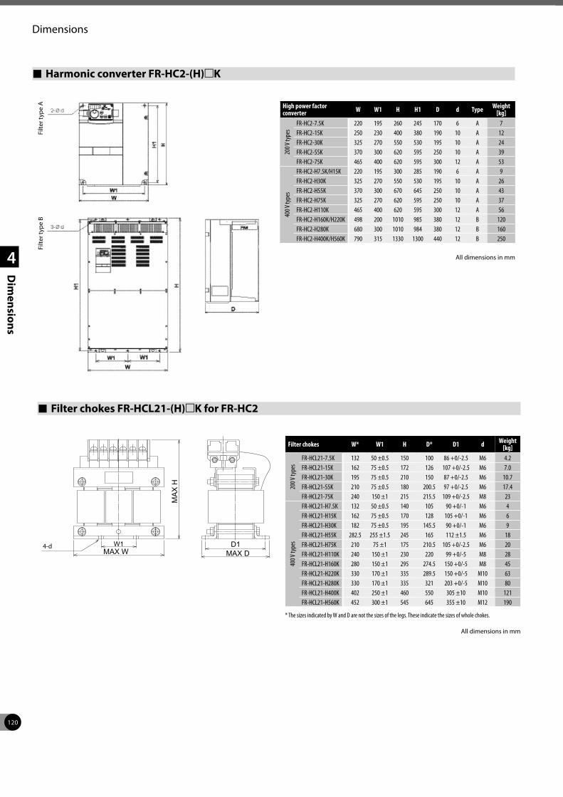
120
Dimensions
1
2
3
4
Dim
ensions
Filter chokes FR-HCL21-(H)mK for FR-HC2
All dimensions in mm
Filter chokes W* W1 H D* D1 d Weight [kg]
200 V
type
s
FR-HCL21-7.5K 132 50 ±0.5 150 100 86 +0/-2.5 M6 4.2FR-HCL21-15K 162 75 ±0.5 172 126 107 +0/-2.5 M6 7.0FR-HCL21-30K 195 75 ±0.5 210 150 87 +0/-2.5 M6 10.7FR-HCL21-55K 210 75 ±0.5 180 200.5 97 +0/-2.5 M6 17.4FR-HCL21-75K 240 150 ±1 215 215.5 109 +0/-2.5 M8 23
400 V
type
s
FR-HCL21-H7.5K 132 50 ±0.5 140 105 90 +0/-1 M6 4FR-HCL21-H15K 162 75 ±0.5 170 128 105 +0/-1 M6 6FR-HCL21-H30K 182 75 ±0.5 195 145.5 90 +0/-1 M6 9FR-HCL21-H55K 282.5 255 ±1.5 245 165 112 ±1.5 M6 18FR-HCL21-H75K 210 75 ±1 175 210.5 105 +0/-2.5 M6 20FR-HCL21-H110K 240 150 ±1 230 220 99 +0/-5 M8 28FR-HCL21-H160K 280 150 ±1 295 274.5 150 +0/-5 M8 45FR-HCL21-H220K 330 170 ±1 335 289.5 150 +0/-5 M10 63FR-HCL21-H280K 330 170 ±1 335 321 203 +0/-5 M10 80FR-HCL21-H400K 402 250 ±1 460 550 305 ±10 M10 121FR-HCL21-H560K 452 300 ±1 545 645 355 ±10 M12 190
* The sizes indicated by W and D are not the sizes of the legs. These indicate the sizes of whole chokes.
MA
X H
MAX DD1
MAX WW14-d
All dimensions in mm
Harmonic converter FR-HC2-(H)mK
High power factor converter W W1 H H1 D d Type Weight
[kg]
200 V
type
s
FR-HC2-7.5K 220 195 260 245 170 6 A 7FR-HC2-15K 250 230 400 380 190 10 A 12FR-HC2-30K 325 270 550 530 195 10 A 24FR-HC2-55K 370 300 620 595 250 10 A 39FR-HC2-75K 465 400 620 595 300 12 A 53
400 V
type
s
FR-HC2-H7.5K/H15K 220 195 300 285 190 6 A 9FR-HC2-H30K 325 270 550 530 195 10 A 26FR-HC2-H55K 370 300 670 645 250 10 A 43FR-HC2-H75K 325 270 620 595 250 10 A 37FR-HC2-H110K 465 400 620 595 300 12 A 56FR-HC2-H160K/H220K 498 200 1010 985 380 12 B 120FR-HC2-H280K 680 300 1010 984 380 12 B 160FR-HC2-H400K/H560K 790 315 1330 1300 440 12 B 250
Filte
r typ
e A
Filte
r typ
e B
All dimensions in mm
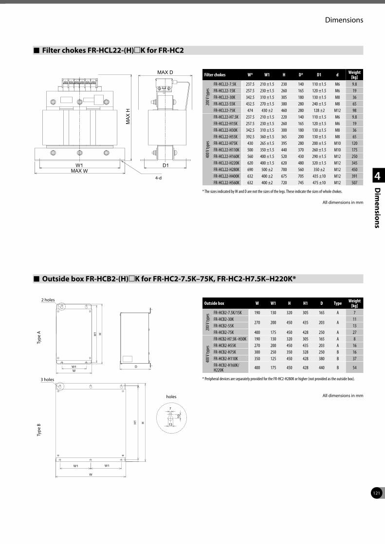
121
Dimensions
1
2
3
4
Dim
ensions
Filter chokes FR-HCL22-(H)mK for FR-HC2
Filter chokes W* W1 H D* D1 d Weight [kg]
200 V
type
s
FR-HCL22-7.5K 237.5 210 ±1.5 230 140 110 ±1.5 M6 9.8FR-HCL22-15K 257.5 230 ±1.5 260 165 120 ±1.5 M6 19FR-HCL22-30K 342.5 310 ±1.5 305 180 130 ±1.5 M8 36FR-HCL22-55K 432.5 270 ±1.5 380 280 240 ±1.5 M8 65FR-HCL22-75K 474 430 ±2 460 280 128 ±2 M12 98
400 V
type
s
FR-HCL22-H7.5K 237.5 210 ±1.5 220 140 110 ±1.5 M6 9.8FR-HCL22-H15K 257.5 230 ±1.5 260 165 120 ±1.5 M6 19FR-HCL22-H30K 342.5 310 ±1.5 300 180 130 ±1.5 M8 36FR-HCL22-H55K 392.5 360 ±1.5 365 200 130 ±1.5 M8 65FR-HCL22-H75K 430 265 ±1.5 395 280 200 ±1.5 M10 120FR-HCL22-H110K 500 350 ±1.5 440 370 260 ±1.5 M10 175FR-HCL22-H160K 560 400 ±1.5 520 430 290 ±1.5 M12 250FR-HCL22-H220K 620 400 ±1.5 620 480 320 ±1.5 M12 345FR-HCL22-H280K 690 500 ±2 700 560 350 ±2 M12 450FR-HCL22-H400K 632 400 ±2 675 705 435 ±10 M12 391FR-HCL22-H560K 632 400 ±2 720 745 475 ±10 M12 507
* The sizes indicated by W and D are not the sizes of the legs. These indicate the sizes of whole chokes.
MA
X H
MAX WW1 D1
MAX D
4-d
All dimensions in mm
Outside box FR-HCB2-(H)mK for FR-HC2-7.5K–75K, FR-HC2-H7.5K–H220K*
Outside box W W1 H H1 D Type Weight [kg]
200 V
type
s FR-HCB2-7.5K/15K 190 130 320 305 165 A 7FR-HCB2-30K
270 200 450 435 203 A11
FR-HCB2-55K 13FR-HCB2-75K 400 175 450 428 250 A 27
400 V
type
s
FR-HCB2-H7.5K–H30K 190 130 320 305 165 A 8FR-HCB2-H55K 270 200 450 435 203 A 16FR-HCB2-H75K 300 250 350 328 250 B 16FR-HCB2-H110K 350 125 450 428 380 B 37FR-HCB2-H160K/H220K 400 175 450 428 440 B 54
* Peripheral devices are separately provided for the FR-HC2-H280K or higher (not provided as the outside box).
D
10
13
7
W
H
W1
H1
W1 W1
W
H1 H
2 holes
Type
ATy
pe B
holes
3 holes
All dimensions in mm
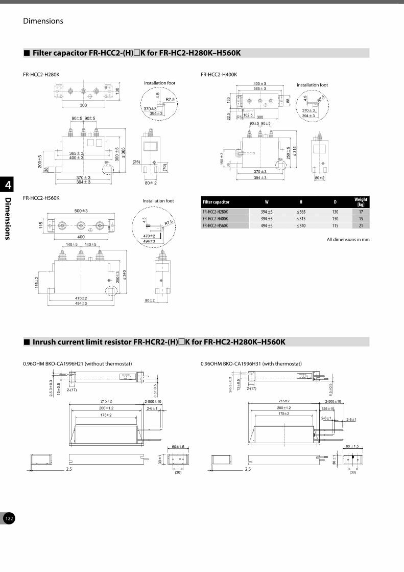
122
Dimensions
1
2
3
4
Dim
ensions
Inrush current limit resistor FR-HCR2-(H)mK for FR-HC2-H280K–H560K
0.96OHM BKO-CA1996H21 (without thermostat) 0.96OHM BKO-CA1996H31 (with thermostat)
200 1.2
215 2
13
0.5
2-5.
3 0
.3
8.5
0.5
30
1
2-(17)
175 2
2-6 1
(30)
2-500 10
60 1.5
200 1.2
215 2 2-500 10
2-6 1
13
0.5
2-5.
3 0
.3
8.5
0.5
60 1.5
30
1
325 15
2-6 1
2-(17)
175 2
(30)2.5 2.5
Filter capacitor FR-HCC2-(H)mK for FR-HC2-H280K–H560K
300
130
90 5
200
3 300
5
≤ 3
65
80 2
(70)
(25)
365 3400 3
370 3394 3
38
4.5
394 3370 3
R7.5
90 5
≤ 31
5
38
394 3 80 2
88
30052.5 102.5
4.5
R7.5
130
22.5 394 3
370 3
370 3
365 3400 3
250
5
150
3
90 5 90 5
470 2494 3
80 2
470 2494 3
140 5140 5
165
2 250
3
≤ 34
0
115
400
500 3
R7.54.5
FR-HCC2-H280K
Installation foot
FR-HCC2-H560K
FR-HCC2-H400K
Installation foot
Filter capacitor W H D Weight [kg]
FR-HCC2-H280K 394 ±3 ≤365 130 17FR-HCC2-H400K 394 ±3 ≤315 130 15FR-HCC2-H560K 494 ±3 ≤340 115 21
All dimensions in mm
Installation foot
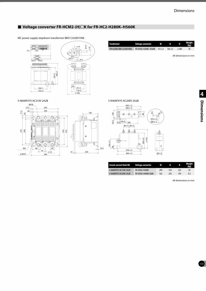
123
Dimensions
1
2
3
4
Dim
ensions
Voltage converter FR-HCM2-(H)mK for FR-HC2-H280K–H560K
MC power supply stepdown transformer BKO-CA2001H06
3V 3V 2V 2V 1V 1V
R/L1 S/L2
115 281 2
(30)
153 2100 1
166
313
2 2
2.3
S5/L25R5/L15
81
2
100 1
(21)
≥ 24
7 ≥ 18
8 1
8
5 2
E
≤ 180
Tranformer Voltage converter W H D Weight [kg]
1PH 630VA BKO-CA2001H06 FR-HCM2-H280K–H560K 153 ±2 166 ±3 ≤180 10
S-N600FXYS AC210V 2A2B
4-M10 290
7080 40
12
270
310
13.5
20
3017.5
275
250
263
250
10 235
10.5
156
M16
M4
S-N400FXYS AC200V 2A2B
≤ 31
5
38
394 3 80 2
88
30052.5 102.5
4.5
R7.513
022
.5 394 3
370 3
370 3
365 3400 3
250
5
150
3
90 5 90 5
Inrush current limit MC Voltage converter W H D Weight [kg]
S-N600FXYS AC210V 2A2B FR-HCM2-H280K 290 310 235 24S-N400FXYS AC200V 2A2B FR-HCM2-H400K/560K 163 243 195 9.5
All dimensions in mm
All dimensions in mm
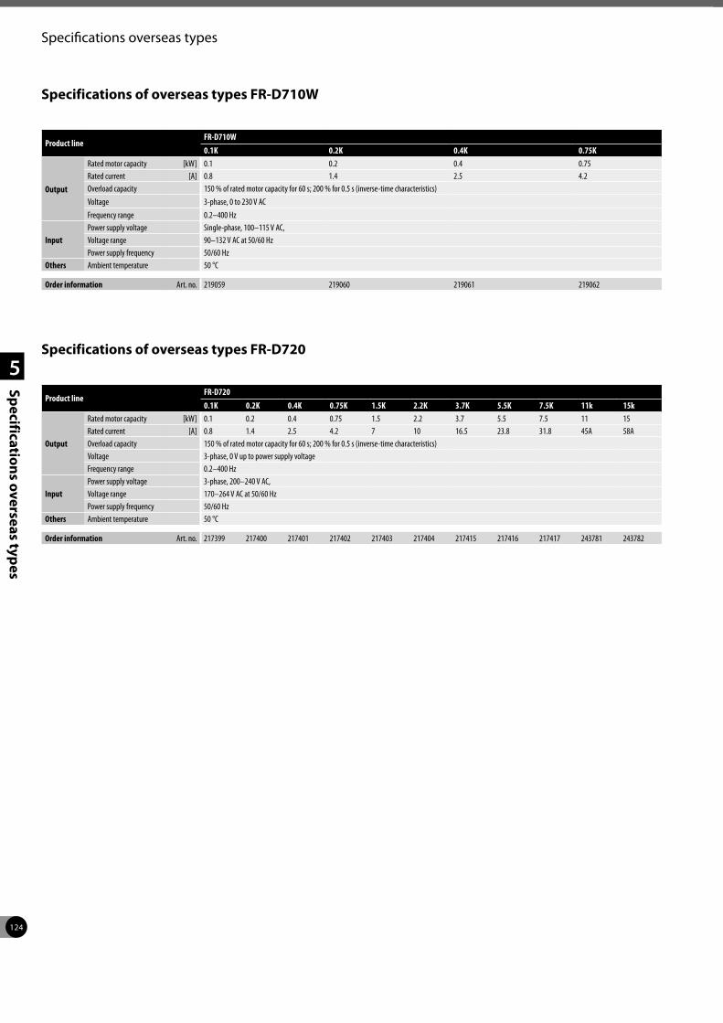
124
Specifications overseas types
1
2
3
4
5
Specifications overseas types
Specifications of overseas types FR-D710W
Specifications of overseas types FR-D720
Product lineFR-D7200.1K 0.2K 0.4K 0.75K 1.5K 2.2K 3.7K 5.5K 7.5K 11k 15k
Output
Rated motor capacity [kW] 0.1 0.2 0.4 0.75 1.5 2.2 3.7 5.5 7.5 11 15Rated current [A] 0.8 1.4 2.5 4.2 7 10 16.5 23.8 31.8 45A 58AOverload capacity 150 % of rated motor capacity for 60 s; 200 % for 0.5 s (inverse-time characteristics)Voltage 3-phase, 0 V up to power supply voltageFrequency range 0.2–400 Hz
InputPower supply voltage 3-phase, 200–240 V AC, Voltage range 170–264 V AC at 50/60 HzPower supply frequency 50/60 Hz
Others Ambient temperature 50 °C
Order information Art. no. 217399 217400 217401 217402 217403 217404 217415 217416 217417 243781 243782
Product lineFR-D710W0.1K 0.2K 0.4K 0.75K
Output
Rated motor capacity [kW] 0.1 0.2 0.4 0.75Rated current [A] 0.8 1.4 2.5 4.2Overload capacity 150 % of rated motor capacity for 60 s; 200 % for 0.5 s (inverse-time characteristics)Voltage 3-phase, 0 to 230 V ACFrequency range 0.2–400 Hz
InputPower supply voltage Single-phase, 100–115 V AC, Voltage range 90–132 V AC at 50/60 HzPower supply frequency 50/60 Hz
Others Ambient temperature 50 °C
Order information Art. no. 219059 219060 219061 219062
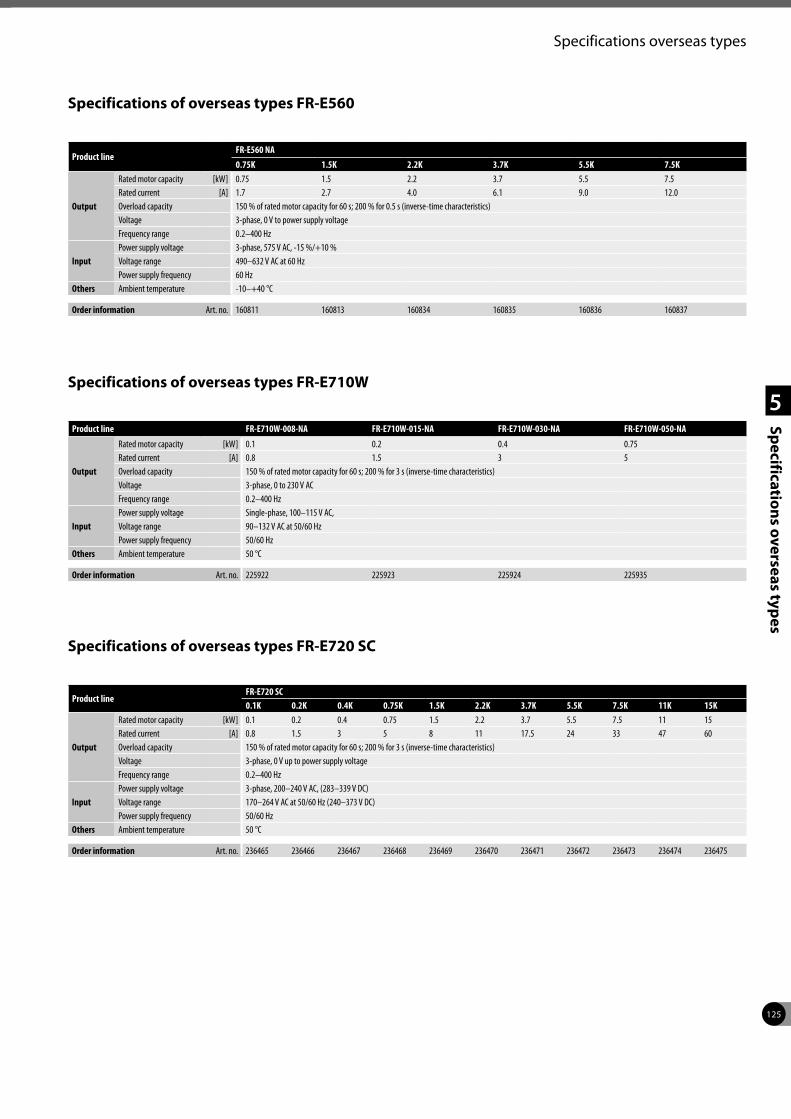
125
Specifications overseas types
1
2
3
4
5
Specifications overseas types
Specifications of overseas types FR-E560
Product lineFR-E560 NA0.75K 1.5K 2.2K 3.7K 5.5K 7.5K
Output
Rated motor capacity [kW] 0.75 1.5 2.2 3.7 5.5 7.5Rated current [A] 1.7 2.7 4.0 6.1 9.0 12.0Overload capacity 150 % of rated motor capacity for 60 s; 200 % for 0.5 s (inverse-time characteristics)Voltage 3-phase, 0 V to power supply voltage Frequency range 0.2–400 Hz
InputPower supply voltage 3-phase, 575 V AC, -15 %/+10 %Voltage range 490–632 V AC at 60 Hz Power supply frequency 60 Hz
Others Ambient temperature -10–+40 °C
Order information Art. no. 160811 160813 160834 160835 160836 160837
Specifications of overseas types FR-E710W
Product line FR-E710W-008-NA FR-E710W-015-NA FR-E710W-030-NA FR-E710W-050-NA
Output
Rated motor capacity [kW] 0.1 0.2 0.4 0.75Rated current [A] 0.8 1.5 3 5Overload capacity 150 % of rated motor capacity for 60 s; 200 % for 3 s (inverse-time characteristics)Voltage 3-phase, 0 to 230 V ACFrequency range 0.2–400 Hz
InputPower supply voltage Single-phase, 100–115 V AC, Voltage range 90–132 V AC at 50/60 HzPower supply frequency 50/60 Hz
Others Ambient temperature 50 °C
Order information Art. no. 225922 225923 225924 225935
Specifications of overseas types FR-E720 SC
Product lineFR-E720 SC0.1K 0.2K 0.4K 0.75K 1.5K 2.2K 3.7K 5.5K 7.5K 11K 15K
Output
Rated motor capacity [kW] 0.1 0.2 0.4 0.75 1.5 2.2 3.7 5.5 7.5 11 15Rated current [A] 0.8 1.5 3 5 8 11 17.5 24 33 47 60Overload capacity 150 % of rated motor capacity for 60 s; 200 % for 3 s (inverse-time characteristics)Voltage 3-phase, 0 V up to power supply voltageFrequency range 0.2–400 Hz
InputPower supply voltage 3-phase, 200–240 V AC, (283–339 V DC)Voltage range 170–264 V AC at 50/60 Hz (240–373 V DC)Power supply frequency 50/60 Hz
Others Ambient temperature 50 °C
Order information Art. no. 236465 236466 236467 236468 236469 236470 236471 236472 236473 236474 236475
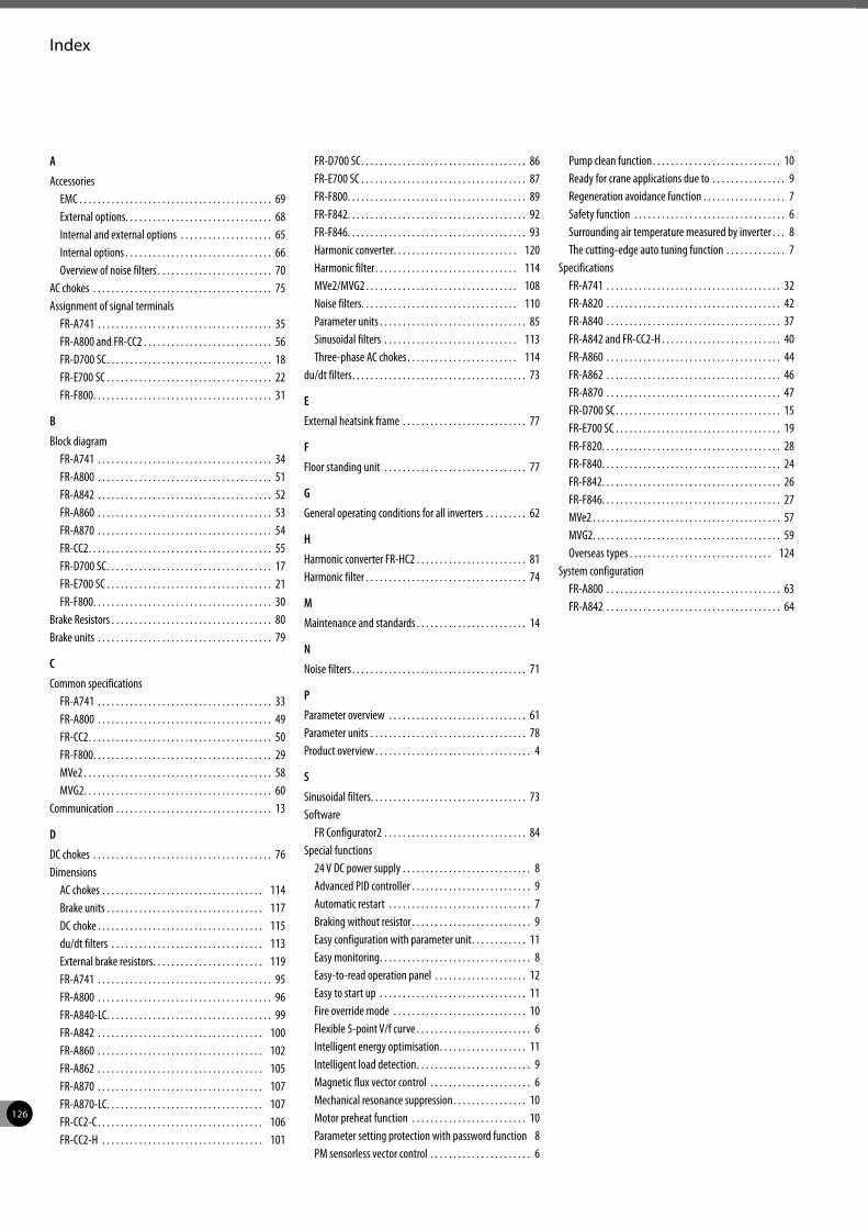
126
Index
A
AccessoriesEMC . . . . . . . . . . . . . . . . . . . . . . . . . . . . . . . . . . . . . . . . . . 69External options. . . . . . . . . . . . . . . . . . . . . . . . . . . . . . . . 68Internal and external options . . . . . . . . . . . . . . . . . . . . 65Internal options . . . . . . . . . . . . . . . . . . . . . . . . . . . . . . . . 66Overview of noise filters . . . . . . . . . . . . . . . . . . . . . . . . . 70
AC chokes . . . . . . . . . . . . . . . . . . . . . . . . . . . . . . . . . . . . . . . 75Assignment of signal terminals
FR-A741 . . . . . . . . . . . . . . . . . . . . . . . . . . . . . . . . . . . . . . 35FR-A800 and FR-CC2 . . . . . . . . . . . . . . . . . . . . . . . . . . . . 56FR-D700 SC. . . . . . . . . . . . . . . . . . . . . . . . . . . . . . . . . . . . 18FR-E700 SC . . . . . . . . . . . . . . . . . . . . . . . . . . . . . . . . . . . . 22FR-F800. . . . . . . . . . . . . . . . . . . . . . . . . . . . . . . . . . . . . . . 31
B
Block diagramFR-A741 . . . . . . . . . . . . . . . . . . . . . . . . . . . . . . . . . . . . . . 34FR-A800 . . . . . . . . . . . . . . . . . . . . . . . . . . . . . . . . . . . . . . 51FR-A842 . . . . . . . . . . . . . . . . . . . . . . . . . . . . . . . . . . . . . . 52FR-A860 . . . . . . . . . . . . . . . . . . . . . . . . . . . . . . . . . . . . . . 53FR-A870 . . . . . . . . . . . . . . . . . . . . . . . . . . . . . . . . . . . . . . 54FR-CC2. . . . . . . . . . . . . . . . . . . . . . . . . . . . . . . . . . . . . . . . 55FR-D700 SC. . . . . . . . . . . . . . . . . . . . . . . . . . . . . . . . . . . . 17FR-E700 SC . . . . . . . . . . . . . . . . . . . . . . . . . . . . . . . . . . . . 21FR-F800. . . . . . . . . . . . . . . . . . . . . . . . . . . . . . . . . . . . . . . 30
Brake Resistors . . . . . . . . . . . . . . . . . . . . . . . . . . . . . . . . . . . 80Brake units . . . . . . . . . . . . . . . . . . . . . . . . . . . . . . . . . . . . . . 79
C
Common specificationsFR-A741 . . . . . . . . . . . . . . . . . . . . . . . . . . . . . . . . . . . . . . 33FR-A800 . . . . . . . . . . . . . . . . . . . . . . . . . . . . . . . . . . . . . . 49FR-CC2. . . . . . . . . . . . . . . . . . . . . . . . . . . . . . . . . . . . . . . . 50FR-F800. . . . . . . . . . . . . . . . . . . . . . . . . . . . . . . . . . . . . . . 29MVe2 . . . . . . . . . . . . . . . . . . . . . . . . . . . . . . . . . . . . . . . . . 58MVG2. . . . . . . . . . . . . . . . . . . . . . . . . . . . . . . . . . . . . . . . . 60
Communication . . . . . . . . . . . . . . . . . . . . . . . . . . . . . . . . . . 13
D
DC chokes . . . . . . . . . . . . . . . . . . . . . . . . . . . . . . . . . . . . . . . 76Dimensions
AC chokes . . . . . . . . . . . . . . . . . . . . . . . . . . . . . . . . . . . 114Brake units . . . . . . . . . . . . . . . . . . . . . . . . . . . . . . . . . . 117DC choke . . . . . . . . . . . . . . . . . . . . . . . . . . . . . . . . . . . . 115du/dt filters . . . . . . . . . . . . . . . . . . . . . . . . . . . . . . . . . 113External brake resistors. . . . . . . . . . . . . . . . . . . . . . . . 119FR-A741 . . . . . . . . . . . . . . . . . . . . . . . . . . . . . . . . . . . . . . 95FR-A800 . . . . . . . . . . . . . . . . . . . . . . . . . . . . . . . . . . . . . . 96FR-A840-LC. . . . . . . . . . . . . . . . . . . . . . . . . . . . . . . . . . . . 99FR-A842 . . . . . . . . . . . . . . . . . . . . . . . . . . . . . . . . . . . . 100FR-A860 . . . . . . . . . . . . . . . . . . . . . . . . . . . . . . . . . . . . 102FR-A862 . . . . . . . . . . . . . . . . . . . . . . . . . . . . . . . . . . . . 105FR-A870 . . . . . . . . . . . . . . . . . . . . . . . . . . . . . . . . . . . . 107FR-A870-LC. . . . . . . . . . . . . . . . . . . . . . . . . . . . . . . . . . 107FR-CC2-C. . . . . . . . . . . . . . . . . . . . . . . . . . . . . . . . . . . . 106FR-CC2-H . . . . . . . . . . . . . . . . . . . . . . . . . . . . . . . . . . . 101
FR-D700 SC. . . . . . . . . . . . . . . . . . . . . . . . . . . . . . . . . . . . 86FR-E700 SC . . . . . . . . . . . . . . . . . . . . . . . . . . . . . . . . . . . . 87FR-F800. . . . . . . . . . . . . . . . . . . . . . . . . . . . . . . . . . . . . . . 89FR-F842. . . . . . . . . . . . . . . . . . . . . . . . . . . . . . . . . . . . . . . 92FR-F846. . . . . . . . . . . . . . . . . . . . . . . . . . . . . . . . . . . . . . . 93Harmonic converter. . . . . . . . . . . . . . . . . . . . . . . . . . . 120Harmonic filter. . . . . . . . . . . . . . . . . . . . . . . . . . . . . . . 114MVe2/MVG2 . . . . . . . . . . . . . . . . . . . . . . . . . . . . . . . . . 108Noise filters. . . . . . . . . . . . . . . . . . . . . . . . . . . . . . . . . . 110Parameter units . . . . . . . . . . . . . . . . . . . . . . . . . . . . . . . . 85Sinusoidal filters . . . . . . . . . . . . . . . . . . . . . . . . . . . . . 113Three-phase AC chokes . . . . . . . . . . . . . . . . . . . . . . . . 114
du/dt filters. . . . . . . . . . . . . . . . . . . . . . . . . . . . . . . . . . . . . . 73
E
External heatsink frame . . . . . . . . . . . . . . . . . . . . . . . . . . . 77
F
Floor standing unit . . . . . . . . . . . . . . . . . . . . . . . . . . . . . . . 77
G
General operating conditions for all inverters . . . . . . . . . 62
H
Harmonic converter FR-HC2 . . . . . . . . . . . . . . . . . . . . . . . . 81Harmonic filter . . . . . . . . . . . . . . . . . . . . . . . . . . . . . . . . . . . 74
M
Maintenance and standards . . . . . . . . . . . . . . . . . . . . . . . . 14
N
Noise filters . . . . . . . . . . . . . . . . . . . . . . . . . . . . . . . . . . . . . . 71
P
Parameter overview . . . . . . . . . . . . . . . . . . . . . . . . . . . . . . 61Parameter units . . . . . . . . . . . . . . . . . . . . . . . . . . . . . . . . . . 78Product overview . . . . . . . . . . . . . . . . . . . . . . . . . . . . . . . . . . 4
S
Sinusoidal filters. . . . . . . . . . . . . . . . . . . . . . . . . . . . . . . . . . 73Software
FR Configurator2 . . . . . . . . . . . . . . . . . . . . . . . . . . . . . . . 84Special functions
24 V DC power supply . . . . . . . . . . . . . . . . . . . . . . . . . . . . 8Advanced PID controller . . . . . . . . . . . . . . . . . . . . . . . . . . 9Automatic restart . . . . . . . . . . . . . . . . . . . . . . . . . . . . . . . 7Braking without resistor . . . . . . . . . . . . . . . . . . . . . . . . . . 9Easy configuration with parameter unit. . . . . . . . . . . . 11Easy monitoring. . . . . . . . . . . . . . . . . . . . . . . . . . . . . . . . . 8Easy-to-read operation panel . . . . . . . . . . . . . . . . . . . . 12Easy to start up . . . . . . . . . . . . . . . . . . . . . . . . . . . . . . . . 11Fire override mode . . . . . . . . . . . . . . . . . . . . . . . . . . . . . 10Flexible 5-point V/f curve . . . . . . . . . . . . . . . . . . . . . . . . . 6Intelligent energy optimisation. . . . . . . . . . . . . . . . . . . 11Intelligent load detection. . . . . . . . . . . . . . . . . . . . . . . . . 9Magnetic flux vector control . . . . . . . . . . . . . . . . . . . . . . 6Mechanical resonance suppression. . . . . . . . . . . . . . . . 10Motor preheat function . . . . . . . . . . . . . . . . . . . . . . . . . 10Parameter setting protection with password function 8PM sensorless vector control . . . . . . . . . . . . . . . . . . . . . . 6
Pump clean function. . . . . . . . . . . . . . . . . . . . . . . . . . . . 10Ready for crane applications due to . . . . . . . . . . . . . . . . 9Regeneration avoidance function . . . . . . . . . . . . . . . . . . 7Safety function . . . . . . . . . . . . . . . . . . . . . . . . . . . . . . . . . 6Surrounding air temperature measured by inverter . . . 8The cutting-edge auto tuning function . . . . . . . . . . . . . 7
SpecificationsFR-A741 . . . . . . . . . . . . . . . . . . . . . . . . . . . . . . . . . . . . . . 32FR-A820 . . . . . . . . . . . . . . . . . . . . . . . . . . . . . . . . . . . . . . 42FR-A840 . . . . . . . . . . . . . . . . . . . . . . . . . . . . . . . . . . . . . . 37FR-A842 and FR-CC2-H . . . . . . . . . . . . . . . . . . . . . . . . . . 40FR-A860 . . . . . . . . . . . . . . . . . . . . . . . . . . . . . . . . . . . . . . 44FR-A862 . . . . . . . . . . . . . . . . . . . . . . . . . . . . . . . . . . . . . . 46FR-A870 . . . . . . . . . . . . . . . . . . . . . . . . . . . . . . . . . . . . . . 47FR-D700 SC. . . . . . . . . . . . . . . . . . . . . . . . . . . . . . . . . . . . 15FR-E700 SC . . . . . . . . . . . . . . . . . . . . . . . . . . . . . . . . . . . . 19FR-F820. . . . . . . . . . . . . . . . . . . . . . . . . . . . . . . . . . . . . . . 28FR-F840. . . . . . . . . . . . . . . . . . . . . . . . . . . . . . . . . . . . . . . 24FR-F842. . . . . . . . . . . . . . . . . . . . . . . . . . . . . . . . . . . . . . . 26FR-F846. . . . . . . . . . . . . . . . . . . . . . . . . . . . . . . . . . . . . . . 27MVe2 . . . . . . . . . . . . . . . . . . . . . . . . . . . . . . . . . . . . . . . . . 57MVG2. . . . . . . . . . . . . . . . . . . . . . . . . . . . . . . . . . . . . . . . . 59Overseas types . . . . . . . . . . . . . . . . . . . . . . . . . . . . . . . 124
System configurationFR-A800 . . . . . . . . . . . . . . . . . . . . . . . . . . . . . . . . . . . . . . 63FR-A842 . . . . . . . . . . . . . . . . . . . . . . . . . . . . . . . . . . . . . . 64

Your solution partner
Your solution partner
Mitsubishi Electric offers a wide range of automation equipment from PLCs and HMIs to CNC and
EDM machines
A name to trust
Since its beginnings in 1870, some 45 companies use the Mitsubishi name, covering a spectrum of finance, commerce and industry.
The Mitsubishi brand name is recognized around the world as a symbol of premium quality.
Mitsubishi Electric Corporation is active in space development, transportation, semiconductors, energy systems, communications and information processing, audio-visual equipment and home electronics, building, and energy management and automation systems, and has 237 factories and laboratories worldwide in over 121 countries.
This is why you can rely on Mitsubishi Electric automation solution - because we know first hand about the need for reliable, efficient, easy-to-use automation and control in our own factories.
As one of the world’s leading companies with a global turnover of over 4 trillion Yen (over $40 billion), employing over 130,000 people, Mitsubishi Electric has the resource and the commitment to deliver the ultimate in service and support as well as the best products.
Low voltage: MCCB, MCB, ACB
Medium voltage: VCB, VCC
Power monitoring, energy management
Compact and modular controllers
Inverters, servos and motors
Visualization: HMIs, software, MES connectivity
Numerical control (NC)
Robots: SCARA, articulated arm
Processing machines: EDM, lasers, IDS
Air-conditioning, photovoltaic, EDS

Global Partner. Local Friend.
European Offices
GermanyMitsubishi Electric Europe B.V.Mitsubishi-Electric-Platz 1D-40882 RatingenPhone: +49 (0)2102 / 486-0
Czech Rep.Mitsubishi Electric Europe B.V.Pekařská 621/7CZ-155 00 Praha 5Phone: +420 255 719 200
FranceMitsubishi Electric Europe B.V.25, Boulevard des BouvetsF-92741 Nanterre CedexPhone: +33 (0)1 / 55 68 55 68
IrelandMitsubishi Electric Europe B.V.Westgate Business Park, BallymountIRL-Dublin 24Phone: +353 (0)1 4198800
ItalyMitsubishi Electric Europe B.V.Viale Colleoni 7 Palazzo SirioI-20864 Agrate Brianza (MB)Phone: +39 039 / 60 53 1
NetherlandsMitsubishi Electric Europe B.V.Nijverheidsweg 23CNL-3641RP MijdrechtPhone: +31 (0) 297 250 350
PolandMitsubishi Electric Europe B.V.ul. Krakowska 48PL-32-083 BalicePhone: +48 (0) 12 347 65 00
RussiaMitsubishi Electric (Russia) LLC2 bld. 1, Letnikovskaya st.RU-115114 MoscowPhone: +7 495 / 721 2070
SpainMitsubishi Electric Europe B.V.Carretera de Rubí 76-80 Apdo. 420E-08190 Sant Cugat del Vallés (Barcelona)Phone: +34 (0) 93 / 5653131
SwedenMitsubishi Electric Europe B.V. (Scandinavia) Hedvig Möllers gata 6SE-223 55 LundPhone: +46 (0) 8 625 10 00
TurkeyMitsubishi Electric Turkey Elektrik Ürünleri A.Ş.Şerifali Mahallesi Kale Sokak No:41 TR-34775 Ümraniye-İSTANBUL Phone: +90 (216) 969 25 00
UKMitsubishi Electric Europe B.V.Travellers LaneUK-Hatfield, Herts. AL10 8XBPhone: +44 (0)1707 / 28 87 80
Representatives
AustriaGEVAWiener Straße 89A-2500 BadenPhone: +43 (0)2252 / 85 55 20
BelarusOOO TECHNIKONProspect Nezavisimosti 177-9BY-220125 MinskPhone: +375 (0)17 / 393 1177
Bosnia and HerzegovinaINEA RBT d.o.o.Stegne 11SI-1000 LjubljanaPhone: +386 (0)1/ 513 8116
BulgariaAKHNATON4, Andrei Ljapchev Blvd., PO Box 21BG-1756 SofiaPhone: +359 (0)2 / 817 6000
CroatiaINEA CRLosinjska 4 aHR-10000 ZagrebPhone: +385 (0)1 / 36 940 - 01/ -02/ -03
Czech RepublicAutoCont C.S. S.R.O.Kafkova 1853/3CZ-702 00 Ostrava 2Phone: +420 595 691 150
DenmarkHANS FØLSGAARD A/STheilgaards Torv 1DK-4600 KøgePhone: +45 4320 8600
EstoniaElectrobit OÜPärnu mnt. 160iEST-11317, TallinnPhone: +372 6518 140
FinlandUTU Automation OyPeltotie 37FIN-28400 UlvilaPhone: +358 (0)207 / 463 500
GreeceUTECO A.B.E.E.5, Mavrogenous Str.GR-18542 PiraeusPhone: +30 (0)211 / 1206-900
HungaryMELTRADE Kft.Fertő utca 14.HU-1107 BudapestPhone: +36 (0)1 / 431-9726
KazakhstanTOO Kazpromavtomatika Ul. Zhambyla 28KAZ-100017 KaragandaPhone: +7 7212 / 50 10 00
LatviaOAK Integrator Products SIARitausmas iela 23LV-1058 RigaPhone: +371 67842280
LithuaniaAutomatikos Centras, UAB Neries krantiné 14A-101LT-48397 KaunasPhone: +370 37 262707
MaltaALFATRADE Ltd.99, Paola HillMalta-Paola PLA 1702Phone: +356 (0)21 / 697 816
MoldovaINTEHSIS SRLbld. Traian 23/1MD-2060 KishinevPhone: +373 (0)22 / 66 4242
PortugalFonseca S.A.R. João Francisco do Casal 87/89PT-3801-997 Aveiro, Esgueira Phone: +351 (0)234 / 303 900
RomaniaSirius Trading & ServicesAleea Lacul Morii Nr. 3RO-060841 Bucuresti, Sector 6Phone: +40 (0)21 / 430 40 06
SerbiaINEA SR d.o.o.Ul. Karadjordjeva 12/217SER-11300 SmederevoPhone: +381 69 172 27 25
SlovakiaSIMAP SKDolné Pažite 603/97SK-911 06 TrenčínPhone: +421 (0)32 743 04 72
SloveniaINEA RBT d.o.o.Stegne 11SI-1000 LjubljanaPhone: +386 (0)1 / 513 8116
SwitzerlandOMNI RAY AGIm Schörli 5CH-8600 DübendorfPhone: +41 (0)44 / 802 28 80
UkraineCSC- AUTOMATION Ltd.4 B, Yevhenа Sverstyuka Str.UA-02002 KievPhone: +380 (0)44 / 494 33 44
EgyptEIM Energy3 Roxy SquareET-11341 Heliopolis, CairoPhone: +202 24552559
IsraelSHERF MOTION TECHN. Ltd.Rehov Hamerkava 19IL-58851 HolonPhone: +972 (0)3 / 559 54 62
LebanonCEG LIBANCebaco Center/Block A Autostrade DORALebanon-BeirutPhone: +961 (0)1 / 240 445
South AfricaADROIT TECHNOLOGIES20 Waterford Office Park 189 Witkoppen RoadZA-FourwaysPhone: + 27 (0)11 / 658 8100
Vers
ion
chec
k Mitsubishi Electric Europe B.V. / FA - European Business Group / Mitsubishi-Electric-Platz 1 / D-40882 Ratingen / Germany / Tel.: +49(0)2102-4860 / Fax: +49(0)2102-4861120 / [email protected] / https://eu3a.mitsubishielectric.com
Art. no. 206313-I / 04.2019 / Specifications subject to change / All trademarks and copyrights acknowledged.