formalization and rule-based transformation of emf ecore-based models
TRANSCRIPT
Formalization and Rule-Based Transformation of EMFEcore-Based Models
Bernhard Schatz
Institut fur Informatik, Technische Universitat MunchenBoltzmannstr. 3, 85748 Garching, Germany
Abstract. With models becoming a common-place in software and systems de-velopment, the support of automatic transformations of those models is an impor-tant asset to increase the efficiency and improve the quality of the developmentprocess. However, the definition of transformations still is quite complex. Sev-eral approaches – from more imperative to more declarative styles – have beenintroduced to support the definition of such transformations. Here, we show howa completely declarative relational style based on the interpretation of a model assingle structured term can be used to provide a transformation mechanism allow-ing a simple, precise, and modular specification of transformations for the EMFEcore platform, using a Prolog rule-based mechanism.
1 Motivation
The construction of increasingly sophisticated software products has led to wideninggap between the required and supplied productivity in software development. To over-come the complexity of realistic software systems and thus increase productivity, cur-rent approaches increasingly focus on a model-based development using appropriatedescription techniques (e.g., UML [1] ). Here, the specification of a software product isdescribed using views of the system under development (horizontal, e.g., structure, thebehavior; vertical, e.g., component/sub-components). To combine those views, they aremapped onto a common model.
Besides view-based development, automated development steps – using rule-basedmechanized transformations – are an important technique to improve the efficiency ofthe development process. Besides increasing efficiency, these transformations offer con-sistency ensuring modification of models, ranging from refactoring steps to improve thearchitecture of a system to the consistent integration of standard behavior.
In the following, a transformation approach is introduced, allowing a simple, pre-cise, and modular specification of transformations. The approach uses a declarative re-lational style to provide a transformation mechanism. It is implemented on the Eclipseplatform, using a term-based abstract representation of an EMF Ecore description anda Prolog rule-based interpretation.
1.1 Related Approaches
The introduced transformation framework is used to describe graph transformations,using a relational calculus focused on basic constructs to manipulate nodes (elements)
and edges (relations) of a conceptual model. In contrast to other graph-based approacheslike MOFLON/TGG [2], VIATRA [3], FuJaBa [4], or GME [5] it is not based on graph-grammars or graphical, rule-based descriptions [6], but uses a textual description basedon a relational, declarative calculus. As shown in Section 3, for the declaration of basictransformations the rule-based approach allows the definition of such transformationsin a pre-model/post-model style of description similar to graph-patterns, both concern-ing complexity and readability of description. However, in contrast to those approaches,the approach introduced here uses only a single formalism to describe basic transfor-mations as well as their compositions; thus, its avoids the problems of using differentformalisms to describe transformation patterns, like object diagrams, OCL expressions,and state machines. Similarly, this relational rule-based approach makes the order ofapplication and interaction of basic transformations explicit, avoiding the imprecisionresulting from the underspecification of these dependencies.
Considering the textual form of description, the transformation framework is simi-lar to the QVT approach [7] and its respective implementations like ATL [8], F-Logicsbased transformation [9], or Tefkat [10]. However, in contrast to those it comes witha precise and straightforward definition of models and transformations. This definitionis directly reflected in the description of models and transformations: There is only asingle homogenous formalism with two simple construction/deconstruction operatorsto describe the basic transformation rules and their composition; complex analysis ortransformation steps can be easily modularized since there are no side-effects or in-cremental changes during the transformation. Furthermore, the rule-based relationalapproach allows to arbitrarily mix more declarative and imperative forms of specifi-cation, which are strictly separated in those other approaches. Thus, e.g., it allows toconstruct an initial description of a specification in a purely declarative fashion, and tosuccessively rephrase it into a more imperative and efficient form.
Similar to other approaches like VIATRA [3] or GEMS [11], Prolog is used to imple-ment a relational style of describing transformations. However, in those approaches themodel is encoded as a set of base clauses. As a consequence, transformations are im-plemented via rules based on side-effects using an assert/retract, thus making atruly relational description of transformations impossible. This use of side-effects, how-ever, complicates the definition of complex declarative transformation, especially whendescribing pattern-like rules potentially requiring backtracking. A similar encoding isalso used in formalizing models instantiating meta-models as facts in a relational data-based schemes, with the schemes derived from the meta-model relations, as in [12]. Incontrast, here the model is encoded as a single complex term, which forms an inputand output argument of the Prolog clause formalizing the transformation, thus allowingto use true relational declarative style without side-effects, even for complex transfor-mation constructed in a modular fashion from simpler transformations. Note that theapproach is not restricted to the use of Prolog; also other formalisms like functionallanguages can be used.
Finally, the approach presented here addresses a different form of application: Whilemost of the above approaches intend to support the transformation from one modelingdomain to another (e.g., from class diagrams to DB schemata), here the goal is rather

Sib Comp Contr
OutLeftOutDst OutSrc
Sub
InSrcInMid
InRightInMidInDst
InLeftContext Contr
Out
OutOut
Fig. 1. Example: Hierarchical Component Model
to provide simple implementations for refactorings of models (e.g., combining a clusterof components).
1.2 Contribution
The approach presented in the following sections supports the transformation of EMFEcore models using a completely declarative relational style in a rule-based fashion:
Relational: A transformation is described as a relation between the models before andafter the transformation; models themselves are also described as relations.
Declarative: The description of the transformation relation characterizes the modelsbefore and after the transformation rather than providing an imperative sequence oftransformation operations.
Rule-Based: The relations and their characterization of the models are described usinga set of axioms or rules.
To support this style of description with its simple, precise, and modular specificationof transformation relations on the problem- rather than the implementation-level, threeessential contributions are supplied by the framework presented here:
1. The term-structure representation of models based on the structure of the meta-models they instantiate, as well its implementation in the Eclipse framework, pro-viding the translation of models of EMF Ecore-based meta-models into their corre-sponding term-structure.
2. The relational formalization of model transformations, as well as its implementa-tion using a Prolog rule-based interpretation, providing the execution of transfor-mations within the Eclipse framework.
3. The application of relations as execution of – generally parameterized – transfor-mations, as well as its implementation as an Eclipse plug-in, providing support forthe definition and the execution of relational transformation rules.
These three contributions are described in the following sections. Section 2 provides aformalized notion of a model used in this relational approach as well as its representa-tion in a declarative fashion using Prolog style. Section 3 describes the the basic princi-ples of describing transformations as relations, using rules similar to graph grammars asa specific description style, and illustrates the modular composition of transformations.Section 4 illustrates the implemented tool support both for the definition of transfor-mation and the transformation execution. Section 5 highlights some benefits and openissues.

2 Model Formalization and Structure
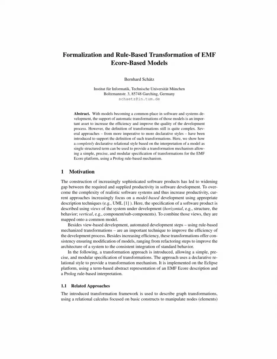
As mentioned in Section 1, the purpose of the approach presented here is the trans-formation of descriptions of systems under development to increase the efficiency andquality of the development process. According to the nomenclature of the OMG, thedescription of a system is called a (system) model in the following. Figure 1 shows sucha model, as it is used in the AutoFOCUS [13] approach to describe the architecturalstructure of a system: the system Context, consisting of subcomponents Sib, Comp,and Contr, the latter with subcomponent Sub; the components have input and outputports like InDst and InMid, connected by channels like InLeft.
To construct formalized descriptions of a system under development, a ‘syntac-tic vocabulary’ also called conceptual model [13] is needed. This conceptual model1
characterizes all possible system models built from the modeling concepts and theirrelations used to construct a description of a system; typically, class diagrams are usedto describe them. Figure 2 shows the conceptual elements and their relations used todescribe the architectural structure of a system in the AutoFOCUS approach. These con-cepts are reflected in the techniques used to model a system. In the following subsection,a formalization of conceptual models and system models based on relations is given aswell as their representation in a declarative fashion using Prolog style.
2.1 Formalization
To define the notion of a conceptual model in the context of model transformationsmore formally, the interpretation along the lines of [13] is used. It provides a seman-tical interpretation for syntactical descriptions like in Figure 2. Basically, the concep-tual model is constructed from a conceptual universe, containing the primitives used todescribe a system: concepts characterizing unique entities used to describe a system,with examples in the AutoFOCUS conceptual model like component, port, or chan-nel to define the components, ports and channels of a structural description of a sys-tem; attributes characterizing properties, like name or direction to define the name ofa component and a channel, or the direction (input or output) of a port. Concepts andattributes form the conceptual universe, consisting of a collection of infinite sets ofconceptual entities, and a collection of – finite or infinite – sets of attribute values.In case of the AutoFOCUS conceptual model, examples for sets of conceptual enti-ties are CompId = {comp1, comp2, . . .}, and PortId = {port1, port2, . . .}; typi-cal examples for set of attribute values are CompName = {‘Sib’, ‘Context’, . . .} orPortDir = {input , output}.
Based on the conceptual universe, the conceptual domain is defined, consisting ofelements corresponding to objects used to model a system, like Component, Port, orChannel to define the components, ports and channels of a structural description of asystem; and relations corresponding to dependencies between the elements, like sub-Comp, chanComp, or srcPort to define the subcomponents of a component, the compo-nent containing a channel, or the source port of channel.
1 In the context of technologies like the Meta Object Facility, the class diagram-like definitionof a conceptual model is generally called meta model.

-name : String-comment : String
Component
-name : String-comment : String-direction : Direction
Port-name : String-comment : String
Channel
0..*
SubComp
portComp chanComp
srcPort
dstPort
0..* 0..*
1 0..2
0..21
Fig. 2. Representation of the Conceptual Model of AutoFOCUS Component Diagrams
The conceptual domain consists of a collection of element relations be-tween conceptual entities and attribute values, and a collection of (binary) as-sociation relations between conceptual entities. In case of the AutoFOCUS con-ceptual domain for structural descriptions as provided in Figure 22, examplesfor element relations are Component = CompId × CompName with values{(comp1, ‘Context’), (comp2, ‘Sib’), . . .}, Port = PortId × PortName × PortDirwith values {(port1, ‘OutSrc’, output), . . .}, or Channel = ChanId × ChanNamewith values {(channel1, ‘OutLeft’), . . .}; examples for association relations areSubComp = CompId × CompId with values {(comp1, comp2), . . .} or srcPort =ChanId ×PortId with values {(channel1, port1), . . .}. Intuitively, the conceptual do-main describes the domain, from which specific instances of the description of an actualsystem are constructed.
Based on the conceptual domain, the conceptual model is the set of all possible sys-tem models that can be constructed within this domain. Intuitively, each system modelis a “sub-model” of the conceptual domain, with sub-sets of its entities and relations. Inorder to be a proper system model, a subset of the conceptual domain generally mustfullfil additional constraints; typical examples are the constraints in meta-models repre-sented as class diagrams. In case of the AutoFOCUS conceptual model shown in Figure2, e.g., each port or channel element must have an associated component in the chan-Comp and portComp relation, resp.; furthermore, each channel must have an associatedsource and destination port in the srcPort and dstPort relation.
2.2 Structure of the Model
The transformation framework provides mechanisms for a pure (i.e., side-effect free)declarative, rule-based approach to model transformation. To that end, the frameworkprovides access to EMF Ecore-based models [14]. As described in Subsection 2.1, for-mally, a (conceptual) model is a collection of sets of elements (each described as aconceptual entity and its attribute values) and relations (each described as a pair of con-ceptual entities). To syntactically represent such a model, a Prolog term is used. Sincethese elements and relations are instances of classes and associations taken from anEMF Ecore model, the structure of the Prolog term – representing an instance of that
2 For simplification purposes, the Comment attribute is ignored in the following.

model – is inferred from the structure of that model. The term comprises the classesand associations, of which the instance of the EMF Ecore model is constructed. It isgrouped according to the structure of that model, depending on the package structure ofthe model and the classes and references of each package. The structure of the model isbuilt using only simple elementary Prolog constructs, namely compound functor termsand list terms. Note that this construction obviously is not specific to Prolog; the sameapproach can be used for the embedding in other rule-based formalisms, e.g., functionallanguages like Haskell [15].
To access a model, the framework provides construction predicates to deconstructand reconstruct a term representing a model. Since the structure makes only use ofcompound functor terms and list terms, only two classes of construction predicates areprovided, namely the union operation and the composition operations.
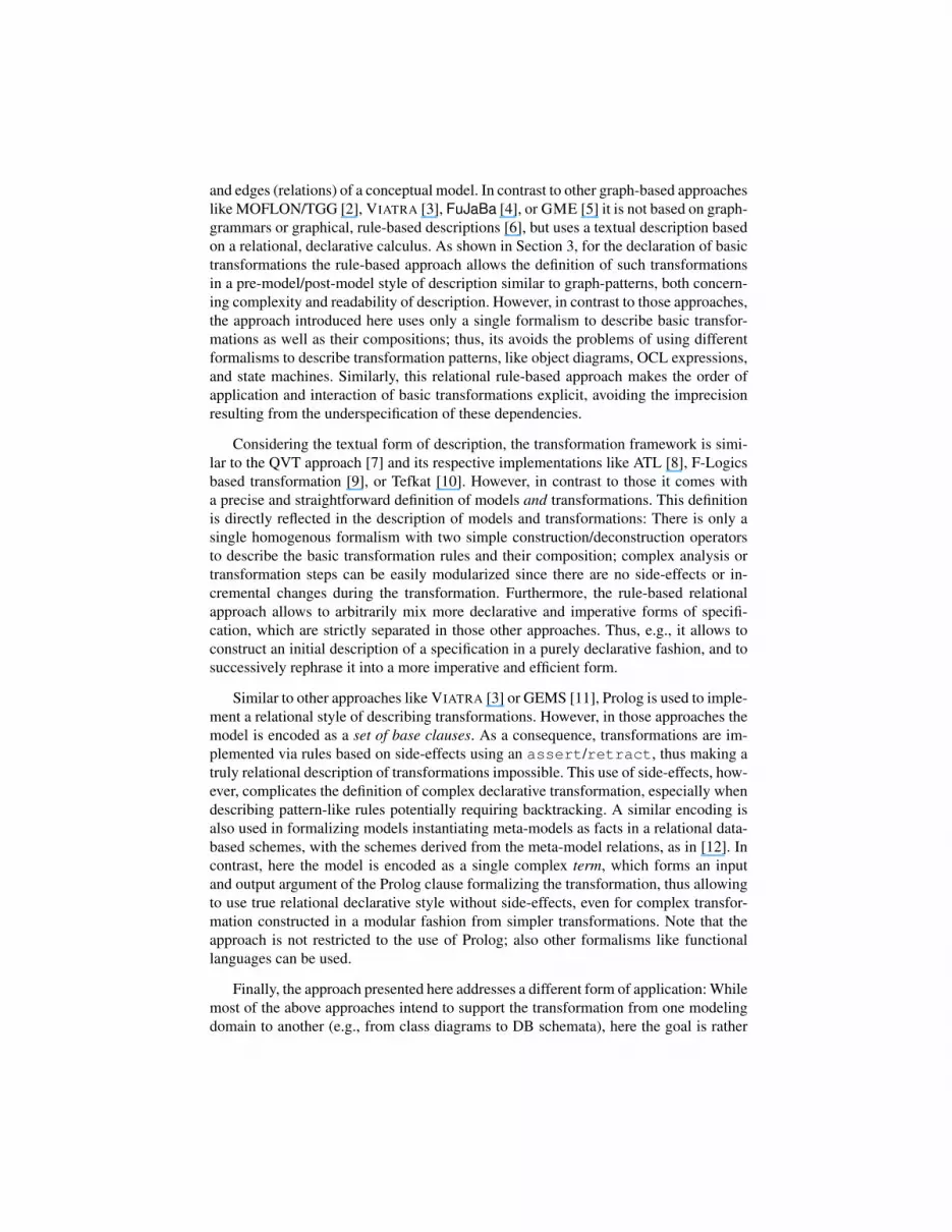
Term Structure of the Model A model term describes the content of an instance of aEMF Ecore model. Each model term is a list of package terms, one for each packagesof the EMF Ecore model. Each package term, in turn, describes the content of the pack-age instance. It consists of a functor – identifying the package – with a sub-packagesterm, a classes terms, and an associations term as its argument. The sub-packages termdescribes the sub-packages of the package; it is a list of package terms.
The classes term describes the EClasses of the corresponding package. It is a list ofclass terms, one for each EClass of the package. Each class term consists of a functor –identifying the class - and an elements term. An elements term describes the collectionof objects instantiating this class, and thus – in turn – is a list of element terms. Note thateach elements term comprises only the collection of those objects of this class, whichare not instantiations of subclasses of this class; objects instantiating specializations ofthis class are only contained in the elements terms corresponding to the most specificclass. Finally, an element term - describing such an instance – consists of a functor –again identifying the class this object belongs to – with an entity identifying the elementand attributes as arguments. Each of the attributes are atomic representations of thecorresponding values of the attributes of the represented object. The entity is a regularatom, unique for each element term.
Similarly to the elements term, the associations terms describe the associations, i.e.,the instances of the EReferences of the EClasses, for the corresponding package. Again,it is a list of association terms, with each association term consisting of a functor – iden-tifying the association - and an relations term, describing the content of the association.The relations term is a list of relation terms, each term consisting of a functor – identify-ing the relation – and the entity identificators of the related objects. In detail, the Prologmodel term has the structure shown in Table 1 in the BNF notation with correspondingnon-terminals and terminals.
The functors of the compound terms are deduced from the EMF Ecore model, whichthe model term is representing:
– the functor of a PackageTerm corresponds to the name of the EPackage the term isan instance of;
– the functor of a ClassTerm to the name of the EClass the term is an instance of; andfinally
ModelTerm ::= [PackageTerm (, PackageTerm )* ]PackageTerm ::= Functor(PackagesTerm,ClassesTerm,AssociationsTerm)PackagesTerm ::= [] | [ PackageTerm (,PackageTerm)* ]ClassesTerm ::= [] | [ ClassTerm (,ClassTerm)* ]ClassTerm ::= Functor(ElementsTerm)ElementsTerm ::= [] | [ ElementTerm (,ElementTerm)* ]ElementTerm ::= Functor(Entity(,AttributeValue)*)Entity ::= AtomAttributeValue ::= AtomAssociationsTerm ::= [] | [ AssociationTerm(,AssociationTerm)*]AssociationTerm ::= Functor(RelationsTerm)RelationsTerm ::= [] | [ RelationTerm(,RelationTerm)*]RelationTerm ::= Functor(Entity,Entity)
Table 1. The Prolog Structure of a Model Term
– the functor of an AssociationTerm corresponds to the name of the EReference theterm in an instance of.
Since EMF – unlike MOF – does not support associations as first-class concepts likeEClasses but uses EReferences instead, EReference names are not necessarily uniquewithin a package. Therefore, if present, EAnnotation attributes of EReferences are usedas the functors of an AssociationTerm. Similarly, the atoms of the attributes are deducedfrom the instance of the EMF Ecore model, which the model term is representing:
– the entity atom corresponds to the object identificator of an instance of a EClass,while
– the attribute corresponds to the attribute value of an instance of an EClass.
Currently, while basically also multi-valued attributes can be handled by the formalism,only single-valued attributes like references (including null references), basic types, andenumerations are supported by the implementation.
2.3 Construction Predicates
In a strictly declarative rule-based approach to model-transformation, the transforma-tion is described in terms of a predicate, relating the models before and after the trans-formation. Therefore, mechanisms are needed in form of predicates to deconstruct amodel into its parts as well as to construct a model from its parts. As the structure ofthe model is defined using only compound functor terms and list terms, only two formsof predicates are needed: union and composition operations.
List Construction The construction and deconstruction of lists is managed by meansof the union predicate union/3 with template3
3 According to standard convention, arbitrary/input/output argument of predicates are indicatedby ?/+/-.
union(?Left,?Right,?All)
such that union(Left,Right,All) is true if all elements of list All areeither elements of Left or Right, and vice versa. Thus, e.g., union([1,3,5],R,[1,2,3,4,5]) succeeds with R = [2,4].
Compound Construction Since the compound structures used to build the modelinstances depend on the actual structure of the EMF Ecore model, only the generalschemata used are described. Depending on whether a package, class/element, or asso-ciation/relation is described, different schemata are used. In all three schemata the nameof the package, class, or relation is used as the name of the predicate for the compoundconstruction.
Package Compounds The construction and deconstruction of packages is managed bymeans of package predicates of the form package/4 with template
package(?Package,?Subpackages,?Classes,?Associations)
where package is the name of the package (de)constructed. Thus, e.g., a pack-age named structure in the EMF Ecore model is represented by the compoundconstructor structure. The predicate is true if Package consists of sub-packages Subpackages, classes Classes, and associations Associations.The predicate is generaly used in the form package(+Package,-Sub-packages,-Classes,-Associations) to deconstruct a compound structureinto its constituents, and package(-Package, +Subpackages,+Classes,+Associations) to construct a compound structure from its constituents.
Class and Element Compounds The (de)construction of classes/elements is managedby means of class/element predicates of the form class/2 and class/N+2 whereN is the number of the attributes of the corresponding class, with templates
class(?Class, ?Elements)class(?Element,?Entity,?Attribute1,...,?AttributeN)
where class is the name of the class and element (de)constructed. Thus, e.g., theclass named Component in the EMF Ecore model in Figure 2 is represented by thecompound constructor Component. The class predicate is true if Class is thelist of Objects; it is generally used in the form class(+Class,Objects)to deconstruct a class into its list of objects, and class(-Class,+Objects)to construct a class from a list of objects. Similarly, the element predicate is trueif Element is an Entity with attributes Attribute1,. . . ,AttributeN;it can be used to deconstruct an element into its entity and attributes viaclass(+Element,-Entity,-Attribute1,...,-AttributeN), toconstruct an element from an entity and attributes (e.g. to change the attributes of an el-ement) via class(-Element,+Entity,+Attribute1,...,AttributeN),or to construct an element including its entity from the attributes viaclass(-Element,-Entity,+Attribute1,...,AttributeN). Thus,

Sib CompContr
OutLeftOutDst OutSrc
Sub
OutMidOutMid
OutRight InSrcInDstInRight
Context ContrOut
OutOut
Fig. 3. Example: Result of Pushing Down Component Comp into Container Contr
e.g., Component(Components,[Context,Sib,Contr]) is used to con-struct a class Components from a list of objects Context, Sib, and Contr.Similarly, Component(Contr,Container,"Contr","The containerelement") is used to construct an element Contr with entity Container, name"Contr", and comment "The container element".
Association and Relation Compounds The construction and deconstruction of associ-ations and relations is managed by means of association and relation predicate of theform association/2 and association/3 with templates
association(?Association,?Relations)association(?Relation,?Entity1,?Entity2)
where association is the name of the association and relation constructed/deconstructed.Thus, e.g., a relation named subComponent in the EMF Ecore model in Figure 2 isrepresented by the compound constructor subComponent. The relation predicateis true if Association is the list of Relations; it is generally used in the formassociation(+Association,-Relations) to deconstruct an associationinto its list of relations, and association(-Association,+Relations)to construct an association from a list of relations. Similarly, the rela-tion predicate is true if Relation associates Entity1 and Entity2;it is used to deconstruct a relation into its associated entities viaassociation(+Relation,-Entity1,-Entity2) and to construct a relationbetween two entities via association(-Relation,+Entity1,+Entity2).E.g., subComponent(subComps,[CtxtSib,CtxtComp,CtxtContr]) isused to construct the subcomponent association subComps from the list of relationsCtxtSib, CtxtComp, and CtxtContr. Similarly, subComponent(Ctxt-Contr,Context,Contr) is used to construct relation CtxtContr with Contrbeing the subcomponent of Context.
3 Transformation Definition
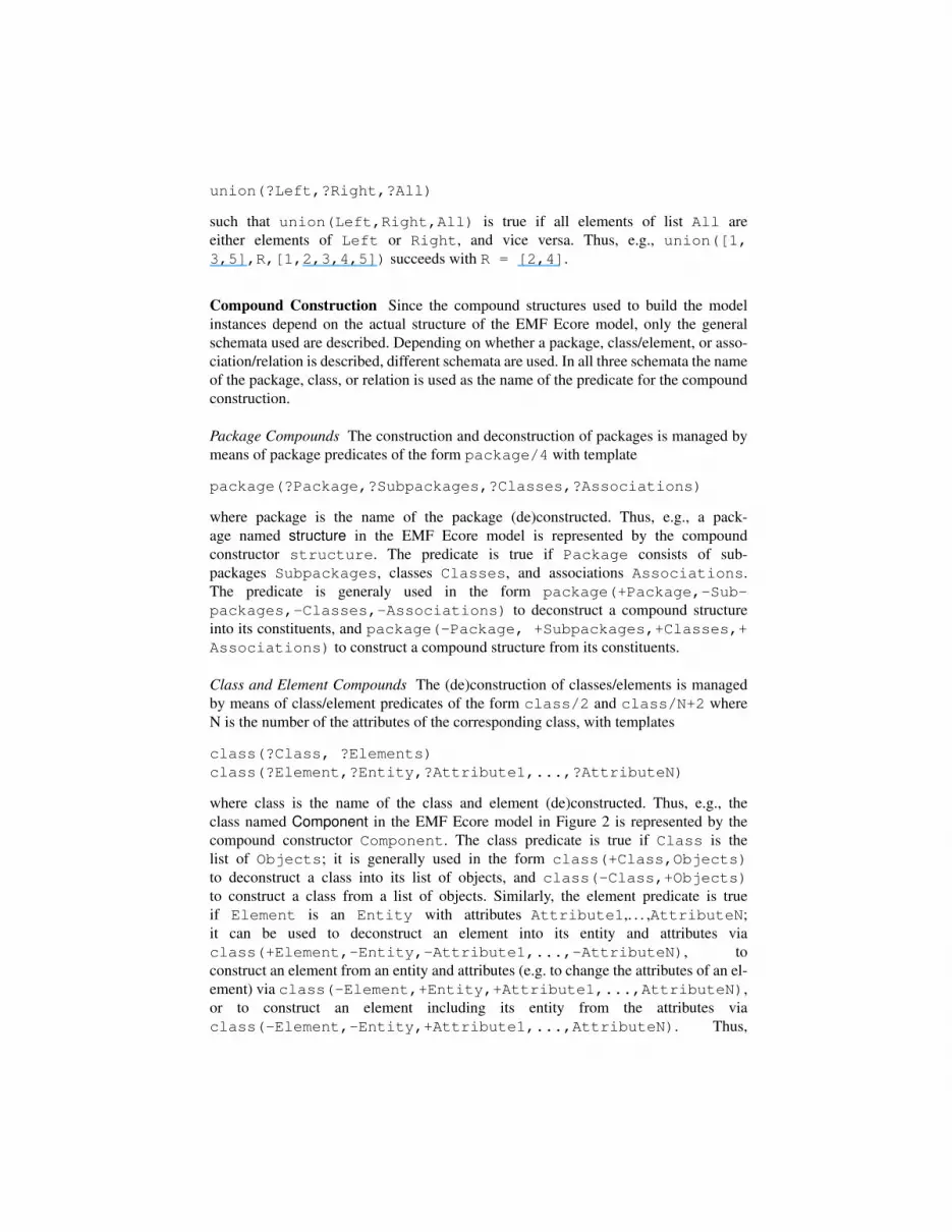
The conceptual model and its structure defined in Section 2 was introduced to definetransformations of system models as shown in Figure 1, in order to improve the develop-ment process by mechanized design steps. A typical transformation step is the pushingdown of a component into a container component, making it a subcomponent of thatcontainer. Figure 3 shows the result of such a transformation pushing down componentComp of the system in Figure 1 into the container Contr. Besides changing the supercomponent of Comp from Context to Contr, furthermore channel chains (e.g., InLeft,

InRight) from a port of a subcomponent (e.g., Sub) of the container (e.g., InSrc) via anintermediate port of the container (e.g., InMid) to a port of Comp (e.g., InDst) have tobe shortened by eliminating the first channel and the intermediate port; symmetrically,a channel (e.g. OutLeft) from a port of the component (e.g., OutSrc) to a port (e.g.,OutDst) of a sibling (e.g., Sib) of the component have to be extended by an additionalchannel (e.g., OutRight) and an intermediate port (e.g., OutMid).
In a relational approach to the description of model transformations, such a transfor-mation is described as a relation between the model prior to the transformation (e.g., asgiven in Figure 1) and the model after the transformation (e.g., as given in Figure 3). Inthis section, the basic principles of describing transformations as relations are describedin Subsection 3.1, while Subsection 3.2 shows how rules similar to graph grammars canbe used as a specific description technique.
3.1 Transformations as Relations
In case of the push-down operation, the relation describing the transformation has theinterface
pushpull(PreModel,Comp,Contr,PostModel)
with parameter PreModel for the model before the transformation, parameterPostModel for the model after the transformation, and parameters Comp and Contrfor the component of the model to be pushed down and the component to containthe pushed-down component, respectively. In the relational approach presented here,a transformation is basically described by breaking down the pre-model into its con-stituents and build up the post-model from those constituents using the relations fromSection 2, potentially adding or removing elements and relations.
With PreModel taken from the conceptual domain described in Figure 2 and pack-aged in a single package structure with no sub-packages, it can be decomposed in con-tained classes (e.g., Port and Channel) and associations (e.g., portComp and srcPort)via
structure(PreModel,PrePackages,PreClass,PreAssoc),union([PreComps,PrePorts,PreChans],[],PreClass),
channel(PreChans,InChans),port(PrePorts,InPorts),union([PrePortComp,PreSrcPort),[],PreAssoc),
portComp(PrePortComp,InPortComp),srcPort(PreSrcPort,InSrcPort)
In the same fashion, PostModel can be composed. Besides using the basic relations toconstruct and deconstruct models (and add or remove elements and relations, as shownin the next subsection), new relations can be defined to support a modular descriptionof transformation, decomposing rules into sub-rules. E.g., in the pushpull relation,the transformation can be decomposed into the reallocation of the component and therearrangement of the channel-chains; for the latter, then a sub-rule splitmerge isintroduced, as explained in the next subsection.
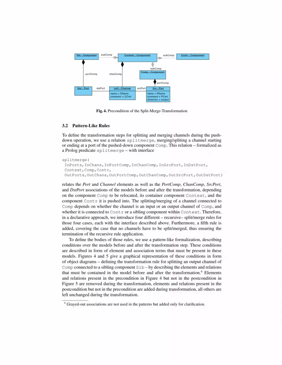
Fig. 4. Precondition of the Split-Merge-Transformation
3.2 Pattern-Like Rules
To define the transformation steps for splitting and merging channels during the push-down operation, we use a relation splitmerge, merging/spliting a channel startingor ending at a port of the pushed-down component Comp. This relation – formalized asa Prolog predicate splitmerge – with interface
splitmerge(InPorts,InChans,InPortComp,InChanComp,InSrcPort,InDstPort,Context,Comp,Contr,OutPorts,OutChans,OutPortComp,OutChanComp,OutSrcPort,OutDstPort)
relates the Port and Channel elements as well as the PortComp, ChanComp, SrcPort,and DstPort associations of the models before and after the transformation, dependingon the component Comp to be relocated, its container component Context, and thecomponent Contr it is pushed into. The splitting/merging of a channel connected toComp depends on whether the channel is an input or an output channel of Comp, andwhether it is connected to Contr or a sibling component within Context. Therefore,in a declarative approach, we introduce four different – recursive– split/merge rules forthose four cases, each with the interface described above. Furthermore, a fifth rule isadded, covering the case that no channels have to be split/merged, thus ensuring thetermination of the recursive rule application.
To define the bodies of those rules, we use a pattern-like formalization, describingconditions over the models before and after the transformation step. These conditionsare described in form of element and association terms that must be present in thesemodels. Figures 4 and 5 give a graphical representation of these conditions in formof object diagrams – defining the transformation rule for splitting an output channel ofComp connected to a sibling component Sib – by describing the elements and relationsthat must be contained in the model before and after the transformation.4 Elementsand relations present in the precondition in Figure 4 but not in the postcondition inFigure 5 are removed during the transformation, elements and relations present in thepostcondition but not in the precondition are added during transformation, all others areleft unchanged during the transformation.
4 Grayed-out associations are not used in the patterns but added only for clarification.

Fig. 5. Postcondition of the Split-Merge-Transformation
Figure 4 states that before the transformation, Comp and Sib each have an associ-ated port Src and Dst, connected by channel Left, owned by Context. Figure 5 statesthat after the transformation, Comp is a subcomponent of Contr; furthermore, a portMid of component Contr must be present with the same attributes as Src, as well asa channel Right owned by Contr, with Left connecting Mid and Dst, and Rightconnecting Src and Mid.
To define this transformation, the conceptual model and its structured representationintroduced in Section 2 are used. Figure 6 shows the relational rule-based formalizationof this step; underlined relations correspond to the construction predicates from Section2.5 Note that this single rule combines the information of both graphical representationsin Figures 4 and 5; it furthermore also describes the order in which individual split-merge steps are chained together in a modular fashion. Within a graphical specificationof transformations, this later step cannot by described using those object-diagram-likediagrams at all. Therefore, graphical specifications require to use additional forms ofdiagrams, e.g., state-transition diagrams as used in [3], [4], or [5]. Unlike those, the ap-proach here allows to simply pass information in form of parameters from the executionof one rule to the next.
Lines 1 to 7 describe the conditions before the transformation, and thus formalizethe conditions described in Figure 4. Similarly, lines 11 to 18 describe the conditionsafter the transformation, thus formalizing the conditions described in Figure 5. Sincethe relational rule-based approach allows the use of recursively defined transformations,lines 8 to 10 introduce further transformation steps after removing the elements of theprecondition and before introducing the elements of the postcondition. Lines 1 to 7 usea common scheme to ensure the validity of the conditions for the elements and relationstaking part in the transformation: for each element and relation
– its occurrence in the list of corresponding elements/relations of the pre-model isestablished via the union constructor
– its contained entities and attributes within the pre-model are established via its cor-responding functor
5 For ease of reading, functors for element relations from Figure 2 with capitalized identifierslike Port or Channel are written as port or channel; in the actual application, the versions’Port’ and ’Channel’ are used.

1 union([SrcComp,DistSib],InPortComp,PrePortComp),2 portComp(SrcComp,Src,Comp),portComp(DstSib,Dst,Sib),3 union([LeftSrc],InSrcPort,PreSrcPort),srcPort(LeftSrc,Left,Src),4 union([LeftDst],InDstPort,PreDstPort),dstPort(LeftDst,Left,Dst),5 union([SrcPort],InPorts,PrePorts),port(SrcPort,Src,PName,PComment,output),6 union([LeftChan],InChans,PreChans),channel(LeftChan,Left,CName,CComment),7 union([LeftCxt],InChanComp,PreChanComp),chanComp(LeftCxt,Left,Context),8 splitmerge(InPorts,InChans,InPortComp,InChanComp,InSrcPort,InDstPort,9 Context,Comp,Contr,
10 OutPorts,OutChans,OutPortComp,OutChanComp,OutSrcPort,OutDstPort),11 chanComp(RightCnt,Right,Contr),union([LeftCxt,RightCnt],OutChanComp,PostChanComp),12 channel(RightChan,Right,CName,CComment),union([LeftChan,RightChan],OutChans,PostChans),13 port(MidPort,Mid,PName,PComment,output),union([SrcPort,MidPort,DstPort],OutPorts,PostPorts),14 dstPort(LeftMid,Left,Mid),dstPort(RightDst,Right,Dst),15 union([LeftMid,RightDst],OutDstPort,PostDstPort).16 srcPort(LeftSrc,Left,Src),srcPort(RightMid,Right,Mid),17 union([LeftSrc,RightMid],OutSrcPort,PostSrcPort),18 portComp(MidCnt,Mid,Contr),union([SrcComp,MidCnt,DstSib],OutPortComp,PostPortComp).
Fig. 6. A Split-Merge Rule for Sibling Channels
Thus, e.g., line 5 ensures the existence of an port element SrcPort consisting of portentity Src and attributes PName, PComment, and output, while line 7 ensures theexistence of a portComp relation SrcComp linking port Src to component Comp.The union constructor is not only used to establish the occurrence of elements andrelations in the pre-model; it is furthermore used to remove the identified elements andrelations from the pre-model. E.g., line 5 also removes the port element SrcPort fromthe port class PrePorts of the pre-model before assigning the remainder to the portclass InPorts, which is used in line 8 as input parameter of the recursive applicationof the splitmerge relation.
The scheme of lines 1 to 7 is used in symmetrical fashion in lines 11 to 18 to ensurethe validity of the conditions for the elements and relations of the post-model. Thus,e.g., line 13 ensures that a port element MidPort, consisting of port entity Mid andattribute values defined by the variables PName and PComment, as well as the constantoutput of enumeration Direction, exists within port class PostPorts; similarly, line11 ensures that a chanComp relation RightCnt, linking channel Right to componentContr, exists within compChan association PostChanComp, together with relationLeftCtx.
In a purely relational interpretation of declarative transformations, the ordering ofthe relations used to define a rule is irrelevant. Thus, using that kind of interpreta-tion, a transformation can be applied in two ways. E.g., in case of the pushpull-transformation, the relation can be used to push-down a component into its containerby assigning the pre- and post-models to the PreModel and PostModel parameter,respectively. Symmetrically it can be used to pull-up a component from a container byassigning the pre-model to the PostModel and the post-model to the PreModel pa-rameter. As however the Prolog engine interpreting the declarative transformation rules
1 union([SrcComp,MidContr,DstSib],InPortComp,PrePortComp),portComp(SrcComp,Src,Comp),2 portComp(MidContr,Mid,Contr),portComp(DstSib,Dst,Sib),3 union([RightSrc,LeftMid],InSrcPort,PreSrcPort),4 srcPort(RightSrc,Right,Src),srcPort(LeftMid,Left,Mid),5 union([RightMid,LeftDst],InDstPort,PreDstPort),6 dstPort(RightMid,Right,Mid),dstPort(LeftDst,Left,Dst),7 union([SrcPort,MidPort,DstPort],InPorts,PrePorts),port(SrcPort,Src, , ,output),8 port(MidPort,Mid, , ,output),9 union([LeftChan,RightChan],InChans,PreChans),
10 channel(LeftChan,Left, , ),channel(RightChan,Right, , ),11 union([LeftCxt,RightCnt],InChanComp,PreChanComp),chanComp(LeftCxt,Left,Context),12 chanComp(RightCnt,Right,Contr),13 splitmerge(InPorts,InChans,InPortComp,InChanComp,InSrcPort,InDstPort,14 Context,Comp,Contr,15 OutPorts,OutChans,OutPortComp,OutChanComp,OutSrcPort,OutDstPort),16 union([LeftCxt],OutChanComp,PostChanComp),17 union([LeftChan],OutChans,PostChans),18 union([SrcPort],OutPorts,PostPorts),19 union([LeftDst],OutDstPort,PostDstPort),20 srcPort(LeftSrc,Left,Src),union([LeftSrc],OutSrcPort,PostSrcPort),21 union([SrcComp,DstSib],OutPortComp,PostPortComp).
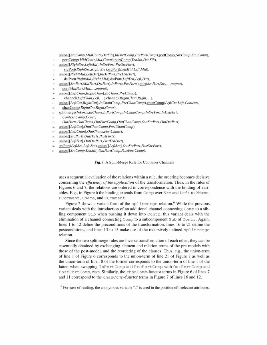
Fig. 7. A Split-Merge Rule for Container Channels
uses a sequential evaluation of the relations within a rule, the ordering becomes decisiveconcerning the efficiency of the application of the transformation. Thus, in the rules ofFigures 6 and 7, the relations are ordered in correspondence with the binding of vari-ables. E.g., in Figure 6 the binding extends from Comp over Src and Left to PName,PComment, CName, and CComment.
Figure 7 shows a variant form of the splitmerge relation.6 While the previousvariant deals with the introduction of an additional channel connecting Comp to a sib-ling component Sib when pushing it down into Contr, this variant deals with theelimination of a channel connecting Comp to a subcomponent Sub of Contr. Again,lines 1 to 12 define the preconditions of the transformation, lines 16 to 21 define thepostconditions, and lines 13 to 15 make use of the recursively defined splitmergerelation.
Since the two splitmerge rules are inverse transformation of each other, they can beessentially obtained by exchanging element and relation terms of the pre-models withthose of the post-model, and the reordering of the clauses. Thus, e.g., the union-termof line 1 of Figure 6 corresponds to the union-term of line 21 of Figure 7 as well asthe union-term of line 18 of the former corresponds to the union-term of line 1 of thelatter, when swapping InPortComp and PrePortComp with OutPortComp andPostPortComp, resp. Similarly, the chanComp-functor terms in Figure 6 of lines 7and 11 correspond to the chanComp-functor terms in Figure 7 of lines 16 and 12.
6 For ease of reading, the anonymous variable “ ” is used in the position of irrelevant attributes.

Fig. 8. Support for Defining and Applying Model Transformations
4 Tool Support
The presented approach has been implemented as an Eclipse plugin using the tuPrologengine [16]. While currently intended for the transformation of AutoFOCUS models,due to its generic nature it supports the transformation of EMF Ecore [14] models ingeneral. As illustrated, the implemented plug-in provides tool support both for the def-inition of transformation and the transformation execution.
4.1 Transformation Definition
From the point of view of the designer of the transformation, its description consists of
– the declaration of the Prolog clauses forming the rules of the transformation rela-tion,
– the declaration of the root clause of the rule set, and– the declaration of the list of parameters of the root clause including their type (i.e.,
input model, output model, Boolean, Integer, String, or model entity),
provided in form of an XML file.Since transformations depend on the structure of the model before and after the
transformation, and transformations are intended to be designed at run-time of the Au-toFOCUS framework, the designer of the model is provided with information on thestructure of the conceptual model at runtime. As shown in the left-hand side of Figure 8,for that purpose, a model structure browser describing the term structure is provided aspart of the online help documentation, based on the EMF Ecore reflection mechanism.By providing the term structure rather than the ECore structure, the declaration of thetransformation rules is simplified.
The term structure is represented by providing the tree of relations used to constructthe term as shown in Table 1; relations are E.g., as shown in Figure 8, the structurepackage term can be broken up into lists of subpackage, class, and association termsusing the functor structure; similarly, the channel element term can be broken upinto the attributes name and comment using the functor Channel.

4.2 Transformation Execution
The transformation is provided in form of a transformation wizard, available for Auto-FOCUS projects and guiding the user through the three transformation steps
1. Selecting the transformation declaration2. Defining the parameters of the transformation3. Declaring the result model
plus an optional debug step. In the first step, the file containing the transformation de-scription is selected. In the second step, as shown in the right-hand side of Figure 8,the parameters of the transformation rule – without the pre- and post model parameter– are defined. In the case of the push-pull transformation, suitable component entitiesmust be assigned to the parameters Comp and Container for the to-be-pushed-downcomponent and the container component. To define entity parameters, a model browseris provided to select suitable elements from the pre-model. After declaring, i.e., namingand locating, a model to contain the result of the transformation in the third step, thetransformation can be executed. Optionally, the execution can be traced for debuggingpurposes, to analyse each application of each transformation rule.
5 Conclusion and Outlook
The AutoFOCUS transformation framework supports the transformation of EMF Ecoremodels using a declarative relational style. The framework provides a term-structurerepresentation of the EMF Ecore description and offers a Prolog rule-based interpre-tation, and thus allows a simple, precise, and modular specification of transformationrelations on the problem- rather than the implementation-level. By taking the opera-tional aspects into consideration, the purely relational declarative form of specificationcan be tuned to ensure an efficient execution. Naturally, the abstraction from the objectlattice of an EMF Ecore model to a model term of the conceptual model leads to someloss of efficiency – with the dereferencing of unique associations as the most promi-nent case (constant vs. linear complexity). However, in our experiments, the approachis practically feasible for real-world sized models (e.g, refactoring models consisting ofmore than 3000 elements and more than 5000 relations within a few seconds).
While the implementation has demonstrated the applicability of the approach, fora more thorough analysis a larger comparative case study considering the approachesmentioned in Subsection 1.1 is necessary, especially considered usability aspects likecomplexity of transformation specification and efficiency of executions. Furthermore,since the rule-based approach allows very general forms of application, other forms ofapplication (e.g., view generation, transformations involving user interactions) will beintegrated to extend the current implementation.
Finally, the current version of the framework covered those features of EMF thatare sufficient to handle the complete AutoFOCUS conceptual model (including, e.g.,data types and state machines). For other meta models like the UML 2.1 additionalfeatures (sorted) multi-valued attributes must be included, which – due to the structure-and list-based formalization – can be readily integrated in the current formalization.

Acknowledgements
It is a pleasure to thank Florian Holzl, Benjamin Hummel, and Elmar Jurgens for theirhelp in getting the implementation running, and Florian Holzl and Peter Braun for thediscussion on rule-based transformation.
References
[1] Fowler, M., Scott, K.: UML Distilled. Addison-Wesley (1997)[2] Klar, F., Konigs, A., Schurr, A.: Model transformation in the large. In: ESEC/FSE’07,
ACM Press (2007)[3] Varro, D., Pataricza, A.: Generic and meta-transformations for model transformation en-
gineering. In Baar, T., Strohmeier, A., Moreira, A., Mellor, S., eds.: UML 2004, Springer(2004) LNCS 3273.
[4] Grunske, L., Geiger, L., Lawley, M.: A graphical specification of model transformationswith triple graph grammars. In Hartman, A., Kreische, D., eds.: Model Driven Architecture.Volume 3748 of LNCS., Springer (2005)
[5] Sprinkle, J., Agrawal, A., Levendovszky, T.: Domain Model Translation Using GraphTransformations. In: ECBS2003 - Engineering of Computer-Based Systems. (2003)
[6] Rozenberg, G., ed.: Handbook on Graph Grammars and Computing by Graph Transforma-tion: Foundations. World Scientific (1997)
[7] OMG: Initial submisison to the MOF 2.0 Q/V/T RFP. Technical Report ad/03-03-27,Object Management Group (OMG), http://www.omg.org (2003)
[8] Jouault, F., Allilaire, F., Bezivin, J., Kurtev, I., Valduriez, P.: ATL: a QVT-like transforma-tion language. In: OOPSLA ’06, ACM Press (2006) 719–720
[9] Gerber, A., Lawley, M., Raymond, K., Steel, J., Wood, A.: Transformation: The MissingLink of MDA. In: Graph Transformation. Volume 2505 of LNCS. (2002)
[10] Lawley, M., Steel, J.: Practical declarative model transformation with tefkat. In Bruel,J.M., ed.: MoDELS Satellite Events. Volume 3844 of LNCS., Springer (2006)
[11] White, J., Schmidt, D.C., Nechypurenko, A., Wuchner, E.: Introduction to the genericeclipse modelling system
[12] Varro, G., Friedl, K., Varro, D.: Implementing a graph transformation engine in relationaldatabases. Software and Systems Modeling 5 (2006)
[13] Schatz, B., Huber, F.: Integrating formal description techniques. In Wing, J.M., Woodcock,J., Davies, J., eds.: FM’99, Springer Verlag (1999) LNCS 1709.
[14] Steinberg, D., Budinsky, F., Paternostro, M., Merks, E.: EMF: Eclipse Modeling Frame-work. Addison Wesley Professional (2007) Second Edition.
[15] Jones, S.P.: Haskell 98 language and libraries: the Revised Report. Cambridge UniversityPress (2003)
[16] Denti, E., Omicini, A., Ricci, A.: Multi-paradigm Java-Prolog integration in tuProlog.Science of Computer Programming 57(2) (2005) 217–250