form finding for complex structures using evolutionary structural optimization method
TRANSCRIPT
Form finding for complex structuresusing evolutionary structuraloptimization method
Y.M. Xie, P. Felicetti and J.W. Tang, School of Civil and Chemical
Engineering, RMIT University, GPO Box 2476V, Melbourne 3001,
Australia
M.C. Burry, Spatial Information Architecture Laboratory, School of
Architecture and Design, RMIT University, GPO Box 2476V,
Melbourne 3001, Australia
This paper demonstrates the effectiveness of the Evolutionary Structural
Optimization (ESO) method in developing conceptual forms of complex
structures. A three-dimensional ESO computer code has been developed
which is capable of analysing and optimizing structures of any geometries
and loading conditions. The technique has been tested on a wide range of
examples. In this paper the ESO method is compared to the hanging
model approach used by the architect Antonio Gaudı́.
� 2004 Elsevier Ltd. All rights reserved.
Keywords: artificial evolution, design technique, engineering design,
computer aided design
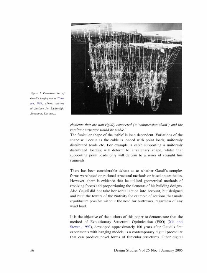
The renowned architect Antonio Gaudı́ (1852e1926) developed
a number of his architectural designs through the use of
funicular structural systemsdthe so called hanging models.
There has been extensive research on the hanging model approach. One
example is shown in Figure 1 below (Tomlow, 1989).
To describe the concept of funicular structural systems, it is worth
quoting a paragraph from Schodek (1992):
‘A cable subjected to external loads will obviously deform in a way
dependent on the magnitude and location of the external forces. The form
acquired is often called the funicular shape of the cable (the term
funicular is derived from the Latin word for ‘rope’). Only tension forces
will be developed in the cable. Inverting the structural form obtained will
yield a new structure that is exactly analogous to the cable structure
except that compression rather than tension forces are developed.
Theoretically, the shape found could be constructed of simply stacked
www.elsevier.com/locate/destud
0142-694X $ - see front matter Design Studies 26 (2005) 55e72
doi:10.1016/j.destud.2004.04.001 55� 2004 Elsevier Ltd All rights reserved Printed in Great Britain
elements that are non rigidly connected (a ‘compression chain’) and the
resultant structure would be stable.’
The funicular shape of the ‘cable’ is load dependent. Variations of the
shape will occur as the cable is loaded with point loads, uniformly
distributed loads etc. For example, a cable supporting a uniformly
distributed loading will deform to a catenary shape, whilst that
supporting point loads only will deform to a series of straight line
segments.
There has been considerable debate as to whether Gaudı́’s complex
forms were based on rational structural methods or based on aesthetics.
However, there is evidence that he utilized geometrical methods of
resolving forces and proportioning the elements of his building designs.
Also Gaudı́ did not take horizontal action into account, but designed
and built the towers of the Nativity for example of sections that made
equilibrium possible without the need for buttresses, regardless of any
wind load.
It is the objective of the authors of this paper to demonstrate that the
method of Evolutionary Structural Optimization (ESO) (Xie and
Steven, 1997), developed approximately 100 years after Gaudı́’s first
experiments with hanging models, is a contemporary digital procedure
that can produce novel forms of funicular structures. Other digital
Figure 1 Reconstruction of
Gaudı́’s hanging model (Tom-
low, 1989) (Photo courtesy
of Institute for Lightweight
Structures, Stuttgart.)
56 Design Studies Vol 26 No. 1 January 2005
Form finding for comp
methods of structural topological optimization, such as homogenization
method (Bendsøe and Kikuchi, 1988; Suzuki and Kikuchi, 1991), can
also be used for form finding of structures. Comparatively, ESOmethod
is simple in concept and effective in application. The authors of this
paper modified the original ESO method pioneered by Xie and Steven
during the early 1990s. The original ESO method consisted of removing
redundant material at each iteration using von Mises stress criterion.
The modifications are enhancements to the method. Instead of von
Mises criterion, there are now options of optimizing structures such that
all remaining elements are in compression, or optimizing such that all
remaining elements are in tension.
1 ESO methodThe automated procedure of ESO is such that each iteration consists of
a finite element analysis (to determine stresses) and then removing
inefficient/inappropriate elements. The process is summarized as
follows:
(1) Execute finite element analysis and output element stresses;
(2) Define element stress se using different design criteria
se ¼
sVM; von Mises criterion
s11Cs22Cs33; tension criterion
�s11 �s22 �s33; compression criterion
8>><>>:
ð1Þ
where sVM is element von Mises stress, s11, s22 and s33 are element
principle stresses, and s11Rs22Rs33.
(3) Sort all elements in design domain by se in descending order. Then
the maximum stress is
smax ¼ seð1Þ ð2Þ
(4) Find the first threshold stress s1th according to volume removal rate
VR. If n � NEð1� VRÞ, then element n is the threshold element
from the total number of elements NE according to VR, and
s1th ¼ seðnÞ ð3Þ
(5) Find the second threshold stress s2th according to rejection ratio
RR.
lex structures using evolutionary structural optimization method 57
s2th ¼ smax �RR ð4Þ
(6) The actual threshold stress that satisfies both RR and VR is
sth ¼minðs1th;s
2thÞ ð5Þ
(7) Delete elements if se!sth;
(8) Repeat steps (1)e(7) until the maximum iteration number is
reached, or a given percentage of volume has been removed from
the ground structure.
For example, in order to design compression-only structures, the
tension-dominant elements are improper for the design condition, and
therefore are first removed. The elements under compression but at low
stress levels are considered as inefficient, and should be gradually
deleted as well. The cycle (iteration) of finite element analysis and
element removal is repeated many times until a desired structural form
is obtained. Typically, the number of iterations ranges from 10 to 100.
2 ExamplesSeveral examples of 2D and 3D continua are presented.
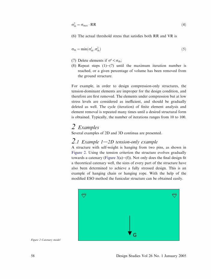
2.1 Example 1d2D tension-only exampleA structure with self-weight is hanging from two pins, as shown in
Figure 2. Using the tension criterion the structure evolves gradually
towards a catenary (Figure 3(a)e(f)). Not only does the final design fit
a theoretical catenary well, the sizes of every part of the structure have
also been determined to achieve a fully stressed design. This is an
example of hanging chain or hanging rope. With the help of the
modified ESO method the funicular structure can be obtained easily.
Figure 2 Catenary model
58 Design Studies Vol 26 No. 1 January 2005
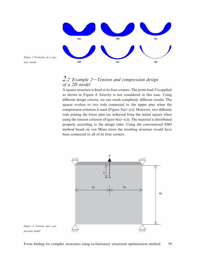
2.2 Example 2dTension and compression designof a 2D modelA square structure is fixed at its four corners. The point load F is applied
as shown in Figure 4. Gravity is not considered in this case. Using
different design criteria, we can reach completely different results. The
square evolves to two rods connected to the upper pins when the
compression criterion is used (Figure 5(a)e(c)). However, two different
rods joining the lower pins are achieved from the initial square when
using the tension criterion (Figure 6(a)e(c)). The material is distributed
properly according to the design rules. Using the conventional ESO
method based on von Mises stress the resulting structure would have
been connected to all of its four corners.
Figure 3 Evolution of a cate-
nary model
a
2a 2a
F
4a
Figure 4 Tension and com-
pression model
Form finding for complex structures using evolutionary structural optimization method 59
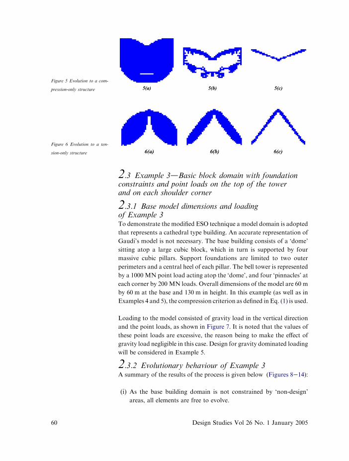
2.3 Example 3dBasic block domain with foundationconstraints and point loads on the top of the towerand on each shoulder corner
2.3.1 Base model dimensions and loadingof Example 3To demonstrate the modified ESO technique a model domain is adopted
that represents a cathedral type building. An accurate representation of
Gaudı́’s model is not necessary. The base building consists of a ‘dome’
sitting atop a large cubic block, which in turn is supported by four
massive cubic pillars. Support foundations are limited to two outer
perimeters and a central heel of each pillar. The bell tower is represented
by a 1000 MN point load acting atop the ‘dome’, and four ‘pinnacles’ at
each corner by 200 MN loads. Overall dimensions of the model are 60 m
by 60 m at the base and 130 m in height. In this example (as well as in
Examples 4 and 5), the compression criterion as defined in Eq. (1) is used.
Loading to the model consisted of gravity load in the vertical direction
and the point loads, as shown in Figure 7. It is noted that the values of
these point loads are excessive, the reason being to make the effect of
gravity load negligible in this case. Design for gravity dominated loading
will be considered in Example 5.
2.3.2 Evolutionary behaviour of Example 3A summary of the results of the process is given below (Figures 8e14):
(i) As the base building domain is not constrained by ‘non-design’
areas, all elements are free to evolve.
Figure 5 Evolution to a com-
pression-only structure
Figure 6 Evolution to a ten-
sion-only structure
60 Design Studies Vol 26 No. 1 January 2005
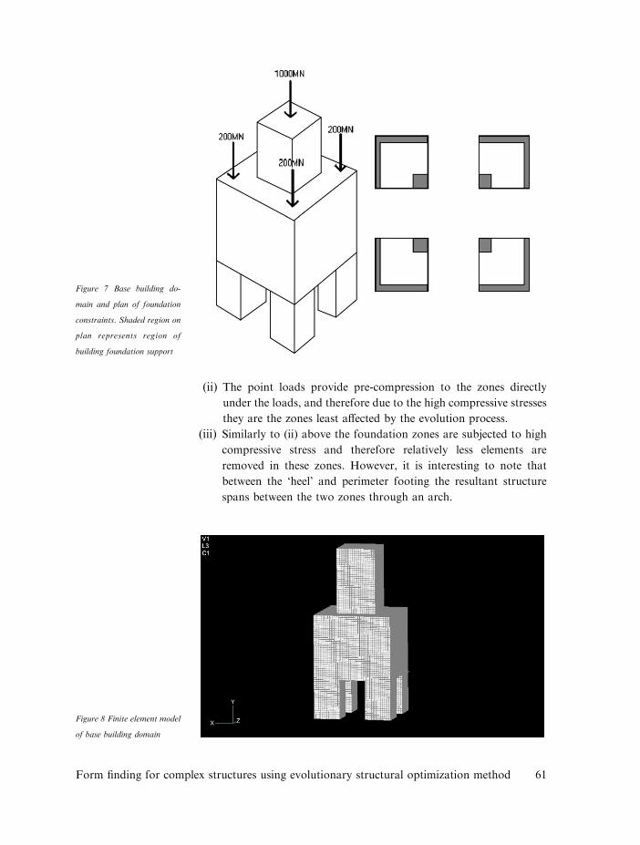
(ii) The point loads provide pre-compression to the zones directly
under the loads, and therefore due to the high compressive stresses
they are the zones least affected by the evolution process.
(iii) Similarly to (ii) above the foundation zones are subjected to high
compressive stress and therefore relatively less elements are
removed in these zones. However, it is interesting to note that
between the ‘heel’ and perimeter footing the resultant structure
spans between the two zones through an arch.
Figure 7 Base building do-
main and plan of foundation
constraints. Shaded region on
plan represents region of
building foundation support
Figure 8 Finite element model
of base building domain
Form finding for complex structures using evolutionary structural optimization method 61
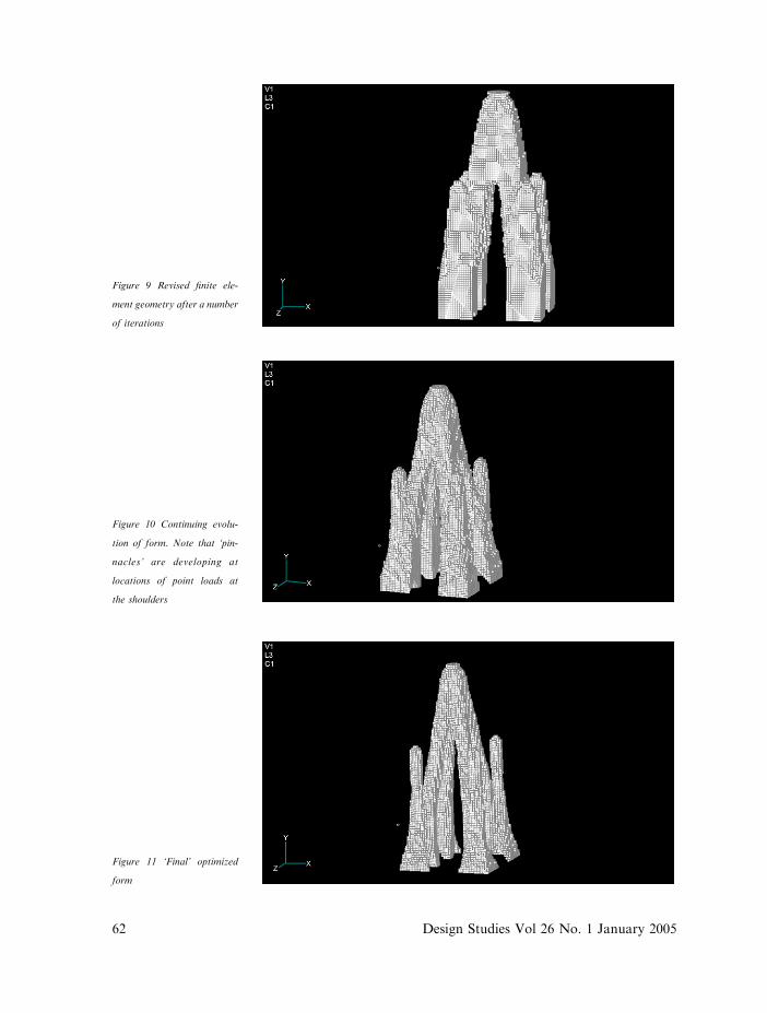
Figure 9 Revised finite ele-
ment geometry after a number
of iterations
Figure 10 Continuing evolu-
tion of form. Note that ‘pin-
nacles’ are developing at
locations of point loads at
the shoulders
Figure 11 ‘Final’ optimized
form
62 Design Studies Vol 26 No. 1 January 2005
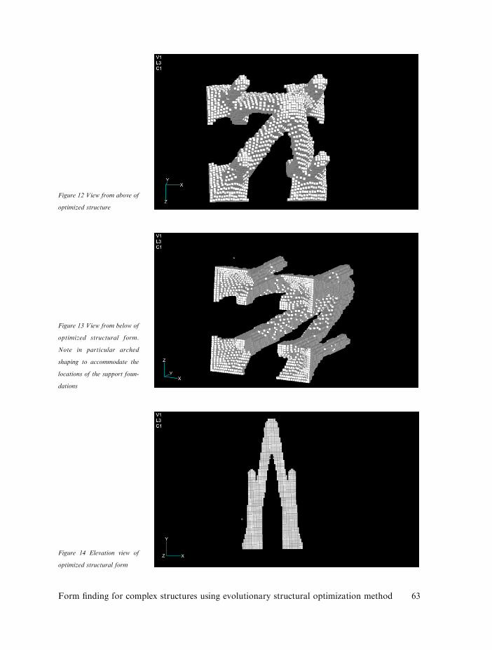
Figure 12 View from above of
optimized structure
Figure 13 View from below of
optimized structural form.
Note in particular arched
shaping to accommodate the
locations of the support foun-
dations
Figure 14 Elevation view of
optimized structural form
Form finding for complex structures using evolutionary structural optimization method 63
(iv) Extending the iteration process to that of Figure 11 results in
a structure that is dominated by resolving the forces of the initial
point loads to the foundations. The base of the resultant structure
splays towards the base.
(v) The resultant tower form is a tower of (almost) uniform
compressive stress.
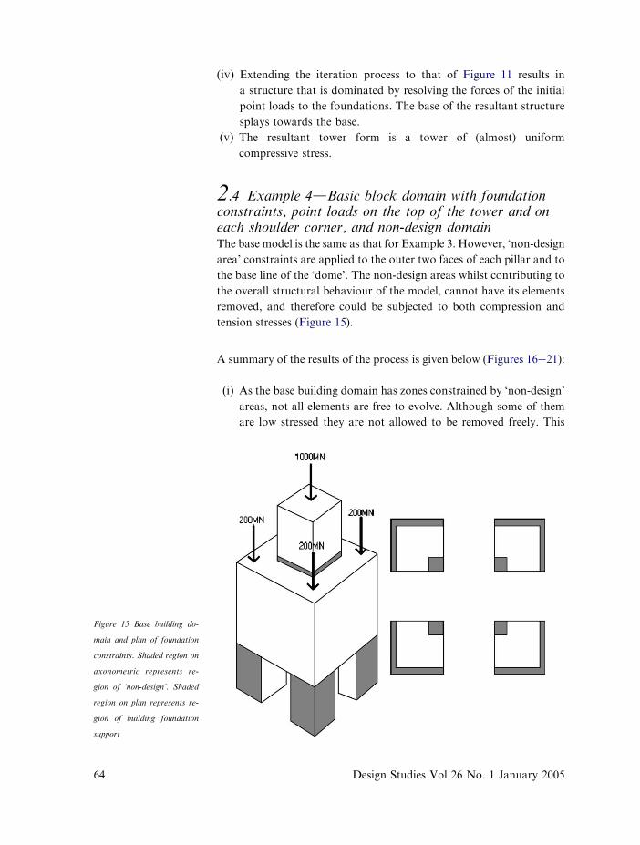
2.4 Example 4dBasic block domain with foundationconstraints, point loads on the top of the tower and oneach shoulder corner, and non-design domainThe base model is the same as that for Example 3. However, ‘non-design
area’ constraints are applied to the outer two faces of each pillar and to
the base line of the ‘dome’. The non-design areas whilst contributing to
the overall structural behaviour of the model, cannot have its elements
removed, and therefore could be subjected to both compression and
tension stresses (Figure 15).
A summary of the results of the process is given below (Figures 16e21):
(i) As the base building domain has zones constrained by ‘non-design’
areas, not all elements are free to evolve. Although some of them
are low stressed they are not allowed to be removed freely. This
Figure 15 Base building do-
main and plan of foundation
constraints. Shaded region on
axonometric represents re-
gion of ‘non-design’. Shaded
region on plan represents re-
gion of building foundation
support
64 Design Studies Vol 26 No. 1 January 2005
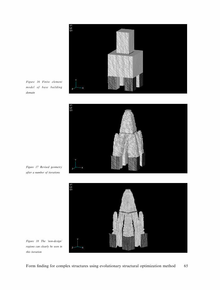
Figure 16 Finite element
model of base building
domain
Figure 17 Revised geometry
after a number of iterations
Figure 18 The ‘non-design’
regions can clearly be seen in
this iteration
Form finding for complex structures using evolutionary structural optimization method 65
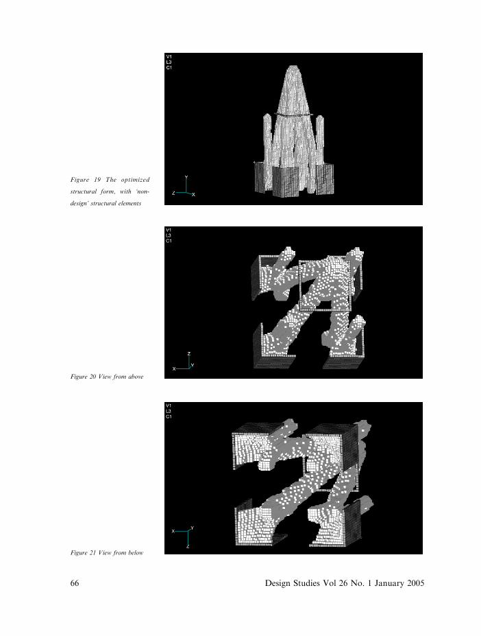
Figure 19 The optimized
structural form, with ‘non-
design’ structural elements
Figure 20 View from above
Figure 21 View from below
66 Design Studies Vol 26 No. 1 January 2005
results in a different form to that of Example 3. In this example the
non-design areas act more as non-structural attachment. But in
some cases the existence of non-design areas could change the
route of structural evolution; therefore the ‘non-design’ could
make the final topology quite different.
(ii) Similar to Example 3, the point loads provided pre-compression to
the zones directly under the loads, and therefore due to the high
compressive stresses they are the zones least affected by the
evolution process.
(iii) Similarly to Example 3, the foundation zones are subjected to high
compressive stress and therefore relatively fewer elements are
removed in these zones. However, it is interesting to note that
between the ‘heel’ and perimeter footing the resultant structure
spans between the two zones through an arch.
(iv) The resultant tower form is a tower of (almost) uniform
compressive stress (except for the non-design areas).
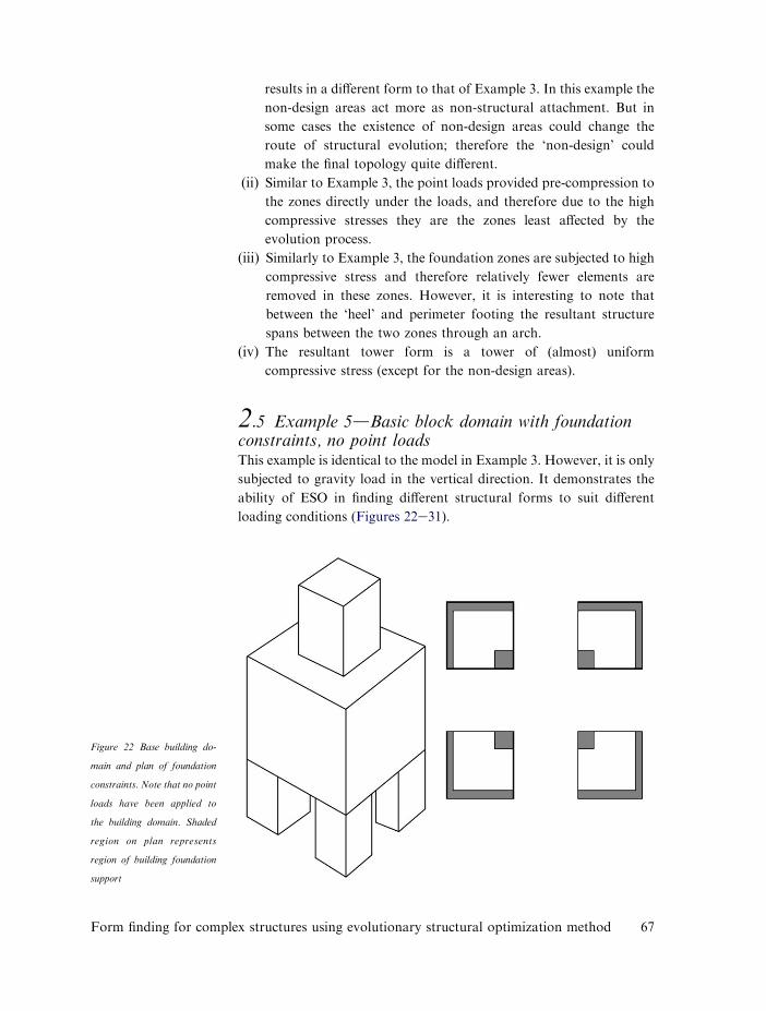
2.5 Example 5dBasic block domain with foundationconstraints, no point loadsThis example is identical to the model in Example 3. However, it is only
subjected to gravity load in the vertical direction. It demonstrates the
ability of ESO in finding different structural forms to suit different
loading conditions (Figures 22e31).
Figure 22 Base building do-
main and plan of foundation
constraints. Note that no point
loads have been applied to
the building domain. Shaded
region on plan represents
region of building foundation
support
Form finding for complex structures using evolutionary structural optimization method 67
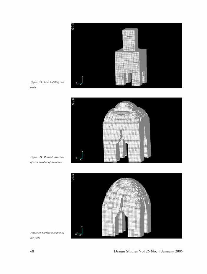
Figure 23 Base building do-
main
Figure 24 Revised structure
after a number of iterations
Figure 25 Further evolution of
the form
68 Design Studies Vol 26 No. 1 January 2005
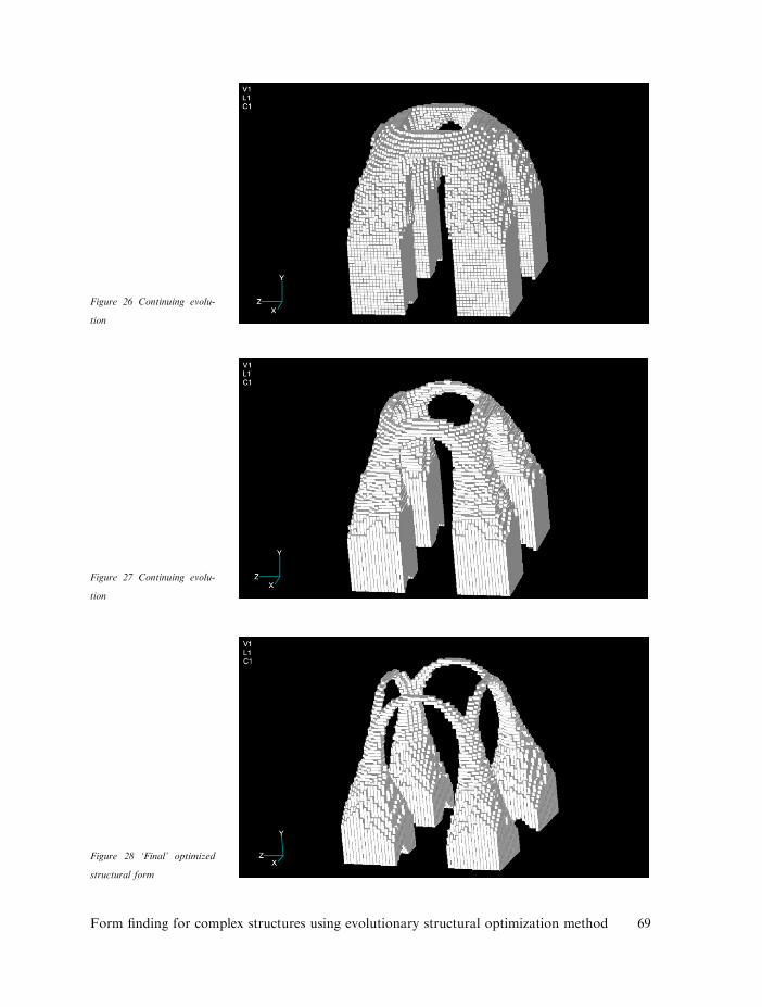
Figure 26 Continuing evolu-
tion
Figure 27 Continuing evolu-
tion
Figure 28 ‘Final’ optimized
structural form
Form finding for complex structures using evolutionary structural optimization method 69
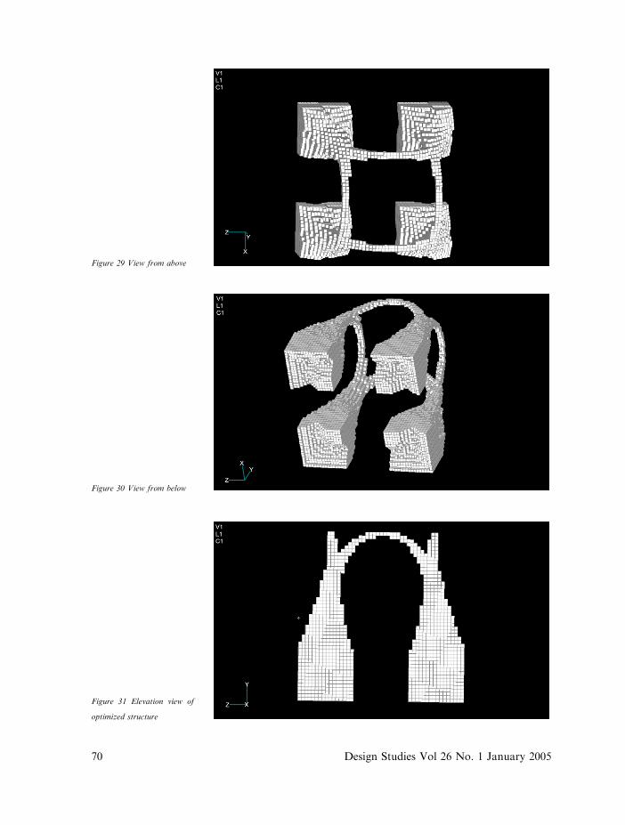
Figure 29 View from above
Figure 30 View from below
Figure 31 Elevation view of
optimized structure
70 Design Studies Vol 26 No. 1 January 2005
2.6 Comments on the results of Examples 3e5From these examples, the following observations and discussions are
made:
(i) The ‘non-design’ areas in these examples have little impact on the
resulting form. However, it is a useful feature in modelling
architectural projects. Clearly, a model could be created initially
that distinguished areas that are fixed from the architect’s
perspective and those that can be optimized structurally.
(ii) The resultant shape of the optimized structure is clearly load
dependant. It is therefore important in seeking to analyse/model
behaviour of projects such as Gaudı́’s hanging model that the
initial design domain and loadings are modelled correctly.
(iii) To reduce computational effort, where there are lines of symmetry
in a proposed model, it is possible to reduce the model to the
symmetrical portion and evolve that portion only. Splicing
together of the elements can then be undertaken to create the
full model.
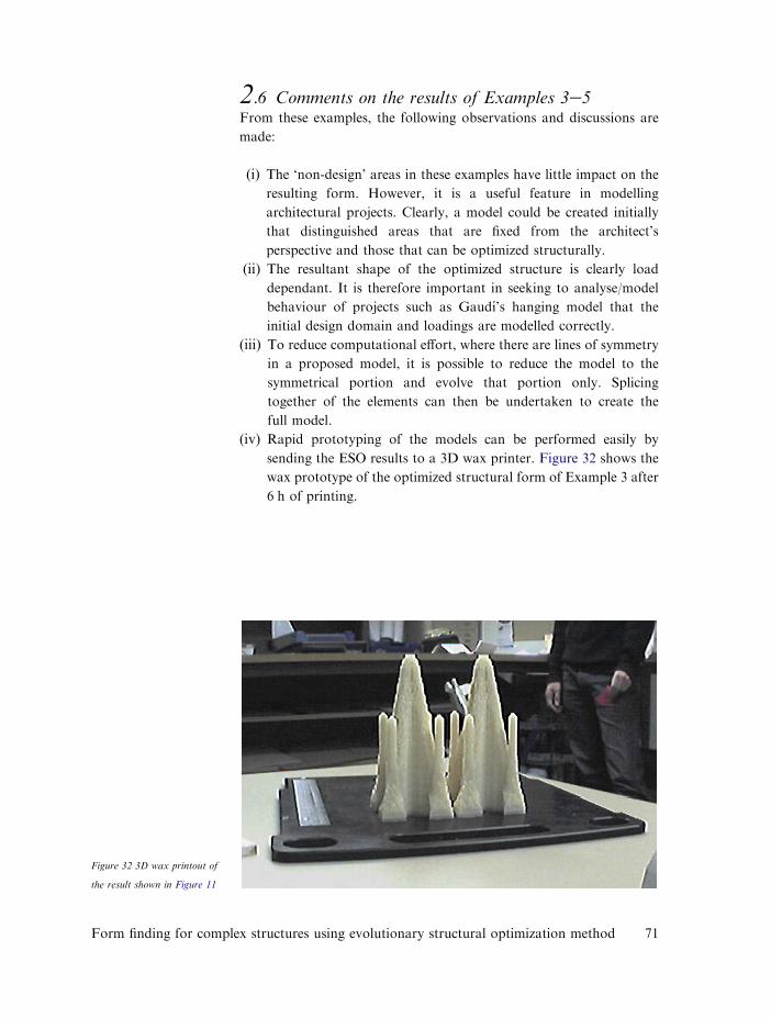
(iv) Rapid prototyping of the models can be performed easily by
sending the ESO results to a 3D wax printer. Figure 32 shows the
wax prototype of the optimized structural form of Example 3 after
6 h of printing.
Figure 32 3D wax printout of
the result shown in Figure 11
Form finding for complex structures using evolutionary structural optimization method 71
72
3 Concluding remarks and further studies
3.1 Comparison to work undertaken by Gaudı́Examples 3e5 (in particular Example 3) show close correlation to the
work of Gaudı́’s buildings. The ESO procedure serves as a quick and
accurate method of developing rational structural formdone may
speculate that it was the same kind of structural rationality that Gaudı́
aspired to achieve with his hanging models (and his graphic calculation
models). The ESO method creates the geometries based on a first
principles structural design process, rather than seeking to input the
actual geometry of Gaudı́’s buildings into a finite element model and
analysing forces/stresses etc.
3.2 The relevance to architecture and opportunitiesfor further studyThe use of the ESO technique provides an exciting new opportunity for
architectural form finding. Complex forms can be created that are based
on rational structural behaviour. Loads are not restricted to those in the
vertical plane such as in Gaudı́’s hanging models, but can be located in
any direction at any point, such that buildings can be optimized for
horizontal forces such as wind and earthquake in addition to gravity.
AcknowledgementThe authors are grateful to Professor Jos Tomlow for his comments on
the paper. They also wish to thank Professor Jos Tomlow and Gabriela
Heim for the photo shown in Figure 1.
ReferencesBendsøe, M P and Kikuchi, N (1988) Generating optimal topology instructural design using a homogenization method Computer Methods in
Applied Mechanics and Engineering Vol 71 No 2 pp 197e224Schodek, D (1992) Structures 2nd edn, Prentice Hall, New YorkSuzuki, K and Kikuchi, N (1991) A homogenization method for shape and
topology optimization Computer Methods in Applied Mechanics andEngineering Vol 93 No 3 pp 291e318Tomlow, J (1989) The model Institute for Lightweight Structures,
University of Stuttgart, GermanyXie, Y M and Steven, G P (1997) Evolutionary structural optimizationSpringer-Verlag, Berlin
Design Studies Vol 26 No. 1 January 2005