for our other free ebooks, go to: 1 -100 transistor circuits go to: 101 -200 transistor circuits go...
TRANSCRIPT
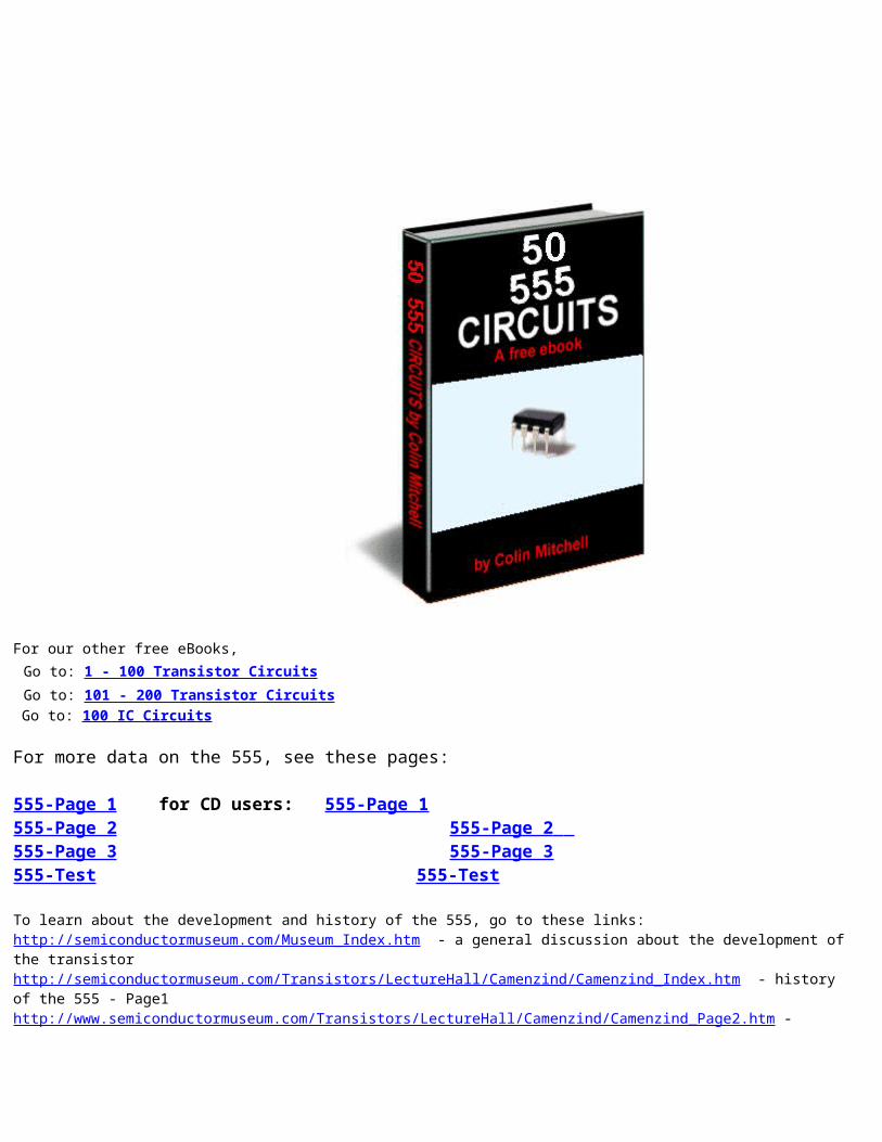
For our other free eBooks, Go to: 1 - 100 Transistor Circuits Go to: 101 - 200 Transistor Circuits Go to: 100 IC Circuits
For more data on the 555, see these pages:
555-Page 1 for CD users: 555-Page 1555-Page 2 555-Page 2 555-Page 3 555-Page 3 555-Test 555-Test
To learn about the development and history of the 555, go to these links:http://semiconductormuseum.com/Museum_Index.htm - a general discussion about the development of the transistor http://semiconductormuseum.com/Transistors/LectureHall/Camenzind/Camenzind_Index.htm - history of the 555 - Page1http://www.semiconductormuseum.com/Transistors/LectureHall/Camenzind/Camenzind_Page2.htm -
history of the 555 - Page2http://www.semiconductormuseum.com/Transistors/LectureHall/Camenzind/Camenzind_Page3.htm - history of the 555 - Page3http://www.semiconductormuseum.com/Transistors/LectureHall/Camenzind/Camenzind_Page4.htm - history of the 555 - Page4http://www.semiconductormuseum.com/Transistors/LectureHall/Camenzind/Camenzind_Page5.htm - history of the 555 - Page5http://www.semiconductormuseum.com/Transistors/LectureHall/Camenzind/Camenzind_Page6.htm - history of the 555 - Page6http://www.semiconductormuseum.com/Transistors/LectureHall/Camenzind/Camenzind_Page7.htm - history of the 555 - Page7http://www.semiconductormuseum.com/Transistors/LectureHall/Camenzind/Camenzind_Page8.htm - history of the 555 - Page8http://www.semiconductormuseum.com/Transistors/LectureHall/Camenzind/Camenzind_Page9.htm - history of the 555 - Page9http://www.semiconductormuseum.com/Transistors/LectureHall/Camenzind/Camenzind_Page10.htm - history of the 555 - Page10
For a list of every electronic symbol, see: Circuit Symbols.
For more articles and projects for the hobbyist: see TALKING ELECTRONICS WEBSITE
See TALKING ELECTRONICS WEBSITE
email Colin Mitchell: [email protected]
INTRODUCTIONThis e-book covers the 555. The 555 is everywhere and it is one of the cheapest and most-rugged chips on the market.
It comes as a TTL 555 and will operate from 4v to about 16-18v. It costs from 20 cents (eBay) to $1.20 depending on the quantityand distributor. The circuitry inside the chip takes about 10mA - even when the output is not driving a load. This means itis not suitable for battery operation if the chip is to be powered ALL THE TIME. The 555 is also available as a CMOS chip (ICM7555 or ICL7555 or TLC555) and will operate from 2v to 18v and takes 60uA when thecircuitry inside the chip is powered. The "7555" costs from 60 cents (eBay) to $2.00We call the TTL version "555" and the CMOS version "7555." This is called ELECTRONICS JARGON. The 555 comes as a single timer in an 8-pin package or a dual timer (556) in a 14 pin package. The 7555 comes as a single timer in an 8-pin package or a dual timer (7556) in a 14 pin package.
The 555 and 7555 are called TIMERS or Timer Chips. They contain about 28 transistors and the only extra components you need are called TIMING COMPONENTS. This is an external resistor and capacitor. When a capacitor is connected to a voltage, it takes a period of time to charge. If a resistor is placed in series with the capacitor, the timing will increase. The chip detects the rising and falling voltage on the capacitor. When the voltage on the capacitor is 2/3 of the supply the output goes LOW and when the voltage falls to 1/3, the output goes HIGH. We can also do other things with the chip such as "freezing" or halting its operation, or allowing it to produce a single HIGH-LOW on the output pin. This is called a "ONE-SHOT" or MONOSTABLEOPERATION. When the chip produces an output frequency above 1 cycle per second, (1Hz), the circuit is called an OSCILLATOR and below one cycle per second, it is called a TIMER. But the chip should not be called a "555 Timer," as it has so many applications. That's why we call it a "555." (triple 5)Another thing you have to be aware of is the voltage on output pin 3. It is about 1-2v LESS THAN rail voltage and does not go to 0v (about 0.7v for 10mA and up to 1900mV for 200mA sinking current). For instance, to get an output swing of 10v you will need a 12.6v supply. In "electronic terms" the 555 has very poor sinking and sourcing capabilities.
For photos of nearly every electronic component, see this website: https://www.egr.msu.edu/eceshop/Parts_Inventory/totalinventory.php
You can also search the web for videos showing the 555 in action. Here are a few: Making A 555 LED Flasher – Video TutorialThree 555 LED Flasher555 Timer FlasherFading LED with 555 timer
Each website has lots more videos and you can see exactly how the circuits work. But there is nothing like building the circuit and that's why you need to re-enforce your knowledge by ACTUAL CONSTRUCTION.
Learning Electronics is like building a model with Lego bricks. Each "topic" or "subject" or "area" must be covered fully and perfectly, just like a Lego brick is perfect and fits with interference-fit to the next block. When you complete this eBook, you can safely say you will have mastered the 555 - one more "building block" under your belt and in the process learn about DC motors, Stepper motors, servos, 4017 chips, LEDs and lots of other things. Any one of these can take you off in a completely different direction. So, lets start . . .
Colin Mitchell TALKING ELECTRONICS. [email protected]
To save space we have not provided lengthy explanations of how any of the circuits work. This has already been covered in TALKING ELECTRONICS Basic Electronics Course, and can be obtained on a CD for $10.00 (posted to anywhere in the world) See Talking Electronics website (http://www.talkingelectronics.com) for more details on the 555 by clicking on the following four pages: 555-Page 1 555-Page 2 555-Page 3 555-Test Many of the circuits have been designed by Colin Mitchell: Music Box, Reaction Timer Game, Traffic Lights, TV Remote Control Jammer, 3x3x3 Cube, while others are freely available onthe web. But this eBook has brought everything together and covers just about every novel 555 circuit. If you think you knoweverything about the 555, take the 555-Test and you will be surprised!
SI NOTATION All the schematics in this eBook have components that are labelled using the System International (SI) notation system.
The SI system is an easy way to show values without the need fora decimal point. Sometimes the decimal point is difficult to seeand the SI system overcomes this problem and offers a clear advantage. Resistor values are in ohms (R), and the multipliers are: k for kilo, M for Mega. Capacitance is measured in farads (F) and the sub-multiples are u for micro, n for nano, and p for pico. Inductors are measured in Henrys (H) and the sub-multiples are mH for milliHenry and uH for microHenry. A 10 ohm resistor would be written as 10R and a 0.001u capacitoras 1n. The markings on components are written slightly differently to the way they are shown on a circuit diagram (such as 100p on a circuit and 101 on the capacitor or 10 on a capacitor and 10p ona diagram) and you will have to look on the internet under BasicElectronics to learn about these differences.
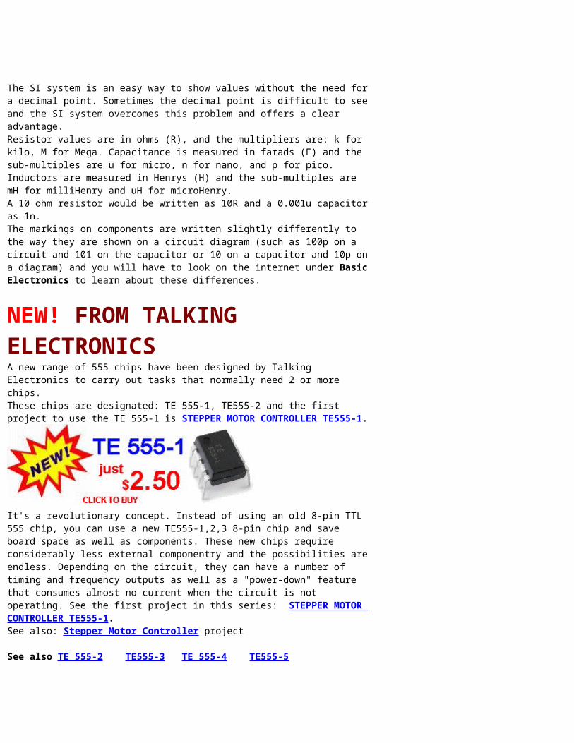
NEW! FROM TALKING ELECTRONICSA new range of 555 chips have been designed by Talking Electronics to carry out tasks that normally need 2 or more chips. These chips are designated: TE 555-1, TE555-2 and the first project to use the TE 555-1 is STEPPER MOTOR CONTROLLER TE555-1.
It's a revolutionary concept. Instead of using an old 8-pin TTL 555 chip, you can use a new TE555-1,2,3 8-pin chip and save board space as well as components. These new chips require considerably less external componentry and the possibilities areendless. Depending on the circuit, they can have a number of timing and frequency outputs as well as a "power-down" feature that consumes almost no current when the circuit is not operating. See the first project in this series: STEPPER MOTOR CONTROLLER TE555-1.See also: Stepper Motor Controller project
See also TE 555-2 TE555-3 TE 555-4 TE555-5
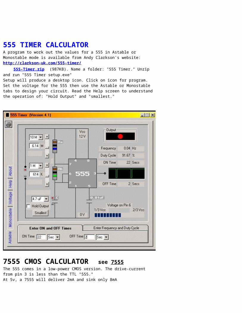
555 TIMER CALCULATOR A program to work out the values for a 555 in Astable or Monostable mode is available from Andy Clarkson's website:http://clarkson-uk.com/555-timer/ 555-Timer.zip (987KB). Name a folder: "555 Timer." Unzip and run "555 Timer setup.exe"Setup will produce a desktop icon. Click on icon for program. Set the voltage for the 555 then use the Astable or Monostable tabs to design your circuit. Read the Help screen to understand the operation of: "Hold Output" and "smallest."
7555 CMOS CALCULATOR see 7555 The 555 comes in a low-power CMOS version. The drive-current from pin 3 is less than the TTL "555."At 5v, a 7555 will deliver 2mA and sink only 8mA
At 12v a 7555 will deliver 10mA and sink 50mAAt 15v a 7555 will deliver 100mA and sink 100mAUse the following 7555 calculator to find the OUTPUT FREQUENCY in Astable mode or OUTPUT TIME in Monostable mode:7555 CMOS Calculator Here's a 555 made with 22 transistors by Malcolm Faed. See his video.
See his Electric Vehicle website.
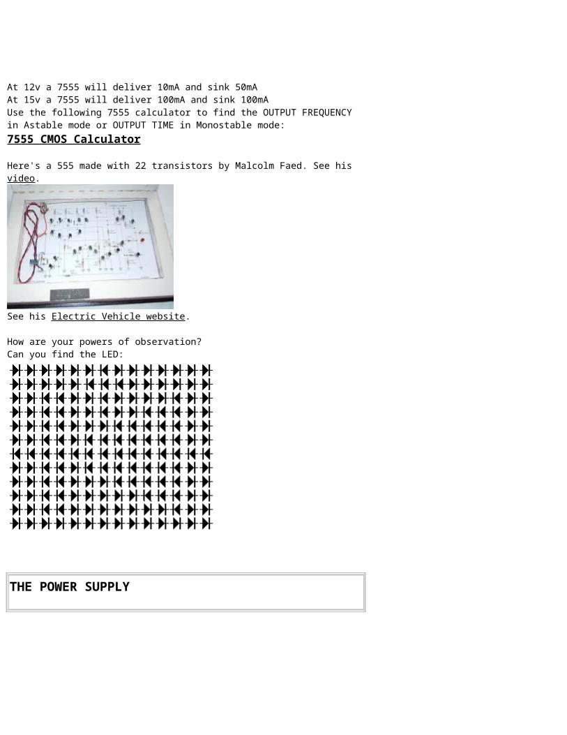
How are your powers of observation?Can you find the LED:
THE POWER SUPPLY
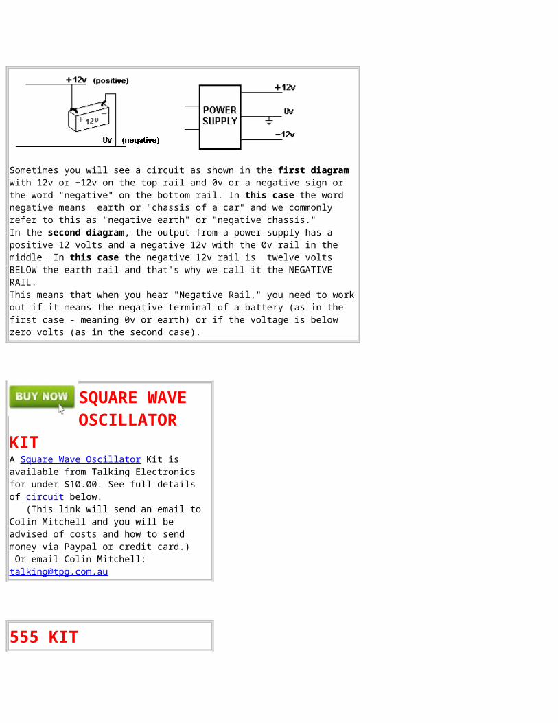
Sometimes you will see a circuit as shown in the first diagram with 12v or +12v on the top rail and 0v or a negative sign or the word "negative" on the bottom rail. In this case the word negative means earth or "chassis of a car" and we commonly refer to this as "negative earth" or "negative chassis." In the second diagram, the output from a power supply has a positive 12 volts and a negative 12v with the 0v rail in the middle. In this case the negative 12v rail is twelve volts BELOW the earth rail and that's why we call it the NEGATIVE RAIL. This means that when you hear "Negative Rail," you need to work out if it means the negative terminal of a battery (as in the first case - meaning 0v or earth) or if the voltage is below zero volts (as in the second case).
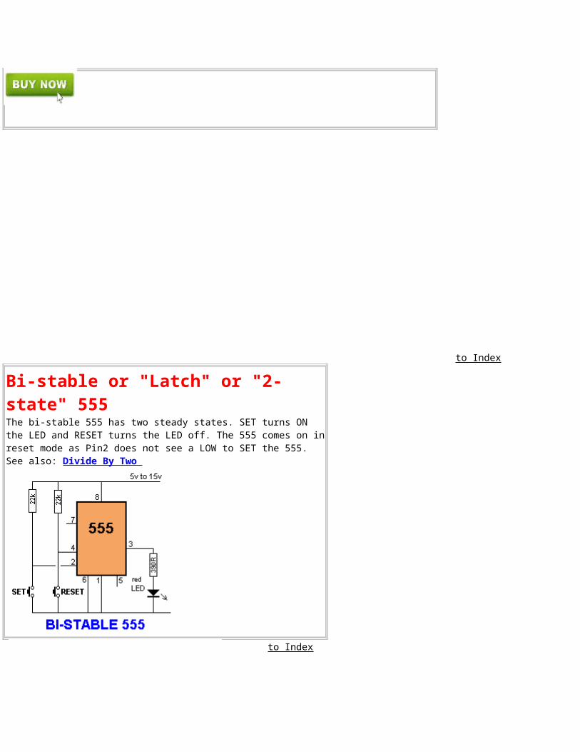
SQUARE WAVE OSCILLATOR
KITA Square Wave Oscillator Kit is available from Talking Electronics for under $10.00. See full details of circuit below. (This link will send an email to Colin Mitchell and you will be advised of costs and how to send money via Paypal or credit card.) Or email Colin Mitchell: [email protected]
555 KIT
A kit of components to make many of the circuits described in
this eBook is available for $10.00 plus $7.00 post. Or email Colin Mitchell: [email protected]
The kit contains the following components:(plus extra 30 resistors and 10 capacitors forexperimenting), plus:
2 - 220R2 - 1k2 - 4k72 - 10k 2 - 33k 2- 100k2 - 1M1 - 10k mini pot1 - 100k mini pot2 - 10n 2 - 100n1 - 10u electrolytic1- 100u electrolytic2 - 1N4148 signal diodes2 - BC547 transistors1 - BC557 transistor1 - 555 timer chip1 - 8 pin IC socket1 - red LED1 - green LED1 - orange LED1 - mini 8R speaker1 - mini piezo 1 - LDR (Light Dependent Resistor)1 - 10mH inductor1 - push button 1 - tactile push button1 - Experimenter Board (will take 8,14 and 16 pin chips)
CONTENTSActive High TriggerActive Low TriggerAlarm Sounds (4 sounds)Alarm 4-ZoneAmplifier using 555Animated DisplayAudio Frequency MeterAutomatic Curtain CloserAstable Multivibrator Basic 555 OscillatorsBattery Charger (voltage doubler)Bi-Coloured LEDBike Turning Signal Bi-Polar LED DriverBi-Stable 555Building the CircuitsBurglar Alarm 4-ZoneCapacitor Charge Pump Car Lights Flasher - warning flasherCar TachometerCharge Pump Clark ZapperClicks Uneven Calculator 555 7555CMOS 555Constant CurrentContinuity TesterCrossing LightsCurtain CloserDark DetectorDelay before turn-on Dog-Bark Stopper DiceDice to 7-Segment Display
Normally Closed TriggerOne-Shot 555Organ Police Lights 1,2,3Police SirenPowering A ProjectPulse ExtenderPulser - 74c14Push PullPush-Pull - high currentPWM Controller - FET bufferPWM - transistor buffersee also Motor PWMRailroad Lights (flashing)Railway TimeRain AlarmRamp GeneratorReaction Timer GameReplacing 556 with two 555'sReplacing TTL 555 with CMOS 555Resistor Colour CodesReversing A Motor RouletteSchmitt TriggerScreamer Siren - Light ControlledServo ControllerServo TesterSimplest 555 Oscillator Sinewave Output Siren 100dBSolar Tracker - not suitable for 555Square Wave Oscillator Stepper Motor ControllerStun GunSubstituting a 555 - Part 1
Display - AnimatedDivide by 2Driving A Bi-Coloured LEDDriving A RelayDriving White LEDsDuty Cycle 1:1 (50%) Fade-IN Fade-OUT LEDsFading LEDFastest 555 OscillatorFlasherFlashing IndicatorsFlashing Railroad LightsFlip Flop see also Toggle Four Alarm Sounds Frequency DividerFrequency Meter Function of each 555 pin H-BridgeH-Bridge Push-Pull - high currentH-Bridge with PWMHeadlight Flasher - faulty circuitHeadlight SelectorHee Haw SirenHigher Sinking CurrentHigh Frequency 555 OscillatorHow to use the 555HysteresisImproving the output of a 555Increasing Sinking CurrentIncreasing Output Push-Pull CurrentInverter 12v to 240vInside the 555Jammer for TVKitt ScannerKnight RiderLaser Ray Sound
Substituting a 555 - Part 2Supply (170v) for Nixie TubesSwitch DebounceTachometerTE555-1 Stepper Motor ControllerTE555-2 Animated DisplayTE555-3 4 Alarm SoundsTE555-4 DiceTE555-5 LED FxTicking BombTilt SwitchToggle 555 see also Flip FlopTouch SwitchTouch ON-OFFToy Organ Traffic LightsTraffic Lights - 4 way Transistor TesterTrigger Timer - 74c14Turning SignalTV Remote Control JammerUseless MachineUneven Clicks Up/Down Fading LEDUsing the 555VCO (Voltage Controlled Oscillator)Voltage Doubler see also Battery ChargerVoltage TriplerVoltage Inverter Voltage Multiplier x10timesWarning Flasher - car lights flasherWater Level DetectorWailing SirenZapper (Dr Clark)Zapper - Voltage Multiplier
LatchLatch - using transistorsLED DiceLED DimmerLED FXLight Controlled Screamer SirenLight DetectorLights - Traffic LightsLMC555 CMOS 555Low Current Timer - 7555 CMOS 555Low Frequency 555 Oscillator Low Power 555Machine Gun Mark-Space RatioMemory Cell see also Toggle Flip FlopMercury Switch Detector - faulty circuitMetal Detector Missing Audio DetectorMissing Pulse Detector - faulty circuitModel Railway Time Monostable 555Morse KeyerMosquito RepellerMotor Controller (stepper Motor)Motor Controller (servo motor)Motor PWMMultivibrator - Astable Music BoxNegative Voltage
Zener Diode Tester2 Minute Timer - 74c143x3x3 Cube4 Alarm Sounds4 way Traffic Lights4-Zone Burglar Alarm1-10 Minute Auto Turn Off5 Seconds Delay10 Minute Timer - 74c1412v DC to 12v DC Battery Charger12v to 240v Inverter50% Duty Cycle100dB Siren 170v Supply for Nixie Tubes555's - a list of substitutes555 Amplifier555 CMOS version LMC555555 Kit of Components555 Pinout555 Pins - Remembering the pins555 Mistakes (No-No's)555 on 24v555 Timer Calculator555 VCO556 Dual Timer 7555 CMOS Calculator7555 Low Current Timer (delay)
to Index
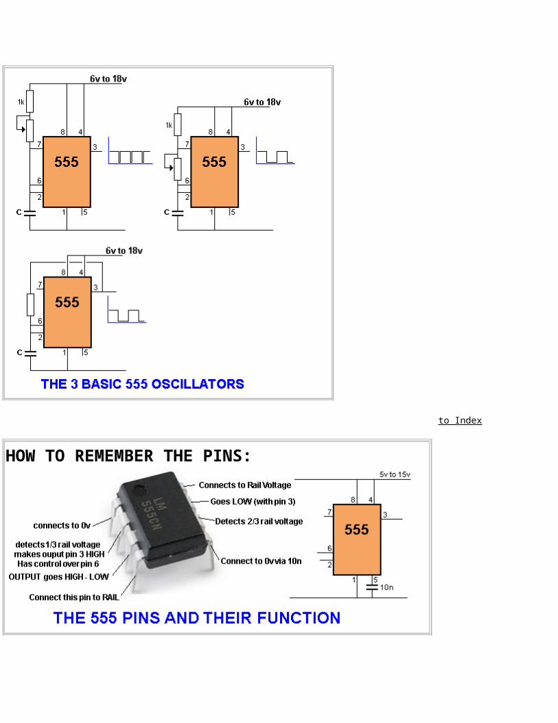
THE 555 PINSHere is the identification for each pin:
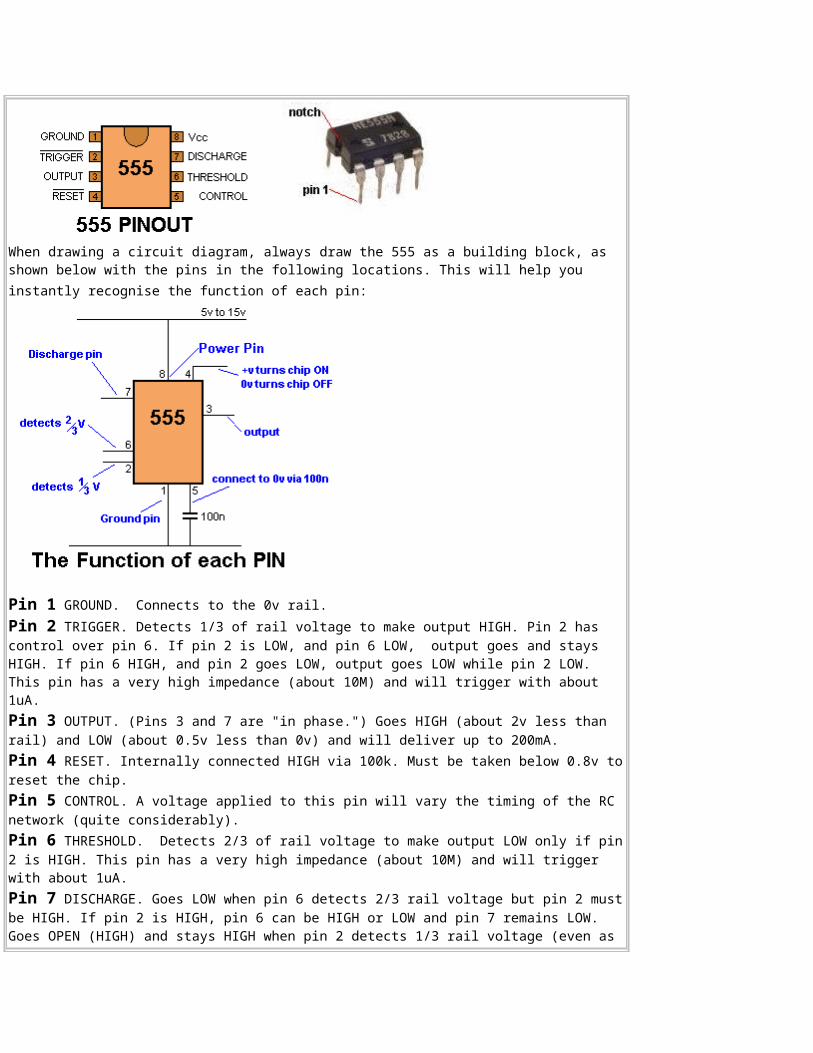
When drawing a circuit diagram, always draw the 555 as a building block, as shown below with the pins in the following locations. This will help you instantly recognise the function of each pin:
Pin 1 GROUND. Connects to the 0v rail. Pin 2 TRIGGER. Detects 1/3 of rail voltage to make output HIGH. Pin 2 has control over pin 6. If pin 2 is LOW, and pin 6 LOW, output goes and stays HIGH. If pin 6 HIGH, and pin 2 goes LOW, output goes LOW while pin 2 LOW. This pin has a very high impedance (about 10M) and will trigger with about 1uA.Pin 3 OUTPUT. (Pins 3 and 7 are "in phase.") Goes HIGH (about 2v less than rail) and LOW (about 0.5v less than 0v) and will deliver up to 200mA.Pin 4 RESET. Internally connected HIGH via 100k. Must be taken below 0.8v toreset the chip. Pin 5 CONTROL. A voltage applied to this pin will vary the timing of the RC network (quite considerably). Pin 6 THRESHOLD. Detects 2/3 of rail voltage to make output LOW only if pin2 is HIGH. This pin has a very high impedance (about 10M) and will trigger with about 1uA.Pin 7 DISCHARGE. Goes LOW when pin 6 detects 2/3 rail voltage but pin 2 mustbe HIGH. If pin 2 is HIGH, pin 6 can be HIGH or LOW and pin 7 remains LOW. Goes OPEN (HIGH) and stays HIGH when pin 2 detects 1/3 rail voltage (even as
a LOW pulse) when pin 6 is LOW. (Pins 7 and 3 are "in phase.") Pin 7 is equal to pin 3 but pin 7 does not go high - it goes OPEN. But it goes LOW and will sink about 200mA. You can connect pin 7 to pin 3 to get a slightly better SINK capability from the chip.Pin 8 SUPPLY. Connects to the positive rail.
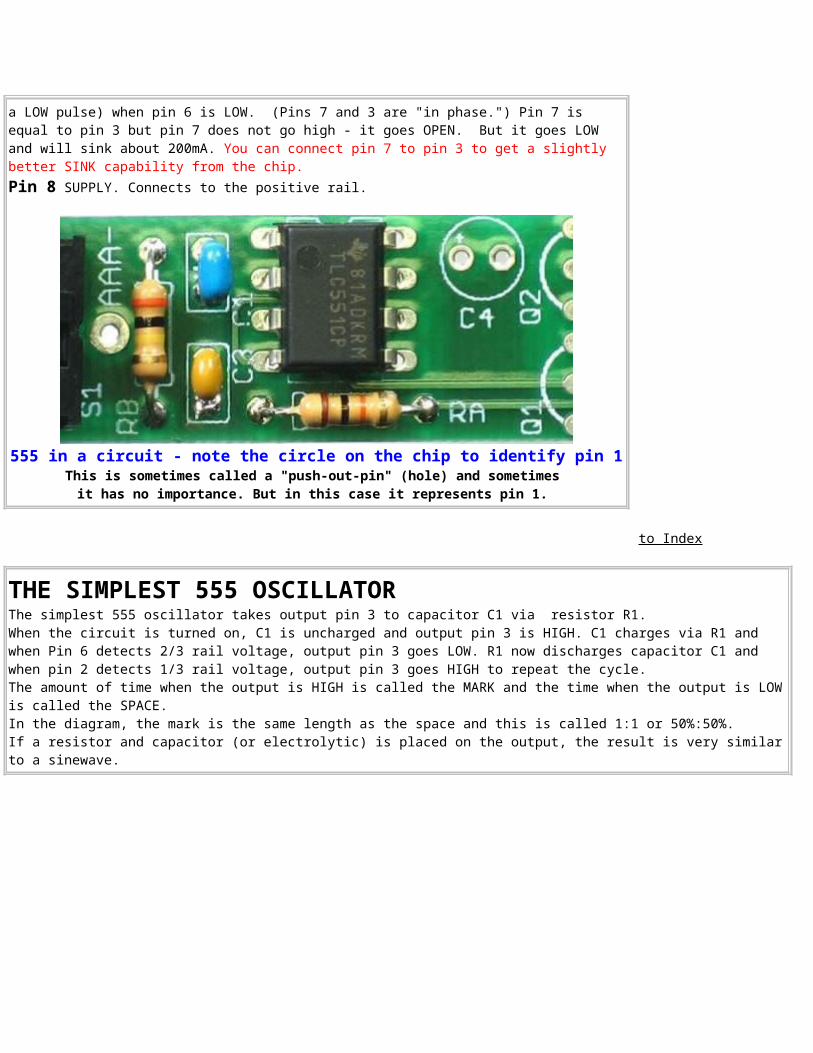
555 in a circuit - note the circle on the chip to identify pin 1This is sometimes called a "push-out-pin" (hole) and sometimes it has no importance. But in this case it represents pin 1.
to Index
THE SIMPLEST 555 OSCILLATORThe simplest 555 oscillator takes output pin 3 to capacitor C1 via resistor R1. When the circuit is turned on, C1 is uncharged and output pin 3 is HIGH. C1 charges via R1 and when Pin 6 detects 2/3 rail voltage, output pin 3 goes LOW. R1 now discharges capacitor C1 and when pin 2 detects 1/3 rail voltage, output pin 3 goes HIGH to repeat the cycle. The amount of time when the output is HIGH is called the MARK and the time when the output is LOWis called the SPACE. In the diagram, the mark is the same length as the space and this is called 1:1 or 50%:50%.If a resistor and capacitor (or electrolytic) is placed on the output, the result is very similarto a sinewave.
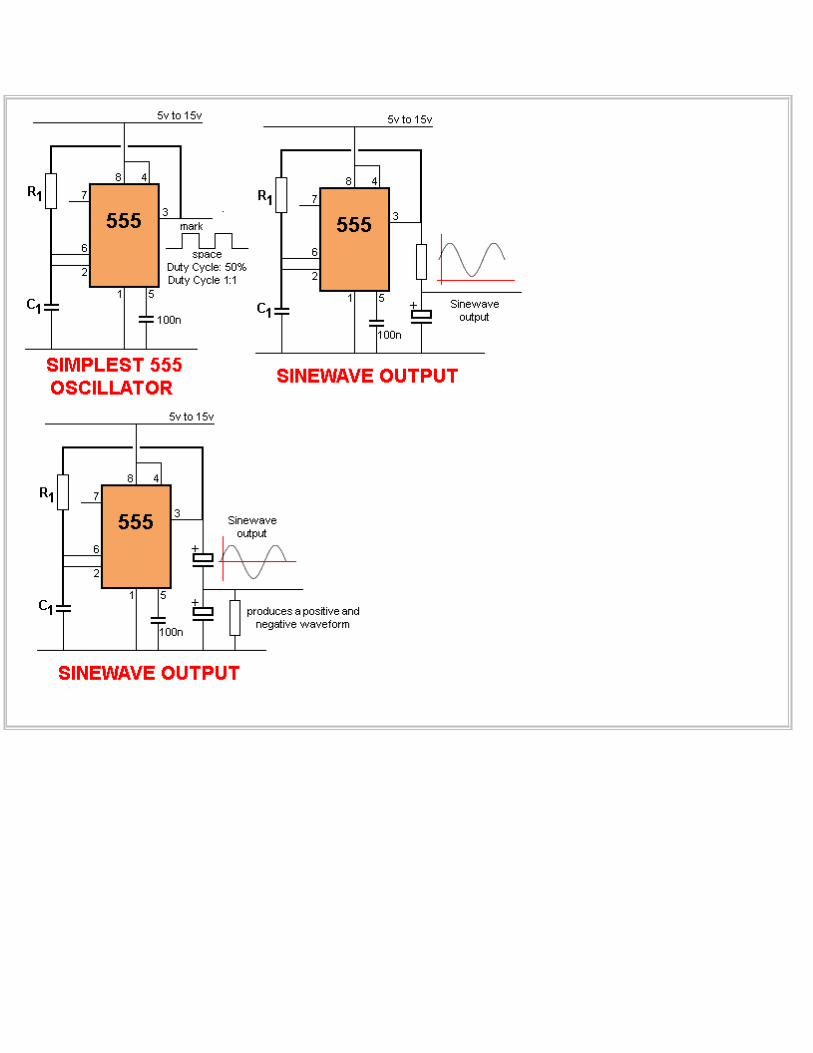
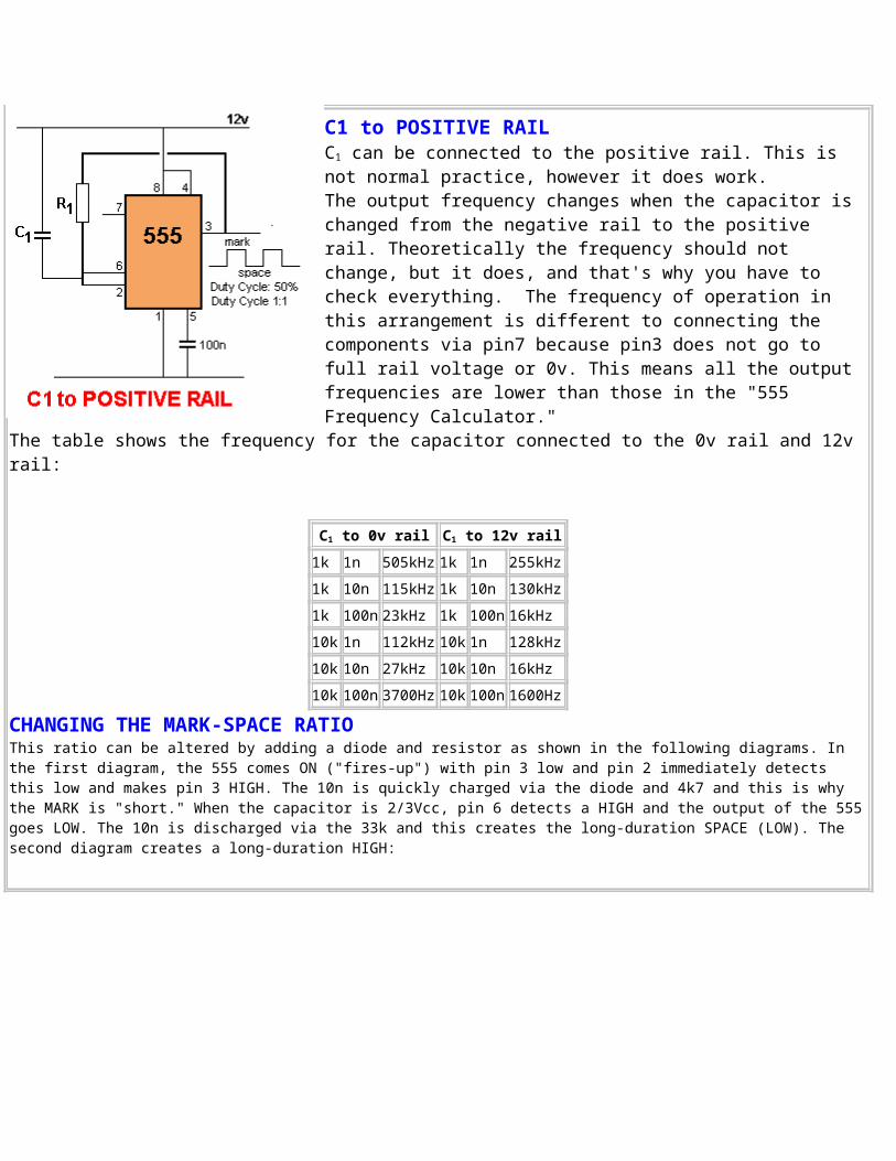
C1 to POSITIVE RAIL C1 can be connected to the positive rail. This is not normal practice, however it does work. The output frequency changes when the capacitor is changed from the negative rail to the positive rail. Theoretically the frequency should not change, but it does, and that's why you have to check everything. The frequency of operation in this arrangement is different to connecting the components via pin7 because pin3 does not go to full rail voltage or 0v. This means all the output frequencies are lower than those in the "555 Frequency Calculator."
The table shows the frequency for the capacitor connected to the 0v rail and 12v rail:
C1 to 0v rail C1 to 12v rail1k 1n 505kHz 1k 1n 255kHz1k 10n 115kHz 1k 10n 130kHz1k 100n 23kHz 1k 100n 16kHz10k 1n 112kHz 10k 1n 128kHz10k 10n 27kHz 10k 10n 16kHz10k 100n 3700Hz 10k 100n 1600Hz
CHANGING THE MARK-SPACE RATIOThis ratio can be altered by adding a diode and resistor as shown in the following diagrams. In the first diagram, the 555 comes ON ("fires-up") with pin 3 low and pin 2 immediately detects this low and makes pin 3 HIGH. The 10n is quickly charged via the diode and 4k7 and this is why the MARK is "short." When the capacitor is 2/3Vcc, pin 6 detects a HIGH and the output of the 555goes LOW. The 10n is discharged via the 33k and this creates the long-duration SPACE (LOW). The second diagram creates a long-duration HIGH:
to Index
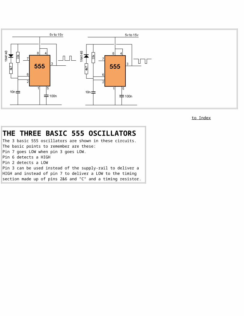
THE THREE BASIC 555 OSCILLATORSThe 3 basic 555 oscillators are shown in these circuits. The basic points to remember are these:Pin 7 goes LOW when pin 3 goes LOW.Pin 6 detects a HIGHPin 2 detects a LOW Pin 3 can be used instead of the supply-rail to deliver a HIGH and instead of pin 7 to deliver a LOW to the timing section made up of pins 2&6 and "C" and a timing resistor.
to Index
HOW TO REMEMBER THE PINS:
to Index
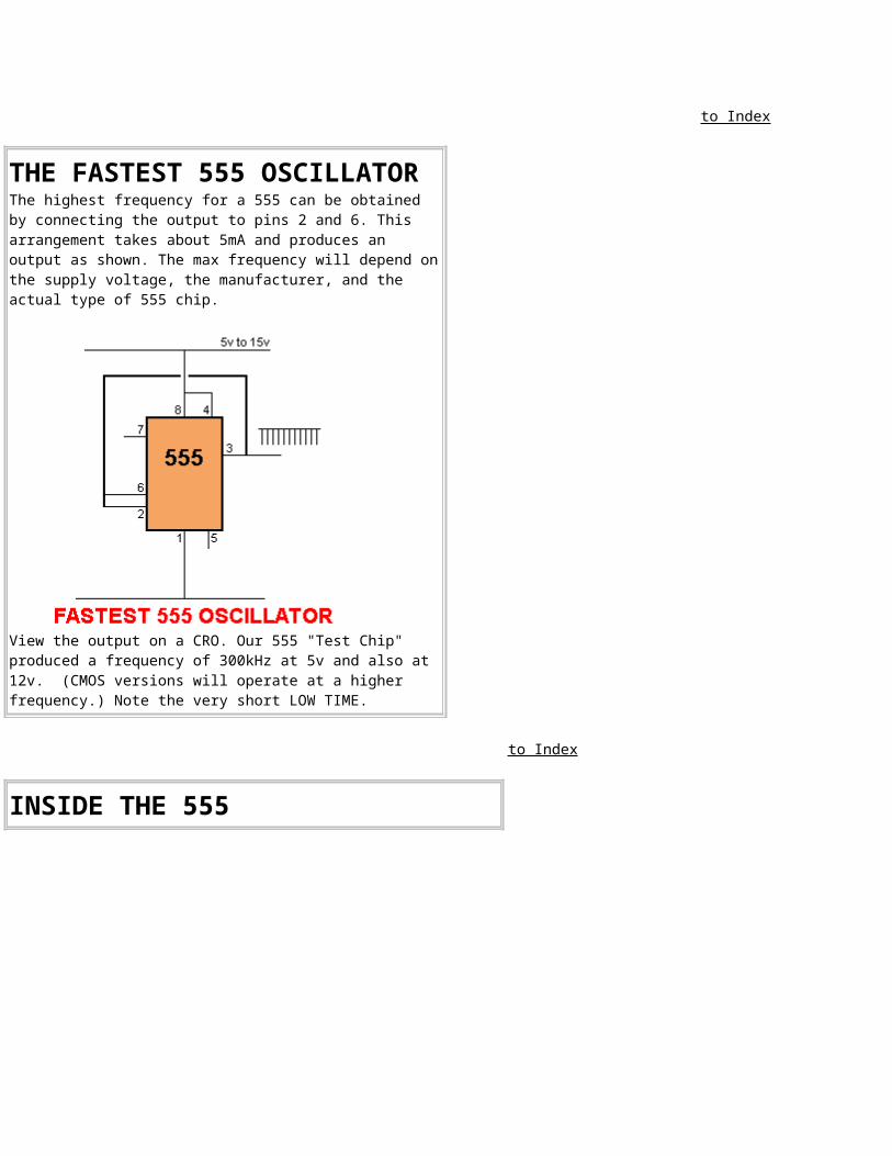
THE FASTEST 555 OSCILLATORThe highest frequency for a 555 can be obtained by connecting the output to pins 2 and 6. This arrangement takes about 5mA and produces an output as shown. The max frequency will depend onthe supply voltage, the manufacturer, and the actual type of 555 chip.
View the output on a CRO. Our 555 "Test Chip" produced a frequency of 300kHz at 5v and also at 12v. (CMOS versions will operate at a higher frequency.) Note the very short LOW TIME.
to Index
INSIDE THE 555
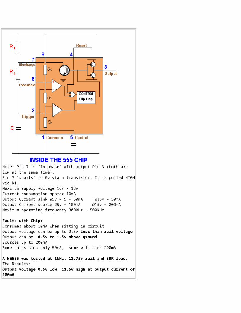
Note: Pin 7 is "in phase" with output Pin 3 (both are low at the same time).Pin 7 "shorts" to 0v via a transistor. It is pulled HIGHvia R1. Maximum supply voltage 16v - 18vCurrent consumption approx 10mAOutput Current sink @5v = 5 - 50mA @15v = 50mAOutput Current source @5v = 100mA @15v = 200mAMaximum operating frequency 300kHz - 500kHz
Faults with Chip:Consumes about 10mA when sitting in circuitOutput voltage can be up to 2.5v less than rail voltage Output can be 0.5v to 1.5v above groundSources up to 200mA Some chips sink only 50mA, some will sink 200mA
A NE555 was tested at 1kHz, 12.75v rail and 39R load. The Results: Output voltage 0.5v low, 11.5v high at output current of180mA
The "test chip" performance was excellent.
to Index
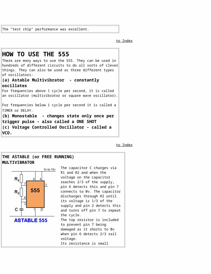
HOW TO USE THE 555There are many ways to use the 555. They can be used in hundreds of different circuits to do all sorts of cleverthings. They can also be used as three different types of oscillators: (a) Astable Multivibrator - constantly oscillates For frequencies above 1 cycle per second, it is called an oscillator (multivibrator or square wave oscillator).
For frequencies below 1 cycle per second it is called a TIMER or DELAY. (b) Monostable - changes state only once per trigger pulse - also called a ONE SHOT(c) Voltage Controlled Oscillator - called a VCO.
to Index
THE ASTABLE (or FREE RUNNING)MULTIVIBRATOR
The capacitor C charges via R1 and R2 and when the voltage on the capacitor reaches 2/3 of the supply, pin 6 detects this and pin 7 connects to 0v. The capacitordischarges through R2 until its voltage is 1/3 of the supply and pin 2 detects thisand turns off pin 7 to repeatthe cycle. The top resistor is included to prevent pin 7 being damaged as it shorts to 0v when pin 6 detects 2/3 rail voltage. Its resistance is small
compared to R2 and does not come into the timing of the oscillator.
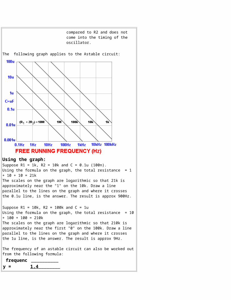
The following graph applies to the Astable circuit:
Using the graph:Suppose R1 = 1k, R2 = 10k and C = 0.1u (100n).Using the formula on the graph, the total resistance = 1 + 10 + 10 = 21k The scales on the graph are logarithmic so that 21k is approximately near the "1" on the 10k. Draw a line parallel to the lines on the graph and where it crosses the 0.1u line, is the answer. The result is approx 900Hz.
Suppose R1 = 10k, R2 = 100k and C = 1uUsing the formula on the graph, the total resistance = 10+ 100 + 100 = 210k The scales on the graph are logarithmic so that 210k is approximately near the first "0" on the 100k. Draw a line parallel to the lines on the graph and where it crosses the 1u line, is the answer. The result is approx 9Hz.
The frequency of an astable circuit can also be worked outfrom the following formula: frequency =
1.4
(R1 + 2R2)
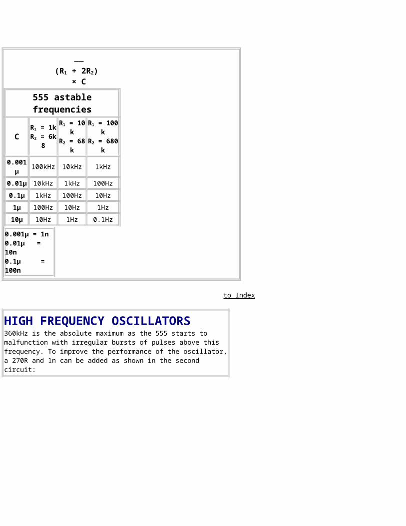
× C555 astablefrequencies
CR1 = 1kR2 = 6k
8
R1 = 10k
R2 = 68k
R1 = 100k
R2 = 680k
0.001µ 100kHz 10kHz 1kHz
0.01µ 10kHz 1kHz 100Hz0.1µ 1kHz 100Hz 10Hz1µ 100Hz 10Hz 1Hz10µ 10Hz 1Hz 0.1Hz
0.001µ = 1n0.01µ = 10n0.1µ = 100n
to Index
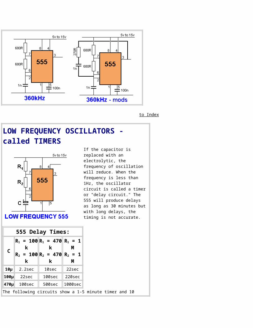
HIGH FREQUENCY OSCILLATORS360kHz is the absolute maximum as the 555 starts to malfunction with irregular bursts of pulses above this frequency. To improve the performance of the oscillator,a 270R and 1n can be added as shown in the second circuit:
to Index
LOW FREQUENCY OSCILLATORS - called TIMERS
If the capacitor is replaced with an electrolytic, the frequency of oscillation will reduce. When the frequency is less than 1Hz, the oscillator circuit is called a timeror "delay circuit." The 555 will produce delays as long as 30 minutes butwith long delays, the timing is not accurate.
555 Delay Times:
C
R1 = 100k
R2 = 100k
R1 = 470k
R2 = 470k
R1 = 1M
R2 = 1M
10µ 2.2sec 10sec 22sec100µ 22sec 100sec 220sec470µ 100sec 500sec 1000secThe following circuits show a 1-5 minute timer and 10
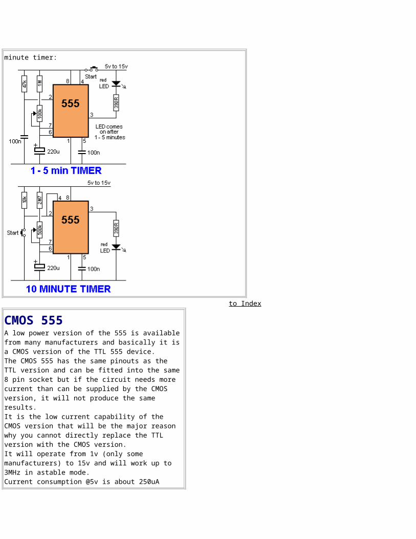
minute timer:
to Index
CMOS 555A low power version of the 555 is availablefrom many manufacturers and basically it isa CMOS version of the TTL 555 device. The CMOS 555 has the same pinouts as the TTL version and can be fitted into the same8 pin socket but if the circuit needs more current than can be supplied by the CMOS version, it will not produce the same results. It is the low current capability of the CMOS version that will be the major reason why you cannot directly replace the TTL version with the CMOS version. It will operate from 1v (only some manufacturers) to 15v and will work up to 3MHz in astable mode. Current consumption @5v is about 250uA
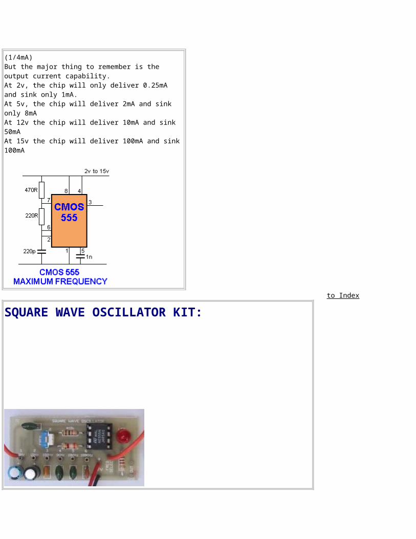
(1/4mA)But the major thing to remember is the output current capability. At 2v, the chip will only deliver 0.25mA and sink only 1mA. At 5v, the chip will deliver 2mA and sink only 8mAAt 12v the chip will deliver 10mA and sink 50mAAt 15v the chip will deliver 100mA and sink100mA
to Index
SQUARE WAVE OSCILLATOR KIT:
to Index
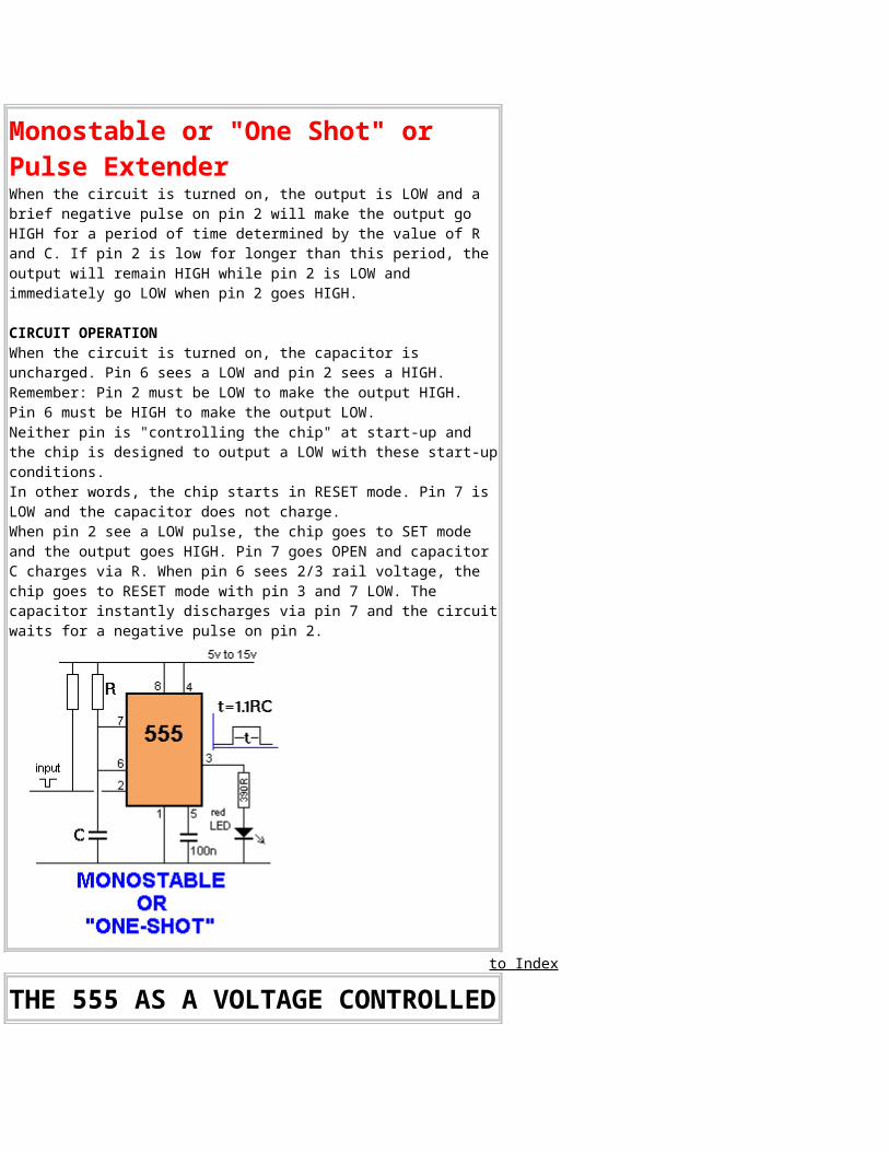
Bi-stable or "Latch" or "2-state" 555The bi-stable 555 has two steady states. SET turns ON the LED and RESET turns the LED off. The 555 comes on inreset mode as Pin2 does not see a LOW to SET the 555. See also: Divide By Two
to Index
Monostable or "One Shot" or Pulse ExtenderWhen the circuit is turned on, the output is LOW and a brief negative pulse on pin 2 will make the output go HIGH for a period of time determined by the value of R and C. If pin 2 is low for longer than this period, the output will remain HIGH while pin 2 is LOW and immediately go LOW when pin 2 goes HIGH.
CIRCUIT OPERATION When the circuit is turned on, the capacitor is uncharged. Pin 6 sees a LOW and pin 2 sees a HIGH. Remember: Pin 2 must be LOW to make the output HIGH. Pin 6 must be HIGH to make the output LOW. Neither pin is "controlling the chip" at start-up and the chip is designed to output a LOW with these start-upconditions. In other words, the chip starts in RESET mode. Pin 7 is LOW and the capacitor does not charge. When pin 2 see a LOW pulse, the chip goes to SET mode and the output goes HIGH. Pin 7 goes OPEN and capacitor C charges via R. When pin 6 sees 2/3 rail voltage, the chip goes to RESET mode with pin 3 and 7 LOW. The capacitor instantly discharges via pin 7 and the circuitwaits for a negative pulse on pin 2.
to Index
THE 555 AS A VOLTAGE CONTROLLED
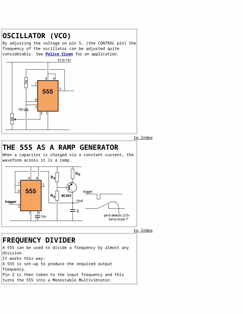
OSCILLATOR (VCO)By adjusting the voltage on pin 5, (the CONTROL pin) thefrequency of the oscillator can be adjusted quite considerably. See Police Siren for an application.
to Index
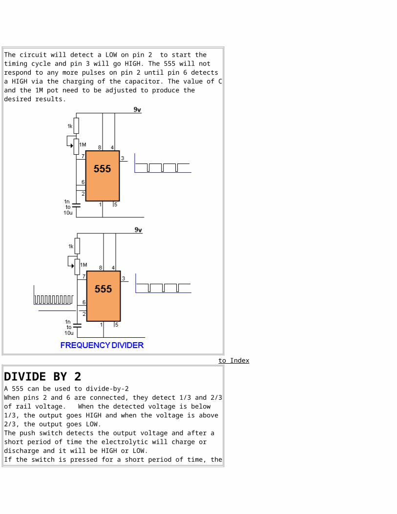
THE 555 AS A RAMP GENERATORWhen a capacitor is charged via a constant current, the waveform across it is a ramp.
to Index
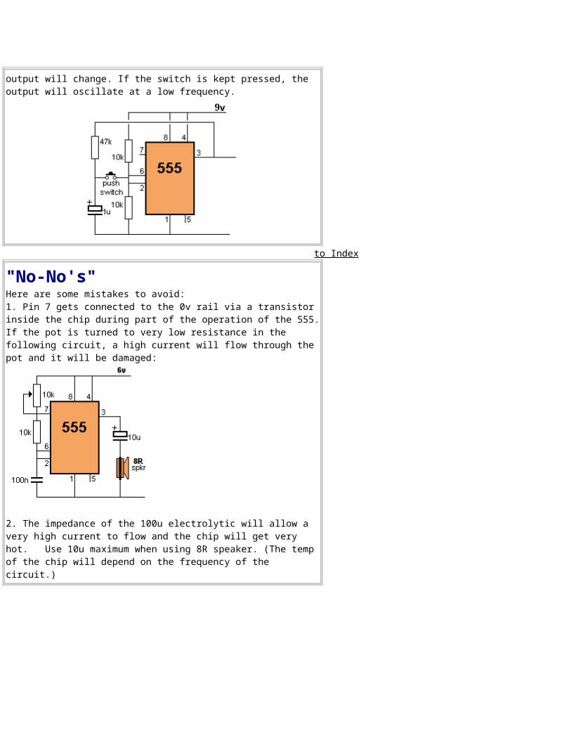
FREQUENCY DIVIDERA 555 can be used to divide a frequency by almost any division. It works this way: A 555 is set-up to produce the required output frequency. Pin 2 is then taken to the input frequency and this turns the 555 into a Monostable Multivibrator.
The circuit will detect a LOW on pin 2 to start the timing cycle and pin 3 will go HIGH. The 555 will not respond to any more pulses on pin 2 until pin 6 detects a HIGH via the charging of the capacitor. The value of Cand the 1M pot need to be adjusted to produce the desired results.
to Index
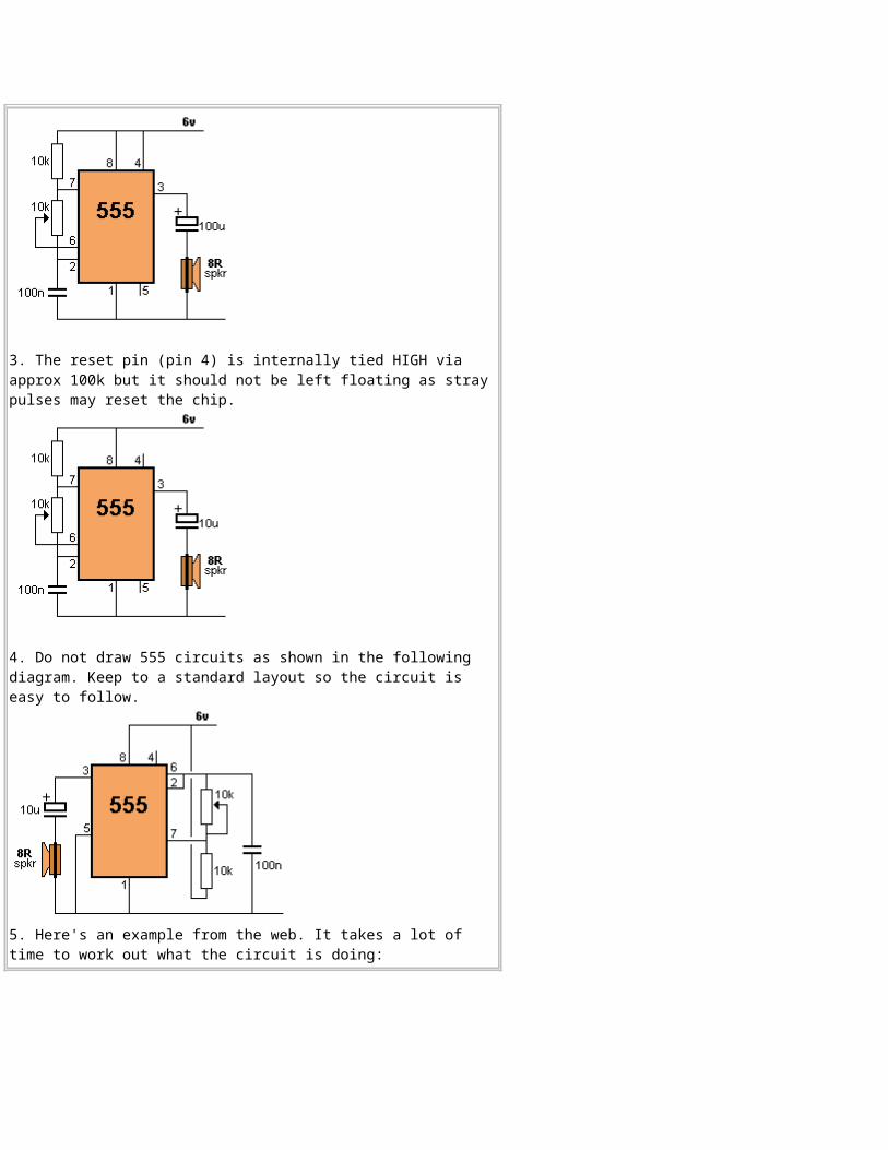
DIVIDE BY 2A 555 can be used to divide-by-2When pins 2 and 6 are connected, they detect 1/3 and 2/3of rail voltage. When the detected voltage is below 1/3, the output goes HIGH and when the voltage is above 2/3, the output goes LOW. The push switch detects the output voltage and after a short period of time the electrolytic will charge or discharge and it will be HIGH or LOW. If the switch is pressed for a short period of time, the
output will change. If the switch is kept pressed, the output will oscillate at a low frequency.
to Index
"No-No's"Here are some mistakes to avoid:1. Pin 7 gets connected to the 0v rail via a transistor inside the chip during part of the operation of the 555.If the pot is turned to very low resistance in the following circuit, a high current will flow through the pot and it will be damaged:
2. The impedance of the 100u electrolytic will allow a very high current to flow and the chip will get very hot. Use 10u maximum when using 8R speaker. (The temp of the chip will depend on the frequency of the circuit.)
3. The reset pin (pin 4) is internally tied HIGH via approx 100k but it should not be left floating as stray pulses may reset the chip.
4. Do not draw 555 circuits as shown in the following diagram. Keep to a standard layout so the circuit is easy to follow.
5. Here's an example from the web. It takes a lot of time to work out what the circuit is doing:
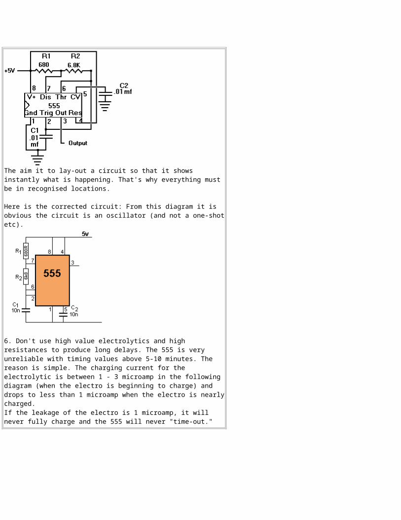
The aim it to lay-out a circuit so that it shows instantly what is happening. That's why everything must be in recognised locations.
Here is the corrected circuit: From this diagram it is obvious the circuit is an oscillator (and not a one-shotetc).
6. Don't use high value electrolytics and high resistances to produce long delays. The 555 is very unreliable with timing values above 5-10 minutes. The reason is simple. The charging current for the electrolytic is between 1 - 3 microamp in the following diagram (when the electro is beginning to charge) and drops to less than 1 microamp when the electro is nearlycharged. If the leakage of the electro is 1 microamp, it will never fully charge and the 555 will never "time-out."
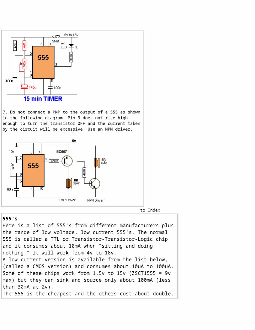
7. Do not connect a PNP to the output of a 555 as shown in the following diagram. Pin 3 does not rise high enough to turn the transistor OFF and the current taken by the circuit will be excessive. Use an NPN driver.
to Index
555'sHere is a list of 555's from different manufacturers plus the range of low voltage, low current 555's. The normal 555 is called a TTL or Transistor-Transistor-Logic chip and it consumes about 10mA when "sitting and doing nothing." It will work from 4v to 18v. A low current version is available from the list below, (called a CMOS version) and consumes about 10uA to 100uA. Some of these chips work from 1.5v to 15v (ZSCT1555 = 9v max) but they can sink and source only about 100mA (less than 30mA at 2v). The 555 is the cheapest and the others cost about double.
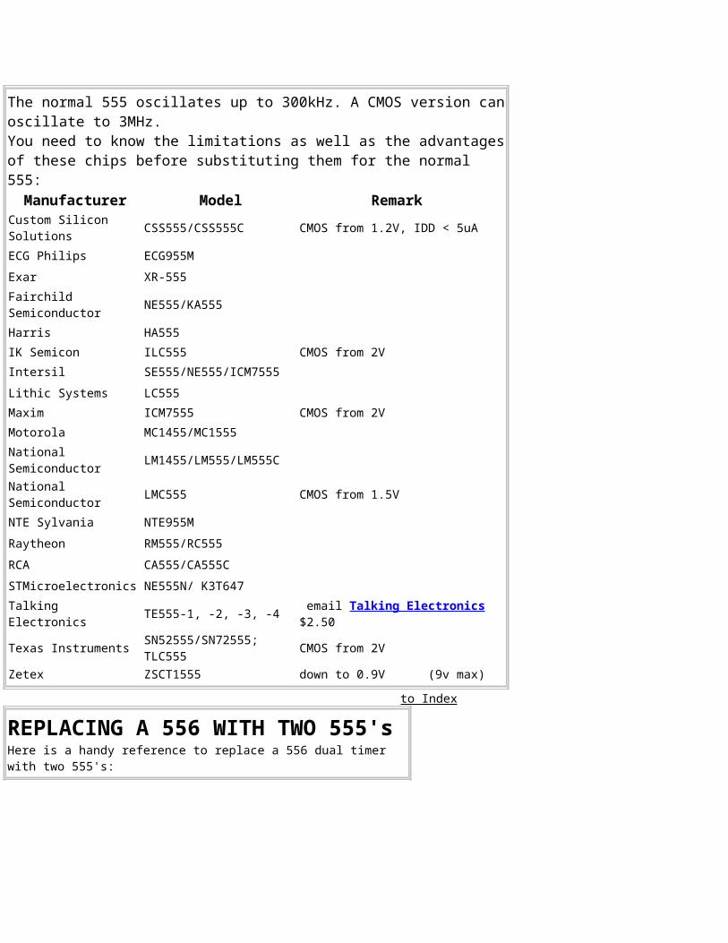
The normal 555 oscillates up to 300kHz. A CMOS version canoscillate to 3MHz.You need to know the limitations as well as the advantagesof these chips before substituting them for the normal 555:Manufacturer Model Remark
Custom Silicon Solutions CSS555/CSS555C CMOS from 1.2V, IDD < 5uA
ECG Philips ECG955MExar XR-555Fairchild Semiconductor NE555/KA555
Harris HA555IK Semicon ILC555 CMOS from 2VIntersil SE555/NE555/ICM7555Lithic Systems LC555Maxim ICM7555 CMOS from 2VMotorola MC1455/MC1555National Semiconductor LM1455/LM555/LM555C
National Semiconductor LMC555 CMOS from 1.5V
NTE Sylvania NTE955MRaytheon RM555/RC555RCA CA555/CA555CSTMicroelectronics NE555N/ K3T647Talking Electronics TE555-1, -2, -3, -4 email Talking Electronics
$2.50
Texas Instruments SN52555/SN72555; TLC555 CMOS from 2V
Zetex ZSCT1555 down to 0.9V (9v max)
to Index
REPLACING A 556 WITH TWO 555'sHere is a handy reference to replace a 556 dual timer with two 555's:
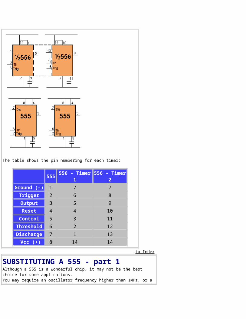
The table shows the pin numbering for each timer:
555 556 - Timer1
556 - Timer2
Ground (–) 1 7 7Trigger 2 6 8Output 3 5 9Reset 4 4 10
Control 5 3 11Threshold 6 2 12Discharge 7 1 13 Vcc (+) 8 14 14
to Index
SUBSTITUTING A 555 - part 1Although a 555 is a wonderful chip, it may not be the best choice for some applications. You may require an oscillator frequency higher than 1MHz, or a
very low quiescent current. You may also need 4 or more 555's to get the timing and delays you require. Here are some circuits to help you substitute a 555.
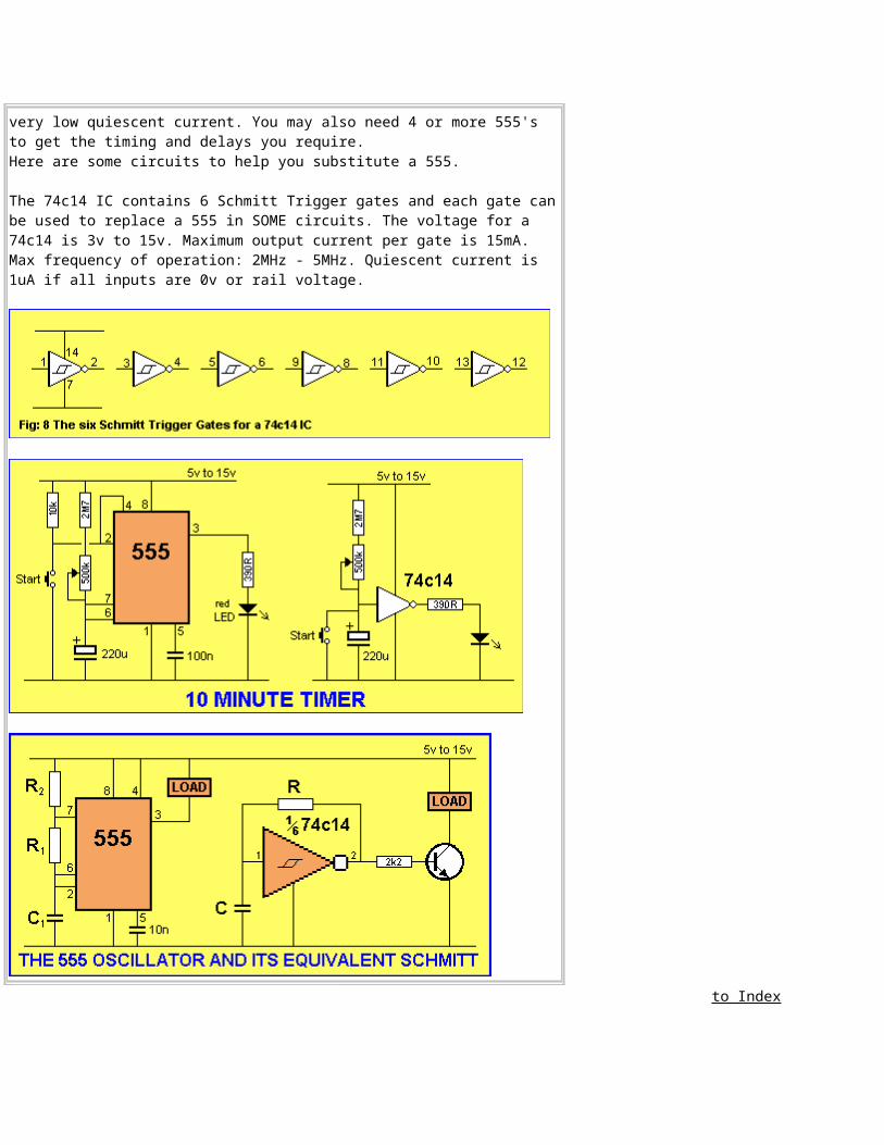
The 74c14 IC contains 6 Schmitt Trigger gates and each gate canbe used to replace a 555 in SOME circuits. The voltage for a 74c14 is 3v to 15v. Maximum output current per gate is 15mA. Max frequency of operation: 2MHz - 5MHz. Quiescent current is 1uA if all inputs are 0v or rail voltage.
to Index
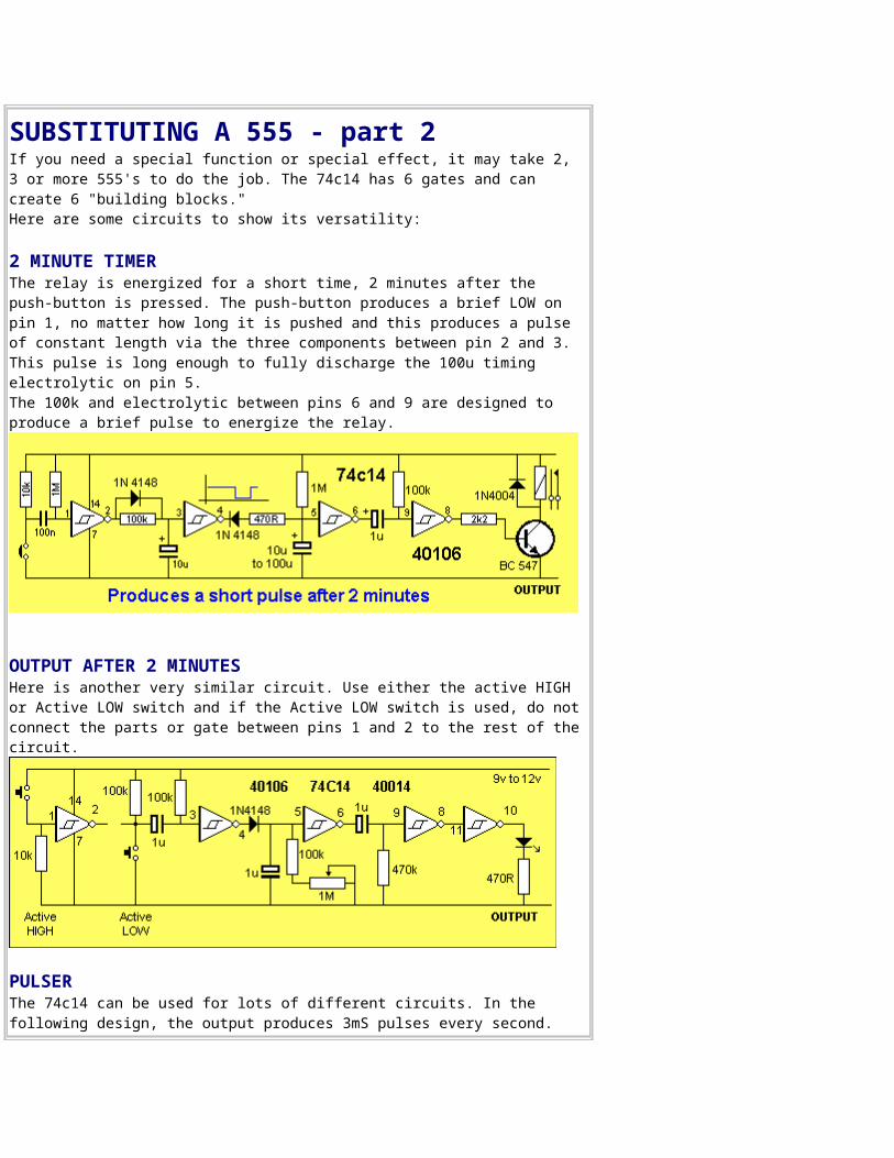
SUBSTITUTING A 555 - part 2If you need a special function or special effect, it may take 2, 3 or more 555's to do the job. The 74c14 has 6 gates and can create 6 "building blocks."Here are some circuits to show its versatility:
2 MINUTE TIMER The relay is energized for a short time, 2 minutes after the push-button is pressed. The push-button produces a brief LOW on pin 1, no matter how long it is pushed and this produces a pulse of constant length via the three components between pin 2 and 3. This pulse is long enough to fully discharge the 100u timing electrolytic on pin 5. The 100k and electrolytic between pins 6 and 9 are designed to produce a brief pulse to energize the relay.
OUTPUT AFTER 2 MINUTESHere is another very similar circuit. Use either the active HIGH or Active LOW switch and if the Active LOW switch is used, do notconnect the parts or gate between pins 1 and 2 to the rest of thecircuit.
PULSERThe 74c14 can be used for lots of different circuits. In the following design, the output produces 3mS pulses every second.
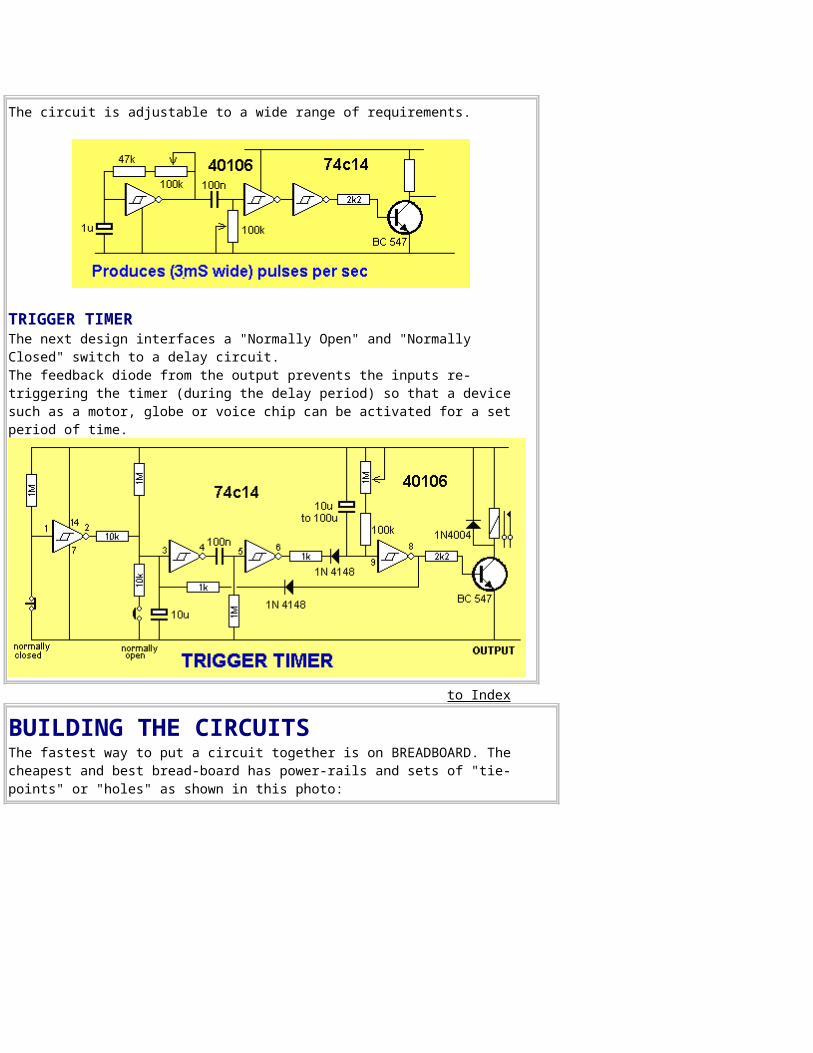
The circuit is adjustable to a wide range of requirements.
TRIGGER TIMERThe next design interfaces a "Normally Open" and "Normally Closed" switch to a delay circuit. The feedback diode from the output prevents the inputs re-triggering the timer (during the delay period) so that a device such as a motor, globe or voice chip can be activated for a set period of time.
to Index
BUILDING THE CIRCUITSThe fastest way to put a circuit together is on BREADBOARD. The cheapest and best bread-board has power-rails and sets of "tie-points" or "holes" as shown in this photo:
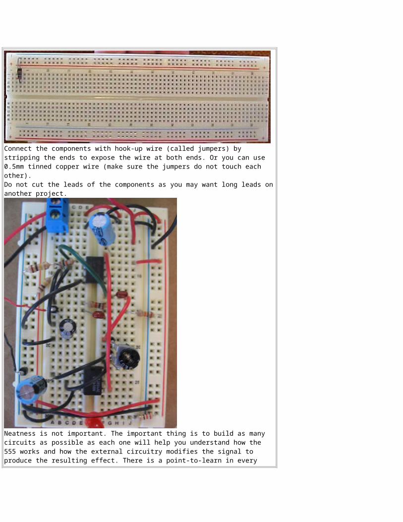
Connect the components with hook-up wire (called jumpers) by stripping the ends to expose the wire at both ends. Or you can use 0.5mm tinned copper wire (make sure the jumpers do not touch each other).Do not cut the leads of the components as you may want long leads onanother project.
Neatness is not important. The important thing is to build as many circuits as possible as each one will help you understand how the 555 works and how the external circuitry modifies the signal to produce the resulting effect. There is a point-to-learn in every
circuit. to Index
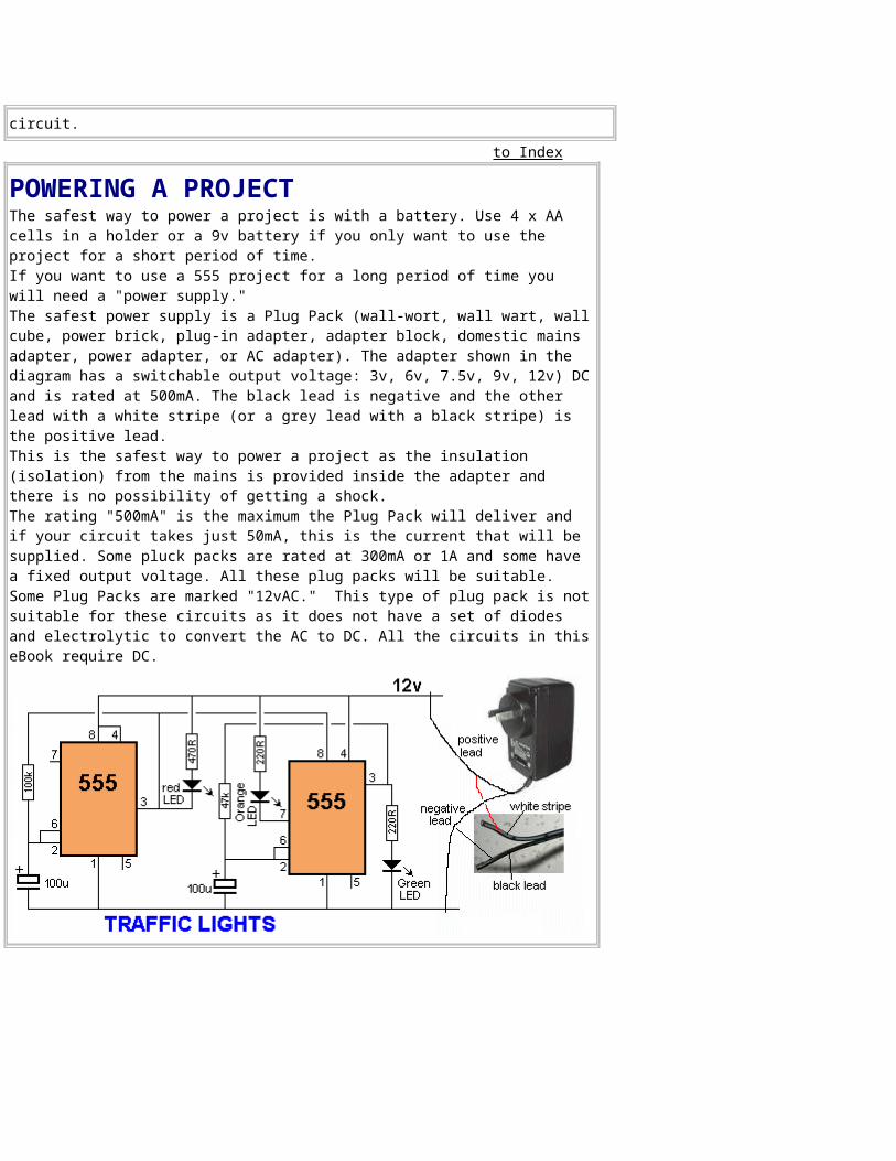
POWERING A PROJECTThe safest way to power a project is with a battery. Use 4 x AA cells in a holder or a 9v battery if you only want to use the project for a short period of time. If you want to use a 555 project for a long period of time you will need a "power supply." The safest power supply is a Plug Pack (wall-wort, wall wart, wallcube, power brick, plug-in adapter, adapter block, domestic mains adapter, power adapter, or AC adapter). The adapter shown in the diagram has a switchable output voltage: 3v, 6v, 7.5v, 9v, 12v) DCand is rated at 500mA. The black lead is negative and the other lead with a white stripe (or a grey lead with a black stripe) is the positive lead.This is the safest way to power a project as the insulation (isolation) from the mains is provided inside the adapter and there is no possibility of getting a shock. The rating "500mA" is the maximum the Plug Pack will deliver and if your circuit takes just 50mA, this is the current that will be supplied. Some pluck packs are rated at 300mA or 1A and some have a fixed output voltage. All these plug packs will be suitable. Some Plug Packs are marked "12vAC." This type of plug pack is notsuitable for these circuits as it does not have a set of diodes and electrolytic to convert the AC to DC. All the circuits in thiseBook require DC.
PROJECTS to Index
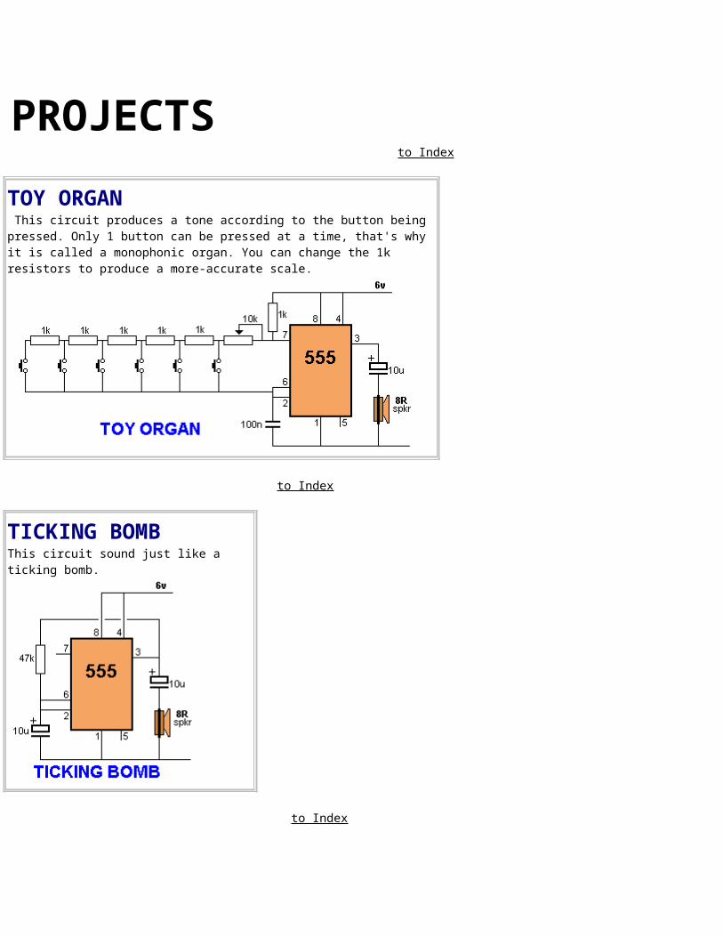
TOY ORGAN This circuit produces a tone according to the button being pressed. Only 1 button can be pressed at a time, that's why it is called a monophonic organ. You can change the 1k resistors to produce a more-accurate scale.
to Index
TICKING BOMBThis circuit sound just like a ticking bomb.
to Index
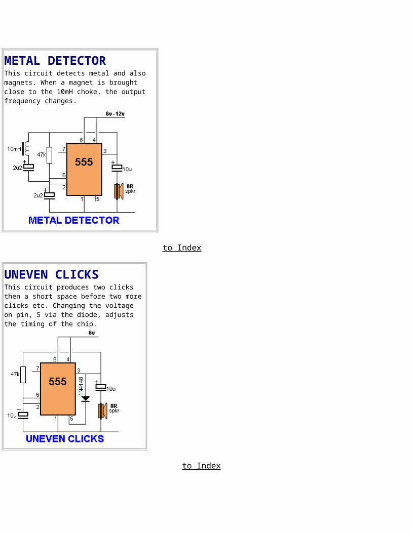
METAL DETECTORThis circuit detects metal and also magnets. When a magnet is brought close to the 10mH choke, the output frequency changes.
to Index
UNEVEN CLICKS This circuit produces two clicks then a short space before two moreclicks etc. Changing the voltage on pin, 5 via the diode, adjusts the timing of the chip.
to Index
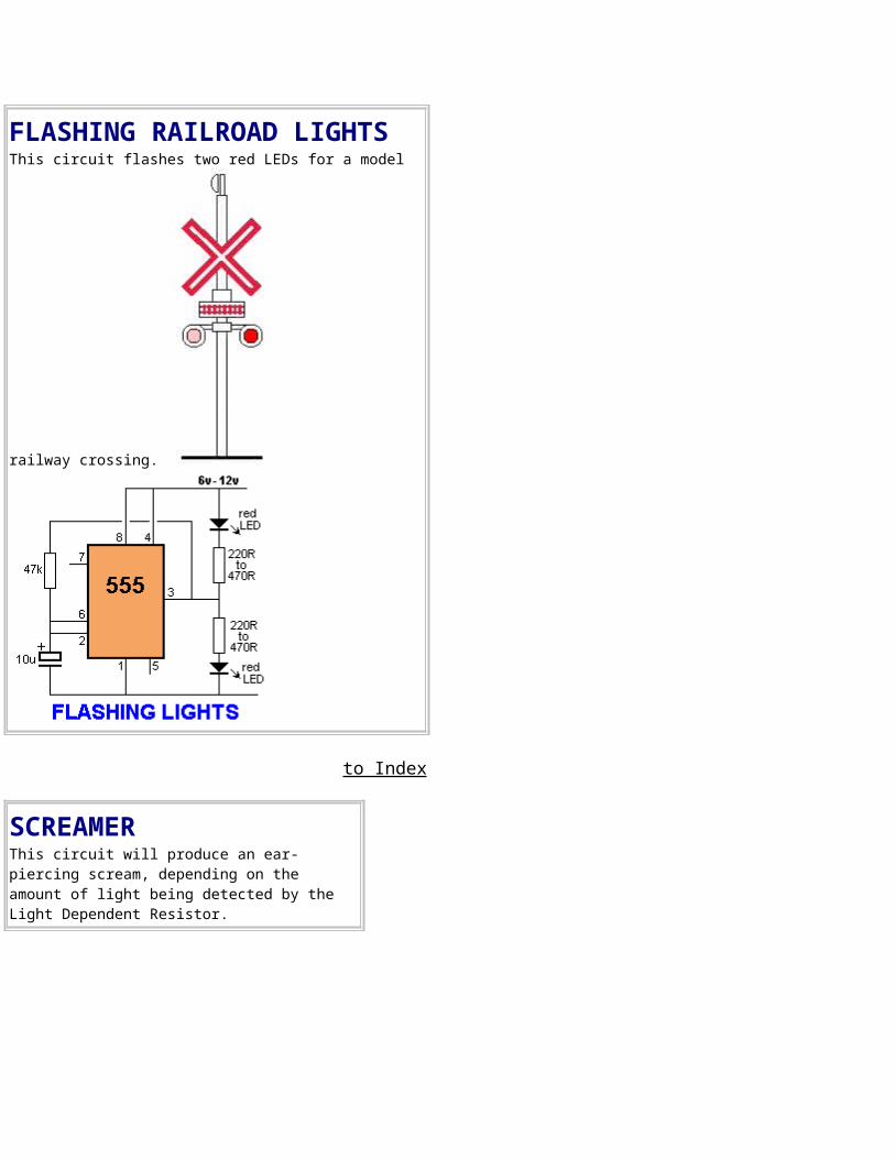
FLASHING RAILROAD LIGHTSThis circuit flashes two red LEDs for a model
railway crossing.
to Index
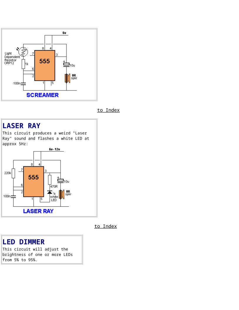
SCREAMERThis circuit will produce an ear-piercing scream, depending on the amount of light being detected by the Light Dependent Resistor.
to Index
LASER RAYThis circuit produces a weird "Laser Ray" sound and flashes a white LED at approx 5Hz:
to Index
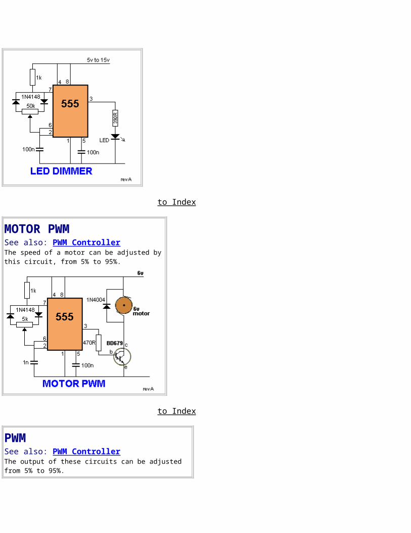
LED DIMMERThis circuit will adjust the brightness of one or more LEDs from 5% to 95%.
to Index
MOTOR PWMSee also: PWM ControllerThe speed of a motor can be adjusted bythis circuit, from 5% to 95%.
to Index
PWMSee also: PWM ControllerThe output of these circuits can be adjusted from 5% to 95%.
to Index
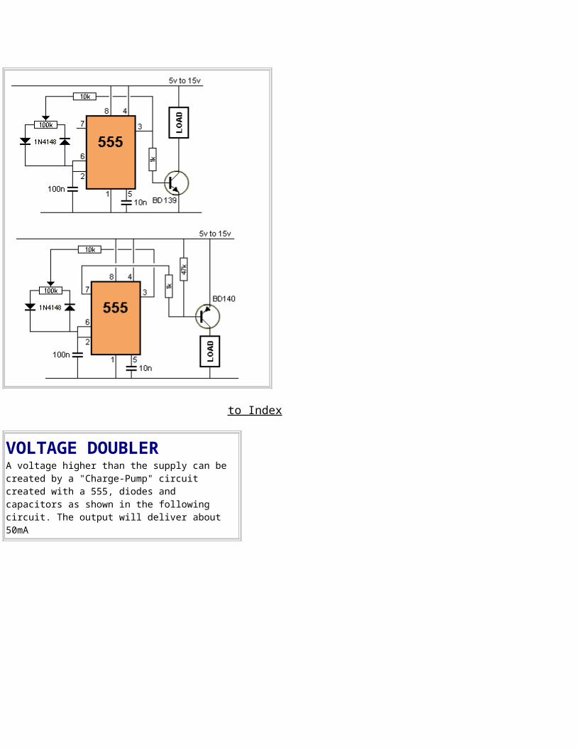
VOLTAGE DOUBLERA voltage higher than the supply can be created by a "Charge-Pump" circuit created with a 555, diodes and capacitors as shown in the following circuit. The output will deliver about 50mA
to Index
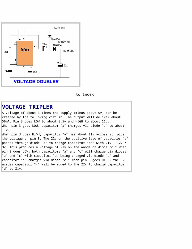
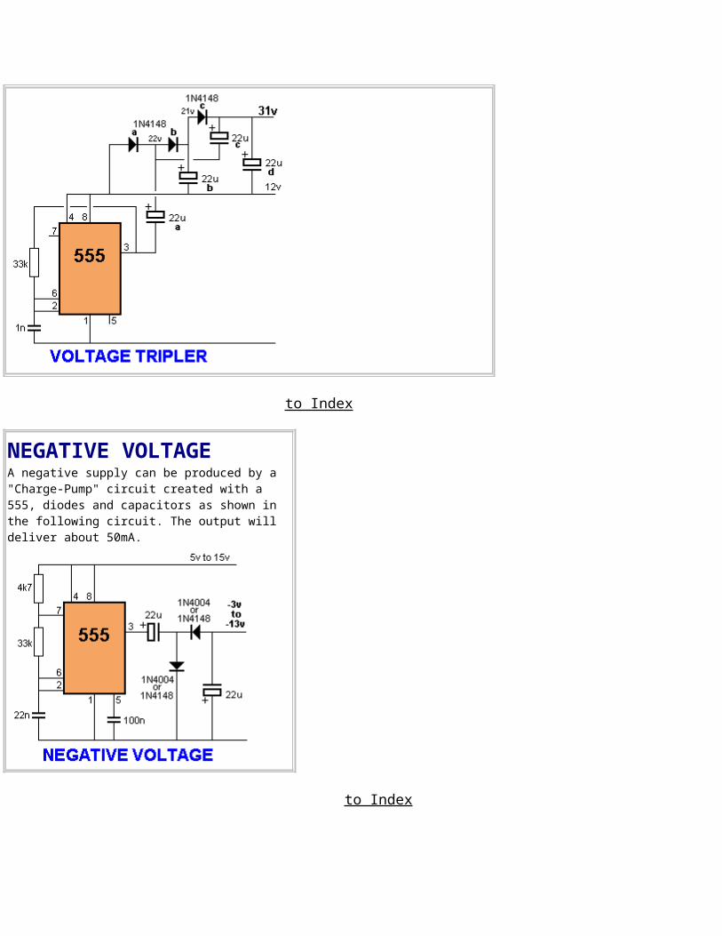
VOLTAGE TRIPLERA voltage of about 3 times the supply (minus about 5v) can be created by the following circuit. The output will deliver about 50mA. Pin 3 goes LOW to about 0.5v and HIGH to about 11v. When pin 3 goes LOW, capacitor "a" charges via diode "a" to about 11v. When pin 3 goes HIGH, capacitor "a" has about 11v across it, plus the voltage on pin 3. The 22v on the positive lead of capacitor "a" passes through diode "b" to charge capacitor "b'' with 21v - 12v = 9v. This produces a voltage of 21v on the anode of diode "c." When pin 3 goes LOW, both capacitors "a" and "c" will charge via diodes "a" and "c" with capacitor "a" being charged via diode "a" and capacitor "c" charged via diode "c." When pin 3 goes HIGH, the 9v across capacitor "c" will be added to the 22v to charge capacitor "d" to 31v.
to Index
NEGATIVE VOLTAGEA negative supply can be produced by a "Charge-Pump" circuit created with a 555, diodes and capacitors as shown in the following circuit. The output will deliver about 50mA.
to Index
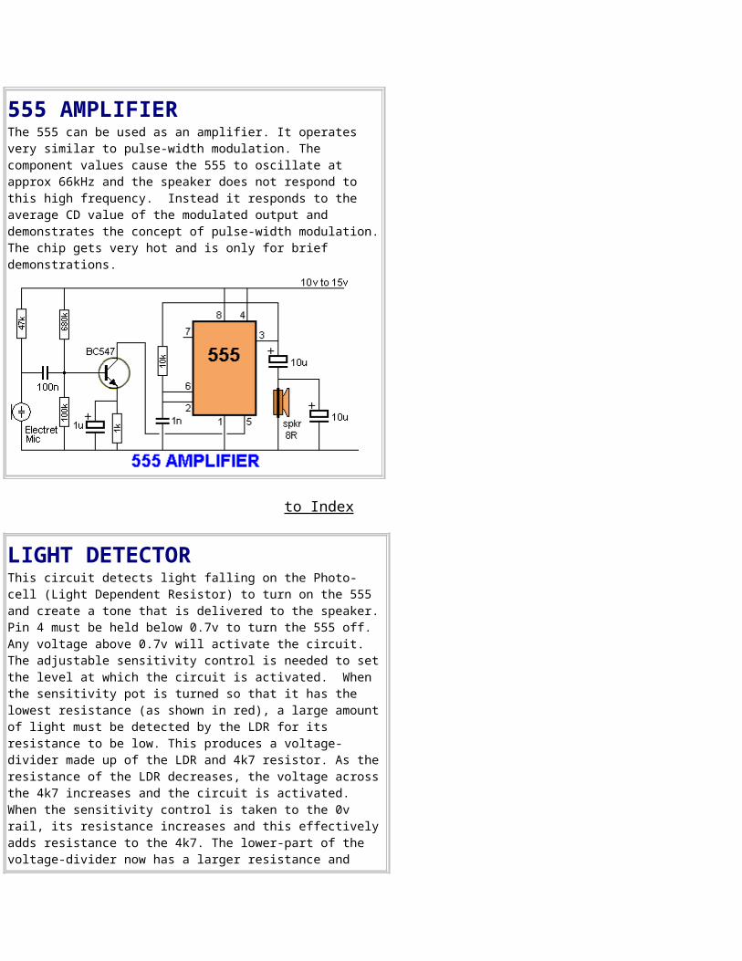
555 AMPLIFIERThe 555 can be used as an amplifier. It operates very similar to pulse-width modulation. The component values cause the 555 to oscillate at approx 66kHz and the speaker does not respond to this high frequency. Instead it responds to the average CD value of the modulated output and demonstrates the concept of pulse-width modulation.The chip gets very hot and is only for brief demonstrations.
to Index
LIGHT DETECTORThis circuit detects light falling on the Photo-cell (Light Dependent Resistor) to turn on the 555 and create a tone that is delivered to the speaker.Pin 4 must be held below 0.7v to turn the 555 off. Any voltage above 0.7v will activate the circuit. The adjustable sensitivity control is needed to setthe level at which the circuit is activated. When the sensitivity pot is turned so that it has the lowest resistance (as shown in red), a large amountof light must be detected by the LDR for its resistance to be low. This produces a voltage-divider made up of the LDR and 4k7 resistor. As theresistance of the LDR decreases, the voltage acrossthe 4k7 increases and the circuit is activated. When the sensitivity control is taken to the 0v rail, its resistance increases and this effectivelyadds resistance to the 4k7. The lower-part of the voltage-divider now has a larger resistance and
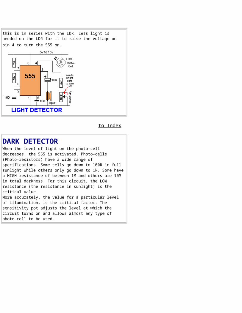
this is in series with the LDR. Less light is needed on the LDR for it to raise the voltage on pin 4 to turn the 555 on.
to Index
DARK DETECTORWhen the level of light on the photo-cell decreases, the 555 is activated. Photo-cells (Photo-resistors) have a wide range of specifications. Some cells go down to 100R in full sunlight while others only go down to 1k. Some havea HIGH resistance of between 1M and others are 10M in total darkness. For this circuit, the LOW resistance (the resistance in sunlight) is the critical value. More accurately, the value for a particular level of illumination, is the critical factor. The sensitivity pot adjusts the level at which the circuit turns on and allows almost any type of photo-cell to be used.
to Index
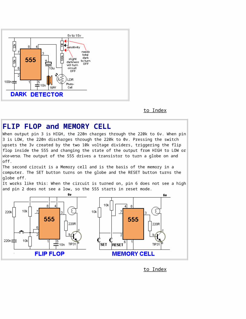
FLIP FLOP and MEMORY CELLWhen output pin 3 is HIGH, the 220n charges through the 220k to 6v. When pin3 is LOW, the 220n discharges through the 220k to 0v. Pressing the switch upsets the 3v created by the two 10k voltage dividers, triggering the flip flop inside the 555 and changing the state of the output from HIGH to LOW orvice-versa. The output of the 555 drives a transistor to turn a globe on and off. The second circuit is a Memory cell and is the basis of the memory in a computer. The SET button turns on the globe and the RESET button turns the globe off. It works like this: When the circuit is turned on, pin 6 does not see a highand pin 2 does not see a low, so the 555 starts in reset mode.
to Index
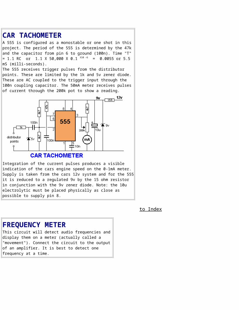
CAR TACHOMETERA 555 is configured as a monostable or one shot in this project. The period of the 555 is determined by the 47k and the capacitor from pin 6 to ground (100n). Time "T" = 1.1 RC or 1.1 X 50,000 X 0.1 X10 -6 = 0.0055 or 5.5 mS (milli-seconds). The 555 receives trigger pulses from the distributor points. These are limited by the 1k and 5v zener diode. These are AC coupled to the trigger input through the 100n coupling capacitor. The 50mA meter receives pulses of current through the 200k pot to show a reading.
Integration of the current pulses produces a visible indication of the cars engine speed on the 0-1mA meter.Supply is taken from the cars 12v system and for the 555it is reduced to a regulated 9v by the 15 ohm resistor in conjunction with the 9v zener diode. Note: the 10u electrolytic must be placed physically as close as possible to supply pin 8.
to Index
FREQUENCY METERThis circuit will detect audio frequencies anddisplay them on a meter (actually called a "movement"). Connect the circuit to the outputof an amplifier. It is best to detect one frequency at a time.
Integration of the audio frequency produces a visible indication on the 0-1mA meter.
to Index
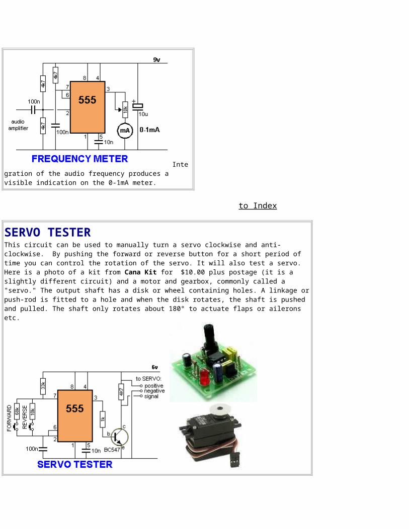
SERVO TESTERThis circuit can be used to manually turn a servo clockwise and anti-clockwise. By pushing the forward or reverse button for a short period of time you can control the rotation of the servo. It will also test a servo. Here is a photo of a kit from Cana Kit for $10.00 plus postage (it is a slightly different circuit) and a motor and gearbox, commonly called a "servo." The output shaft has a disk or wheel containing holes. A linkage orpush-rod is fitted to a hole and when the disk rotates, the shaft is pushed and pulled. The shaft only rotates about 180° to actuate flaps or ailerons etc.
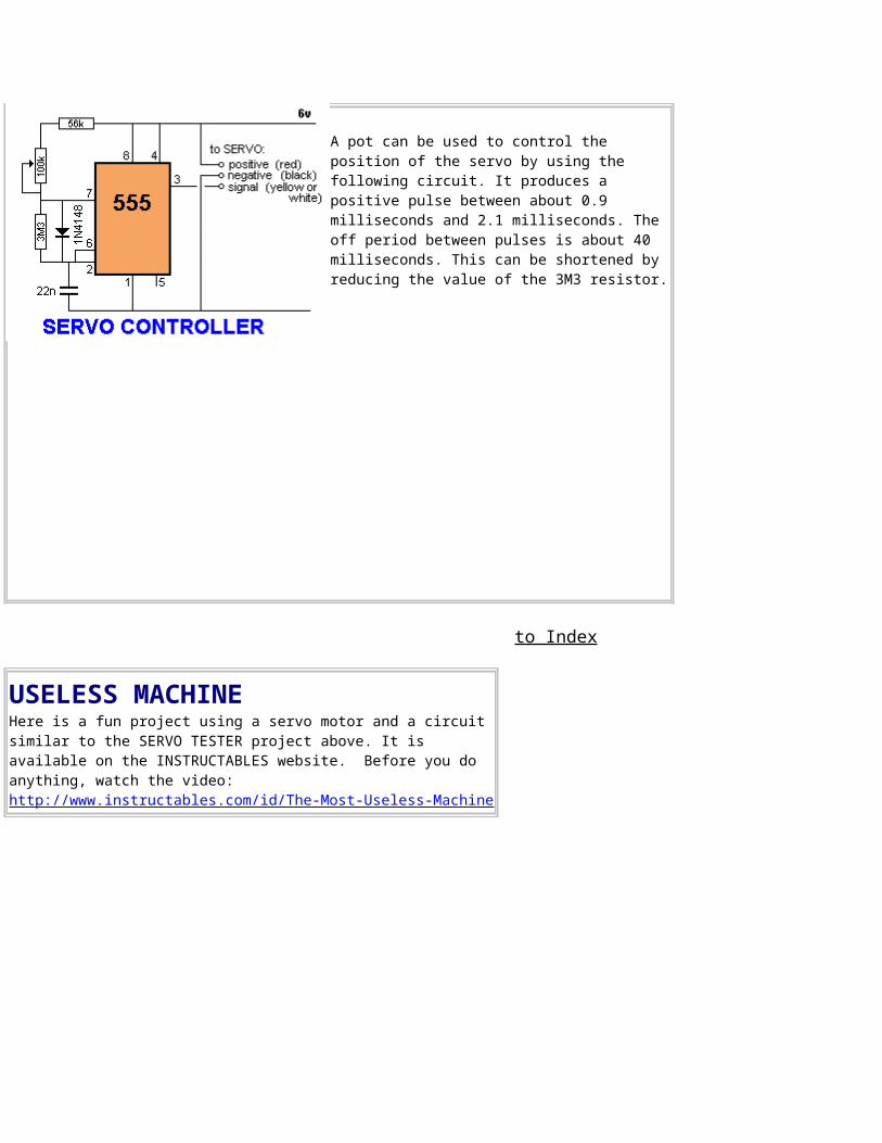
A pot can be used to control the position of the servo by using the following circuit. It produces a positive pulse between about 0.9 milliseconds and 2.1 milliseconds. The off period between pulses is about 40 milliseconds. This can be shortened by reducing the value of the 3M3 resistor.
to Index
USELESS MACHINEHere is a fun project using a servo motor and a circuit similar to the SERVO TESTER project above. It is available on the INSTRUCTABLES website. Before you do anything, watch the video:http://www.instructables.com/id/The-Most-Useless-Machine
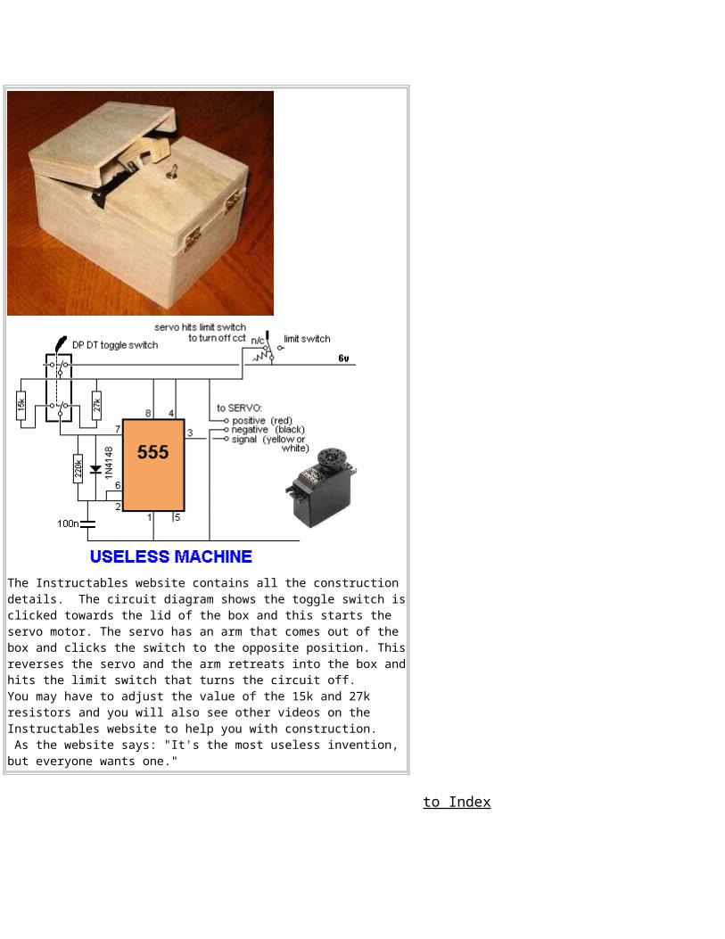
The Instructables website contains all the construction details. The circuit diagram shows the toggle switch isclicked towards the lid of the box and this starts the servo motor. The servo has an arm that comes out of the box and clicks the switch to the opposite position. Thisreverses the servo and the arm retreats into the box andhits the limit switch that turns the circuit off.You may have to adjust the value of the 15k and 27k resistors and you will also see other videos on the Instructables website to help you with construction. As the website says: "It's the most useless invention, but everyone wants one."
to Index
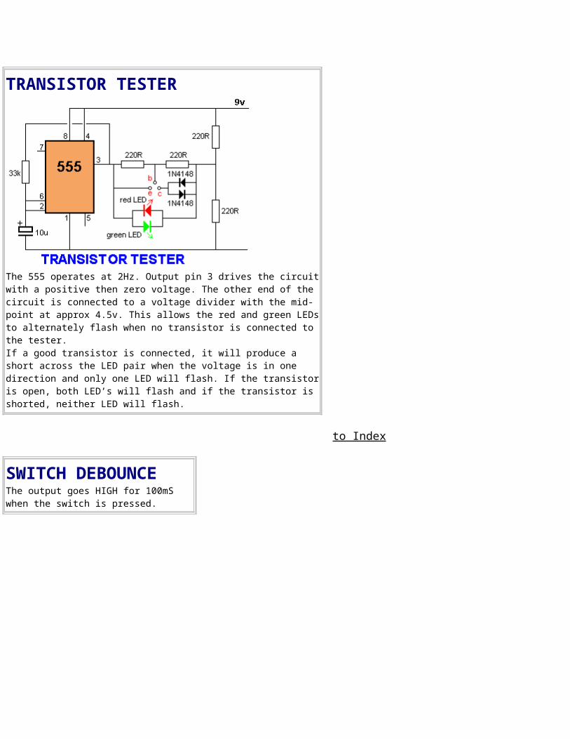
TRANSISTOR TESTER
The 555 operates at 2Hz. Output pin 3 drives the circuitwith a positive then zero voltage. The other end of the circuit is connected to a voltage divider with the mid-point at approx 4.5v. This allows the red and green LEDsto alternately flash when no transistor is connected to the tester.If a good transistor is connected, it will produce a short across the LED pair when the voltage is in one direction and only one LED will flash. If the transistoris open, both LED’s will flash and if the transistor is shorted, neither LED will flash.
to Index
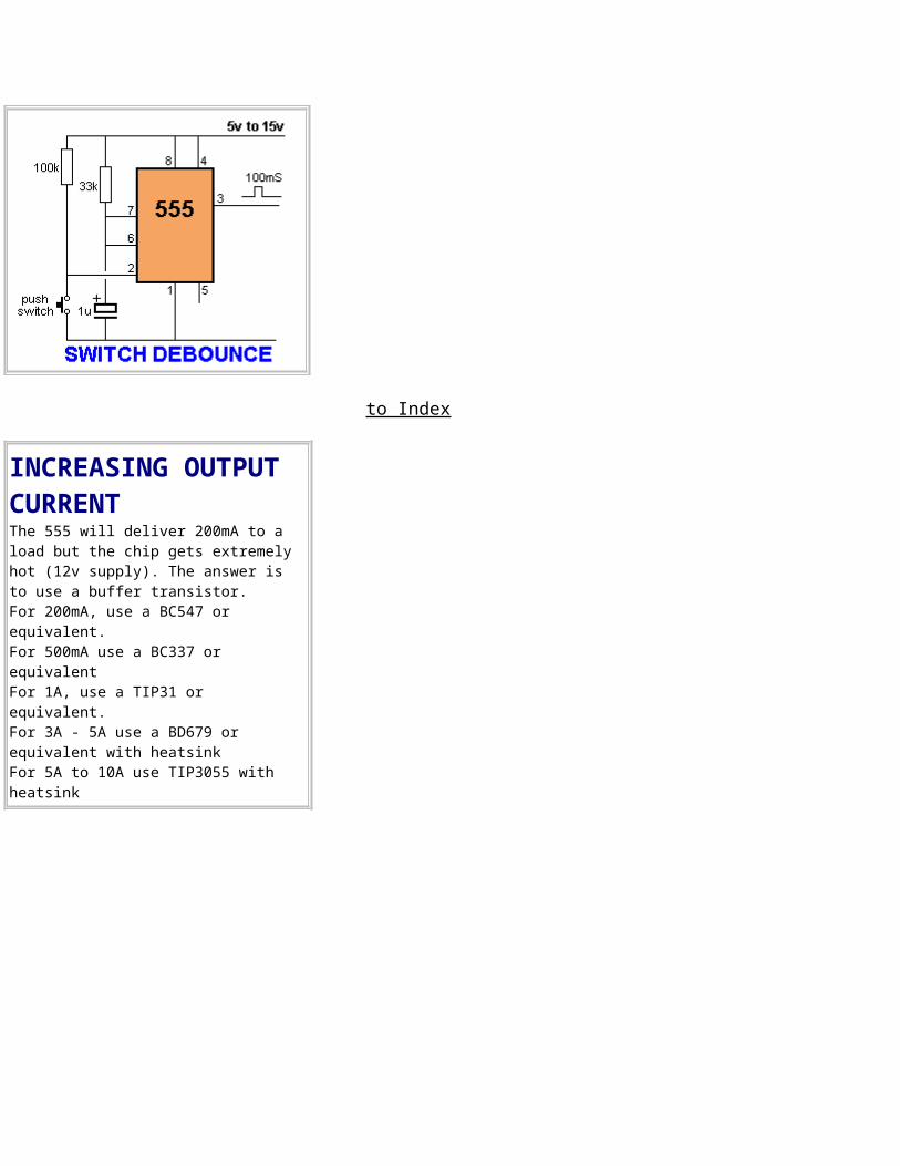
SWITCH DEBOUNCEThe output goes HIGH for 100mS when the switch is pressed.
to Index
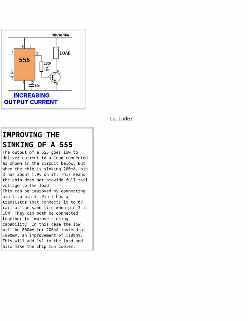
INCREASING OUTPUT CURRENTThe 555 will deliver 200mA to a load but the chip gets extremely hot (12v supply). The answer is to use a buffer transistor. For 200mA, use a BC547 or equivalent.For 500mA use a BC337 or equivalent For 1A, use a TIP31 or equivalent.For 3A - 5A use a BD679 or equivalent with heatsinkFor 5A to 10A use TIP3055 with heatsink
to Index
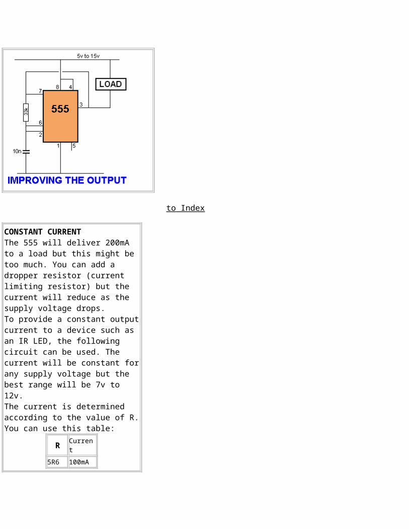
IMPROVING THE SINKING OF A 555The output of a 555 goes low to deliver current to a load connected as shown in the circuit below. But when the chip is sinking 200mA, pin 3 has about 1.9v on it. This means the chip does not provide full rail voltage to the load. This can be improved by connecting pin 7 to pin 3. Pin 7 has a transistor that connects it to 0v rail at the same time when pin 3 is LOW. They can both be connected together to improve sinking capability. In this case the low will be 800mV for 200mA instead of 1900mV, an improvement of 1100mV. This will add 1v1 to the load and also make the chip run cooler.
to Index
CONSTANT CURRENTThe 555 will deliver 200mA to a load but this might be too much. You can add a dropper resistor (current limiting resistor) but the current will reduce as the supply voltage drops. To provide a constant outputcurrent to a device such as an IR LED, the following circuit can be used. The current will be constant forany supply voltage but the best range will be 7v to 12v. The current is determined according to the value of R.You can use this table:
R Current
5R6 100mA

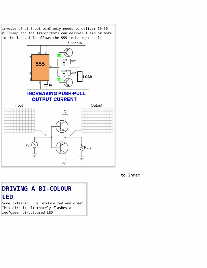
inverse of pin3 but pin3 only needs to deliver 10-50 milliamp and the transistors can deliver 1 amp or more to the load. This allows the 555 to be kept cool.
to Index
DRIVING A BI-COLOUR LEDSome 3-leaded LEDs produce red and green.This circuit alternately flashes a red/green bi-coloured LED:
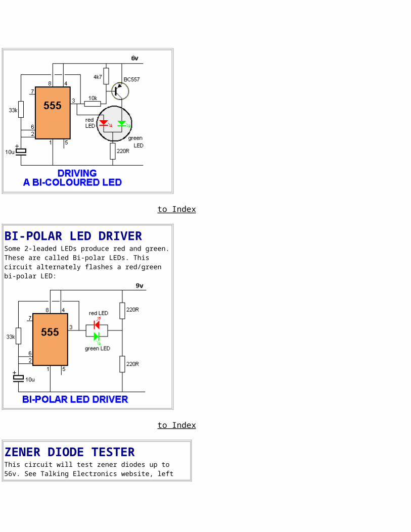
to Index
BI-POLAR LED DRIVERSome 2-leaded LEDs produce red and green.These are called Bi-polar LEDs. This circuit alternately flashes a red/green bi-polar LED:
to Index
ZENER DIODE TESTERThis circuit will test zener diodes up to 56v. See Talking Electronics website, left
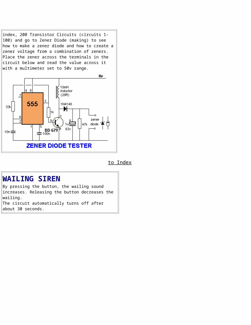
index, 200 Transistor Circuits (circuits 1-100) and go to Zener Diode (making) to see how to make a zener diode and how to create azener voltage from a combination of zeners. Place the zener across the terminals in the circuit below and read the value across it with a multimeter set to 50v range.
to Index
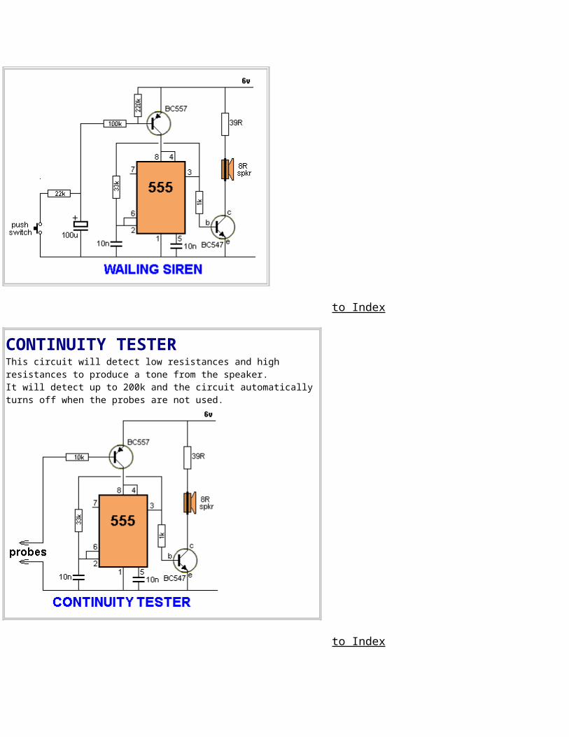
WAILING SIRENBy pressing the button, the wailing sound increases. Releasing the button decreases the wailing. The circuit automatically turns off after about 30 seconds.
to Index
CONTINUITY TESTERThis circuit will detect low resistances and high resistances to produce a tone from the speaker. It will detect up to 200k and the circuit automatically turns off when the probes are not used.
to Index
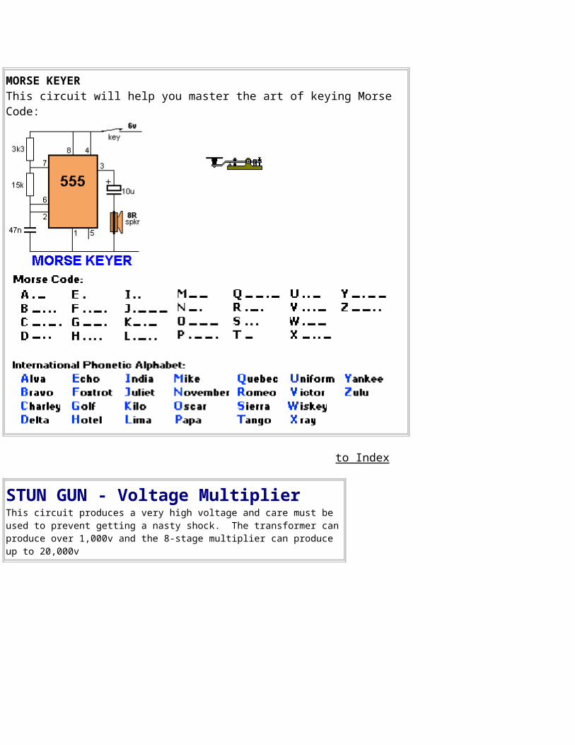
MORSE KEYERThis circuit will help you master the art of keying Morse Code:
to Index
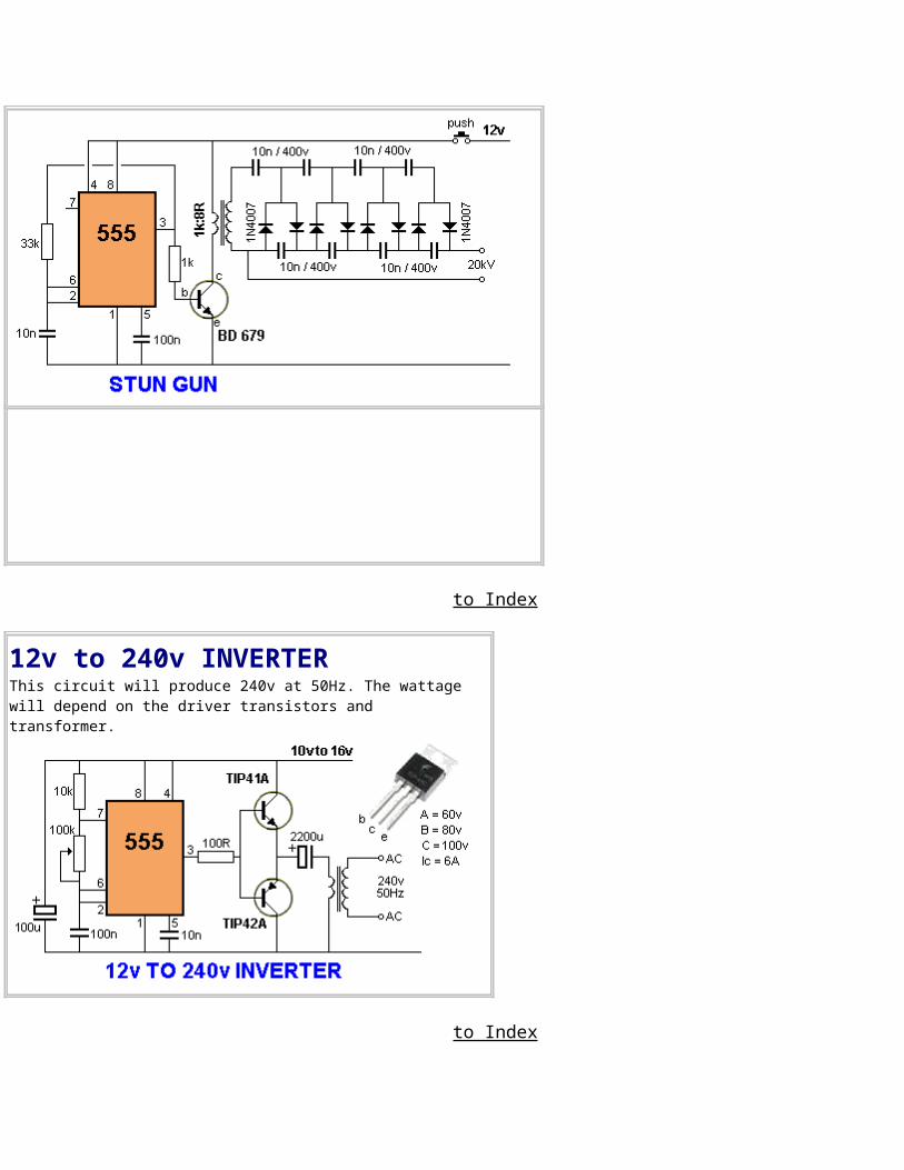
STUN GUN - Voltage MultiplierThis circuit produces a very high voltage and care must be used to prevent getting a nasty shock. The transformer canproduce over 1,000v and the 8-stage multiplier can produce up to 20,000v
to Index
12v to 240v INVERTERThis circuit will produce 240v at 50Hz. The wattage will depend on the driver transistors and transformer.
to Index
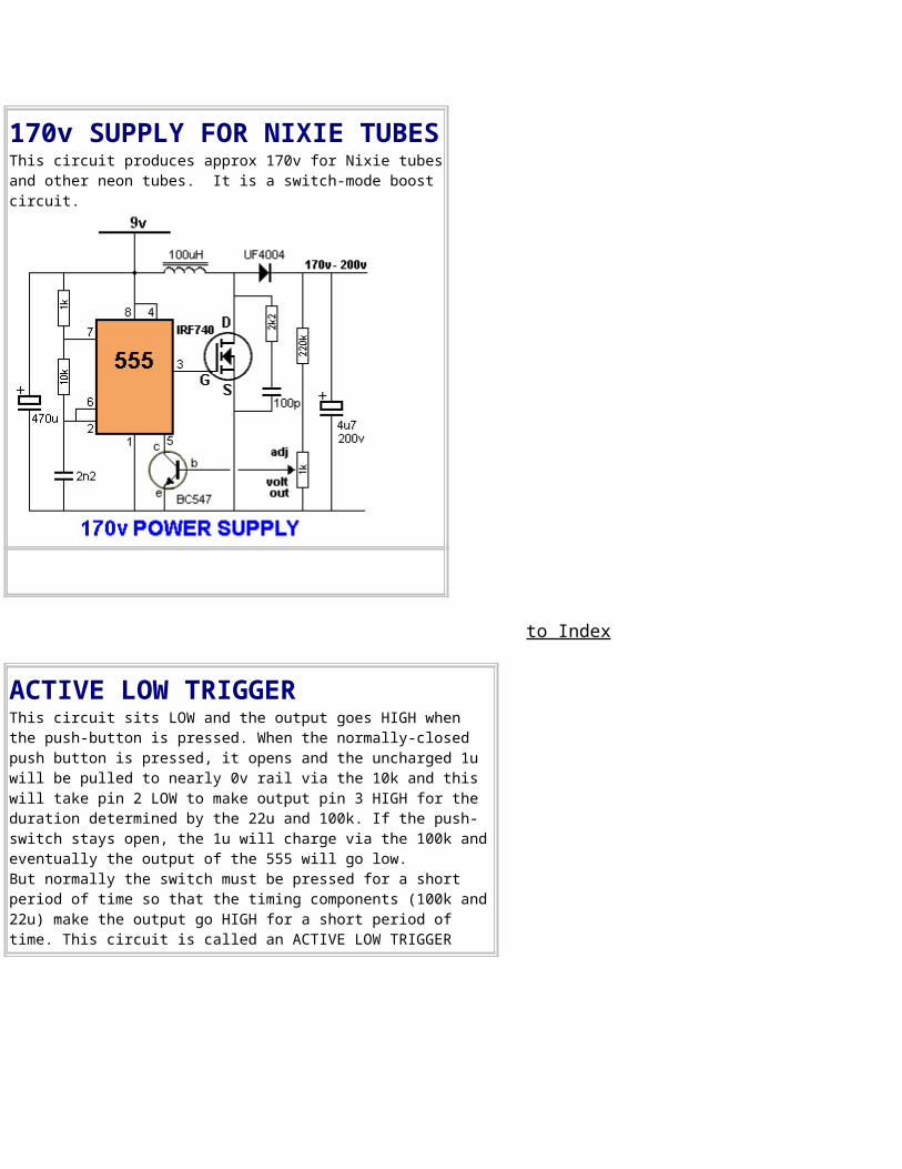
170v SUPPLY FOR NIXIE TUBESThis circuit produces approx 170v for Nixie tubesand other neon tubes. It is a switch-mode boost circuit.
to Index
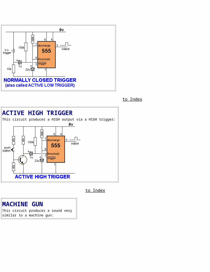
ACTIVE LOW TRIGGERThis circuit sits LOW and the output goes HIGH when the push-button is pressed. When the normally-closed push button is pressed, it opens and the uncharged 1u will be pulled to nearly 0v rail via the 10k and this will take pin 2 LOW to make output pin 3 HIGH for the duration determined by the 22u and 100k. If the push-switch stays open, the 1u will charge via the 100k andeventually the output of the 555 will go low. But normally the switch must be pressed for a short period of time so that the timing components (100k and22u) make the output go HIGH for a short period of time. This circuit is called an ACTIVE LOW TRIGGER
to Index
ACTIVE HIGH TRIGGERThis circuit produces a HIGH output via a HIGH trigger:
to Index
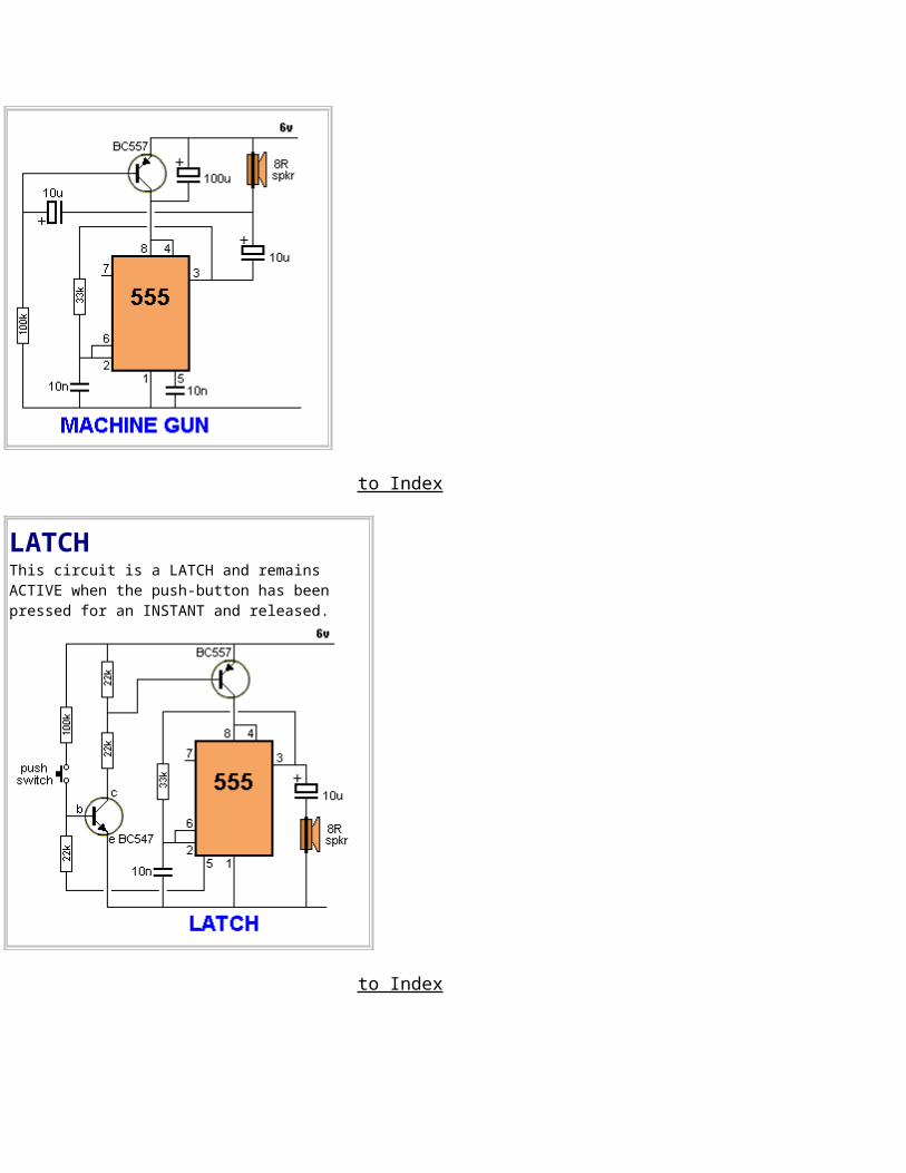
MACHINE GUN This circuit produces a sound very similar to a machine gun:
to Index
LATCHThis circuit is a LATCH and remains ACTIVE when the push-button has been pressed for an INSTANT and released.
to Index
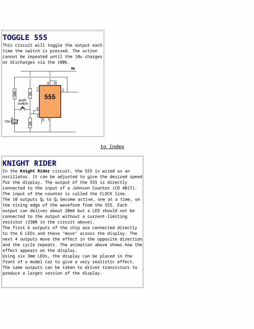
TOGGLE 555This circuit will toggle the output eachtime the switch is pressed. The action cannot be repeated until the 10u chargesor discharges via the 100k.
to Index
KNIGHT RIDERIn the Knight Rider circuit, the 555 is wired as an oscillator. It can be adjusted to give the desired speedfor the display. The output of the 555 is directly connected to the input of a Johnson Counter (CD 4017). The input of the counter is called the CLOCK line. The 10 outputs Q0 to Q9 become active, one at a time, onthe rising edge of the waveform from the 555. Each output can deliver about 20mA but a LED should not be connected to the output without a current-limiting resistor (330R in the circuit above). The first 6 outputs of the chip are connected directly to the 6 LEDs and these "move" across the display. The next 4 outputs move the effect in the opposite directionand the cycle repeats. The animation above shows how theeffect appears on the display. Using six 3mm LEDs, the display can be placed in the front of a model car to give a very realistic effect. The same outputs can be taken to driver transistors to produce a larger version of the display.
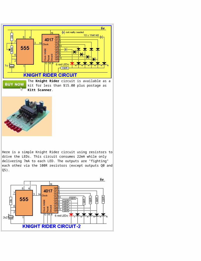
The Knight Rider circuit is available as a kit for less than $15.00 plus postage as Kitt Scanner.
Here is a simple Knight Rider circuit using resistors todrive the LEDs. This circuit consumes 22mA while only delivering 7mA to each LED. The outputs are "fighting" each other via the 100R resistors (except outputs Q0 andQ5).
to Index
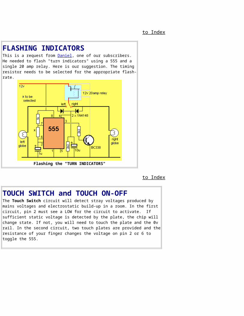
FLASHING INDICATORS This is a request from Daniel, one of our subscribers. He needed to flash "turn indicators" using a 555 and a single 20 amp relay. Here is our suggestion. The timing resistor needs to be selected for the appropriate flash-rate.
Flashing the "TURN INDICATORS"
to Index
TOUCH SWITCH and TOUCH ON-OFFThe Touch Switch circuit will detect stray voltages produced by mains voltages and electrostatic build-up in a room. In the first circuit, pin 2 must see a LOW for the circuit to activate. If sufficient static voltage is detected by the plate, the chip will change state. If not, you will need to touch the plate and the 0v rail. In the second circuit, two touch plates are provided and theresistance of your finger changes the voltage on pin 2 or 6 to toggle the 555.
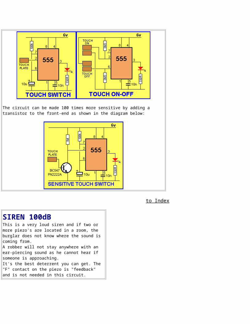
The circuit can be made 100 times more sensitive by adding a transistor to the front-end as shown in the diagram below:
to Index
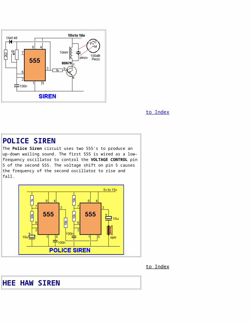
SIREN 100dBThis is a very loud siren and if two or more piezo's are located in a room, the burglar does not know where the sound is coming from. A robber will not stay anywhere with an ear-piercing sound as he cannot hear if someone is approaching.It's the best deterrent you can get. The "F" contact on the piezo is "feedback" and is not needed in this circuit.
to Index
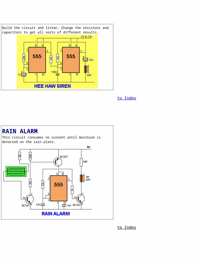
POLICE SIRENThe Police Siren circuit uses two 555's to produce an up-down wailing sound. The first 555 is wired as a low-frequency oscillator to control the VOLTAGE CONTROL pin 5 of the second 555. The voltage shift on pin 5 causes the frequency of the second oscillator to rise and fall.
to Index
HEE HAW SIREN
Build the circuit and listen. Change the resistors and capacitors to get all sorts of different results.
to Index
RAIN ALARMThis circuit consumes no current until moisture is detected on the rain plate.
to Index
PWM CONTROLLERSee also: PWMThis controller will deliver up to 30 amps and control the motor from 5% to 95%.
to Index
SOLAR TRACKERSome ideas are simply not suited for a 555. This is one. A solar tracker should consume little or no current when waiting for a the sun to change position. A 555 takes 10mA+ and suitable circuits using other chips will take less than 1mA. That's why we have not designed a 555 circuit.
to Index
HULDA CLARK ZAPPER
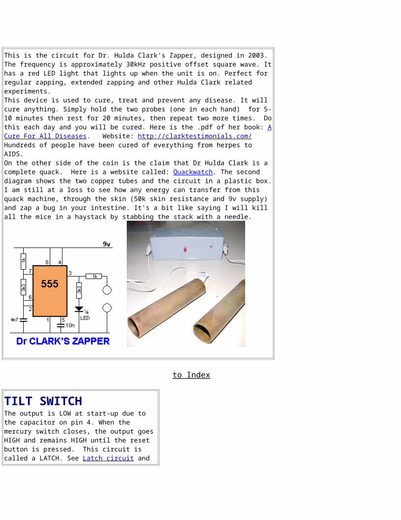
This is the circuit for Dr. Hulda Clark's Zapper, designed in 2003. The frequency is approximately 30kHz positive offset square wave. Ithas a red LED light that lights up when the unit is on. Perfect for regular zapping, extended zapping and other Hulda Clark related experiments.This device is used to cure, treat and prevent any disease. It will cure anything. Simply hold the two probes (one in each hand) for 5-10 minutes then rest for 20 minutes, then repeat two more times. Dothis each day and you will be cured. Here is the .pdf of her book: ACure For All Diseases. Website: http://clarktestimonials.com/ Hundreds of people have been cured of everything from herpes to AIDS. On the other side of the coin is the claim that Dr Hulda Clark is a complete quack. Here is a website called: Quackwatch. The second diagram shows the two copper tubes and the circuit in a plastic box.I am still at a loss to see how any energy can transfer from this quack machine, through the skin (50k skin resistance and 9v supply) and zap a bug in your intestine. It's a bit like saying I will kill all the mice in a haystack by stabbing the stack with a needle.
to Index
TILT SWITCH The output is LOW at start-up due to the capacitor on pin 4. When the mercury switch closes, the output goesHIGH and remains HIGH until the reset button is pressed. This circuit is called a LATCH. See Latch circuit and
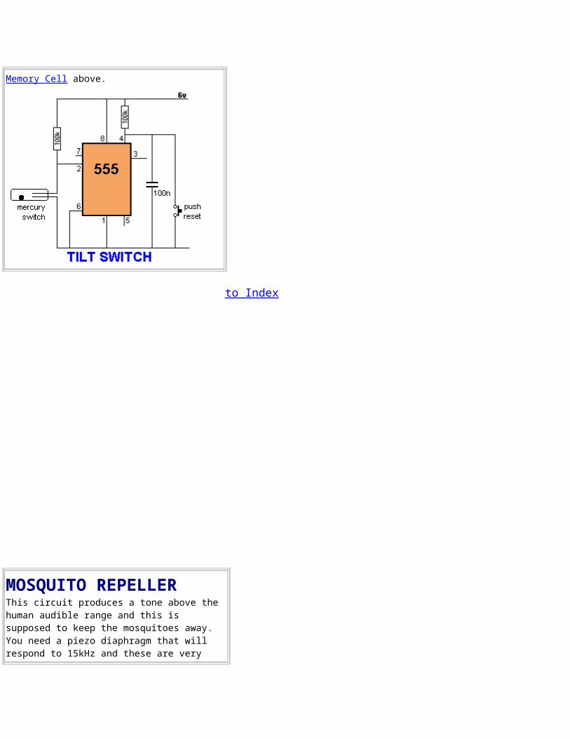
Memory Cell above.
to Index
MOSQUITO REPELLERThis circuit produces a tone above the human audible range and this is supposed to keep the mosquitoes away. You need a piezo diaphragm that will respond to 15kHz and these are very
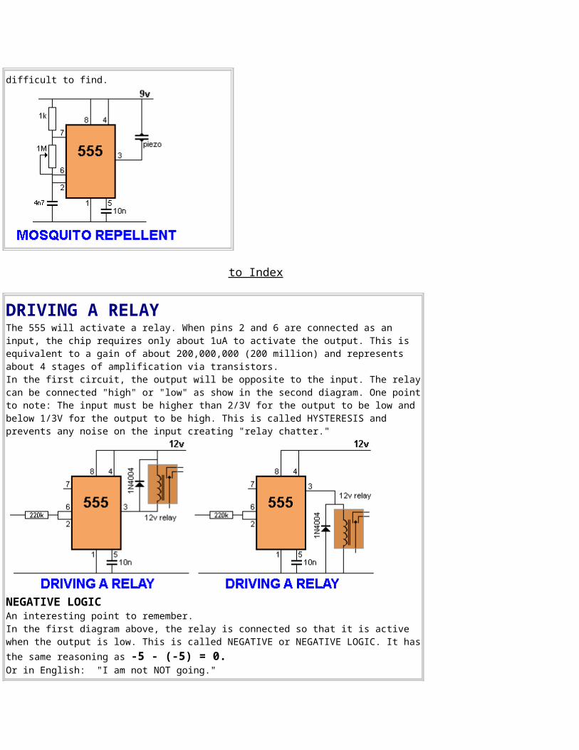
difficult to find.
to Index
DRIVING A RELAYThe 555 will activate a relay. When pins 2 and 6 are connected as an input, the chip requires only about 1uA to activate the output. This is equivalent to a gain of about 200,000,000 (200 million) and represents about 4 stages of amplification via transistors.In the first circuit, the output will be opposite to the input. The relaycan be connected "high" or "low" as show in the second diagram. One pointto note: The input must be higher than 2/3V for the output to be low and below 1/3V for the output to be high. This is called HYSTERESIS and prevents any noise on the input creating "relay chatter."
NEGATIVE LOGICAn interesting point to remember.In the first diagram above, the relay is connected so that it is active when the output is low. This is called NEGATIVE or NEGATIVE LOGIC. It hasthe same reasoning as -5 - (-5) = 0.Or in English: "I am not NOT going."
When the input is low in the first diagram, the output is HIGH and the relay is OFF. The circuitry creates two reversals and makes it easy to see that when the input is LOW, the relay is OFF.
to Index
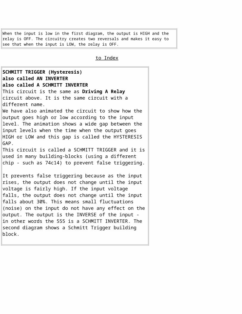
SCHMITT TRIGGER (Hysteresis)also called AN INVERTERalso called A SCHMITT INVERTERThis circuit is the same as Driving A Relay circuit above. It is the same circuit with a different name. We have also animated the circuit to show how the output goes high or low according to the input level. The animation shows a wide gap between the input levels when the time when the output goes HIGH or LOW and this gap is called the HYSTERESIS GAP. This circuit is called a SCHMITT TRIGGER and it isused in many building-blocks (using a different chip - such as 74c14) to prevent false triggering.
It prevents false triggering because as the input rises, the output does not change until the input voltage is fairly high. If the input voltage falls, the output does not change until the input falls about 30%. This means small fluctuations (noise) on the input do not have any effect on theoutput. The output is the INVERSE of the input - in other words the 555 is a SCHMITT INVERTER. The second diagram shows a Schmitt Trigger building block.

to Index
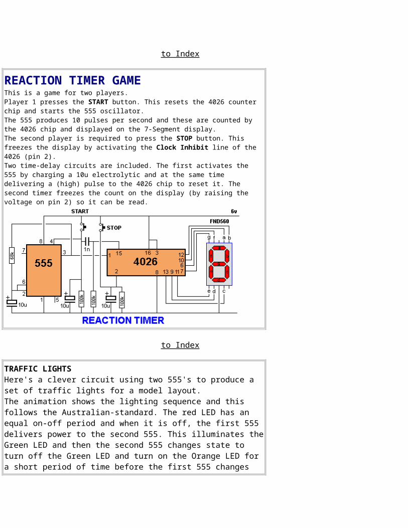
REACTION TIMER GAME This is a game for two players. Player 1 presses the START button. This resets the 4026 counter chip and starts the 555 oscillator. The 555 produces 10 pulses per second and these are counted by the 4026 chip and displayed on the 7-Segment display. The second player is required to press the STOP button. This freezes the display by activating the Clock Inhibit line of the 4026 (pin 2).Two time-delay circuits are included. The first activates the 555 by charging a 10u electrolytic and at the same time delivering a (high) pulse to the 4026 chip to reset it. The second timer freezes the count on the display (by raising the voltage on pin 2) so it can be read.
to Index
TRAFFIC LIGHTS Here's a clever circuit using two 555's to produce a set of traffic lights for a model layout. The animation shows the lighting sequence and this follows the Australian-standard. The red LED has an equal on-off period and when it is off, the first 555 delivers power to the second 555. This illuminates theGreen LED and then the second 555 changes state to turn off the Green LED and turn on the Orange LED for a short period of time before the first 555 changes
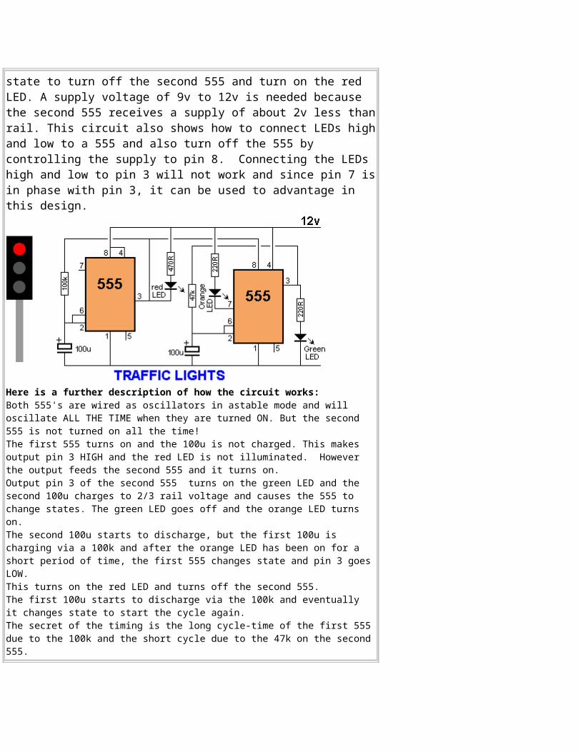
state to turn off the second 555 and turn on the red LED. A supply voltage of 9v to 12v is needed because the second 555 receives a supply of about 2v less thanrail. This circuit also shows how to connect LEDs highand low to a 555 and also turn off the 555 by controlling the supply to pin 8. Connecting the LEDs high and low to pin 3 will not work and since pin 7 isin phase with pin 3, it can be used to advantage in this design.
Here is a further description of how the circuit works:Both 555's are wired as oscillators in astable mode and will oscillate ALL THE TIME when they are turned ON. But the second 555 is not turned on all the time!The first 555 turns on and the 100u is not charged. This makes output pin 3 HIGH and the red LED is not illuminated. However the output feeds the second 555 and it turns on. Output pin 3 of the second 555 turns on the green LED and the second 100u charges to 2/3 rail voltage and causes the 555 to change states. The green LED goes off and the orange LED turns on. The second 100u starts to discharge, but the first 100u is charging via a 100k and after the orange LED has been on for a short period of time, the first 555 changes state and pin 3 goesLOW. This turns on the red LED and turns off the second 555. The first 100u starts to discharge via the 100k and eventually it changes state to start the cycle again. The secret of the timing is the long cycle-time of the first 555due to the 100k and the short cycle due to the 47k on the second555.
to Index
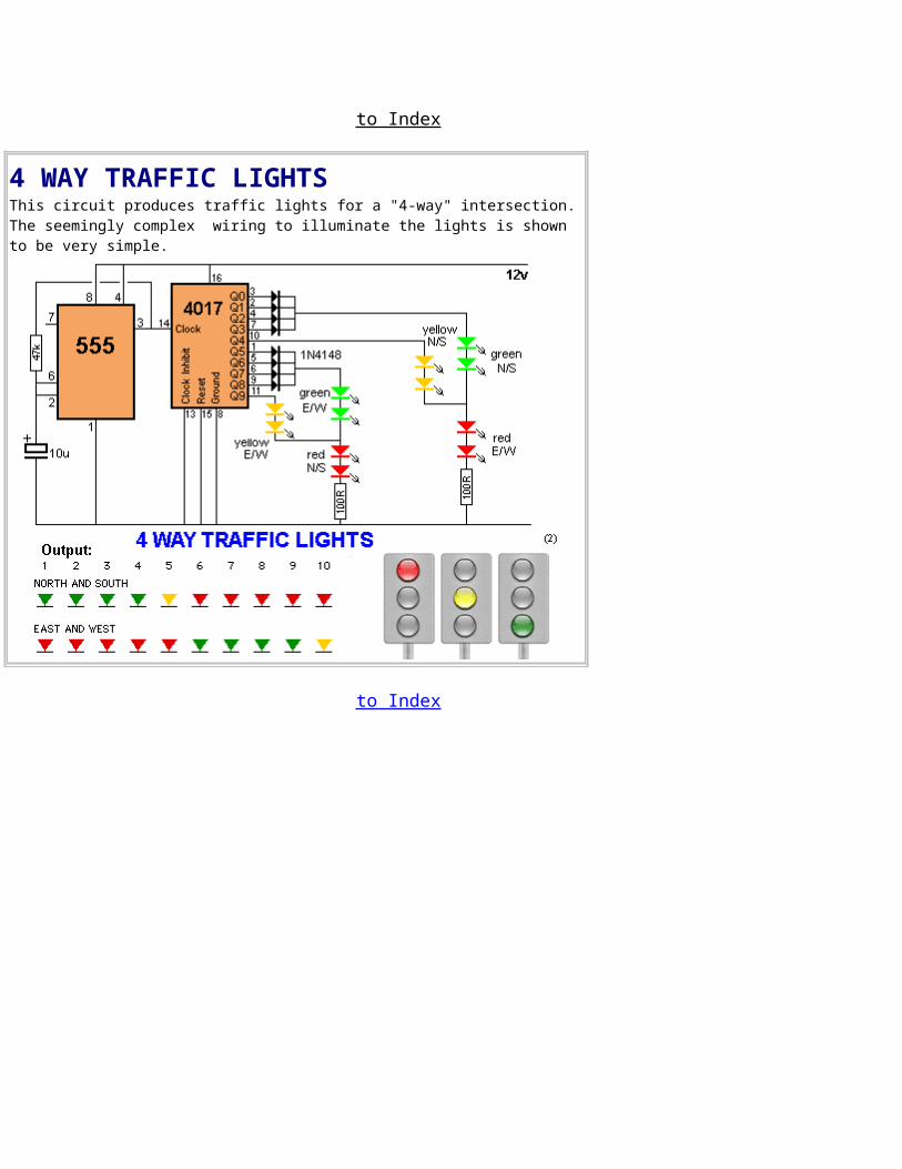
4 WAY TRAFFIC LIGHTS This circuit produces traffic lights for a "4-way" intersection.The seemingly complex wiring to illuminate the lights is shown to be very simple.
to Index
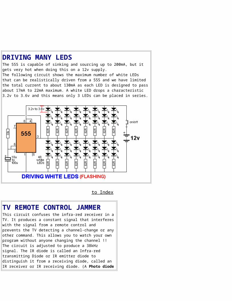
DRIVING MANY LEDS The 555 is capable of sinking and sourcing up to 200mA, but it gets very hot when doing this on a 12v supply. The following circuit shows the maximum number of white LEDs that can be realistically driven from a 555 and we have limited the total current to about 130mA as each LED is designed to passabout 17mA to 22mA maximum. A white LED drops a characteristic 3.2v to 3.6v and this means only 3 LEDs can be placed in series.
to Index
TV REMOTE CONTROL JAMMER This circuit confuses the infra-red receiver in aTV. It produces a constant signal that interfereswith the signal from a remote control and prevents the TV detecting a channel-change or anyother command. This allows you to watch your own program without anyone changing the channel !! The circuit is adjusted to produce a 38kHz signal. The IR diode is called an Infra-red transmitting Diode or IR emitter diode to distinguish it from a receiving diode, called an IR receiver or IR receiving diode. (A Photo diode
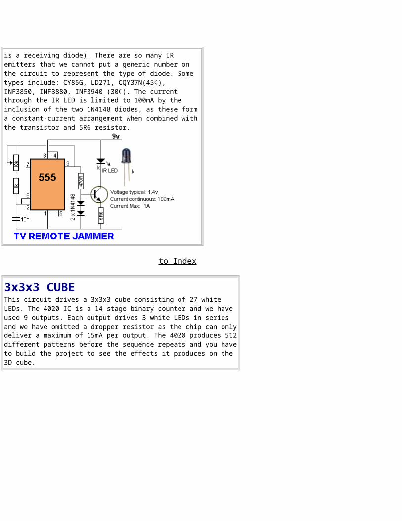
is a receiving diode). There are so many IR emitters that we cannot put a generic number on the circuit to represent the type of diode. Some types include: CY85G, LD271, CQY37N(45¢), INF3850, INF3880, INF3940 (30¢). The current through the IR LED is limited to 100mA by the inclusion of the two 1N4148 diodes, as these forma constant-current arrangement when combined withthe transistor and 5R6 resistor.
to Index
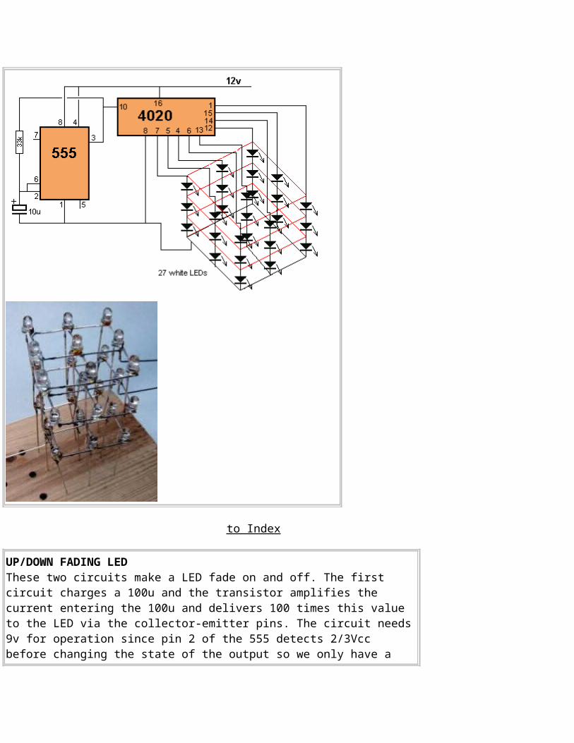
3x3x3 CUBE This circuit drives a 3x3x3 cube consisting of 27 white LEDs. The 4020 IC is a 14 stage binary counter and we have used 9 outputs. Each output drives 3 white LEDs in series and we have omitted a dropper resistor as the chip can onlydeliver a maximum of 15mA per output. The 4020 produces 512different patterns before the sequence repeats and you haveto build the project to see the effects it produces on the 3D cube.
to Index
UP/DOWN FADING LEDThese two circuits make a LED fade on and off. The first circuit charges a 100u and the transistor amplifies the current entering the 100u and delivers 100 times this value to the LED via the collector-emitter pins. The circuit needs9v for operation since pin 2 of the 555 detects 2/3Vcc before changing the state of the output so we only have a
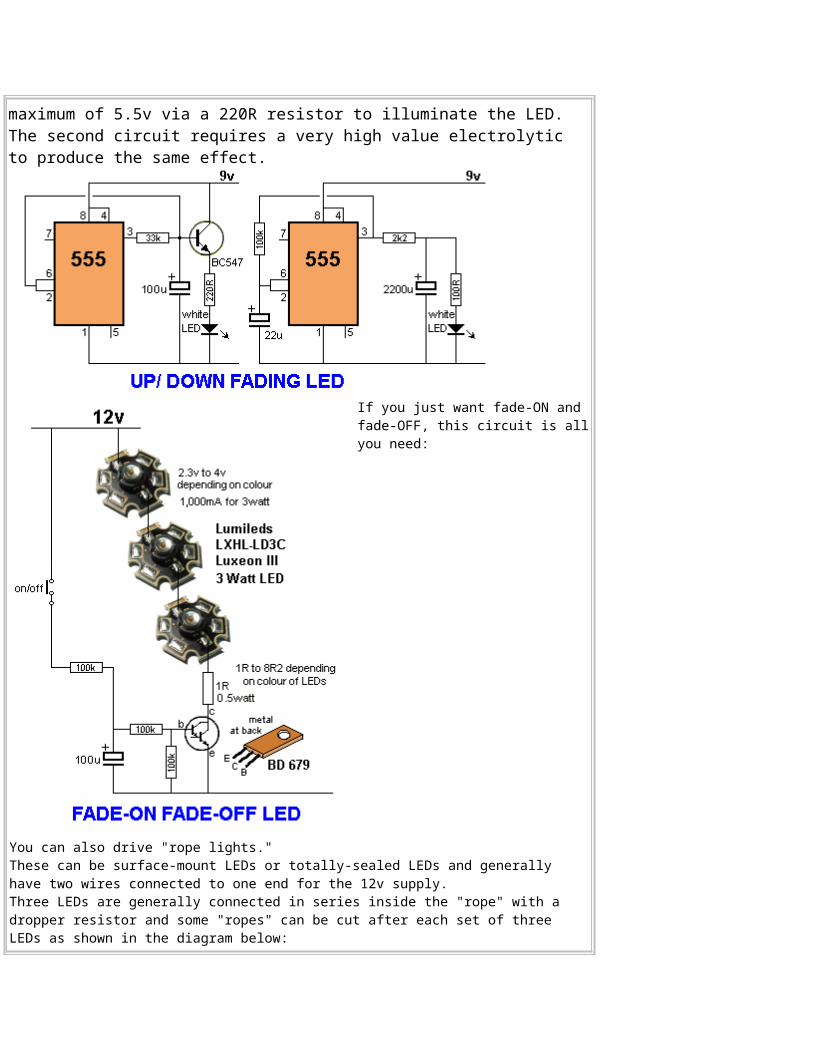
maximum of 5.5v via a 220R resistor to illuminate the LED. The second circuit requires a very high value electrolytic to produce the same effect.
If you just want fade-ON and fade-OFF, this circuit is allyou need:
You can also drive "rope lights." These can be surface-mount LEDs or totally-sealed LEDs and generally have two wires connected to one end for the 12v supply. Three LEDs are generally connected in series inside the "rope" with a dropper resistor and some "ropes" can be cut after each set of three LEDs as shown in the diagram below:

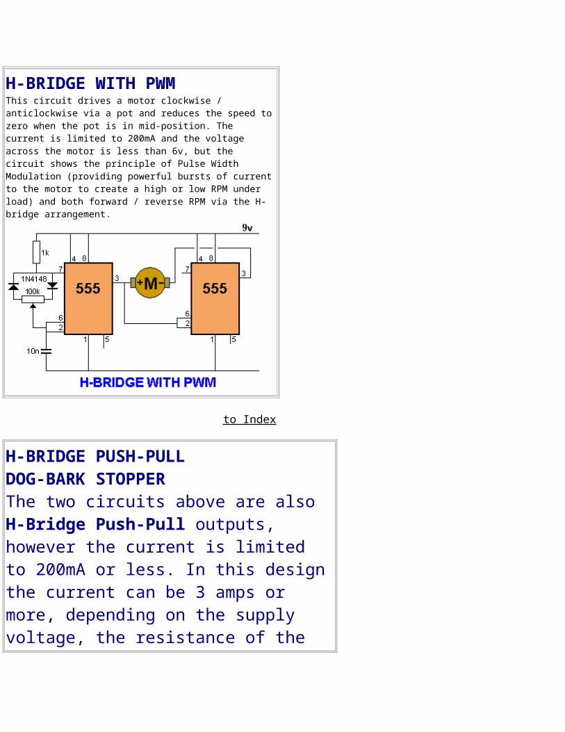
H-BRIDGE WITH PWMThis circuit drives a motor clockwise / anticlockwise via a pot and reduces the speed tozero when the pot is in mid-position. The current is limited to 200mA and the voltage across the motor is less than 6v, but the circuit shows the principle of Pulse Width Modulation (providing powerful bursts of currentto the motor to create a high or low RPM under load) and both forward / reverse RPM via the H-bridge arrangement.
to Index
H-BRIDGE PUSH-PULLDOG-BARK STOPPERThe two circuits above are also H-Bridge Push-Pull outputs, however the current is limited to 200mA or less. In this designthe current can be 3 amps or more, depending on the supply voltage, the resistance of the
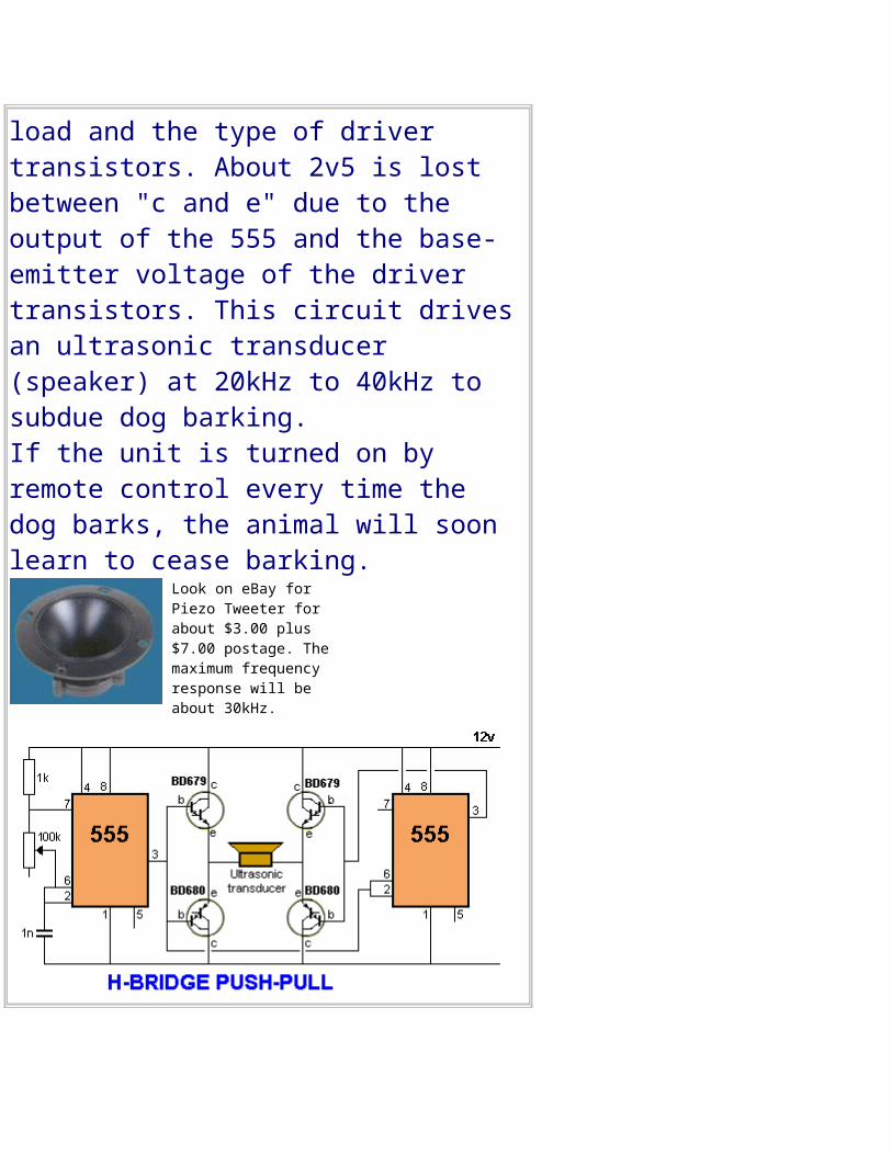
load and the type of driver transistors. About 2v5 is lost between "c and e" due to the output of the 555 and the base-emitter voltage of the driver transistors. This circuit drivesan ultrasonic transducer (speaker) at 20kHz to 40kHz to subdue dog barking. If the unit is turned on by remote control every time the dog barks, the animal will soon learn to cease barking.
Look on eBay for Piezo Tweeter for about $3.00 plus $7.00 postage. The maximum frequency response will be about 30kHz.
to Index
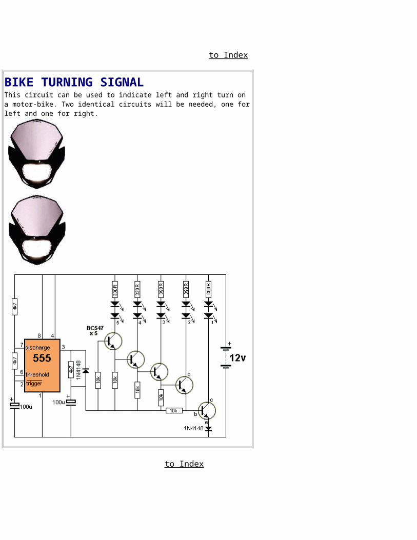
BIKE TURNING SIGNAL This circuit can be used to indicate left and right turn on a motor-bike. Two identical circuits will be needed, one forleft and one for right.
to Index
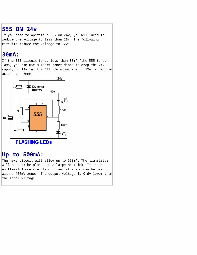
555 ON 24vIf you need to operate a 555 on 24v, you will need to reduce the voltage to less than 18v. The following circuits reduce the voltage to 12v:
30mA:If the 555 circuit takes less than 30mA (the 555 takes 10mA) you can use a 400mW zener diode to drop the 24v supply to 12v for the 555. In other words, 12v is droppedacross the zener.
Up to 500mA:The next circuit will allow up to 500mA. The transistor will need to be placed on a large heatsink. It is an emitter-follower-regulator transistor and can be used with a 400mW zener. The output voltage is 0.6v lower thanthe zener voltage.
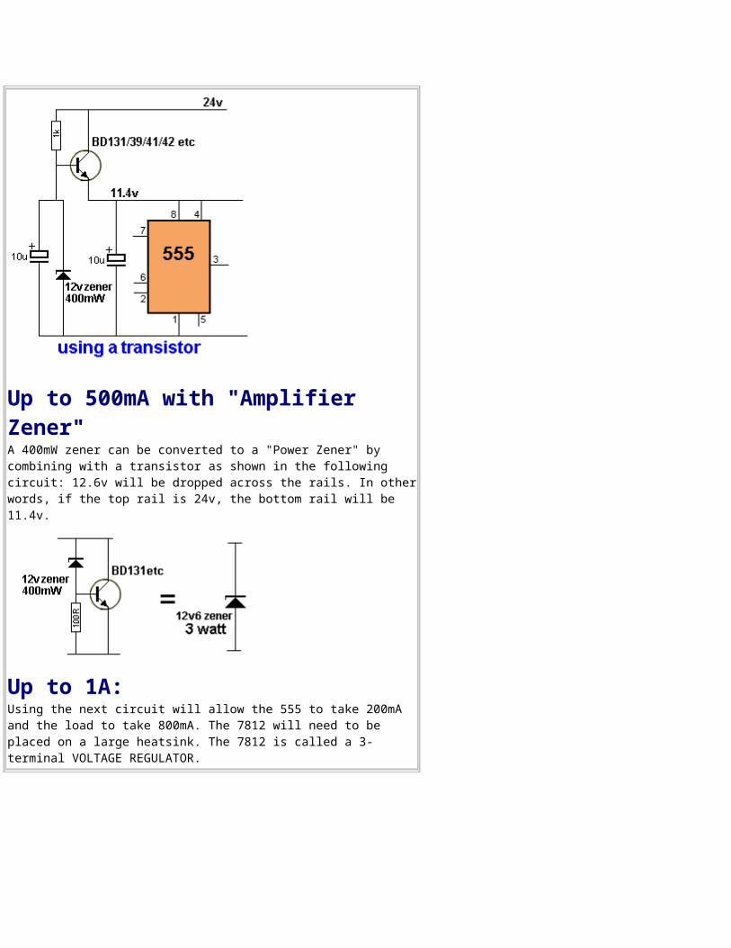
Up to 500mA with "Amplifier Zener"A 400mW zener can be converted to a "Power Zener" by combining with a transistor as shown in the following circuit: 12.6v will be dropped across the rails. In otherwords, if the top rail is 24v, the bottom rail will be 11.4v.
Up to 1A:Using the next circuit will allow the 555 to take 200mA and the load to take 800mA. The 7812 will need to be placed on a large heatsink. The 7812 is called a 3-terminal VOLTAGE REGULATOR.
to Index
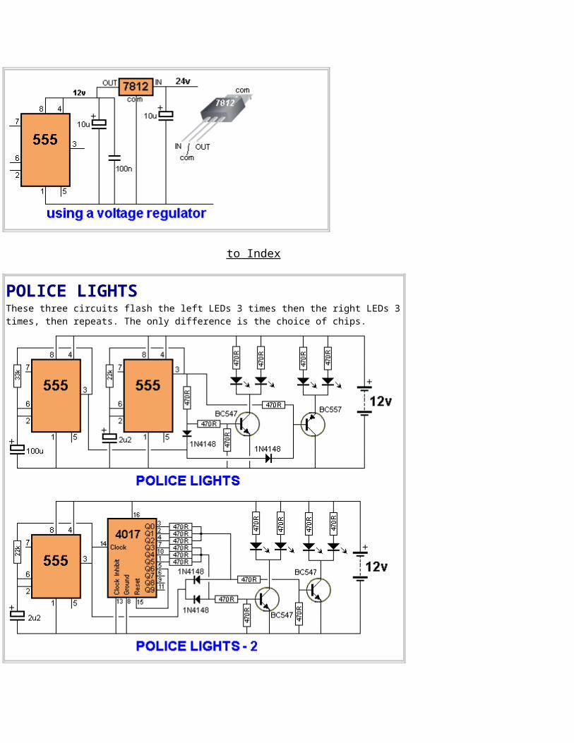
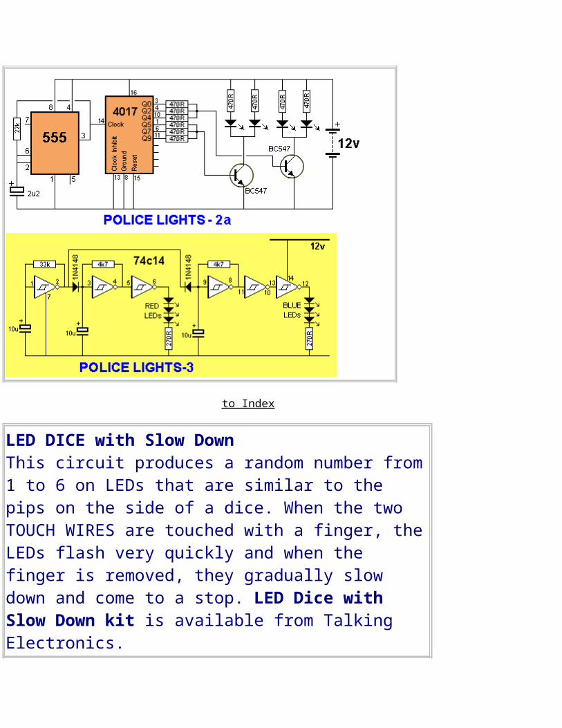
POLICE LIGHTSThese three circuits flash the left LEDs 3 times then the right LEDs 3times, then repeats. The only difference is the choice of chips.
to Index
LED DICE with Slow DownThis circuit produces a random number from1 to 6 on LEDs that are similar to the pips on the side of a dice. When the two TOUCH WIRES are touched with a finger, theLEDs flash very quickly and when the finger is removed, they gradually slow down and come to a stop. LED Dice with Slow Down kit is available from Talking Electronics.
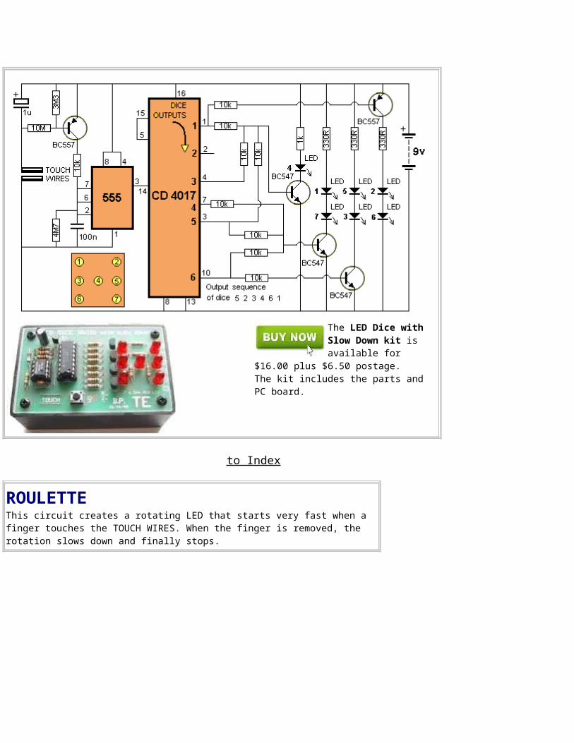
The LED Dice with Slow Down kit is available for
$16.00 plus $6.50 postage. The kit includes the parts and PC board.
to Index
ROULETTEThis circuit creates a rotating LED that starts very fast when a finger touches the TOUCH WIRES. When the finger is removed, the rotation slows down and finally stops.
to Index
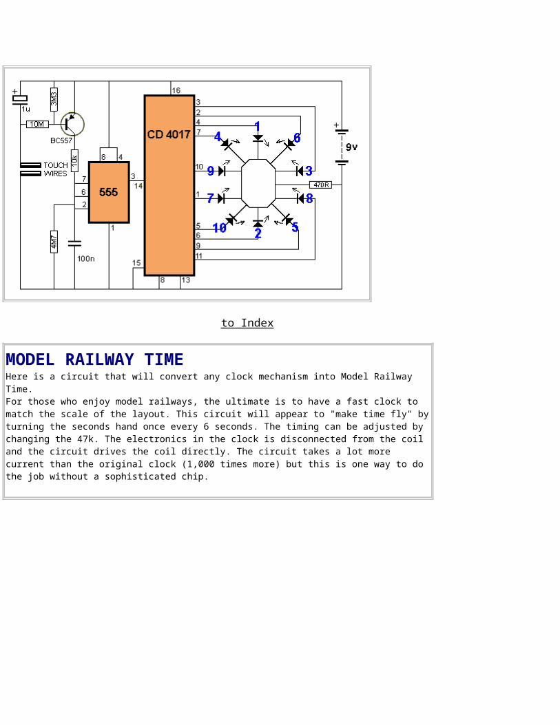
MODEL RAILWAY TIMEHere is a circuit that will convert any clock mechanism into Model Railway Time. For those who enjoy model railways, the ultimate is to have a fast clock to match the scale of the layout. This circuit will appear to "make time fly" byturning the seconds hand once every 6 seconds. The timing can be adjusted by changing the 47k. The electronics in the clock is disconnected from the coil and the circuit drives the coil directly. The circuit takes a lot more current than the original clock (1,000 times more) but this is one way to do the job without a sophisticated chip.
to Index
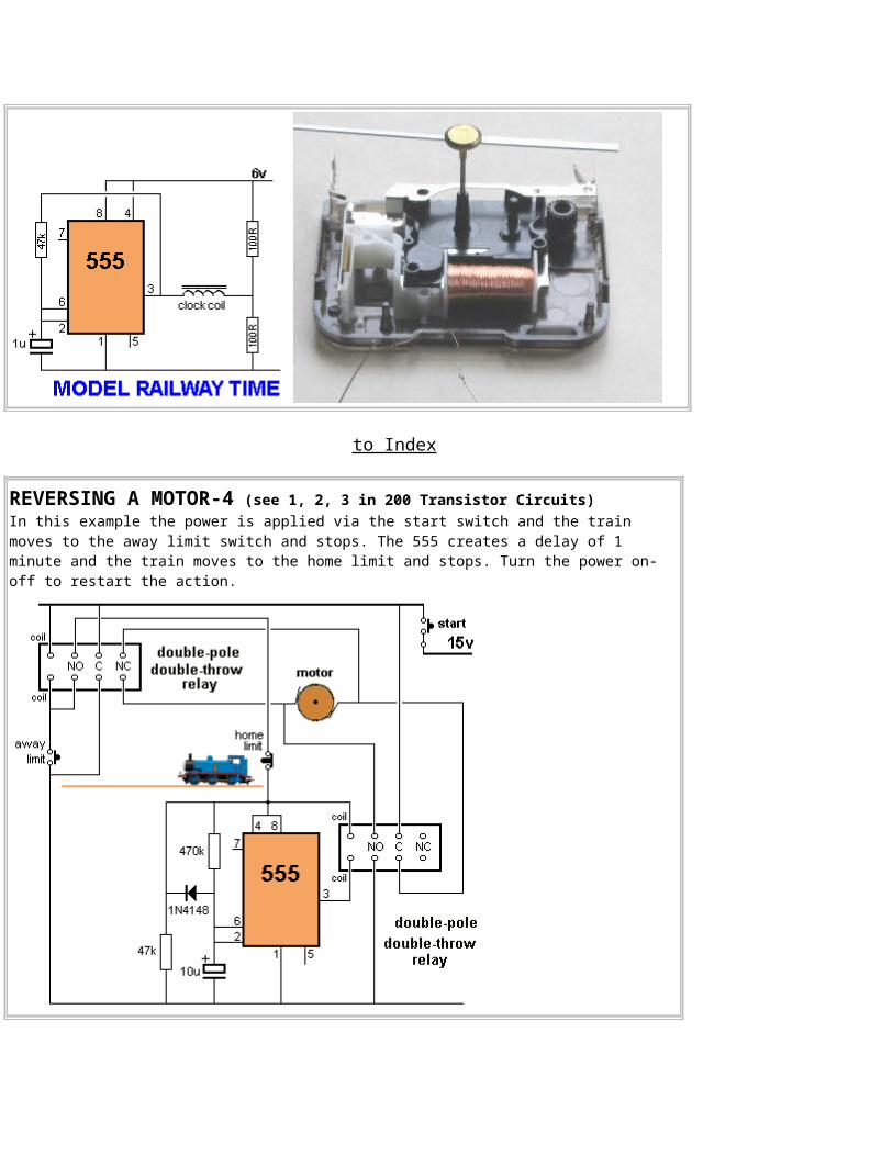
REVERSING A MOTOR-4 (see 1, 2, 3 in 200 Transistor Circuits)In this example the power is applied via the start switch and the train moves to the away limit switch and stops. The 555 creates a delay of 1 minute and the train moves to the home limit and stops. Turn the power on-off to restart the action.
to Index
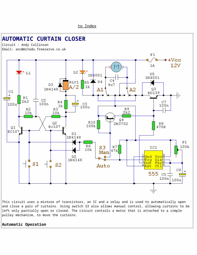
AUTOMATIC CURTAIN CLOSERCircuit : Andy CollinsonEmail: [email protected]
This circuit uses a mixture of transistors, an IC and a relay and is used to automatically open and close a pair of curtains. Using switch S3 also allows manual control, allowing curtains to be left only partially open or closed. The circuit controls a motor that is attached to a simple pulley mechanism, to move the curtains.
Automatic Operation
The circuit can be broken into three main parts; a bi-stable latch, a timer and a reversing circuit. Toggle switch S3 determines manual or automatic mode. The circuit as shown above is drawnin the automatic position and operation is as follows. The bi-stable is built around Q1 and Q2 andassociated circuitry and controls relay A/2. S1 is used to open the curtains and S2 to close the curtains. At power on, a brief positive pulse is applied to the base of Q2 via C2. Q2 will be on, and activate relay A/2.The network of C3 and R4 form a low current holding circuit for the relay. Relay A/2 is a 12V relay with a 500 ohm coil. It requires slightly less current to keep it energized than it does to operate it. Once the relay has operated, the current through the coil is reduced by R4, saving power consumption. When Q2 is off, C3 will be discharged, but when Q2 becomes active (either at switch-on or by pressing S1) capacitor C3 will charge very quickly via the relay coil. The initialcharging current is sufficient to energize the relay and current flow through R4 sufficient to keep it energized.
to Index
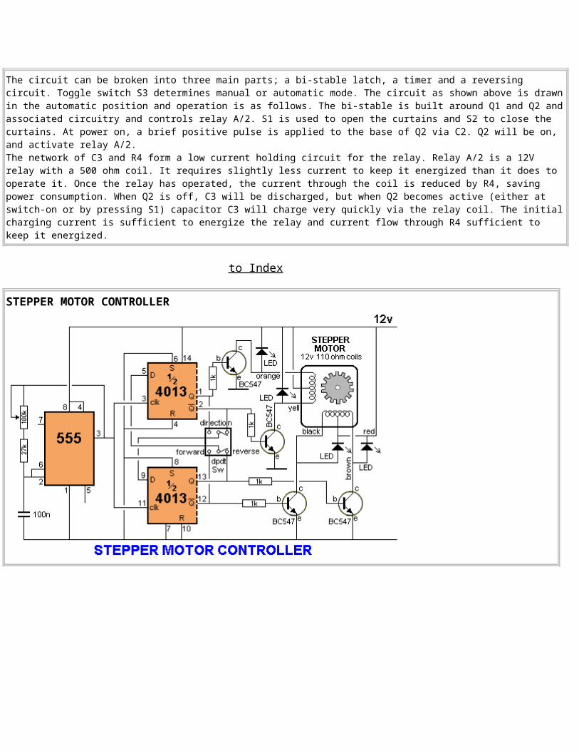
STEPPER MOTOR CONTROLLER

This circuit uses the latest TE555-1 STEPPER MOTOR SPEED CONTROLLER chip from Talking Electronics. It is available for $2.50 and controls the speed ofa stepper motor via the 100k pot. The direction of rotation is determined by the FORWARD and REVERSE switches and the motor does not take any current whena switch is not pressed.
to Index
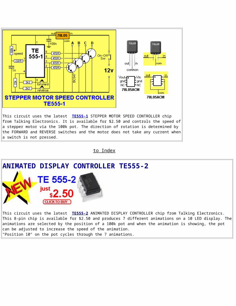
ANIMATED DISPLAY CONTROLLER TE555-2
This circuit uses the latest TE555- 2 ANIMATED DISPLAY CONTROLLER chip from Talking Electronics. This 8-pin chip is available for $2.50 and produces 7 different animations on a 10 LED display. Theanimations are selected by the position of a 100k pot and when the animation is showing, the pot can be adjusted to increase the speed of the animation."Position 10" on the pot cycles through the 7 animations.
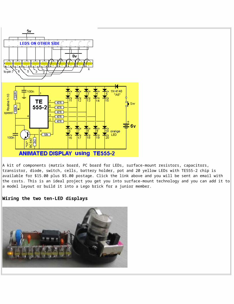
A kit of components (matrix board, PC board for LEDs, surface-mount resistors, capacitors, transistor, diode, switch, cells, battery holder, pot and 20 yellow LEDs with TE555-2 chip is available for $15.00 plus $5.00 postage. Click the link above and you will be sent an email with the costs. This is an ideal project you get you into surface-mount technology and you can add it toa model layout or build it into a Lego brick for a junior member.
Wiring the two ten-LED displays
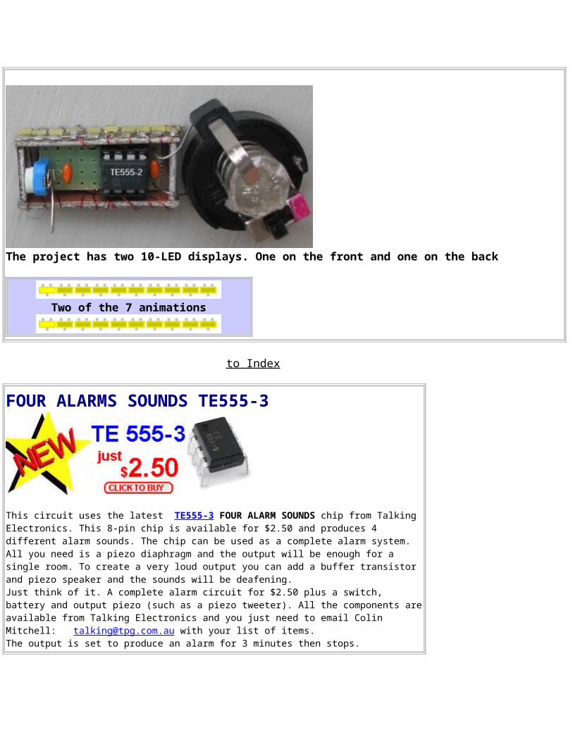
The project has two 10-LED displays. One on the front and one on the back
Two of the 7 animations
to Index
FOUR ALARMS SOUNDS TE555-3
This circuit uses the latest TE555-3 FOUR ALARM SOUNDS chip from Talking Electronics. This 8-pin chip is available for $2.50 and produces 4 different alarm sounds. The chip can be used as a complete alarm system. All you need is a piezo diaphragm and the output will be enough for a single room. To create a very loud output you can add a buffer transistor and piezo speaker and the sounds will be deafening. Just think of it. A complete alarm circuit for $2.50 plus a switch, battery and output piezo (such as a piezo tweeter). All the components areavailable from Talking Electronics and you just need to email Colin Mitchell: [email protected] with your list of items. The output is set to produce an alarm for 3 minutes then stops.
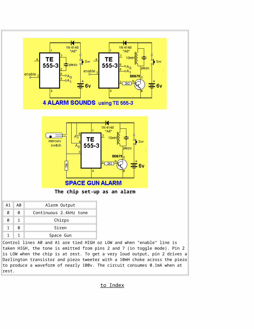
The chip set-up as an alarm
A1 A0 Alarm Output0 0 Continuous 2.4kHz tone0 1 Chirps1 0 Siren 1 1 Space Gun
Control lines A0 and A1 are tied HIGH or LOW and when "enable" line is taken HIGH, the tone is emitted from pins 2 and 7 (in toggle mode). Pin 2 is LOW when the chip is at rest. To get a very loud output, pin 2 drives aDarlington transistor and piezo tweeter with a 10mH choke across the piezoto produce a waveform of nearly 100v. The circuit consumes 0.1mA when at rest.
to Index
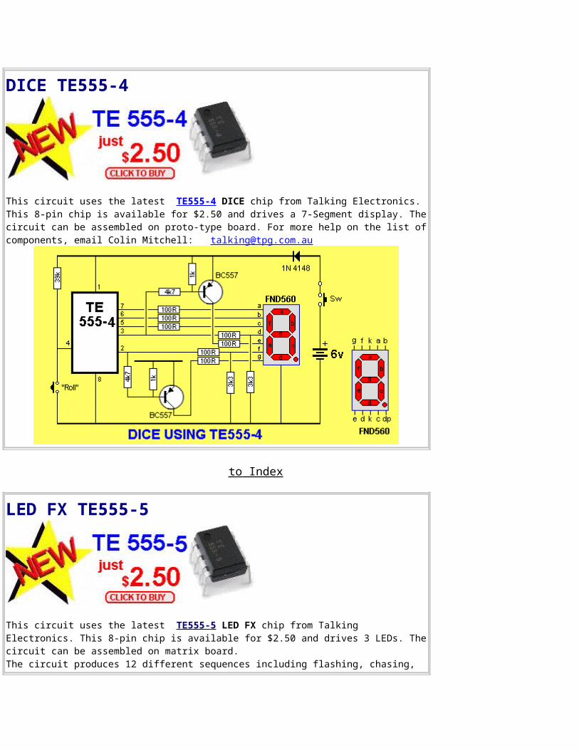
DICE TE555-4
This circuit uses the latest TE555-4 DICE chip from Talking Electronics. This 8-pin chip is available for $2.50 and drives a 7-Segment display. Thecircuit can be assembled on proto-type board. For more help on the list ofcomponents, email Colin Mitchell: [email protected]
to Index
LED FX TE555-5
This circuit uses the latest TE555- 5 LED FX chip from Talking Electronics. This 8-pin chip is available for $2.50 and drives 3 LEDs. Thecircuit can be assembled on matrix board. The circuit produces 12 different sequences including flashing, chasing,
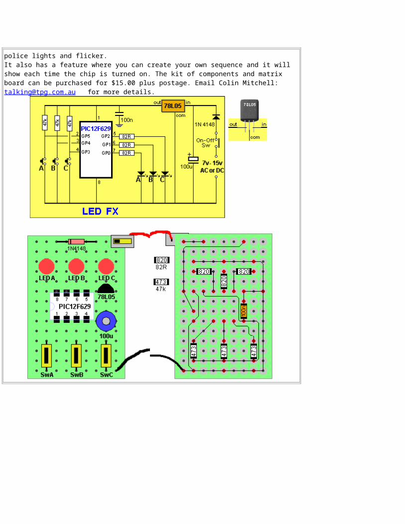
police lights and flicker. It also has a feature where you can create your own sequence and it will show each time the chip is turned on. The kit of components and matrix board can be purchased for $15.00 plus postage. Email Colin Mitchell: [email protected] for more details.
to Index
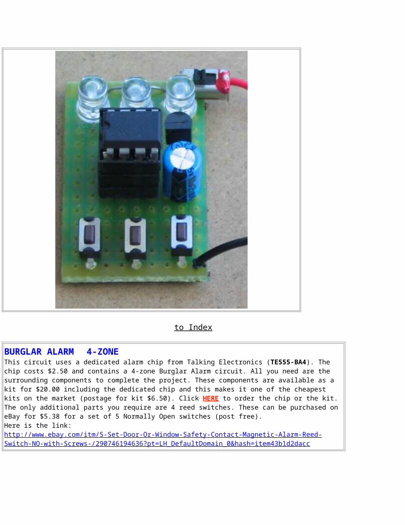
BURGLAR ALARM 4-ZONE This circuit uses a dedicated alarm chip from Talking Electronics (TE555-BA4). The chip costs $2.50 and contains a 4-zone Burglar Alarm circuit. All you need are the surrounding components to complete the project. These components are available as a kit for $20.00 including the dedicated chip and this makes it one of the cheapest kits on the market (postage for kit $6.50). Click HERE to order the chip or the kit. The only additional parts you require are 4 reed switches. These can be purchased on eBay for $5.38 for a set of 5 Normally Open switches (post free). Here is the link:http://www.ebay.com/itm/5-Set-Door-Or-Window-Safety-Contact-Magnetic-Alarm-Reed-Switch-NO-with-Screws-/290746194636?pt=LH_DefaultDomain_0&hash=item43b1d2dacc
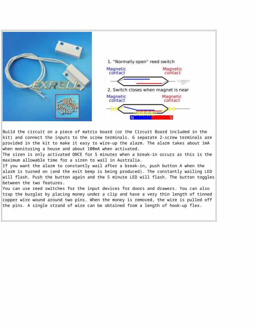
Build the circuit on a piece of matrix board (or the Circuit Board included in the kit) and connect the inputs to the screw terminals. 6 separate 2-screw terminals are provided in the kit to make it easy to wire-up the alarm. The alarm takes about 1mA when monitoring a house and about 100mA when activated. The siren is only activated ONCE for 5 minutes when a break-in occurs as this is the maximum allowable time for a siren to wail in Australia. If you want the alarm to constantly wail after a break-in, push button A when the alarm is turned on (and the exit beep is being produced). The constantly wailing LED will flash. Push the button again and the 5 minute LED will flash. The button togglesbetween the two features. You can use reed switches for the input devices for doors and drawers. You can also trap the burglar by placing money under a clip and have a very thin length of tinned copper wire wound around two pins. When the money is removed, the wire is pulled off the pins. A single strand of wire can be obtained from a length of hook-up flex.
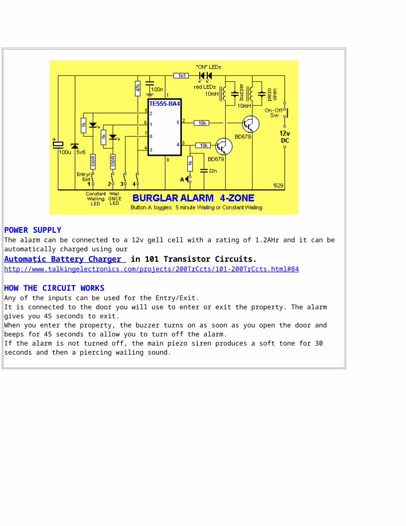
POWER SUPPLY The alarm can be connected to a 12v gell cell with a rating of 1.2AHr and it can be automatically charged using our Automatic Battery Charger in 101 Transistor Circuits. http://www.talkingelectronics.com/projects/200TrCcts/101-200TrCcts.html#84
HOW THE CIRCUIT WORKSAny of the inputs can be used for the Entry/Exit. It is connected to the door you will use to enter or exit the property. The alarm gives you 45 seconds to exit. When you enter the property, the buzzer turns on as soon as you open the door and beeps for 45 seconds to allow you to turn off the alarm. If the alarm is not turned off, the main piezo siren produces a soft tone for 30 seconds and then a piercing wailing sound.
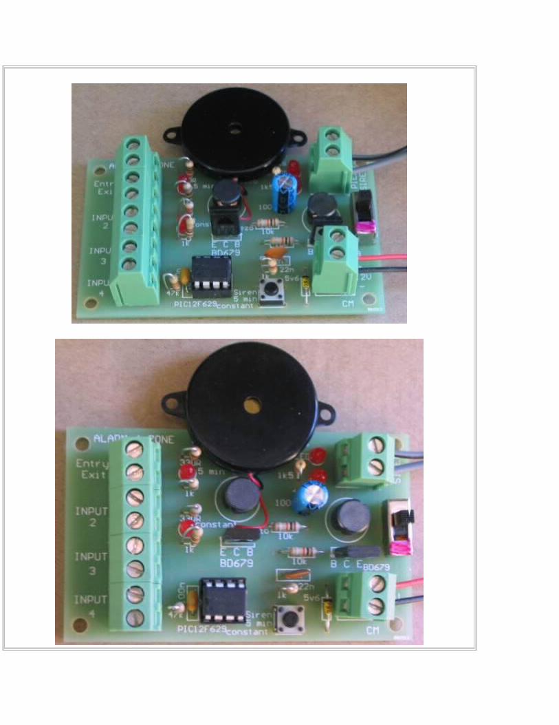
This allows you to turn off the alarm before the loud wailing is produced and is one of the best features of the alarm as the worry of false-triggering an alarm prevents many householders setting their alarm. Any unused inputs must be connected with a link so the alarm can be set. When the circuit is turned ON, you have 45 seconds to exit the premises. The chip then flashes either the 5-min LED or the Constant LED to indicate if the siren will wail for 5 minutes or constantly. You can change the setting by pressing the button. The circuit then beeps for 45 seconds to give you time to exit the property. It then monitors all 4 inputs.
Alarm 4-Zone PCB
The main chip contains an internal oscillator to drive a piezo diaphragm and also a wailing oscillator for the Piezo Siren. The Piezo Siren is an 80dB piezo diaphragm driven by a BD679 Darlington transistor with a 10mH choke to produce a high voltage for the diaphragm. The chip operates on 5v and the rest of the circuit uses 12v. A very simple voltage-dropper consisting of 2 LEDs and 1k5 drops the 12v to 5v.
to Index
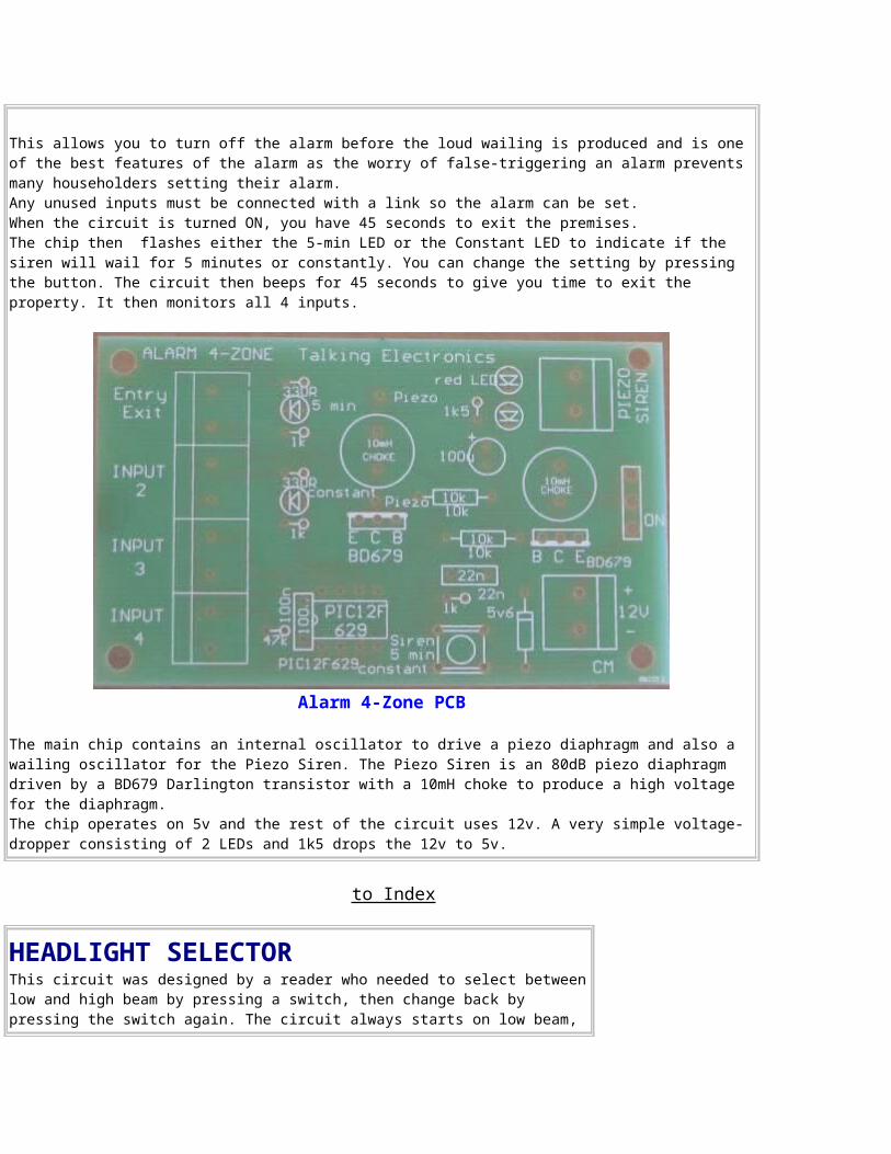
HEADLIGHT SELECTORThis circuit was designed by a reader who needed to select betweenlow and high beam by pressing a switch, then change back by pressing the switch again. The circuit always starts on low beam,
regardless of the state it was turned off.
to Index
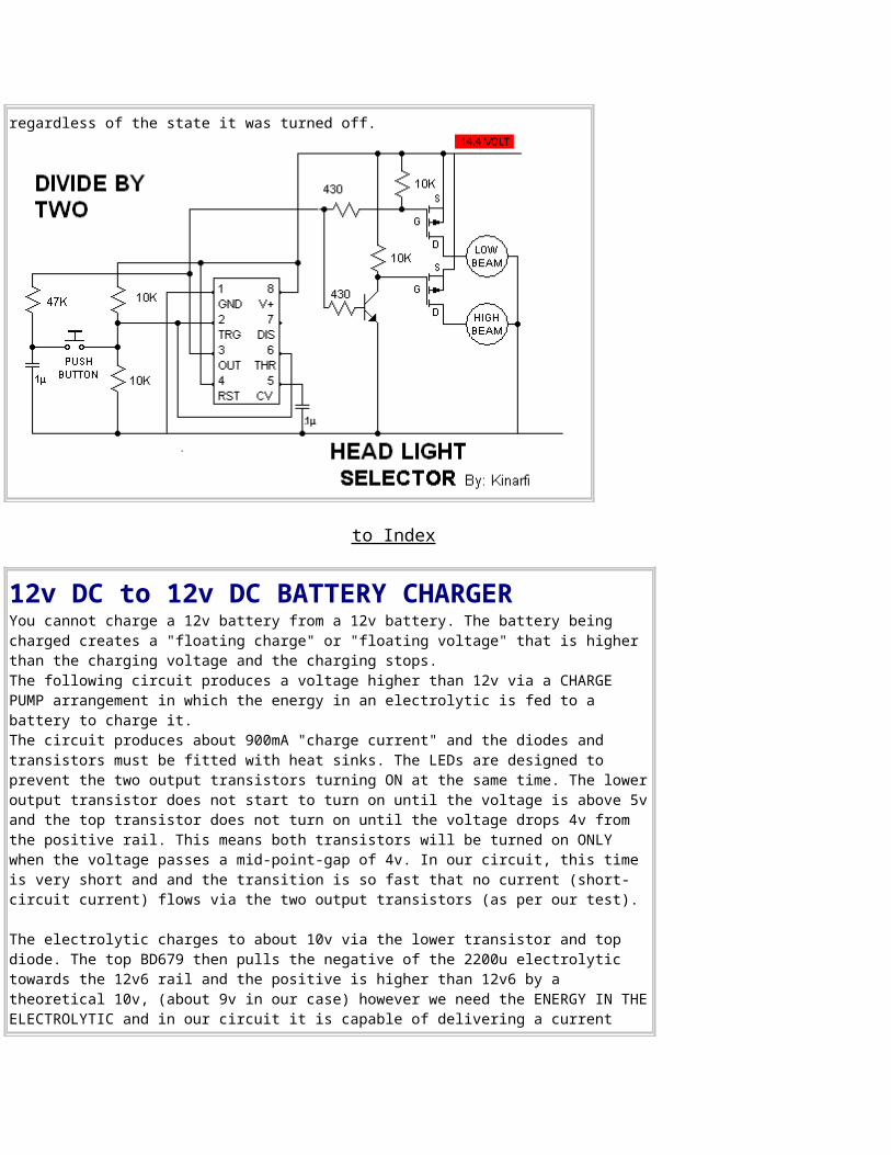
12v DC to 12v DC BATTERY CHARGERYou cannot charge a 12v battery from a 12v battery. The battery being charged creates a "floating charge" or "floating voltage" that is higher than the charging voltage and the charging stops. The following circuit produces a voltage higher than 12v via a CHARGE PUMP arrangement in which the energy in an electrolytic is fed to a battery to charge it.The circuit produces about 900mA "charge current" and the diodes and transistors must be fitted with heat sinks. The LEDs are designed to prevent the two output transistors turning ON at the same time. The loweroutput transistor does not start to turn on until the voltage is above 5vand the top transistor does not turn on until the voltage drops 4v from the positive rail. This means both transistors will be turned on ONLY when the voltage passes a mid-point-gap of 4v. In our circuit, this time is very short and and the transition is so fast that no current (short-circuit current) flows via the two output transistors (as per our test).
The electrolytic charges to about 10v via the lower transistor and top diode. The top BD679 then pulls the negative of the 2200u electrolytic towards the 12v6 rail and the positive is higher than 12v6 by a theoretical 10v, (about 9v in our case) however we need the ENERGY IN THEELECTROLYTIC and in our circuit it is capable of delivering a current
flow of about 900mA. This energy is passed to the battery via the lower diode. Most batteries should not be charged faster than the "14-hour-rate." This basically means a flat battery will be charged in 14 hours. To do this, divide the AHr capacity by 14 to get the charge-rate. For example, a 17AHr battery should be charged at 1.2A or less. For lower-capacity batteries, the 2200u can be reduced to 1,000u. Charging is about80% efficient. In other words, delivering 120% of the AHr capacity of a battery is needed to fully charge it.
to Index
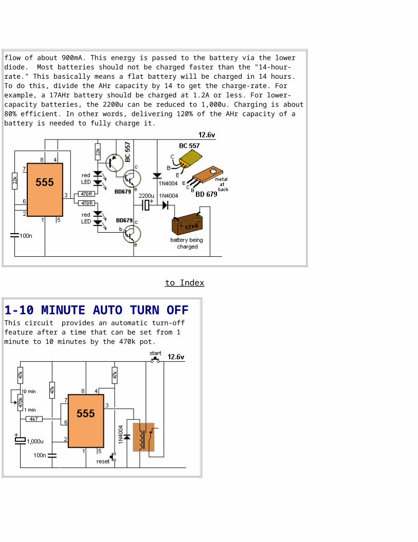
1-10 MINUTE AUTO TURN OFFThis circuit provides an automatic turn-off feature after a time that can be set from 1 minute to 10 minutes by the 470k pot.
to Index
WATER LEVEL DETECTORThis circuit can be used to automatically keep the header tank filled. It uses a double-pole relay. This is the transistor version of the circuit below.
Here is the circuit using a 555:These are the facts you have to remember. In our circuit, Pins 2 and 6 detect a voltage when water is not touching the probes, due to the 100k resistors. When water touches the probes, neither pin "detects a voltage."Don't worry about pin 2 detecting 1/3 of rail voltage and pin 6 detecting 2/3 of rail voltage. In our circuit the pins either detect a voltage or do not detect a voltage. Pin 2 detects a LOW and pin 6 detects a HIGH. Pin 2 does nothing when it detects a HIGH and pin 6 does nothing when it detects a LOW.
When the water is LOW, as shown in fig 1, both pins 2 and 6 are HIGH and the output of the 555 is LOW. As the water rises, as shown in fig 2, Pin 6 goes low but nothing happens to pin 3 except the chip "has beenprepared via the internal flip-flop" to change when pin 2 goes LOW. When the water reaches pin 2, as shownin fig 3, this pin "fails to see a HIGH," the output of the chip goes HIGH and the pump turns off. As the water level goes down, as shown in fig 4, pin 2sees a HIGH but this does not change the 555 as pin 2 only has an effect when it goes LOW. When the water level goes down further, as shown in fig 5, pin 6 sees a HIGH and because pin 2 is not seeing a LOW, the chip will change states. The output goes LOW.
Here's the circuit used in a hydroponic garden, to grow tomatoes: http://indoorhydroponicveggies.wordpress.com/#waterleveldetector
to Index
WARNING LIGHTS FLASHERThese two circuits flash two 5 watt to
21watt car lamps. The first circuit uses BD679 Darlington transistors and the second circuit uses a 555.
This 12v Warning Beacon is suitable for acar or truck break-down on the side of the road. The key to the operation of thecircuit is the high gain of the Darlington transistors. The circuit must be kept "tight" (thick wires) to be sure it will oscillate. A complete kits of parts and PC board costs $5.00 plus postage from: Talking Electronics. Email HERE for details.
The 555 circuit uses two diodes to connect the chip to the negative rail andthis allows the components to be fitted between the "high side" of the lamps and the "power switch."
to Index
MISSING AUDIO DETECTORThis circuit detects when audio is not received for about 4 seconds and turns on an alarm.
to Index
5 SECS DELAY THEN RELAY ON FOR 4 SECONDSThis circuit waits 5 seconds before turning on the relay for 4 seconds.
to Index
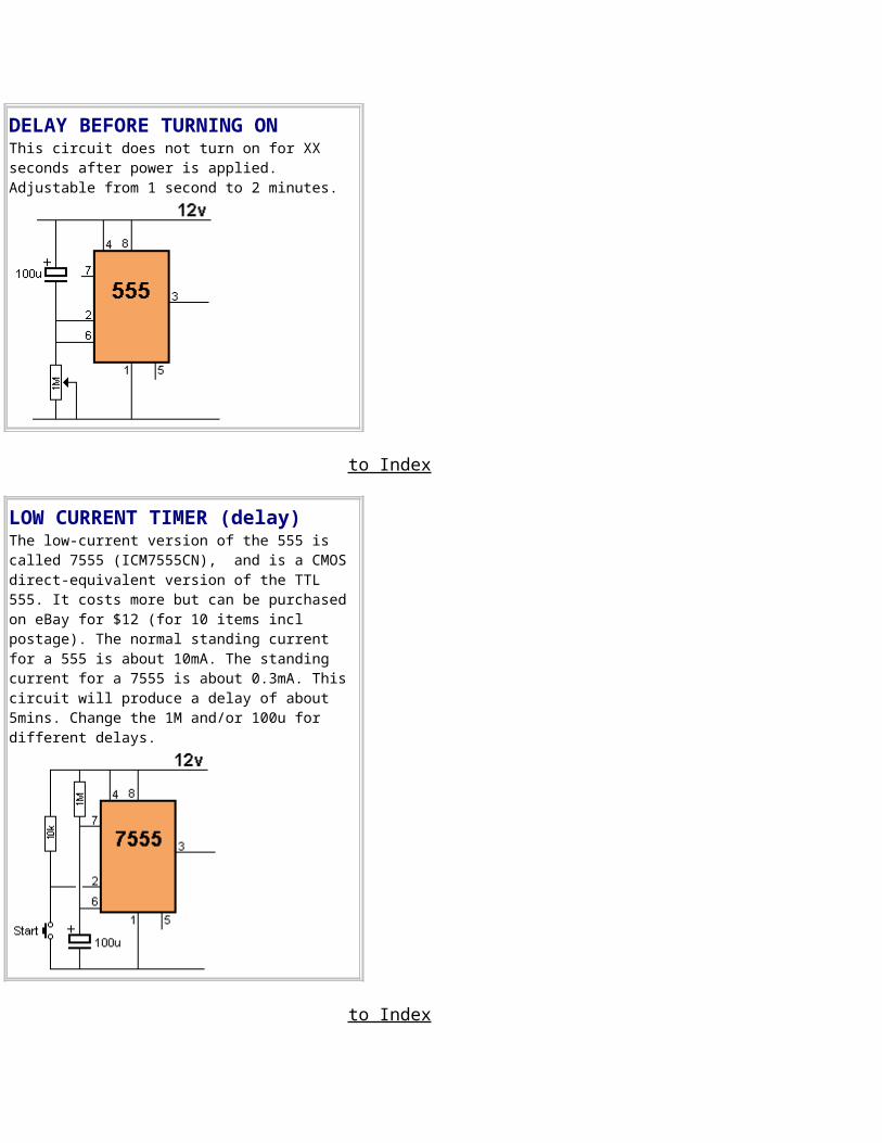
DELAY BEFORE TURNING ONThis circuit does not turn on for XX seconds after power is applied. Adjustable from 1 second to 2 minutes.
to Index
LOW CURRENT TIMER (delay)The low-current version of the 555 is called 7555 (ICM7555CN), and is a CMOS direct-equivalent version of the TTL 555. It costs more but can be purchased on eBay for $12 (for 10 items incl postage). The normal standing current for a 555 is about 10mA. The standing current for a 7555 is about 0.3mA. This circuit will produce a delay of about 5mins. Change the 1M and/or 100u for different delays.
to Index
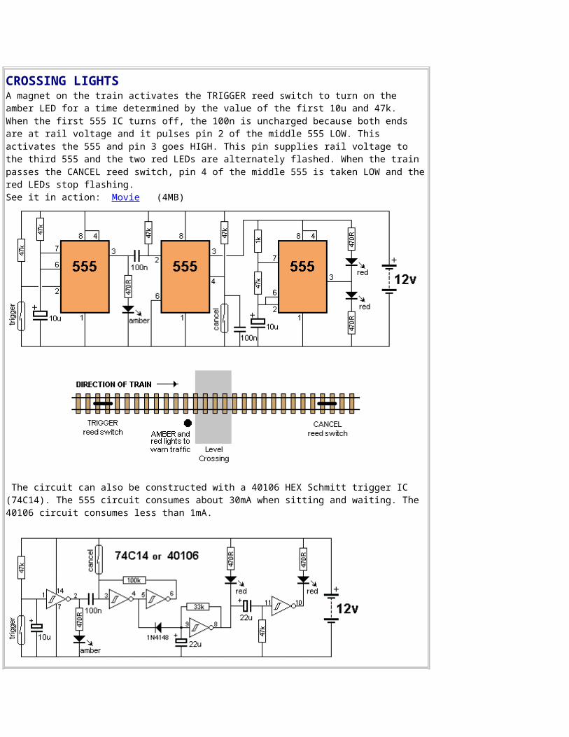
CROSSING LIGHTSA magnet on the train activates the TRIGGER reed switch to turn on the amber LED for a time determined by the value of the first 10u and 47k. When the first 555 IC turns off, the 100n is uncharged because both ends are at rail voltage and it pulses pin 2 of the middle 555 LOW. This activates the 555 and pin 3 goes HIGH. This pin supplies rail voltage to the third 555 and the two red LEDs are alternately flashed. When the train passes the CANCEL reed switch, pin 4 of the middle 555 is taken LOW and thered LEDs stop flashing.See it in action: Movie (4MB)
The circuit can also be constructed with a 40106 HEX Schmitt trigger IC (74C14). The 555 circuit consumes about 30mA when sitting and waiting. The 40106 circuit consumes less than 1mA.
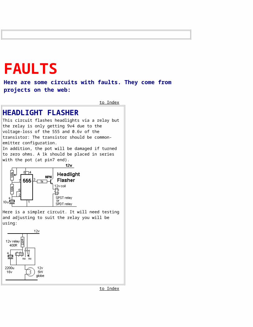
FAULTSHere are some circuits with faults. They come from projects on the web:
to Index
HEADLIGHT FLASHERThis circuit flashes headlights via a relay but the relay is only getting 9v4 due to the voltage-loss of the 555 and 0.6v of the transistor: The transistor should be common-emitter configuration. In addition, the pot will be damaged if turned to zero ohms. A 1k should be placed in series with the pot (at pin7 end).
Here is a simpler circuit. It will need testing and adjusting to suit the relay you will be using:
to Index
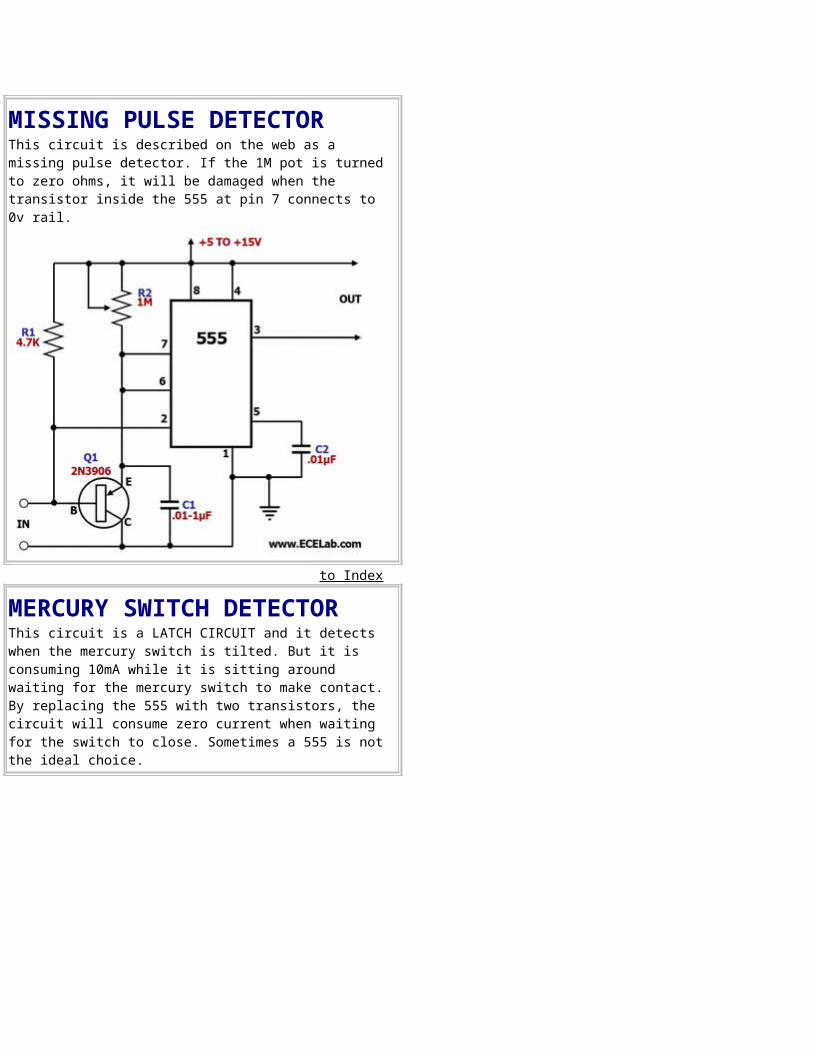
MISSING PULSE DETECTORThis circuit is described on the web as a missing pulse detector. If the 1M pot is turned to zero ohms, it will be damaged when the transistor inside the 555 at pin 7 connects to 0v rail.
to Index
MERCURY SWITCH DETECTORThis circuit is a LATCH CIRCUIT and it detects when the mercury switch is tilted. But it is consuming 10mA while it is sitting around waiting for the mercury switch to make contact. By replacing the 555 with two transistors, the circuit will consume zero current when waiting for the switch to close. Sometimes a 555 is not the ideal choice.
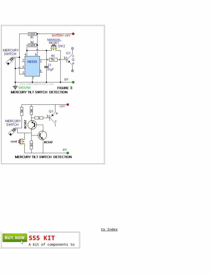
to Index
555 KIT A kit of components to

make many of the circuits described in this eBook is available for $10.00 plus $7.00 post. Or email Colin Mitchell: [email protected]
The kit contains the following components:(plus extra 30 resistors and 10 capacitors forexperimenting), plus:
2 - 220R2 - 1k2 - 4k72 - 10k 2 - 33k 2- 100k2 - 1M1 - 10k mini pot1 - 100k mini pot2 - 10n 2 - 100n1 - 10u electrolytic1- 100u electrolytic2 - 1N4148 signal diodes2 - BC547 transistors1 - BC557 transistor1 - 555 timer chip1 - 8 pin IC socket1 - red LED1 - green LED1 - orange LED1 - mini 8R speaker1 - mini piezo 1 - LDR (Light Dependent Resistor)1 - 10mH inductor1 - push button 4 - tactile push buttons1 - Experimenter Board (will take 8,14 and 16 pin chips)
THE FUTURE
This eBook has shown the enormous number of circuits that can be produced with a 555. However there is something we should point out. The 555 has limitations and disadvantages. It is not a chip you readily add to battery operated devicesas its current consumption is quite high at 10mA. (There is a whole range of low-current equivalents.) Secondly, the 555 is not a chip you add to a complex circuit as there are many other chips that can perform the task of a555 and you will have additional gates within the chip for other sections of the circuit. The 74c14 is an example. It has 6 Schmitt trigger gates and each gate can be wired as an oscillator or delay and the chip takes less than 1mA. Before designing a circuit around a 555, you should look at our eBook: 100 IC Circuits. It has many "building Blocks" to help you design your own circuits.
to Index


