for onsite wastewater treatment system - state water
TRANSCRIPT

DRAFT MAY 11, 2016
LOCAL AGENCY MANAGEMENT
PROGRAM
DRAFT
For Onsite Wastewater Treatment System
TABLE OF CONTENTS
TABLE OF CONTENTS This document is organized into sixteen (16) main Chapters, which contain several sections, in order to address all the requirements of a Local Agency Management Program (LAMP):
CONTENTS CHAPTER 1 ..............................................................................................................................1
Introduction .............................................................................................................................1
Definitions ...............................................................................................................................3
LAMP Overview ................................................................................................................... 11
Regional Water Quality Control Boards (RWQCB)s in San Bernardino County .................... 11
OWTS Policy ........................................................................................................................ 12
LAMP Need .......................................................................................................................... 12
Diversity ............................................................................................................................ 12
Construction....................................................................................................................... 12
LAMP Standards Applicability, Requirements and Exceptions .............................................. 13
Support of Onsite Wastewater Disposal.............................................................................. 13
Applicability of LAMP Standards ...................................................................................... 13
Requirements ..................................................................................................................... 13
Exceptions ......................................................................................................................... 13
Contact Information ............................................................................................................... 14
Santa Ana Region (8) ......................................................................................................... 14
City of Rancho Cucamonga................................................................................................ 14
Involved Agencies ................................................................................................................. 15
Building and Safety Services Department........................................................................... 15
CHAPTER 2 ............................................................................................................................ 17
Minimum Site Evaluation Standards ...................................................................................... 17
Percolation Testing ............................................................................................................ 17
Site Evaluation ................................................................................................................... 17
TABLE OF CONTENTS
Percolation Testing Notification ......................................................................................... 17
Percolation Testing ............................................................................................................ 18
Seepage Pits ....................................................................................................................... 18
Minimum Qualifications and Certification for OWTS Practitioners ....................................... 18
Plot and Grading Requirements ............................................................................................. 19
Plot Plans ........................................................................................................................... 19
Grading Plans .................................................................................................................... 19
CHAPTER 3 ............................................................................................................................ 21
Siting Standards ..................................................................................................................... 21
Setback Requirements ........................................................................................................ 21
Minimum Set Back Requirements ......................................................................................... 22
OWTS Located Near Public Water Systems ....................................................................... 23
Horizontal Sanitary Setbacks for Public Wells ................................................................... 25
Density/Minimum Lot Size Requirements ............................................................................. 25
Lot Size Requirements ....................................................................................................... 26
Lot Size Exemptions .......................................................................................................... 26
Commercial/Industrial Development Requirements ............................................................ 26
City Discretion ................................................................................................................... 26
Minimum Lot Size Exemptions ............................................................................................. 27
Single Family Residential Developments for additions .......................................................... 27
New Developments ............................................................................................................ 27
Replacements ........................................................................................................................ 27
Tracts, Parcels, and Commercial/Industrial Developments ..................................................... 27
Combined Lots Smaller than One Half Acre .......................................................................... 27
CHAPTER 4 ............................................................................................................................ 29
Onsite Wastewater Treatment Systems Permitting Process and Design Criteria ..................... 29
Procedures and Requirements for the Permitting Process ....................................................... 29
The Layout Design ................................................................................................................ 31
Primary and Reserve Area Requirements ............................................................................... 32
Septic Tanks .......................................................................................................................... 32
TABLE OF CONTENTS
OWTS Disposal Systems ....................................................................................................... 33
Setbacks ................................................................................................................................ 33
Grading Plan Review ............................................................................................................. 35
Building Plan Review ............................................................................................................ 36
Guidelines for Determining the Number of Bedrooms ........................................................ 36
Potable Water Supply ............................................................................................................ 37
OWTS Permit Issuance .......................................................................................................... 37
CHAPTER 5 ............................................................................................................................ 38
Wastewater Treatment Systems ............................................................................................. 38
Procedure for Groundwater Determination for Discretionary Projects .................................... 38
Existing Lot OWTS Design Review ...................................................................................... 39
Testing Procedures for Groundwater ...................................................................................... 40
CHAPTER 6 ............................................................................................................................ 41
Percolation Test Procedure .................................................................................................... 41
Test Holes ............................................................................................................................. 41
Number of Test Holes ........................................................................................................ 41
Depth of Testing ................................................................................................................ 42
Soil Classification .............................................................................................................. 42
Location of Test Holes ....................................................................................................... 42
Identification of Test Holes ................................................................................................ 42
Drilling of Borings for Test Holes ...................................................................................... 42
Preparation of Test Holes ................................................................................................... 42
Presoaking the Test Holes .................................................................................................. 42
Procedure ....................................................................................................................... 42
Saturation and Swelling .................................................................................................. 43
Use of Inserts ................................................................................................................. 43
Determination of Percolation Rates........................................................................................ 43
Case 1 ............................................................................................................................ 43
Case 2 ............................................................................................................................ 43
TABLE OF CONTENTS
Case 3 ............................................................................................................................ 44
Case 1 Procedure ............................................................................................................... 44
Case 2 Procedure ............................................................................................................... 44
Case 3 Procedure ............................................................................................................... 44
Calculations and Measurements ............................................................................................. 45
Calculation Example .......................................................................................................... 45
Measurement Principles ..................................................................................................... 45
Measurements, Special Considerations ............................................................................... 45
Reports .................................................................................................................................. 45
Appendix I............................................................................................................................. 47
Adjustment Factor for Gravel Packed Percolation Test Holes ............................................. 47
Calculations .................................................................................................................... 47
Application ........................................................................................................................ 47
Appendix II ........................................................................................................................... 48
Standard and Requirements for Design and Installation of OWTS in Soils with Poor Percolation Rates ............................................................................................................... 48
CHAPTER 7 ............................................................................................................................ 49
Septic Tanks .......................................................................................................................... 49
CHAPTER 8 ............................................................................................................................ 51
Leach Line Systems ............................................................................................................... 51
Percolation Test and Design Procedures ............................................................................. 51
Soil Cover Requirements.................................................................................................... 51
Dimensions ........................................................................................................................ 52
Materials and Construction Considerations ........................................................................ 52
Leach Lines on Steep Slopes ................................................................................................. 53
Sizing .................................................................................................................................... 54
CHAPTER 9 ............................................................................................................................ 58
Vertical Seepage Pit Systems ................................................................................................. 58
Locations Allowed ............................................................................................................. 58
Percolation Test Procedures ............................................................................................... 58
TABLE OF CONTENTS
Dimensions and Construction Requirements ...................................................................... 60
Design Criteria for Replacement of Existing Private Sewage Disposal Systems ..................... 61
Design Criteria for New Private Sewage Disposal Systems .................................................... 63
5-foot diameter pits ............................................................................................................ 63
6-foot diameter pits ............................................................................................................ 66
7-foot diameter pits ............................................................................................................ 68
CHAPTER 10 .......................................................................................................................... 70
Horizontal Seepage Pit Systems ............................................................................................. 70
Percolation Test Procedures ............................................................................................... 70
Dimensions and Construction Requirements ...................................................................... 70
CALCULATIONS ............................................................................................................. 72
CHAPTER 11 .......................................................................................................................... 73
Alternative Treatment Systems and Sewage Holding Tanks. .................................................. 73
CHAPTER 12 .......................................................................................................................... 74
Tier 3 Advanced Protection Management Program for Impaired Areas .................................. 74
Basin Plans ............................................................................................................................ 74
Issues Addressed in Basin Plans ......................................................................................... 74
Impaired Water Bodies....................................................................................................... 74
Total Maximum Daily Load (TMDL) .................................................................................... 75
TMDL Calculation ............................................................................................................. 75
Geographic Area for APMPs .............................................................................................. 76
TMDLs for Impaired Waterbodies ..................................................................................... 76
TMDL Completion Dates ................................................................................................... 76
OWTS without an Adopted TMDL Implementation Plan ....................................................... 77
Requirements for OWTS .................................................................................................... 77
OWTS Located Near Water Bodies Impaired for Nitrogen ................................................. 77
OWTS Located Near Water Bodies Impaired for Pathogens ............................................... 78
CHAPTER 13 .......................................................................................................................... 79
Corrective Action .................................................................................................................. 79
Corrective Action Requirements ........................................................................................ 79
TABLE OF CONTENTS
SUBSTANDARD SYSTEMS ............................................................................................... 80
CHAPTER 14 .......................................................................................................................... 81
LAMP Scope of Coverage ..................................................................................................... 81
Onsite Inspections and Monitoring ..................................................................................... 81
New OWTS .................................................................................................................... 81
Required Onsite Inspection ............................................................................................. 82
Sewage Holding Tanks ...................................................................................................... 83
Alternative Treatment Systems........................................................................................... 83
Variances............................................................................................................................... 83
Above Surface Discharge ................................................................................................... 84
Sewer Availability ............................................................................................................. 84
Sewer Requirement ............................................................................................................ 84
Ground Slope ..................................................................................................................... 84
Leaching Areas .................................................................................................................. 84
Supplemental Treatment .................................................................................................... 84
Depth to Groundwater ........................................................................................................ 85
Recreational Vehicle (RV) Holding Tanks ......................................................................... 85
Minimum Horizontal Setbacks............................................................................................... 85
Setbacks Determined by Depth .......................................................................................... 85
Dispersal Systems near Surface Water Intake Points .......................................................... 85
OWTS within Required Setbacks of a Public Water Supply ............................................... 86
Replacement OWTS Not Meeting Horizontal Setback Requirements ................................. 86
Separation Requirements for OWTS Pre-existing the LAMP ............................................. 86
Site Assessment ..................................................................................................................... 87
Cesspool Elimination ............................................................................................................. 87
Public Education.................................................................................................................... 87
Local Watershed Management ............................................................................................... 87
Chino Basin Watermaster ................................................................................................... 87
CHAPTER 15 .......................................................................................................................... 89
Data Collection/Reporting/Notifications ................................................................................ 89
TABLE OF CONTENTS
Reporting To RWQCB ....................................................................................................... 89
CHAPTER 16 .......................................................................................................................... 91
Reporting Requirements and Data Collection......................................................................... 91
Reporting to the Regional Water Quality Control Boards (RWQCBs).................................... 91
OWTS Water Quality Assessment Program (WQAP) ............................................................ 91
LAMP Assessment ................................................................................................................ 92
CHAPTER 1 - INTRODUCTION 1
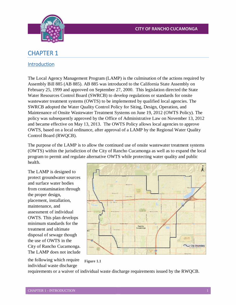
Figure 1.1
Figure 2.1
CHAPTER 1 Introduction
The Local Agency Management Program (LAMP) is the culmination of the actions required by Assembly Bill 885 (AB 885). AB 885 was introduced to the California State Assembly on February 25, 1999 and approved on September 27, 2000. This legislation directed the State Water Resources Control Board (SWRCB) to develop regulations or standards for onsite wastewater treatment systems (OWTS) to be implemented by qualified local agencies. The SWRCB adopted the Water Quality Control Policy for Siting, Design, Operation, and Maintenance of Onsite Wastewater Treatment Systems on June 19, 2012 (OWTS Policy). The policy was subsequently approved by the Office of Administrative Law on November 13, 2012 and became effective on May 13, 2013. The OWTS Policy allows local agencies to approve OWTS, based on a local ordinance, after approval of a LAMP by the Regional Water Quality Control Board (RWQCB).
The purpose of the LAMP is to allow the continued use of onsite wastewater treatment systems (OWTS) within the jurisdiction of the City of Rancho Cucamonga as well as to expand the local program to permit and regulate alternative OWTS while protecting water quality and public health.
The LAMP is designed to protect groundwater sources and surface water bodies from contamination through the proper design, placement, installation, maintenance, and assessment of individual OWTS. This plan develops minimum standards for the treatment and ultimate disposal of sewage though the use of OWTS in the City of Rancho Cucamonga. The LAMP does not include
the following which require individual waste discharge requirements or a waiver of individual waste discharge requirements issued by the RWQCB.

CHAPTER 1 - INTRODUCTION 2
• Any OWTS with a projected wastewater flow of over 10,000 gallons per day.
• Any OWTS that receives high strength wastewater, unless the waste stream is from a commercial food service facility.
• Any OWTS that receives high strength wastewater from a commercial food service facility with a BOD higher than 900 mg/l or that does not have a properly sized and functioning oil/grease interceptor.
CHAPTER 1 - INTRODUCTION 3
Definitions Above Ground Dispersal System
A covered sand bed elevated above original ground surface with an effluent leach field located in the sand bed.
Basin Plan (or Water Quality Control Plan) A plan which identifies surface and ground water bodies within each region’s boundaries, and establishes for each, it’s respective beneficial uses, and water quality objectives. Basin plans are adopted by the Regional Water Quality Control Board (RWQCB) and State Water Resources Control Board (SWRCB), and are approved by the Office of Administrative Law.
Bedrock The rock, usually solid, which underlies soil or other unconsolidated, surficial material.
California Environmental Data Exchange Network (CEDEN) A central location to find and share information about California’s water bodies, including streams, lakes, rivers, and coastal oceans.
Cesspool An excavation in the ground receiving domestic wastewater, designed to retain the organic matter and solids, while allowing the liquids to seep into the soil.
Clay Term used to describe a soil particle, or type of soil texture. As a soil:
• Particle – clay consists of individual rock or mineral particles having diameters of <0.002 millimeters (mm).
• Texture – clay is a soil material that is comprised of 40%, or more, clay particles, not more than 45% sand, and not more than 40% silt particles using the United States Department of Agriculture (USDA) soil classification system.
Cobbles Rock fragments measuring 76 mm (3 inches) or larger, using the USDA soil classification systems.
Dispersal System A type of system for final wastewater treatment and subsurface discharge, which may include a leach field, seepage pit, mound, subsurface drip field, or evapotranspiration and infiltration bed.
CHAPTER 1 - INTRODUCTION 4
Domestic Wastewater Wastewater with a measured strength less than high strength wastewater, which is discharged from plumbing fixtures, appliances and other household devices.
Domestic Well A groundwater well that provides water for human consumption, and is not regulated by the SWRCB.
Effluent
Sewage, water, or other liquid (partially or completely treated, or in its natural state), flowing out of a septic tank, aerobic treatment unit, dispersal system, or other OWTS component.
Electronic Deliverable Format (EDF) The data standard adopted by the SWRCB for submittal of groundwater quality monitoring data to the State Water Board’s internet-accessible database system, Geotracker.
Existing OWTS An OWTS that, was constructed, operating, and issued a permit prior to the effective date of the LAMP.
Grease Interceptor A passive interceptor with a rate of flow exceeding 50 gallons-per-minute located outside a building, and used for separating and collecting grease from wastewater.
Groundwater Water below the land surface that is at, or above, atmospheric pressure.
High Strength Wastewater Wastewater, prior to septic tank or other form of OWTS treatment component, having:
• A 30-day average concentration of Biochemical Oxygen Demand (BOD) greater than 300 milligrams per liter (mg/L),
• Total Suspended Solids (TSS) greater than 330 mg/L, or
• A Fats, Oil, and Grease (FOG) concentration greater than 100mg/L.
Impaired Water Bodies/303(d) List Surface water bodies, or segments thereof, identified on the Section 303(d) list pursuant to the Federal Clean Water Act, approved by the SWRCB, and United States Environmental Protection Agency (EPA).
CHAPTER 1 - INTRODUCTION 5
International Association of Plumbing and Mechanical Officials (IAPMO) An association that assists individual jurisdictions, both in the United States and abroad, to meet their specific needs by coordinating the development and adaptation of plumbing, mechanical, swimming pools, and solar energy codes.
Local Agency Any subdivision of state government responsible for permitting, installation, and regulation of OWTS within its jurisdictional boundaries; typically a county, city, or special district.
Local Agency Management Program (LAMP) A program for the siting, design, operation and maintenance of OWTS, developed by a local agency, and approved by the RWQCB as an alternate method to achieve the same policy purpose as that of OWTS policy.
Major Repair A repair for an OWTS dispersal system due to surfacing wastewater effluent from the dispersal field and/or wastewater backed up into plumbing fixtures. because the dispersal system is not able to percolate the design flow of wastewater associated with the structure served, or for a septic tank as a result of compartment baffle failure, or tank structural integrity; failure such that either wastewater is exfiltrating, or groundwater is infiltrating.
Mottling A soil condition that: • Results from oxidizing or reducing minerals due to soil moisture changes from
saturated to unsaturated over time,
• Is characterized by spots or blotches of different colors or, shades of color (grays and reds), interspersed within the dominant color as described by the USDA soil classification system, and
• May indicate historic seasonal high ground water levels.
Mound System An above ground dispersal system, having subsurface discharge, used to enhance soil treatment, dispersal, and absorption of effluent discharged from an OWTS treatment unit (e.g., septic tank).
National Sanitation Foundation (NSF) International A not for profit, non-governmental organization which develops health and safety standards, and performs product certification.
CHAPTER 1 - INTRODUCTION 6
New Development A proposed tract, parcel, industrial, or commercial development which has not been granted one or more of the following, on or prior to approval of the LAMP:
• Approval, or conditional approval, of a tentative parcel or tract map by the City of Rancho Cucamonga,
• A conditional use permit, and/or
• Approval, or conditional approval, from the City of Rancho Cucamonga Planning Services Department, and/or Building and Safety Services Department.
New OWTS An OWTS permitted after the effective date of this LAMP.
Notice of Condition A “Notice of Condition” is a site specific document that is provided to the customer by Building and Safety Services. It is the owner’s responsibility to ensure the document is recorded with the County Recorder’s office.
OWTS Wastewater treatment systems that use subsurface disposal, including: individual; community collection and disposal; and alternative collection and disposal systems. This is also referred to as a Private Sewage Disposal System in the current adopted California Plumbing Code and may also be referred to in general vernacular by the public as a “septic system”.
Note: OWTS do not include “graywater” systems pursuant to California Health and Safety Code, Section 17922.12.
Percolation Test A method of testing water absorption of the soil by using clean water to determine the dispersal system design.
Permit A document issued by a local agency that allows the installation, use, and/or monitoring of an OWTS.
Projected Flows Wastewater flows into the OWTS determined in accordance with any of the applicable methods for determining average daily flow in the California Plumbing Code.
Public Water System A system for the provision of water for human consumption, through pipes or other constructed conveyances, that has 15 or more service connections (or regularly serves at

CHAPTER 1 - INTRODUCTION 7
least 25 individuals daily), at least 60 days out of the year. Per California Health and Safety Code Section 116275(h), a public water system includes any:
• Collection, treatment storage, and distribution facilities under control of the operator of the system that are used primarily in connection with the system.
• Collection or pretreatment storage facilities not under the control of the operator that are used primarily in connection with the system.
• Water system that treats water on behalf of one or more public water systems for the purpose of rendering it safe for human consumption.
Public Water Well A ground water well serving a public water system.
Qualified Professional An individual licensed, or certified by a State of California agency, to design OWTS and practice as a professional for other associated reports, as allowed under their license or registration. Qualified Professionals include the following:
• Professional Civil Engineers
• Certified Engineering Geologists
• Registered Environmental Health Specialists (REHSs)
• Registered Geologists
• Geotechnical Engineers.
Replacement OWTS An OWTS that, after the effective date of this LAMP, has its treatment capacity expanded or its dispersal system replaced or added onto.
Regional Water Quality Control Board (RWQCB) A regional water board that regulates wastewater discharges to surface water (rivers, ocean, etc.) and to groundwater (via land). It also regulates storm water discharges from construction, industrial, and municipal activities; discharges from irrigated agriculture; dredge and several other activities with practices that could degrade water quality.
Sand A soil particle or type of soil texture. As a:
• Soil particle – Sand consists of individual rock, or mineral particles, having diameters ranging from 0.05 to 2.0 mm.
CHAPTER 1 - INTRODUCTION 8
• Soil texture – Sand is soil that is comprised of 85% or more sand particles, with the percentage of silt plus 1.5 times the percentage of clay particles comprising less than 15%.
Seepage Pit A drilled or dug excavation five (5) to seven (7) feet in diameter with a liner. It is also gravel filled (between the liner and the soil) and receives effluent discharge for dispersal from a septic tank or other OWTS treatment unit.
Seepage Pit Cap A cover placed on the top of the seepage pit liner. Septic Tank
A watertight, covered, receptacle designed for primary treatment of wastewater and constructed to:
• Receive wastewater discharged from a building,
• Separate settleable and floating solids from liquid,
• Digest organic matter using anaerobic bacterial action,
• Store digested solids, and
• Clarify wastewater for further treatment with final subsurface discharge.
Service Provider A person capable of operating, monitoring and maintaining an OWTS in accordance with this LAMP.
Silt A soil particle or type of soil texture. As a:
• Soil particle – Silt consists of individual rock, or mineral particles, having diameters ranging from 0.05 to 0.002mm.
• Soil texture – Silt is soil that is comprised of approximately 80% or more silt particles, and not more than 12% clay particles using the USDA soil classification system.
Site The location of the OWTS and/or a reserve dispersal area, capable of disposing 100% of the design flow from all the sources the OWTS is intended to serve.
Site Evaluation An assessment of the characteristics of the site, sufficient to determine its suitability for an OWTS that meets the requirements of this LAMP.
CHAPTER 1 - INTRODUCTION 9
Soil The naturally occurring body of porous mineral and organic materials on the land surface, which is composed of:
• Unconsolidated materials, including sand, silt, and clay sized particles.
• Varying amounts of larger fragments, and organic matter.
• Earthen material with particles smaller than 0.08 inches (2mm) in size.
Soil Texture The soil class that describes the relative amount of sand, clay, silt, and combinations thereof.
State Water Resources Control Board (SWRCB) A five member State Water Board, which develops statewide water protection plans, and establishes water quality standards.
Supplemental Treatment Any OWTS, or component thereof, which performs additional wastewater treatment, so the effluent meets performance requirements prior to the discharge of effluent into the dispersal field. This excludes septic and/or dosing tanks.
Structure A new separate stand-alone building which is separate from the main structure and does not have a common roof line with the main structure and which requires a plumbing permit.
Surface Water Ambient Monitoring Program (SWAMP) A unifying program created to fulfill the Legislature’s mandate for the coordination of all water quality monitoring conducted by the State and RWQCBs. It is managed by a roundtable of monitoring coordinators from the SWRCB and nine RWQCBs.
Telemetric The ability to automatically measure and transmit OWTS data by wire, radio, or other means.
Total Coliform A group of bacteria consisting of several genera belonging to the family Enterobacteriaceae, which includes Escherichia coli (E. coli) bacteria.
USDA The federal department which provides leadership regarding food, agriculture, natural resources, and related issues.
CHAPTER 1 - INTRODUCTION 10
Waste Discharge Requirement A permit issued for operation and discharge of waste pursuant to California Water Code Section 13260.
Water Quality Control Plan Refer to the Basin Plan definition.
CHAPTER 1 - INTRODUCTION 11
LAMP Overview This section provides information regarding the different regions, OWTS Policy, Lamp needs, requirements, and exceptions, as well as the RWQCBs contact information.
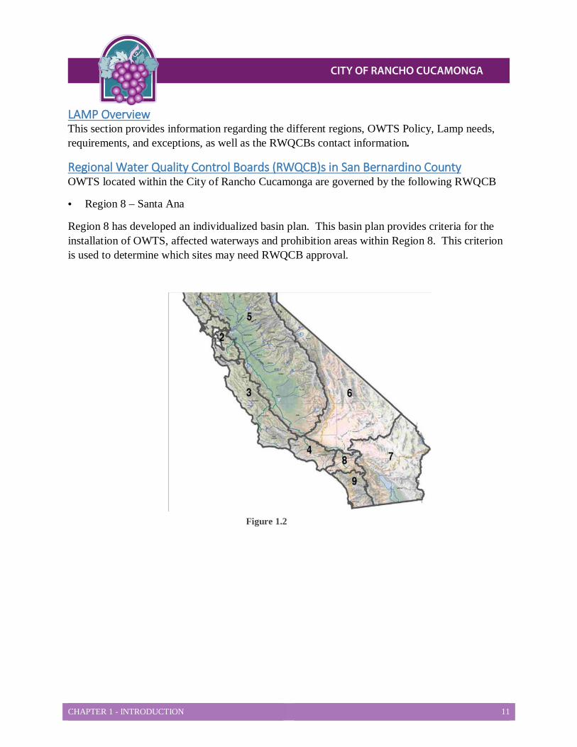
Regional Water Quality Control Boards (RWQCB)s in San Bernardino County OWTS located within the City of Rancho Cucamonga are governed by the following RWQCB
• Region 8 – Santa Ana
Region 8 has developed an individualized basin plan. This basin plan provides criteria for the installation of OWTS, affected waterways and prohibition areas within Region 8. This criterion is used to determine which sites may need RWQCB approval.
Figure 1.2
CHAPTER 1 - INTRODUCTION 12
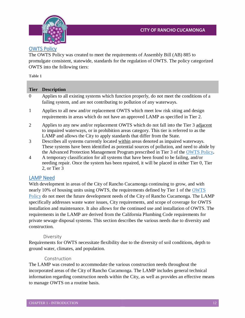
OWTS Policy The OWTS Policy was created to meet the requirements of Assembly Bill (AB) 885 to promulgate consistent, statewide, standards for the regulation of OWTS. The policy categorized OWTS into the following tiers:
Table 1
Tier Description 0 Applies to all existing systems which function properly, do not meet the conditions of a
failing system, and are not contributing to pollution of any waterways.
1 Applies to all new and/or replacement OWTS which meet low risk siting and design requirements in areas which do not have an approved LAMP as specified in Tier 2.
2 Applies to any new and/or replacement OWTS which do not fall into the Tier 3 adjacent to impaired waterways, or in prohibition areas category. This tier is referred to as the LAMP and allows the City to apply standards that differ from the State.
3 Describes all systems currently located within areas denoted as impaired waterways. These systems have been identified as potential sources of pollution, and need to abide by the Advanced Protection Management Program prescribed in Tier 3 of the OWTS Policy.
4 A temporary classification for all systems that have been found to be failing, and/or needing repair. Once the system has been repaired, it will be placed in either Tier 0, Tier 2, or Tier 3
LAMP Need With development in areas of the City of Rancho Cucamonga continuing to grow, and with nearly 10% of housing units using OWTS, the requirements defined by Tier 1 of the OWTS Policy do not meet the future development needs of the City of Rancho Cucamonga. The LAMP specifically addresses waste water issues, City requirements, and scope of coverage for OWTS installation and maintenance. It also allows for the continued use and installation of OWTS. The requirements in the LAMP are derived from the California Plumbing Code requirements for private sewage disposal systems. This section describes the various needs due to diversity and construction.
Diversity Requirements for OWTS necessitate flexibility due to the diversity of soil conditions, depth to ground water, climates, and population.
Construction The LAMP was created to accommodate the various construction needs throughout the incorporated areas of the City of Rancho Cucamonga. The LAMP includes general technical information regarding construction needs within the City, as well as provides an effective means to manage OWTS on a routine basis.
CHAPTER 1 - INTRODUCTION 13
LAMP Standards Applicability, Requirements and Exceptions The LAMP provides minimum standards and requirements for the treatment and disposal of sewage through the use of OWTS, when no connection to a sewer is available, to protect public health and safety. This section describes the minimum standards, and requirements for OWTS under the LAMP, as well as detailing the OWTS that are exceptions, and therefore not covered under the LAMP.
Support of Onsite Wastewater Disposal When a community sewer is not available, and a property improvement will generate wastewater, the property owner must demonstrate the following to City of Rancho Cucamonga Building & Safety to verify the lot will support onsite wastewater disposal: • Soils are conducive to onsite wastewater disposal. • Sewer is not available within 200 feet (plus 100 feet per dwelling unit thereafter). • Enough area is available to install a septic system that meets proper setbacks (for new
construction, 100% expansion area must be available). • OWTS will not impact ground or surface water. • OWTS is sized appropriately to serve the intended land use.
Applicability of LAMP Standards LAMP standards apply to all OWTS which:
• Are newly constructed, replaced, subject to a major repair, and discharge liquid waste below ground.
• Have affected, or have the potential to affect, ground water or other water quality or health hazards.
Requirements The LAMP addresses the minimum requirements for monitoring, and/or conditional waiver of waste discharge for OWTS located within the City of Rancho Cucamonga
The LAMP may include one, or more, of the following to achieve this purpose:
• Differing system requirements • Differing siting controls (i.e., system density and setback requirements) • Requirements for owners to enter agreements regarding monitoring and maintenance.
In addition to all standards and requirements, all proposed, and/or currently installed OWTS must be in compliance with other city adopted construction codes.
Exceptions There are specific OWTS which are not included in the LAMP. These exceptions require individual discharge requirements, or a waiver of individual waste discharge requirements issued by the RWQCB. Exceptions include:

CHAPTER 1 - INTRODUCTION 14
• OWTS having a projected wastewater flow of over 10,000 gallons per day (GPD). • OWTS receiving high strength wastewater, unless the waste stream: Is from a commercial food service facility with BOD less than 900 mg/L, and
Has a properly functioning oil/grease interceptor. • Wastewater treatment plants of any kind or size.
Contact Information This section provides contact information for Region 8 RWQCB and the City of Rancho Cucamonga which can provide additional guidance regarding OWTS in City of Rancho Cucamonga.
Santa Ana Region (8) 3737 Main Street, Suite 500 Riverside, CA 92501-3339 (951) 782-4130 www.waterboards.com
City of Rancho Cucamonga Building & Safety Services Department 10500 Civic Center Drive Rancho Cucamonga, CA 91730 (909) 477-2710 [email protected] Attention: Building and Safety Services Director
CHAPTER 1 - INTRODUCTION 15
Involved Agencies Oversight of OWTS installation and maintenance is a multiple agency effort. This section provides an overview of the primary agencies involved in the City of Rancho Cucamonga..
Building and Safety Services Department The department is responsible for:
• Issuing permits for new construction, replacement and repair of OWTS.
• Reviewing plot plans for new and replacement OWTS.
• Retaining permit information regarding new construction, replacement systems, repairs, and plot plans.
• Complying with LAMP reporting requirements regarding issued permits for new and replacement OWTS.
The following information must be provided by the Building and Safety Services Department to the RWQCB annually for new, replacement and/or repaired OWTS:
• Number of permits issued
• Location
• Description of permits (i.e., new, replacement, an/or repair)
• Tier the permit was issued under
Obtaining an OWTS permit, and obtaining local land use approval, are two separate processes. Local Land Use approval (i.e., obtaining a Land Use permit) is not a substitute for an OWTS permit issued by the Building and Safety Services Department, nor does it guarantee issuance of an OWTS permit.
This department is also responsible for:
• Investigating complaints for overflowing/failed septic tanks for single family residences, and two-unit dwellings, which includes: – Requiring property owners to obtain applicable permits from the Building and Safety
Division for repairs, or replacement of failing systems. – Retaining information regarding complaints and investigations for overflowing or
failed septic systems, and subsequent actions taken. • Complying with the LAMP reporting requirements for complaint investigations, which
includes: – Providing information to the RWQCB annually pertaining to OWTS operation and
maintenance, including number, and location of the complaints. – Identifying investigated complaints, and – Determining how the complaints were resolved.
CHAPTER 1 - INTRODUCTION 16
• Issuing permits for alternative treatment systems. • Reviewing:
– Percolation reports, and – Alternative treatment proposals for new and replacement septic systems in:
High risk residential areas, and Commercial project
• Investigating and storing records for OWTS in multi-family dwellings (3 or more units) • Complying with LAMP reporting requirements, which includes:
– Providing information to the RWQCB annually regarding: Complaints pertaining to OWTS operation and maintenance for multi-family
dwellings, including number and location of complaints. Applications and registrations issued as part of the liquid waste hauler program.
– Identifying investigated complaints for multi-family dwellings, and – Determining how complaints were resolved.
CHAPTER 2 – SITE EVALUATION STANDARDS 17
CHAPTER 2 Minimum Site Evaluation Standards This chapter provides information, to determine when a percolation test is required, the minimum site evaluation standards for parcels where an Onsite Wastewater Treatment System (OWTS) is proposed, and minimum qualifications for OWTS practitioners when a sewer connection is not available. See CHAPTER 6 and CHAPTER 9 for additional information when a percolation test is exempt.
Percolation Testing The City of Rancho Cucamonga Building and Safety Services may require percolation testing for all new septic systems for residential and non-residential development where a percolation report has not already previously been completed. This section provides information regarding the percolation testing, including the site evaluation, percolation testing notification, and information regarding when seepage pits are allowed.
Site Evaluation Prior to reviewing a percolation test, and approving the use of an OWTS, Building and Safety Services may require a site evaluation during percolation testing to:
• Ensure proper system design, and
• Evaluate site location to ensure the system will be in compliance.
Percolation Testing Notification A Qualified Professional (as defined in the Definitions section of this document) may submit a Notification of Percolation Test, to Building and Safety Services at least two business days prior to performing any percolation test in the incorporated areas of the City of Rancho Cucamonga. When a percolation test notification is submitted for a lot which requires a site evaluation (or a percolation report is submitted for a lot which requires a site evaluation and no inspection was conducted), then Building and Safety Services will conduct an inspection of the lot to evaluate:
• Lot size, • Slope, • Streams, • Rock outcroppings, and • Any other criteria which may affect installations of a standard septic system.
Prior to the site evaluation, Building and Safety Services personnel will contact the applicant to inform him/her of the site evaluation date and applicable fees shall be assessed prior to issuance of the permit.

CHAPTER 2 – SITE EVALUATION STANDARDS 18
Percolation Testing Building and Safety Services requires percolation testing, and accompanying reports, to be prepared by a Qualified Professional. For soil to be considered uniform, test results must fall within 25% of the mean percolation rate. Determining the number of percolation tests required will be based on soil conditions and project type. Percolation testing:
• Is used to ensure the dispersal site is located in an area where no conditions exist, which could:
– Adversely affect the performance of the system, or – Results in groundwater contamination.
• Is used to determine the necessary area needed to treat, and maintain underground sewage properly.
• Must be in the general area of the disposal system, both primary and expansion, is the proposed area in known.
Seepage Pits The use of seepage pits, as a dispersal field, will only be allowed in instances where leach lines are not feasible, and minimum separation requirements to groundwater are met. DEHS requires there be a 10 foot minimum separation from the bottom of the seepage pit to ground water. When the pit minutes per inch (MPI) is less than 10, the following must occur:
• The separation to groundwater must be at least 40 feet from the bottom of the seepage pit, or
• A sieve analysis of the soil, for a thickness of 10 feet below the bottom of the seepage pit, must contain at least 15% fines passing the #200 United States standard sieve.
Minimum Qualifications and Certification for OWTS Practitioners The following table outlines the minimum qualifications for OWTS practitioners. Any licenses or certifications possessed by these practitioners must have been issued from the State of California.
Table2- 1
OWTS Service Minimum Qualifications
Alternative Treatment System Inspection and Monitoring
Manufacturer Certified Wastewater Maintenance Provider
OWTS Design • Qualified Professional, or • Licensed Contractor (Class A, C-36, or C-
42) OWTS Certification
Percolation Test Qualified Professional
CHAPTER 2 – SITE EVALUATION STANDARDS 19
OWTS Service Minimum Qualifications
Septic Tank Pumping & Reporting Building and Safety Services permitted Liquid Waste Hauler
System Installation (new and replacement) Licensed Contractor (Class A, C-36, or C-42)
Exception: Per the California Health and Safety Code Sections 19826 and 19826 homeowners may build within their property as an Owner-Builder without the need of a professional.
Plot and Grading Requirements This section provides the requirements needed by the Building and Safety Services Department when preparing plot plans and grading plans.
Plot Plans A plot plan is a plan that is required to be submitted to show where the system will be sited. The plot plan must:
• Include the property, drawn to the following minimum scales: – Single Family Home, Small Commercial Minimum 1” = 30’
– Parcel Map, Subdivision, Large Commercial Minimum 1” = 40’
• Show the proposed system, and 100% expansion area, including existing and potential structures, wells, streams, contours, significant vegetation (including trees), rock outcroppings, the location of all borings/tests, and the proposed house pad.
The proposed dwelling/development must be located so the initial subsurface sewage disposal system (and the required 100% expansion area) functions by gravity flow, unless otherwise approved. When leach lines or pits serve a common system for two or more units, add 30% more square footage to the total absorption area, if approved by The City of Rancho Cucamonga Planning Services and Building and Safety Services Departments.
Grading Plans Depending on the scope of grading for a project, City of Rancho Cucamonga Planning Services Department may require a conceptual grading plan and Building and Safety Services may require a grading plan. If a grading plan is required it should be included with the percolation report submittal. A grading plan helps Building and Safety Services ensure testing was done at the correct depths. Where grading is expected, include the original and finished elevations in the grading plan. For details on how to complete a grading plan contact City of Rancho Cucamonga Building and Safety Services Department.
CHAPTER 2 – SITE EVALUATION STANDARDS 20
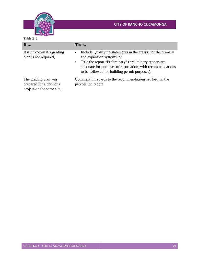
Table 2- 2
If…. Then…
It is unknown if a grading plan is not required,
• Include Qualifying statements in the area(s) for the primary and expansion systems, or
• Title the report “Preliminary” (preliminary reports are adequate for purposes of recordation, with recommendations to be followed for building permit purposes).
The grading plan was prepared for a previous project on the same site,
Comment in regards to the recommendations set forth in the percolation report
CHAPTER 3 – SITING STANDARDS 21
CHAPTER 3 Siting Standards To ensure that Onsite Wastewater Treatment Systems (OWTS) do not adversely affect water quality, the government agencies tasked with protecting the public’s health and safety have developed siting standards for OWTS. This chapter provides information regarding siting standards such as, minimum lot size, setback requirements (including increased setback and notification requirements for OWTS located near public water systems), natural ground slope and density.
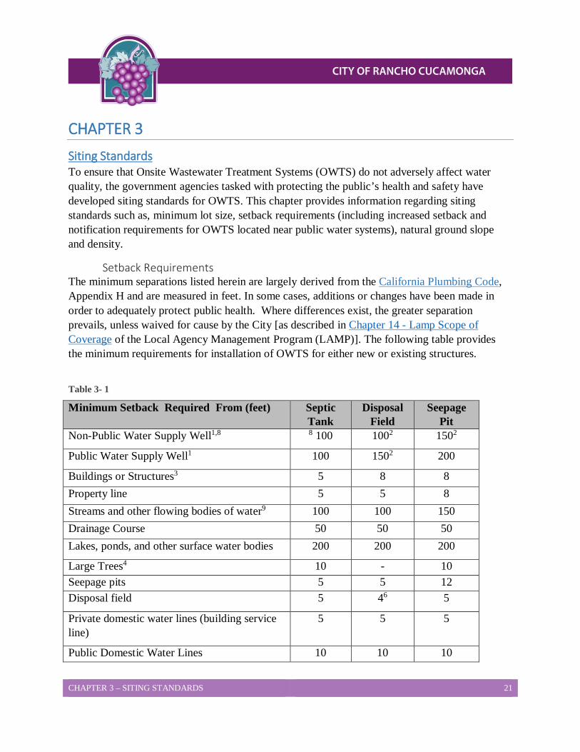
Setback Requirements The minimum separations listed herein are largely derived from the California Plumbing Code, Appendix H and are measured in feet. In some cases, additions or changes have been made in order to adequately protect public health. Where differences exist, the greater separation prevails, unless waived for cause by the City [as described in Chapter 14 - Lamp Scope of Coverage of the Local Agency Management Program (LAMP)]. The following table provides the minimum requirements for installation of OWTS for either new or existing structures.
Table 3- 1
Minimum Setback Required From (feet) Septic Tank
Disposal Field
Seepage Pit
Non-Public Water Supply Well1,8 8 100 1002 1502
Public Water Supply Well1 100 1502 200
Buildings or Structures3 5 8 8
Property line 5 5 8 Streams and other flowing bodies of water9 100 100 150 Drainage Course 50 50 50 Lakes, ponds, and other surface water bodies 200 200 200
Large Trees4 10 - 10 Seepage pits 5 5 12 Disposal field 5 46 5
Private domestic water lines (building service line)
5 5 5
Public Domestic Water Lines 10 10 10
CHAPTER 3 – SITING STANDARDS 22
Minimum Setback Required From (feet) Septic Tank
Disposal Field
Seepage Pit
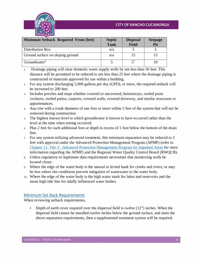
Distribution Box n/a 5 5 Ground surface on sloping ground n/a 15 15
Groundwater5 5 57 10
1. Drainage piping will clear domestic water supply wells by not less than 50 feet. This distance will be permitted to be reduced to not less than 25 feet where the drainage piping is constructed of materials approved for use within a building.
2. For any system discharging 5,000 gallons per day (GPD), or more, the required setback will be increased to 200 feet.
3. Includes porches and steps whether covered or uncovered, breezeways, roofed porte cocheres, roofed patios, carports, covered walls, covered driveway, and similar structures or appurtenances.
4. Any tree with a trunk diameter of one foot or more within 5 feet of the system that will not be removed during construction.
5. The highest known level to which groundwater is known to have occurred rather than the level at the time when testing occurred.
6. Plus 2 feet for each additional foot or depth in excess of 1 foot below the bottom of the drain line.
7. For any system utilizing advanced treatment, this minimum separation may be reduced to 2 feet with approval under the Advanced Protection Management Program (APMP) (refer to Chapter 11: Tier 3 - Advanced Protection Management Program for Impaired Areas for more information regarding the APMP) and the Regional Water Quality Control Board (RWQCB).
8. Unless regulatory or legitimate data requirements necessitate that monitoring wells be located closer.
9. Where the edge of the water body is the natural or levied bank for creeks and rivers, or may be less where site conditions prevent mitigation of wastewater to the water body.
10. Where the edge of the water body is the high water mark for lakes and reservoirs and the mean high tide line for tidally influenced water bodies.
Minimum Set Back Requirements When reviewing setback requirements,
• Depth of earth cover required over the dispersal field is twelve (12”) inches. When the dispersal field cannot be installed twelve inches below the ground surface, and meet the above separation requirements, then a supplemental treatment system will be required.
CHAPTER 3 – SITING STANDARDS 23
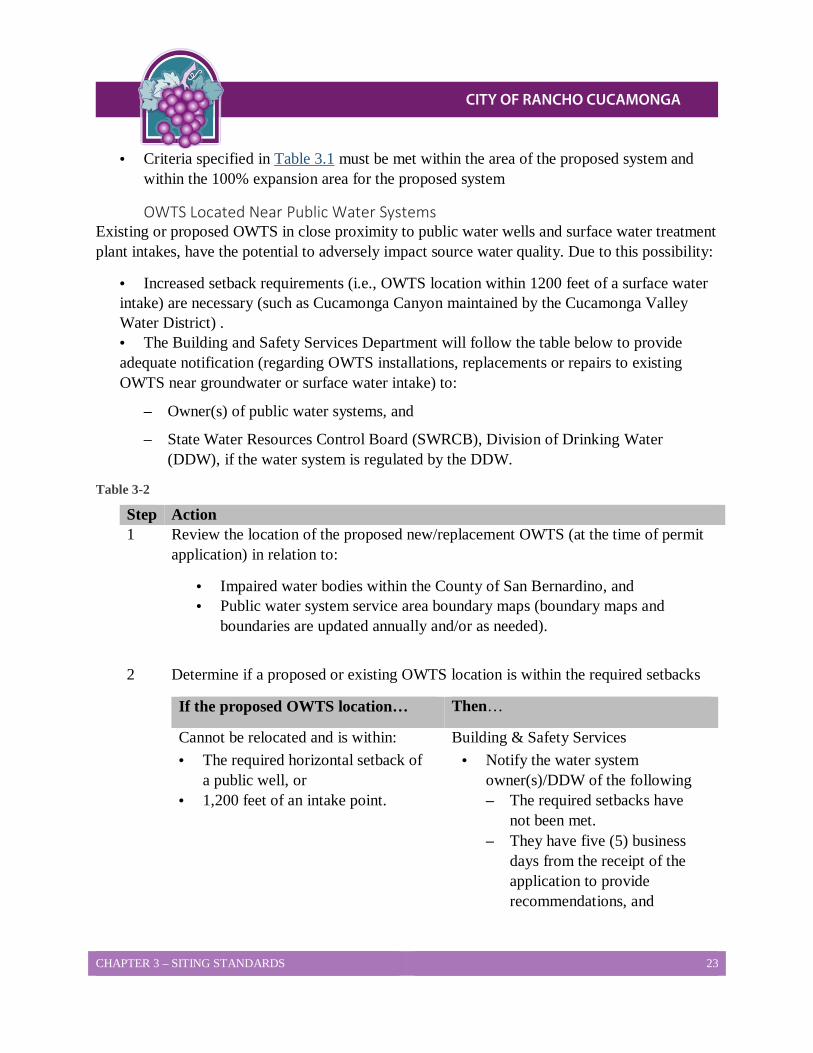
• Criteria specified in Table 3.1 must be met within the area of the proposed system and within the 100% expansion area for the proposed system
OWTS Located Near Public Water Systems Existing or proposed OWTS in close proximity to public water wells and surface water treatment plant intakes, have the potential to adversely impact source water quality. Due to this possibility:
• Increased setback requirements (i.e., OWTS location within 1200 feet of a surface water intake) are necessary (such as Cucamonga Canyon maintained by the Cucamonga Valley Water District) . • The Building and Safety Services Department will follow the table below to provide adequate notification (regarding OWTS installations, replacements or repairs to existing OWTS near groundwater or surface water intake) to:
– Owner(s) of public water systems, and
– State Water Resources Control Board (SWRCB), Division of Drinking Water (DDW), if the water system is regulated by the DDW.
Table 3-2
Step Action 1 Review the location of the proposed new/replacement OWTS (at the time of permit
application) in relation to:
• Impaired water bodies within the County of San Bernardino, and • Public water system service area boundary maps (boundary maps and
boundaries are updated annually and/or as needed).
2 Determine if a proposed or existing OWTS location is within the required setbacks
If the proposed OWTS location… Then…
Cannot be relocated and is within: • The required horizontal setback of
a public well, or • 1,200 feet of an intake point.
Building & Safety Services • Notify the water system
owner(s)/DDW of the following – The required setbacks have
not been met. – They have five (5) business
days from the receipt of the application to provide recommendations, and
CHAPTER 3 – SITING STANDARDS 24
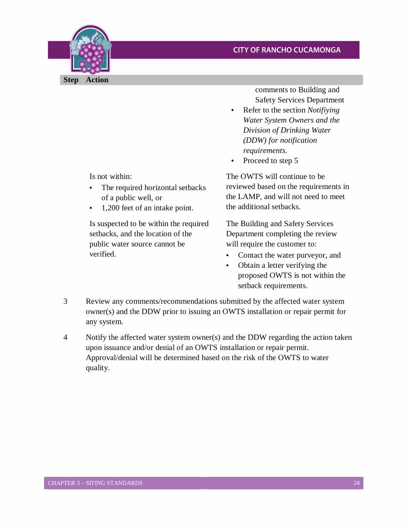
Step Action comments to Building and Safety Services Department
• Refer to the section Notifiying Water System Owners and the Division of Drinking Water (DDW) for notification requirements.
• Proceed to step 5
Is not within: • The required horizontal setbacks
of a public well, or • 1,200 feet of an intake point.
The OWTS will continue to be reviewed based on the requirements in the LAMP, and will not need to meet the additional setbacks.
Is suspected to be within the required setbacks, and the location of the public water source cannot be verified.
The Building and Safety Services Department completing the review will require the customer to: • Contact the water purveyor, and • Obtain a letter verifying the
proposed OWTS is not within the setback requirements.
3 Review any comments/recommendations submitted by the affected water system owner(s) and the DDW prior to issuing an OWTS installation or repair permit for any system.
4 Notify the affected water system owner(s) and the DDW regarding the action taken upon issuance and/or denial of an OWTS installation or repair permit. Approval/denial will be determined based on the risk of the OWTS to water quality.

CHAPTER 3 – SITING STANDARDS 25
Step Action 5 Determine if the proposed OWTS location is approved:
If the location is… Then Building and Safety will…
Approved • Refer the customer to Building and Safety Services Department to complete the plot plan review, or
• Complete the percolation report review.
Not Approved • Inform the customer he/she will need to install an alternative treatment system. The alternative treatment system shall be approved by the Building and Safety Services Director prior to the issuance of any building permits.
CHAPTER 3: SITING STANDARDS
Horizontal Sanitary Setbacks for Public Wells The table below provides information to determine the horizontal sanitary setbacks for public wells. Table 3-3
If the dispersal system… Then the horizontal sanitary setback will be…
Does not exceed 10 feet in depth, 150 feet.
Exceeds 10 feet in depth, 200 feet.
Exceeds 20 feet in depth, 600 feet.
Dispersal systems which exceed 20 feet in depth, and are located within 600 feet of a public well, will be required to have a Qualified Professional evaluate the two-year time travel for microbial contaminants to determine the required setback. In no case will the minimum setback be less than 200 feet.
Density/Minimum Lot Size Requirements The City of Rancho Cucamonga has minimum lot size requirements for subdivisions of property, which rely on OWTS. A minimum lot size of one half acre (average gross) per dwelling unit is required for all new developments, which do not have access to a public sewer. This section provides definitions for a new development, as well as an explanation of the requirements for various development types located within the incorporated areas of the City.

CHAPTER 3 – SITING STANDARDS 26
Lot Size Requirements The City of Rancho Cucamonga has a minimum lot size requirement for lots proposed to be created and developed based on the use of an OWTS as provided by SWRCB Resolution No. 89-157. The average density for any subdivision of property made pursuant to the Subdivision Map Act proposing to use OWTS shall not exceed density of 2 units per acre, for a single-family dwelling (SFD), or its equivalent, without additional studies completed by a qualified professional demonstrating no adverse impacts to groundwater quality will occur. Lots created for commercial developments with flows that exceed those of a SFD will also require such studies. Where those studies show there will be impacts to groundwater quality that exceed the RWQCB Basin Plan standards, any proposed development must utilize an OWTS with supplemental treatment as per Alternative Treatment System Requirements of this LAMP to mitigate those impacts or lot sizes shall be increased to eliminate any adverse groundwater impacts. Where zoning regulations require greater lot sizes, those regulations shall take precedent.
Lot Size Exemptions No exemptions will be granted for new developments on tracts/parcels which are 200 feet or less from a sewer, which could serve that tract/parcel, barring legal impediments to such use. Based on this information, each additional development (i.e., any development which is more than a single family welling) will require this distance to be increased by 100 feet per dwelling unit. As an example, a 10-lot subdivision will be required to connect to a sewer if the sewer is within 1,100 feet [200 + (9 x 100 feet)] = 1,100 feet) of the proposed development.
Commercial/Industrial Development Requirements For new commercial/industrial developments which will be utilizing a septic tank/subsurface disposal system, the wastewater flow for each one-half acre of land may not exceed that from a single dwelling unit. When determining compliance with this criterion, the following will be considered equivalent to a single family dwelling unit:
• A flow rate of 300 gallons per day (this flow rate will be prorated for commercial/industrial developments with lots smaller than one half acre), or
• The equivalent of 20 fixture units.
City Discretion The minimum lot size requirement of one-half acre does not preclude the prescription of more stringent lot size requirements in specific areas, if it is determined necessary to protect water quality. When there is a potential for water quality impacts, the City, at its discretion, may defer consideration of projects to the Regional Water Board (RWB) when the criterion below has not been met. The minimum criteria specified must be met within the area of the proposed OWTS, and within the 100% expansion area of the proposed system.

CHAPTER 3 – SITING STANDARDS 27
Minimum Lot Size Exemptions The minimum lot size requirements do not apply to existing properties with OWTS which were installed prior to the effective date of the LAMP. This section details when exemptions apply to the minimum lot size requirement for new and/or existing developments.
Single Family Residential Developments for additions For single family residential developments with an addition, when the existing septic system will accommodate additional wastewater flows, additional installations (i.e., rooms, bathrooms) or accessory structures will be exempt from the minimum lot size requirements. A septic certification may be required to verify the septic tank’s and disposal field’s capacity to accept additional wastewater flows.
New Developments When additional structures are added to existing developments, and these additions will result in increased wastewater flows to the existing septic system, these developments will be considered new developments. This applies to single family residential, commercial, and/or industrial developments.
Replacements There will be times when the replacement of a septic tank/subsurface disposal system will be required for systems in existing residential, commercial, and industrial developments to bring the system up to code, based on requirements by Building and Safety Services Department.
For single family residential developments only, replacement of the existing septic tank/ subsurface disposal system may be allowed when the system is proposed and capable to allow additional flows, which result from additions to the existing dwelling unit.
Tracts, Parcels, and Commercial/Industrial Developments Tracts, parcels, and/or commercial/industrial developments which received land use approval from the City of Rancho Cucamonga prior to the effective date of the LAMP, are exempt from the minimum lot size requirements and shall not be less than one-half (1/2) acre per this chapter for the use of septic tank/subsurface disposal systems.
Combined Lots Smaller than One Half Acre New lots, which are smaller than one-half acre, may be formed by combining through a lot merger two or more existing lots which have received land use approval prior to the effective date of the LAMP. Individually, these lots would be eligible for an exemption from the minimum lot size requirement. Developments on combined lots may also qualify for an exemption:

CHAPTER 3 – SITING STANDARDS 28
• Provided the total number of units proposed for the new parcel is equal to, or less than the total number of units proposed for the existing parcel, and/or
• When an alternative treatment system is utilized.
When requesting to use an alternative treatment system, each system will be reviewed on a case-by-case basis, and will require the approval of Building and Safety Services, and the RWQCB.

CHAPTER 4 – PERMITTING PROCESS AND DESIGN CRITERIA 29
CHAPTER 4 Onsite Wastewater Treatment Systems Permitting Process and Design Criteria
This Chapter describes how OWTS are reviewed and permits issued in the City of Rancho Cucamonga. This chapter also summarizes key design criteria for these systems. This document relies on and should be read together with Chapter 5 of this LAMP “Groundwater Separation Requirements for Onsite Wastewater Treatment Systems.”
Procedures and Requirements for the Permitting Process The City of Rancho Cucamonga OWTS permitting process includes the steps set out below:
A percolation test may be required when:
• Grading or other soil disturbance has occurred in the proposed OWTS location; • The applicant choose to not use the City of Rancho Cucamonga standard percolation
rates.
The City of Rancho Cucamonga approval of a percolation test design expires after one year, however the test data remains valid and may be used later to design and size an OWTS for a project
1. If a percolation test is needed, the applicant should submit a percolation test and design as performed by a registered civil engineer, registered geologist licensed by the State of California Board of Professional Engineers. Land Surveyors and Geologist for City of Rancho Cucamonga approval.
Note: Grading or clearing of brush for the purposes of completing a percolation test may require approval of the City of Rancho Cucamonga Planning Services Department and requires the implementation of wind and storm water erosion best management practices.
2. With percolation test data and other data in hand, the applicant must develop and submit a Layout Design for the proposed building project and specific OWTS, for City of Rancho Cucamonga Building and Safety review. The Layout Design must take percolation test data and this guidance into account. See below, “The Layout Design” for additional information on submission requirements.
3. After review, if it appears likely that the proposed OWTS can be permitted at the site, City of Rancho Cucamonga Building and Safety will provide an approval for the Layout Design. The City may require additional testing before providing this approval. In some cases, this additional testing will include depth to groundwater measurements
CHAPTER 4 – PERMITTING PROCESS AND DESIGN CRITERIA 30
during a normal average rainfall year. This may delay the City of Rancho Cucamonga Building and Safety’s approval for a year or more, or applicant may use the depth to ground water value in the computer program provided by the County of San Bernardino at Stormwater Facility Mapping Tool. In some cases, the City of Rancho Cucamonga Building and Safety may conclude that a conventional or alternative OWTS cannot be safely used on the lot. Because of the potential for delays or disapproval, City of Rancho Cucamonga Building and Safety recommends that applicants submit a Layout Design and obtain an approval before incurring costs for detailed building plans and architectural fees. The approved layout will state whether a field check of completed grading by the City of Rancho Cucamonga Building & Safety Services is required. The Approval Sheet expires after one year.
4. Typically, City of Rancho Cucamonga will require submission of preliminary plans and applications to the Planning Services Department before any grading or building permits are issued for new developments.
Some projects will require grading permits and some will not. Requirements for grading permits in the City of Rancho Cucamonga are discussed briefly below (Layout Design). Approved layouts and OWTS permits are not grading permits.
5. Building plans, bearing the appropriate stamp which documents plan submittal to the City of Rancho Cucamonga, must be submitted to the Building and Safety Services for review of these plans to ensure that they correspond to the project described in the approved Layout Design.
6. If the City of Rancho Cucamonga does not require a grading permit, and the requirements set out above have been met, a permit to construct the OWTS will be issued. This permit expires after one year.
7. If the City of Rancho Cucamonga requires submission of a grading plan the grading plan must be submitted to the City of Rancho Cucamonga Building and Safety Services for review and approval before grading actually begins. The City of Rancho Cucamonga Building and Safety Services will review the grading plan to verify that it is in agreement with the approved Layout Design.
8. Once the permit to construct the OWTS, has been obtained, the OWTS can be installed. The system must be inspected by the City of Rancho Cucamonga Building and Safety Services before the system is backfilled. Appropriate best management storm water practices must be implemented as needed. If that inspection is satisfactory, the City of Rancho Cucamonga Building and Safety Services will sign off on (“final”) the OWTS permit. Occasionally, the City of Rancho Cucamonga Building and Safety Services will hold final approval on the OWTS permit pending specific conditions to be met.
CHAPTER 4 – PERMITTING PROCESS AND DESIGN CRITERIA 31
9. The City of Rancho Cucamonga Building and Safety Services typically require that the OWTS inspection be completed and the OWTS permit be made final by the City of Rancho Cucamonga Building and Safety Services before occupancy permits are issued.
The Layout Design A layout design of the proposed building construction and OWTS is required. This drawing should be prepared using standard engineer’s scale on 8.5” x 11” or 11” x 17” minimum size paper. The basis for the OWTS design will be from percolation testing data and/or conditions of approval from a recorded subdivision map, parcel map, boundary adjustment, or certificate of compliance. The size of the OWTS is a function of the anticipated peak sewage flow based on the number of bedrooms, dwellings or use, and the percolation rate of the soil on the site.
The layout design should contain the following information: * = Required Information
• *Site Address; • Tax Assessor’s Parcel Number; • *Owner’s Name, mailing address, and phone number; • *Consultant’s/Contractor’s name, mailing address, and phone number; • *Type of proposed construction (residential vs. commercial); • *Number of existing or proposed bedrooms; • *Purpose of project (e.g. new dwelling, new structure, guesthouse, an addition, etc.)
Specify scope of work; • Legal Basis of parcel (map and lot number); • *Vicinity Map, Scale, North arrow, Thomas Bros. Map coordinates; • *Property Lines and lot dimensions; • Topographical lines and elevation points (pad, floor, top leach line, etc); • *Percent slope and direction of fall; • *Proposed OWTS design detail; • Proposed grading with 5:1 setbacks shown along with any impacts to the site and/or
adjacent property. Include energy dissipaters for pad drainage; • *All known, recorded easements on or within 20 feet of lot boundaries (open-space,
utility, road, waterline, etc.); • *Identify source of potable water; • *Location of all public waterlines on or within 20 feet of property; • *Location of all wells on or within 200 feet of property; • Any soils testing information, such as deep borings or percolation tests, plotted on the
design.

CHAPTER 4 – PERMITTING PROCESS AND DESIGN CRITERIA 32
The layout or percolation test design approval is valid for one year. The soils testing data does not expire and will be valid in the use of the system design, unless site conditions change. If a site review reveals any evidence of groundwater changes, including but not limited to; plant growth, ponding water, new information on adjacent lots or OWTS failures in the area, additional groundwater test borings may be required. The Building and Safety Services staff will specify the depth and the locations of the additional test borings in consultation with project qualified professional.
• If groundwater is observed in the borings and/or Building and Safety Services has reason to believe that groundwater could rise to an unacceptable level which would not meet the minimum separation requirements during the course of a normal rainfall season, a permit will not be issued and monitoring may be required. Monitoring must be conducted during the course of a normal rainfall year when full groundwater recharge has occurred.
• The qualified professional must support their express conclusion that the highest anticipated groundwater elevation will not encroach upon the minimum separation from the bottom of the proposed OWTS. The supporting data shall include, but not be limited to, data on the sites topography, soils, geology, basin studies, hydro geologic studies, and groundwater-monitoring data from the onsite and offsite observation wells through a normal rainfall year. For more information, see Chapter 5 of this LAMP.
Information on the layout shall also include the OWTS certification found in one of the handouts available for private sewage disposal systems found on the City of Rancho Cucamonga Building and Safety’s webpage: It only provides a basis on which to size the onsite wastewater system. A previously approved, valid layout must reflect the current proposed development of the parcel including dwelling size and location, grading and any recent off-site impacts that may affect septic system siting; otherwise, a field review will be required.
Primary and Reserve Area Requirements In addition to primary system design criteria, all OWTS design proposals, for both new construction and additions to an existing structure, must show 100% reserve area for the active OWTS. Any parcels once certified with reserve area smaller than the current standards must meet current design standards.
Percolation rates in excess of 120 minutes per inch demonstrate impermeable soil that should not be considered suitable for an OWTS, as this will have a high probability of premature failure.
Septic Tanks All conventional OWTS require the use of a septic tank to allow for the removal of solids in the wastewater prior to being discharged to the dispersal field. Alternative OWTS will also require a septic tank unless a settling chamber is a component of the treatment unit. For specific
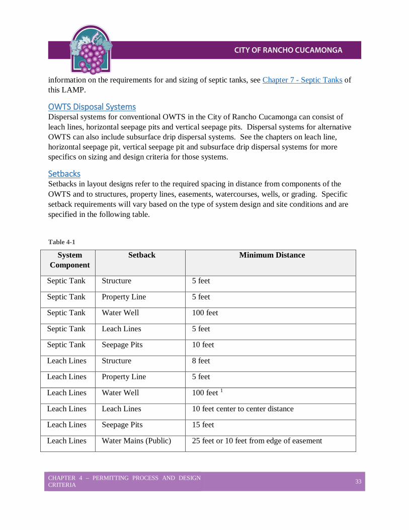
CHAPTER 4 – PERMITTING PROCESS AND DESIGN CRITERIA 33
information on the requirements for and sizing of septic tanks, see Chapter 7 - Septic Tanks of this LAMP.
OWTS Disposal Systems Dispersal systems for conventional OWTS in the City of Rancho Cucamonga can consist of leach lines, horizontal seepage pits and vertical seepage pits. Dispersal systems for alternative OWTS can also include subsurface drip dispersal systems. See the chapters on leach line, horizontal seepage pit, vertical seepage pit and subsurface drip dispersal systems for more specifics on sizing and design criteria for those systems.
Setbacks Setbacks in layout designs refer to the required spacing in distance from components of the OWTS and to structures, property lines, easements, watercourses, wells, or grading. Specific setback requirements will vary based on the type of system design and site conditions and are specified in the following table.
Table 4-1
System Component
Setback Minimum Distance
Septic Tank Structure 5 feet
Septic Tank Property Line 5 feet
Septic Tank Water Well 100 feet
Septic Tank Leach Lines 5 feet
Septic Tank Seepage Pits 10 feet
Leach Lines Structure 8 feet
Leach Lines Property Line 5 feet
Leach Lines Water Well 100 feet 1
Leach Lines Leach Lines 10 feet center to center distance
Leach Lines Seepage Pits 15 feet
Leach Lines Water Mains (Public) 25 feet or 10 feet from edge of easement
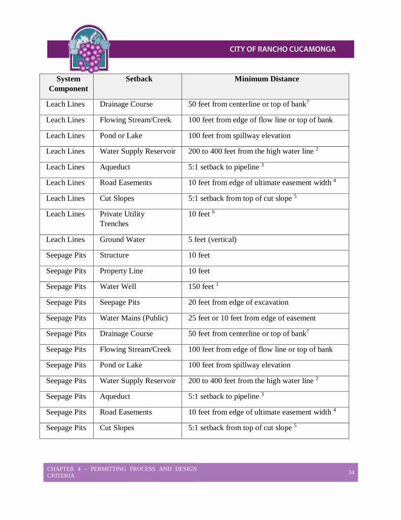
CHAPTER 4 – PERMITTING PROCESS AND DESIGN CRITERIA 34
System Component
Setback Minimum Distance
Leach Lines Drainage Course 50 feet from centerline or top of bank7
Leach Lines Flowing Stream/Creek 100 feet from edge of flow line or top of bank
Leach Lines Pond or Lake 100 feet from spillway elevation
Leach Lines Water Supply Reservoir 200 to 400 feet from the high water line 2
Leach Lines Aqueduct 5:1 setback to pipeline 3
Leach Lines Road Easements 10 feet from edge of ultimate easement width 4
Leach Lines Cut Slopes 5:1 setback from top of cut slope 5
Leach Lines Private Utility Trenches
10 feet 6
Leach Lines Ground Water 5 feet (vertical)
Seepage Pits Structure 10 feet
Seepage Pits Property Line 10 feet
Seepage Pits Water Well 150 feet 1
Seepage Pits Seepage Pits 20 feet from edge of excavation
Seepage Pits Water Mains (Public) 25 feet or 10 feet from edge of easement
Seepage Pits Drainage Course 50 feet from centerline or top of bank7
Seepage Pits Flowing Stream/Creek 100 feet from edge of flow line or top of bank
Seepage Pits Pond or Lake 100 feet from spillway elevation
Seepage Pits Water Supply Reservoir 200 to 400 feet from the high water line 2
Seepage Pits Aqueduct 5:1 setback to pipeline 3
Seepage Pits Road Easements 10 feet from edge of ultimate easement width 4
Seepage Pits Cut Slopes 5:1 setback from top of cut slope 5
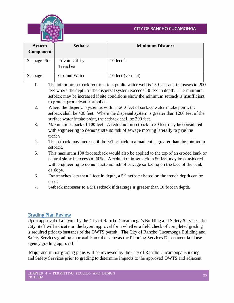
CHAPTER 4 – PERMITTING PROCESS AND DESIGN CRITERIA 35
System Component
Setback Minimum Distance
Seepage Pits Private Utility Trenches
10 feet 6
Seepage Ground Water 10 feet (vertical)
1. The minimum setback required to a public water well is 150 feet and increases to 200 feet where the depth of the dispersal system exceeds 10 feet in depth. The minimum setback may be increased if site conditions show the minimum setback is insufficient to protect groundwater supplies.
2. Where the dispersal system is within 1200 feet of surface water intake point, the setback shall be 400 feet. Where the dispersal system is greater than 1200 feet of the surface water intake point, the setback shall be 200 feet.
3. Maximum setback of 100 feet. A reduction in setback to 50 feet may be considered with engineering to demonstrate no risk of sewage moving laterally to pipeline trench.
4. The setback may increase if the 5:1 setback to a road cut is greater than the minimum setback.
5. This maximum 100 foot setback would also be applied to the top of an eroded bank or natural slope in excess of 60%. A reduction in setback to 50 feet may be considered with engineering to demonstrate no risk of sewage surfacing on the face of the bank or slope.
6. For trenches less than 2 feet in depth, a 5:1 setback based on the trench depth can be used.
7. Setback increases to a 5:1 setback if drainage is greater than 10 foot in depth.
Grading Plan Review Upon approval of a layout by the City of Rancho Cucamonga’s Building and Safety Services, the City Staff will indicate on the layout approval form whether a field check of completed grading is required prior to issuance of the OWTS permit. The City of Rancho Cucamonga Building and Safety Services grading approval is not the same as the Planning Services Department land use agency grading approval
Major and minor grading plans will be reviewed by the City of Rancho Cucamonga Building and Safety Services prior to grading to determine impacts to the approved OWTS and adjacent
CHAPTER 4 – PERMITTING PROCESS AND DESIGN CRITERIA 36
properties. After completion of the grading, the City of Rancho Cucamonga Building and Safety Services must be contacted to arrange for a field check, unless the field check of completed grading is waived on the layout approval.
Building Plan Review The City of Rancho Cucamonga Building and Safety Services recommends that you obtain approval of your OWTS prior to expending funds for a final set of architectural plans for your home or structure. Plans for a new or second dwelling must be submitted to the Planning Services Department for processing and approval. Upon submittal of the plans, the owner/agent shall meet staff at the City of Rancho Cucamonga Building and Safety Services counter for a verification of bedrooms and plot plan concurrence with the approved layout. Bedrooms are used to determine the potential occupancy of a dwelling and therefore the potential amount of wastewater that will be generated.
Guidelines for Determining the Number of Bedrooms 1. Once the living room, dining room, family room, kitchen, bathrooms, and utility
rooms have been established, all other rooms shall be considered as potential sleeping rooms. Dens, libraries, studies, weight rooms, sewing rooms, workshops, etc., shall be determined as bedrooms if they do not conform to the criteria listed below.
2. All other habitable rooms totaling at least seventy (70) square feet in size are to be considered bedrooms suitable for sleeping purposes, regardless of whether or not they contain closets or have access to a bathroom.
3. Rooms that open to a living room, dining room, family room, kitchen, or entry way, and have a single, un-obstructive opening (no doors) with a minimum 50% opening of the total wall space (minimum 6’ wide) with archways or other acceptable means shall not be considered as bedrooms, due to the lack of personal privacy presented by the opening.
4. Rooms that can only be accessed through another bedroom are to be considered part of that bedroom, such as master suite and not an additional bedroom.
5. In the case of an ambiguous situation, where it is not clear as to whether or not a room is a bedroom, the plans may be re-reviewed on a case-by-case basis.
6. Any cases, which will require the relocation or modification of doorways, are to be reviewed and approved by the Planning Services Department and Building and Safety Services to address any structural considerations such as load bearing walls. This is to be done prior to approval or sign-off by the City of Rancho Cucamonga Building and Safety Services.

CHAPTER 4 – PERMITTING PROCESS AND DESIGN CRITERIA 37
Potable Water Supply The City of Rancho Cucamonga Building and Safety Services will require proof of a potable water supply that will serve the proposed development. A public water supply should be confirmed with proof of a service availability letter from the Cucamonga Valley Water District (CVWD), or a water bill showing the property is served by a local water agency. The use of any new domestic water well will require proof of potability and be subject to reviews and approvals by all agencies involved. A copy of the Well Laboratory Report that indicates the absence of bacteria and nitrate contamination of less than 10 mg/l of Nitrate-N or 45 mg/l of nitrate will be necessary for proof of potability of a private well. The date of the test cannot be more than one year old. If a valid test does not exist, the well must be sampled by client’s consultant for bacteriological and nitrate levels. Hand-dug water wells will not be accepted as a potable water supply.
OWTS Permit Issuance When all applicable items above have been completed to the satisfaction of the City of Rancho Cucamonga Building and Safety Services, an OWTS installation permit can be issued to the owner/agent or to a contractor with the required license(s) from the City of Rancho Cucamonga Building and Safety Services. The permit is valid for one year and allows for the inspection of the completed OWTS installation by the City of Rancho Cucamonga Building and Safety Services staff prior to backfilling any portion of the installation.
In order to make the OWTS permit processing as smooth and efficient as possible, it is recommended that the applicant maintain a record of all paperwork and project control numbers obtained from each Department.

CHAPTER 5 – WASTE WATER TREATMENT SYSTEMS 38
CHAPTER 5 Wastewater Treatment Systems
This Chapter is to be used for determining groundwater levels when siting and designing onsite wastewater treatment systems (OWTS) with the purpose to:
• Protect the groundwater quality by ensuring proper treatment of the sewage effluent prior to its entering into the groundwater.
• Protect the public health from failing OWTS caused by high groundwater. • Provide a methodology for the evaluation of potential building sites using OWTS with
regards to maintaining minimum groundwater separation requirements with the use of an OWTS.
The SWRCB requires that at least a five-foot separation be maintained between the bottom of a conventional OWTS disposal system and the highest anticipated groundwater level for leach fields and 10 feet for seepage pits. For OWTS with supplemental treatment, the required separation can be reduced to no less than two feet. This reduction is allowed due to the level of pretreatment provided by the supplemental treatment.
Groundwater typically fluctuates seasonally depending on local geology and rainfall amounts. In certain areas dependent on imported water and OWTS, Chino Basin Water Master has observed rising groundwater levels. Groundwater levels fall in response to drought and well extraction, and rise in response to rainfall and in some cases, increased irrigation, agriculture and residential development.
OWTS failures due to high groundwater result in sewage effluent backing up into homes and surfacing on the ground creating public health hazards, and can contribute to the contamination of potable groundwater resources.
Procedure for Groundwater Determination for Discretionary Projects Subdivisions, parcel maps, boundary adjustments, certificates of compliance and percolation tests are all projects that may require the City of Rancho Cucamonga Building and Safety Services to certify that each lot can support an OWTS that will not violate the RWQCB mandates. To meet this requirement, test borings and/or piezometers for monitoring groundwater in conformance with this policy may need to be installed. Maps showing the location of the borings and their logs shall be submitted to the City of Rancho Cucamonga Building and Safety Services. The applicant, project engineer, or geologist must determine the actual and potential high groundwater levels in the area of the proposed OWTS at the time of submittal for review by

CHAPTER 5 – WASTE WATER TREATMENT SYSTEMS 39
the Building and Safety Services, or may use the San Bernardino County web based program Stormwater Facility Mapping Tool.
The qualified professional, must support their expressed conclusion that it is unlikely that seeps or springs would develop as a results of the OWTS and the high historic groundwater elevation will not encroach upon the minimum separation required between the bottom of the proposed OWTS and the highest anticipated groundwater level.
Transient high groundwater conditions (spikes) must be documented thoroughly if encountered. A written discussion by the qualified professional must be submitted to the City of Rancho Cucamonga Building and Safety Services along with groundwater monitoring log(s) for review and concurrence. The discovery of groundwater spikes on a lot will be evaluated on a case-by-case basis.
Existing Lot OWTS Design Review 1. If this site review reveals any evidence of groundwater changes, including but not limited
to; plant growth, ponding water, or OWTS failures in the area, additional groundwater test borings may be required. The City of Rancho Cucamonga Building and Safety Services staff will specify the depth and the locations of the additional test borings in consultation with the qualified professional in charge of the project.
2. When groundwater is observed in the borings and the City of Rancho Cucamonga Building and Safety Services has reason to believe that groundwater could rise to an unacceptable level during the course of a normal rainfall season, monitoring may be required to determine that groundwater will not rise to an elevation that will not provide the minimum separation required from the bottom of the proposed OWTS. Monitoring, if required, must be conducted during the course of an above average annual rainfall year and/or when full groundwater recharge has occurred.
3. When groundwater is not observed in the boring but there is evidence of past high groundwater levels, such as documentation of groundwater rise on adjacent properties, monitoring may be required.
4. If there is a dry boring, there is not a known history of rising groundwater and there is no evidence of groundwater changes, including but not limited to; plant growth, ponding water, or OWTS failures in the area the project will be able to move forward.
5. The qualified professional conducting the groundwater study must support their express conclusion it is unlikely that seeps or springs would develop as a result of the OWTS and the anticipated high groundwater elevation will not encroach upon the minimum separation required to the bottom of the proposed OWTS. The supporting data shall include, but not be limited to, data on the sites topography, soils, geology, basin studies, hydro-geologic studies, and groundwater-monitoring data from the on-site observation wells through an above normal rainfall year.
CHAPTER 5 – WASTE WATER TREATMENT SYSTEMS 40
Testing Procedures for Groundwater 1. Test borings in the area of an OWTS shall extend to a minimum of 15 feet unless
refusal is reached. Deeper depths may be required depending on site-specific conditions as determined by the City of Rancho Cucamonga Building and Safety Services or the project qualified professional. Site-specific conditions may include, but not be limited to; the proposed depth of the system, local geology, soil types encountered, elevation and terrain, features on site, evidence and/or knowledge of historic ground water levels in the area, and the anticipated fluctuation of the groundwater table in times of normal to above normal annual rainfall.
2. Test borings in the area of a vertical seepage pit or horizontal seepage pit system shall extend to at least 10 feet deeper than the bottom of the proposed pit(s).
3. Since groundwater does not always immediately flow into a test boring, the City of Rancho Cucamonga Building and Safety Services requires a minimum of 72 hours pass before an accurate groundwater measurement is taken. The qualified professional and/or the property owner maintain full responsibility for protecting the public from any hazards related to the test borings. It is recommended that all test borings that encounter groundwater be converted to observation wells so the groundwater conditions can be monitored over time.
4. If the qualified professional does not wish to complete the test borings as observation wells, they can cover the test boring, place safeguards around the borings to prevent unauthorized access and make an appointment for the City of Rancho Cucamonga Building and Safety Services staff to observe the boring at least 72-hours after the boring has been completed.
5. During periods of below normal average rainfall, or after periods of drought where there has not yet been sufficient ground water recharge, the absence of groundwater in test borings in areas where groundwater is suspect may not mean that approval to issue a septic tank permit can be granted. It may be necessary for the City of Rancho Cucamonga Building and Safety Services and the qualified professional to monitor the test borings for a sufficient period of time to determine where groundwater will rise to during normal to above normal rainfall.
CHAPTER 6 – PERCOLATION TEST PROCEDURE 41
CHAPTER 6 Percolation Test Procedure This Chapter is to be used to establish clear direction and methodology for percolation testing in the City of Rancho Cucamonga. The objective is to determine the area necessary to properly treat and maintain sewage underground; to size the OWTS with adequate infiltration surface area based on an expected hydraulic conductivity of the soil and the rate of loading; and to provide for a system intended to allow for a long-term expectation of satisfactory performance.
Percolation testing is required for new developments of two (2) or more units for OWTS (i.e. two or more lots). For a (one) custom single family residential house, the project proponent may use the procedure listed in Chapter 9 - Design Criteria for Replacement of Existing Private Sewage Disposal Systems, Table 9-1.
All percolation testing for dispersal systems except vertical seepage pits in the City of Rancho Cucamonga shall be conducted through the use of the following procedures. The test shall be performed by or under the direct supervision of a California registered professional engineer, geologist. Any deviation shall be authorized only after receiving written approval by the City of Rancho Cucamonga Building and Safety Services. For testing requirements for horizontal and vertical seepage pits and subsurface drip systems, see the Chapters in this LAMP covering those types of dispersal systems.
Note: Grading or clearing of brush for the purposes of completing a percolation test may require approval from Planning Services Department and requires the implementation of wind and storm water erosion best management practices.
Test Holes Number of Test Holes
1. A minimum of four test holes is required when percolation rates are less than 60 minutes per inch (mpi).
2. A minimum of six test holes is required when the average percolation rate is more than 60 mpi.
3. Additional test holes may be necessary on a site specific basis for reasons that include, but are not limited to the following: a. Unacceptable or failed tests. b. Areas of the disposal field requiring defined limits for exclusion. c. The disposal system is located out of a concentrated area. d. Soil conditions are variable or inconsistent.
CHAPTER 6 – PERCOLATION TEST PROCEDURE 42
Depth of Testing 1. Test holes shall be representative of the dispersal system installation depth. 2. Conditions which may require testing deeper than leach line depth:
a. Shallow consolidated rock or impervious soil layers. b. Slope exceeds 25%. c. Other factors as might be determined by sound geotechnical engineering practices.
Soil Classification 1. All test holes and deep borings shall have soil types described according to the
American Society for Testing and Materials (ASTM) Soil Classification System (Unified).
2. All borings are to be reported, including any, which encountered groundwater or refusal. Comments about consolidation and friable characteristics are encouraged.
Location of Test Holes Test holes shall be representative of the dispersal area demonstrating site conditions throughout the entire sewage disposal system with equal consideration of primary and reserve leach fields.
Identification of Test Holes 1. Staked and flagged so the test holes can be located.
2. Identified with: a. A test hole number or letter b. The depth of the test boring c. Lot/parcel number or letter if associated with a subdivision or lot line adjustment.
Drilling of Borings for Test Holes 1. Diameter of each test hole shall be a minimum of 6 inches.
2. If a backhoe excavation is used, a test hole at 12–14 inches in depth shall be excavated into the bottom of the trench.
Preparation of Test Holes 1. The sides and bottom of the holes shall be scarified so as to remove the areas that
became smeared by the auger or other tool used to develop the hole.
2. All loose material should be removed from the hole.
Presoaking the Test Holes Procedure
1. Carefully fill the test hole with 12-14 inches of clear water.
CHAPTER 6 – PERCOLATION TEST PROCEDURE 43
2. Maintain 12-14 inches of clear water for a minimum of four (4) hours. After four hours, allow the water column to drop overnight. (Testing must be done within 15-30 hours after the initial four-hour presoak).
3. Overnight Option: If clay soils are present, it is recommended to maintain the 12-14 inch water overnight. A siphon can be used to maintain the supply at a constant level.
4. In highly permeable sandy soils with no clay and/or silt, the presoak procedure may be modified. If, after filling the hole twice with 12-14 inches of clear water, the water seeps completely away in less than 30 minutes, proceed immediately to Case 2, Item 3 and refill to 6 inches above the pea gravel. If the test is done the following day, a presoak will be necessary for at least an hour in order to reestablish a wetted boundary.
Saturation and Swelling 1. Saturation means that the void spaces between soil particles are full of water.
This can be accomplished in a short period of time. 2. Swelling is caused by the intrusion of water into the individual soil particles are
full of water. This is a slow process, especially in clay-type soil and is the reason for requiring a prolonged soaking.
Use of Inserts 1. If sidewalls are not stable or sloughing results in changing depth, the test hole may
be abandoned or retested after means are taken to shore up the sides. The holes shall be re-cleaned prior to resuming the test.
2. Options for shoring or maintaining test hole stability: a. Hardware cloth (1/8 inch grid) b. Perforated pipe or containers c. Gravel pack (NOTE: A correction factor is necessary if a gravel pack is used.
Show all calculations on the test report. See Chapter 6 - Appendix I)
Determination of Percolation Rates Depending on the soil type and permeability, and the results of the presoak, variations in the procedures used for determining percolation rates can be allowed. Testing shall proceed based on the conditions outlined in the following cases.
Case 1 – Water remains overnight in the test hole following the four-hour presoak. (Unless an overnight siphon is used.)
Case 2 – Soil with a fast percolation rate is encountered where two columns of 12-14 inches of water percolates in less than 30 minutes for each column during the presoak.
CHAPTER 6 – PERCOLATION TEST PROCEDURE 44
Case 3 – No water remains in the test hole 15-30 hours after the four-hour presoak.
Case 1 Procedure 1. Adjust depth of water to 6 inches in the hole.
2. Take two (2) readings at thirty (30) minute intervals and report percolation rate as the slower of the two readings.
NOTE: When a minimum amount of water remains due to a damaged hole or silting, the hole may be cleaned out and tested under Case 3, starting with the presoak.
Case 2 Procedure 1. Begin test 15-30 hours after presoak.
2. Fill the hole twice with 12-14 inches of water. Observe to see if each column of water seeps away in less than 30 minutes. If so, proceed with the percolation test. If not, go to Case 3.
3. Refill hole to 6 inches above the bottom.
4. Measure from a fixed reference point at ten (10) minute intervals over a period of one (1) hour to the nearest 1/16th inch. Add water at each 10-minute time interval.
5. Continue 10 minute readings as long as necessary to obtain a "stabilized" rate with the last 2 rate readings not varying more than 1/16th inch or for a duration of four (4) hours. The last water level drop will be considered in the percolation rate.
Case 3 Procedure 1. Begin test 15-30 hours after presoak.
2. Clean out the silt and mud and add 2 inches of 3/8 inch pea gravel.
3. Adjust water depth to 6 inch above the pea gravel buffer and measure from a fixed reference point at 30 minute intervals to the nearest 1/16th inch. NOTE: It is not necessary to record data points for the first hour as this is an adjustment period and a reestablishment of a wetted boundary.
4. Refill the hole as necessary between readings to maintain a 6-inch column of water over the pea gravel. If a fall of 1 inch or less is recorded, the test can continue without refilling until the next 30 minute reading interval.
5. Continue recording readings at 30 minute intervals for a minimum of four hours.
CHAPTER 6 – PERCOLATION TEST PROCEDURE 45
6. The last water level drop is used to calculate the percolation rate.
Calculations and Measurements Calculation Example
The percolation rate is reported in minutes per inch. For example, a 30 minute time interval with a 3/4 inch fall would be as follows:
30 minutes ÷ 3/4 inch = 40 minutes per inch (mpi)
Measurement Principles 1. The time interval for readings are to reflect the actual times and are to be maintained as
near as possible to the intervals outlined for the test. (10 or 30 minutes). 2. Measurements to the nearest 1/16th inch should be adjusted to the slowest rate, e.g., a
reading observed between 3/8 inch and 5/16 inch (80 mpi and 96 mpi) would be reported as 96 mpi.
3. Measurements on an engineering scale (tenths of an inch) should follow the same principle, e.g., a reading observed between 0.4 inch and 0.3 inch (75 mpi and 100 mpi) would be reported as 100 mpi.
Measurements, Special Considerations 1. Measurement from a fixed reference point shall be from a platform that is stable and
represents the center of the test hole. 2. Percometer devices are encouraged and required when the depth of a test hole is greater
than 60 inch in depth. Accurate measurement is vital and in cases of testing deeper than 60 inch, the report shall include a description of the measurement method and how the borings were cleaned out and prepared for testing.
3. Correction Factors a. Void factor for gravel pack (See Chapter 6 - Appendix I)
Reports 1. All test data and required information shall be submitted on approved City of Rancho
Cucamonga Building and Safety Services forms with appended data or information as needed. A minimum of three copies is required.
2. Reports shall be signed with an original signature and seal by the consultant who either performed or supervised the testing.
3. All percolation testing to be done by a civil engineer, geologist registered in the State of California.
4. The percolation test is only one critical factor in siting an OWTS. Site considerations may require special evaluation by a qualified professional to technically address issues

CHAPTER 6 – PERCOLATION TEST PROCEDURE 46
such as high groundwater, steep slope, nitrate impacts, cumulative impacts, (mounding, and horizontal transmissibility).
5. Qualified professionals who employ technicians are responsible for the work performed by the technician. It is incumbent upon the qualified professional to properly train, equip, and supervise anyone performing work under his or her direction and license.
CHAPTER 6 – PERCOLATION TEST PROCEDURE 47
Appendix I Adjustment Factor for Gravel Packed Percolation Test Holes
Calculations • AH - X-Section Area of Test Hole, AH = .25 π DH
2
• AP - X-Section Area of Pipe, AP = .25 π DP2
• AG - X-Section Area of Gravel Pack, AG = AH - AP
• VD - Drainable Voids in Gravel Pack = n (AG)*
• V - Total Voids = AP + n (AG) = AP + n (AH – AP)
• AF - Adjustment Factor, AF:
AF = ______ AH_______
AP + n (AH – AP)
AF = ___________.25 π DH2_______________
.25 π DP2 + n (.25 π DH
2 - .25 π DP2 )
AF = ________DH2______
DP2 + n (DH
2 - DP2 )
Where: mpi = minutes per inch
n = void ratio
* A test should be run on the actual rock used to establish the Void Ratio (n).
Application Adjusted Percolation Rate = mpi x AF
Typical Values
For n = 0.35
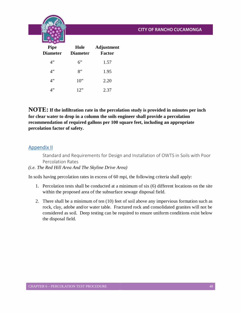
CHAPTER 6 – PERCOLATION TEST PROCEDURE 48
Pipe Diameter
Hole Diameter
Adjustment Factor
4” 6” 1.57
4” 8” 1.95
4” 10” 2.20
4” 12” 2.37
NOTE: If the infiltration rate in the percolation study is provided in minutes per inch for clear water to drop in a column the soils engineer shall provide a percolation recommendation of required gallons per 100 square feet, including an appropriate percolation factor of safety.
Appendix II Standard and Requirements for Design and Installation of OWTS in Soils with Poor Percolation Rates
(i.e. The Red Hill Area And The Skyline Drive Area)
In soils having percolation rates in excess of 60 mpi, the following criteria shall apply:
1. Percolation tests shall be conducted at a minimum of six (6) different locations on the site within the proposed area of the subsurface sewage disposal field.
2. There shall be a minimum of ten (10) feet of soil above any impervious formation such as rock, clay, adobe and/or water table. Fractured rock and consolidated granites will not be considered as soil. Deep testing can be required to ensure uniform conditions exist below the disposal field.
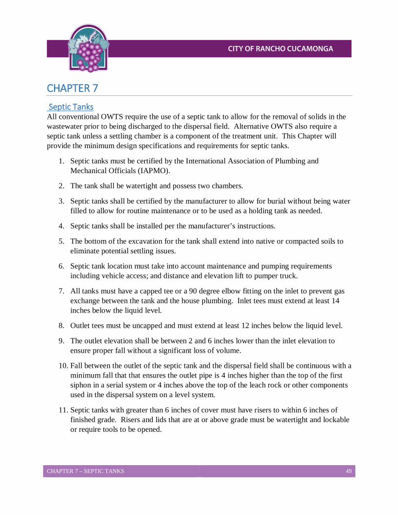
CHAPTER 7 – SEPTIC TANKS 49
CHAPTER 7 Septic Tanks All conventional OWTS require the use of a septic tank to allow for the removal of solids in the wastewater prior to being discharged to the dispersal field. Alternative OWTS also require a septic tank unless a settling chamber is a component of the treatment unit. This Chapter will provide the minimum design specifications and requirements for septic tanks.
1. Septic tanks must be certified by the International Association of Plumbing and Mechanical Officials (IAPMO).
2. The tank shall be watertight and possess two chambers.
3. Septic tanks shall be certified by the manufacturer to allow for burial without being water filled to allow for routine maintenance or to be used as a holding tank as needed.
4. Septic tanks shall be installed per the manufacturer’s instructions.
5. The bottom of the excavation for the tank shall extend into native or compacted soils to eliminate potential settling issues.
6. Septic tank location must take into account maintenance and pumping requirements including vehicle access; and distance and elevation lift to pumper truck.
7. All tanks must have a capped tee or a 90 degree elbow fitting on the inlet to prevent gas exchange between the tank and the house plumbing. Inlet tees must extend at least 14 inches below the liquid level.
8. Outlet tees must be uncapped and must extend at least 12 inches below the liquid level.
9. The outlet elevation shall be between 2 and 6 inches lower than the inlet elevation to ensure proper fall without a significant loss of volume.
10. Fall between the outlet of the septic tank and the dispersal field shall be continuous with a minimum fall that that ensures the outlet pipe is 4 inches higher than the top of the first siphon in a serial system or 4 inches above the top of the leach rock or other components used in the dispersal system on a level system.
11. Septic tanks with greater than 6 inches of cover must have risers to within 6 inches of finished grade. Risers and lids that are at or above grade must be watertight and lockable or require tools to be opened.

CHAPTER 7 – SEPTIC TANKS 50
12. Septic tank risers must have a current IAPMO certification to use. Concrete risers and lids must be constructed of Type V concrete or be protected from corrosion from sewer gases. The interior diameter of the riser shall be a minimum of eighteen (18) inches.
13. Effluent filters must be IAPMO approved if they are to be installed as part of the outlet tee.
14. Septic tanks installed in areas of vehicular traffic must be certified to withstand the proposed loads or have an engineered traffic slab installed to accommodate the proposed loads.
15. Minimum tank size is 1000 gallons for residential and 750 gallons for non-residential structures..
16. Septic tanks shall be sized according to anticipated wastewater flows from the structure(s). The following standard sizes will shall apply:
a. 1-3 bedroom single family dwelling (0-450 GPD) 1000 gallons b. 4 bedroom single family dwelling (451-600 GPD) 1200 gallons c. 5-6 bedroom single family dwelling (601-900GPD) 1500 gallons d. Flows greater than 900 GPD must utilize the following formula to determine
minimum tank sizing: 1125 gallons + (.75)(Flow in GPD).

CHAPTER 8 – LEACH LINE SYSTEMS 51
CHAPTER 8 Leach Line Systems Leach lines systems are the primary means of effluent dispersal for the majority of older OWTS within the City of Rancho Cucamonga and this Chapter will establish procedures for the design and construction of leach line dispersal systems. The procedures are specific for leach lines, and do not apply to other types of dispersal systems. For leach lines on slopes exceeding 25% (4:1) slope, refer to the Steep Slope section of this Chapter. For existing OWTS systems using leach line systems see Vertical Seepage Pit Systems Table 9-1 for sizing requirements.
Percolation Test and Design Procedures Percolation testing shall be performed in accordance with the City of Rancho Cucamonga Building and Safety Services percolation test procedures found in Chapter 3 of this LAMP. Deep borings, backhoe excavations, and percolation tests are used to demonstrate that the dispersal site is located in an area of uniform soil, and that no conditions exist which could adversely affect the performance of the system or result in groundwater degradation.
1. Leach line systems are limited to soils with percolation rates of 120 minutes per inch or less. Percolation rates in excess of 120 minutes per inch are unsuitable for the installation of an OWTS dispersal system.
2. At least four percolation test holes at each leach field location should be provided to represent soil types at the depth of the proposed leach lines.
3. At least one deep boring should extend to a depth of at least 15 feet or to impermeable material but in no case shall there be less than 5 foot of unsaturated, permeable soil below the bottom of the leach line trench. For areas of suspected high groundwater, deep borings are recommended to be 20’-25’ to help determine gradients during varying rainfall periods. See CHAPTER 2 for more information on groundwater separation requirements.
4. Backhoe excavations may be required to demonstrate uniformity of soil throughout the leach field area(s).
5. Leach line dispersal systems are limited to slopes of 25 percent (4:1) or less unless the requirements under the section entitled Leach Lines on Steep Slopes found later in this chapter are met.
Soil Cover Requirements 1. The maximum soil cover allowed over the top of the infiltrative surface is 48 inches,
measured from the top of the leach rock/chamber/etc. to the ground surface.
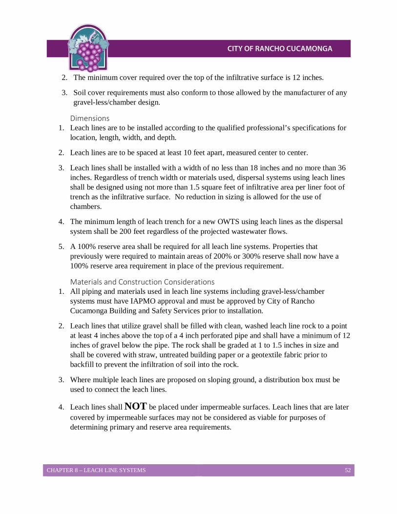
CHAPTER 8 – LEACH LINE SYSTEMS 52
2. The minimum cover required over the top of the infiltrative surface is 12 inches.
3. Soil cover requirements must also conform to those allowed by the manufacturer of any gravel-less/chamber design.
Dimensions 1. Leach lines are to be installed according to the qualified professional’s specifications for
location, length, width, and depth.
2. Leach lines are to be spaced at least 10 feet apart, measured center to center.
3. Leach lines shall be installed with a width of no less than 18 inches and no more than 36 inches. Regardless of trench width or materials used, dispersal systems using leach lines shall be designed using not more than 1.5 square feet of infiltrative area per liner foot of trench as the infiltrative surface. No reduction in sizing is allowed for the use of chambers.
4. The minimum length of leach trench for a new OWTS using leach lines as the dispersal system shall be 200 feet regardless of the projected wastewater flows.
5. A 100% reserve area shall be required for all leach line systems. Properties that previously were required to maintain areas of 200% or 300% reserve shall now have a 100% reserve area requirement in place of the previous requirement.
Materials and Construction Considerations 1. All piping and materials used in leach line systems including gravel-less/chamber
systems must have IAPMO approval and must be approved by City of Rancho Cucamonga Building and Safety Services prior to installation.
2. Leach lines that utilize gravel shall be filled with clean, washed leach line rock to a point at least 4 inches above the top of a 4 inch perforated pipe and shall have a minimum of 12 inches of gravel below the pipe. The rock shall be graded at 1 to 1.5 inches in size and shall be covered with straw, untreated building paper or a geotextile fabric prior to backfill to prevent the infiltration of soil into the rock.
3. Where multiple leach lines are proposed on sloping ground, a distribution box must be used to connect the leach lines.
4. Leach lines shall NOT be placed under impermeable surfaces. Leach lines that are later covered by impermeable surfaces may not be considered as viable for purposes of determining primary and reserve area requirements.

CHAPTER 8 – LEACH LINE SYSTEMS 53
5. Leach line trenches shall be installed with the trench bottom and materials used being level to within 2 inches per 100 feet.
Leach Lines on Steep Slopes The following requirements must be met for the installation of leach line trenches on slopes exceeding 25 percent (4:1) without necessitating the grading of terraces. The design parameters are applicable only to slopes exceeding 25 percent (4:1) and are not intended to be used in any other situation.
1. The maximum slope allowed for leach line trenches is 40 percent (2-1/2:1 slope).
2. All leach lines on steep slopes shall be installed in 5 foot deep trenches with 12 inches of leach rock below the leach pipe or with approved chambers or other gravel-less system.
3. The design of disposal systems on steep slopes requires the experience and expertise to address conditions relative to soil, slope stability, and subsurface conditions which require professional judgment and technical knowledge. Designs for steep slope systems will only be approved when submitted by a qualified professional licensed in the State of California.
4. Testing must provide data representative of the entire disposal area and demonstrate that conditions are uniform below the entire disposal area. The minimum testing required is:
a. Six percolation tests at a depth equal to the proposed trench depth. b. Two percolation tests five feet below the proposed trench depth. c. Percolation testing must show rates of 120 minutes per inch or less. d. At least two soil profile borings demonstrating uniform conditions throughout the
disposal area to a depth of 10 feet below the proposed trench depth.
5. Design reports must include the following:
a. Cross section(s) hillside soil profile(s). b. Detailed boring logs of all test holes and borings. c. Scaled layouts and profiled designs based on accurate topography. d. Any grading proposed on the site in the disposal area. e. A slope stability report or statement from a qualified professional.
6. Any grading, proposed to create a stable work area for trench installation, may be subject to review for conflict with Planning and Development Services (PDS). It is strongly recommended that contact be made with PDS before any grading occurs.
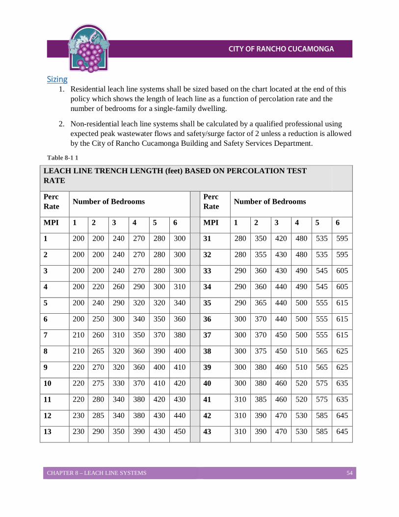
CHAPTER 8 – LEACH LINE SYSTEMS 54
Sizing 1. Residential leach line systems shall be sized based on the chart located at the end of this
policy which shows the length of leach line as a function of percolation rate and the number of bedrooms for a single-family dwelling.
2. Non-residential leach line systems shall be calculated by a qualified professional using expected peak wastewater flows and safety/surge factor of 2 unless a reduction is allowed by the City of Rancho Cucamonga Building and Safety Services Department.
Table 8-1 1
LEACH LINE TRENCH LENGTH (feet) BASED ON PERCOLATION TEST RATE
Perc Rate Number of Bedrooms Perc
Rate Number of Bedrooms
MPI 1 2 3 4 5 6 MPI 1 2 3 4 5 6
1 200 200 240 270 280 300 31 280 350 420 480 535 595
2 200 200 240 270 280 300 32 280 355 430 480 535 595
3 200 200 240 270 280 300 33 290 360 430 490 545 605
4 200 220 260 290 300 310 34 290 360 440 490 545 605
5 200 240 290 320 320 340 35 290 365 440 500 555 615
6 200 250 300 340 350 360 36 300 370 440 500 555 615
7 210 260 310 350 370 380 37 300 370 450 500 555 615
8 210 265 320 360 390 400 38 300 375 450 510 565 625
9 220 270 320 360 400 410 39 300 380 460 510 565 625
10 220 275 330 370 410 420 40 300 380 460 520 575 635
11 220 280 340 380 420 430 41 310 385 460 520 575 635
12 230 285 340 380 430 440 42 310 390 470 530 585 645
13 230 290 350 390 430 450 43 310 390 470 530 585 645
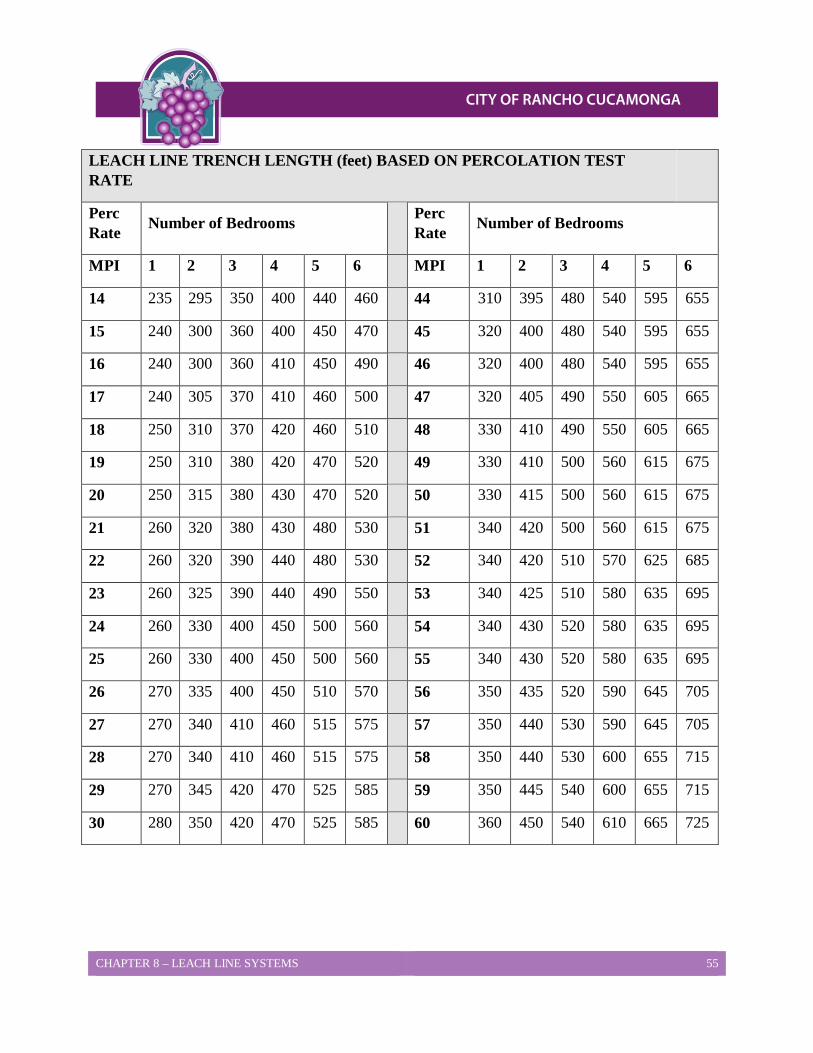
CHAPTER 8 – LEACH LINE SYSTEMS 55
LEACH LINE TRENCH LENGTH (feet) BASED ON PERCOLATION TEST RATE
Perc Rate Number of Bedrooms Perc
Rate Number of Bedrooms
MPI 1 2 3 4 5 6 MPI 1 2 3 4 5 6
14 235 295 350 400 440 460 44 310 395 480 540 595 655
15 240 300 360 400 450 470 45 320 400 480 540 595 655
16 240 300 360 410 450 490 46 320 400 480 540 595 655
17 240 305 370 410 460 500 47 320 405 490 550 605 665
18 250 310 370 420 460 510 48 330 410 490 550 605 665
19 250 310 380 420 470 520 49 330 410 500 560 615 675
20 250 315 380 430 470 520 50 330 415 500 560 615 675
21 260 320 380 430 480 530 51 340 420 500 560 615 675
22 260 320 390 440 480 530 52 340 420 510 570 625 685
23 260 325 390 440 490 550 53 340 425 510 580 635 695
24 260 330 400 450 500 560 54 340 430 520 580 635 695
25 260 330 400 450 500 560 55 340 430 520 580 635 695
26 270 335 400 450 510 570 56 350 435 520 590 645 705
27 270 340 410 460 515 575 57 350 440 530 590 645 705
28 270 340 410 460 515 575 58 350 440 530 600 655 715
29 270 345 420 470 525 585 59 350 445 540 600 655 715
30 280 350 420 470 525 585 60 360 450 540 610 665 725
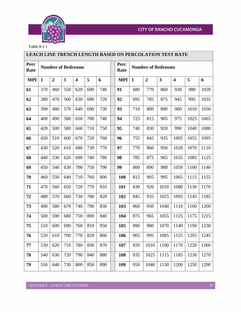
CHAPTER 8 – LEACH LINE SYSTEMS 56
Table 8-2 1
LEACH LINE TRENCH LENGTH BASED ON PERCOLATION TEST RATE
Perc Rate Number of Bedrooms Perc
Rate Number of Bedrooms
MPI 1 2 3 4 5 6 MPI 1 2 3 4 5 6
61 370 460 550 620 690 740 91 680 770 860 930 980 1020
62 380 470 560 630 680 720 92 695 785 875 945 995 1035
63 390 480 570 640 690 730 93 710 800 890 960 1010 1050
64 400 490 580 650 700 740 94 725 815 905 975 1025 1065
65 420 500 580 660 710 750 95 740 830 920 990 1040 1080
66 420 510 600 670 720 760 96 755 845 935 1005 1055 1095
67 430 520 610 680 730 770 97 770 860 950 1020 1070 1110
68 440 530 620 690 740 780 98 785 875 965 1035 1085 1125
69 450 540 630 700 750 790 99 800 890 980 1050 1100 1140
70 460 550 640 710 760 800 100 815 905 995 1065 1115 1155
71 470 560 650 720 770 810 101 830 920 1010 1080 1130 1170
72 480 570 660 730 780 820 102 845 935 1025 1095 1145 1185
73 490 580 670 740 790 830 103 860 950 1040 1110 1160 1200
74 500 590 680 750 800 840 104 875 965 1055 1125 1175 1215
75 510 600 690 760 810 850 105 890 980 1070 1140 1190 1230
76 520 610 700 770 820 860 106 905 995 1085 1155 1205 1245
77 530 620 710 780 830 870 107 920 1010 1100 1170 1220 1260
78 540 630 720 790 840 880 108 935 1025 1115 1185 1230 1270
79 550 640 730 800 850 890 109 950 1040 1130 1200 1250 1290
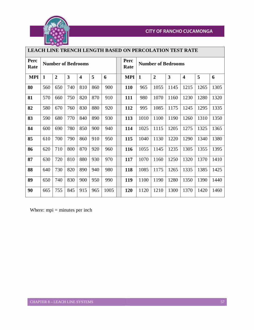
CHAPTER 8 – LEACH LINE SYSTEMS 57
LEACH LINE TRENCH LENGTH BASED ON PERCOLATION TEST RATE
Perc Rate Number of Bedrooms Perc
Rate Number of Bedrooms
MPI 1 2 3 4 5 6 MPI 1 2 3 4 5 6
80 560 650 740 810 860 900 110 965 1055 1145 1215 1265 1305
81 570 660 750 820 870 910 111 980 1070 1160 1230 1280 1320
82 580 670 760 830 880 920 112 995 1085 1175 1245 1295 1335
83 590 680 770 840 890 930 113 1010 1100 1190 1260 1310 1350
84 600 690 780 850 900 940 114 1025 1115 1205 1275 1325 1365
85 610 700 790 860 910 950 115 1040 1130 1220 1290 1340 1380
86 620 710 800 870 920 960 116 1055 1145 1235 1305 1355 1395
87 630 720 810 880 930 970 117 1070 1160 1250 1320 1370 1410
88 640 730 820 890 940 980 118 1085 1175 1265 1335 1385 1425
89 650 740 830 900 950 990 119 1100 1190 1280 1350 1390 1440
90 665 755 845 915 965 1005 120 1120 1210 1300 1370 1420 1460
Where: mpi = minutes per inch
CHAPTER 9 – VERTICAL SEEPAGE PIT SYSTEMS 58
CHAPTER 9 Vertical Seepage Pit Systems Vertical seepage pits are a type of dispersal system allowed in majority of areas of the City of Rancho Cucamonga with specific requirements on their use. This Chapter will provide the requirements to allow for the use of vertical seepage pits as well as the procedures for their design and construction.
Locations Allowed 1. Existing Lots – Any lot previously approved for the use of a vertical seepage pit must
meet all current requirements found in this LAMP to be considered for development based on the use of a vertical seepage pit. In addition, a (one) new custom single family house may use the sizing criteria for existing lots. See Table 9-1 for sizing.
2. New Lots (2 or more OWTS units, i.e. 2 or more lots) – Per the recommendation of a qualified professional soils Engineer and designed by a professional engineer. See Table 9-2 for sizing.
Percolation Test Procedures All vertical seepage pits for new construction, for 2 or more lots, will require percolation testing by a qualified professional certified to perform percolation tests in City of Rancho Cucamonga. A waiver of testing can be considered where adequate information exists as to soil types, depth and permeability. Percolation testing for vertical seepage pits shall be completed per the following guidelines.
1. A 12 to 48 inch diameter test hole shall be excavated to a depth of at least 10 feet deeper than the proposed installation depth.
2. A minimum 10 foot separation between the bottom of the vertical seepage pit and the anticipated high groundwater level is required.
3. Boring logs shall be recorded and included with all test reports indicating soil strata depths and types and visual classification according to the unified soil classification system along with any groundwater encountered.
4. The overdrill must be checked for the presence of groundwater a minimum of 24 hours after the completion of the test boring to allow time for groundwater to stabilize in the hole.
5. After the groundwater reading is recorded, the test hole shall be backfilled to a depth 10 feet above the bottom of the test hole or the groundwater level whichever is shallower.
CHAPTER 9 – VERTICAL SEEPAGE PIT SYSTEMS 59
6. The pit shall be filled with water to the cap depth and a continuous pre-soak shall be maintained at the proposed cap level for a minimum 8-hour period. In highly permeable soils when cap levels cannot be maintained during pre-soak, the test shall be conducted at a depth no higher than the pre-soak level which was attained. Document the pre-soak attempt with gallons of water used. In no case shall less than 5,000 gallons of water be used within a 1 hour period in the attempted pre-soak when the cap level cannot be maintained. The depth of the test shall be noted on the boring log and in no case shall the sidewall of permeable soil below the cap level be less than ten foot.
7. Upon completion of the pre-soak period, fill the pit to cap level and determine uniformity of soil by measuring the falling head. Distance to the water level shall be measured at 15 minute intervals, or more frequently if needed, until the drop stops or the pit empties. A graph of the drop in water level shall be attached to all proposals submitted by the qualified professional. If non-uniform rates persist, the soil will not be considered uniform and the tests discontinued as they will not be approved by City of Rancho Cucamonga Building and Safety Services.
8. If the procedure in Item no. 4 demonstrates uniform soil, proceed with a two-hour static head or falling head capacity test.
a. Static Head – The pit shall be filled with water to the cap depth and the water column shall be maintained at that level for two hours. The amount of water added to maintain this level must be documented. The 24-hour capacity is determined by multiplying by 12. Adjustment to a four foot diameter pit is made if a lesser size test hole is used.
b. Falling Head – The pit shall be filled with water to the cap depth and the column of water shall be allowed to drop for a two hour period. The distance dropped shall be measured and the amount of water absorbed determined. This amount is multiplied by 12 to determine the 24-hour capacity. Adjustment to a four foot diameter pit is made if a lesser size test hole is used.
9. The minimum capacity for a new OWTS using vertical seepage pits as the dispersal system shall be 5 times the volume of the required septic tank or 5000 gallons per day whichever is greater. All individual vertical seepage pit shall have a minimum capacity of 1,667 gallons per day.
10. Each pit must meet these minimum criteria to be acceptable. The qualified professional may include safety factors as he feels the situation warrants.
11. It shall be the responsibility of the qualified professional to maintain all test holes or pits in a safe manner prior to backfill or capping to prevent a hazard or accident.
CHAPTER 9 – VERTICAL SEEPAGE PIT SYSTEMS 60
Dimensions and Construction Requirements 1. Vertical seepage pits shall be installed according to the qualified professional’s
specifications for location, depth and cap depth.
2. The pit excavation shall be five (5), six (6) or seven (7) feet in diameter.
3. The sidewall depth below the cap shall not be less than 17 feet.
4. The minimum depth to the top of the infiltrative surface allowed is 2 feet. This depth is also known as the cap depth. There is no maximum cap depth but documentation must be provided to justify any cap depth greater than 5 feet.
5. The maximum slope allowed for the use of vertical seepage pits is 40 percent (2-1/2:1 slope). Slopes that exceed 25% (4:1) will require additional engineering and design detail as required to address the risk of effluent surfacing on the slope recognizable as sewage as well as slope stability issues. Slopes that exceed 25% (4:1) will, in most cases, require a terrace design or grading to allow for drilling access. Any grading shall be in accordance with any permit requirements for brushing, clearing, and grading from any other agency.
6. All pits must be filled with clean washed leach line rock to the cap depth. The rock shall be graded at 1 to 1.5 inches in size and shall be covered with straw, untreated building paper or a geotextile fabric prior to backfill to prevent the infiltration of soil into the rock.
7. A 4 inch Schedule 40 pipe shall be installed from the ground surface to the bottom of each seepage pit for clean-out, pumping and verification of the total pit depth. The pipe shall have perforations from the cap depth to the bottom of the pit and be of solid construction from the cap depth to the ground surface. A screw fit cap must be placed on top of the riser to allow access.
8. Where more than one vertical seepage pit is proposed for the primary or reserve system, a distribution box must be used to connect the pits. Chaining or lining the seepage pits together such that the overflow from an upstream pit flows to a downstream pit shall not be permitted.
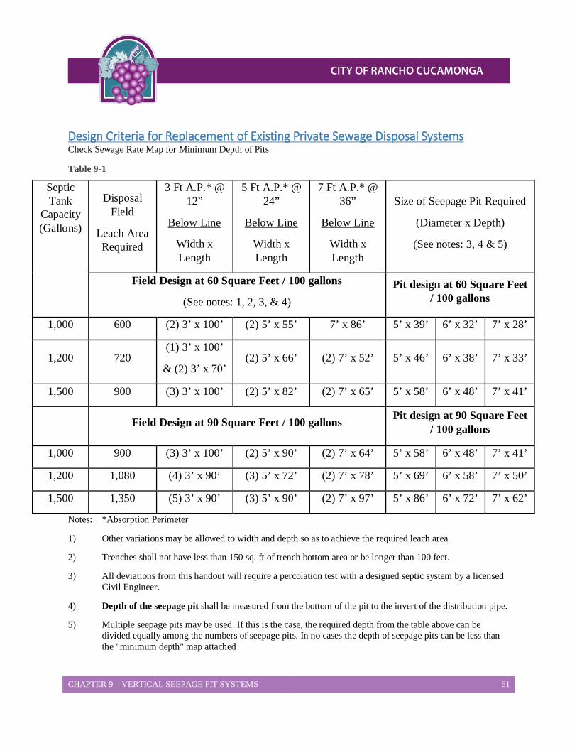
CHAPTER 9 – VERTICAL SEEPAGE PIT SYSTEMS 61
Design Criteria for Replacement of Existing Private Sewage Disposal Systems Check Sewage Rate Map for Minimum Depth of Pits
Table 9-1
Septic Tank
Capacity (Gallons)
Disposal Field
Leach Area Required
3 Ft A.P.* @ 12”
Below Line
Width x Length
5 Ft A.P.* @ 24”
Below Line
Width x Length
7 Ft A.P.* @ 36”
Below Line
Width x Length
Size of Seepage Pit Required
(Diameter x Depth)
(See notes: 3, 4 & 5)
Field Design at 60 Square Feet / 100 gallons
(See notes: 1, 2, 3, & 4) Pit design at 60 Square Feet
/ 100 gallons
1,000 600 (2) 3’ x 100’ (2) 5’ x 55’ 7’ x 86’ 5’ x 39’ 6’ x 32’ 7’ x 28’
1,200 720 (1) 3’ x 100’
& (2) 3’ x 70’ (2) 5’ x 66’ (2) 7’ x 52’ 5’ x 46’ 6’ x 38’ 7’ x 33’
1,500 900 (3) 3’ x 100’ (2) 5’ x 82’ (2) 7’ x 65’ 5’ x 58’ 6’ x 48’ 7’ x 41’
Field Design at 90 Square Feet / 100 gallons Pit design at 90 Square Feet / 100 gallons
1,000 900 (3) 3’ x 100’ (2) 5’ x 90’ (2) 7’ x 64’ 5’ x 58’ 6’ x 48’ 7’ x 41’
1,200 1,080 (4) 3’ x 90’ (3) 5’ x 72’ (2) 7’ x 78’ 5’ x 69’ 6’ x 58’ 7’ x 50’
1,500 1,350 (5) 3’ x 90’ (3) 5’ x 90’ (2) 7’ x 97’ 5’ x 86’ 6’ x 72’ 7’ x 62’
Notes: *Absorption Perimeter
1) Other variations may be allowed to width and depth so as to achieve the required leach area.
2) Trenches shall not have less than 150 sq. ft of trench bottom area or be longer than 100 feet.
3) All deviations from this handout will require a percolation test with a designed septic system by a licensed Civil Engineer.
4) Depth of the seepage pit shall be measured from the bottom of the pit to the invert of the distribution pipe.
5) Multiple seepage pits may be used. If this is the case, the required depth from the table above can be divided equally among the numbers of seepage pits. In no cases the depth of seepage pits can be less than the "minimum depth" map attached
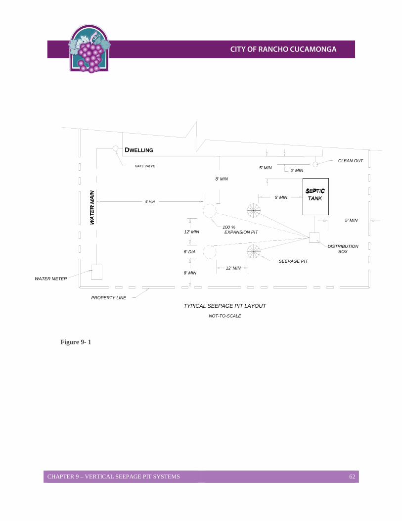
CHAPTER 9 – VERTICAL SEEPAGE PIT SYSTEMS 62
TYPICAL SEEPAGE PIT LAYOUTPROPERTY LINE
WATER METER
12' MIN
DWELLING
GATE VALVE2' MIN
DISTRIBUTIONBOX
CLEAN OUT
12' MIN
8' MIN
6' DIA
5' MIN
SEEPAGE PIT
100 %EXPANSION PIT
NOT-TO-SCALE
5' MIN
8' MIN
5' MIN
5' MIN
Figure 9- 1
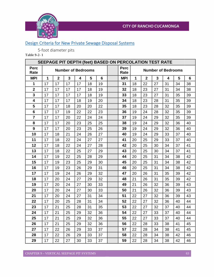
CHAPTER 9 – VERTICAL SEEPAGE PIT SYSTEMS 63
Design Criteria for New Private Sewage Disposal Systems 5-foot diameter pits
Table 9-2- 1
SEEPAGE PIT DEPTH (feet) BASED ON PERCOLATION TEST RATE Perc Rate Number of Bedrooms Perc
Rate Number of Bedrooms
MPI 1 2 3 4 5 6 MPI 1 2 3 4 5 6 1 17 17 17 17 18 19 31 18 22 27 31 34 38 2 17 17 17 17 18 19 32 18 23 27 31 34 38 3 17 17 17 17 18 19 33 18 23 27 31 35 39 4 17 17 17 18 19 20 34 18 23 28 31 35 39 5 17 17 18 20 20 22 35 18 23 28 32 35 39 6 17 17 19 22 22 23 36 19 24 28 32 35 39 7 17 17 20 22 24 24 37 19 24 29 32 35 39 8 17 17 20 23 25 25 38 19 24 29 32 36 40 9 17 17 20 23 25 26 39 19 24 29 32 36 40
10 17 18 21 24 26 27 40 19 24 29 33 37 40 11 17 18 22 24 27 27 41 20 25 29 33 37 40 12 17 18 22 24 27 28 42 20 25 30 34 37 41 13 17 18 22 25 27 29 43 20 25 30 34 37 41 14 17 19 22 25 28 29 44 20 25 31 34 38 42 15 17 19 23 25 29 30 45 20 25 31 34 38 42 16 17 19 23 26 29 31 46 20 25 31 34 38 42 17 17 19 24 26 29 32 47 20 26 31 35 39 42 18 17 20 24 27 29 32 48 21 26 31 35 39 42 19 17 20 24 27 30 33 49 21 26 32 36 39 43 20 17 20 24 27 30 33 50 21 26 32 36 39 43 21 17 20 24 27 31 34 51 22 27 32 36 39 43 22 17 20 25 28 31 34 52 22 27 32 36 40 44 23 17 21 25 28 31 35 53 22 27 32 37 40 44 24 17 21 25 29 32 36 54 22 27 33 37 40 44 25 17 21 25 29 32 36 55 22 27 33 37 40 44 26 17 21 25 29 32 36 56 22 28 33 38 41 45 27 17 22 26 29 33 37 57 22 28 34 38 41 45 28 17 22 26 29 33 37 58 22 28 34 38 42 46 29 17 22 27 30 33 37 59 22 28 34 38 42 46
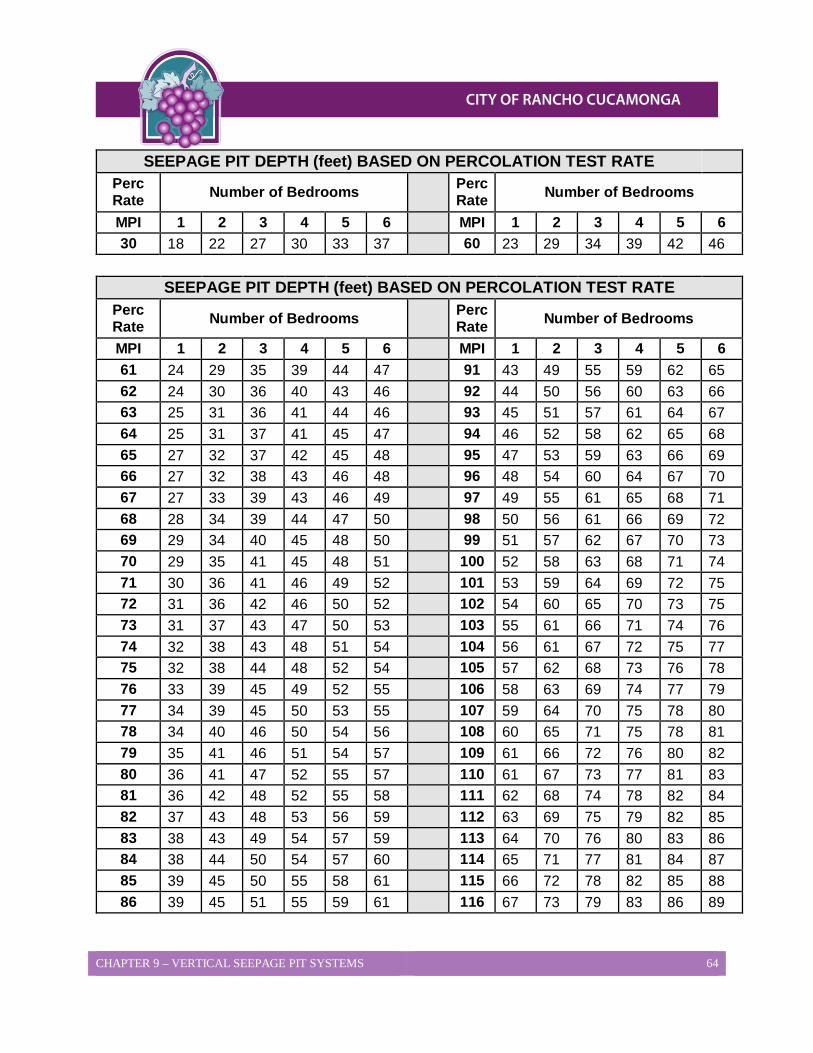
CHAPTER 9 – VERTICAL SEEPAGE PIT SYSTEMS 64
SEEPAGE PIT DEPTH (feet) BASED ON PERCOLATION TEST RATE Perc Rate Number of Bedrooms Perc
Rate Number of Bedrooms
MPI 1 2 3 4 5 6 MPI 1 2 3 4 5 6 30 18 22 27 30 33 37 60 23 29 34 39 42 46
SEEPAGE PIT DEPTH (feet) BASED ON PERCOLATION TEST RATE
Perc Rate Number of Bedrooms Perc
Rate Number of Bedrooms
MPI 1 2 3 4 5 6 MPI 1 2 3 4 5 6 61 24 29 35 39 44 47 91 43 49 55 59 62 65 62 24 30 36 40 43 46 92 44 50 56 60 63 66 63 25 31 36 41 44 46 93 45 51 57 61 64 67 64 25 31 37 41 45 47 94 46 52 58 62 65 68 65 27 32 37 42 45 48 95 47 53 59 63 66 69 66 27 32 38 43 46 48 96 48 54 60 64 67 70 67 27 33 39 43 46 49 97 49 55 61 65 68 71 68 28 34 39 44 47 50 98 50 56 61 66 69 72 69 29 34 40 45 48 50 99 51 57 62 67 70 73 70 29 35 41 45 48 51 100 52 58 63 68 71 74 71 30 36 41 46 49 52 101 53 59 64 69 72 75 72 31 36 42 46 50 52 102 54 60 65 70 73 75 73 31 37 43 47 50 53 103 55 61 66 71 74 76 74 32 38 43 48 51 54 104 56 61 67 72 75 77 75 32 38 44 48 52 54 105 57 62 68 73 76 78 76 33 39 45 49 52 55 106 58 63 69 74 77 79 77 34 39 45 50 53 55 107 59 64 70 75 78 80 78 34 40 46 50 54 56 108 60 65 71 75 78 81 79 35 41 46 51 54 57 109 61 66 72 76 80 82 80 36 41 47 52 55 57 110 61 67 73 77 81 83 81 36 42 48 52 55 58 111 62 68 74 78 82 84 82 37 43 48 53 56 59 112 63 69 75 79 82 85 83 38 43 49 54 57 59 113 64 70 76 80 83 86 84 38 44 50 54 57 60 114 65 71 77 81 84 87 85 39 45 50 55 58 61 115 66 72 78 82 85 88 86 39 45 51 55 59 61 116 67 73 79 83 86 89
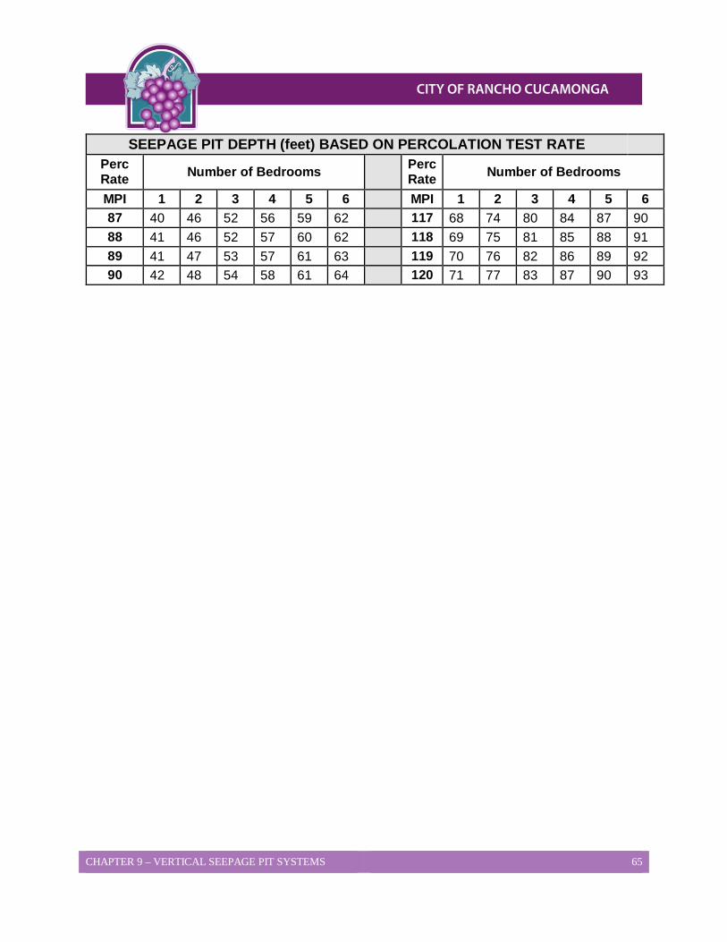
CHAPTER 9 – VERTICAL SEEPAGE PIT SYSTEMS 65
SEEPAGE PIT DEPTH (feet) BASED ON PERCOLATION TEST RATE Perc Rate Number of Bedrooms Perc
Rate Number of Bedrooms
MPI 1 2 3 4 5 6 MPI 1 2 3 4 5 6 87 40 46 52 56 59 62 117 68 74 80 84 87 90 88 41 46 52 57 60 62 118 69 75 81 85 88 91 89 41 47 53 57 61 63 119 70 76 82 86 89 92 90 42 48 54 58 61 64 120 71 77 83 87 90 93
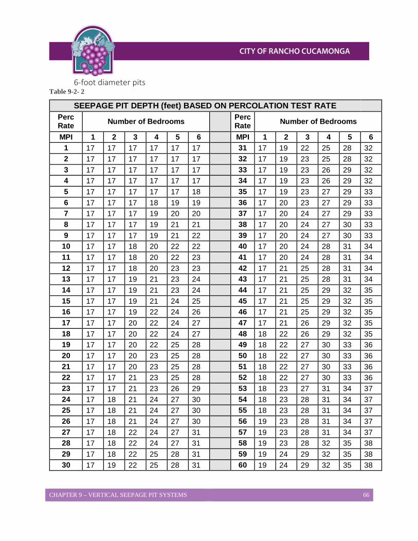
CHAPTER 9 – VERTICAL SEEPAGE PIT SYSTEMS 66
6-foot diameter pits Table 9-2- 2
SEEPAGE PIT DEPTH (feet) BASED ON PERCOLATION TEST RATE Perc Rate Number of Bedrooms Perc
Rate Number of Bedrooms
MPI 1 2 3 4 5 6 MPI 1 2 3 4 5 6 1 17 17 17 17 17 17 31 17 19 22 25 28 32 2 17 17 17 17 17 17 32 17 19 23 25 28 32 3 17 17 17 17 17 17 33 17 19 23 26 29 32 4 17 17 17 17 17 17 34 17 19 23 26 29 32 5 17 17 17 17 17 18 35 17 19 23 27 29 33 6 17 17 17 18 19 19 36 17 20 23 27 29 33 7 17 17 17 19 20 20 37 17 20 24 27 29 33 8 17 17 17 19 21 21 38 17 20 24 27 30 33 9 17 17 17 19 21 22 39 17 20 24 27 30 33
10 17 17 18 20 22 22 40 17 20 24 28 31 34 11 17 17 18 20 22 23 41 17 20 24 28 31 34 12 17 17 18 20 23 23 42 17 21 25 28 31 34 13 17 17 19 21 23 24 43 17 21 25 28 31 34 14 17 17 19 21 23 24 44 17 21 25 29 32 35 15 17 17 19 21 24 25 45 17 21 25 29 32 35 16 17 17 19 22 24 26 46 17 21 25 29 32 35 17 17 17 20 22 24 27 47 17 21 26 29 32 35 18 17 17 20 22 24 27 48 18 22 26 29 32 35 19 17 17 20 22 25 28 49 18 22 27 30 33 36 20 17 17 20 23 25 28 50 18 22 27 30 33 36 21 17 17 20 23 25 28 51 18 22 27 30 33 36 22 17 17 21 23 25 28 52 18 22 27 30 33 36 23 17 17 21 23 26 29 53 18 23 27 31 34 37 24 17 18 21 24 27 30 54 18 23 28 31 34 37 25 17 18 21 24 27 30 55 18 23 28 31 34 37 26 17 18 21 24 27 30 56 19 23 28 31 34 37 27 17 18 22 24 27 31 57 19 23 28 31 34 37 28 17 18 22 24 27 31 58 19 23 28 32 35 38 29 17 18 22 25 28 31 59 19 24 29 32 35 38 30 17 19 22 25 28 31 60 19 24 29 32 35 38
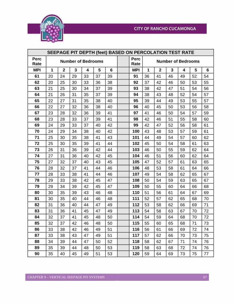
CHAPTER 9 – VERTICAL SEEPAGE PIT SYSTEMS 67
SEEPAGE PIT DEPTH (feet) BASED ON PERCOLATION TEST RATE
Perc Rate Number of Bedrooms Perc
Rate Number of Bedrooms
MPI 1 2 3 4 5 6 MPI 1 2 3 4 5 6 61 20 24 29 33 37 39 91 36 41 46 49 52 54 62 20 25 30 33 36 38 92 37 42 46 50 53 55 63 21 25 30 34 37 39 93 38 42 47 51 54 56 64 21 26 31 35 37 39 94 38 43 48 52 54 57 65 22 27 31 35 38 40 95 39 44 49 53 55 57 66 22 27 32 36 38 40 96 40 45 50 53 56 58 67 23 28 32 36 39 41 97 41 46 50 54 57 59 68 23 28 33 37 39 41 98 42 46 51 55 58 60 69 24 29 33 37 40 42 99 42 47 52 56 58 61 70 24 29 34 38 40 42 100 43 48 53 57 59 61 71 25 30 35 38 41 43 101 44 49 54 57 60 62 72 25 30 35 39 41 44 102 45 50 54 58 61 63 73 26 31 36 39 42 44 103 46 50 55 59 62 64 74 27 31 36 40 42 45 104 46 51 56 60 62 64 75 27 32 37 40 43 45 105 47 52 57 61 63 65 76 28 32 37 41 44 46 106 48 53 58 61 64 66 77 28 33 38 41 44 46 107 49 54 58 62 65 67 78 29 33 38 42 45 47 108 50 54 59 63 65 67 79 29 34 39 42 45 47 109 50 55 60 64 66 68 80 30 35 39 43 46 48 110 51 56 61 64 67 69 81 30 35 40 44 46 48 111 52 57 62 65 68 70 82 31 36 40 44 47 49 112 53 58 62 66 69 71 83 31 36 41 45 47 49 113 54 58 63 67 70 72 84 32 37 41 45 48 50 114 54 59 64 68 70 72 85 32 37 42 46 48 50 115 55 60 65 68 71 73 86 33 38 42 46 49 51 116 56 61 66 69 72 74 87 33 38 43 47 49 51 117 57 62 66 70 73 75 88 34 39 44 47 50 52 118 58 62 67 71 74 76 89 35 39 44 48 50 53 119 58 63 68 72 74 76 90 35 40 45 49 51 53 120 59 64 69 73 75 77
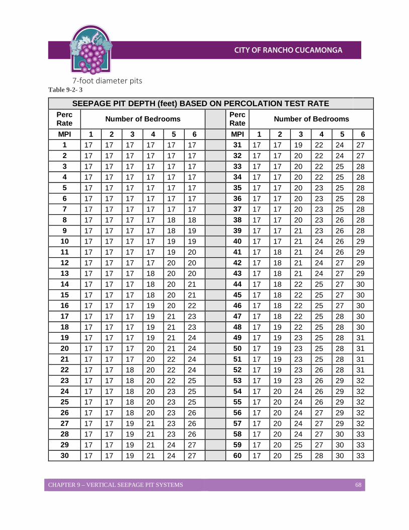
CHAPTER 9 – VERTICAL SEEPAGE PIT SYSTEMS 68
7-foot diameter pits Table 9-2- 3
SEEPAGE PIT DEPTH (feet) BASED ON PERCOLATION TEST RATE Perc Rate Number of Bedrooms Perc
Rate Number of Bedrooms
MPI 1 2 3 4 5 6 MPI 1 2 3 4 5 6 1 17 17 17 17 17 17 31 17 17 19 22 24 27 2 17 17 17 17 17 17 32 17 17 20 22 24 27 3 17 17 17 17 17 17 33 17 17 20 22 25 28 4 17 17 17 17 17 17 34 17 17 20 22 25 28 5 17 17 17 17 17 17 35 17 17 20 23 25 28 6 17 17 17 17 17 17 36 17 17 20 23 25 28 7 17 17 17 17 17 17 37 17 17 20 23 25 28 8 17 17 17 17 18 18 38 17 17 20 23 26 28 9 17 17 17 17 18 19 39 17 17 21 23 26 28
10 17 17 17 17 19 19 40 17 17 21 24 26 29 11 17 17 17 17 19 20 41 17 18 21 24 26 29 12 17 17 17 17 20 20 42 17 18 21 24 27 29 13 17 17 17 18 20 20 43 17 18 21 24 27 29 14 17 17 17 18 20 21 44 17 18 22 25 27 30 15 17 17 17 18 20 21 45 17 18 22 25 27 30 16 17 17 17 19 20 22 46 17 18 22 25 27 30 17 17 17 17 19 21 23 47 17 18 22 25 28 30 18 17 17 17 19 21 23 48 17 19 22 25 28 30 19 17 17 17 19 21 24 49 17 19 23 25 28 31 20 17 17 17 20 21 24 50 17 19 23 25 28 31 21 17 17 17 20 22 24 51 17 19 23 25 28 31 22 17 17 18 20 22 24 52 17 19 23 26 28 31 23 17 17 18 20 22 25 53 17 19 23 26 29 32 24 17 17 18 20 23 25 54 17 20 24 26 29 32 25 17 17 18 20 23 25 55 17 20 24 26 29 32 26 17 17 18 20 23 26 56 17 20 24 27 29 32 27 17 17 19 21 23 26 57 17 20 24 27 29 32 28 17 17 19 21 23 26 58 17 20 24 27 30 33 29 17 17 19 21 24 27 59 17 20 25 27 30 33 30 17 17 19 21 24 27 60 17 20 25 28 30 33
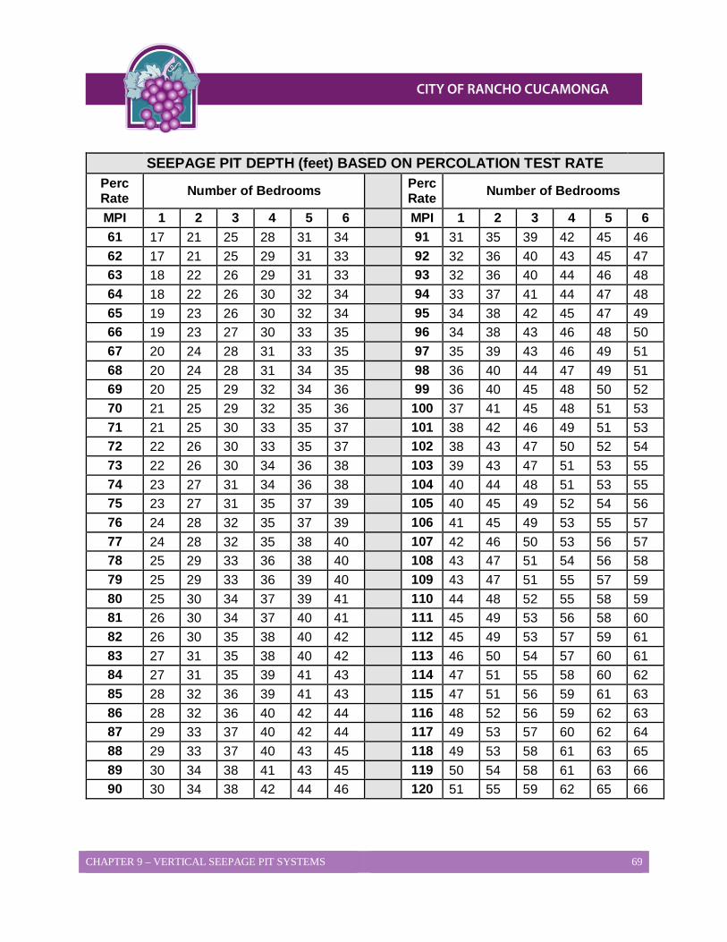
CHAPTER 9 – VERTICAL SEEPAGE PIT SYSTEMS 69
SEEPAGE PIT DEPTH (feet) BASED ON PERCOLATION TEST RATE
Perc Rate Number of Bedrooms Perc
Rate Number of Bedrooms
MPI 1 2 3 4 5 6 MPI 1 2 3 4 5 6 61 17 21 25 28 31 34 91 31 35 39 42 45 46 62 17 21 25 29 31 33 92 32 36 40 43 45 47 63 18 22 26 29 31 33 93 32 36 40 44 46 48 64 18 22 26 30 32 34 94 33 37 41 44 47 48 65 19 23 26 30 32 34 95 34 38 42 45 47 49 66 19 23 27 30 33 35 96 34 38 43 46 48 50 67 20 24 28 31 33 35 97 35 39 43 46 49 51 68 20 24 28 31 34 35 98 36 40 44 47 49 51 69 20 25 29 32 34 36 99 36 40 45 48 50 52 70 21 25 29 32 35 36 100 37 41 45 48 51 53 71 21 25 30 33 35 37 101 38 42 46 49 51 53 72 22 26 30 33 35 37 102 38 43 47 50 52 54 73 22 26 30 34 36 38 103 39 43 47 51 53 55 74 23 27 31 34 36 38 104 40 44 48 51 53 55 75 23 27 31 35 37 39 105 40 45 49 52 54 56 76 24 28 32 35 37 39 106 41 45 49 53 55 57 77 24 28 32 35 38 40 107 42 46 50 53 56 57 78 25 29 33 36 38 40 108 43 47 51 54 56 58 79 25 29 33 36 39 40 109 43 47 51 55 57 59 80 25 30 34 37 39 41 110 44 48 52 55 58 59 81 26 30 34 37 40 41 111 45 49 53 56 58 60 82 26 30 35 38 40 42 112 45 49 53 57 59 61 83 27 31 35 38 40 42 113 46 50 54 57 60 61 84 27 31 35 39 41 43 114 47 51 55 58 60 62 85 28 32 36 39 41 43 115 47 51 56 59 61 63 86 28 32 36 40 42 44 116 48 52 56 59 62 63 87 29 33 37 40 42 44 117 49 53 57 60 62 64 88 29 33 37 40 43 45 118 49 53 58 61 63 65 89 30 34 38 41 43 45 119 50 54 58 61 63 66 90 30 34 38 42 44 46 120 51 55 59 62 65 66

CHAPTER 10 – HORIZONTAL SEEPAGE PIT SYSTEMS 70
CHAPTER 10 Horizontal Seepage Pit Systems Horizontal seepage pits are a type of dispersal system may be used throughout the City of Rancho Cucamonga if specific soil and site conditions exist. The use of the horizontal seepage pit is generally only considered where adequate area does not exist for a leach line system. This Chapter will provide the procedures for the design and construction of horizontal seepage pits. The procedures are specific for horizontal seepage pits and do not apply to vertical seepage pits.
Percolation Test Procedures Percolation tests are to be performed in accordance with the test procedures found in Chapter 6 - Percolation Test Procedure of this LAMP. Deep borings, backhoe excavations, and percolation tests are used to demonstrate that the dispersal field is located in an area of uniform soil with excellent permeability, and that no conditions exist which could adversely affect the performance of the system or result in groundwater degradation.
1. The average percolation rates shall not exceed 30 minutes per inch in any portion of the horizontal seepage pit. Individual rates exceeding 30 minutes per inch may be considered with additional soil testing.
2. At least 4 percolation test holes at each pit location should be provided to represent soil types within the infiltrative surface area of the seepage pit. This profile should represent the entire sidewall depth of the pit.
3. At least 1 deep boring should extend to a depth of at least 10 feet below the bottom of the seepage pit, or to impermeable material. In no case shall less than 5 feet of unsaturated permeable soil exist below the bottom of the seepage pit.
4. Backhoe excavations may be required to demonstrate uniformity of soil throughout the seepage pit. This would be necessary when the pit is proposed in an area of variable soil conditions.
5. Any percolation tests for horizontal seepage pits, which were approved based on testing prior to approval of this LAMP, will require additional percolation testing unless the previous testing meets current requirements.
Dimensions and Construction Requirements 1. Horizontal seepage pits are to be installed according to the qualified professional’s
specifications for location, length, width, and depth.
2. Horizontal seepage pits are to be spaced 20 feet apart measured edge to edge.

CHAPTER 10 – HORIZONTAL SEEPAGE PIT SYSTEMS 71
3. Primary and reserve horizontal seepage pits cannot be combined in one common pit.
4. The pit excavation must be at least 4 feet in width, but not greater than 6 feet in width.
5. The top of the infiltrative surface shall be at least 2 feet below the natural grade but no more than 5 feet. This depth is also known as the cap depth. Additional soil can be placed over the top of the installed horizontal seepage pit at the discretion of the qualified professional.
6. The sidewall depth below the cap shall be at least 6 feet but cannot exceed 7 feet.
7. The pit excavations may arc or bend under the following conditions:
a. The maximum deflection cannot exceed a total of 45 degrees in any direction without increasing the pit length to compensate for loss of sidewall area.
b. Bends or arcs totaling greater than 45 degrees may be accepted on a case-by-case basis. A correction factor will be required, increasing the total length, due to sidewall loss.
c. U-shaped and H-shaped bends will not be accepted.
8. The maximum slope for the use of horizontal seepage pits is 25% (4:1). Exceptions to this slope limit may be considered up to 50% (2:1), on a case-by-case basis, where the soil and slope are uniform, extending 100 feet beyond the seepage pit. Additional testing, and design detail may be required to address the risk of effluent surfacing on the slope recognizable as sewage as well as slope stability issues. Slopes that exceed 25% (4:1) will, in most cases, require a terrace design. Any grading to create terraces should be in accordance with any permit requirements for brushing, clearing, and grading from any other agency.
9. The use of concrete pit liners is allowed. If used, the concrete pit liners shall meet the testing standards established by the International Association of Plumbing and Mechanical Officials (IAPMO).
10. All pits must be filled with clean leach line rock to the cap depth of the horizontal pit liner. The rock should be graded at 1 to 1.5 inches in size and shall be covered with straw, untreated building paper or a geotextile fabric prior to backfill to prevent the infiltration of soil into the rock.
11. A manifold system constructed of 4 inch loop of Schedule 40 perforated pipe shall be installed in the pit to allow for distribution of the effluent throughout the entire pit. The manifold shall be placed 1 foot from the sidewall of the horizontal seepage pit and shall run the length and width of the pit in a rectangular pattern.
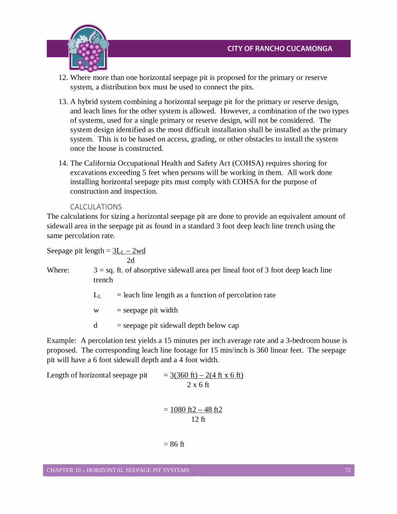
CHAPTER 10 – HORIZONTAL SEEPAGE PIT SYSTEMS 72
12. Where more than one horizontal seepage pit is proposed for the primary or reserve system, a distribution box must be used to connect the pits.
13. A hybrid system combining a horizontal seepage pit for the primary or reserve design, and leach lines for the other system is allowed. However, a combination of the two types of systems, used for a single primary or reserve design, will not be considered. The system design identified as the most difficult installation shall be installed as the primary system. This is to be based on access, grading, or other obstacles to install the system once the house is constructed.
14. The California Occupational Health and Safety Act (COHSA) requires shoring for excavations exceeding 5 feet when persons will be working in them. All work done installing horizontal seepage pits must comply with COHSA for the purpose of construction and inspection.
CALCULATIONS The calculations for sizing a horizontal seepage pit are done to provide an equivalent amount of sidewall area in the seepage pit as found in a standard 3 foot deep leach line trench using the same percolation rate.
Seepage pit length = 3LL – 2wd 2d Where: 3 = sq. ft. of absorptive sidewall area per lineal foot of 3 foot deep leach line
trench
LL = leach line length as a function of percolation rate
w = seepage pit width
d = seepage pit sidewall depth below cap
Example: A percolation test yields a 15 minutes per inch average rate and a 3-bedroom house is proposed. The corresponding leach line footage for 15 min/inch is 360 linear feet. The seepage pit will have a 6 foot sidewall depth and a 4 foot width.
Length of horizontal seepage pit = 3(360 ft) – 2(4 ft x 6 ft) 2 x 6 ft
= 1080 ft2 – 48 ft2 12 ft
= 86 ft
CHAPTER 11 - ATS 73
CHAPTER 11 Alternative Treatment Systems and Sewage Holding Tanks. Note: Alternative Treatment Systems and Sewage Holding Tanks may only be used with prior approval of the Building and Safety Services Director, prior to submittal of plans for permitting purposes.
CHAPTER 12 – IMPAIRED AREAS 74
CHAPTER 12 Tier 3 Advanced Protection Management Program for Impaired Areas An Advanced Protection Management Program (APMP) is the minimum required management program for all Onsite Wastewater Treatment Systems (OWTS) located near a water body that has been listed as impaired due to nitrogen or pathogen indicators, pursuant to the Clean Water Act, Section 303(d). Local agencies are authorized to implement APMPs in conjunction with an approved Local Agency Management Program (LAMP), or when there is no approved LAMP, Tier 1. Per the State Water Resources Control Board’s (SWRCB’s) OWTS Policy, OWTS which are located near impaired water bodies may be addressed by a Total Maximum Daily Load (TMDL) and its implementation program, or special provisions contained in a LAMP. The County of San Bernardino has chosen to develop an APMP closely derived from Tier 3 requirements provided in the OWTS Policy. This chapter provides information regarding the County’s APMP.
Note: As of the adoption of this LAMP there are not any impaired water bodies within the incorporated limits of the City of Rancho Cucamonga.
Basin Plans The Regional Water Quality Control Boards (RWQCBs) have developed basin plans to dictate the water quality protection regulations which govern wastewater discharges. This section provides information regarding basin plans for impaired water bodies located within San Bernardino County.
Issues Addressed in Basin Plans When developing basin plans the RWQCBs address information which includes, but is not limited to:
• Excessive nitrate levels from agricultural practices,
• Perchlorate clean up from industrial activities, and/or
• Bacterial contamination of surface water.
Impaired Water Bodies Within San Bernardino County, the State Water Resources Control Board has identified various surface waterways as impaired, per Attachment 2 of the OWTS Policy. The water bodies listed have been specifically identified per the 303(d) list, where it is likely:
• OWTS will subsequently be determined to be a contribution source of pathogens or nitrogen, and therefore anticipated that OWTS would receive a loading reduction, and
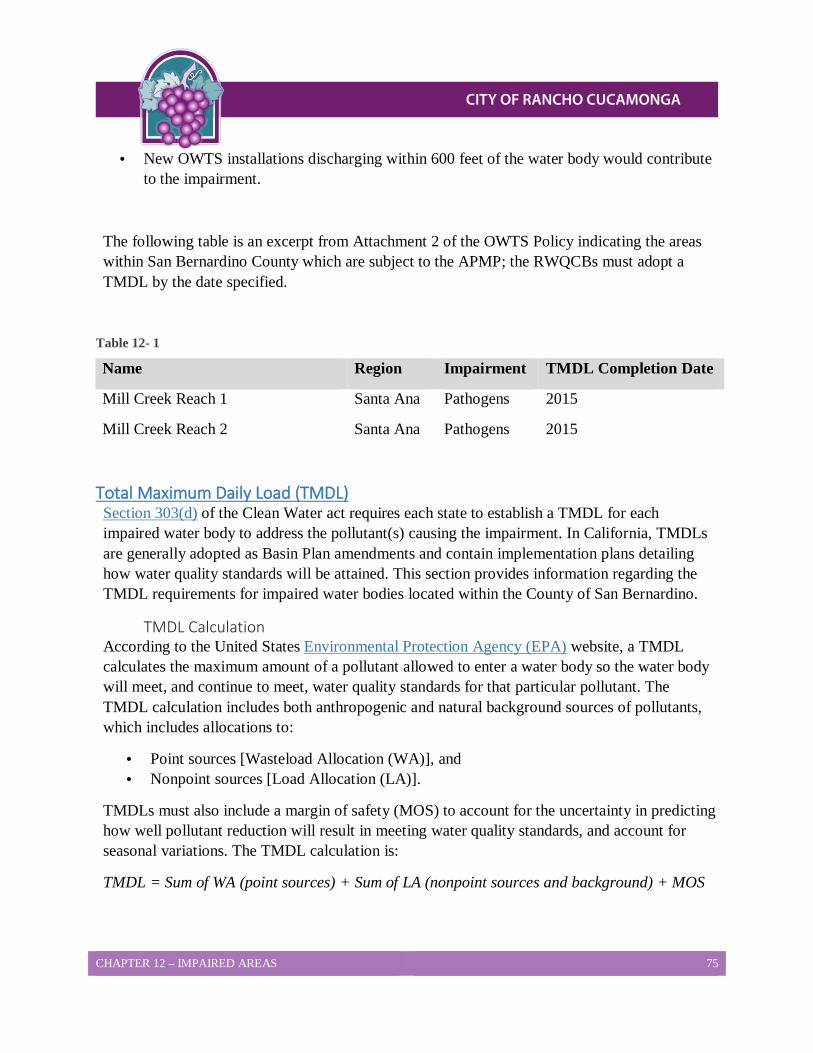
CHAPTER 12 – IMPAIRED AREAS 75
• New OWTS installations discharging within 600 feet of the water body would contribute to the impairment.
The following table is an excerpt from Attachment 2 of the OWTS Policy indicating the areas within San Bernardino County which are subject to the APMP; the RWQCBs must adopt a TMDL by the date specified.
Table 12- 1
Name Region Impairment TMDL Completion Date
Mill Creek Reach 1 Santa Ana Pathogens 2015
Mill Creek Reach 2 Santa Ana Pathogens 2015
Total Maximum Daily Load (TMDL) Section 303(d) of the Clean Water act requires each state to establish a TMDL for each impaired water body to address the pollutant(s) causing the impairment. In California, TMDLs are generally adopted as Basin Plan amendments and contain implementation plans detailing how water quality standards will be attained. This section provides information regarding the TMDL requirements for impaired water bodies located within the County of San Bernardino.
TMDL Calculation According to the United States Environmental Protection Agency (EPA) website, a TMDL calculates the maximum amount of a pollutant allowed to enter a water body so the water body will meet, and continue to meet, water quality standards for that particular pollutant. The TMDL calculation includes both anthropogenic and natural background sources of pollutants, which includes allocations to:
• Point sources [Wasteload Allocation (WA)], and • Nonpoint sources [Load Allocation (LA)].
TMDLs must also include a margin of safety (MOS) to account for the uncertainty in predicting how well pollutant reduction will result in meeting water quality standards, and account for seasonal variations. The TMDL calculation is:
TMDL = Sum of WA (point sources) + Sum of LA (nonpoint sources and background) + MOS
CHAPTER 12 – IMPAIRED AREAS 76
Geographic Area for APMPs Where there is an approved TMDL, the geographic area for each water body’s APMP is defined by the applicable TMDL. When there is not an approved TMDL which defines the geographic area, it will be 600 linear feet (in the horizontal map direction) of a water body listed on the 303(d) list, where the edge of the water body is the:
• Natural or levied band for creeks and rivers.
• High water mark for lakes and reservoirs.
• High tide line for tidally influenced water bodies, as appropriate.
There may be OWTS located near impaired water bodies which would not be included in the APMP; however, must meet all the requirements of the LAMP:
• Not listed in Attachment 2 of the OWTS Policy,
• Without an approved TMDL, and
• Not covered in this LAMP with special provisions.
TMDLs for Impaired Waterbodies Currently, there are no TMDLs for the impaired water bodies on the 303(d) list. Once a TMDL is adopted, the TMDL implementation plan will supersede the APMP. Unless a TMDL is modified to include actions for OWTS, the OWTS located near an impaired water body is not required to take any further actions when there is an approved TMDL, which:
• Addresses the impairment, and
• Does not assign a load allocation to the OWTS.
Note: Existing, new and replacement OWTS located near impaired water bodies are covered by a Basin Plan prohibition and must comply with the terms of the prohibition (refer to Prohibitions and Exemptions for more information).
TMDL Completion Dates The RWQCB must adopt TMDLs for the impaired water bodies identified on the 303(d) list in accordance with the dates specified (refer to Table 12-1 for more information regarding TMDL completion dates). Should the RWQCB not adopt a TMDL within two years of the specified date, coverage provided by the OWTS Policy’s waiver of waste discharge requirements will expire. This applies to any OWTS which has any part of its dispersal system discharging within the geographic area of an APMP. The RWQCB will then be responsible for the following, with regard to these OWTS:
CHAPTER 12 – IMPAIRED AREAS 77
• Corrective action, and • Issuing
– Waste discharge requirements (site specific) – General waste discharge requirements (non-site specific), and – Waivers of waste discharge requirements.
OWTS without an Adopted TMDL Implementation Plan This section provides information regarding requirements for OWTS and supplemental treatment systems that have been permitted after the water body was initially listed in Attachment 2 of the OWTS policy, and have any discharge within the geographic area of the APMP.
Requirements for OWTS In the absence of an adopted TMDL implementation plan, all new and/or replacement OWTS must:
• Utilize supplemental treatment.
• Meet performance requirements for nitrogen/pathogen impairment (see OWTS Located Near Water Bodies Impaired for Nitrogen and OWTS Located Near Water Bodies Impaired for Pathogens for information regarding requirements).
• Comply with:
– Setback requirements detailed in Chapter 3, and
– Any applicable requirements outlined within the LAMP.
OWTS Located Near Water Bodies Impaired for Nitrogen When OWTS are located near water bodies which are impaired for nitrogen, the effluent from the supplement treatment component must meet a 50% reduction in total nitrogen when comparing the 30 day average influent to the 30 day average effluent. This will be accomplished by using supplemental treatment components, which meet the following requirements:
• Designed to reduce nitrogen, and
• Certified by National Sanitation Foundation (NSF) (or other approved third party tester).
Where a drip-line dispersal system is used to enhance vegetative nitrogen uptake, the dispersal system must have at least 12 inches of soil cover.

CHAPTER 12 – IMPAIRED AREAS 78
OWTS Located Near Water Bodies Impaired for Pathogens When an OWTS is located near a water body impaired for pathogens, the supplemental treatment components (designed to perform disinfection of pathogens) must provide sufficient pretreatment of the wastewater so effluent from the supplemental treatment components:
• Does not exceed a 30 day average Total Suspended Solids (TSS) of 30 milligrams per liter (mg/L), and
• Will achieve an effluent fecal coliform bacteria concentration less than, or equal to, 200 Most Probable Number (MPN) per 100 milliliters.
The minimum soil depth and the minimum depth to the anticipated highest level of groundwater below the bottom of the dispersal system will not be less than 3 feet. All dispersal systems will have at least 12 inches of soil cover.
CHAPTER 13 – CORRECTIVE ACTION 79
CHAPTER 13 Corrective Action All OWTS have the potential to fail due to age, misuse or improper design and the failure may result in surfacing effluent, wastewater being discharged to the ground surface or wastewater backing up into plumbing fixtures. These failures will require corrective action to mitigate any risk to public health or contamination of the environment. This Chapter will detail the corrective action that will be required in the event an OWTS fails and enforcement actions that will be taken if the corrective action is not completed within acceptable time frames.
Corrective Action Requirements 1. Building and Safety Services or other designated City departments will complete an
investigation within 24 hours to determine the validity of the complaint or other notification of a failing OWTS.
2. Any OWTS that is found to be failing shall have a notice of violation issued to the property owner requiring action to eliminate the immediate health hazard through pumping of the septic tank by a licensed sewage hauler or elimination of wastewater flows to the failing OWTS. The notice of violation will also require a repair to be completed to the OWTS as needed within a reasonable time frame.
3. The proposed repair shall be evaluated by Building and Safety Services to ensure it meets the minimum design requirements of this LAMP or is in substantial conformance to the greatest extent practicable.
4. Groundwater separation requirements to the bottom of the dispersal system and the highest anticipated groundwater level for repairs shall be as follows:
a. 5 foot for conventional OWTS
b. 2 foot for alternative OWTS with supplemental treatment
c. Less than 2 foot separation cannot be allowed through this LAMP and will require a waste discharge permit through the RWQCB.
5. The repair shall be completed under permit and inspection by Building and Safety Services.
6. Failure to complete the required corrective action within the time frames given will result in additional enforcement action which may include condemnation of the structure for immediate health hazards.
CHAPTER 13 – CORRECTIVE ACTION 80
SUBSTANDARD SYSTEMS All OWTS within the City of Rancho Cucamonga that do not meet minimum design requirements of this LAMP shall be deemed substandard. Sites with substandard OWTS shall be prohibited from having future additions or modifications to the property that would potentially increase wastewater flow to the OWTS or decrease the amount of usable area available for the OWTS.
CHAPTER 14 – LAMP SCOPE OF COVERAGE 81
CHAPTER 14 LAMP Scope of Coverage There are areas of wastewater treatment which are not under the City’s purview. These areas can range from cesspools, which are prohibited in the State of California, to wastewater treatment plants (of any kind or size) or Onsite Wastewater Treatment Systems (OWTS) receiving a projected flow over 10,000 gallons per day (GPD) [which are under the purview of the Regional Water Quality Control Boards (RWQCBs)]. This chapter provides information regarding the City’s role and the scope of coverage provided by the Local Agency Management Program (LAMP) in the monitoring of OWTS within the CIty of Rancho Cucamonga’s boundaries.
Onsite Inspections and Monitoring Onsite inspections and/or monitoring are required for all new OWTS, Designated Maintenance Areas (DMAs), sewage holding tanks and alternative treatment systems. This section provides information regarding the inspection and monitoring required for various OWTS.
New OWTS
Building and Safety Services may conduct an onsite inspection of percolation testing for new OWTS containing any lot which is:
• Located in the foothill areas, this includes any area adjacent to National Forest boundaries, or
• Less than 1.5 acres, and is not served by a permitted water system, or a local water agency.
• Located:
– On a slope greater than 20% (5;1),
– Within 200 feet of a river (in the horizontal map direction), or
– Within 100 feet of a stream (perennial or ephemeral).
• Located in an area which cannot meet the minimum setback requirements for a conventional septic system due to:
– Historically high groundwater, or
– A confining layer.
Note: For more information regarding minimum setback requirements, refer to Chapter 3.
CHAPTER 16- REPORTING REQUIREMENTS 82
Required Onsite Inspection
The Building and Safety Services Department must complete an onsite inspection for percolation testing when the Qualified Professional submitting the report has:
• Not submitted a report to Building and Safety Services in the previous 2 years, or • Previously submitted reports which have been deemed:
– Incomplete, and/or – Significantly deficient.
Building and Safety Services may also, at its discretion, determine an on-site inspection is necessary in instances not mentioned above, or where it is determined the installation of an OWTS may have an adverse impact to public health and safety.
A waiver of the connection to sewer can be considered where such sewer is located more than 200 feet from the building or plumbing stub out, the connection fees and construction costs are greater than twice the total cost of the OWTS and an OWTS can be installed that will meet the minimum requirements of this LAMP and not affect groundwater or surface water to a degree that makes it unfit for drinking or other uses.
1. Except as provided for above, new or replacement OWTS with minimum horizontal setbacks less than any of the following:
a. 150 feet from a public water well where the depth of the effluent dispersal system does not exceed 10 feet in depth.
b. 200 feet from a public water well where the depth of the effluent dispersal system exceeds 10 feet in depth.
c. Where the effluent dispersal system is within 600 feet of a public water well and exceeds 20 feet in depth, the horizontal setback required to achieve a two-year travel time for microbiological contaminants shall be evaluated by a qualified professional. In no case shall the setback be less than 200 feet.
d. Where the effluent dispersal system is within 1,200 feet from a public water system’s surface water intake point, within the catchment of the drainage, and located such that it may impact water quality at the intake point such as upstream of the intake point for flowing water bodies, the dispersal system shall be no less than 400 feet from the high water mark of the reservoir, lake or flowing water body.
e. Where the effluent dispersal system is located more than 1,200 feet but less than 2,500 feet from a public water system’s surface water intake point, within the catchment of the drainage, and located such that it may impact water quality at the intake point such as upstream of the intake point for flowing water bodies, the
CHAPTER 16- REPORTING REQUIREMENTS 83
dispersal system shall be no less than 200 feet from the high water mark of the reservoir, lake or flowing water body.
2. For replacement OWTS that do not meet the horizontal separation requirements in Item 1 above, the replacement OWTS shall meet the horizontal separation to the greatest extent practicable. In such case, the replacement OWTS shall utilize supplement treatment and other mitigation measures, unless the permitting authority finds that there is no indication that the previous system is adversely affecting the public water source, and there is limited potential that the replacement system could impact the water source based on topography, soil depth, soil texture, and groundwater separation.
3. For new OWTS, installed on parcels of record existing before May 13, 2013 which is the effective date of the State’s OWTS Policy, that cannot meet the horizontal separation requirements above, the OWTS shall meet the horizontal separation to the greatest extent practicable and shall utilize supplemental treatment for pathogens as specified in Section 10.8 of the State’s OWTS Policy and any other mitigation measures prescribed by Building and Safety Services
Sewage Holding Tanks All sewage holding tanks located within the City are required to:
• Maintain an operating permit with Building and Safety Services and • Be inspected annually.
Note: Refer to Sewage Holding Tanks for more information.
Alternative Treatment Systems Owners of alternative treatment systems located within the City are required to:
• Maintain an operating permit • Ensure the alternative treatment system is inspected annually, and • Submit quarterly water samples during the first year of use.
Note: Sample frequency may be reduced at Building and Safety Services discretion when when all four quarterly wastewater samples show that the system is meeting the supplemental treatment requirements. Refer to Alternative Onsite Treatment Systems for more information.
Variances On a case by case basis, Building and Safety Services may establish alternative OWTS siting and operational requirements where it is determined by Building and Safety Services the alternate requirements will provide a similar level of protection. There will be situations, however, where variances are not granted. This section details the instances when variances will not be granted.
CHAPTER 16- REPORTING REQUIREMENTS 84
Above Surface Discharge Variances will not be granted for any OWTS which utilizes any form of effluent disposal discharging on, or above, the post installation ground surface; this includes, but is not limited to sprinklers, exposed drip lines, free-surface wetlands, and ponds
Sewer Availability Variances will not be granted for any OWTS where there is a public sewer available. Building and Safety Services Department may require a “Will or Will Not Serve” letter CVWD with each new or replacement OWTS proposal to evaluate the proximity and availability of community systems to the proposed OWTS site. This will ensure septic systems are only installed in areas where a sewer is unavailable. The “Will or Will Not Serve” letter must:
• Include the following: – Parcel number for the property where the OWTS is being proposed. Distance to
nearest available sewer line. – Whether or not the sewering entity will provide service to the parcel.
• Be completed and signed by the appropriate official representing the sewering entity and be filed with the Building and Safety Services Department: – Prior to submittal of the percolation report/plot plan, or – Upon request once the percolation report/plot plan has been submitted.
Sewer Requirement Connection to a public sewer system is required within established sewer service districts and outside such districts when required by the RWQCB. Developments must connect to a sewer system when the nearest property line is within 200 feet of a sewer line. This requirement will be increased by 100 feet for each dwelling unit within the development.
Ground Slope Variances will not be granted for slopes greater than a 25% incline without a slope stability report approved by a Qualified Professional. Refer to Natural Ground Slope for more information regarding natural ground slope requirements.
Leaching Areas As referenced in Leach Line Dispersal Systems, the maximum allowable decreased leaching area for International Association of Plumbing and Mechanical Officials (IAPMO) certified dispersal systems will be a multiplier of 0.70. No variances will be granted for systems using a multiplier of less than 0.70.
Supplemental Treatment As referenced in Alternative Onsite Treatment Systems, OWTS utilizing supplemental treatment require periodic monitoring or inspections. No variances will be granted for supplemental treatments that are unable to meet this requirement.
CHAPTER 16- REPORTING REQUIREMENTS 85
Depth to Groundwater No variance will be granted for OWTS with a deparation from the bottom of the dispersal system to groundwater less than 5 feet. The exception to this will be seepage pits, which will have a separation of no less than 10 feet. Refer to the Soil Deth s section for more information.
Recreational Vehicle (RV) Holding Tanks No variances will be granted for OWTS dedicated to receiving significant amounts of wastes, which are dumped from RV holding tanks.
Minimum Horizontal Setbacks All new and replacement OWTS must meet the minimum horizontal setbacks from community water sources. This section provides details regarding the minimum horizontal setback requirements for OWTS located near public water sources.
Setbacks Determined by Depth The minimum horizontal setbacks for effluent dispersal systems are dependent on the depth of the system. The following table describes the required setbacks for effluent dispersal systems located near public water wells:
Table 14- 1
If the depth of the effluent dispersal system…
Then the required horizontal setback from the public water well is…
Does not exceed 10 feet 150 feet
Exceeds 10 feet 200 feet
Where the effluent dispersal system is within 600 feet of a public water well, and the depth exceeds 20 feet, a Qualified Professional must conduct an evaluation. The evaluation is to determine the horizontal setback required to achieve a two-year travel time for microbiological contaminants. In no case, however, will the setback be less than 200 feet.
Dispersal Systems near Surface Water Intake Points The following minimum horizontal setbacks will be determined when effluent dispersal systems are located:
• Near a public surface water intake point (e.g., reservoir, lake, or flowing water body),
• Within the catchment of the drainage, and
• In such a way that it may impact water quality at the intake point (i.e., upstream of the intake point for flowing water bodies).
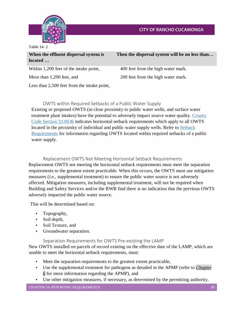
CHAPTER 16- REPORTING REQUIREMENTS 86
Table 14- 2
When the effluent dispersal system is located …
Then the dispersal system will be no less than…
Within 1,200 feet of the intake point, 400 feet from the high water mark.
More than 1,200 feet, and
Less than 2,500 feet from the intake point,
200 feet from the high water mark.
OWTS within Required Setbacks of a Public Water Supply Existing or proposed OWTS (in close proximity to public water wells, and surface water treatment plant intakes) have the potential to adversely impact source water quality. County Code Section 33.0636 indicates horizontal setback requirements which apply to all OWTS located in the proximity of individual and public water supply wells. Refer to Setback Requirements for information regarding OWTS located within required setbacks of a public water supply.
HAPTER 7: LAMP SCOPE OF COVERAGE
Replacement OWTS Not Meeting Horizontal Setback Requirements Replacement OWTS not meeting the horizontal setback requirements must meet the separation requirements to the greatest extent practicable. When this occurs, the OWTS must use mitigation measures (i.e., supplemental treatment) to ensure the public water source is not adversely affected. Mitigation measures, including supplemental treatment, will not be required when Building and Safety Services and/or the RWB find there is no indication that the previous OWTS adversely impacted the public water source.
This will be determined based on:
• Topography, • Soil depth, • Soil Texture, and • Groundwater separation.
Separation Requirements for OWTS Pre-existing the LAMP New OWTS installed on parcels of record existing on the effective date of the LAMP, which are unable to meet the horizontal setback requirements, must:
• Meet the separation requirements to the greatest extent practicable, • Use the supplemental treatment for pathogens as detailed in the APMP (refer to Chapter
6 for more information regarding the APMP), and • Use other mitigation measures, if necessary, as determined by the permitting authority.
CHAPTER 16- REPORTING REQUIREMENTS 87
Note: No variances will be granted for any of the minimum horizontal setback requirements, outlined in this section.
Site Assessment Prior to approving the use of an OWTS, a site evaluation by the Building and Safety Division may be required to:
• Ensure the proper system design, and the existing and proposed disposal locations for seepage meet the minimum requirements of the LAMP.
• Determine compliance with site suitability requirements, and whether adequate capacity is available for the OWTS.
Cesspool Elimination Cesspools are no longer allowed in the County of San Bernardino and the City of Rancho Cucamonga. When City staff discovers a cesspool is still in use, the property owner will be required to replace the cesspool with an OWTS, which meets current standards. The timeframe for complying with this requirement will vary based on the condition of the cesspool and the potential threat it represents to public health and safety.
Public Education Reference and educational material for owners of OWTS can be found on the San Bernardino County DEHS website. These educational documents provide information for owners regarding how to locate, operate, and maintain their OWTS.
Local Watershed Management The City of Rancho Cucamonga has three local watershed management agencies which manage the watersheds located within their boundaries. This agency is the Chino Basin Watermaster. Building and Safety Services notifies the regarding all new well construction within their boundaries, as well as attends meetings, as needed, to stay informed of any relevant water quality concerns. This section provides information regarding Chino Basin Watermaster.
Chino Basin Watermaster The Chino Basin Watermaster is a consensus bases organization, which facilitates development and utilization of the Chino Groundwater Basin. The basin
• Consists of approximately 235 square miles of the upper Santa Ana River watershed, and • Has an estimated storage capacity of five to seven million acre feet (refer to the figure
below for a map of the Chino Basin Watermaster boundaries).
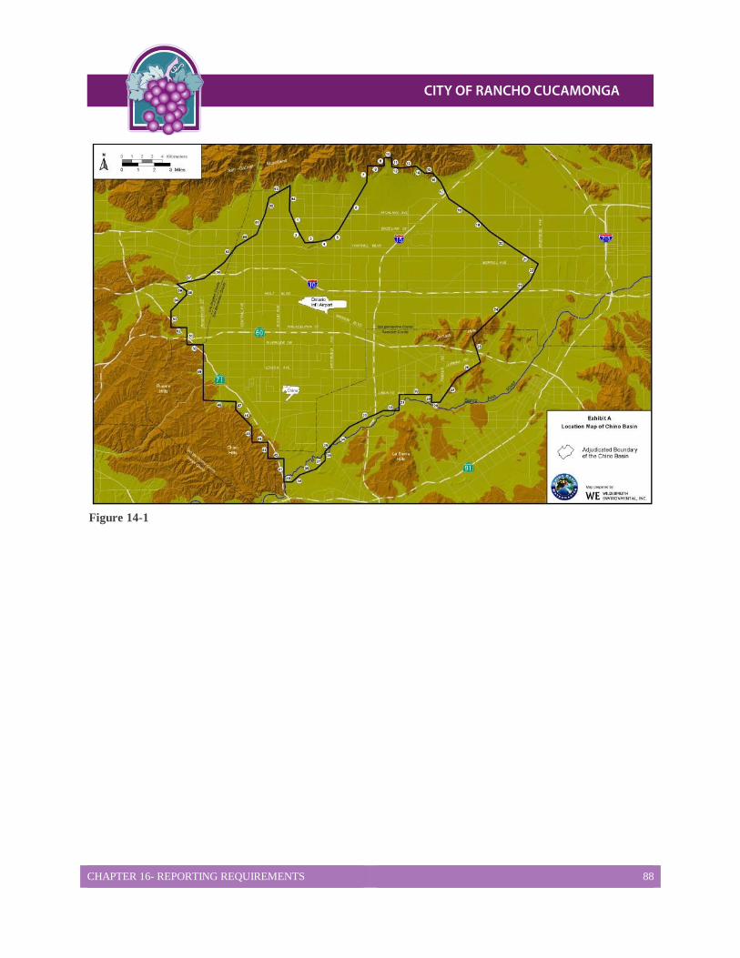
CHAPTER 16- REPORTING REQUIREMENTS 88
Figure 14-1
CHAPTER 15 – DATA COLLECTION 89
CHAPTER 15 Data Collection/Reporting/Notifications As a condition of Building and Safety Services oversight of OWTS within the City of Rancho Cucamonga, Building and Safety Services has certain responsibilities related to data collection and reporting to the Santa Ana Regional Water Quality Control Boards (RWQCB). This Chapter will detail the data that must be collected and the procedure for reporting to RWQCB and notifications to owners of water systems and SWRCB.
Reporting To RWQCB On an annual basis, Building and Safety Services will collect data for and report in tabular spreadsheet format the following information. A copy of the report will be provided to both the San Diego and Colorado River Basin RWQCB.
1. The number and location of complaints pertaining to OWTS operation and maintenance, and identification of those which were investigated and how they were resolved.
2. The number, location and description of permits issued for new and replacement OWTS and under which Tier the permit was issued. Also include the design flow of the OWTS. The Tier designations can be found in the State Water Board’s OWTS Policy.
3. The number, location and description of permits issued for OWTS where a variance from the approved LAMP was granted.
4. The applications and registrations issued for sewage haulers as part of the local septic tank cleaning registration program.
In addition, Building and Safety Services must maintain a water quality assessment program to determine the general operation status of OWTS and to evaluate the impact of OWTS discharges, and assess the extent to which groundwater and local surface water quality may be adversely impacted. The assessment program will include monitoring and analysis of water quality data, review of complaints, failures and OWTS inspections. The water quality data can be obtained from the flowing sources:
1. Random well samples.
2. Well samples taken to establish a well as a “potable source”.
3. Routine water samples taken by community water systems.
4. Beach and bay water quality testing.
5. Any other sampling data deemed relevant or necessary for the protection of ground/surface water supplies.

CHAPTER 15 – DATA COLLECTION 90
A summary of the data shall be submitted on an annual basis on or before February 1st. An evaluation of the monitoring program and an assessment of whether water quality is being impacted by OWTS shall be submitted every 5 years.
CHAPTER 16 – REPORTING REQUIREMENTS 91
CHAPTER 16
Reporting Requirements and Data Collection As a condition to having oversight of the Onsite Wastewater Treatment Systems (OWTS) within the City of Rancho Cucamonga, the City must collect certain data and report it to the Regional Water Quality Control Boards (RWQCBs), in some instances, the Division of Drinking Water (DDW), as well as the owners of water systems. This chapter provides information regarding the minimum reporting responsibilities, the OWTS Water Quality Assessment Program, and the Local Agency Management Program (LAMP) assessment.
Reporting to the Regional Water Quality Control Boards (RWQCBs) The City must report the following information to the RWQCBs on an annual basis, no later than February 1st of each year.
• The quantity and location of complaints pertaining to OWTS in the unincorporated areas of the City, and specifying which complaints were investigated, and how the complaints were resolved.
• The permits issued for new and replacement OWTS, including the number, location and description of the permits, and which Tier the permit was issued under.
• The quantity, location and description of permits issued for OWTS where a variance from the approved LAMP was granted.
• The number, location and results of septic tank pumper inspection reports which were received.
• A list of the applications and registrations issued for the Liquid Waste Hauler Program.
OWTS Water Quality Assessment Program (WQAP) The WAQP was developed to provide a better understanding regarding how OWTS located within the County of San Bernardino were affecting and/or contributing to ground water contamination by nitrates and pathogens. This section provides information regarding the WQAP, including individual well sampling, establishing the water quality baseline levels, constituents of concern and monitoring for pathogens and nitrogen.

CHAPTER 16 – REPORTING REQUIREMENTS 92
LAMP Assessment Every five years an assessment will be completed to evaluate the LAMP and determine whether OWTS within the City are affecting water quality. During this review the LAMP will be modified, as needed, to address the impacts of OWTS. This section provides information regarding how the information will be compiled and reviewed, as well as how the information will be submitted to both the California Environmental Data Exchange Network (CEDEN) and Geotracker. In order to assess the operational status of the OWTS within the City, the City will compile and review:
• Septic tank pumper inspection reports, • Complaints and abatement activities for failing OWTS, • Variances issued for new and/or repair OWTS, • Sample data from the WQAP, • Water quality monitoring reports for alternative treatment systems or other OWTS having
an operating permit, and • Septic system certifications of existing OWTS in connection with:
– Building additions/remodel projects, or – Property transactions (if required by a bank or other agency).
All groundwater monitoring data generated will be submitted in electronic deliverable format (EDF) for inclusion into Geotracker. Surface water monitoring will be submitted to CEDEN in a Surface Water Ambient Monitoring Program (SWAMP) comparable format.
CHAPTER 8: REPORTING REQUIREMENTS AND DATA COLLECTION