flowing wells unified school district
TRANSCRIPT
Flowing Wells Unified School District, #8 Amendment #2 1556 W Prince Road
Tucson, AZ 85705 (520) 696-8820
BID: 21-05-21 PROJECT: Flowing Wells High School Welding Shop
Page 1 of 3
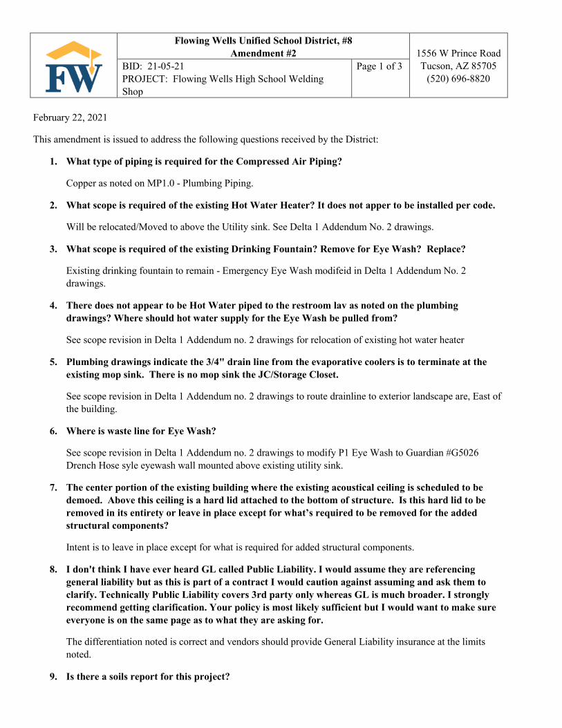
February 22, 2021
This amendment is issued to address the following questions received by the District:
1. What type of piping is required for the Compressed Air Piping?
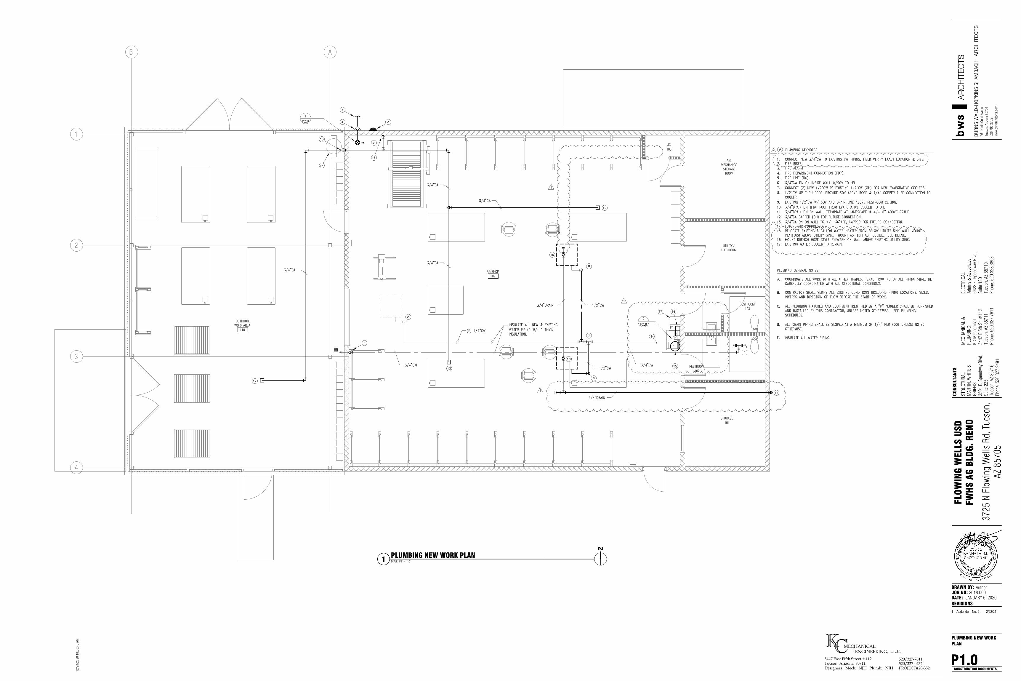
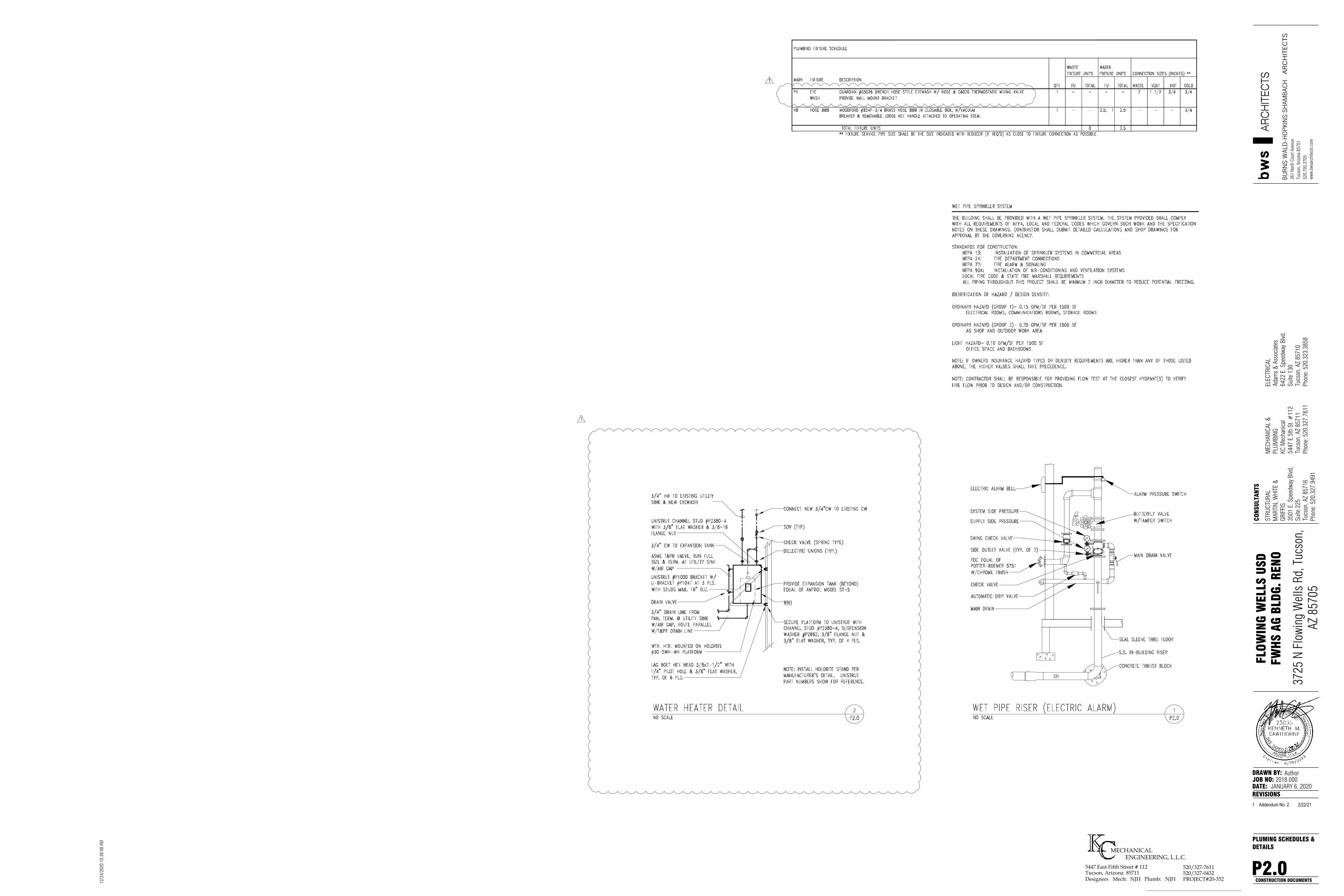
Copper as noted on MP1.0 - Plumbing Piping.
2. What scope is required of the existing Hot Water Heater? It does not apper to be installed per code.
Will be relocated/Moved to above the Utility sink. See Delta 1 Addendum No. 2 drawings.
3. What scope is required of the existing Drinking Fountain? Remove for Eye Wash? Replace?
Existing drinking fountain to remain - Emergency Eye Wash modifeid in Delta 1 Addendum No. 2 drawings.
4. There does not appear to be Hot Water piped to the restroom lav as noted on the plumbing drawings? Where should hot water supply for the Eye Wash be pulled from?
See scope revision in Delta 1 Addendum no. 2 drawings for relocation of existing hot water heater
5. Plumbing drawings indicate the 3/4" drain line from the evaporative coolers is to terminate at the existing mop sink. There is no mop sink the JC/Storage Closet.
See scope revision in Delta 1 Addendum no. 2 drawings to route drainline to exterior landscape are, East of the building.
6. Where is waste line for Eye Wash?
See scope revision in Delta 1 Addendum no. 2 drawings to modify P1 Eye Wash to Guardian #G5026 Drench Hose syle eyewash wall mounted above existing utility sink.
7. The center portion of the existing building where the existing acoustical ceiling is scheduled to be demoed. Above this ceiling is a hard lid attached to the bottom of structure. Is this hard lid to be removed in its entirety or leave in place except for what’s required to be removed for the added structural components?
Intent is to leave in place except for what is required for added structural components.
8. I don't think I have ever heard GL called Public Liability. I would assume they are referencing general liability but as this is part of a contract I would caution against assuming and ask them to clarify. Technically Public Liability covers 3rd party only whereas GL is much broader. I strongly recommend getting clarification. Your policy is most likely sufficient but I would want to make sure everyone is on the same page as to what they are asking for.
The differentiation noted is correct and vendors should provide General Liability insurance at the limits noted.
9. Is there a soils report for this project?
Flowing Wells Unified School District, #8 Amendment #2 1556 W Prince Road
Tucson, AZ 85705 (520) 696-8820
BID: 21-05-21 PROJECT: Flowing Wells High School Welding Shop
Page 2 of 3
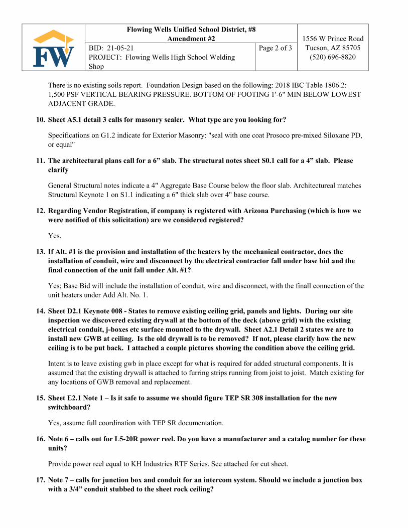
There is no existing soils report. Foundation Design based on the following: 2018 IBC Table 1806.2: 1,500 PSF VERTICAL BEARING PRESSURE. BOTTOM OF FOOTING 1'-6" MIN BELOW LOWEST ADJACENT GRADE.
10. Sheet A5.1 detail 3 calls for masonry sealer. What type are you looking for?
Specifications on G1.2 indicate for Exterior Masonry: "seal with one coat Prosoco pre-mixed Siloxane PD, or equal"
11. The architectural plans call for a 6” slab. The structural notes sheet S0.1 call for a 4” slab. Please clarify
General Structural notes indicate a 4" Aggregate Base Course below the floor slab. Architectureal matches Structural Keynote 1 on S1.1 indicating a 6" thick slab over 4" base course.
12. Regarding Vendor Registration, if company is registered with Arizona Purchasing (which is how we were notified of this solicitation) are we considered registered?
Yes.
13. If Alt. #1 is the provision and installation of the heaters by the mechanical contractor, does the installation of conduit, wire and disconnect by the electrical contractor fall under base bid and the final connection of the unit fall under Alt. #1?
Yes; Base Bid will include the installation of conduit, wire and disconnect, with the finall connection of the unit heaters under Add Alt. No. 1.
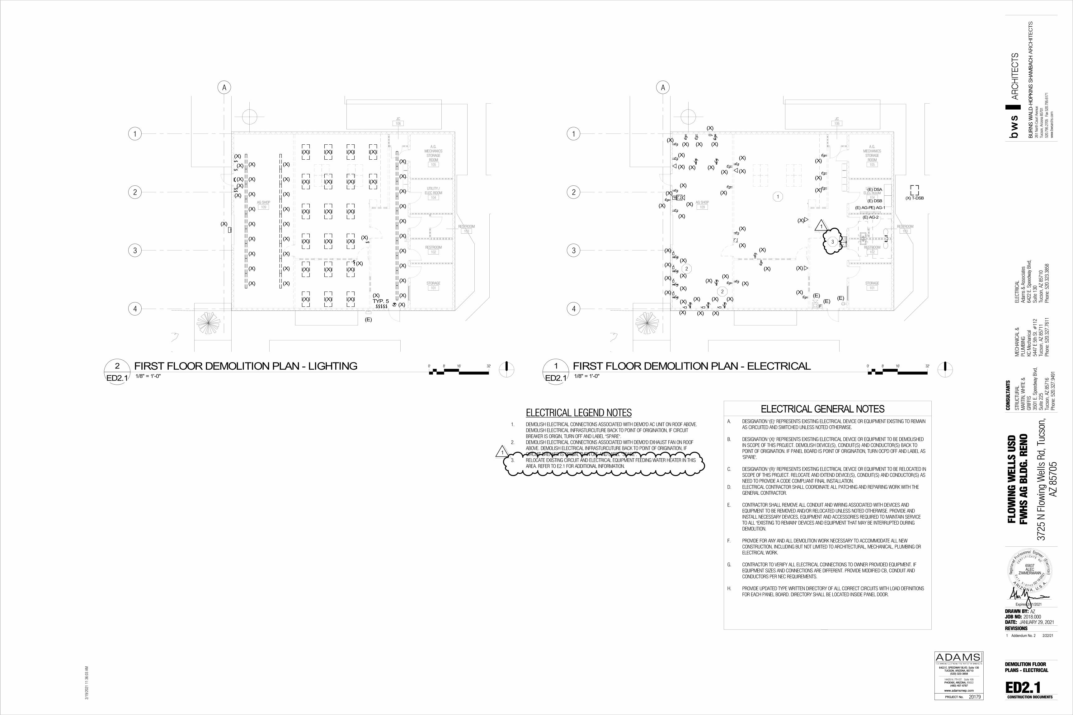
14. Sheet D2.1 Keynote 008 - States to remove existing ceiling grid, panels and lights. During our site inspection we discovered existing drywall at the bottom of the deck (above grid) with the existing electrical conduit, j-boxes etc surface mounted to the drywall. Sheet A2.1 Detail 2 states we are to install new GWB at ceiling. Is the old drywall is to be removed? If not, please clarify how the new ceiling is to be put back. I attached a couple pictures showing the condition above the ceiling grid.
Intent is to leave existing gwb in place except for what is required for added structural components. It is assumed that the existing drywall is attached to furring strips running from joist to joist. Match existing for any locations of GWB removal and replacement.
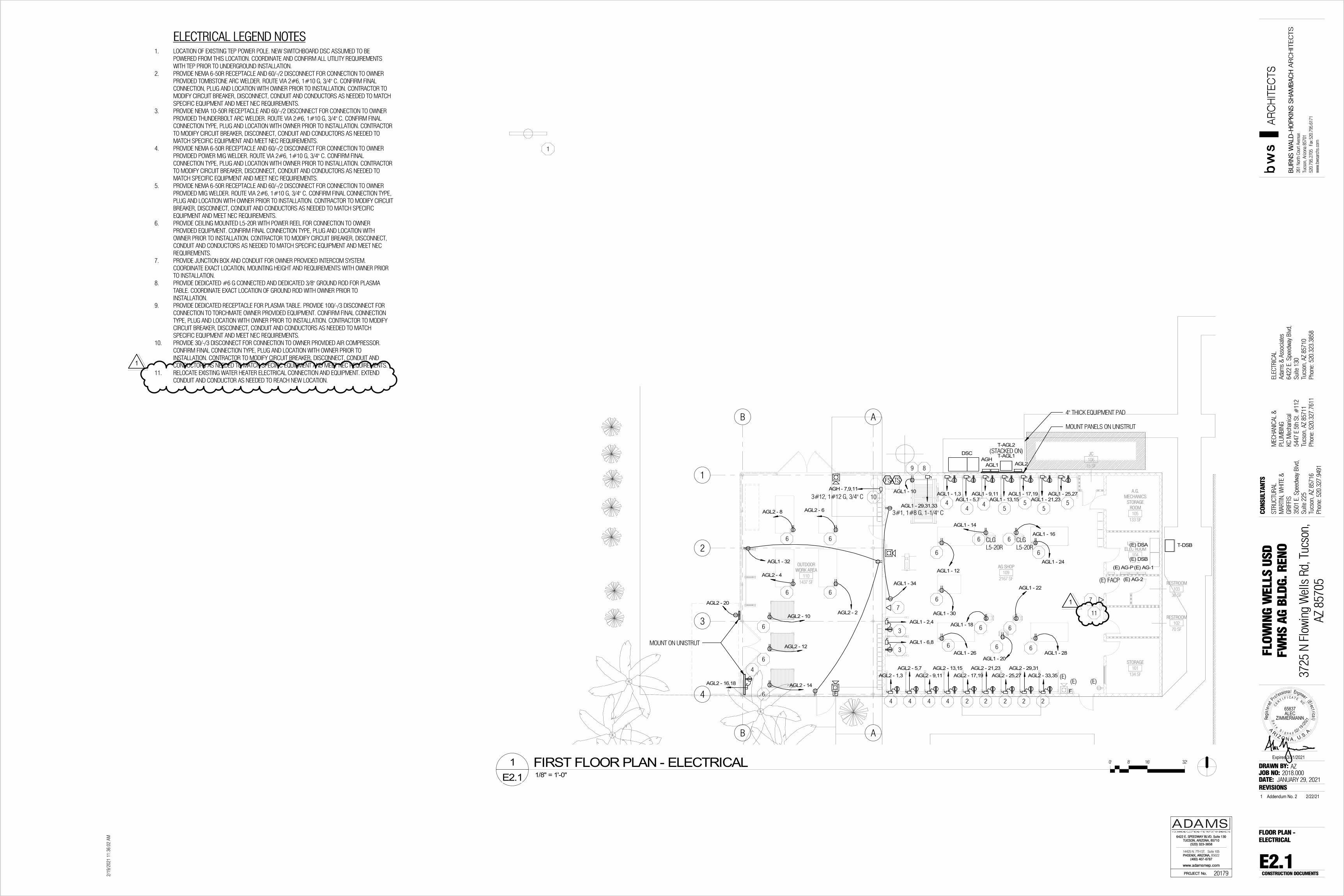
15. Sheet E2.1 Note 1 – Is it safe to assume we should figure TEP SR 308 installation for the new switchboard?
Yes, assume full coordination with TEP SR documentation.
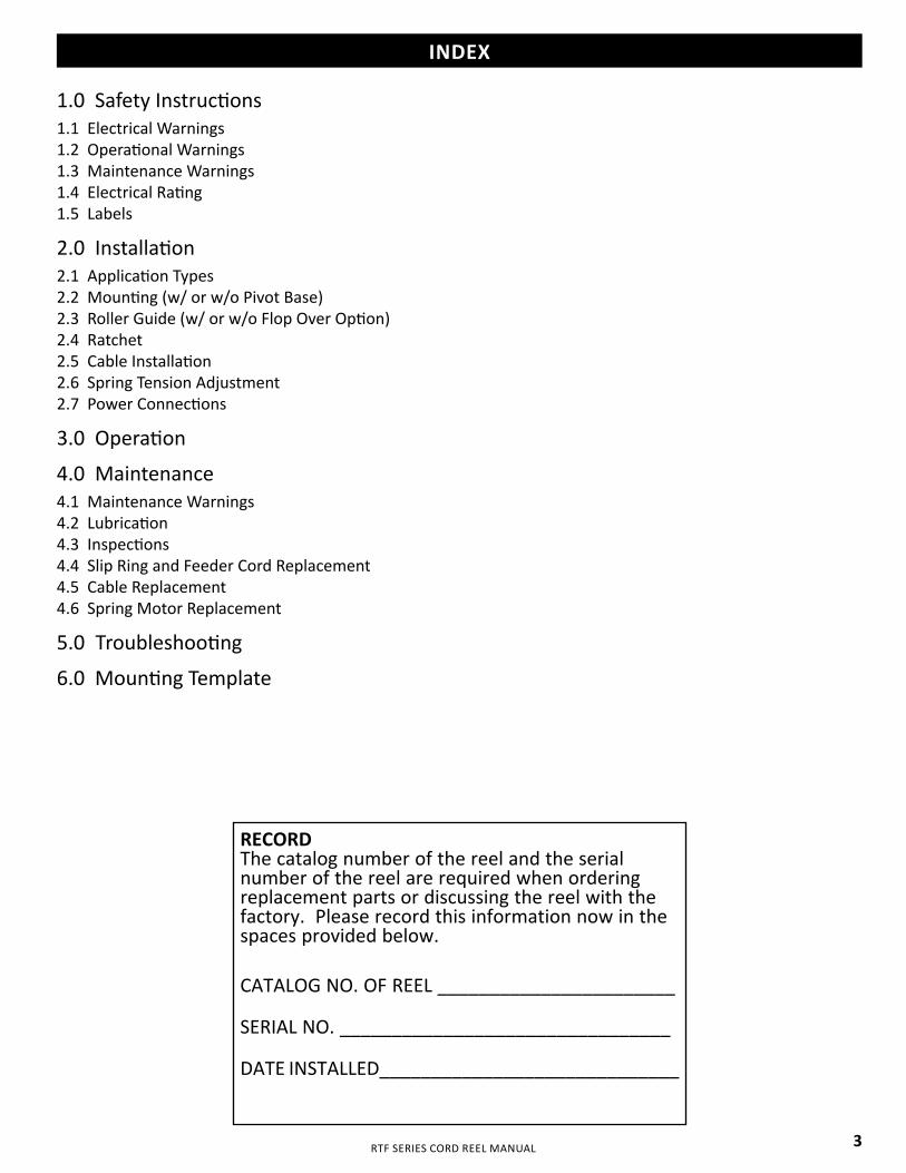
16. Note 6 – calls out for L5-20R power reel. Do you have a manufacturer and a catalog number for these units?
Provide power reel equal to KH Industries RTF Series. See attached for cut sheet.
17. Note 7 – calls for junction box and conduit for an intercom system. Should we include a junction box with a 3/4” conduit stubbed to the sheet rock ceiling?

Flowing Wells Unified School District, #8 Amendment #2 1556 W Prince Road
Tucson, AZ 85705 (520) 696-8820
BID: 21-05-21 PROJECT: Flowing Wells High School Welding Shop
Page 3 of 3
Provide 1" C to above accessible ceiling per symbol legend on E0.1
18. Note 8 – calls for a dedicated #6 ground. Would a ¾” ground rod be acceptable?
Ground rod greater than or equal to 3/8" is acceptable.
19. Note 9 – calls for a recept for the 100 amp power feed to the Plasma Table. Can we get more information on the table so we can provide the correct housing?
See attached installation cut sheet for plasma table information.
20. Note 10 – calls for a disconnect for a compressor. Will the compressor come with a magnetic starter or do we need to include one?
The Air Compressor is an owner furnish item to be purchased at a future date. Specifics of that equipment are unknown.
21. The plans call out to install an owner provided transformer to refeed the existing single phase (residential type) service on the east end of the building. Does this existing service feed something other than the east end of the building ie: restrooms, storage, lighting etc? If so, would it be acceptable to pull the necessary circuits off of the new 800 amp service to feed this portion of the building in lieu of refeeding the single phase service? This is just a cost savings suggestion.
Provide pricing based on construction documents. Once contract is awarded, cost savings suggestions can be discussed.
22. Will the owner accept using #500MCM aluminum conductors in lieu of #300MCM copper conductors for secondary conductors? Another cost savings suggestion.
Provide pricing based on construction documents. Once contract is awarded, cost savings suggestions can be discussed.
23. Regarding Alternate to provide a price to provide electric heaters, should we figure the cost based on doing it during the construction of this project or would it be done at a later date?
Base Bid will include the installation of conduit, wire and disconnect, with the final connection of the unit heaters under Add Alt. No. 1. The installation would be during the construction of the project.
24. I see on the revised proposal form presented in Amendment #1 the incorrect calendar days to complete this project wasn’t corrected. It still states 30 days, then states liquidated damages of $100.00 per day for each calendar day not completed. Since we are signing this revised bid proposal form, can you please correct it and send out the corrected form in your plumbing Amendment that is forthcoming?
Revised bid form attached with the correct number of days.
Sealed bids are due to the Flowing Wells USD Business Office no later than 2:00 p.m. AZ time on Thursday, February 25, 2021.
End of Amendment #2

Flowing Wells Unified School District, #8 Amendment #2 1556 W Prince Road
Tucson, AZ 85705 (520) 696-8820
BID: 21-05-21 PROJECT: Flowing Wells High School Welding Shop
Page 4 of 3
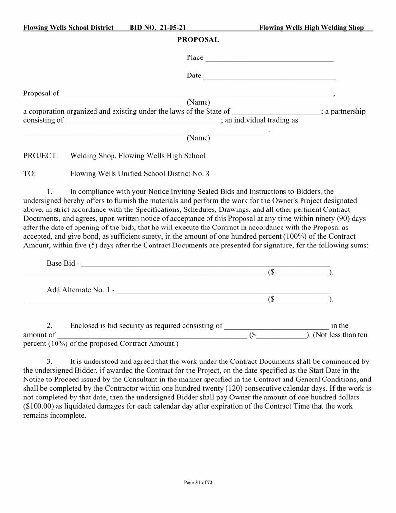
Flowing Wells School District BID NO. 21-05-21 Flowing Wells High Welding Shop
PROPOSAL
Place _________________________________
Date __________________________________
Proposal of ______________________________________________________________________, (Name) a corporation organized and existing under the laws of the State of _______________________; a partnership consisting of ________________________________________; an individual trading as _______________________________________________________________.
(Name)
PROJECT: Welding Shop, Flowing Wells High School
TO: Flowing Wells Unified School District No. 8
1. In compliance with your Notice Inviting Sealed Bids and Instructions to Bidders, theundersigned hereby offers to furnish the materials and perform the work for the Owner's Project designated above, in strict accordance with the Specifications, Schedules, Drawings, and all other pertinent Contract Documents, and agrees, upon written notice of acceptance of this Proposal at any time within ninety (90) days after the date of opening of the bids, that he will execute the Contract in accordance with the Proposal as accepted, and give bond, as sufficient surety, in the amount of one hundred percent (100%) of the Contract Amount, within five (5) days after the Contract Documents are presented for signature, for the following sums:
Base Bid - ________________________________________________________________ ______________________________________________________________ ($______________).
Add Alternate No. 1 - _______________________________________________________ ______________________________________________________________ ($______________).
2. Enclosed is bid security as required consisting of ___________________________ in the amount of _________________________________________________ ($_____________). (Not less than ten percent (10%) of the proposed Contract Amount.)
3. It is understood and agreed that the work under the Contract Documents shall be commenced by the undersigned Bidder, if awarded the Contract for the Project, on the date specified as the Start Date in the Notice to Proceed issued by the Consultant in the manner specified in the Contract and General Conditions, and shall be completed by the Contractor within one hundred twenty (120) consecutive calendar days. If the work is not completed by that date, then the undersigned Bidder shall pay Owner the amount of one hundred dollars ($100.00) as liquidated damages for each calendar day after expiration of the Contract Time that the work remains incomplete.
Page 31 of 72

Flowing Wells School District BID NO. 21-05-21 Flowing Wells High Welding Shop
Page 32 of 72
4. The undersigned Bidder hereby acknowledges receipt of the following Addenda, if any: Addendum No. Date ____________________ _____________________ ____________________ _____________________ ____________________ _____________________
____________________ _____________________ ____________________ _____________________ ____________________ _____________________ 5. The undersigned Bidder understands that the Owner reserves the right to reject any or all Proposals or to waive any formality or technicality, and to accept Alternates in any order or combination, and to determine the low bidder on the basis of the sum of the Base Bid and the Alternates selected, as determined by the Owner in its sole discretion, in any Proposal in the interest of the Owner. 6. The undersigned Bidder hereby certifies and affirms that this Proposal is genuine and not a sham or collusive, nor made in the interest or behalf of any person not herein named, and that the undersigned Bidder has not directly or indirectly induced or solicited any other Bidder to put in a sham bid, or any other person, firm, or corporation to refrain from bidding, and that the Bidder has not in any manner sought by collusion to secure for itself an advantage over any other Bidder. 7. Contractor's Arizona Contractor's License No(s). ________________________. _______________________________________ (Official Name of Firm) SEAL - If Bidder is a By____________________________________ Corporation
Title___________________________________ _______________________________________ (Complete Business Address)

S6
S6
A. DIMENSIONS ARE TO COLUMN CENTERLINE OR FACE OF WALL, U.N.O.B. REFER TO SHEET A2.1 FOR ROOM FINISHES.C. REFER TO A2.1 FOR DOOR SCHEDULE TYPES.D. REFER TO SHEET A10.1 FOR WALL TYPES.
3A5.1
4A5.1
1A5.1
2A5.1
AG SHOP109
STORAGE101
RESTROOM102
RESTROOM103
UTILITY /ELEC ROOM
104
A.G.MECHANICS
STORAGEROOM105
JC106
5
A5.1
5
A5.1
A
A
B
B
1
4
28'-0" 2'-0"
1'-0
"15
'-8"
15'-8
"15
'-8"
1'-0
"
3
2
6
A5.1
6
A5.1
7 5/8"46'-9 1/8" 7 5/8" 11'-4" 7 5/8"
7
A5.1
7
A5.1
OUTDOORWORK AREA
110
8'-0" 12'-4" 8'-0" 7'-3 1/8"
4'-0
"6'
-3 1
/4"
4'-0
"6'
-3 1
/2"
4'-0
"
4'-0"
4'-0
"
3'-0
3/8
"
1'-0" 7'-7 3/4" 12'-4" 9'-8"
208
210
208
203
204
205
205
202
202
200
201
201213213110C
110D
110B
110A
109
216
12'-0
"
5'-0"
CJ
215
218
217
217101
106A
105
101101101101
103
103
102102102102
107
106B108108
108 108
107107107107
107107107112
8
A5.1
8
A5.1
209
209
TYP209
202202
212
202 202
219
214
214
1
211
221
220
AG SHOP109
STORAGE101
RESTROOM102
RESTROOM103
UTILITY /ELEC ROOM
104
A.G.MECHANICS
STORAGEROOM
105
JC106
A
A
B
B
1
4
3
2
6
A5.1
6
A5.1
OUTDOORWORK AREA
110
7
A5.1
7
A5.1
NEW GYP. CEILING
EXISTING STRUCTURE
E.T.R
28'-0"
EQEQ
EQ
GALV. ROOF DECK ON PAINTED STEEL BEAMS
6' -
10 1
/2"
11' -
0"
11' -
0"
11' -
0"
6' -
10 1
/2"
4' - 6" ± 7' - 10" 7' - 10" 7' - 10" 7' - 10" 7' - 10" 3' - 0"
7' -
0"11
' - 0
"11
' - 0
"11
' - 0
"7'
- 0"
EXISTING RELIEF HOOD
EXISTING RELIEF HOOD
E.T.R
E.T.R
E.T.R
E.T.R
E.T.R
1" / 12"
SLOPE
8
A5.1
8
A5.1
113
113
113104 104
104
104
104
108108
108 108
109
110
111
111
A. SEE ARCHITECTURAL REFLECTED CEILING PLANS FOR LOCATIONS AND EXTENT OF SOFFITS.
B. SEE PLANS AND INTERIOR ELEVATIONS FOR LOCATIONS AND EXTENT OF VARIOUS FINISH MATERIALS.
ACP-1ACP-2ATCONCCPTCTESETRGCGWBMTLPRBSCWBWOC
ACOUSTIC CEILING TILEACOUSTIC CEILING TILE - TO MATCH EXISTINGACOUSTIC TREATMENTCONCRETECARPETCERAMIC TILEEXPOSED STRUCTUREEXISTING TO REMAINGROUND/POLISHED CONCRETEGYPSUM WALL BOARDMETALPAINTRUBBER BASESEALED CONCRETEWOOD BASEWALK-OFF CARPET
A. SEE GENERAL NOTES ON SHEET G1.1 FOR SUSPENDED CEILING GRID LAYOUT AND PLACEMENT OF CEILING MOUNTED DEVICES.
B. SEE FLOOR PLAN FOR PARTITION TYPES.C. COORDINATE CEILING PLANS WITH MECHANICAL, FIRE PROTECTION AND
ELECTRICAL PLANS.D. ALL GWB CEILINGS AND SOFFITS SHALL BE TEXTURED AND PAINTED.E. REFER TO SHEET A3.? FOR CEILING DETAILS.F. ACCESS PANELS IN FIRE RATED CEILINGS SHALL MATCH THE FIRE RATING
OF THE CEILING.G. CENTER LIGHT FIXTURES IN CEILING, U.N.O.H. "CJ" INDICATES A GWB CONTROL JOINT.
CEILING TYPES:
A
B E.T.R.
GWB
EXISTING CEILING TO REMAIN
MECH - SUPPLY DIFFUSER
MECH - RETURN DIFFUSER
MECH - EXHAUST
EXTERIOR LIGHT FIXTURE - WALL MOUNT.
CEILING EQUIPMENT:
EB
EMERGENCY BATTERY PACK -WALL MOUNT.
EXIT FIXTURE - CEILING MOUNT.
EXIT FIXTURE - WALL MOUNT.
LIGHT FIXTURE - CEILING MOUNT
RE
GISTERE
D ARCHITECT
A R I Z O N A , U . S. A
.
Da t e S ig n ed . . .. .
..
CERT I F
ICATE NO.23533ROBIN A.SHAMBACH
EXPIRES 06/30/2022
ARCHITEC
TS
261
North
Cou
rt Av
enue
Tucs
on, A
rizon
a 85
701
520.
795.
2705
Fa
x 520
.795
.617
1ww
w.bw
sarc
hs.c
om
BU
RN
S W
ALD
-HO
PK
INS
SH
AM
BA
CH
AR
CH
ITEC
TS
JOB NO:DATE:REVISIONS
DRAWN BY:
CONS
ULTA
NTS
2/22
/202
1 2:
32:0
3 PM
CONSTRUCTION DOCUMENTSA2.1
FLOOR PLAN &REFLECTED CEILINGPLAN
JANUARY 29, 20212018.000
CP, JT
FLOW
ING
WEL
LS U
SDFW
HS
AG B
LDG.
REN
OST
RUCT
URAL
MAR
TIN,
WHI
TE &
GRIF
FIS
3501
E. S
peed
way
Blvd
,Su
ite 2
25Tu
cson
, AZ
8571
6Ph
one:
520
.327
.949
1
MEC
HANI
CAL
&PL
UMBI
NGKC
Mec
hani
cal
5447
E 5
th S
t. #
112
Tucs
on, A
Z 85
711
Phon
e: 5
20.3
27.7
611
ELEC
TRIC
ALAd
ams
& A
ssoc
iate
s64
22 E
. Spe
edwa
y Bl
vd,
Suite
130
Tucs
on, A
Z 85
710
Phon
e: 5
20.3
23.3
858
3725
N F
lowi
ng W
ells
Rd,
Tuc
son,
AZ 8
5705
2-22-21
FLOOR PLAN GENERAL NOTES
SCALE: 1/8" = 1'-0"1 FLOOR PLAN 0' 4' 8' 16'
KEYNOTES200 STORAGE RACK W/ SHELVES, OFOI201 PROJECT STORAGE LOCKERS, OFOI202 4'X8' TABLE W/ 46" POST & ADJ. PLATFORM, TYP., OFOI203 CANTILEVER STORAGE RACK, OFOI204 CUTTING AREA, OFOI205 OXY STATION, TYP., OFOI208 WELDING BOOTH (4'X4') SIDE-TO-SIDE, TYP., OFOI209 BENCH GRINDER, TYP., OFOI210 EXISTING LOCKERS TO REMAIN - 2 TIER211 EMERGENCY EYEWASH, WALL MOUNTED, SEE PLUMBING DRAWINGS212 4'X5' TABLE W/ 46" POST & ADJ. PLATFORM, OFOI213 EQUIPMENT & TOOL STORAGE, OFOI214 FIRE EXTINGUISHER - SURFACE MOUNTED215 FIRE RISER - REF. MECHANICAL216 NEW CONCRETE FLATWORK217 ON EXISTING DOORS -REMOVE EXISTING HARDWARE & PROVIDE NEW
PANIC HARDWARE - REF. SPECIFICATIONS218 GATE HARDWARE WILL INCLUDE PANIC HARDWARE DEVICE - REF.
SPECFICATIONS219 PROVIDE LIGHT SALT PEPPER GRIND, POLISH AND FINISH EXISTING
CONCRETE SLAB220 EXISTING DRINKING FOUNTAIN TO REMAIN.221 RELOCATION WATER HEATER, SEE PLUMBING DRAWINGS
1/8" = 1'-0"2 REFLECTED CEILING PLAN 0' 4' 8' 16'
ROOM SCHEDULE
ROOMNo. ROOM NAME
FLOOR WALLS CEILING
REMARKSFIN BASENORTH EAST SOUTH WEST
SURFACE FINSURFACE FIN SURFACE FIN SURFACE FIN SURFACE FIN
101 STORAGE ETR ETR ETR P ETR P ETR P ETR P GWB P102 RESTROOM ETR ETR ETR P ETR P ETR P ETR P ETR P103 RESTROOM ETR ETR ETR P ETR P ETR P ETR P ETR P104 UTILITY / ELEC ROOM ETR ETR ETR P ETR P ETR P ETR P ETR P105 A.G. MECHANICS STORAGE ROOM ETR ETR ETR P ETR P ETR P ETR P GWB P106 JC ETR ETR ETR P ETR P ETR P ETR P ETR P109 AG SHOP GC RB (E) CMU P (E) CMU P (E) CMU P (E) CMU P GWB P110 OUTDOOR WORK AREA SC PAINTED STRUCTURE
ROOM FINISH GENERAL NOTESROOM FINISH ABBREVIATIONS
REFLECTED CEILING PLAN GENERAL NOTES
REFLECTED CEILING PLAN LEGEND
O.F.O.I. EQUIPMENT SCHED.TAG No. NAME POWER NOTES
101 TOMBSTONE ARC WELDER SINGLE PHASE 230V, 50a101 TOMBSTONE ARC WELDER SINGLE PHASE 230V, 50a101 TOMBSTONE ARC WELDER SINGLE PHASE 230V, 50a101 TOMBSTONE ARC WELDER SINGLE PHASE 230V, 50a101 TOMBSTONE ARC WELDER SINGLE PHASE 230V, 50a102 MIG WELDER SINGLE PHASE 230V, 21a102 MIG WELDER SINGLE PHASE 230V, 21a102 MIG WELDER SINGLE PHASE 230V, 21a102 MIG WELDER SINGLE PHASE 230V, 21a103 THUNDERBOLT ARC WELDER SINGLE PHASE 230V, 47.5a103 THUNDERBOLT ARC WELDER SINGLE PHASE 230V, 47.5a104 BENCH GRINDER ON PEDESTAL 120V FROM CEILING ON POWER REEL104 BENCH GRINDER ON PEDESTAL 120V FROM CEILING ON POWER REEL104 BENCH GRINDER ON PEDESTAL 120V FROM CEILING ON POWER REEL104 BENCH GRINDER ON PEDESTAL 120V FROM CEILING ON POWER REEL104 BENCH GRINDER ON PEDESTAL 120V FROM CEILING ON POWER REEL105 IRON WORKER
106A TORCHMATE 4800 PLASMA TABLE 120V, 15A DEDICATED CIRCUIT 1,250 LBS, 107 GAL CAPACITY, AIR 87-109 psi(6-7.5 bar) 380 SCFH 180 SLPM
106B PLASMA CUTTER - FlexCut 80 230V / 1 / 50 / 60 DEDICATED EARTH GROUND REQUIRED107 POWER MIG 210 MP SINGLE PHASE 230V, 14.7a107 POWER MIG 210 MP SINGLE PHASE 230V, 14.7a107 POWER MIG 210 MP SINGLE PHASE 230V, 14.7a107 POWER MIG 210 MP SINGLE PHASE 230V, 14.7a107 POWER MIG 210 MP SINGLE PHASE 230V, 14.7a107 POWER MIG 210 MP SINGLE PHASE 230V, 14.7a107 POWER MIG 210 MP SINGLE PHASE 230V, 14.7a107 POWER MIG 210 MP SINGLE PHASE 230V, 14.7a108 4' x 8' - PORTABLE WORK TABLE OVERHEAD POWER REEL108 4' x 8' - PORTABLE WORK TABLE OVERHEAD POWER REEL108 4' x 8' - PORTABLE WORK TABLE OVERHEAD POWER REEL108 4' x 8' - PORTABLE WORK TABLE OVERHEAD POWER REEL108 4' x 8' - PORTABLE WORK TABLE OVERHEAD POWER REEL108 4' x 8' - PORTABLE WORK TABLE OVERHEAD POWER REEL108 4' x 8' - PORTABLE WORK TABLE OVERHEAD POWER REEL108 4' x 8' - PORTABLE WORK TABLE OVERHEAD POWER REEL109 4' x 5' PORTABLE WORK TABLE OVERHEAD POWER REEL110 4' x4' CUTTING TABLE OVERHEAD POWER REEL111 4' x 4' - OXY ACETYLENE WELDING STATION OVERHEAD POWER REEL111 4' x 4' - OXY ACETYLENE WELDING STATION OVERHEAD POWER REEL112 AIR COMPRESSOR & VERTICAL TANK 230V / 1 / 50 / 60 DEDICATED EARTH GROUND REQUIRED113 OVERHEAD COMPRESSED AIR REEL113 OVERHEAD COMPRESSED AIR REEL113 OVERHEAD COMPRESSED AIR REEL
--
1 Addendum No.2 2/22/21
1
AB
1
4
3
2
1 SCALE: 1/4" = 1'-0"
PLUMBING NEW WORK PLAN
OUTDOORWORK AREA
110
AG SHOP109
A.G.MECHANICS
STORAGEROOM
JC106
UTILITY /ELEC ROOM
RESTROOM103
RESTROOM102
STORAGE101
261
North
Cou
rt Av
enue
Tucs
on, A
rizon
a 85
701
520.
795.
2705
www.
bwsa
rchi
tect
s.co
m
BU
RN
S W
ALD
-HO
PKIN
S S
HA
MB
AC
HA
RC
HIT
EC
TS
JOB NO:DATE:REVISIONS
DRAWN BY:
CONS
ULTA
NTS
AR
CH
ITEC
TS
12/2
4/20
20 1
0:38
:48
AM
CONSTRUCTION DOCUMENTS
JANUARY 6, 20202018.000
Author
FLOW
ING
WEL
LS U
SDFW
HS
AG B
LDG.
REN
OST
RUCT
URAL
MAR
TIN,
WHI
TE &
GRIF
FIS
3501
E. S
peed
way
Blvd
,Su
ite 2
25Tu
cson
, AZ
8571
6Ph
one:
520
.327
.949
1
MEC
HANI
CAL
&PL
UMBI
NGKC
Mec
hani
cal
5447
E 5
th S
t. #
112
Tucs
on, A
Z 85
711
Phon
e: 5
20.3
27.7
611
ELEC
TRIC
ALAd
ams
& A
ssoc
iate
s64
22 E
. Spe
edwa
y Bl
vd,
Suite
130
Tucs
on, A
Z 85
710
Phon
e: 5
20.3
23.3
858
3725
N F
lowi
ng W
ells
Rd,
Tuc
son,
AZ 8
5705
5447 East Fifth Street # 112Tucson, Arizona 85711 520/327-0432
520/327-7611
Designers Mech: Plumb:
MECHANICAL ENGINEERING, L.L.C.
NJH NJH PROJECT#20-352P1.0
PLUMBING NEW WORKPLAN
1 Addendum No. 2 2/22/21
P2.0
PLUMING SCHEDULES &DETAILS
261
North
Cou
rt Av
enue
Tucs
on, A
rizon
a 85
701
520.
795.
2705
www.
bwsa
rchi
tect
s.co
m
BU
RN
S W
ALD
-HO
PKIN
S S
HA
MB
AC
HA
RC
HIT
EC
TS
JOB NO:DATE:REVISIONS
DRAWN BY:
CONS
ULTA
NTS
AR
CH
ITEC
TS
12/2
4/20
20 1
0:38
:48
AM
CONSTRUCTION DOCUMENTS
JANUARY 6, 20202018.000
Author
FLOW
ING
WEL
LS U
SDFW
HS
AG B
LDG.
REN
OST
RUCT
URAL
MAR
TIN,
WHI
TE &
GRIF
FIS
3501
E. S
peed
way
Blvd
,Su
ite 2
25Tu
cson
, AZ
8571
6Ph
one:
520
.327
.949
1
MEC
HANI
CAL
&PL
UMBI
NGKC
Mec
hani
cal
5447
E 5
th S
t. #
112
Tucs
on, A
Z 85
711
Phon
e: 5
20.3
27.7
611
ELEC
TRIC
ALAd
ams
& A
ssoc
iate
s64
22 E
. Spe
edwa
y Bl
vd,
Suite
130
Tucs
on, A
Z 85
710
Phon
e: 5
20.3
23.3
858
3725
N F
lowi
ng W
ells
Rd,
Tuc
son,
AZ 8
5705
5447 East Fifth Street # 112Tucson, Arizona 85711 520/327-0432
520/327-7611
Designers Mech: Plumb:
MECHANICAL ENGINEERING, L.L.C.
NJH NJH PROJECT#20-352
1 Addendum No. 2 2/22/21
F
F
AG SHOP
109
STORAGE
101
RESTROOM
102
RESTROOM
103
UTILITY /ELEC ROOM
104
A.G.MECHANICS
STORAGEROOM
105
JC
106
A
1
4
3
2
(X)
(X)
(X)
(X)
(X)
(X)(X)
(X)(X)(X)
(X)(X)(X)
(X)
(X)
(X)
(X)
(X)
(X)
(X)
(X)
(X)
(X) (X)
(X)
(X)
(X)
(X)
(X)(X) (X)
(X)
(X)
(X)(X)(X)
(X)
(X)
(X)
(X)
(X)
(X)
(X)
(X)
(X)
(E)(E)
(E)
(E) DSA
(E) DSB
(E) AG-1
(E) AG-2
(E) AG-P
(X) T-DSB1
2
2
3
1
AG SHOP
109
STORAGE
101
RESTROOM
102
RESTROOM
103
UTILITY /ELEC ROOM
104
A.G.MECHANICS
STORAGEROOM
105
JC
106
A
1
4
3
2
(X)
(X)
(X)
(X)
(X)
(X)
(X)
(X)
(X)
(X)
(X)
(X)
(X)
(X)
(X)
(X)
(X)
(X)
(X)
(X)
(X)
(X)
(X)
(X)
(X)
(X)
(X)
(X)
(X)
(X)
(X)
(X)
(X)
(X) (X) (X)
(X)(X)
(X) (X)
(X) (X)
(X)(X) (X)
(X)(X)(X)
(X)
(X)
(X)
(X)
(X)
(X)TYP. 5
(X)
(X)
(X)
(X)
(E)
ELECTRICAL GENERAL NOTESA. DESIGNATION '(E)' REPRESENTS EXISTING ELECTRICAL DEVICE OR EQUIPMENT EXISTING TO REMAIN
AS CIRCUITED AND SWITCHED UNLESS NOTED OTHERWISE.
B. DESIGNATION '(X)' REPRESENTS EXISTING ELECTRICAL DEVICE OR EQUIPMENT TO BE DEMOLISHED
IN SCOPE OF THIS PROJECT. DEMOLISH DEVICE(S), CONDUIT(S) AND CONDUCTOR(S) BACK TO
POINT OF ORIGINATION. IF PANEL BOARD IS POINT OF ORIGINATION, TURN OCPD OFF AND LABEL AS
'SPARE'.
C. DESIGNATION '(R)' REPRESENTS EXISTING ELECTRICAL DEVICE OR EQUIPMENT TO BE RELOCATED IN
SCOPE OF THIS PROJECT. RELOCATE AND EXTEND DEVICE(S), CONDUIT(S) AND CONDUCTOR(S) AS
NEED TO PROVIDE A CODE COMPLIANT FINAL INSTALLATION.
D. ELECTRICAL CONTRACTOR SHALL COORDINATE ALL PATCHING AND REPAIRING WORK WITH THE
GENERAL CONTRACTOR.
E. CONTRACTOR SHALL REMOVE ALL CONDUIT AND WIRING ASSOCIATED WITH DEVICES AND
EQUIPMENT TO BE REMOVED AND/OR RELOCATED UNLESS NOTED OTHERWISE. PROVIDE AND
INSTALL NECESSARY DEVICES, EQUIPMENT AND ACCESSORIES REQUIRED TO MAINTAIN SERVICE
TO ALL "EXISTING TO REMAIN" DEVICES AND EQUIPMENT THAT MAY BE INTERRUPTED DURING
DEMOLITION.
F. PROVIDE FOR ANY AND ALL DEMOLITION WORK NECESSARY TO ACCOMMODATE ALL NEW
CONSTRUCTION, INCLUDING BUT NOT LIMITED TO ARCHITECTURAL, MECHANICAL, PLUMBING OR
ELECTRICAL WORK.
G. CONTRACTOR TO VERIFY ALL ELECTRICAL CONNECTIONS TO OWNER PROVIDED EQUIPMENT. IF
EQUIPMENT SIZES AND CONNECTIONS ARE DIFFERENT. PROVIDE MODIFIED CB, CONDUIT AND
CONDUCTORS PER NEC REQUIREMENTS.
H. PROVIDE UPDATED TYPE WRITTEN DIRECTORY OF ALL CORRECT CIRCUITS WITH LOAD DEFINITIONS
FOR EACH PANEL BOARD. DIRECTORY SHALL BE LOCATED INSIDE PANEL DOOR.
ELECTRICAL LEGEND NOTES1. DEMOLISH ELECTRICAL CONNECTIONS ASSOCIATED WITH DEMO'D AC UNIT ON ROOF ABOVE.
DEMOLISH ELECTRICAL INFRASTURCUTURE BACK TO POINT OF ORIGINATION, IF CIRCUIT
BREAKER IS ORIGIN, TURN OFF AND LABEL "SPARE".
2. DEMOLISH ELECTRICAL CONNECTIONS ASSOCIATED WITH DEMO'D EXHAUST FAN ON ROOF
ABOVE. DEMOLISH ELECTRICAL INFRASTURCUTURE BACK TO POINT OF ORIGINATION, IF
CIRCUIT BREAKER IS ORIGIN, TURN OFF AND LABEL "SPARE".
3. RELOCATE EXISTING CIRCUIT AND ELECTRICAL EQUIPMENT FEEDING WATER HEATER IN THIS
AREA. REFER TO E2.1 FOR ADDITIONAL INFORMATION.
1
20179
6422 E. SPEEDWAY BLVD. Suite 130
TUCSON, ARIZONA, 85710
(520) 323-3858
PROJECT No.
www.adamsmep.com
14425 N. 7TH ST. Suite 105
PHOENIX, ARIZONA, 85022
(480) 407-6787
ARCHITECTS
261
Nor
th C
ourt A
venu
e
Tucs
on, A
rizo
na 8
5701
520.
795.
2705
Fa
x 52
0.79
5.61
71
ww
w.b
wsa
rchs
.com
BU
RN
S W
ALD
-HO
PKIN
S S
HAM
BAC
HARC
HIT
EC
TS
JOB NO:DATE:
REVISIONS
DRAWN BY:
CO
NSU
LTANTS
2/19
/202
1 11
:36:
03 A
M
CONSTRUCTION DOCUMENTS
ED2.1
DEMOLITION FLOOR
PLANS - ELECTRICAL
JANUARY 29, 20212018.000
AZ
FLO
WIN
G W
ELL
S U
SD
FW
HS A
G B
LDG. RENO
STR
UC
TURAL
MARTI
N, W
HIT
E &
GRIF
FIS
3501
E. S
peed
way
Blv
d,
Sui
te 2
25
Tucs
on, A
Z 85
716
Pho
ne: 5
20.3
27.9
491
MEC
HAN
ICAL
&
PLU
MBIN
G
KC
Mec
hani
cal
5447
E 5
th S
t. #
112
Tucs
on, A
Z 85
711
Pho
ne: 5
20.3
27.7
611
ELEC
TRIC
AL
Ada
ms
& A
ssoc
iate
s
6422
E. S
peed
way
Blv
d,
Sui
te 1
30
Tucs
on, A
Z 85
710
Pho
ne: 5
20.3
23.3
858
3725
N F
low
ing
Wel
ls R
d, T
ucso
n,
AZ
8570
5
1/8" = 1'-0"ED2.1
1 FIRST FLOOR DEMOLITION PLAN - ELECTRICAL1/8" = 1'-0"ED2.1
2 FIRST FLOOR DEMOLITION PLAN - LIGHTING 0' 8' 16' 32' 0' 8' 16' 32'
2021
02 19/
/
Expires 3/31/2021
1 Addendum No. 2 2/22/21
FF
2167 SF
AG SHOP
109
134 SF
STORAGE
101
70 SF
RESTROOM
102
36 SF
RESTROOM
103
102 SF
UTILITY /ELEC ROOM
104
133 SF
A.G.MECHANICS
STORAGEROOM
105
15 SF
JC
106
A
A
B
B
1
4
3
2
1437 SF
OUTDOORWORK AREA
110
(E) DSB
(E) DSA
(E) AG-1
(E) AG-2
(E) AG-P
CLG
L5-20R
CLG
L5-20R T-DSB
(E)(E) (E)
DSC
AGHAGL1
T-AGL1
T-AGL2
(STACKED ON)
AGL2
AGL1 - 1,3AGL1 - 5,7
AGL1 - 9,11AGL1 - 13,15
AGL1 - 17,19AGL1 - 21,23
AGL1 - 25,27
1
AGL1 - 2,4
AGL1 - 6,8
AGL2 - 1,3
AGL2 - 5,7
44
45
5
3
3
55
4 4 4 4 2 2 2 2 2
AGL2 - 9,11
AGL2 - 13,15
AGL2 - 17,19
AGL2 - 21,23
AGL2 - 25,27
AGL2 - 29,31
AGL2 - 33,35
6
6 6
6
6
6
6
66
66 6
66
6
6
6
AGL1 - 12
AGL2 - 14
AGL2 - 12
AGL2 - 10
AGL2 - 4
AGL2 - 2
AGL2 - 6AGL2 - 8
AGL1 - 30
AGL1 - 18
AGL1 - 14
AGL1 - 16
AGL1 - 24
AGL1 - 22
AGL1 - 28AGL1 - 20
AGL1 - 26
AGL1 - 32
4
AGL2 - 16,18
AGL2 - 207
7
MOUNT PANELS ON UNISTRUT
4" THICK EQUIPMENT PAD
(E) FACP
MOUNT ON UNISTRUT
AGL1 - 10
AGL1 - 29,31,33
3#1, 1#8 G, 1-1/4" C
89
10
AGH - 7,9,11
3#12, 1#12 G, 3/4" C
AGL1 - 34
FS TS
11
1
ELECTRICAL LEGEND NOTES1. LOCATION OF EXISTING TEP POWER POLE. NEW SWITCHBOARD DSC ASSUMED TO BE
POWERED FROM THIS LOCATION. COORDINATE AND CONFIRM ALL UTILITY REQUIREMENTS
WITH TEP PRIOR TO UNDERGROUND INSTALLATION.
2. PROVIDE NEMA 6-50R RECEPTACLE AND 60/-/2 DISCONNECT FOR CONNECTION TO OWNER
PROVIDED TOMBSTONE ARC WELDER. ROUTE VIA 2#6, 1#10 G, 3/4" C. CONFIRM FINAL
CONNECTION, PLUG AND LOCATION WITH OWNER PRIOR TO INSTALLATION. CONTRACTOR TO
MODIFY CIRCUIT BREAKER, DISCONNECT, CONDUIT AND CONDUCTORS AS NEEDED TO MATCH
SPECIFIC EQUIPMENT AND MEET NEC REQUIREMENTS.
3. PROVIDE NEMA 10-50R RECEPTACLE AND 60/-/2 DISCONNECT FOR CONNECTION TO OWNER
PROVIDED THUNDERBOLT ARC WELDER. ROUTE VIA 2#6, 1#10 G, 3/4" C. CONFIRM FINAL
CONNECTION TYPE, PLUG AND LOCATION WITH OWNER PRIOR TO INSTALLATION. CONTRACTOR
TO MODIFY CIRCUIT BREAKER, DISCONNECT, CONDUIT AND CONDUCTORS AS NEEDED TO
MATCH SPECIFIC EQUIPMENT AND MEET NEC REQUIREMENTS.
4. PROVIDE NEMA 6-50R RECEPTACLE AND 60/-/2 DISCONNECT FOR CONNECTION TO OWNER
PROVIDED POWER MIG WELDER. ROUTE VIA 2#6, 1#10 G, 3/4" C. CONFIRM FINAL
CONNECTION TYPE, PLUG AND LOCATION WITH OWNER PRIOR TO INSTALLATION. CONTRACTOR
TO MODIFY CIRCUIT BREAKER, DISCONNECT, CONDUIT AND CONDUCTORS AS NEEDED TO
MATCH SPECIFIC EQUIPMENT AND MEET NEC REQUIREMENTS.
5. PROVIDE NEMA 6-50R RECEPTACLE AND 60/-/2 DISCONNECT FOR CONNECTION TO OWNER
PROVIDED MIG WELDER. ROUTE VIA 2#6, 1#10 G, 3/4" C. CONFIRM FINAL CONNECTION TYPE,
PLUG AND LOCATION WITH OWNER PRIOR TO INSTALLATION. CONTRACTOR TO MODIFY CIRCUIT
BREAKER, DISCONNECT, CONDUIT AND CONDUCTORS AS NEEDED TO MATCH SPECIFIC
EQUIPMENT AND MEET NEC REQUIREMENTS.
6. PROVIDE CEILING MOUNTED L5-20R WITH POWER REEL FOR CONNECTION TO OWNER
PROVIDED EQUIPMENT. CONFIRM FINAL CONNECTION TYPE, PLUG AND LOCATION WITH
OWNER PRIOR TO INSTALLATION. CONTRACTOR TO MODIFY CIRCUIT BREAKER, DISCONNECT,
CONDUIT AND CONDUCTORS AS NEEDED TO MATCH SPECIFIC EQUIPMENT AND MEET NEC
REQUIREMENTS.
7. PROVIDE JUNCTION BOX AND CONDUIT FOR OWNER PROVIDED INTERCOM SYSTEM.
COORDINATE EXACT LOCATION, MOUNTING HEIGHT AND REQUIREMENTS WITH OWNER PRIOR
TO INSTALLATION.
8. PROVIDE DEDICATED #6 G CONNECTED AND DEDICATED 3/8" GROUND ROD FOR PLASMA
TABLE. COORDINATE EXACT LOCATION OF GROUND ROD WITH OWNER PRIOR TO
INSTALLATION.
9. PROVIDE DEDICATED RECEPTACLE FOR PLASMA TABLE. PROVIDE 100/-/3 DISCONNECT FOR
CONNECTION TO TORCHMATE OWNER PROVIDED EQUIPMENT. CONFIRM FINAL CONNECTION
TYPE, PLUG AND LOCATION WITH OWNER PRIOR TO INSTALLATION. CONTRACTOR TO MODIFY
CIRCUIT BREAKER, DISCONNECT, CONDUIT AND CONDUCTORS AS NEEDED TO MATCH
SPECIFIC EQUIPMENT AND MEET NEC REQUIREMENTS.
10. PROVIDE 30/-/3 DISCONNECT FOR CONNECTION TO OWNER PROVIDED AIR COMPRESSOR.
CONFIRM FINAL CONNECTION TYPE, PLUG AND LOCATION WITH OWNER PRIOR TO
INSTALLATION. CONTRACTOR TO MODIFY CIRCUIT BREAKER, DISCONNECT, CONDUIT AND
CONDUCTORS AS NEEDED TO MATCH SPECIFIC EQUIPMENT AND MEET NEC REQUIREMENTS.
11. RELOCATE EXISTING WATER HEATER ELECTRICAL CONNECTION AND EQUIPMENT. EXTEND
CONDUIT AND CONDUCTOR AS NEEDED TO REACH NEW LOCATION.
1
20179
6422 E. SPEEDWAY BLVD. Suite 130
TUCSON, ARIZONA, 85710
(520) 323-3858
PROJECT No.
www.adamsmep.com
14425 N. 7TH ST. Suite 105
PHOENIX, ARIZONA, 85022
(480) 407-6787
ARCHITECTS
261
Nor
th C
ourt A
venu
e
Tucs
on, A
rizo
na 8
5701
520.
795.
2705
Fa
x 52
0.79
5.61
71
ww
w.b
wsa
rchs
.com
BU
RN
S W
ALD
-HO
PKIN
S S
HAM
BAC
HARC
HIT
EC
TS
JOB NO:DATE:
REVISIONS
DRAWN BY:
CO
NSU
LTANTS
2/19
/202
1 11
:36:
02 A
M
CONSTRUCTION DOCUMENTS
E2.1
FLOOR PLAN -
ELECTRICAL
JANUARY 29, 20212018.000
AZ
FLO
WIN
G W
ELL
S U
SD
FW
HS A
G B
LDG. RENO
STR
UC
TURAL
MARTI
N, W
HIT
E &
GRIF
FIS
3501
E. S
peed
way
Blv
d,
Sui
te 2
25
Tucs
on, A
Z 85
716
Pho
ne: 5
20.3
27.9
491
MEC
HAN
ICAL
&
PLU
MBIN
G
KC
Mec
hani
cal
5447
E 5
th S
t. #
112
Tucs
on, A
Z 85
711
Pho
ne: 5
20.3
27.7
611
ELEC
TRIC
AL
Ada
ms
& A
ssoc
iate
s
6422
E. S
peed
way
Blv
d,
Sui
te 1
30
Tucs
on, A
Z 85
710
Pho
ne: 5
20.3
23.3
858
3725
N F
low
ing
Wel
ls R
d, T
ucso
n,
AZ
8570
5
0' 8' 16' 32'
1/8" = 1'-0"E2.1
1 FIRST FLOOR PLAN - ELECTRICAL
2021
02 19/
/
Expires 3/31/2021
1 Addendum No. 2 2/22/21

REELTUFF™ RTF SERIES CORD REEL MANUAL
ReelTuff™ RTF SeriesCord Reel Manual
160 Elmview Avenue, Hamburg, New York 14075
Phone: 716-312-0088 - Fax: 716-312-0028www.khindustries.com - [email protected]
Includes all models beginning in the KH’s ORF and RTFRetractable Power Cord Reel Series.

RTF SERIES CORD REEL MANUAL
KH Industries - Terms and Conditions of Sale1. TERMS AND CONDITIONS OF CONTRACT. Except where otherwise provided in a written agreement duly executed by an authorized signatory of K & H Industries, Inc. (“KH”), all goods and services supplied by KH pursuant to the Confirmation of Order overleaf and these terms and conditions (the “Goods”) are provided subject to the details set out in the said Confirmation of Order and to the terms and conditions set forth herein. KH’s ACCEPTANCE OF AN ORDER IS EXPRESSLY CONDITIONED UPON BUYER’S ASSENT TO THESE TERMS AND CONDITIONS, AND BUYER’S ACCEPTANCE OF GOODS HEREUNDER SHALL BE DEEMED AN ACCEPTANCE OF THESE TERMS AND CONDITIONS. KH specifically rejects any terms and conditions in Buyer’s order or in any other document from Buyer that in any way conflict with, reduce or affect these terms and conditions.
2. PRICES. Unless otherwise agreed in writing, all prices are quoted F.O.B. at KH’s premises in Hamburg, New York, USA. All price quotes by KH will remain valid for thirty (30) days. Thereafter, prices are subject to change without notice to Buyer. Typographic, clerical and manifest errors in any offer are subject to correction by KH at any time. The minimum billing per order is $100 plus freight charges, orders that do not meet this minimum will be subject to a $25 service charge.
3. PAYMENT TERMS. Payment for all Goods shall be made in U.S. funds and prior to shipment (either by cash, banker’s draft, cashier’s check, check drawn on good funds, telegraphic transfer or approved credit card) or, at the sole discretion of KH, C.O.D., unless Buyer has applied for and been granted a line of credit by KH, in which case purchases can be made up to approved credit limits with payment therefore due net 30 days. Late payments shall be charged interest at the rate of 1.5% per month. KH is entitled hereunder to delay shipment until payment monies have cleared (e.g. check has become final; credit card charge has been authorized). Credit terms are subject to change or withdrawal at any time at KH’s sole discretion, regardless of prior credit arrangements. KH reserves the right to require current financial information from any buyer with an open account as a condition of the continued extension of credit. Buyer shall promptly reimburse KH in respect of KH’s costs, including reasonable attorneys’ fees, incurred in the collection of any monies owed to KH by Buyer. For orders invoiced or shipped outside the United States, KH will require a confirmed, irrevocable letter of credit, payable at sight in United States funds, advised and payable on an acceptable US bank. Buyer shall be solely responsible for procuring any and all necessary export, import and/or other permits. Buyer’s order shall constitute a representation that Buyer is solvent, and KH is relying upon such representation. If KH at any time reasonably believes that the Buyer is insolvent or that the Buyer’s credit is impaired, Buyer shall be in material breach thereof and hereof and KH may, without liability to Buyer, withhold performance hereunder, change the payment terms and/or repossess Goods delivered.
4. ADDITIONAL COSTS & TAXES. All prices and quotations are exclusive of sales, use, excise, duty, VAT and all similar taxes and levies. All such charges shall be for the account of Buyer and, if not included in an original invoice, may be invoiced or added to Buyer’s credit card payment, if any, by KH at a later date.
5. CHANGES; CANCELLATION OF ORDER. If Buyer cancels or changes the order, or any part thereof, for any reason, Buyer agrees to pay cancellation charges for all costs incurred by KH due to such cancellation, including without limitation, costs incurred by KH in the design, development or manufacture of special, custom-made or custom-designed Goods, or Goods altered at the request of Buyer [plus related profit, as reasonably determined by KH.] The costs shall include commitments made by KH to third parties for labor or materials for use in completing such order. KH’s determination of cancellation charges shall be final and conclusive.
6. SHIPPING. Title in Goods and risk of loss or damage thereto shall pass to Buyer upon delivery thereof by KH to the carrier at FOB point. Goods shall be shipped in accordance with the information set out in the Confirmation of Order overleaf. Unless instructed otherwise by Buyer, KH may ship by any reasonable manner and routing. All shipping costs shall be for the account of Buyer. All shipments shall be insured for their full replacement value and all such insurance shall be for the account of Buyer. All orders are subject to KH’s current shipping and handling charges. KH shall not be liable or otherwise responsible for defaults or delays in delivery by carrier. Shipping dates set out on the Confirmation of Order are approximations only, subject to, inter alia, factory schedules and inventory. If any shipment of Goods is delayed due to any act or omission of Buyer, KH may charge Buyer reasonable storage fees in relation thereto, including without limitation, storage costs, insurance costs and cost of money. Unless otherwise agreed by KH in writing, KH, in its sole discretion, may make partial shipments of any order, for which pro rata payments shall be due and payable as indicated on the invoice issued pursuant thereto. KH reserves the right not to ship to Buyer if Buyer’s account is overdue.
7. ACCEPTANCE OF GOODS. Buyer acknowledges that it has a duty to inspect Goods immediately upon receipt. Goods will be deemed accepted by Buyer unless notice of lawful rejection has been delivered in writing to KH within ten (10) business days after receipt thereof. Any
notice of shortage must be delivered in writing to KH within three (3) business days after receipt thereof by Buyer. Any notice of damage to Goods must be delivered in writing to KH and the relevant carrier within three (3) business days after receipt thereof by Buyer. Authorization from KH must be received by Buyer in writing prior to the return of any Goods by Buyer hereunder, and Buyer shall be solely responsible for adequate packing and pre-payment of freight with respect thereto. For the avoidance of doubt, KH shall not be obligated to accept any unauthorized return of Goods, any Goods inadequately packed or Goods for which freight has not been fully pre-paid by Buyer.
8. RETURNED GOODS. KH may, at its sole option, agree to accept unused and merchantable Goods from Buyer, subject always to a re-stocking charge of 20%. Buyer agrees that it shall not return any Goods prior to receiving written authorization from KH so to do. Any and all returned Goods shall be shipped freight pre-paid and risk of damage or loss shall remain vested in Buyer until the relevant Goods are received, inspected and accepted by KH. For the avoidance of doubt, KH is not obligated to accept any returned Goods pursuant to this paragraph. Custom manufactured Goods are non-cancelable/non-returnable.
9. RE-CONDITION & REPAIR. Before shipping any Goods to KH for repair, Buyer shall contact KH for Return Merchandise Authorization (RMA) and shipping instructions. With respect to any repairs by KH, Buyer shall be solely responsible for payment of freight charges, replacement parts, and labor costs at KH’s then current prices. Any repairs to any of the Goods performed by Buyer or by third parties [pre-approved by KH] shall be carried out in strict accordance with the applicable repair manual(s), if any, published by KH from time to time.
10. LIMITED WARRANTY; EXCLUSION OF OTHER WARRANTIES; LIMITATION OF REMEDIES; INDEMNITY. KH warrants the Goods to be free from defects of materials or workmanship, under normal and proper use and service, for a warranty period of one (1) year from the date of shipment (as such date is shown in KH’s records)(the “Warranty Period”). If any of the Goods proves to be defective in any material respect within the Warranty Period, such defective Good(s) shall be promptly returned to KH, F.O.B. KH’s factory, shipping charges prepaid, by the Buyer, and if the same is determined by KH to be defective in any material respect and covered by the terms of the warranty provisions set forth in this Section 10, it will be replaced or repaired, at the exclusive election of KH, free of charge. If Buyer believes any of the Goods are defective in any material respect during the Warranty Period, Buyer shall immediately cease using such Good(s) and notify KH in writing of such non-conformity or defect, specifying in reasonable detail the nature thereof. Notwithstanding the foregoing, KH is not responsible for, and shall have no obligation to replace or repair any Goods which: (i) have been used, operated and/or installed other than in strict accordance with KH’s written instructions and/or policies, if any; (ii) have been installed, operated or used in an improper, abnormal or inappropriate manner, as reasonably determined by KH;, (iii) have been damaged due to the negligence of another party; (iv) have been damaged due to an accident, natural disaster, extreme weather, or other act of God; (v) have been serviced, repaired or altered by anyone other than KH or a third party approved by KH to service or repair the defective or damaged Goods, and provided further, that all such service, repair and alterations by approved third parties must be completed in accordance with the applicable repair manual(s) for the defected or damaged Good, if any; or (vi) have been used in a manner or for a purpose for which the Goods were not designed.No warranty is made with respect to any defects in the Goods due to plans or instructions supplied to KH by or for Buyer. THE LIMITED WARRANTY SET FORTH IN THIS SECTION 10 IS MADE AND ACCEPTED BY BUYER IN LIEU OF ALL OTHER WARRANTIES WITH RESPECT TO THE GOODS, WHETHER EXPRESS OR IMPLIED, MERCHANTABILITY OR OF FITNESS FOR A PARTICULAR PURPOSE. THE LIMITED WARRANTY SET FORTH IN THIS SECTION 10 IS BUYER’S SOLE AND EXCLUSIVE REMEDY FOR ANY DEFECTS OR DAMAGE TO THE GOODS, AND ALL OTHER REMEDIES ARE EXPRESSLY DISCLAIMED.
TO THE MAXIMUM EXTENT PERMITTED BY LAW, KH IS NOT RESPONSIBLE FOR DIRECT, SPECIAL, INCIDENTAL OR CONSEQUENTIAL DAMAGES RESULTING FROM ANY BREACH OF WARRANTY OR CONDITION OF THE GOODS, OR UNDER ANY OTHER LEGAL THEORY, INCLUDING BUT NOT LIMITED TO LOSS OF USE; LOSS OF REVENUE; LOSS OF ACTUAL OR ANTICIPATED PROFITS (INCLUDING LOSS OF PROFITS ON CONTRACTS); LOSS OF THE USE OF MONEY; LOSS OF ANTICIPATED SAVINGS; LOSS OF BUSINESS; LOSS OF OPPORTUNITY; LOSS OF GOODWILL; OR LOSS OF REPUTATION.
Buyer acknowledges that the Goods may be used in inherently dangerous activities and, accordingly, expressly bears the risk of injury damages and other harm to Buyer, and its employees, contractors, representatives, and other third parties arising out of use of the Goods in such inherently dangerous activity(ies). Buyer agrees to indemnify and hold KH harmless from and against any claims, awards, damages or other costs incurred by KH, including reasonable attorneys’ fees incurred by KH in connection with same, arising out of the use of any Good(s) in inherently dangerous activities. While KH uses reasonable endeavors to ensure the accuracy and quality of its publications, sales literature and other printed materials, from
time to time errors might occur in that regard. KH therefore does not guarantee the accuracy or completeness of any publication or other informational materials.
11. INTELLECTUAL PROPERTY. The purchase by Buyer of any Goods hereunder does not grant to, convey or confer upon Buyer or Buyer’s customers, or upon anyone claiming under Buyer, a license or any other legal interest, express or implied, under any patent right, trademark, copyright or other intellectual property right, whether registered or not and whether pending or not, in any jurisdiction, of KH covering or relating to any of the Goods or any combination or process in which any of the Goods might be or are used.Buyer understands and agrees that KH does not warrant that the Goods are free of claims of patent, trademark, trade secret or copyright infringement by a third party. KH hereby disclaims any such warranties or indemnification for such infringement(s) or intellectual property rights. Any rights not expressly granted herein are reserved by KH.
12. FORCE MAJEURE. KH shall not be liable for any failure to perform under the Confirmation of Order or these terms and conditions if it is unable to obtain parts or supplies at reasonable prices or through usual and regular sources on a timely basis, or due to any interruption of transportation, government regulation, labor disputes, strikes, riots, war, civil commotion, fire, flood, accident, storm, or act of God, or other cause beyond KH’s reasonable control that renders it impractical for KH to perform.
13. ARBITRATION. Buyer agrees that the laws of the State of New York, without regard to principles of conflict of laws, shall govern the agreement between KH and Buyer with respect to all sales of Goods, and any dispute of any sort that may arise in connection with these terms and conditions and the sale of Goods to Buyer by KH (a “Dispute”). All Disputes shall be submitted to final and binding arbitration, the proceedings of which shall be located in Buffalo, New York, and conducted in accordance with the Commercial Arbitration Rules of the American Arbitration Association (the “Rules”) by one arbitrator appointed in accordance with the Rules. Notwithstanding the foregoing, Buyer acknowledges that KH may, in its sole discretion, elect to commence an action in a court of competent jurisdiction located in Buffalo, New York (without resorting to commencing arbitration proceedings as specified above) to enforce Buyer’s failure to timely pay any and all amounts due to KH for the purchase of Goods (a “Financial Default”). In connection with the foregoing, in the event KH elects to commences an action against Buyer in connection with a Financial Default, Buyer specifically acknowledges and irrevocably consents to the jurisdiction of a court of competent jurisdiction located in Buffalo, New York, waives objection to the laying of venue of any such action or other legal proceeding in Buffalo, New York, waives personal service of process in such action, and consents to the making of service of process in each such action by registered mail, directed by KH to the last known address of Buyer showing in the records for KH, service to be deemed complete five (5) days after the mailing thereof. Other than a Financial Default (in which case KH may, in its discretion, elect to commence a lawsuit against Buyer in a court of competent jurisdiction located in Buffalo, New York), all Disputes shall be resolved exclusively by arbitration. Any award made by the arbitrator shall be final, binding and conclusive on the parties for all purposes. Any fees or charges of the arbitration and any cost of arbitration, including the cost of personal attorneys of each participant, shall be the sole responsibility of each party to the arbitration; provided, however, in the event of a Financial Default, KH may recover all costs and expenses incurred by it (including its attorney fees) in seeking payment or enforcement of these Terms and Conditions as a result of the Financial Default, including whether KH commences an action or initiates arbitration proceedings.
14. GENERAL. This agreement will be governed by and construed in accordance with the laws of the State of New York. The application of the United Nations Convention for the International Sale of Goods, if it would otherwise apply, is hereby expressly excluded. These terms and conditions and the Confirmation of Order overleaf set out the entire agreement between KH and Buyer relating to the Goods and supersede any prior agreement, arrangement, purchase order, correspondence, communication, advertising or representation concerning the Goods. This agreement may not be modified or amended except by a written instrument duly executed by authorized signatories of the parties. If any provision of this agreement is held to be invalid or unenforceable, that provision is to be given effect to the maximum extent permissible and the remaining provisions of this agreement will remain in full force and effect. Notices hereunder shall be delivered in writing by registered mail to the addresses of the parties overleaf, or as notified to the other party from time to time. If any term, provision, or covenant of these terms and conditions is held to be invalid void, or unenforceable, the remainder of these terms and conditions shall remain in full force and effect and shall in no way be affected, impaired or invalidated. Each shipment of Goods shall be considered a separate transaction between Buyer and KH. In the event of any default by Buyer, KH may decline to make further shipments. If KH elects to continue to make shipments of Goods subsequently ordered by Buyer after a default, such subsequent shipments shall not constitute a waiver of default by KH or in any way affect its legal remedies for any such default.
2
RTF SERIES CORD REEL MANUAL
INDEX
1.0 Safety Instructions 1.1 Electrical Warnings1.2 Operational Warnings1.3 Maintenance Warnings1.4 Electrical Rating1.5 Labels
2.0 Installation2.1 Application Types2.2 Mounting (w/ or w/o Pivot Base)2.3 Roller Guide (w/ or w/o Flop Over Option)2.4 Ratchet2.5 Cable Installation2.6 Spring Tension Adjustment2.7 Power Connections
3.0 Operation
4.0 Maintenance4.1 Maintenance Warnings4.2 Lubrication4.3 Inspections4.4 Slip Ring and Feeder Cord Replacement4.5 Cable Replacement4.6 Spring Motor Replacement
5.0 Troubleshooting
6.0 Mounting Template
RECORDThe catalog number of the reel and the serial number of the reel are required when ordering replacement parts or discussing the reel with the factory. Please record this information now in the spaces provided below.
CATALOG NO. OF REEL _______________________
SERIAL NO. ________________________________
DATE INSTALLED_____________________________
3
RTF SERIES CORD REEL MANUAL
Safety
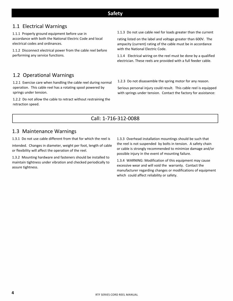
1.1 Electrical Warnings1.1.1 Properly ground equipment before use in accordance with both the National Electric Code and local electrical codes and ordinances.
1.1.2 Disconnect electrical power from the cable reel before performing any service functions.
1.1.3 Do not use cable reel for loads greater than the current
rating listed on the label and voltage greater than 600V. The ampacity (current) rating of the cable must be in accordance with the National Electric Code.
1.1.4 Electrical wiring on the reel must be done by a qualified electrician. These reels are provided with a full feeder cable.
1.2 Operational Warnings1.2.1 Exercise care when handling the cable reel during normal operation. This cable reel has a rotating spool powered by springs under tension.
1.2.2 Do not allow the cable to retract without restraining the retraction speed.
1.2.3 Do not disassemble the spring motor for any reason.
Serious personal injury could result. This cable reel is equipped with springs under tension. Contact the factory for assistance:
Call: 1-716-312-0088
1.3 Maintenance Warnings1.3.1 Do not use cable different from that for which the reel is
intended. Changes in diameter, weight per foot, length of cable or flexibility will affect the operation of the reel.
1.3.2 Mounting hardware and fasteners should be installed to maintain tightness under vibration and checked periodically to assure tightness.
1.3.3 Overhead installation mountings should be such that the reel is not suspended by bolts in tension. A safety chain or cable is strongly recommended to minimize damage and/or possible injury in the event of mounting failure.
1.3.4 WARNING: Modification of this equipment may cause excessive wear and will void the warranty. Contact the manufacturer regarding changes or modifications of equipment which could affect reliability or safety.
4
RTF SERIES CORD REEL MANUAL
1.0 Safety
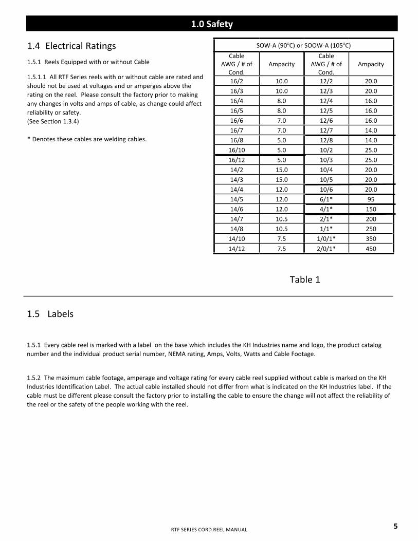
1.4 Electrical Ratings1.5.1 Reels Equipped with or without Cable
1.5.1.1 All RTF Series reels with or without cable are rated and should not be used at voltages and or amperges above the rating on the reel. Please consult the factory prior to making any changes in volts and amps of cable, as change could affect reliability or safety. (See Section 1.3.4)
* Denotes these cables are welding cables.
Table 1
1.5 Labels
1.5.1 Every cable reel is marked with a label on the base which includes the KH Industries name and logo, the product catalog number and the individual product serial number, NEMA rating, Amps, Volts, Watts and Cable Footage.
1.5.2 The maximum cable footage, amperage and voltage rating for every cable reel supplied without cable is marked on the KH Industries Identification Label. The actual cable installed should not differ from what is indicated on the KH Industries label. If the cable must be different please consult the factory prior to installing the cable to ensure the change will not affect the reliability of the reel or the safety of the people working with the reel.
SOW-A (90OC) or SOOW-A (105OC)Cable
AWG / # of Cond.
AmpacityCable
AWG / # of Cond.
Ampacity
16/2 10.0 12/2 20.016/3 10.0 12/3 20.016/4 8.0 12/4 16.016/5 8.0 12/5 16.016/6 7.0 12/6 16.016/7 7.0 12/7 14.016/8 5.0 12/8 14.0
16/10 5.0 10/2 25.016/12 5.0 10/3 25.014/2 15.0 10/4 20.014/3 15.0 10/5 20.014/4 12.0 10/6 20.014/5 12.0 6/1* 9514/6 12.0 4/1* 15014/7 10.5 2/1* 20014/8 10.5 1/1* 250
14/10 7.5 1/0/1* 35014/12 7.5 2/0/1* 450
5

RTF SERIES CORD REEL MANUAL
2.0 Installation
2.1 Application Types2.1.1 Stretch Applications
2.1.1.1 The cable is suspended without any intermediate support. Stretch reels generally require a line pull equal to two times the weight of the cable, which allows approximately 10% sag at full extension. On long applications where sag cannot be tolerated, it is sometimes desirable to put supports at intervals
of 5 to 10 feet.
2.1.2 Lift Applications
2.1.2.1 The cable is lifted vertically in lift applications. The reel is normally designed to handle only the total weight of the cable. Some lift applications may require ball stops to control the length of cable to be retracted.
2.1.3 Drag Applications
2.1.3.1 The reel is mounted on a stationary object and is required to drag the cable over the surface to the reel. The cable is supported by the ground or some type of cable tray. A ball stop may be required.
2.1.4 Retrieve Applications2.1.4.1 The reel is Mounted on the moving object and winds up or pays out the cable as the machine approaches or moves away from the fixed end. Retrieve applications can be elevated up to 4 feet from the cable support surface.
2.2 Mounting2.2.1 Standard Mounting
2.2.1.1 The reel may be mounted by bolting the base to any flat surface which is structurally sound enough to support it and the forces of winding and unwinding the cable.
2.2.1.2 The spool drum must rotate on a level horizontal axis.
2.2.1.3 Position the guide arm so that cable payout is perpendicular to the face of cable roller guide. The total cable deflection should not exceed 15° to either side of the center line of the spool.
2.2.1.4 If deflection is constant to either side of the reel and operation is impaired re-mount the reel.
2.2.1.5 If the angle of deflection exceeds 15° a Pivot Base should be used, otherwise excessive cable wear and unreliable operation will result.
2.2.1.6 A safety chain or cable is recommended for all overhead installations. Attach the safety chain using the 0.39 hole provided in the base. (See figure 2.3 on Page 7)
Fig. 2.2 Cable Deflection with Roller
6
RTF SERIES CORD REEL MANUAL
2.0 Installation
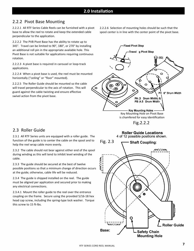
2.3 Roller Guide2.3.1 All RTF Series units are equipped with a roller guide. The function of the guide is to center the cable on the spool and to help the reel wrap cable more evenly.
2.3.2 The cable should not bear against either end of the spool during winding as this will tend to inhibit level winding of the cable.
2.3.3 The guide should be secured at the best of twelve possible positions so that a minimum change of direction occurs at the guide; otherwise, cable life will be reduced.
2.3.4 The guide is shipped installed on the reel. The guide must be aligned per application and secured prior to making any electrical connections.
2.3.4.1 Mount the roller guide to the reel over the entrance coupling on the frame. Secure using the provided 5/16-18 hex head cap screw, including the spring-type lock washer. Torque this screw to 15 ft-lbs.
2.2.2 Pivot Base Mounting2.2.2.1 All RTF Series Cable Reels can be furnished with a pivot base to allow the reel to rotate and keep the extended cable perpendicular to the application.
2.2.2.2 The PVB Pivot Base has the ability to rotate up to 345°. Travel can be limited to 90°, 180°, or 270° by installing an additional roll pin in the appropriate available hole. This Pivot Base is not suitable for applications requiring continuous rotation.
2.2.2.3 A pivot base is required in carousel or loop-track applications.
2.2.2.4 When a pivot base is used, the reel must be mounted horizontally (“ceiling” or “floor” mounted).
2.2.2.5 The Roller Guide should be mounted so the cable will travel perpendicular to the axis of rotation. This will guard against the cable twisting and ensure effective swivel action from the pivot base.
2.2.2.6 Selection of mounting holes should be such that the spool center is in line with the center point of the pivot base.
Fig.2.2.2
Fig. 2.3
Key Mounting Hole on Pivot Base is chamfered for easy identification
7
RTF SERIES CORD REEL MANUAL
2.0 Installation
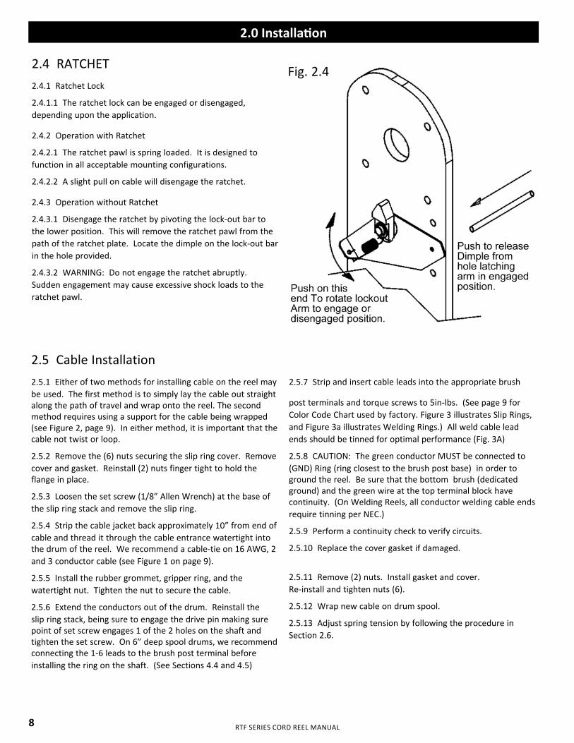
2.4 RATCHET2.4.1 Ratchet Lock
2.4.1.1 The ratchet lock can be engaged or disengaged, depending upon the application.
2.4.2 Operation with Ratchet
2.4.2.1 The ratchet pawl is spring loaded. It is designed to function in all acceptable mounting configurations.
2.4.2.2 A slight pull on cable will disengage the ratchet.
2.4.3 Operation without Ratchet
2.4.3.1 Disengage the ratchet by pivoting the lock-out bar to the lower position. This will remove the ratchet pawl from the path of the ratchet plate. Locate the dimple on the lock-out bar in the hole provided.
2.4.3.2 WARNING: Do not engage the ratchet abruptly. Sudden engagement may cause excessive shock loads to the ratchet pawl.
2.5 Cable Installation 2.5.1 Either of two methods for installing cable on the reel may be used. The first method is to simply lay the cable out straight along the path of travel and wrap onto the reel. The second method requires using a support for the cable being wrapped (see Figure 2, page 9). In either method, it is important that the cable not twist or loop.
2.5.2 Remove the (6) nuts securing the slip ring cover. Remove cover and gasket. Reinstall (2) nuts finger tight to hold the flange in place.
2.5.3 Loosen the set screw (1/8” Allen Wrench) at the base of the slip ring stack and remove the slip ring.
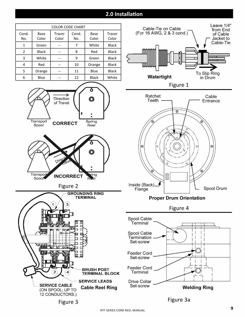
2.5.4 Strip the cable jacket back approximately 10” from end of cable and thread it through the cable entrance watertight into the drum of the reel. We recommend a cable-tie on 16 AWG, 2 and 3 conductor cable (see Figure 1 on page 9).
2.5.5 Install the rubber grommet, gripper ring, and the watertight nut. Tighten the nut to secure the cable.
2.5.6 Extend the conductors out of the drum. Reinstall the slip ring stack, being sure to engage the drive pin making sure point of set screw engages 1 of the 2 holes on the shaft and tighten the set screw. On 6” deep spool drums, we recommend connecting the 1-6 leads to the brush post terminal before installing the ring on the shaft. (See Sections 4.4 and 4.5)
2.5.7 Strip and insert cable leads into the appropriate brush
post terminals and torque screws to 5in-lbs. (See page 9 for Color Code Chart used by factory. Figure 3 illustrates Slip Rings, and Figure 3a illustrates Welding Rings.) All weld cable lead ends should be tinned for optimal performance (Fig. 3A)
2.5.8 CAUTION: The green conductor MUST be connected to (GND) Ring (ring closest to the brush post base) in order to ground the reel. Be sure that the bottom brush (dedicated ground) and the green wire at the top terminal block have continuity. (On Welding Reels, all conductor welding cable ends require tinning per NEC.)
2.5.9 Perform a continuity check to verify circuits.
2.5.10 Replace the cover gasket if damaged.
2.5.11 Remove (2) nuts. Install gasket and cover. Re-install and tighten nuts (6).
2.5.12 Wrap new cable on drum spool.
2.5.13 Adjust spring tension by following the procedure in Section 2.6.
Fig. 2.4
8
RTF SERIES CORD REEL MANUAL
2.0 Installation
COLOR CODE CHART
Cond. No.
Base Color
Tracer Color
Cond.No.
Base Color
Tracer Color
1 Green -- 7 White Black
2 Black -- 8 Red Black
3 White -- 9 Green Black
4 Red -- 10 Orange Black
5 Orange -- 11 Blue Black
6 Blue -- 12 Black White
Figure 2
Figure 3
Figure 1
Figure 4
Figure 3a9
RTF SERIES CORD REEL MANUAL
2.0 Installation
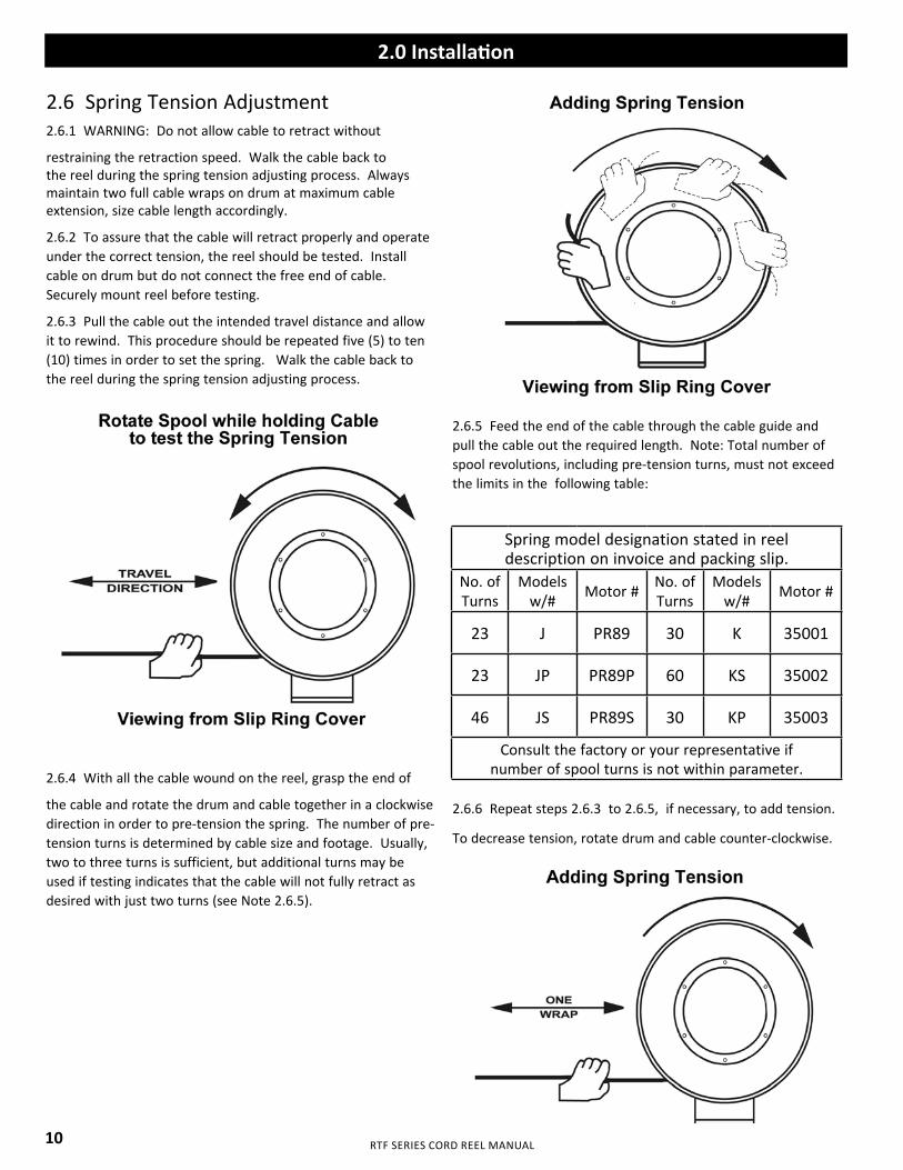
2.6 Spring Tension Adjustment2.6.1 WARNING: Do not allow cable to retract without
restraining the retraction speed. Walk the cable back to the reel during the spring tension adjusting process. Always maintain two full cable wraps on drum at maximum cable extension, size cable length accordingly.
2.6.2 To assure that the cable will retract properly and operate under the correct tension, the reel should be tested. Install cable on drum but do not connect the free end of cable. Securely mount reel before testing.
2.6.3 Pull the cable out the intended travel distance and allow it to rewind. This procedure should be repeated five (5) to ten (10) times in order to set the spring. Walk the cable back to the reel during the spring tension adjusting process.
2.6.4 With all the cable wound on the reel, grasp the end of
the cable and rotate the drum and cable together in a clockwise direction in order to pre-tension the spring. The number of pre-tension turns is determined by cable size and footage. Usually, two to three turns is sufficient, but additional turns may be used if testing indicates that the cable will not fully retract as desired with just two turns (see Note 2.6.5).
2.6.5 Feed the end of the cable through the cable guide and pull the cable out the required length. Note: Total number of spool revolutions, including pre-tension turns, must not exceed the limits in the following table:
2.6.6 Repeat steps 2.6.3 to 2.6.5, if necessary, to add tension.
To decrease tension, rotate drum and cable counter-clockwise.
Spring model designation stated in reeldescription on invoice and packing slip.
No. ofTurns
Modelsw/# Motor # No. of
TurnsModels
w/# Motor #
23 J PR89 30 K 35001
23 JP PR89P 60 KS 35002
46 JS PR89S 30 KP 35003
Consult the factory or your representative if number of spool turns is not within parameter.
10
RTF SERIES CORD REEL MANUAL
2.0 Installation
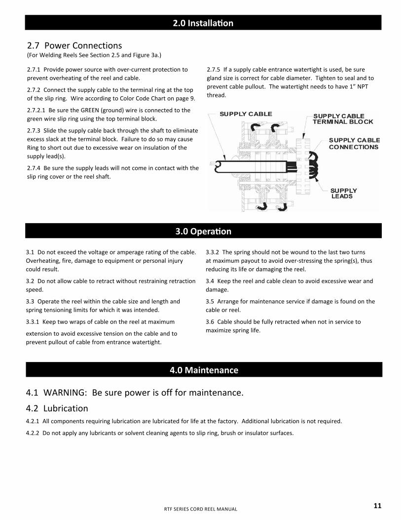
2.7 Power Connections (For Welding Reels See Section 2.5 and Figure 3a.)
2.7.1 Provide power source with over-current protection to prevent overheating of the reel and cable.
2.7.2 Connect the supply cable to the terminal ring at the top of the slip ring. Wire according to Color Code Chart on page 9.
2.7.2.1 Be sure the GREEN (ground) wire is connected to the green wire slip ring using the top terminal block.
2.7.3 Slide the supply cable back through the shaft to eliminate excess slack at the terminal block. Failure to do so may cause Ring to short out due to excessive wear on insulation of the supply lead(s).
2.7.4 Be sure the supply leads will not come in contact with the slip ring cover or the reel shaft.
2.7.5 If a supply cable entrance watertight is used, be sure gland size is correct for cable diameter. Tighten to seal and to prevent cable pullout. The watertight needs to have 1” NPT thread.
3.1 Do not exceed the voltage or amperage rating of the cable. Overheating, fire, damage to equipment or personal injury could result.
3.2 Do not allow cable to retract without restraining retraction speed.
3.3 Operate the reel within the cable size and length and spring tensioning limits for which it was intended.
3.3.1 Keep two wraps of cable on the reel at maximum
extension to avoid excessive tension on the cable and to prevent pullout of cable from entrance watertight.
3.3.2 The spring should not be wound to the last two turns at maximum payout to avoid over-stressing the spring(s), thus reducing its life or damaging the reel.
3.4 Keep the reel and cable clean to avoid excessive wear and damage.
3.5 Arrange for maintenance service if damage is found on the cable or reel.
3.6 Cable should be fully retracted when not in service to maximize spring life.
4.1 WARNING: Be sure power is off for maintenance.
4.2 Lubrication4.2.1 All components requiring lubrication are lubricated for life at the factory. Additional lubrication is not required.
4.2.2 Do not apply any lubricants or solvent cleaning agents to slip ring, brush or insulator surfaces.
3.0 Operation
4.0 Maintenance
11

RTF SERIES CORD REEL MANUAL
4.0 Maintenance
4.3 Inspections4.3.1 Periodically check the reel for any loose or missing
fasteners. Tighten or replace as necessary.
4.3.2 The slip ring assembly should be checked periodically as follows:
4.3.2.1 Clean to remove dust and dirt from the slip ring housing
area and all slip ring assembly and brush surfaces.
4.3.2.2 Brushes should be centered on slip rings and brush
springs should be seated in terminal post grooves. Terminal screw connections should be tight. Check for excessive brush wear. Replace brushes as necessary.
4.3.3 Inspect cable for damage or wear which would make it unsafe to use.
4.4 Slip Ring Replacement4.4.1 The slip ring assembly should be replaced, not rebuilt, if it becomes damaged.
4.4.2 Follow steps 4.5.5 through 4.5.8 to remove the slip ring assembly. 4.4.3 Carefully and thoroughly clean the inside of the reel drum and the slip ring cover.
4.4.4 Follow steps 4.5.5 through 4.5.8 in reverse order to install the new slip ring stack.
4.4.5 Replace cover Gasket if damaged.
12
RTF SERIES CORD REEL MANUAL
4.0 Maintenance
4.5 Cable Replacement4.5.1 Replacement cable should be the same size and length as existing cable. Any variations to cable specifications should be pre-
approved by the factory.
4.5.2 Disconnect all electrical service to the reel before replacing the cable. Follow Lock-Out/Tag-Out procedures as outlined by
OSHA.
4.5.3 Disconnect the terminal outboard end of the cable and allow cable to retract onto spool. Ensure all spring tension is off by manually rotating the spool.
4.5.4 Remove the cable from the spool by looping it over the spool flange and slip ring cover. Make sure the cable end is through the cable guide.
4.5.5 Remove the six (6) nuts holding the slip ring cover. Remove cover and gasket. Reinstall (2) nuts finger tight to hold the flange in place.
4.5.6 Loosen the supply cable terminal screws (set-screws on Welding Reel Ring) and release the supply cable leads from the terminal block of slip ring.
4.5.7 Loosen the brush post terminal screws (set-screws on Welding Reel Ring) and release the cable leads.
4.5.8 Use 1/8” Allen Wrench to loosen the set screw and remove the slip ring stack.
4.5.9 Remove the watertight nut, gripping ring, bushing and the cable to be replaced.
4.5.10 Obtain the replacement cable of the correct size and length and strip the cable end to match the old cable.
4.5.11 Carefully and thoroughly clean the inside surfaces of both flanges and the drum.
4.5.12 Follow instructions 2.5.4 through 2.5.13 to install the replacement cable, taking care to avoid twisting the cable while winding it onto the reel. Care should also be taken to match the color coded cable leads. (For additional information on wiring, see Section 2.7 Power Connections.)
4.6 Spring Motor Replacement4.6.1 CAUTION: Do not open the spring motor or personal injury may result.
4.6.2 The spring replacement process is determined by the spring configuration and cannot be performed in the field. The entire spring motor assembly must be replaced as a unit. Contact KH industries to identify spring.
4.6.3 Disconnect all electrical power to the reel before beginning any maintenance or service.
4.6.4 Remove the slip ring from the shaft by following the procedure outlined in Section 4.4.
4.6.5 Remove the (4) nuts in the bottom of the drum. This may require removing the watertight in order to access all nuts. Lift the cable, drum, and front flange together and set aside.
4.6.6 Remove the shaft coupling.
4.6.7 Remove the spring motor by unscrewing the shaft from the mounting base.
4.6.8 Remove packing material from the replacement spring motor and attach it to the mounting base.
4.6.9 Re-assemble spring reel in reverse order with the new spring motor. Note the following:
A. Replace gaskets as needed.
B. Ratchet must be in the deactivated position (see figure for Section 2.4).
C. Shaft must be fully seated on base before installing coupling and watertight.
D. Reactivate ratchet to ensure proper alignment.
E. Verify drum and ratchet teeth orientation per Figure 4, page 9.
4.6.10 Reassemble the reel by following the instructions in Section 2.5.6 through 2.5.11; refer to Color Code Chart on page 9.
4.6.11 Adjust spring tension by following the procedure in Section 2.6.
13
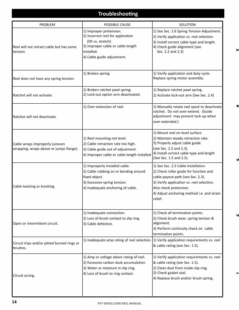
RTF SERIES CORD REEL MANUAL
Troubleshooting
PROBLEM POSSIBLE CAUSE SOLUTION
Reel will not retract cable but has some tension.
1) Improper pretension.2) Incorrect reel for application (lift vs. stretch)3) Improper cable or cable length installed.4) Cable guide adjustment.
1) See Sec. 2.6 Spring Tension Adjustment.2) Verify application vs. reel selection.3) Install correct cable type and length.4) Check guide alignment (see Sec. 2.2 and 2.3)
Reel does not have any spring tension.1) Broken spring. 1) Verify application and duty cycle.
Replace spring motor assembly.
Ratchet will not activate.1) Broken ratchet pawl spring.2) Lock-out option arm deactivated.
1) Replace ratchet pawl spring.2) Activate lock-out arm (See Sec. 2.4)
Ratchet will not deactivate.
1) Over-extension of reel. 1) Manually rotate reel spool to deactivate ratchet. Do not over-extend. (Guide adjustment may prevent lock-up when over-extended.)
Cable wraps improperly (uneven wrapping, wraps above or jumps flange).
1) Reel mounting not level.2) Cable retraction rate too high.3) Cable guide out of adjustment.4) Improper cable or cable length installed
1) Mount reel on level surface.2) Maintain steady retraction rate.3) Properly adjust cable guide (see Sec. 2.2 and 2.3).4) Install correct cable type and length (See Sec. 1.5 and 2.5).
Cable twisting or knotting.
1) Improperly installed cable.2) Cable rubbing on or bending around fixed object.3) Excessive spring tension.4) Inadequate anchoring of cable.
1) See Sec. 2.5 Cable Installation.2) Check roller guide for function and cable payout path (see Sec. 2.3).3) Verify application vs. reel selection. Also check pretension.4) Adjust anchoring method i.e. and strain relief.
Open or intermittent circuit.
1) Inadequate connection.2) Loss of brush contact to slip ring.3) Cable defective.
1) Check all termination points.2) Check brush wear, spring tension & alignment.3) Perform continuity check on cable termination points.
Circuit trips and/or pitted burned rings or brushes.
1) Inadequate amp rating of reel selection. 1) Verify application requirements vs. reel & cable rating (see Sec. 1.5).
Circuit arcing.
1) Amp or voltage above rating of reel.2) Excessive carbon dusk accumulation.3) Water or moisture in slip ring.4) Loss of brush to ring contact.
1) Verify application requirements vs. reel & cable rating (see Sec. 1.5).2) Clean dust from inside slip ring.3) Check gasket seal.4) Replace brush and/or brush spring.
14
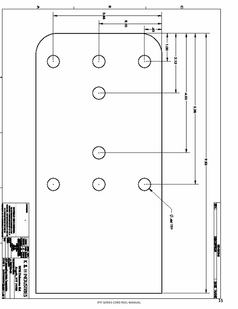
RTF SERIES CORD REEL MANUAL 15

REELTUFF™ RTF SERIES CORD REEL MANUAL © 2020 KH Industries
www.khindustries.com
KH Industries
Customer & Technical Support
Phone: 716-312-0088
Fax: 716-312-0028
www.khindustries.com
KH200-02563_REV-A

SITE PREP GUIDE
October 16, 2020
Copyright 2020
Lincoln Electric Cutting Systems
TORCHMATE®4400 | 4800 | 4510

Page iiTorchmate 4400/4800/4510
Page iiiSite Prep Guide
Unpacking the machine ivSite Preparation vGrounding the Machine viPower/Water/Air Requirements viiPower Supply Requirements viiiCommissioning, Operations, Software Training ixOptional Pre-Onsite Training xTechnical Support xiCustomer Assistance Policy xii
TABLE OF CONTENTS
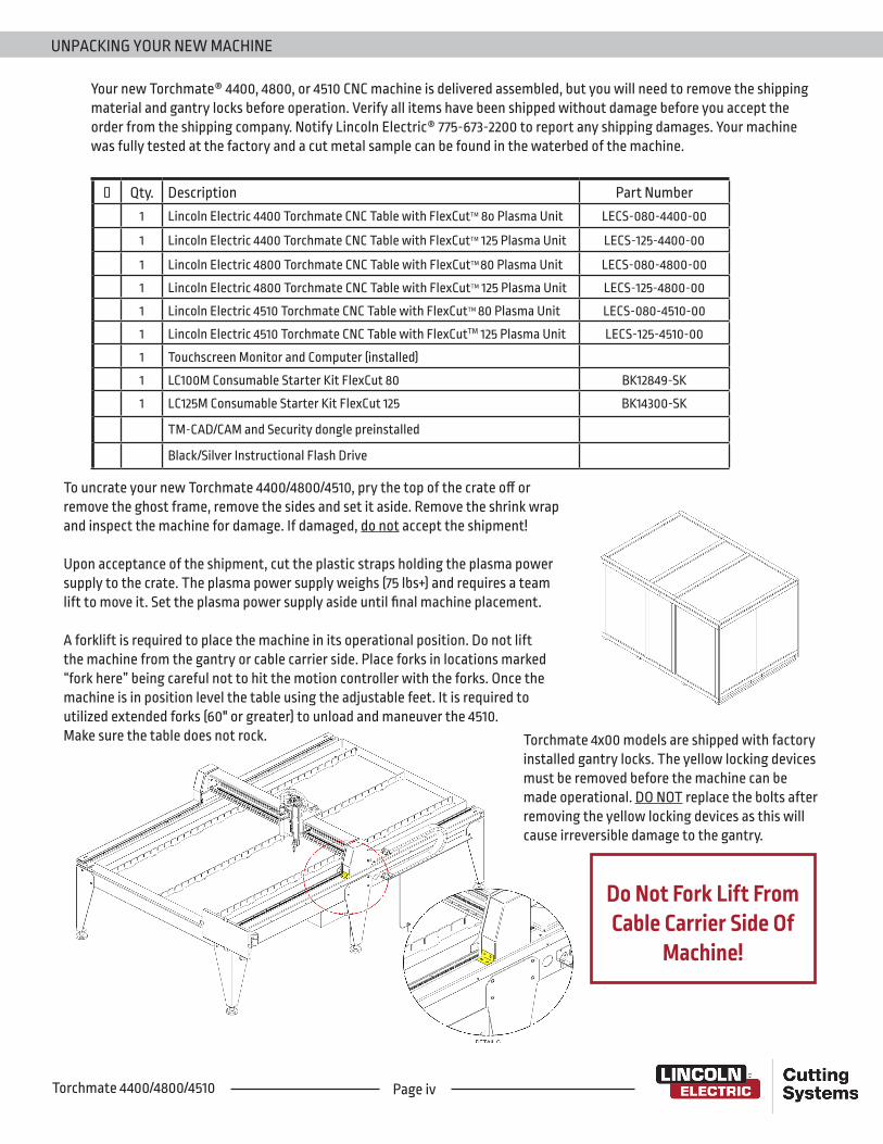
Page ivTorchmate 4400/4800/4510
Your new Torchmate® 4400, 4800, or 4510 CNC machine is delivered assembled, but you will need to remove the shipping material and gantry locks before operation. Verify all items have been shipped without damage before you accept the order from the shipping company. Notify Lincoln Electric® 775-673-2200 to report any shipping damages. Your machine was fully tested at the factory and a cut metal sample can be found in the waterbed of the machine.
Qty. Description Part Number1 Lincoln Electric 4400 Torchmate CNC Table with FlexCutTM 8o Plasma Unit LECS-080-4400-00
1 Lincoln Electric 4400 Torchmate CNC Table with FlexCutTM 125 Plasma Unit LECS-125-4400-00
1 Lincoln Electric 4800 Torchmate CNC Table with FlexCutTM 80 Plasma Unit LECS-080-4800-00
1 Lincoln Electric 4800 Torchmate CNC Table with FlexCutTM 125 Plasma Unit LECS-125-4800-00
1 Lincoln Electric 4510 Torchmate CNC Table with FlexCutTM 80 Plasma Unit LECS-080-4510-00
1 Lincoln Electric 4510 Torchmate CNC Table with FlexCutTM 125 Plasma Unit LECS-125-4510-00
1 Touchscreen Monitor and Computer (installed)
1 LC100M Consumable Starter Kit FlexCut 80 BK12849-SK
1 LC125M Consumable Starter Kit FlexCut 125 BK14300-SK
TM-CAD/CAM and Security dongle preinstalled
Black/Silver Instructional Flash Drive
To uncrate your new Torchmate 4400/4800/4510, pry the top of the crate off or remove the ghost frame, remove the sides and set it aside. Remove the shrink wrap and inspect the machine for damage. If damaged, do not accept the shipment!
Upon acceptance of the shipment, cut the plastic straps holding the plasma power supply to the crate. The plasma power supply weighs (75 lbs+) and requires a team lift to move it. Set the plasma power supply aside until final machine placement.
A forklift is required to place the machine in its operational position. Do not lift the machine from the gantry or cable carrier side. Place forks in locations marked “fork here” being careful not to hit the motion controller with the forks. Once the machine is in position level the table using the adjustable feet. It is required to utilized extended forks (60" or greater) to unload and maneuver the 4510. Make sure the table does not rock. Torchmate 4x00 models are shipped with factory
installed gantry locks. The yellow locking devices must be removed before the machine can be made operational. DO NOT replace the bolts after removing the yellow locking devices as this will cause irreversible damage to the gantry.
Do Not Fork Lift From Cable Carrier Side Of
Machine!
UNPACKING YOUR NEW MACHINE
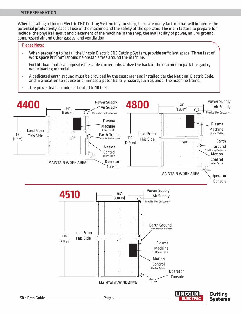
When installing a Lincoln Electric CNC Cutting System in your shop, there are many factors that will influence the potential productivity, ease of use of the machine and the safety of the operator. The main factors to prepare for include: the physical layout and placement of the machine in the shop, the availability of power, an EMI ground, compressed air and other gasses, and ventilation.
Please Note:
• When preparing to install the Lincoln Electric CNC Cutting System, provide sufficient space. Three feet of work space (914 mm) should be obstacle free around the machine.
• Forklift load material opposite the cable carrier only. Utilize the back of the machine to park the gantry while loading material.
• A dedicated earth ground must be provided by the customer and installed per the National Electric Code, and in a location to reduce or eliminate a potential trip hazard, such as under the machine frame.
• The power lead included is limited to 10 feet.
4400 74”
67”Load From This Side
OperatorConsole
PlasmaMachineUnder Table
Power SupplyAir Supply
Provided by Customer
Earth GroundProvided by Customer
MAINTAIN WORK AREA
MotionControl
Under Table
(1.7 m)
(1.88 m)4800 74”
(1.88 m)
114”Load From This Side
OperatorConsole
MotionControl
Under Table
PlasmaMachineUnder Table
Earth Ground
Provided by Customer
Power SupplyAir Supply
Provided by Customer
MAINTAIN WORK AREA
(2.9 m)
4510
Load From This Side
MAINTAIN WORK AREA
138”(3.5 m)
86”(2.18 m)
PlasmaMachineUnder Table
OperatorConsole
MotionControl
Under Table
Earth GroundProvided by Customer
Power SupplyAir Supply
Provided by Customer
SITE PREPARATION
Page vSite Prep Guide
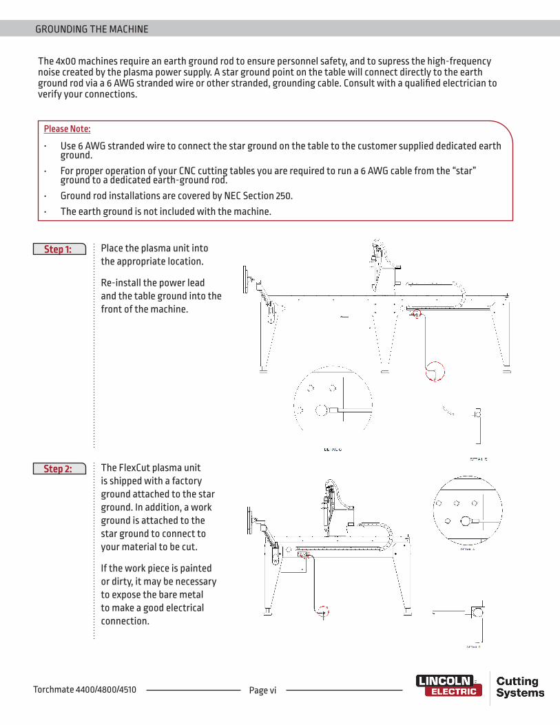
Page viTorchmate 4400/4800/4510
The 4x00 machines require an earth ground rod to ensure personnel safety, and to supress the high-frequency noise created by the plasma power supply. A star ground point on the table will connect directly to the earth ground rod via a 6 AWG stranded wire or other stranded, grounding cable. Consult with a qualified electrician to verify your connections.
Step 1: Place the plasma unit into the appropriate location.
Re-install the power lead and the table ground into the front of the machine.
Step 2: The FlexCut plasma unit is shipped with a factory ground attached to the star ground. In addition, a work ground is attached to the star ground to connect to your material to be cut.
If the work piece is painted or dirty, it may be necessary to expose the bare metal to make a good electrical connection.
Please Note:
• Use 6 AWG stranded wire to connect the star ground on the table to the customer supplied dedicated earth ground.
• For proper operation of your CNC cutting tables you are required to run a 6 AWG cable from the “star” ground to a dedicated earth-ground rod.
• Ground rod installations are covered by NEC Section 250.• The earth ground is not included with the machine.
GROUNDING THE MACHINE
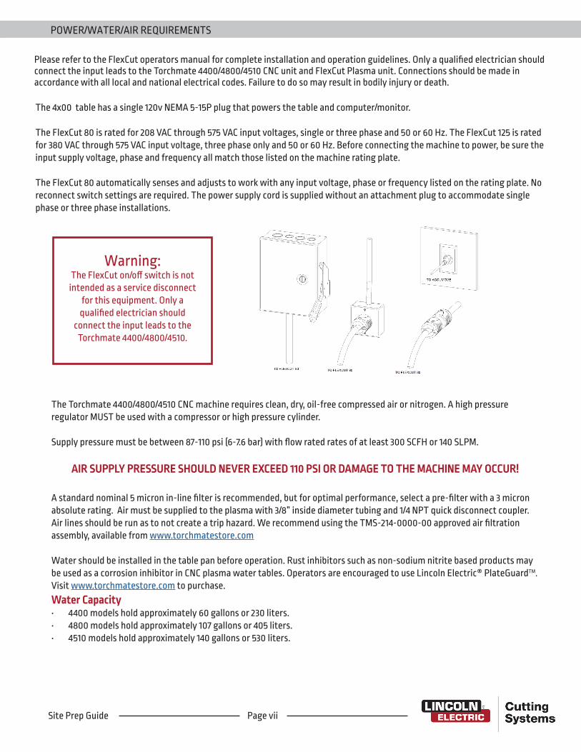
Please refer to the FlexCut operators manual for complete installation and operation guidelines. Only a qualified electrician should connect the input leads to the Torchmate 4400/4800/4510 CNC unit and FlexCut Plasma unit. Connections should be made in accordance with all local and national electrical codes. Failure to do so may result in bodily injury or death.
The 4x00 table has a single 120v NEMA 5-15P plug that powers the table and computer/monitor.
The FlexCut 80 is rated for 208 VAC through 575 VAC input voltages, single or three phase and 50 or 60 Hz. The FlexCut 125 is rated for 380 VAC through 575 VAC input voltage, three phase only and 50 or 60 Hz. Before connecting the machine to power, be sure the input supply voltage, phase and frequency all match those listed on the machine rating plate.
The FlexCut 80 automatically senses and adjusts to work with any input voltage, phase or frequency listed on the rating plate. No reconnect switch settings are required. The power supply cord is supplied without an attachment plug to accommodate single phase or three phase installations.
Warning:The FlexCut on/off switch is not intended as a service disconnect
for this equipment. Only a qualified electrician should
connect the input leads to the Torchmate 4400/4800/4510.
The Torchmate 4400/4800/4510 CNC machine requires clean, dry, oil-free compressed air or nitrogen. A high pressure regulator MUST be used with a compressor or high pressure cylinder.
Supply pressure must be between 87-110 psi (6-7.6 bar) with flow rated rates of at least 300 SCFH or 140 SLPM.
AIR SUPPLY PRESSURE SHOULD NEVER EXCEED 110 PSI OR DAMAGE TO THE MACHINE MAY OCCUR!
A standard nominal 5 micron in-line filter is recommended, but for optimal performance, select a pre-filter with a 3 micron absolute rating. Air must be supplied to the plasma with 3/8” inside diameter tubing and 1/4 NPT quick disconnect coupler. Air lines should be run as to not create a trip hazard. We recommend using the TMS-214-0000-00 approved air filtration assembly, available from www.torchmatestore.com
Water should be installed in the table pan before operation. Rust inhibitors such as non-sodium nitrite based products may be used as a corrosion inhibitor in CNC plasma water tables. Operators are encouraged to use Lincoln Electric® PlateGuardTM. Visit www.torchmatestore.com to purchase.Water Capacity • 4400 models hold approximately 60 gallons or 230 liters.• 4800 models hold approximately 107 gallons or 405 liters. • 4510 models hold approximately 140 gallons or 530 liters.
POWER/WATER/AIR REQUIREMENTS
Page viiSite Prep Guide

Page viiiTorchmate 4400/4800/4510
TORCHMATE 4400/4800/4510 POWER SUPPLY SPECIFICATIONS
CHOOSE YOUR POWERCUT CAPACITY
FLEXCUT® 125
1”
FLEXCUT® 80
3/4”CUT CAPACITY
Product Name Input Power Voltage/Phase/Hz
Rated InputCurrent/Voltage/Duty
Cycle
Air Pressure Required Production Cutting Capacity
FlexCut 80
208/230/400/460/5753PH 50/60Hz
60A/140V /100%80A/140V /80%
87-109 PSI (6.0 - 7.5 Bar)
Mild Steel 3/4” (20 mm)
230 1PH 50/60Hz 60A/140V /100%80A/140V /80% Stainless 5/8”
(16 mm)
200-208 1PH 50/60Hz 60A/140V /100%80A/140V /80% Aluminum 5/8”
(16 mm)
FlexCut 125 308-400-415/460/575V3PH 50/60Hz 125 A/125V /100% 90-120 PSI
(6.2 - 8.2 Bar)
Mild Steel 1.0”(25mm)
Stainless 3/4”(20 mm)
Aluminum 1.0” (25 mm)
*Cut speeds for best quality, production results may vary.
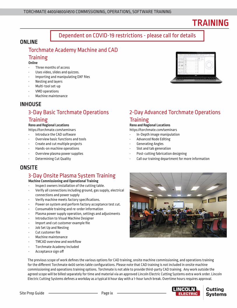
Page ixSite Prep Guide
TRAINING
2-Day Advanced Torchmate Operations TrainingReno and Regional Locationshttps://torchmate.com/seminars• In-Depth image manipulation• Advanced Node Editing• Generating Angles• Slot and tab generation• Post-cutting fabrication designing• Call our training department for more information
The previous scope of work defines the various options for CAD training, onsite machine commissioning, and operations training for the different Torchmate 4x00 series table configurations. Please note that CAD training is not included in onsite machine commissioning and operations training options. Torchmate is not able to provide third-party CAD training. Any work outside the agreed scope will be billed separately for time and material via an approved Lincoln Electric Cutting Systems extra work order. Lincoln Electric Cutting Systems defines a workday as a typical 8 hour day with a 1-hour lunch break. Overtime hours requires approval.
3-Day Basic Torchmate Operations TrainingReno and Regional Locationshttps://torchmate.com/seminars• Introduce the CAD software• Overview basic functions and tools• Create and cut multiple projects• Hands-on machine operations• Overview plasma power supplies• Determining Cut Quality
3-Day Onsite Plasma System TrainingMachine Commissioning and Operational Training• Inspect owners installation of the cutting table. • Verify all connections including ground, gas supply, electrical
connections and power supply• Verify machine meets factory specifications.• Power on system and perform factory acceptance test cut.• Consumable training and re-order information• Plasma power supply operation, settings and adjustments• Introduction to Visual Machine Designer• Import and cut customer example file• Job Set Up and Nesting• Cut customer file• Machine maintenance• TMCAD overview and workflow• Torchmate Academy Included• Acceptance sign off
Torchmate Academy Machine and CAD TrainingOnline• Three months of access• Uses video, slides and quizzes.• Importing and manipulating DXF files• Nesting and layers• Multi-tool set-up• VMD operations• Machine maintenance
TORCHMATE 4400/4800/4510 COMMISSIONING, OPERATIONS, SOFTWARE TRAINING
Dependent on COVID-19 restrictions - please call for detailsONLINE
INHOUSE
ONSITE
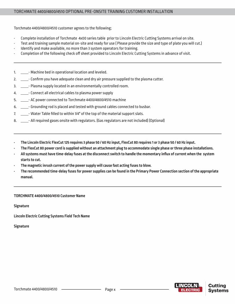
Page xTorchmate 4400/4800/4510
Torchmate 4400/4800/4510 customer agrees to the following;
• Complete installation of Torchmate 4x00 series table prior to Lincoln Electric Cutting Systems arrival on site. • Test and training sample material on-site and ready for use ( Please provide the size and type of plate you will cut.)• Identify and make available, no more than 3 system operators for training. • Completion of the following check off sheet provided to Lincoln Electric Cutting Systems in advance of visit.
1. - Machine bed in operational location and leveled.
2. - Confirm you have adequate clean and dry air pressure supplied to the plasma cutter.
3. - Plasma supply located in an environmentally controlled room.
4. - Connect all electrical cables to plasma power supply
5. - AC power connected to Torchmate 4400/4800/4510 machine
6. - Grounding rod is placed and tested with ground cables connected to busbar.
7. - Water Table filled to within 1/4" of the top of the material support slats.
8. - All required gases onsite with regulators. (Gas regulators are not included) (Optional)
TORCHMATE 4400/4800/4510 OPTIONAL PRE-ONSITE TRAINING CUSTOMER INSTALLATION
TORCHMATE 4400/4800/4510 Customer Name
Signature
Lincoln Electric Cutting Systems Field Tech Name
Signature
• The Lincoln Electric FlexCut 125 requires 3 phase 50 / 60 Hz input, FlexCut 80 requires 1 or 3 phase 50 / 60 Hz input.• The FlexCut 80 power cord is supplied without an attachment plug to accommodate single phase or three phase installations.• All systems must have time-delay fuses at the disconnect switch to handle the momentary influx of current when the system
starts to cut.• The magnetic inrush current of the power supply will cause fast acting fuses to blow.• The recommended time-delay fuses for power supplies can be found in the Primary Power Connection section of the appropriate
manual.

Lincoln Electric Cutting Systems provides a number of technical support opportunities with the purchase of your new 4400, 4800, or 4510 Torchmate CNC cutting machine. The following is a brief outline of available options. Onsite visits are available at an additional cost, call 775-673-2200 for additional information.
• Phone SupportPhone support is available Monday – Friday 7:00am-4:00pm Pacific Time. Lincoln Electric will make every effort to handle phone calls in a timely manner, but due to the nature of machine diagnoses and the varied capabilities of machine operators, we cannot guarantee hold times for phone-in technical support. Technical support includes machine assembly, troubleshooting, configuration, and quality-related issues. Operational training is not included in phone technical support.
• E-mailLincoln Electric will return e-mail to the [email protected] e-mail address within 24 hours Monday-Friday.
• Webinars Lincoln Electric provides live webinars from time to time to assist customers in the optimization and operation of CNC systems. Please subscribe to our newsletter for dates and times. http://torchmate.com/webinars
• Torchmate TrainingLincoln Electric provides a number of training opportunities at our Reno, Nevada campus. Please call 775-673-2200 for details or visit http://torchmate.com/training
• Torchmate AcademyTorchmate Academy is a high definition, detailed video walkthrough covering every aspect of your Torchmate table including setup, operation, detailed Torchmate CAD videos, and maintenance. Call (775) 673-2200 or visit the website to learn more.http://torchmate.com/academy
• Torchmate YouTube Channel: Lincoln Electric provides a wide selection of how to tutorials on our YouTube page. https://www.youtube.com/user/torchmatedotcom
• Torchmate Store A variety of consumables, parts, and accessories can easily be purchased online through the Torchmate store. Visit https://www.torchmatestore.com/ to learn more.
TECHNICAL SUPPORT | ON-SITE SERVICE
Page xiSite Prep Guide
Page xiiTorchmate 4400/4800/4510
The business of The Lincoln Electric Company is manufacturing and selling high quality welding equipment, consumables, and cutting equipment. Our challenge is to meet the needs of our customers and to exceed their expectations. On occasion, purchasers may ask Lincoln Electric Cutting Systems for advice or information about their use of our products. We respond to our customers based on the best information in our possession at that time. Lincoln Electric Cutting Systems is not in a position to warrant or guarantee such advice, and assumes no liability, with respect to such information or advice. We expressly disclaim any warranty of any kind, including any warranty of fitness for any customer’s particular purpose, with respect to such information or advice. As a matter of practical consideration, we also cannot assume any responsibility for updating or correcting any such information or advice once it has been given, nor does the provision of information or advice create, expand or alter any warranty with respect to the sale of our products.
Lincoln Electric Cutting Systems is a responsive manufacturer, but the selection and use of specific products sold by Lincoln Electric Cutting Systems is solely within the control of, and remains the sole responsibility of the customer. Many variables beyond the control of Lincoln Electric Cutting Systems affect the results obtained in applying these types of fabrication methods and service requirements.
Subject to Change – This information is accurate to the best of our knowledge at the time of printing. Please refer to www.torchmate.com for any updated information.
1170 Trademark Suite 101 • Reno, NV • 89521 • U.S.APhone: +1.775.673.2200 • www.torchmate.comUS70-100720SC1-02
CUSTOMER ASSISTANCE POLICY