fire fighting equipment - firetec international ltd
TRANSCRIPT
1-1/2” BS 336 male
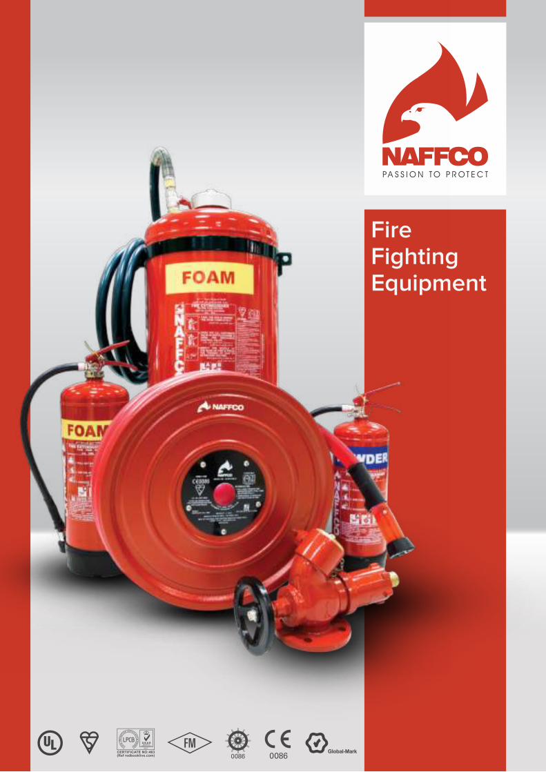
FireFighting Equipment

www.naffco.com2
Contents
Fire Extinguishers
CO2 Portable Fire Extinguishers (UL Listed) .............................................................................................................................................. 6
CO2 Portable Fire Extinguishers (Kite Mark, LPCB) ................................................................................................................................ 7
CO2 Mobile Fire Extinguishers ......................................................................................................................................................................... 8
CO2 High Pressure Cylinders ........................................................................................................................................................................... 9
Dry Powder Fire Extinguishers (UL Listed) ................................................................................................................................................. 10
ABC Dry Powder Portable Fire Extinguishers (Kite Mark, LPCB) ...................................................................................................... 11
ABC Dry Powder Mobile Fire Extinguisher ................................................................................................................................................. 12
Water Portable Fire Extinguishers (Kite Mark, LPCB) ............................................................................................................................. 13
Eco Barid Foam Fire Extinguishers (LPCB) ................................................................................................................................................. 14
Foam Portable Fire Extinguishers (Kite Mark, LPCB) ............................................................................................................................. 15
Foam Mobile Fire Extinguishers ...................................................................................................................................................................... 16
Clean Agent Fire Extinguishers (Ul Listed) ................................................................................................................................................. 16
Clean Agent Fire Extinguishers (LPCB) ........................................................................................................................................................ 17
Wet Chemical Fire Extinguishers (Kite Mark, LPCB) ............................................................................................................................... 18
Fire Hose Reels & Accessories
Semi-Rigid Reel Hose .......................................................................................................................................................................................... 20
Fire Hose Reel With Semi-Rigid Hose .......................................................................................................................................................... 21
Lock Shield Valve ................................................................................................................................................................................................... 24
Fire Hoses
Single Jacket Hose ............................................................................................................................................................................................... 25
Double Jacket Fire Hose .................................................................................................................................................................................... 27
PU Lined Hose ........................................................................................................................................................................................................ 28
Fire Hose Rack Assembly .................................................................................................................................................................................. 29
Fire CabinetsCabinet for Fire Hose Reel, Fire Equipment And Breeching Inlet ................................................................................. 30
Through-Penetration Fire-Stop Systems ........................................................................................................................................ 32
Delivery Hose Coupling ................................................................................................................................................................. 35
www.naffco.com 3
Branch Pipe Handheld Branch Pipe ......................................................................................................................................................................................... 36
Standard Branch Pipe .......................................................................................................................................................................................... 37
Angle Hose Valve ..................................................................................................................................................................................... 37
Valves & Riser Equipment
Oblique Landing Valve, Flanged Inlet ........................................................................................................................................................... 38
Oblique Landing Valve, Male Threaded Inlet ............................................................................................................................................ 39
Pressure Reducing Valve, Flanged Inlet ...................................................................................................................................................... 40
4"X2 Way Breeching Inlet .................................................................................................................................................................................. 41
6"X4 Way Breeching Inlet .................................................................................................................................................................................. 42
Fire HydrantsDry Pillar Fire Hydrants (Kitemark, LPCB) .................................................................................................................................................... 43
Dry Pillar Fire Hydrants (UL Listed, FM Approved) ................................................................................................................................. 45
Wet Type Fire Hydrants ....................................................................................................................................................................................... 48
Under Ground Hydrant ........................................................................................................................................................................................ 50
Fire Blankets ...................................................................................................................................................................................................... 52
Fire Pumps
Horizontal End Suction Pumps ........................................................................................................................................................................ 53
Horizontal Split Case Pumps ............................................................................................................................................................................. 54
Vertical Turbine Pumps ........................................................................................................................................................................................ 55
Pre-Piped Vertical & Horizontal Bladder Tank
Horizontal Foam Bladder Tank ......................................................................................................................................................................... 58
Vertical Foam Bladder Tank .............................................................................................................................................................................. 60
Foam StationFoam Station with Hose Reel Unit .................................................................................................................................................................. 62
Foam Station ............................................................................................................................................................................................................ 64
Above Ground Storage Tank ................................................................................................................................................. 66
Fire Rated Doors ......................................................................................................................................................................................... 67
www.naffco.com6
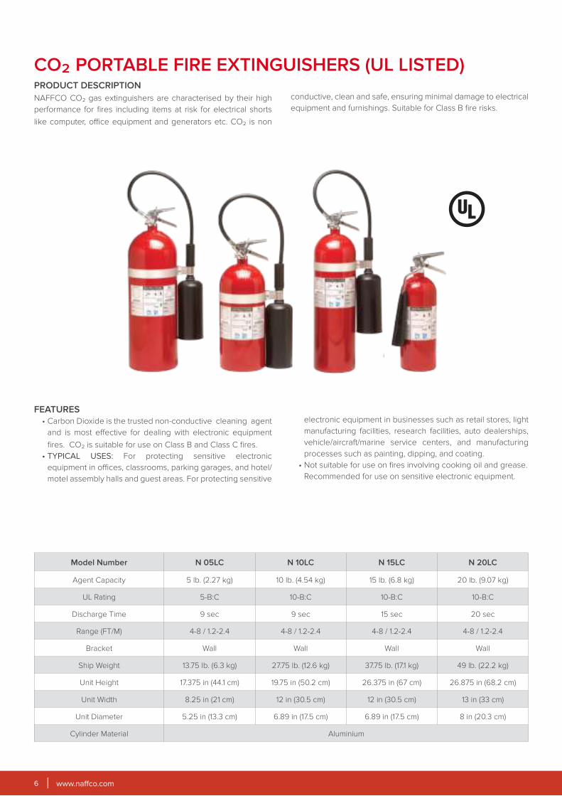
CO2 PORTABLE FIRE EXTINGUISHERS (UL LISTED)PRODUCT DESCRIPTION
NAFFCO CO2 gas extinguishers are characterised by their high
performance for fires including items at risk for electrical shorts
like computer, office equipment and generators etc. CO2 is non
conductive, clean and safe, ensuring minimal damage to electrical
equipment and furnishings. Suitable for Class B fire risks.
FEATURES
• Carbon Dioxide is the trusted non-conductive cleaning agent
and is most effective for dealing with electronic equipment
fires. CO2 is suitable for use on Class B and Class C fires.
• TYPICAL USES: For protecting sensitive electronic
equipment in offices, classrooms, parking garages, and hotel/
motel assembly halls and guest areas. For protecting sensitive
electronic equipment in businesses such as retail stores, light
manufacturing facilities, research facilities, auto dealerships,
vehicle/aircraft/marine service centers, and manufacturing
processes such as painting, dipping, and coating.
• Not suitable for use on fires involving cooking oil and grease.
Recommended for use on sensitive electronic equipment.
Model Number N 05LC N 10LC N 15LC N 20LC
Agent Capacity 5 lb. (2.27 kg) 10 lb. (4.54 kg) 15 lb. (6.8 kg) 20 lb. (9.07 kg)
UL Rating 5-B:C 10-B:C 10-B:C 10-B:C
Discharge Time 9 sec 9 sec 15 sec 20 sec
Range (FT/M) 4-8 / 1.2-2.4 4-8 / 1.2-2.4 4-8 / 1.2-2.4 4-8 / 1.2-2.4
Bracket Wall Wall Wall Wall
Ship Weight 13.75 lb. (6.3 kg) 27.75 lb. (12.6 kg) 37.75 lb. (17.1 kg) 49 lb. (22.2 kg)
Unit Height 17.375 in (44.1 cm) 19.75 in (50.2 cm) 26.375 in (67 cm) 26.875 in (68.2 cm)
Unit Width 8.25 in (21 cm) 12 in (30.5 cm) 12 in (30.5 cm) 13 in (33 cm)
Unit Diameter 5.25 in (13.3 cm) 6.89 in (17.5 cm) 6.89 in (17.5 cm) 8 in (20.3 cm)
Cylinder Material Aluminium
www.naffco.com 7
Model Number NC2 NCS2 NCZ2 NC2A NC5 NC5X* NC5A NCA5X*
Extinguisher Capacity 2 kg 2 kg 2 kg 2 kg 5 kg 5 kg 5 kg 5 kg
Propellant Self Propelling
Fire Rating 34B 34B 55B 55B 55B 70B 55B 70B
Working Pressure 55-60 bar @ 25°C
Maximum Operating Pressure 174 bar @ 60°C
Test Pressure 250 bar
Total Weight 8.2 kg 8.3 kg 8.3 kg 4.9 kg 17.5 kg 17.5 kg 12.1 kg 12.1 kg
Range of Discharge 4-5 m 4-5 m 4-5 m 4-5 m 5-6 m 5-6 m 5-6 m 5-6 m
Duration of Discharge 8-9 sec 8-9 sec 10-12 sec 10-12 sec 10-12 sec 12-13 sec 10-12 sec 12-13 sec
Hose Length N/A N/A N/A N/A 750mm 750mm 750mm 750mm
Operating Temperature -20°C to +60°C
Cylinder MaterialCarbon Steel
Carbon Steel
Carbon Steel
AluminiumCarbon Steel
Carbon Steel
Aluminium Aluminium
Height x Diameter (mm) 610x101.6 610x101.6 610x101.6 572x111 760x139.7 760x139.7 698x152 698x152
* LPCB Approval only
1. Valve / Extn. Lever
2. Safety Pin with Chain
3. Valve Handle
4. Discharge Horn
5. Syphon Tube
*Ideal Use: Chemical manufacturing plant, oil rigs, rail yards, warehouses, construction sites, parking garages, airport, boat and docks, and large laboratories.
FEATURES
• Carbon dioxide is a gaseous agent, colourless, odourless /
non-toxic and provides rapid knock down of industrial fire. It
is capable of fighting Class B fire effectively.
• Kitemark / LPCB Certified to BS EN3.
• Cylinders compliant to council directive 2014/68/EU (PED)
and is certified by BSI (0086).
• Certified by BSI under marine equipment directive 2014/90/
EU.
• Seamless steel body.
• High quality polyester paint.
• Controlled discharge.
• Brass head valve with simple squeeze operations
provided with pressure relieve disc.
• Rechargeable & easy to service.
• Non-conductive agent for electrical use without risk to
operator.
• CO2 gas disappears quickly leaving no residue.
• Swivel horn with no freeze burn, with greater directional
control of CO2 discharge through horn rotation feature.
• 2Kg is available with the 55B Fire rating as efficient as 5Kg
unit.
CO2 PORTABLE FIRE EXTINGUISHERS
www.naffco.com8
FEATURES
• The Fire Extinguishers are designed to comply with the
specifications and requirements of BSEN 1866-1.
• Kitemark approved.
• High-grade brass head valve ensures reliability and
optimizes efficiency.
• Discharge outlet is controlled by High Pressure Ball Valve.
• High gloss polyester powder painted UV stabilized
after shot blasting ensures corrosion resistance under
extreme conditions.
• Safety valve is fitted in each extinguisher for maximum safety.
• Discharge nozzle designed to produce a jet of
extinguishing gas.
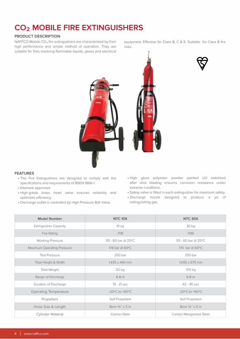
CO2 MOBILE FIRE EXTINGUISHERSPRODUCT DESCRIPTION
NAFFCO Mobile CO2 fire extinguishers are characterized by their
high performance and simple method of operation. They are
suitable for fires involving flammable liquids, gases and electrical
equipment. Effective for Class B, C & E. Suitable for Class B fire
risks.
Model Number NTC 10X NTC 30X
Extinguisher Capacity 10 kg 30 kg
Fire Rating 70B 113B
Working Pressure 55 - 60 bar @ 25ºC 55 - 60 bar @ 25ºC
Maximum Operating Pressure 174 bar @ 60ºC 174 bar @ 60ºC
Test Pressure 250 bar 250 bar
Total Height & Width 1,435 x 440 mm 1,095 x 675 mm
Total Weight 52 kg 125 kg
Range of Discharge 6-8 m 6-8 m
Duration of Discharge 19 - 21 sec 42 - 45 sec
Operating Temperature -20ºC to +60ºC -20ºC to +60ºC
Propellant Self Propellant Self Propellant
Hose Size & Length Bore ⅜’’ x 5 m Bore ⅜’’ x 5 m
Cylinder Material Carbon Steel Carbon Manganese Steel
www.naffco.com 9
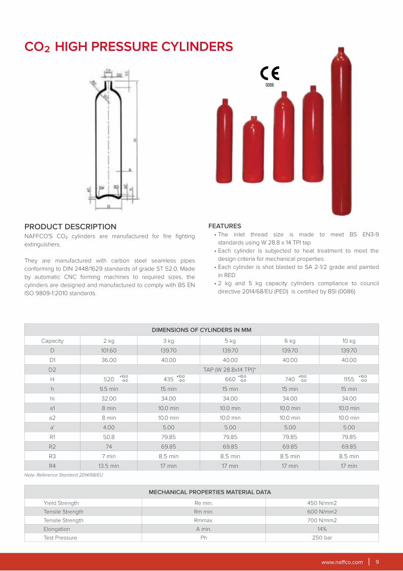
CO2 HIGH PRESSURE CYLINDERS
PRODUCT DESCRIPTIONNAFFCO'S CO2 cylinders are manufactured for fire fighting
extinguishers.
They are manufactured with carbon steel seamless pipes
conforming to DIN 2448/1629 standards of grade ST 52.0. Made
by automatic CNC forming machines to required sizes, the
cylinders are designed and manufactured to comply with BS EN
ISO 9809-1:2010 standards.
FEATURES
• The inlet thread size is made to meet BS EN3-9
standards using W 28.8 x 14 TPI tap
• Each cylinder is subjected to heat treatment to meet the
design criteria for mechanical properties
• Each cylinder is shot blasted to SA 2-1/2 grade and painted
in RED
• 2 kg and 5 kg capacity cylinders compliance to council
directive 2014/68/EU (PED) is certified by BSI (0086)
DIMENSIONS OF CYLINDERS IN MM
Capacity 2 kg 3 kg 5 kg 6 kg 10 kg
D 101.60 139.70 139.70 139.70 139.70
D1 36.00 40.00 40.00 40.00 40.00
D2 TAP (W 28.8x14 TPI}*
H 520 435 660 740 1155
h 9.5 min 15 min 15 min 15 min 15 min
hi 32.00 34.00 34.00 34.00 34.00
a1 8 min 10.0 min 10.0 min 10.0 min 10.0 min
a2 8 min 10.0 min 10.0 min 10.0 min 10.0 min
a' 4.00 5.00 5.00 5.00 5.00
R1 50.8 79.85 79.85 79.85 79.85
R2 74 69.85 69.85 69.85 69.85
R3 7 min 8.5 min 8.5 min 8.5 min 8.5 min
R4 13.5 min 17 min 17 min 17 min 17 min
Note: Reference Standard 2014/68/EU
+10.0
-0.0
+10.0
-0.0
+10.0
-0.0
+10.0
-0.0
+10.0
-0.0
MECHANICAL PROPERTIES MATERIAL DATA
Yield Strength Re min. 450 N/mm2
Tensile Strength Rm min. 600 N/mm2
Tensile Strength Rmmax. 700 N/mm2
Elongation A min. 14%
Test Pressure Ph 250 bar
www.naffco.com10
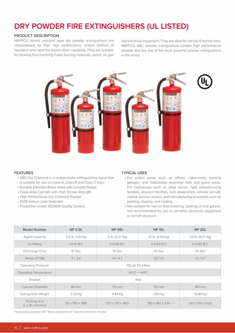
DRY POWDER FIRE EXTINGUISHERS (UL LISTED)PRODUCT DESCRIPTION
NAFFCO stored pressure type dry powder extinguishers are
characterised by their high performance, simple method of
operation and rapid fire knock down capability. They are suitable
for tackling fires involving freely burning materials, petrol, oil, gas
and electrical equipment. They are ideal for vehicle & marine risks.
NAFFCO ABC powder extinguishers contain high performance
powder and are one of the most powerful powder extinguishers
in the world.
FEATURES
• ABC Dry Chemical is a multipurpose extinguishing agent that
is suitable for use on Class A, Class B and Class C fires.
• Durable Extruded Brass Valve with Chrome Plated
• Deep-draw Cylinder with High Tensile Strength
• High Performance Dry Chemical Powder
• 100% Helium Leak Detected.
• Production Under ISO9001 Quality System
TYPICAL USES
• For public areas such as offices, classrooms, parking
garages, and hotel/motel assembly halls and guest areas.
For businesses such as retail stores, light manufacturing
facilities, research facilities, auto dealerships, vehicle/ aircraft/
marine service centers, and manufacturing processes such as
painting, dipping, and coating.
• Not suitable for use on fires involving cooking oil and grease.
Not recommended for use on sensitive electronic equipment
or aircraft structure.
Model Number NP 2.5L NP 05L NP 10L NP 20L
Agent Capacity 2.5 lb. (1.13 Kg) 5 lb. (2.27 Kg) 10 lb. (4.54 Kg) 20 lb. (9.07 Kg)
UL Rating 1-A:10-B:C 3-A:30-B:C 4-A:60-B:C 6-A:80-B:C
Discharge Time 10 Sec 14 Sec 20 Sec 30 Sec
Range (FT/M) 11 / 3.4 14 / 4.3 20 / 6.1 22 / 6.7
Operating Pressure 195 psi (13.4 Bar)
Operating Temperature -40°C ~ +49°C
Bracket Wall
Cylinder Diameter 86 mm 113 mm 135 mm 183 mm
Extinguisher Weight 2.23 Kg 4.44 Kg 7.63 Kg 13.86 Kg
Packing Size
(L x W x H) (mm)95 x 150 x 380 120 x 170 x 460 150 x 180 x 530 210 x 190 x 620
*Head valve available with “Brass and Aluminum” Specify at the time of order

www.naffco.com 11
ABC DRY POWDER PORTABLE FIRE EXTINGUISHERS
FEATURES
• Mono-ammonium phosphate based dry chemical agent.
Capable of fighting Class A, B, C and E fires.
• Kitemark / LPCB certified to BS EN3.
• Cylinders compliance to council directive 2014/68/EU (PED) is
certified by BSI (0086).
• Certified by BSI under marine equipment directive, 2014/90/
EU
• High quality polyester paint.
• Controlled discharge.
• Brass nickel plated head valve with simple squeeze operation.
• Unique gauge testing system.
• Unique colour coded handle and base (optional).
• Rechargeable and easy to service.
• Choice of capacity from 1 to 12 kg.
Model Number NP1 NP2 NP3/NP3x* NP4 NP6 NP9 NP12
Extinguisher Capacity 1 kg 2 kg 3 kg 4 kg 6 kg 9 kg 12 kg
Propellant 95% Nitrogen + 5% Helium
Fire Rating 8A 34B 13A 70B 21A 89B 21A 113B 34A 183B 43A 233B 55A 233B
Working Pressure 14 bar 14 bar 14 bar 15 bar 15 bar 15 bar 15 bar
Maximum Operating Pressure 18.5 bar @ 60°C
Test Pressure 30 bar
Total Weight 2.0 kg 3.7 kg 5.8 kg 7.5 kg 10 kg 14 kg 17.8 kg
Range of Discharge 4-5 m 5-7 m 6-7 m 7-8 m 6-8 m 6-8 m 6-8 m
Duration of Discharge 7-9 sec 10-12 sec 11-12 sec 13-15 sec 18-20 sec 22-24 sec 28-30 sec
Hose Length with Nozzle N/A N/A 395 mm 457 mm 534 mm 534 mm 617 mm
Operating Temperature -20°C to +60°C
Cylinder Material CRCA Steel
Height x Diameter (mm) 365 x 75 385 x 110 420 x 132 408 x 150 520 x 150 515 x 185 620 x 185
*LPCB Approved only.
*Ideal Use: Houses, office, buildings, warehouses, farms, wood working area etc.*Note: Not recommended for use on expensive and delicate equipment like computers, etc.
1. Valve / Extn. Lever
2. Safety Pin with Chain
3. Valve Handle
4. Pressure Gauge
5. Discharge Hose
6. Syphon Tube
7. Hose Holder
8. Discharge Nozzle
9. PVC Base
www.naffco.com12
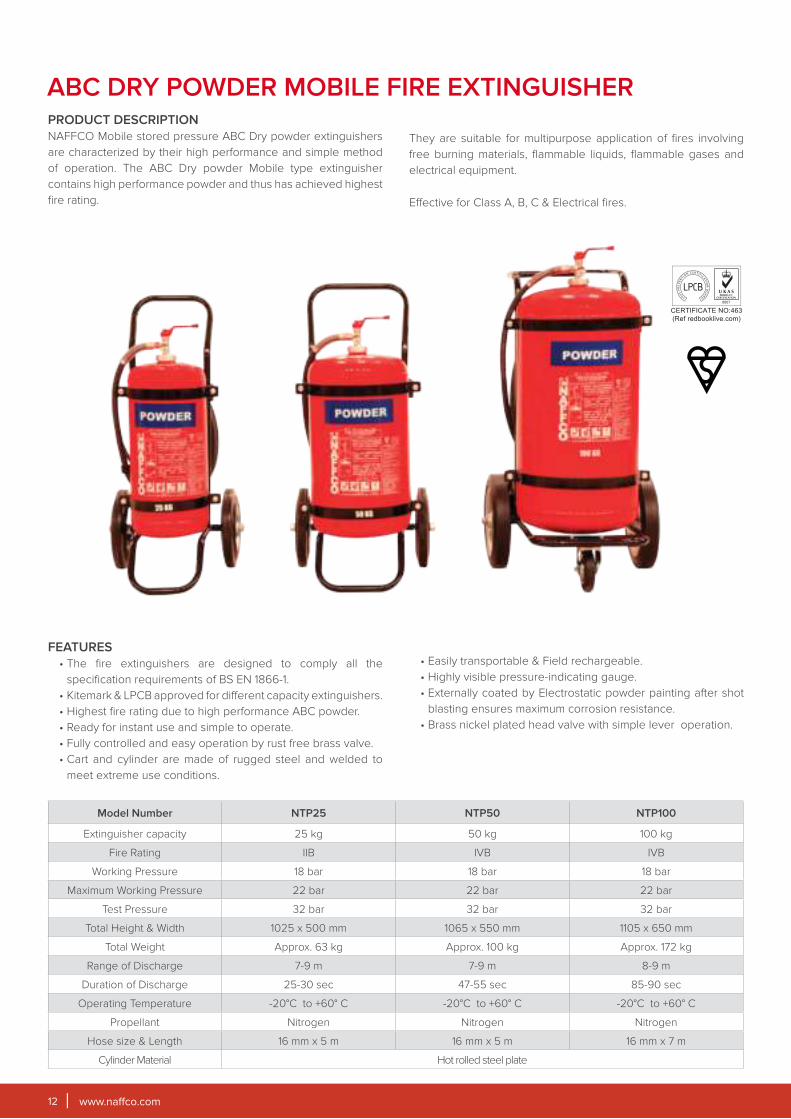
ABC DRY POWDER MOBILE FIRE EXTINGUISHERPRODUCT DESCRIPTION
NAFFCO Mobile stored pressure ABC Dry powder extinguishers
are characterized by their high performance and simple method
of operation. The ABC Dry powder Mobile type extinguisher
contains high performance powder and thus has achieved highest
fire rating.
They are suitable for multipurpose application of fires involving
free burning materials, flammable liquids, flammable gases and
electrical equipment.
FEATURES
• The fire extinguishers are designed to comply all the
specification requirements of BS EN 1866-1.
• Kitemark & LPCB approved for different capacity extinguishers.
• Highest fire rating due to high performance ABC powder.
• Ready for instant use and simple to operate.
• Fully controlled and easy operation by rust free brass valve.
• Cart and cylinder are made of rugged steel and welded to
meet extreme use conditions.
• Easily transportable & Field rechargeable.
• Highly visible pressure-indicating gauge.
• Externally coated by Electrostatic powder painting after shot
blasting ensures maximum corrosion resistance.
• Brass nickel plated head valve with simple lever operation.
Model Number NTP25 NTP50 NTP100
Extinguisher capacity 25 kg 50 kg 100 kg
Fire Rating IIB IVB IVB
Working Pressure 18 bar 18 bar 18 bar
Maximum Working Pressure 22 bar 22 bar 22 bar
Test Pressure 32 bar 32 bar 32 bar
Total Height & Width 1025 x 500 mm 1065 x 550 mm 1105 x 650 mm
Total Weight Approx. 63 kg Approx. 100 kg Approx. 172 kg
Range of Discharge 7-9 m 7-9 m 8-9 m
Duration of Discharge 25-30 sec 47-55 sec 85-90 sec
Operating Temperature -20°C to +60° C -20°C to +60° C -20°C to +60° C
Propellant Nitrogen Nitrogen Nitrogen
Hose size & Length 16 mm x 5 m 16 mm x 5 m 16 mm x 7 m
Cylinder Material Hot rolled steel plate
Effective for Class A, B, C & Electrical fires.
www.naffco.com 13
WATER PORTABLE FIRE EXTINGUISHERSPRODUCT DESCRIPTION
NAFFCO stored pressure and catridge operated water
extinguishers are characterised by their high performance, and
simple method of operation ideal for tackling freely burning
materials such as paper, cloth, wood and furniture. These are
good general purpose fire extinguishers and widely used for their
cost effectiveness.
FEATURES
• Water, a liquid agent only recommended for fighting Class A
Fire.
• Kitemark / LPCB certified to BS EN3.
• Cylinders compliance to council directive 2014/68/EU (PED) is
certified by BSI (0086).
• Certified by BSI under marine equipment directive, 2014/90/
EU
• High quality external polyster paint.
• Thermoplastic internal coating to prevent corrosion.
• Spray nozzle to provide high fire rating.
• Controlled discharge.
• Brass nickel chrome plated head valve with simple squeeze
operation.
• Unique gauge testing system.
• Unique colour code handle and base (Optional).
• Rechargeable and easy to service.
*Ideal Use: Schools, Theaters, Apartments, Offices and Dry Goods Store.
*Note: Water based Extinguishers are not suitable for life involving electrical risk.
WATER FIRE EXTINGUISHER- STORED PRESSURE / EXTERNAL CARTRIDGE TYPE
Model Number NW 6 NW 6X NWNI6 NW N6 NW 9 NW N9 NWNI 9 NWA 9 NW 9X NWC 6X* NWC 9X*
Extinguisher Capacity 6 L 6 L 6 L 6 L 9 L 9 L 9 L 9 L 9 L 6 L 9 L
Propellant 95% Nitrogen + 5% Helium CO2Fire Rating 13A 13A 13A 13A 21A 13A 13A 21A 21A 13A 21A
Working Pressure 14 bar
Maximum Operating Pressure
18.5 bar @ 60° C
Test Pressure 30 bar
Total Weight 11.5 kg 11.5 kg 11.5 kg 11.5 kg 15.5 kg 15.5 kg 15.5 kg 14.5 kg 15.5 kg 12.5 kg 17 kg
Range of Discharge 6 m 6 m 6 m 6-7 m 6-7 m 7-8 m 7-8 m 7-8 m 7-8 m 6 m 7-8 m
Duration of Discharge 22-25 sec 25-27 sec 22-25 sec 22-28 sec 30-32 sec 32-35 sec 32-35 sec 32-35 sec 35-38 sec 18-20 sec 35-40 sec
Hose Length with Nozzle 680mm
Operating Temperature +5° C to +60° C
Cylinder Material CRCA Steel Sheet
Height x Diameter (mm) 625x150 625x150 625x150 625x150 630x185 630x185 630x185 630x185 630x185 630x185 630x185
*LPCB Approval only, External Cartridge Operated.
1. Valve/Extn. Lever
2. Safety Pin with Chain
3. Valve Handle
4. Pressure Gauge
5. PVC Internal Coating
6. Discharge Hose
7. Syphon Tube
8. Hose Holder
9. Filter
10. Discharge Nozzle
11. PVC Base
www.naffco.com14
ECO BARID FOAM FIRE EXTINGUISHERPRODUCT DESCRIPTION
NAFFCO stored pressure type Eco barid foam extinguisher
are multipurpose, ideal for fires involving volatile liquids and
freely burning material such as paper, cloth, wood, furniture and
cooking oil or fat fires.
FOAM FIRE EXTINGUISHER - STORED PRESSURE
Model Number NF 2EB NF 3EB NF 6EB NF 9EB
Cylinder Capacity 2 Liter 3 Liter 6 Liter 6 Liter
Propellant 95% Nitrogen + 5% Helium
Fire Rating 8A 89B 5F 8A 113B 25F 21A 183B 40F 21A 183B 40F
Working Pressure 14 bar 14 bar 14 bar 14 bar
Maximum Operating Pressure 18.5 bar @ 60° C
Test Pressure 30 bar 30 bar 30 bar 30 bar
Total Weight (excluding Hose Assembly) 4.71 kg. 6.36 kg. 11.5 kg. 16.5 kg.
Discharge Range 1 -2 m 1 -2 m 6 m 7 - 8 m
Discharge Time 8 - 10 sec. 12 - 15 sec. 22 - 25 sec. 30 - 34 sec.
Total Weight (excluding Hose Assembly) 4.71 kg. 6.36 kg. 11.5 kg. 16.5 kg.
Hose length with nozzle n/a n/a 680 mm 680mm
Working Temperature +5°C to +60° C +5°C to +60° C +5°C to +60° C +5°C to +60° C
Cylinder Material Cold Rolled Steel Sheet
Outside Diameter 110±2 mm 134±2 mm 150±2 mm 185±2 mm
Overall Height of the Extinguisher±5.0
420 mm±5.0
425 mm±5.0
625 mm±5.0
625 mm
1. Valve/Extn. Lever
2. Safety Pin with Chain
3. Valve Handle
4. Pressure Gauge
5. PVC Internal Coating
6. Discharge Hose
7. Syphon Tube
8. Hose Holder
9. Filter
10. Discharge Nozzle
11. PVC Base
FEATURES
• LPCB certified to BS EN 3
• Eco barid foam agent is capable of fighting class A, B & F fires
• Thermoplastic internal coating to prevent corrosion
• High quality external polyester powder coating
• Brass nickel chrome plated head value with squeeze operation
• Controlled discharged

www.naffco.com 15
FOAM PORTABLE FIRE EXTINGUISHERSPRODUCT DESCRIPTION
NAFFCO stored pressure and catridge operated foam
extinguishers are multipurpose, ideal for fires involving volatile
liquids and freely burning materials such as paper, cloth, wood
and furniture.
FEATURES
• AFFF (6%) Synthetic Aqueous Film - Forming Foam Agent
capable of fighting Class A, B fires.
• Kitemark / LPCB certified to BS EN3.
• Cylinders compliance to council directive 2014/68/EU (PED) is
certified by BSI (0086).
• Certified by BSI under marine equipment directive, 2014/90/
EU
• High quality external polyester paint.
• Thermoplastic internal coating to prevent corrosion.
• Spray nozzle to provide high fire rating.
• Controlled discharge.
• Brass nickel chrome plated head valve with simple squeeze
operation.
• Unique gauge testing system.
• Unique colour code handle and base (Optional).
• Rechargeable and easy to service.
*Ideal Use: Schools, Theaters, Apartments, Offices and Dry Goods Store.
*Note: Water based Extinguishers are not suitable for life involving electrical risk.
FOAM FIRE EXTINGUISHER - STORED PRESSURE / EXTERNAL CARTRIDGE TYPE
Model Number NF 3 NF 3X NF 6 NFI 6 NF 6X NF 9 NFI 9 NFA 9 NF 9X NFC 6X* NFC 9X*
Extinguisher Capacity 3 L 3 L 6 L 6 L 6 L 9 L 9 L 9 L 9 L 6 L 9 L
Propellant 95% Nitrogen + 5% Helium CO2Fire Rating 8A 70B 8A 70B 21A 144B 21A 144B 21A 144B 21A 183B 21A 183B 21A 183B 27A 183B 27A 144B 34A 233B
Working Pressure 14 bar
Maximum Operating Pressure
18.5 bar @ 60°C
Test Pressure 30 bar
Total Weight 11.5 kg 11.5 kg 11.5 kg 11.5 kg 15.5 kg 15.5 kg 15.5 kg 14.5 kg 15.5 kg 12.5 kg 17 kg
Range of Discharge 6 m 6 m 6 m 6-7 m 6-7 m 7-8 m 7-8 m 7-8 m 7-8 m 6 m 7-8 m
Duration of Discharge 22-25 sec 25-27 sec 22-25 sec 22-28 sec 30-32 sec 32-35 sec 32-35 sec 32-35 sec 35-38 sec 18-20 sec 35-40 sec
Hose Length with Nozzle N/A N/A 680 mm 680 mm 680 mm 680 mm 680 mm 680 mm 610 mm 680 mm 680 mm
Operating Temperature +5°C to +60°C
Cylinder Material CRCA Steel Sheet
Height x Diameter (mm) 420x132 420x132 610x150 610x150 610x150 630x185 630x185 630x185 630x185 630x185 630x185
*LPCB Approval only, External Cartridge Operated.
1. Valve/Extn. Lever
2. Safety Pin with Chain
3. Valve Handle
4. Pressure Gauge
5. PVC Internal Coating
6. Discharge Hose
7. Syphon Tube
8. Hose Holder
9. Filter
10. Discharge Nozzle
11. PVC Base
Suitable for Class A and Class B fire risks.
www.naffco.com16
FOAM MOBILE FIRE EXTINGUISHERSPRODUCT DESCRIPTION
NAFFCO Mobile external cartridge operated foam fire
extinguishers are characterized by their high performance
and simple method operation. The extinguisher contains high
performance extinguishing agent 6% AFFF foam and thus has
achieved the highest fire rating.
NAFFCO Mobile Foam extinguishers are most suitable for fires
involving flammable liquids and freely burning materials such as
paper, cloth and wood.
Effective for Class A & Class B fires.
FEATURES
• The fire extinguishers are designed to comply with all the
specification requirements of BS EN 1866-1.
• Kitemark and LPCB approved for different capacity
extinguishers.
• Agent used is AFFF (6%) Synthetic Aqueous film forming foam
for effective fire extinguishment.
• Incorporated with high pressure CE approved CO2 cylinder as
propelling agent.
• Ready for instant use and simple to operate.
• Cart and cylinder are made of rugged steel and welded to
meet extreme use conditions.
• Easily transportable.
• Externally coated by Electrostatic powder painting after shot
blasting ensures maximum corrosion resistance.
• Internally coated by electrostatic block powder using resin for
corrosion resistance.
• Large Brass, nickel chrome plated cap for ease during refilling
the agent.
• Cylinder assemblies are designed for easy maintenance
by mounting it separately on steel frame and thus can be
separated by just removing the steel clamps.
Model Number NTFC 50X NTFC 100X NTFC 135X
Extinguisher capacity 50 L 100 L 135 L
Fire Rating IVB IVB IVB
Propellant CO2 CO2 CO2
Working Pressure 14 bar 14 bar 14 bar
Test Pressure 32 bar 32 bar 32 bar
Maximum Working Pressure 18.5 bar 18.5 bar 18.5 bar
Total Weight 112.5 kg 189 kg 232 kg
Range of Discharge 6-8 m 8-10 m 8-10 m
Duration of Discharge 55-65 sec 110-120 sec 160-170 sec
Hose Length 16 mm x 5 m 16 mm x 7 m 16 mm x 7 m
Operating Temperature +5°C to +60° C +5°C to +60° C +5°C to +60° C
Cylinder Material Hot Rolled steel plate
Extinguisher Height & Width (mm) 1065 x 550 1100 x 625 1005 x 700

www.naffco.com 17
CLEAN AGENT FIRE EXTINGUISHERS (UL LISTED)PRODUCT DESCRIPTION
NAFFCO UL Listed Clean Agent fire extinguishers (HALOTRON)
is a clean, non-conductive gaseous agent that is an excellent
replacement for Halon 1211 extinguishers. Clean Agent is suitable
for use on Class A, Class B, and Class C fires.
FEATURES
• Residue-free Hydro-chlorofluorocarbon gas agent pressurized
with argon.
• Typically used for protecting sensitive electronic equipment
in offices, classrooms, churches, parking garages and hotel/
motel assembly halls and guest areas.
• Also used for protecting sensitive electronic equipment
in businesses such as retail stores, light manufacturing
facilities, research facilities, auto dealerships, vehicle/
aircraft/marine service centers, and manufacturing
processes such as painting, dipping, and coating.
• Not suitable for use on fires involving cooking oil and grease.
Recommended for use on sensitive electronic equipment.
• Clean Agent Extinguishers are USCG Approved (Marine
Application)
Model NumberN 05L FSA*/
N 05L FSB**N 05L HSA***
N 11L SA*/
N 11L SB**
N 15L SA*/
N 15L SB**
Agent Capacity 5 lb. (2.27 kg) 5.5 lb. (2.49 kg) 11 lb. (5 kg) 15.5 lb. (7.03 kg)
UL Rating 5-B:C 5-B:C 1-A:10-B:C 2-A:10-B:C
Discharge Time 9 sec 9 sec 9 sec 13 sec
Range (FT/M) 9-15/2.7-4.5 9-15 / 2.7-4.5 9-15 / 2.7-4.5 12-18 / 3.7-5.5
Operating Pressure 100 psi (689 kPa) 100 psi (689 kPa) 100 psi (689 kPa) 125 psi (862 kPa)
Operating Temperature Range -40ºF to +120° F -40ºF to +120° F -40ºF to +120° F -40ºF to +120° F
Bracket Wall Wall Wall Wall
USCG Approval (Marine Application) Type B:C size I Type B:C size I Type B:C size I Type B:C size II
Ship Weight 9.25 lb. (4.2kg) 10.0 lb. (4.5 kg) 21.25 lb. (9.6 kg) 25.75 lb. (11.75 kg)
Unit Height 16.375 in (41.6 cm) 16.375 in (41.6 cm) 17.5 in (44.5 cm) 17.5 in (44.5 cm)
Unit Width 6.5 in (16.5 cm) 6.5 in (16.5 cm) 8.625 in (21.9 cm) 8.625 in (21.9 cm)
Unit Diameter 4.25 in (10.8 cm) 4.25 in (10.8 cm) 7 in 17.8 cm) 7 in 17.8 cm)
* Aluminum Head valve** Brass Head valve*** Aluminum head valve with discharge hose
www.naffco.com18
CLEAN AGENT FIRE EXTINGUISHERSPRODUCT DESCRIPTION
NAFFCO clean agent extinguishers have an effective
extinguishing action, environmentally acceptable and excellent
alternative for Halon 1211. Clean Agent (HFC-236fa) is a non-
corrosive, electrically non-conductive and free of residue. It is
ideally suited for protecting high value equipment.
FEATURES
• LPCB Approved for different capacity of extinguishers.
• Safe for People: It is indented for use as a streaming agent
providing a gas concentration sufficient to extinguish a
fire. It is safe for use in occupied spaces.
• Safe for Assets: It is electrically non conductive, non
corrosive, and free of residue. As a gaseous agent, it targets
the flame and extinguishes the fire. Operations can resume
quickly, particularly if early detection methods are in use.
• Safe for the Environment: It does not contain chlorine or
bromine, and has zero ozone depletion potential like many
fluoride-based gases, HFC-236fa has some global warming
potential.
• Clean Agent Hexafluoropropane Gas based Extinguishing
Agent capable of fighting class A, B, C and Electrical
fires effectively.
• Low in toxicity.
• Standard compliance BSEN3.
• High Performance Extinguishing Agent.
• High Quality external Polyester Paint to avoid corrosion
• Brass Nickel plated head valve with simple squeeze
operation.
• Rechargeable & easy to service.
Model Number NHFC-4 NHFC-6 NHFC-9 NHFC-12
Extinguisher Capacity 4 kg 6 kg 9 kg 12 kg
Propellant 95% Nitrogen + 5% Helium
Fire Rating 34B C 5A 55B C 8A 70B C 13A 70B C
Working Pressure 15 bar 15 bar 15 bar 15 bar
Maximum Operating Pressure 21 bar @ 60ºC
Test Pressure 30 bar
Total Weight 7.3 kg 10.3 kg 13.8 kg 17.9 kg
Range of Discharge 4 - 5 m 4 - 5 m 4 - 5 m 4 - 5 m
Duration of Discharge 14 - 16 sec 20 - 22 sec 23 - 26 sec 38 - 40 sec
Operating Termprature -20ºC to 60º C
Cylinder Material CRCA Steel Sheet
Hose Length with Nozzle 535 mm 625 mm 595 mm 690 mm
Height x Diameter (mm) 425 x 150 527 x 150 530 x 184 620 x 184
www.naffco.com 19
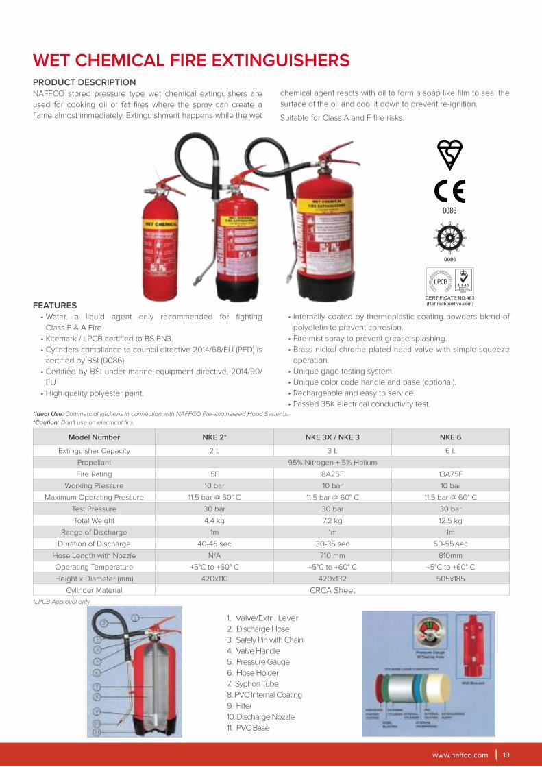
WET CHEMICAL FIRE EXTINGUISHERSPRODUCT DESCRIPTION
NAFFCO stored pressure type wet chemical extinguishers are
used for cooking oil or fat fires where the spray can create a
flame almost immediately. Extinguishment happens while the wet
chemical agent reacts with oil to form a soap like film to seal the
surface of the oil and cool it down to prevent re-ignition.
Suitable for Class A and F fire risks.
FEATURES
• Water, a liquid agent only recommended for fighting
Class F & A Fire.
• Kitemark / LPCB certified to BS EN3.
• Cylinders compliance to council directive 2014/68/EU (PED) is
certified by BSI (0086).
• Certified by BSI under marine equipment directive, 2014/90/
EU
• High quality polyester paint.
• Internally coated by thermoplastic coating powders blend of
polyolefin to prevent corrosion.
• Fire mist spray to prevent grease splashing.
• Brass nickel chrome plated head valve with simple squeeze
operation.
• Unique gage testing system.
• Unique color code handle and base (optional).
• Rechargeable and easy to service.
• Passed 35K electrical conductivity test.*Ideal Use: Commercial kitchens in connection with NAFFCO Pre-engineered Hood Systems.
*Caution: Don't use on electrical fire.
Model Number NKE 2* NKE 3X / NKE 3 NKE 6
Extinguisher Capacity 2 L 3 L 6 L
Propellant 95% Nitrogen + 5% Helium
Fire Rating 5F 8A25F 13A75F
Working Pressure 10 bar 10 bar 10 bar
Maximum Operating Pressure 11.5 bar @ 60° C 11.5 bar @ 60° C 11.5 bar @ 60° C
Test Pressure 30 bar 30 bar 30 bar
Total Weight 4.4 kg 7.2 kg 12.5 kg
Range of Discharge 1m 1m 1m
Duration of Discharge 40-45 sec 30-35 sec 50-55 sec
Hose Length with Nozzle N/A 710 mm 810mm
Operating Temperature +5°C to +60° C +5°C to +60° C +5°C to +60° C
Height x Diameter (mm) 420x110 420x132 505x185
Cylinder Material CRCA Sheet
*LPCB Approval only
1. Valve/Extn. Lever
2. Discharge Hose
3. Safely Pin with Chain
4. Valve Handle
5. Pressure Gauge
6. Hose Holder
7. Syphon Tube
8. PVC Internal Coating
9. Filter
10. Discharge Nozzle
11. PVC Base

www.naffco.com20
SEMI-RIGID REEL HOSEPRODUCT DESCRIPTION
NAFFCO semi-rigid reel hoses are suitable for use in fixed fire
fighting system. The hoses are available in sizes of 19 mm and 25
mm inside diameter. The hoses are flexible so that it can be rolled
and kept on a drum.
The hose are intended for use at a maximum working
pressure of 12 bar (1.2 MPa) and temperature range of
-20°C to +60°C at ambient temperature condition in non-aggresive
or non-corrosive atmosphere.
The semi-rigid reel hoses are manufactured to comply with BSEN
694:2014 standards.
FEATURES
• Materials for inner lining and cover of hose are plasticized
PVC compound
• High tensile textile polyester yarn is used for reinforcement
of hose.
SPECIFICATIONHose Classification Type A, Class 2
Color of Hose Red
Bore 19 mm 25 mm
Length of Hose 30 m
Hydrostatic Properties
Maximum Working Pressure 12 bar
Proof Pressure 24 bar
Burst Pressure 42 bar
www.naffco.com 21
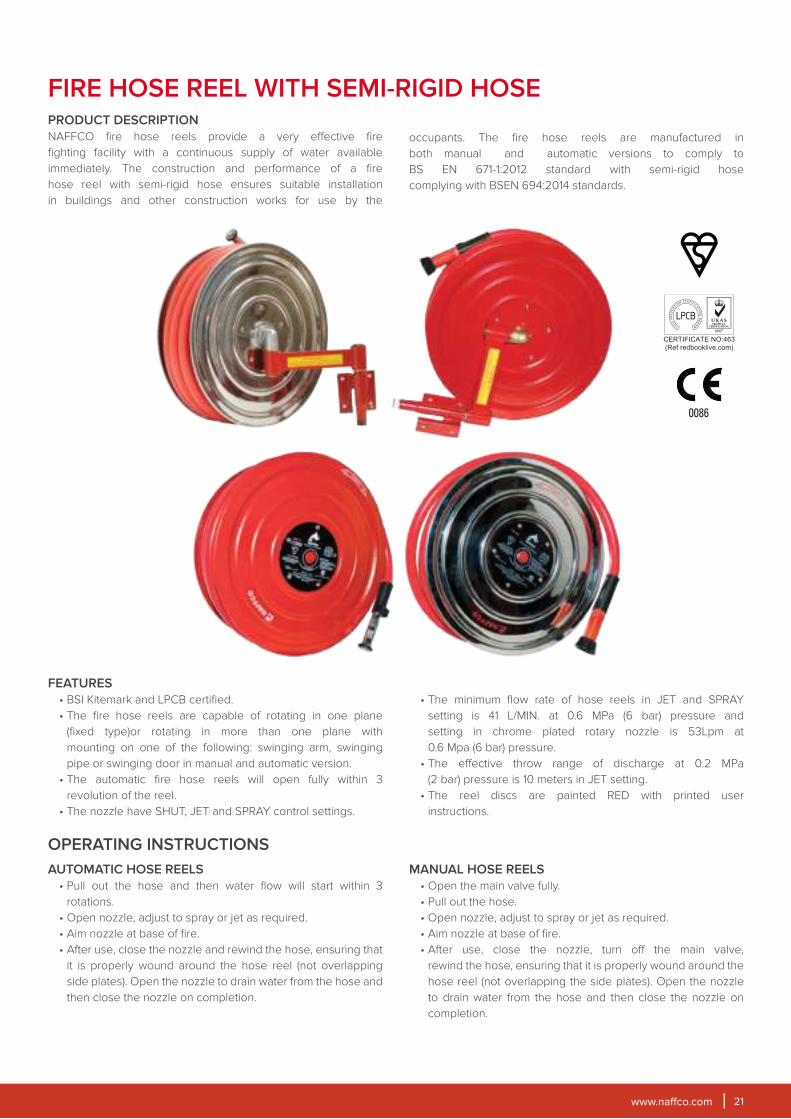
FIRE HOSE REEL WITH SEMI-RIGID HOSEPRODUCT DESCRIPTION
NAFFCO fire hose reels provide a very effective fire
fighting facility with a continuous supply of water available
immediately. The construction and performance of a fire
hose reel with semi-rigid hose ensures suitable installation
in buildings and other construction works for use by the
occupants. The fire hose reels are manufactured in
both manual and automatic versions to comply to
BS EN 671-1:2012 standard with semi-rigid hose
complying with BSEN 694:2014 standards.
FEATURES
• BSI Kitemark and LPCB certified.
• The fire hose reels are capable of rotating in one plane
(fixed type)or rotating in more than one plane with
mounting on one of the following: swinging arm, swinging
pipe or swinging door in manual and automatic version.
• The automatic fire hose reels will open fully within 3
revolution of the reel.
• The nozzle have SHUT, JET and SPRAY control settings.
• The minimum flow rate of hose reels in JET and SPRAY
setting is 41 L/MIN. at 0.6 MPa (6 bar) pressure and
setting in chrome plated rotary nozzle is 53Lpm at
0.6 Mpa (6 bar) pressure.
• The effective throw range of discharge at 0.2 MPa
(2 bar) pressure is 10 meters in JET setting.
• The reel discs are painted RED with printed user
instructions.
AUTOMATIC HOSE REELS
• Pull out the hose and then water flow will start within 3
rotations.
• Open nozzle, adjust to spray or jet as required.
• Aim nozzle at base of fire.
• After use, close the nozzle and rewind the hose, ensuring that
it is properly wound around the hose reel (not overlapping
side plates). Open the nozzle to drain water from the hose and
then close the nozzle on completion.
MANUAL HOSE REELS
• Open the main valve fully.
• Pull out the hose.
• Open nozzle, adjust to spray or jet as required.
• Aim nozzle at base of fire.
• After use, close the nozzle, turn off the main valve,
rewind the hose, ensuring that it is properly wound around the
hose reel (not overlapping the side plates). Open the nozzle
to drain water from the hose and then close the nozzle on
completion.
OPERATING INSTRUCTIONS
www.naffco.com22
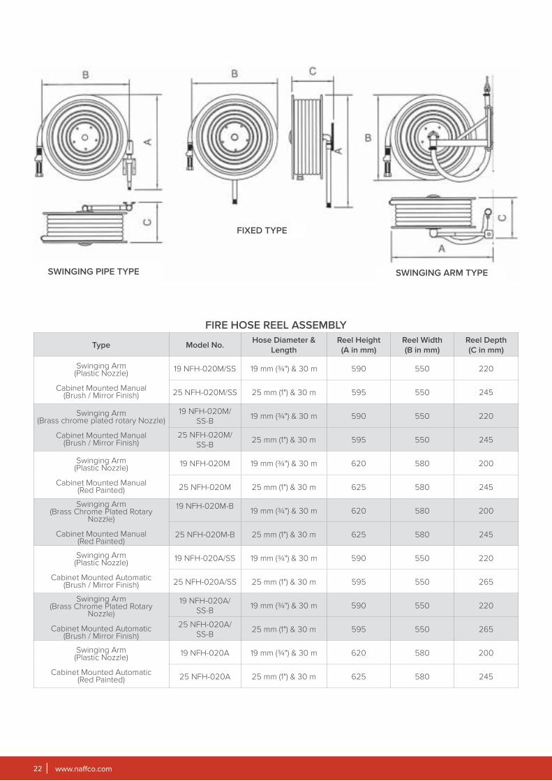
FIRE HOSE REEL ASSEMBLY
Type Model No.Hose Diameter &
Length
Reel Height
(A in mm)
Reel Width
(B in mm)
Reel Depth
(C in mm)
Swinging Arm(Plastic Nozzle)
Cabinet Mounted Manual(Brush / Mirror Finish)
19 NFH-020M/SS 19 mm (¾") & 30 m 590 550 220
25 NFH-020M/SS 25 mm (1") & 30 m 595 550 245
Swinging Arm(Brass chrome plated rotary Nozzle)
Cabinet Mounted Manual(Brush / Mirror Finish)
19 NFH-020M/SS-B
19 mm (¾") & 30 m 590 550 220
25 NFH-020M/SS-B
25 mm (1") & 30 m 595 550 245
Swinging Arm(Plastic Nozzle)
Cabinet Mounted Manual(Red Painted)
19 NFH-020M 19 mm (¾") & 30 m 620 580 200
25 NFH-020M 25 mm (1") & 30 m 625 580 245
Swinging Arm(Brass Chrome Plated Rotary
Nozzle)
Cabinet Mounted Manual(Red Painted)
19 NFH-020M-B19 mm (¾") & 30 m 620 580 200
25 NFH-020M-B 25 mm (1") & 30 m 625 580 245
Swinging Arm(Plastic Nozzle)
Cabinet Mounted Automatic(Brush / Mirror Finish)
19 NFH-020A/SS 19 mm (¾") & 30 m 590 550 220
25 NFH-020A/SS 25 mm (1") & 30 m 595 550 265
Swinging Arm(Brass Chrome Plated Rotary
Nozzle)
Cabinet Mounted Automatic(Brush / Mirror Finish)
19 NFH-020A/SS-B
19 mm (¾") & 30 m 590 550 220
25 NFH-020A/SS-B
25 mm (1") & 30 m 595 550 265
Swinging Arm(Plastic Nozzle)
Cabinet Mounted Automatic(Red Painted)
19 NFH-020A 19 mm (¾") & 30 m 620 580 200
25 NFH-020A 25 mm (1") & 30 m 625 580 245
SWINGING ARM TYPESWINGING PIPE TYPE
FIXED TYPE
www.naffco.com 23
Type Model No.Hose Diameter &
Length
Reel Height
(A in mm)
Reel Width
(B in mm)
Reel Depth
(C in mm)
Swinging Arm(Brass Chrome Plated Rotary
Nozzle)
Cabinet Mounted Automatic(Red Painted)
19 NFH-020A-B 19 mm (¾") & 30 m 620 580 200
25 NFH-020A-B 25 mm (1") & 30 m 625 580 245
Swinging Pipe(Plastic Nozzle)
Wall Mounted Manual(Brush / Mirror Finish)
19 NFH-030M/SS 19 mm (¾") & 30 m 580 550 245
25 NFH-030M/SS 25 mm (1") & 30 m 580 550 245
Swinging Pipe(Brass Chrome Plated Rotary
Nozzle)
Wall Mounted Manual(Brush / Mirror Finish)
19 NFH-030M/SS-B
19 mm (¾") & 30 m 580 550 245
25 NFH-030M/SS-B
25 mm (1") & 30 m 580 550 245
Swinging Pipe(Plastic Nozzle)
Wall Mounted Manual(Red Painted)
19 NFH-030M 19 mm (¾") & 30 m 595 580 220
25 NFH-030M 25 mm (1") & 30 m 595 580 200
Swinging Pipe(Brass Chrome Plated Rotary
Nozzle)
Wall Mounted Manual(Red Painted)
19 NFH-030M-B 19 mm (¾") & 30 m 595 580 220
25 NFH-030M-B 25 mm (1") & 30 m 595 580 200
Swinging Pipe(Plastic Nozzle)
Wall Mounted Automatic(Brush / Mirror Finish)
19 NFH-030A/SS 19 mm (¾") & 30 m 580 550 245
25 NFH-030A/SS 25 mm (1") & 30 m 580 550 285
Swinging Pipe(Brass Chrome Plated Rotary
Nozzle)
Wall Mounted Automatic(Brush / Mirror Finish)
19 NFH-030A/SS-B 19 mm (¾") & 30 m 580 550 245
25 NFH-030A/SS-B
25 mm (1") & 30 m 580 550 285
Swinging Pipe(Plastic Nozzle)
Wall Mounted Automatic(Red Painted)
19 NFH-030A 19 mm (¾") & 30 m 595 580 220
25 NFH-030A 25 mm (1") & 30 m 595 580 200
Swinging Pipe(Brass Chrome Plated Rotary
Nozzle)
Wall Mounted Automatic(Red Painted)
19 NFH-030A-B 19 mm (¾") & 30 m 595 580 220
25 NFH-030A-B 25 mm (1") & 30 m 595 580 200
Manual(Plastic Nozzle)
Fixed(Brush / Mirror Finish)
19 NFH-040M/SS 19 mm (¾") & 30 m 620 550 230
25 NFH-040M/SS 25 mm (1") & 30 m 620 550 275
Manual(Brass Chrome Plated Rotary
Nozzle)
Fixed(Brush / Mirror Finish)
19 NFH-040M/SS-B 19 mm (¾") & 30 m 620 550 230
25 NFH-040M/SS-B
25mm (1") & 30m 620 550 275
Manual(Plastic Nozzle)
Fixed(Red Painted)
19 NFH-040M 19 mm (¾") & 30 m 635 580 210
25 NFH-040M 25 mm (1") & 30 m 635 580 250
Manual(Brass Chrome Plated Rotary
Nozzle)
Fixed(Red Painted)
19 NFH-040M-B 19mm (¾") & 30m 635 580 210
25 NFH-040M-B 25 mm (1") & 30 m 635 580 250

www.naffco.com24
Type Model No.Hose Diameter &
LengthReel Height (A in mm)
Reel Width (B in mm)
Reel Depth (C in mm)
Automatic
(Plastic Nozzle)
Fixed
(Brush / Mirror Finish)
19 NFH-040A/SS19 mm (¾") & 30 m 620 550 230
25 NFH-040A/SS 25 mm (1") & 30 m 620 550 275
Automatic
(Brass Chrome Plated Rotary Nozzle)
Fixed
(Brush / Mirror Finish)
19 NFH-040A/SS-B19 mm (¾") & 30 m 620 550 230
25 NFH-040A/
SS-B25 mm (1") & 30 m 620 550 275
Automatic
(Plastic Nozzle)
Fixed
(Red Painted)
19 NFH-040A19 mm (¾") & 30 m 635 580 210
25 NFH-040A 25 mm (1") & 30 m 635 580 250
Automatic
(Brass Chrome Plated Rotary Nozzle)
Fixed
(Red Painted)
19 NFH-040A-B19 mm (¾") & 30 m 635 580 210
25 NFH-040A-B 25 mm (1") & 30 m 635 580 250
SPECIFICATIONSModel Number Size (in.) Pressure Rating Connecting
NLSV-25 1 PN 20 1" BSPT Female Threaded
LOCK SHIELD VALVENAFFCO Lock Shield Valve is usually installed where
unauthorized operation has to be avoided. A typical
application of this valve is installing these at inlet pipe to the
hose reel where it can be opened only by key and key kept by
maintenance or fire safety department.
FEATURES
• Solid Wedge, non-rising stem, screwed in bonnet.
• Valves are manufactured in accordance to
BS 5154 series B.
• Service temperature -10 to +66ºC.
• Pressure rating is PN 20.
• End connection is BSPT threaded to BS21.
• Material: Brass
www.naffco.com 25
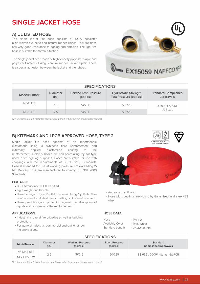
Single jacket fire hose consists of an impermeable
elastomeric lining, a synthetic fibre reinforcement and
externally applied elastomeric coating to the
reinforcement. Delivery hoses are non-percolating lay flat type
used in fire fighting purposes. Hoses are suitable for use with
couplings with the requirements of BS 336:2010 standards.
Hose is intended for use at working pressure not exceeding 15
bar. Delivery hose are manufactured to comply BS 6391: 2009
Standards.
FEATURES
• BSI Kitemark and LPCB Certified.
• Light weight and flexible.
• Hose belongs to Type 2 with Elastomeric lining, Synthetic fibre
reinforcement and elastomeric coating on the reinforcement.
• Hose provides good protection against the absorption of
liquids and resistance of the reinforcement.
B) KITEMARK AND LPCB APPROVED HOSE, TYPE 2
APPLICATIONS
• Industrial and rural fire brigades as well as building
protection.
• For general industrial, commercial and civil engineer
ing applications.
HOSE DATA
Hose
Available Color
Standard Length
: Type 2
: Red, White
: 25/30 Meters
SPECIFICATIONS
Model NumberDiameter
(in.)
Service Test Pressure
(bar/psi)Hydrostatic Strength
Test Pressure (bar/psi)Standard Compliance/
Approvals
NF-FH381.5 14/200 50/725 UL19,NFPA 1961 /
UL listedNF-FH65 2.5 14/200 50/725
SINGLE JACKET HOSE
NH threaded. Storz & instantaneous coupling or other types are available upon request.
A) UL LISTED HOSE The single jacket fire hose consists of 100% polyester
plain-woven synthetic and natural rubber linings. This fire hose
has very good resistance to ageing and abrasion. The light fire
hose is suitable for normal situation.
The single jacket hose made of high tenacity polyester staple and
polyester filaments. Lining is natural rubber. Jacket is plain. There
is a special adhesion between the jacket and the rubber.
• Anti rot and anti twist.
• Hose with couplings are wound by Galvanized mild steel / SS
wire.
SPECIFICATIONS
Model NumberDiameter
(in.)
Working Pressure
(bar/psi)
Burst Pressure
(bar/psi)
Standard
Compliance/Approvals
NF-DH2-65R 2.5 15/215 50/725 BS 6391: 2009/ Kitemark&LPCB
NF-DH2-65W
NH threaded. Storz & instantaneous coupling or other types are available upon request.
www.naffco.com26
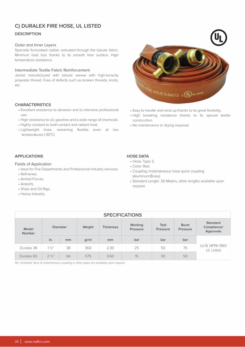
DESCRIPTION
Outer and Inner Layers
Specially formulated rubber, extruded through the tubular fabric.
Minimum load loss thanks to its smooth liner surface. High
temperature resistance.
Intermediate Textile Fabric Reinforcement
Jacket manufactured with tubular weave with high-tenacity
polyester thread. Free of defects such as broken threads, knots,
etc.
CHARACTERISTICS
• Excellent resistance to abrasion and to intensive professional
use.
• High resistance to oil, gasoline and a wide range of chemicals.
• Highly resistant to both contact and radiant heat.
• Lightweight hose, remaining flexible even at low
temperatures (-30°C)
APPLICATIONS
Fields of Application
• Ideal for Fire Departments and Professional Industry services.
• Refineries.
• Armed Forces.
• Airports.
• Ships and Oil Rigs.
• Heavy Industry.
HOSE DATA
• Hose: Type 3.
• Color: Red.
• Coupling: Instantaneous hose quick coupling
(Aluminum/Brass).
• Standard Length: 30 Meters, other lengths available upon
request.
C) DURALEX FIRE HOSE, UL LISTED
SPECIFICATIONS
Model
Number
Diameter Weight ThicknessWorking
Pressure
Test
Pressure
Burst
Pressure
Standard
Compliance/
Approvals
in. mm gr/m mm bar bar bar
UL19, NFPA 1961/
UL ListedDuralex 38 1 ½” 38 360 2.30 25 50 75
Duralex 65 2 ½” 64 575 3.60 15 30 50
NH threaded. Storz & instantaneous coupling or other types are available upon request.
• Easy to handle and wind up thanks to its great flexibility.
• High breaking resistance thanks to its special textile
construction.
• No maintenance or drying required.
www.naffco.com 27
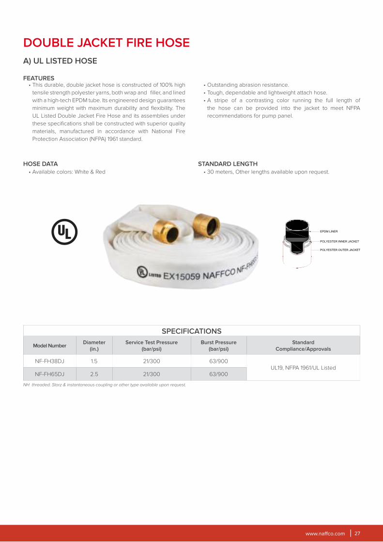
HOSE DATA
• Available colors: White & Red
STANDARD LENGTH
• 30 meters, Other lengths available upon request.
A) UL LISTED HOSE
FEATURES• This durable, double jacket hose is constructed of 100% high
tensile strength polyester yarns, both wrap and filler, and lined
with a high-tech EPDM tube. Its engineered design guarantees
minimum weight with maximum durability and flexibility. The
UL Listed Double Jacket Fire Hose and its assemblies under
these specifications shall be constructed with superior quality
materials, manufactured in accordance with National Fire
Protection Association (NFPA) 1961 standard.
DOUBLE JACKET FIRE HOSE
SPECIFICATIONS
Model NumberDiameter
(in.)
Service Test Pressure
(bar/psi)
Burst Pressure
(bar/psi)
Standard
Compliance/Approvals
NF-FH38DJ 1.5 21/300 63/900UL19, NFPA 1961/UL Listed
NF-FH65DJ 2.5 21/300 63/900
NH threaded. Storz & instantaneous coupling or other type available upon request.
• Outstanding abrasion resistance.
• Tough, dependable and lightweight attach hose.
• A stripe of a contrasting color running the full length of
the hose can be provided into the jacket to meet NFPA
recommendations for pump panel.
www.naffco.com28
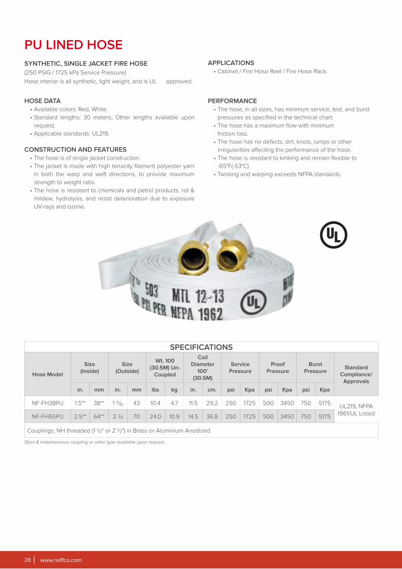
PU LINED HOSE
PERFORMANCE
• The hose, in all sizes, has minimum service, test, and burst
pressures as specified in the technical chart.
• The hose has a maximum flow with minimum
friction loss.
• The hose has no defects, dirt, knots, lumps or other
irregularities affecting the performance of the hose.
• The hose is resistant to kinking and remain flexible to
-65°F(-53°C).
• Twisting and warping exceeds NFPA standards.
SYNTHETIC, SINGLE JACKET FIRE HOSE
(250 PSIG / 1725 kPa Service Pressure)
Hose interior is all synthetic, light weight, and is UL approved.
HOSE DATA
• Available colors: Red, White.
• Standard lengths: 30 meters, Other lengths available upon
request.
• Applicable standards: UL219.
CONSTRUCTION AND FEATURES
• The hose is of single jacket construction.
• The jacket is made with high tenacity filament polyester yarn
in both the warp and weft directions, to provide maximum
strength to weight ratio.
• The hose is resistant to chemicals and petrol products, rot &
mildew, hydrolysis, and resist deterioration due to exposure
UV-rays and ozone.
APPLICATIONS
• Cabinet / Fire Hose Reel / Fire Hose Rack.
SPECIFICATIONS
Hose Model
Size
(Inside)
Size
(Outside)
Wt. 100
(30.5M) Un-
Coupled
Coil
Diameter
100’
(30.5M)
Service
Pressure
Proof
Pressure
Burst
PressureStandard
Compliance/
Approvals
in. mm in. mm lbs kg in. cm. psi Kpa psi Kpa psi Kpa
NF-FH38PU 1.5** 38** 1 11⁄16 43 10.4 4.7 11.5 29.2 250 1725 500 3450 750 5175UL219, NFPA
1961/UL ListedNF-FH65PU 2.5** 64** 2 3⁄4 70 24.0 10.9 14.5 36.8 250 1725 500 3450 750 5175
Couplings; NH threaded (1 ½" or 2 ½") in Brass or Aluminium Anodized.
Storz & instantaneous coupling or other type available upon request.
www.naffco.com 29
NAFFCO Fire hose racks are designed for use in controlling
incipient fire by building occupant use and conform to NFPA
14 standards for CLASS II service. The Fire Hose Racks are
manufactured to comply UL & FM standard.
SPECIFICATIONS
Model Number NHR 38V NHR 64V
FIRE HOSE
Fire Hose Type
Single jacket, Light weight Thermoplastic
lining with high tenacity filament polyester
yarn, UL listed
Single jacket, Light weight Thermoplastic
lining with high tenacity filament polyester
yarn, UL listed
Size & Color 1½" x 30 m., White 2½" x 30 m., White
Service Pressure 250 psi 250 psi
Proof Pressure 500 psi 500 psi
Burst Pressure 750 psi 750 psi
COUPLINGS
Type 1-1½" NH Female Threaded Coupling, Brass 2-½" NH Female Threaded Coupling, Brass
ANGLE VALVE
Working Pressure 300 psi 300 psi
Test Pressure 600 psi 600 psi
NOZZLE
Inlet Size 1.5" Female NST Threaded 2.5" Female NST Threaded
Discharge rate
(in full spray pattern)130±5GPM@100 psi 205±5GPM@100 psi
- Pressure reducing valve available upon request with FM approved rack assembly.
- 1½ Fire Hose Rack, UL/FM Approved.
- 2½ Fire Hose Rack, FM Approved only.
FEATURES
• Hose rack frame material made of Stainless Steel Gr.304.
• Provides an immediate water source for fire suppression.
• Easy individual operation.
• Hose rack is designed to hold the hose with movable pins for
easy & quick operation at the time of Emergency.
• An automatic release mechanism allows water to flow
through the hose after removal of the hose and nozzle.
• Standard assemblies include:
• Angle Valve or pressure reducing type valve (UL/FM
approved).
• Hose Rack frame material made of stainless steel.
- Brush Finish
- Mirror Finish
- RED (RAL 3000) Powder Coated Oven Baked
• Hose rack frame.
• Hose rack nipple.
• Hose coupling.
• Fire Hose - 30 Mtr. (UL Listed).
• Fog nozzle. (UL and/or FM approved).
FIRE HOSE RACK ASSEMBLY
FIRE HOSE RACK ASSEMBLYEX 15330
www.naffco.com30
CABINET FOR FIRE HOSE REEL,
FIRE EQUIPMENT AND BREECHING INLET
PRODUCT DESCRIPTION
NAFFCO cabinets are designed to accommodate fire hose
reel, fire fighting equipment and breeching inlet. Fire hose reel
cabinets are manufactured to comply with BSEN 671-1 standard
and breeching inlet cabinets are manufactured to comply to BS
5041 -5 standard.
FEATURES
• LPCB Certified.
• Cabinet material made of Electro Galvanized sheet or
Stainless Steel Sheet (Full stainless steel brush or mirror
finish).
• Locking of cabinet is either key operated or round handle
cam latch.
• Cabinets are available either in surface mounted or
recessed mounted type.
• Cabinet door shall be solid door.
• Breeching inlet cabinets are available in horizontal or vertical
version.
CABINETS
www.naffco.com 31
BOXES FOR DRY RISER INLETS
SPECIFICATIONS
Sl. No. Model Number DescriptionDimension In Mm
(Hxwxd)
1 NF SM 300 Single Surface Mounted 730x750x280
2 NF RM 300 Single, Recessed Type 700x730x280
3 NF SSB 300 Single Surface Mounted, Stainless Steel 800x750x310
4 NF SSM 300 Single Surface Mounted, Stainless Steel 800x750x310
5 NF RSB 300 Single Recessed Type, Stainless Steel 700x730x280
6 NF RSM 300 Single Recessed Type, Stainless Steel 700x730x280
7 NF SMK 300 Single Surface Mounted, Key Operated 730x750x280
8 NF RMK 300 Single Recessed Type, Key Operated 700x730x280
9 NF SSBK 300 Single Surface Mounted, Stainless Steel, Key Operated 800x750x310
10 NF SSMK 300 Single Surface Mounted, Stainless Steel, Key Operated 800x750x310
11 NF RSBK 300 Single Recessed Type, Stainless Steel, Key Operated 700x730x280
12 NF RSMK 300 Single Recessed Type, Stainless Steel, Key Operated 700x730x280
13 NF SM 900 Double Surface Mounted, Vertical 1520x750x280
14 NF RM 900 Double Recessed Type, Vertical 1500x730x280
15 NF SSB 900 Double Surface Mounted, Vertical, Stainless Steel 1550x750x310
16 NF SSM 900 Steel Double Recessed Type, Vertical, Stainless Steel 1550x750x310
17 NF RSB 900 Double Vertical, Recessed Type, Stainless Steel 1500x730x280
18 NF RSM 900 Double Vertical, Surface Mounted, Stainless Steel 1500x730x280
19 NF SMK 900 Double Vertical, Surface Mounted Vertical, Key Operated 1520x750x280
20 NF RMK 900 Double Vertical, Recessed Vertical, Key Operated 1500x730x280
21 NF RK 900 Double Vertical, Surface Mounted Vertical, Stainless Steel, Key Operated 1550x750x310
22 NF SSMK 900 Double Vertical, Surface Mounted Vertical, Stainless Steel, Key Operated 1550x750x310
23 NF RSBK 900 Double Vertical, Recessed Type Vertical, Stainless Steel, Key Operated 1500x730x280
24 NF RSMK 900 Double Vertical, Recessed Type Vertical, Stainless Steel, Key Operated 1500x730x280
Sl. No.Model
NumberDescription
Dimension In Mm
(Hxwxd)
1 NF-2WDRIC-SM 4" X 2 Way Box For Dry Riser Inlets, Surface Mounted, Horizontal 595x395x295
2 NF-4WDRIC-SM 6" X 4 Way Box For Dry Riser Inlets, Surface Mounted, Horizontal 595x595x295
3 NF-2WDRIC-SMA 4" X 2 Way Box For Dry Riser Inlets, Surface Mounted, Vertical 395x595x295
4 NF-2WDRIC-RT 4" X 2 Way Box For Dry Riser Inlets, Recessed Type 595x395x295
5 NF-4WDRIC-RT 6" X 4 Way Box For Dry Riser Inlets, Recessed Type 595x595x295
6 NF-2WDRIC-RTA 4" X 2 Way Box For Dry Riser Inlets, Recessed Type 395x595x295
www.naffco.com32
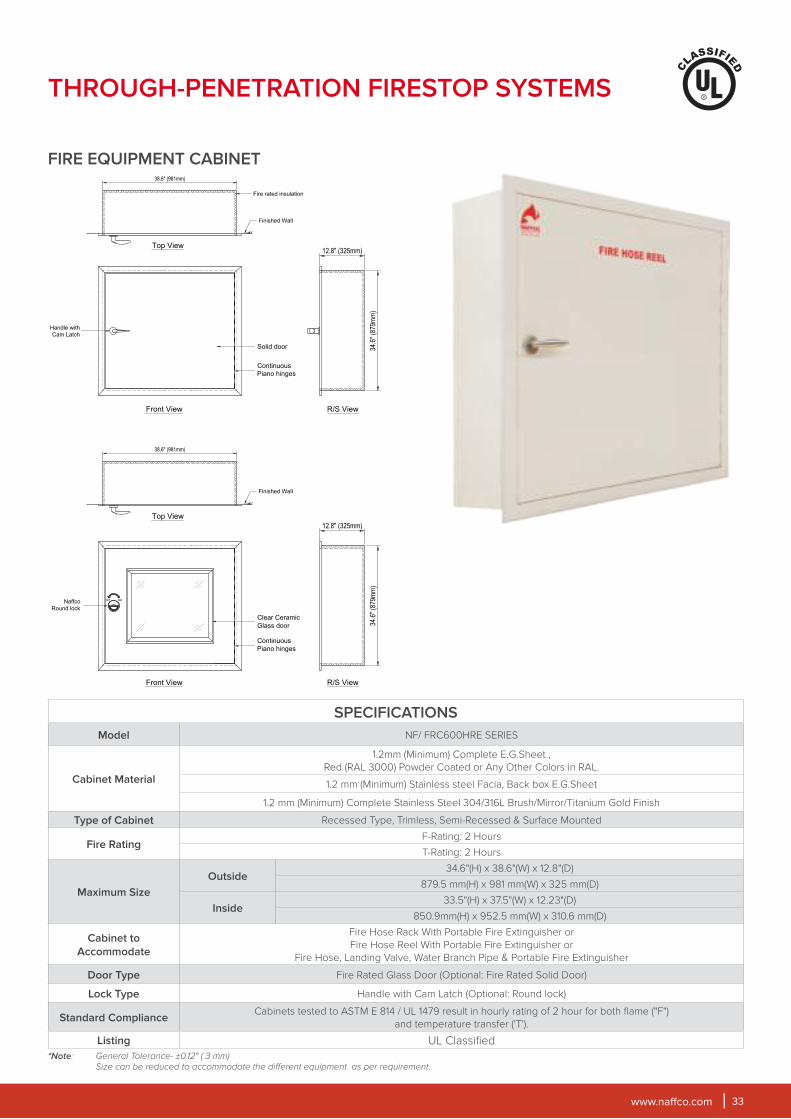
FIRE EXTINGUISHER/VALVE CABINET
THROUGH-PENETRATION FIRESTOP SYSTEMS
PRODUCT DESCRIPTION
NAFFCO proudly manufactures fire-rated cabinets for use
in fire-rated assemblies. Underwriters Laboratories, Inc.
has classified and listed NAFFCO fire-rated cabinets for
combustible and non-combustible wall systems. The cabinets
are tested to ASTM E814 or UL1679 results in hourly rating
of 2 hour for both flame ("F") and temperature transfer("T").
The fire-rated option eliminates the costly need to line the wall
opening with fire-rated material. It also provides the specified
assurance in maintaining the integrity of the wall penetration and
in meeting building code specifications.
SPECIFICATIONS
Model NF/5OOFRCG ELV SERIES
Cabinet Material
1.2 mm (Minimum) Complete E.G. Sheet ,
Red (RAL 3000) Powder Coated or Any Other Colors in RAL.
1.2 mm (Minimum) Stainless steel Facia, Back box E.G.Sheet
1.2 mm (Minimum) Complete Stainless Steel 304/316L Brush/Mirror/Titanium Gold Finish
Type of Cabinet Recessed Type, Semi-Recessed & Surface Mounted
Fire RatingF-Rating: 2 Hours
T-Rating: 2 Hours
Maximum Size
Outside45.12"(H) X 19.12"(W) X 8.85"(D)
1146 mm(H) X 485.5 mm(W) X 225 mm(D)
Inside44"(H) X 18"(W) X 8.18"(D)
1117 .5 mm(H) X 457 mm(W) X 207 .5 mm(D)
Cabinet to
AccommodatePortable Fire Extinguisher or Landing Valve
Door Type Fire Rated Glass Door (Optional: Fire Rated Solid Door)
Lock Type Handle with Cam Latch (Optional: Round lock)
Standard ComplianceCabinets tested to ASTM E 814 / UL 1479 result in hourly rating of 2 hour for both flame ("F")
and temperature transfer ('T').
Listing UL Classified
*Note: General Tolerance- ±0.12" ( 3 mm)
Size can be reduced to accommodate the different acquirements as per requirement.
www.naffco.com 33
SPECIFICATIONS
Model NF/ FRC600HRE SERIES
Cabinet Material
1.2mm (Minimum) Complete E.G.Sheet ,
Red (RAL 3000) Powder Coated or Any Other Colors in RAL.
1.2 mm (Minimum) Stainless steel Facia, Back box E.G.Sheet
1.2 mm (Minimum) Complete Stainless Steel 304/316L Brush/Mirror/Titanium Gold Finish
Type of Cabinet Recessed Type, Trimless, Semi-Recessed & Surface Mounted
Fire RatingF-Rating: 2 Hours
T-Rating: 2 Hours
Maximum Size
Outside34.6"(H) x 38.6"(W) x 12.8"(D)
879.5 mm(H) x 981 mm(W) x 325 mm(D)
Inside33.5"(H) x 37.5"(W) x 12.23"(D)
850.9mm(H) x 952.5 mm(W) x 310.6 mm(D)
Cabinet to
Accommodate
Fire Hose Rack With Portable Fire Extinguisher or
Fire Hose Reel With Portable Fire Extinguisher or
Fire Hose, Landing Valve, Water Branch Pipe & Portable Fire Extinguisher
Door Type Fire Rated Glass Door (Optional: Fire Rated Solid Door)
Lock Type Handle with Cam Latch (Optional: Round lock)
Standard ComplianceCabinets tested to ASTM E 814 / UL 1479 result in hourly rating of 2 hour for both flame ("F")
and temperature transfer ('T').
Listing UL Classified
*Note: General Tolerance- ±0.12" ( 3 mm) Size can be reduced to accommodate the different equipment as per requirement.
FIRE EQUIPMENT CABINET
THROUGH-PENETRATION FIRESTOP SYSTEMS
www.naffco.com34
.
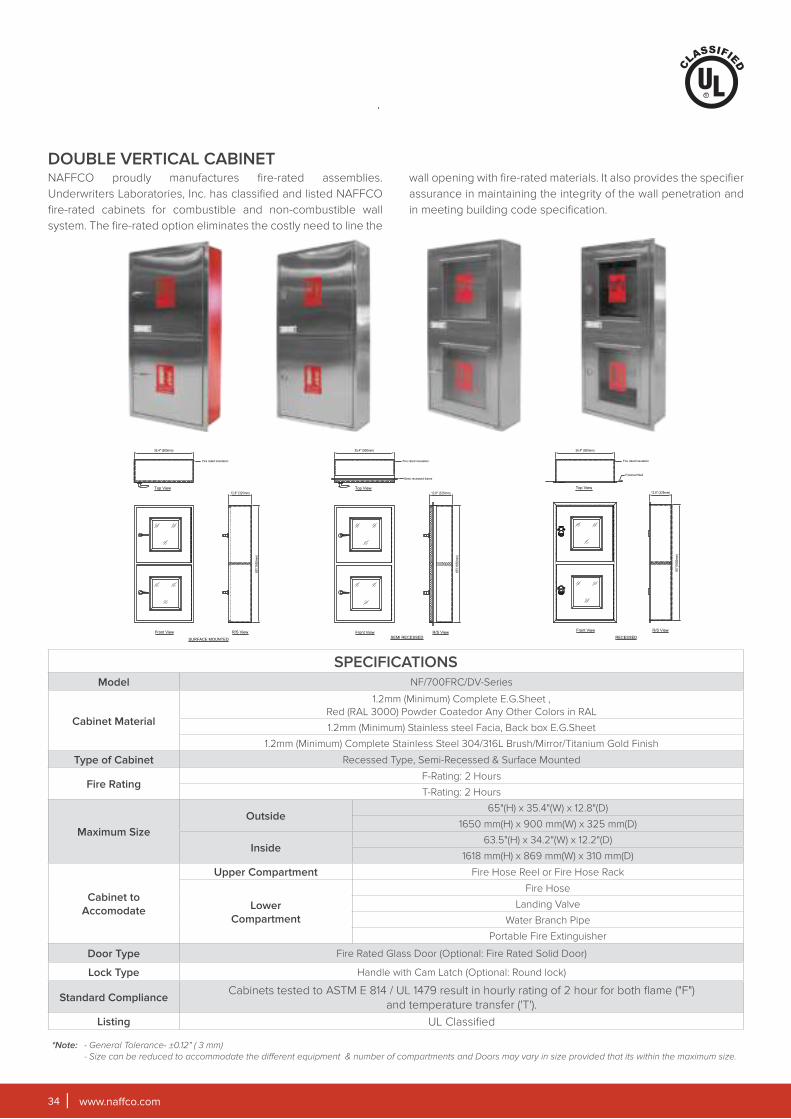
DOUBLE VERTICAL CABINET
SPECIFICATIONSModel NF/700FRC/DV-Series
Cabinet Material
1.2mm (Minimum) Complete E.G.Sheet ,
Red (RAL 3000) Powder Coatedor Any Other Colors in RAL
1.2mm (Minimum) Stainless steel Facia, Back box E.G.Sheet
1.2mm (Minimum) Complete Stainless Steel 304/316L Brush/Mirror/Titanium Gold Finish
Type of Cabinet Recessed Type, Semi-Recessed & Surface Mounted
Fire RatingF-Rating: 2 Hours
T-Rating: 2 Hours
Maximum Size
Outside65"(H) x 35.4"(W) x 12.8"(D)
1650 mm(H) x 900 mm(W) x 325 mm(D)
Inside63.5"(H) x 34.2"(W) x 12.2"(D)
1618 mm(H) x 869 mm(W) x 310 mm(D)
Cabinet to
Accomodate
Upper Compartment Fire Hose Reel or Fire Hose Rack
Lower
Compartment
Fire Hose
Landing Valve
Water Branch Pipe
Portable Fire Extinguisher
Door Type Fire Rated Glass Door (Optional: Fire Rated Solid Door)
Lock Type Handle with Cam Latch (Optional: Round lock)
Standard ComplianceCabinets tested to ASTM E 814 / UL 1479 result in hourly rating of 2 hour for both flame ("F")
and temperature transfer ('T').
Listing UL Classified
*Note: - General Tolerance- ±0.12" ( 3 mm)
- Size can be reduced to accommodate the different equipment & number of compartments and Doors may vary in size provided that its within the maximum size.
NAFFCO proudly manufactures fire-rated assemblies.
Underwriters Laboratories, Inc. has classified and listed NAFFCO
fire-rated cabinets for combustible and non-combustible wall
system. The fire-rated option eliminates the costly need to line the
wall opening with fire-rated materials. It also provides the specifier
assurance in maintaining the integrity of the wall penetration and
in meeting building code specification.
www.naffco.com 35
FEATURES
• BSI Kitemark and LPCB certified.
• Castings are clean, sound and free from gross porosity.
• Machined surface is within tolerance and is in accordance
with BS 1134-2.
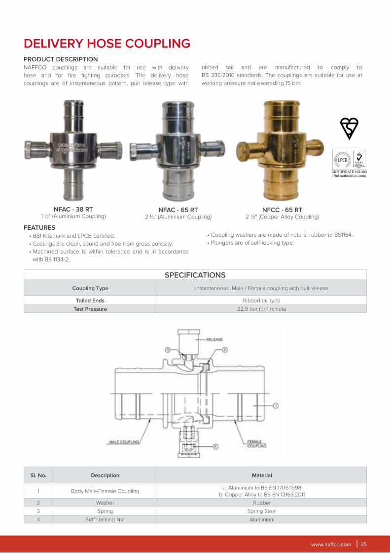
DELIVERY HOSE COUPLING
• Coupling washers are made of natural rubber to BS1154.
• Plungers are of self-locking type.
PRODUCT DESCRIPTION
NAFFCO couplings are suitable for use with delivery
hose and for fire fighting purposes. The delivery hose
couplings are of instantaneous pattern, pull release type with
ribbed tail and are manufactured to comply to
BS 336:2010 standards. The couplings are suitable for use at
working pressure not exceeding 15 bar.
NFAC - 65 RT2 1⁄2" (Aluminium Coupling)
NFAC - 38 RT1 1⁄2" (Aluminium Coupling)
NFCC - 65 RT
2 1⁄2" (Copper Alloy Coupling)
SPECIFICATIONS
Coupling Type Instantaneous Male / Female coupling with pull release
Tailed Ends Ribbed tail type
Test Pressure 22.5 bar for 1 minute
Sl. No. Description Material
1 Body Male/Female Couplinga. Aluminium to BS EN 1706:1998
b. Copper Alloy to BS EN 12163:2011
2 Washer Rubber
3 Spring Spring Steel
4 Self Locking Nut Aluminium
www.naffco.com36
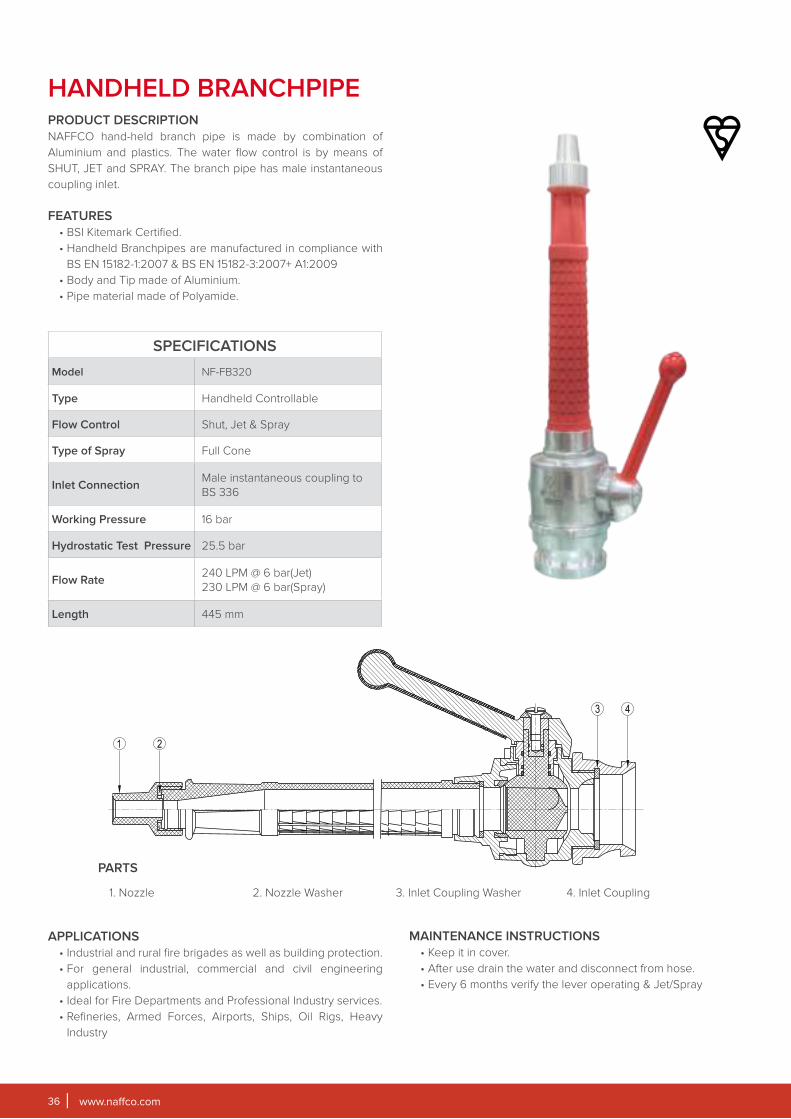
HANDHELD BRANCHPIPEPRODUCT DESCRIPTION
NAFFCO hand-held branch pipe is made by combination of
Aluminium and plastics. The water flow control is by means of
SHUT, JET and SPRAY. The branch pipe has male instantaneous
coupling inlet.
FEATURES
• BSI Kitemark Certified.
• Handheld Branchpipes are manufactured in compliance with
BS EN 15182-1:2007 & BS EN 15182-3:2007+ A1:2009
• Body and Tip made of Aluminium.
• Pipe material made of Polyamide.
SPECIFICATIONS
Model NF-FB320
Type Handheld Controllable
Flow Control Shut, Jet & Spray
Type of Spray Full Cone
Inlet ConnectionMale instantaneous coupling to
BS 336
Working Pressure 16 bar
Hydrostatic Test Pressure 25.5 bar
Flow Rate240 LPM @ 6 bar(Jet)
230 LPM @ 6 bar(Spray)
Length 445 mm
PARTS
1. Nozzle 2. Nozzle Washer 3. Inlet Coupling Washer 4. Inlet Coupling
APPLICATIONS
• Industrial and rural fire brigades as well as building protection.
• For general industrial, commercial and civil engineering
applications.
• Ideal for Fire Departments and Professional Industry services.
• Refineries, Armed Forces, Airports, Ships, Oil Rigs, Heavy
Industry
MAINTENANCE INSTRUCTIONS
• Keep it in cover.
• After use drain the water and disconnect from hose.
• Every 6 months verify the lever operating & Jet/Spray
www.naffco.com 37
FEATURES
BSI Kitemark.
• Body material made of aluminium alloy.
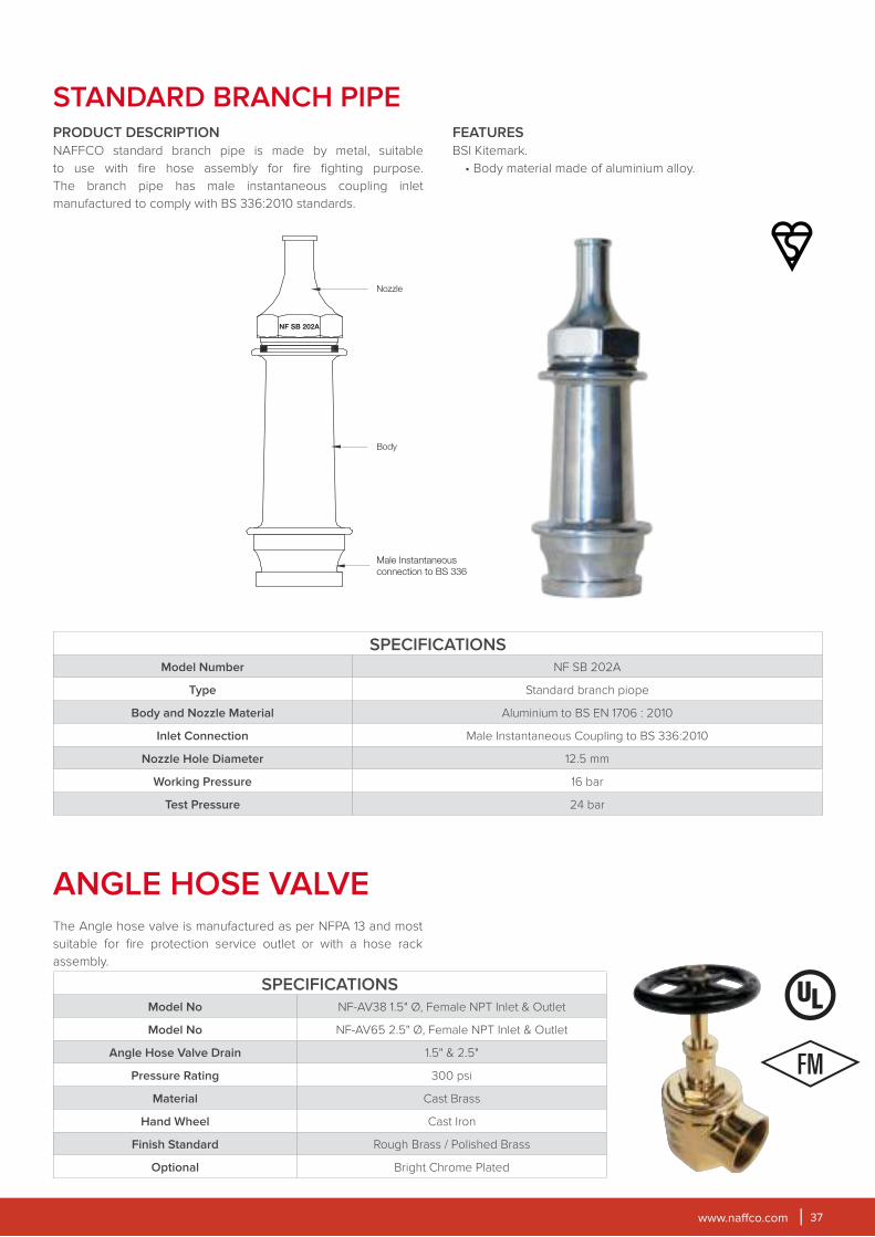
STANDARD BRANCH PIPEPRODUCT DESCRIPTION
NAFFCO standard branch pipe is made by metal, suitable
to use with fire hose assembly for fire fighting purpose.
The branch pipe has male instantaneous coupling inlet
manufactured to comply with BS 336:2010 standards.
SPECIFICATIONSModel Number NF SB 202A
Type Standard branch piope
Body and Nozzle Material Aluminium to BS EN 1706 : 2010
Inlet Connection Male Instantaneous Coupling to BS 336:2010
Nozzle Hole Diameter 12.5 mm
Working Pressure 16 bar
Test Pressure 24 bar
Male Instantaneous
connection to BS 336
Body
Nozzle
NF SB 202A
SPECIFICATIONSModel No NF-AV38 1.5" Ø, Female NPT Inlet & Outlet
Model No NF-AV65 2.5" Ø, Female NPT Inlet & Outlet
Angle Hose Valve Drain 1.5" & 2.5"
Pressure Rating 300 psi
Material Cast Brass
Hand Wheel Cast Iron
Finish Standard Rough Brass / Polished Brass
Optional Bright Chrome Plated
ANGLE HOSE VALVEThe Angle hose valve is manufactured as per NFPA 13 and most
suitable for fire protection service outlet or with a hose rack
assembly.
www.naffco.com38
SPECIFICATIONSModel Number NDR 098 NDR 100*
Valve Type Oblique, Flanged Inlet
Pressure Rating Low Pressure Valve
Nominal Size DN50 DN65
Working Pressure 15 bar Maximum
Test Pressure Valve Seat Test at 16.5 bar • Body Test at 22.5 bar
Flange Drilling BS 4504 Part 2:1974 Table:16/21
Water Flow Rate 8.5 L/S @ 4 bar Outlet Pressure
*Kitemark approved only
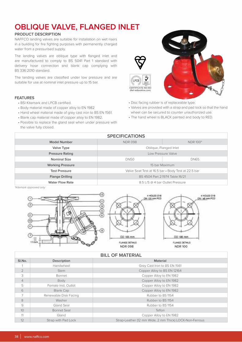
OBLIQUE VALVE, FLANGED INLETPRODUCT DESCRIPTION
NAFFCO landing valves are suitable for installation on wet risers
in a building for fire fighting purposes with permanently charged
water from a pressurised supply.
The landing valves are oblique type with flanged inlet and
are manufactured to comply to BS 5041 Part 1 standard with
delivery hose connection and blank cap complying with
BS 336:2010 standard.
The landing valves are classified under low pressure and are
suitable for use at nominal inlet pressure up to 15 bar.
FEATURES
• BSI Kitemark and LPCB certified.
• Body material made of copper alloy to EN 1982
• Hand wheel material made of grey cast iron to BS EN 1561.
• Blank cap material made of copper alloy to EN 1982.
• Possible to replace the gland seal when under pressure with
the valve fully closed.
• Disc facing rubber is of replaceable type.
• Valves are provided with a strap and pad lock so that the hand
wheel can be secured to counter unauthorized use.
• The hand wheel is BLACK painted and body to RED.
BILL OF MATERIALSl.No. Description Material
1 Handwheel Grey Cast Iron to BS EN 1561
2 Stem Copper Alloy to BS EN 12164
3 Bonnet Copper Alloy to EN 1982
4 Body Copper Alloy to EN 1982
5 Female Inst. Outlet Copper Alloy to EN 1982
6 Blank Cap Copper Alloy to EN 1982
7 Renewable Disk Facing Rubber to BS 1154
8 Washer Rubber to BS 1154
9 Gland Seal Rubber to BS 1154
10 Bonnet Seal Teflon
11 Gland Copper Alloy to EN 1982
12 Strap with Pad Lock Strap-Leather (12 mm Wide, 2 mm Thick) LOCK-Non-Ferrous
NDR 098 NDR 100
www.naffco.com 39
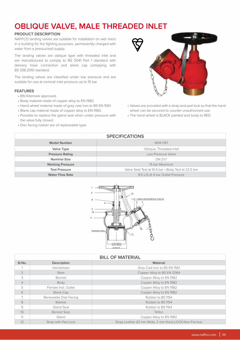
OBLIQUE VALVE, MALE THREADED INLETPRODUCT DESCRIPTION
NAFFCO landing valves are suitable for installation on wet risers
in a building for fire fighting purposes, permanently charged with
water from a pressurized supply.
The landing valves are oblique type with threaded inlet and
are manufactured to comply to BS 5041 Part 1 standard with
delivery hose connection and blank cap complying with
BS 336:2010 standard.
The landing valves are classified under low pressure and are
suitable for use at nominal inlet pressure up to 15 bar.
FEATURES
• BSI Kitemark approved.
• Body material made of copper alloy to EN 1982
• Hand wheel material made of grey cast iron to BS EN 1561.
• Blank cap material made of copper alloy to EN 1982.
• Possible to replace the gland seal when under pressure with
the valve fully closed.
• Disc facing rubber are of replaceable type.
• Valves are provided with a strap and pad lock so that the hand
wheel can be secured to counter unauthorized use.
• The hand wheel is BLACK painted and body to RED.
SPECIFICATIONS
Model Number NDR 097
Valve Type Oblique, Threaded Inlet
Pressure Rating Low Pressure Valve
Nominal Size DN 2½"
Working Pressure 15 bar Maximum
Test Pressure Valve Seat Test at 16.5 bar • Body Test at 22.5 bar
Water Flow Rate 8.5 L/S @ 4 bar Outlet Pressure
BILL OF MATERIALSl.No. Description Material
1 Handwheel Grey Cast Iron to BS EN 1561
2 Stem Copper Alloy to BS EN 12164
3 Bonnet Copper Alloy to EN 1982
4 Body Copper Alloy to EN 1982
5 Female Inst. Outlet Copper Alloy to EN 1982
6 Blank Cap Copper Alloy to EN 1982
7 Renewable Disk Facing Rubber to BS 1154
8 Washer Rubber to BS 1154
9 Gland Seal Rubber to BS 1154
10 Bonnet Seal Teflon
11 Gland Copper Alloy to EN 1982
12 Strap with Pad Lock Strap-Leather (12 mm Wide, 2 mm thick) LOCK-Non-Ferrous

www.naffco.com40
PRESSURE REDUCING VALVE,FLANGED INLETPRODUCT DESCRIPTION
NAFFCO pressure reducing oblique landing valves are
suitable for installation on wet risers in buildings for fire
fighting purposes, permanently charged with water from a
pressurised supply.
These landing valves are pressure reducing type designed to
provide a range of outlet pressure (4 bar -12 bar). The Landing
valves are classified under high pressure and are suitable for use
at nominal inlet pressure up to 20 bar.
FEATURES
• BSI Kitemark approved.
• Body material made of copper alloy to EN 1982.
• Hand wheel material made of grey cast iron to BS EN 1561.
• Blank cap material made of copper alloy to EN 1982.
• Possible to replace the gland seal when under pressure with
the valve fully closed.
SPECIFICATIONSModel Number NWR 120 NWR 122
Valve Type Oblique, Pressure Reducing, Flanged Inlet
Pressure Rating High Pressure Valve
Nominal Size DN50 DN65
Working Pressure 20 bar Maximum
Test Pressure Valve Seat Test at 22 bar • Body Test at 30 bar
Flange Drilling BS4504 Part: 2 :1974Table : 16/21
Min. Water Flow Rate 8.5 L/S @ 4 bar Outlet Pressure
Min. Valve Pressure Regulating 4-12 bar
BILL OF MATERIALSl.No. Description Material
1 Handwheel 0
2 Stem Copper Alloy to BS EN 12164
3 Bonnet Copper Alloy to EN 1982
4 Body Copper Alloy to EN 1982
5 Female Inst. Outlet Copper Alloy to EN 1982
6 Blank Cap Copper Alloy to EN 1982
7 Renewable Disk Facing Rubber to BS 1154
8 Washer Rubber to BS 1154
9 Gland Seal Rubber to BS 1154
10 Bonnet Seal Teflon
11 Gland Copper Alloy to EN 1982
12 Strap with Pad Lock Strap-Leather (12 mm Wide, 2 mm Thick) LOCK-Non-Ferrous
• Disc facing rubber are of replaceable type.
• Valves are provided with a strap and pad lock so that the hand
wheel can be secured to counter unauthorized use.
• The hand is painted black and the body is painted red.
DN 50 DN 65
4 HOLES ØON 125 mm PCD, OD165
8 HOLES ØON 145 mm PCD, OD185

www.naffco.com 41
4"x2 WAY BREECHING INLET
SPECIFICATIONS
Model Number NDR 095
Inlet Connection 2 Nos. Male Instantaneous Connector Complying to BS 336
Pressure Rating Normal Working Pressure of 10 bar
Nominal Size 100 mm Flanged Outlet
Test Pressure 20 bar
Flange Drilling BS 4504 Part: 2:1974 Table: 16/21
BILL OF MATERIAL
Sl.No. Description Material
1 Body Spheroidal Graphite Cast Iron to BS EN 1563:2011
2 Inlet Connection & Non-Return Valves Copper Alloy to BS EN 12163:2011
3 Drain Valve Copper Alloy to BS EN 12163:2011
4 Blank Cap for Drain Valve Copper Alloy to BS EN 12163:2011
5 Blank Cap for Inlet Connector Plastic
PRODUCT DESCRIPTION
NAFFCO breeching inlets are suitable for installation on
dry risers only, in a building for fire fighting purposes, fitted
with inlet connection at fire brigade access level and outlet
connection at specified points, which is normally dry but capable
of being charged with water by pumping from fire service
appliances.
The breeching inlets are manufactured to comply with
BS 5041 PART-3:1975 standard comprising of male
instantaneous connections complying with BS 336:2010, drain
valves complying with BS 5154, PN16 rated and non return valves.
The breeching inlets and its fittings are suitable for a normal
working pressure of 10 bar.
FEATURES
• BSI Kitemark and LPCB certified.
• Body material made of spheroidal graphite cast iron
(Ductile Iron) to BS 1563:2011.
• Inlet connection and non-return valves material made of
copper alloy to BS 12163:2011.
• Each inlet connections are fitted with non-return valve and are
of spring loaded mushroom type.
• Each breeching inlet is painted RED internally and
externally.
www.naffco.com42
6"x4 WAY BREECHING INLET
PRODUCT DESCRIPTION
NAFFCO breeching inlets are suitable for installation on
dry risers only, in a building for fire fighting purposes, fitted
with inlet connection at fire brigade access level and outlet
connection at specified points, which is normally dry but capable
of being charged with water by pumping from fire service
appliances.
The breeching inlets are manufactured to comply with
BS 5041 PART-3:1975 standard comprising of male instantaneous
connections complying with BS 336:2010, drain valves
complying with BS 5154, PN16 rated and non-return valves.
The breeching inlets and its fittings are suitable for a normal
working pressure of 10 bar.
FEATURES
• BSI Kitemark & LPCB certified.
• Body material made of spheroidal graphite cast iron
(Ductile Iron) to BS 1563:2011.
• Inlet connection and non-return valves material made of copper
alloy to BS 12163:2011.
SPECIFICATIONSModel Number NWR 115 & NWRX 115
Inlet Connection 4 Nos. Male Instantaneous Connector Complying to BS 336
Pressure Rating Normal Working Pressure of 10 bar
Nominal Size 150 mm Flanged Outlet
Test Pressure 20 bar
Flange Drilling BS 4504 Part : 2 : 1974 Table : 16/21
BILL OF MATERIALSl.No. Description Material
1 Body Spheroidal Graphite Cast Iron to BS EN 1563:2011
2 Inlet Connection & Non-Return Valves Copper Alloy to BS EN 12163:2011
3 Drain Valve Copper Alloy to BS EN 12163: 2011
4 Blank Cap for Drain Valve Copper Alloy to BS EN 12163: 2011
5 Blank Cap for Inlet Connector Plastic
• Each inlet connection is fitted with non-return valve and of spring
loaded mushroom type.
• Each breeching inlet is painted RED internally and
externally.
www.naffco.com 43
DRY PILLAR FIRE HYDRANTS
FEATURES
• BSI-KITEMARK, LPCB approved
• NAFFCO Fire Hydrants are manufactured to comply BS EN
14384: 2005, BS 1074-1, BS 1074-2 & BS 1074-6 Standards.
• Dry barrel design eliminates damage to the hydrant caused by
freezing of the upper part.
• NAFFCO Fire Hydrants are designed for high performance
and easy to install, maintain and repair.
• Excellent and proven flow characteristics.
• 2 x 2½” gate valve with female instantaneous outlet to BS
336:2010.
• Body material made of spheroidal graphite cast iron
(Ductile Iron) to BS 1563:2011.
• 2 x 2½” Female Instantaneous quick coupling adaptor to
BS 336:2010, flanged inlet to BS EN 1092-2
• 1 x 4” Male/Female BSRT pumper to BS 336:2010.
• Aluminum Hood / GRP cover is provided for protection and
misusing.
• Operation threads are corrosion protected and for easy
operation.
• NAFFCO Fire Hydrants are high Pressure rating to 16 bar.
• Drain starts automatically when hydrant is closed.
• Internal epoxy paint system gives high corrosion
protection to hydrants.
• Hydrant protective covers with handle for easy handling.
*for LPCB approved - Hydrant Model NFHV Series with 2 x 2½" straight through landing valve available upon request.
SHELL MATERIAL
Spheroidal graphite cast iron. (Ductile Iron)
OBTURATOR
• The design of obturator (base valve) in hydrant is made in
such way that it can be replaced at site.
• Material of base valve is high tensile brass.
RESISTANCE TO DISFUNCTION PRODUCTS
Hydrant is built to withstand misuse that may cause dysfunctional
failures.
INLET FLANGED TO BS EN 1092-2
CORROSION PROTECTION
All ferrous components liable to corrode are prepared and
coated as detail below:
SURFACE PREPARATION:
Each hydrant is shot blasted (inside & outside)
PAINT SYSTEM
• INSIDE: barrel inside and rod coated with 3 coat epoxy paint
system, 200 microns DFT.
• OUTSIDE: Outside coating top portion primer coating and
red polyurethane coating , 200 microns. Bottom portion
outside two coat black bituminous coating, 200 microns.
FIELD OF APPLICATION
• Fire fighting purpose.
• Suitable for non-potable water supply purpose only.
DESIGN SPECIFICATIONS
www.naffco.com44
GENERAL DIMENSIONAL DETAILS
SL.No. Model No.Inlet Flange
Size in inch (DN)
Dimensions in mm Working
PressureA B
NHC Series
1 100 NHC-800 4 (100) 1515 530 16
2 100 NHC-1200 4 (100) 1915 530 16
NFHV Series*
1 100 NFHV-800 4 (100) 1450 430 16
2 100 NFHV-1200 4 (100) 1850 430 16
3 150 NFHV-800 6 (150) 1500 480 16
4 150 NFHV-1200 6 (150) 1900 480 16
NFHQ Series
1 100 NFHQ-800 4 (100) 1450 430 16
2 100 NFHQ-1200 4 (100) 1850 430 16
3 150 NFHQ-800 6 (150) 1500 480 16
4 150 NFHQ-1200 6 (150) 1900 480 16
NFHQC Series
1 100 NFHQC-800 4 (100) 1450 430 16
2 100 NFHQC-1200 4 (100) 1850 430 16
3 150 NFHQC-800 6 (150) 1500 480 16
4 150 NFHQC-1200 6 (150) 1900 480 16
NFHQS-CD Series
1 100 NFHQS-CD 800 4 (100) 1450 430 16
2 100 NFHQS-CD 1200 4 (100) 1850 430 16
3 150 NFHQS-CD 800 6 (150) 1500 480 16
4 150 NFHQS-CD 1200 6 (150) 1900 480 16
NFHQM Series
1 150 NFHQM-800 6 (150) 1500 480 16
2 150 NFHQM-1200 6 (150) 1900 480 16
www.naffco.com 45
NHC
NFHQC
NFHV
NFHQS-CD
NFHQ
NFHQM
www.naffco.com46
FEATURES
• NAFFCO Fire Hydrants are designed to comply with ANSI/AWWA
C502.
• Dry barrel design eliminates damage to the hydrant caused by
freezing of the upper part.
• NAFFCO Fire Hydrants are designed for high performance and
easy to install, maintain and repair.
• Excellent and proven flow characteristics.
• 2 x 2½” NH thread connectors for soft hose connection.
• 1 x 4½” NH thread pumper connection for fire trucks.
• 6” inlet connection complying to mechanical joint ANSI/AWWA C111/
A21.11 or flange connection ASME B16.5 Class 150.
• Operation threads are corrosion protected and for easy operation.
• NAFFCO fire hydrants are high pressure rated to 250 psi compatible
with today’s trends.
• Internal epoxy paint system gives high corrosion protection to
hydrants.
• Advanced safety couplings and flange design reduces traffic
damage to hydrant.
• Main valve is easily removed from either the bonnet flange or
ground line flange.
DRY TYPE PILLAR FIRE HYDRANTS
DESIGN FEATURES
• Body Material: Ductile Iron.
• Nominal Pressure 250 psi., Test Pressure: 500 psi.
• O-ring sealed flanges at the bonnet ground line and shoe simplify
maintenance by eliminating gasket adhesion at these points,
making disassembly easier. The O-rings are easier than flat gaskets
to position during reassembly, and provide superior pressure
handling.
• Hold-down nut - features integral weather seal. Prevents
unauthorized removal of hold-down nut or operating nut. Resilient
wiper seal prevents water entry and protects from freezing; material
resistant to sunlight deterioration. O-ring provides second level seal.
• Safety flange - breaks cleanly to help prevent barrel damage, but
strong enough to withstand normal handling. Allows economical
repair, adding of extension section, rotation or changing of upper
barrel without excavation.
• Full flow openings - large, smooth radius hose and pumper openings
reduce friction loss.
ModelInlet
Flange
Dimensions Working
PressureA B C
I5O-NFH(F) 6" 1063 460 805 250 psi
I5O-NFH(M) 6" 1063 460 805 250 psi
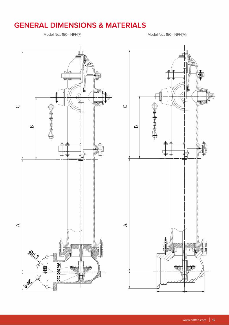
www.naffco.com 47
Model No.: 150 - NFH(M)
GENERAL DIMENSIONS & MATERIALSModel No.: 150 - NFH(F)
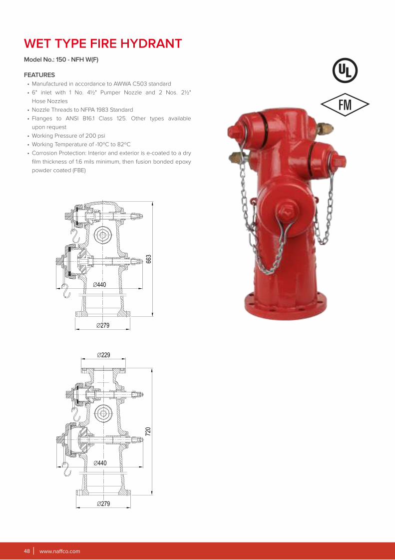
www.naffco.com48
WET TYPE FIRE HYDRANTModel No.: 150 - NFH W(F)
FEATURES
• Manufactured in accordance to AWWA C503 standard
• 6" inlet with 1 No. 41⁄2" Pumper Nozzle and 2 Nos. 21⁄2"
Hose Nozzles
• Nozzle Threads to NFPA 1983 Standard
• Flanges to ANSI B16.1 Class 125. Other types available
upon request
• Working Pressure of 200 psi
• Working Temperature of -10ºC to 82ºC
• Corrosion Protection: Interior and exterior is e-coated to a dry
film thickness of 1.6 mils minimum, then fusion bonded epoxy
powder coated (FBE)
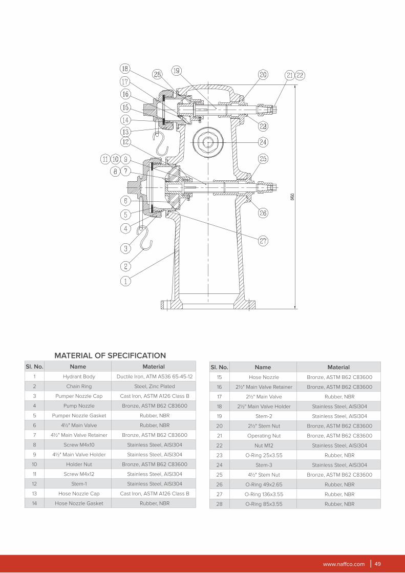
www.naffco.com 49
MATERIAL OF SPECIFICATION
Sl. No. Name Material
1 Hydrant Body Ductile Iron, ATM A536 65-45-12
2 Chain Ring Steel, Zinc Plated
3 Pumper Nozzle Cap Cast Iron, ASTM A126 Class B
4 Pump Nozzle Bronze, ASTM B62 C83600
5 Pumper Nozzle Gasket Rubber, NBR
6 41⁄2" Main Valve Rubber, NBR
7 41⁄2" Main Valve Retainer Bronze, ASTM B62 C83600
8 Screw M4x10 Stainless Steel, AISI304
9 41⁄2" Main Valve Holder Stainless Steel, AISI304
10 Holder Nut Bronze, ASTM B62 C83600
11 Screw M4x12 Stainless Steel, AISI304
12 Stem-1 Stainless Steel, AISI304
13 Hose Nozzle Cap Cast Iron, ASTM A126 Class B
14 Hose Nozzle Gasket Rubber, NBR
Sl. No. Name Material
15 Hose Nozzle Bronze, ASTM B62 C83600
16 21⁄2" Main Valve Retainer Bronze, ASTM B62 C83600
17 21⁄2" Main Valve Rubber, NBR
18 21⁄2" Main Valve Holder Stainless Steel, AISI304
19 Stem-2 Stainless Steel, AISI304
20 21⁄2" Stem Nut Bronze, ASTM B62 C83600
21 Operating Nut Bronze, ASTM B62 C83600
22 Nut M12 Stainless Steel, AISI304
23 O-Ring 25x3.55 Rubber, NBR
24 Stem-3 Stainless Steel, AISI304
25 41⁄2" Stem Nut Bronze, ASTM B62 C83600
26 O-Ring 49x2.65 Rubber, NBR
27 O-Ring 136x3.55 Rubber, NBR
28 O-Ring 85x3.55 Rubber, NBR
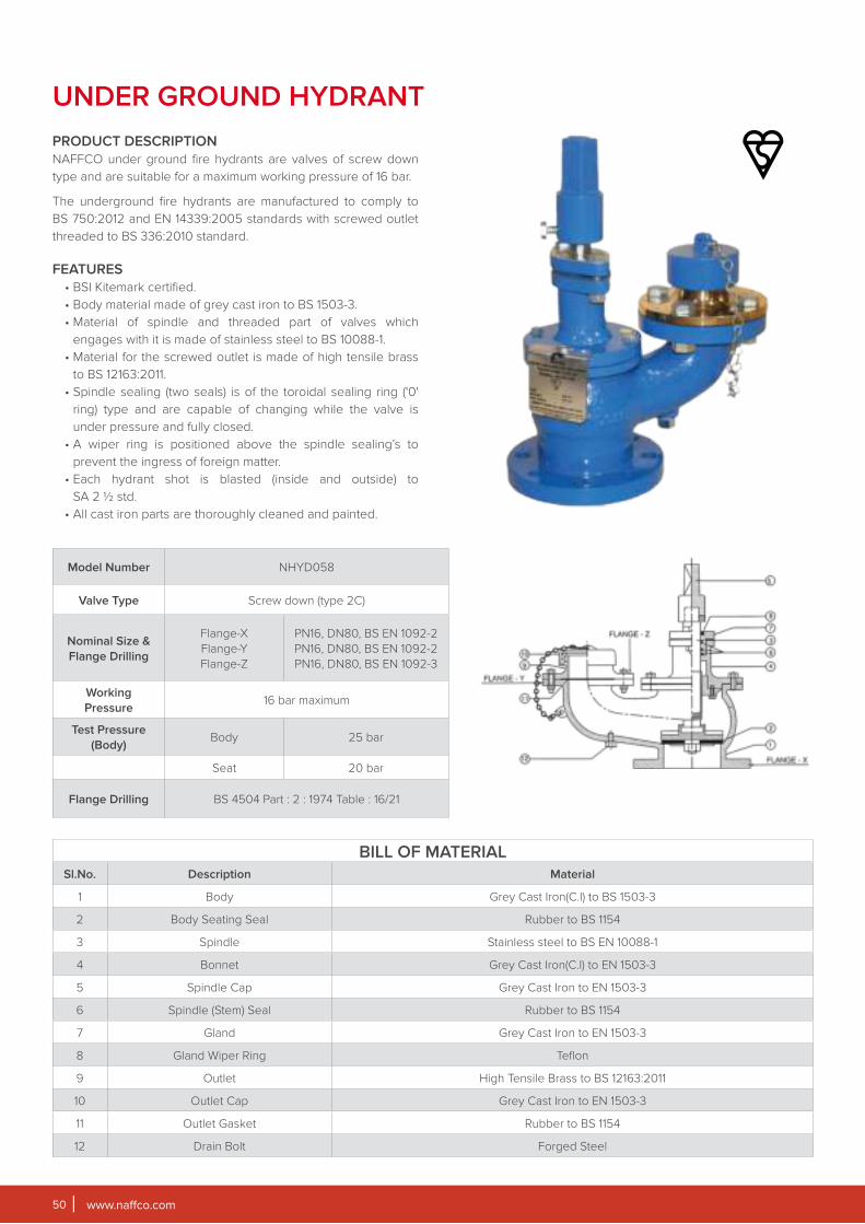
www.naffco.com50
Model Number NHYD058
Valve Type Screw down (type 2C)
Nominal Size &
Flange Drilling
Flange-X
Flange-Y
Flange-Z
PN16, DN80, BS EN 1092-2
PN16, DN80, BS EN 1092-2
PN16, DN80, BS EN 1092-3
Working
Pressure16 bar maximum
Test Pressure
(Body)Body 25 bar
Seat 20 bar
Flange Drilling BS 4504 Part : 2 : 1974 Table : 16/21
BILL OF MATERIALSl.No. Description Material
1 Body Grey Cast Iron(C.I) to BS 1503-3
2 Body Seating Seal Rubber to BS 1154
3 Spindle Stainless steel to BS EN 10088-1
4 Bonnet Grey Cast Iron(C.I) to EN 1503-3
5 Spindle Cap Grey Cast Iron to EN 1503-3
6 Spindle (Stem) Seal Rubber to BS 1154
7 Gland Grey Cast Iron to EN 1503-3
8 Gland Wiper Ring Teflon
9 Outlet High Tensile Brass to BS 12163:2011
10 Outlet Cap Grey Cast Iron to EN 1503-3
11 Outlet Gasket Rubber to BS 1154
12 Drain Bolt Forged Steel
UNDER GROUND HYDRANT
PRODUCT DESCRIPTION
NAFFCO under ground fire hydrants are valves of screw down
type and are suitable for a maximum working pressure of 16 bar.
The underground fire hydrants are manufactured to comply to
BS 750:2012 and EN 14339:2005 standards with screwed outlet
threaded to BS 336:2010 standard.
FEATURES
• BSI Kitemark certified.
• Body material made of grey cast iron to BS 1503-3.
• Material of spindle and threaded part of valves which
engages with it is made of stainless steel to BS 10088-1.
• Material for the screwed outlet is made of high tensile brass
to BS 12163:2011.
• Spindle sealing (two seals) is of the toroidal sealing ring ('0'
ring) type and are capable of changing while the valve is
under pressure and fully closed.
• A wiper ring is positioned above the spindle sealing’s to
prevent the ingress of foreign matter.
• Each hydrant shot is blasted (inside and outside) to
SA 2 ½ std.
• All cast iron parts are thoroughly cleaned and painted.
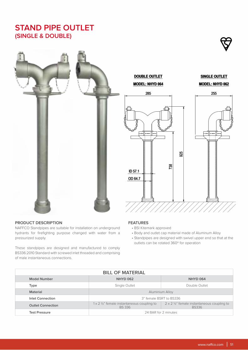
www.naffco.com 51
PRODUCT DESCRIPTION
NAFFCO Standpipes are suitable for installation on underground
hydrants for firefighting purpose changed with water from a
pressurized supply.
These standpipes are designed and manufactured to comply
BS336:2010 Standard with screwed inlet threaded and comprising
of male instantaneous connections.
FEATURES
• BSI Kitemark approved
• Body and outlet cap material made of Aluminum Alloy
• Standpipes are designed with swivel upper end so that at the
outlets can be rotated 360º for operation
STAND PIPE OUTLET(SINGLE & DOUBLE)
BILL OF MATERIALModel Number NHYD 062 NHYD 064
Type Single Outlet Double Outlet
Material Aluminium Alloy
Inlet Connection 3” female BSRT to BS336
Outlet Connection1 x 2 ½” female instantaneous coupling to
BS 3362 x 2 ½” female instantaneous coupling to
BS336
Test Pressure 24 BAR for 2 minutes

www.naffco.com52
FIRE BLANKET
PRODUCT DESCRIPTION
NAFFCO Fire blankets are made of fire resistant glass fiber fabric
with silicone coating. It is primarily intended for extinguishing
cooking oil fires in the kitchen. The Blankets are compliance with
BS1869 Standard Requirements.
FEATURES
• BSI Kitemark & LPCB Approved
• NAFFCO's blankets are electrical resistant not less than 1M to
ensure that in the event of use where live electrical equipment
is concerned, the potential for an electrical shock is minimized
• NAFFCO's fire blanket can be released and can be covered
on the flame in LESS THAN FIVE SECONDS
• It is an excellent fire extinguisher in a car, boat, caravan or
holiday home and we recommend that each family have at
least one for fire safety purpose. Fire blankets can be used
to extinguish fires in electrical appliances (toaster, coffee
maker, etc.) rubbish bins, clothes and table top fires caused by
candles or fat pan fires. Fire blankets can also be used to wrap
around a person whose clothing is on fire.
STANDARD COMPLIANCE
NAFFCO's fire blankets confirm to the requirements of BS EN 1869:1997
NFB 1.2
NFB 1.4
NFB 2.1
SPECIFICATIONS
Model NFB 1.2 NFB 4.4* NFB 1.4 NFB 4.6* NFB 2.1 NFB 6.6*
Size 1.1m X 1.1m 1.2m x 1.2m 1.2m x 1.8m 1.8m x 1.8m
Material Fiberglass with Silicone coating
Weight 340g/m2 480g/m2 340g/m2 480g/m2 340g/m2 480g/m2
Temperature 550°C
Packing Covered in Nylon Bags and Packed in Flat Hard PVC RED Pack
*LPCB Approved only.

www.naffco.com 53
FIRE FIGHTING PUMPS
NAFFCO’s UL listed and FM approved fire pumps provide you a
reliable solution for your fire fighting pump needs by combining
the stringent quality measures of UL, FM and NFPA standards with
our proven experience in the fire protection field.
We can offer you a complete package of services starting from
engineering assistance to field start-up and periodic maintenance.
Each pump sets is tested in our factory, prior to dispatch, as per
UL, FM and NFPA standards. These pumps are covered by a
warranty of one year subject to standard terms and conditions.
HORIZONTAL
END SUCTION PUMPSFEATURES
• Performance characteristics as per NFPA 20
• Complete unit responsiveness.
• Complete in-house fabrication capabilities.
• Hydrostatic strength testing facilities.
• Operation run test as per NFPA 20, UL 448 and FM 1319
requirements.
• End suction models for capacities from 50 to 500 US GPM at
2900 rpm and 3550rpm
• Drivers: Electric motor drive or diesel engine drive.
• Electrical testing capabilities for motors and controllers as
per NFPA standards.
• Capable to supply additional accessories wherever
required.
• Capable to supply single skid mounted fire pump set.
PUMP CASING
The casing is designed for back pull-out which permits the
removal of complete rotor unit without removing suction and
discharge pipe. The cast iron volute casing is of robust design
with integrally cast feet, vertical top centerline discharge with axial
suction incorporating cast inlet vane to give best flow to impeller
eye.
BEARINGS
Driven end / non-driven end bearings are grease lubricated deep
groove ball bearings.
IMPELLER
Impeller is double shrouded type. It is hydraulically balanced and
positively driven by shaft key and axially locked between sleeve
and impeller nut.
SHAFT SEAL
Soft-packed stuffing box. Graphite impregnated type gland
packing.
www.naffco.com54
FEATURES
• Performance characteristics as per NFPA 20
• Complete unit responsiveness.
• Complete in-house fabrication capabilities.
• Hydrostatic testing facilities.
• Operation run test as per NFPA 20, UL 448 and FM 1311
requirements.
• Horizontal Split case pumps for capacities from 500 to 1500
US GPM at 3550 rpm and 750 to 1500 US GPM at 2900
rpm.
• Drivers: Electric motor drive or diesel engine drive.
• Electrical testing capabilities for motors and controllers as
per NFPA standards.
• Capable to supply additional accessories wherever
required.
PUMP CASING: The casing is axially split, which permits
removal of the complete rotor without moving either piping or
motor. Pumps generating high heads have double volutes to
reduce radial forces, ensuring minimal shaft deflection and low
bearing loads. Replaceable wear rings protect the casing at the
impeller running clearances.
IMPELLER: The closed impeller have double curved vanes.
The double suction design gives practically zero axial forces.
Each impeller is dynamically balanced according to ISO 1940-1
standard.
BEARINGS: On both sides grease lubricated deep groove ball
bearings.
SHAFT SEAL: Soft-packed stuffing box. Cooling lines are
provided for additional cooling of the graphite impregnated
type gland packing.
CERTIFIED HORIZONTAL FIRE PUMPS RATING
RATED SPEED - 2900 RPM
RATED CAPACITY(GPM)
RATED PRESSURE RANGE(psi)
50 50 - 139
100 53 - 139
150 56 - 139
200 92 - 216
250 89 - 211
300 87 - 213
350 91 - 211
400 84 - 209
450 81 - 207
500 79 - 203
750 108 - 280
1000 101 - 273
1250 134 - 263
1500 121 - 256
RATED SPEED - 3500 RPM
Rated Capacity(GPM)
Rated Pressure Range(psi)
50 72 - 128
100 62 - 136
150 60 - 131
200 84 - 161
300 75 - 212
400 76 - 210
450 75 - 207
500 118 - 239
750 114 - 236
1000 111 - 234
1250 127 - 214
1500 126 - 211
HORIZONTAL SPLIT CASE PUMPS
www.naffco.com 55
RATED SPEED - 2900 RPM
Rated Capacity(GPM)
Rated Pressure Range(psi)
50 42 - 188
100 52 - 173
150 87 - 254
200 84 - 246
250 50 - 235
RATED SPEED - 1450 RPM
Rated Capacity(GPM)
Rated Pressure Range(psi)
30069 - 86
92 - 230
40066 - 82
88 -221
50063 - 80
84 - 215
75084 - 108
112 - 288
1000
81 - 99
108 - 132
135 - 265
1250 105 - 283
1500108 - 135
144 - 270
SUCTION ASSEMBLY
Suction bell is furnished with an extra long bearing that strengthens and provides rigid support for the
lower end of the pump shaft. Suction bell provides efficient flow into the eye of the first stage impeller.
DISCHARGE HEAD
The rugged pump discharge head assembly is made of close- grained cast iron. It has smooth
passageways that ensures efficient overall operation and provides an above ground connection to
the discharge piping.
BOWL
The pump bowls have vanes cast integrally in them. These vanes are designed to match accurately
with the impeller, and are smoothly contoured to guide the flow to next stage with maximum efficiency.
IMPELLER
Impellers are enclosed type, made of bronze / SS 304 and matched to the pump bowls. Each impeller
is statically / dynamically balanced as per ISO 1940-1 to insure highest efficiency and vibration free
operation.
COLUMN
Pump column pipe shall be in sections not longer than 10.ft each. Column pipe is flanged type. Flanged
connections are accurately machined to accept bearing retainers and are bolted together securely
for proper sealing.
VERTICAL TURBINE PUMPS
FEATURES
• Complete unit responsiveness.
• Complete in-house fabrication capabilities.
• Hydrostatic strength testing facilities.
• Operation run test as per NFPA 20, UL 448 requirements.
• Vertical turbine models for capacities from 50 to 1500 US GPM.
• Drivers: Electric motor drive or diesel engine drive.
• Electrical testing capabilities for motors and controllers as per NFPA standards.
• Capable to supply additional accessories wherever required.
• Rugged construction for longer service life.
• Specifically designed for fire fighting applications as per NFPA 20.
• Excellent mechanical and hydraulic design characteristics for efficient performance.
SHAFT SEAL
The shaft sealing is gland packing type. A lantern ring is furnished
between the packing and it relieves pump pressure from the
upper packing rings by bypassing the high pressure water
through its relief ports.
www.naffco.com56
PRE-PIPED VERTICAL & HORIZONTAL BLADDER TANK
APPLICATIONS
The NAFFCO Pre-piped Bladder tank is a complete balanced pressure proportioning system frequently used in;
Aircraft Hangars Sprinkler SystemsLoading Racks Offshore Platforms
DESCRIPTION
The NAFFCO Pre-piped Bladder tank is an integral component of
balanced pressure proportioning system. Its operation requires no
external power other than a pressurized water system. NAFFCO
bladder tank, with an appropriate proportioner, injects foam
concentrate into the water supply of a fire protection system and
automatically proportions at wide range of flows and pressures.
NAFFCO Pre-piped Foam bladder tank is a steel pressure vessel
fitted with an Internal Elastomeric bladder that stores foam
concentrate. During operation, the concentrate is discharged by
incoming water pressure to the bladder tank until the concentrate
is depleted. The bladder tank discharges foam concentrate at
approximately the same pressure as the water supplied at the
water inlet connection to the tank. Since the bladder tank is
pressurized, the bladder should not be refilled during operation.
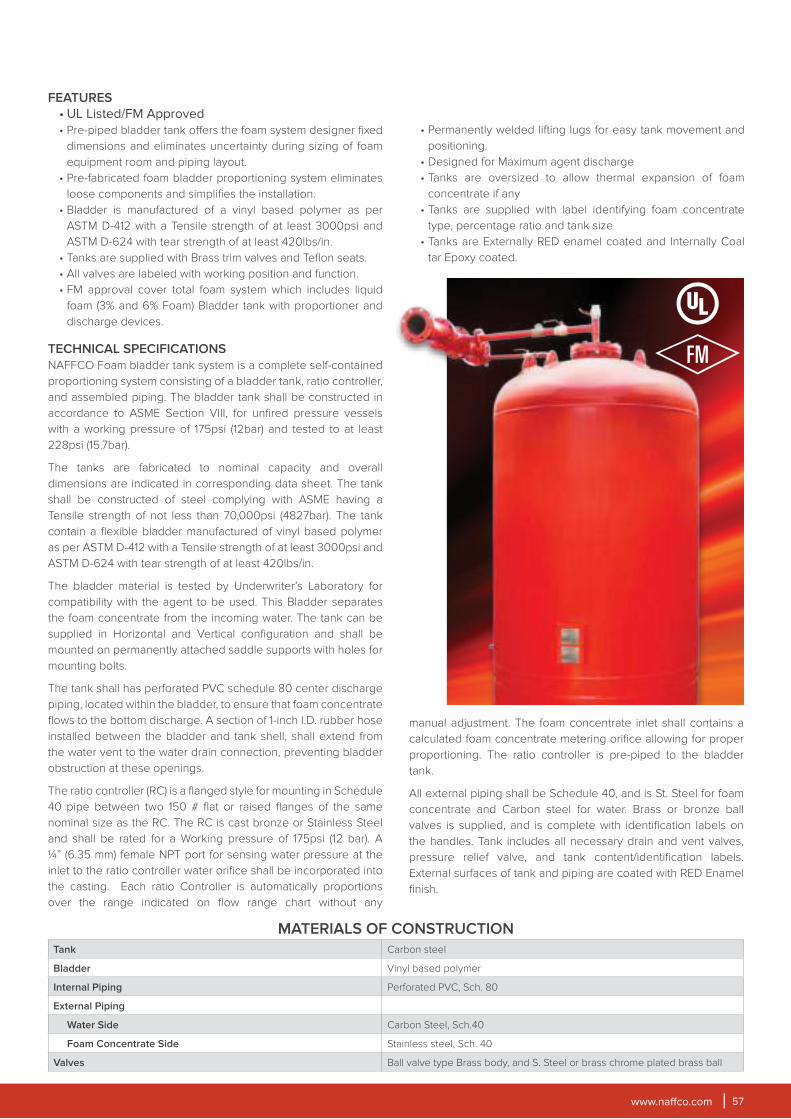
www.naffco.com 57
FEATURES
• UL Listed/FM Approved
• Pre-piped bladder tank offers the foam system designer fixed
dimensions and eliminates uncertainty during sizing of foam
equipment room and piping layout.
• Pre-fabricated foam bladder proportioning system eliminates
loose components and simplifies the installation.
• Bladder is manufactured of a vinyl based polymer as per
ASTM D-412 with a Tensile strength of at least 3000psi and
ASTM D-624 with tear strength of at least 420lbs/in.
• Tanks are supplied with Brass trim valves and Teflon seats.
• All valves are labeled with working position and function.
• FM approval cover total foam system which includes liquid
foam (3% and 6% Foam) Bladder tank with proportioner and
discharge devices.
TECHNICAL SPECIFICATIONS
NAFFCO Foam bladder tank system is a complete self-contained
proportioning system consisting of a bladder tank, ratio controller,
and assembled piping. The bladder tank shall be constructed in
accordance to ASME Section VIII, for unfired pressure vessels
with a working pressure of 175psi (12bar) and tested to at least
228psi (15.7bar).
The tanks are fabricated to nominal capacity and overall
dimensions are indicated in corresponding data sheet. The tank
shall be constructed of steel complying with ASME having a
Tensile strength of not less than 70,000psi (4827bar). The tank
contain a flexible bladder manufactured of vinyl based polymer
as per ASTM D-412 with a Tensile strength of at least 3000psi and
ASTM D-624 with tear strength of at least 420lbs/in.
The bladder material is tested by Underwriter’s Laboratory for
compatibility with the agent to be used. This Bladder separates
the foam concentrate from the incoming water. The tank can be
supplied in Horizontal and Vertical configuration and shall be
mounted on permanently attached saddle supports with holes for
mounting bolts.
The tank shall has perforated PVC schedule 80 center discharge
piping, located within the bladder, to ensure that foam concentrate
flows to the bottom discharge. A section of 1-inch I.D. rubber hose
installed between the bladder and tank shell, shall extend from
the water vent to the water drain connection, preventing bladder
obstruction at these openings.
The ratio controller (RC) is a flanged style for mounting in Schedule
40 pipe between two 150 # flat or raised flanges of the same
nominal size as the RC. The RC is cast bronze or Stainless Steel
and shall be rated for a Working pressure of 175psi (12 bar). A
¼” (6.35 mm) female NPT port for sensing water pressure at the
inlet to the ratio controller water orifice shall be incorporated into
the casting. Each ratio Controller is automatically proportions
over the range indicated on flow range chart without any
• Permanently welded lifting lugs for easy tank movement and
positioning.
• Designed for Maximum agent discharge
• Tanks are oversized to allow thermal expansion of foam
concentrate if any
• Tanks are supplied with label identifying foam concentrate
type, percentage ratio and tank size
• Tanks are Externally RED enamel coated and Internally Coal
tar Epoxy coated.
manual adjustment. The foam concentrate inlet shall contains a
calculated foam concentrate metering orifice allowing for proper
proportioning. The ratio controller is pre-piped to the bladder
tank.
All external piping shall be Schedule 40, and is St. Steel for foam
concentrate and Carbon steel for water. Brass or bronze ball
valves is supplied, and is complete with identification labels on
the handles. Tank includes all necessary drain and vent valves,
pressure relief valve, and tank content/identification labels.
External surfaces of tank and piping are coated with RED Enamel
finish.
MATERIALS OF CONSTRUCTION
Tank Carbon steel
Bladder Vinyl based polymer
Internal Piping Perforated PVC, Sch. 80
External Piping
Water Side Carbon Steel, Sch.40
Foam Concentrate Side Stainless steel, Sch. 40
Valves Ball valve type Brass body, and S. Steel or brass chrome plated brass ball
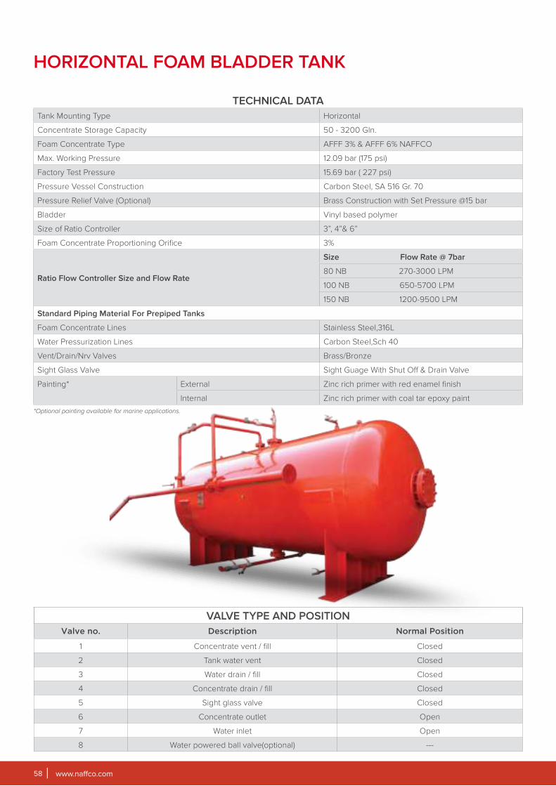
www.naffco.com58
HORIZONTAL FOAM BLADDER TANK
TECHNICAL DATA
Tank Mounting Type Horizontal
Concentrate Storage Capacity 50 - 3200 Gln.
Foam Concentrate Type AFFF 3% & AFFF 6% NAFFCO
Max. Working Pressure 12.09 bar (175 psi)
Factory Test Pressure 15.69 bar ( 227 psi)
Pressure Vessel Construction Carbon Steel, SA 516 Gr. 70
Pressure Relief Valve (Optional) Brass Construction with Set Pressure @15 bar
Bladder Vinyl based polymer
Size of Ratio Controller 3”, 4”& 6”
Foam Concentrate Proportioning Orifice 3%
Ratio Flow Controller Size and Flow Rate
Size Flow Rate @ 7bar
80 NB 270-3000 LPM
100 NB 650-5700 LPM
150 NB 1200-9500 LPM
Standard Piping Material For Prepiped Tanks
Foam Concentrate Lines Stainless Steel,316L
Water Pressurization Lines Carbon Steel,Sch 40
Vent/Drain/Nrv Valves Brass/Bronze
Sight Glass Valve Sight Guage With Shut Off & Drain Valve
Painting* External Zinc rich primer with red enamel finish
Internal Zinc rich primer with coal tar epoxy paint
*Optional painting available for marine applications.
VALVE TYPE AND POSITION
Valve no. Description Normal Position
1 Concentrate vent / fill Closed
2 Tank water vent Closed
3 Water drain / fill Closed
4 Concentrate drain / fill Closed
5 Sight glass valve Closed
6 Concentrate outlet Open
7 Water inlet Open
8 Water powered ball valve(optional) ---

www.naffco.com 59
DIAGRAM
MOUNTING DETAILS
'A'
'B'
'C'
'E'
'F' DIA HOLESTYP.(8) PLACES
OPEN
CLOSE
FOAM DRAIN
6
4
8
'H'
'G'
DRAIN VALVE
WATER INLET
1
RATIO
CONTROLLER
FOR FOAM FILLING
TO RATIO
CONTROLLER
BLADDER BAG
LIFTING LUG
2
3
5
7
'K'
'D'
'I'
FOAM + WATER
OUTLET
L
DIMENSIONAL DATA
BLADDER
TANK
CAPACITY(GLN)
A(mm)
B(mm)
C(mm)
D(mm)
Outside
Dia.
E(mm)
F(mm)
G(mm)
H(mm)
I(mm)
J(Inlet
Flange to
Tank)
L(mm)
Wall
Thickness
50 468 378 80 524 170 26 559 921 661 3" 1751 8
100 556 446 80 626 170 26 616 1029 708 3" 1928 8
150 688 598 80 778 170 26 692 1181 654 3" 1950 8
200 688 598 80 778 170 26 692 1181 1064 3" 2560 8
300 819 729 80 930 170 26 760 1325 1054 3" 2619 8
400 959 785 140 1083 250 26 848 1490 1042 3" 2691 8
500 959 785 140 1083 250 26 851 1493 1246 3" 2894 8
600 959 785 140 1083 250 26 851 1493 1652 3" 3300 8
700 1095 875 140 1239 250 26 1025 1745 1459 3" 3088 10
800 1095 875 140 1239 250 26 1025 1745 1639 3" 3368 10
900 1095 875 140 1239 250 26 1024 1744 2071 3" 3800 10
1000 1095 875 140 1239 250 26 1018 1738 2503 3" 4232 10
1100 1095 875 140 1239 250 26 1025 1745 2808 3" 4537 10
1200 1370 1150 140 1548 250 26 1168 2042 1398 3" 3183 12
1300 1370 1150 140 1548 250 26 1168 2042 1448 3" 3333 12
1400 1370 1150 140 1548 250 26 1168 2042 1868 3" 3757 12
1500 1370 1150 140 1548 250 26 1168 2042 2173 3" 4062 12
1600 1640 1380 140 1863 250 26 1321 2353 1137 3" 3080 12
1800 1640 1380 140 1863 250 26 1321 2353 1442 3" 3385 12
2000 1640 1380 140 1863 250 26 1321 2353 1647 3" 3690 12
2200 1640 1380 140 1863 250 26 1321 2353 1952 3" 3995 12
2400 1640 1380 140 1863 250 26 1321 2353 2256 3" 4299 12
2600 1640 1380 140 1863 250 26 1321 2353 2561 3" 4604 12
2800 1640 1380 140 1863 250 26 1321 2353 2866 3" 4909 12
3000 1640 1380 140 1863 250 26 1321 2353 3170 3" 5213 12
3200 1640 1380 140 1863 250 26 1321 2353 3476 3" 5519 12
*NOTE:
• All dimensions are approximate and may vary.
• All tank and valve openings will be plugged for Shipping.
• Fill funnel and sight glass tube will be packed and shipped separately.
• Contents label will be supplied to customer by NAFFCO and applied by customer to area provided on caution label.
• When designing a building to house bladder tanks, provisions must be made to allow for the removal of the internal piping and bladder.
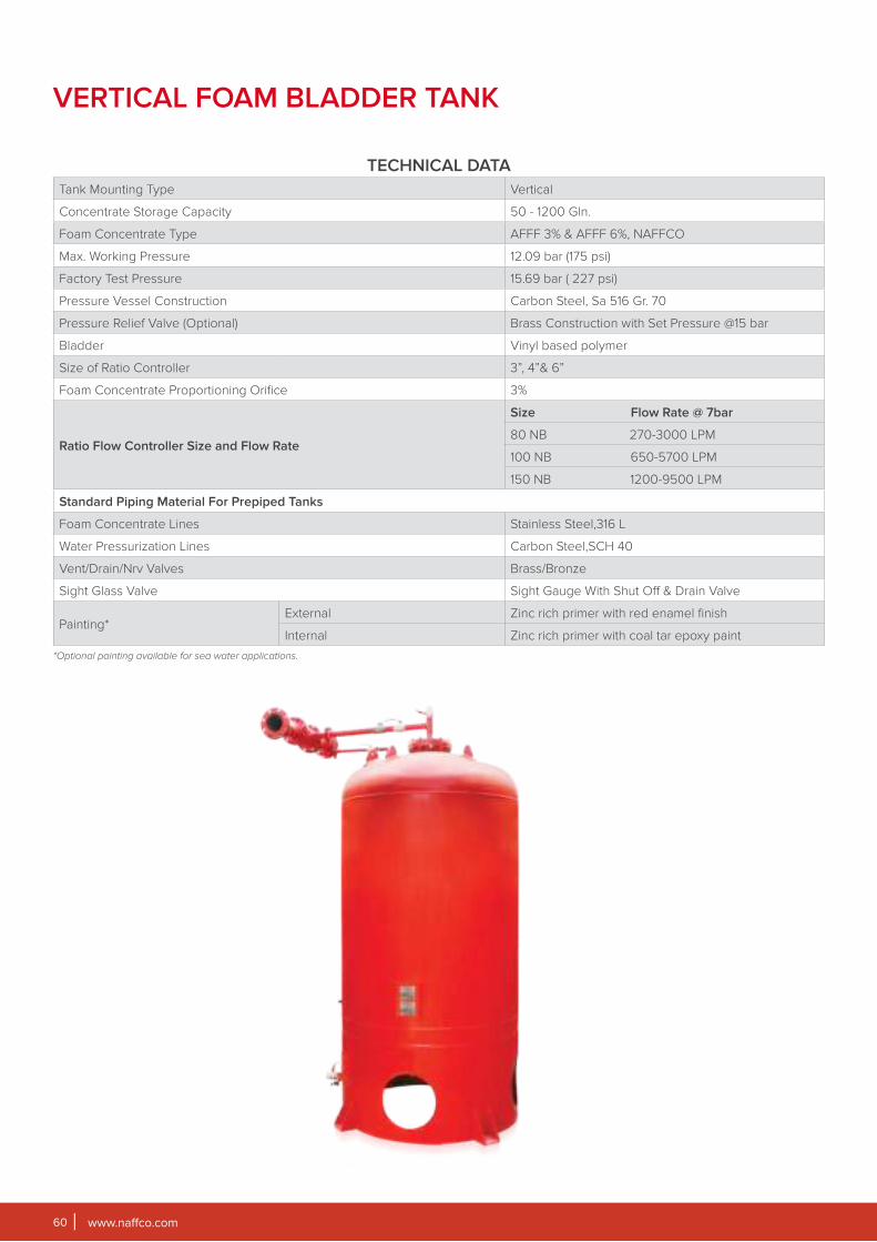
www.naffco.com60
TECHNICAL DATA
Tank Mounting Type Vertical
Concentrate Storage Capacity 50 - 1200 Gln.
Foam Concentrate Type AFFF 3% & AFFF 6%, NAFFCO
Max. Working Pressure 12.09 bar (175 psi)
Factory Test Pressure 15.69 bar ( 227 psi)
Pressure Vessel Construction Carbon Steel, Sa 516 Gr. 70
Pressure Relief Valve (Optional) Brass Construction with Set Pressure @15 bar
Bladder Vinyl based polymer
Size of Ratio Controller 3”, 4”& 6”
Foam Concentrate Proportioning Orifice 3%
Ratio Flow Controller Size and Flow Rate
Size Flow Rate @ 7bar
80 NB 270-3000 LPM
100 NB 650-5700 LPM
150 NB 1200-9500 LPM
Standard Piping Material For Prepiped Tanks
Foam Concentrate Lines Stainless Steel,316 L
Water Pressurization Lines Carbon Steel,SCH 40
Vent/Drain/Nrv Valves Brass/Bronze
Sight Glass Valve Sight Gauge With Shut Off & Drain Valve
Painting*External Zinc rich primer with red enamel finish
Internal Zinc rich primer with coal tar epoxy paint
*Optional painting available for sea water applications.
VERTICAL FOAM BLADDER TANK
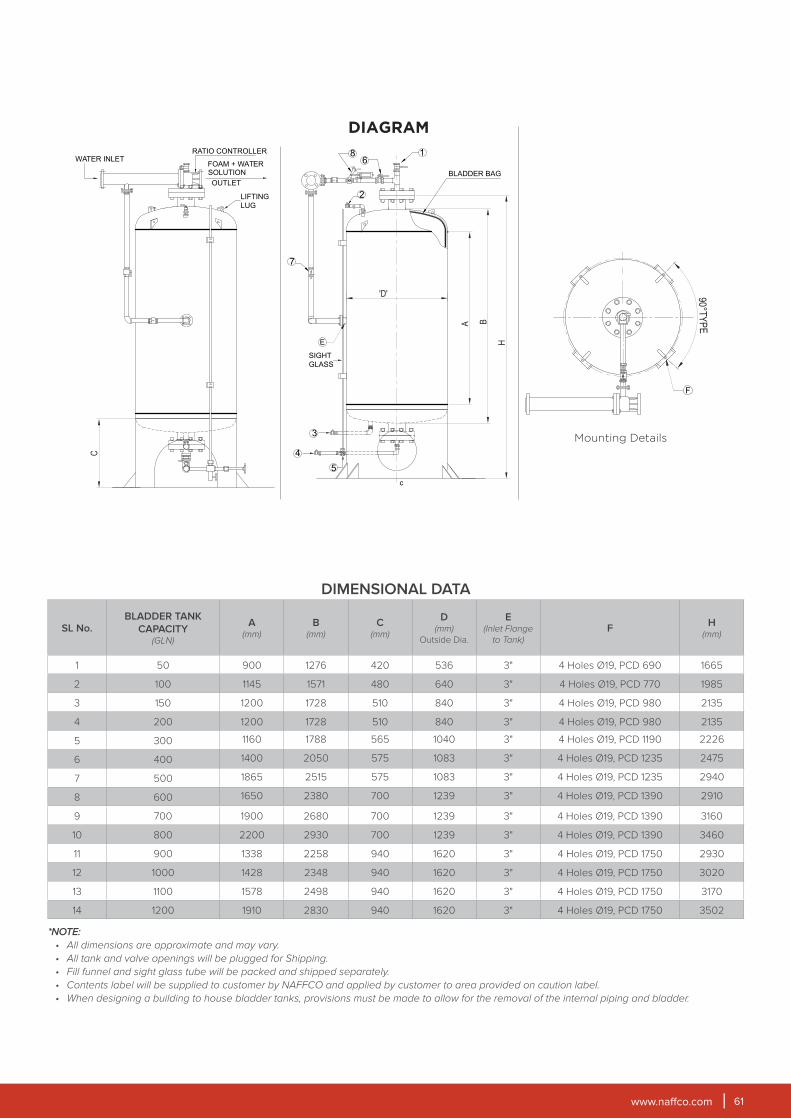
www.naffco.com 61
DIAGRAM
Mounting Details
WATER INLET
OUTLET
RATIO CONTROLLER
LIFTING
LUG
FOAM + WATER SOLUTION
C
5
4
3
SIGHT
GLASS
7
6
2
1
A B
H
8
BLADDER BAGOPEN
CLOSE
'D'
c
E
90°T
YP
E
F
DIMENSIONAL DATA
SL No.BLADDER TANK
CAPACITY(GLN)
A(mm)
B(mm)
C(mm)
D(mm)
Outside Dia.
E(Inlet Flange
to Tank)
FH
(mm)
1 50 900 1276 420 536 3" 4 Holes Ø19, PCD 690 1665
2 100 1145 1571 480 640 3" 4 Holes Ø19, PCD 770 1985
3 150 1200 1728 510 840 3" 4 Holes Ø19, PCD 980 2135
4 200 1200 1728 510 840 3" 4 Holes Ø19, PCD 980 2135
5 300 1160 1788 565 1040 3" 4 Holes Ø19, PCD 1190 2226
6 400 1400 2050 575 1083 3" 4 Holes Ø19, PCD 1235 2475
7 500 1865 2515 575 1083 3" 4 Holes Ø19, PCD 1235 2940
8 600 1650 2380 700 1239 3" 4 Holes Ø19, PCD 1390 2910
9 700 1900 2680 700 1239 3" 4 Holes Ø19, PCD 1390 3160
10 800 2200 2930 700 1239 3" 4 Holes Ø19, PCD 1390 3460
11 900 1338 2258 940 1620 3" 4 Holes Ø19, PCD 1750 2930
12 1000 1428 2348 940 1620 3" 4 Holes Ø19, PCD 1750 3020
13 1100 1578 2498 940 1620 3" 4 Holes Ø19, PCD 1750 3170
14 1200 1910 2830 940 1620 3" 4 Holes Ø19, PCD 1750 3502
*NOTE:
• All dimensions are approximate and may vary.
• All tank and valve openings will be plugged for Shipping.
• Fill funnel and sight glass tube will be packed and shipped separately.
• Contents label will be supplied to customer by NAFFCO and applied by customer to area provided on caution label.
• When designing a building to house bladder tanks, provisions must be made to allow for the removal of the internal piping and bladder.
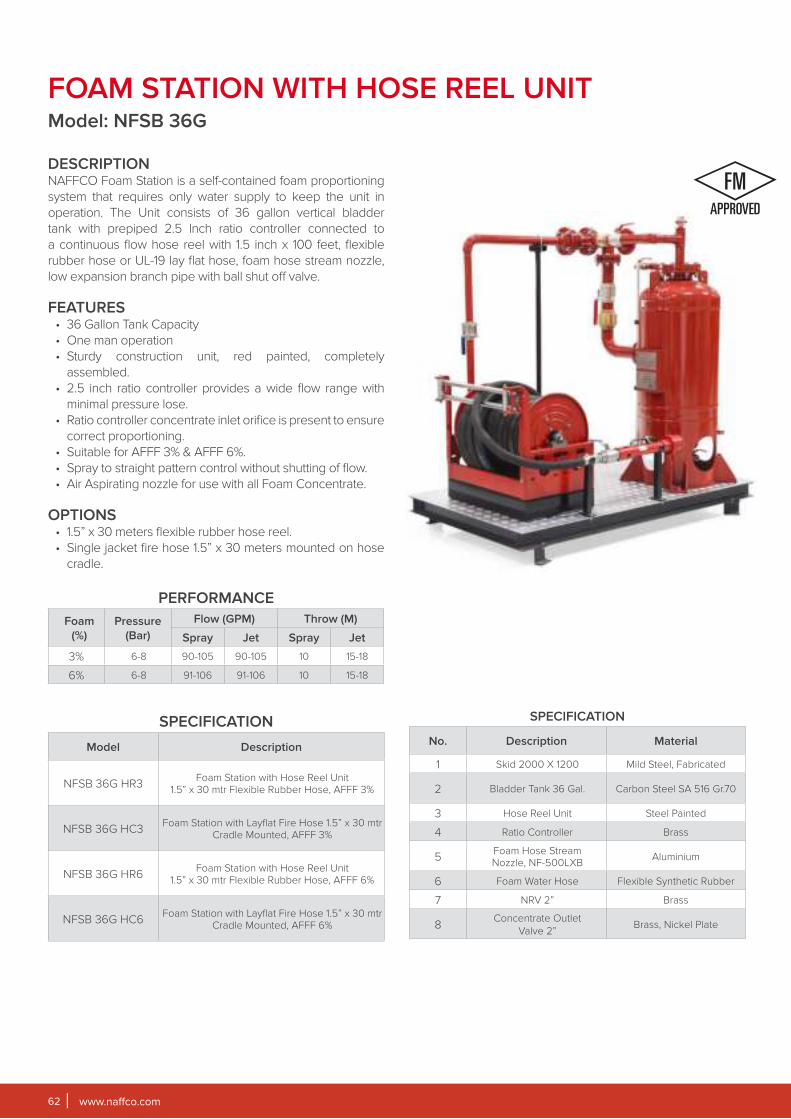
www.naffco.com62
FOAM STATION WITH HOSE REEL UNITModel: NFSB 36G
DESCRIPTIONNAFFCO Foam Station is a self-contained foam proportioning
system that requires only water supply to keep the unit in
operation. The Unit consists of 36 gallon vertical bladder
tank with prepiped 2.5 Inch ratio controller connected to
a continuous flow hose reel with 1.5 inch x 100 feet, flexible
rubber hose or UL-19 lay flat hose, foam hose stream nozzle,
low expansion branch pipe with ball shut off valve.
FEATURES
• 36 Gallon Tank Capacity
• One man operation
• Sturdy construction unit, red painted, completely
assembled.
• 2.5 inch ratio controller provides a wide flow range with
minimal pressure lose.
• Ratio controller concentrate inlet orifice is present to ensure
correct proportioning.
• Suitable for AFFF 3% & AFFF 6%.
• Spray to straight pattern control without shutting of flow.
• Air Aspirating nozzle for use with all Foam Concentrate.
OPTIONS
• 1.5” x 30 meters flexible rubber hose reel.
• Single jacket fire hose 1.5” x 30 meters mounted on hose
cradle.
PERFORMANCE
Foam
(%)
Pressure
(Bar)
Flow (GPM) Throw (M)
Spray Jet Spray Jet
3% 6-8 90-105 90-105 10 15-18
6% 6-8 91-106 91-106 10 15-18
SPECIFICATION
Model Description
NFSB 36G HR3Foam Station with Hose Reel Unit
1.5” x 30 mtr Flexible Rubber Hose, AFFF 3%
NFSB 36G HC3Foam Station with Layflat Fire Hose 1.5” x 30 mtr
Cradle Mounted, AFFF 3%
NFSB 36G HR6Foam Station with Hose Reel Unit
1.5” x 30 mtr Flexible Rubber Hose, AFFF 6%
NFSB 36G HC6Foam Station with Layflat Fire Hose 1.5” x 30 mtr
Cradle Mounted, AFFF 6%
SPECIFICATION
No. Description Material
1 Skid 2000 X 1200 Mild Steel, Fabricated
2 Bladder Tank 36 Gal. Carbon Steel SA 516 Gr.70
3 Hose Reel Unit Steel Painted
4 Ratio Controller Brass
5Foam Hose Stream Nozzle, NF-500LXB
Aluminium
6 Foam Water Hose Flexible Synthetic Rubber
7 NRV 2” Brass
8Concentrate Outlet
Valve 2”Brass, Nickel Plate
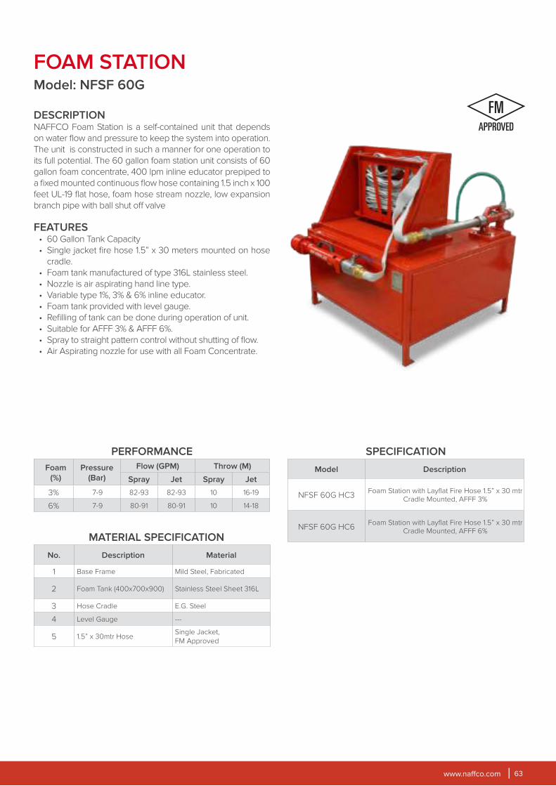
www.naffco.com 63
FOAM STATIONModel: NFSF 60G
DESCRIPTIONNAFFCO Foam Station is a self-contained unit that depends
on water flow and pressure to keep the system into operation.
The unit is constructed in such a manner for one operation to
its full potential. The 60 gallon foam station unit consists of 60
gallon foam concentrate, 400 lpm inline educator prepiped to
a fixed mounted continuous flow hose containing 1.5 inch x 100
feet UL-19 flat hose, foam hose stream nozzle, low expansion
branch pipe with ball shut off valve
FEATURES
• 60 Gallon Tank Capacity
• Single jacket fire hose 1.5” x 30 meters mounted on hose
cradle.
• Foam tank manufactured of type 316L stainless steel.
• Nozzle is air aspirating hand line type.
• Variable type 1%, 3% & 6% inline educator.
• Foam tank provided with level gauge.
• Refilling of tank can be done during operation of unit.
• Suitable for AFFF 3% & AFFF 6%.
• Spray to straight pattern control without shutting of flow.
• Air Aspirating nozzle for use with all Foam Concentrate.
PERFORMANCE
Foam
(%)
Pressure
(Bar)
Flow (GPM) Throw (M)
Spray Jet Spray Jet
3% 7-9 82-93 82-93 10 16-19
6% 7-9 80-91 80-91 10 14-18
SPECIFICATION
Model Description
NFSF 60G HC3Foam Station with Layflat Fire Hose 1.5” x 30 mtr
Cradle Mounted, AFFF 3%
NFSF 60G HC6Foam Station with Layflat Fire Hose 1.5” x 30 mtr
Cradle Mounted, AFFF 6%MATERIAL SPECIFICATION
No. Description Material
1 Base Frame Mild Steel, Fabricated
2 Foam Tank (400x700x900) Stainless Steel Sheet 316L
3 Hose Cradle E.G. Steel
4 Level Gauge ---
5 1.5” x 30mtr HoseSingle Jacket,
FM Approved
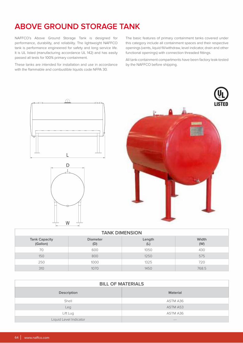
www.naffco.com64
ABOVE GROUND STORAGE TANK
NAFFCO’s Above Ground Storage Tank is designed for
performance, durability, and reliability. The lightweight NAFFCO
tank is performance engineered for safety and long service life.
It is UL listed (manufacturing accordance UL 142) and has easily
passed all tests for 100% primary containment.
These tanks are intended for installation and use in accordance
with the flammable and combustible liquids code NFPA 30.
The basic features of primary containment tanks covered under
this category include all containment spaces and their respective
openings (vents, liquid fill/withdraw, level indicator, drain and other
functional openings) with connection threaded fittings.
All tank-containment compartments have been factory leak-tested
by the NAFFCO before shipping.
TANK DIMENSION
Tank Capacity
(Gallon)
Diameter
(D)
Length
(L)
Width
(W)
70 600 1050 430
150 800 1250 575
250 1000 1325 720
310 1070 1450 768.5
BILL OF MATERIALS
Description Material
Shell ASTM A36
Leg ASTM A53
Lift Lug ASTM A36
Liquid Level Indicator ---
D
W
L

www.naffco.com 65
May it be fire rated, normal, classic, traditional or modern, we have
a vast collection of hardware to suit your design needs. From lock
case, lever handles, cylinders and deadlocks, we have it all in
different finishes like satin finish, gold finish, bronze finish and
silver finish.
You will never go wrong with the selection of your preferred
hardware since NAFFCO offers only the finest quality brands.
NAFFCO FIRE CERTIFIED HARDWARE
EXIT DEVICES
HINGES
CLOSER
LOCKS
FIRE RATED DOORS
NAFFCO manufactures ANSI and BS standard fire rated
doors. Fire rating does not depend on property of
construction, but on the performance of complete elements
of structure, which is composed of a number of materials.
NAFFCO fire rated doors are designed to get optimal
performance from a number of materials combined to
perform for high degree of fire protection.
The design of NAFFCO fire rated doors evolved from actual
testing as per NFPA and BSEN standards, which deal with
methods of determination of resistance to fire of non load
bearing element construction.
NAFFCO fire rated doors satisfy these criteria for the
required period. These doors also satisfy the criteria of
insulation where the mean and minimum temperature is
required to be below specific figures as per standards.
Design and construction of NAFFCO fire rated door
assemblies are in accordance with NFPA 80, UL10B, UL 10C,
BS 476 Part 22 and other international standards.
NAFFCO UL classified doors are tested and certified with 2
hours fire rating. BS standard doors maintains certification till
2 hours for Honeycomb door and 3 hours for glazed door.

CAT.NO.NF/FFE/10/16
Serving Over 100 Countries Worldwide