finite element simulation of the ski–snow interaction of an alpine ski in a carved turn
TRANSCRIPT
1
This is the accepted pre-print version of the manuscript for
Federolf P Roos M Luumlthi A Dual J (2010) Finite Element Simulation of the Ski-Snow Interaction in a Carved Turn in Alpine Skiing Sports Engineering 12 123ndash133
The final publication is available at
httpdxdoiorgdoi101007s12283-010-0038-z
httplinkspringercomarticle1010072Fs12283-010-0038-z
2
Finite Element Simulation of the Ski-Snow
Interaction of an Alpine Ski in a Carved Turn
Abstract
Skiing manufacturers depend in the development of new skis on trial and error cycles and
extensive product testing Simulation tools such as the finite element method (FEM) might be
able to reduce the number of required testing cycles However computer programs simulating a
ski in the situation of a turn so far lack realistic ski-snow interaction models The aim of this study
was to a) implement a finite element simulation of a ski in a carved turn with an experimentally
validated ski-snow interaction model and b) comparison of the simulation results with
instantaneous turn radii determined for an actual carved turn A quasi-static approach was chosen
in which the ski-snow interaction was implemented as a boundary condition on the running surface
of the ski A stepwise linear function was used to characterize the snow pressure resisting the
penetration of the ski In a carved turn the rear section of the ski interacts with the groove that
forms in the snow Two effects were incorporated in the simulation to model this situation a) the
plasticity of the snow deformation b) the influence of the skirsquos side-cut on the formation and
shape of this groove The simulation results agreed well with experiments characterizing snow
penetration Implementation of the groove in the ski-snow interaction model allowed calculation of
the instantaneous turn radii measured in actual turns but also caused significant numerical
instability The simulation contributes to the understanding of the mechanical aspects of the ski-
snow interaction in carved turns and can be used to evaluate new ski designs
Introduction
Alpine skiing is one of the most popular winter sports and alpine ski
manufacturers achieve millions in annual turnover However despite its huge
economical importance skiing manufacturers still depend in the development of
3
new ski types on trial and error cycles that require extensive product testing Other
manufacturing industries employ sophisticated computer simulation methods
such as the finite element modelling (FEM) to reduce the number of expensive
and time consuming testing cycles required in their product development A FEM
simulation of skis in the situation of a turn is difficult to implement because a)
skis are sandwich structures consisting of several isotropic and non-isotropic
material layers whose mechanical properties are often not well known and b) the
ski-snow interaction in skiing is a complicated combination of different
mechanical processes in particular bending and torsion of the ski [1-3]
penetration of the snow [4-6] machining of snow [7-9] friction [10-14] and
system vibrations [1516] Computer simulation programs that have been
developed in recent years [617-26] focus on the calculation of the deformation of
the ski in order to predict performance variables such as the ski radius or the
pressure distribution on the running surface of the ski A limitation of most of
these simulation approaches is a severe simplification of the ski-snow interaction
processes To our knowledge there are only two simulation approaches that
incorporate the plasticity of the snow deformation [2728] Only a small number
of the simulation methods described in the literature have been validated and none
with data from an actual carved turn executed by a skier
The aim of the current work was the development of a simulation model of a ski
in the state of a carved turn using the finite element method (FEM) The
simulation is intended to be used on the one hand to assist in the development of
new ski and binding designs and on the other hand to allow a systematic analysis
of turn parameters and their interrelationship The output of the simulation should
particularly include the deformed shape of the ski The skilsquos shape determines its
turn radius which will be compared to the instantaneous turn radius measured in
4
an actual carved turn The purpose of this paper is to describe the FE model its
boundary conditions the experimental validation procedures and to discuss the
modelrsquos advantages and limitations Application of the simulation described here
in a parameter study investigating the influence of the input variables edging
angle force on the binding and snow conditions will be presented in a subsequent
publication
Methods
Selected Ski and Binding Models
Two skis were selected for this study the all-round carver ski Stoumlckli Spirit of the
winter season 20012002 and the race carver Stoumlckli Laser GS of season
20012002 Present day skis are laminates of several material layers For each ski
the manufacturer Stoumlckli Swiss Sports AG Wolhusen Switzerland provided
detailed data of construction and geometry
The binding model selected for this study was the Rave Powerride binding of
season 2001 manufactured by Fritschi AG Swiss Bindings Reichenbach
Kandertal Switzerland This binding offers a high stance height of the ski boot
rendering an additional damping plate unnecessary In this binding the heel
clamps and the release mechanism are mounted on a stiff aluminium beam which
is connected to the toe part with a hinge joint If the ski is bent the beam can slide
freely back and forth on a rail incorporated on the heel part of the binding
Finite Element Model
Ski and binding were modelled using the commercial FEM-software package
SESESTM
(Numerical Modelling GmbH Winterthur Switzerland) The binding
5
was represented using 8-node volume elements while the ski was represented
using shell elements The governing equations of the SESESTM
shell elements are
based on the classical Kirchhoff plate theory [29] SESESTM
uses the so-called
free formulation shell elements [30] to calculate the element stiffness matrices
The geometry of the shell is specified in three dimensions in SESESTM
Since the
ski consists of several layers SESESTM
calculates the corresponding compound
bending and stretching elasticity matrix from the given 3D-elasticity tensors Cijkl
[29] by suitable integrals along the transverse direction
For a ski represented by such shell elements bending and in-plane stretching
deformations are calculated accurately However the neglect of transverse shear
in the classical Kirchhoff plate theory causes the FEM model of the ski to have a
higher torsional stiffness than in reality Despite this disadvantage shell elements
were selected because they allowed the number of degrees of freedom of the
model to be reduced and kept calculation times to a reasonable level
Discretisation and Material Properties of the Ski
Each material layer of the ski was represented by a one-element layer Between
the layers an adhesive layer with a thickness of 02 mm [31] was included The
element discretisation along the ski axis was chosen such that the elements had a
length between 50 and 80 mm This length scale of the discretisation allowed
reasonable calculation times and it was verified that the numerical solution was
independent of element length for values smaller than 150 mm The width of the
elements was of the order of 1-2 mm near the ski edge and 4-5 mm near the centre
of the ski A higher element density was chosen near the ski edge to provide a
better resolution of the pressure distribution calculated at the ski-snow contact
6
Many component materials are isotropic In this case Youngrsquos modulus and the
Poisson ratio are sufficient to express the stiffness tensor Cijkl Youngrsquos modulus
and the Poisson ratio of most component materials were either taken from
standard literature or provided by the ski company Stoumlckli (they are considered
proprietary and cannot be published here) The mechanical properties of the thin
adhesive layers and the Poisson ratio of some other materials were estimated The
wood core and the fibre glass composite layers within the ski are non-isotropic
materials for which the most important components of the Cijkl tensor were
determined in tensile tests [31]
Comprehensive parameter studies and validation experiments were conducted to
ensure that the employed shell elements could predict the deformation of the ski
Maximal deviations between experimental and numerical results were 15 in
bending tests and 20 in torsion tests However some of these deviations can be
attributed to an idealization of the adopted boundary conditions The parameter
studies also confirmed that the bending stiffness of the skirsquos sandwich structure
are mainly determined by the stiffness and thickness of the metal layers and the
thickness of the wood core the contribution of the other materials to the overall
stiffness properties was marginal
Implementation of the Ski Binding
Modern bindings are complicated mechanical devices which comprise a large
number of different component parts However for a calculation of the turn radius
and the pressure at the ski snow interface only the influence of the binding on the
system stiffness and the force transfer onto the ski are relevant Therefore the
binding was modelled as three separate finite element blocks representing (a) the
beam carrying the holding clamps and the release mechanism for the ski boot (b)
7
the front plate and (c) the rear plate which are screwed onto the ski The
mechanical functionality of the binding was represented in the model by defining
internal constraints at the joint the rail the screws between binding and ski and
at all other contacting surfaces that transfer pressure or forces Internal friction
between parts of the binding was neglected The material properties of the two
blocks directly attached to the ski were adjusted such that the calculated bending
stiffness of the whole ski-binding system agreed with experimental results
obtained from three point bending tests
Boundary Conditions
The main external forces acting on the ski-binding system during a turn are the
forces at the binding the pressure at the ski-snow interface and gravity In the
simulation a quasi-static approach was chosen According to DrsquoAlembertrsquos
principle system accelerations were expressed as inertial forces in the reference
system of the ski and equated with the external forces acting on the system
(equation 1)
(equation 2)
Where Fathlete(t) and Mathlete(t) are the forces and moments transferred from the
athlete onto the binding FSSI(t) and MSSI(t) are the forces and moments created by
ski-snow interaction Gski(t) and MGski(t) are the forces and moments caused by
gravitation and Finertia(t) and Minertia(t) are inertial forces and moments acting on
the ski In this study the centre of the ski boot at the upper surface of the ski was
chosen as reference point for the moment calculations Other forces on the system
eg air resistance were neglected
8
The forces Fathlete(t) and moments Mathlete(t) acting on the binding were determined
experimentally (see Experimental Validation Procedures section) and defined on
the appropriate surface area partΩ of the binding by prescribing the external force
components Fl (using Einstein convention for the notation)
(equation 3)
where n is the normal vector on the surface partΩ s is the stress tensor and k and l
are indices
The gravitational forces Gski(t) and inertial forces Finertia(t) can be obtained from
kinematic measurements that determined the position and orientation of the ski in
an external reference frame as a function of time These were implemented as
volumetric forces assigned to each element depending on its density Hence the
associated moments created by these forces were generated automatically and did
not have to be specified explicitly Terms due to relative accelerations of parts of
the ski-binding system with respect to its centre of mass were neglected based on
an analysis of the inertial components created by the rotating reference system of
the ski [27] and based on the assumptions that no significant vibrations are
present
At the ski-snow interface two types of forces are created reaction forces due to
the penetration of the ski into the snow and frictional forces In the simulation
frictional forces were neglected ie it was assumed that the resistive forces act
always normal to the skirsquos running surface The reaction force FSSI(t) exerted by
the snow to the penetrating ski was implemented as a ldquogeneralized Neumannrdquo
boundary condition on the whole running surface by prescribing the external force
9
component (Fext)l on the boundary surface partΩ as a function f(ul) of the
displacement ul (k and l being indices)
(equation 4)
The function f(ul) depends on the penetration depth D of the ski into the snow and
on the snow strength The coordinate system for the simulation was chosen such
that the snow surface coincides with the x-y-plane Thus the penetration depth D
of any point of the ski model could easily be determined from the z-coordinate of
the (local) displacement
Ski-Snow Contact in a Static Situation
The average reaction pressure paverage that the snow exerts to a penetrating plate
can over a wide range of snow types be appropriately described by a piecewise
linear function of the penetration depth D [32]
00
0)()(
D
DBDADpaverage
(equation 5)
The coefficients A and B define the snow strength and A depends on the edging
angle θ of the penetrating plate For groomed snow on ski slopes the coefficient A
is in the range 5-40 kPamm for θ lt 40deg or in the range 2-20 kPamm for θ gt 40deg
B is in the range between 0 and 400 kPa [32] The penetration into the snow is
facilitated by fracture processes within the snow Deviations from equation 5 may
occur due to random nature of these fracture events Such deviations were
particularly observed for large edging angles of the ski
The simulation requires the actual pressure pSnow(D) at a given point P of the
boundary surface
10
00
02)(
D
DBDADpSnow (equation 6)
as can be derived from equation 10 by using the definition of the averaged
pressure on the plate
BADD
DdDp
Dp
D
Snow
average
0
)(
)( (equation 7)
The function pSnow(D) contains a non-differentiable point at the transition from
positive penetration depths D gt 0 to negative penetration depths D lt 0 which
would cause numeric divergence of the simulation Therefore this function was
approximated with a smoothing function
pSnow(D)= 2Aramp(D) + Bstep(D) (equation 8)
using
(equation 9)
where Doff is an offset and the coefficients Step and Ramp determine the width of the
transition between the two nearly linear parts of the functions In the simulation
Step and Ramp were chosen to be smaller than 05 mm creating a transition zone of
approximately +- 1 mm depth Considering that the typical grain size of the snow
on groomed ski slopes is in the range of 1 to 3 mm this transition zone seemed
acceptable
11
Solving Algorithm in a Static Situation
The generalized Neumann boundary conditions for the ski-snow interaction
provide a non-linearity as the reaction force depends on the penetration depth ie
the local displacement An iterative solution procedure is therefore mandatory
The implemented algorithm iteratively finds the deformation state of the ski and
the corresponding distribution of snow pressure such that the quasi-static
equations 5 and 6 are satisfied The iteration usually converged to a stable solution
in less than 10 calculation steps however the calculation procedure is very
sensitive to the initial conditions and may not converge at all if not properly
initialised The linearised system matrix is non-symmetric and was solved
iteratively by a stabilized biconjugate gradient solver [29]
Ski-Snow Contact for a Ski in Motion
The definition of a carving turn in alpine skiing is that the rear section of the ski
glides in the groove formed by the front section The validation measurements
conducted in this study showed that it is essential to understand how the groove is
formed and how it affects the deformation of the ski Two phenomena have to be
considered and incorporated into the model
a) The plasticity of the snow deformation ie formation of a groove in the
snow
b) The ldquoside-cut effectrdquo ie how the skirsquos side cut affects the shape of the
groove
Plasticity of the snow deformation As the ski shovel passes over the snow the
pressure increases until a maximum pressure is reached somewhere in the middle
of the ski As long as the pressure increases the ski penetrates deeper into the
12
snow However once the point of maximum pressure has passed the snow is
effectively unloaded ie the ski does not penetrate deeper but remains on the
surface of the groove that has formed already
To implement the plastic deformation behaviour of the snow a second
superposed iteration loop was adopted In the first iteration step the point on the
ski-snow contact area with maximum pressure pmax and the maximal penetration
depth Dmax were determined using the snow penetration function (equation 12) to
calculate the snow pressure In the following iteration steps the boundary area
was split into a loading area (shovel to point of maximum pressure) and an
unloading area (point of maximum pressure to ski end) In the unloading area the
function describing the snow resistance pressure was replaced by a function
describing unloading of snow
(equation 10)
Coefficient C in this equation depends on residual elastic energy in the snow and
is typically in the range 015 to 115 MPamm [27] Only the global maximum in
the snow pressure was considered in the current implementation Local maxima
that may occur close to the ski tip in case of small edging angles were not
considered For better numerical stability the function actually used was a
differentiable approximation that converged to the loading function if the pressure
in a later iteration step should exceed the maximum pressure determined in the
previous iteration step (Figure 1)
Figure 1
13
The ldquoside-cut effectrdquo In 2000 Howe presented a model to approximate the shape
of the lower ski edge with and without snow penetration [3] If a ski is set on its
edge and pushed into the snow then the side-cut of the ski determines the contact
line between ski and snow (Figure 2) On a hard icy surface this contact line can
be used to approximate the turn radius RHowe On a snow surface the ski penetrates
the snow at this contact line to the depth at which the snowrsquos resistive pressure is
equal to the load exerted by the ski onto the snow At the ski centre this pressure
is maximal and therefore the ski penetrates deepest at the ski centre At the ski
shovel and at the ski end the pressure on the snow is small and therefore ski
shovel and ski end do not penetrate the snow [3] As the ski penetrates the snow in
the ski centre it becomes more bent and the turn radius RHowesnow becomes smaller
However Howersquos model does not take into account that in an ideally carved turn
the rear section of the ski glides in the groove that has formed in the snow and
thus the actual turn radius depends on the curvature of the groove that forms not
on the curvature of the entire ski edge The width of the groove that forms in the
snow as a ski passes over a point on the snow surface depends on the one hand on
the snow penetration and on the other hand on the side-cut of the ski consider the
front view in Figure 2 as the ski moves forward all snow above the thick line is
removed The groove that forms in the snow therefore does not have a 90deg angle
but a much wider angle which agrees well with observations in the field In a
static case (Howersquos model) or when the ski is skidding then the ski edge at the
rear section returns to the snow surface and the groove has a 90deg angle If the ski
is carving then the rear section of the ski glides within the groove and therefore
the curvature of the ski is reduced in the rear section compared with that of the
front section The radius Rrear determined from the rear section of the ski edge
(projected to the snow surface) is the best approximation of the actual turn radius
14
which can be determined from the trace remaining in the snow after a carved turn
The skirsquos front section has a different curvature which can be approximated with
Howersquos model (Rfront asymp RHowesnow)
If a steady state is assumed and the ski is loaded at the ski centre without
significant forward or backward leaning then a symmetrical shape of the groove
can be assumed and the position of the rear ski edge can be approximated (Figure
2)
Figure 2
In the simulation this is implemented by
a) defining the plastic snow model (which leads to the theoretical position of
the ski end with a correct penetration depth but a wrong lateral position as
indicated by the dashed line in Figure 2) and
b) modifying the boundary condition on the rear part of the ski such that
snow resistance pressure is only present after a lateral displacement of the
ski by L(x) The length L(x) represents the width of the groove parallel to
the snow surface In the simulation L(x) can be calculated from the
penetration depth Dmax the side-cut s(x) and the edging angle θ
cos
)(tan)( max
xsDxL (equation 11)
Here x is the position along the ski length The side-cut s(x) at position x
can be calculated from the skirsquos width W(x) at position x the width WS at
the shovel and the width WE at the ski end
)(
22
1)( xW
WWxs ES (equation 12)
15
Solving Algorithm for a Ski in Motion
The final shape of the ski is determined in an iterative process starting from a
solution for a static state In the following iteration steps a new equilibrium state
is determined for which the boundary condition at the ski-snow interface includes
the plastic snow model and the side-cut effect These modifications of the ski-
snow boundary condition cause the ski to rotate slightly such that its rear section
rests in the groove and is less bent than in the static situation (Figure 3) A number
of additional requirements limit the applicability of this solution namely the
assumption of a steady state and loading that causes a symmetrical ski
deformation In the case of significant moments acting on the binding eg caused
by forward or backward leaning of the skier the solution is not valid A second
limitation of this implementation is the severely decreased numerical stability the
simulation converges only for a limited range of input parameters to a stable
solution Particularly for large edging angles (θ gt 70deg) the model cannot be solved
(see equation 15)
Figure 3
Experimental Validation Procedures
The validation of the simulation results was carried out in three steps First the
implemented snow model was validated by measuring the snow resistive force on
a penetrating plate and simulating the same situation using the snow model as a
boundary condition (Figure 4) In both cases the force was incrementally
increased and the penetration depth into the snow was determined The
16
experiment and the simulation were repeated twice for the following edging
angles 20deg 30deg 40deg 45deg 55deg and 60deg
Figure 4
As a second validation step the shape of the ski was calculated for a static loading
case and compared to the shape determined in a static experiment (Figure 5) To
compare the shape the position of the lower ski edge was determined in the
simulation and compared with the shape of the groove created on an even snow
surface when a ski was pressed into the snow with a force of 3000 N The position
of the groove was measured at 16 positions along ski with a distance of 10 cm
between each measurement The accuracy of the measured position was
approximately +- 3 mm Even though the snow on the experimental field seemed
very homogeneous several large clods of snow broke loose during the experiment
(Figure 5) This caused some deviation in the curvature of the ski edge The
experiment was conducted at edging angles of 39deg and 53deg
Figure 5
The third validation step was to compare the ski shape calculated in the simulation
with the shape determined for an actual carved turn All input parameters
necessary for the simulation particularly the load on the ski and the edging angle
were measured in an actual carved turn skied by an experienced ski racer The
experiment was carried out in a ski dome in Neuss Germany on a section with
constant slope The skier was equipped with two dynamometers (Kistler
Winterthur Switzerland) mounted between ski and binding to record 3D-forces
17
and 3D-moments acting on the skis Several carving turns were skied between
gates defining the path while the skierrsquos motion and the skisrsquo motion were
captured with a video system (Redlake San Diego Ca USA) The kinematic data
were analysed using WINanalyse software (Micromak Service Berlin Germany)
This allowed determination of the edging angles and inertia forces in the reference
system of the ski The coefficients characterising the snow strength in the snow
model were measured at several locations on the slope The data from the video
analysis the dynamometers and the snow measurements provided all input
variables necessary for the simulation [27]
For the validation of the simulation results the actual turn radius was determined
a) from the video analysis (which can be synchronized with the measurements
providing the input data for the simulation) and b) from the traces of the skis in
the snow (geometer measurement with an accuracy in the mm range) Both data
sets were used to determine the actual turn radius as a function of the position on
the slope The actual turn radius determined from the skisrsquo traces were compared
to the radius of the rear section of the ski obtained in the simulation for the same
loading conditions This was done in two steps first the results of the static
simulation were assessed and then the results of the simulation incorporating the
plasticity of the snow deformation and the side-cut effect were compared to the
measured instantaneous turn radius
Results
Validation of the implemented snow model
For small edging angles (20deg 30deg) the simulation calculated the same penetration
depths for a given force as measured in the experiments (Figure 6) For edging
18
angles larger than 40deg significant fluctuations around the general trend in the
forcendashpenetration depth measurements were observed These fluctuations could be
attributed to fracture processes within the snow taking place during the
penetration With the implemented snow model the simulation predicted the
general trend in the forcendashpenetration depth relationship but did not account for
fracture processes occurring within the snow
Figure 6
Validation of the simulation result in a static case
The calculated and measured shapes of the lower ski edge projected on the plane
of the snow surface are shown in Figure 7 for edging angles of 39deg and 53deg The
general magnitude of the ski deflection was predicted correctly by the simulation
However some differences between measurement and simulation results can be
observed in the rear section of the ski (at distances between 200 amd 800 mm
from the ski end) The most likely explanation of these differences is that snow
clods of varying size broke away during the experiment at some sections of the ski
(visible in the photograph in Figure 5) This created an inhomogeneous snow
reaction and affected the shape of the ski
Figure 7
Validation of the simulation result for a moving ski
The instantaneous turn radii calculated for the trace of the skis in the validation
experiment revealed three sections an initiation phase a drift phase and the
steering phase (Figure 8a) The observed drift phase is typical for a modern ski
racing technique and can be observed even in World-Cup ski races The turn
19
radius calculated in the simulation can be compared with the measured
instantaneous radius in the initiation phase and in the steering phase of the turn
because the shape of the groove that remained in the snow indicated that in these
phases the skis carved with no significant drifting or skidding
In the static simulation only the results for the right ski the inside ski in the turn
agree with the measured radius values (Figure 8b) The results for the left ski the
outside ski which is loaded with higher forces and generally more important for
the turn are significantly smaller (between 30 and 70) than the measured
instantaneous turn radii
When the plasticity of the snow deformation and the side-cut effect are
incorporated in the simulation then the results for both skis agree well with the
measured instantaneous turn radii (Figure 8c) However due to the modified
boundary condition at the ski snow interface the simulation often does not
converge to a reliable solution particularly during the steering phase when the
edging angle of the ski exceeds 60deg the simulation did not converge to a valid
solution
Discussion
The validation of the snow model and of the ski in a quasi-static experiment
shows that the simulation is in general able to calculate the correct penetration
depth into the snow and the correct deformation of the ski in a quasi-static test
Small differences between simulation and measurement are caused by frequent
fracture processes taking place in the snow These processes occur more
frequently at large edging angles and may indicate inhomogeneities in the snow
fracture strength Compared to other models used to estimate or calculate the turn
radius of a ski eg Howersquos model [3] the static simulation presented here has the
20
advantage that all of the important influencing variables are taken into account
and their influence on the ski deformation or the ski-snow interaction can be
studied These influencing factors are the force and moment applied to the
binding the snow type and the shape and composition of the ski
The validation using the trace of an actual carved turn showed that a quasi-static
approach to predict the turn radius of a ski is not applicable for a moving ski
Neither the quasi-static simulation presented here nor the model proposed by
Howe were able to predict the instantaneous turn radius measured in the
experiment This suggests that purely quasi-static approaches to calculate the turn
radius or the deformation of a ski [33-35] that are based on Howersquos model might
need to be reconsidered
The instantaneous radius of an actual carved turn was only predicted in a correct
order of magnitude if two dynamic processes affecting the formation of the
groove in the snow were taken into account These processes are the plasticity of
the snow deformation and effects of the side-cut on the shape of the groove The
former effect obviously takes place in the ski-snow interaction and does not need
to be discussed further The later effect can be confirmed by examining the shape
of the groove remaining in the snow after a carved turn [36] due to the side-cut
and the skirsquos motion the angle of the groove is not 90deg (as in a static case) but is
typically about 120deg (depending on the side-cut of the ski that created the groove)
A consequence of this effect is that in a carved turn the curvature at the rear
section of the ski is less than that of the front section The radius of the rear
section that glides through the groove is therefore larger than the radius of the
front section forming the groove or the radius of the entire ski Thus the side-cut
effect might offer an explanation for discrepancies reported in earlier studies for
example Yoneyama et al (2008) equipped a test ski with sensors that measured
21
the ski deflection during an actual turn [37] They reported (page 12) that in the
carving turns the ldquoeffective radiusrdquo determined from the deflection of the test ski
was approximately 10 m whereas the estimated radius of the skisrsquo path was 20 m
The incorporation of the dynamic effects in the simulation presented here allowed
calculation of turn radii that agreed with radii determined from the skisrsquo traces
For steady state conditions the simulation thus allows calculation of reliable turn
radii ski deformation or snow pressure profiles The model can now be used to
assess how varying input parameters eg load on the binding edging angles
snow conditions ski composition or designs affect the turn radius or the ski-snow
interaction (to be covered in a subsequent paper)
However the simulation still has a number of significant limitations 1) It only
describes carved turns with no significant lateral skidding or drifting 2) Poor
numerical stability due to the changing boundary conditions 3) Several necessary
assumptions limit the applicability of the model The most important restrictions
are a) Steady state behaviour has to be assumed Rapid changes of input variables
eg the edging angle would affect the actual ski deformation but will not affect
the simulation result b) No moments may act on the binding eg due to forward
or backward leaning of the skier c) Vibrations of the ski-binding system are not
considered in this simulation model In actual carved turns not only significant
moments on the binding occur [27] but also significant vibrations in a bending
mode were observed [3839] The application of our model to predict actual
carved turns is therefore still problematic
A first step to overcome the limitations present in our model is the dynamic
approach presented by [28] who reported good agreement with sled
measurements that create a steady-state turn To overcome the condition that the
ski has to be in a steady state a dynamic simulation that includes a calculation of
22
how the groove in the snow is formed would be necessary Finite element
simulations using modified Drucker-Prager or crushable foam element types
might offer a means to realistically model the snow deformation [4041] The
most challenging issue to solve will be the huge number of elements that would be
required to model the ski-snow interaction and the formation of the groove the
actual snow deformation occurs on a scale of a few centimetres or millimetres
which requires a high resolution of the finite element lattice representing the
snow while for a simulation of a full turn a spatial range of about 20 m would be
required
Conclusion and Future Work
Our and other models of the ski-snow interaction contribute to a better
understanding of the physical processes governing skiing In steady-state
situations the turn radii ski deformations and snow pressure distributions can
now be predicted However it is still a major challenge to link these results with
performance or comfort characteristics of skis Researchers and ski manufacturers
who want to improve skiing equipment by using simulation approaches instead of
the time consuming and expensive trial and error cycles need to address this lack
of knowledge
Acknowledgements
The study was financially supported by the Swiss Foundation for Innovation KTI and the
companies Stoumlckli Swiss Sports AG and Fritschi Swiss Bindings
23
References
[1] Casolo F Lorenzi V (2001) Relevance of ski mechanical and geometrical properties in
carving technique a dynamic simulation In Mu ller E Schwameder H Raschner C Lindinger S
Kornexl E(eds) Science and Skiing II Verlag Dr Kovac Hamburg pp 165-179
[2] Glenne B DeRocco A Vandergrift J (1997) The modern Alpine ski Cold Regions Science
and Technology 26 35-38
[3] Howe J (2001) The New Skiing Mechanics McIntire Publishing Waterford ME USA
[4] Abele G Gow AJ (1976) Compressibility Characteristics of Compacted Snow CRREL Rep
Federolf P Fauve zab D u thi A Rhyner HU Schneebeli M Ammann W Dual J
(2004) Mechanical properties of snow during rapid impact Snow Engineering V 209-214
[6] Mo ssner M Nachbauer W Innerhofer N Schretter H (2003) Mechanical properties of snow
on ski slopes Abstract Book of the 15th International Congress on Ski Trauma and Skiing Safety
St Moritz Switzerland
[7] Lieu DK Mote CD (1984) Experiments in the machining of ice at negative rake angles J
Glaciology 30 77-81
[8] Tada N Hirano Y (2002) Search of the mechanics of a turning alpine ski using snow cutting
force measurements Sports Engineering 5 15-22
[9] Brown CA (2009) Modeling edge-snow interactions using machining theory In Mu ller E
Lindinger S Stoumlggl T(eds) Science and Skiing IV Meyer amp Meyer Sport (UK) Ltd pp 175-183
[10] Colbeck SC (1988) The kinetic friction of snow Journal of Glaciology 34 78-86
[11] Colbeck SC (1994) A review of the friction of snow skis Journal of Sports Sciences 12 285-
295
[12] Outwater JO (1970) On the friction of skis Medicine and science in sports 2 231-234
[13] Buhl D Fauve M Rhyner H (2001) The kinetic friction of polyethylen on snow The
influence of the snow temperature and the load Cold RegSciTechnol 33 133-140
[14] Theile T Szabo D Luthi A Rhyner H Schneebeli M (2009) Mechanics of the ski-snow
contact Tribology Letters 36 223-231
[15] Nigg BM Neukomm PA Spirig J Unold E (1975) Vibration measurements during skiing
gymnastics walking and running Medizinische Welt 26 765-770
24
[16] Fischer C Overney LS Fauve M Blanke O Rhyner H Herzog MH Bourban P- Ma nson J-
E (2007) What static and dynamic properties should slalom skis possess Judgements by
advanced and expert skiers Journal of Sports Sciences 25 1567-1576
[17] Bruck F Lugner P Schretter H (2003) A dynamic model for the performance of carving skis
ASTM Special Technical Publication 10-23
[18] Casolo F Lorenzi V Vallatta A Zappa B (1997) Simulation techniques applied to skiing
mechanics In Mu ller E Schwameder H Kornexl E Raschner C(eds) Science and Skiing Taylor
amp Francis pp 116-130
[19] Clerc C Gaertner R Trompette P (1989) Computer aided design of skis Finite Elements in
Analysis and Design 5 1-14
[20] Hirano Y Tada N (1996) Numerical simulation of a turning alpine ski during recreational
skiing Medicine and Science in Sports and Exercise 28 1209-1213
[21] Kaps P Mo ssner M Nachbauer W Stenberg R (2000) Pressure distribution under a ski
during carved turns Proceedings of the 2nd Int Congress on Skiing and Science 180-202
[22] Piziali RL Mote Jr CD (1972) Snow Ski as a Dynamic System Journal of Dynamic
Systems Measurement and Control Transactions of the ASME 94 Ser G 133-138
[23] Renshaw AA Mote Jr CD (1989) A model for the turning snow ski International Journal of
Mechanical Sciences 31 721-736
[24] Nordt AA Springer GS Kollaacuter LP (1999)
Simulation of a turn on alpine skis Sports Engineering 2 181-199
[25] Tada N Hirano Y (1999) Simulation of a turning ski using ice cutting data Sports
Engineering 2 55-64
[26] Moumlssner M Heinrich D Kaps P Schretter H Nachbauer W (2009) Computer
simulation of consecutive ski turns ASTM Special Technical Publication 1510
STP pp 126-136
[27] Federolf P (2005) Finite Element Simulation of a Carving Snow Ski Pro BUSINESS GmbH
Berlin Germany
[28] Moumlssner M Heinrich D Schindelwig K Kaps P Lugner P Schmiedmayer H- Schretter
H Nachbauer W (2006) Modeling of the Ski-Snow Contact for a Carved Turn In Moritz EF
Haake S(eds) The Engineering of Sport 6 Springer New York pp 195-5
25
[29] Numerical Modeling GmbH (2003) NM-SESES Finite Element Software for Computer
Aided Engineering Numerical Modeling GmbH Winterthur Switzerland
[30] Graber C (1990) Nichtlineare Analyse von Schalen mit linearisierten elastoplastischen
Schnittkraft-Verformungs-Beziehungen Verlag der Fachvereine Zurich Switzerland
[31] Waumlckerlin J (1997) Numerische Modellierung von RennskisThesis Zurich University of
Applied Sciences
[32] Federolf P JeanRichard F Fauve M Luumlthi A Rhyner H- Dual J (2006) Deformation of
snow during a carved ski turn Cold Regions Science and Technology 46 69-77
[33] Mu ller E Schwameder H (2003) Biomechanical aspects of new techniques in alpine skiing
and ski-jumping Journal of Sports Sciences 21 679-692
[34] Jentschura UD Fahrbach F (2004) Physics of skiing The ideal-carving equation and its
applications Canadian Journal of Physics 82 249-261
[35] Lind D Sanders SP (1996) The Physics of Skiing Springer-Verlag New York Inc New
York USA
[36] Tatsuno D Yoneyama T Kagawa H Scott N Osada K (2009) Measurement of ski
deflection and ski-snow contacting pressure in an actual ski turn on the snow surface In Mu ller E
Lindinger S Stoumlggl T(eds) Science and Skiing iV Meyer amp Meyer Sport (UK) Ltd
[37] Yoneyama T Scott N Kagawa H Osada K (2008) Ski deflection measurement during skiing
and estimation of ski direction and edge angle Sports Engineering 11 3-10
[38] Scott N Yoneyama T Kagawa H Osada K (2007) Measurement of ski snow-pressure
profiles Sports Engineering 10 145-11
[39] Glenne B DeRocco A Foss G (1999) Ski and snowboard vibration Sound and Vibration 33
30-33
[40] Ghoreishy MHR (2008) A state of the art review of the finite element modelling of rolling
tyres Iranian Polymer Journal (English Edition) 17 571-597
[41] Shoop S Kestler K Haehnel R (2006) Finite element modeling of tires on snow Tire
Science and Technology 34 2-37
26
Figures
Figure 1 Example of the mathematical functions implemented to calculate the resistive snow
pressure in case of loading (upper curve) and unloading (lower curve) with A = 04 MPamm B =
2 MPa C = 8 MPamm Dmax = 6 mm
27
Figure 2 Top view the shape of an edged and bent ski (in the situation of a turn) indicated
as the position of the lower ski edge that penetrates the snow and determines the turn radius Front
view Cross section of the ski at the ski shovel (on the snow surface) and at the ski centre (which
penetrates the snow) As the ski moves forward and penetrates deeper into the snow the snow
above the blue line is removed ie the blue line indicates the groove that forms in the snow Left
determination of the turn radius according to Howe [3] Right side cut effect The rear section of
ski end does not return to the snow surface (as in Howersquos model) but remains in the groove that
has formed
28
Figure 3 Solution of the simulation for a static case (left) and for the case of a moving ski
(right) The rotation of the skirsquos rear section into the groove is indicated For better comparison the
position of the snow surface is indicated by an additional mesh
29
Figure 4 Device used to measure snow resistive force on a plate pushed into the snow
(left) Simulation of the plate pushed into the snow with the snow model as boundary condition on
the bottom surface of the plate (right) ([27] modified)
30
Figure 5 Static validation experiment to determine the ski deformation of an edged ski
pressed into a snow surface [27]
31
Figure 6 Measured and simulated snow resistance force in function of the penetration
depth for six different edging angles (hard snow on a racing slope)
simulation result
measurement
32
Figure 7 Measured () and simulated (line) positions of the ski edge projected to the snow
surface for edging angles of 39 and 53deg and a loading force of 3000 N The results are shown
relative to an arbitrary line from ski end to shovel (y axis)
edging angle 53˚
edging angle 39˚
33
Figure 8 a) Instantaneous turn radii determined for both skis in the validation turn displayed as a
function of the position along the fall line on the slope
b) Comparison of measured instantaneous radii with turn radius calculated in the static simulation
(squares) and with the prediction by Howersquos model (line)
34
c) Comparison of measured instantaneous turn radii with turn radius calculated in the simulation
incorporating plasticity of snow deformation and side-cut effect (squares)
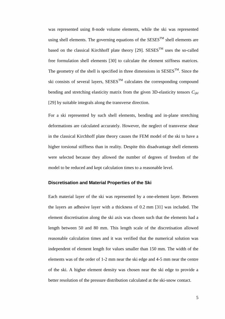
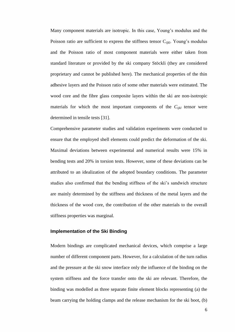
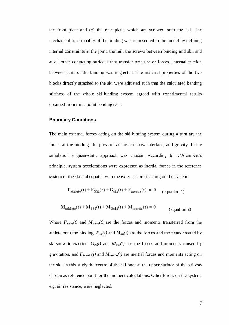
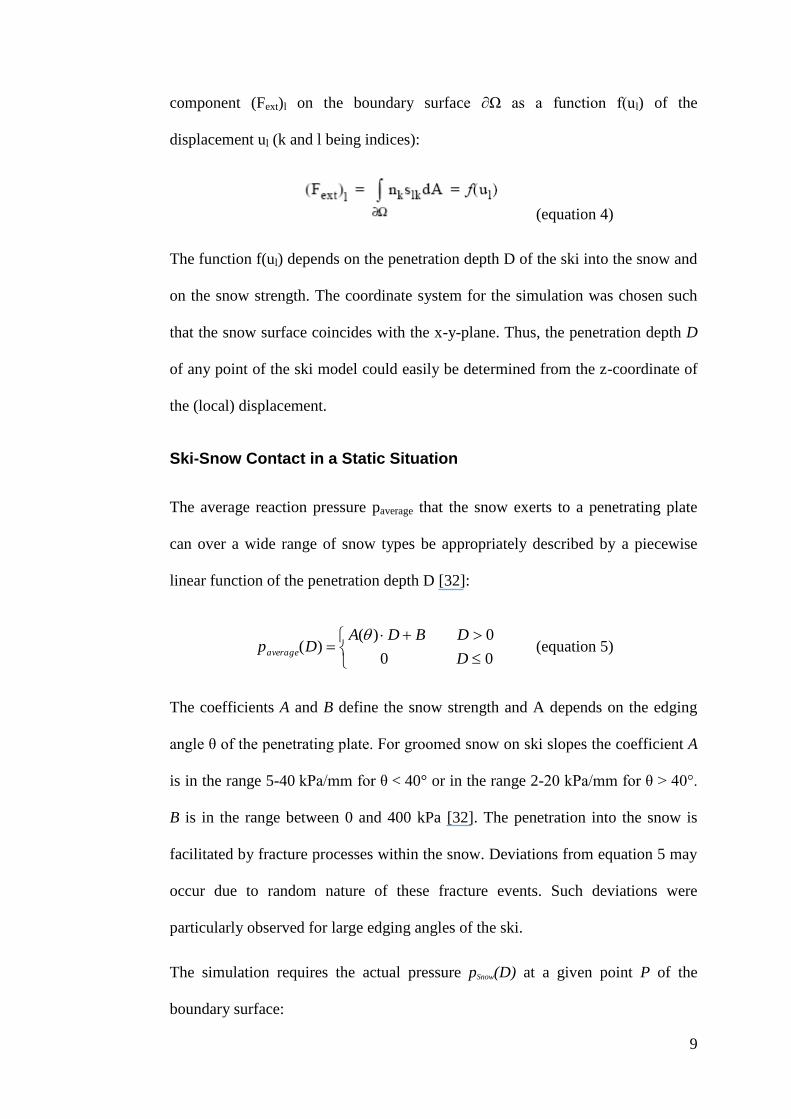
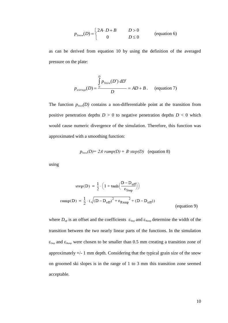
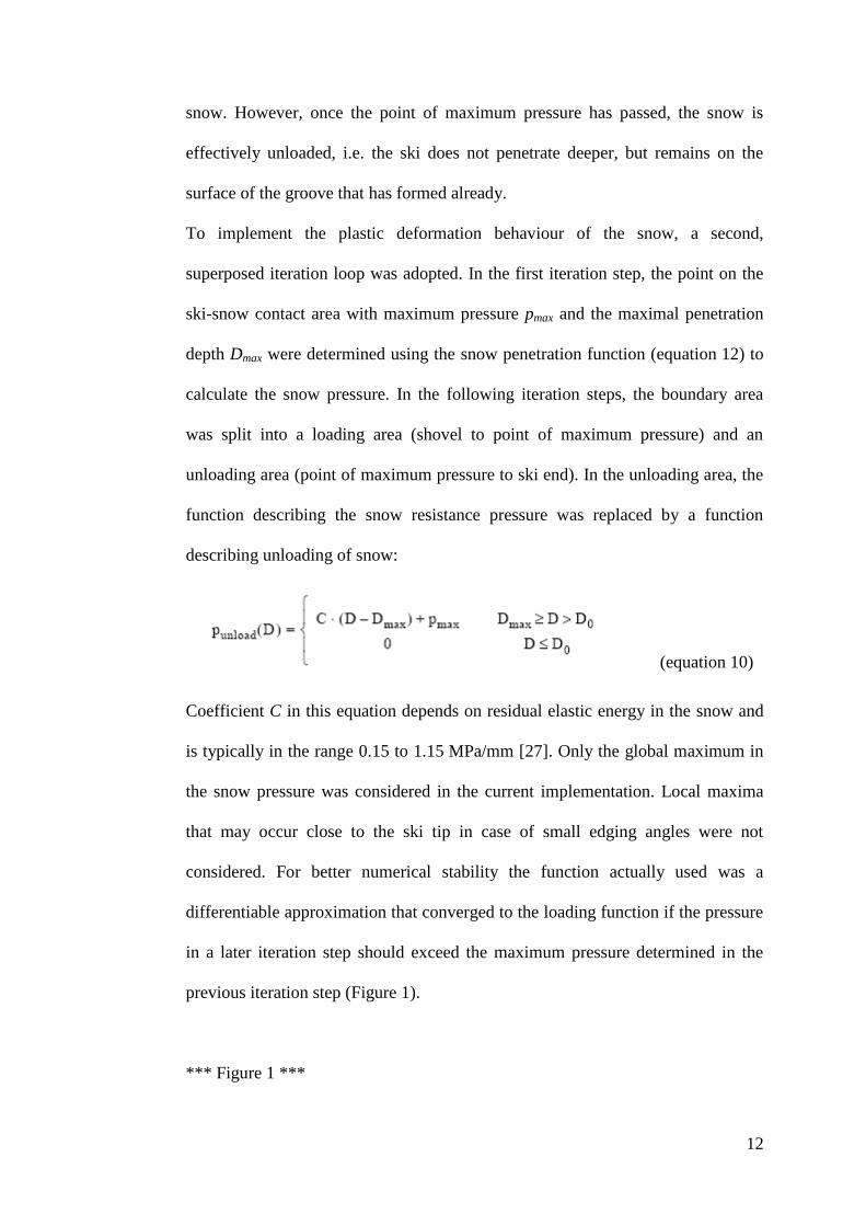
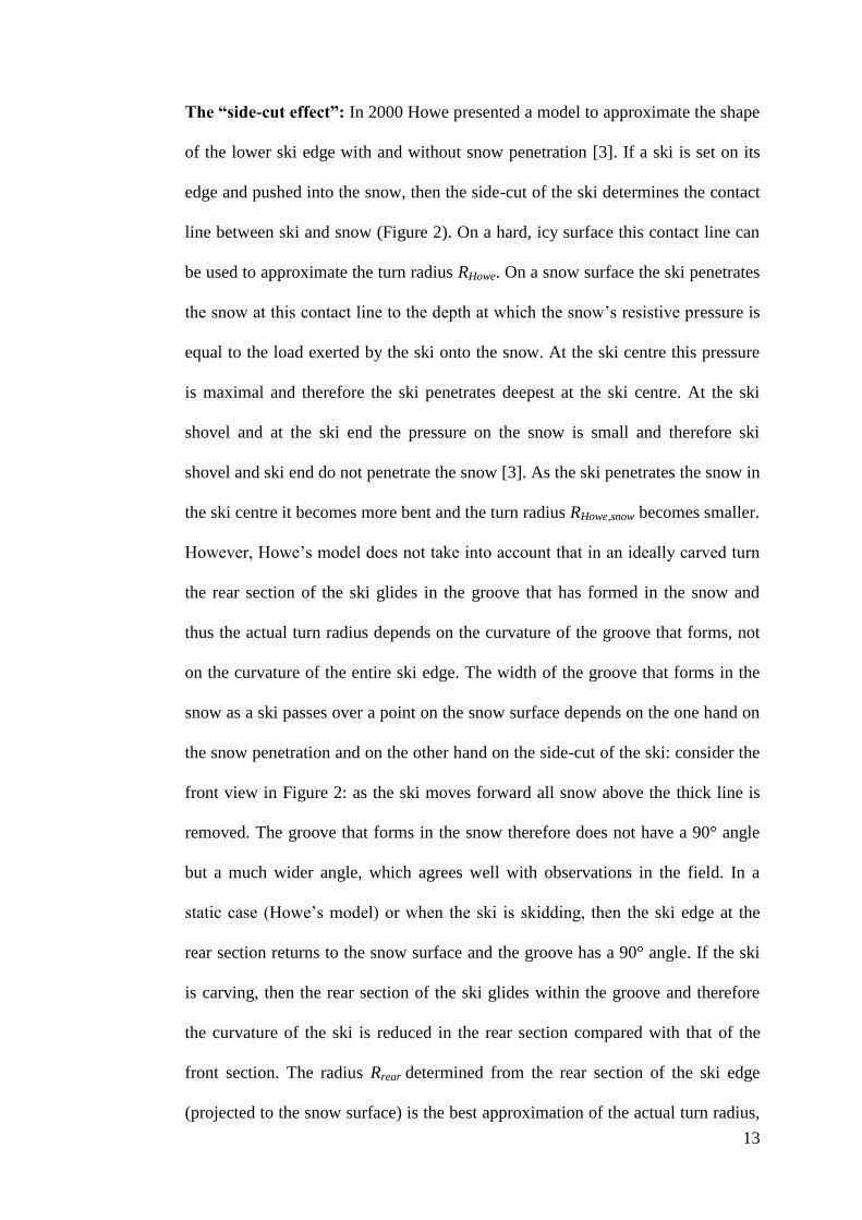
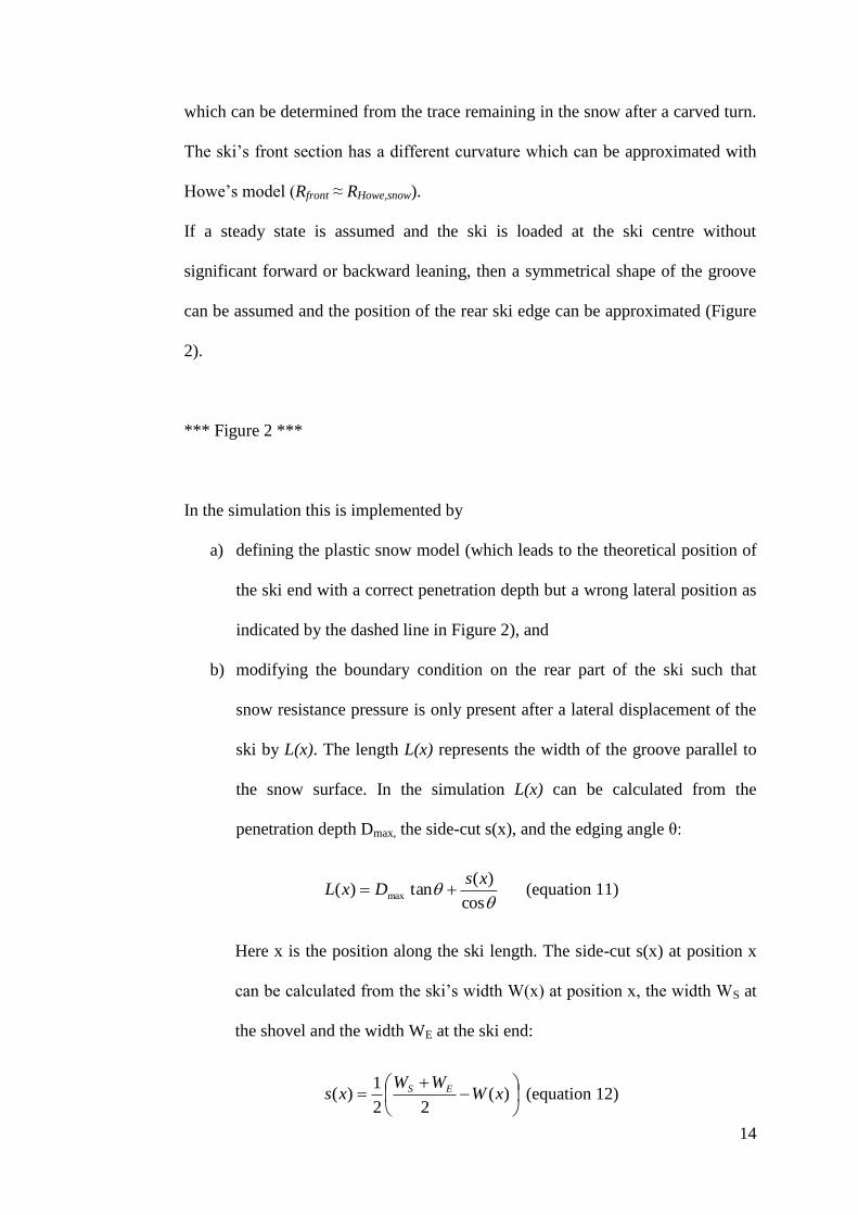
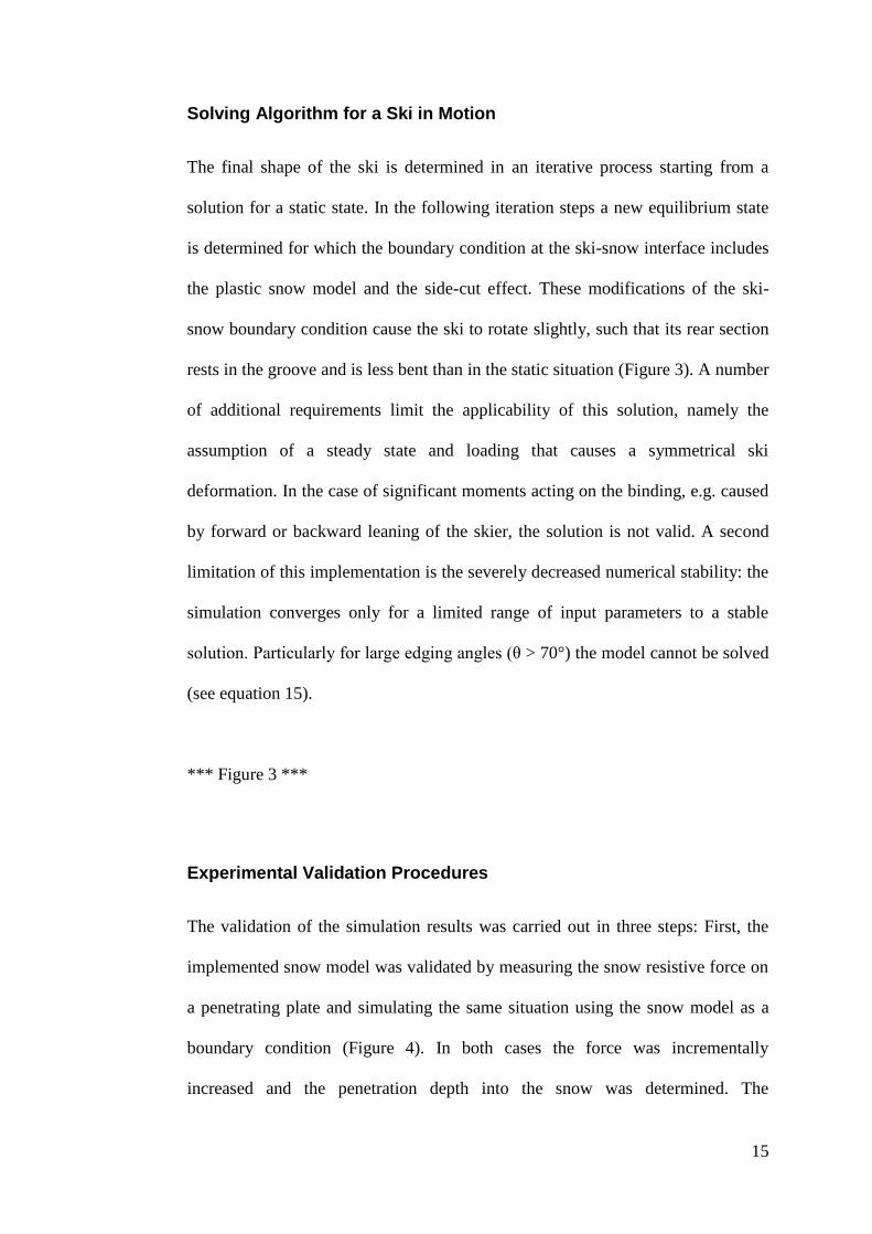
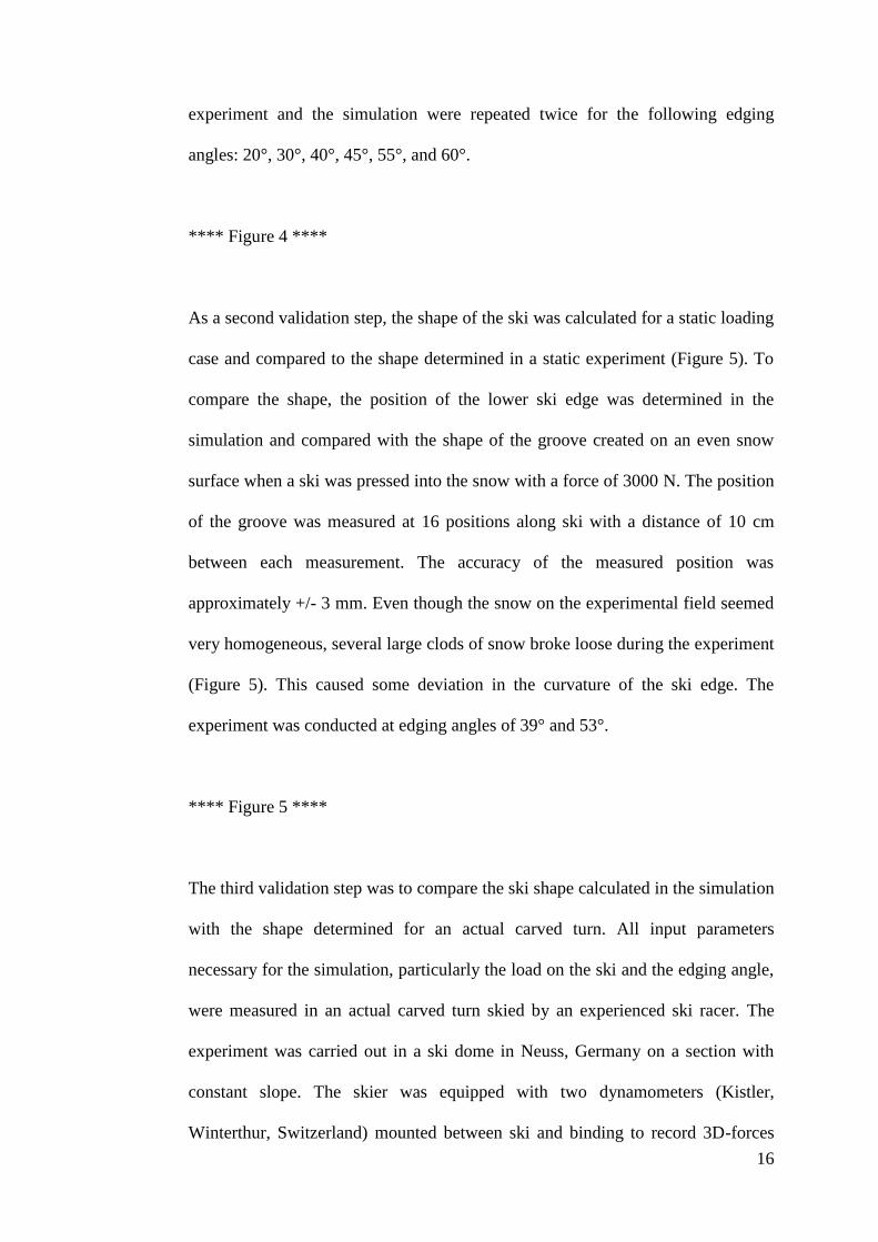
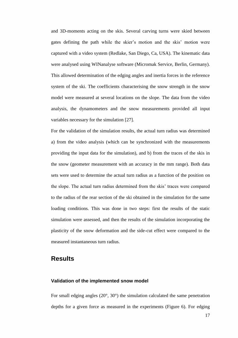
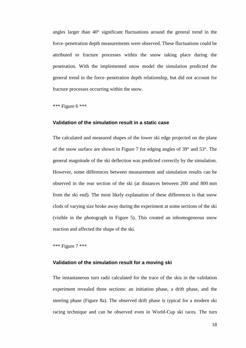
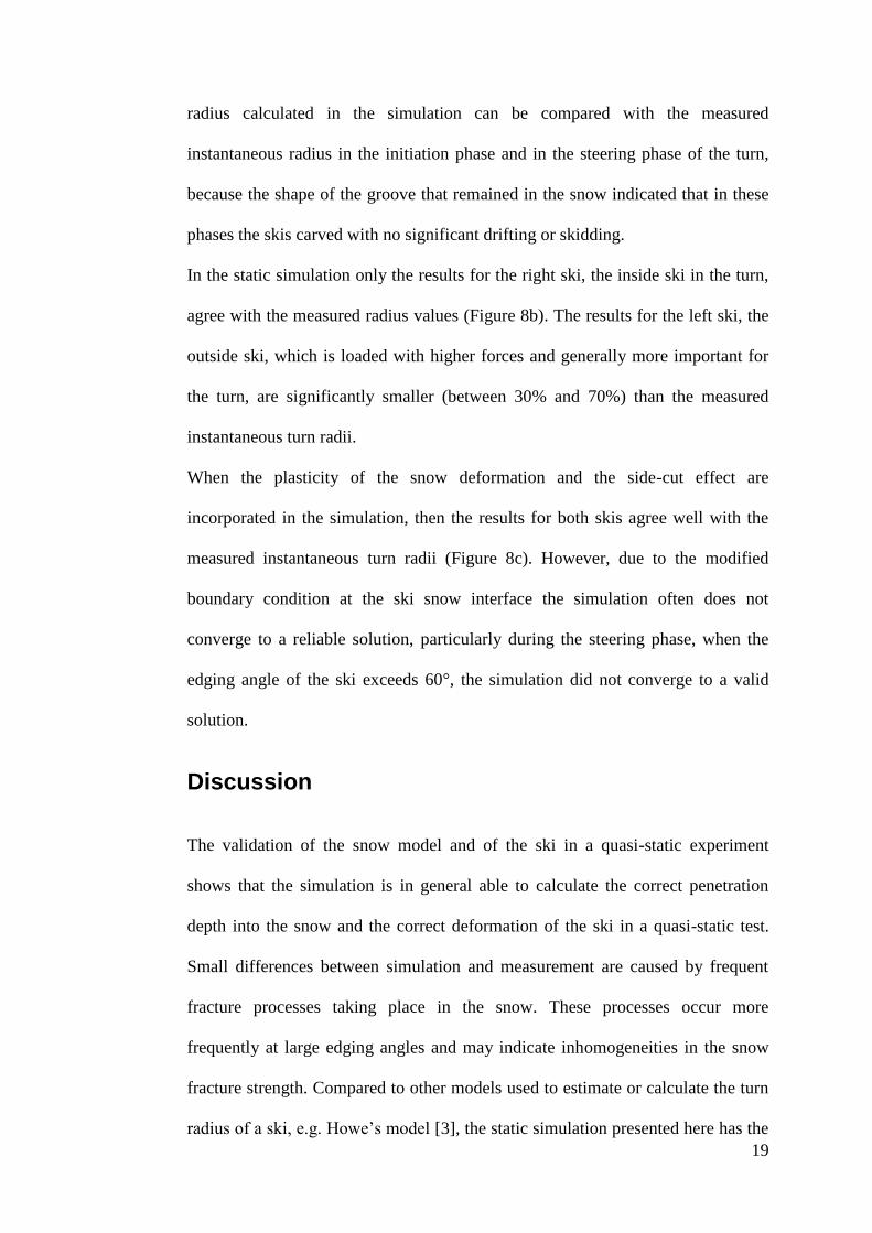
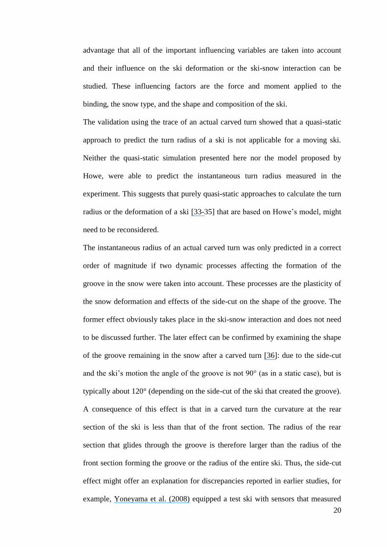
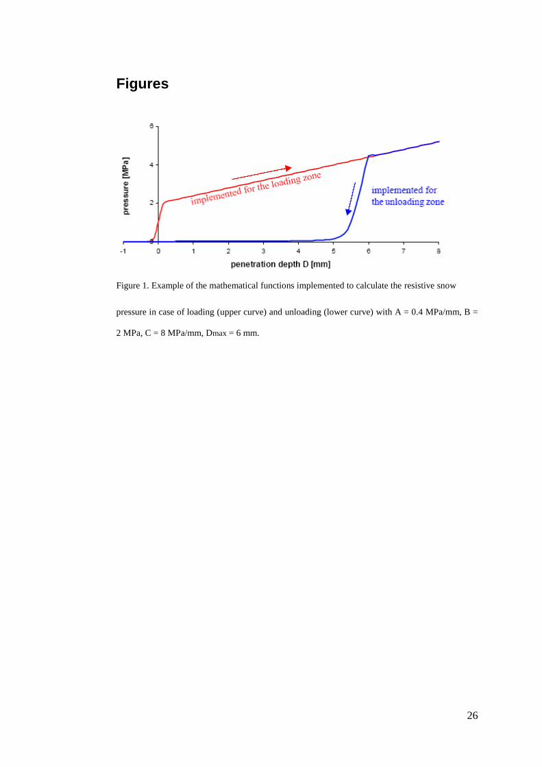
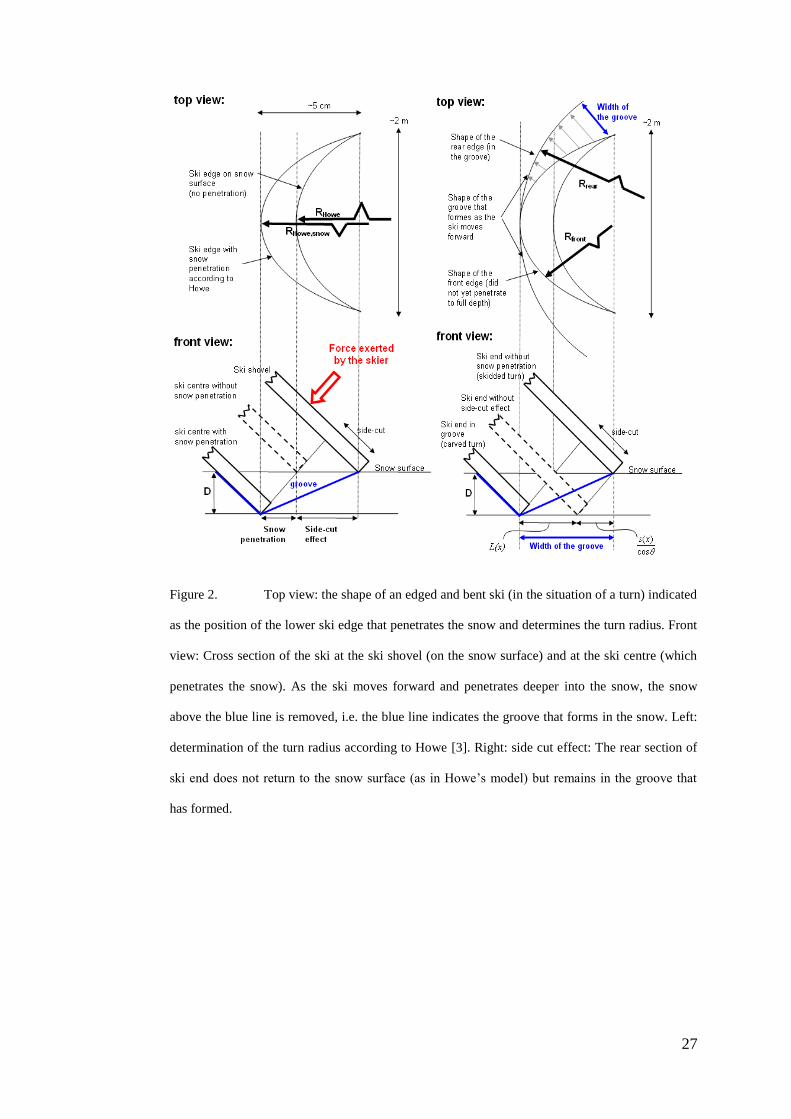
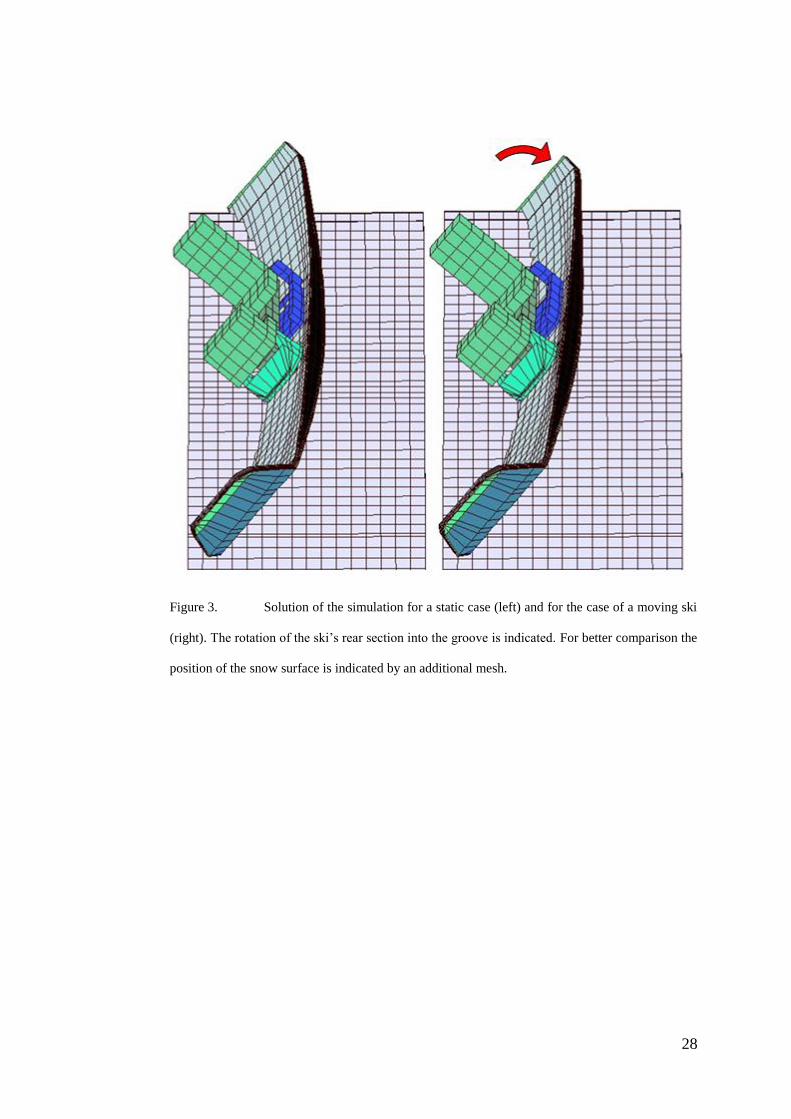
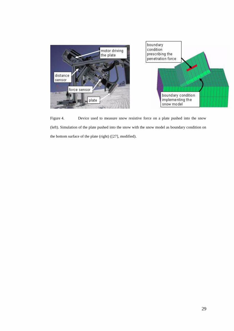
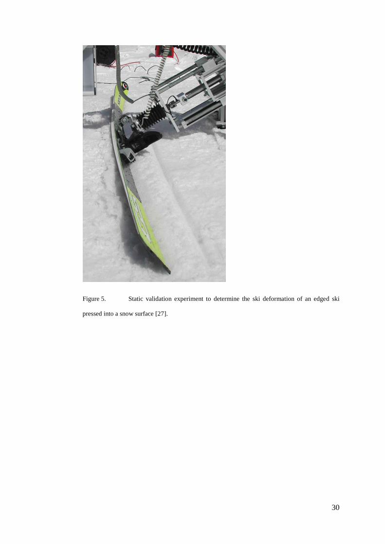
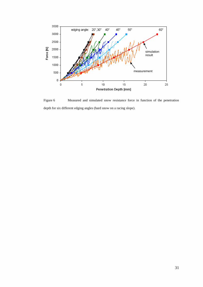
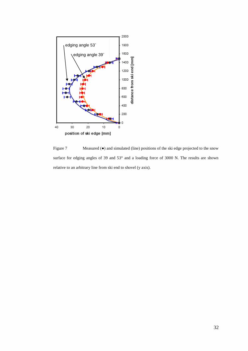
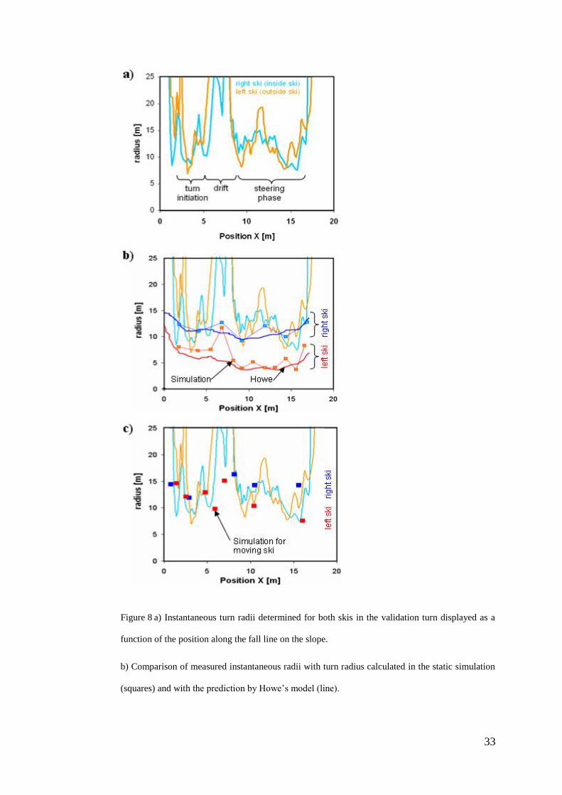

34
c) Comparison of measured instantaneous turn radii with turn radius calculated in the simulation
incorporating plasticity of snow deformation and side-cut effect (squares)