finite element models of octg threaded connections
TRANSCRIPT
Comparers & Structures Vol. 47. No 4/S, pp. 725-734, 1993 Printed in Great B&am.
ooe-7949j93 s6.00 + 0.00 Q 1993 Pcrgamos Pfcss Ltd
FINITE ELEMENT MODELS OF OCTG THREADED CONNECTIONS
A. P. ASSANELLI and E. N. DVORKIN
Center for Industrial Research, FUDETEC, Av. C6rdoba 320, 1054 Buenos Aires, Argentina
Abstract-Modeling of the behavior of different types of tube threaded connections is carried out with ADINA. The calculations are performed for service and ultimate loads of the connections. The information provided by the finite element models allows tube manufacturers to improve their designs on a rational basis and it also allows tube users in the petroleum industry to select the correct joint for each application.
1. INTRODUCTION
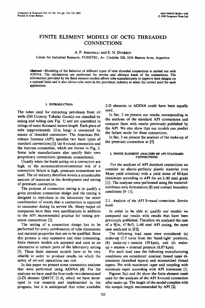
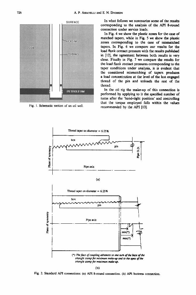
The tubes used for extracting petroleum from oil wells (Oil Country Tubular Goods) are classified by casing and tubing (see Fig. 1) and are assembled in strings of some thousand meters length. Each piece of tube (approximately 12 m long) is connected by means of threaded connectors. The American Pet- roleum Institute (API) specifies two basic types of standard connections [ 11: the 8-round connection and the buttress connection, which are shown in Fig. 2. Some tube manufacturers also specify their own proprietary connections (premium connections).
Usually when the loads acting on a connection are high, or the economical/environmental risk of a connection failure is high, premium connections are used. The oil industry therefore invests a considerable amount of resources in the development and testing of premium connections.
The purpose of connection testing is to qualify a given premium connection design and the testing is designed to reproduce in the laboratory the worst combination of events that a connection is expected to encounter during its service life. Many major oil companies have their own specifications in addition to the API recommended practice for testing pre- mium connections [2].
The testing of a connection design has to be performed for every combination of tube dimensions and material properties that are to be qualified. Since this process is very expensive and time consuming, finite element models are accepted and used as an alternative to certain parts of the laboratory testing [3]. These finite element models have to be very reliable in order to produce results on which the safety of oil-well operations can rest.
In this paper we present some connection analyses that were performed using ADINA [4]. For the analyses we have used the four-node two-dimensional (2-D) element QMITC [S, 61, which we have devel- oped in our research and implemented in the program, but it is anticipated that other available
2-D elements in ADINA could have been equally used.
In Sec. 2 we present our results corresponding to the analyses of the standard API connections and compare them with results previously published by the API. We also show that our models can predict the failure mode for these connections.
In Sec. 3 we present the analysis of the make-up of the premium connection in [A.
2. FINITE ELEMENT ANALYSIS OF API STANDARD CONNECTIONS
For the analyses of API standard connections we consider an elastic-perfectly plastic material (von Mises yield criterion) with a yield stress of 80 kpsi (minimum according to API for an L-80 steel grade [ 11). The analyses were performed using the material- nonlinear-only formulation [8] and contact boundary conditions [9-l 11.
2.1. Analysis of the API 8-round connection. Service loads
In order to be able to qualify our models we compared our results with results that have been previously published. Therefore we analyzed the case of a 9i in, 47 lb/ft, L-80 steel API casing, the same case analyzed in [12].
The following load cases were considered: (a) make-up (3.5 turns from the ‘hand-tight* position), (b) make-up + tension (50 kpsi), and (c) make- up + tension + internal pressure (6.87 kpsi).
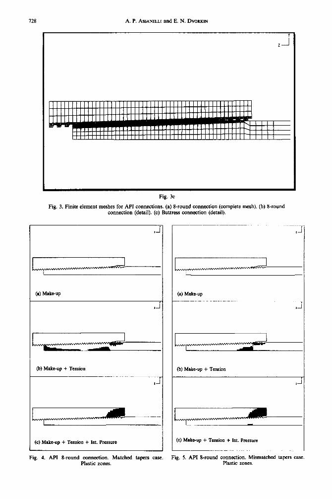
For each load case the following manufacturing conditions are considered: nominal thread taper di- mensions (matched tapers) and mismatched thread tapers. Pin with maximum taper and coupling with minimum taper according with API tolerances [l].
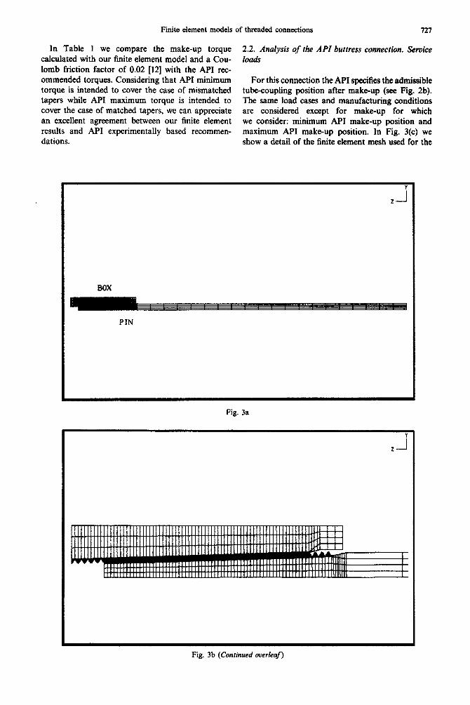
Figures 3(a) and (b) show the finite element mesh used for the analyses of the API 8-round connection after make-up. The length of the model complies with the sample length recommended by API [2].
725
A.P. ASSANELLI and E.N. DVORKIN
SURFACE ,
Fig. 1. Schematic section of an oil well.
In what follows we summarize some of the results corresponding to the analysis of the API I)-round connection under service loads.
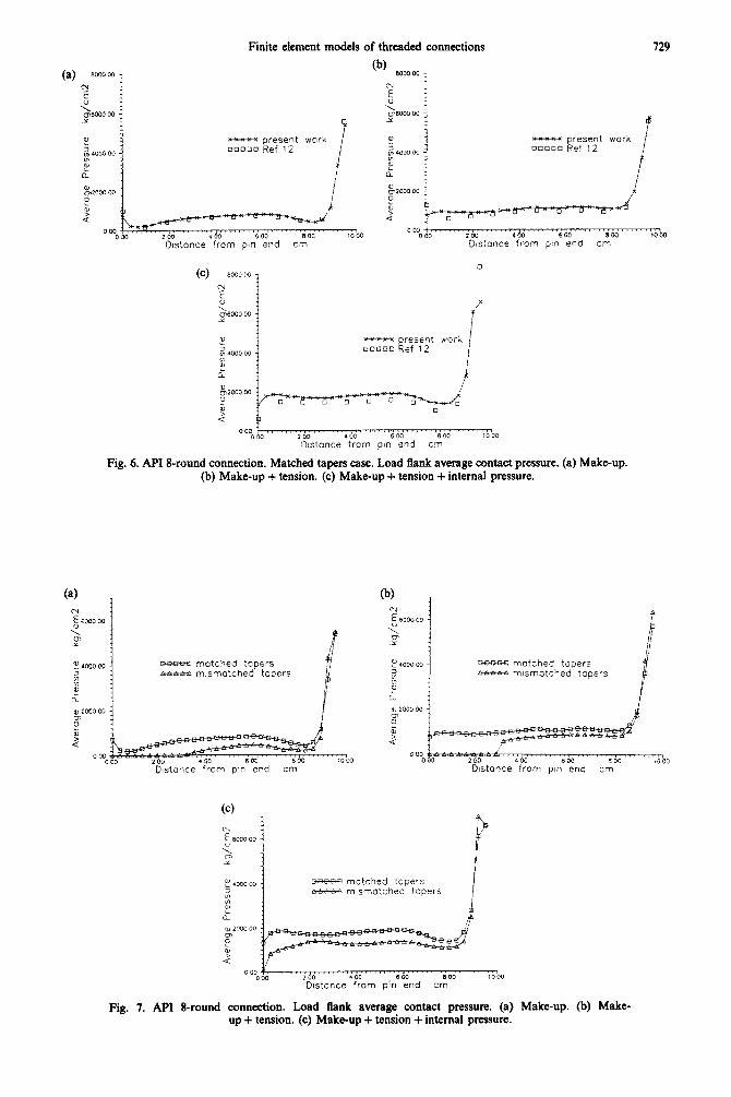
In Fig. 4 we show the plastic zones for the case of matched tapers, while in Fig. 5 we show the plastic zones corresponding to the case of mismatched tapers. In Fig. 6 we compare our results for the load flank contact pressure with the results published in [12], the agreement between both results is very close. Finally in Fig. 7 we compare the results for the load flank contact pressures corresponding to the taper conditions under analysis, it is evident that the considered mismatching of tapers produces a load concentration at the level of the last engaged thread of the pin and unloads the rest of the thread.
In the oil rig the make-up of this connection is performed by app~~ng to it the specified number of turns after the ‘hand-tight position’ and controlling that the torque employed falls within the values recommended by the API [ 131.
I Thread taper on diameter = 6.25%
Pipe axis
t
_-_-_-.~----
(4
I i
Thread lap on diameter = 6.25%
(*) Z78efncc of coupiing adwmxs to one twn &he base qflkc rrianglc sramp for minimum make-y, ad to the qpa o/&f friangfe sfampjbr maximum make-tip.
(b)
Fig. 2. Standard API connections: (a) API S-round connection. (b) API buttress connection.
Finite element models of threaded connections 727
In Table I we compare the make-up torque calculated with our finite element model and a Cou- lomb friction factor of 0.02 [12] with the API rec- ommended torques. Considering that API minimum torque is intended to cover the case of mismatched tapers while API maximum torque is intended to cover the case of matched tapers, we can appreciate an excellent agreement between our finite element results and API experimentally based recommen- dations.
2.2. Analysis of the API buttress connection. Service loaa3
For this connection the API specifies the admissible tu~~oupling position after make-up (see Fig. 2b). The same load cases and manufactu~ng conditions are considered except for make-up for which we consider: minimum API make-up position and maximum API make-up position. In Fig. 3(c) we show a detail of the finite element mesh used for the
BOX
PIN
Fig. 3a
Fig. 3b (Continued overleaf)
728 A. P. ASSANELLI and E. N. DVORKIN
Fig. 3c
Fig. 3. Finite element meshes for API connections. (a) I-round connection (complete mesh). (b) 8-round connection (detail). (c) Buttress connection (detail).
(a) Make-up
I 2-I
(b) Make-up + Tension
(c) Make-up + Tension + hit. Pressure
(a) Make-up
(b) Make-up + Tension
(c) Makeup + Tension + Int. Pressure
Fig. 4. API S-round connection. Matched tapers case. Fig. 5. API g-round connection. Mismatched tapers case. Plastic zones. Plastic zones.
Finite element models of threaded connections 729
- present work ljo~oo Ref 12
Fig. 6. API g-round connection. Matched tapers case. Load frank average contact pressure. (a) Make-up. (b) Make-up + tension. (c) Make-up + tension-t internal pressure.
waw+x matched tapers - mismatched tapers
D&once from p!n end cm
neew matched tapers M-M-A mismatched tapers
000 . . ..r.II.i......,1.,..,.,..CTlm.,,.I,,’.’,,rn 000 2 00 I 00 8W 1000
Distance from pin’%d cm
Fig. 7. API I-round connection. Load tlank average contact pressure. (a) Make-up. (b) Make- up + tension. (c) Make-up + tension + internal pressure.
730 A. P. ASSANELLI and E. N. DVORKIN
Table I. Comparison between FEM calculated make-up torques 01 = 0.02) and API recommendations
Torque (lb. ft)
FEM ADINA Matched tapers 10,515 Mismatched tapers 6680
API recommended Maximum 11,160 Minimum 6700
analysis of the API buttress connection after make-
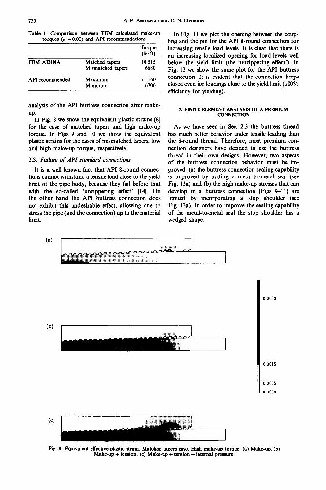
up* In Fig. 8 we show the equivalent plastic strains [8]
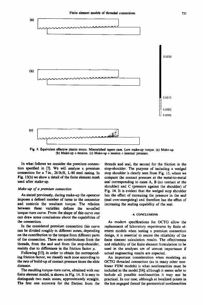
for the case of matched tapers and high make-up torque. In Figs 9 and 10 we show the equivalent plastic strains for the cases of mismatched tapers, low and high make-up torque, respectively.
2.3. Failure of API standard connections
It is a well known fact that API g-round connec- tions cannot withstand a tensile load close to the yield limit of the pipe body, because they fail before that with the so-called ‘unzippering effect’ [14]. On the other hand the API buttress connection does not exhibit this undesirable effect, allowing one to stress the pipe (and the connection) up to the material limit.
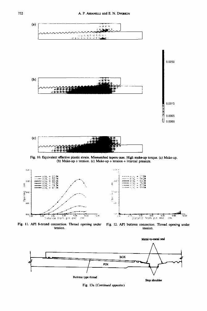
In Fig. 11 we plot the opening between the coup- ling and the pin for the API 8-round connection for increasing tensile load levels. It is clear that there is an increasing localized opening for load levels well below the yield limit (the ‘unzippering effect’). In Fig. 12 we show the same plot for the API buttress connection. It is evident that the connection keeps closed even for loadings close to the yield limit (100% efficiency for yielding).
3. FINITE ELEMENT ANALYSIS OF A PREMIUM CONNECIION
As we have seen in Sec. 2.3 the buttress thread has much better behavior under tensile loading than the g-round thread. Therefore, most premium con- nection designers have decided to use the buttress thread in their own designs. However, two aspects of the buttress connection behavior must be im- proved: (a) the buttress connection sealing capability is improved by adding a metal-to-metal seal (see Fig. 13a) and (b) the high make-up stresses that can develop in a buttress connection (Figs 9-11) are limited by incorporating a stop shoulder (see Fig. 13a). In order to improve the sealing capability of the metal-to-metal seal the stop shoulder has a wedged shape.
/ 0.0050
I 0.0015
~ 0.0005
i 0.0000
Fig. 8. Equivalent effective plastic strain. Matched tapers case. High make-up torque. (a) Make-up. (b) Make-up + tension. (c) Make-up + tension + internal pressure.
Finite element models of threaded connections 731
(b) 1
u 0.0005
0.0000
Fig. 9. Equivalent effective plastic strain. Mismatched tapers case. Low make-up torque. (a) Make-up. (b) Make-up + tension. (c) Makt-up + tension + internal pressure.
In what follows we consider the premium connec- tion specified in [I. We will analyze a premium connection for a 7 in., 26 lb/ft, L-80 steel casing. In Fig. 13(b) we show a detail of the finite element mesh used after make-up.
Make-up of a premium connection
As stated previously, during make-up the operator imposes a defined number of turns to the connector and controls the resultant torque. The relation between these variables defines the so-called torque-turn curve. From the shape of this curve one can draw some conclusions about the capabilities of the connection.
In the considered premium connection this curve can be divided roughly in different zones, depending on the contribution to the torque from different parts of the connection. There are contributions from the threads, from the seal and from the stop-shoulder, mainly due to differences in the friction factor p.
Following [IS], in order to obtain the correspond- ing friction factor, we classify each zone according to the rate of build-up of contact pressure times the slide distance.
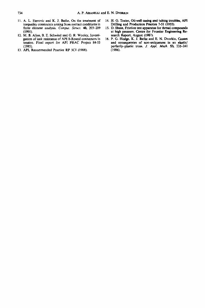
The resulting torqwtum curve, obtained with our finite element model, is shown in Fig. 14. It is easy to distinguish two main zones, approximately straight. The first one accounts for the friction from the
threads and seal, the second for the friction in the stop-shoulder. The purpose of including a wedged stop shoulder is clearly seen from Fig. 15, where we compare the contact pressure at the metal-to-metal seal corresponding to cases A, B (no contact at the shoulder) and C (pressure against the shoulder) of Fig. 14. It is evident that the wedged stop shoulder has the effect of increasing the pressure in the seal (seal over-energizing) and therefore has the effect of increasing the sealing capability of the seal.
4. CONCLUSIONS
As modem specifications for OCTG allow the replacement of laboratory experiments by finite el- ement models when testing a premium connection design, it is essential to assure the reliability of the finite element calculation results. The effectiveness and reliability of the finite element formulation to be used in the analyses are of utmost importance if actual engineering results are expected.
An important consideration when modeling an GCTG threaded connection (as in many other non- linear FEM models) is what nonlinearities must be included in the model [16]; although it seems safer to include all possible nonlinearities it may not be practical. In our case, although at localized points in the last engaged thread the geometrical nonlinearities
732 A.P. ASSANELLI andE.N. DVORKIN
(b)
u 0.0005
0.0000
Fig. 10. Equivalent effective plastic strain. Mismatched tapers case. High make-up torque. (a) Make-up. (b) Make-up + tension. (c) Make-up + tension + internal pressure.
Fig. 11. API &round connection. Thread opening under tension.
-o/o, = 17.8% ---o/J~ = 542% - a/o, 7 63.3% “iLet(. a/o, = 75 4% *- * 0, = 37 5% _1 0 ‘0” = 99 6%
-00 D;s!ance from pin end cm
Fig. 12. API buttress connection. Thread opening under tension.
Metal-to-metal seal
Buttress type thread Stop shoulder
Fig. 13a (Continued opposite)
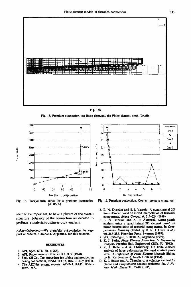
Finite element models of threaded connections 133
i
Fig. 13b
Fig. 13. Premium connection. (a) Basic elements. (b) Finite element mesh (detail).
0 02 0.4 06 08 1 12 0 12 3 4 5 6 7
Tm (frcm t-d-tight positm)
Fig. 14. Torqueturn curve for a premium connection (ADINA).
seem to be important, to have a picture of the overall structural behavior of the connection we decided to perform a material-nonlinear-only analysis.
Acknowledgements-We gratefully acknowledge the sup- port of Siderca, Campana, Argentina, for this research.
:: 3.
4.
REFERENCES
API, Spec. STD 5B. (1988). API, Recommended Practice RP SC5 (1990). Shell Oil Co., Test procedure for tubing and production casing connections, NAM TE0/3, Rev. 3, July (1991). The ADINA system reports, ADINA R&D, Water- town, MA.
Drst chq sed lmnl
Fig. 15. Premium connection. Contact pressure along seal.
5. E. N. Dvorkin and S. I. Vassolo, A quadrilateral 2D linite element based on mixed interpolation of tensorial components. Engng Compur. 6, 217-224 (1989).
6. E. N. Dvorkin and A. P. Assanelli, Elasto-plastic analysis using a quadrilateral 2D element based on mixed interpolation of tensorial components. In Cotn- putational Plasticity (Edited by D. R. J. Owen et al.), pp. 263-283. Pineridge Press, Swansea (1989).
7. SEC Catalogue, SIDERCA, Argentina (1991). 8. K. J. Bathe, Finite Element Procedures in Engineering
Analysis. Prentice-Hall, Englewood Cl& NJ (1982). 9. K. J. Bathe and A. Chaudhary, On finite element
analysis of large deformation frictional contact prob- lems. In Unification of Finite Element Methoa3 (Edited by H. Kardestuncer), North Holland (1984).
10. K. J. Bathe and A. Chaudhary, A solution method for planar and axisymmetric contact problems. Inr. J. Nu- me,. Meth. Engng 21, 65-88 (1985).
134 A.P. ASMNELLI and E.N. DVORKIN
11. A. L. Eterovic and K. J. Bathe, On the treatment of 14. H. G. Texter, Oil-well casing and tubing troubles, API inequality constraints arising from contact conditions in Drilling and Production Practice 7-51 (1955). finite element analysis. Compur. Srrucr. 40, 203-209 15. D. Shute, Friction test apparatus for thread compounds (1991). at high pressure. Centre for Frontier Engineering Re-
12. M. B. Allen, B. E. Schwind and Cl. R. Wooley, Investi- search Report, August (1987). gation of leak resistance of API I-Round connectors in 16. P. G. Hodge, K. J. Bathe and E. N. Dvorkin, Causes tension. Final report for API PRAC Project 84-53 (1985).
and consequences of non-uniqueness in an elastic/ perfectly-plastic truss. J. Appt. Me&. 53, 235-241
13. API, Recommended Practice RP 5Cl (1988). (1986).