ff ip engg. data.cdr - indion resins
TRANSCRIPT
INDION FFIP is a Type 1 strong base, unifunctional
anion exchange resin in bead form, containing
trimethyl benzyl ammonium groups. It is based on
cross-linked polystyrene and has an isoporous
structure.
INDION FFIP has a very high basicity. It is effective in
removing weak acids such as silica and carbon dioxide
and recommended in two stage/multiple stage or
Description
Characteristics
Appearance : Translucent red brown beads
Matrix : Styrene -EDMA copolymer
Functional Group : Benzyl trimethyl amine
Ionic form as supplied : Chloride
Total exchange capacity : 1.2 meq/ml, minimum
Moisture holding capacity : 47-55%3Shipping weight * : 680 kg/m , approximately
Particle size range : 0.3 to 1.2 mm
> 1.2 mm : 5.0%, maximum
< 0.3 mm : 1.0%, maximum
Uniformity co-efficient : 1.7, maximum
Effective size : 0.45 to 0.55 mm0Maximum operating temperature : 60 C in OH form090 C in Cl and other forms
Operating pH range : 0 to 14
Volume change : Cl to OH,10-15 %
Resistance to reducing agents : Good
Resistance to oxidizing agents : Generally good, chlorine should be absent
3* Weight of resin, as supplied, occupying 1 m in a unit after backwashing and draining
FF-IP
mixed bed de-ionising, where high quality de-ionized
water and lowest silica residuals are desired.
In addition INDION FFIP demonstrates stability to high
temperature regeneration required for minimum silica
leakage. It has a high reversible capacity for the natural
organic matter present in some surface waters, with
excellent resistance to fouling by this organic matter.
INDION FFIP is used as the anion exchanger in the second stage of a de-ionising pair with INDION 225 cation exchange resin in the first stage.
When used in a two stage de-ionising plant, upstream of a mixed bed unit, INDION FFIP will protect the strong base anion exchanger in the latter unit against organic fouling. At the same time it will assist in the production of final treated water with a low residual of organic matter and silica.
Multiple stage de-ionisingINDION FFIP is recommended as the anion exchanger in a multiple stage de-ionising train with strong acid
cation exchange resin and weak base anion exchange resin in the preceding stages to keep operating costs low.Regeneration and silica removal efficiency are enhanced if a warm regenerant solution is used. Where plant operating conditions allow, INDION FFIP can be regenerated in this manner.
Mixed bed de-ionising If treated water with the lowest possible level of silica residual is required, two stage/multiple stage treatment should be followed by mixed bed de-ionsing using INDION FFIP.
Applications
Minimum Bed depth …………………… 0.75 m, minimum 1.0 m, minimum 3 2 3 2Treatment flowrate ……………………… 60 m /h m , maximum 60 m /h m , maximum
Pressure loss …………………………….. Refer Figure 19 Refer Figure19
Bed expansion …………………………… Refer Figure 20 Refer Figure 20 3 2 3 2 Backwash………………………………… 3 m /h m for 5 minutes or 3 m /h m till effluent is clear *
till effluent is clear
Sodium HydroxideRegenerant ……………………………… Sodium Hydroxide
(2-4% w/v) (2-4% w/v) 3 2 3 2Regenerant flowrate …………………….. 4.5-18 m /h m 4.5- 18 m /h m
Regenerant injection time …….………… 30 minutes minimum 30 minutes minimum Slow rinse …………………….…………. 2.5 to 3 bv at regenerant 2 to 3 bv at regenerant
flowrate flowrate
Final rinse………………………………… 5 bv at service flowrate 7.5 bv at service flowrate
Typical operating data
Two stage/multiple stage de-ionising
Co-flow regeneration Countercurrentregeneration
De-ionising
Two stage de-ionising
* After a set number of regenerations 3 3 1 bv (bed volume) = 1 m fluid/m resin.
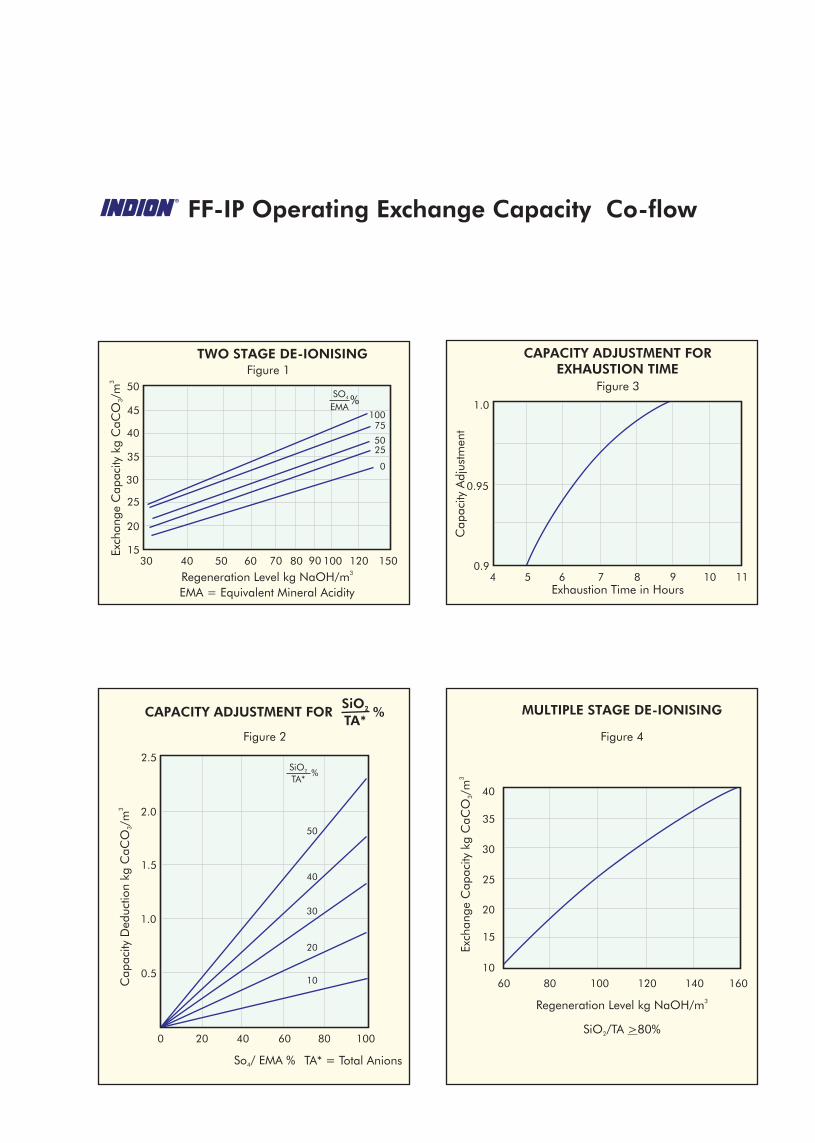
Operating Exchange capacity
The operating exchange capacity of INDION FFIP when used as the anion exchanger in a two stage de-ionising system is dependent upon:l The regeneration level employedlThe composition of water to be treated, specifically the
concentration of mineral acid anions (SO /EMA)4
l Silica content (SiO /TA) 2
l Exhaustion rateFigure 1 shows typical capacities obtained with a de-ionising system using INDION 225 strong acid cation exchange resin in the first stage followed by degasser and INDION FFIP anion exchange resin in the second stage and employing co-flow regeneration.
Effect of sulphate and EMAThe operating exchange capacities (Figure 1) are shown as a function of regeneration level for various percentages of SO /EMA and at EMA values around 4
100-200 ppm CaCO .3
Effect of silicaCapacity deduction data (Figure 2) is shown as a function of SO /EMA ratio for various percentages of 4
SiO upto 50%.2
Effect of exhaustion rate The capacity data is related to exhaustion times greater than nine hours. Figure 3 shows the variation in c a p a c i t y w i t h e x h a u s t i o n t i m e .In selecting operating conditions of INDION FFIP consideration should be given to the expected treated water quality. Figures 9-13 show average treated water quality that can be expected from this resin. These are related to the regeneration level, the temperature of the regenerant and the ratio of silica to total anions in the feed.
Multiple stage de-ionising In a multiple stage de-ionising system, where a strong acid cation exchanger such as INDION 225 is used in the first stage, followed by a weak base anion exchanger such as INDION 850, preceded or followed
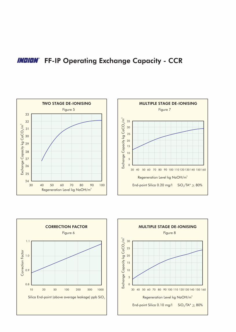
The operating exchange capacity of INDION FFIP when used as the anion exchanger in a two stage De-ionising system is dependent upon:
l The regeneration level employedl Silica content (SiO /TA) 2
l Exhaustion rate
Figure 5 shows typical capacities obtained with a de-ionising system using INDION 225 strong acid cation exchange resin in the first stage followed by a degasser and INDION FFIP anion exchange resin in the second stage and employing countercurrent regeneration. The operating exchange capacities (Figure 5) are shown as a function of regeneration level and refer to an end point silica of 150 ppb over the average silica residual obtained during the run. The capacities are determined with a feed containing zero sodium slip and ratio of silica to total anion of 20%.Figure 6 gives the correction factor for operating exchange capacity as a function of end-point silica. The capacity data apply to exhaustion times greater than 9 hours. Refer Figure 3 for the variation of capacity with exhaustion time. In selecting operating conditions of INDION FFIP, consideration should be given to the expected treated water quality. Figure 14 shows average treated water quality that can be expected from the resin. These are related to the regeneration level and the ratio of silica to total anions in the feed with the temperature of regenerant at 25 °C.
Co-flow regeneration
Countercurrent regeneration(CCR)
Two stage de-ionising
Two stage de-ionising
by a degasser and a strong base anion exchanger such as INDION FFIP in series, INDION FFIP treats an influent water containing predominantly weak acids like silica and carbon dioxide. Figure 4 gives operating exchange capacity of INDION FFIP, when used in co-flow regeneration mode.
efficiency. The useful capacity will be high and silica leakage will be low as the strong base resin receives all the sodium hydroxide required for both columns. The injection is followed by a slow rinse with water to transfer the residual caustic present in the strong base anion exchanger to the weak base anion exchanger. This method is commonly referred to as thoroughfare regeneration.
The quality of the treated water from a two stage de-ionising plant using INDION FFIP as the anion exchanger is determined by:
l The regeneration level employed
l The temperature of the regenerant used for the anion exchanger
l The level of sodium ion leakage from the cation (hydrogen) exchanger
l The silica to total anions ratio of the water fed to anion exchanger
Sodium ions leaking from the cation exchanger are converted to NaOH, as the water passes through the anion exchange stage.
Each mg/1 of sodium leakage, expressed as CaCO , 3
increases the electrical conductivity of the water leaving the anion exchange stage by approximately 5
omicrosiemens/cm at 20 C.
The values for silica residual in the treated water at various regeneration levels and temperatures can be obtained from Figures 9-13 for coflow mode of regeneration.
The values for silica residual in the treated water at various regeneration levels can be obtained from Figure 14, for countercurrent regeneration at a
otemperature of 25 C.
These values assume zero sodium slip and for every mg/I of sodium leakage as CaCO , the residual silica 3
will increase by 15%.
Treated Water Quality
Two stage/Multiple stagede-ionising
When used as the anion exchanger in mixed bed de-ionising systems the capacity of INDION FFIP is independent of the feed water composition and therefore corresponds to the zero curve in Figure 1.
No correction for silica content of the feed water need be made, although the amount loaded on the resin and hence the volume of water treated between regenerations may need to be adjusted in order to obtain satisfactory silica residual in the treated water (Figures 15-18).
Multiple stage de-ionising In a multiple stage de-ionising system, where a strong acid cation exchanger such as INDION 225 is used in the first stage, followed by a weak base anion exchanger such as INDION 850, preceded or followed by a degasser and a strong base anion exchanger such as INDION FFIP in series, INDION FFIP treats an influent water containing predominantly weak acids like silica and carbon dioxide. Figure 7 gives operating exchange capacity of INDION FFIP, when used in countercurrent mode at various regeneration levels with alkali injected at 25°C. The capacities refer to end point silica of 0.2 ppm SiO . 2
Figure 8 gives the operating exchange capacity of INDION FFIP, when used in countercurrent regeneration mode at various regeneration levels with alkali injected at 25° C. The capacities refer to an end-point silica of 0.1 ppm SiO2
Coflow and counter current regeneration The use of sodium hydroxide solution at the recommended flowrate and concentration, results in contact time that is favorable for achieving optimum capacity and leakage characteristics.
Thoroughfare regeneration If the strong base anion exchanger is operating with weak base anion resin in the preceding stage, the regeneration process can be conducted in series in the direction of strong base towards weak base anion exchanger to improve the overall regeneration
Mixed bed de-ionising
Regeneration
FF-IP Operating Exchange Capacity Co-flow
TWO STAGE DE-IONISINGFigure 1
3Regeneration Level kg NaOH/mEMA = Equivalent Mineral Acidity
15
20
25
30
35
40
45
50
30 40 50 60 70 80 90 100 120 150
SO4
EMA%
10075
5025
0
CAPACITY ADJUSTMENT FOREXHAUSTION TIME
Figure 3
Exhaustion Time in Hours
0.9
0.95
1.0
4 5 6 7 8 9 10 11
Cap
acity
Adj
ustm
ent
Figure 4
MULTIPLE STAGE DE-IONISING
SiO /TA >80%2
3Regeneration Level kg NaOH/m
160140120100806010
20
25
15
30
35
40
Figure 2
100806040200
CAPACITY ADJUSTMENT FORSiO2
TA*%
0.5
1.0
1.5
2.0
2.5
So / EMA %4 TA* = Total Anions
SiO2
TA*%
50
40
30
20
10
FF-IP Operating Exchange Capacity - CCR
Figure 5
TWO STAGE DE-IONISING
3Regeneration Level kg NaOH/m605040 9070 1008030
24
26
27
25
30
28
29
31
32
33
Figure 7
MULTIPLE STAGE DE-IONISING
3Regeneration Level kg NaOH/m
605040 9070 100 110 120 130 140 150 1608030
0
5
20
10
15
25
30
35
End-point Silica 0.20 mg/I SiO /TA* > 80%2
Figure 6
CORRECTION FACTOR
Cor
rect
ion
Fact
or
5020 100 200 500 100010
0.8
1.0
0.9
1.1
Silica End-point (above average leakage) ppb SiO2
Figure 8
MULTIPLE STAGE DE-IONISING
3Regeneration Level kg NaOH/m
605040 9070 100 110 120 130 140 150 1608030
0
5
20
10
15
25
30
End-point Silica 0.10 mg/I SiO /TA* > 80%2
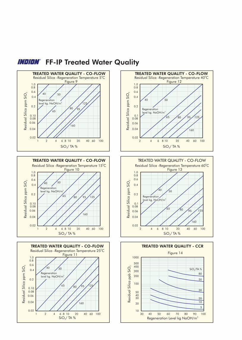
Figure 9
TREATED WATER QUALITY - CO-FLOW
2 41 6 10 20 40 1006080.02
0.04
0.06
0.080.10
0.4
0.8
0.2
0.6
1.0
0Residual Silica -Regeneration Temperature 5 C
SiO / TA %2
Regeneration3level kg. NaOH/m
40 50
6580 95
125
160
Figure 12
TREATED WATER QUALITY - CO-FLOW
2 4 6 10 20 40 1006080.02
0.04
0.06
0.080.1
0.4
0.8
0.2
0.6
1.0
0Residual Silica -Regeneration Temperature 40 C
Regeneration3level kg. NaOH/m
40 50
65 80 95 125
160
Figure 11
TREATED WATER QUALITY - CO-FLOW
2 41 6 10 20 40 1006080.02
0.04
0.06
0.080.10
0.4
0.8
0.2
0.6
1.0
0Residual Silica -Regeneration Temperature 25 C
Regeneration3level kg. NaOH/m
40 50
65 80 95 125
160
Figure 10
TREATED WATER QUALITY - CO-FLOW
2 41 6 10 20 40 1006080.02
0.04
0.06
0.080.10
0.4
0.8
0.2
0.6
1.0
0Residual Silica -Regeneration Temperature 15 C
Regeneration3level kg. NaOH/m
40 50
65 80 95 125
160
Figure 13
TREATED WATER QUALITY - CO-FLOW
2 4 6 10 20 40 1006080.02
0.04
0.06
0.080.1
0.4
0.8
0.2
0.6
1.0
0Residual Silica -Regeneration Temperature 60 C
Regeneration3level kg. NaOH/m
40 50
65 80 95 125
160
FF-IP Treated Water Quality
Figure 14
TREATED WATER QUALITY - CCR
30 40 50 60 70 80 1009010
20
304050
100
300
500
200
400
1000
SiO /TA % 2
3Regeneration Level kg NaOH/m
30
50
20
80
5
10
SiO / TA %2
SiO / TA %2 SiO / TA %2
SiO / TA %2
Total Bed depth …………………… 1.0 - 2.4 m using INDION FFIP and INDION 225 resinRising space …………………………… 75% of bed depth
3 2Treatment flowrate ……………………… 60 m /h m ,maximum 2 Pressure loss ……………………………. 1.2 kg/cm ,maximum
3 2Bed separation .………………………… 9 m /h m for 10 minutes Bed settlement …………………………. Allow 5 minutes after separation before commencing
injection of regenerantsRegenerant ……………………………… Sodium hydroxide for INDION FFIP
Hydrochloric acid/Sulphuric acid for INDION 2253 2Acid injection rate …………………….. 4.5-18 m /h m for 6-10 minutes with 2-5% w/v acid
3 2Down flow ……………………………… 1.5 m /h mAcid rinse …………………….………… 2 bv
3 2Down flow ………………………………. 1.5 m /h m3 2Alkali Injection rate …….………………. 4.5-18 m /h m for 10-15 minutes with 2-5% w/v alkali
3 2Upflow …..…..…………………………… 4.5 m /h mAlkali rinse …..….…………….…………. 4 bv in 10-15 minutes
3 2Upflow …..…..…………………………… 4.5 m /h mUnit drain down ………………………… Before re-mixing the resin, the water level should be
lowered to approximately 0.4 m above the bed. 3 2 2Bed remix …………………………………. 2m /minute m oil free air at 0.4 kg/cm pressure for 10
minutes Settle bed, refill unit, final rinse…………… These operations should be carried out in such a way to
avoid separation of the two resins. Final rinse to satisfactory water quality should be effected at the
3 2treatment flowrate, or at 24 m /h m , whichever is greater. Total time required is normally about 5-10 minutes depending upon end point conductivity required.
Typical operating data
Mixed bed de-ionising
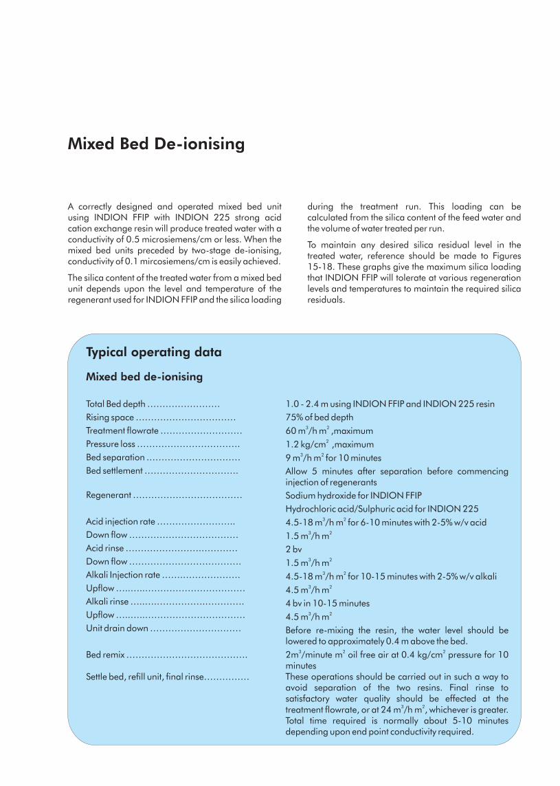
A correctly designed and operated mixed bed unit using INDION FFIP with INDION 225 strong acid cation exchange resin will produce treated water with a conductivity of 0.5 microsiemens/cm or less. When the mixed bed units preceded by two-stage de-ionising, conductivity of 0.1 mircosiemens/cm is easily achieved.
The silica content of the treated water from a mixed bed unit depends upon the level and temperature of the regenerant used for INDION FFIP and the silica loading
during the treatment run. This loading can be calculated from the silica content of the feed water and the volume of water treated per run.
To maintain any desired silica residual level in the treated water, reference should be made to Figures 15-18. These graphs give the maximum silica loading that INDION FFIP will tolerate at various regeneration levels and temperatures to maintain the required silica residuals.
Mixed Bed De-ionising
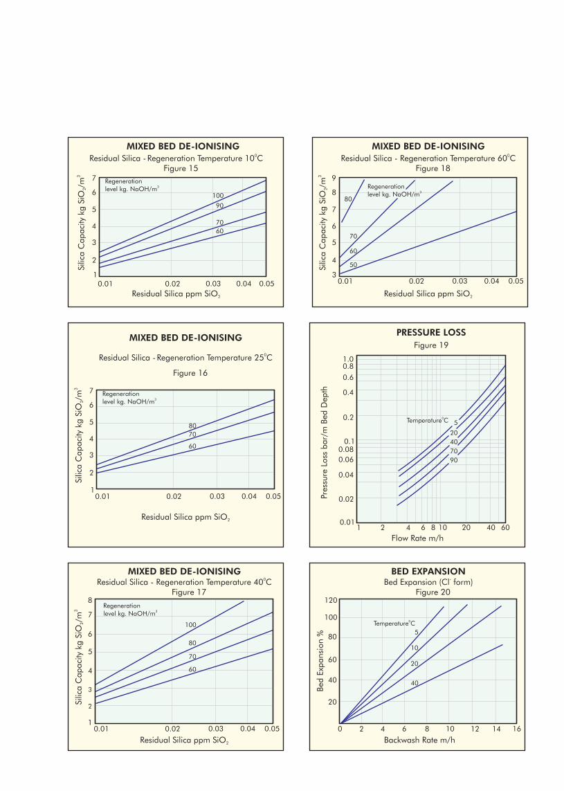
Figure 15
MIXED BED DE-IONISING
0.020.01 0.050.03 0.041
2
3
5
7
4
6
0Residual Silica - Regeneration Temperature 10 C
Residual Silica ppm SiO2
Regeneration3level kg. NaOH/m
100
6070
90
Figure 16
MIXED BED DE-IONISING
0.020.01 0.050.03 0.041
2
3
5
7
4
6
0Residual Silica - Regeneration Temperature 25 C
Residual Silica ppm SiO2
Regeneration3level kg. NaOH/m
60
7080
Figure 17
MIXED BED DE-IONISING
0.020.01 0.050.03 0.04
3
4
5
7
1
2
6
8
0Residual Silica - Regeneration Temperature 40 C
Residual Silica ppm SiO2
Regeneration3level kg. NaOH/m
80
60
70
100
Figure 18
MIXED BED DE-IONISING
0.020.01 0.050.03 0.043
4
5
7
9
6
8
0Residual Silica - Regeneration Temperature 60 C
Residual Silica ppm SiO2
Regeneration3level kg. NaOH/m
80
60
70
50
Figure 19PRESSURE LOSS
80.01
0.02
21 10 60
0.060.08
0.1
0.4
0.04
0.2
0.6
0.81.0
Flow Rate m/h
0Temperature C 5
4020
7090
4 6 20
Pres
sure
Los
s ba
r/m
Bed
Dep
th
40
Figure 20
BED EXPANSION
80 2 1610 14
40
60
100
20
80
120
-Bed Expansion (Cl form)
Backwash Rate m/h
0Temperature C5
40
20
10
4 6 12
Bed
Expa
nsio
n %
StorageIon exchange resins require proper care at all times. The resin must never be allowed to become dry.
Regularly open the plastic bags and check the condition of the resin when in storage. If not moist, add enough
clean demineralised water and keep it in completely moist condition. Always keep the resin drum in the shade. Recommended storage temperature is between
o o20 C and 40 C.
Safety Acid and alkali solutions are corrosive and should be handled in a manner that will prevent eye and skin contact. If any oxidising agents are used, necessary safety precautions should be observed to avoid accidents and damage to the resin.
Use of good quality regenerants
All ion exchange resins are subject to fouling and blockage of active groups by precipitated iron. Hence the iron content in the feed water should be low and the regenerant sodium hydroxide must be essentially free from iron and heavy metals. All resins, especially the anion exchangers are prone to oxidative attack resulting in problems such as loss of capacity, resin clumping, etc. Therefore sodium hydroxide should have as low a chlorate content as possible. Good quality regenerant of technical or chemically pure grade should be used to obtain best results.
Packing HDPE lined bags 25/50 lts LDPE bags 1cft/25 lts
Super sack 1000 lts Super sack 35 cft
MS drums Fiber drumswith liner bags 180 lts with liner bags 7 cft
INDION range of Ion Exchange resins are produced in a state-of-the-art ISO 9001 and ISO 14001 certified manufacturing facilities at Ankleshwar, in the state of Gujarat in India.
To the best of our knowledge the information contained in this publication is accurate. Ion Exchange (India) Ltd. maintains a policy of continuous development and reserves the right to amend the information given herein without notice.
is the registered trademark of Ion Exchange (India) Ltd.
Bulletin R012R2
0413
Ion House, Dr. E. Moses Road, Mahalaxmi, Mumbai 400 011Tel: 022-3989 0909 Fax: 022-2493 8737E-mail: [email protected]
CORPORATE OFFICE
Tel: 022-3989 0909/3047 2400 Fax: 022-2769 7918E-mail: [email protected]; [email protected]
R-14, T.T.C MIDC, Thane-Belapur Road, Rabale, Navi Mumbai 400 701INTERNATIONAL DIVISION
REGIONAL OFFICES
- Fax: 044-2815 3361ChennaiE-mail: [email protected]: 044-3989 0909/3910 2900
Fax: 011-2577 4837Delhi -E-mail: [email protected]: 011-3989 0909/3054 3200
Fax: 033-2400 4345Kolkata -E-mail: [email protected] Tel: 033-3989 0909/3043 3400
Vashi Fax: 022-2788 9839 -E-mail: [email protected]: 022-3989 0909/3913 2300
- Fax: 0265-239 8508VadodaraE-mail: [email protected]: 0265-302 7489/90
-Chandigarh E-mail: [email protected]: 0172-274 5011 Fax: 0172-274 4594
-Hyderabad E-mail: [email protected]: 040-3066 3101/02/03 Fax: 040-3066 3104
- Fax: 0522- 301 3401Lucknow E-mail: [email protected]: 0522-301 3401/02
-VisakhapatnamE-mail: [email protected]: 0891-324 6253
-BhubaneswarE-mail: [email protected]: 0674-326 9525
BRANCH OFFICES-Bengaluru
E-mail: [email protected]: 080-2204 2888
: