feature description - basic configurations
TRANSCRIPT
HUAWEI NE40E-8/X3/X8/X16/NE80E Router
V600R007C00
Feature Description - BasicConfigurations
Issue 04
Date 2014-04-01
HUAWEI TECHNOLOGIES CO., LTD.
Copyright © Huawei Technologies Co., Ltd. 2014. All rights reserved.
No part of this document may be reproduced or transmitted in any form or by any means without prior writtenconsent of Huawei Technologies Co., Ltd. Trademarks and Permissions
and other Huawei trademarks are trademarks of Huawei Technologies Co., Ltd.All other trademarks and trade names mentioned in this document are the property of their respective holders. NoticeThe purchased products, services and features are stipulated by the contract made between Huawei and thecustomer. All or part of the products, services and features described in this document may not be within thepurchase scope or the usage scope. Unless otherwise specified in the contract, all statements, information,and recommendations in this document are provided "AS IS" without warranties, guarantees or representationsof any kind, either express or implied.
The information in this document is subject to change without notice. Every effort has been made in thepreparation of this document to ensure accuracy of the contents, but all statements, information, andrecommendations in this document do not constitute a warranty of any kind, express or implied.
Huawei Technologies Co., Ltd.Address: Huawei Industrial Base
Bantian, LonggangShenzhen 518129People's Republic of China
Website: http://www.huawei.com
Email: [email protected]
Issue 04 (2014-04-01) Huawei Proprietary and ConfidentialCopyright © Huawei Technologies Co., Ltd.
i
About This Document
PurposeThis document describes the basic configurations in terms of its overview, principles, andapplications.
This document together with other types of documents helps intended readers get a deepunderstanding of the basic configurations.
NOTICENote the following precautions:l Currently, the device supports the AES and SHA2 encryption algorithms. AES is reversible,
while SHA2 is irreversible. A protocol interworking password must be reversible, and a localadministrator password must be irreversible.
l If the plain parameter is specified, the password will be saved in plaintext in the configurationfile, which has a high security risk. Therefore, specifying the cipher parameter isrecommended. To further improve device security, periodically change the password.
l Do not set both the start and end characters of a password to "%$%$." This causes thepassword to be displayed directly in the configuration file.
Related VersionsThe following table lists the product versions related to this document.
Product Name Version
HUAWEI NetEngine80E/40ERouter
V600R007C00
Intended AudienceThis document is intended for:
HUAWEI NE40E-8/X3/X8/X16/NE80E RouterFeature Description - Basic Configurations About This Document
Issue 04 (2014-04-01) Huawei Proprietary and ConfidentialCopyright © Huawei Technologies Co., Ltd.
ii
l Network planning engineers
l Commissioning engineers
l Data configuration engineers
l System maintenance engineers
Symbol ConventionsThe symbols that may be found in this document are defined as follows.
Symbol Description
Indicates an imminently hazardous situation which, if notavoided, will result in death or serious injury.
Indicates a potentially hazardous situation which, if notavoided, could result in death or serious injury.
Indicates a potentially hazardous situation which, if notavoided, may result in minor or moderate injury.
Indicates a potentially hazardous situation which, if notavoided, could result in equipment damage, data loss,performance deterioration, or unanticipated results.NOTICE is used to address practices not related to personalinjury.
Calls attention to important information, best practices andtips.NOTE is used to address information not related to personalinjury, equipment damage, and environment deterioration.
Change HistoryChanges between document issues are cumulative. The latest document issue contains all thechanges made in earlier issues.
Changes in Issue 04 (2014-04-01)
The fourth commercial release.
Changes in Issue 03 (2013-11-30)
The third commercial release.
HUAWEI NE40E-8/X3/X8/X16/NE80E RouterFeature Description - Basic Configurations About This Document
Issue 04 (2014-04-01) Huawei Proprietary and ConfidentialCopyright © Huawei Technologies Co., Ltd.
iii
Changes in Issue 02 (2013-09-30)The second commercial release.
Changes in Issue 01 (2013-06-15)This issue is the first official release.
HUAWEI NE40E-8/X3/X8/X16/NE80E RouterFeature Description - Basic Configurations About This Document
Issue 04 (2014-04-01) Huawei Proprietary and ConfidentialCopyright © Huawei Technologies Co., Ltd.
iv
Contents
About This Document.....................................................................................................................ii
1 Basic Configuration.......................................................................................................................11.1 Introduction to Basic Configuration...............................................................................................................................21.2 References......................................................................................................................................................................21.3 Feature Enhancements....................................................................................................................................................41.4 Principles........................................................................................................................................................................41.4.1 FTP..............................................................................................................................................................................41.4.2 TFTP............................................................................................................................................................................91.4.3 Introduction to Telnet................................................................................................................................................101.4.4 SSH............................................................................................................................................................................161.4.5 User Management......................................................................................................................................................221.4.6 Virtual File System....................................................................................................................................................251.4.7 Pipe Character............................................................................................................................................................271.4.8 Daylight Saving Time................................................................................................................................................281.4.9 Timing Restart...........................................................................................................................................................281.4.10 MIB Interface Is Used to Optimize System Upgrade..............................................................................................281.4.11 NAP.........................................................................................................................................................................291.4.12 Dynamic Module Load............................................................................................................................................331.5 Applications..................................................................................................................................................................331.5.1 Applications of FTP...................................................................................................................................................341.5.2 Applications of TFTP................................................................................................................................................341.5.3 Applications of Telnet...............................................................................................................................................351.5.4 Applications of SSH..................................................................................................................................................351.6 Terms, Acronyms, and Abbreviations..........................................................................................................................39
2 Fast Startup...................................................................................................................................412.1 Introduction to Fast Startup..........................................................................................................................................422.2 References....................................................................................................................................................................422.3 Principles......................................................................................................................................................................422.3.1 Fast Startup After a Software Fault...........................................................................................................................432.3.2 Fast Startup After a Hardware Fault..........................................................................................................................432.3.3 Upgrade and Cold Startup.........................................................................................................................................432.3.4 Performance Statistics for Software-based Fast Startup............................................................................................43
HUAWEI NE40E-8/X3/X8/X16/NE80E RouterFeature Description - Basic Configurations Contents
Issue 04 (2014-04-01) Huawei Proprietary and ConfidentialCopyright © Huawei Technologies Co., Ltd.
v
2.4 Applications..................................................................................................................................................................432.5 Terms, Acronyms, and Abbreviations..........................................................................................................................43
3 Clock Synchronization...............................................................................................................443.1 Introduction..................................................................................................................................................................453.2 References....................................................................................................................................................................453.3 Principles......................................................................................................................................................................463.3.1 Basic Concepts..........................................................................................................................................................463.3.2 Clock Protection Switching.......................................................................................................................................483.3.3 Synchronization Mode and Issues of Concern..........................................................................................................513.3.4 Networking Mode for Clock Synchronization..........................................................................................................533.4 Application...................................................................................................................................................................543.5 Terms, Acronyms, and Abbreviations..........................................................................................................................56
4 1588 ACR.......................................................................................................................................574.1 Introduction to 1588 ACR............................................................................................................................................584.2 References....................................................................................................................................................................584.3 Enhancement................................................................................................................................................................594.4 Principles......................................................................................................................................................................594.4.1 Basic Principles of 1588 ACR...................................................................................................................................604.5 Applications..................................................................................................................................................................624.6 Terms and Abbreviations..............................................................................................................................................63
5 1588v2.............................................................................................................................................655.1 Introduction to 1588v2.................................................................................................................................................665.2 References....................................................................................................................................................................685.3 Principles......................................................................................................................................................................695.3.1 Basic Concepts..........................................................................................................................................................705.3.2 Principle of Synchronization.....................................................................................................................................725.4 Application Environment.............................................................................................................................................845.5 Terms and Abbreviations..............................................................................................................................................87
6 CES ACR Clock Synchronization.............................................................................................906.1 Introduction..................................................................................................................................................................916.2 References....................................................................................................................................................................916.3 Principles......................................................................................................................................................................916.3.1 Basic Concepts..........................................................................................................................................................916.3.2 Basic Principles.........................................................................................................................................................926.4 Applications..................................................................................................................................................................926.5 Terms and Abbreviations..............................................................................................................................................93
HUAWEI NE40E-8/X3/X8/X16/NE80E RouterFeature Description - Basic Configurations Contents
Issue 04 (2014-04-01) Huawei Proprietary and ConfidentialCopyright © Huawei Technologies Co., Ltd.
vi
1 Basic Configuration
About This Chapter
1.1 Introduction to Basic Configuration
1.2 References
1.3 Feature Enhancements
1.4 Principles
1.5 Applications
1.6 Terms, Acronyms, and Abbreviations
HUAWEI NE40E-8/X3/X8/X16/NE80E RouterFeature Description - Basic Configurations 1 Basic Configuration
Issue 04 (2014-04-01) Huawei Proprietary and ConfidentialCopyright © Huawei Technologies Co., Ltd.
1
1.1 Introduction to Basic Configuration
DefinitionIn configuration management, the terminal service provides the access interface and human-machine interfaces (HMIs) for users to configure devices.
The login mode includes:
l Login through the console portl Remote login through the AUX portl Telnet server/clientl Login through Secure Shell (SSH), with a password, with Revest-Shamir-Adleman
Algorithm (RSA) authentication, and with the Digital Signature Algorithm (DSA)l Login through customized user interfaces providing multiple user authentications and
authorization modes
The file transfer mode provides transmission control for system files and configuration files,and simple remote management for the file system.
The file transfer mode includes:
l FTP client/serverl TFTP clientl SSH FTP (SFTP) client/server
The following describes the principles of every protocol feature according to the type, includingthe following parts:
l FTPl TFTPl Telnetl SSHl User managementl Virtual file systeml Daylight saving timel Timing restart
PurposeThe terminal service provides the access interface and HMIs for users to configure devices. Filetransfer provides transmission control for system files and configuration files, and simple remotemanagement for the file system.
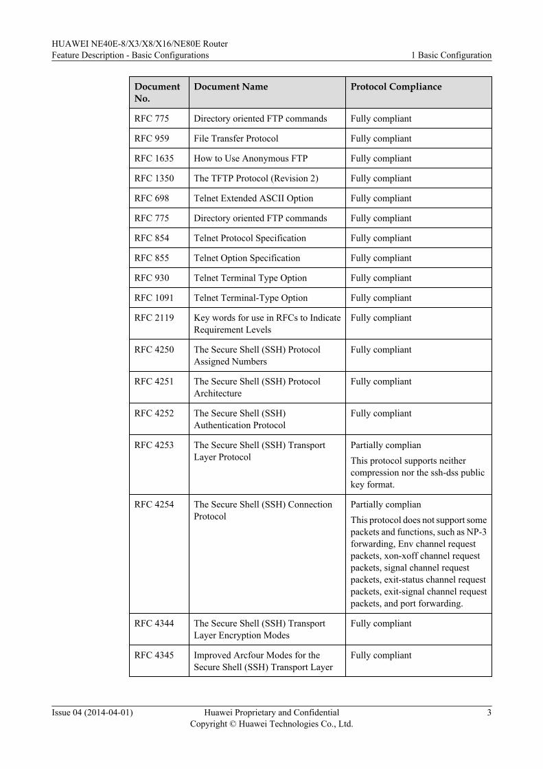
1.2 ReferencesThe following table lists the references.
HUAWEI NE40E-8/X3/X8/X16/NE80E RouterFeature Description - Basic Configurations 1 Basic Configuration
Issue 04 (2014-04-01) Huawei Proprietary and ConfidentialCopyright © Huawei Technologies Co., Ltd.
2
DocumentNo.
Document Name Protocol Compliance
RFC 775 Directory oriented FTP commands Fully compliant
RFC 959 File Transfer Protocol Fully compliant
RFC 1635 How to Use Anonymous FTP Fully compliant
RFC 1350 The TFTP Protocol (Revision 2) Fully compliant
RFC 698 Telnet Extended ASCII Option Fully compliant
RFC 775 Directory oriented FTP commands Fully compliant
RFC 854 Telnet Protocol Specification Fully compliant
RFC 855 Telnet Option Specification Fully compliant
RFC 930 Telnet Terminal Type Option Fully compliant
RFC 1091 Telnet Terminal-Type Option Fully compliant
RFC 2119 Key words for use in RFCs to IndicateRequirement Levels
Fully compliant
RFC 4250 The Secure Shell (SSH) ProtocolAssigned Numbers
Fully compliant
RFC 4251 The Secure Shell (SSH) ProtocolArchitecture
Fully compliant
RFC 4252 The Secure Shell (SSH)Authentication Protocol
Fully compliant
RFC 4253 The Secure Shell (SSH) TransportLayer Protocol
Partially complianThis protocol supports neithercompression nor the ssh-dss publickey format.
RFC 4254 The Secure Shell (SSH) ConnectionProtocol
Partially complianThis protocol does not support somepackets and functions, such as NP-3forwarding, Env channel requestpackets, xon-xoff channel requestpackets, signal channel requestpackets, exit-status channel requestpackets, exit-signal channel requestpackets, and port forwarding.
RFC 4344 The Secure Shell (SSH) TransportLayer Encryption Modes
Fully compliant
RFC 4345 Improved Arcfour Modes for theSecure Shell (SSH) Transport Layer
Fully compliant
HUAWEI NE40E-8/X3/X8/X16/NE80E RouterFeature Description - Basic Configurations 1 Basic Configuration
Issue 04 (2014-04-01) Huawei Proprietary and ConfidentialCopyright © Huawei Technologies Co., Ltd.
3
DocumentNo.
Document Name Protocol Compliance
draft-ietf-secsh-publickey-subsystem-01
Authentication Mechanism that IsBased on Public Keys
Fully compliant
1.3 Feature EnhancementsVersion Feature Enhancement
V600R005C00SPC700 l Now supports SSL.l Now supports FTPS in SSL.l Now supports HTTPS inSSL.l New supports Digital Signature Algorithm (DSA).l When users access a device, they must be
authenticated.
V600R005C00SPC900 New supports dynamic module loading.
V600R007C00 Now supports the Advanced Encryption Standard 256(AES256) encryption algorithm.
V600R007C00 Now supports the RC4, diffie-hellman-group-exchange-sha256, and SM2 encryption algorithms.
1.4 Principles
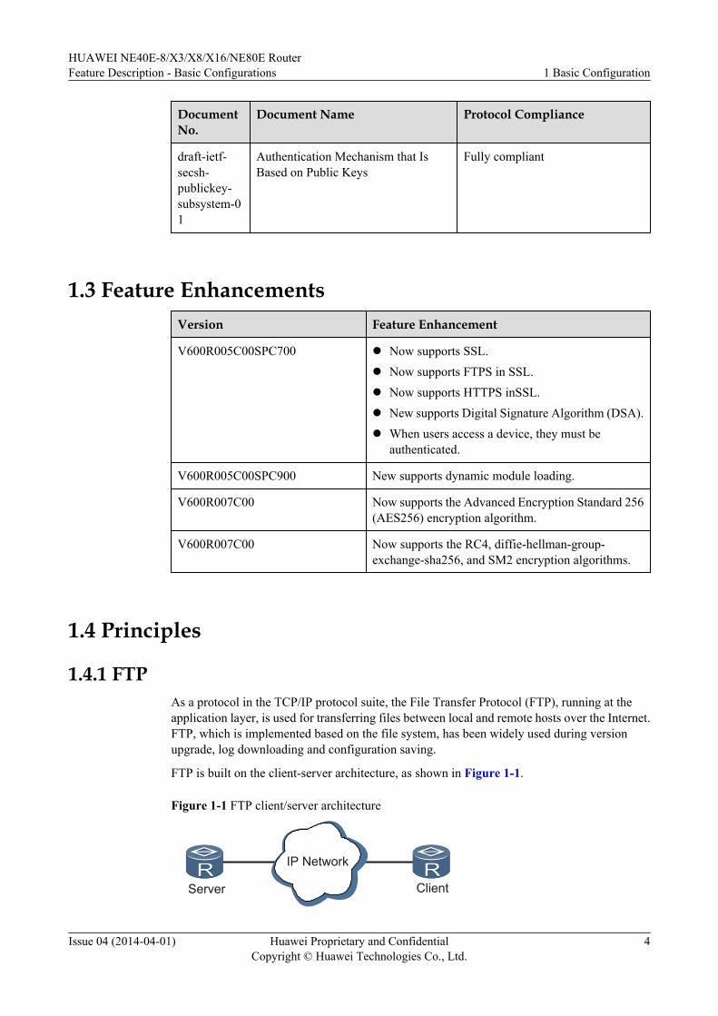
1.4.1 FTPAs a protocol in the TCP/IP protocol suite, the File Transfer Protocol (FTP), running at theapplication layer, is used for transferring files between local and remote hosts over the Internet.FTP, which is implemented based on the file system, has been widely used during versionupgrade, log downloading and configuration saving.
FTP is built on the client-server architecture, as shown in Figure 1-1.
Figure 1-1 FTP client/server architecture
Server Client
IP Network
HUAWEI NE40E-8/X3/X8/X16/NE80E RouterFeature Description - Basic Configurations 1 Basic Configuration
Issue 04 (2014-04-01) Huawei Proprietary and ConfidentialCopyright © Huawei Technologies Co., Ltd.
4
The NE80E/40E provides the following FTP functions:
l FTP server: indicates that the router functions as an FTP server to which users can log into access files by running the FTP client program.
l FTP client: indicates that the router functions as an FTP client that can access files savedon a remote server. After running the terminal emulation program or using the Telnetprogram on a PC to set up a connection to the router, a user can set up a connection to aremote FTP server by using the FTP commands and access files saved on the remote server.
In addition to file transfer, FTP supports interactive access, format specifications, andauthentication control.
FTP provides common file operation s to help users perform simple management over the filesystem as well as supporting file transfer between hosts. Users can use a PC running the FTPclient program to upload files, download files, and access file directories on the router thatfunctions as an FTP server, or, use the FTP client program on the router that functions as an FTPclient to transfer files to an FTP server.
At present, an FTP client can access the IPv6 address of an FTP server, and an FTP serversupports IPv6 connections.
Basic Concepts of FTP
Before using FTP, familiarize yourself with the following basic concepts about file transfer:
l File type
– ASCII mode is used for text. Data is converted from the sender's character representationto "8-bit ASCII" before transmission, and to the receiver's character representation.
– Extended Binary-Coded Decimal Interchange Code (EBCDIC) mode requires that bothends use the EBCDIC character set.
– Binary mode requires that the sender sends each file byte for byte. This mode is oftenused to transfer image files and program files.
– Local mode allows two hosts using different file systems to send files in binary bitstreams. The bit stream of each byte is defined by the sender.
NOTE
The NE80E/40E supports the ASCII and binary modes. Differences between these two modes are asfollows:
l ASCII characters are used to separate carriage returns from line feeds.
l Binary characters can be transferred without format converting.
The client can select an FTP transmission mode, but by default the ASCII mode is used. The clientcan use a mode switch command to switch between the two modes.
l File structure
– Byte stream structure is also called the file structure. A file is considered as a continuousbyte stream.
– Record structure is used only for text files in either ASCII or EBCDIC mode.
– Page structure files are transferred page for page with the pages numbered so the receivercan save them without worrying about the pages being out of order.
HUAWEI NE40E-8/X3/X8/X16/NE80E RouterFeature Description - Basic Configurations 1 Basic Configuration
Issue 04 (2014-04-01) Huawei Proprietary and ConfidentialCopyright © Huawei Technologies Co., Ltd.
5
NOTE
The NE80E/40E supports both the record structure and the byte stream structure.
l Transfer mode– Stream mode
Data is sent as a continuous stream. For the file structure, the sender sends an End-Of-File (EOF) indicator at the end of file transfer to prompts the receiver to close the dataconnection. For the record structure, a two-byte sequence number is used to indicatethe end of the record and file.
– Block modeFTP breaks a file into several blocks and each block starts with a block header.
– Compressed modeFTP compresses the bytes that are the same and consecutively sent.
NOTE
The NE80E/40E supports the stream mode.
l port commandThe port command enables an interface. The command format is port a,b,c,d,e,f. a,b,c,dspecifies the IP address of an interface, in dotted decimal notation; e,f, which consists oftwo decimal numbers, specifies the interface number calculated based on the formula ofe x 256 + f. For example:ftp> debugDebugging On .ftp> ls---> PORT 10,164,9,96,5,28Here, 10.164.9.96 is an IP address; the values 5 and 28 are used to calculate the interfacenumber 1308 (5 x 256 + 28 = 1308).
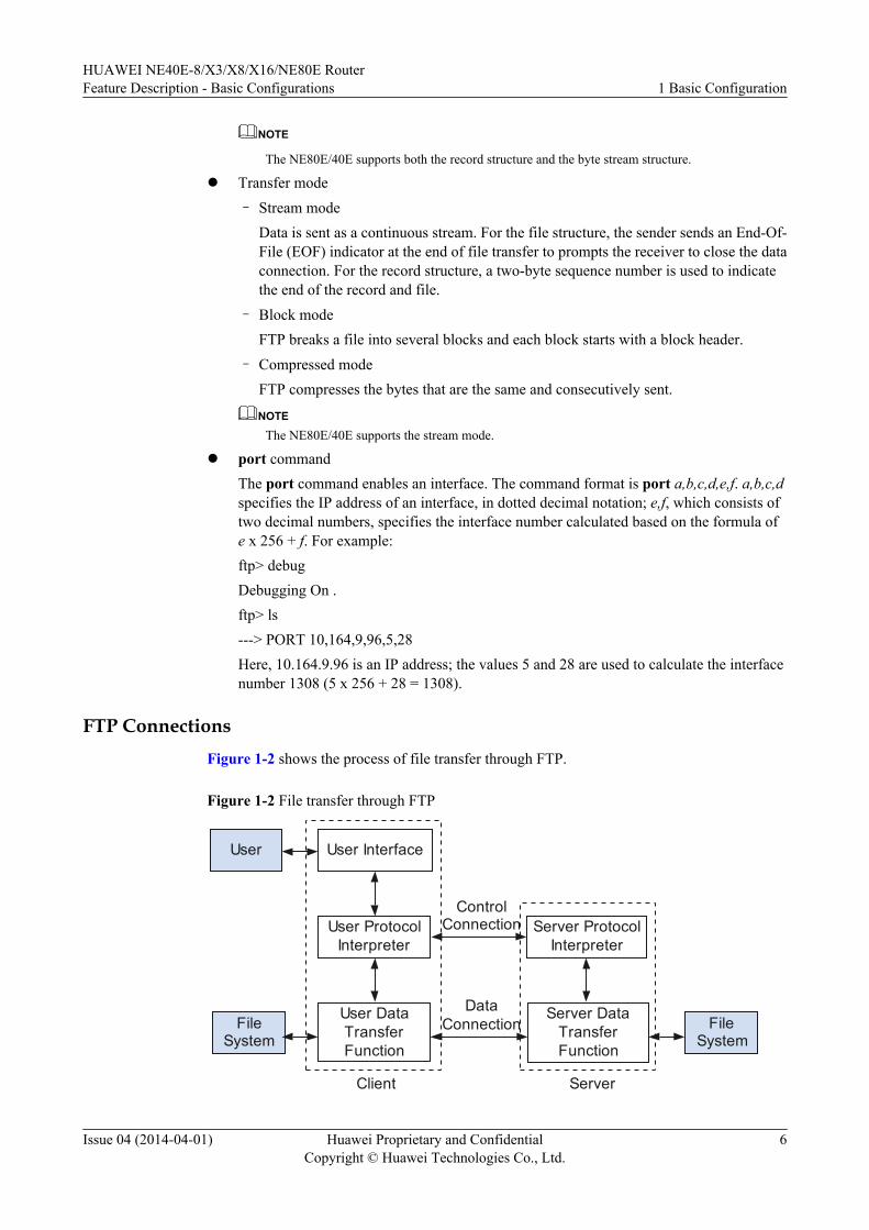
FTP ConnectionsFigure 1-2 shows the process of file transfer through FTP.
Figure 1-2 File transfer through FTP
User DataTransferFunction
User
FileSystem
User Interface
User ProtocolInterpreter
Server ProtocolInterpreter
Server DataTransferFunction
FileSystem
Client Server
ControlConnection
DataConnection
HUAWEI NE40E-8/X3/X8/X16/NE80E RouterFeature Description - Basic Configurations 1 Basic Configuration
Issue 04 (2014-04-01) Huawei Proprietary and ConfidentialCopyright © Huawei Technologies Co., Ltd.
6
FTP uses two TCP connections to transfer files. They are:
l Control connection
A control connection is set up between the FTP client and the FTP server. The server enablescommon port 21 and then waits for a connection request from the client; the client enablescommon port 21 and then sends a request for setting up a connection to the server.
A control connection always waits for communication between the client and the server,transmits related commands from the client to the server, and then responses from the serverto the client.
l Data connection
The server uses port 20 for data connections. Generally, the server can either open or closea data connection actively. For files sent from the client to the server in the form of streams,however, only the client can close a data connection.
FTP transfers each file in streams, using an EOF indicator to identify the end of a file.Therefore, a new data connection is required for each file or directory list to be transferred.When a file is being transferred between the client and the server, it indicates that a dataconnection is set up.
FTP
In the current system, FTP manages the control connection by using User Protocol Interpretation(User-PI) and Server Protocol Interpretation (Server-PI) and transfers files by using the UserData Transport Process (User-DTP) and Server Data Transport Process (Server-DTP).
l FTP client
The FTP User Interface (UI) provides an interactive command line interface (CLI) for users,which receives and interprets command lines input by users and offers help information.After receiving a command on the UI, FTP triggers User-PI to convert the command intoa standard FTP command, and then manages the control connection to the FTP client.
– After a login command is input, User-PI creates a control connection between the clientand the server.
– After a directory operation command is input, User-PI sends and receives control databetween the client and the server.
– After a file transfer command is input, User-PI enables User-DTP to transfer filesbetween the client and the server. User-DTP is responsible for creating a data connectionto the FTP server for data exchange. The data connection is temporarily set up. That is,a data connection is set up when files or directory lists need to be transferred anddisconnected when the transfer process is complete or a disconnection request isreceived.
l FTP server
Server-PI listens to FTP standard port 21 to wait for connection requests from the FTPclient. After receiving a login connection request from the FTP client, the FTP serverhandles the request and sends a reply.
– After a login command is received, the login authentication process is triggered. If thelogin authentication succeeds, a control connection to the FTP client is set up.
HUAWEI NE40E-8/X3/X8/X16/NE80E RouterFeature Description - Basic Configurations 1 Basic Configuration
Issue 04 (2014-04-01) Huawei Proprietary and ConfidentialCopyright © Huawei Technologies Co., Ltd.
7
– After files are received, Server-DTP and User-DTP are triggered to create a dataconnection to transfer files.
Server-DTP supports both active and passive data connection requests. By default, Server-DTP is in the active state.When Server-DTP is transferring data, a user can forcibly disconnect the connection. Uponreceiving a disconnection request, Server-DTP stops transferring data and disconnects theconnection. Normally, a data connection is automatically disconnected when file transferis complete.
Process of Setting Up an FTP ConnectionThe process of setting up an FTP data connection by using active mode is as follows:
1. The server enables port 21 to wait for a connection request from the client.2. The client sends a connection request to the server.3. After the request is received, a control connection is set up between the temporary port on
the client and port 21 on the server.4. The client sends a command for setting up a data connection to the server.5. The client chooses a temporary port for the data connection and sends the port number by
using the port command to the server over the control connection.6. The server sends a request to the client for setting up a data connection to the temporary
port on the client.7. After the request is received by the client, the data connection between the temporary port
on the client and port 20 on the server is set up.
The process of setting up an FTP data connection by using passive mode is as follows:
1. The server enables port 21 to wait for a connection request from the client.2. The client sends a connection request to the server.3. After the request is received, a control connection is set up between the temporary port on
the client and port 21 on the server.4. The client sends a command for setting up a data connection to the server.5. The client sends a command string PASV to the server to request the port number.6. The server chooses a temporary port for the data connection and sends the port number to
the client over the control connection.7. The server sends a request to the client for setting up a data connection.8. The data connection between the temporary port on the client and the temporary port for
the data connection on the server is set up.
HUAWEI NE40E-8/X3/X8/X16/NE80E RouterFeature Description - Basic Configurations 1 Basic Configuration
Issue 04 (2014-04-01) Huawei Proprietary and ConfidentialCopyright © Huawei Technologies Co., Ltd.
8
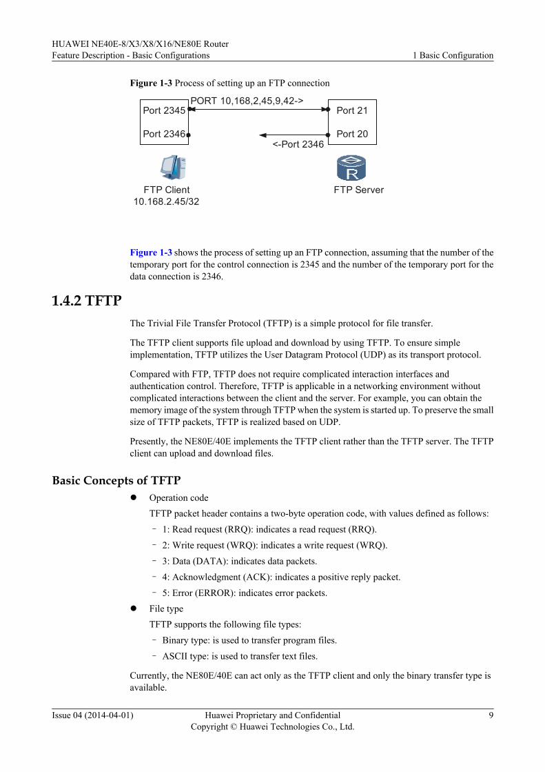
Figure 1-3 Process of setting up an FTP connection
Port 2345
Port 2346
Port 21
Port 20
FTP Client FTP Server10.168.2.45/32
PORT 10,168,2,45,9,42->
<-Port 2346
Figure 1-3 shows the process of setting up an FTP connection, assuming that the number of thetemporary port for the control connection is 2345 and the number of the temporary port for thedata connection is 2346.
1.4.2 TFTPThe Trivial File Transfer Protocol (TFTP) is a simple protocol for file transfer.
The TFTP client supports file upload and download by using TFTP. To ensure simpleimplementation, TFTP utilizes the User Datagram Protocol (UDP) as its transport protocol.
Compared with FTP, TFTP does not require complicated interaction interfaces andauthentication control. Therefore, TFTP is applicable in a networking environment withoutcomplicated interactions between the client and the server. For example, you can obtain thememory image of the system through TFTP when the system is started up. To preserve the smallsize of TFTP packets, TFTP is realized based on UDP.
Presently, the NE80E/40E implements the TFTP client rather than the TFTP server. The TFTPclient can upload and download files.
Basic Concepts of TFTPl Operation code
TFTP packet header contains a two-byte operation code, with values defined as follows:
– 1: Read request (RRQ): indicates a read request (RRQ).
– 2: Write request (WRQ): indicates a write request (WRQ).
– 3: Data (DATA): indicates data packets.
– 4: Acknowledgment (ACK): indicates a positive reply packet.
– 5: Error (ERROR): indicates error packets.l File type
TFTP supports the following file types:
– Binary type: is used to transfer program files.
– ASCII type: is used to transfer text files.
Currently, the NE80E/40E can act only as the TFTP client and only the binary transfer type isavailable.
HUAWEI NE40E-8/X3/X8/X16/NE80E RouterFeature Description - Basic Configurations 1 Basic Configuration
Issue 04 (2014-04-01) Huawei Proprietary and ConfidentialCopyright © Huawei Technologies Co., Ltd.
9
Basic Principle of TFTPl A user name and password are not required.
This is because TFTP is designed for the bootstrap process.
l TFTP transfer
The client initiates the TFTP transfer.
– To download files, the client sends an RRQ to the server. The server then accepts therequest and sends a data packet to the client. After receiving the data packet, the clientsends an ACK packet to the server.
– To upload files, the client sends a WRQ to the server. After the server accepts the request,the client sends a data packet to the server and waits for an ACK packet from the server.
l Support for IPv6
At present, the TFTP client supports access to the IPv6 host address.
1.4.3 Introduction to TelnetThe Telecommunication Network Protocol (Telnet) is derived from ARPANET, which is oneof the earliest Internet applications released in 1969. Telnet enables a terminal to remotely login to a server and provides an interactive operation interface. Through Telnet, a login user ofone host can log in to other hosts to configure and manage them without being physicallyconnected to each of them.
Basic Concepts of Telnetl NVT
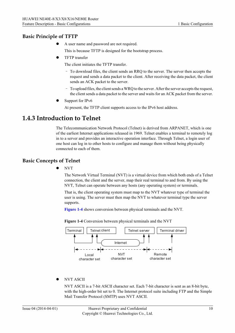
The Network Virtual Terminal (NVT) is a virtual device from which both ends of a Telnetconnection, the client and the server, map their real terminal to and from. By using theNVT, Telnet can operate between any hosts (any operating system) or terminals.
That is, the client operating system must map to the NVT whatever type of terminal theuser is using. The server must then map the NVT to whatever terminal type the serversupports.
Figure 1-4 shows conversion between physical terminals and the NVT.
Figure 1-4 Conversion between physical terminals and the NVT
Terminal Telnet client Telnet server Terminal driver
Internet
Localcharacter set
NVTcharacter set
Remotecharacter set
l NVT ASCII
NVT ASCII is a 7-bit ASCII character set. Each 7-bit character is sent as an 8-bit byte,with the high-order bit set to 0. The Internet protocol suite including FTP and the SimpleMail Transfer Protocol (SMTP) uses NVT ASCII.
HUAWEI NE40E-8/X3/X8/X16/NE80E RouterFeature Description - Basic Configurations 1 Basic Configuration
Issue 04 (2014-04-01) Huawei Proprietary and ConfidentialCopyright © Huawei Technologies Co., Ltd.
10
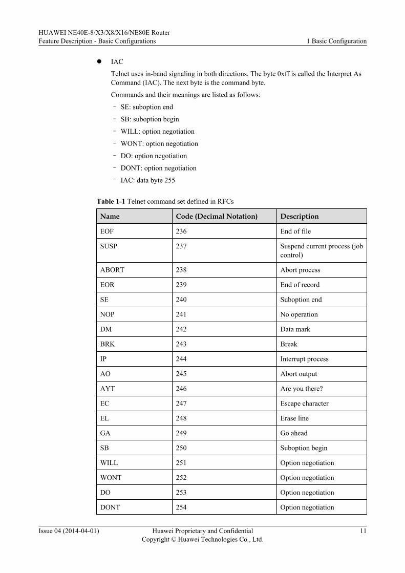
l IAC
Telnet uses in-band signaling in both directions. The byte 0xff is called the Interpret AsCommand (IAC). The next byte is the command byte.
Commands and their meanings are listed as follows:
– SE: suboption end
– SB: suboption begin
– WILL: option negotiation
– WONT: option negotiation
– DO: option negotiation
– DONT: option negotiation
– IAC: data byte 255
Table 1-1 Telnet command set defined in RFCs
Name Code (Decimal Notation) Description
EOF 236 End of file
SUSP 237 Suspend current process (jobcontrol)
ABORT 238 Abort process
EOR 239 End of record
SE 240 Suboption end
NOP 241 No operation
DM 242 Data mark
BRK 243 Break
IP 244 Interrupt process
AO 245 Abort output
AYT 246 Are you there?
EC 247 Escape character
EL 248 Erase line
GA 249 Go ahead
SB 250 Suboption begin
WILL 251 Option negotiation
WONT 252 Option negotiation
DO 253 Option negotiation
DONT 254 Option negotiation
HUAWEI NE40E-8/X3/X8/X16/NE80E RouterFeature Description - Basic Configurations 1 Basic Configuration
Issue 04 (2014-04-01) Huawei Proprietary and ConfidentialCopyright © Huawei Technologies Co., Ltd.
11
Name Code (Decimal Notation) Description
IAC 255 Data byte 255
l Telnet connection
A Telnet connection is a TCP connection used to transmit data with Telnet controlinformation.
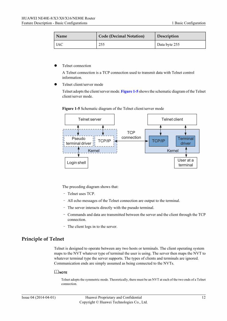
l Telnet client/server mode
Telnet adopts the client/server mode. Figure 1-5 shows the schematic diagram of the Telnetclient/server mode.
Figure 1-5 Schematic diagram of the Telnet client/server mode
Kernel
Login shell
Telnet server
Pseudoterminal driver
TCPconnection
TCP/IP
User at aterminal
Telnet client
Kernel
TCP/IP Terminaldriver
The preceding diagram shows that:
– Telnet uses TCP.
– All echo messages of the Telnet connection are output to the terminal.
– The server interacts directly with the pseudo terminal.
– Commands and data are transmitted between the server and the client through the TCPconnection.
– The client logs in to the server.
Principle of Telnet
Telnet is designed to operate between any two hosts or terminals. The client operating systemmaps to the NVT whatever type of terminal the user is using. The server then maps the NVT towhatever terminal type the server supports. The types of clients and terminals are ignored.Communication ends are simply assumed as being connected to the NVTs.
NOTE
Telnet adopts the symmetric mode. Theoretically, there must be an NVT at each of the two ends of a Telnetconnection.
HUAWEI NE40E-8/X3/X8/X16/NE80E RouterFeature Description - Basic Configurations 1 Basic Configuration
Issue 04 (2014-04-01) Huawei Proprietary and ConfidentialCopyright © Huawei Technologies Co., Ltd.
12
The two ends of a Telnet connection send WILL, WONT, DO, or DONT requests for optionnegotiation. The options to be negotiated include echo, character set of command change, andline mode.
This section describes the operating principles of Telnet:
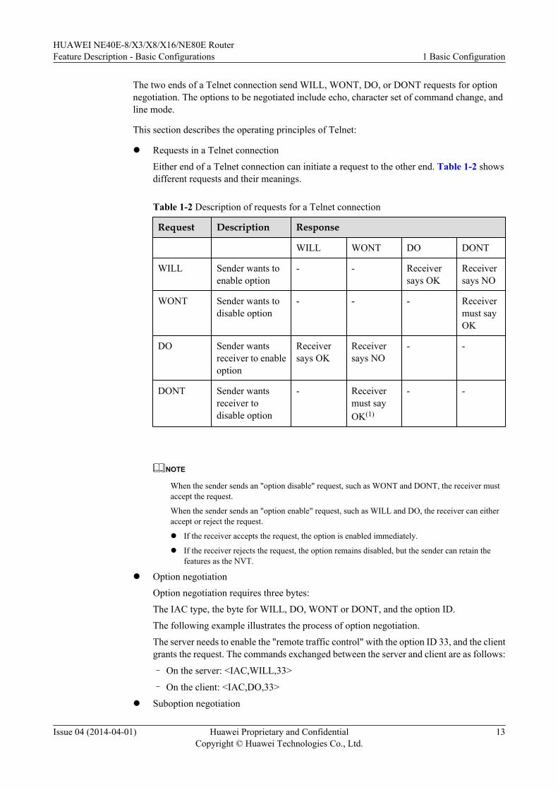
l Requests in a Telnet connection
Either end of a Telnet connection can initiate a request to the other end. Table 1-2 showsdifferent requests and their meanings.
Table 1-2 Description of requests for a Telnet connection
Request Description Response
WILL WONT DO DONT
WILL Sender wants toenable option
- - Receiversays OK
Receiversays NO
WONT Sender wants todisable option
- - - Receivermust sayOK
DO Sender wantsreceiver to enableoption
Receiversays OK
Receiversays NO
- -
DONT Sender wantsreceiver todisable option
- Receivermust sayOK(1)
- -
NOTE
When the sender sends an "option disable" request, such as WONT and DONT, the receiver mustaccept the request.
When the sender sends an "option enable" request, such as WILL and DO, the receiver can eitheraccept or reject the request.
l If the receiver accepts the request, the option is enabled immediately.
l If the receiver rejects the request, the option remains disabled, but the sender can retain thefeatures as the NVT.
l Option negotiation
Option negotiation requires three bytes:
The IAC type, the byte for WILL, DO, WONT or DONT, and the option ID.
The following example illustrates the process of option negotiation.
The server needs to enable the "remote traffic control" with the option ID 33, and the clientgrants the request. The commands exchanged between the server and client are as follows:
– On the server: <IAC,WILL,33>
– On the client: <IAC,DO,33>
l Suboption negotiation
HUAWEI NE40E-8/X3/X8/X16/NE80E RouterFeature Description - Basic Configurations 1 Basic Configuration
Issue 04 (2014-04-01) Huawei Proprietary and ConfidentialCopyright © Huawei Technologies Co., Ltd.
13
Certain options require more information than the option ID. For example, if the senderrequires the receiver to specify the terminal type, the receiver must respond with an ASCIIstring to specify the terminal type.
The format of the commands for suboption negotiation is as follows:
< IAC, SB, option code, contents of suboption, IAC, SE >
A complete process of suboption negotiation is as follows:
– The sender sends a DO or WILL command carrying an option ID to request that theoption be enabled.
– The receiver returns a WILL or DO command carrying the option ID to accept therequest.
After the preceding two steps, both ends agree to enable the option.
One end of the connection starts suboption negotiation by sending a request composedof the SB, suboption ID, and SE in sequence.
– The opposite end responds to the request for suboption negotiation by sending acommand composed of the SB, suboption ID, related negotiation information, and SEin sequence.
– The receiver returns a DO or WILL command to accept the negotiation informationabout the suboption.
If there are no additional suboptions to be negotiated, the negotiation ends.
NOTE
In the preceding process, the receiver is assumed to accept the request from the sender. In practice,the receiver can reject requests from the sender at any time as required.
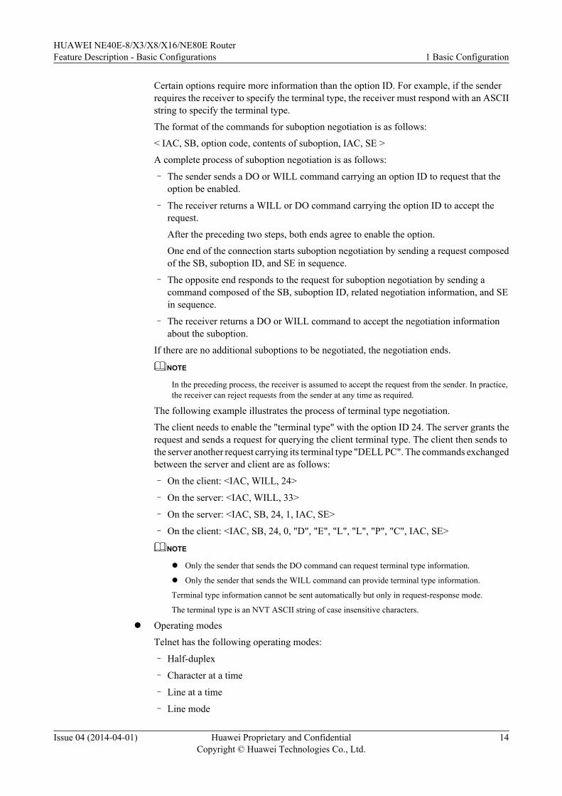
The following example illustrates the process of terminal type negotiation.
The client needs to enable the "terminal type" with the option ID 24. The server grants therequest and sends a request for querying the client terminal type. The client then sends tothe server another request carrying its terminal type "DELL PC". The commands exchangedbetween the server and client are as follows:
– On the client: <IAC, WILL, 24>
– On the server: <IAC, WILL, 33>
– On the server: <IAC, SB, 24, 1, IAC, SE>
– On the client: <IAC, SB, 24, 0, "D", "E", "L", "L", "P", "C", IAC, SE>
NOTE
l Only the sender that sends the DO command can request terminal type information.
l Only the sender that sends the WILL command can provide terminal type information.
Terminal type information cannot be sent automatically but only in request-response mode.
The terminal type is an NVT ASCII string of case insensitive characters.
l Operating modes
Telnet has the following operating modes:
– Half-duplex
– Character at a time
– Line at a time
– Line mode
HUAWEI NE40E-8/X3/X8/X16/NE80E RouterFeature Description - Basic Configurations 1 Basic Configuration
Issue 04 (2014-04-01) Huawei Proprietary and ConfidentialCopyright © Huawei Technologies Co., Ltd.
14
IPv6 Telnet Features Supported by the routerAt present, the Telnet client can access hosts with IPv6 addresses; the Telnet server can receiverequests for connections from hosts with IPv6 addresses.
Telnet Services Provided by the routerThe router provides the following Telnet services:
l Telnet serverA user runs the Telnet client application on a PC to log in and configure and manage therouter.The standard port number for a Telnet server is 23. If attackers access the standard portcontinuously, the bandwidth is consumed and the performance of the server is degraded.As a result, legitimate users cannot access the port.In this case, you can configure another port number to replace the standard port number23. Attackers who do not know the new port number will still send requests for socketconnections to port 23. The Telnet server will reject the requests after detecting the wrongport number. This effectively prevents bandwidth consumption and waste of systemresources caused by an attack on the standard Telnet server port.
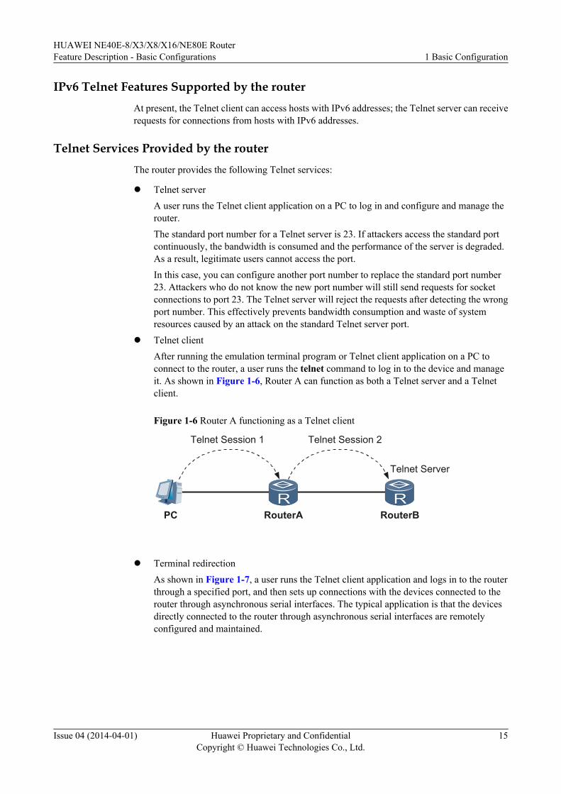
l Telnet clientAfter running the emulation terminal program or Telnet client application on a PC toconnect to the router, a user runs the telnet command to log in to the device and manageit. As shown in Figure 1-6, Router A can function as both a Telnet server and a Telnetclient.
Figure 1-6 Router A functioning as a Telnet client
PC RouterA RouterB
Telnet Server
Telnet Session 1 Telnet Session 2
l Terminal redirection
As shown in Figure 1-7, a user runs the Telnet client application and logs in to the routerthrough a specified port, and then sets up connections with the devices connected to therouter through asynchronous serial interfaces. The typical application is that the devicesdirectly connected to the router through asynchronous serial interfaces are remotelyconfigured and maintained.
HUAWEI NE40E-8/X3/X8/X16/NE80E RouterFeature Description - Basic Configurations 1 Basic Configuration
Issue 04 (2014-04-01) Huawei Proprietary and ConfidentialCopyright © Huawei Technologies Co., Ltd.
15
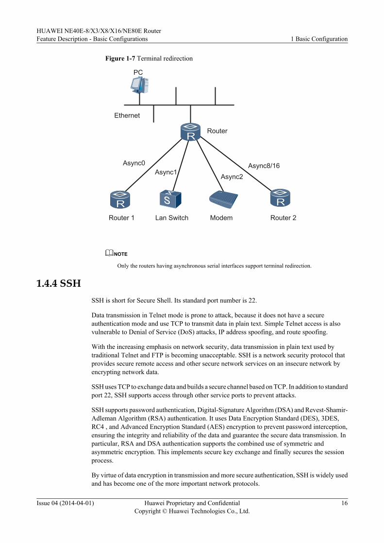
Figure 1-7 Terminal redirection
PC
Router
Ethernet
Router 2Router 1 Lan Switch Modem
Async0
Async2Async8/16
Async1
NOTE
Only the routers having asynchronous serial interfaces support terminal redirection.
1.4.4 SSHSSH is short for Secure Shell. Its standard port number is 22.
Data transmission in Telnet mode is prone to attack, because it does not have a secureauthentication mode and use TCP to transmit data in plain text. Simple Telnet access is alsovulnerable to Denial of Service (DoS) attacks, IP address spoofing, and route spoofing.
With the increasing emphasis on network security, data transmission in plain text used bytraditional Telnet and FTP is becoming unacceptable. SSH is a network security protocol thatprovides secure remote access and other secure network services on an insecure network byencrypting network data.
SSH uses TCP to exchange data and builds a secure channel based on TCP. In addition to standardport 22, SSH supports access through other service ports to prevent attacks.
SSH supports password authentication, Digital-Signature Algorithm (DSA) and Revest-Shamir-Adleman Algorithm (RSA) authentication. It uses Data Encryption Standard (DES), 3DES,RC4 , and Advanced Encryption Standard (AES) encryption to prevent password interception,ensuring the integrity and reliability of the data and guarantee the secure data transmission. Inparticular, RSA and DSA authentication supports the combined use of symmetric andasymmetric encryption. This implements secure key exchange and finally secures the sessionprocess.
By virtue of data encryption in transmission and more secure authentication, SSH is widely usedand has become one of the more important network protocols.
HUAWEI NE40E-8/X3/X8/X16/NE80E RouterFeature Description - Basic Configurations 1 Basic Configuration
Issue 04 (2014-04-01) Huawei Proprietary and ConfidentialCopyright © Huawei Technologies Co., Ltd.
16
SSH has two versions: SSH1 (SSH 1.5) and SSH2 (SSH 2.0). Both are different andincompatible. SSH2.0 is superior to SSH 1.5 in security, functions, and performance.
Devices that can function as the STelnet client and server support both SSH1 (SSH 1.5) andSSH2 (SSH 2.0). Devices that can function as the SFTP client and server support SSH2 (SSH2.0).
Secure Telnet (STelnet) enables users to remotely and securely log in to the device, and providesthe interactive configuration interface. All data exchanges based on STelnet are encrypted. Thisensures the security of sessions.
The SSH File Transfer Protocol (SFTP) enables users to log in to the device securely for filemanagement from a remote device. This improves the security of data transmission for theremote system update. Meanwhile, the client function provided by SFTP enables users to log into the remote device for secure file transmission.
Basic Concepts of SSHl SFTP
SFTP guarantees secure file transfer over an insecure network by authenticating the clientand encrypting data in bidirectional mode.
l STelnetSTelnet ensures secure Telnet services. It guarantees secure file transfer on a traditionalinsecure network by authenticating the client and encrypting data in bidirectional mode.
l RSA authenticationRSA authentication is based on the private key of the client. It is a public key encryptionarchitecture and an asymmetric encryption algorithm. RSA is mainly used to help solve theproblem of factoring large numbers by transmitting the keys of the symmetric encryptionalgorithm, which can improve encryption efficiency and simplify key management.The server checks whether the SSH user, public key, and digital user signature are valid.If all of them are valid, the user is permitted to access the server; if any of them is invalid,the authentication fails and the user is denied access.
l DSA authenticationThe digital signature algorithm (DSA) is an asymmetric encryption algorithm used theauthenticating clients. DSA algorithm consists of a public key and a private key.Like RSA, the server checks whether the SSH user, public key, and digital user signatureare valid. If all of them are valid, the user is permitted to access the server; if any of themis invalid, the authentication fails and the user access is denied.Compared with RSA authentication, DSA authentication adopts the DSA encryption modeand is widely used.
– In many cases, SSH only supports DSA to authenticate the server and the client.
– In SSH, DSA authentication takes precedence over RSA authentication.
l Password authenticationPassword authentication is based on the user name and password.On the server, the AAA module assigns a login password to each authorized user. Theserver has the mappings between user names and passwords. When a user requests accessthe server, the server authenticates the user name and password. If either of them fails topass authentication, the access is denied.
HUAWEI NE40E-8/X3/X8/X16/NE80E RouterFeature Description - Basic Configurations 1 Basic Configuration
Issue 04 (2014-04-01) Huawei Proprietary and ConfidentialCopyright © Huawei Technologies Co., Ltd.
17
l RSA-password authentication and DSA-Password authenticationThe server can authenticate the client by checking both the public key and the password.It allows user access only when both public key and password are consistent with thoseconfigured on the server.
l ALL authenticationThe server can authenticate the client by checking both the public key and the password.It allows user access when either the public key or the password is consistent with thoseconfigured on the server.
SSH Features Supported by the Devicel Basic SSH functions
– Different encryption algorithms for incoming and outgoing data– Different MAC algorithms for incoming and outgoing data– Encryption algorithms of 3DES-cbc, DES, RC4 , Advanced Encryption Standard
(AES128) and AES256– HMAC-sha1 authentication algorithm
HMAC algorithm, including shal, shal-96,sha2-256,sha2-256-96, md5, and md5-96.– diffie-hellman-group1-sha1, diffie-hellman-group-exchange-sha1 , diffie-hellman-
group-exchange-sha256, ecdh-sha2-nistp256, ecdh-sha2-nistp384 and ecdh-sha2-nistp521algorithms for key exchange
– Public key format of SSH-RSA– Public key format of SSH-DSA– Key re-exchange (It indicates renegotiation of the key. During this process, the
algorithm and the key used for the algorithm are negotiated.)– Public key authentication and password authentication
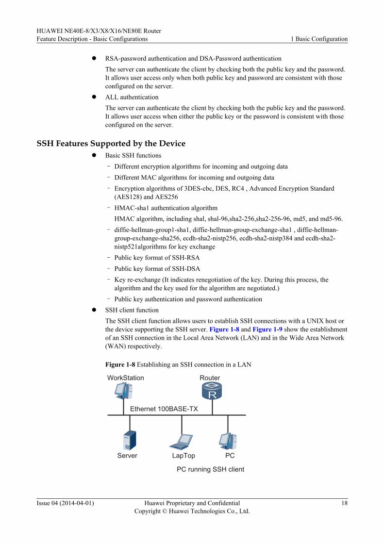
l SSH client functionThe SSH client function allows users to establish SSH connections with a UNIX host orthe device supporting the SSH server. Figure 1-8 and Figure 1-9 show the establishmentof an SSH connection in the Local Area Network (LAN) and in the Wide Area Network(WAN) respectively.
Figure 1-8 Establishing an SSH connection in a LAN
PCLapTopServer
Ethernet 100BASE-TX
PC running SSH client
RouterWorkStation
HUAWEI NE40E-8/X3/X8/X16/NE80E RouterFeature Description - Basic Configurations 1 Basic Configuration
Issue 04 (2014-04-01) Huawei Proprietary and ConfidentialCopyright © Huawei Technologies Co., Ltd.
18
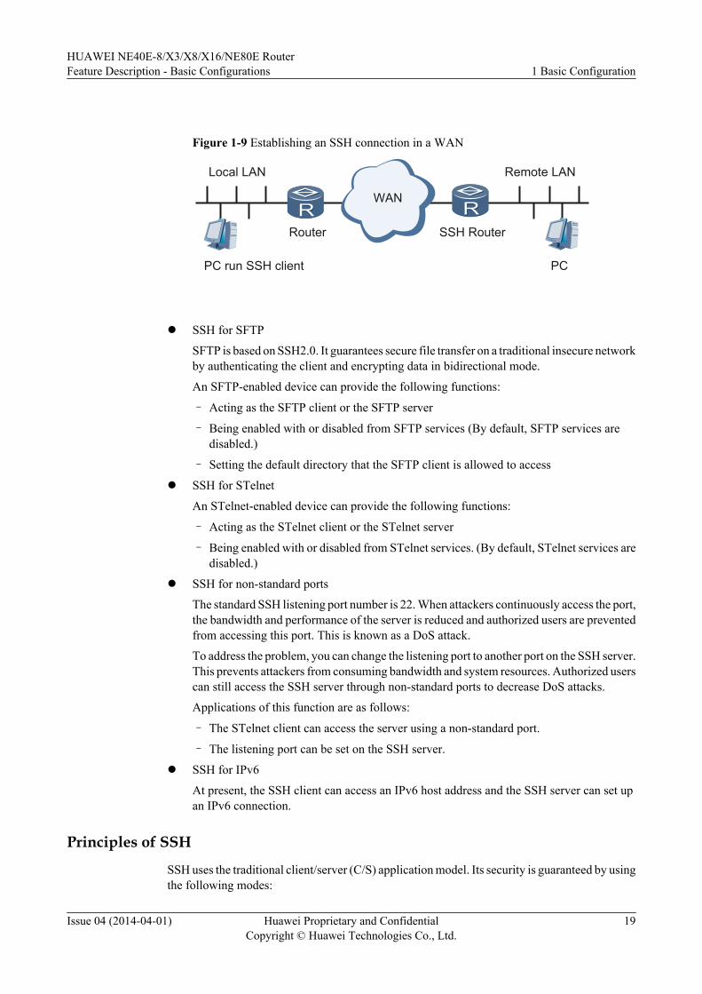
Figure 1-9 Establishing an SSH connection in a WAN
WAN
Router SSH Router
PC run SSH client PC
Local LAN Remote LAN
l SSH for SFTP
SFTP is based on SSH2.0. It guarantees secure file transfer on a traditional insecure networkby authenticating the client and encrypting data in bidirectional mode.
An SFTP-enabled device can provide the following functions:
– Acting as the SFTP client or the SFTP server
– Being enabled with or disabled from SFTP services (By default, SFTP services aredisabled.)
– Setting the default directory that the SFTP client is allowed to access
l SSH for STelnet
An STelnet-enabled device can provide the following functions:
– Acting as the STelnet client or the STelnet server
– Being enabled with or disabled from STelnet services. (By default, STelnet services aredisabled.)
l SSH for non-standard ports
The standard SSH listening port number is 22. When attackers continuously access the port,the bandwidth and performance of the server is reduced and authorized users are preventedfrom accessing this port. This is known as a DoS attack.
To address the problem, you can change the listening port to another port on the SSH server.This prevents attackers from consuming bandwidth and system resources. Authorized userscan still access the SSH server through non-standard ports to decrease DoS attacks.
Applications of this function are as follows:
– The STelnet client can access the server using a non-standard port.
– The listening port can be set on the SSH server.
l SSH for IPv6
At present, the SSH client can access an IPv6 host address and the SSH server can set upan IPv6 connection.
Principles of SSH
SSH uses the traditional client/server (C/S) application model. Its security is guaranteed by usingthe following modes:
HUAWEI NE40E-8/X3/X8/X16/NE80E RouterFeature Description - Basic Configurations 1 Basic Configuration
Issue 04 (2014-04-01) Huawei Proprietary and ConfidentialCopyright © Huawei Technologies Co., Ltd.
19
Data encryption: Through the negotiation between the client and the server, an encryption keyis generated and used in data symmetric encryption. This ensures confidentiality during datatransmission.
Data integrity: Through the negotiation between the client and the server, an integrity key isgenerated and used to uniquely identify a session link. All session packets are identified by theintegrity key. Any modifications made by the third party during transmission can be discoveredby the receiver based on the integrity key. The receiver can discard these modified packets toensure the data integrity.
Authority authentication: There are multiple authentication modes. Authority authenticationallows only valid users to have a session with the server, improving system security andsafeguarding the benefits of valid users.
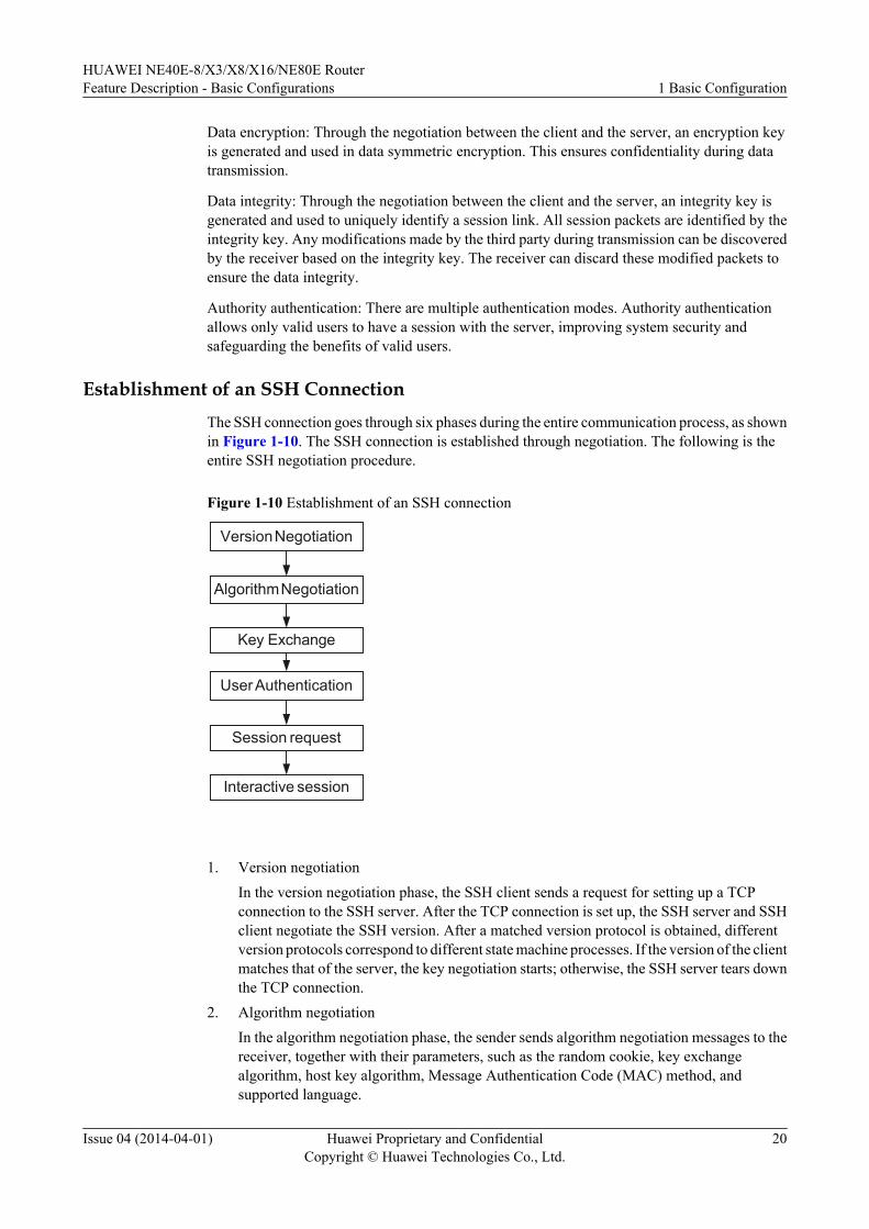
Establishment of an SSH ConnectionThe SSH connection goes through six phases during the entire communication process, as shownin Figure 1-10. The SSH connection is established through negotiation. The following is theentire SSH negotiation procedure.
Figure 1-10 Establishment of an SSH connection
Version Negotiation
Algorithm Negotiation
Key Exchange
User Authentication
Session request
Interactive session
1. Version negotiationIn the version negotiation phase, the SSH client sends a request for setting up a TCPconnection to the SSH server. After the TCP connection is set up, the SSH server and SSHclient negotiate the SSH version. After a matched version protocol is obtained, differentversion protocols correspond to different state machine processes. If the version of the clientmatches that of the server, the key negotiation starts; otherwise, the SSH server tears downthe TCP connection.
2. Algorithm negotiationIn the algorithm negotiation phase, the sender sends algorithm negotiation messages to thereceiver, together with their parameters, such as the random cookie, key exchangealgorithm, host key algorithm, Message Authentication Code (MAC) method, andsupported language.
HUAWEI NE40E-8/X3/X8/X16/NE80E RouterFeature Description - Basic Configurations 1 Basic Configuration
Issue 04 (2014-04-01) Huawei Proprietary and ConfidentialCopyright © Huawei Technologies Co., Ltd.
20
After receiving these algorithm negotiation messages, the receiver compares the receivedalgorithm list set with the local algorithm list set. If the key exchange algorithm, public keyencryption algorithm, or MAC algorithm is not found, the receiver tears down theconnection with the sender and the algorithm negotiation fails.
3. Key exchange
After the server and client negotiate the version, the server sends the client a packetcontaining the server's host public key, the server public key, the supported encryptionalgorithm, the authentication algorithm, the protocol extension flag, and an 8-byte cookie.This packet is sent in simple text.Then, the server and client calculate a 16-byte session IDusing the same parameter. The client also randomly generates a 32-byte session key usedto encrypt data. The client does not send the session key to the server, but use the most-significant 16 bytes of the session key to XOR the 16-byte session ID to obtain a result.The client then arranges the result using the Most Significant Bit (MSB) first rule andobtains a multiple precision (MP) integer. Then the client encrypts the MP integer using apublic key with a smaller module value, arranges the result using the MSB first rule again,and obtains a new value. Then the client uses a public key with a larger module value toencrypt the new value.
The server is now in the waiting state. When receiving a key generation message from theclient, the server then returns a key generation message to the client, which indicates thatkey exchange is complete and that the new key should be used for communications. If theserver fails to receive a key generation message from the client, it returns a key exchangefailure message and tears down the connection.
4. User authentication
After obtaining the session key, the SSH server authenticates the SSH client. The SSHclient sends the identity information to the SSH server. After a specific authentication modeis configured on the SSH server, the client sends an authentication request. If theauthentication succeeds or the connection with the server expires, the connection isterminated.
The SSH server authenticates a user in one of the following methods:
l In RSA, DSA authentication, the client generates an RSA, DSA key pair and sends thepublic key to the server. When a user initiates an authentication request, the clientrandomly generates a text encrypted with the private key and sends it to the server. Theserver decrypts it by using the public key. If decryption succeeds, the server considersthis user trustable and grants access rights. If decryption fails, the server tears down theconnection.
l Password authentication is implemented based on AAA. Like Telnet and FTP, SSHsupports local database authentication and remote RADIUS server authentication. TheSSH server compares the user name and password of an SSH client with the pre-configured ones. If both are matched, authentication succeeds.
5. Session request
After user authentication is completed, the client sends a session request to the server. Thesession requests include the running of Shell and commands. At the same time, the serverwaits to process the request from the client. During this phase, the server responds to theclient with an SSH_SMSG_SUCCESS message after successfully processing a requestfrom the client. If the server fails to process or identify the request, it responds with anSSH_SMSG_FAILURE message.
Possible causes for the authentication failure are as follows:
HUAWEI NE40E-8/X3/X8/X16/NE80E RouterFeature Description - Basic Configurations 1 Basic Configuration
Issue 04 (2014-04-01) Huawei Proprietary and ConfidentialCopyright © Huawei Technologies Co., Ltd.
21
l The server fails to process the request.
l The server cannot identify the request.
6. Interactive session
After the session request is accepted, the SSH connection enters the interactive sessionmode. In this phase, data is transmitted bidirectionally.
a. The client sends a packet with the encrypted command to the server.
b. After receiving the packet, the server decrypts the packet and runs the command. Then,the server packages the encrypted command execution results and sends the packet tothe client.
c. Upon receiving the packet, the client decrypts it and displays the command executionresults on the terminal.
1.4.5 User ManagementUsers can log in to the device to configure, monitor, and maintain local or remote network devicesonly after user interfaces, user management, and terminal services are configured. Userinterfaces provide the login place, user management ensures login security, and terminal servicesoffer login protocols.
The device supports the following login modes:
l Login through the console port
l Local or remote login through the AUX port
l Local or remote login through Telnet or SSH
User management (consisting of user interface configurations, user view configurations, andterminal services) provides secure login and operations, implementing unified management overdifferent user interfaces.
User Interface
A User Interface (UI), which is presented as a user interface view, enables users to log in to thedevice. Through the user interface, you can configure the parameters on all physical and logicalinterfaces that work in asynchronous and interactive modes. In this manner, you can manage,authenticate, and authorize the login users.
l The system supports the following user interfaces:
– Console port: is a linear port on the device's main control board.
Each main control board provides a console port that conforms to the EIA/TIA-232standard, type DCE. The serial port of the user terminal can directly connect to theconsole port of the device to implement local device configurations.
– AUX port: is also a linear port on the device's main control board.
Each main control board provides an AUX port that conforms to the EIA/TIA-232standard, type DTE. The terminal can perform remote access to the device through theModem on the AUX port.
– Virtual Terminal (VTY) is a kind of virtual interface indicating a logical terminal line.
HUAWEI NE40E-8/X3/X8/X16/NE80E RouterFeature Description - Basic Configurations 1 Basic Configuration
Issue 04 (2014-04-01) Huawei Proprietary and ConfidentialCopyright © Huawei Technologies Co., Ltd.
22
When you set up a Telnet or SSH connection with the device through a terminal, youset up a VTY. You can also perform local or remote access to the device through thevirtual connection established through VTY.
l Numbering of user interfacesYou can number a user interface using one of the following methods:
– Relative numberingThe format of relative numbering is: user interface type + number.Relative numbering indicates that the interfaces of the same type are numbered. Relativenumbering uniquely specifies a user interface of the same type. Relative numberingmust comply with the following rules:Number of the CON port: CON 0Number of the AUX port: AUX 0Number of the VTY: The first VTY is 0, the second VTY is 1, and so on
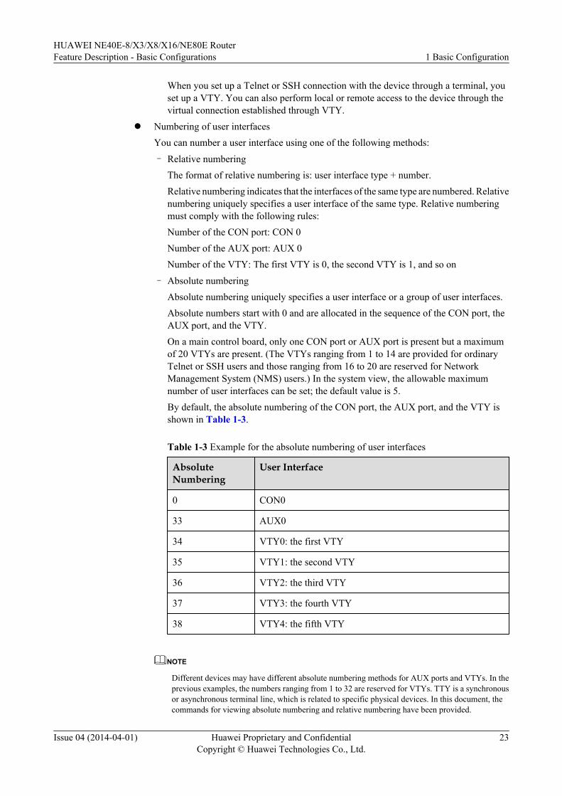
– Absolute numberingAbsolute numbering uniquely specifies a user interface or a group of user interfaces.Absolute numbers start with 0 and are allocated in the sequence of the CON port, theAUX port, and the VTY.On a main control board, only one CON port or AUX port is present but a maximumof 20 VTYs are present. (The VTYs ranging from 1 to 14 are provided for ordinaryTelnet or SSH users and those ranging from 16 to 20 are reserved for NetworkManagement System (NMS) users.) In the system view, the allowable maximumnumber of user interfaces can be set; the default value is 5.By default, the absolute numbering of the CON port, the AUX port, and the VTY isshown in Table 1-3.
Table 1-3 Example for the absolute numbering of user interfaces
AbsoluteNumbering
User Interface
0 CON0
33 AUX0
34 VTY0: the first VTY
35 VTY1: the second VTY
36 VTY2: the third VTY
37 VTY3: the fourth VTY
38 VTY4: the fifth VTY
NOTE
Different devices may have different absolute numbering methods for AUX ports and VTYs. In theprevious examples, the numbers ranging from 1 to 32 are reserved for VTYs. TTY is a synchronousor asynchronous terminal line, which is related to specific physical devices. In this document, thecommands for viewing absolute numbering and relative numbering have been provided.
HUAWEI NE40E-8/X3/X8/X16/NE80E RouterFeature Description - Basic Configurations 1 Basic Configuration
Issue 04 (2014-04-01) Huawei Proprietary and ConfidentialCopyright © Huawei Technologies Co., Ltd.
23
User Login
In the absence of user authentication, any user can configure a device after it is connected to thePC through the console port.
After the IP address is assigned to the main control board or the interface board, any remote usercan use Telnet or SSH to log in to the device, or set up the PPP connection with the device toaccess the network.
Therefore, the device and network are vulnerable to attacks. In this case, users should be createdfor the device and passwords should be set for users so that the device can manage users. SSHusers are configured with RSA authentication and other users are configured with AAA. Formore information, refer to the AAA Feature Description.
NOTE
When a user logs in to the device through a VTY and runs a command, if the device does not respond for15 minutes, the user will be forced to go offline. Meanwhile, the device releases the VTY channel occupiedby the user.
Another user can also log in to the device through this VTY, but the system will prompt the user not to runa similar command to avoid that the device does not respond again.
If the device does not respond twice in a VTY, the VTY will be locked. Users can log into the devicethrough other VTYs. The locked VTY will be restored after the device restarts.
User Classification
Users of the device can be classified into the following types based on the type of service used.
l HyperTerminal users: indicate those who log in to the device through the console port orAUX port.
l Telnet users: indicate those who log in to the device through Telnet.
l FTP users: indicate those who transfer files by setting up the FTP connection with thedevice.
l PPP users: indicate those who access the network by setting up the PPP connection, suchas dialup and (PPP over AAL5) PPPoA, with the device.
l SSH users: indicate those who perform remote access to the network by setting up the SSHconnection with the device, including the STelnet mode and the SFTP mode.
l NMS users: indicate those who set up a connection with the device through SNMP or Telnetto manage devices in machine-to-machine mode.
One user can obtain multiple services simultaneously to perform multiple functions. VTY users,namely, Telnet or SSH users, need to be bound to admission protocols in the user interface viewbefore they log in.
User Priorities
The system supports hierarchical management over HyperTerminal users and VTY users.
The greater the number, the higher the user level. The level of the command that a user can runis determined by the user's level.
l In the case of password authentication, the level of the command that the user can rundepends on the level of the user interface.
HUAWEI NE40E-8/X3/X8/X16/NE80E RouterFeature Description - Basic Configurations 1 Basic Configuration
Issue 04 (2014-04-01) Huawei Proprietary and ConfidentialCopyright © Huawei Technologies Co., Ltd.
24
l In the case of AAA authentication, the command the user can run depends on the level ofthe local user specified in the AAA configuration.
A user can run the commands whose levels are equal to or lower than the user's level. Forexample, the level 2 user can access the commands at levels 0, 1, and 2. The level 3 user canaccess the commands at levels 0, 1, 2, and 3.
NOTE
One-to-one mapping exists between user levels and command lines.
User AuthenticationAfter users are configured, the system authenticates them when they log in to the device.
Two authentication modes are available: password authentication, and Authentication,Authorization, and Accounting (AAA) authentication.
l Password authentication: In this mode, users can log in to the device by entering passwordsrather than usernames. This mode is configured based on the terminal line. A password canbe configured for a terminal line or a group of terminal lines.
NOTE
The passwords must meet the following requirements:
l The password is a string of 8 to 16 bytes of case-sensitive characters.
l The password must contain at least two of the following characters: upper-case character, lower-case character, digit, and special character.
Special character except the question mark (?) and space.
l AAA authentication: includes AAA local and AAA remote authentication. In AAA localauthentication, users need enter both the usernames and passwords on the local device. Ifnecessary, users also need to enter user attributes, such as user rights and FTP paths. InAAA remote authentication, user information needs to be configured on the AAA server.In general, AAA server authentication is used for VTY users; AAA local authentication isused for console users. For more information, refer to the AAA Feature Description.
Planning UsersThe network administrator can plan the users of the device as required.
l Usually, at least a HyperTerminal user needs to be created on the device.l Telnet or SSH users need to be configured to implement remote login to the device through
Telnet or SSH.l FTP or SFTP users need to be configured to enable remote users to upload or download
files to or from the device.l PPP users need to be configured to enable users to access the network through the PPP
connection established with the device.
1.4.6 Virtual File SystemThe virtual file system, that is easy-to-use and tailorable, has two functions, namely, managingthe storage device and managing the files that are stored on the device. In the file system, userscan create, delete, modify, and rename a file or a directory, and view the contents of a file. Tomanage mass storage devices more effectively and ignore the differences of bottom-layer storage
HUAWEI NE40E-8/X3/X8/X16/NE80E RouterFeature Description - Basic Configurations 1 Basic Configuration
Issue 04 (2014-04-01) Huawei Proprietary and ConfidentialCopyright © Huawei Technologies Co., Ltd.
25
devices, the mass storage device must support the virtual file system that is easy-to-use andtailorable.
Basic Conceptsl Storage device: a hardware device used to store datal File: a mechanism used for the system to store and manage informationl Directory: a mechanism used by the system to integrate and organize files and to provide
a logical container of files
Managing Storage Devicesl Repairing the storage device with the abnormal file system
When the file system on a storage device fails, the device terminal prompts that the faultshould be rectified.
l Formatting the storage deviceWhen the repair of the file system fails or when the data on the storage device is no longerneeded, the storage device can simply be reformatted. However, all data on the device willbe lost.If reformatting the storage device fails, a physical fault may occur.
Managing File DirectoriesWhen transmitting files between the client and the server, directories needs to be set up in thefile system. The specific operations are as follows:
l Display the current directory.l Change the current directory.l Display directories or file information.l Create a directory.l Delete a directory.
NOTE
Either the absolute path or relative path is applicable.
Managing FilesYou can perform the following operations for files:
l Display file contents.l Copy files.l Move files. Changing the file storage location.l Rename files. Changing the names of existing files.l Delete files. Deleting existing files and actually moving files to the recycle bin. This
operation is reversible. The wildcard (*) can be used to delete multiple files at a time.l Delete files from the recycle bin. This operation is irreversible.l Restore deleted files. Restoring files from the recycle bin. Restoring deleted files is a reverse
operation of deleting files.
HUAWEI NE40E-8/X3/X8/X16/NE80E RouterFeature Description - Basic Configurations 1 Basic Configuration
Issue 04 (2014-04-01) Huawei Proprietary and ConfidentialCopyright © Huawei Technologies Co., Ltd.
26
Miscellaneousl Executing batch files
A batch file is created and executed to automat several tasks. Batch files must be createdon the client and uploaded to the device.
This operation need edit batch files on the client and upload batch files to the device.
l Configuring the prompt mode of the file system
If data is lost or damaged during file management, the system should provide prompts asto corrective steps.
NOTICEIf the prompt mode is set as quiet, the system does not provide prompts when data is lost becauseof user misoperations such as the accidentally deleting files. Therefore, this quiet mode shouldbe used with caution.
1.4.7 Pipe CharacterThe pipe character is used to filter and then display the output of display commands accordingto the rules set by a user.
During device maintenance, a display command may output a lot of information, only a part ofwhich has real value to the user, for example, the status of interfaces, the status of OSPF peers,and the Cyclic Redundancy Check (CRC) statistics of interfaces (used to determine or locate afault). If all the output of a display command remains unfiltered, users cannot readily obtainpertinent information. The pipe character filters out irrelevant information of the commandoutput, insuring the desired information stands out to help users rapidly determine the exactnature of the problem.
Filtration rules of the pipe character are as follows:
l include + regular expression
In this mode, the lines containing user-specified contents are displayed.
l begin + regular expression
In this mode, the lines from the first line containing user-specified contents are displayed.
l exclude + regular expression
In this mode, the lines not containing user-specified contents are displayed.
l count
In this mode, the lines to be output are counted and only the line numbers are displayed.
Special Processing of the Table-form Output
The output of certain display commands contains tables such as FIB and ARP tables. A table iscomposed of the table heading, table tail, and table text (entries). If the table heading and tailare included in the pipe character filtration, they are probably filtered out. This is not convenient.It is necessary, therefore, that table headings and tails are not included in the filtration process.
HUAWEI NE40E-8/X3/X8/X16/NE80E RouterFeature Description - Basic Configurations 1 Basic Configuration
Issue 04 (2014-04-01) Huawei Proprietary and ConfidentialCopyright © Huawei Technologies Co., Ltd.
27
Generally, all display commands need to support the pipe character. The display commandsthat meet the following requirements, however, do not necessarily support the pipe character:l Commands whose output information is stable can be displayed in current screen.l Commands whose output information does not vary with configurations, dynamic data,
and specifications.l Commands used in the diagnostic view, such as commands used to collect information.
1.4.8 Daylight Saving TimeDaylight Saving Time (DST), also referred to as summer time, is a convention established bycommunities for prolonging daylight hours and saving resources such as the cost of lightingoffice buildings and schools.
In high latitude areas, the sun rises earlier in summer than in the winter. To reduce evening usageof incandescent lighting and save energy, clocks are adjusted forward one hour in the spring. Atpresent, about 110 countries around the world adopt DST.
Users can customize the DST zone according to their countries' or regions' convention. Userscan set when and how clocks are adjusted forward, usually an hour. With DST enabled, thesystem time is adjusted accordingly; when it is time to end DST, the system time automaticallyreturns to normal.
1.4.9 Timing RestartThe system supports timing restart when, at a specified time, the system automatically restartsand updates system files. Such a device upgrade needs to be performed at the exact right time.After a timing restart is configured, maintenance personnel just need to prepare softwarepackages, system image files, and to set the time and files for the automatic device restart.
1.4.10 MIB Interface Is Used to Optimize System UpgradeIn a cluster, version upgrading becomes complex. A user needs to download the system startupfile to the system's master board, and then to copy it to the master and slave boards of otherchassis. After copying the system startup file, the user then needs to configure the startup settingsfor each chassis. This requires a lot of work on the part of the user.
During the system upgrade, how the device processes the MIB is optimized and what the NMSoperates on the device is simplified.
When the user downloads the startup file to the master board through the NMS, the devicedirectly synchronizes the file to the slave board or the master and slave boards on other chassisif in a cluster. The system queries the file index according to the file type and name (includingthe startup file, PAF&License files, configuration file, and patch). The NMS then sets the filefor the next startup according to the file index. This setting is automatically synchronized to theslave boards. In a cluster, this setting can also be synchronized to the master and slave boardsof other chassis without additional configurations. This greatly reduces the user's workload onconfiguring and uploading startup-related files.
Before downloading version-related files (including the startup file, PAF&License files,configuration file, and patch) from the FTP server, the device checks the remaining memory ofthe master and slave boards in each chassis. If the available memory is insufficient, the earliestcreated system file is automatically deleted to ensure sufficient memory. In the case that thedevice contains only files for the current and next startup and does not have enough memory to
HUAWEI NE40E-8/X3/X8/X16/NE80E RouterFeature Description - Basic Configurations 1 Basic Configuration
Issue 04 (2014-04-01) Huawei Proprietary and ConfidentialCopyright © Huawei Technologies Co., Ltd.
28
save the file to be downloaded, an error message is returned and the download operation iscanceled.
When the system upgrade is simplified through the MIB interface, the following functions areemphasized:
l The device checks the available memory to ensure that the remaining memory is enoughto store at least one system file for the upgrade.The object hwFlhOperMemSize is added to huaweiFlhOpTable of HUAWEI-FLASH-MAN-MIB. The value of this object is used to specify the size of the reserved memory (inKB). This object is optional during file uploading, and its default value is 0. If the valueremains 0, no more memory needs to be reserved. If the value of this object is not 0, filesare deleted when available memory is insufficient. There must be two system files, namely,the currently-used system file and the rollback file. The earlier created system file is firstdeleted, and then if the available memory is still insufficient, an error message is returned.In this case, the user needs to manually delete enough remaining files until the availablememory is sufficient.
l The needed file is downloaded and synchronized between the system master and slaveboards and between chassis.After the file is successfully downloaded to the master board of the system, the file isautomatically synchronized to the slave board of the system as well as the master and slaveboards of other chassis. If the file already exists and is not the file for the current startup,the file will be automatically overwritten. If the file already exists and is the file for thecurrent startup, an error message is returned.
l The index of the specified file is queried.The system provides a MIB table for querying a file index through the real-time obtainingfile index operation. The NMS sets the file for the next startup of the device according tothe index.
l The file for the next startup is set and synchronized between the system master and slaveboards and other chassis.The NMS sets the file for next startup through hwSysReloadScheduleTable. After themaster board of the system is specified, the system automatically synchronizes the file forthe next startup to the slave board of the system as well as the master and slave boards ofother chassis.
1.4.11 NAPAs a Layer 3 protocol, the Neighbor Access Protocol (NAP) helps users to remotely log in to adevice with default configurations and then to configure the device. A NAP connection can beestablished as long as the device to be configured and the local device are physically connected.
As shown in Figure 1-11, Router A and Router B are devices on the current network, andRouter C is a device with default configurations. Router B and Router C are connected via asingle hop, both supporting NAP.
HUAWEI NE40E-8/X3/X8/X16/NE80E RouterFeature Description - Basic Configurations 1 Basic Configuration
Issue 04 (2014-04-01) Huawei Proprietary and ConfidentialCopyright © Huawei Technologies Co., Ltd.
29
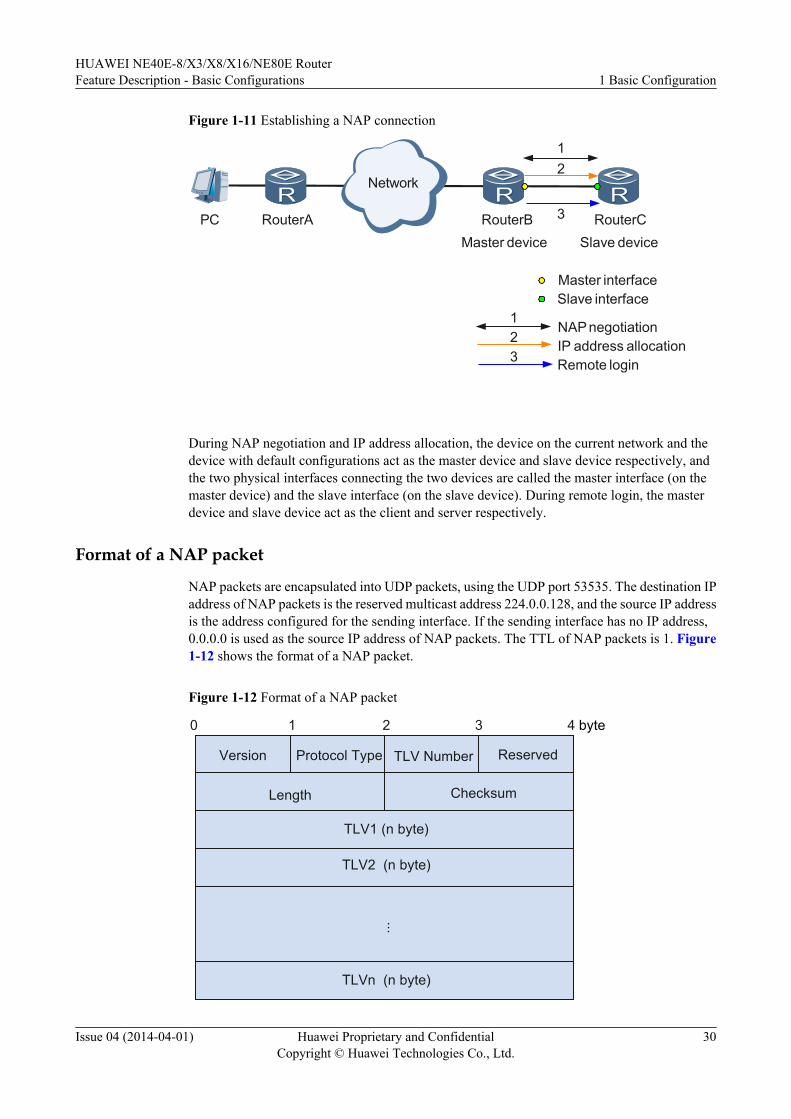
Figure 1-11 Establishing a NAP connection
Network
RouterAPC RouterB RouterC
12
3
Master device Slave device
Master interfaceSlave interface
123
NAP negotiation
Remote loginIP address allocation
During NAP negotiation and IP address allocation, the device on the current network and thedevice with default configurations act as the master device and slave device respectively, andthe two physical interfaces connecting the two devices are called the master interface (on themaster device) and the slave interface (on the slave device). During remote login, the masterdevice and slave device act as the client and server respectively.
Format of a NAP packet
NAP packets are encapsulated into UDP packets, using the UDP port 53535. The destination IPaddress of NAP packets is the reserved multicast address 224.0.0.128, and the source IP addressis the address configured for the sending interface. If the sending interface has no IP address,0.0.0.0 is used as the source IP address of NAP packets. The TTL of NAP packets is 1. Figure1-12 shows the format of a NAP packet.
Figure 1-12 Format of a NAP packet
Version
0 4321
Protocol Type Reserved
Length Checksum
...
TLV1 (n byte)
TLV2 (n byte)
TLVn (n byte)
TLV Number
byte
HUAWEI NE40E-8/X3/X8/X16/NE80E RouterFeature Description - Basic Configurations 1 Basic Configuration
Issue 04 (2014-04-01) Huawei Proprietary and ConfidentialCopyright © Huawei Technologies Co., Ltd.
30
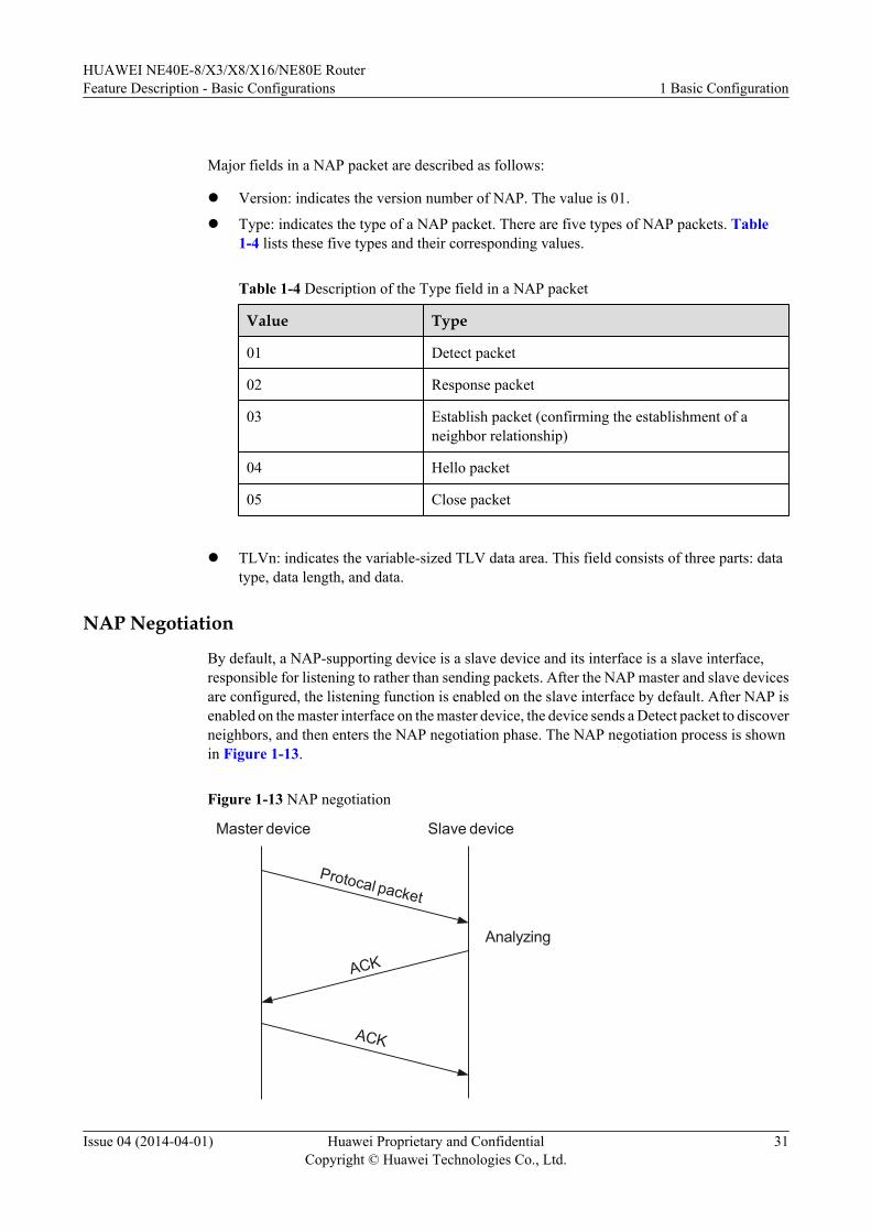
Major fields in a NAP packet are described as follows:
l Version: indicates the version number of NAP. The value is 01.
l Type: indicates the type of a NAP packet. There are five types of NAP packets. Table1-4 lists these five types and their corresponding values.
Table 1-4 Description of the Type field in a NAP packet
Value Type
01 Detect packet
02 Response packet
03 Establish packet (confirming the establishment of aneighbor relationship)
04 Hello packet
05 Close packet
l TLVn: indicates the variable-sized TLV data area. This field consists of three parts: datatype, data length, and data.
NAP Negotiation
By default, a NAP-supporting device is a slave device and its interface is a slave interface,responsible for listening to rather than sending packets. After the NAP master and slave devicesare configured, the listening function is enabled on the slave interface by default. After NAP isenabled on the master interface on the master device, the device sends a Detect packet to discoverneighbors, and then enters the NAP negotiation phase. The NAP negotiation process is shownin Figure 1-13.
Figure 1-13 NAP negotiation
Master device Slave device
Protocal packet
Analyzing
ACK
ACK
HUAWEI NE40E-8/X3/X8/X16/NE80E RouterFeature Description - Basic Configurations 1 Basic Configuration
Issue 04 (2014-04-01) Huawei Proprietary and ConfidentialCopyright © Huawei Technologies Co., Ltd.
31
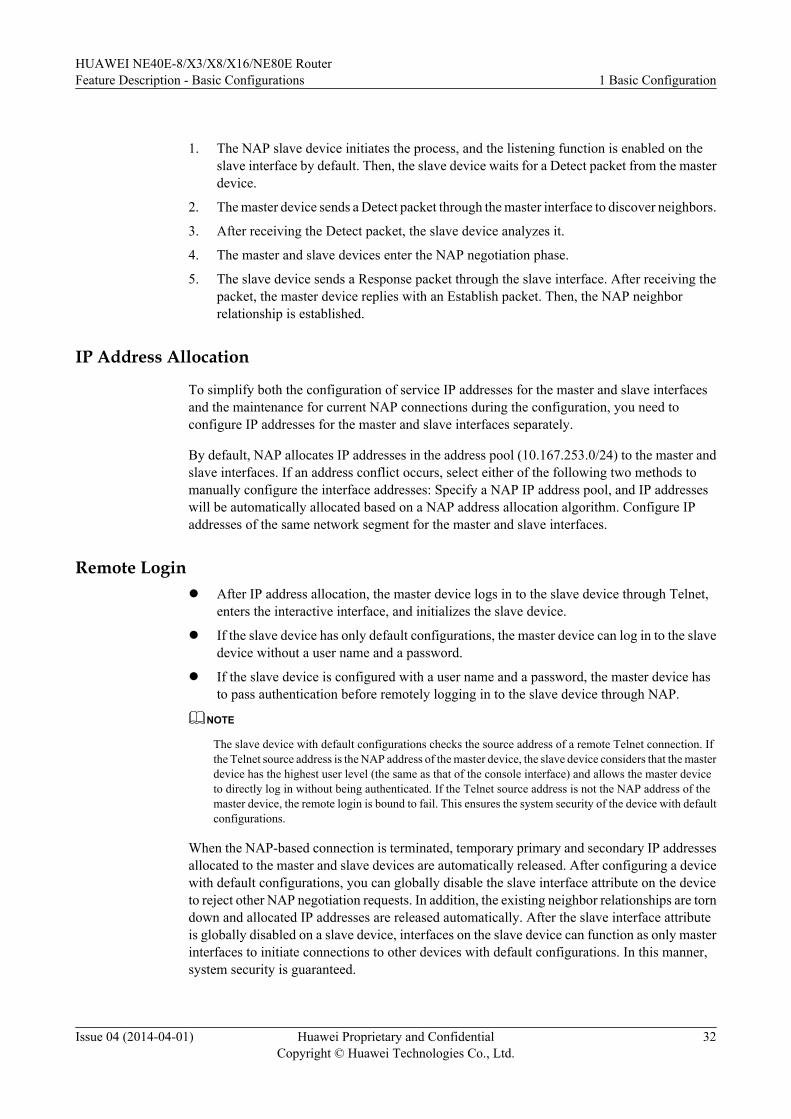
1. The NAP slave device initiates the process, and the listening function is enabled on theslave interface by default. Then, the slave device waits for a Detect packet from the masterdevice.
2. The master device sends a Detect packet through the master interface to discover neighbors.
3. After receiving the Detect packet, the slave device analyzes it.
4. The master and slave devices enter the NAP negotiation phase.
5. The slave device sends a Response packet through the slave interface. After receiving thepacket, the master device replies with an Establish packet. Then, the NAP neighborrelationship is established.
IP Address Allocation
To simplify both the configuration of service IP addresses for the master and slave interfacesand the maintenance for current NAP connections during the configuration, you need toconfigure IP addresses for the master and slave interfaces separately.
By default, NAP allocates IP addresses in the address pool (10.167.253.0/24) to the master andslave interfaces. If an address conflict occurs, select either of the following two methods tomanually configure the interface addresses: Specify a NAP IP address pool, and IP addresseswill be automatically allocated based on a NAP address allocation algorithm. Configure IPaddresses of the same network segment for the master and slave interfaces.
Remote Loginl After IP address allocation, the master device logs in to the slave device through Telnet,
enters the interactive interface, and initializes the slave device.
l If the slave device has only default configurations, the master device can log in to the slavedevice without a user name and a password.
l If the slave device is configured with a user name and a password, the master device hasto pass authentication before remotely logging in to the slave device through NAP.
NOTE
The slave device with default configurations checks the source address of a remote Telnet connection. Ifthe Telnet source address is the NAP address of the master device, the slave device considers that the masterdevice has the highest user level (the same as that of the console interface) and allows the master deviceto directly log in without being authenticated. If the Telnet source address is not the NAP address of themaster device, the remote login is bound to fail. This ensures the system security of the device with defaultconfigurations.
When the NAP-based connection is terminated, temporary primary and secondary IP addressesallocated to the master and slave devices are automatically released. After configuring a devicewith default configurations, you can globally disable the slave interface attribute on the deviceto reject other NAP negotiation requests. In addition, the existing neighbor relationships are torndown and allocated IP addresses are released automatically. After the slave interface attributeis globally disabled on a slave device, interfaces on the slave device can function as only masterinterfaces to initiate connections to other devices with default configurations. In this manner,system security is guaranteed.
HUAWEI NE40E-8/X3/X8/X16/NE80E RouterFeature Description - Basic Configurations 1 Basic Configuration
Issue 04 (2014-04-01) Huawei Proprietary and ConfidentialCopyright © Huawei Technologies Co., Ltd.
32
1.4.12 Dynamic Module Load
Purpose
Software upgrade is a common method to add new services on a network. This method, however,has the following deficiencies:
1. An upgrade process is complex. An upgrade involves all service configurations, andconfigurations may change or be incompatible after an upgrade. In addition, errors easilyoccur due to misoperations.
2. An upgrade process affects services.
In addition, operators have different requirements for functions. If a function is required byoperator A but not operator B, the function must be enabled on operator A's network but disabledon operator B's network. This situation makes an upgrade process more complex. The PAF/license feature can enable and disable specified functions, but it has the following deficiencies:
l The system must be restarted after a PAF/license controlled feature is enabled or disabled,so that the configuration can take effect.
l The PAF/license feature does not have a mechanism to fight against attacks.
Dynamic module load is the answer to these problems. Dynamic module load allows you toinstall the module patch package for a desired function, without upgrading or powering off yourdevice.
Related Concepts
Dynamic module load is a method for deploying new services. Dynamic module load isimplemented by installing the module patch package for a desired function using the install-module command.
Implementation
Dynamic module load is implemented by means of the patch load mechanism. The procedureis as follows:
1. Convert a desired function module into a patch package.
2. Install the module's patch package by running the install-module command.
3. Activate the module's patch package.
Benefits
l Dynamic module load is available only to authorized users. If the process fails, the usercannot enable the specified function even by unlawful methods, improving device security.
l In addition, this feature does not require you to power off your device, minimizing serviceinterruptions.
1.5 Applications
HUAWEI NE40E-8/X3/X8/X16/NE80E RouterFeature Description - Basic Configurations 1 Basic Configuration
Issue 04 (2014-04-01) Huawei Proprietary and ConfidentialCopyright © Huawei Technologies Co., Ltd.
33
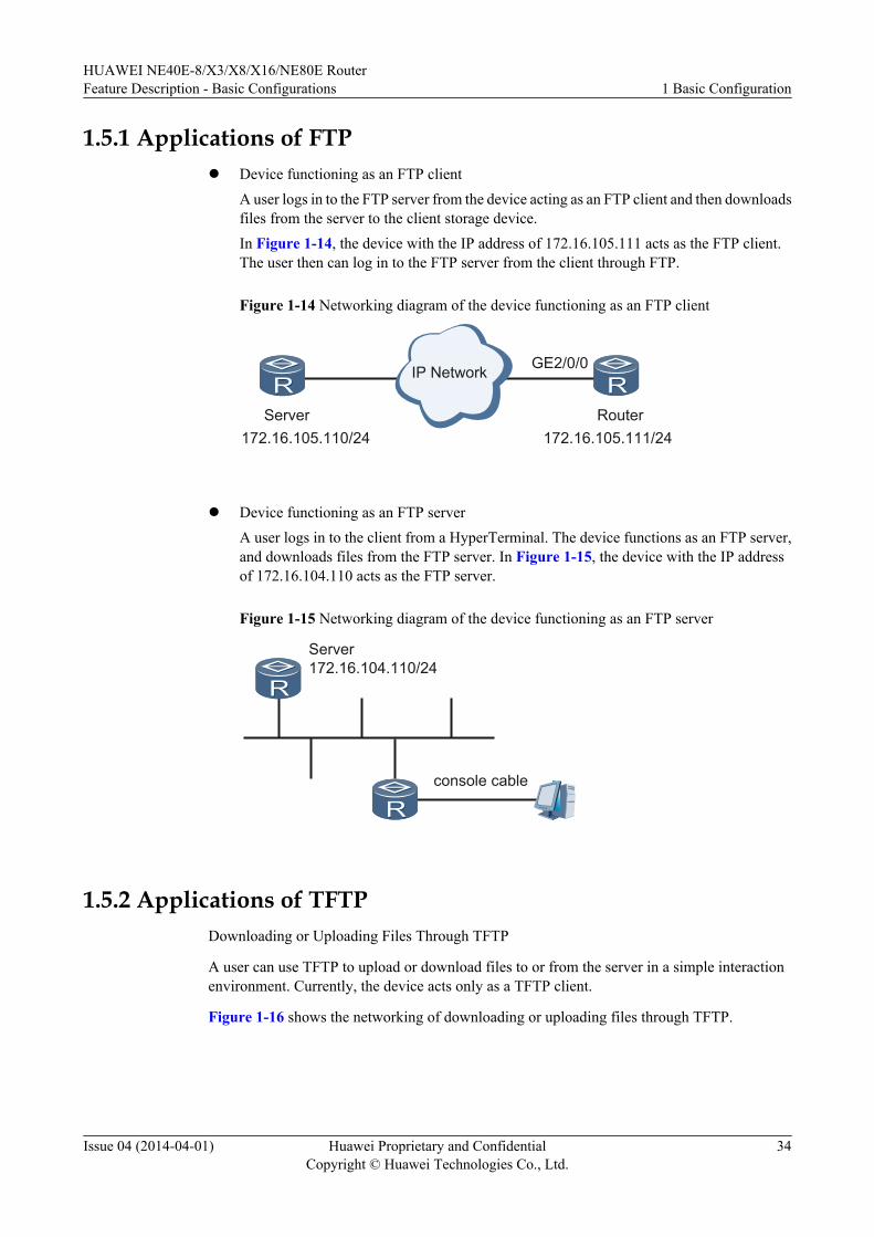
1.5.1 Applications of FTPl Device functioning as an FTP client
A user logs in to the FTP server from the device acting as an FTP client and then downloadsfiles from the server to the client storage device.In Figure 1-14, the device with the IP address of 172.16.105.111 acts as the FTP client.The user then can log in to the FTP server from the client through FTP.
Figure 1-14 Networking diagram of the device functioning as an FTP client
IP Network
RouterServer172.16.105.111/24172.16.105.110/24
GE2/0/0
l Device functioning as an FTP server
A user logs in to the client from a HyperTerminal. The device functions as an FTP server,and downloads files from the FTP server. In Figure 1-15, the device with the IP addressof 172.16.104.110 acts as the FTP server.
Figure 1-15 Networking diagram of the device functioning as an FTP server
Server
console cable
172.16.104.110/24
1.5.2 Applications of TFTPDownloading or Uploading Files Through TFTP
A user can use TFTP to upload or download files to or from the server in a simple interactionenvironment. Currently, the device acts only as a TFTP client.
Figure 1-16 shows the networking of downloading or uploading files through TFTP.
HUAWEI NE40E-8/X3/X8/X16/NE80E RouterFeature Description - Basic Configurations 1 Basic Configuration
Issue 04 (2014-04-01) Huawei Proprietary and ConfidentialCopyright © Huawei Technologies Co., Ltd.
34
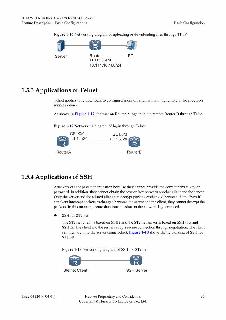
Figure 1-16 Networking diagram of uploading or downloading files through TFTP
TFTP ClientRouter
10.111.16.160/24
PCServer
1.5.3 Applications of TelnetTelnet applies to remote login to configure, monitor, and maintain the remote or local devicesrunning device.
As shown in Figure 1-17, the user on Router A logs in to the remote Router B through Telnet.
Figure 1-17 Networking diagram of login through Telnet
RouterBRouterA
GE1/0/01.1.1.1/24
GE1/0/01.1.1.2/24
1.5.4 Applications of SSHAttackers cannot pass authentication because they cannot provide the correct private key orpassword. In addition, they cannot obtain the session key between another client and the server.Only the server and the related client can decrypt packets exchanged between them. Even ifattackers intercept packets exchanged between the server and the client, they cannot decrypt thepackets. In this manner, secure data transmission on the network is guaranteed.
l SSH for STelnet
The STelnet client is based on SSH2 and the STelnet server is based on SSHv1.x andSSHv2. The client and the server set up a secure connection through negotiation. The clientcan then log in to the server using Telnet. Figure 1-18 shows the networking of SSH forSTelnet.
Figure 1-18 Networking diagram of SSH for STelnet
Stelnet Client SSH Server
HUAWEI NE40E-8/X3/X8/X16/NE80E RouterFeature Description - Basic Configurations 1 Basic Configuration
Issue 04 (2014-04-01) Huawei Proprietary and ConfidentialCopyright © Huawei Technologies Co., Ltd.
35
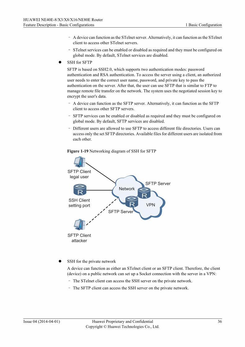
– A device can function as the STelnet server. Alternatively, it can function as the STelnetclient to access other STelnet servers.
– STelnet services can be enabled or disabled as required and they must be configured onglobal mode. By default, STelnet services are disabled.
l SSH for SFTPSFTP is based on SSH2.0, which supports two authentication modes: passwordauthentication and RSA authentication. To access the server using a client, an authorizeduser needs to enter the correct user name, password, and private key to pass theauthentication on the server. After that, the user can use SFTP that is similar to FTP tomanage remote file transfer on the network. The system uses the negotiated session key toencrypt the user's data.
– A device can function as the SFTP server. Alternatively, it can function as the SFTPclient to access other SFTP servers.
– SFTP services can be enabled or disabled as required and they must be configured onglobal mode. By default, SFTP services are disabled.
– Different users are allowed to use SFTP to access different file directories. Users canaccess only the set SFTP directories. Available files for different users are isolated fromeach other.
Figure 1-19 Networking diagram of SSH for SFTP
NetworkSFTP Server
SSH Client setting port VPN
SFTP Server
SFTP Client legal user
SFTP Client attacker
l SSH for the private network
A device can function as either an STelnet client or an SFTP client. Therefore, the client(device) on a public network can set up a Socket connection with the server in a VPN:
– The STelnet client can access the SSH server on the private network.
– The SFTP client can access the SSH server on the private network.
HUAWEI NE40E-8/X3/X8/X16/NE80E RouterFeature Description - Basic Configurations 1 Basic Configuration
Issue 04 (2014-04-01) Huawei Proprietary and ConfidentialCopyright © Huawei Technologies Co., Ltd.
36
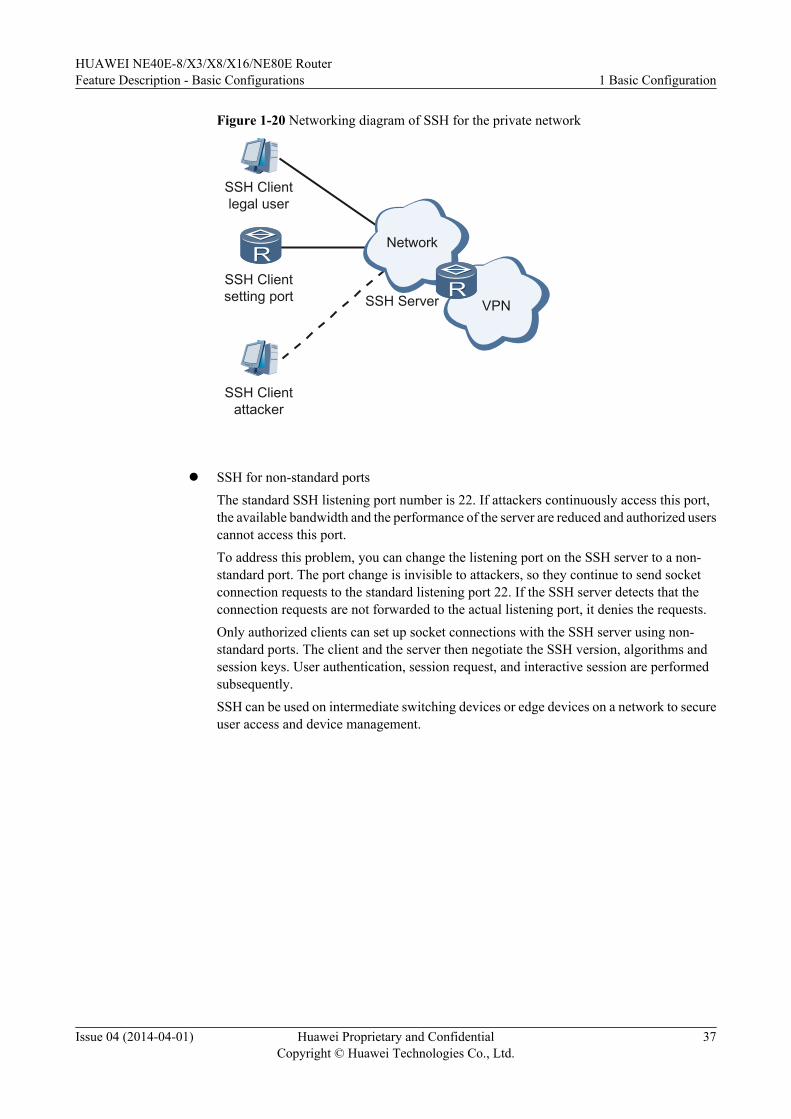
Figure 1-20 Networking diagram of SSH for the private network
Network
SSH ServerSSH Clientsetting port
VPN
SSH Clientlegal user
SSH Clientattacker
l SSH for non-standard ports
The standard SSH listening port number is 22. If attackers continuously access this port,the available bandwidth and the performance of the server are reduced and authorized userscannot access this port.To address this problem, you can change the listening port on the SSH server to a non-standard port. The port change is invisible to attackers, so they continue to send socketconnection requests to the standard listening port 22. If the SSH server detects that theconnection requests are not forwarded to the actual listening port, it denies the requests.Only authorized clients can set up socket connections with the SSH server using non-standard ports. The client and the server then negotiate the SSH version, algorithms andsession keys. User authentication, session request, and interactive session are performedsubsequently.SSH can be used on intermediate switching devices or edge devices on a network to secureuser access and device management.
HUAWEI NE40E-8/X3/X8/X16/NE80E RouterFeature Description - Basic Configurations 1 Basic Configuration
Issue 04 (2014-04-01) Huawei Proprietary and ConfidentialCopyright © Huawei Technologies Co., Ltd.
37
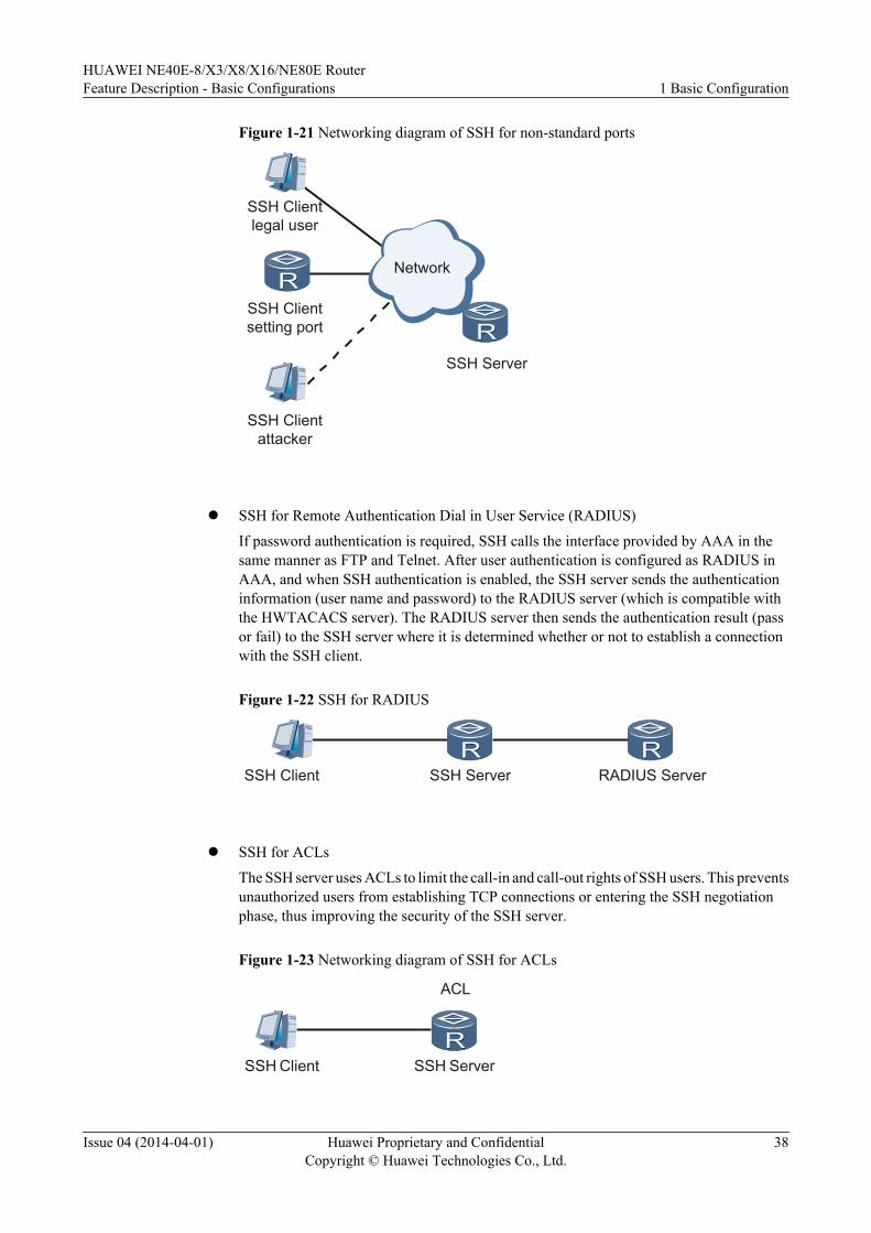
Figure 1-21 Networking diagram of SSH for non-standard ports
Network
SSH Server
SSH Clientsetting port
SSH Clientlegal user
SSH Clientattacker
l SSH for Remote Authentication Dial in User Service (RADIUS)
If password authentication is required, SSH calls the interface provided by AAA in thesame manner as FTP and Telnet. After user authentication is configured as RADIUS inAAA, and when SSH authentication is enabled, the SSH server sends the authenticationinformation (user name and password) to the RADIUS server (which is compatible withthe HWTACACS server). The RADIUS server then sends the authentication result (passor fail) to the SSH server where it is determined whether or not to establish a connectionwith the SSH client.
Figure 1-22 SSH for RADIUS
SSH Client SSH Server RADIUS Server
l SSH for ACLs
The SSH server uses ACLs to limit the call-in and call-out rights of SSH users. This preventsunauthorized users from establishing TCP connections or entering the SSH negotiationphase, thus improving the security of the SSH server.
Figure 1-23 Networking diagram of SSH for ACLs
SSH Client SSH Server
ACL
HUAWEI NE40E-8/X3/X8/X16/NE80E RouterFeature Description - Basic Configurations 1 Basic Configuration
Issue 04 (2014-04-01) Huawei Proprietary and ConfidentialCopyright © Huawei Technologies Co., Ltd.
38
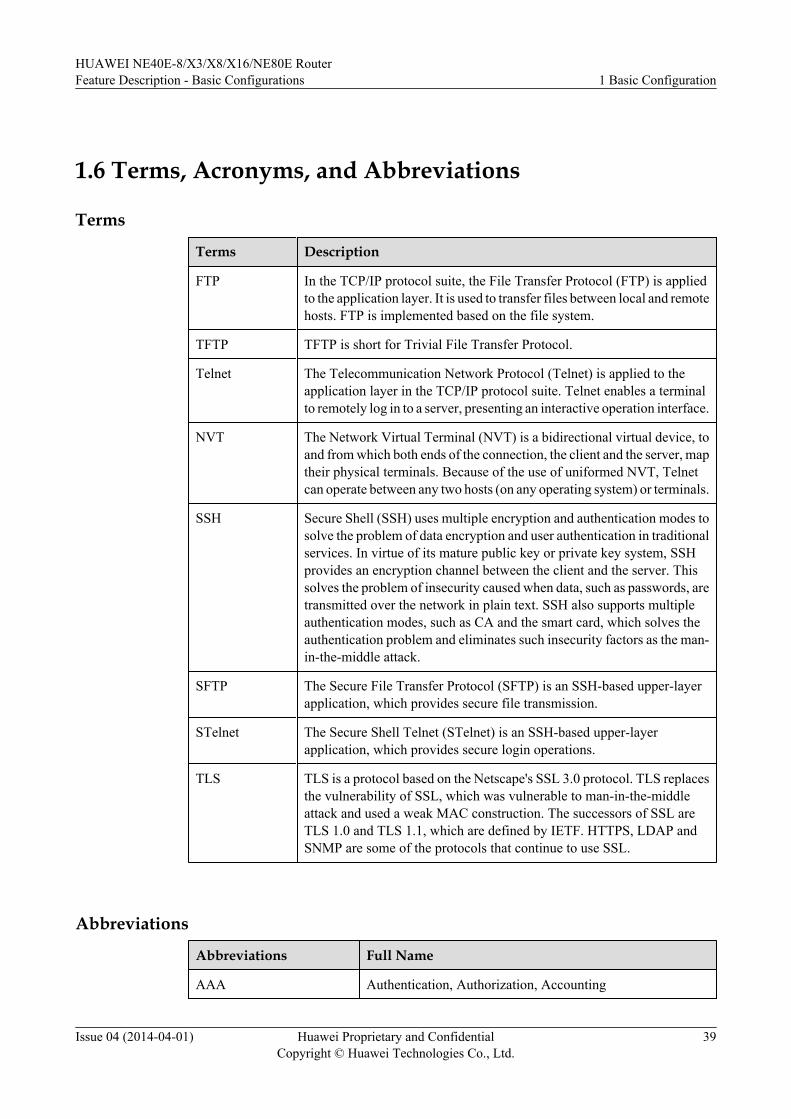
1.6 Terms, Acronyms, and Abbreviations
Terms
Terms Description
FTP In the TCP/IP protocol suite, the File Transfer Protocol (FTP) is appliedto the application layer. It is used to transfer files between local and remotehosts. FTP is implemented based on the file system.
TFTP TFTP is short for Trivial File Transfer Protocol.
Telnet The Telecommunication Network Protocol (Telnet) is applied to theapplication layer in the TCP/IP protocol suite. Telnet enables a terminalto remotely log in to a server, presenting an interactive operation interface.
NVT The Network Virtual Terminal (NVT) is a bidirectional virtual device, toand from which both ends of the connection, the client and the server, maptheir physical terminals. Because of the use of uniformed NVT, Telnetcan operate between any two hosts (on any operating system) or terminals.
SSH Secure Shell (SSH) uses multiple encryption and authentication modes tosolve the problem of data encryption and user authentication in traditionalservices. In virtue of its mature public key or private key system, SSHprovides an encryption channel between the client and the server. Thissolves the problem of insecurity caused when data, such as passwords, aretransmitted over the network in plain text. SSH also supports multipleauthentication modes, such as CA and the smart card, which solves theauthentication problem and eliminates such insecurity factors as the man-in-the-middle attack.
SFTP The Secure File Transfer Protocol (SFTP) is an SSH-based upper-layerapplication, which provides secure file transmission.
STelnet The Secure Shell Telnet (STelnet) is an SSH-based upper-layerapplication, which provides secure login operations.
TLS TLS is a protocol based on the Netscape's SSL 3.0 protocol. TLS replacesthe vulnerability of SSL, which was vulnerable to man-in-the-middleattack and used a weak MAC construction. The successors of SSL areTLS 1.0 and TLS 1.1, which are defined by IETF. HTTPS, LDAP andSNMP are some of the protocols that continue to use SSL.
Abbreviations
Abbreviations Full Name
AAA Authentication, Authorization, Accounting
HUAWEI NE40E-8/X3/X8/X16/NE80E RouterFeature Description - Basic Configurations 1 Basic Configuration
Issue 04 (2014-04-01) Huawei Proprietary and ConfidentialCopyright © Huawei Technologies Co., Ltd.
39
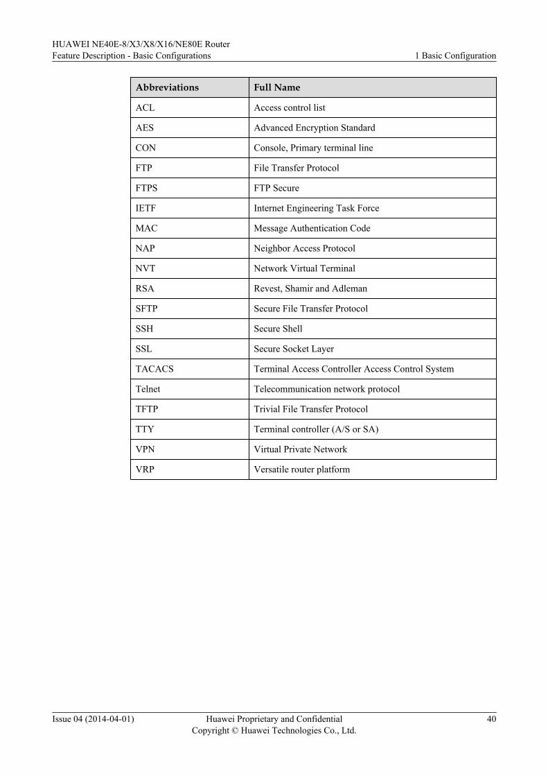
Abbreviations Full Name
ACL Access control list
AES Advanced Encryption Standard
CON Console, Primary terminal line
FTP File Transfer Protocol
FTPS FTP Secure
IETF Internet Engineering Task Force
MAC Message Authentication Code
NAP Neighbor Access Protocol
NVT Network Virtual Terminal
RSA Revest, Shamir and Adleman
SFTP Secure File Transfer Protocol
SSH Secure Shell
SSL Secure Socket Layer
TACACS Terminal Access Controller Access Control System
Telnet Telecommunication network protocol
TFTP Trivial File Transfer Protocol
TTY Terminal controller (A/S or SA)
VPN Virtual Private Network
VRP Versatile router platform
HUAWEI NE40E-8/X3/X8/X16/NE80E RouterFeature Description - Basic Configurations 1 Basic Configuration
Issue 04 (2014-04-01) Huawei Proprietary and ConfidentialCopyright © Huawei Technologies Co., Ltd.
40
2 Fast Startup
About This Chapter
2.1 Introduction to Fast Startup
2.2 References
2.3 Principles
2.4 Applications
2.5 Terms, Acronyms, and Abbreviations
HUAWEI NE40E-8/X3/X8/X16/NE80E RouterFeature Description - Basic Configurations 2 Fast Startup
Issue 04 (2014-04-01) Huawei Proprietary and ConfidentialCopyright © Huawei Technologies Co., Ltd.
41
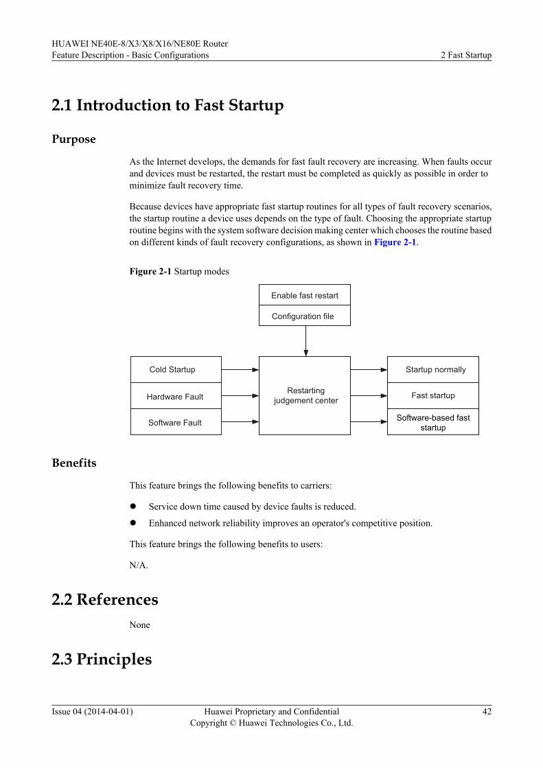
2.1 Introduction to Fast Startup
Purpose
As the Internet develops, the demands for fast fault recovery are increasing. When faults occurand devices must be restarted, the restart must be completed as quickly as possible in order tominimize fault recovery time.
Because devices have appropriate fast startup routines for all types of fault recovery scenarios,the startup routine a device uses depends on the type of fault. Choosing the appropriate startuproutine begins with the system software decision making center which chooses the routine basedon different kinds of fault recovery configurations, as shown in Figure 2-1.
Figure 2-1 Startup modes
Enable fast restart
Configuration file
Cold Startup
Hardware Fault
Software Fault
Startup normally
Fast startup
Software-based fast startup
Restarting judgement center
Benefits
This feature brings the following benefits to carriers:
l Service down time caused by device faults is reduced.
l Enhanced network reliability improves an operator's competitive position.
This feature brings the following benefits to users:
N/A.
2.2 ReferencesNone
2.3 Principles
HUAWEI NE40E-8/X3/X8/X16/NE80E RouterFeature Description - Basic Configurations 2 Fast Startup
Issue 04 (2014-04-01) Huawei Proprietary and ConfidentialCopyright © Huawei Technologies Co., Ltd.
42
2.3.1 Fast Startup After a Software FaultAfter a software fault occurs, the device monitoring process reports a software exception andinstructs the device management module to restart the device using a fast startup routine.
The Basic Input/Output System (BIOS) is not restarted during the process to reduce overallstartup time. Before the restart, the forwarding engine on the data forwarding plane stops traffic.Applications on the control plane are restarted without fault detection. After the restart, theforwarding engine on the data forwarding plane starts traffic once again.
2.3.2 Fast Startup After a Hardware FaultAfter a hardware fault occurs, the device is restarted in hot startup mode. BootLoad restart isnot part of the startup process, reducing startup time.
2.3.3 Upgrade and Cold StartupAfter a software or hardware upgrade, system firmware needs to be re-loaded. When the deviceis powered on, the power-on-self-test is performed on all components simultaneously. Becausecomponents do not have to perform a self-test one by one, overall startup time is reduced.
2.3.4 Performance Statistics for Software-based Fast Startup
2.4 ApplicationsNone.
2.5 Terms, Acronyms, and Abbreviations
TermsNone.
AbbreviationsNone.
HUAWEI NE40E-8/X3/X8/X16/NE80E RouterFeature Description - Basic Configurations 2 Fast Startup
Issue 04 (2014-04-01) Huawei Proprietary and ConfidentialCopyright © Huawei Technologies Co., Ltd.
43
3 Clock Synchronization
About This Chapter
3.1 Introduction
3.2 References
3.3 Principles
3.4 Application
3.5 Terms, Acronyms, and Abbreviations
HUAWEI NE40E-8/X3/X8/X16/NE80E RouterFeature Description - Basic Configurations 3 Clock Synchronization
Issue 04 (2014-04-01) Huawei Proprietary and ConfidentialCopyright © Huawei Technologies Co., Ltd.
44
3.1 Introduction
Definition
Frequency synchronization, also called clock synchronization, allows one clock signal to pulseat the same frequency as another clock signal, ensuring that all the devices on a communicationnetwork share the same global time.
Purpose
Clock synchronization is a technology that limits the clock frequencies of digital networkelements (NEs) to a tolerable range. If the clock frequency of an NE is beyond the tolerable errorrange, bit errors and jitter may occur, deteriorating networking transmission performance.
3.2 ReferencesThe following table lists the references.
Document No. Document Name Protocol Compliance
ITU-T G.813 TimingCharacteristics ofSDH EquipmentSlave Clocks (1996)
Fully compliant
ITU-T G.781 SynchronizationLayer Function
Fully compliant
ITU-T G.783 Characteristics ofSynchronous DigitalHierarchy (SDH)EquipmentFunctional Blocks
Fully compliant
ITU-T G.8264 Distribution ofTiming ThroughPacket Networks
Fully compliant
ITU-T G.703 Physical/ElectricalCharacteristics ofHierarchical DigitalInterfaces
Fully compliant
ITU-T G.823 Control of Jitter andWander WithinDigital NetworksWhich Are Based onthe 2048 kbit/sHierarchy
Fully compliant
HUAWEI NE40E-8/X3/X8/X16/NE80E RouterFeature Description - Basic Configurations 3 Clock Synchronization
Issue 04 (2014-04-01) Huawei Proprietary and ConfidentialCopyright © Huawei Technologies Co., Ltd.
45
Document No. Document Name Protocol Compliance
ITU-T G.8261 Timing andSynchronizationAspects in PacketNetworks
Fully compliant
ITU-T G.8262 TimingCharacteristics ofSynchronousEthernet EquipmentSlave Clock
Fully compliant
3.3 Principles
3.3.1 Basic Concepts
Ethernet Clock Synchronization Technology
Ethernet clock synchronization technology is used to transmit clock signals over the physicallayer on the Ethernet network. A device has multiple Ethernet links and any Ethernet link canprovide clock signals. The device can either select a manually specified Ethernet link or selectan Ethernet link by using the algorithm for selecting the reference clock source. The clock whosesignals are actually transmitted is the reference clock source The clock phase-locked loop (PLL)traces the reference clock source to generate the system clock. The device then transmits clocksignals from the system clock to its downstream devices over Ethernet links.
Timing Loop
Over time, the precision of clocks on a network degrade due to a timing loop. In most situations,all devices on a network synchronize their clocks from the same source. The device transmits aclock signal to its downstream devices, and the downstream devices transmit the clock signal totheir downstream devices until the clock signal reaches every device on the network. Lastly theclock signal returns to the device that first imported the reference clock. By the time the devicesynchronizes its clock with the clock signal, a timing loop has occurred. This loop results in agradual degradation of the precision of clocks on the network. Therefore, preventing timingloops must be considered during network design.
Clock Source
A device that provides clock signals to a local device is called a clock source. A local devicemay have multiple clock sources.
Clock sources are classified into the following types:
l External clock source
HUAWEI NE40E-8/X3/X8/X16/NE80E RouterFeature Description - Basic Configurations 3 Clock Synchronization
Issue 04 (2014-04-01) Huawei Proprietary and ConfidentialCopyright © Huawei Technologies Co., Ltd.
46
The local device uses the clock interface provided by its clock board to search for a higherlevel clock. External clock sources are classified into BITS0, BITS1, and PTP clocksources, and support four types of signals: 2 MHz, 2 Mbit/s, dcls, and 1 pps.
l Line clock sourceThe local device uses the clock board to extract clock signals from Synchronous TransportModule Level N (STM-N) or Ethernet line signals.
l Internal clock sourceThe local device uses its own clock (for example, the clock provided by its clock board) asthe working clock for an interface.
SSMThe Synchronization Status Message (SSM), also called the synchronization quality message,directly reflects transmission level of a synchronous timing signal.
SSMs can indicate clock source quality and are transmitted over Ethernet synchronizationmessaging channels (ESMCs). The reference clock source of a device is determined by the SSMclock source selection algorithm.
If SSMs are used for selecting a reference clock source, quality levels (QLs) of clock sourcesare first compared. If the quality levels of two or more clock sources are the same, the prioritiesof these clock sources are then compared. If SSMs are not used, the priorities of clock sourcesare compared directly.
Clock Working ModeThe working modes of clocks are classified into the following types:
l Tracing stateThe slave clock traces clock signals provided by the higher level clock. The clock signalsmay be provided by either the master clock or the internal clock of the higher-level networkelement (NE).
l Free running stateAfter losing all external clock sources, the slave clock loses clock memory or remains inthe hold-in state for a long time. As a result, the oscillator inside the slave clock works inthe free running state.
l Hold-in stateAfter losing all clock sources, the slave clock enters the hold-in state. The slave clock usesthe last clock source as its final reference clock source. Next, the slave clock adopts thetiming frequency similar to that of the last clock source to ensure that there is only a smalldifference between the frequencies of the provided clock signals and those of the referenceclock source.
Priorities of Clock SourcesPriority order of information for reference clock source selection: SSM > Priority of clock source> Clock source type
l Priority order of SSM information for reference clock source selection: PRC > SSUA >SSUB > SEC > DNU
HUAWEI NE40E-8/X3/X8/X16/NE80E RouterFeature Description - Basic Configurations 3 Clock Synchronization
Issue 04 (2014-04-01) Huawei Proprietary and ConfidentialCopyright © Huawei Technologies Co., Ltd.
47
Candidate reference clock sources must be configured with priorities. A clock source whosequality level is DNU cannot be a candidate reference clock source.
l Priority order of clock sources for reference clock source selection: 1 > 2 > ... > 254 > 255Candidate reference clock sources must be configured with priorities. A smaller priorityvalue indicates a higher priority of a clock source.
l Priority order of clock source types for reference clock source selection: BITS clock source> Interface clock source > PTP clock source
l Priority order of interface information for reference clock source selection: Slot ID > CardID > Interface IDThe interface name is in the format of slot ID/card ID/interface ID. The smaller the slot ID,the higher the priority of the interface clock source. If slot IDs are the same, the smallerthe card ID, the higher the priority of the interface clock source. If card IDs are also thesame, the smaller the interface ID, the higher the priority of the interface clock source.
Threshold SSM Levels That a BITS External Clock Source OutputsThe SSM level output by the external clock source BITS0 is the SSM level of the clock sourcethat the 2M-1 PLL traces.
The SSM level output by the external clock source BITS1 is the SSM level of the clock sourcethat the 2M-2 PLL traces.
The threshold for SSM levels output by a BITS external clock refers to the lowest level that canbe output by the clock. If the BITS external clock outputs an SSM level that is below thethreshold, the clock signal will be blocked and an alarm will be reported.
Selection of Clock Sources in Frequency Offset Detection and Non-frequencyOffset Detection Modes
A clock source can be selected in either frequency offset detection or non-frequency offsetdetection mode.
l In frequency offset detection mode, results are used for reference clock source selection.l In non-frequency offset detection mode, frequency offset detection is not performed on
clock sources.
Frequency offset detection results affect the selection of a system reference clock source, but donot affect the selection of a reference clock source from a 2 M interface.
3.3.2 Clock Protection Switching
OverviewOn a synchronization network, each device can trace the same clock source level by level throughclock synchronization paths to implement clock synchronization on the entire network. Usually,each device has more than one path for tracing clock sources. These clock sources may originatefrom either the same master clock or from reference clock sources of different qualities.
It is very important to keep the clocks of all devices synchronous. To prevent the entire networkfrom becoming faulty due to a faulty clock synchronization path, automatic protection switchingcan be configured.
HUAWEI NE40E-8/X3/X8/X16/NE80E RouterFeature Description - Basic Configurations 3 Clock Synchronization
Issue 04 (2014-04-01) Huawei Proprietary and ConfidentialCopyright © Huawei Technologies Co., Ltd.
48
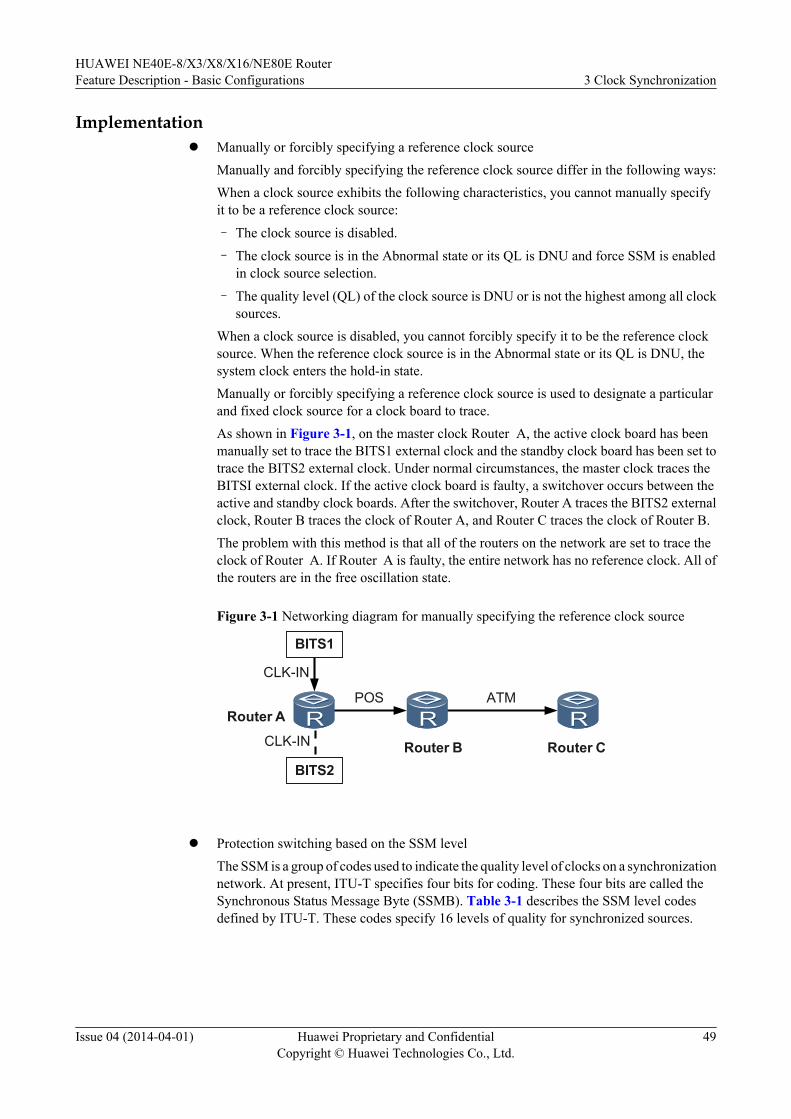
Implementationl Manually or forcibly specifying a reference clock source
Manually and forcibly specifying the reference clock source differ in the following ways:When a clock source exhibits the following characteristics, you cannot manually specifyit to be a reference clock source:
– The clock source is disabled.
– The clock source is in the Abnormal state or its QL is DNU and force SSM is enabledin clock source selection.
– The quality level (QL) of the clock source is DNU or is not the highest among all clocksources.
When a clock source is disabled, you cannot forcibly specify it to be the reference clocksource. When the reference clock source is in the Abnormal state or its QL is DNU, thesystem clock enters the hold-in state.Manually or forcibly specifying a reference clock source is used to designate a particularand fixed clock source for a clock board to trace.As shown in Figure 3-1, on the master clock Router A, the active clock board has beenmanually set to trace the BITS1 external clock and the standby clock board has been set totrace the BITS2 external clock. Under normal circumstances, the master clock traces theBITSI external clock. If the active clock board is faulty, a switchover occurs between theactive and standby clock boards. After the switchover, Router A traces the BITS2 externalclock, Router B traces the clock of Router A, and Router C traces the clock of Router B.The problem with this method is that all of the routers on the network are set to trace theclock of Router A. If Router A is faulty, the entire network has no reference clock. All ofthe routers are in the free oscillation state.
Figure 3-1 Networking diagram for manually specifying the reference clock source
BITS1
BITS2
Router A
CLK-IN
CLK-IN
POS ATM
Router B Router C
l Protection switching based on the SSM level
The SSM is a group of codes used to indicate the quality level of clocks on a synchronizationnetwork. At present, ITU-T specifies four bits for coding. These four bits are called theSynchronous Status Message Byte (SSMB). Table 3-1 describes the SSM level codesdefined by ITU-T. These codes specify 16 levels of quality for synchronized sources.
HUAWEI NE40E-8/X3/X8/X16/NE80E RouterFeature Description - Basic Configurations 3 Clock Synchronization
Issue 04 (2014-04-01) Huawei Proprietary and ConfidentialCopyright © Huawei Technologies Co., Ltd.
49
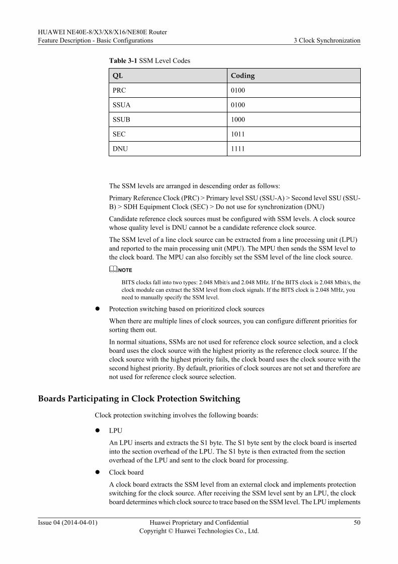
Table 3-1 SSM Level Codes
QL Coding
PRC 0100
SSUA 0100
SSUB 1000
SEC 1011
DNU 1111
The SSM levels are arranged in descending order as follows:
Primary Reference Clock (PRC) > Primary level SSU (SSU-A) > Second level SSU (SSU-B) > SDH Equipment Clock (SEC) > Do not use for synchronization (DNU)
Candidate reference clock sources must be configured with SSM levels. A clock sourcewhose quality level is DNU cannot be a candidate reference clock source.
The SSM level of a line clock source can be extracted from a line processing unit (LPU)and reported to the main processing unit (MPU). The MPU then sends the SSM level tothe clock board. The MPU can also forcibly set the SSM level of the line clock source.
NOTE
BITS clocks fall into two types: 2.048 Mbit/s and 2.048 MHz. If the BITS clock is 2.048 Mbit/s, theclock module can extract the SSM level from clock signals. If the BITS clock is 2.048 MHz, youneed to manually specify the SSM level.
l Protection switching based on prioritized clock sources
When there are multiple lines of clock sources, you can configure different priorities forsorting them out.
In normal situations, SSMs are not used for reference clock source selection, and a clockboard uses the clock source with the highest priority as the reference clock source. If theclock source with the highest priority fails, the clock board uses the clock source with thesecond highest priority. By default, priorities of clock sources are not set and therefore arenot used for reference clock source selection.
Boards Participating in Clock Protection Switching
Clock protection switching involves the following boards:
l LPU
An LPU inserts and extracts the S1 byte. The S1 byte sent by the clock board is insertedinto the section overhead of the LPU. The S1 byte is then extracted from the sectionoverhead of the LPU and sent to the clock board for processing.
l Clock board
A clock board extracts the SSM level from an external clock and implements protectionswitching for the clock source. After receiving the SSM level sent by an LPU, the clockboard determines which clock source to trace based on the SSM level. The LPU implements
HUAWEI NE40E-8/X3/X8/X16/NE80E RouterFeature Description - Basic Configurations 3 Clock Synchronization
Issue 04 (2014-04-01) Huawei Proprietary and ConfidentialCopyright © Huawei Technologies Co., Ltd.
50
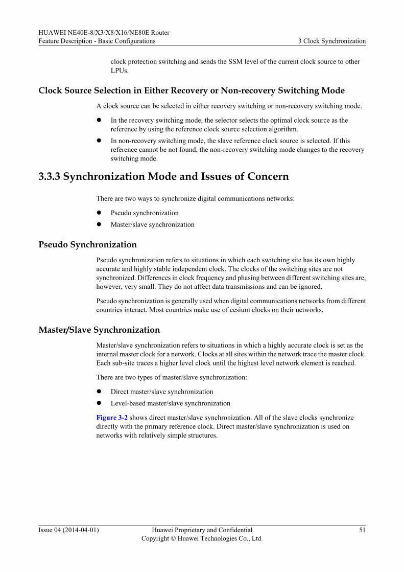
clock protection switching and sends the SSM level of the current clock source to otherLPUs.
Clock Source Selection in Either Recovery or Non-recovery Switching ModeA clock source can be selected in either recovery switching or non-recovery switching mode.
l In the recovery switching mode, the selector selects the optimal clock source as thereference by using the reference clock source selection algorithm.
l In non-recovery switching mode, the slave reference clock source is selected. If thisreference cannot be not found, the non-recovery switching mode changes to the recoveryswitching mode.
3.3.3 Synchronization Mode and Issues of Concern
There are two ways to synchronize digital communications networks:
l Pseudo synchronizationl Master/slave synchronization
Pseudo SynchronizationPseudo synchronization refers to situations in which each switching site has its own highlyaccurate and highly stable independent clock. The clocks of the switching sites are notsynchronized. Differences in clock frequency and phasing between different switching sites are,however, very small. They do not affect data transmissions and can be ignored.
Pseudo synchronization is generally used when digital communications networks from differentcountries interact. Most countries make use of cesium clocks on their networks.
Master/Slave SynchronizationMaster/slave synchronization refers to situations in which a highly accurate clock is set as theinternal master clock for a network. Clocks at all sites within the network trace the master clock.Each sub-site traces a higher level clock until the highest level network element is reached.
There are two types of master/slave synchronization:
l Direct master/slave synchronizationl Level-based master/slave synchronization
Figure 3-2 shows direct master/slave synchronization. All of the slave clocks synchronizedirectly with the primary reference clock. Direct master/slave synchronization is used onnetworks with relatively simple structures.
HUAWEI NE40E-8/X3/X8/X16/NE80E RouterFeature Description - Basic Configurations 3 Clock Synchronization
Issue 04 (2014-04-01) Huawei Proprietary and ConfidentialCopyright © Huawei Technologies Co., Ltd.
51
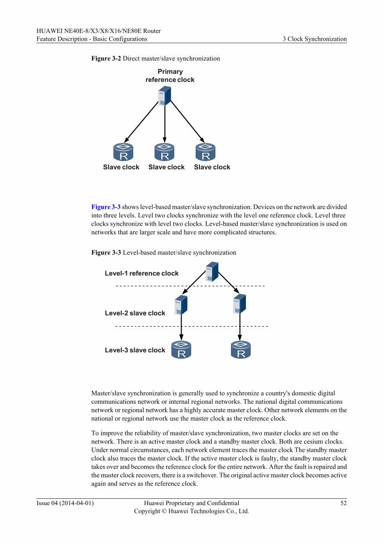
Figure 3-2 Direct master/slave synchronization
Primaryreference clock
Slave clock Slave clock Slave clock
Figure 3-3 shows level-based master/slave synchronization. Devices on the network are dividedinto three levels. Level two clocks synchronize with the level one reference clock. Level threeclocks synchronize with level two clocks. Level-based master/slave synchronization is used onnetworks that are larger scale and have more complicated structures.
Figure 3-3 Level-based master/slave synchronization
Level-1 reference clock
Level-2 slave clock
Level-3 slave clock
Master/slave synchronization is generally used to synchronize a country's domestic digitalcommunications network or internal regional networks. The national digital communicationsnetwork or regional network has a highly accurate master clock. Other network elements on thenational or regional network use the master clock as the reference clock.
To improve the reliability of master/slave synchronization, two master clocks are set on thenetwork. There is an active master clock and a standby master clock. Both are cesium clocks.Under normal circumstances, each network element traces the master clock The standby masterclock also traces the master clock. If the active master clock is faulty, the standby master clocktakes over and becomes the reference clock for the entire network. After the fault is repaired andthe master clock recovers, there is a switchover. The original active master clock becomes activeagain and serves as the reference clock.
HUAWEI NE40E-8/X3/X8/X16/NE80E RouterFeature Description - Basic Configurations 3 Clock Synchronization
Issue 04 (2014-04-01) Huawei Proprietary and ConfidentialCopyright © Huawei Technologies Co., Ltd.
52
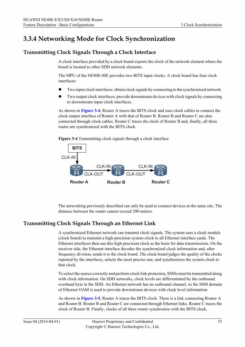
3.3.4 Networking Mode for Clock Synchronization
Transmitting Clock Signals Through a Clock InterfaceA clock interface provided by a clock board exports the clock of the network element where theboard is located to other SDH network elements.
The MPU of the NE80E/40E provides two BITS input clocks. A clock board has four clockinterfaces:
l Two input clock interfaces: obtain clock signals by connecting to the synchronized network.l Two output clock interfaces: provide downstream devices with clock signals by connecting
to downstream input clock interfaces.
As shown in Figure 3-4, Router A traces the BITS clock and uses clock cables to connect theclock output interface of Router A with that of Router B. Router B and Router C are alsoconnected through clock cables. Router C traces the clock of Router B and, finally, all threerouter are synchronized with the BITS clock.
Figure 3-4 Transmitting clock signals through a clock interface
BITS
CLK-IN
CLK-IN
CLK-OUT
CLK-IN
CLK-OUT
Router A Router B Router C
The networking previously described can only be used to connect devices at the same site. Thedistance between the router cannot exceed 200 meters.
Transmitting Clock Signals Through an Ethernet LinkA synchronized Ethernet network can transmit clock signals. The system uses a clock module(clock board) to transmit a high-precision system clock to all Ethernet interface cards. TheEthernet interfaces then use this high-precision clock as the basis for data transmissions. On thereceiver side, the Ethernet interface decodes the synchronized clock information and, afterfrequency division, sends it to the clock board. The clock board judges the quality of the clocksreported by the interfaces, selects the most precise one, and synchronizes the system clock tothat clock.
To select the source correctly and perform clock link protection, SSMs must be transmitted alongwith clock information. On SDH networks, clock levels are differentiated by the outboundoverhead byte in the SDH. An Ethernet network has no outbound channel, so the SSM domainof Ethernet OAM is used to provide downstream devices with clock level information.
As shown in Figure 3-5, Router A traces the BITS clock. There is a link connecting Router Aand Router B. Router B and Router C are connected through Ethernet links. Router C traces theclock of Router B. Finally, clocks of all three router synchronize with the BITS clock.
HUAWEI NE40E-8/X3/X8/X16/NE80E RouterFeature Description - Basic Configurations 3 Clock Synchronization
Issue 04 (2014-04-01) Huawei Proprietary and ConfidentialCopyright © Huawei Technologies Co., Ltd.
53
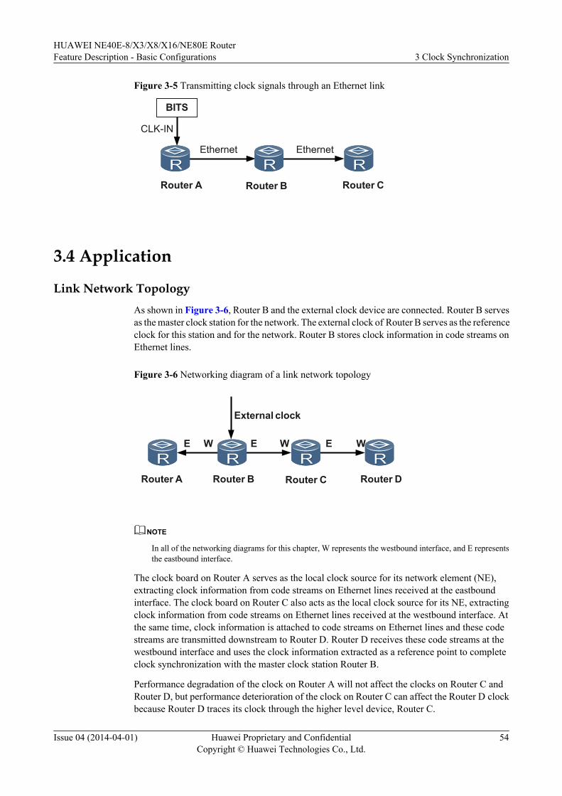
Figure 3-5 Transmitting clock signals through an Ethernet link
BITS
CLK-IN
Ethernet Ethernet
Router A Router B Router C
3.4 Application
Link Network TopologyAs shown in Figure 3-6, Router B and the external clock device are connected. Router B servesas the master clock station for the network. The external clock of Router B serves as the referenceclock for this station and for the network. Router B stores clock information in code streams onEthernet lines.
Figure 3-6 Networking diagram of a link network topology
Router A Router B Router C Router D
External clock
E W E W E W
NOTE
In all of the networking diagrams for this chapter, W represents the westbound interface, and E representsthe eastbound interface.
The clock board on Router A serves as the local clock source for its network element (NE),extracting clock information from code streams on Ethernet lines received at the eastboundinterface. The clock board on Router C also acts as the local clock source for its NE, extractingclock information from code streams on Ethernet lines received at the westbound interface. Atthe same time, clock information is attached to code streams on Ethernet lines and these codestreams are transmitted downstream to Router D. Router D receives these code streams at thewestbound interface and uses the clock information extracted as a reference point to completeclock synchronization with the master clock station Router B.
Performance degradation of the clock on Router A will not affect the clocks on Router C andRouter D, but performance deterioration of the clock on Router C can affect the Router D clockbecause Router D traces its clock through the higher level device, Router C.
HUAWEI NE40E-8/X3/X8/X16/NE80E RouterFeature Description - Basic Configurations 3 Clock Synchronization
Issue 04 (2014-04-01) Huawei Proprietary and ConfidentialCopyright © Huawei Technologies Co., Ltd.
54
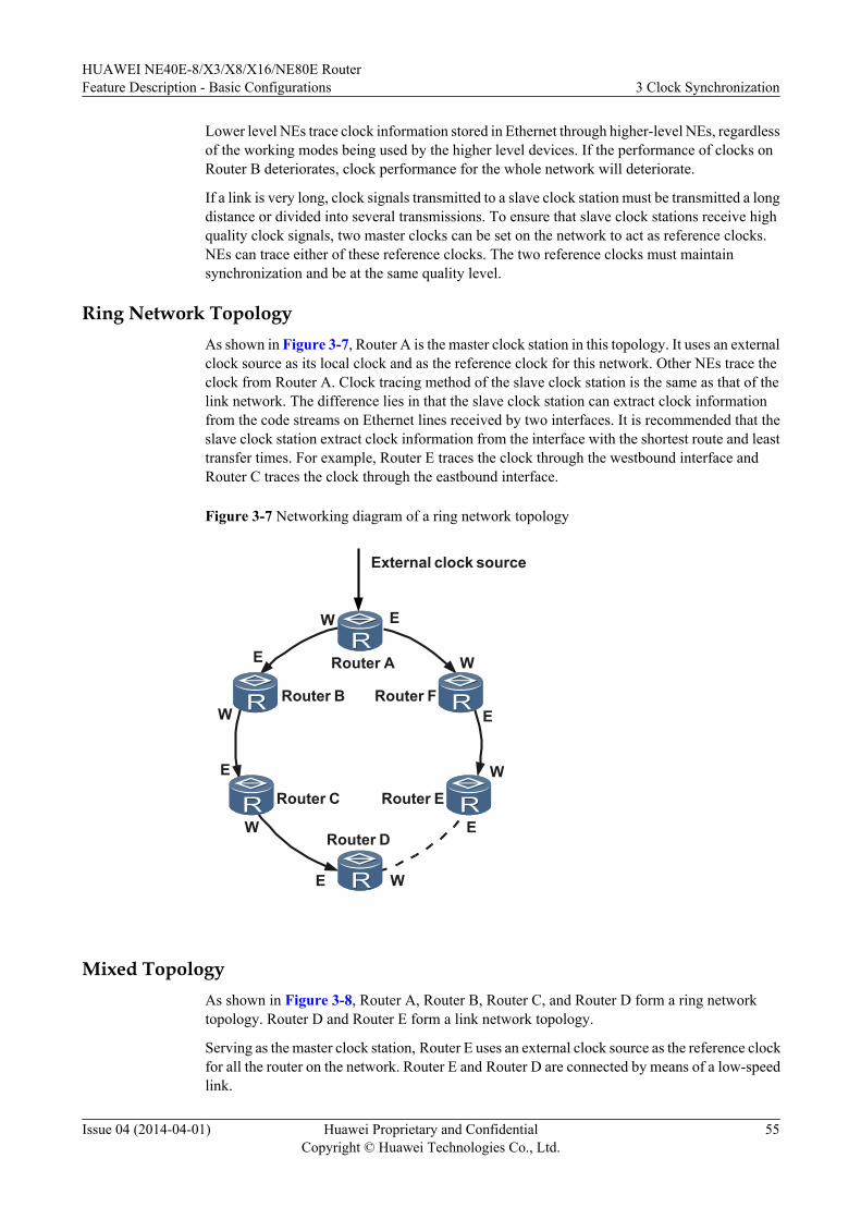
Lower level NEs trace clock information stored in Ethernet through higher-level NEs, regardlessof the working modes being used by the higher level devices. If the performance of clocks onRouter B deteriorates, clock performance for the whole network will deteriorate.
If a link is very long, clock signals transmitted to a slave clock station must be transmitted a longdistance or divided into several transmissions. To ensure that slave clock stations receive highquality clock signals, two master clocks can be set on the network to act as reference clocks.NEs can trace either of these reference clocks. The two reference clocks must maintainsynchronization and be at the same quality level.
Ring Network TopologyAs shown in Figure 3-7, Router A is the master clock station in this topology. It uses an externalclock source as its local clock and as the reference clock for this network. Other NEs trace theclock from Router A. Clock tracing method of the slave clock station is the same as that of thelink network. The difference lies in that the slave clock station can extract clock informationfrom the code streams on Ethernet lines received by two interfaces. It is recommended that theslave clock station extract clock information from the interface with the shortest route and leasttransfer times. For example, Router E traces the clock through the westbound interface andRouter C traces the clock through the eastbound interface.
Figure 3-7 Networking diagram of a ring network topology
W
E
W
E
W
E
W
E
W
E
W
E
Router A
Router B Router F
Router C
Router D
Router E
External clock source
Mixed TopologyAs shown in Figure 3-8, Router A, Router B, Router C, and Router D form a ring networktopology. Router D and Router E form a link network topology.
Serving as the master clock station, Router E uses an external clock source as the reference clockfor all the router on the network. Router E and Router D are connected by means of a low-speedlink.
HUAWEI NE40E-8/X3/X8/X16/NE80E RouterFeature Description - Basic Configurations 3 Clock Synchronization
Issue 04 (2014-04-01) Huawei Proprietary and ConfidentialCopyright © Huawei Technologies Co., Ltd.
55
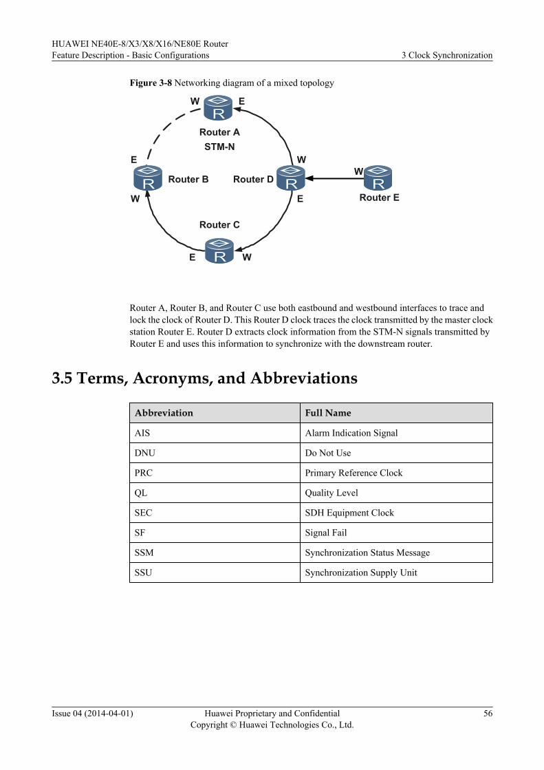
Figure 3-8 Networking diagram of a mixed topology
W
W
E
W
E
W
E
W
E
Router A
Router B Router D
Router C
Router E
STM-N
Router A, Router B, and Router C use both eastbound and westbound interfaces to trace andlock the clock of Router D. This Router D clock traces the clock transmitted by the master clockstation Router E. Router D extracts clock information from the STM-N signals transmitted byRouter E and uses this information to synchronize with the downstream router.
3.5 Terms, Acronyms, and Abbreviations
Abbreviation Full Name
AIS Alarm Indication Signal
DNU Do Not Use
PRC Primary Reference Clock
QL Quality Level
SEC SDH Equipment Clock
SF Signal Fail
SSM Synchronization Status Message
SSU Synchronization Supply Unit
HUAWEI NE40E-8/X3/X8/X16/NE80E RouterFeature Description - Basic Configurations 3 Clock Synchronization
Issue 04 (2014-04-01) Huawei Proprietary and ConfidentialCopyright © Huawei Technologies Co., Ltd.
56
4 1588 ACR
About This Chapter
4.1 Introduction to 1588 ACR
4.2 References
4.3 Enhancement
4.4 Principles
4.5 Applications
4.6 Terms and Abbreviations
HUAWEI NE40E-8/X3/X8/X16/NE80E RouterFeature Description - Basic Configurations 4 1588 ACR
Issue 04 (2014-04-01) Huawei Proprietary and ConfidentialCopyright © Huawei Technologies Co., Ltd.
57
4.1 Introduction to 1588 ACR
Definition
The 1588 adaptive clock recovery (ACR) algorithm is used to carry out clock (frequency)synchronization between the router and clock servers by exchanging 1588v2 messages over aclock link that is set up by sending Layer 3 unicast packets.
Unlike 1588v2 that achieves frequency synchronization only when all devices on a networksupport 1588v2, 1588 ACR is capable of implementing frequency synchronization on a networkwith both 1588v2-aware devices and 1588v2-unaware devices.
After 1588 ACR is enabled on a server, the server provides 1588 ACR frequency synchronizationservices for clients.
Purpose
All-IP has become the trend for future networks and services. Therefore, traditional networksbased on the Synchronous Digital Hierarchy (SDH) have to overcome various constraints beforemigrating to IP packet-switched networks. Transmitting Time Division Multiplexing (TDM)services over IP networks presents a major technological challenge. TDM services are classifiedinto two types: voice services and clock synchronization services. With the development ofVoIP, technologies of transmitting voice services over an IP network have become mature andhave been extensively used. However, development of technologies of transmitting clocksynchronization services over an IP network is still under way.
1588v2 is a software-based technology that carries out time and frequency synchronization. Toachieve higher accuracy, 1588v2 requires that all devices on a network support 1588v2; if not,frequency synchronization cannot be achieved.
Derived from 1588v2, 1588 ACR implements frequency synchronization with clock servers ona network with both 1588v2-aware devices and 1588v2-unaware devices. Therefore, in thesituation where only frequency synchronization is required, 1588 ACR is more applicable than1588v2.
Benefits
This feature brings the following benefits to operators:
l Frequency synchronization can be achieved on networks with both 1588v2-aware and1588v2-unaware devices, reducing the costs of network construction.
l Operators can provide more services that can meet subscribers' requirements for frequencysynchronization.
4.2 ReferencesThe following table lists the references.
HUAWEI NE40E-8/X3/X8/X16/NE80E RouterFeature Description - Basic Configurations 4 1588 ACR
Issue 04 (2014-04-01) Huawei Proprietary and ConfidentialCopyright © Huawei Technologies Co., Ltd.
58
Document Description Protocol Compliance
ITU-T G.813 TimingCharacteristics ofSDH EquipmentSlave Clocks (1996)
Fully compliant
ITU-T G.781 SynchronizationLayer Function
Fully compliant
ITU-T G.8264 Distribution ofTiming ThroughPacket Networks
Fully compliant
ITU-T G.823 Control of Jitter andWander WithinDigital NetworksWhich Are Based onthe 2048 kbit/sHierarchy
Fully compliant
ITU-T G.8261 Timing andSynchronizationAspects in PacketNetworks
Fully compliant
ITU-T G.8262 TimingCharacteristics ofSynchronousEthernet EquipmentSlave Clock
Fully compliant
ITU-T G.8265.1 Precision TimeProtocol TelecomProfile for FrequencySynchronization
Fully compliant
IEEE 1588 V2 Precision ClockSynchronizationProtocol forNetworkedMeasurement andControl Systems
Fully compliant
4.3 EnhancementNone.
4.4 Principles
HUAWEI NE40E-8/X3/X8/X16/NE80E RouterFeature Description - Basic Configurations 4 1588 ACR
Issue 04 (2014-04-01) Huawei Proprietary and ConfidentialCopyright © Huawei Technologies Co., Ltd.
59
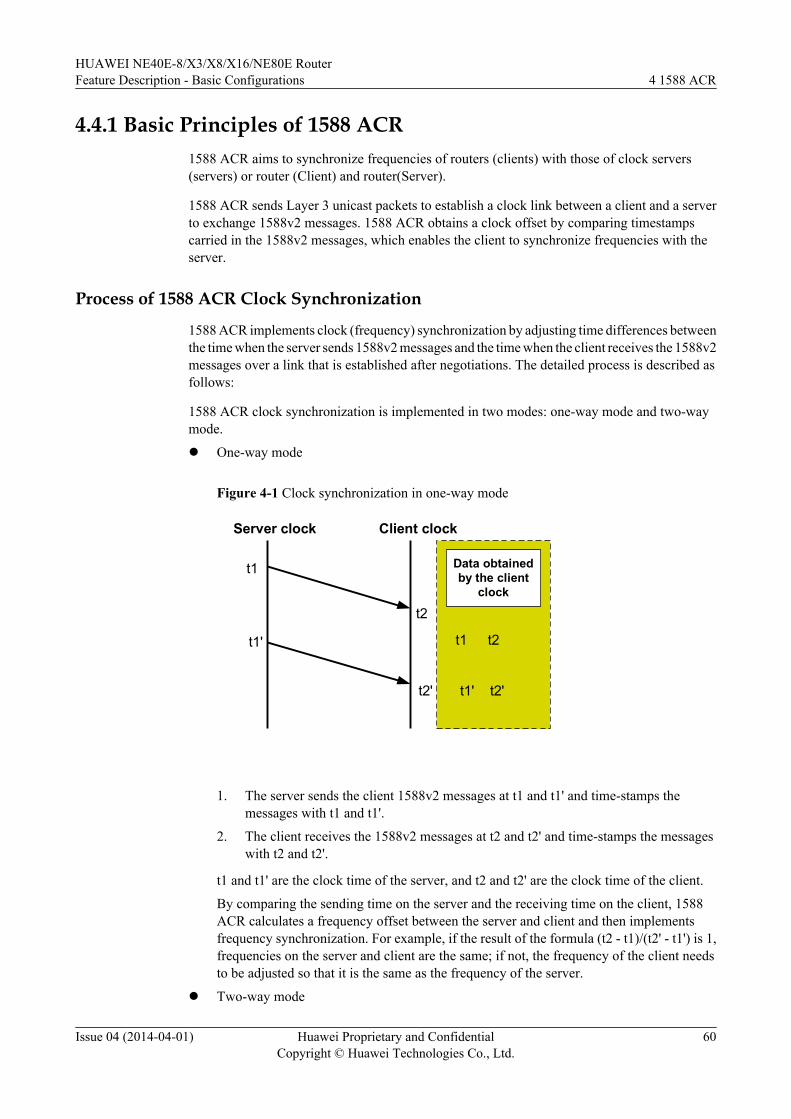
4.4.1 Basic Principles of 1588 ACR1588 ACR aims to synchronize frequencies of routers (clients) with those of clock servers(servers) or router (Client) and router(Server).
1588 ACR sends Layer 3 unicast packets to establish a clock link between a client and a serverto exchange 1588v2 messages. 1588 ACR obtains a clock offset by comparing timestampscarried in the 1588v2 messages, which enables the client to synchronize frequencies with theserver.
Process of 1588 ACR Clock Synchronization
1588 ACR implements clock (frequency) synchronization by adjusting time differences betweenthe time when the server sends 1588v2 messages and the time when the client receives the 1588v2messages over a link that is established after negotiations. The detailed process is described asfollows:
1588 ACR clock synchronization is implemented in two modes: one-way mode and two-waymode.
l One-way mode
Figure 4-1 Clock synchronization in one-way mode
Server clock Client clock
t1
t1'
t2
t2'
Data obtainedby the client
clock
t1 t2
t1' t2'
1. The server sends the client 1588v2 messages at t1 and t1' and time-stamps themessages with t1 and t1'.
2. The client receives the 1588v2 messages at t2 and t2' and time-stamps the messageswith t2 and t2'.
t1 and t1' are the clock time of the server, and t2 and t2' are the clock time of the client.
By comparing the sending time on the server and the receiving time on the client, 1588ACR calculates a frequency offset between the server and client and then implementsfrequency synchronization. For example, if the result of the formula (t2 - t1)/(t2' - t1') is 1,frequencies on the server and client are the same; if not, the frequency of the client needsto be adjusted so that it is the same as the frequency of the server.
l Two-way mode
HUAWEI NE40E-8/X3/X8/X16/NE80E RouterFeature Description - Basic Configurations 4 1588 ACR
Issue 04 (2014-04-01) Huawei Proprietary and ConfidentialCopyright © Huawei Technologies Co., Ltd.
60
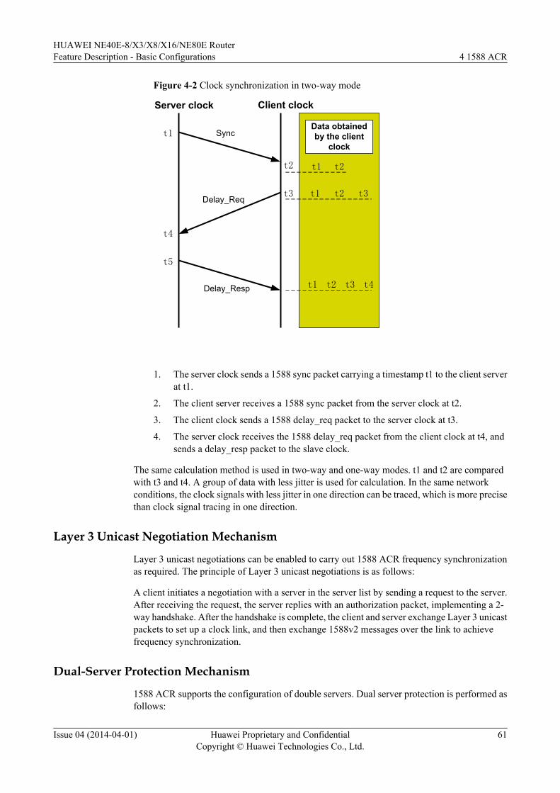
Figure 4-2 Clock synchronization in two-way mode
Server clock Client clock
t1
t4
t2
t3
Data obtained by the client
clock
t1 t2
t1 t2
t5
Sync
Delay_Req
Delay_Resp
t3
t1 t2 t3 t4
1. The server clock sends a 1588 sync packet carrying a timestamp t1 to the client serverat t1.
2. The client server receives a 1588 sync packet from the server clock at t2.
3. The client clock sends a 1588 delay_req packet to the server clock at t3.
4. The server clock receives the 1588 delay_req packet from the client clock at t4, andsends a delay_resp packet to the slave clock.
The same calculation method is used in two-way and one-way modes. t1 and t2 are comparedwith t3 and t4. A group of data with less jitter is used for calculation. In the same networkconditions, the clock signals with less jitter in one direction can be traced, which is more precisethan clock signal tracing in one direction.
Layer 3 Unicast Negotiation Mechanism
Layer 3 unicast negotiations can be enabled to carry out 1588 ACR frequency synchronizationas required. The principle of Layer 3 unicast negotiations is as follows:
A client initiates a negotiation with a server in the server list by sending a request to the server.After receiving the request, the server replies with an authorization packet, implementing a 2-way handshake. After the handshake is complete, the client and server exchange Layer 3 unicastpackets to set up a clock link, and then exchange 1588v2 messages over the link to achievefrequency synchronization.
Dual-Server Protection Mechanism
1588 ACR supports the configuration of double servers. Dual server protection is performed asfollows:
HUAWEI NE40E-8/X3/X8/X16/NE80E RouterFeature Description - Basic Configurations 4 1588 ACR
Issue 04 (2014-04-01) Huawei Proprietary and ConfidentialCopyright © Huawei Technologies Co., Ltd.
61
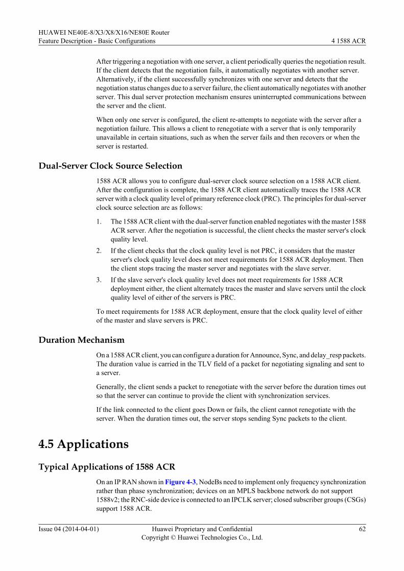
After triggering a negotiation with one server, a client periodically queries the negotiation result.If the client detects that the negotiation fails, it automatically negotiates with another server.Alternatively, if the client successfully synchronizes with one server and detects that thenegotiation status changes due to a server failure, the client automatically negotiates with anotherserver. This dual server protection mechanism ensures uninterrupted communications betweenthe server and the client.
When only one server is configured, the client re-attempts to negotiate with the server after anegotiation failure. This allows a client to renegotiate with a server that is only temporarilyunavailable in certain situations, such as when the server fails and then recovers or when theserver is restarted.
Dual-Server Clock Source Selection1588 ACR allows you to configure dual-server clock source selection on a 1588 ACR client.After the configuration is complete, the 1588 ACR client automatically traces the 1588 ACRserver with a clock quality level of primary reference clock (PRC). The principles for dual-serverclock source selection are as follows:
1. The 1588 ACR client with the dual-server function enabled negotiates with the master 1588ACR server. After the negotiation is successful, the client checks the master server's clockquality level.
2. If the client checks that the clock quality level is not PRC, it considers that the masterserver's clock quality level does not meet requirements for 1588 ACR deployment. Thenthe client stops tracing the master server and negotiates with the slave server.
3. If the slave server's clock quality level does not meet requirements for 1588 ACRdeployment either, the client alternately traces the master and slave servers until the clockquality level of either of the servers is PRC.
To meet requirements for 1588 ACR deployment, ensure that the clock quality level of eitherof the master and slave servers is PRC.
Duration MechanismOn a 1588 ACR client, you can configure a duration for Announce, Sync, and delay_resp packets.The duration value is carried in the TLV field of a packet for negotiating signaling and sent toa server.
Generally, the client sends a packet to renegotiate with the server before the duration times outso that the server can continue to provide the client with synchronization services.
If the link connected to the client goes Down or fails, the client cannot renegotiate with theserver. When the duration times out, the server stops sending Sync packets to the client.
4.5 Applications
Typical Applications of 1588 ACROn an IP RAN shown in Figure 4-3, NodeBs need to implement only frequency synchronizationrather than phase synchronization; devices on an MPLS backbone network do not support1588v2; the RNC-side device is connected to an IPCLK server; closed subscriber groups (CSGs)support 1588 ACR.
HUAWEI NE40E-8/X3/X8/X16/NE80E RouterFeature Description - Basic Configurations 4 1588 ACR
Issue 04 (2014-04-01) Huawei Proprietary and ConfidentialCopyright © Huawei Technologies Co., Ltd.
62
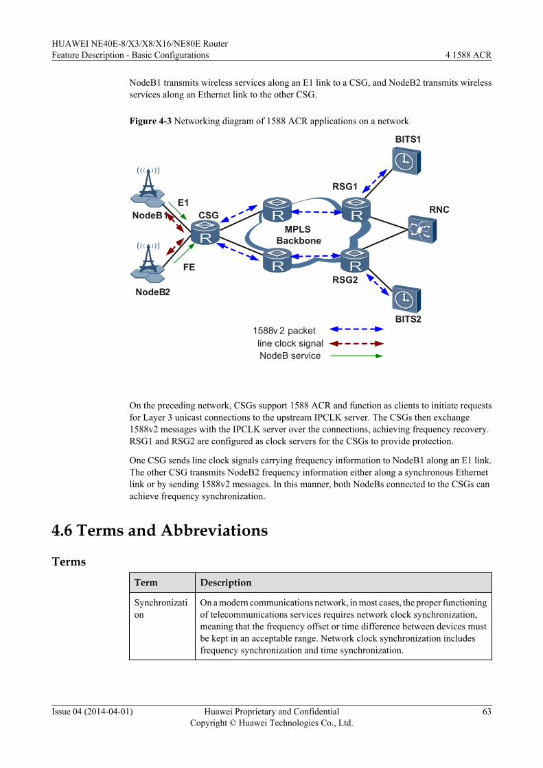
NodeB1 transmits wireless services along an E1 link to a CSG, and NodeB2 transmits wirelessservices along an Ethernet link to the other CSG.
Figure 4-3 Networking diagram of 1588 ACR applications on a network
NodeB1
NodeB2
RNC
BITS1
MPLSBackbone
E1
FE
1588v 2 packetline clock signalNodeB service
CSG
BITS2
RSG1
RSG2
On the preceding network, CSGs support 1588 ACR and function as clients to initiate requestsfor Layer 3 unicast connections to the upstream IPCLK server. The CSGs then exchange1588v2 messages with the IPCLK server over the connections, achieving frequency recovery.RSG1 and RSG2 are configured as clock servers for the CSGs to provide protection.
One CSG sends line clock signals carrying frequency information to NodeB1 along an E1 link.The other CSG transmits NodeB2 frequency information either along a synchronous Ethernetlink or by sending 1588v2 messages. In this manner, both NodeBs connected to the CSGs canachieve frequency synchronization.
4.6 Terms and Abbreviations
Terms
Term Description
Synchronization
On a modern communications network, in most cases, the proper functioningof telecommunications services requires network clock synchronization,meaning that the frequency offset or time difference between devices mustbe kept in an acceptable range. Network clock synchronization includesfrequency synchronization and time synchronization.
HUAWEI NE40E-8/X3/X8/X16/NE80E RouterFeature Description - Basic Configurations 4 1588 ACR
Issue 04 (2014-04-01) Huawei Proprietary and ConfidentialCopyright © Huawei Technologies Co., Ltd.
63
Term Description
Timesynchronization
Time synchronization, also called phase synchronization, refers to theconsistency of both frequencies and phases between signals. This means thatthe phase offset between signals is always 0.
Frequencysynchronization
Frequency synchronization, also called clock synchronization, refers to astrict relationship between signals based on a constant frequency offset or aconstant phase offset, in which signals are sent or received at the sameaverage rate in a valid instance. In this manner, all devices on thecommunications network operate at the same rate. That is, the phasedifference between signals remains a fixed value.
IEEE 1588v2PTP
1588v2, defined by the Institute of Electrical and Electronics Engineers(IEEE), is a standard for Precision Clock Synchronization Protocol forNetworked Measurement and Control Systems. The Precision TimeProtocol (PTP) is used for short.
Abbreviations
Abbreviation Full Spelling
PTP1588v2
Precision Time Protocol
BITS Building Integrated Time Supply System
BMC Best Master Clock
ACR Adaptive Clock Recovery
HUAWEI NE40E-8/X3/X8/X16/NE80E RouterFeature Description - Basic Configurations 4 1588 ACR
Issue 04 (2014-04-01) Huawei Proprietary and ConfidentialCopyright © Huawei Technologies Co., Ltd.
64
5 1588v2
About This Chapter
5.1 Introduction to 1588v2
5.2 References
5.3 Principles
5.4 Application Environment
5.5 Terms and Abbreviations
HUAWEI NE40E-8/X3/X8/X16/NE80E RouterFeature Description - Basic Configurations 5 1588v2
Issue 04 (2014-04-01) Huawei Proprietary and ConfidentialCopyright © Huawei Technologies Co., Ltd.
65
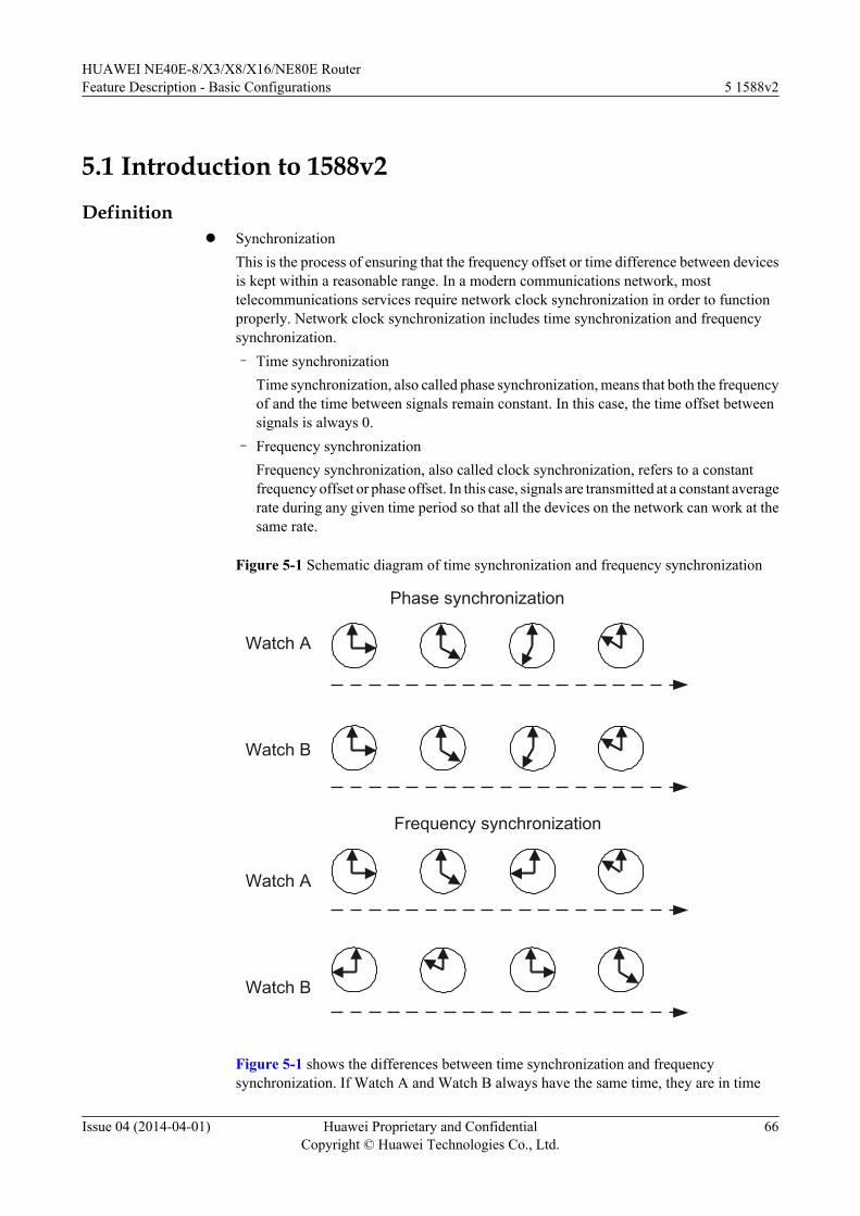
5.1 Introduction to 1588v2Definition
l SynchronizationThis is the process of ensuring that the frequency offset or time difference between devicesis kept within a reasonable range. In a modern communications network, mosttelecommunications services require network clock synchronization in order to functionproperly. Network clock synchronization includes time synchronization and frequencysynchronization.– Time synchronization
Time synchronization, also called phase synchronization, means that both the frequencyof and the time between signals remain constant. In this case, the time offset betweensignals is always 0.
– Frequency synchronizationFrequency synchronization, also called clock synchronization, refers to a constantfrequency offset or phase offset. In this case, signals are transmitted at a constant averagerate during any given time period so that all the devices on the network can work at thesame rate.
Figure 5-1 Schematic diagram of time synchronization and frequency synchronization
Phase synchronization
Watch A
Watch B
Frequency synchronization
Watch A
Watch B
Figure 5-1 shows the differences between time synchronization and frequencysynchronization. If Watch A and Watch B always have the same time, they are in time
HUAWEI NE40E-8/X3/X8/X16/NE80E RouterFeature Description - Basic Configurations 5 1588v2
Issue 04 (2014-04-01) Huawei Proprietary and ConfidentialCopyright © Huawei Technologies Co., Ltd.
66
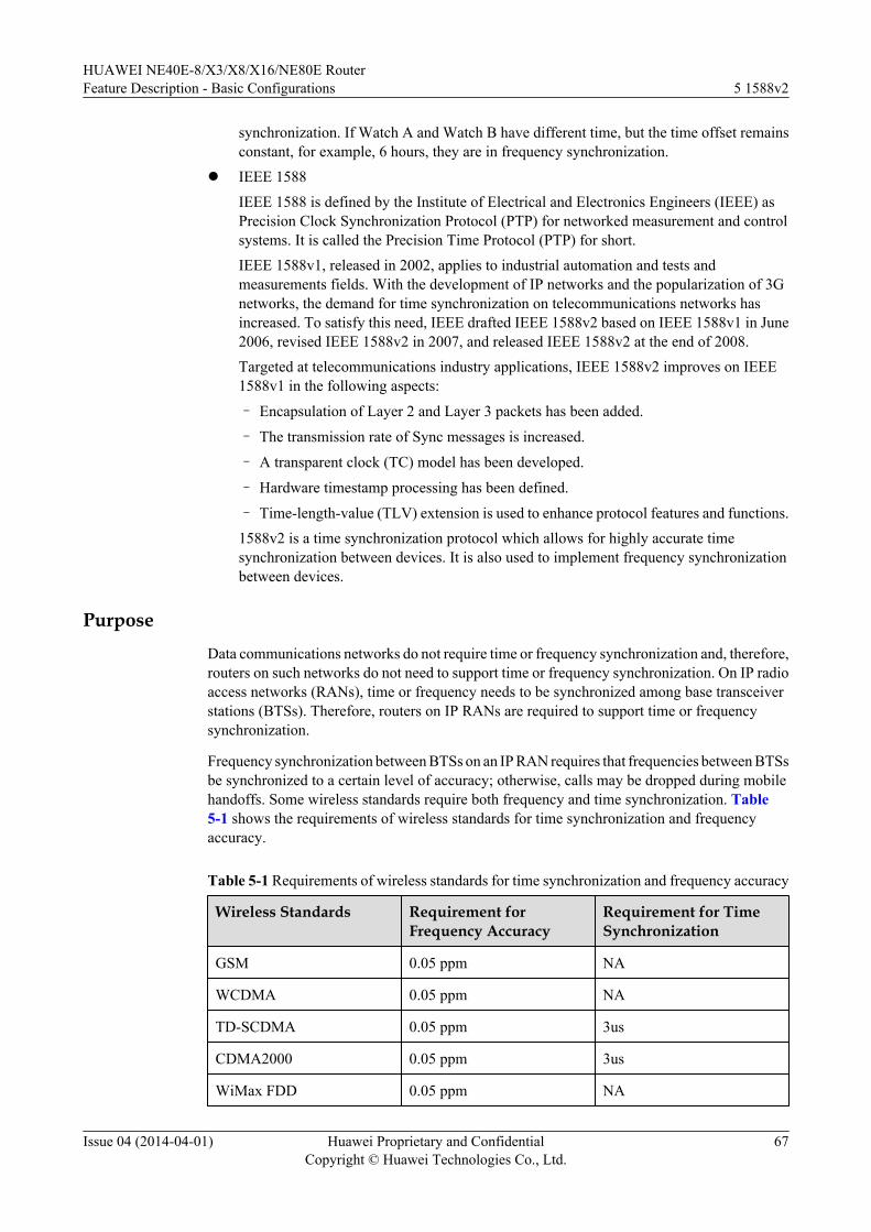
synchronization. If Watch A and Watch B have different time, but the time offset remainsconstant, for example, 6 hours, they are in frequency synchronization.
l IEEE 1588IEEE 1588 is defined by the Institute of Electrical and Electronics Engineers (IEEE) asPrecision Clock Synchronization Protocol (PTP) for networked measurement and controlsystems. It is called the Precision Time Protocol (PTP) for short.IEEE 1588v1, released in 2002, applies to industrial automation and tests andmeasurements fields. With the development of IP networks and the popularization of 3Gnetworks, the demand for time synchronization on telecommunications networks hasincreased. To satisfy this need, IEEE drafted IEEE 1588v2 based on IEEE 1588v1 in June2006, revised IEEE 1588v2 in 2007, and released IEEE 1588v2 at the end of 2008.Targeted at telecommunications industry applications, IEEE 1588v2 improves on IEEE1588v1 in the following aspects:
– Encapsulation of Layer 2 and Layer 3 packets has been added.
– The transmission rate of Sync messages is increased.
– A transparent clock (TC) model has been developed.
– Hardware timestamp processing has been defined.
– Time-length-value (TLV) extension is used to enhance protocol features and functions.1588v2 is a time synchronization protocol which allows for highly accurate timesynchronization between devices. It is also used to implement frequency synchronizationbetween devices.
PurposeData communications networks do not require time or frequency synchronization and, therefore,routers on such networks do not need to support time or frequency synchronization. On IP radioaccess networks (RANs), time or frequency needs to be synchronized among base transceiverstations (BTSs). Therefore, routers on IP RANs are required to support time or frequencysynchronization.
Frequency synchronization between BTSs on an IP RAN requires that frequencies between BTSsbe synchronized to a certain level of accuracy; otherwise, calls may be dropped during mobilehandoffs. Some wireless standards require both frequency and time synchronization. Table5-1 shows the requirements of wireless standards for time synchronization and frequencyaccuracy.
Table 5-1 Requirements of wireless standards for time synchronization and frequency accuracy
Wireless Standards Requirement forFrequency Accuracy
Requirement for TimeSynchronization
GSM 0.05 ppm NA
WCDMA 0.05 ppm NA
TD-SCDMA 0.05 ppm 3us
CDMA2000 0.05 ppm 3us
WiMax FDD 0.05 ppm NA
HUAWEI NE40E-8/X3/X8/X16/NE80E RouterFeature Description - Basic Configurations 5 1588v2
Issue 04 (2014-04-01) Huawei Proprietary and ConfidentialCopyright © Huawei Technologies Co., Ltd.
67
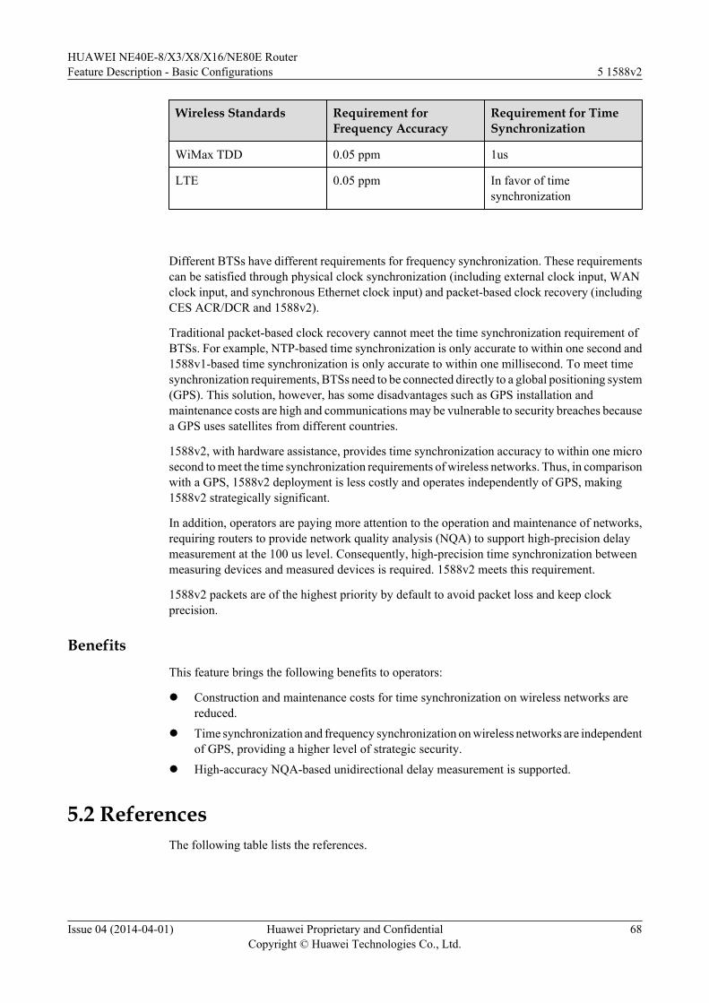
Wireless Standards Requirement forFrequency Accuracy
Requirement for TimeSynchronization
WiMax TDD 0.05 ppm 1us
LTE 0.05 ppm In favor of timesynchronization
Different BTSs have different requirements for frequency synchronization. These requirementscan be satisfied through physical clock synchronization (including external clock input, WANclock input, and synchronous Ethernet clock input) and packet-based clock recovery (includingCES ACR/DCR and 1588v2).
Traditional packet-based clock recovery cannot meet the time synchronization requirement ofBTSs. For example, NTP-based time synchronization is only accurate to within one second and1588v1-based time synchronization is only accurate to within one millisecond. To meet timesynchronization requirements, BTSs need to be connected directly to a global positioning system(GPS). This solution, however, has some disadvantages such as GPS installation andmaintenance costs are high and communications may be vulnerable to security breaches becausea GPS uses satellites from different countries.
1588v2, with hardware assistance, provides time synchronization accuracy to within one microsecond to meet the time synchronization requirements of wireless networks. Thus, in comparisonwith a GPS, 1588v2 deployment is less costly and operates independently of GPS, making1588v2 strategically significant.
In addition, operators are paying more attention to the operation and maintenance of networks,requiring routers to provide network quality analysis (NQA) to support high-precision delaymeasurement at the 100 us level. Consequently, high-precision time synchronization betweenmeasuring devices and measured devices is required. 1588v2 meets this requirement.
1588v2 packets are of the highest priority by default to avoid packet loss and keep clockprecision.
BenefitsThis feature brings the following benefits to operators:
l Construction and maintenance costs for time synchronization on wireless networks arereduced.
l Time synchronization and frequency synchronization on wireless networks are independentof GPS, providing a higher level of strategic security.
l High-accuracy NQA-based unidirectional delay measurement is supported.
5.2 ReferencesThe following table lists the references.
HUAWEI NE40E-8/X3/X8/X16/NE80E RouterFeature Description - Basic Configurations 5 1588v2
Issue 04 (2014-04-01) Huawei Proprietary and ConfidentialCopyright © Huawei Technologies Co., Ltd.
68
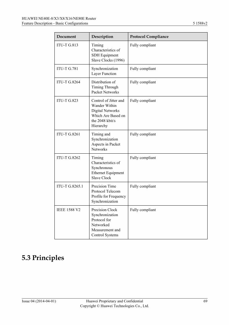
Document Description Protocol Compliance
ITU-T G.813 TimingCharacteristics ofSDH EquipmentSlave Clocks (1996)
Fully compliant
ITU-T G.781 SynchronizationLayer Function
Fully compliant
ITU-T G.8264 Distribution ofTiming ThroughPacket Networks
Fully compliant
ITU-T G.823 Control of Jitter andWander WithinDigital NetworksWhich Are Based onthe 2048 kbit/sHierarchy
Fully compliant
ITU-T G.8261 Timing andSynchronizationAspects in PacketNetworks
Fully compliant
ITU-T G.8262 TimingCharacteristics ofSynchronousEthernet EquipmentSlave Clock
Fully compliant
ITU-T G.8265.1 Precision TimeProtocol TelecomProfile for FrequencySynchronization
Fully compliant
IEEE 1588 V2 Precision ClockSynchronizationProtocol forNetworkedMeasurement andControl Systems
Fully compliant
5.3 Principles
HUAWEI NE40E-8/X3/X8/X16/NE80E RouterFeature Description - Basic Configurations 5 1588v2
Issue 04 (2014-04-01) Huawei Proprietary and ConfidentialCopyright © Huawei Technologies Co., Ltd.
69
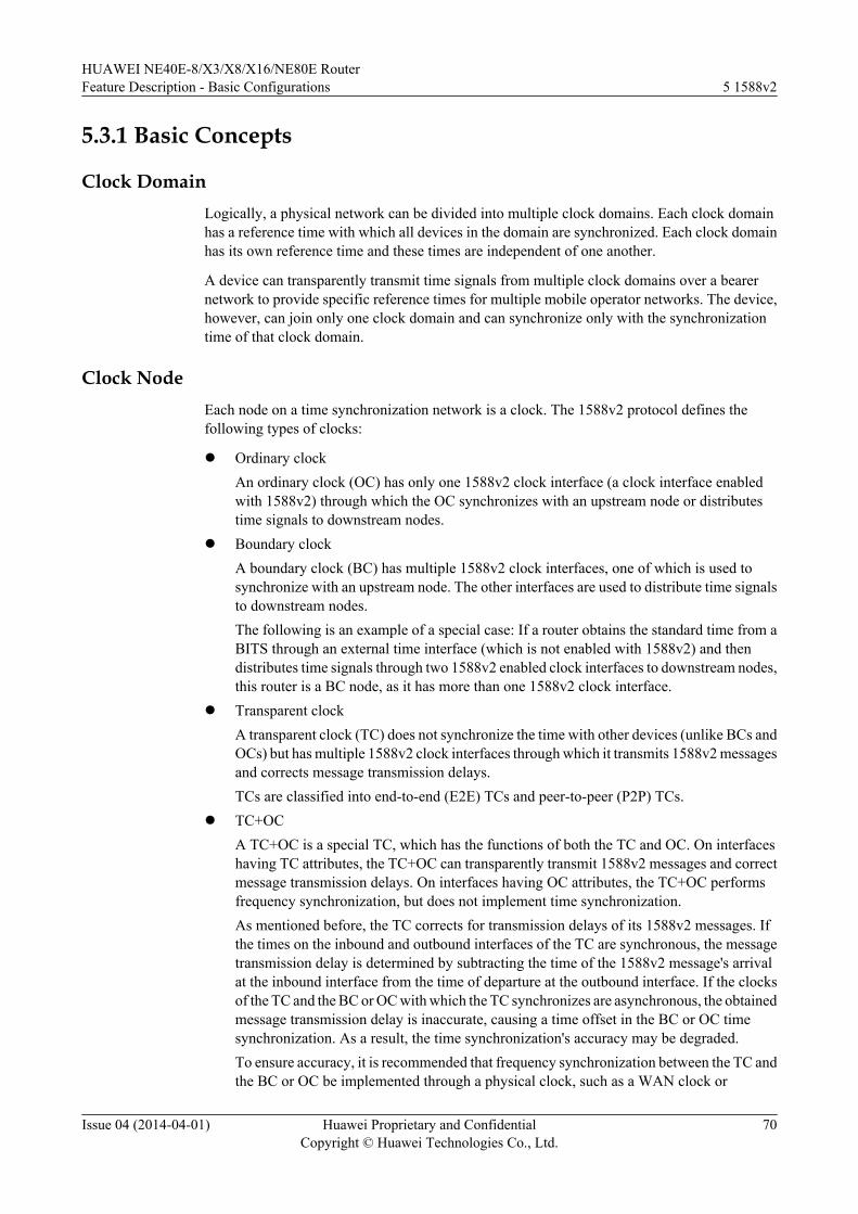
5.3.1 Basic Concepts
Clock DomainLogically, a physical network can be divided into multiple clock domains. Each clock domainhas a reference time with which all devices in the domain are synchronized. Each clock domainhas its own reference time and these times are independent of one another.
A device can transparently transmit time signals from multiple clock domains over a bearernetwork to provide specific reference times for multiple mobile operator networks. The device,however, can join only one clock domain and can synchronize only with the synchronizationtime of that clock domain.
Clock NodeEach node on a time synchronization network is a clock. The 1588v2 protocol defines thefollowing types of clocks:
l Ordinary clockAn ordinary clock (OC) has only one 1588v2 clock interface (a clock interface enabledwith 1588v2) through which the OC synchronizes with an upstream node or distributestime signals to downstream nodes.
l Boundary clockA boundary clock (BC) has multiple 1588v2 clock interfaces, one of which is used tosynchronize with an upstream node. The other interfaces are used to distribute time signalsto downstream nodes.The following is an example of a special case: If a router obtains the standard time from aBITS through an external time interface (which is not enabled with 1588v2) and thendistributes time signals through two 1588v2 enabled clock interfaces to downstream nodes,this router is a BC node, as it has more than one 1588v2 clock interface.
l Transparent clockA transparent clock (TC) does not synchronize the time with other devices (unlike BCs andOCs) but has multiple 1588v2 clock interfaces through which it transmits 1588v2 messagesand corrects message transmission delays.TCs are classified into end-to-end (E2E) TCs and peer-to-peer (P2P) TCs.
l TC+OCA TC+OC is a special TC, which has the functions of both the TC and OC. On interfaceshaving TC attributes, the TC+OC can transparently transmit 1588v2 messages and correctmessage transmission delays. On interfaces having OC attributes, the TC+OC performsfrequency synchronization, but does not implement time synchronization.As mentioned before, the TC corrects for transmission delays of its 1588v2 messages. Ifthe times on the inbound and outbound interfaces of the TC are synchronous, the messagetransmission delay is determined by subtracting the time of the 1588v2 message's arrivalat the inbound interface from the time of departure at the outbound interface. If the clocksof the TC and the BC or OC with which the TC synchronizes are asynchronous, the obtainedmessage transmission delay is inaccurate, causing a time offset in the BC or OC timesynchronization. As a result, the time synchronization's accuracy may be degraded.To ensure accuracy, it is recommended that frequency synchronization between the TC andthe BC or OC be implemented through a physical clock, such as a WAN clock or
HUAWEI NE40E-8/X3/X8/X16/NE80E RouterFeature Description - Basic Configurations 5 1588v2
Issue 04 (2014-04-01) Huawei Proprietary and ConfidentialCopyright © Huawei Technologies Co., Ltd.
70
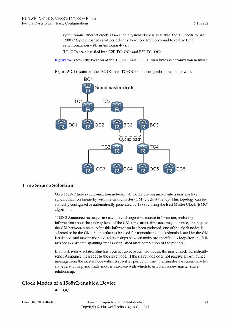
synchronous Ethernet clock. If no such physical clock is available, the TC needs to use1588v2 Sync messages sent periodically to restore frequency and to realize timesynchronization with an upstream device.TC+OCs are classified into E2E TC+OCs and P2P TC+OCs.
Figure 5-2 shows the location of the TC, OC, and TC+OC on a time synchronization network.
Figure 5-2 Location of the TC, OC, and TC+OC on a time synchronization network
BC1
Grandmaster clock
TC1 TC2
BC2OC2OC1
TC3
BC3
TC4
OC6OC5OC4OC3
Cyclic path
Time Source Selection
On a 1588v2 time synchronization network, all clocks are organized into a master-slavesynchronization hierarchy with the Grandmaster (GM) clock at the top. This topology can bestatically configured or automatically generated by 1588v2 using the Best Master Clock (BMC)algorithm.
1588v2 Announce messages are used to exchange time source information, includinginformation about the priority level of the GM, time strata, time accuracy, distance, and hops tothe GM between clocks. After this information has been gathered, one of the clock nodes isselected to be the GM, the interface to be used for transmitting clock signals issued by the GMis selected, and master and slave relationships between nodes are specified. A loop-free and full-meshed GM-rooted spanning tree is established after completion of the process.
If a master-slave relationship has been set up between two nodes, the master node periodicallysends Announce messages to the slave node. If the slave node does not receive an Announcemessage from the master node within a specified period of time, it terminates the current master-slave relationship and finds another interface with which to establish a new master-slaverelationship.
Clock Modes of a 1588v2-enabled Devicel OC
HUAWEI NE40E-8/X3/X8/X16/NE80E RouterFeature Description - Basic Configurations 5 1588v2
Issue 04 (2014-04-01) Huawei Proprietary and ConfidentialCopyright © Huawei Technologies Co., Ltd.
71
l BCl TCl E2ETCl P2PTCl E2ETCOCl P2PTCOCl TCandBC
Encapsulation Modes of a 1588v2 PacketA 1588v2 packet can be encapsulated in either MAC or UDP mode:
l In MAC encapsulation, VLAN IDs and 802.1p priorities are carried in 1588v2 packets.MAC encapsulation is classified into two types:– Unicast encapsulation– Multicast encapsulation
l In UDP encapsulation, Differentiated Service CodePoint (DSCP) values are carried in1588v2 packets. UDP encapsulation is classified into two types:– Unicast encapsulation– Multicast encapsulation
Supported Link TypesTheoretically, 1588v2 supports all types of links, but at present it has only been defined forencapsulation and implementation on Ethernet links and thus the NE80E/40E supports onlyEthernet links.
GrandmasterA time synchronization network is like a GM-rooted spanning tree. All other nodes synchronizewith the GM.
Master/SlaveWhen a pair of nodes perform time synchronization, the upstream node distributing the referencetime signals is the master node and the downstream node receiving the reference time signals isthe slave node.
5.3.2 Principle of SynchronizationThe principles of 1588v2 time synchronization and NTP are the same. The master and slavenodes exchange timing messages, and calculate the message transmission delays in twodirections (sending and receiving) according to the receiving and sending timestamps in theexchanged timing messages. If the message transmission delays in two directions are identical,the message transmission delay in one direction (the time offset between the slave and masternodes) equals the delays in two directions divided by 2. Then, the slave node synchronizes withthe master node by correcting its local time according to the time offset.
In practice, the delay and jitter on the network need to be taken into account, and the sendingand receiving delays are not always identical. Therefore, message-based time synchronization,
HUAWEI NE40E-8/X3/X8/X16/NE80E RouterFeature Description - Basic Configurations 5 1588v2
Issue 04 (2014-04-01) Huawei Proprietary and ConfidentialCopyright © Huawei Technologies Co., Ltd.
72
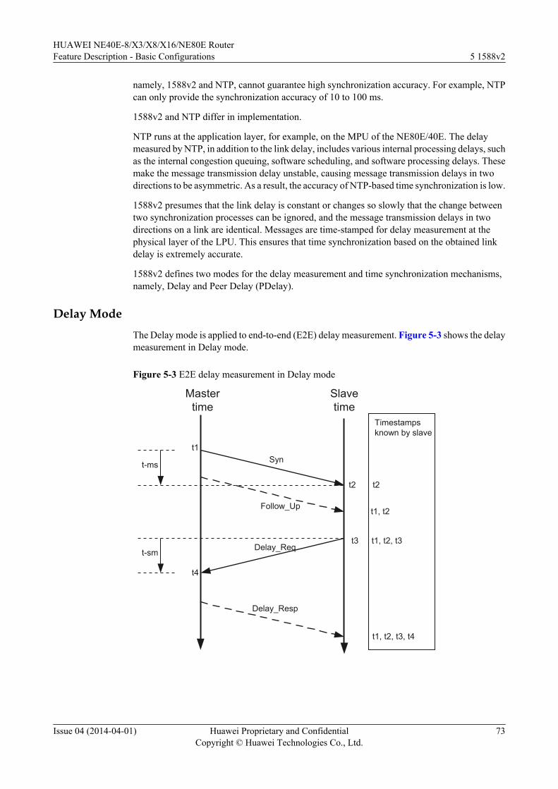
namely, 1588v2 and NTP, cannot guarantee high synchronization accuracy. For example, NTPcan only provide the synchronization accuracy of 10 to 100 ms.
1588v2 and NTP differ in implementation.
NTP runs at the application layer, for example, on the MPU of the NE80E/40E. The delaymeasured by NTP, in addition to the link delay, includes various internal processing delays, suchas the internal congestion queuing, software scheduling, and software processing delays. Thesemake the message transmission delay unstable, causing message transmission delays in twodirections to be asymmetric. As a result, the accuracy of NTP-based time synchronization is low.
1588v2 presumes that the link delay is constant or changes so slowly that the change betweentwo synchronization processes can be ignored, and the message transmission delays in twodirections on a link are identical. Messages are time-stamped for delay measurement at thephysical layer of the LPU. This ensures that time synchronization based on the obtained linkdelay is extremely accurate.
1588v2 defines two modes for the delay measurement and time synchronization mechanisms,namely, Delay and Peer Delay (PDelay).
Delay ModeThe Delay mode is applied to end-to-end (E2E) delay measurement. Figure 5-3 shows the delaymeasurement in Delay mode.
Figure 5-3 E2E delay measurement in Delay mode
Mastertime
Slavetime
t1
t4
t-ms
t-sm
Syn
Follow_Up
Delay_Req
Delay_Resp
t2
t3
Timestampsknown by slave
t2
t1, t2
t1, t2, t3
t1, t2, t3, t4
HUAWEI NE40E-8/X3/X8/X16/NE80E RouterFeature Description - Basic Configurations 5 1588v2
Issue 04 (2014-04-01) Huawei Proprietary and ConfidentialCopyright © Huawei Technologies Co., Ltd.
73
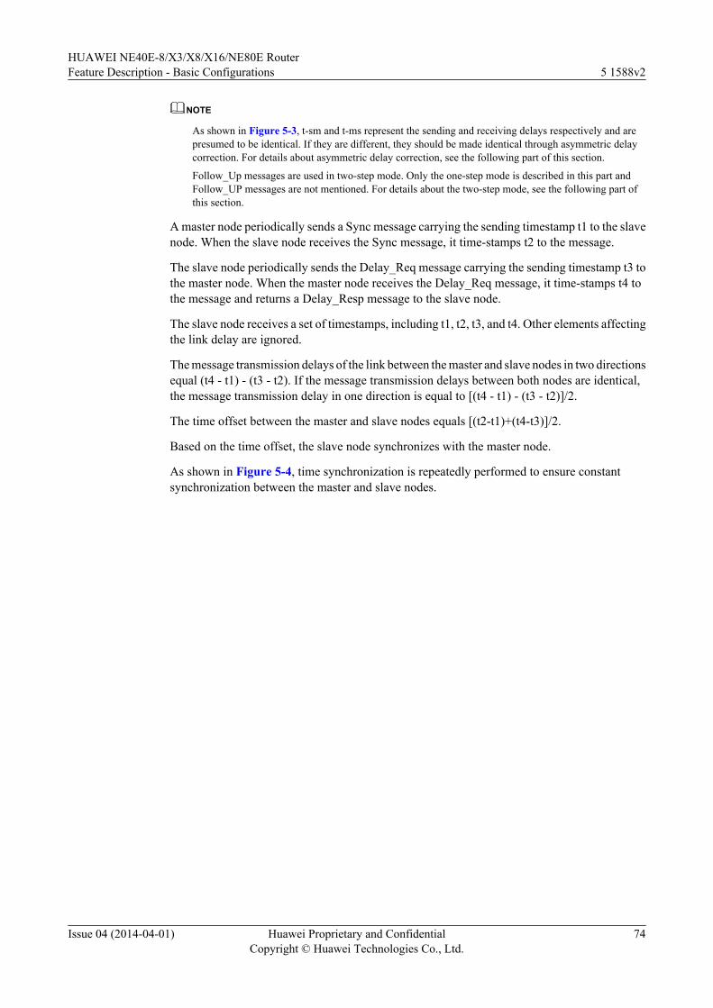
NOTE
As shown in Figure 5-3, t-sm and t-ms represent the sending and receiving delays respectively and arepresumed to be identical. If they are different, they should be made identical through asymmetric delaycorrection. For details about asymmetric delay correction, see the following part of this section.
Follow_Up messages are used in two-step mode. Only the one-step mode is described in this part andFollow_UP messages are not mentioned. For details about the two-step mode, see the following part ofthis section.
A master node periodically sends a Sync message carrying the sending timestamp t1 to the slavenode. When the slave node receives the Sync message, it time-stamps t2 to the message.
The slave node periodically sends the Delay_Req message carrying the sending timestamp t3 tothe master node. When the master node receives the Delay_Req message, it time-stamps t4 tothe message and returns a Delay_Resp message to the slave node.
The slave node receives a set of timestamps, including t1, t2, t3, and t4. Other elements affectingthe link delay are ignored.
The message transmission delays of the link between the master and slave nodes in two directionsequal (t4 - t1) - (t3 - t2). If the message transmission delays between both nodes are identical,the message transmission delay in one direction is equal to [(t4 - t1) - (t3 - t2)]/2.
The time offset between the master and slave nodes equals [(t2-t1)+(t4-t3)]/2.
Based on the time offset, the slave node synchronizes with the master node.
As shown in Figure 5-4, time synchronization is repeatedly performed to ensure constantsynchronization between the master and slave nodes.
HUAWEI NE40E-8/X3/X8/X16/NE80E RouterFeature Description - Basic Configurations 5 1588v2
Issue 04 (2014-04-01) Huawei Proprietary and ConfidentialCopyright © Huawei Technologies Co., Ltd.
74
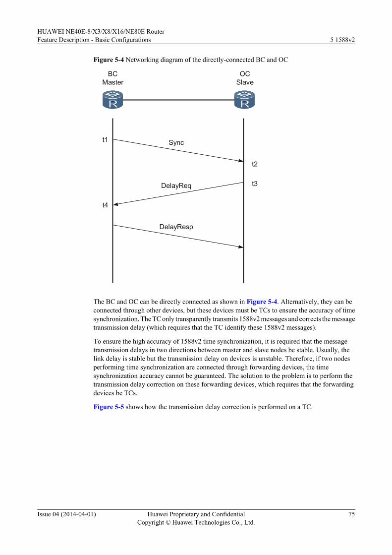
Figure 5-4 Networking diagram of the directly-connected BC and OC
BCMaster
OCSlave
Synct1
t2
t3
t4
DelayReq
DelayResp
The BC and OC can be directly connected as shown in Figure 5-4. Alternatively, they can beconnected through other devices, but these devices must be TCs to ensure the accuracy of timesynchronization. The TC only transparently transmits 1588v2 messages and corrects the messagetransmission delay (which requires that the TC identify these 1588v2 messages).
To ensure the high accuracy of 1588v2 time synchronization, it is required that the messagetransmission delays in two directions between master and slave nodes be stable. Usually, thelink delay is stable but the transmission delay on devices is unstable. Therefore, if two nodesperforming time synchronization are connected through forwarding devices, the timesynchronization accuracy cannot be guaranteed. The solution to the problem is to perform thetransmission delay correction on these forwarding devices, which requires that the forwardingdevices be TCs.
Figure 5-5 shows how the transmission delay correction is performed on a TC.
HUAWEI NE40E-8/X3/X8/X16/NE80E RouterFeature Description - Basic Configurations 5 1588v2
Issue 04 (2014-04-01) Huawei Proprietary and ConfidentialCopyright © Huawei Technologies Co., Ltd.
75
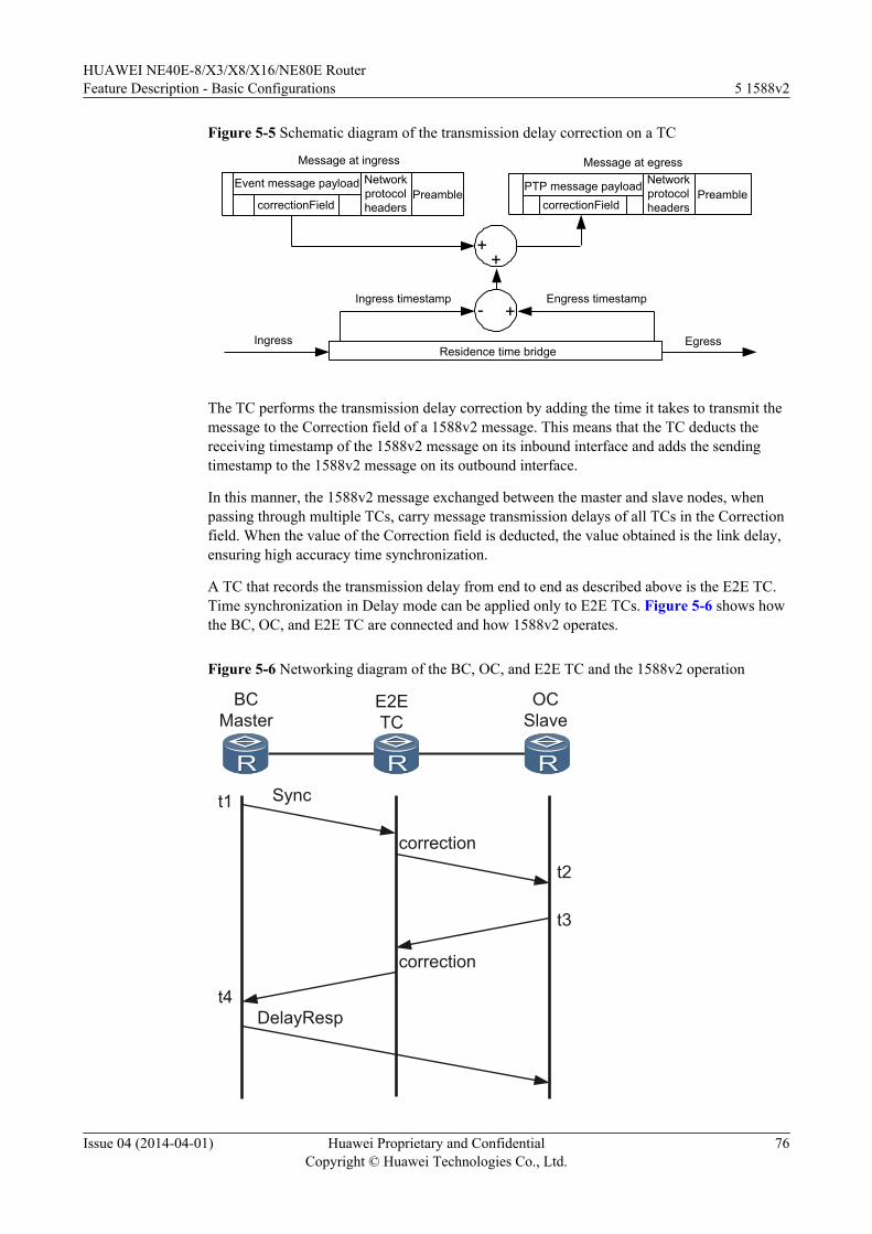
Figure 5-5 Schematic diagram of the transmission delay correction on a TC
Event message payload
correctionField
Networkprotocolheaders
Preamble
Message at ingress Message at egress
PTP message payloadcorrectionField
Networkprotocolheaders
Preamble
Residence time bridgeIngress
Ingress timestamp Engress timestamp
Egress
++
- +
The TC performs the transmission delay correction by adding the time it takes to transmit themessage to the Correction field of a 1588v2 message. This means that the TC deducts thereceiving timestamp of the 1588v2 message on its inbound interface and adds the sendingtimestamp to the 1588v2 message on its outbound interface.
In this manner, the 1588v2 message exchanged between the master and slave nodes, whenpassing through multiple TCs, carry message transmission delays of all TCs in the Correctionfield. When the value of the Correction field is deducted, the value obtained is the link delay,ensuring high accuracy time synchronization.
A TC that records the transmission delay from end to end as described above is the E2E TC.Time synchronization in Delay mode can be applied only to E2E TCs. Figure 5-6 shows howthe BC, OC, and E2E TC are connected and how 1588v2 operates.
Figure 5-6 Networking diagram of the BC, OC, and E2E TC and the 1588v2 operation
BCMaster
E2ETC
OCSlave
t1
t4
correctiont2
correction
t3
Sync
DelayResp
HUAWEI NE40E-8/X3/X8/X16/NE80E RouterFeature Description - Basic Configurations 5 1588v2
Issue 04 (2014-04-01) Huawei Proprietary and ConfidentialCopyright © Huawei Technologies Co., Ltd.
76
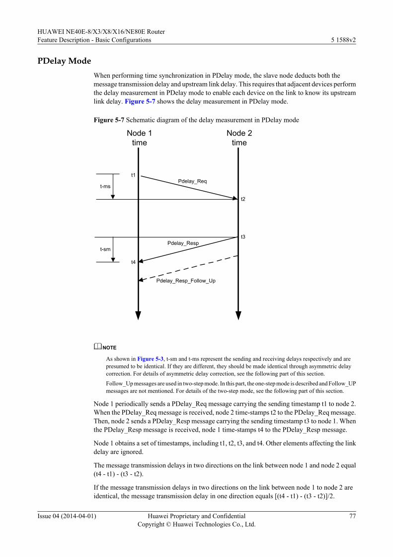
PDelay ModeWhen performing time synchronization in PDelay mode, the slave node deducts both themessage transmission delay and upstream link delay. This requires that adjacent devices performthe delay measurement in PDelay mode to enable each device on the link to know its upstreamlink delay. Figure 5-7 shows the delay measurement in PDelay mode.
Figure 5-7 Schematic diagram of the delay measurement in PDelay mode
Node 1time
Node 2time
t1
t2
t3
t4
t-ms
t-sm
Pdelay_Resp_Follow_Up
Pdelay_Resp
Pdelay_Req
NOTE
As shown in Figure 5-3, t-sm and t-ms represent the sending and receiving delays respectively and arepresumed to be identical. If they are different, they should be made identical through asymmetric delaycorrection. For details of asymmetric delay correction, see the following part of this section.
Follow_Up messages are used in two-step mode. In this part, the one-step mode is described and Follow_UPmessages are not mentioned. For details of the two-step mode, see the following part of this section.
Node 1 periodically sends a PDelay_Req message carrying the sending timestamp t1 to node 2.When the PDelay_Req message is received, node 2 time-stamps t2 to the PDelay_Req message.Then, node 2 sends a PDelay_Resp message carrying the sending timestamp t3 to node 1. Whenthe PDelay_Resp message is received, node 1 time-stamps t4 to the PDelay_Resp message.
Node 1 obtains a set of timestamps, including t1, t2, t3, and t4. Other elements affecting the linkdelay are ignored.
The message transmission delays in two directions on the link between node 1 and node 2 equal(t4 - t1) - (t3 - t2).
If the message transmission delays in two directions on the link between node 1 to node 2 areidentical, the message transmission delay in one direction equals [(t4 - t1) - (t3 - t2)]/2.
HUAWEI NE40E-8/X3/X8/X16/NE80E RouterFeature Description - Basic Configurations 5 1588v2
Issue 04 (2014-04-01) Huawei Proprietary and ConfidentialCopyright © Huawei Technologies Co., Ltd.
77
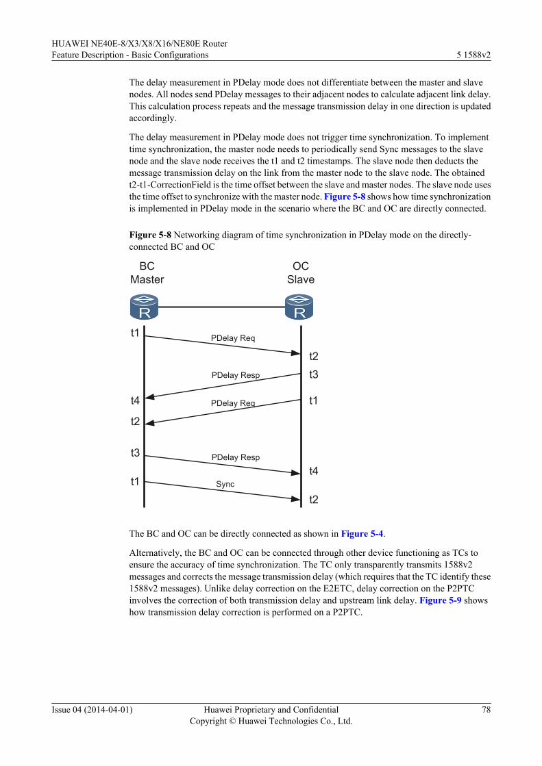
The delay measurement in PDelay mode does not differentiate between the master and slavenodes. All nodes send PDelay messages to their adjacent nodes to calculate adjacent link delay.This calculation process repeats and the message transmission delay in one direction is updatedaccordingly.
The delay measurement in PDelay mode does not trigger time synchronization. To implementtime synchronization, the master node needs to periodically send Sync messages to the slavenode and the slave node receives the t1 and t2 timestamps. The slave node then deducts themessage transmission delay on the link from the master node to the slave node. The obtainedt2-t1-CorrectionField is the time offset between the slave and master nodes. The slave node usesthe time offset to synchronize with the master node. Figure 5-8 shows how time synchronizationis implemented in PDelay mode in the scenario where the BC and OC are directly connected.
Figure 5-8 Networking diagram of time synchronization in PDelay mode on the directly-connected BC and OC
BCMaster
OCSlave
t1
t1
t4
t2
t3
t2
t3
t1
t2
t4Sync
PDelay Req
PDelay Resp
PDelay Req
PDelay Resp
The BC and OC can be directly connected as shown in Figure 5-4.
Alternatively, the BC and OC can be connected through other device functioning as TCs toensure the accuracy of time synchronization. The TC only transparently transmits 1588v2messages and corrects the message transmission delay (which requires that the TC identify these1588v2 messages). Unlike delay correction on the E2ETC, delay correction on the P2PTCinvolves the correction of both transmission delay and upstream link delay. Figure 5-9 showshow transmission delay correction is performed on a P2PTC.
HUAWEI NE40E-8/X3/X8/X16/NE80E RouterFeature Description - Basic Configurations 5 1588v2
Issue 04 (2014-04-01) Huawei Proprietary and ConfidentialCopyright © Huawei Technologies Co., Ltd.
78
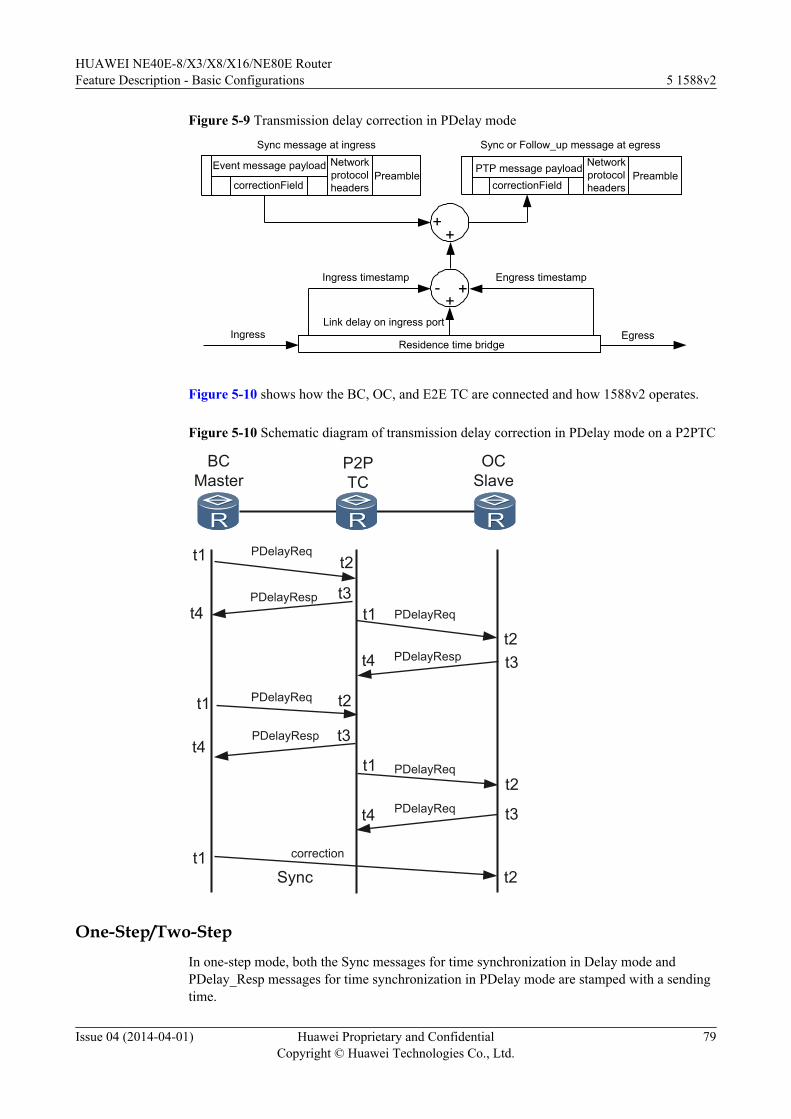
Figure 5-9 Transmission delay correction in PDelay mode
Event message payload
correctionField
Networkprotocolheaders
Preamble
Sync message at ingress Sync or Follow_up message at egress
PTP message payloadcorrectionField
Networkprotocolheaders
Preamble
Residence time bridgeIngress
Ingress timestamp Engress timestamp
Egress
++
- +
Link delay on ingress port
+
Figure 5-10 shows how the BC, OC, and E2E TC are connected and how 1588v2 operates.
Figure 5-10 Schematic diagram of transmission delay correction in PDelay mode on a P2PTC
BCMaster
P2PTC
OCSlave
t1
t1
PDelayReq
t2t3
Sync
t2
PDelayReq
PDelayRespt4
t3t1t4
t2t1
t2
t4t3
t4 t3
PDelayReq
PDelayReq
PDelayResp
PDelayReq
PDelayResp
t1t2
correction
One-Step/Two-StepIn one-step mode, both the Sync messages for time synchronization in Delay mode andPDelay_Resp messages for time synchronization in PDelay mode are stamped with a sendingtime.
HUAWEI NE40E-8/X3/X8/X16/NE80E RouterFeature Description - Basic Configurations 5 1588v2
Issue 04 (2014-04-01) Huawei Proprietary and ConfidentialCopyright © Huawei Technologies Co., Ltd.
79
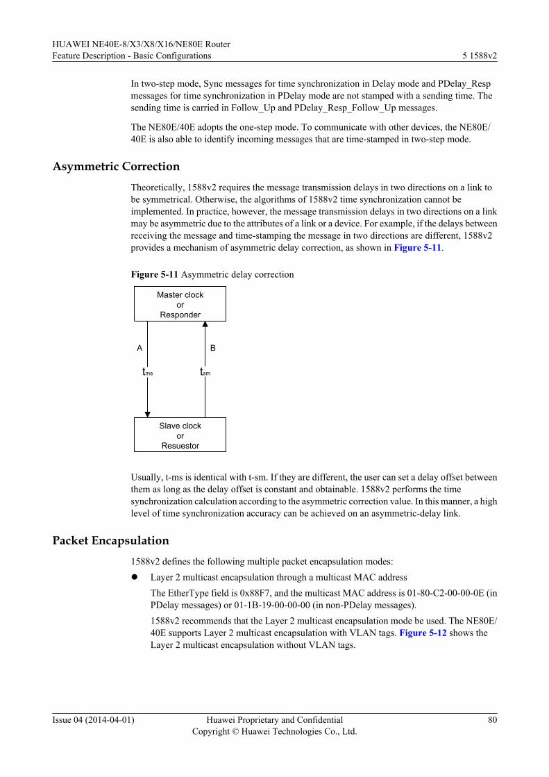
In two-step mode, Sync messages for time synchronization in Delay mode and PDelay_Respmessages for time synchronization in PDelay mode are not stamped with a sending time. Thesending time is carried in Follow_Up and PDelay_Resp_Follow_Up messages.
The NE80E/40E adopts the one-step mode. To communicate with other devices, the NE80E/40E is also able to identify incoming messages that are time-stamped in two-step mode.
Asymmetric CorrectionTheoretically, 1588v2 requires the message transmission delays in two directions on a link tobe symmetrical. Otherwise, the algorithms of 1588v2 time synchronization cannot beimplemented. In practice, however, the message transmission delays in two directions on a linkmay be asymmetric due to the attributes of a link or a device. For example, if the delays betweenreceiving the message and time-stamping the message in two directions are different, 1588v2provides a mechanism of asymmetric delay correction, as shown in Figure 5-11.
Figure 5-11 Asymmetric delay correction
Master clockor
Responder
Slave clockor
Resuestor
A B
tms tsm
Usually, t-ms is identical with t-sm. If they are different, the user can set a delay offset betweenthem as long as the delay offset is constant and obtainable. 1588v2 performs the timesynchronization calculation according to the asymmetric correction value. In this manner, a highlevel of time synchronization accuracy can be achieved on an asymmetric-delay link.
Packet Encapsulation1588v2 defines the following multiple packet encapsulation modes:l Layer 2 multicast encapsulation through a multicast MAC address
The EtherType field is 0x88F7, and the multicast MAC address is 01-80-C2-00-00-0E (inPDelay messages) or 01-1B-19-00-00-00 (in non-PDelay messages).1588v2 recommends that the Layer 2 multicast encapsulation mode be used. The NE80E/40E supports Layer 2 multicast encapsulation with VLAN tags. Figure 5-12 shows theLayer 2 multicast encapsulation without VLAN tags.
HUAWEI NE40E-8/X3/X8/X16/NE80E RouterFeature Description - Basic Configurations 5 1588v2
Issue 04 (2014-04-01) Huawei Proprietary and ConfidentialCopyright © Huawei Technologies Co., Ltd.
80
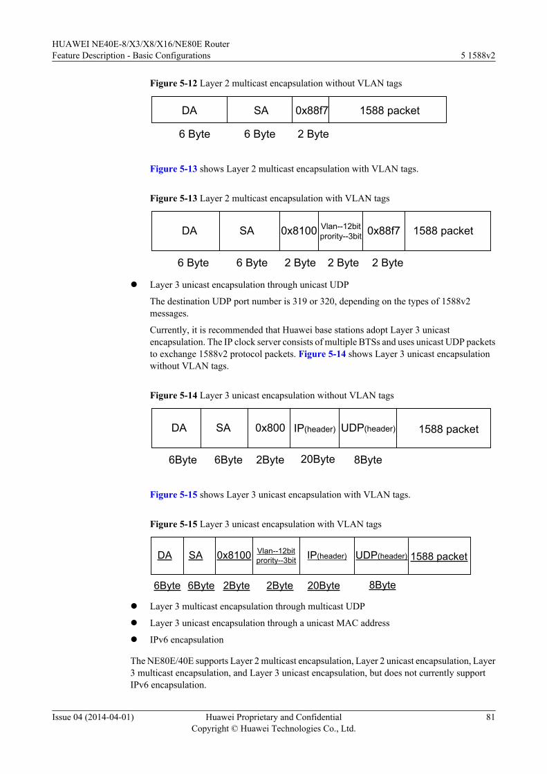
Figure 5-12 Layer 2 multicast encapsulation without VLAN tags
DA SA 0x88f7 1588 packet
6 Byte 6 Byte 2 Byte
Figure 5-13 shows Layer 2 multicast encapsulation with VLAN tags.
Figure 5-13 Layer 2 multicast encapsulation with VLAN tags
DA SA 0x8100 1588 packet
6 Byte 6 Byte 2 Byte 2 Byte 2 Byte
Vlan--12bitprority--3bit 0x88f7
l Layer 3 unicast encapsulation through unicast UDP
The destination UDP port number is 319 or 320, depending on the types of 1588v2messages.
Currently, it is recommended that Huawei base stations adopt Layer 3 unicastencapsulation. The IP clock server consists of multiple BTSs and uses unicast UDP packetsto exchange 1588v2 protocol packets. Figure 5-14 shows Layer 3 unicast encapsulationwithout VLAN tags.
Figure 5-14 Layer 3 unicast encapsulation without VLAN tags
DA SA 0x800 1588 packet
6Byte 6Byte 2Byte 20Byte 8Byte
IP(header) UDP(header)
Figure 5-15 shows Layer 3 unicast encapsulation with VLAN tags.
Figure 5-15 Layer 3 unicast encapsulation with VLAN tags
DA SA 0x8100 1588 packet
6Byte 6Byte 2Byte 2Byte 20Byte
Vlan--12bitprority--3bit UDP(header)IP(header)
8Byte
l Layer 3 multicast encapsulation through multicast UDP
l Layer 3 unicast encapsulation through a unicast MAC address
l IPv6 encapsulation
The NE80E/40E supports Layer 2 multicast encapsulation, Layer 2 unicast encapsulation, Layer3 multicast encapsulation, and Layer 3 unicast encapsulation, but does not currently supportIPv6 encapsulation.
HUAWEI NE40E-8/X3/X8/X16/NE80E RouterFeature Description - Basic Configurations 5 1588v2
Issue 04 (2014-04-01) Huawei Proprietary and ConfidentialCopyright © Huawei Technologies Co., Ltd.
81
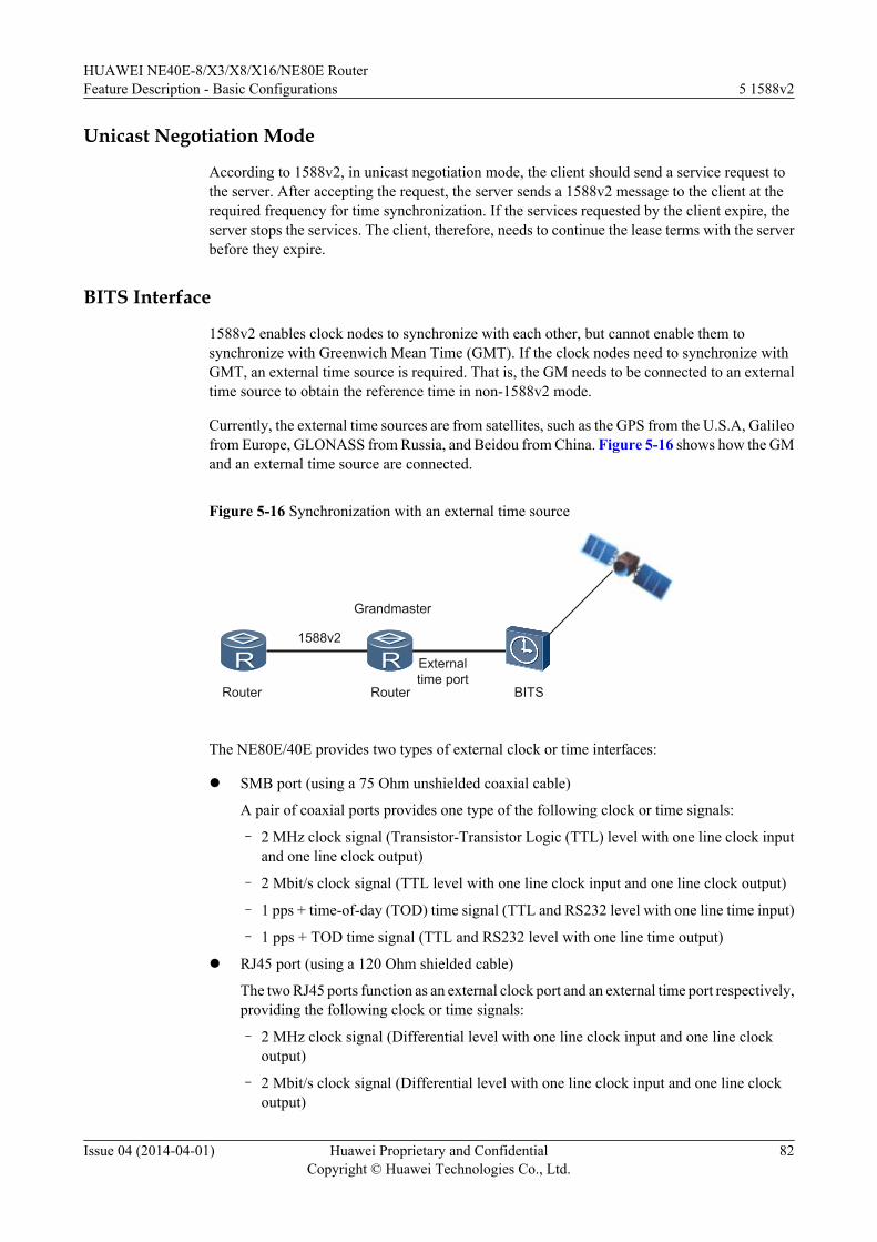
Unicast Negotiation Mode
According to 1588v2, in unicast negotiation mode, the client should send a service request tothe server. After accepting the request, the server sends a 1588v2 message to the client at therequired frequency for time synchronization. If the services requested by the client expire, theserver stops the services. The client, therefore, needs to continue the lease terms with the serverbefore they expire.
BITS Interface
1588v2 enables clock nodes to synchronize with each other, but cannot enable them tosynchronize with Greenwich Mean Time (GMT). If the clock nodes need to synchronize withGMT, an external time source is required. That is, the GM needs to be connected to an externaltime source to obtain the reference time in non-1588v2 mode.
Currently, the external time sources are from satellites, such as the GPS from the U.S.A, Galileofrom Europe, GLONASS from Russia, and Beidou from China. Figure 5-16 shows how the GMand an external time source are connected.
Figure 5-16 Synchronization with an external time source
Router BITS
Externaltime port
Grandmaster
1588v2
Router
The NE80E/40E provides two types of external clock or time interfaces:
l SMB port (using a 75 Ohm unshielded coaxial cable)
A pair of coaxial ports provides one type of the following clock or time signals:
– 2 MHz clock signal (Transistor-Transistor Logic (TTL) level with one line clock inputand one line clock output)
– 2 Mbit/s clock signal (TTL level with one line clock input and one line clock output)
– 1 pps + time-of-day (TOD) time signal (TTL and RS232 level with one line time input)
– 1 pps + TOD time signal (TTL and RS232 level with one line time output)
l RJ45 port (using a 120 Ohm shielded cable)
The two RJ45 ports function as an external clock port and an external time port respectively,providing the following clock or time signals:
– 2 MHz clock signal (Differential level with one line clock input and one line clockoutput)
– 2 Mbit/s clock signal (Differential level with one line clock input and one line clockoutput)
HUAWEI NE40E-8/X3/X8/X16/NE80E RouterFeature Description - Basic Configurations 5 1588v2
Issue 04 (2014-04-01) Huawei Proprietary and ConfidentialCopyright © Huawei Technologies Co., Ltd.
82
– DC level shifter (DCLS) time signal (RS422 differential level with one line clock input+ one line clock output)
– 1 pps + TOD time signal (RS422 differential level with one line time input)
– 1 pps + TOD time signal (RS422 differential level with one line time output)
Clock Synchronization
In addition to time synchronization, 1588v2 can be used for clock synchronization, that is,frequency recovery can be achieved through 1588v2 messages.
1588v2 time synchronization in Delay or PDelay mode requires the device to periodically sendSync messages to its peer.
The sent Sync message carries a sending timestamp. After receiving the Sync message, the peeradds a receiving timestamp to it. When the link delay is stable, the two timestamps change atthe same pace. If the receiving timestamp changes are faster or slower, it indicates that the clockof the receiving device runs faster or slower than the clock of the sending device. In this case,the clock of the receiving device needs to be adjusted. When this occurs, the frequencies of thetwo devices are synchronized.
The frequency restored through 1588v2 messages has a lower accuracy than the frequencyrestored through synchronous Ethernet. Therefore, it is recommended to perform frequencysynchronization through synchronous Ethernet and time synchronization through 1588v2.
1588v2 restores the frequency in the following modes:
l Hop-by-hop
In hop-by-hop mode, all devices on a link are required to support 1588v2. The frequencyrecovery in this mode is highly accurate. In the case of a small number of hops, the frequencyrecovery accuracy can meet the requirement of ITU-T G.813 (stratum 3 standard).
l End-to-end (Delay and jitter may occur on the transit network.)
In end-to-end mode, the forwarding devices do not need to support 1588v2, and the delayof the forwarding path is only required to meet a specified level, for example, less than 20ms. The frequency recovery accuracy in this mode is low, and can meet only therequirements of the G.8261 and base stations (50 pps) rather than that of the stratum 3 clockstandard.
To achieve high frequency recovery accuracy, 1588v2 requires Sync messages to be sent at arate of at least 100 packets/s.
The NE80E/40E meets the following clock standards:
l G.813 and G.823 for external clock synchronization
l G.813 for SDH clocks on POS, ATM, and c-STM-1 links
l G.813 and G.823/G.824 for E1 and T1 clocks
l G.8261 and G.8262 for synchronous Ethernet clocks
l G.8261 and G.823/G.824 for frequency recovery through 1588v2 messages
At present, the NE80E/40E supports frequency recovery through 1588v2 messages in hop-by-hop mode, rather than in end-to-end or inter-packet delay variation (PDV) networkmode. The NE80E/40E is not committed to be G.813 and G.8262 compliant.
HUAWEI NE40E-8/X3/X8/X16/NE80E RouterFeature Description - Basic Configurations 5 1588v2
Issue 04 (2014-04-01) Huawei Proprietary and ConfidentialCopyright © Huawei Technologies Co., Ltd.
83
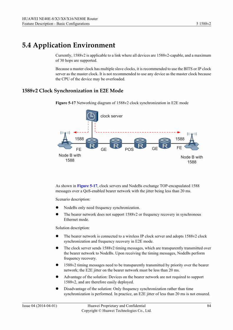
5.4 Application EnvironmentCurrently, 1588v2 is applicable to a link where all devices are 1588v2-capable, and a maximumof 30 hops are supported.
Because a master clock has multiple slave clocks, it is recommended to use the BITS or IP clockserver as the master clock. It is not recommended to use any device as the master clock becausethe CPU of the device may be overloaded.
1588v2 Clock Synchronization in E2E Mode
Figure 5-17 Networking diagram of 1588v2 clock synchronization in E2E mode
clock server
Node B with1588
1588
FE GE POS GE FE
Node B with1588
1588
As shown in Figure 5-17, clock servers and NodeBs exchange TOP-encapsulated 1588messages over a QoS-enabled bearer network with the jitter being less than 20 ms.
Scenario description:
l NodeBs only need frequency synchronization.l The bearer network does not support 1588v2 or frequency recovery in synchronous
Ethernet mode.
Solution description:
l The bearer network is connected to a wireless IP clock server and adopts 1588v2 clocksynchronization and frequency recovery in E2E mode.
l The clock server sends 1588v2 timing messages, which are transparently transmitted overthe bearer network to NodeBs. Upon receiving the timing messages, NodeBs performfrequency recovery.
l 1588v2 timing messages need to be transparently transmitted by priority over the bearernetwork; the E2E jitter on the bearer network must be less than 20 ms.
l Advantage of the solution: Devices on the bearer network are not required to support1588v2, and are therefore easily deployed.
l Disadvantage of the solution: Only frequency synchronization rather than timesynchronization is performed. In practice, an E2E jitter of less than 20 ms is not ensured.
HUAWEI NE40E-8/X3/X8/X16/NE80E RouterFeature Description - Basic Configurations 5 1588v2
Issue 04 (2014-04-01) Huawei Proprietary and ConfidentialCopyright © Huawei Technologies Co., Ltd.
84
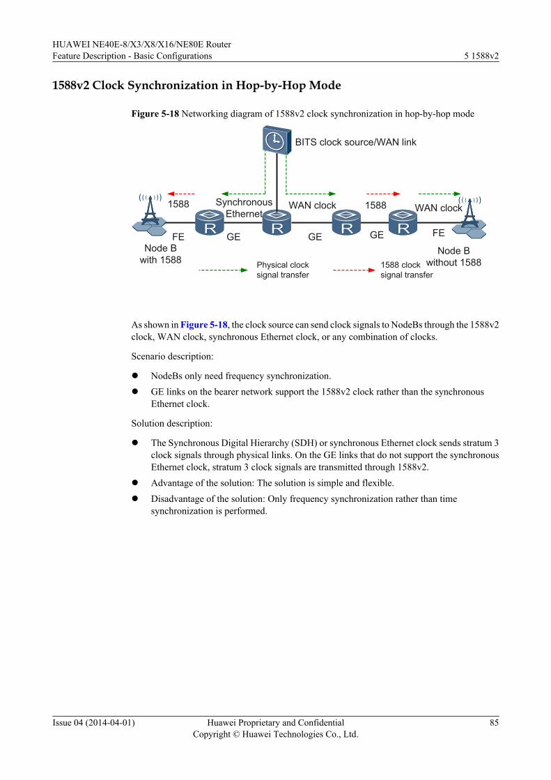
1588v2 Clock Synchronization in Hop-by-Hop Mode
Figure 5-18 Networking diagram of 1588v2 clock synchronization in hop-by-hop mode
Node B with 1588
1588
FE GE GE GE FE
Node B without 1588
Synchronous Ethernet
WAN clock 1588 WAN clock
Physical clock signal transfer
1588 clock signal transfer
BITS clock source/WAN link
As shown in Figure 5-18, the clock source can send clock signals to NodeBs through the 1588v2clock, WAN clock, synchronous Ethernet clock, or any combination of clocks.
Scenario description:
l NodeBs only need frequency synchronization.l GE links on the bearer network support the 1588v2 clock rather than the synchronous
Ethernet clock.
Solution description:
l The Synchronous Digital Hierarchy (SDH) or synchronous Ethernet clock sends stratum 3clock signals through physical links. On the GE links that do not support the synchronousEthernet clock, stratum 3 clock signals are transmitted through 1588v2.
l Advantage of the solution: The solution is simple and flexible.l Disadvantage of the solution: Only frequency synchronization rather than time
synchronization is performed.
HUAWEI NE40E-8/X3/X8/X16/NE80E RouterFeature Description - Basic Configurations 5 1588v2
Issue 04 (2014-04-01) Huawei Proprietary and ConfidentialCopyright © Huawei Technologies Co., Ltd.
85
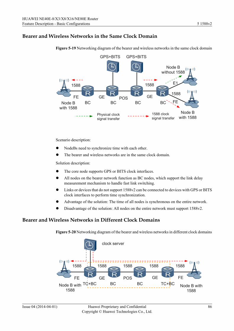
Bearer and Wireless Networks in the Same Clock Domain
Figure 5-19 Networking diagram of the bearer and wireless networks in the same clock domain
GPS+BITS
Node Bwith 1588
1588
FE GE POS GEFE
Node Bwith 1588
1588
Node Bwithout 1588
GPS+BITS
BC BC BC BC
E1
Physical clocksignal transfer
1588 clocksignal transfer
1588
Scenario description:
l NodeBs need to synchronize time with each other.l The bearer and wireless networks are in the same clock domain.
Solution description:
l The core node supports GPS or BITS clock interfaces.l All nodes on the bearer network function as BC nodes, which support the link delay
measurement mechanism to handle fast link switching.l Links or devices that do not support 1588v2 can be connected to devices with GPS or BITS
clock interfaces to perform time synchronization.l Advantage of the solution: The time of all nodes is synchronous on the entire network.l Disadvantage of the solution: All nodes on the entire network must support 1588v2.
Bearer and Wireless Networks in Different Clock Domains
Figure 5-20 Networking diagram of the bearer and wireless networks in different clock domains
clock server
Node B with1588
1588
FE GE POS GE FE
Node B with1588
1588
TC+BC BC BC TC+BC
1588 1588 1588
HUAWEI NE40E-8/X3/X8/X16/NE80E RouterFeature Description - Basic Configurations 5 1588v2
Issue 04 (2014-04-01) Huawei Proprietary and ConfidentialCopyright © Huawei Technologies Co., Ltd.
86
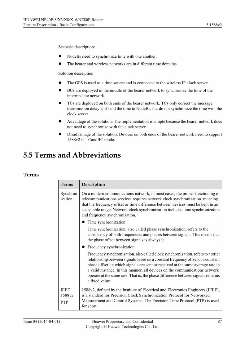
Scenario description:
l NodeBs need to synchronize time with one another.
l The bearer and wireless networks are in different time domains.
Solution description:
l The GPS is used as a time source and is connected to the wireless IP clock server.
l BCs are deployed in the middle of the bearer network to synchronize the time of theintermediate network.
l TCs are deployed on both ends of the bearer network. TCs only correct the messagetransmission delay and send the time to NodeBs, but do not synchronize the time with theclock server.
l Advantage of the solution: The implementation is simple because the bearer network doesnot need to synchronize with the clock server.
l Disadvantage of the solution: Devices on both ends of the bearer network need to support1588v2 in TCandBC mode.
5.5 Terms and Abbreviations
Terms
Terms Description
Synchronization
On a modern communications network, in most cases, the proper functioning oftelecommunications services requires network clock synchronization, meaningthat the frequency offset or time difference between devices must be kept in anacceptable range. Network clock synchronization includes time synchronizationand frequency synchronization.l Time synchronization
Time synchronization, also called phase synchronization, refers to theconsistency of both frequencies and phases between signals. This means thatthe phase offset between signals is always 0.
l Frequency synchronizationFrequency synchronization, also called clock synchronization, refers to a strictrelationship between signals based on a constant frequency offset or a constantphase offset, in which signals are sent or received at the same average rate ina valid instance. In this manner, all devices on the communications networkoperate at the same rate. That is, the phase difference between signals remainsa fixed value.
IEEE1588v2PTP
1588v2, defined by the Institute of Electrical and Electronics Engineers (IEEE),is a standard for Precision Clock Synchronization Protocol for NetworkedMeasurement and Control Systems. The Precision Time Protocol (PTP) is usedfor short.
HUAWEI NE40E-8/X3/X8/X16/NE80E RouterFeature Description - Basic Configurations 5 1588v2
Issue 04 (2014-04-01) Huawei Proprietary and ConfidentialCopyright © Huawei Technologies Co., Ltd.
87
Terms Description
Clockdomain
Logically, a physical network can be divided into multiple clock domains. Eachclock domain has a reference time, with which all devices in the domain aresynchronized. Different clock domains have their own reference time, which isindependent of each other.
Clocknode
Each node on a time synchronization network is a clock. The 1588v2 protocoldefines three types of clocks: OC, BC, and TC.
Clockreferencesource
Clock source selection is a method to select reference clocks based on the clockselection algorithm.
One-stepmode
In one-step mode, Sync messages in Delay mode and PDelay_Resp messages inPDelay mode are stamped with the time when messages are sent.
Two-stepmode
In two-step mode, Sync messages in Delay mode and PDelay_Resp messages inPDelay mode only record the time when messages are sent and carry notimestamps. The timestamps are carried in the messages, such as Follow_Up andPDelay_Resp_Follow_Up messages.
Abbreviations
Abbreviation Full Spelling
1588v2 Precision Time Protocol
IP RAN Internet Protocol Radio Access Network
GSM Global System for Mobile communications
WCDMA Wideband Code Division Multiple Access
TD-SCDMA Time Division-Synchronous Code Division Multiple Access
WiMax FDD Worldwide Interoperability for Microwave Access FrequencyDivision Duplex
WiMax TDD Worldwide Interoperability for Microwave Access Time DivisionDuplex
NTP Network Time Protocol
GPS Global Position System
LTE Long Term Evolution
BC Boundary Clock
OC Ordinary Clock
TC Transparent Clock
BMC Best Master Clock
HUAWEI NE40E-8/X3/X8/X16/NE80E RouterFeature Description - Basic Configurations 5 1588v2
Issue 04 (2014-04-01) Huawei Proprietary and ConfidentialCopyright © Huawei Technologies Co., Ltd.
88
Abbreviation Full Spelling
BITS Building Integrated Time Supply System
HUAWEI NE40E-8/X3/X8/X16/NE80E RouterFeature Description - Basic Configurations 5 1588v2
Issue 04 (2014-04-01) Huawei Proprietary and ConfidentialCopyright © Huawei Technologies Co., Ltd.
89
6 CES ACR Clock Synchronization
About This Chapter
6.1 Introduction
6.2 References
6.3 Principles
6.4 Applications
6.5 Terms and Abbreviations
HUAWEI NE40E-8/X3/X8/X16/NE80E RouterFeature Description - Basic Configurations 6 CES ACR Clock Synchronization
Issue 04 (2014-04-01) Huawei Proprietary and ConfidentialCopyright © Huawei Technologies Co., Ltd.
90
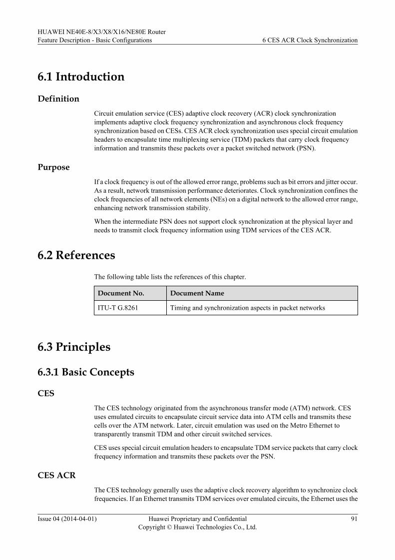
6.1 Introduction
DefinitionCircuit emulation service (CES) adaptive clock recovery (ACR) clock synchronizationimplements adaptive clock frequency synchronization and asynchronous clock frequencysynchronization based on CESs. CES ACR clock synchronization uses special circuit emulationheaders to encapsulate time multiplexing service (TDM) packets that carry clock frequencyinformation and transmits these packets over a packet switched network (PSN).
PurposeIf a clock frequency is out of the allowed error range, problems such as bit errors and jitter occur.As a result, network transmission performance deteriorates. Clock synchronization confines theclock frequencies of all network elements (NEs) on a digital network to the allowed error range,enhancing network transmission stability.
When the intermediate PSN does not support clock synchronization at the physical layer andneeds to transmit clock frequency information using TDM services of the CES ACR.
6.2 ReferencesThe following table lists the references of this chapter.
Document No. Document Name
ITU-T G.8261 Timing and synchronization aspects in packet networks
6.3 Principles
6.3.1 Basic Concepts
CESThe CES technology originated from the asynchronous transfer mode (ATM) network. CESuses emulated circuits to encapsulate circuit service data into ATM cells and transmits thesecells over the ATM network. Later, circuit emulation was used on the Metro Ethernet totransparently transmit TDM and other circuit switched services.
CES uses special circuit emulation headers to encapsulate TDM service packets that carry clockfrequency information and transmits these packets over the PSN.
CES ACRThe CES technology generally uses the adaptive clock recovery algorithm to synchronize clockfrequencies. If an Ethernet transmits TDM services over emulated circuits, the Ethernet uses the
HUAWEI NE40E-8/X3/X8/X16/NE80E RouterFeature Description - Basic Configurations 6 CES ACR Clock Synchronization
Issue 04 (2014-04-01) Huawei Proprietary and ConfidentialCopyright © Huawei Technologies Co., Ltd.
91
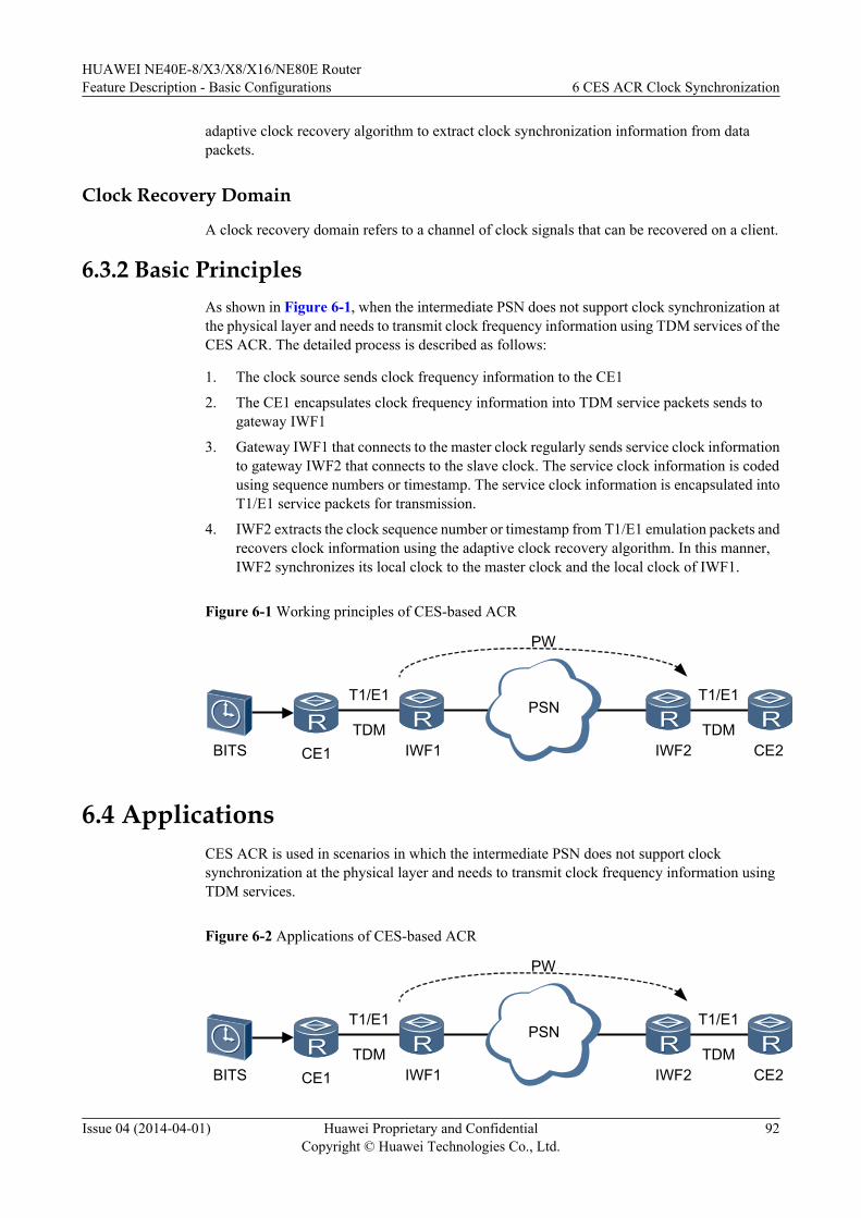
adaptive clock recovery algorithm to extract clock synchronization information from datapackets.
Clock Recovery Domain
A clock recovery domain refers to a channel of clock signals that can be recovered on a client.
6.3.2 Basic PrinciplesAs shown in Figure 6-1, when the intermediate PSN does not support clock synchronization atthe physical layer and needs to transmit clock frequency information using TDM services of theCES ACR. The detailed process is described as follows:
1. The clock source sends clock frequency information to the CE1
2. The CE1 encapsulates clock frequency information into TDM service packets sends togateway IWF1
3. Gateway IWF1 that connects to the master clock regularly sends service clock informationto gateway IWF2 that connects to the slave clock. The service clock information is codedusing sequence numbers or timestamp. The service clock information is encapsulated intoT1/E1 service packets for transmission.
4. IWF2 extracts the clock sequence number or timestamp from T1/E1 emulation packets andrecovers clock information using the adaptive clock recovery algorithm. In this manner,IWF2 synchronizes its local clock to the master clock and the local clock of IWF1.
Figure 6-1 Working principles of CES-based ACR
CE1 CE2IWF1 IWF2
PSNTDMTDM
T1/E1T1/E1
PW
BITS
6.4 ApplicationsCES ACR is used in scenarios in which the intermediate PSN does not support clocksynchronization at the physical layer and needs to transmit clock frequency information usingTDM services.
Figure 6-2 Applications of CES-based ACR
CE1 CE2IWF1 IWF2
PSNTDMTDM
T1/E1T1/E1
PW
BITS
HUAWEI NE40E-8/X3/X8/X16/NE80E RouterFeature Description - Basic Configurations 6 CES ACR Clock Synchronization
Issue 04 (2014-04-01) Huawei Proprietary and ConfidentialCopyright © Huawei Technologies Co., Ltd.
92
As shown in Figure 6-2, the clock source sends clock frequency information to a CE. The CEencapsulates clock frequency information into TDM service packets and transmits these packetsover the intermediate PSN to the peer CE. CES ACR recovers clock frequency information atthe IWF connected to the peer CE. In practical application, multiple E1 or T1 interfaces canbelong to the same clock recovery domain. By default, the system selects a PW as the primaryPW and uses the primary PW to recover clock signals. If the primary PW fails, the system selectsthe next available PW as the primary PW to recover clocks. In this manner, clock protectionamong multiple PWs is implemented.
6.5 Terms and Abbreviations
Abbreviations
Abbreviation Full Spelling
CES Circuit Emulation Service
ACR Adaptive Clock Recovery
HUAWEI NE40E-8/X3/X8/X16/NE80E RouterFeature Description - Basic Configurations 6 CES ACR Clock Synchronization
Issue 04 (2014-04-01) Huawei Proprietary and ConfidentialCopyright © Huawei Technologies Co., Ltd.
93