fdtd modeling of isotropic dispersive magnetic materials
TRANSCRIPT
FDTD modeling of isotropic dispersive magnetic materials Jing Wu
ECE Dept. University of Missouri-Rolla, MO, USA [email protected]
Marina Y. Koledintseva ECE Dept. University of Missouri-Rolla, MO, USA
Abstract Numerical analysis using the finite-difference time-domain (FDTD) algorithm with a piecewise linear recursive convolution (PLRC) procedure for linear isotropic dispersive magnetic materials is presented. The f'equency dependence of susceptibility used for this algorithm is represented in Debye, narrowband Lorentzian, and wideband Lorenfzian forms, depending on fhe ratio of the resonance frequency and the resonance line width. Some numericai exampies along with measuremenfs are provided.
Keywords FDTD modeling, piecewise linear recursive convolution, Lorentzian and Debye dispersion, magnetic materials, Ni- Zn ferrite, complex permeability, complex permittivity, small perturbation theory.
INTRODUCTION The finite difference time domain (FDTD) technique has been widely used to analyze electromagnetic phenomena. The FDTD method is based on the direct time integration of Maxwell's partial differential equations using the central finite difference method. The FDTD method is typically implemented with constant values of permittivity and conductivity. However, it does not allow accurate transient calculations to be made for materials with significant frequency dependence in their constitutive parameters. There are several approaches for incorporating dispersive media into the standard Yee FDTD algorithm. One approach uses recursive convolution (RC) of constitutive parameters and corresponding field components in the time domain [ 1,2]. Another approach is based on discretization of an auxiliary differential equation (ADE) [3]. In the approach proposed by Sullivan, the Z-transform is applied to Maxwell's equations to update field equations in the FDTD algorithm [4]. The piecewise linear recursive convolution (PLRC) method [5, 61 provides accuracy that rivals the ADE and Z-transform approaches, yet retains the speed, memory, and multiple advantages of the RC approach.
Herein, the PLRC method is used to incorporate dispersive magnetic media into FDTD. However, the frequency dependence of the permeability must be a "well-behaved" function having a causal inverse Fourier (or Laplace) transform, which contains a sum of complex exponentials
James L. Drewniak ECE Dept. University of Missouri-Rolla, MO, USA
David J. Pommerenke ECE Dept. University of Missouri-Rolla, MO, USA
of time with constant coefficients. The simplest for linear isotropic magnetic material is a Debye model
(1)
where A is a resonance amplitude parameter depending on the type of the magnetic material and proportional to its
1 . static magnetic susceptibility, and frel = - IS the 2m.
relaxation frequency related to the Debye constant 7,. The dependency (I) is associated with domain walls movement in magnetic materials and describes a comparatively low- frequency (from RF to the lower part of microwave band) behavior of a dispersive medium [7,8]. At higher microwave frequencies resonance effects are associated with electron spin magnetic moment precession in feno-, ferri-, and antiferromagnetic materials [7,8]. These resonance effects can be taken into account by a Lorentzian frequency dependence of the magnetic susceptibility,
where fo is the resonance frequency, f , , = ft / A f is the relaxation frequency, A f is the width of the Lorentzian resonance line at the -3 dB level, and A is a resonance amplitude parameter. The Debye and the Lorentzian models, both narrowband (2frel / f o < 1)and wideband (2 fie, / fo > I ) , were introduced into the FDTD technique using the PLRC procedure [9].
UPDATING EQUATIONS FOR FDTD MODELING OF MAGNETIC DISPERSIVE MEDIUM The updating equation for the magnetic field in the linear isotropic magnetic dispersive medium is obtained in [9 ] ,
e"+'- - 1-5O e"- 1 t x o - ( 0
(3) I - nt- ' Y " , Af V , . x E 2 +
P0( l+X0 - I0 ) l t x Q - 5 Q
0-7803-7835-0/031$17.00 0 2003 IEEE 904

where the recursive convolution accumulator is
Y" = ( A ~ O - A ~ o ) H " + A ~ o ~ " - ' + C , ~ , Y ' - i . (4)
The constants A X o . A ( o , C , , have been derived in [9]. They are real-valued for the Debye media, and, in general, complex-valued for the Lorentzian media. If permittivity of the magnetic medium in the frequency range of interest is also frequency-dependent and follows the Debye or Lorentzian law, the electric field in the medium can be updated using the recursive convolution procedure, too, as in [lo],
where E, is the optical region permittivity, cre is the d.c. conductivity of the dielectric, xen is static dielectric susceptibility depending on the dispersive law governing the susceptibility of the materials and found by integration
Function 6n is a recursive convolution summation for the dielectric dispersion. It is real for the Dehye and wideband Lorentzian cases, and complex for the narrowband Lorentzian case [ I I].
COMPLEX PERMEABILITY MEASUREMENT The FDTD modeling olthe dispersiw magnetic medium i s tested herein with a specimen ofa bulk NI-7.n ferrite.
To modcl an eluitrodynamic s t ruu~re con~aininp this fsrrite, ihe irequcncy dependenci-s o i 11s constitutive paramutun . perniittivit) and psnneability - should he known. I t i i known. that the Dehyc or Larcntzian dispersive laws gotern the frequency behavior of thess parameters. The Deb)e or Lorentlian curvcs can be extracted trom muasurenients using thc msthods d i s u s e d in papers [12,13] .
Ilcrcin, the rciull> ofmcasuring the dispersive permeabilit) of Ni-Zn ierritc are presented. A stripline rcrnnaior k.chnique de\slopcd at NlST (IJSA) 10 mcdsure the pernieabiliiy <)ithc spcclmcn \\;is :ipplicd 1141.
The NIST stripline cavity is schematically shown in Figure 1. It consists of a centered conductor mounted equidistantly between two ground planes and terminated by two end plates. The end plates are permanently attached to the ground planes, thus the resonator is of fixed length and non-tunable.
The length of the resonator is 1 m, giving a fundamental resonance of approximately 150 MHz with harmonic resonances spaced at 150-MHz increments above the fundamental. The resonator upper frequency limit is defined by the frequency at which the first higher order TEle begins to propagate in the stripline cavity. For this cavity, the ground plane separation is 76.2 mm, giving a theoretical upper frequency limit of 1970 MHz. The Q- factor of the unloaded resonator has been several thousand after removing copper oxidation from its walls and applying silver paint to the joints to improve the conductivity of the structure.
A propagating TEM mode is excited within the stripline structure by the coupling loops mounted on one of the end plates. The first, or fundamental, resonance is achieved when the resonator length corresponds to a half- wavelength. There are higher-order resonances of the cavity at the harmonics of the fundamental frequency.
Figure 1. NlST stripline cavity for permittivity and permeability measurements.
905

Measurements of the complex magnetic permeability ( p * = p ' - p " ) are conducted by placing the specimen under test at an axial E-field node, located at the structure's end plates, where the electric field intensity is zero and does not influence on the measurement of permeability.
From Waldron's small perturbation theory [15], for a thin rectangular magnetic slab with 2y in the x-direction, s in the y-direction, and I , in the z-direction, the real and imaginary parts of permeability are found as
Af b(b - t)lo p' ,= l+-
p r =(---)
f o BYSlI (7) 1 1 b(b - t ) l ,
Q L Qo ~ B Y S ~ I
In (7), 2b is the distance between the cavity ground planes; t is the thickness of center conductor; lo is the length of the resonator; and B is a geometry factor determined by the dimensions of the resonator [14,15]. The real and imaginary parts of permeability are measured by obsewing, respectively, the shift of the cavity resonance frequency Af to the lower frequencies, and the decrease of the cavity @factor at the cavity loading with the sample under investigation.
Measured complex permeability data for the sample is shown in Figure 2. The results were checked to satisfy the causality principle, applying the Kramers-Kroenig relations [16]. This means that the corresponding complex frequency characteristic of permeability is a rational function, and the time-domain susceptibility kernel, which is a pulse response of a medium, can be represented as a sum of complex exponential functions. l5
4 \.
Figure 2. Real and imaginary parts of NiZn ferrite permeability.
COMPLEX PERMITTIVITY MEASUREMENT Ni-Zn ferrite is a medium that has both dispersive permeability and permittivity in the frequency range of interest, up to 2 GHz. Hence, the FDTD modeling should include not only updating equations for magnetic field with recursive convolution term taking into account the dispersive law for magnetic susceptibility, but also for electric field taking into account the law for electric susceptibility.
The parameters of the dispersion law for the permittivity have been extracted from measurements. The real part of Ni-Zn ferrite permittivity was measured over the frequency range from 150 MHz to 2 GHz using the NIST's cavity method [14]. The rectangular specimen under test was placed in the region of maximum and uniaxial E-field, specifically, in the midpoint of the center strip, and with the smallest dimension oriented along the x-axis to minimize the E-field nonuniformity across the specimen. The H-field in the point where the ferrite specimen is placed is zero. Thus, the slab is located at the midpoint of the center strip in experiment. This measurement demonstrates that the permittivity of this sample can be approximated by the Debye dispersive curve. The imaginary part of the permittivity was reconstructed based on the Debye parameters extracted from the measurements of the real part of the permittivity.
. . . . . .
( 6 . . . . . . . . . . . . . . . . . . . .
14- ., D . . .
. . . . .
6b .:.. . . . . . . . . :
, .~ ~. . . . . . . . . 4
2 . . . . . . . . . . . .
i 0.5 1 1.5 2 Frequency (HI) 10'
Figure 3. Real and imaginary parts of NiZn ferrite permittivity.
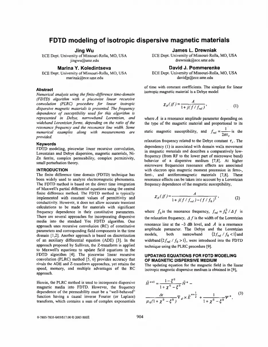
FDTD MODELING AND MEASUREMENTS OF A MICROSTRIP TEST FIXTURE WITH A NI-ZN FERRITE SUBSTRATE The FDTD PLRC algorithm was applied to model a microstrip fixture comprised of two copper layers with an isotropic magnetic material spacer. The photograph of the fixture used in the experiments is shown in Figure 4.
The magnetic material is 3 1.4 mm long, 12.76mm wide and 3.24 mm thick. The upper copper tape is 6.32mm wide. Two MACOM SMA connectors are mounted on each end
906
of the microstrip line as test ports. The outer shields were soldered to the ground plane through two vertical copper- tape walls. The center conductor is soldered on microstrip line at each end. Four small comers were cut to prevent a short circuit of the microstrip line to the ground plane. Two port measurements were conducted using an HP 8753D network analyzer. The electrical lengths of the semi-rigid coaxial cables and SMA connectors were removed using the port extension feature of a full-path two-port calibration.
4 .
Figure 4. Microstrip fixture.
An orthographic view of the structure used in the FDTD modeling is shown in Figure 5 . The basic computational domain in FDTD method consists of a rectangular mesh bounded by perfectly matched layers (PML) to simulate an infinite space. The computational domain was discretized by a uniform mesh of 0.316 mm x 0.324 mm x 0.316 mm along x, y , and z-axes, respectively, and the total number of cells was approximately 250,000. The strip and the ground plane were modeled as perfect electric conductors (PEC) 20 and 80 cells wide, respectively. The magnetic material layer between two adjacent planes was modeled with 10 cells thickness using PLRC algorithm. Two PEC plates were added vertically to model the copper tape at each side of the test fixture in experiment. A sinusoidal modulated Gaussian 50-Ohm voltage source was applied horizontally at Port 1 through a wire with 1 cell width, and Port 2 was terminated with a 50 Ohms load through a wire with 1 cell width. The wire structures were modeled using a thin wire . . . . . . . . . . . . . . . . .
. . . ’’ ’*.. ~. . .... 3 - ~ *..
- algorithm. - Yoltage Lyad
The standard Yee FDTD approach that incorporates the frequency-dependent loss of the media by a constant real value of effective conductivity and magnetic loss sigma in a number of individual frequency points was also used here. The effective conductivity U: and effective magnetic
loss cr: are introduced as
and
As seen from (8) and (9), the effective conductivity and effective magnetic loss are frequency-dependent. By specifying a constant value of U: , the dielecVic loss E” is included in the model using the normal Yee-algorithm updating equations. Similarly, by defining a constant value of magnetic loss o: , the imaginary part of permeability p” can be included in the model that uses the normal %on- dispersive” updating equations.
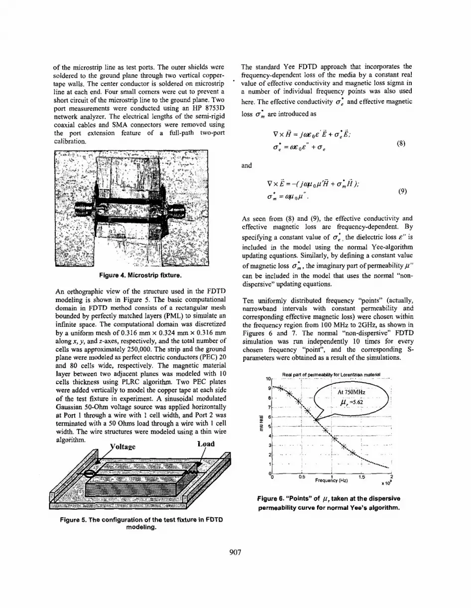
Ten uniformly distributed frequency “points” (actually, narrowband intervals with constant permeability and corresponding effective magnetic loss) were chosen within the frequency region from 100 MHz to 2GHz, as shown in Figures 6 and 7. The normal “non-dispersive” FDTD simulation was nm independently 10 times for every chosen frequency “point”, and the corresponding S- parameters were obtained as a result of the simulations.
Real part of perrneabllny for Lorenhian rnatetial 4 n . . . . . . . . . . . . . . . . . . .
2 01
1 1 5 x r o s O 5 Frequency (Hz)
0
Figure 6. “Points” of p , taken at the dispersive permeability curve for normal Yee’s algorithm.
Figure 5. The configuration of the test fixture in FDTD modeling.
907
05 1 15 2 0 0
.Id Frequency(Hz)
Figure 7. "Points" of CT; taken at the dispersive permeability curve for normal Yee's algorithm.
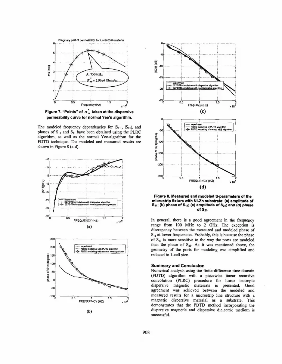
The modeled frequency dependencies for ISIII, IS21/, and phases of SI I and SII have been obtained using the PLRC algorithm, as well as the normal Yee-algorithm for the FDTD technique. The modeled and measured results are shown in Figure 8 (a-d).
. . . . . . . . . . . . . . . . . . . . . . .
...............
05 1 15 2 -261 0
tos FREQUENCY (HZ)
(8)
I FREQUENCY (HZ) X l O Q
0.5 1 1.5 2
(b)
908
. . . . . . . . . . . . . . . . . . . .
. . . . . . . . . . . . . .
..................
0 0.5 1 1.5 2 FREQUENCY (HZ) lo3
(dl Figure 8. Measured and modeled S-parameters of the
microstrip fixture with Ni-Zn substrate: (a) amplitude of SII; (b) phase of %I; (e) amplitude of SZI; and (d) phase
of Sn.
In general, there is a good agreement in the frequency range from 100 MHz to 2 GHz. The exception is discrepancy between the measured and modeled phase of Sil at lower frequencies. Probably, this is because the phase of SI , is more sensitive to the way the ports are modeled than the phase of Szl. As it was mentioned above, the geometry of the ports for modeling was simplified and reduced to 1-cell size.
Summary and Conclusion Numerical analysis using the finite-difference time-domain (FDTD) algorithm with a piecewise linear recursive convolution (PLRC) procedure for linear isotropic dispersive magnetic materials is presented. Good agreement was achieved between the modeled and measured results for a microstrip line structure with a magnetic dispersive material as a substrate. This demonstrates that the FDTD method incorporating the dispersive magnetic and dispersive dielectric medium is successful.

ACKNOWLEDGMENTS The authors of this paper thank Robert Johnk, Claude Weil, and Chriss Grosvenor for providing the NIST stripline cavity and magnetic material samples for experiments conducted at the UMR and for useful discussions. The authors would also like to thank Dr. Konstantin Rozanov (Russian Academy of Sciences) for valuable consultations.
REFERENCES [ I ] K.S.Kunz and R.J.Luebbers, The Finite Difference
Time Domain Method for Electromagnetics, Boca Raton, FL: CRC, 1993.
[2] R.J.Luebbers, F.P.Hunsberger, K.S.Kunz, R.B.Standler, and MSchneider, “A frequency-dependent finite- difference time-domain formulation for dispersive materials”, IEEE Trans. Electromagn. Compat.,vol. 32, no. 3, pp. 222-227, Aug. 1990.
T.Kashiva and I.Fukai, “A treatment by the FDTD method of the dispersive characteristics associated with electronic polarization”, Microwave & Optical Technologies Letters, v. 3, pp.203-205, June, 1990.
[4] D.M.Sulivan, “Frequency-dependent FDTD methods using Z transforms”, IEEE Trans. Antennas Propagat., v. 40, pp.1223-1230, Oct.1992.
[SI A.Taflove and S.Hagness, Computational Electrodynamics: The Finite-Difference Time-Domain Method. 2”d ed., Nonvood, MA: Artech House, 2000.
[6] D.V.Kelley and R.L.Luebbers, “Piecewise Linear Recursive Convolution for Dispersive Media Using FDTD”, IEEE Trans. Antennas Propagat.. v. 44, no. 6 , pp. 792-797, June 1996.
[71 C.Kittel, Introduction to Solid State Physics, 2”d ed., Boca Raton, FL: CRC, 1993.
[XI D.D.Pollock, Physical Properties of Materials for Engineers, 2”d ed., Boca Raton, FL: CRC, 1993.
[9] J. Wu, M. Y. Koledintseva, and J. L.Drewniak, “FDTD Modeling of Structures Containing Dispersive Isotropic Magnetic Materials”, in Proc. XI In!. ConJ Spin-
[3]
Electronics ’ and ’ Gyrovector Electrodynamics, December 20-23, 2002, Firsanovka, Moscow Region, publ. UNC-1, Moscow Power Eng. Inst. (Techn. Univ.), pp. 536-546.
[lo] X.Ye, M.Y Koledintseva, M. Li, and J.L.Drewniak, “DC power-bus design using FDTD modeling with dispersive media and surface mount technology components”, IEEE Trans. Electromagn. Compat.. vol. 43, no. 64, pp. 579-587, Nov. 2001.
[ l l ] M. Y. Koledintseva, D.J.Pommerenke, 3. L. Drewniak, “FDTD Analysis of Printed Circuit Boards Containing Wideband Lorentzian Dielectric Dispersive Media”, in Proc. IEEE Int. Symp. Electromagnetic Compatibility, Minnesota, Aug. 2002, vol. 2, pp. 830-833.
[I21 M.Y.Koledintseva, K.N.Rozanov, J.L.Drewniak, and G.Di Fazio, “Restoration of the Lorentzian and Debye Curves of Dielectrics and Magnetics for FDTD Modeling”, in Proc. EMC EUROPE 5th Inf. Symp. Electromagnetic Compatibility September 9-13, 2002, Sorrento, Italy, no. PD27, pp. 687-692.
[13] M.Y.Koledintseva and G.Di Fazio, “Extraction of the Lorentzian and Debye parameters from measurement data in a few frequency points”, in Proc. lIYh Int. Can$ Spin Electronics, Nov. 2001, Moscow Region, Firsanovka, publ. UNC-1, Moscow Power Eng. Inst. (Techn. Univ.), pp. 530-542.
[14] C.M.Weil, C.A.Jones, Y.Kantor, and J.H.Grosvenor, “On RF Material Characterization in the Stripline Cavity”, IEEE Trans. Microwave Theory Tech., vol. 48, pp.226-274, Feb.2000.
[IS] R.A.Waldron, “Theory of strip-line cavity for measurement of dielectric constants and gyromagnetic- resonance line-widths”, IEEE Trans. Microwave Theory Tech., vol. 12, pp.123-131, Jan. 1964.
[ 161 L.D.Landau, E.M.Lifshitz, and L.P.Pitaevskii, Electrodynamics of Continuous Media, Znd ed., Oxford, NY: Pergamon Press, 1984.
909