fast-neutron imaging spectrometer based on liquid scintillator loaded capillaries
TRANSCRIPT

This content has been downloaded from IOPscience. Please scroll down to see the full text.
Download details:
IP Address: 211.138.121.37
This content was downloaded on 13/10/2013 at 18:10
Please note that terms and conditions apply.
Fast-neutron imaging spectrometer based on liquid scintillator loaded capillaries
View the table of contents for this issue, or go to the journal homepage for more
2012 JINST 7 C04021
(http://iopscience.iop.org/1748-0221/7/04/C04021)
Home Search Collections Journals About Contact us My IOPscience

2012 JINST 7 C04021
PUBLISHED BY IOP PUBLISHING FOR SISSA MEDIALAB
RECEIVED: February 6, 2012ACCEPTED: February 27, 2012
PUBLISHED: April 27, 2012
2nd INTERNATIONAL WORKSHOP ON FAST NEUTRON DETECTORS AND APPLICATIONS,NOVEMBER 6–11 2011,EIN GEDI, ISRAEL
Fast-neutron imaging spectrometer based on liquidscintillator loaded capillaries
I. Mor,a,b D. Vartsky,a,1 M. Brandis,a M.B. Goldberg,a,b D. Bar,a I. Mardor,a
V. Dangendorfb and B. Brombergerb
aSoreq Nuclear Research Center (SOREQ NRC),Yavne 81800, Israel
bPhysikalisch-Technische Bundesanstalt (PTB),Braunschweig 38116, Germany
E-mail: [email protected]
ABSTRACT: A fast-neutron imaging detector based on micrometric glass capillaries loaded withhigh refractive index liquid scintillator has been developed Neutron energy spectrometry is basedon event-by-event detection and reconstruction of neutron energy from the measurement of theknock-on proton track length and the amount of light produced in the track. In addition, the de-tector can provide fast-neutron imaging with position resolution of tens of microns. The detectorprinciple of operation, simulations and experimental results obtained with a small detector proto-type are described. We have demonstrated by simulation energy spectrum reconstruction for inci-dent neutrons in the range of 4–20 MeV. The energy resolution in this energy range was 10–15%.Preliminary experimental results of detector spectroscopic capabilities are presented
KEYWORDS: Scintillators and scintillating fibres and light guides; Neutron detectors (cold, ther-mal, fast neutrons); Neutron radiography
1Corresponding author.
c© 2012 IOP Publishing Ltd and Sissa Medialab srl doi:10.1088/1748-0221/7/04/C04021

2012 JINST 7 C04021
Contents
1 Introduction 1
2 The concept of the capillary based detector 22.1 Irradiation geometries 3
2.1.1 Irradiation parallel to the capillary bundle axis 32.1.2 Irradiation perpendicular to the capillary bundle axis 4
2.2 Determination of neutron energy 5
3 Detector simulations 53.1 Detector geometry 53.2 Reconstruction of neutron energy 6
4 Experimental setup 84.1 Capillary array 84.2 Optics and track imaging 94.3 Irradiation configuration 10
5 Experimental results 10
6 Conclusions 12
1 Introduction
High resolution imaging of fast neutrons combined with energy spectroscopy is required in a varietyof applications, ranging from fast neutron radiography and tomography, nuclear material monitor-ing, to solar and atmospheric physics.
Over the last decade several groups have been developing fast detectors based on particletracking using scintillating plastic fibers or capillary tubes filled with liquid scintillator, mainly inorder to determine the direction of the incident neutron and for high resolution imaging.
Ryan et al [1] and Miller et al. [2] developed the SONTRAC detector which is based on adensely-packed bundle of 250 µm diameter scintillating plastic fibers stacked in orthogonal layers.Using double neutron-proton scattering and recording images of the ionization tracks of the recoilprotons, the detector permits determining the energy and direction of neutrons originating in thesun, at energies of 20–250 MeV.
In addition to SONTRAC, the above-mentioned groups have built a Fast Neutron ImagingTelescope — FNIT [3] for the energy range of 0.8–20 MeV, the purpose being to detect SpecialNuclear Materials (SNM), such as plutonium or Highly-Enriched Uranium (HEU).
Peel et al [4] of Sandia National Lab. have developed a directional detector for neutrons of14 MeV. With this detector, the direction of the neutron is reconstructed by finding the direction
– 1 –

2012 JINST 7 C04021
and energy of the recoil proton from a single elastic scatter. The detector is composed of an arrayof 64 square scintillating plastic fibers (BCF12 of St Gobain [5]) 0.5× 0.5×100 mm3, with 2.3 mmspacings between the fibers.
Furthermore, Disdier et al. [6] described a capillary array detector originally developed atCERN for the CHORUS collaboration [7]. It was filled with deuterated liquid scintillator for high-resolution neutron imaging of laser-imploded D-T targets. They employed 50 mm long, 100x100mm2 coherent arrays of glass capillaries with 85 µm-diameter pores. However, neutron spec-troscopy with this detector has not been reported.
In 2005 the Soreq, PTB and Bern University collaboration investigated a capillary array of 20µm in diameter fibres, developed by the CHORUS collaboration at CERN. The capillaries werefilled with high-refractive-index liquid scintillator developed at Soreq for a Gamma-ray ResonanceAbsorption (GRA) detector [8]. The detector was tested with gamma-rays and mixed gamma andneutron events, produced by radioactive sources. The experiment showed very promising, albeitqualitative, results. Preliminary computer simulation of the detector indicated that it is possible toreconstruct the energy of the incident neutrons, provided the proton track projection is determinedwith sufficient accuracy.
In this context, our principal interest is fast neutron radiography, which requires detectors withthe following properties:
• High neutron efficiency (> 10%)
• Large area or long linear arrays for high resolution radiography of voluminous objects
• Sub-mm position-resolution capabilities
• Neutron spectroscopy (for rejection of scattered radiation)
• Insensitivity to gamma-rays
The imaging neutron detectors we have developed to-date were for Fast Neutron Resonance Ra-diography (FNRR) [10, 11]. These detectors perform high energy resolution spectroscopy bythe method of measuring neutron time-of flight (TOF). This method requires operating with ananosecond-pulsed neutron source, such as a particle accelerator using an intense pulsed deuteronbeam.
In this paper we describe the development of a micro-capillary bundle detector filled withliquid scintillator that will permit high spatial resolution imaging and medium-quality energy spec-troscopy of non-pulsed fast neutron sources, available from continuous beam particle accelerators,isotopic neutron sources or reactor beams.
2 The concept of the capillary based detector
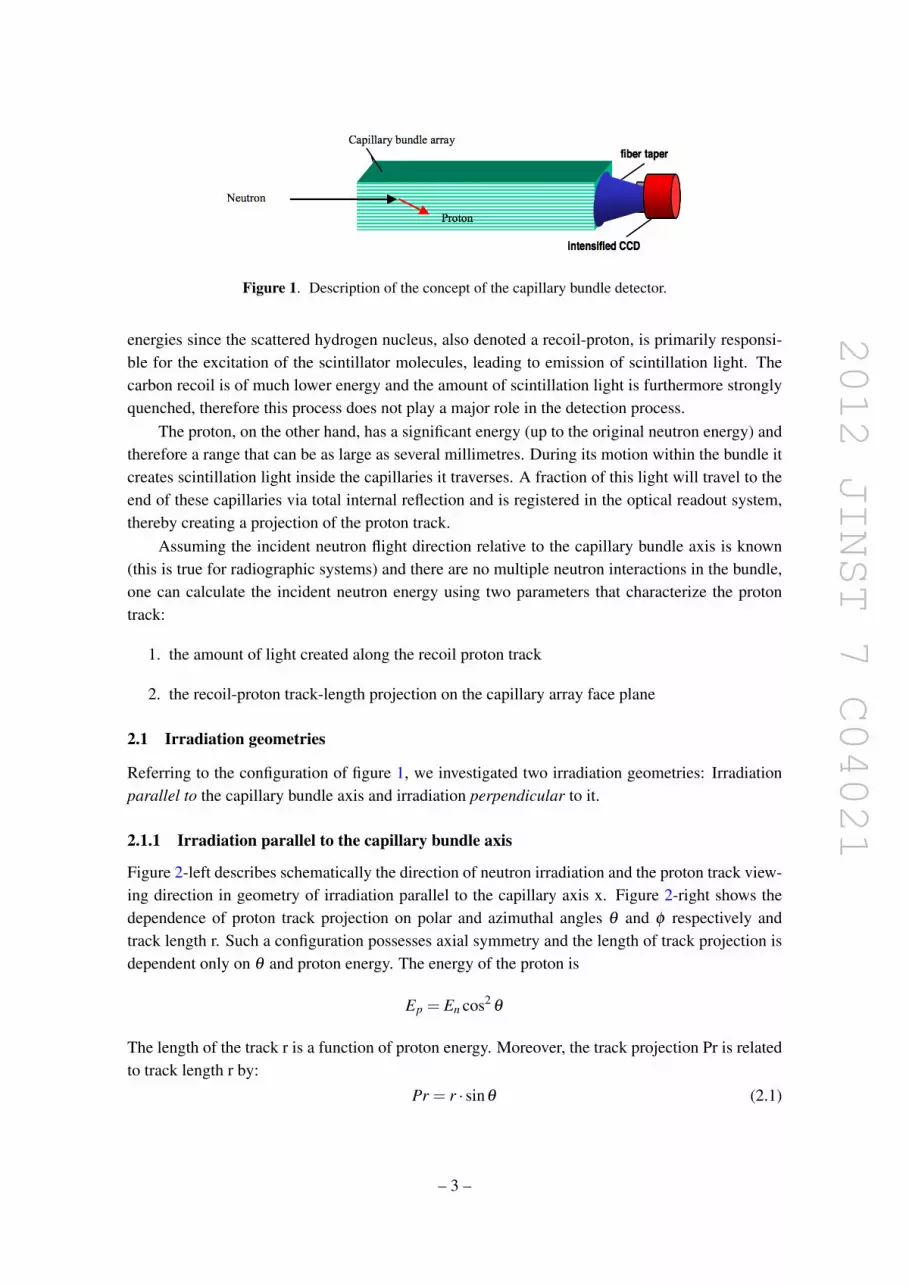
Figure 1 shows schematically the concept of the capillary bundle detector. The detector is basedon a capillary array filled with high-refractive-index liquid scintillator. The principal fast neutroninteraction (in the energy range 0.8–14 MeV) within the liquid scintillator is elastic scattering withhydrogen and, to a somewhat lesser extent, carbon, as both elements have comparable atomic den-sity in such substances. For the detection process, scattering by hydrogen is dominant at such
– 2 –
2012 JINST 7 C04021
Figure 1. Description of the concept of the capillary bundle detector.
energies since the scattered hydrogen nucleus, also denoted a recoil-proton, is primarily responsi-ble for the excitation of the scintillator molecules, leading to emission of scintillation light. Thecarbon recoil is of much lower energy and the amount of scintillation light is furthermore stronglyquenched, therefore this process does not play a major role in the detection process.
The proton, on the other hand, has a significant energy (up to the original neutron energy) andtherefore a range that can be as large as several millimetres. During its motion within the bundle itcreates scintillation light inside the capillaries it traverses. A fraction of this light will travel to theend of these capillaries via total internal reflection and is registered in the optical readout system,thereby creating a projection of the proton track.
Assuming the incident neutron flight direction relative to the capillary bundle axis is known(this is true for radiographic systems) and there are no multiple neutron interactions in the bundle,one can calculate the incident neutron energy using two parameters that characterize the protontrack:
1. the amount of light created along the recoil proton track
2. the recoil-proton track-length projection on the capillary array face plane
2.1 Irradiation geometries
Referring to the configuration of figure 1, we investigated two irradiation geometries: Irradiationparallel to the capillary bundle axis and irradiation perpendicular to it.
2.1.1 Irradiation parallel to the capillary bundle axis
Figure 2-left describes schematically the direction of neutron irradiation and the proton track view-ing direction in geometry of irradiation parallel to the capillary axis x. Figure 2-right shows thedependence of proton track projection on polar and azimuthal angles θ and φ respectively andtrack length r. Such a configuration possesses axial symmetry and the length of track projection isdependent only on θ and proton energy. The energy of the proton is
Ep = En cos2θ
The length of the track r is a function of proton energy. Moreover, the track projection Pr is relatedto track length r by:
Pr = r · sinθ (2.1)
– 3 –

2012 JINST 7 C04021
Figure 2. Geometry of irradiation parallel the capillary axis x.
Figure 3. Geometry of irradiation perpendicular to the capillary axis (along z axis).
The projections are usually short, since forward-going protons (small θ ) will have high energies(that produce more light) but short track projections. As θ increases, the proton energy decreases,thus giving rise to shorter tracks and creating less light.
The crucial feature for the present application is that this configuration permits neutron imag-ing with very high position resolution (typically, tens of microns).
2.1.2 Irradiation perpendicular to the capillary bundle axis
Here the projection Pr is related to track length r by:
Pr = (r2 sin2θ′ cos2
ϕ′+ r2 cos2
θ′)1/2 (2.2)
– 4 –

2012 JINST 7 C04021
There is no axial symmetry along the capillary axis but, in contrast to the previous configuration,the projection length always increases with the length of the proton track.
The projection angle α relative to the direction of the incident neutron is:
tgα = tgθ′ cosφ
′ (2.3)
For φ ’=90o α=0 and the projection Pr is reduced to Pr=r·cosθ ’. Thus for small α’s (or forward-going protons) one can use this expression. In this configuration neutron imaging is not possibleand the detector can be only used as a spectrometer.
2.2 Determination of neutron energy
The only two measurable quantities available are:
• the total amount of light in the track-L
• the track projection length-Pr.
Ignoring for the time being the energy loss in the capillary walls, the amount of light L is propor-tional to the initial proton energy Ep which, in turn, is related to the incident neutron energy byEp = En cos2 θ . In principle, knowledge of Ep should yield information on the true track lengthr in the volume of the bundle. Knowing the relation between the measured Pr and r provides anestimate of θ . Using Ep and the relationship Ep = En cos2 θ one can now determine En.
Clearly, in a physical system of liquid capillaries which include non-negligible capillary walls,the situation is more complicated. In order to study this issue, the capillary system was modelledvia Monte-Carlo simulations.
3 Detector simulations
Detailed capillary detector simulations were performed in order to find relations necessary forreconstruction of the incident neutron energy, namely: recoil-proton energy and recoil-proton track-length vs. total created light
3.1 Detector geometry
An array of 500× 500 round quartz capillaries (refractive index=1.4632), a section of which isshown in figure 4, was simulated. Individual capillary dimensions were: 11 µm in diameter (1µm wall thickness) and 3 cm in length. The scintillator within the capillaries had the followingproperties: density: 0.964 gr/cm3, H/C ratio 1.249, refractive index=1.57, which correspond to theEJ309 liquid scintillator manufactured by ELJEN company [11].
In the simulations the response of the capillary array in both irradiation geometries, parallel tothe capillary array axis and perpendicular to it, were investigated. The following parameters wererecorded for each recoil proton created:
• Point of interaction
• Number of capillaries traversed (track-length projection),
– 5 –

2012 JINST 7 C04021
Figure 4. A section of the capillary array (perpendicular irradiation).
• Full track length in µm,
• Initial recoil proton energy
• Energy deposited in each capillary traversed by the proton
• Number of photons created in each capillary along the track
• Origin of proton creation (capillary core or capillary wall).
• For perpendicular irradiation, the angle α between the track projection and direction of theincident neutron
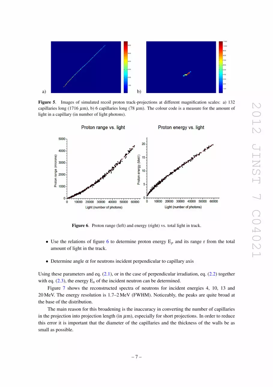
The above parameters were determined for incident neutrons with energies of 4, 10, 13 and 20 MeV.Figures 5a and 5b show two recoil proton track-projections (different magnification scale)
generated by 20 MeV neutrons, 132 and 6 capillaries long (corresponding to 1716 µm and 78 µmprojected track lengths), respectively. As can be seen, each track exhibits increased scintillationlight emission at one end, indicating the Bragg peak. Thus it is possible to determine with highaccuracy (tens of microns) the location of the neutron interaction.
Figure 6 shows the relation between proton range (in microns) and energy (in MeV) vs. totallight yield per track for 20 MeV incident neutrons.
Using these relationships it is possible to determine the proton energy and its track length bymeasuring the total amount of light in the track.
3.2 Reconstruction of neutron energy
The reconstruction of neutron energy from simulated data is performed for each detected neutronusing the following method:
• Count the number of capillaries traversed by the recoil proton
• Convert this number into the projected proton track length Pr (in µm).
• Determine the total amount of light in the track
– 6 –
2012 JINST 7 C04021
a) b)
Figure 5. Images of simulated recoil proton track-projections at different magnification scales: a) 132capillaries long (1716 µm), b) 6 capillaries long (78 µm). The colour code is a measure for the amount oflight in a capillary (in number of light photons).
Figure 6. Proton range (left) and energy (right) vs. total light in track.
• Use the relations of figure 6 to determine proton energy Ep and its range r from the totalamount of light in the track.
• Determine angle α for neutrons incident perpendicular to capillary axis
Using these parameters and eq. (2.1), or in the case of perpendicular irradiation, eq. (2.2) togetherwith eq. (2.3), the energy En of the incident neutron can be determined.
Figure 7 shows the reconstructed spectra of neutrons for incident energies 4, 10, 13 and20 MeV. The energy resolution is 1.7–2 MeV (FWHM). Noticeably, the peaks are quite broad atthe base of the distribution.
The main reason for this broadening is the inaccuracy in converting the number of capillariesin the projection into projection length (in µm), especially for short projections. In order to reducethis error it is important that the diameter of the capillaries and the thickness of the walls be assmall as possible.
– 7 –

2012 JINST 7 C04021
Figure 7. Reconstructed neutron spectra (simulated data, perpendicular irradiation).
The spectra in figure 7. show only tracks where the projected length is larger than 3 capillaries.The distributions can be improved if we reject the short projections. Figure 8 shows a reconstructedmonoenergetic 4 MeV neutron spectrum for tracks with projected length larger than 7 capillaries.As can be observed the spectrum is narrower and without tails. However, rejecting the short tracksreduces the counting efficiency at this neutron energy, by a factor of 2.
4 Experimental setup
The capillary detector, seen in figure 9, consists of the following components: capillary array filledwith liquid scintillator, lens assembly, time-gated image-intensifier and cooled CCD camera.
4.1 Capillary array
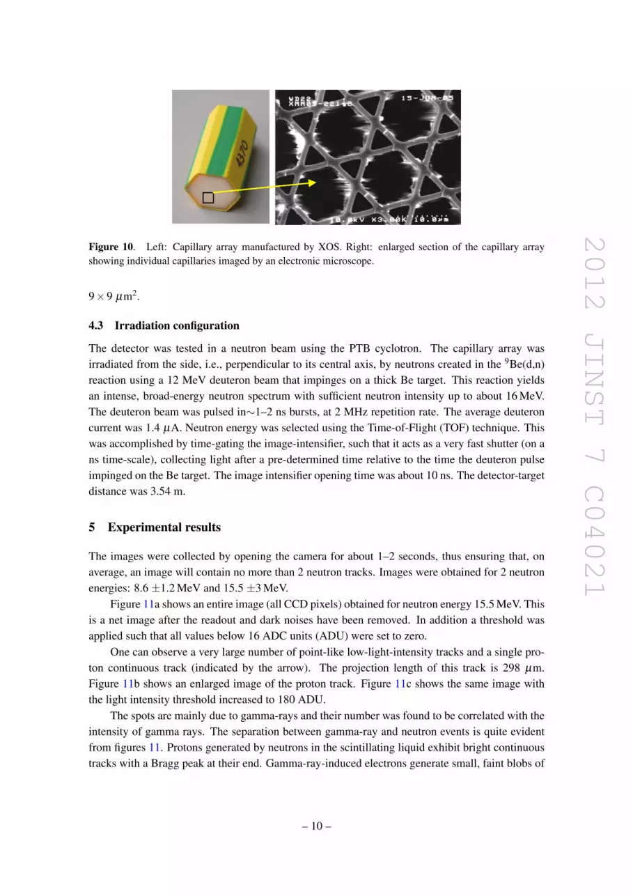
In order to achieve high energy- and spatial-resolution, the capillary cross-sectional dimensionsshould be as small as possible. Figure 10 shows a small capillary array made from silica glass(1.4 cm in width, 3 cm in length, refractive index n=1.4632) made by the XOS company [12].The dimensions of a single capillary are: inner average diameter 11 µm, wall thickness 1 µm; theusable free area (excluding the triangular patterns in figure 10) is about 72%.
– 8 –

2012 JINST 7 C04021
Figure 8. Reconstructed 4 MeV neutron spectrum, track projection length > 7 capillaries.
Figure 9. The capillary detector setup.
The array was filled by capillary action with EJ309 scintillator manufactured by ELJEN [11],presenting the following characteristics: refractive index n=1.57, light yield = 11,500 photons/MeVee,density: 0.965 g/cm, H/C ratio = 1.25, light output: 75% of anthracene.
4.2 Optics and track imaging
The rear end of the capillary array was viewed by a magnifying tandem lens configuration, whichconsists of f=200 mm and f=50 mm lenses mounted face-to-face, resulting in a magnification factorof 4. The image was focused on the photocathode of a 25 mm diameter gateable, two multi-channelplates (MCP) image intensifier manufactured by Proxitronic, Germany. The intensified image atthe phosphor of the intensifier was viewed by a cooled CCD camera ML16083, manufactured byFinger Lakes Instrumentation. The CCD size was 4096× 4096 pixels with pixel dimensions of
– 9 –
2012 JINST 7 C04021
Figure 10. Left: Capillary array manufactured by XOS. Right: enlarged section of the capillary arrayshowing individual capillaries imaged by an electronic microscope.
9×9 µm2.
4.3 Irradiation configuration
The detector was tested in a neutron beam using the PTB cyclotron. The capillary array wasirradiated from the side, i.e., perpendicular to its central axis, by neutrons created in the 9Be(d,n)reaction using a 12 MeV deuteron beam that impinges on a thick Be target. This reaction yieldsan intense, broad-energy neutron spectrum with sufficient neutron intensity up to about 16 MeV.The deuteron beam was pulsed in∼1–2 ns bursts, at 2 MHz repetition rate. The average deuteroncurrent was 1.4 µA. Neutron energy was selected using the Time-of-Flight (TOF) technique. Thiswas accomplished by time-gating the image-intensifier, such that it acts as a very fast shutter (on ans time-scale), collecting light after a pre-determined time relative to the time the deuteron pulseimpinged on the Be target. The image intensifier opening time was about 10 ns. The detector-targetdistance was 3.54 m.
5 Experimental results
The images were collected by opening the camera for about 1–2 seconds, thus ensuring that, onaverage, an image will contain no more than 2 neutron tracks. Images were obtained for 2 neutronenergies: 8.6 ±1.2 MeV and 15.5 ±3 MeV.
Figure 11a shows an entire image (all CCD pixels) obtained for neutron energy 15.5 MeV. Thisis a net image after the readout and dark noises have been removed. In addition a threshold wasapplied such that all values below 16 ADC units (ADU) were set to zero.
One can observe a very large number of point-like low-light-intensity tracks and a single pro-ton continuous track (indicated by the arrow). The projection length of this track is 298 µm.Figure 11b shows an enlarged image of the proton track. Figure 11c shows the same image withthe light intensity threshold increased to 180 ADU.
The spots are mainly due to gamma-rays and their number was found to be correlated with theintensity of gamma rays. The separation between gamma-ray and neutron events is quite evidentfrom figures 11. Protons generated by neutrons in the scintillating liquid exhibit bright continuoustracks with a Bragg peak at their end. Gamma-ray-induced electrons generate small, faint blobs of
– 10 –

2012 JINST 7 C04021
Figure 11. CCD image of the capillary array a) entire image, b) image zoomed on the proton track, c)thresholded image, neutron energy 15.5 MeV.
Figure 12. Examples of 3 proton tracks obtained for 15.5 MeV neutrons.
light, that appear in figure 11a as a multitude of specks. The separation of electron from protonevents can, in principle, be performed automatically by using light and track length thresholding,pixel connectivity analysis and the existence of a Bragg peak. As is evident from figure 11c asimple thresholding procedure removes most of the gamma-ray induced events.
Figure 12 shows 3 additional samples of proton tracks obtained in this run. In all of them theBragg peak is clearly discernible.
At this stage of the project the identification of the proton tracks has been performed by visualinspection of the CCD images. This is a rather labor-consuming task, so that a computerized trackrecognition procedure needs to be developed for rapid automatic identification of proton tracks ina large number of CCD images. In this experiment about 60 proton tracks, with projection lengthabove 7 capillaries, were collected and used in the energy reconstruction. The energy reconstructionprocedure is identical to that described in section 3.2
Figure 13 shows the reconstructed energy spectrum. Clearly, the event statistics is rather poor;nevertheless there is strong evidence for the existence of two neutron groups at about 8.6 MeV andat 15.5 MeV. In this reconstruction, no correction for variability in light emission over the capillarybundle cross-section was made. In addition, one has to take into account the non-uniformitiesof light collection and of the image-intensifier photocathode quantum-efficiency over the imagearea. The correction for these effects can be made by illuminating the capillary bundle with auniform light source and registering the relative intensity for each CCD pixel. This can be used forcorrection of track light intensity.
– 11 –

2012 JINST 7 C04021
Figure 13. Reconstructed spectrum of 8,6 and 15.5 MeV neutrons.
6 Conclusions
An imaging neutron detector consisting of micro-capillaries filled with a high refractive indexliquid scintillator has been developed. The important properties of the detector are: high positionresolution (tens of microns) and good rejection of gamma-ray events. The detection efficiency isdependent on the size of the capillary array and, in principle, can be in the range of 10–20%.
The energy reconstruction method presented here, based on the determination of light yieldand the projection length of each proton track, resulted in 10–15% energy resolution in the energyrange of 4–20 MeV. This energy resolution is inferior by a factor of 2–4 to that obtainable withnon-imaging organic spectrometers that use unfolding algorithms [13] and is certainly poorer thanTOF spectrometry. However, its energy resolution is much better than that of the Bonner multi-sphere method [13]. It is planned to investigate the standard unfolding reconstruction procedureswith the capillary detector, in order to achieve better energy resolution, and yet maintain the highposition resolution.
For high resolution neutron imaging and for neutron spectroscopy based on the method de-scribed here, the direction of the incident neutron relatively to the capillary axis direction must beknown. If the detector is intended for non-spectroscopic purposes, but efficient gamma-ray rejec-tion is none-the-less required, it is possible to use larger diameter capillaries and the direction ofthe incident neutron is of no importance.
References
[1] J.M. Ryan et al., A scintillating plastic fiber tracking detector for neutron and proton imaging andspectroscopy, Nucl. Instrum. Meth. A 422 (1999) 49.
– 12 –

2012 JINST 7 C04021
[2] R.S. Miller et al., SONTRAC: An imaging spectrometer for MeV neutrons, Nucl. Instrum. Meth. A505 (2003) 36.
[3] J.M. Ryan et al., Development and performance of the Fast Neutron Imaging Telescope for SNMdetection, Proc. SPIE 6945 (2008) 694509.
[4] J. Peel et al., Development of a directional scintillating fiber detector for 14 MeV neutrons, Nucl.Instrum. Meth. A 556 (2006) 287.
[5] http://www.detectors.saint-gobain.com/.
[6] L. Disdier et al., Capillary detector with deuterated scintillator for inertial confinement fusionneutron images, Rev. Sci. Instrum. 75 (2004) 2134.
[7] P. Annis et al., High-resolution tracking using large capillary bundles filled with liquid scintillator,Nucl. Instrum. Meth. A 449 (2000) 60.
[8] M. Brandis et al., Proof of principle of a high-spatial-resolution, resonant-response gamma-raydetector for Gamma Resonance Absorption in 14N, 2011 JINST 6 PO2008.
[9] V. Dangendorf et al., Detectors for Energy Resolved Fast Neutron Imaging, Nucl. Instrum. Meth. A535 (2004) 93.
[10] I. Mor et al., Parameters affecting image quality with time-resolved optical integrative neutron(TRION) detector, Nucl. Instrum. Meth. A 640 (2011) 192.
[11] http://www.eljentechnology.com/.
[12] http://www.xos.com/.
[13] F.D. Brooks and H. Klein, Neutron spectrometry-historical review and present status, Nucl. Instrum.Meth. A 476 (2002) 1.
– 13 –