faa order 8260.19h (change 1 only)
TRANSCRIPT
Distribution: Electronic Distribution Initiated By: AFS-400
CHANGE U.S. DEPARTMENT OF TRANSPORTATIONFEDERAL AVIATION ADMINISTRATION
ORDER 8260.19H CHG 1
National Policy Effective Date:
04/26/2018
SUBJ: Flight Procedures and Airspace
1. Purpose. This change incorporates the updated Flight Standards organization structure whileremoving all Flight Standards routing symbols/codes. Also, this change transfers approvalauthority for special instrument flight procedures from the Flight Technologies and ProceduresDivision to the Flight Procedure Implementation and Oversight Branch. It assigns the FlightProcedure Implementation and Oversight Branch as the approval authority for instrument flightprocedures that require specific approval (as identified in this and other 8260-series orders), orthat require waivers to procedure design standards. In addition, the approval authority forAttention All Users Pages (AAUP) have been moved from the Flight Technologies andProcedures Division to the Flight Operations Branch. These changes are intended to reduceadministrative redundancies and improve customer response times. Other editorial changesunrelated to policy and/or guidance have been made to correct publishing errors throughout thedocument.
2. Who this change affects. This change affects only the internal processes within FlightTechnologies and Procedures Division.
3. Where You Can Find This Change. You can find this change on the DirectivesManagement System (DMS) Website: http://www.faa.gov/regulations_policies/orders_notices.
4. Explanation of Changes. Significant areas of new direction, guidance, policy and/or criteriaas follows:
a. General. Throughout the document, Flight Standards’ routing symbols/codes have beenremoved and replaced with the appropriate organizational title.
b. Chapter 1.
(1) Paragraph 1-2-2.a. Deleted last sentence that indicated the division (i.e., FlightTechnologies and Procedures Division) is responsible for the approval/disapproval of special instrument flight procedures and waivers.
c. Paragraph 1-2-2.f. Revised description of Flight Procedure Implementation and OversightBranch’s responsibilities to be inclusive of having the approval authority for specials, approvals, and waivers.
d. Chapter 2.
04/26/2018 Order 8260.19H CHG 1
2
(1) Paragraph 2-12-1, General. Revised language to reflect the Flight ProcedureImplementation and Oversight Branch may permit deviations to standards.
(2) Paragraph 2-12-6.a. Replaced “AFS-400” with “Flight Procedure Implementationand Oversight Branch.”
(3) Paragraph 2-12-6.c. Replaced “AFS-400” with “Flight Procedure Implementationand Oversight Branch.
e. Chapter 4.
(1) Paragraph 4-5-3.m. Replaced “AFS-400” with “Flight Procedure Implementationand Oversight Branch.”
f. Chapter 8.
(1) Table 8-3-2. In the top two rows related to Form 8260-1, replaced “AFS-400” with“Flight Procedure Implementation and Oversight Branch.”
(2) Paragraph 8-4-1. Replaced “AFS-400” with “Flight Procedure Implementation andOversight Branch.”
(3) Paragraph 8-4-1.i. Revised text to remove “AFS-400” from the waiver process andto replace with “Flight Procedure Implementation and Oversight Branch.”
(4) Paragraph 8-5-2.t(4). Replaced “AFS-400” with “Flight Procedure Implementationand Oversight Branch.”
(5) Paragraph 8-6-9.j. Replaced “Flight Standards” with “Flight ProcedureImplementation and Oversight Branch.”
(6) Paragraph 8-6-9.m. Replaced “Flight Standards” with “Flight ProcedureImplementation and Oversight Branch.”
(7) Paragraph 8-6-10.o, Note 1. Replaced “AFS-400” with “Flight ProcedureImplementation and Oversight Branch”
(8) Paragraph 8-6-11.o(2)(h). Replaced “AFS-400” with “Flight ProcedureImplementation and Oversight Branch.”
(9) Paragraph 8-6-17. Replaced “AFS-400” with “Flight Procedure Implementation andOversight Branch.”
(10) Paragraph 8-6-18.b(2). Replaced “AFS-460 Manager” with “Flight ProcedureImplementation and Oversight Branch.”
(11) Paragraph 8-10-4. Revised to indicate Flight Operations Branch as the approvalauthority for AAUPs.
04/26/2018 Order 8260.19H CHG 1
3
(12) Paragraph 8-10-5. Replaced instances of “AFS-400” with “Flight OperationsBranch.”
(13) Paragraph 8-10-9.c. Replaced “AFS-400” with “Flight Operations Branch.”
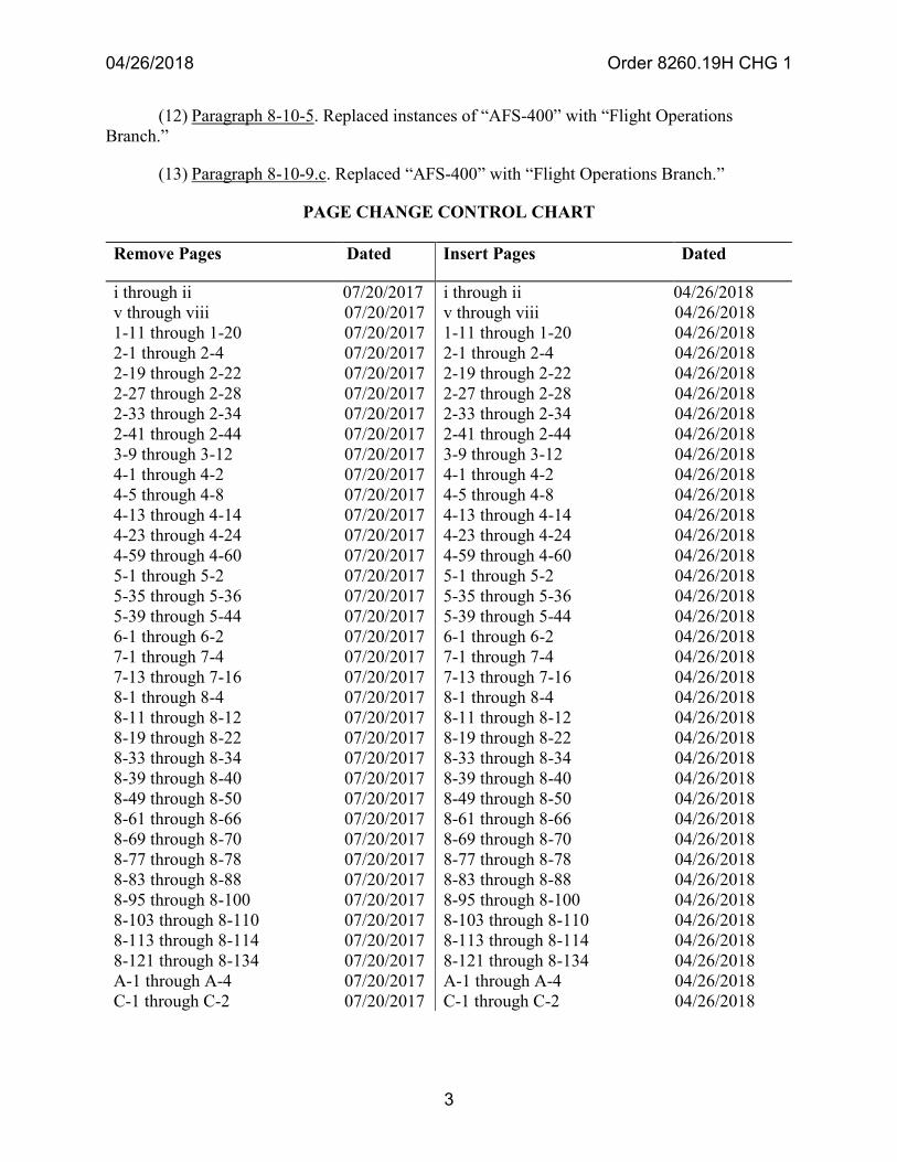
PAGE CHANGE CONTROL CHART
Remove Pages Dated Insert Pages Dated
i through ii 07/20/2017 i through ii 04/26/2018 v through viii 07/20/2017 v through viii 04/26/2018 1-11 through 1-20 07/20/2017 1-11 through 1-20 04/26/2018 2-1 through 2-4 07/20/2017 2-1 through 2-4 04/26/2018 2-19 through 2-22 07/20/2017 2-19 through 2-22 04/26/2018 2-27 through 2-28 07/20/2017 2-27 through 2-28 04/26/2018 2-33 through 2-34 07/20/2017 2-33 through 2-34 04/26/2018 2-41 through 2-44 07/20/2017 2-41 through 2-44 04/26/2018 3-9 through 3-12 07/20/2017 3-9 through 3-12 04/26/2018 4-1 through 4-2 07/20/2017 4-1 through 4-2 04/26/2018 4-5 through 4-8 07/20/2017 4-5 through 4-8 04/26/2018 4-13 through 4-14 07/20/2017 4-13 through 4-14 04/26/2018 4-23 through 4-24 07/20/2017 4-23 through 4-24 04/26/2018 4-59 through 4-60 07/20/2017 4-59 through 4-60 04/26/2018 5-1 through 5-2 07/20/2017 5-1 through 5-2 04/26/2018 5-35 through 5-36 07/20/2017 5-35 through 5-36 04/26/2018 5-39 through 5-44 07/20/2017 5-39 through 5-44 04/26/2018 6-1 through 6-2 07/20/2017 6-1 through 6-2 04/26/2018 7-1 through 7-4 07/20/2017 7-1 through 7-4 04/26/2018 7-13 through 7-16 07/20/2017 7-13 through 7-16 04/26/2018 8-1 through 8-4 07/20/2017 8-1 through 8-4 04/26/2018 8-11 through 8-12 07/20/2017 8-11 through 8-12 04/26/2018 8-19 through 8-22 07/20/2017 8-19 through 8-22 04/26/2018 8-33 through 8-34 07/20/2017 8-33 through 8-34 04/26/2018 8-39 through 8-40 07/20/2017 8-39 through 8-40 04/26/2018 8-49 through 8-50 07/20/2017 8-49 through 8-50 04/26/2018 8-61 through 8-66 07/20/2017 8-61 through 8-66 04/26/2018 8-69 through 8-70 07/20/2017 8-69 through 8-70 04/26/2018 8-77 through 8-78 07/20/2017 8-77 through 8-78 04/26/2018 8-83 through 8-88 07/20/2017 8-83 through 8-88 04/26/2018 8-95 through 8-100 07/20/2017 8-95 through 8-100 04/26/2018 8-103 through 8-110 07/20/2017 8-103 through 8-110 04/26/2018 8-113 through 8-114 07/20/2017 8-113 through 8-114 04/26/2018 8-121 through 8-134 07/20/2017 8-121 through 8-134 04/26/2018 A-1 through A-4 07/20/2017 A-1 through A-4 04/26/2018 C-1 through C-2 07/20/2017 C-1 through C-2 04/26/2018

04/26/2018 Order 8260.19H CHG 1
4
4. Distribution. This change is distributed electronically only.
John Duncan Executive Director, Flight Standards Service
04/26/2018 Order 8260.19H CHG 1 Table of Contents
i
Table of Contents
Chapter 1. General Information ................................................................................ 1-1
Section 1-1. General .................................................................................................................... 1-1 1-1-1. Purpose of this order .................................................................................................... 1-1 1-1-2. Audience ...................................................................................................................... 1-1 1-1-3. Where you can find this order ..................................................................................... 1-1 1-1-4. What this order cancels ............................................................................................... 1-1 1-1-5. Explanation of changes ............................................................................................... 1-1 1-1-6. Effective Date ............................................................................................................ 1-10
Section 1-2. Responsibilities ...................................................................................................... 1-11 1-2-1. Flight Standards Service ............................................................................................ 1-11 1-2-2. Flight Technologies and Procedures Division ........................................................... 1-11 1-2-3. Air Traffic Organization, Flight Program Operations ............................................... 1-14 1-2-4. Air Traffic Organization, Mission Support Services (AJV-0) .................................. 1-15 1-2-5. Individual ................................................................................................................... 1-19
Chapter 2. General Procedures ................................................................................. 2-1
Section 2-1. General .................................................................................................................... 2-1 2-1-1. Requests for public-use IFPs ....................................................................................... 2-1 2-1-2. Air Traffic Letters of Agreement (LOAs) ................................................................... 2-1 2-1-3. Airport lighting and visual aids ................................................................................... 2-1
Section 2-2. Aeronautical Charts ................................................................................................. 2-3 2-2-1. Use of maps and charts ................................................................................................ 2-3 2-2-2. Aeronautical charts and publications .......................................................................... 2-3
Section 2-3. Environmental Requirements ................................................................................... 2-5 2-3-1. Noise abatement .......................................................................................................... 2-5 2-3-2. Environmental impacts ................................................................................................ 2-5
Section 2-4. Facility Utilization and Monitoring ......................................................................... 2-6 2-4-1. Frequency Service Volumes ........................................................................................ 2-6 2-4-2. ATC usable distance and altitude limitations .............................................................. 2-6 2-4-3. Requests for Expanded Service Volumes ................................................................... 2-8 2-4-4. Utilization of localizers ............................................................................................... 2-9 2-4-5. Monitoring of navigation facilities .............................................................................. 2-9 2-4-6. Utilization of monitoring categories .......................................................................... 2-10 2-4-7. Utilization of 75 MHz markers ................................................................................. 2-10
Section 2-5. Implementing Epoch Year Magnetic Variation (MV) ............................................ 2-12 2-5-1. General ...................................................................................................................... 2-12 2-5-2. Responsibilities ......................................................................................................... 2-12 2-5-3. Guidelines for Magnetic Variation (MV) revisions .................................................. 2-17
04/26/2018 Order 8260.19H CHG 1 Table of Contents
ii
Section 2-6. Notices to Airmen (NOTAMs) ................................................................................ 2-20 2-6-1. General ...................................................................................................................... 2-20 2-6-2. United States NOTAM System .................................................................................. 2-20
Section 2-7. Quality/Standardization of Instrument Flight Procedures .................................... 2-21 2-7-1. Aeronautical Information Services action ................................................................. 2-21 2-7-2. Flight Procedure Implementation and Oversight Branch’s action ............................ 2-21
Section 2-8. Periodic Review of Instrument Flight Procedures ................................................ 2-22 2-8-1. General ...................................................................................................................... 2-22 2-8-2. Reviewing organization action .................................................................................. 2-23
Section 2-9. Communications and Weather ............................................................................... 2-25 2-9-1. Communications requirements .................................................................................. 2-25 2-9-2. Use of UNICOM ....................................................................................................... 2-25 2-9-3. Automatic altimeter setting and weather reporting systems ..................................... 2-25
Section 2-10. Navigational Fixes ............................................................................................... 2-26 2-10-1. General ...................................................................................................................... 2-26 2-10-2. Reporting points ........................................................................................................ 2-26 2-10-3. Unplanned holding at designated reporting points .................................................... 2-26 2-10-4. Requests for navigational fixes ................................................................................. 2-26 2-10-5. Naming navigational fixes ......................................................................................... 2-27 2-10-6. Documenting navigational fixes ................................................................................ 2-29 2-10-7. Correlation of navigational fixes and changeover points .......................................... 2-29 2-10-8. Minimum reception altitudes ..................................................................................... 2-30 2-10-9. Flight inspection ........................................................................................................ 2-30 2-10-10. Maximum authorized altitudes .................................................................................. 2-31
Section 2-11. Obstacle Data ...................................................................................................... 2-32 2-11-1. General ...................................................................................................................... 2-32 2-11-2. Obstacle application and data sources ....................................................................... 2-32 2-11-3. Obstacle data accuracy standards .............................................................................. 2-33 2-11-4. Accuracy standards application ................................................................................. 2-34 2-11-5. Controlling obstacles .................................................................................................. 2-35 2-11-6. Datums ....................................................................................................................... 2-40
Section 2-12. Waiver of Standards/Approval Requests .............................................................. 2-42 2-12-1. General ...................................................................................................................... 2-42 2-12-2. Waiver processing ..................................................................................................... 2-42 2-12-3. Waivers for Special Instrument Approach Procedures ............................................. 2-43 2-12-4. Safety Management System (SMS) requirements ..................................................... 2-43 2-12-5. Periodic review of waivers ........................................................................................ 2-44 2-12-6. Cancellation ............................................................................................................... 2-44
04/26/2018 Order 8260.19H CHG 1 Table of Contents
v
Section 5-3. Airport Airspace Analysis ...................................................................................... 5-39 5-3-1. General ...................................................................................................................... 5-39 5-3-2. Service Area OSG-FPT/Flight Standards inputs ....................................................... 5-39 5-3-3. Flight Standards performs the flight safety review of airport proposals ................... 5-39 5-3-4. Service Area OSG-FPT is responsible for evaluation ............................................... 5-39 5-3-5. Alterations of airports or heliports ............................................................................ 5-40 5-3-6. Deactivation of airports or heliports ........................................................................... 5-40 5-3-7. Assistance in zoning problems .................................................................................. 5-41
Section 5-4. Restricted Areas ..................................................................................................... 5-42 5-4-1. General ...................................................................................................................... 5-42 5-4-2. Letter of procedures ................................................................................................... 5-42
Section 5-5. Establishment, Relocation, or Discontinuance of Radio Navigation Aids ........... 5-43 5-5-1. Criteria and guidelines ............................................................................................... 5-43 5-5-2. OSG-FPT action ........................................................................................................ 5-43 5-5-3. Flight Standards action .............................................................................................. 5-43
Chapter 6. Military Procedures ................................................................................. 6-1
6-1-1. General ........................................................................................................................ 6-1 6-1-2. Review and coordination ............................................................................................. 6-1 6-1-3. FAA acceptance .......................................................................................................... 6-1 6-1-4. Assistance .................................................................................................................... 6-1
Chapter 7. Planning .................................................................................................... 7-1
Section 7-1. General .................................................................................................................... 7-1 7-1-1. General ........................................................................................................................ 7-1
Section 7-2. Planning Standards.................................................................................................. 7-2 7-2-1. Planning standards ....................................................................................................... 7-2 7-2-2. Determination of operational benefits/improvements ................................................. 7-2
Section 7-3. Safety Analysis ......................................................................................................... 7-4 7-3-1. Performing a Safety Analysis ...................................................................................... 7-4
Section 7-4. Airway Planning ...................................................................................................... 7-7 7-4-1. General. ....................................................................................................................... 7-7
Section 7-5. Terminal Planning ................................................................................................... 7-8 7-5-1. General. ....................................................................................................................... 7-8 7-5-2. Requirements for outer compass locators ................................................................... 7-8
Section 7-6. Airport Planning .................................................................................................... 7-13 7-6-1. General ...................................................................................................................... 7-13
Section 7-7. Private Aid ............................................................................................................. 7-14 7-7-1. General ...................................................................................................................... 7-14
Section 7-8. Facilities and Equipment (F&E) Support .............................................................. 7-15 7-8-1. Support ...................................................................................................................... 7-15
04/26/2018 Order 8260.19H CHG 1 Table of Contents
vi
Chapter 8. Instrument Approach Procedures Data Transmittal System ............... 8-1
Section 8-1. General .................................................................................................................... 8-1 8-1-1. General ........................................................................................................................ 8-1
Section 8-2. FAA Form Use and Preparation ............................................................................. 8-2 8-2-1. Use of FAA forms ....................................................................................................... 8-2 8-2-2. FAA form preparation ................................................................................................. 8-3 8-2-3. Course and distance information ................................................................................. 8-4 8-2-4. Communications data .................................................................................................. 8-4 8-2-5. Terminal routes - General ............................................................................................ 8-5 8-2-6. Terminal fixes .............................................................................................................. 8-9
Section 8-3. Certification, Processing, and Review ................................................................... 8-11 8-3-1. General ...................................................................................................................... 8-11 8-3-2. Certification and processing of SIAPs ...................................................................... 8-11 8-3-3. Cancellation/Suspension of Instrument Approach Procedures ................................. 8-11 8-3-4. Revisions to IFPs ....................................................................................................... 8-12 8-3-5. Aeronautical Information Services review of SIAPs and charts ............................... 8-17 8-3-6. Processing .................................................................................................................. 8-17 8-3-7. Distribution ................................................................................................................ 8-17 8-3-8. Special procedures printing and distribution ............................................................. 8-17
Section 8-4. Flight Procedures Standards Waiver, FAA Form 8260-1 ..................................... 8-21 8-4-1. Preparation of Form 8260-1 ...................................................................................... 8-21
Section 8-5. Radio Fix and Holding Data Record, FAA Form 8260-2 ..................................... 8-24 8-5-1. Introduction ............................................................................................................... 8-24 8-5-2. Preparation of Form 8260-2 ...................................................................................... 8-24
Section 8-6. Completion of FAA Forms 8260-3/4/5/7A ............................................................. 8-35 8-6-1. General ...................................................................................................................... 8-35 8-6-2. Basic information ...................................................................................................... 8-35 8-6-3. Terminal Arrival Area (TAA) ................................................................................... 8-38 8-6-4. Terminal routes .......................................................................................................... 8-40 8-6-5. Radar terminal area maneuvering sectors and altitudes ............................................ 8-43 8-6-6. Missed Approach ....................................................................................................... 8-43 8-6-7. Profile - Lines 1 through 8 ........................................................................................ 8-48 8-6-8. Equipment requirements notes for conventional ....................................................... 8-55 8-6-9. Notes .......................................................................................................................... 8-57 8-6-10. Additional flight data ................................................................................................. 8-65 8-6-11. Minimums ................................................................................................................. 8-70 8-6-12. Changes and reasons ................................................................................................. 8-82 8-6-13. Coordinated with ....................................................................................................... 8-82 8-6-14. Submitted by .............................................................................................................. 8-83 8-6-15. Flight checked by Inspection/validation official ....................................................... 8-83 8-6-16. Developed by ............................................................................................................. 8-84 8-6-17. Recommended by ...................................................................................................... 8-84
04/26/2018 Order 8260.19H CHG 1 Table of Contents
vii
8-6-18. Approved by .............................................................................................................. 8-84 8-6-19. FAS Data Block Information .................................................................................... 8-84
Section 8-7. Standard Instrument Approach Procedure Data Record, FAA Form 8260-9 ....... 8-85 8-7-1. Preparation of Form 8260-9 ....................................................................................... 8-85
Section 8-8. Transmittal of Airways/Route Data Record, FAA Form 8260-16 ........................ 8-95 8-8-1. Preparation of Form 8260-16 .................................................................................... 8-95
Section 8-9. Simultaneous Close Parallel (SCP) and Simultaneous Offset Instrument Approach (SOIA) Procedure Attention All Users Page (AAUP) ............................ 8-121
8-9-1. Attention All Users Page ......................................................................................... 8-121 8-9-2. Site Implementation Team ...................................................................................... 8-121 8-9-3. AAUP preparation ................................................................................................... 8-121 8-9-4. AAUP processing .................................................................................................... 8-121 8-9-5. AAUP publication ................................................................................................... 8-121 8-9-6. Forms processing ..................................................................................................... 8-122 8-9-7. Title line .................................................................................................................. 8-122 8-9-8. Text .......................................................................................................................... 8-122 8-9-9. Administrative information ..................................................................................... 8-125
Appendix A. Administrative Information ................................................................. A-1
Appendix B. Flight Procedures References ............................................................ B-1
Appendix C. Obstacle Accuracy Standards, Codes, and Sources ....................... C-1
Appendix D. FAA Form 8260-2, Data Worksheet .................................................... D-1
Appendix E. Radio Fix and Holding Data Record Form ..........................................E-1
Appendix F. ILS and RNAV Standard Instrument Approach Procedure Form ..... F-1
Appendix G. Radar – Standard Instrument Approach Procedure Form ............... G-1
Appendix H. Standard Instrument Approach Procedure Form ............................. H-1
Appendix I. Special Instrument Approach Procedure and Special Instrument Procedure Authorization ............................................................................................ I-1
Appendix J. Standard Instrument Approach Procedure ......................................... J-1
Appendix K. FAS Data Block Requirements ........................................................... K-1
Appendix L. FAS Data Block Requirements for Helicopter Operations ................ L-1
Appendix M. Instrument Flight Procedures (IFP) Lifecycle ....................................... M-1

04/26/2018 Order 8260.19H CHG 1 Table of Contents
viii
THIS PAGE IS INTENTIONALLY LEFT BLANK
04/26/2018 Order 8260.19H CHG 1 Chapter 1
1-11
Section 1-2. Responsibilities
Note: Applicable FAA 1100-series directives address organizational responsibilities and functions. Responsibilities specified in this section are provided for information only and for the purpose of assisting instrument procedure developers in knowing whom to contact for assistance and/or information in the performance of their duties. Do not interpret this section as a substitute or supplement to any other FAA directive.
1-2-1. Flight Standards Service.
a. Flight Standards Service is responsible for the use of air navigation facilities, appliances,and systems by aircraft operating in established environments and the National Airspace System (NAS). Responsibility includes governing policy and oversight of manual and automated development and maintenance of terminal and en route flight procedures. The executive director has final authority to issue, amend, and terminate rules and regulations relating to instrument procedures, minimum en route altitudes, flight procedures, operational weather minimums, and minimum equipment requirements.
b. Responsibility for the overall management of the Flight Procedures and AirspaceProgram is vested in the Flight Technologies and Procedures Division. This order is primarily concerned with those offices having direct responsibility for the accomplishment of the Flight Procedures and Airspace Program. The following is a brief description of their activities.
1-2-2. Flight Technologies and Procedures Division.
a. This division is the principal element of the Flight Standards Service governing policies,criteria, and standards for establishing and maintaining terminal and en route flight procedures; for using air navigation facilities, appliances, and systems; and for validation of FAA instrument procedure design software. This office is designated as the final authority to issue, amend, and appeal minimum en route instrument flight rules (IFR) altitudes and associated flight data under 14 CFR part 95; and standard instrument approach procedures and obstacle departure procedures under 14 CFR part 97.
b. Flight Operations Branch. This branch is the principal element of the division withrespect to concepts, policies, systems, and programs associated with the operational and flight technical aspects of all-weather operations. This branch develops concepts for design, evaluation, and approval of category (CAT) I, II, and III approach and landing operations, as well as lower than standard takeoff minimums. This branch develops instrument flight operational concepts, policies, standards, criteria, requirements, specifications, and limitations for new and existing aircraft (all categories) and new and existing airborne, ground-based and space-based systems used in instrument flight operations, and develops and issues Form 8260-7B, Special Instrument Procedure Authorization, as required, through the Procedures Review Board (PRB). This branch provides technical representation to International Civil Aviation Organization (ICAO) on matters related to instrument flight operations, and maintains liaison with foreign civil aviation operational and technical authorities to encourage the acceptance of U.S. instrument flight operations standards and to foster standards with a level of safety consonant with those of the United States. In coordination with original equipment manufacturers (OEMs), Aircraft
04/26/2018 Order 8260.19H CHG 1 Chapter 1
1-12
Certification (AIR), and Aircraft Evaluation Groups (AEGs), identifies explicit operational credit for pilots using new-technology products. This branch provides specific Operations Specification (OpsSpec) language and inspector guidance regarding low visibility operations (CAT II/III) procedures and minima.
c. Flight Procedure Standards Branch. This branch is the principal element within thedivision, with respect to the rulemaking process of the flight procedures program; also with respect to the development, application, and oversight of national policies and directives for the administration of the National Flight Procedures Program; and development of criteria pertinent to the design of instrument flight procedures. This branch serves as the focal point within Flight Standards for all matters relating to airspace, cartographic programs, instrument flight procedure (IFP) Notices to Airmen (NOTAMs), and is the primary interface for industry on matters relating to instrument procedures criteria. The branch assists the Flight Procedure Implementation and Oversight Branch, providing technical advice and assistance to other FAA elements, government agencies, and industry on the interpretation and application of criteria. It analyzes and evaluates execution of flight procedure programs within the FAA to determine compliance with National policy.
d. Flight Operations Simulation Branch. This branch is the principal element within thedivision which provides simulation and human-in-the-loop analysis of new, emerging, or modified Communications, Navigation, and Surveillance (CNS) technologies and procedures in support of flight safety. This simulation and analysis is accomplished through computer modeling, human-in-the-loop observation in flight and air traffic control (ATC) simulators, and/or industry aircraft. This branch manages the Flight Operations Simulation Laboratory comprised of flight simulators and ATC controller stations that can be linked to provide real time pilot/controller interface and data collection to meet the safety studies’ and risk analyses’ data requirements. These simulations are used to support Flight Standards’ offices, ATO, airports, the aviation industry, and FAA executives who seek objective and subjective human factors safety analysis and assessments to enhance flight operations, standards, capacity, and aviation safety within the NAS and international organizations such as ICAO.
e. Flight Systems Laboratory. This branch is the principal element within the division thatanalyzes and quantifies the levels of risk probabilities associated with the implementation of new, emerging, and modified flight operational concepts and navigation systems. This branch conducts safety studies for client-proposed changes to the NAS or international standards for other Flight Standards’ offices, ATO, airports, the aviation industry, and FAA executives who seek objective safety assessments to improve flight operations, standards, capacity, aviation safety within the NAS, and international organizations such as ICAO. This branch also develops Flight Systems Laboratory tools software applications [RNAV-Pro, RDVA-Pro, and the Engine Out Surface Evaluator (EOSE)] for use in area navigation/required navigation performance (RNAV/RNP) procedure design and implementation.
f. Flight Procedure Implementation and Oversight Branch. This branch is the principalelement within the division, with respect to FAA Instrument Flight Procedures and Flight Inspection policy oversight. This branch develops policy and provides oversight of the IFP development process for government and non-FAA Service Providers. This oversight includes clarifying procedure criteria, confirming procedure development data, conducting simulator
04/26/2018 Order 8260.19H CHG 1 Chapter 1
1-13
evaluations, developing policy for flight validation of IFPs, and monitoring validation flights. This branch manages the program for the review and approval of all special IFPs. Also manages the program to review approval/waiver requests of procedure design standards, and functions as the final approving authority for those requests. This branch is responsible for coordinating non-government procedure developer NOTAM authority and access to the Federal NOTAM System (FNS) with ATO Mission Support Services, Aeronautical Information Services. This branch develops standards to ensure the orderly processing of all approved IFPs and evaluates the implementation of these standards and practices to determine compliance with established policy. This branch works with other government agencies, the military, aviation industry leaders, and the international community to improve aviation safety by assisting in the IFP development process worldwide.
g. Performance Based Navigation Branch. This branch is the principal element within thedivision, with respect to performance based navigation across all domains. This branch develops performance based navigation concepts, policies, standards, criteria, requirements, specifications, and limitations for new aircraft and new and existing airborne, ground-based and space-based systems used in instrument flight operations. This branch develops and issues Form 8260-7B, as required. In coordination with original equipment manufacturers, AIR, and AEGs, identifies and enunciates explicit operating procedures for pilots using new-technology products. This branch provides guidance to develop OpsSpec requirements (including parts C and H) related performance based navigation, operating minimums, equipment, and training. This branch is responsible for developing concepts, programs, and system requirements necessary to implement performance based navigation and procedures necessary to implement futuristic communications and surveillance capabilities for oceanic, remote area, domestic en route, and terminal area operations, and for nonprecision and precision instrument approaches. Flight Standards All Weather Operations (AWO) manages and directs air carrier, general aviation, and all weather operations programs for a specified local area. Each AWO provides the local implementation of national concepts, policies, standards, systems, procedures, and programs with respect to the operational and flight technical aspects of the all-weather operations program. AWO responsibilities include but are not limited to the following:
(a) Establishing local requirements for and managing distribution o, specialinstrument approach procedures. Receiving and resolving user/industry comments on new and revised special instrument approach procedures. Executing national programs such as the Required Navigation Performance/Authorization Required (RNP/AR) instrument approach procedure (IAP) program.
(b) Providing technical evaluations in support of local airspace programs todetermine the effect on operational safety and visual flight operations. Specific study responsibilities for AWOs are specified in Order JO 7400.2, Procedures for Handling Airspace Matters, and dictate involvement in a broad range of technical evaluations (i.e., determining feasibility for CAT II/III operations utilizing AWO missed approach tool, assessing operational safety for taxiway/runway separation, and configuration relative to a proposed CAT II/III, etc.).
(c) Coordinating the AWO portion of assigned foreign instrument approachprocedures programs as specified in Order 8260.31, Foreign Terminal Instrument Procedures (FTIPs).
04/26/2018 Order 8260.19H CHG 1 Chapter 1
1-14
(d) Approving CAT II and III operation and coordinating continuity of serviceassurance with the ATO Service Area. Local focal point for coordinating inter-service Surface Movement Guidance Control System (SMGCS) activities, site inspections, and the approval of the associated SMGCS plan and periodic reviews.
(e) Providing the operational input on matters related to local capacity studies andairport operational safety initiatives.
(f) Performing Obstruction Evaluation and Airport/Airspace Analysis (OE/AAA)evaluations to address the effect of obstacles on visual flight operations and instrument flight operations (e.g., OE studies) relative to AAA studies, assess operational safety and safety of persons and property on the ground in coordination with the Airports division, as necessary.
(g) Review of charted visual flight procedures and RNAV visual flightprocedures.
(h) Coordinating with Airports Division in the approval or denial of modificationsto airport standards, providing written safety assessment of end-around taxiway (EAT) proposals/use, and declared distance concepts (see Order JO 7400.2).
(i) Providing operational review and comments for Air Traffic TechnicalOperations Service Area’s submission of a NAS change proposal (NCP), evaluation of new ATC towers and similar ATO projects. This activity includes participation in the associated Safety Risk Management Document (SRMD) analysis and acceptance processes.
(j) Assists in developing the equivalent level of safety for an AeronauticalInformation Services originated procedures waiver.
(k) Provides local level support for activities related to non-FAA serviceproviders.
1-2-3. Air Traffic Organization, Flight Program Operations.
a. Flight Program Operations is the principal element directly responsible for the flightinspection of electronic signals-in-space from ground-based navigational aids, and/or flight validation that support aircraft departure, en route, and arrival flight procedures in the NAS. Flight procedures are also evaluated for accuracy, aeronautical data, human factors flyability, and obstacle clearance; this includes the evaluation of avionics database code which represents the IFP in the Flight Management System (FMS). Flight Program Operations supports flight inspection for the Department of Defense (DoD) on foreign navigational facilities that have been designated as essential to the defense of the United States. Flight Program Operations is also responsible for input (when solicited) to the Air Traffic Technical Operations Service Areas Facilities and Equipment (F&E) budget submission with respect to terminal air navigation aids (other than radar) and visual approach aids.
b. Flight Program Operations, Flight Inspection Scheduling is responsible for schedulingflight inspections. Flight Inspection Scheduling maintains liaison with Aeronautical Information Services, as well as other FAA offices, civil and military interests, to ensure consideration of all
04/26/2018 Order 8260.19H CHG 1 Chapter 1
1-15
requirements relating to the procedural use of navigation facilities. Flight Inspection Scheduling’s responsibilities include but are not limited to:
(1) Issuing NOTAM D in accordance with Order 8200.1, United States Standard FlightInspection Manual.
(2) Managing, processing, and coordinating flight inspection procedure packages.
(3) Scheduling special requests for flight inspections.
(4) Maintaining suitable record system reflecting the status of each flight.
(5) Managing the requirements and technology for Flight Inspection Report System,Flight Operations Management System, and Flight Management Daily Flight Log.
(6) Focal point for all PBN Policy and Support Office generated (CSV) files as well asthe KSN DME/DME directory.
(7) Providing Flight Inspection Reports (FIR) containing data pertinent to the AIRNAVdatabase and resolving AIRNAV data discrepancies.
(8) Ground evaluation (validation) of coded IFPs.
(9) Initiating and completing investigative remedial action with respect to any deficiencyor reported hazard, including restrictions or emergency revisions to procedures.
c. Aircraft Operations is the principal element within Flight Program Operations responsiblefor flight inspection of navigation aids and instrument flight procedures in support of the NAS. Flight Program Operations has multiple facilities that support the flight inspection mission.
1-2-4. Air Traffic Organization, Mission Support Services (AJV-0).
a. Aeronautical Information Services (AJV-5) is directly responsible for managing theagency’s program to provide Aeronautical Information Services to ensure the flow of information necessary for safety, regularity, and efficiency of air navigation. This office is charged with the responsibility for collecting, collating, validating, maintaining, and disseminating aeronautical data regarding the U.S. and its territories. It is also a source for database accuracy standards, content, and format.
(1) The National Flight Data Center (NFDC) is one element within AJV-5 with respect tomaintaining the National Airspace System Resources (NASR) database and for disseminating information relating to the NAS. NFDC is also responsible for maintaining proposed data within the AIRNAV database for the development of instrument flight procedures. NFDC responsibilities include but are not limited to:
(a) Publishing the daily National Flight Data Digest (NFDD) and 56-daysubscriber files to promulgate additions, changes, and deletions to non-regulatory elements of the
04/26/2018 Order 8260.19H CHG 1 Chapter 1
1-16
NAS. Respective changes are also published in Order JO 7340.2, Contractions, and Order JO 7350.8, Location Identifiers.
(b) Conducting pre-publication review of aeronautical data contained in standardinstrument approach and departure procedures, standard terminal arrivals, standard instrument departures, military training routes, navigational aids, airport data, and airspace changes submitted for action, and to identify and correct items in non-conformance with applicable directives.
(c) Validating submitted data with the NASR Database and resolvingcontradictions.
(d) Managing the development and assignment of five-letter fix names andnavigational aid (NAVAID)/airport identifiers.
(e) Issuing, on a predetermined schedule, amendments to 14 CFR part 95.
(f) Maintaining copies of 8260- and 7100-series forms that support public usestandard instrument approach procedures (SIAPs), fixes, airways, standard terminal arrival routes (STARs), and departure procedures (DPs).
(2) Aeronautical Information Services is the principal element responsible fordeveloping, directing, and recommending national policy and criteria for aeronautical information. This group serves as the Mission Support Services focal point for developing and managing Geographic Information Systems for the NAS. They are also responsible for collecting, validating, and maintaining obstacle data to support instrument flight procedure development including minimum vectoring altitude (MVA) and minimum IFR altitude (MIA) charts as well as minimum safe altitude warning (MSAW) data creation. Responsibilities include but are not limited to:
(a) Establishing the U.S. position for AIM and Aeronautical Information Servicesthrough the ICAO.
(b) Collecting, validating, managing, and disseminating as-built obstacle datareported under 14 CFR part 77.
1. Providing the publically-available Digital Obstacle File (DOF), whichcontains a record of all as-built man-made obstructions that effect domestic aeronautical charting products.
2. Providing Obstacle Repository System (ORS) data to other FAA officeson a timely basis.
(c) Verifying source data for as-built obstacles and assigning accuracy codes thatreflect the reliability of the reported obstacle's vertical height and horizontal position.
(d) Managing the verification/validation of airport survey safety critical data.
04/26/2018 Order 8260.19H CHG 1 Chapter 1
1-17
(e) Managing the requirements and technology to support database needs andinfrastructure.
b. Aeronautical Information Services (AJV-5) is also responsible for the development,maintenance, quality assurance, and technical approval of public-use flight procedures, production, and distribution of aeronautical charts and related publications and products. Responsibilities include but are not limited to the following:
(1) Development, publication, and maintenance of SIAPs.
(2) Development, publication, and maintenance of obstacle departure procedures (ODPs)and standard instrument departure procedures (SIDs). Development and maintenance of diverse vector areas (DVA).
(3) Development, publication, and maintenance of Air Traffic Service (ATS) routes.
(4) Review and publication of STAR Airport diagrams and special graphics.
(5) Responsible for quality assurance of items produced by Aeronautical InformationServices.
(6) Operations support, as requested, for NAS-related products.
(7) Selecting and evaluating source data for final chart compilation.
(8) Validating geographical positions, distances, and bearings of items produced byAeronautical Information Services.
(9) Maintaining liaison with elements of FAA to support safe and accurate portrayal ofcharting data.
(10) Providing civilian charts in support of military requirements.
(11) Providing international charting support to selected foreign countries.
(12) Establishing procedures to ensure operational data are included in the NASRdatabase.
(13) Analyzing obstruction evaluations to determine the effects on current and plannedinstrument flight operations, minimums, and/or flight altitudes of all civil, joint-use, and U.S. Army instrument procedures in accordance with current policy.
(14) Promulgating SIAPs, ODPs, and permanent FDC NOTAMs relating to IFPs withassigned effective dates in a bi-weekly transmittal letter and completing necessary requirements for publication in 14 CFR part 97.
c. Air Traffic Standards & Procedures Directorate (AJV-8) provides support to air trafficoperations through policy, procedures, separation standards, equipment, software, and other operations related to air traffic activities across the NAS. AJV-8 serves as the primary point of
04/26/2018 Order 8260.19H CHG 1 Chapter 1
1-18
contact for the Service Areas, Service Centers and field facilities for Terminal, En Route and Oceanic/Offshore operations, standards, and procedures issues. AJV-8 has the following responsibilities regarding ATC policies, standards, and procedures:
(1) Develop and maintain procedural changes to the NAS in support of new systems ornew technologies, or capacity and efficiency improvements, or for the purposes of risk mitigation. These procedural changes are normally accomplished by creating or revising an existing air traffic order.
(2) Effectuate NAS changes through the document change process, issuance of a notice,or the creation of a new air traffic order.
(3) Assess and approve Air Traffic Procedural Waivers, including waivers to separationminima as defined Order 1100.161, Air Traffic Oversight, paragraph 4.2.d.3.
(4) Prepare air traffic procedural interpretations.
(5) Assess and approve letters of authorization for airshows and fly-ins and otherprocedures in accordance with existing orders.
d. Service Center, Operational Support Group, Flight Procedures Teams (OSG-FPTs),responsibilities include but are not limited to:
(1) Evaluating and responding to industry and user comments relating to instrumentprocedures.
(2) Serving as Chairperson of the Regional Airspace and Procedures Team (RAPT)under Order 8260.43, Flight Procedure Management Program.
(3) Coordinating requests for new instrument procedures service with the respective AirTraffic Service Area and other concerned offices, and conducting instrument procedures feasibility studies.
(4) Coordinating submission by responsible offices of all pertinent data and supportingdocuments required for procedures development and assignment of priority when further procedures action is required.
(5) Planning and coordinating new or relocated NAS facilities.
(6) Coordinating with applicable Air Traffic Service Areas to select a charting dateconsistent with priorities and workload when a component of the NAS is to be commissioned, de-commissioned, or altered.
(7) Coordinating the input for the planning and development of regional and Air TrafficService Area F&E budget submissions and programming actions.
(8) Evaluating regional airport and airspace changes for impact on instrument flightprocedures.
04/26/2018 Order 8260.19H CHG 1 Chapter 1
1-19
(9) Determining the necessity for environmental impact studies as required by currentpolicy.
(10) Acting as the focal point for flight inspection issues within the region.
1-2-5. Individual. Personnel working within the Flight Procedures Program are responsible formaintaining professional knowledge in a technical, complex, and specialized field, and for theapplication of the knowledge to assure safety and practicality in air navigation. Where directivesare deficient, each individual must take the initiative to seek an acceptable method of resolutionand to inform the responsible office of any recommended change to policy, procedures, etc. thatis cost beneficial and/or provides increased operational safety.

04/26/2018 Order 8260.19H CHG 1 Chapter 1
1-20
THIS PAGE IS INTENTIONALLY LEFT BLANK
04/26/2018 Order 8260.19H CHG 1 Chapter 2
2-1
Chapter 2. General Procedures
Section 2-1. General
Note: This chapter provides guidelines and procedures that are common to all instrument flight procedures. Specific guidelines and procedures for en route and terminal instrument flight procedures are contained in chapters 3 and 4, respectively.
2-1-1. Requests for public-use Instrument Flight Procedures (IFPs).
a. Requests for approval and/or establishment of instrument flight procedures may originatefrom many different sources (see Order 8260.43). It may be a request from a state, city, airport manager, or an individual. It may also be from an air carrier, air taxi, military, commercial operator, ATC, or Flight Standards’ personnel. General information on the lifecycle process associated with IFPs can be found in appendix M.
b. Requirements for approval of IFPs are contained in Order 8260.3, chapter 1.
c. Procedures with specific effective dates, and other urgent projects, will be assignedpriorities by Aeronautical Information Services. All other projects will be processed as workload permits, by Aeronautical Information Services in order of receipt.
2-1-2. Air Traffic Letters of Agreement (LOAs). When LOAs affect or include flightprocedures, they must be coordinated between ATC facilities and Aeronautical InformationServices.
a. When these letters are received, Aeronautical Information Services must review them toensure compatibility with published or planned flight procedures.
b. Copies of LOAs received in Aeronautical Information Services must be made a part ofthe procedure files, to serve as a reference when developing or amending flight procedures.
c. When the terms of the LOAs and flight procedures are not compatible, or if it isdetermined that the terms do not comply with criteria, Aeronautical Information Services must return the LOAs to the ATC facility with a memorandum that explains the findings. When appropriate and practical, consideration should be given to adjusting the procedures to accommodate the terms of the agreement.
d. Normally, an LOA is an agreement between two or more ATC facilities. UnlessAeronautical Information Services is a party to the agreement, it is not a signatory and does not approve or disapprove the agreement.
2-1-3. Airport lighting and visual aids.
a. Operation of airport lighting and visual aids is contained in the following orders:
(1) Order JO 7110.10, Flight Services.

04/26/2018 Order 8260.19H CHG 1 Chapter 2
2-2
(2) Order JO 7110.65, Air Traffic Control.
(3) Order JO 7210.3, Facility Operation and Administration.
b. Installation criteria are contained in Order 6850.2, Visual Guidance Lighting Systems.
c. Refer to appendix B, Flight Procedures References, for other applicable orders andadvisory circulars.
04/26/2018 Order 8260.19H CHG 1 Chapter 2
2-3
Section 2-2. Aeronautical Charts
2-2-1. Use of maps and charts.
a. Aeronautical Information Services should maintain an adequate supply of current charts,or electronic equivalent, to support the development of instrument procedures within its area of responsibility. For manual application, the largest scale charts available should be used to develop final, circling, and the first part of the missed approach segment. For precision approach procedures, survey information or an equivalent plan and profile chart is recommended for use. For all approach procedures, the 7 1/2 and 15-minute quadrangle topographic charts (Quads) produced by the U.S. Geological Survey provide an excellent source for determining terrain elevation. For efficiency in procedure design and flight inspection, 1:100,000 scale planimetric/topographical (topo) charts are also authorized. Use other data sources such as Digital Obstruction File (DOF), AIRNAV database, Aeronautical Information Services Weekly Obstacle Memo, Digital Terrain Elevation Data (DTED), Digital Elevation Model (DEM), etc., in addition to on-site obstacle assessment evaluations, where necessary. The Sectional Aeronautical Chart (scale 1:500,000) and the visual flight rules (VFR) Terminal Area Chart (scale 1:250,000) are good supporting source documents; however, they may not depict all current information because of the extended charting cycle.
b. Map requirements for inclusion in a flight inspection package are determined by FlightProgram Operations (see Order JO 8200.44, Coordination of Flight Inspection Procedure Packages).
2-2-2. Aeronautical charts and publications.
a. Aeronautical charts used for air navigation are generally of two groups: VFR charts andIFR charts. The VFR charts are the Sectional charts, VFR Terminal Area charts, and the visual navigation chart. IFR charts include the En Route Low and High Altitude and Area charts as well as the Terminal Procedures Publication (TPP), which includes SIAP, textual and graphic DP, STAR, and Charted Visual Flight Procedure charts.
b. The primary publication, which contains basic flight information related to instrumentoperations in the NAS, is the AIM. The primary publication serving as a pre-flight and planning guide for use by U.S. nonscheduled operators, business, and private aviators flying outside of the U.S. is the Aeronautical Information Publication (AIP). Flight Technologies and Procedures Division’s personnel should conduct periodic surveillance of the AIM and AIP to verify the accuracy and appropriateness of the information. AIM and AIP discrepancies and errors should be forwarded to the Air Traffic Procedures, Process Support Group (AJV-81).
c. Aeronautical Information Services personnel should monitor charts or publicationsreleased by the FAA that provide informative material, recommended or mandatory, to determine that safe operating practices and conditions are accurately described for aviation users.
d. Aeronautical Information Services is responsible for the accuracy and completeness offlight data submitted by that office for publication. Procedure specialists should review the resulting published U.S. Government charts to ensure correct portrayal. Aeronautica Information
04/26/2018 Order 8260.19H CHG 1 Chapter 2
2-4
Services serves as the focal point for questions regarding the procedural data published on these charts.
e. Aeronautical Information Services is responsible for ensuring that U.S. GovernmentAeronautical Charts conform to Interagency Air Cartographic Committee (IACC) specifications.
f. The National Flight Data Center (NFDC) serves as the focal point for questions regardingother non-procedural data; e.g., airport/runway data, frequencies, etc. NFDC will resolve questions through the appropriate data source steward.
g. Any FAA personnel who find or are notified of aeronautical chart discrepancies and/orerrors should send notification to [email protected].
04/26/2018 Order 8260.19H CHG 1 Chapter 2
2-19
aerodrome of intended landing or departure. When a SID/STAR serves multiple airports, a primary airport must be selected for the MV that will be used. Some aircraft navigation systems use a “reference NAVAID” for obtaining MV information based on course (Cx) leg types and track from fixes (Fx) leg types. For IAPs, specify in the database record [for RNAV Departure Procedures, specify in the “Remarks” section of Form 8260-15C, Departure (Data Record)], a NAVAID that has the same assigned MV as the airport MV. For STARs, see paragraphs 4-5-3 and 4-5-4 for documentation requirements.
(b) Holding on RNAV IAPs/DPs/STARs. To determine the magnetictrack/course, apply the published MV of the aerodrome, or the en route VOR or NDB assigned variation when proceeding “to” the NAVAID used as part of a procedure/holding pattern fix to the procedure true track/course.
(c) Holding on RNAV routes or stand-alone. For RNAV only holding patterns notassociated with an instrument procedure or a VOR or NDB used as the holding fix, determine the MV by using the magnetic declination (variation) for the holding fix latitude/longitude. This information may be calculated using the WMM.
(3) Diverse Vector Area (DVA). Use airport MV of record when defining DVA headinglimitations.
04/26/2018 Order 8260.19H CHG 1 Chapter 2
2-20
Section 2-6. Notices to Airmen (NOTAMs)
2-6-1. General. NOTAMs provide timely knowledge to flyers and other aviation interestsregarding information or conditions which are essential to safety of flight. NOTAMs pertainingto IFPs are effective upon issuance and must remain in effect until the pertinent aeronauticalcharts are amended or the condition requiring the NOTAM ends. Management and operationalguidance is contained in Order JO 7930.2, Notices to Airmen (NOTAMs).
2-6-2. United States NOTAM System. The United States NOTAM System (USNS) has beenestablished to provide aviators with the current status of the NAS. This system is under thepurview of FAA’s Air Traffic Organization, Vice President of System Operations Services,Flight Services, Safety and Operations Policy Group (AJR-B1). The following describes the useof FDC NOTAMs and related issues due to IFP changes, NAVAID outages, and governmentaeronautical chart corrections.
a. FDC NOTAMs are normally used to disseminate safety of flight information relating toregulatory material as well as to all IFPs and are issued through the United States NOTAM Office (USNOF). See Order JO 7930.2, chapter 7, for specific FDC NOTAM policy.
b. NOTAM Ds. See Order JO 7930.2, chapter 4, for NOTAM D policy.
04/26/2018 Order 8260.19H CHG 1 Chapter 2
2-21
Section 2-7. Quality/Standardization of Instrument Flight Procedures
2-7-1. Aeronautical Information Services action.
a. Aeronautical Information Services is responsible for the accuracy of instrument flightprocedures it develops, and for establishing and conducting a system of quality control that ensures such procedures conform to applicable criteria, standards, and policy.
b. Aeronautical Information Services’ system of quality control must ensure that all flightprocedures and NOTAMs submitted to NFDC are of a professional quality that will not require corrections or changes following release.
c. When unusual circumstances exist, for which policy is not clear or is nonexistent, requesta policy determination from the Flight Procedure Implementation and Oversight Branch prior to submission for publication. Appropriate instructions will be issued as necessary.
d. Instrument charts produced by Aeronautical Information Services must be reviewed forvariations from information submitted for publication and for clarity of the graphic portrayal. Charting errors detected must be immediately corrected by NOTAM [see section 2-6]. Charts that do not clearly portray the procedure(s) as designed should be referred to the Flight Procedure Implementation and Oversight Branch and Aeronautical Information Services, Quality Assurance and Standards Team, with recommendations for charting improvements.
2-7-2. Flight Procedure Implementation and Oversight Branch’s action.
a. The Flight Procedure Implementation and Oversight Branch is responsible for providingoversight of non-FAA service provider's Quality Assurance (QA) process to determine conformance with applicable criteria, standards, and policy.
b. Preliminary reviews may be conducted by the Flight Procedure Implementation andOversight Branch upon request of a non-FAA Service Provider.
04/26/2018 Order 8260.19H CHG 1 Chapter 2
2-22
Section 2-8. Periodic Review of Instrument Flight Procedures
2-8-1. General.
a. This section prescribes the minimum frequency of review of instrument procedures.When deemed necessary, and in the interest of safety or for other proper justification, make more frequent reviews. Review all instrument procedures to ensure that requirements for obstacle clearance, navigational guidance, safety, and practicality are met. When directed by Flight Standards, immediately comply with changes to criteria. Use the review to determine if the procedure must be amended to support changes to new/revised criteria and policy. These changes include, but are not limited to such items as obstacle assessment areas (i.e., to ensure proper OE actions are being administered), procedure naming, requirements to add/remove/modify chart notes, etc. Consideration must also be given to the impact of OEs, F&E, and AIP projects pertinent to the procedure review process. Reviews will be completed within the timeframes specified in paragraph 2-8-2. Document all required changes, including criteria/policy and how they affect the current procedure during the review.
b. The date for determining when a periodic review is due is based on the procedure originalor last full amendment “Approved by” date indicated on the applicable 8260-series form. Subsequent periodic reviews must be based on the completion date documented for the previous periodic review. An abbreviated amendment and P-NOTAM dates must not be used in calculating periodic review requirements.
c. A periodic review is considered completed if it occurs in the period from one month priorto one month after the month in which the periodic review is due; e.g., if the periodic review is due in July, the window is June 1 to August 31. If the window is met, the month it is due remains unchanged. However, if the periodic review occurs outside of the specified window, the next review is due in the month in which the review was actually completed.
d. Document periodic reviews to show the date when review was conducted and include asynopsis of review results based on items mentioned in paragraph 2-8-2, specifying what action, if any, was taken. The method (spreadsheet, memorandum, etc.) used to document the periodic review is at the discretion of the procedure development authority.
Example: NEED TO APPLY CURRENT RULE OF VEGETATION/AAO TO ALL RUNWAYS. RWY 4: REQUIRES A TEXTUAL DEPARTURE PROCEDURE CLIMB HEADING 040.51 TO 1500 BEFORE TURNING LEFT DUE TO NEW OBSTRUCTION IN DIVERSE A AREA 55-000821. RWY 22: SATISFACTORY. RWY 9: SATISFACTORY. RWY 27: PREVIOUSLY DOCUMENTED ICA OBSTRUCTION IS NOT IN THE DATA BASE. MAP STUDY SHOWS IT APPEARS TO BE STILL THERE AND ORS TEAM CONTACTED. OBS EVALUATED AT 4D WHICH REQUIRES NEW CLIMB GRADIENT. TRUE COURSE ON AIRNAV APPEARS TO BE INCORRECT AND EMAIL SENT TO FPT TO VALIDATE. NOTAM ISSUED FOR RWY 4 DIVERSE DEPARTURE AND RWY 27 CLIMB GRADIENT.
04/26/2018 Order 8260.19H CHG 1 Chapter 2
2-27
then processing the form through the appropriate Service Center OSG-FPT to NFDC. A Form 8260-2 submitted with a request for area navigation visual flight procedures (RVFPs) also require OSG-FPT approval and submission to NFDC.
(3) “Service Providers,” also referred to as “non-FAA Service Providers,” of instrumentflight procedures are responsible for initiating and maintaining the Form 8260-2 for those fixes that will not be used by the FAA on other instrument or air traffic procedures. These Form 8260-2s must be submitted to the Flight Procedure Implementation and Oversight Branch with the instrument procedure package, prior to forwarding to NFDC. See appendix D for processing guidelines when using an existing fix that has an FAA OPR.
(4) The military is responsible for initiating and maintaining the Form 8260-2 for thosefixes that are for military operations that are not a part of a 14 CFR part 95 route and/or 14 CFR part 97 instrument flight procedures.
(5) Transferring OPR to Aeronautical Information Services is required when a fix usedsolely for ATC purposes or in a non-FAA Service Provider-developed procedure, or military fix is re-designated for use in an FAA-developed instrument flight procedure. When this occurs, Aeronautical Information Services will first coordinate with the current OPR, then generate a new Form 8260-2 showing them as the OPR for that fix.
(6) All OPRs are responsible for coordinating any fix/holding pattern changes with allorganizations that are responsible for procedures identified under “Fix Use.” In order to prevent extensive, costly, and time consuming procedure changes, fix movement and/or changes to holding patterns, or cancelations must not occur until all affected fix users have agreed to the change.
Note: When establishing effective dates for changes of a Form 8260-2 that also affects Special instrument flight procedures (IFPs), consideration must be given to processing times required to update and distribute these revised procedures to the users/operators. The processing time for Special IFPs is considerably longer than the time required for processing the same change that affects public IFPs due to the special procedure approval and operator authorization processes. If Aeronautical Information Services is the OPR, they must coordinate the effective date of an amended Form 8260-2 utilized in special instrument procedures with the appropriate AWO, prior to processing through NFDC, to minimize the impact on the users/operators.
b. Every effort should be made to use established fixes or NAVAIDs wherever possible inlieu of creating new fixes. Do not create a new waypoint over an existing fix or NAVAID. Do not use any VOR/DME or VORTAC where the VOR coordinates and DME source coordinates are not identical to 0.01 second in RNP AR procedures. Additionally, when establishing new fixes that will be placed on Victor Airways or Jet Routes solely to support RNAV instrument procedures, define them using crossing radials or a DME fix. Additionally, if ATC uses an existing fix for ATC purposes, Form 8260-2 must be updated accordingly [see paragraph 8-5-2.j].
2-10-5. Naming navigational fixes. In order to satisfy the requirements of the FlightManagement System (FMS), the following applies for all procedures:
04/26/2018 Order 8260.19H CHG 1 Chapter 2
2-28
a. All navigational fixes must be named except as noted below. Named fixes collocatedwith a facility retain the same name as the facility [see Order JO 7400.2, Procedures for Handling Airspace Matters]. Navigational fix names consist of a five-letter combination and are obtained from NFDC. Unless otherwise stated in this section, “fix” means a non-RNAV fix, RNAV waypoint, or CNF. Determine fix names as follows:
(1) Fixes not to be named.
(a) VDPs.
(b) Radar fixes used on ASR and/or PAR procedures.
(c) MAP at LTP (e.g., DME used at the MAP, FAF to MAP timing where theMAP is the LTP).
(d) Lead radials or lead bearings.
(e) COPTER RNAV. PinS approach annotated “PROCEED VISUALLY”: AnyATD fix located between the MAP and visual segment descent point.
(2) Pronounceable fix names. Except as stated in paragraph 2-10-5.a(3), all fix namesserving any IFP must be pronounceable. Additionally, a non-RNAV Glidepath Intercept Point (GPIP) located prior to the non-precision FAF on the same chart, by one nautical mile (NM) or greater, must be a pronounceable five-letter name. This naming requirement also applies to the GPIP of a stand-alone vertically-guided procedure absent of non-precision minima on the same chart. These instances do not require documentation of fix makeup in the facility block(s) on the Form 8260-2.
(3) Non-pronounceable fix names. The following fixes should be non-pronounceable:
(a) Fixes located between the FAF and MAP and No-FAF stepdown fixes.Exception: RADAR fix names must be pronounceable.
(b) MAP. Where the MAP is not at the LTP and FAF to MAP timing is not used.
(4) Computer navigation fixes (CNFs). These are non-pronounceable fix names usedsolely to aid in computer navigation. CNFs are not used in ATC communications, are not flight-inspected, and do not employ any type of fix makeup. CNFs are charted in parentheses and must begin with the letters “CF” followed by three-consonants; e.g., “(CFWBG)”, except the letter “Y” is not used. Use a CNF for the following fixes:
(a) Non-RNAV MAP not at the LTP. Establish the MAP as a CNF only if FAF toMAP timing is used.
(b) RF center fixes.
(c) En route dog leg changeover points when required by paragraph 8-8-1.h.
04/26/2018 Order 8260.19H CHG 1 Chapter 2
2-33
established to control its height, location, or both. The control method must be documented in the “Additional Flight Data” portion of the applicable 8260-series form.
2-11-3. Obstacle data accuracy standards. This paragraph identifies the minimum requirementfor accuracy of obstacle data used in the development of MVA/MIAs and instrument procedures;providing the minimum accuracy standards for each.
a. Concept. Obstacle data accuracy is not absolute, and the accuracy depends on the datasource. The magnitude of the error does not preclude the use of these data, provided it is identified and accounted for. In some cases, upgrading obstacle accuracy can provide relief from operational restrictions in an instrument procedure. This will allow expenditure of funds for obstacle surveys in areas where benefit to the aviation community would result. In no case; however, will the application of obstacle data accuracy preempt the requirement for the flight check of an instrument procedure for discrepancies. For sources of obstacle data accuracy, see appendix C.
b. Standards. The minimum accuracy standards in this order are for use in the development,review, and revision of instrument procedures. They must be applied to all new procedures and to existing procedures at the next revision or periodic review, whichever occurs first. The minimum accuracy standards are listed in paragraphs 2-11-3.b(1) through 2-11-3.b(5). Adjust the location and/or elevation of the segment-controlling obstacle by the actual accuracy value assigned to the obstacle only, if the horizontal and/or vertical accuracy assigned to the obstacle does not meet or exceed the standards listed below. For example, if the nonprecision final segment controlling obstacle has an assigned accuracy of 250 feet horizontal and 50 feet vertical (4D), artificially adjust its location by 250 feet laterally, and increase its elevation by 50 feet; this is because 250/50 does not meet or exceed the minimum accuracy requirement of 50 feet horizontal and +20 feet vertical (2C) as required by a nonprecision final segment. Conversely, if the assigned accuracy is 60 feet horizontal and 15 feet vertical, adjust only the obstacle location by 60 feet; do not increase the obstacle elevation by 15 feet because the assigned vertical accuracy exceeds the vertical accuracy requirement for a nonprecision final segment.
(1) +20 feet horizontal and +3 feet vertical accuracy (1A). Precision and APV final andsection 1 of the missed approach segment.
(2) +50 feet horizontal and +20 feet vertical accuracy (2C). Nonprecision final segments;missed approach 40:1 surface evaluation; circling areas; Visual Climb Over Airport (VCOA) level surface; and the initial climb area (ICA) for all DPs.
(3) +250 feet horizontal and +50 feet vertical accuracy (4D). Intermediate segment. ForDPs: all areas outside of the ICA, including VCOA sloping surface.
(4) +500 feet horizontal and +125 feet vertical accuracy (5E); [1000 feet ROC andSpecial required obstacle clearance (ROC) {e.g., MVA/MIA reduced ROC in mountainous areas}]; (non-mountainous). Initial segments; feeder segments; en route areas; missed approach holding and climb-in-holding level surface evaluation; MSA; ESA; MVA; EOVM; MIA. For DPs and SIDs: level route portion.
04/26/2018 Order 8260.19H CHG 1 Chapter 2
2-34
(5) +1000 feet horizontal and +250 feet vertical accuracy (6F); (2000 feet ROC)(mountainous). Feeder segments; en route areas; ESAs; MVA; EOVM; MIA. For DPs and SIDs: level route portion.
c. Automated obstacle database. The obstruction database file contains obstacle locationand elevation data. The data contains both verified and unverified obstacles. Discrepancies in the obstacle database found in the development, review, and revision of instrument procedures must be identified to Aeronautical Information Services. Obstacles contained in the DOF marked as “Dismantled” are not to be used in obstacle assessment of instrument procedures.
2-11-4. Accuracy standards application. Adjust the instrument procedure to meet therequirements of the minimum accuracy standards. Accuracy adjustments are not applied toobstacles evaluated relative to Order 8260.3, paragraph 2-9-10 (Obstacles Close to PFAF orFinal Approach Segment SDF), visual portion of final and/or when evaluating the verticalguidance surface (VGS). Additionally, do not apply an accuracy adjustment to low close-inobstacles or when determining ceiling and/or visibility for departure procedures. When analtitude adjustment is required which would adversely affect the procedure minimum altitudes,evaluate the nature, magnitude, and rationale for the adjustment; and then review records toidentify an existing source validating a higher level of accuracy that could preclude the need foradjustment. Where the review fails to produce an improved accuracy source, notify theappropriate Airports division for assistance relative to existing obstructions; or notify theappropriate Air Traffic Organization office when the review involves a proposed structure ormodification to an existing structure being studied in the OE program. Aeronautical InformationServices need not delay further processing of affected procedures pending receipt of higher-levelaccuracy data except only where operationally prudent. Horizontal and vertical accuracyadjustments must not be applied to restricted airspace containing tethered balloons.
a. Manual. When manually developing the procedure, identify all controlling obstacles onthe applicable FAA Form in coordinates to the second, and assign the highest order of accuracy known for the data source [see paragraph 8-7-1].
b. Automation. When using automation to develop the procedure, apply the accuracystandards as follows:
(1) Obstacle accuracy standards must be applied when determining the altitude(s) to becharted. Additionally, apply the accuracy standard in the evaluation of a proposed obstruction and in the development/revision of any affected procedures.
(2) If segment altitude adjustments are made to meet the requirements of the minimumaccuracy standards, state the reason for the adjustment on the applicable menu.
(3) Non-RNP (AR) procedure evaluation sequence. In either paragraph 2-11-5.b or 2-11-5.c, first determine the controlling obstacle(s) using raw obstacle data only (i.e., accuracyadjustments not applied), then apply horizontal/vertical accuracy adjustments to the raw values.[see Order 8260.58, United States Standard for Performance Based Navigation (PBN) InstrumentProcedure Design, chapter 3, for LNAV/VNAV final]. The adjustment(s) must be applied in themost critical direction; e.g., applied in the horizontal and/or vertical direction which most adversely
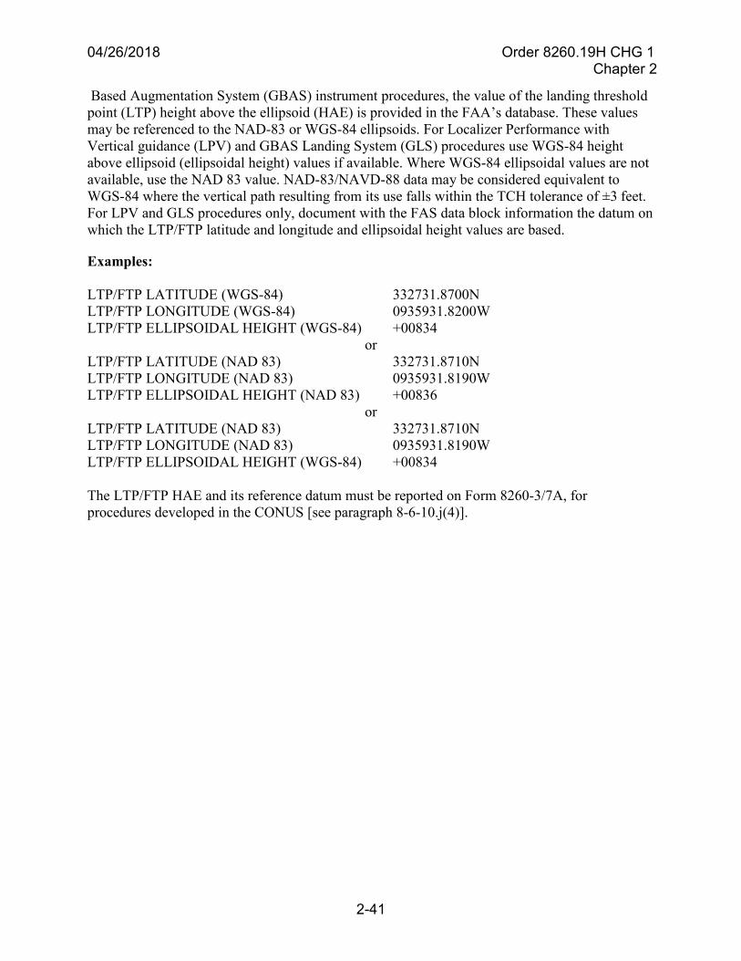
04/26/2018 Order 8260.19H CHG 1 Chapter 2
2-41
Based Augmentation System (GBAS) instrument procedures, the value of the landing threshold point (LTP) height above the ellipsoid (HAE) is provided in the FAA’s database. These values may be referenced to the NAD-83 or WGS-84 ellipsoids. For Localizer Performance with Vertical guidance (LPV) and GBAS Landing System (GLS) procedures use WGS-84 height above ellipsoid (ellipsoidal height) values if available. Where WGS-84 ellipsoidal values are not available, use the NAD 83 value. NAD-83/NAVD-88 data may be considered equivalent to WGS-84 where the vertical path resulting from its use falls within the TCH tolerance of ±3 feet. For LPV and GLS procedures only, document with the FAS data block information the datum on which the LTP/FTP latitude and longitude and ellipsoidal height values are based.
Examples:
LTP/FTP LATITUDE (WGS-84) 332731.8700N LTP/FTP LONGITUDE (WGS-84) 0935931.8200W LTP/FTP ELLIPSOIDAL HEIGHT (WGS-84) +00834
or LTP/FTP LATITUDE (NAD 83) 332731.8710N LTP/FTP LONGITUDE (NAD 83) 0935931.8190W LTP/FTP ELLIPSOIDAL HEIGHT (NAD 83) +00836
or LTP/FTP LATITUDE (NAD 83) 332731.8710N LTP/FTP LONGITUDE (NAD 83) 0935931.8190W LTP/FTP ELLIPSOIDAL HEIGHT (WGS-84) +00834
The LTP/FTP HAE and its reference datum must be reported on Form 8260-3/7A, for procedures developed in the CONUS [see paragraph 8-6-10.j(4)].
04/26/2018 Order 8260.19H CHG 1 Chapter 2
2-42
Section 2-12. Waiver of Standards/Approval Requests
2-12-1. General. The waiver request is used to officially document the nonstandard applicationof criteria, and serves as a means to identify criteria that may require further refinement or toidentify problem areas. Those items identified in 8260-series orders that require approval byFlight Standards Service (e.g., GP angle above 3.00 degrees, climb gradient in excess of500 ft/NM, etc.) are not to be interpreted as a requirement for a waiver and do not requirecompletion of a Form 8260-1, Flight Procedures Standards Waiver. Additionally, on request, theFlight Procedure Implementation and Oversight Branch may permit a deviation from a policystandard for situations where a waiver would not be practicable (e.g., an equivalent level ofsafety is not warranted) on a case-by-case basis and can be authorized through the approvalprocess. Approval requests of these types must be made in plain text by memorandum andsubmitted to the Flight Procedure Implementation and Oversight Branch for approval. Alldocumentation and supporting data must accompany the approval request so reviewing offices(i.e., Procedure Review Board) can conduct an evaluation without additional research. Submitappropriate 8260-series forms with each request to include charts depicting the procedure and allitems that are the subject of the approval request. Instrument procedures must not be submittedfor publication until waiver approval and/or approval request action has been completed.
2-12-2. Waiver processing. Request waivers by completing the front of Form 8260-1. Enteronly one waiver request on the waiver form. Detailed instructions for completing the form arecontained in section 8-4. Figure 8-4-1 provides an easy reference for waiver form processing androuting requirements.
a. Submit a request for a waiver on a Form 8260-1. Each waiver request will be consideredonly when there is no other suitable way to resolve a procedural problem, or to provide a required service.
b. Complete documentation and supporting data must accompany the waiver request soreviewing offices can conduct an evaluation without additional research. Submit appropriate 8260-series forms with each request. Include charts depicting the procedure and/or obstacles that are the subject of the waiver.
c. When a procedure is amended, reprocessing of an existing waiver is not necessary unlessthe reason for the amendment directly affects the basis for the waiver.
d. Forward the original Form 8260-1 and supporting data for approval to the FlightProcedure Implementation and Oversight Branch. For U.S. Army procedures, forward waiver requests for approval to the United States Army Aeronautical Services Agency (USAASA) or United States Army Aeronautical Services Detachment-Europe (USAASDE). Use the automated version of the Form 8260-1 for U.S. Army waiver processing.
e. The Flight Procedure Implementation and Oversight Branch processes all waiver requestsand schedules a PRB to gain consensus on approval/disapproval. If the PRB recommends approval, then the Flight Procedure Implementation and Oversight Branch will endorse the Form 8260-1. When necessary, the Flight Procedure Implementation and Oversight Branch will annotate the Form 8260-1 that approval is contingent upon a successful flight inspection report.
04/26/2018 Order 8260.19H CHG 1 Chapter 2
2-43
f. Aeronautical Information Services is responsible for ensuring that an approved waiver ofstandards is on file for each instrument procedure requiring waiver action. Flight Standards waiver approval must be obtained before submitting the procedure for publication.
2-12-3. Waivers for Special Instrument Approach Procedures. Except for proponent-developed procedures, when a waiver is approved for a special instrument approach procedure,Flight Standards must coordinate with the appropriate FSDO concerning any special conditionsthat may be imposed on the use of a special authorization. This action is necessary to establishrequired supervision to ensure user compliance with equivalent level of safety provisions. Forexample, special aircrew training may be required as an equivalent level of safety.
2-12-4. Safety Management System (SMS) requirements.
a. The FAA’s SMS policy (i.e., Order 8040.4 and Order 8000.369) must be adhered to, andsafety risk management (SRM) procedures, documentation requirements and monitoring activities in that policy must be followed to ensure that all SMS requirements are met. A SRM process ensures that:
(1) Safety-related changes are documented.
(2) Risk is assessed and analyzed.
(3) Unacceptable risk is mitigated.
(4) The effectiveness of the risk mitigation strategies is assessed through a hazardtracking/monitoring plan.
b. All relevant factors are considered when conducting a safety risk assessment, including:
(1) Navigation capabilities and navigation performance.
(2) Suitable weather reporting facilities.
(3) Operator certification and training.
(4) Systems and/or subsystems intended function and flight or ground environment inwhich the system is to perform that function.
(5) Traffic density and distribution.
(6) Airspace complexity, route structure, and classification of the airspace.
(7) Airport layout, including runway configurations, runway lengths, and taxiways.
(8) Types of aircraft and their performance characteristics, including aircraftconfigurations.
(9) Human factors issues.
04/26/2018 Order 8260.19H CHG 1 Chapter 2
2-44
2-12-5. Periodic review of waivers. Aeronautical Information Services must review approvedwaivers at the time of the periodic review [see paragraphs 2-8-1 and 2-8-2] to determine whetherthe waivers are still required. Cancel unnecessary waivers.
2-12-6. Cancellation.
a. Cancellation of waivers must include a reason in the comments block. Such terminationmay be directed by the Flight Procedure Implementation and Oversight Branch. Aeronautical Information Services is responsible for planning ways to eliminate waivers through the modification, addition, or relocation of navigation facilities.
b. Distribution of a canceled waiver must be made to the same organizations that receivedthe approved waiver [see paragraph 8-4-1].
c. An approval granted by the Flight Procedure Implementation and Oversight Branch [seeparagraph 2-12-1] does not require cancellation. Approvals are valid for future amendments, provided no conditions have changed, and are self-cancelling when the procedure is canceled.

04/26/2018 Order 8260.19H CHG 1 Chapter 3
3-9
AWO 1 copy NFDC 2 copies ARTCC 1 copy Aeronautical Information Services Original
b. Non-publication.
AWO 1 copy ARTCC 1 copy Aeronautical Information Services Original
04/26/2018 Order 8260.19H CHG 1 Chapter 3
3-10
Section 3-5. Off-Airway Routes
3-5-1. Establishment. Establish off-airway routes in the same manner, and in accordance withthe same criteria, as airways and jet routes. Off-airway routes predicated on public navigationfacilities and wholly contained within controlled airspace will be published as direct 14 CFR part95 routes. Routes predicated on privately owned navigation facilities or not contained whollywithin controlled airspace will be published as off-airway routes.
a. Process. A scheduled air carrier operator, through its Principal Operations Inspector(POI), may initiate a request for the establishment of off-airway routes. Upon receipt of a request for an off-airway route, the POI forwards the request to the AWO for review and coordination via the RAPT. If approved, the request will be sent to Aeronautical Information Services for action. The applicable Air Traffic Service Area will process the route in accordance with Order JO 7400.2 to ascertain that there is no conflict in use of the airspace. Following Air Traffic coordination and RAPT approval, Aeronautical Information Services must evaluate the adequacy of off-airway routes. Consider the following:
(1) Type of aircraft and the navigation systems used.
(2) Proximity to military bases, training areas, and low-level military routes.
(3) Adequacy of communications along the route.
b. Aeronautical Information Services documentation. Document MEAs and relatedprocedural data on Form 8260-16. Return a copy of the form to the FSDO indicating approval or disapproval of its request.
3-5-2. Listing. Pursuant to the responsibility of the Air Transportation Division forsurveillance of all authorized navigation facilities and routes, a requirement exists formaintaining a current listing of off-airway routes that have been assigned to air carriers by FlightStandards operations personnel. Routes developed by the FAA are documented in the NFDD thatis published by NFDC when changes occur. See exceptions in paragraphs 3-5-3 and 3-5-4 forwhen off-airway routes are developed by non-FAA Service Providers.
3-5-3. Off-airway data. When off-airway routes are developed and maintained by the FAA,Aeronautical Information Services should establish arrangements for obtaining and maintainingcomplete off-airway route information. The following is suggested:
a. FSDOs provide Aeronautical Information Services with copies of all proposed changes orcancellations to IFR off-airway route authorizations.
b. Aeronautical Information Services uses this information for coordination of flightinspection requirements and for maintaining current records.
c. Off-airway routes developed and maintained by non-FAA Service Providers areconsidered proprietary and will be processed through the Flight Standards Service (i.e., Flight Procedure Implementation and Oversight Branch) for approval and processing.
04/26/2018 Order 8260.19H CHG 1 Chapter 3
3-11
3-5-4. Processing data to NFDC. Use Form 8260-16 to forward IFR off-airway data to forprocessing all off-airway routes. Do not designate off-airway, non-part 95 routes as specialroutes even though associated with special instrument approach procedures.
a. Off-airway routes developed by the FAA will be submitted to NFDC to be documented inthe NFDD.
b. Off-airway routes developed by non-FAA Service Providers will be submitted by theFlight Procedure Implementation and Oversight Branch to NFDC for information and record keeping purposes, but will not be documented in the NFDD nor entered into NASR.
Note 1: Existing fixes will require the Form 8260-2, Radio Fix and Holding Data Record, “Fix Use” block updated to show that the fix makes up a part of the non-Part 95 off-airway route (see paragraph 8-5-2.j).
Note 2: New fixes created in support of non-FAA Service Provider developed, non-Part 95 off-airway routes, must also be submitted to NFDC on Form 8260-2 and the information published in the NFDD to ensure they are incorporated into ATC and avionics systems databases.
04/26/2018 Order 8260.19H CHG 1 Chapter 3
3-12
Section 3-6. New or Revised National Airspace System Routes
3-6-1. Definition - Route. For the purpose of this section, a route includes all charted en routedepictions requiring 14 CFR part 71 airspace actions and/or 14 CFR part 95 procedural dataapplication.
3-6-2. Coordination procedures.
a. The applicable Air Traffic Service Area provides Aeronautical Information Services withthe NPRM for new or revised routes. Revisions to currently published routes will be handled on an individual basis. When a currently published route will be revised by a final rule without an NPRM, the applicable Air Traffic Service Area will provide the details of the change to Aeronautical Information Services to request flight inspection and to coordinate the planned effective date.
b. Aeronautical Information Services action. Aeronautical Information Services requestsflight inspection to furnish a copy of the preliminary evaluation and forwards the results to the applicable Air Traffic Service Area. If the proposal is satisfactory, include changeover point information. If the route is not satisfactory, provide alternate recommendations.
3-6-3. Publication of procedural data.
a. Aeronautical Information Services must forward final route data, with the NPRM docketnumber, to NFDC on Form 8260-16. This form must be submitted within the comment period specified in the NPRM. Conditions found during surveillance inspections of established routes, which would require a change to MEA, MOCA, MAA, or COP from the previously published data, must be brought to the attention of the procedures specialist for corrective action.
b. The ARTCC, in conjunction with the applicable Air Traffic Service Area, is responsiblefor developing airspace requirements for the routes published in 14 CFR part 71; and Aeronautical Information Services is responsible for developing the related procedural data published in 14 CFR part 95.
04/26/2018 Order 8260.19H CHG 1 Chapter 4
4-1
Chapter 4. Terminal Procedures
Section 4-1. General
4-1-1. General. The FAA has the responsibility to establish instrument procedures used forterminal operations at civil airports within the U.S. and its possessions. The FAA also providesor approves instrument procedures used by U.S. flag carriers at foreign airports.
4-1-2. Categories of Instrument Approach Procedures. Procedures published in the FederalRegister under 14 CFR part 97 are identified as “standard instrument approach procedures.”These procedures are available to all users. Instrument flight procedures authorized for use onlyby air carriers or some other segment of the aviation industry are not published in the FederalRegister and are identified as “Special procedures.” Special procedures may be developed forpublic and private use based on aircraft performance, aircraft equipment, or crew training, andmay also require the use of landing aids, communications, or weather services not available forpublic use [see paragraph 8-2-1.b].
4-1-3. Airspace requirements.
a. Public-use procedures and Special procedures at part 139 airports must be containedwithin controlled airspace to the maximum extent possible as specified in Order JO 7400.2.
b. Where an airport does not qualify for a class B/C/D/E surface area, designate 700-footclass E airspace. In the latter case, landing minimums may be established below the floor of controlled airspace [see Order JO 7400.2].
c. Designate 1200-foot class E airspace as necessary to transition aircraft to/from theterminal or en route environment to the instrument flight procedure. This includes all arrival terminal routes and departure transitions [see Order JO 7400.2].
d. Requirements for minor adjustment to existing controlled (class B/C/D/E) airspace, tofully encompass an instrument procedure, will not form the basis for withholding procedure publication provided no less than the basic required 700-foot/1200-foot class E airspace is in place. An approach procedure may be published prior to obtaining the optimum configuration of controlled airspace when the following conditions exist [see Order 8260.26, Establishing Submission Cutoff Dates for Civil Instrument Flight Procedures]:
(1) The centerline of all terminal routes is located within existing controlled airspace.
(2) The course reversal (procedure turn, hold-in-lieu of procedure turn, or teardrop)maneuvering area out to the appropriate distance specified in chapter 5 is contained within existing controlled airspace.
(3) The final approach fix is contained within existing controlled airspace.
e. Special procedures other than those noted in paragraph 4-1-3.a, should, where possible,be contained within controlled airspace in accordance with Order JO 7400.2. Special procedures may be established and approved outside of controlled airspace where it is not possible to
04/26/2018 Order 8260.19H CHG 1 Chapter 4
4-2
designate controlled airspace. In such cases, annotate the procedure: “Procedure not contained within controlled airspace,” and advise the appropriate FSDO that controlled airspace will not be provided. Do not use special procedures as a temporary measure pending designation of controlled airspace for public use procedures.
4-1-4. Contractual use of private facilities. An air operator may arrange for the use of aprivately owned NAVAID. The arrangement requires a contractual agreement between thesponsor and the user regarding facility use. Flight Standards must coordinate all requests forcontractual use of private NAVAIDs with the sponsor. Approval of special instrumentprocedures for an operator is contingent upon the AWO receiving a copy of an acceptablecontractual agreement. See paragraph 7-7-1 for processes related to non-Federal NAVAIDs.
4-1-5. TERPS application. Develop all instrument approach procedures, except foreignprocedures developed in accordance with Order 8260.31 under the provisions of Order 8260.3,associated 8260-series orders, and the guidelines in this document. The following specialprovisions and guidelines apply to selected paragraphs of Order 8260.3 criteria. The paragraphnumbers refer to identically numbered paragraphs in Order 8260.3.
a. Order 8260.3, paragraph 1-6-1, General. Military operators have stated a requirement forTACAN instrument approach capability to a limited number of airports. These airports have a prescribed VOR procedure, based on a VOR collocated with tactical area navigational (VORTAC) facility, where TACAN-equipped aircraft are expected to operate will be identified by the military. TACAN-equipped aircraft may execute VOR procedures at these locations when the procedure is identified as “VOR or TACAN.” This informs both the pilot and the controller that an approach may be executed with aircraft equipped with only VOR or with only TACAN. Approval for the use of individual VOR procedures by TACAN-equipped aircraft is subject to review for compliance with Order 8260.3 and flight-check criteria. Take the following actions to implement this program:
(1) Designate VOR/DME procedures, predicated upon the use of VORTAC, as “VOR orTACAN” provided flight inspection has determined that the TACAN and VOR components will support the procedure. These procedures require DME. Establish the missed approach clearance limit at a radial/DME fix in lieu of the VORTAC facility to accommodate aircraft equipped with only TACAN.
(2) Establish a VOR-type procedure when a VOR procedure (no TACAN requirements)is required to accommodate non-DME-equipped aircraft, and is predicated upon a VORTAC facility. However, establish combination VHF/DME fixes, where possible, for optional use by DME-equipped aircraft.
(3) Make provision for TACAN-only equipped aircraft to use VOR approach procedureswhen requested by the appropriate military authority and procedure design and facility performance will permit. Where approval can be authorized, rename VOR procedures based on VORTAC facilities in accordance with the following examples: “VOR or TACAN RWY 30, or VOR or TACAN-A.” Before this identification is used, flight inspection must determine that the TACAN azimuth alignment is satisfactory. Review and modify the procedure as necessary to fully support its use by TACAN-equipped aircraft:
04/26/2018 Order 8260.19H CHG 1 Chapter 4
4-5
Section 4-2. Standard Instrument Approach Procedures (SIAP)
4-2-1. General. SIAPs must be established in accordance with Order 8260.3, other specific8260-series orders, and the policies set forth in this order. FAA policy and instructions forcompleting 8260-series forms are contained in this order.
4-2-2. Coordination of Terminal Instrument Procedures. Coordination requirements forterminal instrument procedures are set forth in Order 8260.3, paragraph 1-5-1 [also seeparagraph 8-6-12].
4-2-3. Radar Instrument Approach Procedures. ATC personnel determine which runwaysrequire radar instrument approach procedures and coordinate these requirements throughAeronautical Information Services.
04/26/2018 Order 8260.19H CHG 1 Chapter 4
4-6
Section 4-3. Category II and III ILS
4-3-1. General.
a. Guidance. The following directives (latest editions) contain criteria/guidance to be usedto determine whether an airport/runway is suitable to support ILS CAT II and III procedures:
(1) AC 120-28, Criteria for Approval of Category III Weather Minima for Takeoff,Landing, and Rollout.
(2) AC 120-29, Criteria for Approval of Category I and Category II Weather Minima forApproach.
(3) AC 120-57, Surface Movement Guidance and Control System (SMGCS).
(4) AC 150/5300-13, Airport Design.
(5) Order 6750.24, Instrument Landing System and Ancillary Electronic ComponentConfiguration and Performance Requirements.
(6) Order 8200.1, United States Standard Flight Inspection Manual.
(7) Order 8400.13, Procedures for the Evaluation and Approval of Facilities for SpecialAuthorization Category I Operations and All Category II and III Operations.
Note: There are other orders and Advisory Circulars that apply to specific runway equipment, placement of hold signs/lines, etc. as well as navigational aid installation requirements. The above list would, in most cases, lead the reader to the other references. A full list of reference documents for all aspects of the procedures function is contained in appendix B of this order.
b. Advise the general public of airports authorized CAT I, II, and III minimums bypublishing the appropriate 14 CFR part 97 SIAP.
c. A detailed explanation of the characters used to identify a facility's class of performanceis contained in Order 6750.24, appendix 2. The first character (I, II, or III), ILS ICAO standards, is determined jointly by flight inspection and engineering personnel. The second character (A, B, T, D, or E), localizer course structure, is determined solely by flight inspection personnel. The third character (1, 2, 3, or 4), ILS integrity and continuity, is determined solely by engineering personnel.
d. Irregularities on pre-threshold terrain or HUD/autoland system/radio altimetercharacteristics might adversely affect radio altimeter indications and thus affect autoland performance of some aircraft. Until or unless these aircraft demonstrate normal radio altimeter readings and acceptable HUD/autoland operations on that runway and this fact is listed in their operations specifications, they cannot conduct CAT III HUD/autoland operations. The Flight Operations/Performance-Based Flight Operations branches act as the clearing house for listing which combinations of HUD/autoland systems/runways are or can be approved, and is positioned for receipt of information from Flight Inspection, AJW-0, ATC, Airports, and airport
04/26/2018 Order 8260.19H CHG 1 Chapter 4
4-7
authorities regarding irregular underlying terrain situations at new runways or runways at which future CAT III procedures are proposed.
4-3-2. Action.
a. Services Areas/Flight Standards.
(1) Applicable Technical Operations Service Areas and Aeronautical InformationServices coordination is essential. Aeronautical Information Services, having been informed of the need for (and suitability of a runway to support) CAT II and III must assure obstacle clearance requirements.
(2) AWO coordinates the procedure request with the RAPT. The AWO is alsoresponsible for coordinating the CAT II/III checklists and will notify Flight Operations/Performance-Based Flight Operations branches when CAT II or III checklists are complete. Notification must contain the information obtained from Aeronautical Information Services [see paragraph 4-3-2.b(1)].
b. Aeronautical Information Services.
(1) Aeronautical Information Services must advise the AWO when a CAT II or IIIsystem has passed flight inspection. Notification must contain the following information:
(a) Airport.
(b) Runway.
(c) Flight inspection completion date.
(d) Facility classification.
(e) Minimums:
CAT II DA and RA. CAT III RVR (as appropriate).
(f) Date approach procedure will be available.
(2) Amend ILS SIAPs when CAT II and III minimums are authorized [see paragraph 8-6-11.m].
(3) Flight Program Operations is responsible to take action when performance class datain AIRNAV needs to be corrected or updated. Flight Program Operations will take immediate NOTAM action if needed and submit a data change request (Form 8240-20) to update the AIRNAV Database. The applicable Technical Operations Service Area must notify the AWO and Flight Program Operations, Technical Services Team, of individual ILS facility performance
04/26/2018 Order 8260.19H CHG 1 Chapter 4
4-8
classification determinations, and any change in the performance class of a facility, so that changes in CAT III authorizations can be made.
c. Flight Operations Branch/Performance-Based Flight Operations Branch’s CAT II/IIIstatus list web site. This notification will provide operators with the planned availability of the new minimums for preparation of operations specifications prior to publication of the SIAP.
4-3-3. NOTAM requirements. When any component of the ILS system fails to meet theappropriate performance tolerances, the Air Traffic Vice President of Technical Operationsissues a NOTAM D for suspension of CAT II/III minimums. If the suspension will exist longerthan 224 days or will be permanent, Aeronautical Information Services must submit anabbreviated or full amendment [see Order 7930.2 for all NOTAM requirements and limitations].
04/26/2018 Order 8260.19H CHG 1 Chapter 4
4-13
(23) All runways served by a STAR must be coded when developing runway transitions.For seldom used runways, consider developing RNAV procedures that end with a radar vector.
(24) If the STAR or any of its transitions cannot be named in compliance with thisparagraph, Aeronautical Information Services, the ATC facility, and the OSG/FPT must collaborate to determine an acceptable name.
(25) Use procedural data notes when limitations are necessary.
Examples: “RADAR REQUIRED”
(26) The following applies to RNAV and RNP STARs only:
(a) RNAV 1 is the default designation for RNAV STARs. Annotate procedureswith a standard note: “RNAV 1” on Form 8260-17.1.
(b) RNP 1 (in lieu of RNAV 1) is used when a STAR contains an RF leg or whensurveillance (radar) monitoring is not acceptable to ATC for when DME/DME/IRU will be used. Annotate the procedure with a standard note: “RNP 1” on Form 8260-17.1.
(c) For RNAV and RNP STARs that terminate on a heading at a fix not on anIAP, annotate on the chart that radar vectors will be provided; e.g., expect radar vectors to final.
(d) For RNP STARs that contain an RF leg, use: Note: RF REQUIRED” if theRF leg is applicable to the entire procedure. If an RF leg is unique to a particular runway transition, incorporate “(RF Required)” into the arrival route description.
(27) All RNAV STARs will contain a note that describes the equipment sensorlimitations. Notes as appropriate are as follows:
Examples: Note: DME/DME/IRU or GPS REQUIRED
Note: GPS REQUIRED
(28) A note may be required to address the need for specific DME facilities to beoperational. These are referred to as “critical DME facilities.”
Examples: Note: FOR NON-GPS EQUIPPED AIRCRAFT, ABC, JKL, AND XYZ DMES MUST BE OPERATIONAL
Note: FOR NON-GPS EQUIPPED AIRCRAFT USING MNO TRANSITION, ABC, JKL, AND XYZ DMES MUST BE OPERATIONAL
(29) All RNAV STARs that are annotated “DME/DME/IRU or GPS REQUIRED” mustbe annotated as follows:
04/26/2018 Order 8260.19H CHG 1 Chapter 4
4-14
Example: Note: RADAR REQUIRED FOR NON-GPS EQUIPPED AIRCRAFT
(30) Depict conventional STAR routing(s) on a VFR Sectional Chart. When use of aSectional Chart is not viable, a Terminal Area Chart may be used. The depiction must include the STAR primary and secondary obstacle clearance areas and identification of the controlling obstacle or terrain used to establish the minimum altitude for each segment published. Depiction of turn expansion areas where two segments are joined is not required on this chart. The turn expansion areas will be added during processing by Aeronautical Information Services. Charts produced electronically are acceptable and must accurately reflect the scale of the type of chart used and be similar in quality to the original printed version to facilitate use by the flight inspection crew in-flight.
(31) For RNAV and RNP STARs, use the Terminal Area Route Generation, Evaluationand Traffic Simulation (TARGETS) software tool to produce depictions of the obstacle clearance areas and the controlling obstacles/terrain. The depiction must include the STAR obstacle clearance areas and identification of the controlling obstacle or terrain used to establish the minimum altitude for each segment published. Where two segments are joined, TARGETS will calculate and display the required turn expansion areas. The chart depiction must accurately reflect the chart scale and be similar in quality to the original printed version to facilitate use by the flight inspection crew in-flight. See Order JO 8200.44, Coordination of Flight Inspection Procedure Packages, for guidance on what must be submitted for Flight Inspection.
(32) Complete and forward the applicable forms and procedure depictions to the OSG. Fora STAR complete Forms 8260-17.1, 8260-17.2, and Form 8260-2 worksheet.
(33) When ATC has determined that they do not want pilots to “Flight Plan” or file aparticular STAR (i.e., use will be determined by ATC), ATC will request that a chart note be placed on the STAR. In the “Procedural Data Notes” section of Form 8260-17.1, use: “Chart Note: Do Not File – To Be Assigned by ATC.”
c. Waivers/Approval requests. Requests for waivers/approval requests to design (i.e.,TERPS) criteria and/or deviation to the requirements specified in this section are processed per section 2-12.
(1) Requests for deviation from non-criteria items outside the scope of this order, e.g.,ATC waivers/approvals, are processed through the service area OSG.
(2) Mission Support Services, PBN Integration Group, AJV-14, reviews RNAV andRNP STAR waiver/approval requests and will participate in the Procedure Review Board with Flight Standards Service as needed.
d. STAR amendments. STARs may be amended using either the full amendment or anabbreviated amendment process as specified below. An amendment must ensure periodic review requirements have been met for the procedures and documented. A full amendment requires a complete procedure package (i.e., all necessary forms, maps, and supporting documentation) be developed and submitted for processing. An abbreviated amendment only requires submission of
04/26/2018 Order 8260.19H CHG 1 Chapter 4
4-23
(1) Where potential for confusion exists (i.e., a procedure terminating on a heading), it ispreferable to publish specific lost communication guidance on the chart. The guidance should provide specific instructions that permit the aircraft to proceed to an IAF for the approach in use. In order to provide for contingencies, instructions should also provide an alternate procedure with the appropriate fix/WP to proceed to and hold prior to executing an instrument approach. Do not describe the lost communication procedure using terms or verbiage that could be mistaken for a coded route; i.e., “track to RUSSH.”
(2) This may be left blank when lost communication procedures are the same as in14 CFR part 91.185 (standard) and there is no potential for confusion. However, it is preferable to provide an appropriate fix to proceed to and hold prior to executing an instrument approach.
i. Remarks. List information/data that is not to be charted; i.e., administrative data or notesfor controller information (requested by air traffic control). These items will not be seen in the National Flight Data Digest.
j. Additional flight data. List any additional charting instructions, items essential to clarifycharting, or information a specialist has determined needs charting as other than a note.
(1) Data may include items such as terrain features, Special Use Airspace, or landingobstacles. Airports not served by the procedure should not be charted unless accompanied by a note in (Procedure Data Notes) indicating the reason for charting; i.e., “FTR jet arrivals below 5000 MSL.”
(2) For RNAV and RNP STARs place the procedure design (arrival airport) magneticvariation of record used to develop the STAR in this section; i.e., MAG VAR: KSEA 17E/2010.
(3) Enter the results of the DME/DME Assessment after completion of the flightinspection. Results will be recorded as: “DME/DME ASSESSMENT: SAT (RNP 1.0 OR 2.0 AS APPROPRIATE)”, “DME/DME ASSESSMENT: UNSAT (RNP 1.0), SAT (RNP 2.0)”, or “DME/DME ASSESSMENT: UNSAT.”
(4) If the DME/DME assessment indicates “UNSAT” or “NOT CONDUCTED,” thenote “GPS Required” must be entered in (Procedure Data Notes).
(5) Enter terminus point information [see paragraph 4-5-1.b(8)(b)].
k. Flight Inspected by. Leave blank. Flight inspection will enter the name of the airspacesystem inspection pilot who conducted the flight inspection and date.
l. Developed by. Enter the name of the procedure specialist. This individual must sign inthe “developed by” space and enter the date.
m. Approved by. Enter the name of the Aeronautical Information Services’ manager, orhis/her delegated representative. This individual must sign in the “approved by” space and enter the date signed. If the procedure is a “Special,” this line will contain the name of and be signed by the Flight Procedure Implementation and Oversight Branch.

04/26/2018 Order 8260.19H CHG 1 Chapter 4
4-24
n. Changes/Reasons. List changes and reasons relating to data entries.
o. Graphic depiction. Include a graphic depiction of the STAR. Identify on the depiction theWPs, navigational aids, and holding patterns.
04/26/2018 Order 8260.19H CHG 1 Chapter 4
4-59
4-6-4. RNAV leg types.
a. Different types of arrival, approach, departure, and en route segments are required forRNAV. Consideration of these requirements during procedure design will result in a more efficiently designed flight path for all operators using airspace; particularly those equipped with computer-based navigation systems. These systems require encoding RNAV route segment flight paths into a format usable in navigation databases.
b. The aviation industry has adopted a route segment definition called “path andterminator.” This concept is used for transforming arrival, approach, and departure procedures into coded flight paths that can be interpreted and used by a computer-based navigation system. A path terminator instructs the aircraft to navigate from a starting point along a defined path to a specified point or terminating condition. The path terminators are identified by a set of two alpha-characters, each of which has a meaning when describing a flight maneuver to a navigation computer. The first character indicates the types of flight path to be flown, and the second indicates where the route segment terminates. For example, a designated route from a NAVAID to a fix would be coded as “TF.” The “T” indicates that a track is to be flown, and the “F” indicates that the segment terminates at a fix. There are over twenty different path and terminator sets (“leg types”) used by the aviation industry to accommodate the coding of procedure route segments. However, only a limited few are suitable for use in RNAV procedure design.
4-6-5. RNAV leg type descriptions.
a. Initial fix. This is the point or fix where a flight segment begins. An IF is not a routesegment and does not define a desired track in and of itself. It is used in conjunction with other leg types such as a TF leg in order to define the desired segment.
Note: “IF” in this context is not to be confused with IAF or IF; however, it may be located at one of these locations for coding purposes.
b. Track-to-fix (TF) leg. This designates a track or geodesic path between two fixes. If theTF leg is the first route segment of a flight path, the TF leg begins at an IF; otherwise, the first fix of the TF leg is the termination fix of the previous route segment. The TF leg is the primary straight route segment for RNAV.
c. Constant radius to a fix (RF) leg. An RF leg defines a curved path route segment about adefined turn center that terminates at a fix. The RF leg begins at the termination fix of the previous route segment. The previous segment is tangent to the arc of the RF leg at that fix. Waypoints defining the beginning and end point of the RF turn must be designated as “Fly-by.”
d. Course-to-altitude (CA) leg. A CA leg defines a specified path terminating at an altitude.A CA leg must specify a course and altitude. See Order 8260.58 for conditions when use of a CA leg required.
e. Direct-to-fix (DF) leg. A DF leg is used to define a route segment (geodesic path) thatbegins at an aircraft present position, or unspecified position, and extends to a specified fix.
04/26/2018 Order 8260.19H CHG 1 Chapter 4
4-60
f. Heading-to-an-altitude (VA) leg. The VA leg is used in a departure route segment wherea heading rather than a track has been specified for climb. The VA segment terminates at a specified altitude without a terminating position defined.
g. Course-to-fix (CF) leg. The CF leg is defined as a magnetic course that terminates at afix.
h. Heading to a manual termination (VM) leg. A VM leg is a manual termination leg usedfor whenever a departure or arrival route description specifies a course or heading to fly in expectation of a radar vector.
i. Heading to an intercept (VI) leg. A VI leg defines a specified heading to intercept thesubsequent leg at an unspecified position.
j. Fix to a manual termination (FM) leg. A course from a fix to a manual termination legused in departure or arrival procedures when a route segment is expected to be terminated by radar vectors.
4-6-6. Final Approach Segment (FAS) data.
a. FAS data is described and attained using established TERPS criteria in Order 8260.58,chapter 3. This data is compiled and formed into what is called the FAS data block. The method of protection required for this flight data is known as the cyclic redundancy check (CRC).
b. Document FAS data block information on either Form 8260-3 or 8260-7A, whichever isapplicable. Guidance on producing data that are placed on this form is located in appendix L.
c. FAS data block coordinates must be in same coordinate system as the ground survey data(WGS-84 preferred).
4-6-7. Remote altimeter setting for Baro-VNAV. Baro-VNAV systems cannot fly toapproach minimums based on a remote altimeter setting. Therefore, when the primary altimetersource is from a remote location, LNAV/VNAV is not authorized to be flown using Baro-VNAV. When the primary altimeter source is local and a secondary altimeter source is remote,LNAV/VNAV minimums must be noted as not authorized (NA) to be flown with Baro-VNAVwhen the secondary altimeter is in use. See paragraph 8-6-9.e(8) for applicable chart note to use.
4-6-8. Critical temperature. Temperature limits above and below which Baro-VNAVoperations are not authorized are published on RNAV instrument approach procedures. CurrentRNAV criteria standards provide the formulas to compute the critical temperatures for the airportof intended landing. See paragraphs 8-6-9.s and 8-7-1.c(10) for charting and documentationrequirements.
4-6-9. DME/DME screening model.
a. Apply the RNAV-Pro DME screening model to ensure satisfactory availability andgeometry of DME navigation signals for RNAV arrivals, instrument approaches (when requested) and departure procedures, and RNAV “Q” routes to support use of FMS-equipped
04/26/2018 Order 8260.19H CHG 1 Chapter 5
5-1
Chapter 5. Airspace
Section 5-1. Obstruction Evaluation (OE)
5-1-1. General. 14 CFR part 77 requires that the Administrator be notified prior to theconstruction or alteration of structures that might present a hazard to flight. Form 7460-1, Noticeof Proposed Construction or Alteration, is the medium for that notification of construction oralteration.
5-1-2. Responsibility and processing of Form 7460-1. The Obstruction Evaluation Group,AJV-15, has the responsibility to process all Forms 7460-1 in accordance with 14 CFR part 77and Order JO 7400.2. In this regard, Aeronautical Information Services must ensure a completeevaluation of the effect the proposed construction or alteration will have on IFR procedures,including the visual portion of a final approach segment, is provided to Air Traffic. The completeevaluation includes evaluation of the effect upon existing and proposed instrument flightprocedures and the effects of airport plans on file to instrument flight procedures as they relate tothe proposed object. Aeronautical Information Services must also assist Air Traffic inreconciling possible discrepancies in IFR findings made by the military services. AeronauticalInformation Services must limit their response to findings of “IFR Effect” or “No IFR Effect.”The process of an obstacle evaluation is captured within the Internet Obstacle Evaluation/AirportAirspace Analysis (iOE/AAA) system. All comments and evaluations should be captured withinthis system to ensure consideration.
5-1-3. Review of Notices. Aeronautical Information Services and Flight Standards Servicepersonnel, when becoming involved in the evaluation of Notices of Construction or Alteration,should be thoroughly familiar with applicable parts of Order JO 7400.2. The AWO evaluates OEcases for effect in accordance with the Code of Federal Regulations and policies set forth inOrder 8900.1, Flight Standards Information Management Systems (FSIMS); 8260-series orders;Order JO 7400.2, and other applicable directives. The effect of a proposed structure on aircraftoperations must be fully stated. Consultation with the appropriate FSDO and/or FIOG may behelpful in formulating comments/recommendations. In all cases, the primary responsibility andthe first consideration is set forth in 14 CFR part 77, which states: “Evaluate the effect of theproposed construction or alteration on safety in air commerce and the efficient use andpreservation of the navigable airspace and of airport traffic capacity at public use airports” [see14 CFR part 77.5].
5-1-4. Adjustments to Instrument Flight Procedures. When requested, Flight Standardsspecialists may provide recommendations regarding what procedure adjustments to mitigate theeffect. Aeronautical Information Services will be notified of when construction will begin andappropriate action (e.g., NOTAM action) will be initiated. Aeronautical Information Servicesmust not amend a procedure until receipt of the “Actual Notice of Construction,” or othernotification relative to an obstacle that will have a procedural effect.
04/26/2018 Order 8260.19H CHG 1 Chapter 5
5-2
Section 5-2. Designation of Controlled Airspace
5-2-1. General.
a. To afford separation from other aircraft, all instrument flight procedures, to include theTAA, must be contained in controlled airspace to the maximum extent possible within the capabilities of the ATC system. For special procedures, refer to paragraph 4-1-3.e.
b. Order JO 7400.2 clarifies that a 300-foot buffer should be taken into consideration whencomputing airspace requirements for IFR procedures. Therefore, a 300-foot buffer has been included in the references to the 1000-foot and 1500-foot points in paragraph 5-2-4.
5-2-2. Air Traffic responsibility. It is the responsibility of the applicable Air Traffic ServiceArea to determine the type and amount of controlled airspace that can be established toencompass instrument flight procedures, including departures from the airport.
a. If the TAA overlies class B airspace, in whole or in part, the ATC facility exercisingcontrol responsibility for the airspace may recommend minimum TAA sector altitudes. It is the responsibility of the ATC facility providing approach control service for the airport to resolve TAA altitude and overlapping airspace issues with adjoining ATC facilities. Modify the TAA to accommodate controlled/restricted/warning areas as appropriate.
b. When notified that an RNAV approach and a standard TAA are being initiated for anairport not underlying controlled airspace, the applicable Air Traffic Service Area must initiate rulemaking action to establish a 1200 feet above ground level class E airspace area with an appropriate radius of the ARP to accommodate the TAA. If a modified TAA is proposed, the airspace will be sized to contain the TAA. The TAA will not be charted or implemented until controlled airspace actions are completed.
5-2-3. Aeronautical Information Services action.
a. Determine airspace requirements for all original IAPs. Analyze IAP amendments, whichaffect any fix, course, or altitude to determine if existing airspace must be extended or can be reduced. Similarly, analyze IAP cancellations to determine if existing airspace can be reduced. Aeronautical Information Services must coordinate with the applicable Air Traffic Control facility to determine if further procedure development needs to be delayed pending any airspace action.
b. Aeronautical Information Services analysis, in accordance with the provisions of thissection, must include, in part, a determination of the minimum required length and width of the class B/C/D/E surface area extensions, and/or any class E 700-foot airspace extension.
c. Document data, as described in paragraph 5-2-4.k, on the Form 8260-9, StandardInstrument Approach Procedure Data Record, supports the IAP being designed. See paragraph 8-7-1.e “Part d: Airspace” for forms completion guidance. Forward this data to the appropriate AirTraffic Service Area.
04/26/2018 Order 8260.19H CHG 1 Chapter 5
5-35
1000-foot point is assumed to be inbound from the turn completion point at a distance determined by application of a 500 ft/NM descent gradient.
(b) If the penetration turn completion altitude equals 1000 feet above the highestterrain in the segment prior to the IF, the 1000-foot point is at the IF.
(c) If the IF altitude is greater than 1000 feet above the highest terrain in theintermediate segment, the 1000-foot point is assumed to be inbound from the IF at a distance determined by application of a 500 ft/NM descent gradient.
(d) If the FAF altitude is greater than 1000 feet above the highest terrain in thefinal segment, apply the methodology in paragraph 5-2-4.c(2)(a).
(2) 1500-foot point:
(a) If the penetration turn completion altitude is less than 1500 feet above thehighest terrain between the turn completion point and the IF, the 1500-foot point is in the penetration turn area. Transition area boundaries must encompass the entire penetration turn area. Provide the appropriate ATC office a drawing clearly depicting the airspace required [see paragraph 5-2-4.k(10)].
Note: In this case, controlled airspace can be minimized by increasing the penetration completion turn altitude to greater than or equal to the turn completion point and the IF; apply paragraph 5-2-4.h(2)(b) or 5-2-4.h(2)(c) as appropriate.
(b) If the penetration turn completion altitude equals 1500 feet above the highestterrain between the turn completion point and the IF, the 1500-foot point is at the turn completion point.
(c) If the penetration turn completion altitude is greater than 1500 feet above thehighest terrain between the turn completion point and the IF, the 1500-foot point is assumed to be inbound from the turn completion point at a distance determined by application of a 500 ft/NM descent gradient.
(d) If the IF altitude is greater than 1500 feet above the highest terrain in theintermediate segment, the 1500-foot point is assumed to be inbound from the IF at a distance determined by application of a 500 ft/NM descent gradient.
(e) If the FAF altitude is greater than 1500 feet above the highest terrain in thefinal segment, apply the methodology in paragraph 5-2-4.c(2)(a) using a 500 ft/NM descent gradient from the FAF.
i. Radar vector to FAF (radar required).
(1) If the FAF altitude is greater than 1000 feet above the highest terrain in the finalsegment, apply the methodology in paragraph 5-2-4.c(2)(a).
04/26/2018 Order 8260.19H CHG 1 Chapter 5
5-36
(2) If the FAF altitude is less than 1000 feet above the highest terrain in the finalsegment, the 1000-foot point is located PRIOR to the FAF [see paragraph 5-2-4.k(4)].
(3) If the FAF altitude is greater than 1500 feet above the highest terrain in the finalsegment, apply the methodology in paragraph 5-2-4.c(2)(a) using a 500 ft/NM descent gradient from the FAF.
(4) If the FAF altitude is less than 1500 feet above the highest terrain in the finalsegment, the 1500-foot point is located prior to the FAF [see paragraph 5-2-4.k(7)].
j. Radar vector to IF (radar required).
(1) If the IF altitude is greater than 1000 feet above the highest terrain in the intermediatesegment, apply the methodology in paragraph 5-2-4.c(2)(b).
(2) If the IF altitude is less than 1000 feet above the highest terrain in the intermediatesegment, the 1000-foot point is located prior to the IF [see paragraph 5-2-4.k(4)].
(3) If the IF altitude is less than 1500 feet above the highest terrain in the intermediatesegment, the 1500-foot point is located prior to the IF [see paragraph 5-2-4.k(7)].
(4) If the 1500-feet point is at/inside the IF, apply the methodology in paragraph 5-2-4.e(1).
k. Information to be forwarded to ATC. Include the following information to be forwardedto ATC in a standard letter from Aeronautical Information Services to the appropriate Air Traffic Service Area (or backside of Form 8260-9 if applicable). The airspace requirements stated in this chapter are detailed. An Airspace Section may be added to the report version of Form 8260-9 in order to separate the ATC Airspace Information from other remarks [see paragraphs 5-2-3.c and 8-7-1.e].
(1) ARP coordinates; threshold coordinates (if straight-in authorized).
(2) FAF or IF coordinates. List FAF and IF coordinates and any other pertinent fixcoordinates (RF or TF fixes to include direction CW or CCW and center-point fixes if applicable) for segments with turns or multiple segments. List fix coordinates which aid in describing the final and intermediate areas, etc., which are not considered straight.
Example: FAF: TEXET 323323.33N/1024354.23W TEXET 323323.33N/1024354.23W 9.22 NM CW from TZRFT 323326.22N/1024352.33W IF: POBOY 323422.12N/1024356.44W
(3) List distance from ARP (for circling only), list distance from runway threshold (forstraight-in), or list distance from a named fix to the 1000-foot point for procedures with multiple turning segments. If RF turns are used in a segment where the 1000-foot point is located, provide a depiction of the segment(s) which define the start of the segment. Include the named fixes and coordinates of the fixes along the route; include the calculated distance from the FAF, IF, IAF or
04/26/2018 Order 8260.19H CHG 1 Chapter 5
5-39
Section 5-3. Airport Airspace Analysis
5-3-1. General.
a. Public Law 103-272, Sections 40103b.1 and 44502, contain the basic authority for theFAA to conduct airport airspace analysis studies, which culminate in an FAA determination. In order for the FAA to fulfill its obligations pursuant to the Public Law, part 157, Notice of Construction, Alteration, Activation and Deactivation of Airports, was promulgated. This regulation requires proponents of the civil airport projects not involving federal funds to give the Administrator reasonable prior notice of such proposals so that he/she may be advised as to the effects the proposal will have upon the safe and efficient use of airspace by aircraft.
b. Other airport projects which are subject to airport airspace analysis studies include thoseeligible for airport improvement programs which are submitted to the FAA pursuant to Order 5100.38, Airport Improvement Program (AIP) Handbook; the Military Construction Program (MCP), submitted to the FAA for review pursuant to Public Law, and Department of Defense Directive 5030.17; the designation of instrument landing runways normally associated with airports under AIP agreements; changes in airport operating status from VFR to IFR; and changes to airport traffic patterns.
c. The provisions of Order JO 7400.2, part 3, are applicable to all participating offices.Therefore, all Flight Standards and Service Area OSG-FPT personnel directly involved in airport airspace analysis must be familiar with Order JO 7400.2, and those general responsibilities specified in section 1-2, of this document.
5-3-2. Service Area OSG-FPT/Flight Standards inputs in establishment of airports andheliports. Since the term “airports” includes small isolated airports (including ultra-light flightparks), heliports, seaplane bases, and large airports, the problems associated with proposedestablishment of airports are varied. However, it may be stated that Service Area OSG-FPT andFlight Standards studies of all proposed airports or heliports relate mainly to the safety aspectsinvolved, the feasibility of proposed anticipated operations, and the practicality of establishingreasonable instrument approach and VFR flight procedures, where required. Any proposednonstandard installation or facility must be thoroughly reviewed to determine if an adequatelevel of safety can be achieved.
5-3-3. Flight Standards performs the flight safety review of airport proposals todetermine whether aircraft operations can be conducted safely considering the proposal’seffect on the safety of persons and property on the ground. When requested by the AirportsDivision, Flight Standards provides an operational safety review for Airports Division approvalof a modification of an airport standard. Flight Standards determinations, including studiesreferred by Service Area OSG-FPT, will be provided to the OPR.
5-3-4. Service Area OSG-FPT is responsible for evaluation and comment on all airportproposals related to IFR impact. Routine coordination with the Flight Standards point ofcontact is expected on joint studies.
a. Questions to be considered in Service Area OSG-FPT/Flight Standards Analysis. It is notintended that the study be confined to these questions. It is recognized that some proposals will
04/26/2018 Order 8260.19H CHG 1 Chapter 5
5-40
present unique problems that cannot be anticipated. Rather, the questions are outlined here to stimulate thinking (some of them are not applicable to all proposals):
(1) Where is the closest landing area? Is it depicted on aeronautical charts?
(2) What type of activity is contemplated for the proposed landing area? Will a conflictwith established instrument approach procedures result? With other airports?
(3) Will existing obstructions result in unrealistic minimums? Unrealistic effectiverunway lengths? Will existing or proposed man-made and/or natural objects in the vicinity of the airport affect the safety of flight operations?
(4) What is the proximity of the closest city or town? Are runways aligned to avoidpopulated areas, schools, hospitals, and to minimize noise complaints? Other airports in close proximity?
(5) Are runways aligned in consonance with wind rose data? Is instrument runwayaligned with IFR wind rose data?
b. Heliport establishment. All proposals for the establishment of heliports must be given anon-site operational evaluation as specified in Order 8900.1, Volume 8, chapter 3, section 3. Proposed heliports to be located in congested areas, or any rooftop heliport, should be evaluated by helicopter qualified operations inspectors, or a qualified procedure evaluation pilot (PEP).
c. Study requirements. It must be recognized that some proposals will be acceptable from anairspace utilization point of view, but may be totally unacceptable from an operational safety standpoint. It is; therefore, important that a thorough study be performed and that Service Area OSG-FPT and Flight Standards positions are developed and forwarded to the appropriate Airports divisions/ branches. A copy of this position should be forwarded to the other appropriate division or branch. This position should clearly state any operational limitations and restrictions that would be required, e.g., ingress/egress routes.
5-3-5. Alterations of airports or heliports. For the purpose of this order, “alteration” meansrealignment, activation, or deactivation of any runway layout, and/or associated taxiways, or anyother substantial change to the surface of that part of an airport that is used or intended to be usedfor aircraft landing and taking off. Generally speaking, the contents of the previous paragraphs ofthis section are also applicable to proposed alterations. However, there is the additionalconsideration of effects on existing instrument approach procedures previously established forthe airport. There is also the possibility of the need for relocation of associated navigationfacilities.
5-3-6. Deactivation of airports or heliports. For the purpose of this order, “deactivation”means the discontinuance of use of an airport or landing area permanently, or for a temporaryperiod of one year or more. The FAA requires notice of deactivation of airports. However,Service Area OSG-FPT and Flight Standards have no authority to recommend approval ordisapproval of such actions. It may be necessary in some cases to cancel approach procedures, orto recommend the relocation of previously associated airspace. Appropriate NOTAMs should, if
04/26/2018 Order 8260.19H CHG 1 Chapter 5
5-41
required, be published and the closed airports should be marked in accordance with existing standards.
5-3-7. Assistance in zoning problems. It is FAA policy to advocate state and local legislationof airport zoning in accordance with model acts prepared in cooperation with other nationalagencies, such as the Council of State Governments, the National Association of State AviationOfficials, and the National Institute of Municipal Law Offices. From time to time, Service AreaOSG-FPT or Flight Standards personnel may receive requests for assistance in the developmentof airport zoning acts (state) or ordinances (local). Such inquiries should be referred to airportspersonnel, and to the appropriate airport engineer. Airports personnel are well versed with themodel legislation that has been developed, and have been instructed in the dissemination of thematerial contained therein.
04/26/2018 Order 8260.19H CHG 1 Chapter 5
5-42
Section 5-4. Restricted Areas
5-4-1. General.
a. A restricted area is airspace designated under 14 CFR part 73 within which the flight ofaircraft, while not wholly prohibited, is subject to restriction. No person may operate an aircraft within a restricted area between the designated altitudes and during the time of designation without the permission of the using or controlling agency.
b. Obstacle clearance. Areas which contain restricted entry (e.g., restricted areas, prohibitedareas, etc.) are not considered obstacles to the establishment of instrument flight procedures. However, obstacle clearance must be provided over terrain and/or manmade obstacles within the restricted area that underlies the flight procedure clearance area. The lateral and vertical boundary of the restricted area must be used to define the obstacle location when tethered balloons are within; do not evaluate the obstacle itself.
5-4-2. Letter of procedures. A letter of procedure between the using agency of a joint-userestricted area and the ATC facility (controlling agency) may be promulgated to allownon-participating aircraft to transit the restricted area when the area is not being used for itsdesignated purpose.
04/26/2018 Order 8260.19H CHG 1 Chapter 5
5-43
Section 5-5. Establishment, Relocation, or Discontinuance of Radio Navigation Aids
5-5-1. Criteria and guidelines. The criteria and guidelines for the establishment, relocation, ordiscontinuance of navigational aids affecting airspace are contained in Order 7031.2, AirwayPlanning Standard Number One Terminal Air Navigation Facilities and ATC Services.
5-5-2. OSG-FPT action. Conduct studies to determine the effect of the proposed action onexisting or proposed IFR flight operations.
5-5-3. Flight Standards action. Conduct studies to determine the effect of the proposed actionon operational safety as relates to existing or proposed visual flight operations. Flight Standardswill provide input to the appropriate Air Traffic Service Area OSG-FPT relating to operationalimpact, and to other interested divisions on request.

04/26/2018 Order 8260.19H CHG 1 Chapter 5
5-44
THIS PAGE IS INTENTIONALLY LEFT BLANK
04/26/2018 Order 8260.19H CHG 1 Chapter 6
6-1
Chapter 6. Military Procedures
6-1-1. General. Order 8260.3 specifies that the U.S. Army, Navy, Air Force, and Coast Guardare responsible for the establishment and approval of instrument procedures as well as the reviewand approval of radar MVA charts for airports under their respective jurisdiction. Thisresponsibility also applies to the approval of deviations from standards. Order 8260.3 also statesthat the FAA will accept responsibility for the development and/or publication of militaryprocedures when requested to do so by the appropriate military service through an interagencyagreement.
a. U.S. Army procedures. Under National Agreement 127 (NAT-127), the FAA providesworldwide terminal instrument procedures service for the U.S. Army. Army procedural requirements must be processed in accordance with Order 8260.15.
b. U.S. Air Force (USAF) procedures. USAF procedural requirements must be processed inaccordance with Order 8260.32.
c. U.S. Navy (USN) procedures. There is no formal agreement for FAA support of USNprocedure development. Questions concerning U.S. Navy procedures must be directed to: Deputy Head, Naval Flight Information Group (NAVFIG); Code 525E0; SPAWARSYSCEN Atlantic; P.O. Box 190022; North Charleston, SC 29419-9022.
6-1-2. Review and coordination.
a. Military procedures. Military instrument procedures are reviewed and coordinated inaccordance with applicable military directives prior to submission for flight inspection. Review of the procedure to determine compliance with Order 8260.3 criteria or other approved 8260-series orders (except as noted in paragraph 6-1-1) is not an FAA responsibility. Flight Program Operations must forward flight inspection comments regarding procedure design, flyability, etc., to the attention of the authority submitting the procedure(s).
b. Military fixes. Military fixes are maintained in the NASR database, which is accessed byFAA air traffic system computers for radar display, and used to develop aeronautical charts and avionics databases. Therefore, it is imperative that the requirement to document and name fixes supporting military operations/procedures receive the same priority as Forms 8260-2 that support civil procedures. See paragraph 8-5-1.a for processing requirements.
6-1-3. FAA acceptance. FAA accepts military procedures for civil use unless the note “Not forCivil Use” is annotated on the procedure by the military. The “not for civil use” annotationshould only be used when a military procedure deviates from standards and an equivalent levelof safety is not achieved.
6-1-4. Assistance. Military commands may contact the Flight Procedure Standards Branch fortechnical assistance regarding instrument procedure design, criteria, use of FAA forms, and indetermining an equivalent level of safety related to a waiver. Aeronautical Information Serviceswill provide assistance in completing and processing forms, waivers, and procedures submittedfor flight inspection, commensurate with present workload.

04/26/2018 Order 8260.19H CHG 1 Chapter 6
6-2
THIS PAGE IS INTENTIONALLY LEFT BLANK
04/26/2018 Order 8260.19H CHG 1 Chapter 7
7-1
Chapter 7. Planning
Section 7-1. General
7-1-1. General.
a. The development of effective and efficient flight procedures is closely related to thefacility establishment and airport programs, and requires active participation by Flight Standards, the applicable Air Traffic Organization Service Area, and Office of Airports personnel in the planning, programming, and budgeting of navigation facilities and airport development plans. Instrument procedures often determine the alignment and location of navigation facilities as well as the location, marking, and lighting of airport landing and maneuvering areas.
b. The allocation of funds frequently depends on the determination that efficient procedurescan be developed and can be justified based on operational benefits (landing minimums) or safety improvements. Therefore, the operational planning associated with facility installations and airport development, particularly in large terminal areas, is one of the most important responsibilities of the Flight Standards, Flight Procedures, and Airspace Programs.
c. General design requirements. Instrument approach procedures must provide a smoothtransition from the en route structure, and provide the pilot with sufficient information to effect a safe instrument approach to a landing or missed approach. In the interest of safety, these charts must be easy to interpret. The speed of modern aircraft demands that greater simplicity, minimum cockpit workload, and ease of interpretation be incorporated in the design of the instrument procedure. Criteria used in the design of standard instrument procedures are contained in Order 8260.3 and other specific 8260-series orders.
Note: Attempts to apply all possible options permitted by criteria to obtain lowest possible minimums should not be made if the resultant procedure is overly complex and only a minor operational benefit is gained.
d. Give full consideration to the environmental impact of procedures on local communities.Consider locations containing plume emitting devices (i.e., smoke stacks, cooling towers, and other systems emitting a vertical exhaust) and their effect on aircraft operations over these locations. Avoid schools, churches, hospitals, stadiums, rest homes, populous residential areas, and other noise-sensitive areas whenever possible due to the potential for adverse environmental impact. Where the location of facilities and/or the flow of air traffic will permit, use the highest possible altitudes consistent with optimum descent angles/rates in all segments of approach procedures to provide the least noise interference.
04/26/2018 Order 8260.19H CHG 1 Chapter 7
7-2
Section 7-2. Planning Standards
7-2-1. Planning standards.
a. Facility establishment. Airway Planning Standards contain the criteria for theestablishment of air navigation facilities. These criteria are based, in part, on air traffic demand since the volume of traffic provides a measurable indication of the need for air navigation facilities and other aeronautical services.
b. Standards limitations. Airway Planning Standards do not; however, cover all situationswhich may arise and are not to be used as a sole determination in denying a service where there is a demonstrated operational or ATC requirement. An aeronautical requirement may exist for facilities that cannot be adequately measured by a consideration of air traffic demand alone. Similarly, air traffic demand does not in itself always constitute a requirement for an air navigation facility. These situations must be individually evaluated to determine whether the benefits to be gained are commensurate with the cost of the facility or service.
c. Benefit/cost ratios have been established by the Office of Aviation Policy and Plans(APO-1). Phase I deals with determining the traffic activity using Airway Planning Standard number one (APS-1). Phase II criteria are a comparison of the present value quantitative benefits of installing an air navigation facility, with the present value of the costs for establishing the aid. Phase II includes other factors such as weather, etc. In most instances, the establishment criteria, in addition to the traffic volume, require an operational improvement in the form of lower altitudes or reduced visibilities with respect to IFR operations or a safety benefit with respect to visual aids that are required to resolve known safety problems.
d. Responsibility. The primary responsibility for determining that a location meets the airtraffic volume requirements rests with Vice President of System Operations. The responsibility for identifying improvements to operational minimums or for establishing safety requirements is jointly shared by the Air Traffic Safety Organization, Aeronautical Information Services, and Flight Standards Service. Specific areas of responsibility are delineated in chapter 1. However, each organization has unique skills and expertise that must, in many situations, be combined in a teamwork approach in the area of airport and navigational facility planning. Aeronautical Information Services personnel serve in a team leadership role in developing and recommending improvements to IFR procedures, operational minimums, and associated facilities.
7-2-2. Determination of operational benefits/improvements.
a. General. An operational benefit and/or improvement are considered to exist:
(1) When IFR operations can be authorized where none existed previously;
(2) Where a reduction of IFR minimums on existing procedures can be achieved;
(3) Where an additional NAVAID will provide lower minimums than those authorizedon existing adjacent facilities; or
04/26/2018 Order 8260.19H CHG 1 Chapter 7
7-3
(4) Where a reduction in minimums cannot be achieved, an improvement in operationalsafety can be demonstrated.
b. Criteria. A reduction of at least 100 feet in descent altitude or a reduction of ¼ SM invisibility requirements should be indicated to adequately support an operational benefit. Where a reduction of less than 100 feet in descent altitude is anticipated, additional justification should be provided to show that other improvements in the overall operation could be achieved with the additional facilities. Such improvements might include simplification of operating procedures; reduction of flight time; improved course guidance; improved runway alignment; or elimination of criteria waiver, etc. Flight Standards Service and Aeronautical Information Services personnel are expected to provide this type of supporting information during the planning phases for new NAVAIDs.
c. Determination. A final determination that the anticipated benefits can actually beachieved is necessarily dependent upon the demonstrated performance of the facility at the time of commissioning; however, a reasonable evaluation can be made for planning purposes based on the best information available at the time.
04/26/2018 Order 8260.19H CHG 1 Chapter 7
7-4
Section 7-3. Safety Analysis
7-3-1. Performing a Safety Analysis.
a. The Airway Planning Standards consider the programming of precision approach pathindicator (PAPI) and runway end identifier lights (REIL) as visual aids provided the runway meets a minimum number of landings and a reasonable safety benefit versus cost can be established. Although not specifically considered in the planning standards for VFR use, an economy approach light system may be considered to resolve a safety problem where the cost of the system is commensurate with the improvement desired, and the REIL or PAPI will not provide the necessary service.
b. In those cases where visual aids are considered essential to operational safety but therunway does not meet the traffic volume requirement, additional justification should be developed highlighting the visual deficiencies, as they exist and the improvements that will be achieved. Aeronautical Information Services personnel will recommend to, or assist, the Airports division and Air Traffic Technical Operations Service Areas in developing the principal justification for programming visual aids at IFR airports.
c. Personnel will provide input to the planning teams through the AWO for visual aids tocorrect deficiencies identified during their flight program activity, contact with the public, or during incident/accident investigations. Flight Standards will provide primary support for the planning of visual aids for safety improvements at VFR public use airports. The AWO will review all inputs for appropriateness and develop recommendations for the regional airports and facilities planning groups.
d. Determining visual aids safety benefits. Orders 7031.2 and Order JO 7400.2 provideFAA personnel with the basic guidance for establishment and justification [see paragraph 7-8-1.c].
(1) There are a number of operational and environmental situations where visualreference deficiencies exist, and where improvements can be made by the installation of a visual aid system to enhance safety. Typical deficiencies include:
(a) Deceptive approach area. A situation in which the topography, landmarks, orlights underlying the approach path do not provide the pilot with an adequate visual reference plane on which to establish a proper approach to a runway. This includes open water, featureless terrain, dense tree growth, deceptive lights, or rapidly rising or falling terrain that presents an unbroken or indefinite surface lacking the contrast for depth perception and glide angle maintenance.
(b) Obstruction clearance. A situation in which natural or man-made obstructionsunder, or penetrating, the approach surface makes pilot judgment of obstruction clearance difficult due to their orientation, irregular pattern, or obscurity due to inability to provide appropriate marking or lighting.
(c) Runway identification. A situation in which environment surrounding anairport derogates the pilot’s ability to instantaneously establish and maintain runway
04/26/2018 Order 8260.19H CHG 1 Chapter 7
7-13
Section 7-6. Airport Planning
7-6-1. General.
a. Familiarity. Since runway location, configuration, and alignment with respect toassociated navigation facilities determine the IFR capability of an airport, applicable Service Area Flight Procedures Team personnel should be thoroughly familiar with all airports existing or planned in their areas of responsibility. Aeronautical Information Services specialists should have access to all available material relative to airport planning and development and be familiar with the AIP projects for which they are responsible. The AWO will participate as an ad hoc team member for airport-planning issues at IFR airports desiring improved low weather operations, or where safety issues dictate Flight Standards involvement.
b. Airport master plans or layout plan changes coordinated by the Office of Airports shouldbe routed through AWOs and applicable Service Area Flight Procedure Team personnel for review and comment. Aeronautical Information Services should develop necessary coordination procedures with Airports division personnel.
04/26/2018 Order 8260.19H CHG 1 Chapter 7
7-14
Section 7-7. Private Aid
7-7-1. General.
a. Informal discussions. The AWO and applicable Service Area Flight Procedures Teampersonnel will be called upon frequently by municipalities, private interests, or other government agencies for recommendations relative to the location and type of instrument approach facilities most practicable. This type of cooperation is encouraged. However, it should be made clear that informal discussions with sponsors of private facilities (non-federal) are advisory in nature and do not necessarily represent the FAA's official position nor commit it to a particular course of action. Flight Program Operations personnel should be familiar with the guidance in Order 6700.20, Non-Federal Navigational Aids and Air Traffic Control Facilities, regarding establishment of non-federal NAVAIDs.
b. Proposal process. Before private facilities can be installed and operated for private orpublic IFR procedural use, the proposal must be processed for airspace analysis and frequency allocation study. Also, agreements for the inspection and acceptance must be drawn in accordance with 14 CFR part171 or other applicable administration directives. Requests received for establishment of non-federal electronic air navigational aid facilities must be forwarded to the appropriate Air Traffic Technical Operations Service Areas for initial processing [see Order 6700.20, paragraph 13].
c. Sponsor advice. Occasions will arise where a sponsor will seek advice concerning the useof a new type of navigational facility or a type that is not approved for use by the FAA. In these situations, the AWO and FPFO personnel must make no commitment with respect to the acceptability, installation, or procedural use of such facilities. Refer inquiries of this nature to the Washington Program Office for information and advice concerning appropriate handling of such matters. Sponsors of private facilities should be advised to direct formal requests or inquiries, relating to the approval and use of private facilities, to the appropriate Air Traffic Technical Operations Service Area for necessary review and processing. Contact the Flight Technologies and Procedures Division, for advice regarding the impact of new/emerging technologies on the facility proposal.
04/26/2018 Order 8260.19H CHG 1 Chapter 7
7-15
Section 7-8. Facilities and Equipment (F&E) Support
7-8-1. Support.
a. The responsibility for identifying improvements to operational minimums or forestablishing safety requirements is jointly shared by the applicable Service Area OSG-FPT and the respective AWO. Section 1-2 specifies primary responsibilities of each organization. Additionally, each organization has unique skills and expertise that, in many situations, can be combined in a teamwork approach in the area of airport and navigational facility planning. FPT personnel serve in a team leadership role developing and recommending improvements to IFR procedures, operational minimums, and associated facilities.
b. It is expected that a Flight Program Operations/Flight Standards Service team approachwill provide a method for AWO input on behalf of system users and operators, which addresses operation and safety concerns. Each team should establish a means of submitting its respective organization’s input to the F&E budget.
c. The AWO also submits written justification for visual aids (not associated with IFRairports) and provides technical advice for IFR studies or recommendations that may not meet established standards; e.g., require Flight Standards’ approval for waiver or NCP.

04/26/2018 Order 8260.19H CHG 1 Chapter 7
7-16
THIS PAGE IS INTENTIONALLY LEFT BLANK
04/26/2018 Order 8260.19H CHG 1 Chapter 8
8-1
Chapter 8. Instrument Approach Procedures Data Transmittal System
Section 8-1. General
8-1-1. General.
a. FAA forms. 8260-series forms are used for the documentation and publication ofinstrument flight procedures. Aeronautical Information Services and other charting agencies publish instrument flight charts based on data contained on these forms. Documentation examples provided throughout this order are to be used to promote standardization and clarity for chart producers and product users. However, these examples do not cover every situation. When these situations occur, contact Aeronautical Information Services QA staff for guidance.
04/26/2018 Order 8260.19H CHG 1 Chapter 8
8-2
Section 8-2. FAA Form Use and Preparation
8-2-1. Use of FAA forms.
a. Procedures published under 14 CFR part 97. Standard instrument approach procedures,fixed-wing, and helicopter, authorized for public use are approved by Aeronautical Information Services and published as rules in the Federal Register by Flight Standards Service using reference to FAA standard forms. An index of all original SIAPs, amendments, and cancellations is published in the Federal Register to provide public notice of the rulemaking actions. Instrument approach procedures must be prepared on the forms listed below or approved computer generated equivalents, as suitable for reproduction.
(1) Form 8260-3, ILS Standard Instrument Approach Procedure, [ILS, GLS, RNAV(GPS or RNP), and LDA (when associated with a glide slope)].
(2) Form 8260-4, Radar Standard Instrument Approach Procedure.
(3) Form 8260-5, Standard Instrument Approach Procedure, (LOC, LDA, VOR, VOR orTACAN, NDB, SDF, RNAV (VOR/DME), and other nonprecision procedures).
b. Special use procedures. Special use instrument approach procedures are documented onForm 8260-7A. A Form 8260-7B must also accompany the Form 8260-7A when issued to an operator. These procedures are developed for individual operators and are issued to the user through Operations Specifications or Letters of Authorization [see Order 8260.60, Special Instrument Procedures].
(1) Radar special procedures. If there is a requirement for a radar special procedure, useForm 8260-4 in lieu of Form 8260-7A. Delete reference to 14 CFR part 97.31 and add the word “Special.” Use the Form 8260-7B to document the approval and to provide for incorporation in the Operations Specifications.
(2) Completing Form 8260-7A. Instructions for completion of Forms 8260-3 are alsoapplicable to Form 8260-7A, except as follows [see paragraphs 8-6-11.o(10)]:
(a) If a newly established fix is required for the Special procedure, the fix must bedocumented on a Form 8260-2 and processed in the normal manner [see paragraph 8-5-2]. The FPT must provide a copy to the user. When an existing fix will be used for a Special instrument procedure, the current Form 8260-2 for that fix must be updated to reflect current fix use [see paragraph 8-5-2.j].
(b) IFR departure procedure/takeoff minimums. At locations where a diversedeparture evaluation to each runway authorized for IFR takeoff [see Order 8260.3, current edition, for departure procedure criteria requirements] reveals that standard takeoff minimums cannot be authorized and an ODP does not already exist, an ODP must be established. A special ODP and/or SID must be documented on the appropriate 8260-15 series form under the latest edition of Order 8260.46. The Form 8260-7A for the approach procedure will indicate the need to “See Form 8260-15A for this airport,” so a Form 8260-15A must accompany the Special
04/26/2018 Order 8260.19H CHG 1 Chapter 8
8-3
approach procedure when charted and/or disseminated. If a public SIAP exists for the airport, the published public ODP, if one was required, applies.
(3) Completing Form 8260-7B. This form will accompany all Special instrumentprocedures and be incorporated as an amendment to the operations specifications of the certificate holder. The form may also be issued with a Letter of Agreement (LOA) to part 91 operators. A separate Form 8260-7B is required for issuance of each Special ODP and/or SID. The requirements documented on this form will be developed and approved by the either the Flight Operations Branch or the Performance-Based Flight Operations Branch (as appropriate) .
c. Departure Procedures/Takeoff Minimums. Use 8260-15-series forms to document DPsand takeoff minimums. Refer to Order 8260.46 for instructions.
8-2-2. FAA form preparation.
a. Preparation. All entries may be in upper case letters or as defined in the examples in thischapter. Form 8260-3 has the title information and appropriate 14 CFR part 97 subpart pre-printed. When other procedures are documented, delete the term “ILS” and substitute the desired equipment acronym in its space. Form 8260-4 has the title information and appropriate 14 CFR part 97 subpart pre-printed. On Form 8260-5, enter the type of procedure, as listed below, in the space preceding the phrase “Standard Instrument Approach Procedure.” For instrument procedures developed by the FAA for the military that are not processed under 14 CFR part 97, in place of the 14 CFR part 97 subpart portion on the applicable FAA Form, insert the applicable abbreviation for the service component; i.e., “USA” for U.S. Army, “USAF” for U.S. Air Force, and “USN” for U.S. Navy. See Order 8260.15 for processing of USA procedures and Order 8260.32 for processing of USAF procedures.
b. Appropriate 14 CFR part 97 subparts for individual types of procedures are:
(1) 97.23 VOR, TACAN, and VOR or TACAN.
(2) 97.25 LOC, LDA, and SDF.
Note: LDA includes those that also may have a glideslope.
(3) 97.27 NDB.
(4) 97.29 ILS and GLS.
(5) 97.31 RADAR.
(6) 97.33 RNAV [includes (GPS), (VOR/DME), and (RNP)].
(7) 97.35 COPTER (includes all Copter SIAPs, regardless of navigation sensor).
(8) 97.37 Takeoff Minima and Obstacle Departure Procedures.
04/26/2018 Order 8260.19H CHG 1 Chapter 8
8-4
c. Combined charting. Certain instrument approach procedures can be combined on onechart where procedural data are compatible. Where an NDB or compass locator is established at an ILS outer marker site, the individual ILS and NDB procedures should be developed in a manner that will permit combined charting, provided TERPS criteria can be complied with for both procedures. Different types of civil instrument approach procedures must not be combined on SIAP forms except for “ILS or LOC” and “VOR or TACAN” SIAPs predicated on VORTAC facilities. SA CAT I and SA CAT II procedures may be combined on the same chart. CAT II and CAT III procedures may be combined on the same chart. Where military offices request combined procedures based on different types of facilities, document separate but compatible procedures on the appropriate forms. Combining of instrument approach procedures on military charts will then be accomplished as a cartographic function of the National Geospatial- Intelligence Agency (NGA). RNAV approach procedures may only depict a single procedure track from the IF through the missed approach. If different tracks are required inside the IF (e.g., for different aircraft categories), separate procedures must be published. See paragraph 8-6-7.b(3)(b) for an exception where RNAV (RNP) procedures could have multiple intermediatesegments.
8-2-3. Course and distance information.
a. Application. Assigned magnetic variation must be applied to terminal routes as follows[see paragraph 8-6-2.l]:
(1) Facility to facility: Variation of the first facility applies.
(2) Dog leg: Variation of each facility forming the route applies to its segment.
(3) Fix to facility or facility to fix: Variation of the facility applies.
(4) RNAV routes: See paragraph 2-5-3.g(2).
(5) Dead reckoning: Variation of the next facility providing course guidance applies.
b. Calculations must be made using the most accurate data available (bearings and distancesto two decimal places). Magnetic variation of record, in whole degrees, is then applied.
c. Data elements. Except where otherwise noted, enter data elements relating to course,bearing, and distance to the nearest hundredth value. Final results are rounded by Aeronautical Information Services.
d. Rounding. Where rounding to the “nearest” value is appropriate, and except whereotherwise required, round numerical values .01 through .49 DOWN, and .50 through .99 UP. This applies to distances, elevations, altitudes, degrees, etc. For example, 1100.49 feet becomes 1100 feet, while 1100.50 feet becomes 1101 feet. Similarly, 131.49 degrees becomes 131 degrees, while 131.50 degrees becomes 132 degrees.
8-2-4. Communications data.
04/26/2018 Order 8260.19H CHG 1 Chapter 8
8-11
Section 8-3. Certification, Processing, and Review
8-3-1. General. Certifying, processing, and reviewing instrument approach procedures must beaccomplished as outlined in this section.
8-3-2. Certification and processing of SIAPs. Certification of instrument approachprocedures must be accomplished on the reverse side of the appropriate 8260-series form.Instructions for completion of the entries are contained in section 8-6 and as follows:
a. Required effective date. The effective date must be either “Routine,” “Concurrent,” or“Hard.” See Order 8260.46 for guidance regarding effective date entries for departure procedures.
(1) Routine dates. If a specific effective date is not required, enter the word “ROUTINE.”
(2) Concurrent dates. If the SIAP is part of a large package and/or publication is to beconcurrent with another event, as when it is associated with an airspace case, enter the word “Concurrent.” Use the following standard note in the “Required Effective Date” block: “Concurrent with KOKC ILS or LOC RWY 17R Amdt 8,” or “Concurrent with [enter Airspace Docket name/number].”
(3) Hard dates. Hard dates apply to procedures based on navigation facilities receiving amagnetic variation rotation, all other associated procedure changes based on a magnetic variation change will use the concurrent date, see paragraph 8-3-2.a(2). For example, a VOR is rotated and the VOR approach will have the hard date, but the RNAV approaches at that location would use the concurrent publication date. Additionally, hard dates may be applied to runway construction projects and ILS glideslope angle changes when necessary. When a hard date is required, enter the applicable AIRAC cycle date the procedure must be published on, e.g., 12/10/15. Use of hard dates requires updating the NFDC database and publication in the NFDD 51 days prior effective date for en route data and 34 days for non-en route data. Hard dates are not to be used as an “easy to use” option.
(4) Deviations. Refer to Order 8260.26 when deviations to the above guidance, proceduresubmission cutoff suspenses, and effective date assignment are required.
8-3-3. Cancellation/Suspension of Instrument Approach Procedures. Cancellation/suspension of instrument approach procedures must be accomplished on the same form numberas required for documentation of the SIAP.
a. Cancellation of a SIAP. All items on the forms must be left blank, except Airport, AirportID, Procedure Name, Original/Amendment, City, State, Airport Elevation, TDZE, Superseded, Original/Amendment, Dated, Required Effective Date. This line must duplicate the currently effective SIAP. The following notation must be typed in the “Terminal Routes” section: “Procedure canceled effective ___________.” (Aeronautical Information Services will fill in the date). Complete the “Coordinated with,” “Developed by,” and the “Approved by” blocks. If applicable, enter in the Changes-Reasons block, for example: “Concurrent with VOR RWY 18, Original.”
04/26/2018 Order 8260.19H CHG 1 Chapter 8
8-12
b. Suspension of a SIAP. If a procedure must be removed from a publication temporarilydue to the 224-day time limit for Temporary NOTAMs, it can be suspended for an indefinite time period. These “Suspended” procedures will continue to be maintained (to include periodic flight inspection, if possible (see Note, below), and OE applications). Document on the applicable 8260-series form, “Procedure suspended effective__________” in the “Terminal Routes” block (i.e., the same process as if it were a cancellation, including signature blocks) and in the Changes-Reasons block, provide a reason for the suspension and an estimated publication return date, if unknown, state “Indefinite.” When the procedure is ready to be re-published, attach a copy of the suspended procedure to a new form that will serve as a cover sheet that must contain, “Procedure reinstated effective __________” in the “Terminal Routes” block. However, if the procedure has to be Amended at the time of reinstatement, process the procedure as if it were a regular Amendment and as the first (top) entry in the “Additional Flight Data” block, enter: “Reinstated Procedure-Amended.” The suspension and reinstatement must be published in the TL with all the other procedures to ensure charting agencies react accordingly.
Note: If Flight Inspection determines that it is not possible or practical to conduct the periodic flight inspection during the procedure suspended time period, they may delay conducting it until such time it is needed. When doing so, they must inform Aeronautical Information Services that it is being delayed and coordinate the date of intended reinstatement [see Order JO 8200.44, current edition, chapters 2 and 5 for Aeronautical Information Services and Flight Inspection responsibilities].
8-3-4. Revisions to IFPs. Some amendments to SIAPs and textual ODPs may qualify to beadministered via P-NOTAM as specified in Order JO 7930.2. When a P-NOTAM is not used,complete, and process revisions to IFPs using the applicable 8260-series form. The guidelineslisted below apply. Table 8-3-1 is provided to assist in the application of the guidance identifiedbelow. See paragraph 4-5-1.d for STAR revisions and Order 8260.46, chapter 2, for revisions todeparture procedures.
Note: The purpose of the procedure amendment process is to provide an expeditious means to incorporate changes to IFPs. Cancelation and reissue of an IFP is permitted when deemed necessary and for reasons other than listed below.
a. Cancellation of an existing procedure and establishment of an original procedure isrequired when:
(1) The 14 CFR part 97 subpart changes as a result of a change in equipment required tofly the procedure; e.g., “LOC” to “ILS or LOC;” “ILS” to “LOC;” etc. [see paragraph 8-2-2.b].
(2) The procedure ID is changed from “VOR-A” to “VOR-B,” etc.
(3) When “L,” “C,” or “R” designation is added or removed from the procedure title;e.g., “VOR RWY 18L/R” is changed to “VOR RWY 18L.”
(4) The navigational aid (NAVAID) providing final course guidance is relocated and therelocation changes the published final approach course ground track.
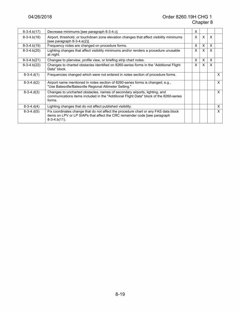
04/26/2018 Order 8260.19H CHG 1 Chapter 8
8-19
8-3-4.b(17) Decrease minimums [see paragraph 8-3-4.c]. X 8-3-4.b(18) Airport, threshold, or touchdown zone elevation changes that affect visibility minimums
[see paragraph 8-3-4.e(2)]. X X X
8-3-4.b(19) Frequency notes are changed on procedure forms. X X X 8-3-4.b(20) Lighting changes that affect visibility minimums and/or renders a procedure unusable
at night. X X X
8-3-4.b(21) Changes to planview, profile view, or briefing strip chart notes. X X X 8-3-4.b(22) Changes to charted obstacles identified on 8260-series forms in the “Additional Flight
Data” block. X X X
8-3-4.d(1) Frequencies changed which were not entered in notes section of procedure forms. X
8-3-4.d(2) Airport name mentioned in notes section of 8260-series forms is changed; e.g., "Use Batesville/Batesville Regional Altimeter Setting."
X
8-3-4.d(3) Changes to uncharted obstacles, names of secondary airports, lighting, and communications items included in the "Additional Flight Data" block of the 8260-series forms.
X
8-3-4.d(4) Lighting changes that do not affect published visibility. X 8-3-4.d(5) Fix coordinates change that do not affect the procedure chart or any FAS data block
items on LPV or LP SIAPs that affect the CRC remainder code [see paragraph 8-3-4.b(11).
X
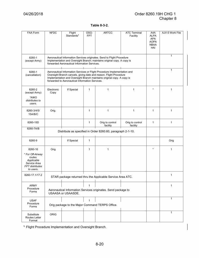
04/26/2018 Order 8260.19H CHG 1 Chapter 8
8-20
Table 8-3-2.
FAA Form NFDC Flight Standards1
OSG-FPT
ARTCC ATC Terminal Facility
A4A ALPA APA
AOPA NBAA HAI
AJV-5 Work File
8260-1 (except Army)
1
8260-1 (cancellation)
1
8260-2 (except Army)
*AWOdistributes to
users.
Electronic Copy
If Special 1 1 1 * 1
8260-3/4/5/ 15A/B/C
Orig. 1 1 1 1 1
8260-15D 1 Orig to control facility
Orig to control facility
1 1
8260-7A/B
8260-9 If Special 1 Orig
8260-16
* For Off-Airwayroutes.
ApplicableService Area
FPT distributesto users.
Orig 1 1 * 1
8260-17.1/17.2 1
ARMY Procedure
Forms
1 1
USAF Procedure
Forms
1 1
Substitute Routes Letter
Format
ORIG 1
1. Flight Procedure Implementation and Oversight Branch.
Aeronautical Information Services originates. Send to Flight Procedure Implementation and Oversight Branch; maintains original copy. A copy is forwarded Aeronautical Information Services.
Aeronautical Information Services or Flight Procedure Implementation and Oversight Branch cancels, giving date and reason. Flight Procedure Implementation and Oversight Branch maintains original copy. A copy is forwarded to Aeronautical Information Services.
Aeronautical Information Services originates. Send package to USAASA or USAASDE.
Orig package to the Major Command TERPS Office.
Distribute as specified in Order 8260.60, paragraph 2-1-10.
STAR package returned thru the Applicable Service Area ATC.
04/26/2018 Order 8260.19H CHG 1 Chapter 8
8-21
Section 8-4. Flight Procedures Standards Waiver, FAA Form 8260-1
8-4-1. Preparation of Form 8260-1, Flight Procedures Standards Waiver. All waivers toOrder 8260.3 and other TERPS-related FAA directives, must be initiated by the developer, andforwarded to the Flight Procedure Implementation and Oversight Branch. See figure 8-4-1 forsample Form 8260-1. Itemized instructions for completing Form 8260-1 are as follows:
a. Control number. Flight Standards will enter a control number that will be used fortracking.
b. Item 1. Flight Procedure identification. Enter the city name and state, official airportname, and the flight procedure identification (excluding amendment number).
c. Item 2. Waiver required and applicable standard. Identify clearly and accurately whatstandard is requested to be waived; e.g., “Missed Approach Section 1 is not aligned with the Final Approach course. Order 8260.3, chapter 10.” Request only one waiver of standards on each form, and address the applicable standard(s) to be waived (Note: More than one reference may be applicable to what is being waived). When a procedure is amended, reprocessing of an existing waiver is not necessary unless the amendment directly impacts the basis for the waiver.
d. Item 3. Reason for waiver. The reason for the waiver must be clear and concise. If thewaiver for an existing procedure is being revised, the effective date of the original procedure must be included. Include full justification for the waiver; e.g., “To avoid obstructions that would require raising the DA 180 feet.”
e. Item 4. Equivalent level of safety provided. Complete this item in all cases with as manypoints as is germane to the equivalent level of safety. Clearly state the equivalent level of safety which would mitigate the nonstandard condition.
Note 1: The fact that the procedure has existed for a number of years or that the procedure conforms to CFRs is not considered to be sole justification for an equivalent level of safety.
Note 2: Satisfactory flight inspection/validation in and of itself does not constitute an equivalent level of safety.
Note 3: Consultation with the AWO responsible for the geographic area the procedure is located in is recommended.
f. Item 5. Alternative actions deemed not feasible. Enter statements in this item to indicateconsideration has been given to alternatives and why they were ultimately deemed as not feasible to eliminate the requirements of the waiver condition. Alternatives may include the consideration of new and/or relocated navigational aids, alternative routes/tracks/radials that were considered, removal of obstacles, etc. These entries must result in a description of why the waiver is the only reasonable alternative.
g. Item 6. Coordination with user organizations. Indicate the FAA offices and otherorganizations with which this waiver will be coordinated.
04/26/2018 Order 8260.19H CHG 1 Chapter 8
8-22
h. Item 7. Submitted by. For FAA developed instrument procedures, the AeronauticalInformation Services manager or his/her designated representative, must sign and date all waiver requests, and forward to the Flight Procedure Implementation and Oversight Branch for further action. Waivers for instrument procedures developed by non-FAA service providers will be signed by the designated representative of the service provider. The waiver package (paper/electronic) submitted to the Flight Procedure Implementation and Oversight Branch must include such technical data (sketches, maps, computations, supporting database information, documentation) as necessary for Flight Standards analysis and understanding of the situation. Packages submitted with insufficient supporting technical data are subject to return to the originating office, or may be held pending receipt of such information.
i. Item 8. Flight Standards action.
(1) The Flight Procedure Implementation and Oversight Branch processes all waiverrequests and schedules a PRB to gain consensus on approval/ disapproval. If the PRB recommends approval, then the Flight Procedure Implementation and Oversight Branch will endorse the Form 8260-1. When necessary, the Flight Procedure Implementation and Oversight Branch will annotate the Form 8260-1 that approval is contingent upon a successful flight inspection/validation report. SRM compliance for the PRB will be implemented as a Quality Management System (QMS) process and documented as part of the online PRB package.
(2) The Flight Procedure Implementation and Oversight Branch retains the original forfile, provides a copy of the completed waiver to Aeronautical Information Services, and makes further distribution as necessary.
j. U.S. Army waivers. Aeronautical Information Services completes Form 8260-1 per theinstructions provided in this order, as supplemented by Order 8260.15. U.S. Army procedures requiring waivers, for joint civil/military use, are sent to the Flight Procedure Implementation and Oversight Branch per the provisions in paragraph 8-4-1.h.
k. Cancellation of a waiver may be initiated by Aeronautical Information Services [seeparagraph 2-12-6] or by the Flight Procedure Implementation and Oversight Branch. The initiating office must enter a signed statement to that effect, with the effective date and reason for cancellation. The Flight Procedure Implementation and Oversight Branch will distribute copies to the same organizations that received the approved waiver.
Example: This waiver is canceled effective February 2, 2002.
Order 8260.3, now permits multiple DME fixes.
(Signature)
(Title, Office Symbol)
04/26/2018 Order 8260.19H CHG 1 Chapter 8
8-33
n. Date of revision. Enter the effective date of the new/revised holding pattern and/or fix.
Note: If the fix/holding pattern serves only a Special instrument procedure, this date must be the same as the effective date established for the procedure [see paragraph 8-6-2.o].
o. Reason for revision. List the reason(s) for the revision. Make “concurrent with” entries ifneeded.
Example: ADDED FACILITY 3 TO FIX MAKE-UP RAISED PATTERN 4 MINIMUM HOLDING ALTITUDE FROM 3000 FT TO 4000 FT CONCURRENT WITH JACKSON HOLE, WY, VOR RWY 36, AMDT 3
p. ATC coordination. Enter the date, air traffic facility Ident and type, and name of the ATCindividual that coordinated the fix request.
q. Initiated by. For Aeronautical Information Services or ATC developed fixes, leave blank.For all other developed fixes, enter the date, organization/company, and name of the individual initiating the fix.
r. Office of primary responsibility. Enter the name and office symbol of the office that isthe focal point for any changes/modifications to this fix and/or holding pattern(s). See appendix D for guidance when submitting changes/modifications to the OPR. The OPR is subject to change based on changes that may occur regarding “fix use.” For example, if the fix were used by a non-FAA service provider or ATC and it will now be used for an instrument flight procedure developed by the FAA; the OPR will be transferred to Aeronautical Information Services [see paragraphs 2-10-4.a(5) and 2-10-4.a(6)].
s. Approved by. Enter the date, office, name, and signature of the approving authority.Aeronautical Information Services is the approval authority for fixes required by FAA-developed instrument flight procedures and/or airways. The Flight Procedure Implementation and Oversight Branch is the approval authority for fixes associated with “Special” instrument flight procedures not developed by the FAA. Non-FAA service providers approved to develop 14 CFR part 97 instrument procedures have approval authority for those fixes used solely for procedures they have developed. The military may sign and approve fixes that are for military operations and have no impact on FAA-developed instrument procedures and/or airways. The applicable Service Area OSG-FPT is the approval authority for fixes created solely for ATC use.
t. Distribution.
(1) Distribute the approved Form 8260-2s for instrument procedure fixes, includingmilitary fixes as defined in table 8-3-2.
(2) Enter the office symbol, abbreviation, or facility Ident. Enter each ARTCC, ATCFacility, or other if sent to more than one of that type.
(3) For U.S. Army fixes, distribute Form 8260-2s in accordance with Order 8260.15.

04/26/2018 Order 8260.19H CHG 1 Chapter 8
8-34
(4) Send the Form 8260-2s (electronic submission preferred) on Specials to the NFDCwhen notified that the Special has been approved by the Flight Procedure Implementation and Oversight Branch.
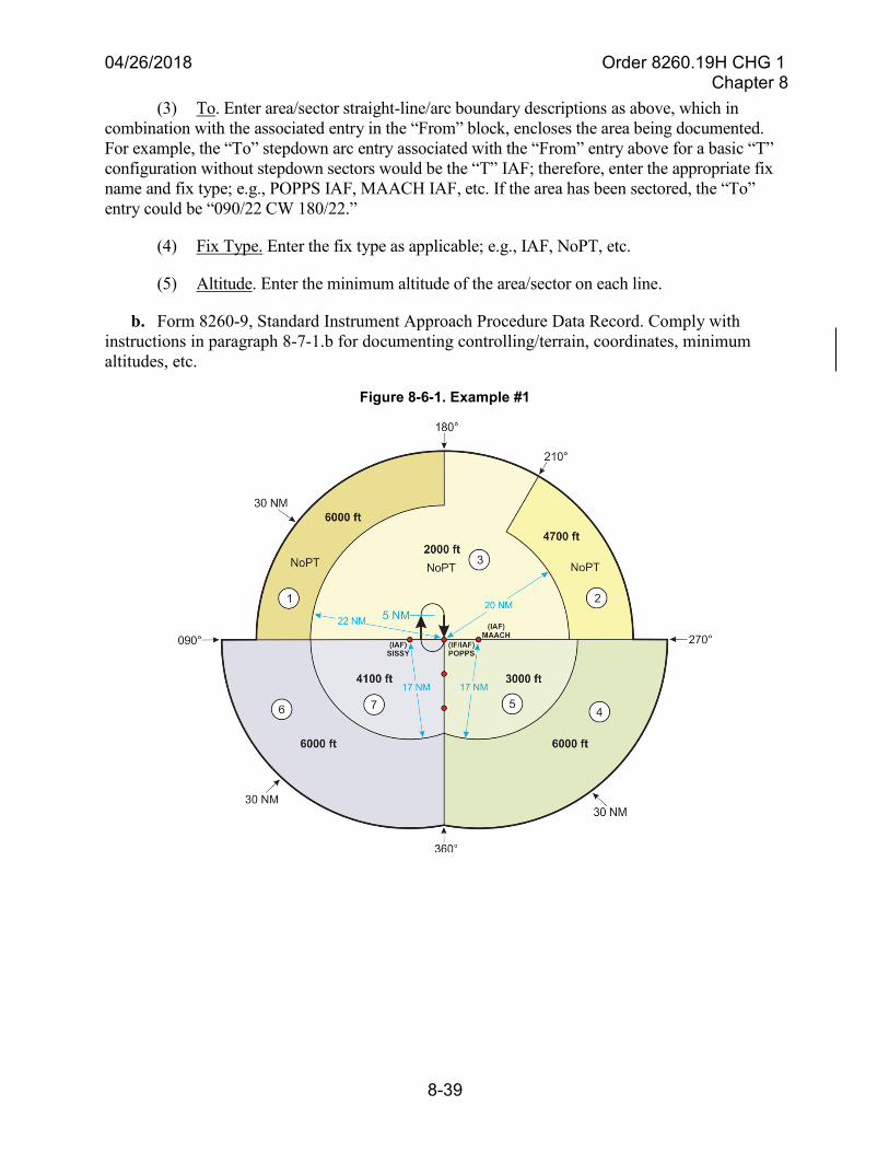
04/26/2018 Order 8260.19H CHG 1 Chapter 8
8-39
(3) To. Enter area/sector straight-line/arc boundary descriptions as above, which incombination with the associated entry in the “From” block, encloses the area being documented. For example, the “To” stepdown arc entry associated with the “From” entry above for a basic “T” configuration without stepdown sectors would be the “T” IAF; therefore, enter the appropriate fix name and fix type; e.g., POPPS IAF, MAACH IAF, etc. If the area has been sectored, the “To” entry could be “090/22 CW 180/22.”
(4) Fix Type. Enter the fix type as applicable; e.g., IAF, NoPT, etc.
(5) Altitude. Enter the minimum altitude of the area/sector on each line.
b. Form 8260-9, Standard Instrument Approach Procedure Data Record. Comply withinstructions in paragraph 8-7-1.b for documenting controlling/terrain, coordinates, minimum altitudes, etc.
Figure 8-6-1. Example #1
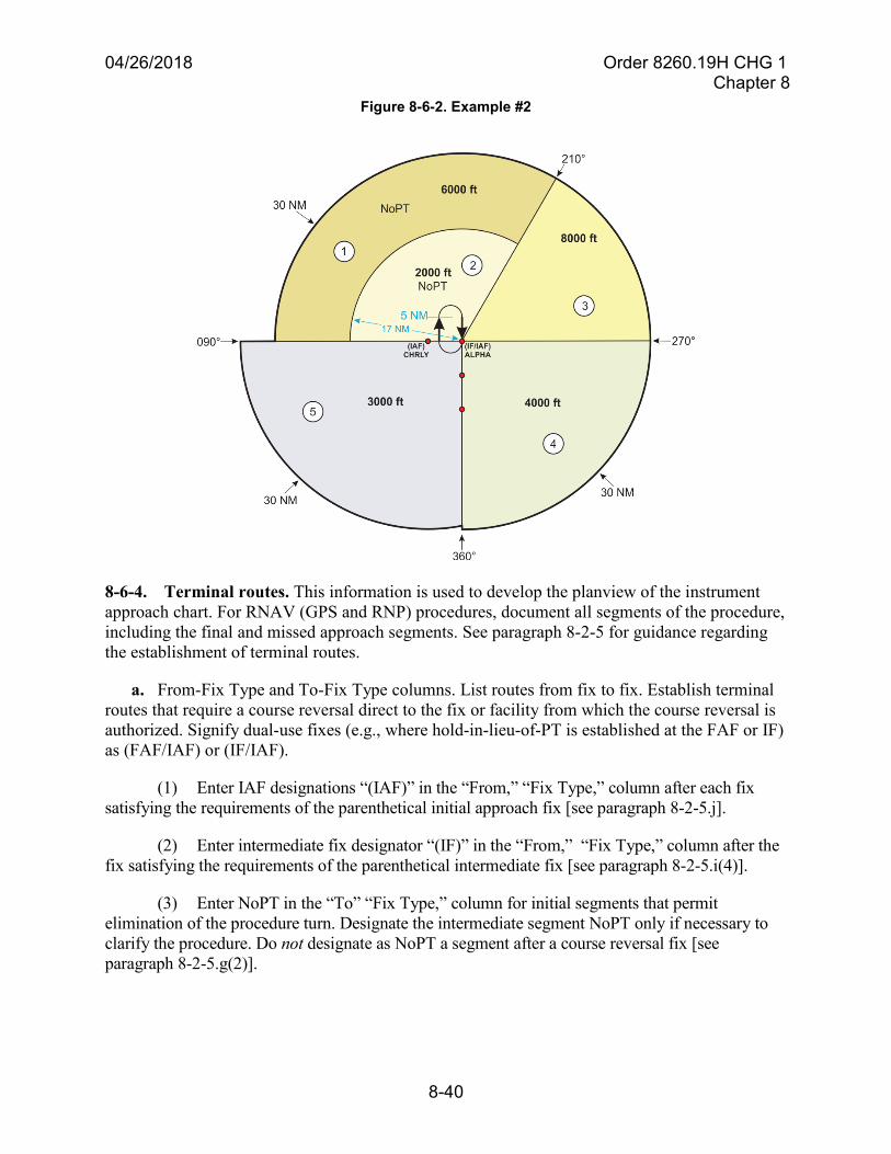
04/26/2018 Order 8260.19H CHG 1 Chapter 8
8-40
Figure 8-6-2. Example #2
8-6-4. Terminal routes. This information is used to develop the planview of the instrumentapproach chart. For RNAV (GPS and RNP) procedures, document all segments of the procedure,including the final and missed approach segments. See paragraph 8-2-5 for guidance regardingthe establishment of terminal routes.
a. From-Fix Type and To-Fix Type columns. List routes from fix to fix. Establish terminalroutes that require a course reversal direct to the fix or facility from which the course reversal is authorized. Signify dual-use fixes (e.g., where hold-in-lieu-of-PT is established at the FAF or IF) as (FAF/IAF) or (IF/IAF).
(1) Enter IAF designations “(IAF)” in the “From,” “Fix Type,” column after each fixsatisfying the requirements of the parenthetical initial approach fix [see paragraph 8-2-5.j].
(2) Enter intermediate fix designator “(IF)” in the “From,” “Fix Type,” column after thefix satisfying the requirements of the parenthetical intermediate fix [see paragraph 8-2-5.i(4)].
(3) Enter NoPT in the “To” “Fix Type,” column for initial segments that permitelimination of the procedure turn. Designate the intermediate segment NoPT only if necessary to clarify the procedure. Do not designate as NoPT a segment after a course reversal fix [see paragraph 8-2-5.g(2)].
04/26/2018 Order 8260.19H CHG 1 Chapter 8
8-49
(3) Leave line 1 blank when there is no PT, or where hold-in-lieu-of-PT or a teardropcourse reversal maneuver is established.
b. Line 2.
(1) Where a SIAP requires a teardrop course reversal maneuver, enter the data inaccordance with the following examples:
(a) Collocated facility: Teardrop R-160 outbound, R-180 inbound, 4300 within15 NM of ABC VORTAC (IAF).
(b) Non-collocated facility: Teardrop R-160 (ABC VORTAC) (IAF) outbound toNIXON/19.00 DME, 355.00 (I-XYZ) inbound, 3000 to KENNY OM/INT.
(c) Non-collocated facility, altitude at turn point or high altitude teardrop:Teardrop R-220 (ABC VORTAC) (IAF) outbound to NIXON/19.00 DME, 5000, 257.28 (I-XYZ) inbound, 4500 to KENNY OM/INT.
(d) Non-collocated NAVAID – IAF after NAVAID – altitude at turn point or highaltitude teardrop - IAF after NAVAID: Teardrop R-220 (ABC VORTAC) START/7.00 DME (IAF) outbound to NIXON/19.00 DME, 5000, 257.28 (I-XYZ) inbound, 4500 to KENNY OM/INT.
(e) Non-collocated NAVAID – IAF at NAVAID – altitude at turn point –stepdown fix(es) or high altitude teardrop - IAF at NAVAID - stepdown fix(es) (example with three stepdown fixes in outbound segment of the teardrop): Teardrop R-220 (ABC VORTAC) (IAF) outbound, MANNY INT 10000 MOOEE INT 9200, JACCK INT 7500 feet to PEEPP INT 6800, R-257 (ABC VORTAC) inbound, 6000 to BOYZS INT.
(f) Non-collocated NAVAID – IAF after NAVAID – altitude at turn point –stepdown fix(es) or high altitude teardrop - IAF after NAVAID - stepdown fix(es) (example with three stepdown fixes in outbound segment of the teardrop): Teardrop R-220 (ABC VORTAC) CARRS/7.00 DME (IAF) outbound, MANNY INT 10000, MOOEE INT 9200, JACCK INT 7500 to PEEPP INT 6800, R-257 (ABC VORTAC) inbound, 6000 to BOYZS INT.
(2) Where an IAP requires a holding pattern in-lieu-of-PT [see Order 8260.3, chapter 2,section 2-4], establish the direction of holding based on the inbound course as shown in table 8-6-1. Information will also include the minimum and maximum holding altitudes. Enter holdingdata in accordance with the following examples:
(a) Hold SE OMEGA LOM, RT, 313.09 inbound, 1600 in lieu of PT (IAF), Max4000.
(b) Hold W FIXXR, LT, 103.28 inbound, 3000 in lieu of PT (IAF), Max 8000.
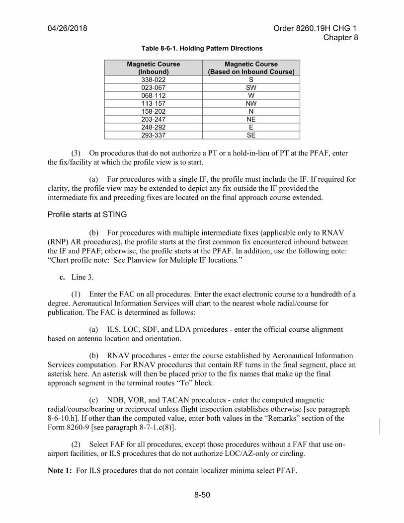
04/26/2018 Order 8260.19H CHG 1 Chapter 8
8-50
Table 8-6-1. Holding Pattern Directions
Magnetic Course (Inbound)
Magnetic Course (Based on Inbound Course)
338-022 S 023-067 SW 068-112 W 113-157 NW 158-202 N 203-247 NE 248-292 E 293-337 SE
(3) On procedures that do not authorize a PT or a hold-in-lieu of PT at the PFAF, enterthe fix/facility at which the profile view is to start.
(a) For procedures with a single IF, the profile must include the IF. If required forclarity, the profile view may be extended to depict any fix outside the IF provided the intermediate fix and preceding fixes are located on the final approach course extended.
Profile starts at STING
(b) For procedures with multiple intermediate fixes (applicable only to RNAV(RNP) AR procedures), the profile starts at the first common fix encountered inbound between the IF and PFAF; otherwise, the profile starts at the PFAF. In addition, use the following note: “Chart profile note: See Planview for Multiple IF locations.”
c. Line 3.
(1) Enter the FAC on all procedures. Enter the exact electronic course to a hundredth of adegree. Aeronautical Information Services will chart to the nearest whole radial/course for publication. The FAC is determined as follows:
(a) ILS, LOC, SDF, and LDA procedures - enter the official course alignmentbased on antenna location and orientation.
(b) RNAV procedures - enter the course established by Aeronautical InformationServices computation. For RNAV procedures that contain RF turns in the final segment, place an asterisk here. An asterisk will then be placed prior to the fix names that make up the final approach segment in the terminal routes “To” block.
(c) NDB, VOR, and TACAN procedures - enter the computed magneticradial/course/bearing or reciprocal unless flight inspection establishes otherwise [see paragraph 8-6-10.h]. If other than the computed value, enter both values in the “Remarks” section of theForm 8260-9 [see paragraph 8-7-1.c(8)].
(2) Select FAF for all procedures, except those procedures without a FAF that use on-airport facilities, or ILS procedures that do not authorize LOC/AZ-only or circling.
Note 1: For ILS procedures that do not contain localizer minima select PFAF.
04/26/2018 Order 8260.19H CHG 1 Chapter 8
8-61
(5) AWOS may be used as a remote secondary altimeter source when data is available toFSS specialists and ATC facilities through WMSCR.
(6) ASOS/AWOS at a remote location may be used as a primary altimeter source for anairport. In this instance, use “Chart note: Use (location) altimeter setting.” However, Non-Federal AWOS not transmitted to WMSCR still require backup altimeter setting sources. In these cases use “Chart note: Use (location) altimeter setting; when not received, use (location) altimeter setting and increase all MDAs 100 feet and all visibilities ½ SM.” Where appropriate, define application to DA and/or MDA within the standard note [see paragraphs 8-6-11.n(1)(a)1 and 8-6-11.n(1)(a)2]. When an airport uses a remote AWOS/ASOS/AWSS that is not available from a FSS to be used as a primary altimeter source, flight inspection ensures AWOS/ASOS/AWSS/non-Federal AWOS discrete frequency reception at the IAFs of that airport.
(7) ASOS/AWOS-3 (or better) may be used as a remote secondary altimeter source andto support alternate minimums at an airport when:
(a) They are installed and commissioned.
(b) Their data are available to FSS specialists and ATC through WMSCR forflight planning purposes.
(8) When the ASOS/AWOS information is transmitted over a discrete frequency (notCTAF) or the voice portion of a local NDB or VOR, AWOS is receivable within 25 NM of the AWOS site, at or above 3000 feet and below 10000 feet AGL. If ASOS/AWOS is located on the voice portion of a NAVAID, flight inspection checks for interference. This check is performed prior to test transmissions.
g. ASR or ARSR may be available to provide assistance in vectoring to the approach course,identifying fixes, or to provide instrument approaches. Include applicable notes to inform the pilot of these capabilities and applicability to the instrument approaches [see paragraph 8-2-5].
(1) When ASR and/or PAR approaches are published for the airport, enter the following:“Chart Note: ASR” or “Chart Note: ASR/PAR,” whichever is applicable.
(2) Where use of Radar is the only acceptable method for procedure entry from theen route environment, enter the following: “Chart equipment required note: Radar Required For Procedure Entry.” See paragraph 8-6-8, for additional equipment that may be used in addition to, or in-lieu-of Radar.
Note: Paragraph 8-6-9.g(2) does not apply to GLS, RNAV (GPS), and RNAV (RNP) procedures. This paragraph also does not apply to ILS and/or LOC procedures where RNAV is used for procedure entry.
h. Approach light plane penetrations. Do not publish notes advising of approach light planepenetrations. When there are penetrations of the approach light plane, the responsible Air Traffic Service Area and regional airports division must jointly take action to either remove the obstacle or modify the system to accommodate the obstacle. If this is not possible, the appropriate Technical Operations office processes an installation waiver. Existing notes referring to approach
04/26/2018 Order 8260.19H CHG 1 Chapter 8
8-62
light penetrations must be removed from the approach procedure when an appropriate waiver has been approved.
i. The use of notes to prohibit a final approach from a holding pattern has beendiscontinued [see paragraph 8-6-6.g(3)].
j. When the “Fly Visual” from MAP to landing area provisions of Order 8260.3, chapter 3,have been applied, annotate the chart as stated in the Flight Procedure Implementation and Oversight Branch’s approval documentation.
k. DME frequencies are paired with the frequencies of the VOR or localizer. When a non-paired DME is used in a VOR, LOC, etc., procedure, simultaneous reception of both facilities must be assured. This requires a note indicating the DME location and the identification of both facilities: “Chart note: DME from XYZ VORTAC. Simultaneous reception of I-ABC and XYZ DME required.” DME frequencies are not paired with NDBs; and DME antennas may or may not be collocated with the NDB. For NDB SIAPs, use “Chart note: Simultaneous reception of ABC NDB and XYZ DME required.” See paragraphs 8-2-6.c, and 8-6-11.n(1)(a)1.
l. Copter procedures require notes relating to missed approach instructions, as well asairspeed limitations on certain segments.
(1) For PinS “Proceed VFR” approach procedures, use: “Chart planview note: ProceedVFR from (MAP) or conduct the specified missed approach.”
(2) For PinS “Proceed Visually” approach procedures, use: “Chart planview note:Proceed visually from (MAP) or conduct the specified missed approach.”
(3) Use the following note for feeder (when applicable), initial, and intermediateapproach segment speed restrictions: “Chart planview note: Limit feeder, initial, and intermediate approach to XX KIAS.” See paragraph 8-6-9.l(4), Note 2.
(4) Use the following note for final and missed approach segment speed restrictions:“Chart planview note: Limit final and missed approach to XX KIAS.”
Note 1: For procedures designed to support USA/USAF/USN/USCG operations, the note should read: “Limit all segments to 90 KIAS.”
Note 2: These speeds are left to the discretion of the procedure developer based on the predominant helicopter model that will use this procedure and/or as limited by the criteria standards used for procedure development.
(5) Holding airspeed is also restricted for containment based on the unique wind affectwhen holding at slow airspeeds. This requires the airspeed to be increased upon reaching the missed approach altitude. When the chart note in paragraph 8-6-9.l(4) is applied and missed approach holding has been established, use the following note: “Chart planview note: Increase to 90 KIAS (or greater) upon reaching the missed approach altitude; Maintain 90 KIAS (or greater) while in holding.

04/26/2018 Order 8260.19H CHG 1 Chapter 8
8-63
m. VGSI and IAP glidepath angles/vertical descent angles should be coincidental (angleswithin 0.20 degrees and TCH values within three feet). See Order 8260.3, section 2-6, for conditions that require approval from the Flight Procedure Implementation and Oversight Branch. Whenever a published glidepath/ descent angle or TCH is not coincident with the VGSI angle for a runway, use the applicable note below.
(1) Where precision/APV approach (ILS, or RNAV) glidepath angles and/or TCH valuesare not coincident with published VGSI values, use “Chart profile note: VGSI and (ILS/RNAV as appropriate) glidepath not coincident (VGSI Angle {angle}/TCH {feet}).”
(2) Where nonprecision vertical descent angles (VDAs) and/or TCH values are notcoincident with published VGSI values, use “Chart profile note: VGSI and descent angles not coincident (VGSI Angle {angle}/TCH {feet}).”
Note: Do not enter the VGSI angle/TCH numerical values; this information will be obtained by chart producers from the applicable source.
n. Where DME/DME RNP-0.3 is not authorized, use “Chart Note: DME/DME RNP-0.3NA.” Where DME/DME RNP-0.3 is authorized, use “Chart note: DME/DME RNP-0.3 Authorized.” Where DME/DME RNP-0.3 is authorized only when required facilities are necessary for proper navigation solution, use “Chart note: DME/DME RNP-0.3 Authorized; ABC and XYZ must be Operational.”
o. LDA instrument procedures with a glide slope must be identified as such with note in theplanview, use “Chart planview note: LDA/GLIDE SLOPE.”
p. Instrument approach procedures with “PRM” in the title (e.g., ILS PRM RWY 12R, LDAPRM RWY 22L, RNAV (GPS) PRM RWY 18R, etc.). The procedure must have an accompanying “Attention All Users Page (AAUP)” [see section 8-9] and must contain an instructional note that reads as follows:
“Chart note: SIMULTANEOUS APPROACH AUTHORIZED. USE OF FD OR AP REQUIRED DURING SIMULTANEOUS OPERATIONS. DUAL VHF COMM REQUIRED. SEE ADDITIONAL REQUIREMENTS ON AAUP.”
q. Simultaneous Offset Instrument Approach (SOIA) procedures with “PRM” in the title(e.g., ILS PRM RWY 12R, LDA PRM RWY 22L, RNAV (GPS) RWY 28R, etc.) the following applies in addition to what is required in paragraph 8-6-9.p:
(1) Do not include non-vertically guided procedure minimums on SOIA procedures.
(2) Specify the distance between centerlines of the adjacent runway, use the following:
“Chart note: RWY (number) and (number) separated by (number) feet centerline to centerline.”
(3) Specify “Radar and DME Required” on LDA PRM approach plate: “Chart note:Radar and DME Required.”
04/26/2018 Order 8260.19H CHG 1 Chapter 8
8-64
(4) For the offset course procedures, aircraft database coding of SOIA RNAV, GLS, andLDA approach procedures are different than other RNAV, GLS, and LDA approach coding. The charted MAP and the database coded MAP (FTP) are not collocated. The charted approach must identify the MAP as determined by the SOIA design tool. The approach coding must identify the FTP as the MAP, so that vertical guidance is available to the runway threshold. Notes on the charted approach plate and on the AAUP must describe the procedures to be followed based on this database coding necessity.
(5) When the offset course procedure has been evaluated for a go-around that could beexecuted after passing DA and it would require a climb gradient that is greater than 200 ft per NM, a minimum climb gradient must be published as a chart note. Use “Chart Note: If go-around executed after passing (fix name), go-around requires minimum climb of XXX feet per NM to (altitude).”
r. Helicopter RNAV approach procedures.
(1) For documentation purposes, consider Copter GPS approaches to be grouped intothree categories:
(a) Approach to a runway. COPTER RNAV (GPS) RWY XX approachprocedure, not associated with a heliport.
(b) Approach to a heliport. COPTER RNAV (GPS) XXX approach proceduresthat are either straight-in to a heliport, or constructed using PinS criteria or noted “Chart Planview Note: PROCEED VISUALLY…;” i.e., visual segment evaluated from MAP to helipoint.
(c) Approach to a PinS. COPTER RNAV (GPS) XXX approach proceduresconstructed using PinS criteria and noted “Chart Planview Note: PROCEED VFR…;” i.e., visual segment evaluated only at the MAP.
(2) When the procedure has been evaluated to permit both “PROCEED VISUALLY”and “PROCEED VFR” operations, “Proceed Visually” will be published on the chart and the option to use “Proceed VFR” may be implemented via NOTAM. Document this information in the following format:
“Proceed VFR” area evaluated and may be initiated by NOTAM when required.
(3) Document one destination airport or heliport on Form 8260-3/5/7A for approaches toa runway, and approaches to a heliport, or a PinS approach to a heliport noted “PROCEED VISUALLY.” PinS approach procedures noted “PROCEED VFR” may serve more than one destination.
(4) The visual segment is based on the premise that the pilot will maintain level flight atthe MDA until the helicopter is in a position to initiate a descent to the helipoint. When obstacles preclude an immediate descent at the MAP to the final approach and takeoff area (FATO) area and an ATD fix has been established to provide a descent point to the FATO, use the following: “Chart profile note: Maintain (MDA altitude) until (distance) NM past (MAP Fix Name).”
04/26/2018 Order 8260.19H CHG 1 Chapter 8
8-65
s. Baro-VNAV critical temperatures. For RNAV (GPS) procedures, use “Chart note: Foruncompensated Baro-VNAV systems, LNAV/VNAV NA below ____°C or above____°.” For RNAV (RNP) procedures, use “Chart note: For uncompensated Baro-VNAV systems, Procedure NA below ____°C or above____°C.” See paragraph 8-7-1.c(10) for Form 8260-9 documentation requirements.
t. Radar notes (Form 8260-4). These notes will not be charted except where annotated with“Chart Note” specified prior to the note:
(1) Establish a FAF, minimum altitude (glidepath intercept altitude for PAR), and finalapproach course for each runway for which radar procedures are established. Runway designation may be omitted if only one runway has a radar approach.
(2) For ASR, provide recommended altitudes for each mile on final, but not below thelowest MDA.
Example Form 8260-4 entry: “RWY 17: FAF 7.8 NM from threshold (at LACKI OM), minimum altitude 9000; minimum altitude 3 NM fix 7300; final approach course 168. Recommended altitude: 7 NM 8720; 6 NM 8360; 5 NM 8000; 4 NM 7660; 3 NM 7300; 2 NM 6920.”
(3) When segments prior to the FAF are required, establish the fixes and minimumaltitudes in a note preceding the note cited above: “9.4 NM from threshold, minimum altitude 9000.”
(4) Define the final approach course in the “Notes” section when circling is the onlyminimum authorized: “FAF 6 NM from runway intersection, minimum altitude 8000; final approach course 060 aligned to intersection of Runways 2 and 15.”
(5) If radar availability is limited, use standard note: “Chart Note: When control towerclosed, ASR NA.” (This is a radar SIAP note only - not to be used on other SIAP types.)
(6) Lost communications instructions must be entered as follows: “As directed by ATCon initial contact.”
u. Limitations notes required on the use of Special procedures.
(1) Where a special procedure requires the use of private facilities, e.g., landing area ornavigational facility, the following statement must be added to the Form 8260-7A restricting the use of that procedure; use: “Chart Note: Use of [name of private facility] requires permission of the owner; use of this procedure requires specific authorization by FAA Flight Standards.”
(2) Where there are no private aspects to a special instrument procedure, the followingstatement must be to the Form 8260-7A restricting the use of that procedure; use: “Chart Note: Use of this procedure requires specific authorization by FAA Flight Standards.”
8-6-10. Additional flight data. When additional information or data is essential to clarify thecharting of a procedure or when the procedures specialist wants information charted, but does
04/26/2018 Order 8260.19H CHG 1 Chapter 8
8-66
not want it to appear on the chart as a note, the necessary information/data must be entered in the “Additional Flight Data” section. Preface specific items to be charted with the term “Chart.” Specific instructions to chart data must be held to a minimum [see also paragraphs 8-2-4.b and 8-6-6.g].
Note: Do not document takeoff obstacles on the Form 8260-9 or in “Additional Flight Data.”
a. Items such as holding information, restricted area data, final approach course alignment,primary remote automated altimeter setting source, etc., must be retained when amending a procedure.
b. Enter holding Instructions as follows:
(1) When primary missed approach instructions provide for holding, enter additionalflight data as follows: “Hold SE, RT, 313.09 inbound” [see paragraph 8-6-6.g].
(2) Where alternate missed approach holding is established, enter the description asdescribed in paragraph 8-6-6.h(2).
(3) Where arrival holding is operationally advantageous, enter: “Chart arrival holding atPUGGY: Hold SE, RT, 313.09 inbound, 4000.”
c. The nonprecision controlling obstacle in the primary and/or secondary area of the FASmust be shown as the FAS Obstacle. In the event a stepdown fix is used in the final approach segment, the controlling obstacle between the stepdown fix and the runway must be shown as the FAS obstacle. If there is more than one FAS obstacle (e.g., LNAV and LP) list both. Enter the obstacle description, elevation in Mean Sea Level (MSL), and location to the nearest second. For a single FAS obstacle or two that are the same, list the obstacle(s) as: “Chart FAS Obst: 317 Tower 364227N/ 0891523W.” For multiple FAS obstacles, list the obstacles as: “Chart FAS Obst: 317 Tower 364227N/ 0891523W, 143 Trees 364210N/0891501W.”
Note: When the FAS Obstacle is an AAO, do not chart it. Enter the data as follows: “FAS Obst: 529 AAO 365029N/0871234W.”
d. To identify certain significant obstacles, other than AAOs, in or near the instrumentapproach area, include locations and MSL heights under additional flight data. If, in the opinion of the procedures specialist, these obstacles could be critical to flight safety, they should be prefaced by the word “Chart.” However, if the data is being furnished only as information, it must not be prefaced by the word “Chart.” Charting agencies will chart any item marked “Chart.” Any item listed without indicating “Chart” will be reviewed by the charting agencies and will be charted if it meets their charting specifications. List obstacles as follows:
“Chart 2674 antenna 372219N/0941657W” or “2674 antenna 372219N/0941657W.”
e. Obstacles close to a final approach or stepdown fix considered under Order 8260.3chapter 2 must be accomplished as follows:
04/26/2018 Order 8260.19H CHG 1 Chapter 8
8-69
n. Where a VDP is established on a SIAP, identify the location of the VDP as follows:
(1) Non-RNAV: Specify the VDP DME fix and distance to threshold.
Chart VDP at _____DME; Distance VDP to THLD_____NM.
Note: If the VDP is for a localizer procedure on an “ILS or LOC” approach plate, indicate the VDP as applicable to LOC Only.
Chart VDP at _____DME*; Distance VDP to THLD_____NM. *LOC only
(2) RNAV and LNAV: Indicate the VDP distance to MAP.
Chart VDP at NM to RW16. Chart VDP at NM to SUSIE.
(3) RNAV/VNAV: Indicate the VDP as applicable to LNAV only.
Chart VDP at NM to RW16* * LNAV only.
o. Enter charting instructions for maximum, mandatory or block altitudes; e.g., “Chartmandatory 5000 at DAVID,” or “Chart at or below 14000 and at or above 12000 at CATTS.”
Note 1: Maximum or mandatory altitudes should be avoided where possible, especially in the final approach segment. Maximum, mandatory, or block altitudes in the intermediate, final and/or missed approach segment requires Flight Standards approval from the Flight Procedure Implementation and Oversight Branch, prior to forwarding for publication.
Note 2: Until such time formal obstacle clearance criteria has been established to address maximum, mandatory, or block altitudes, a waiver will also be required when applying this to the missed approach segment.
p. Vertical descent angle (VDA)/TCH.
(1) For straight-in aligned nonprecision SIAPs (except for procedures that already have aGS/GP angle established for the vertically guided procedure on the same chart and surveillance (ASR) approach procedures), enter the descent angle for the appropriate fix in the final approach segment, and the appropriate TCH: NIXON to RW15: 3.26/55. Where straight-in minimums are not authorized due to an excessive descent angle, enter the straight-in descent angle (may exceed maximum when compliant with circling descent angle). Where the VDA values are not coincident with published VGSI values, see paragraph 8-6-9.m. Only one angle and TCH will be published on the chart. When a flight inspection/validation has determined that a VDA/TCH must not be specified on the chart, a chart note must be placed in the profile view of the chart; use “Chart profile note: Visual Segment – Obstacles.”
04/26/2018 Order 8260.19H CHG 1 Chapter 8
8-70
(2) For Copter PinS procedures, except those annotated “proceed VFR…” enter thevisual segment descent angle (VSDA) (to the hundredth of a degree) from the specified descent point (MAP or ATD after MAP) to a specified hover height (20-foot maximum) which is known and documented as a heliport crossing height (HCH). Data entry format:
(MAP Name) TO HELIPORT: 7.30/5 feet HCH or 0.2 NM after (MAP Name) TO HELIPORT: 7.50/20 feet HCH.
Note: Except for Copter procedures to runways, do not publish vertical descent angle data from FAF to MAP.
q. Computer navigation fixes (CNF). Enter charting instructions for CNFs; e.g., “Chart(CFABC) at (location).”
r. Arc IAFs. Enter the radial that defines the beginning of the arc initial segment; e.g.,“Chart ABC R-060 at WERNR.”
s. DME facility. When a DME is used and is not associated with the facility providing finalcourse guidance and station passage occurs within the final segment, the facility must be shown in the profile view; e.g., “Chart in profile view: I-XYZ DME antenna” or “Chart in profile view: ABC VOR/DME.”
t. Circling icon. Document that the Circling icon must be charted when Order 8260.3, newcircling criteria has been applied as follows: “Chart Circling icon.” See paragraph 8-7-1.d(12) for Form 8260-9 documentation.
u. Secondary airports. When there is another airport(s) in the vicinity of the final approachcourse that may be confused with the airport to which the approach is designed, request the airport be depicted in the plan and profile views of the procedure chart; e.g., “Chart (airport four-letter ID) in plan and profile views.”
v. Non-FAA service provider instrument procedures. Document “Non-FAA Procedure”when a 14 CFR part 97 procedure is developed by a non-FAA service provider.
w. Radar procedures.
(1) Enter the TDZE in the preprinted area for each runway authorized straight-inminimums.
(2) Enter the GS angle, TCH, and distance from RWT to RPI in feet for PAR approachprocedures.
8-6-11. Minimums.
a. Takeoff. Takeoff minimums will be documented on Form 8260-15A in accordance withOrder 8260.46.
b. Alternate. See Order 8260.3, chapter 3. Additionally:
04/26/2018 Order 8260.19H CHG 1 Chapter 8
8-77
2. On procedures where a fan marker is used for the stepdown fix: “FMMINIMUMS.”
3. On procedures where the stepdown fix is identified by radar only: “RADARMINIMUMS.”
Note: When radar fixes are specified, ATC must agree to provide the radar service on a continuous basis and the fix must be identified on the video map or map overlay.
(f) On procedures where course guidance and a stepdown fix use the same type ofreceiver, annotate in the minimums box that dual receivers are required; e.g., “AGNES FIX MINIMUMS (Dual VOR receivers required)” or “AGNES FIX MINIMUMS (Dual VOR receivers or DME required).”
o. Landing minimums limitations. Minimums are affected by a number of differentcircumstances and conditions. Examples are enumerated below indicating the appropriate action to be taken.
(1) Day and night minimums. The authorized minimums apply to both day and nightconditions unless otherwise restricted. Aeronautical Information Services must determine the availability of all lighting aids prior to permitting night minimums. Permanently installed runway edge lights (including threshold/runway end lights), defining the lateral and longitudinal boundaries of the runway, must be operating to support night minimums [see AC 150/5340-30]. Airport or runway boundary lights are not adequate for night landing minimums unless the entire area between such lighting is suitable for landing. In special cases, portable runway lights may be used temporarily as described in AC 150/5345-50.
(2) Restriction of night minimums. When night minimums are not authorized or are higherthan day minimums, a restriction must be entered in the “Notes” section to deny night minimums or to specify increased night minimums.
(a) If unable to authorize night minimums (e.g., when both straight-in and circlingminimums are not authorized at night), use: “Chart note: Procedure NA at night.” See also paragraph 8-6-11.o(14).
(b) If increased night visibility is required by environmental conditions, such asextraneous lighting, use: “Chart note: Night visibility minimum__SM.”
(c) When straight-in minimums are published to an unlighted runway, but anotherrunway is lighted, use: “Chart note: Straight-in minimums NA at night.”
(d) When only circling minimums are published and at least one runway is lighted, anote is not required for non-lighted runways. When no runways are lighted, use: “Chart note: Procedure NA at night.”
(e) At an airport with multiple runways where straight-in minimums are authorizedto a lighted runway, but the other runway(s) is/are unlighted, a note is not required for the unlighted runways.
04/26/2018 Order 8260.19H CHG 1 Chapter 8
8-78
(f) When only circling minimums are published and circling is not authorized atnight, use: “Chart note: Procedure NA at night.”
(g) When aircraft are prohibited from circling to a runway at night, use one of thefollowing options: “Chart note: Circling NA at Night” or “Chart note: Circling Rwy X, XX NA at Night.”
(h) When the Flight Procedure Implementation and Oversight Branch has approveduse of the VGSI in lieu of obstruction lighting, use the following: “Chart note: Straight-in Rwy XX at Night, operational VGSI required, remain on or above VGSI glidepath until threshold” or “Chart note: When Circling to Rwy X, XX at Night, operational VGSI required, remain on or above VGSI glidepath until threshold.”
Note: A combination of paragraphs 8-6-11.o(2)(c) and/or 8-6-11.o(2)(g) and/or 8-6-11.o(2)(h) can be used when applicable and may appear as: “Chart note: Straight-in Rwy XX NA at Night, Circling Rwy X, XX NA at Night, Circling Rwy X, XX at Night, operational VGSI required, remain on or above VGSI glidepath until threshold.”
(3) Inoperative components and visual aids. The inoperative components and visual aidstable informs the pilot how much to increase published minimums when certain components or visual aids are known to be inoperative. When the inoperative table adjustment is not compatible with the credit that has been authorized, add notes to the procedure specifying the necessary adjustment. Enter one of the following in the “Notes” section:
(a) When credit has not been given to a visual aid to reduce visibility, use: “Chartnote: Inoperative table does not apply to ALS RWY 30.”
(b) In many instances, reference to a particular component or visual aid is notnecessary as no portion of the inoperative table is applicable. In this case, use: “Chart note: Inoperative table does not apply.”
(c) When the inoperative table applies only to a few cases, use: “Chart note:Inoperative table does not apply to CAT D;” or “Chart note: Inoperative table does not apply to S-LOC-31 CATs A and B.”
(d) The inoperative table, in certain circumstances, does not provide a sufficientincrease to minimums. When this situation occurs, use: “Chart note: For inoperative ALS, increase S-7 CAT D visibility to 1 ¾;” or “Chart note: For inoperative ALS, increase S-LOC-7 CAT Dvisibility to RVR 5000, and CAT E to RVR 6000.”
(e) Where two sets of minimums are published, specify the applicable minimumsaffected. For example, on a VOR approach with DME minimums published as the second set, use: “Chart note: VOR Minimums: Inoperative table does not apply to S-30 CATs C and D. DME Minimums: For inoperative ALS, increase S-30 CAT D visibility to 1 ¼ SM.” Where the note applies equally to both sets of minimums, do not specify the minimums.
(f) Where a heliport approach lighting system is installed and credit for lights hasbeen taken, annotate the procedure to indicate the minimum no-light visibility applicable if the ALS become inoperative; e.g., “Chart note: For inoperative ALS, increase visibility to 1 SM.”
04/26/2018 Order 8260.19H CHG 1 Chapter 8
8-83
Note 1: Affected military and civil ATC facilities not only include the IFR controlling facility, but also includes those facilities where the instrument procedure enters airport traffic areas at airports with a control tower.
Note 2: These paragraphs also apply to all public departure procedures; see Order 8260.46, Departure Procedure (DP) Program, latest edition.
a. Coordinate with appropriate FSDO according to the type of operations conducted at theairport. Coordinate with other interested organizations as necessary. A copy of the graphic sketch required by paragraph 8-7-1.e must be included in all procedure packages that are submitted for coordination. Coordinate procedures with Airlines for America (A4A) if the airport is served by scheduled air carriers. Coordinate all 14 CFR part 97 SIAPs and all DPs (see Order 8260.46) with the Air Line Pilots Association (ALPA). Coordinate with Allied Pilots Association (APA) for procedures at airports used by American Airlines. Coordinate helicopter procedures with Helicopter Association International (HAI).
b. This coordination action is required to provide advance notice to the user organizationsthat a change to an instrument approach or departure procedure is being initiated. These instrument procedures will be posted on Aeronautical Information Services web site. Civil aviation organizations that are requested to coordinate on these procedures will receive an e-mail alerting them of the procedure posting. Those receiving this notification then have 20 working days in which to review the procedures and respond to the indicated actions during the period that the procedure is being processed. Any substantive adverse user comments during this period permit sufficient time to amend or withdraw the paperwork prior to publication. Evaluation and disposition of user comments are the responsibility of; and all comments must be considered before the procedure is forwarded for publication.
(1) Enter “X” in the appropriate aviation organization spaces.
(2) Designate additional organizations or offices if additional coordination is to beaccomplished.
c. Coordination conflicts that cannot be resolved with the FAA organization responsible forIFP development will be submitted to the RAPT for resolution prior to submission of the procedure for publication [see also paragraph 4-2-2]. Make every effort to thoroughly evaluate the comments/objections, determine the validity and scope of each issue, and if necessary determine the appropriate course of action to resolve the conflict.
8-6-14. Submitted by. Enter the name, signature, company name, and date authorized by thenon-governmental entity that designed the procedure. This block is only found on the Form8260-7A.
8-6-15. Flight checked by. Enter the name of the airspace system inspection pilot(ASIP)/validation pilot who conducted the flight inspection/validation and date flightinspection/validation completed. The flight inspection/validation procedures control form mustbe maintained with the procedure package. The 8260-series forms supporting IFPs require thesignature of the flight inspection/validation pilot or other authorized Flight ProgramOperations/non-FAA service provider designated representative signifying flight
04/26/2018 Order 8260.19H CHG 1 Chapter 8
8-84
inspection/validation completion. If a flight inspection/validation is not required, enter “Flight inspection not required” and the name, title, and signature of the flight Inspection/validation official who makes that determination. Include the date of the most recent flight inspection/validation of the instrument procedure. Use the word “pending” only if the procedure is submitted prior to flight check under Order 8260.26 or if publication is required on a specific charting cycle date. An entry in this block indicates the procedure:
(1) Was flight checked/validated in accordance with applicable directives and standards.
(2) Is approved for further processing and publication.
8-6-16. Developed by. Enter the name, office symbol, and signature of the person responsiblefor developing the IFP, and the date developed.
8-6-17. Recommended by. This section only appears on Form 8260-7A and must be signed byAeronautical Information Services/Division Manager or their designated representative. Forwardthe completed form to the Flight Procedure Implementation and Oversight Branch for finalapproval. See paragraph 8-6-19 for procedures developed by non-government sources.
8-6-18. Approved by.
a. Title 14 CFR part 97 instrument procedures. Enter the name and signature of theAeronautical Information Services manager, or his/her designated representative, and the date signed for instrument procedures developed by the FAA. Non-FAA service providers approved by the FAA have the approval authority for those procedures and must complete this block [see paragraph 8-6-10.v]. Signature in this block certifies that the procedure:
(1) Was developed in accordance with appropriate policies, directives, standards, andcriteria.
(2) Is approved for further processing.
b. Special instrument procedures.
(1) For procedures developed by and quality reviewed by the FAA, the person whodeveloped the procedure signs the original Form 8260-7A in the “Developed by” section.
(2) For procedures developed by non-government sources, the person who developed theprocedure signs the original Form 8260-7A in the “Developed by” section. The “Recommended by” section must be signed by the Flight Procedure Implementation and Oversight Branch. Additionally, see guidelines established in Order 8260.60.
8-6-19. FAS Data Block Information. When “LPV DA” or “LP MDA” is entered in the “FinalType” portion of the Form, or when “GLS” is selected as a procedure type, the “FAS Data BlockInformation” portion will appear. Guidance on entering the required information into thisportion can be found in appendix K.
04/26/2018 Order 8260.19H CHG 1 Chapter 8
8-85
Section 8-7. Standard Instrument Approach Procedure Data Record, FAA Form 8260-9
8-7-1. Preparation of Form 8260-9. The Standard Instrument Approach Procedure DataRecord, Form 8260-9, must be prepared in accordance with the instructions below for eachinstrument approach procedure developed by Aeronautical Information Services or non-Federalprocedure developers. The form is designed as a supporting document for the approachprocedure. It serves as a checklist for the procedures specialist, as a technical reference for theflight inspector, and provides a permanent record of data currently available at the time ofprocedural development. This form supports instrument approach procedures for both fixed-wingaircraft and helicopters. If the form will be used for helicopter procedures, in the upper leftcorner of the form, select those items that apply to the procedure. The appropriate headerinformation will then automatically appear where applicable.
a. Airport and procedure data. Enter the airport name and location identifier (ICAO, ifavailable). Enter the procedure name and if the procedure is an original, enter “ORIG” or if an amendment, enter “AMDT” with the applicable number. Enter the associated city name and state name derived from AIRNAV. Use the official two letter state abbreviation, followed by the airport elevation as specified in the Report Format Form 8260-3/5/7A. For facility, enter identification and type; for RNAV (VOR/DME) procedures, enter the identification of the SIAP reference facility. For RNAV or FMS procedures, insert RNAV or FMS as applicable.
b. Part A: Obstruction data.
(1) Segments. Identify each TAA, feeder, hold-in-lieu of procedure turn, initial,intermediate, and final segment, and stepdown fixes therein. If the segments are associated with an RNP, the RNP values must be included. Example: (RNP 0.15), (RNP 1.00), etc. If the IF is also an initial approach fix, identify the IF with “(IF/IAF)” in the “From” column. For precision approaches which have separate intermediate and final segments for the precision and nonprecision approaches, identify all: Intermediate: ILS and Intermediate: LOC; Final: ILS and Final: LOC. Identify the primary missed approach segments (and alternate missed approach segments, when established).
(2) From/To. Enter segment start/end points, including stepdown segments, as listed inthe “Terminal Routes” section of Report Format Form 8260-3/5/7A. Enter the PT completion distance in the “From” column opposite the intermediate or final segment, as appropriate. Enter RWXXX (fix name for copter PinS procedures) in the “To” column for the final/stepdown segments. Enter “GP Intcp” (or PFAF name if established) in the “From” column and “RWXXX” in the “To” column for vertically guided procedures (even though the missed approach begins at the DA). Enter the hold-in-lieu-of-PT facility/fix in the “From” column, and the holding template number from the controlling obstacle information of the Form 8260-2 for the hold-in-lieu of PT facility/fix in the “To” column. Enter segmented RNP missed approach, when applicable.
(3) RNP. Enter the RNP value, when applicable.
04/26/2018 Order 8260.19H CHG 1 Chapter 8
8-86
(4) Distance. Enter the distance as listed in the “Terminal Routes” section of Form8260-3/5/7A.
(5) PAT. Enter holding template number for the hold-in-lieu of PT facility/fix.
(6) MAP/HAT or HAL/HMAS. When the final segment information is provided, entrieswill include the missed approach point location, height above touchdown, and the starting elevation of the missed approach surface. When a procedure contains multiple lines of minimums, list each final segment independently with the MAP/DA associated with the lowest minimums first. Enter the HAT or HAL followed by the starting elevation of the missed approach surface(s) (HMAS) for each listed MAP and/or DA (for vertically guided procedures, the height of the FAS OCS at the end of Section 1A, except LNAV/VNAV, which is DA minus height loss).
Note: The HMAS value will only appear in the segment entry pertaining to the missed approach.
(7) Obstruction. Select the controlling obstruction as directed by section 2-11. Entercontrolling obstruction type (tower, trees, terrain, AAO, etc.) and state obstacle number, if available, within each approach segment on one line. Enter segment (except final) highest terrain data on the next line. Number obstruction entries sequentially as they appear on the form. For obstructions or terrain common to other segments, the number from the “obstruction” column may be entered for each subsequent repetition and the “coordinates” column may be left blank, but remaining column entries.
(8) Coordinates. Enter coordinates in degrees, minutes, and seconds to the hundredth;e.g., 411532.01N/0943028.09W.
(9) Elev. MSL.
(a) Enter the controlling obstacle/terrain MSL elevation.
(b) Enter the highest terrain elevation used for airspace evaluation to the nearestfoot, followed in parentheses by that value rounded to the nearest 100 feet; e.g., 249 (200) [see paragraph 5-2-4.b]. Do not assign an accuracy code to terrain used for airspace evaluation.
(10) Horizontal and vertical accuracy adjustments. Enter the appropriate values as derivedfrom appendix C, tables 1 & 2, or the digital terrain elevation data (DTED) or digital elevation model (DEM) assigned accuracy; e.g., 50 20.
(11) Accuracy code (AC). Enter the accuracy code corresponding to the adjustment valuesderived from appendix C, tables 1 & 2, when applicable (i.e., do not document an accuracy code when using DTED or DEM assigned accuracy values).
(12) Enter ROC for each segment. For precision PA and APV approaches where the OCSis clear, enter “ASC” (All Surfaces Clear). Where the DA is based on an OCS penetration, enter the slope penetrated; e.g., 34:1. For LNAV/VNAV where the DA is based on the FAS level surface, enter the ROC applied.

04/26/2018 Order 8260.19H CHG 1 Chapter 8
8-87
(13) Climb gradient (CG). Enter the CG value, when applicable.
(14) Climb gradient termination altitude (CGTA). Enter the climb gradient terminationaltitude (raw value), when applicable.
(15) Adjustments. Do not enter additives required for rounding purposes. State only thereason for and amount of adjustment, rounded to the next higher foot [see paragraphs 2-11-3.a and 2-11-3.b]. The following codes should be used: RA - remote altimeter; AS - airspace; AT -airtraffic; AC - accuracy code; CA - cardinal altitude; SI - straight-in minimums; XL - excessivelength of final; PR - precipitous terrain; HAA - circling minimum HAA; MA - missed approach;MT – mountainous terrain; PT - procedure turn; DG - descent gradient; GS - glide slope; HT –minimum HAT; MEA - minimum en route altitude; MAH - missed approach hold; SA - secondaryarea (also X/Y surfaces, transition areas); VEB – Vertical Error Budget. Enter the adjustmentamount for all codes except SI and HAA. Use XP to refer to the “Remarks” section for items notcovered in this paragraph. For example: AC50, SA-27, AS1500, etc. If necessary explain the codeused in “Part C - Remarks.” For precision or APV approaches, where obstacles require a glideslope higher than three degrees, enter GS but exclude the amount of adjustment.
(16) Minimum altitude. The obstruction elevation + ROC + altitude adjustment =minimum altitude (computed); OR, high terrain elevation + airspace adjustment = minimum altitude (computed). Enter the appropriately rounded value. Make entries on the obstruction line as well as the airspace evaluation line. When possible, separate sets of segment entries with a blank line. The segment minimum altitude to be published must be the higher rounded value, and must match the respective altitudes shown on the corresponding report format Form 8260-3/5/7A. For part-time remote altimeters, make entries in the final/stepdown “Alt. Adj.” and “Min. Alt.” columns on a separate line just below the entries for full-time altimeter. The minimum altitude values for nonprecision final/stepdown and circling must be rounded to the next higher 20-foot increment.
(17) Distance to Vertical Error Budget (DVEB). Enter, when applicable, the distance fromthe LTP/FTP to the vertical error budget OCS origin.
(18) Vertical Error Budget (VEB) OCS. Enter, when applicable, the slope of the OCS.
(19) RF center or TF fix/distance. Enter, when applicable, the RF center fix name anddistance.
(20) TF/RF calculations. The calculation values will be entered on this line for each andthe variables used [Where ALT = altitude; DTA = distance to turn anticipation; KIAS = knots indicated airspeed; KTAS = knots true airspeed; HAA = height above airport; VKTW = velocity knots tailwind; TR = turn radius (NM), and BA = bank angle].
Examples: RF SEGMENT ALT KIAS KTAS HAA VKTW TR BA DTA COURSE CHANGE DVEB VEB OCS RF CENTER FIX/DISTANCE CUKLI-LICIP 4000 250 270.21 3985.20 60.00 4.20 19.72 2417.35 20.99:1 (ZEXAX)/6.70NM
TF TURN FIX ALT KIAS KTAS HAA VKTW TR BA DTA COURSE CHANGE DVEB VEB OCS RF CENTER FIX/DISTANCE KINGR 4792 230 252.04 3543.20 55.43 4.25 18.00 4597.68 21.78
04/26/2018 Order 8260.19H CHG 1 Chapter 8
8-88
(21) Segment remarks. The portion can be used to describe such things as speedrestrictions, coordinates for RF center points, etc.
(22) Missed approach. The MAP (or DA for precision/APV approaches) will be identifiedin the “FROM” column. Enter the clearance limit in the “To” column. When more than two lines of minimums are present, or when the missed approach consists of more than one segment, then list each segment of the missed approach separately. For example, a missed approach in the form of “Climb to 2000, then climbing left turn to 3000 heading 260 and PWA-216 to JESKE and hold” consists of three segments which include (1) MAP to 2000 MSL, (2) 2000 MSL to PWA R-216, and (3) PWA R-216 to JESKE. Annotate segments common to all lines of minimums only once. Elaborate in Segment Remarks, if necessary. See paragraph 8-7-1.b(1) thru 8-7-1.b(20) for data entry fields.
(a) When there are multiple controlling obstacles in the missed approach segment(e.g., to support a missed approach climb gradient), specify all controlling obstacles by type, coordinates, elevation and accuracy code. Document the controlling obstacles to include the obstacle requiring the highest climb gradient and the obstacle which controls the climb gradient termination altitude (if different). Document the highest obstacle (and adjustments) used to determine the preliminary missed approach altitude. For multiple segments, document the highest obstacle/adjustments in the primary area, or highest equivalent obstacle/adjustments in the secondary area, for each segment of the missed approach. Document the highest terrain within the primary area for each segment of the missed approach.
(b) Enter “ASC” in the “ROC” column when the 40:1 OCS surface is notpenetrated. If it is penetrated and a non-standard climb gradient has been applied, enter “CG” followed by the OCS slope (e.g., “CG/32:1”). Enter the clearance limit altitude in the “MIN ALT” column. Enter any additional comments in “Segment Remarks,” if necessary.
(23) Circling. Enter the circling data for each category of aircraft authorized by theprocedure. Enter controlling obstacle to include obstacle number, coordinates to the hundredth of a second. Document the variable turn radii values used to the nearest 0.01 NM. When establishing the HAA, the straight-in MDA, or the circling ROC may determine the minimum circling altitude. When the minimum circling altitude has been determined, enter the resulting HAA in the “HAA” block. If two HAAs are available, enter both HAAs separated by a “/.” Enter obstacle elevation MSL followed by the horizontal and vertical accuracy then the appropriate accuracy code. Enter ROC to the nearest foot. When HAA controls the circling minimum altitude, enter “HAA” in the “Adjustments” column; when the straight-in MDA controls the circling minimum altitude, enter “SI.” Enter other adjustment codes and amounts as appropriate. Enter only the published minimum altitudes to the next higher 20-foot increment. If use of a remote altimeter requires a higher minimum circling altitude, enter both values separated by a “/” (or only the remote altimeter value, if applicable). Enter circling remarks as needed.
(24) MSA. Identify the runway number (e.g., RW36) for RNAV procedures without aTAA; NAVAID or fix; or airport reference point (ARP) used as the minimum sector altitude (MSA) “center” point; define the “sector” boundaries when permitted by criteria. If a “common safe altitude” is established, define only one sector (360 degrees - 360 degrees) and only the one controlling obstacle. Identify obstructions by type (e.g., tower, trees, etc.), geographical
04/26/2018 Order 8260.19H CHG 1 Chapter 8
8-95
Section 8-8. Transmittal of Airways/Route Data Record, FAA Form 8260-16
8-8-1. Preparation of Form 8260-16. This form serves as a transmittal sheet of en routeprocedural data for Air Traffic Service (ATS) routes, both non-regulated and those publishedunder 14 CFR part 71 and Minimum IFR Altitudes published under 14 CFR part 95. Part 71 ATSroutes include Victor Airways, Jet Routes, RNAV “Q” (for FL 180 up to FL 450) and “T” and“TK” Routes (below FL 180). The form documents current en route information. Allairway/route changes/cancellations must be documented on Form 8260-16 to ensure publication.Document only one airway or route per Form 8260-16. If airways overlap, document each on aseparate form.
a. Airway No. or Route. Enter the airway number, “part 95 Direct,” or “Off-AirwayNon-95” as appropriate. Use a separate form for each type of route.
Examples: For High Altitude RNAV routes - Q502 For Low Altitude RNAV routes – T204 For Low Altitude helicopter RNAV routes – TK502 For Jet routes – J345 For Victor Airways – V123
b. Routine or Docket No. Enter the docket number when the request is associated with anairspace action. If processing is to be routine, leave blank.
c. From/Fly-By/Fly-Over/To/RNP/Leg Type. Each segment (fix to fix) must be listed,unless succeeding segments have been amended. Segments must be separated at facilities, changes of MEA, MOCA, MAA, and all MCA flagged fixes, and MRA flagged fixes where the MRA is higher than the MEA for route of flight. All airways and routes terminate at the U.S. control area boundary (route alignment may be explained in “Segment Remarks”).
(1) Route segments must be listed from West to East for even numbered ATS routes orSouth to North for odd numbered routes. When amending published routes, follow the order of listing in the annual consolidation of 14 CFR part 95 IFR altitudes.
(2) Facilities are identified by name, by the three letter ICAO identifier in parentheses,the facility type, and the two letter state abbreviation and if a waypoint (include type for RNAV routes).
Examples: Airway/Jet Route: Charlotte (CLT), VOR/DME, NC RNAV Route: Charlotte (CLT), VOR/DME, NC (FB)
(3) Fixes are identified by name, the two letter state abbreviation and if a waypoint(include type for RNAV routes).
04/26/2018 Order 8260.19H CHG 1 Chapter 8
8-96
Examples: Airway/Jet Route: JOTTA, NC RNAV Route: JOTTA, NC (FB)
(4) In the “TO” block, document the leg type (path terminator) used for each segment ofRNAV routes. Only track-to-fix (TF) leg types are used in RNAV routes.
Examples: Charlotte, (CLT), NC, VOR/DME, (FB) (TF) JOTTA, NC (FB) (TF)
(5) “Q” routes can be flown using GNSS or DME/DME/IRU. Required DME facilitieswill be documented in the “Segment Remarks” section. In some cases, sufficient ground-based navigation sources are inadequate/unavailable to support DME/DME/IRU operations. When this occurs, the route must be annotated “GNSS REQUIRED.” Document this requirement in the “Segment Remarks” section of Form 8260-16.
Note: All “Q” routes will be assessed using the RNAV-Pro DME screening software. This screening will determine if the “GNSS REQUIRED” note is required. However, the route may have passed the RNAV-Pro screening but Flight Inspection may have determined that the route is unsuitable for DME/DME/IRU operations and require the note to be placed on the route.
d. Controlling terrain/obstruction and coordinates. Document the highest terrain and thehighest tree or man-made obstacle with the obstacle ID number, if the man-made obstacle is a AAO, the obstacle ID number does not apply. Enter coordinates in degrees, minutes and seconds to the hundredth. Identify which obstacle controls the MEA, even though MRA may require a higher altitude by annotating under the “CONT OBST” block with a “Y” (YES) in either the obstacle or terrain line. Next enter the obstacle height, followed by the “AC” (accuracy code), then enter the required obstacle clearance “ROC” for each segment. If the controlling obstacle is located in the secondary area, state only the reason for and amount of adjustment in the “Adjustments” block. No entry is required for high altitude (Jet or RNAV) routes if terrain is not a factor. Enter reduction of mountainous obstacle clearance in the “Adjustments” block. Document the airspace floor and buffer used to evaluate the segment airspace requirements in the Segment Remarks portion.
e. MRA/MOCA. Enter both figures. To reduce chart clutter, MOCAs less than 500 feetbelow MEAs should not be published unless they allow use of a cardinal altitude within 25 NM of a facility. If a MOCA is not to be published, enter a “Y” or “N” in the “PUB” block.
(1) Low altitude RNAV routes assume GPS/GNSS signal coverage MRA is adequate atthe MOCA; therefore, enter the MOCA value in the MRA block. Increase the MRA value if required by flight inspection.
(2) For low altitude RNAV routes do not publish a MOCA that is less than 500 feetbelow the MEA unless the resulting MOCA will provide a cardinal altitude.
f. MAA/MEA. Enter both figures. When dual MEAs are used, indicate the altitudes inMEA (1) and MEA (2) then indicate the direction of flight in the “Direction” block for each
04/26/2018 Order 8260.19H CHG 1 Chapter 8
8-97
MEA. When an MEA change occurs at a DME-only fix, dual MEAs are required since non-DME aircraft cannot receive the fix. When minor MEA differences exist in adjacent segments, coordinate with ATC to establish a common altitude.
(1) For Low altitude RNAV “T” and “TK” routes enter the MRA value or minimumaltitude based on airspace evaluation, whichever is higher. Increase the MRA value if required by flight inspection. The MEA block will be left blank.
(2) For high altitude RNAV “Q” routes, the MEA, like Jet routes, is considered to be FL180 unless noted otherwise [see paragraph 8-8-1.g]. The MEA block will be left blank except when there is insufficient DME coverage to support the use of DME/DME/IRU “Q” route operations at FL180. An MEA may then be established to define the lowest altitude that will support DME/DME/IRU use. This will be identified in the “D/D/I” block with a “Y” or “N.”
g. GNSS MEA. A GNSS MEA is required on all RNAV routes and may be established(when required) for low altitude Victor or colored airways. Do not establish a GNSS MEA on a Victor or colored airway unless it is at least 500 feet lower than the conventional MEA or achieves a cardinal altitude. The GNSS MEA must be an altitude at or above the MOCA and provide communication capability as required in TERPS.
Note: These MEAs will be depicted on en route charts with a “G” suffix. Example: 3500G.
h. Changeover point (not applicable for RNAV routes). Enter the changeover point in thesegment where it lies. If midpoint, leave blank. If not midpoint, enter the mileage from and the identifier of the nearest facility. If a gap exists, the changeover point may be at the middle of the gap; however, leave blank. If a dogleg course change has been established, enter “DL.” When the dogleg point meets en route VHF intersection and/or DME fix criteria, establish a pronounceable named fix. When this is not possible, establish a CNF to identify the dogleg point.
i. MRA/MCA/MTA. Entries will be made in each associated block “FIX MRA” and “FIXMCA” with fix name and altitude. MCAs will include the direction of flight. The same information is required on the Form 8260-2 for the fix. When an MTA is applicable for the route outbound from the fix/facility, enter a “Y” in the MTA block, otherwise, leave the MTA block blank. Document MTA information to be charted on the Form 8260-16 associated with the route inbound from the fix/facility. See examples below.
j. Segment remarks.
(1) Use this section for all pertinent supporting data. Typical entries include:
Airspace floor Terrain clearance applied Dogleg radials for part 95 Direct and Off-Airway Non-95 Routes Reason for MEA adjustment Reason for MAA reduction MEA gap Cancel segment (reason)
04/26/2018 Order 8260.19H CHG 1 Chapter 8
8-98
GNSS Required DME facilities required for Q routes Airway restrictions Minimum Turning Altitude MCA = Flight Check MRA
(2) When airway restrictions need to be identified on the chart, prior to the restrictionindicate “chart.”
Example: “Chart: ALB R-067 UNUSABLE, USE CAM R-248.” “Chart: MTA V330 E TO V520 W 16000” (Document MTA on V330 Form 8260-16) “Chart: MTA V465 NE TO V330 W OR V520 W 16000” (Document MTA on V465 Form 8260-16)
k. Changes-Reason. To assist charting agencies, when segments are amended or canceled,describe the changes in the “Changes-Reason” section.
Example: RAISED MEA TO MATCH OVERLYING V188 MEA. DELETED DIRECTIONAL MEA
l. Flight Inspection/Validation dates. Enter the date of the original flightinspection/validation, if available, or indicate “On File.” Use “Pending” for new/relocated facility dockets. If flight inspection/validation records are not available, leave blank. Use additional lines to log subsequent flight inspections/validations, periodic reviews, and amendments. When the form’s available spaces are filled, white-out the entries on manually completed forms, and start over. Regenerate electronic forms as necessary when available spaces are filled, deleting previously entered dates. Carry forward any manually entered dates.
m. Distribution. The approved Form 8260-16 must be prepared by Aeronautical InformationServices and distributed as defined in table 8-3-2..
n. Examples. Figure 8-8-1 through figure 8-8-4 contains a consolidated group of examplesthat can be used when completing Form 8260-16.
o. Cancellation. Airways cancellation is accomplished through the rulemaking process.Regions publish a Notice of Proposed Rule-making (NPRM), and upon publication of the final rule, NFDC removes the affected airways from 14 CFR part 95. When cancelling a route segment place “Segment canceled” in the remarks section of the 8260-16 for each segment being canceled.
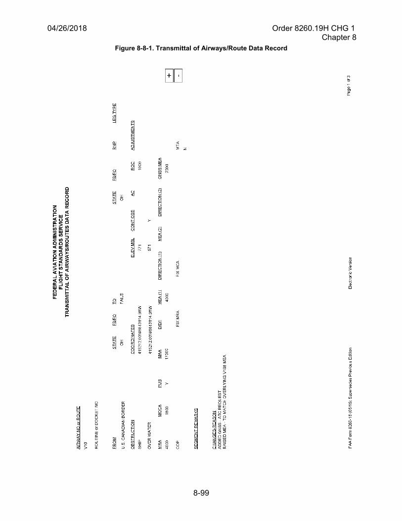
04/26/2018 Order 8260.19H CHG 1 Chapter 8
8-99
Figure 8-8-1. Transmittal of Airways/Route Data Record
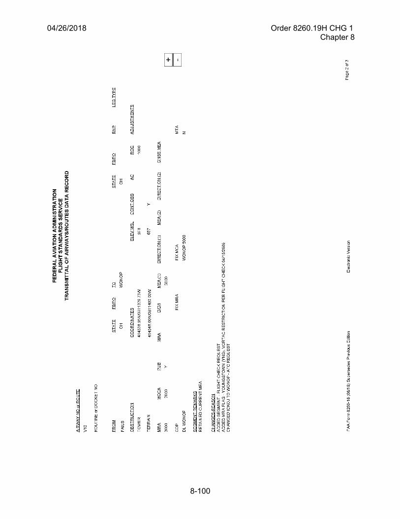
04/26/2018 Order 8260.19H CHG 1 Chapter 8
8-100
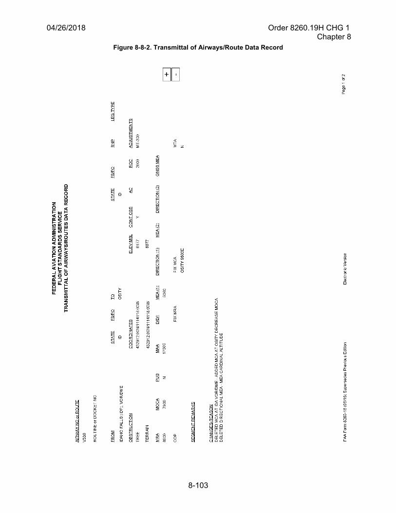
04/26/2018 Order 8260.19H CHG 1 Chapter 8
8-103
Figure 8-8-2. Transmittal of Airways/Route Data Record
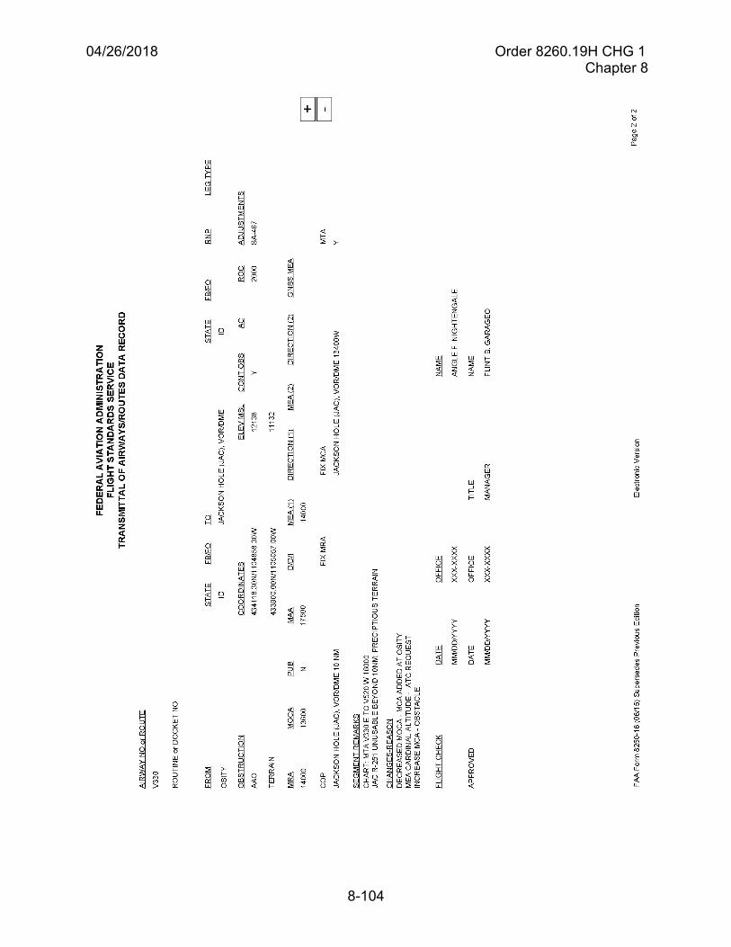
04/26/2018 Order 8260.19H CHG 1 Chapter 8
8-104
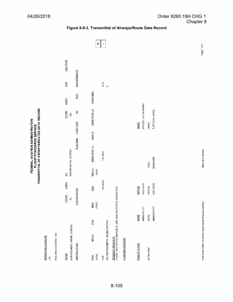
04/26/2018 Order 8260.19H CHG 1 Chapter 8
8-105
Figure 8-8-3. Transmittal of Airways/Route Data Record

04/26/2018 Order 8260.19H CHG 1 Chapter 8
8-106
THIS PAGE IS INTENTIONALLY LEFT BLANK
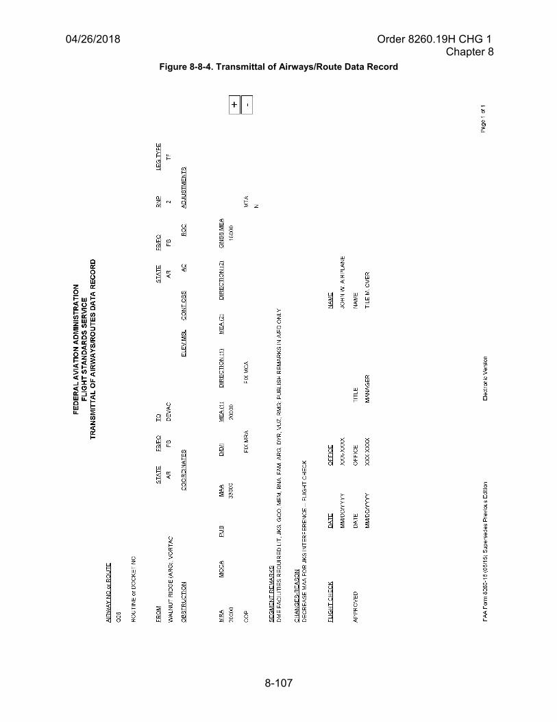
04/26/2018 Order 8260.19H CHG 1 Chapter 8
8-107
Figure 8-8-4. Transmittal of Airways/Route Data Record

04/26/2018 Order 8260.19H CHG 1 Chapter 8
8-108
THIS PAGE IS INTENTIONALLY LEFT BLANK
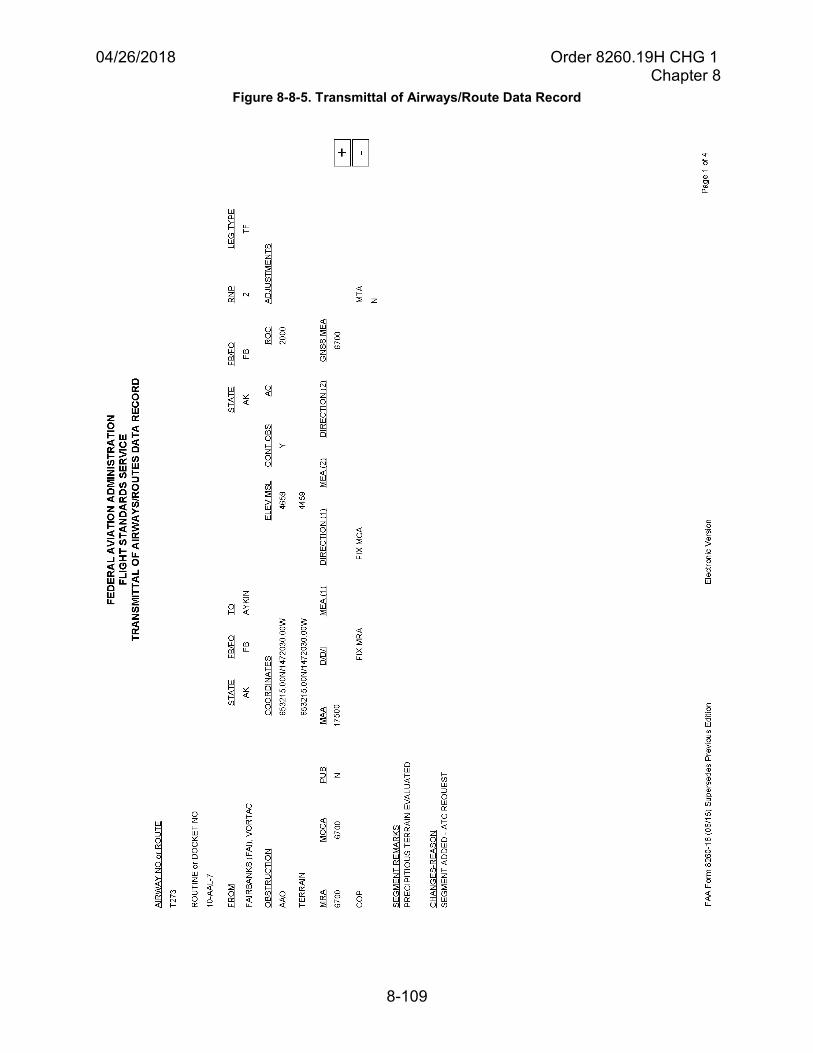
04/26/2018 Order 8260.19H CHG 1 Chapter 8
8-109
Figure 8-8-5. Transmittal of Airways/Route Data Record
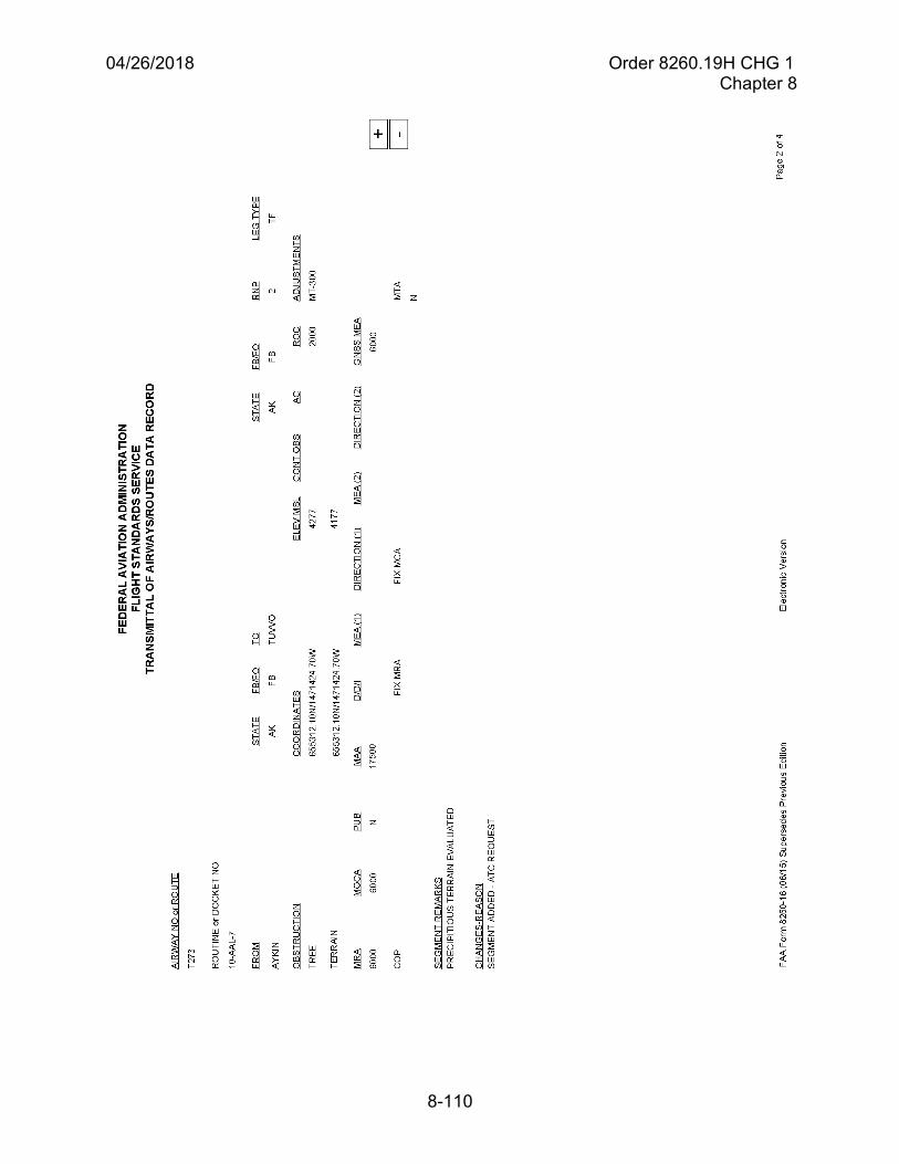
04/26/2018 Order 8260.19H CHG 1 Chapter 8
8-110

04/26/2018 Order 8260.19H CHG 1 Chapter 8
8-113
Figure 8-8-6. Transmittal of Airways/Route Data Record
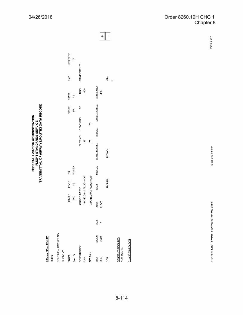
04/26/2018 Order 8260.19H CHG 1 Chapter 8
8-114
04/26/2018 Order 8260.19H CHG 1 Chapter 8
8-121
Section 8-9. Simultaneous Close Parallel (SCP) and Simultaneous Offset Instrument Approach (SOIA) Procedure Attention All Users Page (AAUP)
8-9-1. Attention All Users Page. For SCP approach procedures (runways separated by lessthan 4300 feet), including SOIA, and for simultaneous RNAV departures, an AAUP must bepublished. The AAUP provides the flight crew with procedures that must be used whenconducting these operations, in a form that may be reviewed prior to conducting the procedure.
Note: The flight crew will be notified when an AAUP is published via the following note, “See additional requirements on AAUP.” For an SCP approach, the note will appear in the associated IAP briefing strip. For an RNAV SID, the note will appear on the narrative page immediately beneath the Departure Route Description title.
8-9-2. Site Implementation Team (SIT). A SIT is normally established to address issuesrelated to establishing the procedures. If no team is established, the FAA facility that providesATC services for the airport at which the operations are to be conducted is responsible for theAAUP. The SIT is:
a. Comprised of FAA and industry members with the team leadership designated by ATO.
b. Responsible for the development, among other things, of an AAUP.
8-9-3. AAUP preparation. The AAUP must present the step-by-step procedures used toconduct the procedure. Develop the AAUP using the appropriate 8260-18 forms and theguidance provided in this section. See Order 8260.46 for Simultaneous RNAV DepartureOperations.
Note: AAUP examples found in this section may not be the most current or not necessarily applicable to other locations. These examples should be used as a developmental guideline. AAUPs must reflect the requirements of the specific procedure and airport for which they are developed.
8-9-4. AAUP processing. The SIT (or applicable ATC facility) submits the draft AAUPthrough channels as applicable (that is, Service Areas may have a coordination process unique totheir area). In the case of a departure AAUP, also submit the procedure to AJV-14 for comment.When completed, submit the procedure to Flight Standards’ Flight Operations Branch forapproval and provide an information copy to the Performance-Based Flight Operations Branch.The Flight Operations Branch submits the AAUP and requested effective date to the NFDC.
8-9-5. AAUP publication. The originating organization will determine the requiredpublication date; coordinate with Aeronautical Information Services/NFDC as necessary. Afterreceiving the AAUP from the Flight Operations Branch, the NFDC will:
a. Verify the applicability of the publication date and assign that date for publication.
b. Coordinate with the Flight Operations Branch who will, in turn, contact the originatingorganization and Aeronautical Information Services should a change in the previously agreed upon date be required.
04/26/2018 Order 8260.19H CHG 1 Chapter 8
8-122
Note: When publishing a new AAUP in conjunction with a new or revised procedure, it is important that the AAUP be coordinated jointly between the originating organization, the NFDC, Aeronautical Information Services, and the Flight Operations Branch to ensure its publication is concurrent with the procedure(s) for which the AAUP was developed.
c. Publish the AAUP in the NFDD.
Note: The NFDD is the source for AAUP information for publication by all chart producers.
8-9-6. Forms processing. This section provides procedural guidance for developing AAUPsutilized when independently conducting simultaneous close parallel approach operations to twoor more runways. Use Form 8260-18, Approach Procedure Attention All Users Page, todocument an Approach Procedure AAUP. Instructions and samples for Form 8260-18 are in thissection. Use this form for AAUPs describing ILS PRM, LDA PRM, RNAV (GPS) PRM, RNAV(RNP) PRM, or GLS PRM approaches.
Note: PRM is published as part of the IAP approach title along with the words “Close Parallel” to identify IAPs used to conduct SCP approaches, including SOIA. PRM typically identifies independent operations to runways or approach courses spaced less than 4300 feet apart. However, based on a site specific evaluation, an AAUP (and PRM procedures) may also be required for widely spaced approaches when they are conducted as part of a triple or greater operation when one set of runways is closely spaced. See Order 8260.3, Appendix E, sections 1 and 2.
8-9-7. Title line. The title line consists of the following four elements and will be filled in asnoted:
a. City, State. Enter name of city and state abbreviation. For example: San Francisco, CA.
b. Airport name and Airport ID. Enter airport name and ID as it is, or will be, published onthe instrument approach procedure (All capital letters), e.g., SAN FRANCISCO INTL (SFO).
Note: NFDC, as the official source of airport IDs, will verify that the ID is correct.
c. Effective date. The effective date for original and amended AAUPs is normallyconcurrent with the 56-day charting cycle and the date must be coordinated [see paragraphs 8-9-4 and 8-9-5]. If the AAUP publication date is associated with the publication date of an original procedure or a procedure amendment, enter that procedure name.
Example: “Concurrent with ILS PRM RWY 1R (Orig).” or “Concurrent with RNAV (GPS) RWY 28L (Amdt 3).”
8-9-8. Text. AAUPs must reflect the requirements of the specific procedure and airport forwhich they are developed. Use this guidance and the AAUP examples found in this section as adevelopmental guideline for preparing the AAUP.
04/26/2018 Order 8260.19H CHG 1 Chapter 8
8-123
a. Pilot non-participant procedure. Enter the non-participant procedure applicable for thespecific airport.
Example: Pilots who are unable to participate will be afforded appropriate arrival services as operational conditions permit and must notify the controlling ARTCC as soon as practical, but at least 100 NM from destination.
Note: The AAUP does not have to list the participation requirements because the AAUP is designed to remind the qualified pilot as to the procedures to be used when conducting the approach. Examples of reasons that pilots may not be able to participate include on-board equipment failure (no glideslope or no second communications receiver) or because they do not have the required training. Pilots determine whether they are qualified to conduct the approach through their OpSpecs for commercial operators or through the AIM for general aviation (GA) pilots.
b. Procedure name(s). Enter name of the PRM procedures, e.g., ILS PRM RWY 28L,RNAV (GPS) PRM RWY 28L, RNAV (RNP) PRM RWY 28L. If all PRM approaches utilize the same procedures, enter them all on one line. Otherwise, utilize one line for each approach or sets of approaches that utilize the same procedures, accompanied by their specific briefing points. Only published IAPs are named on the AAUP.
c. Briefing points (required briefing). This consists of a summation of the major tasks inwhich they are to be conducted, that are required to execute the approach(es). For example, “Listen to the PRM monitor (frequency 125.15) when communicating with the NORCAL approach control (frequency 135.65), no later than final approach course intercept.” One or more briefing points may be published for each approach. If all briefing points are applicable to a group or all approaches, the briefing points need only be listed once with the applicable runways listed above.
Note: In the case of the SOIA offset approach where the charted missed approach point and the FMS-coded missed approach point are not collocated, the briefing points should include information as to what the differences are and how the missed approach is to be conducted. See the SFO AAUP in the examples section below.
d. Expanded procedures (optional, brief if necessary). This section explains in greater detailprocedures used to conduct PRM approaches. It consists of the following six elements and will be filled out as noted. Paragraphs 8-9-8.d(1), 8-9-8.d(2), and 8-9-8.d(3) are mandatory. Paragraph 8-9-8.d(4) is applicable for SOIA or other PRM approaches as noted. For SOIA, include paragraph 8-9-8.d(5)(a) for the offset SOIA approach and paragraph 8-9-8.d(5)(b) for straight-in SOIA approach. Paragraph 8-9-8.d(6), Additional Airport Information may be added as necessary. Below are descriptions for each element identified:
(1) ATIS. This element discusses the information that will be transmitted by the ATIS.Based on the ATIS, guidance is provided as to how the approach is to be briefed, and how the approach can be flown using the PRM approach plate when simultaneous operations are not being conducted:
04/26/2018 Order 8260.19H CHG 1 Chapter 8
8-124
(a) Normally identical approaches will be published both as a PRM approach andas a non-PRM identical approach. To be considered identical, approaches using the same type of navigation (ILS or LDA or RNAV for example), must contain the same fixes, fix crossing altitudes, the same approach minimums and coincident missed approach procedures. Examples: RNAV (GPS) PRM Rwy 28L and RNAV (GPS) Rwy 28L; ILS PRM Rwy 8L and ILS Rwy 8L; LDA PRM Rwy 28R and LDA Rwy 28R.
(b) When a PRM and identical non-PRM approaches are both published the ATISportion of the AAUP is written as shown in the following example:
“ATIS. When the ATIS broadcast advises that simultaneous [type] PRM approaches are in progress, pilots should brief to fly the PRM approach. If later advised to expect the non-PRM approach, the PRM chart may be used after completing the following briefing items:
• Minimums and missed approach procedures are unchanged,• Monitor frequency no longer required, and• A lower glide slope intercept altitude may be assigned when advised to expect the
non-PRM approach.”
Note: If the simultaneous procedure operation associated with the AAUP, such as SOIA, requires a specified ceiling and visibility, include that information. For example, “Simultaneous parallel approaches will only be offered/conducted when the weather is at least 1600 feet (ceiling) and 4 SM (visibility).”
(2) Dual VHF Communications Required. The procedures for use of the PRM monitorfrequency are described. Dual communication capability avoids single frequency blocked transmissions by providing an additional communications path by which the no transgression zone (NTZ) monitor controller can issue breakout or other instructions to the pilots.
(3) All “breakouts” are to be hand flown. This element describes pilot procedures whenreceiving a ‘breakout instruction.” It also reminds the pilot of the language that the ATC monitor controller will use to instruct the pilot to initiate a “breakout” maneuver.
(4) Glide Path Navigation. This element contains information about descending on theglide path.
Note 1: Specifically for SOIA operations, describe procedures for flying the glide path of the straight-in SOIA approach [ILS PRM or RNAV (GPS) PRM or RNAV (RNP) PRM].
Example (for straight-in runway 28L): Descending on (not above) the glide path ensures compliance with any charted crossing restrictions and assists traffic approaching runway 28R to mitigate possible wake turbulence encounters without destabilizing the runway 28R approach and creating a go-around.
Example (when the applicable temperature correction has not been applied): Descending on (not above) the glide path assists traffic approaching runway 28R to mitigate possible wake turbulence encounters without destabilizing the runway 28R approach and creating a go-around.
04/26/2018 Order 8260.19H CHG 1 Chapter 8
8-125
Note 2: When the applicable temperature correction has been applied, describe procedures for flying the glide path when conducting a PRM approach utilizing an electronic glide slope (ILS PRM and LDA PRM).
Example: Descending on the glide path ensures compliance with any charted crossing restrictions.
(5) SOIA-specific notes.
(a) (APT ID) LDA PRM, RNAV (GPS) PRM, RNAV (RNP) PRM VisualSegment. This note is applicable only to the offset approach in SOIA. It describes pilot procedures to be used in the visual segment of the approach between the DA and the runway threshold.
Example: Visual Segment (Rwy 28R): If ATC advises that there is traffic approaching runway 28L, pilots are authorized to continue past DARNE to align with runway 28R centerline only when the runway 28L traffic is in sight and is expected to remain in sight; ATC has been advised that "traffic is in sight" (ATC is not required to acknowledge this transmission), and the runway environment is in sight.
Otherwise, a missed approach must be executed at DARNE. Between DARNE and the runway threshold, pilots are responsible for separating themselves visually from traffic approaching runway 28L, which means maneuvering the aircraft as necessary to avoid the runway 28L traffic until landing (do not pass), and providing wake turbulence avoidance, as applicable. If visual contact with the runway 28L traffic is lost, advise ATC as soon as practical and execute the published missed approach unless otherwise instructed by ATC.
(b) Runway (Runway number associated with SOIA straight-in PRM approach)traffic. This note applies only to a SOIA straight-in approach. It describes for the pilot landing straight-in how the trailing aircraft conducting the offset approach will maneuver while executing the runway alignment maneuver after passing the DA.
Example: While conducting this ILS PRM or RNAV (GPS) PRM approach to runway 28L, other aircraft may be conducting the offset LDA PRM or RNAV (GPS) PRM approach to runway 28R. These aircraft will approach from the right-rear and will re-align with runway 28R after making visual contact with the ILS or RNAV (GPS) runway 28L traffic.
(6) Additional airport information. (Specific Guidance, If Applicable): Otherinformation may be included that is deemed pertinent for pilot review before conducting the approach.
8-9-9. Administrative information. Items below are for informational and administrativepurposes only. These items are to be completed on the forms and not to be published on theAAUP. A blank Form 8260-18 is available on the FAA website.
04/26/2018 Order 8260.19H CHG 1 Chapter 8
8-126
a. Developed by. Enter the name of the person responsible for producing the AAUP. Thisindividual must sign in the “developed by” space, and enter the date signed. Enter the office or function of the person responsible, such as ATL TRACON or ATL SIT.
b. Approved by. Specify the office/organization that approved the AAUP.
c. Coordinated with. Specify the offices/organizations with which to coordinate the AAUP.Always include the RAPT and the Flight Operations Branch.
d. Changes (for revised AAUPs)/Reasons (for initial or revised AAUPs). List changes andreasons relating to AAUP entries.
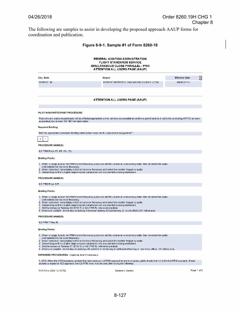
04/26/2018 Order 8260.19H CHG 1 Chapter 8
8-127
The following are samples to assist in developing the proposed approach AAUP forms for coordination and publication.
Figure 8-9-1. Sample #1 of Form 8260-18
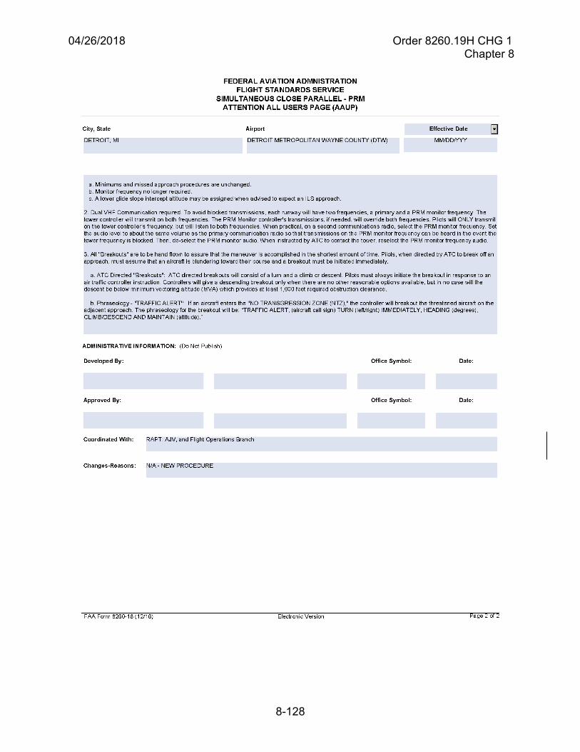
04/26/2018 Order 8260.19H CHG 1 Chapter 8
8-128
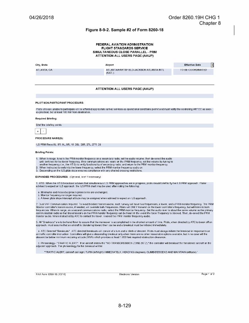
04/26/2018 Order 8260.19H CHG 1 Chapter 8
8-129
Figure 8-9-2. Sample #2 of Form 8260-18
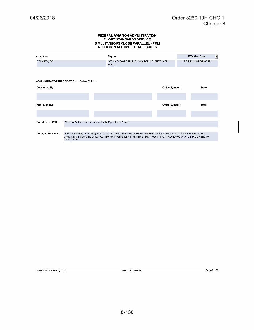
04/26/2018 Order 8260.19H CHG 1 Chapter 8
8-130
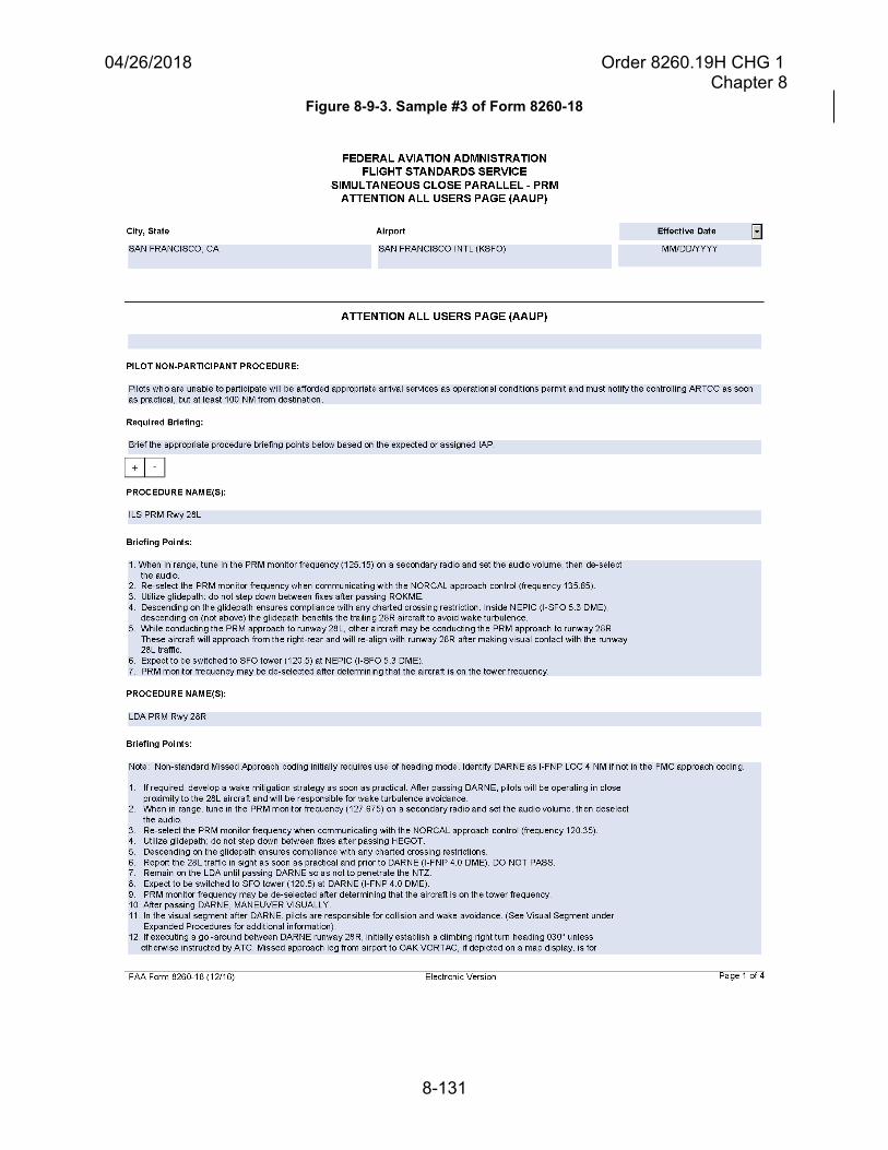
04/26/2018 Order 8260.19H CHG 1 Chapter 8
8-131
Figure 8-9-3. Sample #3 of Form 8260-18
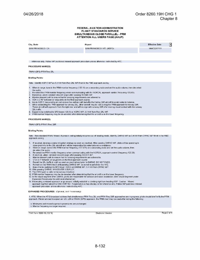
04/26/2018 Order 8260.19H CHG 1 Chapter 8
8-132
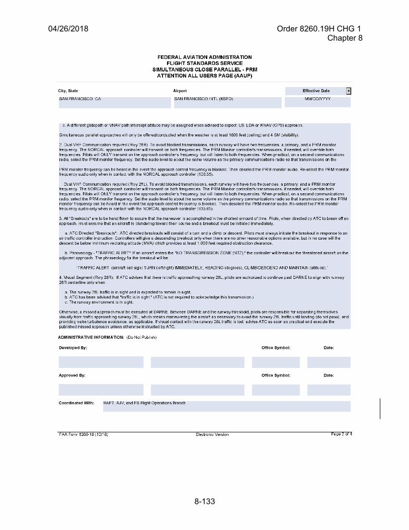
04/26/2018 Order 8260.19H CHG 1 Chapter 8
8-133

04/26/2018 Order 8260.19H CHG 1 Chapter 8
8-134
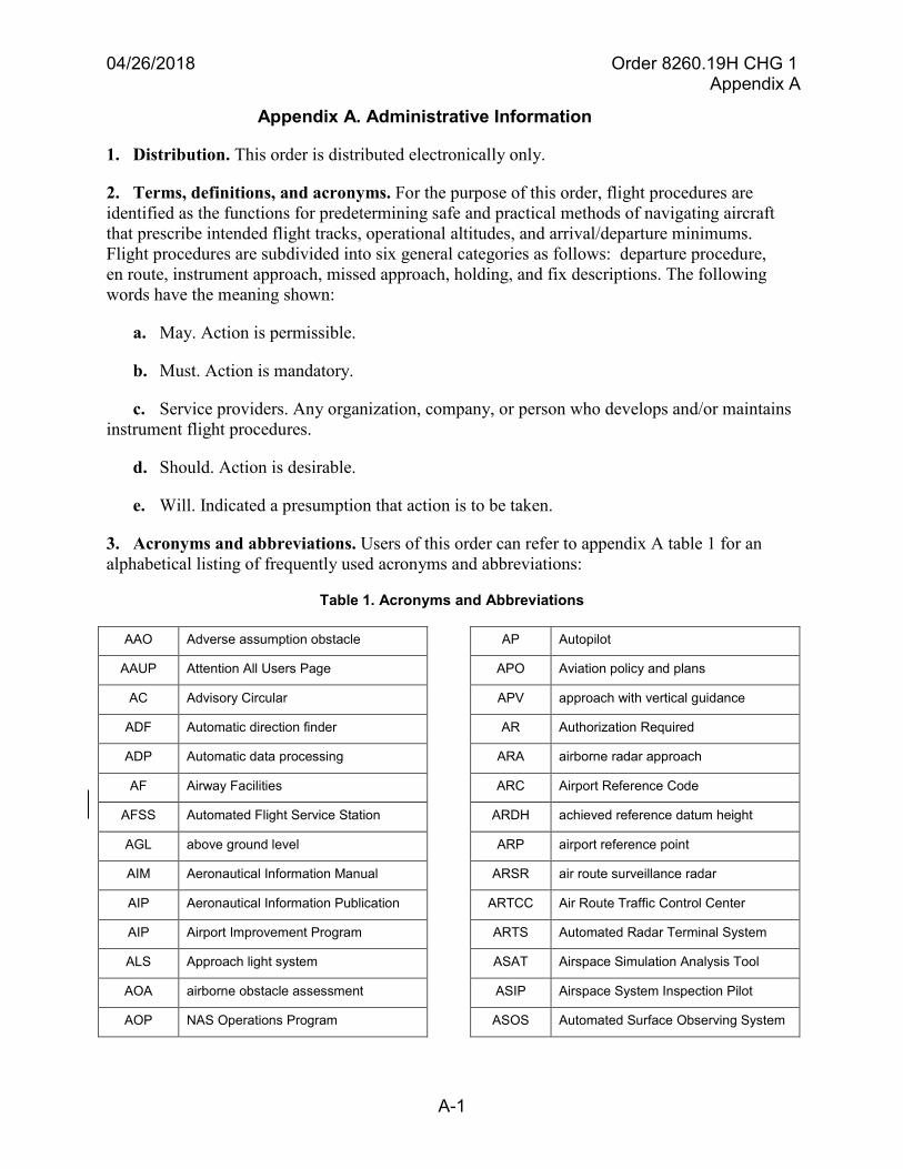
04/26/2018 Order 8260.19H CHG 1 Appendix A
A-1
Appendix A. Administrative Information
1. Distribution. This order is distributed electronically only.
2. Terms, definitions, and acronyms. For the purpose of this order, flight procedures areidentified as the functions for predetermining safe and practical methods of navigating aircraftthat prescribe intended flight tracks, operational altitudes, and arrival/departure minimums.Flight procedures are subdivided into six general categories as follows: departure procedure,en route, instrument approach, missed approach, holding, and fix descriptions. The followingwords have the meaning shown:
a. May. Action is permissible.
b. Must. Action is mandatory.
c. Service providers. Any organization, company, or person who develops and/or maintainsinstrument flight procedures.
d. Should. Action is desirable.
e. Will. Indicated a presumption that action is to be taken.
3. Acronyms and abbreviations. Users of this order can refer to appendix A table 1 for analphabetical listing of frequently used acronyms and abbreviations:
Table 1. Acronyms and Abbreviations
AAO Adverse assumption obstacle
AAUP Attention All Users Page
AC Advisory Circular
ADF Automatic direction finder
ADP Automatic data processing
AF Airway Facilities
AFSS Automated Flight Service Station
AGL above ground level
AIM Aeronautical Information Manual
AIP Aeronautical Information Publication
AIP Airport Improvement Program
ALS Approach light system
AOA airborne obstacle assessment
AOP NAS Operations Program
AP Autopilot
APO Aviation policy and plans
APV approach with vertical guidance
AR Authorization Required
ARA airborne radar approach
ARC Airport Reference Code
ARDH achieved reference datum height
ARP airport reference point
ARSR air route surveillance radar
ARTCC Air Route Traffic Control Center
ARTS Automated Radar Terminal System
ASAT Airspace Simulation Analysis Tool
ASIP Airspace System Inspection Pilot
ASOS Automated Surface Observing System
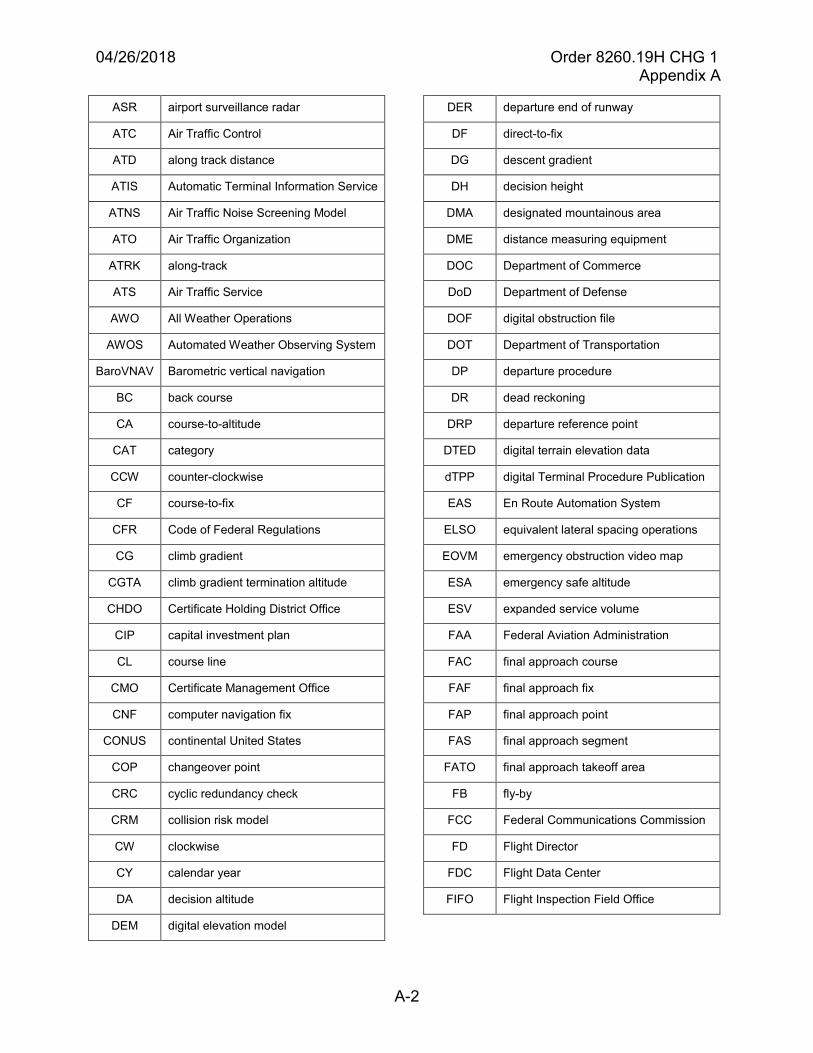
04/26/2018 Order 8260.19H CHG 1 Appendix A
A-2
ASR airport surveillance radar
ATC Air Traffic Control
ATD along track distance
ATIS Automatic Terminal Information Service
ATNS Air Traffic Noise Screening Model
ATO Air Traffic Organization
ATRK along-track
ATS Air Traffic Service
AWO All Weather Operations
AWOS Automated Weather Observing System
BaroVNAV Barometric vertical navigation
BC back course
CA course-to-altitude
CAT category
CCW counter-clockwise
CF course-to-fix
CFR Code of Federal Regulations
CG climb gradient
CGTA climb gradient termination altitude
CHDO Certificate Holding District Office
CIP capital investment plan
CL course line
CMO Certificate Management Office
CNF computer navigation fix
CONUS continental United States
COP changeover point
CRC cyclic redundancy check
CRM collision risk model
CW clockwise
CY calendar year
DA decision altitude
DEM digital elevation model
DER departure end of runway
DF direct-to-fix
DG descent gradient
DH decision height
DMA designated mountainous area
DME distance measuring equipment
DOC Department of Commerce
DoD Department of Defense
DOF digital obstruction file
DOT Department of Transportation
DP departure procedure
DR dead reckoning
DRP departure reference point
DTED digital terrain elevation data
dTPP digital Terminal Procedure Publication
EAS En Route Automation System
ELSO equivalent lateral spacing operations
EOVM emergency obstruction video map
ESA emergency safe altitude
ESV expanded service volume
FAA Federal Aviation Administration
FAC final approach course
FAF final approach fix
FAP final approach point
FAS final approach segment
FATO final approach takeoff area
FB fly-by
FCC Federal Communications Commission
FD Flight Director
FDC Flight Data Center
FIFO Flight Inspection Field Office
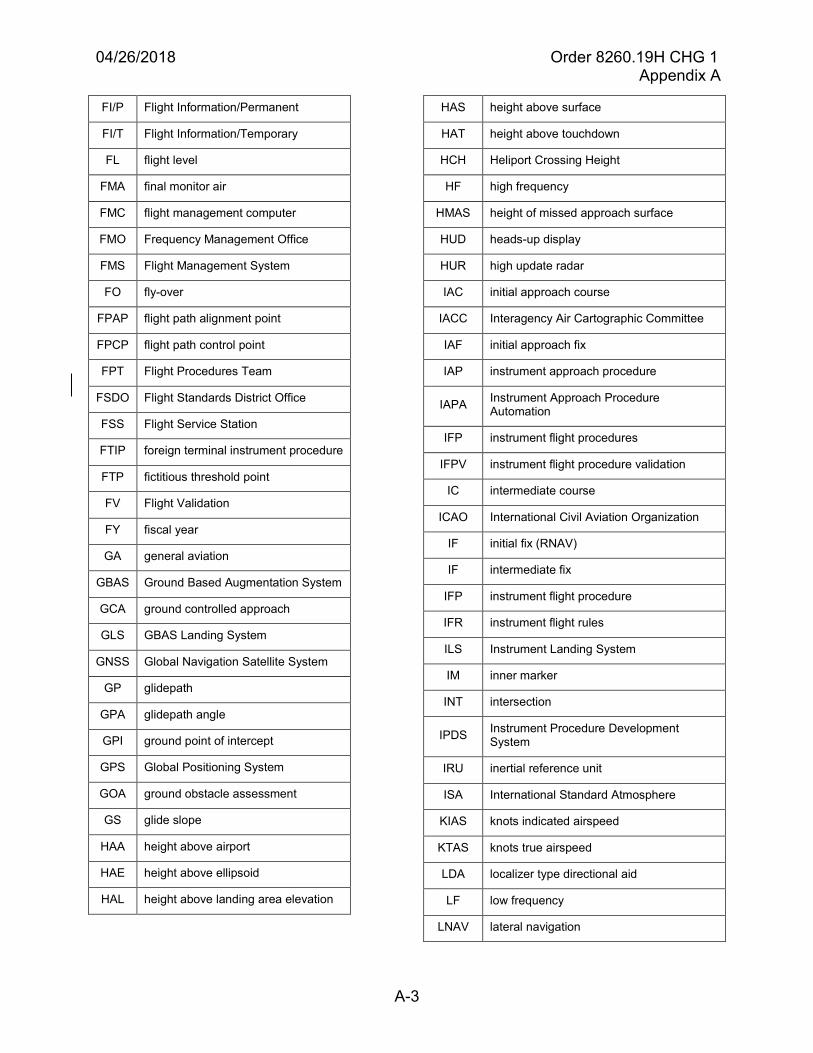
04/26/2018 Order 8260.19H CHG 1 Appendix A
A-3
FI/P Flight Information/Permanent
FI/T Flight Information/Temporary
FL flight level
FMA final monitor air
FMC flight management computer
FMO Frequency Management Office
FMS Flight Management System
FO fly-over
FPAP flight path alignment point
FPCP flight path control point
FPT Flight Procedures Team
FSDO Flight Standards District Office
FSS Flight Service Station
FTIP foreign terminal instrument procedure
FTP fictitious threshold point
FV Flight Validation
FY fiscal year
GA general aviation
GBAS Ground Based Augmentation System
GCA ground controlled approach
GLS GBAS Landing System
GNSS Global Navigation Satellite System
GP glidepath
GPA glidepath angle
GPI ground point of intercept
GPS Global Positioning System
GOA ground obstacle assessment
GS glide slope
HAA height above airport
HAE height above ellipsoid
HAL height above landing area elevation
HAS height above surface
HAT height above touchdown
HCH Heliport Crossing Height
HF high frequency
HMAS height of missed approach surface
HUD heads-up display
HUR high update radar
IAC initial approach course
IACC Interagency Air Cartographic Committee
IAF initial approach fix
IAP instrument approach procedure
IAPA Instrument Approach Procedure Automation
IFP instrument flight procedures
IFPV instrument flight procedure validation
IC intermediate course
ICAO International Civil Aviation Organization
IF initial fix (RNAV)
IF intermediate fix
IFP instrument flight procedure
IFR instrument flight rules
ILS Instrument Landing System
IM inner marker
INT intersection
IPDS Instrument Procedure Development System
IRU inertial reference unit
ISA International Standard Atmosphere
KIAS knots indicated airspeed
KTAS knots true airspeed
LDA localizer type directional aid
LF low frequency
LNAV lateral navigation
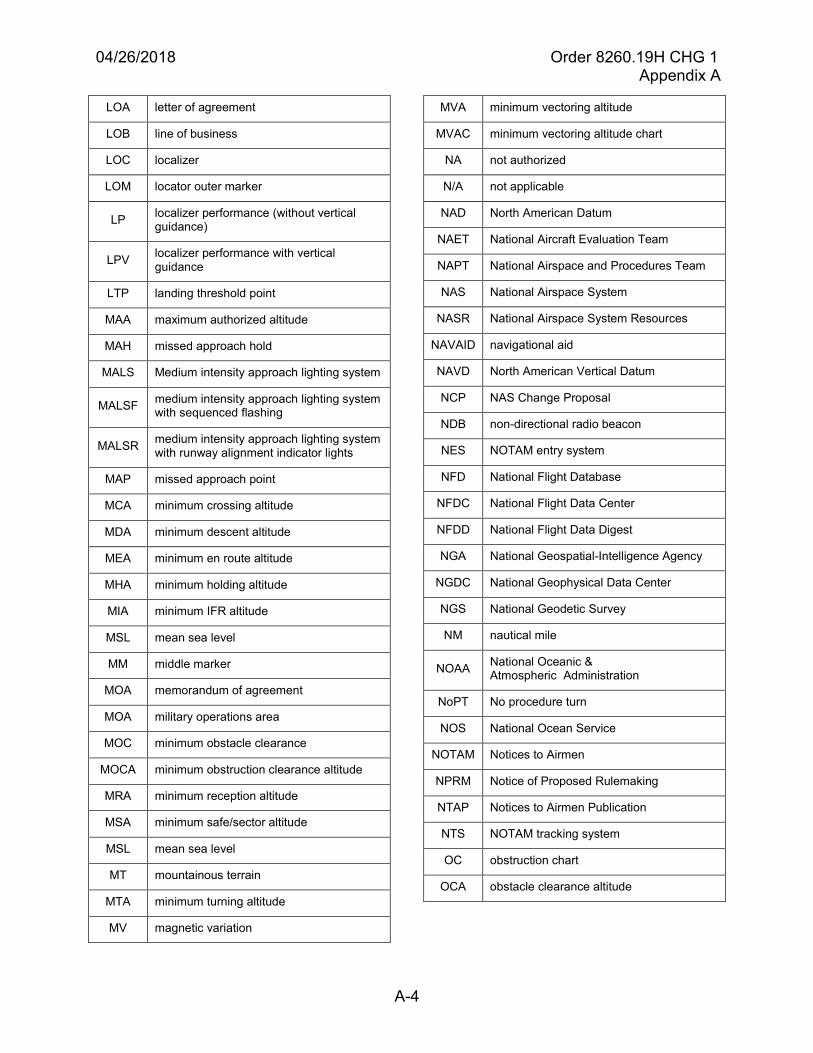
04/26/2018 Order 8260.19H CHG 1 Appendix A
A-4
LOA letter of agreement
LOB line of business
LOC localizer
LOM locator outer marker
LP localizer performance (without vertical guidance)
LPV localizer performance with vertical guidance
LTP landing threshold point
MAA maximum authorized altitude
MAH missed approach hold
MALS Medium intensity approach lighting system
MALSF medium intensity approach lighting system with sequenced flashing
MALSR medium intensity approach lighting system with runway alignment indicator lights
MAP missed approach point
MCA minimum crossing altitude
MDA minimum descent altitude
MEA minimum en route altitude
MHA minimum holding altitude
MIA minimum IFR altitude
MSL mean sea level
MM middle marker
MOA memorandum of agreement
MOA military operations area
MOC minimum obstacle clearance
MOCA minimum obstruction clearance altitude
MRA minimum reception altitude
MSA minimum safe/sector altitude
MSL mean sea level
MT mountainous terrain
MTA minimum turning altitude
MV magnetic variation
MVA minimum vectoring altitude
MVAC minimum vectoring altitude chart
NA not authorized
N/A not applicable
NAD North American Datum
NAET National Aircraft Evaluation Team
NAPT National Airspace and Procedures Team
NAS National Airspace System
NASR National Airspace System Resources
NAVAID navigational aid
NAVD North American Vertical Datum
NCP NAS Change Proposal
NDB non-directional radio beacon
NES NOTAM entry system
NFD National Flight Database
NFDC National Flight Data Center
NFDD National Flight Data Digest
NGA National Geospatial-Intelligence Agency
NGDC National Geophysical Data Center
NGS National Geodetic Survey
NM nautical mile
NOAA National Oceanic & Atmospheric Administration
NoPT No procedure turn
NOS National Ocean Service
NOTAM Notices to Airmen
NPRM Notice of Proposed Rulemaking
NTAP Notices to Airmen Publication
NTS NOTAM tracking system
OC obstruction chart
OCA obstacle clearance altitude
04/26/2018 Order 8260.19H CHG 1 Appendix C
C-1
Appendix C. Obstacle Accuracy Standards, Codes, and Sources
1. United States national map accuracy standards. With a view to the utmost economy andexpedition in producing maps that fulfill not only the broad needs for standard or principal maps,but also the reasonable particular needs of individual agencies, standards of accuracy forpublished maps are defined as follows:
a. Horizontal accuracy. For maps on publication scales larger than 1:20,000, up to 10percent of the points tested must be in error by more than 1/30 inch, measured on the publication scale; for maps on publication scales of 1:20,000 or smaller, 1/50 inch. These limits of accuracy must apply in all cases to positions of well-defined points only. Well-defined points are those that are easily visible or recoverable on the ground, such as the following: monuments or markers, such as bench marks, property boundary monuments; intersections of roads, railroads, etc.; corners of large buildings or structures (or center points of small buildings); etc. In general, what is well defined will also be determined by what can be plotted on the scale of the map within 1/100 inch. Thus, while the intersection of two roads or property lines meeting at right angles would come within a sensible interpretation, identification of the intersection of such lines meeting at an acute angle would obviously not be practicable within 1/100 inch. Similarly, features not identifiable upon the ground within close limits are not to be considered as test points within the limits quoted, even though their positions may be scaled closely upon the map. Timber lines, soil boundaries, etc. would be in this class.
b. Vertical accuracy, as applied to contour maps on all publication scales, must be such thatnot more than 10 percent of the elevations tested must be in error more than one-half the contour interval. In checking elevations taken from the map, the apparent vertical error may be decreased by assuming a horizontal displacement within the permissible horizontal error for a map of that scale.
c. Map accuracy testing may be accomplished by comparing the positions of points whoselocations or elevations are shown upon it with corresponding positions as determined by surveys of a higher accuracy. Tests must be made by the producing agency that must also determine which of its maps are to be tested and the extent of such testing.
d. Published maps meeting these accuracy requirements must note this fact on their legendsas follows: “This map complies with National Map Accuracy Standards.”
e. Published maps whose errors exceed those stated before must omit all mention ofstandard accuracy from their legends.
f. Enlargements. When a published map is a considerable enlargement of a map drawing(manuscript) or of a published map, that fact must be stated in the legend. For example, “This map is an enlargement of a 1:20,000-scale map drawing “or” This map is an enlargement of a 1:24,000-scale published map.”
g. Data interchange. To facilitate ready inter-change and use of basic information for mapconstruction among all Federal map-making agencies, manuscript maps and published maps,
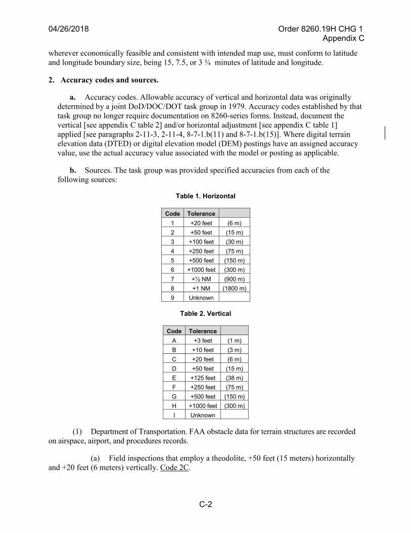
04/26/2018 Order 8260.19H CHG 1 Appendix C
C-2
wherever economically feasible and consistent with intended map use, must conform to latitude and longitude boundary size, being 15, 7.5, or 3 ¾ minutes of latitude and longitude.
2. Accuracy codes and sources.
a. Accuracy codes. Allowable accuracy of vertical and horizontal data was originallydetermined by a joint DoD/DOC/DOT task group in 1979. Accuracy codes established by that task group no longer require documentation on 8260-series forms. Instead, document the vertical [see appendix C table 2] and/or horizontal adjustment [see appendix C table 1] applied [see paragraphs 2-11-3, 2-11-4, 8-7-1.b(11) and 8-7-1.b(15)]. Where digital terrain elevation data (DTED) or digital elevation model (DEM) postings have an assigned accuracy value, use the actual accuracy value associated with the model or posting as applicable.
b. Sources. The task group was provided specified accuracies from each of thefollowing sources:
Table 1. Horizontal
Code Tolerance 1 +20 feet (6 m) 2 +50 feet (15 m) 3 +100 feet (30 m) 4 +250 feet (75 m) 5 +500 feet (150 m) 6 +1000 feet (300 m) 7 +½ NM (900 m) 8 +1 NM (1800 m) 9 Unknown
Table 2. Vertical
Code Tolerance A +3 feet (1 m) B +10 feet (3 m) C +20 feet (6 m) D +50 feet (15 m) E +125 feet (38 m) F +250 feet (75 m) G +500 feet (150 m) H +1000 feet (300 m) I Unknown
(1) Department of Transportation. FAA obstacle data for terrain structures are recordedon airspace, airport, and procedures records.
(a) Field inspections that employ a theodolite, +50 feet (15 meters) horizontallyand +20 feet (6 meters) vertically. Code 2C.