f2: magnetic field experiment
TRANSCRIPT

MAGNETIC FIELD EXPERIMENT ON THE FREJA SATELLITE
F R E J A M A G N E T I C F I E L D E X P E R I M E N T T E A M * The Johns Hopkins University, Applied Physics Laboratory, Laurel, Maryland, U.S.A.
(Received 11 April, 1994)
Abstract. Freja is a Swedish scientific satellite mission to study fine scale auroral processes. Launch was October 6, 1992, piggyback on a Chinese Long March 2C, to the present 600 x 1750 kin, 63 ~ inclination orbit. The JHU/APL provided the Magnetic Field Experiment (MFE), which includes a custom APL-designed Forth language microprocessor. This approach has led to a truly generic and flexible design with adaptability to differing mission requirements and has resulted in the transfer of significant ground analysis to on-board processing. Special attention has been paid to the analog electronic and digital processing design in an effort to lower system noise levels, verified by in- flight data showing unprecedented system noise levels for near-Earth magnetic field measurements, approaching the fluxgate sensor levels. The full dynamic range measurements are of the 3-axis Earth's magnetic field taken at 128 vector samples s -~ and digitized to 16 bit resolution, primarily used to evaluate currents and the main magnetic field of the Earth. Additional 3-axis 'AC' channels are bandpass filtered from 1.5 to 128 Hz to remove the main field spin signal, the range is i 650 nT. These vector measurements cover Pc waves to ion gyrofrequency magnetic wave signals up to the oxygen gyrofrequency (~40 Hz). A separate, seventh channel samples the spin axis sensor with a bandpass filter of 1.5 to 256 Hz, the signal of which is fed to a software FFT. This on-board FFT processing covers the local helium gyrofrequencies (~ 160 Hz) and is plotted in the Freja Summary Plots (FSPs) along with disturbance fields. First data were received in the U.S. October 16 from Kiruna, Sweden
* Freja Magnetic Field Experiment Team
Lawrence Zanetti (PI) Thomas Potemra Robert Erlandson Peter Bythrow Brian Anderson Anthony Lui Shin-ichi Ohtani Glenn Fountain Robert Henshaw Benjamin Ballard David Lohr John Hayes Douglas Holland Mario Acufia Donald Fairfield James Slavin Wolfgang Baumjohann Mark Engbretson Karl-Heinz Glassmeier George Gustafsson Takesi Iijima Hermann Ltihr Fritz Primdahl
The Johns Hopkins University/Applied Physics Laboratory (JHU/APL), Laurel, Maryland, 20723-6099, U.S.A.
NASA/Goddard Space Flight Center, Greenbelt, Maryland, U.S.A.
Max Planck Institute for Estraterrestrial Physics, Garching, Germany Ausburg College, Minneapolis, Minnosota, U.S.A. University of Cologne, Cologne, Germany Swedish Institute for Space Physics, Uppsala, Sweden University of Tokyo, Tokyo, Japan Technical University of Braunschweig, Braunschweig, Germany Danish Space Research Institute, Lyngby, Denmark
Space Science Reviews 70: 465--482, 1994. @ 1994 Kluwer Academic Publishers. Printed in Belgium.
[61]

466 FREJA MAGNETIC FIELD EXPERIMENT TEAM
via the Internet and SPAN e-mail networks, and were from an orbit a few hours earlier over Greenland and Sweden. Data files and data products, e.g., FSPs generated at the Kiruna ground station, are communicated in a similar manner through an automatic mail distribution system in Stockholm to PIs and various users. Distributed management of spacecraft operations by the science team is also achieved by this advanced communications system.
An exciting new discovery of the field-aligned current systems is the high frequency wave power or structure associated with the various large-scale currents. The spin axis 'AC' data and its standard deviation is a measure of this high-frequency component of the Birkeland current regions. The exact response of these channels and filters as well as the physics behind these wave and/or fine-scale current structures accompanying the large-scale currents is being pursued; nevertheless, the association is clear and the results are used for the MFE Birkeland current monitor calculated in the MFE microprocessor. This monitor then sets a trigger when it is greater than a commandable, preset threshold. This 'event' flag can be read by the system unit and used to remotely command all instruments into burst mode data taking and local memory storage. In addition, Freja is equipped with a 400 MHz 'Low Speed Link' transmitter which transmits spacecraft housekeeping that can be received with a low cost, portable receiver. These housekeeping data include the MFE auroral zone current detector; this space weather information indicates the location and strength of ionospheric current systems that directly impact communications, power systems, long distance telephone lines and near-Earth satellite operations. The JHU/APL MFE is a joint effort with NASA/GSFC and was co-sponsored by the Office of Naval Research and NASA/Headquarters in cooperation with the Swedish National Space Board and the Swedish Space Corporation.
1. Specific Objec t ives
Scientific object ives particular to the Magnet ic Field Exper iment (MFE) of the Freja mission involve assessments of static structures of large- and small-scale
size ionospheric and magnetospher ic currents with full orbit data and 50 m reso-
lution coverage respectively, as well as vector wave measurements up to Nyquis t
frequencies of 128 Hz and spin axis FFT measurements of up to 256 Hz. The 63 ~ inclination orbit reaches the northern and southern auroral zones an extraor- dinary amount of t ime because of the present solar cycle maximum. Historically, the downside of any particular solar cycle produces the major geomagnet ic storm
activity. Interesting resonant harmonic and cyclotron frequency waves have been observed in the trough and p lasmapause L-shells with Viking (Potemra et al., 1988; Erlandson et al., 1990) and will be further investigated with the Freja MFE data.
The longitudinal traversal of the auroral zones by the Freja orbit is providing unique local t ime coverage of the large-scale current systems. Some of the remain- ing questions include: (1) questions of separate day-night curent generators of the
Region 1 Birkeland current sys tem and the Region 1 and Region 2 relationship to the ionospheric and inner magnetospheric currents such as the ring and equatorial
radial currents (Mauk and Zanetti, 1987; I i j ima et al., 1990, 1991); (2) the very complex current systems of substorm phenomena are covered with good large- and small-scale spatial resolution, with the traversal of the pre-midnight and post- midnight regions within tens of minutes; and (3) the association of t ime sequences of data with regard to two-dimensional models of the storm current systems in
order to evaluate the dynamics of auroral activity.
[621

MAGNETIC FIELD EXPERIMENT ON THE FREJA SATELLITE 467
A distribution of storm time currents was analyzed from MAGSAT magnetic field disturbance data during a steadily active (Kp 3-4, D S T = - 4 0 nT) period of geomagnetic activity. Zanetti et al. (1984, 1991) correlated Birkeland currents with an composite of Hall currents deduced from BII magnetic disturbance signatures in the dawn-dusk direction, assuming infinitely extended currents in the Sun-midnight direction. This procedure has been expanded into a two-dimensional analysis which does not assume infinity in the Sun-midnight direction but rather inverts the two- dimensional Bll disturbance signatures. Such an analysis will be enhanced with the addition of the unique local time coverage of the Freja orbit. Fine scale, large intensity transverse magnetic field disturbances corresponding to structure in the particle distributions were observed from Viking (Potemra et al., 1987) and will be extended with the Freja coordinated data set. Birkeland current densities reported were approximately 10.6 #A m -2, locally, which, if this could be mapped to the ionosphere (i.e., no Ell ), would be 286 # A m -2, considerably larger than any yet observed (Burke et aI., 1980; Bythrow et al., 1986).
Magnetic disturbance FFT frequency analysis has been first applied to the AMPTE/CCE and Viking magnetic field data in the Pc 3-5 (0.01-0.1 Hz) micropul- sation frequency range (Engebretson, 1986; Erlandson, 1989) and are presently being extended to study the Pcl (0.2-5 Hz) frequency range and the magnetic wave dependence on the equatorial He + gyrofrequency (Anderson e~ aI., 1990; Erlandson et al., 1990). Since the ionosphere acts as a 'short circuit' or sink for many magnetospheric phenomena, these ionospheric signatures play an important role in understanding the interactions with the solar wind energy sources, e.g., front side transients events (FTEs) and solar wind pressure variations. Exploiting the highest Viking frequency sampling (26 Hz Nyquist) with the FFT spectro- gram format, Erlandson et al. (1989) observed magnetic field fluctuations near the hydrogen cyclotron frequency. Magnetic wave events at frequencies up to 64 Hz are shown here, observed by the Freja MFE at lower altitudes and latitudes; wave measurements up to 256 Hz Nyquist are available.
2. The Freja Magnetic Field Experiment
The Freja MFE (denoted F2) is a three axis ring core fluxgate sensor mounted on a two meter boom with spacecraft mounted electronics providing lowpassed and bandpassed analog signals, digitized and signal processed to satisfy the scientific objectives; the MFE is a cooperative venture with the NASA/GSFC. Attention has been paid to the analog electronic design in an effort to significantly lower system noise levels, approaching the fluxgate sensor levels. The full dynamic range measurements are of the 3-axis Earth's magnetic field taken at 128 vector samples s-I and digitized to 16-bit resolution; primarily used to evaluate currents and the main magnetic field of the Earth. The additional 3-axis 'AC' channels are bandpass filtered from 1.5 Hz to 128 Hz to remove the main field spin signal, amplitude is • nT. These measurements cover ion gyrofrequency magnetic
[63]

468 FREJA MAGNETIC FIELD EXPERIMENT TEAM
wave signals up to the oxygen gyrofrequency (--,40 Hz at 600 km altitude) in normal spacecraft telemetry mode (256 kbs, high mode telemetry is 512 kbs and all of the above MFE sample rates double). It must be stressed again that these 'AC' channels are vector wave measurements which will record all information with regard to polarization, ellipticity, etc., of the wave field. A separate, seventh channel samples the spin axis sensor with a permanent bandpass filter of 1.5 to 256 Hz, the signal of which will be fed to the software FFT, this range covers the local helium gyrofrequencies (,,o 160 Hz).
Data are taken throughout the orbit as well and stored in a reduced form in the internal MFE 1.3 Mbit Random Access Memory (RAM). The range and res- olution are as described above but with variable sampling rate (0.0625-16 vector samples s -1, nominal has been 3-s data). Virtually continuous MFE coverage since launch enhances the correlative aspects of this mission with other data sets, e.g., the NASA ISTP data and the NSF GEM program. Full orbit storage totals 0.5 Mbit of RAM that takes a few minutes to transmit during real-time data reception using the 'AC' channel bandwidth which allows the full range measurements to continue uninterrupted. Another 0.5 Mbit of local RAM storage is used in a burst mode, storing data remote from receiving stations on the triggering of an event flag or time tagged command, a standard deviation calculation over a preset threshold is used for the MFE trigger. This trigger information indicates the entrance into the strong field-aligned current regions as discussed below. These general characteristics of the MFE system are outlined in Table I.
Figure 1 is a block diagram of the MFE, which consists of the boom mounted probe and a spacecraft mounted data processor and electronics unit. The circuitry is contained on five circuit boards: (1) the sensor board drives, processes, and filters analog signals from the probe, (2) the filter-A/D board provides additional anti-alias and bandpass filtering and digitizes the analog signals, (3) the Central Processing Unit (CPU) board processes the digital data, formats it for telemetry, and controls the instrument, (4) the telemetry interface board transmits the telemetry and receives commands from the spacecraft, and (5) the DC/DC converter board converts spacecraft power to the voltages required by the other boards.
The remarkable performance of this Freja ring-core fluxgate magnetometer is a result of advances in sensor design, materials, and electronic systems at GSFC for missions such as MAGSAT, Voyager, Ulysses, AMPTE/CCE and others. The fluxgate sensors are constructed utilizing the ring core geometry which has been shown to exhibit superior long term zero level stability and minimal drive power requirements. In addition, the magnetic material used to manufacture these sensors is the latest in a series of advanced molybdenum-permalloy alloys which have been especially developed in cooperation with the Naval Surface Weapons Center (White Oak Laboratory, MD) for low noise, high stability applications. It exhibits superior performance characteristics unmatched by any other type of fluxgate sensor material. Previously developed were improved formulations of 6-81 alloys (Gordon and Brown, 1972; Acufia, 1974; Acufia et al., 1978) which were used in the
[64]

MAGNETIC FIELD EXPERIMENT ON THE FREJA SATELLITE 469
TABLE I
Freja magnetic field experiment (F2)
Summary characteristics: Triaxial ring core fluxgate sensor, 2 m boom mounted Low noise (8/~V) analog, 16 bit A/D, s/c mounted electronics
Internal 1.3 Mbit RAM, event trigger, FFT software, oversampling
Real time data output: t4.3 kbs @ 256 kbs spacecraft rate, 512 kbs rate =~ 28.6 kbs for F2)
(a) 128 vector samples s -1 (vs/s), range +65 000 nT, +1 nT resolution
(b) 'AC'; 128 vs/s, bandpassed 1.5-I28 Hz, range +650 nT (c) Spin axis 1.5-256 Hz FFT, 2 Hz resolution
Weight: 3.5 kg (excluding boom and mount,)
Power: 3.7 W (including dc/dc)
Size: Sensor 10 x 7.5 x 7.5 cm
Data processor 18 x 23 x 9 cm
Data analysis subsystem: (FRISC (SC-32) microprocessor)
magnetometer data collection
oversampling and averaging DC channels
nominally to assure 16 bits potential upgrade to 18 bit, analog system noise floor
digital low pass filtering switchable antialiasing filter corner (14.3/28.6 kbs)
full orbit data collection 0.0625-16 vs/s selectable (0.3 vs/s= 10 orbit summary data)
event detection standard deviation 128 vs/s for 1 s, variable threshold
event information, parameters in spacecraft housekeeping
remote data collection 10 s precursor, 40 s total @ 128 vs/s
spin axis FFT processing 1.5-256 Hz, 2 Hz resolution
telemetry rate detection housekeeping data collection
includes event information for remote transmission
telemetry formatting command processing
[65]

470 FREJA MAGNETIC FIELD EXPERIMENT TEAM
Sensor Electronics
Board
Spacecraft
======================== ....... -:. _~ FREJA F2 ....... @ ...... 2;'71:>. (Magnetic Field Experiment) 1<[~"t:! ~"'~.~~ ~ Block Diagram
error (ar . ~ F|lter / / r id Board
dc S.tmpic Sequenced
Calibratlon fi~at ~ & ~J:O X Y .ad Z DG ch.ane,. --- Z '.~r Tera~ . . . . ~ ~
~' Po~r Recy, tie
~ ' * $ V Digital
~ ~ ' - - " ! . o a r o [ - - - . t ~ v
i l~e & C,,ln~mt Monitor,
I : . . . . . .
~.: <-.Telemet~/ - J Spar |~ \ . I I ~ Z G TM I
I ! 7? I
GSE T~lemetry Monitor
Watchdog Tclcmcwy Timer Buffer
32K x 32 Power-on
React Memory 32K x 32 RAM
I~glnccring Data Memory
Mttrfac, es 64K x 32 _ _ EEPROb/
SC-32 ,UO B~ MicroFror r
AiD to UO Bus
~tet'oJpt Co~ot
On-Bo~d Clack
Boot Memory
2K ~ 32 PROM
, C P U Board
i Electronics Module i
GSE
Connections for Ground Test Only
I +
Fig. 1. Block diagram of the five F2 circuit boards and their functions; sensor, filter-A/D, CPU, TLM and CMD, DC/DC converter. These are chassis mounted on Freja with the 3-axis sensor at the end of a 2-m rigid boom,
[66]

MAGNETIC FIELD EXPERIMENT ON THE FREJA SATELLITE 471
Voyager and Ulysses instruments. The use of this alloy and the ring core geometry allows the realization of compact, ultrastable fluxgate sensors with outstanding noise performance. Used in conjunction with the electronics described below, zero offset stability is better than -4-0.1 nT over a temperature range of -t-60 ~ C and for periods exceeding one year, based on our current Voyager data; the stability of the AMPTE/CCE MFE was < 1 nT per axis over the 4.5 year lifetime. This is welt below typical spacecraft fields at the sensor location.
The design of the analog electronics associated with these sensors is an evolution of that developed for previous missions. It is a flexible, robust, and extremely simple implementation of the basic fluxgate design which exhibits optimal noise performance characteristics (Acufia, 1974; Acufia e~ aI., 1978). In this design complexity is minimized in order to improve reliability and at the same time, reduce power consumption, instrument weight and experiment cost. The design makes use of stable, negative-resistance parametric amplification obtainable from tuned fluxgate sensors to sense magnetic fields at the sensor element. This technique eliminates the need for high-gain, low-power, low-noise amplifiers which can be extremely sensitive to interference and radiation-induced degradation. The sensor element is essentially used as a null detector in a feedback loop; the current required to null the field at the sensor is a measure of the field. This arrangement results in the high sensor linearity and exceptional noise performance for which the GSFC magnetometers are noted. The inherently low-noise circuit design, coupled with careful layout of the critical analog circuitry, produced system noise levels in the Freja MFE approaching the fluxgate sensor levels (~ 10 -7 nT 2 Hz -I).
The Filter-A/D board filters the analog probe signals from the sensor electronics board, converts them to digital form and buffers them in a FIFO under control of the on-board, programmable 'smart' sequencer. As the sensor is being continuously sampled at 256 samples per second, the hardware anti-aliasing filter corner is set at 128 Hz for the high telemetry rate and is digitally filtered to the 64 Hz frequency for the normal rate. The 'AC' channels are bandpass filtered (1.5 to 128 Hz), amplified by a factor of 100 and digitzed to 16 bit resolution. In addition to the goal of mag- netic wave measurements, this frequency band is proving extremely useful for the automatic detection of the auroral zone Birkeland field-aligned currents; this new observational technique is the subject of Figure 5. An analog multiplexer presents one signal at a time to the 16 bit A/D converter, which stores its digital results in an output FIFO for the CPU board to read. The 'smart' sequencer selects the analog multiplexer channel, initiates A/D conversion, oversamples the A/D by up to 16 and averages, and controls FIFO writes based on a program stored in its RAM. The CPU board can download various 'smart' sequencer programs depending on the data collection mode required. Figure 2 verifies unprecedented system noise levels for near-Earth magnetic field measurements, confirming laboratory calibrations with in-flight data. During a quiet interval (Orbit 790) outside of the auroral zone, the 'AC' channels were FFT spectrum analyzed resulting in an average noise level of 5 • 10 -5 nT 2 Hz -I in all three channels from 5 to 64 Hz, corresponding to a
[67J

472 FREJA MAGNETIC FIELD EXPERIMENT TEAM
Freja MFE 1.5-128Hz channel noise floor, measured December 5, 1992 10 ,4 f o ~ X ~ ' . . . . . . "I ' ' ' ' " ' ' U- . . . . . . .
t ~ 102 -
10 - \ \ \ \ \ \ \ o ~ - 2 \ " " . (:
�9 " " B X
b < . . 6x10.6 nT2/hz ~ - BZ
~ 6 [
1 tO
FREQUENCY (Hz) Orbit 790 yyddd=92340 2:23:00 -- 2:23:30 UT
1 0 0
Fig. 2. Fourier Transform spectrum of the three-axis F2 MFE bandpassed channels during a quiet interval on December 5, 1992 (Orbit 790). This measured system noise level is 1.25 x 10 -4 nT Hz- l compared to the digitization level corresponding to the least significant bit (20 pT; 6 x 10 -6 nT Hz- 1).
broadband 60 pT signal in a 0.3 G background field. The least significant bit would produce a level of 6 x 10 -6 nT 2 Hz -1. The high power at frequencies below a few hertz are full field spin modulation not completely removed by the 3 pole 1.5 Hz high pass hardware filter.
The heart of the Freja MFE is the custom APL-designed, single-chip Forth Reduced Instruction Set Computer (FRISC*) microprocessor on the CPU board. This processor was specifically designed to run the Forth high level language and take advantage of the operating system structure to preserve speed and interactive- ness (Hayes et al., 1987); this FRISC can perform 10 MIPS operating at 10 MHz. The use of this powerful 32-bit microprocessor (the first 32-bit processor, aside from an 80386, flown) simplified system hardware design by allowing functions
* Currently, there is an APL patent pending on the FRISC design. APL has licensed the FRISC to Silicon Composers, Inc., Palo Alto, CA, who offers the chip as a commercial grade device designated as the SC32. They also market a single board computer that plugs into IBM PC compatible computers, along with their own operating/development system. The IC foundry (ESS), recently established a Mil-Std-883 line which was used for our Freja FRISC fabrication. APL's reliability group performed a pre-cap visual inspection of the Freja parts at the foundry and confirmed that ESS has a high quality fabrication process. Additionally, there is an internal testing and screening program at APL that upgrades the parts to a reliability above Mil-Std-883 level.
[68]

MAGNETIC FIELD EXPERIMENT ON THE FREJA SATELLITE 473
which would otherwise require specialized hardware to be performed in software. For example, this Forth system performs the on-board FFT function in software to provide selected spectral information from data too voluminous to downlink. This software function eliminates separate FFT hardware and the extra power, board space, and design time it would require. The FRISC processor directly executes the high level language Forth, thus eliminating the penalty of compiling a high level language to machine code. Furthermore, software development and debug- ging were performed interactively on the actual target hardware in Forth via a standard computer terminal. The FRISC performs data acquisition, averaging and storage, digital anti-alias filtering, FFT computation, burst mode event triggering, telemetry formatting, command interpretation and execution, and other instrument control functions. The CPU board reads the data from the FIFO, performs the signal processing tasks, calculates and writes to telemetry the event detector and stores the reduced full orbit data in the local RAM. The CPU board also formats the resulting data and sends it to the telemetry interface board, which buffers it and sends it using a serial protocol to the Freja System Unit (FSU). Concurrent with the data handling tasks, the CPU controls the sampling sequencer, collects and formats the housekeeping data, and executes uplinked commands. The telemetry interface board also receives serial commands and selected telemetry words from the spacecraft. It converts them to parallel and passes them to the CPU board for interpretation and/or execution.
The hardware functions on the CPU board include a fusible link boot PROM program. It loads itself into RAM after any reset command, turns off the PROM to save power, and waits for either a telemetry system command or a debug terminal command. If neither of these occurs within 10 s, the boot program automatically loads the application software stored in the Electrically Erasable Programmable Read Only Memory (EEPROM). Included is the capability to uplink new appli- cation software into the EEPROM via the command system for programming upgrades. One memory module slot on the CPU board has been chosen to be used for more EEPROM. Other hardware functions on the CPU board include a priori- tized interrupt controller, a real time clock, telemetry timers, a housekeeping A/D converter, and a watchdog timer (used to confirm that the application software is running properly). A CPU test port connects to a terminal to provide communi- cation and control functions via the interactive Forth language interpreter during system development and testing, even hardware glitches form the high speed logic were traced with interactive debugging software. Programs on the CPU board are stored in the 64 K• bit EEPROM. At system initialization the flight program is copied into the 64 Kx32 bit RAM, which also contains the buffers referred to earlier for storing the full orbit and burst data. Full flight software was stored into the EEPROMs before launch, however new programs have been uplinked and stored in EEPROM during the mission. This re-programmability of the Freja MFE system presents an ideal and realistic environment to adapt to alternate mission requirements and upgrades (Ballard et al., 1984).
[69]

474 FREJA MAGNETIC FIELD EXPERIMENT TEAM
The telemetry interface board (CMD and TLM) receives data to be downlinked from the CPU board and sends it to the spacecraft telemetry system with the appropriate hardware and timing protocols. Likewise, it receives commands from the spacecraft and passes them to the CPU board for interpretation and execution. The DC/DC converter board receives +28 V DC power from the spacecraft and generates +5 V and + 12 V analog and +5 V digital power for the other boards. This switching converter design also includes: (1) input filtering, (2) power-up surge limiting, (3) current monitoring, (4) latchup protection (overcurrent on output interrupts power temporarily), (5) separate digital and analog supplies to minimize noise in analog circuits.
3. MFE First Data, Processing
Local JHU/APL MFE data processing is making use of the Magnetometer Data Analysis Center (MDAC) to provide efficient and cost effective use of available resources and existing software, and to provide extensive data management and analysis capabilities. The processing and analysis facilities of the MDAC have evolved through the processing of the TRIAD, MAGSAT, AMPTE/CCE, Viking, Polar BEAR, HILAT, UARS and other data sets. The development of processing software for the MDAC has produced a two-part processing system which is being applied to the Freja data set and consists of (1) satellite unique telemetry processing software, and (2) common file access, transformation and display software linked by standard file formats and common internal data structures. The focal analysis program MAGPLOT allows flexible, menu driven, generic MFE data set file han- dling, transformations and filtering and will create many data displays including line plots, polar dial plots and FFT spectrograms. MAGPLOT currently uses NCAR or DI3000 graphics on a variety of output devices: X Windows displays, TEK4010, QMS Laser printers, Postscript and others. The MDAC processing system utilizes VAX stations, Sun, and HP Workstations and Apple and IBM personal computers. Data storage includes magnetic disks, permanent archival of data sets on WORM optical disks and Exabyte, DAT and 9-track magnetic tapes. A local area network connects all work areas and provides access to external computing centers through the SPAN and Internet networks.
Freja Summary Plots (FSPs) are transmitted electronically via Internet as PostScript files from an automatic mail routing system based in the KTH, Stock- holm, Sweden (Marklund et al., 1994), as well as being distributed as bound copies. Along with these FSPs, auxiliary files of ephemeris, model fields and attitude data are distributed by this mail system as well for subsequent data processing and analysis. Distributed management of spacecraft operations by the science team is also achieved by this advanced communications system. Access to telemetry data files and/or real time data are possible; the majority of the instrument groups have remote instrument command capability. Figure 3(a) is a valuable planning tool, also distributed from the KTH Team by the mail system, giving the location and
[7O]

MAGNETIC FIELD EXPERIMENT ON THE FREJA SATELLITE 475
Freja Orbit Characteristics 1992-12-09 P~rlqee- 605 &p~qee- 11]o Petlod-i00.~'t alP, A/dr- -~.55Z dAB/at- 0,0B5
| KTH
; ~ l t t tBe
I L ~ t *s d*r
s Ov~l/ o=r
; ; ' i T r ~ t l p , .
m M ! l i m .IIR
I 2 :00 13:00 14:00 15:00 16:00 17:00 18:00 19:00 20t00 21:00 22:00 23100 00:00
3 b
B z - -; e - i A - --198,2
--537.5 . . . . . . . . . . . . . . . . . . I . . . . . . . . . u . . . . . .
U Y 1 2 : 0 0 1 5 ; O O 1 8 : 0 0 2 1 : O 0 0 0 : 0 0
Fig. 3. (a) Freja Orbit Characteristics planning too] courtesy of KTH, Royal institute of Stockholm, team showing lat, long, station coverage, etc., for one half day. (b) Full orbit F2 MFE RAM storage for the corresponding time period. Galileo Earth flyby with Geotai] near the tail was on December 9, 1992; auroral zone activity is evident from magnetic fluctuations in both northern and southern high latitudes.
other useful information for Freja during a day. The vertical gray stripes indicate ground station coverage and the 'S Oval' and 'N Oval' panels show the intersec- tion of the Freja orbit and statistical auroral oval locations for quiet (Q-3) and disturbed (Q-6) conditions. Figure 3(b) shows the corresponding half-day of the APL MFE RAM-stored full orbit magnetic field data. These data are dumped dur- ing real time telemetry reception at Kiruna, Sweden. These data are 2.94-s vector measurements, the measuring interval is adjustable and at this point in the mission it has been set to allow accumulation of 10 full orbits of data. RAM storage is also allocated for remote collection of 'burst' data. Other on-board processing by the MFE includes detection of the maximum field in the spin plane giving a spin phase reference which is also stored and downlinked during memory dump. This infor- mation together with the spin axis orientation can give a quick 'pseudo-magnetic' coordinate system relying only on the magnetic field data and is sufficient for event identification from the full orbit survey data. The MFE has taken and transmitted these survey data nearly continuously since 12 hours after launch October 6, 1992, until the present. One can note disturbances of high frequency or small-scale struc- ture actually identifying the auroral regions. The amplitude and duration of the
[71]
476 FREJA MAGNETIC FIELD EXPERIMENT TEAM
auroral zone magnetic activity indicate the dynamics or temporal sequence of the magnetospheric/ionospheric current systems; one can also easily view the symme- try of the magnetospheric current systems, northern versus southern hemispheres. These particular data were chosen specifically to coordinate with the Galileo Earth fly-by (December 9, 1992) and hold promising return given the strong geomagnetic activity, the Galileo data and the near-tail positioning of Geotail with good event data as well. Upper Atmospheric Research Satellite (UARS) particle and MFE data are available as well and show coincident data in alternate hemispheres to Freja. These full orbit Freja MFE data are a great advantage in determining the magnetospheric state, and are a direct result of the on-board data processing and storage system.
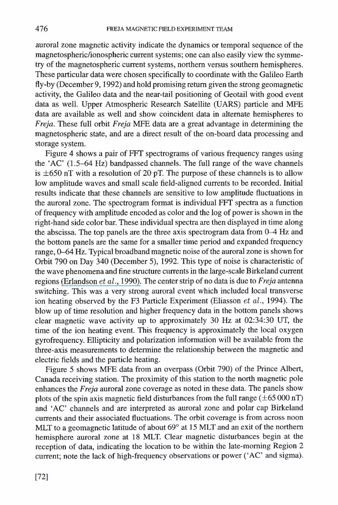
Figure 4 shows a pair of FFT spectrograms of various frequency ranges using the 'AC' (1.5-64 Hz) bandpassed channels. The full range of the wave channels is +650 nT with a resolution of 20 pT. The purpose of these channels is to allow low amplitude waves and small scale field-aligned currents to be recorded. Initial results indicate that these channels are sensitive to low amplitude fluctuations in the auroral zone. The spectrogram format is individual FFT spectra as a function of frequency with amplitude encoded as color and the log of power is shown in the right-hand side color bar. These individual spectra are then displayed in time along the abscissa. The top panels are the three axis spectrogram data from 0-4 Hz and the bottom panels are the same for a smaller time period and expanded frequency range, 0-64 Hz. Typical broadband magnetic noise of the auroral zone is shown for Orbit 790 on Day 340 (December 5), 1992. This type of noise is characteristic of the wave phenomena and fine structure currents in the large-scale Birkeland current regions (Erlandson et al., 1990). The center strip of no data is due to Freja antenna switching. This was a very strong auroral event which included local transverse ion heating observed by the F3 Particle Experiment (Eliasson et al., 1994). The blow up of time resolution and higher frequency data in the bottom panels shows clear magnetic wave activity up to approximately 30 Hz at 02:34:30 UT, the time of the ion heating event. This frequency is approximately the local oxygen gyrofrequency. Ellipticity and polarization information will be available from the three-axis measurements to determine the relationship between the magnetic and electric fields and the particle heating.
Figure 5 shows MFE data from an overpass (Orbit 790) of the Prince Albert, Canada receiving station. The proximity of this station to the north magnetic pole enhances the Freja auroral zone coverage as noted in these data. The panels show plots of the spin axis magnetic field disturbances from the full range (4-65 000 nT) and 'AC' channels and are interpreted as auroral zone and polar cap Birkeland currents and their associated fluctuations. The orbit coverage is from across noon MLT to a geomagnetic latitude of about 69 ~ at 15 MLT and an exit of the northern hemisphere auroral zone at 18 MLT. Clear magnetic disturbances begin at the reception of data, indicating the location to be within the late-morning Region 2 current; note the lack of high-frequency observations or power ( 'AC' and sigma).
[721

4.0
2.'0
0 .0
4.0
2.0
0.0
4.0
2 .0
BX FREJA Mo.onel~m~T YYDDD=92340
~ " 4.0
2.5
Log Po*.ucr
0.0
UT 2 MLT ML~T ALT
64.0
~: 0
32..0
O.O ~ _ _
64,0
32. .0
r~
0 . 0
84.0
32.0
- - 3 , 0 ! 1.5
0.0
-1 .5
- 3 . 0
s Po'u)cr
0 . 0
(IT 238:0 iIL~" M ~ T ~LT
238:0 g37: 0
Fig. 4. FFF spectrogram format for data from Freja Orbit 790. Top panel: 0-4 Hz spectra vs time for most of the orbit, showing typical auroral zone broadband noise. The time resolution (02:33-02:37 UT) and frequency range (0-64 Hz) are both increased in the bottom panel showing ~20-30 Hz wave activity near the time of transverse ion heating, ~02:34:40 UT.

478 FREJA MAGNETIC FIELD EXPERIMENT TEAM
FREJA, Prince Albert Orbit 1106, Dec. 28, 1992, DOY 368
oo .o o= ..... - - - - - \ - ,
;.,.-.~ . : .~
;~y~ : ; ".4.
Ac spinax~ . ..,~.: .. , : ~ ~.. .
-~o~.~ "~'-! "
- - 9 3 9 . 9 750.O
500.0
sigma
250.0
. . . . . _ _ _ L ~ . I - - . ! . I - . ! i ! ! ! ! ! ~ I I I
0.0 , , ~ �9
UT 22:30:00 22:36:~5 I I I
UT 22:31:00 22:37:00 MLT 10.895 13.214 CGLat 58.512 67.349 Alt 1746 1770 FLon -171.975 -139.106 FLat 62.627 65.592 Art -0.0121,-0.9907,0.1357 016B0547.PA / Prince Albert tape 30
22:~3:30 22:50:15 22:57:OG
I 22:43:00 22:4'9:00 22:55:00
15.606 17.220 18.274 69.226 61.863 49.648
1733 1638 1492 -107.856 -88.047 -75.898
60.802 50.900 38,528
Fig. 5. Freja magnetic field data from Orbit 1105, on December 28, 1992, recorded at Prince Albert, Canada. Noon and dusk auroral Birkeland currents are evident from the full range spin axis magnetic disturbance signatures (nT vs time), data have been spin filtered to remove baselines. Also indicative of current regions are the 'AC' data, 1.5-64 Hz bandpassed (nT vs time) and the 2-s standard deviation (sigma) of this 'AC' signal. The latter are used as the F2 MFE event detector trigger.
A clear change in Birkeland current characteristics occurs at the entrance into the dusk Region 1 system (22:37:35 UT, about 13.3 MLT). At this point the 'AC' and corresponding sigma explode with fine-scale structure; there may even be the possibility that the F r e j a spacecraft passed the noon division of the downward dawn Region 1 and the upward dusk Region 1. In fact, the significant increase of the 'AC' levels f rom the dawn to the dusk current region could be explained by the structured, accelerated electron precipitation chiefly responsible for the dusk upward Region 1 current and the variety of populations (with usually less structure) responsible for the downward dawn Region 1 current. Proceeding along
[74]

MAGNETIC F1ELD EXPERIMENT ON THE FREJA SATELLITE 479
the orbit, a variety of currents appear which are at the poleward edge of the auroral zone and slightly into the polar cap. The clear signature of the dusk Region 1 current is indicated by the 500 nT decrease at 22:47 UT and followed by an extensive Region 2 current down to some 57 ~ GMLAT with imbedded current pair structure. The auroral zone is expanded abnormally, allowing observation by the Freja MFE of the mantle currents found above the auroral zone in the polar cap. The above discussion accents the unique local time perspective of the Freja orbit from previously observed auroral zone current systems.
An exciting new discovery of these current systems from the UARS MFE analysis is the high-frequency wave power or structure associated with the various large-scale currents (Anderson et aI., 1993). The middle panel shows the spin axis 'AC' data for this Orbit 1105 and the bottom panel is a standard deviation of this spin axis channel over a 2-s interval. Both of these panels show the high-frequency nature of Birkeland current regions. The exact response of these channels and filters as well as the physics behind these waves and/or fine-scale current structures accompanying the large-scale currents is being pursued with both the Freja and UARS MFE data. Nevertheless, the association is clear and the sigma shown for this orbit is an example of the information used for the MFE Birkeland current monitor calculated in the MFE FRISC. This monitor then sets a trigger generated by the MFE when it is greater than a commandable, preset threshold. This 'event' flag can be read by the system unit and used to remotely command all instruments into burst mode data taking and local memory storage (minimum 30 s). Data are then dumped at the first available opportunity. This mode of operation has been exercised and Freja has recorded data from naturally-occurring events. Note that this allows Freja observations automatically and remote from ground-receiving stations, provided sufficient power is available for the instrument suite.
4. Summary
The Freja opportunity has been a fairly unique one with sufficient lead time and high telemetry bandwidth to allow the possibilities realized with the Freja Mag- netic Field Experiment; there were nearly three years until launch, two years from project start to instrument delivery. Although cost was a severe constraint, a small, dedicated team philosphy surmounted that difficulty. Not insignificant in the design, fabrication and testing of the instrument was the choice of the FRISC processor and the interactive Forth programming and operating system. This cre- ated a high efficiency operation immediately after breadboard, and during flight model fabrication. The spacecraft telemetry interface required a microprocessor based instrument so the advanced capabilities of this MFE came at little added cost. In fact, the cost savings derived from the interactive use of this processor system during design and problem tracking phases (e.g., hardware problems from radiation requiring fast logic devices) far outweighed the added cost of capabilities. This approach has led to a truly generic and flexible design with adaptability to
[75]

480 FREJA MAGNETIC FIELD EXPERIMENT TEAM
differing mission requirements; sampling rates, FFTs, filtering and other on-board processing, even differing telemetry interfaces, can be accomplished, modified and updated in software, providing direct cost savings for future programs. APL with NASA/GSFC had the opportunity to build the most capable near-Earth Magnet- ic Field Experiment to date. The on-board processing described throughout this paper was inspired by increasingly difficult data throughput in ground-computer systems, compounded by the ten times telemetry rate for the Freja MFE alone com- pared to any of our previous missions. Although CPU capabilities are increasing tremendously, input/output remains a bottleneck, and it is much more reasonable to process the information on-board as it proceeds through the instrument. The Kiruna ground station produces summary plots which are produced in conjunction with data taking for immediate distribution; the parameters plotted from the MFE are generated on-board and cover the full MFE bandwidth. Furthermore, these capabil- ities can actually be iterated with information gained from observations or with new requirements from the spacecraft, operations or natural phenomena. For example, understanding was gained during the UARS MFE data analysis effort (Anderson, 1993) with regard to the detection of auroral disturbance regions. Although the Fre- ja MFE had been delivered and was near launch, the flexibility of the MFE FRISC processor allowed the implementation of this newly gained information into the Freja MFE flight software post launch. In March 1993, the MFE auroral current monitor was fine tuned and upgraded based on the UARS experience. In July 1993, the MFE was completely reprogrammed to track and error correct excessive RAM single event upsets due to the high solar and magnetic activity of this present solar cycle maximum.
The MFE auroral current detector has proven extremely useful in simply iden- tifying the Birkeland current regions, and by inference based on correlation studies (Zanetti et al., 1984, 1991), the ionospheric electrojet current system as well. From a Freja orbit approaching North America from the north, the MFE monitor can transmit information on auroral zone Birkeland currents real time. These currents directly effect Earth systems including general communications, power grid dis- tribution systems, long distance telephone lines and near-Earth satellite operations (Zanetti et al., 1994); these Freja MFE space weather data have been captured at the JHU/APL with the 'Low Speed Link' receiver. In addition, the 'AC' data of the UARS and Freja MFEs is condensed into an on-line index file which shows the spacecraft presence in the auroral zone per orbit. This index for the first year of UARS operation (Fall 1991-Fall 1992) shows the northern and/or southern auroral zone expanding into the 57 ~ inclination orbit about 85% of the time. Given this accessibility into the auroral zone, such an inclination as Freja (74 ~ GMLAT) or UARS (68 ~ GMLAT) provides a unique local time scan of active auroral regions (for example, the noon division of oppositely signed Region 1 currents, Figure 4); such observations could settle questions regarding the connection of Birkeland current regions in the dayside auroral zone, mantle and polar cap areas. Likewise,
[76]

MAGNETIC FIELD EXPERIMENT ON THE FREJA SATELLITE 481
orbits across midnight will traverse the storm current wedge circuit from dusk to dawn in a few tens of minutes.
Scientific organizations such as APL and the other institutions participating in this Freja mission have unique 'end-to-end' capabilities. Given the science experi- ence along with hardware capability, up-to-date science objectives are continuously implemented into state-of-the-art instrumentation. We, the MFE team, thank the Swedish Space Corporation and the Swedish and German governments for looking to space plasma science for their Freja mission and the opportunity to participate in an efficient, quick turnaround endeavor. The science return from the MFE has been immediate and highly comprehensive in spite of the small operation. The Freja
magnetic field team looks forward to new opportunities for this highly flexible and generic instrument and to the understanding gained within the Freja mission science.
Acknowledgements
The author and co-authors wish to acknowledge their respective sponsoring agen- cies which have allowed the assembly of this robust and worldwide team of scien- tists and engineers. The Freja Magnetic Field Experiment was supported jointly by the US Office of Naval Research (ONR) and the National Aeronautics and Space Administration/Headquarters (NASA/HQ) with program oversight by the ONR. The National Science Foundation (NSF) is acknowledged for the post-launch anal- ysis support.
The JHU/APL team represents the core personnel, however innumerable staff were directly and indirectly involved in the MFE effort and are sincerely thanked. Appreciation by the team goes to the efficient and cooperative Swedish Space Corporation team led by Sven Grahn, and to Kerstin Fredga, Director General of the Swedish National Space Board for her unrelenting support and encouragement.
References
Acufia, M. H.: 1974, 'Fluxgate Magnetometers for Outer Planets Exploration', IEEE Trans. Magnetics Mag-10, 519.
Acufia, M. H., Scearce, S. C., Seek, J. B., and Scheifele, J.: 1978, The Magsat Vector Magnetometer - A Precision Fluxgate Magnetometer for the Measurement of the Geomagnetic Field, NASA TM-79656.
Anderson, B. J., Takahashi, K., Erlandson, R. E., and Zanetti, L. J.: 1990, 'Pcl Pulsations Observed by AMPTE/CCE in the Earth's Outer Magnetosphere', Geophys. Res. Letters 17, 1853.
Anderson, B. J., Potemra, T. A., Bythrow, E E, Zanetti, L. J., Holland, D. B., and Winningham, J. D.: 1993, 'Auroral Currents During the Magnetic Storm of November 8 and 9, 1991: Observations from the Upper Atmosphere Research Satellite Particle Environment Monitor', Geophys. Res. Letters 20, 1327.
Ballard, B., Henshaw, R., and Zaremba, T.: 1984, 'Forth Direct Execution Processors in the Hopkins Ultraviolet Telescope', The Journal of Forth Application and Research 2, 33M-7.
Burke, W. J., Hardy, D. A., Rich, E J., Kelly, M. C., Smiddy, M., Shuman, B., Sagalyn, R. C., Vancour, R. R, Wipman, E J. L., and Lai, S. T.: 1980, 'Electrodynamic Structure of the Late Evening Sector of the Auroral Zone', J. Geophys. Res. 85, 1179.
[77]

482 FREJA MAGNETIC FIELD EXPERIMENT TEAM
Bythrow, E E, Doyle, M. A., Potemra, T. A., Zanetti, L. J., Huffman, R. E., Meng, C.-I., Hardy, D. A., Rich, E J., and Heelis, R. A.: 1986, 'Multiple Auroral Arcs and Birkeland Currents: Evidence for Plasma Sheet Boundary Waves', Geophys. Res. Letters 13, 805.
Eliasson, L. et al.: 1994, 'The Freja Particle Instrument', Space Sci. Rev. 70, 000 (this issue). Engebretson, M. J., Zanetti, L. J., Potemra, T. A., and Acufia, M. H.: 1986, 'Harmonically Structured
ULF Pulsations Observed by the AMPTE/CCE Magnetic Field Experiment', Geophys. Res. Letters 13, 905.
Erlandson, R. E., Zanetti, L. J., and Potemra, T. A.: 1989, 'Magnetic Fluctuations from 0 to 26 Hz Observed from a Polar Orbiting Satellite', IEEE Trans. on Plasma Sci. 17, 196.
Erlandson, R. E., Zanetti, L. J., Potemra, T. A., Block, L. E, and Holmgren, G.: 1990, 'Viking Magnetic and Electric Field Observations of PC 1 Waves at High Latitudes', J. Geophys. Res. 95, 5941.
Gordon, D. I. and Brown, R. E.: 1972, 'Recent Advances in Fluxgate Magnetometry', 1EEE Trans. Magnetics Mag-8, 76.
Grahn, S. e~ al.: 1994, 'The Freja Spacecraft', Space Sci. Rev. 70, 000 (this issue). Hayes, J. R., Fraeman, M. E., Williams, R. L., and Zaremba, T.: 1987, 'An Architecture for the
Direct Execution of the Forth Programming Language, Proceedings of the Second International Conference on Architectural Support for Programming Languages and Operating System', The Compute Society of the IEEE, pp. 42-49.
Iijima, T., Potemra, T. A., and Zanetti, L. J.: 1990, 'Large-Scale Characteristics of Magnetospheric Equatorial Currents', J. Geophys. Res. 95, 991.
Marklund, G. et al.: 1994, 'The Freja Electric Field Instrument', Space Sci. Rev. 70, 000 (this issue). Mauk, B. H. and Zanetti, L. J.: 1987, 'Magnetospheric Electric Fields and Currents', Rev. Geophys.
Space Phys. 25, 541. Potemra, T. A., Zanetti, L. J., Bythrow, P. E, Erlandson, R. E., Lundin, R., Marklund, G. T., Block,
L. E, and Lindqvist, E-A.: 1988, 'Resonant Geomagnetic Field Oscillations and Birkeland Currents in the Morning Sector', J. Geophys. Res. 93, 2661.
Potemra, T. A., Zanetti, L. J., Erlandson, R. E., Bythrow, E E, Gustafsson, G., Acufia, M. H., and Lundin, R.: 1987, 'Observations of Large-Scale Birkeland Currents with Viking', Geophys. Res. Letters 14, 419.
Zanetti, L. J., Potemra, T. A., Anderson, B., Erlandson, R. E., Holland, D. B., Acuna, M. H., Kappenman, J., Lesher, R., and Feero, W.: 1994, 'Freja Magnetic Field Measurements and the Sunburst Monitor System', Geophys. Res. Letters (in press).
Zanetti, L. J., Baumjohann, W., Potemra, T. A., and Bythrow, E E: 1984, IN T. A. Potemra (ed.), 'Three-Dimensional Birkeland-Ionospheric Current Systems Determined from MAGSAT', Mag- netospheric Currents, Geophysical Monograph 28, 131-136.
Zanetti, L. J., Potemra, T. A., Iijima, T., and Baumjohann, W.: 1991, 'Equatorial, Birkeland, and Ionospheric Currents of the Magnetospheric Storm Circuit', Magnetospheric Substorms, AGU Monograph 64, 111-122.
[78]