exploiting weak connectivity in a distributed file ... - citeseerx
TRANSCRIPT
Exploiting Weak Connectivity in aDistributed File System
Lily B. Mummert
December 1996CMU-CS-96-195
School of Computer ScienceComputer Science DivisionCarnegie Mellon University
Pittsburgh, PA
Submitted in partial fulfillment of the requirementsfor the degree of Doctor of Philosophy.
Thesis Committee:Mahadev Satyanarayanan, Chair
Garth GibsonJames Morris
Patrick Mitchell, Intel Corporation
Copyright c 1996 Lily B. Mummert
This research was sponsored by the Air Force Materiel Command (AFMC) and the Defense Advanced ResearchProjects Agency (DARPA) under contract number F19628-93-C-0193. Additional support was provided by theIBM Corporation, Digital Equipment Corporation, and Intel Corporation.
The views and conclusions contained in this document are those of the authors and should not be interpreted asnecessarily representing the official policies or endorsements, either expressed or implied, of the AFMC, DARPA,DEC, IBM, Intel, or the U. S. Government.

Keywords: Distributed file systems, weak connectivity, high availability, mobile computing,Coda, reintegration, application-transparent adaptation, UNIX

To Todd

Abstract
Weak connectivity, in the form of intermittent, low-bandwidth, or expensive networks is a factof life in mobile computing. For the foreseeable future, access to cheap, high-performance,reliable networks, or strong connectivity will be limited to a few oases, such as work or home,in a vast desert of weak connectivity. The design of distributed file systems has traditionallybeen based on an assumption of strong connectivity. Yet, to provide ubiquitous data access, itis vital that distributed file systems make effective use of weak connectivity.
This dissertation describes the design, implementation, and evaluation of weakly connectedoperation in the Coda File System. The starting point of this work is disconnected operation,in which a file system client operates using data in its cache during server or network failures.Disconnected clients suffer from many limitations: updates are not visible to other clients, cachemisses may impede progress, updates are at risk from client loss or damage, and the dangerof update conflicts increases as disconnections are prolonged. Weak connectivity provides anopportunity to alleviate these limitations.
Coda’s strategy for weakly connected operation is best characterized as application-transparent adaptation. The system bears full responsibility for coping with the demandsof weak connectivity. This approach preserves upward compatibility by allowing applicationsto run unchanged. Coda provides several mechanisms for weakly connected operation moti-vated by actual experience. The foundation of adaptivity in this system is the communicationslayer, which derives and supplies information on network conditions to higher system layers.The rapid cache validation mechanism enables the system to recover quickly in intermittentenvironments. The trickle reintegration mechanism insulates the user from poor networkperformance by propagating updates to servers asynchronously. The cache miss handlingmechanism alerts the user to potentially lengthy service times and provides opportunities forintervention.
A quantitative evaluation of these mechanisms, based on controlled experimentation andempirical data gathered from the deployed system in everyday use, shows that Coda is able toprovide good performance even when network bandwidth varies over four orders of magnitude– from modem speeds to LAN speeds.
v

Acknowledgements
First I would like to thank Satya. I could not have asked for a better advisor or mentor. Healways made time to meet with me, despite his increasingly busy schedule, and he never failedto provide insightful feedback on my work. He was patient and encouraging when I struggled,and demanding when I needed to be challenged. Satya, working with you has been a privilege.
I’d like to thank the other members of my thesis committee, Garth Gibson, Jim Morris, andPat Mitchell, for their feedback on the thesis. Special thanks go to Pat Mitchell, for gallantlystepping in as my outside committee member at the last minute.
I’d like to thank Jeannette Wing for patiently guiding me through my foray in protocolanalysis. I could not have done that work without her. I’d also like to thank Peter Braam forproviding many thoughtful insights on the analysis.
Past and present members of the Coda group provided a great deal of support: Bob Baron,Peter Braam, Maria Ebling, Jay Kistler, Puneet Kumar, Qi Lu, Hank Mashburn, DushyanthNarayanan, Brian Noble, Josh Raiff, David Steere, and Eric Tilton. They are a very talentedgroup of people and it has been a pleasure to work with them.
No systems project can survive without users. Thanks go to all of the Coda users for theirpatience and tolerance in dealing with an experimental system. I’d like to thank David Eckhardtin particular for pushing the system in ways we hadn’t imagined, and for his willingness tolisten to all sorts of half-baked ideas.
Many friends provided emotional support during the long process of finishing my Ph.D.They include: Jay Kistler and Chris Conklin, for making me feel welcome during the firstdifficult months at CMU; Joanne Karohl and Dorcie Jasperse, for providing long-distancethesis support; and Anurag Acharya, Bruce Horn, and Dave Tarditi, for creating a pleasantoffice environment.
I’d like to acknowledge my dogs, Tasha, Zoey, and Boo, for reminding me of the importanceof a life outside of work. Gert Sullivan instructed my first dog obedience class and introducedme to dog sports. I’ve met many wonderful people through dog activities, and I thank them fortheir friendship and for many enjoyable training sessions: Ellen Berman, Annette Bush, MartyCoody, Margo Foster, Phil Gallagher, Gayle Geiger, Nancy Glabicki, Fred Hulme, Doug and
vii
Ann Humbertson, Dorcie Jasperse, Sharon Kilrain, Barb Martin, Erin McGlynn and HaroldWalls, and Libby Simendinger.
I’d like to thank my parents, Victor and Donna Barkovic, for emphasizing the importanceof hard work and encouraging me to strive for excellence. Thanks to my sister Sylvia, for beinga friend.
Finally, I want to thank my husband Todd, for being patient beyond all reasonable expec-tation. I love you.
Lily MummertPittsburgh, Pennsylvania
December 1996
Contents
1 Introduction 1
1.1 Distributed File Systems : : : : : : : : : : : : : : : : : : : : : : : : : : : : 1
1.2 Disconnected Operation : : : : : : : : : : : : : : : : : : : : : : : : : : : : 2
1.3 The Thesis : : : : : : : : : : : : : : : : : : : : : : : : : : : : : : : : : : : 3
1.3.1 Scope of Thesis : : : : : : : : : : : : : : : : : : : : : : : : : : : : 3
1.3.2 Approach : : : : : : : : : : : : : : : : : : : : : : : : : : : : : : : 4
1.3.3 Mechanisms for Weak Connectivity : : : : : : : : : : : : : : : : : : 5
1.3.4 Validation of Thesis : : : : : : : : : : : : : : : : : : : : : : : : : : 5
1.4 Document Roadmap : : : : : : : : : : : : : : : : : : : : : : : : : : : : : : 6
2 Coda File System 7
2.1 Design Goals : : : : : : : : : : : : : : : : : : : : : : : : : : : : : : : : : : 7
2.1.1 Scalability : : : : : : : : : : : : : : : : : : : : : : : : : : : : : : : 7
2.1.2 Performance : : : : : : : : : : : : : : : : : : : : : : : : : : : : : : 8
2.1.3 Security : : : : : : : : : : : : : : : : : : : : : : : : : : : : : : : : 9
2.1.4 Operability : : : : : : : : : : : : : : : : : : : : : : : : : : : : : : : 9
2.2 Mechanisms for High Availability : : : : : : : : : : : : : : : : : : : : : : : 9
2.2.1 Server Replication : : : : : : : : : : : : : : : : : : : : : : : : : : : 10
2.2.2 Disconnected Operation : : : : : : : : : : : : : : : : : : : : : : : : 12
2.3 Client Overview : : : : : : : : : : : : : : : : : : : : : : : : : : : : : : : : 24
2.4 Server Overview : : : : : : : : : : : : : : : : : : : : : : : : : : : : : : : : 24
ix
x CONTENTS
3 Communication Layer Adaptation 27
3.1 Design Alternatives : : : : : : : : : : : : : : : : : : : : : : : : : : : : : : 28
3.2 Remote Procedure Call : : : : : : : : : : : : : : : : : : : : : : : : : : : : 29
3.2.1 Protocol Overview : : : : : : : : : : : : : : : : : : : : : : : : : : : 29
3.2.2 Retransmission Strategy : : : : : : : : : : : : : : : : : : : : : : : : 30
3.2.3 Sharing Liveness Information : : : : : : : : : : : : : : : : : : : : : 35
3.3 Bulk Data Transfer : : : : : : : : : : : : : : : : : : : : : : : : : : : : : : : 36
3.3.1 Protocol Overview : : : : : : : : : : : : : : : : : : : : : : : : : : : 36
3.3.2 Obtaining RTT Observations : : : : : : : : : : : : : : : : : : : : : 39
3.3.3 Estimating RTT : : : : : : : : : : : : : : : : : : : : : : : : : : : : 41
3.3.4 Retransmission Strategy : : : : : : : : : : : : : : : : : : : : : : : : 41
3.4 Exporting Network Information : : : : : : : : : : : : : : : : : : : : : : : : 42
3.4.1 Liveness : : : : : : : : : : : : : : : : : : : : : : : : : : : : : : : : 43
3.4.2 Transmission Logs : : : : : : : : : : : : : : : : : : : : : : : : : : : 44
3.4.3 Application Uses : : : : : : : : : : : : : : : : : : : : : : : : : : : 49
3.5 Effects of Server Replication : : : : : : : : : : : : : : : : : : : : : : : : : : 51
3.5.1 MultiRPC : : : : : : : : : : : : : : : : : : : : : : : : : : : : : : : 51
3.5.2 Connectivity to an AVSG : : : : : : : : : : : : : : : : : : : : : : : 52
3.6 Quality of Service : : : : : : : : : : : : : : : : : : : : : : : : : : : : : : : 52
3.7 Chapter Summary : : : : : : : : : : : : : : : : : : : : : : : : : : : : : : : 53
4 Rapid Cache Validation 55
4.1 Design : : : : : : : : : : : : : : : : : : : : : : : : : : : : : : : : : : : : : 56
4.1.1 Choice of Granularity : : : : : : : : : : : : : : : : : : : : : : : : : 56
4.1.2 Volume Callbacks : : : : : : : : : : : : : : : : : : : : : : : : : : : 57
4.2 Protocol Description : : : : : : : : : : : : : : : : : : : : : : : : : : : : : : 57
4.2.1 Obtaining Callbacks : : : : : : : : : : : : : : : : : : : : : : : : : : 58
4.2.2 Handling Callback Breaks : : : : : : : : : : : : : : : : : : : : : : : 58
4.3 Implementation Details : : : : : : : : : : : : : : : : : : : : : : : : : : : : 61
4.3.1 Server Modifications : : : : : : : : : : : : : : : : : : : : : : : : : : 61
CONTENTS xi
4.3.2 VCB Acquisition Policy : : : : : : : : : : : : : : : : : : : : : : : : 63
4.3.3 Access Rights : : : : : : : : : : : : : : : : : : : : : : : : : : : : : 64
4.3.4 Effects of Replication : : : : : : : : : : : : : : : : : : : : : : : : : 65
4.3.5 VCB Maintenance and Updates : : : : : : : : : : : : : : : : : : : : 66
4.4 Correctness : : : : : : : : : : : : : : : : : : : : : : : : : : : : : : : : : : 66
4.4.1 General Approach : : : : : : : : : : : : : : : : : : : : : : : : : : : 67
4.4.2 Benefits of Formal Analysis : : : : : : : : : : : : : : : : : : : : : : 67
4.5 Chapter Summary : : : : : : : : : : : : : : : : : : : : : : : : : : : : : : : 68
5 Trickle Reintegration 69
5.1 Relationship to Write-Back Caching : : : : : : : : : : : : : : : : : : : : : : 69
5.2 Architecture : : : : : : : : : : : : : : : : : : : : : : : : : : : : : : : : : : 70
5.2.1 Structural Modifications : : : : : : : : : : : : : : : : : : : : : : : : 71
5.2.2 Preserving the Effectiveness of Log Optimizations : : : : : : : : : : 72
5.2.3 Overview of the Algorithm : : : : : : : : : : : : : : : : : : : : : : 73
5.3 Detailed Design : : : : : : : : : : : : : : : : : : : : : : : : : : : : : : : : 79
5.3.1 Concurrency Control : : : : : : : : : : : : : : : : : : : : : : : : : 79
5.3.2 Reducing the Impact of Reintegration : : : : : : : : : : : : : : : : : 83
5.3.3 Remote Updates and Volume Callbacks : : : : : : : : : : : : : : : : 85
5.3.4 Ensuring Atomicity : : : : : : : : : : : : : : : : : : : : : : : : : : 87
5.3.5 Effects of Server Replication : : : : : : : : : : : : : : : : : : : : : 89
5.4 Selecting an Aging Window : : : : : : : : : : : : : : : : : : : : : : : : : : 92
5.4.1 File Reference Traces : : : : : : : : : : : : : : : : : : : : : : : : : 92
5.4.2 Venus Simulator : : : : : : : : : : : : : : : : : : : : : : : : : : : : 96
5.4.3 Results : : : : : : : : : : : : : : : : : : : : : : : : : : : : : : : : : 96
5.5 Chapter Summary : : : : : : : : : : : : : : : : : : : : : : : : : : : : : : : 106
xii CONTENTS
6 Handling Cache Misses 113
6.1 Advice Monitor : : : : : : : : : : : : : : : : : : : : : : : : : : : : : : : : 114
6.2 User Interactions : : : : : : : : : : : : : : : : : : : : : : : : : : : : : : : : 115
6.2.1 Handling Cache Misses : : : : : : : : : : : : : : : : : : : : : : : : 115
6.2.2 Augmenting the HDB : : : : : : : : : : : : : : : : : : : : : : : : : 116
6.2.3 Controlling Hoard Walks : : : : : : : : : : : : : : : : : : : : : : : 119
6.3 Patience Model : : : : : : : : : : : : : : : : : : : : : : : : : : : : : : : : 119
6.4 Chapter Summary : : : : : : : : : : : : : : : : : : : : : : : : : : : : : : : 121
7 Evaluation 123
7.1 Evolution and Implementation Status : : : : : : : : : : : : : : : : : : : : : 123
7.2 Usage Environment : : : : : : : : : : : : : : : : : : : : : : : : : : : : : : 124
7.3 Transport Protocol : : : : : : : : : : : : : : : : : : : : : : : : : : : : : : : 125
7.4 Rapid Cache Validation : : : : : : : : : : : : : : : : : : : : : : : : : : : : 127
7.4.1 Performance Under Ideal Conditions : : : : : : : : : : : : : : : : : 128
7.4.2 Use in Practice : : : : : : : : : : : : : : : : : : : : : : : : : : : : : 136
7.5 Trickle Reintegration : : : : : : : : : : : : : : : : : : : : : : : : : : : : : : 143
7.5.1 Methodology: Trace Replay : : : : : : : : : : : : : : : : : : : : : : 144
7.5.2 Results : : : : : : : : : : : : : : : : : : : : : : : : : : : : : : : : : 145
7.6 Chapter Summary : : : : : : : : : : : : : : : : : : : : : : : : : : : : : : : 157
8 Related Work 159
8.1 Systems that Exploit Weak Connectivity : : : : : : : : : : : : : : : : : : : : 159
8.1.1 Distributed File Systems : : : : : : : : : : : : : : : : : : : : : : : : 159
8.1.2 Databases : : : : : : : : : : : : : : : : : : : : : : : : : : : : : : : 161
8.1.3 Read Only Systems : : : : : : : : : : : : : : : : : : : : : : : : : : 162
8.1.4 Application-Specific Approaches : : : : : : : : : : : : : : : : : : : 163
8.2 Mechanisms for Weak Connectivity : : : : : : : : : : : : : : : : : : : : : : 164
8.2.1 Communications : : : : : : : : : : : : : : : : : : : : : : : : : : : : 165
8.2.2 Rapid Cache Validation : : : : : : : : : : : : : : : : : : : : : : : : 165
8.2.3 Trickle Reintegration : : : : : : : : : : : : : : : : : : : : : : : : : 166
CONTENTS xiii
9 Conclusion 167
9.1 Contributions : : : : : : : : : : : : : : : : : : : : : : : : : : : : : : : : : 167
9.2 Future Work : : : : : : : : : : : : : : : : : : : : : : : : : : : : : : : : : : 169
9.2.1 Refinements for Weakly Connected Operation : : : : : : : : : : : : : 170
9.2.2 Incorporating Monetary Cost : : : : : : : : : : : : : : : : : : : : : 170
9.2.3 Improving Effectiveness and Usability of Hoarding : : : : : : : : : : 170
9.2.4 Exploiting Reserved Network Services : : : : : : : : : : : : : : : : 171
9.2.5 Application-Level Logging : : : : : : : : : : : : : : : : : : : : : : 171
9.2.6 Application-Aware Adaptation : : : : : : : : : : : : : : : : : : : : 172
9.3 Closing Remarks : : : : : : : : : : : : : : : : : : : : : : : : : : : : : : : : 173
A Protocol Analysis 175
A.1 System Model : : : : : : : : : : : : : : : : : : : : : : : : : : : : : : : : : 175
A.2 Logic : : : : : : : : : : : : : : : : : : : : : : : : : : : : : : : : : : : : : : 176
A.3 Goal of Cache Coherence : : : : : : : : : : : : : : : : : : : : : : : : : : : 179
A.4 Protocol Analysis : : : : : : : : : : : : : : : : : : : : : : : : : : : : : : : 179
A.4.1 Cache miss, no failures : : : : : : : : : : : : : : : : : : : : : : : : 183
A.4.2 Successful validation, no failures : : : : : : : : : : : : : : : : : : : 185
A.4.3 Cache miss, followed by failure : : : : : : : : : : : : : : : : : : : : 186
A.4.4 Successful validation, failure : : : : : : : : : : : : : : : : : : : : : 187
A.4.5 Failed validation : : : : : : : : : : : : : : : : : : : : : : : : : : : : 187
A.4.6 Volume miss, no failures : : : : : : : : : : : : : : : : : : : : : : : : 188
A.4.7 Volume miss, failure : : : : : : : : : : : : : : : : : : : : : : : : : : 191
A.4.8 Volume validation, failure : : : : : : : : : : : : : : : : : : : : : : : 191
A.4.9 Volume validation, no failures : : : : : : : : : : : : : : : : : : : : : 192
A.4.10 Other validations : : : : : : : : : : : : : : : : : : : : : : : : : : : 194
A.5 Time-Bounded Correctness : : : : : : : : : : : : : : : : : : : : : : : : : : 195
A.6 Classifying Beliefs : : : : : : : : : : : : : : : : : : : : : : : : : : : : : : : 197
A.7 Extensions : : : : : : : : : : : : : : : : : : : : : : : : : : : : : : : : : : : 197
xiv CONTENTS
B Coda Internals 199
B.1 Client Structure : : : : : : : : : : : : : : : : : : : : : : : : : : : : : : : : 199
B.1.1 Coda MiniCache : : : : : : : : : : : : : : : : : : : : : : : : : : : : 201
B.1.2 Venus : : : : : : : : : : : : : : : : : : : : : : : : : : : : : : : : : 201
B.2 Server Structure : : : : : : : : : : : : : : : : : : : : : : : : : : : : : : : : 208
B.2.1 Vice File Server : : : : : : : : : : : : : : : : : : : : : : : : : : : : 208
B.2.2 Authentication Server : : : : : : : : : : : : : : : : : : : : : : : : : 213
B.2.3 Update System : : : : : : : : : : : : : : : : : : : : : : : : : : : : : 213
List of Figures
2.1 Venus State Transition Diagram : : : : : : : : : : : : : : : : : : : : : : : : 13
2.2 Sample Hoard Profile : : : : : : : : : : : : : : : : : : : : : : : : : : : : : 14
2.5 Type-independent Fields of the CML Record : : : : : : : : : : : : : : : : : 17
2.9 Coda Client Structure : : : : : : : : : : : : : : : : : : : : : : : : : : : : : 23
2.10 Coda Server Structure : : : : : : : : : : : : : : : : : : : : : : : : : : : : : 25
3.1 Calculating RPC2 Retransmission Intervals : : : : : : : : : : : : : : : : : : 31
3.2 RPC2 Retransmission Intervals : : : : : : : : : : : : : : : : : : : : : : : : 32
3.3 Collecting RTT Observations : : : : : : : : : : : : : : : : : : : : : : : : : 34
3.4 SFTP File Transfer: Server to Client : : : : : : : : : : : : : : : : : : : : : : 37
3.5 SFTP File Transfer: Client to Server : : : : : : : : : : : : : : : : : : : : : : 38
3.6 Two-way Timestamping in SFTP : : : : : : : : : : : : : : : : : : : : : : : 40
3.7 SFTP Packet Sets : : : : : : : : : : : : : : : : : : : : : : : : : : : : : : : 42
3.8 Transmission Log Record Formats : : : : : : : : : : : : : : : : : : : : : : : 43
3.9 Transmission Log : : : : : : : : : : : : : : : : : : : : : : : : : : : : : : : 44
3.10 Measuring SFTP Rounds : : : : : : : : : : : : : : : : : : : : : : : : : : : 46
3.11 SFTP Records and Retransmission : : : : : : : : : : : : : : : : : : : : : : : 48
4.1 Obtaining a Volume Callback : : : : : : : : : : : : : : : : : : : : : : : : : 59
4.2 Validating by Volume : : : : : : : : : : : : : : : : : : : : : : : : : : : : : 60
4.3 Breaking a Volume Callback : : : : : : : : : : : : : : : : : : : : : : : : : : 62
4.4 Interface for Volume Version Stamps : : : : : : : : : : : : : : : : : : : : : 63
4.5 Vice Status Block : : : : : : : : : : : : : : : : : : : : : : : : : : : : : : : 65
xv
xvi LIST OF FIGURES
5.1 Venus State Transition Diagram : : : : : : : : : : : : : : : : : : : : : : : : 71
5.2 CML During Trickle Reintegration : : : : : : : : : : : : : : : : : : : : : : 76
5.3 Reintegration RPC : : : : : : : : : : : : : : : : : : : : : : : : : : : : : : : 76
5.5 Shadowing Cache Files : : : : : : : : : : : : : : : : : : : : : : : : : : : : 81
5.6 Interface for Reintegration by Fragment : : : : : : : : : : : : : : : : : : : : 86
5.11 Effect of Aging on CML Optimizations, Base Case, Day Traces : : : : : : : : 99
5.12 Effect of Aging on CML Optimizations, Base Case, Week Traces : : : : : : : 100
5.14 Effect of Aging on CML Optimizations, Day Traces : : : : : : : : : : : : : : 104
5.15 Effect of Aging on CML Optimizations, Week Traces : : : : : : : : : : : : : 105
5.17 Effect of Aging on CML Optimizations, Excluding /tmp, Four-Hour Maxi-mum, Day Traces : : : : : : : : : : : : : : : : : : : : : : : : : : : : : : : 108
5.18 Effect of Aging on CML Optimizations, Excluding /tmp, Four-Hour Maxi-mum, Week Traces : : : : : : : : : : : : : : : : : : : : : : : : : : : : : : : 109
5.20 Effect of Aging on CML Optimizations, Excluding /tmp, Day Traces : : : : 111
5.21 Effect of Aging on CML Optimizations, Excluding /tmp, Week Traces : : : 112
6.1 Advice Monitor Interaction : : : : : : : : : : : : : : : : : : : : : : : : : : 114
6.3 Weakly Connected Miss : : : : : : : : : : : : : : : : : : : : : : : : : : : : 116
6.4 Cache Miss Handling : : : : : : : : : : : : : : : : : : : : : : : : : : : : : 117
6.5 Augmenting the Hoard Database : : : : : : : : : : : : : : : : : : : : : : : : 118
6.6 Specifying an HDB Entry : : : : : : : : : : : : : : : : : : : : : : : : : : : 118
6.7 Controlling the Data Walk : : : : : : : : : : : : : : : : : : : : : : : : : : : 120
6.8 Patience Threshold versus Hoard Priority : : : : : : : : : : : : : : : : : : : 122
7.1 Experiment Configuration : : : : : : : : : : : : : : : : : : : : : : : : : : : 126
7.6 Validation Time Under Ideal Conditions : : : : : : : : : : : : : : : : : : : : 133
7.13 Compressibility of Trace Segments : : : : : : : : : : : : : : : : : : : : : : 146
7.16 Performance of Trace Replay (� = 1 second, A = 300 seconds) : : : : : : : 147
7.18 Performance of Trace Replay (� = 1 second, A = 600 seconds) : : : : : : : 148
7.20 Performance of Trace Replay (� = 10 seconds, A = 300 seconds) : : : : : : 149
7.22 Performance of Trace Replay (� = 10 seconds, A = 600 seconds) : : : : : : 150
LIST OF FIGURES xvii
A.1 Client State Transitions – Invalidation Based, Large Granularity : : : : : : : 182
A.2 Worst Case Behavior During a Failure : : : : : : : : : : : : : : : : : : : : : 196

xviii LIST OF FIGURES
List of Tables
2.3 4.3 BSD File System Interface : : : : : : : : : : : : : : : : : : : : : : : : : 15
2.4 Coda Updates and UNIX System Call Mapping : : : : : : : : : : : : : : : : 16
2.6 Type-specific Fields of CML Records : : : : : : : : : : : : : : : : : : : : : 18
2.7 CML Optimization Templates : : : : : : : : : : : : : : : : : : : : : : : : : 19
2.8 Version and Value Certification : : : : : : : : : : : : : : : : : : : : : : : : 21
5.4 Compatibility Matrix for Object Locks : : : : : : : : : : : : : : : : : : : : 79
5.7 Contents of Trace Records : : : : : : : : : : : : : : : : : : : : : : : : : : : 93
5.8 Summary of the Work-day and Full-week Traces : : : : : : : : : : : : : : : 94
5.9 Trace Filter Specification : : : : : : : : : : : : : : : : : : : : : : : : : : : 95
5.10 Unoptimized and Optimized CML Sizes, Base Case : : : : : : : : : : : : : : 98
5.13 Unoptimized and Optimized CML Sizes, Full Trace Length : : : : : : : : : : 103
5.16 Unoptimized and Optimized CML Sizes, Excluding /tmp, Four Hour Maximum107
5.19 Unoptimized and Optimized CML Sizes, Excluding /tmp, Full Trace Length 110
6.2 Advice Monitor Interfaces : : : : : : : : : : : : : : : : : : : : : : : : : : : 115
7.2 Transport Protocol Performance : : : : : : : : : : : : : : : : : : : : : : : : 127
7.3 Contents of Hoard Profiles for Five Coda Users, by Volume : : : : : : : : : : 129
7.4 Emulated versus Real RPC at 9.6 Kbps : : : : : : : : : : : : : : : : : : : : 130
7.5 Cache Recovery Time : : : : : : : : : : : : : : : : : : : : : : : : : : : : : 132
7.7 Mond Clients and Data Collection Length : : : : : : : : : : : : : : : : : : : 135
7.8 Volume Classification : : : : : : : : : : : : : : : : : : : : : : : : : : : : : 136
7.9 Observed Volume Validation Statistics - Desktops : : : : : : : : : : : : : : : 137
xix
xx LIST OF TABLES
7.10 Observed Volume Validation Statistics - Notebooks : : : : : : : : : : : : : : 138
7.11 Incidence of Volume Callback Breaks : : : : : : : : : : : : : : : : : : : : : 140
7.12 Incidence of False Sharing : : : : : : : : : : : : : : : : : : : : : : : : : : : 140
7.14 Segments Used in Trace Replay Experiments : : : : : : : : : : : : : : : : : 146
7.15 Performance of Trace Replay (� = 1 second, A = 300 seconds) : : : : : : : : 147
7.17 Performance of Trace Replay (� = 1 second, A = 600 seconds) : : : : : : : : 148
7.19 Performance of Trace Replay (� = 10 seconds, A = 300 seconds) : : : : : : 149
7.21 Performance of Trace Replay (� = 10 seconds, A = 600 seconds) : : : : : : 150
7.23 Residual Effect of File Contention : : : : : : : : : : : : : : : : : : : : : : : 151
7.24 Data Generated During Trace Replay (� = 1 second, A = 300 seconds) : : : 153
7.25 Data Generated During Trace Replay (� = 1 second, A = 600 seconds) : : : 154
7.26 Data Generated During Trace Replay (� = 10 seconds, A = 300 seconds) : : 155
7.27 Data Generated During Trace Replay (� = 10 seconds, A = 600 seconds) : : 156
B.1 VFS and Vnode Interfaces : : : : : : : : : : : : : : : : : : : : : : : : : : : 200
B.2 MiniCache Interface : : : : : : : : : : : : : : : : : : : : : : : : : : : : : : 202
B.3 Venus Thread Types : : : : : : : : : : : : : : : : : : : : : : : : : : : : : : 203
B.4 Callback Interface : : : : : : : : : : : : : : : : : : : : : : : : : : : : : : : 204
B.5 RVM Library Interface : : : : : : : : : : : : : : : : : : : : : : : : : : : : : 206
B.6 Vice Interface : : : : : : : : : : : : : : : : : : : : : : : : : : : : : : : : : 209
B.7 File Server Thread Types : : : : : : : : : : : : : : : : : : : : : : : : : : : 210
B.8 Server Inode Interface : : : : : : : : : : : : : : : : : : : : : : : : : : : : : 211
Chapter 1
Introduction
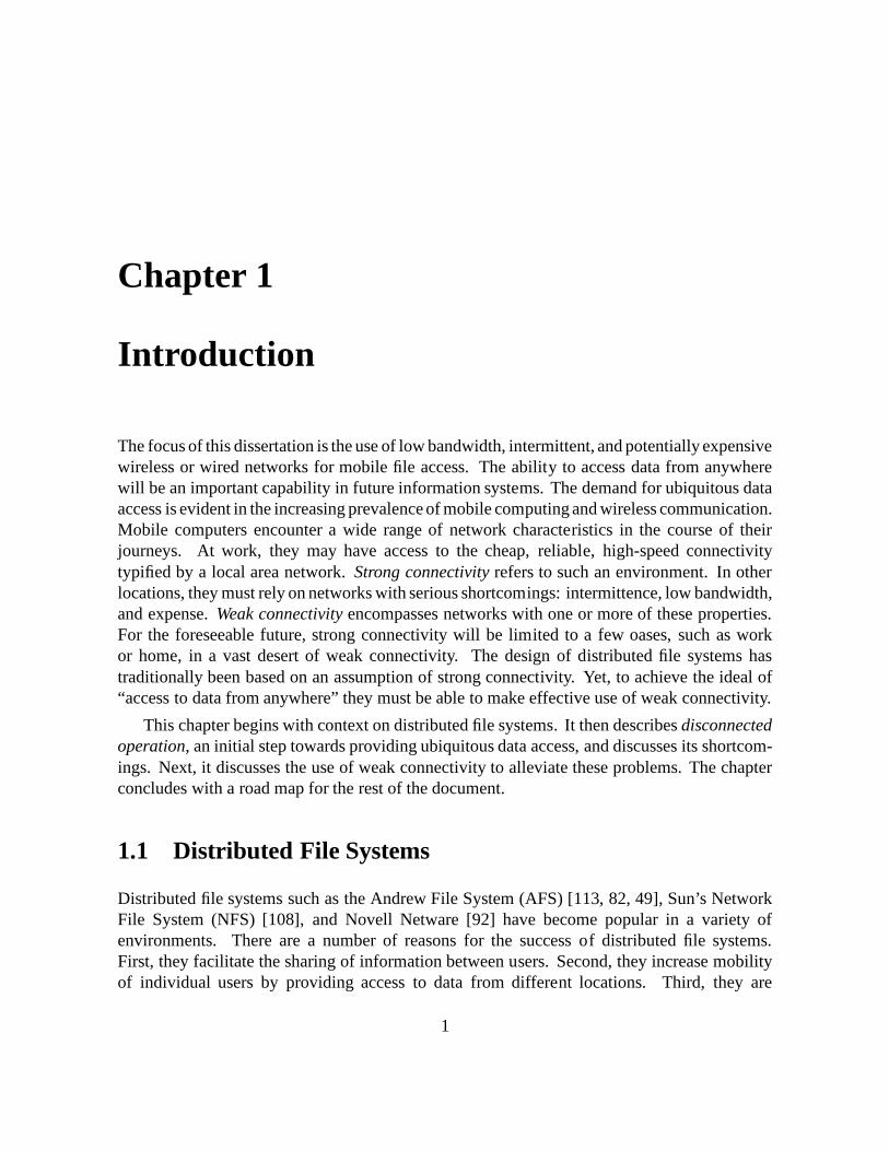
The focus of this dissertation is the use of low bandwidth, intermittent, and potentially expensivewireless or wired networks for mobile file access. The ability to access data from anywherewill be an important capability in future information systems. The demand for ubiquitous dataaccess is evident in the increasing prevalence of mobile computing and wireless communication.Mobile computers encounter a wide range of network characteristics in the course of theirjourneys. At work, they may have access to the cheap, reliable, high-speed connectivitytypified by a local area network. Strong connectivity refers to such an environment. In otherlocations, they must rely on networks with serious shortcomings: intermittence, low bandwidth,and expense. Weak connectivity encompasses networks with one or more of these properties.For the foreseeable future, strong connectivity will be limited to a few oases, such as workor home, in a vast desert of weak connectivity. The design of distributed file systems hastraditionally been based on an assumption of strong connectivity. Yet, to achieve the ideal of“access to data from anywhere” they must be able to make effective use of weak connectivity.
This chapter begins with context on distributed file systems. It then describes disconnectedoperation, an initial step towards providing ubiquitous data access, and discusses its shortcom-ings. Next, it discusses the use of weak connectivity to alleviate these problems. The chapterconcludes with a road map for the rest of the document.
1.1 Distributed File Systems
Distributed file systems such as the Andrew File System (AFS) [113, 82, 49], Sun’s NetworkFile System (NFS) [108], and Novell Netware [92] have become popular in a variety ofenvironments. There are a number of reasons for the success of distributed file systems.First, they facilitate the sharing of information between users. Second, they increase mobilityof individual users by providing access to data from different locations. Third, they are
1
2 CHAPTER 1. INTRODUCTION
extensible, allowing storage to be added as needed in a cost-effective way. Last, they simplifythe administration of large numbers of machines. Tasks such as backup and software installationand maintenance are performed by operators rather than individual users.
Most distributed file systems are organized according to the client-server model. A nucleusof servers acts as the repository for data, which clients access through a standard systeminterface. To improve performance, clients cache files or parts of files in memory, on local disk,or both. To improve availability, some file systems replicate files at multiple sites. Support forreplication varies; client access may be read-only or read-write, and updates during networkpartitions may or may not be allowed. Distributed file systems typically assume that clientsand servers are strongly connected.
1.2 Disconnected Operation
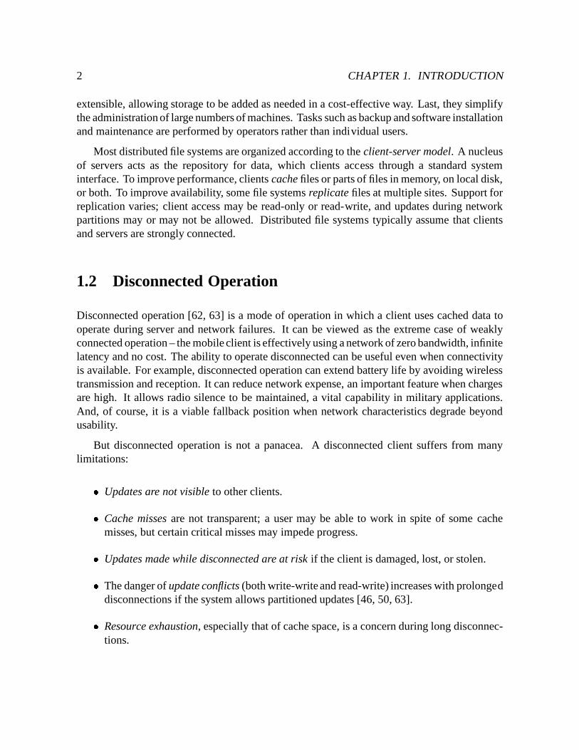
Disconnected operation [62, 63] is a mode of operation in which a client uses cached data tooperate during server and network failures. It can be viewed as the extreme case of weaklyconnected operation – the mobile client is effectively using a network of zero bandwidth, infinitelatency and no cost. The ability to operate disconnected can be useful even when connectivityis available. For example, disconnected operation can extend battery life by avoiding wirelesstransmission and reception. It can reduce network expense, an important feature when chargesare high. It allows radio silence to be maintained, a vital capability in military applications.And, of course, it is a viable fallback position when network characteristics degrade beyondusability.
But disconnected operation is not a panacea. A disconnected client suffers from manylimitations:� Updates are not visible to other clients.� Cache misses are not transparent; a user may be able to work in spite of some cache
misses, but certain critical misses may impede progress.� Updates made while disconnected are at risk if the client is damaged, lost, or stolen.� The danger of update conflicts (both write-write and read-write) increases with prolongeddisconnections if the system allows partitioned updates [46, 50, 63].� Resource exhaustion, especially that of cache space, is a concern during long disconnec-tions.
1.3. THE THESIS 3
1.3 The Thesis
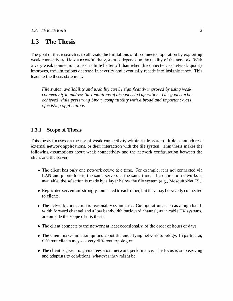
The goal of this research is to alleviate the limitations of disconnected operation by exploitingweak connectivity. How successful the system is depends on the quality of the network. Witha very weak connection, a user is little better off than when disconnected; as network qualityimproves, the limitations decrease in severity and eventually recede into insignificance. Thisleads to the thesis statement:
File system availability and usability can be significantly improved by using weakconnectivity to address the limitations of disconnected operation. This goal can beachieved while preserving binary compatibility with a broad and important classof existing applications.
1.3.1 Scope of Thesis
This thesis focuses on the use of weak connectivity within a file system. It does not addressexternal network applications, or their interaction with the file system. This thesis makes thefollowing assumptions about weak connectivity and the network configuration between theclient and the server.� The client has only one network active at a time. For example, it is not connected via
LAN and phone line to the same servers at the same time. If a choice of networks isavailable, the selection is made by a layer below the file system (e.g., MosquitoNet [7]).� Replicated servers are strongly connected to each other, but they may be weakly connectedto clients.� The network connection is reasonably symmetric. Configurations such as a high band-width forward channel and a low bandwidth backward channel, as in cable TV systems,are outside the scope of this thesis.� The client connects to the network at least occasionally, of the order of hours or days.� The client makes no assumptions about the underlying network topology. In particular,different clients may see very different topologies.� The client is given no guarantees about network performance. The focus is on observingand adapting to conditions, whatever they might be.
4 CHAPTER 1. INTRODUCTION
1.3.2 Approach
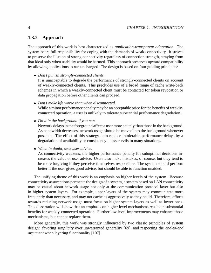
The approach of this work is best characterized as application-transparent adaptation. Thesystem bears full responsibility for coping with the demands of weak connectivity. It strivesto preserve the illusion of strong connectivity regardless of connection strength, straying fromthat ideal only when usability would be harmed. This approach preserves upward compatibilityby allowing applications to run unchanged. The design is based on four guiding principles:� Don’t punish strongly-connected clients.
It is unacceptable to degrade the performance of strongly-connected clients on accountof weakly-connected clients. This precludes use of a broad range of cache write-backschemes in which a weakly-connected client must be contacted for token revocation ordata propagation before other clients can proceed.� Don’t make life worse than when disconnected.While a minor performance penalty may be an acceptable price for the benefits of weakly-connected operation, a user is unlikely to tolerate substantial performance degradation.� Do it in the background if you can.Network delays in the foreground affect a user more acutely than those in the background.As bandwidth decreases, network usage should be moved into the background wheneverpossible. The effect of this strategy is to replace intolerable performance delays by adegradation of availability or consistency – lesser evils in many situations.� When in doubt, seek user advice.As connectivity weakens, the higher performance penalty for suboptimal decisions in-creases the value of user advice. Users also make mistakes, of course, but they tend tobe more forgiving if they perceive themselves responsible. The system should performbetter if the user gives good advice, but should be able to function unaided.
The unifying theme of this work is an emphasis on higher levels of the system. Becauseconnectivity assumptions permeate the design of a system, a system based on LAN connectivitymay be casual about network usage not only at the communication protocol layer but alsoin higher system layers. For example, upper layers of the system may communicate morefrequently than necessary, and may not cache as aggressively as they could. Therefore, effortstowards reducing network usage must focus on higher system layers as well as lower ones.This dissertation will show that an emphasis on higher level mechanisms results in substantialbenefits for weakly-connected operation. Further low level improvements may enhance thosemechanisms, but cannot replace them.
More generally, this work was strongly influenced by two classic principles of systemdesign: favoring simplicity over unwarranted generality [69], and respecting the end-to-endargument when layering functionality [107].
1.3. THE THESIS 5
1.3.3 Mechanisms for Weak Connectivity
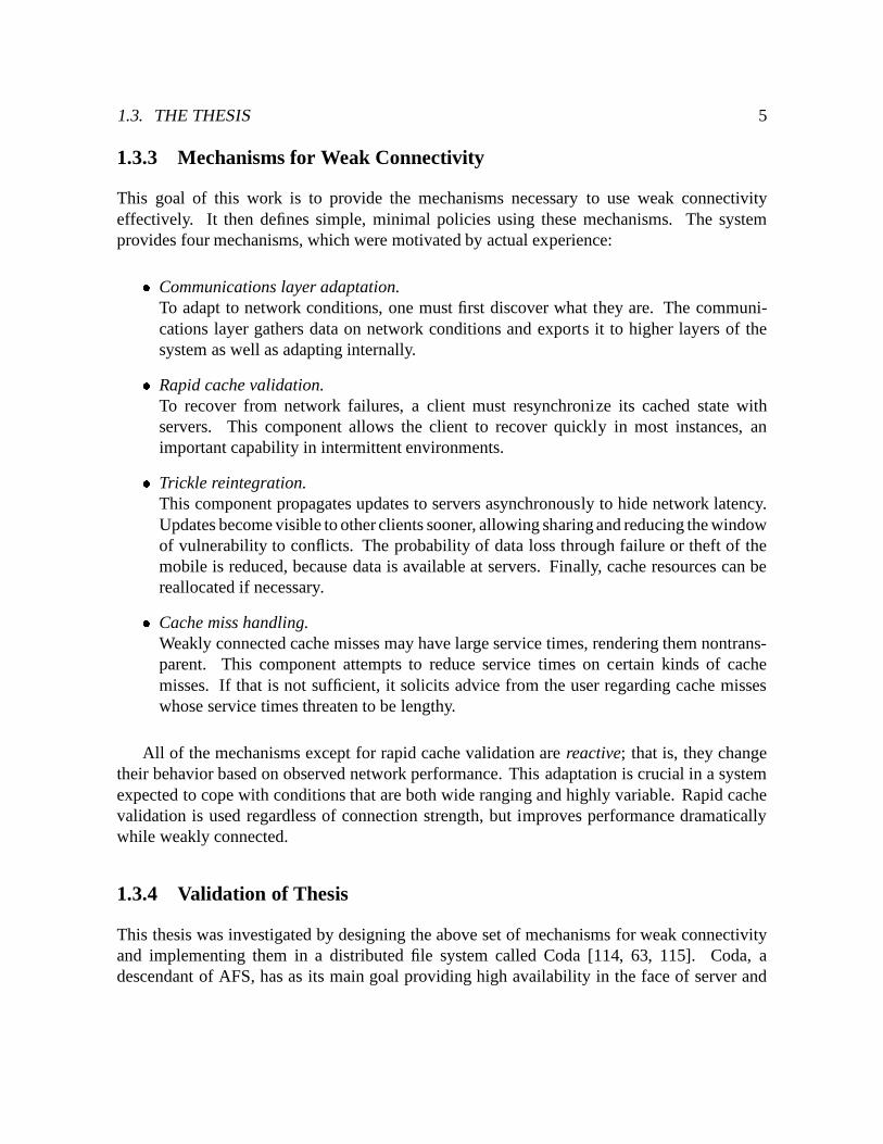
This goal of this work is to provide the mechanisms necessary to use weak connectivityeffectively. It then defines simple, minimal policies using these mechanisms. The systemprovides four mechanisms, which were motivated by actual experience:� Communications layer adaptation.
To adapt to network conditions, one must first discover what they are. The communi-cations layer gathers data on network conditions and exports it to higher layers of thesystem as well as adapting internally.� Rapid cache validation.To recover from network failures, a client must resynchronize its cached state withservers. This component allows the client to recover quickly in most instances, animportant capability in intermittent environments.� Trickle reintegration.This component propagates updates to servers asynchronously to hide network latency.Updates become visible to other clients sooner, allowing sharing and reducing the windowof vulnerability to conflicts. The probability of data loss through failure or theft of themobile is reduced, because data is available at servers. Finally, cache resources can bereallocated if necessary.� Cache miss handling.Weakly connected cache misses may have large service times, rendering them nontrans-parent. This component attempts to reduce service times on certain kinds of cachemisses. If that is not sufficient, it solicits advice from the user regarding cache misseswhose service times threaten to be lengthy.
All of the mechanisms except for rapid cache validation are reactive; that is, they changetheir behavior based on observed network performance. This adaptation is crucial in a systemexpected to cope with conditions that are both wide ranging and highly variable. Rapid cachevalidation is used regardless of connection strength, but improves performance dramaticallywhile weakly connected.
1.3.4 Validation of Thesis
This thesis was investigated by designing the above set of mechanisms for weak connectivityand implementing them in a distributed file system called Coda [114, 63, 115]. Coda, adescendant of AFS, has as its main goal providing high availability in the face of server and
6 CHAPTER 1. INTRODUCTION
network failures. Its support of disconnected operation makes it an ideal vehicle for this work.Coda has been in active use since 1991 by roughly two dozen people. An evaluation based onempirical measurements and controlled experiments provides validation of the thesis statement.
1.4 Document Roadmap
The rest of this document consists of eight chapters. Chapter 2 describes the context ofthis work, and gives a high level overview of the Coda file system. Details regarding theimplementation are deferred to Appendix B.
Chapters 3 through 6 describe the mechanisms for weak connectivity in Coda. They beginin Chapter 3 with the workings of the communications layer. This is the layer that detects andadapts to changing network conditions, and provides information on network performance tohigher layers of the system.
Chapter 4 describes a mechanism for coping with intermittent environments by providinga means for clients to recover from failures quickly. A correctness analysis of this mechanismis provided in Appendix A.
Chapters 5 and 6 describe how weakly connected clients perform updates and handle cachemisses, respectively. The mechanisms described in both chapters adapt to network conditionsbased on the information provided by the communications layer.
Chapter 7 evaluates the mechanisms for weak connectivity in Coda. It presents empiricalresults gathered from the system in actual use over the past year, and quantitative results fromcontrolled experiments.
This document concludes with a discussion of related work in Chapter 8, and summarizesthe contributions of this thesis in Chapter 9.
Chapter 2
Coda File System
This chapter describes the context of this thesis, the Coda File System. The first sectionprovides a high-level overview of Coda, its history, and design rationale. The second sectiondescribes Coda’s mechanisms for high availability at a high level. The last two sections providean overview of the implementation of Coda clients and servers. Implementation details aredeferred to Appendix B.
2.1 Design Goals
Coda is a distributed UNIX file system that strives to provide high data availability. It isa descendant of the Andrew File System (AFS) and as such inherited its design goals ofscalability, performance, security, and operability.1 Like AFS, it exports a single, shared,location-transparent name space. It also retains some of AFS’s usage assumptions. In particular,the system is intended for use in an office or research environment, where typical activitiesare software development, text editing, document preparation, electronic mail, and so on. It isspecifically not intended to support databases.
2.1.1 Scalability
Coda is divided into a small collection of servers and a much larger collection of clients. Theservers are collectively called Vice, are physically separated from clients, and are dedicatedsolely to file service. At the client, the operating system intercepts system calls on Vice objectsand directs them to a process called Venus, which communicates with Vice as necessary to
1Coda is derived from the second of three versions of AFS developed at Carnegie Mellon University. Unlessotherwise specified, the term AFS refers to this version.
7
8 CHAPTER 2. CODA FILE SYSTEM
service file system requests. To maximize the number of clients a server may support, mostof the work required for file access is performed by clients. Because of this division of labor,clients are assumed to be reasonably powerful, general purpose computers, with a low tomoderate amount of local disk storage. They are usually operated by a single user. Typicalclients are desktop workstations and notebook computers, rather than specialized devices suchas PDAs [119] or ParcTabs [128].
2.1.2 Performance
Venus makes extensive use of caching at the client. In addition to caching files, Venus alsocaches directories and symbolic links to improve the efficiency of pathname translation. Filestatus and data are cached separately. Venus caches entire files rather than file blocks, becausethere is substantial empirical evidence that most files are small and applications often accessentire files [6, 13, 39, 95]. This strategy has lower file transfer overhead per byte, and simplifiescache management considerably.
Cache coherence is maintained using callbacks. When a client caches a file from a server,the server promises to notify it if the file changes. This promise is called a callback. Theclient may use the file without further communication with the server until told otherwise. Aninvalidation message is called a callback break. If a client receives a callback break for anobject, it invalidates the cached copy and re-fetches the object when next referenced. Networkpartitions complicate matters, because a server may not be able to break a callback with a client.Until the client realizes the server is unreachable, it believes, perhaps incorrectly, that its cachedfiles are valid. To bound this window of vulnerability, clients probe servers periodically. If afailure occurs, Venus considers its cached files suspect until it validates them with the serverupon reconnection.
Venus ensures the currency of objects involved in a system call by checking that the objectis cached and has a callback. There is one exception: for open files, coherence is maintainedat the granularity of open-close sessions. Venus intercepts only open and close system calls.Reads and writes to a file are performed directly on the cached copy. If the file is written,Venus forwards the updated copy to the server only when the file is closed. Sessions reduceclient-server communication, but relax UNIX file semantics. Only processes on the same clientcan observe the results of a write before a file is closed.
Objects in the distributed file system are named with unique, low-level identifiers calledfids. Venus performs all translation from pathnames to fids; servers are ignorant of pathnames.Since pathname translation is one of the most frequently performed tasks in a file system, thistwo-level naming scheme reduces server load by shifting the burden to clients.
2.2. MECHANISMS FOR HIGH AVAILABILITY 9
2.1.3 Security
Coda and AFS prevent unauthorized release and modification of information in three ways.First, clients and servers are physically as well as logically separated, and are treated verydifferently from a security standpoint. Servers are trusted. They are located in physicallysecure areas, are accessible only to trusted operators, and run only trusted programs. Clients,on the other hand, are untrusted. They are under the control of individual users, who maymodify their hardware and software. They may be located in areas that are not physicallysecure, such as a public workstation cluster. The network connecting clients and servers isnot physically secure, and it is possible to eavesdrop on network traffic. Second, clients andservers use an authentication mechanism based on the Needham and Schroeder private keyauthentication scheme [88], and communicate using a remote procedure call package thatsupports authenticated connections and packet encryption.2 Third, access to the file system iscontrolled through access lists, which specify the access rights of users and groups of userson directories. The practical upshot of these security mechanisms is if a client is subverted,the damage is limited to only those files to which the client has access rights. Details on thesecurity mechanisms are provided by Satyanarayanan [110].
2.1.4 Operability
One of the goals of AFS and Coda is that it should be easy for a small staff to run and monitorthe system. To this end, the file name space is divided into volumes [121], each forming apartial subtree. Volumes are glued together at mount points. Venus transparently recognizesand crosses volume boundaries during pathname translation. A volume is assigned to a singledisk partition at a server; multiple volumes may reside on the same partition. Volumes maygrow or shrink in size, and may be subject to disk quotas. Volumes may be moved from serverto server; Venus uses a volume location database (VLDB) to locate the server for a volume.Read-only copies, or clones, of volumes may be created to increase availability and balanceload over a set of servers. Backups are performed by creating read-only clones of volumes andthen transferring them to backup storage. Volumes are typically created for individual users orprojects.
2.2 Mechanisms for High Availability
Coda uses two complementary mechanisms to provide resilience to server and network fail-ures. The first, server replication, involves storing copies of data at multiple servers. The
2In practice, Coda uses authenticated connections, but not packet encryption.
10 CHAPTER 2. CODA FILE SYSTEM
second, disconnected operation, allows a client to continue operating when no servers areaccessible. This section provides background on Coda’s high availability mechanisms. Thefollowing descriptions correspond to the original versions of these mechanisms as documentedby Kumar [66, 67, 68] and Kistler [62, 63]. Changes to these mechanisms made prior to thisdissertation are noted. For modifications resulting from this work, the reader is referred to theappropriate sections later in this document.
2.2.1 Server Replication
Server replication decreases the probability that data is unavailable by storing copies at multiplesites. The unit of replication is the volume, and the number and identity of the replication sitesis specified when the volume is created. The set of sites at which a volume is stored is thevolume storage group (VSG). At any time, a client may be able to contact only some VSGmembers because of server or network failures. This subset is the accessible volume storagegroup (AVSG). Different clients may have different, even non-intersecting AVSGs for the samevolume.
2.2.1.1 Optimistic Replication
Coda uses an optimistic replication scheme, allowing updates in any network partition. Thisstrategy contrasts with pessimistic replication, which restricts updates to at most one partition.Optimistic replication provides greater availability by trading off consistency between networkpartitions. That is, an object may be updated in multiple partitions, and those updates mayconflict. Therefore, a system employing optimistic replication must provide a mechanism fordetecting and coping with partitioned updates. Evidence suggests that optimistic replicationis a reasonable strategy in distributed UNIX file systems because of the low degree of write-sharing [63].
2.2.1.2 Replica Control Algorithm
The protocol for accessing the servers is best described as read-status-from-all, read-data-from-one, write-all. When Venus fetches a file from the servers, it transfers file data from only oneAVSG member, called the preferred server. However, it obtains status information from allof the replicas to verify that the object is consistent across AVSG members, and the preferredserver has the latest copy of the data. If this is not the case, servers with stale data are notifiedand the server with the latest copy is made the preferred server.
When an object is updated, Venus contacts all AVSG members. The update proceeds intwo phases. In the first phase (COP1), each server performs the update, and stamps the objects
2.2. MECHANISMS FOR HIGH AVAILABILITY 11
involved with a client-generated version stamp called a store ID. In the second phase (COP2),Venus distributes to the AVSG the list of servers who performed the update successfully, calledthe update set. Communication with servers is performed in parallel using the MultiRPCparallel remote procedure call package [117].
Callbacks are maintained at all AVSG members. Venus probes the AVSG as in the non-replicated case to detect connectivity changes. If the AVSG shrinks there is the potential for alost callback from the unavailable server. If the AVSG grows, there may be updated data fromthe newly available server. Venus considers cache entries suspect in this case until it validatesthem with the AVSG.
2.2.1.3 Conflict Detection
Coda detects write-write conflicts on files using version vectors, originally proposed for Lo-cus [97]. A version vector is a summary of the update history of an object. The length of thevector is the number of replicas (i.e., the size of the VSG) for the object. Each entry containsthe number of updates performed at the corresponding replication site. The version vector alsoincludes the store ID of the most recent update to the object. Each replica of an object has aversion vector associated with it.
When two version vectors A and B have the same values for each entry, the replicas areequal. If every entry in A is greater than or equal to the corresponding entry in B, A is saidto dominate B. In this case, the replica at A is the more recent one. If some entries in A aregreater than those in B and others are smaller, then A and B are said to be inconsistent. In thiscase, the replicas are diverging.
Venus detects conflicts lazily as it obtains the status for objects involved in a file systemrequest. When Venus obtains the status of an object, it compares the version vectors. Ifthey are not equal, Venus suspends the file system request and invokes a resolution protocolto merge the replicas automatically. If resolution completes successfully, Venus continuesservicing the request using the merged version of the object. Otherwise, Venus flags the objectas inconsistent, making it appear to the user as a dangling symbolic link. The object is renderedinaccessible until the user repairs it manually; a repair tool is provided for this purpose.
2.2.1.4 Resolution and Repair
Coda’s resolution protocol is executed between servers and consists of determining the set ofpartitioned updates, communicating that set to the AVSG, checking the resolvability of theupdates, performing the partitioned updates at relevant sites, and marking the object as eitherresolved or inconsistent. There are separate strategies for files and directories because of theirdifferent structure and update methods. Directories are structured objects with a well-defined
12 CHAPTER 2. CODA FILE SYSTEM
set of update operations known to the system. On the other hand, files are unstructured bytestreams whose update patterns are specific to an application.
Directory resolution is a four-phase protocol based on operation logging [67]. Each servermaintains a log of updates to the directory. When Venus triggers resolution, a single serveracts as coordinator for the protocol. The coordinator collects and compares the server logs todetermine the partitioned updates, and then distributes the logs to the other servers. The serversread the logs to determine which updates they missed, and then perform them as compensatingoperations.
File resolution comes in two flavors. Servers can resolve file replicas among themselves ifthere is a dominant replica. In that case, the original version of resolution sends the dominantcopy of the file to all AVSG members. The implementation has since been refined to send thedominant copy to only those AVSG members that need it. In effect, servers with stale versionsperform the compensating operation of replacing the file. This refinement is described in moredetail in Section 5.3.5. If the version vectors are inconsistent, Venus invokes an applicationspecific resolver (ASR), if supplied by the application writer, that contains enough informationabout the semantics of the file data to resolve the replicas [68].
If an object is marked inconsistent, it is inaccessible until repaired manually. Coda suppliesa repair tool that, when run at a client, exposes the replicas of the object in situ, and providescommands with which a user can resolve the object manually.
2.2.2 Disconnected Operation
Disconnected operation occurs when the AVSG becomes empty. Disconnections come in twoflavors – involuntary, which are caused by network or server failures, and voluntary, whichoccur when a user unplugs a client such as a notebook computer from the network. Venusbears the brunt of supporting disconnected operation. It has three main responsibilities. First,while connected, it must cache files that will be useful during a disconnection. Second, whiledisconnected, it must service file requests using cached data. Last, upon reconnection, it mustpropagate disconnected updates to the servers.
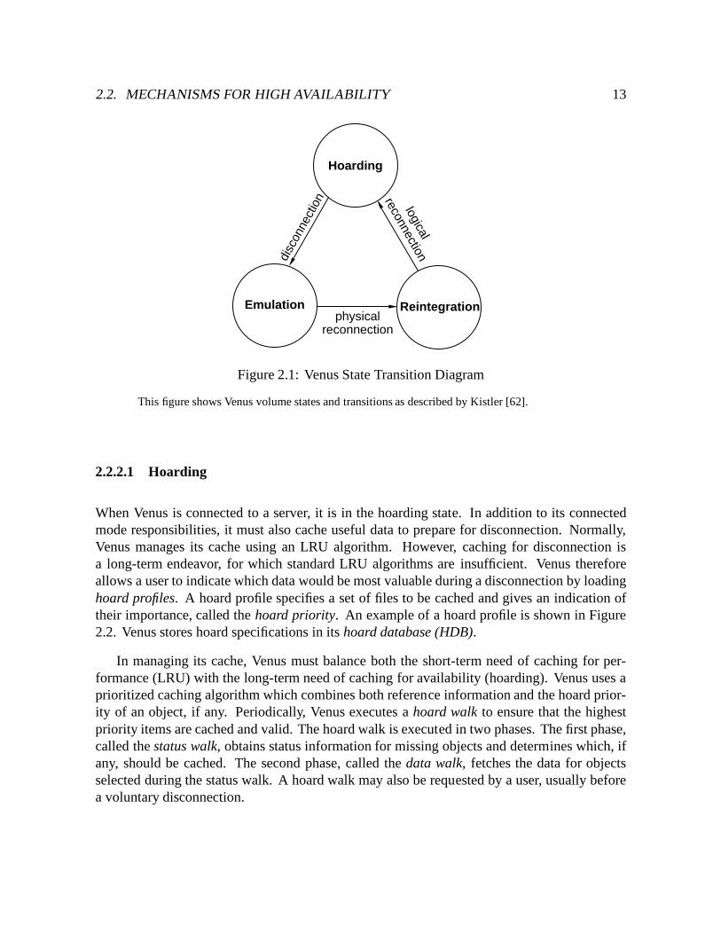
These tasks are represented as states within Venus, shown in Figure 2.1. Most of the time,Venus is in the hoarding state. In this state, it services connected mode requests with the AVSG,maintains cache coherence using callbacks, and caches useful files. When a disconnectionoccurs, Venus enters the emulating state, so named because it emulates the distributed fileservice using local resources. It services requests from its cache, and records updates performedlocally. Upon reconnection, Venus enters the transient reintegrating state, merges disconnectedupdates with servers, and then proceeds to the hoarding state. Since VSGs vary betweenvolumes, Venus may be in different states with respect to different volumes. Modifications tothis state diagram are described in Section 5.2.1.
2.2. MECHANISMS FOR HIGH AVAILABILITY 13
Hoarding
Emulation Reintegration
disc
onne
ctio
nphysical
reconnectionlogical
reconnection
Figure 2.1: Venus State Transition Diagram
This figure shows Venus volume states and transitions as described by Kistler [62].
2.2.2.1 Hoarding
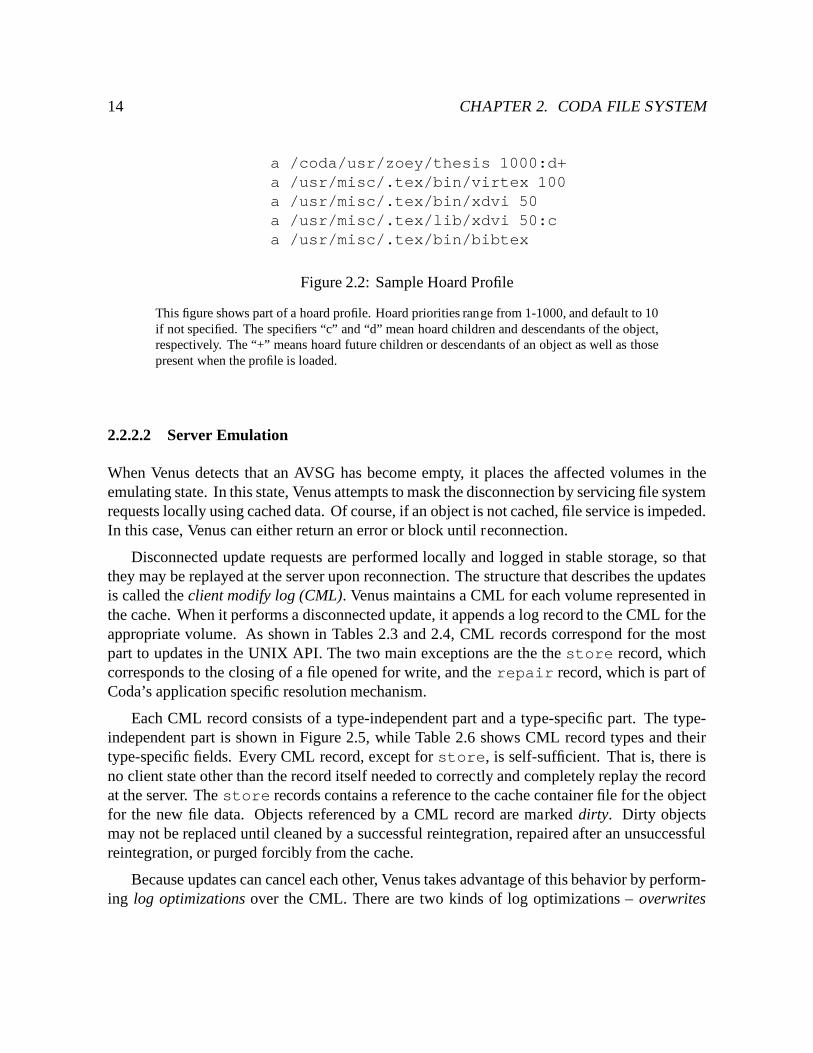
When Venus is connected to a server, it is in the hoarding state. In addition to its connectedmode responsibilities, it must also cache useful data to prepare for disconnection. Normally,Venus manages its cache using an LRU algorithm. However, caching for disconnection isa long-term endeavor, for which standard LRU algorithms are insufficient. Venus thereforeallows a user to indicate which data would be most valuable during a disconnection by loadinghoard profiles. A hoard profile specifies a set of files to be cached and gives an indication oftheir importance, called the hoard priority. An example of a hoard profile is shown in Figure2.2. Venus stores hoard specifications in its hoard database (HDB).
In managing its cache, Venus must balance both the short-term need of caching for per-formance (LRU) with the long-term need of caching for availability (hoarding). Venus uses aprioritized caching algorithm which combines both reference information and the hoard prior-ity of an object, if any. Periodically, Venus executes a hoard walk to ensure that the highestpriority items are cached and valid. The hoard walk is executed in two phases. The first phase,called the status walk, obtains status information for missing objects and determines which, ifany, should be cached. The second phase, called the data walk, fetches the data for objectsselected during the status walk. A hoard walk may also be requested by a user, usually beforea voluntary disconnection.
14 CHAPTER 2. CODA FILE SYSTEM
a /coda/usr/zoey/thesis 1000:d+a /usr/misc/.tex/bin/virtex 100a /usr/misc/.tex/bin/xdvi 50a /usr/misc/.tex/lib/xdvi 50:ca /usr/misc/.tex/bin/bibtex
Figure 2.2: Sample Hoard Profile
This figure shows part of a hoard profile. Hoard priorities range from 1-1000, and default to 10if not specified. The specifiers “c” and “d” mean hoard children and descendants of the object,respectively. The “+” means hoard future children or descendants of an object as well as thosepresent when the profile is loaded.
2.2.2.2 Server Emulation
When Venus detects that an AVSG has become empty, it places the affected volumes in theemulating state. In this state, Venus attempts to mask the disconnection by servicing file systemrequests locally using cached data. Of course, if an object is not cached, file service is impeded.In this case, Venus can either return an error or block until reconnection.
Disconnected update requests are performed locally and logged in stable storage, so thatthey may be replayed at the server upon reconnection. The structure that describes the updatesis called the client modify log (CML). Venus maintains a CML for each volume represented inthe cache. When it performs a disconnected update, it appends a log record to the CML for theappropriate volume. As shown in Tables 2.3 and 2.4, CML records correspond for the mostpart to updates in the UNIX API. The two main exceptions are the the store record, whichcorresponds to the closing of a file opened for write, and the repair record, which is part ofCoda’s application specific resolution mechanism.
Each CML record consists of a type-independent part and a type-specific part. The type-independent part is shown in Figure 2.5, while Table 2.6 shows CML record types and theirtype-specific fields. Every CML record, except for store, is self-sufficient. That is, there isno client state other than the record itself needed to correctly and completely replay the recordat the server. The store records contains a reference to the cache container file for the objectfor the new file data. Objects referenced by a CML record are marked dirty. Dirty objectsmay not be replaced until cleaned by a successful reintegration, repaired after an unsuccessfulreintegration, or purged forcibly from the cache.
Because updates can cancel each other, Venus takes advantage of this behavior by perform-ing log optimizations over the CML. There are two kinds of log optimizations – overwrites
2.2. MECHANISMS FOR HIGH AVAILABILITY 15
Operation Description
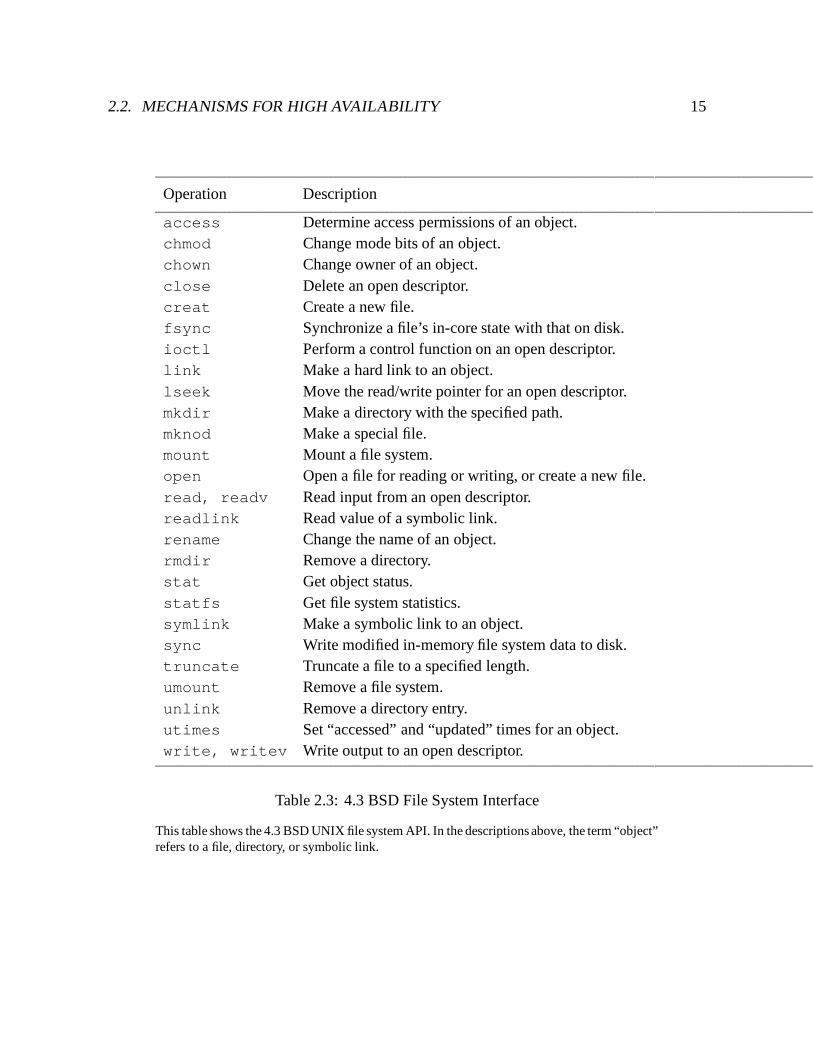
access Determine access permissions of an object.chmod Change mode bits of an object.chown Change owner of an object.close Delete an open descriptor.creat Create a new file.fsync Synchronize a file’s in-core state with that on disk.ioctl Perform a control function on an open descriptor.link Make a hard link to an object.lseek Move the read/write pointer for an open descriptor.mkdir Make a directory with the specified path.mknod Make a special file.mount Mount a file system.open Open a file for reading or writing, or create a new file.read, readv Read input from an open descriptor.readlink Read value of a symbolic link.rename Change the name of an object.rmdir Remove a directory.stat Get object status.statfs Get file system statistics.symlink Make a symbolic link to an object.sync Write modified in-memory file system data to disk.truncate Truncate a file to a specified length.umount Remove a file system.unlink Remove a directory entry.utimes Set “accessed” and “updated” times for an object.write, writev Write output to an open descriptor.
Table 2.3: 4.3 BSD File System Interface
This table shows the 4.3 BSD UNIX file system API. In the descriptions above, the term “object”refers to a file, directory, or symbolic link.
16 CHAPTER 2. CODA FILE SYSTEM
chown(object, user)chown
chmod(object, user)chmod
utimes(object, user)utimes
store(file, user)[[creat j open] [read j write]� close] j truncate
create(directory, name, file, user)creat j open
mkdir(directory1, name, directory2, user)mkdir
symlink(directory, name, symlink, user)symlink
remove(directory, name, file, user)remove(directory, name, symlink, user)
rename j unlink
rmdir(directory1, name, directory2, user)rename j rmdir
link(directory, name, file, user)link
rename(directory1, name1, directory2, name2, object, user)rename
repair(file, user)(no mapping)
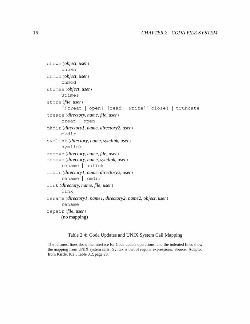
Table 2.4: Coda Updates and UNIX System Call Mapping
The leftmost lines show the interface for Coda update operations, and the indented lines showthe mapping from UNIX system calls. Syntax is that of regular expressions. Source: Adaptedfrom Kistler [62], Table 3.2, page 28.
2.2. MECHANISMS FOR HIGH AVAILABILITY 17
ClientModifyLog *log;rec_dlink handle;
ViceStoreId sid;Date_t time;UserId uid;int tid;CmlFlags flags;
< type specific fields >
dlist *fid_bindings;dlist *pred;dlist *succ;
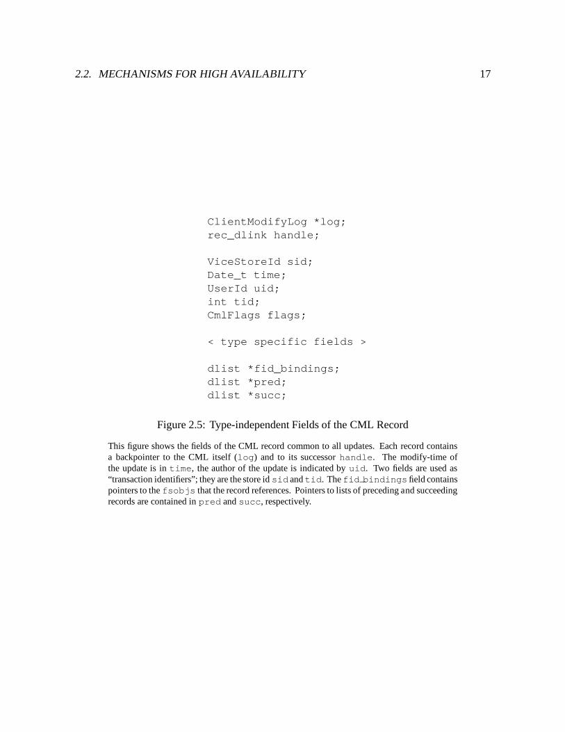
Figure 2.5: Type-independent Fields of the CML Record
This figure shows the fields of the CML record common to all updates. Each record containsa backpointer to the CML itself (log) and to its successor handle. The modify-time ofthe update is in time, the author of the update is indicated by uid. Two fields are used as“transaction identifiers”; they are the store id sid and tid. The fid bindings field containspointers to the fsobjs that the record references. Pointers to lists of preceding and succeedingrecords are contained in pred and succ, respectively.
18 CHAPTER 2. CODA FILE SYSTEM
Record Type Items recorded (with type independent fields)
chown fid, new owner, version id
chmod fid, new mode, version id
utimes fid, new modify time, version id
store fid, new length, new contents, version id, offset, server handles
create parent fid, name, child fid, mode, version id
mkdir parent fid, name, child fid, mode, parent version id
symlink parent fid, old name, new name, child fid, mode, parent version id
remove parent fid, name, child fid, link count, parent version id, child version id
rmdir parent fid, name, child fid, parent version id, child version id
link parent fid, name, child fid, parent version id, child version id
rename from parent fid, from name, to parent fid, to name, from fid, from parent versionid, to parent version id, from version id
repair fid, length, modify time, owner, mode, version id
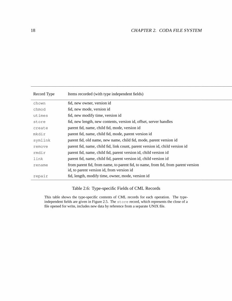
Table 2.6: Type-specific Fields of CML Records
This table shows the type-specific contents of CML records for each operation. The type-independent fields are given in Figure 2.5. The store record, which represents the close of afile opened for write, includes new data by reference from a separate UNIX file.
2.2. MECHANISMS FOR HIGH AVAILABILITY 19
Overwritten Subsequence Overwriter
[store(f, u) | utimes(f, u)]+ store(f, u)
chown(f, u) chown(f, u)
chmod(f, u) chmod(f, u)
utimes(f, u) utimes(f, u)
[store(f, u) | chown(f, u) | chmod(f, u) | utimes(f, u)]+ remove(�, �, f, u)
[chown(s, u) | chmod(s, u) | utimes(s, u)]+ remove(�, �, s, u)
[chown(d, u) | chmod(d, u) | utimes(d, u)]+ rmdir(�, �, d, u)
(a) Overwrite Optimizations
Identity Subsequence
Initiator Intermediaries Terminator
create(�, �, f, �) [ store(f, �) | chown(f, �) |chmod(f, �) | utimes(f, �) |link(�, �, f, �) |remove(�, �, f, �) |rename(�, �, �, �, f, �) ]� remove(�, �, f, �)
symlink(�, �, s, �) [ chown(s, �) | chmod(s, �) |utimes(s, �) |rename(�, �, �, �, s, �) ]� remove(�, �, s, �)
mkdir(�, �, d, �) [ chown(d, �) | chmod(d, �) |utimes(d, �) |rename(�, �, �, �, d, �) ]� rmdir(�, �, d, �)
(b) Identity Subsequence Optimizations
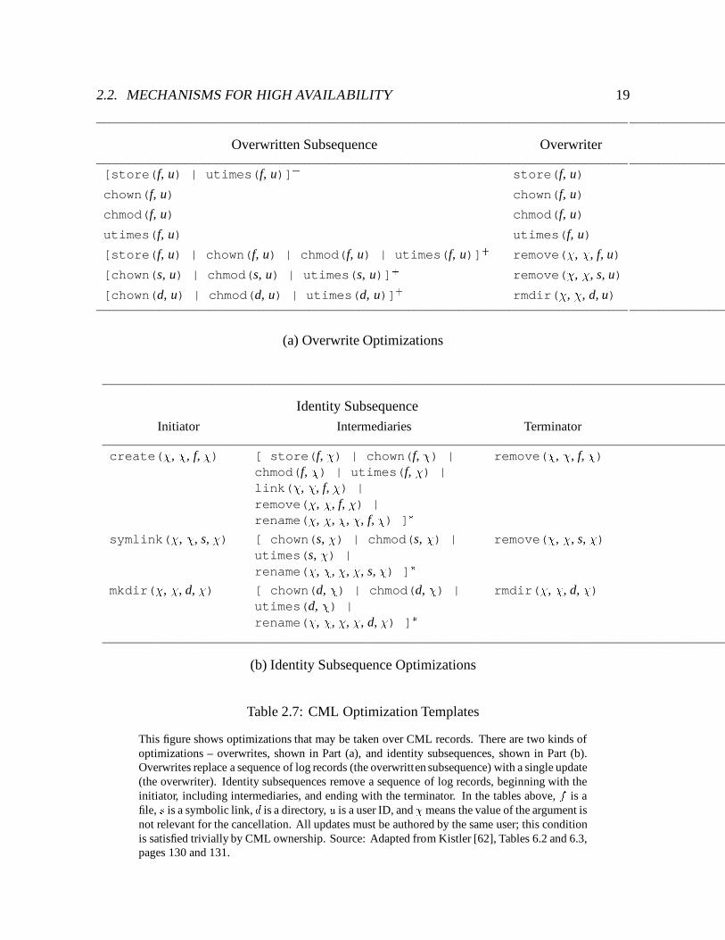
Table 2.7: CML Optimization Templates
This figure shows optimizations that may be taken over CML records. There are two kinds ofoptimizations – overwrites, shown in Part (a), and identity subsequences, shown in Part (b).Overwrites replace a sequence of log records (the overwritten subsequence) with a single update(the overwriter). Identity subsequences remove a sequence of log records, beginning with theinitiator, including intermediaries, and ending with the terminator. In the tables above, f is afile, s is a symbolic link, d is a directory, u is a user ID, and �means the value of the argument isnot relevant for the cancellation. All updates must be authored by the same user; this conditionis satisfied trivially by CML ownership. Source: Adapted from Kistler [62], Tables 6.2 and 6.3,pages 130 and 131.
20 CHAPTER 2. CODA FILE SYSTEM
and identity subsequences. In an overwrite optimization, a series of records collapses into one(e.g. repeated stores to the same file). In an identity subsequence optimization, a series ofrecords may be eliminated completely (e.g., a create of a file followed by a remove). Logoptimizations are given in Table 2.7. To simplify optimizations and reintegration, a non-emptyCML is owned by one user. Only the CML owner may perform updates in a disconnectedvolume.
Persistence of the CML is guaranteed by placing it in recoverable virtual memory usingthe RVM package [116, 75], which provides failure atomicity and permanence of recoverablevirtual memory structures. Details on the use of RVM are provided in Sectionsss:Persistence.
2.2.2.3 Reintegration
Reintegration is a transient process by which Venus transforms a volume from the emulatingstate to the hoarding state. It proceeds in three stages – the prelude, the interlude, and thepostlude. The prelude refers to activities performed by Venus in preparation for reintegration.Venus places the volume in reintegrating state when it notices the AVSG has become non-emptyand the following three conditions are met. First, a triggering event in the volume has occured,such as a reference to an object in the volume. Second, all current activity in the volume hasceased. Reintegration obtains exclusive control of the volume; new activity is blocked for theduration. Third, there are authentication tokens for the CML owner.
The remainder of the prelude consists of the following four tasks. First, Venus cancelsstore records for files open for write. This is necessary because the data associated with thestore record (i.e., the container file) may have been modified since the record was logged,and may no longer be consistent with that record. Second, Venus allocates permanent fids forobjects that have temporary fids.3 Third, Venus marshals the log records into an in-memorybuffer. Finally, the reintegrator thread sends an RPC to the server requesting reintegration.
The interlude is the processing of the reintegration request at the server. The server retrievesthe CML from the client and unmarshals the log records. It then write-locks the objects identifiedin the CML. The server then checks the soundness of each operation through a process calledcertification. The server applies different checks depending on the update and object type, assummarized in Table 2.8. If the operations are sound, the server performs them tentatively.Next the server transfers new data associated with store records. These data transfers arecalled backfetches. If all is well, the server atomically commits the changes to recoverablestorage. Otherwise, it discards the changes. In the current implementation, new data transferscan occur before reintegration. This reordering of backfetch is discussed in Section 5.3.2. Anerror in performing any part of the interlude, for any record , is sufficient cause for the server to
3If Venus runs out of pre-allocated fids while logging updates, it assigns newly-created objects temporary fids.Before reintegration, it must obtain permanent fids from the server and replace the temporary ones.
2.2. MECHANISMS FOR HIGH AVAILABILITY 21
Operation Certification
chown(o, u) o.version-id
chmod(o, u) o.version-id
utimes(o, u) o.version-id
store(f, u) f.version-id
create(d, n, f, u) d.data[n]
mkdir(d1, n, d2, u) d1.data[n]
symlink(d, n, s, u) d.data[n]
remove(d, n, f, u) d.data[n], f.version-id
remove(d, n, s, u) d.data[n], s.version-id
rmdir(d1, n, d2, u) d1.data[n]
link(d, n, f, u) d.data[n]
rename(d1, n1, d2, n2, o, u) d1.data[n1], d2.data[n2]
o.data[‘‘..’’] (if o a directory)
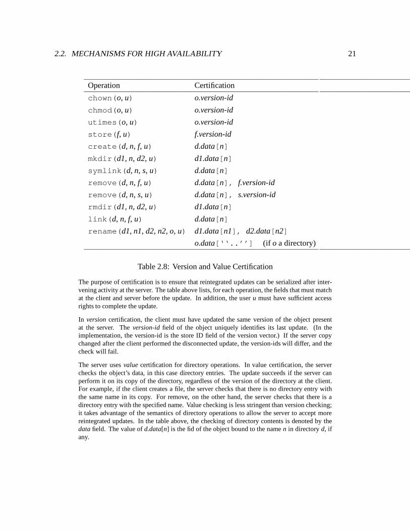
Table 2.8: Version and Value Certification
The purpose of certification is to ensure that reintegrated updates can be serialized after inter-vening activity at the server. The table above lists, for each operation, the fields that must matchat the client and server before the update. In addition, the user u must have sufficient accessrights to complete the update.
In version certification, the client must have updated the same version of the object presentat the server. The version-id field of the object uniquely identifies its last update. (In theimplementation, the version-id is the store ID field of the version vector.) If the server copychanged after the client performed the disconnected update, the version-ids will differ, and thecheck will fail.
The server uses value certification for directory operations. In value certification, the serverchecks the object’s data, in this case directory entries. The update succeeds if the server canperform it on its copy of the directory, regardless of the version of the directory at the client.For example, if the client creates a file, the server checks that there is no directory entry withthe same name in its copy. For remove, on the other hand, the server checks that there is adirectory entry with the specified name. Value checking is less stringent than version checking;it takes advantage of the semantics of directory operations to allow the server to accept morereintegrated updates. In the table above, the checking of directory contents is denoted by thedata field. The value of d.data[n] is the fid of the object bound to the name n in directory d, ifany.
22 CHAPTER 2. CODA FILE SYSTEM
reject the entire reintegration. This failure model has changed, as described later in this section.Finally, the server releases the objects, and responds to the client.
The postlude occurs back at the client. If reintegration succeeds, Venus commits the localchanges by clearing the dirty flags of the objects represented in the CML, and discarding theCML records. The behavior of Venus on failure has evolved. In the original implementation,Venus aborts the changes by spiriting the objects involved away to a local file called a closure,purging them from the cache, and discarding the CML records. Failure representation in thecurrent implementation takes a different form, described below. Commit and abort actions areperformed as single RVM transactions. Venus then changes the volume state from reintegratingto hoarding.
Several refinements were made to the original implementation to support an early version ofisolation only transactions (IOT), a mechanism for detecting read/write conflicts and encapsu-lating sequences of file system operations [73, 72]. The two main refinements are incrementalreintegration and an improved failure model. Incremental reintegration allows Venus to rein-tegrate sets of CML records pertaining to a particular transaction instead of the whole log. TheCML record includes a transaction identifier, and the prelude and postlude are parameterizedby transaction identifier.
The failure model has been improved in two ways – the grain of failure reporting, andfailure representation. The original implementation used coarse-grained failure reporting.Reintegration of a CML succeeds if and only if reintegration of each and every record succeeds.A single failure causes the entire CML to be rejected, even if the other records are independentof the offending update. The advantages of coarse-grained failure handling are simplicity andease of implementation. This approach also captures certain dependencies the system cannotcurrently detect, such as read-write dependencies (e.g., store foo, cat foo > bar).The coarse-grained model has some disadvantages as well. Bandwidth used to transfer unrelatedoperations is wasted. Users find it difficult to determine which operation caused the failure,and inconvenient to restore the changes to an entire volume. The current implementation usesfine-grained failure reporting. If a failure occurs, the server aborts the reintegration and returnsan index containing the position of the offending record. The client may then resend only thoseoperations that are likely to succeed transparently to the user.
The failure representation has changed from exiling the offending objects to a closure, tomarking them in conflict. They appear to the user in place, as dangling symbolic links, and mustbe repaired using the repair tool. The repair tool has been extended to expose and manipulatethe local copy of an object along with the server replicas. Updates corresponding to objectsrequiring local repair remain in the CML.
Reintegration has undergone further transformation as a result of this work. These changesare described in detail in Chapter 5.
2.2. MECHANISMS FOR HIGH AVAILABILITY 23
System call interface
Application
RPC2
Venus
VFS interface Socket layer
Network device to Coda serversKernel
Coda MiniCache
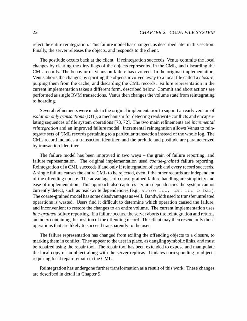
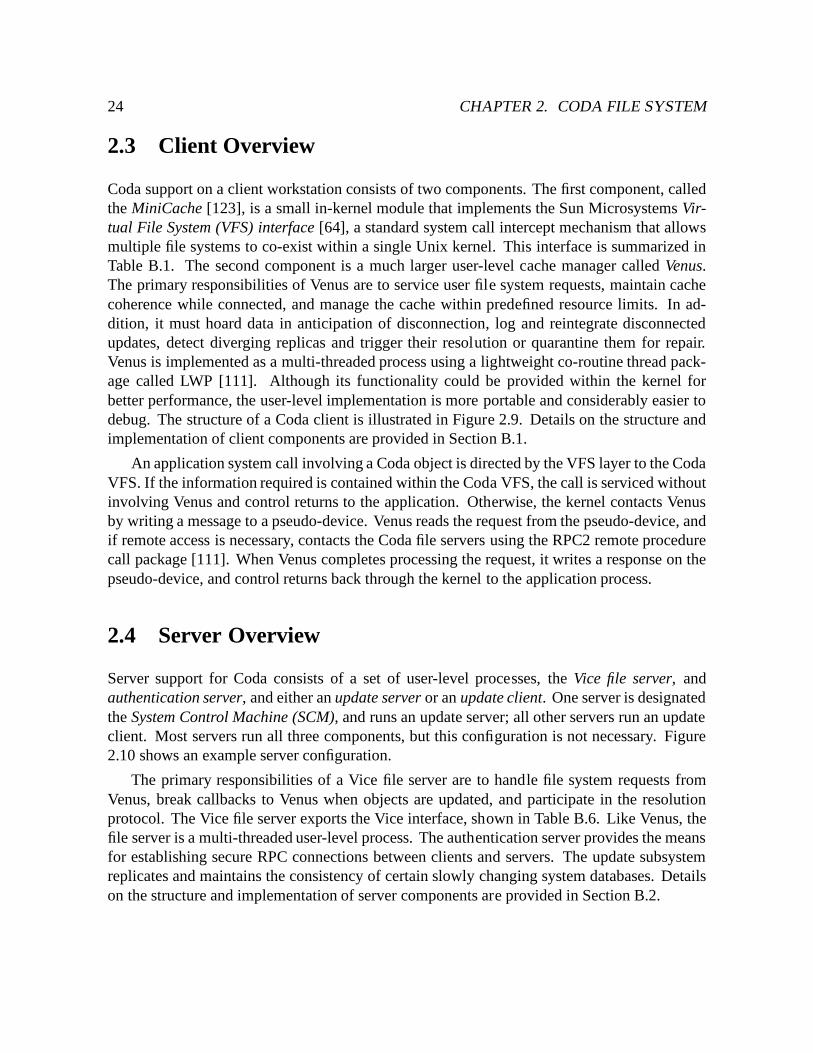
Figure 2.9: Coda Client Structure
24 CHAPTER 2. CODA FILE SYSTEM
2.3 Client Overview
Coda support on a client workstation consists of two components. The first component, calledthe MiniCache [123], is a small in-kernel module that implements the Sun Microsystems Vir-tual File System (VFS) interface [64], a standard system call intercept mechanism that allowsmultiple file systems to co-exist within a single Unix kernel. This interface is summarized inTable B.1. The second component is a much larger user-level cache manager called Venus.The primary responsibilities of Venus are to service user file system requests, maintain cachecoherence while connected, and manage the cache within predefined resource limits. In ad-dition, it must hoard data in anticipation of disconnection, log and reintegrate disconnectedupdates, detect diverging replicas and trigger their resolution or quarantine them for repair.Venus is implemented as a multi-threaded process using a lightweight co-routine thread pack-age called LWP [111]. Although its functionality could be provided within the kernel forbetter performance, the user-level implementation is more portable and considerably easier todebug. The structure of a Coda client is illustrated in Figure 2.9. Details on the structure andimplementation of client components are provided in Section B.1.
An application system call involving a Coda object is directed by the VFS layer to the CodaVFS. If the information required is contained within the Coda VFS, the call is serviced withoutinvolving Venus and control returns to the application. Otherwise, the kernel contacts Venusby writing a message to a pseudo-device. Venus reads the request from the pseudo-device, andif remote access is necessary, contacts the Coda file servers using the RPC2 remote procedurecall package [111]. When Venus completes processing the request, it writes a response on thepseudo-device, and control returns back through the kernel to the application process.
2.4 Server Overview
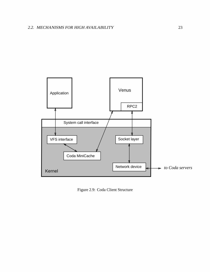
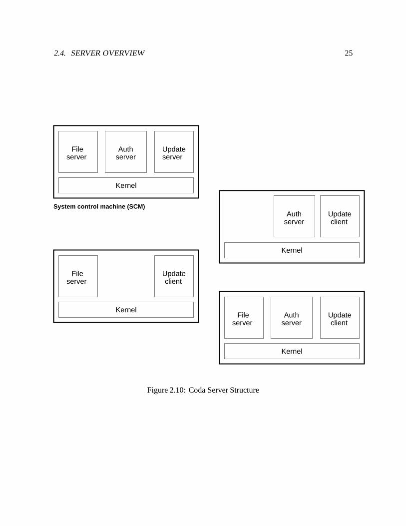
Server support for Coda consists of a set of user-level processes, the Vice file server, andauthentication server, and either an update server or an update client. One server is designatedthe System Control Machine (SCM), and runs an update server; all other servers run an updateclient. Most servers run all three components, but this configuration is not necessary. Figure2.10 shows an example server configuration.
The primary responsibilities of a Vice file server are to handle file system requests fromVenus, break callbacks to Venus when objects are updated, and participate in the resolutionprotocol. The Vice file server exports the Vice interface, shown in Table B.6. Like Venus, thefile server is a multi-threaded user-level process. The authentication server provides the meansfor establishing secure RPC connections between clients and servers. The update subsystemreplicates and maintains the consistency of certain slowly changing system databases. Detailson the structure and implementation of server components are provided in Section B.2.
2.4. SERVER OVERVIEW 25
serverFile
serverAuth Update
server
Kernel
Kernel
serverFile Update
client
Kernel
serverAuth Update
client
serverFile
serverAuth
Kernel
Updateclient
System control machine (SCM)
Figure 2.10: Coda Server Structure

26 CHAPTER 2. CODA FILE SYSTEM
Chapter 3
Communication Layer Adaptation
To adapt to changes in network conditions, a system must be able to gather information onnetwork performance, and then adjust its behavior accordingly. Adaptation can occur at manylevels of a system. For example, a transport protocol might adapt by collecting data on packetround trip times and adjusting its retransmission timeout. At a higher level, a movie playerapplication might adapt by observing network throughput and adjusting the picture quality. Anassumption underlying this adaptation at all levels is that performance in the recent past is agood predictor of performance in the near future.
The source of information on network conditions in Coda is its communications layer,consisting of transport protocols and connection management at the client and server. Thislayer gathers measurements on network transmissions between client and server which formthe basis of estimates of future network performance used by Venus to adapt its behavior. Thegoals for this measurement gathering are as follows. First, the performance impact of obtainingthe measurements should be minimal. Second, because network resources may be scarce, thecommunications layer should not perform any additional communication to gather information.Third, although Venus is the target “application” for this work, the mechanism should be generalenough to support other adaptive applications. Finally, because this communications layer ispart of an actively used production system, data gathering should be introduced in a compatibleway, with minimal design and implementation changes to existing code.
This chapter describes the Coda communications layer. It begins with a discussion of designalternatives and describes the approach taken in this work. The next two sections describe theadaptive transport protocols Coda uses. The fourth section describes how the measurementsexported to applications are collected, and how Venus derives and uses the estimates basedon these measurements. The fifth section discusses the effect of server replication on thecommunications layer. The last section explores the relationship between the communicationslayer and quality of service (QoS) support.
27
28 CHAPTER 3. COMMUNICATION LAYER ADAPTATION
3.1 Design Alternatives
Approaches for estimating network performance may be characterized by type of estimate,monitoring strategy, and placement of monitoring within the system. Estimates of networkperformance fall into two categories – static and dynamic. Static estimates are based on knowncharacteristics of a network connection. For example, an Ethernet connection is nominallyrated at 10 Mb/sec and is reasonably reliable. Static estimates may be derived from a variety ofsources, such as from hints supplied by a user or application (e.g., “I’m connecting via modemnow.”), the current network interface, or upcalls from lower layers when a mobile host changeslocation [56]. Static information allows the system to converge more rapidly to accurateestimates when discontinuities in performance occur, such as when a mobile host switchesbetween network devices or changes locations. The obvious drawback of static estimates isthey contain no information on actual network performance as observed by an application.Under pathological conditions, observed performance can deviate by orders of magnitude fromnominal performance. In addition, an estimate based on the current network interface may beonly a weak upper bound on performance, because the path to a destination may traverse anetwork segment whose characteristics are substantially worse than the segment adjacent to theclient. Indeed, this is often the case with communication between stationary and mobile hosts.
Dynamic estimates are obtained by monitoring network usage. Monitoring may be activeor passive. In active monitoring, a host generates network traffic for the sole purpose ofcollecting measurements (e.g., see [104]). Traffic may be generated periodically to keepestimates up-to-date. Active monitoring may affect or be affected by existing traffic (e.g.,probe compression [12]), particularly if connectivity is weak. The cost of measurement mayalso be significant. In passive monitoring, a host measures only existing traffic. Passivemonitoring has been used extensively on local area networks [81], where some or all trafficmay be monitored using “promiscuous mode” [125]. Estimates based on passive monitoringcan become stale if traffic is infrequent or irregular.
Where within a system should monitoring be performed? Its placement is influenced bythe kinds of measurements one wishes to make. Monitoring at lower system layers, such asat the device driver level, may yield a more accurate picture of network usage, particularly ifthere are multiple tasks competing for that resource. On the other hand, measurements taken inhigher layers may be more meaningful to applications. For example, effective throughput fora bulk transfer can be measured only at or above the transport layer, because protocol-specificknowledge is required to exclude overheads such as packet headers and retransmissions.
The communications layer of Coda uses adaptive transport protocols that export end-to-endmeasurements of network performance to applications. End-to-end measurements are the mostmeaningful in that they reflect the performance the application actually observes. Measurementsare obtained through passive monitoring, but applications may implement active monitoring by
3.2. REMOTE PROCEDURE CALL 29
generating their own traffic. Venus derives estimates based on both measurements and staticinformation to determine connectivity with respect to servers.
3.2 Remote Procedure Call
Client-server communication in Coda is performed using remote procedure call (RPC) [10].Coda uses the RPC2 remote procedure call package [111], a portable, user-level RPC packagebuilt on UDP/IP [98]. This section describes the extensions to RPC2 that enable it to cope withpoor or highly variable network performance.
3.2.1 Protocol Overview
RPC2 implements a remote procedure call service with at-most-once semantics [83]. Clientsbind to servers using a hhost; portal; subsystemi triple, where subsystem refers to a group ofrelated remote procedure calls. Once a client binds to a server and establishes a connection, itmay then send a request, which consists of an operation code and a set of parameters. The serverreplies with a return code and result parameters, if any. Only one request may be in progresson a connection at a time, but multiple connections may be established to permit concurrency.
RPC2 connections may include side effects to allow specialized network operations to beperformed. Coda uses only one side effect, SFTP, a specialized streaming protocol for efficientbulk data transfer. Side effects are initiated by the server during an RPC, and operate from adifferent portal. For extensibility reasons, the RPC and side effect implementations are isolatedfrom each other; RPC2 calls side effect routines only at certain well-defined points.
Since RPC2 is implemented using datagrams, it must provide its own reliable delivery. Inthe absence of failures, a reply serves as an acknowledgement for the request, and the nextrequest serves as an acknowledgement for the reply. To detect failures, the client specifiesa timeout period for an RPC, during which it must receive some sort of response from theserver. During an RPC, the client periodically sends a keepalive, which is a retransmission ofthe request packet. If the server receives a keepalive for a request it has already received buthas not yet serviced, it responds with a busy packet1. To cope with lost reply packets, the serverretains a copy of the most recent reply for one timeout period. If the server receives a keepalivefor the most recently serviced request, it simply retransmits its saved copy of the reply.
1Side effects do not affect the failure detection algorithm as long as the server responds to keepalives withbusy packets.
30 CHAPTER 3. COMMUNICATION LAYER ADAPTATION
3.2.2 Retransmission Strategy
Timeout and retransmission intervals are determined by two parameters: N , the number ofretransmissions, and Bt, the keepalive interval. The values for these parameters are specifiedat RPC2 initialization, and are intended to characterize the likelihood of packet loss and theamount of time the server may take in responding to requests before the client declares it down.During an RPC, the client may send up to N retransmissions of a request to a server within Btof the original request. The retransmissions B1;B2; . . . ; BN are distributed such that:B1 +B2 + � � �+BN = Bt; Bi � Bi+1 (3:1)
If the client times out on the request for the ith time, it schedules its next retransmissionfor Bi later. If the client receives a busy packet, it schedules its next retransmission for afull Bt seconds later. The client declares failure at time t after the original request, whereBt � t � 2Bt. Failure is declared at time Bt after the original request if no retransmissionprovokes a response. The worst case occurs if a failure strikes immediately after the serversends a busy packet. In this case, the client does not declare failure until 2Bt after the originalrequest.
Since different connections may observe different network performance, the retransmissionintervals Bi are maintained on a per-connection basis. They are initialized as in Equation 3.1,with Bi+1 = 2Bi, and are calculated using the algorithm shown in Figure 3.1. For example, theretransmission schedule for the RPC2 defaults of Bt = 60 and N = 6 is 0.47, 0.94, 1.89, 3.78,7.56, and 15.12 seconds, with failure declared after an additional 30.24 seconds if no responseis received from the server. These intervals are shown in Figure 3.2(a).
A lower bound is placed on the Bi to ensure retransmissions are not sent too soon afterone another. The lower bound is initialized to a minimum lower bound of 300 milliseconds2,and then adjusted upwards if necessary based on round trip time estimates [57]. Intuitively,the minimum retransmission interval B1 should be no shorter than the time to send a requestand receive a response. Whenever the round trip time estimate is changed, the retransmissionintervals are recalculated while maintaining Bt, as shown in Figure 3.2(b).
Obviously one cannot increase B1 arbitrarily and maintain both N and Bt; either N mustdecrease or Bt must increase. RPC2 decreases N rather than increasing Bt, as shown in Figure3.2(c), because lengthening the timeout would render system responsiveness unpredictable inthe presence of failures.
3.2.2.1 Obtaining Round Trip Time Observations
An estimate of the round trip time (RTT) is based on observations. RPC2 collects RTT obser-vations on pairs of request and reply packets, including packet exchanges during connection
2The lower bound of 300 milliseconds was chosen as appropriate for Ethernet.
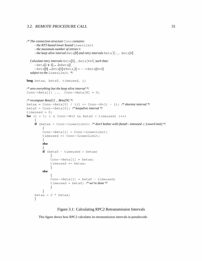
3.2. REMOTE PROCEDURE CALL 31
/* The connection structure Conn contains:- the RTT-based lower bound LowerLimit- the maximum number of retries N- the keep alive interval Beta[0] and retry intervals Beta[1] . . . Beta[N]
Calculate retry intervals Beta[1] . . .Beta[N+1] such that:- Beta[i+ 1] = 2�Beta[i]- Beta[0] =Beta[1]+Beta[2] + � � �+Beta[N+1]
subject to the LowerLimit. */
long betax, beta0, timeused, i;
/* zero everything but the keep alive interval */Conn->Beta[1] ... Conn->Beta[N] = 0;
/* recompute Beta[1] .. Beta[N] */betax = Conn->Beta[0] / ((1 << Conn->N+1) - 1); /* shortest interval */beta0 = Conn->Beta[0]; /* keepalive interval */timeused = 0;for (i = 1; i < Conn->N+2 && beta0 > timeused; i++)f
if (betax < Conn->LowerLimit) /* don’t bother with (beta0 - timeused < LowerLimit) */fConn->Beta[i] = Conn->LowerLimit;timeused += Conn->LowerLimit;gelsefif (beta0 - timeused > betax)f
Conn->Beta[i] = betax;timeused += betax;g
else fConn->Beta[i] = beta0 - timeused;timeused = beta0; /* we’re done */gg
betax = 2 * betax;gFigure 3.1: Calculating RPC2 Retransmission Intervals
This figure shows how RPC2 calculates its retransmission intervals in pseudocode.
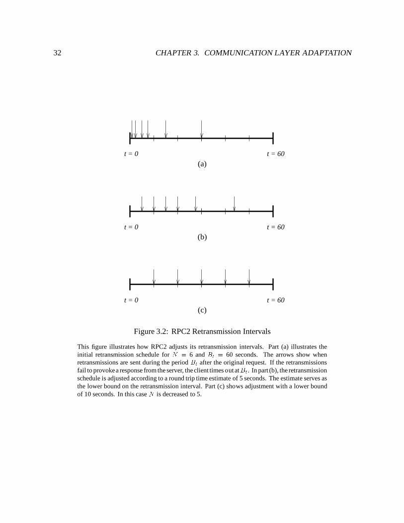
32 CHAPTER 3. COMMUNICATION LAYER ADAPTATION
t = 0 t = 60
(a)
t = 0 t = 60
(b)
t = 0 t = 60
(c)
Figure 3.2: RPC2 Retransmission Intervals
This figure illustrates how RPC2 adjusts its retransmission intervals. Part (a) illustrates theinitial retransmission schedule for N = 6 and Bt = 60 seconds. The arrows show whenretransmissions are sent during the period Bt after the original request. If the retransmissionsfail to provokea response from the server, the client times out atBt. In part (b), the retransmissionschedule is adjusted according to a round trip time estimate of 5 seconds. The estimate serves asthe lower bound on the retransmission interval. Part (c) shows adjustment with a lower boundof 10 seconds. In this case N is decreased to 5.
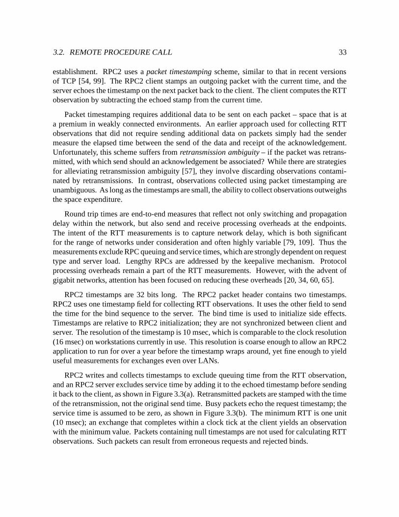
3.2. REMOTE PROCEDURE CALL 33
establishment. RPC2 uses a packet timestamping scheme, similar to that in recent versionsof TCP [54, 99]. The RPC2 client stamps an outgoing packet with the current time, and theserver echoes the timestamp on the next packet back to the client. The client computes the RTTobservation by subtracting the echoed stamp from the current time.
Packet timestamping requires additional data to be sent on each packet – space that is ata premium in weakly connected environments. An earlier approach used for collecting RTTobservations that did not require sending additional data on packets simply had the sendermeasure the elapsed time between the send of the data and receipt of the acknowledgement.Unfortunately, this scheme suffers from retransmission ambiguity – if the packet was retrans-mitted, with which send should an acknowledgement be associated? While there are strategiesfor alleviating retransmission ambiguity [57], they involve discarding observations contami-nated by retransmissions. In contrast, observations collected using packet timestamping areunambiguous. As long as the timestamps are small, the ability to collect observations outweighsthe space expenditure.
Round trip times are end-to-end measures that reflect not only switching and propagationdelay within the network, but also send and receive processing overheads at the endpoints.The intent of the RTT measurements is to capture network delay, which is both significantfor the range of networks under consideration and often highly variable [79, 109]. Thus themeasurements exclude RPC queuing and service times, which are strongly dependent on requesttype and server load. Lengthy RPCs are addressed by the keepalive mechanism. Protocolprocessing overheads remain a part of the RTT measurements. However, with the advent ofgigabit networks, attention has been focused on reducing these overheads [20, 34, 60, 65].
RPC2 timestamps are 32 bits long. The RPC2 packet header contains two timestamps.RPC2 uses one timestamp field for collecting RTT observations. It uses the other field to sendthe time for the bind sequence to the server. The bind time is used to initialize side effects.Timestamps are relative to RPC2 initialization; they are not synchronized between client andserver. The resolution of the timestamp is 10 msec, which is comparable to the clock resolution(16 msec) on workstations currently in use. This resolution is coarse enough to allow an RPC2application to run for over a year before the timestamp wraps around, yet fine enough to yielduseful measurements for exchanges even over LANs.
RPC2 writes and collects timestamps to exclude queuing time from the RTT observation,and an RPC2 server excludes service time by adding it to the echoed timestamp before sendingit back to the client, as shown in Figure 3.3(a). Retransmitted packets are stamped with the timeof the retransmission, not the original send time. Busy packets echo the request timestamp; theservice time is assumed to be zero, as shown in Figure 3.3(b). The minimum RTT is one unit(10 msec); an exchange that completes within a clock tick at the client yields an observationwith the minimum value. Packets containing null timestamps are not used for calculating RTTobservations. Such packets can result from erroneous requests and rejected binds.
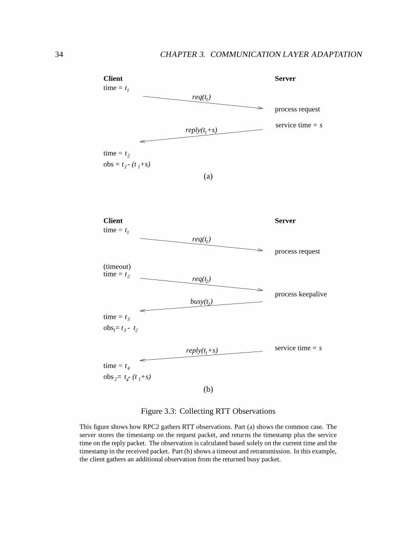
34 CHAPTER 3. COMMUNICATION LAYER ADAPTATION
t2time =
t1time =
1req(t )
reply(t +s)1
2t - (t +s)1
Client Server
process request
service time = s
obs =
(a)
t1time =
t2time =
obs = t2
time = t3
t3
sservice time =
1req(t )
2req(t )
busy(t )2
reply(t +s)1
Client
(timeout)
time = t4
- 1
Server
process request
obs = t - (t +s)2 4 1
process keepalive
(b)
Figure 3.3: Collecting RTT Observations
This figure shows how RPC2 gathers RTT observations. Part (a) shows the common case. Theserver stores the timestamp on the request packet, and returns the timestamp plus the servicetime on the reply packet. The observation is calculated based solely on the current time and thetimestamp in the received packet. Part (b) shows a timeout and retransmission. In this example,the client gathers an additional observation from the returned busy packet.
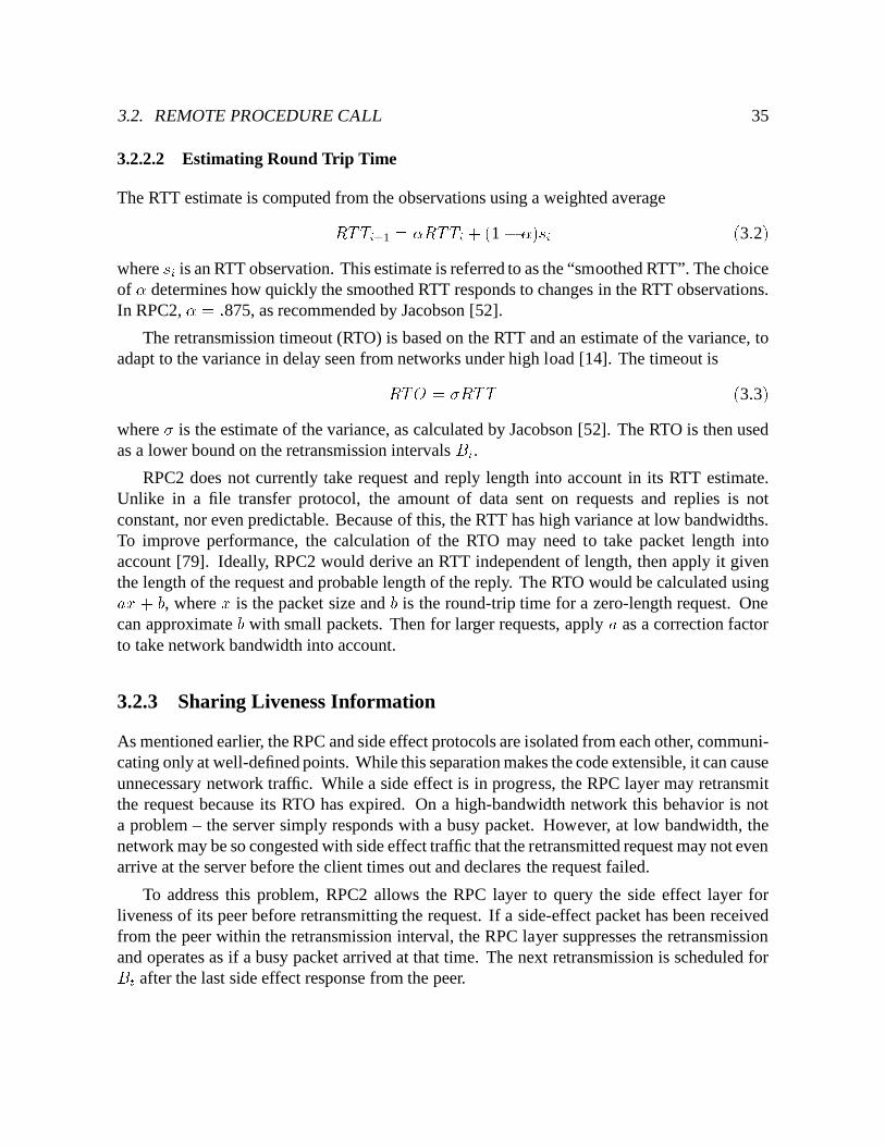
3.2. REMOTE PROCEDURE CALL 35
3.2.2.2 Estimating Round Trip Time
The RTT estimate is computed from the observations using a weighted averageRTTi+1 = �RTTi + (1 � �)si (3:2)where si is an RTT observation. This estimate is referred to as the “smoothed RTT”. The choiceof � determines how quickly the smoothed RTT responds to changes in the RTT observations.In RPC2, � = :875, as recommended by Jacobson [52].
The retransmission timeout (RTO) is based on the RTT and an estimate of the variance, toadapt to the variance in delay seen from networks under high load [14]. The timeout isRTO = �RTT (3:3)where � is the estimate of the variance, as calculated by Jacobson [52]. The RTO is then usedas a lower bound on the retransmission intervals Bi.
RPC2 does not currently take request and reply length into account in its RTT estimate.Unlike in a file transfer protocol, the amount of data sent on requests and replies is notconstant, nor even predictable. Because of this, the RTT has high variance at low bandwidths.To improve performance, the calculation of the RTO may need to take packet length intoaccount [79]. Ideally, RPC2 would derive an RTT independent of length, then apply it giventhe length of the request and probable length of the reply. The RTO would be calculated usingax + b, where x is the packet size and b is the round-trip time for a zero-length request. Onecan approximate b with small packets. Then for larger requests, apply a as a correction factorto take network bandwidth into account.
3.2.3 Sharing Liveness Information
As mentioned earlier, the RPC and side effect protocols are isolated from each other, communi-cating only at well-defined points. While this separation makes the code extensible, it can causeunnecessary network traffic. While a side effect is in progress, the RPC layer may retransmitthe request because its RTO has expired. On a high-bandwidth network this behavior is nota problem – the server simply responds with a busy packet. However, at low bandwidth, thenetwork may be so congested with side effect traffic that the retransmitted request may not evenarrive at the server before the client times out and declares the request failed.
To address this problem, RPC2 allows the RPC layer to query the side effect layer forliveness of its peer before retransmitting the request. If a side-effect packet has been receivedfrom the peer within the retransmission interval, the RPC layer suppresses the retransmissionand operates as if a busy packet arrived at that time. The next retransmission is scheduled forBt after the last side effect response from the peer.
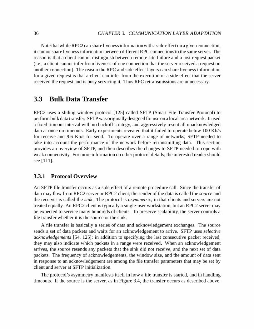
36 CHAPTER 3. COMMUNICATION LAYER ADAPTATION
Note that while RPC2 can share liveness informationwith a side effect on a given connection,it cannot share liveness information between different RPC connections to the same server. Thereason is that a client cannot distinguish between remote site failure and a lost request packet(i.e., a client cannot infer from liveness of one connection that the server received a request onanother connection). The reason the RPC and side effect layers can share liveness informationfor a given request is that a client can infer from the execution of a side effect that the serverreceived the request and is busy servicing it. Thus RPC retransmissions are unnecessary.
3.3 Bulk Data Transfer
RPC2 uses a sliding window protocol [125] called SFTP (Smart File Transfer Protocol) toperform bulk data transfer. SFTP was originally designed for use on a local area network. It useda fixed timeout interval with no backoff strategy, and aggressively resent all unacknowledgeddata at once on timeouts. Early experiments revealed that it failed to operate below 100 Kb/sfor receive and 9.6 Kb/s for send. To operate over a range of networks, SFTP needed totake into account the performance of the network before retransmitting data. This sectionprovides an overview of SFTP, and then describes the changes to SFTP needed to cope withweak connectivity. For more information on other protocol details, the interested reader shouldsee [111].
3.3.1 Protocol Overview
An SFTP file transfer occurs as a side effect of a remote procedure call. Since the transfer ofdata may flow from RPC2 server or RPC2 client, the sender of the data is called the source andthe receiver is called the sink. The protocol is asymmetric, in that clients and servers are nottreated equally. An RPC2 client is typically a single-user workstation, but an RPC2 server maybe expected to service many hundreds of clients. To preserve scalability, the server controls afile transfer whether it is the source or the sink.
A file transfer is basically a series of data and acknowledgement exchanges. The sourcesends a set of data packets and waits for an acknowledgement to arrive. SFTP uses selectiveacknowledgements [54, 125]; in addition to specifying the last consecutive packet received,they may also indicate which packets in a range were received. When an acknowledgementarrives, the source resends any packets that the sink did not receive, and the next set of datapackets. The frequency of acknowledgements, the window size, and the amount of data sentin response to an acknowledgement are among the file transfer parameters that may be set byclient and server at SFTP initialization.
The protocol’s asymmetry manifests itself in how a file transfer is started, and in handlingtimeouts. If the source is the server, as in Figure 3.4, the transfer occurs as described above.
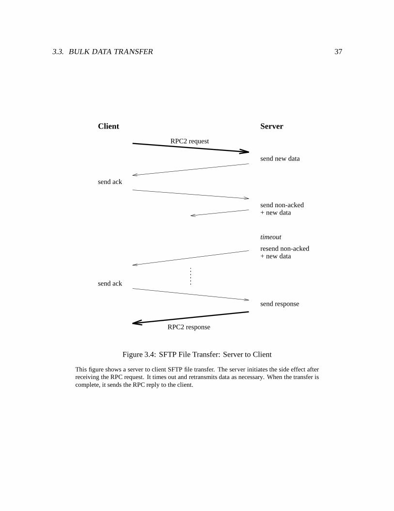
3.3. BULK DATA TRANSFER 37
Client Server
RPC2 request
send new data
send ack
send non-acked+ new data
resend non-acked+ new data
timeout
send response
RPC2 response
send ack
Figure 3.4: SFTP File Transfer: Server to Client
This figure shows a server to client SFTP file transfer. The server initiates the side effect afterreceiving the RPC request. It times out and retransmits data as necessary. When the transfer iscomplete, it sends the RPC reply to the client.
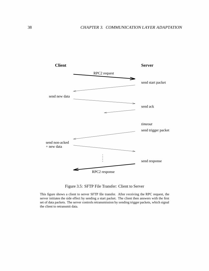
38 CHAPTER 3. COMMUNICATION LAYER ADAPTATION
Client Server
RPC2 request
timeout
RPC2 response
send start packet
send new data
send non-acked
send ack
send trigger packet
+ new data
send response
Figure 3.5: SFTP File Transfer: Client to Server
This figure shows a client to server SFTP file transfer. After receiving the RPC request, theserver initiates the side effect by sending a start packet. The client then answers with the firstset of data packets. The server controls retransmission by sending trigger packets, which signalthe client to retransmit data.
3.3. BULK DATA TRANSFER 39
If an acknowledgement does not arrive before a certain period has passed, the server times outand retransmits its packets. If the source is the client, as in Figure 3.5, data transfer begins onlywhen the client receives a start packet from the server. After sending data, the client passivelywaits for an acknowledgement. It does not retransmit data upon timeout. Instead, the servertimes out and sends a trigger packet, which is a copy of the last acknowledgement.
3.3.2 Obtaining RTT Observations
Like RPC2, SFTP collects RTT observations using packet timestamps. The timestamps andstorage of RTT state is the same as presented in Section 3.2.2. The use of packet timestampsin SFTP to gather RTT observations at the source is similar to that of TCP [54]. However,because of the asymmetry of SFTP, the sink also gathers RTT observations. If the sink is anRPC2 server, it may control the transfer even though it does not send data. Thus it must alsogather RTT observations and derive its own RTO.
In SFTP, timestamping is two-way, allowing both source and sink to collect RTT observa-tions during a transfer. The packet header contains two timestamps: the current timestamp,which is the time at which the packet was sent; and the echoed timestamp, which was generatedby and returned to the receiver. Both the source and the sink keep an additional word of stateto hold the timestamp that will be echoed next. Packets with null timestamps are not usedfor RTT observations. Retransmitted packets are stamped with the time of the retransmission,not the original send time. Packets retransmitted upon timeout echo null timestamps. Thesepackets are sent by the server, and can be data (if server = source) or triggers (if server = sink).These packets do not represent real observations because they are generated spontaneously, notin response to a transmission from the client.
The measurements collected by source and sink are not equivalent, and only the sink mea-sures what could be considered a true packet round trip time. The purpose of the measurementsis to determine when to retransmit. Thus, the measurement of interest for the sink is the timefor a start, acknowledgement, or trigger packet to be sent and a data packet received fromthe source. As shown in Figure 3.6, the source echoes the timestamp on data packets sent tothe sink, and marks the first packet it sends in response to an acknowledgement. (The sourcemust mark this packet because it is not necessarily the first packet in the receive window at thesink.) The sink computes the RTT based on the echoed timestamp in the marked packet. If themarked packet is lost, the sink may be able to calculate an RTT based on its retransmission. Ifthe marked packet is delayed, the RTT will reflect the delay.
The measurement of interest for the source is the time for a set of data packets to be sentand an acknowledgement received. The source timestamps each data packet in the set. Thesink retains and echoes the timestamp from the earliest unacknowledged packet, which is the
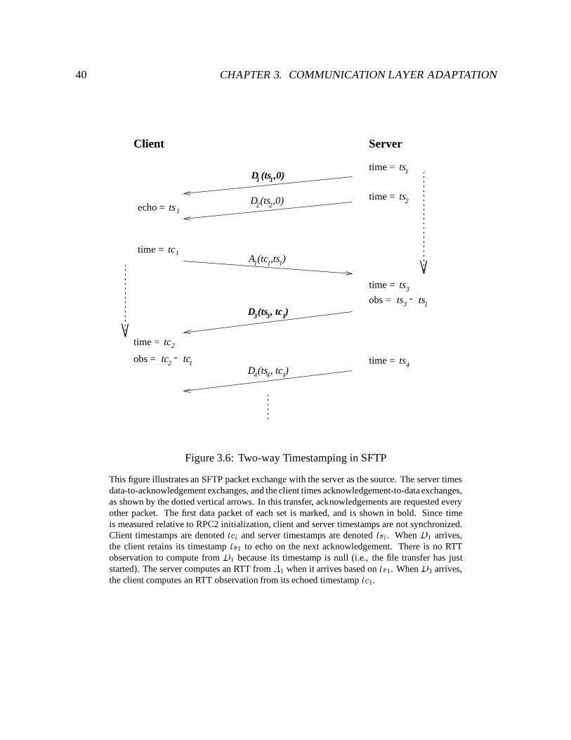
40 CHAPTER 3. COMMUNICATION LAYER ADAPTATION
11A (tc ,ts )1
ts1time =
time = ts2D (ts ,0)2 2
ts1ts3obs = -ts3time =
time = tc2
2tc 1tcobs = - ts4time = D (ts , tc )14 4
tc1time =
D (ts ,0)11
D (ts , tc )3 3 1
1ts
Client Server
echo =
Figure 3.6: Two-way Timestamping in SFTP
This figure illustrates an SFTP packet exchange with the server as the source. The server timesdata-to-acknowledgement exchanges, and the client times acknowledgement-to-data exchanges,as shown by the dotted vertical arrows. In this transfer, acknowledgements are requested everyother packet. The first data packet of each set is marked, and is shown in bold. Since timeis measured relative to RPC2 initialization, client and server timestamps are not synchronized.Client timestamps are denoted tci and server timestamps are denoted tsi. When D1 arrives,the client retains its timestamp ts1 to echo on the next acknowledgement. There is no RTTobservation to compute from D1 because its timestamp is null (i.e., the file transfer has juststarted). The server computes an RTT from A1 when it arrives based on ts1. When D3 arrives,the client computes an RTT observation from its echoed timestamp tc1.
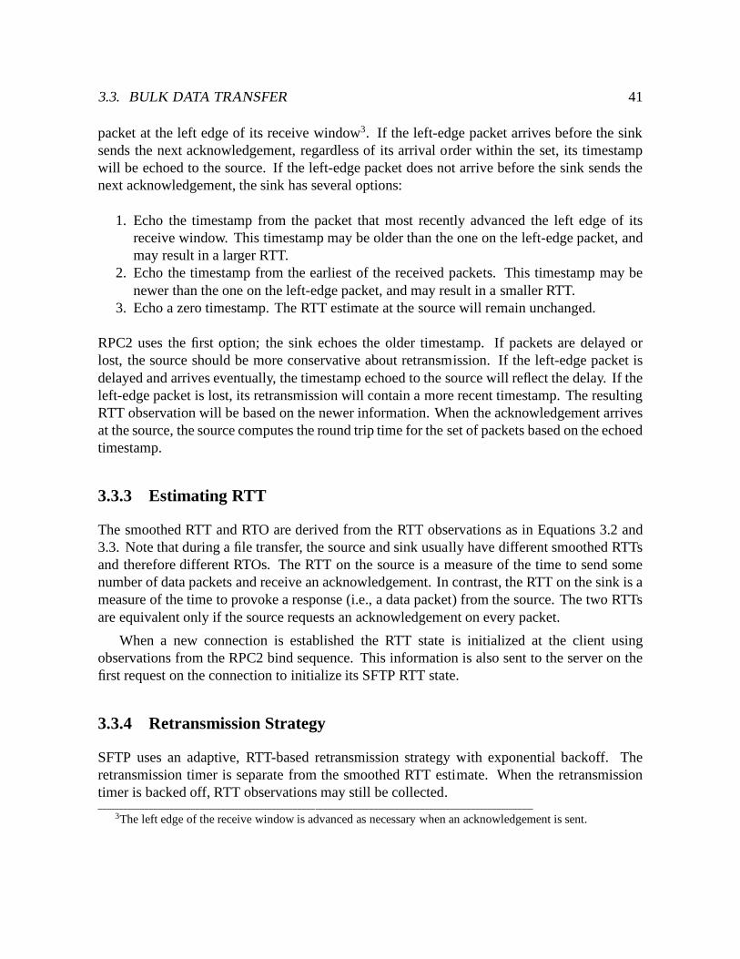
3.3. BULK DATA TRANSFER 41
packet at the left edge of its receive window3. If the left-edge packet arrives before the sinksends the next acknowledgement, regardless of its arrival order within the set, its timestampwill be echoed to the source. If the left-edge packet does not arrive before the sink sends thenext acknowledgement, the sink has several options:
1. Echo the timestamp from the packet that most recently advanced the left edge of itsreceive window. This timestamp may be older than the one on the left-edge packet, andmay result in a larger RTT.
2. Echo the timestamp from the earliest of the received packets. This timestamp may benewer than the one on the left-edge packet, and may result in a smaller RTT.
3. Echo a zero timestamp. The RTT estimate at the source will remain unchanged.
RPC2 uses the first option; the sink echoes the older timestamp. If packets are delayed orlost, the source should be more conservative about retransmission. If the left-edge packet isdelayed and arrives eventually, the timestamp echoed to the source will reflect the delay. If theleft-edge packet is lost, its retransmission will contain a more recent timestamp. The resultingRTT observation will be based on the newer information. When the acknowledgement arrivesat the source, the source computes the round trip time for the set of packets based on the echoedtimestamp.
3.3.3 Estimating RTT
The smoothed RTT and RTO are derived from the RTT observations as in Equations 3.2 and3.3. Note that during a file transfer, the source and sink usually have different smoothed RTTsand therefore different RTOs. The RTT on the source is a measure of the time to send somenumber of data packets and receive an acknowledgement. In contrast, the RTT on the sink is ameasure of the time to provoke a response (i.e., a data packet) from the source. The two RTTsare equivalent only if the source requests an acknowledgement on every packet.
When a new connection is established the RTT state is initialized at the client usingobservations from the RPC2 bind sequence. This information is also sent to the server on thefirst request on the connection to initialize its SFTP RTT state.
3.3.4 Retransmission Strategy
SFTP uses an adaptive, RTT-based retransmission strategy with exponential backoff. Theretransmission timer is separate from the smoothed RTT estimate. When the retransmissiontimer is backed off, RTT observations may still be collected.
3The left edge of the receive window is advanced as necessary when an acknowledgement is sent.
42 CHAPTER 3. COMMUNICATION LAYER ADAPTATION
window
in-transit need-ack worried
Figure 3.7: SFTP Packet Sets
This figure illustrates SFTP packet sets for a window of ten packets, where acknowledgementsare requested every four packets. Packets on the left were sent most recently. Packets for whichan acknowledgement has been requested but not received and the RTO has expired are in theworried set. Only these packets are retransmitted. Packets for which an acknowledgement hasbeen requested but not received and the RTO has not yet expired are in the need-ack set. Packetsfor which an ack has not yet been requested are in the in-transit set.
In the original version of SFTP, the retransmission strategy was as follows: data packetssent by the source and for which an acknowledgement had been requested but not receivedwere placed in a worried set. If the source was an RPC2 server, all of the packets in the worriedset would be resent upon timeout, followed by the next set of data packets. If the source was anRPC2 client, the packets above would be sent upon receipt of a trigger. If the window becamefull, only the first packet in the worried set was sent.
The problem with this strategy for slow networks is that a source becomes worried about apacket the instant it is sent. The key change to this strategy is to delay worrying about a packetuntil after at least a round trip time interval. The worried set is now partitioned into two sets –the need-ack set and the worried set, as illustrated in Figure 3.7. Packets in the need-ack sethave been sent and an acknowledgement has been requested, but not enough time has passed tobe worried about the fact that an acknowledgement has not been received. Packets are movedto the worried set when the RTO expires. Only packets in the worried set are retransmitted.
3.4 Exporting Network Information
How should RPC2 convey information on network performance to higher levels of the system?Different applications may use the information in different ways. For example, they may differin how they average the observations, how recent the observations should be, and how manysamples are taken during any one interval. The form of the information should be flexible
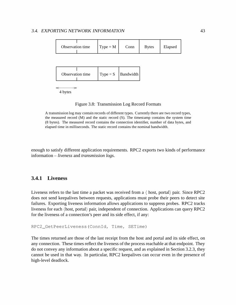
3.4. EXPORTING NETWORK INFORMATION 43
ConnObservation time Bytes ElapsedType = M
Observation time BandwidthType = S
4 bytes
Figure 3.8: Transmission Log Record Formats
A transmission log may contain records of different types. Currently there are two record types,the measured record (M) and the static record (S). The timestamp contains the system time(8 bytes). The measured record contains the connection identifier, number of data bytes, andelapsed time in milliseconds. The static record contains the nominal bandwidth.
enough to satisfy different application requirements. RPC2 exports two kinds of performanceinformation – liveness and transmission logs.
3.4.1 Liveness
Liveness refers to the last time a packet was received from a h host, portali pair. Since RPC2does not send keepalives between requests, applications must probe their peers to detect sitefailures. Exporting liveness information allows applications to suppress probes. RPC2 tracksliveness for each hhost, portali pair, independent of connection. Applications can query RPC2for the liveness of a connection’s peer and its side effect, if any:
RPC2_GetPeerLiveness(ConnId, Time, SETime)
The times returned are those of the last receipt from the host and portal and its side effect, onany connection. These times reflect the liveness of the process reachable at that endpoint. Theydo not convey any information about a specific request, and as explained in Section 3.2.3, theycannot be used in that way. In particular, RPC2 keepalives can occur even in the presence ofhigh-level deadlock.
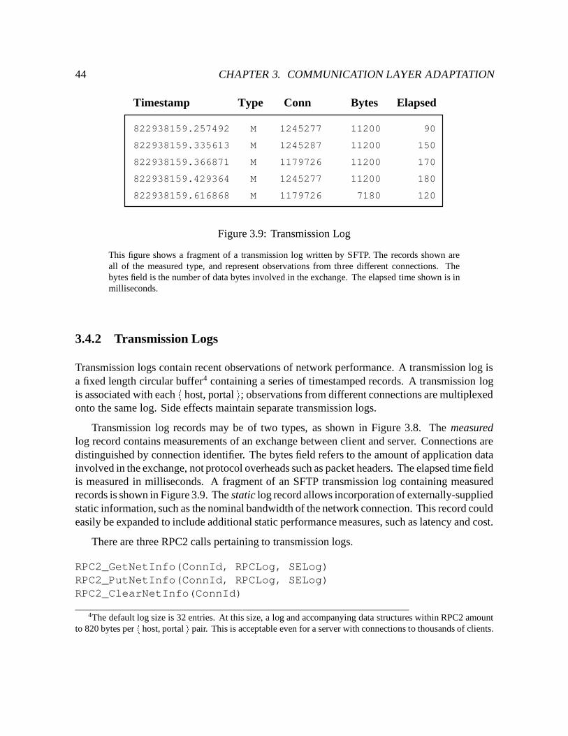
44 CHAPTER 3. COMMUNICATION LAYER ADAPTATION
Elapsed
150
170
180
120
Bytes
11200
11200
11200
11200
1245287
1179726
1245277
1179726
Conn
90
7180
1245277
Type
M
M
M
M
M
822938159.257492
822938159.335613
822938159.366871
822938159.429364
822938159.616868
Timestamp
Figure 3.9: Transmission Log
This figure shows a fragment of a transmission log written by SFTP. The records shown areall of the measured type, and represent observations from three different connections. Thebytes field is the number of data bytes involved in the exchange. The elapsed time shown is inmilliseconds.
3.4.2 Transmission Logs
Transmission logs contain recent observations of network performance. A transmission log isa fixed length circular buffer4 containing a series of timestamped records. A transmission logis associated with each h host, portal i; observations from different connections are multiplexedonto the same log. Side effects maintain separate transmission logs.
Transmission log records may be of two types, as shown in Figure 3.8. The measuredlog record contains measurements of an exchange between client and server. Connections aredistinguished by connection identifier. The bytes field refers to the amount of application datainvolved in the exchange, not protocol overheads such as packet headers. The elapsed time fieldis measured in milliseconds. A fragment of an SFTP transmission log containing measuredrecords is shown in Figure 3.9. The static log record allows incorporation of externally-suppliedstatic information, such as the nominal bandwidth of the network connection. This record couldeasily be expanded to include additional static performance measures, such as latency and cost.
There are three RPC2 calls pertaining to transmission logs.
RPC2_GetNetInfo(ConnId, RPCLog, SELog)RPC2_PutNetInfo(ConnId, RPCLog, SELog)RPC2_ClearNetInfo(ConnId)
4The default log size is 32 entries. At this size, a log and accompanying data structures within RPC2 amountto 820 bytes per h host, portal i pair. This is acceptable even for a server with connections to thousands of clients.
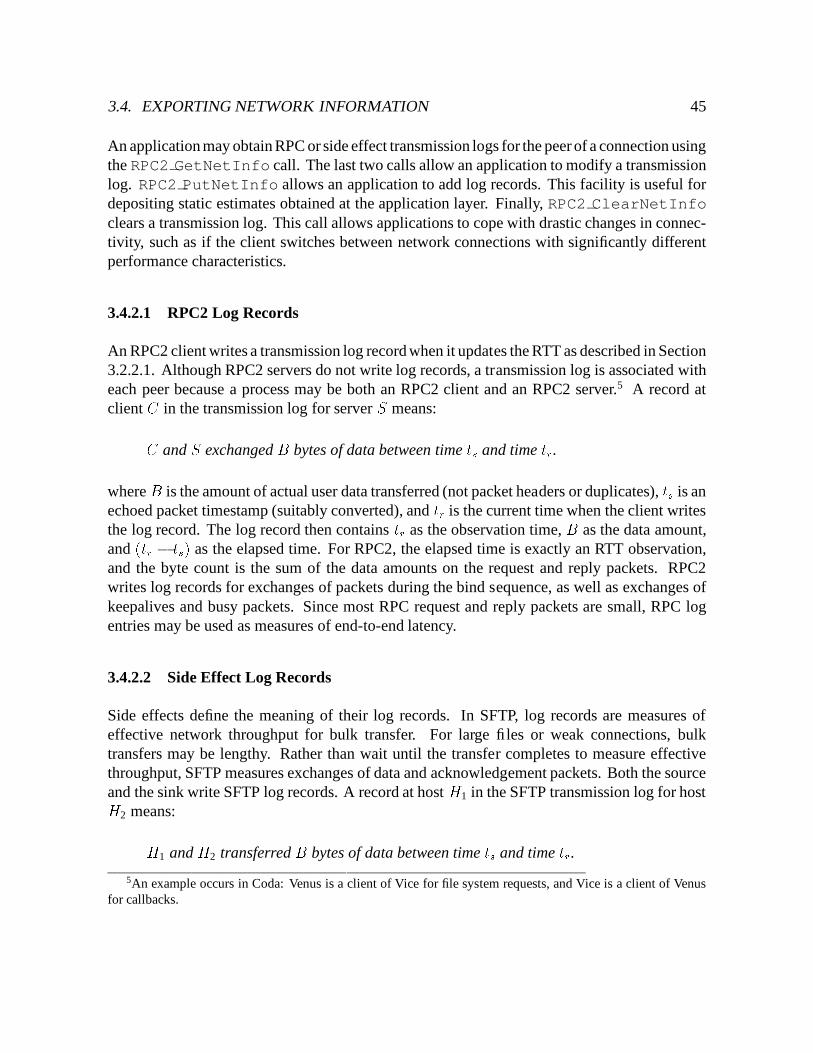
3.4. EXPORTING NETWORK INFORMATION 45
An application may obtain RPC or side effect transmission logs for the peer of a connection usingthe RPC2 GetNetInfo call. The last two calls allow an application to modify a transmissionlog. RPC2 PutNetInfo allows an application to add log records. This facility is useful fordepositing static estimates obtained at the application layer. Finally, RPC2 ClearNetInfoclears a transmission log. This call allows applications to cope with drastic changes in connec-tivity, such as if the client switches between network connections with significantly differentperformance characteristics.
3.4.2.1 RPC2 Log Records
An RPC2 client writes a transmission log record when it updates the RTT as described in Section3.2.2.1. Although RPC2 servers do not write log records, a transmission log is associated witheach peer because a process may be both an RPC2 client and an RPC2 server.5 A record atclient C in the transmission log for server S means:C and S exchanged B bytes of data between time ts and time tr.where B is the amount of actual user data transferred (not packet headers or duplicates), ts is anechoed packet timestamp (suitably converted), and tr is the current time when the client writesthe log record. The log record then contains tr as the observation time, B as the data amount,and (tr � ts) as the elapsed time. For RPC2, the elapsed time is exactly an RTT observation,and the byte count is the sum of the data amounts on the request and reply packets. RPC2writes log records for exchanges of packets during the bind sequence, as well as exchanges ofkeepalives and busy packets. Since most RPC request and reply packets are small, RPC logentries may be used as measures of end-to-end latency.
3.4.2.2 Side Effect Log Records
Side effects define the meaning of their log records. In SFTP, log records are measures ofeffective network throughput for bulk transfer. For large files or weak connections, bulktransfers may be lengthy. Rather than wait until the transfer completes to measure effectivethroughput, SFTP measures exchanges of data and acknowledgement packets. Both the sourceand the sink write SFTP log records. A record at host H1 in the SFTP transmission log for hostH2 means:H1 and H2 transferred B bytes of data between time ts and time tr.
5An example occurs in Coda: Venus is a client of Vice for file system requests, and Vice is a client of Venusfor callbacks.
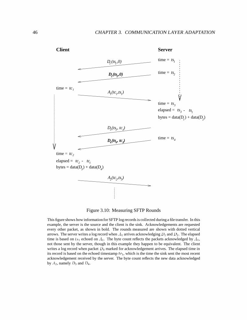
46 CHAPTER 3. COMMUNICATION LAYER ADAPTATION
D (ts ,0)11
time = ts2
ts1time =
11A (tc ,ts )1
ts3time =
ts3
bytes = data(D ) + data(D )1 2
ts1
3D (ts , tc )13
ts4time =
time = tc2
tc1time =
2tc 1tc
3 4bytes = data(D ) + data(D )
A (tc ,ts )2 2 3
D (ts ,0)22
D (ts , tc )4 14
ServerClient
elapsed = -
-elapsed =
Figure 3.10: Measuring SFTP Rounds
This figure shows how information for SFTP log records is collected during a file transfer. In thisexample, the server is the source and the client is the sink. Acknowledgements are requestedevery other packet, as shown in bold. The rounds measured are shown with dotted verticalarrows. The server writes a log record when A1 arrives acknowledgingD1 and D2. The elapsedtime is based on ts1 echoed on A1. The byte count reflects the packets acknowledged by A1,not those sent by the server, though in this example they happen to be equivalent. The clientwrites a log record when packet D4 marked for acknowledgement arrives. The elapsed time inits record is based on the echoed timestamp tc1, which is the time the sink sent the most recentacknowledgement received by the server. The byte count reflects the new data acknowledgedby A2, namely D3 and D4.
3.4. EXPORTING NETWORK INFORMATION 47
where B is the amount of actual user data transferred (the direction depends on which hostis the sink), tr and ts are times measured at H1, tr is the observation time, and tr � ts is theelapsed time. In other words, the data is known to have been sent and received between ts andtr.
SFTP writes log records based on the packet timestamps used for measuring round triptimes as described in Section 3.3.2. To measure elapsed time, the source measures the timefrom sending the first data packet to receiving the acknowledgement. As shown in Figure 3.10,it writes a log record when an acknowledgement packet acknowledging new data arrives. Theechoed timestamp on the acknowledgement is ts, and the resulting elapsed time is equivalentto an RTT observation as described for the source in Section 3.3.2. The sink measures the timefrom sending the acknowledgement to receiving a data packet marked for acknowledgement. Itwrites a log record when a new data packet marked for acknowledgement arrives. The echoedtimestamp on this data packet is ts. In Figure 3.10, the server logs a record when A1 arrives,and the client logs a record beginning when D4 arrives.
To measure effective throughput, SFTP must guarantee that the byte count in each recordreflects only the new data actually sent and received between ts and tr. The byte count in a logrecord includes data on packets that satisfy the following conditions:
1. The packets are in the transmit window (source) or receive window (sink).2. The packets are acknowledged by the acknowledgement (source) or are about to be
acknowledged (sink).3. The packets have not been recorded previously.4. The packets have timestamps no earlier than the echoed timestamp.
Conditions 1 and 2 exclude duplicate packets. Condition 2 ensures only those packetsknown to have been received are recorded. Since acknowledgements are cumulative, condition3 prevents overcounting of packets that are still in the window and have already been includedin a log record. Packets are marked when recorded to detect this condition. Packets must beacknowledged to be recorded, but are not necessarily recorded if acknowledged. Note thatthese conditions do not preclude use of spontaneous retransmissions by the server, as in RTTestimation. Log records may be written at the client as long as the retransmission by the servereither generates new data or acknowledges new data.
Condition 4 is necessary because packets may by lost or delayed. Consider the example inFigure 3.11, in which losses and retransmissions cause an acknowledgement to acknowledgemore data than was sent to provoke it. The source sends data packets, and the acknowledgementis lost. The source times out and retransmits, and sends enough new data to fill its transmitwindow. The acknowledgement is again lost. The source times out again, sending the firstunacknowledged packet in the transmit window. It finally receives a response, acknowledgingreceipt of all data. What should the source log record say? It cannot include all of the data
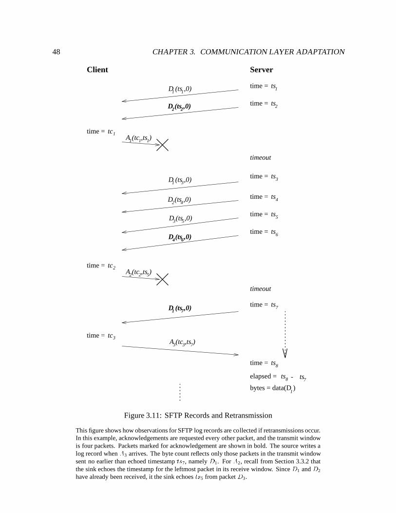
48 CHAPTER 3. COMMUNICATION LAYER ADAPTATION
D (ts ,0)11ts1time =
time = ts2
ts3time =
ts4time =
D (ts ,0)1 3
D (ts ,0)2 4
3 5D (ts ,0)time = ts5
time = ts6
tc1time = 11A (tc ,ts )1
ts7time =
time = tc3
time = ts8
elapsed = -ts78 ts
1bytes = data(D )
time = tc2A (tc ,ts )2 52
A (tc ,ts )733
2D (ts ,0)2
D (ts ,0)4 6
1D (ts ,0)7
ServerClient
timeout
timeout
Figure 3.11: SFTP Records and Retransmission
This figure shows how observations for SFTP log records are collected if retransmissions occur.In this example, acknowledgements are requested every other packet, and the transmit windowis four packets. Packets marked for acknowledgement are shown in bold. The source writes alog record when A3 arrives. The byte count reflects only those packets in the transmit windowsent no earlier than echoed timestamp ts7, namely D1. For A2, recall from Section 3.3.2 thatthe sink echoes the timestamp for the leftmost packet in its receive window. Since D1 and D2
have already been received, it the sink echoes ts5 from packet D3.
3.4. EXPORTING NETWORK INFORMATION 49
acknowledged, because most of it was sent before ts7. Fortunately, one can determine whichpackets are to be included by comparing the timestamp echoed on the acknowledgement (ts)to the timestamps on the packets in the transmit window. Packets with earlier timestamps areexcluded from the log record. Should an earlier acknowledgement arrive after much delay,such packets may be logged at that point.
A similar situation can occur if packets are delayed. For example, suppose in Figure 3.10that packet D1 arrives at the sink after D2. When D4 marked for acknowledgement arrives,what should the sink log record say? It cannot include packet D1, because the packet was notsent in response to A1; the sink cannot prove that it was sent between tc1 and tc2.
The conditions above guarantee data is logged at most once, and only during an interval inwhich it was sent and received. If packets are lost or delayed, condition 4 implies that data maynot be logged at all. For example, in Figure 3.11, the data on packets D2 �D4 is not includedin the source log record. Unfortunately, in the absence of an earlier acknowledgement, notenough is known about the timing of earlier packets to log accurate elapsed times for them,even in separate records. The issue is one of retransmission ambiguity. Consider packet D2. Ifits original send time is used, the elapsed time may be an overestimate because the packet mayhave been lost. If the most recent send time is used (i.e., the packet timestamp), the elapsedtime may be an underestimate because the acknowledgement may reflect receipt of an earliertransmission. SFTP does not log records for the earlier packets, and thus may undercount theamount of data transferred.
3.4.3 Application Uses
Venus uses both liveness information and transmission logs. Liveness information is used tosuppress server probes, which are RPCs that Venus periodically sends to servers to detect statechanges6. If Venus is connected to a server over a heavily loaded weak link, a probe may fail,causing Venus to declare the server down. This behavior can cause communication on otherconnections to the same server (e.g., a file transfer) to fail unnecessarily. To avoid this situation,Venus uses liveness information in lieu of probes. If a server was heard from within a probeinterval, Venus pretends it probed the server successfully at that time.
Venus uses the SFTP transmission logs to calculate bandwidth estimates for each server,using a weighted average as in Equation 3.2. Venus polls RPC2 periodically to harvest newmeasurements and update its estimates, and uses a simple threshold to determine if it is weaklyconnected with respect to a server. While weakly connected, bandwidth estimates are used toinfluence cache miss handling (Chapter 6) and trickle reintegration (Chapter 5).
Bandwidth estimates can become stale, because they are only collected during file transfer.While weakly connected, file transfers can be less frequent for a variety of reasons. For
6Venus probes up servers every 12 minutes, and down servers every 4 minutes.
50 CHAPTER 3. COMMUNICATION LAYER ADAPTATION
example, CML optimizations reduce the amount of data sent to the server during reintegration,compared to the amount for the same updates performed while strongly connected. Userscan reduce the amount of data received from the servers by deferring demand fetches, andby controlling the amount of data fetched during hoard walks. If Venus relies solely on filetransfer for its estimates, it may not detect improvements in network performance promptlywhile weakly connected.
There are two strategies for dealing with stale estimates: generate test traffic, or find anothersource of traffic to monitor. The former approach involves declaring an estimate suspect aftera certain period, and going forth in search of new information. Venus uses the former approachin an indirect way. If an estimate is not updated within a certain period, Venus optimisticallydeclares the connection strong. If the connection is still weak, Venus will discover that facton the next file transfer. The staleness threshold should be large enough to prevent gratuitoustransitions between strong and weak connectivity, and to allow background processes thatmight transfer data (e.g., hoarding and trickle reintegration) to occur. The threshold could alsobe made dependent on worker idle time within Venus to prevent test transitions while a user isactually working.
The second approach involves finding a source of fresh information without generating anyadditional traffic. While weakly connected, Venus still sends server probes. Thus the RPCtransmission logs are refreshed at least once every probe interval. It remains to be seen if themeasurements in the RPC transmission logs are sensitive enough to reliably detect crossingsof the weakly connected threshold.
Venus also deposits static estimates into the transmission logs in response to application-supplied bandwidth hints. For example, some Coda users run a configuration script on theirnotebook computers to change the primary network interface, such as from a wireless LANinterface at the office to a SLIP interface when dialing in from home. Drastic changes innetwork performance are virtually guaranteed when these interface changes occur. The net-work configuration script supplies Venus with the nominal bandwidth associated with the newinterface. Venus then clears the transmission logs associated with each server, and writes intoeach a static log record containing the nominal bandwidth. Bandwidth hints may be sent toVenus from the command line using cfs, or from a program through the pioctl interface.
An artifact of the user-level library implementation of RPC2 is that monitoring is distributedamong applications. There is no facility for sharing measurements between applications, andeach application must discover network performance characteristics independently. SinceVenus is long-lived and is often the primary source of network traffic, these are not seriousdrawbacks.
3.5. EFFECTS OF SERVER REPLICATION 51
3.5 Effects of Server Replication
Venus normally makes requests on replicated objects, which requires that it communicate witha group of servers (the AVSG) instead of a single server. Most of the work for replicationis performed at the Coda client. Venus must coordinate execution of RPCs to the AVSG anddetermine connectivity with respect to the AVSG as a whole.
3.5.1 MultiRPC
Venus uses the MultiRPC extension to RPC2 [117] to make requests to groups of serversin parallel. This extension is layered entirely on the client side implementation of RPC2.Individual request packets are sent to each server sequentially on separate RPC connections.Servers respond as they would normally; the request packets are indistinguishable from thosesent by a single server RPC.
MultiRPC transmissions on different connections can interfere with each other if connec-tivity is weak and packets are large, or if multiple file transfers are in progress. Multiplesimultaneous transfers occur not only as a result of independent requests, but more commonlyas a result of store and reintegration operations to an AVSG. The implementation makes nospecial provision for this interference; competing connections time out and adjust their re-transmission intervals as necessary. However, this approach may not be sufficient in view ofsimulation studies of multiple TCP connections over bottleneck links [120, 131]. These studiespredict phenomena such as clustering of packets by connection, and “ack compression”, whichthwarts the ability of a sliding window protocol to regulate its send rate.
An obvious way to alleviate interference between connections during a MultiRPC is touse multicast, and an early version of Coda [114] used a prototype implementation of IPmulticast [31] over a single Ethernet segment. Multicast addresses were associated with VSGs.Venus supplied the unicast connections and multicast information for each RPC. MultiRPCmulticasted the initial transmission, and then unicasted retransmissions as necessary. Revivingthis support in an internetwork setting would involve changes to device drivers and an updateto the existing IP implementation. The RPC2 RTT collection and transmission log codewould also have to be revisited. Since packet loss vitiates the effectiveness of multicast inreducing interference, the unicast retransmission strategy may also require modification. Inaddition, gateways would have to be tested to ensure multicast packets are handled correctly,and multicast routing would have to be performed on the appropriate networks. Finally, Coda’sreintegration mechanism would require modification to take advantage of multicast support;currently new file data is fetched by each server through a server-to-client RPC on a separateconnection, rather than sent from client to servers. Instead, Coda uses a combination of thereintegration and resolution mechanisms to minimize the amount of data sent over the weak
52 CHAPTER 3. COMMUNICATION LAYER ADAPTATION
connection while propagating updates to all members of the AVSG. This issue is discussedfurther in Chapter 5.
3.5.2 Connectivity to an AVSG
For replicated volumes, Venus must determine the connectivity to the AVSG rather than asingle server. The bandwidth estimates for AVSG members are not necessarily equal, and onecannot assume there is a single bottleneck link between the client and the AVSG7. If bandwidthestimates show some members are weakly connected and others are strongly connected, whatis the connectivity to the AVSG?
Venus considers an AVSG weakly connected if any of its members are weakly connected.The reason for this is that update performance is determined by the slowest server. Once thevolume is weakly connected, updates are logged and propagated to server asynchronously. Thisstrategy is somewhat pessimistic for fetches, because data is transferred from only one server.However, one can arrange to fetch data from the AVSG member with the best estimate.
3.6 Quality of Service
An underlying assumption of Coda’s communications layer is that the network is completelyunhelpful – it neither makes guarantees nor provides feedback regarding the quality of service(QoS) it offers; it simply delivers data in a best-effort manner. The communications layerdescribed in this chapter essentially derives QoS information empirically. Recent work towardssupporting real-time distributed applications, such as video players, allows applications torequest a certain QoS from the network [15, 19, 38, 118, 130] or the operating system [23,77, 90]. If the system accepts the request, it may make guarantees or offer feedback on thequality of service. For example, it may promise to notify the application if the quality of servicechanges significantly.
How would QoS support change the existing communications layer? If such support wereavailable, the communications layer could take advantage of it in a number of ways. Forexample, SFTP could adjust its retransmission strategy based on the packet loss rate. RPC2could reduce the frequency of round trip time measurements depending on the presence andstrength of a latency guarantee. However, the mechanisms for end-to-end measurement shouldremain for two reasons.
7Initial experiments with bandwidth estimates revealed performance differences correlated with which Ethernetsegment a Coda server was attached. Two VSGs of three servers each were split over a private facilities networkand a busy public network. The bandwidth estimates for servers on the public network were, on average, less thanhalf the estimates for servers on the private network.
3.7. CHAPTER SUMMARY 53
First, they allow broadest possible use of the system. Not all systems offer QoS support,and for those that do, there is no standard way to specify QoS. Parameters vary – commonones are bandwidth, latency, jitter, and loss rate. Parameter values also vary – for example,the bandwidth specification may be a peak value, an average value, or a range of acceptablevalues. Having specified QoS, there are no standard service guarantees. The system may offera deterministic (hard) guarantee, a statistical (probabilistic) guarantee, or no guarantee at all.The entity that offers the guarantee may also vary. Most research has focused on guaranteesprovided by the network, but there is also work on guarantees provided by the operating system.
Second, higher system layers could use end-to-end measurements to verify QoS guaranteesor feedback provided by lower layers. Discrepancies may reveal bugs in QoS support orinefficiencies in intervening system layers. If there is a discrepancy, end-to-end measurementsare a more accurate reflection of the QoS the application actually receives.
3.7 Chapter Summary
This chapter describes how the communication layer gathers information on network perfor-mance and exports it to applications, and how one application in particular, Venus, uses theinformation to adapt to network performance. The RPC and bulk transfer protocols employa passive monitoring strategy that gathers measurements without expanding existing packetformats or generating additional network traffic. The protocols use adaptive retransmissionalgorithms based on round trip time estimation. A comparison of throughput with TCP isprovided in Section 7.3. Measurements of network performance are exported to applicationsin a minimalistic and flexible way using transmission logs, which can incorporate both staticand dynamic information. Applications use the measurements as they see fit in defining theircriteria for weak connectivity. In addition to Venus, transmission logs have been used supplyinformation on network performance to other adaptive applications, such a video player [90].

54 CHAPTER 3. COMMUNICATION LAYER ADAPTATION
Chapter 4
Rapid Cache Validation
A distributed file system using weak connections must function in spite of limited bandwidthand intermittent connectivity. The usability of the system in such an environment dependscritically on its ability to resynchronize state rapidly upon reconnection. For a distributed filesystem, the state of interest is the client file cache.
Callback-based cache coherence is invaluable for preserving scalability while maintaining ahigh degree of consistency. This technique is based on the implicit assumption that the networkis fast and reliable. Unfortunately, this assumption is often violated in weakly-connectedenvironments. When a client with callbacks encounters a network failure, it must consider itscached files suspect because it can no longer depend on the server to notify it of updates. Uponrepair of the failure, the client must validate cached files before use. Consequently, as failuresbecome more frequent, the effectiveness of a callback-based scheme in reducing validationtraffic decreases. In the worst case, client behavior may degenerate to contacting the server onevery reference. This problem is exacerbated in systems that use anticipatory caching strategiessuch as hoarding to prepare for failures. In these systems, validation traffic is proportional notjust to the file working set, but to the larger resident set. The more diligent the preparation forfailures, the larger the resident set. The impact of this problem increases as network bandwidthbecomes precious.
The approach used to solving this problem is based on the observation that the vast majorityof cached objects are still valid upon reconnection. In other words, the rate of remote updatesto file system data cached at a client is lower than the rate of connectivity change, particularlyin intermittent environments. The solution therefore increases the granularity at which cachecoherence is maintained. Clients summarize the contents of their caches for the purposeof validation. This technique dramatically reduces reconnection latency, allowing clients torecover from failures more quickly.
This chapter presents the details of rapid cache validation in four parts. The first sectiondiscusses key design issues, such as the granularity at which coherence is maintained. Next
55
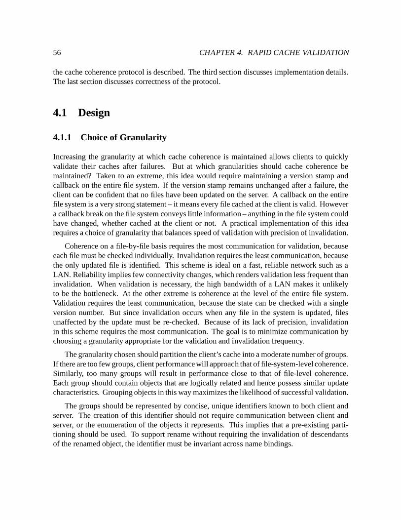
56 CHAPTER 4. RAPID CACHE VALIDATION
the cache coherence protocol is described. The third section discusses implementation details.The last section discusses correctness of the protocol.
4.1 Design
4.1.1 Choice of Granularity
Increasing the granularity at which cache coherence is maintained allows clients to quicklyvalidate their caches after failures. But at which granularities should cache coherence bemaintained? Taken to an extreme, this idea would require maintaining a version stamp andcallback on the entire file system. If the version stamp remains unchanged after a failure, theclient can be confident that no files have been updated on the server. A callback on the entirefile system is a very strong statement – it means every file cached at the client is valid. Howevera callback break on the file system conveys little information – anything in the file system couldhave changed, whether cached at the client or not. A practical implementation of this idearequires a choice of granularity that balances speed of validation with precision of invalidation.
Coherence on a file-by-file basis requires the most communication for validation, becauseeach file must be checked individually. Invalidation requires the least communication, becausethe only updated file is identified. This scheme is ideal on a fast, reliable network such as aLAN. Reliability implies few connectivity changes, which renders validation less frequent thaninvalidation. When validation is necessary, the high bandwidth of a LAN makes it unlikelyto be the bottleneck. At the other extreme is coherence at the level of the entire file system.Validation requires the least communication, because the state can be checked with a singleversion number. But since invalidation occurs when any file in the system is updated, filesunaffected by the update must be re-checked. Because of its lack of precision, invalidationin this scheme requires the most communication. The goal is to minimize communication bychoosing a granularity appropriate for the validation and invalidation frequency.
The granularity chosen should partition the client’s cache into a moderate number of groups.If there are too few groups, client performance will approach that of file-system-level coherence.Similarly, too many groups will result in performance close to that of file-level coherence.Each group should contain objects that are logically related and hence possess similar updatecharacteristics. Grouping objects in this way maximizes the likelihood of successful validation.
The groups should be represented by concise, unique identifiers known to both client andserver. The creation of this identifier should not require communication between client andserver, or the enumeration of the objects it represents. This implies that a pre-existing parti-tioning should be used. To support rename without requiring the invalidation of descendantsof the renamed object, the identifier must be invariant across name bindings.
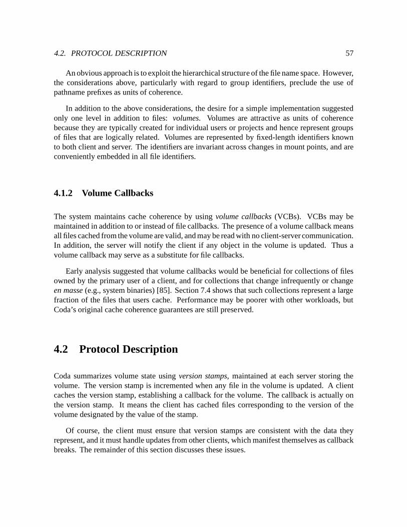
4.2. PROTOCOL DESCRIPTION 57
An obvious approach is to exploit the hierarchical structure of the file name space. However,the considerations above, particularly with regard to group identifiers, preclude the use ofpathname prefixes as units of coherence.
In addition to the above considerations, the desire for a simple implementation suggestedonly one level in addition to files: volumes. Volumes are attractive as units of coherencebecause they are typically created for individual users or projects and hence represent groupsof files that are logically related. Volumes are represented by fixed-length identifiers knownto both client and server. The identifiers are invariant across changes in mount points, and areconveniently embedded in all file identifiers.
4.1.2 Volume Callbacks
The system maintains cache coherence by using volume callbacks (VCBs). VCBs may bemaintained in addition to or instead of file callbacks. The presence of a volume callback meansall files cached from the volume are valid, and may be read with no client-server communication.In addition, the server will notify the client if any object in the volume is updated. Thus avolume callback may serve as a substitute for file callbacks.
Early analysis suggested that volume callbacks would be beneficial for collections of filesowned by the primary user of a client, and for collections that change infrequently or changeen masse (e.g., system binaries) [85]. Section 7.4 shows that such collections represent a largefraction of the files that users cache. Performance may be poorer with other workloads, butCoda’s original cache coherence guarantees are still preserved.
4.2 Protocol Description
Coda summarizes volume state using version stamps, maintained at each server storing thevolume. The version stamp is incremented when any file in the volume is updated. A clientcaches the version stamp, establishing a callback for the volume. The callback is actually onthe version stamp. It means the client has cached files corresponding to the version of thevolume designated by the value of the stamp.
Of course, the client must ensure that version stamps are consistent with the data theyrepresent, and it must handle updates from other clients, which manifest themselves as callbackbreaks. The remainder of this section discusses these issues.
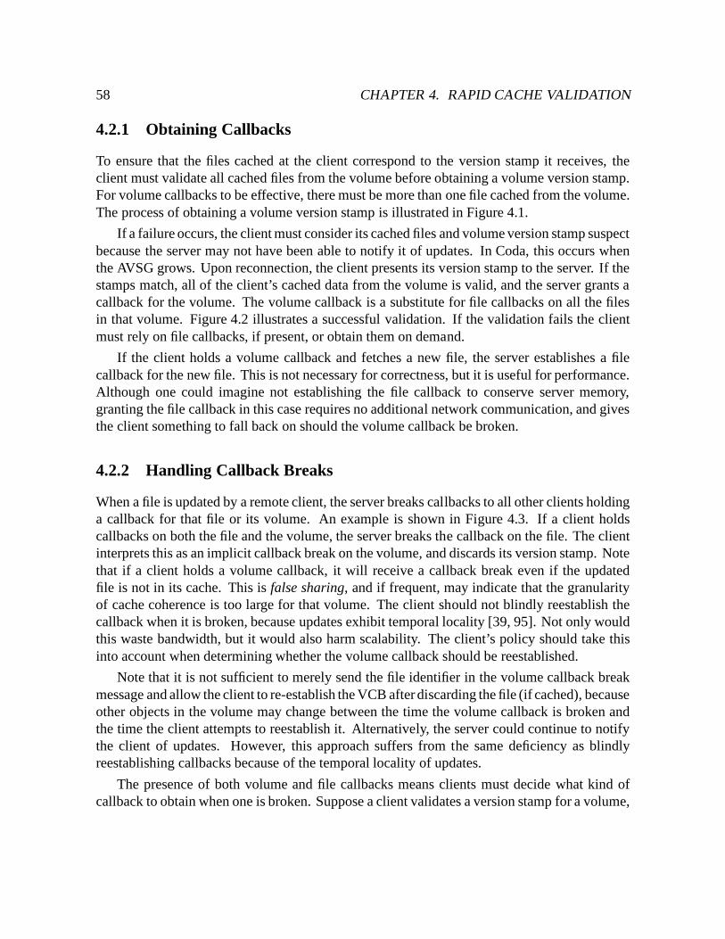
58 CHAPTER 4. RAPID CACHE VALIDATION
4.2.1 Obtaining Callbacks
To ensure that the files cached at the client correspond to the version stamp it receives, theclient must validate all cached files from the volume before obtaining a volume version stamp.For volume callbacks to be effective, there must be more than one file cached from the volume.The process of obtaining a volume version stamp is illustrated in Figure 4.1.
If a failure occurs, the client must consider its cached files and volume version stamp suspectbecause the server may not have been able to notify it of updates. In Coda, this occurs whenthe AVSG grows. Upon reconnection, the client presents its version stamp to the server. If thestamps match, all of the client’s cached data from the volume is valid, and the server grants acallback for the volume. The volume callback is a substitute for file callbacks on all the filesin that volume. Figure 4.2 illustrates a successful validation. If the validation fails the clientmust rely on file callbacks, if present, or obtain them on demand.
If the client holds a volume callback and fetches a new file, the server establishes a filecallback for the new file. This is not necessary for correctness, but it is useful for performance.Although one could imagine not establishing the file callback to conserve server memory,granting the file callback in this case requires no additional network communication, and givesthe client something to fall back on should the volume callback be broken.
4.2.2 Handling Callback Breaks
When a file is updated by a remote client, the server breaks callbacks to all other clients holdinga callback for that file or its volume. An example is shown in Figure 4.3. If a client holdscallbacks on both the file and the volume, the server breaks the callback on the file. The clientinterprets this as an implicit callback break on the volume, and discards its version stamp. Notethat if a client holds a volume callback, it will receive a callback break even if the updatedfile is not in its cache. This is false sharing, and if frequent, may indicate that the granularityof cache coherence is too large for that volume. The client should not blindly reestablish thecallback when it is broken, because updates exhibit temporal locality [39, 95]. Not only wouldthis waste bandwidth, but it would also harm scalability. The client’s policy should take thisinto account when determining whether the volume callback should be reestablished.
Note that it is not sufficient to merely send the file identifier in the volume callback breakmessage and allow the client to re-establish the VCB after discarding the file (if cached), becauseother objects in the volume may change between the time the volume callback is broken andthe time the client attempts to reestablish it. Alternatively, the server could continue to notifythe client of updates. However, this approach suffers from the same deficiency as blindlyreestablishing callbacks because of the temporal locality of updates.
The presence of both volume and file callbacks means clients must decide what kind ofcallback to obtain when one is broken. Suppose a client validates a version stamp for a volume,
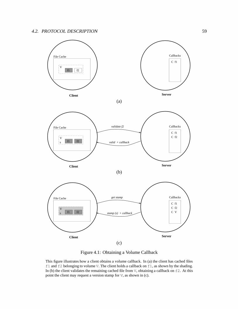
4.2. PROTOCOL DESCRIPTION 59
ServerClient
File Cache
f1 f2V
Callbacks
C f1
(a)
ServerClient
File Cache
f1 f2V
Callbacks
C f1
C f2
s
validate f2
valid + callback
(b)
ServerClient
File Cache
f1 f2V
Callbacks
C f1
C f2
get stamp
s stamp (s) + callback C V
(c)
Figure 4.1: Obtaining a Volume Callback
This figure illustrates how a client obtains a volume callback. In (a) the client has cached filesf1 and f2 belonging to volume V. The client holds a callback on f1, as shown by the shading.In (b) the client validates the remaining cached file from V, obtaining a callback on f2. At thispoint the client may request a version stamp for V, as shown in (c).
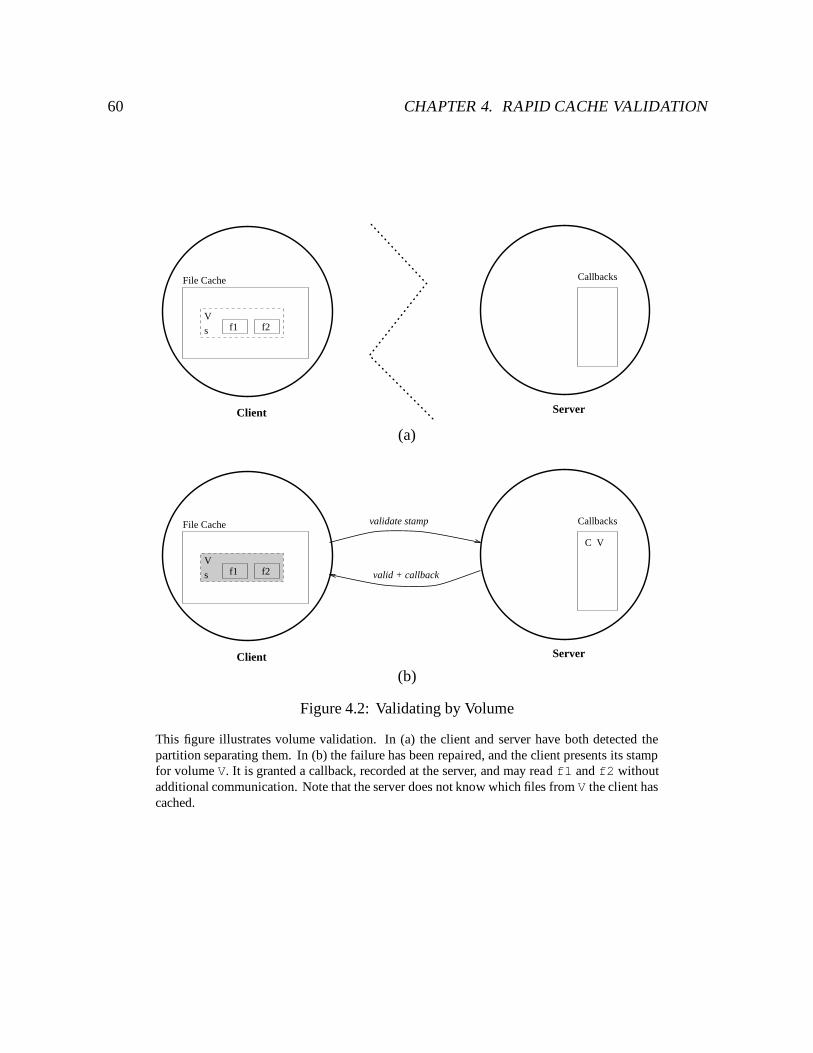
60 CHAPTER 4. RAPID CACHE VALIDATION
ServerClient
File Cache
f1 f2V
Callbacks
s
(a)
ServerClient
File Cache
f1 f2V
Callbacks
s valid + callback
validate stamp
C V
(b)
Figure 4.2: Validating by Volume
This figure illustrates volume validation. In (a) the client and server have both detected thepartition separating them. In (b) the failure has been repaired, and the client presents its stampfor volume V. It is granted a callback, recorded at the server, and may read f1 and f2 withoutadditional communication. Note that the server does not know which files from V the client hascached.
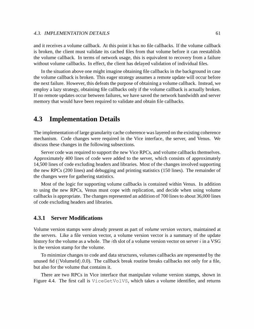
4.3. IMPLEMENTATION DETAILS 61
and it receives a volume callback. At this point it has no file callbacks. If the volume callbackis broken, the client must validate its cached files from that volume before it can reestablishthe volume callback. In terms of network usage, this is equivalent to recovery from a failurewithout volume callbacks. In effect, the client has delayed validation of individual files.
In the situation above one might imagine obtaining file callbacks in the background in casethe volume callback is broken. This eager strategy assumes a remote update will occur beforethe next failure. However, this defeats the purpose of obtaining a volume callback. Instead, weemploy a lazy strategy, obtaining file callbacks only if the volume callback is actually broken.If no remote updates occur between failures, we have saved the network bandwidth and servermemory that would have been required to validate and obtain file callbacks.
4.3 Implementation Details
The implementation of large granularity cache coherence was layered on the existing coherencemechanism. Code changes were required in the Vice interface, the server, and Venus. Wediscuss these changes in the following subsections.
Server code was required to support the new Vice RPCs, and volume callbacks themselves.Approximately 400 lines of code were added to the server, which consists of approximately14,500 lines of code excluding headers and libraries. Most of the changes involved supportingthe new RPCs (200 lines) and debugging and printing statistics (150 lines). The remainder ofthe changes were for gathering statistics.
Most of the logic for supporting volume callbacks is contained within Venus. In additionto using the new RPCs, Venus must cope with replication, and decide when using volumecallbacks is appropriate. The changes represented an addition of 700 lines to about 36,000 linesof code excluding headers and libraries.
4.3.1 Server Modifications
Volume version stamps were already present as part of volume version vectors, maintained atthe servers. Like a file version vector, a volume version vector is a summary of the updatehistory for the volume as a whole. The ith slot of a volume version vector on server i in a VSGis the version stamp for the volume.
To minimize changes to code and data structures, volumes callbacks are represented by theunused fid (hVolumeIdi.0.0). The callback break routine breaks callbacks not only for a file,but also for the volume that contains it.
There are two RPCs in Vice interface that manipulate volume version stamps, shown inFigure 4.4. The first call is ViceGetVolVS, which takes a volume identifier, and returns
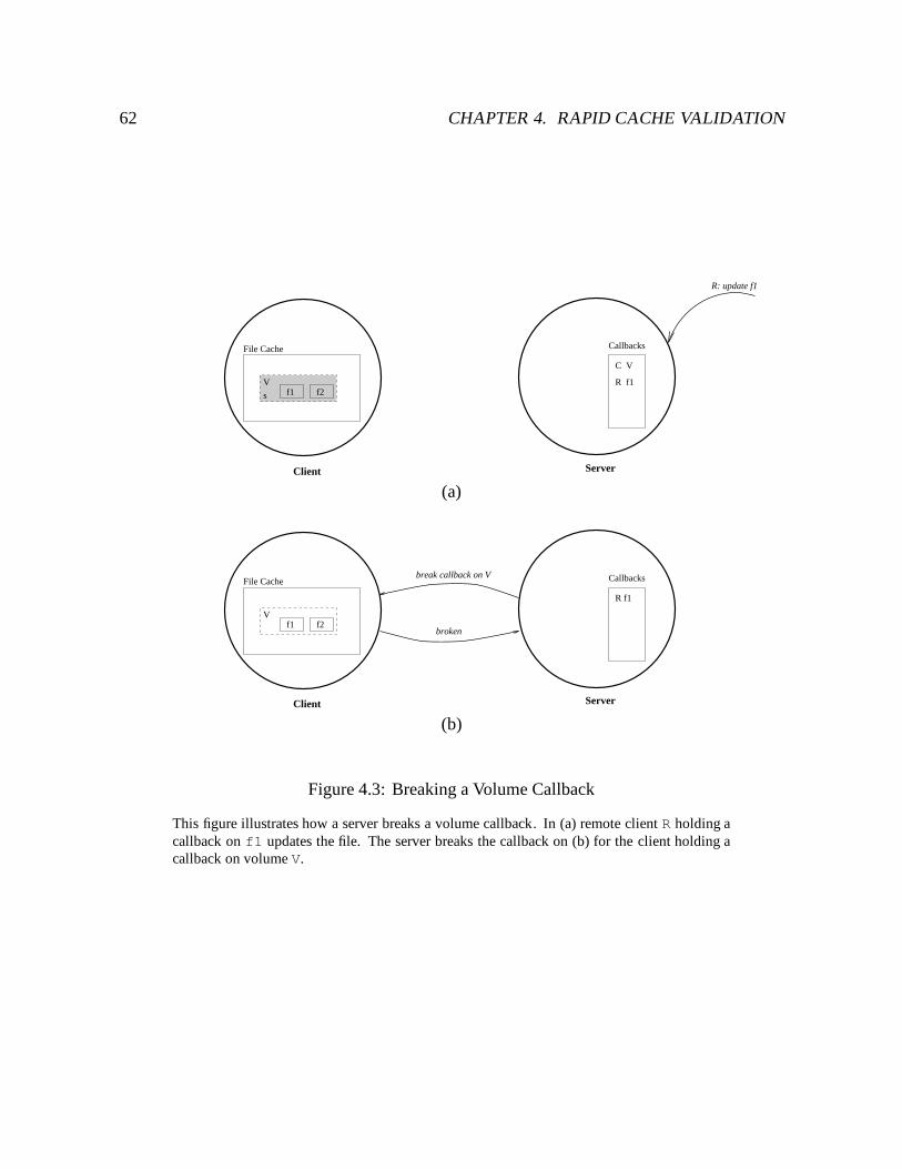
62 CHAPTER 4. RAPID CACHE VALIDATION
ServerClient
File Cache
f1 f2V
Callbacks
s
C V
R f1
R: update f1
(a)
ServerClient
File Cache
f1 f2V
Callbacks
R f1
broken
break callback on V
(b)
Figure 4.3: Breaking a Volume Callback
This figure illustrates how a server breaks a volume callback. In (a) remote client R holding acallback on f1 updates the file. The server breaks the callback on (b) for the client holding acallback on volume V.
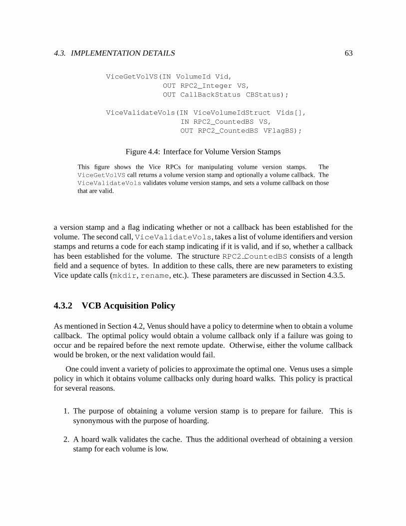
4.3. IMPLEMENTATION DETAILS 63
ViceGetVolVS(IN VolumeId Vid,OUT RPC2_Integer VS,OUT CallBackStatus CBStatus);
ViceValidateVols(IN ViceVolumeIdStruct Vids[],IN RPC2_CountedBS VS,OUT RPC2_CountedBS VFlagBS);
Figure 4.4: Interface for Volume Version Stamps
This figure shows the Vice RPCs for manipulating volume version stamps. TheViceGetVolVS call returns a volume version stamp and optionally a volume callback. TheViceValidateVols validates volume version stamps, and sets a volume callback on thosethat are valid.
a version stamp and a flag indicating whether or not a callback has been established for thevolume. The second call, ViceValidateVols, takes a list of volume identifiers and versionstamps and returns a code for each stamp indicating if it is valid, and if so, whether a callbackhas been established for the volume. The structure RPC2 CountedBS consists of a lengthfield and a sequence of bytes. In addition to these calls, there are new parameters to existingVice update calls (mkdir, rename, etc.). These parameters are discussed in Section 4.3.5.
4.3.2 VCB Acquisition Policy
As mentioned in Section 4.2, Venus should have a policy to determine when to obtain a volumecallback. The optimal policy would obtain a volume callback only if a failure was going tooccur and be repaired before the next remote update. Otherwise, either the volume callbackwould be broken, or the next validation would fail.
One could invent a variety of policies to approximate the optimal one. Venus uses a simplepolicy in which it obtains volume callbacks only during hoard walks. This policy is practicalfor several reasons.
1. The purpose of obtaining a volume version stamp is to prepare for failure. This issynonymous with the purpose of hoarding.
2. A hoard walk validates the cache. Thus the additional overhead of obtaining a versionstamp for each volume is low.
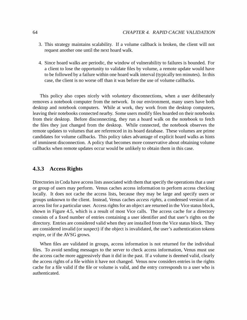
64 CHAPTER 4. RAPID CACHE VALIDATION
3. This strategy maintains scalability. If a volume callback is broken, the client will notrequest another one until the next hoard walk.
4. Since hoard walks are periodic, the window of vulnerability to failures is bounded. Fora client to lose the opportunity to validate files by volume, a remote update would haveto be followed by a failure within one hoard walk interval (typically ten minutes). In thiscase, the client is no worse off than it was before the use of volume callbacks.
This policy also copes nicely with voluntary disconnections, when a user deliberatelyremoves a notebook computer from the network. In our environment, many users have bothdesktop and notebook computers. While at work, they work from the desktop computers,leaving their notebooks connected nearby. Some users modify files hoarded on their notebooksfrom their desktop. Before disconnecting, they run a hoard walk on the notebook to fetchthe files they just changed from the desktop. While connected, the notebook observes theremote updates to volumes that are referenced in its hoard database. These volumes are primecandidates for volume callbacks. This policy takes advantage of explicit hoard walks as hintsof imminent disconnection. A policy that becomes more conservative about obtaining volumecallbacks when remote updates occur would be unlikely to obtain them in this case.
4.3.3 Access Rights
Directories in Coda have access lists associated with them that specify the operations that a useror group of users may perform. Venus caches access information to perform access checkinglocally. It does not cache the access lists, because they may be large and specify users orgroups unknown to the client. Instead, Venus caches access rights, a condensed version of anaccess list for a particular user. Access rights for an object are returned in the Vice status block,shown in Figure 4.5, which is a result of most Vice calls. The access cache for a directoryconsists of a fixed number of entries containing a user identifier and that user’s rights on thedirectory. Entries are considered valid when they are installed from the Vice status block. Theyare considered invalid (or suspect) if the object is invalidated, the user’s authentication tokensexpire, or if the AVSG grows.
When files are validated in groups, access information is not returned for the individualfiles. To avoid sending messages to the server to check access information, Venus must usethe access cache more aggressively than it did in the past. If a volume is deemed valid, clearlythe access rights of a file within it have not changed. Venus now considers entries in the rightscache for a file valid if the file or volume is valid, and the entry corresponds to a user who isauthenticated.
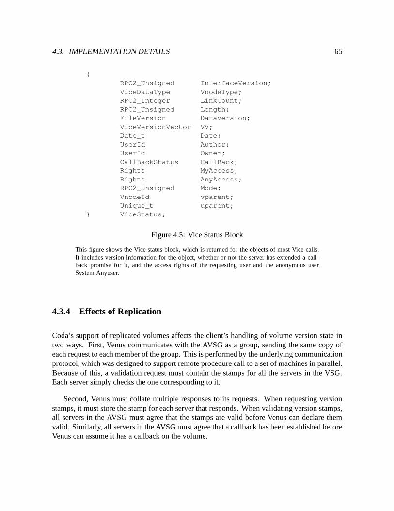
4.3. IMPLEMENTATION DETAILS 65
{RPC2_Unsigned InterfaceVersion;ViceDataType VnodeType;RPC2_Integer LinkCount;RPC2_Unsigned Length;FileVersion DataVersion;ViceVersionVector VV;Date_t Date;UserId Author;UserId Owner;CallBackStatus CallBack;Rights MyAccess;Rights AnyAccess;RPC2_Unsigned Mode;VnodeId vparent;Unique_t uparent;
} ViceStatus;
Figure 4.5: Vice Status Block
This figure shows the Vice status block, which is returned for the objects of most Vice calls.It includes version information for the object, whether or not the server has extended a call-back promise for it, and the access rights of the requesting user and the anonymous userSystem:Anyuser.
4.3.4 Effects of Replication
Coda’s support of replicated volumes affects the client’s handling of volume version state intwo ways. First, Venus communicates with the AVSG as a group, sending the same copy ofeach request to each member of the group. This is performed by the underlying communicationprotocol, which was designed to support remote procedure call to a set of machines in parallel.Because of this, a validation request must contain the stamps for all the servers in the VSG.Each server simply checks the one corresponding to it.
Second, Venus must collate multiple responses to its requests. When requesting versionstamps, it must store the stamp for each server that responds. When validating version stamps,all servers in the AVSG must agree that the stamps are valid before Venus can declare themvalid. Similarly, all servers in the AVSG must agree that a callback has been established beforeVenus can assume it has a callback on the volume.
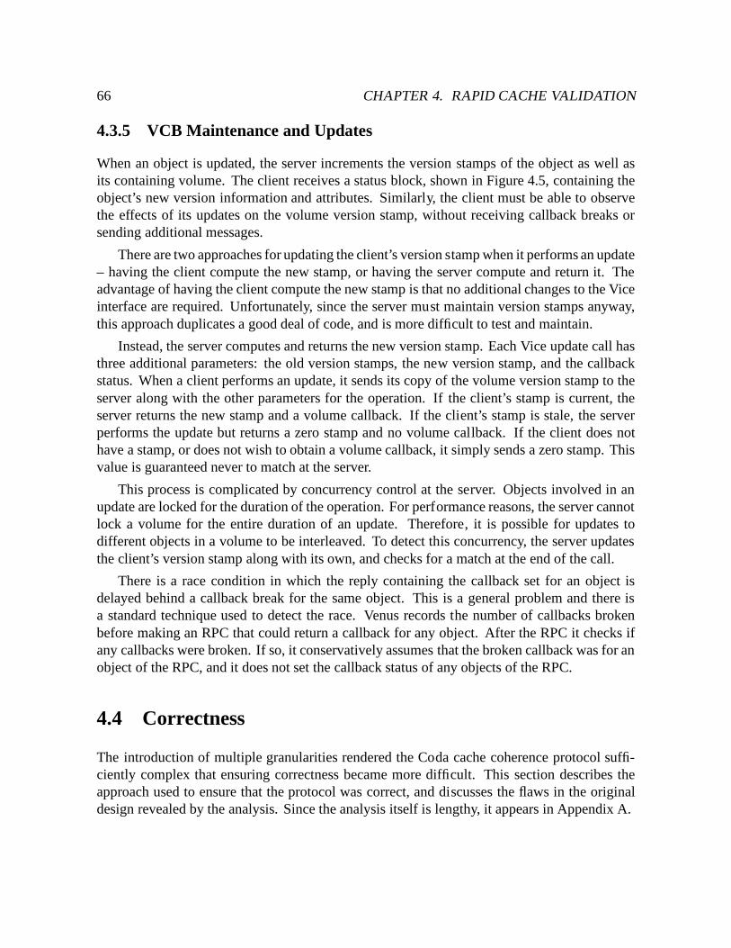
66 CHAPTER 4. RAPID CACHE VALIDATION
4.3.5 VCB Maintenance and Updates
When an object is updated, the server increments the version stamps of the object as well asits containing volume. The client receives a status block, shown in Figure 4.5, containing theobject’s new version information and attributes. Similarly, the client must be able to observethe effects of its updates on the volume version stamp, without receiving callback breaks orsending additional messages.
There are two approaches for updating the client’s version stamp when it performs an update– having the client compute the new stamp, or having the server compute and return it. Theadvantage of having the client compute the new stamp is that no additional changes to the Viceinterface are required. Unfortunately, since the server must maintain version stamps anyway,this approach duplicates a good deal of code, and is more difficult to test and maintain.
Instead, the server computes and returns the new version stamp. Each Vice update call hasthree additional parameters: the old version stamps, the new version stamp, and the callbackstatus. When a client performs an update, it sends its copy of the volume version stamp to theserver along with the other parameters for the operation. If the client’s stamp is current, theserver returns the new stamp and a volume callback. If the client’s stamp is stale, the serverperforms the update but returns a zero stamp and no volume callback. If the client does nothave a stamp, or does not wish to obtain a volume callback, it simply sends a zero stamp. Thisvalue is guaranteed never to match at the server.
This process is complicated by concurrency control at the server. Objects involved in anupdate are locked for the duration of the operation. For performance reasons, the server cannotlock a volume for the entire duration of an update. Therefore, it is possible for updates todifferent objects in a volume to be interleaved. To detect this concurrency, the server updatesthe client’s version stamp along with its own, and checks for a match at the end of the call.
There is a race condition in which the reply containing the callback set for an object isdelayed behind a callback break for the same object. This is a general problem and there isa standard technique used to detect the race. Venus records the number of callbacks brokenbefore making an RPC that could return a callback for any object. After the RPC it checks ifany callbacks were broken. If so, it conservatively assumes that the broken callback was for anobject of the RPC, and it does not set the callback status of any objects of the RPC.
4.4 Correctness
The introduction of multiple granularities rendered the Coda cache coherence protocol suffi-ciently complex that ensuring correctness became more difficult. This section describes theapproach used to ensure that the protocol was correct, and discusses the flaws in the originaldesign revealed by the analysis. Since the analysis itself is lengthy, it appears in Appendix A.
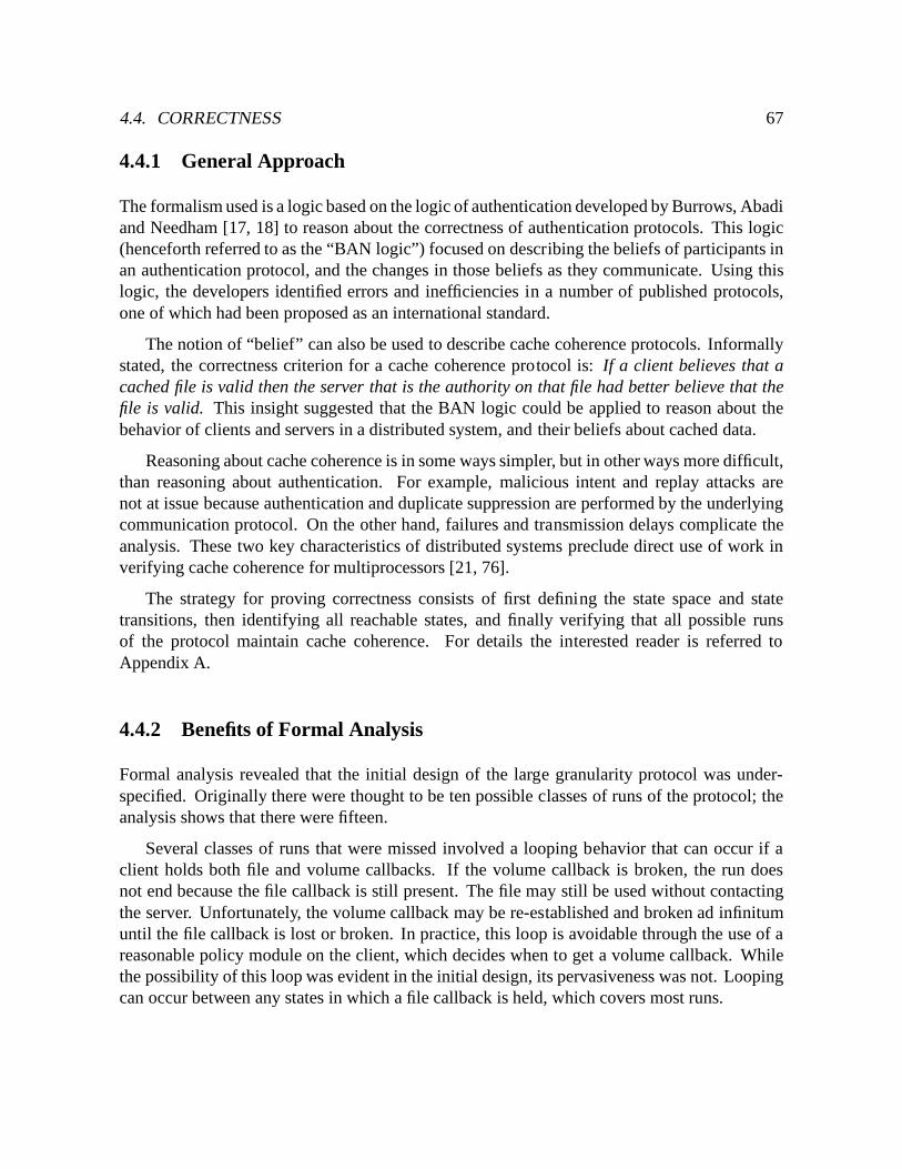
4.4. CORRECTNESS 67
4.4.1 General Approach
The formalism used is a logic based on the logic of authentication developed by Burrows, Abadiand Needham [17, 18] to reason about the correctness of authentication protocols. This logic(henceforth referred to as the “BAN logic”) focused on describing the beliefs of participants inan authentication protocol, and the changes in those beliefs as they communicate. Using thislogic, the developers identified errors and inefficiencies in a number of published protocols,one of which had been proposed as an international standard.
The notion of “belief” can also be used to describe cache coherence protocols. Informallystated, the correctness criterion for a cache coherence protocol is: If a client believes that acached file is valid then the server that is the authority on that file had better believe that thefile is valid. This insight suggested that the BAN logic could be applied to reason about thebehavior of clients and servers in a distributed system, and their beliefs about cached data.
Reasoning about cache coherence is in some ways simpler, but in other ways more difficult,than reasoning about authentication. For example, malicious intent and replay attacks arenot at issue because authentication and duplicate suppression are performed by the underlyingcommunication protocol. On the other hand, failures and transmission delays complicate theanalysis. These two key characteristics of distributed systems preclude direct use of work inverifying cache coherence for multiprocessors [21, 76].
The strategy for proving correctness consists of first defining the state space and statetransitions, then identifying all reachable states, and finally verifying that all possible runsof the protocol maintain cache coherence. For details the interested reader is referred toAppendix A.
4.4.2 Benefits of Formal Analysis
Formal analysis revealed that the initial design of the large granularity protocol was under-specified. Originally there were thought to be ten possible classes of runs of the protocol; theanalysis shows that there were fifteen.
Several classes of runs that were missed involved a looping behavior that can occur if aclient holds both file and volume callbacks. If the volume callback is broken, the run doesnot end because the file callback is still present. The file may still be used without contactingthe server. Unfortunately, the volume callback may be re-established and broken ad infinitumuntil the file callback is lost or broken. In practice, this loop is avoidable through the use of areasonable policy module on the client, which decides when to get a volume callback. Whilethe possibility of this loop was evident in the initial design, its pervasiveness was not. Loopingcan occur between any states in which a file callback is held, which covers most runs.
68 CHAPTER 4. RAPID CACHE VALIDATION
The rest of the missed runs involved ordering: if both file and volume state are present atthe beginning of the run, they may be validated in either order. It is legitimate for a file to bevalidated first if conditions do not favor establishing a volume callback upon connection, forexample, because of a high rate of remote updates in the volume. Different orders may result indifferent runs (e.g., if the file is valid but the volume version stamp is not). The implementationwas structured such that volumes are always validated first if a volume version stamp is present.
Formal analysis also helped in generating test cases, and early in testing we uncovered abug in the implementation that harmed the efficiency of the protocol execution, but not thecorrectness. In the implementation, the client’s volume state consists of two fields: the versionnumber, and the callback status. When a volume callback was broken, the client cleared onlythe callback status field. This is correct, because the client checks the callback status field todetermine if there is a callback. However, because the volume version number was still present,the client attempted to validate it with the server on reconnection. The validation was a wastebecause it was doomed to fail.
4.5 Chapter Summary
For intermittent connectivity to be useful, a system must be able to recover from failuresquickly. This chapter described a mechanism that allows file system clients to synchronizetheir caches rapidly upon reconnection. It does so by introducing an additional level at whichcache coherence is maintained, namely the volume. Clients cache and maintain volume versionstamps, and present them to servers upon reconnection. If the stamps are current, the client’scached files from that volume are valid, and no additional communication is necessary to accessthem. Otherwise, the client discards the stamps and reverts to file-based cache coherence.Section 7.4 will show that Coda is able to take advantage of rapid cache validation in the vastmajority of cases, and that this mechanism dramatically improves the agility of the system inweakly connected environments.
Chapter 5
Trickle Reintegration
Updates at a weakly connected client are performed locally and logged in stable storage,and then propagated to servers asynchronously. This asynchronous propagation is calledtrickle reintegration. As its name implies, trickle reintegration occurs through a series ofreintegration operations, which merge the client’s updates with server state. In addition toreducing update latency, trickle reintegration alleviates several limitations of disconnectedoperation. Updates become visible to other clients sooner, allowing sharing and reducing thewindow of vulnerability to conflicts. The probability of data loss through failure or theft of amobile client is reduced, because the data is available at servers, and the server copies are bothsecure and backed up. The challenge of trickle reintegration is to provide these benefits whileremaining unobtrusive – the impact of trickle reintegration on foreground activity should beminimal.
This chapter presents a detailed description of trickle reintegration in four parts. The firstpart compares trickle reintegration to write-back caching. The second part discusses designconsiderations, and provides an overview of the algorithm. The last two parts discuss designand implementation details, and selection of parameter values.
5.1 Relationship to Write-Back Caching
Trickle reintegration is similar in spirit to write-back caching, as used in distributed file systemssuch as Sprite [89] and Echo [74]. Both techniques improve update latency by deferring thepropagation of updates to servers. They also conserve network bandwidth and server load bytaking advantage of updates that cancel or overwrite each other. However, there are severalimportant differences.
First, write-back caching preserves strict Unix write-sharing semantics, since it is typicallyintended for use in strongly-connected environments. In contrast, optimistic replication allows
69
70 CHAPTER 5. TRICKLE REINTEGRATION
trickle reintegration to trade off consistency for performance. In this way, it avoids forcingstrongly connected clients to wait for updates to propagate from weakly connected clients.
Second, the primary focus of write-back caching is to reduce file system latency. Reductionof network traffic volume is only an incidental concern. But in weakly connected environments,network bandwidth is precious. Hence reduction of traffic volume is a dominant concern oftrickle reintegration.
Third, write-back caching schemes maintain their caches in volatile memory. They sufferfrom the possibility of data loss due to inopportune failures such as software crashes or thepower cycle of the client (an all too frequent occurrence for users of mobile computers). Theirneed to bound the damage due to failures typically limits the maximum delay before updatepropagation to some tens of seconds or a few minutes. In contrast, the local persistence ofupdates is assured on Coda clients. Trickle reintegration can therefore defer update propagationfor many minutes or even hours, bounded only by concerns of theft, loss or disk damage.
5.2 Architecture
The goal of trickle reintegration is threefold. First, it should propagate updates with reasonablepromptness, for the reasons cited at the beginning of this chapter. Propagation is constrainedby the presence and strength of a network connection, and by other activity on the client. Theseconstraints imply that propagation may be delayed indefinitely. To guard against data losscaused by failures, such as software crashes or battery outages, Venus logs updates in stablestorage as in disconnected operation. Once an update is logged, it may be propagated to serversin a best effort manner.
Second, trickle reintegration should be unobtrusive. Propagating updates over a weakconnection can be a lengthy process. Therefore, trickle reintegration, unlike reintegration, isnot a transient event; it is an ongoing concern. Foreground activity, in particular, read andupdate requests, must not be blocked during reintegration.
Finally, Venus should conserve bandwidth by minimizing the amount of data it sends tothe servers. Trace-driven simulations of Coda indicated that CML optimizations, describedin Section 2.2.2.2, were the key to reducing the volume of reintegration data [115], andmeasurements of Coda in actual use confirm this prediction [91]. Reducing the amount ofdata reintegrated has other benefits such as reducing server load and reducing interference withforeground activity, and it is particularly important if there is non-zero cost associated with thenetwork. For a weakly connected client to take advantage of log optimizations, it must delayupdate propagation. This goal must be balanced with the earlier goal of propagating updatespromptly.
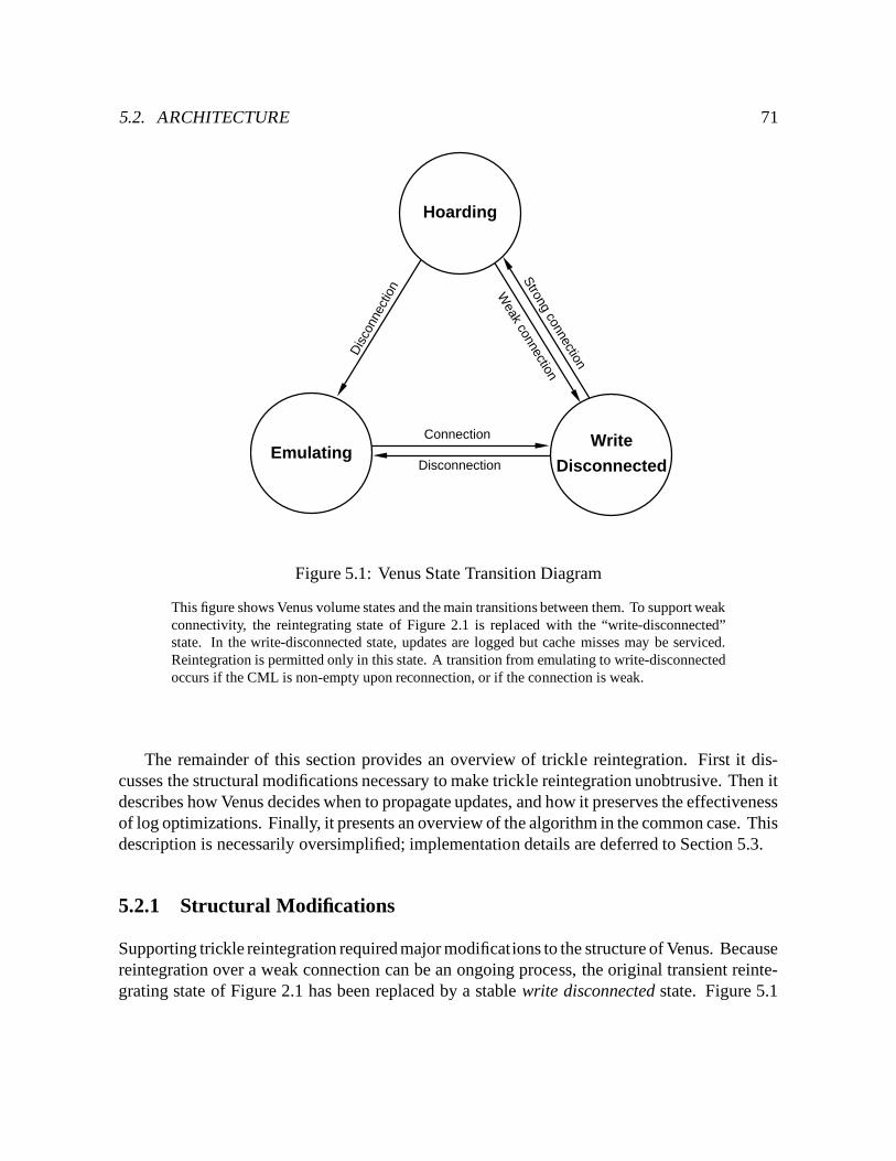
5.2. ARCHITECTURE 71
Hoarding
Write
DisconnectedEmulating
Dis
conn
ectio
n
Disconnection
Connection
Strong connection
Weak connection
Figure 5.1: Venus State Transition Diagram
This figure shows Venus volume states and the main transitions between them. To support weakconnectivity, the reintegrating state of Figure 2.1 is replaced with the “write-disconnected”state. In the write-disconnected state, updates are logged but cache misses may be serviced.Reintegration is permitted only in this state. A transition from emulating to write-disconnectedoccurs if the CML is non-empty upon reconnection, or if the connection is weak.
The remainder of this section provides an overview of trickle reintegration. First it dis-cusses the structural modifications necessary to make trickle reintegration unobtrusive. Then itdescribes how Venus decides when to propagate updates, and how it preserves the effectivenessof log optimizations. Finally, it presents an overview of the algorithm in the common case. Thisdescription is necessarily oversimplified; implementation details are deferred to Section 5.3.
5.2.1 Structural Modifications
Supporting trickle reintegration required major modifications to the structure of Venus. Becausereintegration over a weak connection can be an ongoing process, the original transient reinte-grating state of Figure 2.1 has been replaced by a stable write disconnected state. Figure 5.1
72 CHAPTER 5. TRICKLE REINTEGRATION
shows the volume states of Venus and the main transitions between them.
As in the original state model, Venus is in the hoarding state when strongly connected,and in the emulating state when disconnected. When weakly connected, Venus is in the writedisconnected state. Venus’s behavior in this state is a blend of connected and disconnectedmodes. As in connected mode, Venus services cache misses (although some misses may requireuser intervention), and maintains cache coherence using callbacks. As in disconnected mode,Venus performs updates locally and logs them in the CML, and then propagates them to serversasynchronously using trickle reintegration.
Since connectivity is a per-volume property, it is possible for a client to be in different stateswith respect to different volumes at a given moment. For example, a mobile client may beweakly connected with respect to most volumes, but may be disconnected with respect to a fewbecause their server is down.
A user can force a full reintegration at any time that she is in the write disconnected state.This might be valuable, for example, if she wishes to terminate a long distance phone call orrealizes that she is about to move out of range of wireless communication. It is also valuableif she wishes to ensure that recent updates have been propagated to a server before notifying acollaborator via telephone, e-mail, or other out-of-band mechanism.
To avoid penalizing strongly-connected clients, a weakly-connected client cannot preventthem from reading or updating objects awaiting reintegration. Read requests by stronglyconnected clients are satisfied with data present at the server, because there is no guarantee thatthe weakly connected updates will propagate in a timely manner (e.g., the weakly connectedclient may become disconnected) or at all (e.g., the updates may fail when performed at theserver). Updates by strongly connected clients result in callback breaks at the weakly connectedclient. A callback break does not necessarily mean there is a write-write conflict that wouldprevent reintegration from succeeding; for example, the clients may have added different namesto the same directory. Therefore, the client ignores the callback and proceeds as usual. If thereis a conflict, it is detected at reintegration time, and may be resolvable automatically (e.g., withan application-specific resolver). Failing that, Venus makes the conflict visible to the user justas if it had occured after a disconnected session. The user may then apply the existing Codamechanisms for resolving conflicts [66].
5.2.2 Preserving the Effectiveness of Log Optimizations
Trickle reintegration reduces the effectiveness of optimizations over the CML because recordsare propagated to the server earlier than when disconnected. Thus they have less opportunity tobe eliminated at the client. A good design must balance two factors. On the one hand, recordsshould spend enough time in the CML for optimizations to be effective. On the other hand,updates should be propagated to servers with reasonable promptness. At very low bandwidths,
5.2. ARCHITECTURE 73
the first concern is dominant since reduction of data volume is paramount. As bandwidthincreases, the concerns become comparable in importance. When strongly connected, promptpropagation is the dominant concern.
How can a client maximize log optimizations? The optimal strategy is to reintegrate onlythose log records that will not be cancelled. The strategy used to approximate this idealshould have the following properties. First, it should avoid reintegrating “hot spots” in thelog. Intuitively, hot spots are updates in the log that are cancelled quickly. If updates are goodcandidates for optimization, Venus should not attempt to reintegrate them; it should allow timefor optimizations to occur. Second, it should allow “cool” prefixes of the log to propagate tothe servers. Since the CML is maintained in temporal order, the oldest records are at the head.To ensure that updates arrive at the server with reasonable promptness, the head of the logshould not be blocked indefinitely when opportunities for reintegration arise. Intuitively, if anupdate resides in the CML “long enough”, it is probably worth reintegrating. Last, determiningwhether to reintegrate a record should be efficient.
Coda uses a simple strategy based on aging. The age of a CML record is the length of timeit has spent in the log. A record is not eligible for reintegration until it has spent a minimalamount of time in the CML. This amount of time is called the aging window, A. Aging avoidshot spots if the aging window is large enough. Cancellations remove older records, with newerrecords, if any, appended to the tail of the log. Aging also allows inactive log prefixes topropagate to the servers, even if other objects in the volume are active. Calculation of the ageis very simple and efficient; each CML record contains its creation time.
The aging window establishes a limit on the effectiveness of log optimizations. The currentimplementation uses a fixed A, the selection of which is described in Section 5.4. It would bea simple extension to Coda to make the aging window adaptive to connection strength. At lowbandwidths, a large aging window allows Venus to minimize data volume by taking advantageof log optimizations. As bandwidth increases, the benefits of propagating updates to the serveroutweigh the benefits of reducing the amount reintegrated. When strongly connected, there isno need to reduce data volume, and updates are propagated synchronously.
5.2.3 Overview of the Algorithm
Trickle reintegration is performed on volumes in the write-disconnected state. It proceeds in thethree stages described for reintegration in Section 2.2.2.3: the prelude, interlude, and postlude.The prelude refers to the preparations Venus makes for sending a reintegration request to theserver. The interlude refers to server processing of the reintegration request. The postludeis the client processing of server results and clean-up activities, including commit or abort ofthe CML records involved. Some of the steps enumerated below were discussed previously inSection 2.2.2.3; such steps are reviewed only briefly.
74 CHAPTER 5. TRICKLE REINTEGRATION
5.2.3.1 Prelude
Venus begins the prelude for a volume by checking if it is eligible for reintegration. This checkmay be triggered by a thread referencing an object in the volume, such as a worker LWP or thehoard daemon, or the volume daemon, which runs every five seconds. The triggering threadperforms the following checks to determine the volume’s eligibility:� volume state check – the volume must be write disconnected. By definition, this means
the AVSG is non-empty.� CML check – the volume’s CML must be non-empty.� authentication check – the volume must have authentication tokens for the CML owner.The server requires tokens to perform updates. If tokens are not present, Venus notifiesthe user that a reintegration is awaiting tokens.� reintegration check – the volume must not already be undergoing reintegration.
If the volume meets these conditions, the triggering thread scans the CML to determine if thereare records exceeding the aging window. If it finds ripe records, it dispatches a reintegratorthread to do the actual work, and then moves on to its next task. If any of the checks fail, thetriggering thread exits the prelude and moves on to its next task.
The reintegrator performs the rest of the reintegration. It begins by completing the prelude,the remainder of which consists of the following steps:� prevent interference. Venus allows most read and update activity in the volume to
proceed during trickle reintegration. However, there are several tasks which may interferewith reintegration, or which require exclusive control of the volume to execute. Thesetasks are blocked until trickle reintegration completes:
– application-specific resolvers (ASRs), which require control over when their updatesare propagated. ASRs use the write-disconnected state and update logging in placeof transactional support. Blocking them prevents the reintegrator from reintegratingtheir updates inappropriately.
– the checkpoint daemon, which periodically writes a backup of the CML and associ-ated data to local disk. Blocking this daemon is necessary because the reintegratormay modify the CML.
– resolution, which requires exclusive control of the volume.� cancel store records for files open for write. If the file has been modified, the datain the container file may no longer match the description in the store record.
5.2. ARCHITECTURE 75� determine which records to reintegrate. The reintegrator scans the log for records thatexceed the aging window. Since the CML is maintained in temporal order, the agingwindow partitions log records into two groups: a prefix containing records older than Aand a suffix containing records younger than A. If the client is weakly connected, thereintegrator selects a subset of the prefix, the size of which depends on the size of therecords and data involved and the bandwidth of the network. The selection of this subsetwill be discussed in Section 5.3.2. The reintegrator then erects a logical divider called thereintegration barrier in the CML as shown in Figure 5.2. During reintegration, whichmay take a substantial amount of time on a slow network, the portion of the CML tothe left of the reintegration barrier is frozen. Only records to the right are examined foroptimization.� replace temporary fids. While write-disconnected, Venus may run out of permanentfids for newly created objects. If so, it assigns temporary fids to those objects, ratherthan incur the delay of an RPC to the server to obtain permanent fids during the servicingof a request. If any of the selected records contain temporary fids, Venus now obtainspermanent fids from the server via a ViceAllocFid RPC, and replaces the temporaryones.� lock objects of store records. Because Venus may service updates during reintegra-tion, the reintegrator must lock the objects associated with store records to ensure theirdata is consistent for backfetching. Locking is described in more detail in Section 5.3.1.� pack log records. The reintegrator allocates an in-memory buffer and marshals the logrecords into it.� select the servers for reintegration. If the client is weakly-connected, the reintegratorchooses a single server with which to reintegrate. Otherwise, it reintegrates with allAVSG members. This selection is discussed in more detail in Section 5.3.5.
The reintegrator completes the prelude by sending a ViceReintegrate RPC to theserver. The RPC interface is shown in Figure 5.3.
5.2.3.2 Interlude
The interlude is the processing of the ViceReintegrate RPC at the server. The RPC2socket listener receives the request and dispatches a Vice worker LWP to process it. Theprocessing consists of the following main steps:� retrieve the CML. The CML does not arrive as an argument of the RPC request; rather,
the Vice worker transfers it in bulk through an RPC2 side-effect into an in-memory buffer.
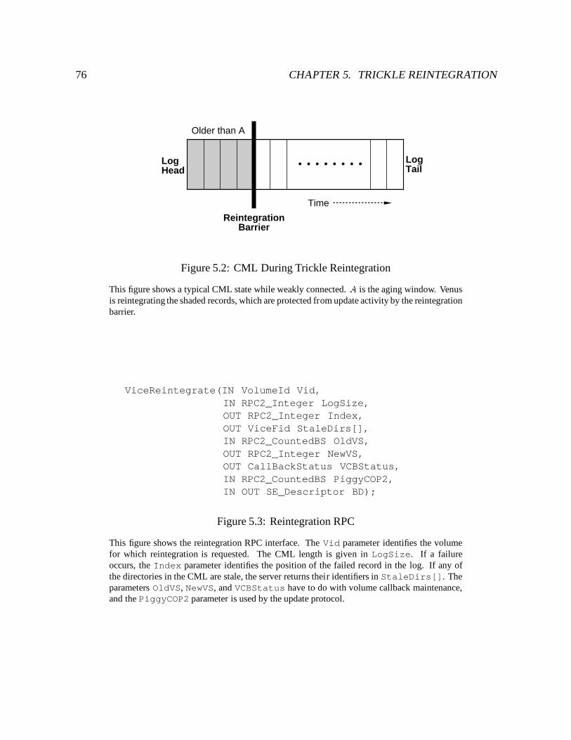
76 CHAPTER 5. TRICKLE REINTEGRATION
Older than A
• • • • • • • •
Time
ReintegrationBarrier
LogHead
LogTail
Figure 5.2: CML During Trickle Reintegration
This figure shows a typical CML state while weakly connected. A is the aging window. Venusis reintegrating the shaded records, which are protected from update activity by the reintegrationbarrier.
ViceReintegrate(IN VolumeId Vid,IN RPC2_Integer LogSize,OUT RPC2_Integer Index,OUT ViceFid StaleDirs[],IN RPC2_CountedBS OldVS,OUT RPC2_Integer NewVS,OUT CallBackStatus VCBStatus,IN RPC2_CountedBS PiggyCOP2,IN OUT SE_Descriptor BD);
Figure 5.3: Reintegration RPC
This figure shows the reintegration RPC interface. The Vid parameter identifies the volumefor which reintegration is requested. The CML length is given in LogSize. If a failureoccurs, the Index parameter identifies the position of the failed record in the log. If any ofthe directories in the CML are stale, the server returns their identifiers in StaleDirs[]. Theparameters OldVS, NewVS, and VCBStatus have to do with volume callback maintenance,and the PiggyCOP2 parameter is used by the update protocol.
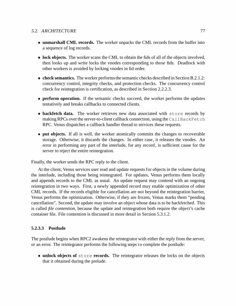
5.2. ARCHITECTURE 77� unmarshall CML records. The worker unpacks the CML records from the buffer intoa sequence of log records.� lock objects. The worker scans the CML to obtain the fids of all of the objects involved,then looks up and write locks the vnodes corresponding to those fids. Deadlock withother workers is avoided by locking vnodes in fid order.� check semantics. The worker performs the semantic checks described in Section B.2.1.2:concurrency control, integrity checks, and protection checks. The concurrency controlcheck for reintegration is certification, as described in Section 2.2.2.3.� perform operation. If the semantic checks succeed, the worker performs the updatestentatively and breaks callbacks to connected clients.� backfetch data. The worker retrieves new data associated with store records bymaking RPCs over the server-to-client callback connection, using theCallBackFetchRPC. Venus dispatches a callback handler thread to services these requests.� put objects. If all is well, the worker atomically commits the changes to recoverablestorage. Otherwise, it discards the changes. In either case, it releases the vnodes. Anerror in performing any part of the interlude, for any record , is sufficient cause for theserver to reject the entire reintegration.
Finally, the worker sends the RPC reply to the client.
At the client, Venus services user read and update requests for objects in the volume duringthe interlude, including those being reintegrated. For updates, Venus performs them locallyand appends records to the CML as usual. An update request may contend with an ongoingreintegration in two ways. First, a newly appended record may enable optimization of otherCML records. If the records eligible for cancellation are not beyond the reintegration barrier,Venus performs the optimization. Otherwise, if they are frozen, Venus marks them “pendingcancellation”. Second, the update may involve an object whose data is to be backfetched. Thisis called file contention, because the update and reintegration both require the object’s cachecontainer file. File contention is discussed in more detail in Section 5.3.1.2.
5.2.3.3 Postlude
The postlude begins when RPC2 awakens the reintegrator with either the reply from the server,or an error. The reintegrator performs the following steps to complete the postlude:� unlock objects of store records. The reintegrator releases the locks on the objects
that it obtained during the prelude.
78 CHAPTER 5. TRICKLE REINTEGRATION� process result. If reintegration succeeded, the reintegrator atomically commits therecords in the prefix. Commitment includes updating object state such as version vectorsand data versions, and clearing the dirty bit for objects that are no longer represented inthe CML. The reintegrator then removes the reintegration barrier and all the records toits left. If the server indicated that any of the directories involved in the reintegration arestale (the StaleDirs out-parameter), the reintegrator invalidates them. The need forthis parameter is discussed in Section 5.3.3. Finally, the reintegrator clears any pendingCML cancellations, as the records on which they depend have been committed at theAVSG.
If reintegration failed, the reintegrator’s actions depend on the type of failure that oc-curred.
– semantic failure – this is a failure in which the server rejects an update, for example,because of a write-write conflict. If the server cannot replay an update, it returnsthe index of the offending record. Since there is a reply from each AVSG member,the reintegrator identifies the offender with the smallest index. It then checkpointsthe CML state to local disk, removes the reintegration barrier, and performs anypending optimizations. If the offending record remains, the reintegrator marks theobjects involved in conflict. Note that once an object is marked in conflict, thesubtree beneath it is inaccessible until the conflict is repaired. The local state isavailable through repair tools. CML records associated with this local state remainin the log, but they are tagged to prevent their inclusion in future reintegrationattempts.
– retryable failure – this is a failure in which the server’s response suggests that thereintegration may succeed if tried again later. For example, the server may betemporarily busy. The reintegrator cancels records marked pending as in semanticfailures, waits a predefined period of time, and then retries the reintegration. Thereis a fixed number of retries permissible, after which the failure is treated as asemantic failure.
– timeout failure – this is a failure in which no response was received from theserver. Venus cannot make any assumptions about whether or not the reintegrationsucceeded at the server, so it leaves the log state as is until it contacts the server.This issue is discussed in Section 5.3.4.� invoke resolution. If Venus reintegrated with a subset of the AVSG, the reintegrator
invokes resolution on the reintegrated objects to propagate the updates to the remainderof the AVSG. This issue is discussed further in Section 5.3.5.� resume waiting threads. Any threads blocked by reintegration are resumed at this point.
Reintegration completes with the retirement of the reintegrator thread.
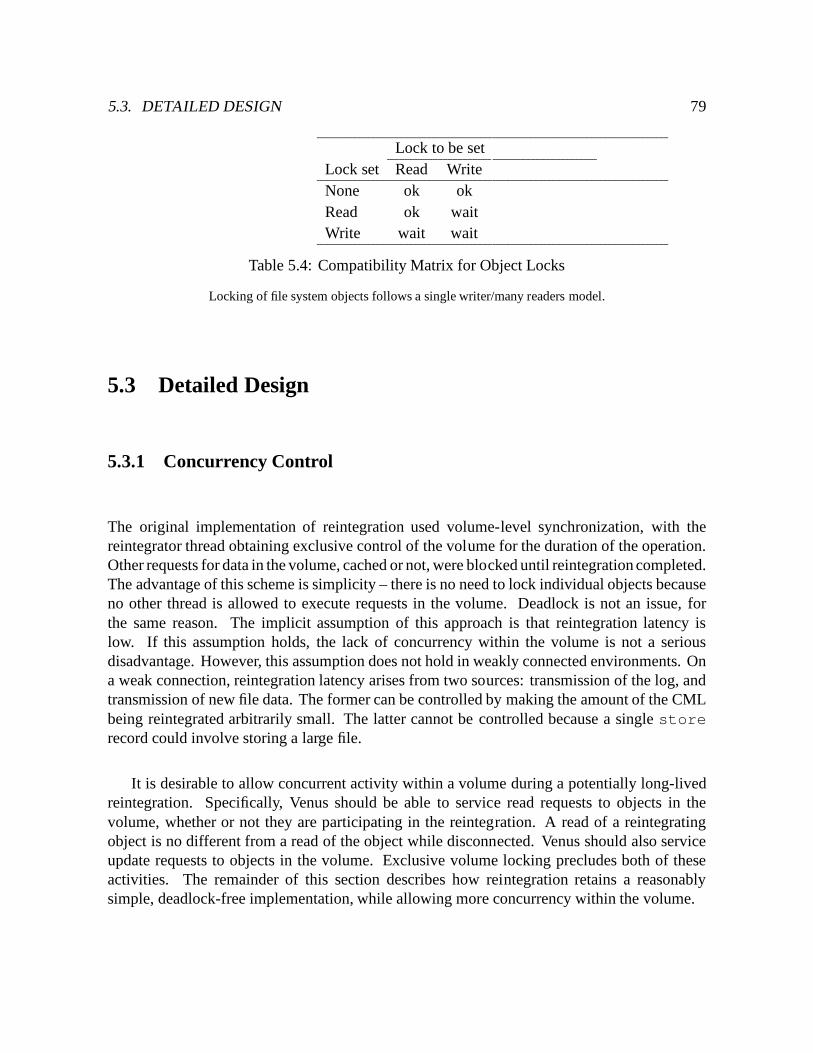
5.3. DETAILED DESIGN 79
Lock to be setLock set Read WriteNone ok okRead ok waitWrite wait wait
Table 5.4: Compatibility Matrix for Object Locks
Locking of file system objects follows a single writer/many readers model.
5.3 Detailed Design
5.3.1 Concurrency Control
The original implementation of reintegration used volume-level synchronization, with thereintegrator thread obtaining exclusive control of the volume for the duration of the operation.Other requests for data in the volume, cached or not, were blocked until reintegration completed.The advantage of this scheme is simplicity – there is no need to lock individual objects becauseno other thread is allowed to execute requests in the volume. Deadlock is not an issue, forthe same reason. The implicit assumption of this approach is that reintegration latency islow. If this assumption holds, the lack of concurrency within the volume is not a seriousdisadvantage. However, this assumption does not hold in weakly connected environments. Ona weak connection, reintegration latency arises from two sources: transmission of the log, andtransmission of new file data. The former can be controlled by making the amount of the CMLbeing reintegrated arbitrarily small. The latter cannot be controlled because a single storerecord could involve storing a large file.
It is desirable to allow concurrent activity within a volume during a potentially long-livedreintegration. Specifically, Venus should be able to service read requests to objects in thevolume, whether or not they are participating in the reintegration. A read of a reintegratingobject is no different from a read of the object while disconnected. Venus should also serviceupdate requests to objects in the volume. Exclusive volume locking precludes both of theseactivities. The remainder of this section describes how reintegration retains a reasonablysimple, deadlock-free implementation, while allowing more concurrency within the volume.
80 CHAPTER 5. TRICKLE REINTEGRATION
5.3.1.1 Object-Level Concurrency Control
Venus services reads and updates to objects in a volume undergoing trickle reintegration byusing object-level concurrency control. The reintegrator locks objects in the prelude and thepostlude. In the prelude, it read-locks the objects of store records. Locking is necessaryto ensure that the version of the data backfetched by the server is consistent with the storerecord. Read-locking prevents the objects from being updated or removed, as shown in theobject lock compatibility matrix in Figure 5.4.
In the postlude, if reintegration suffers a semantic failure, the reintegrator must abort theoffending records and quarantine the objects that were involved. The reintegrator must write-lock objects for abort to ensure that no other threads are reading or updating them. Thereintegrator does not lock objects during commit, even though the object’s version vectors areupdated, because it is the only reader and writer of these fields until the objects are cleaned.
During reintegration, Venus services read requests as usual, relying on cached state ifavailable (even if it is reintegrating), or fetching objects from servers if necessary. Venusperforms update requests locally and logs them in the CML. An update may require writeaccess to a file whose data is being backfetched (i.e., the file is read-locked). This phenomenonis called file contention, and is described below.
5.3.1.2 File Contention
Both volume and object-level concurrency control suffer from blocked updates to varyingdegrees. Object-level locking blocks repeated updates to the same file. Unfortunately, localityof reference suggests that even this case will happen frequently. (Indeed, this is why logoptimizations are so effective.) File contention usually indicates the aging window is too small,and it is most severe at the lowest bandwidths. To avoid holding resources while waiting forthe network, Venus creates a shadow copy of the cache container file associated with an fsobjwhen it detects contention. Shadowing thus involves no overhead in the absence of contention.As shown in Figure 5.5, the shadow includes a copy of the CacheFile structure used todescribe the container file. This structure consists of the container file name, its inode number,and its length.
When a thread tries to write lock an fsobj, Venus determines if the object is alreadylocked for backfetch. If so, the container file associated with the fsobj is moved to theshadow copy, and a new CacheFile structure is allocated to describe the shadow. The datafrom the shadow container file is then copied back to the main container file. The container fileis moved to the shadow rather than copied to preserve any backfetches already in progress, andto ensure that they complete out of the shadow. If the backfetch has not yet begun, the backfetchcode opens and fetches from the shadow if one exists. Once the shadow is constructed, theobject is unlocked, and the thread blocked on the write lock obtains the lock and proceeds.
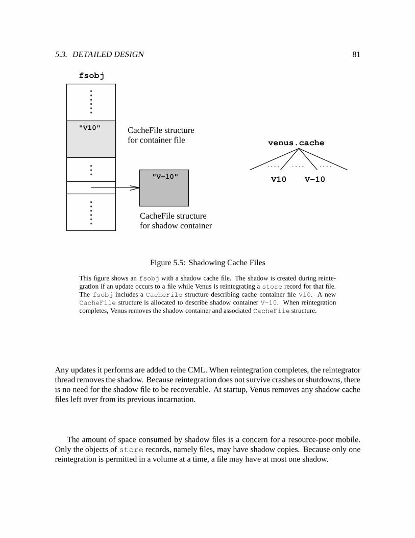
5.3. DETAILED DESIGN 81
CacheFile structurefor shadow container
CacheFile structurefor container file venus.cache
V-10V10
"V10"
"V-10"
fsobj
Figure 5.5: Shadowing Cache Files
This figure shows an fsobj with a shadow cache file. The shadow is created during reinte-gration if an update occurs to a file while Venus is reintegrating a store record for that file.The fsobj includes a CacheFile structure describing cache container file V10. A newCacheFile structure is allocated to describe shadow container V-10. When reintegrationcompletes, Venus removes the shadow container and associated CacheFile structure.
Any updates it performs are added to the CML. When reintegration completes, the reintegratorthread removes the shadow. Because reintegration does not survive crashes or shutdowns, thereis no need for the shadow file to be recoverable. At startup, Venus removes any shadow cachefiles left over from its previous incarnation.
The amount of space consumed by shadow files is a concern for a resource-poor mobile.Only the objects of store records, namely files, may have shadow copies. Because only onereintegration is permitted in a volume at a time, a file may have at most one shadow.
82 CHAPTER 5. TRICKLE REINTEGRATION
5.3.1.3 Deadlock Prevention
It is important to ensure that the reintegrator’s use of object locks is deadlock-free. Thenecessary conditions for deadlock are [96]:
1. Mutual exclusion – at least one resource must be held in a non-sharable mode.
2. Hold and wait – there must exist a thread that is holding at least one resource and waitingto acquire others.
3. No preemption – once a thread holds a resource, only it may release the resource.
4. Circular wait – the deadlock itself is a set of processes holding resources in a pattern thatforms a cycle in the wait-for graph.
In Venus, locks are non-preemptive, and write locks are non-sharable. To prevent deadlocks,either the “hold and wait” or the “circular wait” conditions must be prevented.1
During the prelude, the reintegrator read-locks the objects of store records. These objectsare files (i.e., leaf nodes in the file system hierarchy). For a deadlock involving the reintegratorto occur, there must be another thread that locks more than one leaf node (hold and wait), useswrite locks (mutual exclusion), and locks in no particular order (allows circular wait). There isonly one operation other than reintegration that write locks more than one leaf node – rename.Requiring both rename and reintegration to lock leaf nodes in fid order removes the circularwait, thereby preventing deadlock.
During the postlude of an aborted reintegration, the reintegrator write-locks all objectsinvolved. Unfortunately, these objects are not necessarily leaf nodes. Objects are aborted inorder of their occurrence in the CML, which is not necessarily in fid order. Thus there existsthe potential for deadlock during CML abort. To prevent deadlock, Venus removes the “holdand wait” condition by having the reintegrator thread first release its locks on the backfetchedobjects before abort, and then reacquire them as it aborts each record.2 If a record involvesmore than one object, the reintegrator locks, aborts, and unlocks each object one at a time.Because it does not hold and wait, it cannot be part of a deadlock.
1The original implementation’s use of an exclusive volume lock prevents deadlocks by removing the “holdand wait” condition, because the volume lock is the only lock that need be held. Despite this, the reintegratorthread still write locks objects during CML abort. If locks were held across requests, the reintegrator thread coulddeadlock.
2The objects do not vanish, even if subsequent updates delete them, as long as they are represented in theCML. Once the reintegrator releases the lock on an object, it is possible for another thread to service a requestinvolving the object before the reintegrator reacquires the lock. Such a request is doomed, in a sense, because itinvolves state that is about to be aborted. This example is an instance of a more general problem in which therequest arrives any time before the failed reintegration begins.
5.3. DETAILED DESIGN 83
5.3.2 Reducing the Impact of Reintegration
Given a prefix of the CML older thanA, how much of it should Venus reintegrate at once? Thereis a tradeoff associated with the amount of the log, or chunk size, that Venus sends to the serverfor a single reintegration. A small chunk size maximizes the likelihood of success, becausethere is less time for failures to strike, and there are fewer records to pass through semanticchecks at the server. A small chunk size also minimizes the likelihood that reintegration willinterfere with other tasks requiring the network, such as a demand fetch. On the other hand, alarge chunk size allows Venus to amortize the fixed costs of reintegration, such as RPC latencyand transaction commitment. Clearly, as network bandwidth increases, the effect of chunk sizeon reintegration latency decreases. The chunk size should therefore be adaptive to networkbandwidth.
The goal is to reintegrate the largest amount of data that is likely to succeed, withoutinterfering with other tasks requiring the network. Venus places a time limit on reintegration,and calculates the chunk size C based on this limit and an estimate of the current bandwidth.3
The default time limit is 30 seconds, which corresponds to a C of 36 KB at 9.6 Kb/s, 240 KBat 64 Kb/s, and 7.7 MB at 2 Mb/s. Venus then selects the maximal prefix of the CML that isolder than A and whose sizes sum to C or less. This prefix is the chunk for reintegration. Thereintegration barrier is placed after it, and reintegration proceeds as described in Section 5.2.3.This procedure is repeated a chunk at a time, deferring between chunks to high priority networkuse, until all records older than A have been reintegrated.
Because most log records are small, Venus is usually able to find a prefix of the log that fitswithin the reintegration limit. There is one exception, the store record, which is accompaniedby new file data. If the amount of data is large, reintegration of the store record alone mayexceed the reintegration limit. In this case, Venus should be able to make forward progresswithout monopolizing the link, and in spite of intermittence. Venus transfers the file as aseries of fragments, each of which fit within C. The state of the transfer is preserved acrossconnections; if a failure occurs, the transfer continues from the last successfully transferredfragment. The atomicity of reintegration is preserved, because the server does not reintegratethe store record until all of its data has arrived at the server. Note that this is the reverse of theprocedure at strong connectivity, where the server verifies the logical soundness of the updatesbefore fetching file data. The change in order reflects a change in the more likely cause ofreintegration failure in the two scenarios; while weakly connected, a failure during file transferis much more likely than a semantic failure.
This mechanism is simply a form of fragmentation and reassembly. While fragmentationand reassembly services are provided at lower system layers, the duration of reintegration over
3If a measure of the reliability of server connections is maintained, such as a distributionof connection lengths,the time threshold could also be made sensitive to intermittence.
84 CHAPTER 5. TRICKLE REINTEGRATION
a weak connection is long enough to warrant higher level control. Consistent with the end-to-end argument [107], Venus provides a high-level version of fragmentation and reassemblybecause only it has the information necessary to determine the appropriate chunk size. Usingthis mechanism, Venus can recover from failures without resending the entire file, allowing itto make incremental progress in spite of intermittence.
5.3.2.1 Reintegrating Fragments
When Venus transfers a fragment, the data is stored in a shadow inode for the file at the server.In this way the partially transferred data is not exposed to requests from other clients, andrequests from other clients are not blocked at the server while Venus transfers the new data.Venus references the shadow inode for a file using a handle. The handle is a 3-tuple consistingof the server birth time, and the shadow inode’s device and inode number. The handle isindependent of a specific connection, because the duration of a file transfer over a weak linkmay exceed the lifetime of a single connection. Indeed, it may even exceed the lifetime ofVenus. For this reason, Venus keeps handles in the store record, which is persistent.
Because Venus may disconnect for arbitrarily long periods, or may cancel a store recordbefore it finishes transferring the data, the server must be able to garbage collect shadow inodesperiodically. The salvager, a server thread which runs at startup, automatically garbage collectssuch inodes. To detect if a request involves a shadow inode that has been garbage collected,the server checks the birth time of the handle. This scheme could be generalized for garbagecollection at other times by using an epoch number in place of the server birth time.
There are four calls in the Vice interface pertaining to reintegration of files by fragment,shown in Figure 5.6. Venus requests creation of a shadow inode at the server using theViceOpenReintHandle call. The server returns a handle for a shadow inode associatedwith the specified fid. Venus retains the handles returned by the VSG in the store CMLrecord, and uses them in the remaining three calls. Venus sends fragments of a file using theViceSendReintFragment call. Venus transfers a fragment by specifying the offset withinthe file and the number of bytes to be transferred in the SFTP descriptor. Just as in a backfetch,Venus transfers the fragment from a shadow container file if one exists. Should a failure occur,Venus may check the status of a shadow inode using the ViceQueryReintHandle call,which validates the handle and returns the current length of the file at the server.4 When Venushas transferred all of the data to the server, the ViceCloseReintHandle call reintegratesthe store record using the data in the shadow inode. Except for the absence of a backfetch,the server performs the same reintegration interlude described in Section 2.2.2.3.
If multiple clients attempt to transfer fragments for the same file, the server will createshadow inodes for each client, and the handles it returns will differ by inode number. The host
4The query and send calls could be combined, but a separate query mechanism allows for more sophisticatedqueries and negotiation.
5.3. DETAILED DESIGN 85
that completes its data transfers and reintegrates first will succeed. Subsequent reintegrationsby the other hosts will fail.
5.3.2.2 Selective Reintegration
By default, the CML is reintegrated in temporal order. One possible refinement would allow auser to reintegrate updates pertaining to specific objects. To implement this refinement, Venusmust track the dependencies between records, and first reintegrate the antecedents of the updatesof interest. For example, updates to foo.tex depend on the creation of its parent directory.Dependencies are captured by a precedence graph [29] computed for the CML. A precedencegraph is a directed graph consisting of nodes representing transactions, and arcs representingdependencies between those transactions. The direction of the arc indicates the order betweenthe transactions. In the context of Coda, the transactions are CML records, and the dependenciesrefer to write dependencies.5 Precedence graph construction is not necessary at present becausethe temporal ordering of the CML guarantees that antecedents are reintegrated first.
5.3.3 Remote Updates and Volume Callbacks
There is an interaction between volume callbacks, discussed in Chapter 4, and reintegration ofupdates to directories that have been updated remotely. If an object is dirty, Venus considersit valid whether or not it holds a callback, and services requests for the object from the cache.Venus may obtain a callback on a volume for which it has dirty cached objects, and maintainthe volume callback through reintegration. Because directories are certified by value, it ispossible for Venus to cache stale directory state through a successful reintegration. Recall fromSection 4.1.2 that a volume callback may serve as a substitute for a file (directory) callback.Therefore, to maintain cache coherence, Venus must not retain both the stale directory state andthe volume callback.
This interaction does not occur frequently. To trigger it, a client must update a directorywhile disconnected or weakly connected. Then, before reintegrating, a second client mustupdate the directory at the server, and the first client must obtain a volume callback on thedirectory’s volume. Finally, the first client must reintegrate successfully, and maintain itsvolume callback.
A good solution to this problem requires computation and message traffic proportional onlyto the number of stale directories. That number is small, and often zero. Clearly, discarding thevolume callback after reintegration is not desirable. Nor is the class of solutions requiring workon every remote update (callback break), because not all remote updates correspond to dirty
5The CML does not contain enough information to capture read dependencies, such as in an operation catfoo > bar.
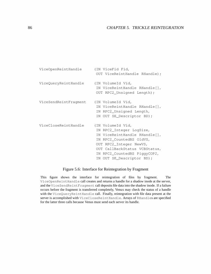
86 CHAPTER 5. TRICKLE REINTEGRATION
ViceOpenReintHandle (IN ViceFid Fid,OUT ViceReintHandle RHandle);
ViceQueryReintHandle (IN VolumeId Vid,IN ViceReintHandle RHandle[],OUT RPC2_Unsigned Length);
ViceSendReintFragment (IN VolumeId Vid,IN ViceReintHandle RHandle[],IN RPC2_Unsigned Length,IN OUT SE_Descriptor BD);
ViceCloseReintHandle (IN VolumeId Vid,IN RPC2_Integer LogSize,IN ViceReintHandle RHandle[],IN RPC2_CountedBS OldVS,OUT RPC2_Integer NewVS,OUT CallBackStatus VCBStatus,IN RPC2_CountedBS PiggyCOP2,IN OUT SE_Descriptor BD);
Figure 5.6: Interface for Reintegration by Fragment
This figure shows the interface for reintegration of files by fragment. TheViceOpenReintHandle call creates and returns a handle for a shadow inode at the server,and the ViceSendReintFragment call deposits file data into the shadow inode. If a failureoccurs before the fragment is transferred completely, Venus may check the status of a handlewith the ViceQueryReintHandle call. Finally, reintegration with file data present at theserver is accomplished with ViceCloseReintHandle. Arrays of RHandles are specifiedfor the latter three calls because Venus must send each server its handle.
5.3. DETAILED DESIGN 87
objects, and these solutions would introduce more distributed state into the system which wouldhave to be maintained. Solutions that involve validating dirty directories after reintegration arealso not ideal, because it is likely that most of the directories will not be stale.
Since the server performs version checks on each object involved in a reintegration, it isa simple matter for it to indicate which, if any, of the directories involved in the reintegrationare stale. The server returns, as a result of the ViceReintegrate RPC, a list of fids thatcorrespond to stale directories in the client’s cache. Venus marks those directories invalid, andpurges them once all references to them are cleared.6 If Venus maintains a volume callbackthrough the reintegration, it is assured that no clean directory state will become stale. Even ifVenus does not have a volume callback, it is still saved from performing doomed validations ofstale objects. The computation and message traffic expended by this solution is minimal, andproportional to the number of stale directories involved in the reintegration.
5.3.4 Ensuring Atomicity
The original implementation of reintegration was flawed with respect to one class of failures,namely, when a reintegration completes at the server successfully but the RPC response to theclient is lost in spite of retransmissions. This failure can occur if a network partition separatesthe client and server during the interlude. When this failure occurs, reintegration succeeds atthe server but fails at the client. Venus declares the server down and preserves the log stateso that the operation may be retried when the failure is repaired. Unfortunately, the retry isdoomed, because the operations have already completed at the server.
This problem is rare on LANs because of their high reliability – even if the RPC responseis lost, it is likely that the RPC layer at the client will retry the request and provoke anotherresponse. However, in an intermittent environment, this problem occurs frequently enough thatit must be addressed. The problem first arose on clients connected via SLIP. Although SLIPconnections are slow, one would expect them to be reasonably reliable. However, the SLIPgateway Coda clients used had a bug that caused it to freeze for periods exceeding the systemtimeout interval, thus producing intermittent behavior.
A standard solution to this sort of problem is to employ a distributed two-phase commitprotocol [28] in which the client is the coordinator, and the servers are subordinates. Each serverindicates whether or not the operation succeeded. The client collects the server responses, andif all is well, it sends a “commit” message to each server. Otherwise, it sends an “abort”message. Each server then commits or aborts the reintegration as instructed, and acknowledgesthe client. Reintegration completes at the client when it receives acknowledgements from allservers. Note that the server must be prepared to “go either way” with the request from the
6There may be other CML records, not yet reintegrated, that also refer to these directories. In the meantime,Venus may continue to service requests on these directories, including updates, from the cached copy.
88 CHAPTER 5. TRICKLE REINTEGRATION
time it indicates the outcome to the client to the time it receives the final outcome from theclient. In particular, all resources needed to complete the reintegration must be held until theoutcome is known. If the client crashes during this interval, the server is blocked, holding lockson the objects involved in the reintegration. Because clients may disconnect for arbitrarily longperiods, this vulnerability to failures makes distributed two-phase commit unattractive.
Instead, if the client times out, it presumes that the reintegration failed at the server (themore likely outcome), but detects if it succeeded. Servers retain the identity of the last recordreintegrated in each volume from each client. The identifier is the store ID embedded in eachlog record. The store ID is a hhost ID, uniquifieri pair. The uniquifier is initialized with thesystem time and incremented on each use. Thus the store ID is strictly increasing over time andunique across client restarts. When the server receives a CML, it compares the store ID of thefirst record with its last store ID for the client, if any. If its uniquifier is greater than that of thefirst log record, it returns an error to the client along with its store ID. The client then commitsall log records up to and including the one with the matching store ID and retries the operationwith the remaining CML.
To ensure atomicity, the server must commit the identifiers to recoverable storage. However,the administrative tasks required to change the format of a server’s recoverable storage areconsiderable. For this reason, the server maintains the identifiers in volatile memory. Hence,it is still possible for reintegration to fail non-atomically if the server crashes after completingreintegration, and the client does not receive a reply. This failure mode is no more frequentthan server crashes, and therefore no more frequent than its original occurrence rate in a LANenvironment.
After most failures, Venus applies log optimizations over the prefix of the log that was beingreintegrated. The advantage of optimizing after failures is two-fold: subsequent reintegrationsinvolve less data, and the offending record may be cancelled. However, care must be takenin applying log optimizations when the client times out, because one cannot be certain thatreintegration failed at the server. If reintegration succeeded, the results of records that the clientwould cancel may be visible to other clients. For example, suppose Venus has a CML containingrecords create foo, remove foo, create foo, and it times out while attempting toreintegrate the first create record. If the reintegration succeeded at the server, foo is globallyvisible. Venus must send the remove record to the server, otherwise the subsequent createwill fail. Therefore Venus applies optimizations over the log prefix for reintegration failuresonly if it receives a response from the server. If it receives no response, optimizations forrecords in the log prefix remain disabled until their fate is known.
For a replicated volume, the responses for a subset of the AVSG may be lost. In this case,the Venus times out on the corresponding servers, and reintegrates with the remaining AVSG.If reintegration succeeds, Venus commits the operations in the log prefix and discards thoserecords. If the AVSG then grows, the existing resolution mechanisms are applied to the objectsinvolved in the previous reintegration. If they are successful, the reintegration proceeds. It
5.3. DETAILED DESIGN 89
is possible for the client to find itself in a situation in which the servers do not agree on theidentity of the last reintegrated record. In this case, Venus declares failure and marks the objectsassociated with the log head in conflict, as it would for a semantic failure.
5.3.5 Effects of Server Replication
When strongly connected, Venus reintegrates with all AVSG members in parallel. Each serverreceives a copy of the CML, and then backfetches the new file data from the client. This strategyis based on the assumption that clients and servers are connected by a fast network. In suchan environment, it is reasonable to expend bandwidth to maximize availability by reintegratingwith as many AVSG members as possible. However, when bandwidth is scarce, Venus mustminimize the amount of data sent over the weak link, while still maximizing the probabilitythat all AVSG members receive the updates.
5.3.5.1 Backfetching
An obvious way to avoid sending multiple copies of data over the weak link is to use multicastbeneath RPC2, as described in Chapter 3. Unfortunately, in addition to the issues discussed inthat chapter, the implementation of reintegration is not structured to take advantage of multicast.Although Venus would no longer send multiple copies of the CML, each AVSG member wouldindividually backfetch a copy of the new file data. Servers perform backfetches independentlyon their server-to-client callback connections; logically these requests are not multicasts. Asthe data in Section 5.4 shows, the vast majority of data transferred during reintegration occursduring backfetch.
Backfetching over a different connection than the reintegration request introduces anotherproblem for weakly connected clients, namely, that traffic on the different connections caninterfere, even though it occurs on behalf of the same request. The connection on whichVenus makes the reintegration RPC has no knowledge of progress on the callback channel,and will time out if a response isn’t forthcoming. On a weak connection, the retransmissionscan contribute to congestion, and may cause the reintegration RPC to time out even thoughbackfetches are proceeding normally.
A solution to both of these problems is to modify RPC2 to allow multiple side effectsper RPC, rather than a single one. The reintegration RPC would then include a side effectdescriptor for the CML, as it does now, and an additional descriptor for each container filewhose contents are to be backfetched. The backfetches would occur in series, over the sameconnection as the reintegration request. This strategy would have lower RPC overhead thanthe current one, because only one RPC is performed per reintegration instead of an additionalRPC for each backfetch. Backfetch traffic would not interfere with the reintegration request
90 CHAPTER 5. TRICKLE REINTEGRATION
because RPC2 and its side effects share liveness information, as described in Section 3.2.3.Backfetches would also be amenable to multicasting. The main disadvantage of this scheme isthat if a failure occurs, communicating its identity to the application would be awkward.
5.3.5.2 Resolution
Coda uses a solution independent of multicast, relying instead on the resolution subsystem. Itassumes that the servers are strongly connected to each other – an assumption required by otherparts of Coda. While weakly connected, Venus reintegrates with a single server. If reintegrationsucceeds, the reintegrator thread then invokes resolution on all reintegrated objects to propagatethem to the remaining AVSG members. In principle, Venus could reintegrate with a subset ofthe AVSG, the size of which is dependent on the strength of the connection.
There are several potential drawbacks to an implementation that depends on resolution.First, resolution is performed lazily, imposing a delay when the object is next referenced. Butsince the reintegrator triggers resolution in the background, most if not all of the delay is hiddenfrom user requests. Second, servers break callbacks on the objects of resolution, because theresolution protocol updates at least their version vectors.7 Although Venus must refetch thestatus of the objects after resolution, it does not refetch the data unless the object’s data actuallychanged. Suppression of data fetches is described next in Section 5.3.5.3. Last, a guidingprinciple in the design of Coda is that clients bear the brunt of the work. Resolution is a four-phase protocol that involves all servers in the AVSG; compared to reintegration, resolutionis a heavyweight operation. Two factors mitigate the increased server load. First, a weakconnection limits the rate at which a client can issue server requests. Second, it is less costly fora server to fetch data from another strongly-connected server via resolution than to backfetchit from a weakly-connected client.
There is a refinement to this solution that would decrease the number of resolutions necessaryto propagate updates to all AVSG members. It is a hybrid of the reintegrate-with-all modelused by strongly-connected clients, and the reintegrate-with-one-and-resolve model used byweakly-connected clients. In the hybrid approach, Venus would send the CML to all servers,but only one server would backfetch new data. Venus would then invoke resolution only for theobjects of store records. This solution takes advantage of the fact that most of the data forreintegration is backfetched. It expends a small amount of bandwidth to eliminate resolutionand status refetch for directories, and may be useful for intermediate points in the connectivityspectrum. The implementation of this solution would require servers that do not backfetchleave enough state behind to trigger a resolution upon reference from any client, because afailure may prevent the reintegrating client from invoking resolution. This is not an issue
7The current implementation of resolution requires servers to update their version vectors whether or not theyperform compensating operations. The implementation could be refined in certain cases, such as file resolution,to suppress the callback break from servers that already possess the most recent copy of the object.
5.3. DETAILED DESIGN 91
in the reintegrate-with-one-and-resolve model, because only one server actually performs theupdates.
5.3.5.3 Suppressing Data Fetches
A callback break does not necessarily mean an object is invalid. It simply means that theserver no longer promises to tell the client if it becomes invalid. A server may break callbacksarbitrarily, for example, to garbage collect state. The client is free to request another callback.
A server sends callback breaks to clients when it performs an update, regardless of whetherthe update changed the status of the object or both status and data. Strongly connected clientsnormally invalidate and discard an object upon receiving a callback break. This could resultin unnecessary data fetches if the data was unchanged. While this is not a serious problem fora strongly connected client, a weakly connected client would be squandering knowledge thattakes time to obtain. Thus a weakly connected client should not discard data gratuitously; itshould retain it until there is strong evidence that the data is actually invalid. This is particularlyimportant in view of the resolution protocol, which updates at least the status of an object onevery invocation.
There are several ways to suppress unnecessary data fetches in the implementation. Codauses the data version field of the Vice status block to detect status-only updates. This field isused for concurrency control checks of non-replicated objects at the server, as a version vectoris used for replicated objects. It is incremented only during update operations that change thedata. When Venus receives a callback break, it retains the data until it obtains a new statusblock for the object. It then determines the currency of its data by checking a separate dataversion field. Since data version numbers may differ from server to server, Venus keeps avector of data versions, similar to the version vector, and checks the appropriate element foreach server. Validating an object then proceeds as follows. First Venus compares the versionvectors obtained from the server with the cached copy. If the version vectors are equal, theclient has the correct data. If the version vector check fails, and the server’s version vector isdominant, the updates at the server could have updated only the status, or both status and data.Venus uses the data version to distinguish the two cases. Data versions require maintenance.Venus must increment them after all locally performed updates. While disconnected, it mustalso decrement them as appropriate when CML records are cancelled.
The main advantage of the client-based solution is that no changes to the server implemen-tation are required. The disadvantage is that an extra status check is necessary after a callbackbreak to determine which part of the object changed.8 A cleaner solution, which would require
8An old version of AFS had a “Check and Fetch” RPC that worked as follows. A client supplies the statusblock of the file it has. If the status is valid, the server grants a callback. If the status is not valid, the server sendsthe new status block, then transfers new data, and then grants a callback. Either way, the client ends with new
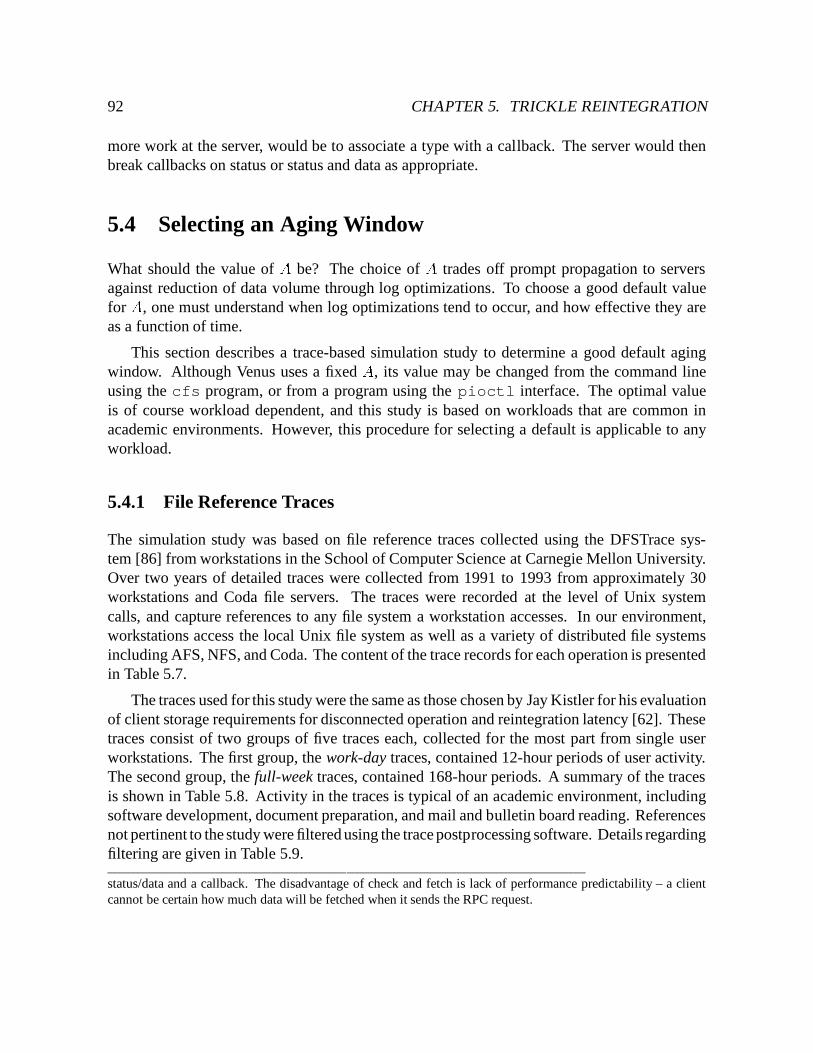
92 CHAPTER 5. TRICKLE REINTEGRATION
more work at the server, would be to associate a type with a callback. The server would thenbreak callbacks on status or status and data as appropriate.
5.4 Selecting an Aging Window
What should the value of A be? The choice of A trades off prompt propagation to serversagainst reduction of data volume through log optimizations. To choose a good default valuefor A, one must understand when log optimizations tend to occur, and how effective they areas a function of time.
This section describes a trace-based simulation study to determine a good default agingwindow. Although Venus uses a fixed A, its value may be changed from the command lineusing the cfs program, or from a program using the pioctl interface. The optimal valueis of course workload dependent, and this study is based on workloads that are common inacademic environments. However, this procedure for selecting a default is applicable to anyworkload.
5.4.1 File Reference Traces
The simulation study was based on file reference traces collected using the DFSTrace sys-tem [86] from workstations in the School of Computer Science at Carnegie Mellon University.Over two years of detailed traces were collected from 1991 to 1993 from approximately 30workstations and Coda file servers. The traces were recorded at the level of Unix systemcalls, and capture references to any file system a workstation accesses. In our environment,workstations access the local Unix file system as well as a variety of distributed file systemsincluding AFS, NFS, and Coda. The content of the trace records for each operation is presentedin Table 5.7.
The traces used for this study were the same as those chosen by Jay Kistler for his evaluationof client storage requirements for disconnected operation and reintegration latency [62]. Thesetraces consist of two groups of five traces each, collected for the most part from single userworkstations. The first group, the work-day traces, contained 12-hour periods of user activity.The second group, the full-week traces, contained 168-hour periods. A summary of the tracesis shown in Table 5.8. Activity in the traces is typical of an academic environment, includingsoftware development, document preparation, and mail and bulletin board reading. Referencesnot pertinent to the study were filtered using the trace postprocessing software. Details regardingfiltering are given in Table 5.9.
status/data and a callback. The disadvantage of check and fetch is lack of performance predictability – a clientcannot be certain how much data will be fetched when it sends the RPC request.
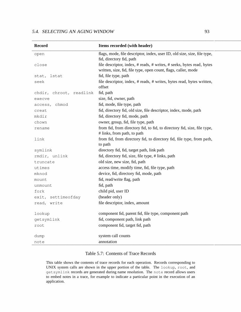
5.4. SELECTING AN AGING WINDOW 93
Record Items recorded (with header)
open flags, mode, file descriptor, index, user ID, old size, size, file type,fid, directory fid, path
close file descriptor, index, # reads, # writes, # seeks, bytes read, byteswritten, size, fid, file type, open count, flags, caller, mode
stat, lstat fid, file type, pathseek file descriptor, index, # reads, # writes, bytes read, bytes written,
offsetchdir, chroot, readlink fid, pathexecve size, fid, owner, pathaccess, chmod fid, mode, file type, pathcreat fid, directory fid, old size, file descriptor, index, mode, pathmkdir fid, directory fid, mode, pathchown owner, group, fid, file type, pathrename from fid, from directory fid, to fid, to directory fid, size, file type,
# links, from path, to pathlink from fid, from directory fid, to directory fid, file type, from path,
to pathsymlink directory fid, fid, target path, link pathrmdir, unlink fid, directory fid, size, file type, # links, pathtruncate old size, new size, fid, pathutimes access time, modify time, fid, file type, pathmknod device, fid, directory fid, mode, pathmount fid, read/write flag, pathunmount fid, pathfork child pid, user IDexit, settimeofday (header only)read, write file descriptor, index, amount
lookup component fid, parent fid, file type, component pathgetsymlink fid, component path, link pathroot component fid, target fid, path
dump system call countsnote annotation
Table 5.7: Contents of Trace Records
This table shows the contents of trace records for each operation. Records corresponding toUNIX system calls are shown in the upper portion of the table. The lookup, root, andgetsymlink records are generated during name resolution. The note record allows usersto embed notes in a trace, for example to indicate a particular point in the execution of anapplication.
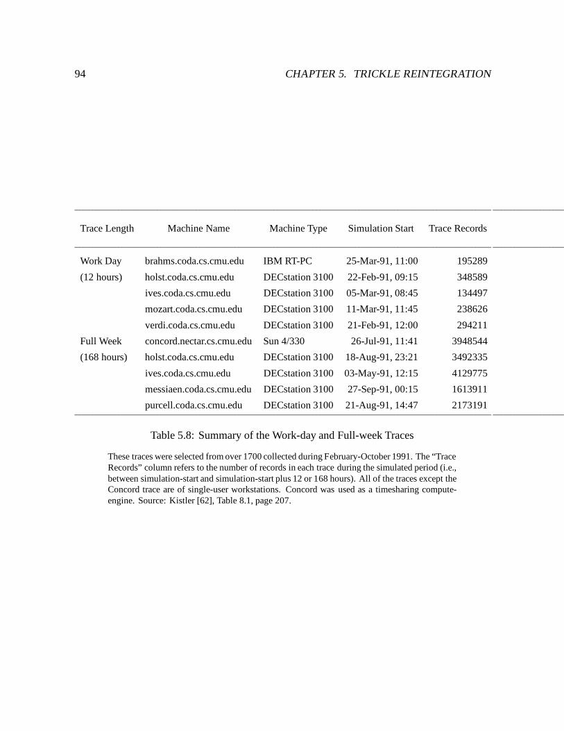
94 CHAPTER 5. TRICKLE REINTEGRATION
Trace Length Machine Name Machine Type Simulation Start Trace Records
Work Day brahms.coda.cs.cmu.edu IBM RT-PC 25-Mar-91, 11:00 195289
(12 hours) holst.coda.cs.cmu.edu DECstation 3100 22-Feb-91, 09:15 348589
ives.coda.cs.cmu.edu DECstation 3100 05-Mar-91, 08:45 134497
mozart.coda.cs.cmu.edu DECstation 3100 11-Mar-91, 11:45 238626
verdi.coda.cs.cmu.edu DECstation 3100 21-Feb-91, 12:00 294211
Full Week concord.nectar.cs.cmu.edu Sun 4/330 26-Jul-91, 11:41 3948544
(168 hours) holst.coda.cs.cmu.edu DECstation 3100 18-Aug-91, 23:21 3492335
ives.coda.cs.cmu.edu DECstation 3100 03-May-91, 12:15 4129775
messiaen.coda.cs.cmu.edu DECstation 3100 27-Sep-91, 00:15 1613911
purcell.coda.cs.cmu.edu DECstation 3100 21-Aug-91, 14:47 2173191
Table 5.8: Summary of the Work-day and Full-week Traces
These traces were selected from over 1700 collected during February-October 1991. The “TraceRecords” column refers to the number of records in each trace during the simulated period (i.e.,between simulation-start and simulation-start plus 12 or 168 hours). All of the traces except theConcord trace are of single-user workstations. Concord was used as a timesharing compute-engine. Source: Kistler [62], Table 8.1, page 207.
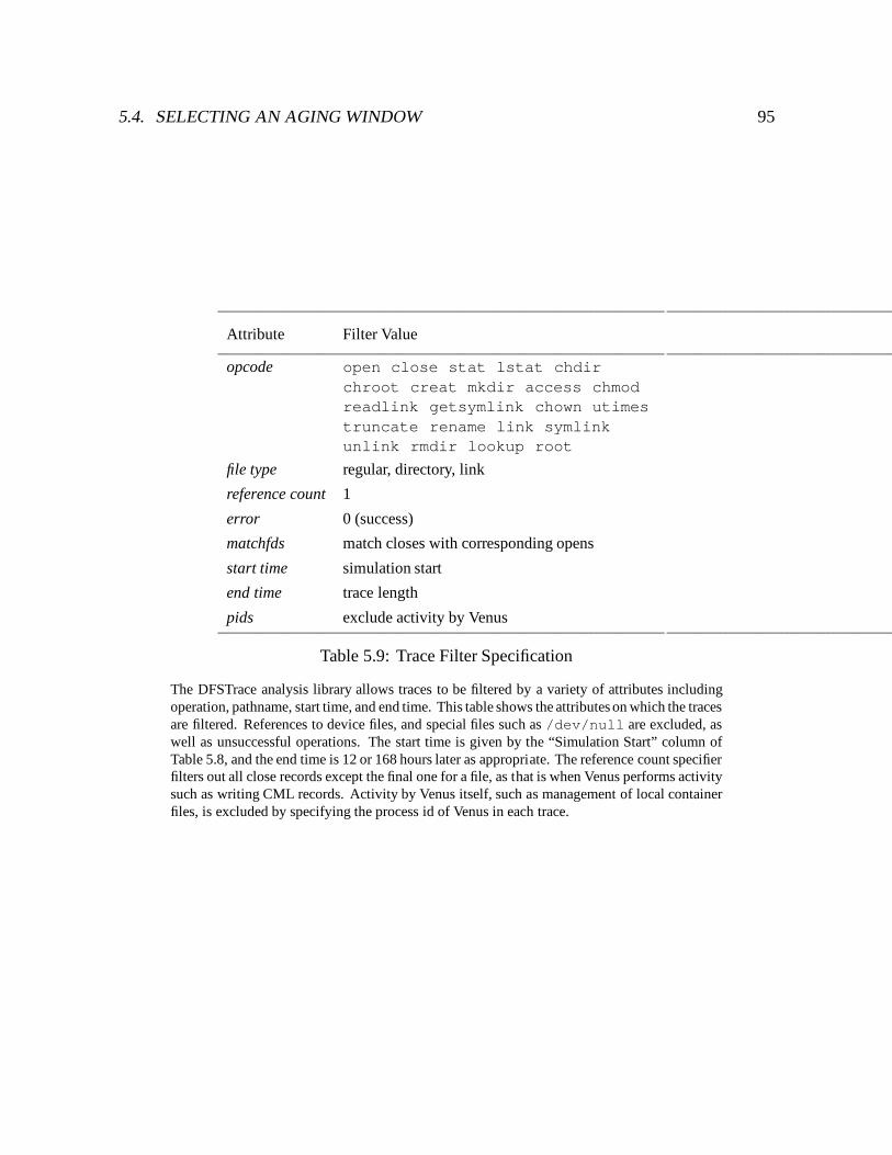
5.4. SELECTING AN AGING WINDOW 95
Attribute Filter Value
opcode open close stat lstat chdirchroot creat mkdir access chmodreadlink getsymlink chown utimestruncate rename link symlinkunlink rmdir lookup root
file type regular, directory, link
reference count 1
error 0 (success)
matchfds match closes with corresponding opens
start time simulation start
end time trace length
pids exclude activity by Venus
Table 5.9: Trace Filter Specification
The DFSTrace analysis library allows traces to be filtered by a variety of attributes includingoperation, pathname, start time, and end time. This table shows the attributes on which the tracesare filtered. References to device files, and special files such as /dev/null are excluded, aswell as unsuccessful operations. The start time is given by the “Simulation Start” column ofTable 5.8, and the end time is 12 or 168 hours later as appropriate. The reference count specifierfilters out all close records except the final one for a file, as that is when Venus performs activitysuch as writing CML records. Activity by Venus itself, such as management of local containerfiles, is excluded by specifying the process id of Venus in each trace.
96 CHAPTER 5. TRICKLE REINTEGRATION
5.4.2 Venus Simulator
The traces were used as input to a Venus simulator. To derive the timing of log optimizations, thesimulator must model the cache management responsibilities of Venus. Writing and validatingsuch a simulator is a difficult task at best. To avoid this, Venus was modified to act as its ownsimulator. In simulator mode, Venus is driven by requests from a trace instead of the operatingsystem. All network access, disk access, and communication with the operating system isstubbed out. Modifications that would normally occur in RVM take place in virtual memory.All volumes are placed in emulating state; updates are logged. The simulator output includesthe state of the CML at the end of the trace, and data on cancelled CML records.
The traces reference file systems other than Coda. For the purposes of simulation, all objectsreferenced in the trace are treated as if they were in the distributed file system. File systemsoutside of Coda are mapped into separate Coda volumes. The simulator assumes there are nocache misses; if an object unknown to Venus is referenced, the simulator implicitly creates it,but does not generate any explicit file system activity in the simulation.
5.4.3 Results
This section presents several sets of results showing the impact of the aging window onthe effectiveness of log optimizations. The analysis assumes throughout that records arereintegrated as soon as they become old enough, and that all reintegrations succeed. Theseassumptions render the aged CML records immune to further optimization. The section beginswith an analysis of the “base case”, in which results are normalized with respect to a maximumaging window of four hours. If a weak connection is available, it is likely that a user will makeuse of it periodically for the reasons listed at the beginning of this chapter, but in particular toreduce the probability of data loss. The four hour maximum represents half a typical workingday, and is a reasonable upper bound on the amount of work loss a user might be willing totolerate. The goal of this analysis is to find a default aging window that yields 50% effectiveness.That is, the default A should enable the client to optimize half of the CML data that it would ifit were disconnected for the entire four hour period. The analysis that follows shows that 50%effectiveness can be achieved with a default aging window of 10 minutes.
The remainder of the section presents a sensitivity analysis of two parameters. The firstparameter is the size of the maximum aging window. Instead of measuring the effectivenessof log optimizations with respect to a four-hour window as in the base case, this part of theanalysis compares the amount of optimization at a given A to that possible over the entirelength of the trace (12 or 168 hours). Since more optimizations are possible over the longerperiod, one would expect the value of A that yields 50% effectiveness to be larger than that forthe base case.
5.4. SELECTING AN AGING WINDOW 97
The second parameter is the set of files assumed to reside in the distributed file system. Thebase case includes all file references in the traces, other than those excluded by the filter givenin Table 5.9. In particular, the base case includes references to /tmp, which would normallyreside in the local file system. Previous work on file reference patterns shows that temporaryfiles tend to be both short-lived and small [39]. Their short lifetimes suggest they would belikely candidates for optimization, and might therefore skew the base case results towards asmaller aging window. On the other hand, their small size may render their effect on the amountof data saved insignificant.
The analysis shows that these perturbations do not change the conclusions of the base caseanalysis significantly. In all cases, the default value exceeds the median window for 50%effectiveness.9 To achieve 50% effectiveness for all ten traces, the aging window would haveto be 11 minutes for the base case. If the maximum window is equal to the full length of thetrace, the 50% mark is reached at 18 minutes; the increase is due to one of the week-long traces.If temporary files are excluded, and the four-hour maximum is used, the 50% mark is at 14minutes. Finally, if temporary files are excluded, and the maximum window is the full lengthof the trace, the 50% mark is at 48 minutes. The increase is due to three of the week long traces,whose 50% marks are at 30, 34, and 48 minutes, respectively.
5.4.3.1 Base Case
The base case assumes that updates are reintegrated no later than four hours after they areperformed. Intuitively, this behavior would occur with a write-disconnected client using anaging window of four hours. For this case, the effectiveness of log optimizations as a function ofthe aging window is normalized with respect to a maximum four-hour aging window. Table 5.10shows the CML sizes for each trace, with and without optimizations, for the base case. Theoptimized section shows the amount of data in the CML at the end of the period traced (full dayor work week) using a four-hour aging window. The unoptimized section shows the amountof data in the CML without optimizations; this amount is produced using an aging window of0. The table shows widely varying numbers of records per trace in both the unoptimized andoptimized sections. With the exception of the ives trace without optimizations, the majorityof data (87% or more) represented by the CML arises from the container files associated withstore records. Even for the unoptimized ives trace, the data size is 65% of the total amountreintegrated.
Figures 5.11 and 5.12 show effectiveness of CML optimizations for base case over the dayand week traces, respectively. The graphs show wide variation across traces. An aging windowof 300 seconds yields only a 30% effectiveness on some traces, but over 80% on others. Some
9The distribution of aging windows at 50% effectiveness has a large range and is skewed towards 0 for allcases. The median is the proper index of central tendency for such data [55].
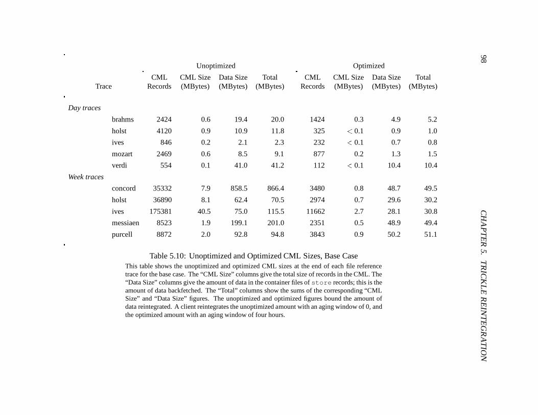
98C
HA
PT
ER
5.T
RIC
KL
ER
EIN
TE
GR
AT
ION
Unoptimized Optimized
CML CML Size Data Size Total CML CML Size Data Size TotalTrace Records (MBytes) (MBytes) (MBytes) Records (MBytes) (MBytes) (MBytes)
Day traces
brahms 2424 0.6 19.4 20.0 1424 0.3 4.9 5.2
holst 4120 0.9 10.9 11.8 325 < 0.1 0.9 1.0
ives 846 0.2 2.1 2.3 232 < 0.1 0.7 0.8
mozart 2469 0.6 8.5 9.1 877 0.2 1.3 1.5
verdi 554 0.1 41.0 41.2 112 < 0.1 10.4 10.4
Week traces
concord 35332 7.9 858.5 866.4 3480 0.8 48.7 49.5
holst 36890 8.1 62.4 70.5 2974 0.7 29.6 30.2
ives 175381 40.5 75.0 115.5 11662 2.7 28.1 30.8
messiaen 8523 1.9 199.1 201.0 2351 0.5 48.9 49.4
purcell 8872 2.0 92.8 94.8 3843 0.9 50.2 51.1
Table 5.10: Unoptimized and Optimized CML Sizes, Base CaseThis table shows the unoptimized and optimized CML sizes at the end of each file referencetrace for the base case. The “CML Size” columns give the total size of records in the CML. The“Data Size” columns give the amount of data in the container files of store records; this is theamount of data backfetched. The “Total” columns show the sums of the corresponding “CMLSize” and “Data Size” figures. The unoptimized and optimized figures bound the amount ofdata reintegrated. A client reintegrates the unoptimized amount with an aging window of 0, andthe optimized amount with an aging window of four hours.
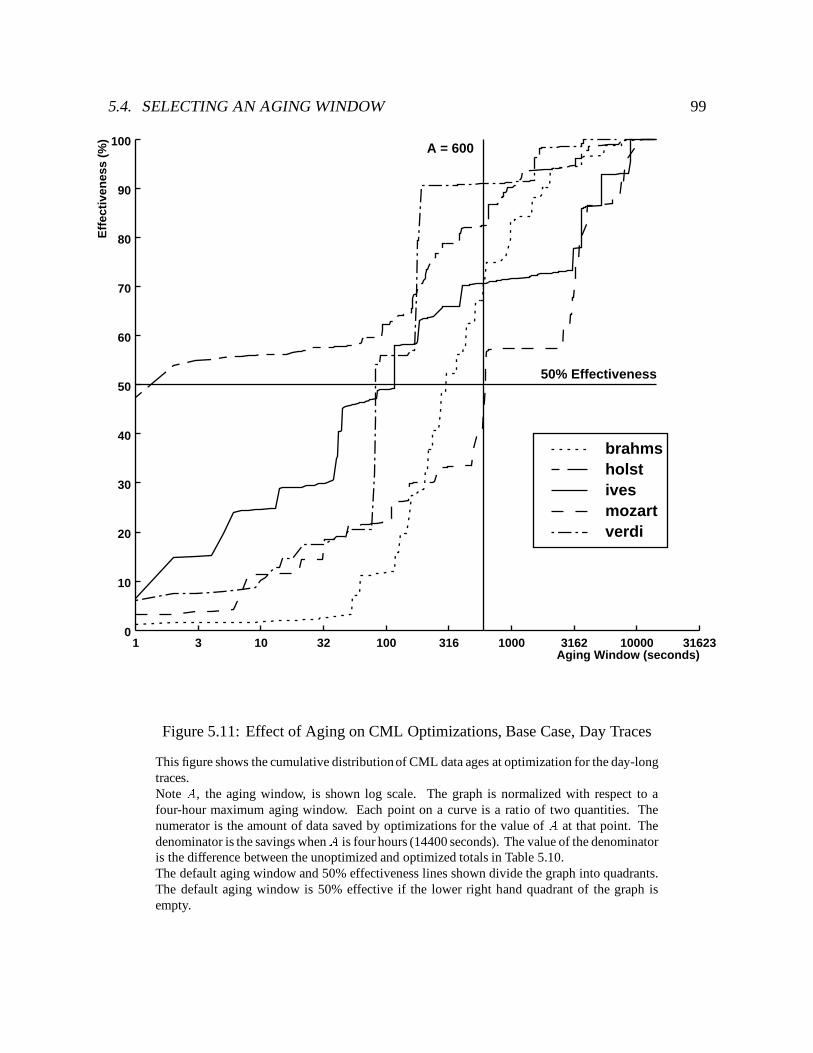
5.4. SELECTING AN AGING WINDOW 99
Aging Window (seconds)3 10 32 100 316 1000 3162 10000 31623
Eff
ecti
ven
ess
(%)
10
20
30
40
50
60
70
80
90
100
01
A = 600
50% Effectiveness
brahmsholstivesmozartverdi
Figure 5.11: Effect of Aging on CML Optimizations, Base Case, Day Traces
This figure shows the cumulative distribution of CML data ages at optimization for the day-longtraces.Note A, the aging window, is shown log scale. The graph is normalized with respect to afour-hour maximum aging window. Each point on a curve is a ratio of two quantities. Thenumerator is the amount of data saved by optimizations for the value of A at that point. Thedenominator is the savings whenA is four hours (14400 seconds). The value of the denominatoris the difference between the unoptimized and optimized totals in Table 5.10.The default aging window and 50% effectiveness lines shown divide the graph into quadrants.The default aging window is 50% effective if the lower right hand quadrant of the graph isempty.
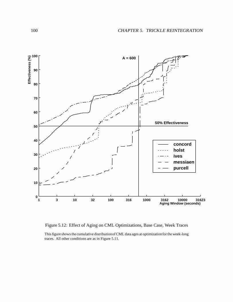
100 CHAPTER 5. TRICKLE REINTEGRATION
Aging Window (seconds)3 10 32 100 316 1000 3162 10000 31623
Eff
ecti
ven
ess
(%)
10
20
30
40
50
60
70
80
90
100
01
A = 600
50% Effectiveness
concordholstivesmessiaenpurcell
Figure 5.12: Effect of Aging on CML Optimizations, Base Case, Week Traces
This figure shows the cumulative distributionof CML data ages at optimizationfor the week-longtraces. All other conditions are as in Figure 5.11.
5.4. SELECTING AN AGING WINDOW 101
of the distributions have long tails: to reach 80% effectiveness on all traces, the aging windowmust be over one hour. For 50% effectiveness, the aging window ranges from 1 – 655 seconds,with a median of 65 seconds. An aging window of 600 seconds yields over 65% effectivenessfor eight of the ten traces. For the remaining two traces, the mozart day trace and the purcellweek trace, the effectiveness is 45% and 47%, respectively. Since 600 seconds yields nearly50% effectiveness on all traces for the base case, it was chosen as the default value for A. Inthe figures, the default aging window is 50% effective if the lower right hand quadrant of thegraph is empty.
5.4.3.2 Full-Length Aging Window
In this case, the client is considered disconnected for the entire trace, and log optimizationsmay occur at any time during that period. Table 5.13 shows the CML sizes at the end of eachtrace, with and without optimizations. The unoptimized section is the same as in Table 5.10.The optimized section shows the amount of data in the CML at the end of the period traced (fullday or work week). The optimized amounts for four of the day traces are virtually identical tothose in Table 5.10. The exception is the verdi trace, whose optimized size is less than half thatobtained with respect to a four hour aging window. The difference is due to the cancellationof two store records for a Venus binary (then just over 3MB) at approximately six hours ofage. The optimized data amounts for the week traces are all significantly lower than those inTable 5.10; they vary from 31–82% of the optimized amounts for the base case. This is notsurprising, because a week-long trace provides much more time for optimizations to occur. Asbefore, the majority of the data in the optimized logs arises from container files associated withstore records.
Figures 5.14 and 5.15 show the effectiveness of CML optimizations with respect to the CMLsize at the end of the day and week traces, respectively. Note that the X axes for Figures 5.14and 5.15 have different scales than the graphs for the base case. For 50% effectiveness, theaging window ranges between 2 – 1040 seconds, with a median of 199 seconds. The defaultaging window yields 51–82% effectiveness for eight of ten traces. The exceptions are themozart day trace and the purcell week trace. At 600 seconds the mozart day trace shows 45%effectiveness; it reaches the 50% mark at 620 seconds. The purcell day trace shows 35%effectiveness at 600 seconds; it requires 1040 seconds to reach 50% effectiveness. Overall,the lower right-hand quadrants of Figures 5.14 and 5.15 show that the default window yieldsnearly 50% effectiveness on nine of the ten traces.
Compared to the base case, the full length aging window made little difference for four of thefive day traces. The exception was the verdi trace, whose aging window for 50% effectivenessjumped from 83 to 174 seconds. The latter window is still much smaller than the default. Notsurprisingly, the week traces were affected more by a full-length aging window than the daytraces. The aging window for 50% effectiveness increased significantly for three of the five
102 CHAPTER 5. TRICKLE REINTEGRATION
week traces, holst, messiaen, and purcell. Only the window for purcell is larger than the defaultaging window.
5.4.3.3 No /tmp Files
This case assumes that /tmp resides in the local file system, and thus excludes trace referencesto it and its descendants. It preserves the maximum four-hour aging window as in the base case.Table 5.16 shows the CML sizes for each trace with respect to the maximum aging window offour hours, excluding references to /tmp. The table shows significantly lower unoptimizedlog sizes for most traces (compared to Table 5.10). In particular, the concord trace had over 200MB less data (a decrease of 28%). As before, the vast majority of data is from the containerfiles associated with store records. This decrease in log sizes illustrates the amount of updateactivity to /tmp in the traces. However, the optimized log sizes differed little from the basecase for all but two traces. The verdi day trace had 3.1 MB less data without /tmp files (adecrease of 30%), and messiaen week trace had 4.0 MB less data (a decrease of 8%). Theseobservations confirm that much of the activity to /tmp is subject to optimization.
Figures 5.17 and 5.18 show the effectiveness of CML optimizations with respect to a fourhour maximum aging window, excluding /tmp files. For 50% effectiveness, the aging windowranges from 1–813 seconds, with a median of 215 seconds. The default aging window yields58–85% effectiveness on seven of ten traces. The remaining three traces, the mozart day trace,the messiaen week trace, and the purcell week trace were all close to 50%, at 45%, 46%, and45% respectively.
Compared to the base case, the graphs show considerably lower effectiveness for smallaging windows. For example, at a 30 second aging window, the median effectiveness dropsfrom a 35% (range 3–77%) in the base case to 14% (range 1–65%) without /tmp files. Thisdecrease is consistent with short /tmp file lifetimes.
5.4.3.4 Full-Length Aging Window, No /tmp Files
This case excludes references to /tmp its descendants, and considers the client disconnectedfor the entire traced period. Table 5.19 shows the unoptimized and optimized log sizes at theend of each trace, excluding references to /tmp. Because updates to /tmp files are excluded,the unoptimized log sizes are smaller than in the full-length window case of Section 5.4.3.2.The optimized log sizes are virtually identical. Because optimizations have the full length ofthe trace to occur, the optimized log sizes are smaller for the verdi trace and the week tracescompared to the four-hour aging window case without /tmp files of Section 5.4.3.3.
Figures 5.20 and 5.21 show the effectiveness of CML optimizations excluding references to/tmp. Note that the X axes for these graphs have different scales than the graphs for the base
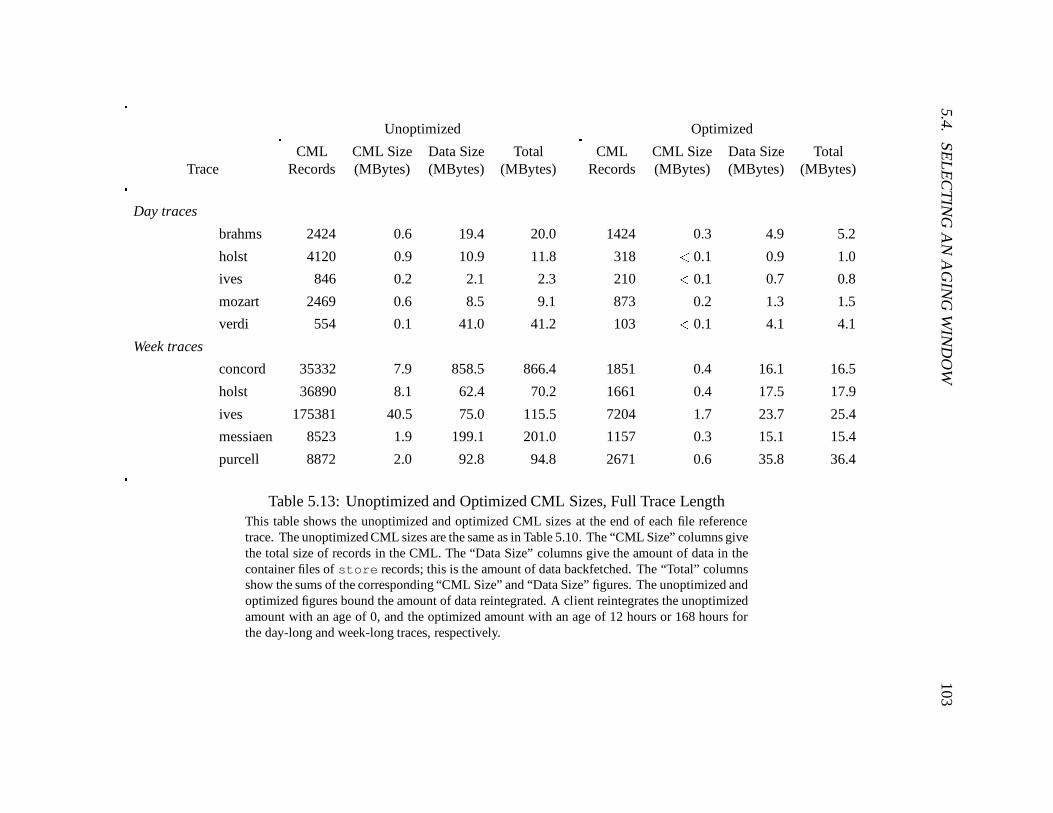
5.4.SE
LE
CT
ING
AN
AG
ING
WIN
DO
W103
Unoptimized Optimized
CML CML Size Data Size Total CML CML Size Data Size TotalTrace Records (MBytes) (MBytes) (MBytes) Records (MBytes) (MBytes) (MBytes)
Day traces
brahms 2424 0.6 19.4 20.0 1424 0.3 4.9 5.2
holst 4120 0.9 10.9 11.8 318 < 0.1 0.9 1.0
ives 846 0.2 2.1 2.3 210 < 0.1 0.7 0.8
mozart 2469 0.6 8.5 9.1 873 0.2 1.3 1.5
verdi 554 0.1 41.0 41.2 103 < 0.1 4.1 4.1
Week traces
concord 35332 7.9 858.5 866.4 1851 0.4 16.1 16.5
holst 36890 8.1 62.4 70.2 1661 0.4 17.5 17.9
ives 175381 40.5 75.0 115.5 7204 1.7 23.7 25.4
messiaen 8523 1.9 199.1 201.0 1157 0.3 15.1 15.4
purcell 8872 2.0 92.8 94.8 2671 0.6 35.8 36.4
Table 5.13: Unoptimized and Optimized CML Sizes, Full Trace LengthThis table shows the unoptimized and optimized CML sizes at the end of each file referencetrace. The unoptimized CML sizes are the same as in Table 5.10. The “CML Size” columns givethe total size of records in the CML. The “Data Size” columns give the amount of data in thecontainer files of store records; this is the amount of data backfetched. The “Total” columnsshow the sums of the corresponding “CML Size” and “Data Size” figures. The unoptimized andoptimized figures bound the amount of data reintegrated. A client reintegrates the unoptimizedamount with an age of 0, and the optimized amount with an age of 12 hours or 168 hours forthe day-long and week-long traces, respectively.
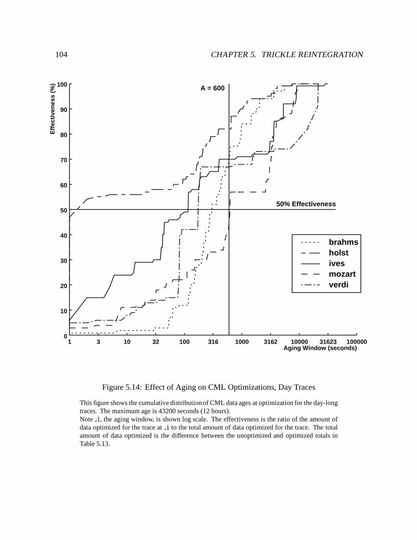
104 CHAPTER 5. TRICKLE REINTEGRATION
Aging Window (seconds)3 10 32 100 316 1000 3162 10000 31623 100000
Eff
ecti
ven
ess
(%)
10
20
30
40
50
60
70
80
90
100
01
A = 600
50% Effectiveness
brahmsholstivesmozartverdi
Figure 5.14: Effect of Aging on CML Optimizations, Day Traces
This figure shows the cumulative distribution of CML data ages at optimization for the day-longtraces. The maximum age is 43200 seconds (12 hours).Note A, the aging window, is shown log scale. The effectiveness is the ratio of the amount ofdata optimized for the trace at A to the total amount of data optimized for the trace. The totalamount of data optimized is the difference between the unoptimized and optimized totals inTable 5.13.
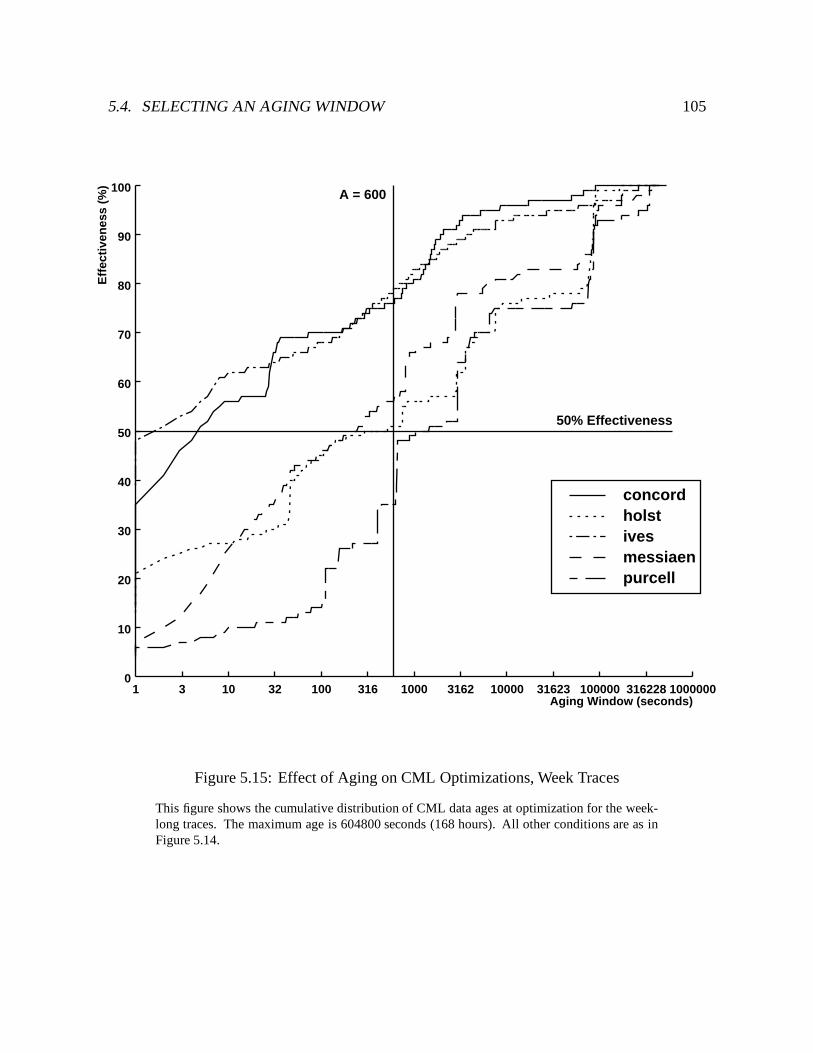
5.4. SELECTING AN AGING WINDOW 105
Aging Window (seconds)3 10 32 100 316 1000 3162 10000 31623 100000 316228 1000000
Eff
ecti
ven
ess
(%)
10
20
30
40
50
60
70
80
90
100
01
A = 600
50% Effectiveness
concordholstivesmessiaenpurcell
Figure 5.15: Effect of Aging on CML Optimizations, Week Traces
This figure shows the cumulative distribution of CML data ages at optimization for the week-long traces. The maximum age is 604800 seconds (168 hours). All other conditions are as inFigure 5.14.
106 CHAPTER 5. TRICKLE REINTEGRATION
case. For 50% effectiveness, the aging window ranges from 2–2851 seconds, with a median of275 seconds. The default aging window yields at least 50% effectiveness for six of the traces.Exceptions are the mozart day trace, and the holst, messiaen, and purcell week traces. Themozart day trace was close, at 45% effectiveness; it reaches the 50% mark at 623 seconds.
Compared to the base case, the median effectiveness is again significantly lower for smallaging windows. At 30 seconds, the median effectiveness drops from 35% (range 3-77%) in thebase case to 11% (range 1-61%). At 600 seconds, there is little difference for the day traces,but the effectiveness is lower for the three week traces mentioned previously.
5.5 Chapter Summary
This chapter describes trickle reintegration, the mechanism Venus uses to propagate updatesperformed at a weakly connected client. Trickle reintegration propagates updates in a besteffort manner, as network availability and bandwidth allows. At the same time, it conservesnetwork usage by delaying propagation to take advantage of updates that cancel or overwriteeach other. Because update propagation over a weak connection can be a lengthy process, it isimportant that trickle reintegration be unobtrusive; that is, it must not interfere with foregroundactivity at the client. The evaluation of trickle reintegration, in Section 7.5, will show that itachieves this goal.
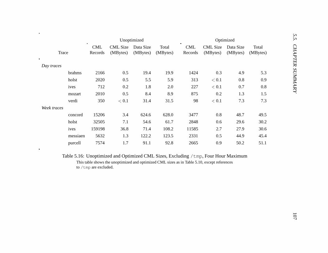
5.5.C
HA
PT
ER
SUM
MA
RY
107Unoptimized Optimized
CML CML Size Data Size Total CML CML Size Data Size TotalTrace Records (MBytes) (MBytes) (MBytes) Records (MBytes) (MBytes) (MBytes)
Day traces
brahms 2166 0.5 19.4 19.9 1424 0.3 4.9 5.3
holst 2020 0.5 5.5 5.9 313 < 0.1 0.8 0.9
ives 712 0.2 1.8 2.0 227 < 0.1 0.7 0.8
mozart 2010 0.5 8.4 8.9 875 0.2 1.3 1.5
verdi 350 < 0.1 31.4 31.5 98 < 0.1 7.3 7.3
Week traces
concord 15206 3.4 624.6 628.0 3477 0.8 48.7 49.5
holst 32505 7.1 54.6 61.7 2848 0.6 29.6 30.2
ives 159198 36.8 71.4 108.2 11585 2.7 27.9 30.6
messiaen 5632 1.3 122.2 123.5 2331 0.5 44.9 45.4
purcell 7574 1.7 91.1 92.8 2665 0.9 50.2 51.1
Table 5.16: Unoptimized and Optimized CML Sizes, Excluding /tmp, Four Hour MaximumThis table shows the unoptimized and optimized CML sizes as in Table 5.10, except referencesto /tmp are excluded.
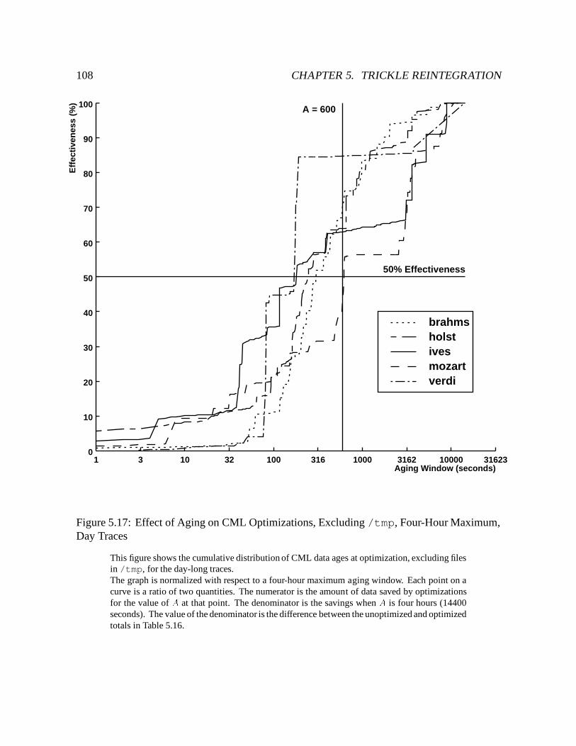
108 CHAPTER 5. TRICKLE REINTEGRATION
Aging Window (seconds)3 10 32 100 316 1000 3162 10000 31623
Eff
ecti
ven
ess
(%)
10
20
30
40
50
60
70
80
90
100
01
A = 600
50% Effectiveness
brahmsholstivesmozartverdi
Figure 5.17: Effect of Aging on CML Optimizations, Excluding /tmp, Four-Hour Maximum,Day Traces
This figure shows the cumulative distribution of CML data ages at optimization, excluding filesin /tmp, for the day-long traces.The graph is normalized with respect to a four-hour maximum aging window. Each point on acurve is a ratio of two quantities. The numerator is the amount of data saved by optimizationsfor the value of A at that point. The denominator is the savings when A is four hours (14400seconds). The value of the denominator is the difference between the unoptimized and optimizedtotals in Table 5.16.
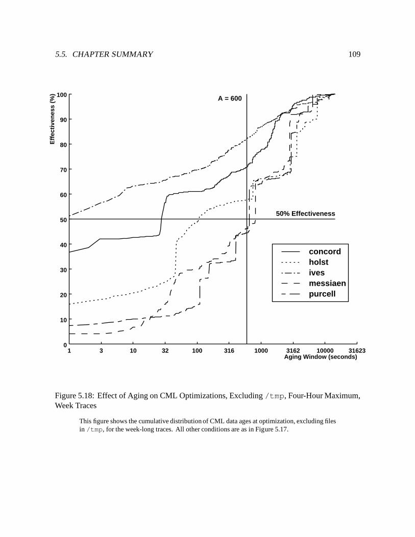
5.5. CHAPTER SUMMARY 109
Aging Window (seconds)3 10 32 100 316 1000 3162 10000 31623
Eff
ecti
ven
ess
(%)
10
20
30
40
50
60
70
80
90
100
01
A = 600
50% Effectiveness
concordholstivesmessiaenpurcell
Figure 5.18: Effect of Aging on CML Optimizations, Excluding /tmp, Four-Hour Maximum,Week Traces
This figure shows the cumulative distribution of CML data ages at optimization, excluding filesin /tmp, for the week-long traces. All other conditions are as in Figure 5.17.
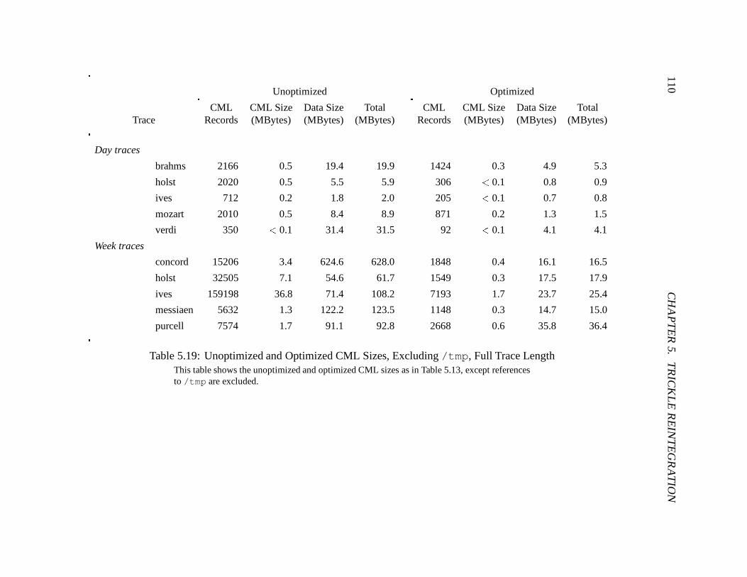
110C
HA
PT
ER
5.T
RIC
KL
ER
EIN
TE
GR
AT
ION
Unoptimized Optimized
CML CML Size Data Size Total CML CML Size Data Size TotalTrace Records (MBytes) (MBytes) (MBytes) Records (MBytes) (MBytes) (MBytes)
Day traces
brahms 2166 0.5 19.4 19.9 1424 0.3 4.9 5.3
holst 2020 0.5 5.5 5.9 306 < 0.1 0.8 0.9
ives 712 0.2 1.8 2.0 205 < 0.1 0.7 0.8
mozart 2010 0.5 8.4 8.9 871 0.2 1.3 1.5
verdi 350 < 0.1 31.4 31.5 92 < 0.1 4.1 4.1
Week traces
concord 15206 3.4 624.6 628.0 1848 0.4 16.1 16.5
holst 32505 7.1 54.6 61.7 1549 0.3 17.5 17.9
ives 159198 36.8 71.4 108.2 7193 1.7 23.7 25.4
messiaen 5632 1.3 122.2 123.5 1148 0.3 14.7 15.0
purcell 7574 1.7 91.1 92.8 2668 0.6 35.8 36.4
Table 5.19: Unoptimized and Optimized CML Sizes, Excluding /tmp, Full Trace LengthThis table shows the unoptimized and optimized CML sizes as in Table 5.13, except referencesto /tmp are excluded.
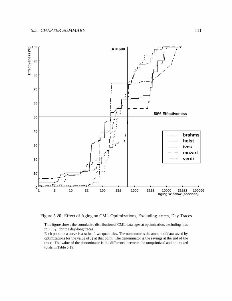
5.5. CHAPTER SUMMARY 111
Aging Window (seconds)3 10 32 100 316 1000 3162 10000 31623 100000
Eff
ecti
ven
ess
(%)
10
20
30
40
50
60
70
80
90
100
01
A = 600
50% Effectiveness
brahmsholstivesmozartverdi
Figure 5.20: Effect of Aging on CML Optimizations, Excluding /tmp, Day Traces
This figure shows the cumulative distribution of CML data ages at optimization, excluding filesin /tmp, for the day-long traces.Each point on a curve is a ratio of two quantities. The numerator is the amount of data saved byoptimizations for the value of A at that point. The denominator is the savings at the end of thetrace. The value of the denominator is the difference between the unoptimized and optimizedtotals in Table 5.19.
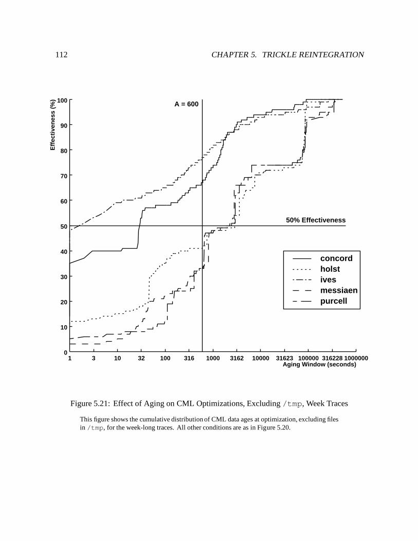
112 CHAPTER 5. TRICKLE REINTEGRATION
Aging Window (seconds)3 10 32 100 316 1000 3162 10000 31623 100000 316228 1000000
Eff
ecti
ven
ess
(%)
10
20
30
40
50
60
70
80
90
100
01
A = 600
50% Effectiveness
concordholstivesmessiaenpurcell
Figure 5.21: Effect of Aging on CML Optimizations, Excluding /tmp, Week Traces
This figure shows the cumulative distribution of CML data ages at optimization, excluding filesin /tmp, for the week-long traces. All other conditions are as in Figure 5.20.
Chapter 6
Handling Cache Misses
As connectivity weakens, the performance penalty of cache misses becomes too large to ignore.From a user’s perspective, this lack of performance transparency can overshadow the functionaltransparency of caching. For example, a cache miss on a 1 MB binary at 10 Mb/sec can usuallybe serviced in a second or two. At 9.6 Kb/sec, the same miss causes a delay of nearly 20minutes! In most cases, a user would rather be told that the file is missing than be forced towait a substantial time for it. But there are also situations where a file is so critical that a useris willing to suffer this delay. The maximum delay a user is willing to tolerate for a particularfile is called his patience threshold for that file.
How can Venus decide whether or not to service a cache miss while weakly connected? Asthe penalty for suboptimal decisions increases, so does the value of user advice. Venus usesa priori advice on a file’s importance as input to a model that determines the user’s patiencethreshold for the file. In cases where the servicing of a cache miss is still questionable, Venussolicits the user for advice through an interactive facility called the advice monitor. Useradvice is optional: if the client is unattended, or if a user does not run an advice monitor, Venusoperates from a set of default actions.
This chapter describes mechanisms for handling cache misses while weakly connected.The user assistance mechanisms are part of a more general framework by Ebling [35]; thischapter describes how that framework is applied to weak connectivity. The chapter begins bydescribing the advice monitor. It then shows how a user can interact with the system to controlthe amount of data fetched during cache miss servicing and hoard walks. The final sectiondelves into the underlying patience model.
113
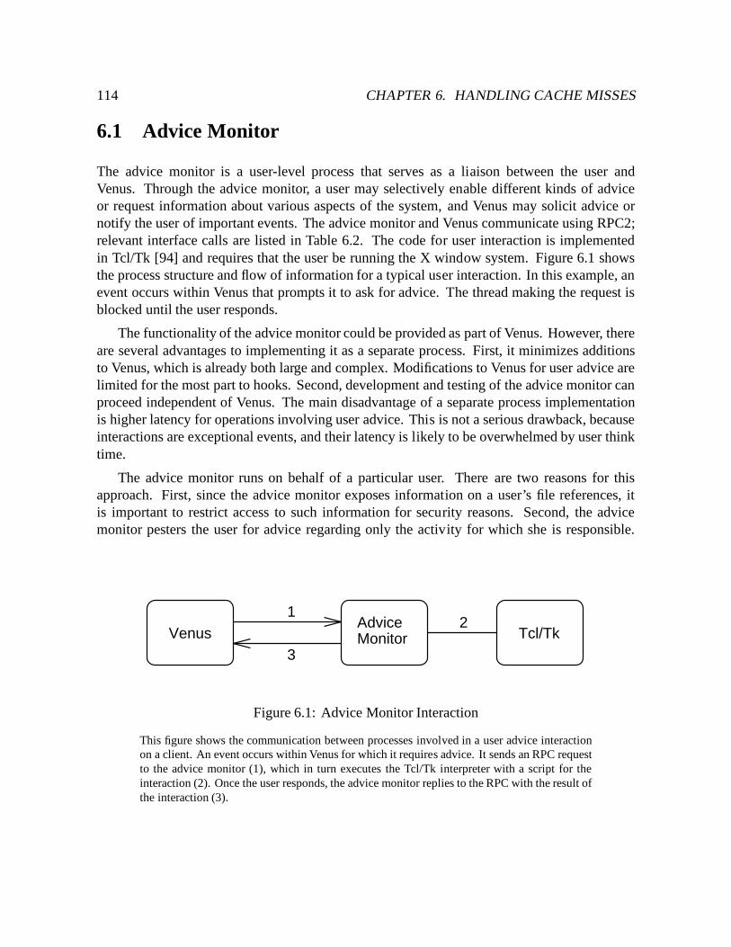
114 CHAPTER 6. HANDLING CACHE MISSES
6.1 Advice Monitor
The advice monitor is a user-level process that serves as a liaison between the user andVenus. Through the advice monitor, a user may selectively enable different kinds of adviceor request information about various aspects of the system, and Venus may solicit advice ornotify the user of important events. The advice monitor and Venus communicate using RPC2;relevant interface calls are listed in Table 6.2. The code for user interaction is implementedin Tcl/Tk [94] and requires that the user be running the X window system. Figure 6.1 showsthe process structure and flow of information for a typical user interaction. In this example, anevent occurs within Venus that prompts it to ask for advice. The thread making the request isblocked until the user responds.
The functionality of the advice monitor could be provided as part of Venus. However, thereare several advantages to implementing it as a separate process. First, it minimizes additionsto Venus, which is already both large and complex. Modifications to Venus for user advice arelimited for the most part to hooks. Second, development and testing of the advice monitor canproceed independent of Venus. The main disadvantage of a separate process implementationis higher latency for operations involving user advice. This is not a serious drawback, becauseinteractions are exceptional events, and their latency is likely to be overwhelmed by user thinktime.
The advice monitor runs on behalf of a particular user. There are two reasons for thisapproach. First, since the advice monitor exposes information on a user’s file references, itis important to restrict access to such information for security reasons. Second, the advicemonitor pesters the user for advice regarding only the activity for which she is responsible.
VenusAdviceMonitor Tcl/Tk
12
3
Figure 6.1: Advice Monitor Interaction
This figure shows the communication between processes involved in a user advice interactionon a client. An event occurs within Venus for which it requires advice. It sends an RPC requestto the advice monitor (1), which in turn executes the Tcl/Tk interpreter with a script for theinteraction (2). Once the user responds, the advice monitor replies to the RPC with the result ofthe interaction (3).
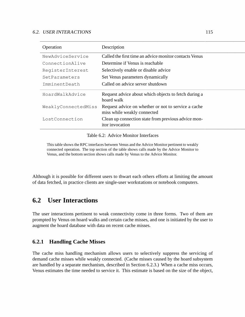
6.2. USER INTERACTIONS 115
Operation Description
NewAdviceService Called the first time an advice monitor contacts Venus
ConnectionAlive Determine if Venus is reachable
RegisterInterest Selectively enable or disable advice
SetParameters Set Venus parameters dynamically
ImminentDeath Called on advice server shutdown
HoardWalkAdvice Request advice about which objects to fetch during ahoard walk
WeaklyConnectedMiss Request advice on whether or not to service a cachemiss while weakly connected
LostConnection Clean up connection state from previous advice mon-itor invocation
Table 6.2: Advice Monitor Interfaces
This table shows the RPC interfaces between Venus and the Advice Monitor pertinent to weaklyconnected operation. The top section of the table shows calls made by the Advice Monitor toVenus, and the bottom section shows calls made by Venus to the Advice Monitor.
Although it is possible for different users to thwart each others efforts at limiting the amountof data fetched, in practice clients are single-user workstations or notebook computers.
6.2 User Interactions
The user interactions pertinent to weak connectivity come in three forms. Two of them areprompted by Venus on hoard walks and certain cache misses, and one is initiated by the user toaugment the hoard database with data on recent cache misses.
6.2.1 Handling Cache Misses
The cache miss handling mechanism allows users to selectively suppress the servicing ofdemand cache misses while weakly connected. (Cache misses caused by the hoard subsystemare handled by a separate mechanism, described in Section 6.2.3.) When a cache miss occurs,Venus estimates the time needed to service it. This estimate is based on the size of the object,
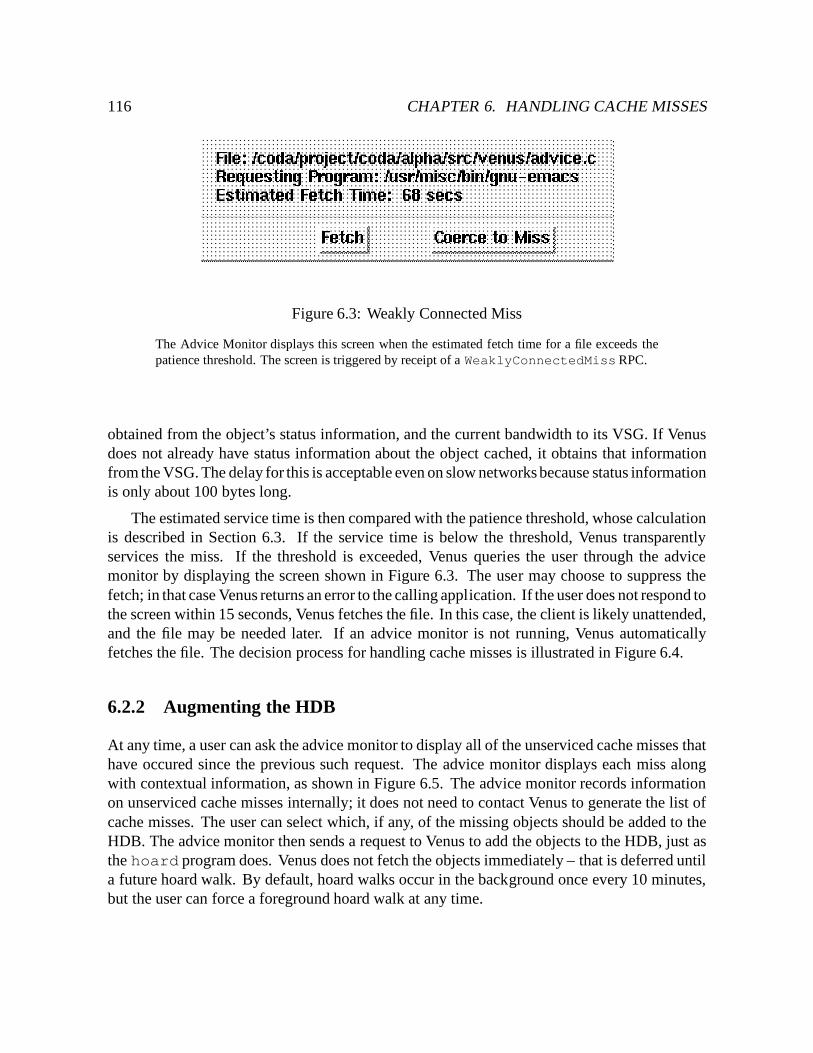
116 CHAPTER 6. HANDLING CACHE MISSES
Figure 6.3: Weakly Connected Miss
The Advice Monitor displays this screen when the estimated fetch time for a file exceeds thepatience threshold. The screen is triggered by receipt of a WeaklyConnectedMissRPC.
obtained from the object’s status information, and the current bandwidth to its VSG. If Venusdoes not already have status information about the object cached, it obtains that informationfrom the VSG. The delay for this is acceptable even on slow networks because status informationis only about 100 bytes long.
The estimated service time is then compared with the patience threshold, whose calculationis described in Section 6.3. If the service time is below the threshold, Venus transparentlyservices the miss. If the threshold is exceeded, Venus queries the user through the advicemonitor by displaying the screen shown in Figure 6.3. The user may choose to suppress thefetch; in that case Venus returns an error to the calling application. If the user does not respond tothe screen within 15 seconds, Venus fetches the file. In this case, the client is likely unattended,and the file may be needed later. If an advice monitor is not running, Venus automaticallyfetches the file. The decision process for handling cache misses is illustrated in Figure 6.4.
6.2.2 Augmenting the HDB
At any time, a user can ask the advice monitor to display all of the unserviced cache misses thathave occured since the previous such request. The advice monitor displays each miss alongwith contextual information, as shown in Figure 6.5. The advice monitor records informationon unserviced cache misses internally; it does not need to contact Venus to generate the list ofcache misses. The user can select which, if any, of the missing objects should be added to theHDB. The advice monitor then sends a request to Venus to add the objects to the HDB, just asthe hoard program does. Venus does not fetch the objects immediately – that is deferred untila future hoard walk. By default, hoard walks occur in the background once every 10 minutes,but the user can force a foreground hoard walk at any time.
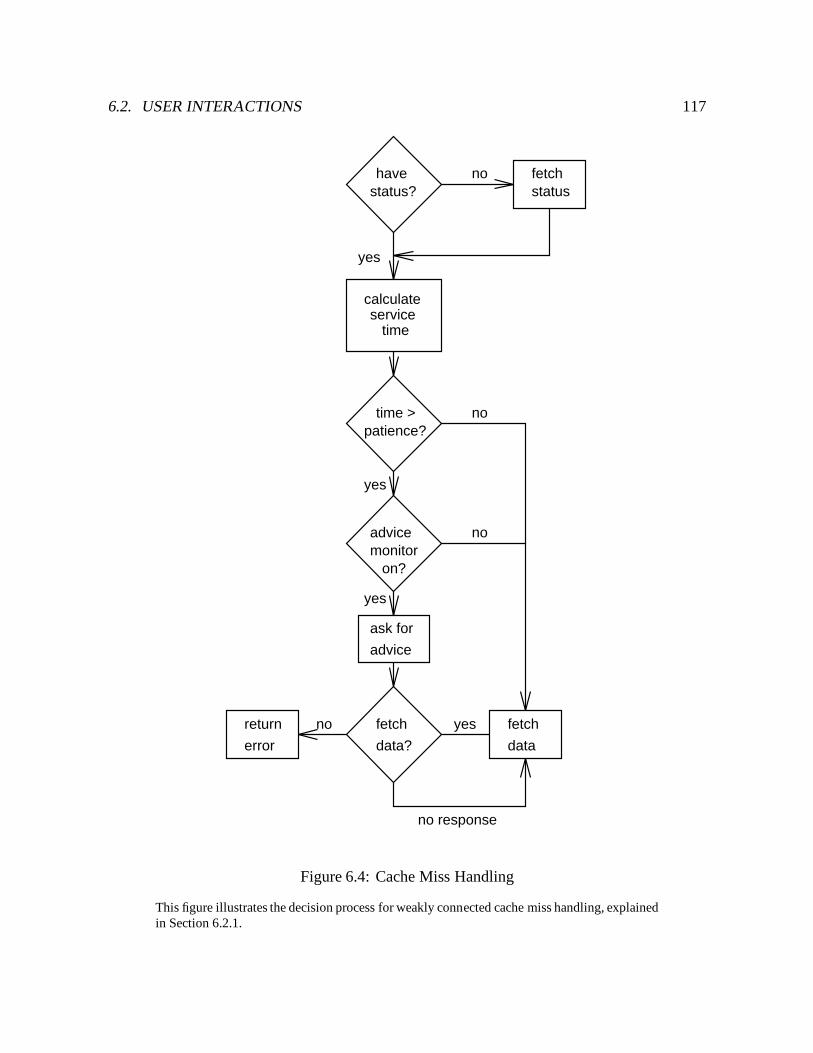
6.2. USER INTERACTIONS 117
havestatus?
fetchstatus
ask for
advice
advicemonitor
on?
fetch
data
return
error
fetch
data?
servicetime
calculate
no
yes
yes
yes
no
no
no
no response
yes
patience?time >
Figure 6.4: Cache Miss Handling
This figure illustrates the decision process for weakly connected cache miss handling, explainedin Section 6.2.1.
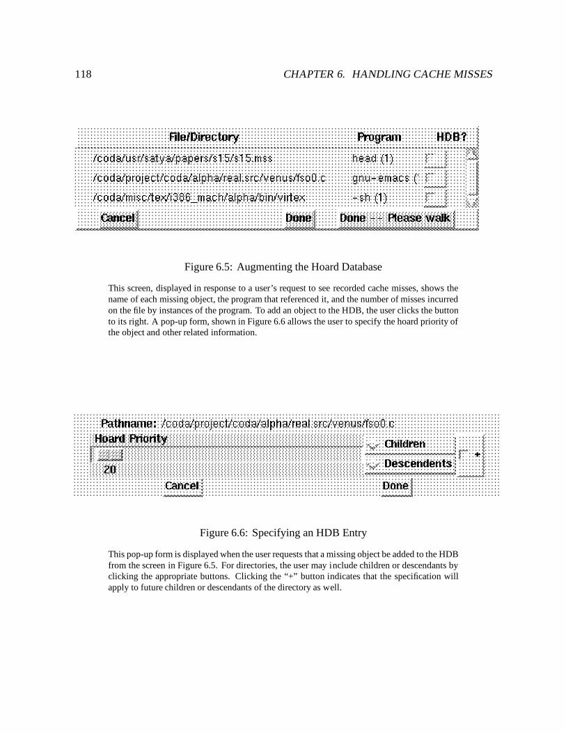
118 CHAPTER 6. HANDLING CACHE MISSES
Figure 6.5: Augmenting the Hoard Database
This screen, displayed in response to a user’s request to see recorded cache misses, shows thename of each missing object, the program that referenced it, and the number of misses incurredon the file by instances of the program. To add an object to the HDB, the user clicks the buttonto its right. A pop-up form, shown in Figure 6.6 allows the user to specify the hoard priority ofthe object and other related information.
Figure 6.6: Specifying an HDB Entry
This pop-up form is displayed when the user requests that a missing object be added to the HDBfrom the screen in Figure 6.5. For directories, the user may include children or descendants byclicking the appropriate buttons. Clicking the “+” button indicates that the specification willapply to future children or descendants of the directory as well.
6.3. PATIENCE MODEL 119
6.2.3 Controlling Hoard Walks
A hoard walk is executed in two phases. In the first phase, called the status walk, Venus obtainsstatus information for missing objects and determines which objects, if any, should be fetched.The status walk usually involves little network traffic. During the second phase, called the datawalk, Venus fetches the contents of objects selected by the status walk. If there are many largeobjects to be fetched, this phase can be a substantial source of network traffic.
An interactive phase between the status and data walks allows a user to limit the volume ofdata fetched in the data walk. For each object selected during the status walk, Venus estimatesits fetch time based on its size and the current bandwidth to its VSG. Those objects whose fetchtimes fall below the user’s patience threshold are pre-approved for fetching, and Venus fetchesthem automatically during the next data walk. The fetching of other objects must be explicitlyapproved by the user.
Venus solicits advice from the user by issuing a HoardWalkAdvice RPC to the advicemonitor between the status and data walks. The advice monitor displays a screen like theone in Figure 6.7. The screen allows users to select the objects to be fetching during the datawalk. If no input is provided by the user within 3 minutes, the screen disappears and the datawalk fetches all objects listed. The user input timeout is much longer than in the cache missinteraction because the user may need more time to examine the list of objects. Of course, ifthe advice monitor is not running, the screen is not displayed, and Venus fetches all objectsselected by the status walk.
6.3 Patience Model
The simplest approach to characterizing a user’s patience threshold (� ) is to use a single,user-selectable number. For example, with � set at 2 seconds, only misses that would takeless than 2 seconds are transparently handled. Implementing such a policy would be trivial.But as mentioned earlier, � really depends on how important a user perceives an object to be:for a very important object, the user is probably willing to wait many minutes. Since userperception of importance is exactly the notion captured by the hoard priority P of an object,we hypothesize that � should be a function of P . The challenge is to determine and validatethe functional form and parameters of this relationship.
At the present time, we are not aware of any data that would enable us to scientificallyscreen potential candidates for this functional form. Hence the current implementation uses afunction based solely on intuition, but this function can easily be replaced if a better alternativebecomes available. We conjecture that patience is similar to other human processes such asvision and hearing, whose sensitivity is logarithmic [22]. This leads to a relationship of theform � = � + �e P , where � and are scaling parameters and � represents a lower bound on
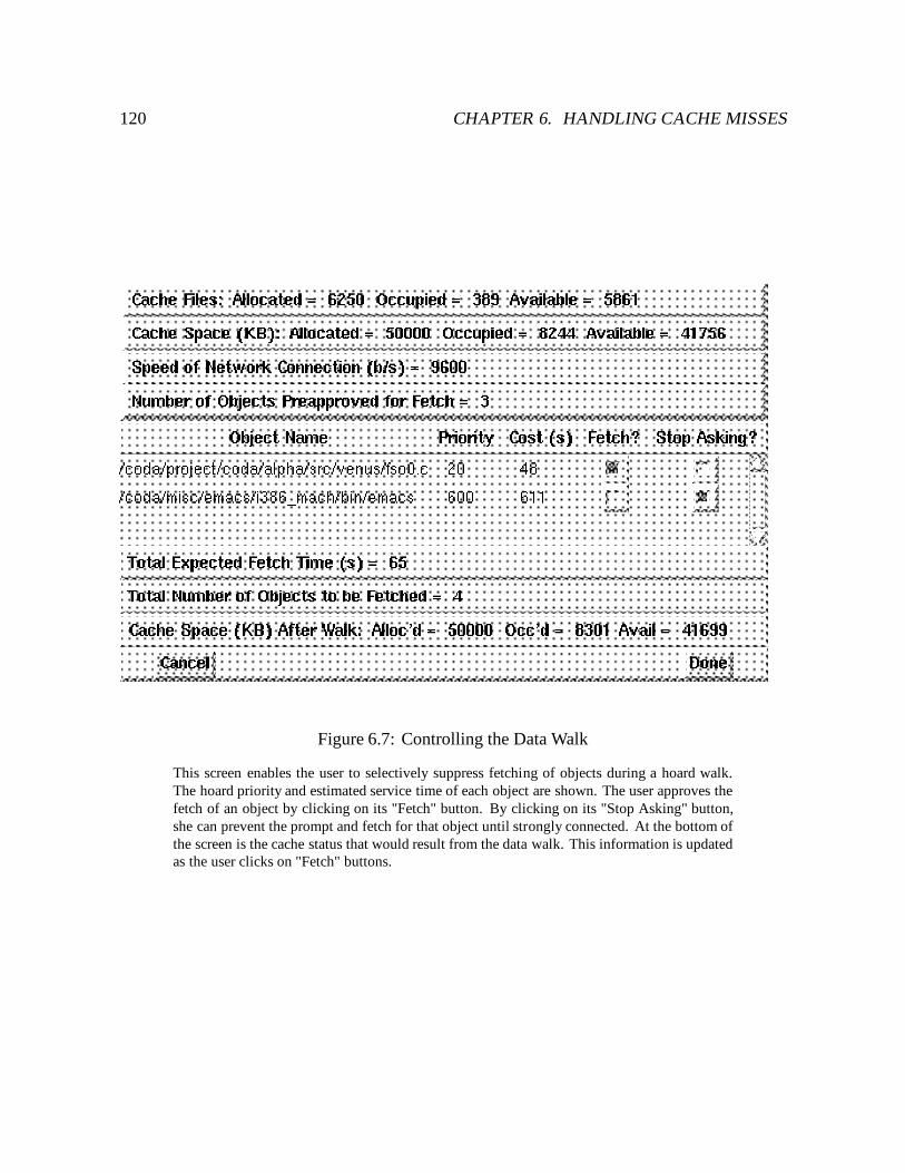
120 CHAPTER 6. HANDLING CACHE MISSES
Figure 6.7: Controlling the Data Walk
This screen enables the user to selectively suppress fetching of objects during a hoard walk.The hoard priority and estimated service time of each object are shown. The user approves thefetch of an object by clicking on its "Fetch" button. By clicking on its "Stop Asking" button,she can prevent the prompt and fetch for that object until strongly connected. At the bottom ofthe screen is the cache status that would result from the data walk. This information is updatedas the user clicks on "Fetch" buttons.
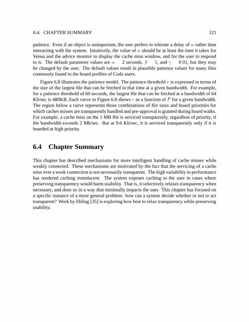
6.4. CHAPTER SUMMARY 121
patience. Even if an object is unimportant, the user prefers to tolerate a delay of � rather thaninteracting with the system. Intuitively, the value of � should be at least the time it takes forVenus and the advice monitor to display the cache miss window, and for the user to respondto it. The default parameter values are � = 2 seconds, � = 1, and = 0:01, but they maybe changed by the user. The default values result in plausible patience values for many filescommonly found in the hoard profiles of Coda users.
Figure 6.8 illustrates the patience model. The patience threshold � is expressed in terms ofthe size of the largest file that can be fetched in that time at a given bandwidth. For example,for a patience threshold of 60 seconds, the largest file that can be fetched at a bandwidth of 64Kb/sec is 480KB. Each curve in Figure 6.8 shows � as a function of P for a given bandwidth.The region below a curve represents those combinations of file sizes and hoard priorities forwhich caches misses are transparently handled and pre-approval is granted during hoard walks.For example, a cache miss on the 1 MB file is serviced transparently, regardless of priority, ifthe bandwidth exceeds 2 Mb/sec. But at 9.6 Kb/sec, it is serviced transparently only if it ishoarded at high priority.
6.4 Chapter Summary
This chapter has described mechanisms for more intelligent handling of cache misses whileweakly connected. These mechanisms are motivated by the fact that the servicing of a cachemiss over a weak connection is not necessarily transparent. The high variability in performancehas rendered caching translucent. The system exposes caching to the user in cases wherepreserving transparency would harm usability. That is, it selectively relaxes transparency whennecessary, and does so in a way that minimally impacts the user. This chapter has focused ona specific instance of a more general problem: how can a system decide whether or not to acttransparent? Work by Ebling [35] is exploring how best to relax transparency while preservingusability.
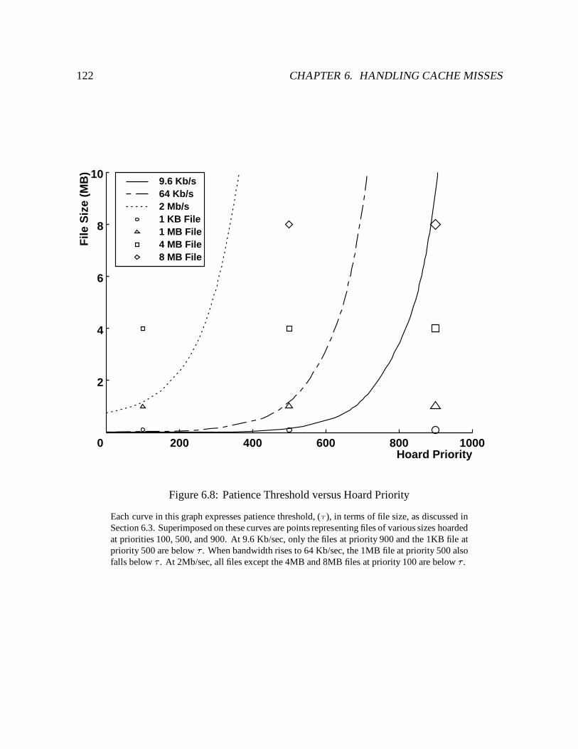
122 CHAPTER 6. HANDLING CACHE MISSES
Hoard Priority200 400 600 800 1000
File
Siz
e (M
B)
2
4
6
8
10
0
9.6 Kb/s64 Kb/s2 Mb/s1 KB File1 MB File4 MB File8 MB File
Figure 6.8: Patience Threshold versus Hoard Priority
Each curve in this graph expresses patience threshold, (� ), in terms of file size, as discussed inSection 6.3. Superimposed on these curves are points representing files of various sizes hoardedat priorities 100, 500, and 900. At 9.6 Kb/sec, only the files at priority 900 and the 1KB file atpriority 500 are below � . When bandwidth rises to 64 Kb/sec, the 1MB file at priority 500 alsofalls below � . At 2Mb/sec, all files except the 4MB and 8MB files at priority 100 are below � .
Chapter 7
Evaluation
The mechanisms for weak connectivity described in this thesis have been implemented anddeployed as part of the Coda file system. This chapter presents a quantitative evaluation of thetransport protocol, rapid cache validation, and trickle reintegration mechanisms. The evaluationis based on controlled experimentation and empirical data gathered from the deployed systemin everyday use. This chapter begins with the status of the implementation and a description ofthe usage environment.
7.1 Evolution and Implementation Status
The mechanisms for weak connectivity were deployed in stages starting in 1993. The firststage involved enabling the transport protocols to operate at low bandwidths. Early anecdotalevidence from Coda indicated that users of disconnected operation often wanted to make theirupdates visible to collaborators after a period of working disconnected, and they felt morecomfortable when the results of many hours of hard work were safely stored on a server. Theseconcerns were significant enough that users sometimes came in to work just to reintegrate. Theability to reintegrate over a phone line addressed both of these concerns.
Serious use of reintegration by phone soon revealed that it was much slower than eventhe most pessimistic estimates. Examination of network traffic and Venus code revealed thatcache validation traffic, which is barely perceptible on a LAN, had substantial impact on aslow network. It was especially painful when connections were intermittent. For slivers ofconnectivity to be useful, it is imperative that cache validation occupy a negligible fractionof each sliver. Batching validation requests on a single RPC helped speed up validation, butnot enough. The rapid cache validation mechanism was then implemented in late 1993 anddeployed in early 1994.
123
124 CHAPTER 7. EVALUATION
The next stage extended Venus to operate write-disconnected. In this state, Venus loggedupdates as if it were disconnected, but continued to service cache misses as if it were con-nected. Entry into and exit from this state was done via explicit commands. A user stayedconnected continuously, operating mostly write-disconnected, but occasionally forcing rein-tegration. Lapses in a user’s hoarding strategy, resulting in cache misses, were functionallymasked. Once write-disconnected mode was operational, the manual triggering of reintegrationwas eliminated with the trickle reintegration mechanism. Trickle reintegration was developedin late 1994 and released for general use in 1995. Early versions of trickle reintegration prop-agated data to all AVSG members regardless of connection strength. To conserve bandwidthover weak connections, users partitioned their clients from all but one server, reintegrated withit, and then manually triggered resolution to propagate the updates to all AVSG members. Theimplementation was refined in 1996 to reintegrate with one server while weakly connected andtrigger resolution automatically, and to check data versions of objects to eliminate unnecessaryrefetching of data after resolution.
The last stage was to substantially improve the handling of cache misses when weaklyconnected. Examination of misses showed that they ranged in importance from critical tobanal, and arose from a wide range of causes. Fully automating the handling of missesappeared unlikely to be satisfactory. Instead, users were provided contextual information aboutmisses, and given opportunity to influence their handling. The user assistance mechanism wasdeveloped in early 1995, and has been released for general use. The mechanism continues tobe refined and extended by Maria Ebling as part of her work [35].
7.2 Usage Environment
Coda has been in daily use by a community of Coda developers and other computer scienceresearchers since 1991. At the time of this writing, there are ten Coda servers housingapproximately 4.0GB of data. The servers are all DECstation 5000/200 series workstationsrunning Mach 2.6 [1]. Three of these servers comprise a production VSG, and three a beta-testVSG. The remaining four servers are used for alpha testing, and hold volumes of varyingreplication factors. Each of the three groups runs different releases of the server software.
The servers collectively store 270 volumes. About 30% of these volumes are user volumes,which store users’ private data. Eighteen of the user volumes are object volumes, used inaddition to home volumes to store the results of compilations. Most user volumes are storedon the production servers. The main exception is object volumes, which are stored on the betaservers. Object volumes are good stress tests for the beta servers because they result from realuser activity and object files are relatively easy to regenerate in case a catastrophic bug strikes.Another 14% are system volumes, which are used to store application software, such as editors,window managers, compilers, and document processing tools, as well as Coda binaries. System
7.3. TRANSPORT PROTOCOL 125
volumes also form the top levels of the Coda name space. About one third of the system volumesare stored on the production servers; the rest reside on the beta servers. Project volumes holddata used in collaborative work, such as the Coda system source areas. Project volumes accountfor 40% of all volumes, and are generally stored on the production servers. The remainingvolumes are test volumes, used for system stress testing and demonstration purposes. Testvolumes are stored on the alpha servers.
There are 50 Coda user accounts, of which about 25 are used regularly. There are about45 clients, evenly divided between desktop and notebook computers. All clients run Mach 2.6,although the Coda client software has been ported to Mach 3.0 [42], and ports are underwayto NetBSD and LINUX [8]. Most workstations are DECstation 5000/200s, although there area few DECstation 3100s and Intel i386-based machines. The notebook computers are all Inteli486-based. Until December 1995, they were almost entirely DEC pc425SLs. Now abouttwo thirds of them are IBM Thinkpad 701cs. Many users run Coda on both their desktopworkstations and their notebook computers.
The environments for desktops and notebooks differ with respect to Coda. For the desktops,most system and application software is supplied by AFS. Hence they tend not to use the Codasystem areas. The notebook computers do not have access to AFS, and were configured thisway for two reasons. First, the notebooks were intended for mobile use, and AFS lackedsupport for disconnected operation. Second, disk space on notebooks was limited, and couldnot support both AFS and Coda caches. (This is no longer true – the new notebooks havemore disk space than our desktops!) The notebooks access application software from the Codasystem areas, and most notebook users store their home directories and environment files intheir Coda user volume.
7.3 Transport Protocol
The addition of round trip timing to RPC2 and SFTP means the protocols do more work whenprocessing packets. The obvious question is then: Is transport protocol performance acceptablewith round trip timing? To answer this question, file transfer performance was compared tothat of the most widely used transport protocol available under Mach 2.6, namely TCP [99].
File transfers were performed using three different network configurations: a 10 Mb/sEthernet, a 2 Mb/s WaveLan wireless network, and a modem operating at 9.6 Kb/s over aphone line using SLIP. The configurations are shown in Figure 7.1. The experiment consistedof disk-to-disk transfers of a 1 MB file using RPC2/SFTP and FTP [100] between a DECpc425SL notebook and a DEC 5000/200 workstation.
The observed throughput, based on end-to-end transfer times, is shown in Table 7.2. Theresults show that RPC2 and SFTP perform well over a wide range of network speeds. In
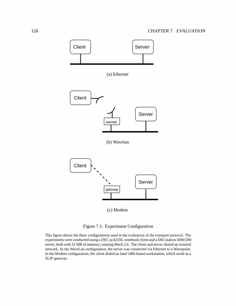
126 CHAPTER 7. EVALUATION
Client Server
(a) Ethernet
Client
Server
wavept
(b) Wavelan
Server
Client
gateway
(c) Modem
Figure 7.1: Experiment Configuration
This figure shows the three configurations used in the evaluation of the transport protocol. Theexperiments were conducted using a DEC pc425SL notebook client and a DECstation 5000/200server, both with 32 MB of memory, running Mach 2.6. The client and server shared an isolatednetwork. In the WaveLan configuration, the server was connected via Ethernet to a Wavepoint.In the Modem configuration, the client dialed an Intel i486-based workstation, which acted as aSLIP gateway.
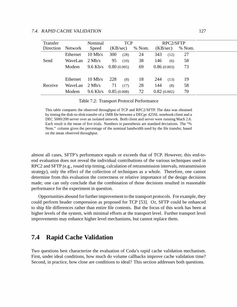
7.4. RAPID CACHE VALIDATION 127
Transfer Nominal TCP RPC2/SFTPDirection Network Speed (KB/sec) % Nom. (KB/sec) % Nom.
Ethernet 10 Mb/s 300 (28) 24 343 (12) 27Send WaveLan 2 Mb/s 95 (10) 38 146 (6) 58
Modem 9.6 Kb/s 0.80 (0.005) 69 0.86 (0.003) 73
Ethernet 10 Mb/s 228 (8) 18 244 (13) 19Receive WaveLan 2 Mb/s 71 (17) 28 144 (8) 58
Modem 9.6 Kb/s 0.85 (0.008) 72 0.82 (0.002) 70
Table 7.2: Transport Protocol Performance
This table compares the observed throughput of TCP and RPC2/SFTP. The data was obtainedby timing the disk-to-disk transfer of a 1MB file between a DECpc 425SL notebook client and aDEC 5000/200 server over an isolated network. Both client and server were running Mach 2.6.Each result is the mean of five trials. Numbers in parenthesis are standard deviations. The “%Nom.” column gives the percentage of the nominal bandwidth used by the file transfer, basedon the mean observed throughput.
almost all cases, SFTP’s performance equals or exceeds that of TCP. However, this end-to-end evaluation does not reveal the individual contributions of the various techniques used inRPC2 and SFTP (e.g., round trip timing, calculation of retransmission intervals, retransmissionstrategy), only the effect of the collection of techniques as a whole. Therefore, one cannotdetermine from this evaluation the correctness or relative importance of the design decisionsmade; one can only conclude that the combination of those decisions resulted in reasonableperformance for the experiment in question.
Opportunities abound for further improvement to the transport protocols. For example, theycould perform header compression as proposed for TCP [53]. Or, SFTP could be enhancedto ship file differences rather than entire file contents. But the focus of this work has been athigher levels of the system, with minimal efforts at the transport level. Further transport levelimprovements may enhance higher level mechanisms, but cannot replace them.
7.4 Rapid Cache Validation
Two questions best characterize the evaluation of Coda’s rapid cache validation mechanism.First, under ideal conditions, how much do volume callbacks improve cache validation time?Second, in practice, how close are conditions to ideal? This section addresses both questions.
128 CHAPTER 7. EVALUATION
7.4.1 Performance Under Ideal Conditions
For a given set of cached objects, the time for validation is minimal when two conditions hold.First, at disconnection, callbacks must exist for all volumes represented in the cache. Second,while disconnected, the volumes containing these objects must not be updated at the server.Then, upon reconnection, communication is needed only to verify volume version stamps.Fresh volume callbacks are acquired as a side effect, at no additional cost.
Under ideal conditions, the primary determinants of performance are network bandwidthand the composition of cache contents. This section describes experiments conducted tomeasure validation time as a function of these two variables.
7.4.1.1 Methodology
The figure of merit for these experiments is the time required to validate a client’s cache after afailure, or the cache recovery time. Obviously, the cache recovery time depends on the cachecontents. For these experiments, the cache contents are based on the hoard profiles of five Codausers, summarized in Table 7.3. The profiles were chosen to represent a range of user activityand expertise. These profiles are used primarily for notebooks.
The experiments were performed with a single client and server, both DECstation 5000/200swith 32 MB of memory, running Mach 2.6. The client used a 50 MB Coda file cache. Themachines were connected via Ethernet. Emulation of slower networks and failure injectionwas performed by a package which intercepts outgoing packets and suppresses or delays themaccording to a filter. For example, the filter might specify that request packets to a certain hostbe dropped with some probability, or delayed as if the network were a lower speed. The delayis a simple-minded calculation, and does not take into account overheads such as UDP and IPheader sizes, or IP fragmentation. A comparison of RPC latency for emulated and real 9.6Kbpslinks is shown in Table 7.4. The filter package is linked into Venus and the server, and requeststo insert and remove filters are issued via RPC.
For each experiment, the client’s hoard database was initialized with the hoard profiles fora single user, and the cache filled by a hoard walk. Each run of the experiment consisted of thefollowing steps:� Partition the client from the server by inserting filters that specify all packets between the
two to be dropped.� At the client, check server status. (The client times out on the server and declares itdown.)� Heal the partition by removing the filters.� At the client, check server status. (The client discovers the server is up.)� Run a hoard walk to validate cache entries.
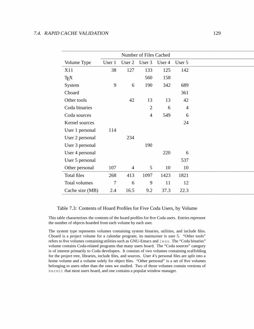
7.4. RAPID CACHE VALIDATION 129
Number of Files Cached
Volume Type User 1 User 2 User 3 User 4 User 5
X11 38 127 133 125 142
TEX 560 158
System 9 6 190 342 689
Cboard 361
Other tools 42 13 13 42
Coda binaries 2 6 4
Coda sources 4 549 6
Kernel sources 24
User 1 personal 114
User 2 personal 234
User 3 personal 190
User 4 personal 220 6
User 5 personal 537
Other personal 107 4 5 10 10
Total files 268 413 1097 1423 1821
Total volumes 7 6 9 11 12
Cache size (MB) 2.4 16.5 9.2 37.3 22.3
Table 7.3: Contents of Hoard Profiles for Five Coda Users, by Volume
This table characterizes the contents of the hoard profiles for five Coda users. Entries representthe number of objects hoarded from each volume by each user.
The system type represents volumes containing system binaries, utilities, and include files.Cboard is a project volume for a calendar program; its maintainer is user 5. “Other tools”refers to five volumes containing utilities such as GNU-Emacs and less. The “Coda binaries”volume contains Coda-related programs that many users hoard. The “Coda sources” categoryis of interest primarily to Coda developers. It consists of two volumes containing scaffoldingfor the project tree, libraries, include files, and sources. User 4’s personal files are split into ahome volume and a volume solely for object files. “Other personal” is a set of five volumesbelonging to users other than the ones we studied. Two of those volumes contain versions ofkermit that most users hoard, and one contains a popular window manager.
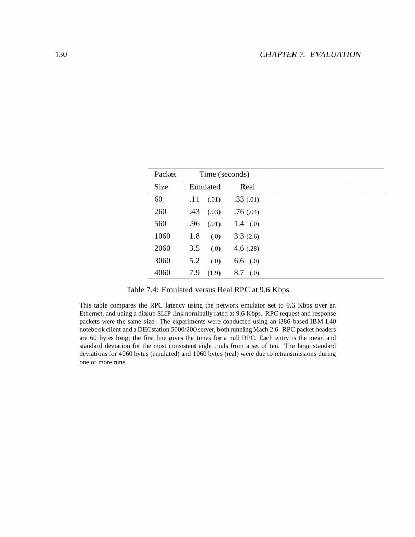
130 CHAPTER 7. EVALUATION
Packet Time (seconds)
Size Emulated Real
60 .11 (.01) .33 (.01)
260 .43 (.03) .76 (.04)
560 .96 (.01) 1.4 (.0)
1060 1.8 (.0) 3.3 (2.6)
2060 3.5 (.0) 4.6 (.28)
3060 5.2 (.0) 6.6 (.0)
4060 7.9 (1.9) 8.7 (.0)
Table 7.4: Emulated versus Real RPC at 9.6 Kbps
This table compares the RPC latency using the network emulator set to 9.6 Kbps over anEthernet, and using a dialup SLIP link nominally rated at 9.6 Kbps. RPC request and responsepackets were the same size. The experiments were conducted using an i386-based IBM L40notebook client and a DECstation 5000/200 server, both running Mach 2.6. RPC packet headersare 60 bytes long; the first line gives the times for a null RPC. Each entry is the mean andstandard deviation for the most consistent eight trials from a set of ten. The large standarddeviations for 4060 bytes (emulated) and 1060 bytes (real) were due to retransmissions duringone or more runs.
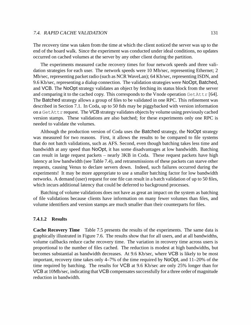
7.4. RAPID CACHE VALIDATION 131
The recovery time was taken from the time at which the client noticed the server was up to theend of the hoard walk. Since the experiment was conducted under ideal conditions, no updatesoccurred on cached volumes at the server by any other client during the partition.
The experiments measured cache recovery times for four network speeds and three vali-dation strategies for each user. The network speeds were 10 Mb/sec, representing Ethernet; 2Mb/sec, representing packet radio (such as NCR WaveLan); 64 Kb/sec, representing ISDN, and9.6 Kb/sec, representing a dialup connection. The validation strategies were NoOpt, Batched,and VCB. The NoOpt strategy validates an object by fetching its status block from the serverand comparing it to the cached copy. This corresponds to the Vnode operation GetAttr [64].The Batched strategy allows a group of files to be validated in one RPC. This refinement wasdescribed in Section 7.1. In Coda, up to 50 fids may be piggybacked with version informationon a GetAttr request. The VCB strategy validates objects by volume using previously cachedversion stamps. These validations are also batched; for these experiments only one RPC isneeded to validate the volumes.
Although the production version of Coda uses the Batched strategy, the NoOpt strategywas measured for two reasons. First, it allows the results to be compared to file systemsthat do not batch validations, such as AFS. Second, even though batching takes less time andbandwidth at any speed than NoOpt, it has some disadvantages at low bandwidth. Batchingcan result in large request packets – nearly 3KB in Coda. These request packets have highlatency at low bandwidth (see Table 7.4), and retransmissions of these packets can starve otherrequests, causing Venus to declare servers down. Indeed, such failures occurred during theexperiments! It may be more appropriate to use a smaller batching factor for low bandwidthnetworks. A demand (user) request for one file can result in a batch validation of up to 50 files,which incurs additional latency that could be deferred to background processes.
Batching of volume validations does not have as great an impact on the system as batchingof file validations because clients have information on many fewer volumes than files, andvolume identifiers and version stamps are much smaller than their counterparts for files.
7.4.1.2 Results
Cache Recovery Time Table 7.5 presents the results of the experiments. The same data isgraphically illustrated in Figure 7.6. The results show that for all users, and at all bandwidths,volume callbacks reduce cache recovery time. The variation in recovery time across users isproportional to the number of files cached. The reduction is modest at high bandwidths, butbecomes substantial as bandwidth decreases. At 9.6 Kb/sec, where VCB is likely to be mostimportant, recovery time takes only 4–7% of the time required by NoOpt, and 11–20% of thetime required by batching. The results for VCB at 9.6 Kb/sec are only 25% longer than forVCB at 10Mb/sec, indicating that VCB compensates successfully for a three order of magnitudereduction in bandwidth.
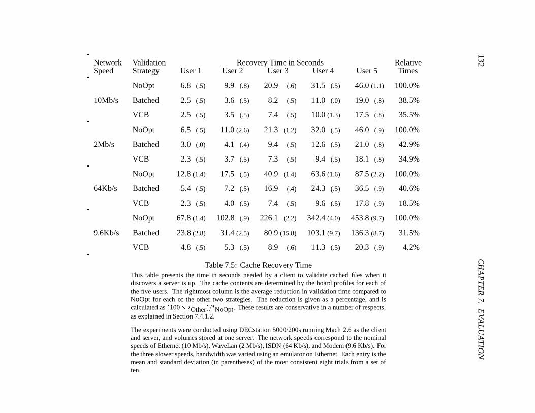
132C
HA
PT
ER
7.E
VA
LU
AT
ION
Network Validation Recovery Time in Seconds RelativeSpeed Strategy User 1 User 2 User 3 User 4 User 5 Times
NoOpt 6.8 (.5) 9.9 (.8) 20.9 (.6) 31.5 (.5) 46.0 (1.1) 100.0%
10Mb/s Batched 2.5 (.5) 3.6 (.5) 8.2 (.5) 11.0 (.0) 19.0 (.8) 38.5%
VCB 2.5 (.5) 3.5 (.5) 7.4 (.5) 10.0 (1.3) 17.5 (.8) 35.5%
NoOpt 6.5 (.5) 11.0 (2.6) 21.3 (1.2) 32.0 (.5) 46.0 (.9) 100.0%
2Mb/s Batched 3.0 (.0) 4.1 (.4) 9.4 (.5) 12.6 (.5) 21.0 (.8) 42.9%
VCB 2.3 (.5) 3.7 (.5) 7.3 (.5) 9.4 (.5) 18.1 (.8) 34.9%
NoOpt 12.8 (1.4) 17.5 (.5) 40.9 (1.4) 63.6 (1.6) 87.5 (2.2) 100.0%
64Kb/s Batched 5.4 (.5) 7.2 (.5) 16.9 (.4) 24.3 (.5) 36.5 (.9) 40.6%
VCB 2.3 (.5) 4.0 (.5) 7.4 (.5) 9.6 (.5) 17.8 (.9) 18.5%
NoOpt 67.8 (1.4) 102.8 (.9) 226.1 (2.2) 342.4 (4.0) 453.8 (9.7) 100.0%
9.6Kb/s Batched 23.8 (2.8) 31.4 (2.5) 80.9 (15.8) 103.1 (9.7) 136.3 (8.7) 31.5%
VCB 4.8 (.5) 5.3 (.5) 8.9 (.6) 11.3 (.5) 20.3 (.9) 4.2%
Table 7.5: Cache Recovery TimeThis table presents the time in seconds needed by a client to validate cached files when itdiscovers a server is up. The cache contents are determined by the hoard profiles for each ofthe five users. The rightmost column is the average reduction in validation time compared toNoOpt for each of the other two strategies. The reduction is given as a percentage, and iscalculated as (100� tOther)=tNoOpt. These results are conservative in a number of respects,as explained in Section 7.4.1.2.
The experiments were conducted using DECstation 5000/200s running Mach 2.6 as the clientand server, and volumes stored at one server. The network speeds correspond to the nominalspeeds of Ethernet (10 Mb/s), WaveLan (2 Mb/s), ISDN (64 Kb/s), and Modem (9.6 Kb/s). Forthe three slower speeds, bandwidth was varied using an emulator on Ethernet. Each entry is themean and standard deviation (in parentheses) of the most consistent eight trials from a set often.
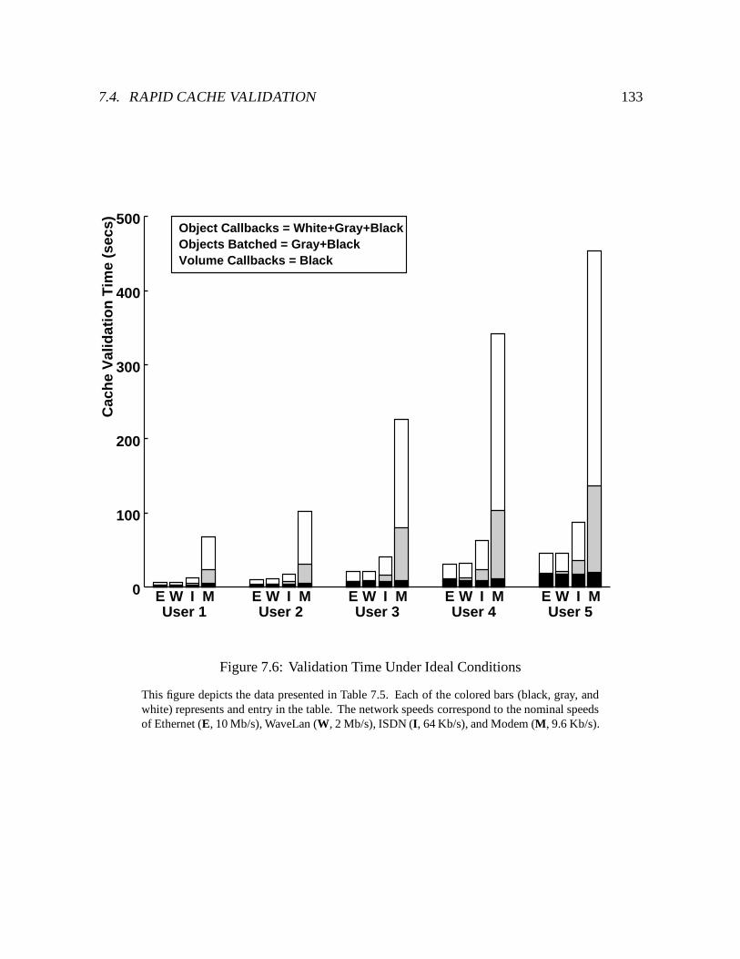
7.4. RAPID CACHE VALIDATION 133C
ach
e V
alid
atio
n T
ime
(sec
s)
100
200
300
400
500
0
User 1 User 2 User 3 User 4 User 5E W I M E W I M E W I M E W I M E W I M
Object Callbacks = White+Gray+BlackObjects Batched = Gray+BlackVolume Callbacks = Black
Figure 7.6: Validation Time Under Ideal Conditions
This figure depicts the data presented in Table 7.5. Each of the colored bars (black, gray, andwhite) represents and entry in the table. The network speeds correspond to the nominal speedsof Ethernet (E, 10 Mb/s), WaveLan (W, 2 Mb/s), ISDN (I, 64 Kb/s), and Modem (M, 9.6 Kb/s).
134 CHAPTER 7. EVALUATION
An unexpected result was that the recovery time using VCB on a slow network was notconstant over all users. The network was expected to be the bottleneck in these cases. Sinceonly one RPC was required to validate the volumes, the recovery times should have beensimilar. Instead, recovery times were proportional to the number of files cached, indicating thebottleneck is Venus. Most of its time is spent on two tasks: marking cached objects suspectwhen the server appears up, and performing the hoard walk, which involves iterating throughall of the objects in the cache to ensure they are valid.
Accuracy of Results The results in Table 7.5 understate the benefits of VCB in a numberof respects. First, the failure library underestimates the delay for a given network speed, asshown in Table 7.4. Second, the volumes used in the experiments were singly replicated,while in practice most volumes in Coda are triply replicated. Since many networks do notsupport multicast, an RPC request to an AVSG with more than one member is sent as separatemessages to each member. If the network is the bottleneck, as with the NoOpt and Batchedstrategies, the time required to validate cached files for each of the strategies in Table 7.5 will beproportionately larger. Last, caches typically contain more than what is hoarded. This occursfor several reasons – name space exploration, objects left over from other tasks, and executionof a task to find files not included by hoard profiles. Each of these effects underestimates thesavings due to VCB, especially over low bandwidth networks.
Callback Overhead The number of callbacks at the server can be derived from Table 7.3,from the number of objects and volumes represented by the hoard profiles for each user. Inthese experiments, clients using the Batched or NoOpt strategies obtain callbacks for each filevalidated. After a successful recovery, clients using VCB obtain callbacks only for the volumesthey validated. The number of callbacks obtained by clients using VCB was less than 3% ofthe number obtained by the other two strategies.
VCB versus Read-only Replication Read-only replication is a feature of AFS and Codawhich allows read-only copies, or clones, of volumes to be created to improve availability andbalance load [49]. Access to clones is very efficient, because no cache coherence protocol isneeded. Read-only replication is useful for volumes which contain files that are frequently readbut seldom updated, such as system programs. When a file in a volume with read-only clonesis updated, manual intervention is required to create new clones before changes are globallyvisible. Volume callbacks represent an alternative to read-only volumes for collections of “readmostly” data. In return for modest validation traffic and callback overhead, clients retain theability to observe updates immediately, without manual intervention.
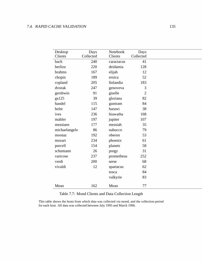
7.4. RAPID CACHE VALIDATION 135
Desktop Days Notebook DaysClients Collected Clients Collectedbach 240 caractacus 41berlioz 220 deidamia 128brahms 167 elijah 12chopin 189 eroica 52copland 205 finlandia 183dvorak 247 genoveva 3gershwin 91 giselle 2gs125 39 gloriana 82handel 115 guntram 84holst 147 harawi 38ives 236 hiawatha 168mahler 197 jupiter 107messiaen 177 messiah 35michaelangelo 86 nabucco 79mootaz 192 oberon 53mozart 234 phoenix 61purcell 154 planets 58schumann 26 porgy 31varicose 237 prometheus 252verdi 200 serse 68vivaldi 12 spartacus 62
tosca 84valkyrie 83
Mean 162 Mean 77
Table 7.7: Mond Clients and Data Collection Length
This table shows the hosts from which data was collected via mond, and the collection periodfor each host. All data was collected between July 1995 and March 1996.
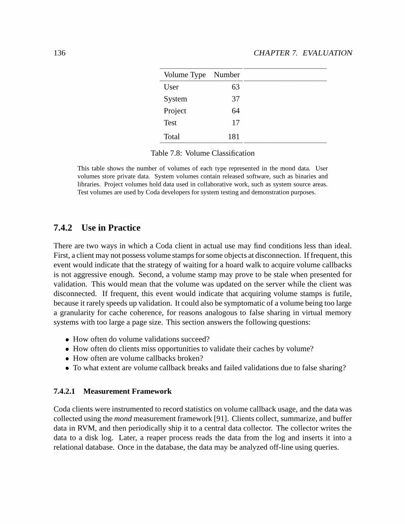
136 CHAPTER 7. EVALUATION
Volume Type Number
User 63
System 37
Project 64
Test 17
Total 181
Table 7.8: Volume Classification
This table shows the number of volumes of each type represented in the mond data. Uservolumes store private data. System volumes contain released software, such as binaries andlibraries. Project volumes hold data used in collaborative work, such as system source areas.Test volumes are used by Coda developers for system testing and demonstration purposes.
7.4.2 Use in Practice
There are two ways in which a Coda client in actual use may find conditions less than ideal.First, a client may not possess volume stamps for some objects at disconnection. If frequent, thisevent would indicate that the strategy of waiting for a hoard walk to acquire volume callbacksis not aggressive enough. Second, a volume stamp may prove to be stale when presented forvalidation. This would mean that the volume was updated on the server while the client wasdisconnected. If frequent, this event would indicate that acquiring volume stamps is futile,because it rarely speeds up validation. It could also be symptomatic of a volume being too largea granularity for cache coherence, for reasons analogous to false sharing in virtual memorysystems with too large a page size. This section answers the following questions:� How often do volume validations succeed?� How often do clients miss opportunities to validate their caches by volume?� How often are volume callbacks broken?� To what extent are volume callback breaks and failed validations due to false sharing?
7.4.2.1 Measurement Framework
Coda clients were instrumented to record statistics on volume callback usage, and the data wascollected using the mond measurement framework [91]. Clients collect, summarize, and bufferdata in RVM, and then periodically ship it to a central data collector. The collector writes thedata to a disk log. Later, a reaper process reads the data from the log and inserts it into arelational database. Once in the database, the data may be analyzed off-line using queries.
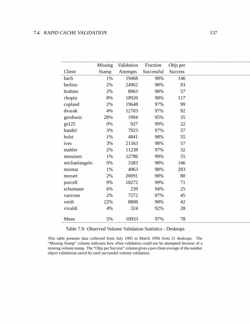
7.4. RAPID CACHE VALIDATION 137
Missing Validation Fraction Objs perClient Stamp Attempts Successful Successbach 1% 19468 98% 146berlioz 2% 24962 98% 93brahms 2% 8963 98% 57chopin 8% 18920 98% 117copland 2% 19648 97% 99dvorak 4% 12703 97% 92gershwin 28% 1994 95% 35gs125 0% 927 99% 22handel 3% 7923 97% 57holst 1% 4841 98% 55ives 3% 21563 98% 57mahler 2% 11238 97% 32messiaen 1% 12786 99% 55michaelangelo 0% 3383 98% 146mootaz 1% 4963 98% 283mozart 2% 20091 98% 80purcell 9% 18272 99% 71schumann 6% 239 94% 25varicose 2% 7572 97% 45verdi 22% 8808 98% 42vivaldi 4% 324 92% 28
Mean 5% 10933 97% 78
Table 7.9: Observed Volume Validation Statistics - Desktops
This table presents data collected from July 1995 to March 1996 from 21 desktops. The“Missing Stamp” column indicates how often validation could not be attempted because of amissing volume stamp. The “Objs per Success” column gives a per-client average of the numberobject validations saved by each successful volume validation.
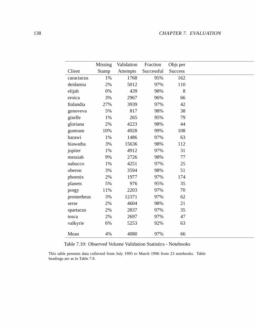
138 CHAPTER 7. EVALUATION
Missing Validation Fraction Objs perClient Stamp Attempts Successful Successcaractacus 1% 1768 95% 162deidamia 2% 5012 97% 110elijah 0% 439 98% 8eroica 3% 2967 96% 66finlandia 27% 3939 97% 42genoveva 5% 817 98% 38giselle 1% 265 95% 79gloriana 2% 4223 98% 44guntram 10% 4928 99% 108harawi 1% 1486 97% 63hiawatha 3% 15636 98% 112jupiter 1% 4912 97% 31messiah 9% 2726 98% 77nabucco 1% 4251 97% 25oberon 3% 3594 98% 51phoenix 2% 1977 97% 174planets 5% 976 95% 35porgy 11% 2203 97% 70prometheus 3% 12371 97% 62serse 2% 4604 98% 21spartacus 2% 2837 97% 35tosca 2% 2697 97% 47valkyrie 6% 5253 92% 63
Mean 4% 4080 97% 66
Table 7.10: Observed Volume Validation Statistics - Notebooks
This table presents data collected from July 1995 to March 1996 from 23 notebooks. Tableheadings are as in Table 7.9.
7.4. RAPID CACHE VALIDATION 139
Clients recorded summary statistics each time a volume version stamp was acquired orvalidated, each time a stamp would have been validated if one had been present, and each timea volume callback was broken or cleared (because of connectivity changes). Data was collectedfrom 44 clients (21 desktops and 23 notebooks) from July 1995 to March 1996. Collectionintervals varied between machines for two reasons. First, a number of clients, particularlynotebooks, were deployed during the collection period. Second, data collection was suspendedduring the period because of two month-long outages at the central data collector. Becauseclients buffer summary statistics in RVM, most were able to cover the failure completelyonce data collection resumed. However, if a Venus was reinitialized on a client during thesuspension, some data was lost. Table 7.7 shows the number of days of data accumulated fromeach machine. The data covered a total of 181 volumes, classified by type in Table 7.8.
7.4.2.2 Results
Validation Statistics Tables 7.9 and 7.10 present validation statistics from all clients. Thedata shows that the average success rate for volume validations was 97%, and each successfulvolume validation saved an average of 70 file validations. There was no significant difference inthe success rate between desktops and notebooks. On average, clients attempted 62 validationsper day. The number of validation attempts is determined by the number of volumes representedin the cache, and the number of connectivity changes observed in the AVSGs for those volumes.(Recall that validation is necessary when the AVSG grows, because a newly available servermay hold new data.) The rate of connectivity changes in our environment is high for tworeasons. First, the servers are restarted automatically once a day, and the time to restart exceedsclient probe intervals. Second, the Ethernet backbone is heavily used and is subject to transientfailures. Desktop machines had a higher rate of validations attempted than notebooks (67compared to 53). Although notebooks observed a slightly higher rate of connectivity changes,desktops had a higher number of volumes represented in the cache on average.
The data also shows that, on average, clients found themselves without a volume stamp onlyin 5% of the cases. This small number indicates that the policy of acquiring stamps on hoardwalks is aggressive enough. Four clients were missing version stamps more than 10% of thetime, and three clients were missing stamps more than 20% of the time. In the past, such rateswere typical for clients whose periodic hoard walks had been deliberately turned off. If hoardwalks are off, Venus does not obtain new volume version stamps, and it loses the ones it hasas volume callbacks are broken and volume validations fail. The two notebook clients, porgyand finlandia, used this feature. The desktop clients, gershwin and verdi, were being used ascompilation engines during the period in which the rate of missing stamps was high. For theseclients, it is unclear if it was callback breaks or the absence of hoard walks that caused the highmissing stamp rates.
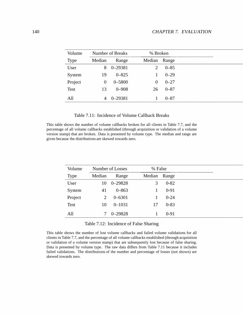
140 CHAPTER 7. EVALUATION
Volume Number of Breaks % Broken
Type Median Range Median Range
User 8 0–29381 2 0–85
System 19 0–825 1 0–29
Project 0 0–5800 0 0–27
Test 13 0–908 26 0–87
All 4 0–29381 1 0–87
Table 7.11: Incidence of Volume Callback Breaks
This table shows the number of volume callbacks broken for all clients in Table 7.7, and thepercentage of all volume callbacks established (through acquisition or validation of a volumeversion stamp) that are broken. Data is presented by volume type. The median and range aregiven because the distributions are skewed towards zero.
Volume Number of Losses % False
Type Median Range Median Range
User 10 0–29828 3 0-82
System 41 0–863 1 0-91
Project 2 0–6301 1 0-24
Test 10 0–1031 17 0-83
All 7 0–29828 1 0-91
Table 7.12: Incidence of False Sharing
This table shows the number of lost volume callbacks and failed volume validations for allclients in Table 7.7, and the percentage of all volume callbacks established (through acquisitionor validation of a volume version stamp) that are subsequently lost because of false sharing.Data is presented by volume type. The raw data differs from Table 7.11 because it includesfailed validations. The distributions of the number and percentage of losses (not shown) areskewed towards zero.
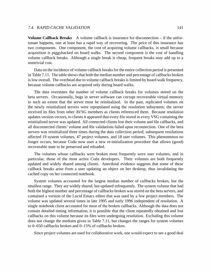
7.4. RAPID CACHE VALIDATION 141
Volume Callback Breaks A volume callback is insurance for disconnection – if the unfor-tunate happens, one at least has a rapid way of recovering. The price of this insurance hastwo components. One component, the cost of acquiring volume callbacks, is small becauseacquisition is piggybacked on hoard walks. The second component is the cost of handlingvolume callback breaks. Although a single break is cheap, frequent breaks may add up to anontrivial cost.
Data on the incidence of volume callback breaks for the entire collection period is presentedin Table 7.11. The table shows that both the median number and percentage of callbacks brokenis low overall. The overhead due to volume callback breaks is limited by hoard walk frequency,because volume callbacks are acquired only during hoard walks.
The data overstates the number of volume callback breaks for volumes stored on thebeta servers. Occasionally, bugs in server software can corrupt recoverable virtual memoryto such an extent that the server must be reinitialized. In the past, replicated volumes onthe newly reinitialized servers were repopulated using the resolution subsystem; the serverreceived its files from other AVSG members as clients referenced them. Because resolutionupdates version vectors, to clients it appeared that every file stored in every VSG containing thereinitialized server was updated. All connected clients lost their volume and file callbacks, andall disconnected clients’ volume and file validations failed upon reconnection. One of the betaservers was reinitialized three times during the data collection period; subsequent resolutionsaffected 19 system volumes, 47 project volumes, and 18 user volumes. This phenomenon nolonger occurs, because Coda now uses a new re-initialization procedure that allows (good)recoverable state to be preserved and reloaded.
The volumes whose callbacks were broken most frequently were user volumes, and inparticular, those of the most active Coda developers. Their volumes are both frequentlyupdated and widely shared among clients. Anecdotal evidence suggests that some of thesecallback breaks arise from a user updating an object on her desktop, thus invalidating thecached copy on her connected notebook.
System volumes accounted for the largest median number of callbacks broken, but thesmallest range. They are widely shared, but updated infrequently. The system volume that hadboth the highest number and percentage of callbacks broken was stored on the beta servers, andcontained a version of the Lucid Emacs editor that was used by a few project members. Thevolume was updated several times in late 1995 and early 1996 independent of resolution. Asingle notebook client accounted for most of the broken callbacks. Although the data does notcontain detailed timing information, it is possible that the client repeatedly obtained and lostcallbacks on this volume because its files were undergoing resolution. Excluding this volumedoes not change the medians given in Table 7.11, but changes the ranges for system volumesto 0–650 callbacks broken and 0–15% of callbacks broken.
Since project volumes are used for collaborative work, one would expect to see a good deal
142 CHAPTER 7. EVALUATION
of callback activity. But the low number of callback breaks indicates that the actual amount ofcollaboration is low. Although these volumes are shared widely, they change relatively slowly.The reason for the slow rate of change is that users of source files make private copies fordevelopment, and modify the shared areas only when they are ready to release final versionsof their changes. The most active project volume by far, both in number and percentage ofcallbacks broken, was the volume containing the alpha release of the Coda sources. Althoughthis volume is updated only occasionally (an earlier set of data showed that it was completelyunchanged for over half the days in a three month period [84]) nearly every client caches filesfrom it and obtains volume callbacks on it. Therefore, an update in this volume generates manyvolume callbacks. Excluding this volume does not change the medians given in Table 7.11, butchanges the ranges for project volumes to 0–1717 callbacks broken and 0–15% of callbacksbroken.
Test volumes showed the highest percentage of callbacks broken, both in median and range.However, the number of callbacks broken was low, and activity in these volumes is by naturecontrived. Results for test volumes are shown only to separate them from other volume classes.
False Sharing Recall from Section 4.2.2 that when a client updates an object in a volume,all other clients caching the volume version stamp will lose the stamp through either a volumecallback or a failed volume validation. If the client caches do not contain the object that wasupdated, false sharing has occured on the volume. Since both the number and percentage offailed validations and volume callback breaks is low overall (Tables 7.9-7.11) the impact offalse sharing on the system is minimal.
Table 7.12 shows the number of losses of volume version stamps over the collection period,from both volume callback breaks and failed validations, and the percentage of losses causedby false sharing. The data overstates the number of losses because of resolution activity afterserver reinitialization. This activity is responsible for some of the false sharing, however, it isnot possible to separate this activity from the data.
User volumes exhibited the largest range of lost version stamps due to false sharing. Thissharing arises from several sources. First, as mentioned earlier, users share files between theirdesktop and notebook clients. Second, users cache files from other user volumes. If the numberof files cached from other user volumes is small, as is the case for the hoard profiles shownin Table 7.3, remote updates are likely to produce false sharing at the volume level. Third,user object volumes are shared among clients of different architectures. When users compilesoftware, the compilation engines update files in the same volume, even though they operateon separate parts of the name space. User object volumes had a higher median proportion offalse sharing (24%, with a range of 0-50%) than user volumes in general.
Project volumes show the lowest proportion of lost version stamps due to false sharing.The Coda source and documentation areas experienced the most false sharing. This is not
7.5. TRICKLE REINTEGRATION 143
surprising, because project members tend to work on independent modules within the system.
System volumes had the widest range of losses by percentage, however, the number oflosses overall was small. The volume with the highest number of losses was the Emacs volumementioned earlier in the discussion on volume callback breaks. The two volumes with thehighest proportion of false sharing were not widely used; collectively clients obtained less than50 volume callbacks on these volumes during the entire collection period. Excluding thesevolumes narrows the range of false sharing by proportion to 0-12%.
7.5 Trickle Reintegration
How much is a typical user’s activity slowed when weakly connected? This is the question mostgermane to trickle reintegration, because the answer will reveal how effectively foregroundactivity is insulated from update propagation over slow networks.
The simplest way to answer this question would be to run a standard file system benchmarkon a write-disconnected client over a wide range of network speeds. The obvious candidate isthe Andrew benchmark [49] because it is compact, portable, and widely used. Unfortunately,this benchmark is of limited value in evaluating trickle reintegration. First, the running timeof the benchmark on current hardware is very small, typically less than three minutes. Thisimplies that no updates would be propagated to the server during an entire run of the benchmarkfor any reasonable aging window. Increasing the total time by using multiple iterations isnot satisfactory because the benchmark is not idempotent. Second, although the benchmarkcaptures many aspects of typical user activity, it does not exhibit overwrite cancellations. Hence,its file references are only marginally affected by log optimizations. Third, the benchmarkinvolves no user think time, which may be atypical of interactive applications.
The ultimate in realism would be to measure trickle reintegration in actual use by mobileusers. But this approach has serious shortcomings. First, a human subject cannot be madeto repeat her behavior precisely enough for multiple runs of an experiment. Second, manyconfounding factors make timing results from actual use difficult to interpret. Third, suchexperiments cannot be replicated at other sites or in the future.
To overcome the limitations of these approaches, the evaluation of trickle reintegration isbased on trace replay, in which a workload from a file reference trace is replayed on the systemunder evaluation. Since a trace replay reflects the activity of a real workload, the results arelikely to be a much better indicator of performance of the system in actual use. The use of tracereplay is an original contribution of this work.
144 CHAPTER 7. EVALUATION
7.5.1 Methodology: Trace Replay
The evaluation of trickle reintegration is based on an experimental methodology in whichoperations in a file reference trace are replayed at the client. Realism is preserved since thetrace was generated in actual use. Timing measurements are much less ambiguous than withhuman subjects, since experimental control and replicability are easier to achieve. In addition,the traces and the replay software can be exported. Note that a trace replay experimentdiffers from a trace-driven simulation in that traces are replayed on a live system. The replaysoftware [86] generates UNIX system calls that are serviced by Venus and the servers just as ifthey had been generated by a human user. The only difference is that a single process performsthe replay, whereas the trace may have been generated by multiple processes. It would be fairlysimple to extend the replay software to exactly emulate the original process structure.
Since a trace is often used many months or years after it was collected, the system on whichit is replayed may be much faster than the original. But a faster system will not speed upthose delays in the trace that were caused by human think time. Unfortunately, it is difficultto reliably distinguish think time delays from system-limited delays in a trace. However, largedelays are more likely to be caused by user think time than system limits.
To incorporate the effect of human think time, the evaluation includes a sensitivity analysisfor think time, using a parameter called think threshold, �. This parameter defines the smallestdelay in the input trace that will be preserved in the replay. When � is 0, all delays in thetrace are preserved; when it is infinity, the trace is replayed as fast as possible. Neither ofthese extreme values is used for the experiments. At � = 0, there is so much opportunity foroverlapping data transmission with think time that experiments would be biased too much infavor of trickle reintegration. At � = 1, the absence of think time makes the experimentas short as the Andrew benchmark. In the light of these considerations, the experiments usevalues of � equal to 1 second and 10 seconds. These are plausible values for typical think timesduring periods of high activity, and they are not biased too far against or in favor of tricklereintegration.
Since log optimizations play such a critical role in trickle reintegration, the evaluationincludes a sensitivity analysis for this factor as well. The traces described in Section 5.4were divided into 45-minute segments, and the segments with the highest activity levels wereanalyzed for their susceptibility to log optimizations. (Segments longer than 45 minuteswould have made the duration of each experiment excessive, allowing only a few parametercombinations to be explored.) The compressibility of a trace segment is defined as the ratioof two quantities obtained when the segment is run through the Venus simulator, described inSection 5.4.2. The numerator is the amount of data optimized out; the denominator is the lengthof the unoptimized CML. Figure7.13 shows the observed distributionof compressibility in thosetrace segments with a final CML of 1 MB or greater. The data shows that the compressibilitiesof roughly a third of the segments are below 20%, while those of the remaining two-thirds
7.5. TRICKLE REINTEGRATION 145
range from 40% to 100%. One segment from each quartile of compressibility was used for theexperiments. The characteristics of these segments are shown in Figure 7.14.
There are 64 combinations of experimental parameters: four workloads, each a tracesegment representing one quartile of compressibility (8, 32, 69, and 94%); two reasonableaging windows (A = 300 and 600 seconds), including the system default; two think thresholds(� = 1 and 10 seconds); and four network types, Ethernet (10 Mb/s), Wavelan (2 Mb/s),ISDN (64 Kb/s), and Modem (9.6 Kb/s). Except for ISDN, experiments were performed onactual networks of the corresponding type, using the configurations depicted in Figure 7.1. TheISDN experiments were conducted on an Ethernet using the network emulator described inSection 7.4.1.1.
The experiments were run in a single volume on a single server. Venus was forced toremain write disconnected at all bandwidths. All measurements were deferred until 600seconds into each run, thus warming the CML for trickle reintegration. The choice of 600seconds corresponds to the largest value of A used in the experiments.
7.5.2 Results
Elapsed Time Tables 7.15 – 7.21 presents the elapsed times of the trace replay experiments.The same data is graphically illustrated in Figures 7.16 – 7.22. These measurements confirmthe effectiveness of trickle reintegration over the entire experimental range. Bandwidth variesover three orders of magnitude, yet elapsed time remains almost unchanged. On average,performance is only about 2% slower at 9.6 Kb/s than at 10 Mb/s. Even the worst case,corresponding to the Ethernet and ISDN numbers for Concord in Figure 7.22, is only 11%slower.
What effects do the experimental parameters have on Venus’ execution of the workloads?The aging window is a factor for compressible workloads. A small aging window gives Venuslittle time to optimize records from the CML, and therefore more data to send to the server.The more time Venus spends reintegrating data, the greater the likelihood of file contention.File contention can cause delays in forward processing because Venus must make a shadowcopy of the cache container file. A large aging window, on the other hand, allows Venus totake greater advantage of CML optimizations on compressible trace segments. Since CMLrecords are stored in RVM, optimizations create more RVM activity. This activity causes Venusto invoke RVM log flush and truncation operations more frequently, and these operations cancause substantial delays in concurrent request processing.
Factors other than the aging window can influence the amount of CML optimization forcompressible workloads. The think threshold controls the amount of delay between operations.Different think thresholds result in different benchmarks; it is not meaningful to compareelapsed times between experiments where this parameter differs. A lower think threshold
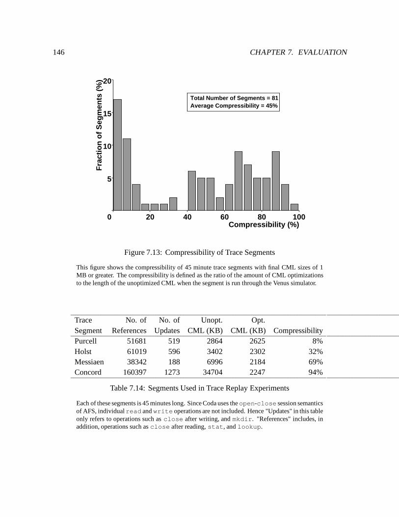
146 CHAPTER 7. EVALUATION
Compressibility (%)20 40 60 80 100
Fra
ctio
n o
f S
egm
ents
(%
)
5
10
15
20
0
Total Number of Segments = 81Average Compressibility = 45%
Figure 7.13: Compressibility of Trace Segments
This figure shows the compressibility of 45 minute trace segments with final CML sizes of 1MB or greater. The compressibility is defined as the ratio of the amount of CML optimizationsto the length of the unoptimized CML when the segment is run through the Venus simulator.
Trace No. of No. of Unopt. Opt.Segment References Updates CML (KB) CML (KB) CompressibilityPurcell 51681 519 2864 2625 8%Holst 61019 596 3402 2302 32%Messiaen 38342 188 6996 2184 69%Concord 160397 1273 34704 2247 94%
Table 7.14: Segments Used in Trace Replay Experiments
Each of these segments is 45 minutes long. Since Coda uses theopen-close session semanticsof AFS, individualread and write operations are not included. Hence "Updates" in this tableonly refers to operations such as close after writing, and mkdir. "References" includes, inaddition, operations such as close after reading, stat, and lookup.
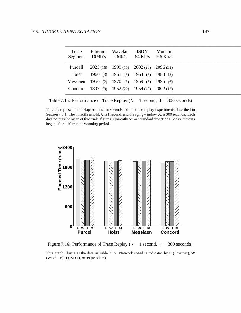
7.5. TRICKLE REINTEGRATION 147
Trace Ethernet Wavelan ISDN ModemSegment 10Mb/s 2Mb/s 64 Kb/s 9.6 Kb/s
Purcell 2025 (16) 1999 (15) 2002 (20) 2096 (32)
Holst 1960 (3) 1961 (5) 1964 (5) 1983 (5)
Messiaen 1950 (2) 1970 (9) 1959 (3) 1995 (6)
Concord 1897 (9) 1952 (20) 1954 (43) 2002 (13)
Table 7.15: Performance of Trace Replay (� = 1 second, A = 300 seconds)
This table presents the elapsed time, in seconds, of the trace replay experiments described inSection 7.5.1. The think threshold,�, is 1 second, and the aging window,A, is 300 seconds. Eachdata point is the mean of five trials; figures in parentheses are standard deviations. Measurementsbegan after a 10 minute warming period.
Ela
pse
d T
ime
(sec
s)
600
1200
1800
2400
0Purcell Holst Messiaen ConcordE W I M E W I M E W I M E W I M
Figure 7.16: Performance of Trace Replay (� = 1 second, A = 300 seconds)
This graph illustrates the data in Table 7.15. Network speed is indicated by E (Ethernet), W(WaveLan), I (ISDN), or M (Modem).
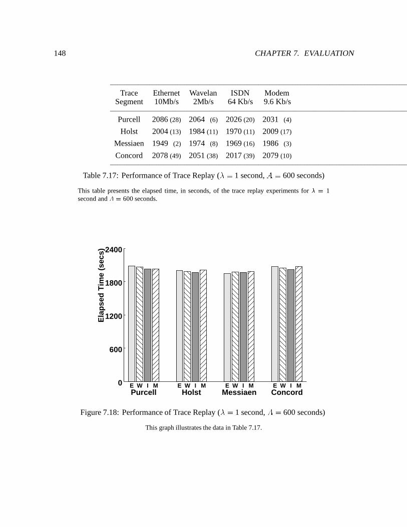
148 CHAPTER 7. EVALUATION
Trace Ethernet Wavelan ISDN ModemSegment 10Mb/s 2Mb/s 64 Kb/s 9.6 Kb/s
Purcell 2086 (28) 2064 (6) 2026 (20) 2031 (4)
Holst 2004 (13) 1984 (11) 1970 (11) 2009 (17)
Messiaen 1949 (2) 1974 (8) 1969 (16) 1986 (3)
Concord 2078 (49) 2051 (38) 2017 (39) 2079 (10)
Table 7.17: Performance of Trace Replay (� = 1 second, A = 600 seconds)
This table presents the elapsed time, in seconds, of the trace replay experiments for � = 1second and A = 600 seconds.
Ela
pse
d T
ime
(sec
s)
600
1200
1800
2400
0Purcell Holst Messiaen ConcordE W I M E W I M E W I M E W I M
Figure 7.18: Performance of Trace Replay (� = 1 second, A = 600 seconds)
This graph illustrates the data in Table 7.17.
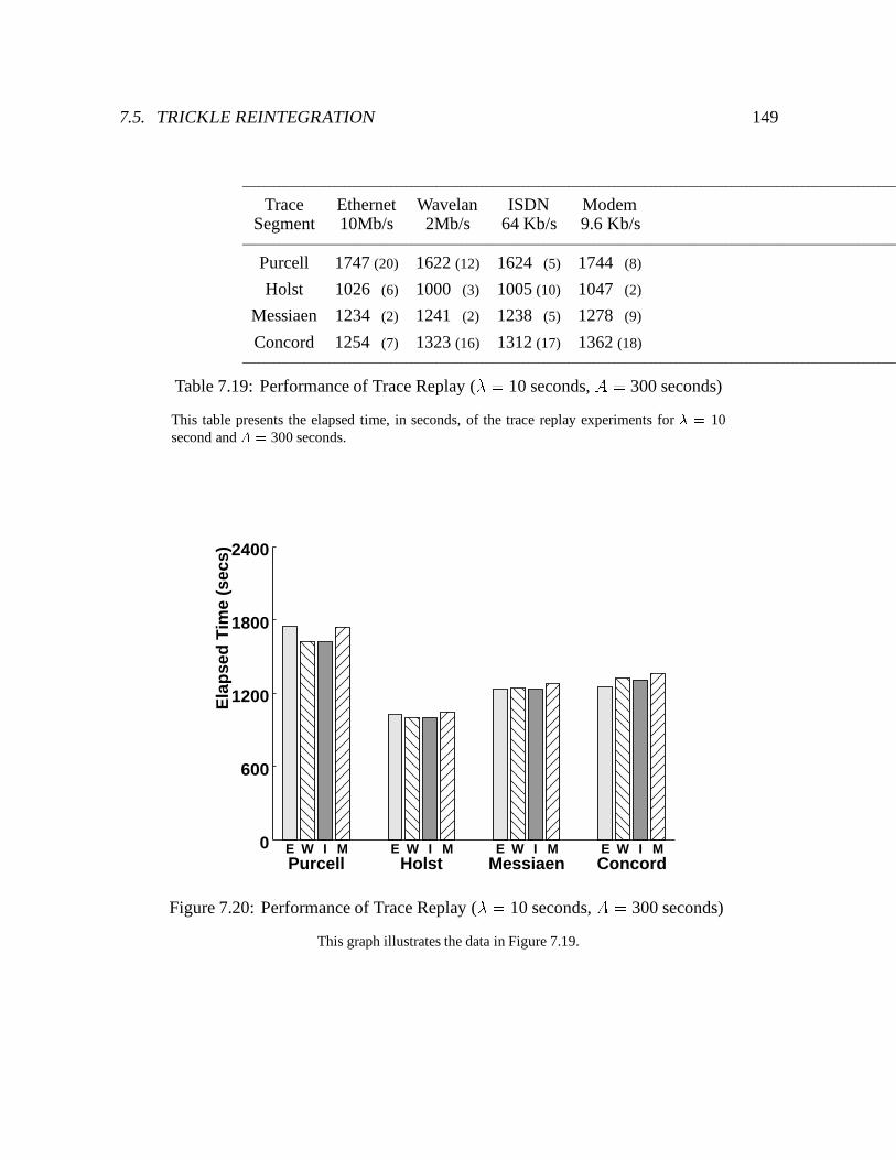
7.5. TRICKLE REINTEGRATION 149
Trace Ethernet Wavelan ISDN ModemSegment 10Mb/s 2Mb/s 64 Kb/s 9.6 Kb/s
Purcell 1747 (20) 1622 (12) 1624 (5) 1744 (8)
Holst 1026 (6) 1000 (3) 1005 (10) 1047 (2)
Messiaen 1234 (2) 1241 (2) 1238 (5) 1278 (9)
Concord 1254 (7) 1323 (16) 1312 (17) 1362 (18)
Table 7.19: Performance of Trace Replay (� = 10 seconds, A = 300 seconds)
This table presents the elapsed time, in seconds, of the trace replay experiments for � = 10second and A = 300 seconds.
Ela
pse
d T
ime
(sec
s)
600
1200
1800
2400
0Purcell Holst Messiaen ConcordE W I M E W I M E W I M E W I M
Figure 7.20: Performance of Trace Replay (� = 10 seconds, A = 300 seconds)
This graph illustrates the data in Figure 7.19.
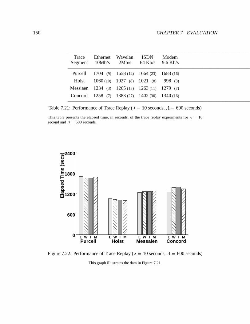
150 CHAPTER 7. EVALUATION
Trace Ethernet Wavelan ISDN ModemSegment 10Mb/s 2Mb/s 64 Kb/s 9.6 Kb/s
Purcell 1704 (9) 1658 (14) 1664 (23) 1683 (16)
Holst 1060 (10) 1027 (8) 1021 (8) 998 (3)
Messiaen 1234 (3) 1265 (13) 1263 (11) 1279 (7)
Concord 1258 (7) 1383 (27) 1402 (30) 1340 (16)
Table 7.21: Performance of Trace Replay (� = 10 seconds, A = 600 seconds)
This table presents the elapsed time, in seconds, of the trace replay experiments for � = 10second and A = 600 seconds.
Ela
pse
d T
ime
(sec
s)
600
1200
1800
2400
0Purcell Holst Messaien ConcordE W I M E W I M E W I M E W I M
Figure 7.22: Performance of Trace Replay (� = 10 seconds, A = 600 seconds)
This graph illustrates the data in Figure 7.21.
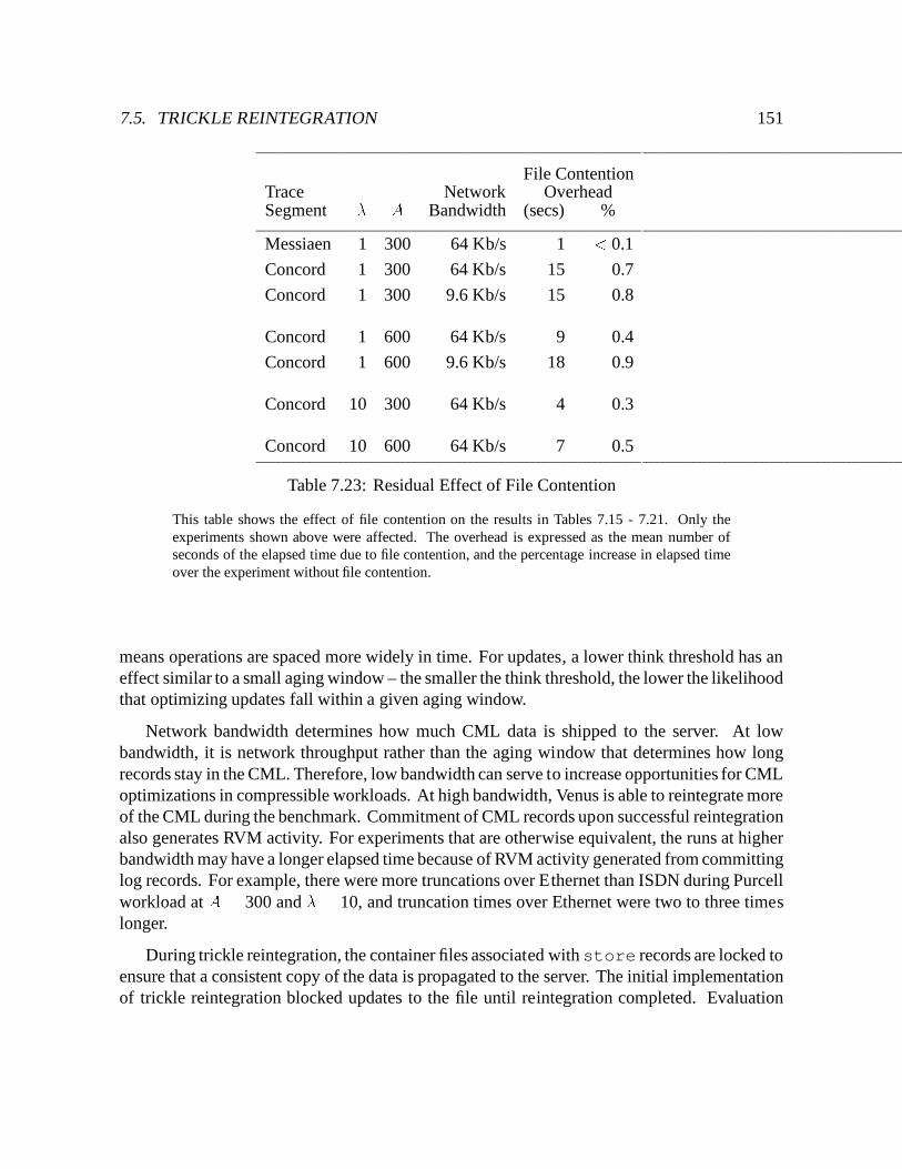
7.5. TRICKLE REINTEGRATION 151
File ContentionTrace Network OverheadSegment � A Bandwidth (secs) %
Messiaen 1 300 64 Kb/s 1 < 0.1
Concord 1 300 64 Kb/s 15 0.7
Concord 1 300 9.6 Kb/s 15 0.8
Concord 1 600 64 Kb/s 9 0.4
Concord 1 600 9.6 Kb/s 18 0.9
Concord 10 300 64 Kb/s 4 0.3
Concord 10 600 64 Kb/s 7 0.5
Table 7.23: Residual Effect of File Contention
This table shows the effect of file contention on the results in Tables 7.15 - 7.21. Only theexperiments shown above were affected. The overhead is expressed as the mean number ofseconds of the elapsed time due to file contention, and the percentage increase in elapsed timeover the experiment without file contention.
means operations are spaced more widely in time. For updates, a lower think threshold has aneffect similar to a small aging window – the smaller the think threshold, the lower the likelihoodthat optimizing updates fall within a given aging window.
Network bandwidth determines how much CML data is shipped to the server. At lowbandwidth, it is network throughput rather than the aging window that determines how longrecords stay in the CML. Therefore, low bandwidth can serve to increase opportunities for CMLoptimizations in compressible workloads. At high bandwidth, Venus is able to reintegrate moreof the CML during the benchmark. Commitment of CML records upon successful reintegrationalso generates RVM activity. For experiments that are otherwise equivalent, the runs at higherbandwidth may have a longer elapsed time because of RVM activity generated from committinglog records. For example, there were more truncations over Ethernet than ISDN during Purcellworkload at A = 300 and � = 10, and truncation times over Ethernet were two to three timeslonger.
During trickle reintegration, the container files associated with store records are locked toensure that a consistent copy of the data is propagated to the server. The initial implementationof trickle reintegration blocked updates to the file until reintegration completed. Evaluation
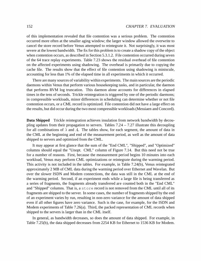
152 CHAPTER 7. EVALUATION
of this implementation revealed that file contention was a serious problem. The contentionoccurred more often at the smaller aging window; the larger window allowed the overwrite tocancel the store record before Venus attempted to reintegrate it. Not surprisingly, it was mostsevere at the lowest bandwidth. The fix for this problem is to create a shadow copy of the objectwhen contention occurs, as described in Section 5.3.1.2. File contention occurred during sevenof the 64 trace replay experiments. Table 7.23 shows the residual overhead of file contentionon the affected experiments using shadowing. The overhead is primarily due to copying thecache file. The results show that the effect of file contention using shadowing is miniscule,accounting for less than 1% of the elapsed time in all experiments in which it occurred.
There are many sources of variability within experiments. The main sources are the periodicdaemons within Venus that perform various housekeeping tasks, and in particular, the daemonthat performs RVM log truncation. This daemon alone accounts for differences in elapsedtimes in the tens of seconds. Trickle reintegration is triggered by one of the periodic daemons;in compressible workloads, minor differences in scheduling can determine whether or not filecontention occurs, or a CML record is optimized. File contention did not have a large effect onthe results, but did occur during the two most compressible workloads (Messiaen and Concord).
Data Shipped Trickle reintegration achieves insulation from network bandwidth by decou-pling updates from their propagation to servers. Tables 7.24 – 7.27 illustrate this decouplingfor all combinations of � and A. The tables show, for each segment, the amount of data inthe CML at the beginning and end of the measurement period, as well as the amount of datashipped to servers and optimized from the CML.
It may appear at first glance that the sum of the "End CML", "Shipped", and "Optimized"columns should equal the "Unopt. CML" column of Figure 7.14. But this need not be truefor a number of reasons. First, because the measurement period begins 10 minutes into eachworkload, Venus may perform CML optimizations or reintegrate during the warming period.This activity is not included in the tables. For example, in Table 7.24(b), Venus reintegratedapproximately 2 MB of CML data during the warming period over Ethernet and Wavelan. Butover the slower ISDN and Modem connections, the data was still in the CML at the end ofthe warming period. Second, if an experiment ends while a large file is being transferred asa series of fragments, the fragments already transferred are counted both in the "End CML"and "Shipped" columns. That is, a store record is not removed from the CML until all of itsfragments are shipped to the server. In some cases, the number of fragments shipped by the endof an experiment varies by run, resulting in non-zero variance for the amount of data shippedeven if all other figures have zero variance. Such is the case, for example, for the ISDN andModem experiments of Table 7.26(a). Third, the packed representation of CML records whenshipped to the servers is larger than in the CML itself.
In general, as bandwidth decreases, so does the amount of data shipped. For example, inTable 7.25(b), the data shipped decreases from 2254 KB for Ethernet to 1536 KB for Modem.
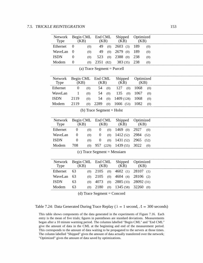
7.5. TRICKLE REINTEGRATION 153
Network Begin CML End CML Shipped OptimizedType (KB) (KB) (KB) (KB)
Ethernet 0 (0) 49 (0) 2603 (3) 189 (0)
WaveLan 0 (0) 49 (0) 2679 (0) 189 (0)
ISDN 0 (0) 523 (0) 2388 (0) 238 (0)
Modem 0 (0) 2351 (82) 383 (35) 238 (0)
(a) Trace Segment = Purcell
Network Begin CML End CML Shipped OptimizedType (KB) (KB) (KB) (KB)
Ethernet 0 (0) 54 (0) 127 (0) 1068 (0)
WaveLan 1 (0) 54 (0) 135 (0) 1067 (0)
ISDN 2119 (0) 54 (0) 1409 (128) 1068 (0)
Modem 2119 (0) 2289 (0) 1666 (53) 1082 (0)
(b) Trace Segment = Holst
Network Begin CML End CML Shipped OptimizedType (KB) (KB) (KB) (KB)
Ethernet 0 (0) 0 (0) 1469 (0) 2927 (0)
WaveLan 0 (0) 0 (0) 1412 (52) 2984 (52)
ISDN 0 (0) 0 (0) 1431 (52) 2965 (52)
Modem 708 (0) 957 (229) 1439 (55) 3022 (0)
(c) Trace Segment = Messiaen
Network Begin CML End CML Shipped OptimizedType (KB) (KB) (KB) (KB)
Ethernet 63 (0) 2105 (0) 4602 (1) 28107 (1)
WaveLan 63 (0) 2105 (0) 4604 (4) 28106 (2)
ISDN 63 (0) 4073 (0) 2885 (33) 28092 (31)
Modem 63 (0) 2180 (0) 1345 (58) 32260 (0)
(d) Trace Segment = Concord
Table 7.24: Data Generated During Trace Replay (� = 1 second, A = 300 seconds)
This table shows components of the data generated in the experiments of Figure 7.16. Eachentry is the mean of five trials; figures in parentheses are standard deviations. Measurementsbegan after a 10 minute warming period. The columns labelled "Begin CML" and "End CML"give the amount of data in the CML at the beginning and end of the measurement period.This corresponds to the amount of data waiting to be propagated to the servers at those times.The column labelled "Shipped" gives the amount of data actually transferred over the network;"Optimized" gives the amount of data saved by optimizations.
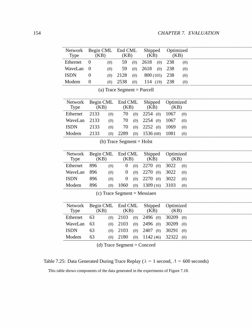
154 CHAPTER 7. EVALUATION
Network Begin CML End CML Shipped OptimizedType (KB) (KB) (KB) (KB)
Ethernet 0 (0) 59 (0) 2618 (0) 238 (0)
WaveLan 0 (0) 59 (0) 2618 (0) 238 (0)
ISDN 0 (0) 2128 (0) 800 (105) 238 (0)
Modem 0 (0) 2538 (0) 114 (19) 238 (0)
(a) Trace Segment = Purcell
Network Begin CML End CML Shipped OptimizedType (KB) (KB) (KB) (KB)
Ethernet 2133 (0) 70 (0) 2254 (0) 1067 (0)
WaveLan 2133 (0) 70 (0) 2254 (0) 1067 (0)
ISDN 2133 (0) 70 (0) 2252 (0) 1069 (0)
Modem 2133 (0) 2289 (0) 1536 (68) 1081 (0)
(b) Trace Segment = Holst
Network Begin CML End CML Shipped OptimizedType (KB) (KB) (KB) (KB)
Ethernet 896 (0) 0 (0) 2270 (0) 3022 (0)
WaveLan 896 (0) 0 (0) 2270 (0) 3022 (0)
ISDN 896 (0) 0 (0) 2270 (0) 3022 (0)
Modem 896 (0) 1060 (0) 1309 (16) 3103 (0)
(c) Trace Segment = Messiaen
Network Begin CML End CML Shipped OptimizedType (KB) (KB) (KB) (KB)
Ethernet 63 (0) 2103 (0) 2496 (0) 30209 (0)
WaveLan 63 (0) 2103 (0) 2496 (0) 30209 (0)
ISDN 63 (0) 2103 (0) 2407 (0) 30291 (0)
Modem 63 (0) 2180 (0) 1142 (46) 32322 (0)
(d) Trace Segment = Concord
Table 7.25: Data Generated During Trace Replay (� = 1 second, A = 600 seconds)
This table shows components of the data generated in the experiments of Figure 7.18.
7.5. TRICKLE REINTEGRATION 155
Network Begin CML End CML Shipped OptimizedType (KB) (KB) (KB) (KB)
Ethernet 0 (0) 49 (0) 2679 (0) 189 (0)
WaveLan 0 (0) 49 (0) 2679 (0) 189 (0)
ISDN 0 (0) 1133 (0) 1528 (105) 238 (0)
Modem 0 (0) 2387 (0) 318 (46) 238 (0)
(a) Trace Segment = Purcell
Network Begin CML End CML Shipped OptimizedType (KB) (KB) (KB) (KB)
Ethernet 99 (0) 70 (0) 114 (0) 1061 (0)
WaveLan 99 (0) 70 (0) 114 (0) 1061 (0)
ISDN 2218 (0) 70 (0) 1059 (2) 1064 (2)
Modem 2218 (0) 2289 (0) 858 (0) 1072 (0)
(b) Trace Segment = Holst
Network Begin CML End CML Shipped OptimizedType (KB) (KB) (KB) (KB)
Ethernet 177 (0) 0 (0) 1734 (0) 3022 (0)
WaveLan 177 (0) 0 (0) 1374 (0) 3022 (0)
ISDN 177 (0) 0 (0) 1374 (0) 3022 (0)
Modem 901 (35) 1060 (0) 954 (18) 3104 (0)
(c) Trace Segment = Messiaen
Network Begin CML End CML Shipped OptimizedType (KB) (KB) (KB) (KB)
Ethernet 164 (0) 2103 (0) 2496 (0) 30146 (0)
WaveLan 164 (0) 2103 (0) 2496 (0) 30146 (0)
ISDN 164 (0) 2103 (0) 2408 (0) 30227 (0)
Modem 164 (0) 2180 (0) 972 (47) 32196 (0)
(d) Trace Segment = Concord
Table 7.26: Data Generated During Trace Replay (� = 10 seconds, A = 300 seconds)
This table shows components of the data generated in the experiments of Figure 7.20.
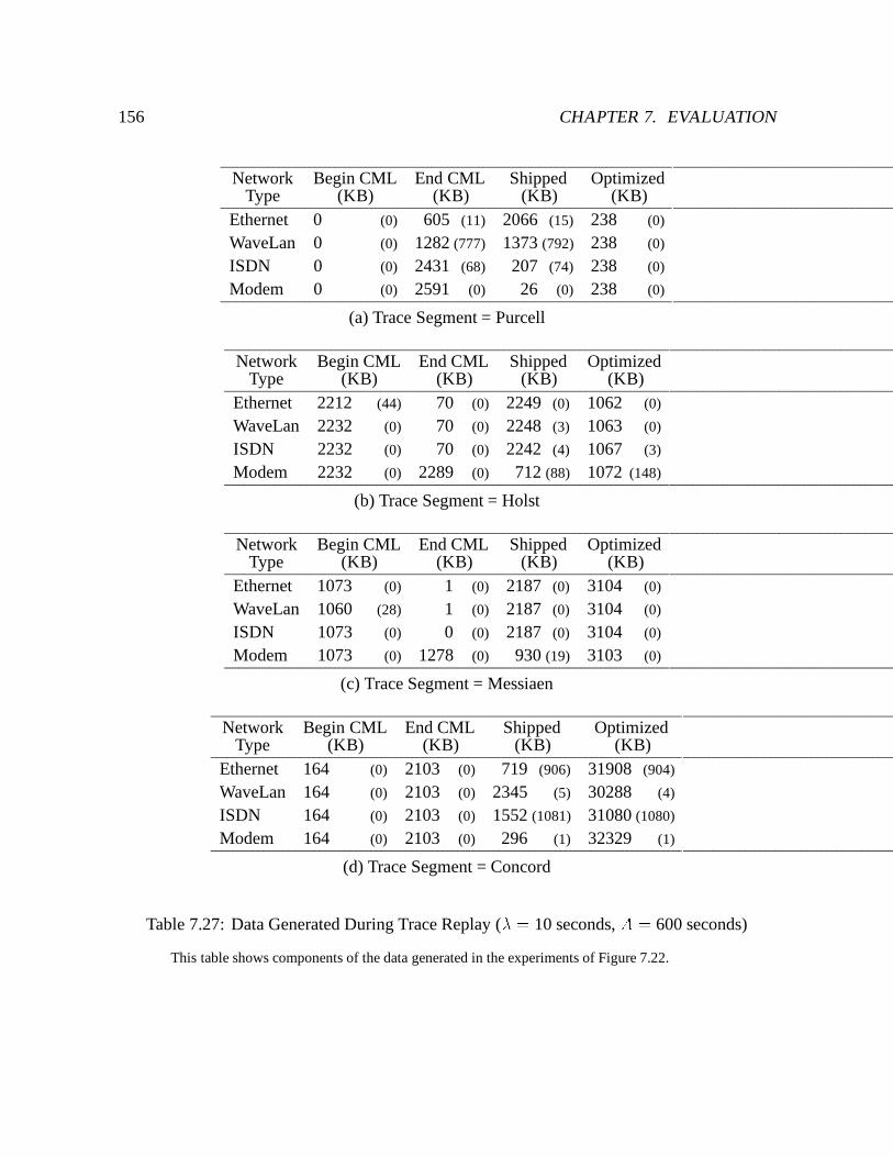
156 CHAPTER 7. EVALUATION
Network Begin CML End CML Shipped OptimizedType (KB) (KB) (KB) (KB)
Ethernet 0 (0) 605 (11) 2066 (15) 238 (0)
WaveLan 0 (0) 1282 (777) 1373 (792) 238 (0)
ISDN 0 (0) 2431 (68) 207 (74) 238 (0)
Modem 0 (0) 2591 (0) 26 (0) 238 (0)
(a) Trace Segment = Purcell
Network Begin CML End CML Shipped OptimizedType (KB) (KB) (KB) (KB)
Ethernet 2212 (44) 70 (0) 2249 (0) 1062 (0)
WaveLan 2232 (0) 70 (0) 2248 (3) 1063 (0)
ISDN 2232 (0) 70 (0) 2242 (4) 1067 (3)
Modem 2232 (0) 2289 (0) 712 (88) 1072 (148)
(b) Trace Segment = Holst
Network Begin CML End CML Shipped OptimizedType (KB) (KB) (KB) (KB)
Ethernet 1073 (0) 1 (0) 2187 (0) 3104 (0)
WaveLan 1060 (28) 1 (0) 2187 (0) 3104 (0)
ISDN 1073 (0) 0 (0) 2187 (0) 3104 (0)
Modem 1073 (0) 1278 (0) 930 (19) 3103 (0)
(c) Trace Segment = Messiaen
Network Begin CML End CML Shipped OptimizedType (KB) (KB) (KB) (KB)
Ethernet 164 (0) 2103 (0) 719 (906) 31908 (904)
WaveLan 164 (0) 2103 (0) 2345 (5) 30288 (4)
ISDN 164 (0) 2103 (0) 1552 (1081) 31080 (1080)
Modem 164 (0) 2103 (0) 296 (1) 32329 (1)
(d) Trace Segment = Concord
Table 7.27: Data Generated During Trace Replay (� = 10 seconds, A = 600 seconds)
This table shows components of the data generated in the experiments of Figure 7.22.
7.6. CHAPTER SUMMARY 157
There are a few exceptions. First, during the Holst workload with A = 300 (Tables 7.24(b)and 7.26(b)) Venus reintegrated data during the warming period. Second, during the Concordworkload with � = 10 and A = 600 (Table 7.27(d)), a large file was shipped in some runs,but not in others because the corresponding store record was optimized from the CML. Thisdifference accounts for the large variance in the figures for data shipped and optimized in thattable.
At the end of the experiment, more data remains in the CML at lower bandwidths. Forexample, in Table 7.25(b), the amount of data remaining in the CML is 70KB for Ethernet,versus 2289 KB for Modem. Many entries are non-zero even for Ethernet because updatesoccurred within an aging window (300 or 600 seconds) from the end of the workload.
CML optimizations increase as bandwidth decreases, because data spends more time in theCML. Using the Holst workload example of Table 7.25(b), the amount optimized for Ethernetis 1067 KB, compared to 1081 KB for Modem. Looking across experiments, as A increasesso do CML optimizations. For example, optimizations increase for each network type duringthe Messiaen workload at � = 1 as A increases from 300 to 600 seconds (Tables 7.24 and7.25). Of course, highly compressible segments benefit more from the increased opportunityfor optimization at lower bandwidths and larger aging windows.
7.6 Chapter Summary
This chapter has presented a quantitative evaluation of the transport protocol, rapid cachevalidation, and trickle reintegration mechanisms. The evaluation was performed in the Codafile system, and was based on controlled experimentation and empirical data gathered from thesystem in actual use. The evaluation showed that:� performance of the transport layer is reasonable compared to the TCP implementation
available under the operating system platform in use.� rapid cache validation works well in practice; validation by volume is successful 97% ofthe time, and when successful, it compensates for a three order of magnitude reductionin network bandwidth.� trickle reintegration successfully decouples client and network file system activity;elapsed time of a trace replay benchmark was nearly unchanged over the entire ex-perimental range of network bandwidths.

158 CHAPTER 7. EVALUATION
Chapter 8
Related Work
The work described in this dissertation is unique in its focus on high level mechanisms forexploiting weak connectivity, and its identification of four key mechanisms through actualsystem use. Although some techniques resembling the mechanisms described have been usedin other distributed systems, to the best of our knowledge, no other system has identified orcombined these mechanisms in this way to provide support for weakly connected operation.
This chapter discusses work related to weak connectivity in distributed systems. The chapteris divided into two parts. The first part reports on systems and applications designed to copewith weak connectivity. The second part describes work related to the specific mechanismsused to support weak connectivity in Coda.
8.1 Systems that Exploit Weak Connectivity
Effective use of low bandwidth networks has been widely recognized as an important capabilityin mobile computing [40, 58]. But only a few systems currently provide this functionality. Ofthese, the Little Work distributed file system project [48, 50, 51] is most closely related to thiswork.
8.1.1 Distributed File Systems
8.1.1.1 Little Work
Like Coda, Little Work provides transparent UNIX file access to disconnected and weakly-connected clients. It is designed to be upward compatible with existing AFS servers, and thusmakes no changes to the AFS client-server interface. This constraint hurts its ability to cope with
159
160 CHAPTER 8. RELATED WORK
intermittent connectivity. First, it renders the use of rapid cache validation infeasible. Second,it weakens fault tolerance because the replay of client updates cannot use a transactional serverprimitive as in reintegration.
Little Work supports two flavors of weakly connected operation – partially connectedoperation and fetch-only mode. Partially connected operation is analogous to Coda’s writedisconnected state. But there are important differences. First, users cannot influence theservicing of cache misses in Little Work. Second, update propagation is less adaptive thantrickle reintegration in Coda. For example, there is no fragmentation mechanism to allowpropagation of large files in a way that minimizes interference with other client activity. Third,much of Little Work’s efforts to reduce and prioritize network traffic occur in the SLIP driver.This is in contrast to Coda’s emphasis on the higher levels of the system. In fetch only mode,the client cache manager uses the network solely to satisfy cache misses. All cached files areassumed to be valid, and no cache coherence protocol is used. There is no analogue of thismode in Coda. It is unclear from the literature on Little Work if the transitions between thestrongly connected, partially connected, and fetch only modes are performed automatically bythe file system.
8.1.1.2 Ficus
Ficus is a distributed file system that supports optimistic replication [45, 46]. In Ficus, nodes areconsidered peers rather than clients and servers. Data is organized into volumes, which may bereplicated across nodes. Updates may be performed as long as a single replica is available, andthey are propagated to other replicas in a best-effort manner. A process called reconciliationruns periodically on behalf of each replica to pull over missed updates and detect conflicts.
Ficus is used over weak connections such as phone lines. A typical configuration includesworkstations at home and at work, each hosting a replica of the user’s environment. The weakconnection is used for reconciliation. The peer-to-peer structure of the system means that anytwo nodes hosting a volume replica may communicate and exchange data. Nodes do not cachedata. Access to objects in volumes replicated at a node is efficient, because the data is local.However, if an object in a volume not hosted by the node is referenced, the node must access itremotely. Although nodes may be configured to minimize remote references, such referencesinevitably occur. Establishing a replica at a node is a heavyweight operation, and is a wasteof resources if the files in that volume are rarely needed. Caching is lighter weight and moreflexible than replica placement.
8.1.1.3 The Siphon
The Siphon system [102] was developed by DEC PRL to manage a shared software repositorywith objects replicated on both sides of a 56 Kb/sec transatlantic link. Repository units are
8.1. SYSTEMS THAT EXPLOIT WEAK CONNECTIVITY 161
file system directories called packages, which are self-contained software or documentationcollections. In this system reads are satisfied by a local replica which may be stale. Writes madeto the local replica are propagated to the others as network bandwidth permits; propagationdelays can range from a few minutes to a few hours. Writes are permitted only after a lockis acquired; a client cannot acquire a lock until the local replica is up-to-date. The repositorydescribed contained roughly 700 packages totalling 1.6 GB, of which about 40 MB propagatedthrough the Siphon each day. The authors point out that availability was more of an issue intheir system than bandwidth or latency. They claim a third to a half of the bandwidth wouldhave been adequate for their purposes.
8.1.1.4 Commercial Products
There are a number of commercial products that keep files on a mobile host synchronized withservers or desktop machines. The one most similar to this work is Airsoft’s AirAccess [2], whichprovides application-transparent support for disconnected and weakly connected file access.Its implementation focuses on the transport level, using techniques such as data compressionand differential file transfer. Like Little Work, it preserves upward compatibility with existingservers and therefore suffers from the same limitations with respect to intermittent connectivity.It does not appear to have analogues to trickle reintegration and rapid cache validation, and theproblem of servicing potentially lengthy cache misses over the weak link is not addressed.
Other file synchronization products, such as Microsoft’s Briefcase [61, 124] and TravelingSoftware’s LapLink [87], are non-transparent and require user intervention. In Briefcase, auser copies files that he wishes to access while mobile to a special part of the namespace calledthe briefcase, which may then be transferred to other devices. The system remembers theoriginal location of the files. The user must manually invoke synchronization, and the systemrecommends reconciliation actions for objects in the briefcase (e.g., copy an updated version ofa file from the briefcase to its original location). Newly created files and files with conflictingupdates require user intervention. LapLink also provides tools for manual synchronization.Like AirAccess, it reduces data volume by transferring file differences rather than entire files.
8.1.2 Databases
There are a number of databases designed for use in weakly connected and disconnectedenvironments. These systems use replicated, weakly consistent data. Replication improvesavailability when sites are disconnected from each other. Weak consistency is preferable tostrong consistency because the latter would impose a severe penalty on availability and perfor-mance. Availability would be limited because read and update activity must be restricted duringdisconnections to avoid conflicts. Performance would suffer because distributed protocols mustexecute over slow and unreliable connections.
162 CHAPTER 8. RELATED WORK
A use of weak connections in databases was proposed by Lilien [71]. In this work, weakconnections are used as backup networks when a main network fails. The mode of operationwhen this occurs, called a quasi-partition, differs from both fully connected and partitionedoperation. During quasi-partitions, activity within partitions is unrestricted, but message trafficis reduced between partitions. There are two primitive operations used during a quasi-partition:creeping retrieval and creeping merge, which provide for reads and update propagation overthe weak link. In addition, the author lists several techniques helpful for reducing the volumeof data sent over the link, such as compression, batching of requests and updates, and definingabbreviated messages. The system uses backup links to avoid making a priori preparations fortrue partitions. Coda does not avoid making preparations for true partitions; on the contrary itencourages it through hoarding.
More recent databases for use in weakly connected environments include Bayou [126],OSCAR [33], and Lotus Notes [59]. In Bayou, servers communicate in a pairwise fashion,propagating updates amongst each other in a process called anti-entropy. In OSCAR, agents forservers called replicators and mediators cooperate to distribute updates to as many replicas aspossible. Lotus Notes is a commercial shared document database system that is used for groupcommunication applications, such as document sharing, e-mail, and computer conferencing.Notes is intended for use in “rarely connected” environments, that is, environments in whichworkgroups do not enjoy continuously available high-speed network connectivity. A specifictarget of this system is workgroups communicating using PCs and dialup lines. The group com-munication applications supported by Notes have the following characteristics. Collaborationis accomplished by adding documents to a database. Once added, documents are not usuallymodified. Finally, collaborators do not need to see up-to-the-minute data at all times. Theseapplications do not have strict consistency requirements, and can be supported by a weaklyconsistent replicated database. Notes uses optimistic replication among nodes that are peers.Updates are performed on the local replica; when nodes connect they pull new and changeddocuments from each other. The system guarantees eventual consistency, that is, changes madeto one replica eventually migrate to all. The system detects and notifies users of conflictingupdates.
These database systems differ from Coda in two important respects. First, they do not adaptdynamically to weak connections. They are structured in such a way that strong connectionsare not necessary, because applications access local replicas, and nodes communicate primarilyto exchange updated data. Second, these systems are vertically integrated applications. Incontrast, Coda can support any application written for the UNIX API.
8.1.3 Read Only Systems
Several read only systems have been implemented for use in wide area networks. The mostnotable of these systems is the World-Wide Web [9]. The Web is a wide area information system
8.1. SYSTEMS THAT EXPLOIT WEAK CONNECTIVITY 163
structured to facilitate browsing. It consists of read only objects. Updates are issued by serversand propagated lazily to clients. The system provides no consistency guarantees. Networkperformance for Web accesses is frequently poor. Browsers such as Netscape Navigator copewith this by caching Web pages, providing user-selectable levels of consistency between cachedand server copies, and hiding latency by overlapping image retrieval with user think time.
8.1.4 Application-Specific Approaches
From a broader perspective, some applications employ techniques to exploit low bandwidthnetworks. This approach differs from Coda in that support for mobility is entirely the respon-sibility of the application. By providing this support at the file system level, Coda obviatesthe need to modify individual applications. Further, by mediating the resource demands ofconcurrent applications, Coda can better manage resources such as network bandwidth andcache space.
8.1.4.1 Window Systems
Low Bandwidth X (LBX) [41] (now X.FAST [105]) is an example of application-specificexploitation of weak connectivity. LBX is a version of the X protocol which is more efficientover low bandwidth, high latency connections. It uses a special program to intercept X packetson either side of the network, and remove as much redundant information as possible. LBXmakes more aggressive use of caching, re-encodes packets to require less space, uses changeswith respect to previous packets (“deltas”) where appropriate, and compresses the result. Totrade cost for performance, the amount of caching and specific compression algorithm usedare negotiable. These strategies are intended for general use, not just in weakly connectedenvironments.
8.1.4.2 Electronic Mail and News
There are a number of e-mail and data services designed to use weak connectivity, particularlyin the form of wireless links. Examples include Eudora [103], Lotus cc:mail [80], RadioMail,and PINE [93]. These packages offer a range of features including automatic uploading anddownloading of e-mail, wireless e-mail (e.g., to pagers), and data services such as news andweather reports.
Eudora and the Internet Message Access Protocol (IMAP4) [25], the protocol underlyingPINE, contain features that help cope with weak connections. Eudora is a mail client basedon the SMTP [101] and POP3 [78] protocols. It provides support for off-line compositionof messages and automatic uploading and downloading of messages. It includes a “skip big
164 CHAPTER 8. RELATED WORK
messages” option, which prevents downloading of large (> 40 Kbytes) messages. In this case,Eudora downloads the first few lines of the message and flags it to alert the user that it is aprefix.
IMAP4 allows a mail client to access and manipulate e-mail message folders, called mail-boxes, at a server. IMAP4 supports includes disconnected message processing and synchro-nization upon reconnection, and online processing, in which the client manipulates remotemessages directly [26]. In both cases, it is assumed that network connections are weak, andthe protocol attempts to minimize network usage. Synchronization involves the processingof any queued commands at the client, and the updating of the client’s message cache withnew server state [4]. In the latter step, the client fetches the current list of mailboxes, then foreach mailbox the list of descriptors. The client determines the server’s state from the list ofdescriptors, and fetches new or updated messages from the server. Message synchronization isguided by the user in the form of configuration files that specify which mailboxes and messagesto examine. IMAP provides three “online performance optimizations” to improve usabilityover weak connections [44]. First, a client can determine the message contents without fetch-ing the entire message. For example, a message might have a few hundred bytes of text andseveral megabytes of image data. Second, the client can selectively fetch parts of messages. Tocontinue the example, a client might elect to fetch only the text portion of a message. Finally,IMAP provides a mechanism for server-based searching and message selection to minimizedata transfer.
8.1.4.3 Electronic Conferencing
The EDFM [32] system, developed at AT&T, combines design for manufacture (DFM) softwarefor printed circuit boards with electronic conferencing software to allow simultaneous real-timeviewing of circuit board designs among geographically separated development teams over a lowbandwidth connection. Since circuit board designs involve many large engineering drawingswith thousands of design objects, EDFM uses off-line preparation for an electronic conferenceto eliminate all but crucial communication for the real-time conference. A conference proceedsas follows. First a complete printed circuit board design is sent from a host to a remote sitesoff-line, prior to the conference. Both sites load this representation and begin the conference.Incremental design changes are transferred in real-time using a compact language for describingdesign elements. The changes, encoded in small messages, are then applied by the remote site.
8.2 Mechanisms for Weak Connectivity
Some of Coda’s mechanisms for weak connectivity a have been investigated in isolation inother systems. This section describes work similar to the individual Coda mechanisms for
8.2. MECHANISMS FOR WEAK CONNECTIVITY 165
exploiting weak connectivity.
8.2.1 Communications
The Coda communications layer offers adaptive transport protocols based on round trip timeestimation, passive monitoring of network transmissions, and the export of measurements toadaptive applications through transmission logs. A number of transport protocols share someof these features. One of the most widely used adaptive transport protocols is TCP/IP [99].Its round trip timing mechanism enables it to adapt to changing network conditions [52]. Itsintroduction of header compression has improved performance over low bandwidth connec-tions [53]. Finally, it has been extended to operate over very high speed networks, and networkswith large bandwidth delay products [54]. The TCP round trip timing and header compressionmechanisms were applied to Rx, the AFS transport protocol, in the context of the Little Workproject [5].
The QEX RPC protocol, an extension of the REX RPC protocol for ANSAware [3], alsoperforms round trip timing [30]. In addition, QEX provides feedback to applications on thestate of underlying communications, but in a different way than RPC2. QEX maintains QoSinformation on a per-session basis, and provides its feedback using a callback mechanism.
Applications that adapt their behavior based on estimates of network bandwidth and otherparameters have been implemented primarily in the domain of multimedia. Strategies commonin video applications include dropping frames and reducing picture quality when networkperformance degrades [24, 90].
8.2.2 Rapid Cache Validation
Independent of this work, the possibility of rapid cache validation has been recognized in theFicus [46] and xFS [127] systems. Ficus uses a strategy called time-based reconciliation toreduce the amount of network traffic while detecting changes between two volume replicas.Each pair of volume replicas records the time that the last successful reconciliation started.Only those files that have changed more recently require checking. Another argument formaintaining cache coherence at a large granularity has been put forth independently by Wangand Anderson [127]. They propose maintaining cache coherence on clusters of files, such assubtrees. Their primary motivation is to reduce server state rather than communication. NeitherFicus nor xFS has reported on any quantitative evaluation of their mechanisms in the literature.Therefore, it is impossible to compare rapid cache validation in Coda with these systems.
The rapid cache validation approach for failure recovery contrasts with systems such asAutonet [106], which hide transients until the network appears stable using a system of skeptics.This approach makes sense if the cost of changing state is high – otherwise the system would
166 CHAPTER 8. RELATED WORK
spend a disproportionate amount of time doing nothing but recovering from connectivitychanges. If the the cost of recovery can be reduced, more slivers of connectivity can be exposedto the system and used. This is particularly important if there is monetary cost associated withthe physical connection, or urgency in detecting the presence of new information.
8.2.3 Trickle Reintegration
Trickle reintegration bears resemblance to write-back caching, as used in distributed file systemssuch as Sprite [89], Echo [47, 74], and MFS [16]. As discussed in Section 5.1, both techniquesreduce latency by deferring propagation of updates to servers, and reduce network bandwidthand server load by taking advantage of updates that cancel or overwrite each other. However,they differ in three respects. First, these systems preserve strict UNIX write-sharing semantics.They are able to do so because they all assume LAN connectivity. In weakly connectedenvironments, this guarantee is impractical, because it would require strongly connected clientsto wait for updates to propagate from weakly connected clients. Second, the primary focusof write-back caching is to reduce file system latency rather than data volume. In weaklyconnected environments, the emphasis is on reducing data volume. Third, write-back cachingschemes maintain their caches in volatile memory, and thus suffer from the possibility of dataloss due to system failures. Their need to bound the damage limits the delay before updatesmust be propagated. In contrast, the local persistence of updates in Coda allows for longerpropagation delays, bounded only by concerns of client theft, loss or disk damage.
Chapter 9
Conclusion
Ubiquitous data access is an increasingly important capability for information systems. Thedemand for this capability is evident in the proliferation of portable computers and wirelesscommunication. Network technology will remain diverse for the foreseeable future. Weakconnectivity represents the lower end of the range of available technologies, and it is inevitablein mobile file access. Thus it is crucial that information systems cope with weak connectivity.
This dissertation has described several mechanisms necessary for coping with weak con-nectivity in a distributed file system. It has introduced adaptation to network conditions inmultiple system layers. The foundation of adaptivity in this system is the communicationslayer, which derives and supplies information on network conditions to higher layers. Therapid cache validation mechanism enables the system to recover quickly in the face of inter-mittent connectivity. The trickle reintegration mechanism insulates the user from poor networkperformance by trading off consistency. The cache miss handling mechanism alerts the user topotentially lengthy service times and provides opportunities for intervention.
These mechanisms were implemented and deployed as part of the Coda file system, whichenjoys daily use by several dozen users from mobile and stationary clients using Ethernet,WaveLAN, and SLIP connections. Measurements from the system show that it allows users tolargely ignore the vagaries of network performance and reliability typical of mobile environ-ments.
9.1 Contributions
The main contribution of this thesis is a demonstration that weak connectivity can be usedeffectively to alleviate the shortcomings of disconnected operation. More specifically, thisthesis makes contributions in the following areas:
167
168 CHAPTER 9. CONCLUSION
1. Conceptual contributions� Architectural focus on high level mechanisms for weak connectivity.Recognition of the importance of high level mechanisms results in substantialbenefits for weakly connected operation. Low level improvements may enhancethose mechanisms, but cannot replace them (Section 1.3).� Identification of mechanisms for weak connectivity.The mechanisms evolved through actual use of system, and were found to benecessary for weakly connected file access (Section 7.1).� First formal analysis of cache coherence in a distributed file system.The introduction of multiple granularities into the cache coherence protocol ren-dered it sufficiently complex that ad-hoc reasoning was no longer sufficient. Anovel technique based on the notion of belief [18] was derived to reason about thecorrectness of the protocol (Appendix A).
2. System design and implementation contributions� Communications layer
– Techniques for adaptation in user-level transport protocols.Incorporation of adaptation into RPC2 and SFTP protocols using round triptime estimation (Sections 3.2 and 3.3).
– Novel log-based technique for flexible, efficient export of network quality in-formation.The transport protocols log measurements on network transmissions using apassive monitoring technique. Venus obtains these measurements through anAPI for exporting transmission logs, and derives bandwidth estimates to triggertransitions to and from weakly connected operation (Sections 3.4 and 3.5.2).� Rapid cache validation
– Design and implementation of large granularity cache coherence protocol forrapid cache validation.Clients synchronize their caches with servers rapidly upon reconnection at thegranularity of volumes. This mechanism improves system agility in intermit-tent environments (Chapter 4).� Trickle Reintegration
– Design and implementation of adaptive, asynchronous update propagationmechanism.Clients propagate updates asynchronously to servers, in a manner that mini-mizes interference with demand activity (Chapter 5).
9.2. FUTURE WORK 169
– Use of aging as a metric for CML record propagation.Aging allows trickle reintegration to preserve the effectiveness of log optimiza-tions by taking advantage of temporal locality of updates (Section 5.2.2).
– Methodology for selecting aging windows and trace based analysis.A good default aging value for the window was chosen as a result of tracedriven simulation and analysis of CML optimizations (Section 5.4).
– Adaptive strategy for determining data propagation volume.The client uses bandwidth estimates to determine the amount of data to prop-agate at one time. If a record involves a large amount of new data, the data istransferred using high level fragmentation (Section 5.3.2).� Cache Miss Handling
– Novel model-based technique for weakly-connected cache miss handling.This mechanism trades off impact of cache misses at low bandwidth betweenusability and performance degradation. (Chapter 6).
3. Evaluation contributions� Controlled experiments showing transport protocol performance at least comparableto that of TCP (Section 7.3).� Controlled experiments showing dramatic reduction in cache recovery times usingrapid cache validation (Section 7.4.1.2).� Empirical data from system in actual use demonstrating effectiveness of rapid cachevalidation in practice (Section 7.4.2.2).� Experimental methodology based on trace replay, in which a workload from a filereference trace is replayed on the live system (Section 7.5.1).� Controlled trace replay experiments confirming effectiveness of trickle reintegrationover a three order of magnitude range in network bandwidth (Section 7.5.2).
9.2 Future Work
Although the system in its current form is useful, it could be improved in a number of ways.This rest of this section discusses directions for future work, in order of increasing scope. Thenarrowest scope represents enhancements to weakly connected operation. Work of mediumscope represents more substantial extensions to the system as a whole. At the broadest scopeare directions for new research.
170 CHAPTER 9. CONCLUSION
9.2.1 Refinements for Weakly Connected Operation
Previous chapters have suggested a number of enhancements to the implementation. In general,they represent more sophisticated policies using the existing mechanisms described in thosechapters. In the communications layer, the transport protocols described in Sections 3.2 and 3.3could incorporate header and data compression. The bandwidth estimates Venus derivesfrom the transmission logs, described in Section 3.4.3, could be improved in several ways.Venus could incorporate variance into its bandwidth estimates, and estimate conservativelywhen variance is high. If Mobile IP is available, the communications layer could incorporateinformation from upcalls generated when a mobile host changes location [56] as static entriesdeposited into its transmission logs.
For trickle reintegration, the selection of the aging window described in Section 5.4 couldbe adaptive to connection strength. At low bandwidths, Venus would use a large window tominimize data volume by taking advantage of log optimizations. At higher bandwidths, Venuswould shrink the window because the benefits of propagating updates to the server outweigh thebenefits of reducing the amount reintegrated. Section 5.3.2.2 describes another enhancementto trickle reintegration called selective reintegration, in which a user or program propagatesupdates to particular objects to the server. Finally, Venus could propagate file differencesinstead of file contents.
9.2.2 Incorporating Monetary Cost
This work has assumed that performance is the only metric of cost. In practice, many networksused in mobile computing cost real money. Where cost is prohibitive, Venus should conserveits use of the network just as it does when performance is very poor. This extension involvesexploring techniques whereby Venus electronically inquires about network cost, and bases itsadaptation on both cost and performance. Of course, full-scale deployment of this capabilitywill require the cooperation of network providers and regulatory agencies.
9.2.3 Improving Effectiveness and Usability of Hoarding
As discussed in Chapter 6, servicing cache misses over a weak connection can be painfullynon-transparent. Avoiding the performance penalty associated with a cache miss remains animportant goal.
Hoarding is the current mechanism for caching for availability in Coda. However, expe-rience has shown that novice users frequently forget to hoard critical files. Further, MariaEbling found that the time to the first reference of a critical file was very small [36]. Thus sheis exploring ways to improve caching for availability [35]. She argues that user assistance is
9.2. FUTURE WORK 171
necessary to avoid cache misses while operating disconnected or weakly connected. Further,assistance should be provided to the system in an ongoing manner rather than a separate activityas in hoarding, and the information supplied by the user should be based on “tasks” rather thandirectories.
In addition, she is evaluating alternative strategies for caching for availability. This evalu-ation is difficult because the only caching metric available today is the miss ratio. This metricassumes that all cache misses are equal. However, while disconnected, cache misses do notexact the same penalty from the user. While weakly connected, cache misses can have wildlydifferent service times. Further, the miss ratio does not take into account the timing of a miss– a user may react very differently to a cache miss at the beginning of a task than at the end.Ebling is exploring new caching metrics to evaluate the impact of different caching strategieson users and the accuracy of user assistance.
9.2.4 Exploiting Reserved Network Services
The communications layer assumes that the network provides no guarantees about perfor-mance. It assumes the network delivers data in a best-effort manner, and it simply observesthe performance of its data transfers and derives estimates from those observations. There isa great deal of work on providing guaranteed or reserved services in both wired and wirelessnetworks [27, 37, 38, 130]. An interesting extension to Coda would be to take advantage ofreserved services when available. For example, the communication layer could adjust its re-transmission strategy and frequency of round trip time measurements given a latency guarantee.Higher layers could take advantage of bandwidth guarantees to schedule file transfers.
9.2.5 Application-Level Logging
When connectivity is weak, a system must strive to minimize bandwidth requirements. Anobvious way to reduce network usage is through compression, and several systems use thistechnique [2, 5]. However, more efficient communication may be possible by examining theactivity at a higher level. For example, rather than shipping data between server and client, itmay be more efficient to send operations.
This idea can be applied to the Coda CML. The CML can be viewed as an operation log fordirectories, and a value log for files. To incorporate function shipping into weakly connectedoperation, one could introduce application-level logging, in which the CML includes operationlogging for files, and applications specify the operation. For example, consider a text editorreplacing string string1 with string2. The current implementation logs a store CMLrecord with the new file data, and ships the new file data in its entirety to the server. In
172 CHAPTER 9. CONCLUSION
application-level logging, the application would log a single CML record with the instructionsfor string replacement, and the server would perform the replacement upon receipt of the record.
High level operation logging places a greater burden on the server, because operationsrequire greater computational resources. To preserve scalability, the system must take serverload into account before agreeing to perform these functions. The client should negotiateoperation logging rights upon connection, and the server should be able to revoke those rightsif load becomes heavy.
9.2.6 Application-Aware Adaptation
This thesis has taken the approach of application transparent adaptation, placing the entireresponsibility for adapting to network conditions on the file system. This approach is attractivebecause applications benefit from weakly connected support without modification. However,there are cases where adaptation performed by the file system is inappropriate for certainapplications. For example, the file system operates weakly connected when the bandwidthto a server (or VSG) falls below a certain threshold. But from an application’s point ofview, a network connection is weak only when it imposes a significant bottleneck on theapplication’s performance. One can imagine a compute-bound application that would not beweakly connected even at low speeds. On the other hand, there are applications that makean Ethernet look weak. Coda’s simple thresholding policy does not take this observation intoaccount.
Application transparent adaptation occupies one end of a spectrum of adaptation strategies.At the other end is the laissez-faire approach [112], which places the responsibility of copingwith network conditions entirely upon the individual application. This approach allows ap-plications to customize their handling of weak connectivity. However, it makes applicationsharder to write, because support for weak connectivity must be reinvented for each application.In addition, there is no way to arbitrate conflicting demands for resources between applications.
Between these two extremes is a spectrum of adaptation strategies referred to as applicationaware adaptation [112]. The application and system collaborate to allow applications toprovide their own adaptation strategies, and the system to control and monitor resource usagebetween applications. This approach is being explored in the Odyssey system [90, 122] andwork by Welling and Badrinath [129]. These systems provide an API that allows applicationsto monitor and react to changes in their environment, and support for resource managementwithin the system.
9.3. CLOSING REMARKS 173
9.3 Closing Remarks
Weak connectivity is a fact of life in mobile computing. The deep challenge of weak connec-tivity is not just poor network performance, but rather the variation in network performanceover a wide range. This variation implies that a system cannot make a priori decisions aboutthe performance impact of communication. It must adapt to network conditions, but in a waythat does not preclude use of strong connectivity. The ideal system takes advantage of strongconnectivity when available, but copes with weak connectivity when necessary. Further, itexploits periods of strong connectivity to improve quality of life during future periods of weakconnectivity.
Disconnected operation is an invaluable starting point for this work. From the standpoint of adisconnected client, weak connectivity provides opportunities for improvement. This work wasable to leverage off of the mechanisms for disconnected operation, such as update logging andreintegration, to exploit weak connectivity. Disconnected operation is still necessary, becauseit provides a viable fallback position when network conditions degrade beyond usability.
Performance, availability, and consistency are conflicting goals in distributed systems.This work trades consistency for performance and availability while weakly connected toallow the user to continue working with minimal interference. When strongly connected,performance, availability, and consistency are unaffected. The system strives to provideweakly connected performance comparable to that of a disconnected client, but with betterconsistency and availability. It maintains transparency as much as possible, but relaxes itwhere necessary in favor of usability. This adaptation is a crucial element for operating inweakly connected environments. Although network performance is improving, the wide rangeof network characteristics available will remain. Thus weakly connected operation will be avital capability in future distributed systems.

174 CHAPTER 9. CONCLUSION
Appendix A
Protocol Analysis
This chapter presents the details of the large granularity cache coherence protocol analysis. Thefirst two sections present the system model, logic, and notation. The correctness criterion isstated formally in Section A.3. Section A.4 presents the analysis of the protocol. For simplicitythe analysis assumes messages are received instantaneously; the effects of transmission delayand failures on correctness are discussed in Section A.5. The chapter closes with a discussionof simplifications made to the model, and how the definitions could be extended.
A.1 System Model
Hosts are designated clients or servers of the file system. Clients and servers communicate bysending messages to each other via remote procedure call [11]; each request made by one partyrequires a response from the other. The notationC ! S : Mmeans client C sends a message M to server S.
Clients speak only to servers, not to other clients. The underlying communication protocoladdresses end-to-end concerns such as guaranteeing authenticity and eliminating duplicatemessages.
Exactly one repository, which could be one server or a group of servers, is the authority fora file system object. The generic term “server” refers to a repository. A file system object isany data stored by a server that may be cached at a client, including files, portions of files, fileattributes, or version numbers.
The local state of a client, C , includes a set of cached data, C:D, and a set of beliefs, C:B,about objects in its cache. The local state of a server, S, includes the set of objects it stores,
175
176 APPENDIX A. PROTOCOL ANALYSISS:D, and for each client C , a set of beliefs, SC:B, that includes which objects are present inC’s cache and their validity.
The global state of the system is a tuple of all clients’ and servers’ local states, plus anagreement set ACS , which determines for each data object d whose authority is S and is cachedat C, whether the server and client copies are equal. It is this state variable that approximatesglobal knowledge about the validity of all files. It represents pairwise knowledge, attainedbetween connected pairs of clients and servers.
State transitions occur when a component of the global state changes. For the most part, thisis when clients and servers exchange messages. The types of message exchanges are discussedin Section A.4.
The analysis makes statements about the presence or absence of file system objects cachedat clients and their validity. An object is valid if it is the most recent copy in the system.Otherwise, it is invalid. Recency is determined by a timestamp associated with the file. Thetimestamp is replaced whenever the file is updated.
Since servers may not hear about updates immediately, validity is global knowledge andcannot always be determined by clients and servers. However, if C and S agree on an object,and S believes its copy is valid, then C should be able to conclude that its cached copy is valid.If S receives an update from a client other than C , then S is justified in telling C that its copyof the object is now invalid, regardless of the global validity of the updated copy.
Each protocol has a predefined set of initial and final messages. A run of a cache coherenceprotocol begins with an initial message and ends with a final message. Failures can terminateruns; they are detected by message timeouts. If a message times out, the principal that sent themessage considers it a final message. However, if a client and server both believe a run is inprogress, then the run ends once both principals detect the failure. An example of this appearsin Section A.5.
Before a run, a client C considers all objects in its cache suspect; that is, it neither believesan object d is valid, nor believes d is invalid. During a run, C and S accumulate beliefs aboutd as a result of exchanging messages. At the end of the run, C and S discard their beliefsregarding the validity of d. If a run is not in progress, C must consider all cached objectssuspect because it cannot check if they are valid, nor can S notify C that they are not.
A.2 Logic
The logic is a subset of the BAN logic [17, 18] with a few extensions. Below, P and Q areprincipals, which are either clients or servers. S refers to a server and C refers to a client. Amessage is denoted X; a file system object d. The constructs are:
A.2. LOGIC 177P believes X P behaves as if X is true.P sees X from Q P receives message X from Q.P controls X P is an authority on X .
The notions of belief and control are taken directly from the BAN logic. The statementP believes X is equivalent to X 2 P:B, where P:B is the belief set for principal P . Thesees construct is derived from the BAN logic based on our assumptions about the underlyingcommunication mechanism.
The following constructs, extensions to the BAN logic, are for reasoning about file systemobjects:d 2 P P has a copy of d, i.e., d 2 P:D. The copy held by P is denoted dP 1.
valid(dP ) The value of d’s timestamp at P is greater than or equal to the timestampassociated with every other copy of d in the system.
Messages can contain the above two constructs and their negations. As in the BAN logic,a message X may consist of formulae, data, or both. For example, a message might contain aformula about some object d such as valid(dC), or it might contain the object itself (simply d).Messages may be classified further based on their contents. For example, the various kinds ofupdate requests form one class of messages. An update request involving object d is denotedupdate(d).
Belief sets can contain the above two constructs and their negations, as well as statementsof the form “P believes X”.
The axioms of the logic are:
A1. 8d 2 C:D (C believes d 2 C)A2. 8d 62 C:D (C believes d 62 C)A3. P believes X ) :(P believes :X)
The first two axioms simply state that client C is allowed to believe what it knows aboutthe contents of its cache.
The third axiom says belief sets must be internally consistent. In the BAN logic, beliefsare stable, meaning that once a principal holds a belief, it holds that belief for the duration ofthe protocol. Thus during their protocols, belief sets only grow. In contrast, in a file systemcached files may become invalid because of updates. Because of this, beliefs about the validityof files may change. Axiom 3 guarantees at most one of X and :X appears in P ’s beliefset. If a new belief is derived during a run that contradicts a currently held belief about d,
1Although P is a parameter, it is more readable as a subscript.
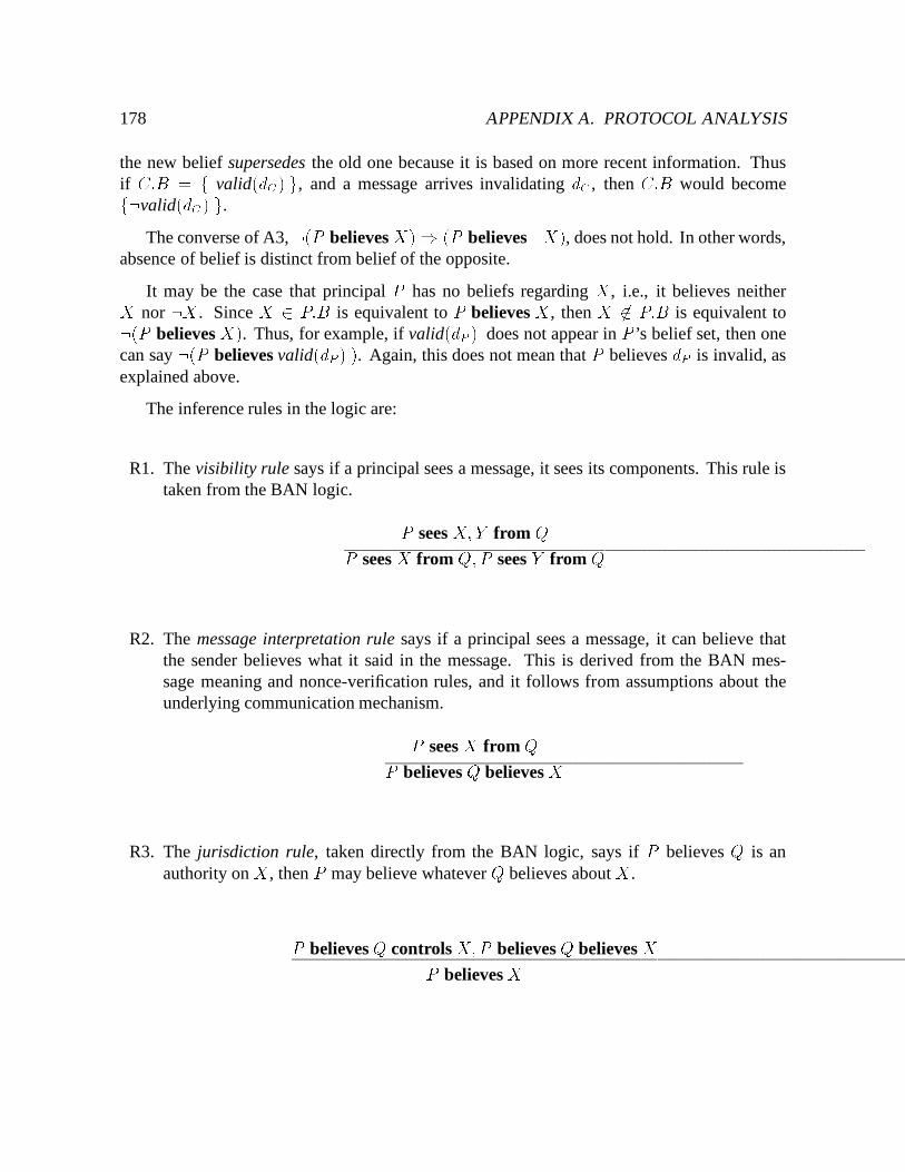
178 APPENDIX A. PROTOCOL ANALYSIS
the new belief supersedes the old one because it is based on more recent information. Thusif C:B = f valid(dC) g, and a message arrives invalidating dC , then C:B would becomef:valid(dC) g.
The converse of A3, :(P believes X)) (P believes :X), does not hold. In other words,absence of belief is distinct from belief of the opposite.
It may be the case that principal P has no beliefs regarding X , i.e., it believes neitherX nor :X . Since X 2 P:B is equivalent to P believes X , then X 62 P:B is equivalent to:(P believes X). Thus, for example, if valid(dP ) does not appear in P ’s belief set, then onecan say :(P believes valid(dP ) ). Again, this does not mean that P believes dP is invalid, asexplained above.
The inference rules in the logic are:
R1. The visibility rule says if a principal sees a message, it sees its components. This rule istaken from the BAN logic. P sees X;Y from QP sees X from Q;P sees Y from Q
R2. The message interpretation rule says if a principal sees a message, it can believe thatthe sender believes what it said in the message. This is derived from the BAN mes-sage meaning and nonce-verification rules, and it follows from assumptions about theunderlying communication mechanism.P sees X from QP believes Q believes X
R3. The jurisdiction rule, taken directly from the BAN logic, says if P believes Q is anauthority on X , then P may believe whatever Q believes about X .P believes Q controls X;P believes Q believes XP believes X
A.3. GOAL OF CACHE COHERENCE 179
R4. The update rule says observers of an update invalidate old versions of the updated data.Below, C 0 6= C, and S is the repository for d.S believes valid(dC),S sees update(d) from C 0S believes :valid(dC)
A.3 Goal of Cache Coherence
The goal of a cache coherence protocol is to ensure that no invalid object is ever portrayed asbeing valid. That is, for all clients C and objects d,
if C believes valid(dC) then valid(dC)This is not achievable in practice because the system model allows partitioned updates.
However, a weaker version of this statement is a practical correctness criterion: for all clientsC , servers S, and objects d for which S is the repository,
if C believes valid(dC) then S believes valid(dC)Notice that the correctness criterion is defined on a per-object basis. The aim of a run is toestablish the correctness criterion for as many cached objects as possible.
Unlike authentication, cache coherence is not a final system state to be achieved afterrunning the protocol, but an invariant to be maintained while running it. To argue a cachecoherence protocol correct, our obligation is to prove the invariance of the correctness criterionover each run of the protocol.
A.4 Protocol Analysis
This section presents an analysis of the large granularity protocol. The protocol is reviewedbriefly, and the initial and final messages are defined. Then the smallest system possible inwhich the protocol could operate is defined. The possible states of a client and server are listed,determining all possible valid runs. Correctness arguments for each follow, assuming initiallythat message transmission and failure detection occur instantly. The effect of transmissiondelays and failures is discussed in Section A.5.
The following assumptions apply to all runs:
180 APPENDIX A. PROTOCOL ANALYSIS
S1. 8d 2 S:D (S believes valid(dS) )S2. 8d 2 S:D d 2 C ) (C believes S controls valid(dC) )S3. 8d 2 S:D d 2 C ) (C believes S controls :valid(dC) )
The first assumption states that a server believes all the data it stores is valid. The last twoassumptions say a server is the authority on the validity of data it stores.
As described in Chapter 4, the large granularity cache coherence protocol allows callbacksto be maintained on volumes in addition to or instead of files. A callback on a volume constitutesproof that all cached files in the volume are valid. To establish a volume callback, the clientcaches the version number for the volume. The server increments the volume version numberwhenever a file in that volume is updated.
A run of this protocol concerns a file f , and optionally the version number v from volumeV containing f . Before requesting v, the client must have at least one file in V in its cache,and all cached files in V must be valid. This requirement ensures the files at C correspond tothe version number it receives.
A client may validate v just as it would a file. If it has both file and volume state at thebeginning of a run, it may validate them in either order. If a client validates v successfully, itreceives a callback for the volume. While holding the volume callback, no communication isnecessary to read any file cached in the volume.
In this protocol, a client may send a server a fetch request for new data, a validation ofalready cached data, or an update. Servers may respond to fetch and validation requests withnew data, and an indication if already cached data is valid. Update requests additionally causeservers to send invalidation messages to clients caching the updated data. The initial messagesfor this protocol are any one of the following: a fetch for a file or a version number, or avalidation for a file or a version number.
Final messages for the protocol are the response to a file invalidation and a failed filevalidation. A volume invalidation response or a failed volume validation are also final messagesif there is no callback on the file. The run ends when the file is discarded or rendered suspect.
This protocol may be analyzed considering one client, C, one server, S, one file, f , andone volume V with version number v. The system state is again a tuple of four variables,(C:D;C:B; S:B;A), where� C:D ranges over ;; ffg; and ff; vg. This means if the volume version number is cached
then so is a file from that volume.2
2This analysis uses a simplified model consisting of only f and v, even though in practice it would take morethan one file to make obtaining a volume callback worthwhile. This is discussed in Section A.7.
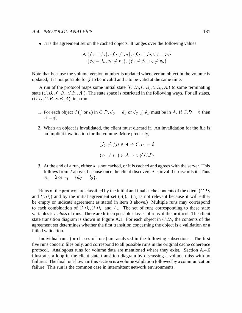
A.4. PROTOCOL ANALYSIS 181� A is the agreement set on the cached objects. It ranges over the following values:;; ffC = fSg;ffC 6= fSg; ffC = fS; vC = vSgffC = fS ; vC 6= vSg; ffC 6= fS; vC 6= vSgNote that because the volume version number is updated whenever an object in the volume isupdated, it is not possible for f to be invalid and v to be valid at the same time.
A run of the protocol maps some initial state (C:Di; C:Bi; S:Bi; Ai) to some terminatingstate (C:Dt; C:Bt; S:Bt; At). The state space is restricted in the following ways. For all states,(C:D;C:B; S:B;A), in a run:
1. For each object d (f or v) in C:D, dC = dS or dC 6= dS must be in A. If C:D = ; thenA = ;.
2. When an object is invalidated, the client must discard it. An invalidation for the file isan implicit invalidation for the volume. More precisely,(fC 6= fS) 2 A) C:Dt = ;(vC 6= vS) 2 A) v 62 C:Dt
3. At the end of a run, either d is not cached, or it is cached and agrees with the server. Thisfollows from 2 above, because once the client discovers d is invalid it discards it. ThusAt = ; or At = fdC = dSg.
Runs of the protocol are classified by the initial and final cache contents of the client (C:Diand C:Dt) and by the initial agreement set (Ai). (At is not relevant because it will eitherbe empty or indicate agreement as stated in item 3 above.) Multiple runs may correspondto each combination of C:Di; C:Dt; and Ai. The set of runs corresponding to these statevariables is a class of runs. There are fifteen possible classes of runs of the protocol. The clientstate transition diagram is shown in Figure A.1. For each object in C:Di, the contents of theagreement set determines whether the first transition concerning the object is a validation or afailed validation.
Individual runs (or classes of runs) are analyzed in the following subsections. The firstfive runs concern files only, and correspond to all possible runs in the original cache coherenceprotocol. Analogous runs for volume data are mentioned where they exist. Section A.4.6illustrates a loop in the client state transition diagram by discussing a volume miss with nofailures. The final run shown in this section is a volume validation followed by a communicationfailure. This run is the common case in intermittent network environments.
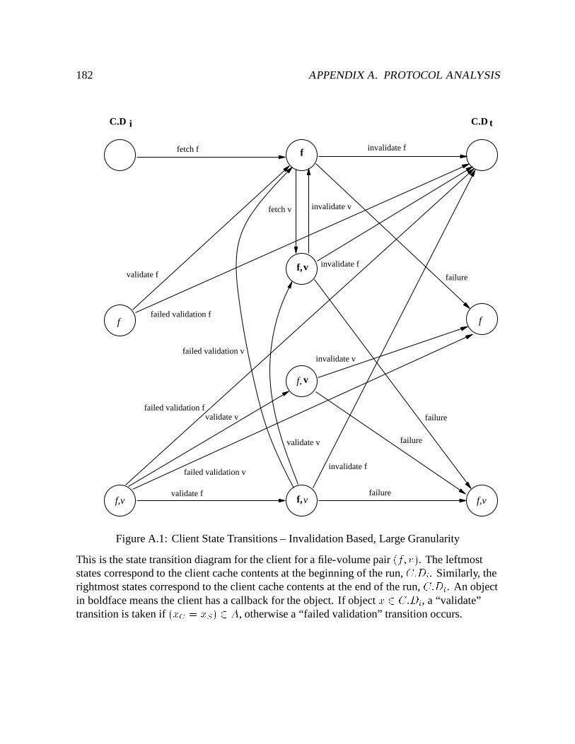
182 APPENDIX A. PROTOCOL ANALYSIS
f,v
f, v
f,v
fetch f invalidate f
validate f failure
validate f
failed validation f
fetch v invalidate v
failed validation fvalidate v
failed validation v
failure
failure
invalidate v
failure
invalidate f
invalidate f
failed validation v
validate v
f,vf,v
f
f
f
C.D tC.D i
Figure A.1: Client State Transitions – Invalidation Based, Large Granularity
This is the state transition diagram for the client for a file-volume pair (f; v). The leftmoststates correspond to the client cache contents at the beginning of the run, C:Di. Similarly, therightmost states correspond to the client cache contents at the end of the run, C:Dt. An objectin boldface means the client has a callback for the object. If object x 2 C:Di, a “validate”transition is taken if (xC = xS) 2 A, otherwise a “failed validation” transition occurs.
A.4. PROTOCOL ANALYSIS 183
The proof of invariance is based on either fC or vC , depending on which callback, if any,is established first. It is never the case that the client switches from depending on one type ofcallback to another during the run. If the proof of invariance concerns vC , and fC is containedby the volume whose version number is vC , if C believes valid(vC) then it can be confidentthat valid(fC) as well.
A.4.1 Cache miss, no failures
The critical transitions for the client are a fetch of f , and an invalidation of f . The initial andfinal system states for this run are both (;; ff 62 Cg; ;; ;). This run corresponds to the topmostpath in Figure A.1.
The run proceeds as follows. A request involving f is issued at C , however f is not presentin C’s cache. C sends the initial message to S requesting a copy of f . S records the fact thatC is caching f (f 2 C on S). This is the callback promise. When C receives the responsefrom S, it may use the data to service requests for f until S tells it otherwise. Since no failuresoccur in this case, eventually some other client updates f , rendering C’s copy invalid. Theserver sends C an invalidation message (the callback break), causing C to discard its copy off . C sends the final message to S indicating that it received the invalidation, and S discards itscallback promise on f for C .
The evolution of C’s and S’s beliefs as the protocol is shown below.
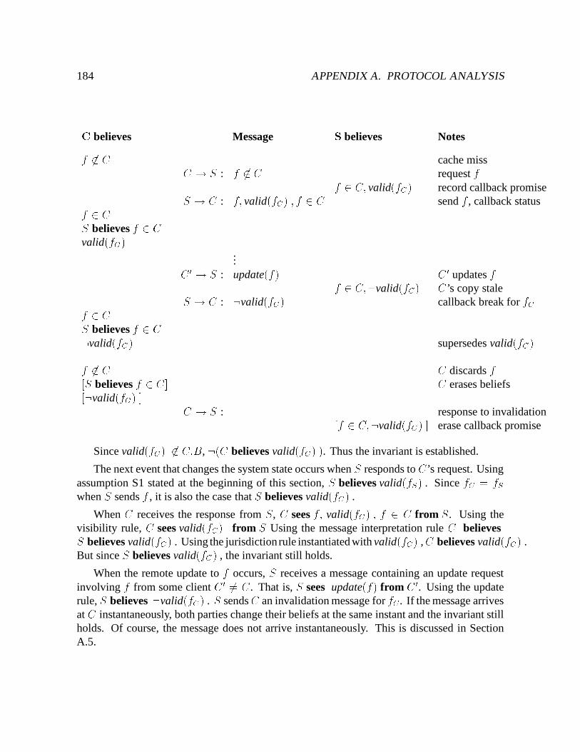
184 APPENDIX A. PROTOCOL ANALYSISC believes Message S believes Notesf 62 C cache missC ! S : f 62 C request ff 2 C; valid(fC) record callback promiseS ! C : f; valid(fC) ; f 2 C send f , callback statusf 2 CS believes f 2 Cvalid(fC)
...C0 ! S : update(f) C 0 updates ff 2 C;:valid(fC) C’s copy staleS ! C : :valid(fC) callback break for fCf 2 CS believes f 2 C:valid(fC) supersedes valid(fC)f 62 C C discards f[S believes f 2 C] C erases beliefs[:valid(fC) ] C ! S : response to invalidation[f 2 C;:valid(fC) ] erase callback promise
Since valid(fC) 62 C:B, :(C believes valid(fC) ). Thus the invariant is established.
The next event that changes the system state occurs when S responds to C’s request. Usingassumption S1 stated at the beginning of this section, S believes valid(fS) . Since fC = fSwhen S sends f , it is also the case that S believes valid(fC) .
When C receives the response from S, C sees f; valid(fC) ; f 2 C from S. Using thevisibility rule, C sees valid(fC) from S Using the message interpretation rule C believesS believes valid(fC) . Using the jurisdiction rule instantiated with valid(fC) ,C believes valid(fC) .But since S believes valid(fC) , the invariant still holds.
When the remote update to f occurs, S receives a message containing an update requestinvolving f from some client C 0 6= C. That is, S sees update(f) from C 0. Using the updaterule, S believes :valid(fC) . S sendsC an invalidation message for fC . If the message arrivesat C instantaneously, both parties change their beliefs at the same instant and the invariant stillholds. Of course, the message does not arrive instantaneously. This is discussed in SectionA.5.
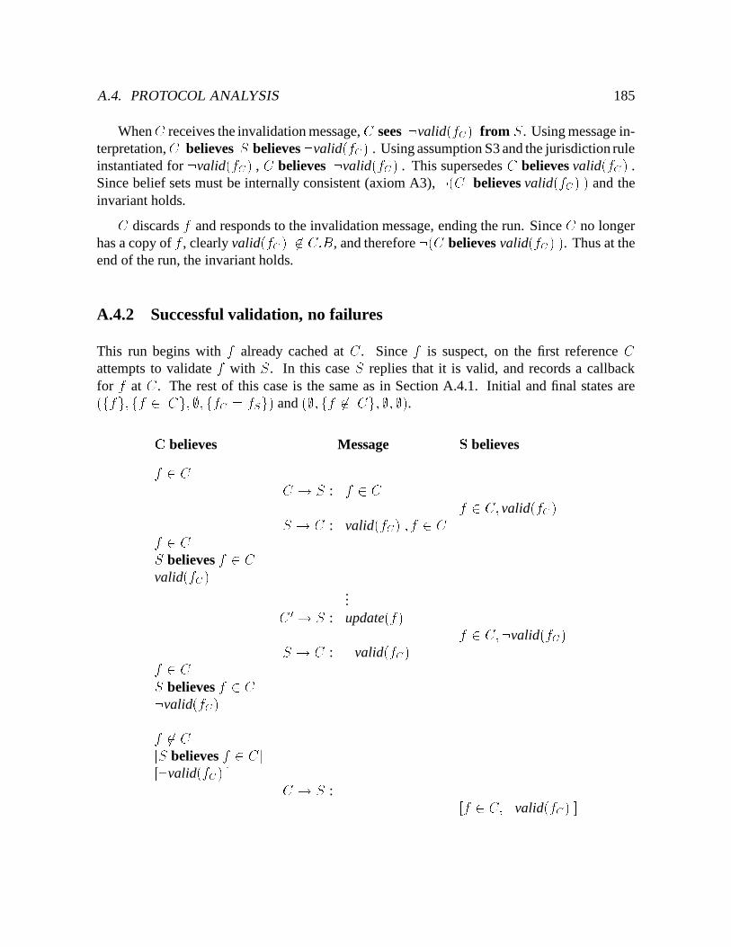
A.4. PROTOCOL ANALYSIS 185
WhenC receives the invalidation message, C sees :valid(fC) from S. Using message in-terpretation,C believes S believes :valid(fC) . Using assumption S3 and the jurisdiction ruleinstantiated for :valid(fC) , C believes :valid(fC) . This supersedes C believes valid(fC) .Since belief sets must be internally consistent (axiom A3), :(C believes valid(fC) ) and theinvariant holds.C discards f and responds to the invalidation message, ending the run. Since C no longerhas a copy of f , clearly valid(fC) 62 C:B, and therefore :(C believes valid(fC) ). Thus at theend of the run, the invariant holds.
A.4.2 Successful validation, no failures
This run begins with f already cached at C. Since f is suspect, on the first reference Cattempts to validate f with S. In this case S replies that it is valid, and records a callbackfor f at C. The rest of this case is the same as in Section A.4.1. Initial and final states are(ffg;ff 2 Cg;;; ffC = fSg) and (;; ff 62 Cg; ;; ;).C believes Message S believesf 2 C C ! S : f 2 C f 2 C; valid(fC)S ! C : valid(fC) ; f 2 Cf 2 CS believes f 2 C
valid(fC)...C 0 ! S : update(f) f 2 C;:valid(fC)S ! C : :valid(fC)f 2 CS believes f 2 C:valid(fC)f 62 C[S believes f 2 C][:valid(fC) ] C ! S : [f 2 C;:valid(fC) ]
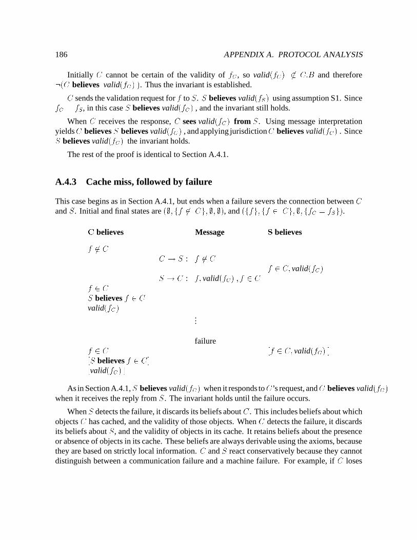
186 APPENDIX A. PROTOCOL ANALYSIS
Initially C cannot be certain of the validity of fC , so valid(fC) 62 C:B and therefore:(C believes valid(fC) ). Thus the invariant is established.C sends the validation request for f to S. S believes valid(fS) using assumption S1. SincefC = fS , in this case S believes valid(fC) , and the invariant still holds.
When C receives the response, C sees valid(fC) from S. Using message interpretationyieldsC believes S believes valid(fC) , and applying jurisdictionC believes valid(fC) . SinceS believes valid(fC) the invariant holds.
The rest of the proof is identical to Section A.4.1.
A.4.3 Cache miss, followed by failure
This case begins as in Section A.4.1, but ends when a failure severs the connection between Cand S. Initial and final states are (;; ff 62 Cg; ;; ;), and (ffg; ff 2 Cg; ;; ffC = fSg).C believes Message S believesf 62 C C ! S : f 62 C f 2 C; valid(fC)S ! C : f; valid(fC) ; f 2 Cf 2 CS believes f 2 C
valid(fC)...
failuref 2 C [f 2 C; valid(fC) ][S believes f 2 C][valid(fC) ]As in Section A.4.1,S believes valid(fC) when it responds toC’s request, andC believes valid(fC)
when it receives the reply from S. The invariant holds until the failure occurs.
When S detects the failure, it discards its beliefs about C . This includes beliefs about whichobjects C has cached, and the validity of those objects. When C detects the failure, it discardsits beliefs about S, and the validity of objects in its cache. It retains beliefs about the presenceor absence of objects in its cache. These beliefs are always derivable using the axioms, becausethey are based on strictly local information. C and S react conservatively because they cannotdistinguish between a communication failure and a machine failure. For example, if C loses
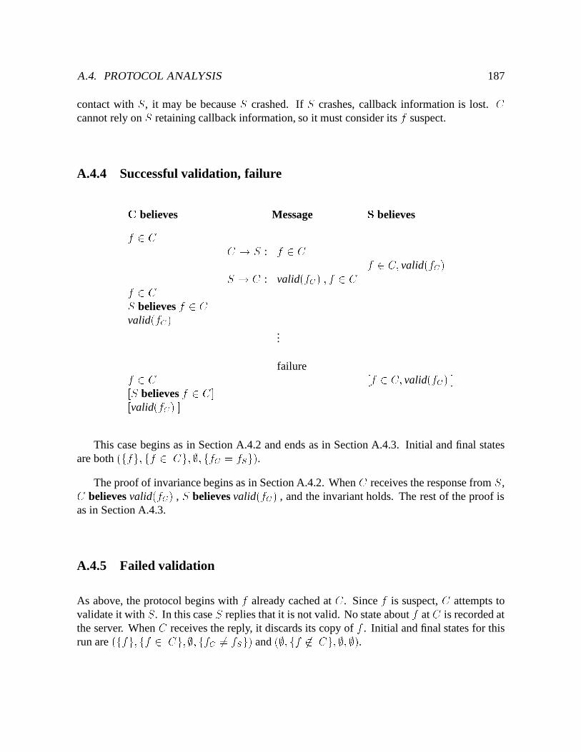
A.4. PROTOCOL ANALYSIS 187
contact with S, it may be because S crashed. If S crashes, callback information is lost. Ccannot rely on S retaining callback information, so it must consider its f suspect.
A.4.4 Successful validation, failureC believes Message S believesf 2 C C ! S : f 2 C f 2 C; valid(fC)S ! C : valid(fC) ; f 2 Cf 2 CS believes f 2 Cvalid(fC)
...
failuref 2 C [f 2 C; valid(fC) ][S believes f 2 C][valid(fC) ]This case begins as in Section A.4.2 and ends as in Section A.4.3. Initial and final states
are both (ffg; ff 2 Cg; ;;ffC = fSg).The proof of invariance begins as in Section A.4.2. When C receives the response from S,C believes valid(fC) , S believes valid(fC) , and the invariant holds. The rest of the proof is
as in Section A.4.3.
A.4.5 Failed validation
As above, the protocol begins with f already cached at C. Since f is suspect, C attempts tovalidate it with S. In this case S replies that it is not valid. No state about f at C is recorded atthe server. When C receives the reply, it discards its copy of f . Initial and final states for thisrun are (ffg; ff 2 Cg;;; ffC 6= fSg) and (;; ff 62 Cg; ;; ;).
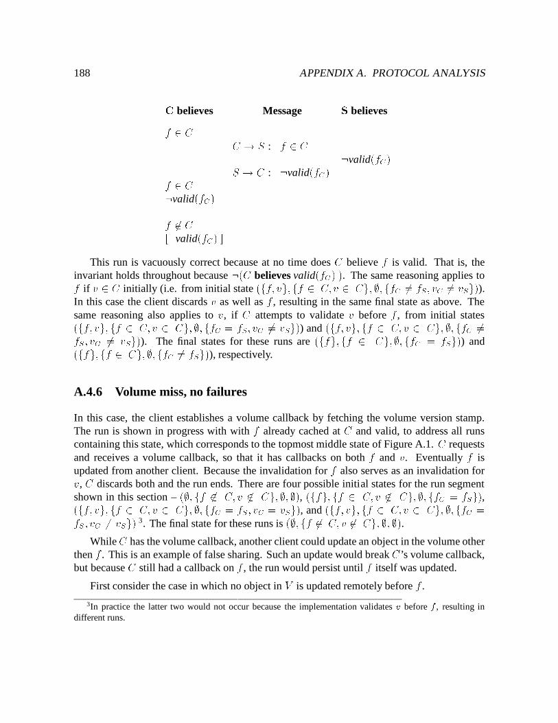
188 APPENDIX A. PROTOCOL ANALYSISC believes Message S believesf 2 C C ! S : f 2 C :valid(fC)S ! C : :valid(fC)f 2 C:valid(fC)f 62 C[:valid(fC) ]This run is vacuously correct because at no time does C believe f is valid. That is, the
invariant holds throughout because :(C believes valid(fC) ). The same reasoning applies tof if v 2 C initially (i.e. from initial state (ff; vg;ff 2 C;v 2 Cg; ;; ffC 6= fS ; vC 6= vSg)).In this case the client discards v as well as f , resulting in the same final state as above. Thesame reasoning also applies to v, if C attempts to validate v before f , from initial states(ff; vg; ff 2 C; v 2 Cg; ;; ffC = fS; vC 6= vSg)) and (ff; vg; ff 2 C; v 2 Cg; ;; ffC 6=fS ; vC 6= vSg)). The final states for these runs are (ffg;ff 2 Cg;;; ffC = fSg)) and(ffg;ff 2 Cg;;; ffC 6= fSg)), respectively.
A.4.6 Volume miss, no failures
In this case, the client establishes a volume callback by fetching the volume version stamp.The run is shown in progress with with f already cached at C and valid, to address all runscontaining this state, which corresponds to the topmost middle state of Figure A.1. C requestsand receives a volume callback, so that it has callbacks on both f and v. Eventually f isupdated from another client. Because the invalidation for f also serves as an invalidation forv, C discards both and the run ends. There are four possible initial states for the run segmentshown in this section – (;; ff 62 C; v 62 Cg; ;;;), (ffg; ff 2 C; v 62 Cg; ;; ffC = fSg),(ff; vg; ff 2 C; v 2 Cg; ;; ffC = fS ; vC = vSg), and (ff; vg; ff 2 C;v 2 Cg; ;;ffC =fS ; vC 6= vSg) 3. The final state for these runs is (;; ff 62 C; v 62 Cg; ;; ;).
While C has the volume callback, another client could update an object in the volume otherthen f . This is an example of false sharing. Such an update would break C’s volume callback,but because C still had a callback on f , the run would persist until f itself was updated.
First consider the case in which no object in V is updated remotely before f .
3In practice the latter two would not occur because the implementation validates v before f , resulting indifferent runs.
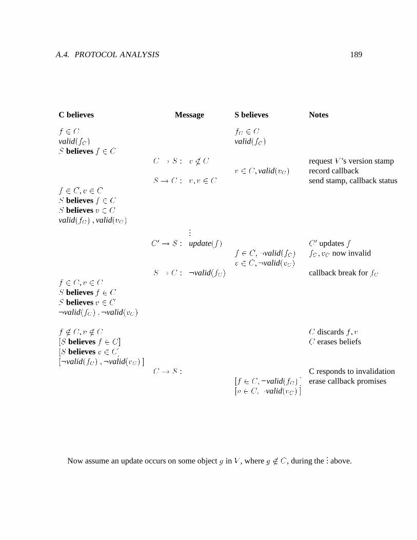
A.4. PROTOCOL ANALYSIS 189
C believes Message S believes Notesf 2 C fC 2 Cvalid(fC) valid(fC)S believes f 2 C C ! S : v 62 C request V ’s version stampv 2 C; valid(vC) record callbackS ! C : v; v 2 C send stamp, callback statusf 2 C; v 2 CS believes f 2 CS believes v 2 Cvalid(fC) ; valid(vC)
...C0 ! S : update(f) C 0 updates ff 2 C;:valid(fC) fC ; vC now invalidv 2 C;:valid(vC)S ! C : :valid(fC) callback break for fCf 2 C; v 2 CS believes f 2 CS believes v 2 C:valid(fC) ;:valid(vC)f 62 C; v 62 C C discards f; v[S believes f 2 C] C erases beliefs[S believes v 2 C][:valid(fC) ;:valid(vC) ] C ! S : C responds to invalidation[f 2 C;:valid(fC) ] erase callback promises[v 2 C;:valid(vC) ]Now assume an update occurs on some object g in V , where g 62 C , during the
... above.
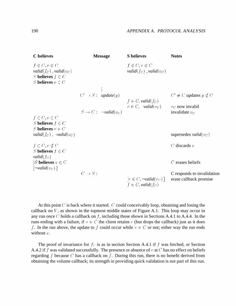
190 APPENDIX A. PROTOCOL ANALYSIS
C believes Message S believes Notesf 2 C; v 2 C f 2 C; v 2 Cvalid(fC) ; valid(vC) valid(fC) ; valid(vC)S believes f 2 CS believes v 2 C
...C0 ! S : update(g) C 0 6= C updates g 62 Cf 2 C; valid(fC)v 2 C;:valid(vC) vC now invalidS ! C : :valid(vC) invalidate vCf 2 C; v 2 CS believes f 2 CS believes v 2 Cvalid(fC) ;:valid(vC) supersedes valid(vC)f 2 C; v 62 C C discards vS believes f 2 Cvalid(fC)[S believes v 2 C] C erases beliefs[:valid(vC) ] C ! S : C responds to invalidation[v 2 C;:valid(vC) ] erase callback promisef 2 C; valid(fC)
At this point C is back where it started. C could conceivably loop, obtaining and losing thecallback on V , as shown in the topmost middle states of Figure A.1. This loop may occur inany run once C holds a callback on f , including those shown in Sections A.4.1 to A.4.4. In theruns ending with a failure, if v 2 C the client retains v (but drops the callback) just as it doesf . In the run above, the update to f could occur while v 2 C or not; either way the run endswithout v.
The proof of invariance for fC is as in section Section A.4.1 if f was fetched, or SectionA.4.2 if f was validated successfully. The presence or absence of v at C has no effect on beliefsregarding f because C has a callback on f . During this run, there is no benefit derived fromobtaining the volume callback; its strength in providing quick validation is not part of this run.
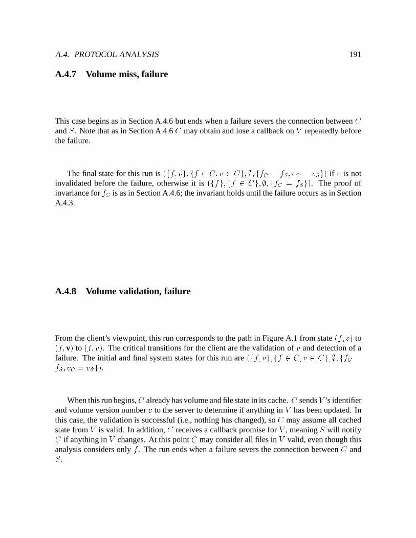
A.4. PROTOCOL ANALYSIS 191
A.4.7 Volume miss, failure
This case begins as in Section A.4.6 but ends when a failure severs the connection between Cand S. Note that as in Section A.4.6 C may obtain and lose a callback on V repeatedly beforethe failure.
The final state for this run is (ff; vg; ff 2 C; v 2 Cg; ;; ffC = fS; vC = vSg) if v is notinvalidated before the failure, otherwise it is (ffg; ff 2 Cg; ;; ffC = fSg). The proof ofinvariance for fC is as in Section A.4.6; the invariant holds until the failure occurs as in SectionA.4.3.
A.4.8 Volume validation, failure
From the client’s viewpoint, this run corresponds to the path in Figure A.1 from state (f; v) to(f; v) to (f; v). The critical transitions for the client are the validation of v and detection of afailure. The initial and final system states for this run are (ff; vg; ff 2 C; v 2 Cg;;; ffC =fS ; vC = vSg).
When this run begins, C already has volume and file state in its cache. C sends V ’s identifierand volume version number v to the server to determine if anything in V has been updated. Inthis case, the validation is successful (i.e., nothing has changed), so C may assume all cachedstate from V is valid. In addition, C receives a callback promise for V , meaning S will notifyC if anything in V changes. At this point C may consider all files in V valid, even though thisanalysis considers only f . The run ends when a failure severs the connection between C andS.
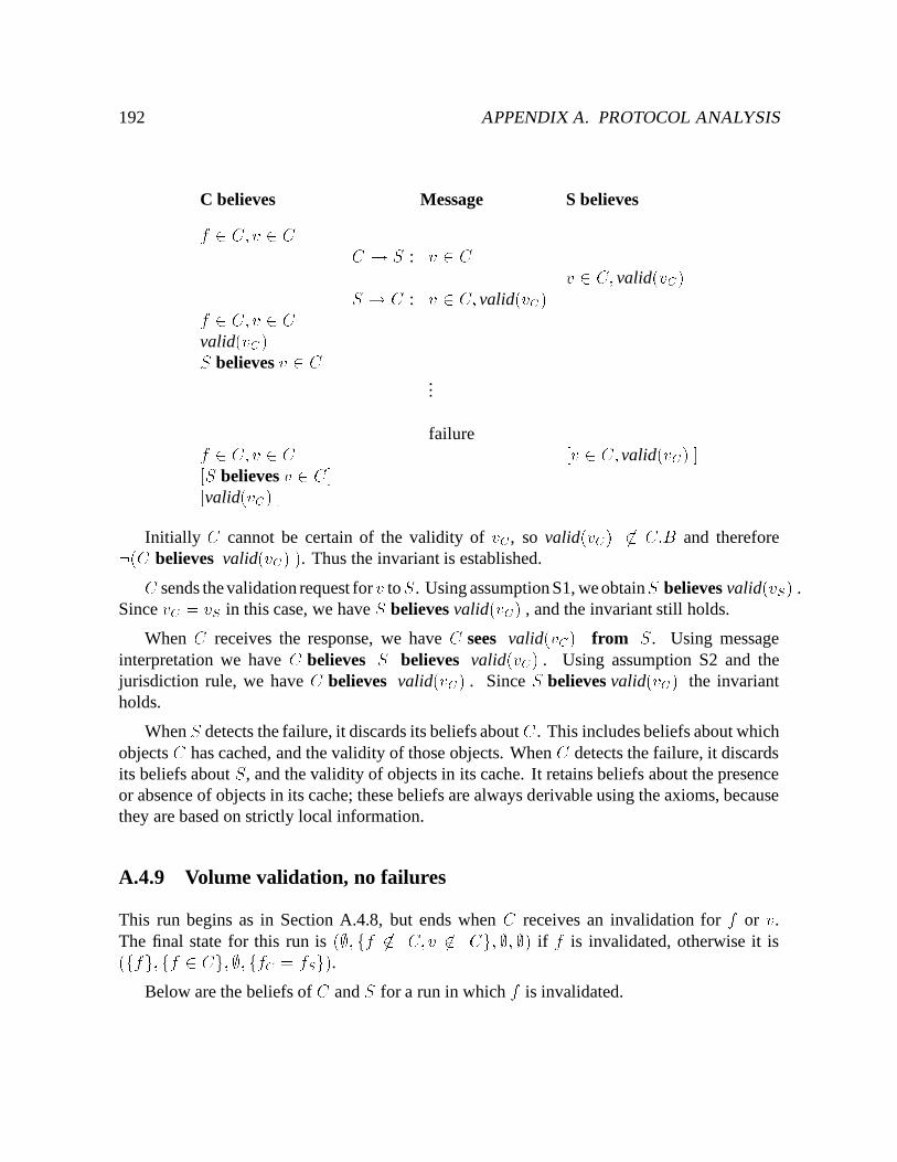
192 APPENDIX A. PROTOCOL ANALYSIS
C believes Message S believesf 2 C; v 2 C C ! S : v 2 C v 2 C; valid(vC)S ! C : v 2 C; valid(vC)f 2 C; v 2 Cvalid(vC)S believes v 2 C
...
failuref 2 C; v 2 C [v 2 C; valid(vC) ][S believes v 2 C][valid(vC) ]Initially C cannot be certain of the validity of vC , so valid(vC) 62 C:B and therefore:(C believes valid(vC) ). Thus the invariant is established.C sends the validation request for v toS. Using assumption S1, we obtainS believes valid(vS) .
Since vC = vS in this case, we have S believes valid(vC) , and the invariant still holds.
When C receives the response, we have C sees valid(vC) from S. Using messageinterpretation we have C believes S believes valid(vC) . Using assumption S2 and thejurisdiction rule, we have C believes valid(vC) . Since S believes valid(vC) the invariantholds.
When S detects the failure, it discards its beliefs about C . This includes beliefs about whichobjects C has cached, and the validity of those objects. When C detects the failure, it discardsits beliefs about S, and the validity of objects in its cache. It retains beliefs about the presenceor absence of objects in its cache; these beliefs are always derivable using the axioms, becausethey are based on strictly local information.
A.4.9 Volume validation, no failures
This run begins as in Section A.4.8, but ends when C receives an invalidation for f or v.The final state for this run is (;; ff 62 C;v 62 Cg; ;; ;) if f is invalidated, otherwise it is(ffg;ff 2 Cg; ;; ffC = fSg).
Below are the beliefs of C and S for a run in which f is invalidated.
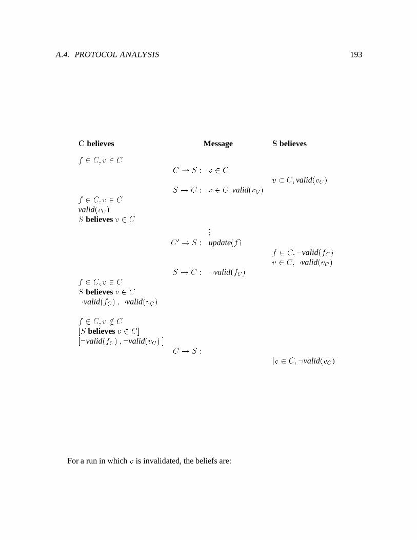
A.4. PROTOCOL ANALYSIS 193
C believes Message S believesf 2 C; v 2 C C ! S : v 2 C v 2 C; valid(vC)S ! C : v 2 C; valid(vC)f 2 C; v 2 Cvalid(vC)S believes v 2 C
...C 0 ! S : update(f) f 2 C;:valid(fC)v 2 C;:valid(vC)S ! C : :valid(fC)f 2 C; v 2 CS believes v 2 C:valid(fC) ;:valid(vC)f 62 C; v 62 C[S believes v 2 C][:valid(fC) ;:valid(vC) ] C ! S : [v 2 C;:valid(vC) ]For a run in which v is invalidated, the beliefs are:
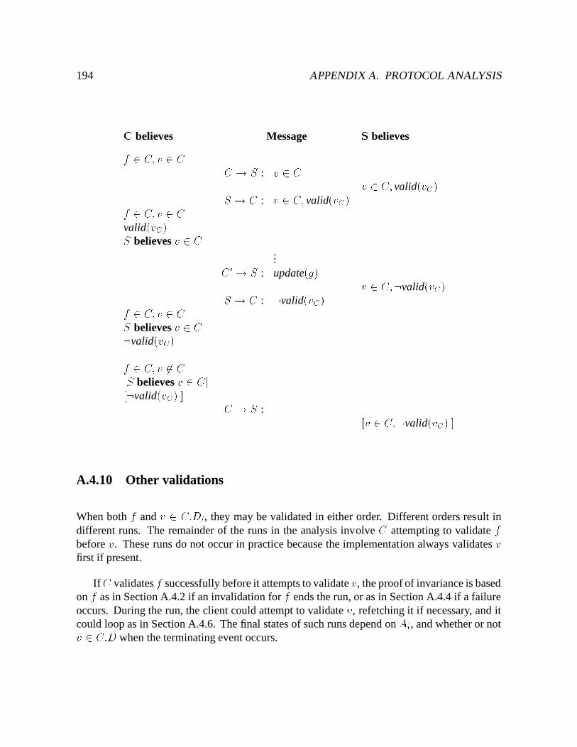
194 APPENDIX A. PROTOCOL ANALYSISC believes Message S believesf 2 C; v 2 C C ! S : v 2 C v 2 C; valid(vC)S ! C : v 2 C; valid(vC)f 2 C; v 2 Cvalid(vC)S believes v 2 C
...C0 ! S : update(g) v 2 C;:valid(vC)S ! C : :valid(vC)f 2 C; v 2 CS believes v 2 C:valid(vC)f 2 C; v 62 C[S believes v 2 C][:valid(vC) ] C ! S : [v 2 C;:valid(vC) ]A.4.10 Other validations
When both f and v 2 C:Di, they may be validated in either order. Different orders result indifferent runs. The remainder of the runs in the analysis involve C attempting to validate fbefore v. These runs do not occur in practice because the implementation always validates vfirst if present.
IfC validates f successfully before it attempts to validate v, the proof of invariance is basedon f as in Section A.4.2 if an invalidation for f ends the run, or as in Section A.4.4 if a failureoccurs. During the run, the client could attempt to validate v, refetching it if necessary, and itcould loop as in Section A.4.6. The final states of such runs depend on Ai, and whether or notv 2 C:D when the terminating event occurs.
A.5. TIME-BOUNDED CORRECTNESS 195
A.5 Time-Bounded Correctness
Two factors complicate reasoning about correctness in distributed systems: transmission delayand failures. During the interval in which a message is traveling, the sender may have madesome state change that renders the correctness condition false until the receiver processes themessage and changes its state. While transmission time is often assumed to be negligiblein LAN-based environments, this assumption is not valid in weakly connected environments.However, transmission delay is loosely bounded by the timeout period used by the underlyingcommunication protocol, denoted by �. If a message is not acknowledged within � after it issent, the sender declares a failure. The timeout period is a system parameter, and is usually onthe order of a minute.
Failures are the second complication. It takes time for principals to detect failures. Duringthe interval between the occurrence of a failure and its detection, it is possible for the correctnesscondition to be false because one of the principals was unable to notify another of some event.This interval, denoted by � , defines a window of vulnerability for the protocol. To bound thefailure detection interval, clients and servers probe each other periodically, and declare failuresif messages time out. Let � be the message timeout period as above, and let � be the probeinterval. Assume clients and servers use the same probe interval, but do not necessarily probeeach other at the same time. Then the failure detection interval � = �+ � at most.
The timetable in Figure A.2 shows the worst-case behavior of a system whose failuredetection interval is � . Let tp be the latest time at which C probes S successfully before thefailure, and let tf be the time at which the failure occurs. Eventually either C or S will send amessage and discover the failure. If the failure is discovered through a probe by either party, Cwas still correct in believing that fC was valid, even though C’s and S’s beliefs about callbackstate were not consistent.
The worst case occurs if another client in contact with S updates f while C is partitionedfrom S, but before C has detected the failure. S tries to break C’s callback on f at time ti butfails. This is a lost callback. During this interval, C believes that fC is valid when it is not.This interval is largest when the failure and the update occur immediately after tp. At timeti + �, C is still blissfully ignorant of the status of f , and does not discover a problem until ittries to contact S at tp+�. It is not until tp+ � that C declares failure and demotes f to suspectstatus. Thus � is the longest period in which C can believe f is valid when it is not.
Correctness for this protocol is bounded by � . A protocol � -correct if the interval in which itdoes not meet the correctness criterion is at most � . A 0-correct protocol obeys the correctnesscriterion strictly. In the Coda file system, � is composed of a probe interval of 10 minutes, anda message timeout of 15 seconds.
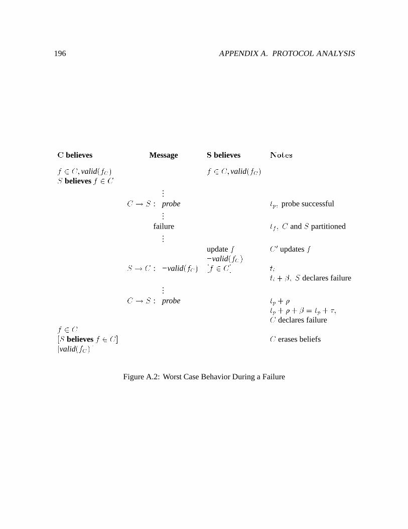
196 APPENDIX A. PROTOCOL ANALYSIS
C believes Message S believes Notesf 2 C; valid(fC) f 2 C; valid(fC)S believes f 2 C...C ! S : probe tp; probe successful...
failure tf ; C and S partitioned...
update f C 0 updates f:valid(fC)S ! C : :valid(fC) [f 2 C] titi + �; S declares failure...C ! S : probe tp + �tp + �+ � = tp + �;C declares failuref 2 C[S believes f 2 C] C erases beliefs[valid(fC) ]
Figure A.2: Worst Case Behavior During a Failure
A.6. CLASSIFYING BELIEFS 197
A.6 Classifying Beliefs
Beliefs can be classified in three ways. Correct beliefs are those beliefs that are actually true.Pessimistic beliefs refer to beliefs that are discarded when a run ends. In effect, this set capturesthose objects for which there are no beliefs. Finally, it is possible to have temporarily falsebeliefs because correctness is time bounded, as described in Section A.5.
Viewed in this way, the goal of a cache coherence protocol is to establish correct beliefs.When a run begins, all beliefs are essentially pessimistic. As the run proceeds, correct beliefsgradually replace pessimistic beliefs. Given a fixed number of objects, the set of pessimisticbeliefs becomes empty after some bounded period of connectivity. Because of failures, the setof temporarily false beliefs may be non-empty. However, Section A.5 shows that no beliefremains in that subset for longer than � .
A.7 Extensions
This analysis is oversimplified in two respects. First, its considers only a single f and v,even though in practice it would take more than one file to make obtaining a volume callbackworthwhile. Given this simplified model, we must exclude the states whereC:D = fvg becausethere must be at least one file present to obtain a volume callback. In practice, this value forC:D is permissible provided there are other files in volume V cached at the client.
Second, although a repository may consist of a group of servers, the analysis ignores someof the practical aspects of replication. For example, if the client uses a replicated volume, itmust collate responses from multiple servers. One complication is that the client may receiveresponses from only a subset of the servers because of failures. A small change to the definitionof a run takes care of this problem. For a replicated service, the run ends when the number ofservers communicating with the client changes. This is natural because if the number shrinks,there exists the potential for a lost callback from a server that disappeared. If the number grows,a newly available server may hold updated versions of cached data.
The notion of a run could be extended in other ways. For example, some systems incorporateexpiration times in their cache coherence mechanism [43]. We can address this by extendingthe definition of a run such that when a token or lease expires, the run ends.
The update rule is applied only at servers. The rule could be extended to apply to anyprincipal in systems where clients observe updates through broadcasts. This extension wouldallow clients to invalidate their own cache entries.
A pleasant surprise in constructing the proofs for the protocol was that the proof couldbe based on the data for which the client received a callback first. That is, the proof restedon f being valid or v being valid. There is one exception, which does not occur in our

198 APPENDIX A. PROTOCOL ANALYSIS
implementation. If a volume callback is obtained before a file callback, the client could losethe volume callback and still continue the run. A notion of hierarchy (i.e., x is “contained in”y) would help to switch the proof from one data type to the other cleanly.
Appendix B
Coda Internals
This chapter provides detail on the Coda client and server implementation and system interfacesnecessary to understand the body of this dissertation. It is intended to be a supplement to thesystem overview given in Chapter 2.
B.1 Client Structure
Coda support on a client workstation consists of two components. The first component,called the MiniCache [123], is a small in-kernel module that implements the Sun MicrosystemsVirtual File System (VFS) interface [64], a standard system call intercept mechanism that allowsmultiple file systems to co-exist within a single Unix kernel. This interface is summarized inTable B.1. The second component is a much larger user-level cache manager called Venus.Although its functionality could be provided within the kernel for better performance, theuser-level implementation is more portable and considerably easier to debug. The structure ofa Coda client is illustrated in Figure 2.9.
An application system call involving a Coda object is directed by the VFS layer to the CodaVFS. If the information required is contained within the Coda VFS, the call is serviced withoutinvolving Venus and control returns to the application. Otherwise, the kernel contacts Venusby writing a message to a pseudo-device. Venus reads the request from the pseudo-device, andif remote access is necessary, contacts the Coda file servers using the RPC2 remote procedurecall package [111]. When Venus completes processing the request, it writes a response on thepseudo-device, and control returns back through the kernel to the application process.
199
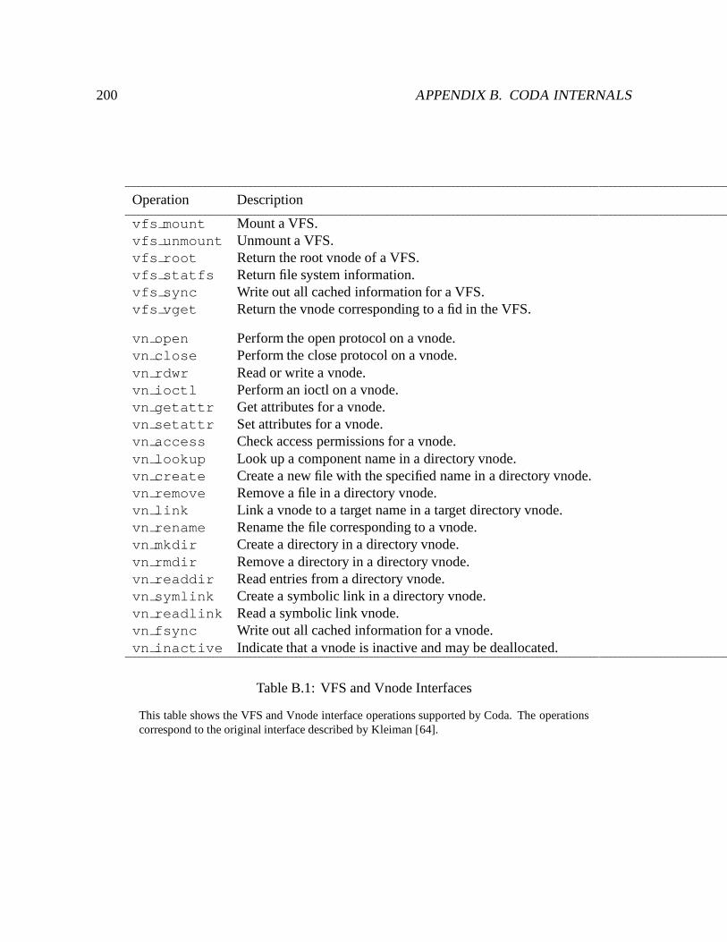
200 APPENDIX B. CODA INTERNALS
Operation Description
vfs mount Mount a VFS.vfs unmount Unmount a VFS.vfs root Return the root vnode of a VFS.vfs statfs Return file system information.vfs sync Write out all cached information for a VFS.vfs vget Return the vnode corresponding to a fid in the VFS.
vn open Perform the open protocol on a vnode.vn close Perform the close protocol on a vnode.vn rdwr Read or write a vnode.vn ioctl Perform an ioctl on a vnode.vn getattr Get attributes for a vnode.vn setattr Set attributes for a vnode.vn access Check access permissions for a vnode.vn lookup Look up a component name in a directory vnode.vn create Create a new file with the specified name in a directory vnode.vn remove Remove a file in a directory vnode.vn link Link a vnode to a target name in a target directory vnode.vn rename Rename the file corresponding to a vnode.vn mkdir Create a directory in a directory vnode.vn rmdir Remove a directory in a directory vnode.vn readdir Read entries from a directory vnode.vn symlink Create a symbolic link in a directory vnode.vn readlink Read a symbolic link vnode.vn fsync Write out all cached information for a vnode.vn inactive Indicate that a vnode is inactive and may be deallocated.
Table B.1: VFS and Vnode Interfaces
This table shows the VFS and Vnode interface operations supported by Coda. The operationscorrespond to the original interface described by Kleiman [64].
B.1. CLIENT STRUCTURE 201
B.1.1 Coda MiniCache
The VFS interface separates system call execution into file system independent and dependentlayers. It defines sets of operations on file systems through the VFS, and on files throughthe virtual inode (vnode). The file system independent layer of the VFS interface redirectsoperations to the appropriate file system implementation based on vnode type. The CodaMiniCache exports the operations in the VFS interface for Coda objects.
As Figure 2.9 shows, the MiniCache interacts with the user-level Venus process to serviceoperations on Coda objects. The performance cost for this interaction can be high; for example,pathname translation involves a separate vnode operation for each pathname component. Toreduce the number of kernel-Venus interactions, the MiniCache caches four kinds of informationthat allows it to satisfy common file system requests without contacting Venus:� Pathname translations. The MiniCache retains successful translations of pathname
components. This allows it to satisfy pathname lookup requests, as well as some accesschecking.� Open file handles. When a file is opened, the MiniCache retains a pointer to the vnodeof the local Unix file in Venus’s cache. This allows read and write system calls to behandled by the local file system. The MiniCache notifies Venus when the file is closed.� File attributes. The MiniCache caches file attributes to allow it to service the frequentlyused stat system call.� Symbolic links. The MiniCache caches symbolic link contents to improve pathnametranslation performance.
The MiniCache has yielded performance results comparable to AFS-3, which has an in-kernel cache manager.
Because the MiniCache shares file system state with Venus, the state must be coherent. TheMiniCache is updated after all calls forwarded to Venus. In addition, it provides an interfacethrough which Venus may invalidate or replace MiniCache state, such as when a server breaksa callback. This interface is shown in Table B.2.
B.1.2 Venus
The primary responsibilities of Venus are to service user file system requests, maintain cachecoherence while connected, and manage the cache within predefined resource limits. Inaddition, it must hoard data in anticipation of disconnection, log and reintegrate disconnectedupdates, detect diverging replicas and trigger their resolution or quarantine them for repair.
Venus is implemented as a multi-threaded process using a lightweight co-routine threadpackage called LWP [111]. Venus threads types are summarized in Table B.3. A main thread
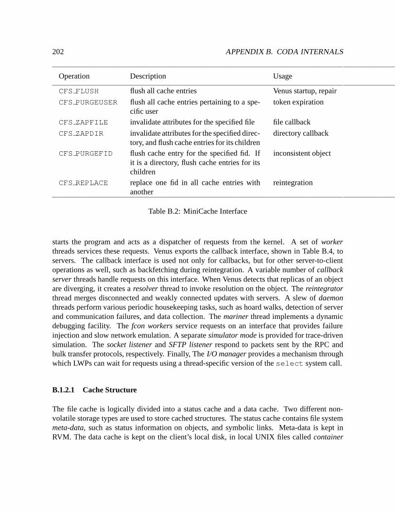
202 APPENDIX B. CODA INTERNALS
Operation Description Usage
CFS FLUSH flush all cache entries Venus startup, repair
CFS PURGEUSER flush all cache entries pertaining to a spe-cific user
token expiration
CFS ZAPFILE invalidate attributes for the specified file file callback
CFS ZAPDIR invalidate attributes for the specified direc-tory, and flush cache entries for its children
directory callback
CFS PURGEFID flush cache entry for the specified fid. Ifit is a directory, flush cache entries for itschildren
inconsistent object
CFS REPLACE replace one fid in all cache entries withanother
reintegration
Table B.2: MiniCache Interface
starts the program and acts as a dispatcher of requests from the kernel. A set of workerthreads services these requests. Venus exports the callback interface, shown in Table B.4, toservers. The callback interface is used not only for callbacks, but for other server-to-clientoperations as well, such as backfetching during reintegration. A variable number of callbackserver threads handle requests on this interface. When Venus detects that replicas of an objectare diverging, it creates a resolver thread to invoke resolution on the object. The reintegratorthread merges disconnected and weakly connected updates with servers. A slew of daemonthreads perform various periodic housekeeping tasks, such as hoard walks, detection of serverand communication failures, and data collection. The mariner thread implements a dynamicdebugging facility. The fcon workers service requests on an interface that provides failureinjection and slow network emulation. A separate simulator mode is provided for trace-drivensimulation. The socket listener and SFTP listener respond to packets sent by the RPC andbulk transfer protocols, respectively. Finally, The I/O manager provides a mechanism throughwhich LWPs can wait for requests using a thread-specific version of the select system call.
B.1.2.1 Cache Structure
The file cache is logically divided into a status cache and a data cache. Two different non-volatile storage types are used to store cached structures. The status cache contains file systemmeta-data, such as status information on objects, and symbolic links. Meta-data is kept inRVM. The data cache is kept on the client’s local disk, in local UNIX files called container
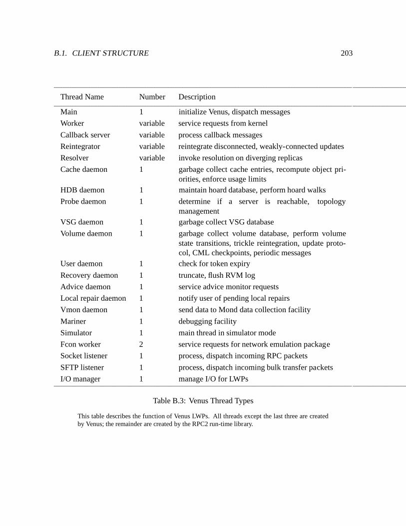
B.1. CLIENT STRUCTURE 203
Thread Name Number Description
Main 1 initialize Venus, dispatch messages
Worker variable service requests from kernel
Callback server variable process callback messages
Reintegrator variable reintegrate disconnected, weakly-connected updates
Resolver variable invoke resolution on diverging replicas
Cache daemon 1 garbage collect cache entries, recompute object pri-orities, enforce usage limits
HDB daemon 1 maintain hoard database, perform hoard walks
Probe daemon 1 determine if a server is reachable, topologymanagement
VSG daemon 1 garbage collect VSG database
Volume daemon 1 garbage collect volume database, perform volumestate transitions, trickle reintegration, update proto-col, CML checkpoints, periodic messages
User daemon 1 check for token expiry
Recovery daemon 1 truncate, flush RVM log
Advice daemon 1 service advice monitor requests
Local repair daemon 1 notify user of pending local repairs
Vmon daemon 1 send data to Mond data collection facility
Mariner 1 debugging facility
Simulator 1 main thread in simulator mode
Fcon worker 2 service requests for network emulation package
Socket listener 1 process, dispatch incoming RPC packets
SFTP listener 1 process, dispatch incoming bulk transfer packets
I/O manager 1 manage I/O for LWPs
Table B.3: Venus Thread Types
This table describes the function of Venus LWPs. All threads except the last three are createdby Venus; the remainder are created by the RPC2 run-time library.
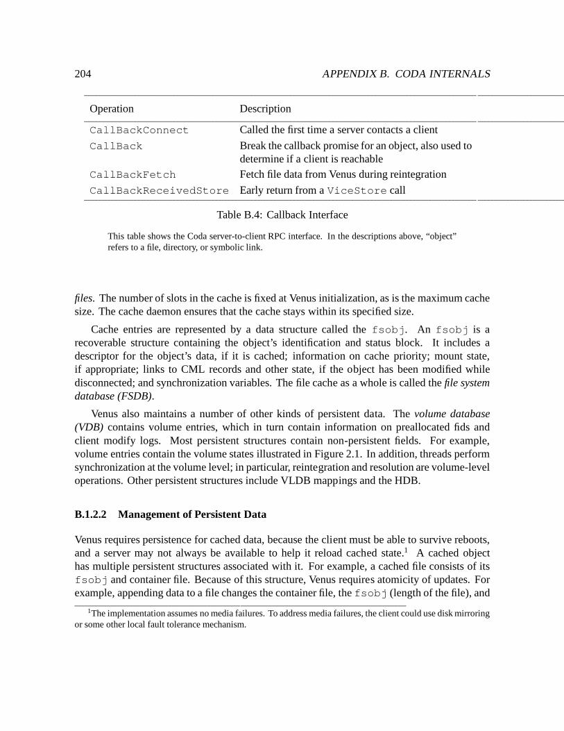
204 APPENDIX B. CODA INTERNALS
Operation Description
CallBackConnect Called the first time a server contacts a client
CallBack Break the callback promise for an object, also used todetermine if a client is reachable
CallBackFetch Fetch file data from Venus during reintegration
CallBackReceivedStore Early return from a ViceStore call
Table B.4: Callback Interface
This table shows the Coda server-to-client RPC interface. In the descriptions above, “object”refers to a file, directory, or symbolic link.
files. The number of slots in the cache is fixed at Venus initialization, as is the maximum cachesize. The cache daemon ensures that the cache stays within its specified size.
Cache entries are represented by a data structure called the fsobj. An fsobj is arecoverable structure containing the object’s identification and status block. It includes adescriptor for the object’s data, if it is cached; information on cache priority; mount state,if appropriate; links to CML records and other state, if the object has been modified whiledisconnected; and synchronization variables. The file cache as a whole is called the file systemdatabase (FSDB).
Venus also maintains a number of other kinds of persistent data. The volume database(VDB) contains volume entries, which in turn contain information on preallocated fids andclient modify logs. Most persistent structures contain non-persistent fields. For example,volume entries contain the volume states illustrated in Figure 2.1. In addition, threads performsynchronization at the volume level; in particular, reintegration and resolution are volume-leveloperations. Other persistent structures include VLDB mappings and the HDB.
B.1.2.2 Management of Persistent Data
Venus requires persistence for cached data, because the client must be able to survive reboots,and a server may not always be available to help it reload cached state.1 A cached objecthas multiple persistent structures associated with it. For example, a cached file consists of itsfsobj and container file. Because of this structure, Venus requires atomicity of updates. Forexample, appending data to a file changes the container file, the fsobj (length of the file), and
1The implementation assumes no media failures. To address media failures, the client could use disk mirroringor some other local fault tolerance mechanism.
B.1. CLIENT STRUCTURE 205
the FSDB (cache space usage). Either all or none of these structures must be updated for thedata to remain mutually consistent.
While it is possible to use local files for all persistent data, such an implementation isawkward for a number of reasons. First, the UNIX buffer cache performs writes asynchronouslyto hide disk latency from applications [70]. Writes may be delayed to amortize the cost of adisk write and take advantage of cancelling or overwrite behavior, and they may be reorderedfor more efficient writing to disk. Data is vulnerable until it is written to disk; if a crash occurssome writes (not necessarily the latest ones) may be lost. To store persistent data entirely inlocal files, Venus would have to employ some combination of the following techniques:� make extensive use of the fsync system call, which forces buffered writes to disk,� modify the kernel to recognize data dependencies and ensure that data is written out in
the correct order,� organize the disk layout of persistent data to avoid inconsistencies after crashes,� implement recovery code that can detect and recover from inconsistencies in persistentdata.
All of these techniques have either high performance cost, are complex to implement anddifficult to verify, or lack generality. Instead, Venus uses a local transaction facility calledRVM [116, 75] that provides failure atomicity and permanence of updates. RVM exports theabstraction of recoverable virtual memory, which allows an application to read and updaterecoverable storage much as it would other in-memory structures. Atomicity of updates isguaranteed as long as they occur within transactions. Crash recovery is handled entirely byRVM.
RVM is implemented as a library which is linked into applications; its interface is shownin Table B.5. Recoverable data is stored as recoverable segments on disk. An applicationmaps regions of these segments into its virtual address using the rvm map routine. Theapplication may perform transactions on recoverable data by bracketing updates betweenrvm begin transaction and rvm end transaction, and indicating the addressesof data updated with rvm set range. RVM tracks the old and new values of updated datain change records. RVM flushes updates to disk by appending the change records to a disklog. If the transaction commits, RVM writes a commit record for the transaction. By default,RVM flushes a transaction to the log at commit time. However, there is a no-flush option thatallows an application to batch flushing of changes to disk. No-flush transactions are bufferedin memory until the next flush occurs. When the RVM log exceeds a threshold, RVM truncatesit by applying the change records for committed transactions in the log to the recoverablesegments. Because flushes and truncates may interfere with request processing, RVM exportsrvm flush and rvm truncate calls to allow applications to manage their own disk writes.
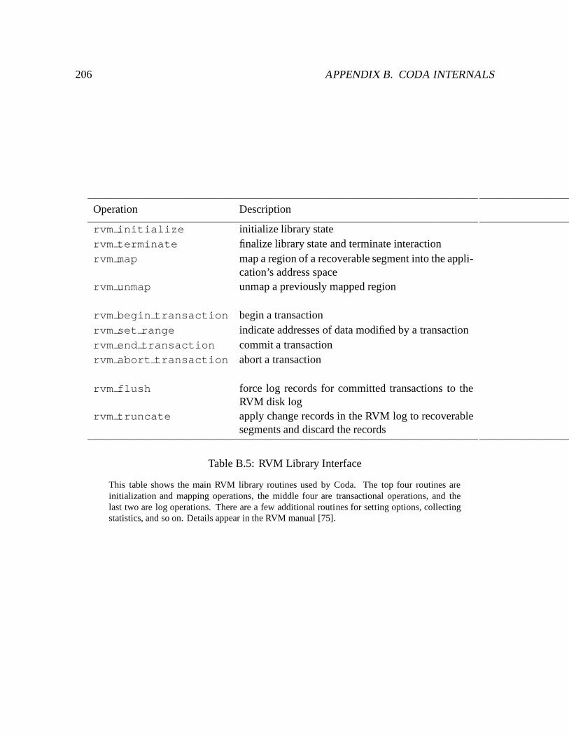
206 APPENDIX B. CODA INTERNALS
Operation Description
rvm initialize initialize library statervm terminate finalize library state and terminate interactionrvm map map a region of a recoverable segment into the appli-
cation’s address spacervm unmap unmap a previously mapped region
rvm begin transaction begin a transactionrvm set range indicate addresses of data modified by a transactionrvm end transaction commit a transactionrvm abort transaction abort a transaction
rvm flush force log records for committed transactions to theRVM disk log
rvm truncate apply change records in the RVM log to recoverablesegments and discard the records
Table B.5: RVM Library Interface
This table shows the main RVM library routines used by Coda. The top four routines areinitialization and mapping operations, the middle four are transactional operations, and thelast two are log operations. There are a few additional routines for setting options, collectingstatistics, and so on. Details appear in the RVM manual [75].
B.1. CLIENT STRUCTURE 207
Venus uses no-flush transactions to avoid the overhead of disk writes on every transaction,and schedules both RVM flushes and truncates to avoid delays during a user request. Flushes andtruncates can impede other client activity because Venus threads are blocked in the meantime,and other client processes encounter contention for the disk. The use of no-flush transactionsmeans that Venus offers bounded persistence, that is, updates are locally persistent only aftersome time period has passed. While connected, the bound is 600 seconds; there is no need fora tighter bound because updates are globally persistent once executed at the servers. Whiledisconnected, the bound is 30 seconds, consistent with the bound offered by UNIX on containerfiles. The recovery daemon performs RVM flushes when:� the persistence time bound has passed since the last flush,� the buffer space used by the no-flush transactions exceeds a threshold (64 KB by default),� Venus has been idle with respect to user requests for some period of time (60 seconds by
default),� Venus receives a signal to shut down.
Log truncation typically takes an order of magnitude longer than a log flush. To avoid theautomatic truncations performed by the RVM library during transaction commit and log flush,the recovery daemon triggers log truncation when:� the log size exceeds a threshold (256 KB by default),� Venus has been idle with respect to user requests for some period of time (60 seconds by
default).
B.1.2.3 Request Processing
The following list outlines Venus request processing of common UNIX file system calls. Venusbegins servicing a request when the kernel writes a message to the Coda pseudo-device.
1. Read request message and dispatch worker. The main thread awakens from theequivalent of a select system call on the pseudo-device and reads the message. Ifthere are any worker threads available, the main thread dispatches a worker to processthe request. Otherwise, it queues the message for the next available worker.
2. Decode request message. The worker thread decodes the message to determine the re-quest type and input parameters. It then invokes a routine that implements the appropriateVFS operation.
3. Validate arguments. The worker thread validates the input parameters for the request.For example, a creat system call cannot create an object with a pathname of “/”.
208 APPENDIX B. CODA INTERNALS
4. Enter the volume. Certain operations require access guarantees at the volume level.For example, resolution requires exclusive access to the volume. In this step, the workerthread performs synchronization on the volume.
5. Get objects. Objects involved in the request must be cached and valid. The workerthread looks up the objects based on the fids in the request message, contacts the servers tofetch or validate them if necessary, and acquires locks. If the worker contacts the servers,it checks the status of the replicas and and invokes resolution if it detects divergence.
6. Perform semantic, protection checks. The worker thread verifies the soundness ofthe operation, and checks that the user making the request has permission to do so. Forexample, the object of an unlink request must not be a directory, and the user musthave delete permission for the parent directory. Venus performs protection checks, eventhough the server does also, for two reasons. First, while connected, Venus can filterout illegal requests without contacting the server. Second, while disconnected, Venusemulates the server by performing local protection checks.
7. Invoke operation. In this step the worker thread actually performs the operation. In thecase of a connected update, the worker issues a Vice RPC to the AVSG and processes theresponses.
8. Put objects. The worker thread releases locks on objects.
9. Exit the volume. Volume state transitions occur after all threads have exited the volume.
10. Return to kernel. The worker thread returns the result of the request and outputparameters, if any, to the kernel by writing them in a message on the Coda pseudo-device. The worker then makes itself available other requests.
B.2 Server Structure
Server support for Coda consists of a set of user-level processes, the Vice file server, andauthentication server, and either an update server or an update client. One server is designatedthe System Control Machine (SCM), and runs an update server; all other servers run an updateclient. Most servers run all three components, but this configuration is not necessary. Figure2.10 shows an example server configuration.
B.2.1 Vice File Server
The primary responsibilities of a Vice file server are to handle file system requests from Venus,break callbacks to Venus when objects are updated, and participate in the resolution protocol.
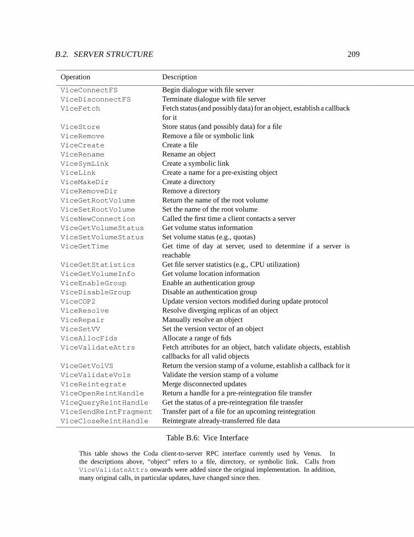
B.2. SERVER STRUCTURE 209
Operation Description
ViceConnectFS Begin dialogue with file serverViceDisconnectFS Terminate dialogue with file serverViceFetch Fetch status (and possibly data) for an object, establish a callback
for itViceStore Store status (and possibly data) for a fileViceRemove Remove a file or symbolic linkViceCreate Create a fileViceRename Rename an objectViceSymLink Create a symbolic linkViceLink Create a name for a pre-existing objectViceMakeDir Create a directoryViceRemoveDir Remove a directoryViceGetRootVolume Return the name of the root volumeViceSetRootVolume Set the name of the root volumeViceNewConnection Called the first time a client contacts a serverViceGetVolumeStatus Get volume status informationViceSetVolumeStatus Set volume status (e.g., quotas)ViceGetTime Get time of day at server, used to determine if a server is
reachableViceGetStatistics Get file server statistics (e.g., CPU utilization)ViceGetVolumeInfo Get volume location informationViceEnableGroup Enable an authentication groupViceDisableGroup Disable an authentication groupViceCOP2 Update version vectors modified during update protocolViceResolve Resolve diverging replicas of an objectViceRepair Manually resolve an objectViceSetVV Set the version vector of an objectViceAllocFids Allocate a range of fidsViceValidateAttrs Fetch attributes for an object, batch validate objects, establish
callbacks for all valid objectsViceGetVolVS Return the version stamp of a volume, establish a callback for itViceValidateVols Validate the version stamp of a volumeViceReintegrate Merge disconnected updatesViceOpenReintHandle Return a handle for a pre-reintegration file transferViceQueryReintHandle Get the status of a pre-reintegration file transferViceSendReintFragment Transfer part of a file for an upcoming reintegrationViceCloseReintHandle Reintegrate already-transferred file data
Table B.6: Vice Interface
This table shows the Coda client-to-server RPC interface currently used by Venus. Inthe descriptions above, “object” refers to a file, directory, or symbolic link. Calls fromViceValidateAttrs onwards were added since the original implementation. In addition,many original calls, in particular updates, have changed since then.
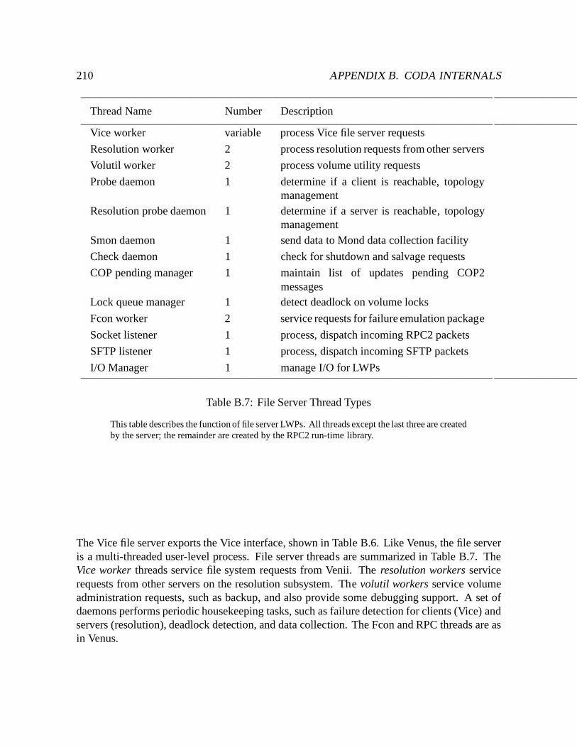
210 APPENDIX B. CODA INTERNALS
Thread Name Number Description
Vice worker variable process Vice file server requests
Resolution worker 2 process resolution requests from other servers
Volutil worker 2 process volume utility requests
Probe daemon 1 determine if a client is reachable, topologymanagement
Resolution probe daemon 1 determine if a server is reachable, topologymanagement
Smon daemon 1 send data to Mond data collection facility
Check daemon 1 check for shutdown and salvage requests
COP pending manager 1 maintain list of updates pending COP2messages
Lock queue manager 1 detect deadlock on volume locks
Fcon worker 2 service requests for failure emulation package
Socket listener 1 process, dispatch incoming RPC2 packets
SFTP listener 1 process, dispatch incoming SFTP packets
I/O Manager 1 manage I/O for LWPs
Table B.7: File Server Thread Types
This table describes the function of file server LWPs. All threads except the last three are createdby the server; the remainder are created by the RPC2 run-time library.
The Vice file server exports the Vice interface, shown in Table B.6. Like Venus, the file serveris a multi-threaded user-level process. File server threads are summarized in Table B.7. TheVice worker threads service file system requests from Venii. The resolution workers servicerequests from other servers on the resolution subsystem. The volutil workers service volumeadministration requests, such as backup, and also provide some debugging support. A set ofdaemons performs periodic housekeeping tasks, such as failure detection for clients (Vice) andservers (resolution), deadlock detection, and data collection. The Fcon and RPC threads are asin Venus.
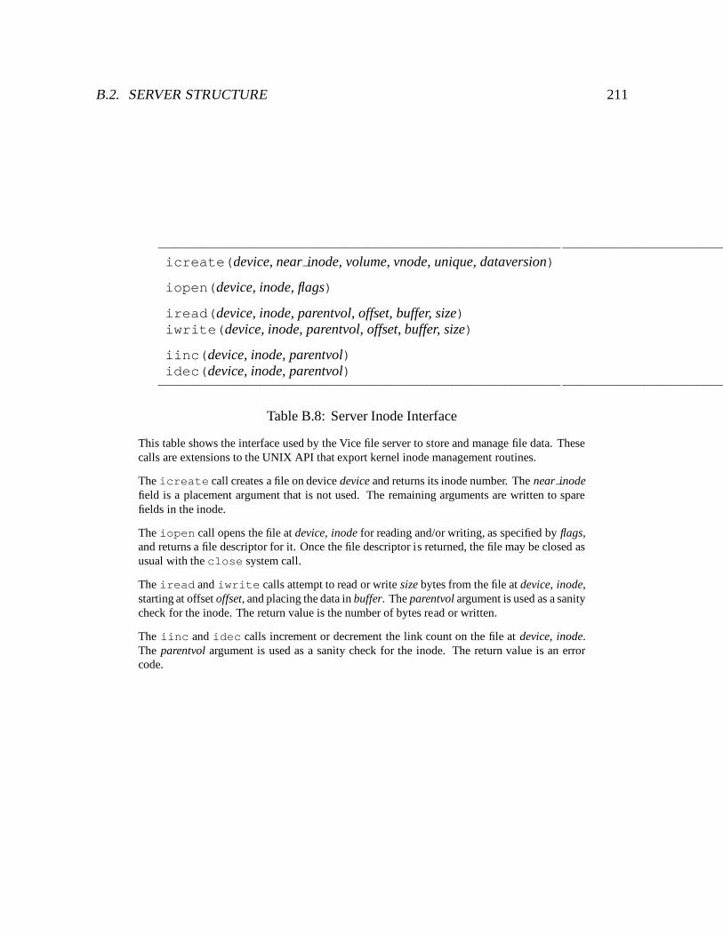
B.2. SERVER STRUCTURE 211
icreate(device, near inode, volume, vnode, unique, dataversion)
iopen(device, inode, flags)
iread(device, inode, parentvol, offset, buffer, size)iwrite(device, inode, parentvol, offset, buffer, size)
iinc(device, inode, parentvol)idec(device, inode, parentvol)
Table B.8: Server Inode Interface
This table shows the interface used by the Vice file server to store and manage file data. Thesecalls are extensions to the UNIX API that export kernel inode management routines.
The icreate call creates a file on device device and returns its inode number. The near inodefield is a placement argument that is not used. The remaining arguments are written to sparefields in the inode.
The iopen call opens the file at device, inode for reading and/or writing, as specified by flags,and returns a file descriptor for it. Once the file descriptor is returned, the file may be closed asusual with the close system call.
The iread and iwrite calls attempt to read or write size bytes from the file at device, inode,starting at offset offset, and placing the data in buffer. The parentvol argument is used as a sanitycheck for the inode. The return value is the number of bytes read or written.
The iinc and idec calls increment or decrement the link count on the file at device, inode.The parentvol argument is used as a sanity check for the inode. The return value is an errorcode.
212 APPENDIX B. CODA INTERNALS
B.2.1.1 Object Representation
Like Venus, the server stores persistent data using a combination of RVM and local UNIX files.File and volume meta-data, contents of directories and symbolic links, and resolution logs arestored in RVM. File contents are stored in local UNIX container files. To avoid overheadfrom pathname translation, container files are not named in any directory. The server accessescontainer files directly by inode through a set of system call extensions, shown in Table B.8.2
The inode number is stored in the server’s status descriptor for the file, much like the containerfile mechanism in Venus.
The server must guarantee permanence of updates when a transaction commits.3 Sincecontainer files are stored in the UNIX file system, the server has additional recovery mechanismsto augment those provided by RVM. If an update changes file data, the new data is stored inanother container file or shadow inode. If the transaction aborts, the server removes the shadow;otherwise, the server installs the shadow as the new file and removes the old container file. Ifthe server crashes, updates to container files may not have been written to disk. The serverrecovers by salvaging the container files at startup.4 If a container file does not exist, the servercreates one and marks the object in conflict, and if a container file is not referenced by anyobject the server garbage collects it. In this way the server ensures that the container files andRVM state are mutually consistent.
B.2.1.2 Request Processing
Server processing of Vice RPCs for most operations is as follows. Processing begins when aVice worker thread receives a request from a client.
1. Validate parameters. The worker thread performs sanity checks on the request. Itbegins by verifying that the request came from a known client. In the case of a replicatedoperation, it verifies that the VSG number corresponds to a volume it stores. It thenperforms request-specific checks.
2. Get objects. In this step, the worker thread looks up or creates objects necessary for therequest, and performs volume and object locking as appropriate.
3. Check semantics. Semantic checks fall into three categories: concurrency control,integrity checks, and protection checks. For concurrency control, the server verifies that
2The inode system call extensions are not necessary for functionality, only for performance. The objects couldbe stored in a UNIX directory just like Venus container files.
3Unlike Venus, the server does not use no-flush transactions.4Since container files are not named in any directory, servers run a special version of the fsck utility that does
not garbage collect them.
B.2. SERVER STRUCTURE 213
the object version information sent by the client matches its current state. The integritycheck ensures that the operation is sound, for example, for an unlink request the targetobject must not be a directory. The protection check verifies that the user responsible forthe request has the rights to perform it. The integrity and protection checks are essentiallythose performed by Venus, but because clients may be subverted the server must alsoperform them.
4. Perform operation. In this step, the worker thread breaks callbacks, performs bulktransfer of data, and sets output parameters for the RPC as appropriate.
5. Put objects. The worker thread updates relevant objects transactionally, and releasesobject and volume locks. In case of an error, it discards any changes made during thecourse of the request.
B.2.2 Authentication Server
The authentication server provides the means for establishing secure RPC connections betweenclients and servers. A user authenticates to Coda by running the clog program and typing in apassword. The login program establishes a secure connection to the authentication server, whichmaintains a database of user and password information. If the user authenticates successfully,the authentication server returns a pair of tokens valid for 25 hours. Then clog passes them toVenus. Venus uses these tokens to create secure connections to servers on behalf of that user.An unauthenticated user may access Coda objects; in that case the connections between Venusand the servers are unauthenticated, and the user has access rights of the “anonymous systemuser”.
B.2.3 Update System
Certain system databases, such as the password database and the volume location database,are replicated on many servers and change relatively slowly. The update system keeps thesedatabases consistent between servers. The SCM runs an update server; all other servers runupdate clients. Modifications to the database are permitted only at the SCM. Update clientspoll the SCM to detect and install new versions of system databases.

214 APPENDIX B. CODA INTERNALS
Bibliography
[1] ACCETTA, M., BARON, R. V., BOLOSKY, W., GOLUB, D. B., RASHID, R. F., TEVANIAN,JR., A., AND YOUNG, M. W. Mach: A New Kernel Foundation for UNIX Development.In Proceedings of the Summer 1986 USENIX Conference (Atlanta, GA, July 1986),pp. 93–113.
[2] AIRSOFT, INC., CUPERTINO, CA. AirSoft AirAccess 2.0: Mobile Networking Software,June 1994.
[3] APM LIMITED, UK. The ANSA Reference Manual Release 01.00, March 1989.
[4] AUSTEIN, R. Synchronization Operations for Disconnected IMAP4 Clients. Work inProgress.
[5] BACHMANN, D., HONEYMAN, P., AND HUSTON, L. The Rx Hex. In Proceedings of theFirst IEEE Workshop on Services in Distributed and Networked Environments (Prague,Czech Republic, June 1994), pp. 66–74. Also available as technical report 93-8, Centerfor InformationTechnology Integration (CITI), University of Michigan, November 1993.
[6] BAKER, M. G., HARTMANN, J. H., KUPFER, M. D., SHIRRIFF, K. W., AND OUSTERHOUT,J. K. Measurement of a Distributed File System. In Proceedings of the Thirteenth ACMSymposium on Operating Systems Principles (October 1991), pp. 198–212.
[7] BAKER, M. G., ZHAO, X., CHESHIRE, S., AND STONE, J. Supporting Mobility inMosquitoNet. In Proceedings of the 1996 USENIX Technical Conference (San Diego,CA, January 1996), USENIX Association, pp. 127 – 139.
[8] BECK, M., BOHME, H., DZIADZKA, M., KUNITZ, U., MAGNUS, R., AND VERWORNER, D.LINUX Kernel Internals. Addison Wesley Longman Limited, Harlow, England, 1996.
[9] BERNERS-LEE, T., CAILLIAU, R., LUOTONEN, A., NIELSEN, H. F., AND SECRET, A. TheWorld-Wide Web. Communications of the ACM 37, 8 (August 1994), 76–82.
215
216 BIBLIOGRAPHY
[10] BIRRELL, A., AND NELSON, B. Implementing Remote Procedure Calls. ACM Transac-tions on Computer Systems 2, 1 (February 1984), 39–59.
[11] BIRRELL, A. D., AND NELSON, B. J. Implementing Remote Procedure Calls. ACMTransactions on Computer Systems 2, 1 (February 1984), 39–59.
[12] BOLOT, J.-C. End-to-End Packet Delay and Loss Behavior in the Internet. In Proceedingsof the SIGCOMM ’93 Conference on Communications Architectures, Protocols, andApplications (San Francisco, CA, September 1993), pp. 289–298.
[13] BOZMAN, G., GHANNAD, H., AND WEINBERGER, E. A Trace-Driven Study of CMS FileReferences. IBM Journal of Research and Development 35, 5–6 (September–November1991), 815–28.
[14] BRADEN, R. Requirements for Internet Hosts – Communication Layers. In InternetRequests for Comments, R. Braden, Ed., RFC 1122. SRI International, Menlo Park, CA,October 1989.
[15] BRADEN, R., CLARK, D., AND SHENKER, S. Integrated Services in the Internet Architec-ture: an Overview. In Internet Requests for Comments, RFC 1633. Network WorkingGroup, July 1994.
[16] BURROWS, M. Efficient Data Sharing. PhD thesis, University of Cambridge, December1988.
[17] BURROWS, M., ABADI, M., AND NEEDHAM, R. A Logic of Authentication. Tech. Rep. 39,DEC Systems Research Center, February 1989.
[18] BURROWS, M., ABADI, M., AND NEEDHAM, R. A Logic of Authentication. ACMTransactions on Computer Systems 8, 1 (February 1990), 18–36.
[19] CLARK, D. D., SHENKER, S., AND ZHANG, L. Supporting Real-Time Applications in anIntegrated Services Packet Network: Architecture and Mechanism. In Proceedings of theSIGCOMM ’92 Conference on Communications Architectures and Protocols (Baltimore,MD, August 1992).
[20] CLARK, D. D., AND TENNENHOUSE, D. L. Architectural Considerations for a New Gener-ation of Protocols. In Proceedings of the SIGCOMM ’90 Conference on CommunicationsArchitectures and Protocols (Philadelphia, PA, September 1990).
[21] CLARKE, E., GRUMBERG, O., HIRAISHI, H., JHA, S., LONG, D., MCMILLAN, K., AND
NESS, L. Verification of the Futurebus+ Cache Coherence Protocol. Tech. Rep. CMU-CS-92-206, Carnegie Mellon University School of Computer Science, October 1992.
BIBLIOGRAPHY 217
[22] CORNSWEET, T. N. Visual Perception. Academic Press, 1971.
[23] COULSON, G., BLAIR, G. S., AND ROBIN, P. Micro-kernel support for continuous mediain distributed systems. Computer Networks and ISDN Systems 26, 10 (July 1994),1323–1341.
[24] COWAN, C., CEN, S., WALPOLE, J., AND PU, C. Adaptive Methods for Distributed VideoPresentation. ACM Computing Surveys 27, 4 (December 1995), 580–583.
[25] CRISPIN, M. R. Internet Message Access Protocol - Version 4 Rev. 1. Work in Progress.
[26] CRISPIN, M. R. Distributed Electronic Mail Models in IMAP4. In Internet Requests forComments, RFC 1733. Network Working Group, December 1994.
[27] CROWCROFT, J., WANG, Z., SMITH, A., AND ADAMS, J. A Rough Comparison of the IETFand ATM Service Models. IEEE Network 9, 6 (November/December 1995), 12–16.
[28] DATE, C. J. An Introduction to Database Systems, vol. II. Addison-Wesley PublishingCompany, Reading, Massachusetts, 1983.
[29] DAVIDSON, S. B. Optimism and Concurrency in Partitioned Distributed Database Sys-tems. ACM Transactions on Database Systems 9, 3 (September 1984), 456–481.
[30] DAVIES, N., BLAIR, G. S., CHEVERST, K., AND FRIDAY, A. A Network Emulator to Supportthe Development of Adaptive Applications. In Proceedings of the Second USENIXSymposium on Mobile & Location-Independent Computing (Ann Arbor, Michigan, April1995), USENIX Association, pp. 47–55.
[31] DEERING, S. Host Extensions for IP Multicasting. In Internet Requests for Comments,RFC 1112. Network Working Group, Stanford, CA, August 1989.
[32] DOMINACH, R. F. Design reviews at a distance. IEEE Spectrum 31, 6 (June 1994),39–40.
[33] DOWNING, A. R., GREENBERG, I. B., AND PEHA, J. M. OSCAR: A System for Weak-Consistency Replication. In Proceedings of the Workshop on Management of ReplicatedData (Houston, Texas, November 1990), IEEE Computer Society Technical Committeeon Operating Systems and Application Environments (TCOS), pp. 26–30.
[34] DRUSCHEL, P., AND PETERSON, L. L. Fbufs: A High-Bandwidth Cross-Domain TransferFacility. In Proceedings of the Fourteenth ACM Symposium on Operating SystemsPrinciples (Asheville, NC, December 1993), pp. 189–202.
218 BIBLIOGRAPHY
[35] EBLING, M. Evaluating and Improving the Effectiveness of Caching for Availability.PhD thesis, Department of Computer Science, Carnegie Mellon University, 1997 (inpreparation).
[36] EBLING, M. R. Evaluating and Improving the Effectiveness of Hoarding. Thesis proposal,Carnegie Mellon University, April 1993.
[37] ECKHARDT, D., AND STEENKISTE, P. Measurement and Analysis of the Error Character-istics of an In-Building Wireless Network. In Proceedings of the ACM SIGCOMM ’96Conference on Applications, Technologies, Architectures, and Protocols for ComputerCommunication (Stanford University, CA, August 1996), pp. 243–254.
[38] FERRARI, D., BANERJEA, A., AND ZHANG, H. Network support for multimedia: Adiscussion of the Tenet Approach. Computer Networks and ISDN Systems 26, 10 (July1994), 1267–1280.
[39] FLOYD, R. Short-Term File Reference Patterns in a UNIX Environment. Tech. Rep. TR177, Department of Computer Science, University of Rochester, March 1986.
[40] FORMAN, G. H., AND ZAHORJAN, J. The Challenges of Mobile Computing. IEEEComputer 27, 4 (April 1994).
[41] FULTON, J., AND KANTARJIEV, C. K. An Update on Low Bandwidth X (LBX). Tech.Rep. CSL-93-2, Xerox Palo Alto Research Center, February 1993.
[42] GOLUB, D., DEAN, R., FORIN, A., AND RASHID, R. UNIX as an Application Program.In USENIX Summer Conference Proceedings (Anaheim, CA, June 1990), USENIXAssociation.
[43] GRAY, C. G., AND CHERITON, D. R. Leases: An Efficient Fault-Tolerant Mechanismfor Distributed File Cache Consistency. In The Twelfth ACM Symposium on OperatingSystems Principles (Dec. 1989), ACM, pp. 202–210.
[44] GRAY, T. Message Access Protocols and Paradigms. Networks and Distributed Comput-ing, University of Washington, http://www.imap.org/imap.vs.pop.html,September 1995.
[45] GUY, R. G., HEIDEMANN, J. S., MAK, W., PAGE, T. W., POPEK, G. J., AND ROTHMEIER,D. Implementation of the Ficus Replicated File System. In USENIX Summer ConferenceProceedings (Anaheim, CA, June 1990), USENIX Association, pp. 63–71.
[46] HEIDEMANN, J. S., PAGE, T. W., GUY, R. S., AND POPEK, G. J. Primarily Discon-nected Operation: Experiences with Ficus. In Second Workshop on the Management of
BIBLIOGRAPHY 219
Replicated Data (Monterey, CA, November 1992), IEEE Computer Society TechnicalCommittee on Operating Systems, pp. 2–5.
[47] HISGEN, A., BIRRELL, A., MANN, T., SCHROEDER, M., AND SWART, G. Availabilityand Consistency Tradeoffs in the Echo Distributed File System. In Proceedings of theSecond Workshop on Workstation Operating Systems (September 1989), pp. 49 – 53.
[48] HONEYMAN, P., AND HUSTON, L. Communications and Consistency in Mobile FileSystems. IEEE Personal Communications 2, 6 (December 1995), 44–48.
[49] HOWARD, J. H., KAZAR, M. L., MENEES, S. G., NICHOLS, D. A., SATYANARAYANAN,M., SIDEBOTHAM, R. N., AND WEST, M. J. Scale and Performance in a Distributed FileSystem. ACM Transactions on Computer Systems 6, 1 (February 1988), 51–81.
[50] HUSTON, L. B., AND HONEYMAN, P. Disconnected Operation for AFS. In Proceedingsof the USENIX Symposium on Mobile & Location-Independent Computing (Cambridge,Massachusetts, August 1993), USENIX Association, pp. 1–10.
[51] HUSTON, L. B., AND HONEYMAN, P. Partially Connected Operation. In Proceedings ofthe Second USENIX Symposium on Mobile & Location-Independent Computing (AnnArbor, Michigan, April 1995), USENIX Association, pp. 91–97.
[52] JACOBSON, V. Congestion Avoidance and Control. In Proceedings of the SIGCOMM’88 Symposium on Communications Architectures and Protocols (Stanford, CA, August1988), pp. 314–329.
[53] JACOBSON, V. Compressing TCP/IP Headers for Low-Speed Serial Links. In InternetRequests for Comments, RFC 1144. SRI International, Menlo Park, CA, February 1990.
[54] JACOBSON, V., BRADEN, R., AND BORMAN, D. TCP Extensions for High Performance.In Internet Requests for Comments, RFC 1323. SRI International, Menlo Park, CA, May1992.
[55] JAIN, R. The Art of Computer Systems Performance Analysis: Techniques for Experi-mental Design, Measurement, Simulation, and Modeling. John Wiley & Sons, Inc., NewYork, NY, 1991.
[56] JOHNSON, D. B., AND MALTZ, D. A. Protocols for Adaptive Wireless and MobileNetworking. IEEE Personal Communications 3, 1 (February 1996), 34 – 42.
[57] KARN, P., AND PARTRIDGE, C. Improving Round-Trip Time Estimates In ReliableTransport Protocols. ACM Transactions on Computer Systems 9, 4 (November 1991),364–373.
220 BIBLIOGRAPHY
[58] KATZ, R. H. Adaptation and Mobility in Wireless Information Systems. IEEE PersonalCommunications 1, 1 (1994).
[59] KAWELL JR., L., BECKHARDT, S., HALVORSEN, T., OZZIE, R., AND GREIF, I. ReplicatedDocument Management in a Group Communication System. In Groupware: Software forComputer-Supported Cooperative Work. IEEE Computer Society Press, Los Alamitos,CA, 1992, pp. 226–235.
[60] KAY, J., AND PASQUALE, J. The Importance of Non-Data Touching Processing Over-heads in TCP/IP. In Proceedings of the SIGCOMM ’93 Conference on Communica-tions Architectures, Protocols, and Applications (San Francisco, CA, September 1993),pp. 259–268.
[61] KING, A. Inside Windows 95. Microsoft Press, Redmond, Washington, 1994.
[62] KISTLER, J. J. Disconnected Operation in a Distributed File System. PhD thesis, Schoolof Computer Science, Carnegie Mellon University, April 1993.
[63] KISTLER, J. J., AND SATYANARAYANAN, M. Disconnected Operation in the Coda FileSystem. ACM Transactions on Computer Systems 10, 1 (February 1992), 3 – 25.
[64] KLEIMAN, S. R. Vnodes: An Architecture for Multiple File System Types in SunUNIX. In USENIX Summer Conference Proceedings (Atlanta, GA, June 1986), USENIXAssociation, pp. 238 – 247.
[65] KLEINPASTE, K., STEENKISTE, P., AND ZILL, B. Software Support for Outboard Bufferingand Checksumming. In Proceedings of the SIGCOMM ’95 Conference on Applications,Technologies, Architectures, and Protocols for Computer Communication (Cambridge,MA, August 1995), pp. 87–98.
[66] KUMAR, P. Mitigating the Effects of Optimistic Replication in a Distributed File System.PhD thesis, School of Computer Science, Carnegie Mellon University, December 1994.
[67] KUMAR, P., AND SATYANARAYANAN, M. Log-Based Directory Resolution in the CodaFile System. In Proceedings of the Second International Conference on Parallel and Dis-tributed Information Systems (January 1993), pp. 202 – 213. Also available as technicalreport CMU-CS-91-164, School of Computer Science, Carnegie Mellon University.
[68] KUMAR, P., AND SATYANARAYANAN, M. Flexible and Safe Resolution of File Conflicts.In Proceedings of 1995 USENIX Conference (New Orleans, LA, January 1995), USENIXAssociation.
[69] LAMPSON, B. W. Hints for Computer System Design. In Proceedings of the Ninth ACMSymposium on Operating Systems Principles (Bretton Woods, NH, October 1983).
BIBLIOGRAPHY 221
[70] LEFFLER, S. J., MCKUSICK, M. K., KARELS, M. J., AND QUARTERMAN, J. S. The Designand Implementation of the 4.3BSD UNIX Operating System. Addison-Wesley PublishingCompany, Reading, Massachusetts, 1989.
[71] LILIEN, L. Quasi-Partitioning: A New Paradigm for Transaction Execution in PartitionedDistributed Database Systems. In Proceedings of the Fifth International Conference onData Engineering (Los Angeles, CA, February 6-10 1989), pp. 546–553.
[72] LU, Q. Improving Data Consistency for Mobile File Access Using Isolation-Only Trans-actions. PhD thesis, School of Computer Science, Carnegie Mellon University, May1996.
[73] LU, Q., AND SATYANARAYANAN, M. Improving Data Consistency in Mobile ComputingUsing Isolation-Only Transactions. In Proceedings of the Fifth Workshop on Hot Topicsin Operating Systems (Orcas Island, WA, May 1995).
[74] MANN, T., BIRRELL, A., HISGEN, A., JERIAN, C., AND SWART, G. A Coherent DistributedFile Cache with Directory Write-Behind. ACM Transactions on Computer Systems 12,2 (May 1994).
[75] MASHBURN, H. M., AND SATYANARAYANAN, M. RVM – Recoverable Virtual Memory.School of Computer Science, Carnegie Mellon University, June 1994.
[76] MCMILLAN, K., AND SCHWALBE, J. Formal Verification of the Encore Gigamax CacheConsistency Protocol. In Proceedings of the 1991 International Symposium on SharedMemory Multiprocessors (April 1991).
[77] MERCER, C. W., ZELENKA, J., AND RAJKUMAR, R. On Predictable Operating System Pro-tocol Processing. Tech. Rep. CMU-CS-94-165, School of Computer Science, CarnegieMellon University, May 1994.
[78] MEYERS, J. G., AND ROSE, M. T. Post Office Protocol - Version 3. In Internet Requestsfor Comments, RFC 1939. Network Working Group, May 1996.
[79] MILLS, D. L. Internet Delay Experiments. In Internet Requests for Comments, RFC 889.SRI International, Menlo Park, CA, December 1983.
[80] MOELLER, M. Lotus Opens cc:Mail to Pagers. PC Week 11, 35 (September 1994), 39.
[81] MOGUL, J. C. Efficient Use of Workstations for Passive Monitoring of Local AreaNetworks. In Proceedings of the SIGCOMM ’90 Symposium on Communications Archi-tectures and Protocols (Philadelphia, PA, September 1990), pp. 253–263.
222 BIBLIOGRAPHY
[82] MORRIS, J. H., SATYANARAYANAN, M., CONNER, M. H., HOWARD, J. H., ROSENTHAL,D. S., AND SMITH, F. D. Andrew: A Distributed Personal Computing Environment.Communications of the ACM 29, 3 (March 1986).
[83] MULLENDER, S. Interprocess Communication. In Distributed Systems, S. Mullender, Ed.,second ed. Addison-Wesley Publishing Company, Reading, MA, 1993, ch. 9, pp. 217–250.
[84] MUMMERT, L., AND SATYANARAYANAN, M. Large Granularity Cache Coherence forIntermittent Connectivity. In USENIX Summer Conference Proceedings (Boston, MA,June 1994), USENIX Association, pp. 279 – 289.
[85] MUMMERT, L., AND SATYANARAYANAN, M. Variable Granularity Cache Coherence.Operating Systems Review 28, 1 (January 1994).
[86] MUMMERT, L., AND SATYANARAYANAN, M. Long Term Distributed File ReferenceTracing: Implementation and Experience. Software: Practice and Experience 26, 6(June 1996), 705–736. Also available as technical report CMU-CS-94-213, School ofComputer Science, Carnegie Mellon University, November 1994.
[87] NANCE, B. File Transfer on Steroids. Byte 20, 2 (February 1995), 129–130.
[88] NEEDHAM, R., AND SCHROEDER, M. Using Encryption for Authentication in LargeNetworks of Computers. Communications of the ACM 21, 12 (December 1978), 993 –998.
[89] NELSON, M. N., WELCH, B. B., AND OUSTERHOUT, J. K. Caching in the Sprite NetworkFile System. ACM Transactions on Computer Systems 6, 1 (February 1988), 134 – 154.
[90] NOBLE, B. D., PRICE, M., AND SATYANARAYANAN, M. A Programming Interface forApplication-Aware Adaptation in Mobile Computing. In Proceedings of the SecondUSENIX Symposium on Mobile and Location-Independent Computing (Ann Arbor, MI,April 1995), pp. 57 – 66. Also available in Computing Systems, the journal of theUSENIX Association, Volume 8, Number 4, Fall 1995.
[91] NOBLE, B. D., AND SATYANARAYANAN, M. An Empirical Study of a Highly Available FileSystem. In Proceedings of the 1994 ACM SIGMETRICS Conference on Measurementand Modeling of Computer Systems (Nashville, TN, May 1994), pp. 138 – 149.
[92] NOVELL CORPORATION. NetWare User Manual, 1993.
[93] OFFICE OF COMPUTING & COMMUNICATIONS, UNIVERSITY OF WASHINGTON. Pine In-formation Center. http://www.cac.washington.edu:1180/pine/.
BIBLIOGRAPHY 223
[94] OUSTERHOUT, J. K. Tcl and the Tk Toolkit. Addison Wesley, 1994.
[95] OUSTERHOUT, J. K., COSTA, H. D., HARRISON, D., KUNZE, J. A., KNUPFER, M., AND
THOMPSON, J. G. A Trace-Driven Analysis of the UNIX 4.2 BSD File System. InProceedings of the Tenth ACM Symposium on Operating Systems Principles (OrcasIsland, Washington, December 1985), pp. 15 – 24.
[96] PETERSON, J. L., AND SILBERSCHATZ, A. Operating System Concepts. Addison-WesleyPublishing Company, Reading, Massachusetts, 1983.
[97] POPEK, G., WALKER, B., CHOW, J., EDWARDS, D., KLINE, C., RUDISIN, G., AND THIEL, G.LOCUS: A Network Transparent, High Reliability Distributed System. In Proceedingsof the Eighth Symposium on Operating System Principles (Pacific Grove, CA, December1981).
[98] POSTEL, J. User Datagram Protocol. In Internet Requests for Comments, RFC 768. SRIInternational, Menlo Park, CA, August 1980.
[99] POSTEL, J. Transmission Control Protocol. In Internet Requests for Comments, RFC793. SRI International, Menlo Park, CA, September 1981.
[100] POSTEL, J., AND REYNOLDS, J. File Transfer Protocol. In Internet Requests for Comments,RFC 959. Network Working Group, Information Sciences Institute, October 1985.
[101] POSTEL, J. B. Simple Mail Transfer Protocol. In Internet Requests for Comments, RFC821. Information Sciences Institute, Univeristy of Southern California, Marina del Rey,CA, August 1982.
[102] PRUSKER, F. J., AND WOBBER, E. P. The Siphon: Managing Distant Replicated Repos-itories. In Proceedings of the Workshop on Management of Replicated Data (Houston,Texas, November 1990), IEEE Computer Society Technical Committee on OperatingSystems and Application Environments (TCOS), pp. 44 – 47.
[103] QUALCOMM INCORPORATED. Eudora Macintosh User Manual, 1996.
[104] RANGANATHAN, M., ACHARYA, A., SHARMA, S., AND SALTZ, J. Network-aware MobilePrograms. Tech. Rep. CS-TR-3659, Department of Computer Science, University ofMaryland, June 1996. To appear in the Proceedings of the 1997 USENIX TechicalConference.
[105] REICHARD, K., AND JOHNSON, E. F. Broadway: Sound And X On The Net. Unix Review14, 7 (June 1996), 69–70.
224 BIBLIOGRAPHY
[106] RODEHEFFER, T. L., AND SCHROEDER, M. D. Automatic reconfiguration in Autonet.In Proceedings of 13th ACM Symposium on Operating Systems Principles (Asilomar,Pacific Grove, CA, October 1991), Association for Computing Machinery SIGOPS,pp. 183–97.
[107] SALTZER, J. H., REED, D. P., AND CLARK, D. D. End-to-end Arguments in SystemDesign. ACM Transactions on Computer Systems 2, 4 (November 1984), 277–288.
[108] SANDBERG, R., GOLDBERG, D., KLEIMAN, S., WALSH, D., AND LYON, B. Design andImplementation of the Sun Network File System. In USENIX Summer ConferenceProceedings (June 1985), USENIX Association.
[109] SANGHI, D., AGARWALA, A. K., GUDMUNDSSON, O., AND JAIN, B. N. ExperimentalAssessment of End-to-end Behavior on Internet. In Proceedings of the IEEE INFO-COM ’93 Conference on Computer Communications (San Francisco, CA, March 1993),pp. 867–874.
[110] SATYANARAYANAN, M. Integrating Security in a Large Distributed System. ACMTransactions on Computer Systems 7, 3 (August 1989), 247 – 280.
[111] SATYANARAYANAN, M. RPC2 User Guide and Reference Manual. School of ComputerScience, Carnegie Mellon University, Pittsburgh PA 15213, October 1991.
[112] SATYANARAYANAN, M. Fundamental Challenges in Mobile Computing. In Proceedingsof the Fifteenth ACM Symposium on Principles of Distributed Computing (Philadelphia,PA, May 1996). Also available as technical report CMU-CS-96-111, School of ComputerScience, Carnegie Mellon University, February 1996.
[113] SATYANARAYANAN, M., HOWARD, J. H., NICHOLS, D. A., SIDEBOTHAM, R. N., SPECTOR,A. Z., AND WEST, M. J. The ITC Distributed File System: Principles and Design.In Proceedings of the Tenth ACM Symposium on Operating Systems Principles (OrcasIsland, Washington, December 1985), pp. 35–50.
[114] SATYANARAYANAN, M., KISTLER, J. J., KUMAR, P., OKASAKI, M. E., SIEGEL, E. H., AND
STEERE, D. C. Coda: A Highly Available File System for a Distributed WorkstationEnvironment. IEEE Transactions on Computers 39, 4 (April 1990), 447 – 459.
[115] SATYANARAYANAN, M., KISTLER, J. J., MUMMERT, L. B., EBLING, M. R., KUMAR, P.,AND LU, Q. Experience with Disconnected Operation in a Mobile Environment. InProceedings of the USENIX Symposium on Mobile & Location Independent Computing(Cambridge, Massachusetts, August 1993), pp. 11 – 28.
BIBLIOGRAPHY 225
[116] SATYANARAYANAN, M., MASHBURN, H. H., KUMAR, P., STEERE, D. C., AND KISTLER,J. J. Lightweight Recoverable Virtual Memory. ACM Transactions on Computer Systems12, 1 (February 1994), 33 – 57. Corrigendum: 12, (2), 165–172 (1994).
[117] SATYANARAYANAN, M., AND SIEGEL, E. H. Parallel Communication in a Large Dis-tributed Environment. IEEE Transactions on Computers 39, 3 (March 1990).
[118] SHARMA, R., AND KESHAV, S. Signaling and Operating System Support for Native-ModeATM Applications. In Proceedings of the SIGCOMM ’94 Conference on Communica-tions Architectures, Protocols, and Applications (London, UK, August/September 1994),pp. 149–157.
[119] SHENG, S., CHANDRAKASAN, A., AND BRODERSEN, R. A Portable Multimedia Terminal.IEEE Communications Magazine 30, 12 (December 1992).
[120] SHENKER, S., ZHANG, L., AND CLARK, D. D. Dynamics of a Congestion ControlAlgorithm. Computer Communications Review 20, 5 (October 1990), 30–39.
[121] SIDEBOTHAM, R. N. Volumes: The Andrew File System Data Structuring Primitive. InEuropean Unix User Group Conference Proceedings (August 1986). Also available asTechnical Report CMU-ITC-053, Carnegie Mellon University, Information TechnologyCenter.
[122] STEERE, D., AND SATYANARAYANAN, M. Using Dynamic Sets to Overcome High I/OLatencies During Search. In Proceedings of the Fifth Workshop on Hot Topics inOperating Systems (Orcas Island, WA, May 1995).
[123] STEERE, D. C., KISTLER, J. J., AND SATYANARAYANAN, M. Efficient User-Level CacheFile Management on the Sun Vnode Interface. In USENIX Summer Conference Pro-ceedings (Anaheim, CA, June 1990), USENIX Association, pp. 325 – 331.
[124] STINSON, C. Running Microsoft Windows 95. Microsoft Press, Redmond, Washington,1995.
[125] TANENBAUM, A. S. Computer Networks, 2nd ed. Prentice Hall, Englewood Cliffs, NJ,1989.
[126] TERRY, D. B., THEIMER, M. M., PETERSEN, K., DEMERS, A. J., SPREITZER, M. J., AND
HAUSER, C. H. Managing Update Conflicts in Bayou, a Weakly Connected ReplicatedStorage System. In Proceedings of the Fifteenth ACM Symposium on Operating SystemsPrinciples (Copper Mountain Resort, CO, December 1995), pp. 172–183.
226 BIBLIOGRAPHY
[127] WANG, R. Y., AND ANDERSON, T. E. xFS: A Wide Area Mass Storage File System. InProceedings of the Fourth Workshop on Workstation Operating Systems (Napa, Califor-nia, October 1993), pp. 71 – 78.
[128] WEISER, M. The Computer for the Twenty-First Century. Scientific American 265, 3(September 1991), 94 – 104.
[129] WELLING, G., AND BADRINATH, B. R. A Framework for Environment Aware MobileApplications. Department of Computer Science, Rutgers University. Submitted forpublication, 1996.
[130] ZHANG, L., DEERING, S., ESTRIN, D., SHENKER, S., AND ZAPPALA, D. RSVP: A NewResource ReSerVation Protocol. IEEE Network 7, 5 (September 1993), 8 – 18.
[131] ZHANG, L., SHENKER, S., AND CLARK, D. D. Observations on the Dynamics of aCongestion Control Algorithm: The Effects of Two-Way Traffic. In Proceedings of theSIGCOMM ’91 Symposium on Communications Architectures and Protocols (Zurich,Switzerland, September 1991), pp. 133–147.